
Intergas Heating Ltd 1
Compact HRE
18 SB (G.C. 41-291-01)
24 SB (G.C. 41-291-02)
30 SB (G.C. 41-291-03)
40 SB (G.C. 41-291-07 )
Installation, service
and user instructions Please read these installation instructions carefully before installing and using the appliance. Keep these installation instructions with the appliance. Always act in accordance with the instructions indicated.

Intergas Heating Ltd 2
Benchmark places responsibilities on both manufacturers and installers. The purpose is to ensure that customers are provided with the correct equipment for their needs, that it is installed, commissioned and serviced in accordance with the manufacturer’s instructions by competent persons and that it meets the requirements of the appropriate Building Regulations. The Benchmark Checklist can be used to demonstrate compliance with Building Regulations and should be provided to the customer for future reference. Please read the Benchmark Checklist carefully, page 50, and complete all sections, as required by law, relevant to the appliance and installation. The details within the Checklist will be required in the event of any warranty work. On completion the Checklist must be left with the end user. The relevant sections of the Service Record, page 51, must be completed on each subsequent Service visit. Installers are required to carry out installation, commissioning and servicing work in accordance with the Benchmark Code of Practice which is available from the Heating and Hotwater Industry Council who manage and promote the scheme. Visit www.centralheating.co.uk for more information.
CONTENT
1 Preface 4 1.1 Regulation ........................................................................................................................................................................................ 4 1.2 Warnings .......................................................................................................................................................................................... 4 1.3 Manual handling .............................................................................................................................................................................. 4 1.4 Warnings on the box ........................................................................................................................................................................ 4 1.5 Pictograms ....................................................................................................................................................................................... 4 1.6 Abbreviations and descriptions used ............................................................................................................................................... 5 1.7 This manual ..................................................................................................................................................................................... 5 1.8 Service and technical support ......................................................................................................................................................... 5 1.9 Product identification ....................................................................................................................................................................... 5
2 Safety regulations 6 2.1 General ............................................................................................................................................................................................ 6 2.2 The Installation ................................................................................................................................................................................ 6 2.3 Approvals ......................................................................................................................................................................................... 7 2.4 Technical data ................................................................................................................................................................................. 8 2.5 Components .................................................................................................................................................................................... 9
3 General boiler information 10 3.1 General .......................................................................................................................................................................................... 10 3.2 Boiler controller .............................................................................................................................................................................. 10 3.3 Parameter list................................................................................................................................................................................. 10 3.4 Heat transfer .................................................................................................................................................................................. 10 3.5 Central heating system .................................................................................................................................................................. 10 3.6 Room temperature control ............................................................................................................................................................. 10 3.7 Integrated clock ............................................................................................................................................................................. 10
4 Operation 11 4.1 General .......................................................................................................................................................................................... 11 4.2 Central heating mode .................................................................................................................................................................... 11 4.3 Operating modes ........................................................................................................................................................................... 11 4.4 Clock function ................................................................................................................................................................................ 12 4.5 PC Interface ................................................................................................................................................................................... 12 4.6 Test programs................................................................................................................................................................................ 13 4.7 Frost protection ............................................................................................................................................................................. 13
5 Installer important points 14
6 Accessories 15
7 Installation 16 7.1 Overall dimensions ........................................................................................................................................................................ 17 7.2 Installation location ........................................................................................................................................................................ 18 7.3 Assembly ....................................................................................................................................................................................... 19 7.4 Installing the appliance .................................................................................................................................................................. 20
8 Connection 21 8.1 Connecting CH installation ............................................................................................................................................................ 21 8.2 Connecting DHW storage cylinder ................................................................................................................................................ 21 8.3 Electrical connection ...................................................................................................................................................................... 22 8.4 Condensate disposal ..................................................................................................................................................................... 24 8.5 Flue System ................................................................................................................................................................................... 24

Intergas Heating Ltd 3
9 Commissioning the appliance 28 9.1 Filling and venting the appliance and the installation .................................................................................................................... 28 9.2 Commissioning the appliance ....................................................................................................................................................... 30 9.3 Setting and adjusting the clock functions ...................................................................................................................................... 31 9.4 Additional functions ....................................................................................................................................................................... 31 9.5 Shutting down ................................................................................................................................................................................ 32
10 Setting and adjustment 33 10.1 Directly via the operating panel ..................................................................................................................................................... 33 10.2 Setting via the service code .......................................................................................................................................................... 34 10.3 Parameters .................................................................................................................................................................................... 34 10.4 Setting maximum CH power .......................................................................................................................................................... 35 10.5 Adjusting pump setting .................................................................................................................................................................. 35 10.6 Weather– compensation adjustment ............................................................................................................................................. 36 10.7 Checking gas-/air ratio .................................................................................................................................................................. 37 10.8 Setting gas/air adjustment procedure............................................................................................................................................ 38 10.9 Conversion to different gas type.................................................................................................................................................... 39
11 Faults 40 11.1 Fault codes .................................................................................................................................................................................... 40 11.2 Other faults ................................................................................................................................................................................... 40
12 Maintenance 43 12.1 Disassembly .................................................................................................................................................................................. 43 12.2 Cleaning ........................................................................................................................................................................................ 43 12.3 Assembly ....................................................................................................................................................................................... 44 12.4 Combustion ................................................................................................................................................................................... 44
13 Electrical diagram 45 13.1 NTC resistances ............................................................................................................................................................................ 46 13.2 Typical Y Plan connection ............................................................................................................................................................. 47 13.3 Typical S Plan connection ............................................................................................................................................................. 47
14 Short spares List 48
15 Warranty Conditions 49
16 CE Declaration 49
17 Gas Boiler System Commissioning Checklist 50
18 Service Record 51
© 2012 Intergas Heating Ltd. All rights reserved. The information provided applies to the standard version of the product. Intergas Heating Ltd cannot therefore be held liable for any loss or damage arising from product specifications deviating from the standard version. The available information has been compiled with all possible care, but Intergas Heating Ltd cannot be held liable for any errors in the information or for the consequences thereof. Intergas Heating Ltd cannot be held liable for any loss or damage arising from work performed by third parties. Subject to change.

Intergas Heating Ltd 4
1 PREFACE
1.1 Regulation
The Intergas boiler meets the requirements of Statutory Instrument 'The Boiler (Efficiency) Regulations' and is deemed to meet the requirements of: • Gas Appliance Directive 90/396/EEC • Boiler Efficiency Directive 92/42/EEC • Low Voltage Directive 2006/95/EC and • Electromagnetic Compatibility Directive 2004/108/EC Intergas declares that the materials used in the manufacturing of this appliance are non-hazardous and that no substances harmful to health are contained within the appliance.
1.2 Warnings
Intergas accepts no responsibility for the unsatisfactory performance of the appliance or flue arising from the failure to comply with the installation and user instructions. Incorrect installation could invalidate your guarantee and may lead to prosecution. If the appliance is re-sold or installation transferred the appliance must be re-registered with Intergas in order to maintain the warranty. The boiler must be installed in accordance with these instructions and the regulations currently in force. Read these instructions carefully before installing or using the appliance.
1.3 Manual handling
When moving the boiler always keep your back straight, bend your knees, don’t twist, move your feet. Avoid bending forwards or sideways and keep the load as close to your body as possible. Where possible transport the boiler using a suitable trolley, sack truck or get some assistance. Grip the boiler firmly and before lifting establish where the weight is concentrated to determine the centre of gravity, repositioning yourself if necessary.
1.4 Warnings on the box
This is a fragile piece of equipment: Please provide a dry storage for the appliance.
This is a fragile piece of equipment: Please be very careful not to drop.
Store the appliance upright as indicated on the box.
No more than three boxes should be stacked on top of each other.
1.5 Pictograms
The following pictograms are used in this manual:
CAUTION
Procedures which – if they are not performed with the necessary caution – can result in damage to the product, the surrounding area or the environment, or in physical injury.
WARNING HIGH VOLTAGE
Risk of electrical shock.
NOTE
Important information regarding the correct usage or installation of the appliance.

Intergas Heating Ltd 5
FROST PROTECTION
Procedures which must be followed to prevent frost damage.
1.6 Abbreviations and descriptions used
Description Referred to as
High efficiency HE
Intergas Compact HRE SB wall mounted gas fired boiler
Appliance
Appliance plus pipe work for central heating CH installation
Appliance plus pipe work for domestic hot water DHW installation
1.7 This manual
This manual will enable you to assemble, install and maintain the appliance safely. Follow the instructions carefully. In case of doubt contact the manufacturer. Keep these installation instructions with the appliance.
1.8 Service and technical support
For information about specific adjustments, installation, maintenance and repair work, please contact:
Intergas Heating Ltd Unit 6, West Court Buntsford Park Road Bromsgrove Worcestershire B60 3DX Tel. 01527 888000 Fax. 01527 888001 [email protected] www.intergasheating.co.uk
1.9 Product identification
You will find the appliance data on the data plate on the underside of the appliance. A. Model B. G.C. registration number C. Heat input (net) [kW] D. Heat output CH [kW] E. Appliance category F. Gas type G. Gas supply pressure [mbar] H. NOx class I. Appliance type J. Maximum CH pressure [bar] K. Maximum DHW pressure [bar] (not applicable for Compact HRE SB) L. Maximum Flow temperature [°C] (not applicable for Compact HRE SB) M. Electrical supply N. Protection O. PIN P. Serial number Q. Production year

Intergas Heating Ltd 6
2 SAFETY REGULATIONS
The manufacturer Intergas Heating Ltd accepts no liability whatsoever for damage or injury caused by failure to adhere (strictly) to the safety regulations and instructions, or carelessness during installation of the Intergas Compact HRE SB High Efficiency wall mounted gas fired boiler and any associated accessories.
2.1 General
It is law that all gas appliances are installed by a Gas Safe registered competent engineer and in accordance with the following recommendations:
• Current Gas Safety (Installation and Use) Regulations • All current building regulations • Building Standards (Scotland) Consolidated • This appliance must be installed in accordance with the Gas (Safety and Use) Regulations,
current Building Regulations, Building Standards (Scotland), I.S.813 Installation of Gas Appliances (Ireland), IEE Wiring Regulations (BS 7671), Health and Safety Document No. 635 (Electricity at Work Regulations) and Local Water Authority Bye Laws
• UK Water Regulations and Bye Laws • Health & Safety
2.2 The Installation
The installation must comply with the following British Standards codes of practice:
• BS 5440: Flues and Ventilation for gas appliances of rated input not exceeding 70kW (Part 1 Flues)
• BS 5440: Flues and Ventilation for gas appliances of rated input not exceeding 70kW (Part 2 Air Supply)
• BS 5546: 2000 Installation of gas hot water supplies for domestic purposes. • BS 5549: 1990 Forced circulation hot water systems • BS 6700: 1997 Design, Installation, testing and maintenance of services supplying hot water • BS 6798: 2000 Specification for installation of gas fired hot water boilers of rated input not
exceeding 70kW • BS 6891: 1998 Installation of low pressure gas pipe-work installations up to 35mm (RI) • BS 7593: 1992 Code of practice for treatment of water in heating systems • BS 7671: 2001 Requirements for electrical installations, IEE Wiring regulations
Reference should also be made to: • Guide to condensing boiler installation assessment procedures for dwellings • The institute of Gas Engineers document IGE/UP/7 for timber frame dwellings

Intergas Heating Ltd 7
2.3 Approvals
Natural Gas
Intergas Compact HRE SB Pre-mix Condensing System Boiler British Gas Service Listing: Compact HRE 40 SB G.C.N. 41-291-07 Compact HRE 30 SB G.C.N. 41-291-03 Compact HRE 24 SB G.C.N. 41-291-02 Compact HRE 18 SB G.C.N. 41-291-01 Notified /Body
The Intergas Compact HRE SB range of central heating boilers are manufactured from high quality materials and designed for reliability and optimum performance. Intergas is committed to the continual development of their appliances and reserves the right to make changes without notification to ensure their customers benefit from the latest advances in combustion technology and energy conservation.
Gastec 0063PT3576 Directive 90/396/EEC Directive 92/42/EEC

Intergas Heating Ltd 8
2.4 Technical data
Appliance category C13; C33; C43; C53; C83
Gas supply pressure 20 mbar -G20 ; 37 mbar – G31
Gas Category II2H3P
Technical data Compact HRE 18 SB 24 SB 30 SB 40 SB
Gas Council number G.C. 41-291-01 G.C. 41-291-02 G.C. 41-291-03 G.C. 41-291-07
CH
Nom. Input rating (lower value)* kW 5.6 – 18.7 7.1 – 23.7 7.6 – 27.0 7.8 – 42.5
Rated power* kW 6.1 – 18.2 7.7 – 23.1 8.2 – 26.6 8.4 – 40.9
Max. CH water pressure bar 3 3 3 3
Max. CH water temperature °C 90 90 90 90
Other data
Gas consumption (G20) m3/h 0.58 – 2.29 0.75 – 2.91 0.79 – 3.39 0.80 – 4.41
Gas consumption (G31) m3/h 0.22 – 0.87 0.28 – 1.11 0.30 – 1.29 0.31 –1.68
Appliance pressure loss (CH) mWk See § 10.5 See § 10.5 See § 10.5 See § 10.5
NOx class natural gas 5 5 5 5
NOx class LPG 5 4 5 5
Electrical data
Mains power V 230 230 230 230
Safety class IP IP44 IP44 IP44 IP44
Power consumption : full load W 130 130 130 190
Power consumption: partial load W 40 40 40 40
Power consumption: standby W 2 2 2 2
Boiler dimensions and weight
Height mm 590 650 710 710
Width mm 450 450 450 450
Depth mm 240 240 240 240
Weight kg 30 33 36 36
We have a policy for continual improvement and development, therefore we reserve the right to change specifications without prior notice.

Intergas Heating Ltd 9
2.5 Components
A. CH pump K. Sight glass
B. Gas valve L. Air supply cap
C. Boiler controller M. Flue pipe adapter (only to be used in combination with the accompanying elbow in flue sets).
D. Sensor S1 N. Connection block / terminal strip X4
E. Sensor S2 O. Condensate drain pan
F. Fan P. N.a.
G. N.a. Q. Condensate trap
H. CH pressure sensor R. Heat exchanger
I. Mains lead 203 V AC without plug (stripped) S. Operating panel and read-out
J. Manual air bleed T. Ionisation / ignition electrode
U. Position of data plate

Intergas Heating Ltd 10
3 GENERAL BOILER INFORMATION
3.1 General
The Intergas Compact HRE SB wall mounted, gas fired boiler is a closed appliance. The appliance is intended to transfer heat to the water circuit in a CH system and when an indirectly heated domestic hot water (DHW) storage cylinder is installed, apply heat to the DHW installation.
The air supply and combustion gas flue connection is as standard prepared for a concentric 60/100 horizontal flue system. The appliance can be connected to a wall mounting jig and expansion vessel. The appliance can also be connected without the wall mounting jig using the robo kit.
The Intergas Compact HRE SB wall mounted gas fired boiler carries the CE rating and IP44 electrical protection.
The appliance is supplied as standard for natural gas (G20). For usage of propane gas (G31) the boiler can be modifed by changing the gas injector. A gas conversion kit can be ordered at Intergas Heating Ltd.
NOTE
Modification of the boiler can only be done by a qualified competent person.
3.2 Boiler controller
An electronic control unit, consisting of a boiler controller and separate ignition module which is placed on the gas valve, provides direct burner ignition and flame supervision along with continuous modulation of the burner’s gas supply.
3.3 Parameter list
All boiler adjustments are accessible through the parameter list in the software.
3.4 Heat transfer
Heat transfer to the boiler’s heating circuit is obtained via a primary, gas to water heat exchanger within a hermetically sealed combustion chamber. A modulated speed fan blows the gas/air mixture into the combustion chamber and expels the products of combustion to outside air via an associated flue system.
3.5 Central heating system/automatic by-pass
An integral pump located in the boilers hydraulic circuit circulates water through the heat exchanger to the central heating circuit. In the event of reduced or interrupted water circulation in the central heating circuit, an automatic system by-pass should be fitted as far away from the boiler as possible. Note It is no longer permissible to utilize a non-thermostatic controlled radiator as a by-pass.
3.6 Room temperature control
Room temperature can be controlled by the use of an external room thermostat and thermostatic radiator valves.
Note Connection of the room thermostat is dependant on the operating voltage of the thermostat.
3.7 Integrated clock
The boiler incorporates an integrated clock, which allows the setting of central heating periods (See the User Instructions, ‘Operation and display read-out’ for details) and the boiler’s control panel incorporates an LED display, which indicates the state of operation and fault defect codes.
Note For S and Y plans set integral clock to C-ON and fit an external timer/programmer.

Intergas Heating Ltd 11
4 OPERATION
4.1 General
The Intergas Compact HRE SB wall mounted, gas fired system boiler is a modulating high efficiency boiler. This means that the power is adjusted in line with the desired heat requirement.
The appliance is equipped with an electronic boiler controller which, each time heat is requested from the heating supply, starts the fan, opens the gas valve, ignites the burner and continuously monitors and controls the flame, depending on the requested output.
4.2 Central heating mode
When a heating demand is requested (power is on, the timer and thermostat are calling for heat) the integral pump is energised and the boiler will fire automatically. The hot water is now circulated around the central heating system. When the end of the central heating demand is reached (the thermostat reaches temperature or the time clock reaches the end of its set period) the burner will shut down while the pump remains functioning during a preset period of time to dissipate any excess heat from within the boiler’s heat-exchanger. After that the boiler will revert to stand-by, waiting to respond to the next heating demand.
4.3 Operating modes
A code on the service display of the operating panel indicates the appliance’s operating mode.
- Off The appliance is out of operation but is supplied with electrical power. No response occurs to calls for DHW or CH. The appliance frost protection is active. This means that the pump operates and the exchanger is heated up if the temperature of the water present in it falls too far.
If the frost protection is actuated, code 7 is displayed (heating the exchanger).
In this operating mode the pressure in the CH installation (in Bar) can also be read on the temperature display.
Waiting mode
The LED at the button is lit and possibly one of the LEDs for the DHW comfort function. The appliance is ready to respond to a request for CH of DHW.
0 Pump overrun of CH After the end of CH operation the pump continues to run. The running time is factory set at the value in accordance with § 10.3. This setting can be changed.
In addition, the pump runs automatically for 10 seconds once every 24 hours in order to prevent seizing. This automatic switching on of the pump occurs at the time of the last call for heat. To change the time, the room thermostat setting should be increased briefly at the desired time.
1 Boiler shutdown when required temperature reached
The boiler controller can temporarily shut down the request for heat. The burner is then stopped. Shutdown occurs because the requested temperature has been reached. When the temperature has fallen sufficiently and the anti cycle time has passed the shutdown is cancelled.
2 Self-test The connected sensors are checked regularly by the boiler controller. During the check the boiler controller does not perform any other tasks.
3 Ventilation
When the appliance is started the fan is first brought to starting speed. When the starting
speed has been reached the burner is lit. Code 3 is also visible when post-ventilation is taking place after the burner has stopped.
4 Ignition When the fan has reached the starting speed, the burner is ignited by means of electrical
sparks. During ignition the code 4 is visible. If the burner does not ignite, a new ignition attempt occurs after approximately 15 seconds. If after 4 ignition attempts the burner is not yet burning, the boiler controller goes into fault mode (See § 11.1 ).
5 CH operation

Intergas Heating Ltd 12
An on/off thermostat, an OpenTherm thermostat, an external sensor or a combination of the latter can be connected to the boiler controller.
When a request for heat is received from a thermostat, the fan is started (code 3 ),
followed by ignition (code 4 ) and CH operating mode (code 5 ).
During CH operation the fan speed and hence the appliance power are controlled by the boiler controller so that the CH water temperature reaches the desired CH supply temperature.
If an on/off thermostat is connected, this is the CH supply temperature set on the display. In the case of an OpenTherm thermostat the desired CH supply temperature is determined by the thermostat. In the case of an external sensor the desired CH suppply temperature is determined by the heating line programmed in the boiler controller. For the latter two, however, the maximum is the temperature set on the display.
During CH operation the requested CH supply temperature is indicated on the operating panel.
The CH supply temperature can be set between 30°C and 90°C.
4.4 Clock function (heat only)
The boiler is equipped with a digital clock and offers the possibility to program 4 points in time to switch from CH off or CH on. During the “clock active” periods the boiler will respond on CH demands from the room thermostat. During the “clock inactive” periods the boiler will not respond on CH demands. N.B. The clock function is only applicable when using the boilers as “heat only”. When using the boiler in combination with an external DHW tank, for example in an S or Y plan wired installation the clock must be set to C-on. Additionally the following special modes can be chosen: 1. t-on (temporary on).
The boiler will respond to every CH demand from the room thermostat until the next switch moment.
2. c-on (continuous on). The boiler will respond to every CH demand from the room thermostat without any time limit.
3. OFF. The boiler will not respond to any CH demand from the room thermostat.
NOTE
For setting and adjusting the clock see § 9.3 Setting and adjusting the clock functions.
4.5 PC Interface
The boiler controller is equipped with an interface for a PC, which can be connected by means of a special cable and associated Intergas Diagnostic Software (IDS). This facility allows the behaviour of the boiler controller, the appliance and the heating installation to be monitored over a longer period.

Intergas Heating Ltd 13
4.6 Test programs
The boiler controller has a facility for placing the appliance in test mode. Activation of a test program will result in the appliance starting operation at a fixed fan speed, without the control functions being actuated. The safety functions do remain active. The test program is ended by pressing the and simultaneously or will end automaticaly after 10 minutes.
Test programs
Program description Button combinations
Display reading
Burner on at minimum power and “L”
Burner on with maximum CH power setting (See § 10.3, parameter 3)
and (1x) “h”
Burner on with maximum DHW power (See § 10.3, parameter 4)
and (2x) "H"
Switch off test program and Actual situation
4.7 Frost protection
FROST PROTECTION
To prevent freezing the appliance is equipped with an internal frost protection. If the heat exchanger temperature falls too low, the burner switches on and the pump runs until the heat exchanger temperature is sufficient. When the appliance frost protection is activated the
symbol code 7777 is displayed (pre heating the heat exchanger).
If the installation (or a part of it) is in danger of freezing, an (external) frost thermostat must be fitted to the return line at the coldest location. This must be connected in accordance with the wiring diagram
(See § 8.3).
NOTE
If the appliance is out of operation ( - on the service display) the appliance’s internal frost protection is still active. However, there will be no response to a heating demand from an (external) frost thermostat.

Intergas Heating Ltd 14
5 INSTALLER IMPORTANT POINTS
Please read all instructions before fitting this appliance • The installer shall instruct the user on the operation of the boiler, safety devices
contained within the boiler and on the location of the filling loop and how to re-pressurise the system if the water pressure falls.
• The installer should then hand over the instructions indicating the included Benchmark Commissioning Checklist that has been completed.
• It is required under Gas Safe Regulations for the installation to be notified to Building Control (Gas Safe Notifcation).
• Before proceeding to commission the boiler check the gas inlet pressure is 20mbar (NG) or 37mbar for Propane.
• Combustion analysis with a correctly calibrated and certificated analyser is essential for safe commissioning of the boiler.
• A pressure reducing valve set to 3.5 bar must be fitted if supply mains pressure is above 4 bar.
• A suitable scale reducer must be fitted if water hardness is above 200 ppm. • The user should be instructed to keep the instructions in a safe place for servicing and
future reference. • It is important to keep the boiler clear of dust during the installation. In particular, do not
allow debris to enter the flue connection at the top. • Before fitting the boiler ensure that the pipe work that you are installing is connected to
the appropriate connections on the boiler. It is important to thoroughly flush the water circuits, after isolating the boiler, in order to remove any fluxes and debris from them. This should be done particularly where boilers are being fitted to existing radiator circuits (please refer to current Standard Codes of Practice).
• BS 7593:2006 for the details to clean DHW and Central heating system. • This boiler has been factory set but adjustment may be required to the heating input in
order to match the individual heating demand. This can be done by changing parameter 3 (= max. power CH) or parameter 4 (= max. power domestic water).
• Please do not use the pressure relief valve as a means of flushing the system. • Remember that after hot water draw of a possible delay may occur before the heating
system will fire up. • All fluxes, residues and cleaner must be flushed from pipe-work and radiators prior to
commissioning. • External expansion vessels are best connected water side downwards to allow correct
draining/cleaning of system and to prolong the life of the vessel diaphragm. • Note: an anti-cycle delay time can be set up to a maximum of 15 minutes by adjusting
parameter P as described in § 10.3. • If you experience any problems please refer to the installation and commissioning
guidelines within the boiler instruction manual. If necessary, please contact Intergas Heating Ltd (See § 1.8).
Remember it is a requirement to complete the Benchmark code of practice logbook before leaving the installation. You are also required to register the boiler through the Gas Safe registration scheme.
Intergas Heating Ltd 15
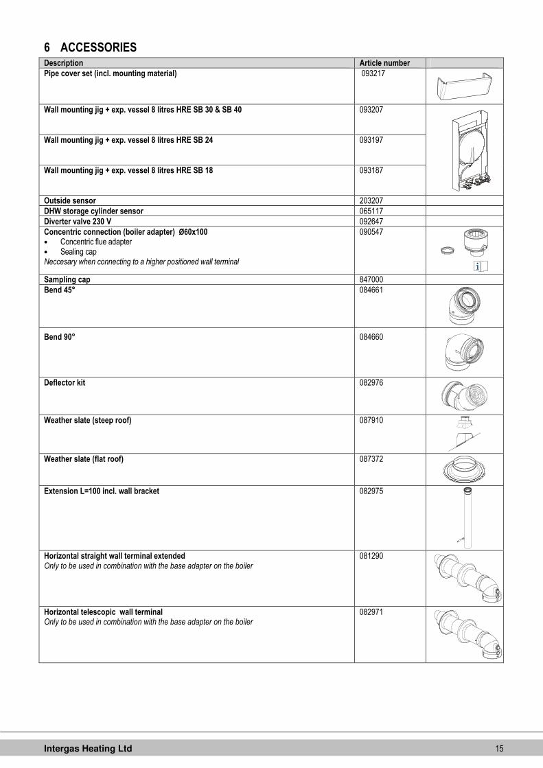
6 ACCESSORIES Description Article number
Pipe cover set (incl. mounting material) 093217
Wall mounting jig + exp. vessel 8 litres HRE SB 30 & SB 40
093207
Wall mounting jig + exp. vessel 8 litres HRE SB 24
093197
Wall mounting jig + exp. vessel 8 litres HRE SB 18
093187
Outside sensor 203207
DHW storage cylinder sensor 065117
Diverter valve 230 V 092647
Concentric connection (boiler adapter) Ø60x100 • Concentric flue adapter • Sealing cap Neccesary when connecting to a higher positioned wall terminal
090547
Sampling cap 847000
Bend 45° 084661
Bend 90° 084660
Deflector kit 082976
Weather slate (steep roof) 087910
Weather slate (flat roof) 087372
Extension L=100 incl. wall bracket 082975
Horizontal straight wall terminal extended Only to be used in combination with the base adapter on the boiler
081290
Horizontal telescopic wall terminal Only to be used in combination with the base adapter on the boiler
082971

Intergas Heating Ltd 16
Description Article number
Horizontal telescopic offset wall terminal Only to be used in combination with the base adapter on the boiler
081282
Vertical roof terminal (incl. boiler adapter 60/100)
082973
Plume management kit
082974
Elbow 90° ((for Plume management kit)
081284
Elbow 60° (for Plume management kit)
081285
Extension L=100 incl. wall bracket (for Plume management kit)
081286
Robo kit 12 litres
090000
Robo kit 8 litres
090100
Intergas Heating Ltd 17
7 INSTALLATION
7.1 Overall dimensions
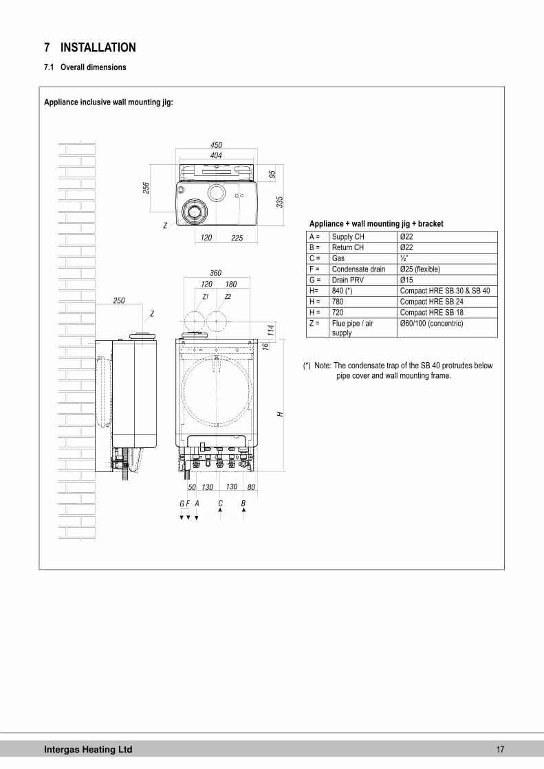
Appliance inclusive wall mounting jig:
Appliance + wall mounting jig + bracket
A = Supply CH Ø22
B = Return CH Ø22
C = Gas ½”
F = Condensate drain Ø25 (flexible)
G = Drain PRV Ø15
H= 840 (*) Compact HRE SB 30 & SB 40
H = 780 Compact HRE SB 24
H = 720 Compact HRE SB 18
Z = Flue pipe / air supply
Ø60/100 (concentric)
(*) Note: The condensate trap of the SB 40 protrudes below pipe cover and wall mounting frame.
Intergas Heating Ltd 18
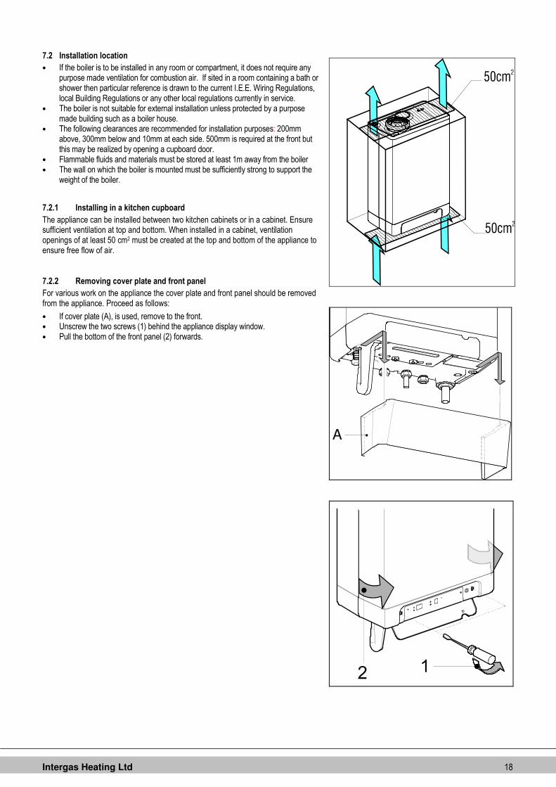
7.2 Installation location
• If the boiler is to be installed in any room or compartment, it does not require any purpose made ventilation for combustion air. If sited in a room containing a bath or shower then particular reference is drawn to the current I.E.E. Wiring Regulations, local Building Regulations or any other local regulations currently in service.
• The boiler is not suitable for external installation unless protected by a purpose made building such as a boiler house.
• The following clearances are recommended for installation purposes: 200mm above, 300mm below and 10mm at each side. 500mm is required at the front but this may be realized by opening a cupboard door.
• Flammable fluids and materials must be stored at least 1m away from the boiler • The wall on which the boiler is mounted must be sufficiently strong to support the
weight of the boiler.
7.2.1 Installing in a kitchen cupboard
The appliance can be installed between two kitchen cabinets or in a cabinet. Ensure sufficient ventilation at top and bottom. When installed in a cabinet, ventilation openings of at least 50 cm2 must be created at the top and bottom of the appliance to ensure free flow of air.
7.2.2 Removing cover plate and front panel
For various work on the appliance the cover plate and front panel should be removed from the appliance. Proceed as follows:
• If cover plate (A), is used, remove to the front. • Unscrew the two screws (1) behind the appliance display window. • Pull the bottom of the front panel (2) forwards.
A
Intergas Heating Ltd 19
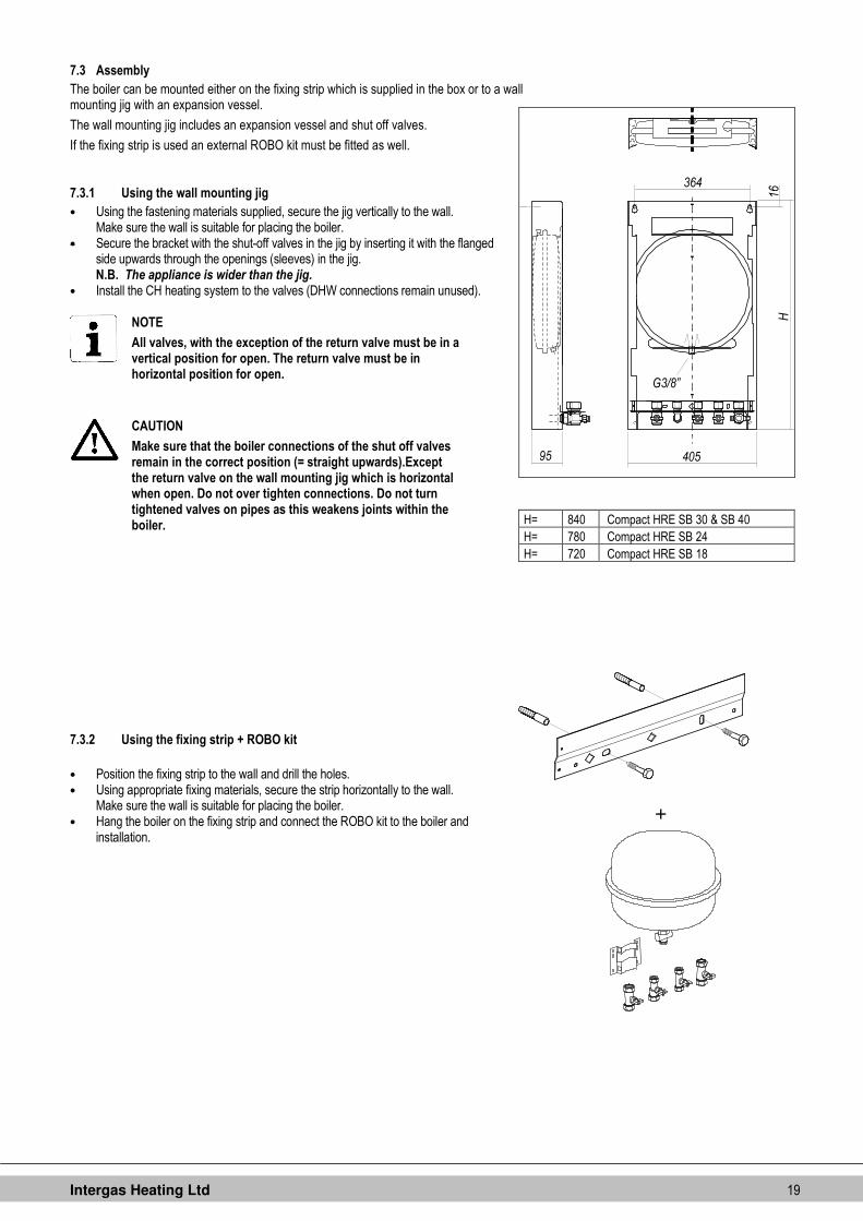
7.3 Assembly
The boiler can be mounted either on the fixing strip which is supplied in the box or to a wall mounting jig with an expansion vessel.
The wall mounting jig includes an expansion vessel and shut off valves.
If the fixing strip is used an external ROBO kit must be fitted as well.
7.3.1 Using the wall mounting jig
• Using the fastening materials supplied, secure the jig vertically to the wall. Make sure the wall is suitable for placing the boiler.
• Secure the bracket with the shut-off valves in the jig by inserting it with the flanged side upwards through the openings (sleeves) in the jig. N.B. The appliance is wider than the jig.
• Install the CH heating system to the valves (DHW connections remain unused).
NOTE
All valves, with the exception of the return valve must be in a vertical position for open. The return valve must be in horizontal position for open.
CAUTION
Make sure that the boiler connections of the shut off valves remain in the correct position (= straight upwards).Except the return valve on the wall mounting jig which is horizontal when open. Do not over tighten connections. Do not turn tightened valves on pipes as this weakens joints within the boiler.
7.3.2 Using the fixing strip + ROBO kit
• Position the fixing strip to the wall and drill the holes. • Using appropriate fixing materials, secure the strip horizontally to the wall.
Make sure the wall is suitable for placing the boiler. • Hang the boiler on the fixing strip and connect the ROBO kit to the boiler and
installation.
H= 840 Compact HRE SB 30 & SB 40
H= 780 Compact HRE SB 24
H= 720 Compact HRE SB 18
+

Intergas Heating Ltd 20
7.4 Installing the appliance
1. Unpack the appliance. 1. Check the contents of the packaging. It consists of:
• Appliance (A)
• Fixing strip (B)
• Condensate trap (C)
• Installation instructions
• Operating instructions
• Warranty card
• Templates for either wall or jig mounting 2. Check the appliance for possible damage: report damage immediately to the
supplier. 3. Decide either to use the fixing strip (supplied) or wall mounting jig. 4. The templates show the positions for the horizontal flue. Drill the exit holes, being
sure to prevent dust or debris from entering the boiler or pipe-work. 5. If the fixing strip is secured to the wall then slide the boiler down until latched. 6. If the jig is fixed securely to the wall then it is possible to fit the pipe connections
prior to hanging the boiler. Pipe connections are (from right to left) as follows for both methods: PRV 15 mm – CH flow 22mm – Gas 22 mm – Return 22 mm. IMPORTANT. The gas supply should be minimum 22mm up to gas isolation valve on boiler. It is the installers responsibility to ensure sufficient gas supply.
7. Check whether the compression rings are sitting squarely in the mounting bracket couplings.
8. Fit the appliance, sliding it downwards on the jig. Ensure at the same time that the pipes slide into the compression fittings.
9. Tighten the compression fittings on the mounting bracket. Do not turn tightened valves on pipes as this weakens joints within the boiler.
10. Fit the flexible tube to the condensate trap outlet. 11. Fill the condensate trap with water and slide it as far as possible upwards on to
the condensate drain connector below the appliance. 12. Connect the flexible tube from the condensate trap to the drain via an open
connection. The condensate discharge system must be made of plastic, no other materials may be used. The discharge duct must have a minimum gradient of 5 – 20 mm/m. Condensate discharge via the gutter is not allowed given the risk of frost and the possible damage to materials.
13. Fit the flue in accordance with the instructions mentioned in § 8.4.4. Allow 15mm of white tube externally to ensure the flue sealing ring is fitted correctly. No white part of the flue should be visible externally once the black sealing ring is fitted correctly.
CAUTION
Always fill the condensate trap with water and place it on the boiler before powering up the boiler.
Not placing or filling up the condensate trap may cause flue gases to come into the installation room and can lead to dangerous situations!
In order to place the condensate trap the front cover must be pulled forward or removed entirely.
NOTE
It is recommended that any external condensate pipe is insulated and increased to 32mm diameter in order to prevent the condensate from freezing.
7.4.1 Fitting the cover plate (optional)
Hang the flanged upper edge of the cover plate on the washers under the base of the appliance and slide the cover plate as far as possible towards the rear.

Intergas Heating Ltd 21
8 CONNECTION
8.1 Connecting CH installation
1. Flush the CH system thoroughly to clean. 2. Fit the flow and the return pipe into the shut off valves. 3. All pipes must be fitted unstressed in order to prevent the pipes from ticking. 4. Existing connections must not be twisted, in order to avoid leakages.
Make sure the compression fittings are thightened thoroughly to prevent leakage.
8.1.1 The CH system should be equipped with:
• A drain tap in the return pipe immediately below the appliance. • (A drain off is included on the wall mounting jig) • A drain tap at the lowest point(s) of the installation.
8.1.2 Thermostatic radiator valves
If all radiators are equipped with thermostatic or radiator valves, an auto bypass must be fitted in order to guarantee minimum water circulation. The auto bypass must be at a distance of at least 20 ft from the appliance in order to prevent overheating of the appliance. A radiator without thermostatic valves is not a suitable by-pass.
8.1.3 Weather compensation and heating DHW cylinder on hot water priority or W system
When connecting a Compact HRE SB to an indirectly heated DHW storage cylinder the folowing parts can be ordered:
• DHW storage cylinder sensor (art. nr. 065.117) • Diverter valve 230V (art. nr. 092.647)
Connect the DHW storage cylinder and diverter valve accourding to the diagram. Remove the loop in 9 – 10 to connector X4. Connect the diverter valve to connector X2 and connect the DHW storage cylinder sensor or thermostat to connector X4 according to the electrical diagram (See chapter 13).
Electrical diagram indirectly heated DHW storage cylinder
C. Boiler
D. DHW storage cylinder
E. Radiator
F. Expansion vessel
G. Pressure relief valve 3 Bar
H. Diverter valve
I. DHW storage cylinder sensor or thermostat
NOTE
When using a DHW storage cylinder thermostat the heating demand will start with opening the thermostat and end when the thermostat closes.

Intergas Heating Ltd 22
8.2 Electrical connection
CAUTION
A 3 amp fused spur or an unswitched socket must be located no more than 1 metre from the appliance.
For installation in damp rooms a fixed connection is obligatory.
When working on the electrical circuit always isolate the electric supply.
1. Slide the cover plate (A) (if present) to the front to remove. 2. Open the display cover and unscrew both screws to remove the front cover. 3. Pull the boiler controller unit forwards; the boiler controller will tip downwards to
provide access. 4. Consult sections § 8.3.1 and chapter 13 for making the connections. 5. After making the desired connections plug the appliance into an earthed
unswitched wall socket or connect to a fused switched spur..
8.2.1 Electrical connections
Temperature control Connector X4 Notes
Room thermostat 6 – 7 Voltage free. Remove link 6-7
Outside temperature sensor 8 – 9 -
Frost protection thermostat 6 – 7 Parallel to room thermostat
Power supply 24 V DC 6 – 7 – 9 6 = 24 V DC 7 = room thermostat 9 = 0 V DC
Open Therm (OT) 11 – 12 Remove link 6-7
Temperature control Connector X2 Notes
Room thermostat 230 V or external control 230 V.
1 – 3 Remove link 6 – 7 (connector X4)
Frost thermostat 230 V 1 – 3 Remove link 6 – 7 (connector X4)
Switch live from S-plan or Y-plan onto connector X2, no.1. See chapter 13.4 and 13.5 for complete electrical schedules.
A

Intergas Heating Ltd 23
8.2.2 On / off room thermostat (low voltage)
To be connected to contacts 6 and 7 of connector X4. This is a 24 volt connection and no mains power must be applied to these terminals. See chapter 13, electrical diagram.
NOTE
When a 24 volt thermostat is connected to contacts 6 and 7, the loop in 6 – 7 must be removed.
1. The on/off room thermostat has to be connected to the contacts 6 and 7 of connector X4. 2. Adjust the feedback resistance of the room thermostat to 0.1 A. In case of doubt measure 3. the current and adjust this accordingly. 4. The allowed maximum electrical resistance of the room thermostat and wiring is 15 Ohm.
8.2.3 Timer - room thermostat
A 3VA-24DC power supply is available for a room thermostat. Connect the timer room thermostat according to § 8.3.1.
8.2.4 Open Therm room thermostat
Open therm is a protocol that enables the boiler and the room thermostat to communicate. Based on the information from the room thermostat the flow temperature of the boiler is adjusted to the most optimal value.
The Open Therm (OT) room thermostat has te be connected tot the contacts 11 and 12 of connector X4 (see chapter 13, electrical diagram ).
CAUTION
Connecting the Open Therm room thermostat to another contacts as 11 – 12 may damage the room thermostat !
NOTE
When an Open Therm thermostat is connected to contacts 11 and 12, the loop in 6 – 7 must be removed.
8.2.5 Outside temperature sensor
The appliance is equipped with a connection for an outside temperature sensor. The outside temperature sensor can be used in combination with an on/off room thermostat or an OpenTherm thermostat.
Connect the outside temperature sensor (See § 8.3.1).
For the heating line setting, see weather-dependent regulation (See § 10.6 ).
8.2.6 230 volt room thermostat
To be connected to contacts 1 and 3 of connector X2 and remove link 6-7. See electrical diagram.
Warning High Voltage
Isolate the appliance from the electrical supply before connecting the thermostat.

Intergas Heating Ltd 24
8.3 Condensate disposal
The appliance is provided with a 25 mm flexible pipe from its condensate trap. Connect the flexible tube from the condensate to the drain via an open connection.
CAUTION
Always fill the condensate trap with water and place it on the boiler before powering up the boiler.
Not placing or filling up the condensate trap may cause flue gases to come into the installation room and can lead to dangerous situations!
In order to place the condensate trap the front cover must be pulled forward or removed entirely.
The condensate discharge system, pipework and fittings must be made of plastic. No other materials may be used. The discharge duct must have a minimum gradient of 5 – 20 mm/m throughout its length. Condensate discharge via the gutter is not allowed given the risk of frost and the possible damage to materials
A. Internal stack pipe (see diagram)
B. Gully
C. Condensate discharge from boiler
D. Servicable waste trap
E. 5 – 20 mm/meter
F. > 100 mm
G. > 110 mm
H. > 450 mm
If an externally-run condensate drainage pipe is used the following measures should be adopted to prevent freezing:
• The pipe should be run internally as far as possible before going externally, the pipe diameter should be increased to a minimum of 30mm ID (typically 32mm OD) before it passes though the wall.
• The external run should be kept as short as possible, taking the most vertical route possible to the discharge point, with no horizontal sections in which condensate might collect.
• The external pipe should be insulated using suitable waterproof and weatherproof insulation (‘’Class O’' pipe insulation is suitable for this purpose)
• The use of fittings, elbows etc should be kept to a minimum and any internal ‘’burrs’’ on cut pipework should be removed so that the internal pipe section is as smoooth as possible.
For more information about preventive measures against freezing please visit the HHIC website http://www.centralheating.co.uk/checklists/frozen-condensate-pipes.
8.4 Flue System

Intergas Heating Ltd 25
8.4.1 Flue pipe and air supply
The boiler utilises a special concentric flue adapter which can only be used with the elbow that is part of the horizontal flue pipes. For the appropriate types see chapter 6 Accessories.
When using a vertical flue system the adapter on the boiler has to be replaced with the adapter 60/100 included in the vertical roof terminal, Intergas article number 082973.
When using a vertical flue system to reach an higher positioned wall terminal the adapter on the boiler has to be replaced with the adapter 60/100, Intergas article number 090547.
NOTE
Only use approved Intergas flue products with this boiler, which can be sourced from the supplier of your boiler or Intergas stockist.
The standard horizontal flue pipe is not supplied with the boiler and should be purchased separately from your supplier. This flue may be routed to the rear, left or right of the appliance by means of the 900 degree bend, which is supplied in the flue kit.
8.4.2 Flue pipe position
Terminal Position Min. distance
A Directly below an open able window or other opening e.g. air brick
300 mm
B Below gutters, soil pipes or drain pipes 75 mm
C Below eaves 200 mm
D Below balconies or car front roofs 200 mm
E From vertical drain pipes and soil pip 150 mm
F From internal or external corners 300 mm
G Above ground, roof or balcony level 300 mm
H From a surface facing a terminal 600 mm
I From a terminal discharging towards another terminal 1200 mm
J From an opening in a car port (e.g. door, window) into a dwelling
1200 mm
K Vertically from a terminal on the same wall 1500 mm
L Horizontally from a terminal on the same wall 300 mm
M Above an opening, air brick, opening windows, etc. 300 mm
N Horizontally to an opening, air brick, opening windows, etc.
300 mm
P Above roof level (to base of terminal) 300 mm
Q From adjacent wall to flue 300 mm
R From an adjacent opening window 1000 mm
S From another roof terminal 600 mm
- From an external boundary. Note: if the terminal is facing a boundary it is recommended that an anti-plume kit be fitted.
600 mm
Terminals adjacent to windows or openings on pitched and flat roofs:
T The flue should not penetrate this area. T1 2000 mm T2 600 mm
N.B. Intergas cannot be held responsible for atmosferic conditions when siting flue terminals
CAUTION
Once the flue has been installed and the appliance commissioned, installer should observe the plume direction. Particular attention should be drawn to plume vapour re-entering the boiler via the air intake. If this occurs, it is highly possible the flue is fitted within a negative pressure area and therefore a plume management kit (PMK) must be fitted.

Intergas Heating Ltd 26
8.4.3 Length flue pipe and air inlet
The following lengtths (L = meters) for the combustion system are valid:
HRE 18 SB
C13(1) C33(2) C13(1) C33(2) C53(3) C33(4)
60/100 60/100 Twin-80 Twin-80 60/100
L1
60
L2
60/100
L1
80
L2 L L L L
10.2 11 37.6 37.6 7 1 9 1
1 12 1 33.7
HRE 24 SB
C13(1) C33(2) C13(1) C33(2) C53(3) C33(4)
60/100 60/100 Twin-80 Twin-80 60/100
L1
60
L2
60/100
L1
80
L2 L L L L
9.7 10 29.8 29.8 6.5 1 9 1
1 10 1 31.2
HRE 30 SB & 40 SB
C13(1) C33(2) C13(1) C33(2) C53(3) C33(4)
60/100 60/100 Twin-80 Twin-80 60/100
L1
60
L2
60/100
L1
80
L2 L L L L
9.7 10 21.3 21.3 6 1 9 1
1 10 1 30
8.4.4 Horizontal flue system
The 60/100 mm horizontal flue system may be extended up to a maximum length as mentioned in the table above. For every bend used the following flue length reductions apply: - 45° bend = 1 metre and for a 90° bend this is 1.5 metres..Allow 15mm of white tube externally to ensure the flue sealing ring is fitted correctly. No white part of the flue should be visible externally
CAUTION
Only an Intergas approved flue is to be used with this product.
Failure to comply with this requirement will invalidate your guarantee and may lead to a dangerous situation!
The wall terminal must be installed horizontally. The horizontal flue between the wall terminal and the boiler must be installed under a 3 degree fall towards the boiler (50 mm per metre) and must be supported with a minimum of 1 bracket at each metre length. Best recommended position of the bracket is just before the joint.
8.4.5 Vertical flue system
A vertical 60/100 mm flue kit is also available, which can be extended up to a maximum of 10 metres, excluding the initial boiler connection, using additional components available from the supplier of your boiler or Intergas stockist.
The vertical flue system contains a flue adapter concentric 60/100 to replace the standard adapter on the boiler.
Please note that the terminal is suitable for a flat or pitched roof and only approved Intergas flue products can be used with this boiler.
Intergas Heating Ltd 27
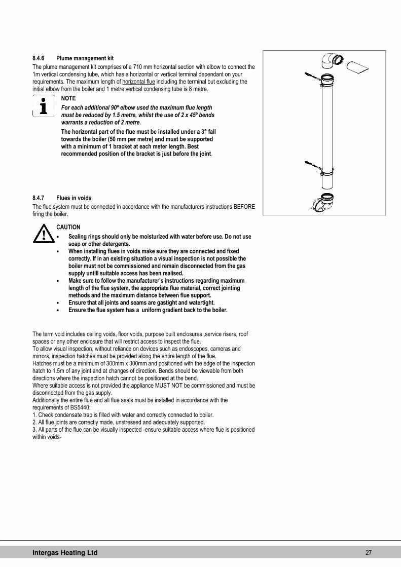
8.4.6 Plume management kit
The plume management kit comprises of a 710 mm horizontal section with elbow to connect the 1m vertical condensing tube, which has a horizontal or vertical terminal dependant on your requirements. The maximum length of horizontal flue including the terminal but excluding the initial elbow from the boiler and 1 metre vertical condensing tube is 8 metre.
NOTE
For each additional 90º elbow used the maximum flue length must be reduced by 1.5 metre, whilst the use of 2 x 45º bends warrants a reduction of 2 metre.
The horizontal part of the flue must be installed under a 3° fall towards the boiler (50 mm per metre) and must be supported with a minimum of 1 bracket at each meter length. Best recommended position of the bracket is just before the joint.
8.4.7 Flues in voids
The flue system must be connected in accordance with the manufacturers instructions BEFORE firing the boiler.
The term void includes ceiling voids, floor voids, purpose built enclosures ,service risers, roof spaces or any other enclosure that will restrict access to inspect the flue. To allow visual inspection, without reliance on devices such as endoscopes, cameras and mirrors, inspection hatches must be provided along the entire length of the flue. Hatches must be a minimum of 300mm x 300mm and positioned with the edge of the inspection hatch to 1.5m of any joint and at changes of direction. Bends should be viewable from both directions where the inspection hatch cannot be positioned at the bend. Where suitable access is not provided the appliance MUST NOT be commissioned and must be disconnected from the gas supply. Additionally the entire flue and all flue seals must be installed in accordance with the requirements of BS5440: 1. Check condensate trap is filled with water and correctly connected to boiler. 2. All flue joints are correctly made, unstressed and adequately supported. 3. All parts of the flue can be visually inspected -ensure suitable access where flue is positioned within voids-
CAUTION
• Sealing rings should only be moisturized with water before use. Do not use soap or other detergents.
• When installing flues in voids make sure they are connected and fixed correctly. If in an existing situation a visual inspection is not possible the boiler must not be commissioned and remain disconnected from the gas supply untill suitable access has been realised.
• Make sure to follow the manufacturer’s instructions regarding maximum length of the flue system, the appropriate flue material, correct jointing methods and the maximum distance between flue support.
• Ensure that all joints and seams are gastight and watertight. • Ensure the flue system has a uniform gradient back to the boiler.

Intergas Heating Ltd 28
9 COMMISSIONING THE APPLIANCE
At the time of commissioning, complete all relevant sections of the Benchmark Checklist located in section 17 of this document.
9.1 Filling and venting the appliance and the installation
9.1.1 CH system
CAUTION
When an additive is added to the CH water, ensure it is suitable for the materials used in the appliance, such as copper, brass, stainless steel, steel, plastic and rubber.
1. Connect to 3 amp fused spur, or via a three pin plug to an unswitched socket. 2. Connect the appliance to mains.
The appliance may perform a self test: 2 (on service display).
The appliance will then go into wait mode: - (on service display).
14. Connect the filling loop and fill the installation with clean drinking water to a maximum pressure of 1-2 bar in the case of a cold installation. (Indicated on the temperature display.)
15. Bleed the appliance with the manual bleed screw (A). An automatic air bleeding device may be fitted to the appliance in place of the manual bleed screw.
16. Bleed the air in the installation with the manual bleed screws on the radiators. 17. Top up the CH installation if the pressure has dropped too far as a result of the
air bleeding. 18. Check all couplings for leakage. 19. Fill the condensate trap with water.
9.1.2 Hot water supply (only when an indirectly heated DHW storage cylinder is applied)
1. Open the main tap to pressurise the hot water section. 2. Vent the exchanger and the pipe system by opening a hot water tap. 3. Leave the tap open until all air has disappeared from the system. 4. Check all connections for leaks including internal connections.
9.1.3 Gas supply
1. Gas supply purged of air via test point D on gas valve (see illustration ) 2. Connect a suitable gauge to test point D .
Static or standing pressure must be 20mb. If 20mb is not obtained DO NOT proceed with commissioning until supply is rectified.
3. If static pressure is correct fire the boiler and allow to reach working temperature.
4. Test working pressure by selecting test program “H”. See section 10.8, High Setting. Working pressure must be 20mb +or- 1mb. If working pressure is less than 19mb appliance heat output will be reduced and correct combustion readings may not be obtained. Do not adjust the air/gas ratio. Correct gas supply to obtain sufficient working pressure.
NOTE
The inlet working pressure must be obtained with all other gas appliances at the property working.

Intergas Heating Ltd 29
9.1.4 Combustion
The combustion for this appliance has been checked, adjusted and preset at the factory for operation on the gas type defined on the appliance data plate. Do not adjust the air/gas ratio valve.
Having checked:
• That the boiler has been installed in accordance with these instructions; • The integrity of the flue system and the flue seal, as described in § 8.4 and the
British Standards codes of practices, specifically BS 5440; • The integrity of the boiler combustion circuit and the relevant seals, as descibed in
§ 12.3 eg. with a flue spillage mirror; proceed to put the boiler into operation as follows:
1. Set up the boiler to operate at maximum rate as described in § 10.7.
2. With the boiler operating in the maximum rate condition check that the CO2 percentage measuered at sampling point (X) complies with the requirements as described in the table under § 10.8.
Ensure that this inlet pressure can be obtained with all other gas appliances in the property working.
9.1.5 Flue system
The flue system must be connected correctly to the appliance in accordance with the manufacturer’s instructions. The flue termination should also be checked. Where suitable access for a visual inspection of an existing flue system has not been provided the appliance must not be commissioned and it must be disconnected from the gas supply.
Allow 15mm of white tube externally to ensure the black external sealing ring is fitted correctly.No white parts of the flue pipe should be visible externaly. Correct fitting of the flue seal as shown in the flue fitting instruction included in the flue package.

Intergas Heating Ltd 30
9.2 Commissioning the appliance
Read-out Operation 1 On / off A On / Off button 2 CH operation or setting maximum CH temperature B DHW / CH button, for setting desired temperature 3 DHW operation or setting DHW temperature(not applicable for Compact HRE SB) C - button 4 Desired temperature of CH or DHW in °C / Ch water pressure (bar) / Fault code/ Time D + button 5 Clock “on” CH enabled E Clock function setting 6 Clock “off” CH disabled F DHW comfort function off/eco/on (not applicable for Compact HRE SB) 7 DHW comfort function eco (not applicable for Compact HRE SB) G Service button 8 DHW comfort function on (continuous) (not applicable for Compact HRE SB) H Reset button 9 Operating code 10 Flashes to indicate fault
Once the preceding actions have been carried out, the appliance may be started up.
1. Press the button , to start the appliance. 2. Adjust the pump setting depending on the maximum power set and the resistance in the
CH installation. For the water head of the pump and the pressure loss of the appliance see § 10.5.
3. Set the room thermostat higher than the room temperature. The appliance will now switch
to CH operation: 5 will show on the display. 4. Heat the installation and the appliance to approximately 80°C. 5. Check the temperature difference between the supply and return for the appliance and the
radiators. This must be approximately 20°C. For this purpose set the maximum power on the service panel. See setting maximum power. If necessary adjust the pump setting and/or the radiator valves. For the minimum flow see § 10.5.
20. Switch the appliance off. 21. Bleed the appliance and the installation after cooling (if necessary top up). 22. Check correct operation of the heating and hot water supply. 23. Instruct the user on filling, bleeding and the operation of the clock, heating and hot water
supply. For setting the clock see § 9.3.Note: for S and Y plans the clock will be set to C-ON to allow the external timer/programmer to operate the CH and DHW cylinder separately or together.
NOTE
• The appliance is equipped with an electronic boiler controller, which ignites the burner and continuously monitors the flame during each request for heat from the heating or from the hot water supply.
• The circulation pump starts running in response to every request for heat. The pump continues running for 1 minute after heating. This post purge period can be changed if desired (See § 10.3.).
• The pump runs automatically for 10 seconds every 24 hours in order to prevent seizing. This will occur at the the time of the last request for heat. To change this time the room thermostat should be turned up briefly at the desired time.

Intergas Heating Ltd 31
9.3 Setting and adjusting the clock functions
NOTE
Setting and adjusting the clock is only applicable when using the boiler as “heat only” or in combination with a system as mentioned under § 8.1.3 .
When using a S and Y plan wired system the clock always has to be set on “C-on
9.3.1 Setting the clock
• Press the button for less than 1 second and repeat this untill ‘’24hr clock’’ appears. For adjusting the clock to the correct time press the [+] or [-] button. Note: Holding the button for more than 1 second will make the clock run fast.
9.3.2 Setting the timer function
• On pressing the button for more than 2 seconds the clock display will flash. • The time for each on/off shows in the clock display and the service display shows
which on 1 and 3 OR off 2 and 4 time is being set. • Pressing the button again will change between the different on/off switching
periods. The pre-set times are as follows: Display : [06:00] and [1] � Start first period CH on.
[09:00] and [2] � End first period CH off. [16:00] and [3] � Start second period CH on. [22:00] and [4] � End second period CH off. • By pressing the button the new times will be stored in the boiler controller.
In the service display [P] appears. • When the clock is in period [1] or [3] (CH ON) the clock symbol LED is on. • When the clock is in period [2] or [4] (CH not active) the LED is on. • By pressing the button over 5 seconds the default setting for the switch moments
will be restored. In the service display “F-set” appears. • By pressing the button the boiler controller will return to the normal situation
without storing any changes.
9.4 Additional functions
• Pressing the button for less than 1 second the following additional functions can be activated: - t-on (temporary on).
The boiler will respond on every CH demand from the room thermostat until the next switch moment. - c-on (continuous on).
The boiler will respond on every CH demand from the room thermostat without any time limit. - OFF
The boiler will not respond on any CH demand from the room thermostat.
.

Intergas Heating Ltd 32
9.5 Shutting down
CAUTION
Drain the appliance and the installation if mains power has been interrupted and there is a possibility of freezing.
1. Adjust all valves to manual operation. 2. Drain the appliance at the drain tap. 3. Drain the installation at the lowest point.
9.5.1 Frost protection
• To avoid freezing of the condensate drain pipe the appliance must be installed in a frost-free area.
• To avoid freezing of the appliance it is equipped with frost protection. If the temperature of the heat exchanger becomes too low, the burner switches on until the temperature of the heat exchanger is sufficient. If there is a possibility of the installation (or part of it) freezing, an (external) frost thermostat must be installed at the coldest point of the return pipe. This must be connected in accordance with the wiring diagram (See chapter 13).
NOTE
If an (external) frost thermostat has been fittted to the installation and connected to the appliance, this will not be active when the appliance is switched off at the operating panel
( ---- on service display).

Intergas Heating Ltd 33
10 SETTING AND ADJUSTMENT The functioning of the appliance is determined primarily by the (parameter) settings in the boiler controller. Part of this can be set directly via the operating panel; another part can only be adjusted using the installer code.
10.1 Directly via the operating panel
The following functions can be operated directly:
10.1.1 Appliance on/off
The appliance is started using the key.
When the appliance is in operation the green LED above the key will light up. When the
appliance is off a singe dash lights up on the service display ( - ) to indicate that supply voltage is present. In this mode the pressure in the CH installation (in bar) can also be read on the temperature display.
10.1.2 Resetting
When a lock-out is indicated by means of a flashing LED above the key and a code on
the display, the appliance can be restarted by pressing the key. Check the nature of the fault on the basis of the fault codes in § 11.1 and resolve the cause of the fault if possible before resetting the appliance.
10.1.3 Changing the settings of the various functions:
Holding the key pressed in for 2 seconds takes you to the user settings menu(LED at
and the figure display start to flash). Pressing the key repeatedly results in a different function LED flashing each time. When the LED is flashing the indicated function can be set
with the and key . The value set is shown on the display.
The on/off key closes the settings menu without storing the changes.
The reset key closes the settings menu and the changes are stored.
If no key is pressed during a period of 30 seconds, the settings menu is closed automatically and the changes are stored.
10.1.4 Maximum CH supply temperature
Press the key until the LED at starts to flash.
With the and key s set the temperature between 30°C and 90°C (default value 80°C).
Intergas Heating Ltd 34
10.2 Setting via the service code
The boiler controller in the appliance is factory set in accordance with the parameters.
These parameters can only be changed using the service code. Proceed as follows to activate the program memory:
1. Press the and keys simultaneously until a 0 appears on the service- and temperature display.
2. Using the and keys set 15 (service code) on the temperature display. 3. Using the key select the parameter to be set on the service display. 4. Using the and keys set the parameter to the desired value (visible) on the
temperature display.
5. Once all desired changes have been entered, press the key until a P appears on the service display.
The boiler controller has now been reprogrammed.
• Pressing the key in takes you out of the menu without storing the parameter changes. • By pressing the button over 5 seconds the default setting for the parameters will be restored. In the display “F-set” appears.
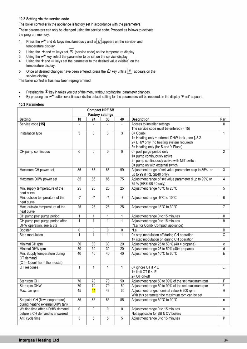
10.3 Parameters
Compact HRE SB Factory settings
Setting 18 24 30 40 Description Par.
Service code [15] - - - - Access to installer settings The service code must be entered (= 15)
0
Installation type 3 3 3 3 0= Combi 1= Heating only + external DHW tank , see § 8.2 2= DHW only (no heating system required) 3= Heating only (for S and Y Plans)
1
CH pump continuous 0 0 0 0 0= post purge period only 1= pump continuously active 2= pump continuously active with MIT switch 3= pump on with external switch
2
Maximum CH power set 85 85 85 99 Adjustment range of set value parameter c up to 85% or up to 99 (HRE SB40 only)
3
Maximum DHW power set 85 85 85 75 Adjustment range of set value parameter d up to 99% or 75 % (HRE SB 40 only)
4
Min. supply temperature of the heat curve
25 25 25 25 Adjustment range 10°C to 25°C 5
Min. outside temperature of the heat curve
-7 -7 -7 -7 Adjustment range -9°C to 10°C 6
Max. outside temperature of the heat curve
25 25 25 25 Adjustment range 15°C to 30°C 7
CH pump post purge period 1 1 1 1 Adjustment range 0 to 15 minutes 8
CH pump post purge period after DHW operation, see & 8.2
1 1 1 1 Adjustment range 0 to 15 minutes (N.a. for Combi Compact appliance)
9
Booster 0 0 0 0 N.a. B
Step modulation 1 1 1 1 0= step modulation off during CH operation 1= step modulation on during CH operation
C
Minimal CH rpm 30 30 30 20 Adjustment range 25 to 50 % (40 = propane) c
Minimal DHW rpm 30 30 30 20 Adjustment range 25 to 50% (40= propane) d
Min. Supply temperature during OT demand (OT= OpenTherm thermostat)
40 40 40 40 Adjustment range 10°C to 60°C E
OT response 1 1 1 1 0= ignore OT if < E 1= limit OT if < E 2= OT on-off
E.
Start rpm CH 70 70 70 50 Adjustment range 50 to 99% of the set maximum rpm F
Start rpm DHW 70 70 70 50 Adjustment range 50 to 99% of the set maximum rpm F.
Max. fan rpm 45 44 48 65 Adjustment range: nominal value ± 200 rpm. With this parameter the maximum rpm can be set
H
Set point CH (flow temperature) during heating external DHW tank
85 85 85 85 Adjustment range 60°C to 90°C n
Waiting time after a DHW demand before a CH demand is answered
0 0 0 0 Adjustment range 0 to 15 minutes Not applicable for SB & OV boilers
o
Anti cycle time
5 5 5 5 Adjustment range 0 to 15 minutes P

Intergas Heating Ltd 35
10.4 Setting maximum CH power
The maximum CH power is set at maximum (85% ) in the factory. If less power is necessary for the CH installation, the maximum CH power can be changed by changing the fan rpm. See table Setting CH power.
This table shows the relationship between the fan rpm and the appliance power.
Setting CH power
Desired CH power (in kW approx.) Setting on service display (in % of max. rpm)
18 SB 24 SB 30 SB 40 SB
- - - 40,9 99
17,8 22,8 26.3 34,8 ± 83
22,2 22,2 70 28,5 70
12,7 16.2 19,0 24,5 60
10,6 13,5 15,8 20,5 50
8,5 11,0 12,7 16,4 40
6,4 8,3 8,5 12,3 30
5,4 6,9 7,1 10,2 25
- - - 7.8 20
NOTE
The power during burning is increased slowly and is reduced as soon as the set supply temperature is reached (modulate on T flow).
10.5 Adjusting pump setting
The switch for adjusting the pump setting is located on the CH pump connection box (Factory setting III).
1. Adjust the pump setting depending on the maximum power set and the water resistance of the installation. See diagram: pressure loss of appliance and pump water head, positions I, II and III.
2. Check the temperature difference between the appliance supply and return: this must be approximately 20°C.
The minimum flow quantity (l/h) Power setting (kW)
155 5,4
510 17,8
650 22,8
750 26,3
1150 40,9
Appliance pressure loss graph, CH side A. Compact HRE 18 SB B. Compact HRE 24 SB C. Compact HRE 30 SB AA. Compact HRE 40 SB
I Pump setting I II Pump setting II III Pump setting III X Flow in l/h Y Pressure loss / water head in mH2O
WILO RS 15/4.1 (SB18, 24 & 30)
WILO RS 15/7-3 (SB 40)
AA
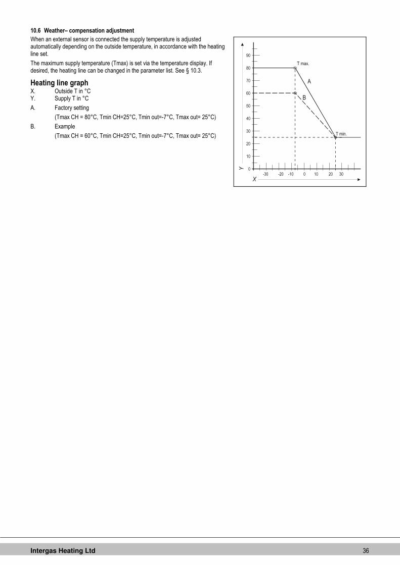
Intergas Heating Ltd 36
10.6 Weather– compensation adjustment
When an external sensor is connected the supply temperature is adjusted automatically depending on the outside temperature, in accordance with the heating line set.
The maximum supply temperature (Tmax) is set via the temperature display. If desired, the heating line can be changed in the parameter list. See § 10.3.
Heating line graph X. Outside T in °C Y. Supply T in °C
A. Factory setting
(Tmax CH = 80°C, Tmin CH=25°C, Tmin out=-7°C, Tmax out= 25°C)
B. Example
(Tmax CH = 60°C, Tmin CH=25°C, Tmin out=-7°C, Tmax out= 25°C)

Intergas Heating Ltd 37
10.7 Checking gas-/air ratio
The gas-/air adjustment has been set in the factory and in principle requires no adjustments.
The setting can be checked by measuring the CO2 percentage in the combustion gases (X).
In the case of possible disturbance of the adjustment, replacement of the gas valve or conversion to another gas type the adjustment must be checked and if necessary set as follows.
1. Switch the appliance off with the (on/off symbol) button .[-] will appear in service display.
2. Remove appliance front panel. 3. Remove sampling point X to insert suitable flue gas analyser probe . 4. Switch appliance on with (on/off symbol)button and create a CH demand
Test program H = HIGH SETTING: 5. Select High setting by simultaneously pressing (spanner symbol) and [+]
buttons twice. [H] appears in service display . (DO NOT TEST with [h] in service display- press (spanner symbol) and [+] again.)
6. Allow readings to stabilize and check the CO2 percentage is as listed in table under § 10.8.
7. Record the CO2 percentage. Test program L = LOW SETTING:
8. Select Low setting by simultaneously pressing (spanner symbol) and [-] once. L appears in service display.
9. Allow readings to stabilize and check the CO2 percentage as listed in table 10. Record the CO2 percentage 11. Switch off appliance with (on/off symbol) and replace sample point cap X.
Replace front cover.
Check that the Flue sampling point X is gas tight after sampling.
It is not possible to adjust the CO2 percentage on test program H. When the CO2 percentage is not in accordance with the value as listed in table 10.8, please contact Intergas Technical Services 01527 888 000. No adjustment to the air/gas ratio should be made without permission from Intergas Technical Services. .
Work on gas carrying parts may only be carried out by a qualified competent person.
A. Cover screw B. Adjusting screw for low position C. Offset pressure measurement nipple D. Gas supply pressure measurement nipple
C
D
A + B
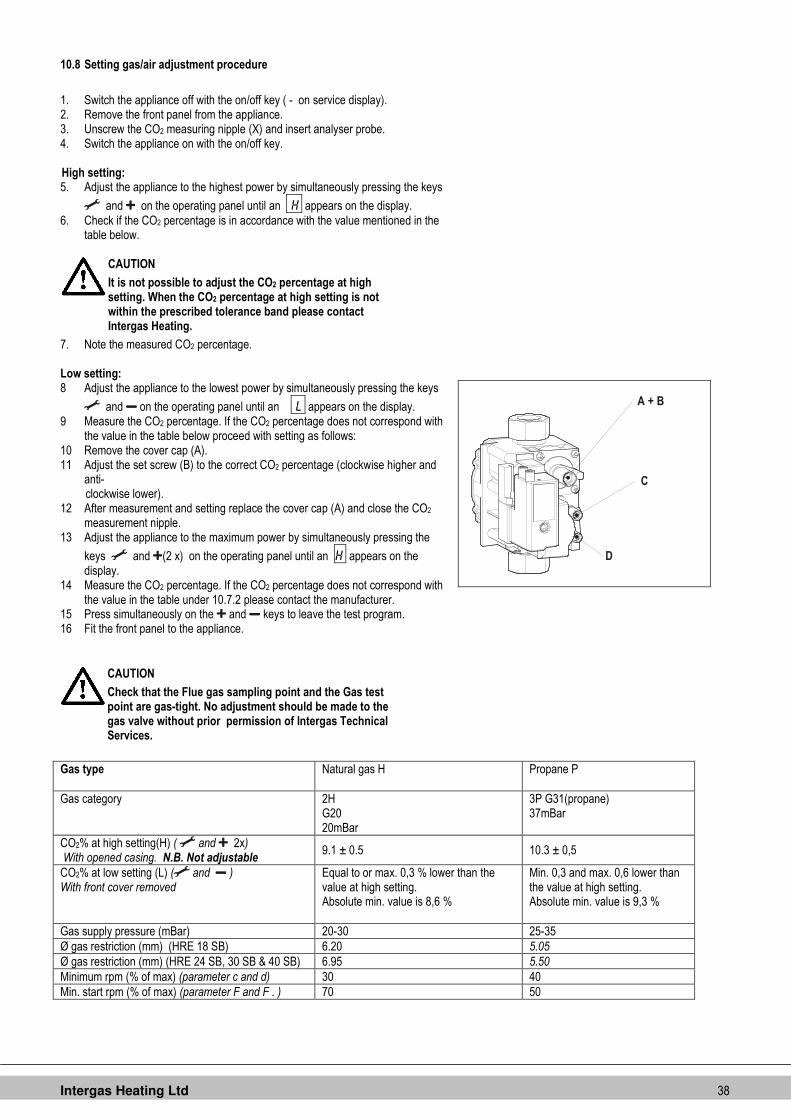
Intergas Heating Ltd 38
10.8 Setting gas/air adjustment procedure
1. Switch the appliance off with the on/off key ( - on service display). 2. Remove the front panel from the appliance. 3. Unscrew the CO2 measuring nipple (X) and insert analyser probe. 4. Switch the appliance on with the on/off key. High setting: 5. Adjust the appliance to the highest power by simultaneously pressing the keys
and on the operating panel until an H appears on the display. 6. Check if the CO2 percentage is in accordance with the value mentioned in the
table below.
CAUTION
It is not possible to adjust the CO2 percentage at high setting. When the CO2 percentage at high setting is not within the prescribed tolerance band please contact Intergas Heating.
7. Note the measured CO2 percentage. Low setting: 8 Adjust the appliance to the lowest power by simultaneously pressing the keys
and on the operating panel until an L appears on the display. 9 Measure the CO2 percentage. If the CO2 percentage does not correspond with
the value in the table below proceed with setting as follows: 10 Remove the cover cap (A). 11 Adjust the set screw (B) to the correct CO2 percentage (clockwise higher and
anti- clockwise lower).
12 After measurement and setting replace the cover cap (A) and close the CO2 measurement nipple.
13 Adjust the appliance to the maximum power by simultaneously pressing the
keys and (2 x) on the operating panel until an H appears on the display.
14 Measure the CO2 percentage. If the CO2 percentage does not correspond with the value in the table under 10.7.2 please contact the manufacturer.
15 Press simultaneously on the and keys to leave the test program. 16 Fit the front panel to the appliance.
Gas type Natural gas H Propane P
Gas category 2H G20 20mBar
3P G31(propane) 37mBar
CO2% at high setting(H) ( and 2x) With opened casing. N.B. Not adjustable
9.1 ± 0.5 10.3 ± 0,5
CO2% at low setting (L) ( and ) With front cover removed
Equal to or max. 0,3 % lower than the value at high setting. Absolute min. value is 8,6 %
Min. 0,3 and max. 0,6 lower than the value at high setting. Absolute min. value is 9,3 %
Gas supply pressure (mBar) 20-30 25-35
Ø gas restriction (mm) (HRE 18 SB) 6.20 5.05
Ø gas restriction (mm) (HRE 24 SB, 30 SB & 40 SB) 6.95 5.50
Minimum rpm (% of max) (parameter c and d) 30 40
Min. start rpm (% of max) (parameter F and F . ) 70 50
C
D
A + B
CAUTION
Check that the Flue gas sampling point and the Gas test point are gas-tight. No adjustment should be made to the gas valve without prior permission of Intergas Technical Services.

Intergas Heating Ltd 39
Examples :
CO2 adustment at low setting for natural gas
The CO2 percentage low setting must be equal to or max. 0.3 % lower than the percentage at high setting. Important: The CO2 percentage at low setting must never be under 8.6%.
Example 1:
CO2 percentage at high setting is 9.2 % ���� then CO2 percentage at low setting must be 8.9 – 9.2 % .
Example 2:
CO2 percentage at high setting is 8.7 % ���� then CO2 percentage at low setting must be 8.6 – 8.7 % .
CO2 adjustment at low setting for propane (G31)
The CO2 percentage at low setting must be between 0.3 % and 0.6 % lower than the percentage at high setting. Important: The CO2 percentage at low setting must never be under 9.3 %.
Example 1:
CO2 percentage at high setting is 10.5 % ���� then CO2 percentage at low setting must be 9.9 – 10.2 %
Example 2:
CO2 percentage at high setting is 9.8 % ���� then CO2 percentage at low setting must be 9.3 – 9.5 % .
10.9 Conversion to different gas type
CAUTION
Work on gas carrying parts may only be carried out by a qualified competent person.
If a different type of gas is connected to the appliance than that for which the appliance has been set by the manufacturer, the gas metering ring should be replaced. Conversion sets for other types of gas are available to order.
10.9.1 Converting to L.P.G
1. Switch the boiler off and isolate the boiler from the mains power. 2. Close the gas tap. 3. Remove the front panel from the appliance. 4. Unscrew the coupling (A) above the gas valve and twist the gas mixing tube
towards the rear (B). 5. Replace the O-ring (C) and the gas restriction (D) with the rings from the
conversion set.(5.05 for 18SB. 5.50 for 24,30,and 40SB) 6. Re-assemble in reverse sequence. 7. Open the gas tap. 8. Check the gas connections before the gas valve for gas-tightness. 9. Switch on the mains power. 10. Check the gas connections after the gas valve for gas-tightness (during
operation). 11. Now check the setting of the CO2 percentage at high setting (H in display) and
low setting (L in display).
CAUTION
It is not possible to adjust the CO2 percentage at high setting. When the CO2 percentage at high setting is not within the prescribed tolerance band please contact Intergas Heating.
For adjusting CO2 percentage at low setting see § 10.8
Place a sticker for the gas type set over the existing sticker next to the gas valve. Place a sticker for the gas type set next to the identification plate.
C
D
A + B
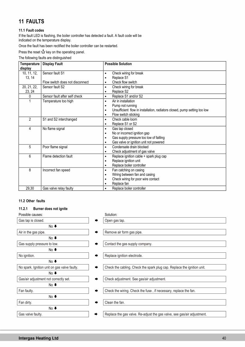
Intergas Heating Ltd 40
11 FAULTS
11.1 Fault codes
If the fault LED is flashing, the boiler controller has detected a fault. A fault code will be indicated on the temperature display.
Once the fault has been rectified the boiler controller can be restarted.
Press the reset key on the operating panel.
The following faults are distinguished
Temperature display
Display Fault Possible Solution
10, 11, 12, 13, 14
Sensor fault S1 Flow switch does not disconnect
• Check wiring for break • Replace S1 • Check flow switch
20, 21, 22, 23, 24
Sensor fault S2 • Check wiring for break • Replace S2
0 Sensor fault after self check • Replace S1 and/or S2
1 Temperature too high • Air in installation • Pump not running • Unsufficient flow in installation, radiators closed, pump setting too low • Flow switch sticking
2 S1 and S2 interchanged • Check cable loom • Replace S1 or S2
4 No flame signal • Gas tap closed • No or incorrect ignition gap • Gas supply pressure too low of failling • Gas valve or ignition unit not powered
5 Poor flame signal • Condensate drain blocked • Check adjustment of gas valve
6 Flame detection fault • Replace ignition cable + spark plug cap • Replace ignition unit • Replace boiler controller
8 Incorrect fan speed • Fan catching on casing • Wiring between fan and casing • Check wiring for poor wire contact • Replace fan
29,30 Gas valve relay faulty • Replace boiler controller
11.2 Other faults
11.2.1 Burner does not ignite
Possible causes: Solution:
Gas tap is closed. � Open gas tap.
No �
Air in the gas pipe. � Remove air form gas pipe.
No �
Gas supply pressure to low. � Contact the gas supply company.
No �
No ignition. � Replace ignition electrode.
No �
No spark. Ignition unit on gas valve faulty. � Check the cabling. Check the spark plug cap. Replace the ignition unit.
No �
Gas/air adjustment not correctly set. � Check adjustment. See gas/air adjustment.
No �
Fan faulty. � Check the wiring. Check the fuse , if necessary, replace the fan.
No �
Fan dirty. � Clean the fan.
No �
Gas valve faulty. � Replace the gas valve. Re-adjust the gas valve, see gas/air adjustment.

Intergas Heating Ltd 41
11.2.2 Burner ignites noisily
Possible causes: Solution:
Gas supply pressure to high. � The house pressure switch may be faulty. Contact the gas company.
No �
Incorrect ignition gap. � Replace the ignition pin. Check the ignition electrode gap.
No �
Gas/air adjustment not correctly set. � Check the setting. See gas/air adjustment.
No �
Weak spark. � Check the ignition gap. Replace the ignition electrode. Replace the ignition unit on the gas valve.
Spark gap app. 4.5 mm
11.2.3 Burner resonating
Possible causes: Solution:
Gas supply pressure too low. � The house pressure switch may be faulty. Contact the gas company.
No �
Recirculation of combustion gasses. � Check the gas flue an the air supply.
No �
Gas/air adjustment not correctly set. � Check the setting, see gas/air adjustment.
11.2.4 No heating (CH)
Possible causes: Solution:
Room thermostat / weather-dependent adjustment not closed or faulty.
� Check the wiring. Replace the thermostat. Replace the weather-dependant adjustment.
No �
No current (24 V). � Check the wiring against the diagram. Check the connector X4. Replace the faulty manager.
No �
Pump not running. �
Check the power supply. Check connector X2. Replace faulty pump.
No �
Burner not firing on CH: sensor S1 or S2 faulty. � Replace sensor S1 or S2. See fault code.
No �
Burner does not ignite. � See burner does not ignite.

Intergas Heating Ltd 42
11.2.5 The power is reduced
Possible causes: Solution:
At high rpm the power has fallen by more than 5%.
� Check appliance and flue system for fouling. Clean the appliance and flue system.
11.2.6 CH does not reach temperature
Possible causes: Solution:
Room thermostat setting incorrect. � Check the setting and if necessary adjust: Set to 0.1A.
No �
Temperature is too low. � Increase the CH temperature. See Operating CH . Check outside sensor for short-circuiting. Rectify.
No �
Pump not running correctly. Pump setting is too low.
� Increase pump setting, or replace the pump.
No �
No circulation in the installation. � Check whether there is circulation: at least 2 or 3 radiators must be open.
No �
The boiler power has not been correctly set for the installation.
� Adjust the power. See setting maximum CH power.
No �
No heat transfer as a result of lime scale or fouling in the heat exchanger.
� De-scale or flush the heat exchanger on the CH side.
11.2.7 No hot water (only when an indirectly heated DHW storage cylinder is applied)
Possible causes: Solution:
No current at the diverter valve. � Check the wiring according to the diagram.
No �
Diverter valve does not switch. � Replace diverter valve.
No �
No current at the DHW storage cylinder sensor/thermostat.
� Check the wiring according to the diagram.
No �
Burner does not ignite on DHW: DHW storage cylinder sensor/thermostat defect.
� Replace DHW storage cylinder sensor/thermostat.
No �
Burner does not ignite. � See burner does not ignite.
11.2.8 Hot water does not reach temperature (only when an indirectly heated DHW storage cylinder is applied)
Solution:
Temperature setting for DHW storage cylinder too low.
� Set the DHW storage cylinder temperature. See 10 Setting and adjustment.

Intergas Heating Ltd 43
12 MAINTENANCE The appliance and the installation should be checked and if necessary cleaned every year by a registered expert.
For assembly and disassembly the following tools can be used:
1. Cross head screwdriver
2. Allen key 8 mm
3. Fork spanner 30 mm
After servicing, complete the relevant Benchmark Service Record section located on page 51 of this document.
CAUTION
Work on gas carrying parts may only be carried out by an authorised installer. When the appliance has just been operating parts may be hot.
12.1 Disassembly
1. Switch the boiler off and isolate the boiler from the mains power. 2. Close the gas tap. 3. Open the display cover and turn the two screws on the left- and right-hand side of
the display and remove the front panel. 4. Wait until the appliance has cooled down. 5. Unscrew the coupling nut at the base of the flue pipe anti-clockwise. 6. Slide the flue pipe upwards (1) turning it anti-clockwise until the bottom of the pipe is
above the condensate drain pan connection. Pull the bottom of the pipe forwards (2) and remove the pipe downwards (3) turning it anti-clockwise.
7. Lift the condensate drain pan on the left-hand side from the connection to the condensate trap (4) and turn it to the right with the condensate trap connection over the edge of the base tray (5). Push the back of the condensate drain pan downward from the connection to the heat exchanger (6) and remove it from the appliance.
8. Remove the connector from the fan and the ignition unit from the gas valve. 9. Unscrew the coupling below the gas valve. 10. Unscrew the socket head screws from the front cover and remove this complete
with gas valve and fan to the front (NB: ensure that the burner, insulation plate, gas valve, gas supply and fan do not get damaged).
NOTE
When the appliance is connected to a wall mounting jig with built-in expansion vessel a regular inspection of the expansion vessel pressure is advisable. Access to re-pressurise the expansion vessel is at the rear back of the vessel.
12.2 Cleaning
1. Clean the heat exchanger from top to bottom with a plastic brush or compressed air. 2. Clean the underside of the heat exchanger. 3. Clean the condensate drain pan with water. 4. Clean the condensate trap with water.

Intergas Heating Ltd 44
12.3 Assembly
CAUTION
It is recommended that the front plate seal is replaced every time the front plate is removed from the heat exchanger.
When fitting the remaining seals check for damage, hardening, tears or hairline tears and/or discoloration. Where necessary fit a new seal. Also check whether seals are still correctly positioned.
Failure to fit the sensors S1 and/or S2, or to fit them correctly, can result in serious damage.
Warranty will be void by not correctly replacing removed parts!
1. Check that the seal around the front cover is correctly installed. Place the front cover on the heat exchanger and secure it using the socket head screws plus serrated lock washers. Tighten the socket head screws equally hand-tight, working crosswise.
2. Fit the gas connection below the gas valve. 3. Fit the connector to the fan and the ignition unit to the gas valve. 4. Fit the condensate drain by sliding on to the exchanger outlet stump (1) with the
condensate trap connection still in front of the base tray. Then turn it to the left (2) and push it downwards into the condensate trap connection (3). Make sure in doing this that the back of the condensate drain pan comes to rest on the lug at the back of the base tray (A).
5. Fill the condensate trap with water and fit it to the connection below the condensate drain pan.
6. Slide the flue pipe, turning it anti-clockwise, with the top around the flue adapter, into the top cover. Insert the bottom into the condensate drain pan and tighten the coupling nut clockwise.
7. Open the gas tap and check the gas connections below the gas valve and on the mounting bracket for leakage.
8. Check the CH and, if applicable, the water pipes for leakage. 9. Switch on the mains power and switch the appliance on with the key. 10. Check the front cover, the fan connection on the front cover and the flue pipe
components for leakage. 11. Check the gas/air adjustment. 12. Fit the casing, tighten the two screws left and right of the display and close the display
cover. 13. Check the heating and, if applicable, the hot water supply.
12.4 Combustion
During routine servicing, and after any maintenance or change of part of the combustion circuit the following must be checked:
• The integrity of the flue system and the flue seals, as described in § 8.5 and the British Standards codes of practices, specifically BS 5440.
• The integrity of the boiler combustion circuit and the relevant seals, as described in § 12.3. • The operational (working) gas inlet pressure at maximum rate, as described in § 10.7.2. • The combustion performance, as described in § 10.7. and § 10.8. BS 6798: 2009 Specification for installation and maintenance of gas-fired boilers of rated input not exceeding 70 kW net advises that: • The person carrying out a combustion measurement should have been assessed as
competent in the use of a flue gas analyser and the interpretation of the results; • The flue gas analyser used should be one meeting the requirements of BS7927 or BS-
EN50379-3 and be calibrated in accordance with the analyser manufacturers’ requirements, and
• Competence can be demonstrated by satisfactory completion of the CPA1 ACS assesment, which covers the use of electronic portable combustion gas analysers in accordance with BS7967, Parts 1 to 4.
Connect the flue gas analyser to the flue gas sampling point (X) and check combustion as described in § 10.7. If the CO2 percentage reading of the combustion gases at low setting falls into the bandwith stated in § 10.7 the combustion setting is correct and no further adjustment is needed. If the combustion reading falls outside the prescribed tolerance band and the integrity of the complete flue system and combustion circuit seals have been verified as well as the inlet gas pressure proceed to adjust the gas/air ratio as descibed in § 10.8. When the CO2 percentage at high setting is not within the prescribed tolerance band please contact Intergas Heating.

Intergas Heating Ltd 45
13 ELECTRICAL DIAGRAM
13.1 Electrical diagram HRE 18 SB, 24 SB & 30 SB
A Earth connections heat-exchanger F Fuse (2A T) P1 CH pump S7 CH water pressure sensor
B Spark plug cover G Gas valve + ignition unit R Resistance V Fan
C Boiler controller I Ionisation-/ ignition probe S1 Flow sensor
E Earth connections boiler controller M Main voltage S2 Return sensor
Connector X4 24V=
4-5
External saving switch (remove connection)
6-7
On/off room thermostat (0,1A-24Vdc) and/or frost thermostat (remove connection 6-7)
8-9
External sensor (12k ohm / 25°C)
11-12
OpenTherm thermostat (remove connection 6-7)
Connector X2 230V~
1-3
Room thermostat 230 AC (1=Switch live, 3=Live(fused)
1-3
Frost thermostat 230 AC (1=Switch live, 3=Live(fused)
2-4 Mains (2=Live (brown), 4=Neutral (blue))
7-8 CV-pump (8=L (brown), 7=N (blue)
Connector X5 Computer interface

Intergas Heating Ltd 46
13.2 Electrical diagram HRE 40 SB
A Earth connections heat-exchanger F Fuse (2A T) P1 CH pump S7 CH water pressure sensor
B Spark plug cover G Gas valve + ignition unit R Resistance V Fan
C Boiler controller I Ionisation-/ ignition probe S1 Flow sensor
E Earth connections boiler controller M Main voltage S2 Return sensor
Connector X4 24V=
4-5
External saving switch (remove connection)
6-7
On/off room thermostat (0,1A-24Vdc) and/or frost thermostat (remove connection 6-7)
8-9
External sensor (12k ohm / 25°C)
11-12
OpenTherm thermostat (remove connection 6-7)
Connector X2 230V~
1-3
Room thermostat 230 AC (1=Switch live, 3=Live(fused)
1-3
Frost thermostat 230 AC (1=Switch live, 3=Live(fused)
2-4 Mains (2=Live (brown), 4=Neutral (blue))
7-8 CV-pump (8=L (brown), 7=N (blue)
Connector X5 Computer interface
13.3 NTC resistances
NTC 12kOhm
T [°C] R[ohm] T [°C] R[ohm] T [°C] R[ohm]
-15 76020 25 12000 65 2752
-10 58880 30 9805 70 2337
-5 45950 35 8055 75 1994
0 36130 40 6653 80 1707
5 28600 45 5522 85 1467
10 22800 50 4609 90 1266
15 18300 55 3863 95 1096
20 14770 60 3253 100 952

Intergas Heating Ltd 47
13.4 Typical Y Plan connection
13.5 Typical S Plan connection.
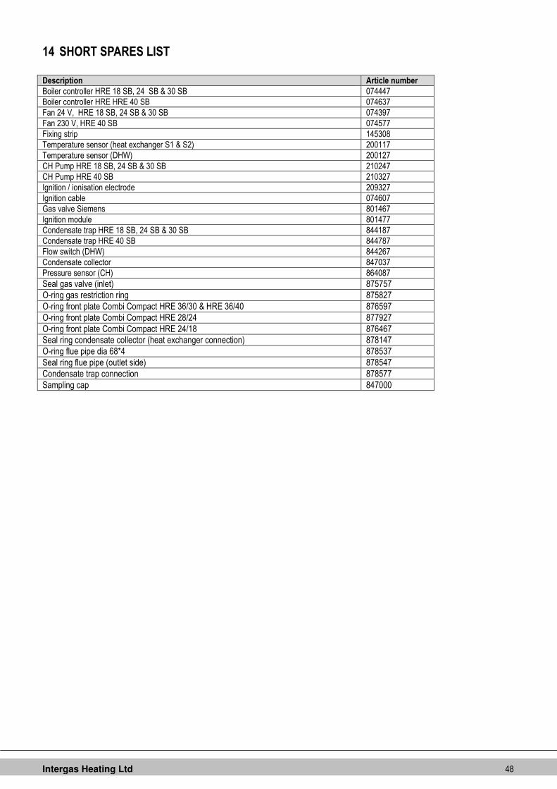
Intergas Heating Ltd 48
14 SHORT SPARES LIST
Description Article number
Boiler controller HRE 18 SB, 24 SB & 30 SB 074447
Boiler controller HRE HRE 40 SB 074637
Fan 24 V, HRE 18 SB, 24 SB & 30 SB 074397
Fan 230 V, HRE 40 SB 074577
Fixing strip 145308
Temperature sensor (heat exchanger S1 & S2) 200117
Temperature sensor (DHW) 200127
CH Pump HRE 18 SB, 24 SB & 30 SB 210247
CH Pump HRE 40 SB 210327
Ignition / ionisation electrode 209327
Ignition cable 074607
Gas valve Siemens 801467
Ignition module 801477
Condensate trap HRE 18 SB, 24 SB & 30 SB 844187
Condensate trap HRE 40 SB 844787
Flow switch (DHW) 844267
Condensate collector 847037
Pressure sensor (CH) 864087
Seal gas valve (inlet) 875757
O-ring gas restriction ring 875827
O-ring front plate Combi Compact HRE 36/30 & HRE 36/40 876597
O-ring front plate Combi Compact HRE 28/24 877927
O-ring front plate Combi Compact HRE 24/18 876467
Seal ring condensate collector (heat exchanger connection) 878147
O-ring flue pipe dia 68*4 878537
Seal ring flue pipe (outlet side) 878547
Condensate trap connection 878577
Sampling cap 847000
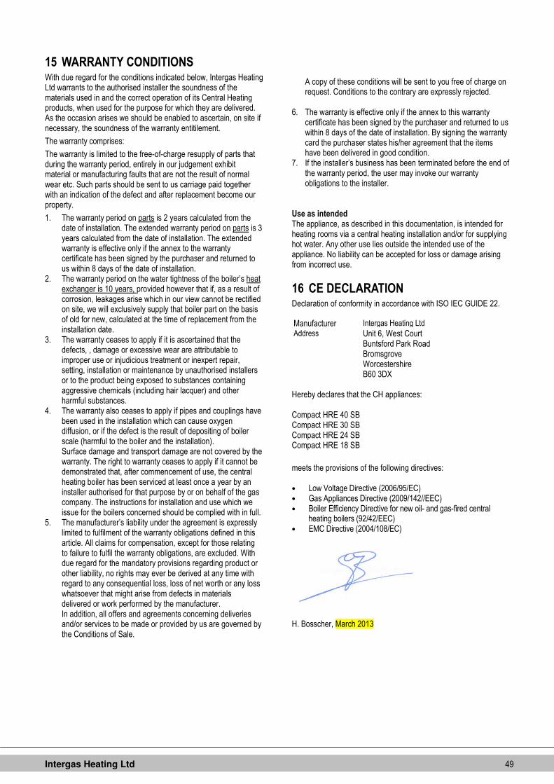
Intergas Heating Ltd 49
15 WARRANTY CONDITIONS With due regard for the conditions indicated below, Intergas Heating Ltd warrants to the authorised installer the soundness of the materials used in and the correct operation of its Central Heating products, when used for the purpose for which they are delivered. As the occasion arises we should be enabled to ascertain, on site if necessary, the soundness of the warranty entitilement.
The warranty comprises:
The warranty is limited to the free-of-charge resupply of parts that during the warranty period, entirely in our judgement exhibit material or manufacturing faults that are not the result of normal wear etc. Such parts should be sent to us carriage paid together with an indication of the defect and after replacement become our property.
1. The warranty period on parts is 2 years calculated from the date of installation. The extended warranty period on parts is 3 years calculated from the date of installation. The extended warranty is effective only if the annex to the warranty certificate has been signed by the purchaser and returned to us within 8 days of the date of installation.
2. The warranty period on the water tightness of the boiler’s heat exchanger is 10 years, provided however that if, as a result of corrosion, leakages arise which in our view cannot be rectified on site, we will exclusively supply that boiler part on the basis of old for new, calculated at the time of replacement from the installation date.
3. The warranty ceases to apply if it is ascertained that the defects, , damage or excessive wear are attributable to improper use or injudicious treatment or inexpert repair, setting, installation or maintenance by unauthorised installers or to the product being exposed to substances containing aggressive chemicals (including hair lacquer) and other harmful substances.
4. The warranty also ceases to apply if pipes and couplings have been used in the installation which can cause oxygen diffusion, or if the defect is the result of depositing of boiler scale (harmful to the boiler and the installation). Surface damage and transport damage are not covered by the warranty. The right to warranty ceases to apply if it cannot be demonstrated that, after commencement of use, the central heating boiler has been serviced at least once a year by an installer authorised for that purpose by or on behalf of the gas company. The instructions for installation and use which we issue for the boilers concerned should be complied with in full.
5. The manufacturer’s liability under the agreement is expressly limited to fulfilment of the warranty obligations defined in this article. All claims for compensation, except for those relating to failure to fulfil the warranty obligations, are excluded. With due regard for the mandatory provisions regarding product or other liability, no rights may ever be derived at any time with regard to any consequential loss, loss of net worth or any loss whatsoever that might arise from defects in materials delivered or work performed by the manufacturer. In addition, all offers and agreements concerning deliveries and/or services to be made or provided by us are governed by the Conditions of Sale.
A copy of these conditions will be sent to you free of charge on request. Conditions to the contrary are expressly rejected.
6. The warranty is effective only if the annex to this warranty
certificate has been signed by the purchaser and returned to us within 8 days of the date of installation. By signing the warranty card the purchaser states his/her agreement that the items have been delivered in good condition.
7. If the installer’s business has been terminated before the end of the warranty period, the user may invoke our warranty obligations to the installer.
Use as intended The appliance, as described in this documentation, is intended for heating rooms via a central heating installation and/or for supplying hot water. Any other use lies outside the intended use of the appliance. No liability can be accepted for loss or damage arising from incorrect use.
16 CE DECLARATION Declaration of conformity in accordance with ISO IEC GUIDE 22. Manufacturer Intergas Heating Ltd
Address Unit 6, West Court Buntsford Park Road
Bromsgrove Worcestershire B60 3DX
Hereby declares that the CH appliances: Compact HRE 40 SB Compact HRE 30 SB Compact HRE 24 SB Compact HRE 18 SB
meets the provisions of the following directives: • Low Voltage Directive (2006/95/EC) • Gas Appliances Directive (2009/142//EEC) • Boiler Efficiency Directive for new oil- and gas-fired central
heating boilers (92/42/EEC) • EMC Directive (2004/108/EC)
H. Bosscher, March 2013
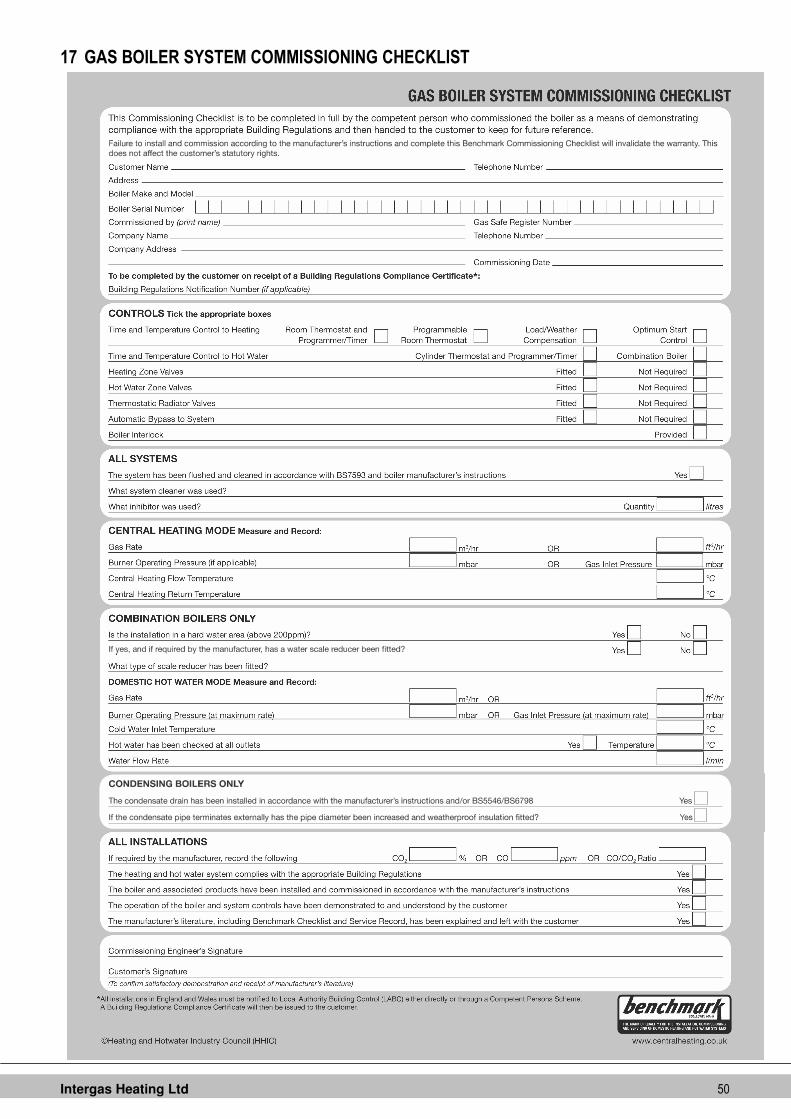
Intergas Heating Ltd 50
17 GAS BOILER SYSTEM COMMISSIONING CHECKLIST
Intergas Heating Ltd 51
18 SERVICE RECORD

Intergas Heating Ltd 52
Intergas boilers are manufactured in a Kiwa ISO 9001 certified production faccility.
Intergas Heating Ltd 88322707.doc
Intergas Heating Limited
Unit 6, West Court Buntsford Park Road
Bromsgrove
Worcestershire
B60 3DX
Telephone : 01527 888000
Fax : 01527 888001 [email protected] www.intergasheating.co.uk


