
CLUTCH
–CLUTCHCL–1

DESCRIPTIONThe diaphragm spring turnover type clutch providing lighter release performance.
–CLUTCH DESCRIPTIONCL–2

PREPARATIONSST(SPECIAL SERVICE TOOLS)
09333–00013 Clutch Diaphragm Spring Aligner
RECOMMENDED TOOLS09082–00050 TOYOTA Electrical Tester Set
09023–00100 Union Nut Wrench 10 mm
09301–00210 Clutch Guide Tool
09905–00013 Snap Ring Pliers
EQUIPMENT
Torque wrench
Dial indicator
Clutch line tube
Calipers
–CLUTCH PREPARATIONCL–3
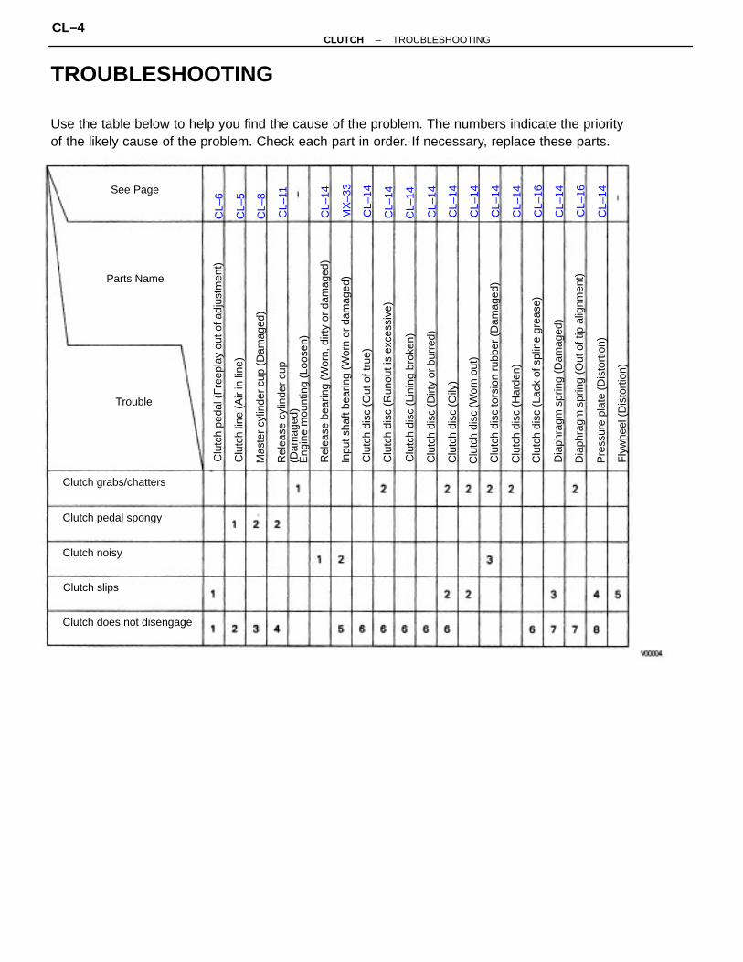
TROUBLESHOOTING
Use the table below to help you find the cause of the problem. The numbers indicate the priorityof the likely cause of the problem. Check each part in order. If necessary, replace these parts.
Clu
tch
peda
l (F
reep
lay
out o
f adj
ustm
ent)
Rel
ease
bea
ring
(Wor
n, d
irty
or d
amag
ed)
Dia
phra
gm s
prin
g (O
ut o
f tip
alig
nmen
t)
Inpu
t sha
ft be
arin
g (W
orn
or d
amag
ed)
Clu
tch
disc
tors
ion
rubb
er (
Dam
aged
)
Clu
tch
disc
(La
ck o
f spl
ine
grea
se)
Clu
tch
disc
(R
unou
t is
exce
ssiv
e)
Rel
ease
cyl
inde
r cu
p(D
amag
ed)
Mas
ter
cylin
der
cup
(Dam
aged
)
Dia
phra
gm s
prin
g (D
amag
ed)
Clu
tch
disc
(Li
ning
bro
ken)
Clu
tch
disc
(D
irty
or b
urre
d)
Clutch does not disengage
Pre
ssur
e pl
ate
(Dis
tort
ion)
Eng
ine
mou
ntin
g (L
oose
n)
Clu
tch
disc
(O
ut o
f tru
e)
Clu
tch
line
(Air
in li
ne)
Clu
tch
disc
(W
orn
out)
Clutch grabs/chatters
Fly
whe
el (
Dis
tort
ion)
Clu
tch
disc
(H
arde
n)Clutch pedal spongy
Clu
tch
disc
(O
ily)
Clutch noisy
Clutch slips
Parts Name
See Page
Trouble
MX
–33
CL–
14
CL–
14
CL–
14
CL–
16
CL–
14
CL–
14
CL–
14
CL–
14
CL–
16
CL–
14
CL–
14
CL–
14
CL–
11
CL–
14
CL–
6
CL–
8
CL–
5
–CLUTCH TROUBLESHOOTINGCL–4

CLUTCH SYSTEM BLEEDINGHINT: If any work is done on the clutch system or if airis suspected in the clutch lines, bleed the system ofair.
NOTICE: Do not let brake fluid remain on a painted sur–face. Wash it off immediately.
1. FILL CLUTCH RESERVOIR WITH BRAKE FLUID2. CONNECT VINYL TUBE TO BLEEDER PLUGInsert the other end of the tube in a half–full contain–er of brake fluid.HINT: Check the reservoir frequently. Add fluid ifnecessary.3. BLEED CLUTCH LINE
(a) Slowly pump the clutch pedal several times.(b) While pressing on the pedal, loosen the bleeder plug
until the fluid starts to run out. Then close the bleederplug.SST 09023–00100
(c) Repeat this procedure until there are no more airbubbles in the fluid.
–CLUTCH CLUTCH SYSTEM BLEEDINGCL–5

CLUTCH PEDALCLUTCH PEDAL CHECK ANDADJUSTMENT1. CHECK THAT PEDAL HEIGHT IS CORRECTPedal height from asphalt sheet:
160.8–170.8 mm (6.33–6.72 in.)
2. IF NECESSARY, ADJUST PEDAL HEIGHT
Loosen the lock nut and turn the stopper bolt until theheight is correct. Tighten the lock nut.3. CHECK THAT PEDAL FREEPLAY AND PUSH ROD
PLAY ARE CORRECTPedal freeplay:Push in on the pedal until the beginning of clutchresistance is felt.
Pedal fresplay:5.0–15.0 mm (0.197–0.591 in.)
Push rod play:Push in on the pedal with a finger softly until the resistance be-gins to increase a little.
Push rod play at pedal top:1.0–5.0 mm (0.039–0.197 in.)
4. IF NECESSARY, ADJUST PEDAL FREEPLAY AND PUSHROD PLAY(a) Loosen the lock nut and turn the push rod until the
freeplay and push rod play are correct.(b) Tighten the lock nut.(c) After adjusting the pedal freeplay, check the pedal
height.(d) Connect the air duct and install the lower finish panel.
–CLUTCH CLUTCH PEDALCL–6

5. INSPECT CLUTCH RELEASE POINT(a) Pull the parking brake lever and install wheel stopper.(b) Start the engine and idle the engine.(c) Without depressing the clutch pedal, slowly shift the
shift lever into reverse position until the gears con–tact.
(d) Gradually depress the clutch pedal and measure thestroke distance from the point the gear noise stops(release point) up to the full stroke end position.
Standard distance:25 mm (0.98 in.) or more(From pedal stroke end position to release point)
If the distance not as specified, perform the followingoperation.• Inspect pedal height.• Inspect push rod play and pedal freeplay.• Bleed the clutch line.• Inspect the clutch cover and disc.
6. CHECK CLUTCH START SYSTEM(a) Check that the engine does not start when the clutch
pedal is released.(b) Check that the engine starts when the clutch pedal is
fully depressed.If necessary, adjust or replace the clutch start switch.
7. CHECK CONTINUITY OF CLUTCH START SWITCH(a) Check that there is continuity between terminals
when the switch is ON (pushed).(b) Check that there is no continuity between terminals
when the switch is OFF (free).If continuity is not as specified, replace the switch.
–CLUTCH CLUTCH PEDALCL–7

MASTER CYLINDER REMOVAL1. DRAW OUT FLUID WITH SYRINGE2. DISCONNECT CLUTCH LINE TUBEUsing SST, disconnect the clutch line tube. Use acontainer to catch the brake fluid.SST 09023–001003. REMOVE CLIP AND CLEVIS PIN4. REMOVE 2 MOUNTING NUTS AND PULL OUT MASTER
CYLINDER
MASTER CYLINDER DISASSEMBLY1. REMOVE RESERVOIR TANK
(a) Using a pin punch and a hammer, drive out the slottedspring pin.
(b) Remove the reservoir tank and grommet.
CLUTCH MASTER CYLINDERCOMPONENTS
–CLUTCH CLUTCH MASTER CYLINDERCL–8

MASTER CYLINDER INSPECTIONHINT: Clean the disassembled parts with compressedair.1. INSPECT MASTER CYLINDER BORE FOR SCORING
OR CORROSIONIf a problem is found, clean or replace the cylinder.2. INSPECT PISTON AND CUPS FOR WEAR, SCORING,
CRACKS OR SWELLINGIf either one requires replacement, use the parts fromthe cylinder kit.3. INSPECT PUSH ROD FOR WEAR OR DAMAGEIf necessary, replace the push rod.
MASTER CYLINDER ASSEMBLY
1. COAT PARTS WITH LITHIUM SOAP BASE GLYCOLGREASE. AS SHOWN
2. INSERT PISTON INTO CYLINDER3. INSTALL PUSH ROD ASSEMBLY WITH SNAP RING
4. INSTALL RESERVOIR TANK(a) Install the reservoir tank and new grommet.(b) Using a pin punch and a hammer, drive in the slotted
spring pin.
2. REMOVE PUSH RODPull back the boot, and using snap ring pliers, removethe snap ring.3. REMOVE PISTON
–CLUTCH CLUTCH MASTER CYLINDERCL–9

MASTER CYLINDER INSTALLATION1. INSTALL MASTER CYLINDERInstall the 2 mounting nuts, and torque them.
Torque: 7.8 N–m (80 kgf–cm, 58 in,.lbf)
2. CONNECT CLUTCH LINE TUBEUsing SST, connect the clutch line tube.SST 09023–00100
Torque: 15 N–m (155 kgf–cm, 11 ft–lbf)
3. CONNECT PUSH ROD AND INSTALL PINInstall the clip in the push rod pin.4. BLEED SYSTEM AND ADJUST CLUTCH PEDAL(See page CL–5,6)
–CLUTCH CLUTCH MASTER CYLINDERCL–10

RELEASE CYLINDER REMOVAL1. DISCONNECT CLUTCH LINE TUBEUsing SST, disconnect the tube. Use a container tocatch the brake fluid.SST 09023–001002. REMOVE 2 BOLTS AND PULL OUT RELEASE CYLINDER
RELEASE CYLINDER DISASSEMBLY
1. REMOVE UNION FROM RELEASE CYLINDERRemove the union bolt, 2 gaskets and union from therelease cylinder.
CLUTCH RELEASE CYLINDERCOMPONENTS
–CLUTCH CLUTCH RELEASE CYLINDERCL–11

RELEASE CYLINDER INSPECTIONHINT: Clean the disassembled parts with compressedair.1. INSPECT RELEASE CYLINDER BORE FOR SCORING
OR CORROSIONIf a problem is found, clean or replace the cylinder.2. INSPECT PISTON AND CUPS FOR WEAR, SCORING,
CRACKS OR SWELLINGIf either one requires replacement, use the parts fromthe cylinder kit.3. INSPECT PUSH ROD FOR WEAR OR DAMAGEIf necessary, replace the push rod.
RELEASE CYLINDER ASSEMBLY
1. COAT PISTON WITH LITHIUM SOAP BASE GLYCOLGREASE, AS SHOWN
2. INSTALL PISTON WITH SPRING INTO CYLINDER3. INSTALL BOOT WITH PUSH ROD TO CYLINDER
4. INSTALL UNION TO RELEASE CYLINDER(a) Adjust the center line of the union is in parallel with
the release cylinder.(b) Install the union bolt.Torque: 25 N–m (250 kgf–cm, 18 ft–lbf)
2. PULL OUT BOOT WITH PUSH ROD3. REMOVE PISTON
Using compressed air, remove the piston with thespring from the cylinder.
–CLUTCH CLUTCH RELEASE CYLINDERCL–12
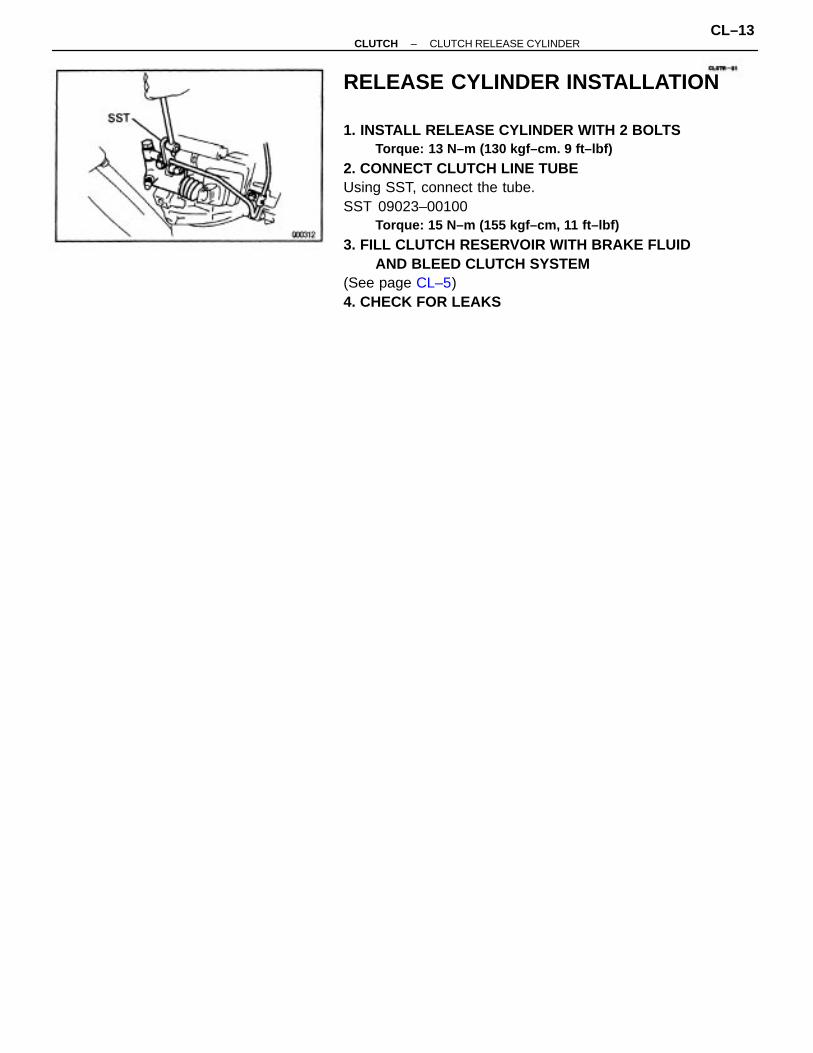
RELEASE CYLINDER INSTALLATION
1. INSTALL RELEASE CYLINDER WITH 2 BOLTSTorque: 13 N–m (130 kgf–cm. 9 ft–lbf)
2. CONNECT CLUTCH LINE TUBEUsing SST, connect the tube.SST 09023–00100
Torque: 15 N–m (155 kgf–cm, 11 ft–lbf)
3. FILL CLUTCH RESERVOIR WITH BRAKE FLUIDAND BLEED CLUTCH SYSTEM
(See page CL–5)4. CHECK FOR LEAKS
–CLUTCH CLUTCH RELEASE CYLINDERCL–13

2. REMOVE CLUTCH COVER AND DISC(a) Place matchmarks on the flywheel and clutch cover.(b) Loosen each set bolt one turn at a time until spring
tension is released.(c) Remove the set bolts, and pull off the clutch cover
with the clutch disc.NOTICE: Do not drop the clutch disc.
CLUTCH UNIT REMOVAL
1. REMOVE TRANSAXLE FROM ENGINE(See page MX–10)
CLUTCH UNITCOMPONENTS
–CLUTCH CLUTCH UNITCL–14

4. INSPECT DIAPHRAGM SPRING FOR WEARUsing calipers, measure the diaphragm spring fordepth and width of wear.
Maximum:A: Depth 0.6 mm (0.024 in.)B: Width 5.0 mm 10.197 In.)
If necessary, replace the clutch cover.
CLUTCH PARTS INSPECTION
1. INSPECT CLUTCH DISC FOR WEAR OR DAMAGEUsing calipers, measure the rivet head depth.
Minimum rivet depth:0.3 mm (0.0121n.)
If a problem is found, replace the clutch disc.
3. INSPECT FLYWHEEL RUNOUTUsing a dial indicator, check the flywheel runout.
Maximum runout:0.1 mm (0.004 in.)
If runout is excessive, replace the flywheel.
3. REMOVE RELEASE BEARING AND FORK FROM TRANS-AXLE(a) Remove the release bearing together with the fork
and then separate them.(b) Remove the boot.
2. INSPECT CLUTCH DISC RUNOUTUsing a dial indicator, check the disc runout.
Maximum runout:0.8 mm (0.031 in.)
If runout is excessive, replace the clutch disc.
–CLUTCH CLUTCH UNITCL–15
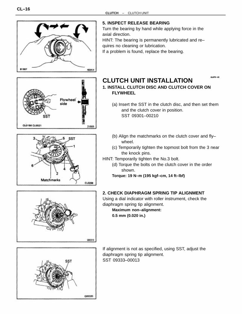
(b) Align the matchmarks on the clutch cover and fly–wheel.
(c) Temporarily tighten the topmost bolt from the 3 nearthe knock pins.
HINT: Temporarily tighten the No.3 bolt.(d) Torque the bolts on the clutch cover in the order
shown.Torque: 19 N–m (195 kgf–cm, 14 ft–lbf)
CLUTCH UNIT INSTALLATION1. INSTALL CLUTCH DISC AND CLUTCH COVER ON
FLYWHEEL
(a) Insert the SST in the clutch disc, and then set themand the clutch cover in position.SST 09301–00210
5. INSPECT RELEASE BEARINGTurn the bearing by hand while applying force in theaxial direction.HINT: The bearing is permanently lubricated and re–quires no cleaning or lubrication.If a problem is found, replace the bearing.
2. CHECK DIAPHRAGM SPRING TIP ALIGNMENTUsing a dial indicator with roller instrument, check thediaphragm spring tip alignment.
Maximum non–alignment:0.5 mm (0.020 in.)
If alignment is not as specified, using SST, adjust thediaphragm spring tip alignment.SST 09333–00013
–CLUTCH CLUTCH UNITCL–16

3. APPLY MOLYBDENUM DISULPHIDE LITHIUM BASEGREASE (NLGI NO.2) TO FOLLOWING PARTS
• Release fork and hub contact point• Release fork and push rod contact point• Release fork pivot point• Clutch disc spline
4. INSTALL RELEASE BEARING AND FORK TO TRANSAXLEInstall the bearing to the release fork, and then installthem to the transaxle.
5. INSTALL TRANSAXLE TO ENGINE(See page MX–15)
–CLUTCH CLUTCH UNITCL–17

SERVICE SPECIFICATIONSSERVICE DATA
Clutch release point from pedal full stroke end position
TORQUE SPECIFICATIONS
Diaphragm spring tip non–alignment (Maximum)
Diaphragm spring finger wear (Maximum depth)
Diaphragm spring finger wear (Maximum width)
Disc rivet head depth (Minimum)
Pedal height from asphalt sheet
Release cylinder installation nut
Master cylinder installation nut
Flywheel runout (Maximum)
Push rod play at pedal top
Disc runout (Maximum)
Clutch cover x Flywheel
Release fork support
Flywheel set bolt
Clutch line union
Part tightened
Pedal freeplay
Bleeder plug
Union bolt
–CLUTCH SERVICE SPECIFICATIONSCL–18


