
Veterinary
Clamp and Rod Internal Fixation(CRIF) System. Modular implant systemfor orthopaedic conditions.
Technique Guide
0X6.000.550_AB_0X6.000.550_AB 09.04.13 07:15 Seite Cvr1

0X6.000.550_AB_0X6.000.550_AB 09.04.13 07:15 Seite Cvr2

Introduction
Surgical Technique
Product Information
Clamp and Rod Internal Fixation System (CRIF) 2
Indications 2
Implant Features 3
AO Principles 4
Clinical Cases 5
Preparation 8
Lag Screw Placement (optional) 9
Rod Preparation 9
Clamps Loading 11
Placing the Construct 12
Implants 14
Instruments 17
Recommended Sets 19
CRIF Implant Set 20
CRIF Instrument Set 22
Table of contents
Synthes 1
0X6.000.550_AB_0X6.000.550_AB 09.04.13 07:15 Seite 1
Clamp and Rod Internal Fixation(CRIF) System. Modular implant systemfor orthopaedic conditions.
2 Synthes Clamp and Rod Internal Fixation (CRIF) System Technique Guide
Mini Small Medium
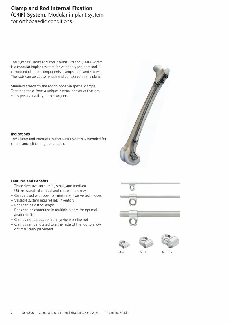
The Synthes Clamp and Rod Internal Fixation (CRIF) Systemis a modular implant system for veterinary use only and iscomposed of three components: clamps, rods and screws.The rods can be cut to length and contoured in any plane.
Standard screws fix the rod to bone via special clamps. Together, these form a unique internal construct that pro-vides great versatility to the surgeon.
Features and Benefits– Three sizes available: mini, small, and medium– Utilizes standard cortical and cancellous screws– Can be used with open or minimally invasive techniques– Versatile system requires less inventory– Rods can be cut to length– Rods can be contoured in multiple planes for optimal
anatomic fit– Clamps can be positioned anywhere on the rod– Clamps can be rotated to either side of the rod to allow
optimal screw placement
IndicationsThe Clamp Rod Internal Fixation (CRIF) System is intended forcanine and feline long bone repair.
0X6.000.550_AB_0X6.000.550_AB 09.04.13 07:15 Seite 2
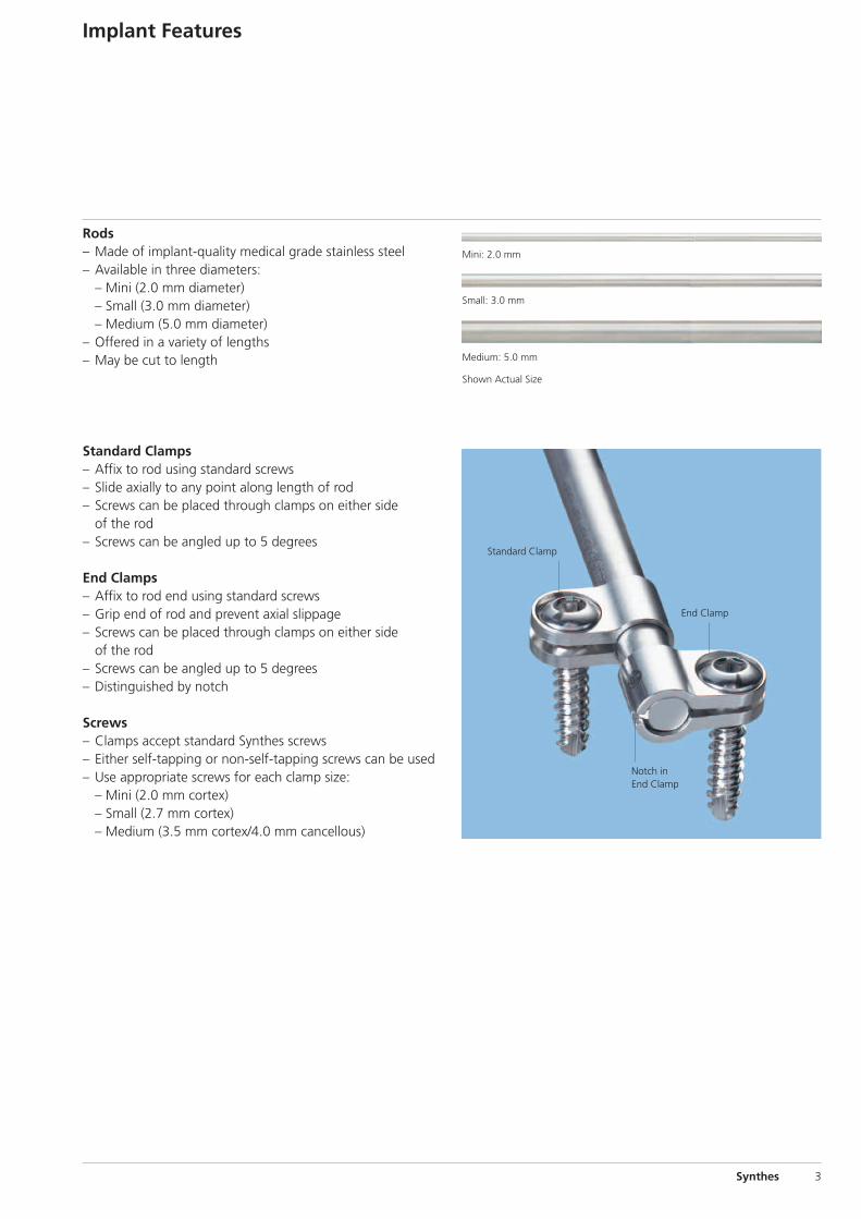
Rods– Made of implant-quality medical grade stainless steel – Available in three diameters:
– Mini (2.0 mm diameter)– Small (3.0 mm diameter)– Medium (5.0 mm diameter)
– Offered in a variety of lengths– May be cut to length
Implant Features
Synthes 3
Standard Clamp
Notch in End Clamp
End Clamp
Mini: 2.0 mm
Small: 3.0 mm
Medium: 5.0 mm
Shown Actual Size
Standard Clamps– Affix to rod using standard screws– Slide axially to any point along length of rod– Screws can be placed through clamps on either side
of the rod– Screws can be angled up to 5 degrees
End Clamps– Affix to rod end using standard screws– Grip end of rod and prevent axial slippage– Screws can be placed through clamps on either side
of the rod– Screws can be angled up to 5 degrees– Distinguished by notch
Screws– Clamps accept standard Synthes screws– Either self-tapping or non-self-tapping screws can be used– Use appropriate screws for each clamp size:
– Mini (2.0 mm cortex)– Small (2.7 mm cortex)– Medium (3.5 mm cortex/4.0 mm cancellous)
0X6.000.550_AB_0X6.000.550_AB 09.04.13 07:15 Seite 3

AO Principles
In 1958, the AO formulated four basic principles for internalfixation, which are still believed to be valid today.1 The Synthes Clamp and Rod Internal Fixation (CRIF) System hasbeen designed with these principles in mind. These principlesare:
Anatomic reductionThe CRIF System can be contoured to the bone, provide fracture reduction, and restore anatomic alignment.
Stable fixationThe CRIF System provides stable fixation to maintain properalignment during healing and restore function to the injuredlimb.
Preservation of blood supplyThe CRIF System minimizes surface contact with the boneand disruption of soft tissue, thereby preserving the bloodsupply.
Early mobilizationThe CRIF System provides stable fixation which may con-tribute to pain reduction and permit early, active mobilizationconducive to optimal recovery.
4 Synthes Clamp and Rod Internal Fixation (CRIF) System Technique Guide
1 A.L. Johnson, J.E.F. Houlton, R. Vannini. AO Principles of Fracture Management inthe Dog and Cat. Davos Platz: AO Publishing. 2005.
0X6.000.550_AB_0X6.000.550_AB 09.04.13 07:15 Seite 4
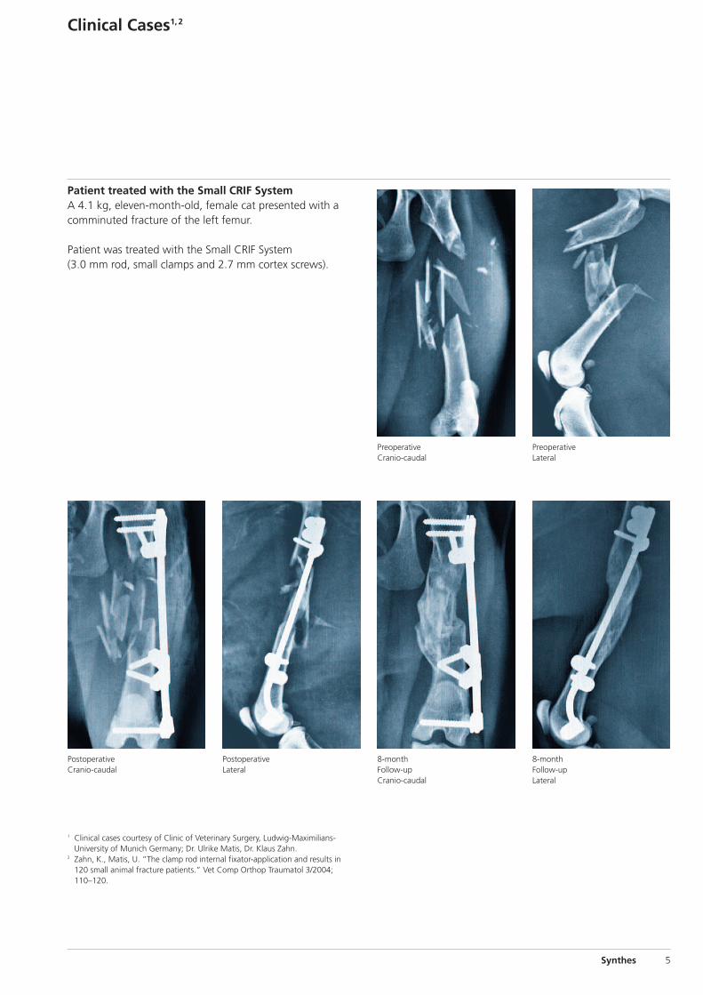
Patient treated with the Small CRIF SystemA 4.1 kg, eleven-month-old, female cat presented with a comminuted fracture of the left femur.
Patient was treated with the Small CRIF System (3.0 mm rod, small clamps and 2.7 mm cortex screws).
Clinical Cases1,2
Synthes 5
1 Clinical cases courtesy of Clinic of Veterinary Surgery, Ludwig-Maximilians-University of Munich Germany; Dr. Ulrike Matis, Dr. Klaus Zahn.
2 Zahn, K., Matis, U. “The clamp rod internal fixator-application and results in120 small animal fracture patients.” Vet Comp Orthop Traumatol 3/2004; 110–120.
PreoperativeCranio-caudal
PreoperativeLateral
8-monthFollow-upCranio-caudal
8-monthFollow-upLateral
PostoperativeCranio-caudal
PostoperativeLateral
0X6.000.550_AB_0X6.000.550_AB 09.04.13 07:15 Seite 5
Clinical Cases
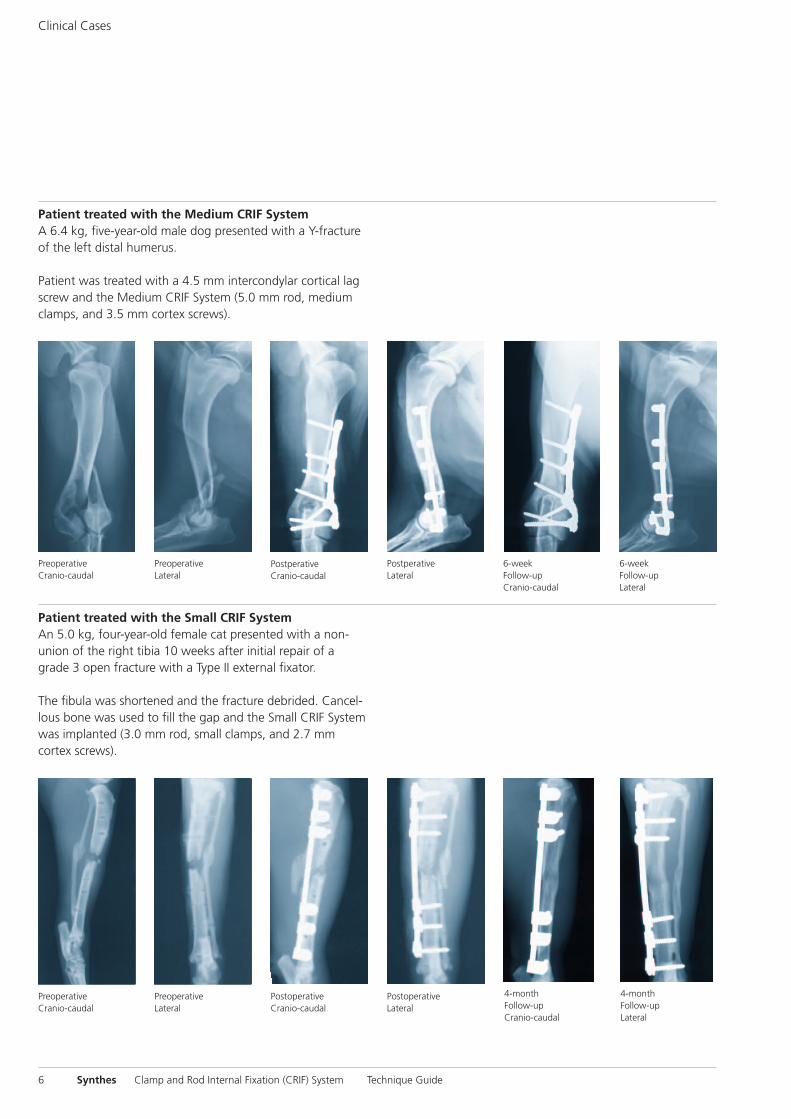
Patient treated with the Medium CRIF SystemA 6.4 kg, five-year-old male dog presented with a Y-fractureof the left distal humerus.
Patient was treated with a 4.5 mm intercondylar cortical lagscrew and the Medium CRIF System (5.0 mm rod, mediumclamps, and 3.5 mm cortex screws).
6 Synthes Clamp and Rod Internal Fixation (CRIF) System Technique Guide
Postperative Cranio-caudal
Postperative Lateral
6-week Follow-up Cranio-caudal
6-weekFollow-up Lateral
Preoperative Lateral
Preoperative Cranio-caudal
Patient treated with the Small CRIF SystemAn 5.0 kg, four-year-old female cat presented with a non-union of the right tibia 10 weeks after initial repair of agrade 3 open fracture with a Type II external fixator.
The fibula was shortened and the fracture debrided. Cancel-lous bone was used to fill the gap and the Small CRIF System was implanted (3.0 mm rod, small clamps, and 2.7 mm cortex screws).
Postoperative Cranio-caudal
Postoperative Lateral
4-month Follow-up Cranio-caudal
4-month Follow-up Lateral
Preoperative Lateral
Preoperative Cranio-caudal
0X6.000.550_AB_0X6.000.550_AB 09.04.13 07:16 Seite 6
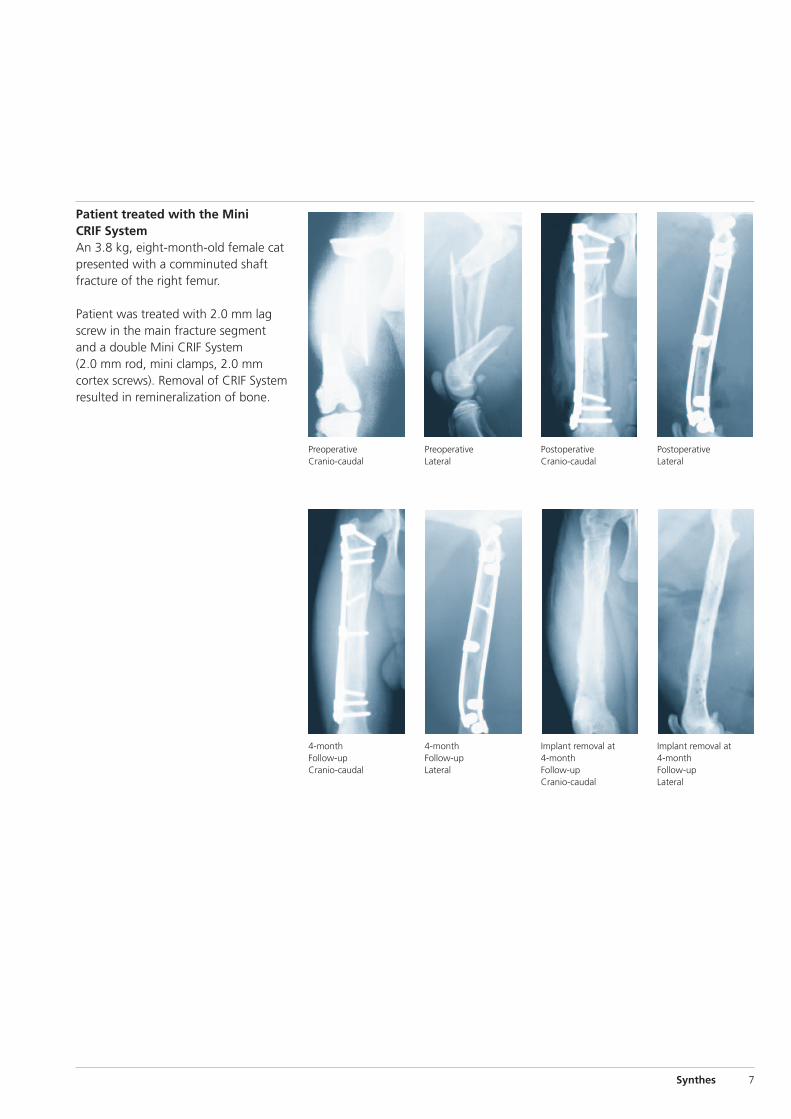
Postoperative Cranio-caudal
Implant removal at4-month Follow-upCranio-caudal
Postoperative Lateral
Implant removal at4-month Follow-upLateral
Preoperative Lateral
4-monthFollow-up Lateral
Preoperative Cranio-caudal
4-monthFollow-upCranio-caudal
Patient treated with the Mini CRIF SystemAn 3.8 kg, eight-month-old female catpresented with a comminuted shaftfracture of the right femur.
Patient was treated with 2.0 mm lagscrew in the main fracture segmentand a double Mini CRIF System(2.0 mm rod, mini clamps, 2.0 mm cortex screws). Removal of CRIF Systemresulted in remineralization of bone.
Synthes 7
0X6.000.550_AB_0X6.000.550_AB 09.04.13 07:16 Seite 7
Preparation
1Preparation
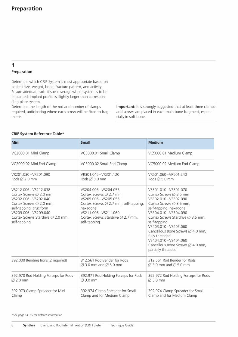
Determine which CRIF System is most appropriate based onpatient size, weight, bone, fracture pattern, and activity.Ensure adequate soft tissue coverage where system is to beimplanted. Implant profile is slightly larger than correspon-ding plate system.Determine the length of the rod and number of clamps required, anticipating where each screw will be fixed to frag-ments.
8 Synthes Clamp and Rod Internal Fixation (CRIF) System Technique Guide
CRIF System Reference Table*
*See page 14 –15 for detailed information
Mini Small Medium
VC2000.01 Mini Clamp VC3000.01 Small Clamp VC5000.01 Medium Clamp
VC2000.02 Mini End Clamp VC3000.02 Small End Clamp VC5000.02 Medium End Clamp
VR201.030 –VR201.090Rods � 2.0 mm
VR301.045 –VR301.120Rods � 3.0 mm
VR501.060 –VR501.240Rods � 5.0 mm
VS212.006 –VS212.038Cortex Screws � 2.0 mmVS202.006 –VS202.040Cortex Screws � 2.0 mm,self-tapping, cruciformVS209.006 –VS209.040Cortex Screws Stardrive � 2.0 mm,self-tapping
VS204.006 –VS204.055Cortex Screws � 2.7 mmVS205.006 –VS205.055Cortex Screws � 2.7 mm, self-tapping,hexagonalVS211.006 –VS211.060Cortex Screws Stardrive � 2.7 mm,self-tapping
VS301.010 –VS301.070Cortex Screws � 3.5 mmVS302.010 –VS302.090Cortex Screws � 3.5 mm,self-tapping, hexagonalVS304.010 –VS304.090Cortex Screws Stardrive � 3.5 mm,self-tappingVS403.010 –VS403.060Cancellous Bone Screws � 4.0 mm,fully threadedVS404.010 –VS404.060Cancellous Bone Screws � 4.0 mm,partially threaded
392.000 Bending Irons (2 required) 312.561 Rod Bender for Rods� 3.0 mm and � 5.0 mm
312.561 Rod Bender for Rods� 3.0 mm and � 5.0 mm
392.970 Rod Holding Forceps for Rods� 2.0 mm
392.971 Rod Holding Forceps for Rods� 3.0 mm
392.972 Rod Holding Forceps for Rods� 5.0 mm
392.973 Clamp Spreader for MiniClamp
392.974 Clamp Spreader for SmallClamp and for Medium Clamp
392.974 Clamp Spreader for SmallClamp and for Medium Clamp
Important: It is strongly suggested that at least three clampsand screws are placed in each main bone fragment, espe-cially in soft bone.
0X6.000.550_AB_0X6.000.550_AB 09.04.13 07:16 Seite 8
Synthes 9
Lag Screw Placement (optional)Rod Preparation
2Lag screw placement (optional)
After reduction, one or more lag screws may be inserted for fracture compression before placement of the CRIF construct. Leave the periosteum intact whenever possible, to preserve the blood supply to the bone fragments.
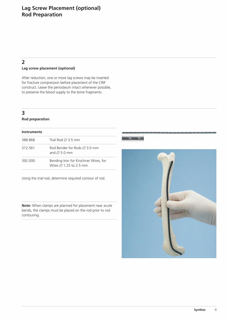
3Rod preparation
Instruments
388.868 Trial Rod � 3.5 mm
312.561 Rod Bender for Rods � 3.0 mm and � 5.0 mm
392.000 Bending Iron for Kirschner Wires, for Wires � 1.25 to 2.5 mm
Using the trial rod, determine required contour of rod.
Note: When clamps are planned for placement near acutebends, the clamps must be placed on the rod prior to rodcontouring.
0X6.000.550_AB_0X6.000.550_AB 09.04.13 07:16 Seite 9
10 Synthes Clamp and Rod Internal Fixation (CRIF) System Technique Guide
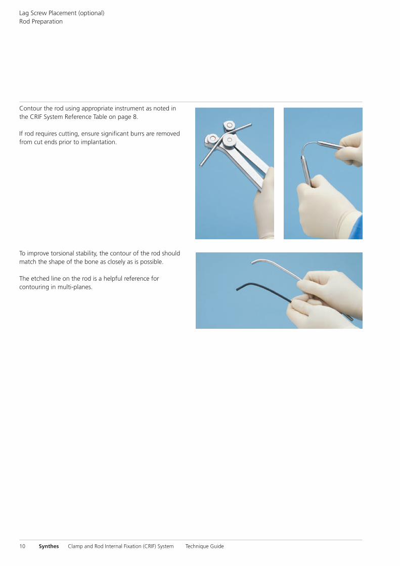
Contour the rod using appropriate instrument as noted inthe CRIF System Reference Table on page 8.
If rod requires cutting, ensure significant burrs are removedfrom cut ends prior to implantation.
To improve torsional stability, the contour of the rod shouldmatch the shape of the bone as closely as is possible.
The etched line on the rod is a helpful reference for contouring in multi-planes.
Lag Screw Placement (optional)Rod Preparation
0X6.000.550_AB_0X6.000.550_AB 09.04.13 07:16 Seite 10
Synthes 11
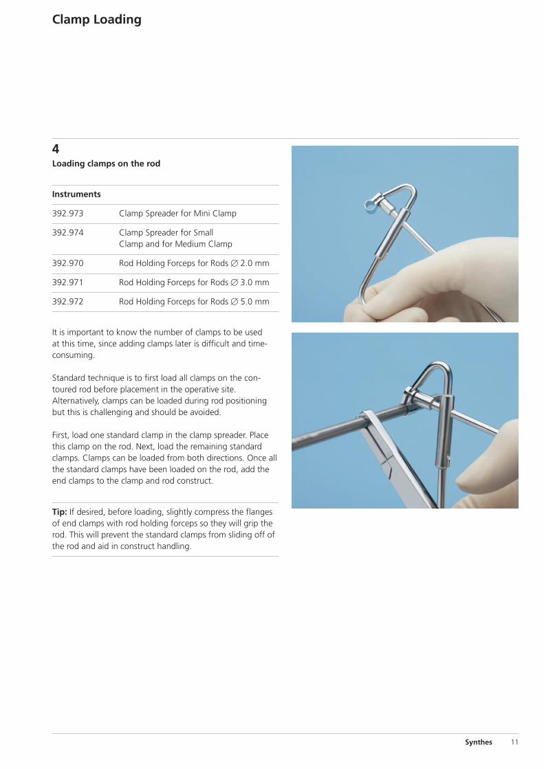
4Loading clamps on the rod
Instruments
392.973 Clamp Spreader for Mini Clamp
392.974 Clamp Spreader for Small Clamp and for Medium Clamp
392.970 Rod Holding Forceps for Rods � 2.0 mm
392.971 Rod Holding Forceps for Rods � 3.0 mm
392.972 Rod Holding Forceps for Rods � 5.0 mm
It is important to know the number of clamps to be usedat this time, since adding clamps later is difficult and time-consuming.
Standard technique is to first load all clamps on the con-toured rod before placement in the operative site. Alternatively, clamps can be loaded during rod positioningbut this is challenging and should be avoided.
First, load one standard clamp in the clamp spreader. Placethis clamp on the rod. Next, load the remaining standardclamps. Clamps can be loaded from both directions. Once allthe standard clamps have been loaded on the rod, add theend clamps to the clamp and rod construct.
Tip: If desired, before loading, slightly compress the flangesof end clamps with rod holding forceps so they will grip therod. This will prevent the standard clamps from sliding off ofthe rod and aid in construct handling.
Clamp Loading
0X6.000.550_AB_0X6.000.550_AB 09.04.13 07:16 Seite 11
12 Synthes Clamp and Rod Internal Fixation (CRIF) System Technique Guide
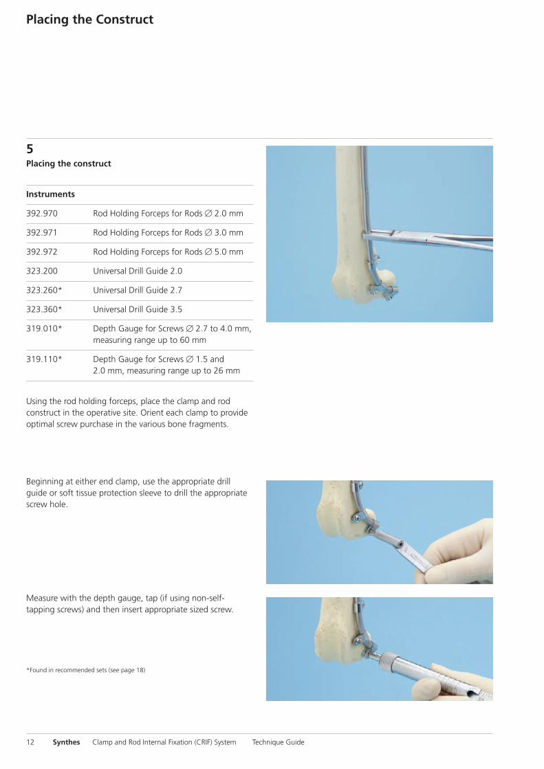
5Placing the construct
Instruments
392.970 Rod Holding Forceps for Rods � 2.0 mm
392.971 Rod Holding Forceps for Rods � 3.0 mm
392.972 Rod Holding Forceps for Rods � 5.0 mm
323.200 Universal Drill Guide 2.0
323.260* Universal Drill Guide 2.7
323.360* Universal Drill Guide 3.5
319.010* Depth Gauge for Screws � 2.7 to 4.0 mm, measuring range up to 60 mm
319.110* Depth Gauge for Screws � 1.5 and 2.0 mm, measuring range up to 26 mm
Using the rod holding forceps, place the clamp and rod construct in the operative site. Orient each clamp to provideoptimal screw purchase in the various bone fragments.
Beginning at either end clamp, use the appropriate drillguide or soft tissue protection sleeve to drill the appropriatescrew hole.
Measure with the depth gauge, tap (if using non-self-tapping screws) and then insert appropriate sized screw.
*Found in recommended sets (see page 18)
Placing the Construct
0X6.000.550_AB_0X6.000.550_AB 09.04.13 07:16 Seite 12
Synthes 13
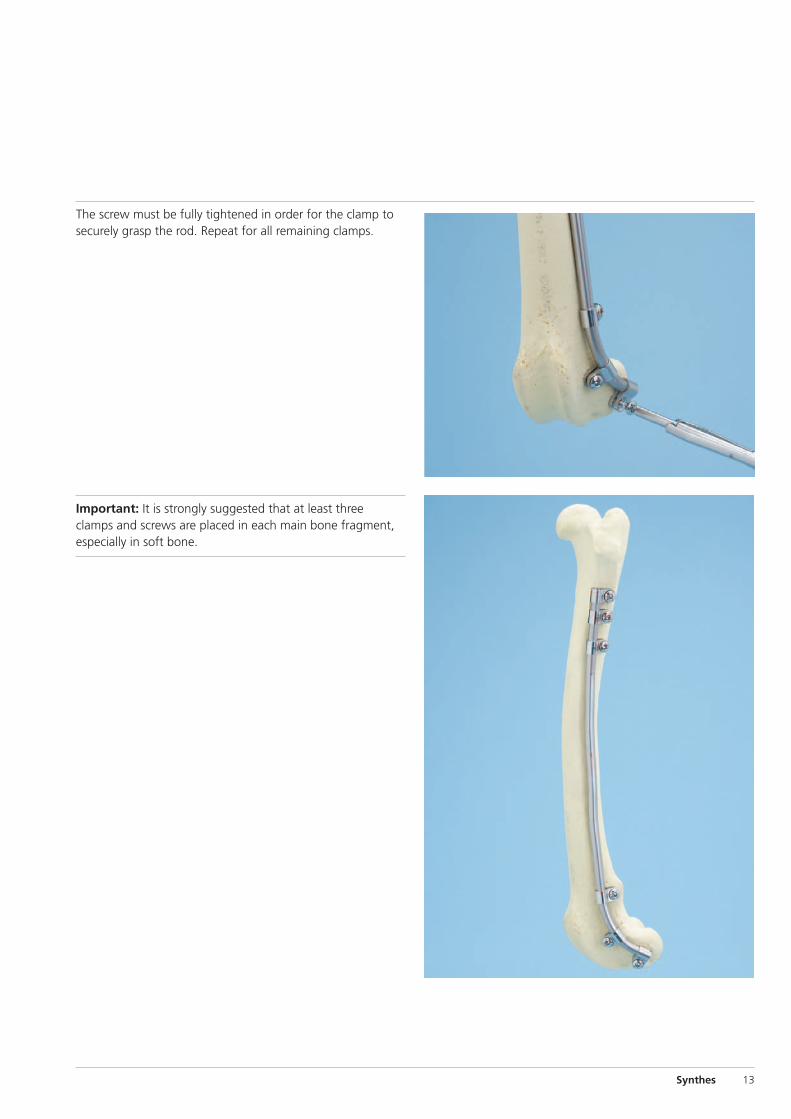
The screw must be fully tightened in order for the clamp tosecurely grasp the rod. Repeat for all remaining clamps.
Important: It is strongly suggested that at least three clamps and screws are placed in each main bone fragment,especially in soft bone.
0X6.000.550_AB_0X6.000.550_AB 09.04.13 07:16 Seite 13

14 Synthes Clamp and Rod Internal Fixation (CRIF) System Technique Guide
Implants
VS212.006 – Cortex Screws � 2.0 mm, VS212.038 Stainless Steel, Lengths 6 –38 mm
Screws
VS202.006 – Cortex Screws � 2.0 mm, self-tapping,VS202.040 Stainless Steel, Lengths 6 –40 mm
VS209.006 – Cortex Screws Stardrive � 2.0 mm,VS209.040 self-tapping, Stainless Steel, Lengths 6 –40 mm
VS204.006 – Cortex Screws � 2.7 mm, Stainless Steel,VS204.055 Lengths 6 –55 mm
VS205.006 – Cortex Screws � 2.7 mm, self-tapping, VS205.055 Stainless Steel, Lengths 6 –55 mm
VS211.006 – Cortex Screws Stardrive � 2.7 mm, VS211.060 self-tapping, Stainless Steel, Lengths 6 –60 mm
0X6.000.550_AB_0X6.000.550_AB 09.04.13 07:16 Seite 14

Synthes 15
VS301.010 – Cortex Screws � 3.5 mm, Stainless Steel,VS301.070 Lengths 10 –70 mm
VS302.010 – Cortex Screws � 3.5 mm, self-tapping,VS302.090 Stainless Steel, Lengths 10 –90 mm
VS304.010 – Cortex Screws Stardrive � 3.5 mm, VS304.090 self-tapping, Stainless Steel, Lengths 10 –90 mm
VS403.010 – Cancellous Bone Screws � 4.0 mm, VS403.060 fully threaded, Stainless Steel, Lenghts 10 –60 mm
VS404.010 – Cancellous Bone Screws � 4.0 mm, VS404.060 partially threaded, Stainless Steel, Lengths 10 –60 mm
0X6.000.550_AB_0X6.000.550_AB 09.04.13 07:16 Seite 15
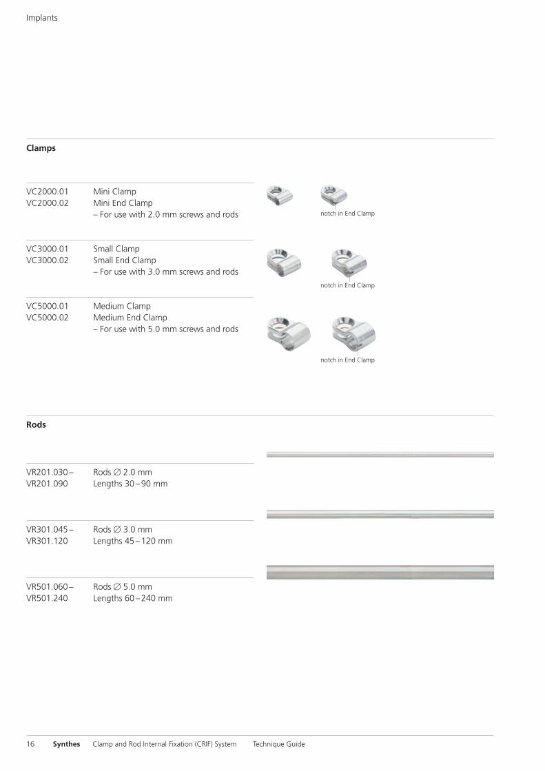
VC2000.01 Mini Clamp VC2000.02 Mini End Clamp
– For use with 2.0 mm screws and rods
VC3000.01 Small ClampVC3000.02 Small End Clamp
– For use with 3.0 mm screws and rods
VC5000.01 Medium ClampVC5000.02 Medium End Clamp
– For use with 5.0 mm screws and rods
VR201.030 – Rods � 2.0 mmVR201.090 Lengths 30 –90 mm
VR301.045 – Rods � 3.0 mmVR301.120 Lengths 45 –120 mm
VR501.060 – Rods � 5.0 mmVR501.240 Lengths 60 –240 mm
notch in End Clamp
notch in End Clamp
notch in End Clamp
Clamps
Rods
16 Synthes Clamp and Rod Internal Fixation (CRIF) System Technique Guide
Implants
0X6.000.550_AB_0X6.000.550_AB 09.04.13 07:16 Seite 16

392.970
392.971
392.972
Synthes 17
Instruments
312.561 Rod Bender, for 3.0 mm and 5.0 mm rods– Used to contour rod– Accommodates both small and medium
rods
392.000 Bending Iron for Kirschner Wires, for Wires � 1.25 to 2.5 mm (2 required) – Used to contour mini rods
– Used in pairs for optimal function
388.868 Trial Rod � 3.5 mm– Malleable rod easily contours to the bone– Reduces time required to properly
contour rods – Reusable for many cases
Rod Holding Forceps392.970 for 2.0 mm Rod, mini392.971 for 3.0 mm Rod, small392.972 for 5.0 mm Rod, medium – Grips rod during contouring, clamp
loading, and screw insertion
0X6.000.550_AB_0X6.000.550_AB 09.04.13 07:16 Seite 17
392.973
392.974
18 Synthes Clamp and Rod Internal Fixation (CRIF) System Technique Guide
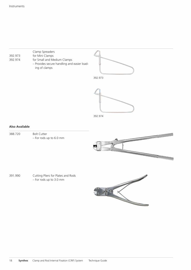
391.990 Cutting Pliers for Plates and Rods – For rods up to 3.0 mm
388.720 Bolt Cutter– For rods up to 6.0 mm
Also Available
Clamp Spreaders392.973 for Mini Clamps392.974 for Small and Medium Clamps – Provides secure handling and easier load-
ing of clamps
Instruments
0X6.000.550_AB_0X6.000.550_AB 09.04.13 07:16 Seite 18
103.527
103.518
103.501
103.521
Synthes 19
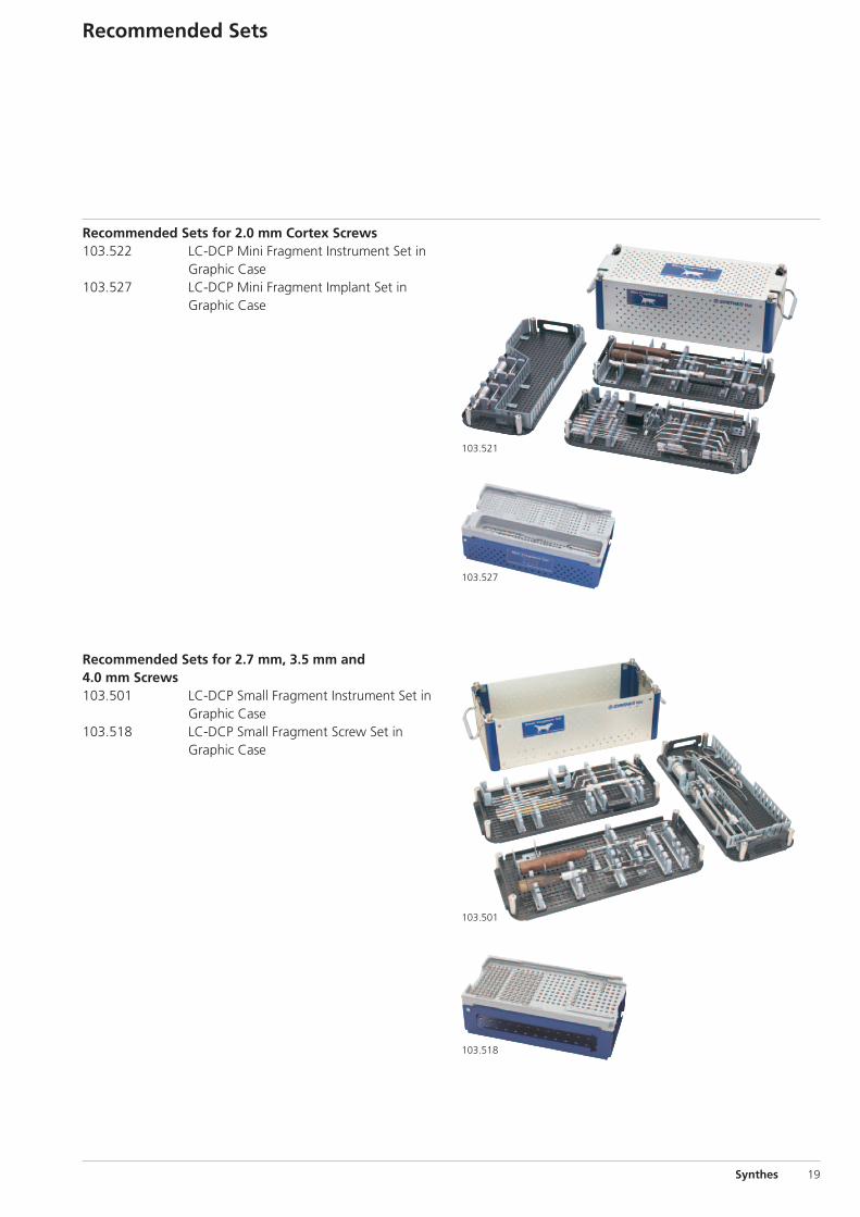
Recommended Sets
Recommended Sets for 2.7 mm, 3.5 mm and4.0 mm Screws103.501 LC-DCP Small Fragment Instrument Set in
Graphic Case 103.518 LC-DCP Small Fragment Screw Set in
Graphic Case
Recommended Sets for 2.0 mm Cortex Screws103.522 LC-DCP Mini Fragment Instrument Set in
Graphic Case103.527 LC-DCP Mini Fragment Implant Set in
Graphic Case
0X6.000.550_AB_0X6.000.550_AB 09.04.13 07:16 Seite 19
20 Synthes Clamp and Rod Internal Fixation (CRIF) System Technique Guide
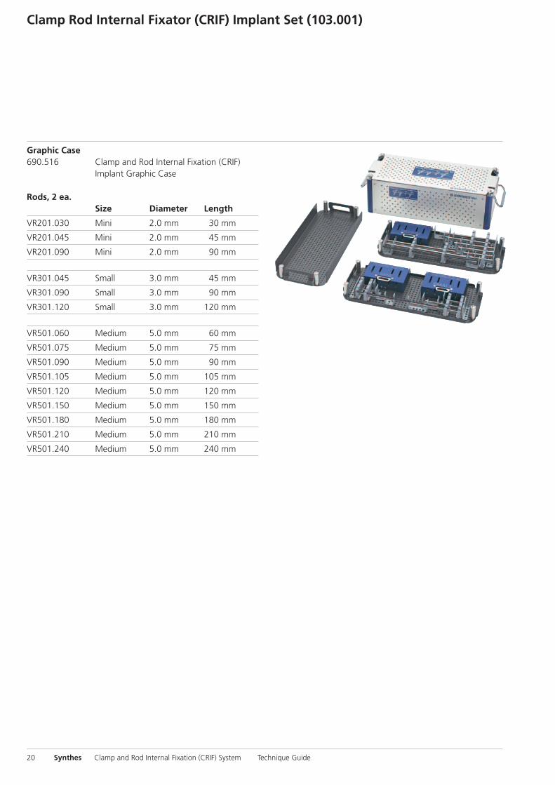
Clamp Rod Internal Fixator (CRIF) Implant Set (103.001)
Graphic Case690.516 Clamp and Rod Internal Fixation (CRIF)
Implant Graphic Case
Rods, 2 ea. Size Diameter Length
VR201.030 Mini 2.0 mm 30 mm
VR201.045 Mini 2.0 mm 45 mm
VR201.090 Mini 2.0 mm 90 mm
VR301.045 Small 3.0 mm 45 mm
VR301.090 Small 3.0 mm 90 mm
VR301.120 Small 3.0 mm 120 mm
VR501.060 Medium 5.0 mm 60 mm
VR501.075 Medium 5.0 mm 75 mm
VR501.090 Medium 5.0 mm 90 mm
VR501.105 Medium 5.0 mm 105 mm
VR501.120 Medium 5.0 mm 120 mm
VR501.150 Medium 5.0 mm 150 mm
VR501.180 Medium 5.0 mm 180 mm
VR501.210 Medium 5.0 mm 210 mm
VR501.240 Medium 5.0 mm 240 mm
0X6.000.550_AB_0X6.000.550_AB 09.04.13 07:16 Seite 20

Synthes 21
Standard Clamps, 10 ea. Size Diameter Rod
VC2000.01 Mini 2.0 mm 2.0 mm
VC3000.01 Small 2.7 mm 3.0 mm
VC5000.01 Medium 3.5 mm 5.0 mm
End Clamps, 4 ea. Size Diameter Rod
VC2000.02 Mini 2.0 mm 2.0 mm
VC3000.02 Small 2.7 mm 3.0 mm
VC5000.02 Medium 3.5 mm 5.0 mm
388.868 Trial Rod � 3.5 mm
0X6.000.550_AB_0X6.000.550_AB 09.04.13 07:16 Seite 21
22 Synthes Clamp and Rod Internal Fixation (CRIF) System Technique Guide
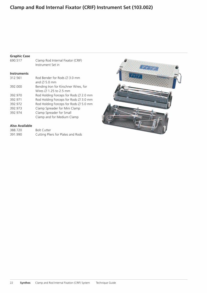
Graphic Case690.517 Clamp Rod Internal Fixator (CRIF) Instrument Set in
Instruments 312.561 Rod Bender for Rods � 3.0 mm
and � 5.0 mm392.000 Bending Iron for Kirschner Wires, for Wires � 1.25 to 2.5 mm392.970 Rod Holding Forceps for Rods � 2.0 mm392.971 Rod Holding Forceps for Rods � 3.0 mm392.972 Rod Holding Forceps for Rods � 5.0 mm392.973 Clamp Spreader for Mini Clamp392.974 Clamp Spreader for Small Clamp and for Medium Clamp Also Available 388.720 Bolt Cutter391.990 Cutting Pliers for Plates and Rods
Clamp and Rod Internal Fixator (CRIF) Instrument Set (103.002)
0X6.000.550_AB_0X6.000.550_AB 09.04.13 07:16 Seite 22

Synthes 23
0X6.000.550_AB_0X6.000.550_AB 09.04.13 07:16 Seite 23

24 Synthes Clamp and Rod Internal Fixation (CRIF) System Technique Guide
0X6.000.550_AB_0X6.000.550_AB 09.04.13 07:16 Seite 24

0X6.000.550_AB_0X6.000.550_AB 09.04.13 07:16 Seite Cvr3

Synthes GmbHEimattstrasse 3CH-4436 Oberdorfwww.synthes.com 03
6.00
0.55
0 ve
rsio
n A
B
rev.
1
04/2
013
3510
0071
©
Syn
thes
, Inc
. or
its a
ffili
ates
Su
bjec
t to
mod
ifica
tion
Synt
hes
is a
tra
dem
ark
of S
ynth
es, I
nc. o
r its
aff
iliat
es
Ö036.000.550öAB„ä
All technique guides are available as PDF files at www.synthes.com/lit
0X6.000.550_AB_0X6.000.550_AB 09.04.13 07:16 Seite Cvr4


