
Robot SimulationA Tool For Project Success
Charles C. Gales, P.E.Manager, Automation Sales
Weldon Solutions

Definition
sim - u - la - tion
The activity of producing conditions which are similar to real ones, especially in order to test something, or
the conditions that are produced.
Source: ldoceonline.com

Robot Simulation – Historical Perspective
• Early 1990s, High End Work Stations produced marginal results.
• Robot Models (RobCad, Delmia, Process Simulate) were not precise.
• Each simulation software manufacturer emulated Robot motion system and performance.
• Cycle times and Robot paths did not match the real world.
• Required significant rework to match actual system to design requirements.
• Garbage in – Garbage out
Realistic Robot Simulation
• Initiative of:• Automotive Companies
• Robot Manufacturers
• Simulator Manufacturers
• Line Builders
• Measurement System Manufacturers
• For Enhancing• Robot Simulation Accuracy
• Robot Off-Line Programming Methodology
Source: realistic-robot-simulation.org

RRS-1, Robot Controller Simulation (RCS)
• RCS Interface• Original Motion Control Software
Developed as a Call Library
• Call Library Provided For Groups, Such As:
• Interpolation
• Transformation
• Kinematics Cell Modeling
• Machine Data
• External Axes
• Conveyor Synchronization
• Event Generation
• Error Messages
Robot Path Deviation
Source: realistic-robot-simulation.org
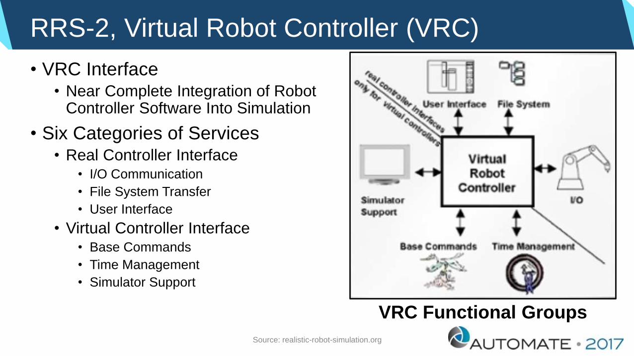
RRS-2, Virtual Robot Controller (VRC)
• VRC Interface• Near Complete Integration of Robot
Controller Software Into Simulation
• Six Categories of Services• Real Controller Interface
• I/O Communication
• File System Transfer
• User Interface
• Virtual Controller Interface• Base Commands
• Time Management
• Simulator Support
VRC Functional Groups
Source: realistic-robot-simulation.org

Where Do I Start?
• Balance These Robot Parameters:• Payload
• Reach
• Speed
• Robots Are Generally Rated By Payload.• If Robot Has Payload Capacity, Will It Have
Enough Reach?
• If Robot Has Payload Capacity, Will It Have Sufficient Speed?
• Robot Simulation Can Answer Questions To Help Balance Robot Selection
Payload
Reach
Balance
Speed

Case Study – Machine Tending Workcell
LATHE
PARTMARK
INFEED
CHAMFER
SHAVER
HOB
OUTFEED
INSPECT

Machine Tending Workcell – Robot Work Envelope

Design With 3D Model
Difficult To Position
Robot With CAD Software
Robot Simulation

Installed System
Part MarkerLatheIn / Out Conveyors

Installed System
Hob Chamfer Shaver

How Do I Do It?
Programming SimulationLayoutLibrary
Robot
Others
Simple Modeling3D CAD data
CAD Interface
IGES
format
Layout Investigation Program Generation Verification
Virtual TP
2D-3D conversion Parts modeling Library registration
2D layout import Layout creation
CAD-to-Path Graphic jogging Easy teaching
Cycle time Robot trajectory
Teach robot data
by same operation
of actual robot
Load program
to actual robot
Source: FANUC Robotics

Duty Estimation
Simulation
TPProgram
OVC, OH
Result
Set payload (EOAT and
Work-piece’s weight, center
of gravity, inertia)
Conditions (Ambient
temperature, cover option)
Source: FANUC Robotics

Life Estimation
TPProgram
Simulation
Actual cycle time
Working hours per day
Working days per year
Reducer’s life
Torque analysis
Source: FANUC Robotics

Power Estimation
TPProgram
Simulation
one cycle Power consumption
Annual power and electric toll
Motion analysis
Source: FANUC Robotics

Case Study – Multi-Robot Workcell
• Cycle Time• Robot 1 – Machine Tending
• Robot 2 – Machine Tending
• Robot 3 – Packing
• Robot Reach
• Footprint Optimization
• Sequence of Operation
• Prevent Robot Interference

Case Study - Assembly
• Cycle Time• Workcell Arrangement
• Combined EOAT Functions
• Robot Reach
• Footprint Optimization
• Sequence of Operation

Case Study – Packing Workcell
• Simulation Allowed For Combined Operations
• Reduced From Two Robots To One Robot
• Robot Reach
• Footprint Optimization
• Sequence of Operation
• Deep Containers Required Attention To Moment Loading

Custom Simulation Package For Spot Welding
3D CAD
model
Servo gun posture
normal to surface
Assign points to each
robot group and sort
the order of assigned
points to minimize the
path distance
Compute the
critical space and
setup the interlock
signals
Critical space
Robot #1Robot #2
3 2 1
1 2 3 4
123123 Robot Robot
4
Source: FANUC Robotics
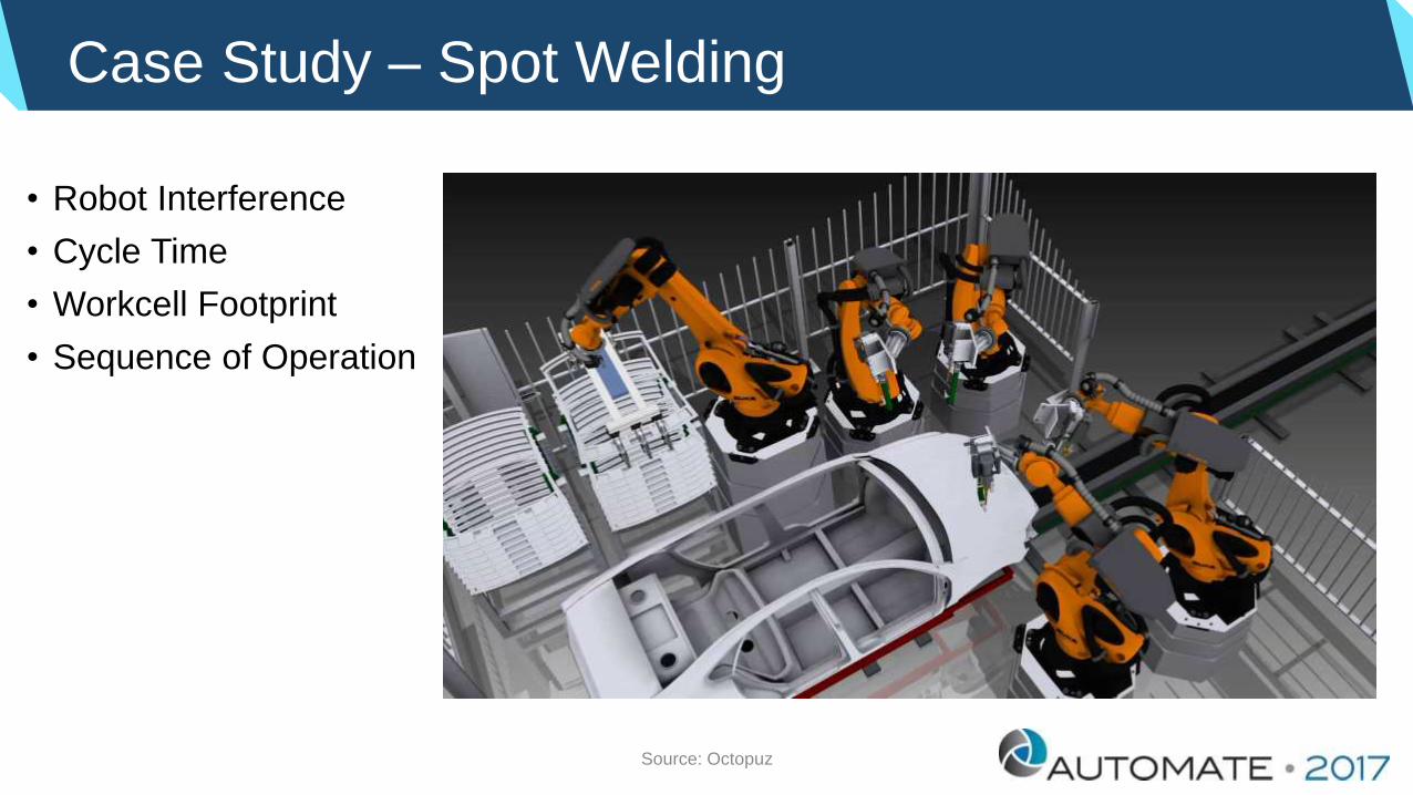
Case Study – Spot Welding
• Robot Interference
• Cycle Time
• Workcell Footprint
• Sequence of Operation
Source: Octopuz

Case Study – Spot / Arc Welding Workcell
• Tooling Clearance
• Robot Clearance
• Cycle Time
• Workcell Footprint
• Sequence of Operation
Source: Octopuz

Custom Simulation Package For Arc Welding
Circular
motion
Linear
motion
Approach
pointRetreat
point
Welding line
Push angleWork angle
Avoid Collisions
Source: FANUC Robotics

Case Study – Arc Welding
• Coordinate Reach With Positioner
• Verify Ability To Reach All Weld Points
• Check Weld Position at Each Seam
• Cycle Time
Source: FANUC Robotics

Case Study – Arc Welding
• Coordinate Reach With Positioner
• Verify Ability To Reach All Weld Points
• Check Weld Position at Each Seam
• Confirm Operator Safety During Unload / Load
• Cycle Time
Source: FANUC Robotics

Custom Simulation Package For Palletizing
4. Generate palletizing Teach Pendant programs
2. Specify the transportation relationship between
each conveyor and each pallet
3. Specify the work required on each conveyor
Conveyor1
Conveyor2
Conveyor3
Pallet-Station2
Pallet-Station3
Work Dimensions
1. Specify the dimensions of the
work and the palletizing
pattern
Pallet-Station1
Source: FANUC Robotics

Case Study - Palletizing
• Multi-Function EOAT• Slipsheets
• Bags
• Equipment Location
• Footprint Optimization
• Sequence of Operation
Source: FANUC Robotics

Case Study - Palletizing
• Multi-Function EOAT• Pallet
• Pails
• Cases (2 Orientations)
• Equipment Location
• Footprint Optimization
• Sequence of Operation

Case Study – High Speed Picking
1. Parallel flow(Life is good at steady state.)
Source: FANUC Robotics

Case Study – High Speed Picking
2. Infeed speed/density(Slower & denser is better.)
Source: FANUC Robotics

Case Study – High Speed Picking
3. Boundaries settings(When they’re good, they’regood. When they’re bad….)
Source: FANUC Robotics

Case Study – High Speed Picking
4. Variable flow(This is the real world.)
Source: FANUC Robotics

Case Study – High Speed Picking
5. Conveyor Stop(Control your destiny.)
Source: FANUC Robotics

Case Study – High Speed Picking
6. De-coupling(Do it if you can.)
Source: FANUC Robotics

Case Study – High Speed Picking
7. Counter Flow(It’s not the silver bullet.)
Source: FANUC Robotics

Case Study – High Speed Picking
• Robot Position
• Conveyor Height and Position
• Conveyor Speed
• Number of Robots Required to Maintain Production Rate

Custom Simulation Package For Material Removal
Placement of the device’s models
Library
CAD Data
Selection of a chamfering line
Rotate Tooling to
avoid collision
Specify Tool Rotation Simulation
Definition of a workcell
Generate Program with
Collision Avoidance
Source: FANUC Robotics

Case Study – Material Removal
• Process To Part
• Cycle Time
• CAD-To-Path
• Orientation of Deburr Spindle Relative To Part

Case Study – Material Removal
• Part to Process
• Cycle Time• Need For Two Robots
• Minimize Footprint
• Prevent Robot Interference

Benefits of Robot Simulation Software
• Quickly Test Numerous Options With Simulation Software.
• Qualify Applications Faster And More Accurately Than With Manual Methods.
• Validate Robot Applications Without Acquiring Costly Equipment.
• Validate Robot Applications Without Time Consuming WorkcellSet Up.
• Perform “What If” Analysis of Installed Robotic Systems With No Down Time.

Use of Simulation When Things Go Wrong
Spot Welder OperationManual Load/Unload

Spot Welding - Simulation

Spot Welding - Installation
Simulated 20kg Robot
Selected 50kg Robot

Typical Features of Process Line Simulation Software
• Beyond The VRC (Virtual Robot Controller)• Replicate and test complex mechanical systems.
• Control the simulation using an actual PLC logic simulation.
• Optimize part-handling operations.
• Analyze component usage to easily find bottlenecks before the cell is ever built.
• Visualize the shop floor process from start to finish.
• Setup I/O communication between components.
Source: Octopuz

Process Line Simulation
• Robotic Case Packing
• Case Recirculation
• Tote Box Conveying
• Pallet Feeding
• Gantry Palletizer
Source: Octopuz

Benefits of Process Line Simulation Software
• Reduced Cost of Change With Early Detection of Product and Process Design Issues.
• Reduced Number of Physical Prototypes Through Virtual Validation.
• Optimized Cycle Times Through Simulation.
• Virtual Validation of Both Mechanical and Electrical (PLC and Robotics) System Components and Processes
Source: plm.automation.siemens.com

The Future of Robot Simulation
• More Specialized Application Tools• Spot Welding
• Arc Welding
• Palletizing
• Picking
• Painting
• Material Removal
• Improved CAD-to-Path
• Recent Enhancements• Modeling of Robot Dress-Out
• Safety
• Ergonomic Considerations

Robot Simulation – Summary
• Powerful• More Features Being Developed
• Improved Ease of Use
• Remote Program Editing
• Has Moved Beyond Path and Cycle Time• Payload / Moment Check
• Interference
• Duty Cycle
• Robot Life Cycle Estimate
• Broader Perspective: Look At Entire Process Line
• Cost Effective Tool

Test The System With The Model!

Robot Simulation – Doesn’t Crash The Robot!

Contact Information
Charles C. Gales, P.E.Manager, Automation Sales
Weldon Solutions425 East Berlin Road
York, PA 17608
USA
Telephone: 717-846-4000
Email: [email protected]
www.weldonsolutions.com


