
Chapter 6
ESC – Electronic Safety Circuit Table of contents 1. ESC – Electronic Safety Circuit.........................................................3
2. Fault detection ESC ........................................................................15
3. X11 Jumper plug.............................................................................21
4. ESC Gateway .................................................................................23
5. Wiring diagrams ESC......................................................................31

Page 2 of 32 Workbook SE KR C2 edition2005 01.06.00
Workbook SE KR C2 edition2005 01.06.00 Page 3 of 32
1. ESC – Electronic Safety Circuit

Page 4 of 32 Workbook SE KR C2 edition2005 01.06.00
I 31.01.2006 I College I NoLi I 1KUKA Roboter GmbH, Hery-Park 3000, D-86368 Gersthofen, Tel.: +49 (0) 8 21/45 33-1906, Fax: +49 (0) 8 21/45 33-2340, http://www.kuka.com© Copyright by KUKA Roboter GmbH College
Electronic Safety Circuit (ESC)
KCP ESC master
ESC board
MFCpassive node
KPS600
The Electronic Safety Circuit (ESC) is a dual-channel, computer-aided safetysystem, that functions with a closed ring bus.
The ESC devices are nodes that are connected to each other via power supply and communication lines.
I 31.01.2006 I College I NoLi I 2KUKA Roboter GmbH, Hery-Park 3000, D-86368 Gersthofen, Tel.: +49 (0) 8 21/45 33-1906, Fax: +49 (0) 8 21/45 33-2340, http://www.kuka.com© Copyright by KUKA Roboter GmbH College
ESC circuit nodes
ESCChip A
ESCChip B
LNAENAZS1ZS2BA (A)QEE2BSAF
Local E-StopExternal E-StopEnabling switchEn. switch (panic)AutomaticQualifying inputSpecial keyswitchOperator safetyEnable drives
Local E-StopExternal E-StopEnabling switchEn. switch (panic)TestQualifying inputSpecial keyswitchOperator safetyActivate drives
LNAENAZS1ZS2BA (T)QEE2BSAA
ESC IN ESC OUT
TA (A) Test output Test output TA (B)
LNA
AE
BA
(A) LNA=Local Emergency Stop
AE=Drives OnBA=Operating mode
Outputs
Inpu
ts
Inpu
ts
LNA
AE BA
(T)

Workbook SE KR C2 edition2005 01.06.00 Page 5 of 32
I 31.01.2006 I College I NoLi I 3KUKA Roboter GmbH, Hery-Park 3000, D-86368 Gersthofen, Tel.: +49 (0) 8 21/45 33-1906, Fax: +49 (0) 8 21/45 33-2340, http://www.kuka.com© Copyright by KUKA Roboter GmbH College
ESC nodes, inputs and outputs
NA Local Emergency StopENA External Emergency StopZS1 Enabling switchZS2 Enabling, panic positionBA Operating mode (Test / Auto) QE Qualifying input (loading stations, range limitation)BS Operator safety (safety gates)
AA Activate drives (Drives ON)AF Drives enable (Drives OFF)
Failsafe inputs
Controller inputs
Failsafe outputsAE Drives ON (drives contactor)LNA Local Emergency StopBA Operating mode (Test / Auto)
I 31.01.2006 I College I NoLi I 4KUKA Roboter GmbH, Hery-Park 3000, D-86368 Gersthofen, Tel.: +49 (0) 8 21/45 33-1906, Fax: +49 (0) 8 21/45 33-2340, http://www.kuka.com© Copyright by KUKA Roboter GmbH College
Errors recognized by the ESC circuit
x Cross-connection between the two channels of an input signal
x Cross-connection between one input channel and the supply voltage
x Communication error (e.g. bus cable discontinuity)
x Hardware fault (e.g. defective relay contacts of the failsafe outputs)
x Defective ESC chip
Page 6 of 32 Workbook SE KR C2 edition2005 01.06.00
I 31.01.2006 I College I NoLi I 5KUKA Roboter GmbH, Hery-Park 3000, D-86368 Gersthofen, Tel.: +49 (0) 8 21/45 33-1906, Fax: +49 (0) 8 21/45 33-2340, http://www.kuka.com© Copyright by KUKA Roboter GmbH College
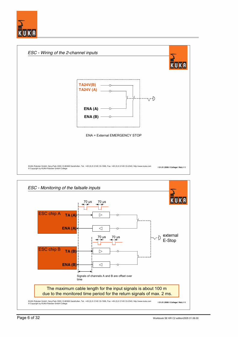
ESC - Wiring of the 2-channel inputs
ENA = External EMERGENCY STOP
TA24V(B)
ENA (A)
ENA (B)
TA24V (A)
I 31.01.2006 I College I NoLi I 6KUKA Roboter GmbH, Hery-Park 3000, D-86368 Gersthofen, Tel.: +49 (0) 8 21/45 33-1906, Fax: +49 (0) 8 21/45 33-2340, http://www.kuka.com© Copyright by KUKA Roboter GmbH College
ESC - Monitoring of the failsafe inputs
The maximum cable length for the input signals is about 100 mdue to the monitored time period for the return signals of max. 2 ms.
ENA (B)
TA (B)
ENA (A)
TA (A)ESC chip A
ESC chip B
externalE-Stop
70 µs 70 µs
70 µs 70 µs
Signals of channels A and B are offset over time

Workbook SE KR C2 edition2005 01.06.00 Page 7 of 32
I 31.01.2006 I College I NoLi I 7KUKA Roboter GmbH, Hery-Park 3000, D-86368 Gersthofen, Tel.: +49 (0) 8 21/45 33-1906, Fax: +49 (0) 8 21/45 33-2340, http://www.kuka.com© Copyright by KUKA Roboter GmbH College
ESC - Monitoring of the failsafe outputs
Each ESC chip sends a bit pattern to its outputs and compares the return signals with this pattern.
Comparison
Comparison
ESC chip A
ESC chip BRelay, e.g. LNA
70 µs 70 µs
70 µs 70 µs
I 31.01.2006 I College I NoLi I 8KUKA Roboter GmbH, Hery-Park 3000, D-86368 Gersthofen, Tel.: +49 (0) 8 21/45 33-1906, Fax: +49 (0) 8 21/45 33-2340, http://www.kuka.com© Copyright by KUKA Roboter GmbH College
ESC board variants
For the KR C2edition2005, different ESC boards can be installed for a variety of configurations and in accordance withcustomer requirements.
The assignment of the individual connectors, relays and fuses remains the same, however.
The fuses are rated for up to 35 V. On the boards there is a redLED for each fuse, which lights up if the fuse is defective.
•CI3 Standard ESC board without node
•CI3 Extended ESC board with node
•CI3 Bus ESC board for connection to SafetyBus p
•CI3 Tech ESC board for RoboTeam, shared pendant, SafeRobot
The following variants of the ESC boards are in use:
Page 8 of 32 Workbook SE KR C2 edition2005 01.06.00
I 31.01.2006 I College I NoLi I 9KUKA Roboter GmbH, Hery-Park 3000, D-86368 Gersthofen, Tel.: +49 (0) 8 21/45 33-1906, Fax: +49 (0) 8 21/45 33-2340, http://www.kuka.com© Copyright by KUKA Roboter GmbH College
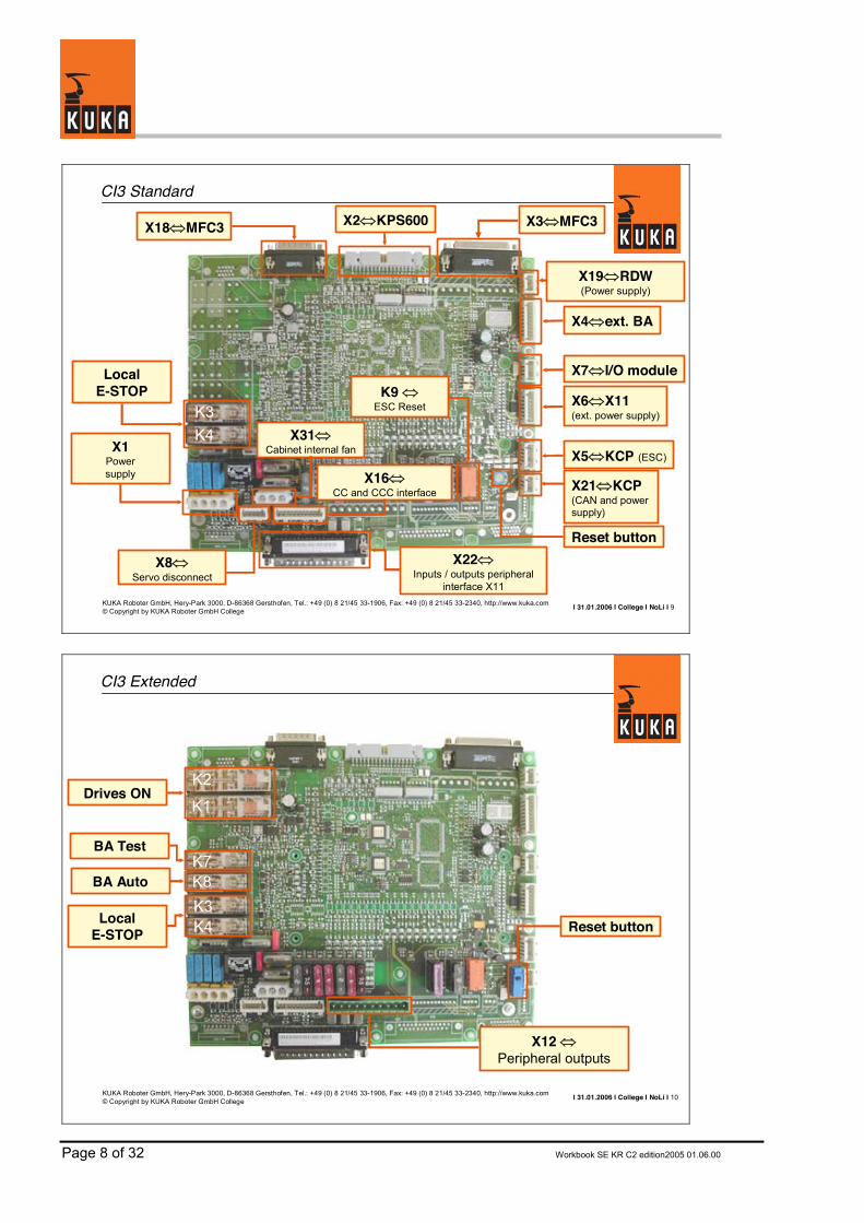
CI3 Standard
K3K4
LocalE-STOP
X2�KPS600 X3�MFC3
X1Power supply
X4�ext. BA
X7�I/O module
X6�X11(ext. power supply)
X5�KCP (ESC)
X21�KCP(CAN and powersupply)
X22�Inputs / outputs peripheral
interface X11
X31�Cabinet internal fan
X8�Servo disconnect
Reset button
K9 �ESC Reset
X18�MFC3
X19�RDW(Power supply)
X16�CC and CCC interface
I 31.01.2006 I College I NoLi I 10KUKA Roboter GmbH, Hery-Park 3000, D-86368 Gersthofen, Tel.: +49 (0) 8 21/45 33-1906, Fax: +49 (0) 8 21/45 33-2340, http://www.kuka.com© Copyright by KUKA Roboter GmbH College
CI3 Extended
K1
K2Drives ON
K8BA AutoK7
BA Test
K3K4Local
E-STOP
X12 �Peripheral outputs
Reset button
Workbook SE KR C2 edition2005 01.06.00 Page 9 of 32
I 31.01.2006 I College I NoLi I 11KUKA Roboter GmbH, Hery-Park 3000, D-86368 Gersthofen, Tel.: +49 (0) 8 21/45 33-1906, Fax: +49 (0) 8 21/45 33-2340, http://www.kuka.com© Copyright by KUKA Roboter GmbH College
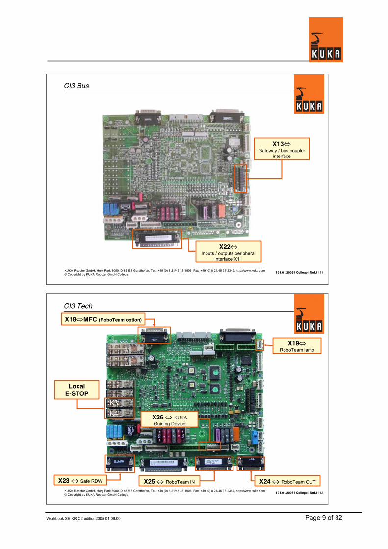
CI3 Bus
X22�Inputs / outputs peripheral
interface X11
X13�Gateway / bus coupler
interface
I 31.01.2006 I College I NoLi I 12KUKA Roboter GmbH, Hery-Park 3000, D-86368 Gersthofen, Tel.: +49 (0) 8 21/45 33-1906, Fax: +49 (0) 8 21/45 33-2340, http://www.kuka.com© Copyright by KUKA Roboter GmbH College
CI3 Tech
X19�RoboTeam lamp
X23 � Safe RDW X25 � RoboTeam IN X24 � RoboTeam OUT
X26 � KUKA Guiding Device
X18�MFC (RoboTeam option)
K3K4
LocalE-STOP

Page 10 of 32 Workbook SE KR C2 edition2005 01.06.00
I 31.01.2006 I College I NoLi I 13KUKA Roboter GmbH, Hery-Park 3000, D-86368 Gersthofen, Tel.: +49 (0) 8 21/45 33-1906, Fax: +49 (0) 8 21/45 33-2340, http://www.kuka.com© Copyright by KUKA Roboter GmbH College
CI3 board interface assignment - Part 1
Servo Disconnect, E-STOP from KGD (optional)X8
Interface to MFC3, ESC Reset, fan monitoring, RoboTeam (optional)X18
Control and return signals for external main contactor (optional)X17
Interface for CC (Cobra Control) and CCC (Common Control Cabinet)X16
E7 special keyswitch (VW option), RoboTeam test outputsX11
Customer interface X11, outputs: internal E-Stop, operating mode, Drives ON X12
Jumper / interface to other safety bus systemsX13
User I/Os to peripheral interface, 16 inputs / 20 outputs via CAN bus (optional)X7
Customer interface X11, internal / external power supplyX6
KCP, ESC busX5
Inputs to the MFC3, stationary operating mode switchX4
Connection to MFC3 via Connector PrintX3
Ribbon cable to KPS 600X2
Power supply with/without battery backupX1
AssignmentInterface
I 31.01.2006 I College I NoLi I 14KUKA Roboter GmbH, Hery-Park 3000, D-86368 Gersthofen, Tel.: +49 (0) 8 21/45 33-1906, Fax: +49 (0) 8 21/45 33-2340, http://www.kuka.com© Copyright by KUKA Roboter GmbH College
CI3 board interface assignment - Part 2
Interface to lamp for RoboTeam (optional)X19
Internal cabinet fan connectionX31
Ext. ESC reset relayX30
MultiPowerTap MPT DeviceNet OUT2X29
KUKA Guiding Device KGD interface (optional)X26
MultiPowerTap MPT DeviceNet from MFC3X27
MultiPowerTap MPT DeviceNet OUT1X28
RoboTeam functionalitiesX25
RoboTeam functionalitiesX24
Interface to SafeRDC (optional)X23
Connection to customer interface X11, inputs: ENA, BS, ext. enablingX22
Interface to KCP, CAN bus and buffered 27 V power supplyX21
Selection Switch on Shared Pendant (RoboTeam option)X20
AssignmentInterface

Workbook SE KR C2 edition2005 01.06.00 Page 11 of 32
I 31.01.2006 I College I NoLi I 15KUKA Roboter GmbH, Hery-Park 3000, D-86368 Gersthofen, Tel.: +49 (0) 8 21/45 33-1906, Fax: +49 (0) 8 21/45 33-2340, http://www.kuka.com© Copyright by KUKA Roboter GmbH College
CI3 board assignment of fuses
Power supply, contactor control AE2 AF3
F24
F23
F21F16
F15
F14
F13
F12
F10
F2
F1
Fuse
Supply, multipower tap MPT2 A
RDC supply2 A
Output AE7.5 A
27 V without battery backup at X127.5 ARoboTeam lamp (optional)2 A
Output AE4 A
27 V without battery backup at X6 for internal ESC supply 4 A
27 V without battery backup at X124 A
Power supply, ESC circuit3 A
Cabinet fan monitoring2 A
AE output at X122 A
FunctionValue
I 31.01.2006 I College I NoLi I 16KUKA Roboter GmbH, Hery-Park 3000, D-86368 Gersthofen, Tel.: +49 (0) 8 21/45 33-1906, Fax: +49 (0) 8 21/45 33-2340, http://www.kuka.com© Copyright by KUKA Roboter GmbH College
CI3 board relay functionality
Local Emergency StopK3
K9
K8
K7
K4
K2
K1Relay
ESC ResetOperating mode TEST / AUTO
Operating mode TEST / AUTO
Local Emergency Stop
Drives ON
Drives ONFunction

Page 12 of 32 Workbook SE KR C2 edition2005 01.06.00
I 31.01.2006 I College I NoLi I 17KUKA Roboter GmbH, Hery-Park 3000, D-86368 Gersthofen, Tel.: +49 (0) 8 21/45 33-1906, Fax: +49 (0) 8 21/45 33-2340, http://www.kuka.com© Copyright by KUKA Roboter GmbH College
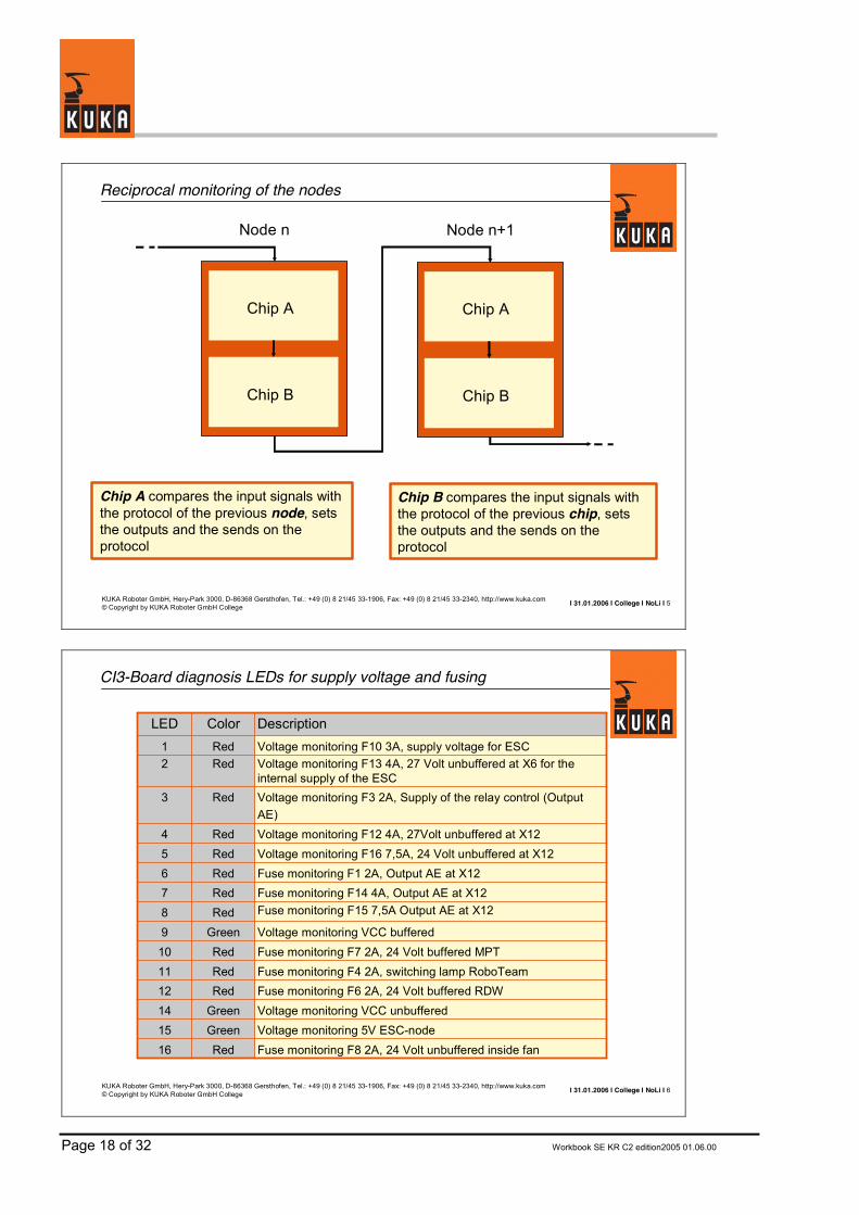
CI3-Board diagnosis LEDs for supply voltage and fusing
Fuse monitoring F6 2A, 24 Volt buffered RDW Red12Voltage monitoring VCC unbufferedGreen14
1615
1110987654
3
21
LEDVoltage monitoring F10 3A, supply voltage for ESCRed
Fuse monitoring F8 2A, 24 Volt unbuffered inside fanRedVoltage monitoring 5V ESC-nodeGreen
Fuse monitoring F4 2A, switching lamp RoboTeamRed
Fuse monitoring F15 7,5A Output AE at X12 RedVoltage monitoring VCC bufferedGreenFuse monitoring F7 2A, 24 Volt buffered MPT Red
Fuse monitoring F14 4A, Output AE at X12 RedFuse monitoring F1 2A, Output AE at X12 RedVoltage monitoring F16 7,5A, 24 Volt unbuffered at X12 RedVoltage monitoring F12 4A, 27Volt unbuffered at X12 Red
Voltage monitoring F3 2A, Supply of the relay control (Output AE)
Red
Voltage monitoring F13 4A, 27 Volt unbuffered at X6 for theinternal supply of the ESC
Red
DescriptionColor
I 31.01.2006 I College I NoLi I 18KUKA Roboter GmbH, Hery-Park 3000, D-86368 Gersthofen, Tel.: +49 (0) 8 21/45 33-1906, Fax: +49 (0) 8 21/45 33-2340, http://www.kuka.com© Copyright by KUKA Roboter GmbH College
CI3-Board diagnosis LEDs for ESC-nodes (Low-level-diagnosis)
ESC-Output MFC OKGreen28Voltage monitoring 3,3 Volt for RoboTeam PLDsGreen29
2726252423222120191817
LEDESC-Output KCP OKGreen
ESC-Output MFC NOKRed
ESC-Output Safetybus Gateway OKGreenESC-Output X6 OKGreenESC-Output X6 NOKRed
ESC-Output Safetybus Gateway NOKRedESC-Output local ESC node NOKRedESC-Output local ESC node OKGreenESC-Output KPS OKGreenESC-Output KPS NOKRedESC-Output KCP NOKRed
DescriptionColor
Workbook SE KR C2 edition2005 01.06.00 Page 13 of 32
I 31.01.2006 I College I NoLi I 19KUKA Roboter GmbH, Hery-Park 3000, D-86368 Gersthofen, Tel.: +49 (0) 8 21/45 33-1906, Fax: +49 (0) 8 21/45 33-2340, http://www.kuka.com© Copyright by KUKA Roboter GmbH College
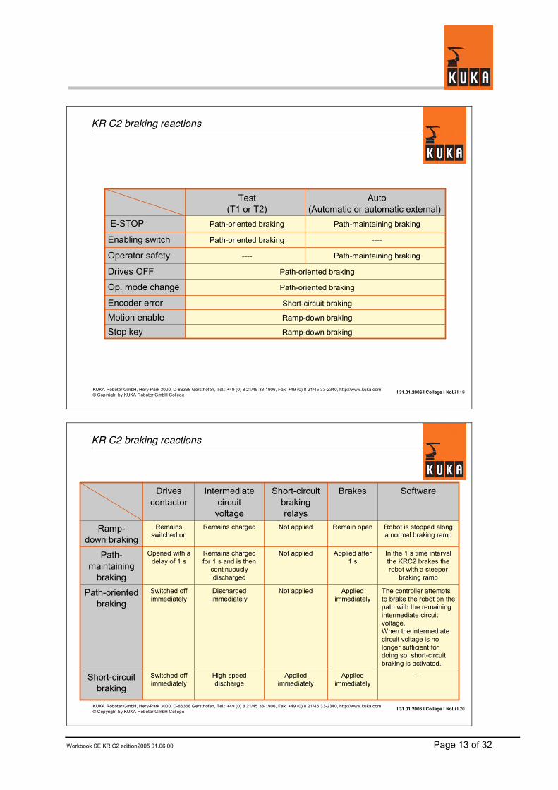
KR C2 braking reactions
Short-circuit brakingEncoder errorRamp-down brakingMotion enableRamp-down braking
Path-oriented braking
Path-oriented braking
----
Path-oriented braking
Path-oriented braking
Test (T1 or T2)
Path-maintaining brakingOperator safety
Drives OFF
Op. mode change
Stop key
----Enabling switch
Path-maintaining brakingE-STOP
Auto (Automatic or automatic external)
I 31.01.2006 I College I NoLi I 20KUKA Roboter GmbH, Hery-Park 3000, D-86368 Gersthofen, Tel.: +49 (0) 8 21/45 33-1906, Fax: +49 (0) 8 21/45 33-2340, http://www.kuka.com© Copyright by KUKA Roboter GmbH College
KR C2 braking reactions
----Appliedimmediately
Appliedimmediately
High-speeddischarge
Switched off immediately
Short-circuitbraking
The controller attempts to brake the robot on the path with the remaining intermediate circuit voltage.When the intermediate circuit voltage is no longer sufficient for doing so, short-circuit braking is activated.
Appliedimmediately
Not appliedDischargedimmediately
Switched off immediately
Path-orientedbraking
In the 1 s time interval the KRC2 brakes the robot with a steeper
braking ramp
Applied after1 s
Not appliedRemains charged for 1 s and is then
continuously discharged
Opened with a delay of 1 s
Path-maintaining
braking
Robot is stopped along a normal braking ramp
Remain openNot appliedRemains chargedRemainsswitched on
Ramp-down braking
SoftwareBrakesShort-circuitbrakingrelays
Intermediatecircuit
voltage
Drives contactor

Page 14 of 32 Workbook SE KR C2 edition2005 01.06.00

Workbook SE KR C2 edition2005 01.06.00 Page 15 of 32
2. Fault detection ESC
Page 16 of 32 Workbook SE KR C2 edition2005 01.06.00
I 31.01.2006 I College I NoLi I 1KUKA Roboter GmbH, Hery-Park 3000, D-86368 Gersthofen, Tel.: +49 (0) 8 21/45 33-1906, Fax: +49 (0) 8 21/45 33-2340, http://www.kuka.com© Copyright by KUKA Roboter GmbH College
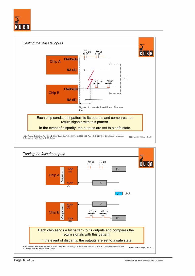
Testing the failsafe inputs
Each chip sends a bit pattern to its outputs and compares the return signals with this pattern.
In the event of disparity, the outputs are set to a safe state.
Chip B
NA (B)
Chip A
NA (A)
TA24V(A)
TA24V(B)
70 µs 70 µs
70 µs 70 µs
Signals of channels A and B are offset over time
I 31.01.2006 I College I NoLi I 2KUKA Roboter GmbH, Hery-Park 3000, D-86368 Gersthofen, Tel.: +49 (0) 8 21/45 33-1906, Fax: +49 (0) 8 21/45 33-2340, http://www.kuka.com© Copyright by KUKA Roboter GmbH College
Testing the failsafe outputs
Each chip sends a bit pattern to its outputs and compares the return signals with this pattern.
In the event of disparity, the outputs are set to a safe state.
70 µs 70 µs
LNA
Com
paris
on
Chip A
LNA (A)
RLNA (A)
Com
paris
on
Chip BLNA (B)
RLNA (B)
70 µs 70 µs

Workbook SE KR C2 edition2005 01.06.00 Page 17 of 32
I 31.01.2006 I College I NoLi I 3KUKA Roboter GmbH, Hery-Park 3000, D-86368 Gersthofen, Tel.: +49 (0) 8 21/45 33-1906, Fax: +49 (0) 8 21/45 33-2340, http://www.kuka.com© Copyright by KUKA Roboter GmbH College
Drives contactor return signal
Each chip compares the state of the outputs with the state of the return signals. In the event of disparity, the outputs are set to a safe state.
70 µs 70 µs
K1
Com
paris
onChip A
AE (A)
RAE (A)C
ompa
risonChip B
AE (B)
RAE (B)
70 µs 70 µs
24 V
RAE2(A)
I 31.01.2006 I College I NoLi I 4KUKA Roboter GmbH, Hery-Park 3000, D-86368 Gersthofen, Tel.: +49 (0) 8 21/45 33-1906, Fax: +49 (0) 8 21/45 33-2340, http://www.kuka.com© Copyright by KUKA Roboter GmbH College
Relay test
The signal sent from the TA must be applied once more to the input of the RREL (return relay).
In the event of disparity, the outputs are set to a safe state.
TA5 V (A)
K4K3
LNA TEST
AUTO
RREL
Open = operating mode selected
Page 18 of 32 Workbook SE KR C2 edition2005 01.06.00
I 31.01.2006 I College I NoLi I 5KUKA Roboter GmbH, Hery-Park 3000, D-86368 Gersthofen, Tel.: +49 (0) 8 21/45 33-1906, Fax: +49 (0) 8 21/45 33-2340, http://www.kuka.com© Copyright by KUKA Roboter GmbH College
Reciprocal monitoring of the nodes
Chip A compares the input signals with the protocol of the previous node, sets the outputs and the sends on the protocol
Chip B compares the input signals with the protocol of the previous chip, sets the outputs and the sends on the protocol
Node n
Chip A
Chip B
Node n+1
Chip A
Chip B
I 31.01.2006 I College I NoLi I 6KUKA Roboter GmbH, Hery-Park 3000, D-86368 Gersthofen, Tel.: +49 (0) 8 21/45 33-1906, Fax: +49 (0) 8 21/45 33-2340, http://www.kuka.com© Copyright by KUKA Roboter GmbH College
CI3-Board diagnosis LEDs for supply voltage and fusing
Fuse monitoring F6 2A, 24 Volt buffered RDW Red12Voltage monitoring VCC unbufferedGreen14
1615
1110987654
3
21
LEDVoltage monitoring F10 3A, supply voltage for ESCRed
Fuse monitoring F8 2A, 24 Volt unbuffered inside fanRedVoltage monitoring 5V ESC-nodeGreen
Fuse monitoring F4 2A, switching lamp RoboTeamRed
Fuse monitoring F15 7,5A Output AE at X12 RedVoltage monitoring VCC bufferedGreenFuse monitoring F7 2A, 24 Volt buffered MPT Red
Fuse monitoring F14 4A, Output AE at X12 RedFuse monitoring F1 2A, Output AE at X12 RedVoltage monitoring F16 7,5A, 24 Volt unbuffered at X12 RedVoltage monitoring F12 4A, 27Volt unbuffered at X12 Red
Voltage monitoring F3 2A, Supply of the relay control (Output AE)
Red
Voltage monitoring F13 4A, 27 Volt unbuffered at X6 for theinternal supply of the ESC
Red
DescriptionColor

Workbook SE KR C2 edition2005 01.06.00 Page 19 of 32
I 31.01.2006 I College I NoLi I 7KUKA Roboter GmbH, Hery-Park 3000, D-86368 Gersthofen, Tel.: +49 (0) 8 21/45 33-1906, Fax: +49 (0) 8 21/45 33-2340, http://www.kuka.com© Copyright by KUKA Roboter GmbH College
CI3-Board diagnosis LEDs for ESC-nodes (Low-level-diagnosis)
ESC-Output MFC OKGreen28Voltage monitoring 3,3 Volt for RoboTeam PLDsGreen29
2726252423222120191817
LEDESC-Output KCP OKGreen
ESC-Output MFC NOKRed
ESC-Output Safetybus Gateway OKGreenESC-Output X6 OKGreenESC-Output X6 NOKRed
ESC-Output Safetybus Gateway NOKRedESC-Output local ESC node NOKRedESC-Output local ESC node OKGreenESC-Output KPS OKGreenESC-Output KPS NOKRedESC-Output KCP NOKRed
DescriptionColor

Page 20 of 32 Workbook SE KR C2 edition2005 01.06.00
Workbook SE KR C2 edition2005 01.06.00 Page 21 of 32
3. X11 Jumper plug
Page 22 of 32 Workbook SE KR C2 edition2005 01.06.00
I 02.02.2006 I College I NoLi I 1KUKA Roboter GmbH, Hery-Park 3000, D-86368 Gersthofen, Tel.: +49 (0) 8 21/45 33-1906, Fax: +49 (0) 8 21/45 33-2340, http://www.kuka.com© Copyright by KUKA Roboter GmbH College
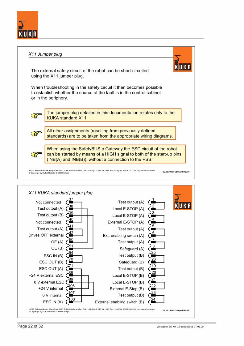
X11 Jumper plug
The external safety circuit of the robot can be short-circuited using the X11 jumper plug.
When troubleshooting in the safety circuit it then becomes possible to establish whether the source of the fault is in the control cabinet or in the periphery.
The jumper plug detailed in this documentation relates only to the KUKA standard X11.
All other assignments (resulting from previously defined standards) are to be taken from the appropriate wiring diagrams.
When using the SafetyBUS p Gateway the ESC circuit of the robot can be started by means of a HIGH signal to both of the start-up pins (INB(A) and INB(B)), without a connection to the PSS.
I 02.02.2006 I College I NoLi I 2KUKA Roboter GmbH, Hery-Park 3000, D-86368 Gersthofen, Tel.: +49 (0) 8 21/45 33-1906, Fax: +49 (0) 8 21/45 33-2340, http://www.kuka.com© Copyright by KUKA Roboter GmbH College
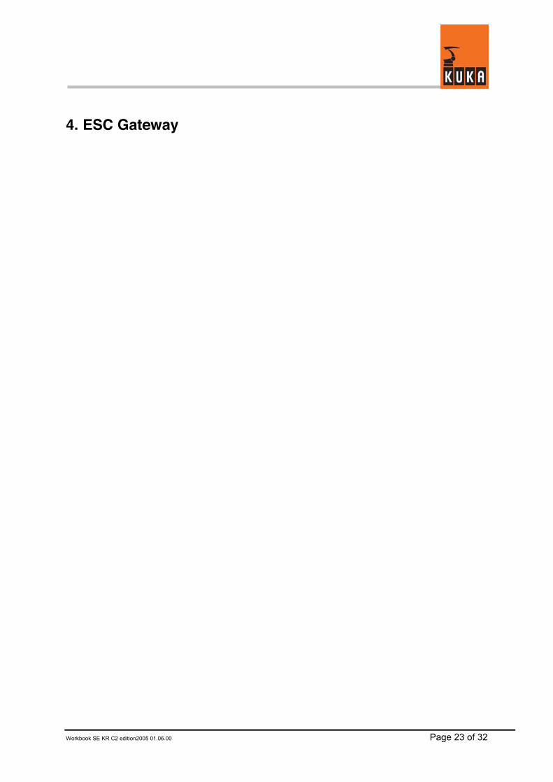
X11 KUKA standard jumper plug
Test output (A)
Local E-STOP (A)
Local E-STOP (A)External E-STOP (A)
Test output (A)Ext. enabling switch (A)
Test output (A)
Safeguard (A)
ESC IN (B)Safeguard (B)
Test output (B)
Local E-STOP (B)
Local E-STOP (B)External E-Stop (B)
Test output (B)
External enabling switch (B)
2
34
5
6
7
825
26
1920
21
22
23
24
Not connected
Test output (A)Drives OFF external
Test output (B)
ESC OUT (B)
ESC OUT (A)
+24 V external ESC
0 V external ESC+24 V internal
0 V internal
ESC IN (A)
38
3940
4142
50515470
71
88
89106
107108
Not connected
QE (A)QE (B)
Test output (A)Test output (B)
37 1
Workbook SE KR C2 edition2005 01.06.00 Page 23 of 32
4. ESC Gateway
Page 24 of 32 Workbook SE KR C2 edition2005 01.06.00
I 31.01.2006 I College I NoLi I 1KUKA Roboter GmbH, Hery-Park 3000, D-86368 Gersthofen, Tel.: +49 (0) 8 21/45 33-1906, Fax: +49 (0) 8 21/45 33-2340, http://www.kuka.com© Copyright by KUKA Roboter GmbH College
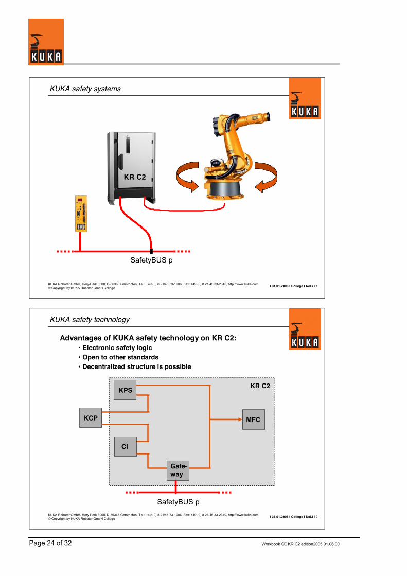
KUKA safety systems
SafetyBUS p
KR C2
I 31.01.2006 I College I NoLi I 2KUKA Roboter GmbH, Hery-Park 3000, D-86368 Gersthofen, Tel.: +49 (0) 8 21/45 33-1906, Fax: +49 (0) 8 21/45 33-2340, http://www.kuka.com© Copyright by KUKA Roboter GmbH College
KUKA safety technology
KPS
CI
KCP MFC
KR C2
Gate-way
SafetyBUS p
Advantages of KUKA safety technology on KR C2:• Electronic safety logic• Open to other standards• Decentralized structure is possible

Workbook SE KR C2 edition2005 01.06.00 Page 25 of 32
I 31.01.2006 I College I NoLi I 3KUKA Roboter GmbH, Hery-Park 3000, D-86368 Gersthofen, Tel.: +49 (0) 8 21/45 33-1906, Fax: +49 (0) 8 21/45 33-2340, http://www.kuka.com© Copyright by KUKA Roboter GmbH College
SafetyBUS p connection
The use of the SafetyBUS p Gateway enables:• Electronic coupling of the ESC circuit to SafetyBUS p• Dual-channel link• Safety category 3
SafetyBUS pGateway
I 31.01.2006 I College I NoLi I 4KUKA Roboter GmbH, Hery-Park 3000, D-86368 Gersthofen, Tel.: +49 (0) 8 21/45 33-1906, Fax: +49 (0) 8 21/45 33-2340, http://www.kuka.com© Copyright by KUKA Roboter GmbH College
SafetyBUS p connection
Field bus I/Os
Robot safety
system (ESC)
PILZ safetycontroller (PSS)
SafetyBUS p
e.g. working rangemonitoring
SafetyBUS p Gateway
Page 26 of 32 Workbook SE KR C2 edition2005 01.06.00
I 31.01.2006 I College I NoLi I 5KUKA Roboter GmbH, Hery-Park 3000, D-86368 Gersthofen, Tel.: +49 (0) 8 21/45 33-1906, Fax: +49 (0) 8 21/45 33-2340, http://www.kuka.com© Copyright by KUKA Roboter GmbH College
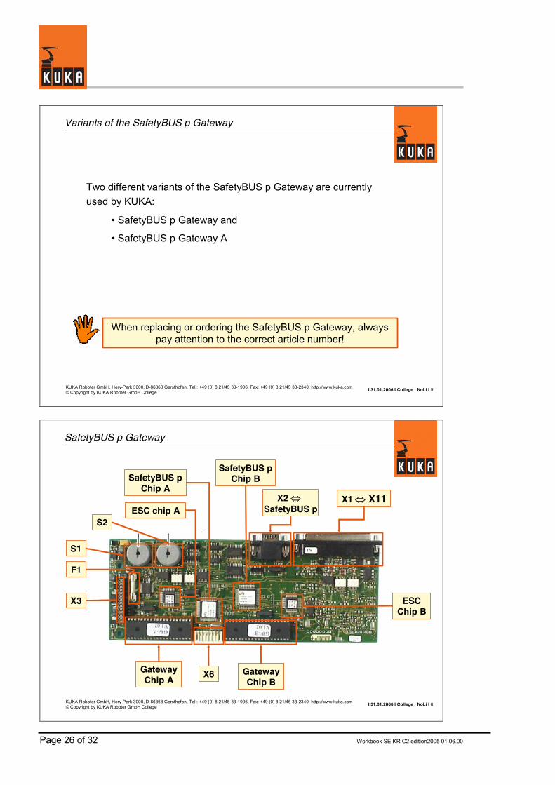
Variants of the SafetyBUS p Gateway
Two different variants of the SafetyBUS p Gateway are currently used by KUKA:
• SafetyBUS p Gateway and
• SafetyBUS p Gateway A
When replacing or ordering the SafetyBUS p Gateway, always pay attention to the correct article number!
I 31.01.2006 I College I NoLi I 6KUKA Roboter GmbH, Hery-Park 3000, D-86368 Gersthofen, Tel.: +49 (0) 8 21/45 33-1906, Fax: +49 (0) 8 21/45 33-2340, http://www.kuka.com© Copyright by KUKA Roboter GmbH College
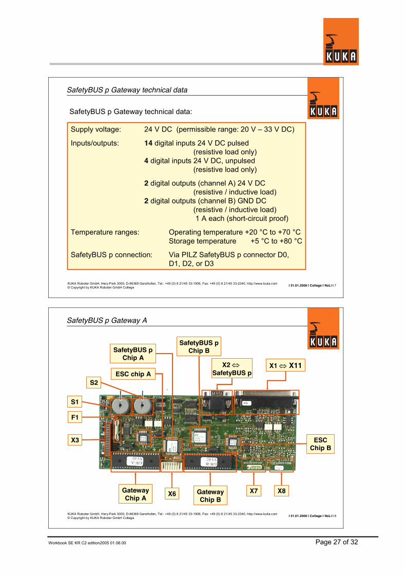
SafetyBUS p Gateway
S1
S2
X1 � X11
X6 GatewayChip B
GatewayChip A
X3
F1
ESCChip B
ESC chip A
SafetyBUS pChip A
SafetyBUS pChip B
X2 �SafetyBUS p
Workbook SE KR C2 edition2005 01.06.00 Page 27 of 32
I 31.01.2006 I College I NoLi I 7KUKA Roboter GmbH, Hery-Park 3000, D-86368 Gersthofen, Tel.: +49 (0) 8 21/45 33-1906, Fax: +49 (0) 8 21/45 33-2340, http://www.kuka.com© Copyright by KUKA Roboter GmbH College
SafetyBUS p Gateway technical data
Supply voltage: 24 V DC (permissible range: 20 V – 33 V DC)
Inputs/outputs: 14 digital inputs 24 V DC pulsed(resistive load only)
4 digital inputs 24 V DC, unpulsed(resistive load only)
2 digital outputs (channel A) 24 V DC(resistive / inductive load)
2 digital outputs (channel B) GND DC(resistive / inductive load)1 A each (short-circuit proof)
Temperature ranges: Operating temperature +20 °C to +70 °CStorage temperature +5 °C to +80 °C
SafetyBUS p connection: Via PILZ SafetyBUS p connector D0, D1, D2, or D3
SafetyBUS p Gateway technical data:
I 31.01.2006 I College I NoLi I 8KUKA Roboter GmbH, Hery-Park 3000, D-86368 Gersthofen, Tel.: +49 (0) 8 21/45 33-1906, Fax: +49 (0) 8 21/45 33-2340, http://www.kuka.com© Copyright by KUKA Roboter GmbH College
SafetyBUS p Gateway A
S1
S2
X1 � X11
X6 GatewayChip B
GatewayChip A
X3
F1
ESCChip B
ESC chip A
SafetyBUS pChip BSafetyBUS p
Chip AX2 �
SafetyBUS p
X7 X8

Page 28 of 32 Workbook SE KR C2 edition2005 01.06.00
I 31.01.2006 I College I NoLi I 9KUKA Roboter GmbH, Hery-Park 3000, D-86368 Gersthofen, Tel.: +49 (0) 8 21/45 33-1906, Fax: +49 (0) 8 21/45 33-2340, http://www.kuka.com© Copyright by KUKA Roboter GmbH College
SafetyBUS p Gateway technical data
Supply voltage: 24 V DC (permissible range: 20 V – 33 V DC)
Inputs/outputs: 16 digital inputs 24 V DC pulsed(resistive load only)
4 digital inputs 24 V DC, unpulsed(resistive load only)
4 digital outputs (channel A) 24 V DC(resistive / inductive load)
4 digital outputs (channel B) GND DC(resistive / inductive load)1 A each (short-circuit proof)
Temperature ranges: Operating temperature +20 °C to +70 °CStorage temperature +5 °C to +80 °C
SafetyBUS p connection: Via PILZ SafetyBUS p connector D0, D1, D2, or D3; 5 V for the supply of the Cu / fiber-optic converters
SafetyBUS p Gateway A technical data:
I 31.01.2006 I College I NoLi I 10KUKA Roboter GmbH, Hery-Park 3000, D-86368 Gersthofen, Tel.: +49 (0) 8 21/45 33-1906, Fax: +49 (0) 8 21/45 33-2340, http://www.kuka.com© Copyright by KUKA Roboter GmbH College
SafetyBUS p Gateway - Interfaces
Connector for wiring output A1 and return signalsX6
Connector for wiring output A2 and return signals X7
Connector for wiring output A3 and return signalsX8
Supply voltage fuse, 2A mTF1
Rotary selector for setting the SafetyBUS p address (units selector)S2
Rotary selector for setting the SafetyBUS p address (tens selector)S1:
Connector to CI bus boardX3:
SafetyBUS p connectionX2:
Peripheral connector inputs and outputsX1:
MeaningDesignation

Workbook SE KR C2 edition2005 01.06.00 Page 29 of 32
I 31.01.2006 I College I NoLi I 11KUKA Roboter GmbH, Hery-Park 3000, D-86368 Gersthofen, Tel.: +49 (0) 8 21/45 33-1906, Fax: +49 (0) 8 21/45 33-2340, http://www.kuka.com© Copyright by KUKA Roboter GmbH College
SafetyBUS p Gateway
Group status, group A (lit = A started)greenLED GR_AH4
Group status, group B (lit = B started)greenLED GR_BH5
Device status (lit = OK, H2 is off)greenLED Device_GH3
Device status (lit = fault, H3 is off)redLED Device_RH2
Status of SafetyBUS p (lit = OK)greenLED BUSH1FunctionColorDesignationLED
S2 S1
SafetyBUS p Gateway with
coverCI busboard
H1...H5
I 31.01.2006 I College I NoLi I 12KUKA Roboter GmbH, Hery-Park 3000, D-86368 Gersthofen, Tel.: +49 (0) 8 21/45 33-1906, Fax: +49 (0) 8 21/45 33-2340, http://www.kuka.com© Copyright by KUKA Roboter GmbH College
Saf
etyB
US
p G
atew
ay
Rob
ot s
afet
ybu
s(E
SC
)
KR C2
SafetyBUS p
BA Operating modeENA External E-StopBS Operator safetyQE Local robot enableE2 Special keyswitch
LNA Local E-STOPRE Robot switched onAE Drives ONBA Operating mode
ZS Enabling switchAF Drives enableAA Activate drivesRES ESC circuit reset
Robot profile in the PSS
SafetyBUS p connection
Page 30 of 32 Workbook SE KR C2 edition2005 01.06.00
I 31.01.2006 I College I NoLi I 13KUKA Roboter GmbH, Hery-Park 3000, D-86368 Gersthofen, Tel.: +49 (0) 8 21/45 33-1906, Fax: +49 (0) 8 21/45 33-2340, http://www.kuka.com© Copyright by KUKA Roboter GmbH College
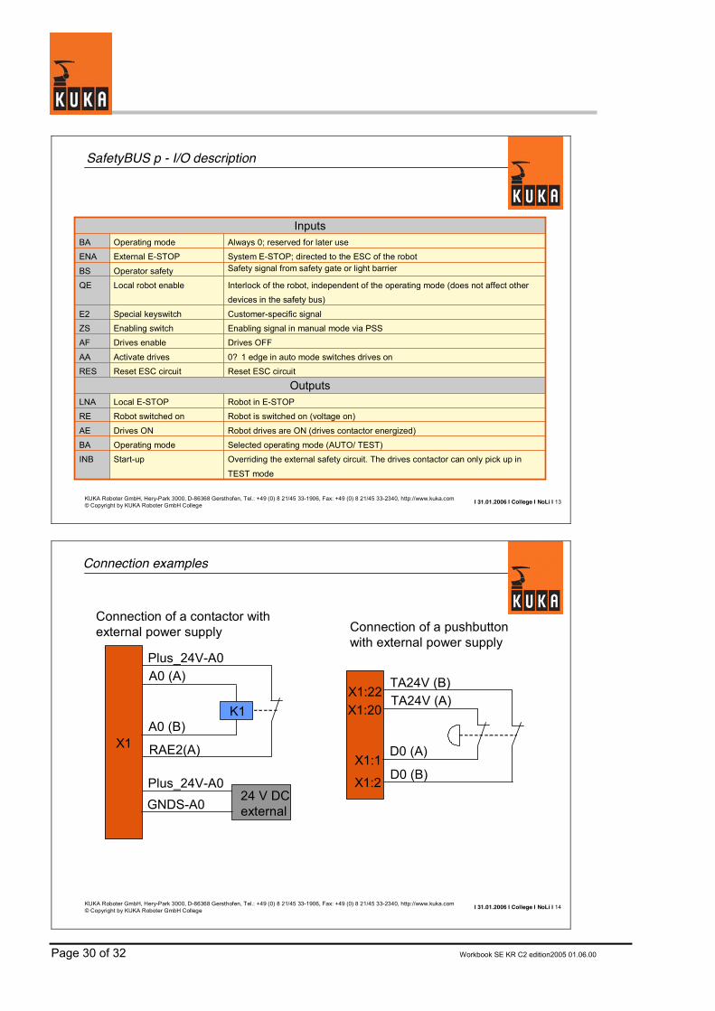
SafetyBUS p - I/O description
Selected operating mode (AUTO/ TEST)Operating modeBA
OutputsReset ESC circuitReset ESC circuitRES
Robot in E-STOPLocal E-STOPLNARobot is switched on (voltage on)Robot switched onRE
Robot drives are ON (drives contactor energized)Drives ONAE
Inputs
Overriding the external safety circuit. The drives contactor can only pick up in
TEST mode
Start-upINB
0? 1 edge in auto mode switches drives onActivate drivesAA
Drives OFFDrives enableAFEnabling signal in manual mode via PSSEnabling switchZSCustomer-specific signalSpecial keyswitchE2
Interlock of the robot, independent of the operating mode (does not affect other devices in the safety bus)
Local robot enableQE
Safety signal from safety gate or light barrierOperator safetyBS
System E-STOP; directed to the ESC of the robotExternal E-STOPENAAlways 0; reserved for later useOperating modeBA
I 31.01.2006 I College I NoLi I 14KUKA Roboter GmbH, Hery-Park 3000, D-86368 Gersthofen, Tel.: +49 (0) 8 21/45 33-1906, Fax: +49 (0) 8 21/45 33-2340, http://www.kuka.com© Copyright by KUKA Roboter GmbH College
Connection examples
K1
24 V DCexternal
Plus_24V-A0A0 (A)
A0 (B)
RAE2(A)
Plus_24V-A0GNDS-A0
X1
TA24V (B)TA24V (A)
D0 (A)
D0 (B)
X1:22X1:20
X1:1
X1:2
Connection of a contactor with external power supply Connection of a pushbutton
with external power supply
Workbook SE KR C2 edition2005 01.06.00 Page 31 of 32
5. Wiring diagrams ESC
Page 32 of 32 Workbook SE KR C2 edition2005 01.06.00

KUKA Roboter GmbH, Hery-Park 3000, D- 86368 Gersthofen, Tel.: +49 (0) 8 21/45 33- 1906, Fax: +49 (0) 8 21/45 33- 2340, http:// www.kuka.com© Copyright by KUKA Roboter GmbH College
Inpu
t 1G
roun
d In
put 1
...4
Inpu
t 2In
put 3
Inpu
t 4
+VC
CG
ND
25 13 12 24 23 11 7 16 17 18 19
ES
C-S
tatu
s-si
gnal
s
+VC
CG
ND
5 6 4 3 2 1
ES
C IN
(B)
ES
C IN
(A)
ESC
OU
T (B
)ES
C O
UT
(A)
RAE2 (A)
AE (A)RAE (A)
RAE2 (B)
AE (B)RAE (B)
LNA (A)RLNA (A)LNA (B)RLNA (B)ENA (A)RENA (A)
ENA (B)RENA (B)AAUTORAUTOATESTRTEST
TA5V (A)TA5V (B)
CI3-Standard
ENA (A)ENA (B)LNA (A)LNA (B)ZS1 (A)ZS1 (B)ZS2 (A)ZS2 (B)BS (A)BS (B)BA AUTOBA TESTQE (A)QE (B)E2 (A)E2 (B)AA AF
E-Stop
Multipoint Enabling
switch
OPM-Selector
Push Button Drives On
Push Button Drives Off
+VC
CG
ND
6 5 4 7 2 1
ES
C IN
(B)
ES
C IN
(A)
ESC
OU
T (B
)ES
C O
UT
(A)
RAE2 (A)
AE (A)RAE (A)
RAE2 (B)
AE (B)RAE (B)
LNA (A)RLNA (A)LNA (B)RLNA (B)ENA (A)RENA (A)
ENA (B)RENA (B)AAUTORAUTOATESTRTEST
TA24V (A)TA24V (B)
ENA (A)ENA (B)LNA (A)LNA (B)ZS1 (A)ZS1 (B)ZS2 (A)ZS2 (B)BS (A)BS (B)
OPM AUTOOPM TEST
QE (A)QE (B)E2 (A)E2 (B)AF(A)AA(B)
24V
K1
31 30 28 29 27
RREL
3 89 10 15 16 2423 17 18 1413 1211 2221 2625 2019
I 14.07.2005 I College I NoLi I 1
X1
1 2 3 4
27V
buf
fere
dG
ND
buf
fere
d
GN
D u
nbuf
fere
d27
V un
buffe
red
1 2 3 4
X6
5 6 7 8 1 2 3 54 6 7 8 109
X4
EN
A (A
)
7
TA (B
)TA
(A)
TA (B
)TA
(A)
TA (B
)TA
(A)
22 4 23 5 24 6 26 8 2725
TA (B
)
21 321 20
EN
A (B
)
ZS1
(B)
ZS1
(A)
9 28
BS
(B)
BS
(A)
10 29
QE
(A)
QE
(B)
11 30
E2 (B
)E2
(A)
12 31
AF(A
)A
A(B)
16 35 17 36
LNA
(A)_
O
LNA
(B)_
O
LNA
(A)_
I
LNA
(B)_
I
K4K3
CI3-
Stan
dard
TA (B
)TA
(A)
TA (B
)TA
(A)
TA (A
)
X22 X8
1 2 3 4 5 6
AF_X
16AF
_X8
NA(
A)_K
GD
NA(
B)_K
GD
NA(
A)
NA(
B)
2A
ESC
OU
T (B
)E
SC O
UT
(A)
+VC
C e
xter
nal
GN
D e
xter
nal
ESC
IN (A
)ES
C IN
(B)
+VC
C in
tern
alG
ND
inte
rnal
4A
2A
X13
Jum
per
1 2 3 4 5 6 7 8 9 10
X16
11 12
27V_
buffe
red
GN
D_b
uffe
red
24V_
IN1_
ES
C24
V_IN
2_E
SC
24V_
OU
T1_E
SC
24V_
OU
T2_E
SC
AF_X
22AF
_X16
24V
_IN
_6_M
FC24
V_I
N_7
_MFC
27V
_unb
uffe
red
GN
D_u
nbuf
fere
d
89 7
ESC
_Res
et_M
FC
AF_
MFC
AF_X
8
K9
OP
M T
est
OP
M T
est
OP
M A
uto
OP
M A
uto
VC
C_C
IIN
_1_2
4VIN
_2_2
4VIN
_3_2
4VIN
_4_2
4V
X3X18X5X2
K3 K4

Inpu
t 1G
roun
d In
put 1
...4
Inpu
t 2In
put 3
Inpu
t 4
+VC
CG
ND
25 13 12 24 23 11 7 16 17 18 19
ES
C-S
tatu
s-si
gnal
s
+VC
CG
ND
5 6 4 3 2 1
ES
C IN
(B)
ES
C IN
(A)
ESC
OU
T (B
)ES
C O
UT
(A)
RAE2 (A)
AE (A)RAE (A)
RAE2 (B)
AE (B)RAE (B)
LNA (A)RLNA (A)LNA (B)RLNA (B)ENA (A)RENA (A)
ENA (B)RENA (B)AAUTORAUTOATESTRTEST
TA5V (A)TA5V (B)
CI3-Extended
ENA (A)ENA (B)LNA (A)LNA (B)ZS1 (A)ZS1 (B)ZS2 (A)ZS2 (B)BS (A)BS (B)
OPM AUTOOPM TESTQE (A)QE (B)E2 (A)E2 (B)AA AF
+VC
CG
ND
6 5 4 7 2 1
ES
C IN
(B)
ES
C IN
(A)
ESC
OU
T (B
)ES
C O
UT
(A)
RAE2 (A)
AE (A)RAE (A)
RAE2 (B)
AE (B)RAE (B)
LNA (A)RLNA (A)LNA (B)RLNA (B)ENA (A)RENA (A)
ENA (B)RENA (B)AAUTORAUTOATESTRTEST
TA24V (A)TA24V (B)
ENA (A)ENA (B)LNA (A)LNA (B)ZS1 (A)ZS1 (B)ZS2 (A)ZS2 (B)BS (A)BS (B)
OPM AUTOOPM TEST
QE (A)QE (B)E2 (A)E2 (B)AF(A)AA(B)
24V
K1
31 30 28 29 27
RREL
3 89 10 15 16 2423 17 18 1413 1211 2221 2625 2019
KUKA Roboter GmbH, Hery-Park 3000, D-86368 Gersthofen, Tel.: +49 (0) 8 21/45 33-1906, Fax: +49 (0) 8 21/45 33-2340, http://www.kuka.com© Copyright by KUKA Roboter GmbH College
I 14.07.2005 I College I NoLi I 1
X1
1 2 3 4
27V
buf
fere
dG
ND
buf
fere
d
GN
D u
nbuf
fere
d27
V un
buffe
red
1 2 3 4
X6
5 6 7 8 1 2 3 54 6 7 8 109
X4
EN
A (A
)
7
TA (B
)TA
(A)
TA (B
)TA
(A)
TA (B
)TA
(A)
22 4 23 5 24 6 26 8 2725
TA (B
)
21 321 20
EN
A (B
)
ZS1
(B)
ZS1
(A)
9 28
BS
(B)
BS
(A)
10 29
QE
(A)
QE
(B)
11 30
E2 (B
)E2
(A)
12 31
AF(A
)A
A(B)
16 35 17 36
LNA
(A)_
O
LNA
(B)_
O
LNA
(A)_
I
LNA
(B)_
I
K4K3
CI3-
Exte
nded
TA (B
)TA
(A)
TA (B
)TA
(A)
TA (A
)
X22 X8
1 2 3 4 5 6
AF_X
16AF
_X8
NA(
A)_K
GD
NA(
B)_K
GD
NA(
A)
NA(
B)
2A
ESC
OU
T (B
)E
SC O
UT
(A)
+VC
C e
xter
nal
GN
D e
xter
nal
ESC
IN (A
)ES
C IN
(B)
+VC
C in
tern
alG
ND
inte
rnal
4A
2A
X13
Jum
per
1 2 3 4 5 6 7 8 9 10
X16
11 12
27V_
buffe
red
GN
D_b
uffe
red
24V_
IN1_
ES
C24
V_IN
2_E
SC
24V_
OU
T1_E
SC
24V_
OU
T2_E
SC
AF_X
22AF
_X16
24V
_IN
_6_M
FC24
V_I
N_7
_MFC
27V
_unb
uffe
red
GN
D_u
nbuf
fere
d
89 7
ESC
_Res
et_M
FC
AF_
MFC
AF_X
8
K9
BA
Tes
tB
A T
est
BA A
uto
BA A
uto
VC
C_C
IIN
_1_2
4VIN
_2_2
4VIN
_3_2
4VIN
_4_2
4V
X3X18X5X2
K3 K4
+VC
CG
ND
ESC
IN (B
)ES
C IN
(A)
ES
C O
UT
(B)
ES
C O
UT
(A)
RAE2 (A)AE (A)RAE (A)
RAE2 (B)AE (B)RAE (B)
LNA (A)RLNA (A)
LNA (B)RLNA (B)
ENA (A)RENA (A)
ENA (B)RENA (B)
AAUTORAUTOATESTRTEST
TA5V (A)TA5V (B)ENA (A)ENA (B)LNA (A)LNA (B)ZS1 (A)ZS1 (B)ZS2 (A)ZS2 (B)BS (A)BS (B)
OPM AUTOOPM TEST
QE (A)QE (B)E2 (A)E2 (B)AF(A)AA(B)
5VK1
K7
K2K1
K7 K8
K2K1
OPM
CO
MO
PM
TE
STO
PM
AU
TO
X12
AE
_OU
T_7,
5AA
E_I
NA
E_O
UT_
4AA
E_O
UT_
2AA
E_I
N
6 7 8 9 10
2A4A
18 19 37
K8
E-Stop
Multipoint Enabling
switch
OPM-Selector
Push Button Drives On
Push Button Drives Off

CI3-Bus
Inpu
t 1G
roun
d In
put 1
...4
Inpu
t 2In
put 3
Inpu
t 4
+VC
CG
ND
25 13 12 24 23 11 7 16 17 18 19
+VC
CG
ND
5 6 4 3 2 1
ES
C IN
(B)
ES
C IN
(A)
ESC
OU
T (B
)ES
C O
UT
(A)
RAE2 (A)
AE (A)RAE (A)
RAE2 (B)
AE (B)RAE (B)
LNA (A)RLNA (A)LNA (B)RLNA (B)ENA (A)RENA (A)
ENA (B)RENA (B)AAUTORAUTOATESTRTEST
TA5V (A)TA5V (B)
ENA (A)ENA (B)LNA (A)LNA (B)ZS1 (A)ZS1 (B)ZS2 (A)ZS2 (B)BS (A)BS (B)
OPM AUTOOPM TESTQE (A)QE (B)E2 (A)E2 (B)AA AF
+VC
CG
ND
6 5 4 7 2 1
ES
C IN
(B)
ES
C IN
(A)
ESC
OU
T (B
)ES
C O
UT
(A)
RAE2 (A)
AE (A)RAE (A)
RAE2 (B)
AE (B)RAE (B)
LNA (A)RLNA (A)LNA (B)RLNA (B)ENA (A)RENA (A)
ENA (B)RENA (B)AAUTORAUTOATESTRTEST
TA24V (A)TA24V (B)
ENA (A)ENA (B)LNA (A)LNA (B)ZS1 (A)ZS1 (B)ZS2 (A)ZS2 (B)BS (A)BS (B)BA AUTOBA TESTQE (A)QE (B)E2 (A)E2 (B)AF(A)AA(B)
24V
K1
31 30 28 29 27
RREL
3 89 10 15 16 2423 17 18 1413 1211 2221 2625 2019
I 14.07.2005 I College I NoLi I 1
X1
1 2 3 4
27V
buf
fere
dG
ND
buf
fere
d
GN
D u
nbuf
fere
d27
V un
buffe
red
1 2 3 4
X6
5 6 7 8 1 2 3 54 6 7 8 109
X4
EN
A (A
)
7
TA (B
)TA
(A)
TA (B
)TA
(A)
TA (B
)TA
(A)
22 4 23 5 24 6 26 8 2725
TA (B
)
21 321 20
EN
A (B
)
ZS1
(B)
ZS1
(A)
9 28
BS
(B)
BS
(A)
10 29
QE
(A)
QE
(B)
11 30
E2 (B
)E2
(A)
12 31
AF(A
)A
A(B)
CI3-
Bus
TA (B
)TA
(A)
TA (B
)TA
(A)
TA (A
)
X22 X8
1 2 3 4 5 6
AF_X
16AF
_X8
NA(
A)_K
GD
NA(
B)_K
GD
NA(
A)
NA(
B)
2A
ESC
OU
T (B
)E
SC O
UT
(A)
+VC
C e
xter
nal
GN
D e
xter
nal
ESC
IN (A
)ES
C IN
(B)
+VC
C in
tern
alG
ND
inte
rnal
4A
2A
1 2 3 4 5 6 7 8 9 10
X16
11 12
27V_
buffe
red
GN
D_b
uffe
red
24V_
IN1_
ES
C24
V_IN
2_E
SC
24V_
OU
T1_E
SC
24V_
OU
T2_E
SC
AF_X
22AF
_X16
24V
_IN
_6_M
FC24
V_I
N_7
_MFC
27V
_unb
uffe
red
GN
D_u
nbuf
fere
d
89 7
ESC
_Res
et_M
FC
AF_
MFC
AF_X
8
K9
BA
Tes
tB
A T
est
BA A
uto
BA A
uto
VC
C_C
IIN
_1_2
4VIN
_2_2
4VIN
_3_2
4VIN
_4_2
4V
X3X18X5X2
X13 X2
Pilz
Safe
tyBu
s p
IN /
OUT
TA (A
)TA
(B)
INB
(B)
INB
(A)
X1
ESC-nodeinternal ring
SafetyBus pExternal ring
ES
C-S
tatu
s-si
gnal
s
E-Stop
Multipoint Enabling
switch
OPM-Selector
Push Button Drives On
Push Button Drives Off
KUKA Roboter GmbH, Hery-Park 3000, D-86368 Gersthofen, Tel.: +49 (0) 8 21/45 33-1906, Fax: +49 (0) 8 21/45 33-2340, http://www.kuka.com© Copyright by KUKA Roboter GmbH College


