
Computer Networking: A Top Down Approach
A note on the use of these Powerpoint slides:We’re making these slides freely available to all (faculty, students, readers). They’re in PowerPoint form so you see the animations; and can add, modify, and delete slides (including this one) and slide content to suit your needs. They obviously represent a lot of work on our part. In return for use, we only ask the following:
If you use these slides (e.g., in a class) that you mention their source (after all, we’d like people to use our book!)
If you post any slides on a www site, that you note that they are adapted from (or perhaps identical to) our slides, and note our copyright of this material.
Thanks and enjoy! JFK/KWR
All material copyright 1996-2016J.F Kurose and K.W. Ross, All Rights Reserved
7th Edition, Global EditionJim Kurose, Keith RossPearsonApril 2016
Chapter 4Network Layer:The Data Plane
4-1Network Layer: Data Plane

4.1 Overview of Network layer• data plane• control plane
4.2 What’s inside a router4.3 IP: Internet Protocol
• datagram format• fragmentation• IPv4 addressing• network address
translation• IPv6
4.4 Generalized Forward and SDN• match• action• OpenFlow examples
of match-plus-action in action
Chapter 4: outline
4-2Network Layer: Data Plane

The Internet network layer
forwardingtable
host, router network layer functions:
routing protocols• path selection• RIP, OSPF, BGP
IP protocol• addressing conventions• datagram format• packet handling conventions
ICMP protocol• error reporting• router “signaling”
transport layer: TCP, UDP
link layer
physical layer
networklayer
4-3Network Layer: Data Plane

ver length
32 bits
data (variable length,typically a TCP
or UDP segment)
16-bit identifierheader
checksumtime to
live
32 bit source IP address
head.len
type ofservice
flgsfragment
offsetupperlayer
32 bit destination IP address
options (if any)
IP datagram formatIP protocol version
numberheader length
(bytes)
upper layer protocolto deliver payload to
total datagramlength (bytes)
“type” of data forfragmentation/reassemblymax number
remaining hops(decremented at
each router)
e.g. timestamp,record routetaken, specifylist of routers to visit.
how much overhead? 20 bytes of TCP 20 bytes of IP = 40 bytes + app
layer overhead
4-4Network Layer: Data Plane

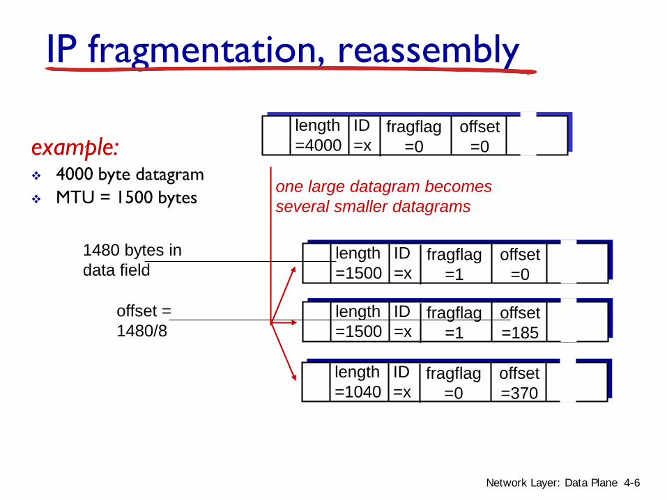
IP fragmentation, reassembly
network links have MTU (max.transfer size) -largest possible link-level frame• different link types,
different MTUs large IP datagram divided
(“fragmented”) within net• one datagram becomes
several datagrams• “reassembled” only at
final destination• IP header bits used to
identify, order related fragments
fragmentation:in: one large datagramout: 3 smaller datagrams
reassembly
…
…
4-5Network Layer: Data Plane
ID=x
offset=0
fragflag=0
length=4000
ID=x
offset=0
fragflag=1
length=1500
ID=x
offset=185
fragflag=1
length=1500
ID=x
offset=370
fragflag=0
length=1040
one large datagram becomesseveral smaller datagrams
example: 4000 byte datagram MTU = 1500 bytes
1480 bytes in data field
offset =1480/8
IP fragmentation, reassembly
4-6Network Layer: Data Plane

4.1 Overview of Network layer• data plane• control plane
4.2 What’s inside a router4.3 IP: Internet Protocol
• datagram format• fragmentation• IPv4 addressing• network address
translation• IPv6
4.4 Generalized Forward and SDN• match• action• OpenFlow examples
of match-plus-action in action
Chapter 4: outline
4-7Network Layer: Data Plane

IP addressing: introduction
IP address: 32-bit identifier for host, router interface
interface: connection between host/router and physical link• router’s typically have
multiple interfaces• host typically has one or
two interfaces (e.g., wired Ethernet, wireless 802.11)
IP addresses associated with each interface
223.1.1.1
223.1.1.2
223.1.1.3
223.1.1.4 223.1.2.9
223.1.2.2
223.1.2.1
223.1.3.2223.1.3.1
223.1.3.27
223.1.1.1 = 11011111 00000001 00000001 00000001
223 1 11
4-8Network Layer: Data Plane

IP addressing: introduction
Q: how are interfaces actually connected?A: we’ll learn about that in chapter 5, 6.
223.1.1.1
223.1.1.2
223.1.1.3
223.1.1.4 223.1.2.9
223.1.2.2
223.1.2.1
223.1.3.2223.1.3.1
223.1.3.27
A: wired Ethernet interfaces connected by Ethernet switches
A: wireless WiFi interfaces connected by WiFi base station
For now: don’t need to worry about how one interface is connected to another (with no intervening router)
4-9Network Layer: Data Plane

Subnets
IP address:• subnet part - high order bits
• host part - low order bits
what’s a subnet ?• device interfaces with same subnet part of IP address
• can physically reach each other without intervening router network consisting of 3 subnets
223.1.1.1
223.1.1.3
223.1.1.4 223.1.2.9
223.1.3.2223.1.3.1
subnet
223.1.1.2
223.1.3.27223.1.2.2
223.1.2.1
4-10Network Layer: Data Plane
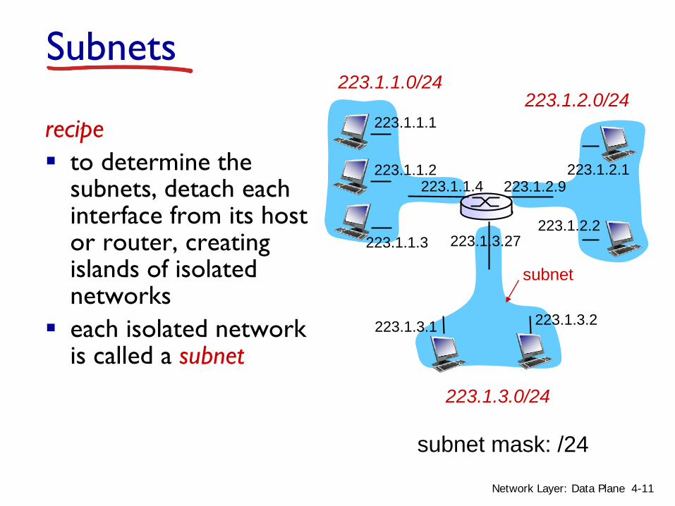
recipe to determine the
subnets, detach each interface from its host or router, creating islands of isolated networks
each isolated network is called a subnet
subnet mask: /24
Subnets223.1.1.0/24
223.1.2.0/24
223.1.3.0/24
223.1.1.1
223.1.1.3
223.1.1.4 223.1.2.9
223.1.3.2223.1.3.1
subnet
223.1.1.2
223.1.3.27223.1.2.2
223.1.2.1
4-11Network Layer: Data Plane
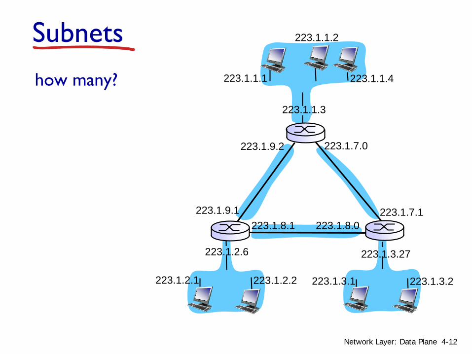
how many? 223.1.1.1
223.1.1.3
223.1.1.4
223.1.2.2223.1.2.1
223.1.2.6
223.1.3.2223.1.3.1
223.1.3.27
223.1.1.2
223.1.7.0
223.1.7.1223.1.8.0223.1.8.1
223.1.9.1
223.1.9.2
Subnets
4-12Network Layer: Data Plane

Network Layer 4-13
Classful Addressing (historical)
What was wrong, if anything, with this addressing model?

IP addressing: CIDR
CIDR: Classless InterDomain Routing• subnet portion of address of arbitrary length• address format: a.b.c.d/x, where x is # bits in
subnet portion of address
11001000 00010111 00010000 00000000
subnetpart
hostpart
200.23.16.0/23
4-14Network Layer: Data Plane
Subnetting/Netmask
Network Layer 4-15
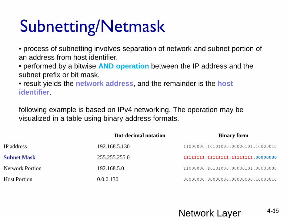
Dot-decimal notation Binary form
IP address 192.168.5.130 11000000.10101000.00000101.10000010
Subnet Mask 255.255.255.0 11111111.11111111.11111111.00000000
Network Portion 192.168.5.0 11000000.10101000.00000101.00000000
Host Portion 0.0.0.130 00000000.00000000.00000000.10000010
• process of subnetting involves separation of network and subnet portion of an address from host identifier. • performed by a bitwise AND operation between the IP address and the subnet prefix or bit mask. • result yields the network address, and the remainder is the host identifier.
following example is based on IPv4 networking. The operation may be visualized in a table using binary address formats.

Network Layer 4-16
Subnetting / Netmask
Consider the IP address 192.168.40.3 that is part of Class C network 192.168.40.0. • A subnet or sub-network is defined through a network mask boundary
using the specified number of significant bits as 1s. • Since Class C defines networks with a 24-bit boundary, we can then
consider that the most significant 24 bits are 1s, and the lower 8 bits are 0s.
• This translates to the dotted decimal notation 255.255.255.0, which is also compactly written as “/24” to indicate how many most significant bits are 1s.
• bit-wise logical “AND” operation between host address and netmask to obtain the Class C network address as shown below:
11000000 10101000 00101000 00000011 → 192.168.40.311111111 11111111 11111111 00000000 → netmask (/24)11000000 10101000 00101000 00000000 → 192.168.40.0 ----netid
Another example:
Network Layer 4-17
Subnetting/Netmask
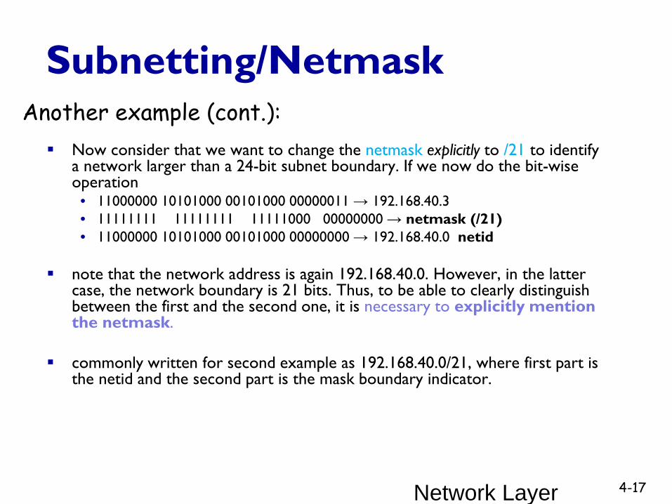
Now consider that we want to change the netmask explicitly to /21 to identify a network larger than a 24-bit subnet boundary. If we now do the bit-wise operation
• 11000000 10101000 00101000 00000011 → 192.168.40.3• 11111111 11111111 11111000 00000000 → netmask (/21)• 11000000 10101000 00101000 00000000 → 192.168.40.0 netid
note that the network address is again 192.168.40.0. However, in the latter case, the network boundary is 21 bits. Thus, to be able to clearly distinguish between the first and the second one, it is necessary to explicitly mention the netmask.
commonly written for second example as 192.168.40.0/21, where first part is the netid and the second part is the mask boundary indicator.
Another example (cont.):

18Notes taken from Cisco Systems, Inc. Part of the CCNA Exploration Course “Network Fundamentals”
Basic Subnetting for given address block Subnetting allows for creating multiple logical networks from a single
address block Subnets are created using one or more of the host bits as network bits
• done by extending the mask to borrow some of the bits from the host portion to create additional network bits

19
Calculating Subnets and Hosts The number of subnets is calculated using 2n, where n is the number of
bits borrowed• 21 = 2 subnets• the more bits borrowed, the more subnets can be defined
The number of useable hosts per subnet is calculated using 2h - 2 where h is the number of host bits left• 27 – 2 = 126 useable hosts per subnet• with each bit borrowed, fewer host addresses are available per subnet

20
Subnetting Example 1 Need to borrow a minimum of 2 host bits to cater for 3 subnets
• 22 = 4 subnets
21
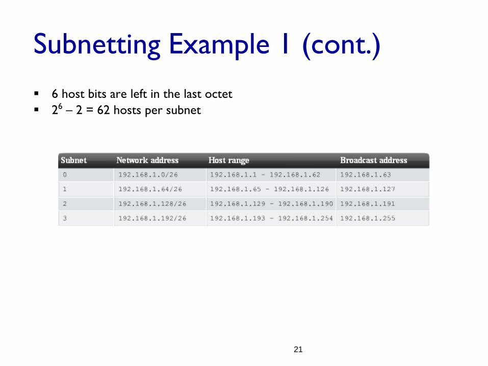
Subnetting Example 1 (cont.) 6 host bits are left in the last octet 26 – 2 = 62 hosts per subnet
22
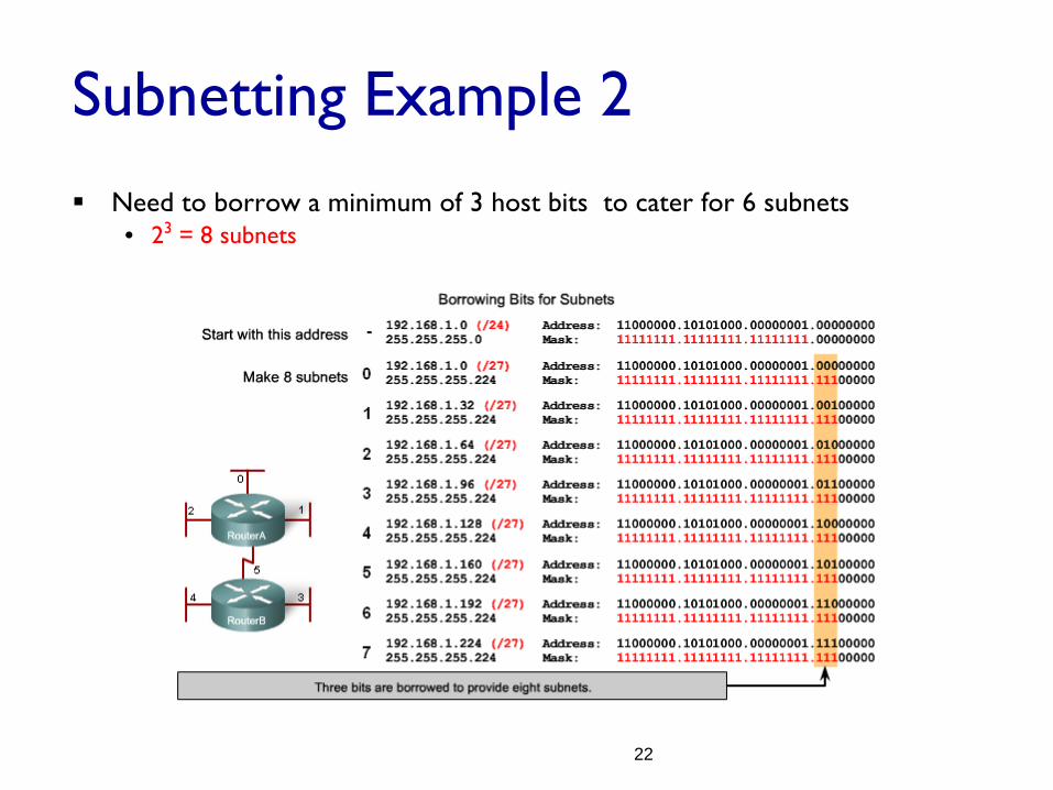
Subnetting Example 2 Need to borrow a minimum of 3 host bits to cater for 6 subnets
• 23 = 8 subnets

23
Subnetting Example 2 (cont.) 5 host bits are left in the last octet 25 – 2 = 30 hosts per subnet

24
Fixed Length Subnet Mask (FLSM) Using traditional subnetting or FLSM, each subnet is allocated the same
number of host addresses• these fixed size address block would be efficient if all subnets have the same
requirements for the number of hosts
25 – 2 = 30 hosts per subnet
25
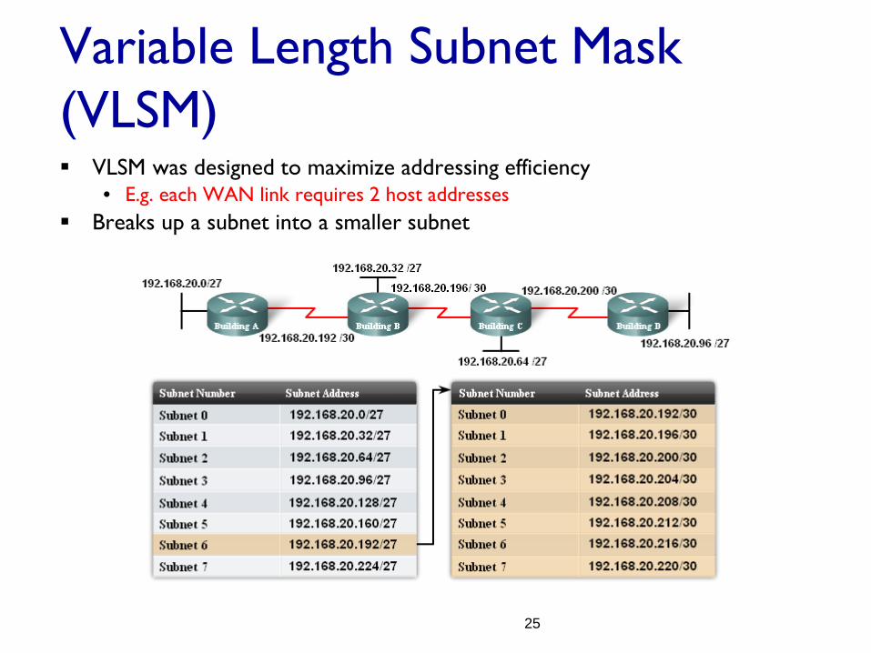
Variable Length Subnet Mask (VLSM) VLSM was designed to maximize addressing efficiency
• E.g. each WAN link requires 2 host addresses Breaks up a subnet into a smaller subnet
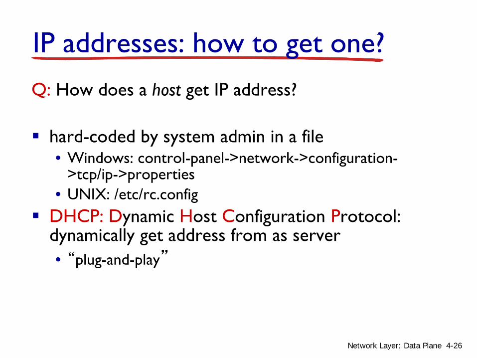
IP addresses: how to get one?Q: How does a host get IP address?
hard-coded by system admin in a file• Windows: control-panel->network->configuration-
>tcp/ip->properties• UNIX: /etc/rc.config
DHCP: Dynamic Host Configuration Protocol: dynamically get address from as server• “plug-and-play”
4-26Network Layer: Data Plane
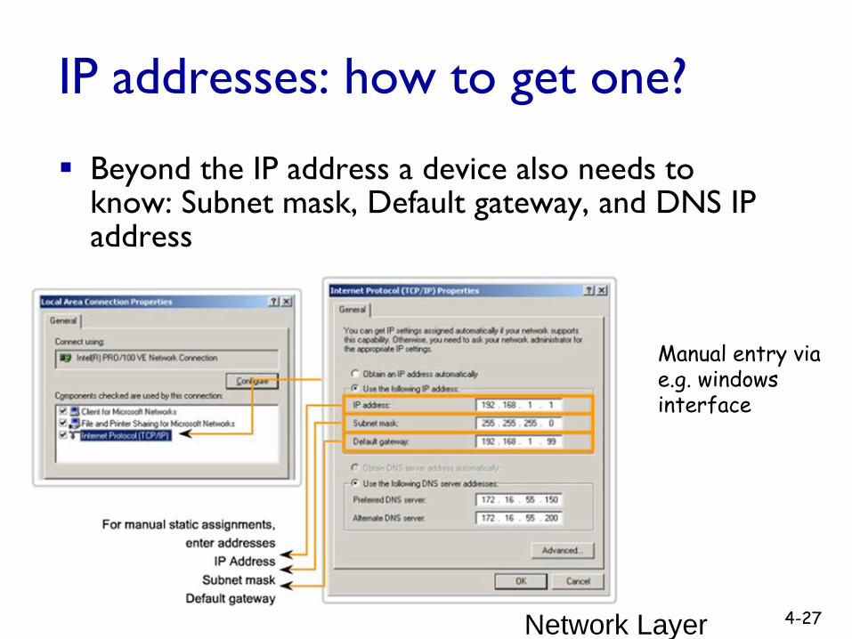
IP addresses: how to get one?
Beyond the IP address a device also needs to know: Subnet mask, Default gateway, and DNS IP address
Network Layer 4-27
Manual entry via e.g. windows interface

DHCP: Dynamic Host Configuration Protocol
goal: allow host to dynamically obtain its IP address from network server when it joins network• can renew its lease on address in use• allows reuse of addresses (only hold address while
connected/“on”)• support for mobile users who want to join network (more
shortly)DHCP overview:
• host broadcasts “DHCP discover” msg [optional]• DHCP server responds with “DHCP offer” msg [optional]• host requests IP address: “DHCP request” msg• DHCP server sends address: “DHCP ack” msg
4-28Network Layer: Data Plane

DHCP client-server scenario
223.1.1.0/24
223.1.2.0/24
223.1.3.0/24
223.1.1.1
223.1.1.3
223.1.1.4 223.1.2.9
223.1.3.2223.1.3.1
223.1.1.2
223.1.3.27223.1.2.2
223.1.2.1
DHCPserver
arriving DHCPclient needs address in thisnetwork
4-29Network Layer: Data Plane
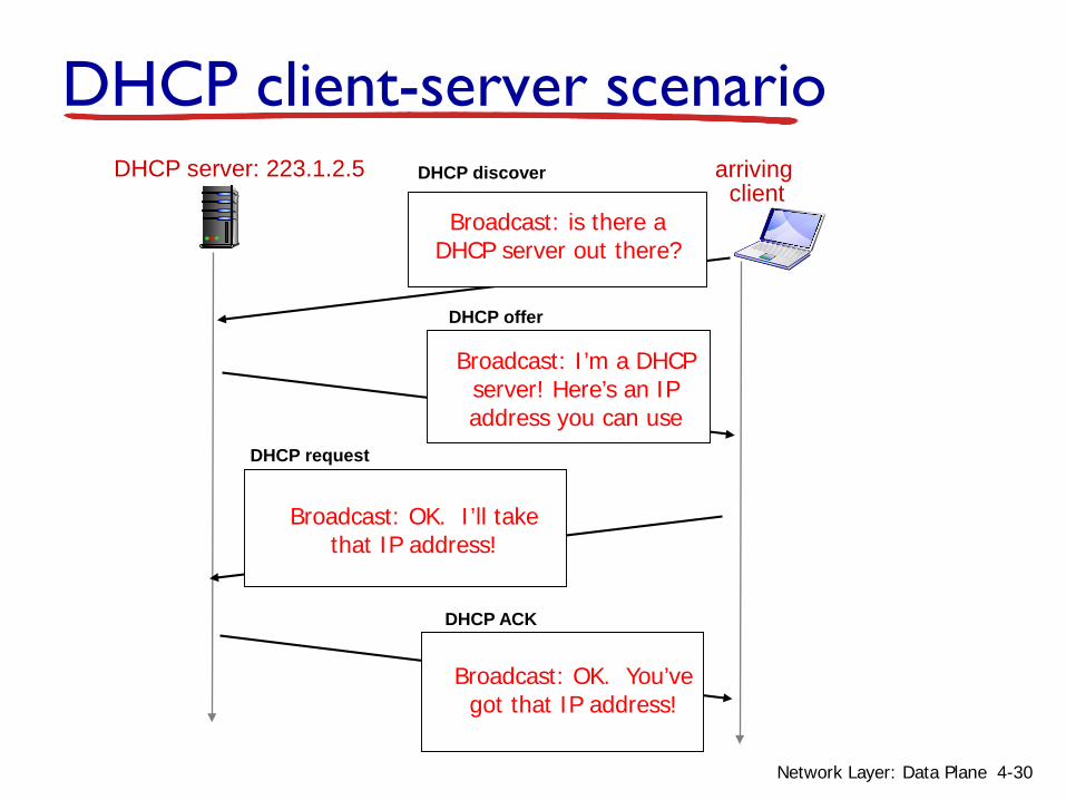
DHCP server: 223.1.2.5 arrivingclient
DHCP discover
src : 0.0.0.0, 68 dest.: 255.255.255.255,67
yiaddr: 0.0.0.0transaction ID: 654
DHCP offersrc: 223.1.2.5, 67
dest: 255.255.255.255, 68yiaddrr: 223.1.2.4
transaction ID: 654lifetime: 3600 secs
DHCP requestsrc: 0.0.0.0, 68
dest:: 255.255.255.255, 67yiaddrr: 223.1.2.4
transaction ID: 655lifetime: 3600 secs
DHCP ACKsrc: 223.1.2.5, 67
dest: 255.255.255.255, 68yiaddrr: 223.1.2.4
transaction ID: 655lifetime: 3600 secs
DHCP client-server scenario
Broadcast: is there a DHCP server out there?
Broadcast: I’m a DHCP server! Here’s an IP address you can use
Broadcast: OK. I’ll take that IP address!
Broadcast: OK. You’ve got that IP address!
4-30Network Layer: Data Plane

DHCP: more than IP addresses
DHCP can return more than just allocated IP address on subnet:• address of first-hop router for client• name and IP address of DNS sever• network mask (indicating network versus host portion
of address)
4-31Network Layer: Data Plane

connecting laptop needs its IP address, addr of first-hop router, addr of DNS server: use DHCP
router with DHCP server built into router
DHCP request encapsulated in UDP, encapsulated in IP, encapsulated in 802.1 Ethernet Ethernet frame broadcast
(dest: FFFFFFFFFFFF) on LAN, received at router running DHCP server
Ethernet demuxed to IP demuxed, UDP demuxed to DHCP
168.1.1.1
DHCPUDP
IPEthPhy
DHCP
DHCP
DHCP
DHCP
DHCP
DHCPUDP
IPEthPhy
DHCP
DHCP
DHCP
DHCPDHCP
DHCP: example
4-32Network Layer: Data Plane

DCP server formulates DHCP ACK containing client’s IP address, IP address of first-hop router for client, name & IP address of DNS server encapsulation of DHCP
server, frame forwarded to client, demuxing up to DHCP at client
DHCP: example
router with DHCP server built into router
DHCP
DHCP
DHCP
DHCP
DHCPUDP
IPEthPhy
DHCP
DHCPUDP
IPEthPhy
DHCP
DHCP
DHCP
DHCP
client now knows its IP address, name and IP address of DSN server, IP address of its first-hop router
4-33Network Layer: Data Plane

DHCP: Wireshark output (home LAN)
Message type: Boot Reply (2)Hardware type: EthernetHardware address length: 6Hops: 0Transaction ID: 0x6b3a11b7Seconds elapsed: 0Bootp flags: 0x0000 (Unicast)Client IP address: 192.168.1.101 (192.168.1.101)Your (client) IP address: 0.0.0.0 (0.0.0.0)Next server IP address: 192.168.1.1 (192.168.1.1)Relay agent IP address: 0.0.0.0 (0.0.0.0)Client MAC address: Wistron_23:68:8a (00:16:d3:23:68:8a)Server host name not givenBoot file name not givenMagic cookie: (OK)Option: (t=53,l=1) DHCP Message Type = DHCP ACKOption: (t=54,l=4) Server Identifier = 192.168.1.1Option: (t=1,l=4) Subnet Mask = 255.255.255.0Option: (t=3,l=4) Router = 192.168.1.1Option: (6) Domain Name Server
Length: 12; Value: 445747E2445749F244574092; IP Address: 68.87.71.226;IP Address: 68.87.73.242; IP Address: 68.87.64.146
Option: (t=15,l=20) Domain Name = "hsd1.ma.comcast.net."
reply
Message type: Boot Request (1)Hardware type: EthernetHardware address length: 6Hops: 0Transaction ID: 0x6b3a11b7Seconds elapsed: 0Bootp flags: 0x0000 (Unicast)Client IP address: 0.0.0.0 (0.0.0.0)Your (client) IP address: 0.0.0.0 (0.0.0.0)Next server IP address: 0.0.0.0 (0.0.0.0)Relay agent IP address: 0.0.0.0 (0.0.0.0)Client MAC address: Wistron_23:68:8a (00:16:d3:23:68:8a)Server host name not givenBoot file name not givenMagic cookie: (OK)Option: (t=53,l=1) DHCP Message Type = DHCP RequestOption: (61) Client identifier
Length: 7; Value: 010016D323688A; Hardware type: EthernetClient MAC address: Wistron_23:68:8a (00:16:d3:23:68:8a)
Option: (t=50,l=4) Requested IP Address = 192.168.1.101Option: (t=12,l=5) Host Name = "nomad"Option: (55) Parameter Request List
Length: 11; Value: 010F03062C2E2F1F21F92B1 = Subnet Mask; 15 = Domain Name3 = Router; 6 = Domain Name Server44 = NetBIOS over TCP/IP Name Server……
request
4-34Network Layer: Data Plane
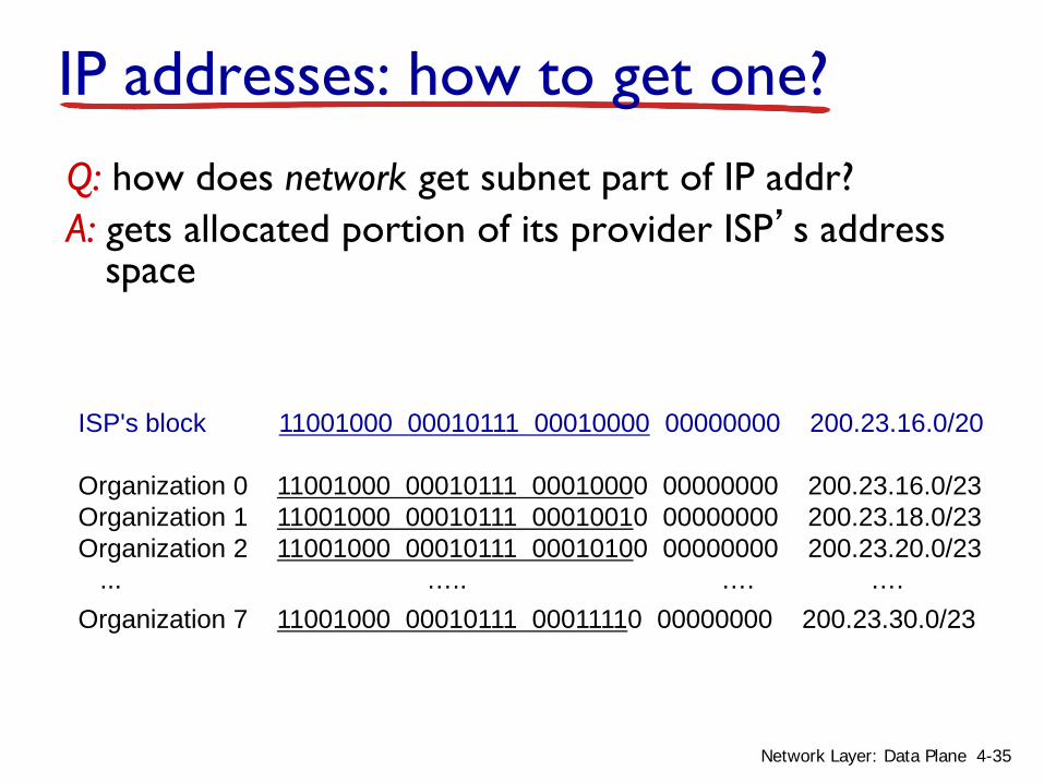
IP addresses: how to get one?Q: how does network get subnet part of IP addr?A: gets allocated portion of its provider ISP’s address
space
ISP's block 11001000 00010111 00010000 00000000 200.23.16.0/20
Organization 0 11001000 00010111 00010000 00000000 200.23.16.0/23 Organization 1 11001000 00010111 00010010 00000000 200.23.18.0/23 Organization 2 11001000 00010111 00010100 00000000 200.23.20.0/23
... ….. …. ….Organization 7 11001000 00010111 00011110 00000000 200.23.30.0/23
4-35Network Layer: Data Plane
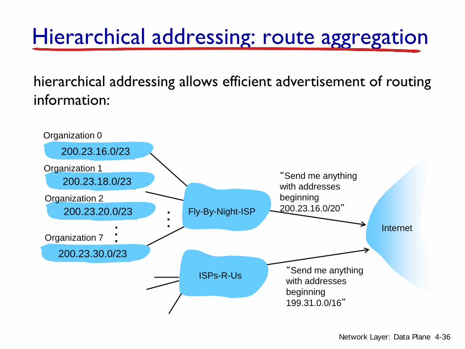
Hierarchical addressing: route aggregation
“Send me anythingwith addresses beginning 200.23.16.0/20”
200.23.16.0/23
200.23.18.0/23
200.23.30.0/23
Fly-By-Night-ISP
Organization 0
Organization 7Internet
Organization 1
ISPs-R-Us “Send me anythingwith addresses beginning 199.31.0.0/16”
200.23.20.0/23Organization 2
...
...
hierarchical addressing allows efficient advertisement of routing information:
4-36Network Layer: Data Plane
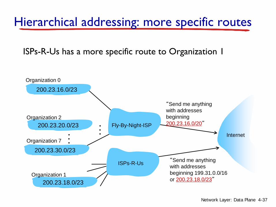
ISPs-R-Us has a more specific route to Organization 1
“Send me anythingwith addresses beginning 200.23.16.0/20”
200.23.16.0/23
200.23.18.0/23
200.23.30.0/23
Fly-By-Night-ISP
Organization 0
Organization 7Internet
Organization 1
ISPs-R-Us “Send me anythingwith addresses beginning 199.31.0.0/16or 200.23.18.0/23”
200.23.20.0/23Organization 2
...
...
Hierarchical addressing: more specific routes
4-37Network Layer: Data Plane

IP addressing: the last word...
Q: how does an ISP get block of addresses?A: ICANN: Internet Corporation for Assigned
Names and Numbers http://www.icann.org/• allocates addresses• manages DNS• assigns domain names, resolves disputes
4-38Network Layer: Data Plane

39Notes taken by Cisco Systems, Inc. Part of the CCNA Exploration Course “Network Fundamentals”
Assigning Addresses to Other Devices--Hints Beyond the IP devices assigned IP addresses via DHCP:
Addresses for servers and peripherals• should have a static address servers and peripherals are concentration points for network
traffic
Addresses for hosts that are accessible from Internet• the addresses for these devices should be static• must have a public space address associated with it
Addresses for intermediary devices• intermediary devices are also a concentration point for network traffic;
may be used as hosts to configure, monitor, or troubleshoot network operation; addresses are assigned manually to these devices
40
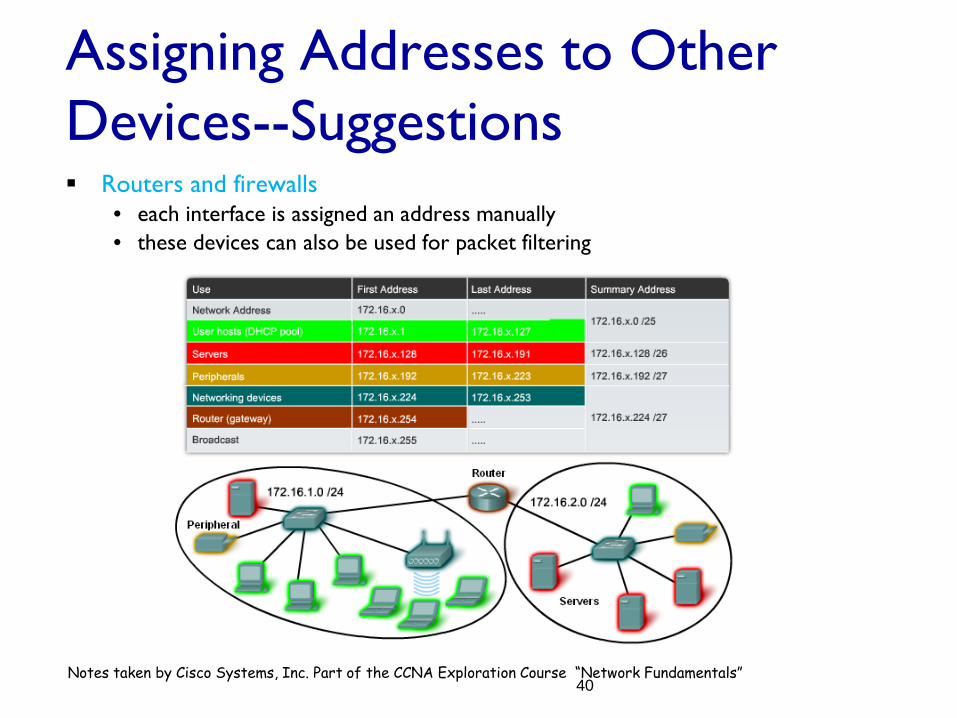
Assigning Addresses to Other Devices--Suggestions Routers and firewalls
• each interface is assigned an address manually• these devices can also be used for packet filtering
Notes taken by Cisco Systems, Inc. Part of the CCNA Exploration Course “Network Fundamentals”

Why do we need private non-global addressing?• Reusability of addresses • Flexibility• Aids in security (internal addresses not visible to the internet)
Reserved address space
Any drawback?
Private addressing (non-global IPs)
Network Layer 4-41
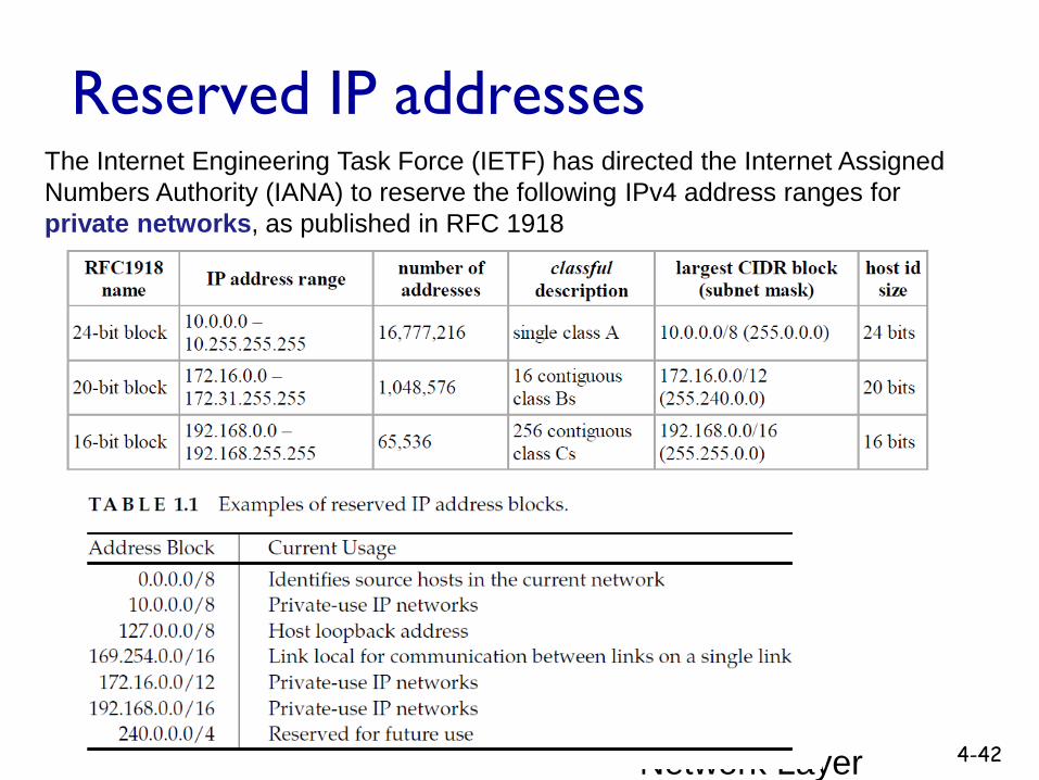
Reserved IP addresses
Network Layer 4-42
The Internet Engineering Task Force (IETF) has directed the Internet Assigned Numbers Authority (IANA) to reserve the following IPv4 address ranges for private networks, as published in RFC 1918
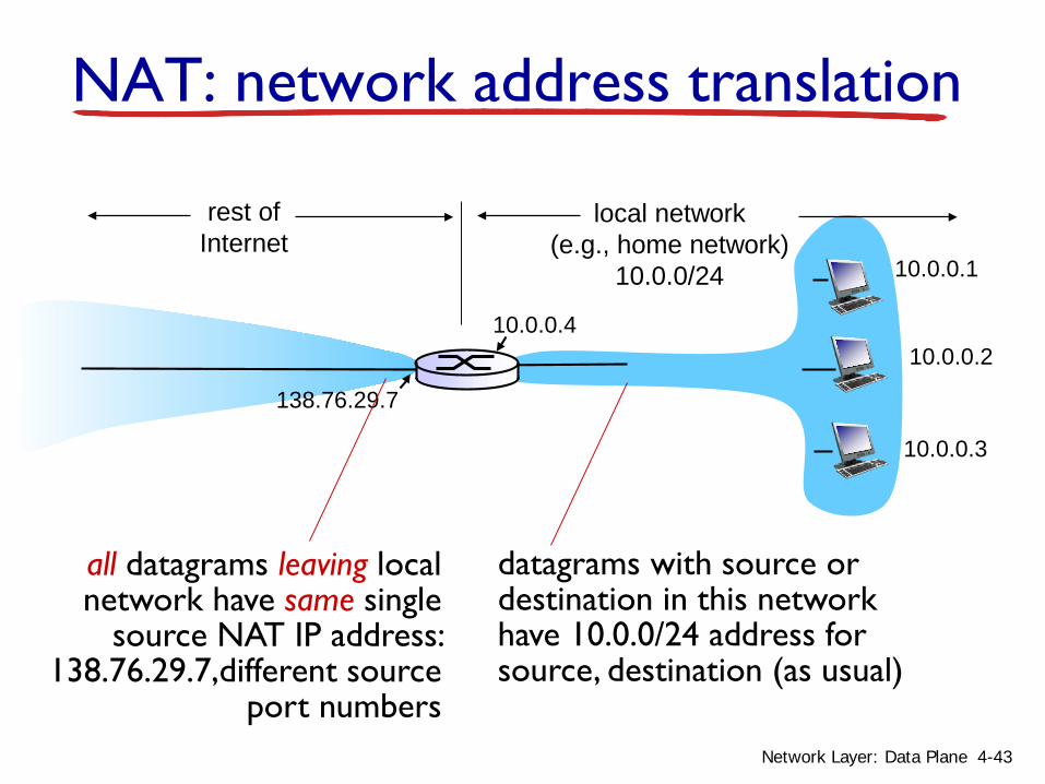
NAT: network address translation
10.0.0.1
10.0.0.2
10.0.0.3
10.0.0.4
138.76.29.7
local network(e.g., home network)
10.0.0/24
rest ofInternet
datagrams with source or destination in this networkhave 10.0.0/24 address for source, destination (as usual)
all datagrams leaving localnetwork have same single
source NAT IP address: 138.76.29.7,different source
port numbers4-43Network Layer: Data Plane

motivation: local network uses just one IP address as far as outside world is concerned: range of addresses not needed from ISP: just one
IP address for all devices can change addresses of devices in local network
without notifying outside world can change ISP without changing addresses of
devices in local network devices inside local net not explicitly addressable,
visible by outside world (a security plus)
NAT: network address translation
4-44Network Layer: Data Plane

implementation: NAT router must:
outgoing datagrams: replace (source IP address, port #) of every outgoing datagram to (NAT IP address, new port #)
. . . remote clients/servers will respond using (NAT IP address, new port #) as destination addr
remember (in NAT translation table) every (source IP address, port #) to (NAT IP address, new port #) translation pair
incoming datagrams: replace (NAT IP address, new port #) in dest fields of every incoming datagram with corresponding (source IP address, port #) stored in NAT table
NAT: network address translation
4-45Network Layer: Data Plane

10.0.0.1
10.0.0.2
10.0.0.3
S: 10.0.0.1, 3345D: 128.119.40.186, 80
110.0.0.4
138.76.29.7
1: host 10.0.0.1 sends datagram to 128.119.40.186, 80
NAT translation tableWAN side addr LAN side addr138.76.29.7, 5001 10.0.0.1, 3345…… ……
S: 128.119.40.186, 80 D: 10.0.0.1, 3345 4
S: 138.76.29.7, 5001D: 128.119.40.186, 802
2: NAT routerchanges datagramsource addr from10.0.0.1, 3345 to138.76.29.7, 5001,updates table
S: 128.119.40.186, 80 D: 138.76.29.7, 5001 3
3: reply arrivesdest. address:138.76.29.7, 5001
4: NAT routerchanges datagramdest addr from138.76.29.7, 5001 to 10.0.0.1, 3345
NAT: network address translation
4-46Network Layer: Data Plane
* Check out the online interactive exercises for more examples: http://gaia.cs.umass.edu/kurose_ross/interactive/

16-bit port-number field: • 60,000 simultaneous connections with a single
LAN-side address! NAT is controversial:
• routers should only process up to layer 3• address shortage should be solved by IPv6• violates end-to-end argument
• NAT possibility must be taken into account by app designers, e.g., P2P applications
• NAT traversal: what if client wants to connect to server behind NAT?
NAT: network address translation
4-47Network Layer: Data Plane

4.1 Overview of Network layer• data plane• control plane
4.2 What’s inside a router4.3 IP: Internet Protocol
• datagram format• fragmentation• IPv4 addressing• network address
translation• IPv6
4.4 Generalized Forward and SDN• match• action• OpenFlow examples
of match-plus-action in action
Chapter 4: outline
4-48Network Layer: Data Plane

IPv6: motivation initial motivation: 32-bit address space soon to be
completely allocated. additional motivation:
• header format helps speed processing/forwarding• header changes to facilitate QoS
IPv6 datagram format: • fixed-length 40 byte header• no fragmentation allowed
4-49Network Layer: Data Plane

IPv6 datagram format
priority: identify priority among datagrams in flowflow Label: identify datagrams in same “flow.”
(concept of“flow” not well defined).next header: identify upper layer protocol for data
data
destination address(128 bits)
source address(128 bits)
payload len next hdr hop limitflow labelpriver
32 bits4-50Network Layer: Data Plane

Other changes from IPv4
checksum: removed entirely to reduce processing time at each hop
options: allowed, but outside of header, indicated by “Next Header” field
ICMPv6: new version of ICMP• additional message types, e.g. “Packet Too Big”• multicast group management functions
4-51Network Layer: Data Plane
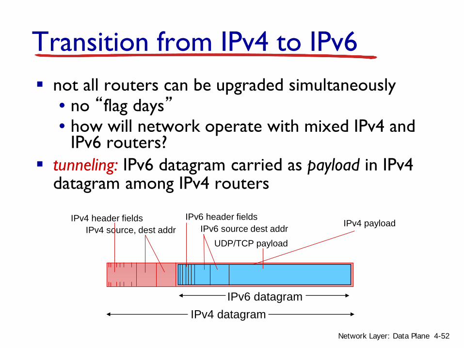
Transition from IPv4 to IPv6 not all routers can be upgraded simultaneously
• no “flag days”• how will network operate with mixed IPv4 and
IPv6 routers? tunneling: IPv6 datagram carried as payload in IPv4
datagram among IPv4 routers
IPv4 source, dest addr IPv4 header fields
IPv4 datagramIPv6 datagram
IPv4 payload
UDP/TCP payloadIPv6 source dest addr
IPv6 header fields
4-52Network Layer: Data Plane
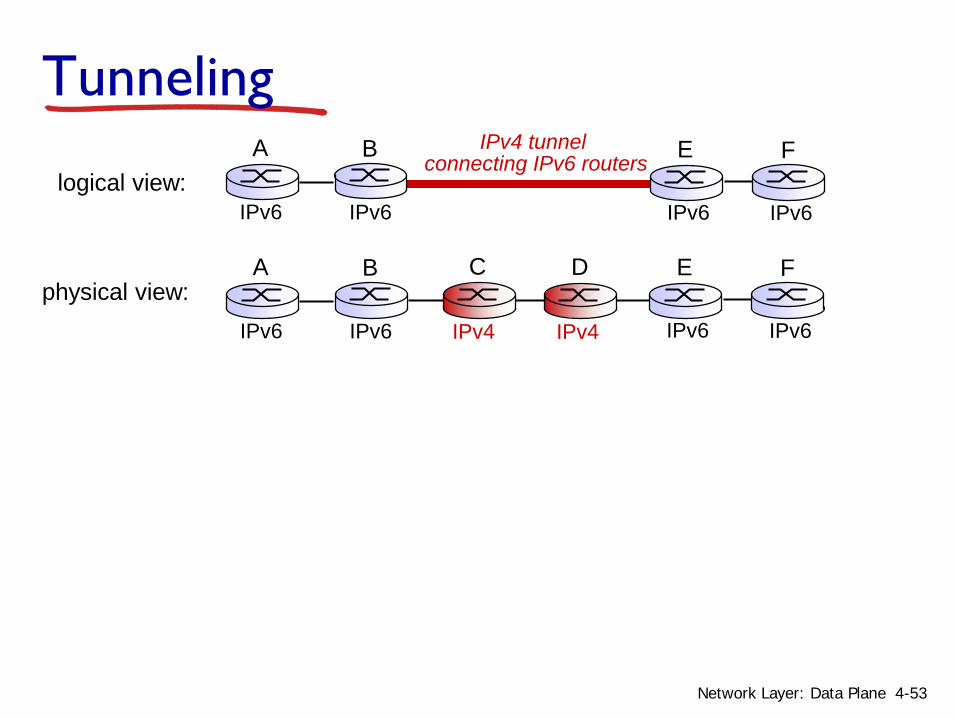
Tunneling
physical view:IPv4 IPv4
A B
IPv6 IPv6
E
IPv6 IPv6
FC D
logical view:
IPv4 tunnel connecting IPv6 routers E
IPv6 IPv6
FA B
IPv6 IPv6
4-53Network Layer: Data Plane

flow: Xsrc: Adest: F
data
A-to-B:IPv6
Flow: XSrc: ADest: F
data
src:Bdest: E
B-to-C:IPv6 inside
IPv4
E-to-F:IPv6
flow: Xsrc: Adest: F
data
B-to-C:IPv6 inside
IPv4
Flow: XSrc: ADest: F
data
src:Bdest: E
physical view:A B
IPv6 IPv6
E
IPv6 IPv6
FC D
logical view:
IPv4 tunnel connecting IPv6 routers E
IPv6 IPv6
FA B
IPv6 IPv6
Tunneling
IPv4 IPv4
4-54Network Layer: Data Plane

IPv6: adoption
Google: 8% of clients access services via IPv6 NIST: 1/3 of all US government domains are IPv6
capable
Long (long!) time for deployment, use•20 years and counting!•think of application-level changes in last 20 years: WWW, Facebook, streaming media, Skype, …•Why?
4-55Network Layer: Data Plane
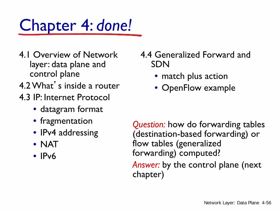
Chapter 4: done!
Question: how do forwarding tables (destination-based forwarding) or flow tables (generalized forwarding) computed?Answer: by the control plane (next chapter)
4.1 Overview of Network layer: data plane and control plane
4.2 What’s inside a router4.3 IP: Internet Protocol
• datagram format• fragmentation• IPv4 addressing• NAT• IPv6
4.4 Generalized Forward and SDN• match plus action• OpenFlow example
4-56Network Layer: Data Plane


