
Apr 30, 2012
Chapter 37
Wave Optics
Wave Optics
Wave optics is a study concerned with phenomena that cannot be adequately explained by geometric (ray) optics.
§ Sometimes called physical optics
These phenomena include:
§ Interference
§ Diffraction
§ Polarization
Light waves
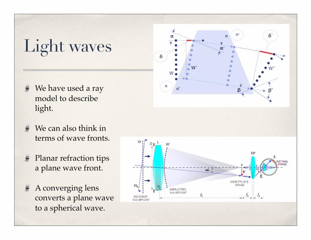
We have used a ray model to describe light.
We can also think in terms of wave fronts.
Planar refraction tips a plane wave front.
A converging lens converts a plane wave to a spherical wave.
Huygen’s principle
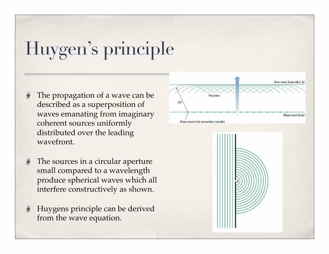
The propagation of a wave can be described as a superposition of waves emanating from imaginary coherent sources uniformly distributed over the leading wavefront.
The sources in a circular aperture small compared to a wavelength produce spherical waves which all interfere constructively as shown.
Huygens principle can be derived from the wave equation.
Interference
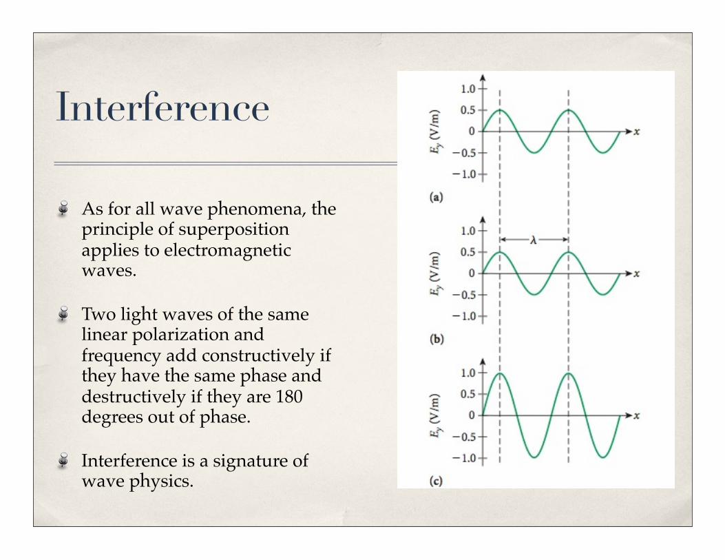
As for all wave phenomena, the principle of superposition applies to electromagnetic waves.
Two light waves of the same linear polarization and frequency add constructively if they have the same phase and destructively if they are 180 degrees out of phase.
Interference is a signature of wave physics.
Interference
In constructive interference the amplitude of the resultant wave is greater than that of either individual wave.
In destructive interference the amplitude of the resultant wave is less than that of either individual wave.
All interference associated with light waves arises when the electromagnetic fields that constitute the individual waves combine.
Wave detection
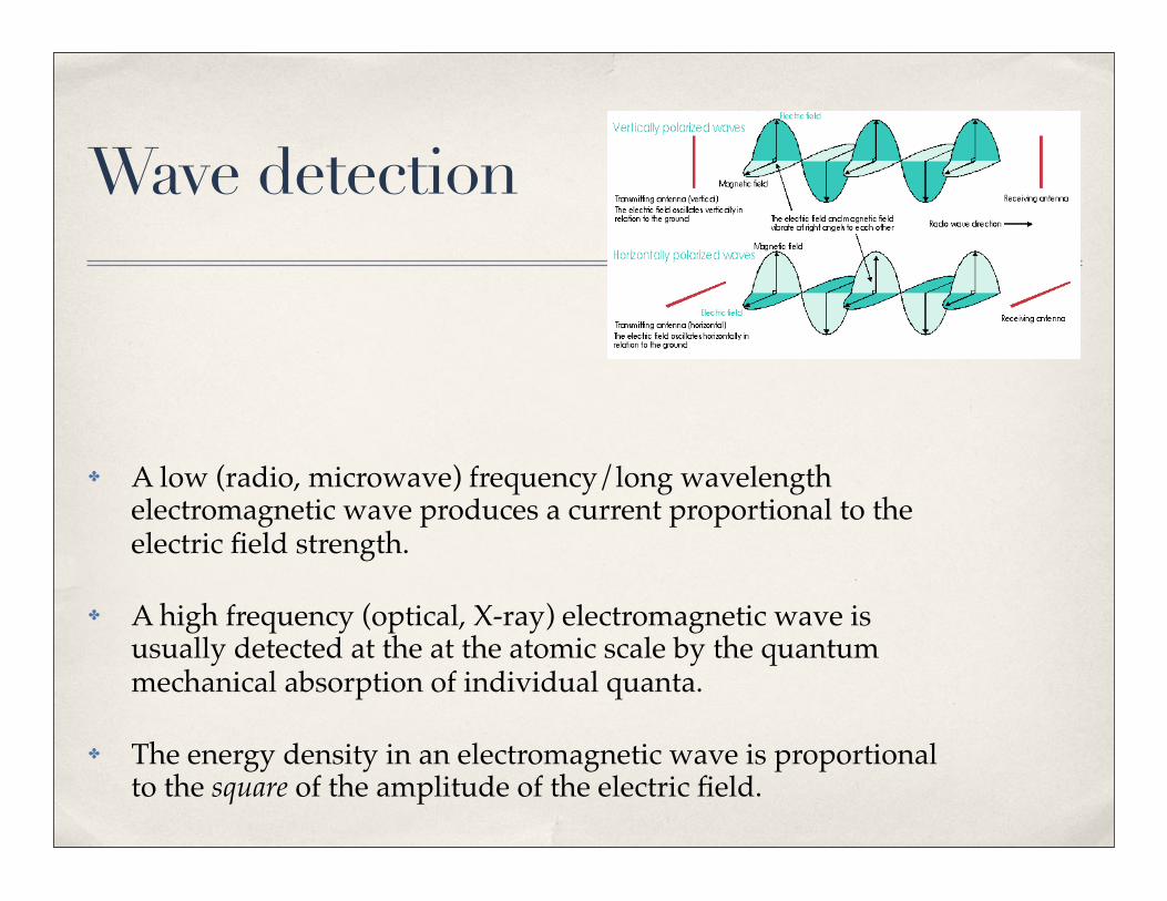
✤ A low (radio, microwave) frequency/long wavelength electromagnetic wave produces a current proportional to the electric field strength.
✤ A high frequency (optical, X-ray) electromagnetic wave is usually detected at the at the atomic scale by the quantum mechanical absorption of individual quanta.
✤ The energy density in an electromagnetic wave is proportional to the square of the amplitude of the electric field.
Young’s Double-Slit Experiment: Schematic
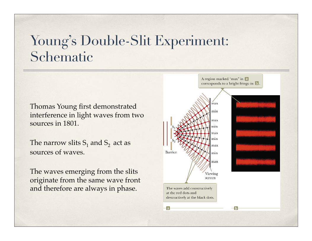
Thomas Young first demonstrated interference in light waves from two sources in 1801.
The narrow slits S1 and S2 act as sources of waves.
The waves emerging from the slits originate from the same wave front and therefore are always in phase.
Resulting Interference Pattern
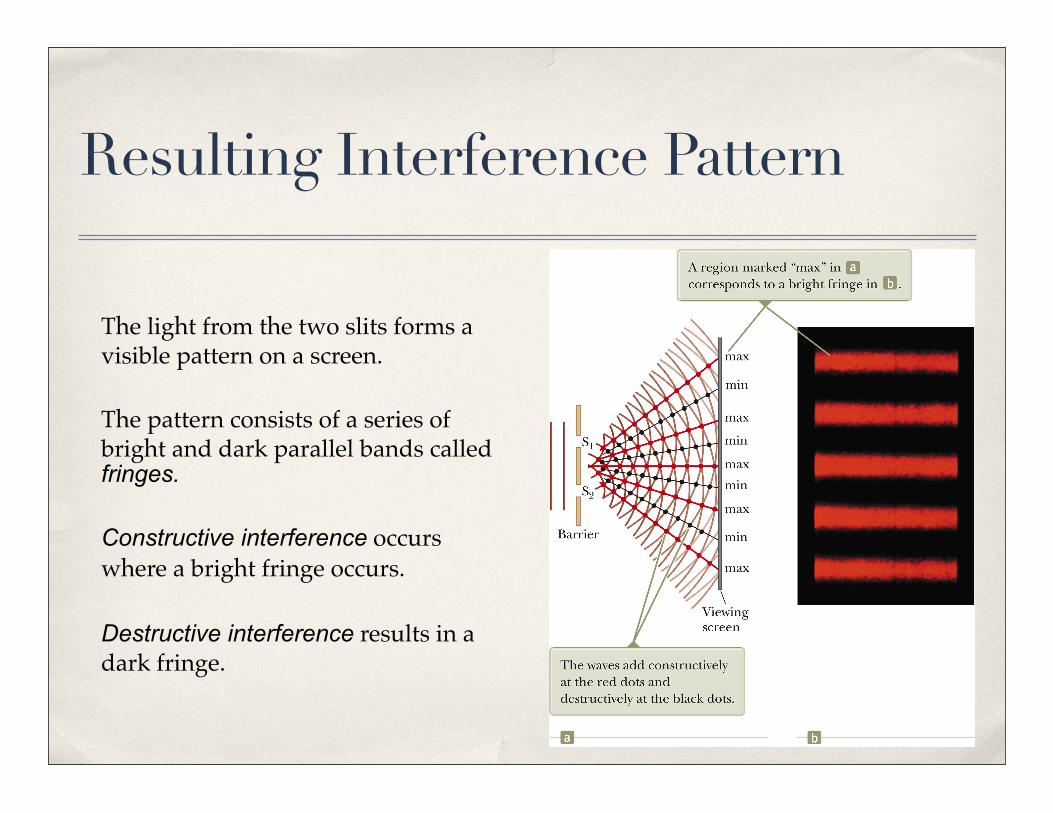
The light from the two slits forms a visible pattern on a screen.
The pattern consists of a series of bright and dark parallel bands called fringes.
Constructive interference occurs where a bright fringe occurs.
Destructive interference results in a dark fringe.
Interference Patterns
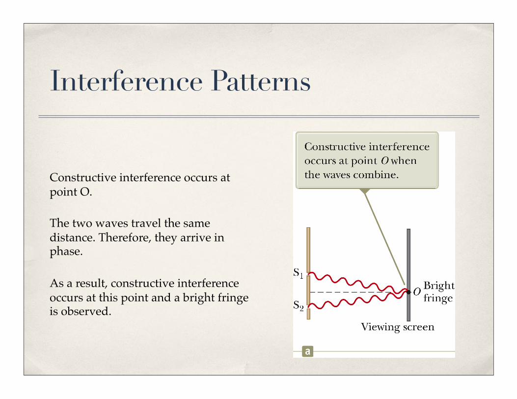
Constructive interference occurs at point O.
The two waves travel the same distance. Therefore, they arrive in phase.
As a result, constructive interference occurs at this point and a bright fringe is observed.
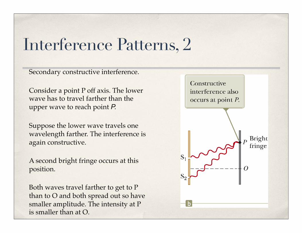
Interference Patterns, 2Secondary constructive interference.
Consider a point P off axis. The lower wave has to travel farther than the upper wave to reach point P.
Suppose the lower wave travels one wavelength farther. The interference is again constructive.
A second bright fringe occurs at this position.
Both waves travel farther to get to P than to O and both spread out so have smaller amplitude. The intensity at P is smaller than at O.
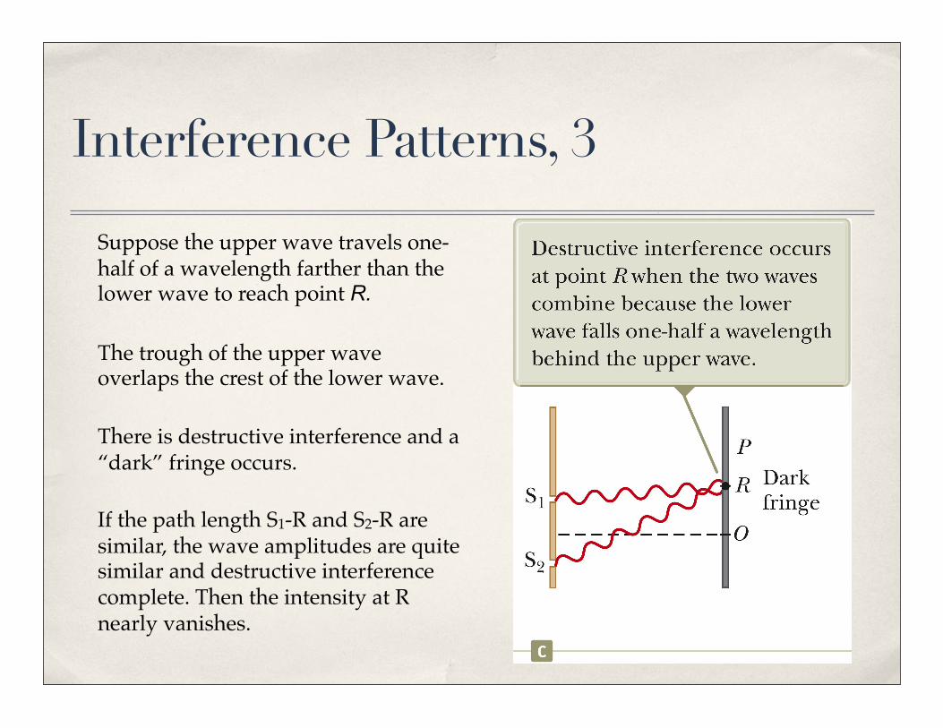
Interference Patterns, 3
Suppose the upper wave travels one-half of a wavelength farther than the lower wave to reach point R.
The trough of the upper wave overlaps the crest of the lower wave.
There is destructive interference and a “dark” fringe occurs.
If the path length S1-R and S2-R are similar, the wave amplitudes are quite similar and destructive interference complete. Then the intensity at R nearly vanishes.
Conditions for Interference
To observe interference in light waves, the following two conditions must be met:
§ The sources must be coherent.
§ They must maintain a constant phase with respect to each other.
§ The sources should be monochromatic.
§ Monochromatic means they have a single wavelength.
Producing Coherent Sources
Light from a monochromatic source is used to illuminate a barrier.
The barrier contains two small openings.
§ The openings are usually in the shape of slits.
The light emerging from the two slits is coherent since a single source produces the original light beam.
This is a commonly used method for producing coherent sources in the optical frequency range.
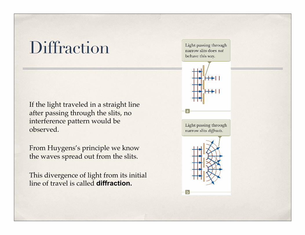
Diffraction
If the light traveled in a straight line after passing through the slits, no interference pattern would be observed.
From Huygens’s principle we know the waves spread out from the slits.
This divergence of light from its initial line of travel is called diffraction.
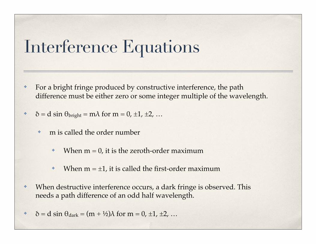
Interference Equations
✤ For a bright fringe produced by constructive interference, the path difference must be either zero or some integer multiple of the wavelength.
✤ δ = d sin θbright = mλ for m = 0, ±1, ±2, …
✤ m is called the order number
✤ When m = 0, it is the zeroth-order maximum
✤ When m = ±1, it is called the first-order maximum
✤ When destructive interference occurs, a dark fringe is observed. This needs a path difference of an odd half wavelength.
✤ δ = d sin θdark = (m + ½)λ for m = 0, ±1, ±2, …
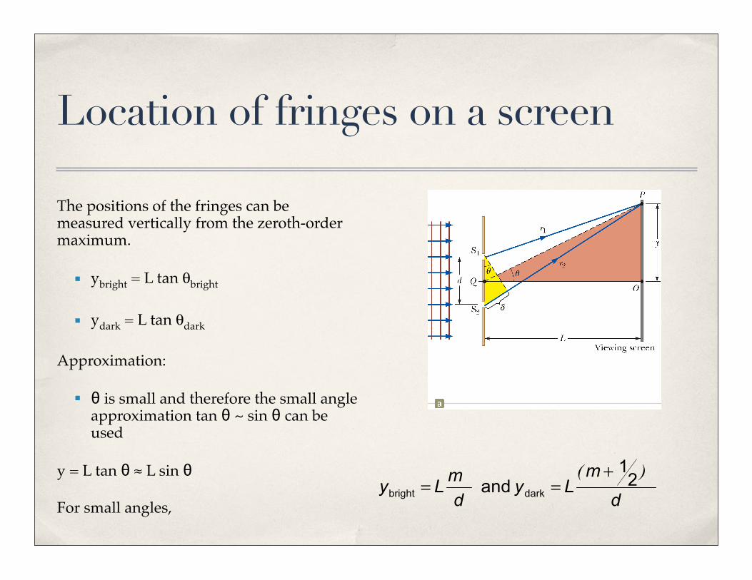
Location of fringes on a screen
The positions of the fringes can be measured vertically from the zeroth-order maximum.
§ ybright = L tan θbright
§ ydark = L tan θdark
Approximation:
§ θ is small and therefore the small angle approximation tan θ ~ sin θ can be used
y = L tan θ ≈ L sin θ
For small angles,
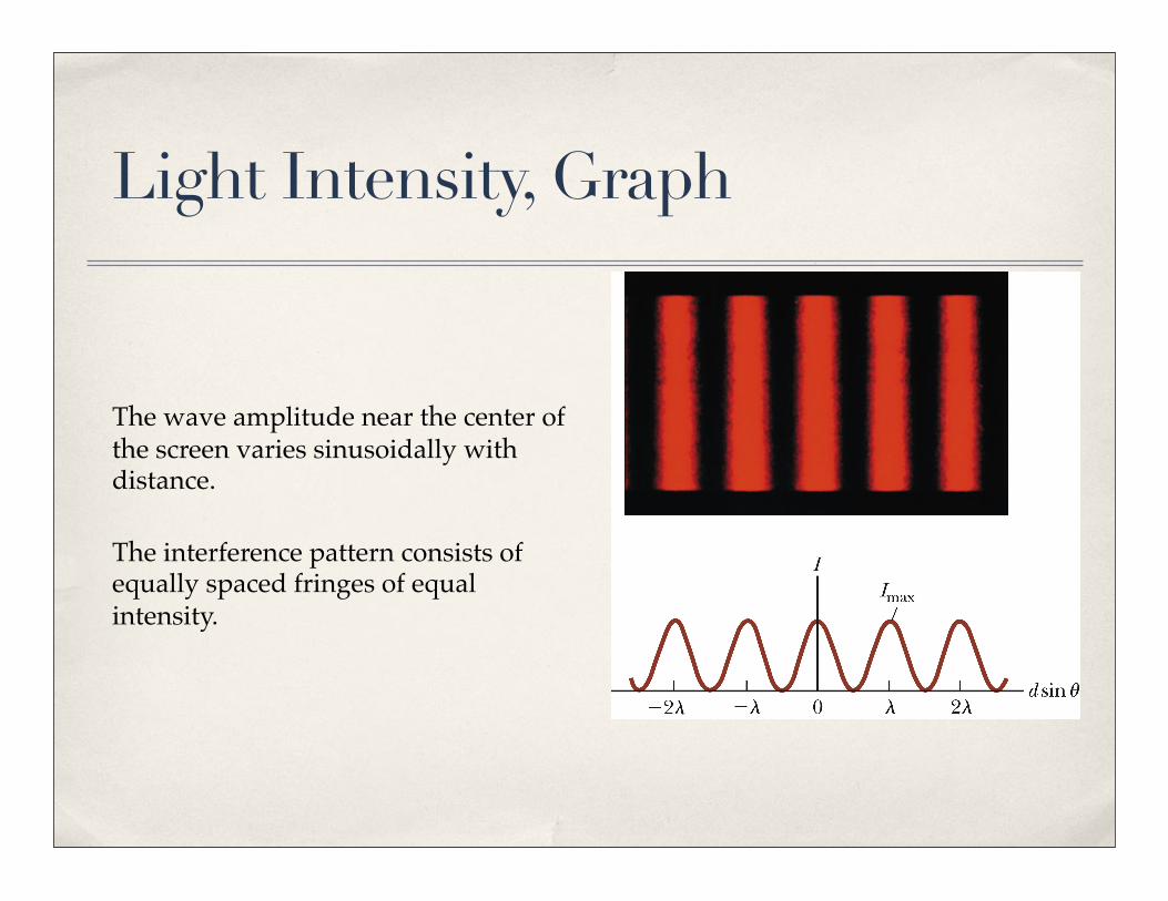
Light Intensity, Graph
The wave amplitude near the center of the screen varies sinusoidally with distance.
The interference pattern consists of equally spaced fringes of equal intensity.
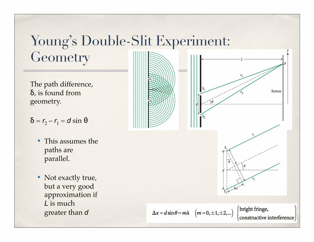
Young’s Double-Slit Experiment: Geometry
The path difference, δ, is found from geometry.
δ = r2 – r1 = d sin θ
§ This assumes the paths are parallel.
§ Not exactly true, but a very good approximation if L is much greater than d
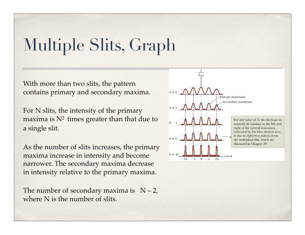
Multiple Slits, Graph
With more than two slits, the pattern contains primary and secondary maxima.
For N slits, the intensity of the primary maxima is N2
times greater than that due to a single slit.
As the number of slits increases, the primary maxima increase in intensity and become narrower. The secondary maxima decrease in intensity relative to the primary maxima.
The number of secondary maxima is N – 2, where N is the number of slits.


