
GMN precision spindles
belt dr iven and direct motorized
have been accepted world wide
as the standard for precision on
internal and universal gr inders.
Their re l iabi l i ty is der ived from
over seven decades of
experience in design, use and
manufacture of precision
rotat ing mechanisms.
GMN has a wide range of models
to choose from with ei ther
manual or automatic tool change
systems and a speed up to
180 000 rpm.
We can offer solut ions to meet
the most di f f icul t appl icat ions.
Our preferred styles offer prompt
del ivery and attract ive pr ic ing.
is the trademark of
Paul Mül ler Industr ie GmbH & Co. KG.
This catalog ref lects the latest design
features at the t ime of pr int ing.
The company reserves the r ight to
change designs and speci f icat ions at any
t ime.
Reprint , photomechanical reproduct ions
as wel l as reproduct ion from cl ippings
only with l icense of
Paul Mül ler Industr ie GmbH & Co. KG.
Catalog 250611/00Index
Spindle specification 3-5
Spindle selection 6
TSA - External taper style 7
TSI - Internal taper style 8
TSP - Cylindric pilot with face clamping 9
TSAV - Heavy duty style with external taper 10-11
TSEV - Direct motorized surface grinder style 12-13
Technical characteristics of TSEV-style 14
Sealing options 15TSA-, TSI-, TSP- and TSAV/TSEV-style
Cutting speed 16
TSA - Grinding wheel f langes 17
TSAV/TSEV - Grinding wheel f langes 18-19
Anti-rotation option 20TSAV/TSEV-style
Taper specifications 21TSA-, TSI-, and TSAV/TSEV-style
Tooling accessories 22TSA - Col let chuck, TSA - Grinding qui l l
Tooling accessories 23TSI - Col let chuck, TSP - Clamping chuck
Grinding quil ls 24-25TSI-, TSP-style
TSI/TSP - Grinding quil l selection data 26
Pulleys 27TSA-, TSI-, TSP- and TSAV-style
TSAV - Balancing system 28
TSEV - Balancing system 29
Balancing system 30Automatic balancing system
Balancing system 31Portable balancing system
Stiffness - Load capacity 32-34TSA-, TSI/TSP-, TSAV- and TSEV-style
General safety rules 35-36
Radial and axial runout 37
GMN - Representations 38
3
Spindle Specification
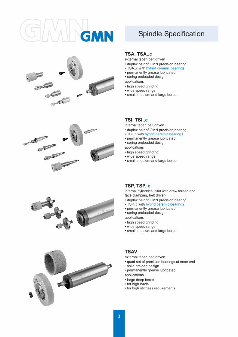
TSA, TSA..cexternal taper, belt driven• duplex pair of GMN precision bearing• TSA..c with hybrid ceramic bearings• permanently grease lubricated• spring preloaded designapplications• high speed grinding• wide speed range• small, medium and large bores
TSI, TSI..cinternal taper, belt driven• duplex pair of GMN precision bearing• TSI..c with hybrid ceramic bearings• permanently grease lubricated• spring preloaded designapplications• high speed grinding• wide speed range• small, medium and large bores
TSAVexternal taper, belt driven• quad set of precision bearings at nose end
solid preload design• permanently grease lubricatedapplications• large deep bores• for high loads• for high stiffness requirements
TSP, TSP..cinternal cylindrical pilot with draw thread andface clamping, belt driven• duplex pair of GMN precision bearing• TSP..c with hybrid ceramic bearings• permanently grease lubricated• spring preloaded designapplications• high speed grinding• wide speed range• small, medium and large bores

4
Spindle Specification
TSLexternal taper and stepped spindle housing,for deep internal bore grinding, belt driven• quad set of precision bearings at nose end
solid preload design• permanently grease lubricatedapplications• medium and large, deep bores
Further information on request.
TSE, TSE..cwith air cooled motor• tool interface: integrated collet nose, HSK or
according to customer’s requirements• precision bearings• permanet oil/air or grease lubrication• TSE..c with hybrid ceramic bearings• clamping on cylindrical housing• frequency inverter compatable• for low power requirements• for light machining operations• for high speed grindingFurther information on request.
TSEVwith air cooled motor• external style grinding taper• precision bearings, solid preloaded• permanent grease lubrication• clamping on cylindrical housing• frequency converter compatable or direct AC voltage• economical support equipment• for heavy machining operations• for high requirement stiffness
TS, HLSOpto spindles with ball bearings, static ordynamic air bearings• scan accuracy ∆t / t = 10-5....10-6
up to 100000 rpm
Please ask for catalog # 2502.

5
Spindle Specification
TSSV, HS, HSXHigh frequency spindle with integral asynchromous motor,liquid cooled front bearings and stator• ultra precision ball bearings• HSX standard with hybrid ceramic bearings• oil/air lubricated• for manual tool change via pilot with
draw thread and clamping face
Please ask for catalog # 2508.
HSPHigh frequency spindle with integral asynchronous motor,liquid cooled front bearings and stator• ultra precision ball bearings• hybrid ceramic bearings• oil/air or permanently grease lubricated• for manual tool change via HSK interface
Please ask for catalog # 2508.
HCSHigh frequency spindle for automatic tool changeand asynchronous motor for closed-loop drive(vectordrive)liquid cooled front bearings and stator• ball bearings of ultra precision quality• hybrid ceramic bearings• oil/air or permanently grease lubricated• ISO taper or HSK tool interface• airblast for tool connection cleaning
Please ask for catalog # 2505.
Special spindles per customer‘s requirements.
6
TSI, TSP
TSA TSA
TSI, TSP
TSAV
TSA
Spindle Selection
Fig. 1 Fig. 2
Fig. 3
Fig. 4
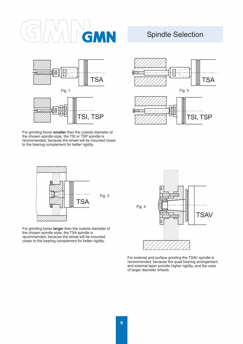
For grinding bores smaller then the outside diameter ofthe chosen spindle style, the TSI or TSP spindle isrecommended, because the wheel will be mounted closerto the bearing complement for better rigidity.
For grinding bores larger then the outside diameter ofthe chosen spindle style, the TSA spindle isrecommended, because the wheel will be mountedcloser to the bearing complement for better rigidity.
For external and surface grinding the TSAV spindle isrecommended, because the quad bearing arrangement,and external taper provide higher rigidity, and the usesof larger diameter wheels.
7
SW
L
k
Bb
L
k
NZ
ο/ ο/Ah5
ο/
A -0,2ο/
M
d
L2 L1
ο/d
M
L1 L2
ο/
TSA - Style
Tool interface Pulley interface
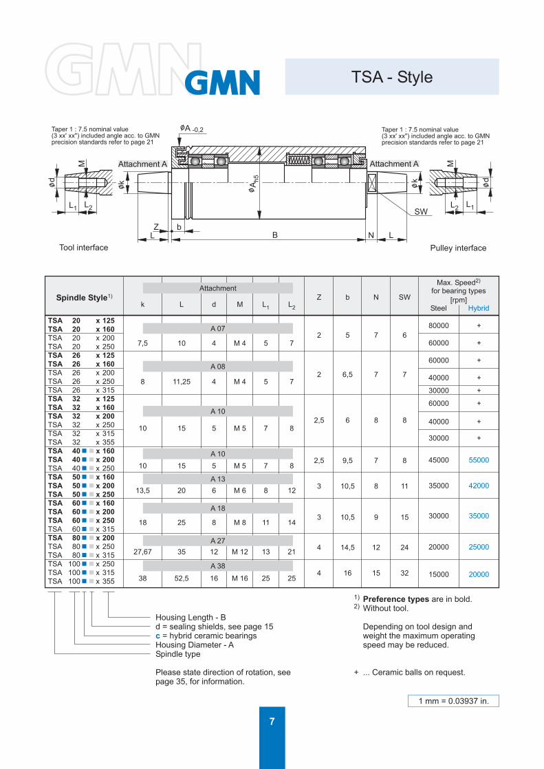
Taper 1 : 7.5 nominal value(3 xx' xx") included angle acc. to GMNprecision standards refer to page 21
Attachment A Attachment A
Taper 1 : 7.5 nominal value(3 xx' xx") included angle acc. to GMNprecision standards refer to page 21
Spindle Style1)
k L d M L1 L2
Z b N SW
Max. Speed2)
for bearing types[rpm]
Steel Hybrid
TSA 20 x 125TSA 20 x 160TSA 20 x 200TSA 20 x 250TSA 26 x 125TSA 26 x 160TSA 26 x 200TSA 26 x 250TSA 26 x 315TSA 32 x 125TSA 32 x 160TSA 32 x 200TSA 32 x 250TSA 32 x 315TSA 32 x 355TSA 40n n x 160TSA 40n n x 200TSA 40n n x 250TSA 50n n x 160TSA 50n n x 200TSA 50n n x 250TSA 60n n x 160TSA 60n n x 200TSA 60n n x 250TSA 60n n x 315TSA 80n n x 200TSA 80n n x 250TSA 80n n x 315TSA 100n n x 250TSA 100n n x 315TSA 100n n x 355
7,5 10 4 M 4 5 7
8 11,25 4 M 4 5 7
10 15 5 M 5 7 8
10 15 5 M 5 7 8
13,5 20 6 M 6 8 12
18 25 8 M 8 11 14
27,67 35 12 M 12 13 21
38 52,5 16 M 16 25 25
2 5 7 6
2 6,5 7 7
2,5 6 8 8
2,5 9,5 7 8
3 10,5 8 11
3 10,5 9 15
4 14,5 12 24
4 16 15 32
80000 +
60000 +
60000 +
40000 +
30000 +
60000 +
40000 +
30000 +
45000 55000
35000 42000
30000 35000
20000 25000
15000 20000
1) Preference types are in bold.2) Without tool.
Housing Length - Bd = sealing shields, see page 15 Depending on tool design andc = hybrid ceramic bearings weight the maximum operatingHousing Diameter - A speed may be reduced.Spindle type
Please state direction of rotation, see + ... Ceramic balls on request.page 35, for information.
Attachment
A 07
A 08
A 10
A 10
A 13
A 18
A 27
A 38
1 mm = 0.03937 in.

8
SW
Zb
ο/W
B
ο/Ah5
N L3
ο/k2
ο/ A -0,2
ο/d
L 4 L 5
M2
ο/k1
L1 L2
M1
TSI - Style
Taper 1 : 7.5 nominal value(3 xx' xx") included angle acc. to GMNprecision standards refer to page 21
Taper 1 : 7.5 nominal value(3 xx' xx") included angle acc. to GMNprecision standards refer to page 21
Tool interface Pulley interface
Attachment IAttachment A
Spindle Style1)k1 L1 L2 M1
W Z SW b Nk2 L3 d M2 L4 L5
Max. speed2)
for bearing types[rpm]
Steel Hybrid
TSI 40 n n x 160TSI 40 n n x 200TSI 40 n n x 250TSI 50 n n x 160TSI 50 n n x 200TSI 50 n n x 250TSI 60 n n x 160TSI 60 n n x 200TSI 60 n n x 250TSI 60 n n x 315TSI 60 n n x 355TSI 80 n n x 200TSI 80 n n x 250TSI 80 n n x 315TSI 80 n n x 355TSI 100 n n x 250TSI 100 n n x 315TSI 100 n n x 355
10 26 16 M 6
14 35 17 M 8
18 45 19 M 10
25 63 25 M 12
32 80 34 M 20
19 6 17 9,5 6
22 6 19 10,5 7
27 8 24 10,5 7
33,7 11 30 14,5 8
43,7 13 41 16 12
10 15 5 M 5 8 7
13,5 20 6 M 6 12 8
18 25 8 M 8 14 11
27,67 35 12 M 12 21 13
38 52,5 16 M 16 25 25
45000 55000
35000 42000
30000 35000
20000 25000
15000 20000
1) Preference types are in bold.2) Without tool.
Housing Length - Bd = sealing shields, see page 15 Depending on tool design andc = hybrid ceramic bearings weight the maximum operatingHousing Diameter - A speed may be reduced .Spindle type
Please state direction of rotation, seepage 35, for information.
Attachment
I 10
I 14
I 18
I 25
I 32
Attachment
A 10
A 13
A 18
A 27
A 38
1 mm = 0.03937 in.

9
SW
Zb
ο/W
B
ο/Ah5
N L3
ο/k
ο/ A -0,2
L 4 L 5
M2
ο/d1
ο/dH
5
1M
1L 2L
TSP - Style
Taper 1 : 7.5 nominal value(3 xx' xx") included angle acc. to GMNprecision standards refer to page 21
Tool interface Pulley interface
Attachment A
Attachment D
Spindle Style1)Attachment
D [d] / [W]L1 L2 M1 b Z SW N
k L3 d1 M2 L4 L5
Max. speed2)
for bearing types[rpm]
Steel Hybrid
TSP 40 n n x 160TSP 40 n n x 200TSP 40 n n x 250TSP 50 n n x 160TSP 50 n n x 200TSP 50 n n x 250TSP 60 n n x 160TSP 60 n n x 200TSP 60 n n x 250TSP 60 n n x 315TSP 60 n n x 355TSP 80 n n x 200TSP 80 n n x 250TSP 80 n n x 315TSP 80 n n x 355TSP 100 n n x 250TSP 100 n n x 315TSP 100 n n x 355
D 08/14
D 10/18
D 14/23
D 16/33
D 28/43
12 14 M 8 9,5 6 13 6
15 19 M 10 10,5 8 15 7
20 19 M 14 x 1,5 10,7 10 19 7
24 19 M 16 x 1,5 14,5 11 27 8
42 25 M 28 x 2 16 13 36 12
10 15 5 M 5 8 7
13,5 20 6 M 6 12 8
18 25 8 M 8 14 11
27,67 35 12 M 12 21 13
38 52,5 16 M 16 25 25
45000 55000
35000 42000
30000 35000
20000 25000
15000 20000
Attachment
A 10
A 13
A 18
A 27
A 38
1) Preference types are in bold.2) Without tool.
Housing Length - Bd = sealing shields, see page 15 Depending on tool design andc = hybrid ceramic bearings weight the maximum operatingHousing Diameter - A speed may be reduced.Spindle type
Please state direction of rotation, seepage 35, for information.
1 mm = 0.03937 in.
10
TSAV TSEV
TSA TSI TSP
A
SW
NB
b
ZLf
M
L fA
M
-0,2 h5
ο/ ο/
ο/du
kο/
kο/
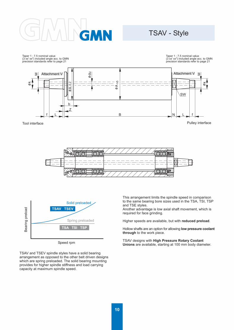
TSAV - Style
Taper 1 : 7.5 nominal value(3 xx' xx") included angle acc. to GMNprecision standards refer to page 21
Tool interface Pulley interface
Speed rpm
Bea
ring
prel
oad
Spring preloaded
Solid preloaded
Attachment V Attachment V
Taper 1 : 7.5 nominal value(3 xx' xx") included angle acc. to GMNprecision standards refer to page 21
TSAV and TSEV spindle styles have a solid bearingarrangement as opposed to the other belt driven designswhich are spring preloaded. The solid bearing mountingprovides for higher spindle stiffness and load carryingcapacity at maximum spindle speed.
This arrangement limits the spindle speed in comparisonto the same bearing bore sizes used in the TSA, TSI, TSPand TSE styles.Another advantage is low axial shaft movement, which isrequired for face grinding.
Higher speeds are available, but with reduced preload.
Hollow shafts are an option for allowing low pressure coolantthrough to the work piece.
TSAV designs with High Pressure Rotary CoolantUnions are available, starting at 100 mm body diameter.
11
TSAV - Style
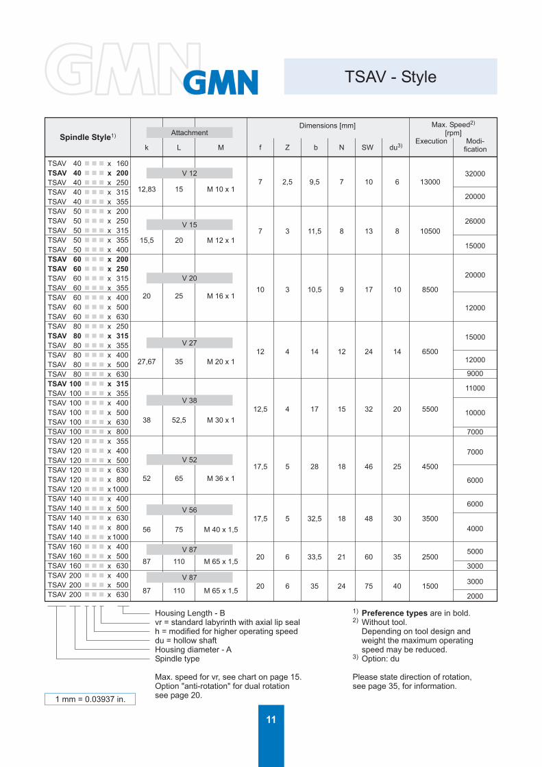
Spindle Style1)
k L M
Dimensions [mm]
f Z b N SW du3)
Max. Speed2)
[rpm]Execution Modi-
fication
TSAV 40 n n n x 160TSAV 40 n n n x 200TSAV 40 n n n x 250TSAV 40 n n n x 315TSAV 40 n n n x 355TSAV 50 n n n x 200TSAV 50 n n n x 250TSAV 50 n n n x 315TSAV 50 n n n x 355TSAV 50 n n n x 400TSAV 60 n n n x 200TSAV 60 n n n x 250TSAV 60 n n n x 315TSAV 60 n n n x 355TSAV 60 n n n x 400TSAV 60 n n n x 500TSAV 60 n n n x 630TSAV 80 n n n x 250TSAV 80 n n n x 315TSAV 80 n n n x 355TSAV 80 n n n x 400TSAV 80 n n n x 500TSAV 80 n n n x 630TSAV 100 n n n x 315TSAV 100 n n n x 355TSAV 100 n n n x 400TSAV 100 n n n x 500TSAV 100 n n n x 630TSAV 100 n n n x 800TSAV 120 n n n x 355TSAV 120 n n n x 400TSAV 120 n n n x 500TSAV 120 n n n x 630TSAV 120 n n n x 800TSAV 120 n n n x 1000TSAV 140 n n n x 400TSAV 140 n n n x 500TSAV 140 n n n x 630TSAV 140 n n n x 800TSAV 140 n n n x 1000TSAV 160 n n n x 400TSAV 160 n n n x 500TSAV 160 n n n x 630TSAV 200 n n n x 400TSAV 200 n n n x 500TSAV 200 n n n x 630
12,83 15 M 10 x 1
15,5 20 M 12 x 1
20 25 M 16 x 1
27,67 35 M 20 x 1
38 52,5 M 30 x 1
52 65 M 36 x 1
56 75 M 40 x 1,5
87 110 M 65 x 1,5
87 110 M 65 x 1,5
7 2,5 9,5 7 10 6 13000
7 3 11,5 8 13 8 10500
10 3 10,5 9 17 10 8500
12 4 14 12 24 14 6500
12,5 4 17 15 32 20 5500
17,5 5 28 18 46 25 4500
17,5 5 32,5 18 48 30 3500
20 6 33,5 21 60 35 2500
20 6 35 24 75 40 1500
32000
20000
26000
15000
20000
12000
15000
12000
9000
11000
10000
7000
7000
6000
6000
4000
5000
3000
3000
2000
Attachment
V 12
V 15
V 20
V 27
V 38
V 52
V 56
V 87
V 87
Housing Length - B 1) Preference types are in bold.vr = standard labyrinth with axial lip seal 2) Without tool.h = modified for higher operating speed Depending on tool design anddu = hollow shaft weight the maximum operatingHousing diameter - A speed may be reduced.Spindle type 3) Option: du
Max. speed for vr, see chart on page 15. Please state direction of rotation,Option "anti-rotation" for dual rotation see page 35, for information.see page 20.1 mm = 0.03937 in.
12
T
f
M
SW
Z
bL
C
D
B
A
CF
o /
h5o /
A
ko /
A -0,2
o/
PG
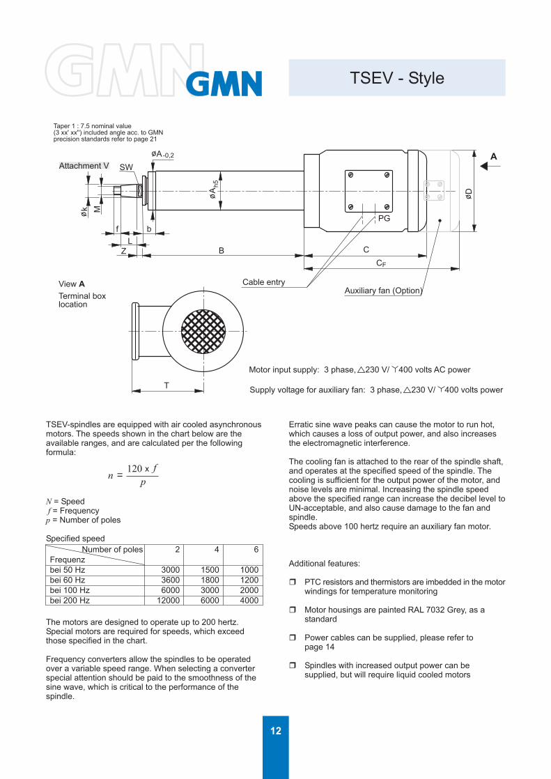
TSEV - Style
Cable entryAuxiliary fan (Option)
Taper 1 : 7.5 nominal value(3 xx' xx'') included angle acc. to GMNprecision standards refer to page 21
Attachment V
View ATerminal boxlocation
Motor input supply: 3 phase, 230 V/ 400 volts AC power
Supply voltage for auxiliary fan: 3 phase, 230 V/ 400 volts power
TSEV-spindles are equipped with air cooled asynchronousmotors. The speeds shown in the chart below are theavailable ranges, and are calculated per the followingformula:
N = Speed f = Frequencyp = Number of poles
Specified speed
The motors are designed to operate up to 200 hertz.Special motors are required for speeds, which exceedthose specified in the chart.
Frequency converters allow the spindles to be operatedover a variable speed range. When selecting a converterspecial attention should be paid to the smoothness of thesine wave, which is critical to the performance of thespindle.
Number of poles 2 4 6Frequenzbei 50 Hz 3000 1500 1000bei 60 Hz 3600 1800 1200bei 100 Hz 6000 3000 2000bei 200 Hz 12000 6000 4000
Erratic sine wave peaks can cause the motor to run hot,which causes a loss of output power, and also increasesthe electromagnetic interference.
The cooling fan is attached to the rear of the spindle shaft,and operates at the specified speed of the spindle. Thecooling is sufficient for the output power of the motor, andnoise levels are minimal. Increasing the spindle speedabove the specified range can increase the decibel level toUN-acceptable, and also cause damage to the fan andspindle.Speeds above 100 hertz require an auxiliary fan motor.
Additional features:
r PTC resistors and thermistors are imbedded in the motorwindings for temperature monitoring
r Motor housings are painted RAL 7032 Grey, as astandard
r Power cables can be supplied, please refer topage 14
r Spindles with increased output power can besupplied, but will require liquid cooled motors
pf
nx
= 120

13
TSEV - Style
Spindle Style1)
k L M
Dimensions [mm]
f Z b SW D C CF TPG
Power2)
[kW]Max. Speed3)
[rpm]nB
4) nmax5)
TSEV 50 n n x 200 - 071/2TSEV 50 n n x 250 - 071/2TSEV 50 n n x 315 - 071/2TSEV 60 n n x 200 - 080/2TSEV 60 n n x 250 - 080/2TSEV 60 n n x 315 - 080/2TSEV 60 n n x 355 - 080/2TSEV 80 n n x 250 - 090/2TSEV 80 n n x 315 - 090/2TSEV 80 n n x 355 - 090/2TSEV 80 n n x 400 - 090/2TSEV 80 n n x 500 - 090/2TSEV 100 n n x 315 - 112/2TSEV 100 n n x 355 - 112/2TSEV 100 n n x 400 - 112/2TSEV 100 n n x 500 - 112/2TSEV 100 n n x 630 - 112/2TSEV 100 n n x 315 - 112/4TSEV 100 n n x 355 - 112/4TSEV 100 n n x 400 - 112/4TSEV 100 n n x 500 - 112/4TSEV 100 n n x 630 - 112/4TSEV 120 n n x 355 - 132/2TSEV 120 n n x 400 - 132/2TSEV 120 n n x 500 - 132/2TSEV 120 n n x 800 - 132/2TSEV 120 n n x 1000 - 132/2TSEV 120 n n x 355 - 132/4TSEV 120 n n x 400 - 132/4TSEV 120 n n x 500 - 132/4TSEV 120 n n x 800 - 132/4TSEV 120 n n x 1000 - 132/4TSEV 140 n n x 400 - 132/2TSEV 140 n n x 500 - 132/2TSEV 140 n n x 630 - 132/2TSEV 140 n n x 800 - 132/2TSEV 140 n n x 1000 - 132/2TSEV 140 n n x 400 - 132/4TSEV 140 n n x 500 - 132/4TSEV 140 n n x 630 - 132/4TSEV 140 n n x 800 - 132/4TSEV 140 n n x 1000 - 132/4TSEV 160 n n x 400 - 160/4TSEV 160 n n x 500 - 160/4TSEV 160 n n x 400 - 160/6TSEV 160 n n x 500 - 160/6
15,5 20 M 12 x 1
20 25 M 16 x 1
27,67 35 M 20 x 1
38 52,5 M 30 x 1
38 52,5 M 30 x 1
52 65 M 36 x 1
52 65 M 36 x 1
56 75 M 40 x 1,5
56 75 M 40 x 1,5
87 110 M 65 x 1,5
87 110 M 65 x 1,5
Attachment
V 15
V 20
V 27
V 38
V 38
V 52
V 52
V 56
V 56
V 87
V 87
7 8 11,5 13 138 222 326 127 11 0,55 4800
10 9 11,5 17 156 238,5 343,5 138,5 16 1,1 4800
12 12 14,5 24 176 282,5 386,5 151 16 2,2 4800
12,5 15 17,5 32 218 312,5 406,5 169,5 16 4 4800
12,5 15 17,5 32 218 312,5 406,5 169,5 16 4 2400
17,5 18 28 46 258 397 528 189,5 16 7,5 4800
17,5 18 28 46 258 397 528 189,5 16 7,5 2400
17,5 18 32,5 48 258 402 518 189,5 16 7,5 3500
17,5 18 32,5 48 258 409 539 189,5 16 7,5 2400
20 21 33,5 60 310 521 672 225 21 11 2400
20 21 33,5 60 310 521 672 225 21 11 1600
1050024000
850020000
650015000
650012000
550010000
55006000
48006000
45006000
35004000
35006000
35004000
2500450025003000
Unit size / Number of poles 1) Preference types are in bold.Housing length - B 2) Power at 50 Hz.vr = standard labyrinth with axial lip seal 3) Without tool.F = auxiliary cooling fan Depending on tool design andHousing diameter - A weight the maximum operating speedSpindle type may be reduced.
4) Max. speed for standard fan.5) Speed for standard bearing application.
Max. speed for vr, see page 15. Marked = Speed for modified bearingapplication and if necessarya special motor.
Please state speed range and directionof rotation, see page 35, for information.
1 mm = 0.03937 in.1 kW = 1.34102 h.p.
14
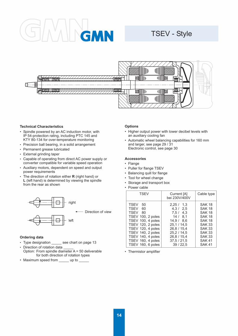
TSEV - Style
Direction of view
Technical Characteristics• Spindle powered by an AC induction motor, with
IP 54-protection rating, including PTC 145 andKTY 80-134 for over-temperature monitoring
• Precision ball bearing, in a solid arrangement• Permanent grease lubricated• External grinding taper• Capable of operating from direct AC power supply or
converter compatible for variable speed operation• Auxiliary motors, dependent on speed and output
power requirements• The direction of rotation either R (right hand) or
L (left hand) is determined by viewing the spindlefrom the rear as shown
right
left
Ordering data• Type designation _____ see chart on page 13• Direction of rotation data _____
Option: From spindle diameter A = 50 deliverable for both direction of rotation types• Maximum speed from _____ up to _____
Options• Higher output power with lower decibel levels with
an auxiliary cooling fan• Automatic wheel balancing capabilities for 160 mm
and larger, see page 29 / 31Electronic control, see page 30
Accessories• Flange• Puller for flange TSEV• Balancing quill for flange• Tool for wheel change• Storage and transport box• Power cable
TSEV 50 2,25 / 1,3 SAK 18TSEV 60 4,3 / 2,5 SAK 18TSEV 80 7,5 / 4,3 SAK 18TSEV 100, 2 poles 14 / 8,1 SAK 18TSEV 100, 4 poles 14,9 / 8,6 SAK 18TSEV 120, 2 poles 25,1 / 14,5 SAK 33TSEV 120, 4 poles 26,8 / 15,4 SAK 33TSEV 140, 2 poles 25,2 / 14,5 SAK 33TSEV 140, 4 poles 26,8 / 15,4 SAK 33TSEV 160, 4 poles 37,5 / 21,5 SAK 41TSEV 160, 6 poles 39 / 22,5 SAK 41
TSEV Current [A] Cable typebei 230V/400V
• Thermistor amplifier
15
M 5
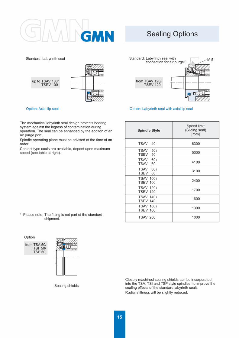
Sealing Options
Option: Axial lip seal Option: Labyrinth seal with axial lip seal
Standard: Labyrinth seal Standard: Labyrinth seal with connection for air purge1)
Sealing shields
Option
from TSA 50/ TSI 50/ TSP 50
from TSAV 120/ TSEV 120
up to TSAV 100/ TSEV 100
The mechanical labyrinth seal design protects bearingsystem against the ingress of contamination duringoperation. The seal can be enhanced by the additon of anair purge port.Spindle operating plane must be advised at the time of anorder.Contact type seals are available, depent upon maximumspeed (see table at right).
1) Please note: The fitting is not part of the standardshipment.
Closely machined sealing shields can be incorporatedinto the TSA, TSI and TSP style spindles, to improve thesealing effects of the standard labyrinth seals.Radial stiffness will be slightly reduced.
Spindle StyleSpeed limit
(Sliding seal)[rpm]
TSAV 40
TSAV 50 /TSEV 50TSAV 60 /TSAV 60TSAV 80 /TSEV 80TSAV 100 /TSEV 100TSAV 120 /TSEV 120TSAV 140 /TSEV 140TSAV 160 /TSEV 160
TSAV 200
6300
5000
4100
3100
2400
1700
1600
1300
1000

16
Cutting Speed
Spindlespeed[rpm]
Wheel diameterE [mm]
80000
70000
60000
55000
50000
45000
40000
35000
33000
32000
30000
27000
25000
24000
23000
22500
21000
20000
19000
18000
16000
15000
14000
13500
13000
12500
12000
11500
11000
10500
10000
9000
8000
7500
7000
6000
5500
5000
4000
2860
1440
4 5 6 8 10 13 16 20 32 40 50 63 80 100 125 175 200 250
16,8 20,9 25,1 33,5 41,9 54,5 67,0 83,8
14,7 18,3 22,0 29,3 36,7 47,6 58,6 73,3
12,6 15,7 18,8 25,1 31,4 40,8 50,3 62,8
11,5 14,4 17,3 23,0 28,8 37,4 46,1 57,6 92,2
10,5 13,1 15,7 20,9 26,2 34,0 41,9 52,4 83,8
11,8 14,1 18,8 23,6 30,6 37,7 47,1 75,4 94,2
10,5 12,6 16,8 20,9 27,2 33,5 41,9 67,0 83,8
11,0 14,7 18,3 23,8 29,3 36,7 58,6 73,3 91,6
10,4 13,8 17,3 22,5 27,6 34,6 55,3 69,1 86,4
10,1 13,4 16,8 21,8 26,8 33,5 53,6 67,0 83,8
12,6 15,7 20,4 25,1 31,4 50,3 62,8 78,5 99,0
11,3 14,1 18,4 22,6 28,3 45,2 56,5 70,7 89,1
10,5 13,1 17,0 20,9 26,2 41,9 52,4 65,4 82,5
10,1 12,6 16,3 20,1 25,1 40,2 50,3 62,8 79,2
12,0 15,7 19,3 24,1 38,5 48,2 60,2 75,9 96,3
11,8 15,3 18,8 23,6 37,7 47,1 58,9 74,2 94,2
11,0 14,3 17,6 22,0 35,2 44,0 55,0 69,3 88,0
10,5 13,6 16,8 20,9 33,5 41,9 52,4 66,0 83,8
12,9 15,9 19,9 31,8 39,8 49,7 62,7 79,6 99,5
12,3 15,1 18,8 30,2 37,7 47,1 59,4 75,4 94,2
10,9 13,4 16,8 26,8 33,5 41,9 52,8 67,0 83,8
12,6 15,7 25,1 31,4 39,3 49,5 62,8 78,5 98,2
11,7 14,7 23,5 29,3 36,7 46,2 58,6 73,3 91,6
11,3 14,1 22,6 28,3 35,3 44,5 56,5 70,7 88,4
10,9 13,6 21,8 27,2 34,0 42,9 54,5 68,1 85,1
10,5 13,1 20,9 26,2 32,7 41,2 52,4 65,4 81,8
10,1 12,6 20,1 25,1 31,4 39,6 50,3 62,8 78,5
12,0 19,3 24,1 30,1 37,9 48,2 60,2 75,3
11,5 18,4 23,0 28,8 36,3 46,1 57,6 72,0
11,0 17,6 22,0 27,5 34,6 44,0 55,0 68,7 96,2
10,5 16,8 20,9 26,2 33,0 41,9 52,4 65,4 91,6
15,1 18,8 23,6 29,7 37,7 47,1 58,9 82,5 94,2
13,4 16,8 20,9 26,4 33,5 41,9 52,4 73,3 83,8
12,6 15,7 19,6 24,7 31,4 39,3 49,1 68,7 78,5 98,2
11,7 14,7 18,3 23,1 29,3 36,7 45,8 64,1 73,3 91,6
10,1 12,6 15,7 19,8 25,1 31,4 39,3 55,0 62,8 78,5
11,5 14,4 18,1 23,0 28,8 36,0 50,4 57,6 72,0
10,5 13,1 16,5 20,9 26,2 32,7 45,8 52,4 65,4
10,5 13,2 16,8 20,9 26,2 36,7 41,9 52,4
12,0 15,0 18,7 26,2 29,9 37,4
13,2 15,1 18,8
1 mm = 0.03937 in.1 m = 1.09361 yd.
vc = E · π · n
[m/s]
E = Wheel diameter [mm]n = Spindle speed [1/min]
60 · 1000
Cutting speed vc [m/s]

17
F
E P G
Q L
ο/ ο/ ο/
TSA - Grinding Wheel Flanges
Balancing screws
Flange style MO Flange style MS
Spindle style Attachment Flange Flange dimensions [mm] Grinding wheel [mm] Max. speed2)
style P Q L E F G1) [rpm]
TSA 20 A 07 MO 20 6,5 1,5 25 8 13 27000
TSA 26 A 08 MO 26 5,5 3,5 36 10 16 20000
TSA 32 A 10 MO 32 6,5 3,5 50 13 20 15000
TSA 40 A 10 MS 40 6 6 63 16 25 12000
TSA 50 A 13 MS 50 6 9 80 20 32 10000
TSA 60 A 18 MS 60 7 9 100 25 32 8000
TSA 80 A 27 MS 80 9 10 125 32 51 6000
TSA 100 A 38 MS 100 15 13 150 40 76 5000
Ordering Information:Flange An /n /n
Type of wheel:D = Diamond or CBNK = Corundum or Non diamondFlange style = MO / MSAttachment = A 07 / A 08 etc.
Puller for flange An /nFlange style = MO etc.Attachment = A 07 etc.
Balancing quill for flange AnAttachment = A 07 etc.
Please state direction of rotation, see page 35,for information.
1) Wheel bore fits:Corundum or Non diamond: Gf7Diamond or CBN: Gh42) Wheel selection must be in accordance with themanufacturer's recommandation for maximum speed.Compliance with ANSI Safety Requirements B 7.1must be adhered to.
Balancing Specifications:For safety reasons, noise levels, and finish quality allrotating components including the grinding wheelsmust be balanced.GMN recommend balancing the system within G 2.5level, according to ISO 1940.
1 mm = 0.03937 in.

18
ο/ ο/ ο/E P G
Q F L1 1
ο/ο/ο/ο/E U P G
Q
VF L2 2
TSAV / TSEV - Grinding Wheel Flanges
Balancing screws
Fig. 1 Fig. 2
Fig. 3 Fig. 4
Flange style MS Flange style MS
Flange style SN Flange style SN
Balancing weights

19
TSAV / TSEV - Grinding Wheel Flanges
Attachment Fig.Flange dimensions [mm]P Q L1 L2
Grinding wheel [mm]Straight wheel Cup wheel
E G1) F1 F2 U V(Spannbereich)
Max.speed2)
(vc = 35 m/s)[rpm]
TSAV 40
TSAV 50 /TSEV 50
TSAV 60 /TSEV 60
TSAV 80 /TSEV 80
TSAV 100 /TSEV100
TSAV 120 /TSEV120
TSAV 140 /TSEV140
TSAV 160 /TSEV160
TSAV 200
V 12
V 15
V 20
V 27
V 38
V 52
V 56
V 87
V 87
1+2 40 6 6 14 100 25
1 40 6 6 --- 80 25
1+2 50 6 9 19 125 32
1 50 6 9 --- 100 32
1+2 60 7 9 21 150 40
2 60 7 9 --- 125 40
1+2 80 9 10 22 200 51
2 80 9 10 --- 150 51
3+4 110 13 13 28 250 76
1+2 110 13,5 13 30 175 76
3+4 165 16 16 44 350 127
1 120 15 16 --- 200 76
3+4 180 18 18 46 450 127
1 140 14 18 --- 250 76
3+4 270 22 22 --- 600 203
3+4 270 22 22 --- 600 203
16(11-16)
16(11-16)
20(14-20)
20(14-20)
25(17-25)
25(17-25)
32(21-32)
32(21-32)
40(20-40)
40(30-40)
60(25-60)
60(45-60)
60(32-60)
60(46-60)
80(40-80)
80(40-80)
50 90 42 6600
--- --- --- 8300
63 110 53 5300
--- --- --- 6600
80 130 67 4400
--- --- --- 5300
100 170 80 3300
--- --- --- 4400
125 190 100 2600
--- --- --- 3800
150 235 118 1900
--- --- --- 3300
150 260 118 1400
--- --- --- 2600
--- --- --- 1100
--- --- --- 1100
Orgering Information:Flange V n /n /n /n
Type of wheel:D = Diamond or CBNK = Corundum or Non diamondG = straight wheelT = cup wheelFlange style = MS / SNAttachment V 12 / V 15 etc.
Puller for flange V 12 / V 15 etc.Balancing quill for flange V 12 / V 15 etc.
Please state direction of rotation, see page 35,for information.
1) Wheel bore fits:Corundum or Non diamond: Gf7Diamond or CBN: Gh42) Wheel selection must be in accordance with themanufacturer's recommandation for maximum speed.Compliance with ANSI Safety Requirements B 7.1must be adhered to.
TSAV / TSEV 50 - 80:• Flange style MS (Fig. 1, 2):
Option: anti-rotation slotFrom TSAV / TSEV 100:• Flange style SN (Fig. 3, 4):
Standard: anti-rotation slot
SpindleStyle
1 mm = 0.03937 in.1 m = 1.09361 yd.

20
N
k
mn
n
Z
ο/
ο/
Lf
MAnti-Rotation Option
Spindle Style AttachmentAttachment dimensions [mm] Dimensions [mm]k L M f m n Z N
TSAV 40 V 12 12,83 15 M 10 x 1 7
TSAV 50 V 15 15,5 20 M 12 x 1 7 3 3 3 8
TSAV 60 V 20 20 25 M 16 x 1 10 3 3 3 9
TSAV 80 V 27 27,67 35 M 20 x 1 12 4 3 4 12
TSAV 100 V 38 38 52,5 M 30 x 1 12,5 5 4 4 15
TSAV 120 V 52 52 65 M 36 x 1 17,5 6 5 5 18
TSAV 140 V 56 56 75 M 40 x 1,5 17,5 6 5 5 18
TSAV 160 V 87 87 110 M 65 x 1,5 20 8 6 6 21
TSAV 200 V 87 87 110 M 65 x 1,5 20 8 6 6 24
TSEV 50 V 15 15,5 20 M 12 x 1 7 3 3 8
TSEV 60 V 20 20 25 M 16 x 1 10 3 3 9
TSEV 80 V 27 27,67 35 M 20 x 1 12 4 3 12
TSEV100 V 38 38 52,5 M 30 x 1 12,5 5 4 15
TSEV120 V 52 52 65 M 36 x 1 17,5 6 5 18
TSEV140 V 52 56 75 M 40 x 1,5 17,5 6 5 18
TSEV160 V 87 87 110 M 65 x 1,5 20 8 6 24
1 mm = 0.03937 in.

21
1
Taper Specifications
Spindle Style Attachment Taper angle α
TSA 20 A 07 3° 50' 03''
TSA 26 A 08 3° 49' 33''
TSA 32 A 10 3° 49' 19''
TSA 40 A 10 3° 49' 19''
TSA 50 A 13 3° 48' 28''
TSA 60 A 18 3° 48' 13''
TSA 80 A 27 3° 48' 55''
TSA 100 A 38 3° 50' 28''
Spindle Style Attachment Taper angle α
TSAV 40
TSAV 50 /TSEV 50TSAV 60 /TSEV 60TSAV 80 /TSEV 80TSEV 100 /TSAV 100TSAV 120 /TSEV 120TSAV 140 /TSEV 140TSAV 160 /TSEV 160
TSAV 200
V 12 3° 49' 15''
V 15 3° 49' 06''
V 20 3° 48' 51''
V 27 3° 48' 55''
V 38 3° 50' 28''
V 52 3° 48' 51''
V 56 3° 49' 27''
V 87 3° 48' 48''
V 87 3° 48' 48''
Spindle Style Attachment Taper angle α
TSI 40 I 10 3° 49' 00''
TSI 50 I 14 3° 48' 42''
TSI 60 I 18 3° 48' 52''
TSI 80 I 25 3° 48' 49''
TSI 100 I 32 3° 49' 00''
Taper angle according to GMN standard.
22
ο/
F L
E
G K
O
ο/ ο/
ο/
H
O KS
LT
ο/ ο/ ο/
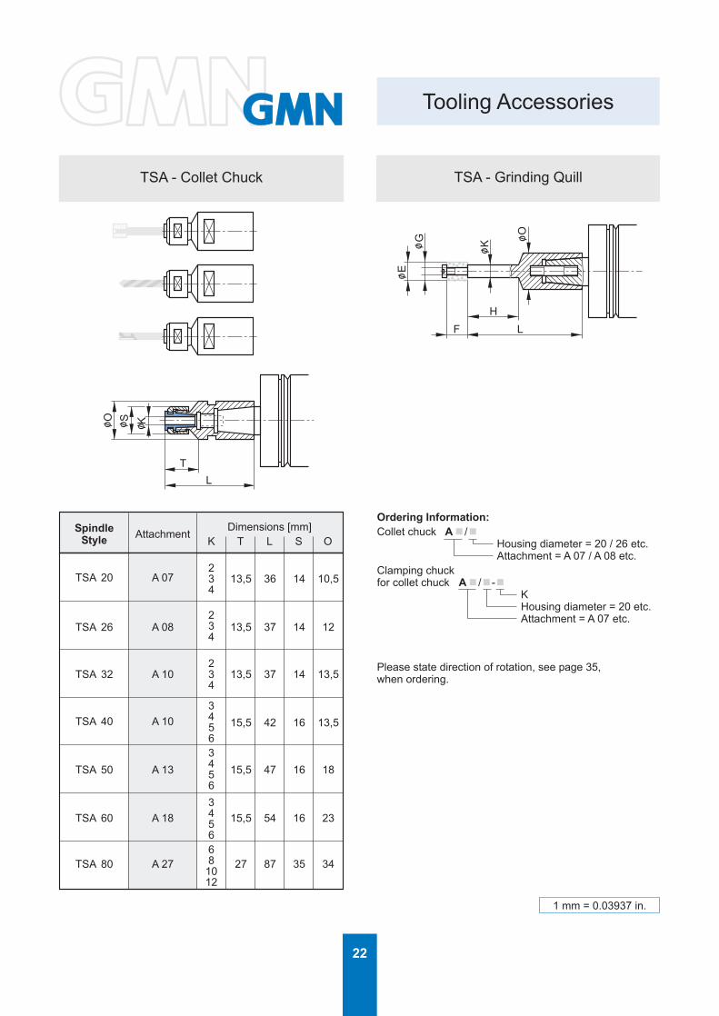
Tooling Accessories
TSA - Collet Chuck TSA - Grinding Quill
SpindleStyle Attachment
Dimensions [mm]K T L S O
TSA 20 A 07
TSA 26 A 08
TSA 32 A 10
TSA 40 A 10
TSA 50 A 13
TSA 60 A 18
TSA 80 A 27
234
234
234
34563456345668
1012
13,5 36 14 10,5
13,5 37 14 12
13,5 37 14 13,5
15,5 42 16 13,5
15,5 47 16 18
15,5 54 16 23
27 87 35 34
Ordering Information:Collet chuck An /n
Housing diameter = 20 / 26 etc.Attachment = A 07 / A 08 etc.
Clamping chuckfor collet chuck An /n-n
KHousing diameter = 20 etc.Attachment = A 07 etc.
Please state direction of rotation, see page 35,when ordering.
1 mm = 0.03937 in.
23
ο/
L
T
ο/
ο/K
S O
L
T
ο/K
ο/S ο/W
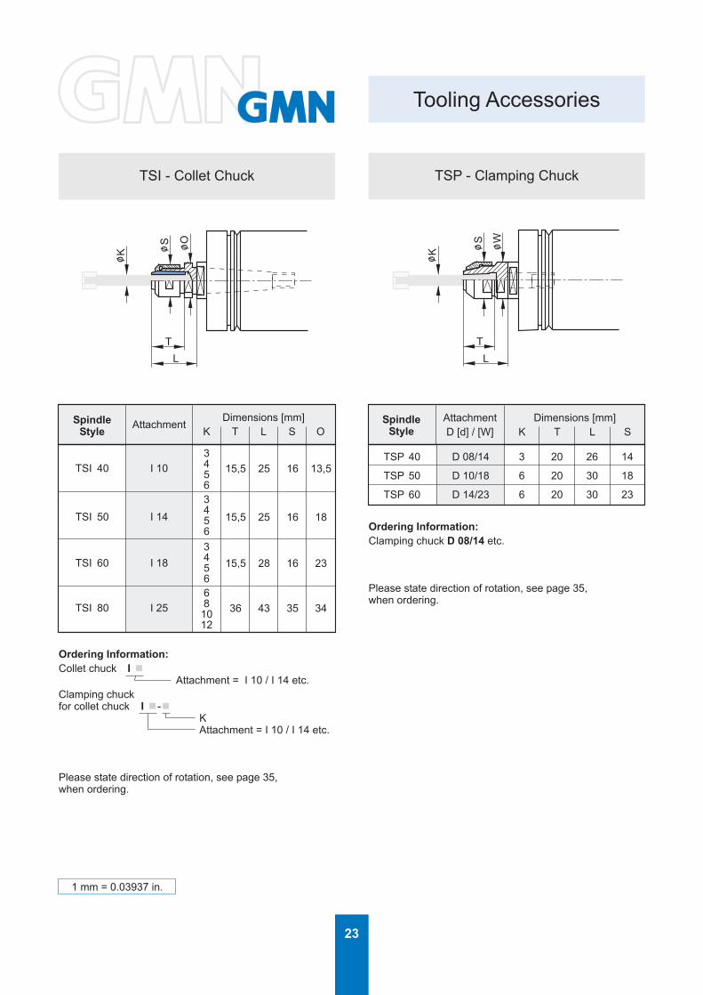
Tooling Accessories
TSI - Collet Chuck TSP - Clamping Chuck
SpindleStyle
AttachmentDimensions [mm]
K T L S O
TSI 40 I 10
TSI 50 I 14
TSI 60 I 18
TSI 80 I 25
34563456345668
1012
15,5 25 16 13,5
15,5 25 16 18
15,5 28 16 23
36 43 35 34
SpindleStyle
AttachmentD [d] / [W]
Dimensions [mm]K T L S
TSP 40 D 08/14 3 20 26 14
TSP 50 D 10/18 6 20 30 18
TSP 60 D 14/23 6 20 30 23
Ordering Information:Clamping chuck D 08/14 etc.
Please state direction of rotation, see page 35,when ordering.
Ordering Information:Collet chuck I n
Attachment = I 10 / I 14 etc.Clamping chuckfor collet chuck I n-n
KAttachment = I 10 / I 14 etc.
Please state direction of rotation, see page 35,when ordering.
1 mm = 0.03937 in.
24
H
F
ο/K
ο/d1H
5
M1
L 5 L 6
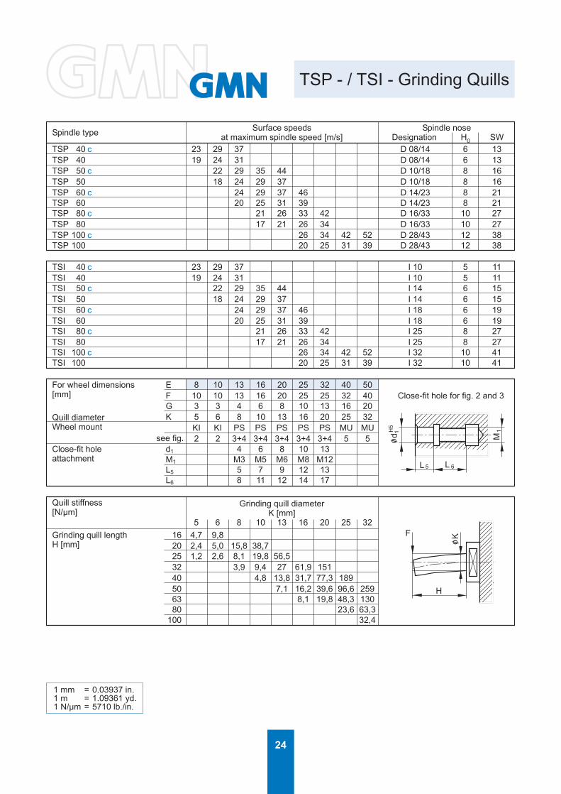
TSP - / TSI - Grinding Quills
Close-fit hole for fig. 2 and 3
Spindle type Surface speedsat maximum spindle speed [m/s]
Spindle noseDesignation H0 SW
D 08/14 6 13D 08/14 6 13D 10/18 8 16D 10/18 8 16D 14/23 8 21D 14/23 8 21D 16/33 10 27D 16/33 10 27D 28/43 12 38D 28/43 12 38
23 29 3719 24 31
22 29 35 4418 24 29 37
24 29 37 4620 25 31 39
21 26 33 4217 21 26 34
26 34 42 5220 25 31 39
TSP 40 cTSP 40TSP 50 cTSP 50TSP 60 cTSP 60TSP 80 cTSP 80TSP 100 cTSP 100
TSI 40 cTSI 40TSI 50 cTSI 50TSI 60 cTSI 60TSI 80 cTSI 80TSI 100 cTSI 100
23 29 3719 24 31
22 29 35 4418 24 29 37
24 29 37 4620 25 31 39
21 26 33 4217 21 26 34
26 34 42 5220 25 31 39
I 10 5 11I 10 5 11I 14 6 15I 14 6 15I 18 6 19I 18 6 19I 25 8 27I 25 8 27I 32 10 41I 32 10 41
For wheel dimensions[mm]
Quill diameterWheel mount
Close-fit holeattachment
see fig.
E 8 10 13 16 20 25 32 40 50F 10 10 13 16 20 25 25 32 40G 3 3 4 6 8 10 13 16 20K 5 6 8 10 13 16 20 25 32
KI KI PS PS PS PS PS MU MU2 2 3+4 3+4 3+4 3+4 3+4 5 5
d1 4 6 8 10 13M1 M3 M5 M6 M8 M12L5 5 7 9 12 13L6 8 11 12 14 17
Quill stiffness[N/µm]
Grinding quill lengthH [mm]
Grinding quill diameterK [mm]
5 6 8 10 13 16 20 25 3216 4,7 9,820 2,4 5,0 15,8 38,725 1,2 2,6 8,1 19,8 56,532 3,9 9,4 27 61,9 15140 4,8 13,8 31,7 77,3 18950 7,1 16,2 39,6 96,6 25963 8,1 19,8 48,3 13080 23,6 63,3
100 32,4
1 mm = 0.03937 in.1 m = 1.09361 yd.1 N/µm = 5710 lb./in.

25
MF H
SW
H0
L1 L2
Eο/
Gο/
Kο/ dο/
Wο/ M
F H
SW
H0
L1 L2
Eο/
Gο/
Kο/ dο/
Wο/
M
F H
SW
H0
L1 L2
Eο/
Gο/
Kο/ dο/
Wο/M
F H
SW
H0
L1 L2
Eο/
Gο/
Kο/ dο/
Wο/
1
M
F H
SW
H0
L1
Eο/
Gο/
Kο/
kο/1
M
F H
SW
H0
L1
Eο/
Gο/
Kο/
kο/1
M
F H
SW
H0
Eο/
Gο/
Kο/
L1
kο/1
M
F H
SW
H0
L1
Eο/
Gο/
Kο/
1
kο/1
H
Kο/
TSP - / TSI - Grinding Quills
Fig. 2: TSI - Cemented wheel (KI) Fig. 3: TSI - Close-fit wheel screw (PS)
Fig. 4: TSI - Threaded wheel studs (PS) Fig. 5: TSI - Quill with nut (MU)
Figures 2 through 5 are examples for quill applications.
Fig. 2: TSP - Cemented wheel (KI)
Fig. 4: TSP - Threaded wheel studs (PS)
Fig. 3: TSP - Close-fit wheel screw (PS)
Fig. 5: TSP - Quill with nut (MU)
TSP - / TSI - Grinding Quills - Semifinished
Semifinished Quills Attachment K [mm] H [mm] Attachment Semifinished QuillsTSP 40 (c) D08/14 13 70 I 10 TSI 40 (c)TSP 50 (c) D10/18 18 90 I 14 TSI 50 (c)TSP 60 (c) D14/23 23 135 I 18 TSI 60 (c)TSP 80 (c) D16/33 33 180 I 25 TSI 80 (c)TSP 100 (c) D28/43 43 240 I 32 TSI 100 (c)
1 mm = 0.03937 in.

26
Grinding Quill Selection Data
Maximum speed [rpm]Spindle nose interface: D 08/14 I 10
Spindle designation
TSP 40 cTSI 40 c
TSP 40TSI 40
H [mm]K [mm] < 16 20 25 32
5 540006 55000 530008 55000 55000 52000 500005 450006 45000 450008 45000 45000 45000 45000
Spindle nose interface: D 10/18 I 14Spindle designation
TSP 50 cTSI 50 c
TSP 50TSI 50
H [mm]K [mm] < 25 32 40
6 420008 42000 42000
10 42000 42000 420006 350008 35000 35000
10 35000 35000 35000Spindle nose interface: D 14/23 I 18
Spindle designation
TSP 60 cTSI 60 c
TSP 60TSI 60
H [mm]K [mm] < 32 40 50 63
8 3500010 35000 35000 3000013 35000 35000 3500016 35000 35000 35000 350008 30000
10 30000 30000 3000013 30000 30000 3000016 30000 30000 30000 30000
Spindle nose interface: D 16/33 I 25Spindle designation
TSP 80 cTSI 80 c
TSP 80TSI 80
H [mm]K [mm] < 63 80
10 2500013 25000 2500016 25000 2500020 25000 2500010 2000013 20000 2000016 20000 2000020 20000 20000
Spindle nose interface: D 28/43 I 32Spindle designation
TSP 100 cTSI 100 c
TSP 100TSI 100
H [mm]K [mm] < 80 100 125 160
16 2000020 20000 2000025 20000 20000 1800032 20000 20000 20000 1800016 1500020 15000 1500025 15000 15000 1500032 15000 15000 15000 15000
1 mm = 0.03937 in.

27
CT
ο/D
CT
ο/D
Pulleys
For SpindleTSA, TSI, TSP
Dimensions [mm]D C T
A 07
A 08
A 10
A 13
A 18
A 27
A 38
1428
1636
18501720256320253580253240
10040455056
125
5063
160
20
25
30
40
50
60
70
80
10
15
20
30
40
50
60
For SpindleTSAV
Dimensions [mm]D C T
V 12
V 15
V 20
V 27
V 38
V 52
V 56
V 87
4050
5063
6380
80100
80125
90160
120210
280
40 30
50 40
60 50
70 60
80 50
100 80
100 80
130 100
Ordering Information:Pulley An-n
DAttachment A 07 / A 08 etc.
Puller for pulley A 07 / A 08 etc.
Pulley Vn-nDAttachment V 12 / V 15 etc.
Puller for pulley V 12 / V 15 etc.
V 15 - V 27 (TSAV 50 - TSAV 80):• Option: anti-rotation slot
From V 38 (TSAV 100):• Standard: anti-rotation slot
1 mm = 0.03937 in.

28
ο/ 50
50
AX 97
Electromechanical balancing sytemTSAV-Spindleswith housing diameter 160 and 200 mm
TSAV 160 x 400 TSAV 200 x 400TSAV 160 x 500 TSAV 200 x 500TSAV 160 x 630 TSAV 200 x 630
consisting of:• Balancing motor• Vibration transducer• Transmitter with speed sensorOptions: • Extension cable for vibration transducer
• Extension cable for balancing motor
Electronic control, see page 30
TSAV - Balancing System
Vibration transducer CableStandard length 3m
Transmitter withspeed sensor
CableStandard length 3m
View A
Balancing motor
X
29
30°
ο/ 5050
A97
X
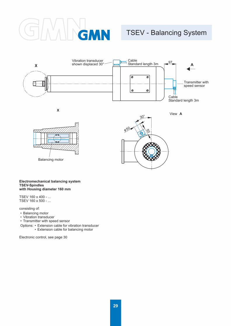
TSEV - Balancing System
X
CableStandard length 3m
CableStandard length 3m
View A
Vibration transducershown displaced 30°
Balancing motor
Transmitter withspeed sensor
Electromechanical balancing systemTSEV-Spindleswith Housing diameter 160 mm
TSEV 160 x 400 - ...TSEV 160 x 500 - ...
consisting of:• Balancing motor• Vibration transducer• Transmitter with speed sensorOptions: • Extension cable for vibration transducer
• Extension cable for balancing motor
Electronic control, see page 30

30
101
87
29
65
3
44
3
56
Balancing System
Automatic Balancing System
Electronic controlMultiplexer is required for multi spindle machines
Included in the delivery of the spindle:Vibration transducer with 3m cableOption: Extension cableInternal balancing sensorReceiverTransmitter with integrated speed sensor3m cableOption: Extension cable
Accessories:Extension cableExtension cableExtension cable
Please state length when ordering.

31
305
70
230
190
Balancing System
AC power input
FlangeGrinding wheel
Vibration sensor
Speed sensor
Balancing weight
Gratuated collar
PulleySpindleA
View A
Portable Unit For Manual Balancing
Bracket
Every rotating part incorporates a degree ofunbalance, which causes sinuous vibration duringrotation.To reduce the effect of unbalancing forces, theunbalancing mass of all rotating parts has to be limited.Shafts and all rotating components of GMN high precisionspindles are always balanced. As a result of higher cuttingspeeds this process is also required for tools. For largespindles automatic balancing systems are available. Werecommend the portable balancing system for smallerspindles.
Process• The vibration transducer with a magnetic base is
attached to either the spindle housing of mountingbracket
• Speed sensor must be positioned to read the speedof the spindle
• Portable unit automatically:• Records the spindle speed• Records vibration levels• Indicates the amount and position of unbalance• Calculates and indicates the corrected results
• To fix the balancing weight• Control and if necessary correction

32
1000 10000 10000010
100
1000
10000
TSA 20
TSA 26
TSA 32
TSA 40
TSA 50TSA 60
TSA 80TSA 100
1000 10000 10000010
100
1000
10000
TSA 40
TSA 50
TSA 60
TSA 80
TSA 100
Stiffness - Load Capacity
Radial stiffness andradial load capacityrelated to centerof taper
Axial loadand stiffnessdirection Adirection B
Speed [rpm]
Rad
ial l
oad
capa
city
[N]
Axi
al lo
ad c
apac
ity [N
]
Speed [rpm]
Style
Stiffness Load capacity[N/µm] [N]
axial radial axial radialA u. B A B
TSA 20 x 125TSA 20 x 160TSA 20 x 200TSA 20 x 250
TSA 26 x 125TSA 26 x 160TSA 26 x 200TSA 26 x 250TSA 26 x 315TSA 32 x 125TSA 32 x 160TSA 32 x 200TSA 32 x 250TSA 32 x 315TSA 32 x 355TSA 40*TSA 50*TSA 60*TSA 80*TSA 100*
12 3,5
17 3,5
14 5,0
20 5,0
15 8,0
21 8,0
32 2541 4151 57
67 9678 113
701) 351)
701) 701)
701) 351)
701) 701)
701) 351)
701) 701)
150225300
450540
see
diag
ram
see
diag
ram
* Data applicable to all spindle length.1) For low speed operation (<0.4 catalog specified speed). Axial load of 2 to 3 times higher then indicated can be
applied, for short periods, depending on noise andvibration levels.
1 N = 0.2248 lbf1 N/µm = 5710 lb./in.

33
1000 10000 10000010
100
1000
10000
TSI 40, TSP 40
TSI 50, TSP 50
TSI 60, TSP 60
TSI 80, TSP 80TSI 100, TSP 100
1000 10000 10000010
100
1000
10000
TSI 40, TSP 40
TSI 50, TSP 50
TSI 60, TSP 60
TSI 80, TSP 80
TSI 100, TSP 100
Stiffness - Load Capacity
Radial stiffness andradial load capacityrelated to spindle nose
Axial loadand stiffnessdirection Adirection B
Speed [rpm] Speed [rpm]
Rad
ial l
oad
capa
city
[N]
Axi
al lo
ad c
apac
ity [N
]
Style
Stiffness Load capacity[N/µm] [N]
axial radial axial radialA u. B A B
TSI / TSP 40TSI / TSP 50TSI / TSP 60
TSI / TSP 80TSI / TSP 100
32 3641 6551 85
67 14078 170
150225300
450540
see
diag
ram
see
diag
ram
Data applicable to all spindle lenghts.
The data provided is to serve as a guide for the proper selection of spindles for a particular application.
The load capacities provided are for either pure radial or axial loads. Combined loads can not be used at the maximiumvalues. Application should be analyzed by GMN Engineering Department for proper spindle selection.
The data can be used as a reference to suit your application and selection of a spindle to meet your requirements.GMN Engineering should be provided with all pertinent data to review each application to provide the optimum spindlefor your application.
5000 hours of B10 bearing life were used as a minimum for the calculation of spindle capacity.
Axial and radial stiffness’ calculation are static values.
1 N = 0.2248 lbf1 N/µm = 5710 lb./in.
34
AB
AB
100 1000 10000 100000100
1000
10000
100000
TSAV 40
TSAV 50TSAV 60
TSAV 80
TSAV 100
TSAV 120TSAV 140
TSAV 160
TSAV 200
100000
100 1000 10000 100000100
1000
10000
TSEV 50TSEV 60
TSEV 80
TSEV 100
TSEV 120TSEV 140
TSEV 160
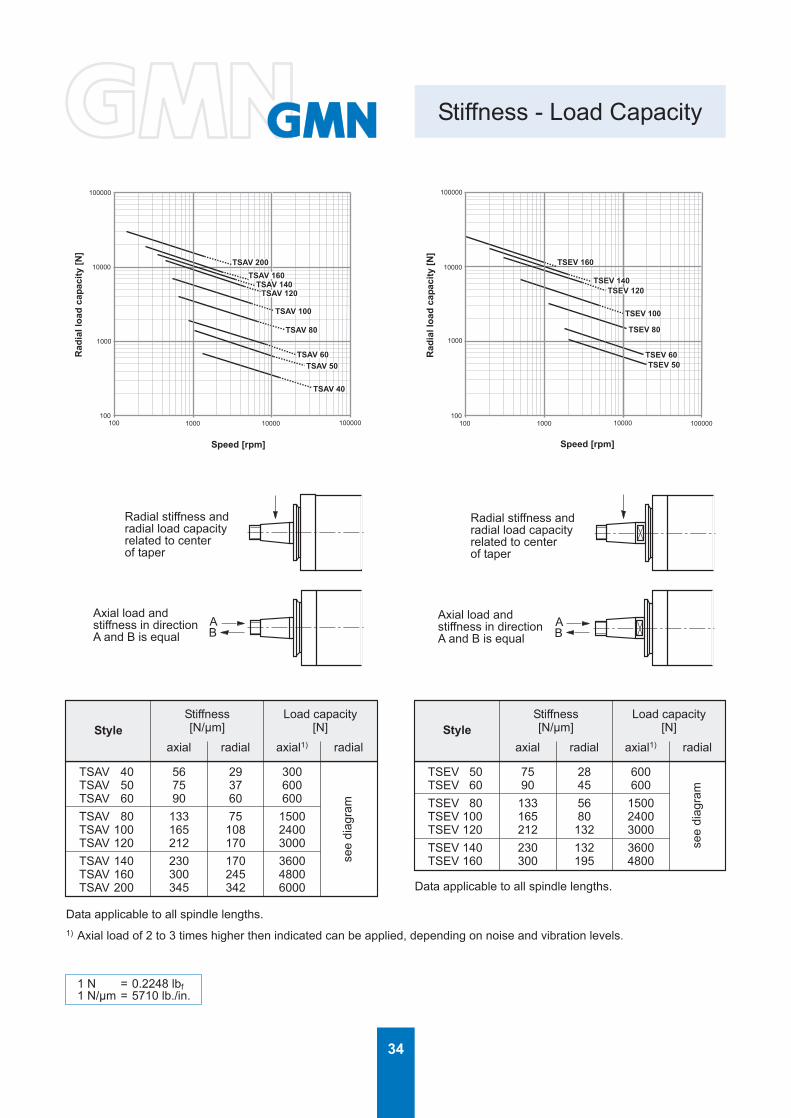
Stiffness - Load Capacity
Radial stiffness andradial load capacityrelated to centerof taper
Axial load andstiffness in directionA and B is equal
Radial stiffness andradial load capacityrelated to centerof taper
Axial load andstiffness in directionA and B is equal
Speed [rpm]
Rad
ial l
oad
capa
city
[N]
Speed [rpm]R
adia
l loa
d ca
paci
ty [N
]
StyleStiffness Load capacity[N/µm] [N]
axial radial axial1) radialStyle
Stiffness Load capacity[N/µm] [N]
axial radial axial1) radial
TSEV 50 75 28 600TSEV 60 90 45 600TSEV 80 133 56 1500TSEV 100 165 80 2400TSEV 120 212 132 3000TSEV 140 230 132 3600TSEV 160 300 195 4800
see
diag
ram
TSAV 40 56 29 300TSAV 50 75 37 600TSAV 60 90 60 600TSAV 80 133 75 1500TSAV 100 165 108 2400TSAV 120 212 170 3000TSAV 140 230 170 3600TSAV 160 300 245 4800TSAV 200 345 342 6000
see
diag
ram
Data applicable to all spindle lengths.
Data applicable to all spindle lengths.
1) Axial load of 2 to 3 times higher then indicated can be applied, depending on noise and vibration levels.
1 N = 0.2248 lbf1 N/µm = 5710 lb./in.

35
General Safety Rules
Guidelines
Grinding Wheels
Choosing the proper spindle and accessories is essentialin obtaining quality grinding performance, long operatinglife, and operator safety.GMN’s extensive manufacturing program can satisfy allyour requirements.
Selection criteria:
1. Choose the spindle with the largest diameter and the shortest length possible.
2. Choose quills, flanges and other wheel mounting accessories as large, robust and compact as possible.
3. Choose the largest spindle, with the necessary speed requirements, as recommended by the wheelmanufacturer, or a spindle with slightly highercapabilities. This will assure maximum bearing life.
4. If possible always select a direct motorized style over the belt driven design. The total system is morecompact, speed changes are effortless, and belttensioning is eliminated.
5. Always provide the direction of rotation of the wheel,when looking into the pulley end of the spindle.
clockwise
counter-clockwise
The grinding wheel sizes illustrated in the catalogcorrespond to DIN 69 120 standards. To select the properwheel for each application, please consult with the wheelmanufacturer.
Grinding wheel speeds and use must adhere to thecorresponding regulations for safety.ANSI B7.1 ”Safety Requirements for USE, Care andProtection of Abrasive Wheels”.
Safety guards or protection hoods must be used when thewheel size reaches a 2 inch diameter and larger. For allinternal grinding applications, hinged or swivel type wheelguards are required to protect the operator.Wheels must be mounted between steel or cast iron flanges,in compliance with the minimum dimensional size at variouspoints, bearing area, reliefs and commonality as specifiedin the ANSI or DIN standards.Both flanges must be alike in diameter and bearing area.Mounting of wheels between dissimilar flanges is one of themost common causes of wheel failure.Flange diameters must not be less then 1/3 of the grindingwheel diameter.Wheels must be properly fit to spindles or mounting devices.Never force a wheel onto the mounting surface, also the fitsshould not be too loose. The clearances should be between0.002” to 0.003” for small wheels and 0.010” to 0.012” forlarger bores.Blotters (compressible washers – paper) shall always beused between the flanges and grinding wheels. Most wheelsare supplied with blotters already mounted.
Small diameter wheels are cemented to the quill or arbors,which provides the following advantages.
No wheel breakage, due to tightening, better balance qualitydue to the elimination of locknuts, and a quieter operation,and smoother performance.
P 1/3 E(P-G)/2 1/6 (E-G)/2
ο/E ο/P Gο/
P-G
2E
-G 2
36
8070605040302010
00 10000 20000 30000 40000 50000 60000
General Safety Rules
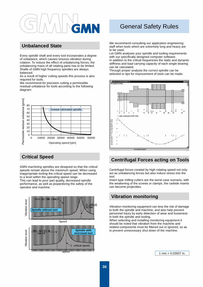
Unbalanced State
Critical Speed
Vibration monitoring
Centrifugal Forces acting on Tools
Grease lubricated spindle
Operating speed [rpm]
Speed
Speed
max. spindle speed
1. criticalspeed
Spindle without tool
max. operatingspeed
Spindle withoversized tool
1. critical speed
Every spindle shaft and every tool incorporates a degreeof unbalance, which causes sinuous vibration duringrotation. To reduce the effect of unbalancing forces, theunbalancing mass of all rotating parts has to be limited.Shafts of GMN high frequency spindles are alwaysbalanced.As a result of higher cutting speeds this process is alsorequired for tools.We recommend for precision cutting a permissibleresidual unbalance for tools according to the followingdiagram:
GMN machining spindles are designed so that the criticalspeeds remain above the maximum speed. When usinginappropriate tooling the critical speed can be decreasedto a level within the operating speed range.This can lead to poor part quality, decreased spindleperformance, as well as jeopardizing the safety of theoperator and machine.
We recommend consulting our application engineeringstaff when tools which are extremely long and heavy areto be used.Let GMN analyses your spindle and tooling requirementswith our specifically designed computer software.In addition to the critical frequencies the static and dynamicstiffness and load carrying capacity of each single bearingcan be calculated.Through proper analysis the correct spindle can beselected or tips for improvement of tools can be made.
Centrifugal forces created by high rotating speed not onlyact as unbalancing forces but also induce stress into thetool.Insert type milling cutters are the worst case scenario, withthe weakening of the screws or clamps, the carbide insertscan become projectiles.
Vibration monitoring equipment can less the risk of damageto both the spindle and machine, and also help preventpersonnel injury by early detection of wear and loosenessin both the spindle and tooling.When selecting and installing monitoring equipment itshould be noted that vibration from the machine andrelated components must be filtered out or ignored, so asto prevent unnecessary shut down of the machine.
1 mm = 0.03937 in.

37
TSA
TSAVTSEV
TSI
TSP
0,003
0,001
0,003
0,001 0,001 0,002 0,003
0,01 0,001 0,002 0,003
0,003
0,001
Radial And Axial Runout
Distance of measuring
Distance of measuring: five times taper dia. (k1) max. 100 mm (3.937 inch)
Distance of measuring
Distance of measuring: five times taper dia. (d) max. 100 mm (3.937 inch)
Spindles with increased radial and axial runout on request.


