
By: S Satish Kumar, S S Mistry B C Shekhar and Siva Prasad NTPC-Sipat
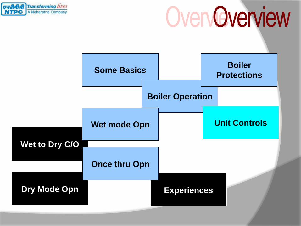
Some Basics
Boiler Operation
Boiler
Protections
Unit Controls
Wet to Dry C/O
Wet mode Opn
Dry Mode Opn Experiences
Once thru Opn

4
Critical point is a thermodynamic Expression describing the state of a substance
(in our case Water-steam) where there is no clear distinction between the liquid
And gaseous phase
Pressure= 22.1Mpa / 221 bar / 225.35 ksc. Temperature= 374oC/705.2 F
Super Critical.............
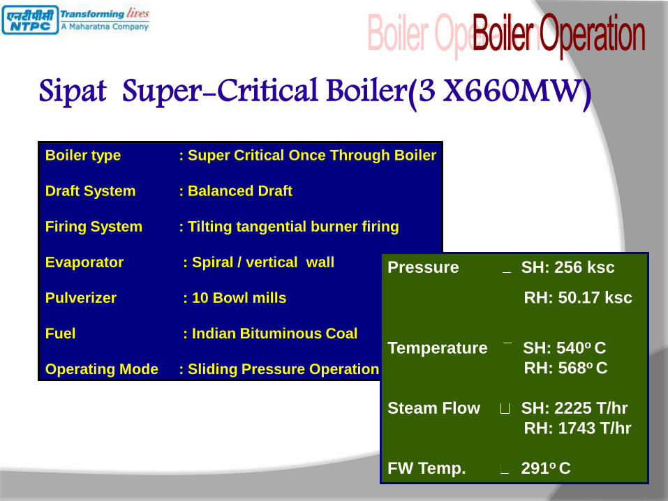
Sipat Super-Critical Boiler(3 X660MW) Boiler type : Super Critical Once Through Boiler
Draft System : Balanced Draft
Firing System : Tilting tangential burner firing
Evaporator : Spiral / vertical wall
Pulverizer : 10 Bowl mills
Fuel : Indian Bituminous Coal
Operating Mode : Sliding Pressure Operation
Pressure SH: 256 ksc
RH: 50.17 ksc
Temperature SH: 540o C
RH: 568o C
Steam Flow SH: 2225 T/hr
RH: 1743 T/hr
FW Temp. 291o C
IPT LPT
C
O
N
D
E
N
S
E
R
FEED WATER
FRS
S
T
O
R
A
G
E
T
A
N
K
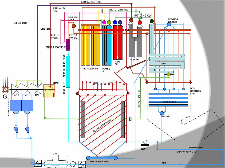
SEPARATOR
BWRP
MS LINE
HRH LINE
VERTICAL WW
ECO I/L
ECO
JUNCTION
HDR
ECO HGR
O/L HDR
FUR LOWER HDR
FUR ROOF
I/L HDR
DIV PANELS SH PLATEN
SH
FINAL
RH
FINAL SH
LTRH
ECONOMISER
290°C, 302 KSC
411°C,
277Ksc 411°C,
275 Ksc
492°C, 260 Ksc
540°C, 255 Ksc
305°C
, 49 K
sc
457°C, 49 Ksc
568°C, 47
Ksc
G LPT
HPT
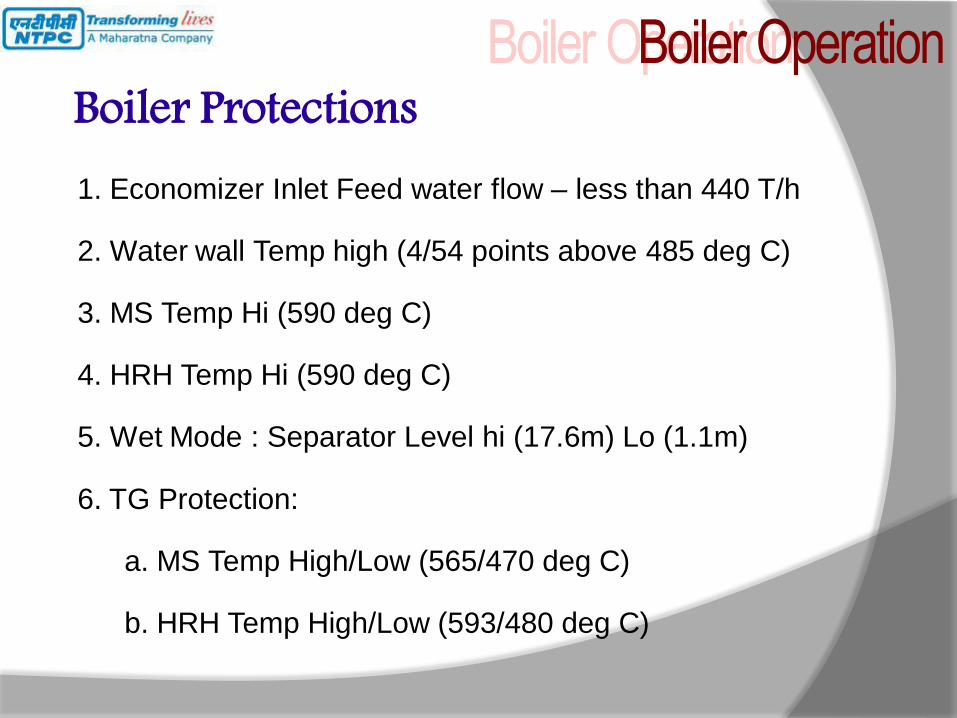
Boiler Protections 1. Economizer Inlet Feed water flow – less than 440 T/h
2. Water wall Temp high (4/54 points above 485 deg C)
3. MS Temp Hi (590 deg C)
4. HRH Temp Hi (590 deg C)
5. Wet Mode : Separator Level hi (17.6m) Lo (1.1m)
6. TG Protection:
a. MS Temp High/Low (565/470 deg C)
b. HRH Temp High/Low (593/480 deg C)
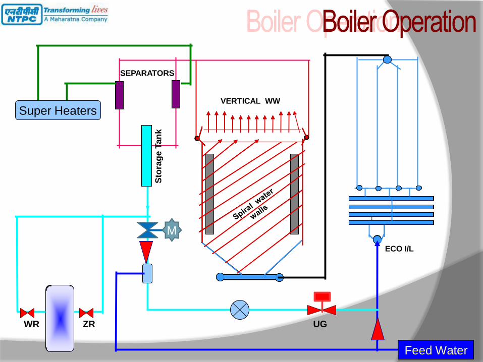
ECO I/L
VERTICAL WW
SEPARATORS
Sto
rag
e T
an
k
Feed Water
WR ZR UG
Super Heaters
M
ECO I/L
VERTICAL WW
SEPARATORS
Sto
rag
e T
an
k
Feed Water
WR ZR UG
Super Heaters
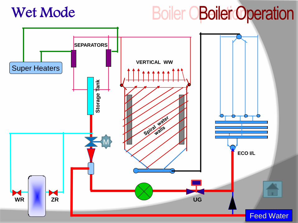
Wet Mode
M
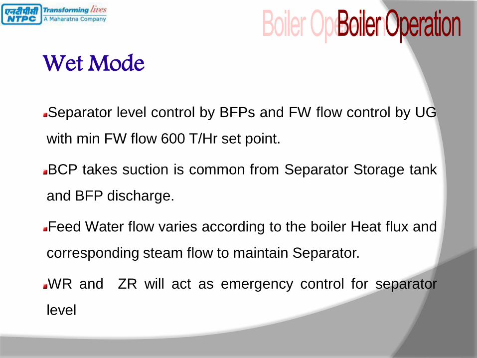
Wet Mode Separator level control by BFPs and FW flow control by UG
with min FW flow 600 T/Hr set point.
BCP takes suction is common from Separator Storage tank
and BFP discharge.
Feed Water flow varies according to the boiler Heat flux and
corresponding steam flow to maintain Separator.
WR and ZR will act as emergency control for separator
level

Dry Mode Conditions for Dry Mode
Separator Level less than 3.0m
Difference between feed water temperature and eco inlet temperature < 2 degree C
Separator outlet steam superheated by 20 degree C
Steam flow > 30%
ECO I/L
VERTICAL WW
SEPARATORS
Sto
rag
e T
an
k
Feed Water
WR ZR UG
Super Heaters
Dry Mode
To SH spray
M
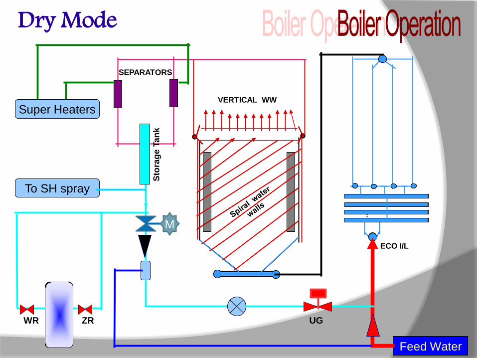
Dry Mode Boiler Operating mode changed to Once Through Operation.
Feed Water flow From FRS directly goes to Eco Inlet
Bypassing the BCP.
Total Feed Water Flow controlled by total Fuel flow in the Boiler
and Degree of Superheat at Separator Outlet
Any water in the separator goes to SH spray from wet Leg.
Wet to Dry Change Over 1. On 27/03/2011 AT 16:30 hrs First Time Wet to Dry Change
Over
2. 24/06/2011 AT 09:45 hrs
3. 24/06/2011 AT 21:20 hrs
4. 25/06/2011 AT 03:36 hrs
Unit tripped on ECO flow low low
Observations.....
Both MDBFP were in service
Both R/C valves are closed
Suction flow is 800 t/hr each
But ECO flow was < 300 t/hr
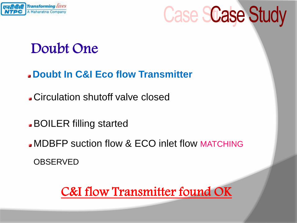
Circulation shutoff valve closed
BOILER filling started
MDBFP suction flow & ECO inlet flow MATCHING
OBSERVED
C&I flow Transmitter found OK
Doubt One Doubt In C&I Eco flow Transmitter
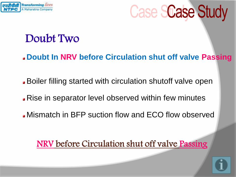
Boiler filling started with circulation shutoff valve open
Rise in separator level observed within few minutes
Mismatch in BFP suction flow and ECO flow observed
NRV before Circulation shut off valve Passing
Doubt Two Doubt In NRV before Circulation shut off valve Passing
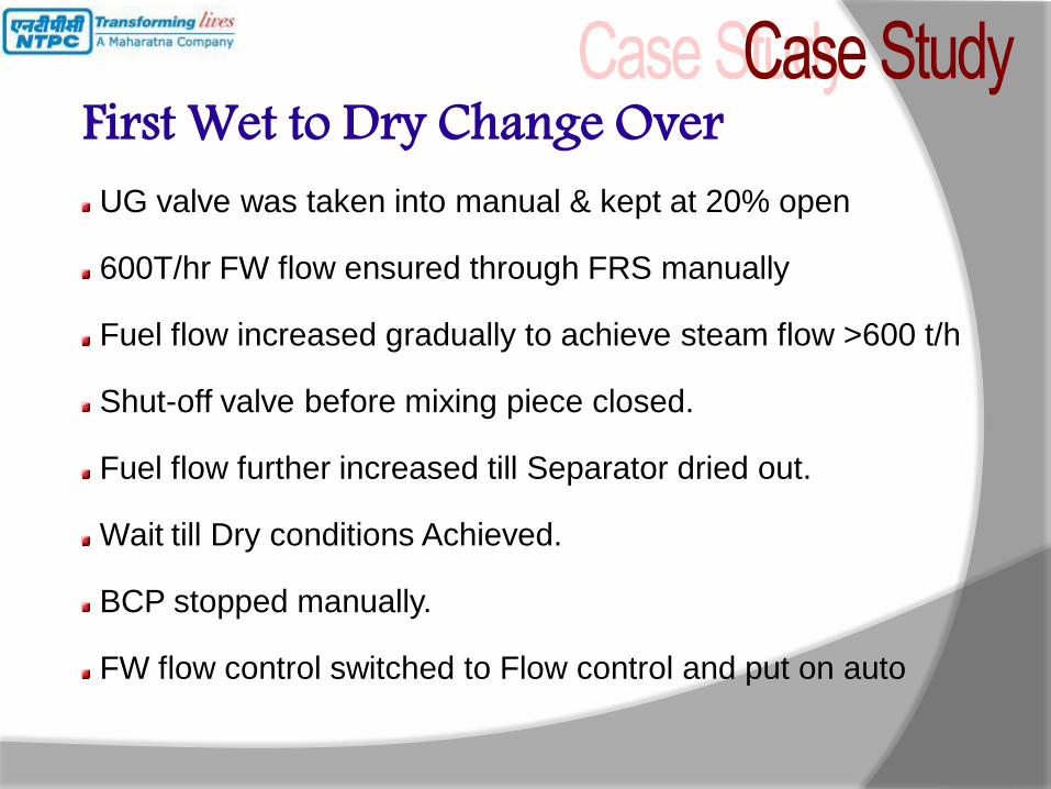
UG valve was taken into manual & kept at 20% open
600T/hr FW flow ensured through FRS manually
Fuel flow increased gradually to achieve steam flow >600 t/h
Shut-off valve before mixing piece closed.
Fuel flow further increased till Separator dried out.
Wait till Dry conditions Achieved.
BCP stopped manually.
FW flow control switched to Flow control and put on auto
First Wet to Dry Change Over

FIRST SUCCESSFUL CHANGEOVER
On 26/06/2011 at 15:10 hrs
NRV replaced on 27/07/2011
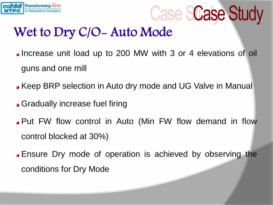
Wet to Dry C/O- Auto Mode Increase unit load up to 200 MW with 3 or 4 elevations of oil
guns and one mill
Keep BRP selection in Auto dry mode and UG Valve in Manual
Gradually increase fuel firing
Put FW flow control in Auto (Min FW flow demand in flow
control blocked at 30%)
Ensure Dry mode of operation is achieved by observing the
conditions for Dry Mode

Wet to Dry C/O- Auto Mode Once dry mode is considered to be achieved, dry mode
indication appears in HFC OWS and BRP stops on Auto
Increase fuel firing further and observe FW flow, furnace
vertical WW tube metal temp
Closely observe Separator outlet temperature and its Set point
in FW flow control
FW flow control should precisely maintain separator outlet
temperature. In case of any deviation wait till the control loop
bring down the deviation to minimum
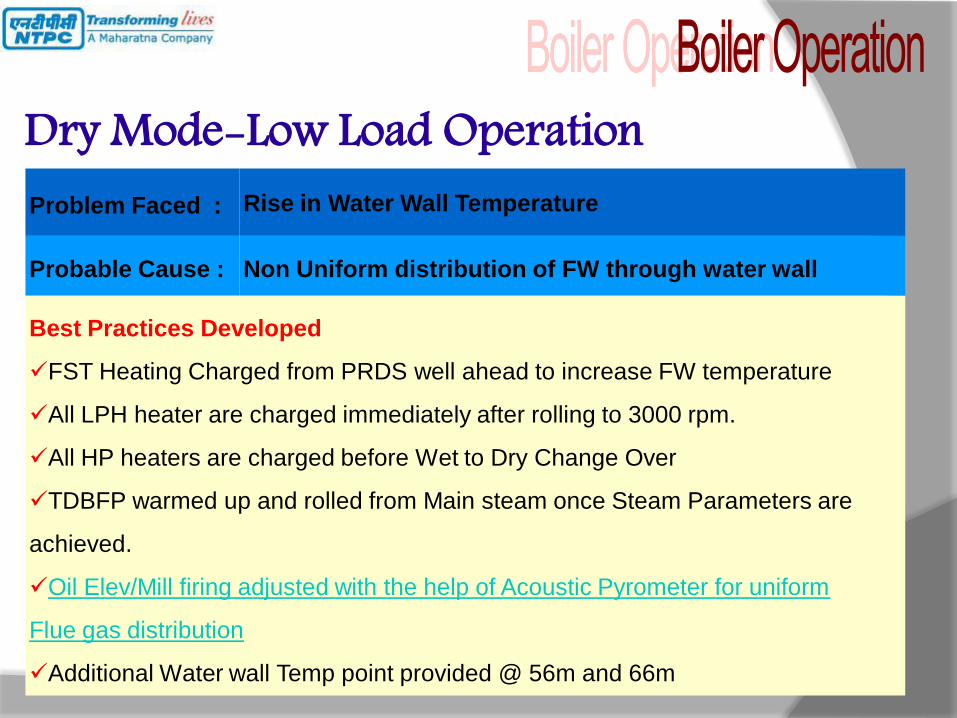
Dry Mode-Low Load Operation Problem Faced : Rise in Water Wall Temperature
Probable Cause : Non Uniform distribution of FW through water wall
Best Practices Developed
FST Heating Charged from PRDS well ahead to increase FW temperature
All LPH heater are charged immediately after rolling to 3000 rpm.
All HP heaters are charged before Wet to Dry Change Over
TDBFP warmed up and rolled from Main steam once Steam Parameters are
achieved.
Oil Elev/Mill firing adjusted with the help of Acoustic Pyrometer for uniform
Flue gas distribution
Additional Water wall Temp point provided @ 56m and 66m

Dry Mode-Low Load Operation Problem Faced : Huge Mismatch in Left-Right Steam Temperature
Probable Cause : Non Uniform Left/right Flue gas distribution
Best Practices Developed
Secondary air flow adjusted to maintain Furnace to WB dp
SADC corner wise Biasing is provided to adjust the Fire ball position.
APH outlet damper and ID fan biasing done to reduce the Left-Right Flue gas
temperature mismatch.
Better Mill combination and burner tilt positions are recorded for future
references.
HRSB done once in a day and LRSB done alternated day
Boiler Operating Pressure Increased to improve the Boiler Performance
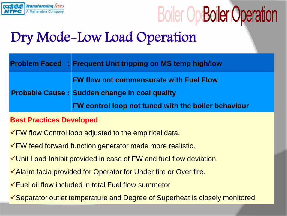
Dry Mode-Low Load Operation Problem Faced : Frequent Unit tripping on MS temp high/low
Probable Cause :
FW flow not commensurate with Fuel Flow
Sudden change in coal quality
FW control loop not tuned with the boiler behaviour
Best Practices Developed
FW flow Control loop adjusted to the empirical data.
FW feed forward function generator made more realistic.
Unit Load Inhibit provided in case of FW and fuel flow deviation.
Alarm facia provided for Operator for Under fire or Over fire.
Fuel oil flow included in total Fuel flow summetor
Separator outlet temperature and Degree of Superheat is closely monitored
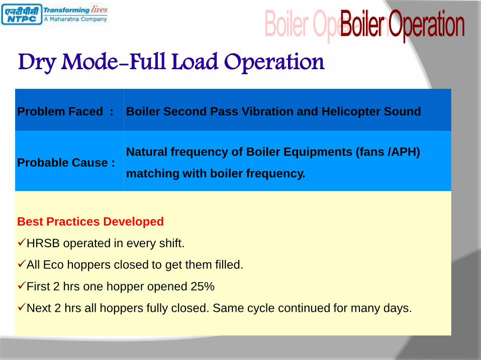
Dry Mode-Full Load Operation Problem Faced : Boiler Second Pass Vibration and Helicopter Sound
Probable Cause : Natural frequency of Boiler Equipments (fans /APH)
matching with boiler frequency.
Best Practices Developed
HRSB operated in every shift.
All Eco hoppers closed to get them filled.
First 2 hrs one hopper opened 25%
Next 2 hrs all hoppers fully closed. Same cycle continued for many days.

UCC-Feed forward structure
Turbine
Master
Boiler
Master
Fuel control FD Fan Pump
(Turbine)
Pump
(Startup)
Load Demand
Computer
High Limit
Low Limit
Ramp Rate
Operator
Set Limits
Runbacks
Rundowns
Block Increase
Block Decrease
Turbine
controller
Remote
Valve
Positioner
Steam
Temp.
Contingency
Local
Sprays
Feedwater Combustion
Air to fuel

BF1 TF1
BF2 TF2
Base
Mode
UCC TG Load
Loop on
TG Load
Loop on
Blr Press
Loop on
Run Back
Run down
Blr Load
Loop on
TG Press
Loop on
UCC-Operating Modes
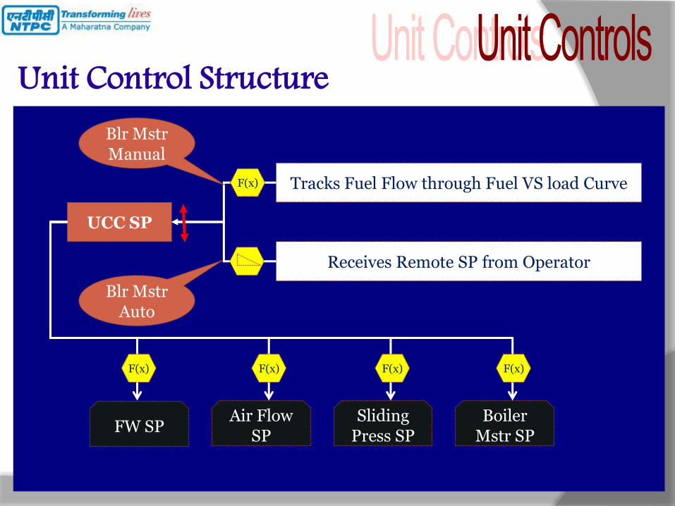
Unit Control Structure
UCC SP
Tracks Fuel Flow through Fuel VS load Curve
Blr Mstr Manual
Receives Remote SP from Operator
Blr Mstr Auto
FW SP Air Flow
SP Sliding
Press SP Boiler
Mstr SP
F(x)
F(x) F(x) F(x) F(x)

UCC SP
FW SP Air Flow
SP Sliding
Press SP Boiler
Mstr SP
Manual/Auto
Mode Change
Transient Cond Tracking
Temp Corr
Oxy Corr
Const Press
Fuel Corr
F(x) F(x) F(x) F(x)
Unit Control Structure

Learning
Sharing Experience


32
Simulation mapping by the software for an ideal furnace
Distorted Fireball simulated by Acoustic Pyrometer
0
50
100
150
200
250
300
0 200 400 600 800
Pre
ssure
Set P
oin
t (K
sc)
Load (MW)
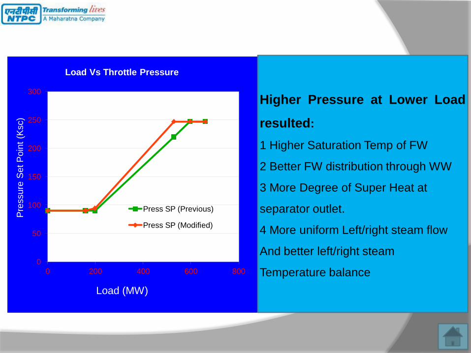
Load Vs Throttle Pressure
Press SP (Previous)
Press SP (Modified)
Higher Pressure at Lower Load
resulted:
1 Higher Saturation Temp of FW
2 Better FW distribution through WW
3 More Degree of Super Heat at
separator outlet.
4 More uniform Left/right steam flow
And better left/right steam
Temperature balance

Dry Mode-Low Load Operation Non-Uniform Distribution of FW through Water Wall
Huge Mismatch in Left-Right Flue Gas temperature
Exponential Rise of Water Wall temperature with Increasing
degree of Superheat at Separator Outlet.
Maintaining lesser Degree of Superheat to contain Water Wall
temperature.
Less Spray Flow capacity at lower Pressure.
Low HRH temperature.
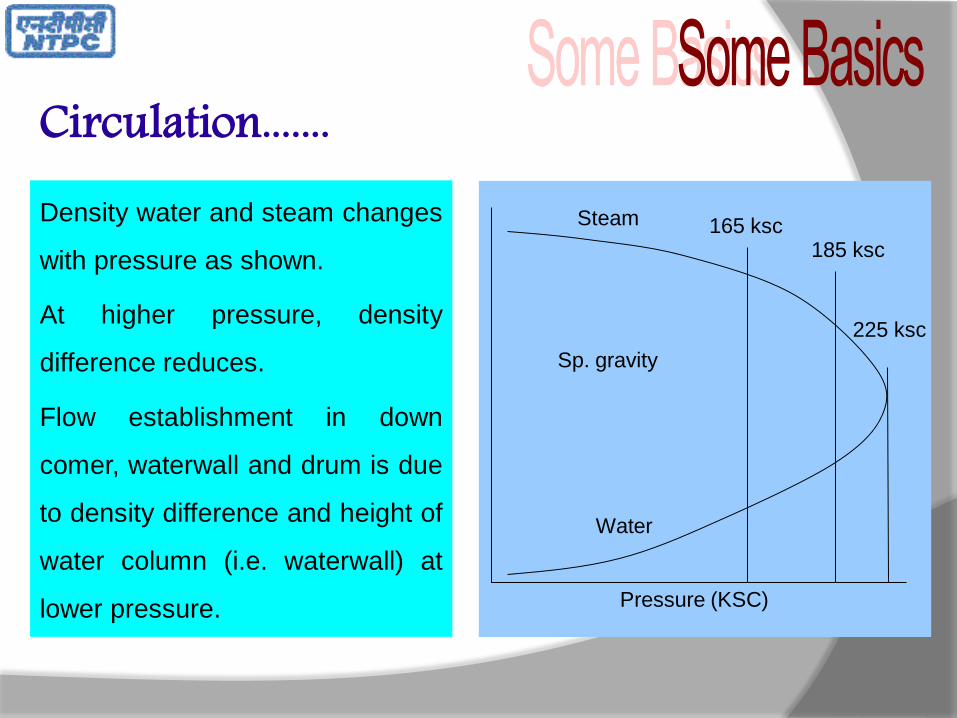
Density water and steam changes
with pressure as shown.
At higher pressure, density
difference reduces.
Flow establishment in down
comer, waterwall and drum is due
to density difference and height of
water column (i.e. waterwall) at
lower pressure.
Circulation.......
225 ksc
185 ksc 165 ksc
Pressure (KSC)
Steam
Sp. gravity
Water


