
Busbar Protection IED

GR-200 seriesThe GRtransmission/distribution networks and providing a platform for distributed and renewable energy systems and railway applications. Flexible adaptation is enabled using extensive hardware and modular software co
Meeting your needs Extensive hardware and modular software combinations provide the flexibility to meet your application and engineering requirements.Future upgrade paths and minor modifications are readily achievable on demand.
PowerfulIn addition to protection & control, GRadvantage of developments in information & comm
APPLICATION
GRBnext generation GRhigh speeduserrequirementspeace of mind.
200 seriesThe GR-200 Series is Toshiba’s next generation of protection and control IED’s, designed transmission/distribution networks and providing a platform for distributed and renewable energy systems and railway applications. Flexible adaptation is enabled using extensive hardware and modular software co
Meeting your needs Extensive hardware and modular software combinations provide the flexibility to meet your application and engineering requirements.Future upgrade paths and minor modifications are readily achievable on demand.owerful and wide application In addition to protection & control, GRadvantage of developments in information & comm
APPLICATION
B200 low impedance differential relay for busbarnext generation GRhigh speed and selective user-friendly IED will provide you requirements, in addition to offering peace of mind.
- GRB200 can be applied for various busbar systems.・ Single busbars with/without transfer・ Double busbars with/without transfer busbar・ Ring busbars with/without transfer busbar・ One and a half busbar・ Four bus
- GRB200 can detect phase and earth faults on the protectphase segregated current differential schemecan be input from feeders, sections and busbetween internal and external faults even in the event of CT saturation.
- Circuit breakalso available.
- Backup overcurrent - Communications
・ Within 61850
200 series - 200 Series is Toshiba’s next generation of protection and control IED’s, designed
transmission/distribution networks and providing a platform for distributed and renewable energy systems and railway applications. Flexible adaptation is enabled using extensive hardware and modular software co
Meeting your needs - Extensive hardware and modular software combinations provide the flexibility to meet your application and engineering requirements.Future upgrade paths and minor modifications are readily achievable on demand.
and wide application In addition to protection & control, GRadvantage of developments in information & comm
APPLICATION
low impedance differential relay for busbarnext generation GR-200 series IED platform and has b
and selective protection for friendly IED will provide you
in addition to offering
GRB200 can be applied for various busbar systems.Single busbars with/without transferDouble busbars with/without transfer busbarRing busbars with/without transfer busbarOne and a half busbarFour bus-coupler busbar
GRB200 can detect phase and earth faults on the protectphase segregated current differential schemecan be input from feeders, sections and busbetween internal and external faults even in the event of CT saturation.Circuit breaker failure protection, end zone protection and blind zone protection are also available.
ackup overcurrent Communications
Within a substation automation system or to a remote control centre,61850-8-1 [Station bus
200 Series is Toshiba’s next generation of protection and control IED’s, designed transmission/distribution networks and providing a platform for distributed and renewable energy systems and railway applications. Flexible adaptation is enabled using extensive hardware and modular software combinations facilitating an ap
Extensive hardware and modular software combinations provide the flexibility to meet your application and engineering requirements.Future upgrade paths and minor modifications are readily achievable on demand.
and wide application - In addition to protection & control, GR-200 has been designed to meet the challenges and take advantage of developments in information & comm
low impedance differential relay for busbar200 series IED platform and has b
protection for friendly IED will provide you with the flexibility to meet your application and engineering
in addition to offering outstanding
GRB200 can be applied for various busbar systems.Single busbars with/without transferDouble busbars with/without transfer busbarRing busbars with/without transfer busbarOne and a half busbar
coupler busbar GRB200 can detect phase and earth faults on the protectphase segregated current differential schemecan be input from feeders, sections and busbetween internal and external faults even in the event of CT saturation.
er failure protection, end zone protection and blind zone protection are
ackup overcurrent and earth fault
substation automation system or to a remote control centre,1 [Station bus], Modbus® RTU protocol
2
200 Series is Toshiba’s next generation of protection and control IED’s, designed transmission/distribution networks and providing a platform for distributed and renewable energy systems and railway applications. Flexible adaptation is enabled using extensive
mbinations facilitating an ap
Extensive hardware and modular software combinations provide the flexibility to meet your application and engineering requirements. Future upgrade paths and minor modifications are readily achievable on demand.
200 has been designed to meet the challenges and take
advantage of developments in information & communications technology.
low impedance differential relay for busbar200 series IED platform and has b
protection for various typewith the flexibility to meet your application and engineering
outstanding performance, high quality and operational
GRB200 can be applied for various busbar systems.Single busbars with/without transfer busbarDouble busbars with/without transfer busbarRing busbars with/without transfer busbar
GRB200 can detect phase and earth faults on the protectphase segregated current differential schemecan be input from feeders, sections and busbetween internal and external faults even in the event of CT saturation.
er failure protection, end zone protection and blind zone protection are
and earth fault protection
substation automation system or to a remote control centre,Modbus® RTU protocol
200 Series is Toshiba’s next generation of protection and control IED’s, designed transmission/distribution networks and providing a platform for distributed and renewable energy systems and railway applications. Flexible adaptation is enabled using extensive
mbinations facilitating an application ori
Extensive hardware and modular software combinations provide the flexibility to meet your
Future upgrade paths and minor modifications are readily achievable on demand.
200 has been designed to meet the challenges and take unications technology.
low impedance differential relay for busbar protection is implemented on Toshiba’s 200 series IED platform and has been designed to provide
various types of busbar systemwith the flexibility to meet your application and engineering
performance, high quality and operational
GRB200 can be applied for various busbar systems. busbar
Double busbars with/without transfer busbar Ring busbars with/without transfer busbar
GRB200 can detect phase and earth faults on the protectphase segregated current differential scheme. A maximum can be input from feeders, sections and bus-couplers, which can between internal and external faults even in the event of CT saturation.
er failure protection, end zone protection and blind zone protection are
protections are provided as option
substation automation system or to a remote control centre,Modbus® RTU protocol and
200 Series is Toshiba’s next generation of protection and control IED’s, designed transmission/distribution networks and providing a platform for distributed and renewable energy systems and railway applications. Flexible adaptation is enabled using extensive
plication oriented
Extensive hardware and modular software combinations provide the flexibility to meet your
Future upgrade paths and minor modifications are readily achievable on demand.
200 has been designed to meet the challenges and take unications technology.
protection is implemented on Toshiba’s een designed to provide
sbar system. This powerful and with the flexibility to meet your application and engineering
performance, high quality and operational
GRB200 can detect phase and earth faults on the protected busbar by employingmaximum of 64 threeplers, which can correctly
between internal and external faults even in the event of CT saturation.er failure protection, end zone protection and blind zone protection are
provided as option
substation automation system or to a remote control centre,and IEC 60870
200 Series is Toshiba’s next generation of protection and control IED’s, designed transmission/distribution networks and providing a platform for distributed and renewable energy systems and railway applications. Flexible adaptation is enabled using extensive
ented solution.
Extensive hardware and modular software combinations provide the flexibility to meet your
Future upgrade paths and minor modifications are readily achievable on demand.
200 has been designed to meet the challenges and take
protection is implemented on Toshiba’s een designed to provide very reliable,
This powerful and with the flexibility to meet your application and engineering
performance, high quality and operational
busbar by employing64 three-phase currents
correctly distinguish between internal and external faults even in the event of CT saturation.
er failure protection, end zone protection and blind zone protection are
provided as options in each bay
substation automation system or to a remote control centre,IEC 60870-5-103.
200 Series is Toshiba’s next generation of protection and control IED’s, designed for transmission/distribution networks and providing a platform for distributed and renewable energy systems and railway applications. Flexible adaptation is enabled using extensive
Extensive hardware and modular software combinations provide the flexibility to meet your
200 has been designed to meet the challenges and take
protection is implemented on Toshiba’s very reliable,
This powerful and with the flexibility to meet your application and engineering
performance, high quality and operational
busbar by employing a phase currents
distinguish
er failure protection, end zone protection and blind zone protection are
bay.
substation automation system or to a remote control centre, IEC

FEATURES• Application- GRB200 can be applied for various
busbar systems.
- GRB200 incorporates a single central unit (CU) and bay units (BU). performs current differential protection. Thanalogue data from each CT which is converted to digital data for transmission to the CU via optical fiber for the differential protection. The BU also receives the trip command from the CU and performs tripping of the cibreaker. The CU can be provided with an optional voltage check element.
- Centralized or Decentralized installation is
A system installation in Figure 1.
EATURESApplication
GRB200 can be applied for various busbar systems.- Single busbars with/without transfer
busbar - Double busbars
transfer busbar- Ring busbars with/without transfer
busbar - One and a half busbar- Four busGRB200 incorporates a single central unit (CU) and bay units (BU). performs current differential protection. The BU is a terminal used to acquire analogue data from each CT which is converted to digital data for transmission to the CU via optical fiber for the differential protection. The BU also receives the trip command from the CU and performs tripping of the cibreaker. The CU can be provided with an optional voltage check element.
Centralized or Decentralized installation is available.
A system installation in Figure 1.
GRB200 can be applied for various busbar systems.
Single busbars with/without transfer
Double busbars with/without transfer busbar Ring busbars with/without transfer
One and a half busbarFour bus-coupler busbar
GRB200 incorporates a single central unit (CU) and bay units (BU). performs current differential protection.
e BU is a terminal used to acquire analogue data from each CT which is converted to digital data for transmission to the CU via optical fiber for the differential protection. The BU also receives the trip command from the CU and performs tripping of the cibreaker. The CU can be provided with an optional voltage check element.
Centralized or Decentralized installation
A system installation example
Figure
GRB200 can be applied for various
Single busbars with/without transfer
with/without
Ring busbars with/without transfer
One and a half busbar coupler busbar
GRB200 incorporates a single central unit (CU) and bay units (BU). The CU performs current differential protection.
e BU is a terminal used to acquire analogue data from each CT which is converted to digital data for transmission to the CU via optical fiber for the differential protection. The BU also receives the trip command from the CU and performs tripping of the circuit breaker. The CU can be provided with an optional voltage check element.
Centralized or Decentralized installation
example is shown
Figure 1 System
3
Single busbars with/without transfer
Ring busbars with/without transfer
GRB200 incorporates a single central The CU
performs current differential protection. e BU is a terminal used to acquire
analogue data from each CT which is converted to digital data for transmission to the CU via optical fiber for the differential protection. The BU also receives the trip command from the CU
rcuit breaker. The CU can be provided with an
Centralized or Decentralized installation
is shown
• Functionality- - - -
• Communication-
-
• Security-
• Flexibility-
- -
- - -
• Human Machine Interface- - - -
- -
System Installation Example
Functionality Eight settings group Automatic supervision Metering and recording functions Time synchronization by external clock
such as IRIGCommunication System interface
100BASE-TX, Multi protocol
IEC 60870-Security Password protectionFlexibility Various models and hardware options for
flexible application depending on system requirement and controlled object
Combined 1A / 5A current inputs Multi range DC power supply: 24 to 60V /
60 to 110 V / 110 to 250V Multi-language Configurable binary inputs and outputs Programmable control, trip and alarm
logic with PLC tool softwareHuman Machine Interface Graphical LCD and 7 configurable function keys USB port for local PC co Direct control buttons
and control authority (43R/L) Help key for supporting operation Monitoring terminals for testin
Electrical
GRB
Installation Example
Eight settings groups Automatic supervision Metering and recording functionsTime synchronization by external clock
as IRIG-B and system networkCommunication
System interface - RS485, Fiber optic, TX,-FX
protocol - DNP3.0,-5-103 and IEC
Password protection
Various models and hardware options for flexible application depending on system requirement and controlled objectCombined 1A / 5A current inputsMulti range DC power supply: 24 to 60V / 60 to 110 V / 110 to 250V
nguage options Configurable binary inputs and outputsProgrammable control, trip and alarm
with PLC tool softwareHuman Machine Interface
Graphical LCD and 24 LEDsonfigurable function keys
port for local PC coirect control buttons for open/close (O/I)
and control authority (43R/L)Help key for supporting operation
onitoring terminals for testin
CU
BU
Electrical cables
GRB200
Installation Example
Metering and recording functions Time synchronization by external clock
system network
RS485, Fiber optic,
, Modbus® RTUand IEC 61850
Various models and hardware options for flexible application depending on system requirement and controlled object Combined 1A / 5A current inputs Multi range DC power supply: 24 to 60V / 60 to 110 V / 110 to 250V
Configurable binary inputs and outputsProgrammable control, trip and alarm
with PLC tool software Human Machine Interface
24 LEDs onfigurable function keys
port for local PC connection for open/close (O/I)
and control authority (43R/L) Help key for supporting operation
onitoring terminals for testing
BU
Optical
Time synchronization by external clock system network
RS485, Fiber optic,
RTU,
Various models and hardware options for flexible application depending on system
Multi range DC power supply: 24 to 60V /
Configurable binary inputs and outputs Programmable control, trip and alarm
for open/close (O/I)
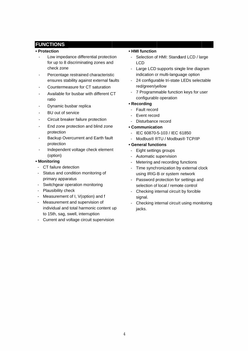
FUNCTIONS• Protection
-
-
-
-
-
-
-
-
-
-
• Monitoring- CT failure detection- Status and condition monitoring of
primary apparatus- Switchgear operation monitoring- Plausibility check- Measu- Measurement and
individual and total harmonic to 15th, sag, swell, interruption
- Current
UNCTIONSProtection
Low impedance differential protection for up to 8 discriminating zonecheck zone
Percentage restrained characteristic ensures stability against external faults
Countermeasure for CT
Available for busbar with different CT ratio
Dynamic busbar replica
BU out of service
Circuit breaker failure protection
End zone protection and blind zone protection Backup Overcurrent protection Independent voltage check (option)
• Monitoring CT failure detectionStatus and condition monitoring of primary apparatusSwitchgear operation monitoringPlausibility checkMeasurement of I, V(option) and fMeasurement and individual and total harmonic to 15th, sag, swell, interruptionCurrent and voltage
Low impedance differential protection for up to 8 discriminating zonecheck zone
Percentage restrained characteristic ensures stability against external faults
Countermeasure for CT
Available for busbar with different CT
Dynamic busbar replica
BU out of service
Circuit breaker failure protection
End zone protection and blind zone
Overcurrent and Earth fault
Independent voltage check
CT failure detection Status and condition monitoring of primary apparatus Switchgear operation monitoringPlausibility check
rement of I, V(option) and fMeasurement and supervisionindividual and total harmonic to 15th, sag, swell, interruption
and voltage circuit supervision
Low impedance differential protection for up to 8 discriminating zones and
Percentage restrained characteristic ensures stability against external faults
Countermeasure for CT saturation
Available for busbar with different CT
Dynamic busbar replica
Circuit breaker failure protection
End zone protection and blind zone
and Earth fault
Independent voltage check element
Status and condition monitoring of
Switchgear operation monitoring
rement of I, V(option) and f supervision of
individual and total harmonic content up to 15th, sag, swell, interruption
circuit supervision
4
Low impedance differential protection and
Percentage restrained characteristic ensures stability against external faults
Available for busbar with different CT
End zone protection and blind zone
and Earth fault
element
up
circuit supervision
• HMI function-
-
-
-
• Recording- - -
• Communication- -
• General function- - - -
-
-
-
HMI function Selection of HMI:
LCD Large LCD support
indication or 24 configurable tri
red/green/yellow 7 Programmable function keys for user
configurableRecording Fault record Event record Disturbance recordCommunication IEC 60870- Modbus® RTU / ModbusGeneral function Eight settings Automatic supervision Metering and recording functions Time synchronization by external clock
using IRIG- Password protection for setting
selection of Checking internal
signal. Checking internal circuit
jacks.
Selection of HMI: Standard LCD
Large LCD supports single or multi-language
24 configurable tri-state LEDs red/green/yellow 7 Programmable function keys for user configurable operation
Fault record Event record Disturbance record
Communication -5-103 / IEC 61850RTU / Modbus
General function s Eight settings groups Automatic supervision Metering and recording functionsTime synchronization by external clock
-B or system networkPassword protection for settingselection of local / remote
internal circuit
internal circuit
Standard LCD / large
ingle line diagram language option state LEDs selectable
7 Programmable function keys for user
103 / IEC 61850 RTU / Modbus® TCP/IP
Metering and recording functions Time synchronization by external clock
system network Password protection for settings and
/ remote control circuit by forcible
internal circuit using monitoring
/ large
line diagram
selectable
7 Programmable function keys for user
Time synchronization by external clock
and
using monitoring
5
APPLICATIONS
PROTECTION
� Busbar Differential Protection
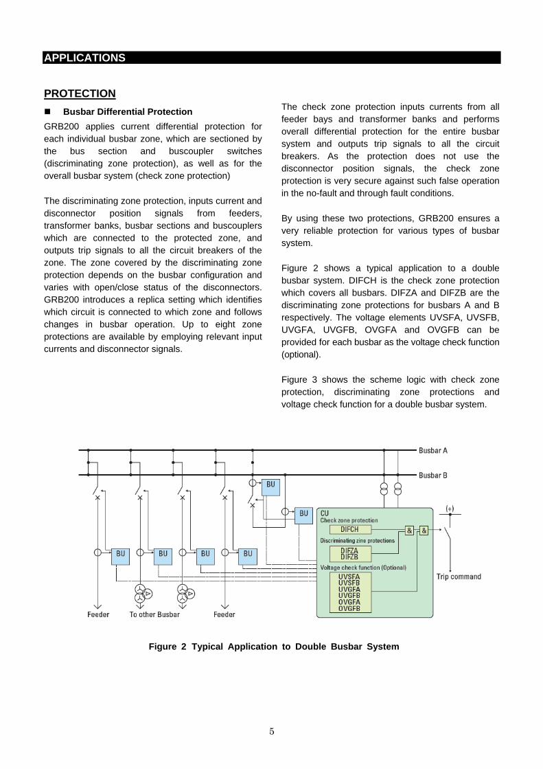
GRB200 applies current differential protection for each individual busbar zone, which are sectioned by the bus section and buscoupler switches (discriminating zone protection), as well as for the overall busbar system (check zone protection)
The discriminating zone protection, inputs current and disconnector position signals from feeders, transformer banks, busbar sections and buscouplers which are connected to the protected zone, and outputs trip signals to all the circuit breakers of the zone. The zone covered by the discriminating zone protection depends on the busbar configuration and varies with open/close status of the disconnectors. GRB200 introduces a replica setting which identifies which circuit is connected to which zone and follows changes in busbar operation. Up to eight zone protections are available by employing relevant input currents and disconnector signals.
The check zone protection inputs currents from all feeder bays and transformer banks and performs overall differential protection for the entire busbar system and outputs trip signals to all the circuit breakers. As the protection does not use the disconnector position signals, the check zone protection is very secure against such false operation in the no-fault and through fault conditions.
By using these two protections, GRB200 ensures a very reliable protection for various types of busbar system.
Figure 2 shows a typical application to a double busbar system. DIFCH is the check zone protection which covers all busbars. DIFZA and DIFZB are the discriminating zone protections for busbars A and B respectively. The voltage elements UVSFA, UVSFB, UVGFA, UVGFB, OVGFA and OVGFB can be provided for each busbar as the voltage check function (optional).
Figure 3 shows the scheme logic with check zone protection, discriminating zone protections and voltage check function for a double busbar system.
Figure 2 Typical Application to Double Busbar System

6
Figure 3 Scheme Logic with Check Zone, Discriminating Zone and Voltage Check
DS-nA : Disconnector condition - busbar A side DS-nB : Disconnector condition - busbar B side DS-BS** : Disconnector condition - bus section
DIFCH
[Current]
UVSFA
UVGFA
[Voltage Check]
CU
DIFZB
DIFZA &
&
DS-1A
DS-1B
≧1
&
&
DS-nA
DS-nB &
&
&
DS-1A
DS-1B
Trip(1)
BU (Feeder 1)
&
&
DS-BC1
Trip(BS1)
BU (Bus section CT1)
&
DS-nA
DS-nB
Trip(n)
BU (Feeder n)
&
&
DS-BC2
Trip(BS2)
BU (Bus section CT2)
&
≧1
≧1
≧1
≧1
≧1
&
&
&
&
OVGFA
UVSFB
UVGFB
≧1
OVGFB
Figure 5 Waveform for CT saturation
Figure 4 Characteristic of Current Differential Element
� Discriminating zone and check zone elements
The check zone element (DIFCH) and discriminating zone elements (DIFZA - DIFZD) are based on the current differential principle and have a differential characteristic for the small current region, and a percentage restraint characteristic for the large current region to cope with erroneous differential current caused by a through-fault current.
The characteristics are shown in Figure 4, and each zone (DIFCH, DIFZA - DIFZD) and each phase (A, B, C phase) have these characteristics respectively.
The minimum operating current (Idk) and the percent slope (k) of the restraint characteristic in the large current region are user-programmable.
CT saturation under external fault conditions can be a serious problem for busbar protection. GRB200 overcomes the CT saturation problem by using a “CT saturation detection” function. When an external fault occurs, a very large erroneous current may be caused by CT saturation. However, once the CT saturates, there is a short period of several milliseconds of non-saturation between the saturation periods in a cycle. By detecting this non-saturation period, the current differential element can be blocked to prevent false operation arising from CT saturation.
Idk
Id=Ir
Operate
Ir
Id
Id=k×Ir
Restraining current
Diff
eren
tial
curr
ent
Incoming terminal current
Outgoing terminal current (Saturation)
Differential current
Non-saturation period

7
� Breaker Failure Protection Phase-segregated breaker failure protection is provided for each bay and can be initiated by either an internal or external signal.
When an overcurrent element remains in operation after a tripping signal has been issued the breaker is judged to have failed and a 2 stage CBF sequence is initiated. The first stage issues a re-trip command to the circuit breaker. If this also fails then the command to backtrip adjacent circuit breakers is executed. The overcurrent element has a high-speed reset time.
GRB200 has two kinds of timer for Breaker Failure Protection. One timer is used for re-trip, the other timer is used for CBF trip.
A remote transfer trip is provided for feeder circuits.
� End zone and Blind Zone Protection This function is provided to cater for circumstances when a dead zone or blind zone is created between the CB and the associated CT.
End zone protection detects a fault located between the CB and the associated CT when the CB is open. Depending on the location of the CT, either the busbar section CB is tripped or an intertrip is sent to the CB at the remote end of the line.
Blind zone protection is used to detect and trip for faults located between the bus-section CB and the associated CT for the arrangement when the CT is installed on one side of the CB only.
� BU out-of-Service Function GRB200 provides a BU out-of-service function for maintenance purposes. When a particular BU is set to out-of-service condition, it is excluded from the operation of the protection scheme.
� Voltage Check Function (Option) GRB200 can enhance security against false tripping due to a failure in a CT or CT secondary circuits by the provision of a voltage check element in the form of a check relay with circuits that are independent from other circuits:
The voltage check function incorporates the following elements.
- Undervoltage element for earth fault detection - Undervoltage element for phase fault detection
- Zero-phase overvoltage element for earth fault detection
� Backup Overcurrent and Earth Fault Protection (Option)
Backup overcurrent and earth fault protection are provided in each bay. Each provides two stage overcurrent and earth fault protection respectively, and can be set to either a definite time or an inverse time characteristic.
The inverse time overcurrent elements are available in conformity with the IEC 60255-151 standard which encompasses both the IEC and IEEE/ANSI standard characteristics. Alternatively, a user-configurable curve may be created.
The definite time overcurrent protection is enabled by the instantaneous overcurrent element and pickup-delay timer.

HMI FUNCTION
■
GRB--
The s
interfaces
stored data
Display (LCD) and operation keys.--
-
-
The local human machine interface includes
which
(option)
M
■
The following power system data is
continuously
relay fascia-
The accuracy of
at rated
measur
HMI FUNCTION
■ Front Panel
GRB200 provide- Standard LCD- Large LCD
The standard
interfaces listed below
stored data
Display (LCD) and operation keys.- 21 character, - Support of English language
Figure 6
- The largeinterfaces listed belowwith back light
- Support of multi language(20 character
The local human machine interface includes
which can display the single line diagram for the bay
(option).
MONITORING
■ Metering
The following power system data is
continuously and
relay fascia, and on a local or remotely connected PC- Measured
frequency
The accuracy of
at rated input and
measurement
HMI FUNCTION
Panel
200 provides the following front panelStandard LCD
CD
tandard LCD panel
listed below. Setting the relay and view
are possible
Display (LCD) and operation keys.character, 8 line LCD with back light
Support of English language
gure 6 HMI Panel
large LCD panel interfaces listed belowwith back light Support of multi language
character and 26
The local human machine interface includes
can display the single line diagram for the bay
ONITORING
Metering
The following power system data is
and can be displayed on
and on a local or remotely connected PCeasured analog currents,
requency.
The accuracy of analog measurement
input and
ement.
the following front panel
LCD panel incorporates the
. Setting the relay and view
are possible using the
Display (LCD) and operation keys. line LCD with back light
Support of English language
HMI Panel (large LCD type)
LCD panel incorporates the interfaces listed below:40 character,
Support of multi language (option) line LCD for multi
The local human machine interface includes
can display the single line diagram for the bay
The following power system data is
displayed on
and on a local or remotely connected PCcurrents, voltages
analog measurement
input and ±0.03Hz
the following front panel options
incorporates the user
. Setting the relay and view
using the Liquid Crystal
line LCD with back light
(large LCD type)
incorporates the usercharacter, 40 line LCD
(option) for multi-language)
The local human machine interface includes an LCD
can display the single line diagram for the bay
The following power system data is measured
displayed on the LCD on the
and on a local or remotely connected PCvoltages (option) and
is ±0.5% for I
for frequency
8
options.
user
. Setting the relay and viewing
Liquid Crystal
user line LCD
language)
an LCD
can display the single line diagram for the bay
The local
to understand
indications.-
-
-
-
■
The user can communicate with
PC via the
series
the user can view
real
measured
on the
and on a local or remotely connected PC. (option) and
0.5% for I, V
for frequency
■
The open or closed status of each switchgear
and
and control equipment are monitored
Both
used to monitor the switchgear status. If an unusual
status is
generated.
The local human
to understand
indications. Status indication LEDs
and 24 configurable LEDs) 7 Function
group change and screen jump operation is configurable by
Test terminals which can monitor three different signals from the front panel without connection the rear terminals.
USB port
Local PC c
The user can communicate with
PC via the USB
series engineering tool
the user can view
real-time measurements.
Status Monitoring
The open or closed status of each switchgear
and failure information concerning power apparatus
and control equipment are monitored
Both normally open and normally closed contacts are
used to monitor the switchgear status. If an unusual
status is detected, a switchgear abnormality alarm is
generated.
human machine interface is
to understand with the
Status indication LEDsconfigurable LEDs)
Function keys for control, monitoring, setting group change and screen jump
ration is configurable by terminals which can monitor three different
signals from the front panel without connection the rear terminals.
Local PC c onnection
The user can communicate with
USB port on the front panel. Using
engineering tool software
the user can view, change
measurements.
Status Monitoring
The open or closed status of each switchgear
failure information concerning power apparatus
and control equipment are monitored
open and normally closed contacts are
used to monitor the switchgear status. If an unusual
detected, a switchgear abnormality alarm is
machine interface is simple and
with the following
Status indication LEDs (IN SERVICE, configurable LEDs)
for control, monitoring, setting group change and screen jump functions
ration is configurable by the userterminals which can monitor three different
signals from the front panel without connection
The user can communicate with GRB200
port on the front panel. Using
software (called
change settings
The open or closed status of each switchgear
failure information concerning power apparatus
and control equipment are monitored by GR
open and normally closed contacts are
used to monitor the switchgear status. If an unusual
detected, a switchgear abnormality alarm is
simple and easy
facilities and
(IN SERVICE, ERROR
for control, monitoring, setting functions of which
the user terminals which can monitor three different
signals from the front panel without connection
200 from a local
port on the front panel. Using GR-200
(called GR-TIEMS
and monitor
The open or closed status of each switchgear device
failure information concerning power apparatus
by GRB200.
open and normally closed contacts are
used to monitor the switchgear status. If an unusual
detected, a switchgear abnormality alarm is
easy
and
ERROR
for control, monitoring, setting of which
terminals which can monitor three different signals from the front panel without connection to
from a local
00
TIEMS),
monitor
device
failure information concerning power apparatus
open and normally closed contacts are
used to monitor the switchgear status. If an unusual
detected, a switchgear abnormality alarm is
9
RECORDING
■ Event Record
Continuous event-logging is useful for monitoring of
the system from an overview perspective and is a
complement to specific disturbance recorder functions.
Up to 1,024 time-tagged events are stored with 1ms
resolution.
■ Fault records
Information about the pre-fault and fault values for
currents and voltages are recorded and displayed for
trip event confirmation. The most recent 8 time-tagged
faults with 1ms resolution are stored. Fault record
items are as follows. - Date and time - Faulted phase - Phases tripped - Tripping mode - Pre-fault and post-fault current and voltage data
(phase, symmetrical components)
■ Disturbance records
The Disturbance Recorder function supplies fast,
complete and reliable information for disturbances in
the power system. It facilitates understanding of
system behavior and performance of related primary
and secondary equipment during and after a
disturbance.
The Disturbance Recorder acquires sampled data
from all selected analogue inputs and binary signals.
The data is stored in COMTRADE format.
COMMUNICATION
■ Station bus
Ethernet port(s) for the substation communication
standards IEC 61850, DNP3.0 and Modbus® RTU are
provided for the station bus.
■ Serial communication
Serial ports for communicating with legacy equipment
or protection relays over IEC 60870-5-103, or
Modbus® RTU are provided. GRB200 can function as
a protocol converter to connect to a Substation
Automation System.
GENERAL FUNCTION
■ Self supervision
Automatic self-supervision of internal circuits and
software is provided. In the event of a failure being
detected, the ALARM LED on the front panel is
illuminated, the ‘UNIT FAILURE’ binary output
operates, and the date and time of the failure is
recorded in the event record.
■ Time synchronization
Current time can be provided with time
synchronization via the station bus by SNTP (Simple
Network Time Protocol) with the IEC 61850 protocol.
■ Setting groups
8 settings groups are provided, allowing the user to
set one group for normal conditions, while the other
groups may be set to cover alternative operating
conditions.
■ Password protection
Password protection is available for the execution of
setting changes, clearing records and switching
between local/remote controls.
■ Simulation and test
GRB200 provides simulation and test functions to
check control functions without modification to wiring
provided by a dummy circuit breaker (virtual
equipment), and the capability to test communication
signals by forced signal status change.
The simulation and test functions can work in the Test
mode only.

TOOLThe PC interface
GRB
a local
stored data,
screen, to configure sequential logics and
purposes.
■
The engineering tool supports functions to change
settings and to view and analyze fault and d
records stored in GRB
distur
measure
version of the engineering tool can provide additional
and powerful analysis tool
support functions.
TOOLS & ACCESSORYThe PC interface
GRB200 and other Toshiba GR
a local personal
stored data,
screen, to configure sequential logics and
purposes.
■ Remote Setting And Monitoring
The engineering tool supports functions to change
settings and to view and analyze fault and d
records stored in GRB
disturbance record
measured and analyzed in detail.
version of the engineering tool can provide additional
and powerful analysis tool
support functions.
Figure
& ACCESSORYThe PC interface GR-TIEMS allows users to access
200 and other Toshiba GR
personal computer (PC) to view on
to change settings, to edit
screen, to configure sequential logics and
Remote Setting And Monitoring
The engineering tool supports functions to change
settings and to view and analyze fault and d
records stored in GRB200. Waveform data in the
bance records can be displayed, edited,
and analyzed in detail.
version of the engineering tool can provide additional
and powerful analysis tool
support functions.
Figure 7 PC Display of
& ACCESSORY TIEMS allows users to access
200 and other Toshiba GR-200 series IEDs from
computer (PC) to view on
change settings, to edit
screen, to configure sequential logics and
Remote Setting And Monitoring
The engineering tool supports functions to change
settings and to view and analyze fault and d
200. Waveform data in the
can be displayed, edited,
and analyzed in detail.
version of the engineering tool can provide additional
and powerful analysis tools and setting calculation
PC Display of GR-
TIEMS allows users to access
200 series IEDs from
computer (PC) to view on-line or
change settings, to edit the LCD
screen, to configure sequential logics and for other
Remote Setting And Monitoring
The engineering tool supports functions to change
settings and to view and analyze fault and disturbance
200. Waveform data in the
can be displayed, edited,
and analyzed in detail. The advanced
version of the engineering tool can provide additional
and setting calculation
-TIEMS
10
TIEMS allows users to access
200 series IEDs from
line or
LCD
other
The engineering tool supports functions to change
isturbance
200. Waveform data in the
can be displayed, edited,
dvanced
version of the engineering tool can provide additional
and setting calculation
■
The user
displayed on the LCD of G
software.
■
The
configure
operation.
and LEDs are
logic editor.
LCD Configuration
he user can configur
displayed on the LCD of G
software.
Figure 8 PC Display of
Programmable Logic Editor
The programmable
configure flexible
operation. Configurable binary inputs, binary outputs
and LEDs are also
logic editor. This complies
Figure
Configuration
can configure and customize
displayed on the LCD of G
PC Display of
Programmable Logic Editor
programmable logic capability allows
flexible logic for customized
Configurable binary inputs, binary outputs
also programmed by
This complies with IEC61131
igure 9 PC display of PLC editor
and customize the
displayed on the LCD of GRB200 using
PC Display of MIMIC configuration
Programmable Logic Editor
logic capability allows
customized application and
Configurable binary inputs, binary outputs
programmed by the programmable
with IEC61131
PC display of PLC editor
the MIMIC data
using GR-TIEMS
MIMIC configuration
logic capability allows the user
application and
Configurable binary inputs, binary outputs
programmable
with IEC61131-3 standard.
PC display of PLC editor
MIMIC data
TIEMS
to
application and
Configurable binary inputs, binary outputs
programmable
3 standard.

11
TECHNICAL DATA
HARDWARE
Analog Inputs
Rated current In 1A / 5A (selectable by user)
Rated voltage Vn 100V to 120V
Rated Frequency 50Hz / 60Hz (selectable by user)
Overload Rating
Current inputs 4 times rated current continuous 5 times rated current for 3 mins
6 times rated current for 2 mins
30 times rated current for 10 sec 100 times rated current for 1 second 250 times rated current for one power cycle (20 or 16.6ms)
Voltage inputs 2 times rated voltage continuous 2.5 times rated voltage for 1 second
Burden
Phase current inputs ≤ 0.1VA at In = 1A, ≤ 0.2VA at In = 5°
Earth current inputs ≤ 0.3VA at In = 1A, ≤ 0.4VA at In = 5A
Sensitive earth fault inputs ≤ 0.3VA at In = 1A, ≤ 0.4VA at In = 5A
Voltage inputs ≤ 0.1VA at Vn
Power Supply
Rated auxiliary voltage 24/48/60Vdc (Operative range: 19.2 – 72Vdc), 48/110Vdc (Operative range: 38.4 – 132Vdc),
110/250Vdc or 100/220Vac (Operative range: 88 – 300Vdc or 80 – 230Vac)
Superimposed AC ripple on DC supply ≤ 15%
Supply interruption ≤ 20ms at 110Vdc
Restart time < 5ms
Power consumption ≤ 15W (quiescent) ≤ 25W (maximum)
Binary Inputs
Input circuit DC voltage 24/48/60Vdc (Operating range: 19.2 – 72Vdc),
48/110Vdc (Operating range: 38.4 – 132Vdc), 110/125/220/250Vdc (Operating range: 88 – 300Vdc)
Note: Variable threshold settings are available for BI2 from 14V to 154V in various steps.
Capacitive discharge immunity 10µF charged to maximum supply voltage and discharged into the input terminals, according to ENA TS 48-4 with an external resistor
Maximum permitted voltage 72Vdc for 24/48/60Vdc rating, 300Vdc for 110/250Vdc rating
Power consumption ≤ 0.5W per input at 220Vdc
Binary Outputs
Fast operating contacts Make and carry
Break
Operating time
5A continuously
30A, 290Vdc for 0.2s (L/R=5ms) 0.15A, 290Vdc (L/R=40ms)
Typical 3 ms
Semi-fast operating contacts Make and carry Break
8A continuously 30A, 240Vdc for 1s (L/R=5ms) 0.1A, 250Vdc (L/R=40ms) 0.2A, 110Vdc (L/R=40ms)
12
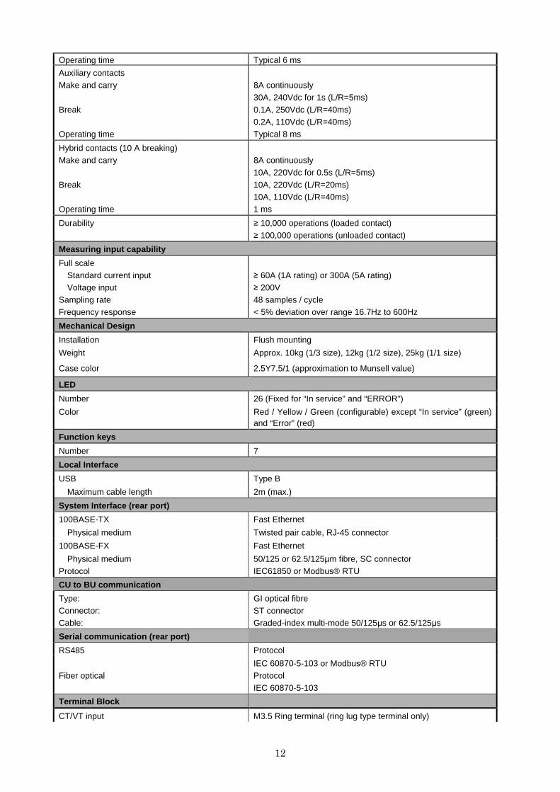
Operating time Typical 6 ms
Auxiliary contacts Make and carry
Break
Operating time
8A continuously
30A, 240Vdc for 1s (L/R=5ms)
0.1A, 250Vdc (L/R=40ms) 0.2A, 110Vdc (L/R=40ms)
Typical 8 ms
Hybrid contacts (10 A breaking) Make and carry
Break
Operating time
8A continuously
10A, 220Vdc for 0.5s (L/R=5ms)
10A, 220Vdc (L/R=20ms) 10A, 110Vdc (L/R=40ms)
1 ms
Durability ≥ 10,000 operations (loaded contact)
≥ 100,000 operations (unloaded contact)
Measuring input capability
Full scale Standard current input
Voltage input Sampling rate
Frequency response
≥ 60A (1A rating) or 300A (5A rating)
≥ 200V 48 samples / cycle
< 5% deviation over range 16.7Hz to 600Hz
Mechanical Design
Installation Flush mounting
Weight Approx. 10kg (1/3 size), 12kg (1/2 size), 25kg (1/1 size)
Case color 2.5Y7.5/1 (approximation to Munsell value)
LED
Number 26 (Fixed for “In service” and “ERROR”)
Color Red / Yellow / Green (configurable) except “In service” (green) and “Error” (red)
Function keys
Number 7
Local Interface
USB Type B
Maximum cable length 2m (max.)
System Interface (rear port)
100BASE-TX Fast Ethernet
Physical medium Twisted pair cable, RJ-45 connector
100BASE-FX Fast Ethernet
Physical medium Protocol
50/125 or 62.5/125µm fibre, SC connector IEC61850 or Modbus® RTU
CU to BU communication
Type: Connector:
Cable:
GI optical fibre ST connector
Graded-index multi-mode 50/125µs or 62.5/125µs
Serial communication (rear port)
RS485 Protocol
Fiber optical
IEC 60870-5-103 or Modbus® RTU Protocol
IEC 60870-5-103
Terminal Block
CT/VT input M3.5 Ring terminal (ring lug type terminal only)
13
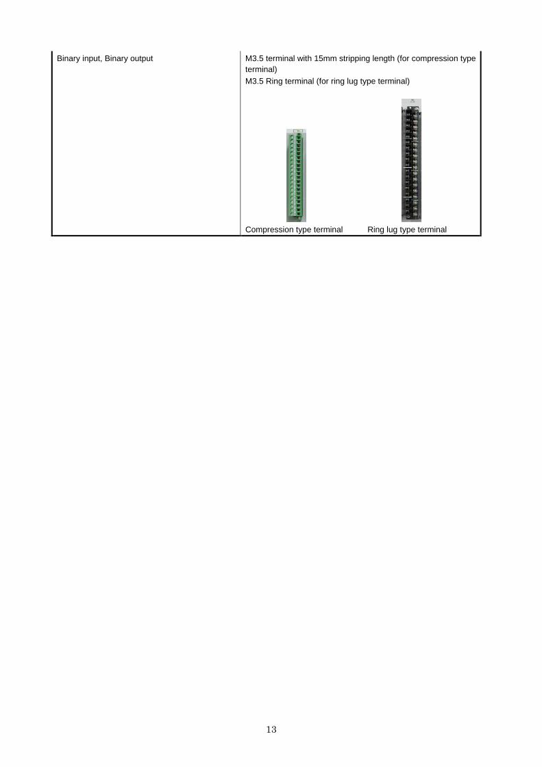
Binary input, Binary output M3.5 terminal with 15mm stripping length (for compression type terminal) M3.5 Ring terminal (for ring lug type terminal)
Compression type terminal Ring lug type terminal
14
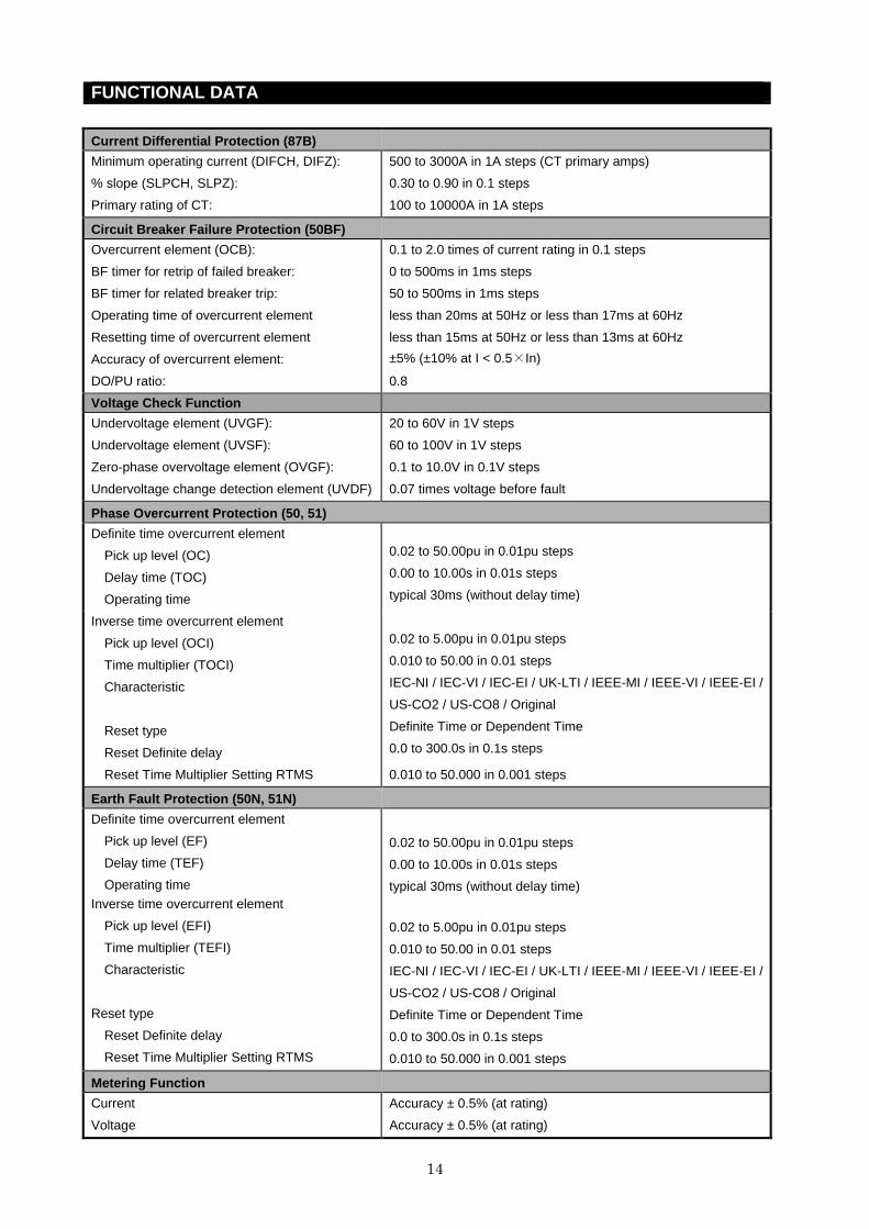
FUNCTIONAL DATA
Current Differential Protection (87B)
Minimum operating current (DIFCH, DIFZ):
% slope (SLPCH, SLPZ):
Primary rating of CT:
500 to 3000A in 1A steps (CT primary amps)
0.30 to 0.90 in 0.1 steps
100 to 10000A in 1A steps
Circuit Breaker Failure Protection (50BF)
Overcurrent element (OCB):
BF timer for retrip of failed breaker:
BF timer for related breaker trip:
Operating time of overcurrent element
Resetting time of overcurrent element
Accuracy of overcurrent element:
DO/PU ratio:
0.1 to 2.0 times of current rating in 0.1 steps
0 to 500ms in 1ms steps
50 to 500ms in 1ms steps
less than 20ms at 50Hz or less than 17ms at 60Hz
less than 15ms at 50Hz or less than 13ms at 60Hz
±5% (±10% at I < 0.5×In)
0.8
Voltage Check Function
Undervoltage element (UVGF):
Undervoltage element (UVSF):
Zero-phase overvoltage element (OVGF):
Undervoltage change detection element (UVDF)
20 to 60V in 1V steps
60 to 100V in 1V steps
0.1 to 10.0V in 0.1V steps
0.07 times voltage before fault
Phase Overcurrent Protection (50, 51)
Definite time overcurrent element
Pick up level (OC)
Delay time (TOC)
Operating time
0.02 to 50.00pu in 0.01pu steps
0.00 to 10.00s in 0.01s steps
typical 30ms (without delay time)
Inverse time overcurrent element
Pick up level (OCI)
Time multiplier (TOCI)
Characteristic
Reset type
Reset Definite delay
0.02 to 5.00pu in 0.01pu steps
0.010 to 50.00 in 0.01 steps
IEC-NI / IEC-VI / IEC-EI / UK-LTI / IEEE-MI / IEEE-VI / IEEE-EI /
US-CO2 / US-CO8 / Original
Definite Time or Dependent Time
0.0 to 300.0s in 0.1s steps
Reset Time Multiplier Setting RTMS 0.010 to 50.000 in 0.001 steps
Earth Fault Protection (50N, 51N)
Definite time overcurrent element
Pick up level (EF)
Delay time (TEF)
Operating time
Inverse time overcurrent element
Pick up level (EFI)
Time multiplier (TEFI)
Characteristic
Reset type
Reset Definite delay
Reset Time Multiplier Setting RTMS
0.02 to 50.00pu in 0.01pu steps
0.00 to 10.00s in 0.01s steps
typical 30ms (without delay time)
0.02 to 5.00pu in 0.01pu steps
0.010 to 50.00 in 0.01 steps
IEC-NI / IEC-VI / IEC-EI / UK-LTI / IEEE-MI / IEEE-VI / IEEE-EI /
US-CO2 / US-CO8 / Original
Definite Time or Dependent Time
0.0 to 300.0s in 0.1s steps
0.010 to 50.000 in 0.001 steps
Metering Function
Current
Voltage
Accuracy ± 0.5% (at rating)
Accuracy ± 0.5% (at rating)

15
Frequency Accuracy ± 0.03Hz
Time Synchronisation
Protocol SNTP

16
ENVIRONMENTAL PERFORMANCE
Atmospheric Environment
Temperature IEC 60068-2-1/2
IEC 60068-2-14
Operating range: -10°C to +55°C.
Storage / Transit: -25°C to +70°C.
Cyclic temperature test as per IEC 60068-2-14
Humidity IEC 60068-2-30
IEC 60068-2-78
56 days at 40°C and 93% relative humidity.
Cyclic temperature with humidity test as per IEC 60068-2-30
Enclosure Protection IEC 60529 IP52 - Dust and Dripping Water Proof IP20 for rear panel
Mechanical Environment
Vibration IEC 60255-21-1 Response - Class 1
Endurance - Class 1
Shock and Bump IEC 60255-21-2 Shock Response Class 1 Shock Withstand Class 1
Bump Class 1
Seismic IEC 60255-21-3 Class 1
Electrical Environment
Dielectric Withstand IEC 60255-5 2kVrms for 1 minute between all terminals and earth. 2kVrms for 1 minute between independent circuits. 1kVrms for 1 minute across normally open contacts.
High Voltage Impulse IEC 60255-5 IEEE C37.90
Three positive and three negative impulses
of 5kV(peak), 1.2/50µs, 0.5J between all
terminals and between all terminals and
earth.
Voltage Dips, Interruptions, Variations and Ripple on DC supply
IEC 60255-11,
IEC 61000-4-29, IEC 61000-4-17
IEC 60255-26 Ed 3
1. Voltage dips:
0 % residual voltage for 20 ms 40 % residual voltage for 200 ms
70 % residual voltage for 500 ms
2. Voltage interruptions: 0 % residual voltage for 5 s
3. Ripple:
15 % of rated d.c. value, 100 / 120 Hz 4. Gradual shut-down / start-up:
60 s shut-down ramp, 5 min power off, 60s start-up ramp
5. Reversal of d.c. power supply polarity: 1 min
Capacitive Discharge ENA TS 48-4 10µF charged to maximum supply voltage and discharged into the input terminals with an external resistance
17
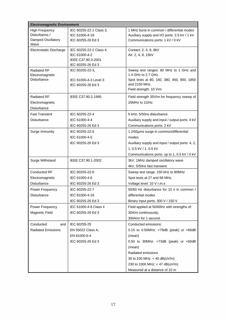
Electromagnetic Environment
High Frequency Disturbance /
Damped Oscillatory Wave
IEC 60255-22-1 Class 3,
IEC 61000-4-18 IEC 60255-26 Ed 3
1 MHz burst in common / differential modes
Auxiliary supply and I/O ports: 2.5 kV / 1 kV Communications ports: 1 kV / 0 kV
Electrostatic Discharge IEC 60255-22-2 Class 4, IEC 61000-4-2
IEEE C37.90.3-2001 IEC 60255-26 Ed 3
Contact: 2, 4, 6, 8kV Air: 2, 4, 8, 15kV
Radiated RF Electromagnetic Disturbance
IEC 60255-22-3,
IEC 61000-4-3 Level 3 IEC 60255-26 Ed 3
Sweep test ranges: 80 MHz to 1 GHz and 1.4 GHz to 2.7 GHz.
Spot tests at 80, 160, 380, 450, 900, 1850 and 2150 MHz.
Field strength: 10 V/m
Radiated RF
Electromagnetic
Disturbance
IEEE C37.90.2-1995 Field strength 35V/m for frequency sweep of
25MHz to 1GHz.
Fast Transient
Disturbance
IEC 60255-22-4
IEC 61000-4-4
IEC 60255-26 Ed 3
5 kHz, 5/50ns disturbance
Auxiliary supply and input / output ports: 4 kV
Communications ports: 2 kV
Surge Immunity IEC 60255-22-5
IEC 61000-4-5
IEC 60255-26 Ed 3
1.2/50µms surge in common/differential
modes:
Auxiliary supply and input / output ports: 4, 2,
1, 0.5 kV / 1, 0.5 kV
Communications ports: up to 1, 0.5 kV / 0 kV
Surge Withstand IEEE C37.90.1-2002 3kV, 1MHz damped oscillatory wave
4kV, 5/50ns fast transient
Conducted RF
Electromagnetic
Disturbance
IEC 60255-22-6
IEC 61000-4-6
IEC 60255-26 Ed 3
Sweep test range: 150 kHz to 80MHz
Spot tests at 27 and 68 MHz.
Voltage level: 10 V r.m.s
Power Frequency
Disturbance
IEC 60255-22-7
IEC 61000-4-16
IEC 60255-26 Ed 3
50/60 Hz disturbance for 10 s in common /
differential modes
Binary input ports: 300 V / 150 V
Power Frequency
Magnetic Field
IEC 61000-4-8 Class 4
IEC 60255-26 Ed 3
Field applied at 50/60Hz with strengths of:
30A/m continuously,
300A/m for 1 second.
Conducted and
Radiated Emissions
IEC 60255-25
EN 55022 Class A,
EN 61000-6-4
IEC 60255-26 Ed 3
Conducted emissions:
0.15 to 0.50MHz: <79dB (peak) or <66dB
(mean)
0.50 to 30MHz: <73dB (peak) or <60dB
(mean)
Radiated emissions
30 to 230 MHz: < 40 dB(uV/m)
230 to 1000 MHz: < 47 dB(uV/m)
Measured at a distance of 10 m

18
Performance and Functional Standards
Category Standards
General
Common requirements IEC 60255-1
Data Exchange IEC 60255-24 / IEEE C37.111 (COMTRADE)
IEEE C37-239 (COMFEDE)
Product Safety IEC 60255-27
Functional
Synchronizing IEC 60255-125
Under/Over Voltage Protection IEC 60255-127
Under/Over Power Protection IEC 60255-132
Thermal Protection IEC 60255-149
Over/Under Current Protection IEC 60255-151
Directional Current Protection IEC 60255-167
Reclosing IEC 60255-179
Frequency Protection IEC 60255-181
Teleprotection IEC 60255-185
European Commission Directives
2004/108/EC
Compliance with the European Commission
Electromagnetic Compatibility Directive is
demonstrated according to generic EMC standards
EN 61000-6-2 and EN 61000-6-4, and product
standard IEC 60255-26.
2006/95/EC
Compliance with the European Commission Low
Voltage Directive for electrical safety is
demonstrated according EN 60255-27.
19
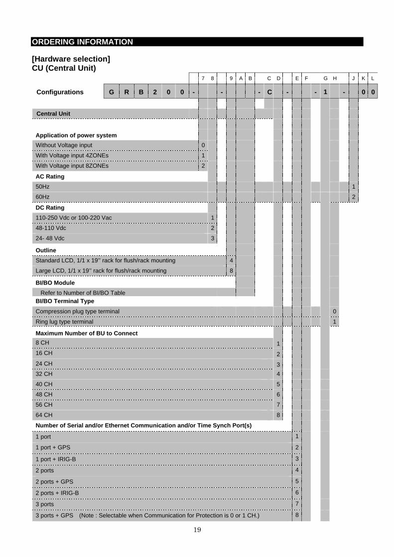
ORDERING INFORMATION
[Hardware selection] CU (Central Unit)
7 8 9 A B C D E F G H J K L
Configurations G R B 2 0 0 - - - C - - 1 - 0 0
Central Unit
Application of power system
Without Voltage input 0
With Voltage input 4ZONEs 1
With Voltage input 8ZONEs 2
AC Rating
50Hz 1
60Hz 2
DC Rating
110-250 Vdc or 100-220 Vac 1
48-110 Vdc 2
24- 48 Vdc 3
Outline
Standard LCD, 1/1 x 19’’ rack for flush/rack mounting 4
Large LCD, 1/1 x 19’’ rack for flush/rack mounting 8
BI/BO Module
Refer to Number of BI/BO Table BI/BO Terminal Type
Compression plug type terminal 0
Ring lug type terminal 1
Maximum Number of BU to Connect
8 CH 1
16 CH 2
24 CH 3
32 CH 4
40 CH 5
48 CH 6
56 CH 7
64 CH 8
Number of Serial and/or Ethernet Communication and/ or Time Synch Port(s)
1 port 1
1 port + GPS 2
1 port + IRIG-B 3
2 ports 4
2 ports + GPS 5
2 ports + IRIG-B 6
3 ports 7
3 ports + GPS (Note : Selectable when Communication for Protection is 0 or 1 CH.) 8
20
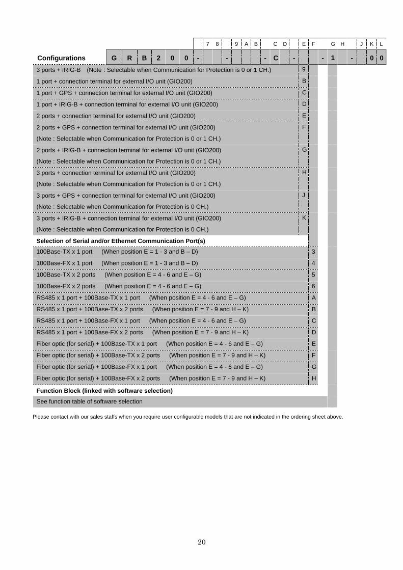
7 8 9 A B C D E F G H J K L
Configurations G R B 2 0 0 - - - C - - 1 - 0 0
3 ports + IRIG-B (Note : Selectable when Communication for Protection is 0 or 1 CH.) 9
1 port + connection terminal for external I/O unit (GIO200) B
1 port + GPS + connection terminal for external I/O unit (GIO200) C
1 port + IRIG-B + connection terminal for external I/O unit (GIO200) D
2 ports + connection terminal for external I/O unit (GIO200) E
2 ports + GPS + connection terminal for external I/O unit (GIO200)
(Note : Selectable when Communication for Protection is 0 or 1 CH.)
F
2 ports + IRIG-B + connection terminal for external I/O unit (GIO200)
(Note : Selectable when Communication for Protection is 0 or 1 CH.)
G
3 ports + connection terminal for external I/O unit (GIO200)
(Note : Selectable when Communication for Protection is 0 or 1 CH.)
H
3 ports + GPS + connection terminal for external I/O unit (GIO200)
(Note : Selectable when Communication for Protection is 0 CH.)
J
3 ports + IRIG-B + connection terminal for external I/O unit (GIO200)
(Note : Selectable when Communication for Protection is 0 CH.)
K
Selection of Serial and/or Ethernet Communication P ort(s)
100Base-TX x 1 port (When position E = 1 - 3 and B – D) 3
100Base-FX x 1 port (When position E = 1 - 3 and B – D) 4
100Base-TX x 2 ports (When position E = 4 - 6 and E – G) 5
100Base-FX x 2 ports (When position E = 4 - 6 and E – G) 6
RS485 x 1 port + 100Base-TX x 1 port (When position E = 4 - 6 and E – G) A
RS485 x 1 port + 100Base-TX x 2 ports (When position E = 7 - 9 and H – K) B
RS485 x 1 port + 100Base-FX x 1 port (When position E = 4 - 6 and E – G) C
RS485 x 1 port + 100Base-FX x 2 ports (When position E = 7 - 9 and H – K) D
Fiber optic (for serial) + 100Base-TX x 1 port (When position E = 4 - 6 and E – G) E
Fiber optic (for serial) + 100Base-TX x 2 ports (When position E = 7 - 9 and H – K) F
Fiber optic (for serial) + 100Base-FX x 1 port (When position E = 4 - 6 and E – G) G
Fiber optic (for serial) + 100Base-FX x 2 ports (When position E = 7 - 9 and H – K) H
Function Block (linked with software selection)
See function table of software selection
Please contact with our sales staffs when you require user configurable models that are not indicated in the ordering sheet above.

21
[Hardware selection] BU (Bay Unit)
7 8 9 A B C D E F G H J K L
Configurations G R B 2 0 0 - - - B 0 - 4 E - 1 - 0
Bay Unit
Application of power system
(CTx4) for 1/3x 19’’ rack 1
(CTx4) for 1/2 x 19’’ rack 2
AC Rating
50Hz 1
60Hz 2
1A 1
5A 2
DC Rating
110-250 Vdc or 100-220 Vac 1
48-110 Vdc 2
24- 48 Vdc 3
Outline
Standard LCD, 1/3 x 19’’ rack for flush mounting 1
Standard LCD, 1/2 x 19’’ rack for flush mounting 2
Large LCD, 1/3 x 19’’ rack for flush mounting 5
Large LCD, 1/2 x 19’’ rack for flush mounting 6
Standard LCD, 1/3 x 19’’ rack for rack mounting E
Standard LCD, 1/2 x 19’’ rack for rack mounting F
Large LCD, 1/3 x 19’’ rack for rack mounting H
Large LCD, 1/2 x 19’’ rack for rack mounting J
BI/BO Module
Refer to Number of BI/BO Table BI/BO Terminal Type
Compression plug type terminal 0
Ring lug type terminal 1
Function Block (linked with software selection)
See function table of software selection Please contact with our sales staffs when you require user configurable models that are not indicated in the ordering sheet above.
22
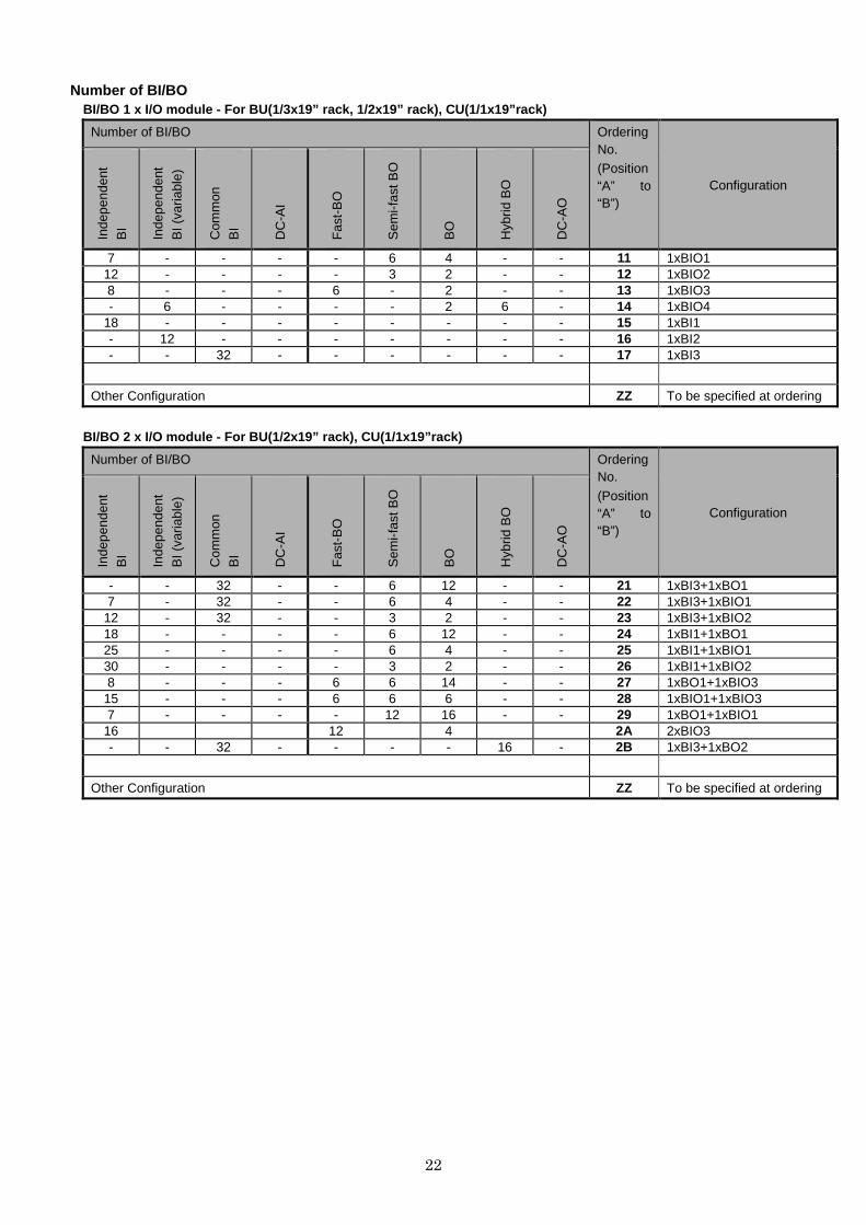
Number of BI/BO BI/BO 1 x I/O module - For BU(1/3x19” rack, 1/2x19” rack), CU(1/1x19”rack)
Number of BI/BO Ordering No.
(Position “A” to “B”)
Configuration
Inde
pend
ent
BI
Inde
pend
ent
BI (
varia
ble)
Com
mon
B
I
DC
-AI
Fas
t-B
O
Sem
i-fas
t BO
BO
Hyb
rid B
O
DC
-AO
7 - - - - 6 4 - - 11 1xBIO1 12 - - - - 3 2 - - 12 1xBIO2 8 - - - 6 - 2 - - 13 1xBIO3 - 6 - - - - 2 6 - 14 1xBIO4
18 - - - - - - - - 15 1xBI1 - 12 - - - - - - - 16 1xBI2 - - 32 - - - - - - 17 1xBI3
Other Configuration ZZ To be specified at ordering
BI/BO 2 x I/O module - For BU(1/2x19” rack), CU(1/1 x19”rack)
Number of BI/BO Ordering No.
(Position “A” to “B”)
Configuration
Inde
pend
ent
BI
Inde
pend
ent
BI (
varia
ble)
Com
mon
B
I
DC
-AI
Fas
t-B
O
Sem
i-fas
t BO
BO
Hyb
rid B
O
DC
-AO
- - 32 - - 6 12 - - 21 1xBI3+1xBO1 7 - 32 - - 6 4 - - 22 1xBI3+1xBIO1
12 - 32 - - 3 2 - - 23 1xBI3+1xBIO2 18 - - - - 6 12 - - 24 1xBI1+1xBO1 25 - - - - 6 4 - - 25 1xBI1+1xBIO1 30 - - - - 3 2 - - 26 1xBI1+1xBIO2 8 - - - 6 6 14 - - 27 1xBO1+1xBIO3
15 - - - 6 6 6 - - 28 1xBIO1+1xBIO3 7 - - - - 12 16 - - 29 1xBO1+1xBIO1
16 12 4 2A 2xBIO3 - - 32 - - - - 16 - 2B 1xBI3+1xBO2
Other Configuration ZZ To be specified at ordering

23
BI/BO 3 x I/O module - For BU(1/2x19” rack)
Number of BI/BO Ordering No.
(Position “A” to “B”)
Configuration
Inde
pend
ent
BI
Inde
pend
ent
BI (
varia
ble)
Com
mon
B
I
DC
-AI
Fas
t-B
O
Sem
i-fas
t BO
BO
Hyb
rid B
O
DC
-AO
15 - - - 6 12 18 - - 31 1xBO1+1xBIO1+1xBIO3 20 - - - 6 9 16 - - 32 1xBO1+1xBIO2+1xBIO3 23 - - - 12 6 8 - - 33 1xBIO1+2xBIO3 26 - - - 6 6 14 - - 34 1xBI1+1xBO1+1xBIO3 8 - 32 - 6 6 14 - - 35 1xBI3+1xBO1+1xBIO3
24 - - - 18 - 6 - - 36 3xBIO3 25 - - - - 12 16 - - 37 1xBI1+1xBO1+1xBIO1 - - 32 10 - 6 12 - - 38 1xBI3+1xDCAI2+1xBO1
36 - - - - 6 12 - - 39 2xBI1+1xBO1 - 24 - - - 6 12 - - 3A 2xBI2+1xBO1
18 6 - - - 6 14 6 - 3B 1xBI1+1xBO1+1xBIO4 7 - 32 - - 6 4 16 - 3C 1xBI3+1xBIO1+1xBO2 7 - 32 - - 12 16 - - 3D 1xBI3+1xBO1+1xBIO1 - - 32 - - 6 12 16 - 3E 1xBI3+1xBO1+1xBO2
16 - - - 12 6 16 - - 3G 1xBO1+2xBIO3 - 6 32 - - 6 14 6 - 3H 1xBI3+1xBO1+1xBIO4
26 - - - 6 6 14 - - 3J 1xBO1+1xBIO3+1xBI1 - - 62 - - 6 12 - - 3K 2xBI3+1xBO1
Other Configuration ZZ To be specified at ordering

24
[Software selection] CU (Central Unit)
1 2 3 4 5 6 7 S G T E F U 9 V
Configurations G R B 2 0 0 - 0 - - E
Application of power system
Assignment on position “7”
Function Block
Refer to Function Table
Communication for Remote / Time Synch. (1)
Assignment on position “E”
Communication for Remote / Time Synch. (2)
Assignment on position “F”
Protocol
IEC 61850 2
Outline
Assignment on position “9”
Language
English E
[Software selection] BU (Bay Unit)
1 2 3 4 5 6 7 S G T E F U 9 V
Configurations G R B 2 0 0 - 0 - 4 E 9 - E
Application of power system
Assignment on position “7”
Function Block
Refer to Function Table
Outline
Assignment on position “9”
Language
English E
25
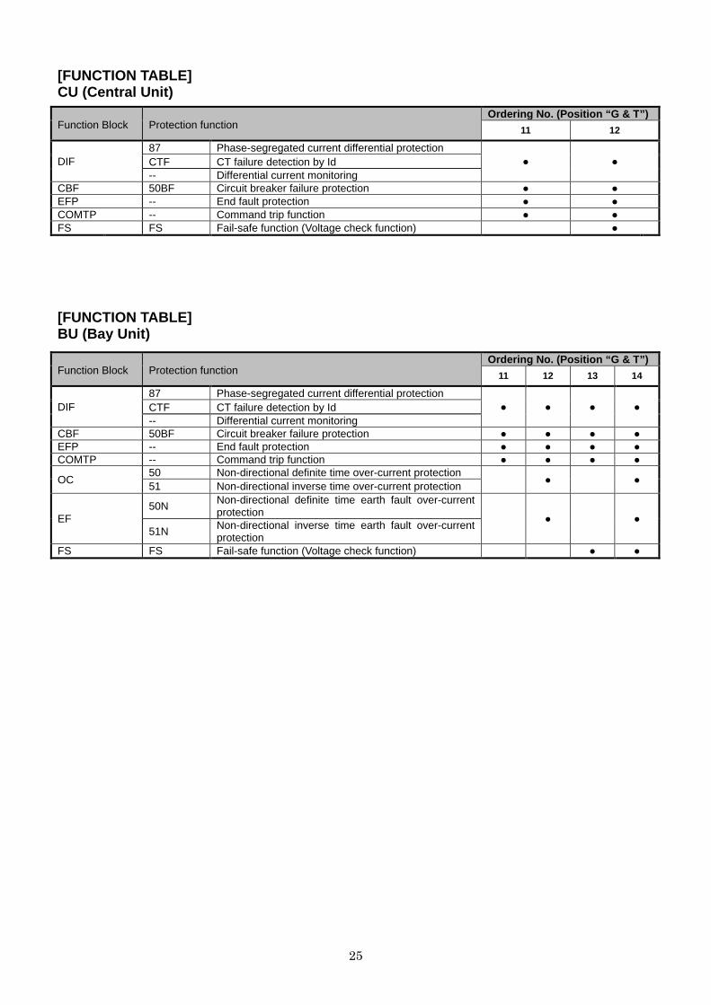
[FUNCTION TABLE] CU (Central Unit)
[FUNCTION TABLE] BU (Bay Unit)
Function Block Protection function Ordering No. (Position “ G & T”)
11 12
DIF 87 Phase-segregated current differential protection
● ● CTF CT failure detection by Id -- Differential current monitoring
CBF 50BF Circuit breaker failure protection ● ● EFP -- End fault protection ● ● COMTP -- Command trip function ● ● FS FS Fail-safe function (Voltage check function) ●
Function Block Protection function Ordering No. (Position “ G & T”)
11 12 13 14
DIF 87 Phase-segregated current differential protection
● ● ● ● CTF CT failure detection by Id -- Differential current monitoring
CBF 50BF Circuit breaker failure protection ● ● ● ● EFP -- End fault protection ● ● ● ● COMTP -- Command trip function ● ● ● ●
OC 50 Non-directional definite time over-current protection
● ● 51 Non-directional inverse time over-current protection
EF 50N
Non-directional definite time earth fault over-current protection
● ● 51N Non-directional inverse time earth fault over-current
protection FS FS Fail-safe function (Voltage check function) ● ●
26
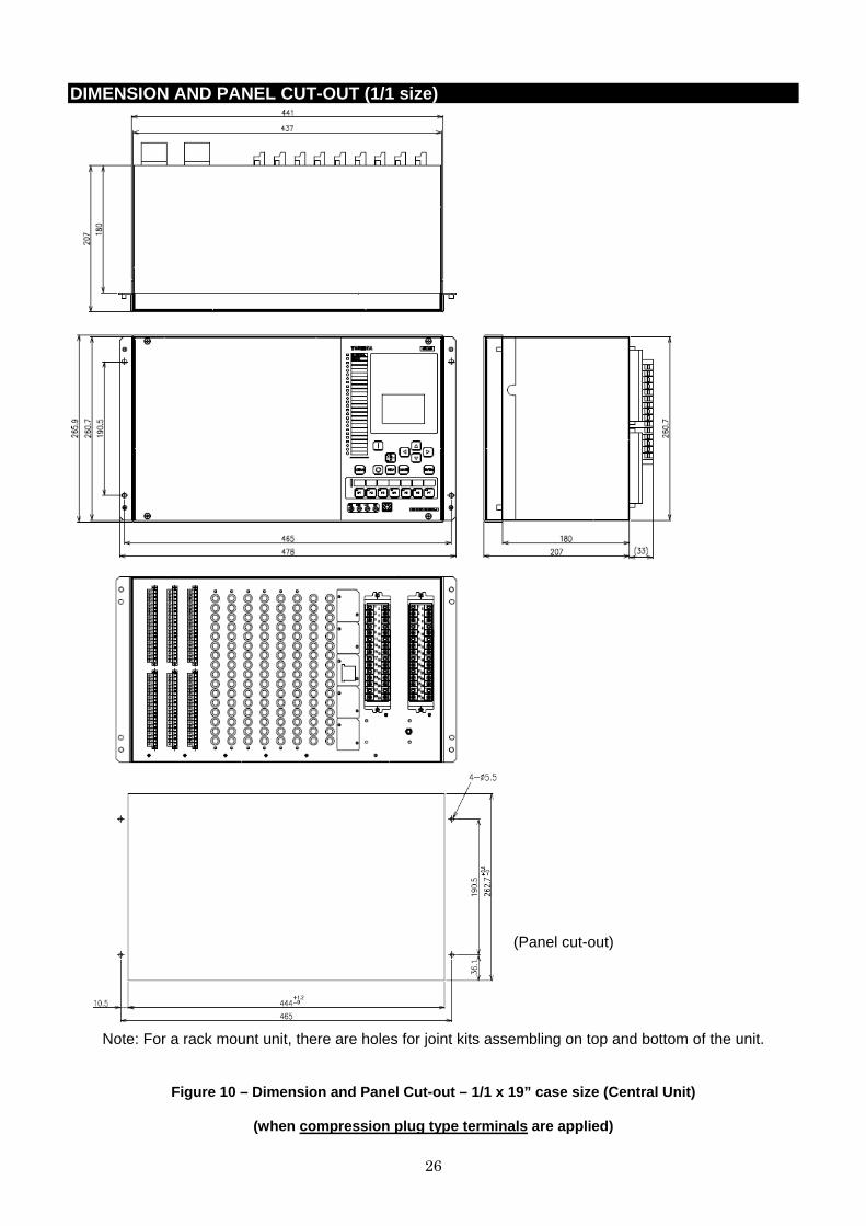
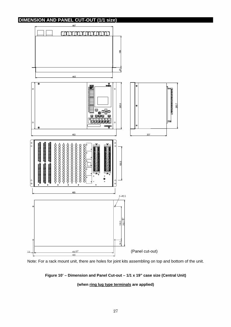
DIMENSION AND PANEL CUT-OUT (1/1 size)
(Panel cut-out)
Note: For a rack mount unit, there are holes for joint kits assembling on top and bottom of the unit.
Figure 10 – Dimension and Panel Cut-out – 1/1 x 19” case size (Central Unit)
(when compression plug type terminals are applied)
27
DIMENSION AND PANEL CUT-OUT (1/1 size)
(Panel cut-out)
Note: For a rack mount unit, there are holes for joint kits assembling on top and bottom of the unit.
Figure 10’ – Dimension and Panel Cut-out – 1/1 x 19” case size (Central Unit)
(when ring lug type terminals are applied)

28
DIMENSION AND PANEL CUT-OUT (1/3 size)
(Panel cut-out)
Note: For a rack mount unit, there are holes for joint kits assembling on top and bottom of the unit.
Figure 11 – Dimension and Panel Cut-out – 1/3 x 19’’ case size (Bay unit)
(when compression plug type terminals are applied)

29
DIMENSION AND PANEL CUT-OUT (1/3 size)
(Panel cut-out)
Note: For a rack mount unit, there are holes for joint kits assembling on top and bottom of the unit.
Figure 11’ – Dimension and Panel Cut-out – 1/3 x 19’’ case siz e (Bay unit)
(when ring lug type terminals are applied)
30
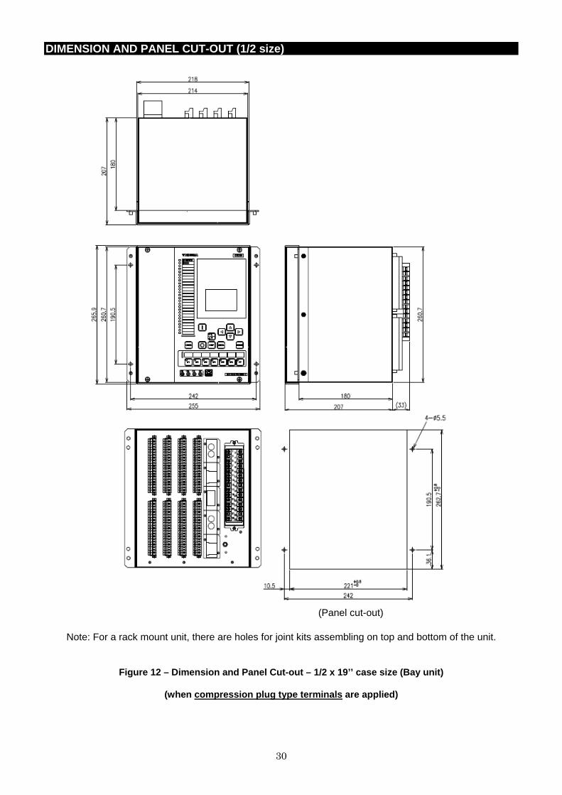
DIMENSION AND PANEL CUT-OUT (1/2 size)
(Panel cut-out)
Note: For a rack mount unit, there are holes for joint kits assembling on top and bottom of the unit.
Figure 12 – Dimension and Panel Cut-out – 1/2 x 19’’ case size (Bay unit)
(when compression plug type terminals are applied)
31
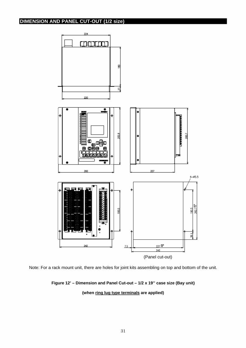
DIMENSION AND PANEL CUT-OUT (1/2 size)
(Panel cut-out)
Note: For a rack mount unit, there are holes for joint kits assembling on top and bottom of the unit.
Figure 12’ – Dimension and Panel Cut-out – 1/2 x 19’’ case siz e (Bay unit)
(when ring lug type terminals are applied)
32
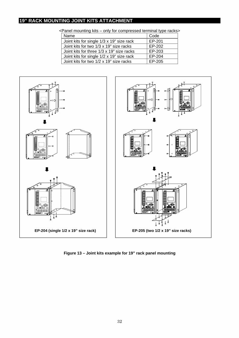
19” RACK MOUNTING JOINT KITS ATTACHMENT
<Panel mounting kits – only for compressed terminal type racks> Name Code Joint kits for single 1/3 x 19” size rack EP-201 Joint kits for two 1/3 x 19” size racks EP-202 Joint kits for three 1/3 x 19” size racks EP-203 Joint kits for single 1/2 x 19” size rack EP-204 Joint kits for two 1/2 x 19” size racks EP-205
EP-204 (single 1/2 x 19” size rack) EP-205 (two 1/2 x 19” size racks)
Figure 13 – Joint kits example for 19” rack panel mounting

33
CONNECTIONS DIAGRAM (COMPRESSION PLUG TYPE)
BI1 A
1
2 BI1
(+)
(-)
3
4 BI2
(+)
(-)
5
6 BI3
(+)
(-)
7
8 BI4
(+)
(-)
9
10 BI5
(+)
(-)
13
14 BI7
(+)
(-)
11
12 BI6
(+)
(-)
15
16 BI8
(+)
(-)
17
18 BI9
(+)
(-)
21
22 BI10
(+)
(-)
23
24 BI11
(+)
(-)
25
26 BI12
(+)
(-)
27
28 BI13
(+)
(-)
29
30 BI14
(+)
(-)
31
32 BI15
(+)
(-)
35
36 BI17
(+)
(-)
33
34 BI16
(+)
(-)
37
38 BI18
(+)
(-)
BI2 A
1
2 BI1
(+)
(-)
5
6 BI2
(+)
(-)
7
8 BI3
(+)
(-)
11
12 BI4
(+)
(-)
13
14 BI5
(+)
(-)
21
22 BI7
(+)
(-)
17
18 BI6
(+)
(-)
25
26 BI8
(+)
(-)
27
28 BI9
(+)
(-)
31
32 BI10
(+)
(-)
33
34 BI11
(+)
(-)
37
38 BI12
(+)
(-)
BI3 A
35
36
(-)
(-)
37
38
(-)
(-)
1 (+) BI1
2 (+) BI2
3 (+) BI3
4 (+) BI4
5 (+) BI5
6 (+) BI6
7 (+) BI7
8 (+) BI8
9 (+) BI9
10 (+) BI10
11 (+) BI11
12 (+) BI12
13 (+) BI13
14 (+) BI14
15 (+) BI15
16 (+) BI16
17 (+) BI17
18 (+) BI18
21 (+) BI19
22 (+) BI20
23 (+) BI21
24 (+) BI22
25 (+) BI23
26 (+) BI24
27 (+) BI25
28 (+) BI26
29 (+) BI27
30 (+) BI28
31 (+) BI29
32 (+) BI30
33 (+) BI31
34 (+) BI32
Figure 14 – Binary input board module (for Compression plug type terminal)

34
CONNECTIONS DIAGRAM (COMPRESSION PLUG TYPE)
BO1 A
BO10
21
22
BO1(*2)
1
2
BO2(*2)
3
4
BO3(*2)
5
6
BO4(*2)
7
8
BO5(*2)
9
10
BO6(*2)
11
12
BO7
13
14
BO8
15
16
BO9
17
18
BO11
23
24
BO12
25
26
BO13
27
28
BO14
29
30
BO15
31
32
BO16
33
34
BO17
35
36
BO18
37
38
BO2 A
BO1(*3)
1
2
(+)
(-)
BO2(*3)
3
4
(+)
(-)
BO3(*3)
5
6
(+)
(-)
BO4(*3)
7
8
(+)
(-)
BO5(*3)
9
10
(+)
(-)
BO6(*3)
11
12
(+)
(-)
BO7(*3)
13
14
(+)
(-)
BO8(*3)
15
16
(+)
(-)
BO9(*3)
17
18
(+)
(-)
BO10(*3)
21
22
(+)
(-)
BO11(*3)
23
24
(+)
(-)
BO12(*3)
25
26
(+)
(-)
BO13(*3)
27
28
(+)
(-)
BO14(*3)
29
30
(+)
(-)
BO15(*3)
31
32
(+)
(-)
BO16(*3)
33
34
(+)
(-)
PWS1 A
29
30
31
32
38
DC/DC
(+)
(-)
35
37
36
3
1
2
4
FAIL1
9
7
8
10
FAIL2
Protective Earth
(*2) Semi-fast BO (*3) Hybrid BO
Figure 15 – Binary output board module and DC/DC module
(for Compression plug type terminal)

35
CONNECTIONS DIAGRAM (COMPRESSION PLUG TYPE)
BIO1 A
BO1(*2)
15
16
BO2(*2)
17
18
BO3(*2)
21
22
BO4(*2)
23
24
BO5(*2)
25
26
BO6(*2)
27
28
BO7
29
30
BO8
31
32
BO9
33
34
1
2 BI1
(+)
(-)
3
4 BI2
(+)
(-)
5
6 BI3
(+)
(-)
7
8 BI4
(+)
(-)
9
10 BI5
(+)
(-)
13
14 BI7
(+)
(-)
11
12 BI6
(+)
(-)
36
38
35
37
BO10
BIO2 A
BO1(*2)
27
28
BO2(*2)
29
30
BO3(*2)
31
32
BO4
33
34
36
38
35
37
BO5
1
2 BI1
(+)
(-)
3
4 BI2
(+)
(-)
5
6 BI3
(+)
(-)
7
8 BI4
(+)
(-)
9
10 BI5
(+)
(-)
13
14 BI7
(+)
(-)
11
12 BI6
(+)
(-)
15
16 BI8
(+)
(-)
17
18 BI9
(+)
(-)
21
22 BI10
(+)
(-)
23
24 BI11
(+)
(-)
25
26 BI12
(+)
(-)
BIO3 A
BO1(*1)
21
22
BO2(*1)
23
24
BO3(*1)
25
26
BO4(*1)
27
28
BO5(*1)
29
30
BO6(*1)
31
32
BO7
33
34
36
38
35
37
BO8
1
2 BI1
(+)
(-)
3
4 BI2
(+)
(-)
5
6 BI3
(+)
(-)
7
8 BI4
(+)
(-)
9
10 BI5
(+)
(-)
13
14 BI7
(+)
(-)
11
12 BI6
(+)
(-)
15
16 BI8
(+)
(-)
BIO4 A
BO7
33
34
36
38
35
37
BO8
1
2 BI1
(+)
(-)
3
4 BI2
(+)
(-)
5
6 BI3
(+)
(-)
7
8 BI4
(+)
(-)
9
10 BI5
(+)
(-)
11
12 BI6
(+)
(-)
BO1(*3)
17
18
(+)
(-)
BO2(*3)
21
22
(+)
(-)
BO3(*3)
23
24
(+)
(-)
BO4(*3)
25
26
(+)
(-)
BO5(*3)
27
28
(+)
(-)
BO6(*3)
29
30
(+)
(-)
(*1) Fast BO (*2) Semi-fast BO (*3) Hybrid BO
Figure 16 – Combined binary input and output module
(for Compression plug type terminal)
36
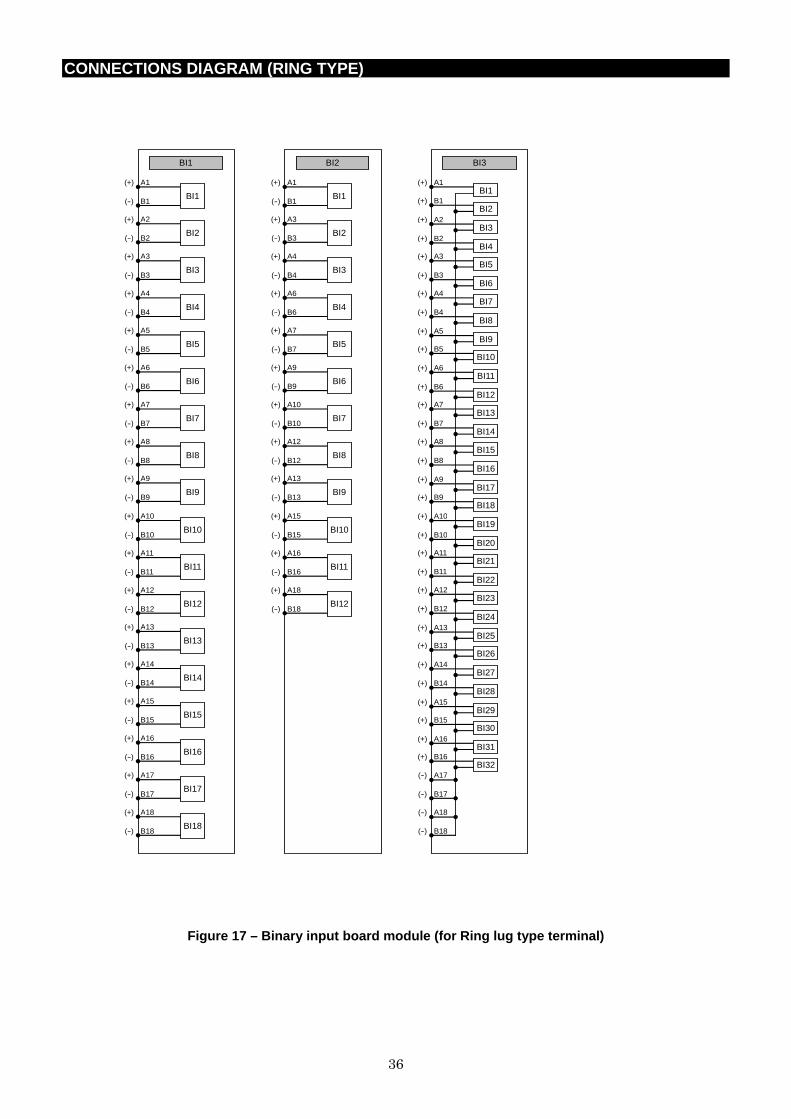
CONNECTIONS DIAGRAM (RING TYPE)
BI1
A1
B1 BI1
(+)
(-)
A2
B2 BI2
(+)
(-)
A3
B3 BI3
(+)
(-)
A4
B4 BI4
(+)
(-)
A5
B5 BI5
(+)
(-)
A7
B7 BI7
(+)
(-)
A6
B6 BI6
(+)
(-)
A8
B8 BI8
(+)
(-)
A9
B9 BI9
(+)
(-)
A10
B10 BI10
(+)
(-)
A11
B11 BI11
(+)
(-)
A12
B12 BI12
(+)
(-)
A13
B13 BI13
(+)
(-)
A14
B14 BI14
(+)
(-)
A15
B15 BI15
(+)
(-)
A17
B17 BI17
(+)
(-)
A16
B16 BI16
(+)
(-)
A18
B18 BI18
(+)
(-)
BI2
A1
B1 BI1
(+)
(-)
A3
B3 BI2
(+)
(-)
A4
B4 BI3
(+)
(-)
A6
B6 BI4
(+)
(-)
A7
B7 BI5
(+)
(-)
A10
B10 BI7
(+)
(-)
A9
B9 BI6
(+)
(-)
A12
B12 BI8
(+)
(-)
A13
B13 BI9
(+)
(-)
A15
B15 BI10
(+)
(-)
A16
B16 BI11
(+)
(-)
A18
B18 BI12
(+)
(-)
BI3
A17
B17
(-)
(-)
A18
B18
(-)
(-)
A1 (+) BI1
B1 (+) BI2
A2 (+) BI3
B2 (+) BI4
A3 (+) BI5
B3 (+) BI6
A4 (+) BI7
B4 (+) BI8
A5 (+) BI9
B5 (+) BI10
A6 (+) BI11
B6 (+) BI12
A7 (+) BI13
B7 (+) BI14
A8 (+) BI15
B8 (+) BI16
A9 (+) BI17
B9 (+) BI18
A10 (+) BI19
B10 (+) BI20
A11 (+) BI21
B11 (+) BI22
A12 (+) BI23
B12 (+) BI24
A13 (+) BI25
B13 (+) BI26
A14 (+) BI27
B14 (+) BI28
A15 (+) BI29
B15 (+) BI30
A16 (+) BI31
B16 (+) BI32
Figure 17 – Binary input board module (for Ring lug type terminal)

37
CONNECTIONS DIAGRAM (RING TYPE)
BO1
BO1(*2)
A1
B1
BO2(*2)
A2
B2
BO3(*2)
A3
B3
BO4(*2)
A4
B4
BO5(*2)
A5
B5
BO6(*2)
A6
B6
BO7
A7
B7
BO8
A8
B8
BO9
A9
B9
BO10
A10
B10
BO11
A11
B11
BO12
A12
B12
BO13
A13
B13
BO14
A14
B14
BO15
A15
B15
BO16
A16
B16
BO17
A17
B17
BO18
A18
B18
BO2
BO1(*3)
A1
B1
(+)
(-)
BO2(*3)
A2
B2
(+)
(-)
BO3(*3)
A3
B3
(+)
(-)
BO4(*3)
A4
B4
(+)
(-)
BO5(*3)
A5
B5
(+)
(-)
BO6(*3)
A6
B6
(+)
(-)
BO7(*3)
A7
B7
(+)
(-)
BO8(*3)
A8
B8
(+)
(-)
BO9(*3)
A9
B9
(+)
(-)
BO10(*3)
A10
B10
(+)
(-)
BO11(*3)
A11
B11
(+)
(-)
BO12(*3)
A12
B12
(+)
(-)
BO13(*3)
A13
B13
(+)
(-)
BO14(*3)
A14
B14
(+)
(-)
BO15(*3)
A15
B15
(+)
(-)
BO16(*3)
A16
B16
(+)
(-)
PWS1
B3
B1
B2
B4
FAIL1
B7
B5
B6
B8
FAIL2
B14
B15
B16
B17
B18
DC/DC
(+)
(-)
(*) (*)The connection of these terminals is made with a short-wire as a default.
Protective Earth E
(*2) Semi-fast BO (*3) Hybrid BO
Figure 18 – Binary output board module and DC/DC module
(for Ring lug type terminal)
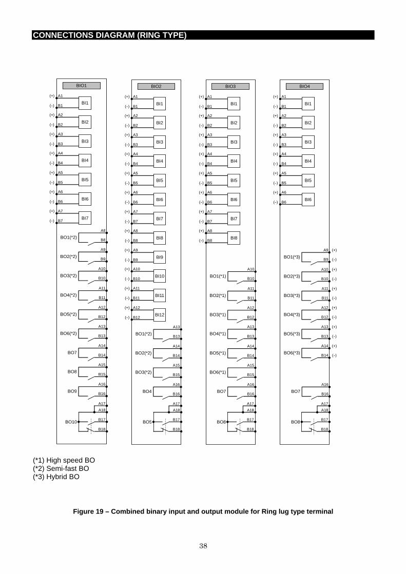
38
CONNECTIONS DIAGRAM (RING TYPE)
BIO1
BO1(*2)
A8
B8
BO2(*2)
A9
B9
BO3(*2)
A10
B10
BO4(*2)
A11
B11
BO5(*2)
A12
B12
BO6(*2)
A13
B13
BO7
A14
B14
BO8
A15
B15
BO9
A16
B16
B17
B18
A17
A18
BO10
A1
B1 BI1
(+)
(-)
A2
B2 BI2
(+)
(-)
A3
B3 BI3
(+)
(-)
A4
B4 BI4
(+)
(-)
A5
B5 BI5
(+)
(-)
A7
B7 BI7
(+)
(-)
A6
B6 BI6
(+)
(-)
BIO2
BO1(*2)
A13
B13
BO2(*2)
A14
B14
BO3(*2)
A15
B15
BO4
A16
B16
B17
B18
A17
A18
BO5
A1
B1 BI1
(+)
(-)
A2
B2 BI2
(+)
(-)
A3
B3 BI3
(+)
(-)
A4
B4 BI4
(+)
(-)
A5
B5 BI5
(+)
(-)
A7
B7 BI7
(+)
(-)
A6
B6 BI6
(+)
(-)
A8
B8 BI8
(+)
(-)
A9
B9 BI9
(+)
(-)
A10
B10 BI10
(+)
(-)
A11
B11 BI11
(+)
(-)
A12
B12 BI12
(+)
(-)
BIO3
BO1(*1)
A10
B10
BO2(*1)
A11
B11
BO3(*1)
A12
B12
BO4(*1)
A13
B13
BO5(*1)
A14
B14
BO6(*1)
A15
B15
BO7
A16
B16
B17
B18
A17
A18
BO8
A1
B1 BI1
(+)
(-)
A2
B2 BI2
(+)
(-)
A3
B3 BI3
(+)
(-)
A4
B4 BI4
(+)
(-)
A5
B5 BI5
(+)
(-)
A7
B7 BI7
(+)
(-)
A6
B6 BI6
(+)
(-)
A8
B8 BI8
(+)
(-)
BIO4
BO7
A16
B16
B17
B18
A17
A18
BO8
A1
B1 BI1
(+)
(-)
A2
B2 BI2
(+)
(-)
A3
B3 BI3
(+)
(-)
A4
B4 BI4
(+)
(-)
A5
B5 BI5
(+)
(-)
A6
B6 BI6
(+)
(-)
BO1(*3)
A9
B9
(+)
(-)
BO2(*3)
A10
B10
(+)
(-)
BO3(*3)
A11
B11
(+)
(-)
BO4(*3)
A12
B12
(+)
(-)
BO5(*3)
A13
B13
(+)
(-)
BO6(*3)
A14
B14
(+)
(-)
(*1) High speed BO (*2) Semi-fast BO (*3) Hybrid BO
Figure 19 – Combined binary input and output module for Ring lug type termina l
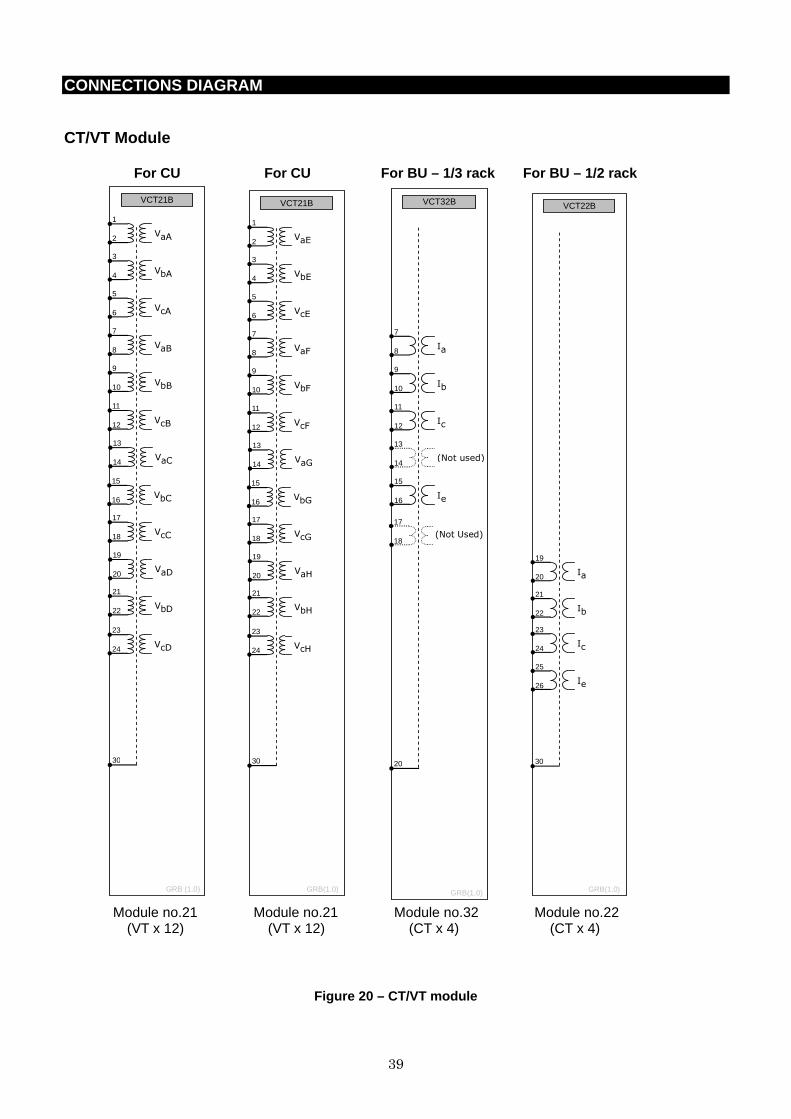
39
CONNECTIONS DIAGRAM
CT/VT Module
For CU For CU For BU – 1/3 rack For BU – 1/2 r ack
VcD
23
24
VaD
19
20
VcC
17
18
VbC
15
16
VaC
13
14
VcB
11
12
VCT21B
VaA
1
2
30
VbA
3
4
VcA
5
6
VaB
7
8
VbB
9
10
VbD
21
22
GRB (1.0)
VcH
23
24
VaH
19
20
VcG
17
18
VbG
15
16
VaG
13
14
VcF
11
12
VCT21B
VaE
1
2
30
VbE
3
4
VcE
5
6
VaF
7
8
VbF
9
10
VbH
21
22
GRB(1.0)
VCT32B
20
Ia
7
8
Ib
9
10
Ic
11
12
(Not used) 13
14
Ie
15
16
(Not Used)
17
18
GRB(1.0)
VCT22B
30
Ia
19
20
Ib
21
22
Ic
23
24
Ie
25
26
GRB(1.0)
Module no.21 Module no.21 Module no.32 Module no.22 (VT x 12) (VT x 12) (CT x 4) (CT x 4)
Figure 20 – CT/VT module

40
EXTERNAL CONNECTIONS DIAGRAM
CU (Central Unit) – 1/1 size
PWS1 A
29
30
31
32
38
DC/DC
(+)
(-)
35
37
36
FG
3
1
2
4
FAIL1
9
7
8
10
FAIL2
BO1 A
BO10(*4)
21
22
BO1(*2)
1
2
BO2(*2)
3
4
BO3(*2)
5
6
BO4(*2)
7
8
BO5(*2)
9
10
BO6(*2)
11
12
BO7(*4)
13
14
BO8(*4)
15
16
BO9(*4)
17
18
BO11(*4)
23
24
BO12(*4)
25
26
BO13(*4)
27
28
BO14(*4)
29
30
BO15(*4)
31
32
BO16(*4)
33
34
BO17(*4)
35
36
BO18(*4)
37
38
BI1 A
1
2 BI1
(+)
(-)
3
4 BI2
(+)
(-)
5
6 BI3
(+)
(-)
7
8 BI4
(+)
(-)
9
10 BI5
(+)
(-)
13
14 BI7
(+)
(-)
11
12 BI6
(+)
(-)
15
16 BI8
(+)
(-)
17
18 BI9
(+)
(-)
21
22 BI10
(+)
(-)
23
24 BI11
(+)
(-)
25
26 BI12
(+)
(-)
27
28 BI13
(+)
(-)
29
30 BI14
(+)
(-)
31
32 BI15
(+)
(-)
35
36 BI17
(+)
(-)
33
34 BI16
(+)
(-)
37
38 BI18
(+)
(-)
TX1
RX1
TX2
RX2
TX3
RX3
TX4
RX4
TX5
RX5
TX6
RX6
TX7
RX7
TX8
RX8
TX1
RX1
TX2
RX2
TX3
RX3
TX4
RX4
TX5
RX5
TX6
RX6
TX7
RX7
TX8
RX8
TX1
RX1
TX2
RX2
TX3
RX3
TX4
RX4
TX5
RX5
TX6
RX6
TX7
RX7
TX8
RX8
TX1
RX1
TX2
RX2
TX3
RX3
TX4
RX4
TX5
RX5
TX6
RX6
TX7
RX7
TX8
RX8
TX1
RX1
TX2
RX2
TX3
RX3
TX4
RX4
TX5
RX5
TX6
RX6
TX7
RX7
TX8
RX8
TX1
RX1
TX2
RX2
TX3
RX3
TX4
RX4
TX5
RX5
TX6
RX6
TX7
RX7
TX8
RX8
TX1
RX1
TX2
RX2
TX3
RX3
TX4
RX4
TX5
RX5
TX6
RX6
TX7
RX7
TX8
RX8
TX1
RX1
TX2
RX2
TX3
RX3
TX4
RX4
TX5
RX5
TX6
RX6
TX7
RX7
TX8
RX8
100BASE-FX
RX
TX
100BASE-FX
RX
TX
V
cD
23
24
V
aD
19
20
V
cC
17
18
V
bC
15
16
V
aC
13
14
V
cB
11
12
VCT21B
V
aA
1
2
30
V
bA
3
4
V
cA
5
6
V
aB
7
8
V
bB
9
10
V
bD
21
22
V
cH
23
24
V
aH
19
20
V
cG
17
18
V
bG
15
16
V
aG
13
14
V
cF
11
12
VCT21B
V
aE
1
2
30
V
bE
3
4
V
cE
5
6
V
aF
7
8
V
bF
9
10
V
bH
21
22
Figure 21 – Typical external connection diagram (VC T: No.21B x 2, IO: BI1A, BO1A )
T3 T2 T1 OP8 VC1 VC2 C11
C12
C13
C14
C15
[IO#2] [IO#1] [OPT#2] [OPT#1] [VCT#1] [VCT#2]
OP7 OP6 OP5 OP4 OP2 OP1 OP3
[OPT#3] [OPT#4] [OPT#5] [OPT#6] [OPT#7] [OPT#8]
(*)
●FG E●
(CASE EARTH)
●FG1 ●FG2
(*)This connection is connected by green earth wire before shipment.
(*) (*) (*)

41
EXTERNAL CONNECTIONS DIAGRAM
BU (Bay Unit) – 1/3 size
PWS1 A
29
30
31
32
38
DC/DC
(+)
(-)
35
37
36
FG
3
1
2
4
FAIL1
9
7
8
10
FAIL2
BIO3 A
BO1(*1)
21
22
BO2(*1)
23
24
BO3(*1)
25
26
BO4(*1)
27
28
BO5(*1)
29
30
BO6(*1)
31
32
BO7(*4)
33
34
36
38
35
37
BO8(*5)
1
2 BI1
(+)
(-)
3
4 BI2
(+)
(-)
5
6 BI3
(+)
(-)
7
8 BI4
(+)
(-)
9
10 BI5
(+)
(-)
13
14 BI7
(+)
(-)
11
12 BI6
(+)
(-)
15
16 BI8
(+)
(-)
100BASE-TX
CU Communication
RX
TX
VCT32B
20
I
a
7
8
I
b
9
10
I
c
11
12
I
e
15
16
Figure 22 – Typical external connection diagram (VC T: No.32B, IO: BIO3A )
(*)This connection is connected by green earth wire before shipment.
[IO#1] [VCT#1]
●FG
●FG1
T2 T1 VC1
E●(CASE EARTH)
(*)
(*)
(*)
C11
C12
C13
C14
C15
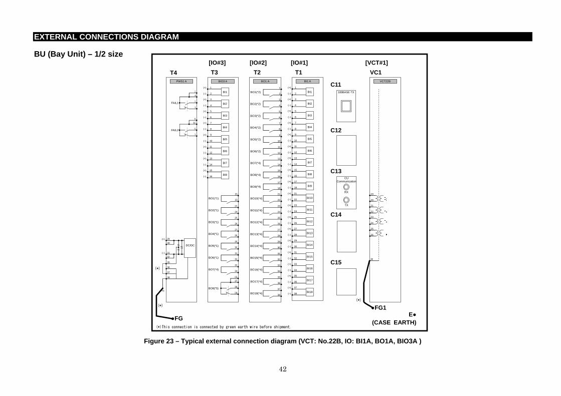
42
EXTERNAL CONNECTIONS DIAGRAM
BU (Bay Unit) – 1/2 size
PWS1 A
29
30
31
32
38
DC/DC
(+)
(-)
35
37
36
FG
3
1
2
4
FAIL1
9
7
8
10
FAIL2
BIO3 A
BO1(*1)
21
22
BO2(*1)
23
24
BO3(*1)
25
26
BO4(*1)
27
28
BO5(*1)
29
30
BO6(*1)
31
32
BO7(*4)
33
34
36
38
35
37
BO8(*5)
1
2 BI1
(+)
(-)
3
4 BI2
(+)
(-)
5
6 BI3
(+)
(-)
7
8 BI4
(+)
(-)
9
10 BI5
(+)
(-)
13
14 BI7
(+)
(-)
11
12 BI6
(+)
(-)
15
16 BI8
(+)
(-)
BO1 A
BO10(*4)
21
22
BO1(*2)
1
2
BO2(*2)
3
4
BO3(*2)
5
6
BO4(*2)
7
8
BO5(*2)
9
10
BO6(*2)
11
12
BO7(*4)
13
14
BO8(*4)
15
16
BO9(*4)
17
18
BO11(*4)
23
24
BO12(*4)
25
26
BO13(*4)
27
28
BO14(*4)
29
30
BO15(*4)
31
32
BO16(*4)
33
34
BO17(*4)
35
36
BO18(*4)
37
38
BI1 A
1
2 BI1
(+)
(-)
3
4 BI2
(+)
(-)
5
6 BI3
(+)
(-)
7
8 BI4
(+)
(-)
9
10 BI5
(+)
(-)
13
14 BI7
(+)
(-)
11
12 BI6
(+)
(-)
15
16 BI8
(+)
(-)
17
18 BI9
(+)
(-)
21
22 BI10
(+)
(-)
23
24 BI11
(+)
(-)
25
26 BI12
(+)
(-)
27
28 BI13
(+)
(-)
29
30 BI14
(+)
(-)
31
32 BI15
(+)
(-)
35
36 BI17
(+)
(-)
33
34 BI16
(+)
(-)
37
38 BI18
(+)
(-)
100BASE-TX
CU Communication
RX
TX
VCT22B
30
I
a
19
20
I
b
21
22
I
c
23
24
I
e
25
26
Figure 23 – Typical external connection diagram (VC T: No.22B, IO: BI1A, BO1A, BIO3A )
[IO#1] [VCT#1] [IO#2] [IO#3]
●FG
●FG1
T4 T3 T2 T1 VC1
E●(CASE EARTH)
(*)
(*)
(*)
C11
C12
C13
C14
C15
(*)This connection is connected by green earth wire before shipment.

©C
op
yri
gh
t 2014 T
osh
iba. A
ll r
igh
ts r
ese
rved
.
・The information given in this catalog is subject to change without notice. ・The information given in this catalog is as of 18 November 2014. ・The information given in this catalog is presented only as a guide for the applications of our products. No responsibility is assumed by TOSHIBA for any infringements of patents or other rights of the third parties which may result from its use. No license is granted by implication or otherwise under any patent or patent rights of TOSHIBA or others.
・TOSHIBA products should not be embedded to the downstream products which are prohibited to be produced and sold, under any law and regulations.
- Toshiba does not take any responsibility for incidental damage (including loss of business profit, business interruption, loss of business information and other pecuniary damage) arising out of the use or disability to use the products.
GKP-99-13011 Rev 1.0
Social Infrastructure Systems Company 72-34, Horikawa-cho, Saiwai-Ku, Kawasaki 212-8585, Japan Tel +81-44-331-1462 Fax +81-44-548-9540 http://www.toshiba-relays.com


