
1 Copyright © 2011 by ASME
Proceedings of the ASME 2011 Power Conference POWER2011
July 12-14, 2011, Denver, Colorado, USA
POWER2011-55270
BURNER COMPONENT UPGRADES FOR
WALL-FIRED COAL BURNERS –
RPI RESULTS AND EXPERIENCES
Stephen W Black Fuel Equipment Design Engineer
Riley Power Inc. Worcester, MA, USA
Murat Yaldizli Computational Fluid Dynamics Engineer
Riley Power Inc. Worcester, MA, USA
ABSTRACT
Improving the operation and emissions performance of coal
fired utility boilers equipped with first and second-generation
wall fired low NOx coal burners is of significant interest to
many utility companies today. The recent development of cost
effective components for existing first and second-generation
wall fired burners permits better combustion performance,
increased wear life reliability, and decreased NOx emissions.
Existing air register systems can typically remain in place,
resulting in reduced capital cost and reduced outage time for
installation.
Computational fluid dynamic (CFD) modeling is used to assist
in the design of key burner components and operating
conditions that enable further reduction of NOx emissions.
Results include better flame attachment, better airflow
recirculation patterns, and early ignition and pyrolysis of the
coal in a more controlled primary combustion zone. NOx
reductions of 10-20% have been demonstrated using burner
component upgrades with improved overall boiler operation.
This paper gives a brief description of the component-only
retrofit design methodology that Riley Power Inc., a Babcock
Power Inc. company developed for other OEM’s low NOx
burners in wall-fired furnaces. The numerical modeling to assist
in the design of these low NOx systems and the corresponding
CFD results are also discussed.
INTRODUCTION
During the past two decades, reduction of NOx emissions in
pulverized coal firing systems has become a high priority for
environmental authorities after the Clean Air Act of 1990 and
the Clean Air Interstate Rule (CAIR) were promulgated. Among
the available technologies, the installation of some form of low
NOx burner technology with or without an overfire air (OFA)
system is a primary means or first step to meet EPA emission
requirements and reduce the operating and maintenance cost of
post-combustion solutions such as selective catalytic reduction
(SCR). In order to meet the increasingly stringent NOx emission
requirements, utilities have recently focused on either replacing
first or second generation low NOx burners or upgrading
existing burners with newer and more advanced low NOx
combustion technology. Within this context, the newer burner
technology not only decreases NOx emissions additionally 10-
20% or more from controlled levels, but also provides greater
operating longevity and decreased maintenance.
Since the early 1980s Riley Power Inc. (RPI), a subsidiary of
Babcock Power Inc. has been developing the Venturi Series
Burner technology to lower NOx emissions from pulverized
coal firing systems. This advanced controlled combustion
technology is capable of achieving significant NOx reductions
in various types of applications including full burner installation
or component only retrofit. The component only retrofit is often
preferred by utility customers due to its cost effectiveness,
because it involves fewer hardware modifications and easier,
less time consuming installation. RPI determined that
retrofitting existing original equipment manufacturer (OEM)
low NOx burners with RPI’s Venturi Series Burner components
would significantly enhance combustion system burner
performance. To date, RPI has completed 14 components only
retrofit projects totaling nearly 320 burners.

2 Copyright © 2011 by ASME
RPI has implemented components type upgrades to 1st and 2
nd
generation RPI burners as well as B&W DRB and XCL
Burners. In all cases, CFD modeling was performed to refine
the final burner design and to shorten the commissioning time
by identifying the initial startup settings of the equipment.
Field-testing of the installed equipment showed that the
modeling accurately represented the field results.
In the past two years, RPI has performed CFD modeling of the
same component retrofit methodology applied to other OEM’s
low NOx burners where the components haven’t yet been
applied in a retrofit situation. The modeling results show that
similar improved burner performance can be achieved on other
low NOx burner designs, by applying the same basic RPI
components. The CFD results of the B&W XCL Burner, FW
PF/SF Burner, and the FW IFS burner are discussed.
COMPONENT-ONLY RETROFIT METHODOLOGY OVERVIEW
Many pulverized coal wall fired utility boilers are equipped
with 1st or 2
nd generation low NOx coal burners. These burners
typically comprise a nozzle that fires a mixture of pulverized
coal and air surrounded by two concentric cylindrically shaped
barrels known as secondary (inner) and tertiary (outer) air
barrels. The secondary and tertiary air barrels are oriented axial
to the coal nozzle. These designs typically have an adjustable
damper that controls the airflow into the secondary and tertiary
air barrels, as well as axial or radial vanes in the tertiary air
(TA) and possibly the secondary air (SA) annuli in order to
create a swirling motion of the air exiting the burner. This
common type of low NOx burner is generally referred to as a
dual air zone burner, double register burner, swirl induced
burner, or some combination thereof. Dual air zone burners
were designed for their low NOx capabilities, specifically the
ability to stage the combustion process by gradually mixing the
combustion air with the coal. The gradual mixing of air and coal
reduces the peak flame temperature and creates a more oxygen-
starved environment as compared to traditional burner designs,
two critical mechanisms for low NOx combustion.
The same design capabilities that give dual air zone burners low
NOx capabilities can also create an adverse impact on flame
length, combustion efficiency, CO emissions, and unburned
carbon in the fly ash. RPI’s latest burner design, the VS III™
low NOx coal-fired burner, shown in Figure 1, addresses these
deficiencies while lowering NOx emissions by another 10-20%
beyond other OEM burners. The key to the design is several
critical components that create very precise air and coal flow
dynamic interactions. These critical components can be added
to numerous OEM dual air zone burners.
RPI’s approach to improving the performance and reliability of
existing OEM low NOx burners is straightforward. First, the
existing coal nozzle is removed and replaced with RPI’s
patented Venturi coal nozzle assembly (US Patent 6,474,250)
and associated anti-roping device (US Patent Application
#12/112,571). Second, if the existing coal nozzle employs a
tangential inlet, the nozzle inlet receiving chamber is replaced
with RPI’s standard straight inlet receiving chamber. Minimal
coal piping modifications are required to accommodate RPI’s
standard inlet receiving chamber. However, if the existing
nozzle inlet receiving chamber utilizes a straight inlet, it may be
reused and preclude any coal piping modifications. Third, air
diverters, similar to the secondary and tertiary air diverters used
on the RPI VS III™ burner, are installed on the existing inner
and outer barrels of the OEM burners. Lastly, fixed swirl vanes
are installed within the inner air zone if either fixed or
adjustable swirl vanes don’t already exist.
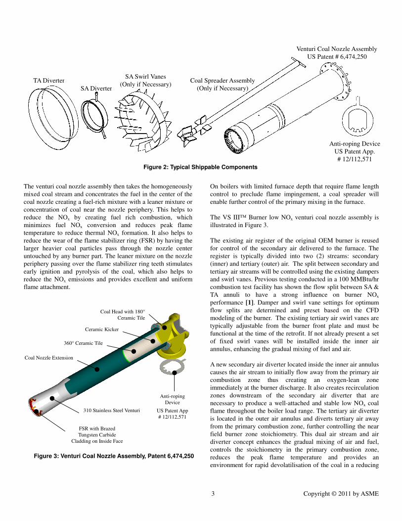
These are the only modifications required to significantly
improve the near field flow patterns and downstream
recirculation zones of the existing OEM low NOx burner. The
typical components that would be added to the existing OEM
low NOx burners are illustrated in Figure 2. The SA Swirl Vanes
and Coal Spreader Assembly are applied only if necessary, as
described in the following section.
DESCRIPTION OF COMPONENT PERFORMANCE
The anti-roping device, in tandem with a ceramic kicker located
at the entrance to the coal nozzle, redistributes the coal particles
entering the pulverized coal burner to break up the coal “rope”
that develops in any typical coal piping system. Coal ropes can
contribute to high CO emissions and high flyash UBC by
presenting too dense a coal stream to the combustion field.
Figure 1: RPI VS III™ Coal Fired Low NOx Burner
3 Copyright © 2011 by ASME
The venturi coal nozzle assembly then takes the homogeneously
mixed coal stream and concentrates the fuel in the center of the
coal nozzle creating a fuel-rich mixture with a leaner mixture or
concentration of coal near the nozzle periphery. This helps to
reduce the NOx by creating fuel rich combustion, which
minimizes fuel NOx conversion and reduces peak flame
temperature to reduce thermal NOx formation. It also helps to
reduce the wear of the flame stabilizer ring (FSR) by having the
larger heavier coal particles pass through the nozzle center
untouched by any burner part. The leaner mixture on the nozzle
periphery passing over the flame stabilizer ring teeth stimulates
early ignition and pyrolysis of the coal, which also helps to
reduce the NOx emissions and provides excellent and uniform
flame attachment.
On boilers with limited furnace depth that require flame length
control to preclude flame impingement, a coal spreader will
enable further control of the primary mixing in the furnace.
The VS III™ Burner low NOx venturi coal nozzle assembly is
illustrated in Figure 3.
The existing air register of the original OEM burner is reused
for control of the secondary air delivered to the furnace. The
register is typically divided into two (2) streams: secondary
(inner) and tertiary (outer) air. The split between secondary and
tertiary air streams will be controlled using the existing dampers
and swirl vanes. Previous testing conducted in a 100 MMBtu/hr
combustion test facility has shown the flow split between SA &
TA annuli to have a strong influence on burner NOx
performance [1]. Damper and swirl vane settings for optimum
flow splits are determined and preset based on the CFD
modeling of the burner. The existing tertiary air swirl vanes are
typically adjustable from the burner front plate and must be
functional at the time of the retrofit. If not already present a set
of fixed swirl vanes will be installed inside the inner air
annulus, enhancing the gradual mixing of fuel and air.
A new secondary air diverter located inside the inner air annulus
causes the air stream to initially flow away from the primary air
combustion zone thus creating an oxygen-lean zone
immediately at the burner discharge. It also creates recirculation
zones downstream of the secondary air diverter that are
necessary to produce a well-attached and stable low NOx coal
flame throughout the boiler load range. The tertiary air diverter
is located in the outer air annulus and diverts tertiary air away
from the primary combustion zone, further controlling the near
field burner zone stoichiometry. This dual air stream and air
diverter concept enhances the gradual mixing of air and fuel,
controls the stoichiometry in the primary combustion zone,
reduces the peak flame temperature and provides an
environment for rapid devolatilisation of the coal in a reducing
Coal Head with 180°
Ceramic Tile
Ceramic Kicker
360° Ceramic Tile
310 Stainless Steel Venturi
FSR with Brazed
Tungsten Carbide
Cladding on Inside Face
Coal Nozzle Extension
Anti-roping
Device
US Patent App
# 12/112,571
Figure 3: Venturi Coal Nozzle Assembly, Patent 6,474,250
TA Diverter
SA Diverter
SA Swirl Vanes
(Only if Necessary) Coal Spreader Assembly
(Only if Necessary)
Venturi Coal Nozzle Assembly
US Patent # 6,474,250
Anti-roping Device
US Patent App.
# 12/112,571
Figure 2: Typical Shippable Components

4 Copyright © 2011 by ASME
atmosphere, all of which are crucial elements of low NOx
combustion.
The benefits demonstrated from this component retrofit
approach on multiple installations have been thoroughly
discussed previously [2-4].
Performance benefits from these component upgrades can
include:
• Improved reliability and wear life of primary air side
burner components
• Lower NOx emissions under the same load conditions
• Lower unburned carbon (UBC) in the flyash
• Improved flame length and CO emissions control
• Improved flame scannability
• Reduced furnace exit gas temperature (FEGT)
• Reduced attemperator spray flow
Economic benefits from these components can include:
• Reduced outage time (over 50% reduction) during
installation as compared to a complete burner
replacement. None of the proposed modifications
require burner removal or windbox alterations. All
modifications are completed from the furnace or
burner deck. The existing air register system remains
intact, saving significant demolition time if completely
new burners were to be installed.
• Low capital cost. Typically 30-50% of the cost of a
complete burner replacement.
• SCR Ammonia consumption savings
CFD BURNER MODELING CFD is a powerful tool and has been used by RPI for over 25
years to assist with the design of burner replacement or burner
retrofit activities. CFD modeling permits customized burner
hardware and also minimizes start-up and setting time in the
field by identifying initial burner settings. In terms of
customizing the burner hardware and minimizing on-site initial
start-up setting time, Particularly, RPI employs single burner
CFD modeling to determine the desired near-field flow patterns
for best flame behavior (e.g., flame length and attachment). The
single burner model uses aero-dynamics only to establish near-
field recirculation zones, which are essential to produce good
low NOx combustion. In this approach, single burner air flow is
simulated in an idealized tunnel furnace representing the
equivalent firing region of the burner. The model tunnel
diameter is similar in size to the actually firing environment but
without flame-to-flame interactions that may affect the flow
behavior several throat diameters from the firing wall [5].
RPI’s experience has shown that when single burner modeling
exhibits optimal near-field flow behavior, the burner
performance in the field correlates well with the CFD results.
For example, predicted near burner results in the form of
streamline plots for an RPI low NOx CCV-DAZ
coal burner at
three different tertiary air (TA) swirl vane settings were given in
a previous study [6]. Illustrating the flow directions and
highlighting the internal recirculation zones, streamlines are
useful in the single burner modeling. The actual UBC and NOx
emissions were also reported. Results indicated that, as the
primary air (PA) driven internal recirculation zone (IRZ) is
balanced with the secondary air (SA) driven external
recirculation zone (ERZ), the balanced flow behavior leads to a
reliable, low NOx flame where the UBC and NOx emissions are
both at optimum levels [6]. As the flow pattern deviates from
the “optimum” pattern, where too much PA recirculation or too
Figure 4: CFD Single Burner Model Geometry (left), and Computed Streamlines (right) for Component-Only Retrofitted B&W XCL Burner
FSR
TA Diverter
SA Diverter
Model Tunnel Furnace
Burner Axis
Outer Spin
Vanes
Fixed
Vanes
Inner Spin
Vanes
Sliding Air
Damper
Venturi
SA Inlet (Windbox)
PA Inlet
ERZ
IRZ
PA Spreader Vanes

5 Copyright © 2011 by ASME
strong PA axial momentum occur, the measured UBC and NOx
emissions also diverge from the optimum levels. The
responsiveness of the test data demonstrates the good
correlation between the actual burner behavior in the field and
the RPI’s CFD model predictions.
LOW NOX COMPONENT-ONLY RETROFIT OF B&W COAL FIRED XCL BURNERS
Due to economic and installation advantages, a partial burner
upgrade is more preferable for some combustion system
improvement projects [4]. In 2006, RPI performed a
component-only retrofit to the existing B&W XCL dual register
burners of a nearly 350 MW wall-fired furnace burning a
bituminous coal. Based on RPI’s component-only retrofit
methodology, the modifications included only the installation of
the patented venturi coal nozzle with low swirl coal spreader,
FSR, and special air diverters. The burner CFD modeling was
utilized as a design tool to customize the burner hardware and
to determine the burner initial start-up settings.
In Figure 4, the burner model geometry is given (left), where
the RPI low NOx coal burner components are colored in red.
The post-retrofit computed streamlines are also shown (right).
The streamline results indicate that the component-only
retrofitted burner geometry produces good near-field
aerodynamics where well-established recirculation zones are
clearly seen. This type of behavior in the burner near-field
region is essential for good flame attachment at the burner tip to
lower UBC values. Additionally, the discrete recirculation zones
of PA flow and SA flow streams are of significance to reduce
NOx emissions.
The pre-retrofit and post-retrofit acceptance test data were also
consistent with the CFD findings. NOx emissions were reduced
by 10% and unburned carbon (UBC) in the flyash was
simultaneously reduced by 15% from the component retrofit
alone.
LOW NOx COMPONENT-ONLY RETROFIT OF FW COAL FIRED BURNERS
In addition to the completed component-only retrofit projects,
RPI conducted several in-house CFD modeling studies within
the past two years to determine the applicability of RPI’s
component-only retrofit methodology to the other OEM dual-air
register type burners. FW IFS and FW PF/SF burners were used
in those studies where the burner modeling was the primary
design tool. Multiple burner cases were conducted for both the
original FW burners and the RPI component-only retrofit
burner designs. Modifications to the original FW burners
include only the critical VS IIITM
low NOx coal burner
components: coal nozzle with low swirl coal spreader, FSR, and
SA and TA diverters. In the case of the FW PF/SF burner, fixed
SA swirl vanes were also added for enhanced mixing.
In Figure 5, the CFD burner model geometry with the Venturi
Series burner component-only upgrade is given for the FW IFS
burner (left). As the figure indicates, the modification includes
only the major VS IIITM
low NOx coal burner components
(colored in red): patented coal nozzle with low swirl coal
spreader, FSR, and SA and TA diverters.
Figure 5 also shows the post-retrofit computed streamlines
(right). The indicated strong PA-driven IRZ and SA-driven ERZ
would produce very well attached flame with a relatively short
PA core flow down the burner axis. This would result in
shortened flame length and increased PA and coal dust mixing
within the flame base, which would lead to lower UBC values.
Also, the separate internal and external recirculation zone
structure completely isolates the primary ignition zone from
FSR
Outer
Vanes
Perf. Plate
TA Diverter
SA Diverter
SA-Driven
External Recirculation Zone (ERZ)
PA-Driven
Internal Recirculation Zone (IRZ)
Figure 5: CFD Single Burner Model Geometry (left), and Computed Streamlines (right) for Component-Only Retrofitted FW IFS Burner
Model Tunnel Furnace
SA Inlet (Windbox)
PA Inlet
Burner Axis
PA Spreader Vanes
Outer
Vanes
Shroud
Inner
Vanes
Venturi
FSR

6 Copyright © 2011 by ASME
oxygen in the SA/TA flow to further reduce NOx production. In
contrast, the streamlines for the original burner configuration
(not shown here) lack the PA-driven IRZ, which can result in a
longer tubular flame with high UBC values due to insufficient
mixing of coal with the combustion air.
The model geometry for another Foster Wheeler dual-air
register type burner retrofitted with the VS III™ low NOx coal
burner components is provided in Figure 6 (left). The retrofit of
this FW PF/SF type burner is limited to the installation of VS
III™ low NOx coal burner components (colored in red)
including the venturi coal nozzle with integrated FSR and low
swirl coal spreader (US Patent #6,474,250), SA and TA
diverters, and fixed SA swirl vanes.
In Figure 6, the computed streamlines for the post-retrofit FW
PF/SF type burner is also shown (right). The desired
recirculation zones for good flame attachment and low NOx are
clearly seen in this figure. The computed results for the original
burner configuration (not shown here) also have a somewhat
similar flow pattern with multiple recirculation zones. However,
computed streamlines for the original burner configuration
indicate early mixing of the PA flow with the oxygen rich SA
flow is occurring very close to the burner throat, which can lead
to high NOx values. Excessive slagging around the burner throat
is another drawback from the early mixing at the burner throat.
SUMMARY
The operators of coal fired power plants today are interested in
improvements that can be made to prevent the adverse impact
on boiler performance, combustion efficiency, and CO
emissions associated with existing low NOx burners, without the
high cost and long outage duration of traditional full burner
replacement. RPI has demonstrated components-only burner
solutions to address these problems on several low NOx burner
designs. In all cases, CFD modeling was used to assist in the
burner design and proved valuable. The same approach has now
been applied to several other low NOx burner designs,
demonstrating similar results to those observed in new burner
installation. In the competitive atmosphere of today’s energy
market, it is important for utility companies to seek proven, cost
effective, and technology-based solutions for achieving
environmental compliance goals.
REFERENCES
1. Patel, R., VonHein, R., Penterson, C., and Dube, R.,
“Reducing NOx Emissions to 0.15 lb/MMBtu with
Babcock Borsig Power Inc.’s Latest CCV® Coal
Burner Technology,” presented at the 26th
International Technical Conference on Coal Utilization
and Fuel Systems, Clearwater Florida, March 5-8,
2001
2. Courtemanche, B., Esclavon, L., and Curow, C., J., “
CCV
Components and Overfire Air Improve Existing
First Generation Low NOx Burner Emissions”, Electric
Power 2005, Chicago, IL, April 2005
3. Penterson, C., Dorman, D., “Low NOx Retrofit
Problems and Solutions.” Presented at the
International Joint Power Generation Conference,
Minneapolis, and October 1995
4. Hules, R., K., and Penterson, C., “Computational Fluid
Dynamics for Cost-Effective Solutions for Problems in
Complex Burner and Combustion Systems”, Power-
Gen International 2005, Las Vegas, NV, December
2005
Shroud
ERZ
IRZ
Figure 6: CFD Single Burner Model Geometry (left), and Computed Streamlines (right) for Component-Only Retrofitted FW PF/SF Burner
Adjustable Inner
Cone Damper
Fixed
SA Vanes
Outer
Vanes Perf. Plate
Model Tunnel Furnace
PA Inlet Burner Axis
PA Spreader Vanes
FSR
TA Diverter
SA Diverter
Venturi
SA Inlet (Windbox)

7 Copyright © 2011 by ASME
5. Penterson, C., and Hules, R., K., “Reducing NOx
Emissions to Below 0.15 lb/106 Btu on a 600 MW
Utility Boiler with Combustion Control Only”,
DOE/EPRI/EPA/A&WMA Combined Power Plant Air
Pollutant Control “Mega” Symposium, Washington,
DC, March 2003
6. Courtemanche, B., Dorman, D., Yilmaz, A., and
Esclavon, L., “ Reducing NOx Emissions and
Commissioning Time on Southern Company Coal
Fired Boilers with Low NOx Burners and CFD
Analysis”, 28th
International Technical Conference on
Coal Utilization & Fuel Systems, Clearwater, FL,
March 2003


