
Cl/SfB (22.3)(35.1)(35.3)
Hh2Jh2
BUILDERS METALWORK
AUGUST 03
02
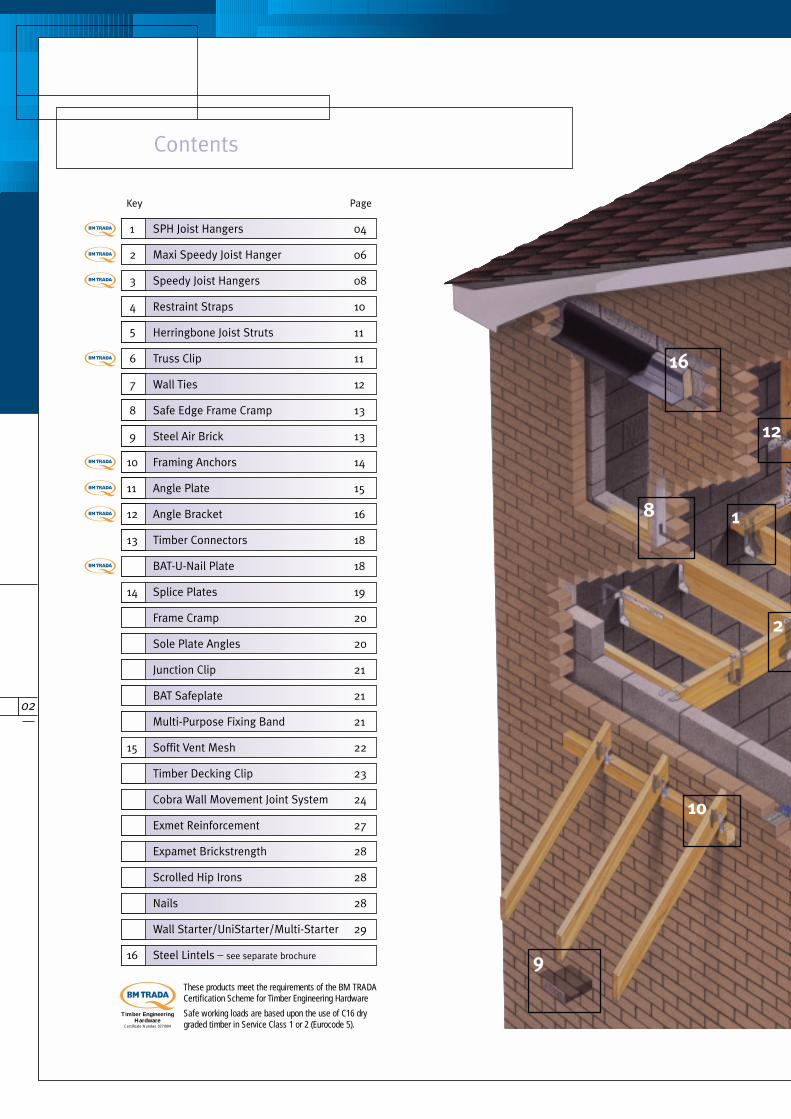
Contents
These products meet the requirements of the BM TRADACertification Scheme for Timber Engineering Hardware
Safe working loads are based upon the use of C16 drygraded timber in Service Class 1 or 2 (Eurocode 5).
12
1
2
8
16
9
10
Key Page
1 SPH Joist Hangers 04
2 Maxi Speedy Joist Hanger 06
3 Speedy Joist Hangers 08
4 Restraint Straps 10
5 Herringbone Joist Struts 11
6 Truss Clip 11
7 Wall Ties 12
8 Safe Edge Frame Cramp 13
9 Steel Air Brick 13
10 Framing Anchors 14
11 Angle Plate 15
12 Angle Bracket 16
13 Timber Connectors 18
BAT-U-Nail Plate 18
14 Splice Plates 19
Frame Cramp 20
Sole Plate Angles 20
Junction Clip 21
BAT Safeplate 21
Multi-Purpose Fixing Band 21
15 Soffit Vent Mesh 22
Timber Decking Clip 23
Cobra Wall Movement Joint System 24
Exmet Reinforcement 27
Expamet Brickstrength 28
Scrolled Hip Irons 28
Nails 28
Wall Starter/UniStarter/Multi-Starter 29
16 Steel Lintels – see separate brochure
Timber EngineeringHardware
Certificate Number 027/004
03
15
11
13
14
3
4
56
7
BUILDERS METALWORK
04
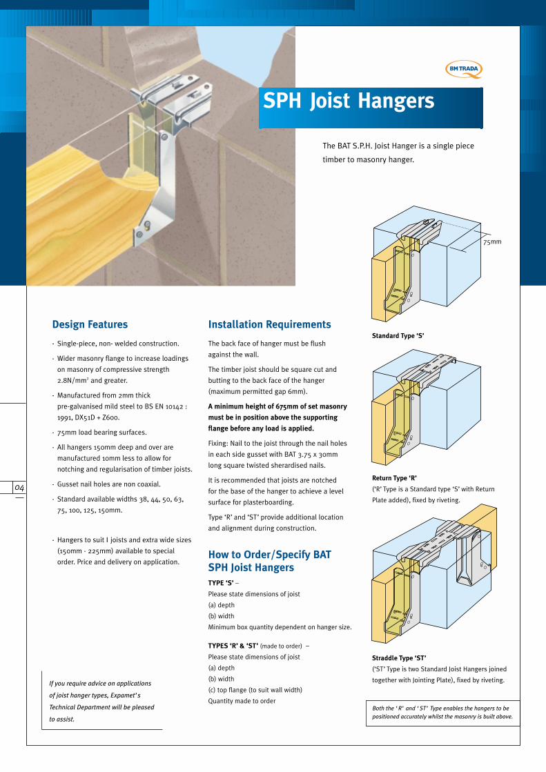
The BAT S.P.H. Joist Hanger is a single piece
timber to masonry hanger.
Straddle Type ‘ST’
(‘ST’ Type is two Standard Joist Hangers joined
together with Jointing Plate), fixed by riveting.
Return Type ‘R’
(‘R’ Type is a Standard type ‘S’ with Return
Plate added), fixed by riveting.
75mm
Standard Type ‘S’
Both the ‘R’ and ‘ST’ Type enables the hangers to be
positioned accurately whilst the masonry is built above.
How to Order/Specify BAT
SPH Joist Hangers
TYPE ‘S’ –
Please state dimensions of joist
(a) depth
(b) width
Minimum box quantity dependent on hanger size.
TYPES ‘R’ & ‘ST’ (made to order) –
Please state dimensions of joist
(a) depth
(b) width
(c) top flange (to suit wall width)
Quantity made to order
The back face of hanger must be flush
against the wall.
The timber joist should be square cut and
butting to the back face of the hanger
(maximum permitted gap 6mm).
A minimum height of 675mm of set masonry
must be in position above the supporting
flange before any load is applied.
Fixing: Nail to the joist through the nail holes
in each side gusset with BAT 3.75 x 30mm
long square twisted sherardised nails.
It is recommended that joists are notched
for the base of the hanger to achieve a level
surface for plasterboarding.
Type ‘R’ and ‘ST’ provide additional location
and alignment during construction.
Installation Requirements
SPH Joist Hangers
- Single-piece, non- welded construction.
- Wider masonry flange to increase loadings
on masonry of compressive strength
2.8N/mm2 and greater.
- Manufactured from 2mm thick
pre-galvanised mild steel to BS EN 10142 :
1991, DX51D + Z600.
- 75mm load bearing surfaces.
- All hangers 150mm deep and over are
manufactured 10mm less to allow for
notching and regularisation of timber joists.
- Gusset nail holes are non coaxial.
- Standard available widths 38, 44, 50, 63,
75, 100, 125, 150mm.
- Hangers to suit Ι joists and extra wide sizes
(150mm - 225mm) available to special
order. Price and delivery on application.
Design Features
If you require advice on applications
of joist hanger types, Expamet’s
Technical Department will be pleased
to assist.
05
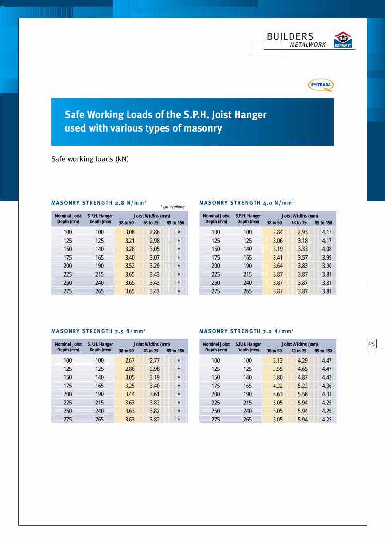
Safe Working Loads of the S.P.H. Joist Hanger
used with various types of masonry
Safe working loads (kN)
38 to 50 63 to 75 89 to 150Joist Widths (mm)Nominal Joist S.P.H. Hanger
Depth (mm) Depth (mm)
100 100 3.08 2.86 *125 125 3.21 2.98 *150 140 3.28 3.05 *175 165 3.40 3.07 *200 190 3.52 3.29 *225 215 3.65 3.43 *250 240 3.65 3.43 *275 265 3.65 3.43 *
* not availableMA SONRY STRENGTH 2.8 N/mm 2
38 to 50 63 to 75 89 to 150Joist Widths (mm)Nominal Joist S.P.H. Hanger
Depth (mm) Depth (mm)
100 100 3.13 4.29 4.47125 125 3.55 4.65 4.47150 140 3.80 4.87 4.42175 165 4.22 5.22 4.36200 190 4.63 5.58 4.31225 215 5.05 5.94 4.25250 240 5.05 5.94 4.25275 265 5.05 5.94 4.25
MA SONRY STRENGTH 7 .0 N/mm 2
38 to 50 63 to 75 89 to 150Joist Widths (mm)Nominal Joist S.P.H. Hanger
Depth (mm) Depth (mm)
100 100 2.67 2.77 *125 125 2.86 2.98 *150 140 3.05 3.19 *175 165 3.25 3.40 *200 190 3.44 3.61 *225 215 3.63 3.82 *250 240 3.63 3.82 *275 265 3.63 3.82 *
MA SONRY STRENGTH 3.5 N/mm 2
38 to 50 63 to 75 89 to 150Joist Widths (mm)Nominal Joist S.P.H. Hanger
Depth (mm) Depth (mm)
100 100 2.84 2.93 4.17125 125 3.06 3.18 4.17150 140 3.19 3.33 4.08175 165 3.41 3.57 3.99200 190 3.64 3.83 3.90225 215 3.87 3.87 3.81250 240 3.87 3.87 3.81275 265 3.87 3.87 3.81
MA SONRY STRENGTH 4.0 N/mm 2
BUILDERS METALWORK
06
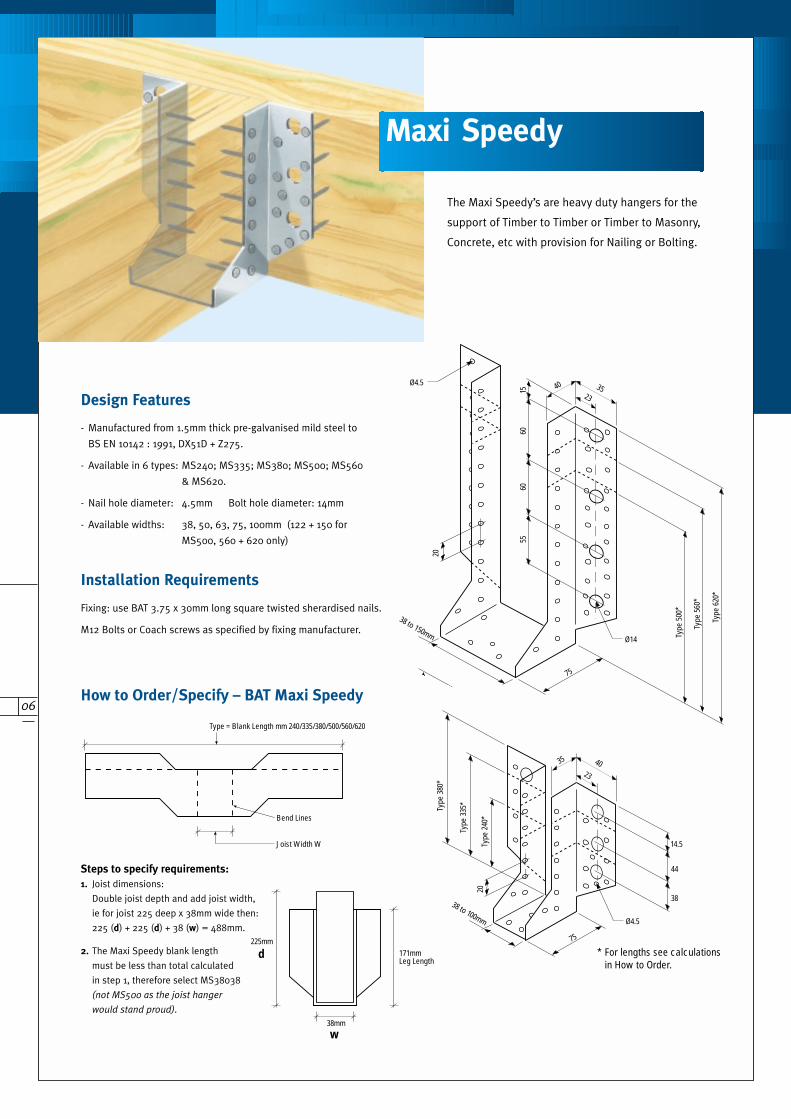
The Maxi Speedy’s are heavy duty hangers for the
support of Timber to Timber or Timber to Masonry,
Concrete, etc with provision for Nailing or Bolting.
How to Order/Specify – BAT Maxi Speedy
- Manufactured from 1.5mm thick pre-galvanised mild steel to
BS EN 10142 : 1991, DX51D + Z275.
- Available in 6 types: MS240; MS335; MS380; MS500; MS560
& MS620.
- Nail hole diameter: 4.5mm Bolt hole diameter: 14mm
- Available widths: 38, 50, 63, 75, 100mm (122 + 150 for
MS500, 560 + 620 only)
Design Features
Fixing: use BAT 3.75 x 30mm long square twisted sherardised nails.
M12 Bolts or Coach screws as specified by fixing manufacturer.
Installation Requirements
Steps to specify requirements:
1. Joist dimensions:
Double joist depth and add joist width,
ie for joist 225 deep x 38mm wide then:
225 (d) + 225 (d) + 38 (w) = 488mm.
2. The Maxi Speedy blank length
must be less than total calculated
in step 1, therefore select MS38038
(not MS500 as the joist hanger
would stand proud).
Bend Lines
Joist Width W
Type = Blank Length mm 240/335/380/500/560/620
38mm
225mm171mmLeg Length
75
23
38
44
14.5
20
38 to 100mm
75
Ø4.5
4035
Type
240
*
Type
335
*
Type
380
*
Ø4.5
20
5560
6015
38 to 150mm
75Ty
pe 5
00*
Type
560
*
Type
620
*
23
Ø14
23
3540
4035
80*
* For lengths see calculationsin How to Order.
Maxi Speedy
w
d
07
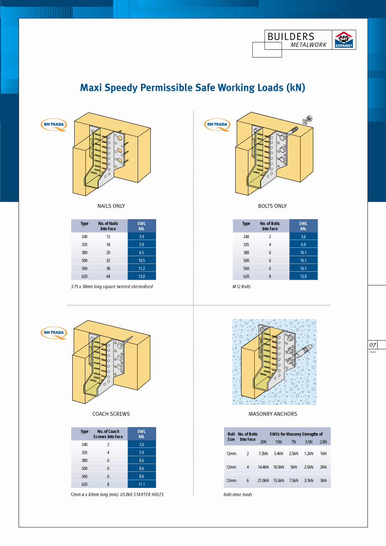
NAILS ONLY BOLTS ONLY
COACH SCREWS MASONRY ANCHORS
Bolt No. of Bolts SWL’s for Masonry Strengths ofSize Into Face 20N 15N 7N 3.5N 2.8N
12mm 2 7.2kN 5.4kN 2.5kN 1.2kN 1kN
12mm 4 14.4kN 10.5kN 5kN 2.5kN 2kN
12mm 6 21.0kN 15.5kN 7.5kN 3.7kN 3kN
3.75 x 30mm long square twisted sherardised M12 Bolts
12mm ø x 63mm long (min). USING STARTER HOLES Indicative loads
Type No. of Nails SWLInto Face kN.
240 12 3.9
335 18 5.9
380 20 6.5
500 32 10.5
560 38 11.2
620 44 13.0
Type No. of Coach SWLScrews Into Face kN.
240 2 3.0
335 4 5.9
380 6 8.6
500 6 8.6
560 6 8.6
620 8 11.1
Type No. of Bolts SWLInto Face kN.
240 2 3.6
335 4 6.9
380 6 10.1
500 6 10.1
560 6 10.1
620 8 13.0
Maxi Speedy Permissible Safe Working Loads (kN)
BUILDERS METALWORK
08
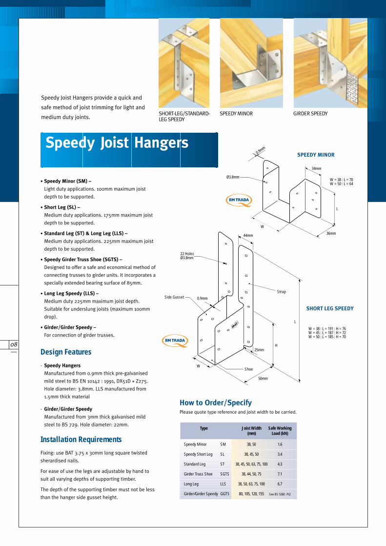
Ø3.8mm
L
36mm
34mm
W
0.9mm
W = 38 : L = 70W = 50 : L = 64
W = 38 : L = 191 : H = 76W = 45 : L = 187 : H = 72W = 50 : L = 185 : H = 70
H
Strap
22 HolesØ3.8mm
25mm
ShoeW
50mm
0.9mmSide Gusset
44mm
L
Speedy Minor SM 38, 50 1.6
Speedy Short Leg SL 38, 45, 50 3.4
Standard Leg ST 38, 45, 50, 63, 75, 100 4.3
Girder Truss Shoe SGTS 38, 44, 50, 75 7.1
Long Leg LLS 38, 50, 63, 75, 100 6.7
Girder/Girder Speedy GGTS 80, 105, 120, 155 See BS 5268 : Pt2
Type Joist Width Safe Working(mm) Load (kN)
How to Order/SpecifyPlease quote type reference and joist width to be carried.
- Speedy Hangers
Manufactured from 0.9mm thick pre-galvanised
mild steel to BS EN 10142 : 1991, DX51D + Z275.
Hole diameter: 3.8mm. LLS manufactured from
1.5mm thick material
- Girder/Girder Speedy
Manufactured from 3mm thick galvanised mild
steel to BS 729. Hole diameter: 22mm.
Design Features
Fixing: use BAT 3.75 x 30mm long square twisted
sherardised nails.
For ease of use the legs are adjustable by hand to
suit all varying depths of supporting timber.
The depth of the supporting timber must not be less
than the hanger side gusset height.
Installation Requirements
SHORT-LEG/STANDARD-LEG SPEEDY
SPEEDY MINOR GIRDER SPEEDY
SPEEDY MINOR
SHORT LEG SPEEDY
Speedy Joist Hangers provide a quick and
safe method of joist trimming for light and
medium duty joints.
Speedy Joist Hangers provide a quick and
safe method of joist trimming for light and
medium duty joints.
• Speedy Minor (SM) –
Light duty applications. 100mm maximum joist
depth to be supported.
• Short Leg (SL) –
Medium duty applications. 175mm maximum joist
depth to be supported.
• Standard Leg (ST) & Long Leg (LLS) –
Medium duty applications. 225mm maximum joist
depth to be supported.
• Speedy Girder Truss Shoe (SGTS) –
Designed to offer a safe and economical method of
connecting trusses to girder units. It incorporates a
specially extended bearing surface of 85mm.
• Long Leg Speedy (LLS) –
Medium duty 225mm maximum joist depth.
Suitable for underslung joists (maximum 100mm
drop).
• Girder/Girder Speedy –
For connection of girder trusses.
Speedy Joist Hangers
09
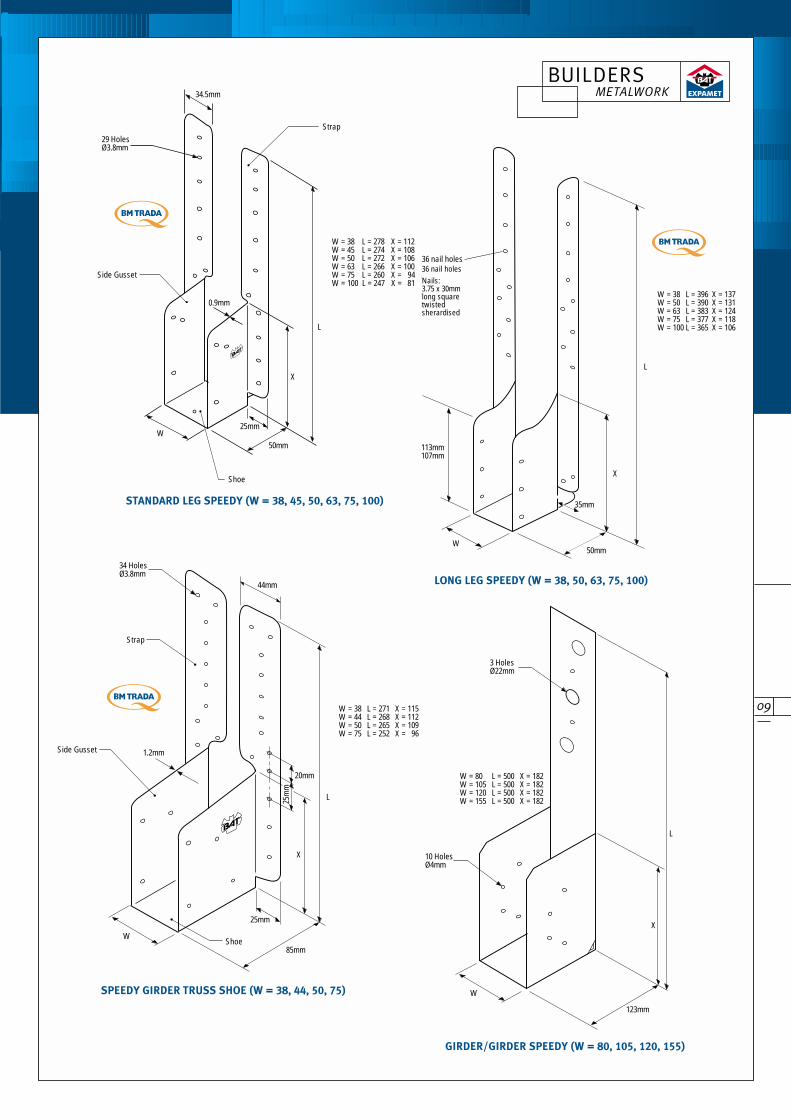
34 HolesØ3.8mm
25mm
Shoe85mm
1.2mmSide Gusset
20mm
25m
m
W = 38 L = 271 X = 115W = 44 L = 268 X = 112W = 50 L = 265 X = 109W = 75 L = 252 X = 96
44mm
Strap
W
L
X
35mm
50mm
113mm107mm
36 nail holesNails:9swg x 32mmlong squaretwistedsheradised
W = 38 L = 396 X = 137W = 50 L = 390 X = 131W = 63 L = 383 X = 124W = 75 L = 377 X = 118W = 100 L = 365 X = 106
W
L
X
W = 38 L = 278 X = 112W = 45 L = 274 X = 108W = 50 L = 272 X = 106W = 63 L = 266 X = 100W = 75 L = 260 X = 94W = 100 L = 247 X = 81
Strap29 HolesØ3.8mm
34.5mm
Shoe
25mm
Side Gusset
W
0.9mm
50mm
L
X
STANDARD LEG SPEEDY (W = 38, 45, 50, 63, 75, 100)
SPEEDY GIRDER TRUSS SHOE (W = 38, 44, 50, 75)
LONG LEG SPEEDY (W = 38, 50, 63, 75, 100)
GIRDER/GIRDER SPEEDY (W = 80, 105, 120, 155)
36 nail holesNails:3.75 x 30mmlong squaretwistedsherardised
3 HolesØ22mm
123mm
W = 80 L = 500 X = 182W = 105 L = 500 X = 182W = 120 L = 500 X = 182W = 155 L = 500 X = 182
W
X
10 HolesØ4mm
L
BUILDERS METALWORK
10
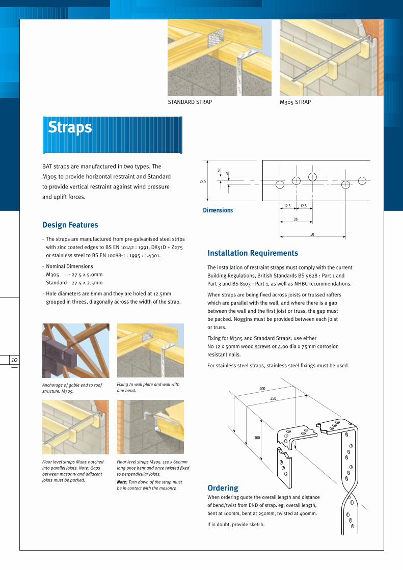
BAT straps are manufactured in two types. The
M305 to provide horizontal restraint and Standard
to provide vertical restraint against wind pressure
and uplift forces.
OrderingWhen ordering quote the overall length and distance
of bend/twist from END of strap. eg. overall length,
bent at 100mm, bent at 250mm, twisted at 400mm.
If in doubt, provide sketch.
Anchorage of gable end to roof
structure, M305.
Floor level straps M305 notched
into parallel joists. Note: Gaps
between masonry and adjacent
joists must be packed.
Fixing to wall plate and wall with
one bend.
Floor level straps M305. 150 x 650mm
long once bent and once twisted fixed
to perpendicular joists.
Note: Turn down of the strap must
be in contact with the masonry.
M305 STRAPSTANDARD STRAP
- The straps are manufactured from pre-galvanised steel strips
with zinc coated edges to BS EN 10142 : 1991, DX51D + Z275
or stainless steel to BS EN 10088-1 : 1995 : 1.4301.
- Nominal Dimensions
M305 - 27.5 x 5.0mm
Standard - 27.5 x 2.5mm
- Hole diameters are 6mm and they are holed at 12.5mm
grouped in threes, diagonally across the width of the strap.
Design Features
The installation of restraint straps must comply with the current
Building Regulations, British Standards BS 5628 : Part 1 and
Part 3 and BS 8103 : Part 1, as well as NHBC recommendations.
When straps are being fixed across joists or trussed rafters
which are parallel with the wall, and where there is a gap
between the wall and the first joist or truss, the gap must
be packed. Noggins must be provided between each joist
or truss.
Fixing for M305 and Standard Straps: use either
No 12 x 50mm wood screws or 4.00 dia x 75mm corrosion
resistant nails.
For stainless steel straps, stainless steel fixings must be used.
Installation Requirements
100
250
400
Straps
Dimensions
50
30
33
25
12.5 12.5
27.5

11
Herringbone Joist Struts
Truss Clip- Manufactured from 0.9mm thick pre-galvanised
mild steel to BS EN 10142 : 1991, DX51D + Z275.
- Hole diameter: 4mm Height: 117mm
- Available in 2 sizes:
- Other thicknesses of trussed rafters may be
fixed using pairs of BAT Framing Anchors,
type MFAAL and MFAAR.
Fixing: use BAT 3.75 x 30mm long square
twisted sherardised nails.
All nail holes must be filled.
Safe Working Load – 1.3kN uplift.
The timber wall plate must be securely held
down onto the supporting masonry.
Installation Requirements
Herringbone Joist Struts provide stability to floor joists. Expamet Herringbone Joist
Struts significantly reduce labour content in fixing strutting on site.
The Bat Truss Clip eliminates the disadvantages
of skew nailing trussed rafters to timber wall
plates; damaged connector plates; split rafters
or wall plates.
4 Holes (both ends)
57mm
30m
m
Length
Fixing Detail9 swg x 32mm SheradisedSquare Twisted Nail
When fixing the second strut a 6mm (approx) gapshould be kept between the struts.
12 Holes @ 4mmØ
38 to 50
117.5
114.3
28.5
25.5 to 31
1.0
- Manufactured from 1mm thick pre-galvanised mild
steel to BS EN 10142 : DX51D + Z275.
- Suitable for joist widths between 38mm and 63mm,
and joist depths between 150mm and 225mm.
- Available in 3 sizes:
Design Features
Joist Span – 2.5m to 4.5m 1 Row at mid span
greater than 4.5m 2 Rows at 1/3 span
positions
Fixing: use BAT 3.75 x 30mm long square twisted
sherardised nails.
Installation Requirements
Ref. Joist Centres Length Qty/Box
HJS400 400mm 480mm 50
HJS450 450mm 523mm 50
HJS600 600mm 660mm 50
Design Features
Ref. Width Qty/Box
TC38 38mm thick truss 200
TC50 50mm thick truss 200
0.9
BUILDERS METALWORK
12
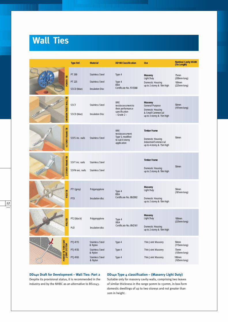
DD140 Draft for Development – Wall Ties: Part 2
Despite its provisional status, it is recommended in the
industry and by the NHBC as an alternative to BS1243.
DD140 Type 4 classification – (Masonry Light Duty)
Suitable only for masonry cavity walls, comprising two leaves
of similar thickness in the range 90mm to 150mm, in box-form
domestic dwellings of up to two storeys and not greater than
10m in height.
Wall Ties
POW
ER T
IECH
EVRO
N T
WIS
T W
ALL
TIE
4 ST
OREY
FRA
ME
TIE
2 ST
OREY
FRA
ME
TIE
POSI
-TIE
POLI
-TIE
POW
ER T
IE T
HIN
COA
T JO
INT
SYST
EM
MasonryLight Duty
Domestic Housingup to 2 storey & 10m high
MasonryLight Duty
Domestic Housingup to 2 storey & 10m high
MasonryLight Duty
Domestic Housingup to 2 storey & 10m high
Timber Frame
Domestic Housingup to 2 storey & 10m high
Timber Frame
Domestic HousingIndustrial/Commercialup to 4 storey & 15m high
MasonryGeneral Purpose
Domestic Housing& Small Commercialup to 3 storey & 15m high
Type 4BBACertificate No. 89/2161
Type 4BBACertificate No. 88/2002
Type 4
Type 4BBACertificate No. 97/3368
BREtest/assessmentType 5, modifiedto suit 4 storeyapplication
BREtest/assessment totheir performancespecification– Grade 2 –
75mm(200mm long)
100mm(225mm long)
100mm(225mm long)
50mm(181mm long)
50mm
50mm
50mm(191mm long)
PT 200 Stainless Steel
PT 225 Stainless Steel
SSCD (blue) Insulation Disc
SSCT Stainless Steel
SSCD (blue) Insulation Disc
SSFS inc. nails Stainless Steel
SSFT inc. nails Stainless Steel
SSFN exc. nails Stainless Steel
PT1 (grey) Polypropylene
PTD Insulation disc
PT2 (black) Polypropylene
PLD Insulation disc
PTJ4115 Stainless Steel Type 4 Thin Joint Masonry 50mm& Nylon (115mm long)
PTJ4135 Stainless Steel Type 4 Thin Joint Masonry 75mm& Nylon (135mm long)
PTJ4165 Stainless Steel Type 4 Thin Joint Masonry 100mm& Nylon (165mm long)
Type Ref. Material DD140 Classification Use Nominal Cavity Width(Tie Length)

13
3.0
4.5 Dia Holes
50
100 / 150 / 200
4.5 Dia Holes
5025.4
12.7
12. 7
25. 0
BAT Safe Edge Frame Cramps provide positive location
of window and door frames to masonry.
BAT Air Bricks have been designed to provide the maximum
air flow at the minimum costs and are vermin resistant.
Manufactured from pre-galvanised steel strip with zinc
coated edges to BS EN 10142 : 1991 DX51D + Z275.
Ref and Sizes:
Design Features
Fixing: use 2 No 4.5mm nails or No. 8
screws, galvanised or sherardised.
Installation Requirements
- Manufactured from 1mm thick pre-galvanised mild steel to
BS EN 10142 : DX51D + Z275.
- Brown powder coated paint finish to merge in with brick facings.
Ref: AB75 = 222 x 70mm - 5000mm2 air flow 25 per box
Design Features
The number of air bricks must provide the opening requirements
given in the current Building Regulations.
Installation Requirements
Steel Air Brick
Safe Edge Frame Cramp
Ref. Width Length Upstand Qty/Box
SEFC150 28mm 100mm 50mm 250
SEFC200 28mm 150mm 50mm 250
SEFC250 28mm 200mm 50mm 250
2.4
6 Dia Holes
28
14
36
1
0
50
50
100 / 150 / 200
BUILDERS METALWORK
14
55
35
10
112632
10
2820
108
127
6040
15
2632
2028
8
127
60
40
15
2632
33.5
43
2926
18
55
35
10
2926
18
6040
15
8
127
6040
15
2632
33.5
43
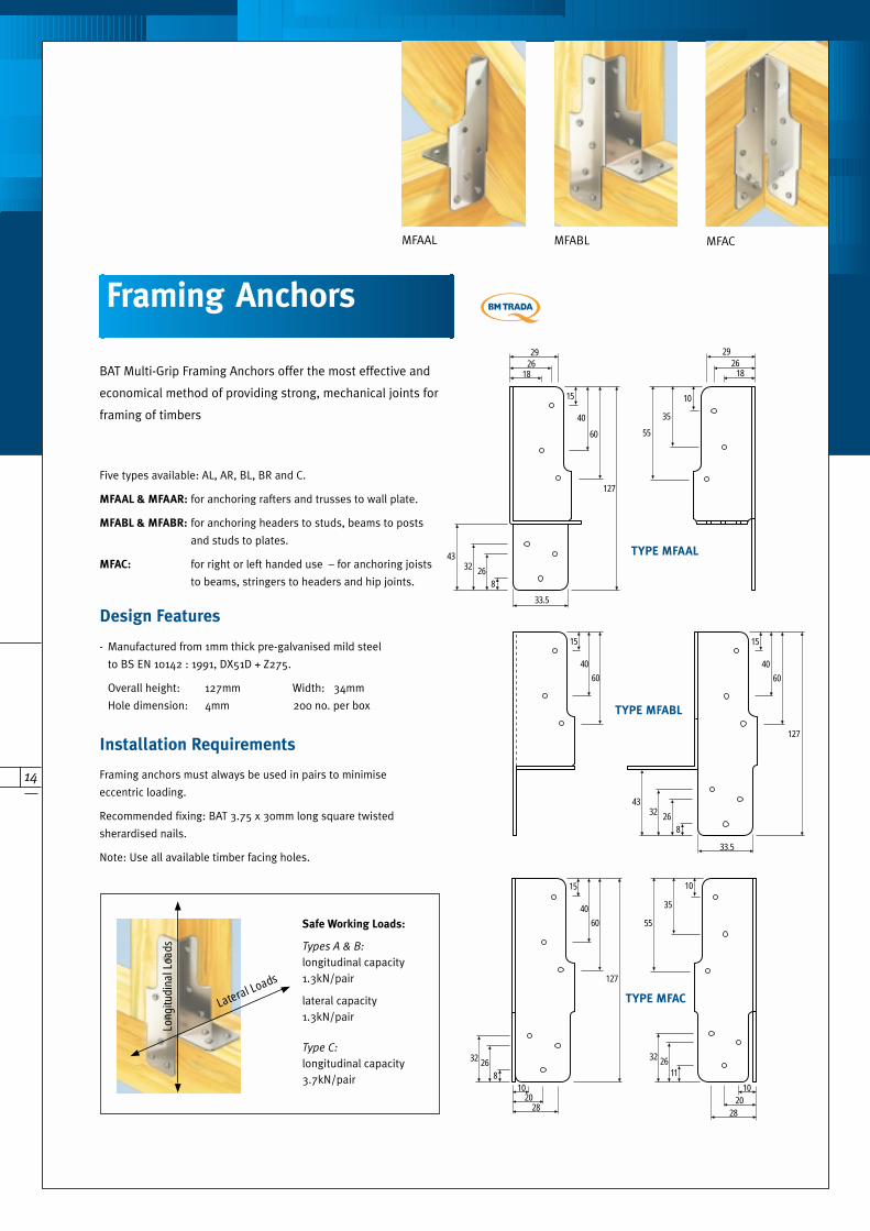
MFAAL MFABL MFAC
BAT Multi-Grip Framing Anchors offer the most effective and
economical method of providing strong, mechanical joints for
framing of timbers
- Manufactured from 1mm thick pre-galvanised mild steel
to BS EN 10142 : 1991, DX51D + Z275.
Overall height: 127mm Width: 34mm
Hole dimension: 4mm 200 no. per box
Five types available: AL, AR, BL, BR and C.
MFAAL & MFAAR: for anchoring rafters and trusses to wall plate.
MFABL & MFABR: for anchoring headers to studs, beams to posts
and studs to plates.
MFAC: for right or left handed use – for anchoring joists
to beams, stringers to headers and hip joints.
Design Features
Framing anchors must always be used in pairs to minimise
eccentric loading.
Recommended fixing: BAT 3.75 x 30mm long square twisted
sherardised nails.
Note: Use all available timber facing holes.
Installation Requirements
Safe Working Loads:
Types A & B:
longitudinal capacity1.3kN/pair
lateral capacity1.3kN/pair
Type C:
longitudinal capacity3.7kN/pair
TYPE MFAAL
TYPE MFABL
TYPE MFAC
Framing Anchors
Long
itudi
nal L
oads
Lateral Loads

15
Steel Beam
Timber packer in beam (bolted).150mm
minimum- Manufactured from 2mm thick hot dipped pre-galvanised
mild steel to BS EN 10142 : 1991, DX51D + Z275.
- Safe Working Loads: 1 pair = 3.5kN
2 pairs = 7.5kN
Ref: AP30030 300mm x 30mm x 30mm 50 per bag
Design Features
Fixing: use BAT 3.75 x 30mm long square twisted
sherardised nails.
Use all timber facing nail holes.
Minimum timber depth of 150mm.
Installation Requirements
BAT Angle Plates are used as a safe and economical
method of connecting joists to purlins.
Angle Plate
BUILDERS METALWORK
16
LIGHT DUTY
18.5
5.5 12 25 5.512
12
14
14
11x30
5.5 12 5.51225
14 14
11
9
6
167Ø 7Ø
11Ø
60
38
AB
2
13
42
17
27
59
59
9Ø
9Ø
11Ø
10
7
10
17.5 17.5 35 10
22.5 32 17
11x3059
Stiffening Rib
9Ø
9Ø
87 2
87
A
B
22.5 32 17
Stiffening Rib
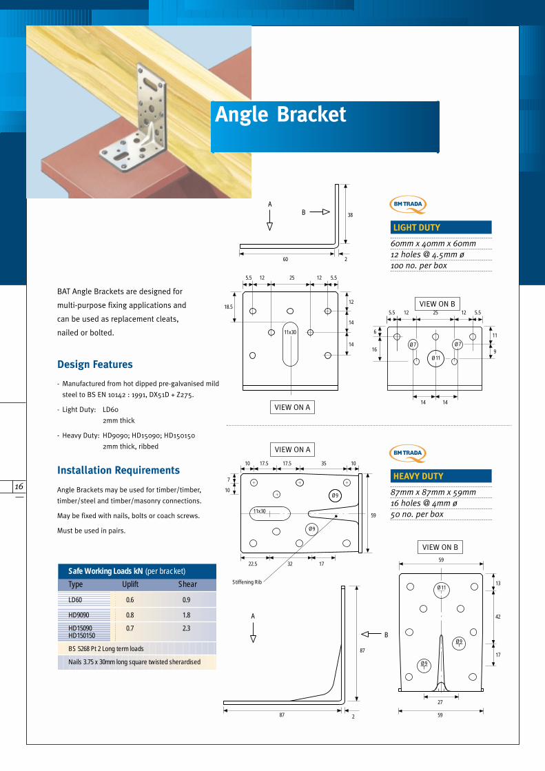
60mm x 40mm x 60mm
12 holes @ 4.5mm ø
100 no. per box
HEAVY DUTY
87mm x 87mm x 59mm
16 holes @ 4mm ø
50 no. per box
BAT Angle Brackets are designed for
multi-purpose fixing applications and
can be used as replacement cleats,
nailed or bolted.
- Manufactured from hot dipped pre-galvanised mild
steel to BS EN 10142 : 1991, DX51D + Z275.
- Light Duty: LD60
2mm thick
- Heavy Duty: HD9090; HD15090; HD150150
2mm thick, ribbed
Design Features
Angle Brackets may be used for timber/timber,
timber/steel and timber/masonry connections.
May be fixed with nails, bolts or coach screws.
Must be used in pairs.
Installation Requirements
VIEW ON B
VIEW ON B
VIEW ON A
VIEW ON A
Safe Working Loads kN (per bracket)
Type Uplift Shear
LD60 0.6 0.9
HD9090 0.8 1.8
HD15090 0.7 2.3HD150150
BS 5268 Pt 2 Long term loads
Nails 3.75 x 30mm long square twisted sherardised
Angle Bracket
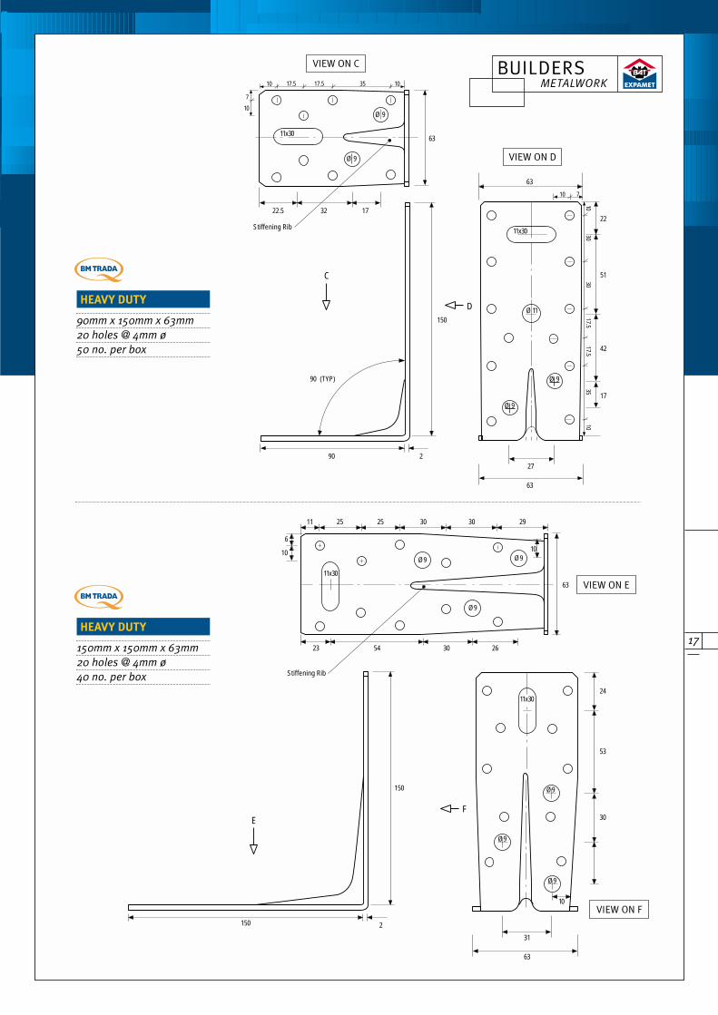
17
HEAVY DUTY
90mm x 150mm x 63mm
20 holes @ 4mm ø
50 no. per box
HEAVY DUTY
150mm x 150mm x 63mm
20 holes @ 4mm ø
40 no. per box
VIEW ON C
VIEW ON D
VIEW ON E
VIEW ON F
F
11x30
31
63
24
53
30
Ø 9
63
11 25 25 30 30 29
6
10
11x30
23 54 30
2
150
150
E
Stiffening Rib
26
10
10
Ø 9
Ø 9
Ø 9
Ø 9
Ø 9
D
27
63
2222.5
C
290
150
90 (TYP)
11x30
51
42
17
63
1030
3017.5
17.535
10
10 7
63
32 17
Stiffening Rib
11x30
10 17.5 17.5 35 10
7
10
Ø 9
11Ø
Ø 9
Ø 9
Ø 9
BUILDERS METALWORK

18
BAT-U-Nail plates are to be fixed on both sides of the timber.
Fixing: use BAT 3.75 x 30mm long square twisted sherardised nails –
Loading in the direction of the plate stiffening ribs (50.8 nail spacing
direction);
345 N/nail (parallel to timber grain).
145 N/nail (perpendicular to timber grain).
Plate compression value 40 N/mm width of plate. To calculate
capacity of connections, the lesser of anchorage, plate compression
and tension should be taken.
Fix in accordance with BS 5268 : Part 2.
Installation Requirements
BAT-U-Nail is a plate system which enables timber structures
to be made on site or in the builders workshop, since it is
nailed by hand.
SHEAR PLATE 101
SHEAR PLATE 67
BAT Timber Connectors are made in accordance with the requirements of BS 1579 ‘specification for connectors
for timber’. Safe working loads, end distances and spacing are all set out in BS 5268 Part 2.
Design Features
Shear Plate
Manufactured in 2 sizes:
SPT67 (150 per box) and
SPT101 (50 per box)
Designed for use with M20 bolt.
Material Specification:
67mm – Manufactured from HRPO
mild steel to BS1449 Part 1 : 1991.
100mm – Cast forging.
Square Plate Washers
Manufactured in 1 size:
SPW50 (50mm square).
To suit 12mm bolt.
250 per box.
Bolts are not supplied
with timber connectors.
Tooth Plate (Round)Manufactured in 3 sizes:
50, 63 and 75 diameter. 200, 150
and 100 per box respectively.
Available in both single and double
sided, eg. ref. TCSS; TCDS etc.
Suitable for M12 bolt.
Material Specification:
Manufactured from pre-galvanised
steel to BS EN 10142 : DX51D + Z275.
Split RingManufactured in 2 sizes:
SRTC63 (250 per box) and
SRTC100 (100 per box)
Designed for use with M12
and M20 bolts respectively.
Double bevelled.
Material Specification:
Manufactured from HRPO mild
steel to BS1449 Part 1 : 1991.
Timber Connectors
BAT-U-Nail Plate
Ø3.5
50 .8
12.7
19 4.75
± 1.576
114
152
51100
152203
254
305
354
- Manufactured from 0.9mm pre-galvanised mild
steel to BS EN 10142 : DX51D + Z275.
- Widths: 76, 114 and 152mm
- Lengths: 51, 100, 152, 203, 254, 305 and 354mm.
- Various quantities per box.
Ref. eg. BP7651.
Design Features
Application Tools For use with timber connectors.REF TYPE SIZE mm
SRGT63 Split Ring Grooving &Dapping Tool 63mm split ring
DT67 Shear Plate Grooving &Dapping Tool 67mm shear plate
DT101 Shear Plate Grooving &Dapping Tool 101mm plates
19
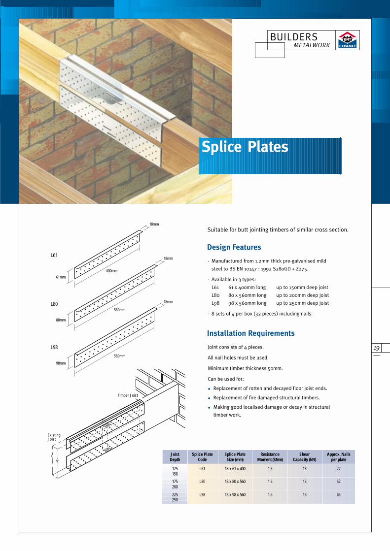
Suitable for butt jointing timbers of similar cross section.
- Manufactured from 1.2mm thick pre-galvanised mild
steel to BS EN 10147 : 1992 S280GD + Z275.
- Available in 3 types:
L61 61 x 400mm long up to 150mm deep joist
L80 80 x 560mm long up to 200mm deep joist
L98 98 x 560mm long up to 250mm deep joist
- 8 sets of 4 per box (32 pieces) including nails.
Design Features
Joint consists of 4 pieces.
All nail holes must be used.
Minimum timber thickness 50mm.
Can be used for:
• Replacement of rotten and decayed floor joist ends.
• Replacement of fire damaged structural timbers.
• Making good localised damage or decay in structural
timber work.
Installation Requirements
Joist Splice Plate Splice Plate Resistance Shear Approx. NailsDepth Code Size (mm) Moment (kNm) Capacity (kN) per plate
125 L61 18 x 61 x 400 1.5 13 27150
175 L80 18 x 80 x 560 1.5 13 52200
225 L98 18 x 98 x 560 1.5 13 65250
61mm
18mm
L61
400mm
80mm
18mm
L80560mm
98mm
18mm
L98
560mm
Timber Joist
Existing Joist
Splice Plates
BUILDERS METALWORK

20
To provide positive location and support of window
from timber framing to resist wind and incidental
loadings.
BAT Sole Plate Angles positively locate timber sole
plates to concrete floor slabs using masonry fixings
as required, without penetrating the dpc.
- Manufactured from 0.9mm thick hot dipped galvanised
mild steel to BS EN 10142 : DX51D + Z275.
- Available in 2 sizes:
Design Features
- Manufactured from 0.9mm thick hot dipped galvanised
mild steel to BS EN 10142 : DX51D + Z275.
- Available in 2 sizes:
Design Features
BAT Sole Plate Angles may be fixed on the inside of the
sole plate or alternatively fixed under the sole plate with
the upstand on the outside of the sole plate.
Fixing: use 3.75 x 50mm minimum length nails/masonry
nails.
Installation Requirements
Fixing: use BAT 3.75 x 30mm long square twisted
sherardised nails.
Installation Requirements
PLAN VIEW
SECTION VIEW
Frame Cramp
Sole Plate Angles
Ref. Width Length Upstand Qty/Box
FC1 76mm 202mm - 100
FC2 76mm 212mm 40mm 100
Ref. Width Length Upstand Qty/Box
SPA112 76mm 112mm 40mm 100
SPA162 76mm 162mm 40mm 100
21
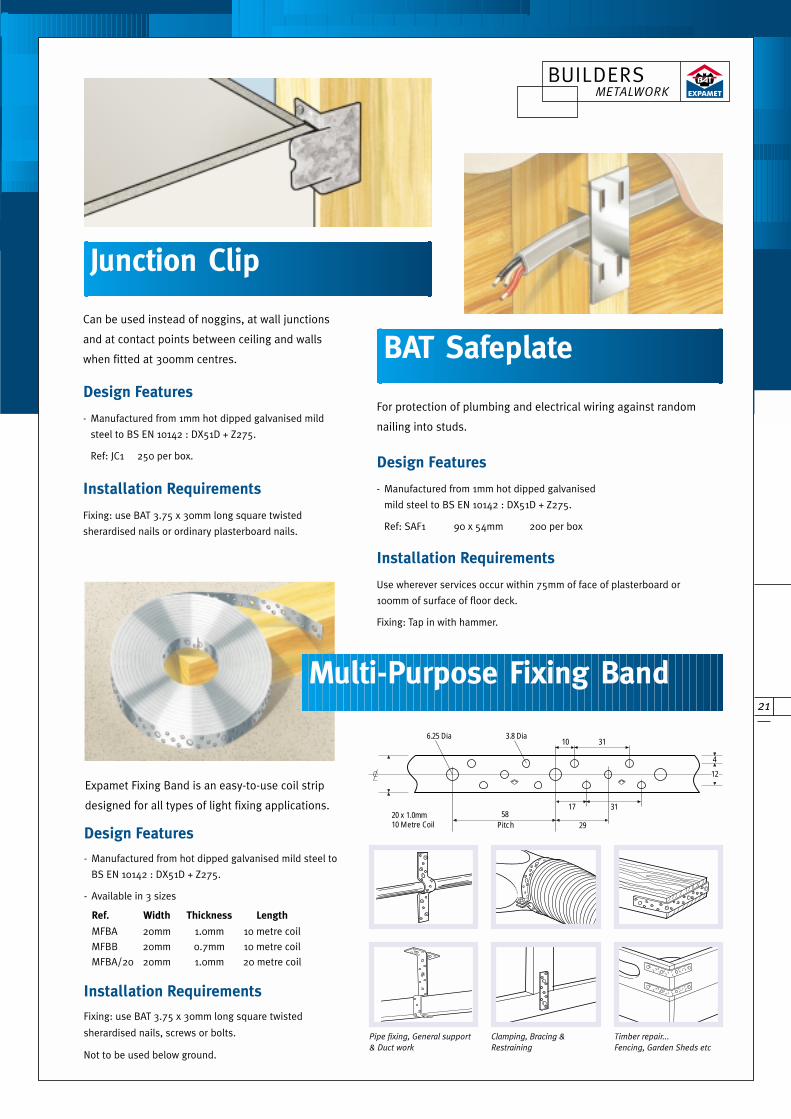
For protection of plumbing and electrical wiring against random
nailing into studs.
- Manufactured from 1mm hot dipped galvanised
mild steel to BS EN 10142 : DX51D + Z275.
Ref: SAF1 90 x 54mm 200 per box
Design Features
Use wherever services occur within 75mm of face of plasterboard or
100mm of surface of floor deck.
Fixing: Tap in with hammer.
Installation Requirements
Can be used instead of noggins, at wall junctions
and at contact points between ceiling and walls
when fitted at 300mm centres.
Design Features
Fixing: use BAT 3.75 x 30mm long square twisted
sherardised nails or ordinary plasterboard nails.
Installation Requirements
Junction Clip
- Manufactured from 1mm hot dipped galvanised mild
steel to BS EN 10142 : DX51D + Z275.
Ref: JC1 250 per box.
BAT Safeplate
Pipe fixing, General support
& Duct work
5820 x 1.0mm10 Metre Coil Pitch
17 31
29
12
31103.8 Dia6.25 Dia
4
Clamping, Bracing &
Restraining
Timber repair...
Fencing, Garden Sheds etc
Multi-Purpose Fixing Band
Expamet Fixing Band is an easy-to-use coil strip
designed for all types of light fixing applications.
- Manufactured from hot dipped galvanised mild steel to
BS EN 10142 : DX51D + Z275.
- Available in 3 sizes
Design Features
Fixing: use BAT 3.75 x 30mm long square twisted
sherardised nails, screws or bolts.
Not to be used below ground.
Installation Requirements
Ref. Width Thickness Length
MFBA 20mm 1.0mm 10 metre coil
MFBB 20mm 0.7mm 10 metre coil
MFBA/20 20mm 1.0mm 20 metre coil
BUILDERS METALWORK
22
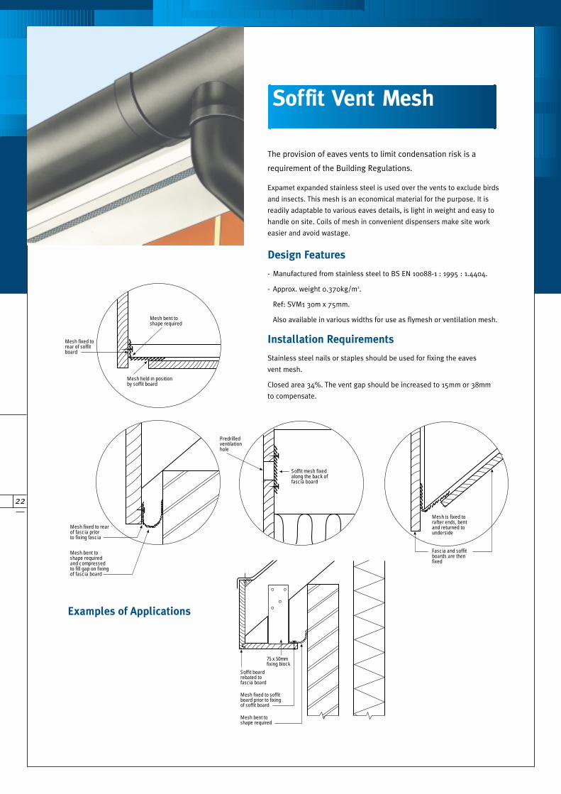
The provision of eaves vents to limit condensation risk is a
requirement of the Building Regulations.
Expamet expanded stainless steel is used over the vents to exclude birds
and insects. This mesh is an economical material for the purpose. It is
readily adaptable to various eaves details, is light in weight and easy to
handle on site. Coils of mesh in convenient dispensers make site work
easier and avoid wastage.
Stainless steel nails or staples should be used for fixing the eaves
vent mesh.
Closed area 34%. The vent gap should be increased to 15mm or 38mm
to compensate.
Installation Requirements
Examples of Applications
Soffit mesh fixed along the back of fascia board
Predrilled ventilation hole
75 x 50mm fixing block
Soffit board rebated to fascia board
Mesh fixed to soffit board prior to fixing of soffit board
Mesh bent to shape required
Mesh fixed to rear of soffit board
Mesh bent to shape required
Mesh held in position by soffit board
Mesh fixed to rearof fascia priorto fixing fascia
Mesh bent to shape required and compressed to fill gap on fixing of fascia board
Mesh is fixed to rafter ends, bent and returned to underside
Fascia and soffit boards are then fixed
- Manufactured from stainless steel to BS EN 10088-1 : 1995 : 1.4404.
- Approx. weight 0.370kg/m2.
Ref: SVM1 30m x 75mm.
Also available in various widths for use as flymesh or ventilation mesh.
Design Features
Soffit Vent Mesh
23
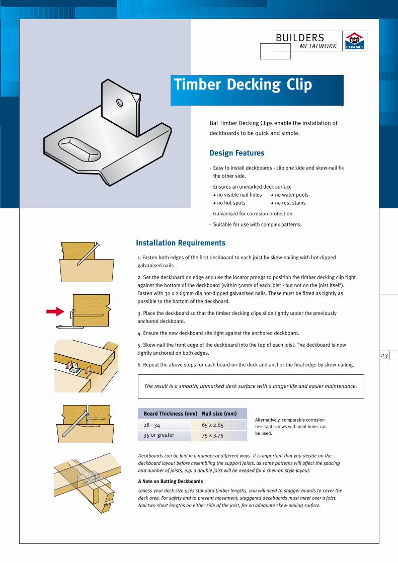
Bat Timber Decking Clips enable the installation of
deckboards to be quick and simple.
Installation Requirements
Design Features
A Note on Butting Deckboards
Unless your deck size uses standard timber lengths, you will need to stagger boards to cover the
deck area. For safety and to prevent movement, staggered deckboards must meet over a joist.
Nail two short lengths on either side of the joist, for an adequate skew-nailing surface.
Deckboards can be laid in a number of different ways. It is important that you decide on the
deckboard layout before assembling the support joists, as some patterns will affect the spacing
and number of joists, e.g. a double joist will be needed for a chevron style layout.
- Easy to install deckboards - clip one side and skew-nail fix
the other side.
- Ensures an unmarked deck surface
• no visible nail holes • no water pools
• no hot spots • no rust stains
- Galvanised for corrosion protection.
- Suitable for use with complex patterns.
1. Fasten both edges of the first deckboard to each joist by skew-nailing with hot-dipped
galvanised nails.
2. Set the deckboard on edge and use the locator prongs to position the timber decking clip tight
against the bottom of the deckboard (within 50mm of each joist - but not on the joist itself ).
Fasten with 30 x 2.65mm dia hot-dipped galvanised nails. These must be fitted as tightly as
possible to the bottom of the deckboard.
3. Place the deckboard so that the timber decking clips slide tightly under the previously
anchored deckboard.
4. Ensure the new deckboard sits tight against the anchored deckboard.
5. Skew-nail the front edge of the deckboard into the top of each joist. The deckboard is now
tightly anchored on both edges.
6. Repeat the above steps for each board on the deck and anchor the final edge by skew-nailing.
The result is a smooth, unmarked deck surface with a longer life and easier maintenance.
Board Thickness (mm) Nail size (mm)
28 - 34 65 x 2.65
35 or greater 75 x 3.75
Alternatively, comparable corrosion
resistant screws with pilot holes can
be used.
Timber Decking Clip
BUILDERS METALWORK
24
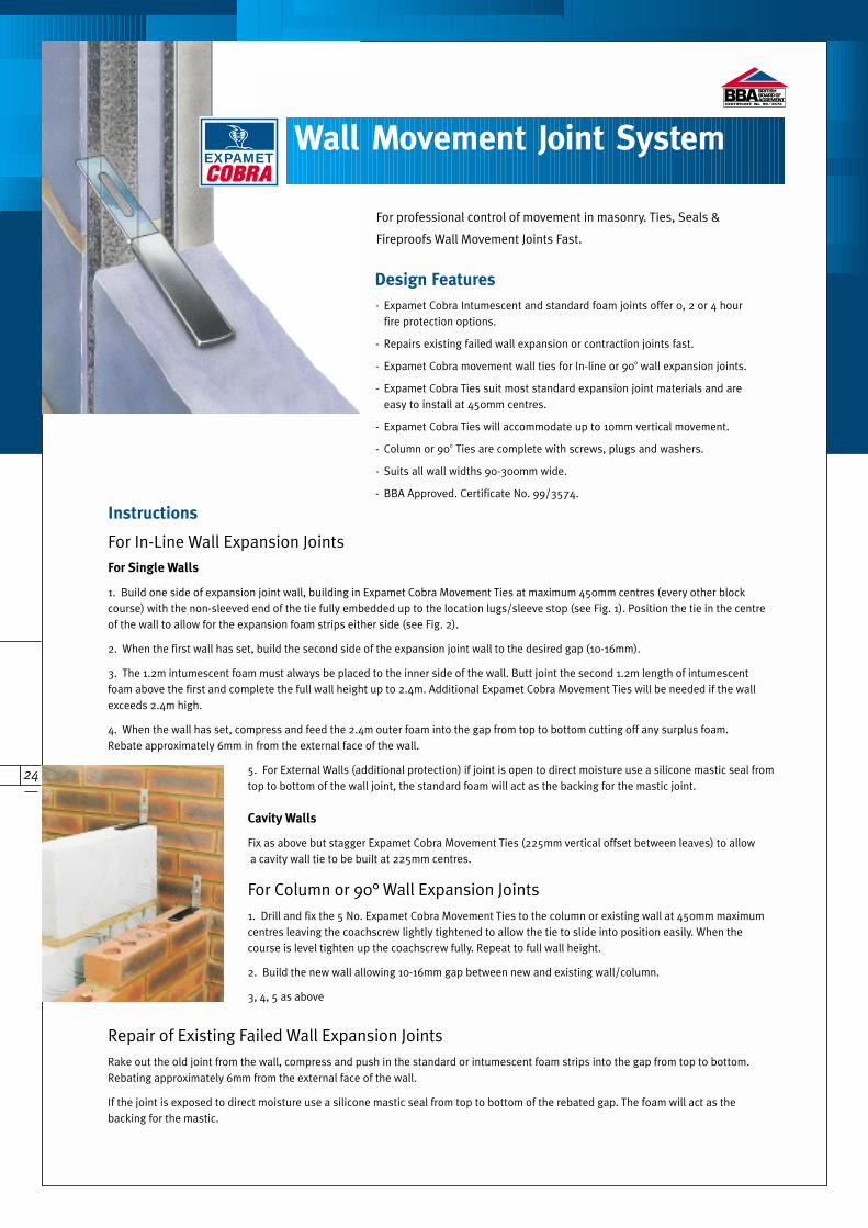
- Expamet Cobra Intumescent and standard foam joints offer 0, 2 or 4 hour fire protection options.
- Repairs existing failed wall expansion or contraction joints fast.
- Expamet Cobra movement wall ties for In-line or 900 wall expansion joints.
- Expamet Cobra Ties suit most standard expansion joint materials and are easy to install at 450mm centres.
- Expamet Cobra Ties will accommodate up to 10mm vertical movement.
- Column or 900 Ties are complete with screws, plugs and washers.
- Suits all wall widths 90-300mm wide.
- BBA Approved. Certificate No. 99/3574.
Design Features
Wall Movement Joint System
For professional control of movement in masonry. Ties, Seals &
Fireproofs Wall Movement Joints Fast.
EXPAMET
For In-Line Wall Expansion JointsFor Single Walls
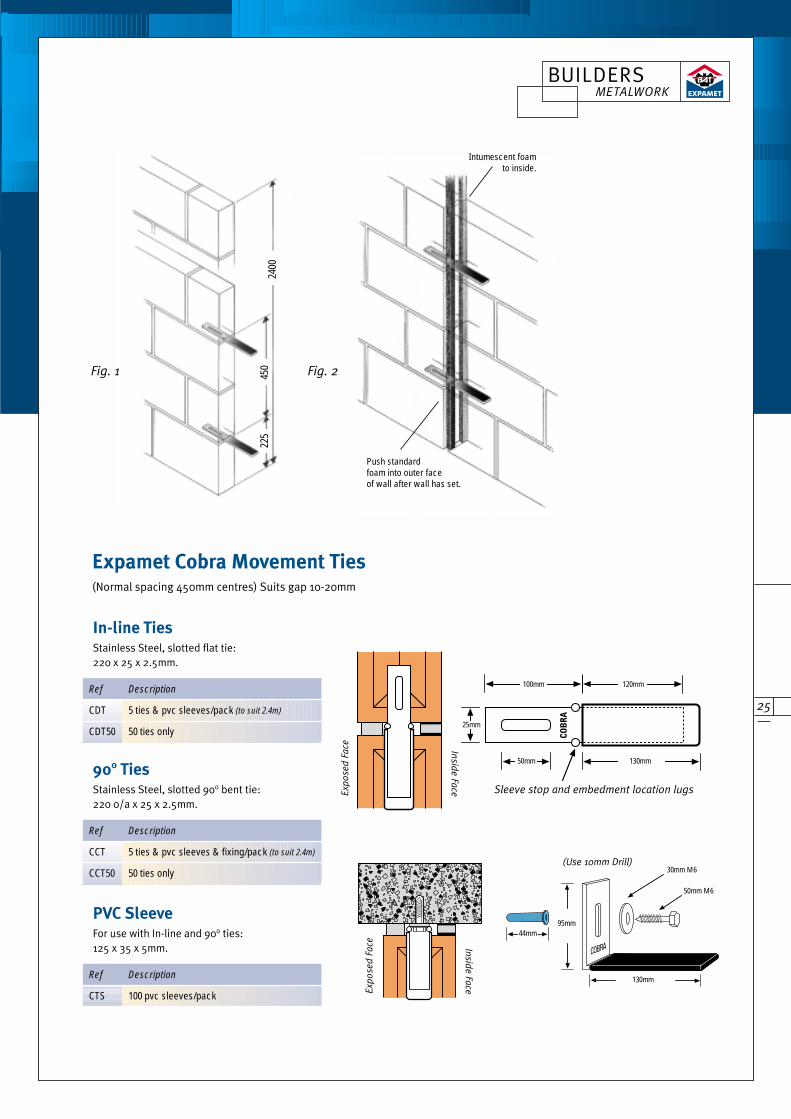
1. Build one side of expansion joint wall, building in Expamet Cobra Movement Ties at maximum 450mm centres (every other blockcourse) with the non-sleeved end of the tie fully embedded up to the location lugs/sleeve stop (see Fig. 1). Position the tie in the centreof the wall to allow for the expansion foam strips either side (see Fig. 2).
2. When the first wall has set, build the second side of the expansion joint wall to the desired gap (10-16mm).
3. The 1.2m intumescent foam must always be placed to the inner side of the wall. Butt joint the second 1.2m length of intumescentfoam above the first and complete the full wall height up to 2.4m. Additional Expamet Cobra Movement Ties will be needed if the wallexceeds 2.4m high.
4. When the wall has set, compress and feed the 2.4m outer foam into the gap from top to bottom cutting off any surplus foam. Rebate approximately 6mm in from the external face of the wall.
5. For External Walls (additional protection) if joint is open to direct moisture use a silicone mastic seal fromtop to bottom of the wall joint, the standard foam will act as the backing for the mastic joint.
Cavity Walls
Fix as above but stagger Expamet Cobra Movement Ties (225mm vertical offset between leaves) to allowa cavity wall tie to be built at 225mm centres.
For Column or 90° Wall Expansion Joints1. Drill and fix the 5 No. Expamet Cobra Movement Ties to the column or existing wall at 450mm maximumcentres leaving the coachscrew lightly tightened to allow the tie to slide into position easily. When thecourse is level tighten up the coachscrew fully. Repeat to full wall height.
2. Build the new wall allowing 10-16mm gap between new and existing wall/column.
3, 4, 5 as above
Repair of Existing Failed Wall Expansion JointsRake out the old joint from the wall, compress and push in the standard or intumescent foam strips into the gap from top to bottom.Rebating approximately 6mm from the external face of the wall.
If the joint is exposed to direct moisture use a silicone mastic seal from top to bottom of the rebated gap. The foam will act as thebacking for the mastic.
Instructions
CERTIFICATE No. 99/3574
25
Expamet Cobra Movement Ties (Normal spacing 450mm centres) Suits gap 10-20mm
Exp
ose
d F
ace
Sleeve stop and embedment location lugs
(Use 10mm Drill)
50mm
25mm
130mm
130mm
95mm44mm
50mm M6
30mm M6
120mm100mm
Insid
e Fa
ce
Exp
ose
d F
ace In
side
Face
2400
450
225
Push standard foam into outer face of wall after wall has set.
Intumescent foamto inside.
In-line TiesStainless Steel, slotted flat tie:220 x 25 x 2.5mm.
Fig. 1 Fig. 2
Ref Description
CDT 5 ties & pvc sleeves/pack (to suit 2.4m)
CDT50 50 ties only
900 TiesStainless Steel, slotted 90o bent tie:220 0/a x 25 x 2.5mm.
Ref Description
CCT 5 ties & pvc sleeves & fixing/pack (to suit 2.4m)
CCT50 50 ties only
PVC SleeveFor use with In-line and 90o ties:125 x 35 x 5mm.
Ref Description
CTS 100 pvc sleeves/pack
BUILDERS METALWORK
26
Materials
Expamet Cobra Ties
Expamet Cobra Joints
Fire Retardent Foam:
Polyurethane, 20mm thick x 30mm wide x 2.4m high.
Cobra Intumescent Foam:
Graphite base, 2.4mm x 30mm x 2.4m high, bonded to
15mm x 30mm x 2.4m high fire retardent foam (supplied in
2 lengths of 1.2m).
Movement
Expamet Cobra masonry movement joints are suitable for use to
accommodate longitudinal expansion and/or contraction, and up
to 10mm vertical movement in brick or blockwork masonry.
Structural Performance
Characteristic shear loads for Expamet Cobra ties embedded
in mortar designation (IV) to BS5628 : Part 1 : 1992 tested at
maximum 20mm gap. Values per single tie:
The provision of movement joints shall be in accordance
with the recommendations of BS 5628 : Part 3 : 1985
Fire Performance
Expamet Cobra CF0, CF2 and CF4 joints shown will have
0 hour, 2 hour and 4 hour fire resistance respectively.
Tested to BS 476 : Part 20 : 1987.
Thermal Resistance
The thermal resistance of the Expamet Cobra foam joint is
such that it will not constitute a cold bridge.
Loading In-Line Tie 90° Tie
Lateral 2.2kN 0.7kN
Vertical 2.5kN 0.7kN
Stainless Steel to BS EN 10088-1 : 1995 : 1.4301
Sleeve 30 x 130 PVC.
Screws & Washers Stainless steel grade 304
Plugs High density polyurethane
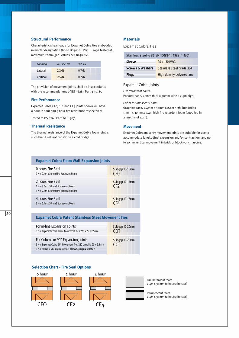
Expamet Cobra Foam Wall Expansion Joints
0 hours Fire Seal Suit gap 10-16mm2 No. 2.4m x 30mm Fire Retardant Foam CF0
2 hours Fire Seal Suit gap 10-16mm1 No. 2.4m x 30mm Intumescent Foam CF21 No. 2.4m x 30mm Fire Retardant Foam
4 hours Fire Seal Suit gap 10-16mm2 No. 2.4m x 30mm Intumescent Foam CF4
Expamet Cobra Patent Stainless Steel Movement Ties
For in-line Expansion Joints Suit gap 10-20mm5 No. Expamet Cobra Inline Movement Ties 220 x 25 x 2.5mm CDT
For Column or 90° Expansion Joints Suit gap 10-20mm5 No. Expamet Cobra 90° Movement Ties 220 overall x 25 x 2.5mm CCT5 No. 50mm x M6 stainless steel screws, plugs & washers
0 hour
CFO
2 hour
CF2
4 hour
CF4
Fire Retardant foam2.4m x 30mm (0 hours fire seal)
Intumescent foam2.4m x 30mm (2 hours fire seal)
Selection Chart - Fire Seal Options
27
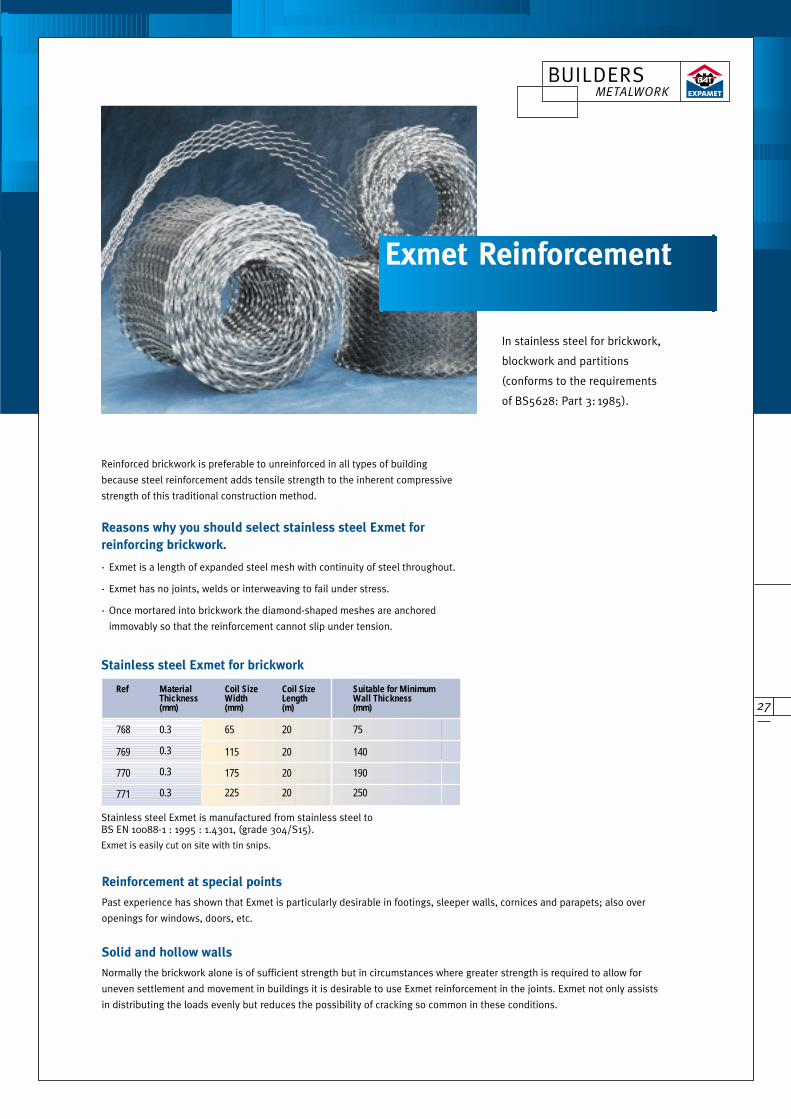
Reinforced brickwork is preferable to unreinforced in all types of building
because steel reinforcement adds tensile strength to the inherent compressive
strength of this traditional construction method.
Reasons why you should select stainless steel Exmet for
reinforcing brickwork.
- Exmet is a length of expanded steel mesh with continuity of steel throughout.
- Exmet has no joints, welds or interweaving to fail under stress.
- Once mortared into brickwork the diamond-shaped meshes are anchored
immovably so that the reinforcement cannot slip under tension.
Exmet Reinforcement
Stainless steel Exmet for brickwork
Stainless steel Exmet is manufactured from stainless steel to BS EN 10088-1 : 1995 : 1.4301, (grade 304/S15).
Exmet is easily cut on site with tin snips.
Ref Material Coil Size Coil Size Suitable for Minimum Thickness Width Length Wall Thickness(mm) (mm) (m) (mm)
768 0.3 65 20 75
769 0.3 115 20 140
770 0.3 175 20 190
771 0.3 225 20 250
In stainless steel for brickwork,
blockwork and partitions
(conforms to the requirements
of BS5628: Part 3: 1985).
Reinforcement at special points
Past experience has shown that Exmet is particularly desirable in footings, sleeper walls, cornices and parapets; also over
openings for windows, doors, etc.
Solid and hollow walls
Normally the brickwork alone is of sufficient strength but in circumstances where greater strength is required to allow for
uneven settlement and movement in buildings it is desirable to use Exmet reinforcement in the joints. Exmet not only assists
in distributing the loads evenly but reduces the possibility of cracking so common in these conditions.
BUILDERS METALWORK
28
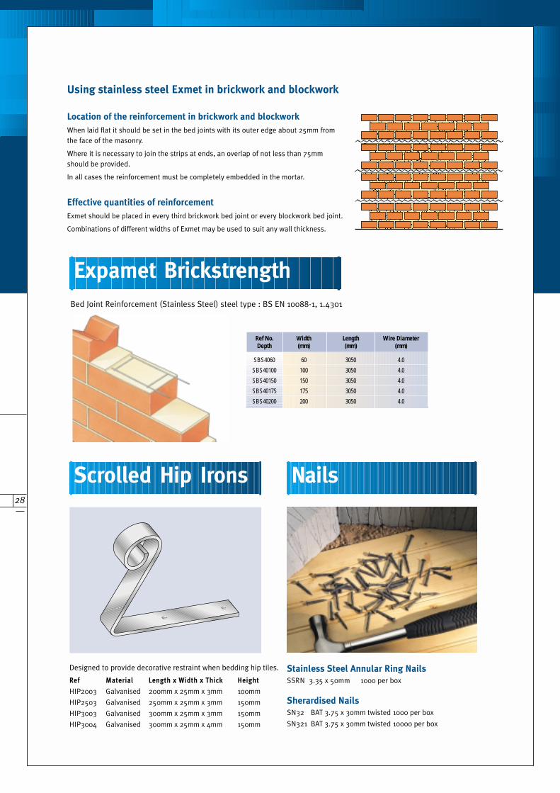
Location of the reinforcement in brickwork and blockwork
When laid flat it should be set in the bed joints with its outer edge about 25mm fromthe face of the masonry.
Where it is necessary to join the strips at ends, an overlap of not less than 75mmshould be provided.
In all cases the reinforcement must be completely embedded in the mortar.
Using stainless steel Exmet in brickwork and blockwork
Effective quantities of reinforcement
Exmet should be placed in every third brickwork bed joint or every blockwork bed joint.
Combinations of different widths of Exmet may be used to suit any wall thickness.
Stainless Steel Annular Ring Nails
SSRN 3.35 x 50mm 1000 per box
Sherardised Nails
SN32 BAT 3.75 x 30mm twisted 1000 per box
SN321 BAT 3.75 x 30mm twisted 10000 per box
Designed to provide decorative restraint when bedding hip tiles.
Ref Material Length x Width x Thick Height
HIP2003 Galvanised 200mm x 25mm x 3mm 100mm
HIP2503 Galvanised 250mm x 25mm x 3mm 150mm
HIP3003 Galvanised 300mm x 25mm x 3mm 150mm
HIP3004 Galvanised 300mm x 25mm x 4mm 150mm
Scrolled Hip Irons
Expamet Brickstrength
Nails
Bed Joint Reinforcement (Stainless Steel) steel type : BS EN 10088-1, 1.4301
Ref No. Width Length Wire Diameter Depth (mm) (mm) (mm)
SBS4060 60 3050 4.0
SBS40100 100 3050 4.0
SBS40150 150 3050 4.0
SBS40175 175 3050 4.0
SBS40200 200 3050 4.0
29
Wall StartersIndividual products designed for specific widths of new walls
There are four ‘flanged’ products in the Expamet Wall Starter range,
each designed for a specific wall widths, from 60mm to 260mm thick.
UniStartersThe universal wallstarter for any wall
The flat flange-free design of Expamet UniStarters means
they can be used to construct any wall between 75mm
and 250mm thick – one product, multiple applications.
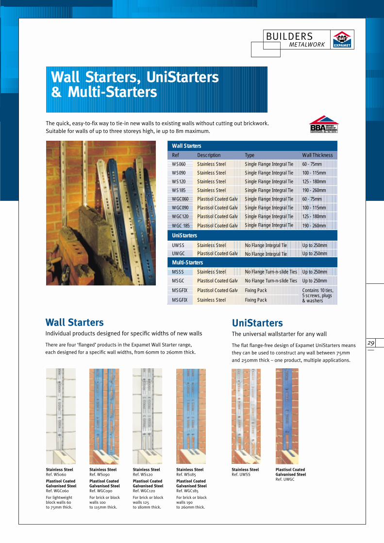
Wall Starters, UniStarters & Multi-Starters
The quick, easy-to-fix way to tie-in new walls to existing walls without cutting out brickwork.Suitable for walls of up to three storeys high, ie up to 8m maximum.
Stainless SteelRef. WS060
Plastisol CoatedGalvanised SteelRef. WGC060
For lightweightblock walls 60to 75mm thick.
Stainless SteelRef. WS090
Plastisol CoatedGalvanised SteelRef. WGC090
For brick or blockwalls 100to 115mm thick.
Stainless SteelRef. WS120
Plastisol CoatedGalvanised SteelRef. WGC120
For brick or blockwalls 125to 180mm thick.
Stainless SteelRef. WS185
Plastisol CoatedGalvanised SteelRef. WGC185
For brick or blockwalls 190to 260mm thick.
Stainless SteelRef. UWSS
Plastisol CoatedGalvanised Steel Ref. UWGC
CERTIFICATE No. 99/3574
Wall Starters
Ref Description Type Wall Thickness
WS060 Stainless Steel Single Flange Integral Tie 60 - 75mm
WS090 Stainless Steel Single Flange Integral Tie 100 - 115mm
WS120 Stainless Steel Single Flange Integral Tie 125 - 180mm
WS185 Stainless Steel Single Flange Integral Tie 190 - 260mm
WGC060 Plastisol Coated Galv Single Flange Integral Tie 60 - 75mm
WGC090 Plastisol Coated Galv Single Flange Integral Tie 100 - 115mm
WGC120 Plastisol Coated Galv Single Flange Integral Tie 125 - 180mm
WGC 185 Plastisol Coated Galv Single Flange Integral Tie 190 - 260mm
UniStarters
UWSS Stainless Steel No Flange Integral Tie Up to 250mm
UWGC Plastisol Coated Galv No Flange Integral Tie Up to 250mm
Multi-Starters
MSSS Stainless Steel No Flange Turn-n-slide Ties Up to 250mm
MSGC Plastisol Coated Galv No Flange Turn-n-slide Ties Up to 250mm
MSGFIX Plastisol Coated Galv Fixing Pack
MSGFIX Stainless Steel Fixing Pack
Contains 10 ties,5 screws, plugs& washers
BUILDERS METALWORK
30
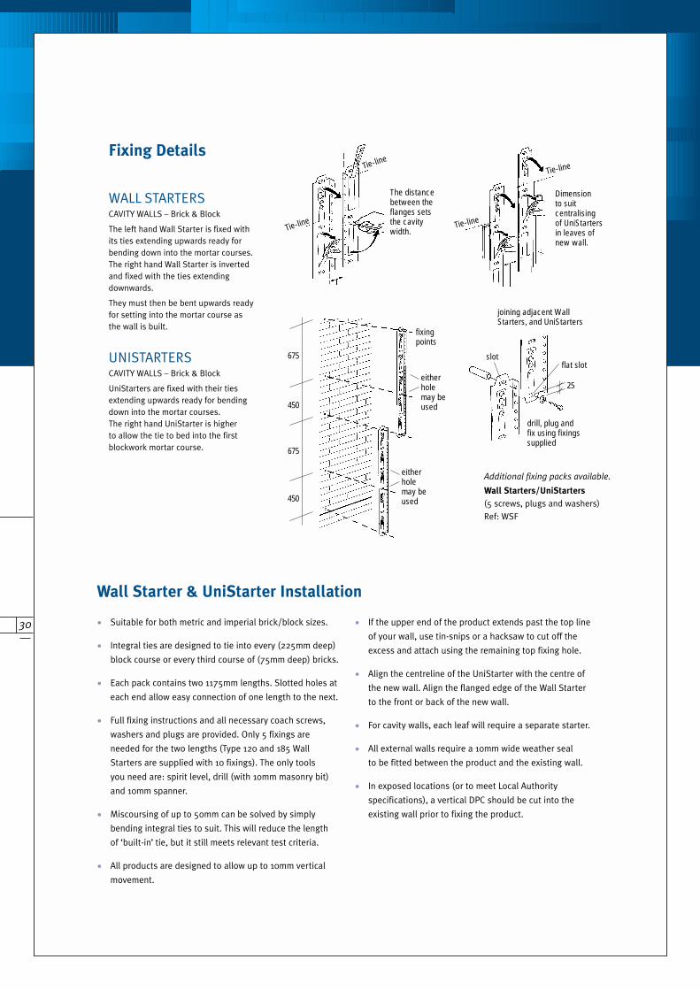
Fixing Details
675
fixingpoints
drill, plug andfix using fixingssupplied
The distancebetween theflanges setsthe cavitywidth.Tie-line
Tie-line
Tie-line
Tie-line
Dimensionto suit centralisingof UniStartersin leaves ofnew wall.
25
eitherholemay beused
eitherholemay beused
slotflat slot
joining adjacent WallStarters, and UniStarters
450
675
450
CAVITY WALLS – Brick & Block
The left hand Wall Starter is fixed withits ties extending upwards ready forbending down into the mortar courses.The right hand Wall Starter is invertedand fixed with the ties extending downwards.
They must then be bent upwards readyfor setting into the mortar course asthe wall is built.
WALL STARTERS
CAVITY WALLS – Brick & Block
UniStarters are fixed with their tiesextending upwards ready for bendingdown into the mortar courses.The right hand UniStarter is higherto allow the tie to bed into the firstblockwork mortar course.
UNISTARTERS
Additional fixing packs available.
Wall Starters/UniStarters
(5 screws, plugs and washers)
Ref: WSF
Wall Starter & UniStarter Installation
• Suitable for both metric and imperial brick/block sizes.
• Integral ties are designed to tie into every (225mm deep)
block course or every third course of (75mm deep) bricks.
• Each pack contains two 1175mm lengths. Slotted holes at
each end allow easy connection of one length to the next.
• Full fixing instructions and all necessary coach screws,
washers and plugs are provided. Only 5 fixings are
needed for the two lengths (Type 120 and 185 Wall
Starters are supplied with 10 fixings). The only tools
you need are: spirit level, drill (with 10mm masonry bit)
and 10mm spanner.
• Miscoursing of up to 50mm can be solved by simply
bending integral ties to suit. This will reduce the length
of ‘built-in’ tie, but it still meets relevant test criteria.
• All products are designed to allow up to 10mm vertical
movement.
• If the upper end of the product extends past the top line
of your wall, use tin-snips or a hacksaw to cut off the
excess and attach using the remaining top fixing hole.
• Align the centreline of the UniStarter with the centre of
the new wall. Align the flanged edge of the Wall Starter
to the front or back of the new wall.
• For cavity walls, each leaf will require a separate starter.
• All external walls require a 10mm wide weather seal
to be fitted between the product and the existing wall.
• In exposed locations (or to meet Local Authority
specifications), a vertical DPC should be cut into the
existing wall prior to fixing the product.
31
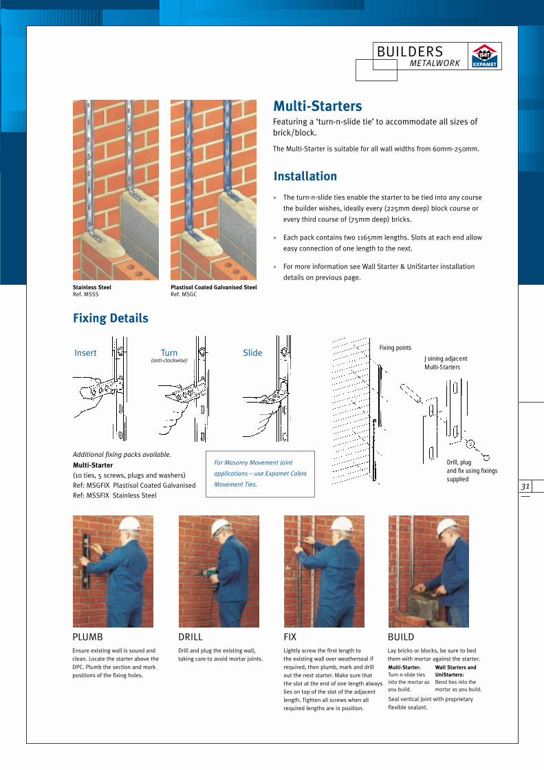
Fixing Details
• The turn-n-slide ties enable the starter to be tied into any course
the builder wishes, ideally every (225mm deep) block course or
every third course of (75mm deep) bricks.
• Each pack contains two 1165mm lengths. Slots at each end allow
easy connection of one length to the next.
• For more information see Wall Starter & UniStarter installation
details on previous page.
Joining adjacentMulti-Starters
Fixing points
Drill, plug and fix using fixingssupplied
Seal vertical joint with proprietaryflexible sealant.
Additional fixing packs available.
Multi-Starter
(10 ties, 5 screws, plugs and washers)
Ref: MSGFIX Plastisol Coated Galvanised
Ref: MSSFIX Stainless Steel
Turn (anti-clockwise)
Slide
Multi-Starter:
Turn-n-slide ties into the mortar asyou build.
Insert
For Masonry Movement Joint
applications – use Expamet Cobra
Movement Ties.
Wall Starters and
UniStarters:
Bend ties into themortar as you build.
Installation
Multi-StartersFeaturing a ‘turn-n-slide tie’ to accommodate all sizes ofbrick/block.
The Multi-Starter is suitable for all wall widths from 60mm-250mm.
PLUMBEnsure existing wall is sound andclean. Locate the starter above theDPC. Plumb the section and markpositions of the fixing holes.
DRILLDrill and plug the existing wall,taking care to avoid mortar joints.
FIXLightly screw the first length tothe existing wall over weatherseal ifrequired, then plumb, mark and drillout the next starter. Make sure that the slot at the end of one length alwayslies on top of the slot of the adjacentlength. Tighten all screws when allrequired lengths are in position.
BUILDLay bricks or blocks, be sure to bedthem with mortar against the starter.
Stainless SteelRef. MSSS
Plastisol Coated Galvanised Steel Ref. MSGC
BUILDERS METALWORK

The company policy is one of continuous development, we therefore reserve the right to alterspecifications, etc. without notice. Stock material may be collected from company depots forcash or by prior arrangement. Customers are advised to check availability of material.
CERTIFICATE No. 89/2292
COSHH We are not aware of any risk to the person arising from chemicals or other substancespresent on or in our products.
However, there exists the possibility of superficial injury from edges of relatively thin gaugemetals but this is obvious and arises largely from careless handling. It is akin to the risk fromtimber splinters or any sharp corner.
Expamet Building Products is a subsidiary of The Expanded Metal Company Limited.
PO Box 52, Greatham Street, Longhill Industrial Estate (North), Hartlepool
TS25 1PR England
TE L EPHONE
General: +44 (0)1429 866688 Sales: +44 (0)1429 866611
Fax: +44 (0)1429 866633 E-mail: [email protected]
Technical: +44 (0)1429 866655 Tech E-mail: [email protected]
Website: www.expamet.co.uk
EMS 45225FM 36694
SALES OFFICE
DUBLIN: Westlink Industrial Estate, Kylemore Road, Ballyfermot, D10
Tel: 00-3531 626 5981 Fax: 00-3531 626 7802 E-mail: [email protected]
Quality Assurance BS EN ISO 9002:1994 and ISO 14001 Registered Firms Certificate No. FM36694, EMS 45225
CERTIFICATE No. 99/3574


