

Break-in atmowerfor
10hours
first
INTRODUCTION
The International 105 Balanced Moweris designed for use on the International Cub 8
Lo-Boye, Farmall Cub e, International andFarmal18 Super A, Super A-l, 100, 130 and140 Tractors. It is well suited for both in-dustrial and farm use. A completing packageis required to mount on your tractor.
This mower is especially built for high-speed mowing. It is ruggedly built with anexclusive new wrist-action drive, balancedfor smooth running for longer machine lifeand operator's comfort. It is especiallydesigned for cutting heavy hay and othervegetation.
or for mowing highway shoulders,rights-of-way, and other industrial applica-tions. It will operate efficiently with the cut-ter bar at any angle from. 450 below horizontalto 900 vertical. This feature makes it desir-able for cutting steep highway banks andslopes. The. free floating action of the cutterbar permits close operating positions alongthe contour of the ground.
The tractors must be equipped with one ofthe following units:
Touch Control for Farmall and hlternational140 Basic Tractors for use with 105 Mowers(Factory Application) (Standard Equipment onhlternational 140 Standard Tractor).
354 467 R99 Special Touch Control forFarmall and mternational"A", Super A,100, 130, and 140 Tractors not previouslyequipped with Touch Control.
The hydraulic system enables the operatorto raise the cutter bar to clear obstructions
or to raise the mowe r to transport position.
The mower operator can quickly adjust thecutter bar for height to meet various mowingconditions, permitting independent control ofthe
inner and outer shoes. A completing pack-age is required for the International Cub Lo-Boy and Farmall Cub Tractors.
358 119 R 91 Special Touch Control Con-version Package for Farmall and International
"A", Super A, 100, 130, and 140 Tractorsequipped with Touch Control.
381 223 R91 Restricted Actuator Package(Factory Application) for International CubLo-Boy, and Farrnall Cub Tractors. A 5-foot cutter bar is standard equipment,
381 228 R9l Restricted Actuator Package(Field Conversion) for International Cub Lo-Boy and Farmall Cub Tractors.
A variety of special knife assemblies areavailable for this cutter bar.
Note: The Farmall Cub and InternationalCub La-Boy tractors must be equipped withhead
gasket 351 989 R6.
Other special equipment and attachmentsare as follows:
The tractor Fast-Hitch cannot be used inconjunction with the mower. However, theFast-Hitch helper spring parts are requiredwhen the mower is mounted on the Cub orCub Lo-Boy Tractors.
Outer Shoe Grass Deflector -to preventthe cut material from falling into the un-cut material.
Knife Rack Attachment -to carry extraknife assembly in the field.The mower is mounted on the right side ofthe
tractor main frame between the front andrear wheels. Power is transmitted from therear power take-off on the tractor through aroller chain to the universal joint drive shaft.A heavy-duty V -belt drive transmits the powerto the balanced drive. The entire drive iscompletely shielded.
Curb Lift Attachment for International CubLo-Boy and Farmall Cub Tractors -willhold the inner shoe above ground level, upto lO'l high to enable the cutter bar to beplaced in and position with the workingrange of 45 below horizontal to vertical.
half throttle
LUBRICA TION
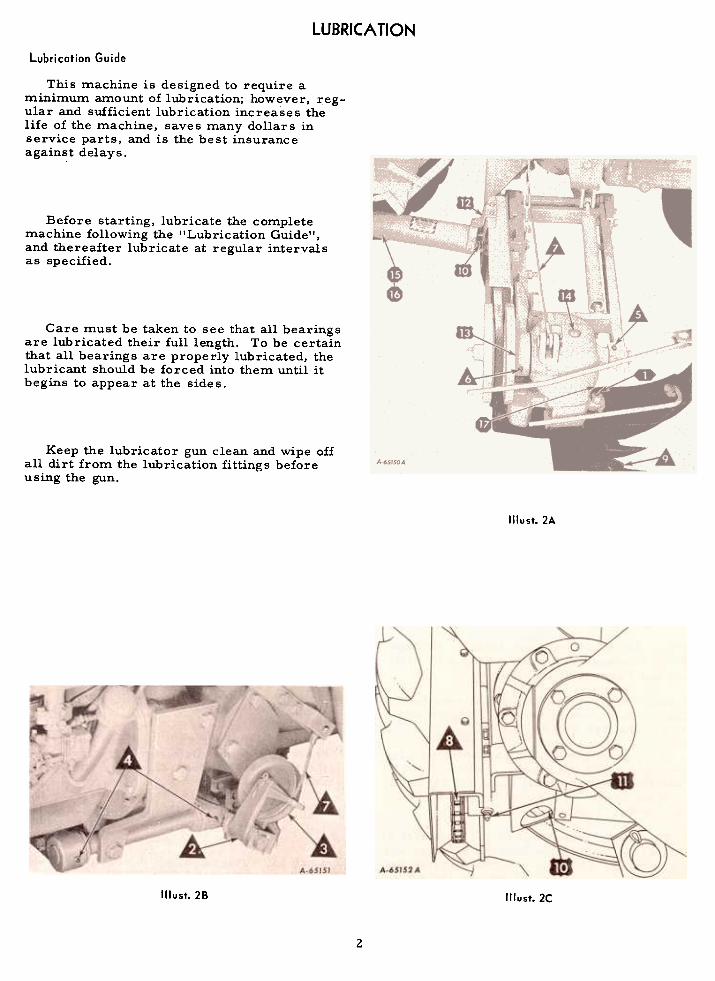
Lubrication Guide
This machine is designed to require aminimum amount of lubrication; however, reg-ular and sufficient lubrication increases thelife of the machine, saves many dollars inservice parts, and is the best insuranceagainst delays.
Before starting, lubricate the completemachine following the "Lubrication Guide",and thereafter lubricate at regular intervalsas specified.
Care must be taken to see that all bearingsare lubricated their full length. To be certainthat all bearings are properly lubricated, thelubricant should be forced into them until itbegins to appear at the sides.
Keep the lubricator gun clean and wipe offall dirt from the lubrication fittings beforeusing the gun.
Illust. 2A
Illust.28 Illust.2C
2

Key to Lubrication Guide
The symbols shown around the reference numbers in Illusts. 2A, 2B,and 2C indicate the intervals of lubrication. Paragraph numberscorrespond to reference numbers in the illustrations.
More Often Than Daily
Twice daily, use chassis lubricant (pressure-gun grease)and apply sufficient lubricant to flush out the old grease anddirt.
Knife pin
Daily or After Every 10 Hours of Operation
2. Cable pulley support3. Cable pulley4.
Frame hinge5. Front hinge
6. Rear hinge
Use chassis lubricant (pressure-gun grease) and applysufficient lubricant to flush out the old grease and dirt.
7.8.
Lifting cableDrive chain Use an oilcan.
Lubricate with oil, using an oilcan.
9.
Knife guides, wearingplates, and knife clips
hllocalities where the soil is sandy or full of grit, theknife guides, wearing plates, and knife clips should not be
oiled. hl other localities where these conditions do not exist,oil them daily.
Every Three Days of After 30 Hours of Operati on
10. Power drive knuckle
Use chassis lubricant (pressure-gun grease) and lubricatethe universal drive center crosses (2 fittings).
Only a few strokes of the pressure-gun are required. Donot use a high-pressure gun. Excessive lubricant force_dthrough the bearings may destroy the seals.
1112.
Rear drive shafthousing
Belt pulley bearing
Use chassis lubricant (pressure-gun grease).
Only a few strokes of the pressure-gun are required. Donot use a high-pressure gun. Excessive lubricant forcedthrough the bearings may destroy the seals.
Use a pressure-gun lubricant (Lithium mUlti-purposegrease, type 2). Apply 3/8-ounce of Lithium mUlti-purposegrease, type 2. This can be determined in terms of strokesof the lubricating gun, depending on the type used. Do notuse
a high-pressure gun. Under extremely dusty conditions,lubricate every 20 hours.
13. Balancing head bearinghousirtg14. Crankshaft housing(under top button plug)
Periodic
15.
Knuckle shaft and sleeve16. Telescoping shields
Two or three times a season, or whenever assembling theknuckle shaft and sleeve, be sure to insert a liberal amountof grease in the end of the sleeve; then freely grease theshaft. Work the shaft in and Qut of the sleeve so that thesleeve .and shaft are well lubricated. Repeat when necessary.
When assembling the shields, grease and work them inand out several times. Repeat when ~ecessary.
Two or three times a season, use lithium multi-purposegrease, type 2 (pressure-gun grease). Ten strokes of thepressure-gun are required: Do not use a high pressuregun. Excessive lubricant forced through the bearings maydestroy the seals. .
3
17. Balanced HeadPivot Bearing (behindfro~t button plug)

ADJUSTING AND OPERATING
OPERATING
Before going into the field, check to seethat your machine is properly set up, adjusted,and lubricated as in'structed.
Farmall and Internatianal Super A, Super A.l, 100, 130, and140 Tractor: To raise the cutter bar. move theleft Touch-Control lever forward; to lower thecutter bar. move the lever to the rear. Toraise the mower frame. move the right Touch-Control lever forward; to lower the frame movethe lever to the rear.Be sure all nuts are tight. They should be
tightened after a few hours of service. Spreadall cotters to keep them from falling out.
The wrist action drive is rugged and simpledesigned to insure long life and trouble freeoperation, however, its precision constructionrequires a certain amount of break-in time.Therefore, it is suggested that this mower berun at. half (1/2) throttle under actual fieldconditions for approximately the first 10 hoursThis should be sufficient break-in time, afterwhich the mower can be operated at full speed.
During the break-in period the bearings willrun warmer than usual, but will not cause anyundue damage because of the unit being pre-packed with "Lithium multi-purpose grease'!as specified in the lubrication chart.
TOUCH.CONTROL SYSTEM
The Touch-Control power system utilizesthe power of the tractor engine to raise andlower the cutter bar. A light touch of yourfinger on the control lever is sufficient.
Illust. 4A
The cutter bar can be operated at any anglefrom 450 below level to 900 above level formowing of terraces. steep banks. and ditchesas shown in Illust. 4A.
The mower can be regulated and adjustedwithout stopping work while the tractor is inmotion or while standing still. Power is pro-vided any time the engine is running. Disen-gaging the engine clutch does not affect theoperation of the hydraulic power system.
Farmall Cub and Internatianal Cub Lo.8oy Tractors: To
raise the cutter bar, move the Touch-Controllever forward; to lower the cutter bar, movethe Touch-Control lever to the rear. Thecutter bar and mower frame will raise andlower together. Independent movement of thecutter bar can be accomplished with the use ofthe curb lift attachment.
CUTTING A SQUARE CORNER
To cut a square corner, turn the tractorsharply to the right when the cutter bar ap-proaches the edge of the uncut material. Alittle experience soon shows at just what pointthe turn must be started.
4

CUTTER BAR LIFT
The cutter bar lift cable and lifting chainshould be set so that when the Touch-Controllever is in the forward position, the cutter barwill be approximately vertical. If the bar isnot vertical, this can be corrected by adjustingthe length of the cable and chain, eitherlengthening or shortening.
Illust. 58DRIVING MECHANISM
To adjust the drive belt, loosen the twobolts 'IE" (1IIust.58) securing the belt shield tothe coupling frame. Turn the set screw "M",onthe front side of this shield, until properbelt tension is obtained. Retighten bolts. TheV -belt is properly adjusted when a slight thumbpressure will deflect the belt 1 (2" a.t a pointmidway between the pulleys.
CUTTER BAR TILT
Illust. SA
Power is delivered to the cutter. bar bymeans of a roller chain drive, a universalknuckle drive, and a heavy-duty V-belt. Theuniv~rsal knuckle drive does not requireattention other than periodic lubrication.
To adjust the drive chain,loosen the boltsholding the bearing housing to the rear mount-ing plate. Draw the sprocket against thechain until proper tension is obtained. Hold-ing this pos ition, retighten the bolts.
Illust. SC
The cutter bar can be tilted upward ordownward either 40 or 80 from the horizontalposition by removing the tilt bolt "H" (1IIust.5C)and moving it to the hole giving the desiredadju stme nt.
CAUTION! Be sure the shield over the chainguard is in place to guard against injury.
5

INNER SHOE BALANCE SPRING
Illust.6A
The pressure of the balance spring is pro-perly adjusted when 80 to 100 Ibs. is requiredto lift the inner shoe.
To adjust the pressure of the balance spring,loosen the two nuts on the spring adjusting bolt,turning them clockwise. To apply additionalspring pressure, screw the spring adjustingbolt into the spring plug, turning the bolt clock-wise. To reduce the spring pressure, screwthe adjusting bolt counterclockwise. Tightenthe
hex-nuts against the spring plug.
Illust.6C
The cur b lift attachment will hold themower above ground level. up to 10" high, in-dependent of the regular lift. This will enablethe mower to be used for high level cuttingwith the cutter bar in the desired cutting angle.
HEIGHT OF CUT
To operate, move the Touch-Control leverto raise the mower to the proper heightdesired. Move the curb lift handle to set thepin in the hole of the quadrant which will keepthe hold-up chain taut. It may be necessaryto readjust the length of the hold-up chain.The mower will now be held at this height bythe hold-up chain. Using the Touch-Controllever, lower the cutter bar until it is in thedesired cutting angle.
OUTER SHOE GRASS DEFLECTOR (Special)
Illust. 68
CURB LIFT ATTACHMENT (Special)
International Cub Lo-Boy and Farmall Cub Tractors
When the mower is equipped with a curblift attachment. the cutter bar can be held inany position parallel to the ground. Illust.6D
6

SERVICING THE CUTTER BAR
Increased acreages, mowing of pastures,higher tractor speeds, and the greatly in-creased power of modern tractors subjectmowers to more severe usage than in thepast.
Therefore, periodic checking and ser-vicing of your mower will pay big dividendsin a cleaner job of mowing, less damage toparts, and decreased draft. Below are a fewsuggestions pertaining to daily care of yourcutter bar:
Bent guards must be reset to the properheight 50 that all guards are at the sameheight (level).
Do not hammer or bend down the lips of theguards. This practice will result in chokingthe knife, causing the mower to run hard.
NOTE: Do not raise the bar with the hydrauliclift when the bar is "plugged" or "hung up" onan obstruction. You may damage the bar.
Excessive draft is usually due to the fol-lowing:
Knife Section Riveting Tools
The knife section riveting tools will permitthe knife sections to be replaced without re-moving the knife assembly.
A dull knife.Poor lubrication.Non-alignment of the cutter bar.Poor adjustment of the cutter bar parts.
The knife is permanently registered at thefactory and no further adjustment is needed.
Illust.78Correct tool usage for riveting
knife sections.
(Guards removed for clarity.)
The knife must be straight. It must be sup-ported by the wearing plates so that all sec-tions contact the front of the ledger plate asshown in Illust. 1A. Keep cutting apparatus inperfect condition.
Ledger plates must be at the same height(level) so that all sections contact. (Correctinstallation of new guards is very important).
Insert new rivets into the bottom of theknife back and position the new knife sectiononto the rivets.
Position the anvil tool "A" onto the rivethead and tighten tool "A" until the tool andtool holder is snug.
Tighten the heading tool "B" to secure therivet.
7

SERVICING THE CUTTER BAR. Continued
Removing the Knifeledger Plate Riveting Tools
The ledger plate riveting tools will permitthe ledger plates to be replaced without re-moving the guards.
Illust.88
Illust. SACorrect tool usoge for riveting ledger plote.
Remove
knife.
Remove the old ledger plate and rivet, usinga 3/16-inch dia. punch at the flared end of therivet.
Position the new ledger plate onto the guardand insert the new tubular rivet into the ledgerplate and guard.
Position the anvil tool rIG It onto the rivethead an'd tighten tool IIG II until the tool and
tool holder is snug.
Tighten the flaring tool lID).! to flare therivet. Illust.8C
8

must be pounded down to the proper height bystriking on the heavy section just ahead of theplate. See Illust. 9A. Low guards must be raisedby striking the underside of this same loca-tion.
SERVICING THE CUTTER BAR -Continued
Preparing and Replacing Guards
Remove broken guards and all dull ledgerplates.
NOTE: If guards are bent during field opera-tion, remove the knife and bend the guard sothat it is at the correct height according to thegauge.
Steel Wearing Plates and Clips
The steel wearing plates support the backof the knife so that the sections will contactthe ledger plate with a shearing action asshown in Illust. 7A. If they are worn excessively,the back of the knife will be low and the frontof the section will tip up, resulting in raggedcutting. When this happens, they should be re-placed.
Illust.9AServicing the Kn ife
When installing new guards make certainthat the bar is free of dirt. Draw the nut uptight and then strike the guard several hammerblows on the pad section of the countersunk holefor the bolt. See Illust. 9A. This will seat theguard. Then retighten the bolt.
Illust. 9C
Illust.98
Check all old guards for correct ledgerplate height after reinstalling them, using theledger plate height gauge. The gauge mustrest flat against the slab and be flat on theledger plate to within 1/64 to 1/32 of an inch.See Illust. 98. Guards which have been bent up
Remove all broken and dull sections asshown in Illust. 9C;
9


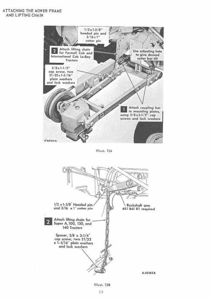
DETACHING THE MOWER
Lower the mower frame to the ground anddisconnect the lifting chain.
Lower the cutter bar to the ground and dis-connect the lifting cable.
With the lifting chain taut, remove the capscrews from the left, right, and rear sidemounting plates. Disconnect the power take-off.
CARE OF THE MOWER DURING STORAGE
STORING THE MACHINE Lubricate all points of the mower as shownin the lubrication guide, and run the unit forapproximately ten minutes to allow lubricantto give a protective coating to all bearings andmembers subject to rust and corrosion.
The life of the machine depends on how wellit is taken care of during the mowing seasonand while in storage between seasons. Thestoring period of the machine, which isusually about eight months of each year, is animportant factor in the life of the machine.
Apply a light coating of oil on all expo sedmetal wearing parts.
Make a list of any service parts needed andorder these early. This will give your dealerample time to provide the parts and give yousufficient time to install them before the nextmowing season.
Even though the machine is idle and notsubject to operational wear, it can, if notproperly stored, receive costly wear andserious damage by being exposed to theweather or by being struck by heavy objects.No machine should be allowed to stand outsideunprotected from the weather for a long periodof time any more than an automobile.
AFTER REMOVING THE MACHINE FROM STORAGE ANDBEFORE BEGINNING THE MOWING SEASON
Remove
the excess grease from the mower.
Make sure th~t all bolts and nuts are properly tightened.
This can save wasted time and needless expense.
A storage shed is a good investment be-cause of the savings effected by assuring alonger-lasting
machine, reducing the operatingcosts, and continuing the highly efficient mow-ing performance.
BEFORE STORING THE MACHINE
Lubricate the machine thoroughly in accord-ance with the instructions under "Lubrication"to make sure that all bearings have a protec-tive coating prior to field operation.
Clean the machine of all dirt, trash, andsuperfluous grease; if left on, it will holdmoisture and thus cause serious damage fromrust.
SETTING UP
Remove all wires and arrange the partsconveniently.
..Lubricate all bearings and moving parts as
you proceed, and see that they work freely.Illust.llA
Bolts must be used in the holes in whichthey are found, or in the parts to which theyare attached, unless otherwise shown.
The cap screws furnished with this mowerare identified by 3 radial lines on the head andare washer-faced to assure ma~mum surfacecontact. See !llust. l1A.
Whenever the terms "left" and "right" areused, it should be understood to mean from a
position behind and facing the machine.
When assembling this machine, start at thebeginning of the setting up instructions andfollow the sequence of steps for each assembly.
11

SIDE MOUNTING PLATES
Note: Side mounting plate cap screws must be tightened to 172 foot pounds torque.
Internatianal and Farmall Super A, Super A-l, 100, 130, and140 Tractors
International Cub Lo-Boy and Farmal! Cub Tractors
Illust. 12CLeft side mounting plates.
Illust. 12ALeft side mounting plates.
NOTE: If the mower is to be equipped withthe Knife Rack, assemble it on the sidemounting plate bolt at this time.
NOTE: If the mower is to be equipped withthe Knife Rack, assemble it on the sidemounting plate bolt at this time.
Illust. 126Right side mounting plotes.
NOTE: If the mower is to be equipped withthe Curb Lift. assemble it on the side mount-ing plate bolts at this time.
Illust. 12DRight side mounting plotes.
12


DRIVE SPROCKET AND CHAINS
International and Farmall Super A, Super A-l,100,130, and 140 Tractors.
International Cub Lo-Boy and Farmall Cub Tractors
Illust. 15A
Illust. 15C
Illust. 158
15

CABLE LIFT ARM BALANCED HEAD STOP
Illust. 16A
II lust. 16E
Internatianal Cub la-Boy Tractor.
1(lust. 16BInternatianal Cub La-Bay
and Farmall Cub Tractars.
Illust. 16FFarmall Cub and Internatianal and
Farmall Super A, Super A-I, 100, 130, and140 Tractars.
Illust. 16C
Internatianal Cub La-Bayand Farmall Cub Tractars.
Note: Hole s are provided in the lift arm toreposition the hammer strap when desired.
r Attach liftarm to rockshaft, using
1/2 x 2-1/2" and 3/4 x 2-1/2" capscrews, lock washers and nuts
~- -cable around
I...
---1-
lift arm pivot
Attach pulley with ~haftand 3/16x 1 "cotter pins
A-83375 -11/
Loole or "floppy" clothing should not be wornby the operator because of the danger of itwrapping on or getting into the moving parts.
Illust. 16DInternational and Farmall Super A,
Super A-l, 100, 130, and 140 Tractors.
16


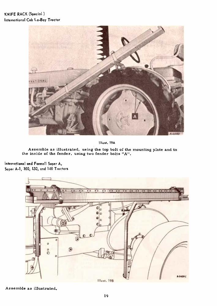
KNIFE RACK (Special)
Internationa I Cub Lo-Boy Tractor
Illust. 19A
Assemble as illustrated, using the top bolt of the mounting plate and tothe inside of the fender, using two fender bolts 'IA".
International and Farmall Super A,
Super A-I, '],00, 130, and 140 Tractors
Assemble as illustrated.
19

CURB LIFT ATTACHMENT (Special)
International Cub Lo-Boy and Farmall Cub Tractors
Illust. 208Illust.20A
Illust.20C
20

MEMBER, NATIONAL SAFETY COUNCIL
Accidents
withNo accident-prevention program can be suc-
cessful without the wholehearted co-operation
of the person who is directly responsible for the
operation of equipment.
To read accident reports from allover the
country is to be convinced that a large number
of accidents can be prevented only by the
operator anticipating the result before the
accident is caused and doing something about
it. No power-driven equip.aent, whether it be
transportation or processing, whether it be on
the highway, in the harvest field or in the
industrial plant, can be safer than the man who
is at the controls. If accidents are to be pre-
vented-and they can be prevented-it will be
done by the operators who accept a full measure
of their responsibility.
It is true that the designer, the manufacturer,
the safety engineer can help; and they will help,
but their combined efforts can be wiped out by
a single careless act of the operator.
It is said that' 'the best kind of a safetydevice is a careful operator. II We ask you
to be that kind of an operator.
Price $1.00


