
Linear Motion andAssembly Technologies ServicePneumaticsHydraulics
Electric Drives and Controls
Series 10, 11 and 30Size 40...1000Nominal pressure 5100 psi (350 bar)Peak pressure 5800 psi (400 bar)Open circuit
Features– Axial piston pump in swash plate design for hydrostatic
drives in open circuit operation
– The fl ow is proportional to the input drive speed and dis-placement. By adjusting the swash plate angle it is possible to infi nitely vary the output fl ow.
– Excellent suction characteristics
– Low noise level
– Long service life
– Modular design
– Short response times
– Wide range of through drive options
– Visual swivel angle indicator
– Optional mounting position
– Operation on HF-fl uids under reduced operational data possible
A special version is available for operation with HFC-fl uid see data sheet RA 92053
RA 92050-A/06.09 1/64Replaces: 09.97 Axial piston variable pump
(A)A4VSO
Data sheet
ContentsType code for standard program 2
Technical data 5
Characteristics 10
Summary of controls 13
Dimensions, size 40 18
Dimensions, size 71 20
Dimensions, size 125 22
Dimensions, size 180 24
Dimensions, size 250 26
Dimensions, size 355 28
Dimensions, size 500 30
Dimensions, size 750 32
Dimensions, size 1000 36
Through drive 38
Summary mounting options on (A)A4VSO 39
Permissible mass bending moment 40
Dimensions combination pumps 41
Dimensions through drive 43
Installation notes 63
General information 64
For the descriptions of the control devices see the separate RA (RE) data sheetsRE 92056, RA 92060, RA 92064,RE 92072, RA 92076, RA 92080, RE 92088
AA4VSO for HFC fluids RA 92050-A/06.092/64 Bosch Rexroth Corp.
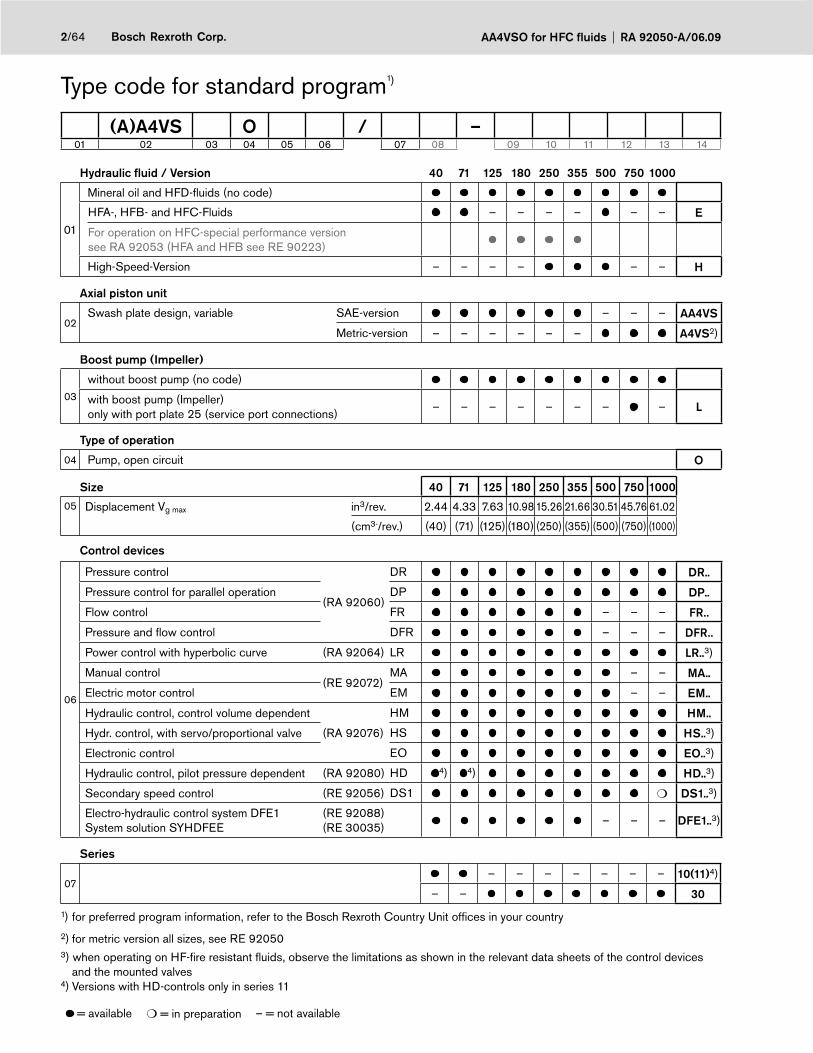
Type code for standard program1)
(A)A4VS O / –01 02 03 04 05 06 07 08 09 10 11 12 13 14
Hydraulic fl uid / Version 40 71 125 180 250 355 500 750 1000
01
Mineral oil and HFD-fl uids (no code)
HFA-, HFB- and HFC-Fluids – – – – – – E
For operation on HFC-special performance versionsee RA 92053 (HFA and HFB see RE 90223)
High-Speed-Version – – – – – – H
Axial piston unit
02Swash plate design, variable SAE-version – – – AA4VS
Metric-version – – – – – – A4VS2)
Boost pump (Impeller)
03
without boost pump (no code)
with boost pump (Impeller) only with port plate 25 (service port connections)
– – – – – – – – L
Type of operation
04 Pump, open circuit O
Size 40 71 125 180 250 355 500 750 1000
05 Displacement Vg max in3/rev. 2.44 4.33 7.63 10.98 15.26 21.66 30.51 45.76 61.02
(cm3-/rev.) (40) (71) (125) (180) (250) (355) (500) (750) (1000)
Control devices
06
Pressure control
(RA 92060)
DR DR..
Pressure control for parallel operation DP DP..
Flow control FR – – – FR..
Pressure and fl ow control DFR – – – DFR..
Power control with hyperbolic curve (RA 92064) LR LR..3)
Manual control(RE 92072)
MA – – MA..
Electric motor control EM – – EM..
Hydraulic control, control volume dependent
(RA 92076)
HM HM..
Hydr. control, with servo/proportional valve HS HS..3)
Electronic control EO EO..3)
Hydraulic control, pilot pressure dependent (RA 92080) HD 4) 4) HD..3)
Secondary speed control (RE 92056) DS1 ❍ DS1..3)
Electro-hydraulic control system DFE1System solution SYHDFEE
(RE 92088)(RE 30035)
– – – DFE1..3)
Series
07– – – – – – – 10(11)4)
– – 30
1) for preferred program information, refer to the Bosch Rexroth Country Unit offi ces in your country
2) for metric version all sizes, see RE 920503) when operating on HF-fi re resistant fl uids, observe the limitations as shown in the relevant data sheets of the control devices
and the mounted valves4) Versions with HD-controls only in series 11
= available ❍ = in preparation – = not available

3/64Bosch Rexroth Corp.RA 92050-A/06.09 AA4VSO for HFC fluids
Type code for standard program1)
(A)A4VS O / –01 02 03 04 05 06 07 08 09 10 11 12 13 14
Direction of rotation
08with view on shaft end clockwise R
counter-clockwise L
Seals 40 71 125 180 250 355 500 750 1000
09
NBR (Nitrile-rubber), Shaft seal FKM (Fluoro-rubber) P
FKM (Fluoro-rubber) / for operation on HFD V
HFC-special performance version see RA 92053 – – – – – F
Shaft end
10
SAE parallel keyed shaft to ISO 3019-1 – – – K
SAE splined shaft to ISO 3019-1 – – – – S
SAE splined shaft similar to ISO 3019-1 – – – – – – – – R
Metric keyed parallel shaft to DIN 6885 – – – – – – P
Metric splined shaft to DIN 5480 – – – – – – Z
Mounting fl ange 40 71 125 180 250 355 500 750 1000
11to ISO 3019-1 (SAE J 744) 4-bolt – – – D
similar to ISO 3019-2 metric 8-bolt – – – – – – H
Service line connections
12
Port B and S: SAE fl ange on side, 90° offset, UNC mounting bolts
– – – 63 2)
Port B and S: SAE fl ange on side, 90° offset, 2nd pressure port B1, opposite to B – closed with blanking plate on delivery
UNC mounting bolts – – – 75
metric mounting bolts – – – – – – 25
1) for preferred program information, refer to the Bosch Rexroth Country Unit offi ces in your country2) only with through drive code N00 and K..
= available – = not available
continuation of type code see page 4
AA4VSO for HFC fluids RA 92050-A/06.094/64 Bosch Rexroth Corp.
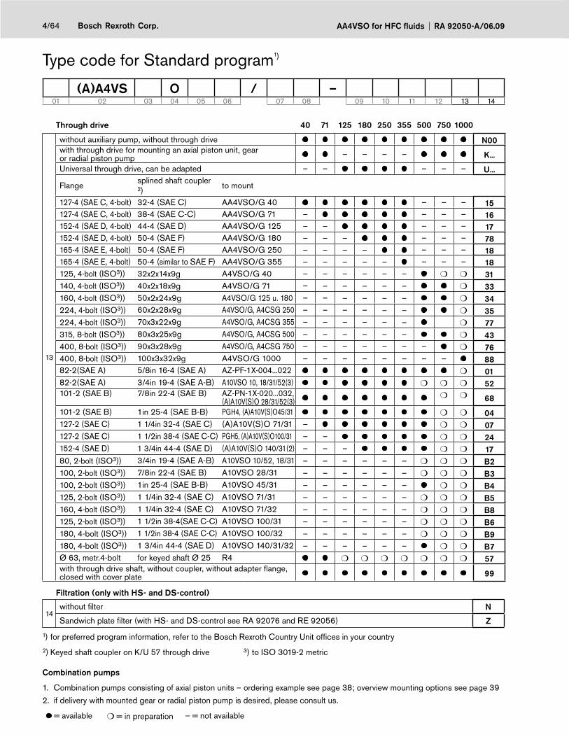
Type code for Standard program1)
(A)A4VS O / –01 02 03 04 05 06 07 08 09 10 11 12 13 14
Through drive 40 71 125 180 250 355 500 750 1000
13
without auxiliary pump, without through drive N00with through drive for mounting an axial piston unit, gear or radial piston pump – – – – K...
Universal through drive, can be adapted – – – – – U...
Flange splined shaft coupler 2)
to mount
127-4 (SAE C, 4-bolt) 32-4 (SAE C) AA4VSO/G 40 – – – 15127-4 (SAE C, 4-bolt) 38-4 (SAE C-C) AA4VSO/G 71 – – – – 16152-4 (SAE D, 4-bolt) 44-4 (SAE D) AA4VSO/G 125 – – – – – 17152-4 (SAE D, 4-bolt) 50-4 (SAE F) AA4VSO/G 180 – – – – – – 78165-4 (SAE E, 4-bolt) 50-4 (SAE F) AA4VSO/G 250 – – – – – – – 18165-4 (SAE E, 4-bolt) 50-4 (similar to SAE F) AA4VSO/G 355 – – – – – – – – 18125, 4-bolt (ISO3)) 32x2x14x9g A4VSO/G 40 – – – – – – ❍ ❍ 31140, 4-bolt (ISO3)) 40x2x18x9g A4VSO/G 71 – – – – – – ❍ 33160, 4-bolt (ISO3)) 50x2x24x9g A4VSO/G 125 u. 180 – – – – – – ❍ 34224, 4-bolt (ISO3)) 60x2x28x9g A4VSO/G, A4CSG 250 – – – – – – ❍ 35224, 4-bolt (ISO3)) 70x3x22x9g A4VSO/G, A4CSG 355 – – – – – – ❍ 77315, 8-bolt (ISO3)) 80x3x25x9g A4VSO/G, A4CSG 500 – – – – – – ❍ 43400, 8-bolt (ISO3)) 90x3x28x9g A4VSO/G, A4CSG 750 – – – – – – – ❍ 76400, 8-bolt (ISO3)) 100x3x32x9g A4VSO/G 1000 – – – – – – – – 8882-2(SAE A) 5/8in 16-4 (SAE A) AZ-PF-1X-004...022 ❍ 0182-2(SAE A) 3/4in 19-4 (SAE A-B) A10VSO 10, 18/31/52(3) ❍ ❍ ❍ 52101-2 (SAE B) 7/8in 22-4 (SAE B) AZ-PN-1X-020...032,
(A)A10V(S)O 28/31/52(3)❍ ❍ 68
101-2 (SAE B) 1in 25-4 (SAE B-B) PGH4, (A)A10V(S)O45/31 ❍ ❍ 04127-2 (SAE C) 1 1/4in 32-4 (SAE C) (A)A10V(S)O 71/31 – ❍ ❍ 07127-2 (SAE C) 1 1/2in 38-4 (SAE C-C) PGH5, (A)A10V(S)O100/31 – – ❍ ❍ 24152-4 (SAE D) 1 3/4in 44-4 (SAE D) (A)A10V(S)O 140/31(2) – – – ❍ ❍ 1780, 2-bolt (ISO3)) 3/4in 19-4 (SAE A-B) A10VSO 10/52, 18/31 – – – – – – ❍ ❍ ❍ B2100, 2-bolt (ISO3)) 7/8in 22-4 (SAE B) A10VSO 28/31 – – – – – – ❍ ❍ ❍ B3100, 2-bolt (ISO3)) 1in 25-4 (SAE B-B) A10VSO 45/31 – – – – – – ❍ ❍ B4125, 2-bolt (ISO3)) 1 1/4in 32-4 (SAE C) A10VSO 71/31 – – – – – – ❍ ❍ ❍ B5160, 4-bolt (ISO3)) 1 1/4in 32-4 (SAE C) A10VSO 71/32 – – – – – – ❍ ❍ ❍ B8125, 2-bolt (ISO3)) 1 1/2in 38-4(SAE C-C) A10VSO 100/31 – – – – – – ❍ ❍ ❍ B6180, 4-bolt (ISO3)) 1 1/2in 38-4 (SAE C-C) A10VSO 100/32 – – – – – – ❍ ❍ ❍ B9180, 4-bolt (ISO3)) 1 3/4in 44-4 (SAE D) A10VSO 140/31/32 – – – – – – ❍ ❍ B7Ø 63, metr.4-bolt for keyed shaft Ø 25 R4 ❍ ❍ ❍ ❍ ❍ ❍ ❍ 57with through drive shaft, without coupler, without adapter fl ange, closed with cover plate 99
Filtration (only with HS- and DS-control)
14without fi lter N
Sandwich plate fi lter (with HS- and DS-control see RA 92076 and RE 92056) Z
1) for preferred program information, refer to the Bosch Rexroth Country Unit offi ces in your country
2) Keyed shaft coupler on K/U 57 through drive 3) to ISO 3019-2 metric
Combination pumps
1. Combination pumps consisting of axial piston units – ordering example see page 38; overview mounting options see page 39
2. if delivery with mounted gear or radial piston pump is desired, please consult us.
= available ❍ = in preparation – = not available
5/64Bosch Rexroth Corp.RA 92050-A/06.09 AA4VSO for HFC fluids
Technical data
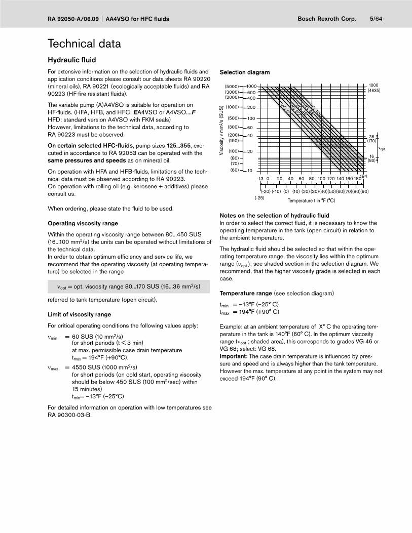
Selection diagram
Visc
osity
v m
m2 /
s (S
US
)
16(80)
36(170)
1000 (4635)
vopt.
VG 22
VG 32
VG 46
VG 68
Temperature t in °F (°C)
VG 100
(-20) (-10) (0) (10) (20) (30)(40)(50)(60)(70)(80)(90)
100 120 1400 20 40 60 80 160 180
1000600400
200
100
60
40
20
10
(5000)(3000)(2000)
(1000)
(500)
(300)
(150)(200)
(100)
(80)(70)(60)
(-25)
-13 194
Notes on the selection of hydraulic fl uidIn order to select the correct fl uid, it is necessary to know the operating temperature in the tank (open circuit) in relation to the ambient temperature.
The hydraulic fl uid should be selected so that within the ope-rating temperature range, the viscosity lies within the optimum range (νopt ); see shaded section in the selection diagram. We recommend, that the higher viscosity grade is selected in each case.
Temperature range (see selection diagram)
tmin = –13°F (–25° C)tmax = 194°F (+90° C)
Example: at an ambient temperature of X° C the operating tem-perature in the tank is 140°F (60° C). In the optimum viscosity range (νopt ; shaded area), this corresponds to grades VG 46 or VG 68; select: VG 68.Important: The case drain temperature is infl uenced by pres-sure and speed and is always higher than the tank temperature. However the max. temperature at any point in the system may not exceed 194°F (90° C).
Hydraulic fl uidFor extensive information on the selection of hydraulic fl uids and application conditions please consult our data sheets RA 90220 (mineral oils), RA 90221 (ecologically acceptable fl uids) and RA 90223 (HF-fi re resistant fl uids).
The variable pump (A)A4VSO is suitable for operation on HF-fl uids. (HFA, HFB, and HFC: EA4VSO or A4VSO....F HFD: standard version A4VSO with FKM seals)However, limitations to the technical data, according to RA 90223 must be observed.
On certain selected HFC-fl uids, pump sizes 125...355, exe-cuted in accordance to RA 92053 can be operated with the same pressures and speeds as on mineral oil.
On operation with HFA and HFB-fl uids, limitations of the tech-nical data must be observed according to RA 90223.On operation with rolling oil (e.g. kerosene + additives) please consult us.
When ordering, please state the fl uid to be used.
Operating viscosity range
Within the operating viscosity range between 80...450 SUS (16...100 mm2/s) the units can be operated without limitations of the technical data. In order to obtain optimum effi ciency and service life, we recommend that the operating viscosity (at operating tempera-ture) be selected in the range
νopt = opt. viscosity range 80...170 SUS (16...36 mm2/s)
referred to tank temperature (open circuit).
Limit of viscosity range
For critical operating conditions the following values apply:
νmin = 60 SUS (10 mm2/s) for short periods (t < 3 min) at max. permissible case drain temperature tmax = 194°F (+90°C).
νmax = 4550 SUS (1000 mm2/s) for short periods (on cold start, operating viscosity should be below 450 SUS (100 mm2/sec) within 15 minutes) tmin= –13°F (–25°C)
For detailed information on operation with low temperatures see RA 90300-03-B.
AA4VSO for HFC fluids RA 92050-A/06.096/64 Bosch Rexroth Corp.
Technical dataBearing fl ushingFor the following operating conditions bearing fl ushing is required for a safe, continuous operation:
– Applications with special fl uids (non mineral oils) due to limited lubricity and narrow operating temperature range
– Operation at critical conditions of temperature and viscosity with mineral oil
Flushing is recommended with vertical mounting (drive shaft facing upwards) in order to ensure lubrication of the front bearing and shaft seal.
Flushing is carried out via port „U“, located in the front fl ange area of the pump. The fl ushing fl uid fl ows through the front be-aring and leaves the pump together with the case drain fl ow.
Depending on pump size, the following fl ushing fl ows are recommended:
Size 40 71 125 180 250
recommended fl ushing fl ow
qSpgpm(L/min)
0.8(3)
1.0(4)
1.3(5)
1.8(7)
2.6(10)
Size 355 500 750 1000
recommended fl ushing fl ow
qSpgpm(L/min)
4.0(15)
5.3(20)
7.9(30)
10.6(40)
These recommended fl ushing fl ows will cause a pressure drop of approx. 30 psi (2 bar) (series 1) and 45 psi (3 bar) (series 3) between the entrance to port„U“ and the pump case (including the pipe fi ttings).
Notes regarding series 30
When using external bearing fl ushing the throttle screw at port U must be turned in to the end stop.
Filtration of the fl uid (Axial piston unit)
The fi ner the fi ltration, the better the achieved cleanliness of the fl uid and the longer the life of the axial piston pump.
To ensure a reliable functioning of the axial piston unit, a mini-mum cleanliness class of
20/18/15 acc. to ISO 4406 is necessary.
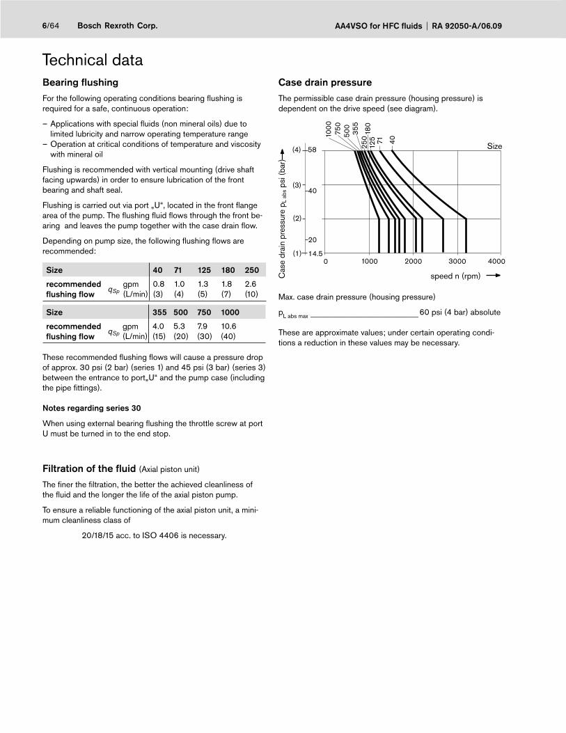
Case drain pressureThe permissible case drain pressure (housing pressure) is dependent on the drive speed (see diagram).
40003000200010000
180
125 71 40
500
750
250
355
1000
40
20
14.5
58
(2)
(1)
(3)
(4)
speed n (rpm)
Size
Cas
e dr
ain
pres
sure
pL
abs p
si (b
ar)
Max. case drain pressure (housing pressure)
pL abs max _____________________________________ 60 psi (4 bar) absolute
These are approximate values; under certain operating condi-tions a reduction in these values may be necessary.

7/64Bosch Rexroth Corp.RA 92050-A/06.09 AA4VSO for HFC fluids
Technical dataOperating pressure range
Pressure at service line port (pressure port) B
Nominal pressure pnom ________ 5100 psi (350 bar) absolute
Peak pressure pmax ___________ 5800 psi (400 bar) absoluteTotal operating period _____________________________ 300 hSingle operating period _____________________________ 1 s
Minimum pressure (high-pressure side) ___ 215 psi (15 bar)For lower pressures please consult us.
Rate of pressure change RA ___ 232000 psi/s (16000 bar/s)
pnom
Δt
Δp
Time t
Pre
ssur
e p
Pressure at suction port S (inlet)Minimum suction pressure pS min ______12 psi (0,8 bar) absoluteMaximum suction pressure pS max ____ 435 psi (30 bar) absolute
Minimum pressure (inlet)In order to avoid damage to the axial piston unit, a minimum pressure must be ensured at the suction port S (inlet). The mi-nimum pressure is dependent on the speed and displacement of the axial piston unit.
1.251.2
1.1
1.0
0.9
23 (1.6)20 (1.4)17.5 (1.2)14.5 (1.0)
12 (0.8)
0.5 0.6 0.7 0.8 0.9 1.0
psi (bar)
Inle
t pre
ssur
e p a
bs
Spe
edn n o
max
DisplacementVg
Vg max
The inlet pressure is the static feed pressure or the minimumdynamic value of the boost pressure.
Please note:Max. permissible drive speed no max. perm. (speed limit) see page 8
Please contact us if these conditions cannot be satisfied.
Definition
Nominal pressure pnom
The nominal pressure corresponds to the maximum design pressure.
Peak pressure pmax
The peak pressure corresponds the maximum operating pres-sure within the single operating period. The sum of the single operating periods must not exceed the total operating period.
Minimum pressure (high-pressure side)Minimum pressure on the high-pressure side (B) that is requi-red in order to prevent damage to the axial piston unit.
Rate of pressure change RA
Maximum permissible rate of pressure build-up and pressure reduction during a pressure change over the entire pressure range.
Pre
ssur
e p t1
t2 tnSingle operating period
Minimum pressure (high-pressure side)
Peak pressure pmaxNominal pressure pnom
Time t
Total operating period = t1 + t2 + ... + tn

AA4VSO for HFC fluids RA 92050-A/06.098/64 Bosch Rexroth Corp.
Technical dataTable of values (theoretical values, without considering effi ciencies and tolerances; values rounded off)
Size 40 71 125 180 250/ H 1)
355/H 1)
500/H 1)
750 750 with boost pump
1000
Displacement Vg max in3
(cm3)2.44(40)
4.33(71)
7.63(125)
11.0(180)
15.26(250)
21.7(355)
30.51(500)
45.8(750)
45.8(750)
61.02(1000)
Speed 2)max. at Vg max no max rpm 2600 2200 1800 1800 1500/
19001500/1700
1320/1500
1200 1500 1000
max. at Vg ≤ Vg max
(speed limit)no max perm. rpm 3200 2700 2200 2100 1800/
21001700/1900
1600/1800
1500 1500 1200
Flowat no max qvo max gpm 27.5 41.2 59.4 85.6 99/
125140/159
174/198
237.9 297.2 264.1
(L/min) (104) (156) (225) (324) (375/475)
(533/604)
(660/750)
(900) (1125) (1000)
Power Δp = 5100 psi (350 bar)at no max Po max HP 81 122 176 254 294/
372417/473
518/587
708 885 781
(kW) (61) (91) (131) (189) (219/277)
(311/352)
(385/437)
(525) (656) (583)
Torqueat Vg max Δp = 5100 psi (350 bar) Tmax lb-ft
(Nm)165(223)
292(395)
516(696)
744(1002)
1032(1391)
1467(1976)
2063(2783)
3097(4174)
3097(4174)
4104(5565)
Δp = 1450 psi (100 bar) T lb-ft(Nm)
47(64)
83(113)
147(199)
211(286)
294(398)
417(564)
586(795)
880(1193)
880(1193)
1172(1590)
Rotary stiffnessShaft end K
c klb-ft/rad(kNm/rad)
57(79)
106(146)
175(241)
235(323)
322(443)
592(814)
– – – –
Shaft end S c klb-ft/rad(kNm/rad)
49(67)
92(126)
141(194)
202(278)
267(368)
– – – – –
Shaft end R
c klb-ft/rad(kNm/rad)
– – – – – 345(475)
– – – –
Shaft end P
c klb-ft/rad(kNm/rad)
– – – – – – 832(1145)
1352(1860)
1352(1860)
1985(2730)
Shaft end Z
c klb-ft/rad(kNm/rad)
– – – – – – 826(1136)
1317(1812)
1317(1812)
2068(2845)
Moment of inertiarotary group
JTW lb-ft2
(kgm2)0.116(0.0049)
0.287(0.0121)
0.712(0.03)
1.305(0.055)
2.276(0.0959)
4.509(0.19)
7.809(0.3325)
15.66(0.66)
15.66(0.66)
28.47(1.20)
Angular acceleration max.4) α rad/s2 17000 11000 8000 6800 4800 3600 2800 2000 2000 1450Case volume V gal (L) 0.5(2) 0.6(2.5) 1.3(5) 1.0(4) 2.6(10) 2.1(8) 3.7(14) 5.0(19) 5.8(22) 7.13(27)Weight (with pressure control) approx.
m lbs (kg)
86(39)
117(53)
194(88)
225(102)
406(184)
456(207)
705(320)
1014(460)
1080(490)
1333(605)
1) High-Speed-Version2) Values are valid with inlet pressure pabs 14.5 psi (1 bar) at inlet port S, with increased speed up to speed limit please observe diagram, page 73) Vg < Vg max
4) – The range of validity lies between zero and the maximum permissible drive speeds. Valid for external excitation (eg. diesel engine 2- to 8-fold rotary frequency, cardan shaft 2-fold rotary frequency). – The limiting value is only valid for a single pump. – The loading capacity of the connecting parts must be considered.
NotesExceeding the maximum or falling below the minimum permissible values can lead to a loss of function, a reduction in operational service life or total destruction of the axial piston unit.The permissible values can be determined through calculation.

9/64Bosch Rexroth Corp.RA 92050-A/06.09 AA4VSO for HFC fluids
Technical dataPermissible radial and axial forces on the drive shaft
Size 40 71 125 180 250 355 500 750* 1000
Radial force, max. Fq
X
X/2 X/2
at X/2 Fq maxlb(N)
225(1000)
270(1200)
360(1600)
450(2000)
450(2000)
495(2200)
560(2500)
675(3000)
786(3500)
Axial force, max.
± Fax ± Fax maxlb(N)
135(600)
180(800)
225(1000)
315(1400)
405(1800)
450(2000)
450(2000)
495(2200)
495(2200)
* also valid for versions with boost pump
Determination of pump size
Flow qV =Vg • n • ηV
[gpm] ( Vg • n • ηV[L/min])231 1000
Drive torque T =Vg • Δp
[lb-ft] (Vg • Δp
[Nm] )24 • π • ηmh
20 • π • ηmh
Power P =qV • Δp
[HP] ( qV • Δp[kW] )1714 • ηt 600 • ηt
Vg = geometr. displacement per rev. in in3 (cm3)
Δp = pressure difference in psi (bar)
n = speed in rpm
ηV = volumetric effi ciency
ηmh = mechanical-hydraulic effi ciency
ηt = overall effi ciency (ηt = ηV • ηmh)
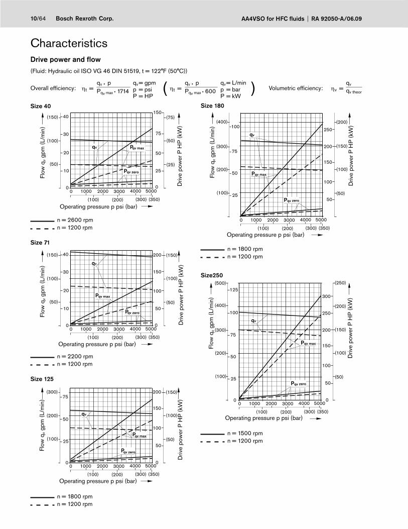
AA4VSO for HFC fluids RA 92050-A/06.0910/64 Bosch Rexroth Corp.
Characteristics
Size 180
n = 1800 rpmn = 1200 rpm
Size250
0 0
Pqv max
Pqv zero
qv
0 1000 2000 3000 4000 5000
(100) (200) (300) (350)
5025
50
100
(100)
(50)
(200)
(100)
(200)
(400)
200
250
150
100
75(150)(300)
(250)
300125
(500)
Flow
qv g
pm (
L/m
in)
Operating pressure p psi (bar)
Driv
e po
wer
P H
P (
kW)
n = 1500 rpmn = 1200 rpm
Drive power and fl ow(Fluid: Hydraulic oil ISO VG 46 DIN 51519, t = 122°F (50°C))
Overall effi ciency: ηt =qv • p qv
pP
= gpm= psi= HP
( ηt =qv • p qv
pP
= L/min= bar= kW
) Volumetric effi ciency: ηv =qv
Pqv max • 1714 Pqv max • 600 qv theor
Pqv max
Pqv zero
qv
0 1000 2000 3000 4000 5000
(100) (200) (300) (350)
5025
50
100
(100)
(50)
(200)
(100)
(200)
(400)
200
250
150
100
75(150)(300)
Flow
qv g
pm (
L/m
in)
Operating pressure p psi (bar)
Driv
e po
wer
P H
P (
kW)
Size 40
0 1000 2000 3000 4000 5000
(100) (200) (300) (350)
25
20
10
0 0
30
40
(50)
(25)
(75)
(50)
(100)
(150)150
75
50
Pqv zero
Pqv maxqv
Flow
qv g
pm (
L/m
in)
Operating pressure p psi (bar)
Driv
e po
wer
P H
P (
kW)
n = 2600 rpmn = 1200 rpm
Size 71
0 0
qv
Pqv max
Pqv zero
0 1000 2000 3000 4000 5000
(100) (200) (300) (350)
50
20
10
30
40
(100)
(50)
(150)
(50)
(100)
(150) 200
150
100
Flow
qv g
pm (
L/m
in)
Operating pressure p psi (bar)
Driv
e po
wer
P H
P (
kW)
n = 2200 rpmn = 1200 rpm
Size 125
0 0
qv
Pqv max
Pqv zero
0 1000 2000 3000 4000 5000
(100) (200) (300) (350)
5025
50
75
(100)
(50)
(150)
(100)
(200)
(300) 200
150
100
Flow
qv g
pm (
L/m
in)
Operating pressure p psi (bar)
Driv
e po
wer
P H
P (
kW)
n = 1800 rpmn = 1200 rpm
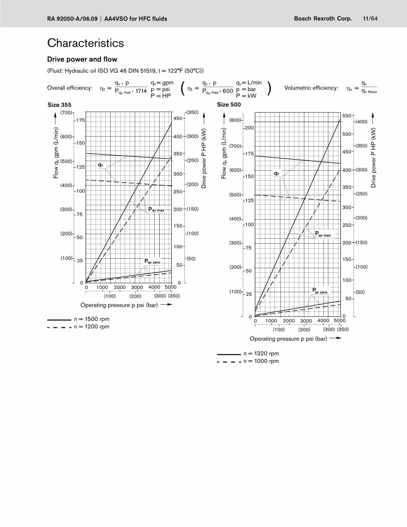
11/64Bosch Rexroth Corp.RA 92050-A/06.09 AA4VSO for HFC fluids
Characteristics
Size 355
0 0
Pqv zero
P
qv
qv max
0 1000 2000 3000 4000 5000
(100) (200) (300) (350)
5025
50
100
(100)
(50)
(200)
(100)
(200)
(400)
200
250
150
100
75(150)(300)
(250)
300125
(500)
(300)
350
150(600)
(350)
400
450175
(700)
n = 1500 rpmn = 1200 rpm
Size 500
0 0
Pqv zero
Pqv max
qv
0 1000 2000 3000 4000 5000
(100) (200) (300) (350)
5025
50
100
(100)
(50)
(200)
(100)
(200)
(400)
200
250
150
100
75(150)(300)
(250)
300125
(500)
(300)
350
150(600)
(350)
400
450175
(700)
(400)
500200
(800)550
n = 1320 rpmn = 1000 rpm
Flow
qv g
pm (
L/m
in)
Driv
e po
wer
P H
P (
kW)
Operating pressure p psi (bar)
Flow
qv g
pm (
L/m
in)
Operating pressure p psi (bar)
Driv
e po
wer
P H
P (
kW)
Drive power and fl ow(Fluid: Hydraulic oil ISO VG 46 DIN 51519, t = 122°F (50°C))
Overall effi ciency: ηt =qv • p qv
pP
= gpm= psi= HP
( ηt =qv • p qv
pP
= L/min= bar= kW
) Volumetric effi ciency: ηv =qv
Pqv max • 1714 Pqv max • 600 qv theor
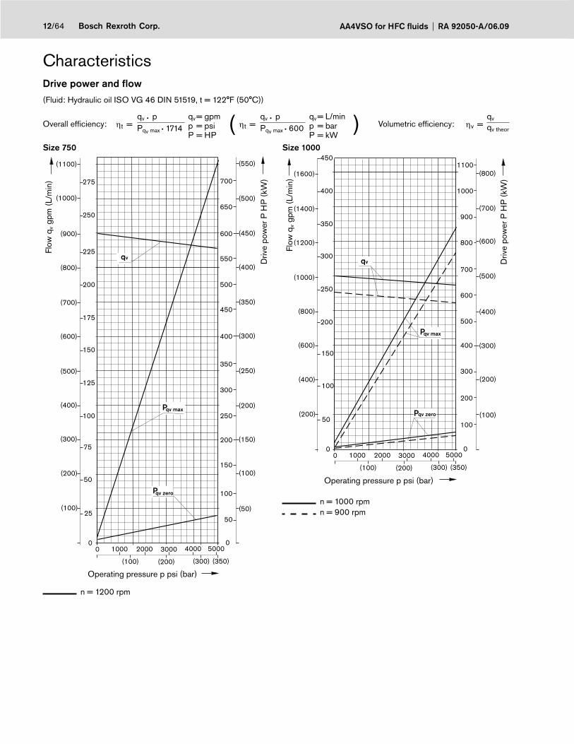
AA4VSO for HFC fluids RA 92050-A/06.0912/64 Bosch Rexroth Corp.
Characteristics
Size 750
0 0
Pqv zero
qv
Pqv max
0 1000 2000 3000 4000 5000
(100) (200) (300) (350)
5025
50
100
(100)
(50)
(200)
(100)
(200)
(400)
200
250
150
100
75(150)(300)
(250)
300125
(500)
(300)
350
150
(600)
(350)
400
450175
(700)
(400)
500200
(800)
225
(900)
250
(1000)
275
(1100)
550
(450)
(500)
600
650
(550)
700
n = 1200 rpm
Size 1000
Pqv zero
Pqv max
qv
0 00 1000 2000 3000 4000 5000
(100) (200) (300) (350)
100
200
50
100
200
(200)
(100)
(400)
(200)
(400)
(800)
150(300)(600)
(500)
250
(1000)
(600)
300
(1200)
(700)
350
(1400)
(800)
400
(1600)
450
300
400
500
600
800
700
900
1000
1100
n = 1000 rpmn = 900 rpm
Flow
qv g
pm (
L/m
in)
Driv
e po
wer
P H
P (
kW)
Operating pressure p psi (bar)
Flow
qv g
pm (
L/m
in)
Operating pressure p psi (bar)
Driv
e po
wer
P H
P (
kW)
Drive power and fl ow(Fluid: Hydraulic oil ISO VG 46 DIN 51519, t = 122°F (50°C))
Overall effi ciency: ηt =qv • p qv
pP
= gpm= psi= HP
( ηt =qv • p qv
pP
= L/min= bar= kW
) Volumetric effi ciency: ηv =qv
Pqv max • 1714 Pqv max • 600 qv theor
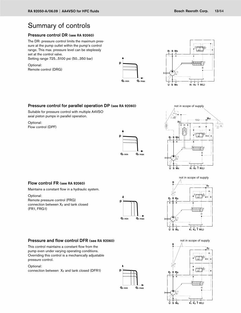
13/64Bosch Rexroth Corp.RA 92050-A/06.09 AA4VSO for HFC fluids
Pressure control DR (see RA 92060)
R(L)TU S MS K1 K2
MBBB1
The DR- pressure control limits the maximum pres-sure at the pump outlet within the pump‘s control range. This max. pressure level can be steplessly set at the control valve.Setting range 725...5100 psi (50...350 bar)
Optional: Remote control (DRG)
qv min qv max
p
Pressure control for parallel operation DP (see RA 92060)
Mst
R(L)TU S MS K1 K2
BB1 MB
XD
Suitable for pressure control with multiple A4VSO axial piston pumps in parallel operation.
Optional: Flow control (DPF)
p
qv min qv max
Flow control FR (see RA 92060)
R(L)TU S MS K1 K2
BB1 MB
XF
B
Maintains a constant fl ow in a hydraulic system.
Optional: Remote pressure control (FRG)connection between XF and tank closed (FR1, FRG1)
p
qv min qv max
Pressure and fl ow control DFR (see RA 92060)
R(L)TU S MS K1 K2
BB1 MB
XF
BThis control maintains a constant fl ow from the pump even under varying operating conditions. Overriding this control is a mechanically adjustable pressure control.
Optional: connection between XF and tank closed (DFR1) p
qv min qv max
not in scope of supply
not in scope of supply
not in scope of supply
Summary of controls
AA4VSO for HFC fluids RA 92050-A/06.0914/64 Bosch Rexroth Corp.
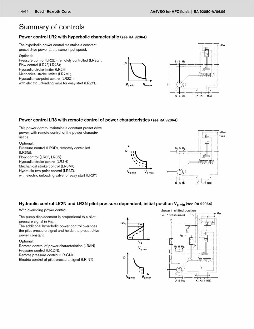
Summary of controlsPower control LR2 with hyperbolic characteristic (see RA 92064)
The hyperbolic power control maintains a constant preset drive power at the same input speed.
Optional: Pressure control (LR2D), remotely controlled (LR2G);Flow control (LR2F, LR2S);Hydraulic stroke limiter (LR2H);Mechanical stroke limiter (LR2M); Hydraulic two-point control (LR2Z);with electric unloading valve for easy start (LR2Y). Vg min Vg max
p
R(L)TU S MS K1 K2
MBBB1
RKV
Power control LR3 with remote control of power characteristics (see RA 92064)
This power control maintains a constant preset drive power, with remote control of the power characte-ristics.
Optional: Pressure control (LR3D), remotely controlled (LR3G);Flow control (LR3F, LR3S);Hydraulic stroke control (LR3H);Mechanical stroke control (LR3M);Hydraulic two-point control (LR3Z).with electric unloading valve for easy start (LR3Y)
Vg min Vg max
p
R(L)TU S MS K1 K2
MBBB1
RKV
XLR
Hydraulic control LR2N and LR3N pilot pressure dependent, initial position Vg min (see RA 92064)
With overriding power control.
The pump displacement is proportional to a pilot pressure signal in PSt. The additional hyperbolic power control overrides the pilot pressure signal and holds the preset drive power constant.
pSt
Vg min Vg max
Vg
Vg max
p
MBBB1
1
R(L)TU S MS K1 K2
PSt
MSt
P
shown in shifted position i.e. P pressurized
Optional: Remote control of power characteristics (LR3N) Pressure control (LR.DN), Remote pressure control (LR.GN)Electric control of pilot pressure signal (LR.NT)
15/64Bosch Rexroth Corp.RA 92050-A/06.09 AA4VSO for HFC fluids
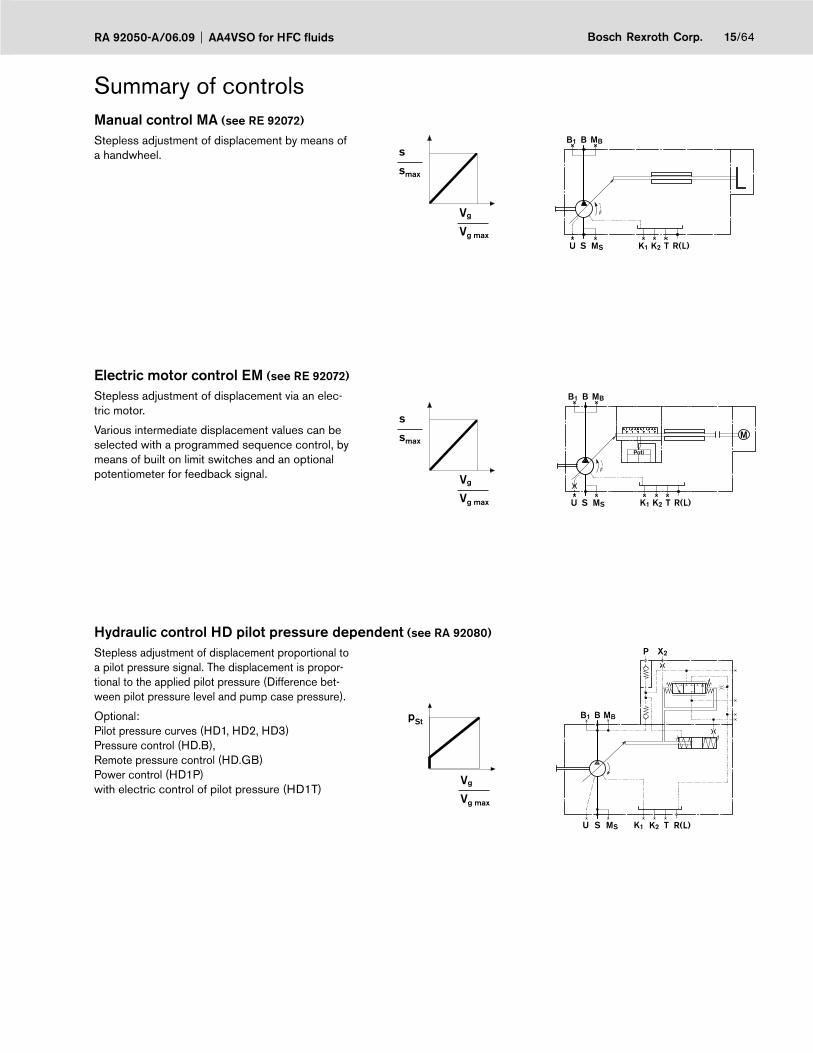
Summary of controlsManual control MA (see RE 92072) Stepless adjustment of displacement by means of a handwheel.
Vg
Vg max
s
smax
R(L)TU S MS K1 K2
B MBB1
Electric motor control EM (see RE 92072)
Stepless adjustment of displacement via an elec-tric motor.
Vg
Vg max
s
smaxPoti
R(L)TU S MS K1 K2
B MBB1
MVarious intermediate displacement values can be selected with a programmed sequence control, by means of built on limit switches and an optional potentiometer for feedback signal.
Hydraulic control HD pilot pressure dependent (see RA 92080)
Stepless adjustment of displacement proportional to a pilot pressure signal. The displacement is propor-tional to the applied pilot pressure (Difference bet-ween pilot pressure level and pump case pressure).
Vg
Vg max
pSt
P
U R(L)TK1 K2MSS
BB1 MB
X2
Optional: Pilot pressure curves (HD1, HD2, HD3)Pressure control (HD.B), Remote pressure control (HD.GB)Power control (HD1P)with electric control of pilot pressure (HD1T)

AA4VSO for HFC fluids RA 92050-A/06.0916/64 Bosch Rexroth Corp.
Summary of controlsHydraulic control HM 1/2, control volume dependent (see RA 92076)
The pump displacement is infi nitely variable in rela-tion to the control oil volume in ports X1 and X2. B1 MBB
X1X2
K1 K2 R(L)TMSU S
Application: – 2-point control– basic control device for servo or proportional valve control
Control system HS, HS4, with servo or proportional valve (see RA 92076)
The stepless displacement control is accomplis-hed by by means of servo or proportional valve with electrical feedback of the swivel angle.The HS4P-control system is fi tted with a built on pressure transducer so that it can be utilized for electrical pressure and power control.
Vg
Vg max
U
Umax
; pHD
U
BB1 MB
R(L)TK2K1MSS
SP
PRKV
S
U
Optional: Servo valve (HS); Proportional valve (HS4); Short circuit valve (HSK, HS4K, HS4KP); Without valves (HSE, HS4E). For oil-immersed use (HS4M)
Control system EO1/2 (see RA 92076) The stepless adjustment of the displacement is accomplished by means of a proportional valve with electrical feedback of the swivel angle.This control can be utilized as an electric control of displacement.
Vg
Vg max
U
Umax
K1 K2MS M1 R(L)TU S M2
B RKVP
B1 MBSP
U
a
S
b
Optional: Control pressure range (EO1, EO2)Short circuit valve (EO1K, EO2K)Without valves (EO1E, EO2E)

17/64Bosch Rexroth Corp.RA 92050-A/06.09 AA4VSO for HFC fluids
Summary of controlsSpeed control DS1, secundary controlled (see RE 92056)
The speed control DS1 controls the secundary unit (motor) in such a manner, that this motor delivers suffi cient torque to maintain the required output speed. When connected to a constant pressure system, this torque is proportional to motor displacement and thus also proportional to the swivel angle.
n2(min-1)
n2(min-1)
n
n (-)
(+)
K1 K2MS1 MS2 R(L)TU S
B RKVB1 MBSP
T T B A P
P
Electro hydraulic control system DFE1 (see RE 92088)
The power, pressure and swivel angle control of the variable pump A4VSO...DFE1 is accomplished by means of an electrically controlled proportional val-ve. A current signal to the proportional valve moves the control piston and determines via an integrated positional transducer the cradle‘s swivel angle and thus the pump fl ow. When the electric drive motor is switched off and the system is pressureless, the bias spring in the control chamber will swivel the pump to max. displacement (Vg max).
p
K1M1 K2MS R(L)TU S M2
BB1 MB
SU
I/UP
US
In s
cope
of s
uppl
y
AA4VSO for HFC fluids RA 92050-A/06.0918/64 Bosch Rexroth Corp.
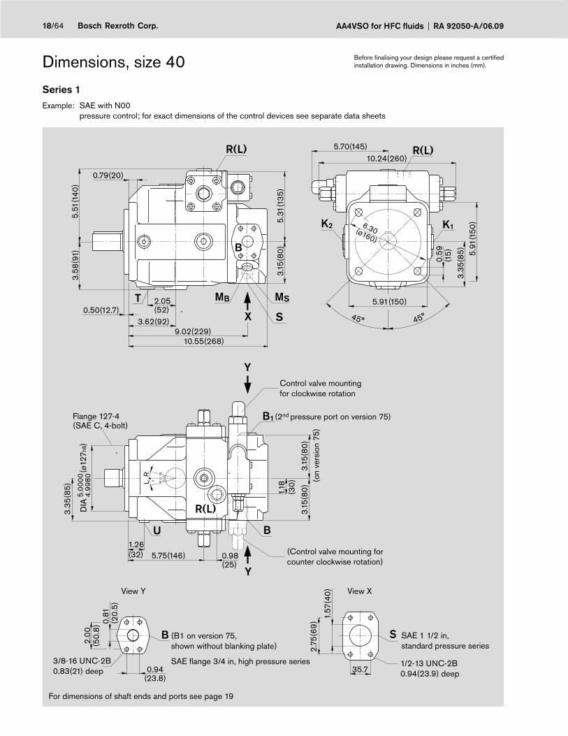
Dimensions, size 40
Series 1Example: SAE with N00 pressure control; for exact dimensions of the control devices see separate data sheets
For dimensions of shaft ends and ports see page 19
Before fi nalising your design please request a certifi ed installation drawing. Dimensions in inches (mm).
X
T MB MS
S
B
K2 K1
U
B1
R(L)
Y
Y
B S
R(L) R(L)
B
3.58
(91)
3.62(92)
2.05(52)0.50(12.7)
5.51
(140
)
10.55(268)9.02(229)
3.15
(80
)
0.79(20)
10.24(260)
5.91
(150
)3.
35(8
5)
0.59
(15)
5.91(150)
6.30(ø160)
5.70(145)
1.26(32) 5.75(146) 0.98
(25)
3.15
(80
)
1.18
(30
)
3.35
(85)
3.15
(80
)
(ø12
7h8)
0.94(23.8)
2.00
(50.
8) 0.
81(2
0.5)
35.7
2.75
(69
) 1.57
(40
)45° 45°
DIA
5.00
004.
9980
5.31
(135
)
15
15
0
LR
Control valve mounting for clockwise rotation
(Control valve mounting for counter clockwise rotation)
SAE 1 1/2 in,standard pressure series
1/2-13 UNC-2B0.94(23.9) deep
View XView Y
3/8-16 UNC-2B0.83(21) deep
(B1 on version 75,shown without blanking plate)
SAE fl ange 3/4 in, high pressure series
(2nd pressure port on version 75)
(on
vers
ion
75)
Flange 127-4(SAE C, 4-bolt)
19/64Bosch Rexroth Corp.RA 92050-A/06.09 AA4VSO for HFC fluids
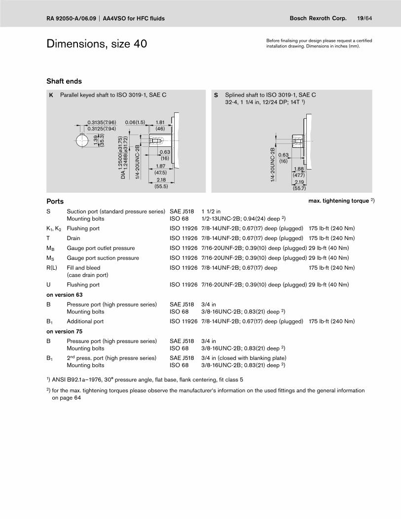
Dimensions, size 40
Shaft ends
K Parallel keyed shaft to ISO 3019-1, SAE C S Splined shaft to ISO 3019-1, SAE C32-4, 1 1/4 in, 12/24 DP; 14T 1)
1.39
(35.
3)
0.3135(7.96)0.3125(7.94)
1/4-
20U
NC
-2B
0.63(16)
1.87(47.5)
1.25
00(ø
31.7
5)1.
2488
(ø31
.72)
0.06(1.5) 1.81(46)
2.18(55.5)
DIA
1.88(47.7)
0.63(16)
1/4-
20U
NC
-2B
2.19(55.7)
Ports max. tightening torque 2)
S Suction port (standard pressure series) Mounting bolts
SAE J518ISO 68
1 1/2 in1/2-13UNC-2B; 0.94(24) deep 2)
K1, K2 Flushing port ISO 11926 7/8-14UNF-2B; 0.67(17) deep (plugged) 175 lb-ft (240 Nm)
T Drain ISO 11926 7/8-14UNF-2B; 0.67(17) deep (plugged) 175 lb-ft (240 Nm)
MB Gauge port outlet pressure ISO 11926 7/16-20UNF-2B; 0.39(10) deep (plugged) 29 lb-ft (40 Nm)
MS Gauge port suction pressure ISO 11926 7/16-20UNF-2B; 0.39(10) deep (plugged) 29 lb-ft (40 Nm)
R(L) Fill and bleed(case drain port)
ISO 11926 7/8-14UNF-2B; 0.67(17) deep 175 lb-ft (240 Nm)
U Flushing port ISO 11926 7/16-20UNF-2B; 0.39(10) deep (plugged) 29 lb-ft (40 Nm)
on version 63
B Pressure port (high pressure series)Mounting bolts
SAE J518ISO 68
3/4 in3/8-16UNC-2B; 0.83(21) deep 2)
B1 Additional port ISO 11926 7/8-14UNF-2B; 0.67(17) deep (plugged) 175 lb-ft (240 Nm)
on version 75
B Pressure port (high pressure series)Mounting bolts
SAE J518ISO 68
3/4 in3/8-16UNC-2B; 0.83(21) deep 2)
B1 2nd press. port (high pressre series)Mounting bolts
SAE J518ISO 68
3/4 in (closed with blanking plate)3/8-16UNC-2B; 0.83(21) deep 2)
1) ANSI B92.1a–1976, 30° pressure angle, fl at base, fl ank centering, fi t class 5
2) for the max. tightening torques please observe the manufacturer‘s information on the used fi ttings and the general information on page 64
Before fi nalising your design please request a certifi ed installation drawing. Dimensions in inches (mm).
AA4VSO for HFC fluids RA 92050-A/06.0920/64 Bosch Rexroth Corp.
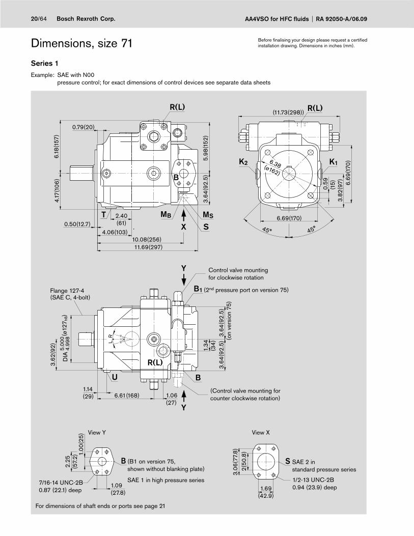
Dimensions, size 71
Series 1Example: SAE with N00 pressure control; for exact dimensions of control devices see separate data sheets
For dimensions of shaft ends or ports see page 21
Y
U
R(L)
B1
Y
K2 K1
MB MS
SX
B
SB
T
R(L) R(L)
B
(ø12
7 h8)
DIA
1.14(29)
3.62
(92)
6.61(168) 1.06(27)
3.64
(92.
5)
1.34
(34)
3.64
(92.
5)
(11.73(298))
6.69
(170
)3.
82(9
7)
0.59
(15)
6.69(170)
6.38(ø162)
6.18
(157
)
0.79(20)
4.17
(106
)
4.06(103)
2.40(61)0.50(12.7)
11.69(297)10.08(256)
3.64
(92.
5)
1.69(42.9)
3.06
(77.
8)
2(50
.8)
1.09(27.8)
2.25
(57.
2)1.
00(2
5)
5.98
(152
)
5.00
04.
998
15
15
0
LR
45° 45°
Control valve mounting for clockwise rotation
(Control valve mounting for counter clockwise rotation)
SAE 2 instandard pressure series
1/2-13 UNC-2B0.94 (23.9) deep
View XView Y
7/16-14 UNC-2B0.87 (22.1) deep
(B1 on version 75,shown without blanking plate)
SAE 1 in high pressure series
(2nd pressure port on version 75)
(on
vers
ion
75)
Flange 127-4(SAE C, 4-bolt)
Before fi nalising your design please request a certifi ed installation drawing. Dimensions in inches (mm).

21/64Bosch Rexroth Corp.RA 92050-A/06.09 AA4VSO for HFC fluids
Dimensions, size 71
Shaft ends
K Parallel keyed shaft to ISO 3019-1, SAE C-C S Splined shaft to ISO 3019-1, SAE C-C 38-4, 1 1/2 in, 12/24 DP; 17T 1)
1.66
(42.
2)
0.3757(9.54)0.3748(9.52)
7/16
-14U
NC
-2B
1.10(28)
2.13(54)
1.50
00(ø
38.1)
1.49
88(ø
38.0
7)0.06(1.5) 2.05
(52)D
IA
2.44(62)
2.13(54)
1.10(28)
7/16
-14U
NC
-2B
2.44(62)
Ports max. tightening torque 2)
S Suction port (standard pressure series)Mounting bolts
SAE J518 ISO 68
1 1/2 in1/2-13UNC-2B; 0.87(22) deep 2)
K1, K2 Flushing port ISO 11926 1 1/16-12UN-2B; 0.79(20) deep (plugged) 265 lb-ft (360 Nm)
T Drain ISO 11926 1 1/16-12UN-2B; 0.79(20) deep (plugged) 265 lb-ft (360 Nm)
MB Gauge port outlet pressure ISO 11926 7/16-20UNF-2B; 0.39(10) deep (plugged) 29 lb-ft (40 Nm)
MS Gauge port suction pressure ISO 11926 7/16-20UNF-2B; 0.39(10) deep (plugged) 29 lb-ft (40 Nm)
R(L) Fill + air bleed (case drain port) ISO 11926 1 1/16-12UN-2B; 0.79(20) deep 265 lb-ft (360 Nm)
U Flushing port ISO 11926 7/16-20UNF-2B; 0.39(10) deep (plugged) 29 lb-ft (40 Nm)
on version 63
B Pressure port (high pressure series)Mounting bolts
SAE J518 ISO 68
1 in7/16-14UNC-2B; 0.87(22) deep 2)
B1 Additional port ISO 11926 1 1/16-12UN-2B; 0.79(20) deep (plugged) 265 lb-ft (360 Nm)
on version 75
B Pressure port (high pressure series)Mounting bolts
SAE J518 ISO 68
1 in7/16-14UNC-2B; 0.87(22) deep 2)
B1 2nd pressure port (high pressure series)Mounting bolts
SAE J518 ISO 68
1 in (closed with blanking plate)7/16-14UNC-2B; 0.87(22) deep 2)
1) ANSI B92.1a–1976, 30° pressure angle, fl at base, fl ank centering, fi t class 5
2) for the max. tightening torques please observe the manufacturer‘s information on the used fi ttings and the general information on page 64
Before fi nalising your design please request a certifi ed installation drawing. Dimensions in inches (mm).

AA4VSO for HFC fluids RA 92050-A/06.0922/64 Bosch Rexroth Corp.
Dimensions, size 125
Series 3Example: SAE with N00 (for U99 dimensions, see page 61) pressure control; for exact dimensions of control devices see separate data sheets
B
1.25(31.8)
2.63
(66.
7) 1.25
(31)
M2(1) B1
M1(2)
BU
T MB MS
S
K2 K1
R(L) R(L)
X
Y
Y
R(L)
B
14.06(357)
7.50
(191
)
12.28(312)
4.43
(112
.5)
0.94(24)
4.74
(121
)
0.50(12.7)5.00(127)
2.76(70)
1.97
(50
)4.
43(1
12.5
)4.
43(1
12.5
)
1.38(35)
4.41
(112
)
0.55(14)
0.55(14)
(ø15
2 h8)
DIA
6.00
005.
9975
2.50
(63
)3.
50(8
8.9
)
2.00(50.8)
S
(13.94(354))
9.00(ø228.6)
4.51
(114
.5)
7.87
(200
)
7.87(200)
0.83
(21)
7.32
(186
)
8.07(205)
15
15
0
LR
45° 45°
For dimensions of shaft ends and ports see page 23
Before fi nalising your design please request a certifi ed installation drawing. Dimensions in inches (mm).
1/2-13 UNC-2B1.06 (26.9) deep
Flange 152-4(SAE D, 4-bolt)
Control valve mounting for clockwise rotation
(Control valve mounting for counter clockwise rotation)
SAE 2 1/2 instandard pressure series
View XView Y
1/2-13 UNC-2B1.06 (26.9) deep
(B1 on version 75,shown without blanking plate
SAE 1 1/4 in high pressure series
(2nd pressure port on version 75)
(on
vers
ion
75)
Position R(L) on HD- and EP-control

23/64Bosch Rexroth Corp.RA 92050-A/06.09 AA4VSO for HFC fluids
Dimensions, size 125
Shaft ends
K Parallel keyed shaft to ISO 3019-1, SAE D S Splined shaft to ISO 3019-1, SAE D 44-4, 1 3/4 in, 8/16 DP; 13T 1)
1.94
(49.
28)
0.4383(11.13)0.4347(11.11)
1/2-
13U
NC
-2B
1.26(32)
2.63(66.8)1.
7500
(ø44
.45)
1.74
88(ø
44.4
2)0.06(1.5) 2.55
(64.7)
2.94(74.8)
DIA
2.63(66.8)
1.26(32)
1/2-
13U
NC
-2B
2.94(74.8)
Ports max. tightening torque 2)
S Suction port (standard pressure series)Mounting bolts
SAE J518ISO 68
2 1/2 in1/2-13UNC-2B; 1.06(27) deep 2)
K1, K2 Flushing port ISO 11926 1 5/16-12UN-2B; 0.79(20) deep (plugged) 394 lb-ft (540 Nm)
T Drain ISO 11926 1 5/16-12UN-2B; 0.79(20) deep (plugged) 394 lb-ft (540 Nm)
MB Gauge port outlet pressure ISO 11926 7/16-20UNF-2B; 0.39(10) deep (plugged) 29 lb-ft (40 Nm)
MS Gauge port suction pressure ISO 11926 7/16-20UNF-2B; 0.39(10) deep (plugged) 29 lb-ft (40 Nm)
R(L) Fill + air bleed (case drain port) ISO 11926 1 5/16-12UN-2B; 0.79(20) deep 394 lb-ft (540 Nm)
U Flushing port ISO 11926 7/16-20UNF-2B; 0.39(10) deep (plugged) 29 lb-ft (40 Nm)
M1, M2 Gauge port control chamber press. DIN 3852 M14x1.5; 0.47(12) deep (plugged) 29 lb-ft (40 Nm)
on version 63
B Pressure port (high pressure series)Mounting bolts
SAE J518ISO 68
1 1/4 in1/2-13UNC-2B; 1.06(27) deep 2)
B1 Additional port ISO 11926 1 5/16-12UN-2B; 0.79(20) deep (plugged) 394 lb-ft (540 Nm)
on version 75
B Pressure port (high pressure series)Mounting bolts
SAE J518ISO 68
1 1/4 in1/2-13UNC-2B; 1.06(29) deep 2)
B1 2nd pressure port (high pressure series)Mounting bolts
SAE J518ISO 68
1 1/4 in (closed with blanking plate)1/2-13UNC-2B; 1.06(29) deep 2)
1) ANSI B92.1a–1976, 30° pressure angle, fl at base, fl ank centering, fi t class 5
2) for the max. tightening torques please observe the manufacturer‘s information on the used fi ttings and the general information on page 64
Before fi nalising your design please request a certifi ed installation drawing. Dimensions in inches (mm).
AA4VSO for HFC fluids RA 92050-A/06.0924/64 Bosch Rexroth Corp.
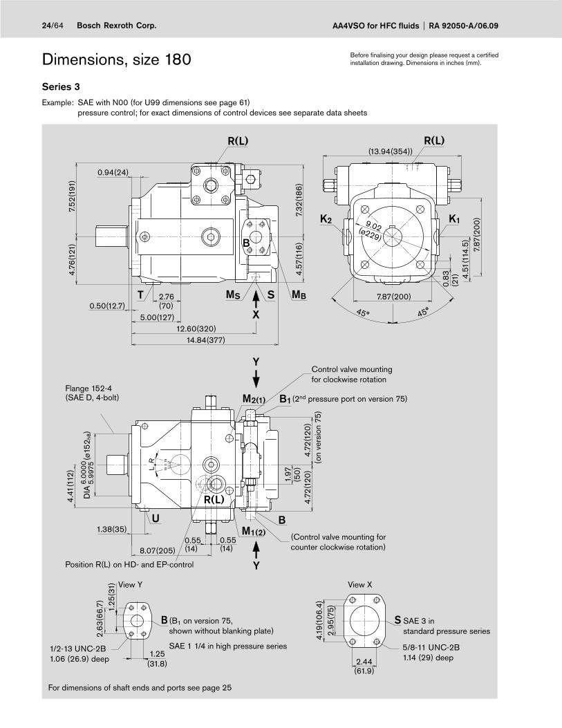
Dimensions, size 180
Series 3Example: SAE with N00 (for U99 dimensions see page 61) pressure control; for exact dimensions of control devices see separate data sheets
For dimensions of shaft ends and ports see page 25
BUM1(2)
M2(1) B1
K2 K1
MBSMST
B
R(L)
R(L)
R(L)
X
Y
Y
B
(13.94(354))
4.51
(114
.5)
7.87
(200
)
7.87(200)
0.83
(21)
9.02(ø229)
0.94(24)
14.84(377)
4.57
(116
)
12.60(320)
4.76
(121
)7.
52(1
91)
0.50(12.7)5.00(127)
2.76(70)
4.41
(112
)
1.38(35)
4.72
(120
)4.
72(1
20)
1.97
(50
)
2.95
(75)
4.19
(106
.4)
2.44(61.9)
S
7.32
(186
)
0.55(14)
0.55(14)
1.25(31.8)
2.63
(66.
7) 1.25
(31)
8.07(205)
15
15
0
LR(ø
152 h
8)D
IA6.
0000
5.99
75
45° 45°
Flange 152-4(SAE D, 4-bolt)
Position R(L) on HD- and EP-control
Control valve mounting for clockwise rotation
(Control valve mounting for counter clockwise rotation)
SAE 3 instandard pressure series
View XView Y
(B1 on version 75,shown without blanking plate)
SAE 1 1/4 in high pressure series
(2nd pressure port on version 75)
(on
vers
ion
75)
Before fi nalising your design please request a certifi ed installation drawing. Dimensions in inches (mm).
1/2-13 UNC-2B1.06 (26.9) deep
5/8-11 UNC-2B1.14 (29) deep

25/64Bosch Rexroth Corp.RA 92050-A/06.09 AA4VSO for HFC fluids
Dimensions, size 180, SAE with N003)
Shaft ends
K Parallel keyed shaft to ISO 3019-1, SAE F S Splined shaft to ISO 3019-1, SAE F50-4, 2 in, 8/16 DP; 15T 1)
2.22
(56.
38)
0.501(12.73)0.500(12.70)
5/8-
11U
NC
-2B
1.42(36)
3.62(92)
0.18(4.6) 3.41(86.6)
2.00
00(ø
50.8
0)
1.99
88(ø
50.7
7)D
IA
3.94(100)
3.13(79.5)
1.42(36)
5/8-
11U
NC
-2B
3.44(87.5)
Ports max. tightening torque 2)
S Suction port (standard pressure series)Mounting bolts
SAE J518ISO 68
3 in5/8-11UNC-2B; 1.14(29) deep 2)
K1, K2 Flushing port ISO 11926 1 5/16-12UN-2B; 0.79(20) deep (plugged)394 lb-ft (540 Nm)
T Drain ISO 11926 1 5/16-12UN-2B; 0.79(20) deep (plugged)394 lb-ft (540 Nm)
MB Gauge port outlet pressure ISO 11926 7/16-20UNF-2B; 0.39(10) deep (plugged) 29 lb-ft (40 Nm)
MS Gauge port suction pressure ISO 11926 7/16-20UNF-2B; 0.39(10) deep (plugged) 29 lb-ft (40 Nm)
R(L) Fill + air bleed(case drain port)
ISO 11926 1 5/16-12UN-2B; 0.79(20) deep 394 lb-ft (540 Nm)
U Flushing port ISO 11926 7/16-20UNF-2B; 0.39(10) deep (plugged) 29 lb-ft (40 Nm)
M1, M2 Gauge port control chamber pressure
DIN 3852 M14x1,5; 0.47(12) deep (plugged) 58 lb-ft (80 Nm)
on version 63
B Pressure port (high pressure series)Mounting bolts
SAE J518ISO 68
1 1/4 in1/2-13UNC-2B; 1.06(27) deep 2)
B1 Additional port ISO 11926 1 5/16-12UN-2B; 0.79(20) deep (plugged)394 lb-ft (540 Nm)
on version 75
B Pressure port (high pressure series)Mounting bolts
SAE J518ISO 68
1 1/4 in1/2-13UNC-2B; 1.06(27) deep 2)
B1 2nd pressure port (high pressure series)Mounting bolts
SAE J518ISO 68
1 1/4 in (closed with blanking plate)1/2-13UNC-2B; 1.06(27) deep 2)
1) ANSI B92.1a–1976, 30° pressure angle, fl at base, fl ank centering, fi t class 5
2) for the max. tightening torques please observe the manufacturer‘s information on the used fi ttings and the general information on page 64
Before fi nalising your design please request a certifi ed installation drawing. Dimensions in inches (mm).
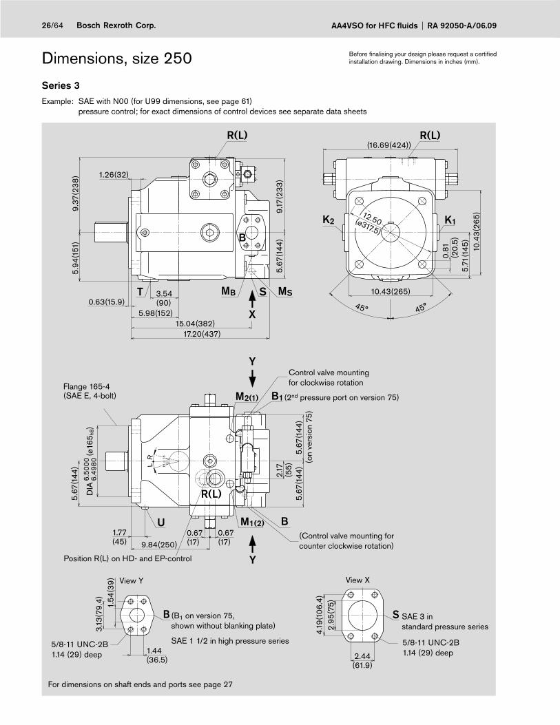
AA4VSO for HFC fluids RA 92050-A/06.0926/64 Bosch Rexroth Corp.
Dimensions, size 250
Series 3Example: SAE with N00 (for U99 dimensions, see page 61) pressure control; for exact dimensions of control devices see separate data sheets
For dimensions on shaft ends and ports see page 27
Flange 165-4(SAE E, 4-bolt)
K2 K1
T MB MSS
U M1(2) B
B1M2(1)
B S
R(L)
B
R(L) R(L)
X
Y
Y
15.04(382)
5.67
(144
)
17.20(437)
1.26(32)
5.94
(151
)
5.98(152)0.63(15.9)
3.54(90)
12.50(ø317.5)
10.43(265)
5.71
(145
)10
.43(
265)
0.81
(20.
5)
(16.69(424))
1.77(45)
5.67
(144
)
0.67(17)
2.17
(55)
5.67
(144
)
9.84(250)
3.13
(79.
4)
1.44(36.5)
1.54
(39
)
2.95
(75)
4.19
(106
.4)
2.44(61.9)
5.67
(144
)
9.17
(233
)
0.67(17)
9.37
(238
)
15
15
0
LR
45° 45°
(ø16
5 h8)
DIA
6.50
006.
4980
Control valve mounting for clockwise rotation
(Control valve mounting for counter clockwise rotation)
SAE 3 instandard pressure series
View XView Y
(B1 on version 75,shown without blanking plate)
SAE 1 1/2 in high pressure series
(2nd pressure port on version 75)
(on
vers
ion
75)
Position R(L) on HD- and EP-control
Before fi nalising your design please request a certifi ed installation drawing. Dimensions in inches (mm).
5/8-11 UNC-2B1.14 (29) deep
5/8-11 UNC-2B1.14 (29) deep

27/64Bosch Rexroth Corp.RA 92050-A/06.09 AA4VSO for HFC fluids
Dimensions, size 250
Shaft ends
K Parallel keyed shaft to ISO 3019-1, SAE F S Splined shaft to ISO 3019-1, SAE F 50-4 (2 in, 8/16 DP; 15T 1)
2.22
(56.
38)
0.501(12.73)0.500(12.70)
5/8-
11U
NC
-2B
1.42(36)
3.62(92)2.
0000
(ø50
.80
)1.
9988
(ø50
.77)
0.08(2) 3.52(89.3)
DIA
3.93(100)
3.13(79.4)
1.42(36)
5/8-
11U
NC
-2B
3.44(87.4)
Ports max. tightening torque 2)
S Suction port (standard pressure series)Mounting bolts
SAE J518 ISO 68
3 in5/8-11UNC-2B; 1.14(29) deep 2)
K1, K2 Flushing port ISO 11926 1 5/8-12UN-2B; 0.79(20) deep (plugged) 700 lb-ft (960 Nm)
T Drain ISO 11926 1 5/8-12UN-2B; 0.79(20) deep (plugged) 700 lb-ft (960 Nm)
MB Gauge port outlet pressure ISO 11926 7/16-20UNF-2B; 0.39(10) deep (plugged) 29 lb-ft (40 Nm)
MS Gauge port suction pressure ISO 11926 7/16-20UNF-2B; 0.39(10) deep (plugged) 29 lb-ft (40 Nm)
R(L) Fill + air bleed(case drain port)
ISO 11926 1 5/8-12UN-2B; 0.79(20) deep 700 lb-ft (960 Nm)
U Flushing port ISO 11926 7/16-20UNF-2B; 0.39(10) deep (plugged) 29 lb-ft (40 Nm)
M1, M2
Gauge port control chamber pressure DIN 3852 M18x1,5; 0.47(12) deep (plugged) 102 lb-ft (140 Nm)
on version 63
B Pressure port (high pressure series)Mounting bolts
SAE J518 ISO 68
1 1/2 in5/8-11UNC-2B; 1.14(29) deep 2)
B1 Additional port ISO 11926 1 5/8-12UN-2B; 0.79(20) deep (plugged) 700 lb-ft (960 Nm)
on version 75
B Pressure port (high pressure series)Mounting bolts
SAE J518 ISO 68
1 1/2 in5/8-11UNC-2B; 1.14(29) deep 2)
B1 2nd pressure port (high pressure series)Mounting bolts
SAE J518 ISO 68
1 1/2 in (closed with blanking plate)5/8-11UNC-2B; 1.14(29) deep 2)
1) ANSI B92.1a–1976, 30° pressure angle, fl at base, fl ank centering, fi t class 5
2) for the max. tightening torques please observe the manufacturer‘s information on the used fi ttings and the general information on page 64
Before fi nalising your design please request a certifi ed installation drawing. Dimensions in inches (mm).

AA4VSO for HFC fluids RA 92050-A/06.0928/64 Bosch Rexroth Corp.
Dimensions, size 355
Series 3Example: SAE with N00 (for U99 dimensions, see page 61) pressure control; for exact dimensions of control devices see separate data sheets)
K1K2
T MBMS S
M2(1)
B1
BM1(2)U
S
R(L) R(L)
X
Y
Y
R(L)
9.37
(238
)
0.67(17)
0.67(17)
2.17
(55)
5.83
(148
)5.
83(1
48)
(16.69(424))
15.55(395)18.43(468)
9.84(250)
10.43(265)
5.69
(144
.5)
10.4
3(26
5)12.50(ø317.5)
0.81
(20.
5)
1.26(32)
5.94
(151
)
5.98(152)0.63(16)
3.54(90)
1.65(42)
5.67
(144
)
5.67
(144
)
3.94
(100
)5.
07(1
28.8
)
3.06(77.8)
9.17
(233
)
(ø16
5 h8)
DIA
6.50
006.
4980
B
3.07
(80
)
1.44(36.5)
1.57
(40
)
15
15
0
LR
45° 45°
B
Control valve mounting for clockwise rotation
(Control valve mounting for counter clockwise rotation)
SAE 4 instandard pressure series
View XView Y
5/8-11 UNC-2B1.14 (29) deep
(B1 on version 75,shown without blanking plate)
SAE 1 1/2 in high pressure series
(2nd pressure port on version 75)
(on
vers
ion
75)
For dimensions of shaft ends and ports see page 29
Flange 165-4(SAE E, 4-bolt)
Position R(L) on HD- and EP-control
Before fi nalising your design please request a certifi ed installation drawing. Dimensions in inches (mm).
5/8-11 UNC-2B1.14 (29) deep

29/64Bosch Rexroth Corp.RA 92050-A/06.09 AA4VSO for HFC fluids
Dimensions, size 355
Shaft ends
K Parallel keyed shaft to ISO 3019-1 R Splined shaft similar to ISO 3019-1, similar to SAE F50-4, 2 in, 8/16 DP; 15T 1)
3.07
(78
)
0.7510(19.07)0.7500(19.05)
3/4
-10U
NC
-2B
1.65(42)
3.62(92)2.
7500
(ø69
.85)
2.74
88(ø
69.8
2)0.17(4.2) 3.41
(86.6)D
IA
3.94(100)
3.13(79.4)
1.42(36)
5/8-
11U
NC
-2B
2.33(59.2)
3.44(87.4)
Ports max. tightening torque 2)
S Suction port (standard pressure series)Mounting bolts
SAE J518ISO 68
3 in5/8-11UNC-2B; 1.14(29) deep 2)
K1, K2 Flushing port ISO 11926 1 5/8-12UN-2B; 0.79(20) deep (plugged) 700 lb-ft (960 Nm)
T Drain ISO 11926 1 5/8-12UN-2B; 0.79(20) deep (plugged) 700 lb-ft (960 Nm)
MB Gauge port outlet pressure ISO 11926 7/16-20UNF-2B; 0.39(10) deep (plugged)29 lb-ft (40 Nm)
MS Gauge port suction pressure ISO 11926 7/16-20UNF-2B; 0.39(10) deep (plugged)29 lb-ft (40 Nm)
R(L) Fill + air bleed(case drain port)
ISO 11926 1 5/8-12UN-2B; 0.79(20) deep 700 lb-ft (960 Nm)
U Flushing port ISO 11926 3/4-16UNF-2B; 0.59(15) deep (plugged) 117 lb-ft (160 Nm)
M1, M2
Gauge port control chamber pressure
DIN 3852 M18x1,5; 0.47(12) deep (plugged) 102 lb-ft (140 Nm)
on version 63
B Pressure port (high pressure series)Mounting bolts
SAE J518ISO 68
1 1/2 in5/8-11UNC-2B; 1.14(29) deep 2)
B1 Additional port ISO 11926 1 5/8-12UN-2B; 0.79(20) deep (plugged) 700 lb-ft (960 Nm)
on version 75
B Pressure port (high pressure series)Mounting bolts
SAE J518ISO 68
1 1/2 in5/8-11UNC-2B; 1.14(29) deep 2)
B1 2nd pressure port (high pressure series)Mounting bolts
SAE J518ISO 68
1 1/2 in (closed with blanking plate)5/8-11UNC-2B; 1.14(29) deep 2)
1) ANSI B92.1a–1976, 30° pressure angle, fl at base, fl ank centering, fi t class 5
2) for the max. tightening torques please observe the manufacturer‘s information on the used fi ttings and the general information on page 64
Before fi nalising your design please request a certifi ed installation drawing. Dimensions in inches (mm).
usable spline length
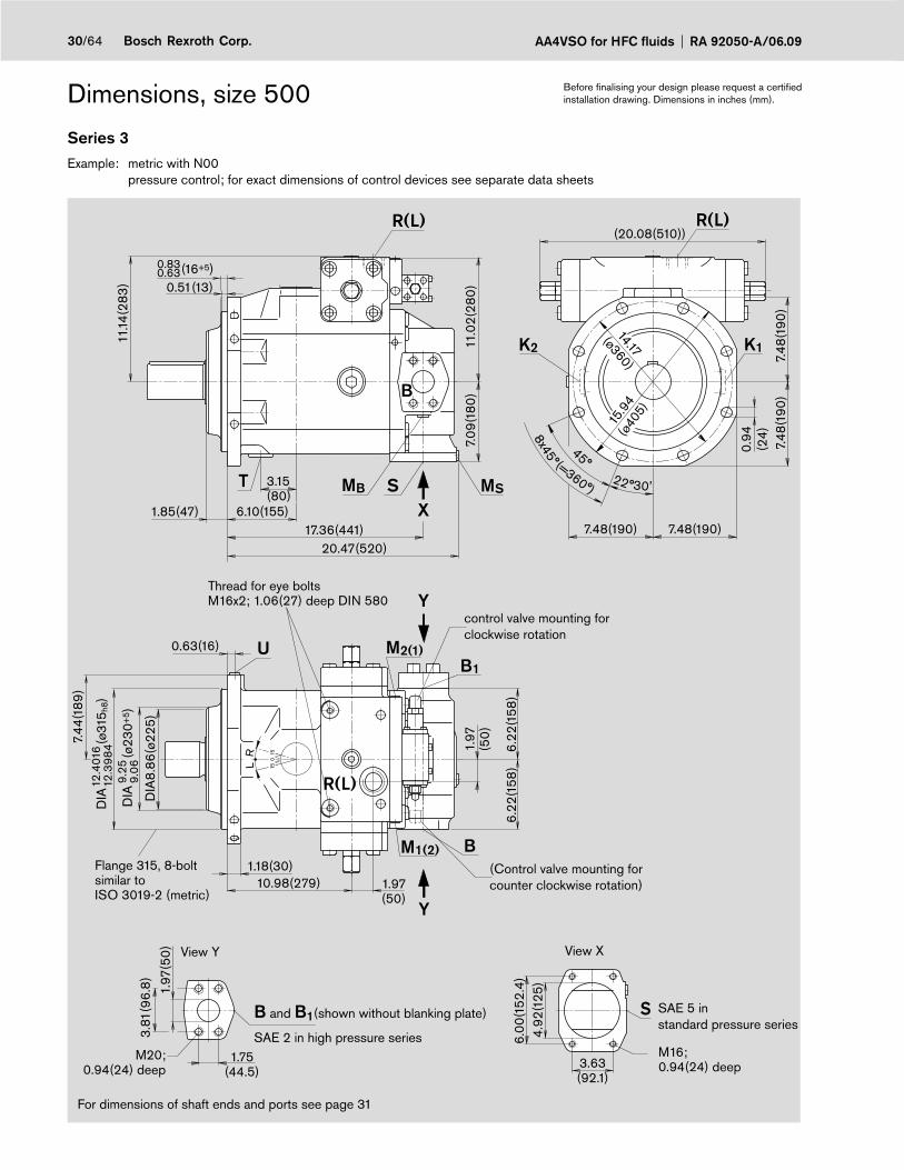
AA4VSO for HFC fluids RA 92050-A/06.0930/64 Bosch Rexroth Corp.
Dimensions, size 500
Series 3Example: metric with N00 pressure control; for exact dimensions of control devices see separate data sheets
U
0.94
(24)
M2(1)B1
M1(2) B
K1K2
MSMB ST
S
R(L) R(L)
R(L)
X
Y
Y
20.47(520)17.36(441)
1.85(47)
3.15(80)
6.10(155)
11.14
(283
)
(20.08(510))
15.9
4(ø
405)
7.48
(190
)
14.17
(ø360)
7.48(190) 7.48(190)
8x45°
45°
22°7.
09(1
80)
30'
(=360°)
6.22
(158
)6.
22(1
58)
1.97
(50
)
10.98(279)1.18(30)
DIA
8.86
(ø22
5)
1.97(50)
4.92
(125
)6.
00(1
52.4
)
3.63(92.1)
1.97
(50
)
3.81
(96.
8)
1.75(44.5)
0.830.63(16+5)
7.48
(190
)
11.0
2(28
0)
0.63(16)
7.44
(189
)
15
15
0
LR
(ø31
5 h8)
DIA
12.4
016
12.3
984 (ø23
0+5 )
DIA
9.25
9.06
0.51(13)
B
control valve mounting for clockwise rotation
(Control valve mounting for counter clockwise rotation)
SAE 5 instandard pressure series
M16; 0.94(24) deep
View XView Y
M20; 0.94(24) deep
B and B1(shown without blanking plate)
SAE 2 in high pressure series
For dimensions of shaft ends and ports see page 31
Flange 315, 8-boltsimilar to ISO 3019-2 (metric)
Thread for eye bolts M16x2; 1.06(27) deep DIN 580
Before fi nalising your design please request a certifi ed installation drawing. Dimensions in inches (mm).

31/64Bosch Rexroth Corp.RA 92050-A/06.09 AA4VSO for HFC fluids
Dimensions, size 500
Shaft ends
P Keyed to DIN 6885 AS22x14x125
Z Splined to DIN 5480 W80x3x25x9g
3.35
(85)
(22h9)0.86610.8641
7.09(180)
5.12(130)
(ø80
m6)
1.65(42)
0.12(3) 4.92(125)
M20
1 )2 )
DIA
3.15
083.
1500 1.65
(42)3.54(90)
5.51(140)
M20
1 )2 )
Ports max. tightening torque 2)
S Suction port (standard pressure series)Mounting bolts
SAE J518 3)DIN 13
5 inM16x2; 0.94(24) deep 2)
K1, K2 Flushing port DIN 3852 M48x2; 0.87(22) deep (plugged) 700 lb-ft (960 Nm)
T Drain DIN 3852 M48x2; 0.87(22) deep (plugged) 700 lb-ft (960 Nm)
MB Gauge port outlet pressure DIN 3852 M18x1,5; 0.47(12) deep (plugged) 102 lb-ft (140 Nm)
MS Gauge port suction pressure DIN 3852 M18x1,5; 0.47(12) deep (plugged) 102 lb-ft (140 Nm)
R(L) Fill + air bleed(case drain port)
DIN 3852 M48x2; 0.87(22) deep 700 lb-ft (960 Nm)
U Flushing port DIN 3852 M18x1,5; 0.47(12) deep (plugged) 102 lb-ft (140 Nm)
M1, M2 Gauge port control chamber pressureor dependent on control device
DIN 3852DIN 3852
M18x1,5; 0.47(12) deep (plugged)M14x1,5; 0.47(12) deep (plugged)
102 lb-ft (140 Nm)58 lb-ft (80 Nm)
B Pressure port (high pressure series)Mounting bolts
SAE J518 3)DIN 13
2 inM20x2,5; 0.94(24) deep 2)
B1 2nd pressure port (high pressure series)Mounting bolts
SAE J518 3)DIN 13
2 in (closed with blanking plate)M20x2,5; 0.94(24) deep 2)
1) Center bore to DIN 332 (thread to DIN 13)
2) for the max. tightening torques please observe the manufacturer‘s information on the used fi ttings and the general information on page 64
3) Caution: metric thread deviates from standard
Before fi nalising your design please request a certifi ed installation drawing. Dimensions in inches (mm).

AA4VSO for HFC fluids RA 92050-A/06.0932/64 Bosch Rexroth Corp.
Dimensions, size 750
Series 3Example: metric with N00 pressure control; for exact dimensions of control devices see separate data sheets
R(L)
TMS
MB
S
K2 K1
R(L)
U
BM1(2)
M2(1)B1
S
R(L)
X
Y
Y
22.05(560)
3.50(89)
6.34(161)18.62(473)
7.87
(200
)
(22.91(582))
9.13
(232
)
(=360°)
19.4
9(ø
495)
0.63(16)
3.81
(96.
8)
7.17(
182)
1.26(32)1.97(50)
11.85(301)
0.87
(22)
17.72(ø450)
4.92
(125
)6.
00(1
52.4
)
3.63(92.1)
1.97
(50
)
1.75(44.5)
0.51(13)
12.6
8(32
2)
9.13
(232
)
9.13(232) 9.13(232)
8x45°45°
22° 30'
9.09
(231
)
1.97
(50
)
7.17(
182)
12.4
8(31
7)
15
15
0
LR
1.85(47)
DIA
10.0
4(ø2
25)
(ø40
0 h8)
DIA
15.7
480
15.7
445 (ø
263+
5 )D
IA10
.55
10.3
5
0.830.63(16+5)
B
Control valve mounting for clockwise rotation
(Control valve mounting for counter clockwise rotation)
SAE 5 instandard pressure series
M16; 0.94(24) deep
View XView Y
M20; 0.94(24) deep
For dimensions of shaft ends and ports see page 33
Flange 400, 8-bolt similar to ISO 3019-2 (metric)
Thread for eye bolts M16x2; 1.06(27) deep DIN 580
B and B1(shown without blanking plate)
SAE 2 in high pressure series
Before fi nalising your design please request a certifi ed installation drawing. Dimensions in inches (mm).

33/64Bosch Rexroth Corp.RA 92050-A/06.09 AA4VSO for HFC fluids
Dimensions, size 750
Shaft ends
P Keyed to DIN 6885 AS25x14x125
Z Splined to DIN 5480 W90x3x28x9g
(95 -
0.2)
(25h9)
7.09(180)
5.12(130)
(ø90
m6)
1.97(50)
0.18(4.5) 4.92(125)
M24
1 )2 )
DIA
3.54
473.
5438
0.98430.9822
3.74
3.73
1.97(50)
4.13(105)
6.10(155)
M24
1 )2 )
Ports max. tightening torques 2)
S Suction port (standard pressure series)Mounting bolts
SAE J518 3)DIN 13
5 inM16x2; 0.94(24) deep 2)
K1, K2 Flushing port DIN 3852 M48x2; 0.79(20) deep (plugged) 700 lb-ft (960 Nm)
T Drain DIN 3852 M48x2; 0.79(20) deep (plugged) 700 lb-ft (960 Nm)
MB Gauge port outlet pressure DIN 3852 M18x1,5; 0.47(12) deep (plugged) 102 lb-ft (140 Nm)
MS Gauge port suction pressure DIN 3852 M18x1,5; 0.47(12) deep (plugged) 102 lb-ft (140 Nm)
R(L) Fill + air bleed(case drain port)
DIN 3852 M48x2; 0.79(20) deep 700 lb-ft (960 Nm)
U Flushing port DIN 3852 M18x1,5; 0.47(12) deep (plugged) 102 lb-ft (140 Nm)
M1, M2 Gauge port control chamber press.or dependent on control device
DIN 3852DIN 3852
M18x1,5; 0.47(12) deep (plugged)M14x1,5; 0.47(12) deep (plugged)
102 lb-ft (140 Nm)58 lb-ft (80 Nm)
B Pressure port (high pressure series)Mounting bolts
SAE J518 3)DIN 13
2 inM20x2,5; 0.94(24) deep 2)
B1 2nd pressure port (high pressure series)Mounting bolts
SAE J518 3)DIN 13
2 in (closed with blanking plate)M20x2,5; 0.94(24) deep 2)
1) Center bore to DIN 332 (thread to DIN 13)
2) for the max. tightening torques please observe the manufacturer‘s information on the used fi ttings and the general information on page 64
3) Caution: metric thread deviates from standard
Before fi nalising your design please request a certifi ed installation drawing. Dimensions in inches (mm).

AA4VSO for HFC fluids RA 92050-A/06.0934/64 Bosch Rexroth Corp.
Dimensions, size 750 with boost pump (Impeller)Series 3Example: metric with N00 pressure control; for exact dimensions of control devices see separate data sheets
T
MB
ML
K2 K1
R(L)R(L)
X
MS
24.17(614)25.20(640)
20.87(530)
8.27
(210
)
(22.91(582))
9.13
(232
)
(=360°)
19.4
9(ø
495)
0.87
(22)
17.72(ø450)
17.99(457)
3.50(89)
6.34(161)1.85(47)
9.13
(232
)
9.13(232) 9.13(232)
8x45°45°
22° 30'12
.48(
317)
12.6
8(32
2) 0.51(13)0.830.63(16+5)
R(L)
U
BM1(2)
M2(1)B1
S
Y
Y
15
15
0
LR
B
0.63(16)
9.09
(231
)
DIA
10.0
4(ø2
25)
(ø40
0 h8)
DIA
15.7
480
15.7
445 (ø
263+
5 )D
IA10
.55
10.3
5
1.26(32)1.97(50)
11.85(301)
7.17(
182)
1.97
(50
)
7.17(
182)
1.97
(50
)
3.81
(96.
8)
1.75(44.5)
4.92
(125
)6.
00(1
52.4
)
3.63(92.1)
Control valve mounting for clockwise rotation
(Control valve mounting for counter clockwise rotation)
SAE 5 instandard pressure series
M16; 0.94(24) deep
View XView Y
M20; 0.94(24) deep
For dimensions of shaft ends and ports see page 35
Flange 400, 8-boltsimilar toISO 3019-2 (metric)
Thread for eye bolts M16x2; 1.06(27) deep DIN 580
B and B1(shown without blanking plate)
SAE 2 in high pressure series
Before fi nalising your design please request a certifi ed installation drawing. Dimensions in inches (mm).

35/64Bosch Rexroth Corp.RA 92050-A/06.09 AA4VSO for HFC fluids
Dimensions, size 750 with boost pump (Impeller)
Shaft ends
P Keyed to DIN 6885 AS25x14x125
Z Splined to DIN 5480 W90x3x28x9g
(95 -
0.2)
(25h9)
7.09(180)
5.12(130)
(ø90
m6)
1.97(50)
0.18(4.5) 4.92(125)
M24
1 )2 )
DIA
3.54
473.
5438
0.98430.9822
3.74
3.73
1.97(50)
4.13(105)
6.10(155)
M24
1 )2 )
Ports max. tightening torque 2)
S Suction port (standard pressure series)Mounting bolts
SAE J518 3)DIN 13
5 inM16x2; 0.94(24) deep 2)
K1, K2 Flushing port DIN 3852 M48x2; 0.79(20) deep (plugged) 700 lb-ft (960 Nm)
T Drain DIN 3852 M48x2; 0.79(20) deep (plugged) 700 lb-ft (960 Nm)
MB Gauge port outlet pressure DIN 3852 M18x1,5; 0.47(12) deep (plugged) 102 lb-ft (140 Nm)
MS Gauge port suction pressure DIN 3852 M18x1,5; 0.47(12) deep (plugged) 102 lb-ft (140 Nm)
ML Gauge port boost pressure DIN 3852 M18x1,5; 0.47(12) deep (plugged) 102 lb-ft (140 Nm)
R(L) Fill + air bleed(case drain port)
DIN 3852 M48x2; 0.79(20) deep 700 lb-ft (960 Nm)
U Flushing port DIN 3852 M18x1,5; 0.47(12) deep (plugged) 102 lb-ft (140 Nm)
M1, M2 Gauge port control chamber press.or dependent on control device
DIN 3852DIN 3852
M18x1,5; 0.47(12) deep (plugged)M14x1,5; 0.47(12) deep (plugged)
102 lb-ft (140 Nm)58 lb-ft (80 Nm)
B Pressure port (high pressure series)Mounting bolts
SAE J518 3)DIN 13
2 inM20x2,5; 0.94(24) deep 2)
B1 2nd pressure port (high pressure series)Mounting bolts
SAE J518 3)DIN 13
2 in (closed with blanking plate)M20x2,5; 0.94(24) deep 2)
1) Center bore to DIN 332 (thread to DIN 13)
2) for the max. tightening torques please observe the manufacturer‘s information on the used fi ttings and the general information on page 64
3) Caution: metric thread deviates from standard
Before fi nalising your design please request a certifi ed installation drawing. Dimensions in inches (mm).

AA4VSO for HFC fluids RA 92050-A/06.0936/64 Bosch Rexroth Corp.
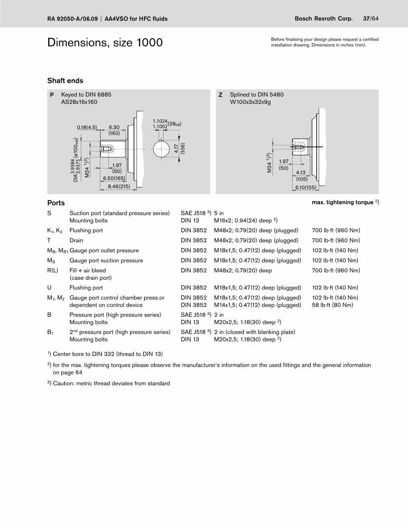
Dimensions, size 1000
Series 3Example: metric with N00 pressure control; for exact dimensions of control devices see separate data sheets
U
R(L)
MB
MSST
K2 K1
B1 MB1
MBM1(2) B
M2(1)
S
X
Y
Y
B
21.57(548)24.92(633)
13.7
8(35
0)
7.99(203)
3.8(98)
13.5
4(34
4)8.
86(2
25)
(=360°)
9.13(232) 9.13(232)
8x45°45°
22° 30'
3.81
(96.
8)
1.75
(44.
5)1.97
(50
)
9.13
(232
)
17.72(ø450)
19.4
9(ø
495)
0.63(16)
9.09
(231
)
DIA
12.6
8(ø3
22)
(ø40
0 h8)
DIA
15.7
480
15.7
445 (ø
333+
5 )D
IA13
.31
13.11
8.27
(210
)
2.17
(55)
8.27
(210
)
4.92
(125
)6.
00(1
52.4
)
3.63(92.1)
(24.49(622))
0.87
(22)
2.00(51)
1.38(35)14.17(360)
3.81(96.8)
1.75(44.5)
15
15
0
LR
R(L)
1.85(47)
0.51(13)
0.830.63(16+5)
R(L)
Control valve mounting for clockwise rotation
(Control valve mounting for counter clockwise rotation)
SAE 5 instandard pressure series
M16; 0.94(24) deep
View XView Y
M20; 1.18(30) deep
For dimensions of shaft ends and ports see page 37
Flange 400, 8-boltsimilar toISO 3019-2 (metric)
Thread for eye bolts M20x2,5; 1.18(30) deep DIN 580
B and B1(shown without blanking plate)
SAE 2 in high pressure series
Before fi nalising your design please request a certifi ed installation drawing. Dimensions in inches (mm).
37/64Bosch Rexroth Corp.RA 92050-A/06.09 AA4VSO for HFC fluids
Dimensions, size 1000
Shaft ends
P Keyed to DIN 6885 AS28x16x160
Z Splined to DIN 5480 W100x3x32x9g
4.17
(106
)
(28h9)
8.46(215)
6.50(165)
(ø10
0 m6)
1.97(50)
0.18(4.5) 6.30(160)
M24
1 )2 )
DIA
3.93
843.
9375
1.10241.1002
1.97(50)
4.13(105)
6.10(155)
M24
1 )2 )
Ports max. tightening torque 2)
S Suction port (standard pressure series)Mounting bolts
SAE J518 3)DIN 13
5 inM16x2; 0.94(24) deep 2)
K1, K2 Flushing port DIN 3852 M48x2; 0.79(20) deep (plugged) 700 lb-ft (960 Nm)
T Drain DIN 3852 M48x2; 0.79(20) deep (plugged) 700 lb-ft (960 Nm)
MB, MB1 Gauge port outlet pressure DIN 3852 M18x1,5; 0.47(12) deep (plugged) 102 lb-ft (140 Nm)
MS Gauge port suction pressure DIN 3852 M18x1,5; 0.47(12) deep (plugged) 102 lb-ft (140 Nm)
R(L) Fill + air bleed(case drain port)
DIN 3852 M48x2; 0.79(20) deep 700 lb-ft (960 Nm)
U Flushing port DIN 3852 M18x1,5; 0.47(12) deep (plugged) 102 lb-ft (140 Nm)
M1, M2 Gauge port control chamber press.or dependent on control device
DIN 3852DIN 3852
M18x1,5; 0.47(12) deep (plugged)M14x1,5; 0.47(12) deep (plugged)
102 lb-ft (140 Nm)58 lb-ft (80 Nm)
B Pressure port (high pressure series)Mounting bolts
SAE J518 3)DIN 13
2 inM20x2,5; 1.18(30) deep 2)
B1 2nd pressure port (high pressure series)Mounting bolts
SAE J518 3)DIN 13
2 in (closed with blanking plate)M20x2,5; 1.18(30) deep 2)
1) Center bore to DIN 332 (thread to DIN 13)
2) for the max. tightening torques please observe the manufacturer‘s information on the used fi ttings and the general information on page 64
3) Caution: metric thread deviates from standard
Before fi nalising your design please request a certifi ed installation drawing. Dimensions in inches (mm).
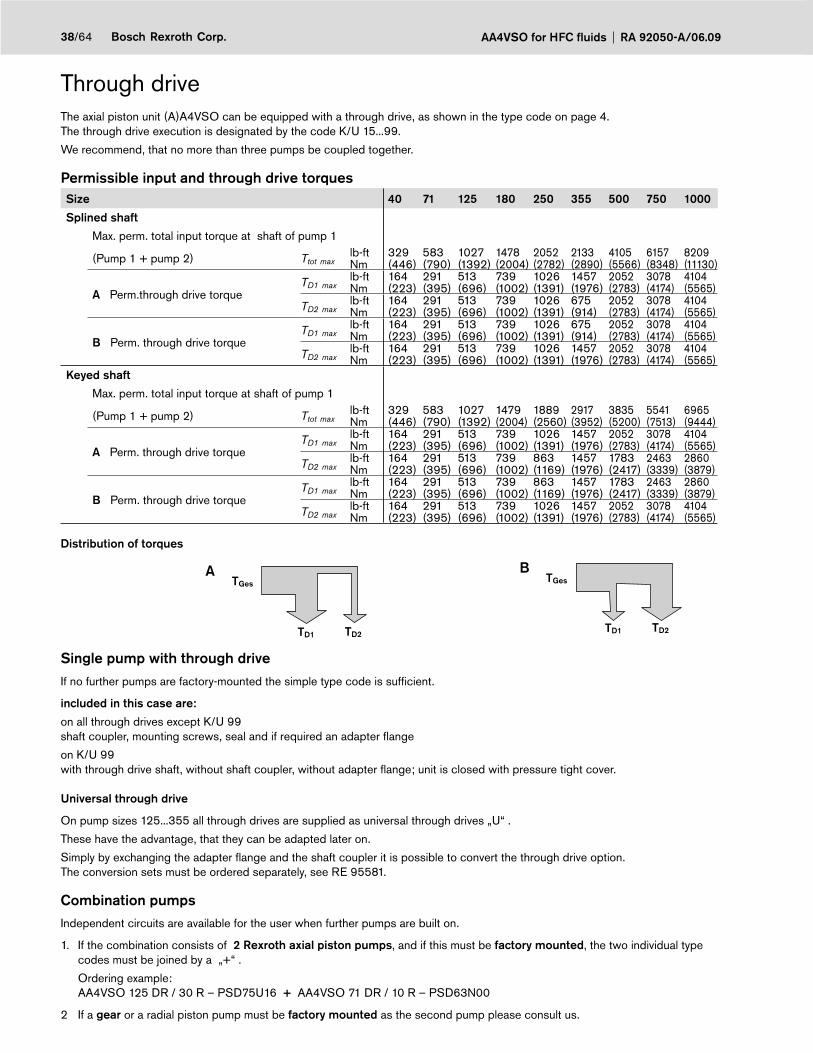
AA4VSO for HFC fluids RA 92050-A/06.0938/64 Bosch Rexroth Corp.
Through drive The axial piston unit (A)A4VSO can be equipped with a through drive, as shown in the type code on page 4.The through drive execution is designated by the code K/U 15...99.
We recommend, that no more than three pumps be coupled together.
Permissible input and through drive torquesSize 40 71 125 180 250 355 500 750 1000
Splined shaft
Max. perm. total input torque at shaft of pump 1
(Pump 1 + pump 2) Ttot maxlb-ftNm
329(446)
583(790)
1027(1392)
1478(2004)
2052(2782)
2133(2890)
4105(5566)
6157(8348)
8209(11130)
A Perm.through drive torque TD1 max
lb-ftNm
164(223)
291(395)
513(696)
739(1002)
1026(1391)
1457(1976)
2052(2783)
3078(4174)
4104(5565)
TD2 maxlb-ftNm
164(223)
291(395)
513(696)
739(1002)
1026(1391)
675(914)
2052(2783)
3078(4174)
4104(5565)
B Perm. through drive torque TD1 max
lb-ftNm
164(223)
291(395)
513(696)
739(1002)
1026(1391)
675(914)
2052(2783)
3078(4174)
4104(5565)
TD2 maxlb-ftNm
164(223)
291(395)
513(696)
739(1002)
1026(1391)
1457(1976)
2052(2783)
3078(4174)
4104(5565)
Keyed shaft
Max. perm. total input torque at shaft of pump 1
(Pump 1 + pump 2) Ttot maxlb-ftNm
329(446)
583(790)
1027(1392)
1479(2004)
1889(2560)
2917(3952)
3835(5200)
5541(7513)
6965(9444)
A Perm. through drive torqueTD1 max
lb-ftNm
164(223)
291(395)
513(696)
739(1002)
1026(1391)
1457(1976)
2052(2783)
3078(4174)
4104(5565)
TD2 maxlb-ftNm
164(223)
291(395)
513(696)
739(1002)
863(1169)
1457(1976)
1783(2417)
2463(3339)
2860(3879)
B Perm. through drive torqueTD1 max
lb-ftNm
164(223)
291(395)
513(696)
739(1002)
863(1169)
1457(1976)
1783(2417)
2463(3339)
2860(3879)
TD2 maxlb-ftNm
164(223)
291(395)
513(696)
739(1002)
1026(1391)
1457(1976)
2052(2783)
3078(4174)
4104(5565)
Distribution of torques
TGes
TD1 TD2
A
TD1 TD2
TGesB
Single pump with through driveIf no further pumps are factory-mounted the simple type code is suffi cient.
included in this case are:
on all through drives except K/U 99 shaft coupler, mounting screws, seal and if required an adapter fl ange
on K/U 99with through drive shaft, without shaft coupler, without adapter fl ange; unit is closed with pressure tight cover.
Universal through drive
On pump sizes 125...355 all through drives are supplied as universal through drives „U“ .
These have the advantage, that they can be adapted later on.
Simply by exchanging the adapter fl ange and the shaft coupler it is possible to convert the through drive option. The conversion sets must be ordered separately, see RE 95581.
Combination pumpsIndependent circuits are available for the user when further pumps are built on.
1. If the combination consists of 2 Rexroth axial piston pumps, and if this must be factory mounted, the two individual type codes must be joined by a „+“ .
Ordering example: AA4VSO 125 DR / 30 R – PSD75U16 + AA4VSO 71 DR / 10 R – PSD63N00
2 If a gear or a radial piston pump must be factory mounted as the second pump please consult us.
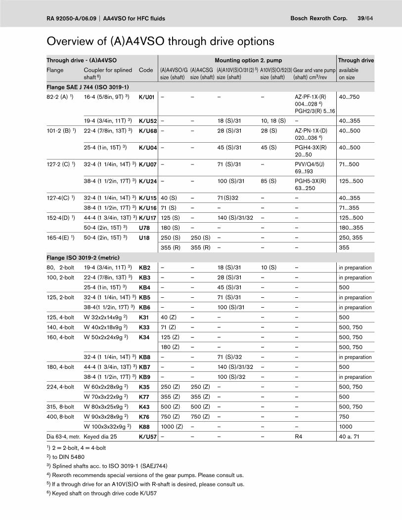
39/64Bosch Rexroth Corp.RA 92050-A/06.09 AA4VSO for HFC fluids
Overview of (A)A4VSO through drive optionsThrough drive - (A)A4VSO Mounting option 2. pump Through drive
Flange Coupler for splined shaft 6)
Code (A)A4VSO/Gsize (shaft)
(A)A4CSGsize (shaft)
(A)A10V(S)O/31(2) 5)size (shaft)
A10V(S)O/52(3)size (shaft)
Gear and vane pump(shaft) cm3/rev
available on size
Flange SAE J 744 (ISO 3019-1)
82-2 (A) 1) 16-4 (5/8in, 9T) 3) K/U01 – – – – AZ-PF-1X-(R) 004...028 4)PGH2/3(R) 5...16
40...750
19-4 (3/4in, 11T) 3) K/U52 – – 18 (S)/31 10, 18 (S) – 40...355
101-2 (B) 1) 22-4 (7/8in, 13T) 3) K/U68 – – 28 (S)/31 28 (S) AZ-PN-1X-(D) 020...036 4)
40...500
25-4 (1in, 15T) 3) K/U04 – – 45 (S)/31 45 (S) PGH4-3X(R)20...50
40...500
127-2 (C) 1) 32-4 (1 1/4in, 14T) 3) K/U07 – – 71 (S)/31 – PVV/Q4/5(J)69...193
71...500
38-4 (1 1/2in, 17T) 3) K/U24 – – 100 (S)/31 85 (S) PGH5-3X(R)63...250
125...500
127-4(C) 1) 32-4 (1 1/4in, 14T) 3) K/U15 40 (S) – 71(S)32 – – 40...355
38-4 (1 1/2in, 17T) 3) K/U16 71 (S) – – – – 71...355
152-4(D) 1) 44-4 (1 3/4in, 13T) 3) K/U17 125 (S) – 140 (S)/31/32 – – 125...500
50-4 (2in, 15T) 3) U78 180 (S) – – – – 180...355
165-4(E) 1) 50-4 (2in, 15T) 3) U18 250 (S) 250 (S) – – – 250, 355
355 (R) 355 (R) – – – 355
Flange ISO 3019-2 (metric)
80, 2-bolt 19-4 (3/4in, 11T) 3) KB2 – – 18 (S)/31 10 (S) – in preparation
100, 2-bolt 22-4 (7/8in, 13T) 3) KB3 – – 28 (S)/31 – – in preparation
25-4 (1in, 15T) 3) KB4 – – 45 (S)/31 – – 500
125, 2-bolt 32-4 (1 1/4in, 14T) 3) KB5 – – 71 (S)/31 – – in preparation
38-4(1 1/2in, 17T) 3) KB6 – – 100 (S)/31 – – in preparation
125, 4-bolt W 32x2x14x9g 2) K31 40 (Z) – – – – 500
140, 4-bolt W 40x2x18x9g 2) K33 71 (Z) – – – – 500, 750
160, 4-bolt W 50x2x24x9g 2) K34 125 (Z) – – – – 500, 750
180 (Z) – – – – 500, 750
32-4 (1 1/4in, 14T) 3) KB8 – – 71 (S)/32 – – in preparation
180, 4-bolt 44-4 (1 3/4in, 13T) 3) KB7 – – 140 (S)/31/32 – – 500
38-4 (1 1/2in, 17T) 3) KB9 – – 100 (S)/32 – – in preparation
224, 4-bolt W 60x2x28x9g 2) K35 250 (Z) 250 (Z) – – – 500, 750
W 70x3x22x9g 2) K77 355 (Z) 355 (Z) – – – 500
315, 8-bolt W 80x3x25x9g 2) K43 500 (Z) 500 (Z) – – – 500, 750
400, 8-bolt W 90x3x28x9g 2) K76 750 (Z) 750 (Z) – – – 750
W 100x3x32x9g 2) K88 1000 (Z) – – – – 1000
Dia 63-4, metr. Keyed dia 25 K/U57 – – – – R4 40 a. 71
1) 2 = 2-bolt, 4 = 4-bolt 2) to DIN 5480 3) Splined shafts acc. to ISO 3019-1 (SAEJ744)4) Rexroth recommends special versions of the gear pumps. Please consult us.5) If a through drive for an A10V(S)O with R-shaft is desired, please consult us.6) Keyed shaft on through drive code K/U57
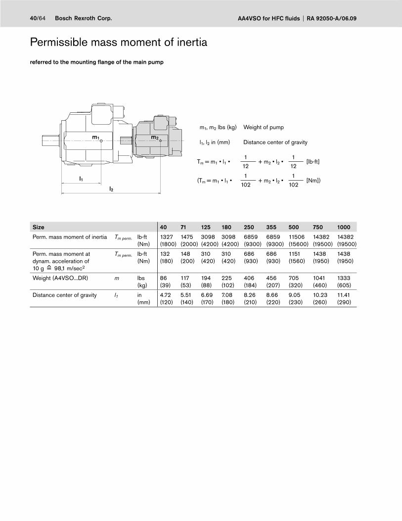
AA4VSO for HFC fluids RA 92050-A/06.0940/64 Bosch Rexroth Corp.
Permissible mass moment of inertia
referred to the mounting fl ange of the main pump
l2
l1
m1 m2
m1, m2 lbs (kg) Weight of pump
l1, l2 in (mm) Distance center of gravity
Tm = m1 • l1 • 1
+ m2 • l2 • 1
[lb-ft] 12 12
(Tm = m1 • l1 • 1
+ m2 • l2 • 1
[Nm])102 102
Size 40 71 125 180 250 355 500 750 1000
Perm. mass moment of inertia Tm perm. lb-ft(Nm)
1327(1800)
1475(2000)
3098(4200)
3098(4200)
6859(9300)
6859(9300)
11506(15600)
14382(19500)
14382(19500)
Perm. mass moment at dynam. acceleration of10 g = 98,1 m/sec2
Tm perm. lb-ft(Nm)
132(180)
148(200)
310(420)
310(420)
686(930)
686(930)
1151(1560)
1438(1950)
1438(1950)
Weight (A4VSO...DR) m lbs(kg)
86(39)
117(53)
194(88)
225(102)
406(184)
456(207)
705(320)
1041(460)
1333(605)
Distance center of gravity l1 in(mm)
4.72(120)
5.51(140)
6.69(170)
7.08(180)
8.26(210)
8.66(220)
9.05(230)
10.23(260)
11.41(290)
^
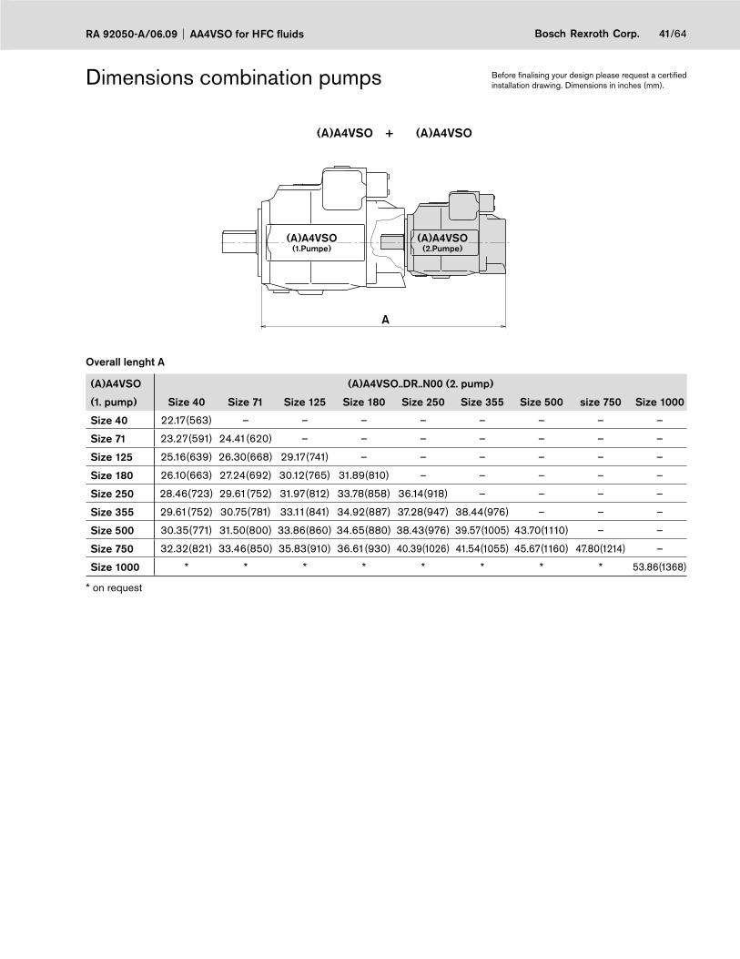
41/64Bosch Rexroth Corp.RA 92050-A/06.09 AA4VSO for HFC fluids
Dimensions combination pumps
(A)A4VSO + (A)A4VSO
A
(A)A4VSO(1.Pumpe)
(A)A4VSO(2.Pumpe)
Overall lenght A
(A)A4VSO (A)A4VSO..DR..N00 (2. pump)
(1. pump) Size 40 Size 71 Size 125 Size 180 Size 250 Size 355 Size 500 size 750 Size 1000
Size 40 22.17(563) – – – – – – – –
Size 71 23.27(591) 24.41(620) – – – – – – –
Size 125 25.16(639) 26.30(668) 29.17(741) – – – – – –
Size 180 26.10(663) 27.24(692) 30.12(765) 31.89(810) – – – – –
Size 250 28.46(723) 29.61(752) 31.97(812) 33.78(858) 36.14(918) – – – –
Size 355 29.61(752) 30.75(781) 33.11(841) 34.92(887) 37.28(947) 38.44(976) – – –
Size 500 30.35(771) 31.50(800) 33.86(860) 34.65(880) 38.43(976) 39.57(1005) 43.70(1110) – –
Size 750 32.32(821) 33.46(850) 35.83(910) 36.61(930) 40.39(1026) 41.54(1055) 45.67(1160) 47.80(1214) –
Size 1000 * * * * * * * * 53.86(1368)
* on request
Before fi nalising your design please request a certifi ed installation drawing. Dimensions in inches (mm).

AA4VSO for HFC fluids RA 92050-A/06.0942/64 Bosch Rexroth Corp.
Dimensions combination pumps
(A)A4VSO + (A)A10VSO
A
(A)A4VSO(1.Pumpe)
(A)A10VSO(2.Pumpe)
Overall lenght A
(A)A4VSO (A)A10VSO.../31 (2. pump)
(1. pump) Size 18 Size 28 Size 45 Size 71 Size 100 Size 140
Size 40 18.11(460) 19.61(498) 20.31(516) – – –
Size 71 20.16(512) 20.87(530) 21.57(548) 22.83(580) – –
Size 125 22.28(566) 22.72(577) 23.43(595) 24.72(628) 27.56(700) –
Size 180 23.23(590) 23.66(601) 24.37(619) 25.67(652) 28.50(724) 29.33(745)
Size 250 25.59(650) 26.02(661) 26.73(679) 28.03(712) 30.87(784) 31.18(792)
Size 355 * * 27.87(708) 29.17(741) * 32.32(821)
Size 500 27.56(700) 27.99(711) 28.70(729) 30.08(764) 33.74(857) 34.17(868)
Size 750 29.53(750) 29.96(761) 30.67(779) 31.97(812) 35.71(907) 36.10(917)
Size 1000 * * * * * *
* on request
Before fi nalising your design please request a certifi ed installation drawing. Dimensions in inches (mm).
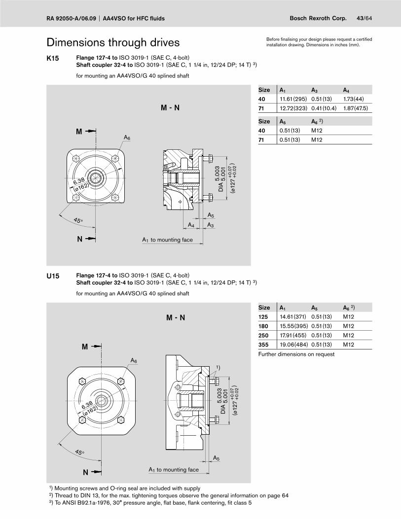
43/64Bosch Rexroth Corp.RA 92050-A/06.09 AA4VSO for HFC fluids
Dimensions through drivesK15 Flange 127-4 to ISO 3019-1 (SAE C, 4-bolt)
Shaft coupler 32-4 to ISO 3019-1 (SAE C, 1 1/4 in, 12/24 DP; 14 T) 3)
for mounting an AA4VSO/G 40 splined shaft
45º
M - N
N
M
6.38
(ø162)
A3
A1
A5
A4D
IA5.
003
5.00
1
(ø12
7+
0.07
+0.
02)
A6
Size A1 A3 A4
40 11.61(295) 0.51(13) 1.73(44)
71 12.72(323) 0.41(10.4) 1.87(47.5)
Size A5 A6 2)
40 0.51(13) M12
71 0.51(13) M12
U15 Flange 127-4 to ISO 3019-1 (SAE C, 4-bolt)Shaft coupler 32-4 to ISO 3019-1 (SAE C, 1 1/4 in, 12/24 DP; 14 T) 3)
for mounting an AA4VSO/G 40 splined shaft
M - N
N
M
6.38
(ø162)
45ºA5
A1
A61)
DIA
5.00
35.
001
(ø12
7+
0.07
+0.
02)
to mounting face
Size A1 A5 A6 2)
125 14.61(371) 0.51(13) M12
180 15.55(395) 0.51(13) M12
250 17.91(455) 0.51(13) M12
355 19.06(484) 0.51(13) M12
Further dimensions on request
1) Mounting screws and O-ring seal are included with supply2) Thread to DIN 13, for the max. tightening torques observe the general information on page 643) To ANSI B92.1a-1976, 30° pressure angle, fl at base, fl ank centering, fi t class 5
Before fi nalising your design please request a certifi ed installation drawing. Dimensions in inches (mm).
to mounting face

AA4VSO for HFC fluids RA 92050-A/06.0944/64 Bosch Rexroth Corp.
Dimensions through drivesK16 Flange 127-4 to ISO 3019-1 (SAE C, 4-bolt)
Shaft coupler 38-4 to ISO 3019-1 (SAE C-C, 1 1/2 in, 12/24 DP; 17T) 3)
for mounting an AA4VSO/G 71 splined shaft only on mainpump AA4VSO/G 71
45º
M - N
N
M
6.38
(ø162)
0.41(10.4)
12.72(323)
0.51(13)
2.05(52)
DIA
5.00
35.
001
(ø12
7+
0.07
+0.
02)
M12
U16 Flange 127-4 to ISO 3019-1 (SAE C, 4-bolt)Shaft coupler 38-4 to ISO 3019-1 (SAE C-C, 1 1/2 in, 12/24 DP; 17T) 3)
for mounting an AA4VSO/G 71 splined shaft
N
M
A1
1)
45º
M - N
A5
A6
6.38
(ø162) DIA
5.00
35.
001
(ø12
7+
0.07
+0.
02)
to mounting face
Size A1 A5 A6 2)
125 14.61(371) 0.51(13) M12
180 15.55(395) 0.51(13) M12
250 17.91(455) 0.51(13) M12
355 19.06(484) 0.51(13) M12
Further dimensions on request
1) Mounting screws and O-ring seal are included with supply2) Thread to DIN 13, for the max. tightening torques observe the general information on page 643) To ANSI B92.1a-1976, 30° pressure angle, fl at base, fl ank centering, fi t class 5
Before fi nalising your design please request a certifi ed installation drawing. Dimensions in inches (mm).
to mounting face
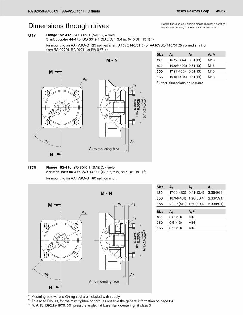
45/64Bosch Rexroth Corp.RA 92050-A/06.09 AA4VSO for HFC fluids
Dimensions through drivesU17 Flange 152-4 to ISO 3019-1 (SAE D, 4-bolt)
Shaft coupler 44-4 to ISO 3019-1 (SAE D, 1 3/4 in, 8/16 DP; 13 T) 3)
for mounting an AA4VSO/G 125 splined shaft, A10VO140/31(2) or AA10VSO 140/31(2) splined shaft S (see RA 92701, RA 92711 or RA 92714)
A6
N
M
9.02
(ø229)
45º
M - N
A5
A1
DIA
6.00
206.
0008
(ø15
2.4
+0.
05+
0.02
)
1)
to mounting face
Size A1 A5 A6 2)
125 15.12(384) 0.51(13) M16
180 16.06(408) 0.51(13) M16
250 17.91(455) 0.51(13) M16
355 19.06(484) 0.51(13) M16
Further dimensions on request
U78 Flange 152-4 to ISO 3019-1 (SAE D, 4-bolt)Shaft coupler 50-4 to ISO 3019-1 (SAE F, 2 in, 8/16 DP; 15 T) 3)
for mounting an AA4VSO/G 180 splined shaft
A6
9.02
(ø229)
DIA
6.00
206.
0008
(ø15
2.4
+0.
05+
0.02
)
N
M
45º
M - N
A5
A1
A4 A3
1)
to mounting face
Size A1 A3 A4
180 17.05(433) 0.41(10.4) 3.39(86.1)
250 18.94(481) 1.20(30.4) 2.33(59.1)
355 20.08(510) 1.20(30.4) 2.33(59.1)
Size A5 A6 2)
180 0.51(13) M16
250 0.51(13) M16
355 0.51(13) M16
1) Mounting screws and O-ring seal are included with supply2) Thread to DIN 13, for the max. tightening torques observe the general information on page 643) To ANSI B92.1a-1976, 30° pressure angle, fl at base, fl ank centering, fi t class 5
Before fi nalising your design please request a certifi ed installation drawing. Dimensions in inches (mm).
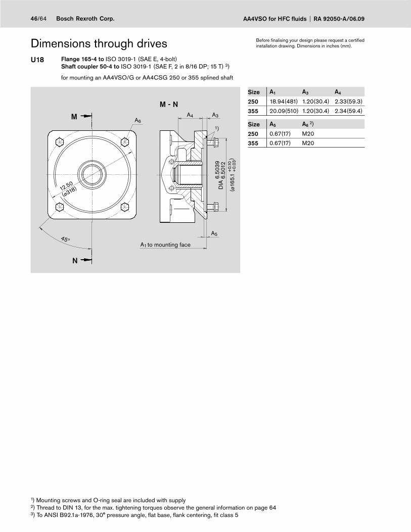
AA4VSO for HFC fluids RA 92050-A/06.0946/64 Bosch Rexroth Corp.
Dimensions through drivesU18 Flange 165-4 to ISO 3019-1 (SAE E, 4-bolt)
Shaft coupler 50-4 to ISO 3019-1 (SAE F, 2 in 8/16 DP; 15 T) 3)
for mounting an AA4VSO/G or AA4CSG 250 or 355 splined shaft
1)
12.50
(ø318) DIA
6.50
396.
5012
(ø16
5.1
+0.
10+
0.03
)
A6
N
M
45º
M - N
A5
A1
A4 A3
to mounting face
Size A1 A3 A4
250 18.94(481) 1.20(30.4) 2.33(59.3)
355 20.09(510) 1.20(30.4) 2.34(59.4)
Size A5 A6 2)
250 0.67(17) M20
355 0.67(17) M20
1) Mounting screws and O-ring seal are included with supply2) Thread to DIN 13, for the max. tightening torques observe the general information on page 643) To ANSI B92.1a-1976, 30° pressure angle, fl at base, fl ank centering, fi t class 5
Before fi nalising your design please request a certifi ed installation drawing. Dimensions in inches (mm).

47/64Bosch Rexroth Corp.RA 92050-A/06.09 AA4VSO for HFC fluids
Dimensions through drivesK31 Flange 125, 4-bolt – 125B4HW to ISO 3019-2
Shaft coupler N32x2x14x8H to DIN 5480
for mounting an A4VSO/G 40 splined shaft
M - N
N
M
6.30
ø160
45ºA5
A7A1
A4
A8
A6
1)
A3
(ø12
5+0.
07
+0.
02
DIA
4.92
44.
922
)
to mounting face
Size A1 A3 A4
500 19.88(505) 0.49(12.5) 1.52(38.5)
750 in preparation
1000 in preparation
Size A5 A6 2) A7
500 0.35(9) M12 0.59(15)
750 in preparation
1000 in preparation
Size A8
500 9.45(240)
750 in preparation
1000 in preparation
K33 Flange 140, 4-bolt B4HW to ISO 3019-2Shaft coupler N40x2x18x8H to DIN 5480
for mounting an A4VSO/G 71 splined shaft
N
M
7.09
(ø180)
45º
A8
M - N
A5
A7
A4 A3
A6
5.51
465.
5126
(ø14
0 +
0.07
+
0.02
(
DIA
A1
1)
to mounting face
Size A1 A3 A4
500 19.88(505) 0.49(12.5) 2.24(57)
750 21.85(555) 0.49(12.5) 1.75(44.5)
1000 in preparation
Size A5 A6 2) A7
500 0.35(9) M12 0.59(15)
750 0.35(9) M12 –
1000 in preparation
Size A8
500 9.45(240)
750 –
1000 in preparation
1) Mounting screws and O-ring seal are included with supply2) Thread to DIN 13, for the max. tightening torques observe the general information on page 64
Before fi nalising your design please request a certifi ed installation drawing. Dimensions in inches (mm).
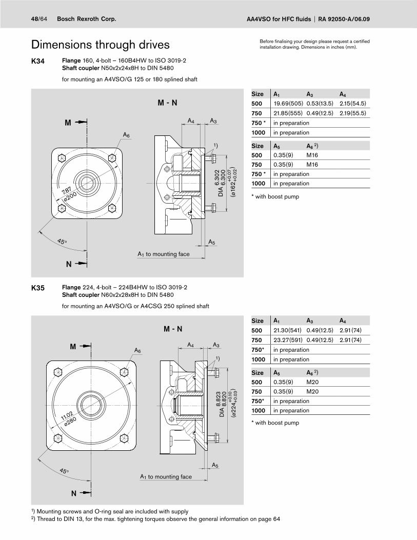
AA4VSO for HFC fluids RA 92050-A/06.0948/64 Bosch Rexroth Corp.
Dimensions through drivesK34 Flange 160, 4-bolt – 160B4HW to ISO 3019-2
Shaft coupler N50x2x24x8H to DIN 5480
for mounting an A4VSO/G 125 or 180 splined shaft
A6
N
M
45º
M - N
A5
A1
A4 A3
1)
7.87
ø200 (ø16
2+0.
07
+0.
02
DIA
6.30
26.
300
)
to mounting face
Size A1 A3 A4
500 19.69(505) 0.53(13.5) 2.15(54.5)
750 21.85(555) 0.49(12.5) 2.19(55.5)
750 * in preparation
1000 in preparation
Size A5 A6 2)
500 0.35(9) M16
750 0.35(9) M16
750 * in preparation
1000 in preparation
* with boost pump
K35 Flange 224, 4-bolt – 224B4HW to ISO 3019-2Shaft coupler N60x2x28x8H to DIN 5480
for mounting an A4VSO/G or A4CSG 250 splined shaft
1)A6
N
M
45º
M - N
A5
A1
A4 A3
11.02
ø280
(ø22
4+0.
10+
0.03
DIA
8.82
38.
820
)
to mounting face
Size A1 A3 A4
500 21.30(541) 0.49(12.5) 2.91(74)
750 23.27(591) 0.49(12.5) 2.91(74)
750* in preparation
1000 in preparation
Size A5 A6 2)
500 0.35(9) M20
750 0.35(9) M20
750* in preparation
1000 in preparation
* with boost pump
1) Mounting screws and O-ring seal are included with supply2) Thread to DIN 13, for the max. tightening torques observe the general information on page 64
Before fi nalising your design please request a certifi ed installation drawing. Dimensions in inches (mm).
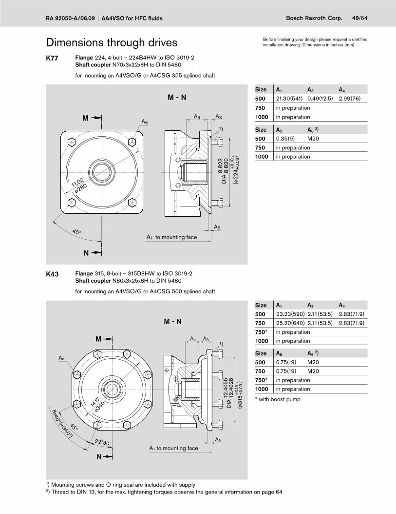
49/64Bosch Rexroth Corp.RA 92050-A/06.09 AA4VSO for HFC fluids
Dimensions through drivesK77 Flange 224, 4-bolt – 224B4HW to ISO 3019-2
Shaft coupler N70x3x22x8H to DIN 5480
for mounting an A4VSO/G or A4CSG 355 splined shaft
A6
N
M
45º
M - N
A5
A1
A4 A3
1)
11.02
ø280
(ø22
4+0.
10
+0.
03
DIA
8.82
38.
820
)to mounting face
Size A1 A3 A4
500 21.30(541) 0.49(12.5) 2.99(76)
750 in preparation
1000 in preparation
Size A5 A6 2)
500 0.35(9) M20
750 in preparation
1000 in preparation
K43 Flange 315, 8-bolt – 315D8HW to ISO 3019-2Shaft coupler N80x3x25x8H to DIN 5480
for mounting an A4VSO/G or A4CSG 500 splined shaft
M - N
22º30´
45º
8x45º (=360º)
N
M
A5
A1
A4 A3
A6
1)
(ø31
5+0.
10
DIA
12.4
055
12.4
028 )
14.17
ø360
+0.
03
to mounting face
Size A1 A3 A4
500 23.23(590) 2.11(53.5) 2.83(71.9)
750 25.20(640) 2.11(53.5) 2.83(71.9)
750* in preparation
1000 in preparation
Size A5 A6 2)
500 0.75(19) M20
750 0.75(19) M20
750* in preparation
1000 in preparation
* with boost pump
1) Mounting screws and O-ring seal are included with supply2) Thread to DIN 13, for the max. tightening torques observe the general information on page 64
Before fi nalising your design please request a certifi ed installation drawing. Dimensions in inches (mm).

AA4VSO for HFC fluids RA 92050-A/06.0950/64 Bosch Rexroth Corp.
Dimensions through drivesK76 Flange 400, 8-bolt – 400D8HW to ISO 3019-2
Shaft coupler N90x3x28x8H to DIN 5480
for mounting an A4VSO/G or A4CSG 750 splined shaft
M - N
22º30´
45º
8x45º (=360º)
N
M
A5
A1
A4 A3
A6
1)
(ø40
0+0.
10
DIA
15.7
520
15.7
492 )
17.72
ø450
+0.
03
to mounting face
Size A1 A3 A4
750 25.79(655) 2.09(53) 4.09(104)
750* in preparation
1000 in preparation
Size A5 A6 2)
750 0.75(19) M20
750* in preparation
1000 in preparation
* with boost pump
K88 Flange 400, 8-bolt – 400D8HW to ISO 3019-2Shaft coupler N100x3x32x8H to DIN 5480
for mounting an A4VSO/G 1000 splined shaft
Size 1000
22º30´
45º
8x45º (=360º)1)
N
M
M20 2)
19
28.66(728)
M - N
4.17(106)
2.09(53)
(ø40
0+0.
10
DIA
15.7
520
15.7
492 )
17.72
ø450
+0.
03
1) Mounting screws and O-ring seal are included with supply2) Thread to DIN 13, for the max. tightening torques observe the general information on page 64
Before fi nalising your design please request a certifi ed installation drawing. Dimensions in inches (mm).
to mounting face
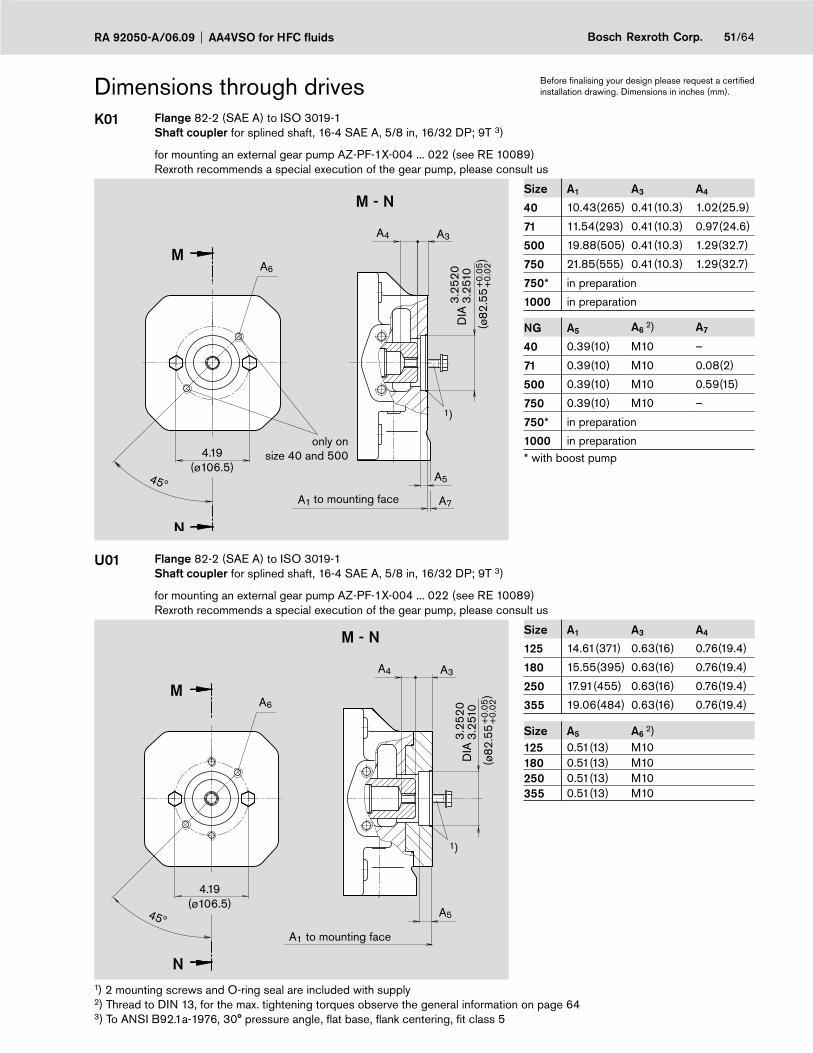
51/64Bosch Rexroth Corp.RA 92050-A/06.09 AA4VSO for HFC fluids
Dimensions through drivesK01 Flange 82-2 (SAE A) to ISO 3019-1
Shaft coupler for splined shaft, 16-4 SAE A, 5/8 in, 16/32 DP; 9T 3)
for mounting an external gear pump AZ-PF-1X-004 ... 022 (see RE 10089)Rexroth recommends a special execution of the gear pump, please consult us
1)
A6
N
M
45º
M - N
A5
A1
A4 A3
A7
4.19(ø106.5)
(ø82
.55
DIA
3.25
203.
2510
)+
0.05
+0.
02to mounting face
only on size 40 and 500
Size A1 A3 A4
40 10.43(265) 0.41(10.3) 1.02(25.9)
71 11.54(293) 0.41(10.3) 0.97(24.6)
500 19.88(505) 0.41(10.3) 1.29(32.7)
750 21.85(555) 0.41(10.3) 1.29(32.7)
750* in preparation
1000 in preparation
NG A5 A6 2) A7
40 0.39(10) M10 –
71 0.39(10) M10 0.08(2)
500 0.39(10) M10 0.59(15)
750 0.39(10) M10 –
750* in preparation
1000 in preparation* with boost pump
U01 Flange 82-2 (SAE A) to ISO 3019-1Shaft coupler for splined shaft, 16-4 SAE A, 5/8 in, 16/32 DP; 9T 3)
for mounting an external gear pump AZ-PF-1X-004 ... 022 (see RE 10089)Rexroth recommends a special execution of the gear pump, please consult us
A6
N
M
45º
M - N
A5
A1
A4 A3
1)
4.19(ø106.5)
(ø82
.55
DIA
3.25
203.
2510
)+
0.05
+0.
02
to mounting face
Size A1 A3 A4
125 14.61(371) 0.63(16) 0.76(19.4)
180 15.55(395) 0.63(16) 0.76(19.4)
250 17.91(455) 0.63(16) 0.76(19.4)
355 19.06(484) 0.63(16) 0.76(19.4)
Size A5 A6 2)
125 0.51(13) M10180 0.51(13) M10250 0.51(13) M10355 0.51(13) M10
1) 2 mounting screws and O-ring seal are included with supply2) Thread to DIN 13, for the max. tightening torques observe the general information on page 643) To ANSI B92.1a-1976, 30° pressure angle, fl at base, fl ank centering, fi t class 5
Before fi nalising your design please request a certifi ed installation drawing. Dimensions in inches (mm).

AA4VSO for HFC fluids RA 92050-A/06.0952/64 Bosch Rexroth Corp.
Dimensions through drivesK52 Flange 82-2 (SAE A) to ISO 3019-1
Shaft coupler for splined shaft, 19-4 SAE A-B, 3/4 in, 16/32 DP; 11T 3)
for mounting an A10VSO 18/31 splined shaft S (see RA 92711) orA10VSO10 or 18/52 splined shaft S (see RA 92703)
1)
A6
N
M
45º
M - N
A5
A1
A4 A3
4.19(ø106.5)
(ø82
.55
DIA
3.25
203.
2510
)+
0.05
+0.
02
to mounting face
Size A1 A3 A4
40 10.43(265) 0.41(10.5) 1.33(33.8)
71 12.48(317) 0.41(10.5) 1.18(30)
500 in preparation
750 in preparation
1000 in preparation
NG A5 A6 2)
40 0.39(10) M10
71 0.39(10) M10
500 in preparation
750 in preparation
1000 in preparation
U52 Flange 82-2 (SAE A) to ISO 3019-1Shaft coupler for splined shaft, 19-4 SAE A-B, 3/4 in, 16/32 DP; 11T 3)
for mounting an A10VSO 18/31 splined shaft S (see RA 92711) orA10VSO10 or 18/52 splined shaft S (see RA 92703)
A6
N
M
45º
M - N
A5
A1
1)
4.19(ø106.5)
(ø82
.55
DIA
3.25
203.
2510
)+
0.05
+0.
02
to mounting face
Size A1 A5 A6 2)
125 14.61(371) 0.51(13) M10
180 15.55(395) 0.51(13) M10
250 17.91(455) 0.51(13) M10
355 19.06(484) 0.51(13) M10
Further dimensions on request
1) 2 mounting screws and O-ring seal are included with supply2) Thread to DIN 13, for the max. tightening torques observe the general information on page 643) To ANSI B92.1a-1976, 30° pressure angle, fl at base, fl ank centering, fi t class 5
Before fi nalising your design please request a certifi ed installation drawing. Dimensions in inches (mm).
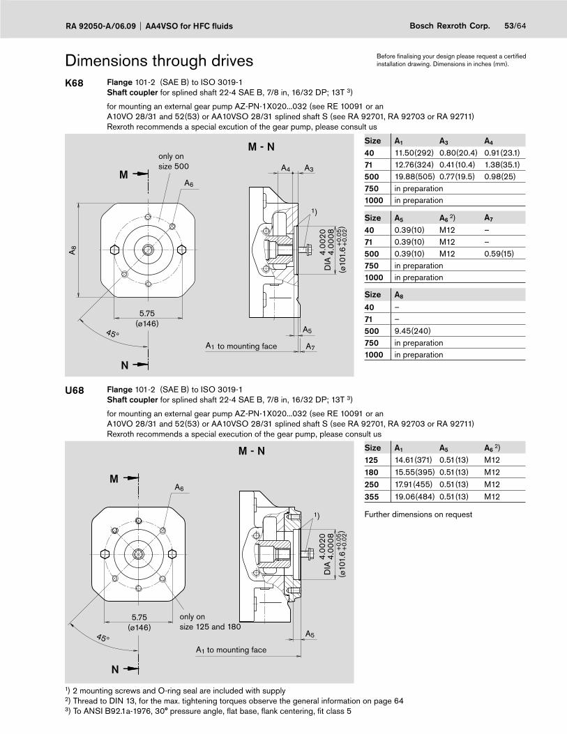
53/64Bosch Rexroth Corp.RA 92050-A/06.09 AA4VSO for HFC fluids
Dimensions through drivesK68 Flange 101-2 (SAE B) to ISO 3019-1
Shaft coupler for splined shaft 22-4 SAE B, 7/8 in, 16/32 DP; 13T 3)
for mounting an external gear pump AZ-PN-1X020...032 (see RE 10091 or an A10VO 28/31 and 52(53) or AA10VSO 28/31 splined shaft S (see RA 92701, RA 92703 or RA 92711) Rexroth recommends a special excution of the gear pump, please consult us
A6
N
M
45º
M - N
A5
A1
A4 A3
A7
A8
1)
5.75(ø146)
(ø10
1.6
DIA
4.00
204.
0008
)+
0.05
+0.
02to mounting face
only onsize 500
Size A1 A3 A4
40 11.50(292) 0.80(20.4) 0.91(23.1)71 12.76(324) 0.41(10.4) 1.38(35.1)500 19.88(505) 0.77(19.5) 0.98(25)750 in preparation1000 in preparation
Size A5 A6 2) A7
40 0.39(10) M12 –71 0.39(10) M12 –500 0.39(10) M12 0.59(15)750 in preparation1000 in preparation
Size A8
40 –71 –500 9.45(240)750 in preparation1000 in preparation
U68 Flange 101-2 (SAE B) to ISO 3019-1Shaft coupler for splined shaft 22-4 SAE B, 7/8 in, 16/32 DP; 13T 3)
for mounting an external gear pump AZ-PN-1X020...032 (see RE 10091 or an A10VO 28/31 and 52(53) or AA10VSO 28/31 splined shaft S (see RA 92701, RA 92703 or RA 92711) Rexroth recommends a special execution of the gear pump, please consult us
A6
N
M
45º
M - N
A5
A1
1)
5.75(ø146)
(ø10
1.6
DIA
4.00
204.
0008
)+
0.05
+0.
02
only onsize 125 and 180
to mounting face
Size A1 A5 A6 2)
125 14.61(371) 0.51(13) M12
180 15.55(395) 0.51(13) M12250 17.91(455) 0.51(13) M12
355 19.06(484) 0.51(13) M12
Further dimensions on request
1) 2 mounting screws and O-ring seal are included with supply2) Thread to DIN 13, for the max. tightening torques observe the general information on page 643) To ANSI B92.1a-1976, 30° pressure angle, fl at base, fl ank centering, fi t class 5
Before fi nalising your design please request a certifi ed installation drawing. Dimensions in inches (mm).
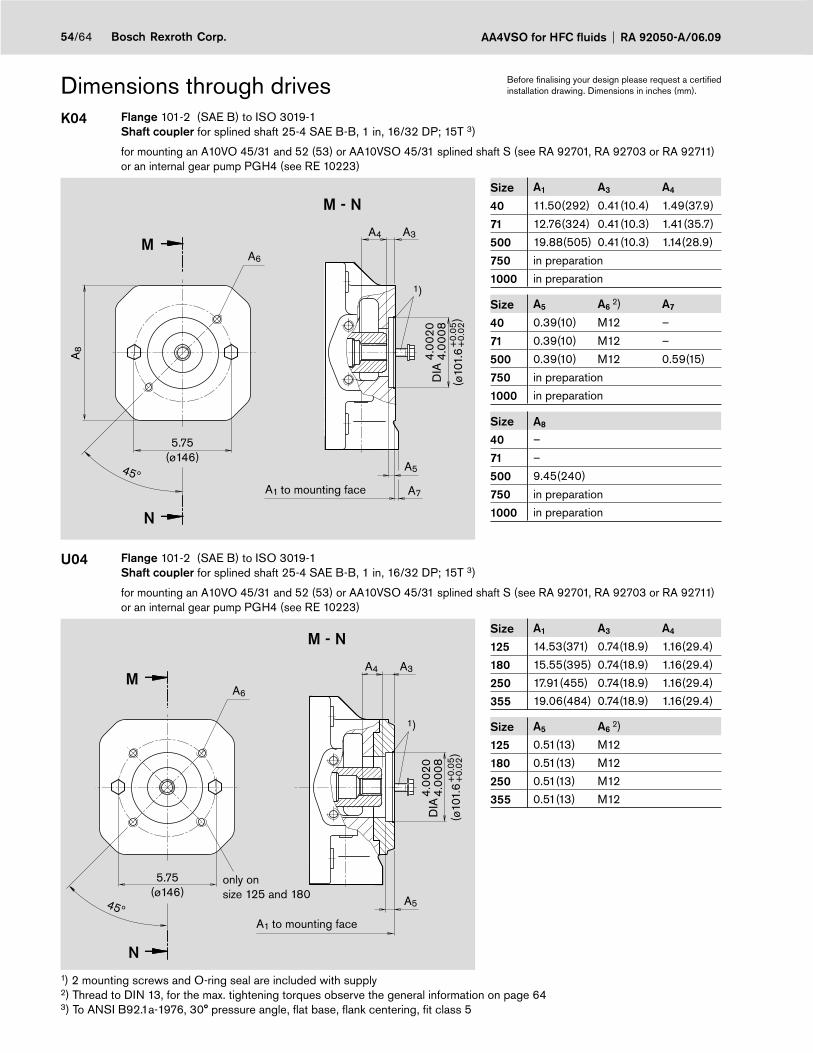
AA4VSO for HFC fluids RA 92050-A/06.0954/64 Bosch Rexroth Corp.
Dimensions through drivesK04 Flange 101-2 (SAE B) to ISO 3019-1
Shaft coupler for splined shaft 25-4 SAE B-B, 1 in, 16/32 DP; 15T 3)
for mounting an A10VO 45/31 and 52 (53) or AA10VSO 45/31 splined shaft S (see RA 92701, RA 92703 or RA 92711) or an internal gear pump PGH4 (see RE 10223)
1)
A6
N
M
45º
M - N
A5
A1
A4 A3
A7
A8
5.75(ø146)
(ø10
1.6
DIA
4.00
204.
0008
)+
0.05
+0.
02
to mounting face
Size A1 A3 A4
40 11.50(292) 0.41(10.4) 1.49(37.9)
71 12.76(324) 0.41(10.3) 1.41(35.7)
500 19.88(505) 0.41(10.3) 1.14(28.9)
750 in preparation
1000 in preparation
Size A5 A6 2) A7
40 0.39(10) M12 –
71 0.39(10) M12 –
500 0.39(10) M12 0.59(15)
750 in preparation
1000 in preparation
Size A8
40 –
71 –
500 9.45(240)
750 in preparation
1000 in preparation
U04 Flange 101-2 (SAE B) to ISO 3019-1Shaft coupler for splined shaft 25-4 SAE B-B, 1 in, 16/32 DP; 15T 3)
for mounting an A10VO 45/31 and 52 (53) or AA10VSO 45/31 splined shaft S (see RA 92701, RA 92703 or RA 92711) or an internal gear pump PGH4 (see RE 10223)
1)
A6
N
M
45º
M - N
A5
A1
A4 A3
5.75(ø146)
(ø10
1.6
DIA
4.00
204.
0008
)+
0.05
+0.
02
to mounting face
only onsize 125 and 180
Size A1 A3 A4
125 14.53(371) 0.74(18.9) 1.16(29.4)
180 15.55(395) 0.74(18.9) 1.16(29.4)
250 17.91(455) 0.74(18.9) 1.16(29.4)
355 19.06(484) 0.74(18.9) 1.16(29.4)
Size A5 A6 2)
125 0.51(13) M12
180 0.51(13) M12
250 0.51(13) M12
355 0.51(13) M12
1) 2 mounting screws and O-ring seal are included with supply2) Thread to DIN 13, for the max. tightening torques observe the general information on page 643) To ANSI B92.1a-1976, 30° pressure angle, fl at base, fl ank centering, fi t class 5
Before fi nalising your design please request a certifi ed installation drawing. Dimensions in inches (mm).

55/64Bosch Rexroth Corp.RA 92050-A/06.09 AA4VSO for HFC fluids
Dimensions through drivesK07 Flange 127-2 (SAE C) to ISO 3019-1
Shaft coupler for splined shaft 32-4 SAE C, 1 1/4 in, 12/24 DP; 14T 3)
for mounting an A10VO 71/31 or AA10VSO 71/31 splined shaft S (see RA 92701 or RA 92711)
1)
A6
N
M
45º
M - N
A5
A1
A4 A3
A7
A8
7.13(ø181)
(ø12
7
DIA
5.00
205.
0008
)+
0.05
+0.
02to mounting face
Size A1 A3 A4
71 12.72(323) 0.41(10.4) 1.87(47.6)
500 19.88(505) 0.44(11.3) 1.58(40.2)
750 in preparation
1000 in preparation
Size A5 A6 2) A7
71 0.51(13) M16 –
500 0.51(13) M16 0.59(15)
750 in preparation
1000 in preparation
Size A8
71 –
500 9.45(240)
750 in preparation
1000 in preparation
U07 Flange 127-2 (SAE C) to ISO 3019-1Shaft coupler for splined shaft 32-4 SAE C, 1 1/4 in, 12/24 DP; 14T 3)
for mounting an A10VO 71/31 or AA10VSO 71/31 splined shaft S (see RA 92701 or RA 92711)
1)
A6
N
M
45º
M - N
A5
A1
A4 A3
7.13(ø181)
(ø12
7
DIA
5.00
205.
0008
)+
0.05
+0.
02
to mounting face
Size A1 A3 A4
125 14.53(371) 0.82(20.9) 1.49(37.9)
180 15.55(395) 0.82(20.9) 1.49(37.9)
250 17.91(455) 0.82(20.9) 1.49(37.9)
355 19.06(484) 0.82(20.9) 1.49(37.9)
Size A5 A6 2)
125 0.51(13) M16
180 0.51(13) M16
250 0.51(13) M16
355 0.51(13) M16
1) 2 mounting screws and O-ring seal are included with supply2) Thread to DIN 13, for the max. tightening torques observe the general information on page 643) To ANSI B92.1a-1976, 30° pressure angle, fl at base, fl ank centering, fi t class 5
Before fi nalising your design please request a certifi ed installation drawing. Dimensions in inches (mm).
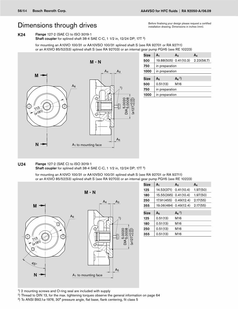
AA4VSO for HFC fluids RA 92050-A/06.0956/64 Bosch Rexroth Corp.
Dimensions through drivesK24 Flange 127-2 (SAE C) to ISO 3019-1
Shaft coupler for splined shaft 38-4 SAE C-C, 1 1/2 in, 12/24 DP; 17T 3)
for mounting an A10VO 100/31 or AA10VSO 100/31 splined shaft S (see RA 92701 or RA 92711) or an A10VO 85/52(53) splined shaft S (see RA 92703) or an internal gear pump PGH5 (see RE 10223)
M - N
A5
A1
A4 A3
A6
N
M
1)
7.13
(ø181)
(ø12
7
DIA
5.00
205.
0008
)+
0.05
+0.
02
to mounting face
Size A1 A3 A4
500 19.88(505) 0.41(10.3) 2.23(56.7)
750 in preparation
1000 in preparation
Size A5 A6 2)
500 0.51(13) M16
750 in preparation
1000 in preparation
U24 Flange 127-2 (SAE C) to ISO 3019-1Shaft coupler for splined shaft 38-4 SAE C-C, 1 1/2 in, 12/24 DP; 17T 3)
for mounting an A10VO 100/31 or AA10VSO 100/31 splined shaft S (see RA 92701 or RA 92711) or an A10VO 85/52(53) splined shaft S (see RA 92703) or an internal gear pump PGH5 (see RE 10223)
45º
1)
M - N
A5
A1
A4 A3
A6
N
M
7.13
(ø181)
(ø12
7
DIA
5.00
205.
0008
)+
0.05
+0.
02
to mounting face
Size A1 A3 A4
125 14.53(371) 0.41(10.4) 1.97(50)
180 15.55(395) 0.41(10.4) 1.97(50)
250 17.91(455) 0.49(12.4) 2.17(55)
355 19.06(484) 0.49(12.4) 2.17(55)
Size A5 A6 2)
125 0.51(13) M16
180 0.51(13) M16
250 0.51(13) M16
355 0.51(13) M16
1) 2 mounting screws and O-ring seal are included with supply2) Thread to DIN 13, for the max. tightening torques observe the general information on page 643) To ANSI B92.1a-1976, 30° pressure angle, fl at base, fl ank centering, fi t class 5
Before fi nalising your design please request a certifi ed installation drawing. Dimensions in inches (mm).

57/64Bosch Rexroth Corp.RA 92050-A/06.09 AA4VSO for HFC fluids
Dimensions through drivesK17 Flange 152-4 (SAE D) to ISO 3019-1
Shaft coupler for splined shaft 44-4 SAE D, 1 3/4 in, 8/16 DP; 13T 3)
for mounting an A10VO 140/31 or AA10VSO 140/31 splined shaft S (see RA 92701 or RA 92711)
N
M A6
45º
M - N
A5
A1
A4 A3
1)
8.00
(ø228.5)
(ø15
2.4
DIA
6.00
206.
0008
)+
0.05
+0.
02to mounting face
Size A1 A3 A4
500 19.88(505) 0.41(10.4) 2.35(59.6)
750 in preparation
1000 in preparation
Size A5 A6 2)
500 0.51(13) M16
750 in preparation
1000 in preparation
U17 Flange 152-4 (SAE D) to ISO 3019-1Shaft coupler for splined shaft 44-4 SAE D, 1 3/4 in, 8/16 DP; 13T 3)
for mounting an A10VO 140/31 or AA10VSO 140/31 splined shaft S (see RA 92701 or RA 92711)
N
M A6
45º
M - N
A5
A1
A4 A3
1)
8.00
(ø228.5)
(ø15
2.4
DIA
6.00
206.
0008
)+
0.05
+0.
02
to mounting face
Size A1 A3 A4
180 16.06(408) 0.41(10.4) 2.44(62)
250 17.91(455) 0.42(10.6) 2.44(62)
355 19.06(484) 0.42(10.6) 2.44(62)
Size A5 A6 2)
180 0.51(13) M16
250 0.51(13) M16
355 0.51(13) M16
1) 2 mounting screws and O-ring seal are included with supply2) Thread to DIN 13, for the max. tightening torques observe the general information on page 643) To ANSI B92.1a-1976, 30° pressure angle, fl at base, fl ank centering, fi t class 5
Before fi nalising your design please request a certifi ed installation drawing. Dimensions in inches (mm).
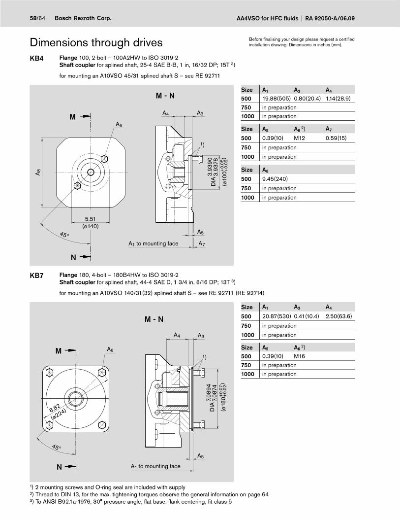
AA4VSO for HFC fluids RA 92050-A/06.0958/64 Bosch Rexroth Corp.
Dimensions through drivesKB4 Flange 100, 2-bolt – 100A2HW to ISO 3019-2
Shaft coupler for splined shaft, 25-4 SAE B-B, 1 in, 16/32 DP; 15T 3)
for mounting an A10VSO 45/31 splined shaft S – see RE 92711
A8
1)
A6
N
M
45º
M - N
A5
A1
A4 A3
A7
(ø10
0
DIA
3.93
903.
9378
)+
0.05
+0.
025.51
(ø140)
to mounting face
Size A1 A3 A4
500 19.88(505) 0.80(20.4) 1.14(28.9)
750 in preparation
1000 in preparation
Size A5 A6 2) A7
500 0.39(10) M12 0.59(15)
750 in preparation
1000 in preparation
Size A8
500 9.45(240)
750 in preparation
1000 in preparation
KB7 Flange 180, 4-bolt – 180B4HW to ISO 3019-2Shaft coupler for splined shaft, 44-4 SAE D, 1 3/4 in, 8/16 DP; 13T 3)
for mounting an A10VSO 140/31(32) splined shaft S – see RE 92711 (RE 92714)
A6
N
M
45º
M - N
A4 A3
A5
A1
1)
8.82
(ø224) (ø18
0
DIA
7.08
947.
0874
)+
0.07
+0.
02
to mounting face
Size A1 A3 A4
500 20.87(530) 0.41(10.4) 2.50(63.6)
750 in preparation
1000 in preparation
Size A5 A6 2)
500 0.39(10) M16
750 in preparation
1000 in preparation
1) 2 mounting screws and O-ring seal are included with supply2) Thread to DIN 13, for the max. tightening torques observe the general information on page 643) To ANSI B92.1a-1976, 30° pressure angle, fl at base, fl ank centering, fi t class 5
Before fi nalising your design please request a certifi ed installation drawing. Dimensions in inches (mm).

59/64Bosch Rexroth Corp.RA 92050-A/06.09 AA4VSO for HFC fluids
Dimensions through drivesK57 dia. 63 metric, 4-bolt
Shaft coupler for keyed shaft dia. 25
for mounting a radial piston pump R4 (see RE 11263)
(ø25H7)A
6
N
M
45º
M - N
A4 A3
A5
A1
(28.
3+0.
2 )(8JS8) A7
DIA
3.11
(ø80
)
1)
(ø63
DIA
2.48
152.
4807 )
H7
1.122
1.114
0.98510.9843
0.31540.3145
to mounting face
Size A1 A3 A4
40 11.42(290) 0.43(11) 2.20(56)
71 12.64(321) 0.43(10.9) 1.65(42)
500 in preparation
750 in preparation
Size A5 A6 2) A7
40 0.31(8) M8 0.35(9)
71 0.31(8) M8 0.35(9)
500 in preparation
750 in preparationSizes 125...355 with U-through drive in preparation
1) Mounting screws and O-ring seal are included with supply2) Thread to DIN 13, for the max. tightening torques observe the general information on page 64
Before fi nalising your design please request a certifi ed installation drawing. Dimensions in inches (mm).
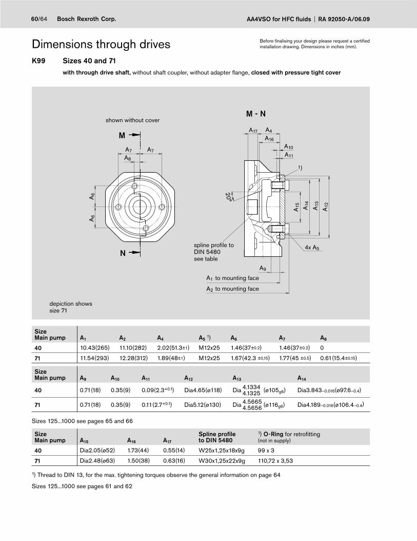
AA4VSO for HFC fluids RA 92050-A/06.0960/64 Bosch Rexroth Corp.
Dimensions through drivesK99 Sizes 40 and 71
with through drive shaft, without shaft coupler, without adapter fl ange, closed with pressure tight cover
N
M
M - N
A9
A1
A4
A10
4x A5
A2
A16
A17
A11
A15 A14
A12A13
A7A7
A8
A6
A6
20°
1)
to mounting face
shown without cover
spline profi le toDIN 5480 see table
depiction shows size 71
to mounting face
SizeMain pump A1 A2 A4 A5 1) A6 A7 A8
40 10.43(265) 11.10(282) 2.02(51.3±1) M12x25 1.46(37±0.2) 1.46(37±0.2) 0
71 11.54(293) 12.28(312) 1.89(48±1) M12x25 1.67(42.3 ±0,15) 1.77(45 ±0.5) 0.61(15.4±0.15)
SizeMain pump A9 A10 A11 A12 A13 A14
40 0.71(18) 0.35(9) 0.09(2.3+0.1) Dia4.65(ø118) Dia 4.13344.1325 (ø105g6) Dia3.843–0.016(ø97.6–0.4)
71 0.71(18) 0.35(9) 0.11(2.7+0.1) Dia5.12(ø130) Dia 4.56654.5656 (ø116g6) Dia4.189–0.016(ø106.4–0.4)
Sizes 125...1000 see pages 65 and 66
SizeMain pump A15 A16 A17
Spline profi leto DIN 5480
1) O-Ring for retrofi tting(not in supply)
40 Dia2.05(ø52) 1.73(44) 0.55(14) W25x1,25x18x9g 99 x 3
71 Dia2.48(ø63) 1.50(38) 0.63(16) W30x1,25x22x9g 110,72 x 3,53
1) Thread to DIN 13, for the max. tightening torques observe the general information on page 64
Sizes 125...1000 see pages 61 and 62
Before fi nalising your design please request a certifi ed installation drawing. Dimensions in inches (mm).
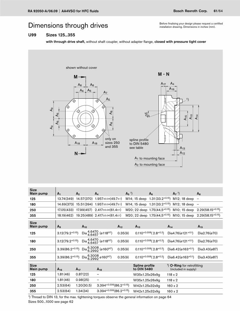
61/64Bosch Rexroth Corp.RA 92050-A/06.09 AA4VSO for HFC fluids
Dimensions through drivesU99 Sizes 125...355
with through drive shaft, without shaft coupler, without adapter fl ange, closed with pressure tight cover
N
M M - N
A1
A4
A12
A13
A2
A16
A17
A15 A10
A8
A14
A8A8
A18A18
A6
A6
A6
20°A8A
9A
9
A6 A7
A5 1)
to mounting face
to mounting face
shown without cover
spline profi le to DIN 5480 see table
only on sizes 250and 355
SizeMain pump A1 A2 A4 A5 1) A6 A7 1) A8
125 13.74(349) 14.57(370) 1.957±0.04(49.7±1) M14; 15 deep 1.31(33.2+0.15) M12; 18 deep –
180 14.69(373) 15.51(394) 1.957±0.04(49.7±1) M14; 15 deep 1.31(33.2+0.15) M12; 18 deep –
250 17.05(433) 17.99(457) 2.417±0.04(61.4±1) M20; 22 deep 1.75(44,5+0.15) M10; 15 deep 2.29(58.15+0.15)
355 18.19(462) 19.25(489) 2.417±0.04(61.4±1) M20; 22 deep 1.75(44,5+0.15) M10; 15 deep 2.29(58.15+0.15)
SizeMain pump A9 A10 A12 A13 A14 A15
125 3.12(79.2+0.15) Dia 4.64704.6457 (ø118H7) 0.35(9) 0.110+0.008( 2.8+0.2) Dia4.76(ø121+0.1) Dia2.76(ø70)
180 3.12(79.2+0.15) Dia 4.64704.6457 (ø118H7) 0.35(9) 0.110+0.008( 2.8+0.2) Dia4.76(ø121+0.1) Dia2.76(ø70)
250 3.39(86.2+0.15) Dia 6.30086.2992 (ø160H7) 0.35(9) 0.110+0.008( 2.8+0.2) Dia6.42(ø163+0.1) Dia3.43(ø87)
355 3.39(86.2+0.15) Dia 6.30086.2992 ø160H7) 0.35(9) 0.110+0.008( 2.8+0.2) Dia6.42(ø163+0.1) Dia3.43(ø87)
SizeMain pump A16 A17 A18
Spline profi leto DIN 5480
1) O-Ring for retrofi tting (included in supply)
125 1.81(46) 0.87(22) – W35x1.25x26x9g 118 x 2
180 1.81(46) 0.98(25) – W35x1.25x26x9g 118 x 2
250 2.53(64) 1.20(30.5) 3.394+0.006(86.2+0.15) W42x1.25x32x9g 160 x 2
355 2.53(64) 1.34(34) 3.394+0.006(86.2+0.15) W42x1.25x32x9g 160 x 21) Thread to DIN 13, for the max. tightening torques observe the general information on page 64 Sizes 500...1000 see page 62
Before fi nalising your design please request a certifi ed installation drawing. Dimensions in inches (mm).
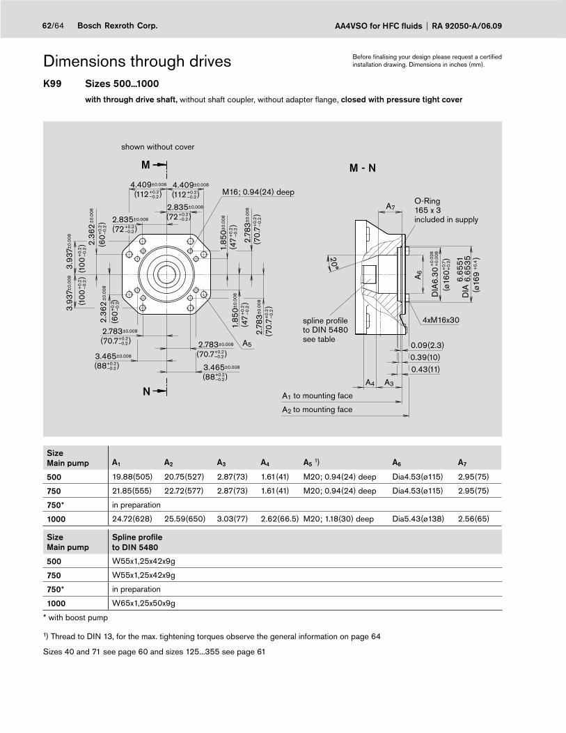
AA4VSO for HFC fluids RA 92050-A/06.0962/64 Bosch Rexroth Corp.
Dimensions through drivesK99 Sizes 500...1000
with through drive shaft, without shaft coupler, without adapter fl ange, closed with pressure tight cover
A5
(60+
0.2
—0.
2
(100
+0.
2—
0.2
M16; 0.94(24) deep
2.36
2±
0.00
8
3.93
7±0.
008
(100
+0.
2—
0.2
3.93
7±0.
008 )
(60+
0.2
—0.
2
2.36
2±
0.00
8
)
(70.
7+0.
2—
0.2
2.78
3±0.
008
)(7
0.7+
0.2
—0.
2
2.78
3±0.
008
)
(47
+0.
2—
0.2
1.85
0±0.
008
)
N
M M - N
0.09(2.3)0.39(10)0.43(11)
A3
A2
A1
A4
20°
A7
A6
(ø16
0+0.
7+
0.2
(ø16
9+
0.4
4xM16x30
)
)
(47
+0.
2—
0.2
1.85
0±0.
008
)
(70.7+0.2—0.2
2.783±0.008
)
(70.7+0.2—0.2
2.783±0.008
)
(88+0.2—0.2
3.465±0.008
)(88+0.2
—0.2
3.465±0.008
)
(72+0.2—0.2
2.835±0.008
)
(112+0.2—0.2
4.409±0.008
)
(72+0.2—0.2
2.835±0.008
)
(112+0.2—0.2
4.409±0.008
)
DIA
6.30
)
+0.
028
+0.
008
)D
IA6.
6551
6.65
35
to mounting face
to mounting face
spline profi leto DIN 5480 see table
shown without cover
O-Ring 165 x 3included in supply
SizeMain pump A1 A2 A3 A4 A5 1) A6 A7
500 19.88(505) 20.75(527) 2.87(73) 1.61(41) M20; 0.94(24) deep Dia4.53(ø115) 2.95(75)
750 21.85(555) 22.72(577) 2.87(73) 1.61(41) M20; 0.94(24) deep Dia4.53(ø115) 2.95(75)
750* in preparation
1000 24.72(628) 25.59(650) 3.03(77) 2.62(66.5) M20; 1.18(30) deep Dia5.43(ø138) 2.56(65)
SizeMain pump
Spline profi leto DIN 5480
500 W55x1,25x42x9g
750 W55x1,25x42x9g
750* in preparation
1000 W65x1,25x50x9g
* with boost pump
1) Thread to DIN 13, for the max. tightening torques observe the general information on page 64
Sizes 40 and 71 see page 60 and sizes 125...355 see page 61
Before fi nalising your design please request a certifi ed installation drawing. Dimensions in inches (mm).
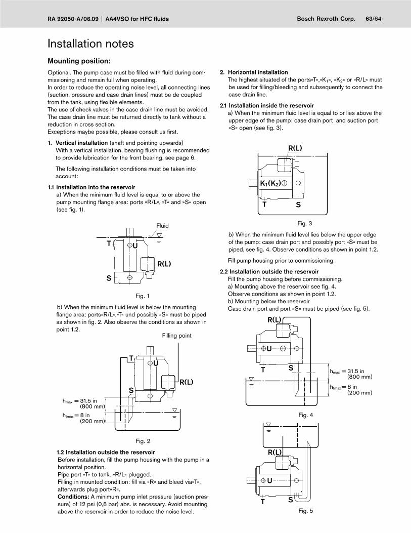
63/64Bosch Rexroth Corp.RA 92050-A/06.09 AA4VSO for HFC fluids
Installation notesMounting position:Optional. The pump case must be fi lled with fl uid during com-missioning and remain full when operating.In order to reduce the operating noise level, all connecting lines (suction, pressure and case drain lines) must be de-coupled from the tank, using fl exible elements.The use of check valves in the case drain line must be avoided.The case drain line must be returned directly to tank without a reduction in cross section.Exceptions maybe possible, please consult us fi rst.
1. Vertical installation (shaft end pointing upwards) With a vertical installation, bearing fl ushing is recommended
to provide lubrication for the front bearing, see page 6.
The following installation conditions must be taken into account:
1.1 Installation into the reservoir a) When the minimum fl uid level is equal to or above the
pump mounting fl ange area: ports »R/L«, »T« and »S« open (see fi g. 1).
T
S
R(L)
U
Fig. 1
b) When the minimum fl uid level is below the mounting fl ange area: ports»R/L«,»T« und possibly »S« must be piped as shown in fi g. 2. Also observe the conditions as shown in point 1.2.
T
SR(L)
hmax = 31.5 in
htmax = 8 in
U
(200 mm)
(800 mm)
Fig. 2
1.2 Installation outside the reservoir Before installation, fi ll the pump housing with the pump in a
horizontal position. Pipe port »T« to tank, »R/L« plugged. Filling in mounted condition: fi ll via »R« and bleed via»T«,
afterwards plug port»R«. Conditions: A minimum pump inlet pressure (suction pres-
sure) of 12 psi (0,8 bar) abs. is necessary. Avoid mounting above the reservoir in order to reduce the noise level.
2. Horizontal installation The highest situated of the ports»T«,»K1«, »K2« or »R/L« must
be used for fi lling/bleeding and subsequently to connect the case drain line.
2.1 Installation inside the reservoir a) When the minimum fl uid level is equal to or lies above the
upper edge of the pump: case drain port and suction port »S« open (see fi g. 3).
T S
R(L)
K1(K2)
Fig. 3
b) When the minimum fl uid level lies below the upper edge of the pump: case drain port and possibly port »S« must be piped, see fi g. 4. Observe conditions as shown in point 1.2.
Fill pump housing prior to commissioning.
2.2 Installation outside the reservoir Fill the pump housing before commissioning. a) Mounting above the reservoir see fi g. 4. Observe conditions as shown in point 1.2. b) Mounting below the reservoir Case drain port and port »S« must be piped (see fi g. 5).
T S
R(L)
U
hmax = 31.5 in
htmax = 8 in(200 mm)
(800 mm)
Fig. 4
T S
R(L)
U
Fig. 5
Filling point
Fluid

AA4VSO for HFC fluids RA 92050-A/06.0964/64 Bosch Rexroth Corp.
Bosch Rexroth CorporationHydraulicsAxial & Radial Piston Units8 Southchase CourtFountain Inn, SC 29644-9018, USATelephone (864) 967-2777Facsimile (864) 967-8900www.boschrexroth-us.com
© 2009 Bosch Rexroth Corporation
All rights reserved. Neither this document, nor any part of it, may be reproduced, duplicated, circulated or disseminated, whether by copy, electronic format or any other means, without the prior consent and authorization of Bosch Rexroth Corp.
The data and illustrations in this brochure/data sheet are intended only to descri-be or depict the products. No representation or warranty, either express or im-plied, relating to merchantability or fitness for intended use, is given or intended by virtue of the information contained in this brochure/data sheet. The information contained in this brochure/data sheet in no way relieves the user of its obligation to insure the proper use of the products for a specific use or application. All products contained in this brochure/data sheet are subject to normal wear and tear from usage.
Subject to change.
Bosch Rexroth Corporation2315 City Line RoadBethlehem, PA 18017-2131, USATelephone (610) 694-8300Facsimile (610) 694-8467 www.boschrexroth-us.com
General informationThe pump( A)A4VSO was designed for operation in open loop circuits. –
Systems design, installation and commissioning requires trained technicians or tradesmen. –
All hydraulic ports can only be used for the fastening of hydraulic service lines. –
Tightening torques: –- All tightening torques mentioned in this data sheet are maximum values and may not be exceeded (Maximum values for the female threads in the castings). Please comply with the manufacturer‘s information regarding the max. permissible tightening torques for the used fittings. - For fastening screws to ISO 68 / DIN 13 we recommend to check the permissible tightening torque in each individual case acc. to VDI 2230 issue 2003.
During and shortly after operation of a pump the housing and especially a solenoid can be extremely hot. Take suitable safety –measures (e.g. wear protective clothing).
All given data and information has to be adhered to. –


