AUTONOMOUS MOBILITY APPLIQUÉ SYSTEM (AMAS)
Robotics cooperation workshop(May 24-26, 2011)
1
Report Documentation Page Form ApprovedOMB No. 0704-0188
Public reporting burden for the collection of information is estimated to average 1 hour per response, including the time for reviewing instructions, searching existing data sources, gathering andmaintaining the data needed, and completing and reviewing the collection of information. Send comments regarding this burden estimate or any other aspect of this collection of information,including suggestions for reducing this burden, to Washington Headquarters Services, Directorate for Information Operations and Reports, 1215 Jefferson Davis Highway, Suite 1204, ArlingtonVA 22202-4302. Respondents should be aware that notwithstanding any other provision of law, no person shall be subject to a penalty for failing to comply with a collection of information if itdoes not display a currently valid OMB control number.
1. REPORT DATE 24 MAY 2011
2. REPORT TYPE N/A
3. DATES COVERED -
4. TITLE AND SUBTITLE Autonomous Mobility Applique System (AMAS)
5a. CONTRACT NUMBER
5b. GRANT NUMBER
5c. PROGRAM ELEMENT NUMBER
6. AUTHOR(S) 5d. PROJECT NUMBER
5e. TASK NUMBER
5f. WORK UNIT NUMBER
7. PERFORMING ORGANIZATION NAME(S) AND ADDRESS(ES) US Army RDECOM-TARDEC 6501 E 11 Mile Rd Warren, MI48397-5000, USA
8. PERFORMING ORGANIZATION REPORT NUMBER 21984
9. SPONSORING/MONITORING AGENCY NAME(S) AND ADDRESS(ES) US Army RDECOM-TARDEC 6501 E 11 Mile Rd Warren, MI48397-5000, USA
10. SPONSOR/MONITOR’S ACRONYM(S) TACOM/TARDEC/RDECOM
11. SPONSOR/MONITOR’S REPORT NUMBER(S) 21984
12. DISTRIBUTION/AVAILABILITY STATEMENT Approved for public release, distribution unlimited
13. SUPPLEMENTARY NOTES Presented at the Robotics Cooperation Workshop, TARDEC, Warren, MI, USA May 24-26, The originaldocument contains color images.
14. ABSTRACT
15. SUBJECT TERMS
16. SECURITY CLASSIFICATION OF: 17. LIMITATIONOF ABSTRACT
SAR
18.NUMBEROF PAGES
45
19a. NAME OF RESPONSIBLE PERSON
a. REPORT unclassified
b. ABSTRACT unclassified
c. THIS PAGE unclassified
Standard Form 298 (Rev. 8-98) Prescribed by ANSI Std Z39-18
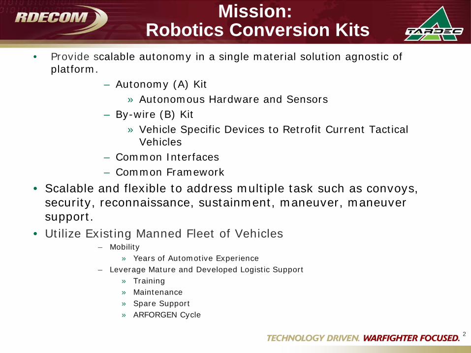
Mission: Robotics Conversion Kits
• Provide scalable autonomy in a single material solution agnostic of platform.
– Autonomy (A) Kit» Autonomous Hardware and Sensors
– By-wire (B) Kit» Vehicle Specific Devices to Retrofit Current Tactical
Vehicles– Common Interfaces– Common Framework
• Scalable and flexible to address multiple task such as convoys, security, reconnaissance, sustainment, maneuver, maneuver support.
• Utilize Existing Manned Fleet of Vehicles– Mobility
» Years of Automotive Experience– Leverage Mature and Developed Logistic Support
» Training» Maintenance» Spare Support» ARFORGEN Cycle
2
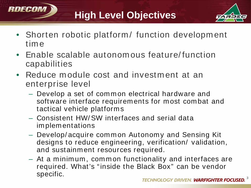
High Level Objectives
• Shorten robotic platform/ function development time
• Enable scalable autonomous feature/function capabilities
• Reduce module cost and investment at an enterprise level– Develop a set of common electrical hardware and
software interface requirements for most combat and tactical vehicle platforms
– Consistent HW/SW interfaces and serial data implementations
– Develop/acquire common Autonomy and Sensing Kit designs to reduce engineering, verification/ validation, and sustainment resources required.
– At a minimum, common functionality and interfaces are required. What’s “inside the Black Box” can be vendor specific.
3

Potential AMAS Block Diagram
4
Radar/Lidar System
Vision System
Throttle Position
Brake Sensor
Yaw Rate
Brake Control
Steering Control
Warnings / Displays- Route Planning
-Target selection/ ODOA
- Intelligent Behaviors
-Safety/ Diagnostics & Prognostics
X-By-Wire Platform Specific “B” Kit
Autonomy Computer /Tele-op Controller: “A” – Kit
Nav/GPS System
Wheel Speed
Long. Accel
Lateral Accel
Environmental Sensing and Communications –“A” Kit
Vehicle State Sensors –platform specific “B” Kit
Throttle Control
Steer Angle
E-Stop
Radio Communications
Potential“C” Kit ?- Payload Devices (manipulators, Weapons?, etc.)
Power upgrades:Generator, Battery, etc. –platform specific
Remote/Tele-op Controller
5
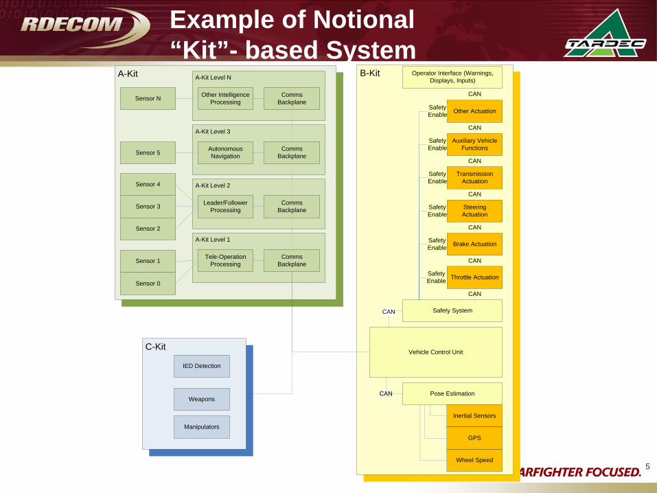
B-KitA-Kit
Throttle Actuation
Brake Actuation
Steering Actuation
Transmission Actuation
Auxiliary Vehicle Functions
Other Actuation
Safety System
CAN
CAN
CAN
CAN
CAN
CAN
SafetyEnable
SafetyEnable
SafetyEnable
SafetyEnable
SafetyEnable
SafetyEnable
Operator Interface (Warnings, Displays, Inputs)
CAN
Pose Estimation
Wheel Speed
Inertial Sensors
GPS
Sensor 0
Sensor 1
Sensor 3
Sensor 2
Sensor 4
Sensor 5
Sensor N
CAN
Vehicle Control Unit
A-Kit Level 1
Comms Backplane
Tele-Operation Processing
A-Kit Level 2
Comms Backplane
Leader/Follower Processing
A-Kit Level 3
Comms Backplane
Autonomous Navigation
A-Kit Level N
Comms Backplane
Other Intelligence Processing
CAN
C-Kit
IED Detection
Weapons
Manipulators
Example of Notional “Kit”- based System
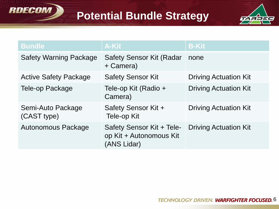
Potential Bundle Strategy
Bundle A-Kit B-KitSafety Warning Package Safety Sensor Kit (Radar
+ Camera)none
Active Safety Package Safety Sensor Kit Driving Actuation KitTele-op Package Tele-op Kit (Radio +
Camera)Driving Actuation Kit
Semi-Auto Package(CAST type)
Safety Sensor Kit +Tele-op Kit
Driving Actuation Kit
Autonomous Package Safety Sensor Kit + Tele-op Kit + Autonomous Kit (ANS Lidar)
Driving Actuation Kit
6
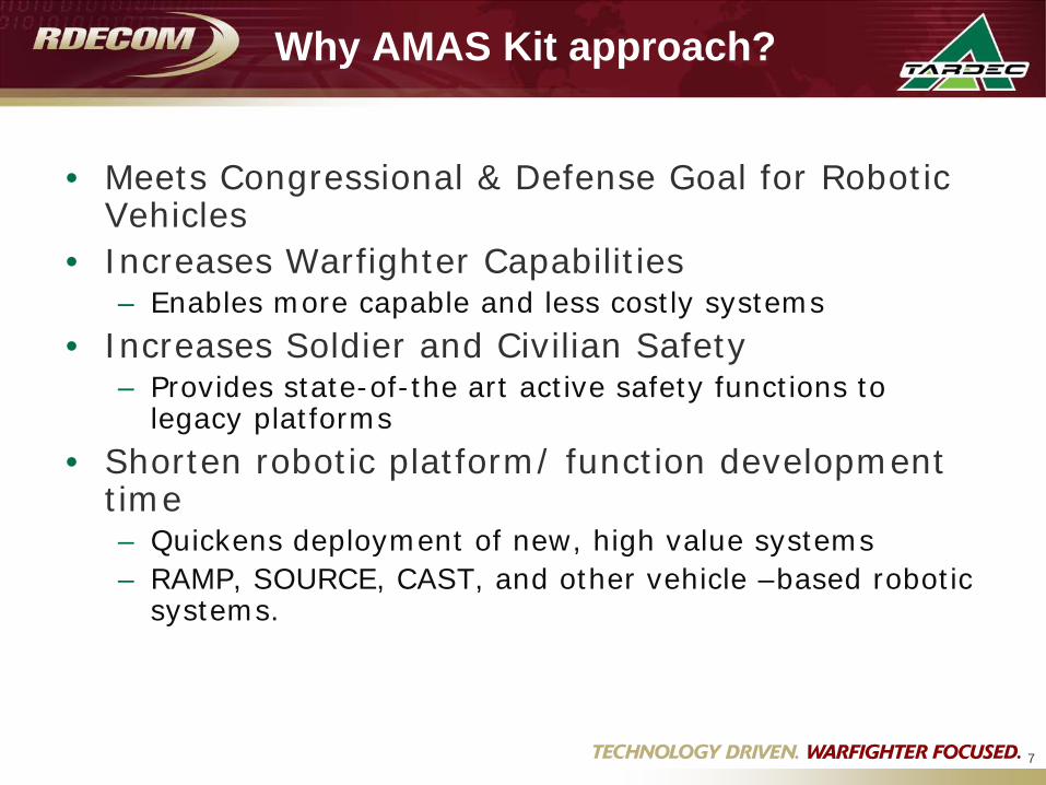
Why AMAS Kit approach?
• Meets Congressional & Defense Goal for Robotic Vehicles
• Increases Warfighter Capabilities– Enables more capable and less costly systems
• Increases Soldier and Civilian Safety– Provides state-of-the art active safety functions to
legacy platforms• Shorten robotic platform/ function development
time– Quickens deployment of new, high value systems– RAMP, SOURCE, CAST, and other vehicle –based robotic
systems.
7
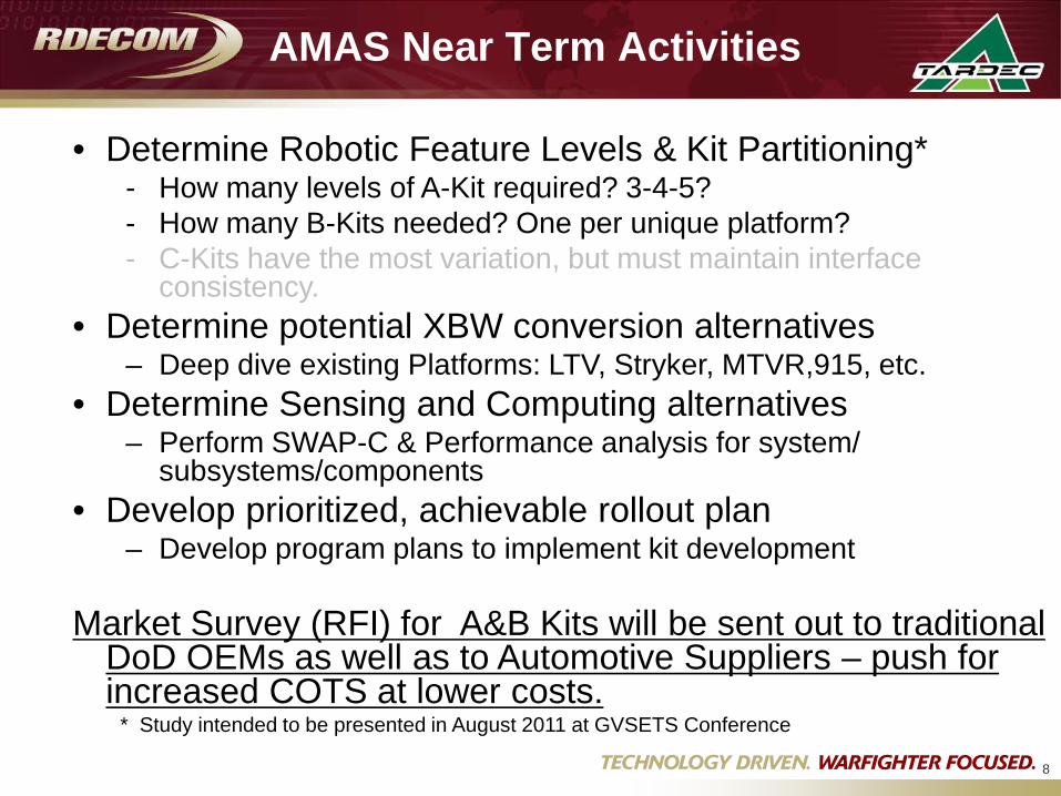
AMAS Near Term Activities
8
• Determine Robotic Feature Levels & Kit Partitioning*- How many levels of A-Kit required? 3-4-5?- How many B-Kits needed? One per unique platform?- C-Kits have the most variation, but must maintain interface
consistency.• Determine potential XBW conversion alternatives
– Deep dive existing Platforms: LTV, Stryker, MTVR,915, etc.• Determine Sensing and Computing alternatives
– Perform SWAP-C & Performance analysis for system/ subsystems/components
• Develop prioritized, achievable rollout plan– Develop program plans to implement kit development
Market Survey (RFI) for A&B Kits will be sent out to traditional DoD OEMs as well as to Automotive Suppliers – push for increased COTS at lower costs.
* Study intended to be presented in August 2011 at GVSETS Conference
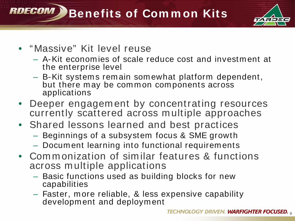
Benefits of Common Kits
• “Massive” Kit level reuse– A-Kit economies of scale reduce cost and investment at
the enterprise level– B-Kit systems remain somewhat platform dependent,
but there may be common components across applications
• Deeper engagement by concentrating resources currently scattered across multiple approaches
• Shared lessons learned and best practices– Beginnings of a subsystem focus & SME growth– Document learning into functional requirements
• Commonization of similar features & functions across multiple applications– Basic functions used as building blocks for new
capabilities– Faster, more reliable, & less expensive capability
development and deployment9
10
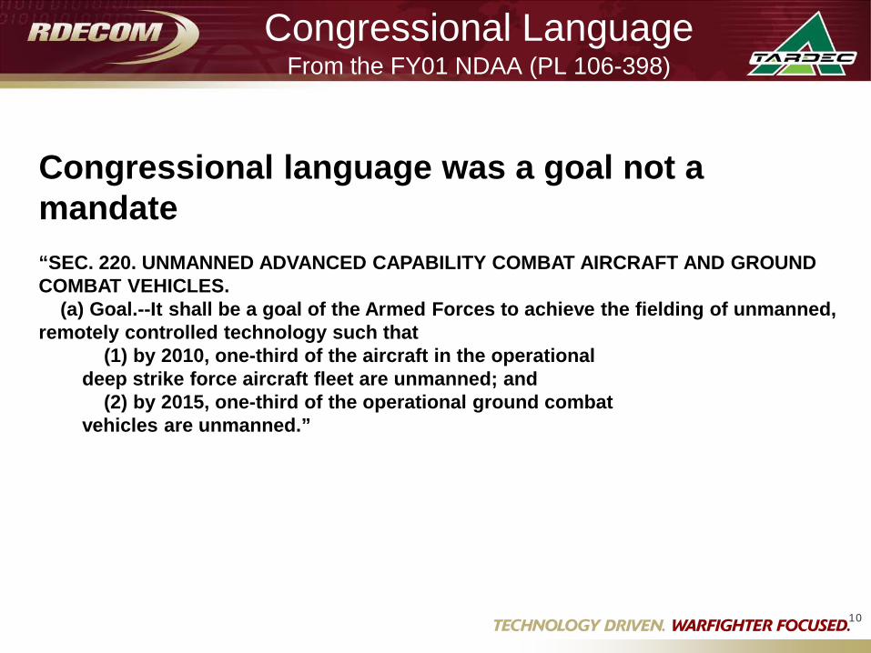
Congressional LanguageFrom the FY01 NDAA (PL 106-398)
Congressional language was a goal not a mandate“SEC. 220. UNMANNED ADVANCED CAPABILITY COMBAT AIRCRAFT AND GROUND COMBAT VEHICLES.
(a) Goal.--It shall be a goal of the Armed Forces to achieve the fielding of unmanned, remotely controlled technology such that
(1) by 2010, one-third of the aircraft in the operational deep strike force aircraft fleet are unmanned; and
(2) by 2015, one-third of the operational ground combat vehicles are unmanned.”

June 1, 2011 11
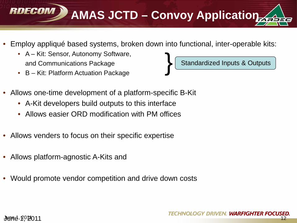
AMAS JCTD – Convoy Application
11
• Depots– Many current / legacy vehicles
under-utilized– Multi-service PMs
• LSI’s– Building Systems to Specific
Platforms– Repeating Work Across Platforms– Working Outside Expertise
• Sensor + software + actuation• Sub-contracting (cost increase)
• Tier II Venders– Do not have specific metrics to
build COTS products to
June 1, 2011 12June 1, 2011
• Employ appliqué based systems, broken down into functional, inter-operable kits:• A – Kit: Sensor, Autonomy Software,
and Communications Package• B – Kit: Platform Actuation Package
• Allows one-time development of a platform-specific B-Kit• A-Kit developers build outputs to this interface• Allows easier ORD modification with PM offices
• Allows venders to focus on their specific expertise
• Allows platform-agnostic A-Kits and
• Would promote vendor competition and drive down costs
AMAS JCTD – Convoy Application
} Standardized Inputs & Outputs
13
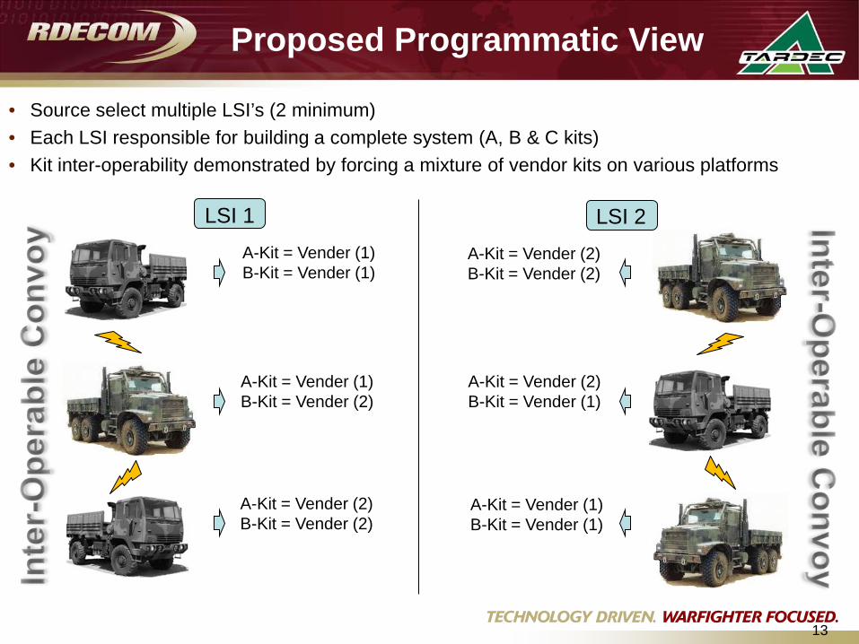
• Source select multiple LSI’s (2 minimum)• Each LSI responsible for building a complete system (A, B & C kits)• Kit inter-operability demonstrated by forcing a mixture of vendor kits on various platforms
Proposed Programmatic View
LSI 1 LSI 2A-Kit = Vender (1) B-Kit = Vender (1)
A-Kit = Vender (1) B-Kit = Vender (2)
A-Kit = Vender (2) B-Kit = Vender (2)
A-Kit = Vender (2) B-Kit = Vender (2)
A-Kit = Vender (2) B-Kit = Vender (1)
A-Kit = Vender (1) B-Kit = Vender (1)

14June 1, 2011
• Integration and interoperability with existing systems– AMAS Technology design is kit-based / emphasis on COTS hardware– Minimize impact to legacy interfaces
• Redundant communications for functionality in jamming environments• Dual kit interface path: Simple Hardware Unit / Graphical user Interface
• Functionality within operational architecture – Enhancement to current CONOPS– New functionality for legacy operation – Maintenance procedure development / System Training Plan (STRAP)
• Seek compliance with COCOM / XM / Sponsor guidance– Interoperability validation– Operational approval
Interoperability and Integration
June 1, 2011 15
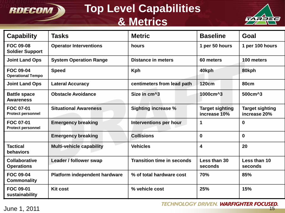
Capability Tasks Metric Baseline GoalFOC 09-08 Soldier Support
Operator Interventions hours 1 per 50 hours 1 per 100 hours
Joint Land Ops System Operation Range Distance in meters 60 meters 100 meters
FOC 09-04 Operational Tempo
Speed Kph 40kph 80kph
Joint Land Ops Lateral Accuracy centimeters from lead path 120cm 80cm
Battle space Awareness
Obstacle Avoidance Size in cm^3 1000cm^3 500cm^3
FOC 07-01 Protect personnel
Situational Awareness Sighting increase % Target sighting increase 10%
Target sighting increase 20%
FOC 07-01 Protect personnel
Emergency breaking Interventions per hour 1 0
Emergency breaking Collisions 0 0
Tactical behaviors
Multi-vehicle capability Vehicles 4 20
Collaborative Operations
Leader / follower swap Transition time in seconds Less than 30 seconds
Less than 10 seconds
FOC 09-04 Commonality
Platform independent hardware % of total hardware cost 70% 85%
FOC 09-01 sustainability
Kit cost % vehicle cost 25% 15%
Top Level Capabilities & Metrics
16
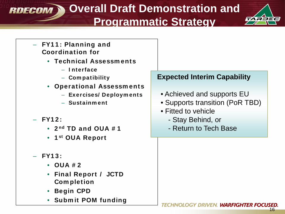
– FY11: Planning and Coordination for
• Technical Assessments– Interface– Compatibility
• Operational Assessments– Exercises/Deployments– Sustainment
– FY12:• 2nd TD and OUA #1• 1st OUA Report
– FY13: • OUA #2• Final Report / JCTD
Completion• Begin CPD • Submit POM funding
Expected Interim Capability
• Achieved and supports EU• Supports transition (PoR TBD)• Fitted to vehicle
- Stay Behind, or- Return to Tech Base
Overall Draft Demonstration and Programmatic Strategy
17
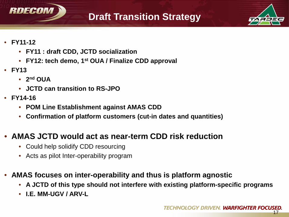
• FY11-12• FY11 : draft CDD, JCTD socialization• FY12: tech demo, 1st OUA / Finalize CDD approval
• FY13• 2nd OUA• JCTD can transition to RS-JPO
• FY14-16 • POM Line Establishment against AMAS CDD• Confirmation of platform customers (cut-in dates and quantities)
• AMAS JCTD would act as near-term CDD risk reduction • Could help solidify CDD resourcing• Acts as pilot Inter-operability program
• AMAS focuses on inter-operability and thus is platform agnostic• A JCTD of this type should not interfere with existing platform-specific programs• I.E. MM-UGV / ARV-L
Draft Transition Strategy
INTEROPERABILITY
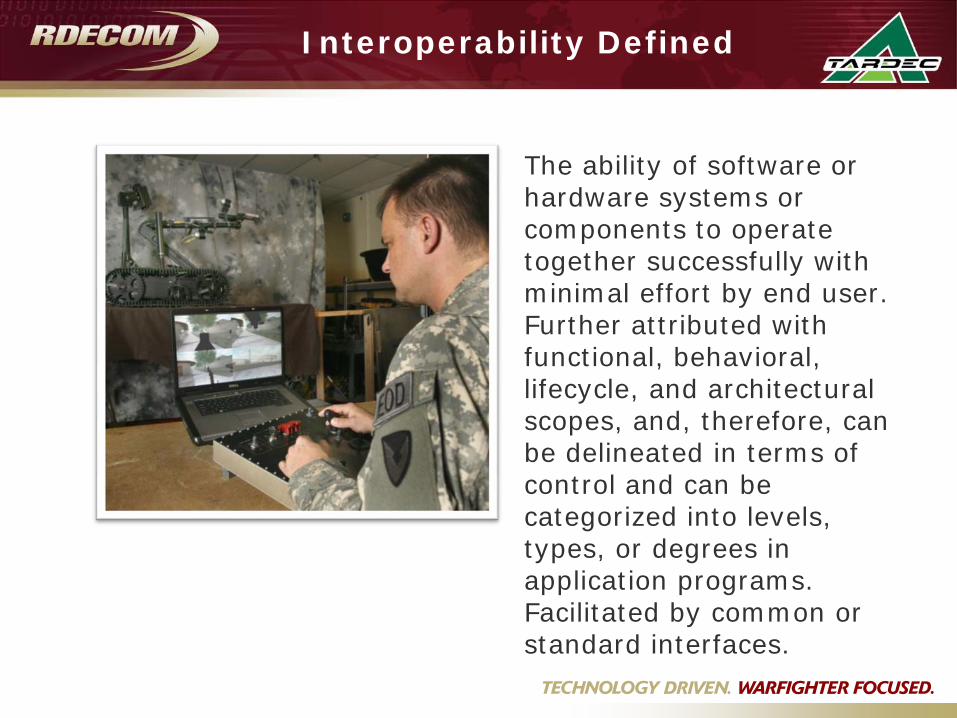
Interoperability Defined
The ability of software or hardware systems or components to operate together successfully with minimal effort by end user. Further attributed with functional, behavioral, lifecycle, and architectural scopes, and, therefore, can be delineated in terms of control and can be categorized into levels, types, or degrees in application programs. Facilitated by common or standard interfaces.
Why Interoperability?
• To provide sustainable and repeatable processes and capabilities to support the current and future Warfighter
• Leverage technologies and capabilities across all UGS partner organizations
• Increased Modular payloads across multiple platforms• Enables agile, responsive mission realignment• Enables Air/Ground coordination/collaboration• Broadens payload/mission equipment package vendor base• Specifies logical architecture, standards, requirements, and
conformance approach • Offers increased capabilities at lower life cycle costs• Facilitates common control of multiple robotic systems• Employed by robotic Program Managers
– Acquisition of future ground robotics system programs of record– Upgrade of currently fielded systems– Evaluation/acquisition of COTS components
“Interoperability is the countermeasure to obsolescence” – LTC Hatfield, ARCIC
Interoperability Capabilities Implementation Thought
Process
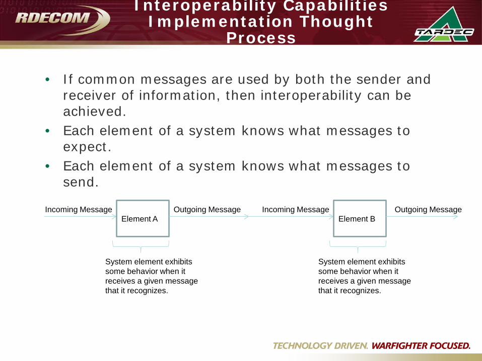
• If common messages are used by both the sender and receiver of information, then interoperability can be achieved.
• Each element of a system knows what messages to expect.
• Each element of a system knows what messages to send.
Element AIncoming Message Outgoing Message
System element exhibits some behavior when it receives a given message that it recognizes.
Element BIncoming Message Outgoing Message
System element exhibits some behavior when it receives a given message that it recognizes.
Interoperability Capabilities Implementation Thought
Process (cont.)
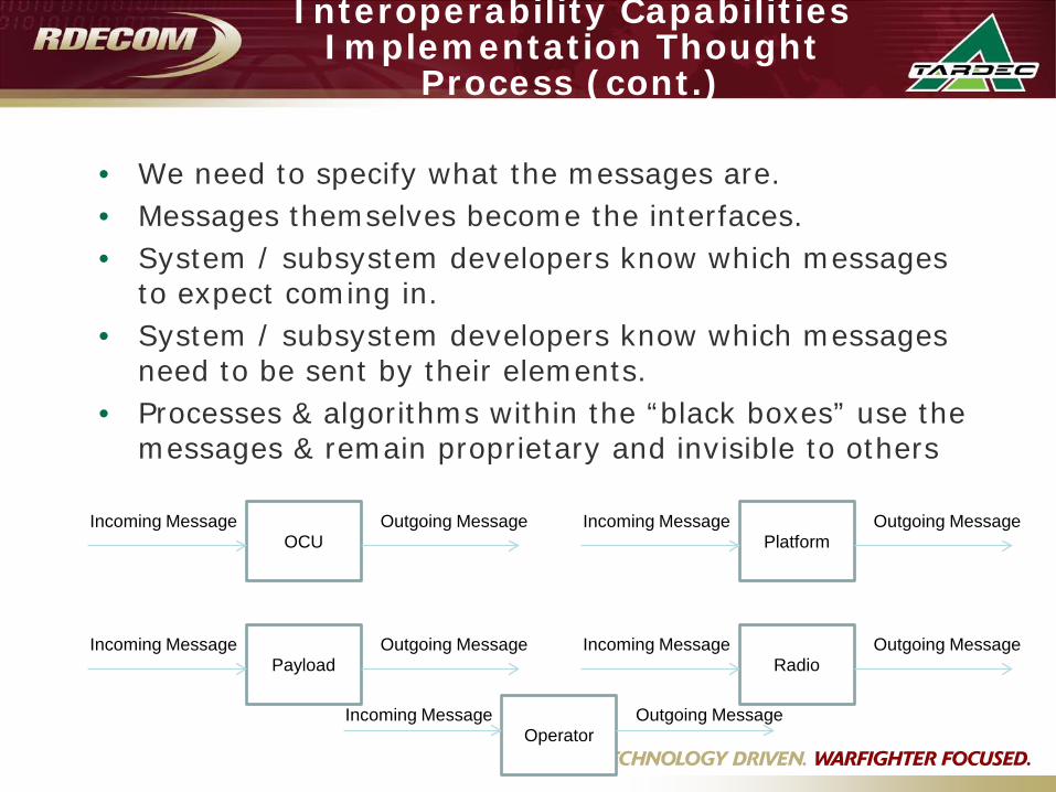
• We need to specify what the messages are.• Messages themselves become the interfaces.• System / subsystem developers know which messages
to expect coming in.• System / subsystem developers know which messages
need to be sent by their elements.• Processes & algorithms within the “black boxes” use the
messages & remain proprietary and invisible to others
OCUIncoming Message Outgoing Message
PlatformIncoming Message Outgoing Message
PayloadIncoming Message Outgoing Message
RadioIncoming Message Outgoing Message
OperatorIncoming Message Outgoing Message
Interoperability Capabilities Implementation Thought
Process (cont.)
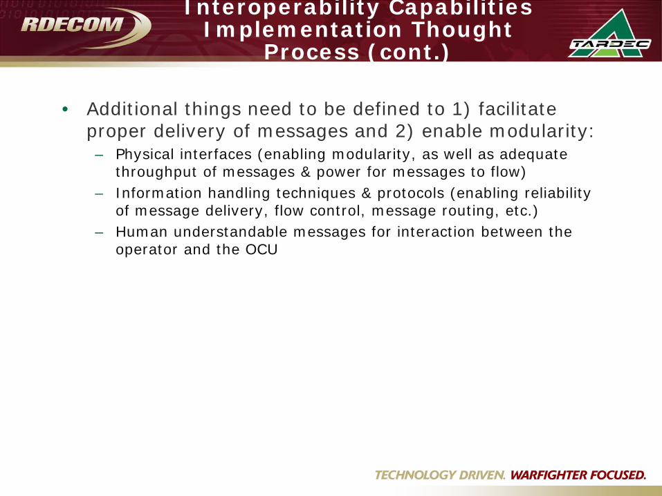
• Additional things need to be defined to 1) facilitate proper delivery of messages and 2) enable modularity:– Physical interfaces (enabling modularity, as well as adequate
throughput of messages & power for messages to flow)– Information handling techniques & protocols (enabling reliability
of message delivery, flow control, message routing, etc.)– Human understandable messages for interaction between the
operator and the OCU
Interoperability Overview –Scope & Objectives
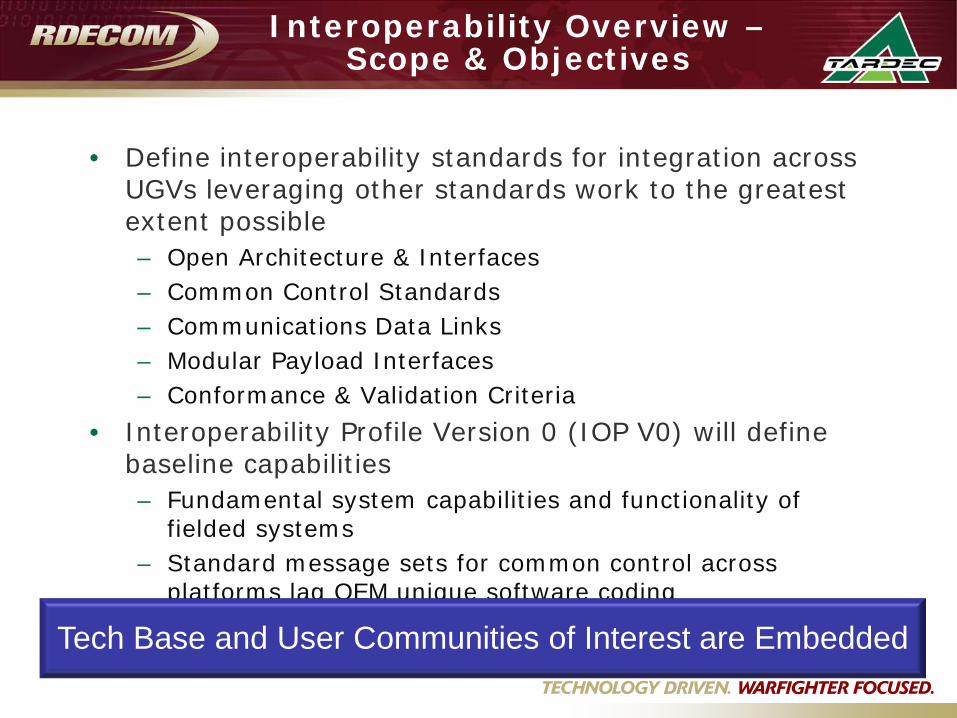
• Define interoperability standards for integration across UGVs leveraging other standards work to the greatest extent possible– Open Architecture & Interfaces– Common Control Standards– Communications Data Links– Modular Payload Interfaces– Conformance & Validation Criteria
• Interoperability Profile Version 0 (IOP V0) will define baseline capabilities– Fundamental system capabilities and functionality of
fielded systems– Standard message sets for common control across
platforms lag OEM unique software coding • Successive IOPs (V1, V2, etc.) expand capabilities
based on Combat Developer guidanceTech Base and User Communities of Interest are Embedded
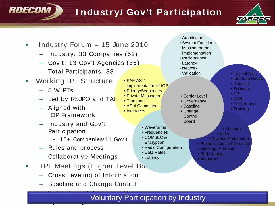
• Industry Forum – 15 June 2010– Industry: 33 Companies (52)– Gov’t: 13 Gov’t Agencies (36)– Total Participants: 88
• Working IPT Structure – 5 WIPTs – Led by RSJPO and TARDEC– Aligned with
IOP Framework– Industry and Gov’t
Participation • 15+ Companies/11 Gov’t
– Rules and process– Collaborative Meetings
• IPT Meetings (Higher Level Body)– Cross Leveling of Information– Baseline and Change Control– WIPT Presentations and Concurrence– Open Dialogue
Industry/Gov’t Participation
Voluntary Participation by Industry
SAE AS-4WIPT
OverarchingWIPT
PayloadWIPT
CommsWIPT
ControlWIPTRS JPO
Interoperability IPT
• SAE AS-4 implementation of IOP
• Priority/Sequences• Private Messages• Transport• AS-4 Committee• Interfaces
• Waveforms• Frequencies• COMSEC &
Encryption• Radio Configuration• Data Rates• Latency
• Architecture• System Functions• Mission threads• Implementation • Performance• Latency• Network• Validation • Logical Arch.
• Interface Reqt’s• Data link• Software• C2• WMI• Performance• Training
• Sensors• Video
• Payload Architecture• Emitters, Audio & Acoustic• Message Protocol• Performance• Actuators
• Senior Level• Governance • Baseline• Change
Control Board
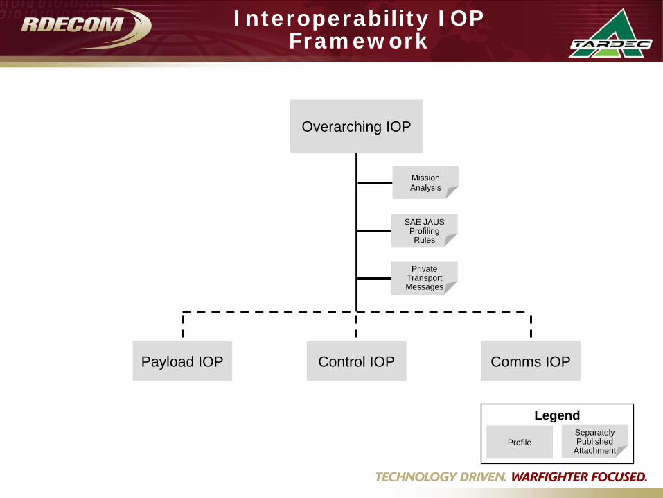
Interoperability IOP Framework
Payload IOP
MissionAnalysis
Private Transport Messages
Legend
ProfileSeparately Published
Attachment
Control IOP Comms IOP
SAE JAUSProfiling Rules
Overarching IOP
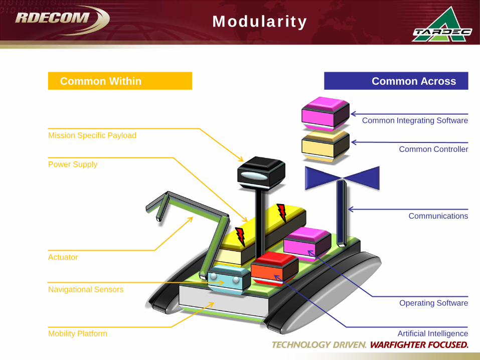
Modularity
Common Within Platforms
Common Across Platforms
Actuator
Power Supply
Mobility Platform
Mission Specific Payload
Navigational Sensors
Communications
Common Controller
Common Integrating Software
Operating Software
Artificial Intelligence
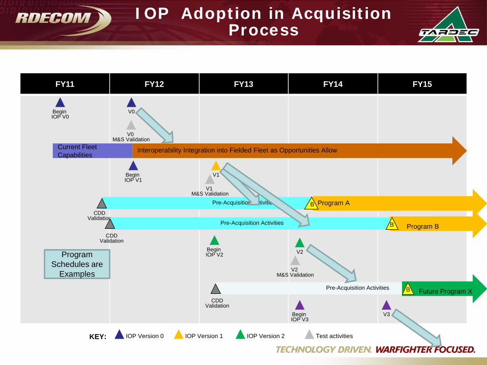
IOP Adoption in Acquisition Process
FY11 FY12 FY13 FY14 FY15
Interoperability Integration into Fielded Fleet as Opportunities AllowCurrent Fleet Capabilities
V0 M&S Validation
V1 M&S Validation
Begin IOP V0
Begin IOP V1
Begin IOP V2
V1
V0
IOP Version 0 Test activitiesIOP Version 1 IOP Version 2KEY:
Begin IOP V3
V2
Program APre-Acquisition Activities
CDD Validation
B
Program BPre-Acquisition Activities B
CDD Validation
Program Schedules are
Examples
Future Program XPre-Acquisition Activities B
CDD Validation
V2 M&S Validation
V3
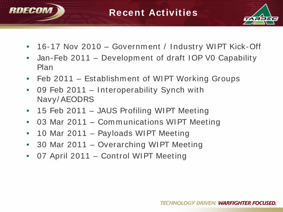
Recent Activities
• 16-17 Nov 2010 – Government / Industry WIPT Kick-Off• Jan-Feb 2011 – Development of draft IOP V0 Capability
Plan• Feb 2011 – Establishment of WIPT Working Groups• 09 Feb 2011 – Interoperability Synch with
Navy/AEODRS• 15 Feb 2011 – JAUS Profiling WIPT Meeting• 03 Mar 2011 – Communications WIPT Meeting• 10 Mar 2011 – Payloads WIPT Meeting• 30 Mar 2011 – Overarching WIPT Meeting• 07 April 2011 – Control WIPT Meeting
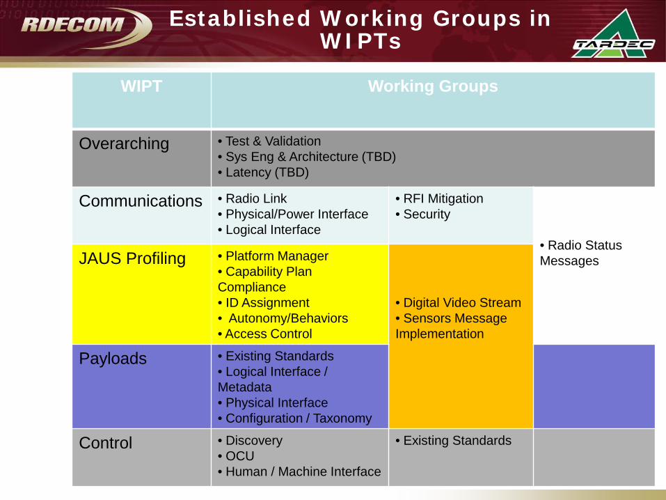
Established Working Groups in WIPTs
WIPT Working Groups
Overarching • Test & Validation• Sys Eng & Architecture (TBD)• Latency (TBD)
Communications • Radio Link• Physical/Power Interface• Logical Interface
• RFI Mitigation• Security
• Radio Status MessagesJAUS Profiling • Platform Manager
• Capability Plan Compliance• ID Assignment• Autonomy/Behaviors• Access Control
• Digital Video Stream• Sensors Message Implementation
Payloads • Existing Standards• Logical Interface / Metadata• Physical Interface• Configuration / Taxonomy
Control • Discovery• OCU• Human / Machine Interface
• Existing Standards

IOP V0 Capability Plan
• V0 Capability Plan has been drafted• Scopes & bounds what IOP V0 will define• Focused on foundational capabilities inherent in
currently fielded systems

IOP V0 Capability Plan Content
• 3.1 Platform/Vehicle– Electrical, Mechanical, & Power– Basic Platform
• Battery Status, Usage & Engine Data• Platform Mode• Position / Attitude• Sub-System Configuration & Health• Pose / Articulation• E-Stop & Heartbeat (Liveness)
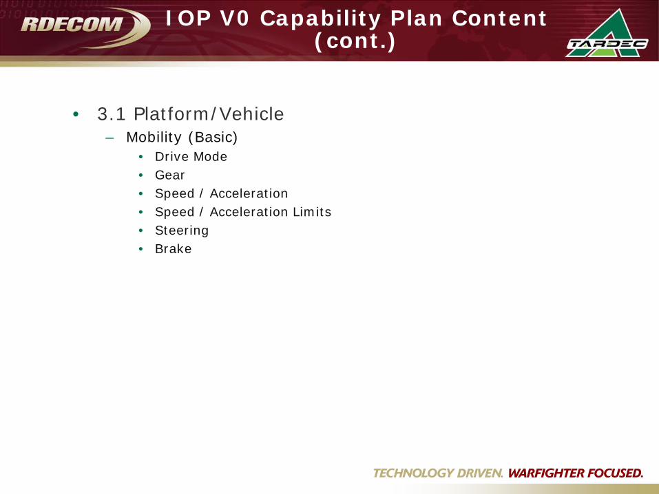
IOP V0 Capability Plan Content (cont.)
• 3.1 Platform/Vehicle– Mobility (Basic)
• Drive Mode• Gear• Speed / Acceleration• Speed / Acceleration Limits• Steering• Brake
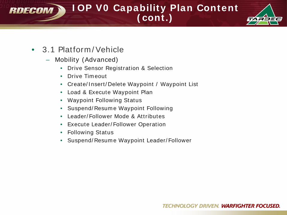
IOP V0 Capability Plan Content (cont.)
• 3.1 Platform/Vehicle– Mobility (Advanced)
• Drive Sensor Registration & Selection• Drive Timeout• Create/Insert/Delete Waypoint / Waypoint List• Load & Execute Waypoint Plan• Waypoint Following Status• Suspend/Resume Waypoint Following• Leader/Follower Mode & Attributes• Execute Leader/Follower Operation• Following Status• Suspend/Resume Waypoint Leader/Follower

IOP V0 Capability Plan Content (cont.)
• 3.2 Payload– Sensor
• Drive Vision• Motion Imagery• Still Imagery• CBRN• Chemical Explosive Detection• Microphone• Range Finder• Thermal

IOP V0 Capability Plan Content (cont.)
• 3.2 Payload– Emitter
• Lights• Speaker
– Actuator• General Actuators• Basic Arm• Telescoping (Mast)• Pan/Tilt• End Affectors
IOP V0 Capability Plan Content (cont.)
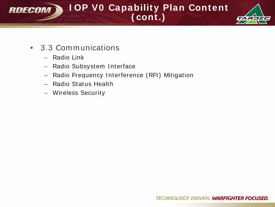
• 3.3 Communications– Radio Link– Radio Subsystem Interface– Radio Frequency Interference (RFI) Mitigation– Radio Status Health– Wireless Security
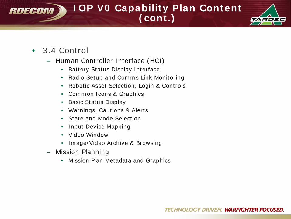
IOP V0 Capability Plan Content (cont.)
• 3.4 Control– Human Controller Interface (HCI)
• Battery Status Display Interface• Radio Setup and Comms Link Monitoring• Robotic Asset Selection, Login & Controls• Common Icons & Graphics• Basic Status Display• Warnings, Cautions & Alerts• State and Mode Selection• Input Device Mapping• Video Window• Image/Video Archive & Browsing
– Mission Planning• Mission Plan Metadata and Graphics

Draft V0 Implementation Concepts
• Slides develop as a communication tool for what needs to be defined for IOP V0
• Includes concepts & ideas for specific “instantiations” of what V0 capabilities require in terms of messages & interfaces

Implementation Concept Example: Battery Status
• Battery Status:– Description: Percentage of battery power or hours of battery
operation remaining– Action: Display a message on the OCU that provides the battery
state of charge. May be a graphical display, a percentage, or a summary of expected remaining minutes of operation.
– V0 Deliverable:• Message structure & format
– Query Battery Status– Report Battery Status
Battery Other Elements
OCU
What is battery status?
Battery status is XOpen Questions:• Format as percentage?• Format as remaining minutes?• Define timing requirements?
Define Requirements: Overarching WIPTDefine Messages: JAUS Profiling WIPT
*Conceptual Example

Implementation Concept Example: Drive Sensor
Registration / Selection
• Steering:– Description: Specifies sensor used to drive the platform (if
multiple – e.g., forward, reverse)– Action: Report the available drive sensors. Report current drive
sensor. Set drive sensors.– V0 Deliverable:
• Message structure & format– Query Current Drive Sensor– Report Current Drive Sensor– Set Drive Sensor– Query Available Drive Sensors– Report Available Drive Sensors
Platform Element
Other Elements
OCU
Open Questions:•Correlate this message to Drive Mode or other messages?• Define logical description of drive sensors in messages?•Define timing requirements?
What drive sensorare you using now?
Use X drive sensor.
I am using drive sensor X.What other drive sensors do you have?I have drive sensors X, Y,
and Z available.
Define Requirements: Payloads WIPTDefine Messages: JAUS Profiling WIPT
*Conceptual Example
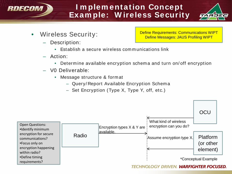
Implementation Concept Example: Wireless Security
• Wireless Security:– Description:
• Establish a secure wireless communications link– Action:
• Determine available encryption schema and turn on/off encryption– V0 Deliverable:
• Message structure & format– Query/Report Available Encryption Schema– Set Encryption (Type X, Type Y, off, etc.)
Define Requirements: Communications WIPTDefine Messages: JAUS Profiling WIPT
Open Questions:•Identify minimum encryption for secure communications?•Focus only on encryption happening within radio?•Define timing requirements?
Radio Platform (or other element)
OCU
What kind of wireless encryption can you do?Encryption types X & Y are
available.Assume encryption type X.
*Conceptual Example

Path Forward Toward IOP V0 Completion
• Continue regular WIPT telecons & execution of WIPT deliverables
• Develop matrix mapping V0 capabilities with existing standards messages, interfaces & protocols– Identify gaps in existing standards– Compare trades of different standards/messages that achieve
similar capabilities
• Select / develop IOP V0 standards/messages with WIPTs
• Document proposed IOPs• Staff proposed IOPs through WIPTs & JPO chain for
approval• Target September 2011 for V0 Publish
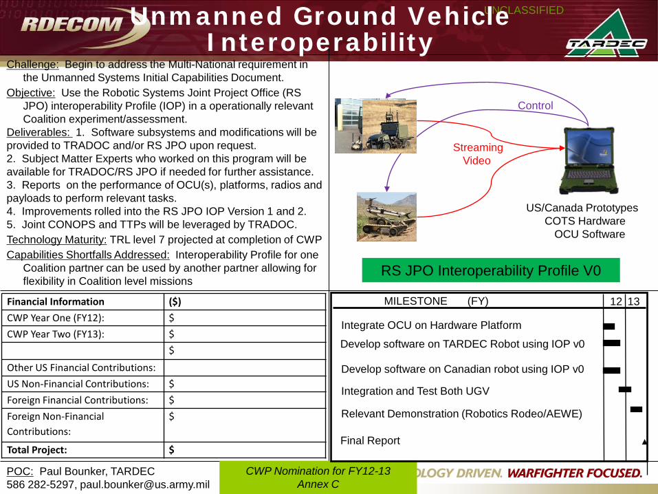
Challenge: Begin to address the Multi-National requirement in the Unmanned Systems Initial Capabilities Document.
Objective: Use the Robotic Systems Joint Project Office (RS JPO) interoperability Profile (IOP) in a operationally relevant Coalition experiment/assessment.
Deliverables: 1. Software subsystems and modifications will be provided to TRADOC and/or RS JPO upon request. 2. Subject Matter Experts who worked on this program will be available for TRADOC/RS JPO if needed for further assistance. 3. Reports on the performance of OCU(s), platforms, radios and payloads to perform relevant tasks.4. Improvements rolled into the RS JPO IOP Version 1 and 2. 5. Joint CONOPS and TTPs will be leveraged by TRADOC. Technology Maturity: TRL level 7 projected at completion of CWP Capabilities Shortfalls Addressed: Interoperability Profile for one
Coalition partner can be used by another partner allowing for flexibility in Coalition level missions
POC: Paul Bounker, TARDEC586 282-5297, [email protected]
UNCLASSIFIED
CWP Nomination for FY12-13Annex C
Financial Information ($)
CWP Year One (FY12): $
CWP Year Two (FY13): $
$
Other US Financial Contributions:
US Non-Financial Contributions: $
Foreign Financial Contributions: $
Foreign Non-Financial Contributions:
$
Total Project: $
US/Canada Prototypes COTS Hardware
OCU Software
StreamingVideo
Control
RS JPO Interoperability Profile V0
MILESTONE 12 13(FY)
Develop software on TARDEC Robot using IOP v0
Develop software on Canadian robot using IOP v0
Integration and Test Both UGV
Integrate OCU on Hardware Platform
Relevant Demonstration (Robotics Rodeo/AEWE)
Final Report
Unmanned Ground Vehicle Interoperability


