Austin’s Full-Scale Step-BNR Demonstration
Rajendra P. Bhattarai, P.E., DEE Austin Water Utility, City of Austin
625 East 10th Street, Suite 300 Austin, Texas 78701
Phone: 512-972-0075, Fax: 512-974-3504 [email protected]
San Antonio, Texas
July 24, 2015
Summer Seminar Emerging Issues in the Water/Wastewater Industry
Presentation Outline
• Background • Step-Feed • Biological Nutrient Removal (BNR)
System Used • Operating Characteristics • Results • Lessons Learned
Background • Austin’s wastewater treatment plants
discharge to the Colorado River • Waterbody of exceptional quality • Nutrient removal required in future • Need for demonstration of N & P removal
• Goal: TP < 1mg/L; TN < 10 mg/L • Full-Scale Step-Feed BNR operated at
South Austin Regional (SAR) WWTP for two years: January 1996 - December 1997
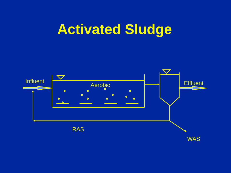
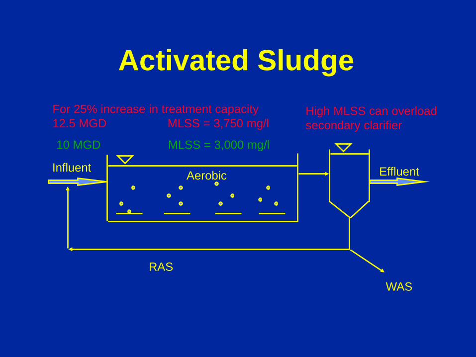
Activated Sludge
Influent
RAS
WAS
Aerobic Effluent
Influent
RAS
WAS
Aerobic Effluent
10 MGD MLSS = 3,000 mg/l
For 25% increase in treatment capacity 12.5 MGD MLSS = 3,750 mg/l
High MLSS can overload secondary clarifier
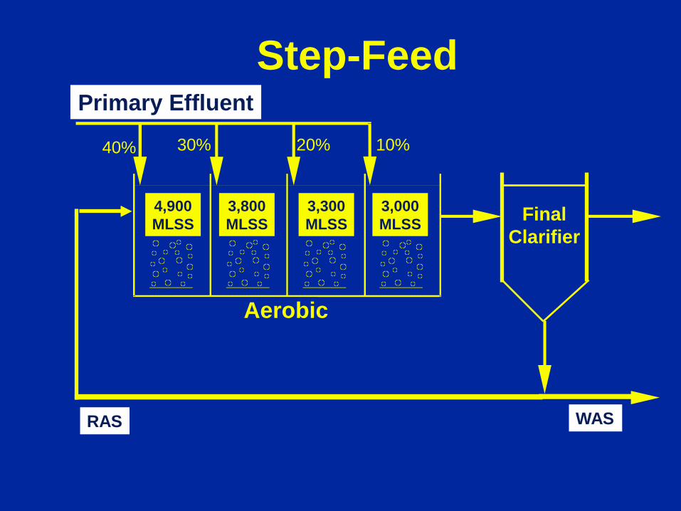
Activated Sludge
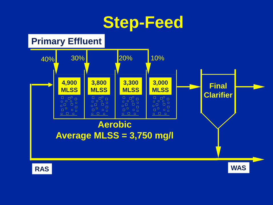
Step-Feed Primary Effluent
4,900 MLSS
3,800 MLSS
3,300 MLSS
3,000 MLSS
Aerobic Average MLSS = 3,750 mg/l
RAS WAS
Final Clarifier
40% 30% 20% 10%
Advantages of Step-Feed
• Operational Flexibility • Higher MLSS results in higher capacity
without increasing solids loading to secondary clarifiers
• Maximize use of existing facilities • Better handling of peak flows • Robust and stable operation
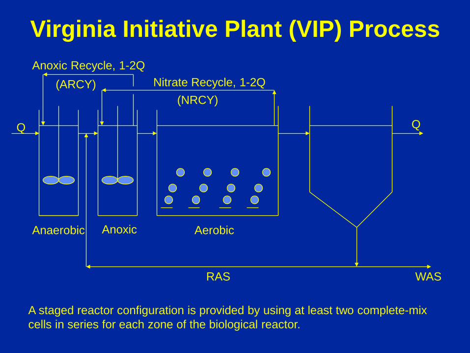
Q
Anaerobic Aerobic
Q
WAS RAS
Anoxic
Nitrate Recycle, 1-2Q Anoxic Recycle, 1-2Q
A staged reactor configuration is provided by using at least two complete-mix cells in series for each zone of the biological reactor.
Virginia Initiative Plant (VIP) Process
(NRCY) (ARCY)
Step-Feed Primary Effluent
4,900 MLSS
3,800 MLSS
3,300 MLSS
3,000 MLSS
Aerobic
RAS WAS
Final Clarifier
40% 30% 20% 10%
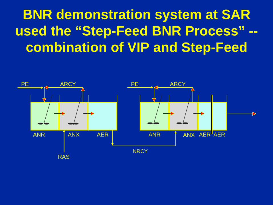
BNR demonstration system at SAR used the “Step-Feed BNR Process” --
combination of VIP and Step-Feed
PE ARCY PE ARCY
ANR ANX AER ANR ANX AER AER
RAS NRCY
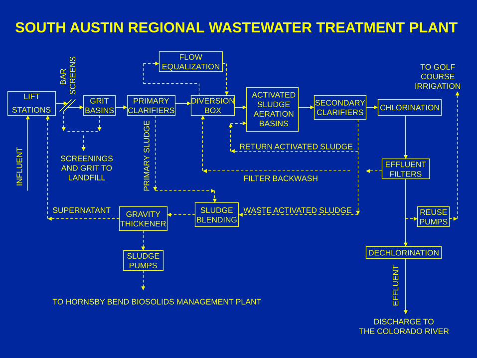
SOUTH AUSTIN REGIONAL WASTEWATER TREATMENT PLANT
LIFT
STATIONS GRIT
BASINS
INFL
UE
NT
BA
R
SC
RE
EN
S
PRIMARY CLARIFIERS
FLOW EQUALIZATION
DIVERSION BOX
ACTIVATED SLUDGE
AERATION BASINS
SECONDARY CLARIFIERS CHLORINATION
SCREENINGS AND GRIT TO
LANDFILL EFFLUENT FILTERS
DECHLORINATION
DISCHARGE TO THE COLORADO RIVER
EFF
LUE
NT
RETURN ACTIVATED SLUDGE
WASTE ACTIVATED SLUDGE SLUDGE BLENDING
GRAVITY THICKENER
SLUDGE PUMPS
TO HORNSBY BEND BIOSOLIDS MANAGEMENT PLANT
FILTER BACKWASH
SUPERNATANT REUSE PUMPS
TO GOLF COURSE
IRRIGATION
PR
IMA
RY
SLU
DG
E
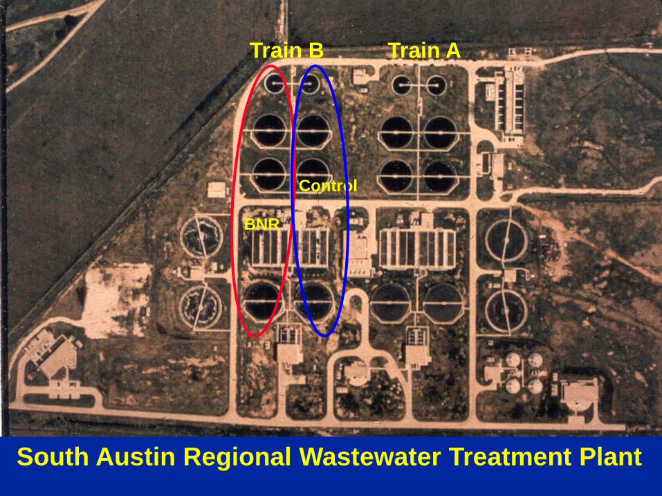
South Austin Regional Wastewater Treatment Plant
Train A Train B
BNR
Control
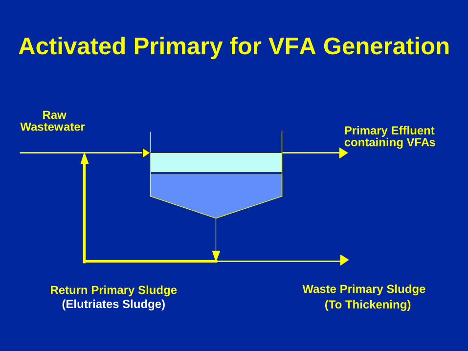
Activated Primary for VFA Generation
Raw Primary Effluent Wastewater containing VFAs
Return Primary Sludge (Elutriates Sludge)
Waste Primary Sludge (To Thickening)
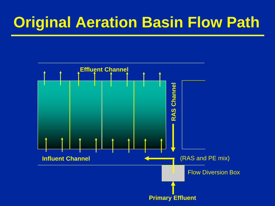
Original Aeration Basin Flow Path
Effluent Channel
Influent Channel
RAS
Cha
nnel
(RAS and PE mix)
Primary Effluent
Flow Diversion Box
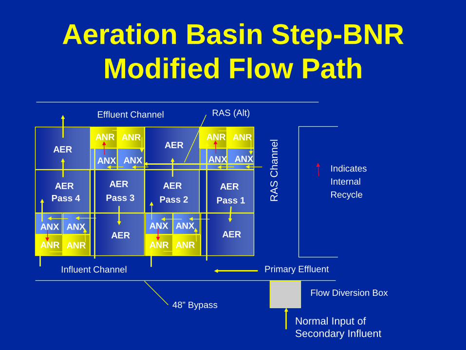
Aeration Basin Step-BNR Modified Flow Path
Effluent Channel
Influent Channel R
AS
Cha
nnel
Primary Effluent
Normal Input of Secondary Influent
Flow Diversion Box
AER
AER Pass 4
AER Pass 3
AER Pass 2
AER Pass 1
AER ANR
ANX
ANR
ANX
ANR
ANX
ANR
ANX
ANR ANR
ANX ANX
ANR ANR
ANX ANX AER AER
48” Bypass
Indicates Internal Recycle
RAS (Alt)

Baffles added to Existing Aeration Basins to form Anaerobic, Anoxic and Aerobic Zones Volume, million gallons Step- BNR Control Total 2.6 2.6 Anaerobic 0.4 0 Anoxic 0.4 0 Aerobic 1.8 2.6
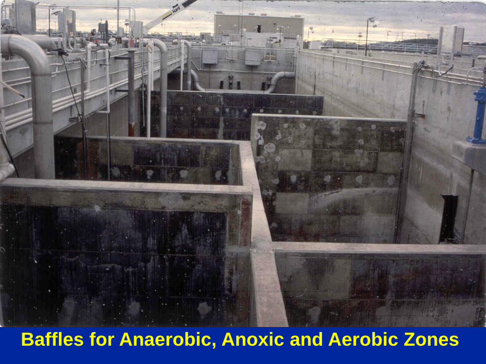
Baffles for Anaerobic, Anoxic and Aerobic Zones
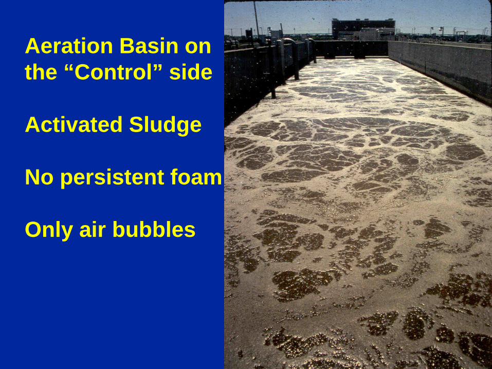
Aeration Basin on the “Control” side Activated Sludge No persistent foam Only air bubbles
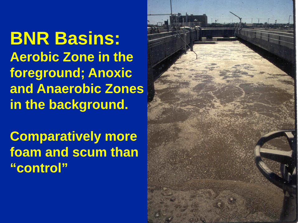
BNR Basins: Aerobic Zone in the foreground; Anoxic and Anaerobic Zones in the background. Comparatively more foam and scum than “control”
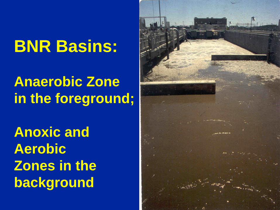
BNR Basins: Anaerobic Zone in the foreground; Anoxic and Aerobic Zones in the background
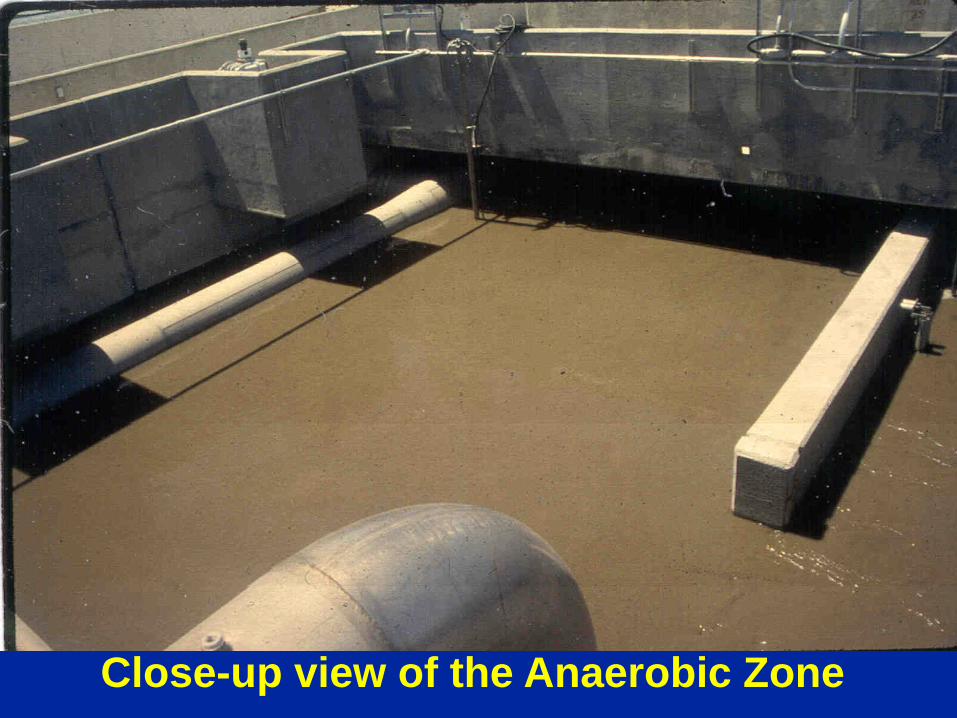
Close-up view of the Anaerobic Zone
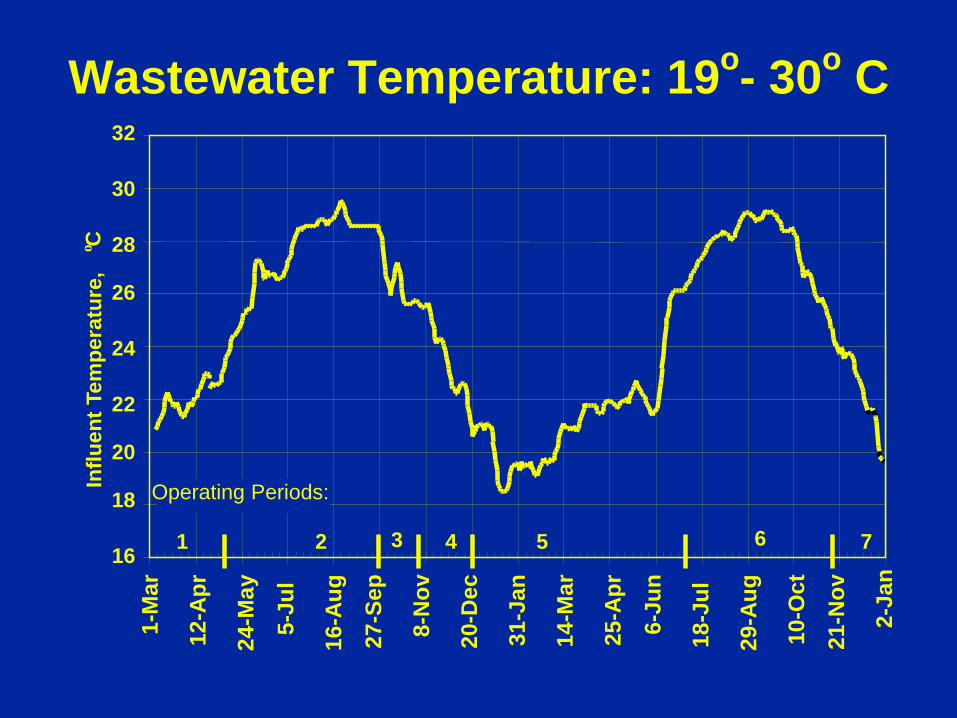
Wastewater Temperature: 19o- 30o C
16
18
20
22
24
26
28
30
32
Influ
ent T
empe
ratu
re,
o C
1 7 6 5 4 3 2
Operating Periods:
1-M
ar
12-A
pr
24-M
ay
5-Ju
l
16-A
ug
27-S
ep
8-N
ov
20-D
ec
31-J
an
14-M
ar
25-A
pr
6-Ju
n
18-J
ul
29-A
ug
10-O
ct
21-N
ov
2-Ja
n
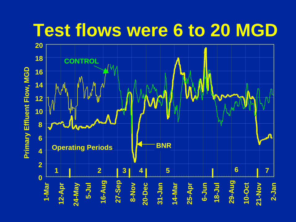
Test flows were 6 to 20 MGD
0
2
4
6
8
10
12
14
16
18
20
Prim
ary
Efflu
ent F
low
, MG
D
BNR
CONTROL
Operating Periods:
1 7 6 5 4 3 2
1-M
ar
12-A
pr
24-M
ay
5-Ju
l
16-A
ug
27-S
ep
8-N
ov
20-D
ec
31-J
an
14-M
ar
25-A
pr
6-Ju
n
18-J
ul
29-A
ug
10-O
ct
21-N
ov
2-Ja
n
Jan-
96
Mar
-96
Jun-
96
Sep-
96
Dec
-96
Mar
-97
Jun-
97
Sep-
97
Dec
-97
Period 7
Period 6
Period 5
Period 4
Period 3
Period 2
Period 1
Startup
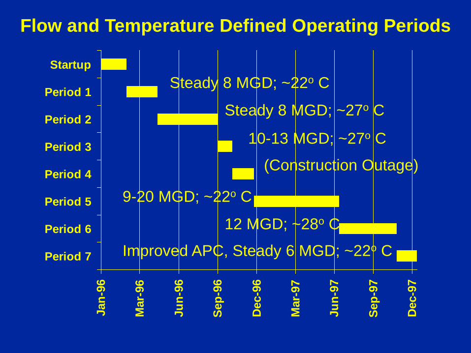
Flow and Temperature Defined Operating Periods
Steady 8 MGD; ~22o C
Steady 8 MGD; ~27o C
(Construction Outage)
9-20 MGD; ~22o C
12 MGD; ~28o C
10-13 MGD; ~27o C
Improved APC, Steady 6 MGD; ~22o C
0
10
20
30
40
50
60
70
80
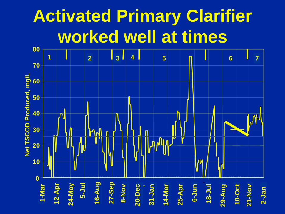
Net
TSC
OD
Pro
duce
d, m
g/L
1 7 6 5 4 3 2
Activated Primary Clarifier worked well at times
1-M
ar
12-A
pr
24-M
ay
5-Ju
l
16-A
ug
27-S
ep
8-N
ov
20-D
ec
31-J
an
14-M
ar
25-A
pr
6-Ju
n
18-J
ul
29-A
ug
10-O
ct
21-N
ov
2-Ja
n

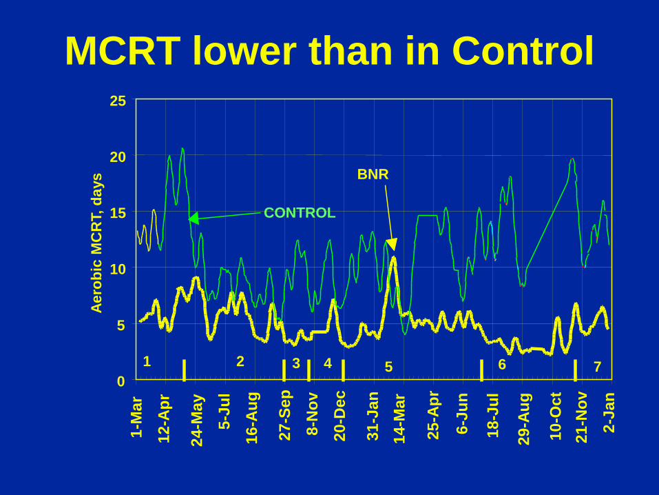
MCRT lower than in Control
0
5
10
15
20
25 Ae
robi
c M
CR
T, d
ays
CONTROL
BNR
1 2 3 4 5 6 7
1-M
ar
12-A
pr
24-M
ay
5-Ju
l
16-A
ug
27-S
ep
8-N
ov
20-D
ec
31-J
an
14-M
ar
25-A
pr
6-Ju
n
18-J
ul
29-A
ug
10-O
ct
21-N
ov
2-Ja
n
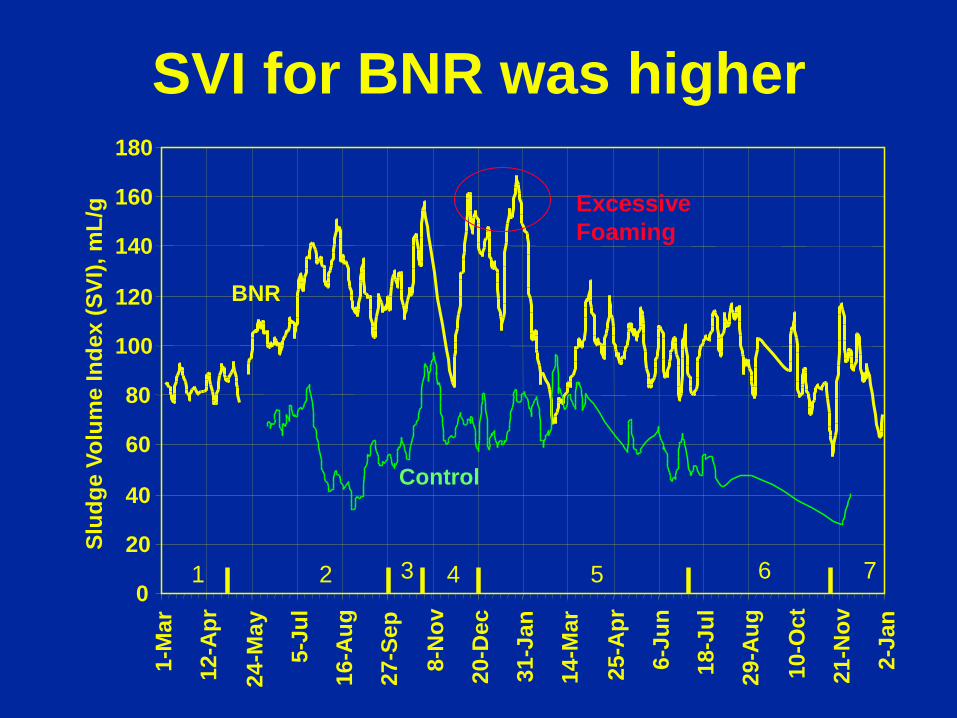
SVI for BNR was higher
0
20
40
60
80
100
120
140
160
180 1-
Mar
12-A
pr
24-M
ay
5-Ju
l
16-A
ug
27-S
ep
8-N
ov
20-D
ec
31-J
an
14-M
ar
25-A
pr
6-Ju
n
18-J
ul
29-A
ug
10-O
ct
21-N
ov
2-Ja
n
Slud
ge V
olum
e In
dex
(SVI
), m
L/g
BNR
Control
Excessive Foaming
1 2 3 4 5 6 7
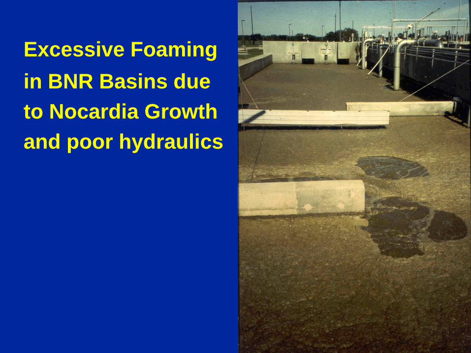
Excessive Foaming in BNR Basins due to Nocardia Growth and poor hydraulics
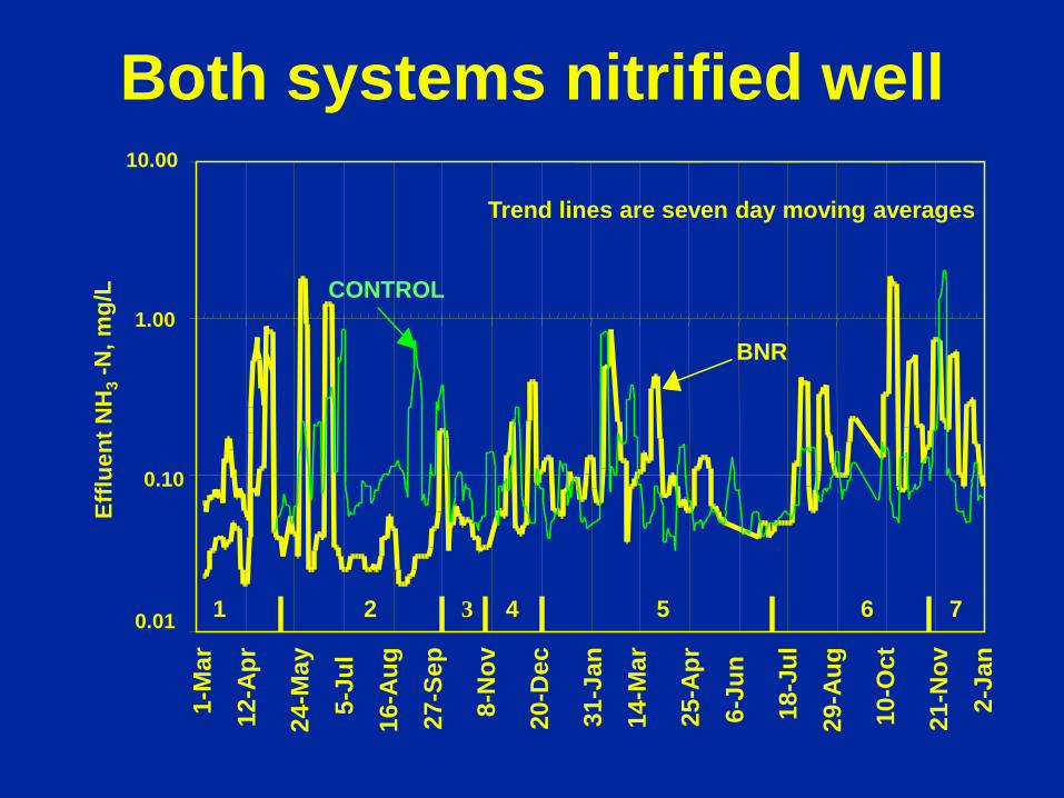
Both systems nitrified well Ef
fluen
t NH
3 -N
, mg/
L
BNR
CONTROL
Trend lines are seven day moving averages
1 7 6 5 4 3 2
10.00
1.00
0.10
0.01
1-M
ar
12-A
pr
24-M
ay
5-Ju
l
16-A
ug
27-S
ep
8-N
ov
20-D
ec
31-J
an
14-M
ar
25-A
pr
6-Ju
n
18-J
ul
29-A
ug
10-O
ct
21-N
ov
2-Ja
n
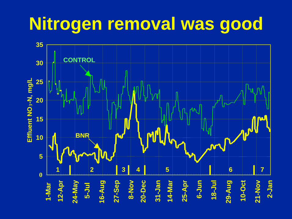
0
5
10
15
20
25
30
35
Efflu
ent N
O 3 -
N, m
g/L
BNR
CONTROL
1 7 6 5 4 3 2
Nitrogen removal was good 1-
Mar
12-A
pr
24-M
ay
5-Ju
l
16-A
ug
27-S
ep
8-N
ov
20-D
ec
31-J
an
14-M
ar
25-A
pr
6-Ju
n
18-J
ul
29-A
ug
10-O
ct
21-N
ov
2-Ja
n
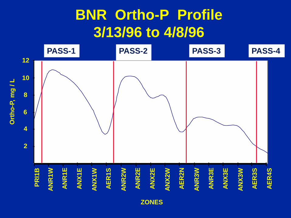
BNR Ortho-P Profile 3/13/96 to 4/8/96
PASS-1 PASS-2 PASS-3 PASS-4
2
4
6
8
10
12
PRI1
B
ANR
1W
ANR
1E
ANX1
E
ANX1
W
AER
1S
ANR
2W
ANR
2E
ANX2
E
ANX2
W
AER
2N
ANR
3W
ANR
3E
ANX3
E
ANX3
W
AER
3S
AER
4S
ZONES
Ort
ho-P
, mg
/ L
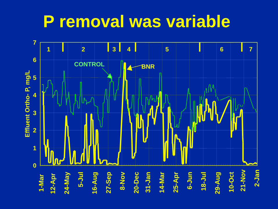
P removal was variable
0
1
2
3
4
5
6
7
Efflu
ent O
rtho
- P, m
g/L
BNR CONTROL
1 7 6 5 4 3 2 1-
Mar
12-A
pr
24-M
ay
5-Ju
l
16-A
ug
27-S
ep
8-N
ov
20-D
ec
31-J
an
14-M
ar
25-A
pr
6-Ju
n
18-J
ul
29-A
ug
10-O
ct
21-N
ov
2-Ja
n
Lessons Learned
• BNR systems not that different from other treatment systems
• But they do require some understanding and familiarity
• BNR systems need more operational attention than conventional activated sludge
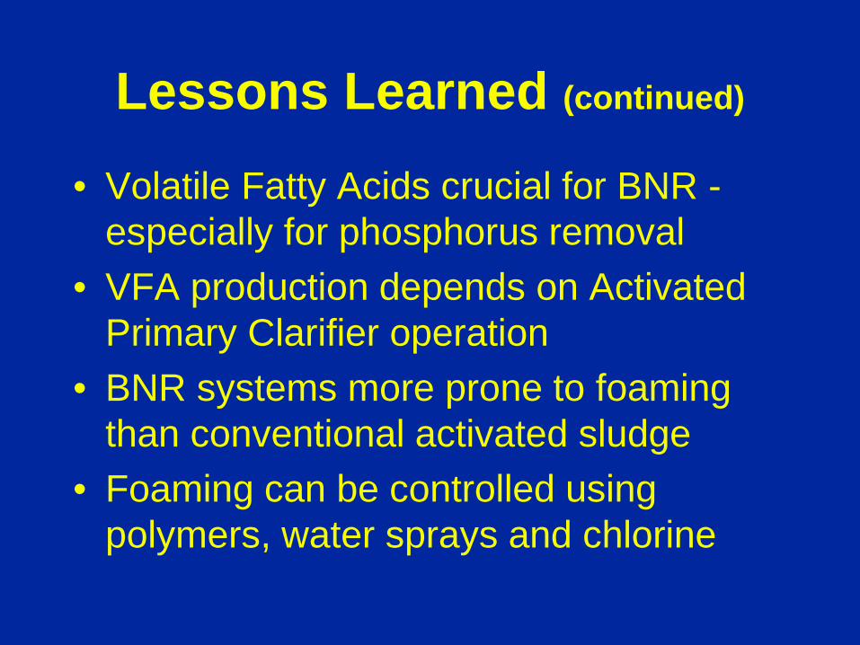
Lessons Learned (continued)
• Volatile Fatty Acids crucial for BNR - especially for phosphorus removal
• VFA production depends on Activated Primary Clarifier operation
• BNR systems more prone to foaming than conventional activated sludge
• Foaming can be controlled using polymers, water sprays and chlorine
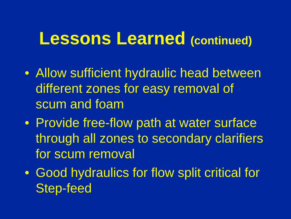
Lessons Learned (continued)
• Allow sufficient hydraulic head between different zones for easy removal of scum and foam
• Provide free-flow path at water surface through all zones to secondary clarifiers for scum removal
• Good hydraulics for flow split critical for Step-feed
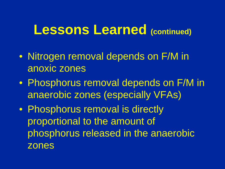
Lessons Learned (continued)
• Nitrogen removal depends on F/M in anoxic zones
• Phosphorus removal depends on F/M in anaerobic zones (especially VFAs)
• Phosphorus removal is directly proportional to the amount of phosphorus released in the anaerobic zones

Questions, Comments?
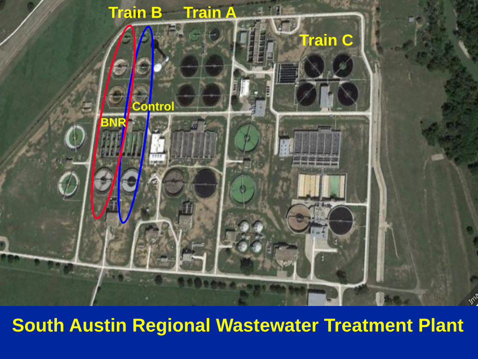
South Austin Regional Wastewater Treatment Plant
Train A Train C
Train B
Control BNR


