
Application of UPFC to Improve the FRT
Capability of Wind Turbine Generator
Yasser M. Alharbi Ministry of Higher Education, Saudi Arabia
King Abdullah scholarship Program
A. M. ShiddiqYunus Mechanical Eng. Department, Energy Conv. Study Prog.
State Polytechnic of Ujung Pandang, South Sulawesi, Indonesia
A. Abu-Siada Electrical and Computer Eng. Department, Curtin University, Perth, Western Australia
Abstract—Variable speed wind turbine generators
installation has been significantly increased worldwide in
the last few years. Faults at the grid side may call for the
disconnection of the wind turbine from the grid as under
such events, wind turbine generator (WTG) may not comply
with the recent developed grid codes for wind energy
conversion systems (WECS). In this paper, a unified power
flow controller (UPFC) is applied to improve the fault ride
through (FRT) capability of doubly fed induction generator
(DFIG)-based WECS during voltage swell and voltage sag
at the grid side. Simulation is carried out using
MATLAB/Simulink software. Results show that UPFC can
effectively improve the FRT capability of DFIG-based
WECS and hence maintaining wind turbine connection to
the grid during certain levels of voltage fluctuation at the
grid side.
Index Terms—HVRT, LVRT, UPFC, DFIG, WTG
I. INTRODUCTION
Renewable energy sources have been recently given a
significant concern worldwide as they generate electricity
from infinite and clean natural resources[1], [2]. Wind
energy is one of the most efficient and promising
renewable energy resources in the world which is
continuously growing with the increase of electrical
power demand and the decrease in conventional
electricity generation resources [3]. In the year 2012, the
growth rate in wind power generation worldwide was 28%
and by the year 2015 the global wind power capacity is
expected to be 600 000 MW which is expected to
increase to 150 000 MW by the year 2020 [4]. In the
early stages of using wind turbine generators (WTG), it
was allowed to disconnect the WTG from the grid during
the event of grid disturbances to avoid wind turbine
Manuscript received May 27, 2013; revised August 12, 2013.
damages. Due to the significant increase in WTGs and
the global trend to establish reliable smart grids, the
transmission system operators (TSOs) require the
connection of WTGs with the grid to be maintained
during certain level of faults to provide support to the
grid during fault conditions. Therefore, grid codes have
been established in many countries to comply with the
new requirements. Since voltage fluctuation is a common
power quality problem in power systems, most of studies
are focused on the performance of WTGs during voltage
sag [5]-[7]. Although it is a less power quality problem,
voltage swell may also lead to the disconnection of
WTGs from the grid. Voltage swell is mainly caused by
switching off a large load, energizing a capacitor bank
and voltage increase in un-faulted phases during a single
line-to-ground fault and is defined as an increase in
voltage level in a range of 1.1 pu to 1.8 pu for a duration
of 0.5 cycle to 1 minute [8]. On the other hand, voltage
sag is defined as a decrease in voltage level within a
range of 0.9 pu to 0.2 pu of the nominal steady state level
for a duration of 0.5 cycle to 1 minute [8]. There are
many international codes related to the fault ride through
(FRT) capability of WTGs. Among these codes, this
paper focuses on the FRT grid codes for Spain and the
US shown in Fig. 1.
Figure 1. FRT grid codes of Spain and US
188
International Journal of Electrical Energy, Vol. 1, No. 4, December 2013
©2013 Engineering and Technology Publishingdoi: 10.12720/ijoee.1.4.188-193
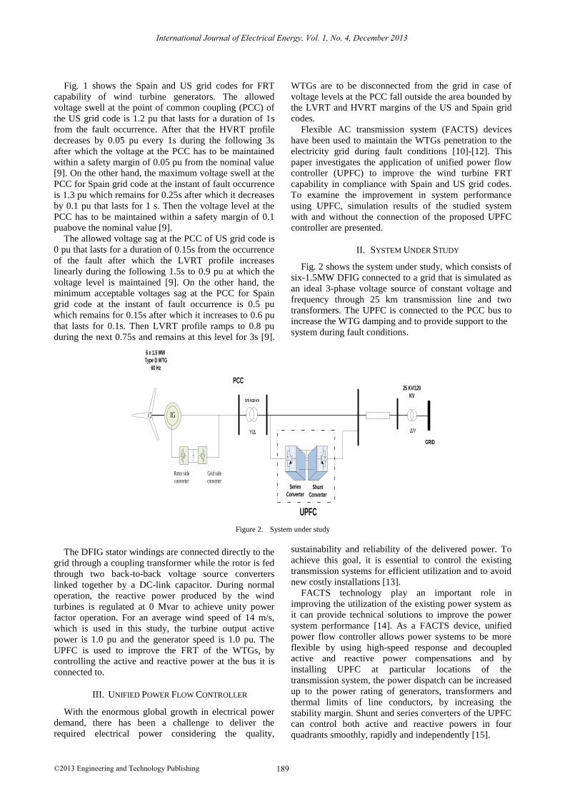
Fig. 1 shows the Spain and US grid codes for FRT
capability of wind turbine generators. The allowed
voltage swell at the point of common coupling (PCC) of
the US grid code is 1.2 pu that lasts for a duration of 1s
from the fault occurrence. After that the HVRT profile
decreases by 0.05 pu every 1s during the following 3s
after which the voltage at the PCC has to be maintained
within a safety margin of 0.05 pu from the nominal value
[9]. On the other hand, the maximum voltage swell at the
PCC for Spain grid code at the instant of fault occurrence
is 1.3 pu which remains for 0.25s after which it decreases
by 0.1 pu that lasts for 1 s. Then the voltage level at the
PCC has to be maintained within a safety margin of 0.1
puabove the nominal value [9].
The allowed voltage sag at the PCC of US grid code is
0 pu that lasts for a duration of 0.15s from the occurrence
of the fault after which the LVRT profile increases
linearly during the following 1.5s to 0.9 pu at which the
voltage level is maintained [9]. On the other hand, the
minimum acceptable voltages sag at the PCC for Spain
grid code at the instant of fault occurrence is 0.5 pu
which remains for 0.15s after which it increases to 0.6 pu
that lasts for 0.1s. Then LVRT profile ramps to 0.8 pu
during the next 0.75s and remains at this level for 3s [9].
WTGs are to be disconnected from the grid in case of
voltage levels at the PCC fall outside the area bounded by
the LVRT and HVRT margins of the US and Spain grid
codes.
Flexible AC transmission system (FACTS) devices
have been used to maintain the WTGs penetration to the
electricity grid during fault conditions [10]-[12]. This
paper investigates the application of unified power flow
controller (UPFC) to improve the wind turbine FRT
capability in compliance with Spain and US grid codes.
To examine the improvement in system performance
using UPFC, simulation results of the studied system
with and without the connection of the proposed UPFC
controller are presented.
II. SYSTEM UNDER STUDY
Fig. 2 shows the system under study, which consists of
six-1.5MW DFIG connected to a grid that is simulated as
an ideal 3-phase voltage source of constant voltage and
frequency through 25 km transmission line and two
transformers. The UPFC is connected to the PCC bus to
increase the WTG damping and to provide support to the
system during fault conditions.
Grid side
converter
Rotor side
converter
IG
575 V/25 KV
25 KV/120
KV
GRID
6 x 1.5 MW
Type D WTG
60 Hz
Y/Δ Δ/Y
PCC
Series
ConverterShunt
Converter
UPFC
Figure 2. System under study
The DFIG stator windings are connected directly to the
grid through a coupling transformer while the rotor is fed
through two back-to-back voltage source converters
linked together by a DC-link capacitor. During normal
operation, the reactive power produced by the wind
turbines is regulated at 0 Mvar to achieve unity power
factor operation. For an average wind speed of 14 m/s,
which is used in this study, the turbine output active
power is 1.0 pu and the generator speed is 1.0 pu. The
UPFC is used to improve the FRT of the WTGs, by
controlling the active and reactive power at the bus it is
connected to.
III. UNIFIED POWER FLOW CONTROLLER
With the enormous global growth in electrical power
demand, there has been a challenge to deliver the
required electrical power considering the quality,
sustainability and reliability of the delivered power. To
achieve this goal, it is essential to control the existing
transmission systems for efficient utilization and to avoid
new costly installations [13].
FACTS technology play an important role in
improving the utilization of the existing power system as
it can provide technical solutions to improve the power
system performance [14]. As a FACTS device, unified
power flow controller allows power systems to be more
flexible by using high-speed response and decoupled
active and reactive power compensations and by
installing UPFC at particular locations of the
transmission system, the power dispatch can be increased
up to the power rating of generators, transformers and
thermal limits of line conductors, by increasing the
stability margin. Shunt and series converters of the UPFC
can control both active and reactive powers in four
quadrants smoothly, rapidly and independently [15].
189
International Journal of Electrical Energy, Vol. 1, No. 4, December 2013
©2013 Engineering and Technology Publishing
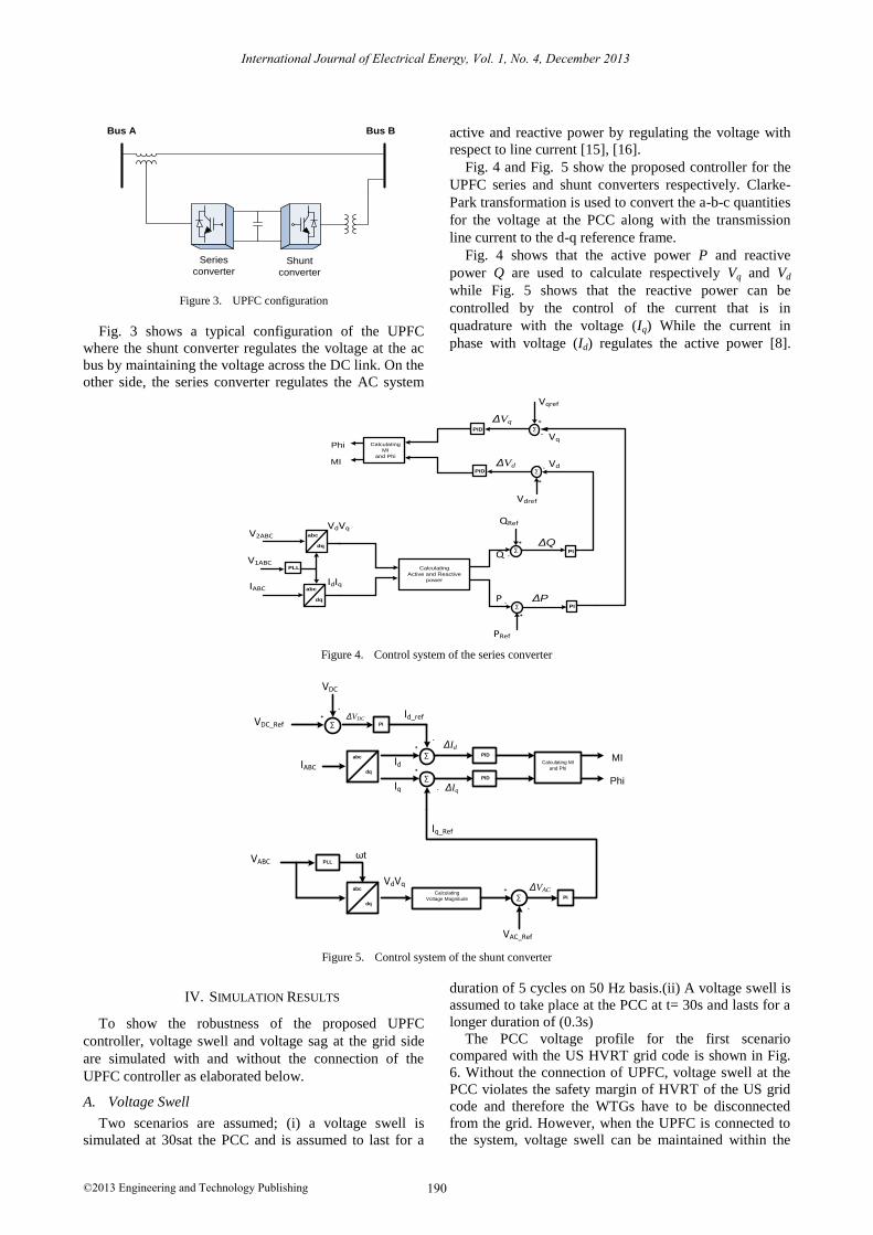
Figure 3. UPFC configuration
Fig. 3 shows a typical configuration of the UPFC
where the shunt converter regulates the voltage at the ac
bus by maintaining the voltage across the DC link. On the
other side, the series converter regulates the AC system
active and reactive power by regulating the voltage with
respect to line current [15], [16].
Fig. 4 and Fig. 5 show the proposed controller for the
UPFC series and shunt converters respectively. Clarke-
Park transformation is used to convert the a-b-c quantities
for the voltage at the PCC along with the transmission
line current to the d-q reference frame.
Fig. 4 shows that the active power P and reactive
power Q are used to calculate respectively Vq and Vd
while Fig. 5 shows that the reactive power can be
controlled by the control of the current that is in
quadrature with the voltage (Iq) While the current in
phase with voltage (Id) regulates the active power [8].
Figure 4. Control system of the series converter
Figure 5. Control system of the shunt converter
IV. SIMULATION RESULTS
To show the robustness of the proposed UPFC
controller, voltage swell and voltage sag at the grid side
are simulated with and without the connection of the
UPFC controller as elaborated below.
A. Voltage Swell
Two scenarios are assumed; (i) a voltage swell is
simulated at 30sat the PCC and is assumed to last for a
duration of 5 cycles on 50 Hz basis.(ii) A voltage swell is
assumed to take place at the PCC at t= 30s and lasts for a
longer duration of (0.3s)
The PCC voltage profile for the first scenario
compared with the US HVRT grid code is shown in Fig.
6. Without the connection of UPFC, voltage swell at the
PCC violates the safety margin of HVRT of the US grid
code and therefore the WTGs have to be disconnected
from the grid. However, when the UPFC is connected to
the system, voltage swell can be maintained within the
Series
converterShunt
converter
Bus A Bus B
abc
dq
VdVq
abc
dq
PLL
V1ABC
IdIq
Calculating
Active and Reactive
power
IABC
∑
∑
QRef
PRef
Q
P
-
-
+
+
PI
PI
V2ABC
∑
Vd
Vdref
∑
Vq
Vqref
-
-
+
+
PID
PID
Calculating
MI
and Phi
MI
Phi
ΔVq
ΔVd
ΔQ
ΔP
abc
dq
abc
dq
PLL
IABC
VABC
∑Calculating
Voltage Magnitude
+
VAC_Ref
VdVq
PI
-
Iq_Ref
∑
+
-
∑
+
-
∑
+
-
VDC_Ref
VDC
Id
Iq
PID
PID
Calculating MI
and Phi
MI
Phi
Id_refPI
ωt
ΔVDC
ΔVAC
ΔId
ΔIq
190
International Journal of Electrical Energy, Vol. 1, No. 4, December 2013
©2013 Engineering and Technology Publishing
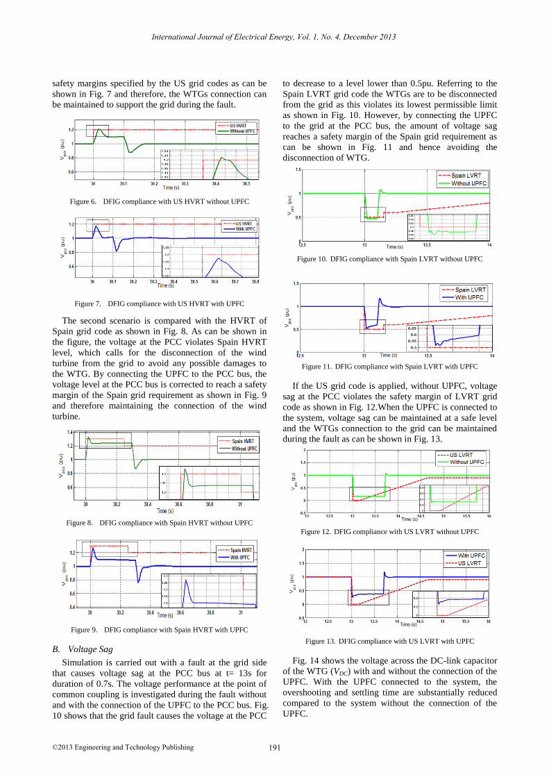
safety margins specified by the US grid codes as can be
shown in Fig. 7 and therefore, the WTGs connection can
be maintained to support the grid during the fault.
Figure 6. DFIG compliance with US HVRT without UPFC
Figure 7. DFIG compliance with US HVRT with UPFC
The second scenario is compared with the HVRT of
Spain grid code as shown in Fig. 8. As can be shown in
the figure, the voltage at the PCC violates Spain HVRT
level, which calls for the disconnection of the wind
turbine from the grid to avoid any possible damages to
the WTG. By connecting the UPFC to the PCC bus, the
voltage level at the PCC bus is corrected to reach a safety
margin of the Spain grid requirement as shown in Fig. 9
and therefore maintaining the connection of the wind
turbine.
Figure 8. DFIG compliance with Spain HVRT without UPFC
Figure 9. DFIG compliance with Spain HVRT with UPFC
B. Voltage Sag
Simulation is carried out with a fault at the grid side
that causes voltage sag at the PCC bus at t= 13s for
duration of 0.7s. The voltage performance at the point of
common coupling is investigated during the fault without
and with the connection of the UPFC to the PCC bus. Fig.
10 shows that the grid fault causes the voltage at the PCC
to decrease to a level lower than 0.5pu. Referring to the
Spain LVRT grid code the WTGs are to be disconnected
from the grid as this violates its lowest permissible limit
as shown in Fig. 10. However, by connecting the UPFC
to the grid at the PCC bus, the amount of voltage sag
reaches a safety margin of the Spain grid requirement as
can be shown in Fig. 11 and hence avoiding the
disconnection of WTG.
Figure 10. DFIG compliance with Spain LVRT without UPFC
Figure 11. DFIG compliance with Spain LVRT with UPFC
If the US grid code is applied, without UPFC, voltage
sag at the PCC violates the safety margin of LVRT grid
code as shown in Fig. 12.When the UPFC is connected to
the system, voltage sag can be maintained at a safe level
and the WTGs connection to the grid can be maintained
during the fault as can be shown in Fig. 13.
Figure 12. DFIG compliance with US LVRT without UPFC
Figure 13. DFIG compliance with US LVRT with UPFC
Fig. 14 shows the voltage across the DC-link capacitor
of the WTG (VDC) with and without the connection of the
UPFC. With the UPFC connected to the system, the
overshooting and settling time are substantially reduced
compared to the system without the connection of the
UPFC.
191
International Journal of Electrical Energy, Vol. 1, No. 4, December 2013
©2013 Engineering and Technology Publishing

Figure 14. VDC waveform (a) voltage swell, (b) voltage sag
Figure 15. Reactive power response of UPFC (a) voltage swell, (b)
voltage sag
The performance of the UPFC during fault can be
examined in Fig. 15. When voltage swell or sag at the
PCC is applied, the UPFC controller acts to instantly
exchange reactive power with the AC system (delivering
in case of voltage sag and absorbing in case of voltage
swell) to regulate the voltage at the PCC within a safety
level. It worth to notice that during normal operating
conditions, there is no reactive power exchange between
the UPFC and the AC system and the reactive power
generation is maintained at zero level to achieve unity
power factor operation for the WTG. The direct and
quadrature currents response of the UPFC during fault are
shown in Fig. 16. At normal operating conditions both
currents are set to zero level and there will be no power
transfer between the UPFC and the system. Upon fault
occurrence, Id and Iq levels change accordingly to provide
reactive power support to the system during the fault.
After fault clearance, both currents return to zero level.
Figure 16. Shunt converterd-q current during (a) voltage swell (b)
voltage sag
V. CONCLUSION
This paper investigates the application of UPFC to
enhance the FRT of wind energy conversion system to
comply with the grid codes of Spain and US. Results
show that, without UPFC, WTGs must be disconnected
from the grid during voltage swell or voltage sag event to
avoid the turbines from being damaged, as the voltage at
the PCC will violate the safety margins required for both
studied grid codes. The proposed controller for the UPFC
can significantly improve the FRT capability of the
WTGs and hence their connection to the grid can be
maintained to support the grid during fault conditions and
to guarantee the continuity ofits power delivery to the
grid, as in Table I.
TABLE I. PARAMETERS OF DFIG
Rated Power [email protected]
Stator Voltage 575 V
Frequency 60 Hz
RS 1.2pu
VDC 1200 V
ACKNOWLEDGMENT
The first author would like to thank the Higher
Education Ministry of Saudi Arabia and King Abdullah
scholarship program for providing him with a PhD
scholarship at Curtin University, Australia
REFERENCES
[1] S. Mathew, "Wind energy conversion systems," in Wind Energy, Springer Berlin Heidelberg, 2006, pp. 89-143.
[2] S. Mathew, "Wind energy and environment," in Wind Energy,
Springer Berlin Heidelberg, 2006, pp. 179-207. [3] S. M. Muyeen, J. Tamura, and T. Murata, "Introduction," in
Stability Augmentation of a Grid-Connected Wind Farm, Springer
London, 2009, pp. 1-22.
192
International Journal of Electrical Energy, Vol. 1, No. 4, December 2013
©2013 Engineering and Technology Publishing
[4] Word Wind Energy Association (WWEA). (December 20, 2012). Available: www.wwindea.org
[5] M. M. Kyaw and V. K. Ramachandaramurthy, "Fault ride through
and voltage regulation for grid connected wind turbine," Renewable Energy, vol. 36, no. 1, pp. 206-215, 2011.
[6] A. M. Shiddiq Yunus, M. A. S. Masoum, and A. Abu-Siada,
"Effect of STATCOM on the low-voltage-ride-through capability of type-D wind turbine generator," in Proc. Innovative Smart Grid
Technologies Asia, IEEE PES, 2011, pp. 1-5.
[7] A. M. S. Yunus, A. Abu-Siada, and M. A. S. Masoum, "Improvement of LVRT capability of variable speed wind turbine
generators using SMES unit," in Proc. Innovative Smart Grid
Technologies Asia, IEEE PES, 2011, pp. 1-7. [8] E. F. Fuchs and M. A. S. Masoum, Power Quality in Power
Systems and Electrical Machines, Elsevier, 2008, pp. 3-8.
[9] Alt, et al., "Overview of recent grid codes for wind power integration," in Proc. International Conference on Optimization of
Electrical and Electronic Equipment, 12th, 2010, pp. 1152-1160.
[10] R. Grunbaum, "FACTS for grid integration of wind power," in
Proc. Innovative Smart Grid Technologies Conference Europe,
2010 IEEE PES, 2010, pp. 1-8.
[11] M. T. Hagh, A.Lafzi, and A. R. Milani, "Dynamic and stability improvement of a wind farm connected to grid using UPFC," in
Proc. IEEE International Conference on, Industrial Technology,
2008, pp. 1-5. [12] A. M. S. Yunus, M. A. S. Masoum, and A. Abu-Siada,
"Application of SMES to enhance the dynamic performance of
DFIG during voltage sag and swell," IEEE Transactions on Applied Superconductivity, vol. 22, no. 4, pp. 5702009, 2012.
[13] V. Mahajan, "Power system stability improvement with flexible
A.C. transmission system (FACTs) controller," in Proc. Power System Technology and IEEE Power India Conference, Joint
International Conference on, 2008, pp. 1-7.
[14] R. M. Mathur and R. K. Varma, Thyristor-Based FACTS Controllers and Electrical Transmission Systems, Wiley-IEEE
Press, 2002, pp. 6-12.
[15] H. Akagi, E. H. Watanabe, and M. Aredes, Instantaneous Power Theory and Applications to Power Conditioning, Wiley-IEEE
Press, 2007, pp. 265-281.
[16] L. G. c. E.-H., N. G. Hingorani, consulting editor., Understanding FACTS : Concepts and Technology of Flexible AC Transmission
Systems, New York : IEEE Press, 2000, pp. 299-308.
Yasser Mohammed R Alharbi(S’11) received his B.Eng. from Riyadh collage of technology, Riyadh,
Saudi Arabia, in 2007. He also received his M.Sc. from
Curtin University of Technology, Perth, Australia, in 2010. He is currently pursuing his PhD study at Curtin
University of Technology. His research interest
includes Power quality, Renewable energy and power
system stability.
A. M. ShiddiqYunus (S’11) was born in Makassar, Indonesia, on August 4, 1978. He received his B.Sc.
from Hasanuddin University in 2000 and his M.Eng.Sc
from Queensland University of Technology, Australia in 2006 both in Electrical Engineering. He is towards
his PhD study in Curtin University, WA, Australia in
2012. His employment experience included lecturer in the Department of Mechanical Engineering, Energy Conversion Study
Program, State Polytechnic of Ujungpandang since 2001. His special
fields of interest included superconducting magnetic energy storage (SMES) and renewable energy.
A. Abu-Siada (SM’12) received his B.Sc. and M.Sc.
degrees from Ain Shams University, Egypt and the PhD degree from Curtin University of Technology,
Australia, All in Electrical Engineering. Currently, he is a senior lecturer in the Department of Electrical and
Computer Engineering at Curtin University. His
research interests include power system stability, Condition monitoring, Power Electronics, Power Quality, Energy
Technology and System Simulation. He is a regular reviewer for the
IEEE Transaction on Power Electronics, IEEE Transaction on Dielectrics and Electrical Insulations, and the Qatar National Research
Fund (QNRF).
193
International Journal of Electrical Energy, Vol. 1, No. 4, December 2013
©2013 Engineering and Technology Publishing


