
AP11LCD / AP11LED Engineering Manual
AP11LED/LCD-Eng- Rev 02 1
AP11LCD / AP11LED
10 Zone Off Board Alarm Panel
Engineering Manual
SAFETY
Before proceeding with the installation, please note the following safety warnings:
DO NOT connect the mains supply directly to the products, this will cause permanent damage to the products. Control panel is for indoor use only. Avoid mounting location which can expose this product to splashing or dripping
liquid.
Always follow the manufacturer’s advice when using any tools power tools, ladder/steps,. using steps or ladders, and
wear suitable protective equipment (e.g. safety goggles) when drilling holes, etc. The use of ear defenders are advisable
when working in close proximity to the External Siren or the Control Panel’s Siren when the front panel cover is
removed due to the high sound level produced by it. Before drilling holes in walls, check for hidden electricity cables
and water pipes. The use of a cable/pipe locator is advisable if in doubt. Batteries (battery pack or batteries installed)
should not be exposed to excessive heat. Danger of damage to the unit may occur if battery is incorrectly replaced.
Replace only with the same or equivalent type. (Do not mix batteries type).

AP11LCD / AP11LED Engineering Manual
AP11LED/LCD-Eng- Rev 02 2
Table of Contents
SECTION 1 - OVERVIEW OF SYSTEM..............................................4
1.1 - Kit Contents................................................................................................................. 4
1.2 - Tools Required ............................................................................................................ 4
1.2 - Tools Required ............................................................................................................ 5
1.3 - System Feature ............................................................................................................ 5
1.4 - Explanation of Terms .................................................................................................. 5
SECTION 2 – INSTALLING YOUR SYSTEM......................................6
2.1 - Fixing the Control Panel.............................................................................................. 6
2.2 - PCB ............................................................................................................................. 7
2.3 - Tamper network .......................................................................................................... 7
2.4 - Remote Keypads.......................................................................................................... 7
2.5 - Security Zones............................................................................................................. 9
2.6 - Fire Zone Circuit ......................................................................................................... 9
2.7 - Tamper Zone Circuit ................................................................................................... 9
2.8 - PA Zone Circuit......................................................................................................... 10
2.9 - Doorbell Zone Circuit ............................................................................................... 10
2.10 - Keyswtich Circuit.................................................................................................... 10
2.11 - Exit Terminate Circuit............................................................................................. 11
2.12 - Extension speaker.................................................................................................... 11
2.13 - External Siren Output (Bell box)............................................................................. 12
2.14 - 13V Supply Output.................................................................................................. 12
2.15 - Set............................................................................................................................ 12
SECTION 3 - FACTORY DEFAULT SETTING .................................13
SECTION 4 - MAINS CONNECTION ................................................14
SECTION 5 - FIRST POWER UP......................................................14
SECTION 6 – HOW TO SET UP THE SYSTEM................................16
6.1 - LED Keypad ............................................................................................................ 16
6.1.1 - Setup Programs..................................................................................................... 16
6.1.2 - Setup Zones Type................................................................................................. 21
6.1.3 - Setup Zones Attrs ................................................................................................. 22
6.1.4 - Setup Codes.......................................................................................................... 24
6.1.5 - Setup system......................................................................................................... 26
6.1.6 - Misc menu ............................................................................................................ 31

AP11LCD / AP11LED Engineering Manual
AP11LED/LCD-Eng- Rev 02 3
6.1.7 - View Event Log.................................................................................................... 31
6.1.8 - Test System .......................................................................................................... 32
6.2 - LCD Keypad ............................................................................................................ 35
6.2.1 - Setup Programs..................................................................................................... 35
6.2.2 - Setup Zones Type................................................................................................. 39
6.2.3 - Setup Zones Attributes ......................................................................................... 42
6.2.4 - Setup Codes.......................................................................................................... 43
6.2.5 - Setup system......................................................................................................... 46
6.2.6 - Misc menu ............................................................................................................ 53
6.2.7 - View Event Log.................................................................................................... 57
6.2.8 - Test System .......................................................................................................... 58
SECTION 7 - USING SYSTEM..........................................................61
7.1 – LED Keypad............................................................................................................ 61
7.1.1 - Setting the System................................................................................................ 61
7.1.2 - How to OMIT a zone(s) ....................................................................................... 62
7.1.3 - Unsetting the System............................................................................................ 62
7.1.4 - How to UNSET from Alarm and RESET the system .......................................... 63
7.1.5 - How to use Panic Alarm on keypad ..................................................................... 63
7.2 - LCD Keypad ............................................................................................................ 64
7.2.1 - Setting the System................................................................................................ 64
7.2.2 - How to OMIT a zone(s) ....................................................................................... 64
7.2.3 - Unsetting the System............................................................................................ 65
7.2.4 - How to UNSET from Alarm and RESET the system .......................................... 65
7.2.5 - How to use Panic Alarm on keypad ..................................................................... 66
SECTION 8 - MAINTENANCE ..........................................................67
SECTION 9 - TROUBLESHOOTING GUIDE ....................................67
SECTION 10 - SPECIFICATIONS.....................................................69
APPENDIX 1 – EVENT LOG MESSAGES........................................71
APPENDIX 2 – ZONE – LOCATION & PROGRAMMING TABLE....72
DISPOSAL AND RECYCLING..........................................................72
ERRORS AND OMISSIONS .............................................................73
MENU MAP.......................................................................................74

AP11LCD / AP11LED Engineering Manual
AP11LED/LCD-Eng- Rev 02 4
Section 1 - Overview of System The 10 zone intruder alarm system is an indoor alarm system based on advanced technology to
give professional levels of protection and reliability. It is 10 zones wired system with special
electronic design for short-circuit protection. It is simple to use, to be installed by a competent
installation engineer, special tools or training is required.
IMPORTANT – Please read this manual carefully, in full, before commencing Installation.
You will find installation easier if you follow these steps in the sequence shown.
1.1 - Kit Contents
AP11LCD 10 Zone Intruder Alarm Panel with LCD Keypad The system comprises of:
10 ZONE OFF-BOARD CONTROL PANEL
This is the heart of the system. It receives signals from detectors. Accepts input from a user and activates warning devices such as siren and strobe lights.
LCD REMOTE KEYPAD Uses a programming system after it connects with control panel.
AP11LED 10 Zone Intruder Alarm Panel with LED Keypad The system comprises of:
10 ZONE OFF-BOARD CONTROL PANEL
This is the heart of the system. It receives signals from detectors. Accepts input from a user and activates warning devices such as siren and strobe lights.
LED REMOTE KEYPAD
Uses a programming system after it connects with control panel.
LCD Control Panel LCD Remote Keypad
LED Remote Keypad LCD Control Panel

AP11LCD / AP11LED Engineering Manual
AP11LED/LCD-Eng- Rev 02 5
1.2 - Tools Required
• Large and small flat bladed screwdrivers
• Large and small cross-point screwdrivers
• Power drill
• Hammer & ear defenders
• 5mm, 8mm and 10mm masonry drill bits
• Sharp knife
• Wire cutters & wire stripper
• Ladder or other safe working platform
• Cable Detector
1.3 - System Feature
• 10 Zones programmable for security, PA, Fire, 24Hr Tamper.
• TAMPER input
• Output for External Siren and Strobe.
• 4 Access Level Codes, manager code, engineer code, user code (LED system has two, LCD system has ten ), holiday code, all programmable.
• 1 Full set and 2 fully selectable part set programs.
• Chime on any security zone
• 250 events memory for LCD Keypad, 16 events memory for LED Keypad
• Programmable timers for exit, entry and bell cut off
• Walk Test mode
• Quick set system
• Single Key Set mode
• Name zone for LCD remote keypad
• Supports up to four remote keypads with on board PA , Keys positioned up to 100 meters from control panel.
• Keypads can be wired in a star or daisy chain configuration from control panel
• Non-volatile memory for protection of engineer program, manager and event log.
• Battery capacity of up to 2.1AH
1.4 - Explanation of Terms
Zone – A logical area that is monitored by one detector.
Disarm – It is the normal state of the system when the house is occupied. Enter your four-digit user PIN code would return to OFF state.
Full Alarm (ARM state) – The CU will sound full alarm (internal siren) when it receives alarm signals.
Part Arm (Home state) – Arming the system so that certain zones omitted (i.e. will not trigger an alarm).
Entry/Exit Zone – Zone that allows timed entry/exit in to/out the premises before alarm activation
OK Beep – Rapid double tone; it indicates correct operation.
Error Beep – Long single tone; it indicates incorrect operation.

AP11LCD / AP11LED Engineering Manual
AP11LED/LCD-Eng- Rev 02 6
Section 2 – Installing your System
In choosing a suitable location you should bear in mind:
� The need to reach the keypad easily, within the 30 seconds, when entering and leaving the
premises, ideally passing only one detector.
� The CU should not be visible from the exterior of the protected premises.
� Reception of radio signals can be affected by the presence of metal objects within a few
feet of the CU. (E.g. mirrors, central heating radiators, garage doors and cars parked in
garages on the opposite side of the wall. Avoid any location which is near (within 60cm)
to these or any other large metal objects.
2.1 - Fixing the Control Panel
CAUTION: When positioning the control panel ensure that it is located in a dry place
away from damp areas.
Step 1. Remove the front cover(s) from the base
assembly.
Disconnect the transformer wires from the board,
these are marked AC. Carefully remove the board by
gently pushing down the holding clips on the bottom
edge of the board and with draw it from the base.
Step 2. Fit the panel to wall with suitable fixings.
Ensure the wall surface is flat to prevent base
distortion. There are cable entry holes provided in
the rear of the base and around the outside edges
through the thinned out plastic sections which may
be cut away as required.
Step 3.The hole provided adjacent to the mains
transformer is a dedicated mains cable entry point.
Disconnect the
transformer from
the board

AP11LCD / AP11LED Engineering Manual
AP11LED/LCD-Eng- Rev 02 7
2.2 - PCB
There are three fuses mounted on the circuit board. All are 20mm anti-surge
F1 1.6A – to protect the positive (+Ve) line of 12V battery
F2 1A – to protect the RKP 13V supply
F3 1A – to protect the Siren (Bell)&Strobe supply
As supplied, wire links are fitted across the Tamper terminal to represent a closed circuit.
CAUTION: Always power-down the panel when wiring external circuits, to prevent
damage to the panel electronics.
Systematically wire and test each circuit:
• Zone, Tamper circuit and PA circuits
• Finish by wiring any additional extension speaker sounders, external siren(bell)/strobe and
the 13V supply.
2.3 - Tamper network
The Tamper circuit is used to protect all cables and detectors in the system from unauthorized
access including the panel and RKP covers.
The zone and PA tampers should be series wired and connected to TAMP terminals.
Terminals RTN-&- are for the external siren tamper. The TAMP terminals at the bottom left of
the board are for the RKP tampers.
2.4 - Remote Keypads
CAUTION: When the LCD Control Panel is being installed ensure there is at least one
LCD /LED remote keypad wired to the panel before first power up.
RKP Tamper Detector Tamper Siren tamper CP Tamper
CEF_LCD_CP_V1.3
PWR
LED 1

AP11LCD / AP11LED Engineering Manual
AP11LED/LCD-Eng- Rev 02 8
A combination of up to four LCD/LED remote keypads can be connected to the panel.
LCD /LED remote keypad connects with LCD control panel
1). Select remote keypad jumper
2). Wiring diagram
Fitting the Remote Keypad
a. Separate the RKP base plate from the main assembly by slackening the retaining screw.
b. Cut away the required thin wall sections around the edges of the base plate for cable entry.
c. The base plate may be fitted directly to the wall using the screws and wall plugs supplied, if
these are not appropriate for the wall the use suitable alternative fixings.
d. Bring the cables into the base plate and wire to the terminal block on the base plate, see
diagram on the previous page.

AP11LCD / AP11LED Engineering Manual
AP11LED/LCD-Eng- Rev 02 9
e. Refit the RKP main assembly to the base plate by hooking it onto the top holding clips.
Check that the wiring is not trapped by the tamper switch/spring or the PCB support pillar.
Inset the screw and tighten in the bottom of the case.
2.5 - Security Zones
PIR and door contact connect to control panel
block diagram, only one device per alarm
zone.
2.6 - Fire Zone Circuit
Any zone may be programmed as a fire zone. This
will automatically exclude the availability of the zone
from programs and normal security applications.
(Normally closed circuit required)
2.7 - Tamper Zone Circuit
Any zone may be programmed as a Tamper zone.
Operational in Day and set, the Tamper circuit will
cause a full alarm condition when activated.
(Normally closed circuit required)
NC
NC
Ala
rmT
am
p

AP11LCD / AP11LED Engineering Manual
AP11LED/LCD-Eng- Rev 02 10
PanicButton
Tam
p
2.8 - PA Zone Circuit
Any quantity of normally closed type personal
attack button may be wired in series and then
connected to the PA circuit.
If a zone is required for PA this will require
programming, refer to section 6.2.2.2
Operational in Day and set, the PA circuit will
cause a full alarm condition when activated.
PA is indicated on the control panel or RKP as
Attack.
2.9 - Doorbell Zone Circuit
Any zone may be programmed as a Doorbell
zone. Operational in Day and set, the Doorbell
circuit will cause Doorbell sound.
(Normally closed circuit required)
The PTS terminals on the PCB can also be
used as doorbell. A normally open contact such
as doorbell push could used.
(ensure flag 2 is set to door Bell)
2.10 - Keyswtich Circuit
When Keyswitch flag is set ON, system to
be SET and UNSET with the use of a key
switch in PTS terminal.
(Normally open unset, normally closed set)
Note
The PTS cannot be set to as a doorbell and
keyswitch

AP11LCD / AP11LED Engineering Manual
AP11LED/LCD-Eng- Rev 02 11
2.11 - Exit Terminate Circuit
If the Exit Terminate is programmed in the
Exit mode the exit time will not time out until
a momentary normally open switch has
triggered the PTS terminals. Pressing the
button once on PTS will terminate the exit time
and the system will set immediately.
2.12 - Extension speaker
Extension speaker may be connected to the loudspeaker terminals to produce high volume alarm
tones and low volume entry/exit/fault tones.
External speaker connects to control panel
Only one 16 ohm extension speaker may be wired across the speaker terminals. Mounted in
convenient position within the installation the extension speaker will reproduce all of the alarm
tones generated by the control panel.
A control marked VOLUME in the center of the board may be used to adjust the low volume
entry/exit tones to suit environmental conditions.
The factory fitted sounder inside the control panel
is not a speaker and the volume cannot be adjusted.
16 Ohms Extension Speaker
- SET+RTN- - S-
BELLSPEAKER
Panel
BoardSTROBE

AP11LCD / AP11LED Engineering Manual
AP11LED/LCD-Eng- Rev 02 12
Yel
low
Gre
en
Bla
ck
Red
Blu
e
2.13 - External Siren Output (Bell box)
The external siren (bell box) is usually installed in a high position from where the siren could be
seen and heard.
Terminal + S- RTN- - strobe + and - are for connection to the external siren. These terminals
provide a power/hold –off supply, sounder trigger and tamper circuit to protect the external siren
housing.
The terminals are summarized as follows:
+ +Ve supply (13V)
S- -Ve Sounder trigger
RTN- -Ve tamper return
- -Ve supply (0)
Strobe + -
Where a discrete external siren is used, it should be connected to terminals + & S-. Terminals
RTN- & - are then used for tamper protection for the housing.
Bell box wiring to control panel
2.14 - 13V Supply Output
The 13V output is to power detectors which require a voltage supply (PIR detector etc). The
supply is present at all times and may be used to supply a total of 350mA.
2.15 - Set
The output marked SET becomes positive on correct Set of the system and is removed by entry of a valid user code.
Bell

AP11LCD / AP11LED Engineering Manual
AP11LED/LCD-Eng- Rev 02 13
Section 3 - Factory Default Setting
Indications on the system
Indications
LED steady on indication
LED flashing indication
LED off
Internal Sound
External Device: Strobe
External Siren: Bell
Defaulting Manager code and Engineer code
1. Power down panel.
2. Remove wiring from SET+ output and TAMP input.
3. Fit shorting wire between SET+ and right-hand TAMP terminal.
4. Power up.
5. Wait for alarm to start.
6. Power down panel and then restore original wiring.
System status
User code 1-10 : Not used
Holiday code : Not used
Manager code : 0123
Engineer code : 9999
Bell time : 14 minutes
Bell delay time : No delay
Rearm Count : 3 Rearms
Service Date : 01/01/09
System Time : 00:00:00
System Date : 08-08-08
Alarm INFO text is Null
Zone type : Security
Omit Allowed : Off
Double Knock : Off
Chime : Off
System flag
Silent PA : Off
RKP PA : On
Engineer Reset : Off
PA user Reset : On
Fire user Reset : On
Bell in Fire : On
Disable Bell Tamper : Off
Lock Engineer Code : Off
Auto walk test exit : Off
Key Switch : Off
PTS as Doorbell : Off
Strobe on SET : On
Single key SET : Off
EOLR zone : Off
EN compliant : Off
Daylight Saving : Off
Service Timer : Off
SET mode
Full mode:
Zone 1 : Timed
Zone 2 : Inhibited
Zone 3-10 : Immediate
Exit Mode : Timed Exit
Exit Time : 45 sec
Entry Time : 45 sec
Part 1 mode:
Zone 1,2 : Timed
Zone3-8 : Immediate
Zone 9-10 : Not Used
Exit Mode : Timed Exit
Exit Time : 45 sec
Entry Time : 45 sec
Part 2 mode : Disabled

AP11LCD / AP11LED Engineering Manual
AP11LED/LCD-Eng- Rev 02 14
Section 4 - Mains Connection
The mains power should be connected using a 3 core cable of not less than 1mm sq. from a fused
spur to the mains connector inside the control panel.
NOTE: The mains supply must be connected by a technically competent person and according
to current IEE regulations.
CAUTION: To avoid the risk of electrical shock you must always totally isolate the mains
supply before opening the control panel cover(s).
Mains input fuse rating: 125mA, 250V type.
On connecting the mains supply to the panel the power indicator is lit. Power
Testing the System
Complete the wiring of the system and then:
• Fully test the system and ensure it is fault free.
• Fully program the system.
• Fill in the installation log at the back of the manual and retain if for future reference.
• Finally explain the operation of the system to the end user.
Section 5 - First Power Up
Before power up, for AP11LED panel only – fit the top cover on to the base and connect the
speaker wires. Leave the cover in position throughout the reset of the installation.
a. Check that the factory fitted links are connected to terminals TAMP and RTN-& -.
b. Fit the battery wires to the BATT terminals on the Board, Red to +and Black to -.

AP11LCD / AP11LED Engineering Manual
AP11LED/LCD-Eng- Rev 02 15
c. On connecting the battery the system will now go into alarm condition and Day led is
will be lit.
LCD INDICATIONS LED INDICATIONS
d. Fit the cover to hold down the tamper spring at the bottom right-hand of the board.
e. Enter User code / Manager code (factory set code).
f. Press to return to Day mode.
g. Immediately enter the engineer code 9-9-9-9 factory default setting
h. The system will go into Engineer program mode.
Engineer Program Mode The control panel may be programmed to suit a wide variety of installations.
Once the engineer program mode has been accessed, each configuration may be changed in any
order.
Before entering engineer program mode the system should be in the Day mode, with the Day and
Power indicators lit.
LC ENGINEER MENU
Setup Program?
Day
PA TAMP
1 2 3 4 5 6 7 8 9 10
Alarm sound
Day
PA TAMP
1 2 3 4 5 6 7 8 9 10
01:28:16 08-Aug
DAY
CP Tamper
01:28:16 08-Aug
DAY
0 1 2 3
R ES TE
Day
PA
TAMP
1 2 3 4 5 6 7 8 9 10
Day
PA
TAMP
1 2 3 4 5 6 7 8 9 10

AP11LCD / AP11LED Engineering Manual
AP11LED/LCD-Eng- Rev 02 16
Section 6 – How to Set up the system
6.1 - LED Keypad
How to enter Engineer Program Mode
You should require the manager to authorize Engineer access. It is accessed directly from Day
mode via the Manager code.
To operate the “Engineer Authorise Access” as follow:
LED Remote Keypad: ·Enter Manager program mode. ·Press (Default)
·Press to authorize Engineer access.
Then Engineer can access program mode
within 3hr hour.
·Press to leave the current menu.
• Input 4-digit Engineer code
and go to engineer operation window within
5 seconds.
6.1.1 - Setup Programs
The panel has three programs: 1 = Program Full, 2 = Program Part1, 3 = Program Part2.
Each program can set all parameters independent, these are 1 = Zone Function, 2 = Exit Mode,
3 = Exit Time, 4 = Entry Time.
Zones can also be assigned different functions in different programs. Refer to the following
diagram for the programming structure.
6.1.1.1 - How to go into Full mode Setting
LED Remote Keypad: ·Under Engineer mode. ·Press to Select Setup Programs.
·Press to accept and go into Program Full.
Day
PA TAMP
1 2 3 4 5 6 7 8 9 10
Day
PA TAMP
1 2 3 4 5 6 7 8 9 10 P OR G 0 1 2 3
3
R ES TE
9 9 9 9 Day
PA
TAMP
1 2 3 4 5 6 7 8 9 10
Day
PA TAMP
1 2 3 4 5 6 7 8 9 10
Day
PA TAMP
1 2 3 4 5 6 7 8 9 10 ES T
1
R ES TE
Day
PA TAMP
1 2 3 4 5 6 7 8 9 10

AP11LCD / AP11LED Engineering Manual
AP11LED/LCD-Eng- Rev 02 17
6.1.1.2 - How to go into Part 1 mode Setting
LED Remote Keypad: ·Under Engineer mode. ·Press to Select Setup Programs.
·Press to accept and go into Program Part 1.
6.1.1.3 - How to go into Part 2 mode Setting
LED Remote Keypad: ·Under Engineer mode. ·Press to Select Setup Programs.
·Press to accept and go into Program Part 2.
6.1.1.4 - How to set zone function
In Zone Function, Security type zones can be assigned different functions. These are
1= Immediate (alarm) Zone, 2 = Timed (entry/exit) Zone, 3 = Inhibited (walkthrough) Zone.
Immediate (Alarm) Zone: Use this function when the zone is not part of an entry/exit route. When the system is SET,
activation of an immediate zone will cause a full alarm condition.
Timed (Entry/Exit) Zone: A time zone would be used to protect an entry/exit route. Opening the door or triggering the
sensor in this type of zone when the system is SET will start the entry timer.
Inhibited (Walkthrough) Zone:
A time-inhibited zone operates as an immediate zone unless a timed zone has been operated
and a timer started. Such a zone should be utilized to allow passage between the entry/exit
door and the control panel when there are detectors present.
Day
PA TAMP
1 2 3 4 5 6 7 8 9 10
Day
PA TAMP
1 2 3 4 5 6 7 8 9 10
Day
PA TAMP
1 2 3 4 5 6 7 8 9 10
Day
PA TAMP
1 2 3 4 5 6 7 8 9 10
O I M T 1
1

AP11LCD / AP11LED Engineering Manual
AP11LED/LCD-Eng- Rev 02 18
LED Remote Keypad:
Set zone Immediate function
Under Engineer Menu/Setup Program, the program
Full mode is chosen. LED 1 and LED 2 is flashing.
·Press to program Immediate (Alarm) Zone.
LED 1~10 ON indicate selected immediate
zones.
Default settings are LED’s 3~10 on.
·To edit the other zones press Zone number
(1~10). If select, LED is on.
If select Zone 2 to be immediate zone,
·Press to accept the change
Or press to cancel.
Set zone Timed (Entry/Exit) function
Under Engineer Menu/Setup Program, the program
Full mode is chosen. LED 1 and LED 2 is flashing.
·Press to program Timed Zone.
LED 1~10 ON indicate selected Timed
zones.
Default settings are LED 1 on.
·To edit the other zones press Zone number
(1~10). If select, LED is on.
If select Zone 4 to be immediate zone,
·Press to accept the change
Or press to cancel.
Set zone Inhibited (Walkthrough) function
Under Engineer Menu/Setup Program, the program
Full mode is chosen LED 1 and LED 2 is flashing.
·Press to program Timed Zone.
LED 1~10 ON indicate selected Timed zones.
Default settings are LED 2 on.
Day
PA TAMP
1 2 3 4 5 6 7 8 9 10
Day
PA TAMP
1 2 3 4 5 6 7 8 9 10
Day
PA TAMP
1 2 3 4 5 6 7 8 9 10
Day
PA TAMP
1 2 3 4 5 6 7 8 9 10
Day
PA TAMP
1 2 3 4 5 6 7 8 9 10
Day
PA TAMP
1 2 3 4 5 6 7 8 9 10
Day
PA TAMP
1 2 3 4 5 6 7 8 9 10
Day
PA TAMP
1 2 3 4 5 6 7 8 9 10
R ES TE
Day
PA TAMP
1 2 3 4 5 6 7 8 9 10
R ES TE
Day
PA TAMP
1 2 3 4 5 6 7 8 9 10
1
2
3
ES T
ES T

AP11LCD / AP11LED Engineering Manual
AP11LED/LCD-Eng- Rev 02 19
·To edit the other zones press Zone number
(1~10). If select, LED is on.
If select Zone 3 to be inhibited zone,
Then press , and press
·Press to accept the change
Or press to cancel.
6.1.1.5 - How to set Exit mode function
There are four selections for Exit Mode in all mode: 1 = Timed Exit, 2 = Final Door, 3 = Silent
Exit, 4 = Terminated, 0 = Disable.
Timed Exit:
A timed program will set once the exit timer has expired and all zones are clear.
Final Door:
A final door program will set 5 seconds after the final door has been opened and closed.
Silent Exit:
This operates exactly the same as Timed Exit but completely silent without internal sounder
signal.
Terminated:
A terminated program will set once the PTS terminal has been trigger.
Disable:
A disabled program is not available for use and cannot be selected and setting time.
LED Remote Keypad:
Under Engineer Menu/Setup Program, the program
Full mode is chosen. LED 1 and LED 2 is flashing.
·Press to program Exit Mode.
LED 1 ON indicates system selected: Timed
·Change exit mode to Silent.
Press to select silent
·Press to accept the change
Or press to cancel.
Day
PA TAMP
1 2 3 4 5 6 7 8 9 10
Day
PA TAMP
1 2 3 4 5 6 7 8 9 10
R ES TE
32
Day
PA TAMP
1 2 3 4 5 6 7 8 9 10
Day
PA TAMP
1 2 3 4 5 6 7 8 9 10
Day
PA TAMP
1 2 3 4 5 6 7 8 9 10
Day
PA TAMP
1 2 3 4 5 6 7 8 9 10
3
4
R ES TE
ES T
ES T
AP11LCD / AP11LED Engineering Manual
AP11LED/LCD-Eng- Rev 02 20
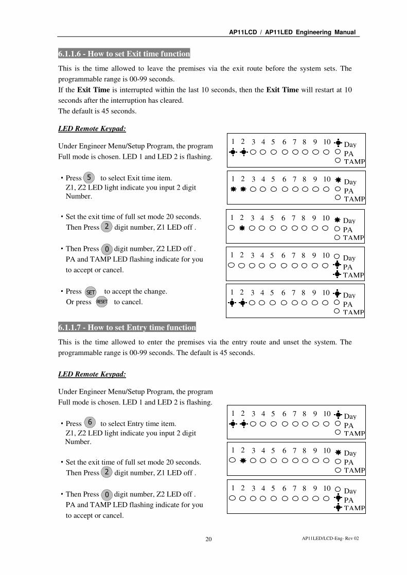
6.1.1.6 - How to set Exit time function
This is the time allowed to leave the premises via the exit route before the system sets. The
programmable range is 00-99 seconds.
If the Exit Time is interrupted within the last 10 seconds, then the Exit Time will restart at 10
seconds after the interruption has cleared.
The default is 45 seconds.
LED Remote Keypad:
Under Engineer Menu/Setup Program, the program
Full mode is chosen. LED 1 and LED 2 is flashing.
·Press to select Exit time item.
Z1, Z2 LED light indicate you input 2 digit
Number.
·Set the exit time of full set mode 20 seconds.
Then Press digit number, Z1 LED off .
·Then Press digit number, Z2 LED off .
PA and TAMP LED flashing indicate for you
to accept or cancel.
·Press to accept the change.
Or press to cancel.
6.1.1.7 - How to set Entry time function
This is the time allowed to enter the premises via the entry route and unset the system. The
programmable range is 00-99 seconds. The default is 45 seconds.
LED Remote Keypad:
Under Engineer Menu/Setup Program, the program
Full mode is chosen. LED 1 and LED 2 is flashing.
·Press to select Entry time item.
Z1, Z2 LED light indicate you input 2 digit
Number.
·Set the exit time of full set mode 20 seconds.
Then Press digit number, Z1 LED off .
·Then Press digit number, Z2 LED off .
PA and TAMP LED flashing indicate for you
to accept or cancel.
Day
PA TAMP
1 2 3 4 5 6 7 8 9 10
Day
PA TAMP
1 2 3 4 5 6 7 8 9 10
Day
PA TAMP
1 2 3 4 5 6 7 8 9 10
Day
PA TAMP
1 2 3 4 5 6 7 8 9 10
2
0
R ES TE
5
Day
PA TAMP
1 2 3 4 5 6 7 8 9 10
Day
PA TAMP
1 2 3 4 5 6 7 8 9 10
2
0
6
Day
PA TAMP
1 2 3 4 5 6 7 8 9 10
Day
PA TAMP
1 2 3 4 5 6 7 8 9 10
ES T

AP11LCD / AP11LED Engineering Manual
AP11LED/LCD-Eng- Rev 02 21
·Press to accept the change. Or press
to cancel. Press to return to Engineer mode.
6.1.2 - Setup Zones Type
The ‘Setup Zones Type’ contains: 1 = Zone name, 2 = Zone type.
6.1.2.1 - How to set Zone Name
LED Remote Keypad:
The LED Remote Keypad cannot program zone names.
6.1.2.2 - How to set Zone Type
There are six types for Zone: 1 = Security, 2 = PA, 3 = Door Bell, 4 = Fire, 5 = Tamper/24H,
0 = Not Used.
Security:
The system comes supplied with factory links fitted to the zone terminals to simulate a
closed circuit. As each zone is connected these links should be removed. All zones are fully
programmable. When the panel is set a security zone creates an immediate alarm.
PA:
A Zone may be programmed for audible PA and should be wired in series. This is 24hr and
operates if panel is set or unset.
Door Bell:
This feature can be programmed into any Zone. A doorbell will not operate whilst the
entry/exit timers have started, when the system is in full alarm condition or whilst in
programming mode.
Fire:
If you choose to utilize a zone as a fire zone then no other detectors may be wired into this
zone. Therefore a zone cannot be both fire and intruder. This is zone 24hr operates when
panel is set or unset.
Tamper/24H:
Provides 24 hour monitoring.
Not used
A zone may be programmed for Not used, then is ignored by the panel.
To operate the Setup Zone type as follow.
e.g. Change zone 5 type to Fire zone.
Day
PA TAMP
1 2 3 4 5 6 7 8 9 10 R ES TE
R ES TE R ES TE
ES T

AP11LCD / AP11LED Engineering Manual
AP11LED/LCD-Eng- Rev 02 22
LED Remote Keypad: ·Under Engineer mode. ·Press to select set up Zone Type.
·Press a number button to select Zone to be
Configured ie.
Press to select zone 5,
Zone 5 is Security.
·Press to select Fire
·Press to accept the change. or press
to cannel. Press to return to engineer mode.
6.1.3 - Setup Zones Attrs
There are three attributes for Zone: 1 = Omit Allowed, 2 = Double Knock, 3 = Chime. You can
set it ON or OFF.
Omit Allowed:
When a Zone is programmed as Omit Allowed, the panel allows the Zone to be Omitted for
one set period by the user when setting the system.
Note: The zone type must be set to Security for the “Omit Allowed” function.
Double Knock:
Double knock programming is used when zones are likely to create false activations.
Double knock requires two activations within 10 minutes of the same Zone or a Zone left
open for 10 seconds.
Chime:
If a Security Zone is programmed as Chime, then chime tone is activated when it is
triggered in DAY mode.
Note: Only zones programmed for security can chime.
To operate the Setup Zone attribute as follow.
e.g. Set zone 2 have Omit Allowed, Double Knock and Chime attributes (set ON).
Day
PA TAMP
1 2 3 4 5 6 7 8 9 10
Day
PA TAMP
1 2 3 4 5 6 7 8 9 10
4
5
2
Day
PA TAMP
1 2 3 4 5 6 7 8 9 10
Day
PA TAMP
1 2 3 4 5 6 7 8 9 10 R ES TE
R ES TE
ES T
AP11LCD / AP11LED Engineering Manual
AP11LED/LCD-Eng- Rev 02 23
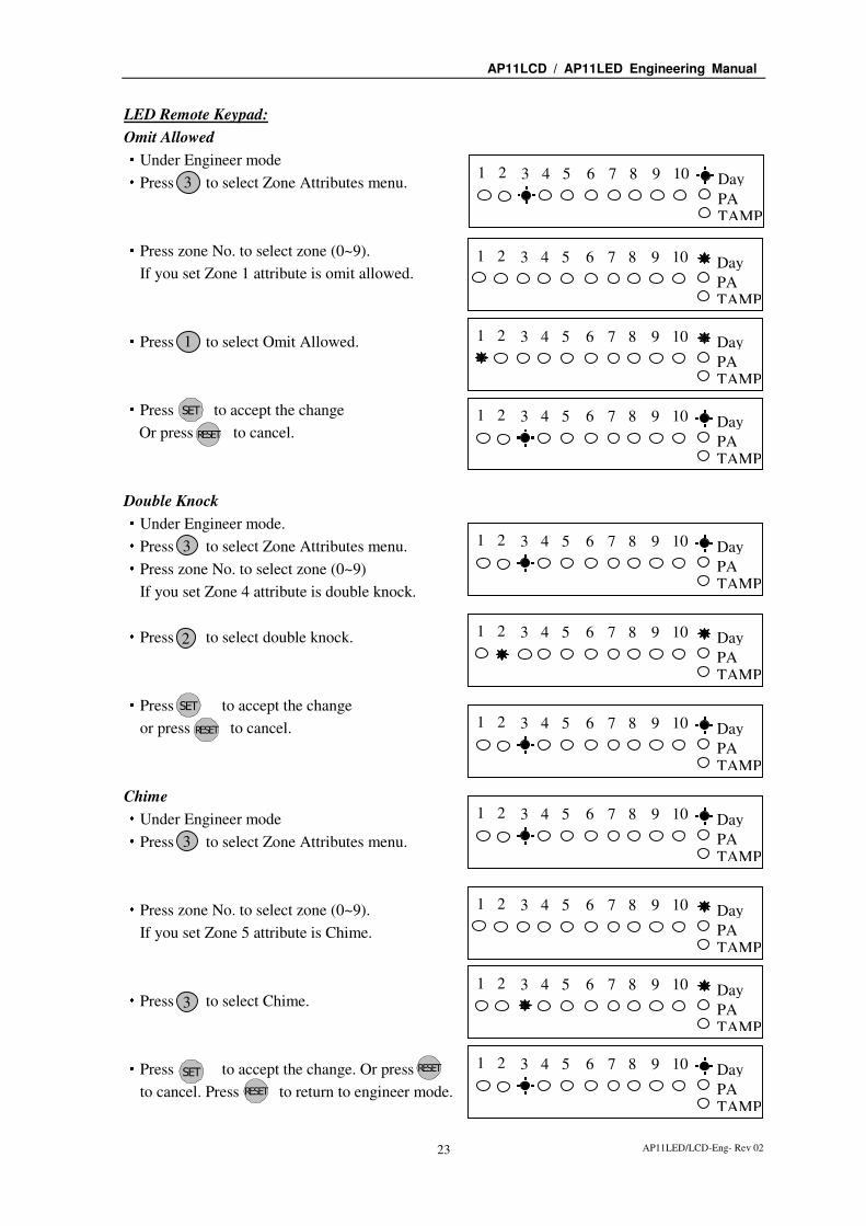
LED Remote Keypad:
Omit Allowed ·Under Engineer mode ·Press to select Zone Attributes menu.
·Press zone No. to select zone (0~9).
If you set Zone 1 attribute is omit allowed.
·Press to select Omit Allowed.
·Press to accept the change
Or press to cancel.
Double Knock ·Under Engineer mode. ·Press to select Zone Attributes menu. ·Press zone No. to select zone (0~9)
If you set Zone 4 attribute is double knock.
·Press to select double knock.
·Press to accept the change
or press to cancel.
Chime ·Under Engineer mode ·Press to select Zone Attributes menu.
·Press zone No. to select zone (0~9).
If you set Zone 5 attribute is Chime.
·Press to select Chime.
·Press to accept the change. Or press
to cancel. Press to return to engineer mode.
3
Day
PA TAMP
1 2 3 4 5 6 7 8 9 10
Day
PA TAMP
1 2 3 4 5 6 7 8 9 10
1 Day
PA TAMP
1 2 3 4 5 6 7 8 9 10
Day
PA TAMP
1 2 3 4 5 6 7 8 9 10
3 Day
PA TAMP
1 2 3 4 5 6 7 8 9 10
2 Day
PA TAMP
1 2 3 4 5 6 7 8 9 10
Day
PA TAMP
1 2 3 4 5 6 7 8 9 10
3
Day
PA TAMP
1 2 3 4 5 6 7 8 9 10
Day
PA TAMP
1 2 3 4 5 6 7 8 9 10
3
Day
PA TAMP
1 2 3 4 5 6 7 8 9 10
Day
PA TAMP
1 2 3 4 5 6 7 8 9 10 R ES TE
R ES TE
R ES TE
R ES TE
ES T
ES T
ES T

AP11LCD / AP11LED Engineering Manual
AP11LED/LCD-Eng- Rev 02 24
6.1.4 - Setup Codes
6.1.4.1 - How to set up User Code
There are 2 user codes can be set by LED Keypad in the system. All are 4-digit and can be set to
any number from 0000 to 9999. The access codes ensure that only authorized users can operate
the system.
1 = user 1, 2 = user 2, 3 = Holiday, 6=Manager’s Code, 4 = Engineer
Managers Code:
The Managers Code (default 0123) can change all codes and has full access to the option
in the user programming mode.
Note: The Managers Code can only be changed from the User Programming Menu not
from engineer mode.
User 1 – User 2 codes:
The user 1 –user 2 codes have the same operation for testing and Setting and Unsetting,
changing their own code.
Holiday code:
The purpose of this code is to allow access to the property whilst the manager is absent. The
Holiday access code is programmed by the Manager and is only valid until the manager use’s
the system. At this point the Holiday code becomes invalid and is no longer accepted by the
control panel.
Engineer code:
Accesses the Engineer program mode to allow the system to be programmed. If configured
the Engineer’s code can be used to reset the system after an alarm.
NOTE: Entering an invalid user code 4 times will operate the code tamper and lock you
out. After another 5 times invalid user code, a full alarm condition will be generated.
6.1.4.2 - How to change User Name
LED Remote Keypad:
The LED Remote Keypad cannot program user names.
AP11LCD / AP11LED Engineering Manual
AP11LED/LCD-Eng- Rev 02 25
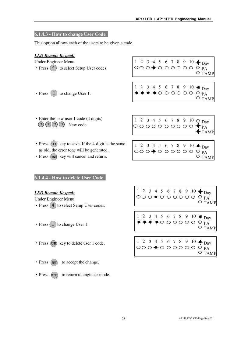
6.1.4.3 - How to change User Code
This option allows each of the users to be given a code.
LED Remote Keypad:
Under Engineer Menu. ·Press to select Setup User codes.
·Press to change User 1.
·Enter the new user 1 code (4 digits)
·Press key to save. If the 4-digit is the same
as old, the error tone will be generated. ·Press key will cancel and return.
6.1.4.4 - How to delete User Code
LED Remote Keypad:
Under Engineer Menu. ·Press to select Setup User codes.
·Press to change User 1.
·Press key to delete user 1 code.
·Press to accept the change.
·Press to return to engineer mode.
Day
PA TAMP
1 2 3 4 5 6 7 8 9 10
? ? ? ? Day
PA TAMP
1 2 3 4 5 6 7 8 9 10 New code
Day
PA TAMP
1 2 3 4 5 6 7 8 9 10
R ES TE
Day
PA TAMP
1 2 3 4 5 6 7 8 9 10
Day
PA TAMP
1 2 3 4 5 6 7 8 9 10
Day
PA TAMP
1 2 3 4 5 6 7 8 9 10
Day
PA TAMP
1 2 3 4 5 6 7 8 9 10 OIMT
1
4
4
1
R ES TE
ES T
ES T

AP11LCD / AP11LED Engineering Manual
AP11LED/LCD-Eng- Rev 02 26
6.1.5 - Setup system
The catalog of Setup system contains eight parts. They are list as follow:
1 = Flags1, 2 = Flags2, 3 = Bell Time, 4 = Rearm count, 5 = Bell delay time, 6 = Set Time,
7 = Set Date, 8 = Service Date.
6.1.5.1 - How to Setup System Flags
The System Flags are divided into Flags1, 2.
Flag1 – Options
There are eight options under Flag1 which are described below:
2=RKP-PA, 3=Engineer Reset, 4=PA user Reset, 5=Fire user Reset, 6=Bell in Fire,
7=Disable Bell Tamper, 8=lock Engineer Code, 9=Exit Walk Test
RKP-PA
When this flag is set to ON, the keypad’s PA function is enabled. Pressing 0 & 5 together
creates a PA alarm.
Engineer Reset
When this flag is set to ON, an engineer code must be entered to reset the system after
Tamper, PA or Fire alarm. When the flag is set to OFF the system can be reset by the user.
PA user Reset
When this flag is set to ON, it permits the user to reset the system after a PA alarm, by
pressing user code. The user can reset the system even if the Engineer Reset flag is set to
ON.
Fire user Reset
When this flag is set to ON, it permits user to reset the system after a Fire alarm by pressing
user code. The user can reset the system even if the Engineer Reset flag is set to ON.
Bell in Fire
When this flag is set to ON, the external siren Bell box will sound On/two second off during
the fire alarm.
Disable Bell Tamper
When this flag is set to ON, when the Bell Tamper is trigger in FULL, Part1, Part2 mode the
alarm system will not process it.
Lock Engineer Code
When this flag is set to ON, the system can’t reset the engineer code to default when you
use “Reset NVM” command.
Exit Walk Test
When this flag is set to ON, it will automatically return to next option after 20 minutes.

AP11LCD / AP11LED Engineering Manual
AP11LED/LCD-Eng- Rev 02 27
LED Remote Keypad: ·Under Engineer mode ·Press to select Setup system.
·Press to select system flag item.
·Press to select system flag 1 option.
Default settings are on.
·For example, add Engineer Reset and
Walk Test Auto-exit enable.
Press and to select.
·And cancel PA User Reset,
Press to disable, the corresponding LED OFF.
·Press to accept the change. Or press to
cancel. Press to return to engineer mode.
Flag2 – Options
There are eight options under Flag2 which are described below:
1=Key switch, 2=Doorbell, 3=Strobe on Set, 4=Single key Set, 5=EN Compliant, 6=EOLR Zone
7=Daylight Saving, 8=Service Timer
PTS terminals used with a Keyswitch
When this flag is set to ON, this enables the system to be SET and UNSET with the use of a
key switch in the PTS terminals (NO contacts = Day mode, NC contacts = Full Set). If the
panel needs to be reset then a manager/user code must be entered.
PTS as Doorbell
When this flag is set to ON, Keyswitch = OFF, the PTS terminal is programmed to a
doorbell (Momentary NO contacts required i.e. bell push button), if the Keyswitch = ON,
the PTS terminal is used as Keyswitch.
Strobe on Set
When this flag is set to ON, the external strobe will stay on for five seconds once the panel
has set.
Day
PA TAMP
1 2 3 4 5 6 7 8 9 10
Day
PA TAMP
1 2 3 4 5 6 7 8 9 10
Day
PA TAMP
1 2 3 4 5 6 7 8 9 10
Day
PA TAMP
1 2 3 4 5 6 7 8 9 10
Day
PA TAMP
1 2 3 4 5 6 7 8 9 10 R ES TE
5
3
4
9
1
1
R ES TE R ES TE
Day
PA TAMP
1 2 3 4 5 6 7 8 9 10
ES T

AP11LCD / AP11LED Engineering Manual
AP11LED/LCD-Eng- Rev 02 28
Single key Set
When this flag is set to ON, it allows the panel to be set Full mode by pressing the [Set]
button, set Part 1 mode by pressing [▲] key, set Part 2 mode by pressing [▼] key. A code
entry is not required. However, a 4-digit code is required to Unset the panel.
EN Compliant
When this flag is set to ON, the alarm system has Battery Monitoring function.
EOLR Zone
When this flag is set to ON, the alarm system goes to EOLR mode. Each detector must have
a 2k2 resistor connected across its alarm contacts. In addition, a 2k2 resistor must be
connected across the end of the Zone wiring, as shown in the following diagram. Note the
PIR detectors usually have a “spare” terminal for this purpose.
Daylight Saving
When this flag is set to ON, the system will turn clock back 1 hour 2 am on the first Sunday
in Apr and ahead 1 hour 2 am on the first Sunday in Oct.
Service Timer
When this flag is set to ON, the user can use the alarm system during Service Time.
LED Remote Keypad:
·Under Engineer mode. ·Press to select Setup system.
·Press to select system flag item.
·Press to select system flag 2 option.
Default settings are on.
·For example, add EN Compliant flag.
Press to select.
·Press to accept the change, Or press
to cancel. Press to return to engineer mode.
Day
PA TAMP
1 2 3 4 5 6 7 8 9 10
Day
PA TAMP
1 2 3 4 5 6 7 8 9 10
Day
PA TAMP
1 2 3 4 5 6 7 8 9 10
Day
PA
TAMP
1 2 3 4 5 6 7 8 9 10
R ES TE
5
5
2
1
R ES TE R ES TE
Day
PA TAMP
1 2 3 4 5 6 7 8 9 10
ES T

AP11LCD / AP11LED Engineering Manual
AP11LED/LCD-Eng- Rev 02 29
6.1.5.2 - How to Setup Bell Time
This is the duration that the external bell output is active. The range is 01-20 minutes. The
default is 14 minutes.
e.g. Change the Bell Time from 14 to 15 minutes.
LED Remote Keypad:
·Under Engineer mode ·Press to select Setup system.
·Press to select bell time item.
·Press and to change 15 minutes.
·Press to accept the change.
Or press to cancel.
6.1.5.3 - How to Setup Rearm count
After an alarm the panel will automatically ream itself when the external siren (Bell) timer has
expired. Any Zones and tamper, panic which still remain open at that time will be automatically
omitted.
The default is 3 rearms. 0 = no rearms, 1-8= number of rearms, 9= always rearm
e.g. Change the Rearm Count from 3 to Always rearm.
LED Remote Keypad: ·Under Engineer mode ·Press to select system item.
·Press to select rearm count item.
LED 1 ON indicate you enter only 1 digit.
·Press to change to always rearm.
·Press to accept the change.
Or press to cancel.
Day
PA TAMP
1 2 3 4 5 6 7 8 9 10
Day
PA TAMP
1 2 3 4 5 6 7 8 9 10
Day
PA TAMP
1 2 3 4 5 6 7 8 9 10
Day
PA TAMP
1 2 3 4 5 6 7 8 9 10 R ES TE
5
1 5
Day
PA TAMP
1 2 3 4 5 6 7 8 9 10
Day
PA TAMP
1 2 3 4 5 6 7 8 9 10
Day
PA TAMP
1 2 3 4 5 6 7 8 9 10
R ES TE
2
5
3
9
Day
PA TAMP
1 2 3 4 5 6 7 8 9 10
ES T
ES T

AP11LCD / AP11LED Engineering Manual
AP11LED/LCD-Eng- Rev 02 30
6.1.5.4 - How to Setup Bell delay time
This delays the activation of the Bell for the required time. The range is 00-99 minutes. The
default is 00 minutes.
e.g. Change the Bell Delay time from 0 to 1 minute.
LED Remote Keypad: ·Under Engineer mode ·Press to select system item.
·Press to select bell delay time item.
LED 1 and 2 ON indicates you enter only 2 digits.
·Press to change bell delay time.
·Press to accept the change Or press
to cancel. Press to return to engineer
6.1.5.5 - How to Setup Set Time
LED Remote Keypad:
The LED Remote Keypad cannot set time.
6.1.5.6 - How to Setup Set Date
LED Remote Keypad:
The LED Remote Keypad cannot set date.
6.1.5.7 - How to Setup Service Date
LED Remote Keypad:
The LED Remote Keypad cannot set service date.
5 Day
PA TAMP
1 2 3 4 5 6 7 8 9 10
4
Day
PA TAMP
1 2 3 4 5 6 7 8 9 10
Day
PA TAMP
1 2 3 4 5 6 7 8 9 10
Day
PA TAMP
1 2 3 4 5 6 7 8 9 10
0 1
R ES TE
R ES TE
ES T

AP11LCD / AP11LED Engineering Manual
AP11LED/LCD-Eng- Rev 02 31
6.1.6 - Misc menu
6.1.6.1- How to Restore to factory default settings using the menu
Factory defaulting the system will default all factory parameters.
CAUTION: All configurations of the panel are reset to reset to factory default conditions.
To default to factory settings:
Led Remote Keypad: ····Under Engineer mode.
LED 1~10 is flashing.
·Press twice within 2 second when entering engineering mode.
Rapid bleeps. All system setting returns to factory default.
NOTE: if Lock Engineer flag is ON, Engineer Code cannot reset to factory default
6.1.7 - View Event Log
The event log gives a display of all the events that have taken place. The events are arranged by
date and time. Up to 16 events can be stored in the memory. When the log reaches 16 events and
another event takes place, the first event drops out. The system is known as FILO (First In Last
Out).
To view the event log:
Led Remote Keypad:
Press: Jump to oldest event
Move one event older
Move one event newer
Jump to newest event
Clear all alarm event
After selecting Alarm Log the zone, PA and Tamper LED’s will show the latest event
A flashing LED indicates the zone that was first activated.
Any other LED lit was activated after the first event but before system unset.
Day
PA
TAMP
1 2 3 4 5 6 7 8 9 10
1
4
2
3
9
OIMT

AP11LCD / AP11LED Engineering Manual
AP11LED/LCD-Eng- Rev 02 32
·Under Engineer code
·Press to select view alarm event.
LED 1flashing indicate Zone 1 is triggered first.
TAMPER is triggered after Zone 1
·Press to leave view alarm log menu.
How to clear all alarm events? ·Under Engineer code
·Press to select view alarm event.
·Press to clear all alarm events.
System all LEDs would be dark and emit
a confirm sound to indicate clear all alarm event.
·Press to leave view alarm log menu.
6.1.8 - Test System
This function has three parts in Test System:
Test output
Walk Test
View Walk Test
Day
PA TAMP
1 2 3 4 5 6 7 8 9 10
Day
PA TAMP
1 2 3 4 5 6 7 8 9 10
Day
PA
TAMP
1 2 3 4 5 6 7 8 9 10
Day
PA TAMP
1 2 3 4 5 6 7 8 9 10
Day
PA
TAMP
1 2 3 4 5 6 7 8 9 10
Acknowledge
R ES TE
R ES TE
9

AP11LCD / AP11LED Engineering Manual
AP11LED/LCD-Eng- Rev 02 33
6.1.8.1 - How to Test Outputs
The test outputs are: 0 = BELL, 1 = Strobe, 2 = Speaker,
LED Remote Keypad ·Under Engineer code ·Press key to Select Test System.
·Press key to select Bell test.
·Press key to select Strobe test.
·Press key to select Speaker test.
·Press key to exit current level.
6.1.8.2 - How to enter Walk Test
The walk test function allows check each Zone trigger, Zone tamper, Detect Tamper, Control
panel tamper, Bell Box tamper, Remote Keypad tamper. if order to verify that they are
functioning correctly. A tone is generated as each zone or tamper is activated (opened).
e.g. Trigger Zone and Zone tamper
LED Remote Keypad : ·Under Engineer code ·Press key to Select Test System.
·Press key to select Walk test.
Trigger zone 1, when a zone is successfully tested,
the LED is on, Zones are added to list as each one
is activated.
8
Day
PA TAMP
1 2 3 4 5 6 7 8 9 10
Day
PA TAMP
1 2 3 4 5 6 7 8 9 10 0
Day
PA TAMP
1 2 3 4 5 6 7 8 9 10 1
Bell on
Strobe on
2 Day
PA TAMP
1 2 3 4 5 6 7 8 9 10
Alarm sound
8
Day
PA TAMP
1 2 3 4 5 6 7 8 9 10
8
R ES TE Day
PA
TAMP
1 2 3 4 5 6 7 8 9 10
Day
PA TAMP
1 2 3 4 5 6 7 8 9 10

AP11LCD / AP11LED Engineering Manual
AP11LED/LCD-Eng- Rev 02 34
·Trigger zone 1 tamper and its appropriate led will
light.
·The Tamper LED comes on when tested.
·Press key to exit current level.
6.1.8.3 - How to enter View Walk Test
LED Remote Keypad :
The LED Remote Keypad cannot operate the menu item.
6.1.8.4 - How to enter View Panel Version
LED Remote Keypad :
The LED Remote Keypad cannot operate the menu item.
6.1.8.5 - How to Exit Engineer Program Menu
LED Remote Keypad : ····Under Engineer menu. ····Press key return to top of engineer menu.
····Press key to exit engineer program mode.
and check system faults (all Tamper, TA zone,
PA zone, Fire zone is open)
····When no fault, press any key to exit.
····Return to DAY mode.
R ES TE Day
PA TAMP
1 2 3 4 5 6 7 8 9 10
R ES TE
R ES TE
Day
PA TAMP
1 2 3 4 5 6 7 8 9 10
Day
PA
TAMP
1 2 3 4 5 6 7 8 9 10
Day
PA
TAMP
1 2 3 4 5 6 7 8 9 10
Exit hint tone
Day
PA TAMP
1 2 3 4 5 6 7 8 9 10
Day
PA TAMP
1 2 3 4 5 6 7 8 9 10

AP11LCD / AP11LED Engineering Manual
AP11LED/LCD-Eng- Rev 02 35
6.2 - LCD Keypad
The full menu structure for the panel can only be accessed while in Engineer Program Mode.
The structure is shown in the following table:
6.2.1 - Setup Programs
How to enter Engineer Program Mode
You require the manager to authorize Engineer access. It is accessed directly from Day mode via
the Engineer code.
To operate the “Enter Engineer operation mode” as follow:
LCD Remote Keypad:
• Enter Manager program mode
Press
• Press key for the Manage to authorize Engineer
access.
• Press to accept. It will give a 3hr window to use
the Engineer operation mode.
• Press to accept, the accept tone will be generated.
• Press to go back DAY mode.
• Input 4-digit Engineer code and go to
Engineer operation window within 5 seconds.
MENU OPTIONS
1 Setup Programs 5 Setup System
2 Setup Zone Names and Types 6 Misc Menu
3 Setup Zone Attributes 7 View alarm log
4 Setup Codes 8 Test System
MANAGER MENU
Authorise Engr?
Engr Authorised
for 3 hours
MANAGER MENU
Set Chime Zones?
MANAGER MENU
Setup Codes?
00:26:15 08-Aug
DAY
LC ENGINEER MENU
Setup Programs?
P OR G 0 1 2 3
3
P OR G
P OR G
R ES TE
9 9 9 9

AP11LCD / AP11LED Engineering Manual
AP11LED/LCD-Eng- Rev 02 36
6.2.1.1 - How to go into Full mode Setting
LCD Remote Keypad: ·Under Engineer mode. ·Press to Select Setup Programs.
·Press to accept and go into Program Full.
6.2.1.2 - How to go into Part 1 mode Setting
LCD Remote Keypad: ·Under Engineer mode. ·Press to Select Setup Programs.
·Press to accept and go into Program Part 1.
6.2.1.3 - How to go into Part 2 mode Setting
LCD Remote Keypad: ·Under Engineer mode. ·Press to Select Setup Programs.
·Press to accept and go into Program Part 2.
6.2.1.4 - How to set zone function
In Zone Function, Security type zones can be assigned different functions. These are
1= Immediate Zone, 2 = Timed Zone, 3 = Inhibited Zone, 0 = Not Used.
Immediate (Alarm) Zone: Use this function when the zone is not part of an entry/exit route. When the system is SET,
activation of an immediate zone will cause a full alarm condition.
Timed (Entry/Exit) Zone: A time zone would be used to protect an entry/exit route. Opening the door or triggering the
sensor in this type of zone when the system is SET will start the entry timer.
Inhibited (Walkthrough) Zone:
A time-inhibited zone operates as an immediate zone unless a timed zone has been operated
and a timer started. Such a zone should be utilized to allow passage between the entry/exit
door and the keypad when there are detectors present.
Not Used:
If the zone set as a not used zone. When the system is SET, activation of the zone will not
cause a full alarm condition
LC ENGINEER MENU
Setup Programs? 1 P OR G
2 P OR G
1 P OR G
3 P OR G
SELECT PROGRAM
Program Part 1?
LC ENGINEER MENU
Setup Programs?
SELECT PROGRAM
Program Part 2?
LC ENGINEER MENU
Setup Programs? 1 P OR G
SELECT PROGRAM
Program Full? 1 P OR G

AP11LCD / AP11LED Engineering Manual
AP11LED/LCD-Eng- Rev 02 37
LCD Remote Keypad:
Under Engineer Menu/Setup Program, the program mode is chosen. ·Press go into zone functions function.
·Select Zone No. using or key.
Note: Zone No. not displayed means this zone isn’t selected “Security”
Under <Engineer Menu / Setup Zones Type / Type> p.23
·Press to accept. Display zone current function.
·If press to select Immediate zone function.
·If press to select Timed zone function.
·If press to select Inhibited zone function.
·If press to select Not used function.
·Press to accept and return to next zone option or press
to cancel and exit.
6.2.1.5 - How to set Exit mode function
There are four selections for Exit Mode in all mode: 1 = Timed Exit, 2 = Final Door, 3 = Silent
Exit, 4 = Terminated, 0 = Disable.
Timed Exit:
A timed program will set once the exit timer has expired and all zones are clear.
Final Door:
A final door program will set 5 seconds after the final door has been opened and closed.
Silent Exit:
This operates exactly the same as Timed Exit but completely silent without internal sounder
signal.
Terminated:
A terminated program will set once the PTS terminal has been trigger.
Disable:
A disabled program is not available for use and cannot be selected and setting time.
SETUP PROGRAM
Zone Functions?
SELECT ZONE
Z1::::Zone 1 name?
Zone Function
Immediate zone?
SELECT ZONE
Z2::::Zone 2 name?
1 P OR G
OIMT
P OR G Zone Function
Immediate zone?
0
1
2
3
Zone Function
Timed zone?
Zone Function
Inhibited zone?
Zone Function
Not used?
P OR G R ES TE

AP11LCD / AP11LED Engineering Manual
AP11LED/LCD-Eng- Rev 02 38
LCD Remote Keypad:
Under Engineer Menu/Setup Program, the program mode is chosen. ·Press go into Exit mode function.
·Press to accept. Display current exit mode function.
·If press to select Timed exit function.
·If press to select Final door function.
·If press to select Silent exit function.
·If press to select Terminated function.
·If press to select Disabled function.
·Press to save the exit mode that you selected above,
or press to cancel, it will exit and go to “Exit Time”.
6.2.1.6 - How to set Exit time function
This is the time allowed to leave the premises via the exit route before the system sets. The
programmable range is 00-99 seconds.
If the Exit Time is interrupted with the last 10 seconds, then the Exit Time will restart at 10
seconds after the interruption has cleared.
The default is 45 seconds.
LCD Remote Keypad:
Under Engineer Menu/Setup Program, the program mode is chosen. ·Press to select Exit Time function.
·Press to accept. Display current exit time number.
Set the time by pressing number key. The range is 00-99.
eg. Set the exit time 20 seconds. ·Press number key, cursor move to next a char.
SETUP PROGRAM
Exit Mode?
SELECT EXIT MODE
Timed exit?
SETUP PROGRAM
Exit Time?
P OR G SELECT EXIT MODE
Timed exit?
1
2
3
SELECT EXIT MODE
Final door?
SELECT EXIT MODE
Silent exit?
SELECT EXIT MODE
Terminated?
P OR G
R ES TE
2
SELECT EXIT MODE
Disabled?
0
4
SETUP PROGRAM
Exit Time?
Exit Time ????45
3
Exit Time ????25 2
P OR G

AP11LCD / AP11LED Engineering Manual
AP11LED/LCD-Eng- Rev 02 39
·Then press number key, cursor move to next a char.
·Press to save it, or press to cancel, it will exit
and go to “Entry Time”.
6.2.1.7 - How to set Entry time function
This is the time allowed to enter the premises via the entry route and unset the system. The
programmable range is 00-99 seconds. The default is 45 seconds.
LCD Remote Keypad:
Under Engineer Menu/Setup Program, the program mode is chosen. ·Press go into Entry Time function.
·Press to accept. Display current exit time number.
Set the time by pressing number key. The range is 00-99.
eg. Set the entry time 20 seconds. ·Press number key, cursor move to next a char.
·Then press number key, cursor move to next a char.
·Press to accept or press to cancel. It goes to next program
mode, if the current mode is “Program Part 2”, it will leave “Setup
Programs” and go to next menu “Setup Zone Type”.
6.2.2 - Setup Zones Type
The ‘Setup Zones Type’ contains: 1 = Zone name, 2 = Zone type.
6.2.2.1 - How to set Zone Name
This option allows each of the ten zones to be given a name.
e.g. Change zone 5 name to Bedroom 1.
SETUP PROGRAM
Entry Time?
Exit Time ????20
0
SETUP PROGRAM
Entry Time?
Entry Time ????45
LC ENGINEER MENU
Setup Zones Type?
P OR G R ES TE
Entry Time ????25
Entry Time ????20
0
2
P OR G
4
R ES TEP OR G

AP11LCD / AP11LED Engineering Manual
AP11LED/LCD-Eng- Rev 02 40
LCD Remote Keypad:
Under Engineer Menu.
·Press to select Setup Zone Type function.
·Press to accept.
·Press keys to select zone 5.
Note: =zone 1, =zone 2, … = zone 10
·Press keys go into setup zone name function.
Press key, it will clear the last character.
·Press key, it will clear the line text.
[0]..[9] key have different characters.
_0 ,)?1 abc2 def3
ghi4 jkl5 mno6 pqrs7
tuv8 wxyz9 ·Press key twice within 3 seconds, 'B' can be shown on LCD.
·Press key, it will toggles capitals (exchange
between capital and lowercase), ABC-abc. default input capital character.
·Press key twice within 3 seconds, 'e' can be shown on LCD.
·Input “Bedroom 1” string.
·Press key to accept input and save the text, ·Press key will exit without change to the text.
SETUP PROGRAM
Setup Zone Type?
SELECT ZONE
Zone 1?
P OR G
2
P OR G
021
SELECT ZONE TYPE
Name?
1 P OR G ZONE NAME ????Zone 5
OIMT
ES T
0 21
5
8
3
4 76
9
2
P OR G
ZONE NAME ????Zone
ZONE NAME ????
ZONE NAME ????B
ZONE NAME ????Be
R ES TE
ZONE NAME ????Bedroom 1
SELECT ZONE TYPE
Type?
5
3

AP11LCD / AP11LED Engineering Manual
AP11LED/LCD-Eng- Rev 02 41
6.2.2.2 - How to set Zone Type
There are six types for Zone: 1 = Security, 2 = PA, 3 = Door Bell, 4 = Fire, 5 = Tamper/24H,
0 = Not Used.
Security:
A Security Zone is only active when the system is set. The system comes supplied with
service links fitted to the zone terminals to simulate a closed circuit. As each zone is
connected these links should be removed. All zone are fully programmable.
PA:
A Personal Attack Zone is always active. A Zone may be programmed for audible PA
should be wire in series.
Door Bell:
This feature can be programmed into any Zone. A doorbell will not operate whilst the
entry/exit timers have started, when the system is in full alarm condition or whilst in
programming mode.
Fire:
If you choose to utilize a zone as a fire zone then no other detectors may be wired into this
zone. Therefore a zone cannot be both fire and intruder.
Tamper/24H:
Provides 24 hour monitoring.
Not used
A zone may be programmed for Not used, then is ignored by the panel.
To operate the Setup Zone type as follow.
e.g. Change zone 5 type to Fire zone.
LCD Remote Keypad: Under Engineer Menu.
·Press keys go into Setup Zone Type function.
·Press keys to select zone 5.
Note: =zone 1, =zone 2, … = zone 10
·Press key to select setup zone type function.
·Press key to go into Select Zone Type function.
·Press key to select Fire zone type.
SETUP PROGRAM
Setup Zone Type?
SELECT ZONE
Zone 1?
P OR G2
P OR G
021
SETUP ZONE TYPE
Type?
P OR G SELECT ZONE TYPE
Security?
5
2
4 SELECT ZONE TYPE
Fire?

AP11LCD / AP11LED Engineering Manual
AP11LED/LCD-Eng- Rev 02 42
·Press to save, or press to cannel. it goes to next Zone.
If the Zone is “Zone 10”, it will leave “Setup Zone type” and
go to next menu “Setup Zone Attributes”.
6.2.3 - Setup Zones Attributes
There are three attributes for Zones: 1 = Omit Allowed, 2 = Double Knock, 3 = Chime. You can
set it ON or OFF.
Omit Allowed:
When a Zone is programmed as Omit Allowed, the panel allows the Zone to be omitted for
one set period by the user when setting the system.
Note: The zone must be a security zone for it to be programmed as omit allowed.
Double Knock:
Double knock programming is used when zones are likely to create false activations.
Double knock requires two activations within 10 minutes of the same Zone or a Zone left
open for 10 seconds.
Chime:
If a Security Zone is programmed as Chime, then chime tone is activated when it is
triggered in DAY mode.
Note: The zone must be a security zone for it to be programmed as Chime.
To operate the Setup Zone attributes as follow.
e.g. Set zone 2 have Omit Allowed, Double Knock and Chime attributes (set ON).
LCD Remote Keypad:
Under Engineer Menu. ·Press keys go into Setup Zone Attribute function.
·Press keys to select zone 2.
Note: =zone 1, =zone 2, … = zone 10
·Press key to go into setup Zone Omit Allowed function
·Press or key to toggle ON/OFF,
Press to save, or press to cannel.
·Press key to go into setup Zone Double Knock function
P OR G R ES TE
LC ENGINEER MENU
Setup Zone Attr?
SELECT ZONE
Zone 2?
P OR G
P OR G
021
SELECT ATTRIBUTE
Omit Allowed?
P OR G
3
2
Omit Allowed
OFF?
SELECT ATTRIBUTE
Double Knock?
1
OIMT
P OR G R ES TE
P OR G2 Double Knock
OFF?

AP11LCD / AP11LED Engineering Manual
AP11LED/LCD-Eng- Rev 02 43
·Press or key to toggle ON/OFF,
Press to save, or press to cannel.
·Press key to go into setup Zone Chime Attributes.
·Press or key to toggle ON/OFF, ·Press to save, or press to cannel. it goes to next Zone.
If the Zone is “Zone 10”, it will leave “Setup Zone Attr” and
go to next menu “Setup Codes”.
6.2.4 - Setup Codes
6.2.4.1 - How to set up User Code
There is a Managers code and 10 user codes that can be created and set by LCD Keypad in the
system, all are 4-digit and can be set to any number from 0000 to 9999. The access codes ensure
that only authorized users can operate the system.
1 = user 1, 2 = user 2, 3 = user 3, 4 = user 4, 5 = user 5, 6 = user 6, 7 = user 7,
8 = user 8, 9 = user 9, 0 = user10.
Managers Code:
The Managers Code (default 0123) can change all codes and has full access to the option
in the user programming mode.
Note: The Managers Code can only be changed from the User Programming Menu.
User 1 – User10 codes:
The user 1 –user 10 codes have the same operation for testing and Setting and Unsetting,
changing their own code.
Holiday code:
The purpose of this code is to allow access to the property whilst the manager is absent. The
Holiday access code is programmed by the Manager and is only valid until the manager uses
the system. At this point the Holiday code becomes invalid and is no longer accepted by the
control panel.
Engineer code:
Access the Engineer program mode to allow the system to be programmed. If configured the
Engineer’s code can be used to reset the system after an alarm.
NOTE: Entering an invalid user code 4 times will operate the code tamper and lock you
out. After another 5 times invalid user code, a full alarm condition will be generated.
6.2.4.2 - How to change User Name
This option allows each of the users to be given a name.
P OR G R ES TELC ENGINEER MENU
Setup Codes?
SELECT ATTRIBUTE
Chime?
OIMT
P OR G R ES TE
P OR G
OIMT
3

AP11LCD / AP11LED Engineering Manual
AP11LED/LCD-Eng- Rev 02 44
LCD Remote Keypad:
Under Engineer Menu. ·Press keys go into Setup Codes function.
·Press … or or or key to select a code
that you want to set.
Note: =user 1, = user 2, … = user 10
or press key to select Holiday, Engineer.
·Press to accept and go into set the user.
·Press keys go into setup change user name function.
·Enter new name string.
How to input string text refer to page 22, How to set zone name.
·Press key to accept input and save the text, ·Press key will without change the text and exit.
6.2.4.3 - How to change User Code
This option allows each of the users to be given a code.
LCD Remote Keypad:
Under Engineer Menu. ·Press keys go into Setup Codes function.
·Press … or or or key to select a code
that you want to set.
Note: =user 1, = user 2, … = user 10
or press key to select Holiday, Engineer.
·Press to accept and go into set the user.
·Press key to select Change Code function.
·Press key go into Change Code function.
LC ENGINEER MENU
Setup Codes?
SELECT CODE
User 1?
P OR G
021
4
1 9 OIMT0
P OR G SETUP CODE
Change Name?
1 P OR G
USER NAME ????User 1
P OR G
R ES TE
SETUP CODE
Change Code?
SETUP PROGRAM
Setup Codes?
SELECT CODE
User 1?
P OR G
021
4
1 9 OIMT0
P OR G
SETUP CODE
Change Name?
P OR G USER CODE ????****************
2
SETUP CODE
Change Code?
AP11LCD / AP11LED Engineering Manual
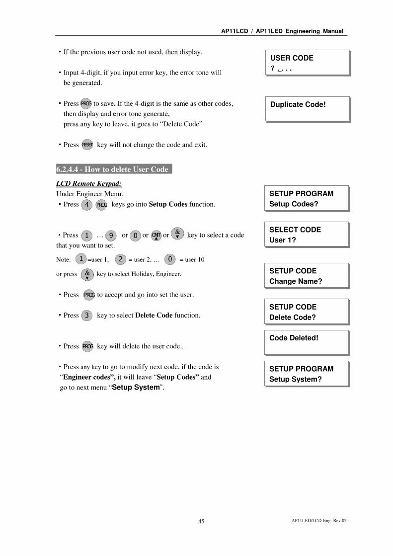
AP11LED/LCD-Eng- Rev 02 45
·If the previous user code not used, then display.
·Input 4-digit, if you input error key, the error tone will
be generated.
·Press to save. If the 4-digit is the same as other codes,
then display and error tone generate,
press any key to leave, it goes to “Delete Code”
·Press key will not change the code and exit.
6.2.4.4 - How to delete User Code
LCD Remote Keypad:
Under Engineer Menu. ·Press keys go into Setup Codes function.
·Press … or or or key to select a code
that you want to set.
Note: =user 1, = user 2, … = user 10
or press key to select Holiday, Engineer.
·Press to accept and go into set the user.
·Press key to select Delete Code function.
·Press key will delete the user code..
·Press any key to go to modify next code, if the code is
“Engineer codes”, it will leave “Setup Codes” and
go to next menu “Setup System”.
USER CODE ????. . . .
P OR G Duplicate Code!
R ES TE
SETUP PROGRAM
Setup Codes?
SELECT CODE
User 1?
P OR G
021
4
1 9 OIMT0
P OR G
SETUP CODE
Change Name?
Code Deleted!
SETUP PROGRAM
Setup System?
P OR G
3SETUP CODE
Delete Code?

AP11LCD / AP11LED Engineering Manual
AP11LED/LCD-Eng- Rev 02 46
6.2.5 - Setup system
The catalog of Setup system contains eight parts. They are list as follow:
1 = Flags1, 2 = Flags2, 3 = Bell Time, 4 = Rearm count, 5 = Bell delay time, 6 = Set Time,
7 = Set Date, 8 = Service Date.
6.2.5.1 - How to Setup System Flags
The System Flags are divided into Flags1, 2.
Flag1 – Options
There are eight options under Flag1 which are described below:
2=RKP PA, 3=Engineer Reset, 4=PA user Reset, 5=Fire user Reset, 6=Bell in Fire,
7=Disable Bell Tamper, 8=lock Engineer Code, 9=Exit Walk Test
RKP PA
When this flag is set to ON, the keypad’s PA function is enabled.
Engineer Reset
When this flag is set to ON, an engineer code must be entered to reset the system after
Tamper, PA or Fire alarm. When the flag is set to OFF the system can be reset by the user.
PA user Reset
When this flag is set to ON, it permits the user to reset the system after a PA alarm, by
pressing user code. The user can reset the system even if the Engineer Reset flag is set to
ON.
Fire user Reset
When this flag is set to ON, it permits user to reset the system after a Fire alarm by pressing
user code. The user can reset the system even if the Engineer Reset flag is set to ON.
Bell in Fire
When this flag is set to ON, the external siren Bell box will sound On/two second off during
the fire alarm.
Disable Bell Tamper
When this flag is set to ON, when the Bell Tamper is trigger in FULL, Part1, Part2 mode the
alarm system will not process it.
Lock Engineer Code
When this flag is set to ON, the system can’t reset the engineer code to default when you
use “Reset NVM” command.
Exit Walk Test
When this flag is set to ON, it will automatically return to next option after 20 minutes.
AP11LCD / AP11LED Engineering Manual
AP11LED/LCD-Eng- Rev 02 47
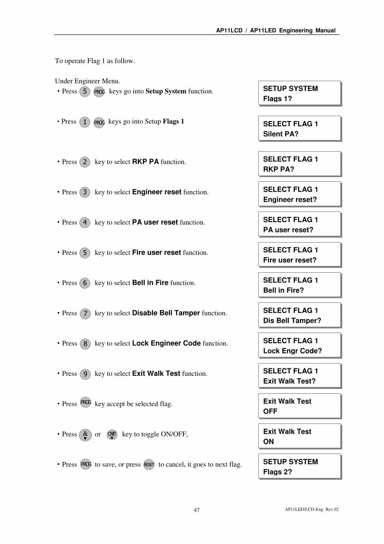
To operate Flag 1 as follow.
Under Engineer Menu. ·Press keys go into Setup System function.
·Press keys go into Setup Flags 1
·Press key to select RKP PA function.
·Press key to select Engineer reset function.
·Press key to select PA user reset function.
·Press key to select Fire user reset function.
·Press key to select Bell in Fire function.
·Press key to select Disable Bell Tamper function.
·Press key to select Lock Engineer Code function.
·Press key to select Exit Walk Test function.
·Press key accept be selected flag.
·Press or key to toggle ON/OFF,
·Press to save, or press to cancel. it goes to next flag.
SETUP SYSTEM
Flags 1? P OR G
1
Exit Walk Test
OFF
P OR G
P OR G
5
2
5
8
3
4
7
6
9
SELECT FLAG 1
Silent PA?
SELECT FLAG 1
RKP PA?
SELECT FLAG 1
Engineer reset?
SELECT FLAG 1
PA user reset?
SELECT FLAG 1
Fire user reset?
SELECT FLAG 1
Bell in Fire?
SELECT FLAG 1
Dis Bell Tamper?
SELECT FLAG 1
Lock Engr Code?
SELECT FLAG 1
Exit Walk Test?
P OR G R ES TE
Exit Walk Test
ON
OIMT
SETUP SYSTEM
Flags 2?

AP11LCD / AP11LED Engineering Manual
AP11LED/LCD-Eng- Rev 02 48
Flag2 – Options
There are eight options under Flag2 which are described below:
1=Key switch, 2=Doorbell, 3=Strobe on Set, 4=Single key Set, 5=EN Compliant, 6=EOLR Zone
7=Daylight Saving, 8=Service Timer
PTS terminals used with a Keyswitch
When this flag is set to ON, this enables the system to be SET and UNSET with the use of a
key switch in the PTS terminals (NO contacts = Day mode, NC contacts = Full Set). If the
panel needs to be reset then a manager/user code must be entered.
PTS as Doorbell
When this flag is set to ON, Keyswitch = OFF, the PTS terminal is programmed to a
doorbell (Momentary NO contacts required i.e. bell push button), if the Keyswitch = ON,
the PTS terminal is used as Keyswitch.
Strobe on Set
When this flag is set to ON, the external strobe will stay on for five seconds once the panel
has set.
Single key Set
When this flag is set to ON, it allows the panel to be set Full mode by pressing the [Set]
button, set Part 1 mode by pressing [▲] key, set Part 2 mode by pressing [▼] key. A code
entry is not required. However, a 4-digit code is required to Unset the panel.
EN Compliant
When this flag is set to ON, the alarm system has Battery Monitoring function.
EOLR Zone
When this flag is set to ON, the alarm system goes to EOLR mode. Each detector must have
a 2k2 resistor connected across its alarm contacts. In addition, a 2k2 resistor must be
connected across the end of the Zone wiring, as shown in the following diagram. Note the
PIR detectors usually have a “spare” terminal for this purpose.
Daylight Saving
When this flag is set to ON, the system will turn clock back 1 hour 2 am on the first Sunday
in Apr and ahead 1 hour 2 am on the first Sunday in Oct.
Service Timer
When this flag is set to ON, the user can use the alarm system during Service Time.

AP11LCD / AP11LED Engineering Manual
AP11LED/LCD-Eng- Rev 02 49
To operate Flag 2 as follow.
Under Engineer Menu. ·Press keys go into Setup System function.
·Press keys go into Setup Flags 2
·Press key to select Key switch function.
·Press key to select PTS as Doorbell function.
·Press key to select Strobe on SET function.
·Press key to select Single key SET function.
·Press key to select EN Compliant function.
·Press key to select EOLR Zone function.
·Press key to select Daylight Saving function.
·Press key to select Service Timer function.
·Press key accept be selected flag.
·Press or key to toggle ON/OFF.
·Press to save, or press to cannel.
SETUP SYSTEM
Flags 1?
SELECT FLAG 2
Keyswitch?
P OR G
Service Timer
OFF P OR G
P OR G
5
2
1
5
8
3
4
7
6
SELECT FLAG 2
PTS as Doorbell?
SELECT FLAG 2
Strobe on SET?
SELECT FLAG 2
Single key SET?
SELECT FLAG 2
EN Compliant?
SELECT FLAG 2
EOLR Zone?
SELECT FLAG 2
Daylight Saving?
SELECT FLAG 2
Service Timer?
P OR G R ES TE
Service Timer
ON OIMT
SETUP SYSTEM
Bell Time?
2
SELECT FLAG 2
Keyswitch?

AP11LCD / AP11LED Engineering Manual
AP11LED/LCD-Eng- Rev 02 50
6.2.5.2 - How to Setup Bell Time
This is the duration that the external bell output is active. The range is 01-20 minutes. The
default is 14 minutes.
e.g. Change the Bell Time from 14 to 15 minutes.
LCD Remote Keypad:
Under Engineer Menu ·Press keys go into Setup System function.
·Press to select Bell Time function.
·Press to accept. Display current Bell time number.
Set the time by pressing number key. The range is 00-20.
·Press number key, cursor move to next a char.
·Then press number key, cursor move to next a char.
·Press to save it, or press to cancel, it will exit
and go to “Rearm Count”.
6.2.5.3 - How to Setup Rearm count
After an alarm the panel will automatically ream itself when the external siren (Bell) timer has
expired. Any Zones and tamper, panic which still remain open at that time will be automatically
omitted.
The default is 3 rearms. 0 = no rearms, 1-8= number of rearms, 9= always rearm
e.g. Change the Rearm Count from 3 to Always rearm.
SETUP SYSTEM
Bell Time?
Bell Time ????14
3
SETUP SYSTEM
Rearm Count?
Bell Time ????14
Bell Time ????15
P OR G
R ES TEP OR G
SETUP SYSTEM
Flags 1?
P OR G5
5
1

AP11LCD / AP11LED Engineering Manual
AP11LED/LCD-Eng- Rev 02 51
LCD Remote Keypad:
Under Engineer Menu ·Press keys go into Setup System function.
·Press to select Rearm Count function.
·Press to accept. Display current Rearm count number.
Set the Rearm count by pressing number key. The range is 0-9. ·Press number key.
·Press to save it, or press to cancel, it will exit
and go to “Bell Delay Time”.
6.2.5.4 - How to Setup Bell delay time
This delays the activation of the Bell for the required time. The range is 00-99 minutes. The
default is 00 minutes.
e.g. Change the Bell Delay time from 0 to 1 minute.
LCD Remote Keypad:
Under Engineer Menu ·Press keys go into Setup System function.
·Press to select Bell Delay Time function.
·Press to accept. Display current bell delay time.
Set the bell delay time by pressing number key. The range is 00-99.
·Press number keys.
·Press to save it, or press to cancel, it will exit
and go to “Set Time”.
SETUP SYSTEM
Rearm Count?
Rearm Count ????3
SETUP SYSTEM
Bell Delay Time?
Rearm Count ????9
P OR G
R ES TEP OR G
SETUP SYSTEM
Flags 1?
P OR G5
4
9
SETUP SYSTEM
Bell Delay Time?
Bell Delay Time ????00
SETUP SYSTEM
Set Time?
Bell Delay Time ????01
P OR G
R ES TEP OR G
SETUP SYSTEM
Flags 1? P OR G5
5
0 1

AP11LCD / AP11LED Engineering Manual
AP11LED/LCD-Eng- Rev 02 52
6.2.5.6 - How to Setup Set Time
The time can be modified in hours, minutes in the format HH:MM. you must set it correctly, or
else System will generate an error tone and not save the change. key will help you to
select the bit that you want to write.
* Time and Date will be lost once the power supply from both main power and backup battery are cut
e.g. Change the system time to 12:02
LCD Remote Keypad:
Under Engineer Menu ·Press keys go into Setup System function.
·Press to select Set Time function.
·Press to accept. Display current time.
set new time to 12:02 ·Press number keys.
·Press to save it and clear second time, or press to
cancel, it will exit and go to “Set Date”.
6.2.5.7 - How to Setup Set Date
Before you set the date, you select day for the date that you want to set. Using -
or or key to change day, pressing key to save, pressing key to not
change. The date can be changed in day, month, year format DD/MM/YY. The method of set
date is the same as how to set time.
e.g. Set current system date: Tuesday, 28-08-2009
LCD Remote Keypad:
Under Engineer Menu ·Press keys go into Setup System function.
·Press to select Set Date function.
·Press to accept. Display current week.
SETUP SYSTEM
Set Time?
Set Time HH:MM
00:00
SETUP SYSTEM
Set Date?
Set Time HH:MM
12:02
P OR G
R ES TEP OR G
SETUP SYSTEM
Flags 1?
P OR G5
01
6
2 2
SETUP SYSTEM
Set Date?
P OR G
SETUP SYSTEM
Flags 1? P OR G5
7
SELECT DAY
Monday?
P OR G R ES TEOIMT
1 7

AP11LCD / AP11LED Engineering Manual
AP11LED/LCD-Eng- Rev 02 53
·Select a week day No , and Press to accept.
·Enter system date: Day/Mon/Year(6-digits)
·Press number keys.
·Press to save it, or press to cancel, it will exit
and go to “Service Date”.
6.2.5.8 - How to Setup Service Date
You can use the alarm system before the Service data. The date can be changed in day, month,
year format DD/MM/YY. The method of set date is the same as how to set time.
e.g. Set current system date: Tuesday, 30-12-2010
LCD Remote Keypad:
Under Engineer Menu ·Press keys go into Setup System function.
·Press to select Service Date function and
to save it,
·Enter system date: Day/Mon/Year(6-digits)
·Press number keys.
·Press to save it, or press to cancel, it will exit
and go to “Misc Menu”.
6.2.6 - Misc menu
“Misc menu” is divided into four parts:
1 = Show help, 2 = Challenger Tel, 3 = Alarm Co. Info, 4 = Reset NVM.
SELECT DAY
Tuesday?
SETUP SYSTEM
Service Date?
R ES TEP OR G
02
P OR G2
Date: DD/MM/YY
08/08/08
Date: DD/MM/YY
28/08/09 8 98 0
SETUP SYSTEM
Service Date?
LC ENGINEER MENU
Misc Menu?
R ES TEP OR G
SETUP SYSTEM
Flags 1?
P OR G5
0 2
Date: DD/MM/YY
01/01/09
Date: DD/MM/YY
30/12/10
8
13 1 0
P OR G

AP11LCD / AP11LED Engineering Manual
AP11LED/LCD-Eng- Rev 02 54
6.2.6.1 - How to Show Help file
It guides you to use the function key in different operation.
LCD Remote Keypad:
Under Engineer Menu ·Press keys go into Misc Menu function.
·Press keys go into Show help function.
·Press key show next page.
·Press to cancel at any time, it will exit and
go to “Challenger Tel”. Else help file finish will exit.
MISC MENU
Show help?
MISC MENU
Challenger Tel?
R ES TE
LC ENGINEER MENU
Misc Menu?
P OR G
In help screens,
[▼] for nextpage
1
6
P OR G

AP11LCD / AP11LED Engineering Manual
AP11LED/LCD-Eng- Rev 02 55
·Help file as follow:
Note: [P] using key, [R] using key, [S] using key,
[▲] using key, [▼] using key.
In help screens,
[▼▼▼▼] for nextpage
[▲] for previous
page,
or [R] key
to QUIT help
[▲] key gives
PREVIOUS option.
When entering
Numbers...
[P] Accepts
[▼] Backspaces.
[R] Quits.
[P] shows time
and date
[▼] previous
[▲] next
event (newer)
[R] to quit.
Most recent
shown first
[S] for Full mode
or Quick Set
[▲] key for
Part 1 mode
[▼] key for
In Menus...
In Set mode...
[P] Accepts
[▼] Backspaces.
[R] Quits Without
change to name
Text is entered
same as mobile
[S] toggles
capitals, ABC-abc
When entering
Names...
This is the end
of the help page
Challenger Tel
****************
[P] key Accepts,
or Selects.
When viewing
Event Log...
event (older)
Part 2 mode
[▼] key gives
NEXT option.
[R] Key always
Quits Menu.
OIMT
ES TP OR G R ES TE

AP11LCD / AP11LED Engineering Manual
AP11LED/LCD-Eng- Rev 02 56
6.2.6.2 - How to Show Challenger Telephone
It records the company telephone number that you buy the alarm system from.
LCD Remote Keypad:
Under Engineer Menu ·Press keys go into Misc Menu function.
·Press key to select Challenger Tel function.
·Press key show Challenger Telephone.
·Press any key will exit and go to “Alarm Co. Info”.
6.2.6.3 - How to modify alarm company information
You can write two lines of the information about your company in this menu. The max number
of characters in one line is 14, so you can write 28 chars most in “Alarm Co. Info”
LCD Remote Keypad:
Under Engineer Menu ·Press keys go into Misc Menu function.
·Press key to select Alarm Co. Info function.
·Press key show Challenger Telephone.
·Enter new string . e.g. input “Challenger”.
How to input string text refer to page.22 , How to set zone name.
·Press key to accept input and save the text,
Press key to cannel and go to next option. ·Enter new string “10 Zone System”.
How to input string text refer to page.22 , How to set zone name.
·Press key to accept input and save the text,
Press key to cannel and exit.
MISC MENU
Challenger Tel?
MISC MENU
Alarm Co. Info?
LC ENGINEER MENU
Misc Menu?
P OR G
Challenger Tel
****************
6
P OR G
2
3 MISC MENU
Alarm Co. Info?
LC ENGINEER MENU
Misc Menu? P OR G
First Line Text
?_
6
P OR G
P OR G
R ES TE
First Line Text
?Challenger_
Second Line Text
?_
P OR G
R ES TE
Second Line Text
?10 Zone System_
MISC MENU
Reset NVM?

AP11LCD / AP11LED Engineering Manual
AP11LED/LCD-Eng- Rev 02 57
6.2.6.4 - How to Restore the factory default setting using the menu
You will change the value of all parameters to factory default value when you set it.
CAUTION: All configurations of the panel are reset to reset to factory default conditions.
To default to factory settings:
LCD Remote Keypad : ····Under Engineer menu
····Press go into MISC MENU
····Press to select Reset NVM function
····Press go into Reset NVM function.
····Press to accept and system will generate an extended
acceptance tone.
····Finished and return to next option.
NOTE: if Lock Engineer flag is ON, Engineer Code cannot reset to factory default
6.2.7 - View Event Log
The event log gives a display of all the events that have taken place. The events are arranged by
date and time. Up to 250 events can be stored in the memory. When the log reaches 250 events
and another event takes place, the first event drops out. The system is known as FILO (First In
Last Out).
To view the event log:
LCD Remote Keypad : ····Under Engineer menu ·Press key to select View Event Log function.
·Press to accept and most recent event shown first.
LC ENGINEER MENU
View Event Log?
Code Change
05:User 5
MISC MENU
Reset NVM?
Are you sure?
Press P for yes
LC ENGINEER MENU
View Event Log?
LC ENGINEER MENU
Setup Program?
P OR G Extended acceptance tone
P OR G6
MISC MENU
Show Help?
P OR G
4
7
P OR G

AP11LCD / AP11LED Engineering Manual
AP11LED/LCD-Eng- Rev 02 58
·View other event log using or key.
·View event happen time and date using key.
·Press any key to return the currently event log when you view
the time and data of it. ·Press to accept and system will generate an extended
acceptance tone. or press key to leave
·Finished and return to next option.
6.2.8 - Test System
This function has four parts in Test System: Test output, Walk Test, View Walk Test, Panel
Version.
6.2.8.1 - How to Test Outputs
The basic test outputs are: 0 = BELL, 1 = Strobe, 2 = Speaker,
LCD Remote Keypad : ····Under Engineer menu ·Press key to select Test System function.
·Press key go into test system bell item.
·Press key to select Bell output test.
·If press key to select Strobe output test.
·If press key to select speaker output test.
·Press key to accept and The toggle test outputs ON,
or press key , it will leave the menu “Test System”.
·Press any key stop output and menu return to next test option.
If the test output is “Abort”, it will go to “Walk Test”.
Time : 00 : 28
Date : 08 - Aug
LC ENGINEER MENU
Test System?
TEST SYSTEM
Walk Test?
P OR G
P OR G
OIMT
Code Change
04:User 4 Code Change
04:User 4
LC ENGINEER MENU
Test System?
TEST SYSTEM
Bell? P OR G
BELL BELL BELL BELL is ON
Press any key
TEST SYSTEM
Bell? 8
TEST SYSTEM
Speaker?
TEST SYSTEM
Strobe?
0
2
1
P OR G
R ES TE
R ES TE

AP11LCD / AP11LED Engineering Manual
AP11LED/LCD-Eng- Rev 02 59
6.2.8.2 - How to enter Walk Test
The walk test function allows check each Zone trigger, Zone tamper, Detect Tamper, Control
panel tamper, Bell Box tamper, Remote Keypad tamper. in order to verify that they are
functioning correctly. A tone is generated as each zone or tamper is activated (opened).
e.g. Trigger Zone and Zone tamper
LCD Remote Keypad : ·Under Engineer code ·Press keys go into Test System function.
·Press key to select Walk Test function.
·Press key go into walk test.
·Trigger zone 1, the toggle Zone will display in LCD,
if it isn’t displayed, to check the Zone that you trigger.
·Trigger zone 1 tamper, the toggle Tamper will display
in LCD, if it isn’t displayed, to check the Tamper that
you trigger. ·Trigger Control panel tamper, the toggle Tamper
will display in LCD, if it isn’t displayed, to check the
Tamper that you trigger. ·Press any key to exit “Walk Test”, then you can view walk Test.
Or when ‘Exit Walk Test’ = ON, it will automatically exit after
20 minutes.
6.2.8.3 - How to enter View Walk Test
To operate the “View Walk Test” as follow:
LCD Remote Keypad : ·Under Engineer code ·Press keys go into Test System function.
·Press key to select Walk Test function.
·Press key go into walk test.
TEST SYSTEM
Walk Test? P OR G
Walk Test 8
TEST SYSTEM
Bell? 8
P OR G
Zone Tested
Z1:Zone 1 Zone Tamper
Z1: Zone 1 CP Tamper TEST SYSTEM
View Walk Test?
TEST SYSTEM
View Walk Test? P OR G
Zone Tested
Z1:Zone 1 8 TEST SYSTEM
Bell? P OR G
9

AP11LCD / AP11LED Engineering Manual
AP11LED/LCD-Eng- Rev 02 60
····Press key to see the next news
····when you see “Finished” press key to exit.
or Press key to exit.
6.2.8.4 - How to enter View Panel Version
Panel Version
The version of software in this panel.
To operate the view “Panel Version” as follow:
LCD Remote Keypad : ·Under Engineer menu ·Press keys go into Test System function.
·Using key to select Panel Version item.
·Press key to view the software version.
····Press any key to leave “TEST SYSTEM” .
····Press key to exit engineer program mode.
6.2.8.5 - How to Exit Engineer Program Menu
LCD Remote Keypad : ····Under Engineer menu. ····Press key return to top of engineer menu.
····Press key to exit engineer program mode.
and check system faults (all Tamper, TA zone, PA zone,
Fire zone is open)
····When no fault, press any key to exit.
····LCD show DAY mode.
TEST SYSTEM
Panel Version? P OR G8 TEST SYSTEM
Bell? P OR G
Software Version
2.0
LC ENGINEER MENU
Setup Programs?
P OR G
Zone Tamper
Z1:Zone 1 Finished?
R ES TE
Checking for
Faults… R ES TE
R ES TE
LC ENGINEER MENU
Setup Programs?
No Fault
Press any key
00:28:08 08-Aug
DAY
R ES TE

AP11LCD / AP11LED Engineering Manual
AP11LED/LCD-Eng- Rev 02 61
Section 7 - Using System
After you have finished system settings, you can then use the system. This section gives an
operation of how to set and unset the system as well as how to reset after an alarm.
7.1 – LED Keypad
7.1.1 - Setting the System
The panel has three programs: Program Full, Program Part1, Part2. Each can be programmed
independently in the Engineer operations mode. So you can set the system to the corresponding
mode: Full Mode, Part1 Mode and Part2 mode. You can set them as follows.
LED Remote Keypad :
·System is in Day mode and supply power 1 minute
later.
·Enter User code/Manager code
Day LED will flash 5 second, then you can
select arm mode.
·Press key to select Full arm mode,
Or press key to select Part 1 arm mode,
Or press key to select Part 2 arm mode.
Or press key to exit.
····If it has faults in system, you can see the fault
from LED and the fault tone will be generated,
you should to solve the fault to entry the mode
e.g. Detector 1 activated.
·Press key quick set the system.(Optional)
·After the system has armed the Day LED will
not be lit.
? ? ? ? Day
PA TAMP
1 2 3 4 5 6 7 8 9 10
Day
PA TAMP
1 2 3 4 5 6 7 8 9 10
Day
PA TAMP
1 2 3 4 5 6 7 8 9 10
Count down beep
ES T
R ES TE
Day
PA TAMP
1 2 3 4 5 6 7 8 9 10
ES T
Day
PA TAMP
1 2 3 4 5 6 7 8 9 10
Exit error beep
OIMT

AP11LCD / AP11LED Engineering Manual
AP11LED/LCD-Eng- Rev 02 62
7.1.2 - How to OMIT a zone(s)
If you cannot set the alarm system because a detector is faulty and in constant alarm you may
need to omit its zone from the alarm system. A zone which has been omitted cannot cause an
alarm. Omitted zones will be restored after the system is unset.
Before a zone can be omitted it has to be enabled by the engineer as “Setup zone attrs/Omit
Allowed” zone.
LED Remote Keypad : ·System work in setting mode, add the set mode
is chosen. (for more information see
“How to Setting the System”)
·Press key to go into omit zone window,
and all allowed zones to be omit will light.
e.g. To omit zone 4
Press to omit zone 4, the corresponding LED OFF.
Press same key to toggle ON/OFF.
Note: 1-9 key= zone1 –zone 9, 0 key = zone 10.
·Press key to accept and continue setting
or press key to cancel omit function.
····System work in setting mode
7.1.3 - Unsetting the System
To unset the system.
LED Remote Keypad :
·System is Set.
·Enter User code/Manager code
System returns to Day mode.
CAUTION: Entering an invalid user code will operate the code tamper. After 9 incorrect keys pushes a full alarm condition will be generated.
Day
PA TAMP
1 2 3 4 5 6 7 8 9 10
? ? ? ? Day
PA TAMP
1 2 3 4 5 6 7 8 9 10
Day
PA TAMP
1 2 3 4 5 6 7 8 9 10
P OR G
R ES TE
4
Day
PA TAMP
1 2 3 4 5 6 7 8 9 10
Day
PA TAMP
1 2 3 4 5 6 7 8 9 10
OIMT
Day
PA TAMP
1 2 3 4 5 6 7 8 9 10

AP11LCD / AP11LED Engineering Manual
AP11LED/LCD-Eng- Rev 02 63
7.1.4 - How to UNSET from Alarm and RESET the system
You can unset the system in SET and reset it after an alarm, Tamper or PA.
The system will be programmed to be reset by the user or engineer. This is dependent on System
flags set up. See Engineer mode / Setup System/ Flags 1.
e.g. Control Panel tamper trigger alarm
LED Remote Keypad : ·System is in Set mode.
·Enter User code/Manager code
It will stop system in alarm and the LED keypad will
hint of alarm event. First event is flashing, other lit.
·Enter User code/Manager code
System returns to Day mode.
7.1.5 - How to use Panic Alarm on keypad
Should you need to attract attention, the full alarm signal can be activated at emergency by
pressing 0 and 5 together
Press & simultaneously, the system and external sounder will sound immediately.
Note:
This flag is factory default on.
0 5
Day
PA TAMP
1 2 3 4 5 6 7 8 9 10
? ? ? ?
? ? ? ? Day
PA TAMP
1 2 3 4 5 6 7 8 9 10
Day
PA TAMP
1 2 3 4 5 6 7 8 9 10

AP11LCD / AP11LED Engineering Manual
AP11LED/LCD-Eng- Rev 02 64
7.2 - LCD Keypad
7.2.1 - Setting the System
The panel has three programs: Program Full, Program Part1, Part2. Each can be programmed
independently in the Engineer operations mode. So you can set the system to the corresponding
mode: Full Mode, Part1 Mode and Part2 mode. You can set them as follows.
LCD Remote Keypad : ·System is in Day mode and supply power 1 minute later.
····Enter 4-digit manager or user code and wait later.
e.g. press
····the display will show user (i.e. manager).
····Within 3 seconds select the appropriate arming mode
Press key to select Full arm mode,
Or press key to select Part 1 arm mode,
Or press key to select Part 2 arm mode.
Or press key to exit.
····Exit and check system faults.
System fault contains: Tamper Zone, PA Zone, Fire Zone, Zone N tamper (when EOLR function
enable), CP tamper, Detect Tamper, RKP Tamper, Bell Box Tamper
····If the system has a fault this will be displayed on LCD display and
the fault tone will be generated.
e.g. Detect 1 activated.
····When no fault, it will display “Exit–No Faults” and the
exit tone will be generated, it is going to the mode that you selected
until the exit time is end, if press key will quick set the system.
····Arm mode is set.
Note: “To Set Select **** ” will be displayed the mode that you set not to disable in Engineer
Mode/ Setup Programs/ Exit mode.
7.2.2 - How to OMIT a zone(s)
If you cannot set the alarm system because a detector is faulty and in constant alarm you may
Enter your code *** ===Welcome ===
Manager
00:01:00 08-Aug
DAY
To Set Select
[Full] [P1] [P2]
Exit–No Faults
0 1 2 3
OIMT
ES T
R ES TE
Exit Faults…
Z1:Zone 1
00:01:45 08-Aug
Count down beep ES T
Exit error beep

AP11LCD / AP11LED Engineering Manual
AP11LED/LCD-Eng- Rev 02 65
need to omit its zone from the alarm system. A zone which has been omitted cannot cause an
alarm. Omitted zones will be restored after the system is unset.
Before a zone can be omitted it has to be enabled by the engineer as “Setup zone attrs/Omit
Allowed” zone.
LCD Remote Keypad : ·System work in setting mode, select the set mode is required .
( for more information see “How to Setting the System”)
·Press key to go into omit zone window, and display
first omit allowed zone.
·Select a omit allowed zone using or key.
·Press key to accept and continue setting
or press key to cancel omit function.
····System work in setting mode
7.2.3 - Unsetting the System
To unsetting the system in SET as follows.
LCD Remote Keypad : ·System is in the SET mode
·Input 4-digit manager or user code.
e.g. press
····Hint manager unset 3 seconds.
····System will be reset and work in DAY mode.
CAUTION: Entering an invalid user code will operate the code tamper. After 9 incorrect keys pushes a full alarm condition will be generated.
7.2.4 - How to UNSET from Alarm and RESET the system
You can unset the system in SET and reset it after an alarm, Tamper or PA.
The system will be programmed to be reset by the user or engineer. This is dependent on System
flags set up. See Engineer mode / Setup System/ Flags 1.
e.g. Control Panel tamper trigger alarm
System unset by
Manager
00:26:15 08-Aug
DAY
00:05:45 08-Aug
Enter your code *** 0 1 2 3
OMIT ZONE
Z3:Zone 3
Exit–No Faults
OMIT ZONE
Z4:Zone 4
Exit–No Faults
To Set Select
[Full] [P1] [P2]
OIMT
P OR G
OIMT
R ES TE

AP11LCD / AP11LED Engineering Manual
AP11LED/LCD-Eng- Rev 02 66
LCD Remote Keypad : ·System work in SET mode
·Enter manager / user code
e.g. press (manager code)
·It will stop system in alarm and the LCD keypad will
display the message of newest alarm event.
Hint (the display will scroll the following two screens)
·Enter manager/ user/ engineer code reset.
·Day mode
7.2.5 - How to use Panic Alarm on keypad
Should you need to attract attention, the full alarm signal can be activated at emergency by
pressing 0 and 5 together
Press & simultaneously, the system and external sounder will sound immediately.
Note:
This flag is factory default on.
0 5
CP Tamper
Reset Required
Enter your code
System Reset
00:26:15 08-Aug
DAY
System unset by
Manager
00:26:15 08-Aug
? ? ? ?
0 1 2 3

AP11LCD / AP11LED Engineering Manual
AP11LED/LCD-Eng- Rev 02 67
Section 8 - Maintenance
Once every three months,
• Test all detectors.
• Check loudspeaker of control unit.
• Test sirens and strobes of the bell box.
Additionally, once every year,
• Check external bell box
• Test detector feature
Additionally, once every three years,
• Replace the rechargeable battery in the Control Unit.
Section 9 - Troubleshooting Guide
Control Unit (CU)
Symptoms Possible cause & cures
Power indicator off. Key pad not
responding.
No power supply to unit.
Check connectors to mains and backup battery.
Power indicator does not light up but
the RKP is working.
Main supply is out. It is operating from backup
battery. Check power connections/adaptor.
TAMPER Tamper triggered, check tampers (panel, keypad,
detectors, bell box). Or
Low backup battery condition; check battery fuse.
Replace panel battery as soon as possible.
No response to detectors Check if Links are across used zones.. Remove them.
No response to keystroke Power reset (both mains and backup battery)
Remote Keypad (RKP)
Symptoms Possible cause & cures
Keypad not working. Check the connection, check keypad address.
Keypads not working one at a time. Check address jumper in the back PCB of keypad.
Remark: If you have any problem with the alarm system. To default to factory settings, please follow sections 5 explained in this manual.

AP11LCD / AP11LED Engineering Manual
AP11LED/LCD-Eng- Rev 02 68
LED System Faults/Troubleshooting
Control Panel
When system flag. EN Compliant flag is ON, There are 2 possible faults:
In Day mode the flashing Tamper LED indicates a fault. Entry of a valid code will show up to 2
LEDs flashing, prompting the user to accept the fault by pressing the key.
Mains Fail ·System is in Day mode.
Day LED ON, TAMP LED flashing.
·Enter User code / Manager code
Show TAMP LED, Z1 LED flashing.
·Press key to accept the fault.
Low Battery Volts ·System is in Day mode.
Day LED ON, TAMP LED flashing.
·Enter User code/Manager code
Show TAMP LED, Z3 LED flashing.
·Press key to accept the fault.
Key Board Lockout
When you enter 4 invalid codes in succession the keypad will lockout for 90 seconds.
If another 4 subsequent invalid codes are entered then the keypad will lockout for 90 seconds.
If another invalid code is entered again in succession the system will go in to alarm condition.
Day
PA TAMP
1 2 3 4 5 6 7 8 9 10
? ? ? ?
Day
PA TAMP
1 2 3 4 5 6 7 8 9 10
Day
PA TAMP
1 2 3 4 5 6 7 8 9 10
? ? ? ?
Day
PA TAMP
1 2 3 4 5 6 7 8 9 10 R ES TE
R ES TE
R ES TE
Day
PA TAMP
1 2 3 4 5 6 7 8 9 10
Day
PA TAMP
1 2 3 4 5 6 7 8 9 10

AP11LCD / AP11LED Engineering Manual
AP11LED/LCD-Eng- Rev 02 69
Section 10 - Specifications
10 ZONE OFF-BOARD CONTROL PANEL
Type of Alarm Panel Microprocessor based control unit
Housing Polycarbonate
Entry Delay default 45 seconds, programmable
Exit Delay default 45 seconds, programmable
Alarm Zone 10 Zones - Programmable function
Remote Keypad Up to 4 LCD / LED Keypads
Tamper -Ve loop
External Bell box output DC12V, max current : 400mA,
adjustable timer( 1-20 mins)
Strobe output DC12V latching
External Speaker 16ohm, max current : 230mA
Set+ output 0V in Day mode
13V in Set mode
Siren Duration Default 14 minutes
Current consumption control panel Standby : 50mA
Alarm : 100mA
Current consumption for LCD keypad Standby : 60mA
Alarm : 100mA
Current consumption for LED keypad Standby : 40mA
Alarm : 70mA
Rechargeable battery voltage output 13.8V DC stabilized(+/- 5%) up to
350mA
Rechargeable battery DC12V, up to 2.1Ah
Charge Voltage 13.8V dc
Battery fuse on control panel 1.6A 20mm quick blow
Aux & Bell fuse on control panel 1A 20mm quick blow
Main input fuse 125mA 20mm A/S
Total Current output 1A when supported by a fully charged
battery
Mains supply voltage
230V AC (+/- 10%) 50Hz max load
0.5A
Ambient operating temperature 0℃ ~ 40℃
Dimensions (mm) 253 x 195 x 61

AP11LCD / AP11LED Engineering Manual
AP11LED/LCD-Eng- Rev 02 70
LCD REMOTE KEYPAD
Type
Remote keypad with LCD display
Housing
ABS
Operational Voltage
DC13V
Dimensions
130 x 90 x 30
Connection length
100 m
LED REMOTE KEYPAD
Type
Remote keypad with LEDs indicator
Housing
ABS
Operational Voltage
DC13V
Dimensions
130 x 90 x 30
Connection length
100 m

AP11LCD / AP11LED Engineering Manual
AP11LED/LCD-Eng- Rev 02 71
Appendix 1 – Event Log Messages
Keypad text Description
Power up Supply power on
Engineer Start Enter engineer program mode
Engineer End Leaving engineer program mode
Code Change User N code be changed
Battery Low Battery low voltage
AC Mains Failed Mains power supply failure
AC Mains OK Mains power supply restored
Battery OK Battery voltage normal
Service Due Service Time expired
Program SET User has set the system with program Full. Part 1, or Part 2
System SET System into Set mode
System Unset User has unset the system
Key SET Keyswitch set the system
Key Unset Keyswitch unset the system
Unset from Alarm User has unset the system from alarm
Intruder Alarm Intruder zone activated (opened)
Entry Start Entry time started
Entry Deviate Entry time Deviate ( Immediate zone activated)
PANIC Alarm Panic zone activated (opened)
Fire Alarm Fire zone activated (opened)
RKP Tamper RKP tamper opened
Detect Tamper Detect tamper opened
CP Tamper Control panel tamper opened
Bell Box Tamper Bell box tamper opened
Code Tamper Invalid user code was entered
Tamper Alarm
Zn: Zone n 24h/Tamper zone activated (opened)
Zone Tamper
Zn: Zone n EOLR Zone tamper opened

AP11LCD / AP11LED Engineering Manual
AP11LED/LCD-Eng- Rev 02 72
Appendix 2 – Zone – Location & Programming Table
Zone
No: Location
Type i.e.
E/E/Alarm/PA
Full
Set
Part
Set 1
Part
Set 2
1
2
3
4
5
6
7
8
9
10
Exit
Time
Entry
Time
Exit
Mode
Timed, Final Door, Silent Exit, Terminated,
Disabled
Disposal and Recycling
Batteries and waste electrical products should not be disposed of with household waste. Please
recycle where these facilities exist.
Time
FLAG 1
On/
Off
Flag 2 On/
Off
Bell Time RKP PA PTS as Keyswitch
Bell Delay Eng Reset PTS as Door Bell
PA User reset Strobe on Set
Fire user reset Single Key Set
Bell in fire EN Compliant
Disable Bell Tmp EOLR Zone
Lock Eng Code
Exit Walk Test

AP11LCD / AP11LED Engineering Manual
AP11LED/LCD-Eng- Rev 02 73
Errors and Omissions
Due to our policy of continuous improvement we reserve the right to change specification
without prior notice.
Errors and omissions excepted.
These instructions have been carefully checked prior to publication. However, no responsibility
can be accepted by Challenger Security Products for any misinterpretation of these instructions.

AP11LCD / AP11LED Engineering Manual
AP11LED/LCD-Eng- Rev 02 74
Menu Map
Input 4-digit EngineerCode
(Factory default 9999)
Set Up
Programs
P rogram FULL
Entry Exit Zone
Full Alarm Zone
P rogram PART 1
P rogram
PART 2
InhibitZone
(Walk though)
Exit Mode
Exit Time?
Entry Time?
Return to DayMode
1
SET
OMIT
RESET
����
4
3
2
6
5
1
RESET
RESET
Select Zone
Select Zone
Select ZoneOperational Zones
Illuminated
Operational ZonesIlluminated
Operational ZonesIlluminated
Enter
Option
Enter Time
Enter Time
SET
SET
SET
SET
SET
SET
Select Zone
Set Up Zone Types
Select Option
1 = Security2 = PA3 = Door Bell4 = F ire5 = Tampe/24Hr0 = Not Used
2
SET
More Zones
Return to DayMode
Or
RESET
RESET
RESET
1=Timed Exit2=Final Door3=Silent Exit
MENU

AP11LCD / AP11LED Engineering Manual
AP11LED/LCD-Eng- Rev 02 75
Select Zone
Set Up ZoneAttributes
Select Option
1 = Omit Allowed2 = Double Knock3 = ChimesSet it ON or OFF
3
SET
Return to DayMode
RESET
RESET
RESET
All Zone LED’s F lash
Set Up Codes
Select Code To Be Changed
1 = User 12 = User 23 = Holiday4 = Engineer
Enter New Code(4 digit) or
Press “Omit” to delete
SET
Return to Day
Mode
RESET
RESET
RESET
4Set UpFlags
Flag 1
2 = PKP PA3 = Engineer Resets4 = PA user Reset5 = F ire user Reset6 = Bell in F ire7 = Disable Bell Tamper8 = Lock Engineer Code9 = Exit Walk Test
Led On = Option onSelect above otions
SET
Return to DayMode
RESET
RESET
RESET
5 1
1
Flag 2
1 = Key switch2 = Doorbell3 = Strobe on Set4 = Single key Set5 = EN Compliant6 = EOLR Zone
Led On = Option onSelect above otions
2
9999
Managers Code (0123) can only be done from
“User Programming Menu”
. MAP

AP11LCD / AP11LED Engineering Manual
AP11LED/LCD-Eng- Rev 02 76
CHALLENGER SECURITY PRODUCTS
10 Sandersons Way
Blackpool,
FY4 4NB
Sales Tel No: 0044 1253 791888
Technical No: 0044 1253 792 898
Website: challenger.co.uk
Email: [email protected]


