ANL-FNAL Collaboration on High Intensity Neutrino Source
Activities
G. Apollinari
• Introduction• Collaboration Activities• ‘05-’07 Achievements• ’07-’10 Plans• Conclusions

Fermilab
2
Role of Multi-GeV Proton Sources (FNAL)
• Multi-MW proton source necessary for full exploration sector– NoVA will operate at 700 kW
– SuperNuMI could operate in the 1 MW range
• Multi-MW proton source is necessary as FE for source
• Multi-MW proton source in EA applications
• …
• An 8 GeV Linac coupled with an upgraded Main Injector is required to get above 2 MW at 120 GeV
• The 8 Linac =1 section can be used to ri-circulate and accelerate cooled ’s
• The 8 GeV Linac idea* incorporates concepts from the ILC, the Spallation Neutron Source, RIA and APT.
– Copy SNS, RIA, and JPARC Linac design up to 1.3 GeV– Use ILC Cryomodules from 1.3 - 8 GeV– H- Injection at 8 GeV in Main Injector
* The 8 GeV Linac concept actually originated with Vinod Bharadwaj and Bob Noble in 1994,when it was realized that the MI would benefit from a Linac injector. Gradients of 4-5 Mev/m did not make the proposal cost effective at the time. Idea revived and expanded by GWF in 2004 with the advent of 20-25 MeV/m gradients.
~1 GeV’sh
Fermilab
3
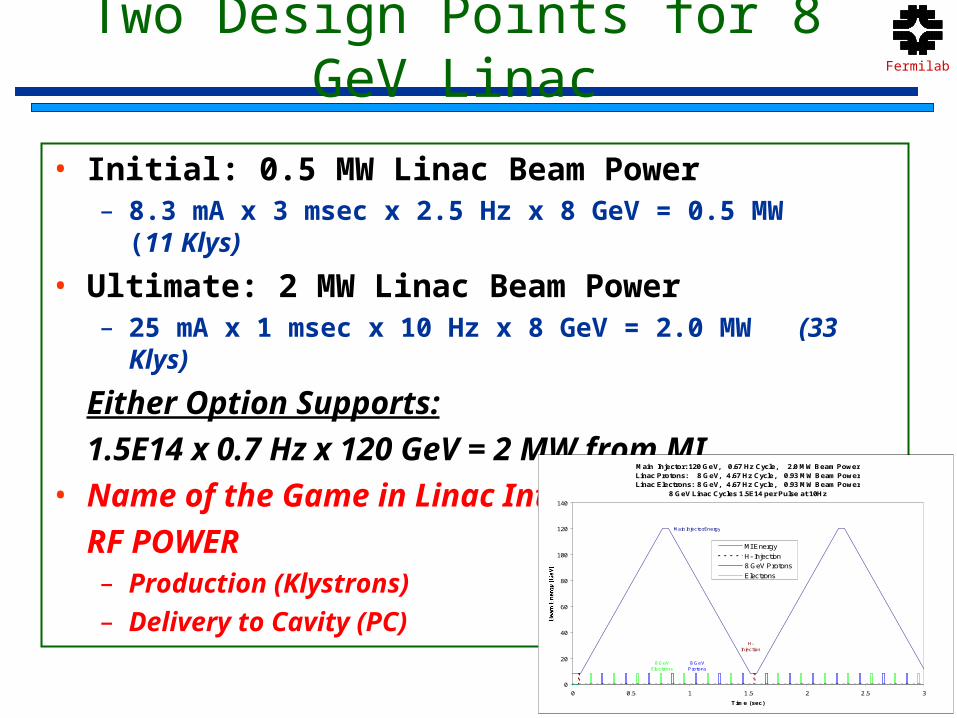
Two Design Points for 8 GeV Linac
• Initial: 0.5 MW Linac Beam Power – 8.3 mA x 3 msec x 2.5 Hz x 8 GeV = 0.5 MW (11 Klys)
• Ultimate: 2 MW Linac Beam Power– 25 mA x 1 msec x 10 Hz x 8 GeV = 2.0 MW (33 Klys)
Either Option Supports:
1.5E14 x 0.7 Hz x 120 GeV = 2 MW from MI• Name of the Game in Linac Intensity:
RF POWER– Production (Klystrons)– Delivery to Cavity (PC)
Main Injector: 120 GeV, 0.67 Hz Cycle, 2.0 MW Beam PowerLinac Protons: 8 GeV, 4.67 Hz Cycle, 0.93 MW Beam Power Linac Electrons: 8 GeV, 4.67 Hz Cycle, 0.93 MW Beam Power
8 GeV Linac Cycles 1.5E14 per Pulse at 10Hz
Main Injector Energy
H-Injection
8 GeVProtons
8 GeVElectrons
0
20
40
60
80
100
120
140
0 0.5 1 1.5 2 2.5 3
Time (sec)
MI Energy
H- Injection
8 GeV Protons
Electrons

Fermilab
4
~ 700m Active Length8 GeV Linac
8 GeVneutrino
MainInjector@2 MW
Anti-Proton
SY-120Fixed-Target
Neutrino“Super- Beams”
NUMI
Off- Axis
8 GeV Superconducting Linac
X-RAY FEL LAB
Neutrino Target
Neutrinosto “Homestake”

Fermilab
5
HINS-PD-ILC
• Meld two apparently competing priorities into a single synergistic program.– 1.5% ILC Demonstration– Seed for SCRF Industrialization in the US and International
Collaborations (India/China)
• In the event the start of the ILC construction is slower than the technically-limited schedule, this is beneficial to:– and “high-intensity” proton-beam physicists with near-term
physics program– ……– X-ray FEL Lab in Illinois– Illinois Neutron Lab– “RIA-like” Lab
HEP - eyes
Multi-Disc. Lab - e
yes
Fermilab
6β=1 β=1 β=1 β=1 β=1
Modulator
β=1 β=1 β=1 β=1
Modulator
36 Cavites / Klystron
ILC LINAC8 Klystrons288 Cavities in 36 Cryomodules 1300 MHz β=1
β<1 ILC LINAC
2 Klystrons96 Elliptical Cavities12 Cryomodules
1300 MHz 0.1-1.2 GeV
β=1 β=1 β=1 β=1 β=1
Modulator
β=1 β=1 β=1 β=1
Modulator
β=1 β=1 β=1 β=1 β=1
Modulator
β=1 β=1 β=1 β=1
Modulator
β=1 β=1 β=1 β=1 β=1
Modulator
β=1 β=1 β=1 β=1
Modulator
10 MWILC
Multi-BeamKlystrons48 Cavites / Klystron
β=.81
Modulator
β=.81 β=.81 β=.81 β=.81 β=.81
8 Cavites / Cryomodule
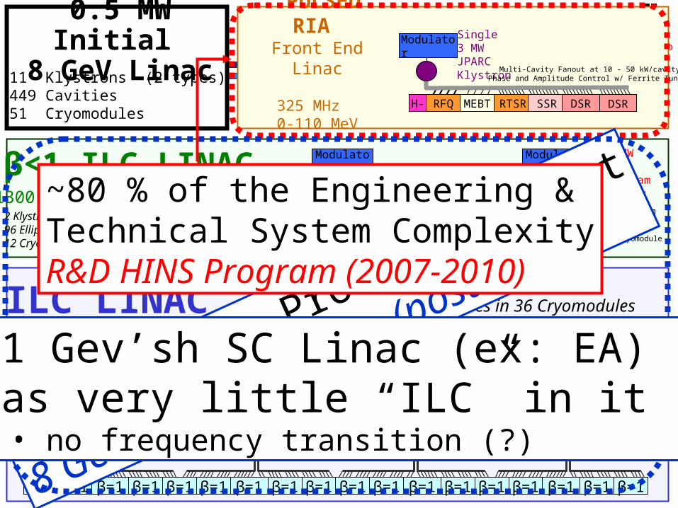
0.5 MW Initial 8 GeV Linac11 Klystrons (2 types)449 Cavities 51 Cryomodules
“PULSED RIA”Front End Linac
325 MHz 0-110 MeV H- RFQ MEBT RTSR SSR DSR
Single3 MWJPARCKlystron
Multi-Cavity Fanout at 10 - 50 kW/cavityPhase and Amplitude Control w/ Ferrite Tuners
DSR
β=.47
Modulator
β=.47 β=.61 β=.61 β=.61 β=.61
or… 325 MHz Spoke Resonators
Elliptical Option
Modulator
10 MWILC
Klystrons
80 % of the Production Cost
8 GeV Linac Program (post-2010?)
~1 Gev’sh SC Linac (ex: EA) has very little “ILC” in it
• no frequency transition (?)
~80 % of the Engineering & Technical System ComplexityR&D HINS Program (2007-2010)

Fermilab
7
HINS R&D Goals
• HINS R&D Phase: Proof of innovative approach to high intensity beam acceleration !– 2007-2010 R&D period– Prove, Develop & Build Front-End in Meson Bldg. at 325 MHz (0-60
MeV) since much of the technical complexity is in the FE Mechanical/RF Systems
• Demonstrate for the first time Amplitude/Phase Modulator (FVM) Technology and RF Power Scheme with H-
• Demonstrate for the first time RT-SC Transition at 10 MeV • Acquire capability to test/operate SC Spoke Cavities at FNAL• Demonstrate for the first time beam loading and pulsed operation of Spoke
Cavities• Demonstrate Axis-Symmetric focusing and Beam Chopping• Demonstrate for the first time the ability to drive RT and SC Sections with a
single klystron– Retain conceptual design compatibility between HINS and ILC
• =1 R&D is necessary in the event of an 8 GeV Linac phase • 8 GeV Linac Phase
– “Post-2010”period– Construction of ~400 ILC-like cavities and ~50 ILC-like cryomodules at
1.3 GHz
AN
L-FN
AL
ANL-FNAL Collaboration on R&D
Fermilab
8
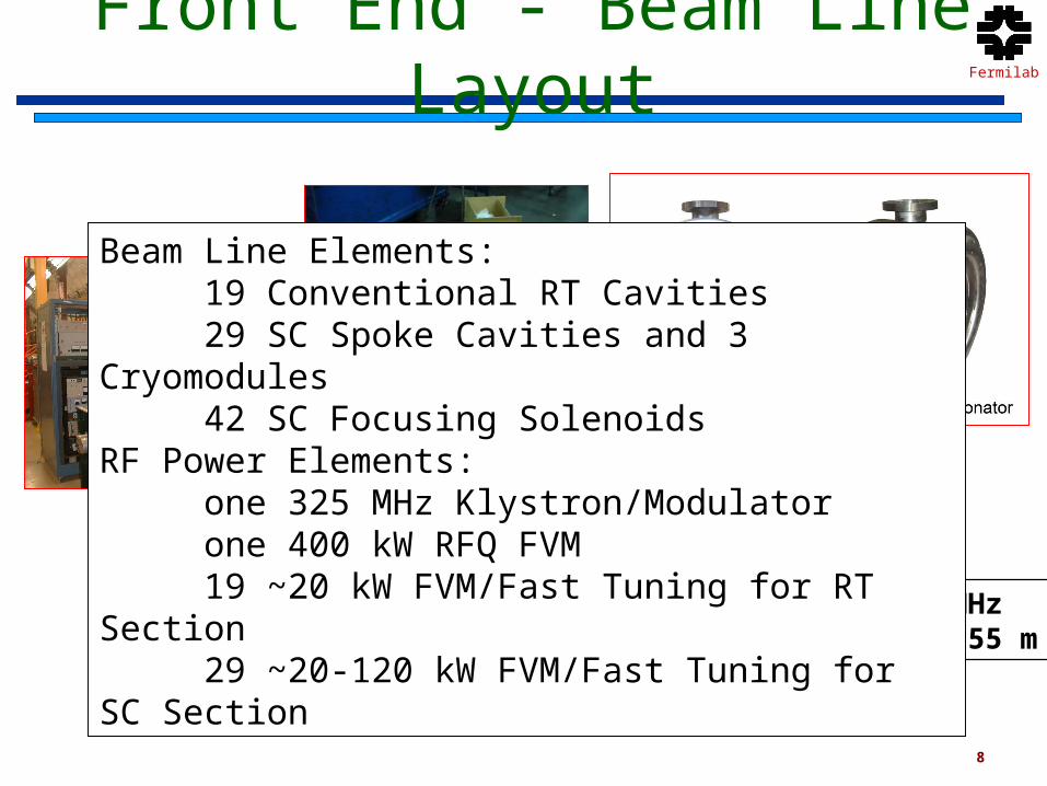
Front End - Beam Line Layout
Frequency 325 MHzTotal length ~ 55 m
SSR1(=0.22)
SSR2(=0.4)
RT -CHSRMEBTRFQ
IS
W (MeV) 2.50.050 603010
Beam Line Elements:19 Conventional RT Cavities29 SC Spoke Cavities and 3 Cryomodules42 SC Focusing Solenoids
RF Power Elements:one 325 MHz Klystron/Modulatorone 400 kW RFQ FVM19 ~20 kW FVM/Fast Tuning for RT Section29 ~20-120 kW FVM/Fast Tuning for SC Section

Fermilab
9
HINS Floor Plan in Meson Detector Building
RF Component Test Facility
Ion Source and RFQ Area 150 ft.
Cavity Test Cave
60 MeV Linac Cave
Klystron and Modulator Area
Existing CC2 Cave
ILC HTC Cave
Modulator Pulse TransformerKlystron
Fermilab
10
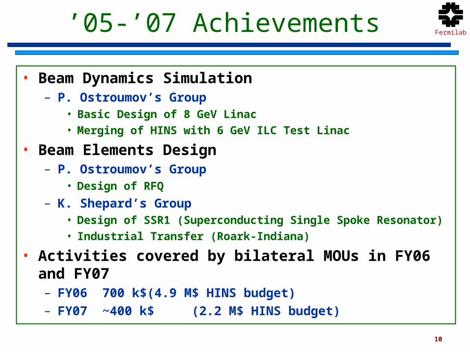
’05-’07 Achievements
• Beam Dynamics Simulation– P. Ostroumov’s Group
• Basic Design of 8 GeV Linac
• Merging of HINS with 6 GeV ILC Test Linac
• Beam Elements Design– P. Ostroumov’s Group
• Design of RFQ
– K. Shepard’s Group• Design of SSR1 (Superconducting Single Spoke Resonator)
• Industrial Transfer (Roark-Indiana)
• Activities covered by bilateral MOUs in FY06 and FY07– FY06 700 k$ (4.9 M$ HINS budget)– FY07 ~400 k$ (2.2 M$ HINS budget)
Fermilab
11
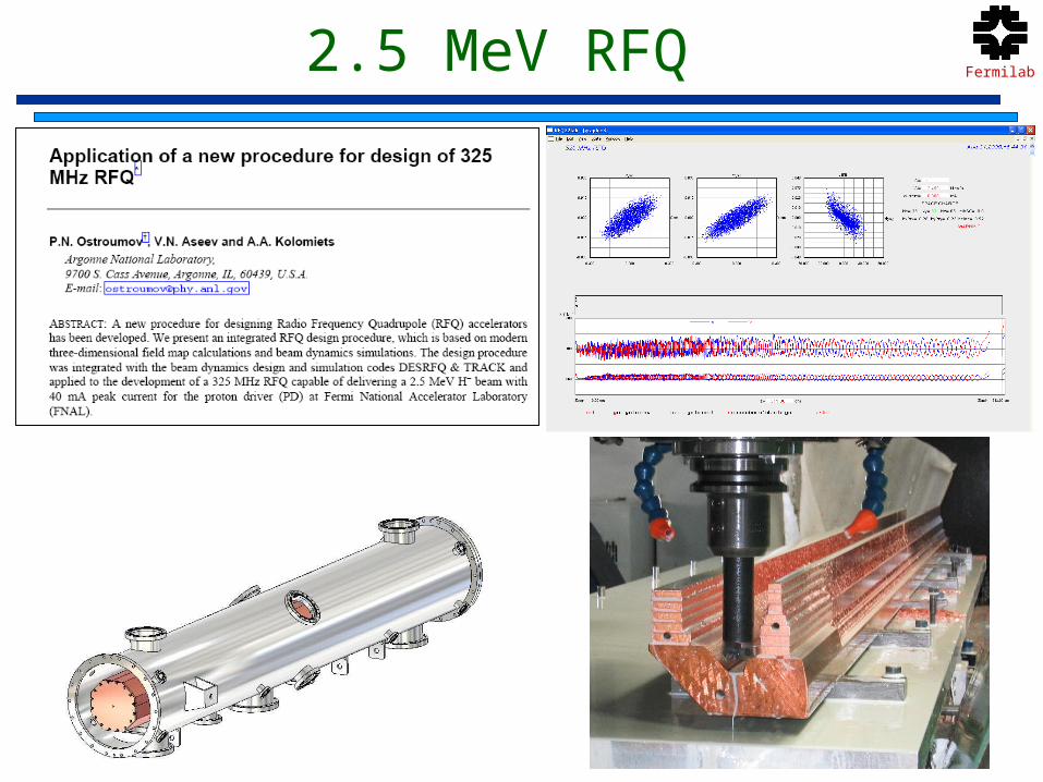
2.5 MeV RFQ

Fermilab
12
PD-ILC 6 GeV Test Linac
Original Design
P.Ostroumov (ANL)J.P.Carniero (FNAL)S.Aseev (FNAL – ex ANL)I. Mustafa (ANL)
Fermilab
13
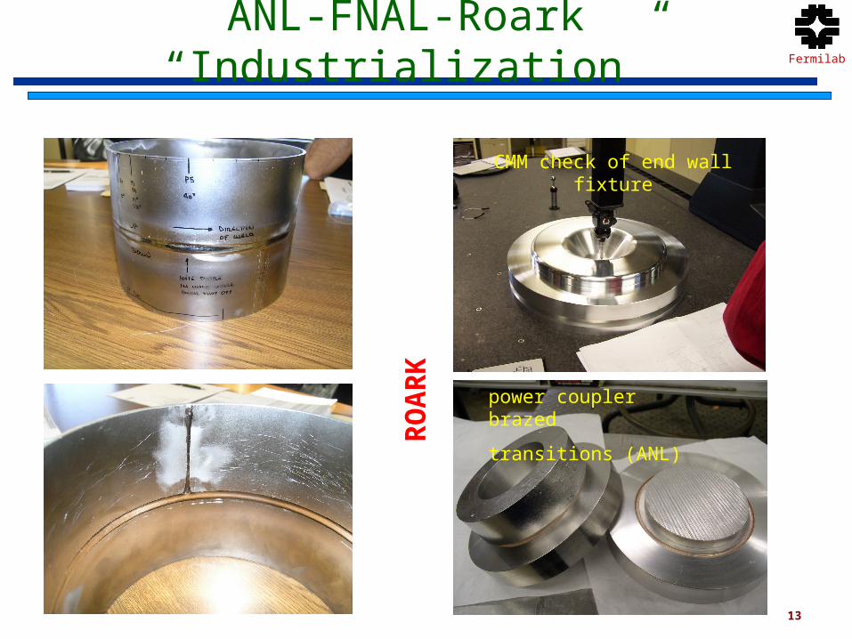
ANL-FNAL-Roark “Industrialization”
CMM check of end wall fixture
RO
AR
Kpower coupler brazed
transitions (ANL)

Fermilab
14
’07-’10 Plans for ANL-FNAL
• Beam Dynamics Simulation– P. Ostroumov’s Group
• Continued support on Beam Simulation
• Definition or Mechanical and RF Tolerancies
• Analysis/Optimization of Beam Operations
• Merging of HINS with 6 GeV ILC Test Linac
• Beam Elements Operations/Production– P. Ostroumov’s Group
• Participation in RFQ Operation
– M.Kelly- J.Fuerst Group• Etching of Prototype SSR1 (4 cavities)
• Etching of SSR1 Production (18+ cavities) in 2008-’09
• Etching of SSR1 Production (11+ Cavities) in 2009-’10

Fermilab
15
ANL Processing Facilities
Housing cathode
End plate cathode

Fermilab
16
Conclusions
• Very fruitful ANL-FNAL Collaboration in place on HINS
• Strong relationship between FNAL and ANL Scientist on accelerator physics and design of beam elements
• Plans to use heavily ANL processing facilities for HINS SSR cavities
• Funding support of manpower may become problematic if HINS budget remains constant or decreases
Fermilab
17
Supporting Slides

Fermilab
18
Intense Proton Source & FE under consideration around the World
…excluding SNS and JPARC
Pulsed• CERN SPL II – (,EURISOL)
– 3.5 GeV H- Linac at 4 MW
• Rutherford Accelerator Lab – ESS (Neutron, )– Synchrotron-based PD, 5-15
GeV, 4 MW, 180 MeV Linac FE
CW• CEA Saclay – IPHI Injector
(Neutron, Transmutation)• LNL TRASCO –
(Transmutation)
R.Maier – EPAC 2002
Fermilab
19
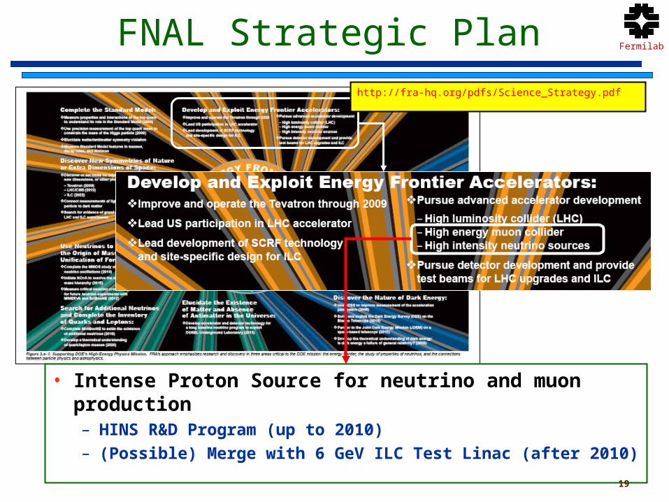
FNAL Strategic Plan
• Intense Proton Source for neutrino and muon production– HINS R&D Program (up to 2010)– (Possible) Merge with 6 GeV ILC Test Linac (after 2010)
http://fra-hq.org/pdfs/Science_Strategy.pdf

Fermilab
20
Beam Dynamicsstandard with 8 ILC-units
RMS long. emittance
Max envelope


