
This is a repository copy of An analytical and numerical prediction for ductility demand on steel beam-to-column connections in fire.
White Rose Research Online URL for this paper:http://eprints.whiterose.ac.uk/105286/
Version: Accepted Version
Article:
Sun, R. and Burgess, I.W. orcid.org/0000-0001-9348-2915 (2016) An analytical and numerical prediction for ductility demand on steel beam-to-column connections in fire. Engineering Structures, 115. pp. 55-66. ISSN 0141-0296
https://doi.org/10.1016/j.engstruct.2016.02.036
Article available under the terms of the CC-BY-NC-ND licence (https://creativecommons.org/licenses/by-nc-nd/4.0/)
[email protected]://eprints.whiterose.ac.uk/
Reuse
This article is distributed under the terms of the Creative Commons Attribution-NonCommercial-NoDerivs (CC BY-NC-ND) licence. This licence only allows you to download this work and share it with others as long as you credit the authors, but you can’t change the article in any way or use it commercially. More information and the full terms of the licence here: https://creativecommons.org/licenses/
Takedown
If you consider content in White Rose Research Online to be in breach of UK law, please notify us by emailing [email protected] including the URL of the record and the reason for the withdrawal request.

_______________________________________________________________________ 1 Structural Engineer, MMI Engineering Ltd, Aberdeen, AB12 3JG, Email:
[email protected] 2 Professor, Department of Civil and Structural Engineering, the University of Sheffield,
Sheffield, S1 3JD, UK, Email: [email protected]
AN ANALYTICAL AND NUMERICAL PREDICTION FOR
DUCTILITY DEMAND ON STEEL BEAM-TO-COLUMN
CONNECTIONS IN FIRE
Ruirui Sun1 and Ian W Burgess
2
ABSTRACT:
In this paper a simplified analytical method to assess the ductility demand on connections
according to fire resistance requirements is developed on the basis of fundamental structural
mechanics principles. An objective is to enable the development of a viable method to allow
engineers to take the ductility of connections into account in design practice. Numerical finite
element simulations of the single beam model were also performed to validate the simplified
analytical model and reveal the important parameters that can influence the ductility demand
within the connections. Using both analytical and numerical methods, the principal factors
which influence the ductility demand of a connection, such as the span of the connected beam
and the required connection strength, are also assessed. It is shown that:
1. The compressive ductility of connections is helpful in reducing the push-out of
perimeter columns and the possibility of local buckling of beams;
2. Provision of high tensile deformation capacity allows large deflection in the beam,
substantially reduces catenary forces on the connections, and consequently reduces
the risk of structural collapse in fire;
3. The ductility demand of the connection is closely related to its stiffness and strength,
as well as to the slenderness and load ratio of the connected beam.
KEYWORDS: Ductility demand, Connection, Structural Mechanics, Design Method, Fire.

1
Notation 畦 area of the beam’s cross-section 経頂通┸脹 Compressive deformation limit 経痛通┸脹 Normal tensile deformation capacity, or ductility
,y Tf yield strength of steel at temperature 劇
,B TK axial stiffness of the beam at temperature 劇 計頂┸態待 axial compressive stiffness of the connection at ambient temperature 計頂┸脹 Initial stiffness in tension of a connection at temperature 劇 倦頂 axial stiffness of each connection 倦帳┸脹 degradation of elastic modulus due to temperature rise 計徴眺┸脹 rotational stiffness of the connections
,R TK the rotational stiffness of the steel beam 計痛┸脹 Initial stiffness in tension of a connection at temperature 劇 倦槻┸脹 reduction factor for the yield strength of steel at temperature 劇
TE Elastic modulus of steel at temperature 劇
I Second moment of area of beam section 警帳 externally applied free bending moment at mid-span 警彫 bending moment at the mid-span of the beam 警陳 mid-span bending moment for a pin-ended beam of span 健 without restraint
,P TM moment capacity of the beam’s cross-section at temperature 劇 警眺鳥┸態待 moment capacity of beam section at ambient temperature
,Rd TM moment capacity of beam section at temperature 劇 警眺 moment at the left-hand connection 警痛┸脹 moment at the beam ends 軽寵┸脹 Axial force in the connection at temperature 劇
,Cmax TN maximum axial compression force 軽寵眺鳥┸脹 axial compression capacity of the connection at temperature 劇 軽眺鳥┸態待 axial capacity of beam section at ambient temperature
,Rd TN axial capacity of beam section at temperature 劇 軽脹 Axial force of a beam 軽脹眺鳥┸脹 Tensile capacity of a connection at temperature 劇 軽蝶 shear force at each beam-end connection 劇 Temperature in fire 劇怠 Temperature at which the connection contacts with the column flange 劇喋 Temperature at point B in Figure 2 劇寵 Temperature at point C in Figure 2
2
劇帖 Temperature at point D in Figure 2 糠 thermal expansion coefficient
temperature change
c compressive deformation in the connection at temperature 劇
S accumulated mechanical strain of the beam
,c m normalized ductility of the connection up to its contact with the connected
column
,m T normalized ductility of the connection at temperature 劇
T the ductility factor at temperature 劇
m design ductility at ambient temperature
load ratio of the beam, normalized with respect to its plastic moment
capacity
tensile capacity of the connection, normalized with respect to the plastic
moment capacity of the beam 膏 slenderness ratio of the beam 堅鎚 radius of gyration ッ maximum (mid-span) deflection of the beam 紅頂 axial restraint ratio of each connection
,t m designed-in tensile ductility of the connection at ambient temperature
,t m normalized designed-in tensile ductility of the connection at ambient
temperature
,c m designed-in compressive ductility of the connection at ambient temperature
,c m normalized designed-in compressive ductility of the connection at ambient
temperature
3
1 INTRODUCTION
After the events of 11 September 2001, the focus of research in structural fire engineering has
gradually moved towards the robustness of structures in fire. The capacity of a structure to
prevent fire-induced progressive collapse is now recognized as one of the more important
criteria in performance-based structural fire engineering design. Structural integrity in fire is
a rather complex issue, involving the strength and expansion performance of different
materials under elevated temperatures, the behaviour of individual members and their
interactions. Among the structural components that contribute to the robustness of a frame,
beam-to-column connections have vital importance, since they bridge the horizontal and
vertical members and provide the load paths from slabs and beams to columns. Restrained by
surrounding structure, steel/composite beams can develop significant forces in the
connections, which are not considered in the ambient-temperature design of the connections,
when exposed to fire. In this sense, connections can be both the most vulnerable and the least
adequately designed parts of a frame, having the potential to trigger progressive collapse in
exceptional fire events. The failure of connections can also lead to loss of fire
compartmentation, and consequently cause the spread of fire between compartments, which
can trigger a catastrophic escalation of failures within the structure.
The current trend of fire engineering design has been to move away from prescriptive
methods to performance-based methods, in which the behaviour of structural members and
their interactions are embedded into the assessment of overall structural fire resistance. In
advanced fire engineering design, large deformations are allowed, provided that structural
integrity (robustness) is maintained [1]. Tests and numerical studies have revealed that
catenary action in beams, which occurs at high deflection, can increase the structural
resistance to avoid progressive collapse. Li et al. [2] conducted high-temperature experiments
on axially restrained steel beams, in which significant axial forces were measured. Liu et al.
[3] investigated the effect of restraint on steel beams, leading to the catenary action which
might be able to prevent deflections from running away at very high temperatures, also

4
experimentally. Catenary action was observed in these tests, and it was clear that horizontal
restraint and catenary action are both important to the behaviour of beams in fire conditions.
In order to utilize the catenary action in beams exposed to fire, one of the key issues is to
retain the robustness of the connection under the complex set of internal forces caused by
heating. Sufficient strength and ductility within the connections is clearly necessary to sustain
these forces along with large deflections. Nevertheless, recent experimental studies [4, 5]
have indicated that the conventional connections (endplates, fin plates and web cleats) exhibit
relatively limited ductility under fire conditions. Thus, taking into account the ductility
demand on connections at the design stage of a building is imperative in order to ensure their
robustness when it is necessary to utilize beam catenary action in the event of a fire.
Achieving sufficient ductility in connections to prevent the collapse of beams in fire will
require: (1) a design method to quantify the ductility demand on the connection; (2)
innovative design of the connection details such as bolts, endplates and their overall geometry.
Simplified methods to predict the behaviour of steel beams have been proposed by many
researchers. Wang and Yin [6] used the finite element and simplified methods to predict the
behaviour in fire of restrained steel beams. Their simplified method iteratively predicts the
deflections and internal forces of beams on the basis of both equilibrium and a moment-axial
force interaction. Tan and Huang [7] studied the fire-induced restraint forces in steel beams
considering the effects of slenderness ratio, load utilization factor and thermal gradient across
the steel section. Dwaikat and Kodur [8, 9] proposed a simplified approach to predict the fire-
induced forces and deflections of restrained steel beams. This method applies equilibrium
equations to obtain critical fire-induced forces, and then utilizes compatibility principles to
obtain the temperature-deflection history of the beam. It is validated by comparing its
predictions with results obtained from detailed finite element analysis. Although these
proposed approaches might be applicable in practical design to assess a beam’s behaviour in
fire, none of them have taken the ductility within connections into account.
The intention of this study is to propose a simplified method to estimate approximately the
ductility demand on a steel beam-to-column connection in fire. Such an estimate could
potentially serve as a baseline for subsequent detailed connection design calculations for the
fire limit state. Numerical finite element modelling of steel beams with connection at both

5
ends have been performed, firstly to validate the simplified analytical model and secondly to
reveal the important factors which can influence the ductility demand within the connections.
Using both analytical and numerical approaches, a series of parametric studies on the
ductility demand on connections have been carried out. These have provided an initial view
of how the designed-in ductility of connections, in both tension and compression, affects the
robustness of structures in fire, and on how other parameters can affect the ductility demand
on connections.
2. LIMITATIONS
In this study, a simplified estimation of the ductility demand on connections is derived from
the behaviour of restrained beams in fire. An effective structural fire collapse analysis tool
has been developed in the software Vulcan [10, 11, 12, 13], with which the sequence of
progressive failure within connections can be tracked during the course of a fire. The
software is here utilized, firstly to validate the approximation of ductility demand from the
simplified method, and secondly to perform the parametric study on the factors that affect it
in fire.
As discussed above, achieving the required ductility also relies heavily on the detailing of a
connection. However, the simplified method proposed in this study is intended to estimate in
a general manner the required plastic movement capacity (ductility) in tension and
compression of a steel connection to achieve the desired fire resistance. It does not consider
connection detailing directly, but can provide guidance on the ductility that the detailed
design needs to achieve.
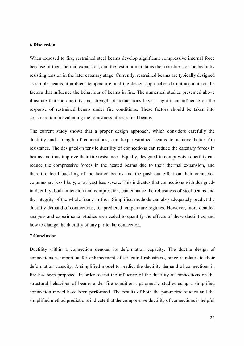
3. SIMPLIFIED CHARACTERISTICS OF A CONNECTION
In a simplified fashion, the essential characteristics of a beam-to-column connection in terms
of its movements normal to the column flange can be illustrated as shown in Figure 1, in
which ideal elastic-to-plastic characteristics in both compression and tension are assumed.
The terms defining its characteristics are:
The initial stiffnesses 計痛┸脹 and 計頂┸脹 in tension and compression at temperature 劇;
The tensile and compressive capacities 軽脹眺鳥┸脹 and 軽寵眺鳥┸脹 ;

6
The tensile deformation at fracture 経痛通┸脹 , which is known the normal tensile
deformation capacity, or ductility.
The compressive deformation limit 経頂通┸脹 , at which it is assumed that the beam
contacts the column flange directly, causing rapid increase of the compression force
without fracture.
4 ANALYTICAL MODEL OF BEAM BEHAVIOUR IN FIRE
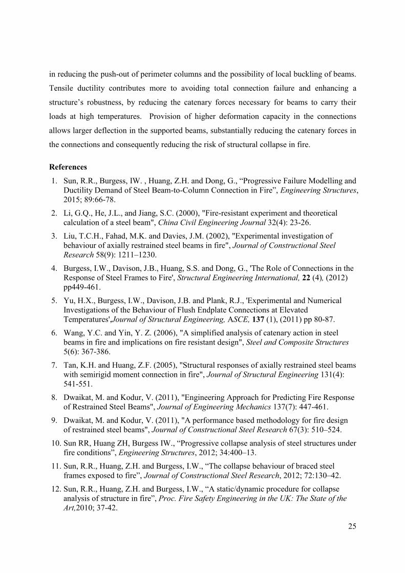
The typical response of a restrained beam in fire, illustrated in Figure 2, can be categorized
into three main stages:
Stage 1 The axial compression force grows due to restrained thermal expansion, until it
reaches an ultimate value at point B, due to a combination of material stiffness
and strength degradation and thermal buckling;
Stage 2 The axial compression force gradually reduces to zero, because of further
reduction of strength and plastic buckling;
Stage 3 Catenary tension develops in the beam.
The connection behaviour during each of these stages will be discussed in this section.
The connection behaviour during each of these stages will be discussed in this section. The
most important assumptions made in the derivation of the analytical model are:
1. A beam supported at connections is subjected to uniformly distributed load;
2. There is no significant sagging deflection in the beam in Stage 1 (the thermal
expansion stage);
3. The external axial restraint to the beam and its connections, provided by the
surrounding structure, is infinite compared to the axial stiffness of the beam;
4. The moment capacities of the cross sections of the beam and its connections
are assumed to follow the same reduction factor with temperature;
5. In the connection model, the locations of the tension and compression springs
coincide, and therefore have the same lever-arm;

7
6. All beams are assumed to be straight and prismatic, and bending behaviour
only occurs about the major axis. Neither local nor lateral-torsional buckling is
considered.
For the sake of clarity, these assumptions will be reiterated in the text when they are applied
in the derivation of the analytical model.
Figure 3 shows a steel beam with connections at its ends. Assuming that the beam is
symmetrically loaded with a uniformly distributed load 拳, equilibrium of the left-hand part of
the beam provides:
/ 2 0T V I R EN N l M M M (1)
Where: 軽脹 is the axial force (軽寵┸脹 in compression and 軽脹┸脹 in tension)
軽蝶 噺 栂鎮態 is the shear force at each beam-end connection;
警彫 is the bending moment at the mid-span of the beam; 警眺 is the moment at the left-hand connection;
警帳 噺 栂鎮鉄腿 is the externally applied free bending moment at mid-span;
健 is the length of the beam; ッ is the maximum (mid-span) deflection of the beam.
The beam’s deformed shape can be considered as a symmetric parabola as the deflection
develops. This can be defined as:
4 1x x
z xl l
(2)

8
where, 権岫捲岻 is the vertical deflection at a distance 捲 along the beam length. Then, the beam’s
elongation E due to accommodating this deflected shape within its horizontal span is:
12 2 2
0
81
3
l
E
dzdx l
dx l
(3)
Stage I
In this stage, the beam is assumed to expand as its temperature rises, without significant
deflection. The connections at the beam ends are pushed towards the connected column
flanges. The response of the beam is initially elastic, but properties degrade as its
temperatures rises. The axial compression force 軽寵┸脹 in each connection is:
, ,
,
, ,
, ,
1
2 1 2
c T B T
C T
c T B T
c T B T
K KN l l
K K
K K
(4)
where , , 20 /T
B T E T
E AK k E A l
l is the axial stiffness of the beam at temperature 劇; 倦帳┸脹 is
the degradation of elastic modulus due to temperature rise, 計頂┸脹 噺 倦帳┸脹計頂┸態待 is the axial
compressive stiffness of the connection at temperature 劇 ; 糠 is the thermal expansion
coefficient; 健 is the span of the beam; 畦 is the area of the beam’s cross-section; 20T is
the temperature change. The compressive deformation in the connection c is
,
, ,2
B T
c
c T B T
Kl
K K
(5)
If the compressive deformation of the connection is characterized in dimensionless terms as:
cc
l
(6)
Then
9
,
, ,2
B T
c
c T B T
K
K K
(7)
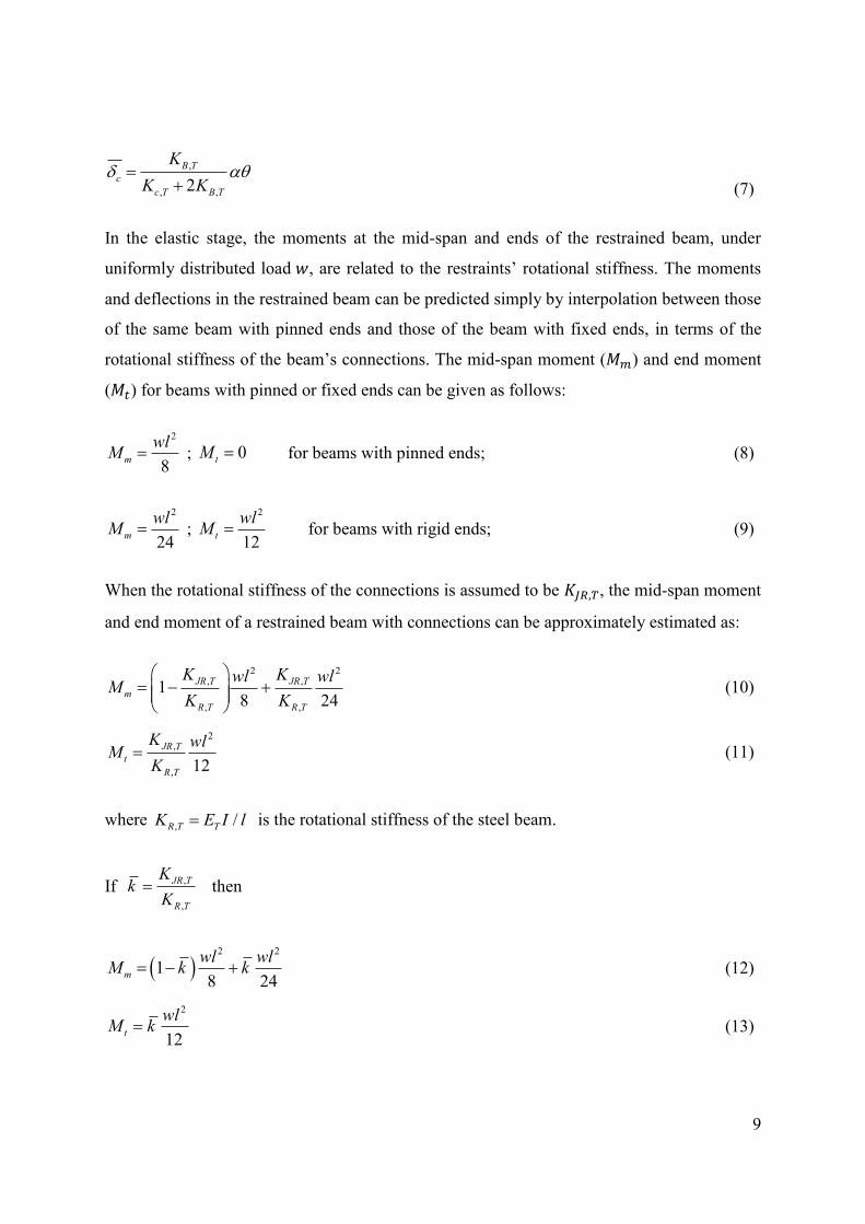
In the elastic stage, the moments at the mid-span and ends of the restrained beam, under
uniformly distributed load 拳, are related to the restraints’ rotational stiffness. The moments
and deflections in the restrained beam can be predicted simply by interpolation between those
of the same beam with pinned ends and those of the beam with fixed ends, in terms of the
rotational stiffness of the beam’s connections. The mid-span moment (警陳) and end moment
(警痛) for beams with pinned or fixed ends can be given as follows:
2
8m
wlM ; 0tM for beams with pinned ends; (8)
2
24m
wlM ;
2
12t
wlM for beams with rigid ends; (9)
When the rotational stiffness of the connections is assumed to be 計徴眺┸脹, the mid-span moment
and end moment of a restrained beam with connections can be approximately estimated as:
2 2, ,
, ,
18 24
JR T JR T
m
R T R T
K Kwl wlM
K K
(10)
2,
, 12
JR T
t
R T
K wlM
K (11)
where , /R T TK E I l is the rotational stiffness of the steel beam.
If ,
,
JR T
R T
Kk
K then
2 2
18 24
m
wl wlM k k (12)
2
12t
wlM k (13)
10
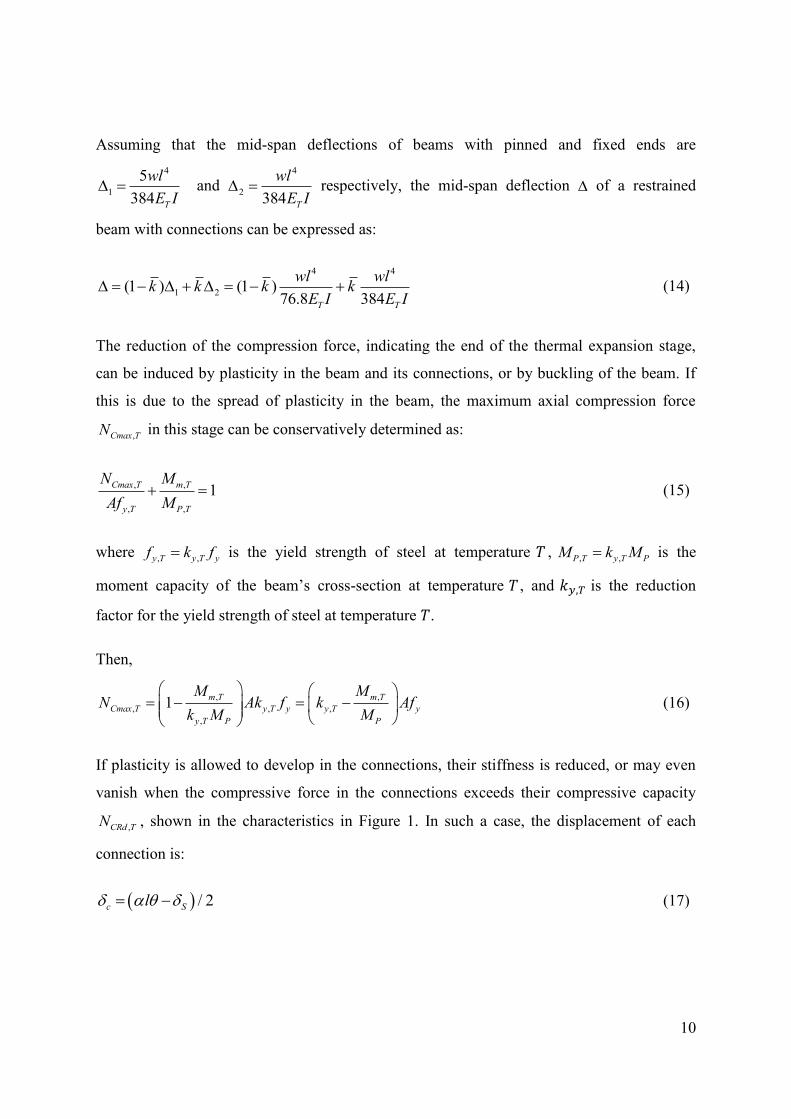
Assuming that the mid-span deflections of beams with pinned and fixed ends are
4
1
5
384 T
wl
E I and
4
2384 T
wl
E I respectively, the mid-span deflection of a restrained
beam with connections can be expressed as:
4 4
1 2(1 ) (1 )76.8 384T T
wl wlk k k k
E I E I (14)
The reduction of the compression force, indicating the end of the thermal expansion stage,
can be induced by plasticity in the beam and its connections, or by buckling of the beam. If
this is due to the spread of plasticity in the beam, the maximum axial compression force
,Cmax TN in this stage can be conservatively determined as:
, ,
, ,
1Cmax T m T
y T P T
N M
Af M (15)
where , ,y T y T yf k f is the yield strength of steel at temperature 劇 ,
, , P T y T PM k M is the
moment capacity of the beam’s cross-section at temperature 劇 , and 倦槻┸脹 is the reduction
factor for the yield strength of steel at temperature 劇.
Then,
, ,
, , ,
,
1m T m T
Cmax T y T y y T y
y T P P
M MN Ak f k Af
k M M
(16)
If plasticity is allowed to develop in the connections, their stiffness is reduced, or may even
vanish when the compressive force in the connections exceeds their compressive capacity
,CRd TN , shown in the characteristics in Figure 1. In such a case, the displacement of each
connection is:
/ 2c Sl (17)

11
where ,
,
CRd T
S
B T
N
K is a conservative estimate of the mechanical shortening of the beam.
Thus,
,
, 20
/ 2
CRd T
c
E T
N
k E A
(18)
, , ,C T C Rd TN N (19)
If the compressive deformation of a connection reaches its deformation capacity 経頂通┸脹, its
compressive force increases rapidly, since the beam ends have come into contact with the
connected column, at temperature 劇怠 . If the stiffness of the axial restraint to the beam
provided by the connected structure is assumed to be infinite, the deformation and
compression force in the connection when it is in contact with the column are:
,
,
cu T
c m
D
l (20)
, ,C T B TN l K (21)
where 1T T and ,c m is the normalized ductility of the connection up to its contact with
the connected column, when the compressive force in the beam and its connections is
reduced.
Stage II
The axial force in the connection gradually decreases as the beam’s axialdeflection increases,
and plasticity spreads within the beam during this stage. The end of this stage can be
identified as the point at which the axial force in its connections becomes zero. The
interaction between axial force and the moment in the connection may be simply represented
(normally conservatively) as:
, ,
, ,
1C T R T
Rd T Rd T
N M
N M (22)
12
where , , ,20Rd T y T RdN k N is the axial capacity and
, , ,20Rd T y T RdM k M is the moment capacity
at temperature 劇. 軽眺鳥┸態待 and 警眺鳥┸態待 are its axial capacity and moment capacity at ambient
temperature. When 軽寵┸脹 reduces to zero, the moment in the connection reaches its full
moment capacity at the temperature. Thus, the equilibrium of the beam can be represented by
the following relationship:
, ,/ 2 0V P T Rd T EN l M M M (23)
If the moment capacity of a connection is assumed to follow the same reduction factor (倦槻┸脹)
with temperature as the moment capacity of the beam’s cross-section, then Eqn. (23) gives,
, ,20 ,20/2
Vy T E P Rd
N lk M M M
(24)
The temperature (劇寵) at point C, shown in Figure 2, can be obtained from this reduction
factor, from the temperature-strength reduction factor curve for structural steels, as given in
Eurocode 3 Part 1.2 [14].
Stage III
During the catenary action stage, the normal forces carried by the connections become tensile.
The tensile force on a connection increases until it reaches a maximum value, after which the
connection is purely in tension with insignificant moment. With rising temperature, the load
is then resisted by catenary action. This stage ends once the deformation of the connection
exceeds its ductility, causing it to detach completely.
It can be seen from Figure 2 that, when the connection is purely in tension, its normal force
(shown as Line 2) can be estimated as:
, , ,20TRd T y T TRdN k N (25)
A conservative approximation [9] of the maximum tensile force in the catenary stage is
proposed by extending a straight line (Line 1 in Figure 2) between the point of maximum
compressive force (B in Figure 2) and the point at which the catenary action starts (C in

13
Figure 2). The intersection point (D in Figure 2) of Line 1 and Line 2 is assumed to be the
point at which the maximum tensile force occurs. The temperature 劇帖 at which this maximum
catenary force occurs in the beam is determined by:
, , ,20D
D CCmax T y T Rd
C B
T TN k N
T T
(26)
Then,
,20
, , D
Rd C BD C
Cmax T y T
N T TT T
N k
(27)
Before the temperature achieves the value 劇帖,
, ,C
t T Cmax T
C B
T TN N
T T
(28)
The interaction between axial force and moment in the connection gives:
, ,20
, , , ,20 ,
, ,20
1t T Rd
R T Rd T y T Rd t T
Rd T Rd
N MM M k M N
N N
(29)
As the temperature rises, the load-carrying mechanism gradually becomes that of a cable, in
which the load on the beam is completely sustained by catenary tension. The equilibrium can
be expressed as:
, , 0TRd T P T EN M M (30)
Then,
, ,20,
, , ,20
E y T PE P T
TRd T y T TRd
M k MM M
N k N
(31)
The change of the beam’s length is due to a combination of its thermal expansion, the
ductilities of its connections and its mechanical strain. This can be expressed as:

14
,E m T Sl (32)
The mechanical deformations can conservatively be estimated as:
, ,20
, 20
y T TRd
S
E T
k N l
k E A (33)
Substituting Eqns. (32) and (33) into Eqn. (3),
, ,20
,
, 20
3 3
8 8
y T Rd
E m T
E T
k N ll l l
k E A
(34)
The displacement of the connections increases faster, because stiffness has been lost or
reduced, at this stage. When the axial displacement in a connection exceeds its axial ductility
the connection breaks and detaches from the connected column because of the fracture of its
internal components.
The tensile ductility demand of the connection at elevated temperature can then be estimated
as:
22
, ,20, 2
,
, ,20 , 20
8
3
y T RdE P T
m T
y T TRd E T
k N lM Ml l
k N k E A
(35)
In dimensionless terms, this is equivalent to:
2 2
, , ,20 , , ,20
,
, , 20 , , 20
8 8
3 3
y T y T TRd y T y T TRd
m T
y T E T s y T E T
k k N k k N
lk k E A r k k E A
(36)
where ,
,
m T mm T T
l l
is the normalized ductility of the connection at temperature 劇; T
is the ductility factor at temperature 劇; m is the design ductility at ambient temperature;
E
P
M
M is the load ratio of the beam, normalized with respect to its plastic moment capacity,
15
,20TRd
P
N
M is the tensile capacity of the connection, normalized with respect to the plastic
moment capacity of the beam. Other terms are 膏, the slenderness ratio of the beam and 堅鎚, its
radius of gyration, both about the beam’s bending axis.
The ductilities of the connections play important roles in the thermal expansion stage (Stage I)
and the catenary action stage (Stage III). In the thermal expansion stage, the compressive
ductility determines the point at which the connection contacts the column flange, causing
rapidly-increasing compression force in the beam. In the catenary action stage, the axial force
in a connection, before its breakage, decreases as its tensile ductility increases. The demand
for such ductility in connections is closely related to the beam’s slenderness, the connection’s
capacity (strength), the cross-sectional properties of the beam and its loading.
5 Tensile and compressive ductility demands of the connections
In order to test the effects of these factors on the structural behaviour of steel beams, and the
ductility demands which they place on their connections in fire, a study based on a simplified
model is now carried out. It is difficult to evaluate the ductility of a complex connection in
an accurate way, since it is determined and limited by so many different characteristics. A
simplified connection model, shown in Figure 4(a), which consists of four rows of springs, is
adopted to simulate a generic beam-to-column connection.
The model has upper and lower pairs of tension and compression springs separated by a
lever-arm. The main aim is to understand in general terms the ways in which design of
connections specifically to achieve a certain ductility could influence a structure’s resistance
to progressive collapse in fire. The generic model is relatively straightforward as a way of
defining the ductility properties of a connection, and it is useful to reflect these ductilities in
generic terms rather than by modelling a real connection in detail. The ductilities of each of
the upper and lower bolt rows are defined in two parts; compressive and tensile. It is
assumed that a bolt row fails when its tensile displacement exceeds the tensile ductility limit,
but the stiffness of a bolt row becomes infinite when its compressive displacement reaches
the compressive ductility limit. A beam with connections at both ends, as shown as Figure
4(b), heated by fire, is chosen as the basic model to investigate the effects of different factors
16
on the behaviour of the heated beam. As mentioned in Section 2.0, a finite element analysis
has also been conducted using the computer program Vulcan. The beam is represented by 3-
noded line elements with two Gaussian integration points along their length. The cross
section of the beam is assumed to be UB 356×171×67. It is assumed that the beam is
uniformly heated following the standard fire curve. The temperature of the beam was
obtained by a heat transfer calculation according to Eurocode 1 [15]. The temperature of the
connection is the same as that of the beam. The yield strength of the steel is 275 MPa and the
material degradation with temperature is defined following Eurocode 3 Part 1.2 [14] . The
mesh size of the models involved in the following studies was set as 500 mm. Simplified
(component-based) connection models are placed at the beam ends. The key properties of the
components in the connection, as shown in Figure 1, are main parameters in this study and
thus they are changed according to different study objectives as discussed in Section 5.1.
Only ductile fracture of the connection components is considered in this study and these
fractures are defined on the basis of the tensile deformation capability. Once the tensile
deformation capability is exceeded, the connection component strength is reduced to zero to
simulate the fracture.
To evaluate the degree of restraint given by the connection to the beam, it is convenient to
define the axial restraint ratio as
/
cc
b b
k
E A l (37)
in which 倦頂 is the axial stiffness of each connection, and 継長畦長【健 represents the beam’s axial
stiffness at ambient temperature. In this study, 紅頂 ranges from 0.02 to 0.5. The slenderness
ratios 膏 of beams are chosen as 20, 50, 75 to represent stocky to intermediate beams. Given
that steel beams tend to be initially sized to a span:depth ratio of 20, and that the radius of
gyration tends to be about 0.42-0.44 of the mean depth, the median slenderness ratio of 50 is
in a fairly representative range. The designed-in moment capacity of the connection is
represented by:
Rdc
P
M
M (38)
17
in which, 警眺鳥 and 警牒 are respectively the plastic moment capacities of the connection and
the beam at ambient temperature. Liu [3] studied the effect of the connection capacity on the
limiting temperatures of unprotected beams, which is defined according to the criterion that
the beam “fails” when its mid-span deflection exceeds 健【にど. It was concluded that moment-
resisting connections can increase the limiting temperature of a beam compared with that of
simply supported beams, but this benefit was limited by the capacity of the beam in the
vicinity of the connection, where extensive tensile yielding near to the top of the web of the
beam and local buckling of the bottom flange of the beam adjacent to the connection +were
observed. The benefit diminishes when c exceeds 0.667. In this study, c ranges from
0.084 to 0.667.
In the generic connection model, only two bolt rows are considered, both of which can act in
tension and compression. Under the assumption that both the tension and compression
springs are in the same place, and therefore have the same lever-arm, the relationship
between the axial capacity and the moment capacity can be simply evaluated as:
,20
,20
2 Rd
Rd
MN
z (39)
where 権 is the lever arm. Thus, the designed-in axial capacity of the connection can be
characterized as:
,20 2
Rd c
P
N
M z
(40)
All beams are assumed to be straight and prismatic, and bending behaviour only occurs about
the major axis. Neither local nor lateral-torsional buckling is considered. The load ratio for a
Class 1 cross-section of a pin-ended beam sustaining a uniformly distributed load 拳 is
defined at ambient temperature as
m
P
M
M (41)
where 警陳 噺 拳健態【ぱ is the mid-span bending moment for a pin-ended beam of span 健 without
restraint. The mid-span moment is normally less than 拳健態【ぱ for a beam with semi-rigid
18
connections. In this study the load ratio for a restrained beam is kept the same as that for a
pin-ended beam, to provide a basis for comparison. The load ratio 航 takes the values 0.30,
0.50 and 0.70 in this study. The designed-in tensile or compressive ductility in each
connection is characterized as
,
,
t m
t ml
or
,
,
c m
c ml
(42)
where ,t m and ,c m are the designed-in tensile and compressive ductilities of the connection
at ambient temperature.
In this context an idealized predefined temperature field, which avoids heat transfer analysis,
was directly applied to the structure. Thus, instead of a nonlinear analysis in the time domain,
the analysis can more easily be conducted within the temperature domain.
5.1 Ductility demand in catenary action
From Eqn. (36), the properties affecting the tensile ductility demand of a beam connection
include: the beam’s load ratio, the beam’s slenderness ratio and a connection’s tensile
strength. In this section the influences of different parameters are evaluated. Firstly, the
effects of the stiffnesses, strengths and ductilities of the connections are discussed. Then, the
influences of the slenderness ratio and load ratio of the beam on the connections’ ductility
demand are studied.
Stiffness, Strength and Ductility
Three key properties (initial stiffness, strength and ductility) are generally considered in the
design of connections at ambient temperature. In order to test which are the key parameters
with respect to the robustness of connections in fire, several analyses are carried out based on
a uniformly heated beam with slenderness ratio of 50 and load ratio of 0.5, but with
connections of different stiffness, strength and ductility.
Table 1 shows the values of the key parameters defined for the different connections, and the
failure temperatures at which complete detachment of any connection occurs. It indicates that
connections with different stiffnesses, but the same strengths and ductilities, generate very
similar failure temperatures. The initial stiffness of a connection does not play an important

19
role in enhancing its robustness, which is mostly related to the fracture of its components and
fracture of the connection. The strength and ductility of a connection have much greater
influence than stiffness on its failure temperature. Higher strength and higher ductility can
each retain the integrity of a connection to higher temperatures in fire. This demonstrates that,
for a connection with a given strength, a higher ductility is required to achieve a higher
failure temperature. Alternatively, for a connection with a given ductility, a higher failure
temperature requires higher connection strength.
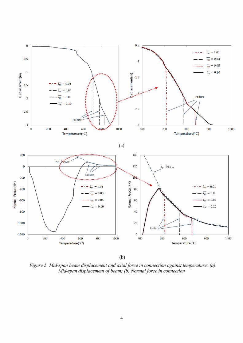
Figure 5 shows the beam deflection at mid-span and the axial force in the connection against
temperature for an analyzed beam of slenderness ratio 50, derived from the finite element
analysis. The abrupt increase of mid-span deflection and the decrease of the connection axial
force are due to fracture of the connection. The plastic axial capacity of the connection, 軽脹眺鳥┸脹 噺 倦槻┸脹軽眺鳥┸態待 , which represents the maximum plastic axial capacity that can be
attained by the connection in catenary action, is also plotted. It can be seen that the catenary
force decreases as the deflection and temperature increase. If the tensile ductility of the
connections is sufficient, then collapse of beams can be avoided within a specified
temperature range.
Strengths and ductilities are the key factors which enable connections to retain their integrity
in fire. Since this study is concerned with the influence of ductility on resistance to
progressive collapse in fire, all of the following case studies in this section focus solely on
how the change of tensile ductility (rather than strength) of connections, affects the behaviour
of the supported beams.
Slenderness Ratio
Beams of different slenderness ratios are tested. Since all the beams in this study have the
same cross-section, different slenderness ratios represent different beam spans. The same
load ratios are adopted for these beams. Figure 6 shows the change of ductility demand of
connections of strength ratio c=0.334 to beams with different slenderness ratios, for different
required failure temperatures. The solid line in each case represents the results from finite
element analysis, and the dashed line shows the results from Eqn. (36). It can be seen that
Eqn. (36) generally gives a conservative estimate of the ductility demand of connections over
20
most of the range of failure temperatures. The differences between these results become
larger as the ductility increases. This is because, in Eqn. (36) the term , ,20
, 20
y T TRd
E T
k N
k E A, which
represents the mechanical strain in the beam, is calculated using the reduced initial modulus 倦帳┸脹継態待 , although the stress-strain curve is highly curvilinear at high temperatures. A more
realistic estimate of the mechanical strain would give a much higher value, which would
reduce the ductility demand more, and the simplified method curves in Figure 6 would close
in towards the FE curves.
With a given normalized ductility provided by the connections, longer beams can survive for
longer periods in fire, which equates to higher failure temperatures. It should be noted that,
because the definition of normalized ductility is that given in Eqn. (42), a certain value of
normalized ductility implies higher deformation capacity for connections to longer beams
than to shorter beams. In the catenary action stage, the tensile force is dependent on the
transverse load carried by the beam, and its deflection magnitude. The cases shown in Figure
6 all have the same load ratio, but with connections of the same ductility, larger spans can
obviously generate larger mid-span deflections, which means that lower catenary tensions
may be needed to keep the connections robust at any given temperature. Thus, with the same
cross-section and the same load ratio, beams with longer spans require less normalized
ductility, as defined in Eqn. (36), to achieve the same failure temperature.
Load Ratio
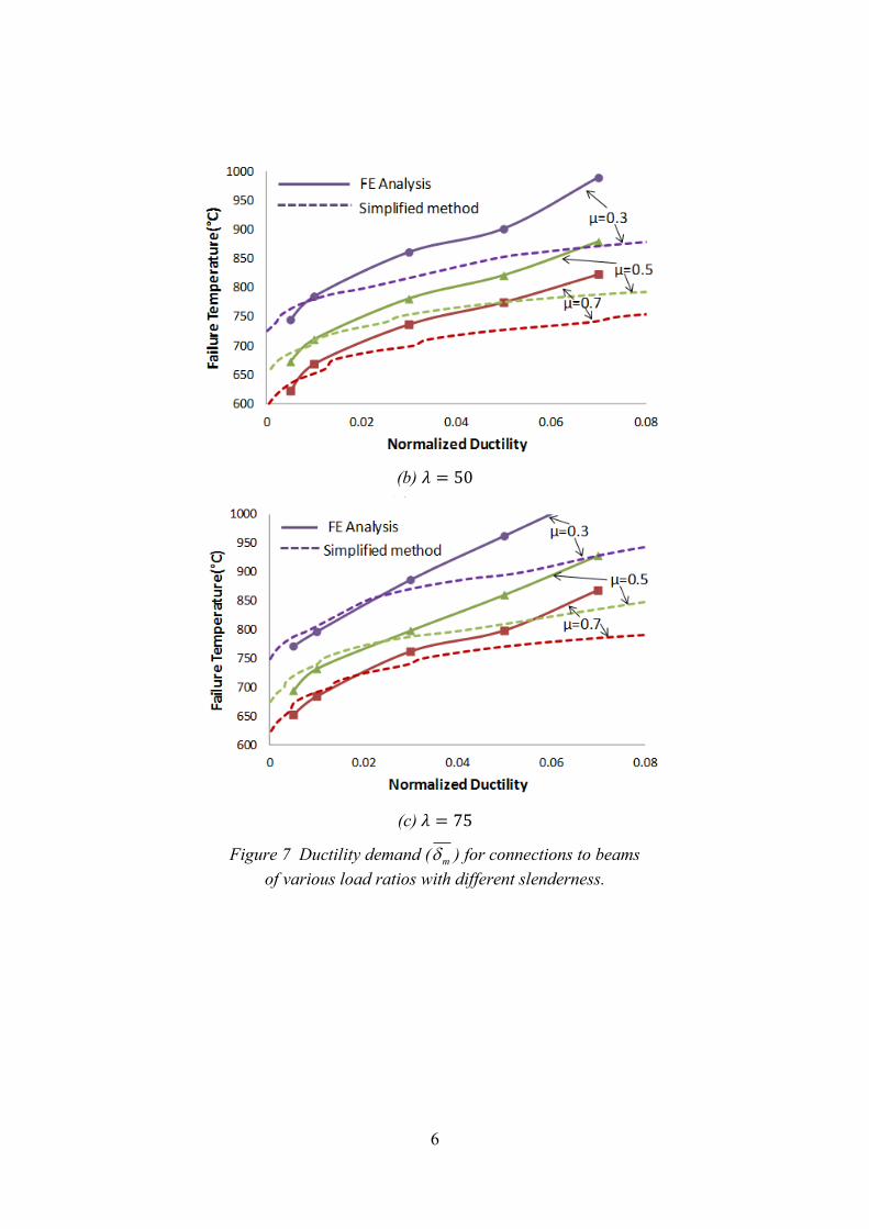
Figure 7 shows the ductility demands of connections to beams of various load ratios and
different slenderness ratios. Obviously, the ductility demand increases with load ratio. The
heavier load on the beams requires a higher tension in the catenary action stage to maintain
robustness. Therefore, beams of higher load ratio require more tensile ductility in
connections for any given strength before fracture occurs.
Figure 8 shows the development of the normal forces in connections as temperatures increase
for different cases of load ratio. It indicates that increased load ratios reduce the magnitude
of normal force in the connection in the two initial stages, but increase the normal force in the
catenary action stage. The bending moments at mid-span of the beams with higher load ratios
21
are higher than those of the beams with lower load ratios. From Eqn. (16), the maximum
compressive forces in the beams, before plastic bending develops, are lower with higher mid-
span bending moments. The temperature at which the beams step into catenary action is
lower for higher loads.
5.2 Ductility demand in thermal expansion stage
According to the discussion in Section 2.2, the compressive ductility of a connection, which
represents its deformation capacity in compression, defines the point at which the connection
contacts the connected column. This contact induces stiffer restraint to the beam’s thermal
expansion. This may cause two negative effects: firstly, the large compression force
generated by this restraint can push columns, especially those at the edge of the building,
outwards and therefore reduce their buckling capacities somewhat; secondly, this
compression force can induce buckling or plasticity to develop within the beam.
The end of the thermal expansion stage can occur due to plasticity being developed in the
beams (in line with the discussion in Section 2.2) which reduces their net compression forces.
If plasticity is allowed to develop first in the connections, the maximum compression in the
beam (at Point B in Figure 2) can be estimated as:
,
, ,
,
1t T
Cmax T CRd T
Rd T
MN N
M
(43)
where, 警痛┸脹 is the moment at the beam ends, 警眺鳥┸脹 and 軽寵眺鳥┸脹are respectively the moment
capacity and the axial compression capacity of its connections. This indicates that
introducing plasticity and ductility into the connection characteristics can effectively reduce
the axial compression in beams under fire conditions. The effects of the compressive ductility
are studied here on the basis of beams with cross-sections of UB 356×171×67, slenderness
ratio 50 and load ratio 0.5. The connections at the ends of these beams have the same initial
compressive axial stiffness. The connections in Case 1 are assumed to be elastic in
compression, with constant compressive axial stiffness. In Cases 2 and 3, both plasticity and
deformation are allowed to develop in the connections. The properties of these connections
are listed in Table 2.

22
Figure 9 shows the axial forces in the beam for the three different cases. The maximum
compression appears in Case 2, because of the increase in restraint stiffness after the beam
has contacted the connected column. The connections in Case 3 are designed with sufficient
deformation capacity for the axial compression in the beam to be less than that in the other
cases. The significant reduction in the axial force in the beam in Case 3, compared to that in
Cases 2 and 1, is attributed to the allowable deformation capacity (the ductility in the
connections). The connections move towards the column flange due to the thermal expansion
of the beam. The connections in Case 3 possess sufficient compressive ductility to allow the
movement, and so the expansion of the beam due to the temperature rise is not restrained.
However, lower compressive ductility in the connections of Case 2 limit the movements of
the connections due to thermal expansion, and induce contact between the connection and the
column flange. The restrained thermal expansion leads to a significant increase in the axial
force in the beam. It is evident that this axial compression in the beam due to restrained
thermal expansion can be effectively reduced by introducing plasticity and sufficient ductility
into the connections..
If the beam is elastically restrained, the key factors which affect its behaviour in fire include
the compressive restraint stiffness, the beam’s axial stiffness and its slenderness ratio. The
effects of these factors have been studied by several researchers [2, 3, 7, 8, 9] , and it can be
concluded that, in general, higher axial restraint stiffness induces higher compressive forces
in the heated beams during their thermal expansion stage. Restrained beams with
connections of different compressive stiffness are now tested, and the compressive
deformations in the connections are investigated. Again, the beams are assumed to have the
same cross-section (UB 356×171×67) and load ratio (0.5). The tensile properties of the
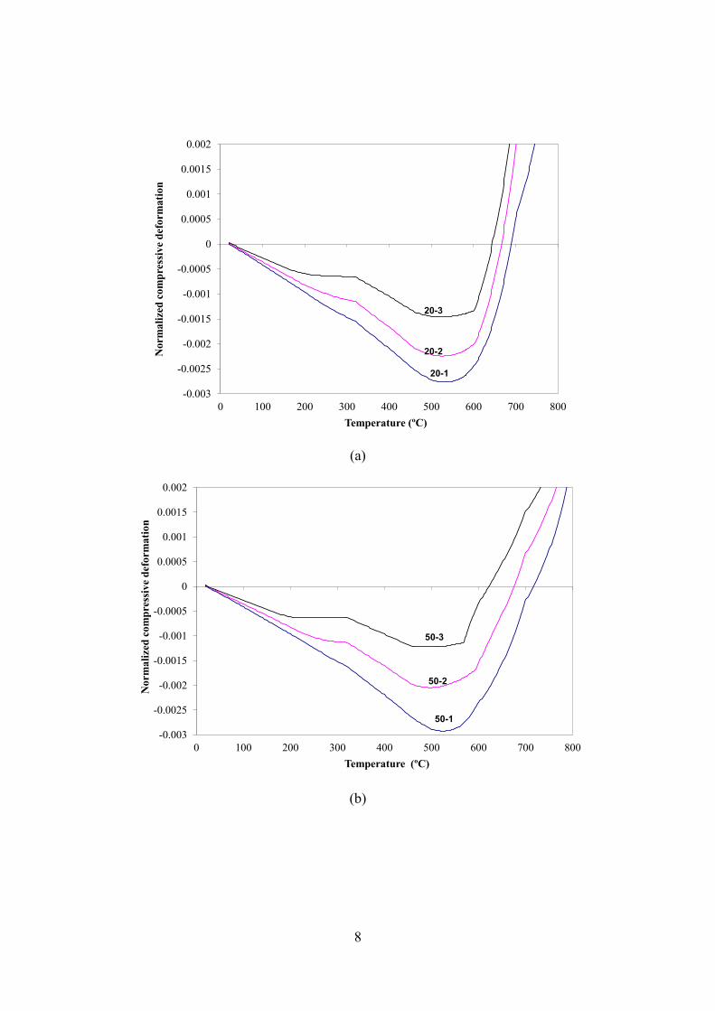
connections are assumed to be the same. Beams with three different slenderness ratios are
studied. All the connections are assumed to be elastic in compression. Table 3 lists the
compressive stiffnesses of the connections for different cases. The compressive deformations
in the connections for these different cases are shown in Figure 10. The compressive
deformations in the connections are normalized with respect to the length of the beam, so that:
Normalized compressive deformation = (Compressive connection deformation / Beam Length)
23
It can be seen that, for beams with connections which are elastic in compression, higher
stiffness ratios 紅頂 generate smaller compressive deformations in the connections in their
thermal expansion stages; this is also indicated by Eqn. (7). This is to say; if a connection is
elastic in compression, its compressive ductility demand reduces as its stiffness increases.
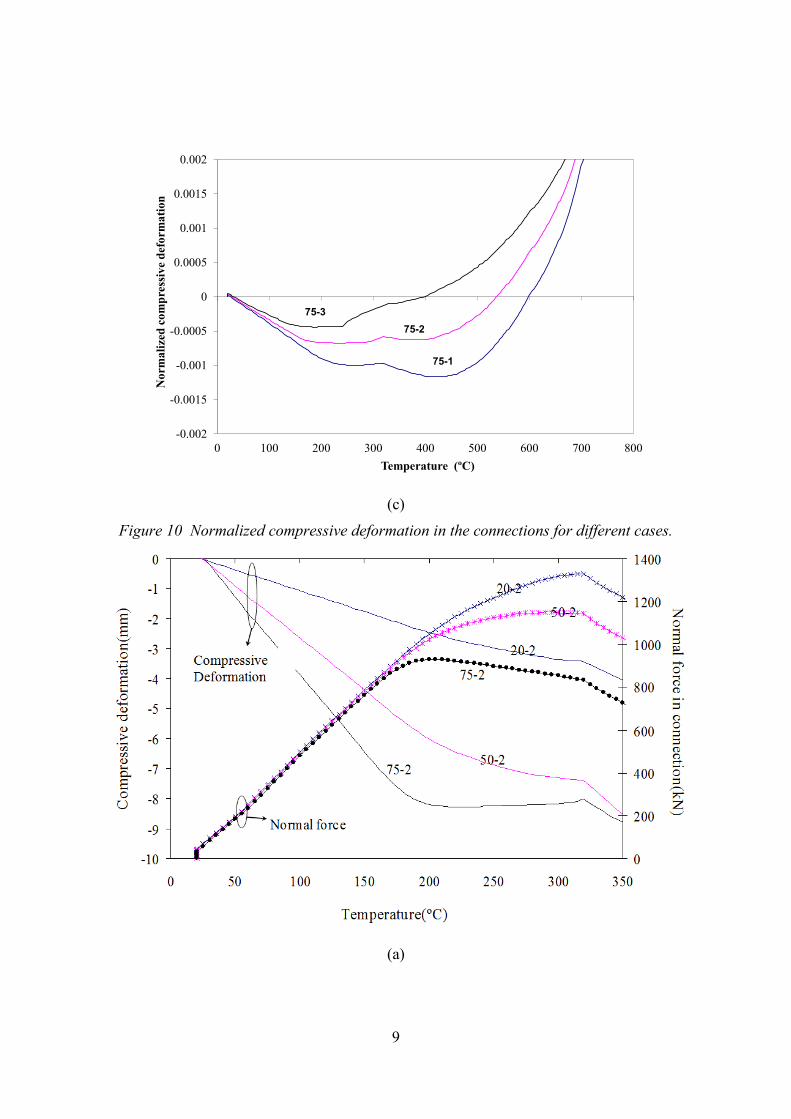
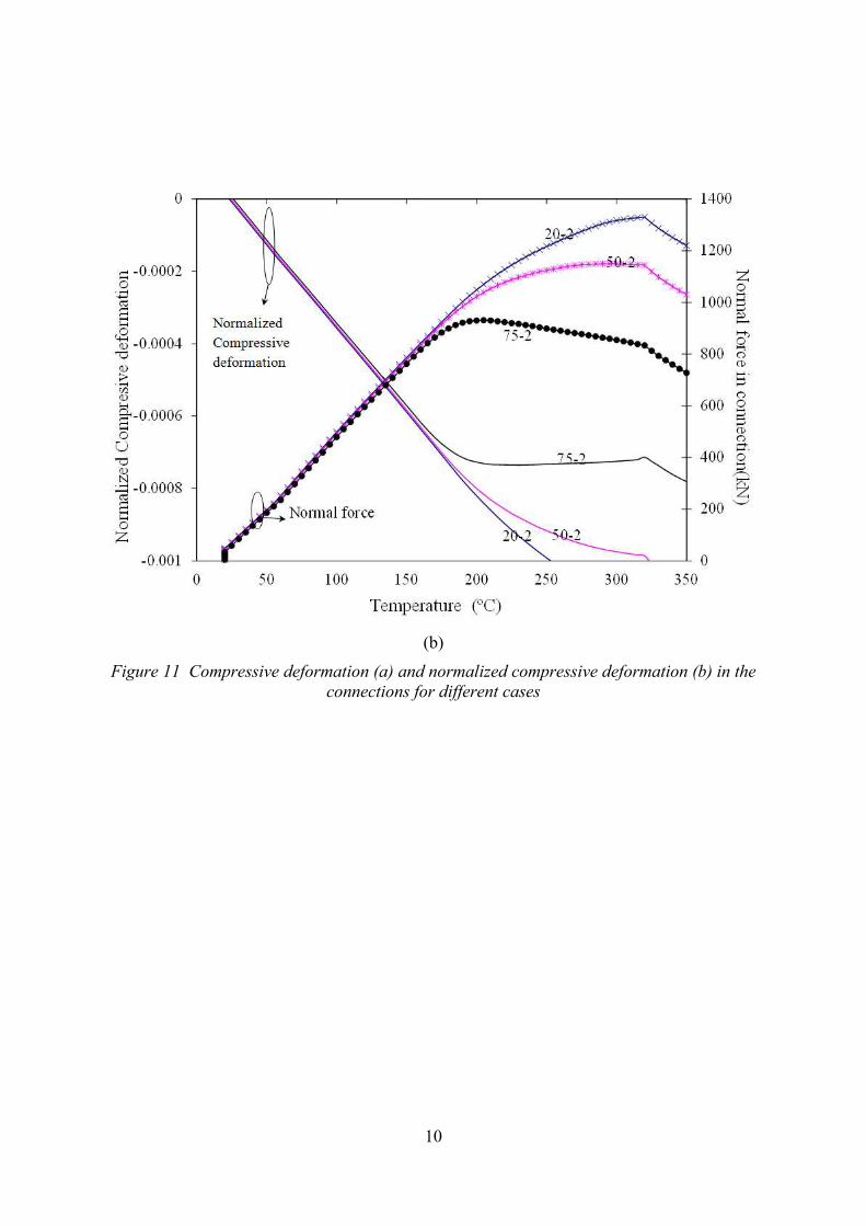
Figure 11(a) shows the development of compressive deformation in the connection during the
thermal expansion stage of Cases: 20-2, 50-2 and 75-2, which have beam slenderness ratios
of 20, 50, and 75 respectively. This comparison illustrates the effect of the length of the beam
on the development of compressive deformation within the connections. The axial
compressive forces in the connection in these cases are also plotted against temperature in
Figure 11. It can be seen that, in the thermal expansion stage, the longer beams generate
larger compressive deformations in the connections, and so require more compressive
ductility in order to avoid the connections contacting the connected column. Figure 11 (b)
shows the compressive deformation of the connections, normalized with respect to the length
of the beam, against temperature. It can be seen from Figure 11 that the normalized
compressive deformations are almost identical for these cases, and are independent of the
beam span in their thermal expansion stages, which is explained by Eqn. (18).
According to Eqn. (18), if plasticity is allowed to develop in the connections, their ductility
demand, in order to reduce the axial force in the connected beam, is also related to their axial
compressive capacities. The effect of the compressive axial strength of the connections on
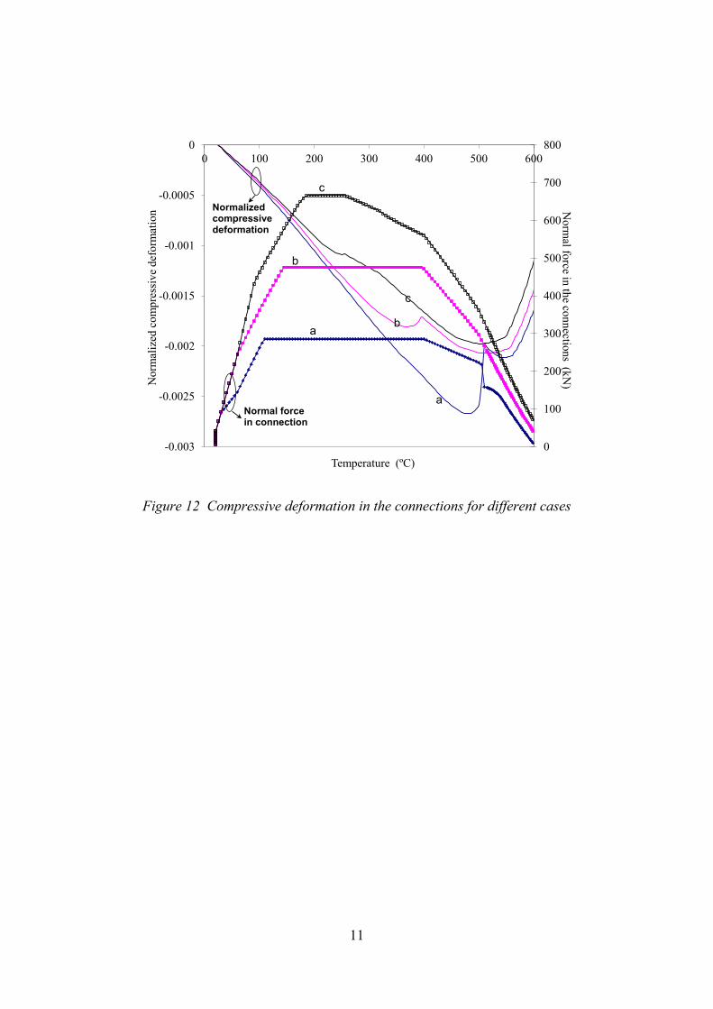
their compressive ductility demand is now studied. Table 4 lists the properties of the
connections in different cases. In these cases, in order to study the development of the
compressive deformation in the connections, it is assumed that the beam does not come into
contact with the column flange.
Figure 12 shows the normalized compressive axial deformations of the connections in each
case as temperature increases. This indicates that, if the connection is designed with less
strength, it develops more compressive deformation with temperature rise in the thermal
expansion stage, and therefore it needs higher compressive ductility to avoid contacting the
connected column.
24
6 Discussion
When exposed to fire, restrained steel beams develop significant compressive internal force
because of their thermal expansion, and the restraint maintains the robustness of the beam by
resisting tension in the later catenary stage. Currently, restrained beams are typically designed
as simple beams at ambient temperature, and the design approaches do not account for the
factors that influence the behaviour of beams in fire. The numerical studies presented above
illustrate that the ductility and strength of connections have a significant influence on the
response of restrained beams under fire conditions. These factors should be taken into
consideration in evaluating the robustness of restrained beams.
The current study shows that a proper design approach, which considers carefully the
ductility and strength of connections, can help restrained beams to achieve better fire
resistance. The designed-in tensile ductility of connections can reduce the catenary forces in
beams and thus improve their fire resistance. Equally, designed-in compressive ductility can
reduce the compressive forces in the heated beams due to their thermal expansion, and
therefore local buckling of the heated beams and the push-out effect on their connected
columns are less likely, or at least less severe. This indicates that connections with designed-
in ductility, both in tension and compression, can enhance the robustness of steel beams and
the integrity of the whole frame in fire. Simplified methods can also adequately predict the
ductility demand of connections, for predicted temperature regimes. However, more detailed
analysis and experimental studies are needed to quantify the effects of these ductilities, and
how to change the ductility of any particular connection.
7 Conclusion
Ductility within a connection denotes its deformation capacity. The ductile design of
connections is important for enhancement of structural robustness, since it relates to their
deformation capacity. A simplified model to predict the ductility demand of connections in
fire has been proposed. In order to test the influence of the ductility of connections on the
structural behaviour of beams under fire conditions, parametric studies using a simplified
connection model have been performed. The results of both the parametric studies and the
simplified method predictions indicate that the compressive ductility of connections is helpful
25
in reducing the push-out of perimeter columns and the possibility of local buckling of beams.
Tensile ductility contributes more to avoiding total connection failure and enhancing a
structure’s robustness, by reducing the catenary forces necessary for beams to carry their
loads at high temperatures. Provision of higher deformation capacity in the connections
allows larger deflection in the supported beams, substantially reducing the catenary forces in
the connections and consequently reducing the risk of structural collapse in fire.
References
1. Sun, R.R., Burgess, IW. , Huang, Z.H. and Dong, G., “Progressive Failure Modelling and Ductility Demand of Steel Beam-to-Column Connection in Fire”, Engineering Structures,
2015; 89:66-78.
2. Li, G.Q., He, J.L., and Jiang, S.C. (2000), "Fire-resistant experiment and theoretical
calculation of a steel beam", China Civil Engineering Journal 32(4): 23-26.
3. Liu, T.C.H., Fahad, M.K. and Davies, J.M. (2002), "Experimental investigation of
behaviour of axially restrained steel beams in fire", Journal of Constructional Steel
Research 58(9): 1211–1230.
4. Burgess, I.W., Davison, J.B., Huang, S.S. and Dong, G., 'The Role of Connections in the
Response of Steel Frames to Fire', Structural Engineering International, 22 (4), (2012)
pp449-461.
5. Yu, H.X., Burgess, I.W., Davison, J.B. and Plank, R.J., 'Experimental and Numerical
Investigations of the Behaviour of Flush Endplate Connections at Elevated
Temperatures',Journal of Structural Engineering, ASCE, 137 (1), (2011) pp 80-87.
6. Wang, Y.C. and Yin, Y. Z. (2006), "A simplified analysis of catenary action in steel
beams in fire and implications on fire resistant design", Steel and Composite Structures
5(6): 367-386.
7. Tan, K.H. and Huang, Z.F. (2005), "Structural responses of axially restrained steel beams
with semirigid moment connection in fire", Journal of Structural Engineering 131(4):
541-551.
8. Dwaikat, M. and Kodur, V. (2011), "Engineering Approach for Predicting Fire Response
of Restrained Steel Beams", Journal of Engineering Mechanics 137(7): 447-461.
9. Dwaikat, M. and Kodur, V. (2011), "A performance based methodology for fire design
of restrained steel beams", Journal of Constructional Steel Research 67(3): 510–524.
10. Sun RR, Huang ZH, Burgess IW., “Progressive collapse analysis of steel structures under
fire conditions”, Engineering Structures, 2012; 34:400–13.
11. Sun, R.R., Huang, Z.H. and Burgess, I.W., “The collapse behaviour of braced steel
frames exposed to fire”, Journal of Constructional Steel Research, 2012; 72:130–42.
12. Sun, R.R., Huang, Z.H. and Burgess, I.W., “A static/dynamic procedure for collapse
analysis of structure in fire”, Proc. Fire Safety Engineering in the UK: The State of the
Art,2010; 37-42.

26
13. Sun, R.R., ‘Numerical Modelling for Progressive Collapse of Steel Framed Structures in Fire’, PhD thesis, University of Sheffield, November 2012.
14. European Committee for Standardization (CEN), BS EN 1993-1-2, Eurocode 3: design of
steel structures, Part 1.2: General rules- structural fire design, British Standards
Institution, UK, 2005.
15. European Committee for Standardization (CEN), BS EN 1991-1-2, Eurocode 1:Actions
on structures-Part 1-2: General actions – Actions on structures exposed to fire, British
Standards Institution, UK, 2002.

1
Table List:
Table 1 Failure temperatures (°C) of cases with different stiffness, strength and ductility
Table 2 Properties of connections in compression in different cases
Table 3 Properties of connections in compression and slenderness ratio for different cases
Table 4 Properties of connections in compression in Case A, B and C

2
Table 1 Failure temperatures (°C) of cases with different stiffness, strength and ductility
膏 紅頂 c ,t m
0.005 0.01 0.03 0.05 0.07
50
0.02
0.084 619 639 677 703 749
0.167 637 671 719 763 799
0.334 665 705 779 835 893
0.667 699 783 857 937 No failure
0.1
0.084 625 639 675 701 747
0.167 649 671 719 763 799
0.334 673 711 781 835 893
0.667 701 771 861 941 No failure
0.5
0.084 626 640 677 705 745
0.167 651 671 719 763 800
0.334 674 712 783 837 892
0.667 705 772 860 943 No failure
Table 2 Properties of connections in compression in different cases
Cases Initial Axial
Stiffness (紅頂)
Axial Compressive
Strength( )
Compresive
Ductility( ,t m )
Case 1 0.42 ------ ------
Case 2 0.42 0.002 0.0015
Case 3 0.42 0.002 0.0030
Table 3 Properties of connections in compression and slenderness ratio for different cases
Slenderness
ratio(膏)
Compressive Axial
Stiffness (紅頂) Cases
20
0.21 20-1
0.42 20-2
0.84 20-3
50
0.21 50-1
0.42 50-2
0.84 50-3
75
0.21 75-1
0.42 75-2
0.84 75-3

3
Table 4 Properties of connections in compression in Case A, B and C (z=350mm is the lever-arm of the connections)
Slenderness
ratio(膏)
Compressive Axial
Strength ( ) Compressive Axial
Strength (紅頂)
Cases
50
0.3/z 0.42 A
0.5/z 0.42 B
0.7/z 0.42 C

1
Figure Captions
Figure 1 Simplified characteristics of a connections
Figure 2 Typical curve of normal force (N) in an axially restrained beam against temperature.
Figure 3 Equilibrium in a heated connected beam
Figure 4 (a) Generic connection model (T: tensile springs; C: compression springs); (b) The
beam with these connections at each end.
Figure 5 Mid-span beam displacement and axial force in connection against temperature: (a)
Mid-span displacement of beam; (b) Normal force in connection
Figure 6
different slenderness.
Figure 7 Ductility demand ( m ) for connections to beams of various load ratios with different
slenderness.
Figure 8 Normal forces in connections to beams with different load ratios.
Figure 9 Axial forces at mid-span of the beam for different cases
Figure 10 Normalized compressive deformation in the connections for different cases.
Figure 11 Compressive deformation (a) and normalized compressive deformation (b) in the
connections for different cases
Figure 12 Compressive deformation in the connections for different cases
2
Figure 1 Simplified characteristics of a connections
Figure 2 Typical curve of normal force (N) in an axially restrained beam against temperature.
Dcu,
Stage I
Tension
Stage III
Compression
B
Dtu,T
C
NTRd,T
D
NCRd,T
Stage II
Kt,T
Maximum compression
Kc,T
TB
Disp.
D
TC TD
倦槻┸脹軽脹眺鳥┸態待
Line 1
Line 2
軽寵陳銚掴┸脹
Connection failure
A Temperature
Axia
l fo
rce
Force
N

3
Figure 3 Equilibrium in a heated connected beam
(a)
(b)
Figure 4 (a) Generic connection model (T: tensile springs; C: compression springs); (b) The
beam with these connections at each end.
w
C
UDL(w)
l
T
l
x
T
z
Z
NT
Z: effective depth of the connection
MR
Beam
ME
C
MI
∆
Nv
x
z
4
(a)
(b)
Figure 5 Mid-span beam displacement and axial force in connection against temperature: (a)
Mid-span displacement of beam; (b) Normal force in connection

5
Figure 6 Ductility demand of the connections of strength ratio c=0.334 on beams with
different slenderness.
(a) 膏 噺 にど
6
(b) 膏 噺 のど
(c) 膏 噺 ばの
Figure 7 Ductility demand ( m ) for connections to beams
of various load ratios with different slenderness.

7
Figure 8 Normal forces in connections to beams with different load ratios.
Figure 9 Axial forces at mid-span of the beam for different cases
-1400
-1200
-1000
-800
-600
-400
-200
0
200
0 200 400 600 800 1000
Ax
ial
Fo
rce
(KN
)
Temperature ( C)
Series1
Series2
Series3
0.7=ߤ0.5=ߤ0.3=ߤ
-1400
-1200
-1000
-800
-600
-400
-200
0
200
0 200 400 600 800 1000
Ax
ial f
roce
in b
eam
s(k
N)
Temperature( C)
Case 1
Case 2
Case 3
8
(a)
(b)
-0.003
-0.0025
-0.002
-0.0015
-0.001
-0.0005
0
0.0005
0.001
0.0015
0.002
0 100 200 300 400 500 600 700 800
No
rma
lize
d c
om
pre
ssiv
e d
efo
rma
tio
n
Temperature (ºC)
20-1
20-2
20-3
-0.003
-0.0025
-0.002
-0.0015
-0.001
-0.0005
0
0.0005
0.001
0.0015
0.002
0 100 200 300 400 500 600 700 800
No
rma
lize
d c
om
pre
ssiv
e d
efo
rma
tio
n
Temperature (ºC)
50-1
50-2
50-3
9
(c)
Figure 10 Normalized compressive deformation in the connections for different cases.
(a)
-0.002
-0.0015
-0.001
-0.0005
0
0.0005
0.001
0.0015
0.002
0 100 200 300 400 500 600 700 800
No
rma
lize
d c
om
pre
ssiv
e d
efo
rma
tio
n
Temperature (ºC)
75-1
75-2
75-3
10
(b)
Figure 11 Compressive deformation (a) and normalized compressive deformation (b) in the
connections for different cases
11
Figure 12 Compressive deformation in the connections for different cases
0
100
200
300
400
500
600
700
800
-0.003
-0.0025
-0.002
-0.0015
-0.001
-0.0005
0
0 100 200 300 400 500 600N
orm
al force in
the co
nn
ection
s (kN
)No
rmal
ized
co
mp
ress
ive
def
orm
atio
n
Temperature (ºC)
Normalized compressive deformation
Normal force in connection
a
b
c
a
b
c


