
Aircraft Mission
Constraints analysisIntroduction
Concept of Constraints
Mathematical model
Aerodynamic Polar
Throttle Lapse
Flight phases
Mission analysisIntroduction
Aircraft weights
Cruise weight ratio
TSFC behavior
BCM/BCA
Takeoff weight estimation
Conclusions
8.108
Lecture 8Aircraft MissionText:
Motori AeronauticiMar. 22, 2016
Mauro ValoraniUniversità La Sapienza

Aircraft Mission
Constraints analysisIntroduction
Concept of Constraints
Mathematical model
Aerodynamic Polar
Throttle Lapse
Flight phases
Mission analysisIntroduction
Aircraft weights
Cruise weight ratio
TSFC behavior
BCM/BCA
Takeoff weight estimation
Conclusions
8.109
Agenda
1 Constraints analysisIntroductionConcept of ConstraintsMathematical model
Aerodynamic PolarThrottle Lapse
Flight phases
2 Mission analysisIntroductionAircraft weightsCruise weight ratio
TSFC behavior
BCM/BCATakeoff weight estimation
3 Conclusions

Aircraft Mission
Constraints analysisIntroduction
Concept of Constraints
Mathematical model
Aerodynamic Polar
Throttle Lapse
Flight phases
Mission analysisIntroduction
Aircraft weights
Cruise weight ratio
TSFC behavior
BCM/BCA
Takeoff weight estimation
Conclusions
8.110
The difficulties of engine design
Gas Turbine engines exert a dominant influence on aircraft performanceand must be custom tailored for each specific application.
⇒ Engine Specifications come from Aircraft Specifications
The design process is both started by and constrained by an identifiedneed
The process is inherently iterative

Aircraft Mission
Constraints analysisIntroduction
Concept of Constraints
Mathematical model
Aerodynamic Polar
Throttle Lapse
Flight phases
Mission analysisIntroduction
Aircraft weights
Cruise weight ratio
TSFC behavior
BCM/BCA
Takeoff weight estimation
Conclusions
8.111
The need : Request for Proposal (RFP)
It’s the mission specification that defines the desired engineperformance.
The aircraft customer describes the desired aircraft performance in adocument such as a Request for Proposal
Example:1 Takeoff, field is at 2000 ft pressure altitude. Takeoff ground roll must be
less than 2500 m at MTOW2 Takeoff rate of climb greater than 1000ft/min3 Subsonic cruise at Best Cruise Mach, maximum range 10000 km4 Payload of 60000 kg

Aircraft Mission
Constraints analysisIntroduction
Concept of Constraints
Mathematical model
Aerodynamic Polar
Throttle Lapse
Flight phases
Mission analysisIntroduction
Aircraft weights
Cruise weight ratio
TSFC behavior
BCM/BCA
Takeoff weight estimation
Conclusions
8.112
Design Process
Figure: Design process, schematic

Aircraft Mission
Constraints analysisIntroduction
Concept of Constraints
Mathematical model
Aerodynamic Polar
Throttle Lapse
Flight phases
Mission analysisIntroduction
Aircraft weights
Cruise weight ratio
TSFC behavior
BCM/BCA
Takeoff weight estimation
Conclusions
8.113
A Roadmap
DESIGN PROCESS⇒ Constraint and Mission AnalysisChoice of (TSL/WTO) and (WTO/S)Estimation of WTO to obtain TSL
ENGINE SELECTION⇒ Parametric Cycle Analysis and Performance
ENGINE COMPONENTS⇒ Components Sizing

Aircraft Mission
Constraints analysisIntroduction
Concept of Constraints
Mathematical model
Aerodynamic Polar
Throttle Lapse
Flight phases
Mission analysisIntroduction
Aircraft weights
Cruise weight ratio
TSFC behavior
BCM/BCA
Takeoff weight estimation
Conclusions
8.114
Design Process
MASS FLOW
CONSTRAINT&
MISSIONANALYSIS
PARAMETRICCYCLE
ANALYSIS
Mission Specs Efficiencies (1st attempt)
Thrust Cycle parameters (βc, T4, BPR, …)
Specific Thrust Ia
Componentsizing
Assumed TSFCbehavior with
h, V, δT
OFF-DESIGN
Geometries
Efficiencies (Actual)
Cross-section,blade profiles,combustor, …
Desired TSFCReference flight conditionTech limitation
Figure: Design process, schematic

Aircraft Mission
Constraints analysisIntroduction
Concept of Constraints
Mathematical model
Aerodynamic Polar
Throttle Lapse
Flight phases
Mission analysisIntroduction
Aircraft weights
Cruise weight ratio
TSFC behavior
BCM/BCA
Takeoff weight estimation
Conclusions
8.115
The concept of constraints
The requirements of the RFP can be converted into a series of functionalrelationships between:
the thrust-to-weight ratio at sea-level takeoff
TSL/WTO
the wing loading at takeoffWTO/S
We are looking for equations of the kind:
TSL/WTO = f (WTO/S)
for each of the requirements (flight phases).
These will represent constraints that have to be attained simultaneously.
Of course, many legitimate solutions exist, and none can be identified asoptimal or unique.
The "best" solution is always given by judgment and compromise.

Aircraft Mission
Constraints analysisIntroduction
Concept of Constraints
Mathematical model
Aerodynamic Polar
Throttle Lapse
Flight phases
Mission analysisIntroduction
Aircraft weights
Cruise weight ratio
TSFC behavior
BCM/BCA
Takeoff weight estimation
Conclusions
8.116
Constraints Diagram
Each requirement gives life to a curve in the constraint diagram.
The solution space is the region above all the curves
For a given WTO , a low WTO/S means large wing area and increased drag,while a high TSL/WTO results in a large thrust requirement. One may prefer,therefore, relatively low thrust and high wing loadings.

Aircraft Mission
Constraints analysisIntroduction
Concept of Constraints
Mathematical model
Aerodynamic Polar
Throttle Lapse
Flight phases
Mission analysisIntroduction
Aircraft weights
Cruise weight ratio
TSFC behavior
BCM/BCA
Takeoff weight estimation
Conclusions
8.117
Constraints DiagramDesign points of actual passenger/cargo aircrafts.
The selected design point is very sensitive to the application and thepreferences of the designer.
1 lbfft2
= 47.88 Nm2
Aircraft Mission
Constraints analysisIntroduction
Concept of Constraints
Mathematical model
Aerodynamic Polar
Throttle Lapse
Flight phases
Mission analysisIntroduction
Aircraft weights
Cruise weight ratio
TSFC behavior
BCM/BCA
Takeoff weight estimation
Conclusions
8.118
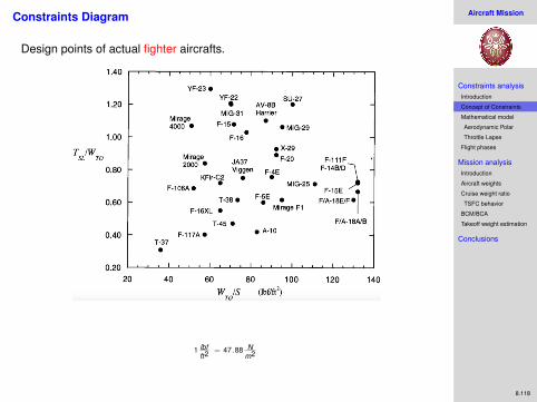
Constraints Diagram
Design points of actual fighter aircrafts.
1 lbfft2
= 47.88 Nm2
Aircraft Mission
Constraints analysisIntroduction
Concept of Constraints
Mathematical model
Aerodynamic Polar
Throttle Lapse
Flight phases
Mission analysisIntroduction
Aircraft weights
Cruise weight ratio
TSFC behavior
BCM/BCA
Takeoff weight estimation
Conclusions
8.119
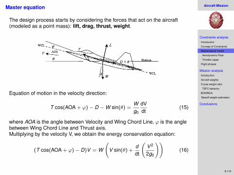
Master equation
The design process starts by considering the forces that act on the aircraft(modeled as a point mass): lift, drag, thrust, weight.
Equation of motion in the velocity direction:
T cos(AOA + ϕ)− D −W sin(θ) =Wg0
dVdt
(15)
where AOA is the angle between Velocity and Wing Chord Line, ϕ is the anglebetween Wing Chord Line and Thrust axis.Multiplying by the velocity V, we obtain the energy conservation equation:
(T cos(AOA + ϕ)− D)V = W
(V sin(θ) +
ddt
(V 2
2g0
))(16)
Aircraft Mission
Constraints analysisIntroduction
Concept of Constraints
Mathematical model
Aerodynamic Polar
Throttle Lapse
Flight phases
Mission analysisIntroduction
Aircraft weights
Cruise weight ratio
TSFC behavior
BCM/BCA
Takeoff weight estimation
Conclusions
8.120
Master equation
Assuming small angles of attack (AOA ≈ 0) and small thrust vectormisalignments with V (ϕ ≈ 0), and recalling that V Sinθ = dh
dt :
V(T − D)
W=
d(
V 2
2g0+ h)
dt=
dze
dt= Ps (17)
where ze represents the aircraft mechanical energy (kinetic + potential) andis often referred to as "energy height".
Ps is the time rate of change of the energy height and is called weight specificexcess power.
Isolating the thrust-to-weight ratio at LHS:
TW
=DW
+Ps
V(18)
Here, both T and W depend on the flight condition and mission phase.

Aircraft Mission
Constraints analysisIntroduction
Concept of Constraints
Mathematical model
Aerodynamic Polar
Throttle Lapse
Flight phases
Mission analysisIntroduction
Aircraft weights
Cruise weight ratio
TSFC behavior
BCM/BCA
Takeoff weight estimation
Conclusions
8.121
Master equation: assumptions for T and W
It is assumed that the installed thrust and the actual aircraft weight are given by(SL=Sea Level Static, TO=Take-Off):
T = αTSL (19)
W = βWTO (20)
where α is the full throttle thrust lapse (dependent on altitude, speed andafterburner on/off) and β depends on how much fuel has been consumed.
The equation becomes:
TSL
WTO=β
α
(D
βWTO+
Ps
V
)(21)

Aircraft Mission
Constraints analysisIntroduction
Concept of Constraints
Mathematical model
Aerodynamic Polar
Throttle Lapse
Flight phases
Mission analysisIntroduction
Aircraft weights
Cruise weight ratio
TSFC behavior
BCM/BCA
Takeoff weight estimation
Conclusions
8.122
Aerodynamic polar
Recall that lift can be expressed through the lift coefficient as follows:
L = nW =12ρV 2SCL = qSCL q :=
12ρV 2 (22)
⇒ CL =nWqS
=nβq
WTO
S(23)
and that also drag has a similar expression:
D = qCDS (24)
where CD can be expressed through the aerodynamic lift-drag polar:
CD = CD0 + K1C2L + K2CL (25)

Aircraft Mission
Constraints analysisIntroduction
Concept of Constraints
Mathematical model
Aerodynamic Polar
Throttle Lapse
Flight phases
Mission analysisIntroduction
Aircraft weights
Cruise weight ratio
TSFC behavior
BCM/BCA
Takeoff weight estimation
Conclusions
8.123
Aerodynamic polar
Conventional form:
CD = CDmin + K ′C2L + K ′′(CL − CLmin )2 (26)
where:
K ′ is the induced drag (inviscid drag due to lift)
K ′′ is the skin+pressure drag (viscous drag due to lift)
Expanding:
CD = (K ′ + K ′′)C2L − (2K ′′CLmin )CL + (CDmin + K ′′C2
Lmin)
or:CD = CD0 + K1C2
L + K2CL (27)
where
K1 = K ′ + K ′′
K2 = −2K ′′CLmin
CD0 = CDmin + K ′′C2Lmin
Assumptions widely used:
K1 = 1πARe
K2 ' 0

Aircraft Mission
Constraints analysisIntroduction
Concept of Constraints
Mathematical model
Aerodynamic Polar
Throttle Lapse
Flight phases
Mission analysisIntroduction
Aircraft weights
Cruise weight ratio
TSFC behavior
BCM/BCA
Takeoff weight estimation
Conclusions
8.124
The equation:TSL
WTO=β
α
(D
βWTO+
Ps
V
)(28)
becomes, using the expression D = qCDS and the aerodynamic polar:
TSL
WTO=β
α
{q
β(WTO/S)
[k1C2
L + k2CL + CD0
]+
Ps
V
}(29)
and using the expression for CL = nβq
WTOS :
TSLWTO
= βα
{q
β(WTO/S)
[k1
(nβq (WTO/S)
)2+ k2
(nβq (WTO/S)
)+ CD0
]+ Ps
V
}(30)
This equation is the sought after TSL/WTO = f (WTO/S) which depends on
flight conditions (α, β, V , ρ, n, PS)
aircraft aerodynamic features (CD0 , k1[AR, e], k2)

Aircraft Mission
Constraints analysisIntroduction
Concept of Constraints
Mathematical model
Aerodynamic Polar
Throttle Lapse
Flight phases
Mission analysisIntroduction
Aircraft weights
Cruise weight ratio
TSFC behavior
BCM/BCA
Takeoff weight estimation
Conclusions
8.125
Throttle Lapse (α)
The available thrust is expressed as:
T = αTSL
The meaning of α is NOT that of a throttle setting, but rather that of aoff-design engine behavior, affected by flight conditions.
It can be obtained from full off-design runs or from semi-empirical models.
Flight conditions (altitude and Mach number) are often blended together into asingle parameter: the Dimensionless Freestream Total Temperature θ0
θ0 :=T0a
TSL=
Ta
(1 + (γ−1)
2 M2a
)TSL
(31)
where
0 = total
a = freestream
SL = (Standard day) Sea Level⇒ TSL = 15C

Aircraft Mission
Constraints analysisIntroduction
Concept of Constraints
Mathematical model
Aerodynamic Polar
Throttle Lapse
Flight phases
Mission analysisIntroduction
Aircraft weights
Cruise weight ratio
TSFC behavior
BCM/BCA
Takeoff weight estimation
Conclusions
8.126
Constant θ0 contours
note that: θ0 = 1 at sea level static conditions, θ0 can be greater or less than 1,θ0 depends only on Mach number above the tropopause (being T0 constant),the range of θ0 of today’s aircrafts is 0.8 /1.4

Aircraft Mission
Constraints analysisIntroduction
Concept of Constraints
Mathematical model
Aerodynamic Polar
Throttle Lapse
Flight phases
Mission analysisIntroduction
Aircraft weights
Cruise weight ratio
TSFC behavior
BCM/BCA
Takeoff weight estimation
Conclusions
8.127
Engine behavior
The engine compressor pressure ratio πc depends upon
the turbine temperature ratio τt
the throttle setting T04
the flight conditions θ0
With the hypothesis of choked turbine (≡ constant temperature ratio τt ), it can
be demonstrated that πc varies only with the ratioT04θ0
.
From the TurboJet power balance [ −(ma + mf )LT = maLC ]:
ηm(1 + f )(h04 − h05) = h03 − h02 (32)
τc − 1 = ηm(1 + f ) (1− τt )1
TSL
(cpt T04)
(cpc θ0); τ :=
h0dn
h0up
; T02 ≈ T0a (33)
⇒ πc = [1 + ηc (τc − 1)]γγ−1 =
(1 + C1
T04
θ0
)γγ−1 (34)
where the constant C1 is:
C1 = ηcηm(1 + f ) (1− τt )1
TSL
cpt
cpc

Aircraft Mission
Constraints analysisIntroduction
Concept of Constraints
Mathematical model
Aerodynamic Polar
Throttle Lapse
Flight phases
Mission analysisIntroduction
Aircraft weights
Cruise weight ratio
TSFC behavior
BCM/BCA
Takeoff weight estimation
Conclusions
8.128
Engine behavior (cont’d)
We came up with the relationship between πc and the ratio T04θ0
πc =
(1 + C1
T04
θ0
)γγ−1
it follows that πc increases as the ratio T04θ0
increases.
Example:
with fixed Mach number and throttle setting, πc increases if the aircraftclimbs to higher altitudes (thus θ0 diminishes)
πc diminishes if, for fixed altitude and throttle setting, the aircraft isaccelerated to higher Mach numbers
Aircraft Mission
Constraints analysisIntroduction
Concept of Constraints
Mathematical model
Aerodynamic Polar
Throttle Lapse
Flight phases
Mission analysisIntroduction
Aircraft weights
Cruise weight ratio
TSFC behavior
BCM/BCA
Takeoff weight estimation
Conclusions
8.129
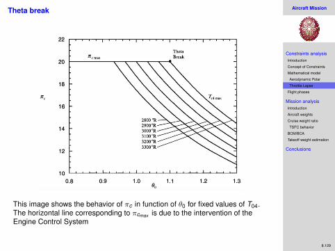
Theta break
This image shows the behavior of πc in function of θ0 for fixed values of T04.The horizontal line corresponding to πcmax is due to the intervention of theEngine Control System

Aircraft Mission
Constraints analysisIntroduction
Concept of Constraints
Mathematical model
Aerodynamic Polar
Throttle Lapse
Flight phases
Mission analysisIntroduction
Aircraft weights
Cruise weight ratio
TSFC behavior
BCM/BCA
Takeoff weight estimation
Conclusions
8.130
Theta Break (cont’d)
Role of the Engine Control System
Prevent aircraft engines from operating outside their safety margins, such as:
maximum compressor pressure ratio (preventing stall phenomena)
maximum cycle temperature (preventing the turbine to overheat)
These two limits are clearly visible in the previous slide.
The ECS has two logics of operation:when πc is below its maximum allowable value, it limits the maximumallowable temperature reducing πc itself
if πc reaches its maximum, it reduces T04
The value of θ0 at which the control logic switches from limiting πc to limitingT04 is known as:
θ0break

Aircraft Mission
Constraints analysisIntroduction
Concept of Constraints
Mathematical model
Aerodynamic Polar
Throttle Lapse
Flight phases
Mission analysisIntroduction
Aircraft weights
Cruise weight ratio
TSFC behavior
BCM/BCA
Takeoff weight estimation
Conclusions
8.131
The importance of Theta Break in the design phase
At any flight condition different from θ0 = θ0break the engine cannot beoperated at its maximum compressor pressure ratio and maximum cycletemperature simultaneously.
If θ0 < θ0break the engine can be operated at πcmax but T04 < T04max(obtaining less specific thrust than nominal)
if θ0 < θ0break the engine can be operated at T04max but πc < πcmax (withgreater fuel consumption than nominal)
The engine designer would therefore have the engine operating as closer aspossible to θ0 = θ0break and this can be done with a wise choice of θ0break
The design with θ0break = 1 implies MAX THRUST AT SEA LEVEL STATIC
A design with θ0break > 1 may be advisable for supersonic aircrafts

Aircraft Mission
Constraints analysisIntroduction
Concept of Constraints
Mathematical model
Aerodynamic Polar
Throttle Lapse
Flight phases
Mission analysisIntroduction
Aircraft weights
Cruise weight ratio
TSFC behavior
BCM/BCA
Takeoff weight estimation
Conclusions
8.132
How to design Theta Break?
Recalling from eq. (34) that the control system acts to maintain the ratioTt4θ0
constant in order to keep πc = πcmax = constant, it follows immediately that, inthe case of θ0break ≥ 1:
T04max
θ0break
=
(T04
θ0
)πcmax
=
(T04SL
θ0SL
)πcmax
= T04SL(35)
being θ0SL= 1.
The engine has to be designed to have T04SLgiven by eq. (35), that is the ratio
between the maximum allowable and the desired θ0break .
Defining the Thottle Ratio as the ratio between the maximum allowabletemperature and the sea-level-static temperature:
TR :=T04max
T04SL
= θ0break (36)
it follows that TR is identical to θ0break .

Aircraft Mission
Constraints analysisIntroduction
Concept of Constraints
Mathematical model
Aerodynamic Polar
Throttle Lapse
Flight phases
Mission analysisIntroduction
Aircraft weights
Cruise weight ratio
TSFC behavior
BCM/BCA
Takeoff weight estimation
Conclusions
8.133
Throttle Lapse
Example of engine behavior with varying Mach and altitude. It was obtainedwith semi-empirical models of the kind:
α = f [h,M,TR] (TR fixed by design) (37)
Figure: Throttle Lapse of two Low-BPR-TurboFan (one with TR=1.0 and one with TR=1.1)as a function of Mach with varying altitude
Remember that T = αTSL

Aircraft Mission
Constraints analysisIntroduction
Concept of Constraints
Mathematical model
Aerodynamic Polar
Throttle Lapse
Flight phases
Mission analysisIntroduction
Aircraft weights
Cruise weight ratio
TSFC behavior
BCM/BCA
Takeoff weight estimation
Conclusions
8.134
Flight Phases
The "master equation" (eq. 30) can be specialized for each flight phase, inorder to obtain the constraints that have to be attained to satisfy the RFP.
The following cases will be analyzed:
Constant altitude/speed cruise
Constant altitude/speed turn
Takeoff Roll
All the other flight phases can be obtained similarly and easily

Aircraft Mission
Constraints analysisIntroduction
Concept of Constraints
Mathematical model
Aerodynamic Polar
Throttle Lapse
Flight phases
Mission analysisIntroduction
Aircraft weights
Cruise weight ratio
TSFC behavior
BCM/BCA
Takeoff weight estimation
Conclusions
8.135
Constant altitude/speed cruise
Master equation (eqn. 30):
TSLWTO
= βα
{q
β(WTO/S)
[k1
(nβq (WTO/S)
)2+ k2
(nβq (WTO/S)
)+ CD0
]+ Ps
V
}Known quantities:
Constant altitude and speed⇒ dhdt = 0 dV
dt = 0⇒ PS = 0
Level flight⇒ n = 1 (L = W )
Aerodynamic polar (assigned): k1, k2, CD0 as functions of M, AR, e
Assumptions:
β = 0.7÷ 0.9 (an high enough value to simulate the beginning of thecruise phase, which is the more demanding scenario)
The requirements are given in terms of:
Desired cruise altitude h
Desired cruise Mach number M
Altitude and Mach number appear in:
α(h,M)
q = 12ρ∞(h)V 2
∞ = 12γp∞(h)M2
∞
Aerodynamic polar (CD depends on Mach)

Aircraft Mission
Constraints analysisIntroduction
Concept of Constraints
Mathematical model
Aerodynamic Polar
Throttle Lapse
Flight phases
Mission analysisIntroduction
Aircraft weights
Cruise weight ratio
TSFC behavior
BCM/BCA
Takeoff weight estimation
Conclusions
8.136
Constant altitude/speed cruise (cont’d)
Figure: Constant altitude/speed cruise constraint. h = 11000 m, M = 0.85
The minimum of the curve is found at:
[WTO
S
]minT/W
= qβ
√CD0K1
⇒[
TSLWTO
]min
= βα
{2√
CD0 K1 + K2
}which is the condition of minimum thrust and drag (maximum range)
Aircraft Mission
Constraints analysisIntroduction
Concept of Constraints
Mathematical model
Aerodynamic Polar
Throttle Lapse
Flight phases
Mission analysisIntroduction
Aircraft weights
Cruise weight ratio
TSFC behavior
BCM/BCA
Takeoff weight estimation
Conclusions
8.137
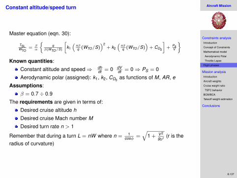
Constant altitude/speed turn
Master equation (eqn. 30):
TSLWTO
= βα
{q
β(WTO/S)
[k1
(nβq (WTO/S)
)2+ k2
(nβq (WTO/S)
)+ CD0
]+ Ps
V
}Known quantities:
Constant altitude and speed⇒ dhdt = 0 dV
dt = 0⇒ PS = 0
Aerodynamic polar (assigned): k1, k2, CD0 as functions of M, AR, e
Assumptions:
β = 0.7÷ 0.9
The requirements are given in terms of:
Desired cruise altitude h
Desired cruise Mach number M
Desired turn rate n > 1
Remember that during a turn L = nW where n = 1cosφ =
√1 + V 2
g0r (r is theradius of curvature)

Aircraft Mission
Constraints analysisIntroduction
Concept of Constraints
Mathematical model
Aerodynamic Polar
Throttle Lapse
Flight phases
Mission analysisIntroduction
Aircraft weights
Cruise weight ratio
TSFC behavior
BCM/BCA
Takeoff weight estimation
Conclusions
8.138
Constant altitude/speed turn (cont’d)
Figure: Constant altitude/speed turn constraint. h = 11000 m, M = 0.85, n = 1.1

Aircraft Mission
Constraints analysisIntroduction
Concept of Constraints
Mathematical model
Aerodynamic Polar
Throttle Lapse
Flight phases
Mission analysisIntroduction
Aircraft weights
Cruise weight ratio
TSFC behavior
BCM/BCA
Takeoff weight estimation
Conclusions
8.139
Takeoff Ground RollMaster equation (eqn. 18):
V (T − D)
W=
d(
V 2
2g0+ h)
dt
the takeoff ground roll distance is obtained with the assumption of constantaltitude dh/dt = 0 and TSL >> D:
TSL
WTO=
β
αg0
dVdt
which can be rearranged to (dt = ds/V ):
ds =β
αg0
WTO
TSLVdV
and integrated to yield:
sG =β
αg0
WTO
TSL
V 2TO
2g0
Being:12ρSV 2
STALLCLmax = βWTO
where VTO = kTOVSTALL and kTO ≈ 1.2, the equation can be recast to give:
sG =β2
α
k2TO
(TSL/WTO) ρ g0CLmax
(WTO
S
)

Aircraft Mission
Constraints analysisIntroduction
Concept of Constraints
Mathematical model
Aerodynamic Polar
Throttle Lapse
Flight phases
Mission analysisIntroduction
Aircraft weights
Cruise weight ratio
TSFC behavior
BCM/BCA
Takeoff weight estimation
Conclusions
8.140
Takeoff Ground Roll (cont’d)
The ground roll distance equation:
sG =β2
α
k2TO
(TSL/WTO) ρ g0CLmax
(WTO
S
)tells that the ground roll distance is inversely proportional to:
density ρ, which is function of altitude and temperature. High elevationairports and hot days deteriorate take-off performance.
aerodynamic performance CLmax , whose value is increased by the useof high lift devices (slats, flaps, ...)
Aircraft Mission
Constraints analysisIntroduction
Concept of Constraints
Mathematical model
Aerodynamic Polar
Throttle Lapse
Flight phases
Mission analysisIntroduction
Aircraft weights
Cruise weight ratio
TSFC behavior
BCM/BCA
Takeoff weight estimation
Conclusions
8.141
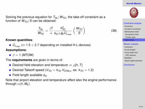
Solving the previous equation for TSL/WTO , the take-off constraint as afunction of WTO/S can be obtained:
TSL
WTO=β2
α
k2TO
sG ρ g0CLmax
(WTO
S
)(38)
Known quantities:
CLmax (≈ 1.5÷ 2.7 depending on installed H-L-devices)
Assumptions:
β = 1 (MTOW)
The requirements are given in terms of:
Desired field elevation and temperature⇒ ρ[h,T ]
Desired Takeoff speed (VTO = kTO VSTALL, es: kTO = 1.2)
Field length available sG
Note that airport elevation and temperature affect also the engine performancethrough α(h,M0)

Aircraft Mission
Constraints analysisIntroduction
Concept of Constraints
Mathematical model
Aerodynamic Polar
Throttle Lapse
Flight phases
Mission analysisIntroduction
Aircraft weights
Cruise weight ratio
TSFC behavior
BCM/BCA
Takeoff weight estimation
Conclusions
8.142
Takeoff Roll (cont’d)
The relationship is linear
Figure: Takeoff Roll. h = 1500 m, CLmax = 2.4, sG = 2000 m, HOT (ISA +30) vs COLD(ISA +0) day

Aircraft Mission
Constraints analysisIntroduction
Concept of Constraints
Mathematical model
Aerodynamic Polar
Throttle Lapse
Flight phases
Mission analysisIntroduction
Aircraft weights
Cruise weight ratio
TSFC behavior
BCM/BCA
Takeoff weight estimation
Conclusions
8.143
Constraint diagram
Cases analyzed: constant altitude/speed cruise, constant altitude/speed turn,takeoff roll, horizontal acceleration, service ceiling
Figure: All constraints
The solution space is the white region over the constraint curves. We canchoose:
TSL
WTOand
WTO
S
Aircraft Mission
Constraints analysisIntroduction
Concept of Constraints
Mathematical model
Aerodynamic Polar
Throttle Lapse
Flight phases
Mission analysisIntroduction
Aircraft weights
Cruise weight ratio
TSFC behavior
BCM/BCA
Takeoff weight estimation
Conclusions
8.144
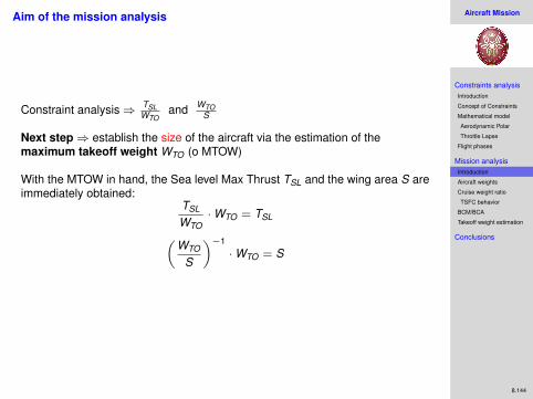
Aim of the mission analysis
Constraint analysis⇒ TSLWTO
and WTOS
Next step⇒ establish the size of the aircraft via the estimation of themaximum takeoff weight WTO (o MTOW)
With the MTOW in hand, the Sea level Max Thrust TSL and the wing area S areimmediately obtained:
TSL
WTO·WTO = TSL(
WTO
S
)−1·WTO = S

Aircraft Mission
Constraints analysisIntroduction
Concept of Constraints
Mathematical model
Aerodynamic Polar
Throttle Lapse
Flight phases
Mission analysisIntroduction
Aircraft weights
Cruise weight ratio
TSFC behavior
BCM/BCA
Takeoff weight estimation
Conclusions
8.145
Who is WTO?
WTO is the sum of 3 main contributions:empty weight WE
aircraft structuresequipments (engines, avionics, seats, etc.)
payload weight WP
fuel weight WF
WTO = WE + WP + WF (39)
The sum of Empty weight and Payload weight is the Maximum Zero FuelWeight (MZFW)
it follows that:WTO =
WP
1− WFWTO− WE
WTO
(40)
The fuel weight WF represents the fuel gradually consumed during themission: the aircraft weight decreases at exactly the same rate at the which thefuel is consumed:
dWdt
= −dWF
dt= −TSFC · T (41)
Aircraft Mission
Constraints analysisIntroduction
Concept of Constraints
Mathematical model
Aerodynamic Polar
Throttle Lapse
Flight phases
Mission analysisIntroduction
Aircraft weights
Cruise weight ratio
TSFC behavior
BCM/BCA
Takeoff weight estimation
Conclusions
8.146
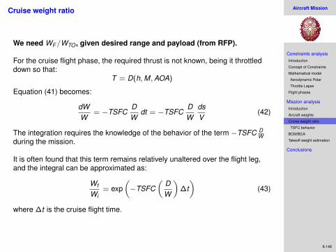
Cruise weight ratio
We need WF/WTO , given desired range and payload (from RFP).
For the cruise flight phase, the required thrust is not known, being it throttleddown so that:
T = D(h,M,AOA)
Equation (41) becomes:
dWW
= −TSFCDW
dt = −TSFCDW
dsV
(42)
The integration requires the knowledge of the behavior of the term −TSFC DW
during the mission.
It is often found that this term remains relatively unaltered over the flight leg,and the integral can be approximated as:
Wf
Wi= exp
(−TSFC
(DW
)∆t)
(43)
where ∆t is the cruise flight time.

Aircraft Mission
Constraints analysisIntroduction
Concept of Constraints
Mathematical model
Aerodynamic Polar
Throttle Lapse
Flight phases
Mission analysisIntroduction
Aircraft weights
Cruise weight ratio
TSFC behavior
BCM/BCA
Takeoff weight estimation
Conclusions
8.147
TSFC behavior
We now seek the behavior of TSFC with varying flight conditions.
TSFC is a complex function of the combination of instantaneous altitude,speed and throttle setting
A satisfactory approximation for this design stage is the following:
TSFC ≈ (C1 + C2M) (44)
where C1 and C2 are constants that are known in advance for each type ofengine cycle.
Aircraft Mission
Constraints analysisIntroduction
Concept of Constraints
Mathematical model
Aerodynamic Polar
Throttle Lapse
Flight phases
Mission analysisIntroduction
Aircraft weights
Cruise weight ratio
TSFC behavior
BCM/BCA
Takeoff weight estimation
Conclusions
8.148
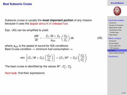
Best Subsonic Cruise
Subsonic cruise is usually the most important portion of any missionbecause it uses the largest amount of onboard fuel.
Eqn. (42) can be simplified to yield:
dWW
= −C1/M + C2
astd
(CD
CL
)ds (45)
where astd is the speed of sound for ISA conditions.Best Cruise condition⇒ minimum fuel consumption⇒
min[
(C1/M + C2)
(CD
CL
)]= (C1/M? + C2)
(C?DC?L
)
The best cruise is identified by the values M?, C?L , C?D
Next task: find their expressions

Aircraft Mission
Constraints analysisIntroduction
Concept of Constraints
Mathematical model
Aerodynamic Polar
Throttle Lapse
Flight phases
Mission analysisIntroduction
Aircraft weights
Cruise weight ratio
TSFC behavior
BCM/BCA
Takeoff weight estimation
Conclusions
8.149
Best Subsonic Cruise Mach number
Below the critical drag rise Mach number MCRIT (approximately 0.8), neitherCL nor CD depend on M.
In this range:CD
CL=
CD0 + K1C2L + K2CL
CL(46)
whose minimum can be found differentiating with respect to CL:
(CD
CL
)∗=√
4K1(CD0
)+ K2 at C∗L =
√CD0
K1(47)
which is the maximum efficiency CL, as expected.
Next, because the lowest achievable value of(
CDCL
)is constant below MCRIT , it
follows that:
(C1/M + C2)(
CDCL
)decreases as M increases
Further increases past MCRIT cause(
CDCL
)to increase again
⇒ M? = MCRIT
Aircraft Mission
Constraints analysisIntroduction
Concept of Constraints
Mathematical model
Aerodynamic Polar
Throttle Lapse
Flight phases
Mission analysisIntroduction
Aircraft weights
Cruise weight ratio
TSFC behavior
BCM/BCA
Takeoff weight estimation
Conclusions
8.150
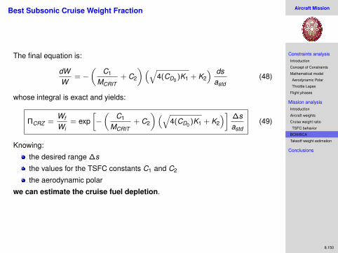
Best Subsonic Cruise Weight Fraction
The final equation is:
dWW
= −(
C1
MCRIT+ C2
)(√4(CD0 )K1 + K2
) dsastd
(48)
whose integral is exact and yields:
ΠCRZ =Wf
Wi= exp
[−(
C1
MCRIT+ C2
)(√4(CD0 )K1 + K2
)] ∆sastd
(49)
Knowing:
the desired range ∆s
the values for the TSFC constants C1 and C2
the aerodynamic polar
we can estimate the cruise fuel depletion.
Aircraft Mission
Constraints analysisIntroduction
Concept of Constraints
Mathematical model
Aerodynamic Polar
Throttle Lapse
Flight phases
Mission analysisIntroduction
Aircraft weights
Cruise weight ratio
TSFC behavior
BCM/BCA
Takeoff weight estimation
Conclusions
8.151
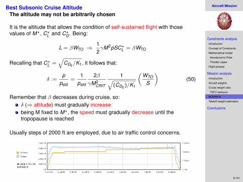
Best Subsonic Cruise AltitudeThe altitude may not be arbitrarily chosen
It is the altitude that allows the condition of self-sustained flight with thosevalues of M?, C?L and C?D . Being:
L = βWTO ⇒12γM2pSC?L = βWTO
Recalling that C?L =√
CD0/K1, it follows that:
δ :=p
pstd=
1pstd
2βγM2
CRIT
1√(CD0 )/K1
(WTO
S
)(50)
Remember that β decreases during cruise, so:δ (⇒ altitude) must gradually increasebeing M fixed to M?, the speed must gradually decrease until thetropopause is reached
Usually steps of 2000 ft are employed, due to air traffic control concerns.

Aircraft Mission
Constraints analysisIntroduction
Concept of Constraints
Mathematical model
Aerodynamic Polar
Throttle Lapse
Flight phases
Mission analysisIntroduction
Aircraft weights
Cruise weight ratio
TSFC behavior
BCM/BCA
Takeoff weight estimation
Conclusions
8.152
Takeoff weight estimation
Recalling eqn. 39WTO = WE + WP + WF (51)
it follows that:WTO =
WP
1− WFWTO− WE
WTO
(52)
WP is the desired payload weightWFWTO
is the product of the weight ratios of all the phases of flight (weexamined best cruise only)WEWTO
can be estimated with empirical models as a function of WTO
N.B. The calculations of WTO requires an iterative procedure because of thedependence of WE
WTOon WTO
Aircraft Mission
Constraints analysisIntroduction
Concept of Constraints
Mathematical model
Aerodynamic Polar
Throttle Lapse
Flight phases
Mission analysisIntroduction
Aircraft weights
Cruise weight ratio
TSFC behavior
BCM/BCA
Takeoff weight estimation
Conclusions
8.153
What we have done so far and what’s next
Done:
RFP⇒ Constraints on TSL/WTO and WTO/S
First attempt choice of TSL/WTO and WTO/S
Mission Analysis⇒WTO ⇒ TSL
Next: How to achieve this TSL?
We have performance to meet (TSFC)
We have design limitations (T4max , βCmax , etc.)
We can play with design parameters (BPR, βF , βC , etc.)
⇒ Parametric Cycle Analysis and Performance estimation


