MINI-SPACE380-415/3/50
© STULZ GmbH, Hamburg
AIR CONDITIONING
INDEX 20
Issue 10.07
A/C UNITS
OPERATING INSTRUCTIONS
PRECISION A/C UNITS


E/1007/20/3
Contents
1. Safety ...........................................................................................................................41.1 Regulations ....... 41.2 Marking .............. 41.3 Safety instructions .............................................................................................................................51.4 Handling refrigerants .........................................................................................................................51.5 Safety and environmental requirements ............................................................................................6
2. Type code ....................................................................................................................73. Description ..................................................................................................................8
3.1 Design of CCD 41 - 121 A ...............................................................................................................123.2 Design of CCD 171/201 A ...............................................................................................................143.3 Design of CCU 41 - 121 G ..............................................................................................................163.4 Design of CCU 171/201 G ...............................................................................................................183.5 Application Ranges .........................................................................................................................20
4. Technical Data ..........................................................................................................214.1 Sound data ...... 274.2 Electrical connected loads ...............................................................................................................284.3 Unit characteristics, air circuit ..........................................................................................................294.4 Dimensions ..... 34
5. Installation and commissioning ..............................................................................355.1 Dismantling and disposal ................................................................................................................44
6. Operation and maintenance ....................................................................................457. Causes and elimination of faults ............................................................................578. Refrigerant Piping ....................................................................................................65
8.1 Selection of pressure and liquid line ................................................................................................658.2 Routing refrigerant-conducting pipes ..............................................................................................678.3 Evacuating refrigeration systems ....................................................................................................698.4 Filling systems with R22 and R407C refrigerants ...........................................................................71
9. Options ......................................................................................................................739.1 Steam humidifier .............................................................................................................................73
9.1.1 Description ..............................................................................................................................739.1.2 Technical data ..........................................................................................................................739.1.3 Supply connections .................................................................................................................749.1.4 Commissioning ........................................................................................................................759.1.5 Operation . 769.1.6 Maintenance ............................................................................................................................809.1.7 Malfunction causes / Remedy .................................................................................................81
9.2 Heating ............ 849.3 Raised floor stand ...........................................................................................................................869.4 Refrigerant Circuit Options ..............................................................................................................899.5 Air Circuit Options ...........................................................................................................................929.6 Control Options .............................................................................................................................107
10. Appendix ...............................................................................................................11011. Customer service .................................................................................................111

E/1007/20/4
1. Safety
1.1 RegulationsCEE Guide-lines / Standards
- Guide-line for the security of machines (CEE 98/37/EG)
- Low voltage guide-line (CEE 73/23)
- Electromagnetical interference suppression regulation (CEE 89/336)
- Pressure equipment guide-line (CEE 97/23)
EN 378 - T1/T2/T3/T4 Refrigerating systems and heat pumps
EN ISO 12100 - 1/2 Safety of machines
EN 294 Safety of machines
EN 60204-1 Electrical equipment of machines
EN 61000-6-2 Electromagnetic compatibility, Immunity standard
1.2 Marking
Danger - threatening danger, grievous bodily harm and death
Attention - dangerous situation, light bodily injury and material damage
Information - important information and application notice

E/1007/20/5
1.3 Safety instructionsGeneralThese operating instructions contain basic information which is to be complied with for installation, operation and maintenance. They must therefore be read and complied with by the fitter and the responsible trained staff/operators before assembly and commissioning. They must be permanently available at the place where the system is used.R407C refrigerants are used in STULZ units. Refrigerants are volatile, or highly volatile fluorinated hydro-carbons which are liquefied under pressure. They are incombustible and not hazardous to health when used as intended.
- Works have to be carried out by competent staff only- Observance of the regulations for accident prevention- Stay out of danger when lifting and setting off the unit- Secure the unit to avoid the risk of overturning- Safety devices may not be bypassed.- Respect the corresponding VDE-, EN- and IEC standards for the electrical connection of
the unit and observe the conditions of the power supply companies- Switch off the voltage from the unit when working on it.
- Observe the national regulations of the country where the unit will be installed- The refrigerant circuit contains refrigerant and refrigerating plant oil, observe profes-
sional disposal for maintenance and when setting the unit out of service.- Cooling water additives have an acidic effect on skin and eyes, wear safety glasses and
safety gloves- Observe personal protective equipment when working on the refrigerant circuit.- The unit may only be used to cool air according to the Stulz specification.
- Respect material compatibility in the whole hydraulic circuit.- The male triangular wrench is to be placed in a visible location in the immediate vicinity
of the unit.
1.4 Handling refrigerantsAccording to EN 378, refrigerants are divided in groups in respect of health and safety: R407C and R134a belong to Group L1.- Adherence to the regulations by law and guide-lines- Execution only by competent staff- Responsability for correct disposal of refrigerant and system parts is incumbent on the operator.- Refrigerants have a narcotic effect when inhaled in high concentrations.- The room is to be evacuated immediately if high concentrations of refrigerant suddenly occur. The room
may only be entered again after adequate ventilation.- If unavoidable work is required in the presence of a high concentration of refrigerant, breathing apparatus
must be worn. This does not mean simple filter masks. Comply with breathing protection data sheet.- Safety glasses and safety gloves are to be worn.- Do not eat, drink or smoke at work.- Liquid refrigerant must not get onto the skin (risk of burns).- Only use in well ventilated areas.- Do not inhale refrigerant vapours.- Warn against intentional misuse.

E/1007/20/6
- It is absolutely essential to comply with the first aid measures if accidents occur.- Refrigerants containing FCs contribute to the global warming and with this to climate changes. The FCs
must therefore be disposed of in accordance with the regulations, i.e. only by companies specially qualified under § 191 of the water resources management law and licensed as recognised disposal companies for refrigerants.
1.5 Safety and environmental requirementsThe following requirements relate to the operation of refrigerating plants within the European Community.- The used components must correspond to the pressure equipment guide-line EC/97/23 and EN 378 part
1-4.- Independent of the design, the equipment and inspection before the delivery, also the operator of such
plants has duties according to EN 378 and national regulations.
This concerns the installation, the operation and the repeated inspection:
- Installation: according to EN 378
- Operation: Determination of emergency measures (accidents, malfunctions) Creation of an abbreviated instruction and notification (template page) a. A unit protocol must be kept. b. To be stored in the proximity of the unit c. Access for competent staff in case of repairs and repeated inspection must be en-
sured.
- Repeated inspection: according to EN 378 The operator is responsible for the execution.
The operator must ensure that all maintenance, inspection and assembly work is carried out by authorised and qualified specialist staff who have made an in-depth study of the operating instructions.It is absolutely essential to comply with the procedure for shutting down the system described in the operat-ing instructions. Before maintenance work, the unit must be switched off at the main switch and a warning sign displayed to prevent unintentional switching-on.
First aid measures- If health problems occur during or after handling fluorinated hydrocarbons, a doctor is to be consulted
immediately. The doctor is to be informed that the work involved the use of fluorinated hydrocarbons.- In the case of acute effects, the casualty is to be brought into the fresh air as quickly as possible.- The casualty must never to be left unsupervised. - If the casualty is not breathing, initiate mouth-to-mouth resuscitation immediately.- If the casualty is unconscious or very dazed he or she must not be given any liquid.- Splashes of fluorinated hydrocarbons in the eyes can be blown out or fanned out by an assistant. Then
rinse with water.
Independent conversion and manufacture of replacement parts The system may only be converted or modified after consultation with STULZ. Original replacement parts and replacement parts/accessories authorised by STULZ are an aid to safety.
Unacceptable operating methodsThe operating safety of the system is only guaranteed when it is used as intended (see operating instructions, page 11). The limit values stipulated in the technical data must not be exceeded under any circumstances.
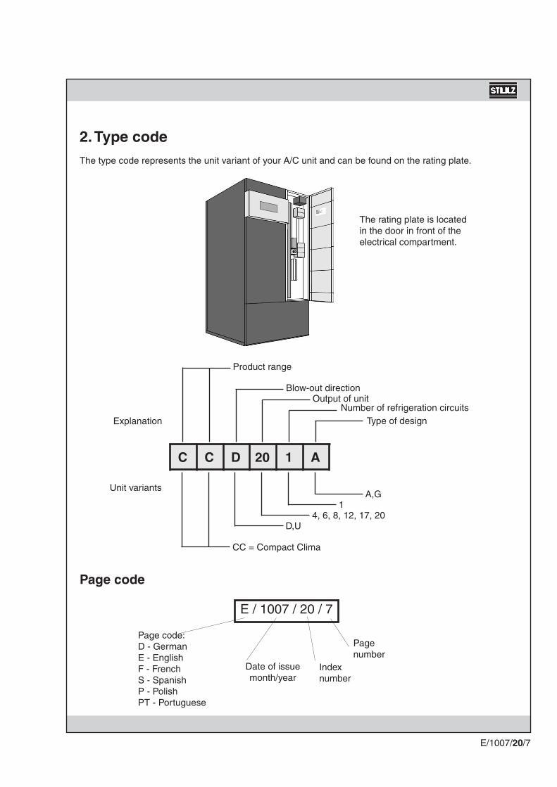
C C D 20 1 A
CC = Compact Clima
D,U4, 6, 8, 12, 17, 20
1A,G
E/1007/20/7
Explanation
Unit variants
Product range
Blow-out directionOutput of unit
Number of refrigeration circuitsType of design
Page code
E / 1007 / 20 / 7
Pagenumber
Indexnumber
Date of issuemonth/year
Page code:D - GermanE - EnglishF - FrenchS - SpanishP - PolishPT - Portuguese
2. Type codeThe type code represents the unit variant of your A/C unit and can be found on the rating plate.
The rating plate is located in the door in front of the electrical compartment.

E/1007/20/8
Design of an A/C unit
The A/C unit is divided into three areas, an air, water and electrical section.
The evaporator, the expansion valve, the fan and the optional electrical heating are housed in the air section. The air to be cooled is drawn in by the fan and flows through the evaporator.All the electronics and electrics to control and monitor the A/C unit are located in the electrical section. All the wiring of the A/C unit comes together in the electrical section and is connected here.The compressor, collector, condenser and the G-units as well as various fittings and pressure switches are housed in the low temperature section.
3. Description
General
This A/C unit is used for the air conditioning of rooms. It is available in various designs, as described under method of operation. The A/C unit is to be installed in accordance with the "Assembly/commissioning" section. The A/C unit is only operated via the controller.
Intended use
The A/C unit is used to control room temperature and air humidity. Any use beyond this is not deemed to be use as intended. STULZ is not liable for any damage resulting from such misuse. The operator alone bears the risk.
Air section
Electrical section
Refrigerant section

E/1007/20/9
Basic components/function of refrigerant circuit
The refrigeration circuit of the A/C unit consists of a compressor, a condenser, an expansion valve and an evaporator. These components are connected by pipelines to a sealed refrigerant circuit. The compressor is used to compress the refrigerant and maintain the refrigerant flow. The heat of the refrigerant is given up in the condenser. The expansion valve with pressure compensation is used as a throttling component in the refrigerant circuit. The evaporator extracts the heat from the air flowing through. All components of the refrigerant circuit are designed for a maximum operating pressure of 25 bar. On air conditioning units of type A (A-units), the condenser is not in the A/C unit but located externally.
The heat of the room is absorbed by the gaseous low temperature refrigerant in the evaporator. The gase-ous refrigerant is compressed in the compressor and enters the condenser. The condenser gives up the heat absorbed and liquefies the refrigerant which is under high pressure. The liquid refrigerant enters the expansion valve and is from there conducted back to the evaporator at low pressure and low temperature. Thus low pressure and low temperature prevails in the evaporator whilst high pressure and high temperature exist in the condenser.
Dehumidifying economy circuit
The A/C units of the upper capacity range (17 and 20 kW) are equipped with a dehumidify-ing economy circuit. Here approx. one third of the evaporator is switched off via a solenoid valve. As a result the evapo-ration temperature of the refrigerant is reduced and the air flowing past the evaporator falls below the dew point. The moisture contained in the air condenses in the evaporator and is carried away.At the A/C units of the lower capacity range (4 to 12 kW) a dehumidification is achieved by a reduction of the air flow. The fan speed can be adjusted manually, a precise description of the function can be found in the section "operation and maintenance" on page 45.

E/1007/20/10
Method of operation of type G A/C unit The room air drawn in by the fan flows through the evaporator. In this process heat is drawn from the room air and given up to the refrigerant. The refrigerant gives up the heat to a water/glycol mixture via a condenser con-tained in the A/C unit. The cooling water flows through an air-cooled external dry cooler which gives up the heat to the outside air.
Air conditioned room
A/C unit
EvaporatorCondenser
Drycooler
Room air
Refrigerant
Cooling water
Outside air
Method of operation of type A A/C unit
The room air drawn in by the fan flows th-rough the evaporator. In this process heat is drawn from the room air and given up to the refrigerant. The refrigerant gives up the heat to the outside air via an external air-cooled condenser. The A/C unit and the external condenser are connected with each other by a sealed refrigerant circuit.
Air conditioned room
A/C unit
Evaporator Condenser
Room air
Refrigerant
Outside air
Method of operation of A/C unit
There are the design types A and G in the MINI-SPACE A/C units, the method of operation is as shown below, in respect of heat flow:

E/1007/20/11
UpflowDownflow
Room air/return air Supply air
Air flow
A distinction is made between downflow and upflow A/C units. On downflow units the room air is drawn into the A/C unit from above and passed down into the raised floor. On upflow units the room air is drawn in from the front of the A/C unit and passed upwards.
Preventative safety devices
The A/C units have various safety devices to avoid malfunctions. A non-return valve is fitted in the liquid line on A-units which prevents backflow of refrigerant into the condenser. In the liquid line of all units there is a filter drier, a sight glass and a solenoid valve which shuts off the refrigerant flow when the A/C unit is shut down.
Safety devices
The A/C unit is protected against insufficient operating pressure by a low-pressure switch. If the operating pressure is fallen below, a warning signal appears on the display and the A/C unit is put out of operation. A high-pressure switch is triggered at an excessive operating pressure of 24.5 bar and switches off the com-pressor. A warning signal on the display of the controller appears. A safety valve is fitted on the collector as the last link in the chain, which opens at a pressure of 27.5 bar.
Supply air
Room air/return air

1
34
5
6
7
10
11
17
13
14
16
15
18
12
E/1007/20/12
3.1 Design of CCD 41 - 121 A(Downflow)

1
3
46 510
711
13
14
12
1615
12
8 8
E/1007/20/13
Refrigeration diagram CCD/U 41 - 121 A
Expansion valveEvaporatorShutoff valveSafety valveNon-return valve (liquid line)Low-pressure pressostatHigh-pressure pressostatTemp./humidity sensor (behind elec. compart.)Electrical compartment
10.11.12.13.14.15.16.17.18.
FanMotorCompressorFilter drierSight glassSolenoid valve in liquid lineCollectorSchrader valve -
1.2.3.4.5.6.7.8.9.
to external condenser

18
7
1
11
2
4
5
6
9
10
14
123
16
15
17
E/1007/20/14
3.2 Design of CCD 171/201 A(Downflow)

1
3
46 510
711
9
13
14
8
1615
12
8
E/1007/20/15
Refrigeration diagram CCD/U 171/201 A
Expansion valveEvaporatorShutoff valveSafety valveNon-return valve (liquid line)Low-pressure pressostatHigh-pressure pressostatTemp./humidity sensor (behind elec. compart.)Electrical compartment
10.11.12.13.14.15.16.17.18.
FanMotorCompressorFilter drierSight glassSolenoid valve in liquid lineCollectorRotalock valveDehumidifier valve
1.2.3.4.5.6.7.8.9.
to external condenser
Rotalock valve only at CCD/U 201

34
5
6
7
10
16
11
12
15
14
1
9
17
13
E/1007/20/16
3.3 Design of CCU 41 - 121 G(Upflow)

46 5
10
1
9
3
1514
12
13
88
187 11
E/1007/20/17
Shutoff valveSafety valveCondensorLow-pressure pressostatHigh-pressure pressostatTemp./humidity sensor (behind elec. compart.)Electrical compartmentVent valve
11.12.13.14.15.16.17.18.
FanMotorCompressorFilter drierSight glassSolenoid valve in liquid lineCollectorSchrader valveExpansion valveEvaporator
1.2.3.4.5.6.7.8.9.
10.
Refrigeration diagram CCD/U 41 - 121 G

13
113
16
4
5
6
15
2
18
1
108
9
7
E/1007/20/18
3.4 Design of CCU 171/201 G(Upflow)

46 5
10
1
89
3
1514
7
12
11
13
2020
19
E/1007/20/19
Shutoff valveSafety valveCondensorLow-pressure pressostatHigh-pressure pressostatTemp./humidity sensor (behind elec. compart.)Master switchElectrical compartmentVent valveRotalock valve
11.12.13.14.15.16.17.18.19.20.
FanMotorCompressorFilter drierSight glassSolenoid valve in liquid lineCollectorDehumidifier valveExpansion valveEvaporator
1.2.3.4.5.6.7.8.9.
10.
Refrigeration diagram CCD/U 171/201 G
Rotalock valves only at CCD/U 201

E/1007/20/20
3.5 Application Ranges
The STULZ MINI-SPACE units are provided for ope-ration within the following ranges:
- Room conditions: Between 18°C, 45% R.H. and 27°C, 55% R.H.
- Outdoor ambient conditions: lower limit: -10°C upper limit: dependent on the selected conden-
ser
- Air flow: nominal values are listed in the tables on the pages 21-26.
- Voltage: 400 +/- 10%
- Frequency: 50 Hz +/- 1%
G units:- max. water pressure: 10 bar
- Hot water conditions for optional heating coil: max. inlet water temperature: 110°C max. water head pressure: 8.5 bar
- Max. length of piping between A/C unit and air cooled condenser: 30m equivalent.
- Max. level difference between condenser and A/C unit: 3m (when condenser is below the A/C unit).
- Storage conditions: between -20°C and +35°C
The warranty is invalidated for any possible damage or malfunction that may occur during or in conse-quence of operation outside the application ranges.

kWkW
m³/hPakW
kWl
°C°Cm³/hkPa
kPa
mmmm
kW
kg/h
V/-/Hzkgmm
CCD/U 41A
4.9/4.64.4/4.4
200050/400.37
Scroll1.5
1.0**
KSV 006 A1132-
2400-
---
EU4
640/570/20972/395/20
21
1,5-3,0
380-415/3/50/N180
600 / 1850 / 600
CCD/U 41G
4.9/4.64.4/4.4
200050/400.37
Scroll1.52.4
B 10x603945
1.081.1
3/4''5.5
EU4
640/570/20972/395/20
21
1,5-3,0
380-415/3/50/N185
600 / 1850 / 600
E/1007/20/21
4. Technical Data
CCD/U 41
* The electrical power consumption of the fan is to be added to the room load.** only with running test, otherwise with protective nitrogene filling
Evap. cool. capacity (total/sensible)With return air at 24°C/50% RHWith return air at 22°C/50% RH
FanVolume flowExternal pressure D/UMotor nominal output
CompressorModelMotor nominal outputRefrigerant charge R407C
CondenserCooling mediumModelMedium inlet temperatureMedium outlet temperatureVolume flowPressure drop, condenser/CW coil and piping
Control valveSizePressure drop, valve
FilterQualityDesignWidth/Height/Depth - DWidth/Height/Depth - U
Electrical reheat (option) Heating capacityNo of stages
Steam humidifier (option)Capacity
General unit dataElectrical connectionWeight Width/Height/Depth
Air
Filter mat
30%Glycol
3-way
EU4Filter mat

kWkW
m³/hPakW
kWl
°C°Cm³/hkPa
kPa
mmmm
kW
kg/h
V/-/Hzkgmm
CCD/U 61A
6.8/6.26.2/6.0
200050/400.37
Scroll1.9
1.0**
KSV 008 A1132-
4300-
---
EU4
640/570/20972/395/20
21
1,5-3,0
380-415/3/50/N185
600 / 1850 / 600
CCD/U 61G
6.8/6.26.2/6.0
200050/400.37
Scroll1.92.4
B 10x6039451.41.8
3/4''9
EU4
640/570/20972/395/20
21
1,5-3,0
380-415/3/50/N190
600 / 1850 / 600
E/1007/20/22
Technical Data CCD/U 61
Evap. cool. capacity (total/sensible)With return air at 24°C/50% RHWith return air at 22°C/50% RH
FanVolume flowExternal pressure D/UMotor nominal output
CompressorModelMotor nominal outputRefrigerant charge R407C
CondenserCooling mediumModelOutputMedium inlet temperatureMedium outlet temperatureVolume flowPressure drop, condenser/CW coil and piping
Control valveSizePressure drop, valve
FilterQualityDesignWidth/Height/Depth - DWidth/Height/Depth - U
Electrical reheat (option) Heating capacityNo of stages
Steam humidifier (option)Capacity
General unit dataElectrical connection Width/Height/Depth* The electrical power consumption of the fan is to be added to the room load.** only with running test, otherwise with protective nitrogene filling
Air
Filter mat
30%Glycol
3-way
Filter mat

kWkW
m³/hPakW
kWl
°C°Cm³/hkPa
kPa
mmmm
kW
kg/h
V/-/Hzkgmm
CCD/U 81A
8.9/8.08.0/7.6
200050/400.37
Scroll2.5
1.0**
KSV 012 A1132-
7000-
---
EU4
640/570/20972/395/20
21
1,5-3,0
380-415/3/50/N190
600 / 1850 / 600
CCD/U 81G
8.9/8.08.0/7.6
200050/400.37
Scroll2.52.4
B 10x603945
1.782.9
3/4''15
EU4
640/570/20972/395/20
21
1,5-3,0
380-415/3/50/N195
600 / 1850 / 600
E/1007/20/23
Technical Data CCD/U 81
* The electrical power consumption of the fan is to be added to the room load.** only with running test, otherwise with protective nitrogene filling
Evap. cool. capacity (total/sensible)With return air at 24°C/50% RHWith return air at 22°C/50% RH
FanVolume flowExternal pressure D/UMotor nominal output
CompressorModelMotor nominal outputRefrigerant charge R407C
CondenserCooling mediumModelMedium inlet temperatureMedium outlet temperatureVolume flowPressure drop, condenser/CW coil and piping
Control valveSizePressure drop, valve
FilterQualityDesignWidth/Height/Depth - DWidth/Height/Depth - U
Electrical reheat (option) Heating capacityNo of stages
Steam humidifier (option)Capacity
General unit dataElectrical connectionWeight Width/Height/Depth
Air
Filter mat
30%Glycol
3-way
Filter mat

kWkW
m³/hPakW
kWl
°C°Cm³/hkPa
kPa
mmmm
kW
kg/h
V/-/Hzkgmm
CCD/U 121A
12.4/11.011.5/11.0
320050/400.55
Scroll2.9
1.0**
KSV 016 A1132-
6800-
---
EU3
640/570/20972/395/20
41
1,5-3,0
380-415/3/50/N200
600 / 1850 / 600
CCD/U 121G
12.4/11.011.5/11.0
320050/400.55
Scroll2.92.4
B 10x603943
3.4911
3/4''57
EU3
640/570/20972/395/20
41
1,5-3,0
380-415/3/50/N205
600 / 1850 / 600
E/1007/20/24
Technical Data CCD/U 121
Evap. cool. capacity (total/sensible)With return air at 24°C/50% RHWith return air at 22°C/50% RH
FanVolume flowExternal pressure D/UMotor nominal output
CompressorModelMotor nominal outputRefrigerant charge R407C
CondenserCooling mediumModelMedium inlet temperatureMedium outlet temperatureVolume flowPressure drop, condenser/CW coil and piping
Control valveSizePressure drop, valve
FilterQualityDesignWidth/Height/Depth - DWidth/Height/Depth - U
Electrical reheat (option) Heating capacityNo of stages
Steam humidifier (option)Capacity
General unit dataElectrical connectionWeight Width/Height/Depth* The electrical power consumption of the fan is to be added to the room load.** only with running test, otherwise with protective nitrogene filling
Air
Filter mat
30%Glycol
3-way
Filter mat

kWkW
m³/hPakW
kWl
°C°Cm³/hkPa
kPa
mmmm
kW
kg/h
V/-/Hzkgmm
CCD/U 171A
17.8/17.016.6/16.4
6000702.2
Scroll4.4
2.0**
KSV 021 A2132-
10600-
---
EU4
870/970/20975/650/20
2 x 62
1,5-3,0
380-415/3/50/N220
1000 / 1850 / 810
CCD/U 171G
17.8/17.016.6/16.4
6000702.2
Scroll4.43.2
B 25x503945
3.5721
3/4"59
EU4
870/970/20975/650/20
2 x 62
1,5-3,0
380-415/3/50/N225
1000 / 1850 / 810
E/1007/20/25
30%Glycol
3-way
Filter mat
Technical Data CCD/U 171
* The electrical power consumption of the fan is to be added to the room load.** only with running test, otherwise with protective nitrogene filling
Evap. cool. capacity (total/sensible)With return air at 24°C/50% RHWith return air at 22°C/50% RH
FanVolume flowExternal pressure D/UMotor nominal output
CompressorModelMotor nominal outputRefrigerant charge R407C
CondenserCooling mediumModelMedium inlet temperatureMedium outlet temperatureVolume flowPressure drop, condenser and piping
Control valveSizePressure drop, valve
FilterQualityDesignWidth/Height/Depth - DWidth/Height/Depth - U
Electrical reheat (option) Heating capacityNo of stages
Steam humidifier (option)Capacity
General unit dataElectrical connectionWeight Width/Height/Depth
Filter mat

kWkW
m³/hPakW
kWl
°C°Cm³/hkPa
kPa
mmmm
kW
kg/h
V/-/Hzkgmm
CCD/U 201A
22.6/20.920.7/20.1
7000702.2
Scroll5.5
2.0**
KSV 037 A2132-
13000-
---
EU4
870/970/20975/650/20
2 x 62
1,5-3,0
380-415/3/50/N350
1000 / 1850 / 810
CCD/U 201G
22.6/20.920.7/20.1
7000702.2
Scroll5.53.4
B 25x503945
4.3431
3/4"88
EU4
870/970/20975/650/20
2 x 62
1,5-3,0
380-415/3/50/N358
1000 / 1850 / 810
E/1007/20/26
30%Glycol
3-way
Filter mat
Technical Data CCD/U 201
* The electrical power consumption of the fan is to be added to the room load.** only with running test, otherwise with protective nitrogene filling
Evap. cool. capacity (total/sensible)With return air at 24°C/50% RHWith return air at 22°C/50% RH
FanVolume flowExternal pressure D/UMotor nominal output
CompressorModelMotor nominal outputRefrigerant charge R407C
CondenserCooling mediumModelMedium inlet temperatureMedium outlet temperatureVolume flowPressure drop, condenser and piping
Control valveSizePressure drop, valve
FilterQualityDesignWidth/Height/Depth - DWidth/Height/Depth - U
Electrical reheat (option) Heating capacityNo of stages
Steam humidifier (option)Capacity
General unit dataElectrical connectionWeight Width/Height/Depth
Filter mat

M
2000
1000
Downflow
CCU
47
47
47
50
57
59
CCD
45
45
45
48
55
57
M
2000
1000
Upflow
E/1007/20/27
4.1 Sound data
The data are valid at a height of 1m and distance of 2m in front of the unit under free field conditions and with nominal data. The values take into account the effects of all installation and design parts contained in the standard unit. The values are due to the noise, which is emitted through the suction opening and the unit casing.The noise which is emitted through the discharge opening is not taken into account. It is presupposed that the discharge noise is muffled by appropriate measures in the raised floor (downflow units) or in the discharge duct (upflow units).The data for the upflow units are intended for a mounted discharge duct. The sound levels stated can be further reduced by suitable attenuation measures determined by individual site conditions.
Unit size
41 A/G
61 A/G
81 A/G
121 A/G
171 A/G
201 A/G
Sound level in dB (A)

CCD/U41
A/G
CCD/U61
A/G
CCD/U81
A/G
CCD/U121A/G
CCD/U171A/G
5,1
12,3
8,7
17,3
4,2
18,4
27,1
35,7
23,6
CCD/U201A/G
5,1
13,4
8,7
17,3
4,2
19,5
28,2
36,8
24,7
6 kW
2x6 kW
6 kW
2x6 kW
L1 L2 L3
— 4,7 —
3,3 3,3 3,3
3,2 — 4,8
— — 12,7
3,3 8,0 3,3
6,5 8,0 8,1
3,3 8,0 16,0
L1 L2 L3
— 4,7 —
4,3 4,3 4,3
3,2 — 4,8
— — 12,7
4,3 9,0 4,3
7,5 9,0 9,1
4,3 9,0 17,0
L1 L2 L3
— 4,7 —
5,9 5,9 5,9
3,2 — 4,8
— — 12,7
5,9 10,6 5,9
9,1 10,6 10,7
5,9 10,6 18,6
L1 L2 L3
— 5,5 —
7,3 7,3 7,3
8,0 — 8,0
— — 12,7
7,3 12,8 7,3
15,3 12,8 15,3
7,3 12,8 20,0
1~
3~
2~
1~
E/1007/20/28
4.2 Electrical connected loads380-415V / 3Ph / 50Hz
Key: Fan Compressor El. heater Steam humidifier
Components
max. current consumption [Amp]
Components
max. current consumption [Amp]

E/1007/20/29
4.3 Unit characteristics, air circuitDesign example for the fan speed
The units CCD/U 41-121 have a fan which is directly driven by a motor without a v-belt. The speed and thus the air flow can exclu-sively be modified by the speed controller (see page 46).
By means of this example it is explained how the fan speed and power requirement at the shaft are determined from the fan curve for a CCD 201 A/G A/C unit.
Given: (A) Air volume 5000 m3/h (B) p external 75 Pa
Required: (D) Pressure loss of the unit (E) Overall pressure loss (F) Fan speed (G) Power requirement at the shaft
PROCEDURE:
Establish the intersection point (C) of the air volume (A) and the unit characteristics and determine the pressure loss of the unit:
determined value (D) = 240 Pa
Add the Pressure loss of the unit (D) and the external pressure (B):
(D)+(B)= (E)
determined value (E): 240 + 75 = 315 Pa
The operating point (H) is at the intersection point of air volume (A) 5000 m3/h and the overall pressure loss (E) 315 Pa.
Read off the fan speed (F): 800 rpm
Read off the power requirement at the shaft (G): 0.62 kW

SP [Pa]
500
400
300
200
100
0
0 1000 2000 3000 Q[m³/h]
0 100 200 300 Pd[Pa]
RPM
1500
1450
1400
1350
1300
1250
1200
1150
1100
1050
mA
5000
4500
4000
3500
3000
2500
2000
1500
E/1007/20/30
Unit characteristics, air circuit for CCD/U 41-81
(unit characteristics = internal pressure drop in unit)
Factor for dynamic pressure: Downflow = 1.6, Upflow with duct connection = 1.0

RPM1000
950
900
850
800
750
Input W1200
1100
1000
900
800
700
600
500
400
mA6000
5500
5000
4500
4000
3500
3000
2500
2000
SP [Pa]400
300
200
100
0
0 100 200 300 400 500 600 700 Pd[Pa]
0 1000 2000 3000 4000 Q[m³/h]
E/1007/20/31
Unit characteristics, air circuit for CCD/U 121
(unit characteristics = internal pressure drop in unit)
Factor for dynamic pressure: Downflow = 1.6, Upflow with duct connection = 1.0
E/1007/20/32
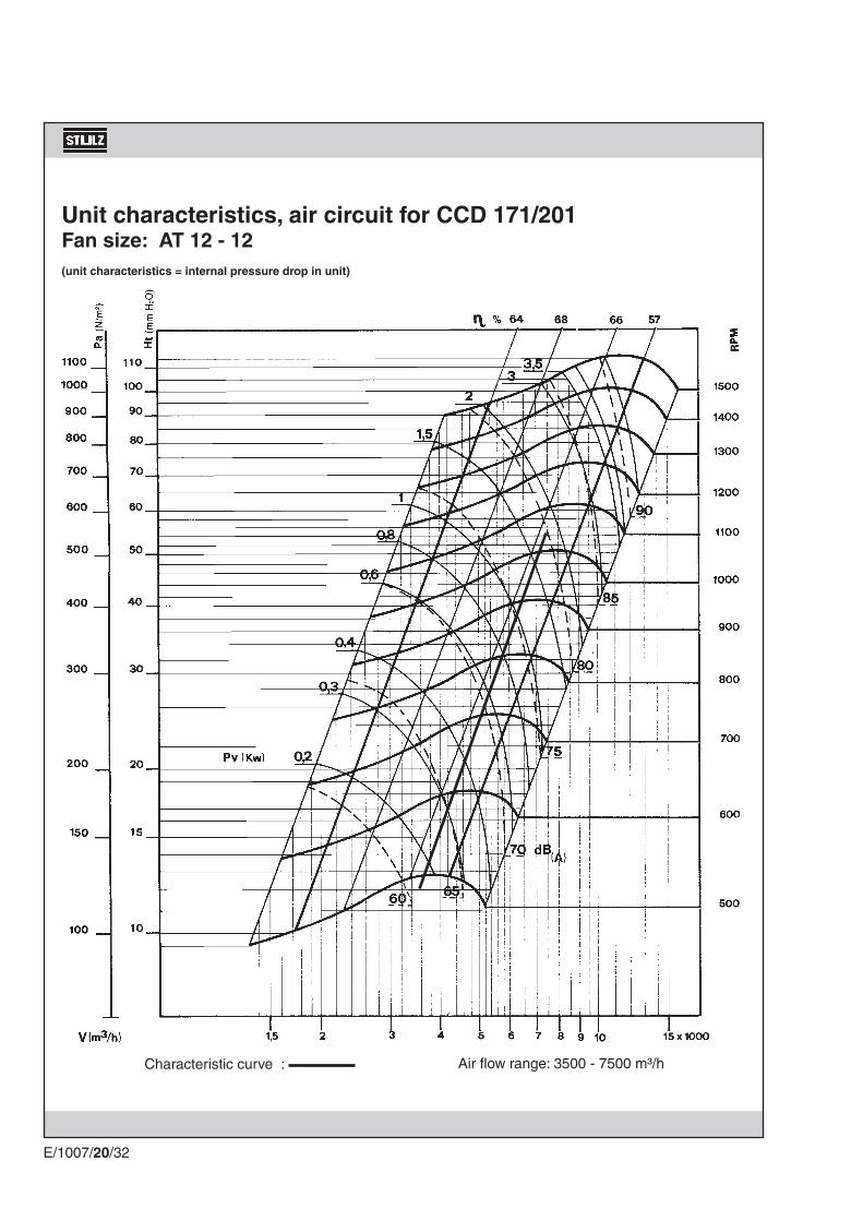
Unit characteristics, air circuit for CCD 171/201Fan size: AT 12 - 12(unit characteristics = internal pressure drop in unit)
Characteristic curve : Air flow range: 3500 - 7500 m³/h

E/1007/20/33
Unit characteristics, air circuit for CCU 171/201Fan size: AT 12 - 12(unit characteristics = internal pressure drop in unit)
Characteristic curve : Air flow range: 3500 - 7500 m³/h

CCD/U 171/201
8101000
370
1850
1850
220
600600
E/1007/20/34
4.4 Dimensions
(in mm)
CCD/U 41-121

CCD/U 171/201CCD/U 41 - 121
1100 mm
1500
mm
1300
mm
700 mm
E/1007/20/35
Space required for unit installation
All assembly and maintenance work can be carried out from the front of the A/C unit once the units have been installed. Observe the clearance required for maintenance as shown below.
5. Installation and commissioning
Delivery of units
Stulz A/C units are mounted on pallets and packed several times in plastic film. They must always be trans-ported upright on the palettes.
When delivery is accepted, the unit is to be checked against the delivery note for com-pleteness and checked for external damage. The delivery note can be found on the A/C unit when delivered.
The following information can be found on the packing. 1) Stulz logo 2) Stulz order number 3) Type of unit 4) Packing piece - contents 5) Warning symbols also upon request 6) Gross weight 7) Net weight 8) Dimensions 9) Customer order number10) Additional customer requirements
Construction of protective covering(from inside to outside)
1. Neopole cushioning2. Shrink film3. Additional board in container ship-
ments
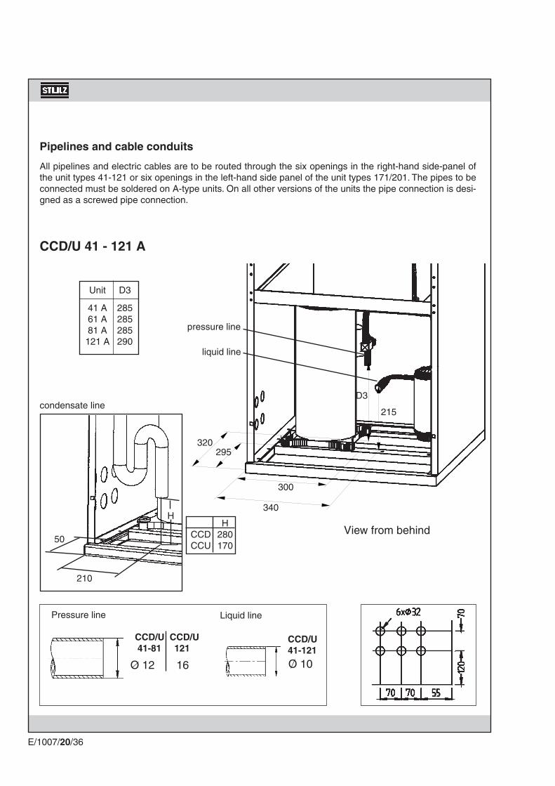
O 12 16 O 10
340
295
215
D3
300
320
D3
285285285290
CCD/U 41 - 121 A
CCD/U CCD/U 41-81 121
210
50
H HCCD 280CCU 170
CCD/U41-121
E/1007/20/36
Pipelines and cable conduits
All pipelines and electric cables are to be routed through the six openings in the right-hand side-panel of the unit types 41-121 or six openings in the left-hand side panel of the unit types 171/201. The pipes to be connected must be soldered on A-type units. On all other versions of the units the pipe connection is desi-gned as a screwed pipe connection.
Pressure line Liquid line
View from behind
Unit
41 A61 A81 A121 A
condensate line
liquid line
pressure line
O O 16
D2
28565
D3
270525
D1
550575
55 70 70
120
7
0
2 x 50
4 x 32
D3
75D1
D2150
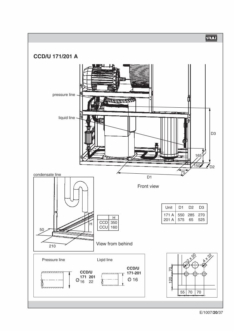
CCD/U 171/201 A
CCD/U171 20116 22
210
50H
HCCD 350CCU 160
165
CCD/U 171-201
E/1007/20/37
Pressure line Liqid line
Unit
171 A201 A
Front view
View from behind
condensate line
liquid line
pressure line

CCD/U 41 - 121 G
D
E3
A3
A2E2
E1
A1
E1
170170170120
A1
130130130140
E2
70707070
A2
70707065
E3
190190190190
A3
125125125120
210
50
H HCCD 280CCU 170
E/1007/20/38
Unit
41 G61 G81 G
121 G
41 G61 G81 G
121 G
View from behind
Inlet/Outlet
Unit DCCD/U 41-81 22CCD/U 121 28
condensate line
Outlet
Inlet

CCD/U 171/201 G
28
240
120
600
255510 175
210
50H
HCCD 350CCU 160
55 70 70
120
7
0
2 x 50
4 x 32
E/1007/20/39
Inlet/Outlet
View from behind
Inlet
Outlet
condensate line

E/1007/20/40
Installing the A/C unit
Check the A/C unit to ensure it is complete and not damaged. If the A/C unit is incomplete or damaged, please contact STULZ customer service.
Transport the complete A/C unit to the installation point.
Installing the A/C unit
Installation sequence
Intake duct 4 Refer to manufacturer's documentation
Louvered flap 3 For assembly, refer to "Louvered flap" options
A/C unit 2 Described below
Raised floor stand 1 For assembly, refer to "Raised floor stand" options
The A/C unit must only be transported upright.
Transport the complete A/C unit to the installation point or onto the existing raised floor stand (option).
Ensure that all electric cables, condensate-water connections and water connections (on G-units only) are already routed to the A/C unit or to the individual modules and are ready for connection.
If the water quality is insufficient, we recommend the additional installation of a strainer.Connect the cooling-water pipes as follows:Remove the protective caps from the flanges of the water pipes.
G-Units :
Water pipes are only fitted on the G units.

33 mm
E/1007/20/41
Water remaining from the test run may escape when the protective caps are removed.
If any seals have got lost, these may only be replaced by glycol-resistant rubber seals.
Insulate the water pipes with the insulating material supplied.
The insulation material required is included with the respective module as a supplementary pack.
Flanged connection
Insulation of water pipes
Insert the seals and screw on the flanges of the water pipes.
Screw the water pipes of the A/C unit together with the local water pipes of the dry cooler or the water chiller.
Connect the condensate water drains to the local waste water system.
Comply with the regulations of the local water supply authority.
All Units :
A filling connection and several schrader valves for bleeding are fitted to the A/C unit. Refer to refrigerati-on/piping diagram.
Fill and bleed the cooling-water circuit.
Unit type Thread
41-121 R 1"171/201 R 1 1/2"

E/1007/20/42
A refrigerant pipe to the external condensor is only required on A-units.
Electrical connection
Position of refrigerant connections
Connection diameter of the copper pipelines of the A/C unit (in mm):
Unit types: 41 - 81 121 171 201Pressure line: 12 16 16 22Liquid line: 10 10 16 16
Fill the refrigerant circuit with refrigerant. (Refer to refrigerant piping section). For this, the solenoid valve in the liquid line must be energized (24 V AC).
Ensure that the electric cables are de-energized.The electric cables are only to be connected by an authorised specialist.
Route the electric cable into the electrics box from below and connect them to the master switch in accordance with the wiring diagram (Appendix).
Electrical connection
The refrigerant-conducting pipelines are only to be connected by an authorised specialist. Comply with the safety instructions at the start of these operating instructions.
Connect the pipelines carrying refrigerant to the external condensor (refer to section on "refrigerant piping").
A-Units :
pressure line
liquid line

E/1007/20/43
Electrical connectionThe A/C unit must be installed and connected in ac-cordance with the chapter on "installation of A/C unit" before initial commissioning.
Open the electrical compartment door of the A/C unit using the key provided.
Check whether all power switches and control-circuit fuses in the electrical section of the A/C unit are switched off.
Switch on the control-circuit fuses and the power switches of the fan and the compressor in sequence as well as the built-in options in ac-cordance with the wiring diagram. The wiring diagram can be found in the "Appendix".
Do not turn the adjustment screw beyond the end of the calibrated scale range, as it may result in overheating and short-circuit at the consumer.
Switch on the A/C unit at the master switch.
Caution. Electric cables and electrical components of the A/C unit are live.
Power switch ON
Electrical compartment
Power switch OFF
Control-circuit fuses
Power switch
Master switch
non calibrated range

E/1007/20/44
5.1 Dismantling and disposalThe A/C unit can only be dismantled by qualified specialists.
Switch off the A/C unit at the controller and at the master switch.
Disconnect the A/C unit from the de-energized network.
Dispose of the refrigerant in the A/C unit in accordance with the disposal and safety regulations applicable on site (refer to chapter on refrigerant piping).
If fitted, disconnect the depressurized refrigerant lines, the depressurized cooling water pipes and the con-densate water drainage pipes from the A/C unit.
Dispose of the A/C unit in accordance with the disposal and safety regulations applicable on site. We recom-mend a recycling company for this. The A/C unit basically contains the raw materials aluminium (evaporator), copper (pipelines, wiring), and iron (panelling, mounting panel).
Let the A/C unit operate for approx. 1 hour while paying attention to any unusual noises.
Check the level of refrigerant in the sight glass on A-type A/C units.
If bubbles are continuously visible in the sight glass, top up the refrigerant circuit with refrigerant in ac-cordance with the chapter "refrigerant piping".
G-units are equipped with a sealed refrigerant circuit in the A/C unit which has been checked and approved by the factory.
Set the required specified values for room temperature and air humidity on the controller of the A/C unit. Refer to Controller Manual. Sight glass
If your A/C unit is equipped with additional options, further measures on initial commissioning are to be found in the "Options" section.
Switch on the A/C unit at the controller.
Controller C1002

E/1007/20/45
6. Operation and maintenance
Switching the A/C unit on and off
The A/C unit is only to be switched on when it has been installed in accordance with the "assembly and commissioning" section, connected correctly and commissioned for the first time.
Switching off the complete A/C unit
Operating the A/C unit
The A/C unit is operated via the controller. A complete description of the functions of the controller can be found in the enclosed manual. All alarm and fault signals of the basic A/C unit are also described.
Controller C1002
The A/C unit is switched on and off by pressing the on/off button on the controller. The complete functional sequence of the A/C unit is controlled and monitored by the controller.The actual values of room temperature/humidity are shown on the display when the A/C unit is switched on.
The fan runs on for approx. 3 minutes when the A/C unit is switched off.
The complete A/C unit is switched off via the controller and via the built-in master switch. To do this, open the electrical com-partment and put the master switch in position "0".

E/1007/20/46
adjustableresistors
LED
Fuse 6A
For the operation of the unit variants CCD/U 41 - 121 there is an additional device:
The Fan Speed Control
With the fan speed control you can adapt the fan speed individually to the application domain of the A/C unit.The speed control is installed in the middle part of the electric box on the terminal strip. You can adjust the fan speed with two variable resistors which are situated on the printed circuit board of the speed control.With the variable resistor indicated PHI 1 you adjust the speed for the operation without dehumidification (Non-dehumidifying speed, N-D speed). With the variable resistor indicated PHI 2 you adjust the speed for the dehumidification. The speed, adjusted with PHI 2, should be smaller than the N-D speed to make sure that a dehumidification takes place. Both resistors have got the same range of control from a minimum speed to the nominal speed.
Consequences, if the speed is too small:
- Icing of the evaporator - The air flow control can give an alarm. - Overheating of the electric reheat, the overheat protection is actuated.
Two LEDs on the printed circuit board indicate the state of operation. At a non-dehumidification phase the LED I1 is illuminated and the fan motor runs at the adjusted speed by PHI 1. At a dehumidification phase the LED I2 is illuminated and the fan motor runs at the adjusted speed by PHI 2.

E/1007/20/47
Maintenance
Safety instructions
All maintenance work is to be carried out under strict compliance with the country-specific accident pre-vention regulations. In particular we refer to the accident prevention regulations for electrical installations, refrigerating machines and equipment.Maintenance work is only to be carried out on the A/C units by authorised and qualified specialist staff.
Work on the system must always only be carried out when it is shut down. To do this, the A/C unit must be switched off at the controller and at the master switch. A "DO NOT SWITCH ON" warning sign must be displayed.
Live electrical components are to be switched to de-energized and checked to ensure that they are in the de-energized state.
Non-compliance with the safety instructions can endanger people and the environment.Contaminated parts always result in a loss of performance and, in the case of switching and control units, can result in the failure of the system.
The built-in filters cannot be washed and the dust cannot be beaten out of them. Therefore contaminated filters must be replaced regularly, otherwise air output is reduced, energy consumption increases considerably and the system may fail.
Maintenance measures and intervals
Measure Intervals in months
GeneralChecking A/C unit for external damage 12Cleaning inside of A/C unit and checking for damage 12
MechanicalChecking fan for satisfactory condition 12Replacing filter 3 Replacing V-belt 6
Air conditioningChecking refrigerant circuit 3Visually inspecting water circuit for leaks 3Checking compressor for satisfactory condition 3
This table contains all the maintenance measures required for a basic A/C unit. If your A/C unit is equipped with additional options, the required maintenance measures can be found in the "options" section.The intervals specified in the table are only reference values, which can vary depending on where the unit is installed and the degree of contamination.

E/1007/20/48
Maintenance work
Opening the A/C unit
The A/C unit is opened by opening the electrical com-partment door and by remo-ving two front panelsThe panel in front of the low temperature section is secu-red by ball pins and can be removed without auxiliary equipment. To remove the front panel in front of the air section, first open the electri-cal compartment door using the male triangular wrench provided.
All maintenance measures can be performed from the open front of the A/C unit.
Checking A/C unit for external damage
- Ensure that the A/C unit is switched on and is in operation.
- Pay attention to unusual noises.
- Check the A/C unit externally for damage, contamination and corrosion.
- Check whether warning information is shown on the display.

E/1007/20/49
Master switch
Condensate water trayEvaporator
Cleaning inside of A/C unit and checking for damage
- Switch the A/C unit off at the controller.
- Attach a "DO NOT SWITCH ON" warning sign to the A/C unit.
- Wait until the fan stands still.
- Open the electrical compartment door of the A/C unit using the male triangular wrench.
- Switch off the A/C unit at the master switch.
- Remove the front panels.
- Clean the A/C unit with a vacuum cleaner.
- Check the filter for contamination and replace it, if necessary.
- Clean the condensate water tray.
- Clean the fins of the evaporator with a brush.
- Clean the unit components with a cloth.
- Check all built-in unit components for external damage, contaminati-on and corrosion.
- Check the hose connections for damage.
- Check the pipeline system for damage.
- Check the cable connections for firm seating and damage.
- Re-install the front panels.
- Switch on the master switch and close the electrical compartment door.
- Remove the warning sign and put the A/C unit into operation.

E/1007/20/50
Checking fan for satisfactory condition
- Switch off the A/C unit at the controller.
- Attach a "DO NOT SWITCH ON" warning sign to the A/C unit.
- Wait until the fan stands still.
- Open the electrical compartment of the A/C unit using the STULZ door opener.
- Switch off the A/C unit at the master switch.
- Switch off the power switch of the fan.
- Remove the front panel in front of the air section.
- Check fan for damage, corrosion and firm seating.
- Turn the fan by hand, checking ease of movement and noting any running noises from the bearings.
- Check the V-belt for wear and replace it, if necessary. (only for CCD/U 171/201)
- Check whether the pulleys of the V-belt align.
- Check the tension of the V-belt.
The V-belt may yield by a maximum of one V-belt thick-ness. The V-belt tension is adjusted by turning the hexagon shaft on the motor slide.
- Install the front panel in front of the air section.
- Switch on the power switch of the fan.
- Switch on the master switch and close the electrical compartment.
- Remove the warning sign and put the A/C unit into operation.
Master switch
Aligning the V-belt pulleys
Tension of the V-belt

E/1007/20/51
Downflow unit filter
Replacing filters
- Switch off the A/C unit at the controller.
- Attach a "DO NOT SWITCH ON" warning sign to the A/C unit.
- Wait until the fan stands still.
- Open the electrical compartment.
- Switch off the A/C unit at the master switch.
- Remove the filters. On a downflow unit the filter is accessible from above. On an upflow unit, remove the air section panel in which the filter is housed.
- Remove contamination from the filter seat.
- Install new filters.
- Re-install the air section panel, if appropriate.
- Switch the master switch on and close the electrical compartment.
- Remove the warning sign and put the A/C unit into operation.
Master switch
Upflow unit filter

E/1007/20/52
Replacing V-belt (only for CCD/U 171/201)
This measure is only to be performed by an authorised, trained specialist. We recommend STULZ customer service.
- Switch off the A/C unit at the controller.
- Attach a "DO NOT SWITCH ON" warning sign to the A/C unit.
- Wait until the fan stands still.
- Open the electrical compartment of the A/C unit.
- Switch off the A/C unit at the master switch.
- Remove the air section panel.
- Check the fan by hand for ease of operation.
- Loosen the V-belt by turning the shaft on the motor slide.
- Replace the V-belt.
- Tension the V-belt by turning the shaft on the motor slide.
- Check the tension of the V-belt.
The V-belt may yield by a maximum of one V-belt thickness.
- Check whether the pulleys align.
Remove all tools and repair equipment in the A/C unit.
- Switch on the A/C unit at the master switch.
Caution: Do not reach into the fan when the fan wheel is running.
! Caution: rotating parts. Do not reach into the V-belt when it is in operation.
Loosening/tensioning V-belt
Master switch
Aligning the pulleys

E/1007/20/53
Caution: Current-conducting cables and electrical components of the A/C unit are live
- Switch on the A/C unit at the controller.
- Check the fan for satisfactory function. Pay particular attention to running noises from the fan and bearings.
- Switch off the A/C unit at the controller.
- Re-install the air section panel.
- Close the electrical compartment of the A/C unit.
- Remove the warning sign and put the A/C unit into operation.

E/1007/20/54
Checking refrigerant circuit
- Switch off the A/C unit at the controller.
- Attach a "DO NOT SWITCH ON" warning sign to the A/C unit.
- Open the electrical compartment and switch off the A/C unit at the master switch.
- Remove both front panels.
- Visually inspect the pipelines of the refrigerant circuit for damage.
- Check whether the safety valve has triggered.
Caution: current-conducting cables and electrical com-ponents of the A/C unit are live.
- Switch on the A/C unit at the master switch and at the controller.
- Check the refrigerant quantity at the sight glass during operation.
If bubbles are visible in the sight glass over a long pe-riod, there is insufficient refrigerant in the refrigerant circuit.
- Check the pipe connections and connections of the refrigerant circuit for leaks with leak-detecting spray.
- Switch off the A/C unit at the controller and master switch.
In the case of G-units, the quantity of refrigerant spe-cified for the unit can be found on the rating plate. If there is insufficient refrigerant, the refrigerant is to be extracted and refilled completely.
Sight glass
Master switch
Location of rating plate

E/1007/20/55
Refrigerant containing fluorinated hydrocarbons damages the ozone layer and is therefore to be disposed of properly!
- Top up with refrigerant, if there is no leakage and insufficient refrigerant (refer to the section on "refrigerant piping").
- Re-install the front panels.
- Switch on the master switch and close the electrical compartment door.
- Remove the warning sign and put the A/C unit into operation.
Screwed pipe connec-tions
Visually inspecting water circuit for leaks
- Switch off the A/C unit at the controller.
- Attach a "DO NOT SWITCH ON" warning sign to the A/C unit.
- Open the electrical compartment and switch off the A/C unit at the master switch.
- Remove the low temperature section panel.
- Visually inspect the pipelines of the water circuit for leaks.
- Visually inspect the screwed pipe connections for leaks and for damage.
- Re-install the low temperature section panel.
- Switch on the master switch and close the electrical compartment.
- Remove the warning sign and put the A/C unit into operation.
Master switch

E/1007/20/56
Compressor
Master switch
Checking compressor for satisfactory condition
- Switch off the A/C unit at the controller.
- Attach a "DO NOT SWITCH ON" warning sign to the A/C unit.
- Open the electrical compartment and switch off the A/C unit at the master switch.
- Remove the low temperature section panel.
- Switch off the compressor power switch.
- Check the compressor for external damage and corrosion.
- Re-install the low temperature section panel.
- Switch on the power switch of the compressor.
- Switch on the A/C unit at the master switch.
- Close the electrical compartment.
- Remove the warning sign and put the A/C unit into operation

ALARMHEIZUNG 1BefeuchterFern EinMonitor On
E/1007/20/57
7. Causes and elimination of faults
All faults which are detected by the A/C-unit are visualized on the display of the controller. On the following pages the most current faults are documented.
Program entry: Set values, start values, limit values, hysteresis
24 V 220 V
Outputs1x Fan1x Humidification (dry contacts)2x Heating1x Compressor/Valve1x Alarm (dry contacts)
TRANS-FORMER
InputsAlarm inputs: Humidification Airflow Filter Heating Conductivity Aux1/water detector
Remote ON/OFF
Display4-digit LED4x Status 4x Alarm
Sensorstemperatureand humidity
Operation4 keys4 switch (rear side)
RS485

E/1007/20/58
Limit value alarms shown on display
Room temperature too high Room temperature too low
After the elimination of the
fault press the key code
twice.
Cause of fault
Sensor measures defective specified or limit values.
Limit or specified values have been exceeded.
Room temperature too high:
Filter contaminated.
Expansion valve frozen up.
Compressor or fan have failed.
Shortage of refrigerant in refrige-rant circuit.
Room temperature too low:
Compressor does not switch off.
Heating defective.
Elimination
Calibrate sensor.
Check in the controller the speci-fied and limit values entered.
Replace filter. Refer to "Opera-tion/Maintenance" section.
Switch off A/C unit and switch on again after expansion valve has thawed.
Check compressor or fan for satis-factory condition. Refer to section "Operation/Maintenance". Inform customer service if compressor/fan is defective.
Check refrigerant circuit. Refer to "Operation/Maintenance" section.
Inform customer service.
Inform customer service.
Comments
To calibrate, check values in the controller with external thermo-meter.
Before opening the A/C unit, this is to be switched off at the controller and at the master switch. A "DO NOT SWITCH ON" warning sign is to be attached. Comply with the safety instructions at the start of these operating instruc-tions.
3
4
1
2

E/1007/20/59
Cause of fault
Sensor measures defective specified or limit values.
Limit or specified values exceeded.
Room humidity too high:
CCD/U 171/201 A/G :Solenoid valve for dehumidifying economy circuit defective.
CCD/U 41 - 121 :Fan speed on the board is adjus-ted too high.Fan speed control is defective.
Room humidity too low:
Steam humidifier defective.
Elimination
Calibrate sensor.
Check in the controller the speci-fied and limit values entered.
Replace defective solenoid valve. This measure is only to be carried out by an authorised specialist or by STULZ customer service. Turn down the fan speed with PHI 2 on the circuit board in the electric cabinet.Replace the fan speed control.
Check function of steam humi-difier.
Comments
To calibrate, check values in the controller with the external hygro-meter.
Before opening the A/C unit, this is to be switched off at the controller and at the master switch. A "DO NOT SWITCH ON" warning sign is to be displayed. Comply with the safety instructions at the start of these operating instruc-tions.
Room humidity too high Room humidity too low
1
2
After the elimination of the
fault press the key code
twice.

E/1007/20/60
Cause of fault
Air flow monitor defective.
Hoses to flow monitor conta-minated or kinked.
Fan defective.
CCD/U 171/200/201:V-belt worn.
CCD/U 41-121 :The fan speed is adjusted too small.
Elimination
Check air flow monitor electrically. Defective air flow monitors are only to be replaced by authorised specialist staff or by STULZ cus-tomer service.
Clean hoses and check for kink points.
Check fan for satisfactory condi-tion. Refer to "Operation/Mainte-nance" section.
Rep lace V-be l t . Re fe r to "Operation/maintenance" section.
Turn up the fan speed. (page 46)
Comments
Work on the electrical systems is only to be carried out by qualified specialist staff.
Before opening the A/C unit, this is to be switched off at the controller and at the master switch. A "DO NOT SWITCH ON" warning sign is to be displayed. Comply with the safety instructions at the start of these operating instruc-tions.
Air flow failure
1
2
3
4
After the elimination of the
fault press the key code
twice.

E/1007/20/61
Cause of fault
Filter contaminated
Filter monitor does not ope-rate.
Elimination
Replace filter.
Replace defective filter monitor.
Check hoses for contamination and kink points.
Comments
Before opening the A/C unit, this is to be switched off at the controller and at the master switch. A "DO NOT SWITCH ON" warning sign is to be displayed. Comply with the safety instructions at the start of these operating instruc-tions.
Replace defective parts, DO NOT REPAIR THEM.
After the elimination of the
fault press the and
key on the C1002.
Filter alarm
1
2

E/1007/20/62
Low pressure alarm
Cause of fault
Pressure switch defective.
Expansion valve defective.
Solenoid valve in fluid line defective.
Voltage supply of solenoid valve defective.
Power switch of compressor does not operate.
Power switch of compressor has triggered.
Shortage of refrigerant in system.
Elimination
Adjust or replace pressure switch.
Replace expansion valve. DO NOT REPAIR IT.Replace coil or lower section of valve.
Check electrical actuation with a voltage tester.
Check start temperature of the compressor at the controller.
Check adjustment value of motor protection switch. Measure com-pressor power consumption.
Locate and eliminate leaks in re-frigerant system.Replenish refrigerant on A units. Replace refrigerant on G units.
Comments
Repairs on components of the refrigerant circuit and electrical compon-
ents are only to be carried out by authorised specialist staff or by STULZ customer service.
Before opening the A/C unit, this is to be switched off at the controller and at the master switch. A "DO NOT SWITCH ON" warning sign is to be displayed.
Comply with the safety instructions at the start of these operating instructions.
1
2
3
4
After the elimination of the
fault press the key code
twice.

E/1007/20/63
Symptom
Compressor contactor trip-ped.
Compressor contactor does not operate.
High pressure switch has tripped.
Overfilling of the refrigerant circuit.
Overheating of compressor due to shortage of water in con-denser water circuit.
Overheating of compressor due to insufficient heat transmission to the air cooled condenser.
Action
Check adjustment of contactor. Measure power consumption of compressor. Replace defective compressor.
Check contactor for satisfactory function.
After elimination of the failure press the blue button on the high pressure switch.
Reduce quantity of refrigerant. Surplus refrigerant has to be dis-posed of in accordance with the regulations.
Replenish cooling medium. Elimi-nate any leakages. Bleed water circuit. Check condenser water pumps or drycoolers for satisfac-tory function.
Clean the fins of the air cooled condenser.
Comments
Repairs on components of the refrigerant circuit and electrical compon-ents
are only to be carried out by authorised trained staff or by STULZ customer service.
Before opening the A/C unit, this is to be switched off at the master switch.Comply with the notes on safety at the start of these operating instructions.
1
High pressure alarm
2
After the elimination of the
fault press the key code
twice.
3

E/1007/20/64
Symptom
The controller has detected a check sum error concerning the EPROM.
Sensor failure temperature:The measured temperature is below 3°C or above 50°C.
Sensor failure humidity:The measured humidity is below 3% r.h. or above 97% r.h.
Action
Replace the controller.
Check the actual temperature with an external thermometer.Check the sensor, cable and the electrical connection, if the tempe-rature is in between the measuring range.
Check the actual humidity with an external hygrostat.Check the sensor, cable and the electrical connection, if the humi-dity is in between the measuring range.
Controller fault, Sensor failure
Comments
Repairs on electrical components are only to be carried out by autho-rised trained staff or by
STULZ customer service.
Before opening the A/C unit, this is to be switched off at the master switch. Comply with the notes on safety at the beginning of this manual.
After the elimination of the
fault press the key code
twice.

Kupferrohr Bogen Winkel T-Stück
Außen - Ø mm 45° 90° 180° 90°
10 0,16 0,20 0,53 0,32 0,20
12 0,21 0,27 0,70 0,42 0,27
15 0,24 0,30 0,76 0,48 0,30
18 0,26 0,36 0,87 0,54 0,36
22 0,27 0,42 0,98 0,61 0,42
28 0,39 0,51 1,20 0,79 0,51
35 0,51 0,70 1,70 1,00 0,70
42 0,64 0,80 1,90 1,20 0,80
E/1007/20/65
8.1 Selection of pressure and liquid line- Establish the shortest route for pipework from the unit to the condenser. Exceptions only when unne-
cessary bends are to be avoided.- Determine the required pipe fittings/specials between the unit and condenser.- With the aid of table No. 1, convert the pressure loss of the individual fittings into equivalent pipe lengths,
look up equivalent pipe lengths for pipe specials and fittings, add these to the real pipe lengths.- Select the pipe dimensions from diagram No. 1 on the following page corresponding to the calculated
overall pipe length and refrigeration output.
Precautions for pressure line, if the condenser is higher than the unit.- To ensure oil return in ascending hot gas lines, particularly at part load, the minimum refrigeration capacity
must not fall below the value stated on table 2 of the following page, for the corresponding pipe size.- An oil separator must be installed in systems with a pipe length above 25 m.- Oil traps (even when an oil separator is installed) are to be installed every 5-6 m (illustr. 3, p. 68).- The horizontal lines must always be routed with a slope towards the condenser.
Recommendation for liquid lines:With liquid refrigerant, bubbles can form upstream of the expansion valve. This is always the case when the ambient temperature is higher than the temperature of the liquid line (approx. +30°C) upstream of the expansion valve. In this case insulation with Armaflex or equivalent material with a wall thickness of 9 mm is recommended for lines outside the unit. A thicker insulation is not required as the insulating effect increases only insignificantly as the wall thickness increases.
Precautions for pressure lines:Pressure lines can reach a temperature of up to +80°C and should be insulated inside the building at places, where a possibility of contact exists (risk of burn!).
All work on refrigeration systems may only be carried out by competent staff or by STULZ customer service
Table 1: Pressure drop of pipe fittings/specials in metres for equivalent pipe length
Copper pipe Bend Angle T-piece
outside - Ø mm 45° 90° 180° 90°
8. Refrigerant Piping

Rohrdurchmesser mm 15 18 22 28 35 42
Kälteleistung kW 4,41 5,17 7,14 10,0 16,58 25,9
E/1007/20/66
Pressure lines depending on the overall pipe lengths and refrige-ration outputs.
Liquid lines depending on the overall pipe lengths and refrige-ration outputs.
Selection of the pipe diameters Diagrams for designing the refrigerant lines for R407C/R22
Refrigeration output in kW
Ove
rall
pip
e le
ng
th in
mO
vera
ll p
ipe
len
gth
in m
Refrigeration output in kW
Outside diameter in mm
Outside diameter in mm
Minimum refrigeration outputs which are required for oil transportation in rising pipes of pressure lines for R407C/R22 at tc (dew point) 48°C.
Table 2: Selecting the pipe lines
Pipe diameter
Refrig. capacity

E/1007/20/67
8.2 Routing refrigerant-conducting pipes
Never route pipelines through rooms such as conference rooms, rest rooms, offices etc.
Pipe mountings are to be provided at least every 2 m. The pipe mountings are to be insulated against vibrations. The first pipe mounting behind the unit and upstream of the condenser should be flexible. So that the pressure lines can expand, the pipe mountings are to be attached at least 1 m from the bend, in accordance with sketch No. 1, following page.
- All copper pipes which pass through masonry must be insulated in this area so that the pipes are pro-tected from damage and a certain flexibility is retained.
- For routing, only copper pipes are to be used which correspond to the national regulations. Sealing caps or ends added as flux must be meticulously clean and dry and meet the requirements of refrigeration engineering.
- Before commencing with routing the pipelines, one should ensure that the pipes are dry and clean inside, by checking whether the sealing caps are seated on the pipe ends and by blowing through the pipes with nitrogen. If the sealing caps are no longer seated on the pipe ends, the pipes must be cleaned with a clean non fraying cloth and a spiral and then blown through with nitrogen to remove the remaining dirt.
Furthermore it must be ensured that the remaining pipe is always sealed with a plug after cutting off pipe ends.
- Pipes for refrigerant must always be cut to length with a pipe cutter and then brought to the correct inside diameter by slightly expanding or calibrating.
Sawing refrigerant pipes is not permitted as the swarf cannot be completely removed and blockages can occur in the control components or the compressor may be irreparably damaged. The same can also occur as a result of contaminated pipes.
- If copper pipes are flared, the taper of the tube flaring tool must be coated lightly with refrigerator oil to prevent a burr occurring on the copper pipe during the flaring process which can enter the pipe. According to EN 378, pipes with a diameter < 9 mm and > 19 mm may not be flared.
- Refrigerant-conducting pipes may only be brazed under nitrogen so that no oxidisation occurs on the inside of the pipes which also contaminates pipelines.
Before the final connection is brazed, a screwed connection must be released at the appropriate point so that no pressure occurs in the pipe system.
After brazing, do not forget to retighten the screwed connection which has been released.
Once the pipework installation is finished, it is mandatory that the system is checked for leaks and for pres-sure resistance. This must be carried out as follows:
- The system is filled with dry nitrogen up to the maximum nominal pressure.- The system is shut off, the valve in the system is closed and the nitrogen bottle is removed.- Each connection (including screwed connections) is checked for leaks by brushing on a liquid. In parallel
with this check a pressure gauge is connected on which it can again be checked whether the system is leaking, the pressure on the pressure gauge being checked for a reasonable period according to the size of the system.

1000
1000
max. 5 m
ca. 5 - 6 m
E/1007/20/68
Incorrect
Routing pressure lines when the Condenser is higher than the compressor.
Use oil separator for rising pipe longer than 25m.
Sketch 3
For height differences of over 5 m the system must be designed so as to gua-rantee additional subcooling (consult STULZ).
Sketch 4
Dealing with obstacles
Sketch 2
Correct
Mounting the refrigerant pipes in corners
Sketch 1
gas
gas liquid
liquid
Instructions for the routing of refrigerant-conducting pipes

1
2
34 5
6
7
8
9
E/1007/20/69
Refrigerant bottle Vacuum meter
Pressure measuring station
Pressure side Suction side
Vacuum pumpfilling station with programmable scale
Explanation of the evacuation process with reference to the numbers overleaf.
8.3 Evacuating refrigeration systems
pressure line
liquid line

E/1007/20/70
Process Values Operation
1. Preparation ——— Open the valves (1) to (5).Close the valve (9).
2. Evacuation 70 mbar Operate the vacuum pump until the value of 70 mbar is displayed on the pressure gauge. Stop the vacuum pump after evacuation.
3. Breaking vacuum 0,98 bar Close the valves (3), (4) and (5). Open the valve (9) and fill refri-gerant whilst the high pressure gauge (6) and the low pressure gauge (7) are observed. When the value of 0,98 bar is reached, close valve (9).
4. Waiting time 5 minutes ———
5. Disposal ——— Disposal of refrigerant in accor-dance with the valid country-speci-fic regulations. (e.g. using disposal station for FC)
6. Repeat 2. - 5. 1 x as the above items
7. Last evacuation 1-2 mbar as item 2
8. Completion ——— Close the suction side valves (3), (4) and (5). Stop the vacuum pump.
9. Filling refrigerant As required by system
Open the valve (9). Pre-fill the liquid receiver with refrigerant.The correct amount to be filled must be determined during the operation of the compressor.Close all valves after completing the filling process.
For reference see the illustration on the previous page.

PS- PS+
24V
E/1007/20/71
- Systems without refrigerant receiver or sight glass must always be filled according to weight.
- Systems with refrigerant receiver should be filled according to weight but can also be filled by checking the sight glass.
If you use the refrigerant R407C, please note that R407C is a 3-compound mixture. Take care that you add refrigerant in a liquid state, as the ratio of the refrigerant components changes if one of the three compounds passes over into the gaseous phase.
- Before the system is filled with refrigerant, it must be clean and dry inside. (Refer to evacuation instruc-tions). Then proceed as follows:
The standing refrigerant bottle is connected to the suction side via a pressure gauge station. The weight is noted shortly before filling. The specified amount of refrigerant is now added when the system is ope-rating. During filling the pressure in the refrigerant bottle will adjust to that of the system. Filling is then no longer necessary.
This can be seen by the icing up of the bottle or by checking the pressure gauge. The bottle valve must then be closed until a pressure increase has taken place which is above the suction pressure of the system. This process can be accelerated if the bottle is wrapped in hot moist towels or it is placed in a water bath at a maximum temperature of 50°C.
Never heat up the refrigerant bottle with a naked flame as there is a risk of explosion.For R134a: Refer to the special requirements of the refrigerant manufacturer.
8.4 Filling systems with R22 and R407C refrigerantsOpen the stop valves and fill the refrigerant circuit with refrigerant. For this, the solenoid valve in the liquid line must be energized (24 V AC), for the refrigerant can evenly disperse in the circuit.
Compressor
Condenser
Receiver
Safety valve
Solenoid valve
to expansions valve
to evaporator
A/C unit
external installation
Non return valve
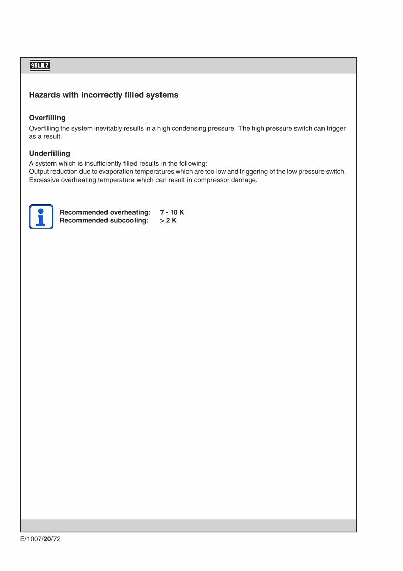
E/1007/20/72
Hazards with incorrectly filled systems
OverfillingOverfilling the system inevitably results in a high condensing pressure. The high pressure switch can trigger as a result.
UnderfillingA system which is insufficiently filled results in the following:Output reduction due to evaporation temperatures which are too low and triggering of the low pressure switch. Excessive overheating temperature which can result in compressor damage.
Recommended overheating: 7 - 10 KRecommended subcooling: > 2 K

Gerätetypen Befeuchterleistung [kg/h]
Nennstrom[A]
Nennleistung[kW]
CCD/U 41-121 230V / 1 Ph / 50Hz
1,5 6,4 1,13
3 12,7 2,25
CCD/U 171/201 400V / 3 Ph / 50Hz
3 4,2 2,25
E/1007/20/73
Unit type Humidifying capacity[kg/h]
Nominal current[A]
Nominal power[kW]
The steam humidifier is an optional extra for your A/C unit. It is installed complete and integrated within the function and method of operation of the A/C unit. Details concerning the connection assignment for the power supply can be found in the electrical diagrams in the appendix.
We recommend the installation of an Aqua-stop valve in the water supply of the humidifier. In addition to this, the room, in which the A/C unit with the humidifier is installed, should be equipped with a water detection system.
9.1.1 DescriptionThe humidifier uses normal mains water for the production of steam. The conductivity of the water should be within the range of min. 300 to max. 1250 µS/cm. The water is converted directly into steam by means of electrical energy in a steam cylinder with electrode heating. The steam is introduced into the airflow via the steam throttle.
Due to the evaporation the water level in the cylinder falls. The current consumption is reduced, as the electrodes are then immersed less in the water. With a sinking water level the mineral concentration in the cylinder increases, as the minerals do not evaporate. The current is kept by the control between two limit values (IN+10%, IN-5%). When the lower limit value is reached, the inlet valve opens. Now fresh water is mixed with residual water, which has a high mineral concentration. After several evaporation and filling cy-cles, the mineral concentration has increased in such a way, that the current reduction due to evaporation and falling water level takes place quite rapidly. When a certain limit value of current reduction is exceeded, the drain valve is opened at the moment, when also the lower current limit value is reached, and finally the cylinder is completely drained.
The filling phase is automatically interrupted if the sensor electrode is contacted due to the high water level in the steam cylinder. This may happen in the start-up phase with a new steam cylinder.
9.1.2 Technical dataFour different sizes of humidifier are installed in STULZ A/C units. You can see which humidifier is installed in your unit from the following table.
9. Options
9.1 Steam humidifier
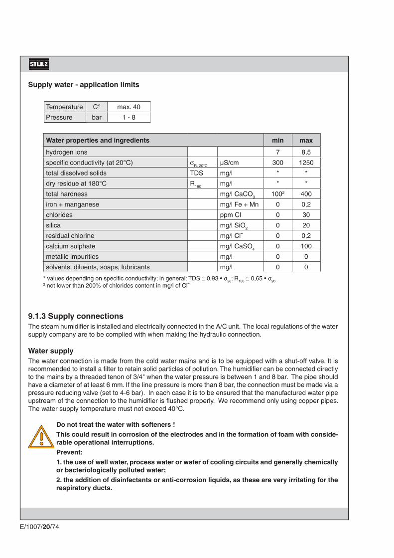
Temperatur C° max. 40
Druck bar 1 - 8
E/1007/20/74
Supply water - application limits
Temperature
Pressure
Water properties and ingredients min max
hydrogen ions 7 8,5
specific conductivity (at 20°C) σR, 20°C µS/cm 300 1250
total dissolved solids TDS mg/l * *
dry residue at 180°C R180 mg/l * *
total hardness mg/l CaCO3 1002 400
iron + manganese mg/l Fe + Mn 0 0,2
chlorides ppm Cl 0 30
silica mg/l SiO2 0 20
residual chlorine mg/l Cl¯ 0 0,2
calcium sulphate mg/l CaSO4 0 100
metallic impurities mg/l 0 0
solvents, diluents, soaps, lubricants mg/l 0 0
* values depending on specific conductivity; in general: TDS ≅ 0,93 • σ20; R180 ≅ 0,65 • σ202 not lower than 200% of chlorides content in mg/l of Cl¯
9.1.3 Supply connectionsThe steam humidifier is installed and electrically connected in the A/C unit. The local regulations of the water supply company are to be complied with when making the hydraulic connection.
Water supplyThe water connection is made from the cold water mains and is to be equipped with a shut-off valve. It is recommended to install a filter to retain solid particles of pollution. The humidifier can be connected directly to the mains by a threaded tenon of 3/4" when the water pressure is between 1 and 8 bar. The pipe should have a diameter of at least 6 mm. If the line pressure is more than 8 bar, the connection must be made via a pressure reducing valve (set to 4-6 bar). In each case it is to be ensured that the manufactured water pipe upstream of the connection to the humidifier is flushed properly. We recommend only using copper pipes. The water supply temperature must not exceed 40°C.
Do not treat the water with softeners !This could result in corrosion of the electrodes and in the formation of foam with conside-rable operational interruptions. Prevent:1. the use of well water, process water or water of cooling circuits and generally chemically or bacteriologically polluted water;2. the addition of disinfectants or anti-corrosion liquids, as these are very irritating for the respiratory ducts.

E/1007/20/75
Water drainThe drain is achieved by a plastic hose and is routed out of the unit by means of the openings in the unit provided for this purpose (refer to 6.3.1 pipe entrance area).When creating the drain, attention is to be paid to provision for cleaning. As the water drain is depressurized, we recommend routing the drain hose directly into an open collector funnel to ensure free discharge. The drainage pipe should be routed to the sewerage system with sufficient gradient (at least 5%) and should be located approx. 30 cm below the humidifier. Attention is to be paid to temperature resistance when plastic pipes are used. If copper pipe is used, it must be earthed. For the drainage pipe an inside diameter of 32 mm is recommended, however the minimum inside diameter should not be less than 25 mm.
9.1.4 CommissioningAs soon as the controller requires the humidifier function, the heating current is switched on; after approx. 30 seconds water is fed into the steam cylinder through the inlet valve which opens and fully automatic operation begins. A condition is the open shut-off valve in the water supply.
IMPORTANT NOTICE: After the water pipes have been connected, the supply piping must be flushed for approx. 30 minutes, where the water is directly conducted into the drain, without letting it flow into the steam humidifier. This way residues or substances of the installation process are removed, which otherwise could block the fill valve and cause foam during the boiling process.
Decommissioning the humidifierThe steam cylinder is to be emptied if the humidifier has been out of operation for a longer period (e.g. in summer, decommissioning the air conditioning system etc.) (see 9.1.6 Maintenance - Drainage).

3 4ON
OFF
3 4ON
OFF
3 4ON
OFF
3 4ON
OFF
RS485RS485
1 2ON
OFF
1 2ON
OFF
5 6ON
OFF
5 6ON
OFF
5 6ON
OFF
5 6ON
OFF
E/1007/20/76
9.1.5 OperationThe steam humidifier is controlled and monitored by the controller. No further operating measures are required for continuous operation.However, you can always vary the humidifier output, by operating the DIP-switches A3/4, which are located on the humidifier printed circuit board in the electrical section of the A/C unit.
The humidifier operation is indicated by a green LED. From the yellow LED you can see the state of opera-tion of the humidifier (see diagram 1,2). The red LED indicates if an alarm is active (see alarm table).You can also manually drain the steam cylinder (see 9.1.6 Maintenance). The position of the TA RATE-switches 1-4, the DIP-switches A2 and B2 is not to be changed under no circumstances. For this reason the switches are sealed.
100 % humidification capacity
75 % humidification capacity
50 % humidification capacity
20 % humidification capacity
Power supply 24 VACG/G0
manual drainage
drain valvefill valve
high level/foam sensor
conductivity sensor
external TAM
immersed electrodes max. 5A
alarm relayhumidity sensor external controller
remote ON/OFF
green LEDyellow LEDred LED
fig. 1
DIP A2: Alarm relay status
Relay energized (contact closed), when at least 1 alarm is active, other-wise not energized (contact open).
Relay not energized (contact open), when at least 1 alarm is active, other-wise energized (contact closed).
3 days
2 days
3 days
7 days
DIP A5-6: Adjustment of the inactivity period, after which the cylinder is completely drained.

1 2 3 4ON
OFF
1 2 3 4ON
OFF
E/1007/20/77
DIP-switch B1 : Setting of the hour counter and maintenance alarm
OFF (default): hour counter and maintenance alarm enabled
ON: hour counter and maintenance alarm disabled (only if the DIP-switch B1 is already ON before switching on the humidifier board).
Maintenance warningAfter 2000 humidifier operating hours a warning is released, which is indicated by a flashing red LED (7 short flashes) and the intermittent activation of the alarm relay (only if no other alarms are active). The alarm indicates the need for a cylinder maintenance. However, the humidifier operation is still possible.
Maintenance alarmAfter 3000 operating hours an alarm is released, which is indicated by a flashing red LED (8 short flashes) and the steady activation of the alarm relay. The alarm indicates the necessary exchange of the steam cy-linder. The humidifier operation is blocked.
Reset of the hour counter and the alarms1. Set DIP-switch B1 to ON, after 5 seconds the alarm LED (red) and the operation LED (yellow) lights up
for 3 seconds (the alarms are still active and the hour counter is still in operation).
2. Set DIP-switch B1 to OFF, the hour counter starts from 0, the alarms are cancelled. The humidifier operation is enabled again.
Notice for counting the operating hoursThe counting of the operating hours is proportional to the steam production, because the amount of lime accumulating in the cylinder (as a criterion for the cylinder exchange) depends on the steam production. Example:After 100 operating hours with 100% steam production the hour counter has saved 100 hours.After 100 operating hours with 75% steam production the hour counter has saved 75 hours.

1 2 3 4ON
OFF
1 2 3 4ON
OFF
1 2 3 4ON
OFF
5 6ON
OFF
5 6ON
OFF
5 6ON
OFF
5 6ON
OFF
7 8ON
OFF
7 8ON
OFF
7 8ON
OFF
7 8ON
OFF
E/1007/20/78
time = default
time = default - 30%
time = default + 33%
time = default + 66%
threshold = default
threshold = default - 30%
threshold = default + 33%
threshold = default + 66%
DIP B5-6: DIP B7-8:automatic drainage time evaporation time threshold
Change the default adjustment only after confirmation of the STULZ technical support. The dip-switches serve to adapt the drain cycle to extreme water conditions beyond the previously described limit values.
DIP-switch B2-8 : Auxiliary functions and automatic drain timings
DIP B2: automatic drainage with electrodes powered/not poweredON: electrodes powered during automatic drainageOFF (default): elctrodes not powered
DIP B3: automatic drainage when request is reduced by at least 25%.ON: new humidification capacity achieved by steam cyclesOFF (default): 1. new humidification capacity is achieved by steam cycles, if the request
is reduced by less than 25%. 2. automatic drainage, if the request is reduced by at least 25%
DIP B4: disabling of the pre-alarm and the warning for wornout cylinder (see alarm table 2)
ON: warnings are never displayed.OFF (default): warnings are displayed when the cylinder is worn out.

< 1%
1-19%
20-29%
90-99%
< 1%
1-19%
20-29%
90-99%
100%
E/1007/20/79
The yellow LED stays off when no steam is produced, whereas it stays continuously on at 100% of the nominal production.
When steam is being produced at a transient production rate while approaching the steady-state production, the yellow LED is quickly turned on and off to produce 2 Hz-pulse sequences which are related to the actual steam production as shown in diagram 1.
When the steady-state production is achieved, the yellow LED is slowly turned on and off to produce 0,5 Hz-pulse sequences which are related to the actual steam production as shown in diagram 2.
Each pulse sequence is separated from the following by a 3-second delay, so that the user can count the pulse number of a sequence and determine, using the diagram, the actual humidification capacity.
Diagram 1: Steam production: yellow LED - transient production "short flashing"
Diagram 2: Steam production: yellow LED - constant production "long flashing"
time
time
time
time
time
time
time
time
time
steam
steam

E/1007/20/80
9.1.6 Maintenance
Please switch off the A/C unit at the controller and the main isolator before starting work and put the power circuit breaker F70 in the electrical box to position 0!
The following work and checks can be carried out:- check steam hoses, condensate hoses, water hoses and other parts of the humidifier for external effects
or wear.
- Flush out the water drain.
Replacing the steam cylinderThe steam cylinder needs replacing if the electrodes are so highly insulated due to the increasing calcification or furring that the water level in the steam cylinder constantly touches the sensor electrode.The specially constructed water filling beaker provides additional safety here, excessive water being routed to an overflow and being able to drain away there.
Warning note!The temperature of the discharged water is approx. 60°C during normal operation but can reach 100°C briefly, if the steam cylinder is emptied manually during maintenance work.
The steam cylinder should be allowed to cool down slightly before removal. If the alarm code 11x long on the humidifier printed circuit board in the electrical section (also refer to Alarm table 2) occurs repeatedly, the steam cylinder has worn out and must be replaced. The life of a steam cy-linder depends on the operating period and the hardness of the water.
Manual drainageBy means of a switch on the humidifier board, you can manually drain the cylin-der. After the drainage the switch must be reset to position "ON", otherwise no humidification can take place.
Position "ON" Position "DR"
Switch off the power supply circuits to the humidifier before continuing the work!
The steam cylinder can be unscrewed from the mount after releasing the hose clamp, pulling off the steam hose and disconnecting the electrical plug on the cylinder.The new steam cylinder is installed in the reverse sequence. The humidifier is re-started in accordance with the recommendations of the chapter "9.1.4 Commissioning".

E/1007/20/81
9.1.7 Malfunction causes / RemedyAlarm: Humidifier defect
The humidifier alarm is received by the controller and can be requested according to the equipment.
C7000-control system: no display (display only externally)C7000 plus-terminal: indication on the displayC7000 advanced terminal: indication on the display
In the event of this signal on the controller, please look for the exact cause of the fault on the humidifier printed circuit board in the electrical section of the A/C unit. If an alarm has been raised, the red light-emitting diode displays a flashing alarm code. The meaning of the alarm codes can be seen in the alarm table 2.
time
time
time
time
time
time
time
time
no alarm
1x flashing
2x flashing
9x flashing
Diagram 3: Alarms: red LED - "short flashing"
Diagram 4: Alarms: red LED - "long flashing"
no alarm
1x flashing
2x flashing
9x flashing

E/1007/20/82
Reset (if alarm cause has been removed)
manual: to restart, turn the cp-card off and then on again.
• automatic• manual: to restart, turn the cp-card off and then on again.
Note: the distinction between the automatic and manual reset is shown in the table below.
• automatic
Type
Blocking
Disabling
Warning
Description
CP-card stops humidifier.
CP-card stops humidifier.
CP-card does not stop humidifier.
Red LED
Alarm codes:each code is displayed in sequence.
The codes are displayed even if the alarm causes have been removed; to stop displaying them, turn the cp-card off and then on again.
Alarm relay
The relay is normally open or normally close depending on DIP A2.The relay action is cumulative:• contact is closed (opened), if at least 1 alarm is active.• contact is opened (closed), if:- all alarm causes have been removed.- all alarms have been reset, either manually or automati-cally.
Note: each alarm is not assi-gned to the relay (see table below)
Table 2 - Alarms
Description & Causes
Electrode over-current1. water conductivity too high (usually when starting after a short stop)2. high water level due to drain valve malfunction3. high water level due to fill valve leakage4. electrode malfunction
No voltage at the electrodes:with the unit on, no steam is produced.
Internal memory error
High conductivity of the supply water
Red LED flashes2xshort
3xshort
4xshort
5xshort
Remedy
1. Drain part of the water and re-start.2. Verify that the drain valve is properly working.3. Check for any leakage of the fill valve when the humidifier
is switched off.
1. Check the external command signal: type (V or mA)? Value? Connections?
2. Switch off the unit and disconnect it from the mains: check the internal electrical connections.
1. Download the proper default configuration via HumiSet.2. If the problem persists, contact the STULZ customer ser-
vice.
1. Switch off the unit and clean the conductivity sensor elec-trodes;
2. If the problem persists, change the source of supply water or install a suitable treatment system (demineralisation, even partial).
Note: the problem will not be solved by softening the supply water.
Type
blocking
blocking
blocking
blocking
Reset
manual
manual
manual
manual
Alarm-relayactive
active
active
active
Alarm list
Table 1 - Alarm types

E/1007/20/83
Description & Causes
Cylinder depleted
Lack of supply water
Excessive reduction of steam productionDrain malfunction
User parameter error
Supply water high conductivity pre-alarm
External command signal not properly connected(only 2/10V)Cylinder full with steam pro-duction not in progress
Foam inside the cylinder
Cylinder almost completely depleted
Red LED flashes2x long
3x long
4x long
5x long
6x long
7x long
8x long
9x long
10xlong
11xlong
Remedy
Do maintenance and/or replace the cylinder.
1. Check that the fill pipe from the mains to the humidifier and the internal pipe are not blocked or bent and that there is sufficient supply pressure (1-8 bar).
2. Check that the fill valve is properly working.3. Check whether the counter-pressure onto the steam hose
is higher than the maximum limit, preventing the entry of supply water into the cylinder by gravity.
4. Check that the steam outlet pipe is not choked and that there is no condensate inside.
1. Cylinder completely depleted or excessive foam. Do main-tenance to the cylinder.
1. Check the drain circuit and the proper operation of the drain valve.
1. Download the proper default configuration via HumiSet.2. If the problem persists, contact the STULZ customer ser-
vice.
1. Check the conductivity of the supply water. 2. If necessary install a suitable demineralizer.Note: the problem will not be solved by softening the supply
water.
1. Check the connection to the (external) controller.
with the humidifier switched off:1. Check for any leaks from the fill valve or the condensate
return pipe.2. Check that the level sensors are clean.Foam is usually caused by surfactants in the water (lubri-cants, solvents, detergents, water treatment agents, softe-ners) or an excessive concentration of dissolved salts:1. Drain and clean the water supply pipes.2. Clean the cylinder.3. Check for the presence of softeners. (in this case, use
another type of supply water or reduce the softening)
Do maintenance and/or replace the cylinder.
Type
warning
disabling
disabling
disabling
blocking
warning
disabling
disabling
warning
warning
Reset
manual
manual
manual
manual
manual
display:auto-matic reset
alarm:automat.
manual
display:manualreset
display:manualreset
Alarm-relaynot activeactive
active
active
active
not active
active
active
notactive
notactive
Table 2 - Alarms (continued)
Note: "manual reset" means one of the following activities - pulling off and putting on the power supply plug G/G0 (see 9.1.5 operation - fig. 1) - switching off and on the control fuses F02 (Caution: unit is switched off.)

CCD/U 41-121
CCD/U 171/201
E/1007/20/84
Installation
The reheats are installed and connected in the A/C unit. The LPHW reheat is to be connected on site to the external hot water circuit. The pipelines are to be routed out of the A/C unit in accordance with the section Installation "pipeline and cable ducts". The LPHW reheat is connected via a 22 mm copper pipe.
Operation
The reheat is controlled and monitored by the controller. No further measures are required for operation.
Maintenance
Clean the reheat annually from contaminations and check it for damage.
The heater is an optional extra for your A/C unit. It is installed complete and integrated in the function and method of operation of the A/C unit. It is used to heat up the air. The following versions of the reheat are available: - Electrical reheat - Low pressure hot water reheat (LPHW) - Refrigerant reheat (RF)
Electrical reheat LPHW reheat RF reheat
The LPHW reheat is to be connec-ted to an external hot water circuit. The water supply is controlled via an electrically actuated LPHW valve.The LPHW valve is controlled via the controller. Refer to the C1002 manual.
The refrigerant reheat is inte-grated in the refrigerant circuit in accordance with the refrigerant diagram in the "Appendix". The refrigerant supply is controlled via an electrically-actuated 3-way so-lenoid valve. The solenoid valve is controlled via the controller. Refer to the C1002 manual.
The heater is connected in accord-ance with the connection diagram (refer to "Appendix"). It is controll-ed and monitored by the controller. The values for switching on and off are adjusted on the controller. Refer to the C1002 manual.
9.2 Heating

E/1007/20/85
Electrical Heating Alarm
Symptom
The overheat protection has triggered.
Power circuit-breaker has triggered.
Cable connection to heater open circuit.
Action
Check whether the fins of the heating are dirty.Raise air flow (at CCD/U 41-121)Mesure the current consumption of the heating.
for CCD/U 171/201:Check power circuit-breakers and electrical heater for damage.Replace defective power circuit breaker or electrical heater.
for CCD/U 41-121:In this case there is no display on the C1002.
Check cable connection.
1
Comments
Repairs to the electri-cal components are only to be carried out
by authorized trained staff or by STULZ Customer Service Department.
The A/C unit is to be switched off at the master switch before opening it.
After the elimination of the
fault press the key code
twice.
2
3

CCD 41-121
600
620
575
595
CCD 171-201
810
830
1000
1020
495
E/1007/20/86
9.3 Raised floor stand
The floor stand is used to adjust the height of the A/C unit to the existing raised floor and consists of an encircling rectangular profile of galvanized steel with adjustable screw sockets. Anti vibration compound is recommended between concrete floor and base plate.The delivery volume contains: 4 bars of rectangular profile 70 x 40, 4 mafund plates, 4 adjustable supports, which can be shortened on site, 8 hammer head screws M8 x 30
Rectangular profile 70 x 40 x 2
Cut out in raised floor
Connecting the bars(View from below)
Rectangular profile 70 x 40 x 2
Cut out in raised floor
Angle Connection
Positioning of supports
Positioning of supports

X Z
Z (min. 30)
Y
Z (min. 800)Z(min. 30)
10 mm 10mm600 mm /1000 mm
max 500 m
in 250
E/1007/20/87
X/Y = Opening in raised floor Z = Limit of distance
- the raised floor cutting (notch) should at least be 15° and must not have any contact to the raised floor stand, which could result in bone-conduction.
- the dimensions of the openings in the raised floor (X and Y) are 10 mm longer than the raised floor stand. The joint must be closed by customers with a continuous seal.
- a concrete foundation is recommended in the area of the raised floor supports.
- the raised floor supports have to be installed on vibration dampening material (do not screw down the supports!).
- prior to installation of the A/C unit, the raised floor must be installed 7 mm higher than the raised floor plates, as the mafund plates are compressed by the weight of the A/C unit.
Minimum distances and mounting instructions
General design of the raised foor stand
Recommended concrete foundations
(no (floor) finish)
Hammer head screw M8 x 30Upper support partRange of adjustment :± 20mm
Mafund strips
Upper edge of rough floor
Raised floor supportRaised floor stand
Continuous seal
Raised floor
Supporting pipe
Raised floorconnection refer to details on next page
Floor stand
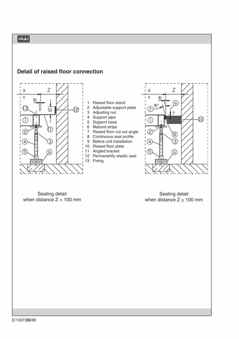
E/1007/20/88
Raised floor standAdjustable support plateAdjusting nutSupport pipeSupport baseMafund stripsRaised floor cut out angleContinuous seal profileBefore unit installationRaised floor plateAngled bracketPermanently elastic sealFixing
123456789
10111213
Sealing detail when distance Z < 100 mm
Sealing detail when distance Z > 100 mm
Detail of raised floor connection

E/1007/20/89
STULZ A/C units of the type A, G are equipped as standard with a refrigerant circuit which can be expanded with various options.
Description
9.4 Refrigerant Circuit Options
A/C unit type A with hot gas bypass extension
The refrigerant circuit of your A/C unit is equipped with a compressor which is designed for 12 switching cycles per hour. The following operating curve for the refrigerant circuit results from these switching on and off phases.
In order to reduce the switching rate and thus increase the life of the compressor, the refrigerant circuit can be enhanced by a hot gas bypass or with a suction throttle. The hot gas bypass has a control range of 50 to 100%.
Off 0%
On 100%Compressor
Evaporator
Fan
Hot gas bypass
Low tem-perature section
Air section
Collector

E/1007/20/90
A/C unit type A with suction throttle extension
The suction throttle has a control range of 40 to 100%.
Evaporator
Fan
Low tem-perature section
Air section
Collector
Suction throttle

kWm³/h
kW°C°CV/-/Hz
KSI 018CCD/U
41-121 A17.54000
10.553248
230/1/50
KSI 033CCD/U
171-201 A32
75001
2.23248
400/3/50
KSI 018
840400120100361329721366006001850
KSI 033
10257402108036141569
242,58109001950
E/1007/20/91
Adjustable HP/LP switch
The compressor is controlled and monitored by the controller of your A/C unit. Permanently set high-pressure and low-pressure switches are required as sensors for this. An adjustable version of these HP/LP switches is supplied in order to individually adapt the switching points for the high pressure and low pressure to the operating conditions.
Internal condenser
Type of condenserfor A/C unit
Condenser outputAir flowNo. of fansMotor powerAir inlet temperatureTemp. of condensationElectrical connection
Technical Data
The internal condenser is an option for A-type units and is in-stalled on the left side of the A/C unit. It contains a fan with a motor and a heat exchanger which is connected with the A/C unit by copper tubes.
Dim.
ABCDEFGHJKL
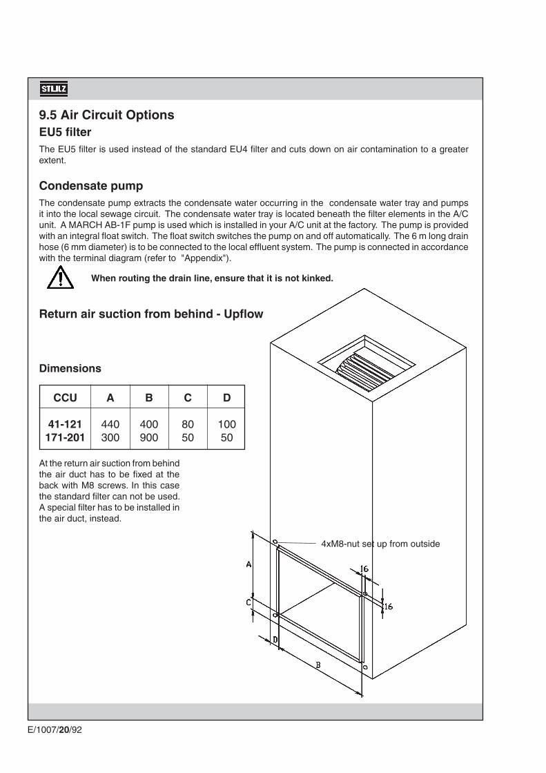
CCU
41-121171-201
A
440300
B
400900
C
8050
D
10050
E/1007/20/92
Return air suction from behind - Upflow
At the return air suction from behind the air duct has to be fixed at the back with M8 screws. In this case the standard filter can not be used. A special filter has to be installed in the air duct, instead.
Dimensions
4xM8-nut set up from outside
9.5 Air Circuit OptionsEU5 filterThe EU5 filter is used instead of the standard EU4 filter and cuts down on air contamination to a greater extent.
Condensate pumpThe condensate pump extracts the condensate water occurring in the condensate water tray and pumps it into the local sewage circuit. The condensate water tray is located beneath the filter elements in the A/C unit. A MARCH AB-1F pump is used which is installed in your A/C unit at the factory. The pump is provided with an integral float switch. The float switch switches the pump on and off automatically. The 6 m long drain hose (6 mm diameter) is to be connected to the local effluent system. The pump is connected in accordance with the terminal diagram (refer to "Appendix").
When routing the drain line, ensure that it is not kinked.

CCU
41-121171-201
A
572782
B
6001000
C
425625
D
525825
E
325425
H
500500
E/1007/20/93
Air discharge plenum - Upflow
Dimensions
The air discharge plenum is set on the A/C unit without being screwed.
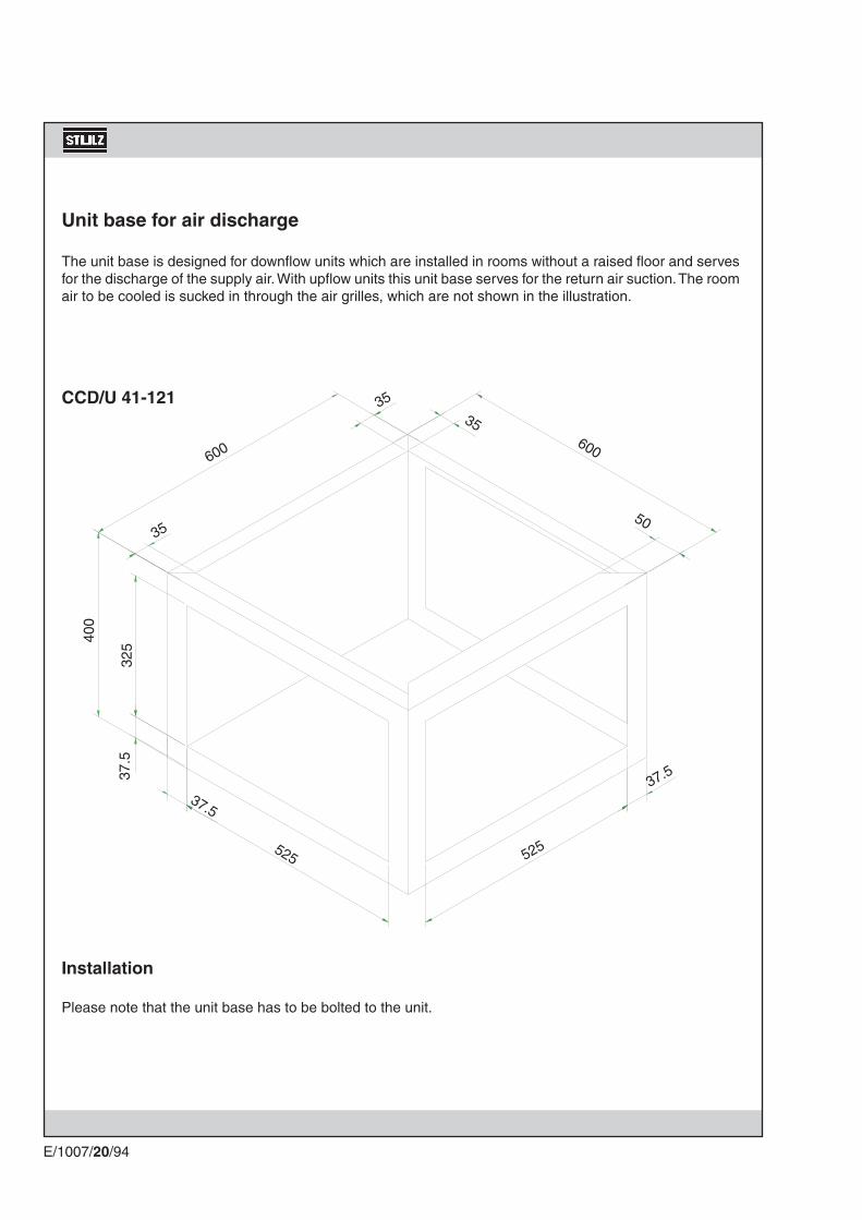
600600
35
35
525
37.5
50
35
525
37.5
400
325
37.5
CCD/U 41-121
E/1007/20/94
Unit base for air discharge
The unit base is designed for downflow units which are installed in rooms without a raised floor and serves for the discharge of the supply air. With upflow units this unit base serves for the return air suction. The room air to be cooled is sucked in through the air grilles, which are not shown in the illustration.
Installation
Please note that the unit base has to be bolted to the unit.

415
51535
336
415
39.5
133.5
39.5515
133.540
031
5
315
42.5 436
782
8.5
8.5
8.5
8.5
16 x Ø3.2
1000
60 42.5
315
35
E/1007/20/95
insulation of foamed material
Unit base for air discharge for CCD/U 171-201

A
400675
B
400800
C
523738
D
552977
E
4031.5
F
5688.5
G
12x9.526x9.5
H
1720
E/1007/20/96
Base for duct connection and air damper - Upflow
The base is set on the A/C unit without being screwed. The duct is fixed on the base with 4 M8 screws.
Dimensions
4xM8-nut set up from above.(only for CCU 41-121)
Unit size
CCU 41-121CCU 171/201

A
345500500
B
400700700
AB
H
CCD/U 41-121CCD 171/201CCU 171/201
H
175120120
E/1007/20/97
Dimensions
Air damperAn air damper can only be provided on the discharge side for downflow and upflow units. The most frequent use of the air damper is shown, on the discharge side of upflow units. For the installation of an air damper on the upflow unit a connection plate (see page before) is necessary.
Continuous flange, 38 mm wide
Unit size

E/1007/20/98
Fresh air intake
Insulation
Dummy rivetCollar
Filter cartridge
Cover
Unit rear side
By means of the fresh air intake outside air is taken in, conducted through a filter into the unit and used to cool the room air. If the outside temperature is below the room temperature the required cooling capacity is reduced.The fresh air intake consists of three parts:
1. Collar 2. Filter cartridge 3. Cover
The collar is bolted at the rear wall of the unit. The filter cartridge is put on the collar in the unit and is closed with the cover. This way the outside air is only taken in via the filter surface.
We recommend to install an additional fan between the unit and the fresh air intake, to control the fresh air ratio.

CCU 110 CW CCU 200 CW
CCD 110 CW CCD 200 CW
1000600
1850
1850
30
100 mm100 mm
30
280
350
320
150
150 150
100 mm
100 mm
120
120
1850
1850
1000
3030
600
E/1007/20/99
Opening in the unit rear wall - Upflow
Opening in the unit rear wall - Downflow

E/1007/20/100
Ecocool
With the Ecocool function outside air is used for cooling the room air and is mixed with the return air via louvers. Two louvers per unit are installed. At the downflow unit the louvers are situated on top and at the upper part of the rear side, at the upflow unit the louvers are situated at the bottom part of the front and the rear side.The louvers at the rear allow outside air to come into the unit. The louver on top of the downflow unit and at the front of the upflow unit allow room air to come into the unit. The louver installed on top of the inside condenser serves to diminish the exceeding pressure in the room, as a result of the intake of additional outside air. The surplus room air flows via the opened louver into the inside condenser and through the fan intake and heat exchanger (which are out of operation) to the outside.To cut down the dust content of the outside air two filters (EU2 and EU4) are installed upstream the evapo-rator. They are part of the delivery volume.The controller C5000 and a special software are required for the louver control and must be ordered sepa-rately.
Actuators and end position switch
Louver actuator NM 24 - SR for fresh or return air
The louver actuator has no end position switch and is overload-proof. When the limit stop of the louver is attained, the actuator stops automatically.After switching on the power supply or actuating the push button on the actuator a function test with calibration is automatically executed. The actuator scans the two end positions and adapts its electrical operating range of 2-10 V DC and the running time of 150 s to the actual mechanical louver swing angle. The actuator then adjusts itself on the position which is required by the control signal. The actuators are constantly supplied with 24 V AC. The control is realized with 0-10 V DC. The actuator NM24-SR is mounted on the fresh air louver.
Function test: By pressing the button at the housing the gear shift is released, and the louver can be operated manually.
Louver actuator NM 24 for return air (option pressure compensation)
The louver actuator has no end position switch and is overload-proof. When the limit stop of the louver is attained, the actuator stops automatically.The control is realized by a 24 V AC/DC signal.
Function test: By pressing the button at the housing the gear shift is released, and the louver can be operated manually.

E/1007/20/101
Configuration of the C5000
To start the A/C unit with the free cooling device, the special software has to be installed. (The EPROMs are installed by Stulz Hamburg). After the start the software version is displayed at the C5000.
In the menu point "Control/module functions/cooling/ECO-louver the start parameters: start temperature and gradient can be modified.
In the menu point "Service/equipment/cooling/ECO-louver the unit configuration must be determined (made by Stulz Hamburg). For the ECO-louver the louver 1 field must be set on "S" ( = proportional).
Control
Two conditions are necessary for enabling the free cooling:
1. The room humidity must be within the limits, at which the unit control neither humidifies nor dehumidi-fies.
2. The outside temperature value, which can be set in the menu "Control/module functions/cooling/ECO-damper", must be passed under. The outside temperature is measured by an outside air temperature sensor connected to the C5000.The limit value can by adjusted from 0 to 99°C. In practical use the best results are obtained with a value in the range of 16-20°C.
The free cooling is switched off (and thus the cooling by compressor is switched on), if either the outside temperature rises above the adjusted value (ECO-off) in the above mentionned menu, or the room humidity is half of the humidification hysteresis below the value, at which the humidification is turned off (point 1 in the control diagram) or the room humidity is half of the dehumidification hysteresis above the value, at which the dehumidification is turned off (point 2 in the control diagram).
The louvers are proportionally controlled. In the same extent, as the outside air louver opens, the room air louver closes. The louver at the condenser is completely opened, when the free cooling is enabled and competely closed at compressor operation.
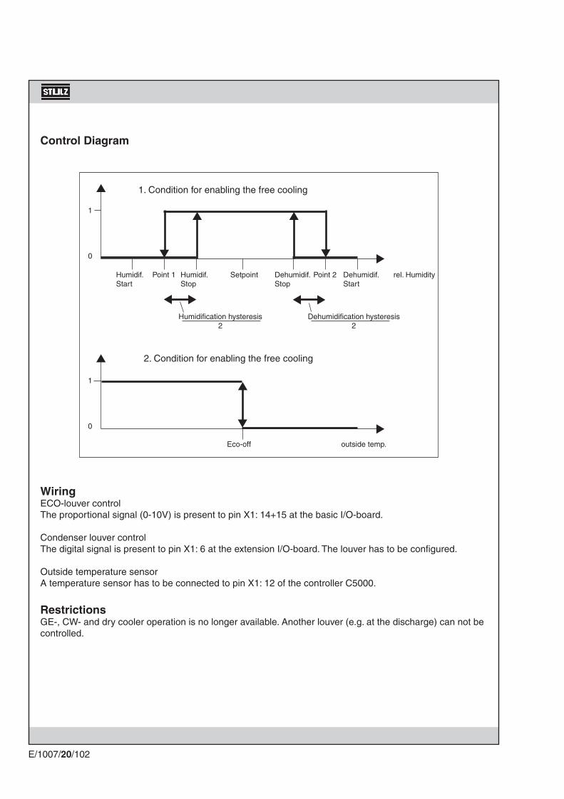
▲ ▲
▼
▲
▼ ▲
▲▼▲▼
1
0
▲
▲
1
0
▲
▼
E/1007/20/102
WiringECO-louver controlThe proportional signal (0-10V) is present to pin X1: 14+15 at the basic I/O-board.
Condenser louver controlThe digital signal is present to pin X1: 6 at the extension I/O-board. The louver has to be configured.
Outside temperature sensorA temperature sensor has to be connected to pin X1: 12 of the controller C5000.
RestrictionsGE-, CW- and dry cooler operation is no longer available. Another louver (e.g. at the discharge) can not be controlled.
Control Diagram
Humidif. Point 1 Humidif. Setpoint Dehumidif. Point 2 Dehumidif. rel. HumidityStart Stop Stop Start
Dehumidification hysteresis2
Humidification hysteresis2
1. Condition for enabling the free cooling
Eco-off outside temp.
2. Condition for enabling the free cooling

104 375 104
583
600
583
81
376
110
642
376
63
250
63
1311
187619
86
E/1007/20/103
Dimensions - CCD 41 - 121 with Ecocool louvers
front side rear side

104 375 104
583
600
110 599 110
829
58349
376
63
250
63
213
376
1850
E/1007/20/104
Dimensions - CCU 41 - 121 with Ecocool louversFront RearLeft side

91
376
131
63
250
63
129 125 129
383
50 50300
400
50.5 253 96.5
404
280
1960
1366
.5
122.
5
1850
E/1007/20/105
Dimensions - Internal Condenser KSI 010 with Ecocool louvers
front side left side rear side

117
852
89
583
876
583
1184
187419
94
104
125
125
125
104
1000
876
63 125 125 125 125 125 125 63
E/1007/20/106
Dimensions - CCD 171 - 201 with Ecocool louvers
rear sidefront side

CCD/U 41-121 CCD/U 171-201
E/1007/20/107
9.6 Control Options
C7000
Instead of the C1002 controller a C7000 controller can be fitted. For the operation of the C7000 exists a separate manual.With the application of a C7000 the design of the electrical box changes as described below.
Humidifier board (optional)
Control circuit fuses
Speed actuator
Power switches
Master switch

E/1007/20/108
Remote on/off switch
With this option you can also start your A/C unit from another point other than directly at the C1002 controller. The switch required for this is also suitable for wall mounting.
Water detector
The water detector consists of two electrodes with a voltage difference of 24 V, which are fitted in the raised floor. If water appears in the raised floor, a current flows between the electrodes, the C1002 switches off the humidifier and the signal "LLS" appears on the display.
Fire stat
There are two versions of the fire stat available: provided with a heat detector, it triggers the signal "fire" if there is excessive heat on the C1002. Equipped with a smoke detector, it reacts in a similar manner when there is smoke. In both cases the C1002 switches off the A/C unit and closes the louvered flaps (if fitted).

E/1007/20/109
Hea
ting
1
Hea
ting
2
OE
M h
umid
ifica
tion
EN
S h
umid
ifica
tion
Seq
uenc
ing
Wat
er d
etec
tor
Louv
er
Fire
sta
t/sm
oke
dete
ct.
Tem
p. li
mita
tion
Heating 1 x x x x
Heating 2 x x x x x
OEM humidification x x x
ENS humidification x x x x x x x
Sequencing x x x x x x
Water detector x x x x x
Louver x x x x x x x x
Fire stat/smoke detect. x x x x x x x x
Temp. limitation x x x x x x x x
Extension card for C1002
This card is necessary for the complete functionality and a sequencing between two units together with a water detector and a second heating stage. It is also necessary if an input for a fire stat and/or an input for an Ultrasonic conductivity alarm in a unit with a compressor is needed. With the extension card, additional inputs and outputs are provided to the CompTrol 1002, such as a louver output, a second compressor output, two pressure alarms, an airflow alarm for a second module and an input for a temperature limit. The extension card is fastened to the CompTrol 1002 by means of the two distance pieces enclosed. The electric connection to the basic board is made with a 20-channel plug connector.
When you need an extension card for CCD/U 41-201 A/G units :
x = extension card required = this combination is not possible.

E/1007/20/110
The following list contains all documents which are supplied with your unit, apart from the operating instruc-tions.
UNIT-SPECIFIC DOCUMENTS
Test report on unit final inspection ...........................................................................................
Test report on continuous testing .............................................................................................
Test report on final acceptance .................................................................................................
Test certificate for pressure test ................................................................................................
Replacement parts list ................................................................................................................
Refrigerating diagram .................................................................................................................
Terminal plan for electrical engineering ...................................................................................
Wiring diagram ............................................................................................................................
10. Appendix

E/1007/20/111
11. Customer serviceSTULZ customer service ensures optimum operating reliability by means of preventative maintenance and repair during the entire service life of your A/C units. Customer service is available to you round the clock. You can contact our customer service at the STULZ branch responsible for you.
Your partner for a safe climate
AIR CONDITIONING
STULZ - SERVICE
For your service address please look at the back cover of this manual.


