Advanced Routingin Changing Technology
LandscapeHardy Leung, MagmaISPD 2003
Overview
•Introduction- Problem solved?
•Routing Challenges (selected)- Complex spacing rules- Transitional pitches- Process antenna rules
•Opportunities (selected)- Redundant vias- Wire spreading, widening, and filling- OPC- and PSM-aware routing
•Conclusion

Introduction
•The Routing Flow- Global routing
Focused on congestion, capacity, prediction (for placement)
Global view, supply/demand-based
- Detailed routing Focused on design-rule correctness (DRC) Local view, model complex design rules, pins
- Track routing (optional) Bridge the gap between GR and DR Optimization opportunity for timing, noise
- Other combinations Simultaneous GR-TR-DR, hierarchical routing, …

Introduction (cont.)
•Academic Focus- Net-based topology generation- Congestion analysis- Global routing
•Industrial Focus- Detailed routing with complex design rules- Very high capacity (10M gates and beyond)
•The disconnect- Industry has not benefited from academia for a
while in this area- The classical DR problem is perceived as “solved”
(only grunt work or implementation details remain)

Introduction (cont.)
•Classical Detailed Routingobstacle
pin
Introduction (cont.)
•Classical Detailed Routing- Mapped into a graph problem- Solved with Dijkstra’s algorithm or variants- Common thought
nanometer design rules merely implementation details
•Reality – Devil’s in the Detail- 90nm brings about a new set of challenges- New rules- Tightening of existing rules- Capacity- Prototype of a router may take 3 months; Maturity will take
5 years- Appreciation for nanometer routing problem is much
needed Design rules are KEY Must handle high capacity

Overview
•Introduction- Problem solved?
•Routing Challenges (selected)- Complex spacing rules- Transitional pitches- Process antenna rules
•Opportunities (selected)- Redundant vias- Wire spreading, widening, and filling- OPC- and PSM-aware routing
•Conclusion
Routing Challenges
•Complex Spacing Rules- Width-dependency, length-dependency, halo
•Transitional Pitches- Drastic difference in pitches and consequences
•Process Antenna Rules- Complex rules, tightened constraints
•Routing in Uncertainty (physical OCV)- How to reduce sensitivity to process variation
•Interaction Between Complex Design Rules- Redundant via addition antenna violations- Antenna fixing timing closure issues (due to addition of
vias)- Transitional pitches Hard to fix antenna with jumpers
•… (many more) …

Complex Spacing Rules
•Evolution of Spacing Rules- Per-layer constant
- “Fatwire” spacing Special spacing for very fat wire (20X minimum width)
- Width-dependent spacing Spacing is expressed as a function of max(W1, W2)
- WW-dependent spacing Spacing is expressed as a function of W1, W2
- WL-dependent spacing Spacing is expressed as a function of L, max(W1, W2)
Complex Spacing Rules (cont.)
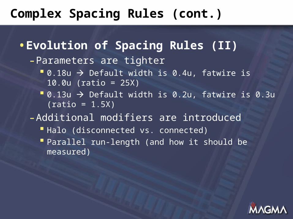
•Evolution of Spacing Rules (II)- Parameters are tighter
0.18u Default width is 0.4u, fatwire is 10.0u (ratio = 25X)
0.13u Default width is 0.2u, fatwire is 0.3u (ratio = 1.5X)
- Additional modifiers are introduced Halo (disconnected vs. connected) Parallel run-length (and how it should be measured)
Complex Spacing Rules (cont.)
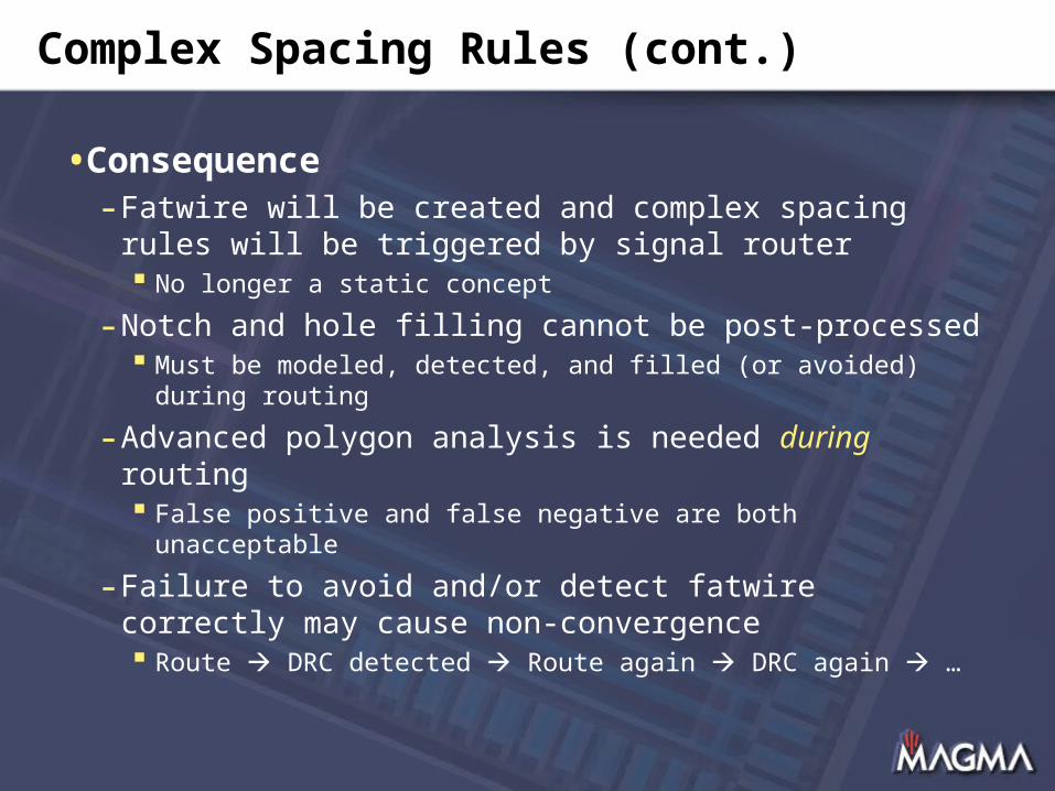
•Consequence- Fatwire will be created and complex spacing rules
will be triggered by signal router No longer a static concept
- Notch and hole filling cannot be post-processed Must be modeled, detected, and filled (or avoided) during
routing
- Advanced polygon analysis is needed during routing False positive and false negative are both unacceptable
- Failure to avoid and/or detect fatwire correctly may cause non-convergence Route DRC detected Route again DRC again …
Complex Spacing Rules (cont.)
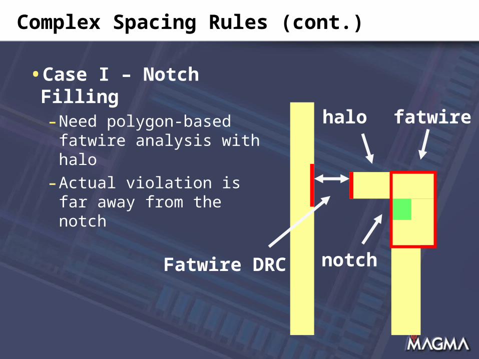
•Case I – Notch Filling- Need polygon-based
fatwire analysis with halo
- Actual violation is far away from the notch
notch
fatwirehalo
Fatwire DRC

Complex Spacing Rules (cont.)
•Case II – Tricky Pin Geometries- Pins may be designed just one notch shy of
fatwire
- Any non-trivial connection may result in spacing violations

Complex Spacing Rules (cont.)
•Case III – Fatwire Created During Routing- Individual wires and vias look clean
- Not if combined
0.9u
M4
M5
M6 M6M5
M4
0.9u
1.8u
Complex Spacing Rules (cont.)
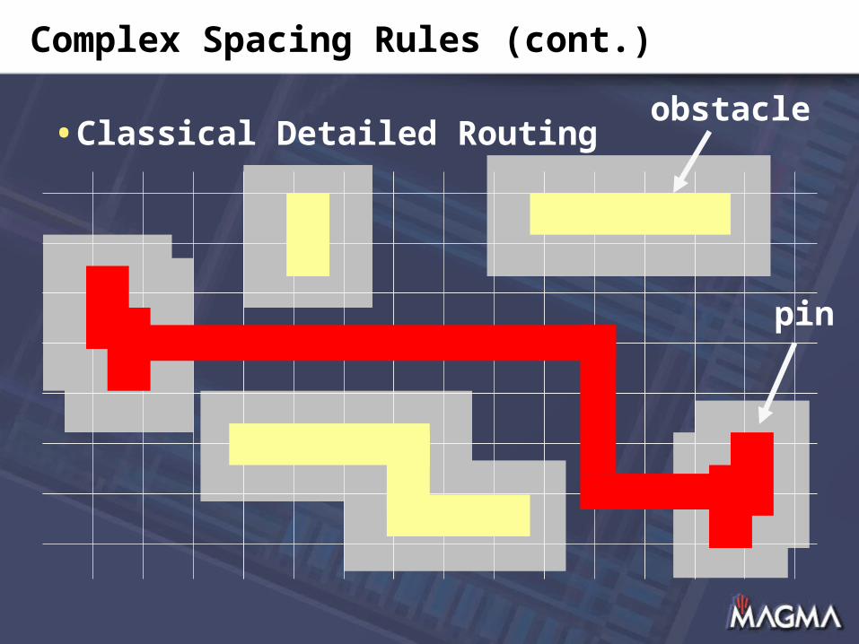
•Classical Detailed Routingobstacle
pin
Complex Spacing Rules (cont.)
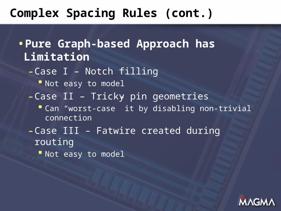
•Pure Graph-based Approach has Limitation- Case I – Notch filling
Not easy to model
- Case II – Tricky pin geometries Can “worst-case” it by disabling non-trivial connection
- Case III – Fatwire created during routing Not easy to model

Transitional Pitches
•Definition of routing grids- Typically at least the line-to-”via” spacing
- In general, line-to-upvia != line-to-downvia
Locallayers
Intermediatelayers
Globallayers

Transitional Pitches (cont.)
•In case of major pitch change- Recommend use of line-to-downvia for pitch
efficiency
- Global, track, detailed routers must understand and manage the pitch transition
Transitional Pitches (cont.)
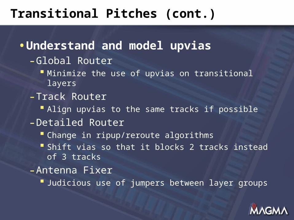
•Understand and model upvias- Global Router
Minimize the use of upvias on transitional layers
- Track Router Align upvias to the same tracks if possible
- Detailed Router Change in ripup/reroute algorithms Shift vias so that it blocks 2 tracks instead of 3 tracks
- Antenna Fixer Judicious use of jumpers between layer groups
Process Antenna Rules
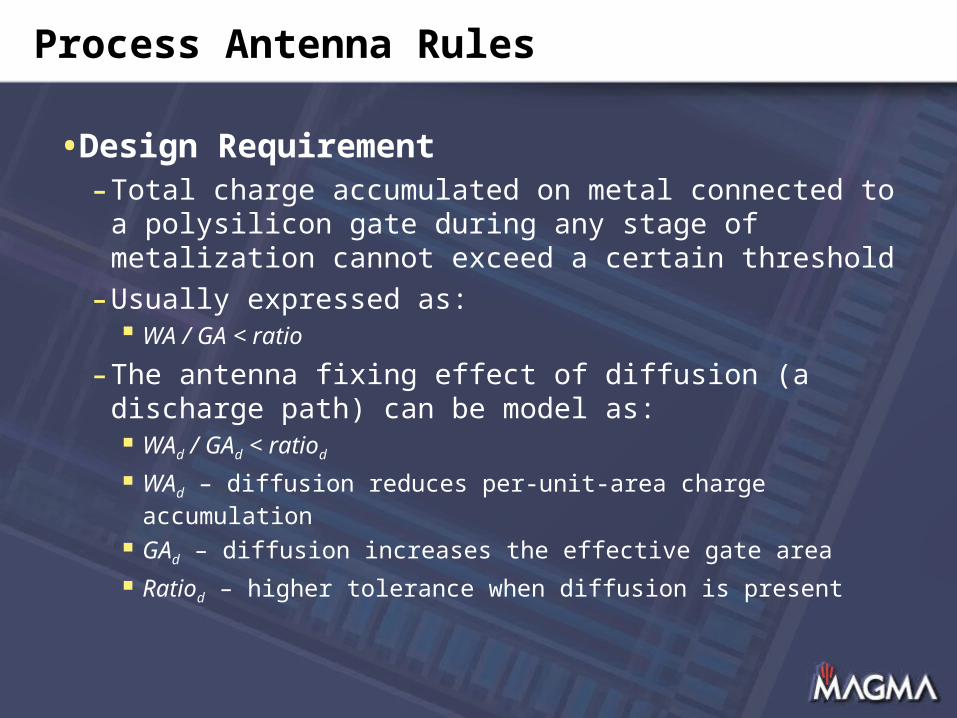
•Design Requirement- Total charge accumulated on metal connected to
a polysilicon gate during any stage of metalization cannot exceed a certain threshold
- Usually expressed as: WA / GA < ratio
- The antenna fixing effect of diffusion (a discharge path) can be model as: WAd / GAd < ratiod
WAd – diffusion reduces per-unit-area charge accumulation
GAd – diffusion increases the effective gate area
Ratiod – higher tolerance when diffusion is present
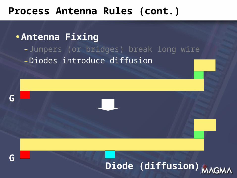
Process Antenna Rules (cont.)
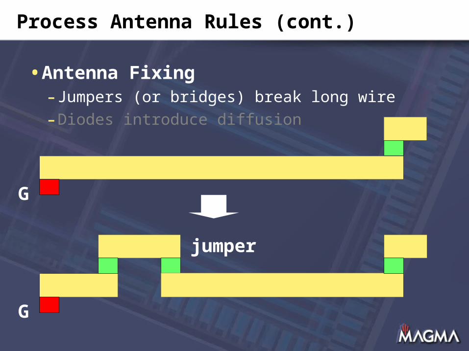
•Antenna Fixing- Jumpers (or bridges) break long wire
- Diodes introduce diffusion
G
G
jumper
Process Antenna Rules (cont.)
•Antenna Fixing- Jumpers (or bridges) break long wire
- Diodes introduce diffusion
G
G
Diode (diffusion)
Process Antenna Rules (cont.)
•Antenna Fixing- Jumpers (or bridges) break long wire
- Diodes introduce diffusion
- Buffering (a way to break long wires)
- Sizing (to increase the gate area)
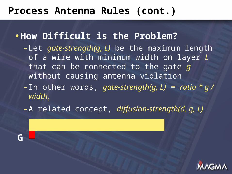
Process Antenna Rules (cont.)
•How Difficult is the Problem?- Let gate-strength(g, L) be the maximum length
of a wire with minimum width on layer L that can be connected to the gate g without causing antenna violation
- In other words, gate-strength(g, L) = ratio * g / widthL
- A related concept, diffusion-strength(d, g, L)
G
Process Antenna Rules (cont.)
•Gate and Diffusion Strengths are Functions of- process + library- foundry (different modeling, conservatism)
•Difficulty of Antenna Fixing- Gate and diffusion strengths are useful metrics to
measure how difficult it is to fix antenna violation- 0.18u
Gate strength ~ 1000u (trivial to fix) Infinite diffusion strength
- 0.13u / 90nm Gate strength ~ 100u Worst case, 15u (very poor cell design) Limited diffusion strength
Process Antenna Rules (cont.)
•Advance in Process Technology …- Reduced gate strength
Process antenna effect very easy to be violated Limited degree of freedom in antenna fixing
- Reduced diffusion strength Diffusion no longer a panacea Accurate blackbox abstraction needed (can’t waive)
- Transitional pitches surgical jumper may not be feasible due to fat
overhang
- Pervasive power mesh for IR-drop surgical jumper may not be feasible since upper layers
blocked

Process Antenna Rules (cont.)
•How to Fix it Then?- More powerful jumper techniques
- Antenna-aware global routing WARNING, most preventive implementation will not
work
- Hierarchical antenna checking and fixing
- Buffering and sizing with antenna-awareness (in addition to timing, noise, crosstalk, EM, …)

Overview
•Introduction- Problem solved?
•Routing Challenges (selected)- Complex spacing rules- Transitional pitches- Process antenna rules
•Opportunities (selected)- Redundant vias- Wire spreading, widening, and filling- OPC- and PSM-aware routing
•Conclusion
Redundant Vias
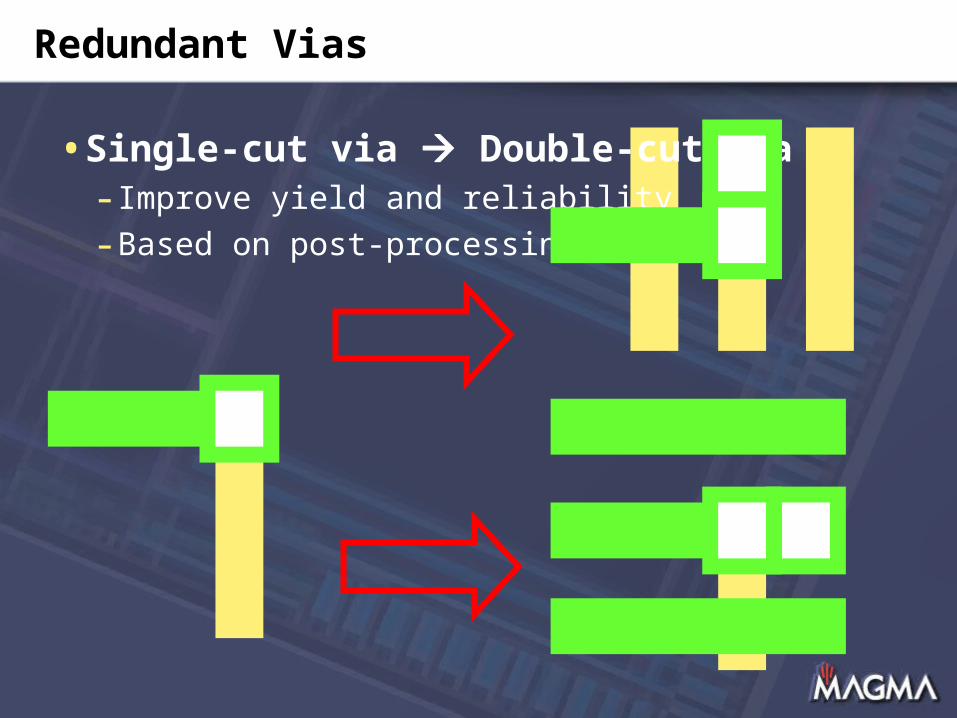
•Single-cut via Double-cut via- Improve yield and reliability
- Based on post-processing
Redundant Vias (cont.)
•Many Different Choices- 1x2, 2x1, centered, biased- 70% to 80% coverage even for very congested
designs
•Observations- Need room on only one of the two adjacent layers- Rare to see congestion on all layers everywhere
•Additional Degree of Freedom- DR creates local detour, or enforce double vias in
uncongested regions- TR assigns track in redundant-via friendly ways- GR avoids congestion on both layers whenever
possible (good to do so for routability anyway)

Redundant Vias (cont.)
•More Aggressive Redundant Vias- Can achieve 90% coverage
•Caveats- Foundry technology may negatively impact
feasibility If redundant vias have fat via overhang
- Redundant vias may introduce antenna violation Dramatically tightened antenna rules on via layers
- Redundant vias will change timing Speed up some paths, slow down some Therefore, it needs to be done within P&R framework
Wire Spreading and Widening
•Again, for Yield and Reliability- Detailed router (or post-processing) can spread
wires whenever possible
- Better result if global router and track router spread the wires in a more global scope
- Potential consequence in timing, crosstalk, … Therefore, it needs to be done within P&R framework
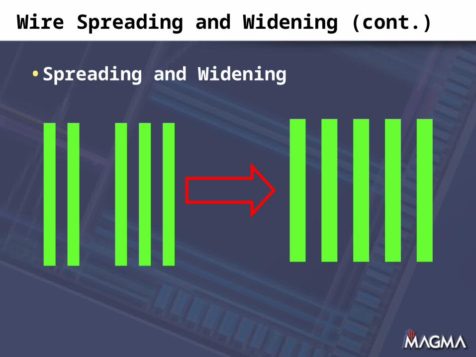
Wire Spreading and Widening (cont.)
•Spreading and Widening
Metal Filling
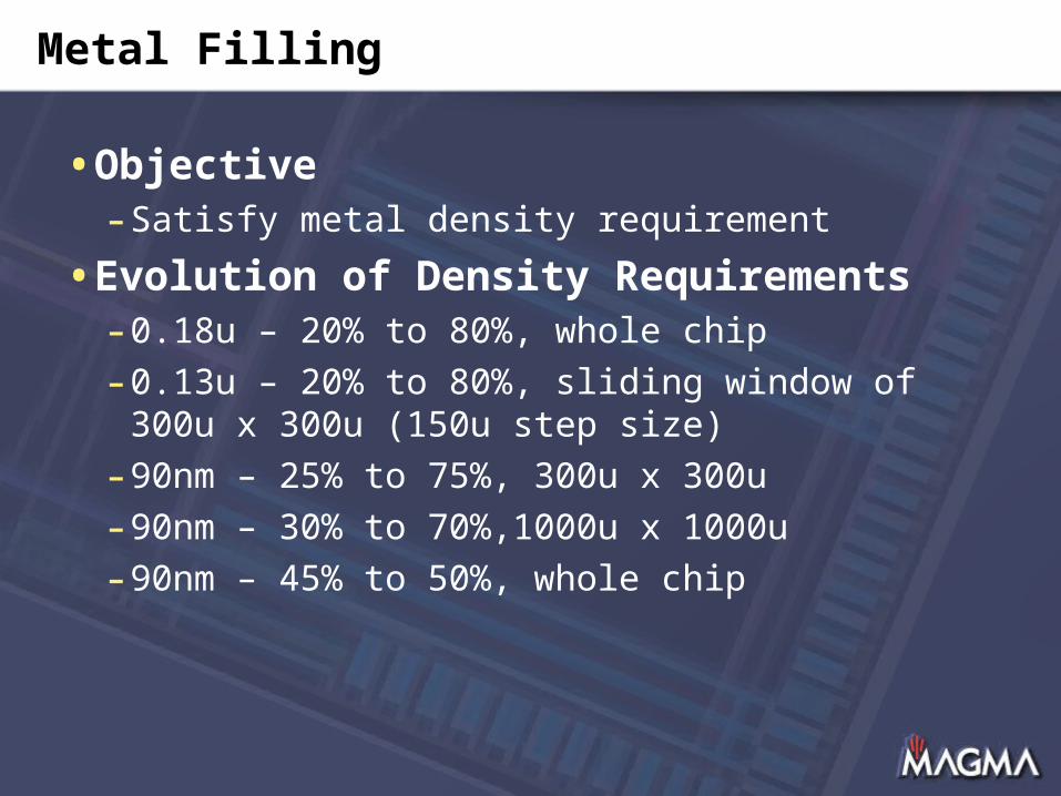
•Objective- Satisfy metal density requirement
•Evolution of Density Requirements- 0.18u – 20% to 80%, whole chip
- 0.13u – 20% to 80%, sliding window of 300u x 300u (150u step size)
- 90nm – 25% to 75%, 300u x 300u
- 90nm – 30% to 70%,1000u x 1000u
- 90nm – 45% to 50%, whole chip
Metal Filling (cont.)
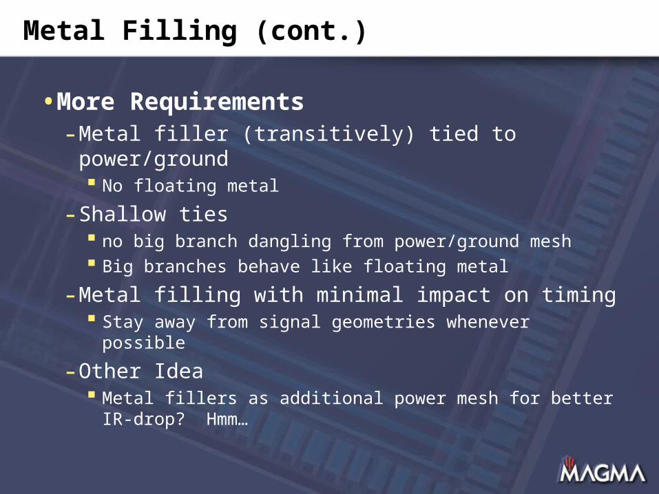
•More Requirements- Metal filler (transitively) tied to power/ground
No floating metal
- Shallow ties no big branch dangling from power/ground mesh Big branches behave like floating metal
- Metal filling with minimal impact on timing Stay away from signal geometries whenever possible
- Other Idea Metal fillers as additional power mesh for better IR-
drop? Hmm…
Metal Filling (cont.)
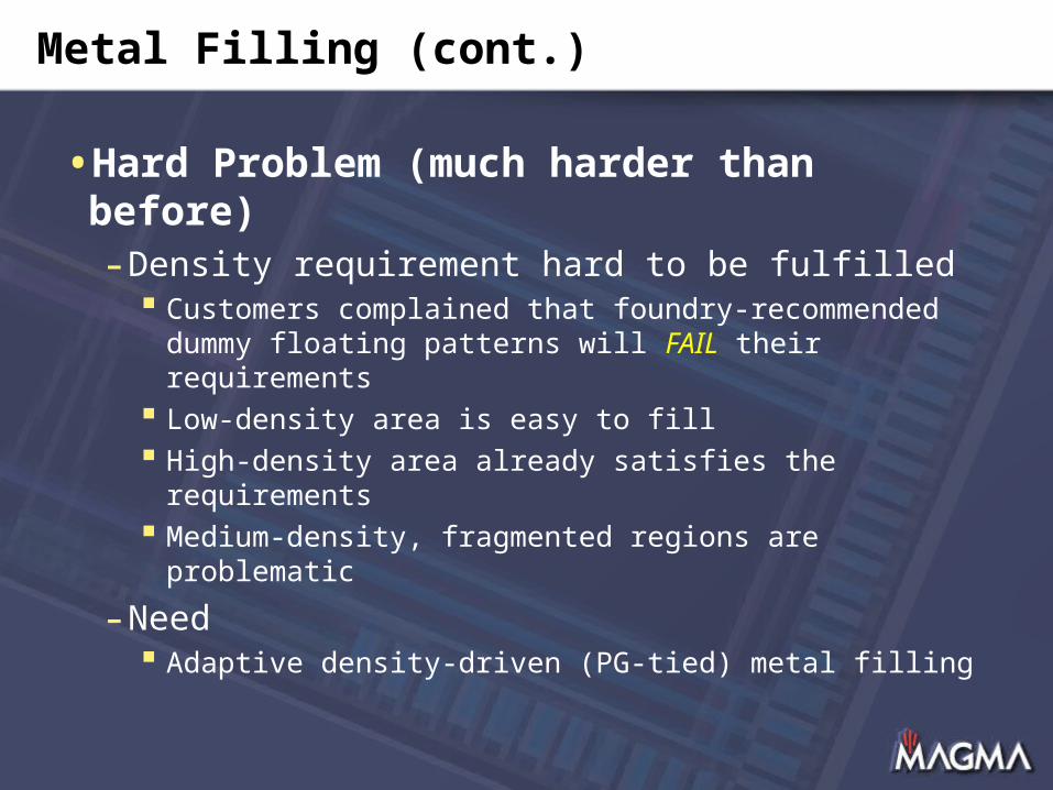
•Hard Problem (much harder than before)- Density requirement hard to be fulfilled
Customers complained that foundry-recommended dummy floating patterns will FAIL their requirements
Low-density area is easy to fill High-density area already satisfies the requirements Medium-density, fragmented regions are problematic
- Need Adaptive density-driven (PG-tied) metal filling

Metal Filling (cont.)
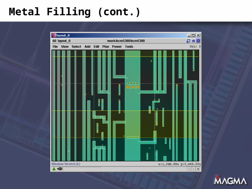
Metal Filling (cont.)
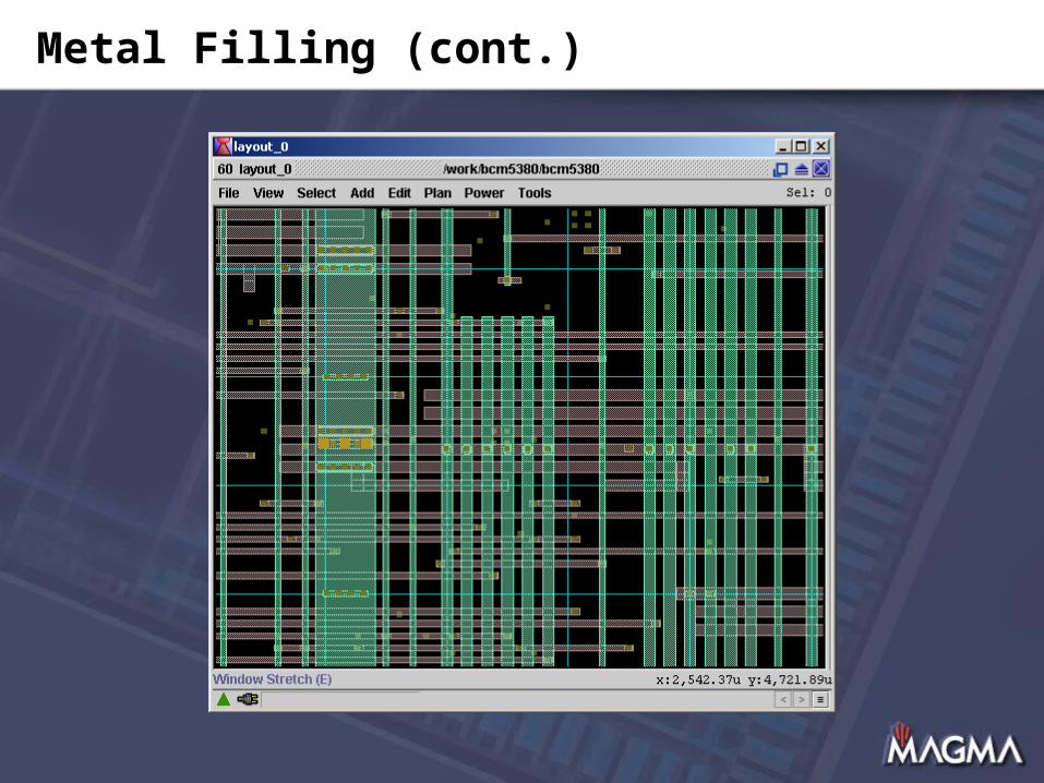
Metal Filling (cont.)
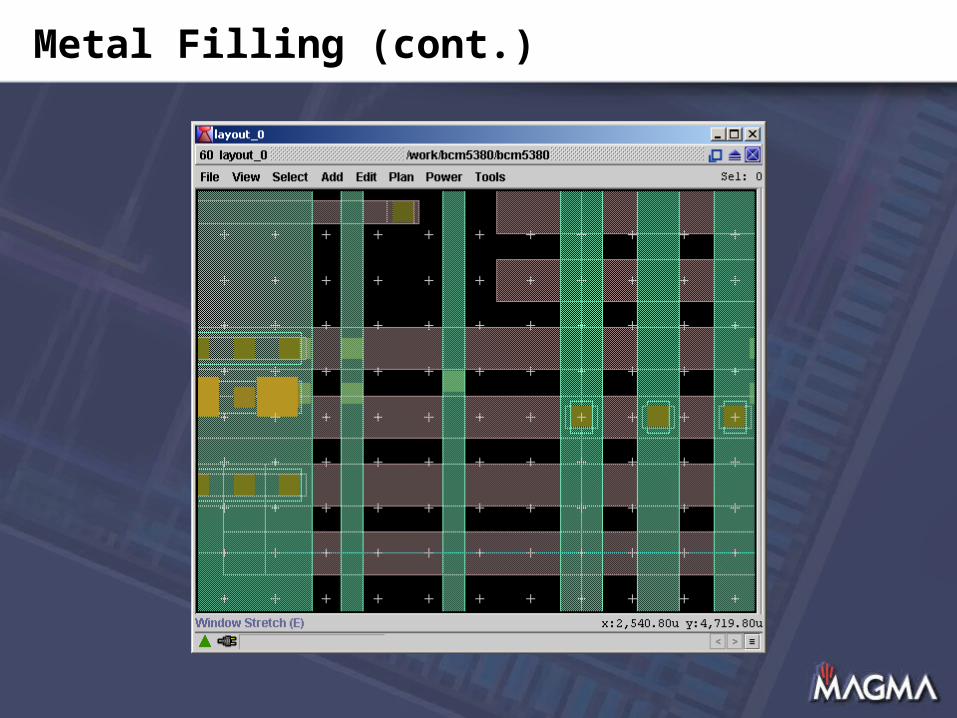
Metal Filling (cont.)
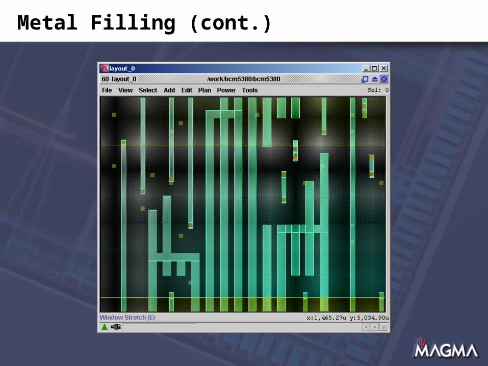
Metal Filling (cont.)
OPC- and PSM-Aware Routing
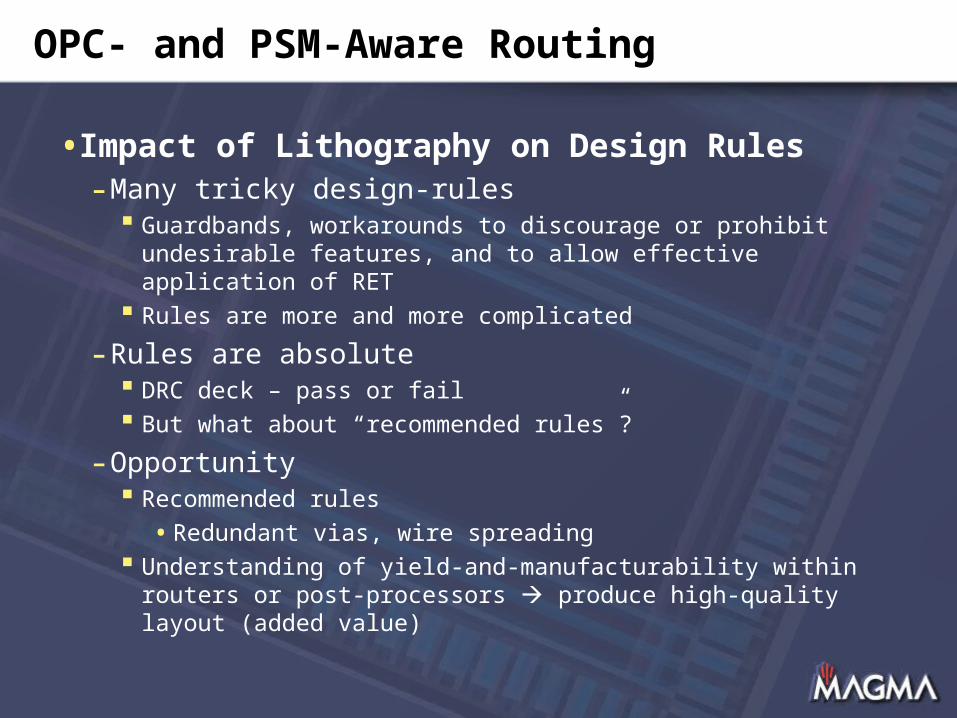
•Impact of Lithography on Design Rules- Many tricky design-rules
Guardbands, workarounds to discourage or prohibit undesirable features, and to allow effective application of RET
Rules are more and more complicated
- Rules are absolute DRC deck – pass or fail But what about “recommended rules”?
- Opportunity Recommended rules
•Redundant vias, wire spreading Understanding of yield-and-manufacturability within routers
or post-processors produce high-quality layout (added value)
OPC- and PSM-Aware Routing (cont.)
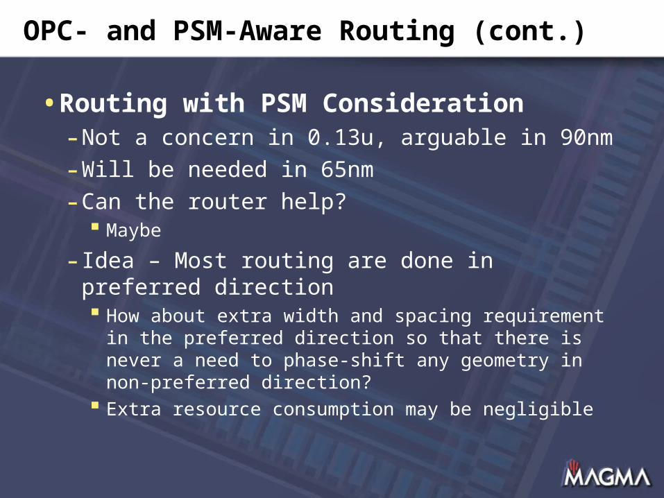
•Routing with PSM Consideration- Not a concern in 0.13u, arguable in 90nm
- Will be needed in 65nm
- Can the router help? Maybe
- Idea – Most routing are done in preferred direction How about extra width and spacing requirement in the
preferred direction so that there is never a need to phase-shift any geometry in non-preferred direction?
Extra resource consumption may be negligible
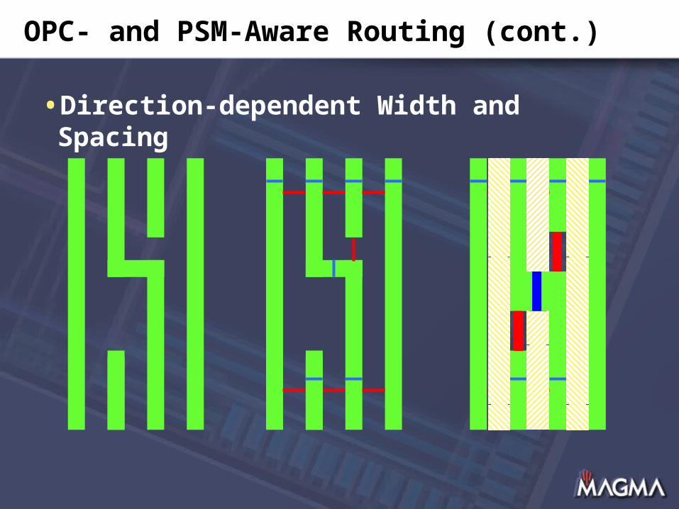
OPC- and PSM-Aware Routing (cont.)
•Direction-dependent Width and Spacing
Overview
•Introduction- Problem solved?
•Routing Challenges (selected)- Complex spacing rules- Transitional pitches- Process antenna rules
•Opportunities (selected)- Redundant vias- Wire spreading, widening, and filling- OPC- and PSM-aware routing
•Conclusion

Conclusion
•Problem Solved? Not•Challenges? Definitely
- Complex spacing rules- Transitional pitches- Process antenna rules- … (many more) …
•Opportunities? Plenty- Redundant vias- Wire spreading, widening, and filling- OPC- and PSM-aware routing- … (many more) …
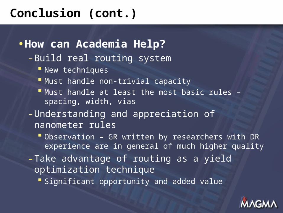
Conclusion (cont.)
•How can Academia Help?- Build real routing system
New techniques Must handle non-trivial capacity Must handle at least the most basic rules – spacing,
width, vias
- Understanding and appreciation of nanometer rules Observation – GR written by researchers with DR
experience are in general of much higher quality
- Take advantage of routing as a yield optimization technique Significant opportunity and added value
Thank You


