
A Practical Approach to Rapid Prototyping ofSCA Waveforms
Jacob A. DePriest
Thesis submitted to the faculty of the
Virginia Polytechnic Institute and State University
in partial fulfillment of the requirements for the degree of
Master of Science
in
Electrical Engineering
Dr. J. H. Reed, Chair
Dr. C. Dietrich
Dr. M. Robert
Dr. C. Patterson
April 25, 2006
Blacksburg, Virginia
Keywords: Wireless, Software Defined Radio, Waveform Development, SCA, Component
Development, Rapid Prototyping

A Practical Approach to Rapid Prototyping of SCA Waveforms
Jacob A. DePriest
ABSTRACT
With the growing interest in software defined radios (SDRs), cognitive radios, the Joint Tac-
tical Radio System (JTRS), and the Software Communication Architecture (SCA) comes the
need for a rapid prototyping approach to radio design. In the past, radios have tradition-
ally been designed to have a static implementation with the express goal of implementing
a specific type of communication, such as 802.11b, CDMA voice communication, or just a
simple FM tuner. However, when designing an SDR, the developer must not only be able to
understand the radio engineering aspects of the design, but also be able to interface correctly
with the underlying core software framework. This added software complexity, along with
the general need for faster, more economical waveform development, illuminates the need for
a rapid prototyping SDR development environment.
This thesis takes a fresh look at the task of providing radio designers with a functional,
straightforward design tool that enables the developer to focus more on the radio design
than the tedious task of interacting with CORBA, IDL, and the SCA Core Framework. The
design approach used to create such a tool is investigated along with an overview of general
SDR concepts and an introduction to MPRG’s open source SCA Core Framework, OSSIE.
Discussion on the design methodology behind creating an SCA waveform is provided and the
final result of this research, OSSIE Waveform Developer (OWD), is introduced and explored
in detail. The code generated using OWD is detailed and waveform design approaches are
presented with some suggested modifications. Finally, the improvements gained by using
OSSIE Waveform Developer instead of the traditional approach of manually developing
waveforms are presented.

For Heather
You have made this all worthwhile
Acknowledgments
First of all, I must give thanks to my Lord and Savior, Jesus Christ, who has blessed me
immensely and made all of this possible.
I would like to thank my advisor, Dr. Jeffrey H. Reed, for his support and assistance
during my time at MPRG. He has provided me with the guidance and means to further
my education, and his influence has already begun to shape my future. I would also like to
thank all of the faculty, staff, and students at MPRG whose endless support made this work
possible.
I would like to specifically thank the OSSIE Team: Tom Tsou, Dr. Max Robert, Carlos
Aguayo, Philip Balister, Tuan Pham, Dr. Carl Dietrich, and Joseph Gaeddert for guiding
me in my knowledge of this subject material and patiently answering all of my questions. I
have enjoyed getting to know each of them and appreciate not only the technical knowledge
they have imparted to me, but also their friendship.
I owe a great deal to Dr. Max Robert. From the first day I joined the OSSIE team, he
has ceaselessly answered my questions and shared his knowledge with me. He not only took
the time to invest in my education, but was available as a friend as well. I will forever be
grateful for his investment in my life.
I would like to thank my parents, Roger and Cathy, and my sister, Betsy, for their tireless
support of my ever-changing passions and goals throughout the years. Their love, guidance,
and encouragement have helped make me the person I am today.
Last but not least, I must thank my wonderful wife, Heather. She has encouraged me,
picked me up when I am down, and kept me anchored through this entire process. She has
supported me every step of the way and she has truly made this all worthwhile.
iv

Grant Information
This work received support from SAIC and the Wireless @ Virginia Tech Affiliates Program.
This material is also based upon work supported in part by the National Science Foundation
under Grant No. 0520418.
Any opinions, findings, and conclusions or recommendations expressed in this material are
those of the author and do not necessarily reflect the views of the National Science Founda-
tion.
v

Contents
1 Introduction 1
1.1 Motivation . . . . . . . . . . . . . . . . . . . . . . . . . . . . . . . . . . . . . 1
1.2 Contributions . . . . . . . . . . . . . . . . . . . . . . . . . . . . . . . . . . . 2
1.3 Thesis Organization . . . . . . . . . . . . . . . . . . . . . . . . . . . . . . . . 2
2 Background 4
2.1 Introduction . . . . . . . . . . . . . . . . . . . . . . . . . . . . . . . . . . . . 4
2.2 Software Defined Radio . . . . . . . . . . . . . . . . . . . . . . . . . . . . . . 4
2.3 Software Communications Architecture . . . . . . . . . . . . . . . . . . . . . 7
2.4 OSSIE . . . . . . . . . . . . . . . . . . . . . . . . . . . . . . . . . . . . . . . 9
2.5 Waveform Development . . . . . . . . . . . . . . . . . . . . . . . . . . . . . 9
2.6 Related Work . . . . . . . . . . . . . . . . . . . . . . . . . . . . . . . . . . . 11
2.6.1 Ptolemy . . . . . . . . . . . . . . . . . . . . . . . . . . . . . . . . . . 11
2.6.2 SCA Development Environments . . . . . . . . . . . . . . . . . . . . 13
3 Design Considerations 16
vi

3.1 Design Approach . . . . . . . . . . . . . . . . . . . . . . . . . . . . . . . . . 16
3.1.1 Component Design . . . . . . . . . . . . . . . . . . . . . . . . . . . . 17
3.1.2 Device Assignment . . . . . . . . . . . . . . . . . . . . . . . . . . . . 23
3.1.3 Platform Development . . . . . . . . . . . . . . . . . . . . . . . . . . 25
3.1.4 Development Environment . . . . . . . . . . . . . . . . . . . . . . . . 27
3.1.5 Development Language . . . . . . . . . . . . . . . . . . . . . . . . . . 28
3.1.6 Input Granularity . . . . . . . . . . . . . . . . . . . . . . . . . . . . . 30
3.2 Development Modules . . . . . . . . . . . . . . . . . . . . . . . . . . . . . . 30
3.2.1 XML Profiles . . . . . . . . . . . . . . . . . . . . . . . . . . . . . . . 30
3.2.2 Waveform Specific Code . . . . . . . . . . . . . . . . . . . . . . . . . 31
3.2.3 Interface Description Language . . . . . . . . . . . . . . . . . . . . . 33
3.2.4 Installation Structure . . . . . . . . . . . . . . . . . . . . . . . . . . . 34
4 OSSIE Waveform Developer 37
4.1 Waveform Design . . . . . . . . . . . . . . . . . . . . . . . . . . . . . . . . . 37
4.1.1 Mapping Radio Design to Software Components . . . . . . . . . . . . 37
4.1.2 Component I/O . . . . . . . . . . . . . . . . . . . . . . . . . . . . . . 38
4.1.3 Assembly Controller . . . . . . . . . . . . . . . . . . . . . . . . . . . 40
4.1.4 Device Considerations . . . . . . . . . . . . . . . . . . . . . . . . . . 41
4.2 Waveform Layout . . . . . . . . . . . . . . . . . . . . . . . . . . . . . . . . . 43
4.2.1 Adding a Component . . . . . . . . . . . . . . . . . . . . . . . . . . . 45
4.2.2 Editing a Component . . . . . . . . . . . . . . . . . . . . . . . . . . . 47
vii

4.2.3 Removing a Component . . . . . . . . . . . . . . . . . . . . . . . . . 52
4.2.4 Connections . . . . . . . . . . . . . . . . . . . . . . . . . . . . . . . . 52
4.2.5 Generation . . . . . . . . . . . . . . . . . . . . . . . . . . . . . . . . 55
4.3 Platform Layout . . . . . . . . . . . . . . . . . . . . . . . . . . . . . . . . . 57
4.3.1 Adding a Platform Node . . . . . . . . . . . . . . . . . . . . . . . . . 58
4.3.2 Adding a Device . . . . . . . . . . . . . . . . . . . . . . . . . . . . . 58
4.3.3 Editing the Platform Layout . . . . . . . . . . . . . . . . . . . . . . . 60
4.4 Menu Reference . . . . . . . . . . . . . . . . . . . . . . . . . . . . . . . . . . 61
4.4.1 File . . . . . . . . . . . . . . . . . . . . . . . . . . . . . . . . . . . . . 62
4.4.2 Waveform . . . . . . . . . . . . . . . . . . . . . . . . . . . . . . . . . 63
4.4.3 Platform . . . . . . . . . . . . . . . . . . . . . . . . . . . . . . . . . . 64
4.4.4 Help . . . . . . . . . . . . . . . . . . . . . . . . . . . . . . . . . . . . 64
4.4.5 OSSIE Component Editor: File . . . . . . . . . . . . . . . . . . . . . 65
4.4.6 OSSIE Component Editor: Component . . . . . . . . . . . . . . . . . 65
5 Post-Generation Design 66
5.1 Description of Generated Code . . . . . . . . . . . . . . . . . . . . . . . . . 66
5.1.1 File and Directory Structure . . . . . . . . . . . . . . . . . . . . . . . 67
5.1.2 XML Domain Profile . . . . . . . . . . . . . . . . . . . . . . . . . . . 68
5.1.3 C++ Code . . . . . . . . . . . . . . . . . . . . . . . . . . . . . . . . 72
5.2 Modifications . . . . . . . . . . . . . . . . . . . . . . . . . . . . . . . . . . . 74
5.2.1 Processing Data . . . . . . . . . . . . . . . . . . . . . . . . . . . . . . 75
viii

5.2.2 Threading . . . . . . . . . . . . . . . . . . . . . . . . . . . . . . . . . 76
5.2.3 Autoconf . . . . . . . . . . . . . . . . . . . . . . . . . . . . . . . . . . 76
5.3 Results and Analysis . . . . . . . . . . . . . . . . . . . . . . . . . . . . . . . 77
5.3.1 Design Flow . . . . . . . . . . . . . . . . . . . . . . . . . . . . . . . . 78
5.3.2 Component Reuse . . . . . . . . . . . . . . . . . . . . . . . . . . . . . 80
5.3.3 Deployment . . . . . . . . . . . . . . . . . . . . . . . . . . . . . . . . 82
6 Conclusion and Future Work 84
A Installation and Usage 87
A.1 Installation - Single Node . . . . . . . . . . . . . . . . . . . . . . . . . . . . 87
A.2 Installation - Multiple Nodes . . . . . . . . . . . . . . . . . . . . . . . . . . . 89
A.3 Usage - Single Node . . . . . . . . . . . . . . . . . . . . . . . . . . . . . . . . 90
A.4 Usage - Multiple Nodes . . . . . . . . . . . . . . . . . . . . . . . . . . . . . . 90
ix

List of Figures
2.1 SCA Core Framework IDL Relationships [1] . . . . . . . . . . . . . . . . . . 8
3.1 Example Physical Platform Layout . . . . . . . . . . . . . . . . . . . . . . . 25
3.2 Installation Structure . . . . . . . . . . . . . . . . . . . . . . . . . . . . . . . 36
4.1 Simple Receiver Block Diagram . . . . . . . . . . . . . . . . . . . . . . . . . 38
4.2 Simple Receiver Block Diagram with Software Component Groupings . . . . 39
4.3 Sample Component Communication Layouts . . . . . . . . . . . . . . . . . . 40
4.4 OSSIE Waveform Developer Main Window . . . . . . . . . . . . . . . . . . . 44
4.5 Importing a Resource from the Component Library . . . . . . . . . . . . . . 46
4.6 OSSIE Component Editor Window . . . . . . . . . . . . . . . . . . . . . . . 48
4.7 Add Port Dialog . . . . . . . . . . . . . . . . . . . . . . . . . . . . . . . . . 49
4.8 Renaming a Component . . . . . . . . . . . . . . . . . . . . . . . . . . . . . 49
4.9 Deployment Settings . . . . . . . . . . . . . . . . . . . . . . . . . . . . . . . 50
4.10 Setting the Assembly Controller . . . . . . . . . . . . . . . . . . . . . . . . . 51
4.11 Removing a Component . . . . . . . . . . . . . . . . . . . . . . . . . . . . . 52
4.12 Connecting a Component . . . . . . . . . . . . . . . . . . . . . . . . . . . . . 53
x

4.13 Connections Dialog . . . . . . . . . . . . . . . . . . . . . . . . . . . . . . . . 54
4.14 Removing a Connection . . . . . . . . . . . . . . . . . . . . . . . . . . . . . 55
4.15 Configuring ACE Support . . . . . . . . . . . . . . . . . . . . . . . . . . . . 56
4.16 Generating a Single Component . . . . . . . . . . . . . . . . . . . . . . . . . 57
4.17 Adding a Platform Node . . . . . . . . . . . . . . . . . . . . . . . . . . . . . 59
4.18 Adding a Device Instance to a Platform Node . . . . . . . . . . . . . . . . . 59
4.19 Editing the Platform Layout . . . . . . . . . . . . . . . . . . . . . . . . . . . 60
5.1 Generated Directory Layout . . . . . . . . . . . . . . . . . . . . . . . . . . . 68
5.2 Pre-OWD Design Flow . . . . . . . . . . . . . . . . . . . . . . . . . . . . . . 79
5.3 OWD Design Flow . . . . . . . . . . . . . . . . . . . . . . . . . . . . . . . . 80
A.1 Generated Directory Layout . . . . . . . . . . . . . . . . . . . . . . . . . . . 88
xi
List of Tables
2.1 SCA Development Environment Comparison . . . . . . . . . . . . . . . . . . 15
5.1 OWD Generated Waveform Files . . . . . . . . . . . . . . . . . . . . . . . . 69
5.2 OWD Generated Component Files . . . . . . . . . . . . . . . . . . . . . . . 70
xii
List of Abbreviations
AGC Automatic Gain Control
API Application Program Interface
BPF Band Pass Filter
CF Core Framework
COTS Commercial Off-the-Shelf
DAS Device Assignment Sequence
DSP Digital Signal Processor
FPGA Field-Programmable Gate Array
GPP General Purpose Processor
IDE Integrated Development Environment
LO Local Oscillator
JTRS The Joint Tactical Radio System
MPRG Mobile and Portable Radio Research Group
OSSIE Open Source SCA Implementation::Embedded
OWD OSSIE Waveform Developer
PRF Properties Descriptor
SCA Software Communications Architecture
SCD Software Component Descriptor
SDR Software Defined Radio
SPD Software Package Descriptor
UML Unified Modeling Language
UUID Universally Unique Identifier
WDE Waveform Development Environment
XML Extensible Markup Language
xiii

Chapter 1
Introduction
1.1 Motivation
With the growing interest in software defined radios (SDRs), cognitive radios, the Joint Tac-
tical Radio System (JTRS), and the Software Communication Architecture (SCA) comes the
need for a rapid prototyping approach to radio design. In the past, radios have tradition-
ally been designed to have a static implementation with the express goal of implementing
a specific type of communication, such as 802.11b, CDMA voice communication, or just a
simple FM tuner. However, when designing an SDR, the developer must not only be able to
understand the radio engineering aspects of the design, but also be able to interface correctly
with the underlying core software framework. This added software complexity, along with
the general need for faster, more economical waveform development, illuminates the need for
a rapid prototyping SDR development environment.
1

Jacob A. DePriest Chapter 1. Introduction 2
1.2 Contributions
The impact that rapid prototyping environments for software defined radios will have on
the wireless community has yet to be fully realized. The proliferation of software radios has
pushed the need for a seamless development environment for waveforms to the forefront of the
industry. This work takes a fresh look at providing developers with an easy to use, powerful
development tool to aid in the design and deployment of SCA waveforms and components.
The following items detail the major contributions that resulted from this work.
• OSSIE Waveform Developer - a graphical development environment for designing SCA
waveforms and components. Features include: a waveform layout and design environ-
ment, a platform design and deployment tool, a component editor, ability to add and
remove ports, ability to import new interfaces to define component communication, the
ability to utilize pre-existing components in a waveform design, and automatic code
generation. The code generation includes all of the waveform and component SCA
XML descriptor files, the C++ wrapper code for components, and the files needed to
build and install the code on a system.
• Documentation detailing waveform and component design using OSSIE Waveform De-
veloper and a detailed description of the resulting C++, XML, and installation files
including suggested modification strategies.
1.3 Thesis Organization
This thesis begins with background information on software defined radios, the SCA, OSSIE,
and waveform development, as well as an overview of relevant related work in Chapter
2. The design considerations and decisions that went into developing OSSIE Waveform
Developer (OWD) are covered in Chapter 3. Chapters 4 and 5 encompass a developer’s
guide of sorts for OSSIE Waveform Developer, detailing waveform design considerations,

Jacob A. DePriest Chapter 1. Introduction 3
OWD usage, and basic functionality. They also cover post-generation design issues and
detail the major components of the OSSIE waveform. Chapter 6 contains the concluding
remarks and recommendations for future work on OSSIE Waveform Developer.

Chapter 2
Background
2.1 Introduction
Software defined radios are set to redefine the current landscape of wireless communications
in the military and commercial sectors. To better understand the challenges in designing
SDRs, a basic understanding of the goals and purpose of SDRs is needed. This chapter
details the reasons that SDR is being pursued and why it will change the way that radios
are designed. Background is given on the Joint Tactical Radio System Software Commu-
nications Architecture (SCA), MPRG’s open source software defined radio effort (OSSIE),
and waveform development in general. Finally, current work in the area of rapid prototyping
with respect to software defined radios is described.
2.2 Software Defined Radio
In his book, Software Radio: A Modern Approach to Radio Engineering, Dr. Jeffrey H. Reed
states that a software radio is “a radio that is substantially defined in software and whose
physical layer behavior can be significantly altered through changes to its software” [2]. The
4

Jacob A. DePriest Chapter 2. Background 5
need for software defined radios has come about in recent years due to the proliferation of
new wireless technologies and the growing demand to use these technologies in new and
exciting ways. Never before have there been so many consumer and military devices that
use at least one form of wireless technology, with many implementing two or more wireless
protocols in a single device. While these gadgets and tools make all of our lives somewhat
more convenient, the technical challenges involved in implementing more and more wireless
protocols on single devices are requiring engineers to begin looking for a better solution than
just packing more transistors and silicon on a chip.
There are several factors contributing to the increased focus on the development of software
defined radios. As mentioned above, there is currently an energetic push in the consumer
electronics area and the military to produce devices that support multiple wireless protocols.
Cars that can receive wireless Internet signals as well as interface with a driver’s Bluetooth-
capable cellular phone, wireless office devices, and the advent of personal digital assistant
(PDA) phones are just a few examples of the combination of wireless technologies in everyday
devices. Other factors encouraging the SDR movement include the need for global communi-
cation capable devices and compact radios that replace the multiple traditional radios needed
for the same communication capabilities. Manufacturing costs will likely decrease as more
radio functionality is implemented in software and the need for specialized RF hardware
decreases in certain wireless devices. Finally, software radios provide the ability to upgrade
existing devices in such a way as to completely change the functionality of a device. This is
not only important from a business point of view, but the ability to upgrade hard-to-service
devices such as satellites can increase the usefulness of the hardware far beyond traditional
time limits. For instance, if a new wireless protocol is created after a satellite deployment,
the onboard SDR simply has to install the new software to gain the new functionality. A
software radio system has the potential to provide developers and consumers alike with a
radio that can dynamically alter things such as operating frequency, modulation schemes,
waveform protocols, error correction schemes, and even support future technological devel-
opments. This is not only an exciting prospect for radio designers, it is quickly becoming a
Jacob A. DePriest Chapter 2. Background 6
much needed feature for wireless devices. [2]
One of the first software defined radio architectures was the SPEAKeasy system, originally
initiated by the U.S. Air Force and eventually turning into a joint effort by the U.S. military
branches. In the early 1990’s, Phase-1 of SPEAKeasy sought to create proof-of-concept four-
channel, high-speed, frequency hopping and pseudorandom spread-spectrum waveforms for
military communications. The goal to create a modem with much of the signal processing
taking place in a reconfigurable DSP was achieved. Phase-2 led to an open, modular, repro-
grammable system architecture based largely on commercial off-the-shelf (COTS) modules
in the second half of the 1990’s. However, this system was limited in RF range from 4-400
MHz and also lacked the structure to support the broad range of waveforms needed outside
of the military. [2][3]
The GNU Radio project is another popular software radio architecture developed in the open
source community to provide “signal processing in free software”. Software radios based on
the GNU Radio platform essentially combine a series of signal processing blocks implemented
in software with user-selected hardware to form a radio. While the the GNU Radio project is
educational and potentially beneficial in a research environment, the architecture definition
is not yet extensive enough to compete for serious commercial or military applications. [4]
Software defined radio is not confined to a particular architecture or a stringent method of
implementation. Any radio that has a significant software component providing substantial
physical layer flexibility is on some level a software radio. However, for software defined
radios to be widely accepted in the military as well as commercially, there must exist a
standard which thoroughly defines the requirements, structure, and design models of an
SDR architecture. The JTRS’s Software Communications Architecture (SCA) is currently
the most complete, thorough, and well-defined architecture available for SDRs.

Jacob A. DePriest Chapter 2. Background 7
2.3 Software Communications Architecture
The U.S. Department of Defense’s Joint Program Office (JPO) sponsored the development of
a communications system to address the growing wireless communication needs in the U.S.
Armed Forces. The military has a myriad of wireless application needs such as aircraft-to-
aircraft, aircraft-to-ground, command center communications, handheld, and ground-mobile
communications to name a few. To keep up with the changing technology and in order to
expand the communications capabilities of the armed forces, a redesign from the ground up
was needed. This communication system is the Joint Tactical Radio System based on the
Software Communications Architecture. [5]
While this system was originally intended solely for military use, it is slowly gaining com-
mercial viability due to the efforts of groups like the Object Management Group (OMG)
[6] and the SDR Forum [7]. The goal of the SCA is to provide a framework in which the
interoperability of products developed under the SCA is assured. To achieve this goal, the
SCA sets out requirements for behavioral specifications, interface specifications, application
program interfaces (APIs), and rules. The software structure of the SCA is made up of three
main components: the SCA Core Framework (CF), CORBA middleware, and a POSIX-
based operating system. Because CORBA middleware implementations and POSIX-based
operating systems are generally developed by established third party vendors, the CF is the
main focus for entities seeking to implement an SCA-based software defined radio. The CF
“describes a set of relationships that are used to organize the functionality of the different
objects (or components) necessary to deploy the appropriate SDR functionality” [5]. The
base relationships that make up the SCA Core Framework can be seen in Figure 2.1. [1]
The SCA is fundamentally a component-based architecture allowing a radio to be the sum
of its individual parts by focusing on interoperability of components and connection-based
layouts. It could be argued that traditional radios based on Application-Specific Integrated
Circuits (ASICs) are component-based, because the radio is built by combining various chips
on a board to achieve the desired functionality. However, what distinguishes SCA SDRs from

Jacob A. DePriest Chapter 2. Background 8
Figure 2.1: SCA Core Framework IDL Relationships [1]
traditional radios is the reconfigurability of the various components making up the radio.
If an FM voice communication waveform is deployed on a properly designed SDR and AM
functionality is later needed, the transition should simply involve replacing one or more of
the software components on the FM radio with the components needed to provide the AM
functionality. Component-based radios promote component reuse, future-proofing of devices,
and the ability to have reconfigurable radios that are not limited to pre-defined functionality.
Jacob A. DePriest Chapter 2. Background 9
2.4 OSSIE
The Open Source SCA Implementation::Embedded (OSSIE) is MPRG’s open source SCA
Core Framework solution. OSSIE was created out of the need for a C++-based, open source
SCA implementation that could be easily used in a research environment. The current version
of OSSIE is based on version 2.2.1 of the SCA specification. At the time of this writing,
OSSIE implements the majority of the functionality detailed in the SCA specification.1
While there are several commercially available Core Frameworks available on the market,
unless otherwise stated, the topics covered in this paper are based upon OSSIE. The software
developed in relation to the research discussed in this thesis is based on a direct relationship
with OSSIE and is tailored to the functionality provided by the OSSIE CF.
2.5 Waveform Development
Software defined radios provide a platform that can replicate various modulation schemes,
wireless protocols, coding, and other signaling features of current systems as well as future
generations of wireless systems on a single hardware platform [8]. Not only will consumers
benefit from the improvements and multi-functionality that SDRs can provide, but the mili-
tary’s communications can also benefit from this seamless technological integration. In order
to take advantage of the gains made available by software radio platforms, a consistent, ef-
ficient way to create and deploy the software that drives these radios must be used.
To create an SCA-compliant software defined radio, the radio developer must fully integrate
the waveform software with a CORBA middleware, a Core Framework implementation, and
a POSIX-based operating system. The challenges of creating the underlying structure of
each desired waveform in such a way as to promote future interoperability is daunting even
1When a major OWD design decision was affected by a deviation of the OSSIE implementation from
the SCA specification, the deviation and the resulting decision were clearly noted in this thesis.
Jacob A. DePriest Chapter 2. Background 10
without addressing actual radio functionality. A rapid prototyping environment is needed to
allow radio engineers to concentrate on component and waveform implementation instead of
spending an inordinate amount of time ensuring that each piece of the radio conforms to the
required underlying code structure. A development environment for waveforms would allow
designs and implementations to proceed in a timely manner and enhance the quality of the
final products.
There are several other factors that motivate the need for development environment for soft-
ware defined radios. With the ability to develop component-based software radios comes
the need to modify those designs at a later time. A development environment not only
standardizes and streamlines the initial design phase, but provides the possibility to modify
designs for future upgrades and applications. Another factor that illuminates the need for an
SDR development environment is the problem of component reuse. Without a standardized
way to develop components and waveforms, it is essentially impossible to expect multiple
developers to design components that comply with a certain structure. Defining a common
component architecture that adheres to a given API is necessary for the interoperability of
components, and a waveform and component development environment provides the consis-
tency and efficiency needed to achieve this goal. Finally, an efficient and simple development
environment for the rapid prototyping of waveforms not only saves manufacturers money
and time, but it also promotes a wider acceptance in the technological community.
There have been advances in the area of creating an SCA-based waveform development
environment (WDE) to streamline the waveform and component development for software
defined radios. Unfortunately, when we investigated the area of WDEs, all of the relevant
efforts to produce such a useful tool were proprietary projects developed by individual com-
panies or organizations and could only be acquired through significant financial cost. Since
OSSIE was originally developed as a free, open source project to facilitate research in the
SDR area, it was not only financially restrictive to purchase a proprietary WDE solution, it
also did not fit with the spirit of the research effort. To this end, we chose to implement a
free, open source waveform development environment that could be paired with OSSIE to

Jacob A. DePriest Chapter 2. Background 11
provide researchers and developers with a powerful development package to design, create,
and deploy software defined radios.
2.6 Related Work
As mentioned in section 2.5, there are multiple development environments available that
deal with software defined radios. One project that has played an important role in the
development of modular design patterns is the Ptolemy Project at the University of Cali-
fornia Berkeley. While it does not deal directly with the SCA or software defined radios, it
addresses the issue of system modeling and software-based signal processing design. There
are also several rapid prototyping tools that are specifically geared toward SCA waveforms
and components.
This section briefly describes some of the major waveform development environment projects
available today along with an overview of the Ptolemy effort.
2.6.1 Ptolemy
The Ptolemy Project [9] is made up of a group of researchers at U.C. Berkeley whose research
focuses on the methodology of modeling, designing, and investigating design techniques for
embedded systems. Unless otherwise stated, the information in this section was obtained
from the Ptolemy Project’s technical memorandum, Overview of the Ptolemy Project [10].
The Ptolemy Project started in the second half of the 1980’s with the goal of simulating, mod-
eling, and generating code for programmable DSPs. This first generation software, known as
Gabriel, facilitated the maturation of the techniques used in the synchronous dataflow (SDF)
model of computation among other things. The second generation of the project, Ptolemy
Classic, began in 1990 and lasted until 1997. Ptolemy Classic was written in C++ and
supported multiple models of computation including boolean dataflow and multidimensional

Jacob A. DePriest Chapter 2. Background 12
synchronous dataflow. This generation of software introduced joint modeling of communica-
tion networks and signal processing as well as promoting advances in scheduling techniques
for the synchronous dataflow model of computation.
The current generation of the Ptolemy Project’s software infrastructure is Ptolemy II, and
is based on the Java programming language. Ptolemy II implements a sophisticated en-
vironment that enables developers to model systems that relate to signal processing and
embedded devices. More generally, the Ptolemy Project focuses on the study of “hetero-
geneous modeling, simulation, and design of concurrent systems”, with a concentration on
embedded systems.
One of the underlying ideas that permeates the Ptolemy II design model, is the notion of
a model of computation. In this case a model of computation refers to a set of rules that
provide a framework for modeling behavior related to concurrency and time issues. The type
of model being constructed plays a significant role in choosing a model of computation. In
other words, the decision to use a sequential language such as C++ or a parallel language like
VHDL depends on the type of system being modeled. Ptolemy II provides various models
of computation that can be used to build models of various systems.
Ptolemy II could be considered an actor-based design. In the context of Ptolemy, an actor
refers to a component in a model of concurrent computation that has well-defined interfaces,
communicates via message channels, and whose internal behavior and state are inconse-
quential when viewed from outside the actor. Actors provide an abstract way to represent
components and provide a means to model dataflow. The model of computation used for a
particular model influences the operational environment of the actors and defines how com-
ponents communicate in a model “emphasizing concurrency and communication between
components”.
While Ptolemy II shares many characteristics with the SCA such as component usage, inter-
face definition, and persistent data storage using XML, the underlying goal of the project is
fundamentally different than the SCA. As discussed above, the SCA was born out of a need
Jacob A. DePriest Chapter 2. Background 13
for seamless communications among warfighters in the U.S. military; the interoperability
of components and waveforms along with rapid development and a convenient deployment
strategy were the influencing factors that shaped the SCA. The Ptolemy Project is fun-
damentally focused on concurrency issues and modeling the behavior of a system and its
dataflow. Ptolemy II provides an abstract environment enabling users to model signal pro-
cessing applications and even generate some functional code to support a system. However,
Ptolemy II is not a means of deploying and using the systems that it models. The SCA
not only defines the structure needed for component communication and reuse, it is also the
architecture on which these components will be based and deployed.
Ptolemy II provides a simulation-based design approach similar to tools like SimuLink [11].
These environments focus on the behavior of a system in a platform-independent way. In-
tegrating these environments into a tool with the goal of creating SCA waveforms is a
complicated task, because the SCA is based on connections and interoperability rather than
behavior. The SCA was created specifically for building radios, and it tends to be more
platform-dependent that simulation tools like Ptolemy II.
2.6.2 SCA Development Environments
There are several development environments available on the market today that deal specif-
ically with the SCA. Some of the environments provide fully integrated visual design of
the component layout and connections, XML profile generation and management, and code
generation, while others offer only a subset of these features. As mentioned earlier, these
are proprietary tools that can only be obtained at significant cost to the user. Table 2.1
summarizes the major features supported by the SCA waveform development environments
covered in this section and compares them to OSSIE Waveform Developer.
Harris Corporation [12] offers not only a Core Framework implementation, but also a Domain
Management Tool Kit (dmTK) that provides developers with an environment suited to
developing SCA software defined radios. The dmTK provides a visual modeling environment

Jacob A. DePriest Chapter 2. Background 14
that allows developers to graphically lay out components and software. This toolset includes
SCA specification checking, XML management, and an integrated Domain Manager XML
parser with a constraint engine. According to freely available dmTK documentation, the
dmTK toolset provides an XML management and design system coupled with a domain
management monitor and control tool, but it does not provide automatic code generation
support to the developer.
Harris Corporation has joined forces with Zeligsoft [13] to provide users with a fully featured
waveform development environment complete with Harris’s Core Framework. Zeligsoft’s
flagship product, Component Enabler, provides a UML interface for designing, generating,
and validating the XML profiles of SCA waveforms and applications. Zeligsoft also offers a
Code Generator product that provides developers with the option of not only generating the
XML profiles for a design, but also the underlying code skeleton. By using code templates,
a wide variety of environments can be supported along with a number of programming
languages including C, C++, VHDL, Java, and ADA. As with most SCA code generation
tools, only SCA wrapper code is generated and the actual functional source code must be
added by a third party.
The Communications Research Centre (CRC) [14] in Canada also provides an SDR develop-
ment solution called the SCARI Software Suite. The suite consists of two main components:
CRC’s C++ implementation of the SCA Core Framework, SCARI++, and an SDR De-
velopment Toolset. According to CRC’s description of the product, the SDR Development
Toolset provides developers with a Component Editor to create and edit components and
devices visually as well as to generate and maintain the component XML domain profile.
The included Code Generator is used to generate C++ code based on the SCARI Compo-
nent Development Library. A Node Boot Builder is included to define a hardware platform
configuration and generate the resulting SCA XML files. Finally, the Waveform Applica-
tion Builder is used to create and modify waveform applications using previously created
components.

Jacob A. DePriest Chapter 2. Background 15
Lastly, the productivity tools and middleware company, PrismTech [15], offers Eclipse-based
[16] tools for waveform development (Spectra SE) and a combined waveform and platform
modeling and development tool (Spectra PE). They also offer automatic code generators to
supplement the modeling tools. A Unit Test Framework is included to verify and test code
generated by the Spectra Code Generators. Finally, PrismTech offers the Spectra Operating
Environment which includes their proprietary Core Framework and middleware implemen-
tations. From the information provided on PrismTech’s website, it appears that the Spectra
SE version 1.1 software supports modeling of SCA applications and the corresponding XML
and C++ source code generation.
Software Package XML Generation Code Generation Domain Management Free
Harris dmTK Yes No Yes No
Zeligsoft Component Enabler Yes Yes No No
CRC Development Toolset Yes Yes No No
PrismTech Spectra Yes Yes No No
OSSIE Waveform Developer Yes Yes No Yes
Table 2.1: SCA Development Environment Comparison

Chapter 3
Design Considerations
3.1 Design Approach
When designing a Waveform Development Environment (WDE), there are many considera-
tions that must be addressed. The initial cost investment, ease of use, waveform compliance,
underlying code structures, and the granularity of input at development time are all key
issues when considering the best approach to developing a WDE [17]. Initial development
time must be considered because the cost and time required to develop a WDE must be
less than the cost of simply purchasing a similar commercially available product. Although
this seems like a simple cost/benefit analysis, other factors must be accounted for as well.
Because OSSIE is an open source effort, the desire for an open source set of tools to utilize
the OSSIE Core Framework and enable developers to focus on SDR applications ultimately
factored into the analysis of the initial cost versus the long term benefit of developing an
in-house WDE.
The usability of the software must also be taken into consideration as development begins.
The granularity of input control is closely tied to the usability of the software. Our software
should provide researchers and third parties enough control to implement a useful radio while
16
Jacob A. DePriest Chapter 3. Design Considerations 17
maintaining a reasonable learning curve. Time restrictions and man-power limitations also
play a role in the level of input control integrated into any software project.
The following sections describe some of the design methodology and decisions that went into
the development of OSSIE Waveform Developer.
3.1.1 Component Design
The creation of OSSIE Waveform Developer was not only significant in and of itself, it
also played an important role in the standardization of a component structure. Prior to
the creation of OWD, waveform developers using the OSSIE platform tended to customize
components very specifically to meet the needs of each application. While there is nothing
inherently wrong with component customization, the lack of uniformity among the resulting
components deterred future component reuse. Without some sort of software tool, a practical
solution to creating components in an efficient, standardized way was implausible. As OSSIE
Waveform Developer matured, we saw the need and the opportunity to standardize the
structure and use-model for components. There were two main areas that needed to be
addressed in order to achieve uniformity in components: the port communication structure
and the threading environment.
Port Implementation Strategy
While most of the component structure is detailed explicitly in the SCA specification, the
component port architecture is largely left to the developer’s interpretation. Prior to the
re-analysis brought about by the advent of OWD, individual components inherited a specific
port interface directly. A component would not only inherit the standard SCA application
interface, Resource, which includes the PortSupplier, LifeCycle, TestableObject, and
PropertySet interfaces, it would also directly inherit from the Port interface. While this
solution for port communication is perfectly valid according to the SCA specification, it
Jacob A. DePriest Chapter 3. Design Considerations 18
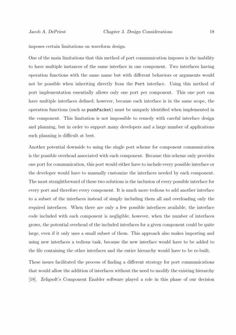
imposes certain limitations on waveform design.
One of the main limitations that this method of port communication imposes is the inability
to have multiple instances of the same interface in one component. Two interfaces having
operation functions with the same name but with different behaviors or arguments would
not be possible when inheriting directly from the Port interface. Using this method of
port implementation essentially allows only one port per component. This one port can
have multiple interfaces defined; however, because each interface is in the same scope, the
operation functions (such as pushPacket) must be uniquely identified when implemented in
the component. This limitation is not impossible to remedy with careful interface design
and planning, but in order to support many developers and a large number of applications
such planning is difficult at best.
Another potential downside to using the single port scheme for component communication
is the possible overhead associated with each component. Because this scheme only provides
one port for communication, this port would either have to include every possible interface or
the developer would have to manually customize the interfaces needed by each component.
The most straightforward of these two solutions is the inclusion of every possible interface for
every port and therefore every component. It is much more tedious to add another interface
to a subset of the interfaces instead of simply including them all and overloading only the
required interfaces. When there are only a few possible interfaces available, the interface
code included with each component is negligible; however, when the number of interfaces
grows, the potential overhead of the included interfaces for a given component could be quite
large, even if it only uses a small subset of them. This approach also makes importing and
using new interfaces a tedious task, because the new interface would have to be added to
the file containing the other interfaces and the entire hierarchy would have to be re-built.
These issues facilitated the process of finding a different strategy for port communications
that would allow the addition of interfaces without the need to modify the existing hierarchy
[18]. Zeligsoft’s Component Enabler software played a role in this phase of our decision

Jacob A. DePriest Chapter 3. Design Considerations 19
process [13]. Component Enabler treats ports as individual units that each contain only
the interface or interfaces relevant to that port. We realized that this port implementation
strategy not only worked when analyzing the problem from a UML and XML standpoint
as Zeligsoft had done, but it also allowed us to exploit some of the inherent features of
object-oriented programming and resolve the issues discussed above.
By treating ports as objects associated with a component, there is no longer a need to modify
the existing hierarchy when a new type of communication is required. In order to implement
this port communication strategy we removed the Port inheritance from the component
hierarchy and created individual port objects for each type of interface that a component
requires. Uses and Provides classes are created for each unique interface in a component
design with each class inheriting from the appropriate interface. The developer can then
create as many instances of the particular port classes as needed for a given component
design. Section 4.1.2 discusses in more detail port-based communication in the SCA.
Essentially, the port communication strategy changed from one where each component com-
municated directly with other components via remote procedure calls via known interfaces
to one where a specific Uses port communicates directly with a compatible Provides port
and vice versa. While both methods are valid according to the SCA, the new strategy pro-
vides a more compartmentalized way of viewing ports and components. Because Uses ports
talk directly to Provides ports (and vice versa), instead of one component talking directly
to an interface on another component, it becomes clear what interfaces are being used to
handle given communications. It is also easier to distinguish between Uses and Provides
ports when they are implemented as separate classes as opposed to just being a series of
overloaded functions in the component’s class structure. We complied with the specification
in the SCA Developer’s Guide stating that only the Uses port needs to implement the actual
port interface which includes the connectPort and disconnectPort functions [19].
This strategy addresses both issues with the original port communication scheme. First of
all, because each port object only inherits from the needed interfaces, each instance does not

Jacob A. DePriest Chapter 3. Design Considerations 20
have to carry with it all possible interfaces, thus decreasing most of the associated overhead.
Also, adding an interface after the initial design is simply a matter of creating a new port
class that inherits from the desired interface and instantiating as many instances of that
interface as needed. Secondly, because each interface’s operation function is encapsulated in
that particular interface’s class structure, multiple interfaces can have the same operation
function. This is significant when considering the large number of interfaces that will likely
be made available over time; developers will no longer have to worry about creating interfaces
with unique operating functions because each one will be encapsulated in an individual class
object associated with that interface.
The new port implementation scheme has significant implications for OSSIE Waveform De-
veloper. By having each component only support those interfaces that it specifically needs,
OWD only has to generate the needed support classes for these ports. More significantly,
OWD can provide support for importing new interfaces at design time because each compo-
nent only needs to know about the interfaces that pertain to its ports and no others. Under
the old scheme, in order to add a new interface the developer would have to add the IDL code
to the master interface file instead of simply include the needed interface in a new individual
IDL file. Overall, the move to the new port implementation scheme has positively affected
the OSSIE effort as well as the maturation of OSSIE Waveform Developer.
Threading Strategy
The topic of threading has traditionally been controversial when considered in the context of
default inclusion in components. When designing OSSIE Waveform Developer, the decision
had to be made whether or not to automatically include threading functionality with gener-
ated component code. In the past, much of the threading implemented in OSSIE waveforms
was based on ACE. ACE is the Adaptive Communication Environment, and it provides
threading, buffering, and software communication tools that can be integrated into existing
C++ code [20]. Since the current OSSIE implementation is based on the omniORB CORBA
Jacob A. DePriest Chapter 3. Design Considerations 21
implementation [21], the built-in omniORB threading package, omnithread, is also used by
some OSSIE waveform developers. Another widely used threading library, Pthreads, pro-
vides another threading possibility for OSSIE components. With all of these choices, the
decision whether to include threading support as a standard feature was indeed a difficult
one which encompassed several factors.
One of the first things to consider when dealing with threading in the software radio environ-
ment is the type of hardware on which the radio will be deployed. Even though most DSPs
and all modern GPPs include threading support, not every device will have native threading
support built it. When considering waveform deployment on older hardware, this issue be-
comes especially significant. With that said, it should technically be a straightforward task to
strip out the threading code for the rare component that must be deployed on a unthreaded
device. Obviously, some provision would also have to be made for LoadableDevices as dis-
cussed in section 4.1.4; but since these components are specialized by nature and the code
controlling the LoadableDevice would likely be running on a thread-compliant processor,
this is not a pivotal consideration.
A closely related topic of interest to the threading discussion revolves around the type of
application being designed. Many radio designs are time-sensitive in nature and the issue of
latency in communication is very important. In most cases, threading takes place on devices
that dynamically manage the system load and do not take real time considerations into
account when setting thread priority. If such a latency-sensitive radio were being designed
on such a platform, the operating system and data flow would be of greater importance than
the requirement of the asynchronous data flow that threading provides. With regards to the
buffering that the ACE package provides, a similar argument could be made. As mentioned
before, certain radio designs are time-sensitive, but the need for buffering implies that there
may be cases where the components become so out of sync with each other that buffering
is needed. Assuredly, a small amount of buffering is most likely a desirable thing for most
radio applications, but the expansive buffering tools that ACE provides may be considered
overkill for time-sensitive applications. These applications would likely consider a situation

Jacob A. DePriest Chapter 3. Design Considerations 22
that requires ACE’s buffering tools to be unacceptable and indicative of a much more serious
design or operational problem.
Conversely, ACE buffering and threading could be considered extremely useful for certain
applications. If the buffering required for a cellular base station using an SDR is under the
identifiable limit of human hearing (generally 150 ms), then the ACE toolkit could be a
significant asset to the system developers. Alternatively, a component that simply graphs
data or displays visual information may also benefit from ACE’s buffering capabilities. The
same could be said for the omnithread package or the Pthreads library. Each could be useful
under certain circumstances and unnecessary or even undesirable for other applications.
Because of the vast number of SDR scenarios, automatically including any specific threading
option simply does not give the developer the flexibility that is needed when developing a
wide range of applications. However, because we felt that certain applications could benefit
so greatly from threading and buffering, we chose to allow developers to have a choice
when designing waveforms and components using OSSIE Waveform Developer. Because the
support structure to include all three packages as options in the development environment
would be extremely difficult and time consuming to implement, we chose to allow designers
to choose between having no built-in threading support or including ACE package support.
Since ACE not only supports threads but buffering and other communication tools as well,
it provides developers a good selection of tools to use when needed.
Even with the decision to give the developer the option of using the ACE package in wave-
form and component designs, there was one final issue to be resolved with regard to the
automatically generated code. This was the issue of how much ACE functionality to include
by default when the developer chooses to have ACE support included. As mentioned before,
ACE offers developers a wide variety of tools including not only threading support, but dy-
namic buffering, event handling, and message routing among others. The decision to include
one or more aspects of the ACE toolkit is application-specific and not all-inclusive. Even
if something like buffering is desirable in almost every application, the implementation may
Jacob A. DePriest Chapter 3. Design Considerations 23
not be the same in every case. Because of the extensive number of application scenarios,
we chose to include a minimal amount of actual ACE-specific functional code. The auto-
generated code includes the needed libraries to implement ACE functionality and sets up
the ports and the component itself to take advantage of the ACE toolkit; however, actual
communication-specific code is left to the developer to implement in the post-generation
phase.
3.1.2 Device Assignment
One significant step in the waveform design process is device assignment and deployment.
The SCA specifies that each component’s Software Package Descriptor file should contain
information regarding loading dependencies (processor type, OS, compiler, etc.) and pro-
cessing capacities (memory, process, etc.), and that these dependencies should be used to
select a suitable device on which to deploy the given component at load time [1]. As each
component is assigned to a particular device by the ApplicationFactory, the device’s various
capacities should be adjusted based on the resources being used by each assigned compo-
nent. In this way, no component should ever be deployed to a device that does not have the
capacity to support it or is not compatible with it.
This process of device assignment and deployment has some problematic aspects for imple-
mentation. First, determining a priori the exact processing requirements of a component is
a complex task. Normally, identifying the processing requirements of any piece of software
requires extensive testing on the target hardware under varying conditions. While this is
an acceptable procedure for an environment with few devices, it becomes time consuming
and complex when a component can be deployed on more than one device based on avail-
able resources. Ideally, an automated tool would take care of this process of exhaustively
determining the processing requirements of a particular software component.
The second complication with implementing the SCA’s suggested device deployment strategy
is the complexity of the deployment problem. Assuming that each component’s processing
Jacob A. DePriest Chapter 3. Design Considerations 24
requirements have been accurately assessed and recorded in the appropriate SPD file, the
algorithm required to decide which component should be deployed on a given device based on
dynamically changing resources is not trivial. For instance, if a certain platform contained
5 available devices and a waveform had 20 components, the number of iterations needed
to find the best deployment with a simple iterative algorithm is 520, which is roughly 1014
iterations. Assuming that each iteration takes around 1000 clock cycles for a processor to
calculate (conservative estimate), a 3.0 GHz processor would take approximately 385 days
just to check each possible deployment configuration. When considering the possibility of
using a DSP to do the calculations, the time required to find the best deployment would be
even longer because DSPs tend to have slower clock speeds than GPPs. In order for this
deployment problem to run in a reasonable amount of time, an intelligent algorithm would
need to be developed that exploits certain knowledge about the components or the available
devices. Again, the development of such an algorithm is not a trivial task and would likely
take a significant research effort to accomplish.
Because of the inherent difficulty in implementing this deployment scheme, OSSIE does not
support this specific functionality at the time of this writing. However, some scheme for
device assignment must be used in order to have functional software defined radios based
on the OSSIE Core Framework. To this end, we decided to create a separate XML file
to be included with each waveform called the Device Assignment Sequence (DAS). This
file contains a mapping of each component instance in the waveform to a specific device
instance using UUIDs. This file is then parsed at load time and fed to the ApplicationFactory
dynamically during the waveform creation process.
This process allows the developer to choose the device to which a specific component should
be deployed during the design phase. So instead of identifying the processor type, OS, etc.
with which a component should be compatible, the developer simply makes a device selection
from the available device instances in the platform design. OSSIE Waveform Developer
provides a graphical means to accomplish this assignment as discussed in section 4.2.2.
While not as dynamic as the specified SCA method, this method of deployment still allows

Jacob A. DePriest Chapter 3. Design Considerations 25
the developer a significant amount of control and flexibility in the device assignment process.
3.1.3 Platform Development
Platform development is an area of the software radio design process that the SCA does not
cover in significant detail. In this context, platform development refers to the abstract layout
of devices that corresponds to the physical layout of the radio system. For example, Figure
3.1 shows a possible physical setup where two computers with associated peripheral devices
are connected. Assuming that the developer wants one waveform to use devices connected
to both machines, the need arises to be able to design the platform layout in software such
that this goal can be met.
Figure 3.1: Example Physical Platform Layout
As discussed in section 3.1.2, the SCA specifies that device assignments should automatically
be made at waveform load time based on the available devices and their respective resources
seen by the core framework. Under this implementation scheme, the platform layout of
the system is completely transparent to the device assignment procedure, because the CF
only sees available devices and does not care if those devices are locally connected or reside
on a remote host. For example, in Figure 3.1, we will assume that the DomainManager
and ApplicationFactory are running on machine A, and that machine B and its associated
peripherals will be used in the same waveform. From the perspective of the SCA, the fact
that the devices connected to machine B are not physically connected to machine A does
not matter. It also should not matter at design time what devices are available, because the
Jacob A. DePriest Chapter 3. Design Considerations 26
device assignments should be made dynamically at load time according to the SCA. However,
because of the reasons detailed in section 3.1.2, OSSIE does not make device assignments
dynamically at waveform load time. Instead, components are assigned to devices by the
developer during the waveform design phase.
Because device assignments are made in this way, a separate tool cannot be as easily used to
design the platform layout. For this reason, OSSIE Waveform Developer integrates platform
development into the waveform design and generation process. In order to logically represent
platform designs in OWD, several naming conventions and assumptions had to be made. A
Node refers to a physical or logical grouping of devices. The distinguishing factor among
nodes is that each Node is managed by a separate DeviceManager. So for the example setup
in Figure 3.1, machine A and its peripheral devices can be considered Node A and machine
B and its corresponding devices can be referred to as Node B. While both Node A and Node
B each have their own DeviceManagers, only Node A will run the DomainManager and the
ApplicationFactory. This essentially allows the creation of the Device Assignment Sequence
to span multiple nodes. So even though the platform layout and device assignments are
created during the design phase using OWD, the platform layout is still transparent to the
waveform creation process because only the DAS is passed into the ApplicationFactory.
There are several advantages to creating the platform layout during the design phase of
the waveform development process. First of all, because the platform deployment model
is integrated into OSSIE Waveform Developer, the waveform designer can have a visual
representation of the platform node structure and device grouping. Since device assignments
must be made manually, allowing the developer to associate device instances with particular
nodes during the waveform design phase enables increased control and flexibility of the
waveforms that can be created. Secondly, including the platform development tool in the
same environment where the waveform design and device assignment take place allows OWD
to automatically generate the various DeviceManager XML files needed by each node to
connect to and register its devices with the node running the DomainManager. While
this seems insignificant when considering a small number of nodes, manually managing the

Jacob A. DePriest Chapter 3. Design Considerations 27
appropriate files for each node in a design containing a large number of nodes can be a
time consuming task. By integrating platform functionality into OWD, the developer has
the ability to design and generate applications that run on multiple nodes with minimal
differences compared to a simple single node deployment. Section 4.3 details how to design
platform layouts using OSSIE Waveform Developer.
3.1.4 Development Environment
One of the main objectives considered during the design phase of OWD was to provide
researchers a convenient and powerful way to utilize the flexibility and power of OSSIE
while promoting code reusability. A rapid prototyping environment was needed to promote
standard waveform and component design procedures along with the ability to generate C++
code wrappers and SCA XML descriptor files in an efficient, logical manner.
There are two primary environments that would support a rapid-prototyping tool for wave-
form generation: a command line-based environment or a graphical environment. It quickly
became apparent that the complexity and feature-set desired would far exceed the constraints
that a command line-based tool would impose not only on the users but the designers as well.
Having eliminated the command line approach, the next challenge was to decide which graph-
ical package would be used to implement the waveform development environment (WDE).
Even though there are many Windows-based graphical design packages such as Microsoft
Visual Studio and Borland Builder, we chose to evaluate only Linux-based packages simply
because the majority of code development and waveform design in our research group takes
place in Linux. However, we wanted to choose a design approach that would allow us to
have the option of using the rapid-prototyping tool across multiple platforms. Three main
graphical, Linux-based tool-kits met these requirements and were subsequently evaluated:
Eclipse [16], Qt [22], and wxWidgets [23].
Eclipse is an open source Integrated Development Environment (IDE) that provides cross-
platform functionality and interoperability. Eclipse relies heavily on C++ and Java for

Jacob A. DePriest Chapter 3. Design Considerations 28
development and implementation. Qt is a “comprehensive C++ development framework”
[22] that defines a mature API for developers to design C++-based graphical applications.
wxWidgets is cross-platform graphical user interface (GUI) framework that was originally
based on a C++ API. However, in recent years a project called wxPython [24] has developed
an advanced Python API for the wxWidgets toolset. In the end, both Eclipse and Qt
were discarded as viable options due to a combination of the learning curve associated with
each one and our initial project sponsor’s desire to see a Python-based rapid-prototyping
tool. Another benefit of creating a Python-based WDE is that the CORBA implementation
integrated into the current version of OSSIE, omniORB [21], provide Python bindings for
added flexibility. These bindings would allow such features as waveform testing and dynamic
waveform control to be added to the WDE.
The final development environment chosen to create OSSIE Waveform Developer included
Boa Constructor [25], the Python programming language, and the wxPython GUI toolkit.
Boa Constructor is a cross platform Python IDE designed to utilize the wxPython API to
the wxWidgets graphical design library. Since the IDE, resulting GUI, and programming
language are all considered to be cross platform, we gained the added benefit of being able
to port OWD to multiple operating systems.
3.1.5 Development Language
The fact that the initial sponsor for this project desired to see OSSIE Waveform Developer
developed using the Python programming language was certainly a factor in the final decision
to use the language; however, it was not the only one. Python was originally created in
1990 and has been increasing in popularity with programmers ever since [26]. Python is
an interpreted, object-oriented language that allows for elegant, yet powerful cross-platform
development. When considering languages for OWD, C++ and Python were the two main
candidates. C++ is widely known, includes object-oriented design, and is used or understood
by a large percentage of the scientific community. There are also several IDEs that specialize

Jacob A. DePriest Chapter 3. Design Considerations 29
in C++ GUI design as discussed in 3.1.4. However, C++ has some restrictive qualities when
analyzed from a researcher’s point of view. As stated before, one of the motivating factors
behind the creation of OWD was to provide users with an environment enabling them to
utilize the full potential of the OSSIE CF and promote code reusability. In order to benefit
current researchers, the software had to be released in a timely fashion. Because C++ is
an older language, many of the common tasks that programmers use on a regular basis
must still be implemented manually. Things such as dynamically linked lists, dictionary-like
mappings, and string manipulations are complex and tedious even with some of the modern
C++ libraries available to developers.
Alternatively, the Python programming language provides developers with a modern toolset
containing almost every common task built in to the language. Because these tedious tasks
are provided as simple function calls, the developer can concentrate on the core of the
software development structure. Another benefit of Python is its built in string and file
manipulation tools. Since OWD is inherently concerned with code generation, the ability
to efficiently interact with files and strings is essential to a flexible and powerful rapid pro-
totyping environment. These assets combine with a straightforward syntax to enable rapid
software development while maintaining quality, object-oriented structures.
Even though the Python programming language has many positive attributes, there are also
some downsides to using the language. Because it is an interpreted language, it will never
be as fast as a pre-compiled language such as C++. Also, it does not provide an easy to use
interface for maintaining class privacy like C++ does with its public, private, and protected
inheritance schemes. While Python does contain partial solutions to both of these problems,
they are still not as effective as the equivalent C++ methods. However, because OWD is a
smaller, in-house software project and because waveform generation speed is not essential,
these factors were not significant enough to justify slowing down the development time by
using C++ for OSSIE Waveform Developer.

Jacob A. DePriest Chapter 3. Design Considerations 30
3.1.6 Input Granularity
The debate over how much input control to give the user versus what is implemented auto-
matically by the software is one that pervades software development in almost all fields. In
the case of OWD, the SCA provides an enormous amount of configuration and fine-tuned
control that has the possibility of being integrated into the development environment. From
naming conventions to component development models, the SCA provides a flexibility that
can be overwhelming to someone who is not intimately familiar with the specification. When
designing OSSIE Waveform Developer, we decided to provide the user with input control
commensurate with the flexibility inherent in OSSIE. Since OSSIE implements a core frame-
work that is close to a basic SCA-compliant design, the need to give the full flexibility of
the specification to the user is not needed, and would likely make OWD too complicated
to be learned and utilized in a timely fashion. Chapter 4 details the specifics of OWD and
provides an explanation of the core pieces needed for waveform development.
3.2 Development Modules
3.2.1 XML Profiles
In an SCA, software defined radio system, the components and devices that make up a
particular domain or waveform are described by XML descriptor files which are collectively
referred to as the Domain Profile [1]. These files make up an integral part of an SCA
waveform and must be properly generated and used by OSSIE Waveform Developer in order
for the generation and deployment of waveforms to be successful. The Domain Profile is
discussed at length in section 5.1.2, but for the purposes of this discussion all that needs to
be grasped is the integral nature of the XML descriptor files’ relationship with a successful
waveform development environment.
For OWD to be a useful software tool it must be able to gracefully handle XML in a

Jacob A. DePriest Chapter 3. Design Considerations 31
flexible way. Python comes with some built in XML handling classes that allow reading and
manipulation of XML documents. This functionality can be greatly improved by installing
the PyXML package which includes, among other things, an XML validator, SAX, and
DOM [27]. Even with all of the features that are built into the language, a steep learning
curve must still be overcome in order to utilize the full extent of the XML manipulation and
generation functionality. Since XML descriptor files must not only be read by OWD but
also generated, modified, and parsed, the use of these complicated tools encouraged us to
look elsewhere for a simpler XML solution for Python.
This solution presented itself in the Amara XML Toolkit [28], which is a collection of
Pythonic tools intended to aid in XML processing. This toolkit provided not only the
level of functionality that we desired for OWD, but also the ease of use that was needed
for timely integration into the new WDE. The main feature of the Amara XML Toolkit is
its ability to represent a XML file using a Pythonic, object-oriented, hierarchical structure.
Since XML files are typically structured in a nested fashion, the ability to represent that
nesting in an equivalent Python structure is not only invaluable for XML parsing, but also
for ground-up XML generation. The Amara XML Toolkit allowed us to make a relatively
simple translation of our waveform class structure to the corresponding XML descriptor files.
3.2.2 Waveform Specific Code
Each software component in an OSSIE waveform contains up to five C++ files that im-
plement the SCA functionality, port communications, and overall component setup. The
specifics of the C++ component code are discussed in more detail in section 5.1.3, but it is
important to note that the main functionality of a component resides in these files. Much
of the confusion regarding CORBA interaction, port structure, and general SCA component
setup resides within the C++ files for each component. Because these issues are common to
each component and not specifically related to the functionality of the radio, OSSIE Wave-
form Developer should generate as much of the common code as possible, leaving the user

Jacob A. DePriest Chapter 3. Design Considerations 32
to fill in the radio specifics.
Automatic code generation has long been a goal of many software packages; being able to
model software in a GUI and then have the code structure be automatically generated has
indeed motivated the advance of languages such as UML. Several code-generation models
were looked at when determining the best method for OWD code generation: UML GUI
modeling, a custom code-generation flow structure, and a template-based generation model.
We analyzed the popular open source Linux-based UML Modeler, Umbrello [29]. This tool
provides a graphical design environment for modeling code structures in UML with subse-
quent code-generation capabilities based on the layout. At first glance this seemed like the
perfect solution to our problem of automatic code-generation, but the task of integrating
Umbrello with OSSIE and the SCA-specific requirements of OWD or vice versa would have
pushed the project well beyond the set time constraints. Also, most of the impressive func-
tionality of Umbrello would have gone unused by OWD because only a small subset of its
features would have been needed to implement the code-generation required by OWD.
The second alternative to implementing code-generation in OWD was to develop a generic
code-generation flow structure that supported any object-oriented class structure. The idea
was to have a series of black boxes that each took a specific input from the previous block
and eventually produced source code from a completely arbitrary object-oriented structure.
Essentially, OWD would take the information input by the user and format it in a specific
fashion required by the code-generation flow structure, which would subsequently parse
the data and progressively generate the appropriate source code. This type of tool could
theoretically handle generating source code for components in an OSSIE SDR or arbitrary
source code for any other type of software. While this method would certainly work, the
complexities of creating a tool that would generate arbitrary object-oriented class structures
based on a specifically formatted input outweighed the need for this type of solution.
The final alternative involved generating component-specific code from predefined, generic
C++ templates. Because Python has powerful string and file manipulation tools built into

Jacob A. DePriest Chapter 3. Design Considerations 33
the language, this option became a reality as we tested the possibility. By predefining the
most basic C++ structures for an OSSIE software component, OWD could essentially fill
in the blanks with the user-specific code. Certain parts of the C++ code in a component
require information only available after user input. In these instances we used Python’s
substantial string functions combined with user input to generate the specific code needed.
The benefit of auto-generated source code becomes evident when compared with the al-
ternative of writing component code by hand. The significant differences between OSSIE
waveform development before OWD and after its creation are detailed in section 5.3. By
using templates, if a new component structure is needed, all that is required to implement
the change is a simple alteration in either the template itself or the Python code used to
generate the specific section.
3.2.3 Interface Description Language
One of the main building blocks of an SCA software defined radio is the interface description
language (IDL). In order for software components to be interoperable there must be a defined
way for them to communicate with each other. IDL provides this mechanism and is not only
used to define OSSIE software components, but it is also used to define the interfaces of an
SCA Core Framework implementation. In OSSIE Waveform Developer, users should have
the option to define communication between components by using predefined IDL or their
own custom IDL. Because of the need to support custom IDL and to support a growing
base of standard IDL interfaces, OWD should be able to dynamically import IDL to provide
users with a flexibility that a fixed list of interfaces hardcoded into the software does not
provide. Unfortunately, we were not able to find a readily available Python IDL parser that
produced a usable structure. This left us with only two options: develop an IDL parser
from the ground up or utilize an existing IDL parser by extracting the relevant data and
constructing a Pythonic structure usable by OWD. Since the former option would require
extensive development and could not be implemented in a timely fashion, we chose to utilize
Jacob A. DePriest Chapter 3. Design Considerations 34
the IDL parser included with omniORB, omniidl.
Omniidl is an IDL parser written in Python that is included with the omniORB CORBA
distribution; however, by default it does not output a concise Pythonic structure that is
usable by external programs. By trial and error, we were able to determine what parts of
the parser would return the information relevant to the interfaces. The end result was a
Python script that OWD utilizes to display the interfaces installed on a given system and
allows the user to import custom IDL.
3.2.4 Installation Structure
Using OSSIE Waveform Developer to design waveforms, layout platform structures, and
create components provides a straightforward and efficient way to generate C++ code and
XML domain profiles for a software defined radio. However, in order to take full advantage
of the waveforms and components generated with OWD, a well defined and logical installa-
tion structure must exist to provide developers with a standard way to install and run the
generated code.
Before the maturation of OWD, each waveform was wholly contained in one directory. The
waveform specific XML files were located at the top level, and each component’s C++
and XML descriptor files along with their respective binaries (executables) were located in
individual directories named after the given component. Once all of the code had been
compiled, the waveform was run directly from the waveform’s own top-level directory. While
this usage model for waveforms and components was perfectly valid, it became apparent
there were several limiting factors inherent to this scheme.
First of all, this method of using waveforms did not promote easy code reuse. Because all of
the components for a waveform resided in the top-level of the waveform directory, there was
a close association between the components and the encompassing waveform. For example,
if a generic Channel component were developed for testing purposes, every time a developer

Jacob A. DePriest Chapter 3. Design Considerations 35
wanted to include this component in a waveform, the entire component directory would have
to be copied into the new waveform’s directory. While this may not seem significant at first
glance, a potentially critical issue arises if a bug is found in the Channel component or new
functionality needs to be added. Every waveform that uses this Channel component would
have to be located, and the changes would have to be implemented for each instance.
The second limitation imposed by this inclusive waveform usage structure is the lack of
support for a component library. A component library is a collection of mature components
that developers can select from to create various applications during the waveform design
process. The goal is to provide an environment that promotes “drag-and-drop” radio design.
This is not only a significant vision of the OSSIE movement, but also the SDR community
as a whole. By associating the component source code, binary, and XML profile with a
specific waveform, there is no efficient way to keep track of all the available components and
to maintain a version control system that would allow developers to use the latest version of
a component in a waveform.
These issues facilitated the process of standardizing an install structure for OSSIE waveforms
and components. This structure can be seen in Figure 3.2. The idea was to have a common
installation location for all waveforms and components on a system. In Figure 3.2, the
installation location is the sca directory located somewhere on the developer’s system. There
are three directories under the main location: bin, xml, and waveforms. These directories
contain all of the necessary files used to run waveforms and to enable a component library.
The bin directory contains the binary (executable) files for every installed component and
device. The xml directory contains the XML profiles for every component and device installed
on the system; each component or device’s XML files are located in a subdirectory by
the same name. Finally, the waveforms directory contains the XML files needed for each
waveform that has been installed; as with the xml directory, these files will be located in
subdirectories of the same name as the waveform.
This structure provides not only a standardized way to install and manage components and
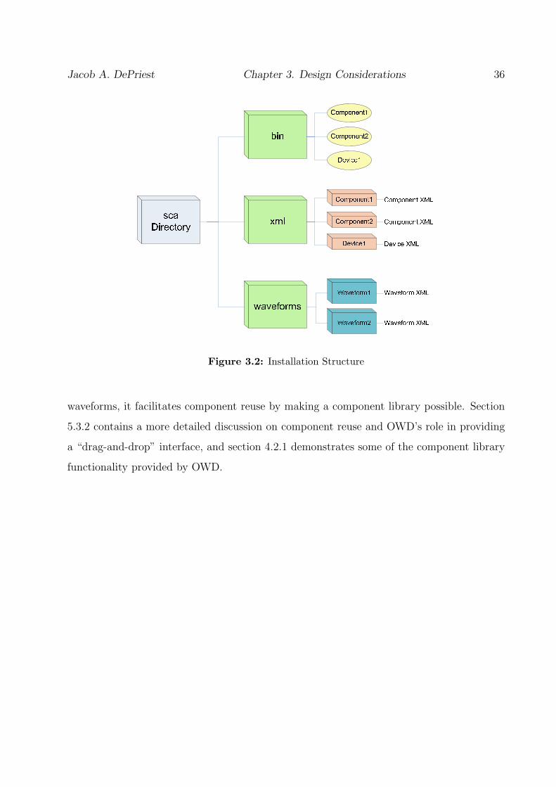
Jacob A. DePriest Chapter 3. Design Considerations 36
Figure 3.2: Installation Structure
waveforms, it facilitates component reuse by making a component library possible. Section
5.3.2 contains a more detailed discussion on component reuse and OWD’s role in providing
a “drag-and-drop” interface, and section 4.2.1 demonstrates some of the component library
functionality provided by OWD.
Chapter 4
OSSIE Waveform Developer
4.1 Waveform Design
There are several considerations that must be looked at before actually designing a waveform
using OSSIE Waveform Developer. First of all, the desired radio layout must be considered
and appropriately translated to a software component design. Secondly, component input
and output must be analyzed and the proper methods must be chosen. An Assembly Con-
troller selection must also be taken into account when laying out the software design. The
final consideration involves device deployment strategies. All of these issues must be carefully
resolved before a modular, reusable waveform can be successfully designed and implemented.
4.1.1 Mapping Radio Design to Software Components
Because the concepts and structure of software defined radios are so different from those
of conventional radio design, one cannot simply design a basic block diagram of a radio
and then map it directly to the respective software components. The inherent reusability of
SDR components lends itself to a much simpler design approach. Consider the simple block
diagram of a two-stage conversion receiver in Figure 4.1. If a direct mapping from diagram
37

Jacob A. DePriest Chapter 4. OSSIE Waveform Developer 38
blocks to software components were used in this design, one would need close to ten SDR
components to implement the receiver. While this is certainly acceptable, it is unnecessarily
complex.
Figure 4.1: Simple Receiver Block Diagram
By grouping the similar components into the general categories: filter, amplifier control,
local oscillator control, and automatic gain control as seen in Figure 4.2, we have effectively
reduced the number of components from approximately ten to around four. Obviously, each
BPF cannot have exactly the same configuration and each local oscillator control will be
driving a different frequency; however, by designing the components in a flexible, config-
urable way we can simple create four instances of a BPF with different configurations for
each. The SCA provides for the configuration of component instances in two different ways:
runtime configuration based on sending control information directly to the component, or
by predefined properties loaded into the component as it is installed onto the waveform.1
4.1.2 Component I/O
Software components in an SCA waveform use ports to communicate with each other. There
are two major categories for ports that can be defined:
1At the time of this writing, OWD does not support configuration by means of pre-defined properties
using a Properties Descriptor file (PRF file).

Jacob A. DePriest Chapter 4. OSSIE Waveform Developer 39
Figure 4.2: Simple Receiver Block Diagram with Software Component Groupings
• Uses
• Provides
Uses ports are generally considered to be ports where information flows outward and Pro-
vides ports are generally associated with the inward flow of data; however, under certain
circumstances information is technically allowed to flow both ways. For the purposes of this
discussion, we will assume that each type of port is used in the accepted fashion. A software
component can have any number of ports associated with it for communication purposes.
Each port inherits from a specific IDL-defined interface that defines the type and method
of communication that it can support. For instance, the following IDL defines an interface
that is used by implementing the pushPacket operation function.
interface complexShort {
void pushPacket(in PortTypes::ShortSequence I, in PortTypes::ShortSequence Q);
};
This interface has two parameters, I and Q, both of which are CORBA ShortSequences. This
means that a Uses port that inherits from this interface can communicate with a Provides
port that inherits from complexShort and vice versa. Data flow is initiated between ports
using remote procedure calls (RPC). Another feature of port-based communication is the
support of multiple inputs and multiple outputs for a single port. Figure 4.3 shows a few
possible component communication scenarios supported in the SCA.

Jacob A. DePriest Chapter 4. OSSIE Waveform Developer 40
Figure 4.3: Sample Component Communication Layouts
4.1.3 Assembly Controller
Because one of the inherent benefits of SDRs is component reusability, components should
be designed to function outside the confines of a specific waveform. In other words, each
component of a waveform should be designed in such a way that it could potentially be used
in other waveforms without modification. However, this component design approach presents
the problem of waveform interaction: if all of the components in the waveform are completely
portable and generic, then what happens when a waveform needs to make waveform-specific
adjustments at run-time or control various components during operation. It is infeasible for
one unique component to be the controller, moderator, and decision maker for all possible
waveforms. The solution to this problem resides in the notion of the Assembly Controller.
The Assembly Controller is the naming convention used to describe a component in a wave-
form that has intimate knowledge of that specific waveform. If specific components need to

Jacob A. DePriest Chapter 4. OSSIE Waveform Developer 41
be started or stopped at specific times, dynamically configured during operation, or essen-
tially made to operate in any way other than the most portable implementation, it falls to
the Assembly Controller to moderate these tasks. The Assembly Controller does not neces-
sarily have to be a separate, dedicated component in a waveform; the task of the Assembly
Controller could be assigned to any one of the components in the waveform. Section 4.2.2
describes in detail the process used in OWD to handle the Assembly Controller.
The main distinction that separates the Assembly Controller from the other components is
that it is the only component on which the CF calls start when the waveform is loaded.
All other functionality must be added by the developer after code generation is complete.
Although this may seem like a small difference, it is enough to let the Assembly Controller
know that it is time to start the radio, which gives it the freedom to moderate the waveform
at the developer’s discretion.
4.1.4 Device Considerations
Before designing a waveform for a particular platform, the device structure and layout of the
system must be considered. There are four basic device definitions provided by the SCA:
• Device
• LoadableDevice
• ExecutableDevice
• AggregateDevice
A Device is a hardware abstraction used to represent a physical device in software, provid-
ing a means of access and control for software components to interact with hardware. A
Device is the most generic abstraction provided by the SCA for this purpose; it includes
functionality such as checking the state of the device and allocation and deallocation of de-
vice capacities. Devices are simply software component Resources that add varying levels

Jacob A. DePriest Chapter 4. OSSIE Waveform Developer 42
of hardware interfaces. Because of its generality, Device can act as a proxy for devices that
do not fall under one of the other categories. The inheritance relationships between all four
types of device abstractions can be seen in Figure 2.1.
A LoadableDevice provides additional functionality for loading and unloading data onto
a device. This device type would be used when a software component had the task of
interacting with a piece of hardware that requires a bitfile to be loaded for the required
functionality, such as an FPGA. However, when working with a hardware device such as
a DSP, simply loading and unloading the data onto the device does not provide sufficient
functionality. An ExecutableDevice provides execution and termination functionality to
give the developer control over starting and stopping code execution on a particular device.
The AggregateDevice abstraction is different from the other types in that it simply provides
a way to aggregate a number of devices into a structure that can be treated as one software
device. The explanation of these types is rudimentary but provides a basic understanding
of the differences and uses of devices in the context of the SCA. [1][5]
A software component must be associated or assigned to a particular device during the
design to allow proper execution when the waveform is being run. Depending on the type of
device, more than one software component can be assigned to it, or in some cases no devices
have to be directly associated with it because it is acting as a type of proxy for a hardware
device. In the latter case, communication with this device proxy is carried out in the normal
fashion, through port connections that are set up at design time. For example, say that
we need to develop a device proxy to communicate with a specific piece of RF equipment
that can be only controlled using specialized C++. We could have our Assembly Controller
or some other software component connected to the device proxy give it the signal to start
the hardware, which it would then pass on to the actual device by means of the specialized
code. No other software component could actually be deployed on the proxy device, but
communication would still be necessary to control the device and to send and receive data.

Jacob A. DePriest Chapter 4. OSSIE Waveform Developer 43
Because device components are specific to the hardware that they are associated with, OWD
does not explicitly provide a method for creating new devices. However, when devices are
detected on a system, the software does allow the designer to choose a predefined device for
software component deployment. Section 4.2.2 provides details of this procedure in OWD.
4.2 Waveform Layout
This section provides documentation, examples, and additional information regarding actual
design using OSSIE Waveform Developer. Each of the major waveform tasks is covered
in detail including specific examples of software component interaction. Because of the
complexity of the code generation results, they will be discussed separately in Chapter 5.
Figure 4.4 shows the main window of OSSIE Waveform Developer. This window contains
the main features of OWD and is where most of the design takes place. There are three
main areas in this window: the Available Resources area, the Waveform Layout area, and
the Platform Layout area.
Available Resources Pane
The left pane, Available Resources, lists all of the software components and devices installed
on the system. When new components are imported or built and installed on the system,
they will appear here for use when OWD is first loaded. All resources under the Components
node are generally considered to be reusable software components that can be used in various
waveforms. The resources under the Devices node are derived from the Device interfaces
described in section 4.1.4 and are used when defining the platform deployment of a waveform.
The resources in the left pane are also referred to as the Component Library.
Usage Note
OWD must be restarted for a newly installed resource to be available if OWD is currently running.

Jacob A. DePriest Chapter 4. OSSIE Waveform Developer 44
Figure 4.4: OSSIE Waveform Developer Main Window
Waveform Layout Pane
The upper right pane, Waveform Layout, displays the current waveform design in progress.
Newly created resources and resources imported from the component library will be displayed
here with most waveform design features being accessed using the mouse right-click or from
Waveform menu.
Platform Layout Pane
The lower right pane, Platform Layout, displays the current platform configuration used for
device deployment. Components in the Waveform Layout section can be assigned to device
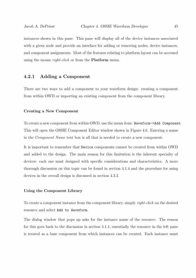
Jacob A. DePriest Chapter 4. OSSIE Waveform Developer 45
instances shown in this pane. This pane will display all of the device instances associated
with a given node and provide an interface for adding or removing nodes, device instances,
and component assignments. Most of the features relating to platform layout can be accessed
using the mouse right-click or from the Platform menu.
4.2.1 Adding a Component
There are two ways to add a component to your waveform design: creating a component
from within OWD or importing an existing component from the component library.
Creating a New Component
To create a new component from within OWD, use the menu item: Waveform->Add Component.
This will open the OSSIE Component Editor window shown in Figure 4.6. Entering a name
in the Component Name text box is all that is needed to create a new component.
It is important to remember that Device components cannot be created from within OWD
and added to the design. The main reason for this limitation is the inherent specialty of
devices: each one must designed with specific considerations and characteristics. A more
thorough discussion on this topic can be found in section 4.1.4 and the procedure for using
devices in the overall design is discussed in section 4.3.2.
Using the Component Library
To create a component instance from the component library, simply right-click on the desired
resource and select Add to Waveform.
The dialog window that pops up asks for the instance name of the resource. The reason
for this goes back to the discussion in section 4.1.1; essentially the resource in the left pane
is treated as a base component from which instances can be created. Each instance must
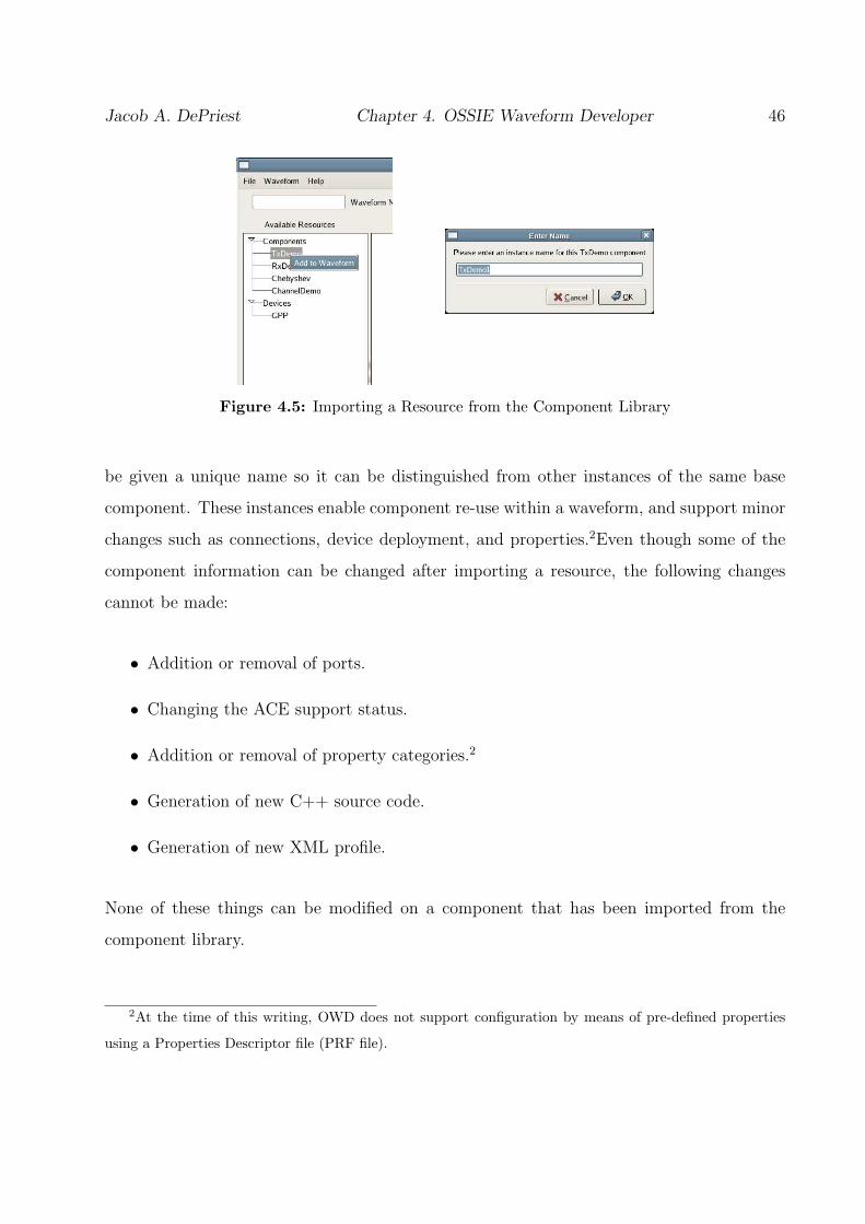
Jacob A. DePriest Chapter 4. OSSIE Waveform Developer 46
Figure 4.5: Importing a Resource from the Component Library
be given a unique name so it can be distinguished from other instances of the same base
component. These instances enable component re-use within a waveform, and support minor
changes such as connections, device deployment, and properties.2Even though some of the
component information can be changed after importing a resource, the following changes
cannot be made:
• Addition or removal of ports.
• Changing the ACE support status.
• Addition or removal of property categories.2
• Generation of new C++ source code.
• Generation of new XML profile.
None of these things can be modified on a component that has been imported from the
component library.
2At the time of this writing, OWD does not support configuration by means of pre-defined properties
using a Properties Descriptor file (PRF file).

Jacob A. DePriest Chapter 4. OSSIE Waveform Developer 47
4.2.2 Editing a Component
The OSSIE Component Editor can be accessed in one of several ways. From within OWD,
right-click on the desired component and select Edit, select the desired component and use
the menu item: Waveform->Edit Component, or simply double-click on the component to
be edited. This will open the window shown in Figure 4.6. The OSSIE Component Editor
provides an interface to add and remove ports, set generation characteristics, edit properties,
and assign device deployment.3Some of the functionality is limited depending on whether the
component being edited was newly created within OWD or imported from the component
library. The OSSIE Component Editor can also be run as a stand-alone application used for
creating, modifying, and generating single components.
Adding / Removing Ports
To add a new port to a component, either right-click in the Ports box in the OSSIE Com-
ponent Editor and select Add or click on the Add button next to the box. This will open up
the Add Port dialog shown in Figure 4.7.
The Interface box lists the available interfaces that OWD was able to read from the system
on startup. These interfaces are separated by namespace association (the enclosing module
in the IDL) and define how a port will communicate. In order to add a port, an interface
must be selected in the Interface box, a name must be entered in the Port Name text box,
and a Port Type must be selected. Some of the issues surrounding ports are discussed in
section 4.1.2.
The newly created port will now show up in the Ports box in the OSSIE Component Editor
under the appropriate category: Uses or Provides.
3At the time of this writing, OWD does not support configuration by means of pre-defined properties
using a Properties Descriptor file (PRF file).

Jacob A. DePriest Chapter 4. OSSIE Waveform Developer 48
Figure 4.6: OSSIE Component Editor Window
Importing IDL
If the component design requires a port interface that is not listed by default, an IDL file
detailing the desired interface can be imported directly into OWD. Simply select the Import
button in the Add Port dialog shown in Figure 4.7. The IDL file must then be selected
in the resulting Open dialog and all compliant interfaces in that file will be imported into
OWD for use. The new interface(s) will automatically show up in the Interface box under
its respective namespace.
Usage Note
In order for the C++ and installation code generated by OWD to run properly, all IDL files imported
into OWD must be copied to the installed standardInterfaces location. For permanent addition to
OWD, the interfaces can be added to the standardInterfaces.

Jacob A. DePriest Chapter 4. OSSIE Waveform Developer 49
Figure 4.7: Add Port Dialog
Renaming a Component
There are two ways to rename a component. The first is simply to enter a new name into
the Component Name box in the OSSIE Component Editor while modifying or creating a
component. An alternative solution is to right-click on the component in the main window
of OWD and select Rename. These two procedures can be seen in Figure 4.8.
Figure 4.8: Renaming a Component
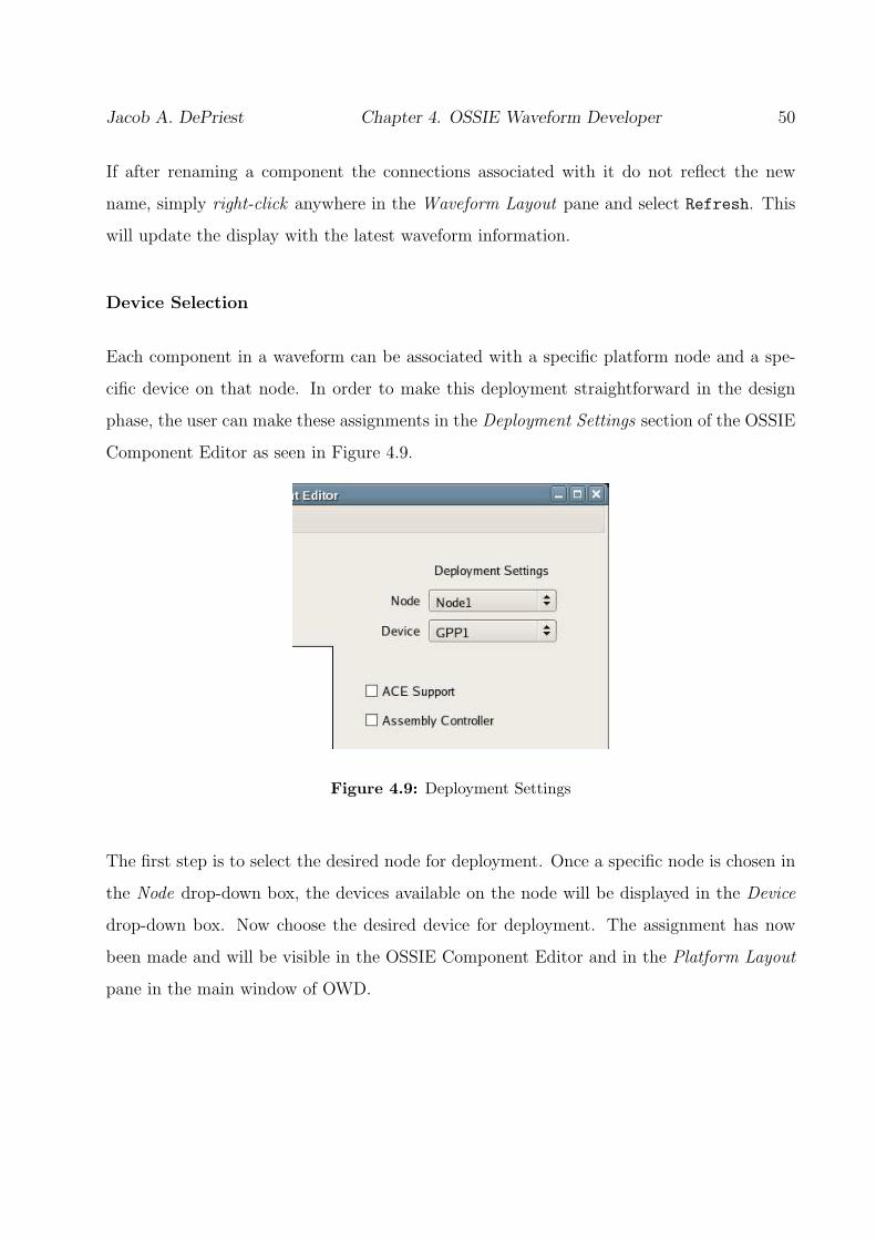
Jacob A. DePriest Chapter 4. OSSIE Waveform Developer 50
If after renaming a component the connections associated with it do not reflect the new
name, simply right-click anywhere in the Waveform Layout pane and select Refresh. This
will update the display with the latest waveform information.
Device Selection
Each component in a waveform can be associated with a specific platform node and a spe-
cific device on that node. In order to make this deployment straightforward in the design
phase, the user can make these assignments in the Deployment Settings section of the OSSIE
Component Editor as seen in Figure 4.9.
Figure 4.9: Deployment Settings
The first step is to select the desired node for deployment. Once a specific node is chosen in
the Node drop-down box, the devices available on the node will be displayed in the Device
drop-down box. Now choose the desired device for deployment. The assignment has now
been made and will be visible in the OSSIE Component Editor and in the Platform Layout
pane in the main window of OWD.

Jacob A. DePriest Chapter 4. OSSIE Waveform Developer 51
Setting the Assembly Controller
As discussed in section 4.1.3, each waveform must have an assigned Assembly Controller in
order to be fully operational. Because of the nature of the Assembly Controller, there can only
be one per waveform. There are two ways to define which component is to be the Assembly
Controller. The first is simply to right-click on the component in the Waveform Layout pane
in the main OSSIE Waveform Developer window and select Set Assembly Controller. The
second is to check the Assembly Controller box in the OSSIE Component Editor window
when editing or creating the given component. Both options can be seen in Figure 4.10.
Figure 4.10: Setting the Assembly Controller
After setting the Assembly Controller component, that component’s name will show up in
bold print in the Waveform Layout pane. Since the Assembly Controller assignment is
mutually exclusive, setting one component as the Assembly Controller will automatically
unset any other component that had previously been designated as the Assembly Controller.
Jacob A. DePriest Chapter 4. OSSIE Waveform Developer 52
4.2.3 Removing a Component
There are two ways to remove a component from a waveform design. The first is to right-click
on the component in the Waveform Layout pane and select Remove. The second way is to se-
lect the component to be removed and then use the menu item: Waveform->Remove Component.
Both ways are shown in Figure 4.11.
Figure 4.11: Removing a Component
When a component is removed from the waveform design, all connections associated with
it will also be removed, locally and remotely. In other words, if any other component has
a connection to the removed component, the respective connection will be automatically
removed.
4.2.4 Connections
Once the ports for the waveform components have been established, the resources can be
connected to each other via the Connections dialog. This can be accessed in one of two
ways: right-click on the component in the Waveform Layout pane and select Connect. The
second way is to select the desired component and then use the menu item: Waveform->
Connect Component. Both ways are shown in Figure 4.12.

Jacob A. DePriest Chapter 4. OSSIE Waveform Developer 53
Figure 4.12: Connecting a Component
Both methods will bring up the Connections dialog seen in Figure 4.13. The left box displays
all of the available ports on the current component. The right-hand box has two main
nodes: Components and Devices. The Components node displays all of the components in
the current waveform and their available ports. The Devices node displays all of the devices
in the current platform deployment model and their ports. In general, devices that act
as proxies for actual hardware devices most often need to have available ports. However,
devices may have control ports, monitoring ports, or any number of port implementations
depending on the use model for the platform.
Adding Connections
The creation of connections takes place in the Connections dialog shown in Figure 4.13. The
following steps detail the process of adding a connection to a component:
1. Select the port from current component to be used in the connection from the left-hand
box.
2. Select a port from any resource in the right-hand box for the other side of the connec-
tion.

Jacob A. DePriest Chapter 4. OSSIE Waveform Developer 54
Figure 4.13: Connections Dialog
3. Check to insure that the ports are compatible: Provides->Uses or Uses->Provides.
4. Note the Interface type of each port underneath the respective boxes.
5. Click on the Connect button in between the two boxes.
The details for the newly created connection will be displayed in the bottom of the dialog
in the Connections box with the following form.
<Port on this Component> ==> <Component of other port>::<Other port>
It will also be displayed in the main OSSIE Waveform Developer window as a child of the
respective component. Duplicate connections are detected and prohibited by the Connection
dialog.
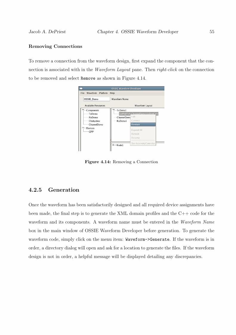
Jacob A. DePriest Chapter 4. OSSIE Waveform Developer 55
Removing Connections
To remove a connection from the waveform design, first expand the component that the con-
nection is associated with in the Waveform Layout pane. Then right-click on the connection
to be removed and select Remove as shown in Figure 4.14.
Figure 4.14: Removing a Connection
4.2.5 Generation
Once the waveform has been satisfactorily designed and all required device assignments have
been made, the final step is to generate the XML domain profiles and the C++ code for the
waveform and its components. A waveform name must be entered in the Waveform Name
box in the main window of OSSIE Waveform Developer before generation. To generate the
waveform code, simply click on the menu item: Waveform->Generate. If the waveform is in
order, a directory dialog will open and ask for a location to generate the files. If the waveform
design is not in order, a helpful message will be displayed detailing any discrepancies.
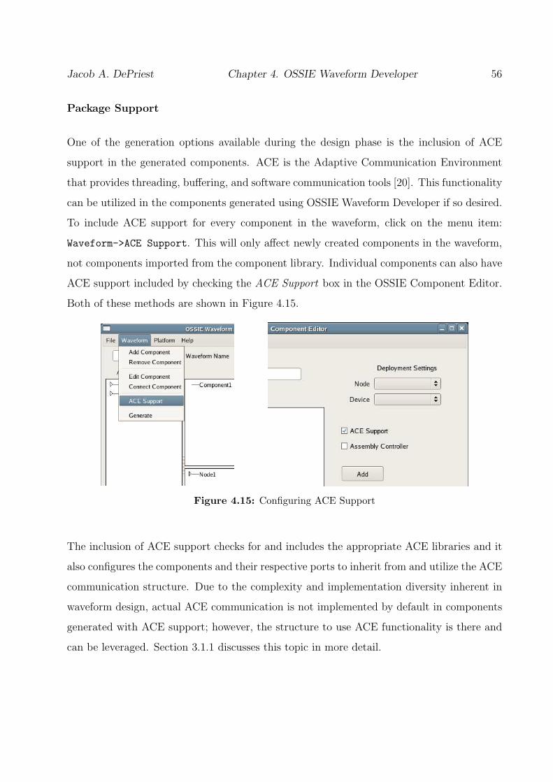
Jacob A. DePriest Chapter 4. OSSIE Waveform Developer 56
Package Support
One of the generation options available during the design phase is the inclusion of ACE
support in the generated components. ACE is the Adaptive Communication Environment
that provides threading, buffering, and software communication tools [20]. This functionality
can be utilized in the components generated using OSSIE Waveform Developer if so desired.
To include ACE support for every component in the waveform, click on the menu item:
Waveform->ACE Support. This will only affect newly created components in the waveform,
not components imported from the component library. Individual components can also have
ACE support included by checking the ACE Support box in the OSSIE Component Editor.
Both of these methods are shown in Figure 4.15.
Figure 4.15: Configuring ACE Support
The inclusion of ACE support checks for and includes the appropriate ACE libraries and it
also configures the components and their respective ports to inherit from and utilize the ACE
communication structure. Due to the complexity and implementation diversity inherent in
waveform design, actual ACE communication is not implemented by default in components
generated with ACE support; however, the structure to use ACE functionality is there and
can be leveraged. Section 3.1.1 discusses this topic in more detail.

Jacob A. DePriest Chapter 4. OSSIE Waveform Developer 57
Generating a Single Component
In certain instances, it may be desirable to generate the XML profile and C++ skeleton code
for a single component, without having to generate an entire waveform. To generate just the
component code, simply click on the menu item: Component->Generate Component in the
OSSIE Component Editor window as shown in Figure 4.16. This can be done when OSSIE
Component Editor is running as a stand-alone application or when it is run in conjunction
with OSSIE Waveform Developer.
Figure 4.16: Generating a Single Component
4.3 Platform Layout
Even though platform support is built directly into OSSIE Waveform Developer, it is fun-
damentally separate from the actual waveform design from an abstract point of view. It
could be argued that a separate tool should be used to handle the platform design and lay-
out, because the configuration of the platform is technically transparent to the waveform
once the device assignments have been made (see section 3.1.3 for more detail). Ideally,
software components could be designed in such a way that they were simply assigned dy-
namically to the available hardware of a system at load time. However, this deployment
strategy is extremely complex and involves many algorithms and strategies that have not
Jacob A. DePriest Chapter 4. OSSIE Waveform Developer 58
been fully explored with regard to software radios and the SCA (see section 3.1.2 for more
detail). Therefore, OSSIE Waveform Developer supports built-in platform design and the
direct mapping of components to hardware devices at design time. This allows the developer
to still design waveforms separately from the platform deployment model, but assign the
components to the appropriate devices before generation.
A Node in the context of OSSIE Waveform Developer refers to a grouping of devices. This
can be a physical machine and its associated peripherals or it can be a logical grouping of
devices. The main characteristic that distinguishes one node from another is that each one
has its own DeviceManager.
This section provides documentation, examples, and additional information regarding plat-
form layout design using OSSIE Waveform Developer. Each of the major platform tasks is
covered in detail.
4.3.1 Adding a Platform Node
There are two ways to add a platform node to the platform deployment model. The first is
to select the menu item: Platform->Add Deployment Node, and the second is to right-click
anywhere in the lower right Platform Layout pane of the main OWD window and select
Add Node. Both methods are shown below in Figure 4.17.
4.3.2 Adding a Device
Each node can have any number of devices associated with it. A device associated with
a node can be any one of the types discussed in 4.1.4, but only LoadableDevices and
ExecutableDevices can have components assigned to them in OWD.
It is important to note that a device must first be added to a node in order for it to be used
in the rest of the waveform design. In other words, if a component needs to be assigned to

Jacob A. DePriest Chapter 4. OSSIE Waveform Developer 59
Figure 4.17: Adding a Platform Node
or connected to a particular device, that device must first be added to a node.
To add a device to a node, simply right-click on the desired device type in the Available
Resources pane and select Add to Node. This will pop up a dialog with a suggested device
instance name and a drop-down menu used to select the desired node. Both the method for
adding a device instance to node and the subsequent dialog are shown in Figure 4.18. Once
a device instance has been associated with a node, it will show up as a child of that node in
the Platform Layout pane.
Figure 4.18: Adding a Device Instance to a Platform Node

Jacob A. DePriest Chapter 4. OSSIE Waveform Developer 60
4.3.3 Editing the Platform Layout
As discussed in the previous sections the Platform Layout pane provides an interface to
manage the platform deployment model for a particular design. Figure 4.19 shows an example
deployment model. There is only one node, Node1, and it has only one device instance
associated with it, GPP1. TxDemo1, ChannelDemo1, and RxDemo1 are component instances
that are to be deployed on GPP1. The following sections detail the editing options available
for the platform deployment design.
Figure 4.19: Editing the Platform Layout
Removing a Component Association
Once a component has been associated with a device in the OSSIE Component Editor, it
can be unassociated by right-clicking on the particular component in the Platform Layout
pane and selecting Remove. This does not remove the component from the waveform, just
the component’s deployment association with the particular device instance.

Jacob A. DePriest Chapter 4. OSSIE Waveform Developer 61
Removing a Device Instance
To remove a device instance that has been associated with a node simply right-click on the
particular device instance in the Platform Layout pane and select Remove. Every component
instance assigned to this device will have that assignment voided.
Removing a Node
To remove a deployment node right-click on the particular node in the Platform Layout
pane and select Remove. All device instances associated with that node and their component
assignments will also be removed and voided respectively.
Renaming a Platform Layout Element
Platform nodes and their respective device instances can be renamed at any time by right-
clicking on the desired element in the Platform Layout pane and selecting Rename. Renaming
a node or device instance does not void any component assignments associated with it - they
are automatically updated. Component instances deployed to a particular device cannot be
edited in any way from the Platform Layout pane; all component instance editing must be
done from the upper right Waveform Layout pane.
4.4 Menu Reference
This section describes each menu item in the main OSSIE Waveform Developer Window.

Jacob A. DePriest Chapter 4. OSSIE Waveform Developer 62
4.4.1 File
New
Clears out the current waveform design and creates a new, blank waveform.
Open
Displays an Open dialog allowing the user to load previous platform, waveform, or project
designs.
Save Project
Saves the current project to its respective .owd file. If the project has not been previously
saved, a Save dialog will ask for a file name and the location to save the project design. An
OWD project file contains both the platform layout and waveform design.
Save Project As...
Displays a Save dialog that asks for a file name and the location to save the project design.
Save Waveform
Saves the current waveform design to its respective .sca file. If the waveform has not been
previously saved, a Save dialog will ask for a file name and the location to save the waveform
design.
Save Waveform As...
Displays a Save dialog that asks for a file name and the location to save the waveform design.

Jacob A. DePriest Chapter 4. OSSIE Waveform Developer 63
Save Platform
Saves the current platform layout to its respective .plt file. If the platform has not been
previously saved, a Save dialog will ask for a file name and the location to save the platform
design.
Save Platform As...
Displays a Save dialog that asks for a file name and the location to save the platform design.
Exit
Closes OSSIE Waveform Developer.
4.4.2 Waveform
Add Component
Adds a new component to the current waveform design. Displays the OSSIE Component
Editor.
Remove Component
Removes the currently selected component from the waveform design. All connections asso-
ciated with the particular component will also be removed.
Edit Component
Displays the OSSIE Component Editor for the selected component.
Jacob A. DePriest Chapter 4. OSSIE Waveform Developer 64
Connect Component
Displays the Connections dialog for the selected component.
ACE Support
Toggles ACE compatibility inclusion for the waveform design.
Generate
Displays a Directory dialog allowing the user to select a location for the output of the code
generation.
4.4.3 Platform
Add Deployment Node
Adds a new deployment node to the platform layout. Displays a text entry dialog for the
name of the new node.
4.4.4 Help
Sample Waveform
Loads a sample waveform design.
About
Displays the version of OSSIE Waveform Developer.

Jacob A. DePriest Chapter 4. OSSIE Waveform Developer 65
4.4.5 OSSIE Component Editor: File
New
Clears out the current component design and creates a new, blank component. (Only avail-
able in stand-alone mode)
Open
Displays an Open dialog allowing the user to load previous component designs. (Only avail-
able in stand-alone mode)
Save
Saves the current component design to its respective .cmp file. If the component has not
been previously saved, a Save dialog will ask for a file name and the location to save the
component design.
Save As...
Displays a Save dialog that asks for a file name and the location to save the component
design.
4.4.6 OSSIE Component Editor: Component
Generate Component
Displays a Directory dialog allowing the user to select a location for the output of the code
generation.

Chapter 5
Post-Generation Design
5.1 Description of Generated Code
OSSIE Waveform Developer provides a graphical interface to design SCA waveforms and
components. The end result of the design is to obtain C++ code, XML profiles, and an
install structure to implement a useful radio. To this end, OWD generates SCA Domain
Profiles, OSSIE-specific XML, skeleton C++ code which implements basic communication
setup, and Autoconf configuration files for installation [30].
OWD basically supports two waveform building techniques: generating waveform skeleton
code to be filled in with the desired radio’s functionality or creating a waveform from pre-
viously designed and installed components. These two methods of waveform design can be
used exclusively or in conjunction. When a resource from the component library is used in a
waveform design, the C++ code associated with that component is not generated again. The
Domain Profile for the waveform simply reflects the use of a previously installed component
instead of a newly created resource. Conversely, when a component is created from within
OWD and used in a waveform, the C++ code associated with it is generated and can be
edited to add functionality.
66

Jacob A. DePriest Chapter 5. Post-Generation Design 67
This section discusses in detail all of the generated code, files, and structure of the output
from OSSIE Waveform Developer. Depending on the waveform design, the directory struc-
ture of the output and the generated files will differ. This is dependent on the use of the
component library and the platform deployment layout.
5.1.1 File and Directory Structure
Figure 5.1 shows a typical directory and file layout resulting from waveform generation using
OWD. Notice that each component’s files are put in a separate directory with the exception
of the Assembly Controller. Since the Assembly Controller is the only component that
should have intimate knowledge of the waveform, its files are generated in a sub-directory
of the waveform directory. Each component directory and the waveform directory have the
necessary Autoconf files needed to build and install the entire waveform. Even though the
Assembly Controller is generated under the waveform directory, it is installed in the same
way as the other components. See section 3.2.4 for more information on the installation
structure.
It is important to note that the generation structure in Figure 5.1 reflects a waveform design
where all of the visible components were newly created from within OWD. When components
are used from the component library, no component specific files are generated and therefore
a separate component directory is not needed. The use of components from the component
library is reflected in the waveform specific XML only.
Tables 5.1 and 5.2 list the files that are generated for typical waveforms and components
respectively. Again, depending on the platform layout and component library usage, there
may be more or fewer files generated.

Jacob A. DePriest Chapter 5. Post-Generation Design 68
Figure 5.1: Generated Directory Layout
5.1.2 XML Domain Profile
The XML files that are generated with each waveform and component are integral to the
operation of the radio. These files “describe the identity, capabilities, properties, and inter-
dependencies of the hardware devices and software components that make up the system”
[1]. Each of the different types of XML files generated by OWD is discussed in this section.
Software Package Descriptor (SPD)
The Software Package Descriptor contains the information needed by the Domain Manager
to manage the particular component and its various implementations. The SPD lists the
different implementations of a component and where the relevant files are that are needed
for its deployment. [1]
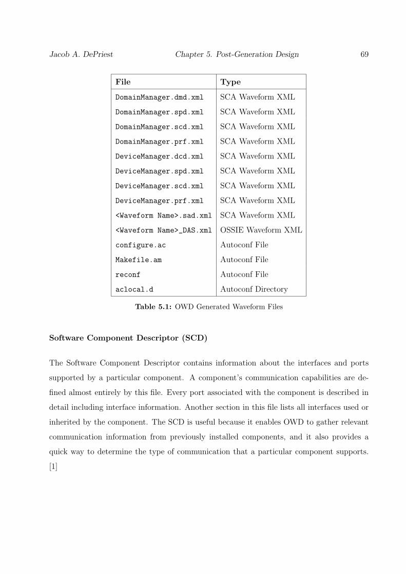
Jacob A. DePriest Chapter 5. Post-Generation Design 69
File Type
DomainManager.dmd.xml SCA Waveform XML
DomainManager.spd.xml SCA Waveform XML
DomainManager.scd.xml SCA Waveform XML
DomainManager.prf.xml SCA Waveform XML
DeviceManager.dcd.xml SCA Waveform XML
DeviceManager.spd.xml SCA Waveform XML
DeviceManager.scd.xml SCA Waveform XML
DeviceManager.prf.xml SCA Waveform XML
<Waveform Name>.sad.xml SCA Waveform XML
<Waveform Name>_DAS.xml OSSIE Waveform XML
configure.ac Autoconf File
Makefile.am Autoconf File
reconf Autoconf File
aclocal.d Autoconf Directory
Table 5.1: OWD Generated Waveform Files
Software Component Descriptor (SCD)
The Software Component Descriptor contains information about the interfaces and ports
supported by a particular component. A component’s communication capabilities are de-
fined almost entirely by this file. Every port associated with the component is described in
detail including interface information. Another section in this file lists all interfaces used or
inherited by the component. The SCD is useful because it enables OWD to gather relevant
communication information from previously installed components, and it also provides a
quick way to determine the type of communication that a particular component supports.
[1]

Jacob A. DePriest Chapter 5. Post-Generation Design 70
File Type
<Component Name>.spd.xml SCA Component XML
<Component Name>.scd.xml SCA Component XML
<Component Name>.prf.xml SCA Component XML
<Component Name>.h OSSIE Component C++
<Component Name>.cpp OSSIE Component C++
main.cpp OSSIE Component C++
port_impl.h OSSIE Port Implementation C++
port_impl.cpp OSSIE Port Implementation C++
configure.ac Autoconf File
Makefile.am Autoconf File
reconf Autoconf File
aclocal.d Autoconf Directory
Table 5.2: OWD Generated Component Files
Properties Descriptor (PRF)
The Properties Descriptor contains component and device settings for given attributes. This
file provides the means to utilize resource instances and facilitate component reuse. As
discussed in section 4.1.1, a resource can be designed in a flexible way using properties that
are configured at runtime instead of hard-coding the specific attributes into the C++ code.
The PRF file allows component instances of the same base resource to behave differently
based on the attribute configurations in the PRF.1[1]
1At the time of this writing, OWD does not support configuration by means of pre-defined properties
using a Properties Descriptor file (PRF file).

Jacob A. DePriest Chapter 5. Post-Generation Design 71
Software Assembly Descriptor (SAD)
The Software Assembly Descriptor provides a means of describing the information needed
to deploy a waveform application on a system. There are four basic types of waveform
information that are contained in the SAD file. The first type is partitioning information that
details any special requirements for the components used in the application; each component
instance used in the waveform design is listed under this category. The second defines the
Assembly Controller assignment for the particular waveform. Third, the SAD file contains
the connection information for the waveform components, including the specific ports used in
the connections. Finally, the SAD file should contain information regarding available ports
for the waveform assembly. [1]
Device Configuration Descriptor (DCD)
The Device Configuration Descriptor is similar in nature to the SAD file discussed above;
however, it concerns the devices used in a particular deployment instead of the software
components. The intent of the DCD is to define which device components are started by the
Device Manager on a particular node, describe any connections to Device components, and
to identify how to obtain the Domain Manager reference. The DCD lists all of the device
instances that should be started on a particular node. [1]
Domain Manager Descriptor (DMD)
The Domain Manager Descriptor contains information identifying the Domain Manager used
in the application [1].

Jacob A. DePriest Chapter 5. Post-Generation Design 72
Device Assignment Sequence (DAS)
The Device Assignment Sequence is an OSSIE-specific file used to define the deployment
mapping of components to devices. According to the SCA, component deployment to devices
should ideally be dynamic and based on available resources, compatibility, and other factors.
However, due to the complexity of this operation, we chose to allow the user to set device
deployment during the design phase as detailed in section 4.2.2. For more discussion on this
topic, see section 3.1.2.
The DAS file that is generated with each waveform details the mapping chosen during the
design of the waveform. The componentid tag contains the UUID assigned to a particular
component instance in the SAD file. The assigndeviceid tag contains the UUID assigned
to a particular device instance in the DCD file of the particular node that the device is
assigned to. This file is used when running an application on the OSSIE CF.
5.1.3 C++ Code
As shown in table 5.2, there are five C++ files that are auto-generated for each new compo-
nent: <Component Name>.h, <Component Name>.cpp, port_impl.h, port_impl.cpp, and
main.cpp. This section provides details on the contents of each one of these files and their
relevance to the component. These files make up the functionality of a particular component
and are where the bulk of post-generation design takes place. Even though OWD provides
extensive communication support built into these files, the actual radio functionality of a
component is left to the developer to add after generation.
Component Name.h
Each newly generated component has a C++ header file with the same name as the compo-
nent. This file contains all of the C++ class definitions for the particular component. The
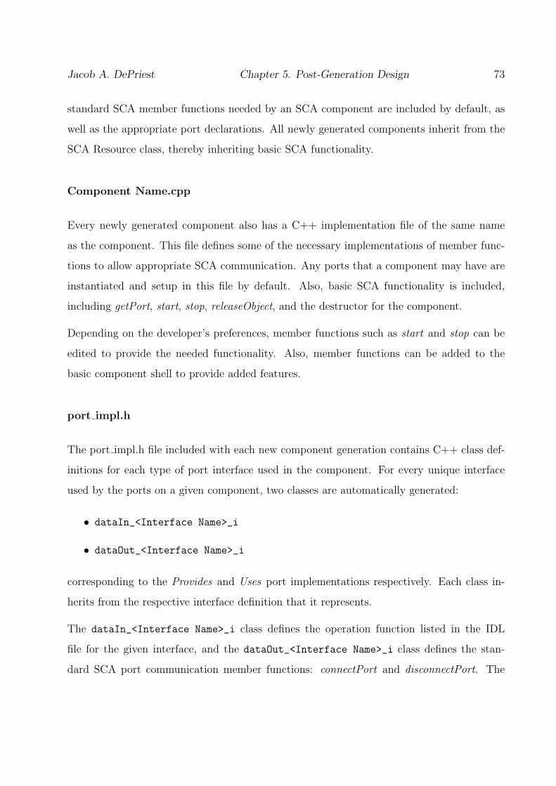
Jacob A. DePriest Chapter 5. Post-Generation Design 73
standard SCA member functions needed by an SCA component are included by default, as
well as the appropriate port declarations. All newly generated components inherit from the
SCA Resource class, thereby inheriting basic SCA functionality.
Component Name.cpp
Every newly generated component also has a C++ implementation file of the same name
as the component. This file defines some of the necessary implementations of member func-
tions to allow appropriate SCA communication. Any ports that a component may have are
instantiated and setup in this file by default. Also, basic SCA functionality is included,
including getPort, start, stop, releaseObject, and the destructor for the component.
Depending on the developer’s preferences, member functions such as start and stop can be
edited to provide the needed functionality. Also, member functions can be added to the
basic component shell to provide added features.
port impl.h
The port impl.h file included with each new component generation contains C++ class def-
initions for each type of port interface used in the component. For every unique interface
used by the ports on a given component, two classes are automatically generated:
• dataIn_<Interface Name>_i
• dataOut_<Interface Name>_i
corresponding to the Provides and Uses port implementations respectively. Each class in-
herits from the respective interface definition that it represents.
The dataIn_<Interface Name>_i class defines the operation function listed in the IDL
file for the given interface, and the dataOut_<Interface Name>_i class defines the stan-
dard SCA port communication member functions: connectPort and disconnectPort. The

Jacob A. DePriest Chapter 5. Post-Generation Design 74
dataOut_<Interface Name>_i class also defines a private variable used to connect to re-
mote ports. This variable is of the type NameSpace::<Interface Name>_var, which allows
a CORBA narrow to correctly link this variable to a remote port when connectPort is called.
port impl.cpp
The port impl.cpp file included with each new component generation contains the C++
implementation of the member functions defined in the port impl.h file. The connectPort and
disconnectPort are both automatically populated with functional C++ code. Functionality
can be added to the operation member function defined by the interface for the given port.
main.cpp
The main.cpp file generated with each new component is necessary from a practical point
of view. This file instantiates a class object of the type defined in the <Component Name>.h
file. It also takes care of setting up the CORBA environment for the component, including
registering the component with the Naming Service. It also includes some omniORB specific
threading code that takes care of shutting down the component when it is released by OSSIE
CF.
5.2 Modifications
There is a large number of different platforms on which a waveform and its components can
be deployed. A waveform design can be developed for an even larger number of applications.
Software defined radios can be deployed on GPPs, embedded devices, FPGAs, floating point
devices, fixed point devices, and any number of other such devices to implement almost any
kind of communication. Because of the multitude of options that can be configured, coded,
and designed after the generation of a waveform using OSSIE Waveform Developer, it is
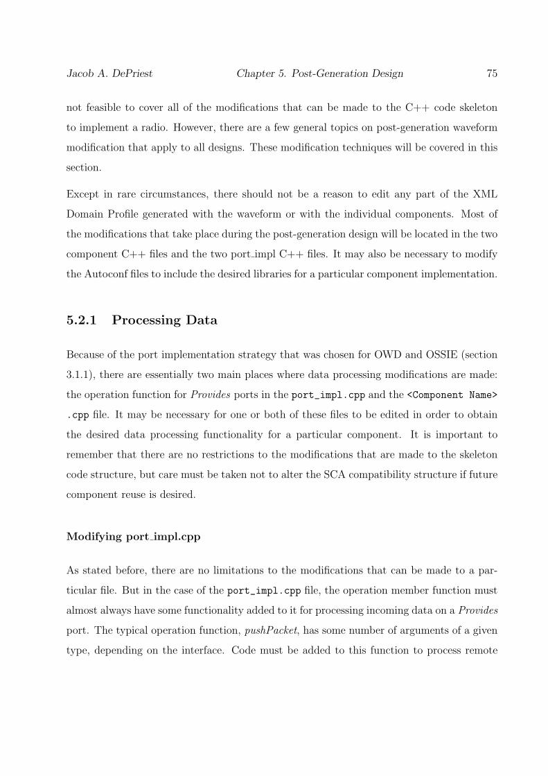
Jacob A. DePriest Chapter 5. Post-Generation Design 75
not feasible to cover all of the modifications that can be made to the C++ code skeleton
to implement a radio. However, there are a few general topics on post-generation waveform
modification that apply to all designs. These modification techniques will be covered in this
section.
Except in rare circumstances, there should not be a reason to edit any part of the XML
Domain Profile generated with the waveform or with the individual components. Most of
the modifications that take place during the post-generation design will be located in the two
component C++ files and the two port impl C++ files. It may also be necessary to modify
the Autoconf files to include the desired libraries for a particular component implementation.
5.2.1 Processing Data
Because of the port implementation strategy that was chosen for OWD and OSSIE (section
3.1.1), there are essentially two main places where data processing modifications are made:
the operation function for Provides ports in the port_impl.cpp and the <Component Name>
.cpp file. It may be necessary for one or both of these files to be edited in order to obtain
the desired data processing functionality for a particular component. It is important to
remember that there are no restrictions to the modifications that are made to the skeleton
code structure, but care must be taken not to alter the SCA compatibility structure if future
component reuse is desired.
Modifying port impl.cpp
As stated before, there are no limitations to the modifications that can be made to a par-
ticular file. But in the case of the port_impl.cpp file, the operation member function must
almost always have some functionality added to it for processing incoming data on a Provides
port. The typical operation function, pushPacket, has some number of arguments of a given
type, depending on the interface. Code must be added to this function to process remote

Jacob A. DePriest Chapter 5. Post-Generation Design 76
procedure calls in order to handle the received data appropriately.
Modifying Component Name.cpp
If any significant amount of data processing and communication is needed by a compo-
nent, generally the <Component Name>.cpp is used to implement the desired functionality.
Threads, function calls, or a combination of the two can be used to handle processing de-
mands at the developer’s discretion. Device specific considerations must also be made for this
file. For instance, if the component is to be deployed on a fixed point embedded processor,
then the code added to this file must reflect the given deployment.
5.2.2 Threading
The choice about whether to use threading in a particular component implementation is
largely application dependent. Asynchronous communication may be a necessity for some
radio applications or may be viewed negatively for others. As discussed earlier in section
4.2.5, ACE support may be included in the generated output by selecting the option during
the graphical design phase. Because OWD and OSSIE support the omniORB [21] CORBA
implementation, the omnithread library can also be used with little difficulty. Ultimately,
the threading and processing decisions made for each component are left to the developer
because of the vast number of applications that are possible using software defined radios.
5.2.3 Autoconf
Autoconf [30] is a Linux configuration and installation manager that allows the automatic
creation of Makefiles and dependency checking. Because OWD relies heavily on Autoconf
for the installation of components and waveforms on a system, this tool can also be utilized
by the developer in the post-generation phase of the design. Many software packages have

Jacob A. DePriest Chapter 5. Post-Generation Design 77
Autoconf support built in, and therefore the dependency checking and inclusion of these
packages into a component simply becomes a matter of adding the appropriate syntax to
the configure.ac and Makefile.am files.
The configure.ac contains the software package support information that checks for and
includes desired software packages and libraries into the building of the component. The
Makefile.am file contains the component specific instructions for generating the Makefiles
needed to build and install components. Proper editing of this file gives the developer control
over the files included in the installation of the component or waveform and the needed files
for the build process. Details on the editing of these files will not be covered in this document
due to the scope of the issue; however, there are many tutorials and manuals on the Internet
regarding the use and capabilities of the Autoconf tool.
5.3 Results and Analysis
OSSIE Waveform Developer has dramatically accelerated SCA waveform development by en-
abling major improvement in the way the the OSSIE team designs and implements waveforms
and components. Before OWD was used in the design process, the CORBA communication
structure, OSSIE interaction, XML Profile creation, and the installation structure were all
created by hand for each specific application. This approach was neither efficient nor consis-
tent. To create a new component, developers would copy a previously designed component
and edit all of the name references, port communications, and XML entries to meet the
specifications of the new component. There were many problems with this approach to
component and waveform development; however, there was not another viable option for
development at that time. OSSIE Waveform Developer solved many of these problems and
allowed developers to concentrate on the software radio application instead of the specific
CORBA and OSSIE code. Some of the major benefits, changes to the development process,
and overall results that were brought about by OSSIE Waveform Developer will be detailed

Jacob A. DePriest Chapter 5. Post-Generation Design 78
and discussed in this section.
5.3.1 Design Flow
First and foremost among the benefits provided by OWD is the ease and conciseness of the
design flow for waveforms. Figure 5.2 shows a rough outline of the design flow used prior
to having OSSIE Waveform Developer as part of the design process. Note that the process
enclosed in the dashed box had to be implemented for each component in the waveform.
Except for the initial planning and conceptual design phase, the entire waveform develop-
ment process was implemented by hand using a text editor. To create a new component,
a previously designed component was copied and then each C++ and XML file was hand-
edited to reflect the desired component attributes. After each component had been altered
and edited satisfactorily, the process continued with the construction of the waveform XML
files. The SAD file had to have knowledge of each of the components and specify the de-
sired connections. If more than a few components were needed for a waveform, this process
became tedious and error prone.
Figure 5.3 shows the current design flow using OSSIE Waveform Developer. Three process
blocks are unchanged from the previous design flow diagram: Conceptual Design and Com-
ponent Mapping, Add Component Functionality, and Build and Install Waveform. These
three steps must be implemented regardless of the tools being used because of the com-
plexity and range of possible components and waveforms. The conceptual design phase is
key to any software radio design as discussed in section 4.1.1. Since OWD only produces
code that incorporates basic communication setup, the actual functionality of the component
must be implemented after the generation phase. And finally, the build and install process
is fundamentally the same regardless of the path to reach that point in the development
process.
The new design flow essentially incorporates all of the steps of the previous process; however,
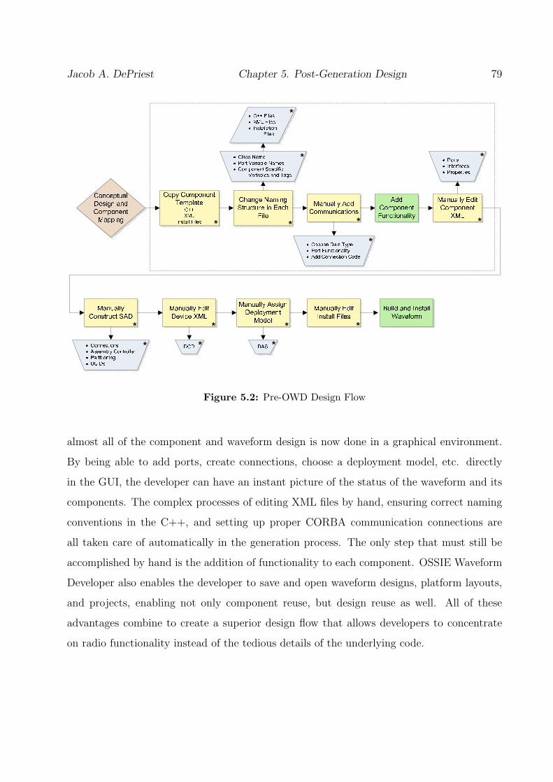
Jacob A. DePriest Chapter 5. Post-Generation Design 79
Figure 5.2: Pre-OWD Design Flow
almost all of the component and waveform design is now done in a graphical environment.
By being able to add ports, create connections, choose a deployment model, etc. directly
in the GUI, the developer can have an instant picture of the status of the waveform and its
components. The complex processes of editing XML files by hand, ensuring correct naming
conventions in the C++, and setting up proper CORBA communication connections are
all taken care of automatically in the generation process. The only step that must still be
accomplished by hand is the addition of functionality to each component. OSSIE Waveform
Developer also enables the developer to save and open waveform designs, platform layouts,
and projects, enabling not only component reuse, but design reuse as well. All of these
advantages combine to create a superior design flow that allows developers to concentrate
on radio functionality instead of the tedious details of the underlying code.

Jacob A. DePriest Chapter 5. Post-Generation Design 80
Figure 5.3: OWD Design Flow
5.3.2 Component Reuse
Even though OWD does not yet support a fully integrated block diagram style of waveform
development, it does provide a “drag-and-drop” interface that drastically speeds up the de-
velopment process. OSSIE Waveform Developer enables the use of a type of Component
Library that was previously too complicated to implement without some sort of manage-
ment tool. An SCA component library refers to a repository of previously designed and
implemented components that can be used in various waveform designs without having to
rebuild and manually modify each one. Essentially, each component in the library would
be designed from a similar skeleton structure and comply with a general set of standards.
Once the library is populated with several such components, then a form of “drag-and-drop”
radio design can be employed with the proper tool. OSSIE Waveform Developer provides
this functionality.
While this concept was not impossible to implement before OWD, the complexity of man-
aging the UUIDs and the XML data deterred developers from attempting to create and use
such a library by hand. Because OWD utilizes XML parsing and portable data structures,
it was a reasonable expectation for it to be able to provide access to already built compo-
nents installed on the current system. The actual functionality of the component library is

Jacob A. DePriest Chapter 5. Post-Generation Design 81
described in section 4.2.1. An SCA component library has been the dream of many SDR
developers for a long time. There were two main obstacles to implementing a component
library by hand: UUID management and component uniformity.
The SCA makes use of UUIDs to identify components, files, and instances. A UUID is
generated by an algorithm designed specifically to make each one unique. Because of the
prevalence of UUIDs in component and waveform XML, the issue of managing them for
newly created components was difficult by itself, but to keep track of and manage UUIDs
when component instances are created from the component library was an enormous task.
OWD manages all of the UUIDs in a design seamlessly. Every time OWD is started, each
base resource in the component library is issued a new UUID, and every time a component
or device instance is created from the component library, it is issued a new instance-specific
UUID. In this way, each component instance of the same base resource will have instance-
specific UUIDs, but still maintain a reference to the base resource profile data. UUIDs are
also refreshed when a previous design is loaded into OWD. OSSIE Waveform Developer’s
UUID management greatly reduces the probability that a UUID will be mismanaged or will
reference an incorrect object.
Component uniformity is the other obstacle on the path to a “drag-and-drop” radio design
environment. As Figure 5.2 shows, the old waveform and component design process was
tedious and provided ample opportunity for different or even the same developer to create
components in different ways. Because there was such a reliance on manual editing of code,
it was rare that two different components designed by different developers where identical in
communication structure and overall layout. This made it difficult to implement a component
library because there was no assurance that all of the components could be used in the same
manner. One developer may have forgotten to implement a needed function in a component,
whereas another developer could unknowingly put an incorrect tag in the XML profile for a
particular component. Even the smallest inconsistencies could render the component library
effort unsatisfactory. Because OWD uses predefined C++ templates and a standard XML
structure, each component created using OWD will have the same general structure. This

Jacob A. DePriest Chapter 5. Post-Generation Design 82
provides the uniformity needed to implement the component library and therefore have the
sought after “drag-and-drop” radio design architecture.
The component library functionality incorporated into OSSIE Waveform Developer is nei-
ther comprehensive nor platform independent. Because of the limitations on the property
implementation in OSSIE, creating component instances that have significantly different be-
havior based on property settings is not yet available during the design phase.2Also, OWD
does not yet support platform specific implementations of components with the same name.
For example, if a particular filter component were designed and built for a GPP and a
specific DSP, each implementation would have to be named differently. Ideally, the install
structure and OWD would allow the developer to choose which implementation is desired or
even automatically choose an implementation based on available hardware. Even with these
limitations, the component library support in OWD allows developers the opportunity to
reuse components in a way that was previously infeasible.
5.3.3 Deployment
Ideally, deployment of components to devices should be a dynamic process based on available
resources, compatibility, and other similar factors. However, because this is a complex
problem that has not been dealt with, OSSIE Waveform Developer provides an integrated
environment for platform layout and deployment. Not only does the component library list
the available components installed on a particular system, but also the available devices.
Any of the Device types discussed in section 4.1.4 can used. The developer can create a
platform layout model and add instances of devices to a particular node much like adding a
component instance to a waveform design.
Before OSSIE Waveform Developer was created, platform layout design and deployment
models were done manually on each node of the layout. Each node has individual XML
2At the time of this writing, OWD does not support configuration by means of pre-defined properties
using a Properties Descriptor file (PRF file).
Jacob A. DePriest Chapter 5. Post-Generation Design 83
files that distinguish that node from the others and allow component deployment on the
node’s available devices. OWD provides a method to create the desired platform layout and
make the appropriate component assignments during the design phase. Not only does this
allow the developer to visually layout the platform, but the XML generation for each node
is handled automatically by OWD. This not only saves the developer a significant amount
of time, but it also prevents spurious errors from occurring when each node is being setup.
Another benefit of using OWD to handle the platform deployment model is its ability to
save individual platform models for later use. This becomes important when a particular
platform layout is used for several different waveforms.

Chapter 6
Conclusion and Future Work
Software defined radios are indeed set to redefine the wireless communications landscape.
From military applications to commercial devices, the flexibility, increased functionality,
and economic benefits of SDRs put them in a position to become the next “killer app”. The
JTRS software communications architecture establishes a well-defined foundation for SDRs
on which military and commercial applications can be built. However, a straightforward,
efficient way to create waveforms and components for these applications is needed because
of the complexity of interfacing the signal processing elements, hardware elements, and
the underlying software framework to form a functional unit. An SCA rapid prototyping
waveform development environment would allow SDR application developers to view the
underlying core framework as an abstraction and focus on the desired radio functionality.
OSSIE Waveform Developer was designed and created to satisfy the need for a waveform
development environment and facilitate the use of the OSSIE Core Framework. The signifi-
cant design decisions involved in the development of the rapid prototyping environment have
been investigated in this thesis along with a thorough explanation of the end result, OSSIE
Waveform Developer. Issues such as a standardized component structure, a device assign-
ment model, implementation language, and the environment design were also investigated
in this work. A detailed discussion was also presented on the C++, XML, and other related
84

Jacob A. DePriest Chapter 6. Conclusion and Future Work 85
files included in the auto-generation of waveforms and components using OWD.
OSSIE Waveform Developer provides SDR developers with a graphical interface to design
waveforms, components, and platform layouts. It supports functionality such as adding and
removing ports, connections between resources, importing interfaces, and creating deploy-
ment models for waveforms. One of the most significant features provided by OWD is the
ability to utilize a component library, thus enabling developers to have a type of “drag-and-
drop” radio design environment.
Several aspects of waveform development were not studied or implemented in this work.
The SCA specifies that the device assignment process should be implemented dynamically
by the framework. Some of the issues inhibiting this method were covered in this work, but
the move to a dynamic device assignment should be more carefully studied and the options
tested to provide a method of assignment based on available resources and device options.
Another avenue of future study should involve exploring the possibility of converting the
current OWD design environment of drop-down menus and tree-lists to a graphical block
design environment. While this would not necessarily improve the overall results, it would
enable developers to more easily visualize a design and improve the usability of the toolset.
The SCA provides self-testing interfaces for resources that would essentially allow a com-
ponent or device to automatically run tests to verify certain working conditions. Inclusion
of testing functionality in auto-generated components would likely make components and
waveforms more robust. OSSIE Waveform Developer includes a few options that affect the
auto-generated code, but developers would benefit from being able to select different ORB
compatibility or even a specific language for the auto-generated code. Also, the ability
to define and configure component properties should be added to OWD in order to fully
exploit component reuse. Finally, further work is suggested on waveform and component
compatibility with other SCA Core Frameworks.
The goal of this work was to provide SDR developers with an open source tool to facilitate
waveform and component design by abstracting the details of CORBA communication and

Jacob A. DePriest Chapter 6. Conclusion and Future Work 86
Core Framework interactions to allow the designer to focus on signal processing and radio
design issues. Not only do the results presented in this thesis show the benefits provided by
OSSIE Waveform Developer, but to date, researchers and students have been using OSSIE
Waveform Developer to successfully design and generate waveforms and components; the
feedback has been decidedly positive.

Appendix A
Installation and Usage
This appendix covers some of the usage details left out of the body of this work to protect the
casual reader from mundane details. The topics covered here will be of interest to developers
using OSSIE Waveform Developer, and will hopefully provide some insight into how to use
the waveforms and components that are produced with OWD.
A.1 Installation - Single Node
This section specifically addresses the installation of waveforms being deployed on devices
that are associated with only one platform Node. When a waveform has devices that are
deployed on more than one platform Node, special steps must be taken to install the generated
code.
Once a waveform or component has been successfully designed, generated, and modified,
there are a few steps that need to be taken before being able to use the new software. The
generated code structure is described in detail in section 5.1 and graphically by Figure 5.1,
but for convenience this figure will be shown again in Figure A.1. Once all of the necessary
modifications have been made to the component C++ files, the waveform and components
87

Jacob A. DePriest Appendix A. Installation and Usage 88
must be installed to the common installation location described in section 3.2.4 and shown
in Figure 3.2.
Figure A.1: Generated Directory Layout
Since the waveforms and components generated using OSSIE Waveform Developer include
properly configured Autoconf [30] files, the installation procedure is fairly straightforward.
The following commands must be executed in each of the second-level directories of the
generation structure (Waveform Name, Component 1, Component 2, etc.) shown in Figure
A.1.
./reconf
./configure
make
make install [prefix=/path/to/install/location]
The first two lines simply make use of the Autoconf package to configure the code and create
Makefiles to be used for compilation and installation. The third line builds the code and

Jacob A. DePriest Appendix A. Installation and Usage 89
compiles it into the binary (executable). Note that if a waveform is generated using only
components from the component library (Available Resources pane in OWD), then the Make
command may be skipped because there is no C++ code to be compiled in that case. The
fourth line actually installs the binary and XML files into the common installation location
for the system. Note that the [prefix=/path/to/install/location] argument is optional
and is only needed when the installation location for the system is somewhere other than
the default: /home/sca.
The wavedev.cfg file located in the top directory of the OSSIE Waveform Developer source
tree provides the configuration setting needed to change the default installation location.
Usage Note
When only a single component is generated using OSSIE Component Editor, the same commands will
build and install the individual component when executed in the generated component’s directory.
A.2 Installation - Multiple Nodes
This section details the installation procedure for waveforms being deployed on devices that
are associated with more than one Node. As discussed in section 3.1.3, each Node in a
platform layout is associated with a different DeviceManager. Because of this, when OSSIE
Waveform Developer generates waveforms with devices that are deployed on more than one
Node, an extra directory is created in the generated waveform directory for each Node in the
platform design. These directories contain the XML files needed to run the DeviceManager
on each Node.
The installation procedure for the generated waveform and components is similar to the one
described in section A.1; however, one more step is needed to complete the procedure for a
multi-Node design. The Node which will run the DomainManager must be identified, and
the XML files for all of the nodes must be copied into the installation waveform directory

Jacob A. DePriest Appendix A. Installation and Usage 90
(/home/sca/waveforms/<Waveform Name> is the common location) on that Node. For ev-
ery other Node, only the XML files relevant to that specific Node need to copied into the
installation waveform directory on that Node.
A.3 Usage - Single Node
This section describes how to run a waveform that has been properly installed on a system
and only has devices deployed on a single Node. First of all, the user must have nodeBooter
installed on the system and wavLoader copied into the installation waveform directory of
interest (see the OSSIE website for more details [31]). Then the following steps must be
taken to run the waveform.
• Ensure the CORBA Naming Service is running.
• Enter the waveform installation directory in one shell.
- (typically /home/sca/waveforms/<Waveform Name>)
• Run the nodeBooter with the DCD file as input:
- nodeBooter -D -d DeviceManager.dcd.xml
• Enter the waveform installation directory in another shell.
• Run wavLoader with the DAS as input:
- ./wavLoader <Waveform Name>_DAS.xml
• Select the appropriate waveform.
A.4 Usage - Multiple Nodes
This section describes how to run a waveform that has been properly installed on a system
and has devices deployed on a multiple Nodes. The user needs the nodeBooter tool to be

Jacob A. DePriest Appendix A. Installation and Usage 91
installed on each of the Nodes; however, the wavLoader only needs to be present on the
Node running the DomainManager. For ease of use, we will refer to the Node that runs the
DomainManager as the MasterNode. The following steps must be taken to run a waveform
distributed across multiple Nodes.
MasterNode
• Ensure the CORBA Naming Service is running.
• Enter the waveform installation directory in one shell.
- (typically /home/sca/waveforms/<Waveform Name>).
• Run the nodeBooter with the DCD file as input:
- nodeBooter -D -d DeviceManagerNode1.dcd.xml
• Enter the waveform installation directory in another shell.
• Wait for all the nodeBooters to be run on each Node.
• Run wavLoader with the DAS as input:
- ./wavLoader <Waveform Name>_DAS.xml
• Select the appropriate waveform.
Other Nodes
• Ensure the CORBA Naming Service is running on the MasterNode.
• Enter the waveform installation directory.
- (typically /home/sca/waveforms/<Waveform Name>)
• Run the nodeBooter with the DCD file as input:
- nodeBooter -d DeviceManagerNodeX.dcd.xml
- Note that the -D has been removed - this indicates that only the DeviceManager
should be started on this Node.

Bibliography
[1] Software Communications Architecture Specification, 2nd ed., Joint Tactical Radio Sys-
tem (JTRS) Joint Program Office, April 2004.
[2] J. H. Reed, Software Radio: A Modern Approach to Radio Engineering, 1st ed. New
Jersey: Prentice Hall, 2002.
[3] P. G. Cook and W. Bonser, “Architectural Overview of the SPEAKeasy System,” IEEE
Journal on Selected Areas in Communications, vol. 17, no. 4, April 1999.
[4] [Online]. Available: http://www.gnu.org/software/gnuradio
[5] M. Robert, J. H. Reed, and J. Smith, “The Joint Tactical Radio System (JTRS) Soft-
ware Communications Architecture (SCA) Core Framework (CF): A Tutorial,” written
in conjunction with the Mobile and Portable Radio Research Group at Virginia Tech.
[6] [Online]. Available: http://www.omg.org
[7] [Online]. Available: http://www.sdrforum.org
[8] W. Bonser, “Engineering design steps for fast, simple and economical waveform develop-
ment,” in Military Communications Conference, 2001. MILCOM 2001, vol. 1, October
2001, pp. 195 – 201.
[9] [Online]. Available: http://ptolemy.eecs.berkeley.edu
92

Jacob A. DePriest Bibliography 93
[10] C. Hylands, E. Lee, J. Liu, X. Liu, S. Neuendorffer, Y. Xiong, Y. Zhao, and H. Zheng,
“Overview of the Ptolemy Project,” Department of Electrical Engineering and Com-
puter Science, U.C. Berkeley, Tech. Rep. UCB/ERL M03/25, July 2003.
[11] [Online]. Available: http://www.mathworks.com/products/simulink
[12] [Online]. Available: http://www.harris.com
[13] [Online]. Available: http://www.zeligsoft.com
[14] [Online]. Available: http://www.crc.ca
[15] [Online]. Available: http://www.prismtechnologies.com
[16] [Online]. Available: http://www.eclipse.org
[17] M. S. Gudaitis and R. D. Hinman, “Practical considerations for a waveform development
environment,” in Military Communications Conference, 2001. MILCOM 2001, vol. 1,
October 2001, pp. 190 – 194.
[18] R. C. Martin, Agile Software Development - Pattern Principles and Practices, 1st ed.
Prentice Hall, 2002.
[19] Joint Tactical Radio System (JTRS) SCA Developer’s Guide, 1st ed., Raytheon, June
2002.
[20] [Online]. Available: http://www.cs.wustl.edu/∼schmidt/ACE.html
[21] [Online]. Available: http://omniorb.sourceforge.net
[22] [Online]. Available: http://www.trolltech.com/products/qt/index.html
[23] [Online]. Available: http://www.wxwidgets.org
[24] [Online]. Available: http://www.wxpython.org
[25] [Online]. Available: http://boa-constructor.sourceforge.net

Jacob A. DePriest Bibliography 94
[26] [Online]. Available: http://www.python.org/doc/Introduction.html
[27] [Online]. Available: http://sourceforge.net/projects/pyxml
[28] [Online]. Available: http://uche.ogbuji.net/tech/4suite/amara
[29] [Online]. Available: http://uml.sourceforge.net/index.php
[30] [Online]. Available: http://www.gnu.org/software/autoconf
[31] [Online]. Available: http://ossie.mprg.org
Vita
Jacob was born on in Bristol, TN on August 16, 1981. He received his B.S. degree in
Computer Engineering from the University of Tennessee in 2004 and subsequently joined
the Bradley Department of Electrical and Computer Engineering at Virginia Polytechnic
Institute and State University beginning in the Fall of 2004.
After spending one semester as a Graduate Teaching Assistant with the department, Jacob
began research with the Mobile and Portable Radio Research Group (MPRG) at Virginia
Tech. He worked as a Graduate Research Assistant to MPRG under Dr. J. H. Reed.
95


