
Ci!!Ji!!da1r .... .-11enqer MODEL CL-600-2A12
AIRPLANE FLIGHT MANUAL PSP 601-18-1
EMERGENCY PROCEDURES
TABLE OF CONTENTS
Page
1. POWER PLANT EMERGENCIES • • • • • • . . • • • • • • • • • • • • • • • • • • • • • • • • • • • • • • • • • • • • • • • • • 1
A. Double Engine Failure •••••••••••••••••••••••••••••••.•.•••••.•••••• 1 B. Engine Fire or Severe Engine Damage ••••••••••••••••••••••••••••••• 2F C. Inadvertent Thrust Reverser Deployment in Flight • • • • • • • • • • • • • • • • • • • 3 D. APU Fire ••••••••••••••••••••••••••••••••••••••••••••••••••••••••••• 6 E. Jet Pipe/Pylon Overheat • • • • • • • . • • • . • • • • • • • • • • • • • • • • • • • • • • • • • • • • • • • 6A F. Engine Qi l Pressure Low • • • • • • . . • . • . • • • • • • • • • • • • • • • • • • • • • • • • • • • • • • • 6A G. Uncommanded Acceleration •••••••••..•••••••••••••••••••••••••••••••• 7
2. SMOKE/FIRE/FUMES EMERGENCIES ••.••••••••••••••••••••••••••••.•••••••.•••• 8
A. B.
Smoke/Fi re/Fumes Procedure ••••••••••..•••••...• • • • • • • • • • • • • • • • • • • • • 8 I Smoke or Fumes Removal Procedure • • • • • • • • • • • • • . • • • • • • • • • • • • • • • • • • • lOC
3. BLEED AIR LEAK EMERGENCIES ••••••••••••••••••••••••••••.•••.••.••••••••• 11
A. 10th Stage Left or Right Bleed Duct Failure (Bleed air supplied by engine) •••••••••••••••.•••••••••••••••••••• 11
B. 10th Stage Left or Right Bleed Duct Failure (Bleed air supplied by APU) ••••••••••••••••••••••••••••••••••••••• 11
C. 14th Stage Left or Right Bleed Duct Failure •••••••••••••••••.•••. 12
4. EMERGENCY DESCENT • • • • • • • • • • • • • • • • • • • • • • • • • • • • • • • • • • • • • • • • • • • • • • • • • • • • • • 13
A. Procedure • • • • • • • • • • • • • • • • • • • . • • • • • • • • • • • • • • • • • • • . • • . • • • • • . • • • • • • • 13
5. AIR CONDITIONING AND PRESSURIZATION SYSTEM EMERGENCIES • • • • • • • • • • • • • • . • • 14
A. Rapid Loss of Cabin Pressure • • • • • • • • • • • • • • • • • • • • • • • • • • • • • • • • • • • • • • 14 B. Cabin Low Pressure • • • • • • • • • • • • • • • • • • • • • • . • . . • . • • • • • • • • • • • • • • • • • • • • 15 C. High Rate of Cabin Pressurization or Over-Pressurization •••••••••• 16
6. AUTOMATIC FLIGHT CONTROL SYSTEM EMERGENCIES • • • • • • • • • • • • • • • • • • • • • • • • • • • • 17
A. Autopilot Failure ••••••••••••••••••••••.••.••.••••••••••••••.••••• 17 B. Automatic Flight Control System Disconnect in Flight •••••••••••••• 18
7. ELECTRICAL SYSTEM EMERGENCIES •••••••••••••••••••••••••••••••••••••••••• 19
A. Loss of All Normal Generated Electrical Power ••••••••••••••.•••••• 19
DOT Approved Oct 29/13 44,600/45,100
EMERGENCY PROCEDURES - CONTENTS
Page i
canada1r "Chiiillenqer
MODEL CL-600-2A12 AIRPLANE FLIGHT MANUAL
PSP 601-18-1
Page
8. FLIGHT CONTROL SYSTEM EMERGENCIES •••••••••••••••••••••••••••••••••••••• 21
A. Stall Recovery • • • • • • • • • • • • • • • • • • • • • • • • • • • • • • • • • • • • • • • • • • • • • • • • • • • • 21 B. Pitch Control System Jammed ••••••••••••••••••••••.•••••.•••••••••• 22 C. Roll Control System Jammed ••••••••••••••••••••••••••••••••••••••• 22A D. Rudder Control System Jammed • • • • • • • • • • • • • • • • • • • • • • • • • • • • • • • • • • • • • 22B
9. YAW DAMPER SYSTEM EMERGENCIES ••••••••••••••••••••••••••••••••••••••••• 22C
A. Yaw Damper Failure • • • • • • • • • • • • • • • • • • • • • • • • • • • • • • • • • • • • • • • • • • • • • • • 22C
10. STALL PROTECTION SYSTEM EMERGENCIES • • • • • • • • • • • • • • • • • • • • • • • • • • • • • • • • • • • • 24
A. Stall Protection System Failure ••••••••••••••••••••••••••••••••••• 24 B. Stall Protection Sys tern Power Supply Failure • • • • • • • • • • • • • • • • • • • • • • 25 C. Stall Protection System Altitude Compensation Malfunction ••••••••• 25 D. Lightning Strike •••••••••••••••••••••••••••••••••••••••••••••••••• 26
11. DITCHING AND FORCED LANDING ••••••••••.••••••••••••••••••••••••••••••••• 27
A. Ditching .......................................................... 27 B. Forced Landing • • • • • • • • • • • • • • • • • • • • • • • • • • • • • • • • • • • • • • • • • • • • • • • • • • • • 30
12. LANDING GEAR, WHEEL AND BRAKE SYSTEM EMERGENCIES ••••••••••••••••••••••• 32
A. Gear UP Disagree •••••••••••••••••••••••••••••••••••••••••••••••••• 32 B. Gear DN Disagree •••••••••••••••••••••••••••••••••••••••••••••••••• 33 C. Landing Gear Lever Jammed in the UP Position ••••••••••••••.••••••• 34 D. Landing Gear Up / Unsafe Landing Procedure •••••••••••••••••••••••• 35 E. Main Landing Gear Bay Overheat Warning •••••••••••••••••••••••••••• 37 F. Nose Gear Doors Open • • • • • • • • • • • • • • • • • • • • • • • • • • • • • • • • • • • • • • • • • • • • • • 37 G. Excessive Asymmetry or Loss of Braking • • • • • • • • • • • • • • • • • • • • • • • • • • • • 38
13. ANTI-ICE, WING SYSTEM EMERGENCIES • •••••••••••••••••••••••••••••••••••• 39
A. Wing Leading Edge Overheat • • • • • • • • • • • • • • • • • • • • • • • • • • • • • • • • • • • • • • • • 39 B. Anti-Ice, Wing Duct Failure • • • • • • • • • • • • • • • • • • • • • • • • • • • • • • • • • • • • • • • 41
14. REJECTED TAKE-OFF • • • • • • • • • • • • • • • • • • • • • • • • • • • • • • • • • • • • • • • • • • • • • • • • • • • • • • 42
A. Engine Failure or Rejected Take-Off Before Achieving V1 •••••••••••• 42
15. EMERGENCY EVACUATION ••••••••••••••••••••••••••••••••••••••••••••••••••• 43
A. Emergency Evacuation Procedure •••••••••••••••••••••••••••••••••••• 43
EMERGENCY PROCEDURES - CONTENTS Page ii
DOT Approved Oct 29/13
44,600/45,100

canadatr cna11enQer
MODEL CL-600-2A12 AIRPLANE FLIGHT MANUAL
PSP 601-18-1
EMERGENCY PROCEDURES
Immediate action items are boxed at the beginning of each emergency procedure. These items are those for which immediate action is essential to safety.
1. POWER PLANT EMERGENCIES
A. DOUBLE ENGINE FAILURE
(1) Both IN FLT START swi tch/1 i ghts ............ Press in
(2) Airspeed ................. 240 KIAS
(3) Engine instruments ......... Verify If engines continue to run down: (4) Both thrust levers ....... SHUT OFF (5) ADG manual deploy handle ..... Pull
(6) Hydraulic system No. 3 pressure ....... Check
When ADG power is established: (7) Pitch trim .................. Reset (8) Yaw damper .................. Reset (9) Crew oxygen masks ............. Don (10) Crew communication ...... Establish (11) APU (if available) .......... Start
(12) AC POWER, APU generator control switch ....... ON
(13) L and R ACU
Both ignition ON lights on. minimum.
Ni. N2 and ITT.
for at least 1 second to ensure proper opening of uplock, then press in lever release and push handle to stowed position.
ELECT PUMP No. 3B ON.
CHAN 2 CHAN 2 if required. Set to 100%.
when at or below 20,000 feet (15,000 feet on airplanes not incorporating Service Bulletin 601-0568 or 601-0581).
switch/1 i ghts ........... Press out OFF 1 i ghts on. (14) ANTI-ICE, WING
cont ro 1 switch ................ OFF (15) ANTI-ICE, COWL LEFT and
RIGHT switch/1 i ghts ..... Press out ON 1 i ghts out.
DOT Approved May 26/09 44,600/45,100
lw ARNINGI
To avoid thermal seizure, increase airspeed as required to maintain at least 4% N2 indicated. If the N2 is allowed to drop to 0%, the engine may thermally seize and may not rotate even at higher airspeeds or with starter engagement.
EMERGENCY PROCEDURES
Page 1
I

canada1r c::na11enQer
MODEL CL-600-2A12 AIRPLANE FLIGHT MANUAL
PSP 601-18-1
1. POWER PLANT EMERGENCIES (Cont'd)
A. DOUBLE ENGINE FAILURE (Cont'd)
NOTE
1. Between 21,000 feet and 10,000 feet, a m1n1mum of 13% N2 is necessary for a windmill relight.
2. At 10,000 feet and below, a minimum of 12% N2 is necessary for a windmill relight.
3. Acceleration to VMo is recommended to attain the necessary N2 for a windmill relight.
4. The altitude loss when accelerating from 240 KIAS to VMo, could be more than 5,000 feet.
5. A push-over to as steep as 15 degrees nose down may be required.
If a windmill relight is considered feasible: (16) Relight Using
Wi ndmi 11 i ng Procedure .. Accomplish
If an APU assisted relight is considered feasible: (16) Relight Using APU
Bleed Air Procedure .... Accomplish
If relight of either engine is not considered feasible: (16) All Engine Out
Procedure .............. Accomplish
To Relight Using Windmilling Procedure:
(1) Glide airspeed .... Increase to VMo
The resulting high rate of descent (up to 7800 fpm) will cause a significant reduction of available gliding distance.
NOTE With the ADG deployed, speeds up to 330 KIAS are permitted for a period of twelve (12) minutes reducing to a period of four (4) minutes at VMo·
(2) Descent .................. Initiate (3) Both FUEL CONTROL, PUMP
to 21,000 feet or below, at VMo·
switch/lights ............ Press in
EMERGENCY PROCEDURES Page 2
DOT Approved May 26/09
44,600/45,100

Ci!!J§!.da1r -·•llenQer
MODEL CL-600-2A12 AIRPLANE FLIGHT MANUAL
PSP 601 -1 8-1
1. POWER PLANT EMERGENCIES (Cont'd)
A. DOUBLE ENGINE FAILURE (Cont'd) To Relight Using Windmilling Procedure (Cont'd):
At 21,000 feet and below, attempt to start both engines at the same time: (4) Ignition ............... Confirm ON When ITT is ::; 120°C and N2 is ;;:::13% (between 21,000 feet and 10,000 feet) or N2 is ;;:::12% (10,000 feet and below): (5) Both thrust 1 evers ........... IDLE (6) Engine indications ........ Monitor engine acceleration, ITT and
oil pressure. If no engine relights within 25 seconds:
(7) Both thrust 1 evers ....... SHUT OFF If another windmilling relight attempt is possible: (8) Airspeed ............. Maintain VMo (9) Wait 30 seconds, then repeat windmilling relight procedure. If another windmilling relight attempt is not possible: (8) Relight Using APU
Bleed Air Procedure .... Accomplish If at least one engine relights within 25 seconds (stable idle within 2 minute):
(7) Thrust lever(s) ....... As required
NOTE Maximum airspeed for continuous operation of the air driven generator is 250 KIAS.
Operating engine(s): (8) Applicable generator
control switch(es) .......... Check set to ON. On airplanes not incorporating Service Bulletin 601-0568 or 601-0581:
(9) AC POWER, APU generator cont ro 1 switch ................ OFF
(10) Applicable ACU switch/light(s) .......... Press in OFF light(s) out.
(11) Both IN FLT START switch/lights ........... Press out IN FLT START lights out.
Re-establish normal power: (12) PWR TXFR OVERRIDE switch .... Press
(13) NO. 3B ELECT PUMP switch ...... OFF
Check essential AC and DC available and ADG is not supplying power.
If only one engine is operating: I (14) Affected engine ......... Shut down Refer to ABNORMAL PROCEDURES -
POWER PLANT MALFUNCTION.
DOT Approved May 26/09 44,600/45,100
EMERGENCY PROCEDURES
Page 2A

c~S\ida1r flenQer MODEL CL-600-2A12
AIRPLANE FLIGHT MANUAL PSP 601-18-1
1. POWER PLANT EMERGENCIES (Cont'd)
A. DOUBLE ENGINE FAILURE (Cont'd)
To Relight Using APU Bleed Air Procedure:
(1) Airspeed ........ Maintain 240 KIAS minimum. (2) Both FUEL CONTROL, PUMP
swi tch/1 i ghts ............ Press in (3) BLEED AIR, lOTH STAGE,
L and R switch/lights ... Press out BLEED CLOSED 1 i ghts on. (4) APU, BLEED AIR
switch/1 i ght ............. Press in OPEN 1 i ght on.
Attempt to start one engine at a time. When at or below 15,000 feet (10,000 feet on airplanes not incorporating Service Bulletin 601-0568 or 601-0581): (5) Ignition ............... Confirm ON (6) L or R ENGINE START
switch/1 i ght ............. Press in START 1 i ght on.
When ITT is 90°C or less and N2 is at least 28% : (7) Thrust 1 ever ................. IDLE (8) Engine indications ........ Monitor engine acceleration, ITT and
oil pressure.
If engine does not relight within 25 seconds: (9) Affected thrust lever .... SHUT OFF (10) Affected engine STOP
switch/light ................ Press
If another APU bleed air relight attempt is possible: (11) Airspeed ........ Maintain 240 KIAS minimum. (12) Attempt relight on other engine.
If neither engine can be restarted: (11) All Engine Out
Procedure .............. Accomplish
If engine relights within 25 seconds (stable idle within 2 minute): (9) Thrust lever .......... As required
NOTE Maximum airspeed for continuous operation of the air driven generator is 250 KIAS.
Operating engine: (10) Applicable generator
control switch .............. Check set to ON.
J
On airplanes not incorporating Service Bulletin 601-0568 or 601-0581: (11) AC POWER, APU generator . '\
control switch ................ OFF ....,,
EMERGENCY PROCEDURES Page 2B
DOT Approved May 26/09
44,600/45,100
Ci2.!J!!.da1r .... ,,..11enQer MODEL CL-600-2A12
AIRPLANE FLIGHT MANUAL PSP 601-18-1
1. POWER PLANT EMERGENCIES (Cont'd)
A. DOUBLE ENGINE FAILURE (Cont'd)
To Relight Using APU Bleed Air Procedure (Cont'd): (12) APU, BLEED AIR
switch/light ............ Press out OPEN light out. (13) Applicable BLEED AIR,
lOTH STAGE switch/light .. Press in BLEED CLOSED light out. (14) Applicable ACU
switch/light ............. Press in OFF light out. (15) Both IN FLT START
switch/lights ........... Press out IN FLT START lights out.
Re-establish normal power: (16) PWR TXFR OVERRIDE switch .... Press Check essential AC and DC
available and ADG is not supplying power.
(17) NO. 3B ELECT PUMP switch ...... OFF (18) Other engine ................ Start Refer to ABNORMAL PROCEDURES -
AIR START PROCEDURES.
If only one engine is operating: (19) Affected engine ......... Shut down Refer to ABNORMAL PROCEDURES -
All
(1)
(2)
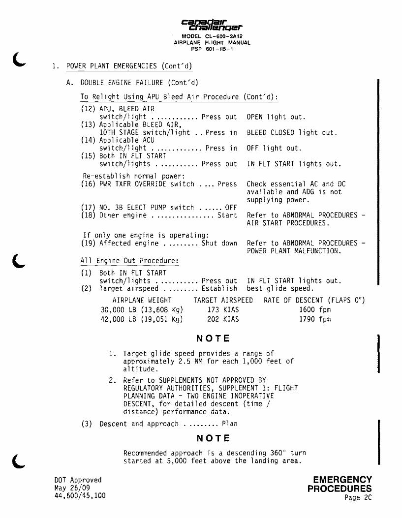
POWER PLANT MALFUNCTION. Engine Out Procedure:
Both IN FLT START switch/lights ........... Press out IN FLT START lights out. Target airspeed ......... Establish best glide speed.
AIRPLANE WEIGHT TARGET AIRSPEED RATE OF DESCENT (FLAPS 0°) 30,000 LB (13,608 Kg) 173 KIAS 1600 fpm 42,000 LB (19,051 Kg) 202 KIAS 1790 fpm
NOTE 1. Target glide speed provides a range of
approximately 2.5 NM for each 1,000 feet of altitude.
2. Refer to SUPPLEMENTS NOT APPROVED BY REGULATORY AUTHORITIES, SUPPLEMENT 1: FLIGHT PLANNING DATA - TWO ENGINE INOPERATIVE DESCENT, for detailed descent (time / distance) performance data.
(3) Descent and approach ......... Pl an
DOT Approved May 26/09 44,600/45,100
NOTE Recommended approach is a descending 360° turn started at 5,000 feet above the landing area.
EMERGENCY PROCEDURES
Page 2C
canada1r -cna11enqer MODEL CL-600-2A12
AIRPLANE FLIGHT MANUAL PSP 601-18-1
1. POWER PLANT EMERGENCIES (Cont'd)
A. DOUBLE ENGINE FAILURE (Cont'd)
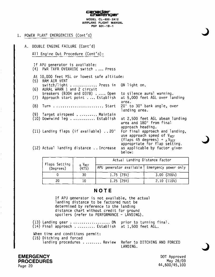
All Engine Out Procedure (Cont'd):
If APU generator is available: (4) PWR TXFR OVERRIDE switch .... Press
At 10,000 feet MSL or lowest safe altitude: (5) RAM AIR VENT
switch/light ............. Press in ON light on. (6) AURAL WARN 1 and 2 circuit
breakers (B304 and D378) ..... Open to silence aural warning. (7) Approach start point .... Establish at 5,000 feet AGL over landing
(8) Turn ........................ Start
(9) Target airspeed .......... Maintain (10) Downwind leg ............ Establish
(11) Landing flaps (if available) .. 20°
(12) Actual landing distance .. Increase
area. 20° to 30° bank angle, over landing area.
at 2,500 feet AGL abeam landing area and 180° from final approach heading. For final approach and landing, use approach speed of VREF (flaps 45 degrees) + !':.. V REF appropriate for flap setting. as applicable by factor given below:
Actual Landing Distance Factor Flaps Setting !':.. VREF
(Degrees) (KTS) APU generator available Emergency power only
0 30 1. 75 (75%)
20 10 1.25 (25%)
NOTE If APU generator is not available, the actual landing distance to be factored must be determined by reference to the landing distance chart without credit for ground spoilers (refer to PERFORMANCE - LANDING).
3.00 (200%)
2.10 (110%)
(13) Landing gear ................... DN (14) Fina 1 approach .......... Es tab 1 i sh
prior to turning final. at 1,500 feet AGL.
When time and conditions permit: (15) Ditching and forced
landing procedures ......... Review
EMERGENCY PROCEDURES Page 2D
Refer to DITCHING AND FORCED LANDING.
DOT Approved May 26/09
44,600/45,100
DOT Approved May 26/09 44,600/45, 100
Ci2Q!!.da1r .... .-11enqer
MODEL CL-600-2A12 AIRPLANE FLIGHT MANUAL
PSP 601-18-1
THIS PAGE LEFT INTENTIONALLY BLANK
EMERGENCY PROCEDURES I
Page 2E

canada1r cnallenQer
MODEL CL-600-2A12 AIRPLANE FLIGHT MANUAL
PSP 601-18-1
1. POWER PLANT EMERGENCIES (Cont'd)
NOTE
In the event of a lightning strike, simultaneous fire/overheat indications could occur. Abnormal values of secondary symptoms may be used to determine if an actual fire exists.
B. ENGINE FIRE OR SEVERE ENGINE DAMAGE
Affected engine: (1) Thrust lever ............. SHUT OFF (2) ENG FIRE PUSH
switch/light ............. Press in
(3) IN FLT START switch/light ............. Press in
(4) Ignition ...................... Off
(5) FUEL CONTROL PUMP switch/light ............ Press out
If warning persists: (6) Bottle No. 1 ............ Discharge
BOTTLE ARMED PUSH TO DISCH lights on. GEN OFF light, fuel VALVE CLOSED light, 10th stage BLEED CLOSED light and fuel pump ON lights all on.
on operative engine, if required.
to shut off affected pump. Fuel pump !NOP light on.
If warning still persists after 30 seconds: (7) Bottle No. 2 ............ Discharge
(8) Land at nearest suitable airport. (9) Affected engine ......... Shut down Refer to ABNORMAL PROCEDURES -
POWER PLANT MALFUNCTION.
NOTE Do not operate the APU in flight if engine rotor burst damage is suspected.
EMERGENCY DOT Approved May 26/09
44,600/45,100 I PROCEDURES Page 2F
canada1r cna11enQer
MODEL CL-600-2A12 AIRPLANE FLIGHT MANUAL
PSP 601-18-1
1. POWER PLANT EMERGENCIES (Cont;d)
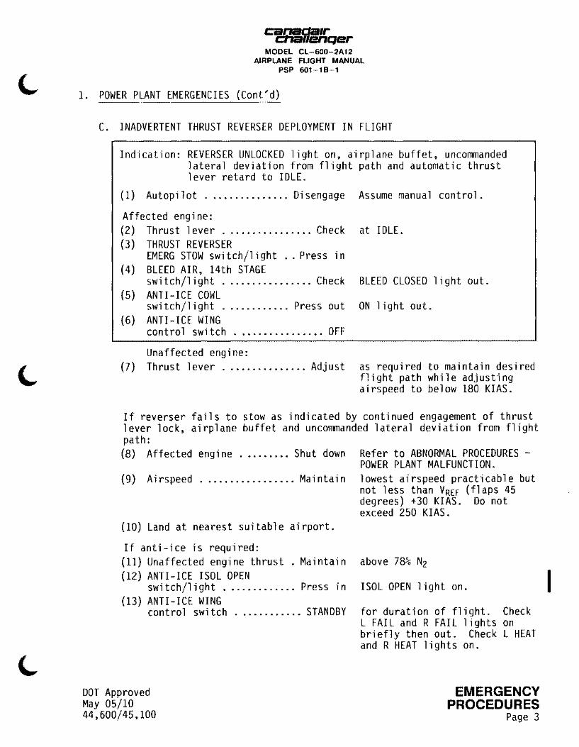
C. INADVERTENT THRUST REVERSER DEPLOYMENT IN FLIGHT
Indication: REVERSER UNLOCKED light on, airplane buffet, uncommanded lateral deviation from flight path and automatic thrust lever retard to IDLE.
(1) Autopilot ............... Disengage
Affected engine: (2) Thrust lever ................ Check (3) THRUST REVERSER
EM ERG STOW switch/light .. Press in (4) BLEED AIR, 14th STAGE
switch/light ................ Check (5) ANTI-ICE COWL
switch/light ............ Press out (6) ANTI-ICE WING
control switch ................ OFF
Unaffected engine: (7) Thrust lever ............... Adjust
Assume manual control.
at IDLE.
BLEED CLOSED light out.
ON light out.
as required to maintain desired flight path while adjusting airspeed to below 180 KIAS.
If reverser fails to stow as indicated by continued engagement of thrust lever lock, airplane buffet and uncommanded lateral deviation from flight path: (8) Affected engine ......... Shut down Refer to ABNORMAL PROCEDURES -
POWER PLANT MALFUNCTION. (9) Airspeed ................. Maintain lowest airspeed practicable but
(10) Land at nearest suitable airport.
If anti-ice is required: (11) Unaffected engine thrust . Maintain (12) ANTI-ICE ISOL OPEN
switch/light ............. Press in (13) ANTI-ICE WING
control switch ............ STANDBY
DOT Approved May 05/10 44,600/45,100
not less than VREF (flaps 45 degrees) +30 KIAS. Do not exceed 250 KIAS.
above 78% Nz
ISOL OPEN light on.
for duration of flight. Check L FAIL and R FAIL lights on briefly then out. Check L HEAT and R HEAT lights on.
EMERGENCY PROCEDURES
Page 3
I
ca..a.a_c:Ja1r ... ..J11enQer
MODEL CL-600-2A12 AIRPLANE FLIGHT MANUAL
PSP 601-18-1
1. POWER PLANT EMERGENCIES (Cont'd)
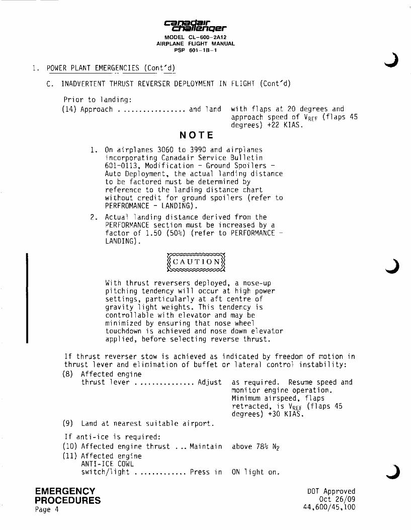
C. INADVERTENT THRUST REVERSER DEPLOYMENT IN FLIGHT (Cont'd)
Prior to landing: {14) Approach ................. and 1 and with flaps at 20 degrees and
approach speed of VREF (flaps 45 degrees) +22 KIAS.
NOTE 1. On airplanes 3060 to 3990 and airplanes
incorporating Canadair Service Bulletin 601-0113, Modification - Ground Spoilers -Auto Deployment, the actual landing distance to be factored must be determined by reference to the landing distance chart without credit for ground spoilers (refer to PERFROMANCE - LANDING).
2. Actual landing distance derived from the PERFORMANCE section must be increased by a factor of 1.50 (50%) (refer to PERFORMANCE -LANDING).
With thrust reversers deployed, a nose-up pitching tendency will occur at high power settings, particularly at aft centre of gravity light weights. This tendency is controllable with elevator and may be minimized by ensuring that nose wheel touchdown is achieved and nose down elevator applied, before selecting reverse thrust.
If thrust reverser stow is achieved as indicated by freedom of motion in thrust lever and elimination of buffet or lateral control instability: (8) Affected engine
thrust lever ............... Adjust as required. Resume speed and
(9) Land at nearest suitable airport.
If anti-ice is required:
monitor engine operation. Minimum airspeed, flaps retracted, is VREF (flaps 45 degrees) +30 KIAS.
(10) Affected engine thrust ... Maintain above 78% N2 (11) Affected engine
ANTI-ICE COWL switch/light ............. Press in ON light on.
EMERGENCY PROCEDURES Page 4
DOT Approved Oct 26/09
44,600/45,100
J
J

cgda1r #lenQer
MODEL CL-600-2A12 AIRPLANE FLIGHT MANUAL
PSP 601-18-1
1. POWER PLANT EMERGENCIES (Cont'd)
C. INADVERTENT THRUST REVERSER DEPLOYMENT IN FLIGHT (Cont'd)
(12) ANTI-ICE ISOL OPEN I switch/light ............. Press in ISOL OPEN light on.
(13) Affected engine wing anti-ice valve circuit breaker (D392 for left and B295 for right) .......... Open for duration of flight.
(14) ANTI-ICE WING control switch ............ STANDBY for duration of flight. Check
L FAIL and R FAIL lights on briefly then out. Check L HEAT and R HEAT lights on.
Prior to landing: (15) Approach ................. and land with flaps at 20 degrees and
approach speed of VREF (flaps 45 degrees) +22 KIAS.
DOT Approved May 05/10 44,600/45,100
NOTE 1. Following emergency stow operation,
REVERSER UNLOCKED light remains on. press switch/light nor arm affected reverser.
affected Do not
thrust
2. On airplanes 3060 to 3990 and airplanes incorporating Canadair Service Bulletin 601-0113, Modification - Ground Spoilers -Auto Deployment, the actual landing distance to be factored must be determined by reference to the landing distance chart without credit for ground spoilers (refer to PERFROMANCE - LANDING).
3. Actual landing distance derived from the PERFORMANCE section must be increased by a factor of 1.50 (50%) (refer to PERFORMANCE -LANDING).
With thrust reversers deployed, a nose-up pitching tendency will occur at high power settings, particularly at aft centre of gravity light weights. This tendency is controllable with elevator and may be minimized by ensuring that nose wheel touchdown is achieved and nose down elevator applied, before selecting reverse thrust.
EMERGENCY PROCEDURES
Page 5

c:anada1r cna11enQer
MODEL CL-600-2A12 AIRPLANE FLIGHT MANUAL
PSP 601-18-1
1. POWER PLANT EMERGENCIES (Cont'd)
D. APU FIRE
lwARNINGI
The APU must not be restarted following a fire.
(1) APU FIRE PUSH switch/light ............. Press in
(2) APU, START/STOP switch/light ............ Press out
(3) APU, PWR FUEL ON/OFF switch/light ............ Press out
If fire warning persists:
BOTTLE ARMED PUSH TO DISCH light on.
APU ROY light out.
APU SOV CLOSED light on. (AUXILIARY BATTERY ON light out on airplanes 3045 and subsequent and airplanes incorporating Canadair Service Bulletin 601-0099, Modification - APU Control -APU Cold Start Improvements).
(4) BOTTLE ARMED PUSH TO DISCH ... Push to discharge, light out.
If fire warning persists during flight: I (5) Land at nearest suitable airport.
EMERGENCY PROCEDURES Page 6
NOTE
Following an APU fire, the APU enclosure must be replaced before the next flight.
DOT Approved Apr 21/99
44,600/45,100

Ci!Q!!.da1r ....... 11enQer MODEL CL-600-2A12
AIRPLANE FLIGHT MANUAL PSP 601-18-1
1. POWER PLANT EMERGENCIES (Cont'd)
E. JET PIPE/PYLON OVERHEAT
Indication: LEFT or RIGHT ENG JET PIPE OVHT light on. (1) Affected engine ...... Thrust lever Retard slowly until warning
1 i ght out.
If OVHT indication persists: (2) Affected engine ......... Shut down Refer to ABNORMAL PROCEDURES -
POWER PLANT MALFUNCTION.
F. ENGINE OIL PRESSURE LOW
Indication: Lor ROIL PRESS, LOP light on, or Lor ROIL PRESS is below 25 psi.
(1) Affected thrust 1 ever .......... Confirm and retard to IDLE.
(2) Affected engine oi 1 pressure ................ Check
If LOP light is on and affected engine oil pressure is below 25 psi:
(3) Affected thrust 1 ever ........ Confirm and SHUT OFF
(4) Affected engine ......... Shut down Refer to ABNORMAL PROCEDURES -POWER PLANT MALFUNCTION.
If LOP light is on and affected engine oil pressure is normal: I (3) Affected thrust lever ...... Adjust as required. (4) Affected engine ........... Monitor
If engine oil pressure is below 25 psi and associated LOP light is out: I (3) Affected thrust lever ...... Adjust as required. (4) Affected engine ........... Monitor
DOT Approved Sep 11/06 44,600/45,100
EMERGENCY PROCEDURES
Page 6A
EMERGENCY
I PROCEDURES Page 68
canada1r cna11enQer
MODEL CL-600-2A12 AIRPLANE FLIGHT MANUAL
PSP 601-18-1
THIS PAGE LEFT INTENTIONALLY BLANK
DOT Approved Jan 14/05
44,600/45,100
Ci!.!J!l..da1r ~ • .-11enqer
MODEL CL-600-2A12 AIRPLANE FLIGHT MANUAL
PSP 601-18-1
1. POWER PLANT EMERGENCIES (Cont'd)
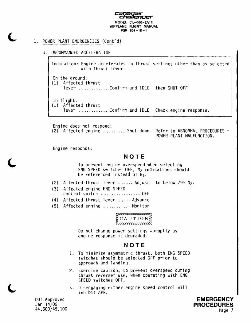
G. UNCOMMANDED ACCELERATION
Indication: Engine accelerates to thrust settings other than as selected with thrust lever.
On the ground: (1) Affected thrust
1 ever ............ Confirm and IDLE then SHUT OFF.
In flight: (1) Affected thrust
lever ............ Confirm and IDLE Check engine response.
Engine does not respond: (2) Affected engine ......... Shut down Refer to ABNORMAL PROCEDURES -
POWER PLANT MALFUNCTION.
Engine responds:
NOTE To prevent engine overspeed when selecting ENG SPEED switches OFF, N2 indications should be referenced instead of N1 •
(2) Affected thrust lever ...... Adjust to below 79% N2 •
(3) Affected engine ENG SPEED cont ro 1 switch ................ OFF
( 4) Affected thrust 1 ever ..... Advance (5) Affected engine ........... Monitor
DOT Approved Jan 14/05 44,600/45,100
Do not change power settings abruptly as engine response is degraded.
NOTE 1. To minimize asymmetric thrust, both ENG SPEED
switches should be selected OFF prior to approach and landing.
2. Exercise caution, to prevent overspeed during thrust reverser use, when operating with ENG SPEED switches OFF.
3. Disengaging either engine speed control will inhibit APR.
EMERGENCY PROCEDURES
Page 7
I
t:a.JJ111_cJa1r ~· ..JHenQer
MODEL CL-600-2A12 AIRPLANE FLIGHT MANUAL
PSP 601-18-1
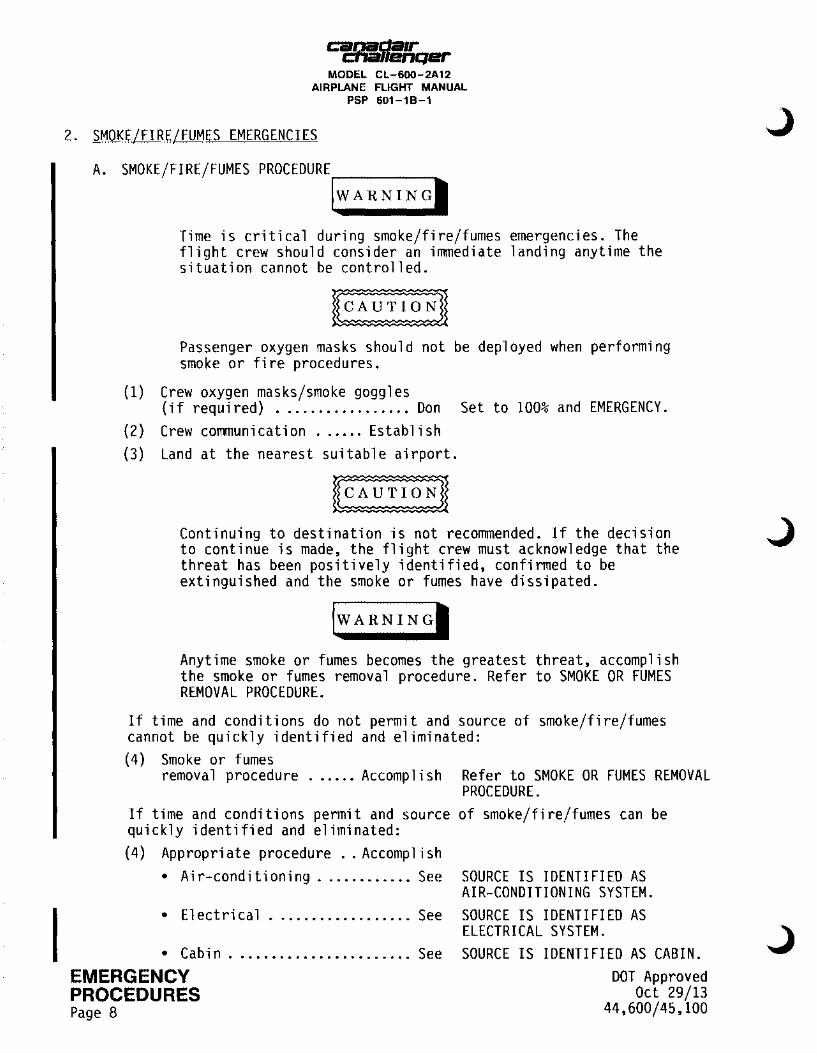
2. SMOKE/FIRE/FUMES EMERGENCIES
A. SMOKE/FIRE/FUMES PROCEDURE~----
lw ARN IN GI
Time is critical during smoke/fire/fumes emergencies. The flight crew should consider an immediate landing anytime the situation cannot be controlled.
Passenger oxygen masks should not be deployed when performing smoke or fire procedures.
(1) Crew oxygen masks/smoke goggles (if required) ................. Don Set to 100% and EMERGENCY.
(2) Crew communication ...... Establish (3) Land at the nearest suitable airport.
Continuing to destination is not recommended. If the decision to continue is made, the flight crew must acknowledge that the threat has been positively identified, confirmed to be extinguished and the smoke or fumes have dissipated.
lwARNINGI
Anytime smoke or fumes becomes the greatest threat, accomplish the smoke or fumes removal procedure. Refer to SMOKE OR FUMES REMOVAL PROCEDURE.
If time and conditions do not permit and source of smoke/fire/fumes cannot be quickly identified and eliminated: (4) Smoke or fumes
removal procedure ...... Accomplish Refer to SMOKE OR FUMES REMOVAL PROCEDURE.
If time and conditions permit and source of smoke/fire/fumes can be quickly identified and eliminated: (4) Appropriate procedure .. Accomplish
• Air-conditioning ............ See SOURCE IS IDENTIFIED AS AIR-CONDITIONING SYSTEM.
• El ectri ca 1 .................. See SOURCE IS IDENTIFIED AS ELECTRICAL SYSTEM.
• Cabin ....................... See SOURCE IS IDENTIFIED AS CABIN. EMERGENCY PROCEDURES Page 8
DOT Approved Oct 29/13
44,600/45,100

Ci!J1!l..da1r .... .-11enQer MODEL CL-600-2A12
AIRPLANE FLIGHT MANUAL PSP 601 -1 8-1
2. SMOKE/FIRE/FUMES EMERGENCIES {Cont'd)
A. SMOKE/FIRE/FUMES PROCEDURE (Cont'd)
SOURCE IS IDENTIFIED AS AIR-CONDITIONING SYSTEM
If APU is supplying bleed air for air-conditioning: (1) BLEED AIR, 10th STAGE
L and R switch/lights .... Press in BLEED CLOSED lights out. (2) APU, BLEED AIR
switch/light ............ Press out OPEN light out. (3) BLEED AIR, !SOL
switch/light . . . . . . . . . . . . Press out OPEN light out.
( 4) CKPT HEAT switch .............. OFF ( 5) L ACU switch/light ...... Press out OFF light on.
Monitor and determine if smoke/fire/fumes persists. If smoke/fire/fumes ceases: (6) Smoke or fumes
removal procedure ...... Accomplish if required. Refer to SMOKE OR FUMES REMOVAL PROCEDURE.
If smoke/fire/fumes persists: (6) L ACU switch/light ....... Press in OFF light out. (7) R ACU switch/light ...... Press out OFF light on.
Monitor and determine if smoke/fire/fumes persists. If smoke/fire/fumes persists: (8) R ACU switch/light ....... Press in OFF light out. (9) Smoke or fumes
removal procedure ...... Accomplish Refer to SMOKE OR FUMES REMOVAL
DOT Approved Oct 29/13 44,600/45,100
PROCEDURE.
EMERGENCY PROCEDURES
Page 9
I
I
~r.1-Qer MODEL CL-600-2A12
AIRPLANE FLIGHT MANUAL PSP 601-18-1
2. SMOKE/FIRE/FUMES EMERGENCIES (Cont'd)
I A. SMOKE/FIRE/FUMES PROCEDURE (Cont'd)
I
I
I
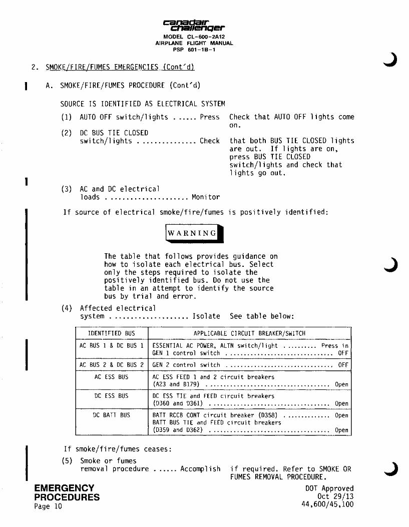
SOURCE IS IDENTIFIED AS ELECTRICAL SYSTEM
(1) AUTO OFF switch/lights ...... Press Check that AUTO OFF lights come on.
(2) DC BUS TIE CLOSED swi tch/1 i ghts ............... Check that both BUS TIE CLOSED lights
are out. If lights are on, press BUS TIE CLOSED switch/lights and check that 1 i ghts go out.
(3) AC and DC electrical loads ..................... Monitor
If source of electrical smoke/fire/fumes is positively identified:
lwARNINGI
The table that follows provides guidance on how to isolate each electrical bus. Select only the steps required to isolate the positively identified bus. Do not use the table in an attempt to identify the source bus by trial and error.
(4) Affected electrical system .................... I sol ate See table below:
IDENTIFIED BUS APPLICABLE CIRCUIT BREAKER/SWITCH
AC BUS 1 & DC BUS 1 ESSENTIAL AC POWER, ALTN switch/light .......... Press in GEN 1 control switch ................................ OFF
AC BUS 2 & DC BUS 2 GEN 2 cont ro 1 switch ................................ OFF
AC ESS BUS AC ESS FEED 1 and 2 circuit breakers (A23 and Bl79) ..................................... Open
DC ESS BUS DC ESS TIE and FEED circuit breakers (D360 and D361) .................................... Open
DC BATT BUS BATT RCCB CONT circuit breaker (D358) .............. Open BATT BUS TIE and FEED circuit breakers (D359 and D362) .................................... Open
If smoke/fire/fumes ceases: (5) Smoke or fumes
removal procedure ...... Accomplish if required. Refer to SMOKE OR
EMERGENCY PROCEDURES Page 10
FUMES REMOVAL PROCEDURE. DOT Approved
Oct 29/13 44,600/45,100
canada1r cnanenQer
MODEL CL-600-2A12 AIRPLANE FLIGHT MANUAL
PSP 601-18-1
2. SMOKE/FIRE/FUMES EMERGENCIES (Cont'd)
A. SMOKE/FIRE/FUMES PROCEDURE (Cont'd)
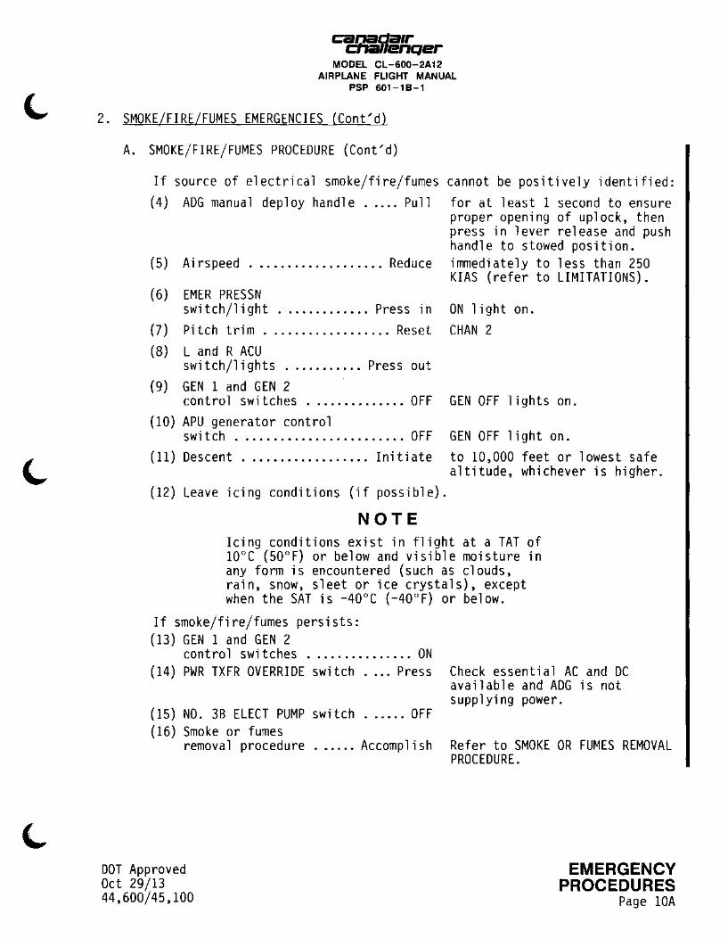
If source of electrical smoke/fire/fumes cannot be positively identified: (4) ADG manual deploy handle ..... Pull for at least 1 second to ensure
proper opening of uplock, then press in lever release and push handle to stowed position.
(5) Ai rs peed ................... Reduce immediately to less than 250
(6) EMER PRESSN switch/light ............. Press in
(7) Pitch trim .................. Reset (8) L and R ACU
switch/lights ........... Press out (9) GEN 1 and GEN 2
control switches .............. OFF (10) APU generator control
switch ........................ OFF
KIAS (refer to LIMITATIONS).
ON light on. CHAN 2
GEN OFF lights on.
GEN OFF light on. (11) Descent .................. Initiate to 10,000 feet or lowest safe
altitude, whichever is higher. (12) Leave icing conditions (if possible).
NOTE Icing conditions exist in flight at a TAT of 10°c (50°F) or below and visible moisture in any form is encountered (such as clouds, rain, snow, sleet or ice crystals), except when the SAT is -40°C (-40°F) or below.
If smoke/fire/fumes persists: (13) GEN 1 and GEN 2
control switches ............... ON (14) PWR TXFR OVERRIDE switch .... Press
(15) NO. 3B ELECT PUMP switch ...... OFF (16) Smoke or fumes
removal procedure ...... Accomplish
DOT Approved Oct 29/13 44,600/45,100
Check essential AC and DC available and ADG is not supplying power.
Refer to SMOKE OR FUMES REMOVAL PROCEDURE.
EMERGENCY PROCEDURES
Page lOA
~r,saa1r ,J/enqer MODEL CL-600-2A12
AIRPLANE FLIGHT MANUAL PSP 601-18-1
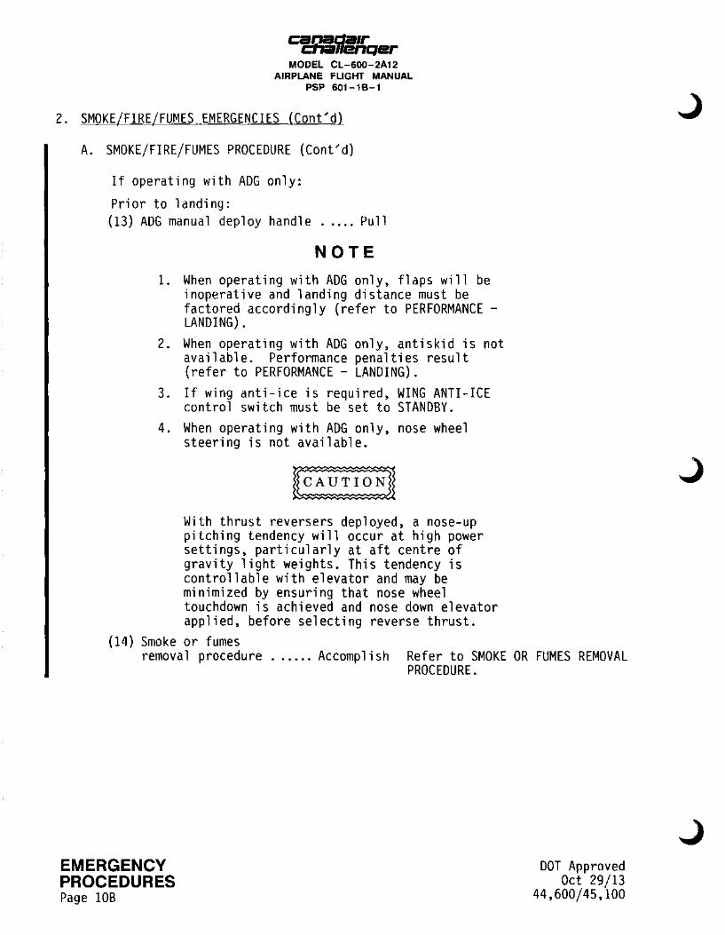
2. SMOKE/FIRE/FUMES EMERGENCIES (Cont'd)
A. SMOKE/FIRE/FUMES PROCEDURE (Cont'd)
If operating with ADG only:
Prior to landing: (13) ADG manual deploy handle ..... Pull
NOTE 1. When operating with ADG only, flaps will be
inoperative and landing distance must be factored accordingly (refer to PERFORMANCE -LANDING).
2. When operating with ADG only, antiskid is not available. Performance penalties result (refer to PERFORMANCE - LANDING).
3. If wing anti-ice is required, WING ANTI-ICE control switch must be set to STANDBY.
4. When operating with ADG only, nose wheel steering is not available.
With thrust reversers deployed, a nose-up pitching tendency will occur at high power settings, particularly at aft centre of gravity light weights. This tendency is controllable with elevator and may be minimized by ensuring that nose wheel touchdown is achieved and nose down elevator applied, before selecting reverse thrust.
(14) Smoke or fumes removal procedure ...... Accomplish Refer to SMOKE OR FUMES REMOVAL
PROCEDURE.
EMERGENCY PROCEDURES Page lOB
DOT Approved Oct 29/13
44,600/45,100

Ci2!1§!.da1r .... .-11enqer MODEL CL-600-2A12
AIRPLANE FLIGHT MANUAL PSP 601-18-1
2. SMOKE/FIRE/FUMES EMERGENCIES (Cont'd)
A. SMOKE/FIRE/FUMES PROCEDURE (Cont'd)
SOURCE IS IDENTIFIED AS CABIN
I
(1) Designated crew member ..... Advise to isolate and extinguish I source of fire or smoke, and to secure the area as necessary.
(2) Smoke or fumes removal procedure ...... Accomplish Refer to SMOKE OR FUMES REMOVAL I
PROCEDURE.
B. SMOKE OR FUMES REMOVAL PROCEDURE
(1) Descent .................. Initiate
(2) CABIN PRESSURIZATION MODE se 1 ector ................. MAN
(3) MAN REG ........................ UP (4) MAN REG RATE
knob ......................... Ful 1 (5) EMER DEPRESS
switch/light ............. Press in
NOTE
to 10,000 feet or lowest safe altitude, whichever is higher.
!NCR
to depressurize airplane. ON light on.
To assist smoke clearance the ram air vent may be used. In this case, a minimum airspeed of 250 KIAS must be used.
If smoke/fire/fumes is uncontrolled: (6) Land immediately at the nearest suitable airport.
Dependent upon the severity of the situation, the flight crew should expedite the landing. The crew should also consider an overweight landing, tailwind landing, ditching or a forced off-airport landing.
(7) Emergency evacuation procedure .............. Accomplish Refer to EMERGENCY EVACUATION.
I
I
If required: I (6) Smoke/fire/fumes
procedure ................ Continue Refer to SMOKE/FIRE/FUMES I
DOT Approved Oct 29/13 44,600/45,100
PROCEDURE.
EMERGENCY PROCEDURES
Page lOC

EMERGENCY
I PROCEDURES Page 100
cgda1r 11enqer MODEL CL-600-2A12
AIRPLANE FLIGHT MANUAL PSP 601-18-1
THIS PAGE LEFT INTENTIONALLY BLANK
DOT Approved Oct 29/13
44,600/45,100

3. BLEED AIR LEAK EMERGENCIES
~Lla1r 'lenQer MODEL CL-600-2A12
AIRPLANE FLIGHT MANUAL PSP 601-18-1
A. 10th STAGE LEFT OR RIGHT BLEED DUCT FAILURE (Bleed air supplied by engine)
Affected engine 10th stage bleed air supply:
(1) BLEED AIR 10th STAGE L or R switch/light ...•.....•.. Press out to close fail indicated bleed
air valve. BLEED CLOSED light on.
(2) BLEED AIR ISOL switch/light .........•.. Press out OPEN light out.
(3) Lor R ACU switch/light . Press out OFF light on. If 10th STAGE L DUCT FAIL light is on:
(4) APU BLEED AIR switch/light .•....•....• Press out
(5) CKPT HEAT switch •.•..•.•..••.. OFF If above 40,000 feet:
(6) ANTI-ICE COWL LEFT or
OPEN light out.
RIGHT switch/light .•..... Press in to operate cowl anti-ice system to provide required bleed (refer to LIMITATIONS).
If DUCT FAIL light remains on after 30 seconds: (7) Associated thrust lever ..•• Retard to eliminate warning.
NOTE If the light goes out, operate the affected engine at a reduced power that will not re-activate the warning.
If DUCT FAIL light stays on: (8) Land at nearest suitable airport.
B. 10th STAGE LEFT OR RIGHT BLEED DUCT FAILURE (Bleed air supplied by APU)
(1) APU, BLEED AIR switch/light ....••••.... Press out OPEN light out.
(2) BLEED AIR ISOL switch/light .•.••••..••• Press out OPEN light out.
DOT Approved Apr 21/99 44,600/45,100
EMERGENCY PROCEDURES
Page 11

ca&-,.sger MODEL CL-600-2A12
AIRPLANE FLIGHT MANUAL PSP 601-18-1
3. BLEED AIR LEAK EMERGENCIES (Cont'd)
C. 14th STAGE LEFT OR RIGHT BLEED DUCT FAILURE
Affected engine 14th stage bleed air supply: (1) BLEED AIR 14th STAGE L or R
switch/light .....•...••• Press out to close bleed air valve on affected engine. BLEED CLOSED light on.
NOTE 1. Cowl anti-ice for the affected engine will
not be available. 2. Thrust reverser for the affected engine will
not be available. If DUCT FAIL light remains on after 30 seconds: (2) Associated thrust lever •.•. Retard to eliminate warning.
NOTE If the light goes out, operate the affected engine at a reduced power that will not re-activate the warning.
If DUCT FAIL light stays on: (3) Land at nearest suitable airport.
EMERGENCY PROCEDURES Page 12
NOTE On airplanes 3060 to 3990 and airplanes incorporating Canadair Service Bulletin 601-0113, Modification - Ground Spoilers -Auto Deployment, the actual landing distance to be factored must be determined by reference to the landing distance chart without credit for ground spoilers (refer to PERFORMANCE - LANDING).
DOT Approved Apr 21/99
44,600/45,100

4. EMERGENCY DESCENT
A. PROCEDURE
Cl!JJ§!dCllr ~ • .-11enQer
MODEL CL-600-2A12 AIRPLANE FLIGHT MANUAL
PSP 601-18-1
(1) Autopilot ............... Disengage (2) Airspeed ................... MMo/VMo Refer to NOTE. (3) Thrust levers ................ IDLE (4) Flight spoilers ............ Extend to MAX.
(5) CABIN PRESSURIZATION SELECTOR . Set (6) Cabin pressure rate selector .. Set
to destination altitude. to maximum.
At safe altitude, if oxygen still in use: (7) Crew oxygen masks ............. Set to N (normal air/oxygen
dilution).
(8) ANTI-ICE, WSHLD LEFT and RIGHT control switch ......... HIGH LEFT and RIGHT, FRONT and
DOT Approved Oct 30/12 44,600/45,100
SIDE, NO HT lights out.
NOTE 1. If air driven generator is deployed, airspeed
must not exceed 250 KIAS except when operationally necessary (refer to LIMITATIONS).
2. If the structural integrity of the airplane is in doubt, limit speed as much as possible and avoid high maneuvering loads.
EMERGENCY PROCEDURES
Page 13
I
cac9i1da1r fllenQer MODEL CL-600-2A12
AIRPLANE FLIGHT MANUAL PSP 601-18-1
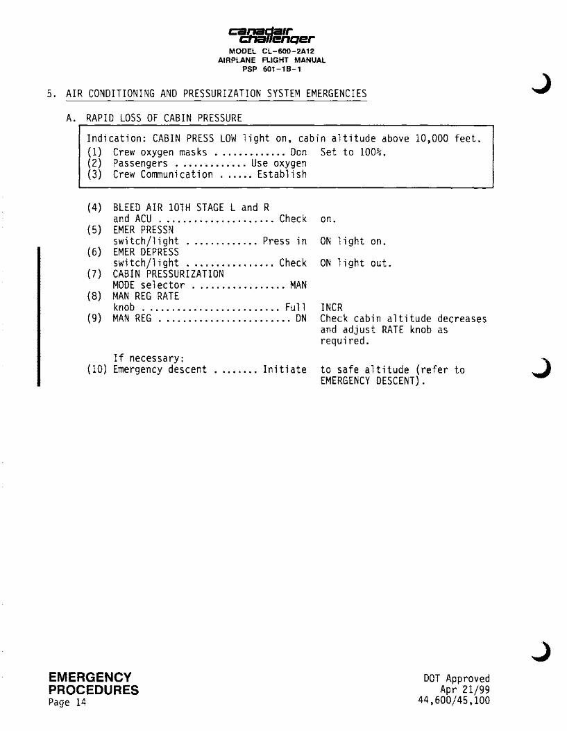
5. AIR CONDITIONING AND PRESSURIZATION SYSTEM EMERGENCIES
A. RAPID LOSS OF CABIN PRESSURE
Indication: CABIN PRESS LOW light on, cabin altitude above 10,000 feet. (1) Crew oxygen masks ............. Don Set to 100%. (2) Passengers ............. Use oxygen (3) Crew Communication ...... Establish
(4) BLEED AIR lOTH STAGE L and R and ACU . . . . . . . . . . . . . . . . . . . . . Cheek
(5) EMER PRESSN switch/1 i ght ............. Press in
(6) EMER DEPRESS switch/1 i ght ................ Check
(7) CABIN PRESSURIZATION MODE se 1 ector ................. MAN
(8) MAN REG RATE knob ......................... Full
(9) MAN REG ........................ ON
If necessary: (10) Emergency descent ........ Initiate
EMERGENCY PROCEDURES Page 14
on.
ON light on.
ON 1 i ght out.
INCR Check cabin altitude decreases and adjust RATE knob as required.
to safe altitude (refer to EMERGENCY DESCENT).
DOT Approved Apr 21/99
44,600/45,100

canada1r cna11enqer
MODEL CL-600-2A12 AIRPLANE FLIGHT MANUAL
PSP 601-18-1
5. AIR CONDITIONING AND PRESSURIZATION SYSTEM EMERGENCIES (Cont'd)
B. CABIN LOW PRESSURE
(1) Engine power setting ..... Increase (2) BLEED AIR lOTH STAGE L and R
and ACU ..................... Check (3) EMER DEPRESS
switch/light ................ Check (4) Land R ACU ............... Isolate
If pressurization not restored: (5) EMER PRESSN
switch/light ............. Press in
(6) CABIN PRESSURIZATION MODE selector ................. MAN
(7) MAN REG RATE knob ......................... Full
(8) MAN REG ........................ DN
If necessary:
on.
ON light out. in turn
ON light on.
INCR Check cabin altitude decreases and adjust RATE knob as required.
(9) Descent .................. Initiate to safe altitude.
If required: (10) Oxygen masks .................. Don Set to 100%. (11) Crew communications ..... Establish ( 12) Passengers ............. Use oxygen (13) Emergency descent ........ Initiate Refer to EMERGENCY DESCENT.
DOT Approved Apr 21/99 44,600/45,100
EMERGENCY PROCEDURES
Page 15
I
~p,:da1r '"enQer MODEL CL-600-2A12
AIRPLANE FLIGHT MANUAL PSP 601-18-1
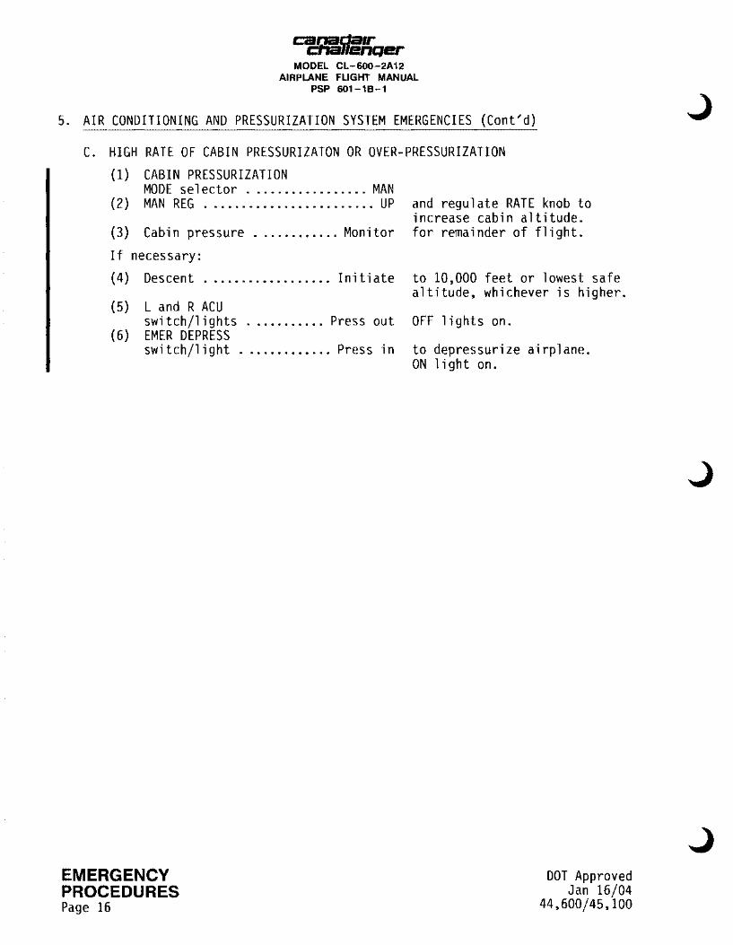
5. AIR CONDITIONING AND PRESSURIZATION SYSTEM EMERGENCIES (Cont~d)
C. HIGH RATE OF CABIN PRESSURIZATON OR OVER-PRESSURIZATION (1) CABIN PRESSURIZATION
MODE se 1 ector ................. MAN (2) MAN REG ........................ UP
(3) Cabin pressure ............ Monitor If necessary: (4) Descent .................. Initiate
(5) L and R ACU switch/1 i ghts ........... Press out
(6) EMER DEPRESS switch/1 i ght ............. Press in
EMERGENCY PROCEDURES Page 16
and regulate RATE knob to increase cabin altitude. for remainder of flight.
to 10,000 feet or lowest safe altitude, whichever is higher.
OFF lights on.
to depressurize airplane. ON light on.
DOT Approved Jan 16/04
44,600/45,100
Ci2!:J!!.da1r .... .-11enqer MODEL CL-600-2A12
AIRPLANE FLIGHT MANUAL PSP 601 -1 8-1
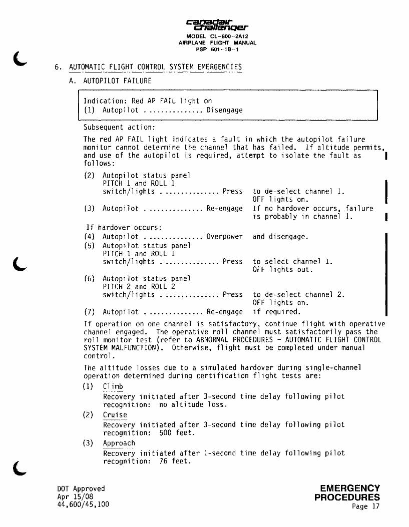
6. AUTOMATIC FLIGHT CONTROL SYSTEM EMERGENCIES
A. AUTOPILOT FAILURE
Indication: Red AP FAIL light on (1) Autopilot ............... Disengage
Subsequent action: The red AP FAIL light indicates a fault in which the autopilot failure monitor cannot determine the channel that has failed. If altitude permits, and use of the autopilot is required, attempt to isolate the fault as I follows: (2) Autopilot status panel
PITCH 1 and ROLL 1 switch/lights ............... Press to de-select channel 1.
OFF lights on. I (3) Autopilot ............... Re-engage
If hardover occurs: (4) Autopilot ............... Overpower (5) Autopilot status panel
PITCH 1 and ROLL 1 switch/lights ............... Press
(6) Autopilot status panel PITCH 2 and ROLL 2 switch/lights ............... Press
(7) Autopilot ............... Re-engage
If no hardover occurs, failure is probably in channel 1.
and disengage.
to select channel 1. OFF lights out.
to de-select channel 2. OFF lights on. if required.
If operation on one channel is satisfactory, continue flight with operative channel engaged. The operative roll channel must satisfactorily pass the roll monitor test (refer to ABNORMAL PROCEDURES - AUTOMATIC FLIGHT CONTROL SYSTEM MALFUNCTION). Otherwise, flight must be completed under manual control. The altitude losses due to a simulated hardover during single-channel operation determined during certification flight tests are: ( 1) Climb
Recovery initiated after 3-second time delay following pilot recognition: no altitude loss.
(2) Cruise Recovery initiated after 3-second time delay following pilot recognition: 500 feet.
(3) Approach Recovery initiated after I-second time delay following pilot recognition: 76 feet.
DOT Approved Apr 15/08 44,600/45,100
EMERGENCY PROCEDURES
Page 17
I
cacr.:il/fqer MODEL CL-600-2A12
AIRPLANE FLIGHT MANUAL PSP 601-18-1
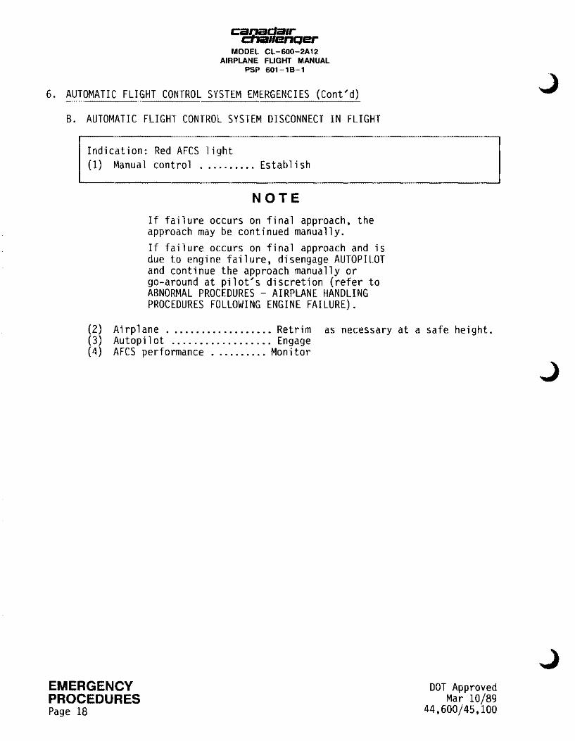
6. AUTOMATIC FLIGHT CONTROL SYSTEM EMERGENCIES (Cont'd)
B. AUTOMATIC FLIGHT CONTROL SYSTEM DISCONNECT IN FLIGHT
Indication: Red AFCS light (1) Manual control .......... Establish
NOTE If failure occurs on final approach, the approach may be continued manually. If failure occurs on final approach and is due to engine failure, disengage AUTOPILOT and continue the approach manually or go-around at pilot's discretion (refer to ABNORMAL PROCEDURES - AIRPLANE HANDLING PROCEDURES FOLLOWING ENGINE FAILURE).
(2) Airplane ................... Retrim as necessary at a safe height. (3) Autopilot .................. Engage (4) AFCS performance .......... Monitor
EMERGENCY PROCEDURES Page 18
DOT Approved Mar 10/89
44,600/45,100
L
Ci2!1!J.da1r .... .-11enqer MODEL CL-600-2A12
AIRPLANE FLIGHT MANUAL PSP 601-18-1
7. ELECTRICAL SYSTEM EMERGENCIES
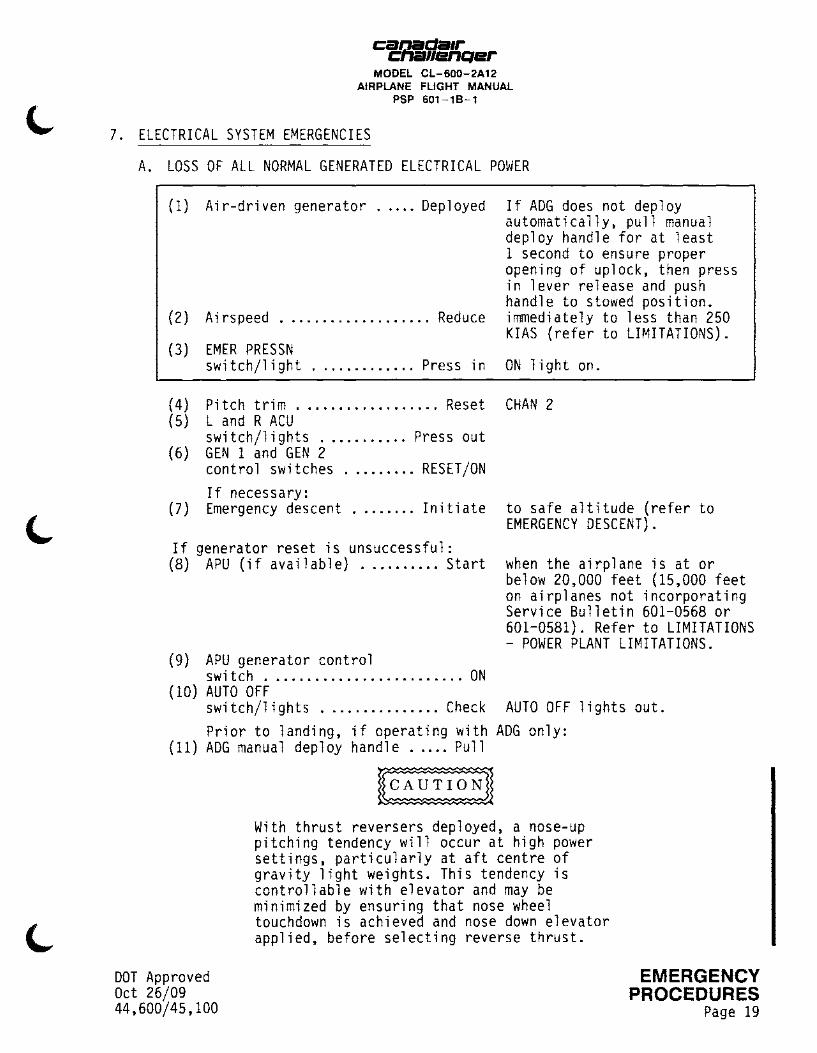
A. LOSS OF ALL NORMAL GENERATED ELECTRICAL POWER
(1) Air-driven generator ..... Deployed If ADG does not deploy automatically, pull manual deploy handle for at least 1 second to ensure proper opening of uplock, then press in lever release and push handle to stowed position.
(2) Airspeed ................... Reduce immediately to less than 250 KIAS (refer to LIMITATIONS).
(3) EMER PRESSN switch/light ............. Press in ON light on.
(4) Pitch trim .................. Reset CHAN 2 (5) L and R ACU
switch/lights ........... Press out (6) GEN 1 and GEN 2
control switches ......... RESET/ON If necessary:
(7) Emergency descent ........ Initiate to safe altitude (refer to EMERGENCY DESCENT).
If generator reset is unsuccessful: (8) APU {if available) .......... Start when the airplane is at or
below 20,000 feet (15,000 feet on airplanes not incorporating Service Bulletin 601-0568 or 601-0581). Refer to LIMITATIONS - POWER PLANT LIMITATIONS.
(9) APU generator control switch ......................... ON
(10) AUTO OFF switch/lights ............... Check AUTO OFF lights out. Prior to landing, if operating with ADG only:
(11) ADG manual deploy handle ..... Pull
DOT Approved Oct 26/09 44,600/45,100
~ With thrust reversers deployed, a nose-up pitching tendency will occur at high power settings, particularly at aft centre of gravity light weights. This tendency is controllable with elevator and may be minimized by ensuring that nose wheel touchdown is achieved and nose down elevator applied, before selecting reverse thrust.
EMERGENCY PROCEDURES
Page 19

cgda1r flenQer MODEL CL-600-2A12
AIRPLANE FLIGHT MANUAL PSP 601-18-1
7. ELECTRICAL SYSTEM EMERGENCIES (Cont'd)
A. LOSS OF ALL NORMAL GENERATED ELECTRICAL POWER (Cont'd)
NOTE 1. The AC essential bus and hydraulic pump can
be transferred back to either main generator, or to the APU generator, if operating, by pressing the PWR TXFR OVERRIDE switch on the ADG control panel after the ADG manual deploy handle is re-stowed.
2. Flaps will be inoperative and landing distance must be factored accordingly (refer to PERFORMANCE - LANDING).
3. If use of thrust reversers is required and ADG is only source of power, ADG manual deploy handle must be pulled.
4. When operating with ADG only, antiskid is not available. Performance penalties result (refer to PERFORMANCE - LANDING).
5. If wing anti-ice is required, WING ANTI-ICE control switch must be set to STANDBY.
6. When operating with ADG only, nose wheel steering is not available.
EMERGENCY
I PROCEDURES Page 20
DOT Approved Oct 26/09
44,600/45,100
J

Ci!J21!.da1r .... .-11enqer MODEL CL-600-2A12
AIRPLANE FLIGHT MANUAL PSP 601-18-1
8. FLIGHT CONTROL SYSTEM EMERGENCIES
A. STALL RECOVERY
Indication: Aircraft buffet, uncommanded roll, stick shaker activated and/or stall warbler on.
( 1) Autopi 1 ot ............... Disengage if applicable. (2) Pitch attitude ......... Lower nose (3) Thrust 1 evers ............. Advance
to reduce angle of attack. to MAX POWER.
(4) Roll attitude ......... Wings level (5) Flight spoilers ........... Retract
After airspeed increases and stall warning is extinguished: (6) Pitch attitude ............. Adjust to minimize altitude loss. (7) Thrust levers and
airplane configuration ..... Adjust as required.
DOT Approved Apr 19/13 44,600/45,100
NOTE
1. It is essential that the AOA be immediately reduced, even if this means a loss of altitude.
2. Avoid abrupt or aggressive pitch control inputs during recovery.Inappropriate recovery inputs can result is a secondary stall.
3. Height loss resulting from high AOA recovery, especially at cruise altitude and/or low initial thrust conditions, can be significant.
EMERGENCY PROCEDURES
Page 21
I

canada1r cna11enQer
MODEL CL-600-2A12 AIRPLANE FLIGHT MANUAL
PSP 601-18-1
8. FLIGHT CONTROL SYSTEM EMERGENCIES (Cont;d)
B. PITCH CONTROL SYSTEM JAMMED
(1) Autopilot ............... Disengage if applicable. (2) Elevator controls ....... Overpower Attempt to overpower jammed
condition. Use pitch trim to compensate if elevator jam occurs away from the neutral position.
If unable to overpower, release pilot/copilot differential pressure on the controls and:
(3) PITCH DISCON handle .............. PULL and TURN 90 degrees to lock.
(4) Determine which side of system is jammed.
(5) Pilot with normal elevator control will fly airplane. (6) Land at nearest suitable airport.
Subsequent airplane handling:
Controllability is reduced. The stall protection system stick pusher operates only on the right control column and is not operative if jammed '"\ condition is affecting the right control circuit. This type of failure ~ does not activate the STALL PROTECT FAIL light but the STALL PROTECTION SYSTEM EMERGENCIES procedures are applicable. The stick shaker on the operable control column still operates but at a lower intensity. Land with flaps at 20 degrees (refer to PERFORMANCE - LANDING). Select runway with minimum turbulence and crosswind.
EMERGENCY
I PROCEDURES Page 22
With thrust reversers deployed, a nose-up pitching tendency will occur at high power settings, particularly at aft centre of gravity light weights. This tendency is controllable with elevator and may be minimized by ensuring that nose wheel touchdown is achieved and nose down elevator applied, before selecting reverse thrust.
DOT Approved Oct 21/10
44,600/45,100

Ci!J1!!.da1r ....... 11enqer MODEL CL-600-2A12
AIRPLANE FLIGHT MANUAL PSP 601-18-1
8. FLIGHT CONTROL SYSTEM EMERGENCIES (Cont'd)
C. ROLL CONTROL SYSTEM JAMMED
(1) Autopilot ............... Disengage if applicable. (2) Aileron controls ........ Overpower Attempt to overpower jammed
condition. Attempt to use aileron trim to alleviate forces on controls, if jam has occured away from neutral position.
If unable to overpower, release pilot/copilot differential pressure on the controls and: (3) ROLL DISCON
handle .............. PULL and TURN 90 degrees to 1 ock.
(4) Determine which side of system is jammed. (5) Pilot with normal aileron control will fly airplane. (6) Land at nearest suitable airport.
Subsequent airplane handling:
Controllability is reduced. If necessary co-ordinate aileron with rudder during turns. Land with flaps at 20 degrees (refer to PERFORMANCE -LANDING). Select runway with minimum turbulence and crosswind.
DOT Approved Oct 21/10 44,600/45,100
With thrust reversers deployed, a nose-up pitching tendency will occur at high power settings, particularly at aft centre of gravity light weights. This tendency is controllable with elevator and may be minimized by ensuring that nose wheel touchdown is achieved and nose down elevator applied, before selecting reverse thrust.
EMERGENCY PROCEDURES I
Page 22A
canada1r CIV!i11enQer
MODEL CL-600-2A12 AIRPLANE FLIGHT MANUAL
PSP 601-18-1
8. FLIGHT CONTROL SYSTEM EMERGENCIES (Cont'd)
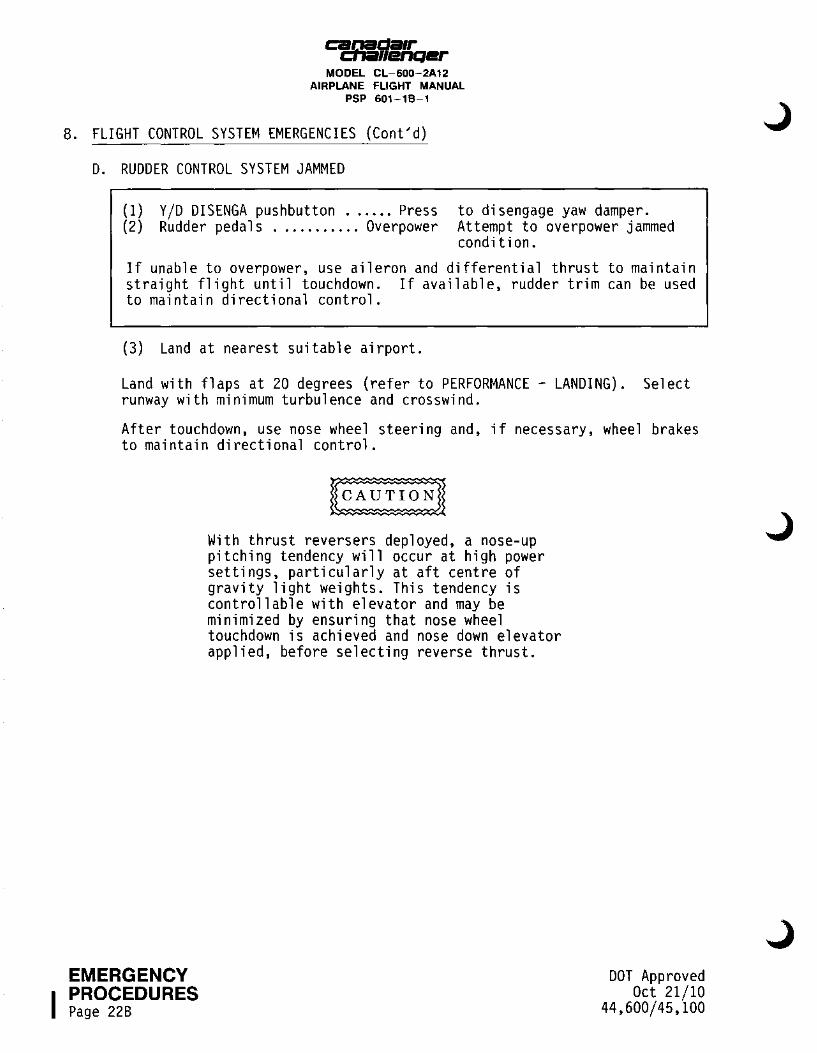
D. RUDDER CONTROL SYSTEM JAMMED
(1) Y/D DISENGA pushbutton ...... Press (2) Rudder pedals ........... Overpower
to disengage yaw damper. Attempt to overpower jammed condition.
If unable to overpower, use aileron and differential thrust to maintain straight flight until touchdown. If available, rudder trim can be used to maintain directional control.
(3) Land at nearest suitable airport.
Land with flaps at 20 degrees (refer to PERFORMANCE - LANDING). Select runway with minimum turbulence and crosswind.
After touchdown, use nose wheel steering and, if necessary, wheel brakes to maintain directional control.
EMERGENCY
I PROCEDURES Page 228
With thrust reversers deployed, a nose-up pitching tendency will occur at high power settings, particularly at aft centre of gravity light weights. This tendency is controllable with elevator and may be minimized by ensuring that nose wheel touchdown is achieved and nose down elevator applied, before selecting reverse thrust.
DOT Approved Oct 21/10
44,600/45,100

cac:fi!illi/l/fqer MODEL CL-600-2A12
AIRPLANE FLIGHT MANUAL PSP 601-18-1
9. YAW DAMPER SYSTEM EMERGENCIES
A. YAW DAMPER FAILURE
Indication: Red YD FAIL and AFCS lights flashing
(1) Y /D DISENGA pushbutton ...... Press to disengage yaw damper.
Attempt to isolate the failed channel as follows: (2) Autopilot status panel
YAW 2 switch/1 i ght .......... Press
(3) Yaw damper .............. Re-engage
to revert system to singlechannel yaw 1 operation. If system engages, monitor for proper operation. Failure is in channel 2. Continue flight with the operative yaw damper channel engaged.
If system does not function properly, failure is probably in channel 1. Disconnect yaw damper and repeat procedure isolating yaw 1. (4) Yaw damper .............. Disengage (5) Autopilot status panel
YAW 2 switch/light .......... Press to select channel 2. OFF light out.
(6) Autopilot status panel YAW 1 swi tch/1 i ght .......... Press to revert system to single
channel yaw 2 operation. OFF light on.
(7) Yaw damper .............. Re-engage
If operation is not satisfactory: (8) Yaw damper .............. Disengage (9) Flaps ..................... Retract to 20 degrees if applicable.
Approach and land with flaps at 20 degrees (refer to PERFORMANCE - LANDING).
DOT Approved Oct 21/10 44,600/45,100
With thrust reversers deployed, a nose-up pitching tendency will occur at high power settings, particularly at aft centre of gravity light weights. This tendency is controllable with elevator and may be minimized by ensuring that nose wheel touchdown is achieved and nose down elevator applied, before selecting reverse thrust.
EMERGENCY PROCEDURES I
Page 22C

canada1r -cna11enQer
MODEL CL-600-2A12 AIRPLANE FLIGHT MANUAL
PSP 601-18-1
9. YAW DAMPER SYSTEM EMERGENCIES (Cont'd)
A. YAW DAMPER FAILURE (Cont'd)
EMERGENCY
I PROCEDURES Page 22D
NOTE If the landing distance with flaps at 20 degrees is excessive, a landing with flaps at 45 degrees (no autopilot) may be carried out, provided a runway with minimum crosswind and turbulence is selected.
DOT Approved Oct 21/10
44,600/45,100
J

DOT Approved Oct 21/10 44,600/45,100
Ci!&J!!.da1r ....... 11enQer
MODEL CL-600-2A12 AIRPLANE FLIGHT MANUAL
PSP 601-18-1
THIS PAGE LEFT INTENTIONALLY BLANK
EMERGENCY PROCEDURES I
Page 23
I
cacr.sda1r rllenQer MODEL CL-600-2A12
AIRPLANE FLIGHT MANUAL PSP 601-18-1
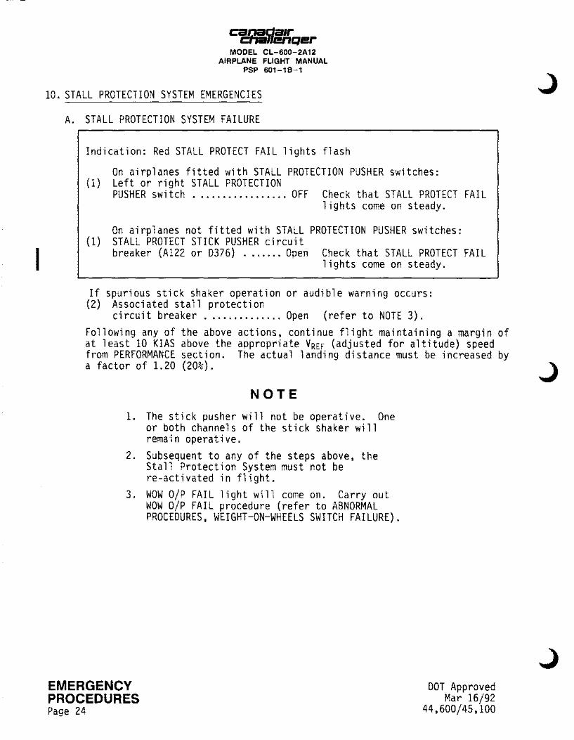
10. STALL PROTECTION SYSTEM EMERGENCIES
A. STALL PROTECTION SYSTEM FAILURE
Indication: Red STALL PROTECT FAIL lights flash
On airplanes fitted with STALL PROTECTION PUSHER switches: (1) Left or right STALL PROTECTION
PUSHER switch ................. OFF Check that STALL PROTECT FAIL lights come on steady.
On airplanes not fitted with STALL PROTECTION PUSHER switches: (1) STALL PROTECT STICK PUSHER circuit
breaker (A122 or D376) ....... Open Check that STALL PROTECT FAIL lights come on steady.
If spurious stick shaker operation or audible warning occurs: (2) Associated stall protection
circuit breaker .............. Open (refer to NOTE 3). Following any of the above actions, continue flight maintaining a margin of at least 10 KIAS above the appropriate VREF (adjusted for altitude) speed from PERFORMANCE section. The actual landing distance must be increased by a factor of 1.20 (20%).
NOTE
1. The stick pusher will not be operative. One or both channels of the stick shaker will remain operative.
2. Subsequent to any of the steps above, the Stall Protection System must not be re-activated in flight.
3. WOW O/P FAIL light will come on. Carry out WOW O/P FAIL procedure (refer to ABNORMAL PROCEDURES, WEIGHT-ON-WHEELS SWITCH FAILURE).
EMERGENCY PROCEDURES Page 24
DOT Approved Mar 16/92
44,600/45,100
J

canaaa1r t:hallenqer
ll>DEL Cl-eo-?A12 AIRPLANE FLIGHT twlJAL
PSP 601-11-1
10. STALL PROTECTION SYSTEM EMERGENCIES <Cont'd)
B. STALL PROTECTION SYSTEM POHER SUPPLY FAILURE
Indication: Red STALL PROTECT FAIL lights on steady
Continue flight maintaining a margin· of at least 10 KIAS above the appropriate VREF (adjusted for altitude) speed given in PERFORMANCE -LANDING. The actual landing distance must be increased by a factor of 1.20 (201).
NOTE
1. The stick pusher may not be operative. One or both channels of the stick shaker will remain operative.
2. WOW O/P FAIL light may come on. In this case. carry out WOW O/P FAIL procedure Crefer to ABNORMAL PROCEDURES -HEIGHT-ON-HHEELS SHITCH FAILURE).
C. STALL PROTECTION SYSTEM ALTITUDE COMPENSATION MALFUNCTION
Indication: ALT COMP FAIL lights on.
Cl) An airplanes 3001 to 3066 not incorporating Canadair Service Bulletin I 601-0237. Modification - Stall Protection System - Computer Reliability Improvement:
The stall protection system reverts to the fixed altitude (15.000 feet) stall speed mode.
All airborne reference speeds for take-off. climb. approach. approach climb and landing climb must be based on the Vs appropriate to 15.000 feet.
For landing approach speed. increase 10.000 foot speeds shown in PERFORMANCE. by 2.5 KIAS. In this event. climb gradient degradation will be ·I negligible and actual landing distances must be increased by a factor of 1. 15 (151).
DOT Approved Feb 20/90 44,600
EMERGENCY PROCEDURES
Page 25
canaaa1r ct1a11enqer
lllOE1. CL-fi00-2A12 AIRPLANE FLIGHT IWIJAL
PSP 601-11-1
10. STALL PROTECTION SYSTEM EMERGENCIES <Cont'd)
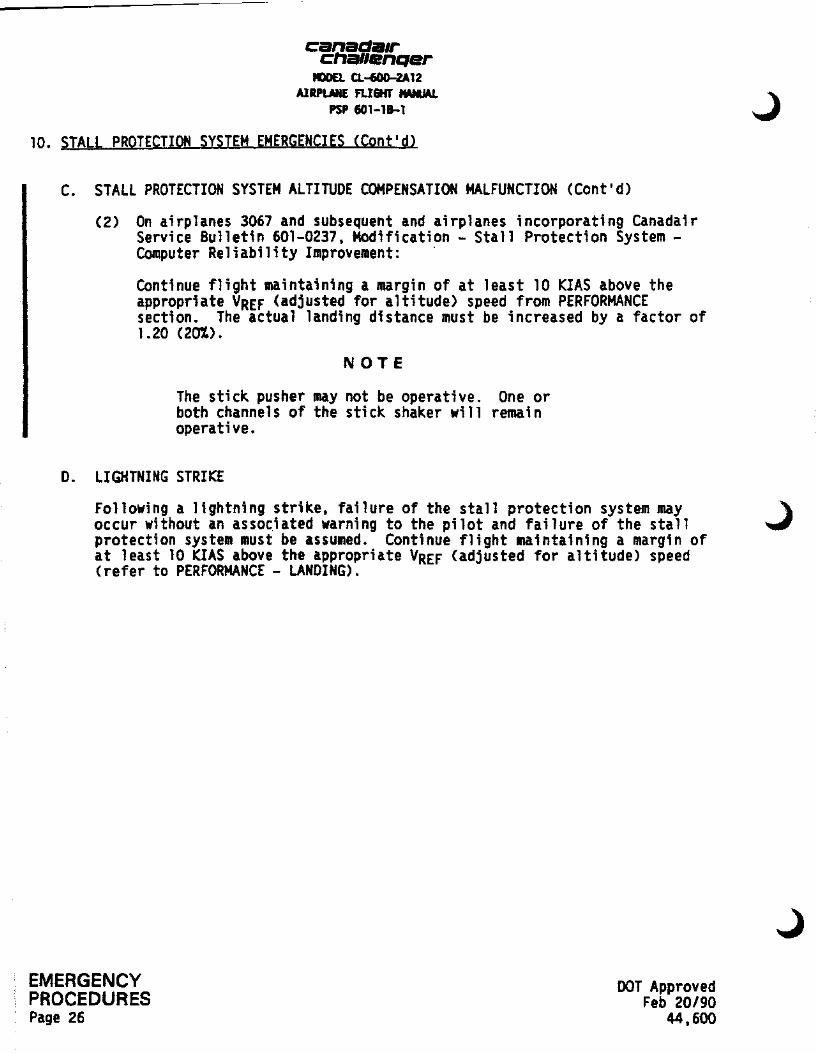
C. STALL PROTECTION SYSTEM ALTITUDE COMPENSATION MALFUNCTION (Cont'd)
(2) On airplanes 3067 and subsequent and airplanes incorporating Canadair Service Bulletin 601-0237, Modification - Stall Protection System -Computer Reliability Improvement: ·
Continue flight maintaining a margin of at least 10 KIAS above the appropriate VREF (adjusted for altitude) speed from PERFORMANCE section. The actual landing distance must be increased by a factor of 1.20 (201.).
NOTE
The stick pusher may not be operative. One or both channels of the stick shaker will remain operative.
D. LIGHTNING STRIKE
Following a lightning strike, failure of the stall protection system may occur without an assoc.iated warning to the pilot and failure of the stall protection system must be assumed. Continue flight maintaining a margin of at least 10 KIAS above the appropriate VREF (adjusted for altitude) speed (refer to PERFORMANCE - LANDING).
EMERGENCY PROCEDURES Page 26
DOT Approved Feb 20/90
44,600

canada1r cna11enqer
MODEL CL-600-2A12 AIRPLANE FLIGHT MANUAL
PSP 601-18-1
11. DITCHING AND FORCED LANDING
TO ENSURE A SAFE WATER LANDING: TO ENSURE A SAFE FORCED LANDING:
• Approach speed ........ V REF • Approach speed ........ V REF
• Descent rate • Descent rate (if thrust available) . 200-300 f pm (if thrust available) . 200-300 f pm
• Landing gear .......... Retracted • Landing gear .......... As required
• Flaps setting ......... 45 degrees • Flaps setting ......... 45 degrees
• If flaps 45 is not possible, use most extended flap setting available. • FINAL APPROACH SPEED: • FLAPS 0: V REF + 30 KTS • FLAPS 20: VREF + 10 KTS • FLAPS 30: V REF +8 KTS
A. DITCHING
PRELIMINARY:
(1) Descent ...................... Pl an
(2) Passengers .................. Brief
(3) Loose articles ............... Stow
(4) Life vests and seat belts ... Check
(5) Survival equipment Check
(6) AURAL WARN 1 and 2 circuit breakers (8304 and D378) ..... open
DOT Approved Jul 16/04 44,600/45,100
to reduce fuel to a m1n1mum if possible while retaining sufficent fuel to make controlled powered approach.
on ditching procedures and caution not to inflate life vests inside airplane. Seat backs upright and tables stowed. that all occupants are wearing a life vest and that seat belts are fastened. that equipment is prepared and ready for removal from airplane.
to silence aural warning.
EMERGENCY PROCEDURES I
Page 27

canada1r cna11enQer
MODEL CL-600-2A12 AIRPLANE FLIGHT MANUAL
PSP 601-18-1
11. DITCHING AND FORCED LANDING (Cont;d)
A. DITCHING (Cont;d)
APPROACH:
At approximately 2000 feet above sea level:
(1) Sea conditions and wind direction ........... Appraise
(2) Descent rate/ approach speed .......... Establish
(3) L and R ACU switch/1 i ghts ........... Press out
(4) CKPT HEAT switch .............. OFF (5) CABIN PRESSURIZATION
MODE selector ................. MAN (6) MAN REG ................... Full UP When cabin is completely depressurized: (7) BLEED AIR 10th STAGE L and R
swi tch/1 i ghts ........... Press out (8) MAN REG ................... Full ON (9) APU ..................... Shut down (10) FUEL CONTROL L and R
PUMP switch/lights ...... Press out (11) At 8 to 10 feet ......... Level off
EMERGENCY
I PROCEDURES Page 28
Select ditching heading parallel to any major swell pattern.
OFF lights on.
BLEED CLOSED lights on. to close outflow valves. if not essential.
ON lights out. above crest of swell.
DOT Approved Jul 16/04
44,600/45,100
Ci!Qi!.da1r ... .-11enQer
MODEL CL-600-2A12 AIRPLANE FLIGHT MANUAL
PSP 601-18-1
11. DITCHING AND FORCED LANDING (Cont'd)
A. DITCHING (Cont'd)
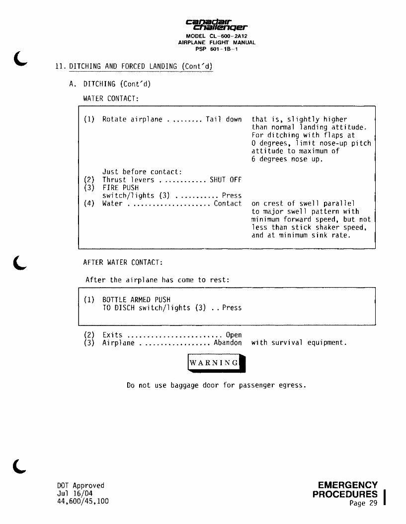
WATER CONTACT:
(1) Rotate airplane ......... Tail down
Just before contact: (2) Thrust levers ............ SHUT OFF (3) FIRE PUSH
switch/lights (3) ........... Press (4) Water ..................... Contact
AFTER WATER CONTACT:
After the airplane has come to rest:
(1) BOTTLE ARMED PUSH TO DISCH switch/lights (3) .. Press
(2) Exits ........................ Open
that is, slightly higher than normal landing attitude. For ditching with flaps at 0 degrees, limit nose-up pitch attitude to maximum of 6 degrees nose up.
on crest of swell parallel to major swell pattern with minimum forward speed, but not less than stick shaker speed, and at minimum sink rate.
(3) Airplane .................. Abandon with survival equipment.
DOT Approved Jul 16/04 44,600/45,100
jw ARNINGI
Do not use baggage door for passenger egress.
EMERGENCY PROCEDURES I
Page 29

canada1r avillenQer
MODEL CL-600-2A12 AIRPLANE FLIGHT MANUAL
PSP 601-18-1
11. DITCHING AND FORCED LANDING (Cont~d)
B. FORCED LANDING
PRELIMINARY:
(1) Descent ...................... Plan to reduce fuel to a minimum
(2) Passengers .................. Brief (3) Loose articles ............... Stow
(4) Seat belts .................. Check
(5) Survival equipment .......... Check
(6) AURAL WARN 1 and 2 circuit breakers (B304 and D378) ..... open
APPROACH:
At approximately 2000 feet:
(1) Land conditions and wind direction ........... Appraise
(2) Descent rate/ approach speed .......... Establish
(3) L and R ACU switch/lights ........... Press out
( 4) CKPT HEAT switch .............. OFF (5) CABIN PRESSURIZATION
MODE selector ................. MAN (6) MAN REG ................... Full UP
When cabin is completely depressurized: (7) BLEED AIR 10th STAGE L and R
switch/lights ........... Press out (8) APU ..................... Shut down (9) FUEL CONTROL L and R
PUMP switch/lights ...... Press out (10) At 8 to 10 feet ......... Level off
EMERGENCY
I PROCEDURES Page 30
if possible while retaining sufficent fuel to make controlled powered approach.
on forced landing procedures. Seat backs upright and tables stowed. that all occupants have seat belts fastened. that equipment is prepared and ready for removal from airplane.
to silence aural warning.
OFF lights on.
BLEED CLOSED lights on. if not essential.
ON lights out.
DOT Approved Jul 16/04
44,600/45,100

c~da1r ... ..JHenQer
MODEL CL-600-2A12 AIRPLANE FLIGHT MANUAL
PSP 601-18-1
11. DITCHING AND FORCED LANDING (Cont'd)
B. FORCED LANDING (Cont'd)
PRIOR TO CONTACT:
(1) Rotate airplane ......... Tail down
Just before contact: (2) Thrust 1 evers ............ SHUT OFF (3) FIRE PUSH
switch/1 ights (3) ........... Press (4) Terrain ................... Contact
AFTER CONTACT:
After the airplane has come to rest:
(1) BOTTLE ARMED PUSH TO DISCH switch/lights (3) .. Press
(2) Exits ........................ Open (3) Airplane .................. Abandon
DOT Approved Jul 16/04 44,600/45,100
that is, slightly higher than normal landing attitude. For landing with flaps at 0 degrees, limit nose-up pitch attitude to maximum of 6 degrees nose up.
with minimum forward speed, but not less than stick shaker speed, and at minimum sink rate.
with survival equipment.
EMERGENCY PROCEDURES I
Page 31

car:rada1r CIVilllenQer
MODEL CL-600-2A12 AIRPLANE FLIGHT MANUAL
PSP 601-18-1
12. LANDING GEAR, WHEEL AND BRAKE SYSTEM EMERGENCIES
A. GEAR UP DISAGREE
Indication: Discrepancy in landing gear safe lights and/or flashing red gear handle light with landing gear lever UP.
(1) Ai rs peed ................... Reduce to not more than: Flaps 0 degrees - 181 KIAS Flaps 20 degrees - 197 KIAS Flaps 30 degrees - 197 KIAS Flaps 45 degrees - 190 KIAS
(2) Hydraulic ELECT PUMP switches 2 and 3B .............. ON
Nose wheel steering may not be available upon landing.
(3) LANDING GEAR MANUAL RELEASE handle ............... PULL Press button, pull handle to
NOTE
full extent and release button to latch handle.
The NOSE DOOR OPEN light will come on when manual gear extension is accomplished.
(4) Landing gear ................... DN (5) Landing gear indications .... Check for three green gear safe
lights.
If three green gear safe lights are indicated, do not stow LANDING GEAR MANUAL RELEASE handle until gear locking pins are installed.
If discrepancy in landing gear safe lights persists: (6) Gear DN disagree
procedure .............. Accomplish Refer to GEAR DN DISAGREE.
EMERGENCY PROCEDURES Page 32
DOT Approved Oct 14/08
44,600/45,100
J
J
canacla1r cna11enqer MODEL CL-600-2A12
AIRPLANE FLIGHT MANUAL PSP 601-18-1
12. LANDING GEAR, WHEEL AND BRAKE SYSTEM EMERGENCIES (Cont~d)
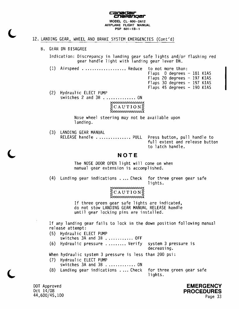
B. GEAR ON DISAGREE
Indication: Discrepancy in landing gear safe lights and/or flashing red gear handle light with landing gear lever ON.
(1) Ai rs peed ................... Reduce to not more than:
(2) Hydraulic ELECT PUMP switches 2 and 38 .............. ON
Flaps 0 degrees - 181 KIAS Flaps 20 degrees - 197 KIAS Flaps 30 degrees - 197 KIAS Flaps 45 degrees - 190 KIAS
Nose wheel steering may not be available upon landing.
(3) LANDING GEAR MANUAL RELEASE handle ............... PULL
NOTE
Press button, pull handle to full extent and release button to latch handle.
The NOSE DOOR OPEN light will come on when manual gear extension is accomplished.
(4) Landing gear indications .... Check for three green gear safe lights.
If three green gear safe lights are indicated, do not stow LANDING GEAR MANUAL RELEASE handle until gear locking pins are installed.
If any landing gear fails to lock in the down release attempt:
position following manual
(5) Hydraulic ELECT PUMP switches 3A and 38 ............ OFF
(6) Hydraulic pressure ......... Verify
When hydraulic system 3 pressure is less (7) Hydraulic ELECT PUMP
switches 3A and 38 ............. ON (8) Landing gear indications .... Check
DOT Approved Oct 14/08 44,600/45,100
system 3 pressure is decreasing.
than 200 psi:
for three green gear safe lights.
EMERGENCY PROCEDURES
Page 33

~RSillfQer MODEL CL-600-2A12
AIRPLANE FLIGHT MANUAL PSP 601-18-1
12. LANDING GEAR, WHEEL AND BRAKE SYSTEM EMERGENCIES (Cont'd)
B. GEAR DN DISAGREE (Cont'd)
If three green gear safe lights are indicated, do not stow LANDING GEAR MANUAL RELEASE handle until gear locking pins are installed.
If discrepancy in landing gear safe lights persists: (9) Landing gear up / unsafe
landing procedure ...... Accomplish Refer to LANDING GEAR UP / UNSAFE LANDING PROCEDURE.
C. LANDING GEAR LEVER JAMMED IN THE UP POSITION
(1) Airspeed ................... Reduce to not more than: Flaps 0 degrees - 181 KIAS Flaps 20 degrees - 197 KIAS Flaps 30 degrees - 197 KIAS Flaps 45 degrees - 190 KIAS
(2) Hydraulic ELECT PUMP switches 2 and 3B .............. ON
Nose wheel steering may not be available upon landing.
(3) LANDING GEAR MANUAL RELEASE handle ............... PULL Press button, pull handle to
full extent and release button to latch handle.
NOTE 1. The NOSE DOOR OPEN light will come on when
manual gear extension is accomplished. 2. The flashing red gear handle light will come
on when manual gear extension is accomplished. ( 4) N/W STEER switch .............. OFF (5) Landing gear indications .... Check for three green gear safe
lights.
If three green gear safe lights are indicated, do not stow LANDING GEAR MANUAL RELEASE handle until gear locking pins are installed.
If discrepancy in landing gear safe lights persists: (6) Gear DN disagree
procedure .............. Accomplish Refer to GEAR DN DISAGREE.
EMERGENCY PROCEDURES Page 34
DOT Approved Oct 14/08
44,600/45,100
c!91ida1r fllenQer MODEL CL-600-2A12
AIRPLANE FLIGHT MANUAL PSP 601-18-1
12. LANDING GEAR, WHEEL AND BRAKE SYSTEM EMERGENCIES (Cont'd)
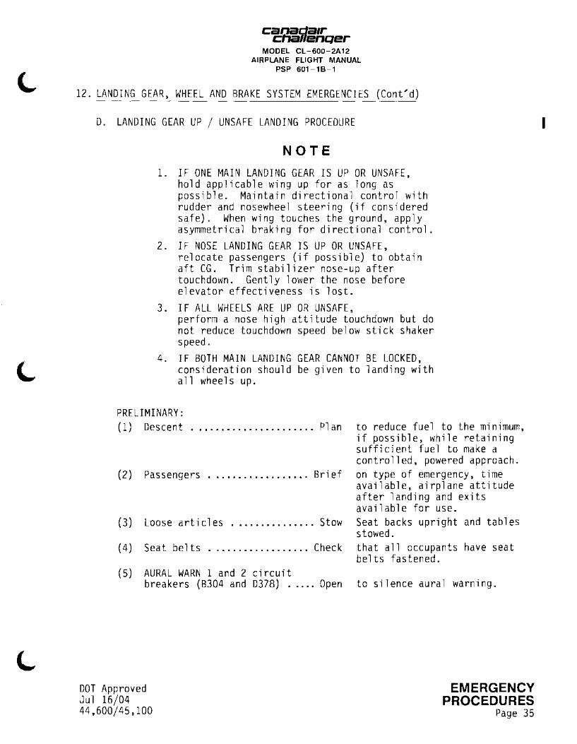
D. LANDING GEAR UP / UNSAFE LANDING PROCEDURE
NOTE
1. IF ONE MAIN LANDING GEAR IS UP OR UNSAFE, hold applicable wing up for as long as possible. Maintain directional control with rudder and nosewheel steering (if considered safe). When wing touches the ground, apply asymmetrical braking for directional control.
2. IF NOSE LANDING GEAR IS UP OR UNSAFE, relocate passengers (if possible) to obtain aft CG. Trim stabilizer nose-up after touchdown. Gently lower the nose before elevator effectiveness is lost.
3. IF ALL WHEELS ARE UP OR UNSAFE, perform a nose high attitude touchdown but do not reduce touchdown speed below stick shaker speed.
4. IF BOTH MAIN LANDING GEAR CANNOT BE LOCKED, consideration should be given to landing with all wheels up.
PRELIMINARY: (1) Descent ...................... Pl an
(2) Passengers .................. Brief
(3) Loose articles ............... Stow
(4) Seat belts Check
(5) AURAL WARN 1 and 2 circuit breakers (B304 and D378) ..... Open
DOT Approved Jul 16/04 44,600/45,100
to reduce fuel to the minimum, if possible, while retaining sufficient fuel to make a controlled, powered approach. on type of emergency, time available, airplane attitude after landing and exits available for use. Seat backs upright and tables stowed. that all occupants have seat belts fastened.
to silence aural warning.
EMERGENCY PROCEDURES
Page 35
I
I
canada1r c:na11enQer
MODEL CL-600-2A12 AIRPLANE FLIGHT MANUAL
PSP 601-18-1
12. LANDING GEAR WHEEL, AND BRAKE SYSTEM EMERGENCIES (Cont'd)
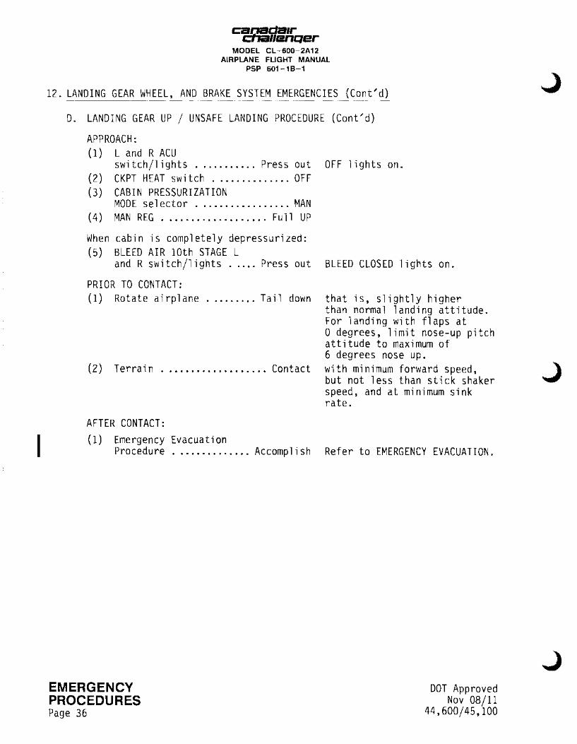
D. LANDING GEAR UP / UNSAFE LANDING PROCEDURE (Cont'd)
APPROACH: (1) L and R ACU
switch/1 i ghts ........... Press out OFF 1 i ghts on. (2) CKPT HEAT switch .............. OFF (3) CABIN PRESSURIZATION
MODE se 1 ector ................. MAN (4) MAN REG ................... Full UP
When cabin is completely depressurized: (5) BLEED AIR 10th STAGE L
and R switch/lights ..... Press out BLEED CLOSED 1 i ghts on.
PRIOR TO CONTACT: (1) Rotate airplane ......... Tail down that is, slightly higher
than normal landing attitude. For landing with flaps at 0 degrees, limit nose-up pitch attitude to maximum of 6 degrees nose up.
(2) Terrain ................... Contact with minimum forward speed,
AFTER CONTACT: (1) Emergency Evacuation
but not less than stick shaker speed, and at minimum sink rate.
Procedure .............. Accomplish Refer to EMERGENCY EVACUATION.
EMERGENCY PROCEDURES Page 36
DOT Approved Nov 08/11
44,600/45,100

canada1r cna11enQer
MODEL CL-600-2A12 AIRPLANE FLIGHT MANUAL
PSP 601-18-1
12. LANDING GEAR, WHEEL AND BRAKE SYSTEM EMERGENCIES (Cont;d)
E. MAIN LANDING GEAR BAY OVERHEAT WARNING
(1) Airspeed ................... Reduce to 197 KIAS. (2) Landing gear ................... DN
(3) MLG BAY OVHT light .......... Check (4) Flight ................... Continue
(5) Landing gear ................... Up (6) MLG BAY OVHT light .......... Check
If light comes on: (7) Landing gear ................... DN (8) Land at nearest suitable airport.
F. NOSE GEAR DOORS OPEN
Indication: NOSE DOOR OPEN light on (1) Airspeed ................... Reduce
If NOSE gear safe light is green: (2) Gear disagree
that warning is out. with landing gear down for minimum of five minutes. Refer to LIMITATIONS - MAXIMUM OPERATING LIMIT SPEED for VLo and VLE·
light remains out.
to not more than: Flaps 0 degrees - 181 KIAS Flaps 20 degrees - 197 KIAS Flaps 30 degrees - 197 KIAS Flaps 45 degrees - 190 KIAS
procedure .............. Accomplish Refer to GEAR DISAGREE.
NOTE Cycling the landing gear with NOSE DOOR OPEN and NOSE gear safe light on may result in a nose gear jam.
If NOSE gear safe light is out: (2) Landing gear ................ Cycle down and up once.
If NOSE DOOR OPEN light persists: (3) Landing gear ................... DN (4) Land at nearest suitable airport.
DOT Approved Oct 14/08 44,600/45,100
EMERGENCY PROCEDURES
Page 37
I
ca&\iillfQer MODEL CL-600-2A12
AIRPLANE FLIGHT MANUAL PSP 601-18-1
12. LANDING GEAR, WHEEL AND BRAKE SYSTEM EMERGENCIES (Cont'd)
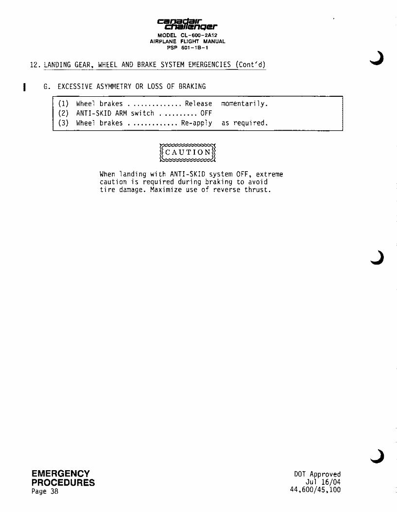
I G. EXCESSIVE ASYMMETRY OR LOSS OF BRAKING
(1) Wheel brakes .............. Release momentarily. (2) ANTI-SKID ARM switch .......... OFF (3) Wheel brakes ............. Re-apply as required.
EMERGENCY PROCEDURES Page 38
When landing with ANTI-SKID system OFF, extreme caution is required during braking to avoid tire damage. Maximize use of reverse thrust.
DOT Approved Jul 16/04
44,600/45,100
C12&Ji!.da1r - • .-11enqer
MODEL CL-600-2A12 AIRPLANE FLIGHT MANUAL
PSP 601-18-1
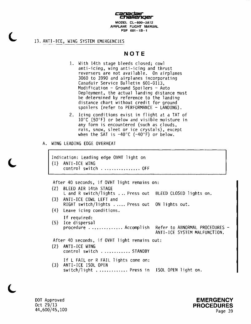
13. ANTI-ICE, WING SYSTEM EMERGENCIES
NOTE
1. With 14th stage bleeds closed; cowl anti-icing, wing anti-icing and thrust reversers are not available. On airplanes 3060 to 3990 and airplanes incorporating Canadair Service Bulletin 601-0113, Modification - Ground Spoilers - Auto Deployment, the actual landing distance must be determined by reference to the landing distance chart without credit for ground spoilers (refer to PERFORMANCE - LANDING).
2. Icing conditions exist in flight at a TAT of 10°c (50°F) or below and visible moisture in any form is encountered (such as clouds, rain, snow, sleet or ice crystals), except when the SAT is -40°C (-40°F) or below.
A. WING LEADING EDGE OVERHEAT
Indication: Leading edge OVHT light on (1) ANTI-ICE WING
control switch ................ OFF
After 40 seconds, if OVHT light remains on: (2) BLEED AIR 14th STAGE
L and R switch/lights ... Press out BLEED CLOSED lights on. (3) ANTI-ICE COWL LEFT and
RIGHT switch/lights ..... Press out ON lights out. (4) Leave icing conditions.
If required: (5) Ice dispersal
procedure .............. Accomplish Refer to ABNORMAL PROCEDURES -ANTI-ICE SYSTEM MALFUNCTION.
After 40 seconds, if OVHT light remains out: (2) ANTI-ICE WING
control switch ............ STANDBY
If L FAIL or R FAIL lights come on: (3) ANTI-ICE !SOL OPEN
switch/light ............. Press in
DOT Approved Oct 29/13 44,600/45,100
!SOL OPEN light on.
EMERGENCY PROCEDURES
Page 39
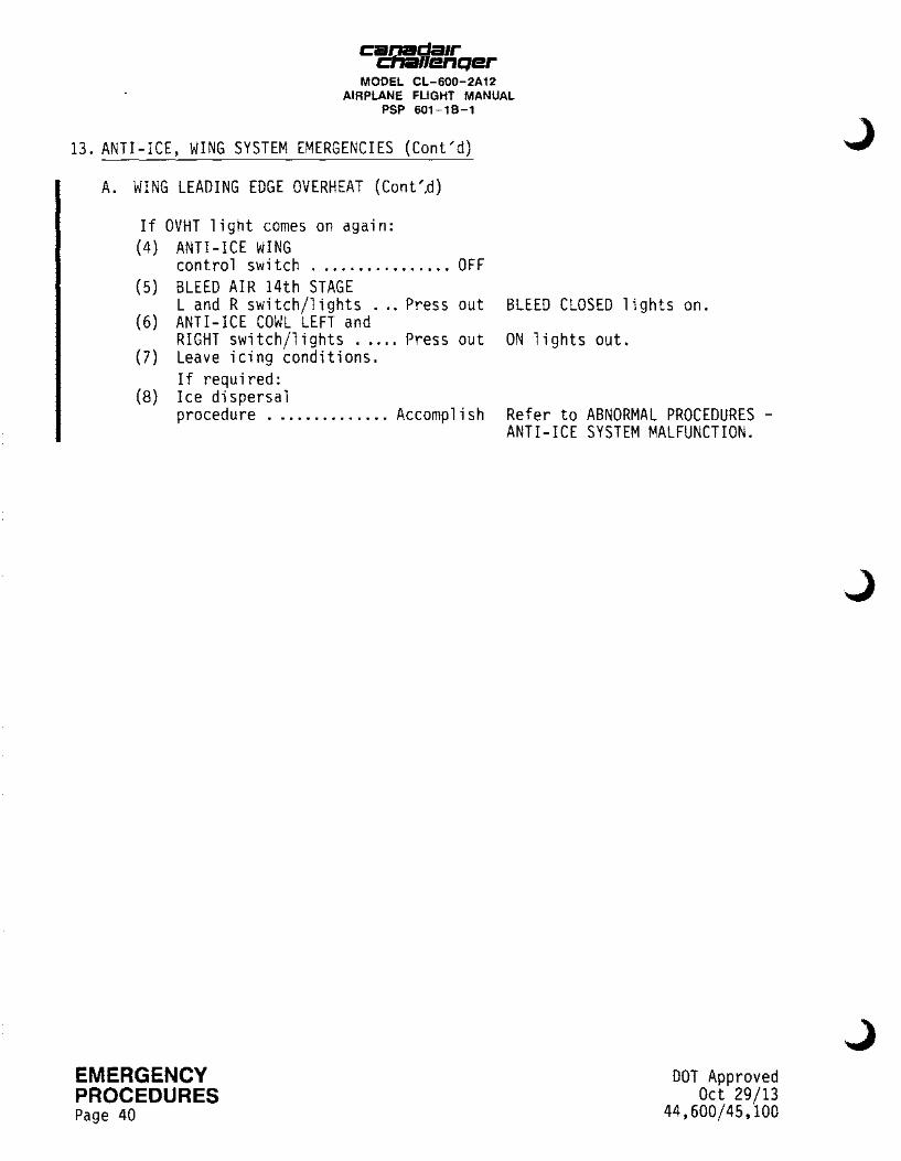
canada1r cna11enQer
MODEL CL-600-2A12 AIRPLANE FLIGHT MANUAL
PSP 601-18-1
13. ANTI-ICE, WING SYSTEM EMERGENCIES (Cont'd)
A. WING LEADING EDGE OVERHEAT (Cont'.d)
If OVHT light comes on again: (4) ANTI-ICE WING
control switch ................ OFF (5) BLEED AIR 14th STAGE
L and R swi tch/1 i ghts ... Press out (6) ANTI-ICE COWL LEFT and
RIGHT switch/lights ..... Press out (7) Leave icing conditions.
If required: (8) Ice dispersal
procedure . . ............ Ac comp 1 is h
EMERGENCY PROCEDURES Page 40
BLEED CLOSED lights on.
ON 1 i ghts out.
Ref er to ABNORMAL PROCEDURES -ANTI-ICE SYSTEM MALFUNCTION.
DOT Approved Oct 29/13
44,600/45,100
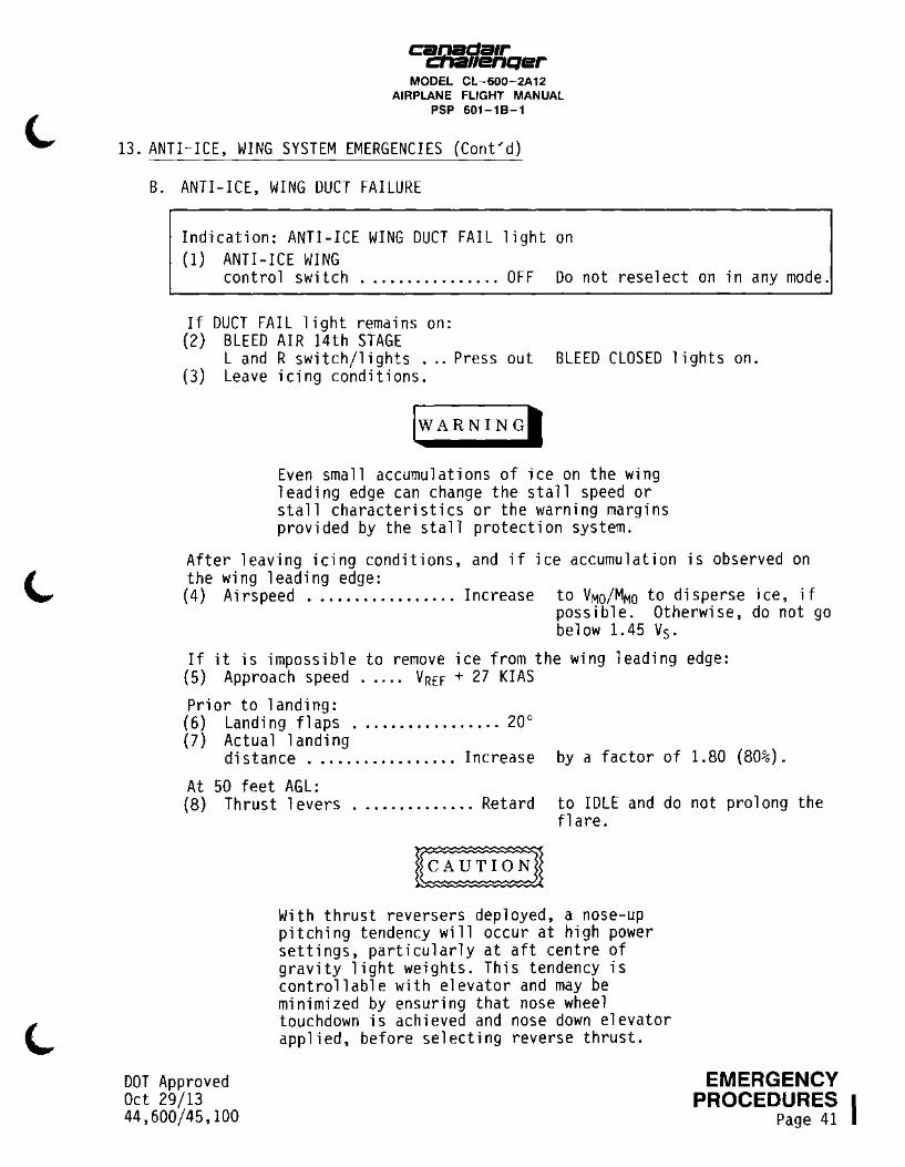
C:i!!J!!.da1r ._ • .-11enqer MODEL CL-600-2A12
AIRPLANE FLIGHT MANUAL PSP 601-18-1
13. ANTI-ICE, WING SYSTEM EMERGENCIES (Cont/d)
B. ANTI-ICE, WING DUCT FAILURE
Indication: ANTI-ICE WING DUCT FAIL light on (1) ANTI-ICE WING
control switch ................ OFF Do not reselect on in any mode.
If DUCT FAIL light remains on: (2) BLEED AIR 14th STAGE
L and R switch/lights ... Press out BLEED CLOSED lights on. (3) Leave icing conditions.
lwARNINGI
Even small accumulations of ice on the wing leading edge can change the stall speed or stall characteristics or the warning margins provided by the stall protection system.
After leaving icing conditions, and if ice accumulation is observed on the wing leading edge: (4) Airspeed ................. Increase to VMo/MMo to disperse ice, if
possible. Otherwise, do not go below 1.45 V5.
If it is impossible to remove ice from the wing leading edge: (5) Approach speed . . . . . VREF + 27 KIAS
Prior to landing: (6) Landing flaps ................. 20° (7) Actual landing
distance ................. Increase by a factor of 1.80 (80%).
At 50 feet AGL: (8) Thrust levers .............. Retard to IDLE and do not prolong the
DOT Approved Oct 29/13 44,600/45,100
fl are.
With thrust reversers deployed, a nose-up pitching tendency will occur at high power settings, particularly at aft centre of gravity light weights. This tendency is controllable with elevator and may be minimized by ensuring that nose wheel touchdown is achieved and nose down elevator applied, before selecting reverse thrust.
EMERGENCY PROCEDURES I
Page 41
cad:da1r fl/enQer
MODEL CL-600-2A12 AIRPLANE FLIGHT MANUAL
PSP 601-18-1
14. REJECTED TAKE-OFF
A. ENGINE FAILURE OR REJECTED TAKE-OFF BEFORE ACHIEVING V1
Rejection of the take-off must be initiated no later than V1.
(1) Thrust levers ................ Move (2) Wheel brakes ................ Apply (3) Flight and ground
spoilers ................... Extend (4) Maximum braking .......... Maintain
(5) Thrust reverser (operating engine) ............ Use
( 6) Aileron and rudder . . . . . . . . . . . . Use
( 7) Nose wheel steering . . . . . . . . . . . Use
If required: (8) Emergency Evacuation
rapidly to IDLE.
until a safe stop on runway is assured.
as required to supplement wheel brakes commensurate with directional and lateral control (refer to LIMITATIONS - SYSTEMS LIMITATIONS). as required to maintain directional control. as required to maintain directional control.
Procedure .............. Accomplish Refer to EMERGENCY EVACUATION. After rejected take-off, procedures associated with cooling of wheels, brakes and tires must be observed (refer to NORMAL PROCEDURES - LANDING GEAR WHEELS AND BRAKES).
EMERGENCY
I PROCEDURES Page 42
DOT Approved Oct 29/13
44,600/45,100
J
J

Ci!!J!!.da1r .... .-11enqer MODEL CL-600-2A12
AIRPLANE FLIGHT MANUAL PSP 601-18-1
15. EMERGENCY EVACUATION
A. EMERGENCY EVACUATION PROCEDURE
This procedure contains the steps required to prepare evacuation on land, and is initiated when a condition potentially endangering life or physical well-being of passengers and crew exists.
Pilot:
(1) Parking brake ................. Set (2) Evacuation ................ Command (3) GROUND SPOILERS switch ........ OFF (4) Flight spoilers ........... Retract to fair spoilers with wing
surface. (5) Thrust 1 evers ............ SHUT OFF (6) FIRE PUSH
switch/1 i ghts (3) ........... Press
Coilot: On evacuation comnand
(7) ATC ........................ Notify of emergency conditions and of
(8) L and R ACU switch/lights
(9) EMER DEPRESS
Press out
switch/light ............. Press in
(10) EMERGENCY LIGHTING switch ......................... ON
(11) Exits ........................ Open (12) Passenger
evacuation ...... Render assistance
(13) Airplane .................. Abandon
DOT Approved Oct 29/13 44,600/45,100
intention to evacuate.
to ensure minimum differential pressure within airplane.
to depressurize airplane. ON light on.
and direct passengers away from the airplane. by any suitable exit.
EMERGENCY PROCEDURES I
Page 43

EMERGENCY
I PROCEDURES Page 44
caada1r '"enQer MODEL CL-600-2A12
AIRPLANE FLIGHT MANUAL PSP 601-18-1
THIS PAGE LEFT INTENTIONALLY BLANK
DOT Approved Oct 29/13
44,600/45,100
J


