Honeywell
Relays Pneumatic
and Switches
ENGINEERING DATA
.
Introduction
RP418A-C Pneumatic1 Electric Relays
RP470A Higher-of-Two- Pressures Relay
RP470B Lockout Relay
RP471A Snap-Acting Relay
RP670A and B Switching Relays
RP913A Load Analyzer
RP922A Pneumatic Potentiometer
RP970A Capacity Relay
RP971A Ratio Relay
Contents ................................................................................................................................
General .................................................................................................................. Air Data ..................................................................................................................
................................................................................................................................ General .................................................................................................................. Operation ................................................................................................................ Application .............................................................................................................
................................................................................................................................ General .................................................................................................................. Operation ........ ............................................................................................. Application .............................................................................................................
General .................................................................................................................. Operation ................................................................................................................ Application .............................................................. .........................................
.........................................................................................................
................................................................................................................................ General .................................................................................................................. Operation ................................................................................................................ Application ............................................................................................................. ................................................................................................................................
General ........................................... ..............................................
.................. ......................
......................................................................... Application .......................... ................................................................. .................................. ..................
.......................................................... ...........................................................................................
................................................................................................................................ General .................................................................................................................. Operation .................................................................... .._.. Application .............................................................................................................
.......................................
General .................................................................................................................. Operation ....................................................................... Application .............................................................................................................
........................................
1 1 1
1 1 1 2
2 2 3 3 3 3 3 4 5 5 5 5 6 6 6 6 7 7 7 7 8 8 8 8 .
10 10 10 11 11 11 11 11
Copyright 0 1994 Honeywell Inc . * All Rights Reserved 77-9384
Contents (Continued) RP972A Reversing Relay
RP973A Averaging Relay
RP975A Hesitation Relay
SP470A and B Pneumatic Switches
SP970A-D ManuaVMimimum Position Swtiches
14003238-004 Biasing Repeater Relay
14003617-002 Minimum/Maximum Signal Limiter
................................................................................................................................ General .................................................................................................................. Operation ................................................................................................................ Appllcatlon ............................................................................................................. General .................................................................................................................. Operation ................................................................................................................ Application ............................................................................................................. General ..................................................................................................................
. . ................................................................................................................................
................................................................................................................................
Operation .................. .._........... ............................................................................... Application .............................................................................................................
12 12 13 13 13 13 14 14 14 14 15 15
............... :; ......................................................................................... 16 ........................ : ............................................. ....................................... 16
Operation ................................................................................................................ 16 Application .................. ; ....... ; .................................................................................. 17
................................ ........................................................................................... 17
Operation ........ ................................................................................... 17 General .................................................................................................................. 17
SF970A an Switches ........................................................ 17 SP970C and D Four-Port Switches ................................................................. 18
Application ................................................................................. ....................... 18
........... ............... ........................................................................... 19 General .............. ............................................................................. 19 Operation ................................................ ................................................... Application ...................... ....................................... ..................................... 19
.......................................................................................................... ........................................................................... 20
Operation ....................... Application .................................. ................... 20
77-9384

INTRODUCTION
14W3617-W2Minimum/M~uximum 0.022 (10.4) Pneumatic Signal Limiter
GENERAL
0.WZ (1.7) **
Table 1. Air Data
This sheet provides the user with information about miniaturerelaysandswitches.F'ush-on barhs areusedforall connections. Main connections are for 114-in. (6-mm) O.D. tubing, exceptfortheRP975 andthe SP970, whichuse5/32- in. (4-mm) O.D. tubing. All other connections are for 5/32- in. (4-mm) O.D. tubing.
AIR DATA
Table 1 provides air consumption and capacit, information for the relays, switches, and restrictors described in this sheet.
RP418A-C ELECTRIC/PNEUMATIC RELAYS
RP418A
RP418B
GENERAL
The RP418A-C Electricpneumatic Relays are electrically operated pneumatic switches that open and closetheairsupplytopneumaticcontcols.Theconm1input to an RP418 is an ONIOFF line voltage signal. An RP418 can function as a diverting relay, a selector relay, or a stop- and-bleed relay.
OPERATION ' When the RP418 coil is deenergized, Ports 2 and 3 are
connected and Port 1 is blocked (Fig. 1A). When the relay coil is energized, Ports 1 and 3 are connected and Port 2 is blocked (Fig. IB). i
- 1 77-9384

FAN INTERLOCK
DISCONNECTE CONNECTED SUPPLY AIR
A. RELAY DEENERGIZEO
RP418
SOLENOID FAN INTERLOCK SPRING
RELAY COIL VOLTAGE
NORMALLY WPLUNGER t NORMALLY
4 CONNECTED DISCONNECTED SUPPLY AIR
c4103.1 B. RELAY ENERGIZED
Fig. 1. RP418A-C Operation.
AP P L I CAT1 0 N
Figure 2 shows a typical application of an RP418. When the fan turns on, the coil energizes, passing supply air through Ports 1 and 3 to the damper actuator. When the fan turns off, supply Port 1 is blocked and Ports 2 and 3 are connected, bleeding the air from the damper actuator to the atmosphere.
_--- VOLTAGE SUPPLY
SWITCH
ti---
I t---
SUPPLY
AIR a2Q RP418A-C ACTUATOR DAMPER
Fig. 2. RP418A-C Typical Application.
An RP418 is used for interlock between an electrical and a pneumatic control system and can be used as a stop-and- bleed relay or as a diverting 01 selector relay. Depending upon the piping hookup, thew418 functions asathree-way normally open or normally closed air valve or a three-way diverting control.
RP470A HIGHER-OF-TWO-PRESSURES RELAY
GENERAL
RP470A
The RP470A Higher-of-Two-Pressures Relay is a three- port relay used to transmit the higher of two input signals from a thermostat to a valve or damper actuator. The RP470A selects the higher pressure with a sensitivity of 0.12 to 0.18 psi (0.9 to 1.2 kPa). Because of its high sensitivity, the RP470A can be used in sensor lines such as those from an LP914 or LP915 Temperature Sensor within an accuracy of 2 to 3 degrees F (1.1 to 1.7 degrees C).
NOTE. Do not use the RP470A on small-Fozzle sensors such as the Tp974. Greater errors will occur because of tbeair leakageinvolved duringintemal switching on the RP470K
77-9384 2

OPERATION APPLICATION
When the pressure at Port 3 is greater than the pressure at Port 5 (Fig. 3A), Port 3 supplies the output through Port 2 and the output at Port 2 equals the Port 3 pressure. When the pressure at Port 5 is greater than the pressure at Port 3 (Fig. 3B),Port3closesoff andtheoutput atPort2equals theport 5 pressure.
RP4rnA
PILOT INPUTA PILOT INPUT8
R-
A
PILOT INPUTA m : G T B
L
BRANCHOUTPUT
u293
Fig. 3. RP470A Operation.
Figure 4 shows a typical application using three zone thermostats and two RP470As for control. Each zone is controlled by a separate thermostat. The thermostat that calls for the most cooling (transmits the highest branchline pressure) controls the cooling valve through one or both of the RP470As.
ZONE 1 ZCY DA [
DAMPER ACTUATOR
/ /
DAMPER ACTUATOR
/ / "ro RP4mA
ZOI c
IAT THERh
DAMPER ACTUATOR
/ /
I
r
RP47OA
VALVE ff-- ACTUATOR w4w
Fig. 4. RP470A Typical Application.
RP470B LOCKOUT RELAY GENERAL
RP470B
The RP470B Lockout Relay is a three-port relay used to shut off one pressure signal when a second signal is higher. It can also be connected to function as arepeater for signal isolation or as a lower-of-two-pressures selector.
For easy identification, the RP470A body is all gray and the Rp470B body is gray and black. Other differences are i n t e d .
OPERATION
When the pressure at Port-2 is greater than the input pressure at Port 5 (Fig. 5A), Port 2 supplies the output
3 77-9384
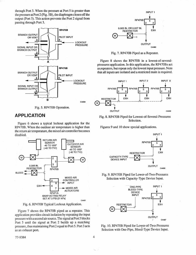
through Port 3. When the pressure at Port 5 is greater than tbepressureatPort2(Fig. SB),thediaphragmclosesoff the output (Port 3). This action prevents the Port 2 signal from passing through Port 3.
r -------r̂ l RP470B
BRANCH OUTPUT ORVENT PILOT INPUT
LOCKOUT PRESSURE
SIGNAL INPUTOR BRANCH OUTPUT I \ IJ I -4 A
RP470B
BRANCH OUTPUT OR VENT PILOT INPUT
LOCKOUT PRESSURE
SIGNAL INPUTOR BRANCH OUTPUT -
u281 B
Fig. 5. RP470B Operation.
APPLICATION
Figure 6 shows a typical lockout application for the RP470B. When the outdoor air temperature is higher than the return air tempmame, the mixed air controller becomes disabled.
~
SENSOR 4OTOIEOF (-40 TO 71C)
(4OTO71C)
INPUT 1 i;pH 0,005 IN. OR 0.007 IN.
RESTRICTOR
OUTPUT C 4 4 0
Fig. 7. RP470B Pi@ as a Repeater.
Figure 8 shows the RP470B in a lowest-of-several- ptessures application. In this application, the RP470Bs act assepeaters, but repeat only the lowest input pressure. Note that a l l inputs are isolated and a restricted main is required.
INPUT1 INPUT2 INPUT X
RP4706 & RP4706 RP4706
0.005 IN.
BLEED
MIXED AIR CONTROLLER
INPUT EXHI+ MIXED AIR ACTUATORS
RP471A SNAP-ACTING RELAY SET AT 3 PSI (21 kPa)
a491
Fig. 6. RP470B Typical Lockout Application.
Figure 7 shows the RP470B piped as a repeater. This application provides circuit isolation by repeating the input pressurewithasecondairsource.ThesignalatPort5 blocks Port 3 until the signal at Po% 2 builds up a matching pressure, thusmaintainingPort2equaltoPort5.Port3acts as an exhaust port.
77-9384 4
t OUTPUT
Fig. 8. RP470B Piped for Lowest-of-Several-Pressures Selection.
Figures 9 and 10 show special applications.
INPUTI
1
“““H RESTRICTOR 1 EXH
CAPACIPI-TYPE DEVICE INPUT
t OUTPUT
CYBB
Fig. 9. RP470B Piped for Lower-of-Two-Pressures Selection with Capacity-Type Device Input.
INPUT 1 .-
ONE-PIPE BLEED-TYPE
DEVICE INPUT
I RP470B RESTRICTOR * ExH
OUTPUT i U4W
Fig. 10. RP470B Piped for hwer-of-Two-Press- Selection with One-Pipe, ~ l&i -~ype Device Input.

RP471A SNAP-ACTING RELAY
R 1 S S
R P471 A
GENERAL
TheRP471A snap- Acting Relay is a spdt, positive-acting pneumatic switch thatprovidespositive switchingactionon modulating signal lines with an adjustable switching point. The switching differential is specified at 1.0 psi (7 kPa) but actuallyoperatesat 0.3 toO.4psi(2 to3kPa),nonadjustable.
The RP471A has a slight air bleed in its pilot chamber, approximately 0.002 scfm (1.0 ml/sec), which keeps the device from locking up when the pilot passage is blocked. This bleed is necessary for the operational design, because it prevents air from being trapped in the circuit. The switchingpressureismanuallyadjustablefor3 to 15psi (21 to 103 Wa) operation.
OPERATION
Theretum spring (Fig. 11A) has anequivalent pressureof less than 1 psi (7kF'a).Thepilot pressureatPort3 mustequal or exceed the switching pressure developed by the setpoint spring. At that point, the control chamber port opens. Pilot pressure enters the control chamber and pushes up the controlchamber diaphragm, opening Port 8 and closing Port 6. When thepilot pressuredropsbelow setpoint, the setpoint spring relaxes and closes the control chamber port. Air trapped in the control chamber bleeds to the atmosphere.
When the conwl chamber pressure is less than the pressure of the return spring, Port 6 connects to Port 7 and Port 8 closes (Fig. 11B). Port 3 is the pilot port.
APPLICATION
Figure 12 shows atypicalRP471Aapplication.When the outdoorair thermostatbranchline pressureis higberthan the RP471 setpoinrmainairpressureisappliedtothenormally open valve, closing it. When the branchline pressure drops,
the valve actuator is placed under control of the space thermostat through Port 6. The setscrew located between the 3 and 15 psi markings is a stop for the adjustment. However, if it is necessary to lock the setting, the setscrew may be used by turning it to contact the adjustment.
CHAMBER PORT
VFNT
6 NORMALLY CONNECTED t- COMMON
NORMALLY DISCONNECTED - PILOT
SPRING VENT 6
Fig. 11. RP471AOperation.
OUTDOOR AIR THERMOSTAT
OA SPACE
MIXING VALVE BOXES
PERIMETER HEAT -6
Fig. 12. RP471ATypical Application. -
77-9384 5

RP670A AND B SWITCHING RELAYS
RP670A RP670B
GENERAL
The RP670A and B Switching Relays are two-position relays. The RP670A has spdt switching action and the RP670B has dpdt switching action. TheFW67OAis all gray. In the RP670B, one spdt switch is gray while the second spdt switchisblack.Theswitchpointisfactory setanddoes not usually require adjustment. However, the switch point maybefieldreadjustedZto3psi(14 to21Wa)byusingthe screwdriver slot in the top of the relay body.
TheRP670isavailablewithswitchingrangesof 3 to7psi (20 to SOkPa), 13 to 17 psi(90 to 120Wa), 18 to22psi(124 to 152 Wa), and 20 to 25 psi (140 to 175 Wa).
Both models me used in pneumatic heating and cooling control systems whereavalveoradamperactuatormustbe switched from one circuit to another. Switchover pilot pressure must be two position, not modulated, because during the 2 psi (14 P a ) span that switching occurs, all three ports of the switch (6.7, and 8) are interconnected. If not considered, this situation can cause problems during a slow (modulating) switchova.
OPERATION
To prevent floating, a two-position signal to the pilot port (Fig. 13)isrequired.Thissignalmustcover4to6psi(28 to 41 Pa ) , 14 to 16psi(97to IlOkPa), or 19 to21 psi(l31 to 145Wa).When thepilotpressureexceeds the presetspnng pressure, Port 8 opens and connects to Port 7 and Port 6 closes (Fig. 13A). When the pilot pressure is less than the preset spring pressure, Port 8 closes and Port 6 opens and connects to Port 7 (Fig. 13B).
-- RP6MA
SPRING
COMMON
PILOT
A RP6MA
6 NORMALLY CONNECTED COMMON
PILOT
C1287
Fig. 13. RP670A Operation.
APPLICATION
Figure 14 shows a typical application for heating/cooling operation using an Rp670A (spdt). During the cooling cycle, the pilot pressure port 3) is below the minimum switchingpressureoftherelay.Ports6and7 areconnected. Port 8 is blocked, removing the low-limit controller from the system.
During the heating cycle, the pilot pressure is above the preset switching pressure. Ports 7 and 8 are connectedand the low limit controller resumes its override operation. Port 6 is blocked.
An RP670B (dpdt) can be piped in the same type of system as shown in Figure 14. It can also be piped to two systems which use the same pilot signal because Ports 6,7, and 8 are duplicated in the black section of the relay.
DISCHARGE LOW LIMIT
THERMOSTAT n NORMALLY DISCONNECTED
NORMALLY CONNECTED 13118psi
(9Ol125 kPa) RP670A
RESTRICTOR
I'
Fig. 14. RP670A Typical- Application.
77-9384 6
L
RP913A LOAD ANALYZER ImUTS
RP913A
GENERAL
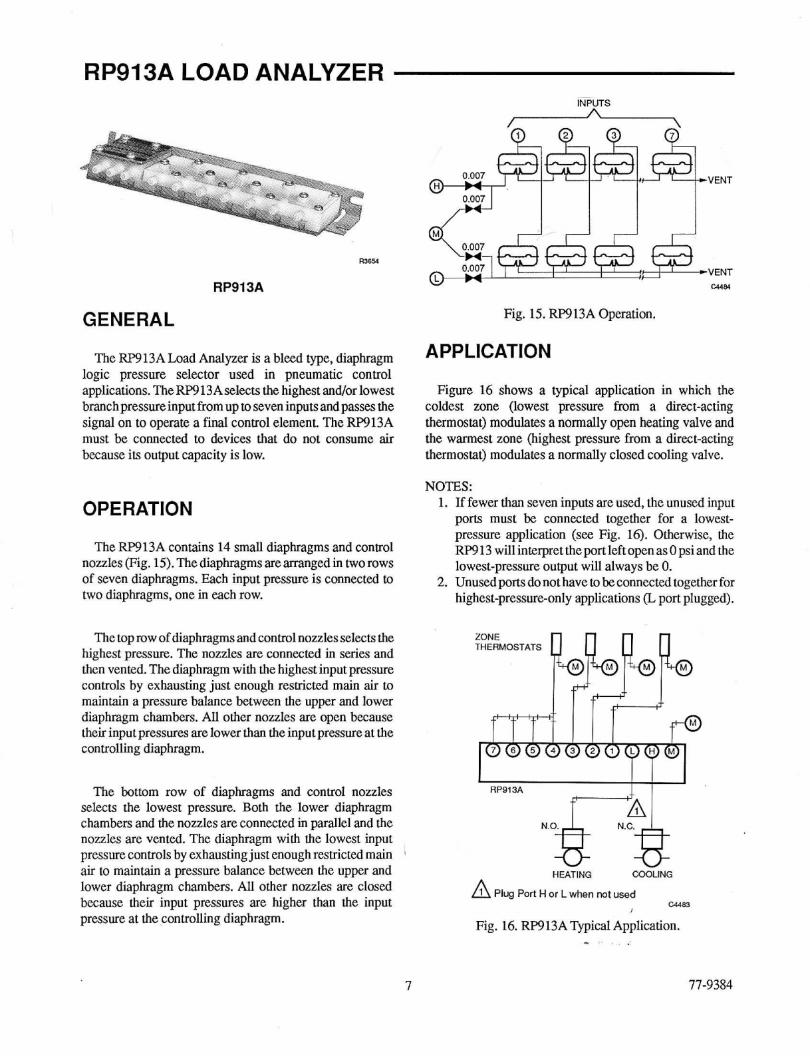
The RP9 13A Load Analyzer is a bleed type, diaphragm logic pressure selector used in pneumatic control applications. TheRF'913Aselect.s thehighest and/or lowest branch pressure input from up to seven inputs and passes the signal on to operate a final control element. The RP913A must be connected to devices that do not consume air because irs output capacity is low.
OPERATION
The RP913A contains 14 small diaphragms and control nozzles (Fig. 15). The diaphragms are arranged in two rows of seven diaphragms. Each input pressure is connected to two diaphragms, one in each row.
The top row of diaphragms and control nozzles selects the highest pressure. The nozzles are connected in series and then vented. The diaphragm with the highest input pressure controls by exhausting just enough resmcted main air to maintain a pressure balance between the upper and lower diaphragm chambers. All other nozzles are open because their input pressures are lower than the input pressure at the controlling diaphragm.
The bottom row of diaphragms and control nozzles selects the lowest pressure. Both the lower diaphragm chambers and the nozzles are connected in parallel and the nozzles are vented. The diaphragm with the lowest input pressure controls hy exhausting just enough restricted main ' air to maintain a pressure balance between the upper and lower diaphragm chambers. All other nozzles are closed because their input pressures are higher than the input pressure at the controlling diaphragm.
I I I I
Fig. 15. RP913A Operation.
APPLICATION
Figure 16 shows a typical application in which the coldest zone (lowest pressure from a direct-acting thermostat) modulates a normally open heating valve and the warmest zone (highest pressure from a direct-acting thermostat) modulates a normally closed cooling valve.
NOTES: 1. If fewer than seven inputs are used, the unused input
ports must be connected together for a lowest- pressure application (see Fig. 16). Otherwise, the RF913 willinterprettheportleftopeuasOpsiand the lowest-pressure output will always be 0.
2. Unusedportsdonothavetobeconnected togetherfor highest-pressure-only applications (L port plugged).
THERMOSTATS ZONE bb b b
RP913A
HEATING COOLING A Plug Port H or L when not used
Fig. 16. RF'913ATypical Application.
C44a83
-
I 11-9384
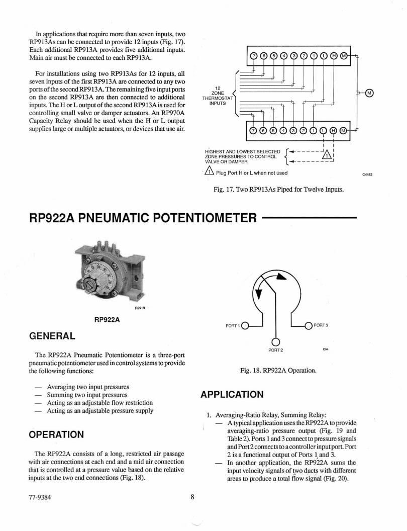
In applications that require more than seven inputs, two RF'913As can be connected to provide 12 inputs (Fig. 17). Each additional RP913A provides five additional inputs. Main air must be connected to each RF913A.
For installations using two RP913As for 12 inputs, all seven inputs of the fist RP913A are connected to any two portsofthesecondRP913A.Theremainingfiveinputports on the second RP913A are then connected to additional inputs.TheHorLoutputof thesecondRP913Aisusedfor contmlling small valve or d a m p actuators. An RP970A Capacity Relay should be used when the H or L output supplies large or multiple actuators, or devices that use air.
Z G E THERMOSTAT
INPUTS
I 1 HiGHEST AND LOWEST SELECTED
4 _ _ _ _ _ _ _ J ZONE PRESSURES TO CONTROL V~LVEOR DAMPER
'A Plug Port H or L when not c-2
Fig. 17. TwoRP913As Piped for Twelve Inputs.
RP922A PNEUMATIC POTENTIOMETER
R2419
RP922A
GENERAL
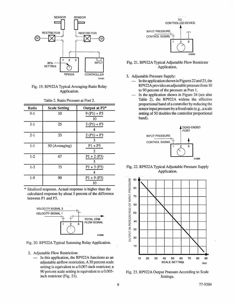
The RP922A Pneumatic Potentiometer is a threeport pneumatic potentiometer used in control systems to provide the following functions:
- Averaging two input pressures - Summing two input pressures - Acting as an adjustable flow restriction - Acting as an adjustable pressure supply
OPERATION
The RP922A consists of a long, reshicted air passage with air connections at each end and a mid air connection that is controlled at a pressure value based on the relative inputs at the two end connections (Fig. 18).
PORT2 e*
Fig. 18. RP922A Operation.
APP LlCATl ON
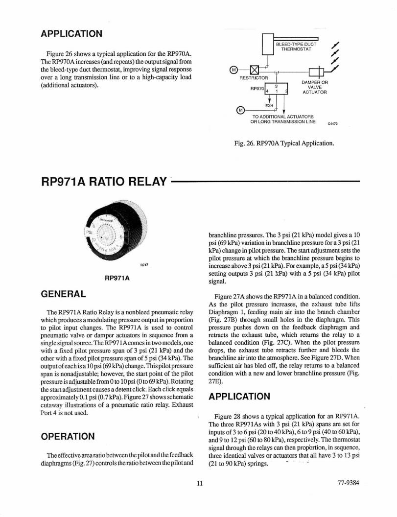
1. Averaging-Ratio Relay, Summing Relay: - A typicalapplicationuses theRP922A toprovide
averaging-ratio pressure output (Fig. 19 and Table 2). Ports 1 and 3 connect to pressure signals andPort2connects to acontroller inputport. Port 2 is a functional output of Ports 1,and 3.
- In another application, the RP922A sums the input velocity signals of P o ducts with different areas to produce a total flow Sigrid (Fig. 20).
71-9384
SENSOR SENSOR
3-1 25
SEnING mo%bT r"l RF922A CONTROLLER
3(Pl)+P3
c148i
Fig. 19. RP922A Qpical Averaging-Ratio Relay Application.
Table 2. Ratio Pressure at Port 2.
2- 1
1-1
1-2
1-3
Ratio I Scale Setting I Output at PZ* 9-1 I 10 I 9(Pl)+P3
33 2(Pl)+P3 3
2
3
4
50 (Averaging) Pl+P3
67 P1+ 2 (P3)
75 P1+ 3 (P3)
. . I I in
1-9 90 PI + 9 (P3) in
I I A
~~~
* Idealized response. Actual response is higher than the calculated response by about 5 percent of the difference between P1 and P3.
~
VELOCllY SIGNAL 2
VELOCITY SIGNAL 1
TOTAL CFM FLOW SIGNAL 73%- cu88
Fig. 20. RP922A Typical Summing Relay Application.
2. Adjustable Flow Restriction: - In this application, the RP922A functions as an
adjustable M o w restriction. A 30 percent scale setting is equivalent to a 0.007-inch restrictor; a 90 percent scale setting is equivalent to a 0.005- inch restrictor (Fig. 21).
TO CONTROLLED DEVICE
INPUT PRESSURE
El W292
Fig. 21. RP922AQpical Adjustable Flow Restrictor Application.
3. Adjustable Pressure Supply: - In theapplication shown inFignres 22 and 23, the
RP922Aprovides an adjustable pressure from 10 to 90 percent of the pressure at Port 1.
- In the application shown in Figure 24 (see also Table 2). the RP922A widens the effective proportional band of a controller by reducing the sensor input pressureby afixed ratio (e.g., a scale setting of 50 doubles the conaoller proportional band).
INPUT PRESSURE
CONTROL SIGNAL
c42m
Fig. 22. RP922A Mica l Adjustable Pressure Supply Application.
10 20 30 40 50 60 70 80 90
SCALE SETTIN? Csli
Fig. 23. RF'922.A Output Prsssure According to Scale Settings.
9 77-9384

RESTRKXOR
%-@ RP970A
CAPACITY REIAY
TO CONTROLLER
4 (BLOCKED PORT) f"t INPUT
RW22A POTENTIOMETER
Fig. 24. Rp922A Typical Adjustable Sensor Input Span Application.
RP970A CAPACITY RELAY
RP970A
GENERAL
TheRF'970A Capacity Relay is a direct-acting relay used to isolate an input, repeat a pressure, and increase the capacity of an input signal.
OPERATION
When thepilotpressureincreases,theexhausttuberaises the diaphragm off the branch chamber port and main air flows into the branch line, pushing against Diaphragm 2 (Fig. 25A). This pressure forces the exhaust tube down and closes the branch chamber port Branchline pressure now equalspilotpressure (Fig. 25B).As the pilot pressure drops, the branchline pressure against Diaphragm 2 forces the exhaust tube down, which opens the exhaust port (Fig. 25C). This function allows the branch air to bleed out through the exhaust Port 4. When the branchlme pressure equals the pilot pressure, the exhaust tube rises and the exhaust chamber port closes (Fig. 25D).
DIAPHRAGM 2
A
MAIN
PILOT
MAIN
PILOT
C
MAIN
PILOT % BRANCH
EXHAUST
- u a 5
Fig. 25. RF'970A Operation.
77-9384 10
APPLICATION
Figure 26 shows a typical application for the RF'970A. TheRP97OAincreases (andrepeats) theoutput signal from the bleed-type duct thermostat, improving signal response over a long transmission line or to a high-capacity load (additional actuators).
BLEED-TYPE DUCT THERMOSTAT
RESTRICTOR DAMPER OR
ACTUATOR RP970 VALVE
TO ADDITIONAL ACTUATORS OR LONG TPANSMISSION LINE ~~
Fig. 26. RP970ATypical Application.
RP971A RATIO RELAY.
K7Il
RP971A
GENERAL
The RF971A Ratio Relay is a nonbleed pneumatic relay which produces amodulatingpressure outputin proportion to pilot input changes. The RP971A is used to control pneumatic valve or damper actuators in sequence from a singlesignal source.TheRP97lAcomesintwomodels,one with a fixed pilot pressure span of 3 psi (21 P a ) and the other with a fixed pilot pressure span of 5 psi (34 Wa). The outputofeachis a 10 psi (69Wa) change.Thispi1otpressure span is nonadjustable; however, the start point of the pilot pressureisadjustablefromoto lopsi (0 to69kPa).Rotating the start adjustment causes a detent click. Each click equals approximatelyO.1 psi(0,7Wa).Figure27 shows schematic cutaway illustrations of a pneumatic ratio relay. Exhaust Port 4 is not used.
OPERATION
The effective arearatiobetween the pilot and the feedback diaphragms (Fig. 27) controls theratiobetween thepilot and
branchline pressures. The 3 psi (21 Wa) model gives a 10 psi (69 Wa) variation in branchline pressure for a 3 psi (21 P a ) change in pilot pressure. The start adjustment sets the pilot pressure at which the branchline pressure begins to increaseabove3psi(21 Wa).Forexample,a5psi(34kPa) setting outputs 3 psi (21 !*a) with a 5 psi (34 kPa) pilot signal.
Figure 27A shows the RP971A in a balanced condition. As the pilot pressure increases, the exhaust tube lifts Diaphragm 1, feeding main air into the branch chamber (Fig. 27B) through small holes in the diaphragm. This pressure pushes down on the feedback diaphragm and retracts the exhaust tube, which returns the relay to a balanced condition (Fig. 27C). When the pilot pressure drops, the exhaust tube retracts further and bleeds the branchline air into the atmosphere. See Figure 27D. When sufficient air has bled off, the relay returns to a balanced condition with a new and lower branchline pressure (Fig. 27E).
APPLICATION
Figure 28 shows a typical application for an RP971A. The three RP971As with 3 psi (21 Wa) spans are set for inputs of 3 to 6 psi (20 to 40 kPa), 6 to 9 psi (40 to 60 Pa) , and 9 to 12 psi (60 to 80 Wa), respectively. The thermostat signal through the relays can then prOportion, in sequence, three identical valves or actuators that all have 3 to 13 psi (21 to 90 Wa) springs. "
11 71-9384

A. BALANCED CONDITION 8 . PILOT CALLING FOR INCREASED OUTPUT
MA1
BRANCH
3 RP971A ...
BRANCH
C. BALANCE CONDITION D. REDUCED PILOT EXHAUSTING BRANCH E. BALANCE0 CONDITION us02
Fig. 27. FS'971A Operation. ~~ ~-
ROOM THERMOSTAT
3-6 PSI 6-9 PSI 9-12 PSI (20-40 we) (4C-60 kPa) (rn-80 wa)
c ALL DAMPER ACTUATOR
SPRINGS 313 PSI (20-90 kPa)
/ / / /
/ #
Fig. 28. W71ATypicaJ Application.
RP972A REVERSING RELAY
.. R151
RP972A
77-9384
GENERAL
The Rp972A Reversing Relay has three distinct, detented, field-adjustable reversing settings: 13 psi (90 kPa) minus pilot, 16 psi (110 P a ) minus pilot, and 18 psi (124kPa) minus pilot. It comes factory set at 16 minus pilot togiveanexactreversalfor3 to 13psi(21 to9OkPa)inputs. The 13 minus pilot setting gives a 0 psi (0 Ha) output on a 13 psi (90 kPa) main. The 18 minus pilot setting gives a 3 to lSpsi(21to 103kPa)exactreversalwhichisacommonly used range for international applications.
12
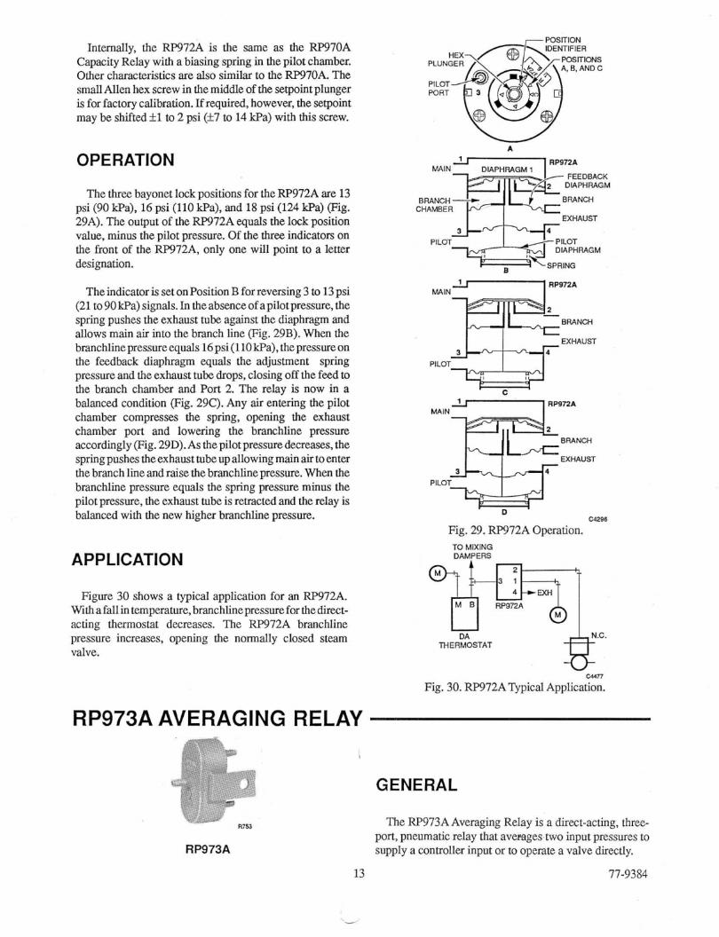
Internally, the RP972A is the same as the RP970A Capacity Relay with a biasing spring in the pilot chamber. Other characte&ics are also similar to the RF'970A. The small Allen hex screw in the middle of the setpointplunger is for factory calibration. If required, however, the setpoint may be shifted *1 to 2 psi (rt7 to 14 kPa) with this screw.
OPERATION
The three bayonet lock positions for the RP972A are 13 psi (90 P a ) , 16 psi (110 kPa), and 18 psi (124 !@a) (Pig. 29A). The output of the RP972A equals the lock position value, minus the pilot pressure. Of the three indicators on the front of the RP972A, only one will point to a letter designation.
TheindicatorissetonPositionB forreversing3 to 13psi (21 to 90 kPa) signals. In the absence of a pilot pressure, the spring pushes the exhaust tube against the diaphragm and allows main air into the branch line (Fig. 29B). When the branchlinepressureequals 16psi(llOkPa),thepressureon the feedback diaphragm equals the adjustment spring pressure and the exhaust tube drops, closing off the feed to the branch chamber and Port 2. The relay is now in a balanced condition (Fig. 29C). Any ah entering the pilot chamber compresses the spring, opening the exhaust chamber port and lowering the branchline pressure accordingly (Fig. 29D). As the pilot pressure decreases, the spring pushes theexhaust tubeup allowing main air toenter the branch line and raise the branchline pressure. When the branchline pressure equals the spring pressure minus the pilot pressure, the exhaust tube is retracted and the relay is balanced with the new higher branchlie pressure.
APPLICATION
Figure 30 shows a typical application for an RP972A. With afallin temperature, branchline pressure forthedirect- acting thermostat decreases. The RP972A branchline pressure increases, opening the normally closed steam valve.
MAIN- DIAf
-
-BRANCH
EXHAUST
-\SPRING
D C4296
Fig. 29. RP972.4 Operation. TO MIXING DAMPERS
OA THERMOSTAT
w n Fig. 30. RF'972A Typical Application.
RP973A AVERAGING RELAY
RP973A
13
.d
GENERAL
The RP973AAveraging Relay is a direct-acting, three- port, pneumatic relay that averages two input pressures to supply a controller input or to operate a valve directly.
77-9384

OPERATION APPLICATION
The RP973A consisrs of two 0.005-inch matched reslrictors in a single housing (Fig. 31). The two signals to be averaged are each fed through a restrictor to a common chamber (Fig. 31A). This construction ensures that the pressure at the output can never be more than the average of the two input pressures, as often occurs in valve-unit type averaging relays. The higher pressure flows through the restrictor and out the other input.
The output pressure is the average of the two input pressures within f20 percent or f.7 psi of the difference between the high and the low and always falls approximately half-way between the two input pressures. The closer the input pressures are in psi, the more accurate the RF'973A becomes. For example, if the inputs are 3 and 13 psi (21 and 90 P a ) , the output will be 8 52 psi (55 k14 kPa) (Fig. 31B). If the inputs are closer, however, at 12 and 13 psi (83 and 90 Wa), the output is closer to the average, at 12.5 f.7 psi (86 f5 kPa).
_ -
INPUT I
INPUT2
RESTRICTOR A
INPUT 1 3 PSI
INPUT2 - 13 PSI
OUTPUl 8 PSI
c42ss B
Fig. 31. RF'973A Operation.
RP975A HESITATION
RP975A
77-9384
The RF'973A can be used to average two Lp914 Temperature Sensor lines (Fig. 32). The output will be withimf15percentofthemathematicalaverageoftheinput signals. The closer the signals, the more accurate the FW973A becomes.
Because input signal air flows from higher to lower, do not usethisdeviceonbleed-typethermostatlinesotherthan the Lp914 or Lp915. If bleed-type devices (including another RF'973A) are to be averaged, use an isolating (rkpeatine) circuit (Fig. 33).
Fig. 32. W 7 3 A Typical Averaging Cicuit.
RESTRICTOR
RP470B LOCKOUT RELAY PIPED AS A REPEATER RP973A
t TO CONTROLLER A RP470B relay allows the use of an averaging relay on
smallnozzle bleed devices. CAI75
Fig. 33. RP973A in an Isolating Circuit.
RELAY GENERAL
' The RP975A Hesitation Relay can be combined with the MP909 actuator to eliminate the MF'516 actuator in unit ventilatorapplications. Itisalsoa bleeddevicesimilar tothe SP970ManuaVMinimumPositionSwitch.Fia3ure34shows RP975Aoutput accordingtoitsknobsettings.TheRP975A scaleplateismarkedfromOto 1OOandthekuobrotates 188 degrees, limitedby breakaway stops,representinganoutput
14

pressure range of 7 to 12 psi (48 to 83 Pa) . The relay goes to minimum whenever the pilot pressure is greater than 2.5 psi (17.2 kPa) and less than the minimum setting. If the stops are broken away, the knob rotation is 300 degrees, representing an output pressure range of 5 to 13 psi (34 to 90 kPal
0 2 6 8 10 12 14 16 18 (15) (A) (40) (55) (70) (85) (95) (110)(125)
INPUT IN PSI (kPa) PILOT FROM THERMOSTAT cuol
Fig. 34. RF975A Output Pressure According to Knob Setting.
OPERATION
The main airflows through a 0.007-inch restriction inPort 1 into the two branch chambers (Fig. 35A). When the pilot pressure force is less than the spring force, the air entering the lower branch chamber flows out of the exhaust port. When the pilot pressure exceeds approximately 1.5 psi (10 kPa),internalPortAbetween thelowerbranch chamberand the exhaust chamber closes and Port B in the pilot chamber opens at one end only (Fig. 35B). The branchline pressure then begins to increase up to the spring setting.
Atthepressuredictatedbytheknobsetting(7 to 12psi [48 to 83 kPa]), the branchlime pressure in the upper branch chamber overcomes the spring and opens Port C (Fig. 35C). Excess air from the branch lime flows out the pilot port because the pilot pressure is less than the branchline , pressure. (Note the similarity to the SP970A and B with exhaust air flowing out the pilot line. Arestricted pilot lime cannot be used.) If the pilot pressure increases above the knob setting, pilot air flows into the branch chamber until the branchlime pressure equals the pilot line pressure. Then the excess bleed air again exhausts through the pilot (Fig. 35D).
PILOT
BRANCH MA A
RP975A
--SPRING
-0.007 IN. , RESTRICTOR
RP975A
RP975A
F - I 712, BRANCH MAIN
C
RP975A
BRANCH MAIN
v l a 7 D
Fig. 35. RF975A Operation.
APPLICATION
Figure 36 shows a typical hookup f y the W975A and a pneumatic damper actuator. When the thermostat branchline pressure exceeds i .5 psi (10 Wa), the damper actuator goes to a preset minimum position determined by
15 77-9384
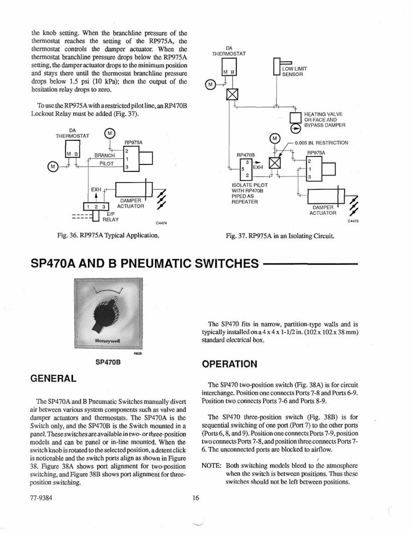
the knob setting. When the branchline pressure of the thermostat reaches the setting of the RP975A, the thermostat conaols the damper actuator. When the thermostat branchline pressure drops below the RP975A sening, the damper actuator drops to the minimum position and stays there until the thermostat branchline pressure drops below 1.5 psi (10 Wa); then the output of the hesitation relay drops to zero.
To use the RP975Awith arestrictedpilotline, an W470B Lockout Relay must be added (Fig. 37).
THERMOSTAT RP975A
PILOT
Fig.
_-__ &ti?? DAMPER
c4474 RELAY ----
36. RP975A Typical Application.
DA THERMOSTAl
SENSOR
HEATING VALVE OR FACE AN0 BYPASS DAMPER
9 0.005 IN. RESTRICTION
RW75A RP470B
WITH RP470B PIPED AS REPEATER
ACTUATOR cur3
Fig. 37. W975A in an Isolating Circuit.
SP470A AND B PNEUMATIC SWITCHES
I I i . > n m ... . . I . .. .. . - . . .. .. . .. . . - .. . .- .. . -.
9828
SP47OB
GENERAL
The SP470A and B Pneumatic Switches manually divert air between various system components such as valve and damper actuators and thermostats. The SP470A is the Switch only, and the SP47OB is the Switch mounted in a panel. Theseswitchesareavailablein two-or three-position models and can be panel or in-line mounted. When the switchknobisrotatedtotheselectedposition,adetentclick is noticeable and the switch ports align as shown in Figure 38. Figure 38A shows port alignment for two-position switching, and Figure 38B shows port alignment for three- position switching.
77-9384
The SP470 fits in narrow, partition-type walls and is typically installedona4x4 x 1-1/2in. (102x 102x 38 mm) standard electrical box.
OPERATION
The SP470 two-position switch (Fig. 38A) is for circuit interchange. Position one connects Ports 7-8 and Ports 6-9. Position two connects Ports 7-6 and Ports 8-9.
The SP470 three-position switch (Fig. 38B) is for sequential switching of one poIt (Port 7) to the other ports (Por!s6,8, and 9).PositiononeconnectsPorts 7-9,position twoconnectsPorts7-8,andpositionthreeconnectsPorts7- 6. The unconnected ports are blocked to airflow.
NOTE: Both switching models bleed to the atmosphere when the switch is between positi,ons. Thus these switches should not be left between positions.
16
L

sp47oA.B TWO-POSITION
APPLICATION
Figure 39 shows a typical application for sequential switching. In Position 1, the actuator exhausts through Port 9andthevalveopens.InPositiou2,theswitchconnectsthe
POSITION 2 actuator to the direct-acting controller and the valve is inthe automatic mode. In Position 3, the switch connects the
POSITION 1 A
SP470A.B THREE-POSITION
POSITION 1 POSITION 2 fi- rn POSITION 3
C1887-1 B
Fig. 38. SP470A. B Operation.
actuator to main air and the valve closes.
SP470
EXH
NOTES:
Position 1, valve open: Ports 7 and 9 connected,
Position 2, valve auto: Ports 7 and 8 connected,
Position 3, valve closed Ports 7 and 6 connected,
Fig. 39. SP47OA, B ?Lpical Three-Position Application.
Ports 6 and 8 blocked
Ports 6 and 9 blocked
Ports 8 and 9 blocked c4290
SP970A-D MANUAL/MINIMUM POSITION SWITCHES
NOTE: The device feeding the pilot must be able to exhaust the aimow from the 0.007-inch restricted main. A highcapacity device such as the -20 Controller works well.
The SF'970C must be used with a low-capacity, bleed- type device as an input because the SP97OC has an isolated pilot. This makes the SP'37OC a true bleed-type device. The pilot of the Sp970A or B may be used as the restricted main to any 0.007-inch bleed-type thermostat. R I S E
SP970A SP97OC
GENERAL
The SP970A-D Manual/Minimum Position Switches are 0.007-inch bleed-type switches whose capacity is not directly affected. The 0.007-inch restriction in the SP970 supplies minimum-position air. The pilot feeds the branch. The capacity of the SP970, above minimum position, is a function of the capacity of the device feeding the pilot. Pressure builds to the minimum pressure slowly during start-up, but once there the pilot feeds and bleeds from that point.
OPERATION
SP970A AND B THREE-PORT SWITCHES
The SP970A and B three-port switches are used to regulatethebranchlinepressureatapresetlimit (Eg.4OA). Main air flows through the restriction in Port 1 into the branchchamber. In themanualpositioningmode, when the Port2 chamber output pressure rises above theknob setting, the exhaust nozzle opens and excess air is exhausted through Port 4, maintaining The desired pressure in the branch line (Fig. 40B).
17 77-9384

BRANCH
PILOT MAIN A. BRANCH AT OR BELOW MINIMUM SEITNG
BRANCH
PILOT MAIN
B. BRANCH ABOVE MINIMUM SRTING c4288
Fig. 40. SF970A and B Operation.
SP97OC AND D FOUR-PORT SWITCHES
PILOT CHAMBER
PILOT
BRANCH
VENT MAIN
A. BUILDING TO MINIMUM SEmNG
SP970C.D
PILOT
BRANCH
1 VENT MAIN
B. BALANCEOATMINIMUM SRTING
~
SP970C.D The SP97OC and D four-pa switches have two additional diaphragms that isolate the pilot chamber so it is dead-ended (Fig. 41A). The disc shown in Figure 41 is a
spacing. free-floating coupling between the diaphragms to maintain PILOT
BRANCH
If the pilot pressure (Port 3) is less than the spring pressure, the SF970C or D functions as a regulator with the 1
VENT MAIN discincontactwith bothdiaphragms(Fig.41B). Thespring pressure holds the exhaust closed until the branchline C. PILOT BUILDING BRANCH ABOVE
MINIMUM SEiTING pressure at Port 2 rises to the spring setting. It then begins venting throughPort4. When the pilotpressure exceeds the spring pressure., the spring is isolated and the pilot pressure controls the exhaust port (Fig. 41C and 41D).
APPLICATION
Figure 42A shows a typical manual position application using the three-port SP970A or B. This control system manually positions a damper between open and closed. Turning the setpoint position knob clockwise increases the branchline pressure to the damper actuator and opens the damper. Turning the setpoint position knob counterclockwise decreases the branchline pressure and closes the damper.
I
~
SP97OC.D
PILOT
BRANCH
1 VENT MAIN
D. BALANCED AGAINST PILOT C4300
Fig. 41. SP97oC and D Operation.
77-9384 18
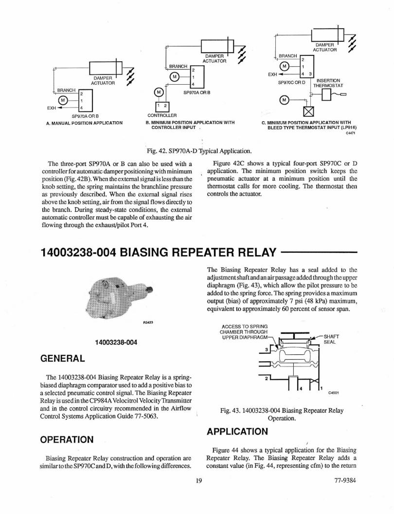
DAMPER
EXH INSERTDN f ACTUATOR
EXH ~
SPSmA OR B A. MANUAL POSITION APPLICATION
fii& BRANCH 4
M SPQmAORB
1 2
CONTROLLER B. MINIMUM POSmON APPLICATION WITH C. MINIMUM POSITION APPLICATION WITH
CONTROLLER INPUT , BLEED N P E THERMOSTAT INPUT (LP916) CM71
Fig. 42. SP97OA-D Wical Application.
The three-port SP970A or B can also he used with a controller for automatic damperpositioning with minimum position ~ig.42B).Whentheexte~lsignalislessthanthe knob setting, the spring maintains the hranchline pressure as previously described. When the external signal rises above the knob setting, air from the signal flows directly to the branch. During steady-state conditions, the external automatic controller must be capable of exhausting the air flowing through the exhaust/pilot Port 4.
Figure 42C shows a typical four-port SP970C or D application. The minimum position switch keeps the pneumatic actuator at a minimum position until the thermostat calls for more cooling. The thermostat then controls the actuator.
,
14003238-004 BIASING REPEATER RELAY
R Y 2 1
14003238-004
GENERAL
The 14003238-004 Biasing Repeater Relay is a spring- biased diaphragm comparator used to add a positive bias to a selected pneumatic control signal. The Biasing R e p t e r Relay is usedin the CP984AVelocitrol Velocity Transmitter
The Biasing Repeater Relay has a seal added to the adjustmentshaft andanairpassageaddedthrough theupper diaphragm (Fig. 43). which allow the pilot pressure to he added to the spring force. The spring provides a maximum output (bias) of approximately 7 psi (48 Wa) maximum, equivalent to approximately 60 percent of sensor span.
ACCESS TO SPRING CHAMBER THROUGH
UPPER DIAPHRAGM
and in the control circuiny recommended in the Airflow Control Systems Application Guide 77-5063.
Fig. 43.14003238-004 Biasing Repeater Relay Operation.
APPLICATION OPERATION i
Figure 44 shows a typical application for the Biasing Repeater Relay. The Biasing Repeater Relay adds a constant value (in Fig. 44, representing cfm) to the return
19 77-9384
Biasing Repeater Relay consauction and operation are similar totheSF97OC andD, with thefollowingdifferences.
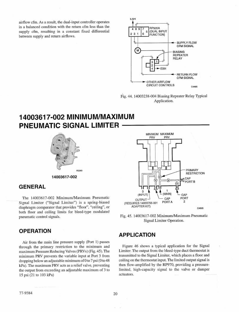
airflow cfm. As a result, the dual-input controller operates
in between supply a balanced cfm, supply resulting condition and return in with airflows. a the constant return fixed cfm less differential than the Fz&;? 5 (DUALINPUT
RETURN FLOW CFM SIGNAL
c4485
EXH
OTHER AIRFLOW CIRCUIT CONTROLS
Fig, 44. 14003238-004 Biasing Repeater Relay Typical Application.
1400361 7-002 MINIMUM/MAXIMUM PNEUMATIC SIGNAL LIMITER
MINIMUM MAXIMUM
14003617-002
GENERAL
2 The 14003617-002 Minimumhlaximum Pneumatic
Signal Limiter (“Signal Limiter”) is a spring-biased diaphragm comparator that provides “floor”, “ceiling”, or both floor and ceiling limits for bleed-type modulated pneumatic control signals.
(REQUIRES 14003755-001 ADAPTER KIT)
a505
Fig. 45. 14003617-002 MinimumlMaximnm Pneumatic Signal Limiter Operation.
APPLICATION OPERATION
Air from the main line pressure supply (Port 1) passes through the primary restriction to the minimum and Figure 46 shows a typical application for the Signal maximum PressureReducing Valves (PRVs) (Fig. 45). The Limiter. The output from the bleed-type duct thermostat is minimum PRV prevents the variable input at Port 3 from transmitted to the Signal Limiter, which places a floor and droppingbelowanadjustableminimumofOto7psi(Oto48 ceiling onthethemostatinput.Thelimitedoutputsignalis Wa). The maximum PRV acts as a relief valve, preventing then flow-amplified by the -970, providing a pressure- the output from exceeding an adjustable maximum of 3 to limited, high-capacity signal to the vabe or damper 15 psi (21 to 103 Wa) actuators.
77-9384 20

BLEED-PIPE DUCT THERMOSTAT
RESTRICTOR
MINIMUMMAXIMUM SIGNAL LIMITER
RP970A
DAMPER ACTUATOR
EXH +..+
4=b ACTUATOR / C W 4
Fig. 46.14003617-002 Minimum/Maximum n e m a t i c Signal Limiter Typical Application.
21
_A
11-9384

PNEUMATIC RELAYS AND SWITCHES
Honeywell J
Home and Building Control Honeywell Inc. Honeywell Limited-Honeywell Limit& Honeywell Plaza 740 Ellesmere Road P.O. Box 524 Scarborough, Ontario Minneapolis, MN 55408-0524 M1P 2V9
Home and Building Control Helping You Control Your World
77-9384 Rev. 10-94


