
Application Note
5G NEW RADIO OVER-THE-AIR BASE STATION TRANSMITTER TESTS
Radiated conformance testing according to TS 38.141-2, Rel. 16
Products: ► R&S®TS8991 with WPTC
► R&S®ATS1800C
► R&S®PWC200
► R&S®FSW
► R&S®FSV(A)3000
► R&S®FSV(A)
► R&S®SMW200A
► R&S®SMBV100B
Christian Wicke, Fabian Bette | GFM324 | Version 1e | 06.2020
https://www.rohde-schwarz.com/appnote/GFM324

Rohde & Schwarz | Application Note 5G New Radio Over-The-Air Base Station Transmitter Tests 2
Contents
1 Introduction ................................................................................................... 4
2 General Test Conditions .............................................................................. 6
2.1 Safety indication ..................................................................................................6
2.2 Base station classes and configurations .............................................................6
2.2.1 Base station reference points ..............................................................................6
2.2.2 BS type 1-O and 2-O (FR1, FR2, radiated) .........................................................6
2.2.3 BS type 1-H (FR1, hybrid) ...................................................................................6
2.2.4 BS classes (TS 38.104, chapter 4.4) ...................................................................7
2.3 5G NR frequency ranges .....................................................................................8
2.4 R&S devices and options ....................................................................................8
2.5 Reference coordinate system ..............................................................................9
3 Basics about OTA testing .......................................................................... 10
3.1 OTA Calibration ................................................................................................. 10
3.2 Effective isotropic radiated power (EIRP) .......................................................... 10
3.3 Total radiated power (TRP) ............................................................................... 11
3.3.1 Theoretical background ..................................................................................... 11
3.3.2 TRP measurement grids ................................................................................... 12
3.3.3 TRP measurement procedures ......................................................................... 14
4 OTA antenna test solutions from R&S ...................................................... 15
4.1 WPTC indoor anechoic chambers (as part of R&S TS8991) ............................. 16
4.2 R&S ATS1800C (CATR) ................................................................................... 17
4.2.1 CATR principles in general ................................................................................ 18
4.3 R&S PWC200 Plane Wave Converter (PWC) ................................................... 19
5 Transmitter Tests (Chapter 6) .................................................................... 20
5.1 Requirements classification ............................................................................... 21
5.2 Complete Tx test setup overview ...................................................................... 23
5.3 Radiated transmit power (6.2) ........................................................................... 24
5.4 OTA base station output power (6.3)................................................................. 25
5.5 OTA output power dynamics (6.4) ..................................................................... 27
5.5.1 OTA RE power control dynamic range (6.4.2) ................................................... 27
5.5.2 OTA total power dynamic range (6.4.3) ............................................................. 27
5.6 OTA transmit ON/OFF power (6.5).................................................................... 30
5.6.1 OTA transmitter OFF power (EIRP in beam peak) (6.5.1) ................................. 30
5.6.2 OTA transmitter transient period (6.5.2) ............................................................ 30
5.7 OTA transmitted signal quality (6.6) .................................................................. 33
5.7.1 OTA frequency error (6.6.2) .............................................................................. 33

Rohde & Schwarz | Application Note 5G New Radio Over-The-Air Base Station Transmitter Tests 3
5.7.2 OTA modulation quality (6.6.3) .......................................................................... 33
5.7.3 OTA time alignment error (6.6.4) ....................................................................... 35
5.8 OTA unwanted emissions (6.7) ......................................................................... 37
5.8.1 OTA occupied bandwidth (6.7.2) ....................................................................... 37
5.8.2 OTA Adjacent Channel Leakage Power Ratio (ACLR) (6.7.3) .......................... 39
5.8.3 OTA operating band unwanted emissions (6.7.4) ............................................. 44
5.8.4 OTA transmitter spurious emissions (6.7.5) ...................................................... 45
5.9 OTA transmitter intermodulation (6.8) ............................................................... 52
6 Literature ..................................................................................................... 55
7 Ordering Information .................................................................................. 56
8 Appendix ..................................................................................................... 57
A Glossary ............................................................................................................ 57

Rohde & Schwarz | Application Note 5G New Radio Over-The-Air Base Station Transmitter Tests 4
1 Introduction
The 5th generation (5G) of mobile networks introduces a paradigm shift towards a user and application
centric technology framework.
The goal of 5G New Radio (NR) is to flexibly support three main service families:
Figure 1: 5G New Radio main service families
► Enhanced mobile broadband (eMBB) for higher end-user data rates
► Massive machine type communications (mMTC) targets cost-efficient and robust D2X connections
► Ultra-reliable, low latency communications (URLLC) supporting new requirements from vertical
industries such as autonomous driving, remote surgery or cloud robotics
3GPP, the responsible standardization body, defines the Radio Frequency (RF) conformance test methods
and requirements for NR Base Stations (BS) in the technical specifications TS 38.141 which covers
transmitter (Tx), receiver (Rx) and performance (Px) testing.
The technical specification TS 38.141 consists of two parts depending on whether the test methodology has
conducted or radiated requirements:
► TS 38.141-1: Part 1 [1]: Conducted conformance testing
► TS 38.141-2: Part 2 [2]: Radiated conformance testing

Rohde & Schwarz | Application Note 5G New Radio Over-The-Air Base Station Transmitter Tests 5
This application note describes all mandatory RF transmitter tests (TS 38.141-2, chapter 6), according to
Release 16 (V16.3.0). Furthermore, chapter 4 of this document provides a brief introduction about the
different R&S OTA antenna test solutions and how they're applicable for base station conformance testing.
Rohde & Schwarz offers suitable solutions for any test case that is mentioned in this application note.
Generally, each chapter is structured in three sections:
First, a short introduction at the beginning of a chapter is covering the scope of the individual test case. Next,
there comes a step-by-step description of the testing procedure showing the necessary testing parameters
and a schematic test setup.
Hereinafter, Table 1 gives an overview of all 5G base station transmitter tests covered individually in this
document.
Table 1: OTA transmitter tests
Chapter TS 38.141-2
Test Single Carrier (SC)
Multi Carrier (MC)
6.2 Radiated transmit power ✓
6.3 OTA base station output power ✓
6.4.2 OTA RE power control dynamic range ✓
6.4.3 OTA total power dynamic range ✓
6.5.1 OTA transmitter OFF power ✓
6.5.2 OTA transmitter transient period ✓
6.6.2 OTA frequency error ✓
6.6.3 OTA modulation quality ✓
6.6.4 OTA time alignment error ✓
6.7.2 OTA occupied bandwidth ✓
6.7.3 OTA Adjacent channel leakage power ratio (ACLR) ✓
6.7.4 OTA operating band unwanted emissions ✓
6.7.5.2 General OTA transmitter spurious emissions ✓
6.7.5.3 OTA transmitter spurious emissions - Protection of the base station receiver of own or different base station
✓
6.7.5.4 OTA transmitter spurious emissions - Additional spurious emissions requirements
✓
6.7.5.5 OTA transmitter spurious emissions - Co-location requirements
✓
6.8 OTA transmitter intermodulation ✓
Note: this document covers single carrier (SC) tests only.
Base station (RF) receiver tests (TS 38.141-2, chapter 7) are described in GFM325
For further reading
Find a more detailed overview of the technology behind 5G New Radio from this Rohde & Schwarz book [3]
and www.rohde-schwarz.com/5G.

Rohde & Schwarz | Application Note 5G New Radio Over-The-Air Base Station Transmitter Tests 6
2 General Test Conditions
2.1 Safety indication
VERY HIGH OUTPUT POW ERS CAN OCCUR ON BASE STATIONS.
MAKE SURE TO USE SUITABLE ATTENUATORS IN ORDER TO PREVENT
DAM AGE TO THE TEST EQUIPMENT.
2.2 Base station classes and configurations
The minimum RF characteristics and performance requirements for 5G NR in-band base stations are
generally described in 3GPP document TS 38.104 [4].
2.2.1 Base station reference points
This application note covers radiated measurements only. In [1] and [4] two different base station types are
defined for frequency range one (FR1) and two (FR2). Radiated requirements are also referred to as OTA
requirements.
2.2.2 BS type 1-O and 2-O (FR1, FR2, radiated)
For base station type 1-O and 2-O the radiated characteristics are defined over the air where the OTA
interface is referred to as Radiated Interface Boundary (RIB). Co-location requirements are specified at the
conducted interface of the co-location reference antenna.
Figure 2: Radiated reference points for BS type 1-O and BS type 2-O [2]
2.2.3 BS type 1-H (FR1, hybrid)
This base station type has two reference points fulfilling both radiated and conducted requirements.
Conducted characteristics are defined at the transceiver array boundary (TAB) which is the conducted
interface between the transceiver unit array and the composite antenna equipped with connectors for
conducted measurements. The specific requirements and test cases are defined in TS 38.141-1 [1].
Radiated interface boundary
Radio Distribution
NetworkRDN
Antenna Array(AA)
Transceiver unit array(TRXUA)
1 to P

Rohde & Schwarz | Application Note 5G New Radio Over-The-Air Base Station Transmitter Tests 7
Furthermore, the specific conducted measurements are described in extra Rohde & Schwarz application
notes [5], [6] and [7].
Radiated characteristics are defined over-the air (OTA) and to be measured at the radiated interface
boundary (RIB). The specific requirements and test cases are defined in TS 38.141-2 [2]. This application
note applies to radiated measurements only at the RIB.
Figure 3: Radiated and conducted reference points for BS type 1-H [2]
2.2.4 BS classes (TS 38.104, chapter 4.4)
The specification distinguishes base station classes by BS type 1-O and 2-O and BS type 1-H.
Table 2: Base station classes - BS to UE minimum distance along the ground
Base station type Name Cell size Minimum distance along the ground
BS type 1-O and BS type 2-O
Wide area Macro cell 35 m
Medium range Micro cell 5 m
Local area Pico cell 2 m
Table 3: Base station classes - BS to UE minimum distance along the ground
Base station type Name Cell size Minimum coupling loss
BS type 1-H Wide area Macro cell 70 dB
Medium range Micro cell 53 dB
Local area Pico cell 45 dB
#1
#2
#K
Transceiver array boundary Radiated interface boundary
Transceiver array boundary connector (TAB)
Composite antenna
Radio Distribution
NetworkRDN
Antenna Array(AA)
Transceiver unit array(TRXUA)1 to M

Rohde & Schwarz | Application Note 5G New Radio Over-The-Air Base Station Transmitter Tests 8
2.3 5G NR frequency ranges
The frequency ranges in which 5G NR can operate according to Release 16 (V16.3.0) specifications are
shown in Table 4.
Table 4: Frequency ranges [4], chapter 5
Frequency range designation Corresponding frequency range
FR1 410 MHz - 7125 MHz
FR2 24250 MHz - 52600 MHz
2.4 R&S devices and options
For OTA base station transmitter tests the following Rohde & Schwarz antenna test solutions can be used:
► R&S®TS8991 OTA Performance Test System with WPTC test chamber (FR1, FR2)
► R&S®ATS1800C CATR based 5G NR mmWave test chamber (FR2)
► R&S®PWC200 Plane wave converter (shielded in a WPTC test chamber, opt.) (FR1)
Any of the following Rohde & Schwarz signal and spectrum analyzers can be used for the tests described in
this document:
► R&S®FSW
► R&S®FSV and R&S®FSVA
► R&S®FSV3000 and R&S®FSVA3000
► R&S®FPS
Furthermore, the 5G NR Downlink Measurements software option is needed:
► R&S®FSW-/FSV-/FSV3-/FPS-K144
For further information on R&S signal and spectrum analyzers, please see:
https://www.rohde-schwarz.com/signal-spectrum-analyzers
The OTA Transmitter Intermodulation test case (6.8) requires an additional interfering signal. This
interferer can be generated by any of the following Rohde & Schwarz vector signal generators equipped with
-K144 5G NR software option:
► R&S®SMW200A
► R&S®SMBV100B
For demonstration purposes any of these signal generators mentioned before can be used to simulate a
5G NR base station as well. However, please keep in mind that the maximum upper frequency of a specific
generator model may not be sufficient to providing all NR operating bands in FR2 specified by today. In that
case, please also consider applicable frequency up-converters.

Rohde & Schwarz | Application Note 5G New Radio Over-The-Air Base Station Transmitter Tests 9
For further information on R&S signal generators, please see:
https://www.rohde-schwarz.com/signalgenerators
The following test equipment and abbreviations are used in this application note:
► R&S R&S®TS8991 OTA performance test system is referred to as the TS8991
► R&S®ATS1800C CATR based 5G NR mmWave test chamber is referred to as the ATS1800C
► R&S®PWC200 Plane wave converter is referred to as the PWC200
► R&S®FSW spectrum analyzer is referred to as the FSW
► R&S®SMW200A vector signal generator is referred to as the SMW
2.5 Reference coordinate system
For radiated test setups a reference coordinate system is required. The reference coordinate system should
be associated to an identifiable physical feature on the base station enclosure.
The reference coordinate system is created of a cartesian coordinate system with rectangular axis x,y,z and
spherical angles θ, φ as showed in Figure 4.
Figure 4: Reference coordinate system [2]

Rohde & Schwarz | Application Note 5G New Radio Over-The-Air Base Station Transmitter Tests 10
3 Basics about OTA testing
3.1 OTA Calibration
In order to carry out accurate measurements, the OTA system must be calibrated prior to perform the tests.
For this purpose, the user defined frequency response correction options SMW-K544 and the
FSW-K544 are used. More information about these software options can be found in [8] and [9].
The system loss (cable losses, antennas losses, OTA losses, etc.) is measured with a CW signal, which is
swept over the frequency. For every frequency step the received power is measured and an attenuation table
is created:
For further reading
► Rohde & Schwarz, Demystifying over-the-air (OTA) testing - White paper, 2019
► Demystifying 5G – System calibration basics for over-the-air (OTA) testing (video content)
► Demystifying 5G – Calibrating OTA test systems using gain transfer method (video content)
3.2 Effective isotropic radiated power (EIRP)
The EIRP denotes the absolute output power in a given direction. If no direction is defined, the direction of
maximum radiation intensity is implied. The EIRP is the power an ideal isotropic radiator requires as input
power to achieve the same power density in the given direction. EIRP is the power accepted by the antenna
multiplied by the antenna gain, or radiated power multiplied by the directivity [10]:
𝐸𝐼𝑅𝑃 = 𝑃𝑖𝑛 ∙ 𝐺
𝐸𝐼𝑅𝑃𝑑𝐵𝑚 = 𝑃𝑖𝑛,𝑑𝐵𝑚 + 𝐺𝑑𝐵𝑖
The following testcases are performed using EIRP measurement:
► 6.2 Radiated transmit power
► 6.5.1 OTA transmitter OFF power (EIRP in beam peak)
► 6.5.2 OTA transmitter transient period
Sweep CW signalMeasure received
powerCreate
attenuation table
Apply attenuation tabel and reference
antenna gain table to K544

Rohde & Schwarz | Application Note 5G New Radio Over-The-Air Base Station Transmitter Tests 11
3.3 Total radiated power (TRP)
3.3.1 Theoretical background
The TRP or the radiated power is simply the total power radiated by a base station. It is defined as the
radiation intensity at each angle in watts per steradian 𝐼(𝜃, 𝜑) integrated over the whole sphere around the
antenna:
The power radiated by the antenna (𝑃𝑟𝑎𝑑) is also called the total radiated power (𝑃𝑇𝑅𝑃). It is defined as the
radiant intensity 𝐼(𝜃, 𝜑) integrated over the whole sphere around the antenna:
Figure 5: TRP integral
𝑃𝑇𝑅𝑃 = ∫ ∫ 𝐼(𝜃, 𝜑) ∙ sin 𝜃 𝑑𝜃𝑑𝜑
𝜋
𝜃=0
2𝜋
𝜑=0
In the far field the radiation intensity can be defined as:
𝐼(𝜃, 𝜑) = 𝐸𝐼𝑅𝑃(𝜃, 𝜑)
4π
With this definition of the radiation intensity it is possible to rewrite the TRP integral:
𝑃𝑇𝑅𝑃 =1
4𝜋∫ ∫ 𝐸𝐼𝑅𝑃(𝜃, 𝜑) ∙ sin 𝜃 𝑑𝜃𝑑𝜑
𝜋
𝜃=0
2𝜋
𝜑=0
Even though these above equations are derived under far-field conditions (distance > Fraunhofer distance),
they are also valid in closer distances due to energy conservation principle.
Fort further reading
► 3GPP TR 37.941 [11] ► On the shortest range length to measure the total radiated power ► Get ready for over-the-air (OTA) testing! [10]

Rohde & Schwarz | Application Note 5G New Radio Over-The-Air Base Station Transmitter Tests 12
3.3.2 TRP measurement grids
Figure 6: 2-cut grid [11]
Figure 7: 3-cut grid [11]
Figure 8: Equal angle grid [11]
Figure 9: Equal area grid [11]

Rohde & Schwarz | Application Note 5G New Radio Over-The-Air Base Station Transmitter Tests 13
Figure 10: Fibonacci grid [11]
For further reading
► 3GPP TR 37.941 subsection 6.3.4 [11]

Rohde & Schwarz | Application Note 5G New Radio Over-The-Air Base Station Transmitter Tests 14
3.3.3 TRP measurement procedures
Different procedures can be used to evaluate the TRP estimate. These procedures can provide either an
accurate assessment or a controlled overestimate of the TRP. The choice of methods is based also on the
available test setup, measurement equipment, and the measurement time. [11]
Table 5 gives an overview about the different TRP measurement procedures and their applicability to the
different test cases.
Table 5: TRP measurement procedures
Chapter TS 38.141-2
① ② ③ ④ ⑤ ⑥ ⑦ ⑧ Comment
6.3 ✓ ✓ ✓
6.7.3 ✓ ✓ ✓ ✓1) ✓ Two TRP measurements are needed
6.7.4 ✓ ✓ ✓ ✓1) ✓ ✓ ✓
6.7.5.2 ✓ ✓2) ✓
2) ✓ ✓ ✓ Pre-scan is needed to identify the frequencies of interest. Pre-scan can also be applied to ACLR, OBUE and SEM
6.7.5.3 ✓ ✓2) ✓
2) ✓ ✓ ✓
6.7.5.4 ✓ ✓2) ✓
2) ✓ ✓ ✓
6.7.5.5 ✓ ✓2) ✓
2) ✓ ✓ ✓
6.8 ✓ ✓2) ✓ Relies on unwanted emission requirements
(i.e. 6.7.3 OTA ACLR, 6.7.4 OTA operating band unwanted emissions and 6.7.5 OTA transmitter spurious emissions)
1) Applicable if the directivity of corresponding requirement at the reference direction is equivalent to the directivity at the reference direction when
BS emits Prated,c,TRP and Prated,c,EIRP
2) At harmonic frequencies the use of this method is FFS (for further study) due to risk of high beamforming gain.
Please note: If box is blank the method is not generally excluded.
① Full sphere using reference steps (accurate)
② Full sphere using sparse sampling (overestimate)
③ Two cuts + Pattern multiplication (accurate)
Note: Pattern multiplication is conditional
④ Two/three cuts (overestimate)
⑤ Beam-based directions
⑥ Peak method
⑦ Equal sector with peak average
⑧ Pre-scan
For further reading
► 3GPP TR 37.941 [11]
Rohde & Schwarz | Application Note 5G New Radio Over-The-Air Base Station Transmitter Tests 15
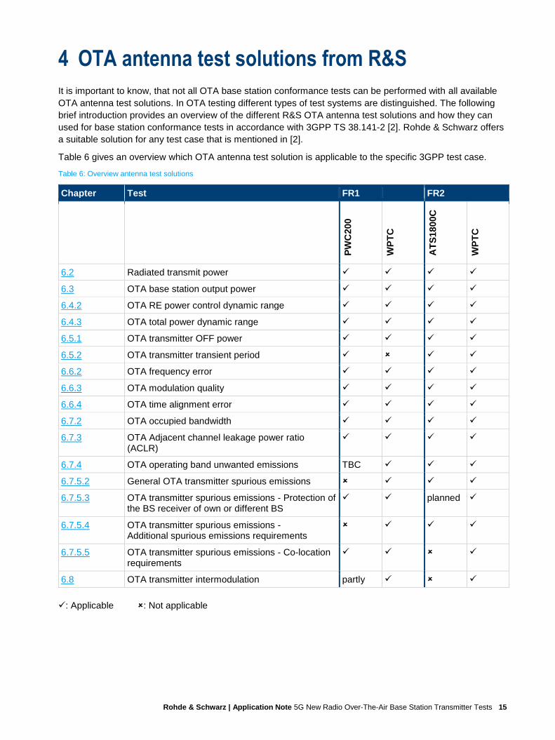
4 OTA antenna test solutions from R&S
It is important to know, that not all OTA base station conformance tests can be performed with all available
OTA antenna test solutions. In OTA testing different types of test systems are distinguished. The following
brief introduction provides an overview of the different R&S OTA antenna test solutions and how they can
used for base station conformance tests in accordance with 3GPP TS 38.141-2 [2]. Rohde & Schwarz offers
a suitable solution for any test case that is mentioned in [2].
Table 6 gives an overview which OTA antenna test solution is applicable to the specific 3GPP test case.
Table 6: Overview antenna test solutions
Chapter Test FR1 FR2
PW
C200
WP
TC
AT
S18
00C
WP
TC
6.2 Radiated transmit power ✓ ✓ ✓ ✓
6.3 OTA base station output power ✓ ✓ ✓ ✓
6.4.2 OTA RE power control dynamic range ✓ ✓ ✓ ✓
6.4.3 OTA total power dynamic range ✓ ✓ ✓ ✓
6.5.1 OTA transmitter OFF power ✓ ✓ ✓ ✓
6.5.2 OTA transmitter transient period ✓ ✓ ✓
6.6.2 OTA frequency error ✓ ✓ ✓ ✓
6.6.3 OTA modulation quality ✓ ✓ ✓ ✓
6.6.4 OTA time alignment error ✓ ✓ ✓ ✓
6.7.2 OTA occupied bandwidth ✓ ✓ ✓ ✓
6.7.3 OTA Adjacent channel leakage power ratio (ACLR)
✓ ✓ ✓ ✓
6.7.4 OTA operating band unwanted emissions TBC ✓ ✓ ✓
6.7.5.2 General OTA transmitter spurious emissions ✓ ✓ ✓
6.7.5.3 OTA transmitter spurious emissions - Protection of the BS receiver of own or different BS
✓ ✓ planned ✓
6.7.5.4 OTA transmitter spurious emissions - Additional spurious emissions requirements
✓ ✓ ✓
6.7.5.5 OTA transmitter spurious emissions - Co-location requirements
✓ ✓ ✓
6.8 OTA transmitter intermodulation partly ✓ ✓
✓: Applicable : Not applicable

Rohde & Schwarz | Application Note 5G New Radio Over-The-Air Base Station Transmitter Tests 16
4.1 WPTC indoor anechoic chambers (as part of R&S TS8991)
Rohde & Schwarz offers a turnkey over the air solution for antenna, cellular and non-cellular testing. In
cooperation with Albatross Projects GmbH a broad range of standardized Wireless Performance Test
Chambers (WPTC) in various dimensions are available. These offered test chambers belong to the category
of indoor anechoic chambers or general chambers. When configuring a TS8991 OTA-Performance test
system, the configurator gives the choice of different test chamber sizes.
The anechoic chamber for models XS to M have absorber linings to cover frequencies down to approx.
600 MHz while the larger L and XL models have larger absorbers that cover frequencies down to
approximately 400 MHz. By default, the upper frequency of the WPTC-series is approximately 18 GHz, but
could be increased if needed. For base station tests in FR2 this is mandatory.
It is possible to figure out static measurements as well as 3D pattern measurements with the conical cut
positioner.
Table 7 and Figure 11 gives an overview about the different WPTC models. Due to the rather large
dimensions of a base station antenna, the larger models are more suitable for the base station conformance
tests. The Rohde & Schwarz sales engineers will assist with the selection of a suitable model:
► https://www.rohde-schwarz.com/service-sales-locator
Table 7: WPTC model overview
Model Outer dimensions [m] Typical range length [m]
WPTC-XS 2.43 x 2.40 x 2.43 > 0.65
WPTC-S 3.70 x 3.00 x 3.10 > 1.02
WPTC-M 4.60 x 3.45 x 3.70 > 1.30
WPTC-L 5.20 x 4.05 x 4.30 > 1.38
WPTC-XL 5.80 x 5.10 x 5.20 > 1.83
Figure 11: WPTC models
For further reading
► https://rohde-schwarz.com/product/ts8991
► https://www.rohde-schwarz.com/brochure-datasheet/ts8991/
XS S M L XL
WPTC-

Rohde & Schwarz | Application Note 5G New Radio Over-The-Air Base Station Transmitter Tests 17
4.2 R&S ATS1800C (CATR)
The R&S ATS1800C is a compact antenna test range (CATR) test system which was designed for 5G NR
antennas, modules and devices (user equipment, UE) characterization throughout the entire development
lifecycle, from R&D to conformance tests for both active and passive measurements (3D antenna gain
patterns, ACLR, EVM, EiRP, TRP, EiS, etc.). The ATS1800C covers an in-band frequency range from
23.5 GHz to 44 GHz and an out-of-band frequency range from 6 GHz to 110 GHz. Therefore, this test
chamber is perfectly suited for base station conformance tests in FR2.
The coordinate system used is as follows:
Figure 12: Coordinate system R&S®ATS1800C
Figure 13: Coordinate system R&S®ATS1800C [12]
The ATS1800C provides RF feedthroughs (CATR-CSRF1: 1.85 mm (f), CATR-FEED2: 2 x 2.4 mm) for
connecting the measurement devices that are located at the rear side of the chamber (see Figure 14).
Figure 14: Feedthroughs R&S®ATS1800C
In order to reduce path loss, keeping the measurement devices near to the feedthroughs by using short
cables is highly recommended. Chapter 7 provides recommendations for suitable RF cables.

Rohde & Schwarz | Application Note 5G New Radio Over-The-Air Base Station Transmitter Tests 18
However, the quiet zone of this chamber measures around 30 cm x 30 cm and the DUT load capacity of the
positioner is limited to 8 kg. In case of base station modules that exceed these restrictions please contact
Rohde & Schwarz for a customized solution.
4.2.1 CATR principles in general
Inside the fully shielded chamber is the compact antenna test range (CATR) consisting of a feed antenna, a
bidirectional parabolic reflector and a 3D positioner. The reflector has an extremely high precision surface
roughness, which minimizes the errors introduced by the reflection. This allows the reflector to be used in a
very wide frequency range for accurate measurement results. [13]
Figure 15: R&S®ATS1800C CATR [13]
Figure 16: Wave propagation in the CATR setup [12]
1 = Feed antenna at focus of reflector
2 = Blocker to decouple feed from direct path to DUT
3 = Parabolic reflector with blended rolled edges
4 = Reflected plane wave
5 = Quiet zone for DUT
For further reading
► https://rohde-schwarz.com/product/ats1800c
► https://www.rohde-schwarz.com/brochure-datasheet/ats1800c/

Rohde & Schwarz | Application Note 5G New Radio Over-The-Air Base Station Transmitter Tests 19
4.3 R&S PWC200 Plane Wave Converter (PWC)
The R&S®PWC200, designed for 5G massive MIMO base station testing, offers instantaneous
measurements of far-field characteristics at a tremendously reduced distance from the phased antenna array
to the DUT. Among other things, this makes it perfectly suited for OTA base station conformance tests in
FR1.
The PWC200 plane wave converter is a bidirectional array of 156 wideband Vivaldi antennas placed in the
radiating near field of the device under test (DUT). The phased antenna array can form planar waves inside a
specified quiet zone (e.g. 1m Ø) within the radiating near field of the 5G massive MIMO base station module
for real-time radiated power and transceiver measurements (EVM, ACLR, SEM, etc.).
Each antenna includes a phase shifter and attenuator path, allowing arbitrary synthesis of the
electromagnetic field directly in front of the array at the spherical quiet zone enclosing the DUT. All signal
paths are combined to a single port that can be connected to measurement equipment (e.g. spectrum
analyzer). [14]
The R&S®PWC200 generates a 3D spherical quiet zone within a 1 m diameter sphere at a distance of
1.50 meters at a frequency of 3.5 GHz. In comparison, a direct far field measurement already requires a
distance of 23.5 m.
Figure 17: R&S® PWC200 equipped in anechoic test chamber
The R&S®PWC200 has to be shielded in a suitable wireless performance test chamber (e.g. WPTC, offered
by Rohde & Schwarz).
For more details on this technology, refer to the EuCAP 2018 publication "Plane Wave Converter for 5G
Massive MIMO Basestation Measurements".
For further reading
► https://rohde-schwarz.com/product/pwc200
► https://www.rohde-schwarz.com/brochure-datasheet/pwc200/
► EuCAP 2018 publication "Plane Wave Converter for 5G Massive MIMO Basestation Measurements"

Rohde & Schwarz | Application Note 5G New Radio Over-The-Air Base Station Transmitter Tests 20
5 Transmitter Tests (Chapter 6)
Specification TS 38.141-2 [2] defines the tests required in the various frequency ranges and positions
(Bottom, Middle, Top) in the operating band. In instruments from Rohde & Schwarz, the frequency range can
be set to any frequency within the supported range independently of the operating bands.
Please note that this version of the application note describes single carrier (SC) tests under normal test
environment (TE) only.
In order to allow comparisons between tests, test models (TMs) standardize the resource block (RB)
allocations. For NR, these are called enhanced NR TMs with the frequency range (e.g. NR-FR2-TM1.1). The
NR FR2 test models needed for BS type 2-O are described in TS 38.141-2 [2]. The NR FR1 test models are
described in TS 38.141-1 [1]. Both of them are stored as predefined settings in instruments from
Rohde & Schwarz.
Table 8 provides an overview of the basic parameters for the individual tests numbered by the chapters of
TS 38.141-2 and linked to the corresponding chapters in this application note. Both, the required test models
(TM) for BS type 2-O and the frequency positions (B, M, T) to be measured are shown.
Table 8: Tx basic parameters overview
Chapter
Test TE RF channels to be tested
FR2 test models (BS type 2-O)
6.2 Radiated transmit power N, E1) B, M, T NR-FR2-TM1.1
6.3 OTA base station output power N B, M, T NR-FR2-TM1.1
6.4.2 OTA RE power control dynamic range N B, T NR-FR2-TM2 NR-FR2-TM3.1
6.4.3 OTA total power dynamic range N M NR-FR2-TM2
6.5.1 OTA transmitter OFF power N M NR-FR2-TM1.1
6.5.2 OTA transmitter transient period N M
6.6.2 OTA frequency error N B, T NR-FR2-TM2 NR-FR2-TM3.1
6.6.3 OTA modulation quality N B, T
6.6.4 OTA time alignment error N M NR-FR2-TM1.1
6.7.2 OTA occupied bandwidth N M NR-FR2-TM1.1
6.7.3 OTA Adjacent channel leakage power ratio (ACLR) N B, T
6.7.4 OTA operating band unwanted emissions N B, M, T
6.7.5.2 General OTA transmitter spurious emissions N B, T NR-FR2-TM1.1
6.7.5.3 OTA transmitter spurious emissions - Protection of the base station receiver of own or different base station
N M
6.7.5.4 OTA transmitter spurious emissions - Additional spurious emissions requirements
N B, T
6.7.5.5 OTA transmitter spurious emissions - Co-location requirements
N M
6.8 OTA transmitter intermodulation N M Test not applicable for BS type 2-O
1) Please note that this application note covers normal test environment conditions only

Rohde & Schwarz | Application Note 5G New Radio Over-The-Air Base Station Transmitter Tests 21
As of now, there are still several requirements not available or finalized in TS 38.141-2 (V16.3.0) yet,
especially for base station type 1-H. Table 9 shows the requirements as officially published:
Table 9: Available requirements (TS 38.141-2, version 16.3.0)
Requirement Requirement set
BS type 1-H BS type 1-O BS type 2-O
Radiated transmit power 6.2 6.2 6.2
OTA base station output power
N/A
6.3 6.3
OTA output power dynamics 6.4 6.4
OTA transmit ON/OFF power 6.5 6.5
OTA transmitted signal quality 6.6 6.6
OTA occupied bandwidth 6.7.2 6.7.2
OTA ACLR 6.7.3 6.7.3
OTA out-of-band emission 6.7.4 6.7.4
OTA transmitter spurious emission 6.7.5 6.7.5
OTA transmitter intermodulation 6.8 N/A
5.1 Requirements classification
Table 10: Classification of radiated transmitter requirements [11]
TX requirement Description Classification
Radiated transmit power
The minimum requirements for radiated transmit power, are placed on one or more manufacturer declared beams over a declared OTA peak direction set. OTA requirements for BS output power are defined for directional EIRP requirements as radiated transmit power requirements. This requirement originates from the Rel-13 AAS BS requirement for the EIRP accuracy.
Directional
OTA BS output power
TRP metric is used for BS output power limit requirement. TRP
OTA output power dynamics
OTA output power dynamics consists of the Total power dynamic range, as well as the RE power control dynamic range requirements. For E-UTRA specification, the RE power control dynamic range requirement has no specific test and is tested together with the EVM. Furthermore, verification of the output power dynamics is not impacted by the spatial aspects around the BS. Therefore, the OTA output power dynamics requirements are considered as directional requirements.
Directional

Rohde & Schwarz | Application Note 5G New Radio Over-The-Air Base Station Transmitter Tests 22
OTA transmit OFF power
The OTA transmit OFF power is a co-location requirement in FR1, defined at the co-location reference antenna conductive output side, subject to scaling. For FR2, it is defined as TRP requirement.
FR1: Co-location FR2: TRP
OTA transient period
Same as OTA transmit OFF power, the OTA transient period is a co-location requirement in FR1, defined at the co-location reference antenna conductive output side, subject to scaling. For FR2, it is defined as directional requirement.
FR1: Co-location FR2: directional
OTA transmitted signal quality
EVM: The range of directions where the EVM requirement must be met is declared by the manufacturer as OTA coverage range, while the requirement itself is considered directional. Frequency error: The frequency error is coherent and will have a ‘flat’ response in the spatial domain, i.e. OTA frequency error will not depend on the selection of the measurement point within beam’s compliance directions set. Therefore, single directional requirement can be applied. TAE: In terms of testing effort it is beneficial, to coordinate testing of OTA TAE with testing of other transmitter parameters such as OTA frequency error and radiated transmit power.
Directional
OTA occupied bandwidth
For occupied bandwidth, the beam characteristics are not important. The requirement should however cover the fact that all transmitter is active and the system is operating at the maximum declared rated total radiated power. Occupied bandwidth is specified as a directional requirement valid over the OTA coverage range.
Directional
OTA ACLR ACLR requirement is the ratio of two TRP measures: the total radiated filtered mean power centred on the assigned channel frequency to the total radiated filtered mean power centred on an adjacent channel frequency.
TRP
OTA operating band unwanted emission
The OBUE unwanted emissions requirement in the OTA domain must capture all emissions around the BS by application of the TRP metric.
TRP
OTA transmitter spurious emission
Similar to other Unwanted emissions requirements, the metric used to capture transmitter spurious emissions OTA is TRP.
TRP except for co-location requirements applicable in FR1
OTA transmitter intermodulation
OTA transmitter intermodulation requirement relies on Unwanted emission requirements (i.e. operating band unwanted emission, transmitter spurious emission, and ACLR; all defined as TRP) in the presence of a wanted signal and an interfering signal. No requirement for FR2 is defined.
Co-location

Rohde & Schwarz | Application Note 5G New Radio Over-The-Air Base Station Transmitter Tests 23
5.2 Complete Tx test setup overview
Figure 18 shows the general test setup for transmitter tests. A spectrum analyzer (FSW) is used to perform
the tests. Some tests require special setups which are described in the respective sections.
Figure 18: Complete Tx test setup overview
A B
A Reference point of AAS BS
B Phase center of the receiving antenna

Rohde & Schwarz | Application Note 5G New Radio Over-The-Air Base Station Transmitter Tests 24
5.3 Radiated transmit power (6.2)
Radiated transmit power is defined as the EIRP (equivalent isotropically radiated power) level for a declared
beam at a specific beam peak direction. [2]
The test purpose is to verify the ability to accurately generate and direct radiated power per beam.
For each declared conformance beam direction pair, the EIRP measurement shall remain within the values
provided in Table 11 relative to the manufacturers declared rated beam EIRP value:
Table 11: Test requirement for radiated transmit power
BS type Normal test environment
1-H f ≤ 3 GHz: ± 3.3 dB
3 GHz < f ≤ 6 GHz: ± 3.5 dB
1-O f ≤ 3 GHz: ± 3.3 dB
3 GHz < f ≤ 6 GHz: ± 3.5 dB
2-O 24.15 GHz < f ≤ 29.5 GHz: ± 5.1 dB
37 GHz < f ≤ 40 GHz: ± 5.4 dB
Test setup
Figure 19: Measurement setup for Radiated transmit power
A B
A Reference point of AAS BS
B Phase center of the receiving antenna

Rohde & Schwarz | Application Note 5G New Radio Over-The-Air Base Station Transmitter Tests 25
Test procedure
1. Place the base station at the positioner and align the coordinate system
2. Move the base station in order that the direction to be tested aligns with the test antenna
3. Set the base station to transmit the corresponding test model
BS type 2-O: NR-FR2-TM1.1
BS type 1-O: according to TS 38.141-1 [1]
4. Measure the EIRP for any two orthogonal polarizations (p1 and p2) and calculate total radiated transmit
power: 𝐸𝐼𝑅𝑃 = 𝐸𝐼𝑅𝑃𝑝1 + 𝐸𝐼𝑅𝑃𝑝2
5. Repeat measurement for all declared beams
5.4 OTA base station output power (6.3)
OTA BS output power is declared as rated carrier TRP, with the output power accuracy requirement defined
at the RIB during the transmitter ON period. [2]
The test purpose is to verify the accuracy of the maximum carrier TRP (Total Radiated Power) (Pmax,c,TRP)
across the frequency range for all RIBs. OTA BS output power is declared as rated carrier TRP, with the
output power accuracy requirement defined at the RIB during the transmitter ON period. [2]
The base station rated carrier TRP for BS type 1-O shall be within the limits as specified in Table 12. For BS
type 2-O there is no upper limit for the rated carrier TRP.
Table 12: BS rated carrier TRP limits for BS type 1-O
BS class Prated,c,TRP
Wide Area BS No upper limit
Medium Range BS ≤ +47 dBm
Local Area BS ≤ +33 dBm
The TRP measurement results shall remain within the values provided in Table 13 relative to the
manufacturers declared rated carrier TRP values:
Table 13: Test requirement - TRP difference to the manufacturer´s declared rated carrier TRP
BS type Frequency range TRP allowed difference
1-H N/A
1-O f ≤ 3.0 GHz ± 3.4 dB
3.0 GHz ≤ f ≤ 4.2 GHz ± 3.5 dB
4.2 GHz ≤ f ≤ 6.0 GHz ± 3.5 dB
2-O 24.25 GHz < f ≤ 29.5 GHz ± 5.1 dB
37 GHz < f ≤ 40 GHz ± 5.4 dB

Rohde & Schwarz | Application Note 5G New Radio Over-The-Air Base Station Transmitter Tests 26
Test setup
Figure 20: Measurement set up for OTA base station output power
Test procedure
Procedure for measuring TRP is based on the directional power measurements. More information about TRP
measurements can be found in chapter 3.3.
1. Place the base station at the positioner and align the coordinate system
2. Set the base station in the direction of the declared beam peak direction
3. Set the BS to transmit the corresponding test model
BS type 2-O: NR-FR2-TM1.1
BS type 1-O: according to TS 38.141-1 [1]
4. Orient the positioner (and BS) in order that the direction to be tested aligns with the test antenna such
that measurements to determine TRP can be performed
5. Measure the EIRP for any two orthogonal polarizations (p1 and p2) and calculate total radiated transmit
power: 𝐸𝐼𝑅𝑃 = 𝐸𝐼𝑅𝑃𝑝1 + 𝐸𝐼𝑅𝑃𝑝2
6. Repeat step 5) for all directions in the appropriated TRP measurement grid needed for full TRP
estimation
7. Calculate TRP
TRP = 1
4π∫ ∫ EIRP(θ, φ)sinθdθdφ
π
θ=0
2π
φ=0
A B
A Reference point of AAS BS
B Phase center of the receiving antenna

Rohde & Schwarz | Application Note 5G New Radio Over-The-Air Base Station Transmitter Tests 27
5.5 OTA output power dynamics (6.4)
The requirements apply during the transmitter ON period.
5.5.1 OTA RE power control dynamic range (6.4.2)
The OTA RE power control dynamic range is the difference between the power of an RE and the average RE
power for a BS at maximum output power (Pmax,c,EIRP) for a specified reference condition.
This requirement shall apply at each RIB supporting transmission in the operating band [2].
For this test no specific test or test requirements are defined. Test 6.6.3 OTA modulation quality (5.7.1) test
provides sufficient test coverage for this requirement.
5.5.2 OTA total power dynamic range (6.4.3)
The OTA total power dynamic range is the difference between the maximum and the minimum transmit
power of an OFDM symbol for a specified reference condition.
This requirement shall apply at each RIB supporting transmission in the operating band [2].
The test purpose is to verify that the total power dynamic range is within the limits specified by the minimum
requirement. [2]
For BS type 1-O the downlink (DL) total power dynamic range for each NR carrier shall be larger than or
equal to the levels in Table 14.
Table 14: Total power dynamic range for BS type 1-O
BS channel bandwidth (MHz)
Total power dynamic range (dB)
15 kHz SCS 30 kHz SCS 60 kHz SCS
5 13.5 10.0 N/A
10 16.7 13.4 10.0
15 18.5 15.3 12.1
20 19.8 16.6 13.4
25 20.8 17.7 14.5
30 21.6 18.5 15.3
40 22.9 19.8 16.6
50 23.9 20.8 17.7
60 N/A 21.6 18.5
70 N/A 22.3 19.2
80 N/A 22.9 19.8
90 N/A 23.4 20.4
100 N/A 23.9 20.9
OTA total power dynamic range minimum requirement for BS type 2-O is specified such as for each NR
carrier. It shall be larger than or equal to the levels specified in Table 15 [2].

Rohde & Schwarz | Application Note 5G New Radio Over-The-Air Base Station Transmitter Tests 28
Table 15: Minimum requirement for BS type 2-O - total power dynamic range (dB)
SCS (kHz) 50 MHz 100 MHz 200 MHz 400 MHz
60 17.7 dB 20.8 dB 23.8 dB N/A
120 14.6 dB 17.7 dB 20.8 dB 23.8 dB
Test setup
Figure 21: Measurement setup for OTA output power dynamics
Test procedure
1. Place the base station at the positioner and align the coordinate system
2. Move the base station in order that the direction to be tested aligns with the test antenna
3. Configure the beam peak direction of the BS according to the declared beam direction pair
4. Set the base station to transmit the corresponding test model
A B
A Reference point of AAS BS
B Phase center of the receiving antenna
BS type 1-O
256 QAM is supported
without power back off:
NR-FR1-TM3.1a
with power back off:
NR-FR1-TM3.1
256 QAM is not supported
NR-FR1-TM3.1

Rohde & Schwarz | Application Note 5G New Radio Over-The-Air Base Station Transmitter Tests 29
5. Measure the OFDM symbol Tx power by measuring the EIRP for any two orthogonal polarizations
(p1 and p2)
6. Calculate total radiated transmit power as for particular beam direction pair as EIRP = EIRPp1 + EIRPp2
7. Set the base station to transmit corresponding test model
8. Measure the OFDM symbol Tx power (OSTP) by measuring the EIRP for any two orthogonal
polarizations (p1 and p2) and calculate total radiated transmit power for particular beam direction pair:
EIRP = EIRPp1 + EIRPp2
Note: Measured OFDM symbols shall not contain RS or SSB
BS type 2-O
64 QAM is supported without power back off
NR-FR2-TM3.1 with 64QAM
64 QAM is not supported
NR-FR1-TM3.1 with highest modulation
order supported without power back off
64 QAM is supported with power back off
NR-FR1-TM3.1 with highest modulation
BS type 1-O
256 QAM is supported
NR-FR1-TM2a
256 QAM is not supported
NR-FR1-TM2
BS type 2-O
64 QAM is supported
NR-FR2-TM2
64 QAM is not supported
NR-FR2-TM2 with highest modulation
order supported

Rohde & Schwarz | Application Note 5G New Radio Over-The-Air Base Station Transmitter Tests 30
5.6 OTA transmit ON/OFF power (6.5)
5.6.1 OTA transmitter OFF power (EIRP in beam peak) (6.5.1)
OTA transmitter OFF power requirements apply only to TDD operation of NR base stations. It´s the mean
power measured over 70/N µs filtered with a square filter of bandwidth equal to the transmission bandwidth
configuration of the BS (BWConfig) centered on the assigned channel frequency during the transmitter OFF
period. N = SCS/15, where SCS is Sub Carrier Spacing in kHz. [2]
For BS supporting intra-band contiguous CA, the transmitter OFF power is defined as the mean power
measured over 70/N µs filtered with a square filter of bandwidth equal to the aggregated BS channel
bandwidth BWChannel_CA centered on (Fedge_high+Fedge_low)/2 during the transmitter OFF period.
For BS type 1-O, the transmitter OFF power is defined as the output power at the co-location test antenna
conducted output(s). For BS type 2-O the transmitter OFF power is defined as TRP. [2]
The purpose of this test is to verify the OTA transmitter OFF power is within the limits of the minimum
requirements [2].
This test is tested together with test case 6.5.2. Therefor please see chapter 5.6.2 for the required test setup
and the test requirements.
5.6.2 OTA transmitter transient period (6.5.2)
The OTA transmitter transient period requirements apply only to TDD operation of BS. It is the time period
during which the transmitter unit is changing from the OFF period to the ON period or vice versa. The OTA
transmitter transient period is illustrated in Figure 22.
For BS type 1-O this requirement applies for RIB supporting transmission in the operating band and is
measured at the co-location test antenna conducted outputs. For BS type 2-O the requirement applies at
each RIB supporting transmission in the operating band. [2]
Figure 22: Definition of transmitter ON and OFF periods [2]
The purpose of this test is to verify the OTA transmitter transient periods are within the limits of the minimum
requirements.
The mean power spectral density (for BS type 1-O) and the mean EIRP spectral density (for BS type 2-O)
measured shall be less than the values specified in Table 16.

Rohde & Schwarz | Application Note 5G New Radio Over-The-Air Base Station Transmitter Tests 31
Table 16: Test requirements for OTA transmitter transient period (6.5.2)
BS type Frequency Mean power spectral density /mean EIRP spectral density
1-O1) f ≤ 3.0 GHz -102.6 dBm/MHz
3.0 GHz < f ≤ 6.0 GHz -102.4 dBm/MHz
2-O 24.15 GHz < f ≤ 29.5 GHz -33.1 + Prated,c,EIRP - Prated,c,TRP dBm/MHz
37 GHz < f ≤ 40 GHz -32.7 + Prated,c,EIRP - Prated,c,TRP dBm/MHz
1) For multi-band RIB, the requirement is only applicable during the transmitter OFF period in all supported
operating bands.
Prated,c,TRP: value declared for the reference beam direction pair for the beam identifier which provides the
highest intended EIRP
Test setup
Figure 23: Measurement setup for OTA transmit ON/OFF power (BS type 2-O)
A B
A Reference point of AAS BS
B Phase center of the receiving antenna

Rohde & Schwarz | Application Note 5G New Radio Over-The-Air Base Station Transmitter Tests 32
Figure 24: Measurement setup for OTA transmit ON/OFF power (BS type 1-O)
Test procedure
1. Place the base station at the positioner and align the coordinate system
2. Set the BS in the direction of the declared beam peak direction (beam to be tested)
3. BS type 2-O:
a) Set the base station to transmit NR-FR2-TM1.1 test model
b) Measure the mean EIRP spectral density as the power sum over two orthogonal polarizations over
70/N μs filtered with a square filter of bandwidth equal to the RF bandwidth of the NR BS centered
on the central frequency of the RF bandwidth (x = 3)
4. BS type 1-O
a) Place the co-location test antenna (more information can be found in [2], subclause 4.12)
b) Set the base station to transmit the corresponding test model
c) Measure the mean power spectral density at the output(s) of co-location test antenna as power sum
over two orthogonal polarizations over 70/N μs filtered with a square filter of bandwidth equal to the
RF bandwidth of the BS centered on the central frequency of the RF bandwidth
A B
A Reference point of AAS BS
B Phase center of the receiving antenna

Rohde & Schwarz | Application Note 5G New Radio Over-The-Air Base Station Transmitter Tests 33
Note: 70/N μs average window center is set from 35/N μs after end of one transmitter ON period + 10 μs to
35/N μs before start of next transmitter ON period - 10 μs. N = SCS/15, where SCS is sub carrier spacing in
kHz.
5.7 OTA transmitted signal quality (6.6)
5.7.1 OTA frequency error (6.6.2)
OTA frequency error is the measure of the difference between the actual BS transmit frequency and the
assigned frequency. The same source shall be used for RF frequency and data clock generation. [2]
The modulated carrier frequency of each NR carrier configured by the BS shall be accurate to within the
accuracy range given in Table 17 observed over 1ms.
Table 17: OTA frequency error test requirement for BS type 1-O and BS type 2-O
BS class Accuracy
Wide Area BS ±(0.05 ppm + 12 Hz)
Medium Range BS ±(0.1 ppm + 12 Hz)
Local Area BS ±(0.1 ppm + 12 Hz)
For this measurement, the FSW (spectrum analyzer) must be synchronized via an external reference to a
high precision time reference.
This test case is tested together with test 6.6.3 OTA modulation quality. For test setup and test procedure
please see chapter 5.7.2.
5.7.2 OTA modulation quality (6.6.3)
OTA modulation quality is defined by the difference between the measured carrier signal and an ideal signal.
Modulation quality can e.g. be expressed as Error Vector Magnitude (EVM). The Error Vector Magnitude is a
measure of the difference between the ideal symbols and the measured symbols after the equalization. This
difference is called the error vector. [2]
The measured EVM of each NR carrier shall be less than the limits in Table 18.
Table 18: EVM requirements
Base Station type Modulation scheme for PDSCH Required EVM (%)
BS type 1-O QPSK 18.5
16QAM 13.5
64QAM 9
256QAM 4.5
BS type 2-O QPSK 18.5
16QAM 13.5
64QAM 9

Rohde & Schwarz | Application Note 5G New Radio Over-The-Air Base Station Transmitter Tests 34
For NR, for all bandwidths, the EVM measurement shall be performed for each NR carrier over all allocated
resource blocks and downlink slots within 10 ms measurement periods. The boundaries of the EVM
measurement periods need not be aligned with radio frame boundaries.
Test setup
Figure 25: Test setup OTA modulation quality
Test procedure
1. Place the base station at the positioner and align the coordinate system
2. Orient the base station in order that the direction to be tested aligns with the test antenna
3. Configure the beamforming settings of the base station to the direction to be tested
4. Set the base station to transmit the corresponding test model
A B
A Reference point of AAS BS
B Phase center of the receiving antenna
BS type 2-O
64QAM is supported
with power back off: NR-FR2-TM3.1 with 64QAM or highest modulation
order supported
without power back off: NR-FR2-TM3.1 with 64QAM signal
64QAM is not supported
NR-FR2-TM3.1 with highest modulation order without power back
off

Rohde & Schwarz | Application Note 5G New Radio Over-The-Air Base Station Transmitter Tests 35
5. Measure the EVM and the frequency error for each carrier
6. Repeat the measurement for the following test models
Note: The OFDM symbol power (in the conformance direction) shall be at the lower limit of the dynamic
range according to the test procedure and test requirement in chapter 5.5.2.
5.7.3 OTA time alignment error (6.6.4)
This requirement shall apply to frame timing in MIMO transmission, carrier aggregation and their
combinations. Frames of the NR signals present in the radiated domain are not perfectly aligned in time. In
relation to each other, the RF signals present in the radiated domain may experience certain timing
differences. For a specific set of signals/transmitter configuration/transmission mode, the OTA Time
Alignment Error (OTA TAE) is defined as the largest timing difference between any two different NR signals.
The OTA time alignment error requirement is defined as a directional requirement at the RIB and shall be
met within the OTA coverage range. [2]
Measure the time alignment error between the different reference symbols on different beams on the
carrier(s).
Table 19 lists the limits for the OTA TAE values.
BS type 1-O
256 QAM is supported
without power back off:NR-FR1-TM3.1a
with power back offNR-FR1-TM3.1a
highest modulation order supported: 64QAM
NR-FR1-TM3.1
highest modulation order supported: 16QAM
NR-FR1-TM3.2
highest modulation order supported: QPSK
NR-FR1-TM3.3
BS type 2-O NR-FR2-TM2
BS type 1-O
256 QAM is supported NR-FR1-TM2a
256 QAM is not supported NR-FR1-TM2

Rohde & Schwarz | Application Note 5G New Radio Over-The-Air Base Station Transmitter Tests 36
Table 19: Test Requirements for OTA TAE
BS type Combination OTA TAE (µs)
BS type 1-O MIMO transmission, at each carrier frequency ≤ 0.090
intra-band contiguous carrier aggregation, with or without MIMO ≤ 0.285
intra-band non-contiguous carrier aggregation, with or without MIMO ≤ 3.025
inter-band carrier aggregation, with or without MIMO ≤ 3.025
BS type 2-O MIMO transmission, at each carrier frequency ≤ 0.090
intra-band contiguous carrier aggregation, with or without MIMO ≤ 0.155
intra-band non-contiguous carrier aggregation, with or without MIMO ≤ 0.285
inter-band carrier aggregation, with or without MIMO ≤ 3.025
Test setup
Figure 26: Test setup OTA time alignment error
A B
A Reference point of AAS BS
B Phase center of the receiving antenna

Rohde & Schwarz | Application Note 5G New Radio Over-The-Air Base Station Transmitter Tests 37
Test procedure
1. Place the base station at the positioner and align the coordinate system
2. Move the base station in order that the direction to be tested aligns with the test antenna
3. Configure the beamforming settings of the base station to the direction to be tested
4. Select the corresponding test model
a) BS type 2-O: NR-FR2-TM1.1 or any DL signal using MIMO transmission or carrier aggregation
b) BS type 1-O: NR-FR1-TM1.1 or any DL signal using MIMO transmission or carrier aggregation
Note: For MIMO transmission, different ports may be configured in NR-FR1-TM1.1 and NR-FR2-TM1.1
(using DMRS ports p = 1000 and 1001 with CDM)
For a BS declared to be capable of single carrier operation only, set the BS to transmit according to the
applicable test configuration using the corresponding test model at manufacturer's declared rated output
power, Prated,c,TRP.
5. Measure the time alignment error between the different reference symbols on different beams on the
carriers
5.8 OTA unwanted emissions (6.7)
OTA unwanted emissions consist of so-called out-of-band emissions and spurious emissions according to
ITU definitions. In ITU terminology, out of band emissions are unwanted emissions immediately outside the
BS channel bandwidth resulting from the modulation process and non-linearity in the transmitter but
excluding spurious emissions. Spurious emissions are emissions which are caused by unwanted transmitter
effects such as harmonics emission, parasitic emission, intermodulation products and frequency conversion
products, but exclude out of band emissions. The OTA out-of-band emissions requirement for the
BS type 1-O and BS type 2-O transmitter is specified both in terms of Adjacent Channel Leakage Power
Ratio (ACLR) and operating band unwanted emissions (OBUE). The OTA operating band unwanted
emissions define all unwanted emissions in each supported downlink operating band plus the frequency
ranges ΔfOBUE above and ΔfOBUE below each band. OTA Unwanted emissions outside of this frequency range
are limited by an OTA spurious emissions requirement. [2]
The maximum offset of the operating band unwanted emissions mask from the operating band edge is
ΔfOBUE. The value of ΔfOBUE is defined in Table 20.
Table 20: Maximum offset ΔfOBUE outside the downlink operating band
BS type Operating band characteristics ΔfOBUE (MHz)
BS type 1-O FDL_high – FDL_low < 100 MHz 10
100 MHz ≤ FDL_high – FDL_low ≤ 900 MHz 40
BS type 2-O FDL_high – FDL_low ≤ 3250 MHz 1500
5.8.1 OTA occupied bandwidth (6.7.2)
The OTA occupied bandwidth is the width of a frequency band such that, below the lower and above the
upper frequency limits, the mean powers emitted are each equal to a specified percentage β/2 of the total
mean transmitted power. The value of β/2 shall be taken as 0.5%.
The test purpose is to verify that the emission at the RIB does not occupy an excessive bandwidth for the
service to be provided and is, therefore, not likely to create interference to other users of the spectrum
beyond undue limits. [2]

Rohde & Schwarz | Application Note 5G New Radio Over-The-Air Base Station Transmitter Tests 38
Table 21: Span and number of measurement points for OBW measurements for FR1
Bandwidth BS channel bandwidth BWChannel (MHz)
Aggregated BS channel bandwidth BWChannel_CA (MHz)
5 10 15 20 > 20 > 20
Span (MHz) 10 20 30 40 2 × BWChannel 2 × BWChannel_CA
Minimum number of measurement points
400 400 400 400 ⌈2 × BWChannel
100kHz⌉ ⌈
2 × BWChannel_CA
100kHz⌉
Table 22: Span and number of measurement points for OBW measurements for FR2
Bandwidth BS channel bandwidth BWChannel (MHz)
Aggregated BS channel bandwidth BWChannel_CA (MHz)
50 100 200 400 > 50
Span (MHz) 2 × BWChannel 𝟐 × 𝐁𝐖𝐂𝐡𝐚𝐧𝐧𝐞𝐥_𝐂𝐀
Minimum number of measurement points ⌈2 × BWChannel
200kHz⌉ ⌈
𝟐 × 𝐁𝐖𝐂𝐡𝐚𝐧𝐧𝐞𝐥_𝐂𝐀
𝟐𝟎𝟎𝐤𝐇𝐳⌉
The measured OTA occupied bandwidth for each carrier shall be smaller than the channel bandwidth. For
contiguous CA, the occupied bandwidth shall be less than or equal to the aggregated BS channel bandwidth
(see Table 21 and Table 22).
Test setup
Figure 27: Measurement setup for OTA occupied bandwidth test
A B
A Reference point of AAS BS
B Phase center of the receiving antenna

Rohde & Schwarz | Application Note 5G New Radio Over-The-Air Base Station Transmitter Tests 39
Test procedure
1. Place the base station at the positioner and align the coordinate system
2. Move the base station in order that the direction to be tested aligns with the test antenna
3. Configure the beam peak direction of the base station to the declared beam direction pair
4. Set the base station to transmit signal
a) BS type 2-O: NR-FR2-TM1.1
b) BS type 1-O: according to TS 38.141-1 [1]
5. Measure the spectrum emission of the transmitted signal (measurement settings according to Table 21
and Table 22
6. Compute total EIRP (P0) of all measurement cells in the measurement span
7. Compute the EIRP (P1) outside the occupied bandwidth on each side
8. Measure EIRP for any two orthogonal polarizations (p1 and p2) and calculate total radiated transmit
power: EIRP = EIRPp1 + EIRPp2
9. Determine the lowest frequency (f1) for which the sum of all EIRP in the measurement cells from the
beginning of the span to f1 exceeds P1
10. Determine the highest frequency (f2) for which the sum of all EIRP in the measurement cells from the
end of the span to f2 exceeds P1
11. Calculate OTA occupied bandwidth: OBWOTA = f2 - f1
5.8.2 OTA Adjacent Channel Leakage Power Ratio (ACLR) (6.7.3)
OTA Adjacent Channel Leakage power Ratio (ACLR) is the ratio of the filtered mean power centered on the
assigned channel frequency to the filtered mean power centered on an adjacent channel frequency. The
measured power is TRP. [2]
Figure 28: ACLR
For the OTA ACLR requirement either the OTA ACLR limits or the OTA ACLR absolute limits shall apply,
whichever is less stringent. Furthermore the OTA CACLR limits or the OTA CACLR absolute limits shall
apply, whichever is less stringent.

Rohde & Schwarz | Application Note 5G New Radio Over-The-Air Base Station Transmitter Tests 40
Table 23: BS type 1-O ACLR absolute limit
BS category / BS class OTA ACLR absolute limit
Category A Wide Area BS -4 dBm/MHz
Category B Wide Area BS -6 dBm/MHz
Medium Range BS -16 dBm/MHz
Local Area BS -23 dBm/MHz
Table 24: BS type 1-O ACLR limit
BS channel bandwidth of lowest/highest NR carrier transmitted BWChannel (MHz)
BS adjacent channel center frequency offset below the lowest or above the highest carrier center frequency transmitted
Assumed adjacent channel carrier (informative)
Filter on the adjacent channel frequency and corresponding filter bandwidth
OTA ACLR limit (0 – 3 GHz)
OTA ACLR limit (3 – 6 GHz)
5, 10, 15, 20, 25, 30, 40, 50, 60, 70, 80, 90,100
BWChannel NR of same BW2) Square (BWConfig) 44 dB 43.8 dB
2 x BWChannel NR of same BW2) Square (BWConfig) 44 dB 43.8 dB
BWChannel /2 + 2.5 MHz 5 MHz E-UTRA Square (4.5 MHz) 44 dB3) 43.8 dB3)
BWChannel /2 + 7.5 MHz 5 MHz E-UTRA Square (4.5 MHz) 44 dB3) 43.8 dB3)
Table 25: BS type 1-O ACLR limit in non-contiguous spectrum or multiple bands
BS channel BW of lowest/ highest NR carrier transmitted BWChannel (MHz)
Sub-block or Inter RF BW gap size (Wgap) where the limit applies (MHz)
BS adjacent channel center frequency offset below or above the sub-block or BS RF BW edge (inside the gap)
Assumed adjacent channel carrier
Filter on the adjacent channel frequency and corresponding filter bandwidth
OTA ACLR limit (0-3 GHz)
OTA ACLR limit (3-6 GHz)
5, 10, 15, 20 Wgap ≥ 15 Wgap ≥ 45
2.5 MHz 5 MHz NR Square (BWConfig) 44 dB 43.8 dB
Wgap ≥ 20 Wgap ≥ 50
7.5 MHz 5 MHz NR Square (BWConfig) 44 dB 43.8 dB
25, 30, 40, 50, 60, 70, 80, 90, 100
Wgap ≥ 60 Wgap ≥ 30
10 MHz 20 MHz NR Square (BWConfig) 44 dB 43.8 dB
Wgap ≥ 80 Wgap ≥ 50
30 MHz 20 MHz NR Square (BWConfig) 44 dB 43.8 dB

Rohde & Schwarz | Application Note 5G New Radio Over-The-Air Base Station Transmitter Tests 41
Table 26: BS type 1-O CACLR limit
BS channel BW of lowest/ highest NR carrier transmitted BWChannel (MHz)
Sub-block or Inter RF BW gap size (Wgap) where the limit applies (MHz)
BS adjacent channel center frequency offset below or above the sub-block or BS RF Bandwidth edge (inside the gap)
Assumed adjacent channel carrier
Filter on the adjacent channel frequency and corresponding filter bandwidth
OTA CACLR limit (0-3 GHz)
OTA CACLR limit (3-6 GHz)
5, 10, 15, 20 5 ≤ Wgap < 15 5 ≤ Wgap < 45
2.5 MHz 5 MHz NR Square (BWConfig) 44 dB 43.8 dB
10 < Wgap < 20 10 ≤ Wgap < 50
7.5 MHz 5 MHz NR Square (BWConfig) 44 dB 43.8 dB
25, 30, 40, 50, 60, 70, 80,90, 100
20 ≤ Wgap < 60 20 ≤ Wgap < 30
10 MHz 20 MHz NR Square (BWConfig) 44 dB 43.8 dB
40 < Wgap < 80 40 ≤ Wgap < 50
30 MHz 20 MHz NR Square (BWConfig) 44 dB 43.8 dB
Table 27: BS type 1-O CACLR absolute limit
BS category / BS class OTA CACLR absolute limit
Category A Wide Area BS -4 dBm/MHz
Category B Wide Area BS -6 dBm/MHz
Medium Range BS -16 dBm/MHz
Local Area BS -23 dBm/MHz
Table 28: Filter parameters for the assigned channel
RAT of the carrier adjacent to the sub-block or Inter RF Bandwidth gap
Filter on the assigned channel frequency and corresponding filter bandwidth
NR NR of same BW with SCS that provides largest transmission bandwidth configuration
Table 29: BS type 2-O ACLR absolute limit
BS class ACLR absolute limit
Wide-area BS -10.3dBm/MHz
Medium-range BS -17.3 dBm/MHz
Local-area BS -17.3 dBm/MHz

Rohde & Schwarz | Application Note 5G New Radio Over-The-Air Base Station Transmitter Tests 42
Table 30: BS type 2-O ACLR limit
BS channel BW of lowest/ highest NR carrier transmitted BWChannel (MHz)
BS adjacent channel center frequency offset below the lowest or above the highest carrier center frequency transmitted
Assumed adjacent channel carrier
Filter on the adjacent channel frequency and corresponding filter bandwidth
OTA ACLR limit (dB)
50, 100, 200, 400 BWChannel NR of same BW Square (BWConfig) 25.7 23.4
Table 31: BS type 2-O ACLR limit in non-contiguous spectrum
BS channel bandwidth of lowest/highest NR carrier transmitted (MHz)
Sub-block gap size (Wgap) where the limit applies (MHz)
BS adjacent channel centre frequency offset below or above the sub-block edge (inside the gap)
Assumed adjacent channel carrier
Filter on the adjacent channel frequency and corresponding filter bandwidth
OTA ACLR limit (MHz)
50, 100 Wgap ≥ 100 Wgap ≥ 250
25 MHz 50 MHz NR Square (BWConfig) 25.7 23.4
200, 400 Wgap ≥ 400 Wgap ≥ 250
100 MHz 200 MHz NR Square (BWConfig) 25.7 23.4
Table 32: BS type 2-O ACLR limit in non-contiguous spectrum
BS channel bandwidth of lowest/ highest NR carrier transmitted (MHz)
Sub-block gap size (Wgap) where the limit applies (MHz)
BS adjacent channel centre frequency offset below or above the sub-block edge (inside the gap)
Assumed adjacent channel carrier
Filter on the adjacent channel frequency and corresponding filter bandwidth
OTA CACLR limit (dB)
50, 100 50 ≤ Wgap < 100 50 ≤ Wgap < 250
25 MHz 50 MHz NR Square (BWConfig) 25.7 23.4
200, 400 200 ≤ Wgap < 400 200 ≤ Wgap < 250
100 MHz 200 MHz NR Square (BWConfig) 25.7 23.4
Table 33: BS type 2-O CACLR absolute limit
BS class CACLR absolute limit
Wide area BS -10.3 dBm/MHz
Medium range BS -17.3 dBm/MHz
Local area BS -17.3 dBm/MHz

Rohde & Schwarz | Application Note 5G New Radio Over-The-Air Base Station Transmitter Tests 43
Table 34: Filter parameters for the assigned channel
RAT of the carrier adjacent to the sub-block gap
Filter on the assigned channel frequency and corresponding filter bandwidth
NR NR of same BW with SCS that provides largest transmission bandwidth configuration
Test setup
Figure 29: Measurement setup for OTA ACLR
Test procedure
1. Place the base station at the positioner and align the coordinate system
2. Measurement devices characteristics
a) Detection mode: true RMS voltage or true power averaging
b) Measurement filter bandwidth: according to the preceding tables
3. Set the base station to transmit test model
a) BS type 2-O: NR-FR2-TM1.1
b) BS type 1-O: according to TS 38.141-1 [1]
4. Align the BS and the test antenna (TRP measurement can be performed)
5. Measure the absolute power of the assigned frequency and the adjacent channel frequency
6. Repeat step 4 and step 5 for all directions in the TRP measurement grid
7. Calculate TRPEstimate (wanted channel and adjacent channel)
A B
A Reference point of AAS BS
B Phase center of the receiving antenna

Rohde & Schwarz | Application Note 5G New Radio Over-The-Air Base Station Transmitter Tests 44
TRPEstimate =π
2NM∑ ∑ EIRP(θn, φm) sin θn
M−1
m=0
N−1
n=0
8. Calculate relative ACLR estimate
ACLR is calculated by the ratio of the absolute TRP of the assigned channel frequency and the absolute
TRP of the adjacent frequency channel.
9. Measure OTA ACLR for the frequency offsets both side of channel frequency (according to Table 24
and Table 30)
10. For the OTA ACLR requirement applied inside sub-block gap for non-contiguous spectrum operation
a) Measure OTA ACLR inside sub-block gap
b) Measure OTA CACLR inside sub-block gap
11. Repeat the test with the channel setup using NR-FR1-TM1.2 for BS type 1-O
5.8.3 OTA operating band unwanted emissions (6.7.4)
This test measures the emissions of the BS, close to the assigned channel bandwidth of the wanted signal,
while the BS is in operation. The OTA limits for operating band unwanted emissions are specified as TRP per
RIB, unless otherwise stated. [2]
As of the large scope, the test requirements for this test were not printed in this application note. The
requirements can be found in TS 38.141-2 [2] section 6.7.4.5.
Test setup
Figure 30: Measurement setup for OTA operating band unwanted emissions
A B
A Reference point of AAS BS
B Phase center of the receiving antenna

Rohde & Schwarz | Application Note 5G New Radio Over-The-Air Base Station Transmitter Tests 45
Test procedure
1. Place the base station at the positioner and align the coordinate system
2. Measurement devices characteristics
a) Detection mode: True RMS voltage or true power averaging
b) Measurement filter bandwidth: according to the test requirement tables
3. Set the base station to transmit
a) BS type 2-O: NR-FR2-TM1.1
b) BS type 1-O: according to TS 38.141-1 [1]
4. Align the BS in order that the direction to be tested aligns with the test antenna such that TRP
measurements can be performed
5. Sweep the center frequency of the measurement filter in contiguous steps
6. Measure emission power within the specified frequency ranges, with the specified measurement
bandwidth
7. Repeat step 4, 5 and 6 for all directions in the TRP measurement grid
8. Calculate TRPEstimate (wanted channel and adjacent channel)
TRPEstimate =π
2NM∑ ∑ EIRP(θn, φm) sin θn
M−1
m=0
N−1
n=0
Note: For BS type 1-O and multi-band RIB and single band tests, repeat the steps above per involved band
where single band test configurations and test models shall apply with no carrier activated in the other band.
5.8.4 OTA transmitter spurious emissions (6.7.5)
The OTA transmitter spurious emission limits for FR1 shall apply from 30 MHz to 12.75 GHz, excluding the
frequency range from ΔfOBUE below the lowest frequency of each supported downlink operating band, up to
ΔfOBUE above the highest frequency of each supported downlink operating band, where the ΔfOBUE is defined
in Table 20. For some operating bands, the upper limit of the spurious range might be higher than 12.75 GHz
in order to comply with the 5th harmonic limit of the downlink operating band.
The OTA transmitter spurious emission limits for FR2 shall apply from 30 MHz to 2nd harmonic of the upper
frequency edge of the downlink operating band, excluding the frequency range from ΔfOBUE below the lowest
frequency of each supported downlink operating band, up to ΔfOBUE above the highest frequency of each
supported downlink operating band, where the ΔfOBUE is defined. [2]
5.8.4.1 General OTA transmitter spurious emissions (6.7.5.2)
The test purpose is to verify if the radiated spurious emissions from the BS at the RIB are within the specified
minimum requirements. [2]
Table 35: RF channels to be tested
FR From - To RF channel
FR1 30MHz to FDL_low - ΔfOBUE B
FDL_high + ΔfOBUE to 12.75 GHz (or to 5th harmonic) T
FR2 30 MHz to FDL_low - ΔfOBUE B
FDL_high + ΔfOBUE to 2nd harmonic (or to 60 GHz) T

Rohde & Schwarz | Application Note 5G New Radio Over-The-Air Base Station Transmitter Tests 46
Table 36: General OTA BS transmitter spurious emission limits for BS type 1-O, category A
Spurious frequency range Test limit Measurement bandwidth
30 MHz – 1 GHz -13 + X dBm 100 kHz
1 GHz – 12.75 GHz 1 MHz
12.75 GHz – 5th harmonic of the upper frequency edge of the DL operating band in GHz
1 MHz
Table 37: General OTA BS transmitter spurious emission limits for BS type 1-O, category B
Spurious frequency range Test limit Measurement bandwidth
30 MHz – 1 GHz -36 + X dBm 100 kHz
1 GHz – 12.75 GHz -30 + X dBm 1 MHz
12.75 GHz – 5th harmonic of the upper frequency edge of the DL operating band in GHz
1 MHz
Table 38: General OTA BS transmitter spurious emission limits for BS type 2-O
Spurious frequency range Test limit Measurement bandwidth
30 MHz – 1 GHz -13 dBm 100 kHz
1 GHz – min(2nd harmonic of the upper frequency edge of the DL operating band in GHz; [60] GHz)
1 MHz
Table 39: BS radiated Tx spurious emission limits in FR2 (category B)
Frequency range (Note 4)
Test limit Measurement Bandwidth
30 MHz 1 GHz -36 dBm 100 kHz
1 GHz 18 GHz -30 dBm 1 MHz
18 GHz Fstep,1 -20 dBm 10 MHz
Fstep,1 Fstep,2 -15 dBm 10 MHz
Fstep,2 Fstep,3 -10 dBm 10 MHz
Fstep,4 Fstep,5 -10 dBm 10 MHz
Fstep,5 Fstep,6 -15 dBm 10 MHz
Fstep,6 min(2nd harmonic of the upper frequency edge of the DL operating band in GHz; [60] GHz)
-20 dBm 1 MHz
Table 40: Step frequencies for defining the BS radiated Tx spurious emission limits in FR2 (category B)
Operating band Fstep,1 [GHz]
Fstep,2 [GHz]
Fstep,3 [GHz]
Fstep,4 [GHz]
Fstep,5 [GHz]
Fstep,6 [GHz]
n258 18.00 21.00 22.75 29.00 30.75 40.50

Rohde & Schwarz | Application Note 5G New Radio Over-The-Air Base Station Transmitter Tests 47
Test setup
Figure 31: Measurement setup for OTA spurious emissions
Test procedure
1. Place the base station at the positioner and align the coordinate system
2. Measurements shall use a measurement bandwidth according to Table 36 to Table 39
3. Select detection mode: True RMS
4. Set the base station to transmit
For BS type 2-O: NR-FR2-TM1.1
For BS type 1-O: NR-FR1-TM1.1
5. Align the BS in order that the direction to be tested aligns with the test antenna such that TRP
measurements can be performed
6. Measure the emission at the specified frequencies with specified measurement bandwidth according to
Table 36 to Table 39.
7. Repeat step 5 and step 6 for all directions in the appropriated TRP measurement grid
8. Calculate TRP at each specified frequency
Note: For BS type 1-O and multi-band RIBs and single band tests, repeat the steps above per involved band
where single band test configurations and test models shall apply with no carrier activated in the other band.
A B
A Reference point of AAS BS
B Phase center of the receiving antenna

Rohde & Schwarz | Application Note 5G New Radio Over-The-Air Base Station Transmitter Tests 48
5.8.4.2 Protection of the BS receiver of own or different BS (6.7.5.3)
This requirement shall be applied for NR FDD operation in order to prevent the receivers of own or a different
BS of the same band being desensitized by emissions from a BS type 1-O. This requirement is a co-location
requirement. [2]
The test purpose is to verify that the emission is within the specified requirement limits at the CLTA
conducted output(s). The co-location spurious emission is measured at the CLTA conducted output(s). [2]
RF channels to be tested for single carrier: M
Table 41: BS type 1-O OTA spurious emissions limits for protection of the BS receiver
BS class Frequency range
Maximum Level for bands below 3GHz
Maximum Level for bands between 3 and 4.2GHz
Maximum Level for bands between 4.2 and 6GHz
Measurement bandwidth
Wide Area BS FUL_low – FUL_high
-113.9 dBm -113.7 dBm -113.6 dBm 100 kHz
Medium Range BS -108.9 dBm -108.7 dBm -108.6 dBm
Local Area BS -105.9 dBm -105.7 dBm -105.6 dBm
Test setup
Figure 32: Measurement setup for OTA co-location emissions
A B
A Reference point of AAS BS
B Phase center of the receiving antenna

Rohde & Schwarz | Application Note 5G New Radio Over-The-Air Base Station Transmitter Tests 49
Test procedure
1. Place the base station and the CLTA (Several CLTAs might be required to cover the whole co-location
spurious emission frequency ranges; more information can be found in [2], subclause 4.12)
2. Place test antenna in reference direction at far-field distance, aligned in all supported
3. The test antenna shall be dual (or single) polarized with the same frequency range as the NR BS for co-
location spurious emission test case
4. OTA co-location spurious emission is measured as the power sum over all supported polarizations at
the CLTA conducted output(s)
5. The detection mode of the measurement device shall be "True RMS"
6. Set BS type 1-O to transmit test model according to TS 38.141-1 [1]
7. Measure the emission at the specified frequencies with specified measurement bandwidth
5.8.4.3 Additional spurious emissions requirements (6.7.5.4)
These requirements may be applied for the protection of systems operating in frequency ranges other than
the BS downlink operating band. The limits may apply as an optional protection of such systems that are
deployed in the same geographical area as the BS, or they may be set by local or regional regulation as a
mandatory requirement for an NR operating band.
The test purpose is to verify the radiated spurious emissions from the BS at the RIB are within the specified
additional spurious emissions requirements. [2]
Table 42: RF channels to be tested
FR From - To RF channel
FR1 30MHz to FDL_low - ΔfOBUE B
FDL_high + ΔfOBUE to 12.75 GHz (or to 5th harmonic)
T
As of the large scope, the test requirements for this test were not printed in this application note. The
requirements can be found in TS 38.141-2 [2] section 6.7.5.4.5.
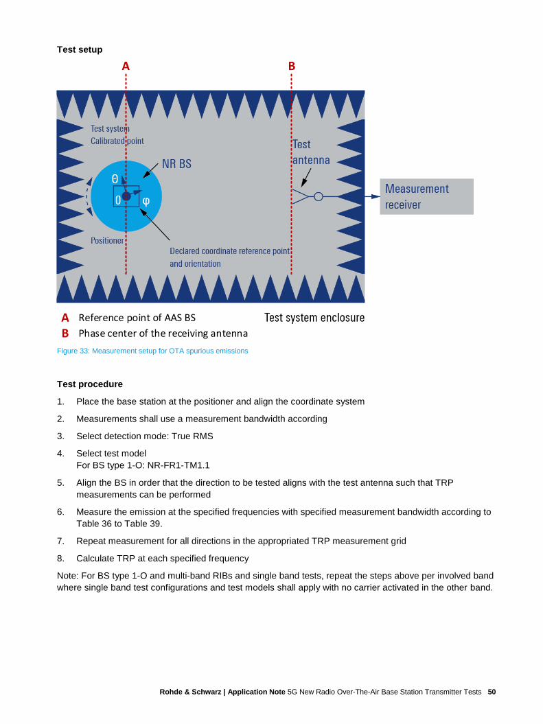
Rohde & Schwarz | Application Note 5G New Radio Over-The-Air Base Station Transmitter Tests 50
Test setup
Figure 33: Measurement setup for OTA spurious emissions
Test procedure
1. Place the base station at the positioner and align the coordinate system
2. Measurements shall use a measurement bandwidth according
3. Select detection mode: True RMS
4. Select test model
For BS type 1-O: NR-FR1-TM1.1
5. Align the BS in order that the direction to be tested aligns with the test antenna such that TRP
measurements can be performed
6. Measure the emission at the specified frequencies with specified measurement bandwidth according to
Table 36 to Table 39.
7. Repeat measurement for all directions in the appropriated TRP measurement grid
8. Calculate TRP at each specified frequency
Note: For BS type 1-O and multi-band RIBs and single band tests, repeat the steps above per involved band
where single band test configurations and test models shall apply with no carrier activated in the other band.
A B
A Reference point of AAS BS
B Phase center of the receiving antenna

Rohde & Schwarz | Application Note 5G New Radio Over-The-Air Base Station Transmitter Tests 51
5.8.4.4 Co-location requirements (6.7.5.5)
These requirements may be applied for the protection of other BS receivers when GSM900, DCS1800,
PCS1900, GSM850, CDMA850, UTRA FDD, UTRA TDD,
E-UTRA and/or NR BS are co-located with a BS. The requirements assume co-location with base stations of
the same class.
The test purpose is to verify that the emission is within the specified requirement limits at the CLTA
conducted output(s). [2]
RF channels to be tested for single carrier: M
As of the large scope, the test requirements for this test were not printed in this application note. The
requirements can be found in TS 38.141-2 [2] section 6.7.5.5.5
Test setup
Figure 34: Measurement setup for OTA co-location emissions
A B
A Reference point of AAS BS
B Phase center of the receiving antenna

Rohde & Schwarz | Application Note 5G New Radio Over-The-Air Base Station Transmitter Tests 52
Test procedure
1. Place the base station and the CLTA (Several CLTAs might be required to cover the whole co-location
spurious emission frequency ranges; more information can be found in [2], subclause 4.12)
2. Several CLTAs might be required to cover the whole co-location spurious emission frequency ranges
3. Place test antenna in reference direction at far-field distance, aligned in all supported
4. The test antenna shall be dual (or single) polarized with the same frequency range as the NR BS for co-
location spurious emission test case
5. OTA co-location spurious emission is measured as the power sum over all supported polarizations at
the CLTA conducted output(s)
6. The detection mode of the measurement device shall be "True RMS"
7. Set BS type 1-O to transmit test model according to TS 38.141-1 [1]
8. Measure the emission at the specified frequencies with specified measurement bandwidth
5.9 OTA transmitter intermodulation (6.8)
This test is not applicable for BS type 2-O.
The OTA transmitter intermodulation requirement is a measure of the capability of the transmitter unit to
inhibit the generation of signals in its non-linear elements caused by presence of the wanted signal and an
interfering signal reaching the transmitter unit via the RDN and antenna array from a co-located base station.
The requirement applies during the transmitter ON period and the transmitter transient period.
The transmitter intermodulation level is the total radiated power of the intermodulation products when an
interfering signal is injected into the colocation test antenna (CLTA).
For BS type 1-O, the transmitter intermodulation requirement is captured by the co-location transmitter
intermodulation scenario case, in which the interfering signal is injected into the CLTA. [2]
Figure 35: Transmitter intermodulation

Rohde & Schwarz | Application Note 5G New Radio Over-The-Air Base Station Transmitter Tests 53
The OTA transmitter intermodulation requirement is not applicable for BS type 2-O.
Table 43: Test requirements for BS type 1-O: Interfering and wanted signals for the OTA transmitter intermodulation requirement
Parameter Value
Wanted signal NR single or multi-carrier, or multiple intra-band contiguously or non-contiguously aggregated carriers
Interfering signal type NR signal, the minimum BS channel bandwidth (BWChannel) with 15 kHz SCS of the band defined in subclause 5.3.5 of TS 38.104 [2]
Interfering signal level The interfering signal level is the same power level as the BS (Prated,t,TRP) fed into a CLTA.
Interfering signal center frequency offset from the lower (upper) edge of the wanted signal or edge of sub-block inside a gap
foffset = ± BWchannel (n −1
2)
For n = 1, 2 and 3
Test setup
Figure 36: Measurement setup for OTA transmitter intermodulation
A B
A Reference point of AAS BS
B Phase center of the receiving antenna

Rohde & Schwarz | Application Note 5G New Radio Over-The-Air Base Station Transmitter Tests 54
Test procedure
1. Select a CLTA; The test antenna(s) shall be dual (or single) polarized
Note: Several test antennas are required to cover both the NR BS and the whole emission frequency
range
2. Connect test antenna and CLTA to the measurement equipment according to Figure 36
3. The OTA emission measurement method shall be TRP and the detection mode of the measurement
device shall be "True RMS"
4. Set the base station to transmit test model according to TS 38.141-1 [1]
5. SMW: Generating the interfering signal (via the CLTA)
c) Select test model according to TS 38.141-1 [1]
d) Center frequency offset according to Table 43
e) Adjust the interfering signal (according to Table 43)
6. Perform OTA ACLR test (6.7.3), OTA OBUE test (6.7.4) and OTA spurious emission test (6.7.5) as
specified in sub clause 5.8.2, 5.8.3 and 5.8.4
7. Repeat the test for the remaining interfering signal center frequency offsets

Rohde & Schwarz | Application Note 5G New Radio Over-The-Air Base Station Transmitter Tests 55
6 Literature
[1] 3GPP Technical Specification Group Radio Access Network, "NR Base station conformance testing,
Part 1: Radiated conformance testing, Release 16; 3GPP TS 38.141-1, V16.3.0", 2020
Available: https://www.3gpp.org/DynaReport/38141-1.htm
[2] 3GPP Technical Specification Group Radio Access Network, "NR Base station conformance testing,
Part 2: Radiated conformance testing, Release 16; 3GPP TS 38.141-2, V16.3.0", 2020
Available: https://www.3gpp.org/DynaReport/38141-2.htm
[3] Rohde & Schwarz, 5G NR Technology Introduction, 2019
[4] 3GPP Technical Specification Group Radio Access Network, "NR Base Station (BS) radio
transmission and reception, Release 15; TS 38.104, V16.3.0", 2020
Available: https://www.3gpp.org/DynaReport/38104.htm
[5] Rohde & Schwarz, "5G NR Base Station Transmitter Tests (GFM313)", 2020
Available: https://rohde-schwarz.com/appnote/gfm313
[6] Rohde & Schwarz, "5G NR Base Station Receiver Tests (GFM314)", 2020
Available: https://rohde-schwarz.com/appnote/gfm314
[7] Rohde & Schwarz, "5G NR Base Station Performance Tests (GFM315)", 2020
Available: https://rohde-schwarz.com/appnote/gfm315
[8] Rohde & Schwarz, R&S®SMW-K544 User-Defined Frequency Response Correction - User manual,
2019
[9] Rohde & Schwarz, R&S®FSW Signal and Spectrum Analyzer - User Manual
[10] Rohde & Schwarz, "White paper - Demystifying over-the-air (OTA) testing - important antenna
parameters, test system setup and calibration", May 2019
Available: https://www.rohde-schwarz.com/de/loesungen/test-and-measurement/wireless-
communication/wireless-5g-and-cellular/5g-test-and-measurement/ota-white-paper_251028.html
[11] 3GPP Technical Specification Group Radio Access Network, "Radio Frequency (RF) conformance
testing background for radiated Base Station (BS) requirements; TR 37.941", 2020
[12] Rohde & Schwarz, R&S®ATS1800C - User manual, 2019
[13] Rohde & Schwarz, "R&S®ATS1800C CATR product brochure"
Available: https://scdn.rohde-schwarz.com/ur/pws/dl_downloads/dl_common_library/
dl_brochures_and_datasheets/pdf_1/ATS1800C_pro-fly_en_3608-1298-32_v0100.pdf
[14] Rohde & Schwarz, "R&S PWC200 Plane Wave Converter - Product Flyer", 2019
Available: https://scdn.rohde-schwarz.com/ur/pws/dl_downloads/dl_common_library/
dl_brochures_and_datasheets/pdf_1/PWC200_fly_en_5215-5971-32_v0200.pdf

Rohde & Schwarz | Application Note 5G New Radio Over-The-Air Base Station Transmitter Tests 56
7 Ordering Information
Type Designation Order No.
R&S®TS8991 OTA Performance Test System Note: includes WPTC test chambers
1119.4309.02
R&S®ATS1800C Compact antenna test range (CATR) OTA test system 1534.1800K02
R&S®ATS-C50MF 50 GHz cable, length: 1.2m (M-F) 1535.7977.02
R&S®ATS-C50MM 50 GHz cable, length 1.2m (M-M) 1535.7983.02
R&S®PWC200 Plane Wave Converter 1532.3006.02
R&S®FSW67 Signal and spectrum analyzer 1331.5003.67
R&S®FSW-K144 3GPP 5G-NR downlink measurements 1338.3606.02
R&S®FSW-K544 User defined frequency response correction by SnP file 1338.2716.02
R&S®SMBV100B Vector signal generator 1423.1003.02
R&S®SMBVB-B103 Frequency range 8 kHz to 3 GHz 1423.6270.02
R&S®SMBVBKB106 Frequency extension 6 GHz 1423.6370.02
R&S®SMBVB-K520 Baseband realtime extension 1423.7676.02
R&S®SMBVB-K144 5G New Radio 1423.8608.02
R&S®SMW200A Vector signal generator 1412.0000.02
R&S®SMW-B1007 Frequency option 1428.7700.02
R&S®SMW-B10 or R&S®SMW-B9
Baseband generator option 1413.1200.02 or 1413.7350.02
R&S®SMW-B13T or R&S®SMW-B13XT
Baseband main module option 1413.3003.02 or 1413.8005.02
R&S®SMW-K144 5G New Radio 1414.4990.02
R&S®SMW-K544 User-defined frequency response correction 1414.3707.02
Please note that the above table does not include all the test instruments and system components needed
for 5G NR base station conformance testing.
For further ordering information please contact your local sales team:
► https://www.rohde-schwarz.com/service-sales-locator

Rohde & Schwarz | Application Note 5G New Radio Over-The-Air Base Station Transmitter Tests 57
8 Appendix
A Glossary
Abbreviation Description
5G NR 5G New Radio
ACLR Adjacent channel leakage power ratio
BS Base station
CA Carrier aggregation
CATR Compact antenna test range
CLTA Colocation test antenna
DUT Device under test
EIRP Equivalent isotropically radiated power
EVM Error vector magnitude
FDD Frequency division duplex
FFS For further study
FR1 Frequency range 1
IAC Indoor anechoic chamber
MIMO Multiple input multiple output
OBUE Operating band unwanted emissions
OBW Occupied bandwidth
OTA Over the air
PDSCH Physical downlink shared channel
Prat Rated output power
Px- Performance-
RB Resource block
RBW Resolution bandwidth
RF Radio frequency
RIB Radiated interface boundary
RS Reference signal
Rx- Receiver-
SC Single carrier
SCS Subcarrier spacing
SSB Synchronization signal block
TAB Transceiver array boundary

Rohde & Schwarz | Application Note 5G New Radio Over-The-Air Base Station Transmitter Tests 58
TAE Time alignment error
TDD Time division duplex
TM Test model
TRP Total radiated power
Tx- Transmitter-
UE User equipment
VSWR Voltage standing wave ratio
WPTC Wireless Performance Test Chamber

Rohde & Schwarz The Rohde & Schwarz electronics group offers
innovative solutions in the following business fields: test
and measurement, broadcast and media, secure
communications, cybersecurity, monitoring and network
testing. Founded more than 80 years ago, the
independent company which is headquartered in
Munich, Germany, has an extensive sales and service
network with locations in more than 70 countries.
Rohde & Schwarz training www.training.rohde-schwarz.com
Rohde & Schwarz customer support www.rohde-schwarz.com/support
Certified Quality Management
ISO 9001
PA
D-T
-M: 3573.7
380.0
2/0
4.0
0/E
N
R&S® is a registered trademark of Rohde & Schwarz GmbH & Co. KG
Trade names are trademarks of the owners.
GFM324 | Version 1e | 06.2020
Application Note | 5G New Radio Over-The-Air Base Station Transmitter
Tests
Data without tolerance limits is not binding | Subject to change
© 2020 Rohde & Schwarz GmbH & Co. KG | 81671 Munich, Germany
www.rohde-schwarz.com


