
ii
5.1 SOUND SYSTEM
NUR HIDAYAH BT MAT NOR
This report is submitted in partial fulfillment of this requirement for the award of
Bachelor of Electronic Engineering (Industrial Electronic) With Honors
Faculty of Electronic and Computer Engineering
Universiti Teknikal Malaysia Melaka
April 2009
i

iii
UNIVERSTI TEKNIKAL MALAYSIA MELAKA
FAKULTI KEJURUTERAAN ELEKTRONIK DAN KEJURUTERAAN KOMPUTER
BORANG PENGESAHAN STATUS LAPORAN
PROJEK SARJANA MUDA II
Tajuk Projek : 5.1 Sound System
Sesi Pengajian : Januari 2009
Saya NUR HIDAYAH BT MAT NOR
mengaku membenarkan Laporan Projek Sarjana Muda ini disimpan di Perpustakaan dengan syarat-
syarat kegunaan seperti berikut:
1. Laporan adalah hakmilik Universiti Teknikal Malaysia Melaka.
2. Perpustakaan dibenarkan membuat salinan untuk tujuan pengajian sahaja.
3. Perpustakaan dibenarkan membuat salinan laporan ini sebagai bahan pertukaran antara institusi
pengajian tinggi.
4. Sila tandakan ( √ ) :
SULIT*
(Mengandungi maklumat yang berdarjah keselamatan atau
kepentingan Malaysia seperti yang termaktub di dalam AKTA
RAHSIA RASMI 1972)
TERHAD*
(Mengandungi maklumat terhad yang telah ditentukan oleh
organisasi/badan di mana penyelidikan dijalankan)
TIDAK TERHAD
Disahkan oleh:
__________________________ ___________________________________
(TANDATANGAN PENULIS) (COP DAN TANDATANGAN PENYELIA)
Alamat Tetap: ……………………………......
……………………………......
Tarikh: ……………………….. Tarikh: ………………………..
ii

iv
“I hereby declare that this report is result of my own effort except for works that
have been cited clearly in the references.”
Signature :
Name : Nur Hidayah Bt Mat Nor
Date :
iii
v
“I hereby declare that I have read this report and in my opinion this report is
sufficient in terms of scope and quality for the award of Bachelor of Electronic
Engineering (Electronic Industrial) with Honours”
Signature : ……………………………….
Supervisor‟s Name : En. Ahmad Sadhiqin bin Mohd Isira
Date : ……………………………….
iv

vi
ACKNOWLEDGEMENT
All praises be upon Allah s.w.t the Almighty and peace be upon Prophet
Muhammad s.a.w. Before I go any further, I would like to thank God with the
blessing that help me to go through the Projek Sarjana Muda and thesis smoothly.
Upon completing this subject and the final report, I would like to thank my
project‟s supervisor, En. Ahmad Sadhiqin B. Mohd Isira for his helps and supports
for completion of this project. Also I would like to take this opportunity to express
my deepest gratitude to all my friends for all their kindness and guidance on me
throughout my project.
This thank also I dedicate to my family for the support, help, cooperation and
guidance for this project. I am thankful for their love and never give up on me no
matter what happen. A lot of thanks also to all the individuals who involved in this
project since the first day it started.
THANK YOU
v

vii
ABSTRACT
5.1 Sound System is a project of „Projek Sarjana Muda (PSM)‟ that includes
the knowledge of the electronic specifically in circuit operation. This project requires
designing and constructing the hardware for the sound system based on power
amplifier, treble and bass. It will have FIVE (5) sound system speakers together with
a subwoofer (5.1 channels). There are 8 circuits of amplifiers which includes the bass
(low frequency) and treble (high frequency). The circuit will filter and channel the
high and low frequency to the appropriate speaker. This will utilize the use of
microprocessor and the speakers will collect the sound signals from CD player / tape
player and Auxiliary system. 5.1 project is suitable for the sound system at home or a
room with a scope area of 6 × 4 metre and with the audience of 5 to 8 audiences such
as a family. From this project, the information and knowledge about the audio system
and circuit involved will be analyzed like the output power and current required, the
suitable speaker used, and the impedance for the speakers, before choosing the power
amplifier circuit that will be used to amplify the treble and base output for both side
(left and right). Then, the output from amplifier will be sending to the speaker to
produce the sound needed.
vi

viii
ABSTRAK
“ 5.1 Sound System “ adalah satu projek yang dibina sebagai memenuhi
syarat “ Projek Sarjana Muda (PSM) “ yang mengambil kira pengetahuan tentang
operasi litar elektronik. Projek ini memerlukan rekaan dan binaan untuk perkakasan
sistem bunyi berdasarkan kepada litar penguat, treble dan bass. Ia mempunyai 5
sistem pembesar suara (speakers) dan satu subwoofer (5.1 channels) bersama dengan
6 litar termasuk treble dan bass. Litar ini berfungsi untuk menapis dan menyalurkan
frekuensi tinggi dan rendah kepada pembesar suara yang sesuai. Pada keadaan ini,
mikropemproses akan digunakan dan pembesar suara berfungsi untuk
mengumpul/memungut isyarat bunyi dari pemain CD/pemain pita dan sistem
auxiliary. Projek ini adalah bersesuaian digunakan untuk sistem bunyi dirumah atau
dibilik yang mempunyai keluasan 6 × 4 meter bersama dengan 5 hingga 8 orang
pendengar /penonton. Selain daripada itu, melalui projek ini juga pengetahuan dan
maklumat mengenai sistem audio dan litar yang terlibat dapat diketahui dan
dianalisis seperti kuasa keluaran dan arus yang diperlukan, pembesar suara yang
bersesuaian, dan impedans pembesar suara yang bersesuaian sebelum litar penguat
dipilih dan digunakan sebagai penguat kepada keluaran treble dan bass bagi kedua-
dua bahagian kiri dan kanan. Keluaran daripada penguat akan dihantar kepada
pembesar suara untuk mengeluarkan suara yang diperlukan / diingini.
vii

ix
TABLE OF CONTENT
CHAPTER TITLE PAGE
TITLE i
STATUS FORM ii
DECLARATION iii
DEDICATION iv
ACKNOWLEDGEMENT v
ABSTRACT vi
ABSTRAK vii
TABLE OF CONTENT viii
LIST OF FIGURE xii
I INTRODUCTION 1
1.1 Introduction 1
1.2 Objectives 3
1.3 Problem Statement 3
1.4 Scope 3
1.5 Methodology 4
1.6 Working Flowchart 6
II LITERATURE REVIEW 7
2.1 Introduction 7
2.2 Pre Amplifier 8
2.3 Power Amplifier 9
2.3.1 Input Stage 10
2.3.1.1 Differential Pair Transistor 10
viii

x
2.3.2 VAS Stage 11
2.3.3 Output Stage 12
2.3.3.1 Complementary Symmetry
Transistor Class B 13
2.3.3.2 Circuit Operation Of
Class B Output Stage 14
2.4 Example of Power Amplifier 15
III CIRCUIT DESIGN 17
3.1 Hardware Prototype 17
3.2 Printed Circuit Board (PCB) 17
3.3 Power Amplifier Schematic Circuit 18
3.3.1 Component Used 19
3.3.1.1 BJT Transistor 19
3.3.1.2 How Transistor Work 19
3.3.1.3 NPN Transistor 20
3.3.1.4 PNP Transistor 20
3.3.1.5 Common Emitter Amplifier 21
3.3.1.6 Common Collector Amplifier 22
3.3.1.7 Power Transistor 23
3.3.2 PCB Layout for the Project Board 24
3.4 Pre Amplifier Schematic Circuit 26
3.4.1 Component Used 26
3.4.1.1 LM348 (Four UA741
Quad Bipolar Operational
Amplifiers) 26
3.4.1.2 Description 26
3.4.1.3 Pin Connections 27
3.4.1.4 Schematic Diagram of
The L348 28
3.4.2 PCB Layout for the Project Board 28
ix
xi
IV EXPERIMENTS AND RESULTS 31
4.1 Simulation Results 31
4.2 Simulation of the Types of Power
Amplifier 31
4.2.1 Class B Push Pull Operation 31
4.2.2 Complementary Symmetry
Transistors 33
4.2.3 Class AB Push Pull Amplifier 35
4.2.4 Darlington Class AB Amplifier 36
4.3 Simulation of the Stage in Power Amplifier 38
4.3.1 Input Stage 38
4.3.2 Second Stage 39
4.3.3 Output Stage 40
4.4 Experiment and Troubleshooting of the
Circuit 42
4.4.1 Output at C2238 42
4.4.2 Output at A968 43
4.4.3 Output at Stage Result 44
V DISCUSSION 46
5.1 Discussion 46
VI CONCLUSION AND FUTURE
RECOMMENDATIONS 49
6.1 Conclusion 49
6.2 Future Recommendations 50
x

xii
REFERENCES 51
APPENDIX A 52
APPENDIX B 55
APPENDIX C 57
APPENDIC D 65
APPENDIX E 69
APPENDIX F 72
xi

xiii
LIST OF FIGURE
FIGURE TITLE PAGE
1.1 Block Diagram of 5.1 Sound System 1
1.2 Position of the Speaker 2
1.3 Flow Chart 6
2.1 Sound System Block Diagram 8
2.2 Differential Pair Transistors 11
2.3 Darlington Pair 12
2.4 Complementary Symmetry Transistor Class B 13
2.6 Example of Power Amplifier 15
3.1 Power Amplifier 18
3.2 Symbol of NPN Transistor 20
3.3 Symbol of PNP Transistor 21
3.4 Common Emitter Amplifier 22
3.5 Common Collector Amplifier 22
3.6 Power Transistor 23
3.7 PCB Layout with Mounted Component for
Power Amplifier 24
3.8 Layout for negative type PCB board 24
3.9 Front layout of 3D board 25
3.10 Back side layout of 3D board 25
3.11 Pre-amplifier 26
3.12 LM 348 27
3.13 Schematic diagram of LM348 28
3.14 PCB layout with mounted component for
xii

xiv
Pre-amplifier 28
3.15 Layout for negative type PCB board 29
3.16 Front layout of 3D board 29
3.17 Back side layout of 3D board 30
4.1 Class B push pull 32
4.2 Output of class B push-pull 32
4.3 Complementary symmetry transistors 33
4.4 Output of complementary symmetry transistors 34
4.5 Crossover distortion 34
4.6 Class AB Push-Pull Amplifier 35
4.7 Output of Class AB Push-Pull Amplifier 36
4.8 Darlington Class AB Amplifier 37
4.9 Output of Darlington Class AB Amplifier 37
4.10 Input stage 38
4.11 Output of input stage 38
4.12 Second stage 39
4.13 Output of second stage 40
4.14 Output stage 40
4.15 Output of output stage 41
4.16 Input given 41
4.17 Output at base C2238 42
4.18 Expected result for C2238 and MJ15003 43
4.19 Output at base A968 43
4.20 Expected result for A968 and MJ15004 44
4.21 Equipment used in circuit experiment 44
4.22 Output of the power amplifier 45
5.1 Crossover distortion at output stage 48
xiii
xv
CHAPTER I
INTRODUCTION
1.1 Project introduction
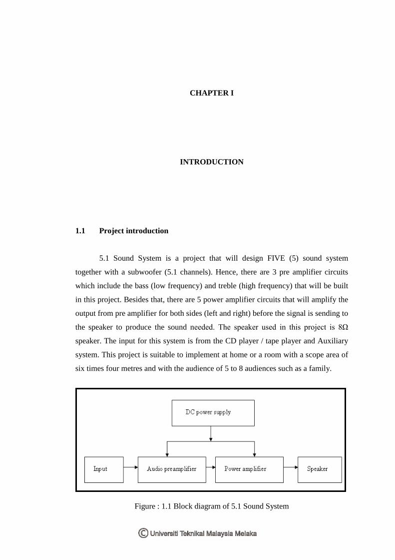
5.1 Sound System is a project that will design FIVE (5) sound system
together with a subwoofer (5.1 channels). Hence, there are 3 pre amplifier circuits
which include the bass (low frequency) and treble (high frequency) that will be built
in this project. Besides that, there are 5 power amplifier circuits that will amplify the
output from pre amplifier for both sides (left and right) before the signal is sending to
the speaker to produce the sound needed. The speaker used in this project is 8Ω
speaker. The input for this system is from the CD player / tape player and Auxiliary
system. This project is suitable to implement at home or a room with a scope area of
six times four metres and with the audience of 5 to 8 audiences such as a family.
Figure : 1.1 Block diagram of 5.1 Sound System
xvi
In sound system, power amplifiers are the bridge between loudspeakers and
the rest of any sound system like showed in Figure 1.1. Power amplifiers are large-
signal amplifiers. It means that a much larger portion of load line is used during
signal operation than in a small-signal amplifier. In a small-signal amplifier, the ac
signal moves over a small percentage of the total ac load line. When the output signal
is larger and approaches the limits of the ac load line, the amplifier is a large-signal
type. Power amplifiers are normally used as the final stage of a communications
receiver or transmitter to provide signal power to speakers or to a transmitting
antenna. In this project, a power amplifier circuit used can generate an output of
100W. The circuit consist the transistors, resistors, diodes and capacitors. The type of
amplifier used is a Darlington class AB push-pull amplifier. When the push-pull is
used, the load resistance is relatively small. An 8ohm speaker is a common load for a
class AB push-pull amplifier. A push-pull amplifier using Darlington transistors can
be used to increase the input resistance presented to the driving amplifier and avoid
reducing the voltage gain. [3]
For the treble and bass circuit (pre amplifier), it acts like a two band
equalizer. Treble circuit controls the higher frequencies of sound, and bass controls
the lower frequencies of sound. The treble and bass circuit will be included in all of
the circuits used for this project. [4]
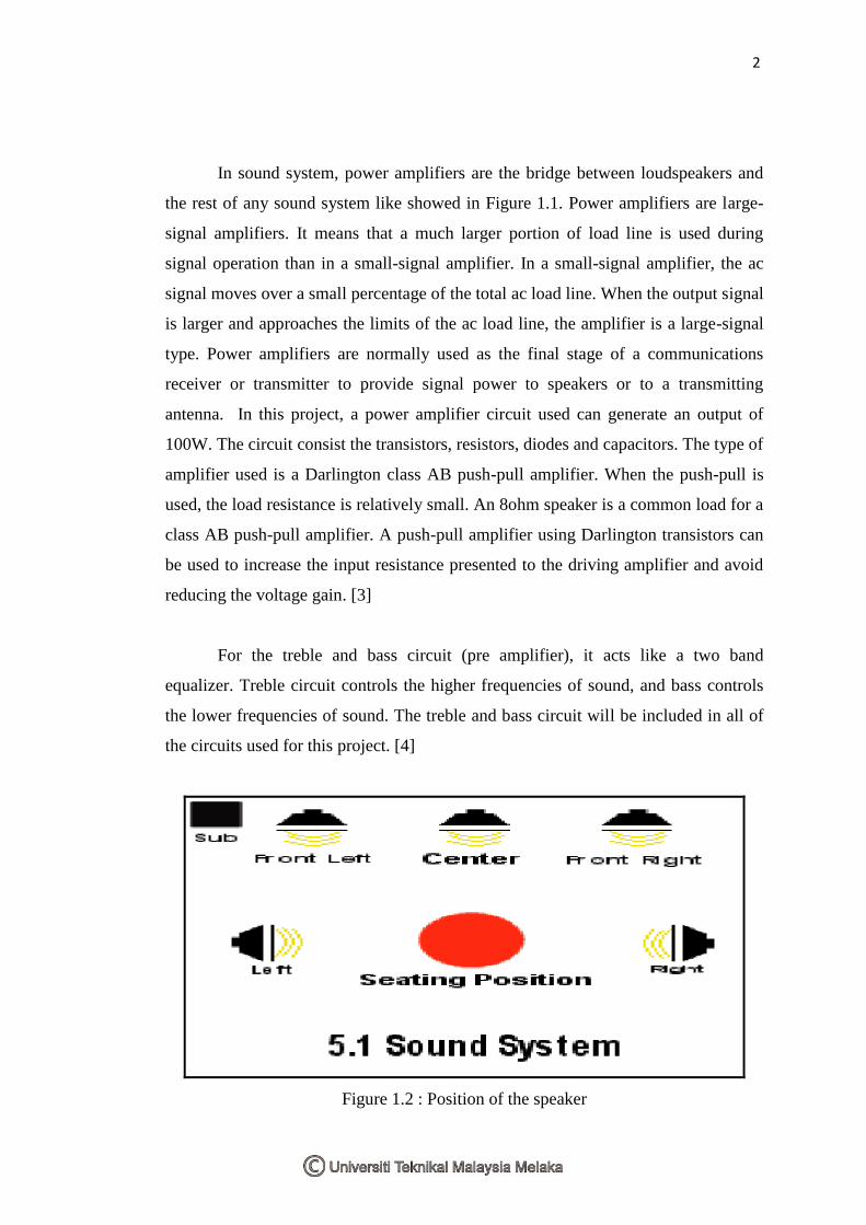
Figure 1.2 : Position of the speaker
2

xvii
1.2 Objectives of the project
1) To learn about the audio system and the circuit needed.
2) To be familiar with the audio power amplifier.
3) To improve the troubleshooting of the electronic circuit.
4) To design and implement the 5.1 sound system circuit.
5) To be familiar with the simulation of 5.1 sound system circuit.
1.3 Problem statement
This project is about a sound system at home or a room with a scope area of
six times four metres. It is suitable for a group of audience of five to eight. There are
three circuits used for this project which includes the low (bass) and high (treble)
frequency circuit and the power amplifier circuit. Both circuits will control the
tone/sound and the power amplifier will amplify it input to be sent to the speaker.
1.4 Scope of work
As the scope of the project, it must be noted that an undergraduate project, it is not
expected to be perfect design. There must be a border, in which the student should
attain to fulfill the requirement of the project. This project scope is list as below:
1) To search for information from reliable resources.
2) To study and analyze the information and choose the suitable circuit for the
project.
3) To design the circuit :
i. Low frequency circuit
ii. High frequency circuit
4) To simulate the circuits.
5) To troubleshoot and implement the circuit.
3
xviii
1.5 Project methodology
This part will explain about the path that has been taken until the hardware
realization. First, before start the project, the information and knowledge about 5.1
sound system must be analyzed and gain. This will be under the first method called
literature review. The information about the circuit and project is found from the
internet, books, journal, thesis and others. From the sources, the aspects involved
with this project like circuit used, the suitable speaker used, the output power and
current required and the impedance for the speakers can be determined. Following
that, the comparison between the companies involved in this field had been made.
For example, Pioneer and Sony company. The characteristics that are compared will
be the features of the product, the power output provided, the equipment used and the
price. Then, the best one will be choose as a reference to the project.
The main circuit in this project is divided into two; preamplifier circuit that
will include the bass and treble circuit; and the power amplifier circuit. For
preamplifier circuit, it has to function as the equalizer of the sound. This circuit will
control the low and high frequency of the sound. In this circuit the main component
is the IC LM348, that is quadruple, independent, high-gain, internally compensated
operational amplifiers. Both of the circuit (bass & treble) will use it.
For power amplifier, it is function to amplify the signal to 100watt and then
sent it to the speaker. There is a few types of amplifier design that is commonly used
in the audio system such as class A amplifier, B amplifier and AB amplifier. These
three types had their own special characteristics. For class A, it is a straightforward
common-collector amplifier. In class A amplifier, the transistor must be conducting
for the whole of the cycle. It is biased sufficiently to keep it on continuously, even
during the negative half of the cycle. In general, class A amplifier show little
distortion. The type of amplifying device used has no bearing on the class. Class A
amplifier may base on BJTs, FETs, valves, Darlington pairs and several other
devices. [6]
4
xix
In class B amplifier, the excessive waste of power of the class A may be
eliminated by using two transistors, one to handle positive going excursions of the
signal and the other to handle the negative going excursions. This design is known as
push-pull operation. The amplitude of the harmonics in the output of class B is much
greater than the class A. For class AB amplifier, it is not really a separate class of its
own, but a combination of A and B. If an amplifier is biased into Class B, and then
the bias further increased, it will enter AB. For outputs below a certain level both
output devices conduct, and operation is class A. At higher levels, one device will be
turned off completely as the other provides more current, and the distortion jumps
upward at this point as AB action begins. Class AB is less linear than either A or B.
[6]
Then, base on the type of amplifier, the circuit needed for power amplifier
will be designed. The main component used in power amplifier circuit is power
transistor, capacitor and resistor. During the designing, the two stage power amplifier
is used. For the input stage, there is a circuit called differential pair amplifier will be
used. For the last stage, the circuit used is complementary push-pull amplifier class
AB transistor combined with the Darlington amplifier.
Next, the simulation using the MultiSim will take part to verify the
functionality of the circuit. From the result of simulation, the signal will be compared
to the reference result of the reference circuit to see the different between it. If any
difference appears, the circuit has to be modified and find the error. Lastly, the
circuit will be troubleshoots and tested before hardware mounting process. In the
testing stage, the circuit involved is power supply circuit, high and low frequency
circuit, and power amplifier circuit. The case for the entire circuit is designed where
it will have space for cd, tape player and auxiliary system.
5
xx
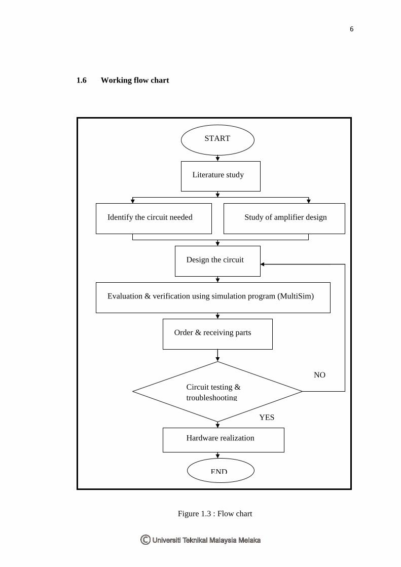
1.6 Working flow chart
Figure 1.3 : Flow chart
START
Literature study
Identify the circuit needed Study of amplifier design
Design the circuit
Evaluation & verification using simulation program (MultiSim)
Circuit testing &
troubleshooting
NO
Hardware realization
END
YES
Order & receiving parts
6
xxi
CHAPTER II
LITERATURE REVIEW
2.1 Introduction
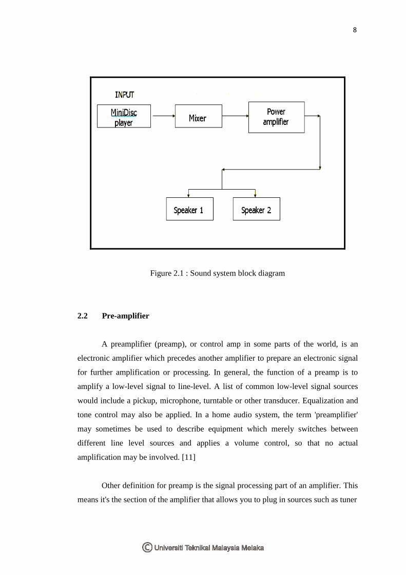
The sound system consists of four main components: the input (the
microphone, MiniDisc, cassette tape players, CD player), audio preamplifier, the
power amplifier, and the speakers. To use the sound system to its fullest potential,
the understanding of its components is necessary. One way of explaining a system is
in terms of the signal path, which refers to the path the signal (the electrical form of
the sound) gets from the recording system the to audience. The signal usually begins
at either the MiniDisc player or the cassette deck, the microphone. These devices
serve as your inputs. All of your input devices feed the preamplifier, which includes
the tone control (treble bass circuit). Using the preamplifier, the electric signal is sent
to the right places at the right volumes. [4]
From the preamplifier, the signal will go through the power amplifier to
amplify the line level signal into a higher level signal powerful enough to drive a
speaker. The speakers convert the electrical signal into vibrations which we is heard
as sound. [4]
xxii
Figure 2.1 : Sound system block diagram
2.2 Pre-amplifier
A preamplifier (preamp), or control amp in some parts of the world, is an
electronic amplifier which precedes another amplifier to prepare an electronic signal
for further amplification or processing. In general, the function of a preamp is to
amplify a low-level signal to line-level. A list of common low-level signal sources
would include a pickup, microphone, turntable or other transducer. Equalization and
tone control may also be applied. In a home audio system, the term 'preamplifier'
may sometimes be used to describe equipment which merely switches between
different line level sources and applies a volume control, so that no actual
amplification may be involved. [11]
Other definition for preamp is the signal processing part of an amplifier. This
means it's the section of the amplifier that allows you to plug in sources such as tuner
8
xxiii
and CD player. It's also the section that allows you to change volume and possibly to
change treble and bass settings. So it's a glorified switch with volume pot. [11]
2.3 Power amplifier
The term "power amplifier" is a relative term with respect to the amount of
power delivered to the load and/or sourced by the supply circuit. In general a power
amplifier is designated as the last amplifier in a transmission chain (the output stage)
and is the amplifier stage that typically requires most attention to power efficiency.
Power amplifiers are large-signal amplifiers. In a small-signal amplifier, the ac signal
moves over a small percentage of the total ac load line. When the output signal is
larger and approaches the limits of the ac load line, the amplifier is a large-signal
type. The purpose of an amplifier is to make an electronic signal bigger without
affecting the electronic device in any other way. [3]
Most power amplifier has two channels, a left and a right. The input signal
assigned to an amplifier determined the speaker component connected to the output.
The number of speaker components connected to an amplifier channel depends on
the electrical resistance (ohms) of the speaker component and the way they are
wired. The speakers can be wired in series or parallel. The total resistance of
speakers wired in series is calculated by summing the values of the speakers. A
speaker cabinet with two 8-ohm speakers wired in series would put a load of 16
ohms on an amplifier. The resistance of speakers wired in parallel is a little more
difficult to calculate. The values of the speakers are multiplied and the total is
divided by the sum of the values. A cabinet with two 8-ohm speakers wired in
parallel would put a load of 4-ohms on an amplifier (8×8 =64; 64÷16 =4). The
amount of power that an amplifier delivers depends on output load. The lower the
speaker‟s resistance (ohms), the higher the output power (watts), and the greater the
amplifier‟s power, the cleaner is the sound. [2]
9

xxiv
Power amplifiers usually are set with the volume full up; most level
adjustments are made by the controlling the system. The amplifiers are the last
components to be switched on in the signal path and the first to be switched off,
because any electronics in the chain that are powered up while connected in line will
cause a loud, possibly damaging click through the speakers. [2]
There are three stages in power amplifier. The first being a transconductance
stage or input stage (differential voltage in, current out), the second a transimpedance
stage (current in, voltage out) and the third a unity-voltage-gain output stage. The
second stage clearly has to provide all the voltage gain and it is called as voltage-
amplifier stage or VAS. [2]
2.3.1 Input stage
The input stage of an amplifier performs the critical duty of subtracting the
feedback signal from the input, to generate the error signal that drives the output. It is
almost invariably a differential transconductance stage; a voltage-difference input
results in a current output that is essentially insensitive to the voltage at the output
port. In this circuit, the differential pair transistor is used as the input stage of the
amplifier because of its low DC offset. Apart from its inherently lower offset due to
the cancellation of the Vbe voltages, it has the important added advantage that its
standing current does not have to flow through the feedback network. However a
second powerful reason, which seems less well-known, is that linearity is far superior
to single transistor input stages. [2]
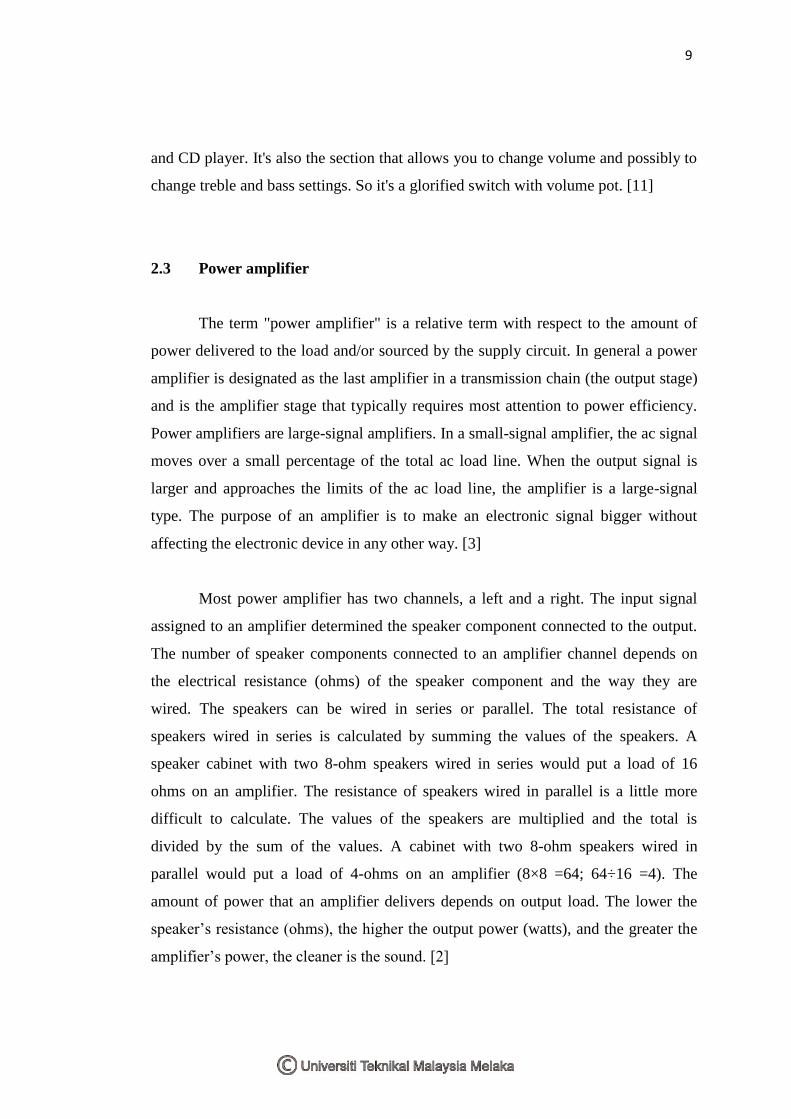
2.3.1.1 Differential pair transistor
A differential amplifier has two inputs instead of only one and its function is
to amplify the difference between the two inputs. There are two terms of mode for
the differential pair. First is the differential mode that describes the normal operation
10
xxv
of an amplifier in detecting and amplifying the difference in potential between its
two inputs. The second term is common mode. Common mode implies that both
sides of the amplifier are identical. They both have the same supply voltages and the
resistors and transistor used in both sides of the amplifier should have identical
performance. [5]
Figure 2.2 : Differential pair transistor
2.3.2 VAS stage
The Voltage-Amplifier Stage (VAS) has often been regarded as the most critical
part of a power amplifier, since it not only provides all the voltage gain but also must
give the full output voltage swing. (The input stage may give substantial
transconductance gain, but the output is in the form of a current). [2]
In this stage, the circuit involves is Darlington pair with current mirror diodes
bias. The Darlington pair consists of BJTs connected as Figure 2.3.
11


