
Series 45Axial Piston Open Circuit Pumps
Technical Information

2 520L0519 • Rev FK • October 2008
Series 45 Axial Piston Open Circuit PumpsTechnical Information
© 2008 Sauer-Danfoss. All rights reserved.Sauer-Danfoss accepts no responsibility for possible errors in catalogs, brochures and other printed material. Sauer-Danfoss reserves the right to alter its products without prior notice. This also applies to products already ordered provided that such alterations aren’t in conflict with agreed specifications. All trademarks in this material are properties of their respective owners. Sauer-Danfoss and the Sauer-Danfoss logotype are trademarks of the Sauer-Danfoss Group.
Front cover illustrations: F101 178, F101 180, F101 337, F101 168, P101 992
Revisions
Table of RevisionsDate Page Changed Rev.
October 2008 62, 65 add SAE-C two bolt housing FK
September 2008 58-62 dimension changes for Frame J FJ
June 2008 78, 93, 94, 95 various minor edits, removed S5 shaft from Frame E FI
May 2008 32, 74, 75, 92 correction to schematics drawings FH
April 2008 76 correction to S2 spline width (inch measurement only) FG
April 2008 52, 53 correction to schematics drawings FG
April 2008 27, 50, 72, 89 add Load sensing - RP and BP must be 20 bar FF
April 2008 76 Correction to S2 shaft - Class 6 and 37.91 mm length FF
March 2008 4 Correction to TOC FE
February 2008 Various Add LS setting to specifications for each frame FD
December 2007 Various Relocate F and E sections, add displacement limiter info. FC
November 2007 50 Change load sensing setting - bar increments FB
September 2007 Various Add Frame F, remove Frame G, and many edits FA
November 2006 51, 52, 53 Revised schematics information E
August 2005 - Removed Frame H, added Frame J D
April 2003 Added Frame E C
May 2001 - Added Frame H and Frame G B
May 1999 - First printing A
HistoRy of Revisions

3520L0519 • Rev FK • October 2008
Series 45 Axial Piston Open Circuit PumpsTechnical InformationContents
GeneRaL infoRmation
fRames L anD K
Overview ........................................................................................................................................................... 6Design ................................................................................................................................................................ 6Typical applications ....................................................................................................................................... 6
High performance .................................................................................................................................... 6Latest technology ..................................................................................................................................... 6Reliability ..................................................................................................................................................... 6
The Series 45 product family ...................................................................................................................... 7Basic units .................................................................................................................................................... 7
Load sensing open circuit system ............................................................................................................ 8Pressure compensated controls ................................................................................................................ 9
Operation ..................................................................................................................................................... 9Pressure compensated system characteristics ............................................................................... 9Typical applications for pressure compensated systems ........................................................... 9
Remote pressure compensated controls .............................................................................................10Remote pressure compensated system characteristics ............................................................10Typical applications for remote pressure compensated systems .........................................10
Load sensing controls .................................................................................................................................11Operation ...................................................................................................................................................11Load sensing system characteristics ................................................................................................11Typical applications for load sensing systems..............................................................................11
Electrical on/off pressure compensated controls .............................................................................12Operating parameters ................................................................................................................................13
Fluids ...........................................................................................................................................................13Viscosity......................................................................................................................................................13Temperature .............................................................................................................................................13Inlet pressure ............................................................................................................................................13Case pressure ...........................................................................................................................................13Pressure ratings .......................................................................................................................................14Speed ratings ...........................................................................................................................................14Duty cycle and pump life .....................................................................................................................14Speed, flow, and inlet pressure ...........................................................................................................14
Design parameters.......................................................................................................................................15Installation .................................................................................................................................................15Filtration .....................................................................................................................................................15Reservoir ....................................................................................................................................................15Fluid velocity ............................................................................................................................................16Shaft loads .................................................................................................................................................16Bearing life.................................................................................................................................................16Mounting flange loads ..........................................................................................................................17Auxiliary mounting pads ......................................................................................................................18Input shaft torque ratings ....................................................................................................................18Understanding and minimizing system noise .............................................................................19
Sizing equations ...........................................................................................................................................20
Design ..............................................................................................................................................................21Specifications .................................................................................................................................................22Performance L25C ........................................................................................................................................23Performance L30D .......................................................................................................................................24Performance K38C .......................................................................................................................................25Performance K45D .......................................................................................................................................26Order code ......................................................................................................................................................27

4 520L0519 • Rev FK • October 2008
Series 45 Axial Piston Open Circuit PumpsTechnical InformationContents
fRames L anD K(continued)
fRame J
Controls ............................................................................................................................................................29Pressure compensated control (PC) .................................................................................................29Remote PC control (RP) .........................................................................................................................29Load sensing control (LS) .....................................................................................................................30Load sensing control with internal bleed orifice (LB) ................................................................30Normally closed on/off electric PC control (ED) .........................................................................31Normally open on/off electric PC control (AA) ............................................................................31Electric proportional control (EJ) (Normally closed) .................................................................32
Input shafts .....................................................................................................................................................33Auxiliary mounting pads ...........................................................................................................................35
SAE-A auxiliary mounting pad ...........................................................................................................35SAE-B auxiliary mounting pad ...........................................................................................................35 SAE-A Auxilliary Pad ..............................................................................................................................36 Mounting pads at 90 degrees ...........................................................................................................36Running cover ..........................................................................................................................................36 Special SAE-A 11 tooth ........................................................................................................................36
Displacement limiter ...................................................................................................................................37Installation drawings ...................................................................................................................................38
Axial ported endcap ..............................................................................................................................38Radial ported endcap ............................................................................................................................40Electric on/off control............................................................................................................................42
Design ..............................................................................................................................................................43Specifications .................................................................................................................................................44Performance J45B ........................................................................................................................................45Performance J51B ........................................................................................................................................46Performance J60B ........................................................................................................................................47Performance J65C ........................................................................................................................................48Performance J75C ........................................................................................................................................49Order code ......................................................................................................................................................50Controls ............................................................................................................................................................52
Pressure compensated control (PC, BC) ..........................................................................................52Remote PC control (RP, BP) ..................................................................................................................52Load sensing control (LS, BS) ..............................................................................................................53Load sensing control with internal bleed orifice (LB, BB) .........................................................53Normally closed on/off electric PC control (AG) .........................................................................54Normally open on/off electric PC control (AF) ............................................................................54
Input shafts .....................................................................................................................................................55Auxiliary mounting pads ...........................................................................................................................58
SAE-A auxiliary mounting pad (non-integral) ..............................................................................58SAE-B auxiliary mounting pad ...........................................................................................................58
Displacement limiter ...................................................................................................................................59SAE-C auxiliary mounting pad ...........................................................................................................60Running cover ..........................................................................................................................................60
Installation drawings ...................................................................................................................................61Axial ported endcap ..............................................................................................................................61Radial ported endcap ............................................................................................................................64Electric on/off control/Radial endcap .............................................................................................66
5520L0519 • Rev FK • October 2008
Series 45 Axial Piston Open Circuit PumpsTechnical InformationContents
fRame e
fRame f Design ..............................................................................................................................................................68Specifications .................................................................................................................................................69Performance F74B ........................................................................................................................................70Performance F90C ........................................................................................................................................71Order code ......................................................................................................................................................72Controls ............................................................................................................................................................74
Pressure compensated control (PC) .................................................................................................74Remote PC Control (RP) ........................................................................................................................74Load sensing control with internal bleed orifice (LB) ................................................................75Load sensing control (LS) .....................................................................................................................75
Input shafts .....................................................................................................................................................76Auxiliary mounting pads ...........................................................................................................................77
SAE-A auxiliary mounting pad ...........................................................................................................77SAE-B auxiliary mounting pad ...........................................................................................................77
Displacement limiter ...................................................................................................................................78SAE-C auxiliary mounting pad ...........................................................................................................78
Adjustable displacement limiter and running cover .......................................................................79Axial ported endcap ....................................................................................................................................80Radial ported endcap .................................................................................................................................82
Design ..............................................................................................................................................................84Specifications .................................................................................................................................................85Performance E100B .....................................................................................................................................86Performance E130B .....................................................................................................................................87Performance E147C .....................................................................................................................................88Order code ......................................................................................................................................................89Controls ............................................................................................................................................................91
Pressure compensated control (PC) .................................................................................................91Remote PC control (RP) .........................................................................................................................91Load sensing control (LS) .....................................................................................................................92Load sensing control with internal bleed orifice (LB) ................................................................92
Input shafts .....................................................................................................................................................93Auxiliary mounting pads ...........................................................................................................................95
SAE-A auxiliary mounting pad ...........................................................................................................95SAE-B auxiliary mounting pad ...........................................................................................................95SAE-C auxiliary mounting pad ...........................................................................................................96Running cover ..........................................................................................................................................96
Displacement limiters .................................................................................................................................97Installation drawings ...................................................................................................................................98
Axial ported endcap, clockwise rotation ........................................................................................98Axial ported endcap, counterclockwise rotation ..................................................................... 100Radial ported endcap, clockwise rotation ................................................................................... 102Radial ported endcap, counterclockwise rotation ................................................................... 104

6 520L0519 • Rev FK • October 2008
Series 45 Axial Piston Open Circuit PumpsTechnical InformationGeneral information
oveRview Series 45 is a complete family of variable displacement, axial piston pumps for open circuit applications. Each frame within the Series 45 family is uniquely designed to optimize performance, size, and cost, matching the work function requirements of the demanding mobile equipment marketplace.
High performance• Displacements from 25 cm³ - 147 cm³ [1.53 - 8.97 in3/rev]• Speeds up to 3600 rpm• Pressures up to 310 bar [4495 psi] continuous, and 400 bar [5800 psi] peak• Variety of control system options including load sensing and pressure compensated• Through-drive capability for multi-circuit systems• Range of mounting flanges, shafts, and porting options for ease of installation
Latest technology• Customer-driven using quality function deployment (QFD) and design for
manufacturability (DFM) techniques• Optimized valve plates for maximum efficiency and quiet operation• Computer-modeled castings to optimize inlet conditions for maximum pump speed• Compact package size minimizing installation space requirements• Heavy-duty tapered roller bearings for long life• Single piece rigid housing to reduce noise and leak paths• Integrated controls for high speed response and system stability
Reliability• Designed to rigorous standards• Proven in both laboratory and field• Manufactured to rigid quality standards• Long service life• Significantly fewer parts• No gasketed joints• Robust input shaft bearings to handle large external shaft loads• Integrated gauge ports for monitoring operating conditions
• Cranes• Telescopic handlers• Forklift trucks• Wheel loaders• Sweepers• Backhoe loaders• Forestry and agricultural machinery• Fan drives• Other uses
DesiGn
tyPiCaL aPPLiCations
7520L0519 • Rev FK • October 2008
Series 45 Axial Piston Open Circuit PumpsTechnical InformationGeneral information
General performance specifications for the series 45 pump family
Pump Displacementspeed Pressure theoretical flow
(at rated speed)mounting
Continuous max. min. Continuous maximum
Model cm3 in3 min-1 (rpm) min-1 (rpm) min-1 (rpm) bar psi bar psi US gal/min l/min Flange
frame L See page 21
L25C 25 1.53 3200 3600 500 260 3770 350 5075 21.0 80.0 SAE B - 2 bolt
L30D 30 1.83 3200 3600 500 210 3045 300 4350 25.4 96.0 SAE B - 2 bolt
frame K See page 21
K38C 38 2.32 2650 2800 500 260 3770 350 5075 26.6 100.7 SAE B - 2 bolt
K45D 45 2.75 2650 2800 500 210 3045 300 4350 31.5 119.3 SAE B - 2 bolt
See page 43
J45B 45 2.75 2800 3360 500 310 4495 400 5800 33.3 126.0SAE B 2-bolt
SAE C 2 and 4-bolt
J51B 51 3.11 2700 3240 500 310 4495 400 5800 36.4 137.7SAE B 2-bolt
SAE C 2 and 4-bolt
J60B 60 3.66 2600 3120 500 310 4495 400 5800 41.2 156.0SAE B 2-bolt
SAE C 2 and 4-bolt
J65C 65 3.97 2500 3000 500 260 3770 350 5075 42.9 162.6SAE B 2-bolt
SAE C 2 and 4-bolt
J75C 75 4.58 2400 2880 500 260 3770 350 5075 47.5 180.0SAE B 2-bolt
SAE C 2 and 4-bolt
frame f See page 68
F74B 74 4.52 2400 2800 500 310 4495 400 5800 46.9 177.6 SAE B 2-boltSAE C 4-bolt
F90C 90 5.49 2200 2600 500 260 3770 350 5075 52.3 198 SAE B 2-boltSAE C 4-bol
frame e See page 84
E100B 100 6.10 2450 2880 500 310 4495 400 5800 64.7 245.0 SAE C 4-bolt
E130B 130 7.93 2200 2600 500 310 4495 400 5800 75.5 286.0 SAE C 4-bolt
E147C 147 8.97 2100 2475 500 260 3770 350 5075 81.5 308.7 SAE C 4-bolt
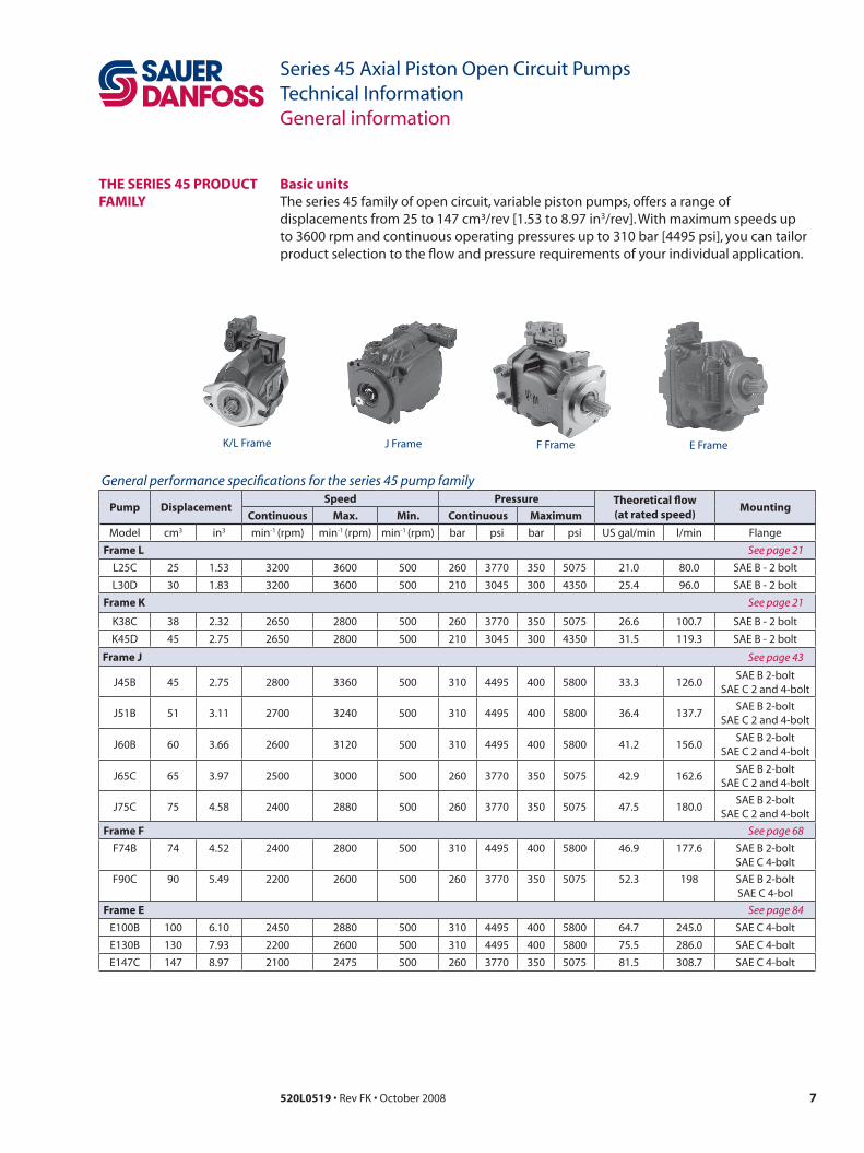
tHe seRies 45 PRoDuCt famiLy
Basic unitsThe series 45 family of open circuit, variable piston pumps, offers a range of displacements from 25 to 147 cm³/rev [1.53 to 8.97 in3/rev]. With maximum speeds up to 3600 rpm and continuous operating pressures up to 310 bar [4495 psi], you can tailor product selection to the flow and pressure requirements of your individual application.
K/L Frame E FrameF FrameJ Frame

8 520L0519 • Rev FK • October 2008
Series 45 Axial Piston Open Circuit PumpsTechnical InformationGeneral information
LoaD sensinG oPen CiRCuit system
The pump receives fluid directly from the reservoir through the inlet line. A screen in the inlet line protects the pump from large contaminants. The pump outlet feeds a PVG-32 multi-section, load sensing, directional control valve. The PVG valve directs pump flow to the cylinder and gear motor. A heat exchanger cools the fluid returning from the valve. A filter cleans the fluid before it returns to the reservoir.
Flow in the circuit determines the speed of the actuators. The position of the PVG valve determines the flow demand. A hydraulic pressure signal (LS signal) communicates demand to the pump control. The pump control monitors the pressure differential between pump outlet and the LS signal, and regulates servo pressure to control the swashplate angle. Swashplate angle determines pump flow.
Actuator load determines system pressure. The pump control monitors system pressure and will decrease the swashplate angle to reduce flow if system pressure reaches the PC setting. A system relief valve in the PVG valve acts as a back-up to control system pressure.
Pictorial circuit diagram
System pressure
Servo pressure
Actuator pressure
Load sense pressure
Actuator return
Suction / case drain /system return
K/L Frame Series 45open circuit axialpiston pump withload sensing control
PVG 32mulit-sectionloadsensingcontrolvalve
P101 658E
Reservoir FilterHeat exchanger
Double-acting cylinder
Bi-directionalgear motor
9520L0519 • Rev FK • October 2008
Series 45 Axial Piston Open Circuit PumpsTechnical InformationGeneral information
PRessuRe ComPensateD ContRoLs
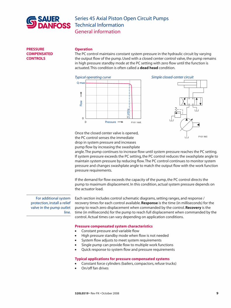
operationThe PC control maintains constant system pressure in the hydraulic circuit by varying the output flow of the pump. Used with a closed center control valve, the pump remains in high pressure standby mode at the PC setting with zero flow until the function is actuated. This condition is often called a dead head condition.
P101 965
Simple closed-center circuit
Once the closed center valve is opened, the PC control senses the immediate drop in system pressure and increases pump flow by increasing the swashplate
00
Q max
Pressure
Flow
P101 166E
PC s
ettin
g
Typical operating curve
angle. The pump continues to increase flow until system pressure reaches the PC setting. If system pressure exceeds the PC setting, the PC control reduces the swashplate angle to maintain system pressure by reducing flow. The PC control continues to monitor system pressure and changes swashplate angle to match the output flow with the work function pressure requirements.
If the demand for flow exceeds the capacity of the pump, the PC control directs the pump to maximum displacement. In this condition, actual system pressure depends on the actuator load.
Each section includes control schematic diagrams, setting ranges, and response / recovery times for each control available. Response is the time (in milliseconds) for the pump to reach zero displacement when commanded by the control. Recovery is the time (in milliseconds) for the pump to reach full displacement when commanded by the control. Actual times can vary depending on application conditions.
Pressure compensated system characteristics• Constant pressure and variable flow• High pressure standby mode when flow is not needed• System flow adjusts to meet system requirements• Single pump can provide flow to multiple work functions• Quick response to system flow and pressure requirements
typical applications for pressure compensated systems• Constant force cylinders (bailers, compactors, refuse trucks)• On/off fan drives
For additional system protection, install a relief valve in the pump outlet
line.
10 520L0519 • Rev FK • October 2008
Series 45 Axial Piston Open Circuit PumpsTechnical InformationGeneral information
Remote PRessuRe ComPensateD ContRoLs
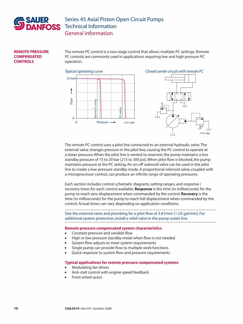
The remote PC control is a two-stage control that allows multiple PC settings. Remote PC controls are commonly used in applications requiring low and high pressure PC operation.
P101 966
Closed center circuit with remote PC
The remote PC control uses a pilot line connected to an external hydraulic valve. The external valve changes pressure in the pilot line, causing the PC control to operate at a lower pressure. When the pilot line is vented to reservoir, the pump maintains a low standby pressure of 15 to 20 bar [215 to 300 psi]. When pilot flow is blocked, the pump maintains pressure at the PC setting. An on-off solenoid valve can be used in the pilot line to create a low-pressure standby mode. A proportional solenoid valve, coupled with a microprocessor control, can produce an infinite range of operating pressures.
Each section includes control schematic diagrams, setting ranges, and response / recovery times for each control available. Response is the time (in milliseconds) for the pump to reach zero displacement when commanded by the control. Recovery is the time (in milliseconds) for the pump to reach full displacement when commanded by the control. Actual times can vary depending on application conditions.
Size the external valve and plumbing for a pilot flow of 3.8 l/min [1 US gal/min]. For additional system protection, install a relief valve in the pump outlet line.
Remote pressure compensated system characteristics• Constant pressure and variable flow• High or low pressure standby mode when flow is not needed• System flow adjusts to meet system requirements• Single pump can provide flow to multiple work functions• Quick response to system flow and pressure requirements
typical applications for remote pressure compensated systems• Modulating fan drives• Anti-stall control with engine speed feedback• Front wheel assist
00
Q max
Pressure
Flo
w
P101 969EPC
set
tin
g
Rem
ote
PC
set
tin
g
Typical operating curve
11520L0519 • Rev FK • October 2008
Series 45 Axial Piston Open Circuit PumpsTechnical InformationGeneral information
LoaD sensinG ContRoLs
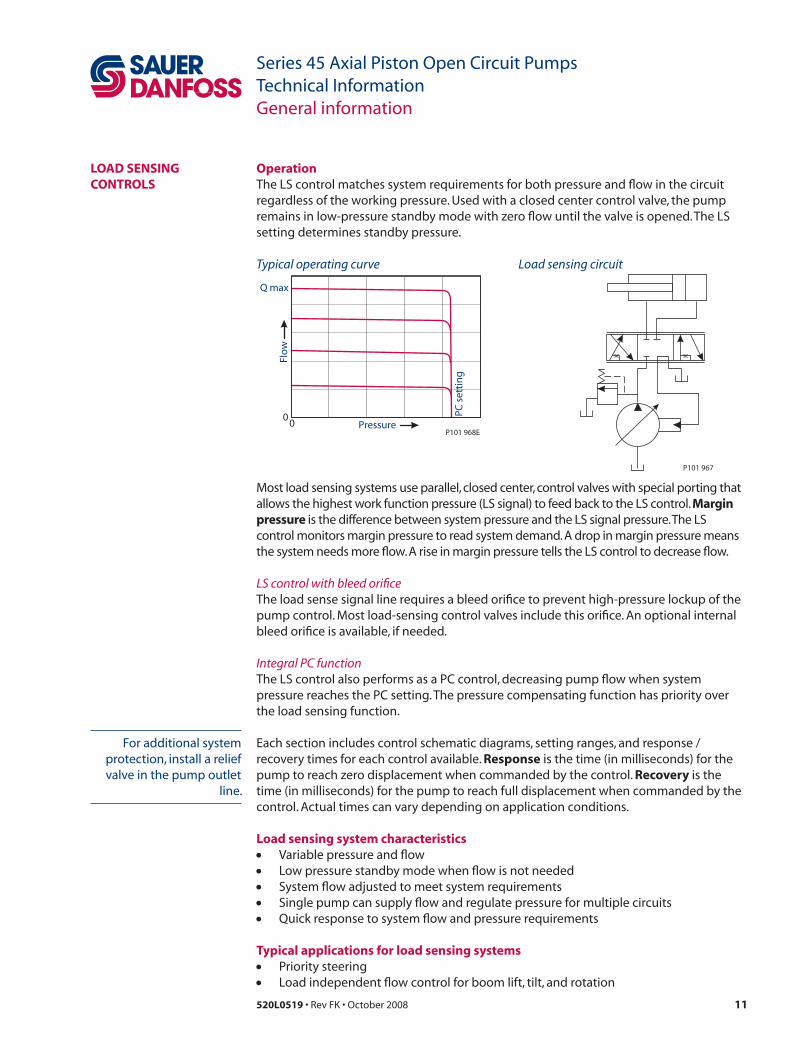
operationThe LS control matches system requirements for both pressure and flow in the circuit regardless of the working pressure. Used with a closed center control valve, the pump remains in low-pressure standby mode with zero flow until the valve is opened. The LS setting determines standby pressure.
P101 967
Load sensing circuit
Most load sensing systems use parallel, closed center, control valves with special porting that allows the highest work function pressure (LS signal) to feed back to the LS control. margin pressure is the difference between system pressure and the LS signal pressure. The LS control monitors margin pressure to read system demand. A drop in margin pressure means the system needs more flow. A rise in margin pressure tells the LS control to decrease flow.
LS control with bleed orificeThe load sense signal line requires a bleed orifice to prevent high-pressure lockup of the pump control. Most load-sensing control valves include this orifice. An optional internal bleed orifice is available, if needed.
Integral PC functionThe LS control also performs as a PC control, decreasing pump flow when system pressure reaches the PC setting. The pressure compensating function has priority over the load sensing function.
Each section includes control schematic diagrams, setting ranges, and response / recovery times for each control available. Response is the time (in milliseconds) for the pump to reach zero displacement when commanded by the control. Recovery is the time (in milliseconds) for the pump to reach full displacement when commanded by the control. Actual times can vary depending on application conditions.
Load sensing system characteristics• Variable pressure and flow• Low pressure standby mode when flow is not needed• System flow adjusted to meet system requirements• Single pump can supply flow and regulate pressure for multiple circuits• Quick response to system flow and pressure requirements
typical applications for load sensing systems• Priority steering• Load independent flow control for boom lift, tilt, and rotation
00
P101 968E
PC s
etti
ng
Flo
w
Pressure
Q max
Typical operating curve
For additional system protection, install a relief valve in the pump outlet
line.
12 520L0519 • Rev FK • October 2008
Series 45 Axial Piston Open Circuit PumpsTechnical InformationGeneral information
eLeCtRiCaL on/off PRessuRe ComPensateD ContRoLs
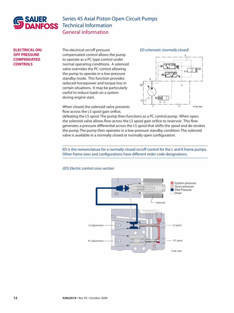
The electrical on/off pressure compensated control allows the pump to operate as a PC type control under normal operating conditions. A solenoid valve overrides the PC control allowing the pump to operate in a low-pressure standby mode. This function provides reduced horsepower and torque loss in certain situations. It may be particularly useful to reduce loads on a system during engine start.
When closed, the solenoid valve prevents flow across the LS spool gain orifice,
ED schematic (normally closed)
M2
L2
S L1
X
P106 044
B
Solenoid
LS adjustment
PC adjustment
LS spool
PC spool
P106 183E
System pressure
Pilot PressureServo pressure
Drain
(ED) Electric control cross-section
defeating the LS spool. The pump then functions as a PC control pump. When open, the solenoid valve allows flow across the LS spool gain orifice to reservoir. This flow generates a pressure differential across the LS spool that shifts the spool and de-strokes the pump. The pump then operates in a low-pressure standby condition. The solenoid valve is available in a normally closed or normally open configuration.
ED is the nomenclature for a normally closed on/off control for the L and K frame pumps. Other frame sizes and configurations have different order code designations.
13520L0519 • Rev FK • October 2008
Series 45 Axial Piston Open Circuit PumpsTechnical InformationGeneral information
oPeRatinG PaRameteRs
fluidsRatings and performance data for Series 45 products are based on operating with premium hydraulic fluids containing oxidation, rust, and foam inhibitors. These include premium turbine oils, API CD engine oils per SAE J183, M2C33F or G automatic transmission fluids (ATF), Dexron II (ATF) meeting Allison C-3 or Caterpillar T0-2 requirements, and certain specialty agricultural tractor fluids. For more information on hydraulic fluid selection, see Sauer-Danfoss publications 520L0463 Hydraulic Fluids and Lubricants, Technical Information, and 520L0465 Experience with Biodegradable Hydraulic Fluids, Technical Information.
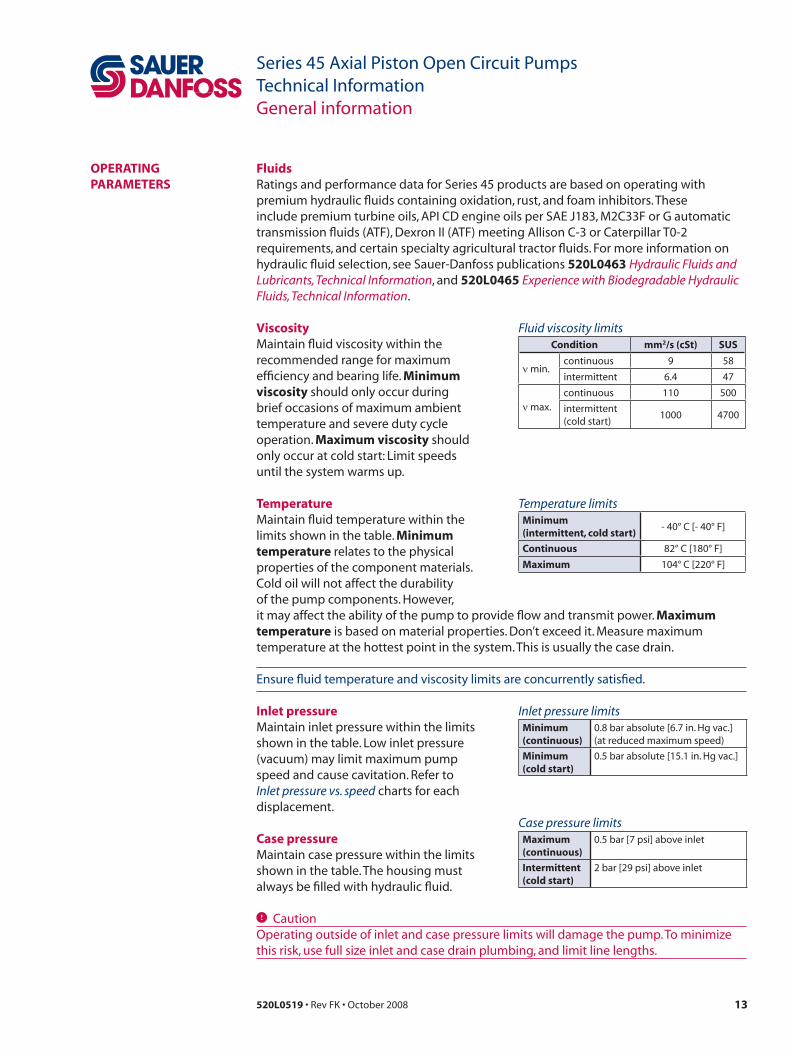
viscosityMaintain fluid viscosity within the recommended range for maximum efficiency and bearing life. minimum viscosity should only occur during brief occasions of maximum ambient temperature and severe duty cycle operation. maximum viscosity should only occur at cold start: Limit speeds until the system warms up.
temperatureMaintain fluid temperature within the limits shown in the table. minimum temperature relates to the physical properties of the component materials. Cold oil will not affect the durability of the pump components. However,
Fluid viscosity limitsCondition mm2/s (cst) sus
ν min.continuous 9 58
intermittent 6.4 47
ν max.continuous 110 500
intermittent (cold start)
1000 4700
Temperature limitsminimum (intermittent, cold start)
- 40° C [- 40° F]
Continuous 82° C [180° F]
maximum 104° C [220° F]
it may affect the ability of the pump to provide flow and transmit power. maximum temperature is based on material properties. Don’t exceed it. Measure maximum temperature at the hottest point in the system. This is usually the case drain.
Ensure fluid temperature and viscosity limits are concurrently satisfied.
inlet pressureMaintain inlet pressure within the limits shown in the table. Low inlet pressure (vacuum) may limit maximum pump speed and cause cavitation. Refer to Inlet pressure vs. speed charts for each displacement.
Case pressureMaintain case pressure within the limits shown in the table. The housing must always be filled with hydraulic fluid.
Inlet pressure limitsminimum(continuous)
0.8 bar absolute [6.7 in. Hg vac.](at reduced maximum speed)
minimum(cold start)
0.5 bar absolute [15.1 in. Hg vac.]
Case pressure limitsmaximum(continuous)
0.5 bar [7 psi] above inlet
intermittent(cold start)
2 bar [29 psi] above inlet
C CautionOperating outside of inlet and case pressure limits will damage the pump. To minimize this risk, use full size inlet and case drain plumbing, and limit line lengths.
14 520L0519 • Rev FK • October 2008
Series 45 Axial Piston Open Circuit PumpsTechnical InformationGeneral information
Pressure ratingsThe specification tables in each section give maximum and continuous pressure ratings for each displacement. Not all displacements within a given frame operate under the same pressure limits. Definitions of the operating pressure limits appear below.
system pressure is the differential pressure between the outlet and inlet ports. It is the dominant operating variable affecting hydraulic unit life. High system pressure, which results from high load, reduces expected life. System pressure must remain at or below rated pressure during normal operation to achieve expected life.
Continuous working pressure is the average, regularly occurring operating pressure. Operating at or below this pressure should yield satisfactory product life. For all applications, the load should move below this pressure.
maximum (peak) working pressure is the highest intermittent pressure allowed. Maximum machine load should never exceed this pressure.
speed ratingsThe specification tables in each section give minimum, maximum, and rated speeds for each displacement. Not all displacements within a given frame operate under the same speed limits. Definitions of these speed limits appear below.
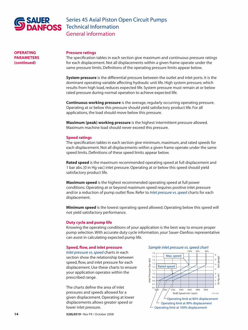
Rated speed is the maximum recommended operating speed at full displacement and 1 bar abs. [0 in Hg vac] inlet pressure. Operating at or below this speed should yield satisfactory product life.
maximum speed is the highest recommended operating speed at full power conditions. Operating at or beyond maximum speed requires positive inlet pressure and/or a reduction of pump outlet flow. Refer to Inlet pressure vs. speed charts for each displacement.
minimum speed is the lowest operating speed allowed. Operating below this speed will not yield satisfactory performance.
Duty cycle and pump lifeKnowing the operating conditions of your application is the best way to ensure proper pump selection. With accurate duty cycle information, your Sauer-Danfoss representative can assist in calculating expected pump life.
speed, flow, and inlet pressureInlet pressure vs. speed charts in each section show the relationship between speed, flow, and inlet pressure for each displacement. Use these charts to ensure your application operates within the prescribed range.
The charts define the area of inlet pressures and speeds allowed for a given displacement. Operating at lower displacements allows greater speed or lower inlet pressure.
0.6
0.7
0.8
0.9
1.0
1.1
1.2
1.3
1.4
1.5
1.6
2800 3000 3200 3400 3600 3800 4000
100% 90% 80%
Shaft Speed min (rpm)-1
Inle
t Pr
essu
re (b
ar a
bs)
(psi
gau
ge)
(in H
g v
ac)
P101 972E
0
3
6
9
8
6
4
2
Sample inlet pressure vs. speed chart
Operating limit at 100% displacementOperating limit at 90% displacement
Operating limit at 80% displacement
Rated speed
Max. speed
oPeRatinG PaRameteRs(continued)
15520L0519 • Rev FK • October 2008
Series 45 Axial Piston Open Circuit PumpsTechnical InformationGeneral information
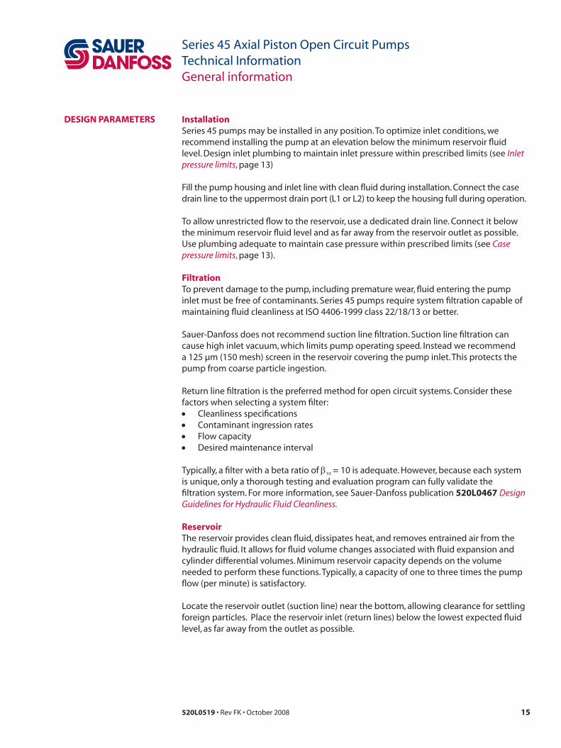
DesiGn PaRameteRs installationSeries 45 pumps may be installed in any position. To optimize inlet conditions, we recommend installing the pump at an elevation below the minimum reservoir fluid level. Design inlet plumbing to maintain inlet pressure within prescribed limits (see Inlet pressure limits, page 13)
Fill the pump housing and inlet line with clean fluid during installation. Connect the case drain line to the uppermost drain port (L1 or L2) to keep the housing full during operation.
To allow unrestricted flow to the reservoir, use a dedicated drain line. Connect it below the minimum reservoir fluid level and as far away from the reservoir outlet as possible. Use plumbing adequate to maintain case pressure within prescribed limits (see Case pressure limits, page 13).
filtrationTo prevent damage to the pump, including premature wear, fluid entering the pump inlet must be free of contaminants. Series 45 pumps require system filtration capable of maintaining fluid cleanliness at ISO 4406-1999 class 22/18/13 or better.
Sauer-Danfoss does not recommend suction line filtration. Suction line filtration can cause high inlet vacuum, which limits pump operating speed. Instead we recommend a 125 µm (150 mesh) screen in the reservoir covering the pump inlet. This protects the pump from coarse particle ingestion.
Return line filtration is the preferred method for open circuit systems. Consider these factors when selecting a system filter:• Cleanliness specifications• Contaminant ingression rates• Flow capacity• Desired maintenance interval
Typically, a filter with a beta ratio of β10 = 10 is adequate. However, because each system is unique, only a thorough testing and evaluation program can fully validate the filtration system. For more information, see Sauer-Danfoss publication 520L0467 Design Guidelines for Hydraulic Fluid Cleanliness.
ReservoirThe reservoir provides clean fluid, dissipates heat, and removes entrained air from the hydraulic fluid. It allows for fluid volume changes associated with fluid expansion and cylinder differential volumes. Minimum reservoir capacity depends on the volume needed to perform these functions. Typically, a capacity of one to three times the pump flow (per minute) is satisfactory.
Locate the reservoir outlet (suction line) near the bottom, allowing clearance for settling foreign particles. Place the reservoir inlet (return lines) below the lowest expected fluid level, as far away from the outlet as possible.

16 520L0519 • Rev FK • October 2008
Series 45 Axial Piston Open Circuit PumpsTechnical InformationGeneral information
DesiGn PaRameteRs(continued)
fluid velocityChoose piping sizes and configurations sufficient to maintain optimum fluid velocity, and minimize pressure drops. This reduces noise, pressure drops, and overheating. It maximizes system life and performance.
SI units
Q = flow (l/min)A = area (mm²)
Velocity = 16.67•Q (m/sec) A
Recommended fluid velocitiessystem lines 6 to 9 m/sec [20 to 30 ft/sec]
suction line 1 to 2 m/sec [4 to 6 ft/sec]
Case drain 3 to 5 m/sec [10 to 15 ft/sec]
typical guidelines; obey all pressure ratings.
Velocity equations US units
Q = flow (US gal/min)A = area (in²)
Velocity = 0.321•Q (ft/sec) A
shaft loadsSeries 45 pumps have tapered roller bearings capable of accepting external radial and thrust loads. The external radial shaft load limits are a function of the load position, orientation, and the operating conditions of the pump.
The maximum allowable radial load (Re) is based on the maximum external moment (Me) and the distance (L) from the mounting flange to the load. Compute radial loads using the formula below. Tables in each section give maximum external moment (Me) and thrust load (Tin , Tout) limits for each pump frame size and displacement.
Me = Re•LL = Distance from mounting flange
to point of loadMe = Maximum external moment Re = Maximum radial side load
Bearing lifeAll shaft loads affect bearing life. In applications where external shaft loads can not be avoided, maximize bearing life by orientating the load between the 150° and 210° positions, as shown. We recommend tapered input shafts or clamp-type couplings for applications with radial shaft loads. Tables in each section give B10 bearing life for each pump frame size and displacement.
Shaft load orientation
P101 080E
TinTout
L
Re
Mounting flange
0̊ Re
180˚ Re
90˚ Re 270˚ Re
150˚ 210˚
Axis of swashplaterotation
Radial load formula
17520L0519 • Rev FK • October 2008
Series 45 Axial Piston Open Circuit PumpsTechnical InformationGeneral information
DesiGn PaRameteRs(continued)
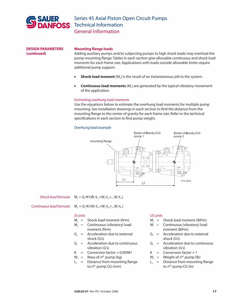
mounting flange loadsAdding auxiliary pumps and/or subjecting pumps to high shock loads may overload the pump mounting flange. Tables in each section give allowable continuous and shock load moments for each frame size. Applications with loads outside allowable limits require additional pump support.
• shock load moment (MS) is the result of an instantaneous jolt to the system.
• Continuous load moments (Mc) are generated by the typical vibratory movement of the application.
Estimating overhung load momentsUse the equations below to estimate the overhung load moments for multiple pump mounting. See installation drawings in each section to find the distance from the mounting flange to the center of gravity for each frame size. Refer to the technical specifications in each section to find pump weight.
Shock load formula
Continuous load formula
Ms = Gs•K•(W1•L1+W2•L2+...Wn•Ln)
Mc = Gc•K•(W1•L1+W2•L2+...Wn•Ln)
mounting flange
Center of Gravity (CG)pump 1
L1L2
Center of Gravity (CG)pump 2
P101 081E
Overhung load example
SI unitsMs = Shock load moment (N•m)Mc = Continuous (vibratory) load
moment (N•m)Gs = Acceleration due to external
shock (G’s)Gc = Acceleration due to continuous
vibration (G’s)K = Conversion factor = 0.00981Wn = Mass of nth pump (kg)Ln = Distance from mounting flange
to nth pump CG (mm)
US unitsMs = Shock load moment (lbf•in)Mc = Continuous (vibratory) load
moment (lbf•in)Gs = Acceleration due to external
shock (G’s)Gc = Acceleration due to continuous
vibration (G’s)K = Conversion factor = 1Wn = Weight of nth pump (lb)Ln = Distance from mounting flange
to nth pump CG (in)

18 520L0519 • Rev FK • October 2008
Series 45 Axial Piston Open Circuit PumpsTechnical InformationGeneral information
DesiGn PaRameteRs(continued)
auxiliary mounting padsAuxiliary mounting pads are available for all radial ported Series 45 pumps. Since the auxiliary pad operates under case pressure, use an O-ring to seal the auxiliary pump mounting flange to the pad. Oil from the main pump case lubricates the drive coupling.
• All mounting pads meet SAE J744 Specifications.
• The combination of auxiliary shaft torque and main pump torque must not exceed the maximum pump input shaft rating. Tables in each section give input shaft torque ratings for each frame size.
• Applications subject to severe vibratory or shock loading may require additional support to prevent mounting flange damage. Tables in each section give allowable continuous and shock load moments for each frame size.
• The drawing and table below give mating pump dimensions for each size mount. Refer to installation drawings in each section for auxiliary mounting pad dimensions.
Dimensionssae a sae B sae C
P82.55[3.250]
101.60[4.000]
127.00[5.000]
B6.35[0.250]
9.65[0.380]
12.70[0.500]
C12.70[0.500]
15.20[0.600]
23.37[0.920]
D58.20[2.290]
53.10[2.090]
55.60[2.190]
e15.00[0.590]
17.50[0.690]
30.50[1.200]
f13.50[0.530]
14.20[0.560]
18.30[0.720]
+0 -0.05[+0 -0.002]
mm[in.]
Dmax.
Emax.
F min. spline engagementfor full torque rating
Mountingflange (ref )
Undercutspline
Sled-runnerspline
P Ø
R 0.8 [0.03] max.
Bmax.
Cmax.
Coupling
Recommendedcutter clearance2.3 [0.090]
P101 079E
Mating pump specifications
input shaft torque ratingsInput shaft tables in each section give maximum torque ratings for available input shafts. Ensure that your application respects these limits.
maximum torque ratings are based on shaft strength. Do not exceed them.
Coupling arrangements that are not oil-flooded provide a reduced torque rating. Contact your Sauer-Danfoss representative for proper torque ratings if your application involves non oil-flooded couplings.
Sauer-Danfoss recommends mating splines adhere to ANSI B92.1-Class 5. Sauer-Danfoss external splines are modified class 5 fillet root side fit. The external major diameter and circular tooth thickness dimensions are reduced to ensure a good clearance fit with the mating spline. Tables in each section give full spline dimensions and data.
19520L0519 • Rev FK • October 2008
Series 45 Axial Piston Open Circuit PumpsTechnical InformationGeneral information
understanding and minimizing system noiseTables in each section give sound levels for each frame size and displacement. Sound level data are collected at various operating speeds and pressures in a semi-anechoic chamber. Many factors contribute to the overall noise level of any application. Here is some information to help understand the nature of noise in fluid power systems, and some suggestions to help minimize it.
Noise is transmitted in fluid power systems in two ways: as fluid borne noise, and structure borne noise.
fluid-borne noise (pressure ripple or pulsation) is created as pumping elements discharge oil into the pump outlet. It is affected by the compressibility of the oil, and the pump’s ability to transition pumping elements from high to low pressure. Pulsations travel through the hydraulic lines at the speed of sound (about 1400 m/s [4600 ft/sec] in oil) until there is a change (such as an elbow) in the line. Thus, amplitude varies with overall line length and position.
structure-borne noise is transmitted wherever the pump casing connects to the rest of the system. The way system components respond to excitation depends on their size, form, material, and mounting.
System lines and pump mounting can amplify pump noise. Follow these suggestions to help minimize noise in your application:
• Use flexible hoses.• Limit system line length.• If possible, optimize system line position to minimize noise.• If you must use steel plumbing, clamp the lines.• If you add additional support, use rubber mounts.• Test for resonants in the operating range, if possible avoid them.
DesiGn PaRameteRs(continued)

20 520L0519 • Rev FK • October 2008
Series 45 Axial Piston Open Circuit PumpsTechnical InformationGeneral information
sizinG equations
Based on si units
Output flow Q = (l/min)
Input torque M = (N•m)
Input power P = = (kW)
Based on us units
Output flow Q = (US gal/min)
Input torque M = (lbf•in)
Input power P = = (hp)
SI units [US units]
Vg = Displacement per revolution cm3/rev [in3/rev]pO = Outlet pressure bar [psi]pi = Inlet pressure bar [psi]∆p = pO - pi (system pressure) bar [psi]n = Speed min-1 (rpm)ηv = Volumetric efficiencyηm = Mechanical efficiencyηt = Overall efficiency (ηv • ηm)
Variables
Vg • n • ηv
1000
Vg • ∆p
20 • π • ηm
Q • ∆p600 • ηt
M • n • π30 000
Vg • n • ηv
231
Vg • ∆p
2 • π • ηm
Q • ∆p1714 • ηt
M • n • π198 000
Use these equations to help choose the right pump size and displacement for your application:
Flow
Torque
Power
21520L0519 • Rev FK • October 2008
Series 45 Axial Piston Open Circuit PumpsTechnical InformationFrames L and K
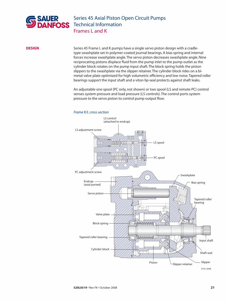
DesiGn Series 45 Frame L and K pumps have a single servo piston design with a cradle-type swashplate set in polymer-coated journal bearings. A bias spring and internal forces increase swashplate angle. The servo piston decreases swashplate angle. Nine reciprocating pistons displace fluid from the pump inlet to the pump outlet as the cylinder block rotates on the pump input shaft. The block spring holds the piston slippers to the swashplate via the slipper retainer. The cylinder block rides on a bi-metal valve plate optimized for high volumetric efficiency and low noise. Tapered roller bearings support the input shaft and a viton lip-seal protects against shaft leaks.
An adjustable one spool (PC only, not shown) or two spool (LS and remote PC) control senses system pressure and load pressure (LS controls). The control ports system pressure to the servo piston to control pump output flow.
Servo piston
Tapered rollerbearing
Shaft seal
LS adjustment screw
LS spool
PC adjustment screw
PC spool
Swashplate
Input shaft
Cylinder block
Piston Slipper
Valve plate
Bias spring
Block spring
Slipper retainer
LS control(attached to endcap)
Endcap(axial ported)
P101 659E
Tapered roller bearing
Frame K/L cross section
22 520L0519 • Rev FK • October 2008
Series 45 Axial Piston Open Circuit PumpsTechnical InformationFrames L and K
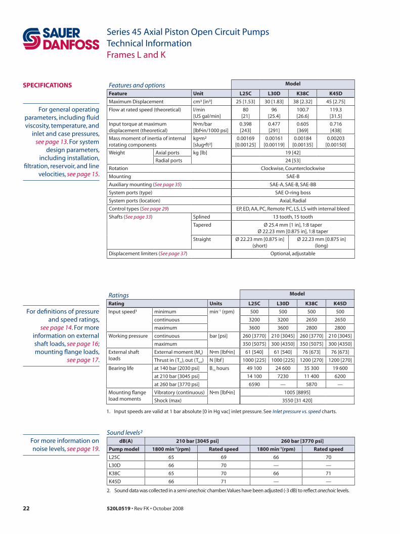
sPeCifiCations Features and options model
feature unit L25C L30D K38C K45D
Maximum Displacement cm³ [in³] 25 [1.53] 30 [1.83] 38 [2.32] 45 [2.75]
Flow at rated speed (theoretical) l/min [US gal/min]
80 [21]
96[25.4]
100.7[26.6]
119.3[31.5]
Input torque at maximum displacement (theoretical)
N•m/bar[lbf•in/1000 psi]
0.398[243]
0.477[291]
0.605[369]
0.716[438]
Mass moment of inertia of internal rotating components
kg•m²[slug•ft²]
0.00169[0.00125]
0.00161[0.00119]
0.00184[0.00135]
0.00203[0.00150]
Weight Axial ports kg [lb] 19 [42]
Radial ports 24 [53]
Rotation Clockwise, Counterclockwise
Mounting SAE-B
Auxiliary mounting (See page 35) SAE-A, SAE-B, SAE-BB
System ports (type) SAE O-ring boss
System ports (location) Axial, Radial
Control types (See page 29) EP, ED, AA, PC, Remote PC, LS, LS with internal bleed
Shafts (See page 33) Splined 13 tooth, 15 tooth
Tapered Ø 25.4 mm [1 in], 1:8 taperØ 22.23 mm [0.875 in], 1:8 taper
Straight Ø 22.23 mm [0.875 in](short)
Ø 22.23 mm [0.875 in](long)
Displacement limiters (See page 37) Optional, adjustable
Ratings model
Rating units L25C L30D K38C K45D
Input speed¹ minimum min-1 (rpm) 500 500 500 500
continuous 3200 3200 2650 2650
maximum 3600 3600 2800 2800
Working pressure continuous bar [psi] 260 [3770] 210 [3045] 260 [3770] 210 [3045]
maximum 350 [5075] 300 [4350] 350 [5075] 300 [4350]
External shaft loads
External moment (Me) N•m [lbf•in] 61 [540] 61 [540] 76 [673] 76 [673]
Thrust in (Tin), out (Tout) N [lbf ] 1000 [225] 1000 [225] 1200 [270] 1200 [270]
Bearing life at 140 bar [2030 psi] B10 hours 49 100 24 600 35 300 19 600
at 210 bar [3045 psi] 14 100 7230 11 400 6200
at 260 bar [3770 psi] 6590 — 5870 —
Mounting flange load moments
Vibratory (continuous) N•m [lbf•in] 1005 [8895]
Shock (max) 3550 [31 420]
1. Input speeds are valid at 1 bar absolute [0 in Hg vac] inlet pressure. See Inlet pressure vs. speed charts.
Sound levels²dB(a) 210 bar [3045 psi] 260 bar [3770 psi]
Pump model 1800 min-1(rpm) Rated speed 1800 min-1(rpm) Rated speed
L25C 65 69 66 70
L30D 66 70 — —
K38C 65 70 66 71
K45D 66 71 — —
2. Sound data was collected in a semi-anechoic chamber. Values have been adjusted (-3 dB) to reflect anechoic levels.
For general operating parameters, including fluid viscosity, temperature, and
inlet and case pressures, see page 13. For system
design parameters, including installation,
filtration, reservoir, and line velocities, see page 15.
For more information on noise levels, see page 19.
For definitions of pressure and speed ratings,
see page 14. For more information on external shaft loads, see page 16; mounting flange loads,
see page 17.

23520L0519 • Rev FK • October 2008
Series 45 Axial Piston Open Circuit PumpsTechnical InformationFrames L and K
PeRfoRmanCe L25C
Input power vs. speed
Flow vs. speed
Inlet pressure vs. speed
Flow and power data valid at 49°C [120°F] and viscosity
of 17.8 mm²/sec [88 SUS].
The chart on the right shows allowable inlet
pressure and speed at various displacements.
Greater speeds and lower inlet pressures are possible
at reduced displacement. Operating outside of
acceptable limits reduces pump life.
Flo
w (l
/min
)
Speed min (rpm)-1
Flo
w (U
S g
al/m
in)
P101 970E
0
20
40
60
80
100
0 500 1000 1500 2000 2500 3000 35000
4
8
12
16
20
24
Pow
er (k
W)
Speed min (rpm)-1
Pow
er (h
p)
P101 971E
0
10
20
30
40
50
0 500 1000 1500 2000 2500 3000 35000
10
20
30
40
50
60
260 bar [3770 psi]
210 bar [3045 psi]
140 bar [2030 psi]
0.6
0.7
0.8
0.9
1.0
1.1
1.2
1.3
1.4
1.5
1.6
2800 3000 3200 3400 3600 3800 4000
100% 90% 80%
Shaft Speed min (rpm)-1
Inle
t Pr
essu
re (b
ar a
bs)
(psi
gau
ge)
(in H
g v
ac)
P101 972E
0
3
6
9
8
6
4
2

24 520L0519 • Rev FK • October 2008
Series 45 Axial Piston Open Circuit PumpsTechnical InformationFrames L and K
PeRfoRmanCe L30D
Input power vs. speed
Flow vs. speed
Flow and power data valid at 49°C [120°F] and viscosity
of 17.8 mm²/sec [88 SUS].
The chart on the right shows allowable inlet
pressure and speed at various displacements.
Greater speeds and lower inlet pressures are possible
at reduced displacement. Operating outside of
acceptable limits reduces pump life.
0
20
40
60
80
100
0 500 1000 1500 2000 2500 30000
4
8
12
16
20
24
Flo
w (l
/min
)
Speed min (rpm)-1
Flo
w (U
S g
al/m
in)
P101 973E
0
10
20
30
40
50
0 500 1000 1500 2000 2500 30000
10
20
30
40
50
60
Pow
er (k
W)
Speed min (rpm)-1Po
wer
(hp
)P101 974E
210 bar [3045 psi]
140 bar [2030 psi]
0.6
0.7
0.8
0.9
1.0
1.1
1.2
1.3
1.4
1.5
1.6
2800 3000 3200 3400 3600 3800 4000
100% 90% 80%
Shaft Speed min (rpm)-1
Inle
t Pr
essu
re (b
ar a
bs)
(psi
gau
ge)
(in H
g v
ac)
P101 972E
0
3
6
9
8
6
4
2
Inlet pressure vs. speed

25520L0519 • Rev FK • October 2008
Series 45 Axial Piston Open Circuit PumpsTechnical InformationFrames L and K
PeRfoRmanCe K38C
Input power vs. speed
Flow vs. speed
Flow and power data valid at 49°C [120°F] and viscosity
of 17.8 mm²/sec [88 SUS].
The chart on the right shows allowable inlet
pressure and speed at various displacements.
Greater speeds and lower inlet pressures are possible
at reduced displacement. Operating outside of
acceptable limits reduces pump life.
0
25
50
75
100
125
0 500 1000 1500 2000 25000
5
10
15
20
25
30
Flo
w (l
/min
)
Speed min (rpm)-1
Flo
w (U
S g
al/m
in)
P101 975E
0
10
20
30
40
50
60
0 500 1000 1500 2000 25000
10
20
30
40
50
60
70
80
Pow
er (k
W)
Speed min (rpm)-1
Pow
er (h
p)
P101 976E
260 bar [3770 psi]
140 bar [2030 psi]
0.6
0.7
0.8
0.9
1.0
1.1
1.2
1.3
1.4
1.5
1.6
2200 2400 2600 2800 3000
100% 90% 80%
Shaft Speed min (rpm)-1
Inle
t Pr
essu
re (b
ar a
bs)
(psi
gau
ge)
(in H
g v
ac)
P101 977E
0
3
6
9
8
6
4
2
Inlet pressure vs. speed
26 520L0519 • Rev FK • October 2008
Series 45 Axial Piston Open Circuit PumpsTechnical InformationFrames L and K
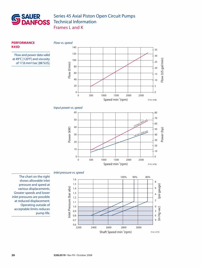
PeRfoRmanCe K45D
Inlet pressure vs. speed
Input power vs. speed
Flow vs. speed
Flow and power data valid at 49°C [120°F] and viscosity
of 17.8 mm²/sec [88 SUS].
The chart on the right shows allowable inlet
pressure and speed at various displacements.
Greater speeds and lower inlet pressures are possible
at reduced displacement. Operating outside of
acceptable limits reduces pump life.
0
20
40
60
80
100
120
140
0 500 1000 1500 2000 25000
5
10
15
20
25
30
35
Flo
w (l
/min
)
Speed min (rpm)-1
Flo
w (U
S g
al/m
in)
P101 978E
0
10
20
30
40
50
60
0 500 1000 1500 2000 25000
10
20
30
40
50
60
70
80
Pow
er (k
W)
Speed min (rpm)-1Po
wer
(hp
)P101 979E
210 bar [3045 psi]
140 bar [2030 psi]
0.6
0.7
0.8
0.9
1.0
1.1
1.2
1.3
1.4
1.5
1.6
2200 2400 2600 2800 3000
100% 90% 80%
Shaft Speed min (rpm)-1
Inle
t Pr
essu
re (b
ar a
bs)
(psi
gau
ge)
(in H
g v
ac)
P101 977E
0
3
6
9
8
6
4
2

27520L0519 • Rev FK • October 2008
Series 45 Axial Piston Open Circuit PumpsTechnical InformationFrames L and K
oRDeR CoDe
R ProductKR K Frame, variable displacement open circuit pump
LR L Frame, variable displacement open circuit pump
s RotationL Left hand (counterclockwise)
R Right hand (clockwise)
P Displacement and pressure rating025C 025 cm³/rev [1.53 in³/rev], 260 bar [3770 psi] continuous working pressure
030D 030 cm³/rev [1.83 in³/rev], 210 bar [3045 psi] continuous working pressure
038C 038 cm³/rev [2.32 in³/rev], 260 bar [3770 psi] continuous working pressure
045D 045 cm³/rev [2.75 in³/rev], 210 bar [3045 psi] continuous working pressure
C Control typePC Pressure compensated control
RP Remote pressure compensated control
Ls Load sensing / pressure compensating control
LB Load sensing / pressure compensating control with internal bleed orifice
eD Normally closed on/off electric PC control
eP Normally closed electric proportional control (fan drive applications)
aa Normally open on/off electric PC control
D PC setting (2 digit code, 10 bar increments)example 10 = 100
10–26 100 to 260 bar [1450 to 3770 psi] (025C and 038C)
10–21 100 to 210 bar [1450 to 3045 psi] (030D and 045D)
e Load sensing setting (2 digit code, 1 bar increments)example 20 = 20 bar
12–40 12 to 40 bar [174 to 580 psi]
nn Not applicable (use with PC and RP controls)
RP Must be 20 bar
f Not usednn Not applicable
G Pilot orificen None (standard)
H Gain orifice
R s P C D e f G H 1 2 3 1 2 3 L m n
– –
J K

28 520L0519 • Rev FK • October 2008
Series 45 Axial Piston Open Circuit PumpsTechnical InformationFrames L and K
oRDeR CoDe (continued)
3 Standard orifice
J1 Input shaftC2 13 tooth, 16/32 pitch (ANSI A92.1 1970 - Class 5)
C3 15 tooth, 16/32 pitch (ANSI A92.1 1970 - Class 5)
t1 Ø 25.4 mm [1 in], 1:8 taper
t2 Ø 22.23 mm [0.875 in], 1:8 taper
K1 Ø 22.23 mm [0.875 in] (short)
K2 Ø 22.23 mm [0.875 in] (long)
J2 Auxiliary mounting flangen None
R Running cover
a SAE-A, 9-tooth output spline
t SAE-A, 11-tooth output spline
G SAE-A, 11 tooth rotated 90 degrees
B SAE-B, 13-tooth output spline
v SAE-BB, 15-tooth output spline
J3 System port size and locationCode Location Port type Inlet size Outlet size
K Radial 4 bolt split flange 38.1 mm [1.5 in] 25.4 mm [1 in]
m Axial 4 bolt split flange 31.8 mm [1.25 in] 25.4 mm [1 in]
f Axial O-ring boss 1 7/8 in. 1 5/16 in.
G Radial O-ring boss 1 7/8 in. 1 5/16 in.
K1 Shaft seala Single lip seal, viton
K2 Mounting flange and housing port style6 SAE-B 2-bolt, SAE O-ring boss housing ports
K3 Not usedn Not applicable
L Displacement limiterKnB None
PLB Endcap machined and plugged
aaa Adjustable, factory set at max angle
m Special hardwarennn None
n Special featuresnnn None
R s P C D e f G H 1 2 3 1 2 3 L m n
– –
J K

29520L0519 • Rev FK • October 2008
Series 45 Axial Piston Open Circuit PumpsTechnical InformationFrames L and K
ContRoLs
PC schematic
M2
L2
S L1 P101 980
B
LegendB = OutletS = InletL1, L2 = Case drainM2 = System pressure gauge port
Remote PC control (RP)
Pressure compensated control (PC)
PC control setting rangemodel bar psi
L25C 100–260 1450–3770
L30D 100–210 1450–3045
K38C 100–260 1450–3770
K45D 100–210 1450–3045
Response/recovery times*(ms) Response Recovery
L25C 30 90
L30D 30 100
K38C 30 105
K45D 30 110
* For definitions, see page 9
Specifications
Schematic diagram
PC control setting rangemodel bar psi
L25C 100–260 1450–3770
L30D 100–210 1450–3045
K38C 100–260 1450–3770
K45D 100–210 1450–3045
Response/recovery times*(ms) Response Recovery
L25C 30 90
L30D 30 100
K38C 30 105
K45D 30 110
* For definitions, see page 10.
Specifications
Schematic diagram
LegendB = OutletS = InletL1, L2 = Case drainM2 = System pressure gauge portX = Remote PC port
Remote PC schematicX
B
M2
L2
S L1 P101 981
LS settingmodel bar psi
all 20 290
30 520L0519 • Rev FK • October 2008
Series 45 Axial Piston Open Circuit PumpsTechnical InformationFrames L and K
ContRoLs (continued)
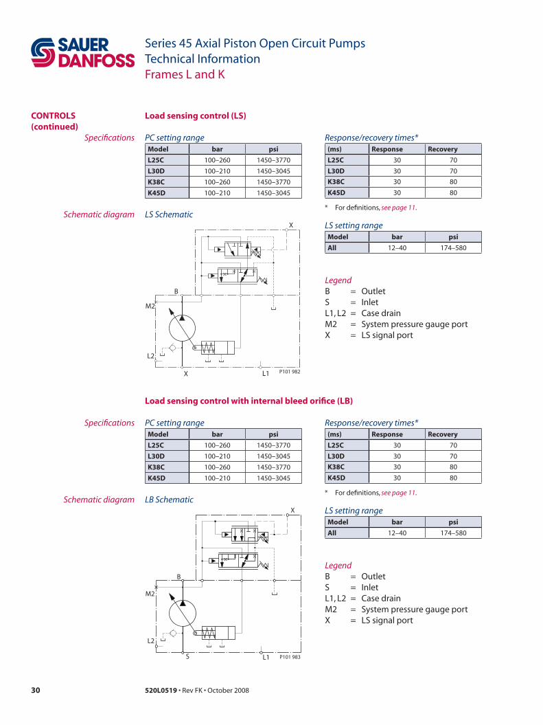
Load sensing control (Ls)
PC setting rangemodel bar psi
L25C 100–260 1450–3770
L30D 100–210 1450–3045
K38C 100–260 1450–3770
K45D 100–210 1450–3045
Response/recovery times*(ms) Response Recovery
L25C 30 70
L30D 30 70
K38C 30 80
K45D 30 80
* For definitions, see page 11.
Specifications
Schematic diagramLS setting rangemodel bar psi
all 12–40 174–580
X
B
M2
L2
X L1 P101 982
LS Schematic
LegendB = OutletS = InletL1, L2 = Case drainM2 = System pressure gauge portX = LS signal port
PC setting rangemodel bar psi
L25C 100–260 1450–3770
L30D 100–210 1450–3045
K38C 100–260 1450–3770
K45D 100–210 1450–3045
Response/recovery times*(ms) Response Recovery
L25C 30 70
L30D 30 70
K38C 30 80
K45D 30 80
* For definitions, see page 11.
Specifications
Schematic diagramLS setting rangemodel bar psi
all 12–40 174–580
S
L2
M2
L1
B
X
P101 983
LB Schematic
LegendB = OutletS = InletL1, L2 = Case drainM2 = System pressure gauge portX = LS signal port
Load sensing control with internal bleed orifice (LB)

31520L0519 • Rev FK • October 2008
Series 45 Axial Piston Open Circuit PumpsTechnical InformationFrames L and K
ContRoLs (continued)
normally closed on/off electric PC control (eD)
Specifications
Schematic diagram
LegendB = OutletS = InletL1, L2 = Case drainM2 = System pressure gauge portX = Remote PC port
ED schematic
M2
L2
S L1
X
P106 044
B
Response/recovery times*(ms) Response Recovery
L25C 30 90
L30D 30 100
K38C 30 105
K45D 30 110
* For definitions, see page 11.
PC control setting rangemodel bar psi
L25C, K38C
100-240 bar [1450-3480 psi]
L30D, K45D
100-210 bar [1450-3045 psi]
normally open on/off electric PC control (aa)
Specifications
Schematic diagram
LegendB = OutletS = InletL1, L2 = Case drainM2 = System pressure gauge portX = Remote PC port
AA schematic
M2
L2
S L1
X
P106 049
B
Evaluate the system to decide if normally open on/off (failsafe) control is necessary.
Response/recovery times*(ms) Response Recovery
L25C 30 90
L30D 30 100
K38C 30 105
K45D 30 110
* For definitions, see page 11.
PC control setting rangemodel bar psi
L25C, K38C, L30D, K45D
100-210 bar [1450-3045 psi]
LS setting rangemodel bar psi
all 12-40 174-580
LS setting rangemodel bar psi
all 12-40 174-580
32 520L0519 • Rev FK • October 2008
Series 45 Axial Piston Open Circuit PumpsTechnical InformationFrames L and K
ContRoLs (continued)
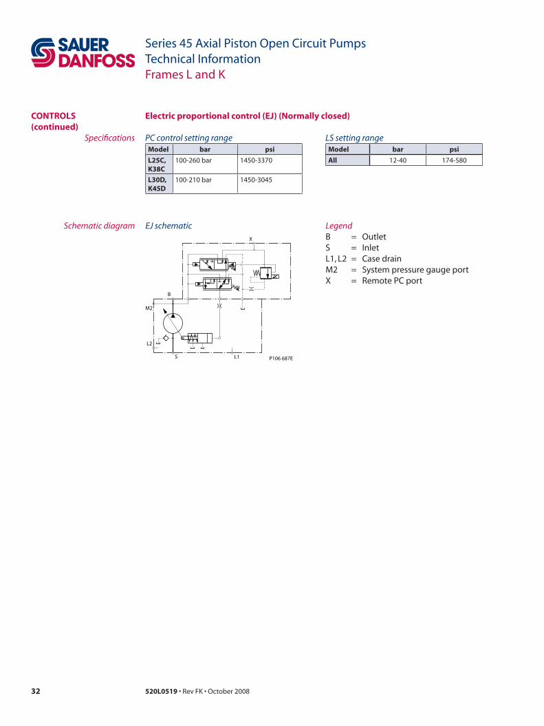
electric proportional control (eJ) (normally closed)
Specifications
Schematic diagram LegendB = OutletS = InletL1, L2 = Case drainM2 = System pressure gauge portX = Remote PC port
EJ schematic
M2
L2
S L1
X
P106 687E
B
PC control setting rangemodel bar psi
L25C, K38C
100-260 bar 1450-3370
L30D, K45D
100-210 bar 1450-3045
LS setting rangemodel bar psi
all 12-40 174-580
33520L0519 • Rev FK • October 2008
Series 45 Axial Piston Open Circuit PumpsTechnical InformationFrames L and K
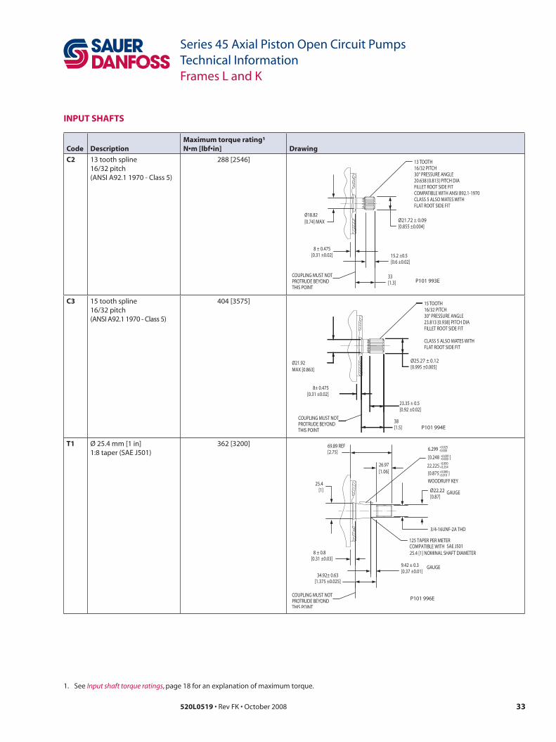
inPut sHafts
Code Descriptionmaximum torque rating¹N•m [lbf•in] Drawing
C2 13 tooth spline16/32 pitch(ANSI A92.1 1970 - Class 5)
288 [2546]
8 ± 0.475[0.31 ±0.02]
33[1.3]
15.2 ±0.5[0.6 ±0.02]
Ø21.72 ± 0.09[0.855 ±0.004]
Ø18.82[0.74] MAX
13 TOOTH16/32 PITCH30° PRESSURE ANGLE20.638 [0.813] PITCH DIAFILLET ROOT SIDE FITCOMPATIBLE WITH ANSI B92.1-1970CLASS 5 ALSO MATES WITHFLAT ROOT SIDE FIT
COUPLING MUST NOTPROTRUDE BEYONDTHIS POINT
P101 993E
C3 15 tooth spline16/32 pitch(ANSI A92.1 1970 - Class 5)
404 [3575]
8± 0.475[0.31 ±0.02]
38[1.5]
23.35 ± 0.5[0.92 ±0.02]
Ø25.27 ± 0.12[0.995 ±0.005]
Ø21.92MAX [0.863]
COUPLING MUST NOTPROTRUDE BEYONDTHIS POINT
15 TOOTH16/32 PITCH30° PRESSURE ANGLE23.813 [0.938] PITCH DIAFILLET ROOT SIDE FIT
CLASS 5 ALSO MATES WITHFLAT ROOT SIDE FIT
P101 994E
t1 Ø 25.4 mm [1 in]1:8 taper (SAE J501)
362 [3200]6.299 +0.025
-0.000
[0.248 +0.001 -0.000 ]
WOODRUFF KE Y
[0.875 +0.000 -0.010 ]
Ø22.22 [0.87]
GA UGE
3/4-16UNF-2A THD
9.42 ± 0.3[0.37 ±0.01]
25. 4 [1 ]
8 ± 0.8[0.31 ±0.03]
69.89 REF [2.75]
34.92± 0.63 [1.375 ±0.025]
26.97 [1.06]
C OUPLING MUST NO T PR OT RUDE BEY OND THIS POINT
125 TAPER PER METER SAE J501
GA UGE
P101 996E
22.225 +0.254 -0.000
COMPATIBLE WITH 25.4 [1] NOMINAL SHAFT DIAMETER
1. See Input shaft torque ratings, page 18 for an explanation of maximum torque.

34 520L0519 • Rev FK • October 2008
Series 45 Axial Piston Open Circuit PumpsTechnical InformationFrames L and K
inPut sHafts (continued)
Code Descriptionmaximum torque rating¹N•m [lbf•in] Drawing
t2 Ø 22.23 mm [0.875 in]1:8 taper (SAE J501)
305 [2700]
8 ± 0.3[0.31 ±0.03]
28.68± 0.63 [1.129 ±0.025]
3.18± 0.3[0.13 ±0.01]
59.69 REF [2.35]
23.01 [0.91]
Ø22.22 [0.875]
Ø19.05 [0.75]
5/8-18 UNF 2A THD
C OUPLING MUST NO T PR OT RUDE BEY OND THIS POINT
GA UGE
GA UGE
6.299 +0.025 -0.000
[0.248 +0.001 -0.000 ]
WOODRUFF KE Y
[0.875 +0.000 -0.010 ]
P101 995E
22.225 +0.254 -0.000
125 TAPER PER METER SAE J501 COMPATIBLE WITH
22.2 [0.874] NOMINAL SHAFT DIAMETER
K1 Ø 22.23 mm [0.875 in]33 mm [1.3 in]
305 [2700]
8± 0.8[0.31 ±0.03]
33 [1.3]
Ø22.2 ±0.025[0.874 ±0.001]
COUPLING MUST NOTPROTRUDE BEYONDTHIS POINT
6.35 [0.25]x 12.7 [0.50] LONGSQUARE KEY
P101 997E
[0.98 +0-0.01 ]
24.89+0-0.25
K2 Ø 22.23 mm [0.875 in]63 mm [2.48 in] long
305 [2700]
8 ± 0.3[0.315 ±0.035]
63 [2.48]
6.35 [0.25] x 38.1 [1.5] L ONG SQU ARE KE Y
CO UPLING MUST NO T PR OT RUDE BEY OND THIS POINT P101 998E
Ø22.2 ±0.025 [0.874 ±0.001]
[0.98 +0 -0.01 ]
24.89 +0 -0.25
1. See Input shaft torque ratings, page 18 for an explanation of maximum torque.

35520L0519 • Rev FK • October 2008
Series 45 Axial Piston Open Circuit PumpsTechnical InformationFrames L and K
auxiLiaRy mountinG PaDs
See page 18 for mating pump pilot and spline dimensions.
Dimensionssae-a auxiliary mounting pad
SpecificationsCoupling 9-tooth 11-tooth
spline minimum engagement
12.6 mm [0.50 in] 13.5 mm [0.53 in]
maximum torque 107 N•m [950 lbf•in] 147 N•m [1300 lbf•in]
Dimensionssae-B auxiliary mounting pad
SpecificationsCoupling 13-tooth 15-tooth
spline minimum engagement
13.2 mm [0.52 in] 16.1 mm [0.63 in]
maximum torque 171 N•m [1512 lbf•in] 171 N•m [1512 lbf•in]
53.2 [2.09]
106.4 [4.19]
59.65 [2.35]
228.53 [8.997]
1.95 [0.08]
8.1 ± 0.7 [0.319 ±0.028]
Ø88.62 [3.49]
3/8-16UNC-2BTHD 17.8 [0.70] MI N THD DEPTH
C OUPLING-SAE A: SPLINE: 11 TO OT H 16/32 PIT CH 30° PRESSURE ANGLE 17.463 [0.6875] PIT CH DI A FILLET RO OT SIDE FIT PER SAE B92.1-1970, CLASS 6
MOUNTIN G FLANGE
R 0.51 MA X [0.020]
8 ± 0.8 [0.32 ±0.03]
PER SAE J744
O-RING SEAL REQUIRED REF 82.22 [3.237] I.D. X 2.62 [0.103] CROSS SECTION
MIN SHAF T CLEARANC E
C OUPLING-SAE A: SPLINE: 9 T OO TH 16/32 PIT CH 30 PRESSURE ANGL E °14.288 [0.5625] PIT CH DI A FILLET RO OT SIDE FIT PER ANSI B92.1-1970, CLASS 6
Ø82. 6 +0.08 -0
[3.252 +0.003 -0 ]
P101999E
P/N 5000373
73 [2.87]
146 [5.75]
55.27 [2.18]
8 ± 0. 8 [0.31 ±0.03]
224.15 [8.82]
1. 3 [0.05]
11 ± 0.13 [0.43±0.01]
Ø105.64 [4.159]
1/2-13UNC-2BTHD 19.7 [0.76] MI N THD DEPTH
MOUNTIN G FLANGE
C OUPLING-SAE B SPLINE: 13 TO OT H 16/32 PIT CH 30° PRESSURE ANGLE 20.638 [0.8125] PIT CH DI A FILLET RO OT SIDE FIT PER ANSI B92.1-1970 CLASS 6
R2 MA X [0.08]
C OUPLING-SAE B-B SPLINE: 15 TO OT H 16/32 PIT CH 30 PRESSURE ANGL E °23.813 [0.9375] PIT CH DI A FILLET RO OT SIDE FIT PER ANSI B92.1-1970 CLASS 6
MIN SHAF T CLEARANC E
O-RING SEAL REQUIRED REF 101.32 [3.989] I.D .X 1.78 [0.070] CROSS SECTIO N
PER SAE J744
Ø101.65 +0.08 -0
[4.002 +0.003 -0 ]
P104000E
P/N 726935
See page 18 for mating pump pilot and spline dimensions.
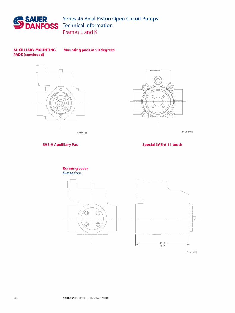
36 520L0519 • Rev FK • October 2008
Series 45 Axial Piston Open Circuit PumpsTechnical InformationFrames L and K
mounting pads at 90 degrees
P106 076E
DimensionsRunning cover
P106 077E
212.7[8.37]
auxiLLiaRy mountinG PaDs (continued)
P106 644E
sae-a auxilliary Pad special sae-a 11 tooth

37520L0519 • Rev FK • October 2008
Series 45 Axial Piston Open Circuit PumpsTechnical InformationFrames L and K
DisPLaCement LimiteR L and K Frame open circuit pumps are available with an optional adjustable displacement limiter. This adjustable stop limits the pump’s maximum displacement.
Displacement limiter cross-section
Setting rangeL25C 0 to 25 cm³ [0 to 1.53 in³]
L30D 0 to 30 cm³ [0 to 1.83 in³]
K38C 0 to 38 cm³ [0 to 2.32 in³]
K45D 0 to 45 cm³ [0 to 2.75 in³] P104 084
Displacement per turnL25C 1.20 cm³/rev [0.07 in³/rev]
L30D 1.43 cm³/rev [0.09 in³/rev]
K38C 1.81 cm³/rev [0.11 in³/rev]
K45D 2.15 cm³/rev [0.13 in³/rev]
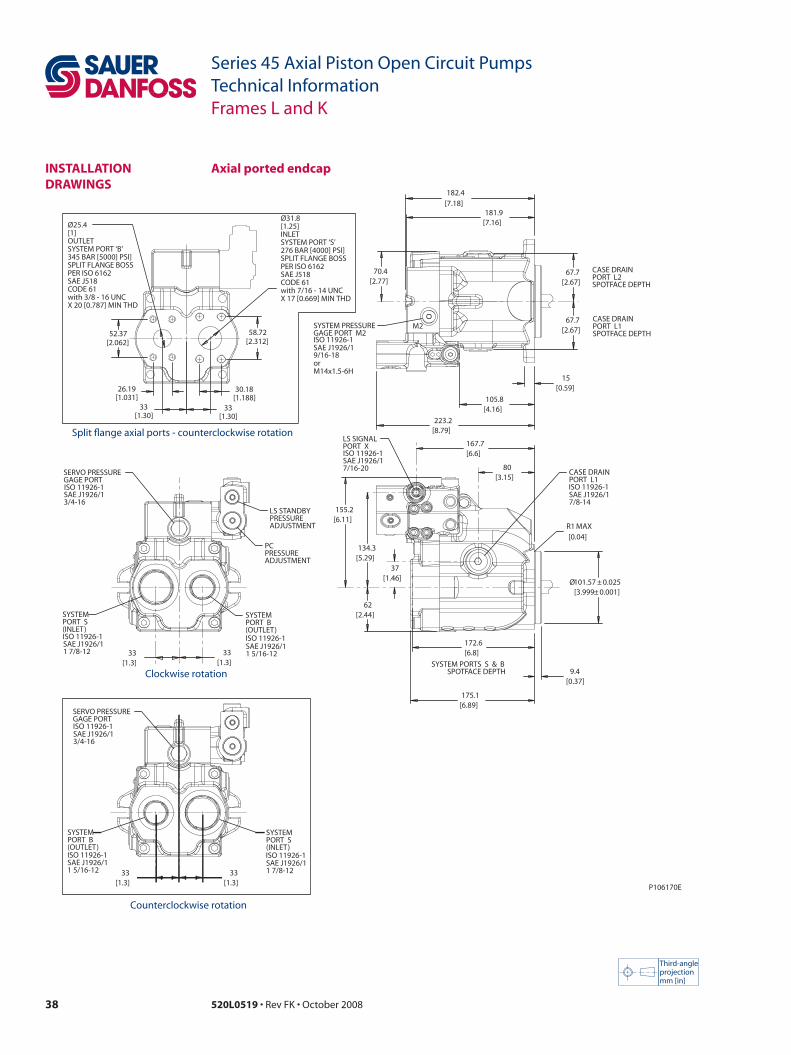
38 520L0519 • Rev FK • October 2008
Series 45 Axial Piston Open Circuit PumpsTechnical InformationFrames L and K
instaLLation DRawinGs
Third-angleprojectionmm [in]
axial ported endcap
Clockwise rotation
Counterclockwise rotation
P106170E
[0.04]R1 MAX
[1.46]37
[3.999 0.001]± 101.57Ø 0.025±
[0.37]9.4
[6.89]175.1
[6.8]172.6
[3.15]80
[6.6]167.7
[5.29]134.3
[6.11]155.2
[2.44]62
LS SIGNALPORT X
SAE J1926/17/16-20 CASE DRAIN
PORT L1
SAE J1926/17/8-14
[8.79]223.2
[4.16]105.8
[2.77]70.4
[7.16]181.9
[2.67]67.7
[2.67]67.7
[0.59]15
[7.18]182.4
SYSTEM PRESSUREGAGE PORT M2
SAE J1926/19/16-18orM14x1.5-6H
[1.3]33
[1.3]33
SYSTEMPORT S (INLET)
SAE J1926/11 7/8-12
SYSTEMPORT B (OUTLET)
SAE J1926/11 5/16-12
PCPRESSUREADJUSTMENT
LS STANDBYPRESSUREADJUSTMENT
[1.3]33
[1.3]33
SYSTEMPORT B (OUTLET)
SAE J1926/11 5/16-12
SYSTEMPORT S (INLET)
SAE J1926/11 7/8-12
SYSTEM PORTS S & B SPOTFACE DEPTH
M2
CASE DRAINPORT L2 SPOTFACE DEPTH
CASE DRAINPORT L1 SPOTFACE DEPTH
SERVO PRESSUREGAGE PORT
SAE J1926/13/4-16
SERVO PRESSUREGAGE PORT
SAE J1926/13/4-16
ISO 11926-1
ISO 11926-1
ISO 11926-1
ISO 11926-1 ISO 11926-1
ISO 11926-1
ISO 11926-1 ISO 11926-1
ISO 11926-1
58.72[2.312]
52.37[2.062]
Ø31.8[1.25]INLETSYSTEM PORT ‘S’276 BAR [4000] PSI]SPLIT FLANGE BOSSPER ISO 6162SAE J518CODE 61with 7/16 - 14 UNCX 17 [0.669] MIN THD
30.18[1.188]
33[1.30]
26.19[1.031]
33[1.30]
Ø25.4[1]OUTLETSYSTEM PORT ‘B’345 BAR [5000] PSI]SPLIT FLANGE BOSSPER ISO 6162SAE J518CODE 61with 3/8 - 16 UNCX 20 [0.787] MIN THD
Split flange axial ports - counterclockwise rotation

39520L0519 • Rev FK • October 2008
Series 45 Axial Piston Open Circuit PumpsTechnical InformationFrames L and K
P104064E
[3.9]99
[0.26]6.7
[2.87]73
[5.75]146
[4.8]121.9
[5.2]132
APPROXIMATECENTER OFGRAVITY
[1.26]32
[3.15]80
[1.02]25.8
[3.83]97.4
APPROXIMATECENTER OFGRAVITY
CASE DRAINPORT L2
SAE J1926/17/8-14
[3.28]83.3
[8.74]222
CCWCW
[0.563] 14.3Ø
2X
ISO 11926-1
axial ported endcap (continued)instaLLation DRawinGs (continued)
Third-angleprojectionmm [in]
Adjustable displacement limiter
Split flange axial endcap (counterclockwise rotation shown)

40 520L0519 • Rev FK • October 2008
Series 45 Axial Piston Open Circuit PumpsTechnical InformationFrames L and K
instaLLation DRawinGs (continued)
Radial ported endcap
Third-angleprojectionmm [in]
Clockwise rotation
Counterclockwise rotation
P106 171E
R1 MAX[0.04]
62[2.44]
166[6.54]
37[1.46]
80[3.15]
Ø101.57 ± 0.025 [3.999 ± 0.001]
9.4[0.37]
94.5[3.72]
94.5[3.72]
95[3.74]
95[3.74]
67.7[2.67]
67.7[2.67]
90.5[3.56]
207.9[8.19]
15[0.59]
207[8.15]
94.5[3.72]
94.5[3.72]
95[3.74]
95[3.74]
SYSTEM PORT B (OUTLET)
SAE J1926/11 5/16 -12
CASE DRAINPORT L1
SAE J1926/17/8 -14
SYSTEM PRESSUREGAGE PORT M2
SAE J1926/19/16 -18
B
SYSTEM PORT S SPOTFACE DEPTH
SYSTEM PORT B SPOTFACE DEPTH
CASE DRAINPORT L1 SPOTFACE DEPTH
CASE DRAINPORT L2 SPOTFACE DEPTH
SYSTEM PORT S SPOTFACE DEPTH
SYSTEM PORT B SPOTFACE DEPTH
ISO 11926-1
ISO 11926-1
ISO 11926-1
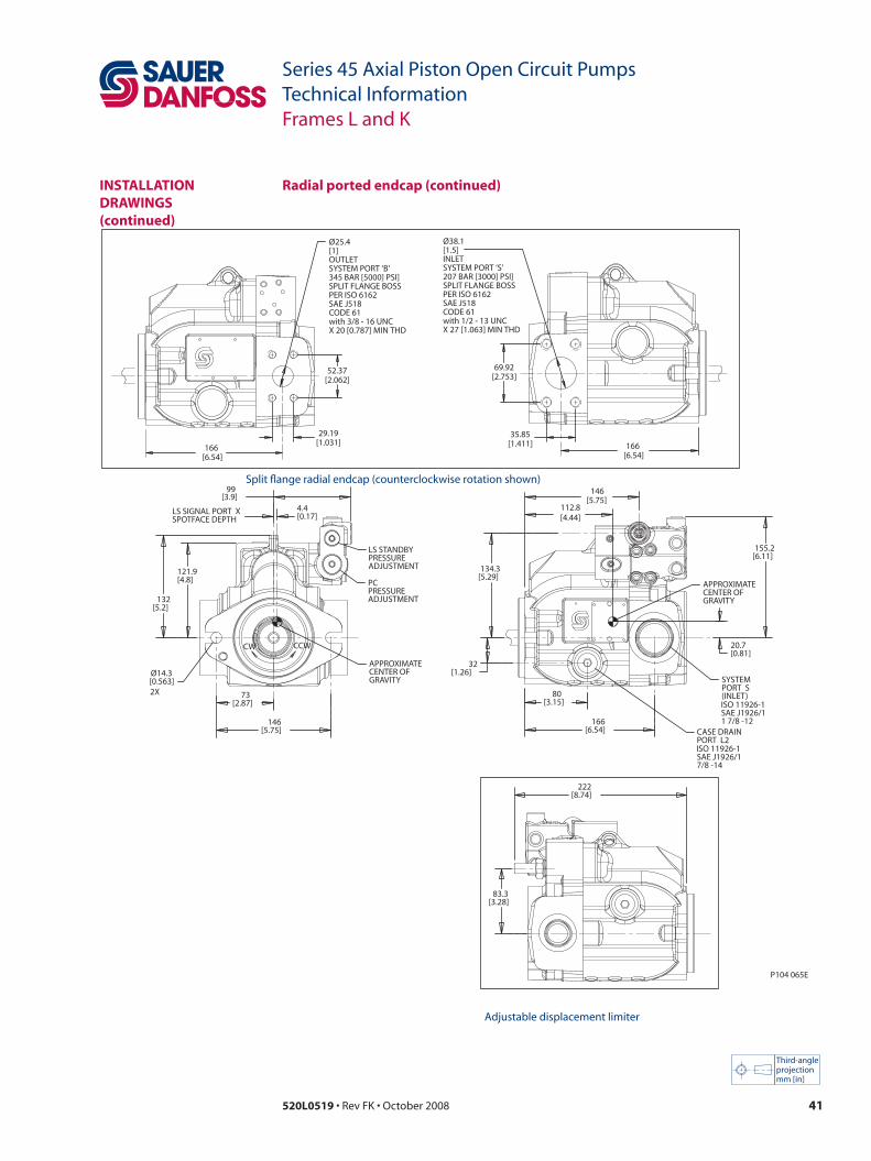
41520L0519 • Rev FK • October 2008
Series 45 Axial Piston Open Circuit PumpsTechnical InformationFrames L and K
P104 065E
99[3.9]
4.4[0.17]
Ø14.3[0.563]
73[2.87]
146[5.75]
121.9[4.8]
132[5.2]
80[3.15]
166[6.54]
32[1.26]
134.3[5.29]
20.7[0.81]
155.2[6.11]
112.8[4.44]
146[5.75]
83.3[3.28]
222[8.74]
LS STANDBYPRESSUREADJUSTMENT
PCPRESSUREADJUSTMENT
APPROXIMATECENTER OFGRAVITY
CASE DRAINPORT L2
SAE J1926/17/8 -14
SYSTEMPORT S (INLET)
SAE J1926/11 7/8 -12
APPROXIMATECENTER OFGRAVITY
CCWCW
2X
LS SIGNAL PORT X SPOTFACE DEPTH
ISO 11926-1
ISO 11926-1
69.92[2.753]
Ø38.1[1.5]INLETSYSTEM PORT ‘S’207 BAR [3000] PSI]SPLIT FLANGE BOSSPER ISO 6162SAE J518CODE 61with 1/2 - 13 UNCX 27 [1.063] MIN THD
Ø25.4[1]OUTLETSYSTEM PORT ‘B’345 BAR [5000] PSI]SPLIT FLANGE BOSSPER ISO 6162SAE J518CODE 61with 3/8 - 16 UNCX 20 [0.787] MIN THD
35.85[1.411] 166
[6.54]
52.37[2.062]
29.19[1.031]
166[6.54]
instaLLation DRawinGs (continued)
Radial ported endcap (continued)
Third-angleprojectionmm [in]
Adjustable displacement limiter
Split flange radial endcap (counterclockwise rotation shown)
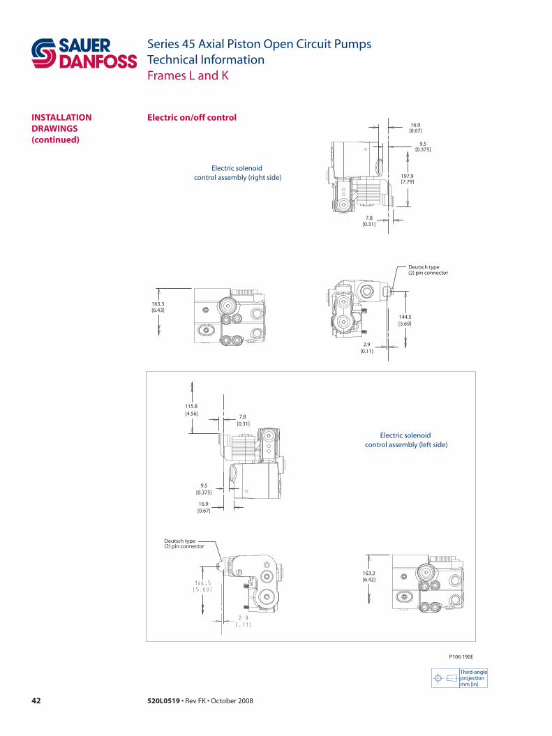
42 520L0519 • Rev FK • October 2008
Series 45 Axial Piston Open Circuit PumpsTechnical InformationFrames L and K
instaLLation DRawinGs (continued)
electric on/off control
Third-angleprojectionmm [in]
P106 190E
Deutsch type(2) pin connector
16.9[0.67]
163.2[6.42]
7.8[0.31]
115.8[4.56]
9.5[0.375]
16.9[0.67]
(2) pin connectorDeutsch type
9.5[0.375]
197.9[7.79]
7.8[0.31]
163.3[6.43]
144.5[5.69]
2.9[0.11]
Electric solenoid control assembly (right side)
Electric solenoid control assembly (left side)

43520L0519 • Rev FK • October 2008
Series 45 Axial Piston Open Circuit PumpsTechnical InformationFrame J
DesiGn Series 45 Frame J pumps have a single servo piston design with a cradle-type swashplate set in polymer-coated journal bearings. A bias spring and internal forces increase swashplate angle. The servo piston decreases swashplate angle. Nine reciprocating pistons displace fluid from the pump inlet to the pump outlet as the cylinder block rotates on the pump input shaft. The block spring holds the piston slippers to the swashplate via the slipper retainer. The cylinder block rides on a bi-metal valve plate optimized for high volumetric efficiency and low noise. Tapered roller bearings support the input shaft and a viton lip-seal protects against shaft leaks.
An adjustable one spool (PC only, not shown) or two spool (LS and PC) control senses system pressure and load pressure (LS controls). The control ports system pressure to the servo piston to control pump output flow.
Frame J cross section
LS adjustment
PC adjustment
LS spool
PC spool
LS control(attached to endcap)
Servo piston
Swashplate
Taperedrollerbearing
Shaft seal
Tapered rollerbearing
Input shaft
Cylinderblock
Valveplate
Cylinderblockspring
Piston
Slipper
Slipper retainer
Bias springLS control
P104 204E
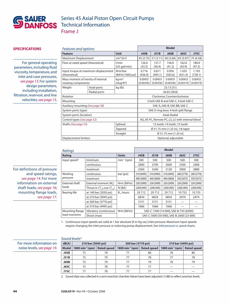
44 520L0519 • Rev FK • October 2008
Series 45 Axial Piston Open Circuit PumpsTechnical InformationFrame J
sPeCifiCations Features and options model
feature unit J45B J51B J60B J65C J75C
Maximum Displacement cm³ [in³] 45 [2.75] 51 [3.11] 60 [3.66] 65 [3.97] 75 [4.58]
Flow at rated speed (theoretical) l/min [US gal/min]
126.0[33.3]
137.7[36.4]
156.0[41.2]
162.6[42.9]
180.0[47.5]
Input torque at maximum displacement (theoretical)
N•m/bar[lbf•in/1000 psi]
0.716[436.9]
0.811[495.1]
0.956[583.6]
1.035[631.4]
1.193[728.1]
Mass moment of inertia of internal rotating components
kg•m²[slug•ft²]
0.00455[0.00336]
0.00455[0.00336]
0.00455[0.00336]
0.00433[0.00319]
0.00433[0.00319]
Weight Axial ports kg [lb] 23.13 [51]
Radial ports 26.65 [58.8]
Rotation Clockwise, Counterclockwise
Mounting 2 bolt SAE-B and SAE-C, 4 bolt SAE-C
Auxiliary mounting (See page 58) SAE-A, SAE-B, SAE-BB, SAE-C
System ports (type) SAE O-ring boss. 4-bolt split flange
System ports (location) Axial, Radial
Control types (See page 52) AG, AF, PC, Remote PC, LS, LS with internal bleed
Shafts (See page 55) Splined 13 tooth, 14 tooth, 15 tooth
Tapered Ø 31.75 mm [1.25 in], 1:8 taper
Straight Ø 31.75 mm [1.25 in]
Displacement limiters Optional, adjustable
Ratings model
Rating units J45B J51B J60B J65C J75C
Input speed¹ minimum min-1 (rpm) 500 500 500 500 500
continuous 2800 2700 2600 2500 2400
maximum 3360 3240 3120 3000 2880
Working pressure
continuous bar [psi] 310 [4495] 310 [4495] 310 [4495] 260 [3770] 260 [3770]
maximum 400 [5800] 400 [5800] 400 [5800] 350 [5075] 350 [5075]
External shaft loads
External moment (Me) N•m [lbf•in] 226 [2000] 226 [2000] 226 [2000] 226 [2000] 226 [2000]
Thrust in (Tin), out (Tout) N [lbf ] 2200 [495] 2200 [495] 2200 [495] 2200 [495] 2200 [495]
Bearing life at 140 bar [2030 psi] B10 hours 29 712 29 712 29 712 10 755 10 755
at 210 bar [3045 psi] 6834 6834 6834 2474 2474
at 260 bar [3770 psi] 3151 3151 3151 — —
at 310 bar [4495 psi] 1666 1666 1666 — —
Mounting flange load moments
Vibratory (continuous) N•m [lbf•in] SAE-C: 1500 [14 000], SAE-B: 735 [6500]
Shock (max) SAE-C: 5600 [50 000], SAE-B: 2600 [23 000]
1. Continuous input speeds are valid at 1 bar absolute [0 in Hg vac] inlet pressure. Maximum input speeds require changing the inlet pressure or reducing pump displacement. See Inlet pressure vs. speed charts.
Sound levels²dB(a) 210 bar [3045 psi] 260 bar [3770 psi] 310 bar [4495 psi]
model 1800 min-1 (rpm) Rated speed 1800 min-1 (rpm) Rated speed 1800 min-1 (rpm) Rated speed
J45B 75 79 77 80 76 80
J51B 75 79 77 78 77 78
J60B 75 79 77 79 76 79
J65C 75 78 77 77 — —
J75C 77 78 77 77 — —
2. Sound data was collected in a semi-anechoic chamber. Values have been adjusted (-3 dB) to reflect anechoic levels.
For general operating parameters, including fluid viscosity, temperature, and
inlet and case pressures, see page 13. For system
design parameters, including installation,
filtration, reservoir, and line velocities, see page 15.
For more information on noise levels, see page 19.
For definitions of pressure and speed ratings,
see page 14. For more information on external shaft loads, see page 16; mounting flange loads,
see page 17.

45520L0519 • Rev FK • October 2008
Series 45 Axial Piston Open Circuit PumpsTechnical InformationFrame J
PeRfoRmanCe J45B
Input power vs. speed
Flow vs. speed
Inlet pressure vs. speed
Flow and power data valid at 49°C [120°F] and viscosity
of 17.8 mm²/sec [88 SUS].
The chart on the right shows allowable inlet
pressure and speed at various displacements.
Greater speeds and lower inlet pressures are possible
at reduced displacement. Operating outside of
acceptable limits reduces pump life.
0
20
40
60
80
100
0 500 1000 1500 2000 2500 3000 35000
20
40
60
80
100
120
Pow
er (k
W)
Speed min (rpm)-1
Pow
er (h
p)
P104 205E
140 bar [2030 psi]
260 bar [3770 psi]
310 bar [4495 psi]
0
25
50
75
100
125
150
0 500 1000 1500 2000 2500 3000 35000
5
10
15
20
25
30
35
Flo
w (l
/min
)
Speed min (rpm)-1
Flo
w (U
S g
al/m
in)
P104 206E
0.6
0.7
0.8
0.9
1.0
1.1
1.2
1.3
1.4
1.5
1.6100% 90% 80%
Shaft Speed min (rpm)-1
Inle
t Pr
essu
re (b
ar a
bs)
(psi
gau
ge)
(in H
g v
ac)
P104 207E
0
3
6
9
8
6
4
2
2400 2600 2800 3000 3200 3400 3600

46 520L0519 • Rev FK • October 2008
Series 45 Axial Piston Open Circuit PumpsTechnical InformationFrame J
Input power vs. speed
Flow vs. speed
Flow and power data valid at 49°C [120°F] and viscosity
of 17.8 mm²/sec [88 SUS].
The chart on the right shows allowable inlet
pressure and speed at various displacements.
Greater speeds and lower inlet pressures are possible
at reduced displacement. Operating outside of
acceptable limits reduces pump life.
Inlet pressure vs. speed
0
25
50
75
100
125
150
175
0 500 1000 1500 2000 2500 3000 35000
10
20
30
40
Flo
w (l
/min
)
Speed min (rpm)-1
Flo
w (U
S g
al/m
in)
P104 209E
0
20
40
60
80
100
0 500 1000 1500 2000 2500 3000 35000
25
50
75
100
125
140 bar [2030 psi]
260 bar [3077 psi]310 bar [4
495 psi]
Pow
er (k
W)
Speed min (rpm)-1
Pow
er (h
p)
P104 208E
0.6
0.7
0.8
0.9
1.0
1.1
1.2
1.3
1.4
1.5
1.6100% 90% 80%
Shaft Speed min (rpm)-1
Inle
t Pr
essu
re (b
ar a
bs)
(psi
gau
ge)
(in H
g v
ac)
P104 210E
0
3
6
9
8
6
4
2
2200 2400 2600 2800 3000 3200 3400 3600
PeRfoRmanCe J51B
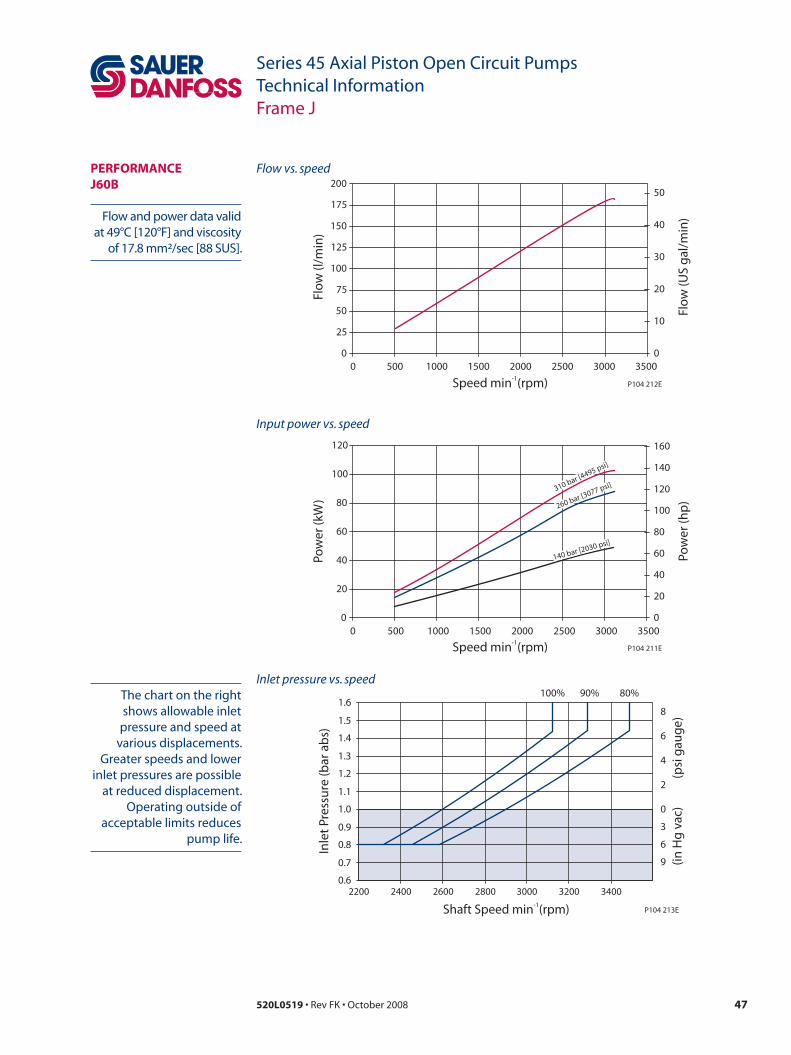
47520L0519 • Rev FK • October 2008
Series 45 Axial Piston Open Circuit PumpsTechnical InformationFrame J
Input power vs. speed
Flow vs. speed
Flow and power data valid at 49°C [120°F] and viscosity
of 17.8 mm²/sec [88 SUS].
The chart on the right shows allowable inlet
pressure and speed at various displacements.
Greater speeds and lower inlet pressures are possible
at reduced displacement. Operating outside of
acceptable limits reduces pump life.
Inlet pressure vs. speed
0
20
40
60
80
100
120
0 500 1000 1500 2000 2500 3000 35000
20
40
60
80
100
120
140
160
140 bar [2030 psi]
260 bar [3077 psi]310 bar [4495 psi]
Pow
er (k
W)
Speed min (rpm)-1
Pow
er (h
p)
P104 211E
0
25
50
75
100
125
150
175
200
0 500 1000 1500 2000 2500 3000 35000
10
20
30
40
50
Flo
w (l
/min
)
Speed min (rpm)-1
Flo
w (U
S g
al/m
in)
P104 212E
0.6
0.7
0.8
0.9
1.0
1.1
1.2
1.3
1.4
1.5
1.6100% 90% 80%
Shaft Speed min (rpm)-1
Inle
t Pr
essu
re (b
ar a
bs)
(psi
gau
ge)
(in H
g v
ac)
P104 213E
0
3
6
9
8
6
4
2
2200 2400 2600 2800 3000 3200 3400
PeRfoRmanCe J60B
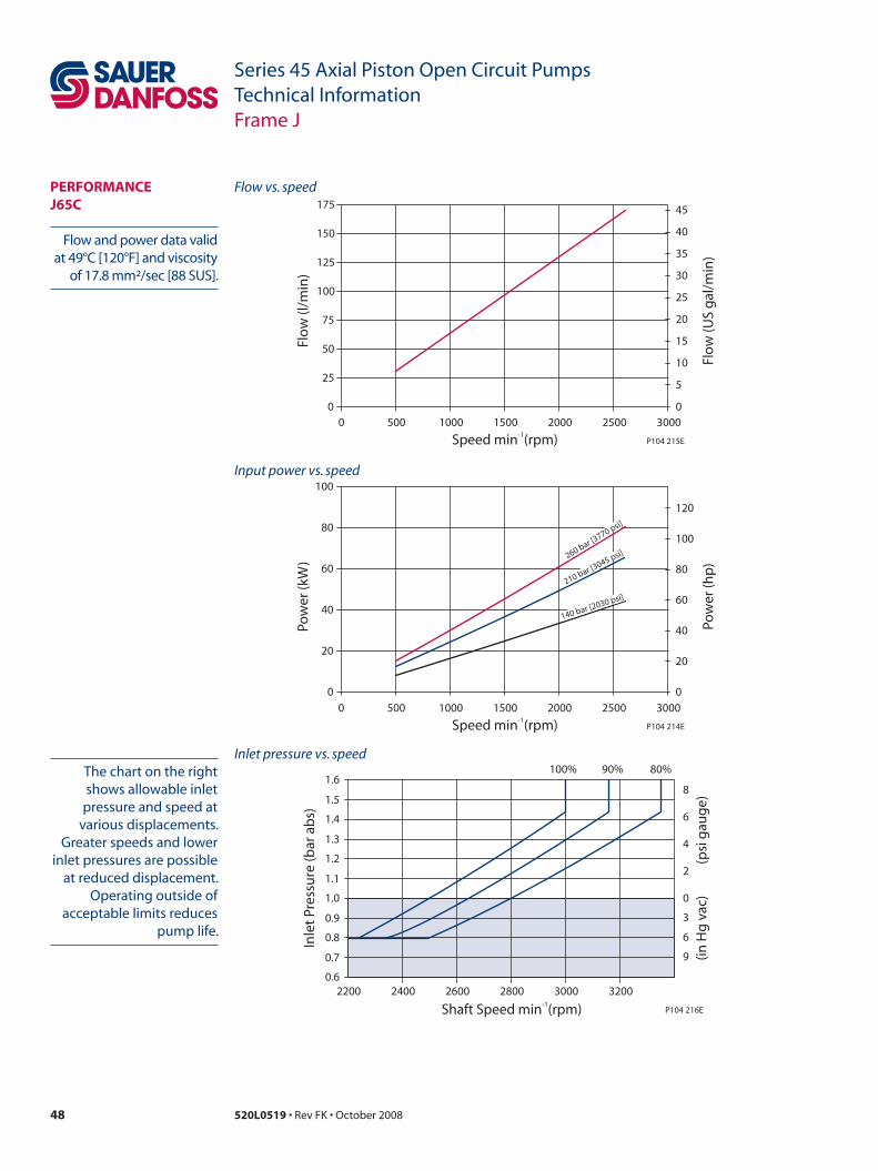
48 520L0519 • Rev FK • October 2008
Series 45 Axial Piston Open Circuit PumpsTechnical InformationFrame J
Inlet pressure vs. speed
Input power vs. speed
Flow vs. speed
Flow and power data valid at 49°C [120°F] and viscosity
of 17.8 mm²/sec [88 SUS].
The chart on the right shows allowable inlet
pressure and speed at various displacements.
Greater speeds and lower inlet pressures are possible
at reduced displacement. Operating outside of
acceptable limits reduces pump life.
0
20
40
60
80
100
0 500 1000 1500 2000 2500 3000
0
20
40
60
80
100
120
140 bar [2030 psi]
210 bar [3045 psi]260 bar [3770 psi]
Pow
er (k
W)
Speed min (rpm)-1
Pow
er (h
p)
P104 214E
0
25
50
75
100
125
150
175
0 500 1000 1500 2000 2500 30000
5
10
15
20
25
30
35
40
45
Flo
w (l
/min
)
Speed min (rpm)-1
Flo
w (U
S g
al/m
in)
P104 215E
0.6
0.7
0.8
0.9
1.0
1.1
1.2
1.3
1.4
1.5
1.6100% 90% 80%
Shaft Speed min (rpm)-1
Inle
t Pr
essu
re (b
ar a
bs)
(psi
gau
ge)
(in H
g v
ac)
P104 216E
0
3
6
9
8
6
4
2
2200 2400 2600 2800 3000 3200
PeRfoRmanCe J65C

49520L0519 • Rev FK • October 2008
Series 45 Axial Piston Open Circuit PumpsTechnical InformationFrame J
Input power vs. speed
Flow vs. speed
Flow and power data valid at 49°C [120°F] and viscosity
of 17.8 mm²/sec [88 SUS].
The chart on the right shows allowable inlet
pressure and speed at various displacements.
Greater speeds and lower inlet pressures are possible
at reduced displacement. Operating outside of
acceptable limits reduces pump life.
Inlet pressure vs. speed
0
40
80
120
160
200
0 500 1000 1500 2000 25000
10
20
30
40
50
Flo
w (l
/min
)
Speed min (rpm)-1
Flo
w (U
S g
al/m
in)
P104 218E
0
20
40
60
80
100
0 500 1000 1500 2000 25000
20
40
60
80
100
120
Pow
er (k
W)
Speed min (rpm)-1
Pow
er (h
p)
P104 217E
260 bar [3770 psi]
210 bar [3045 psi]
140 bar [2030 psi]
0.6
0.7
0.8
0.9
1.0
1.1
1.2
1.3
1.4
1.5
1.6100% 90% 80%
Shaft Speed min (rpm)-1
Inle
t Pr
essu
re (b
ar a
bs)
(psi
gau
ge)
(in H
g v
ac)
P104 219E
0
3
6
9
8
6
4
2
2000 2200 2400 2600 2800 3000 3200
PeRfoRmanCe J75C

50 520L0519 • Rev FK • October 2008
Series 45 Axial Piston Open Circuit PumpsTechnical InformationFrame J
oRDeR CoDe
R ProductJR J Frame, variable displacement open circuit pump
s RotationL Left hand (counterclockwise)
R Right hand (clockwise)
P Displacement and pressure rating045B 045 cm³/rev [2.75 in³/rev], 310 bar [4495 psi] continuous working pressure
051B 051 cm³/rev [3.11 in³/rev], 310 bar [4495 psi] continuous working pressure
060B 060 cm³/rev [3.66 in³/rev], 310 bar [4495 psi] continuous working pressure
065C 065 cm³/rev [3.97 in³/rev], 260 bar [3077 psi] continuous working pressure
075C 075 cm³/rev [4.58 in³/rev], 260 bar [3077 psi] continuous working pressure
C Control typePC Pressure compensated control 100-280 bar [1450-4060 psi]
BC* Pressure compensated control 290-310 bar [4205-4495 psi]
RP Remote pressure compensated control 100-280 bar [1450-4060 psi]
BP* Remote pressure compensated control 290-310 bar [4205-4495 psi]
Ls Load sensing / pressure compensating control 100-280 bar [1450-4060 psi]
Bs* Load sensing / pressure compensating control 290-310 bar [4205-4495 psi]
LB Load sensing / pressure compensating control with internal bleed orifice 100-280 bar [1450-4060 psi]
BB* Load sensing / pressure compensating control with internal bleed orifice 290-310 bar [4205-4495 psi]
aG Pressure compensated control with electric on/off solenoid operated 2-way valve (normally closed)
af Pressure compensated control with electric on/off solenoid operated 2-way valve (normally open)
* Use only with 45, 51, and 60 cm³ displacements.
D PC setting (2 digit code, 10 bar increments)example 10 = 100 bar
10–26 100 to 260 bar [1450 to 3770 psi] (065C and 075C)
10–31 100 to 310 bar [1450 to 4495 psi] (045B, 051B and 060B)
e Load sensing setting (2 digit code, 1 bar increments)example 20 = 20 bar
10–40 10 to 40 bar [145 to 580 psi]
nn Not applicable (use with PC controls)
RP and BP Must be 20 bar
f Not usednn Not applicable
G Pilot orificen None (standard)
H Gain orifice3 Standard orifice
R s P C D e f G H 1 2 3 1 2 3 L m n
– –
J K

51520L0519 • Rev FK • October 2008
Series 45 Axial Piston Open Circuit PumpsTechnical InformationFrame J
oRDeR CoDe (continued)
J1 Input shaftC2 13 tooth, 16/32 pitch (ANSI A92.1 1970 - Class 5)
C3 15 tooth, 16/32 pitch (ANSI A92.1 1970 - Class 5)
s1 14 tooth, 12/24 pitch (ANSI A92.1 1970 - Class 5)
K4 Ø 31.75 mm [1.25 in] straight key
to Ø 31.75 mm [1.25 in], 1:8 taper
J2 Auxiliary mounting flange type and couplingn None (Use with axial ported endcap options 3 and 4 below)
a SAE-A, 9-tooth output spline
B SAE-B, 13-tooth output spline
C SAE-C, 14-tooth output spline
t SAE-A, 11-tooth output spline
v SAE-BB, 15-tooth output spline
R Running cover (Radial ported endcap machined for aux. pad. Pad and coupling sold separately.)
G Special SAE-A, 11 tooth, rotated 90 degrees
J3 Endcap option (system port size and location)Code Port location Port type Inlet size Outlet size
2 Radial 4-bolt split flange 50.8 mm [2.0 in] 25.4 mm [1.0 in]
3 Axial O-ring boss 1 7/8 in. 1 5/16 in.
4 Axial 4-bolt split flange 50.8 mm [2.0 in] 25.4 mm [1.0 in]
v * Radial 4-bolt split flange 50.8 mm [2.0 in] 25.4 mm [1.0 in]
w ** Axial 4-bolt split flange 50.8 mm [2.0 in] 25.4 mm [1.0 in]
* must have auxilliary mounting flange or runnung cover
** must have displacement limiter FFF
K1 Shaft seala Single lip seal, viton
K2 Mounting flange and housing port style2 SAE-C 4-bolt, SAE O-ring boss housing ports
8 SAE-B 2-bolt, SAE O-ring boss housing ports
9 SAE-C 2-bolt, SAE O-ring boss housing ports
K3 Not usedn Not applicable
L Displacement limiternnn None
fff * Adjustable, factory set at maximum angle
* can only be used with v and w endcap options
m Special hardwarennn None
n Special featuresnnn None
R s P C D e f G H 1 2 3 1 2 3 L m n
– –
J K

52 520L0519 • Rev FK • October 2008
Series 45 Axial Piston Open Circuit PumpsTechnical InformationFrame J
ContRoLs
Remote PC control (RP, BP)
Pressure compensated control (PC, BC)
Specifications
Schematic diagram
Specifications
Schematic diagram
LegendB = OutletS = InletL1, L2 = Case drainM1* = System pressure gauge port* M1 port is available on axially ported endcaps
only
LegendB = OutletS = InletL1, L2 = Case drainX = Remote PC portM1* = System pressure gauge port* M1 port is available on axially ported endcaps
only
Attach remote PC valve at port X. Size the external valve and plumbing for a pilot flow of 3.8 l/min [1 US gal/min].
Remote PC schematic
M1
L2
S L1 P104 221
X
X
B
PC schematic
B
M1
L2
S L1 P104 220
PC control setting rangemodel RP BP
J45B, J51B, J60B
100-280 bar[1450-4060 psi]
290-310 bar[4205-4495 psi]
J65C, J75C
100-260 bar[1450-3770 bar]
N/A
Response/recovery times*(ms) Response Recovery
J45B 33 140
J51B 33 150
J60B 39 170
J65B 45 140
J75B 45 150
* For definitions, see page 10
Response/recovery times*(ms) Response Recovery
J45B 33 140
J51B 33 150
J60B 39 170
J65B 45 140
J75B 45 150
* For definitions, see page 9.
PC control setting rangemodel PC BC
J45B, J51B, J60B
100-280 bar[1450-4060 psi]
290-310 bar[4205-4495 psi]
J65C, J75C
100-260 bar[1450-3770 bar]
N/A
LS settingmodel bar psi
all 20 290

53520L0519 • Rev FK • October 2008
Series 45 Axial Piston Open Circuit PumpsTechnical InformationFrame J
ContRoLs (continued)
Load sensing control (Ls, Bs)
Specifications
Schematic diagram LS setting rangemodel bar psi
all 10-40 145–580
Specifications
Schematic diagram LS setting rangemodel bar psi
all 10–40 145–580
Load sensing control with internal bleed orifice (LB, BB)
LegendB = OutletS = InletL1, L2 = Case drainX = LS signal portM1* = System pressure gauge port* M1 port is available on axially ported endcaps
only
LegendB = OutletS = InletL1, L2 = Case drainX = LS signal portM1* = System pressure gauge port* M1 port is available on axially ported endcaps
only
LS Schematic
M1
L2
S L1
X
X
P104 223
B
LSBSchematic
M1
L2
S L1
X
X
P104 222
B
Response/recovery times*(ms) J45B J51B J60B J65B J75B
Response 28 30 33 43 45
Recovery 111 125 140 101 140
* For definitions, see page 11.
PC control setting rangeCode Ls Bs
J45B, J51B, J60B
100-280 bar[1450-4060 psi]
290-310 bar[4205-4495 psi]
J65C, J75C
100-260 bar[1450-3770 bar]
N/A
PC control setting rangeCode LB BB
J45B, J51B, J60B
100-280 bar[1450-4060 psi]
290-310 bar[4205-4495 psi]
J65C, J75C
100-260 bar[1450-3770 bar]
N/A
Response/recovery times*(ms) J45B J51B J60B J65B J75B
Response 28 30 33 43 45
Recovery 111 125 140 101 140
* For definitions, see page 11.

54 520L0519 • Rev FK • October 2008
Series 45 Axial Piston Open Circuit PumpsTechnical InformationFrame J
ContRoLs (continued)
normally closed on/off electric PC control (aG)
Specifications
Schematic diagram
LegendB = OutletS = InletL1, L2 = Case drainX = Remote PC portM1* = System pressure gauge port* M1 port is available on axially ported endcaps
only
AG schematic
M1
L2
S L1
X
P106 656E
B
Response/recovery times*(ms) J45B J51B J60B J65B J75B
Response 33 33 39 45 45
Recovery 140 150 170 140 150
* For definitions, see page 12.
PC control setting rangeCode aG
J45B, J51B, J60B
100-280 bar[1450-4060 psi]
J65C, J75C
100-260 bar[1450-3770 bar]
normally open on/off electric PC control (af)
Specifications
Schematic diagram
LegendB = OutletS = InletL1, L2 = Case drainX = Remote PC portM1* = System pressure gauge port* M1 port is available on axially ported endcaps
only
AF schematic
M1
L2
S L1
X
P106 657E
B
Response/recovery times*(ms) J45B J51B J60B J65B J75B
Response 33 33 39 45 45
Recovery 140 150 170 140 150
* For definitions, see page 12.
AF control setting rangeCode af
J45B, J51B, J60B
100-280 bar[1450-4060 psi]
J65C, J75C
100-260 bar[1450-3770 bar]
Evaluate your system to decide if normally open or normally closed control override is required for failsafe operation.
LS setting rangemodel bar psi
all 10-40 145-580
LS setting rangemodel bar psi
all 10-40 145-580
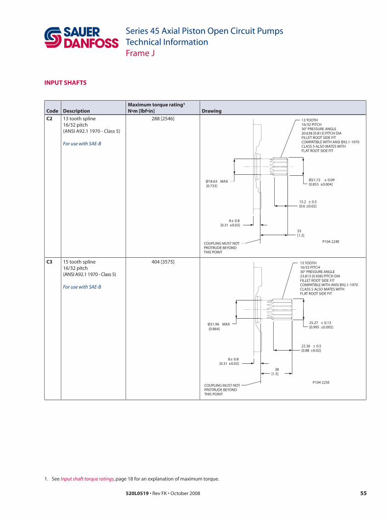
55520L0519 • Rev FK • October 2008
Series 45 Axial Piston Open Circuit PumpsTechnical InformationFrame J
inPut sHafts
Code Descriptionmaximum torque rating¹N•m [lbf•in] Drawing
C2 13 tooth spline16/32 pitch(ANSI A92.1 1970 - Class 5)
For use with SAE-B
288 [2546]
Ø18.63 MAX
8± 0.8[0.31 ±0.03]
33[1.3]
15.2 ± 0.5[0.6 ±0.02]
Ø21.72 ± 0.09[0.855 ±0.004]
13 TOOTH16/32 PITCH30° PRESSURE ANGLE20.638 [0.813] PITCH DIAFILLET ROOT SIDE FITCOMPATIBLE WITH ANSI B92.1-1970CLASS 5 ALSO MATES WITHFLAT ROOT SIDE FIT
COUPLING MUST NOTPROTRUDE BEYONDTHIS POINT
[0.733]
P104 224E
C3 15 tooth spline16/32 pitch(ANSI A92.1 1970 - Class 5)
For use with SAE-B
404 [3575]
25.27 ± 0.13[0.995 ±0.005]
Ø21.96 MAX
8± 0.8[0.31 ±0.03]
38[1.5]
22.36 ± 0.5[0.88 ±0.02]
15 TOOTH16/32 PITCH30° PRESSURE ANGLE23.813 [0.938] PITCH DIAFILLET ROOT SIDE FITCOMPATIBLE WITH ANSI B92.1-1970CLASS 5 ALSO MATES WITHFLAT ROOT SIDE FIT
COUPLING MUST NOTPROTRUDE BEYONDTHIS POINT
[0.864]
P104 225E
1. See Input shaft torque ratings, page 18 for an explanation of maximum torque.

56 520L0519 • Rev FK • October 2008
Series 45 Axial Piston Open Circuit PumpsTechnical InformationFrame J
inPut sHafts (continued)
Code Descriptionmaximum torque rating¹N•m [lbf•in] Drawing
s1 14 tooth spline12/24 pitch (ANSI A92.1 1970 - Class 5)
For use with SAE-C
734 [6495]
8± 0.8[0.31 ±0.03]
Ø25.5 MAX[1]
Ø31.14 ± 0.08[1.226 ±0.003]
28 ± 0.5[1.1 ±0.02]
47.6[1.87]
COUPLING MUST NOTPROTRUDE BETONDTHIS POINT
14 TOOTH 12/24 PITCH30° PRESSURE ANGLE29.634 [1.167] PITCHFILLET ROOT SIDE FITCOMPATIBLE WITHANSI B92.1-1970 CLASS 5ALSO MATES WITHFLAT ROOT SIDE FIT
P104 226E
K4 Ø 31.75 mm [1.25 in]straight key
For use with SAE-C
655 [5797] 56[2.2]
48.03±0.43
[1.89]±0.02
8± 0.8[0.31 ±0.03]
35.2 ± 0.13[1.39 ±0.01]
Ø31.72 ± 0.025[1.249 ±0.001]
7.94 [0.313]X 28.56 [1.125] LONGSQUARE KEY
COUPLING MUST NOTPROTRUDE BETONDTHIS POINT
P104 227E
1. See Input shaft torque ratings, page 18 for an explanation of maximum torque.

57520L0519 • Rev FK • October 2008
Series 45 Axial Piston Open Circuit PumpsTechnical InformationFrame J
Code Descriptionmaximum torque rating¹N•m [lbf•in] Drawing
to Ø 31.75 mm [1.25 in]1:8 taper
For use with SAE-C
734 [6495]
8± 0. 8 [0.31 ±0.03]
22. 4 ± 0. 3 [0.88 ±0.01]
Ø30.1625 [1.19]
42.92
[1.69]
30.96±0.25
[1.219]±0.01
GA UGE GA UGE
7.887
X Dia. 31.8
WOODRUFF KEY
1.00-20 UNF-2A THD
C OUPLING MUST NO T PR OT RUDE BEY OND THIS POINT
P104 228E
125 TAPER PER METER SAE J501 COMPATIBLE WITH
31.8 [1.25] NOMINAL SHAFT DIAMETER
+0.8-1.1
+.03-0.04
[0.3105]
+0.025- 0
+0.001- 0
[1.25]
+0- 0.010+0-0.25
inPut sHafts (continued)
1. See Input shaft torque ratings, page 18 for an explanation of maximum torque.

58 520L0519 • Rev FK • October 2008
Series 45 Axial Piston Open Circuit PumpsTechnical InformationFrame J
auxiLiaRy mountinG PaDs
See page 18 for mating pump pilot and spline dimensions.
Dimensionssae-a auxiliary mounting pad (non-integral)
See page 18 for mating pump pilot and spline dimensions.
SpecificationsCoupling 9-tooth 11-tooth
spline minimum engagement
13.5 mm [0.53 in] 15 mm [0.59 in]
maximum torque 107 N•m [950 lbf•in] 147 N•m [1300 lbf•in]
3[0.12]
9.8[0.39]
53. 2 [2.09]
106. 4 [4.19]
3/8 -16 UNC-2B THD
137.1[5.4]
264.43[10.41]
59.4[2.34]
8.1[0.32]
1.95[0.08]
23 [0.91]
Ø82. 6 +0.08 -0
[3.25 ] Ø88.62 [3.49]
R1.2 MA X
17.8 [0.70] MI N FULL THD DEPTH 2X
APPR OX IM AT E CENTER OF GR AV IT Y APPR OX IM AT E
CENTER OF GR AV IT Y
MOUNTING FLANGE
O-RING SEAL REQUIRED REF 82.22 [3.23] I.D x2.62 [0.103] CROSS SECTIONP/N 5000373
P104 230E
C OUPLING-SAE A T SPLINE: 11 TO OT H 16/32 PI TC H 30° PRESSURE ANGLE 17.463 [0.6875] PIT CH DI A FILLET RO OT SIDE FI T PER ANSI B92.1-1970 CLASS 6
C OUPLING-SAE A A SPLINE: 9 T OO TH 16/32 PI TC H 30° PRESSURE ANGLE 14.288 [0.5625] PIT CH DI A FILLET RO OT SIDE FI T PER ANSI B92.1-1970 CLASS 6
+0.003 -0
Dimensionssae-B auxiliary mounting pad
73 [2.87]
146 [5.75]
3.1[0.122]
9.8[0.39]
260.05 [10.24]
22 [0.87]
R2.0 MA X [0.08]
Ø101.65 +0.08 - 0
[4.002 ] +.003 - 0
Ø105.64 [4.159]
1.3 [0.05]
11 ± 0.12 [0.433 ±0.005]
55[2.17]
136.1[5.4]
APPRO XIM AT E CENTER OF GRA VIT Y
MIN SHAFT CLEARANCE
C OUPLING-SAE B-B V SPLINE: 15 TO OT H 16/32 PIT CH 30° PRESSURE ANGL E 23.813 [0.9375] PIT CH DI A FILLET RO OT SIDE FIT PER ANSI B92.1-1970 CLASS 6
APPRO XIM AT E CENTER OF GRA VIT Y
1/2 -13UNC-2B TH D 19.7 [0.76] MI N THD DEPTH 2X
O-RING SEAL REQUIRED REF 101.32 [3.989] I.D . X 1.78 [0.070] CROSS SECTIONP/N 726935
C OUPLING-SAE B B SPLINE: 13 TO OT H 16/32 PIT CH 30° PRESSURE ANGL E 20.638 [0.8125] PIT CH DI A FILLET RO OT SIDE FIT PER ANSI B92.1-1970 CLASS 6
MOUNTIN G FLANGE
P104 231E
SpecificationsCoupling 13-tooth 15-tooth
spline minimum engagement
14.2 mm [0.56 in] 18.9 mm [0.74 in]
maximum torque 249 N•m [2200 lbf•in] 339 N•m [3000 lbf•in]
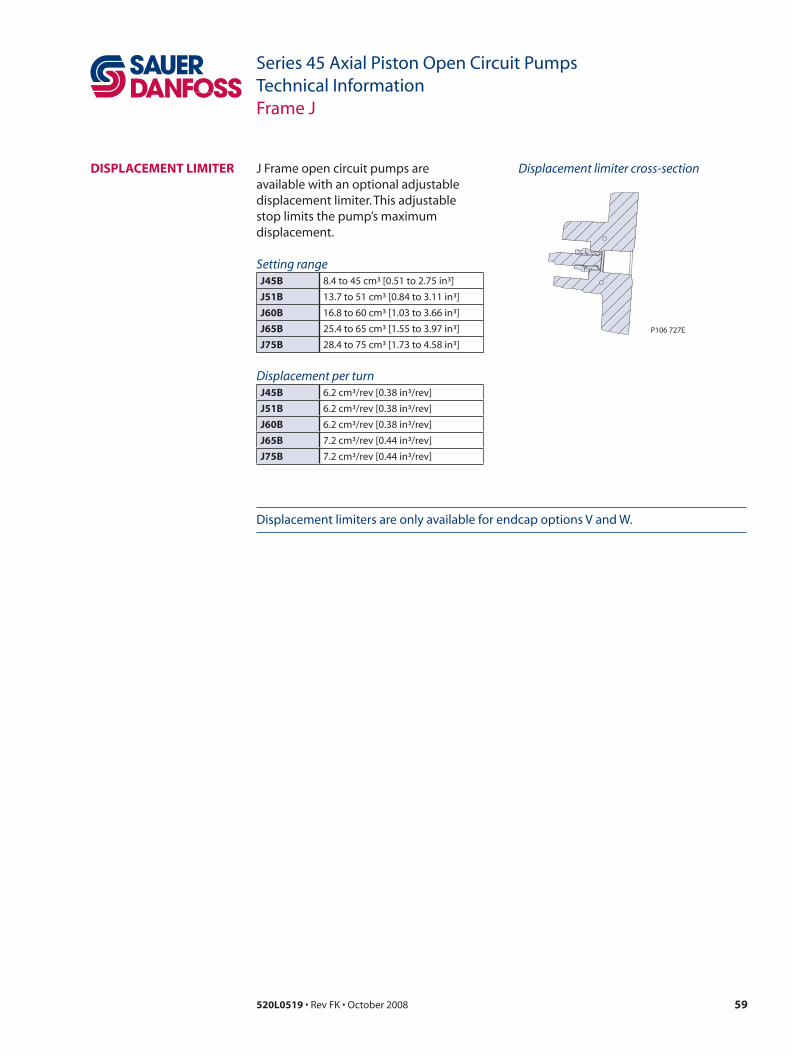
59520L0519 • Rev FK • October 2008
Series 45 Axial Piston Open Circuit PumpsTechnical InformationFrame J
DisPLaCement LimiteR J Frame open circuit pumps are available with an optional adjustable displacement limiter. This adjustable stop limits the pump’s maximum displacement.
Displacement limiter cross-section
Setting rangeJ45B 8.4 to 45 cm³ [0.51 to 2.75 in³]
J51B 13.7 to 51 cm³ [0.84 to 3.11 in³]
J60B 16.8 to 60 cm³ [1.03 to 3.66 in³]
J65B 25.4 to 65 cm³ [1.55 to 3.97 in³]
J75B 28.4 to 75 cm³ [1.73 to 4.58 in³]
P106 727E
Displacement per turnJ45B 6.2 cm³/rev [0.38 in³/rev]
J51B 6.2 cm³/rev [0.38 in³/rev]
J60B 6.2 cm³/rev [0.38 in³/rev]
J65B 7.2 cm³/rev [0.44 in³/rev]
J75B 7.2 cm³/rev [0.44 in³/rev]
Displacement limiters are only available for endcap options V and W.
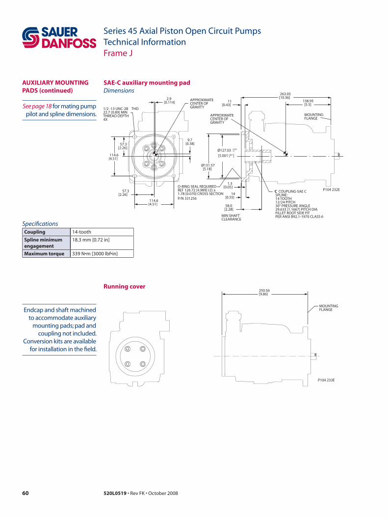
60 520L0519 • Rev FK • October 2008
Series 45 Axial Piston Open Circuit PumpsTechnical InformationFrame J
See page 18 for mating pump pilot and spline dimensions.
Dimensionssae-C auxiliary mounting pad
SpecificationsCoupling 14-tooth
spline minimum engagement
18.3 mm [0.72 in]
maximum torque 339 N•m [3000 lbf•in]
auxiLiaRy mountinG PaDs (continued)
14 [0.55]
1. 3 [0.05]
11 [0.43]
Ø131.57 [5.18]
263.05 [10.36]
Ø127.03 +0.05 - 0
[5.001 ] +.002 - 0
58.0[2.28]
138.95[5.5]
57.3 [2.26]
114.6 [4.51]
57.3 [2.26]
114. 6 [4.51]
2.9[0.114]
9.7[0.38]
MIN SHAFT CLEARANCE
MOUNTIN G FLANGE
APPRO XIM AT E CENTER OF GRA VIT Y
1/2 -13 UNC-2B TH D 22.7 [0.89] MI N THREAD DEPTH 4X
APPRO XIM AT E CENTER OF GRA VIT Y
O-RING SEAL REQUIRED REF 126.72 [4.989] I.D. x 1.78 [0.070] CROSS SECTIONP/N 331256
C OUPLING-SAE C C SPLINE: 14 TO OT H 12/24 PIT CH 30° PRESSURE ANGL E 29.633 [1.1667] PIT CH DI A FILLET RO OT SIDE FIT PER ANSI B92.1-1970 CLASS 6
P104 232E
Running cover
Endcap and shaft machined to accommodate auxiliary
mounting pads; pad and coupling not included.
Conversion kits are available for installation in the field.
250.56[9.86]
MOUNTINGFLANGE
P104 233E

61520L0519 • Rev FK • October 2008
Series 45 Axial Piston Open Circuit PumpsTechnical InformationFrame J
Third-angleprojectionmm [in]
Clockwise rotation, O-ring boss ports
Counterclockwise rotation, O-ring boss ports
axial ported endcapinstaLLation DRawinGs
Ø101.58 ± 0.025[3.999 ±0.001]
R1 MA X [0.04]
9. 4 [0.37]
198. 8 [7.83]
15 [0.59]
82. 4 [3.24]
77. 5 [3.05]
113.6[4.5]
36. 2 [1.4 ]
44. 5 [1.75]
82.1[3.2]
262.3[10.33]
83.4[3.28]
47 [1.85]
28.9[1.14]
246.3[9.7]
73. 2 [2.88]
137. 1 [5.4 ]
37 [1.46]
APPR OX IM AT E CENTER OF GR AV IT Y
SY STEM PORT S
SY STEM PORT B
SY STEM PRESSURE
CASE DRAIN PORT L1
LS SIGNAL PORT X
CASE DRAIN PORT L2
CASE DRAI N PORT L1 SPO TF AC E DEPTH
CASE DRAI N PORT L2 SPO TF AC E DEPTH
(INLET POR T)
SAE J1926/1 1 7/8 -12
(OUTLET POR T)
SAE J1926/ 1 1 5/16 -12
BO TH SIDES
GA UGE PORT M1
SAE J1926/ 1 9/16 -18 SAE J1976/ 1
7/8 -14
SAE J1926/1 7/16 -20
BO TH SIDES
SAE J1926/ 1 7/8 -14
P106 172E
ISO 11926-1
ISO 11926-1
ISO 11926-1
ISO 11926-1 ISO 11926-1
ISO 11926-1 36. 2 [1.43]
44. 5 [1.8 ]
SY STEM PORTS
SY STEM PORT B
(INLET POR T)
SAE J1926/ 1 1 7/8 -12
(OUTLET POR T)
SAE J1926/1 1 5/16 -12
ISO 11926-1
ISO 11926-1
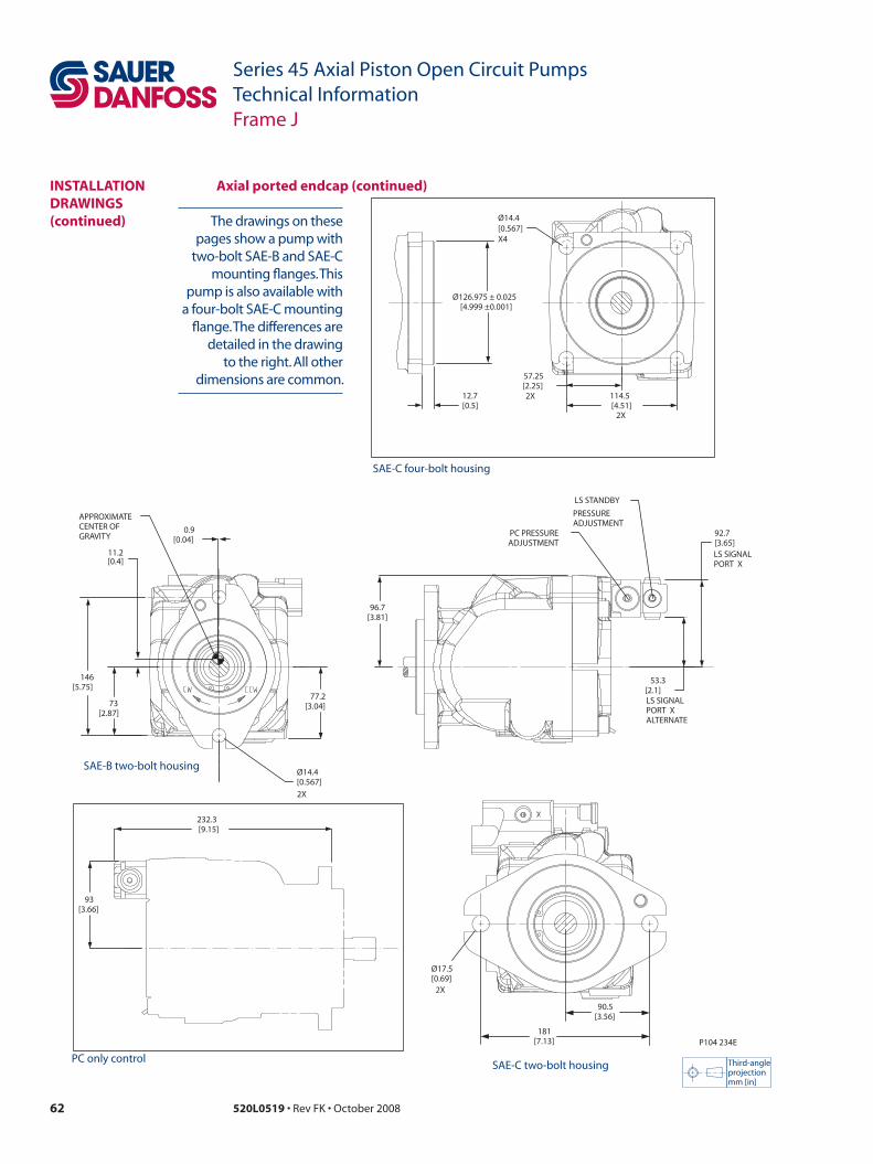
62 520L0519 • Rev FK • October 2008
Series 45 Axial Piston Open Circuit PumpsTechnical InformationFrame J
73 [2.87]
146 [5.75]
Ø14. 4 [0.567]
77. 2 [3.04]
0. 9 [0.04]
11.2[0.4]
96.7[3.81]
53.3 [2.1 ]
92. 7 [3.65]
APPR OX IM AT E CENTER OF GR AV IT Y PC PRESSURE
LS ST ANDBY
ADJUSTMENT
PRESSURE ADJUSTMENT
LS SIGNAL PORT X AL TERNA TE
LS SIGNAL PORT X
2X
P104 234E
93 [3.66]
232. 3 [9.15]
Ø17.5[0.69]
90.5[3.56]
181[7.13]
2X
12.
Ø126.975 ± 0.025
57.25 [2.25]
114. [4.51]
2X
2X
Ø14.4 [0.567] X4
7 [0.5
[4.999 ±0.001]
5 ]
instaLLation DRawinGs(continued)
Third-angleprojectionmm [in]
SAE-C four-bolt housing
PC only control
axial ported endcap (continued)
The drawings on these pages show a pump with
two-bolt SAE-B and SAE-C mounting flanges. This
pump is also available with a four-bolt SAE-C mounting
flange. The differences are detailed in the drawing
to the right. All other dimensions are common.
SAE-B two-bolt housing
SAE-C two-bolt housing

63520L0519 • Rev FK • October 2008
Series 45 Axial Piston Open Circuit PumpsTechnical InformationFrame J
36.2[1.43]
44.5[1.75]
44.5[1.75]
36.2[1.43]
SYSTEM PORT SOUTLET Ø50.8 [2]
SYSTEM PORT B
(INLET PORT)
3000 PSISPLIT FLANGE BOSS
SAE J518(CODE 61)
(OUTLET PORT)
5000 PSISPLIT FLANGE BOSS
SAE J518(CODE 61)
P104 235E
207 bar
PER ISO 6162
with 1/2-13 UNCX 27 [1.063] MIN THREAD
OUTLETØ25.4 [1]
345 bar
PER ISO 6162
with 3/8-16 UNCX 18.61 [0.732] MIN THREAD
77.77[3.062]
42.88[1.688]
26.19[1.031]
52.37[2.062]
SYSTEM PORT SOUTLET Ø50.8 [2]
(INLET PORT)
3000 PSISPLIT FLANGE BOSS
SAE J518(CODE 61)
207 bar
PER ISO 6162
with 1/2-13 UNCX 23 [0.906] MIN THREAD
SYSTEM PORT B(OUTLET PORT)
5000 PSISPLIT FLANGE BOSS
SAE J518(CODE 61)
OUTLETØ25.4 [1]
345 bar
PER ISO 6162
with 3/8-16 UNCX 18.61 [0.732] MIN THREAD
77.77[3.062]52.37
[2.062]
42.88[1.688]
26.19[1.031]
Clockwise rotation, split-flange ports
Counter clockwise rotation, split-flange ports
instaLLationDRawinGs(continued)
axial ported endcap (continued)

64 520L0519 • Rev FK • October 2008
Series 45 Axial Piston Open Circuit PumpsTechnical InformationFrame J
Third-angleprojectionmm [in]
Clockwise rotation
Counterclockwise rotation
Radial ported endcapinstaLLationDRawinGs
77.5[3.05]
194.6[7.66]
9.4[0.37]
242.4[9.54]
Ø101.58 ± 0.025[3.999 ±0.001]
R1 MAX[0.04]
15[0.59]
239.8[9.44]
200.4[7.89]
82.4[3.24]
SYSTEM PORT S
116.5[4.59]
44.9[1.77]
132[5.2]
76.2[3]
84[3.31]
99.4[3.9]
47[1.85]
82.1[3.23]
37[1.46]
137.1[5.4]76.2
[3]84
[3.31]
PC PRESSURE
LS STANDBY
LS SIGNAL PORT X
CASE DRAIN PORT L1
CASE DRAIN PORT L2
CASE DRAINPORT L2SPOTFACEDEPTH
LS SIGNAL PORT X
LS SIGNAL PORT XALTERNATE
CASE DRAINPORT L1SPOTFACEDEPTH
(INLET PORT)207 BAR [3000 PSI}SPLIT FLANGE
SAE J518(CODE 61)
ADJUSTMENT
PRESSUREADJUSTMENT
SAE J1926/10.4375-20
BOTHSIDES
SYSTEMPORT SINLET
SYSTEMPORT BOUTLET
BOTHSIDES
SAE J 1976/17/8-14
SAE J1926/17/8-14
SYSTEMPORT SINLET
SYSTEMPORT BOUTLET
P106 173E
PER ISO 11976-1
PER ISO 6162
with 1/2-13 UNCX 27 [1.063] MIN THREAD DEPTH
Ø50.8 [2]INLET
PER ISO 11926-1PER ISO 11926-1

65520L0519 • Rev FK • October 2008
Series 45 Axial Piston Open Circuit PumpsTechnical InformationFrame J
Ø14. 4 [0.567]
73 [2.87]
146 [5.75]
77. 2 [3.04]
3.2[0.1 ] 10.4
[0.4]128.8
[5.1]
188.84 [7.43]
96. 7 [3.8 ]
APPR OX IM AT E CENTER OF GR AV IT Y
APPR OX IM AT E CENTER OF GR AV IT Y
SY STEM PORT B (OUTLET POR T) 345 BAR [5000 PSI] SPLIT FLANGE PER ISO 6162
2X
P104 236E
240. 1 [9.45]
106.62 [4.20]
Ø25.4 [1]
SAE J518 (C ODE 61) with 3/8-16 UNC X 22 [0.866] MINIMUM THREAD DEPTH
26.19 [1.031]
52.37 [2.062]
12.
Ø126.975 ± 0.025
57.25 [2.25]
114. [4.51]
2X
2X
Ø14.4 [0.567] X4
7 [0.5
[4.999 ±0.001]
5 ]
Ø17.5[0.69]
90.5[3.56]
181[7.13]
2X
Third-angleprojectionmm [in]
SAE-C four-bolt housing
PC only control
Radial ported endcap (continued)
The drawings on these pages show a pump with
two-bolt SAE-B and SAE-C mounting flanges. This
pump is also available with a four-bolt SAE-C mounting
flange. The differences are detailed in the drawing
to the right. All other dimensions are common.
instaLLationDRawinGs(continued)
SAE-C two-bolt housing
SAE-B two-bolt housing

66 520L0519 • Rev FK • October 2008
Series 45 Axial Piston Open Circuit PumpsTechnical InformationFrame J
instaLLationDRawinGs(continued)
electric on/off control/Radial endcap
Third-angleprojectionmm [in]
P106 191E
287.3[11.31]
139.84[5.51]
20°
60.92[2.4]
99.4[3.91]
60.92[2.4]
99.4[3.91]
139.84[5.51]
287.3[11.31]
20°
Radial endcap with electric on/off right control (clockwise) Radial endcap with electric on/off left control (counterclockwise)
269.0[10.62]
141.0[5.55]
20°
83.4[3.28]
76.9[3.03]
141[5.55]
20°
Axial endcap with electric on/off right control (counter clockwise) Axial endcap with electric on/off left control (clockwise)
83.4[3.28]
76.9[3.03]
269.0[10.62]
141.0[5.55]
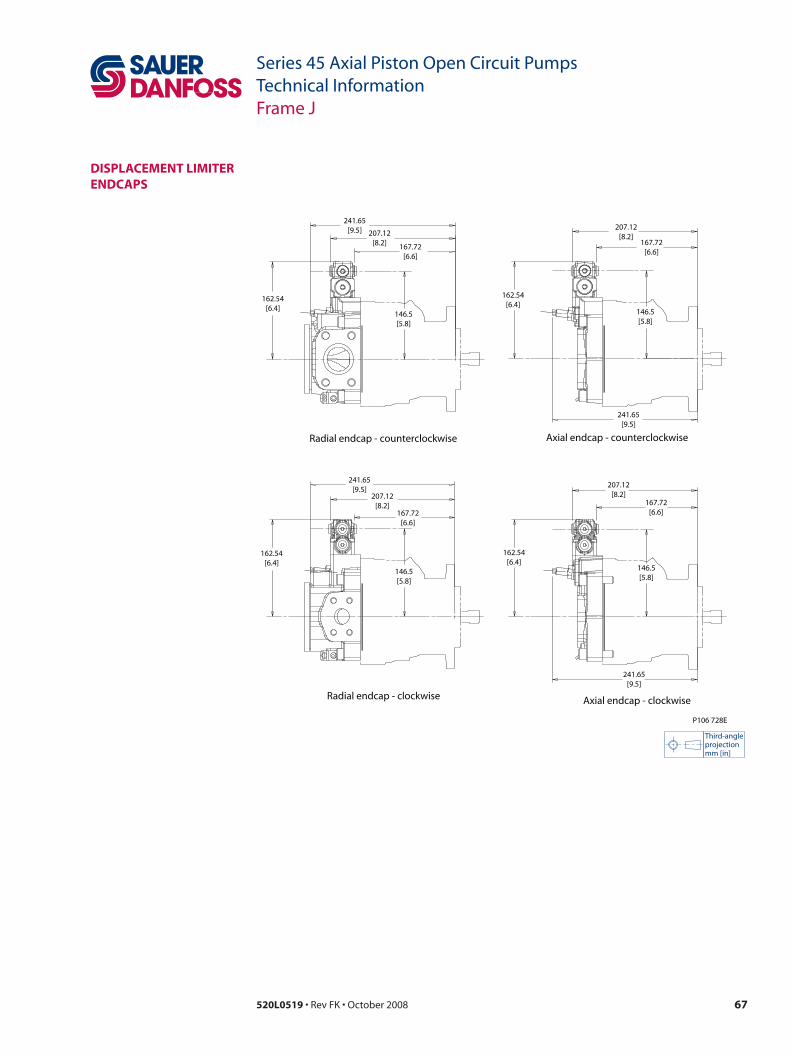
67520L0519 • Rev FK • October 2008
Series 45 Axial Piston Open Circuit PumpsTechnical InformationFrame J
DisPLaCement LimiteR enDCaPs
P106 728E
Axial endcap - clockwiseRadial endcap - clockwise
Radial endcap - counterclockwise Axial endcap - counterclockwise
207.12[8.2]
167.72[6.6]
146.5[5.8]
241.65[9.5]
162.54[6.4]
207.12[8.2]
167.72[6.6]
146.5[5.8]
241.65[9.5]
162.54[6.4]
207.12[8.2]
167.72[6.6]
146.5[5.8]
241.65[9.5]
162.54[6.4]
207.12[8.2] 167.72
[6.6]
146.5[5.8]
241.65[9.5]
162.54[6.4]
Third-angleprojectionmm [in]

68 520L0519 • Rev FK • October 2008
Series 45 Axial Piston Open Circuit PumpsTechnical InformationFrame F
DesiGn Series 45 Frame F pumps have a dual servo piston design with a cradle-type swashplate set in polymer-coated journal bearings. The bias piston increases swashplate angle. The servo piston decreases swashplate angle. At equal pressure, the larger diameter servo piston overpowers the bias piston. Nine reciprocating pistons displace fluid from the pump inlet to the pump outlet as the cylinder block rotates on the pump input shaft. The block spring holds the piston slippers to the swashplate via the slipper retainer. The cylinder block rides on a bi-metal valve plate optimized for high volumetric efficiency and low noise. Tapered roller bearings support the input shaft and a viton lip-seal protects against shaft leaks.
An adjustable one spool (PC only, not shown) or two spool (LS) control senses system pressure and load pressure (LS controls). The control ports system pressure to the servo piston to control pump output flow.
Frame F cross section
Slipper
LS adjustmen t
PC adjustmen t
LS spoo l
PC spoo l
LS contro l (attached to endcap)
Se rv o piston
Swashplat e
Ta pere d roller bearing
Shaf t seal
Ta pered roller bearing
Input shaf t
C ylinder block
V alv e plate
C ylinder block spring
Piston
Slipper retainer
Bias sprin g
P104 341E Bias piston

69520L0519 • Rev FK • October 2008
Series 45 Axial Piston Open Circuit PumpsTechnical InformationFrame F
sPeCifiCations
For general operating parameters, including fluid viscosity, temperature, and
inlet and case pressures, see page 13. For system
design parameters, including installation,
filtration, reservoir, and line velocities, see page 15.
For more information on noise levels, see page 19.
For definitions of pressure and speed ratings,
see page 14. For more information on external shaft loads, see page 16; mounting flange loads,
see page 17.
Features and options model
feature unit f74B f90C
Maximum Displacement cm³ [in³] 74 [4.52] 90 [5.49]
Flow at rated speed (theoretical) l/min [US gal/min]
177.6 [46.9]
198[52.3]
Input torque at maximum displacement (theoretical)
N•m/bar[lbf•in/1000 psi]
1.178[719]
1.432[874]
Mass moment of inertia of internal rotating components
kg•m²[slug•ft²]
0.00630[0.00465]
0.00650[0.00480]
Weight Axial ports kg [lb] 29 [64]
Radial ports 31.8 [70.1]
Rotation Clockwise, Counterclockwise
Mounting SAE B 2 bolt, SAE-C 4 bolt
Auxiliary mounting (See page 77) SAE-A, SAE-B, SAE-BB, SAE-C
System ports (type) 4-bolt split flange
System ports (location) Axial, Radial
Control types (See page 74) PC, Remote PC, LS, Electric
Shafts (See page 76) Splined 14 tooth, 17 tooth
Straight Ø 31.75 mm [1.25 in]
Displacement limiters (See page 78) Optional, adjustable
Ratings model
Rating units f74B f90C
Input speed1 minimum min-1 (rpm) 500 500
continuous 2400 2200
maximum 2800 2600
Working pressure continuous bar [psi] 310 [4495] 260 [3770]
maximum 400 [5800] 350 [5075]
External shaft loads
External moment (Me) N•m [lbf•in] 300 [2655]
Thrust in (Tin), out (Tout) N [lbf ] 2900 [650]
Bearing life at 150 bar [2175 psi] B10 hours 31300 17400
at 200 bar [2900 psi] 11100 5700
at 250 bar [3625 psi] 4810 2490
at 280 bar [4060 psi] 3080 1636
Mounting flange load moments
Vibratory (continuous) N•m [lbf•in] 3730 [33000]
Shock (max) 13220 [117000]
1. Input speeds are valid at 1 bar absolute [0 in Hg vac] inlet pressure. See Inlet pressure vs. speed charts next page.
Sound levels2
dB(a) 140 bar [2030 psi] 210 bar [3045 psi] 260 bar [3770 psi]
model 1800 min-1(rpm) Rated speed 1800 min-1(rpm) Rated speed 1800 min-1(rpm) Rated speed
F74B 72 76 74 78 75 79
F90C 76 77 76 77 79 79
2. Sound data was collected in a semi-anechoic chamber. Values have been adjusted (-3 dB) to reflect anechoic levels.

70 520L0519 • Rev FK • October 2008
Series 45 Axial Piston Open Circuit PumpsTechnical InformationFrame F
PeRfoRmanCe f74B
Input power vs. speed
Flow vs. speed
Flow and power data valid at 49°C [120°F] and viscosity
of 17.8 mm²/sec [88 SUS].
The chart on the right shows allowable inlet
pressure and speed at various displacements.
Greater speeds and lower inlet pressures are possible
at reduced displacement. Operating outside of
acceptable limits reduces pump life.
0
40
80
120
160
200
0 500 1000 1500 2000 25000
10
20
30
40
50
Flo
w (l
/min
)
Speed min (rpm)-1
Flo
w (U
S g
al/m
in)
P104 004E
0
20
40
60
80
100
0 500 1000 1500 2000 25000
20
40
60
80
100
120
Pow
er (k
W)
Speed min (rpm)-1Po
wer
(hp
)P104 005E
140 bar [2030 psi]
210 bar [3045 psi]260 bar [3770 psi]
0.6
0.7
0.8
0.9
1.0
1.1
1.2
1.3
1.4
1.5
1.6100% 90% 80%
Shaft Speed min (rpm)-1
Inle
t Pr
essu
re (b
ar a
bs)
(psi
gau
ge)
(in H
g v
ac)
P104 015E
0
3
6
9
8
6
4
2
2000 2200 2400 2600 2800 3000
Inlet pressure vs. speed

71520L0519 • Rev FK • October 2008
Series 45 Axial Piston Open Circuit PumpsTechnical InformationFrame F
PeRfoRmanCe f90C
Inlet pressure vs. speed
Input power vs. speed
Flow vs. speed
Flow and power data valid at 49°C [120°F] and viscosity
of 17.8 mm²/sec [88 SUS].
The chart on the right shows allowable inlet
pressure and speed at various displacements.
Greater speeds and lower inlet pressures are possible
at reduced displacement. Operating outside of
acceptable limits reduces pump life.
0
50
100
150
200
250
0 500 1000 1500 2000 25000
10
20
30
40
50
60
Flo
w (l
/min
)
Speed min (rpm)-1
Flo
w (U
S g
al/m
in)
P104 006E
0
20
40
60
80
100
120
0 500 1000 1500 2000 25000
25
50
75
100
125
150
124 bar [1798 psi]
186 bar [2697 psi]
255 bar [3698 psi]
Pow
er (k
W)
Speed min (rpm)-1
Pow
er (h
p)
P104 007E
0.6
0.7
0.8
0.9
1.0
1.1
1.2
1.3
1.4
1.5
1.6100% 90% 80%
Shaft Speed min (rpm)-1
Inle
t Pr
essu
re (b
ar a
bs)
(psi
gau
ge)
(in H
g v
ac)
P104 015E
0
3
6
9
8
6
4
2
1800 2000 2200 2400 2600 2800
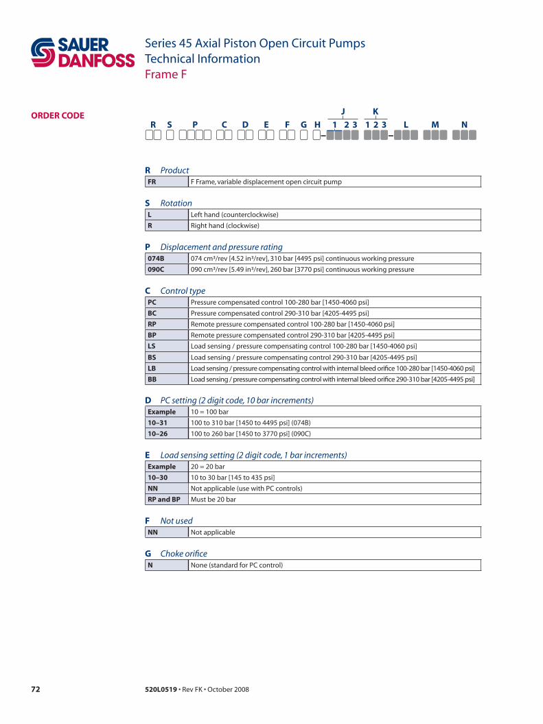
72 520L0519 • Rev FK • October 2008
Series 45 Axial Piston Open Circuit PumpsTechnical InformationFrame F
oRDeR CoDe
R ProductfR F Frame, variable displacement open circuit pump
s RotationL Left hand (counterclockwise)
R Right hand (clockwise)
P Displacement and pressure rating074B 074 cm³/rev [4.52 in³/rev], 310 bar [4495 psi] continuous working pressure
090C 090 cm³/rev [5.49 in³/rev], 260 bar [3770 psi] continuous working pressure
C Control typePC Pressure compensated control 100-280 bar [1450-4060 psi]
BC Pressure compensated control 290-310 bar [4205-4495 psi]
RP Remote pressure compensated control 100-280 bar [1450-4060 psi]
BP Remote pressure compensated control 290-310 bar [4205-4495 psi]
Ls Load sensing / pressure compensating control 100-280 bar [1450-4060 psi]
Bs Load sensing / pressure compensating control 290-310 bar [4205-4495 psi]
LB Load sensing / pressure compensating control with internal bleed orifice 100-280 bar [1450-4060 psi]
BB Load sensing / pressure compensating control with internal bleed orifice 290-310 bar [4205-4495 psi]
D PC setting (2 digit code, 10 bar increments)example 10 = 100 bar
10–31 100 to 310 bar [1450 to 4495 psi] (074B)
10–26 100 to 260 bar [1450 to 3770 psi] (090C)
e Load sensing setting (2 digit code, 1 bar increments)example 20 = 20 bar
10–30 10 to 30 bar [145 to 435 psi]
nn Not applicable (use with PC controls)
RP and BP Must be 20 bar
f Not usednn Not applicable
G Choke orificen None (standard for PC control)
R s P C D e f G H 1 2 3 1 2 3 L m n
– –
J K
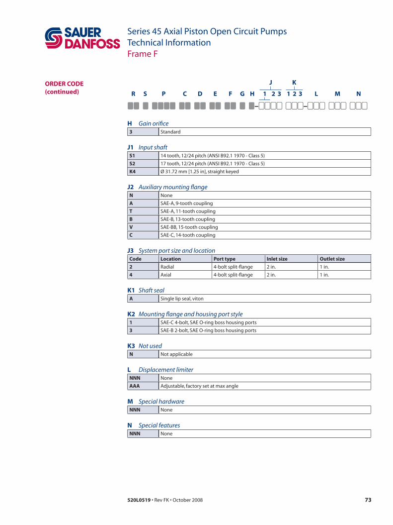
73520L0519 • Rev FK • October 2008
Series 45 Axial Piston Open Circuit PumpsTechnical InformationFrame F
oRDeR CoDe (continued)
H Gain orifice3 Standard
J1 Input shafts1 14 tooth, 12/24 pitch (ANSI B92.1 1970 - Class 5)
s2 17 tooth, 12/24 pitch (ANSI B92.1 1970 - Class 5)
K4 Ø 31.72 mm [1.25 in], straight keyed
J2 Auxiliary mounting flangen None
a SAE-A, 9-tooth coupling
t SAE-A, 11-tooth coupling
B SAE-B, 13-tooth coupling
v SAE-BB, 15-tooth coupling
C SAE-C, 14-tooth coupling
J3 System port size and locationCode Location Port type inlet size outlet size
2 Radial 4-bolt split-flange 2 in. 1 in.
4 Axial 4-bolt split-flange 2 in. 1 in.
K1 Shaft seala Single lip seal, viton
K2 Mounting flange and housing port style1 SAE-C 4-bolt, SAE O-ring boss housing ports
3 SAE-B 2-bolt, SAE O-ring boss housing ports
K3 Not usedn Not applicable
L Displacement limiternnn None
aaa Adjustable, factory set at max angle
m Special hardwarennn None
n Special featuresnnn None
R s P C D e f G H 1 2 3 1 2 3 L m n
– –
J K

74 520L0519 • Rev FK • October 2008
Series 45 Axial Piston Open Circuit PumpsTechnical InformationFrame F
ContRoLs
Remote PC Control (RP)
Pressure compensated control (PC)
PC control setting rangemodel bar psi
f74B 100–310 1450–4495
f90C 100–260 1450–3770
Response/recovery times*(ms) Response Recovery
f74B 35 120
f90C 35 135
* For definitions, see page 9.
Specifications
Schematic diagram
PC control setting rangemodel bar psi
f74B 100–310 1450–4495
f90C 100–260 1450–3770
Response/recovery times*(ms) Response Recovery
f74B 35 120
f90C 35 135
* For definitions, see page 10.
Specifications
Schematic diagram
LegendB = OutletS = InletL1, L2 = Case drainM2 = System pressure gauge portM4 = Servo pressure gauge port
LegendB = OutletS = InletL1, L2 = Case drainM2 = System pressure gauge portM4 = Servo pressure gauge portX = Remote PC port
Remote PC schematic
M2
L2
S L1 P107 789E
X
X
B
M4
PC schematic
B
M2
L2
S L1 P107 788E
M4
LS settingmodel bar psi
all 20 290

75520L0519 • Rev FK • October 2008
Series 45 Axial Piston Open Circuit PumpsTechnical InformationFrame F
ContRoLs (continued)
Load sensing control (Ls)
PC setting rangemodel bar psi
f74B 100–310 1450–4495
f90C 100–260 1450–3770
Response/recovery times*(ms) Response Recovery
f74B 35 135
f90C 45 135
* For definitions, see page 11.
Specifications
Schematic diagram LS setting rangemodel bar psi
all 10–30 145–435
PC setting rangemodel bar psi
f74B 100–310 1450–4495
f90C 100–260 1450–3770
Response/recovery times*(ms) Response Recovery
f74B 35 135
f90C 40 135
* For definitions, see page 11.
Specifications
Schematic diagram LS setting rangemodel bar psi
all 10–30 145–435
Load sensing control with internal bleed orifice (LB)
LegendB = OutletS = InletL1, L2 = Case drainM2 = System pressure gauge portM4 = Servo pressure gauge portX = LS signal port
LegendB = OutletS = InletL1, L2 = Case drainM2 = System pressure gauge portM4 = Servo pressure gauge portX = LS signal port
LS Schematic
M2
L2
S L1
X
X
P107 791E
B
M4
LB Schematic
M2
L2
S L1
X
X
P107 790E
B
M4

76 520L0519 • Rev FK • October 2008
Series 45 Axial Piston Open Circuit PumpsTechnical InformationFrame F
inPut sHafts
Shaft data
Code Descriptionmaximum torque rating¹N•m [lbf•in] Drawing
s1 14 tooth spline12/24 pitch(ANSI B92.1 1970 - Class 5)
594 [5257]
P104 349E
Ø25.52 MAX [1.005]
8 ± 0.8
[0.31 ± 0.03]
28 ± 0.15 [1.102± 0.006]
Ø31.14 ± 0.08
[1.226 ± 0.003]
14 TEETH 12/24 PITCH 29.634 [1.167] PITCH Ø 30° PRESSURE ANGLEFILLET ROOT SIDE FIT COMPATIBLE WITH
CLASS 5. ALSO MATES WITH FLAT ROOT SIDE FIT
MOUNTING FLANGE
COUPLING MUST NOT PROTRUDE BEYOND THIS POINT
ANSI B92.1-1970
47.6 ± 0.06 [1.874 ± 0.024]
s2 17 tooth spline12/24 pitch(ANSI B92.1 1970 - Class 5)
1044 [9240]
53.97 ± 0.6 [2.125 ± 0.24]
30.75 MAX [1.211]
8 ± 0.8
[0.31 ± 0.03]
39.91 ± 0.09[1.571 ± 0.0035]
Ø37.91 ± 0.09[1.49 ± 0.0035]
35.983 [1.417] PITCH Ø 17 TEETH 12/24 PITCH
30° PRESSURE ANGLE FILLET ROOT SIDE FIT COMPATIBLE WITH
CLASS 6 ALSO MATES WITHFLAT ROOT SIDE FIT
MOUNTINGFLANGE
COUPLING MUST NOT PROTRUDE BEYOND THIS POINT
ANSI B92.1-1970
P104 350E
K4 Ø 31.75 mm [1.25 in]Straight keyed
734 [6495]
Ø31.72 ± 0.02[1.249 ± .001]
35.19 ± 0.13[1.385 ±0.005]
SQ. KEY X 28.58 LG[1.125 ±0.010]
8 ± 0.8[0.31 ± 0.03]
MOUNTINGFLANGE
COUPLING MUST NOTPROTRUDE BEYONDTHIS POINT P104 351E
48 ± 0.6[1.89 ±0.024]
7.938+0.0-0.05
[0.3125 ]+0.0-0.0020
1. See Input shaft torque ratings, page 18 for an explaination of maximum torque.
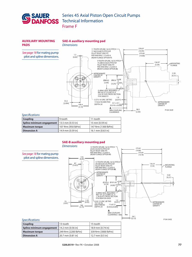
77520L0519 • Rev FK • October 2008
Series 45 Axial Piston Open Circuit PumpsTechnical InformationFrame F
auxiLiaRy mountinG PaDs Dimensions
sae-a auxiliary mounting pad
SpecificationsCoupling 9-tooth 11-tooth
spline minimum engagement 13.5 mm [0.53 in] 15 mm [0.59 in]
maximum torque 107 N•m [950 lbf•in] 147 N•m [1300 lbf•in]
Dimension a 14.9 mm [0.59 in] 16.1 mm [0.63 in]
Dimensionssae-B auxiliary mounting pad
SpecificationsCoupling 13-tooth 15-tooth
spline minimum engagement 14.2 mm [0.56 in] 18.9 mm [0.74 in]
maximum torque 249 N•m [2200 lbf•in] 339 N•m [3000 lbf•in]
Dimension a 20.7 mm [0.81 in] 12.7 mm [0.5 in]
MOUNTING FLANGE
P104 342E
53.2 [2.094]
106.4 [4.19]
Ø88.62 [3.49]
1.9 [0.077]
58.5 [2.30]
278.07 [10.95]
136.97 [5.39]
5.39 [0.21]
APPROXIMATE CENTER OF GRAVITY
9 TOOTH SPLINE, 16/32 PITCH 14.288 [0.5625] PITCH Ø FILLET ROOT SIDE FIT PER ANSI B92.1, CLASS 6
11 TOOTH SPLINE, 16/32 PITCH 17.463 [0.6875] PITCH Ø FILLET ROOT SIDE FIT PER ANSI B92.1, CLASS 6
O-RING SEAL REQUIRED REF 82.27 [3.239] I.D. X 2.62 [0.103] CROSS SECTIONP/N 5000373
MIN COUPLING CLEARANCE
A
0.375-16 UNC-2B THD17.8 [0.70] MIN THD DEPTH 2X
1.3 [0.05] (REAR FLANGE OPTION T)
(REAR FLANGE OPTION A)
8.1 ± 0.7 [0.319 ± 0.028]
APPROXIMATE CENTER OF GRAVITY
275.82 [10.86]
Ø82.6 +0.08 0
[3.252 ] +0.003 0
73 [2.87]
146 [5.75]
87 [3.425]
174 [6.85]
Ø101.65 +0.08 0
[4.002 ] +0.003 0
Ø105.6 [4.16]
0.50-13 UNC-2B THD 19.7 [0.76] MIN THREAD
O-RING SEAL REQUIREDREF 101.32 [3.989] I.D. X 1.78 [0.07] CROSS SECTIONP/N 9004104-0450
P104 343E
MOUNTING FLANGE
275.82 [10.86]
136.24 [5.36]
5.42 [0.21]
APPROXIMATE CENTER OF GRAVITY
13 TOOTH SPLINE, 16/32 PITCH 20.638 [0.8125] PITCH Ø FILLET ROOT SIDE FIT PER ANSI B92.1, CLASS 6
(REAR FLANGE OPTION B)
1.32 [0.05]
1.3 [0.051]
54.1 [2.13]
15 TOOTH SPLINE, 16/32 PITCH 23.813 [0.9375] PITCH Ø FILLET ROOT SIDE FIT PER ANSI B92.1, CLASS 6 (REAR FLANGE OPTION V)
DEPTH 2X 11±0.12
[0.433±0.005]
MIN COUPLING CLEARANCE
A
APPROXIMATE GRAVITY CENTER OF
273.69 [10.78]
See page 18 for mating pump pilot and spline dimensions.
See page 18 for mating pump pilot and spline dimensions.
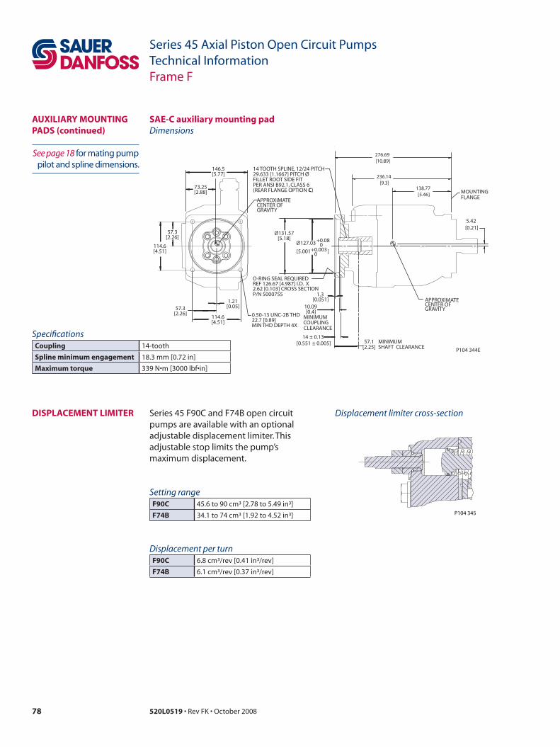
78 520L0519 • Rev FK • October 2008
Series 45 Axial Piston Open Circuit PumpsTechnical InformationFrame F
Dimensionssae-C auxiliary mounting pad
SpecificationsCoupling 14-tooth
spline minimum engagement 18.3 mm [0.72 in]
maximum torque 339 N•m [3000 lbf•in]
auxiLiaRy mountinG PaDs (continued)
57.3 [2.26]
114.6 [4.51]
57.3 [2.26]
114.6 [4.51]
73.25 [2.88]
146.5 [5.77]
Ø131.57 [5.18]
0.50-13 UNC-2B THD22.7 [0.89] MIN THD DEPTH 4X
O-RING SEAL REQUIREDREF 126.67 [4.987] I.D. X 2.62 [0.103] CROSS SECTIONP/N 5000755
P104 344E
MOUNTING FLANGE
276.69 [10.89]
138.77 [5.46]
5.42 [0.21]
APPROXIMATE CENTER OF GRAVITY
14 TOOTH SPLINE, 12/24 PITCH 29.633 [1.1667] PITCH Ø FILLET ROOT SIDE FIT PER ANSI B92.1, CLASS 6
14 ± 0.13 [0.551 ± 0.005]
APPROXIMATE CENTER OF GRAVITY
(REAR FLANGE OPTION C)
1.21 [0.05]
1.3 [0.051]
10.09 [0.4]
MINIMUM COUPLING CLEARANCE
57.1 [2.25]
MINIMUM SHAFT CLEARANCE
Ø127.03 +0.08 0
[5.001 ] +0.003 0
236.14 [9.3]
See page 18 for mating pump pilot and spline dimensions.
DisPLaCement LimiteR Series 45 F90C and F74B open circuit pumps are available with an optional adjustable displacement limiter. This adjustable stop limits the pump’s maximum displacement.
Displacement limiter cross-section
Setting rangef90C 45.6 to 90 cm³ [2.78 to 5.49 in³]
f74B 34.1 to 74 cm³ [1.92 to 4.52 in³] P104 345
Displacement per turnf90C 6.8 cm³/rev [0.41 in³/rev]
f74B 6.1 cm³/rev [0.37 in³/rev]

79520L0519 • Rev FK • October 2008
Series 45 Axial Piston Open Circuit PumpsTechnical InformationFrame F
Endcap and shaft machined to accommodate auxiliary
mounting pads; pad and coupling not included.
Conversion kits are available for installation in the field.
aDJustaBLe DisPLaCement LimiteR anD RunninG CoveR
MOUNTING FLANGE
264.2[10.4]
275.82[10.86]
P104 346E
Dimensions

80 520L0519 • Rev FK • October 2008
Series 45 Axial Piston Open Circuit PumpsTechnical InformationFrame F
axiaL PoRteD enDCaP
Third-angleprojectionmm [in]
P104 347E
158.7[6.25]
89 [3.5]
Ø126.975 ± 0.025 [4.999 ± 0.001]
165.14 [6.5]
CASE DRAIN PORT L2
LS SIGNAL PORT X SAE J1926 7/16-20
SYSTEM PORT B AND S
143.2 [5.64]
103.54 [4.08]
121.83 [4.8]
16.44 [0.65]
6.44 [0.25]
12.7[0.5]
227.74 [8.97]
239.74 [9.44]
4X
61.24 [2.41]
53 [2.09]
CASE DRAIN PORT L1 SAE J1926 7/8-14
256.355 [10.09]
45 [1.77]
120.74 [4.75]
CASE DRAIN PORT L2 SAE J1926 7/8-14GAGE PORT M2
SAE J1926/1 7/16-20
SYSTEM PRESSURE
77.34 [3.04]
78.94 [3.11]
40 [1.57]
45 [1.77]
49.7 [1.96]
10.3 [0.41]
SYSTEM PORT S (INLET PORT) 2.00 in -3000 PSISPLIT FLANGE BOSS PER SAE J518 (CODE 61)with 1/2 13 UNCx 27 [1.06] Min.threads
SYSTEM PORT B (OUTLET PORT) 1.00 in -5000 PSISPLIT FLANGE BOSS PER SAE J518 (CODE 61)with 3/8-16 UNCx 22 [0.87] Min.threads
LS SIGNAL PORT X
LS SIGNAL PORT X ALTERNATE
SERVO PRESSURE GAUGE PORT M4 SAE J1926/1 3/4-16
40 [1.57]
45 [1.77]
SYSTEM PORT S (INLET PORT)2.00 in -3000 PSISPLIT FLANGE BOSSPER SAE J518(CODE 61)with 1/2 13 UNCx 27 [1.06] Min.threads
SERVO PRESSURE GAUGE PORT M4 SAE J1926/1 3/4-16
10.3 [0.41]
LS SIGNAL PORT X ALTERNATE
49.7 [1.96]
LS SIGNAL PORT X
SYSTEM PORT B (OUTLET PORT)1.00 in -5000 PSISPLIT FLANGE BOSSPER SAE J518(CODE 61)with 3/8-16 UNCx 22 [0.87] Min.threads
Clockwise rotation
Counterclockwise rotation

81520L0519 • Rev FK • October 2008
Series 45 Axial Piston Open Circuit PumpsTechnical InformationFrame F
axiaL PoRteD enDCaP (continued)
Third-angleprojectionmm [in]
P106 628E
57.25 [2.25]
114.5 [4.51]
57.25 [2.25]
114.5 [4.51]
Ø14.3 [0.56]
LS STANDBY
PC PRESSURE
PRESSURE ADJUSTMENT
ADJUSTMENT
APPROXIMATE CENTER OF GRAVITY
CCW CW 91 [3.58]
143.2 [5.64]
165.14 [6.5]
CASE DRAIN PORT L1
LS SIGNAL PORT X ALTERNATE SAE J1926 7/16-20
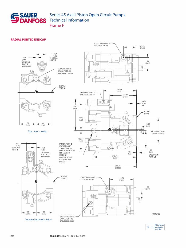
82 520L0519 • Rev FK • October 2008
Series 45 Axial Piston Open Circuit PumpsTechnical InformationFrame F
RaDiaL PoRteD enDCaP
Third-angleprojectionmm [in]
Clockwise rotation
Counterclockwise rotation
P104 348E
45 [1.77]
CASE DRAIN PORT L2 SAE J1926 7/8-14
120.74 [7.75]
SERVO PRESSURE GAUGE PORT M4 SAE J1926/1 3/4-16
49.7 [1.96]
10.3 [0.41]
75 [2.95]
82 [3.23]
LS SIGNAL PORT X ALTERNATE
LS SIGNAL PORT X
49.7 [1.96]
10.3 [0.41]
75 [2.95]
82 [3.23]
LS SIGNAL PORT X ALTERNATE
LS SIGNAL PORT X
61.24 [2.41]
53 [2.09]
CASE DRAIN PORT L1 SAE J1926 7/8-14
143.2 [5.64]
158.7 [6.25]
103.54 [4.08]
LS SIGNAL PORT X SAE J1926 7/16-20
256.04 [10.08]
212.74 [8.38]
12.7 [0.5]
Ø126.975 ± 0.025 [4.999 ± 0.001]
89 [3.5]
CASE DRAIN PORT L2
5.98 [0.24]
R1 MAX [0.04]
16.44 [0.65]
165.14 [6.5]
133.45 [5.25]
4X
SYSTEM PRESSURE GAUGE PORT M2 SAE J1926 7/16-20
SYSTEM PORT B
SYSTEM PORT S
SYSTEM PORT B (OUTLET PORT)1.00 in -5000 PSISPLIT FLANGE BOSSPER SAE J518(CODE 61)with 3/8-16 UNCx 22 [0.87] Min.threads

83520L0519 • Rev FK • October 2008
Series 45 Axial Piston Open Circuit PumpsTechnical InformationFrame F
RaDiaL PoRteD enDCaP (continued)
Third-angleprojectionmm [in]
P106 629E
57.25 [2.25]
114.5 [4.51]
57.25 [2.25]
114.5 [4.51]
Ø14.3 [0.56]
LS STANDBY PRESSURE ADJUSTMENT
PC PRESSURE ADJUSTMENT
CCW CW
165.14 [6.5]
143.2 [5.64]
LS SIGNAL PORT X ALTERNATE SAE J1926 7/16-20
91 [3.58]
215.74 [8.49]
SYSTEM PORT S (INLET PORT)2.00 in -3000 PSISPLIT FLANGE BOSSPER SAE J518 (CODE 61)with 1/2-13 UNCx 27 [1.06] Min.threads
SERVO PRESSURE
SAE J1926 7/16-20
GAGE PORT M4
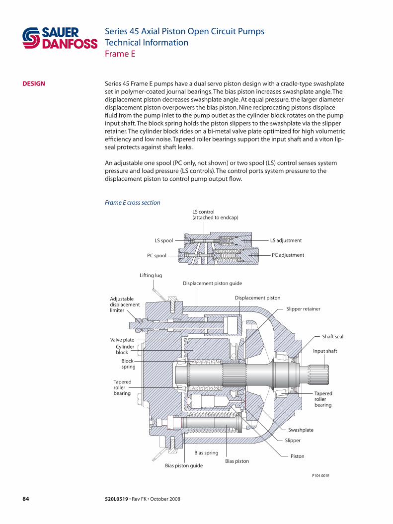
84 520L0519 • Rev FK • October 2008
Series 45 Axial Piston Open Circuit PumpsTechnical InformationFrame E
DesiGn Series 45 Frame E pumps have a dual servo piston design with a cradle-type swashplate set in polymer-coated journal bearings. The bias piston increases swashplate angle. The displacement piston decreases swashplate angle. At equal pressure, the larger diameter displacement piston overpowers the bias piston. Nine reciprocating pistons displace fluid from the pump inlet to the pump outlet as the cylinder block rotates on the pump input shaft. The block spring holds the piston slippers to the swashplate via the slipper retainer. The cylinder block rides on a bi-metal valve plate optimized for high volumetric efficiency and low noise. Tapered roller bearings support the input shaft and a viton lip-seal protects against shaft leaks.
An adjustable one spool (PC only, not shown) or two spool (LS) control senses system pressure and load pressure (LS controls). The control ports system pressure to the displacement piston to control pump output flow.
Frame E cross section
Adjustabledisplacementlimiter
Lifting lug
Displacement piston
Displacement piston guide
Swashplate
Input shaft
Shaft seal
Bias piston
Bias spring
Cylinderblock
Bias piston guide
Piston
Slipper
Blockspring
Valve plate
Taperedrollerbearing
Slipper retainer
Taperedrollerbearing
LS adjustment
PC adjustment
LS spool
PC spool
LS control(attached to endcap)
P104 001E

85520L0519 • Rev FK • October 2008
Series 45 Axial Piston Open Circuit PumpsTechnical InformationFrame E
sPeCifiCations Features and options model
feature unit e100B e130B e147C
Maximum Displacement cm³ [in³] 100 [6.10] 130 [7.93] 147 [8.97]
Flow at rated speed (theoretical) l/min [US gal/min]
245[64.7]
286 [75.6]
309[81.6]
Input torque at maximum displacement (theoretical)
N•m/bar[lbf•in/1000 psi]
1.592[972]
2.069[1263]
2.340[1428]
Mass moment of inertia of internal rotating components
kg•m²[slug•ft²]
0.0128[0.0094]
0.0128[0.0094]
0.0128[0.0094]
Weight Axial ports kg [lb] 52 [114]
Radial ports 56 [123.5]
Rotation Clockwise, Counterclockwise
Mounting SAE-C
Auxiliary mounting (See page 95) SAE-A, SAE-B, SAE-BB, SAE-C, SAE-CC
System ports (type) 4-bolt split flange
System ports (location) Axial, Radial
Control types (See page 91) PC, Remote PC, LS, LS with internal bleed
Shafts (See page 93) Splined 13-tooth, 14-tooth, 17-tooth
Straight Ø 38.08 mm [1.5 in]
Displacement limiters (See page 97) Optional, adjustable
Ratings model
Rating units e100B e130B e147C
Input speed¹ minimum min-1 (rpm) 500 500 500
continuous 2450 2200 2100
maximum 2880 2600 2475
Working pressure continuous bar [psi] 310 [4495] 310 [4495] 260 [3770]
maximum 400 [5800] 400 [5800] 350 [5075]
External shaft loads
External moment (Me) N•m [lbf•in] 455 [4030] 360 [3190] 396 [3500]
Thrust in (Tin), out (Tout) N [lbf ] 2846 [640] 1735 [390] 2113 [475]
Thrust out (Tout) 7740 [1740] 6672 [1500] 7117 [1600]
Bearing life at 140 bar [2030 psi] B10 hours 77 200 32 700 21 600
at 210 bar [3045 psi] 19 800 8400 5500
at 260 bar [3770 psi] 9700 4116 2700
at 310 bar [4495 psi] 5400 2300 —
Mounting flange load moments
Vibratory (continuous) N•m [lbf•in] 1920 [17 000]
Shock (max) 6779 [60 000]
1. Input speeds are valid at 1 bar absolute [0 in Hg vac] inlet pressure. See Inlet pressure vs. speed charts.
Sound levels²dB(a) 210 bar [3045 psi] 260 bar [3770 psi] 310 bar [4495 psi]
model 1800 min-1(rpm) Rated speed 1800 min-1(rpm) Rated speed 1800 min-1(rpm) Rated speed
E100B 75 77 77 78 77 80
E130B 77 81 78 81 78 81
E147C 77 78 78 78 — —
2. Sound data was collected in a semi-anechoic chamber. Values have been adjusted (-3 dB) to reflect anechoic levels.
For general operating parameters, including fluid viscosity, temperature, and
inlet and case pressures, see page 13. For system
design parameters, including installation,
filtration, reservoir, and line velocities, see page 15.
For more information on noise levels, see page 19.
For definitions of pressure and speed ratings,
see page 14. For more information on external shaft loads, see page 16; mounting flange loads,
see page 17.
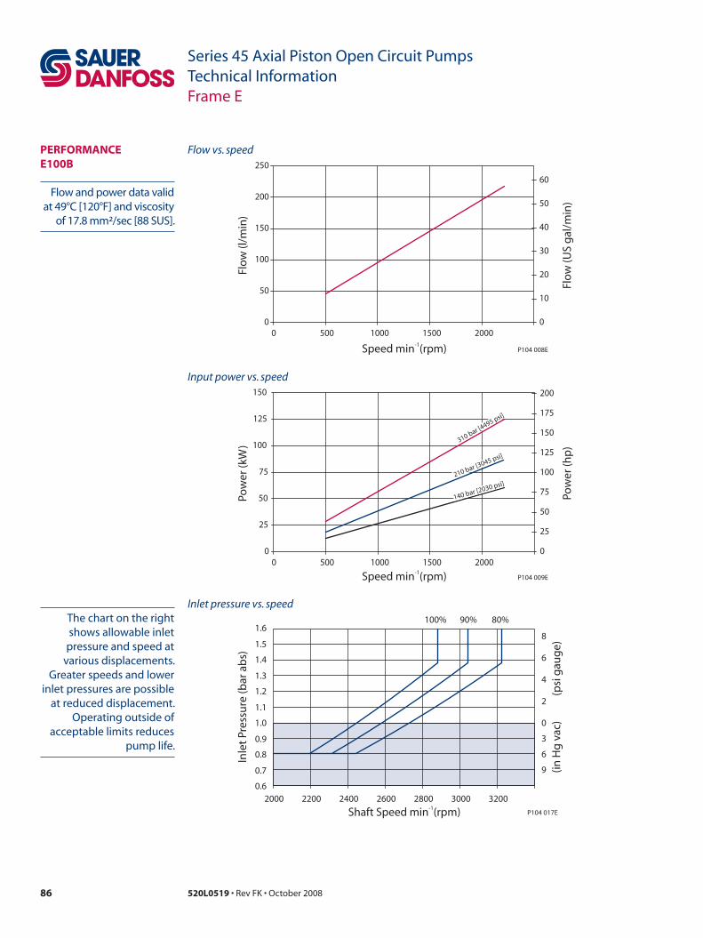
86 520L0519 • Rev FK • October 2008
Series 45 Axial Piston Open Circuit PumpsTechnical InformationFrame E
PeRfoRmanCe e100B
Input power vs. speed
Flow vs. speed
Flow and power data valid at 49°C [120°F] and viscosity
of 17.8 mm²/sec [88 SUS].
The chart on the right shows allowable inlet
pressure and speed at various displacements.
Greater speeds and lower inlet pressures are possible
at reduced displacement. Operating outside of
acceptable limits reduces pump life.
0
50
100
150
200
250
0 500 1000 1500 20000
10
20
30
40
50
60
Flo
w (l
/min
)
Speed min (rpm)-1
Flo
w (U
S g
al/m
in)
P104 008E
0
25
50
75
100
125
150
0 500 1000 1500 20000
25
50
75
100
125
150
175
200
Pow
er (k
W)
Speed min (rpm)-1Po
wer
(hp
)P104 009E
140 bar [2030 psi]210 bar [3045 psi]
310 bar [4495 psi]
0.6
0.7
0.8
0.9
1.0
1.1
1.2
1.3
1.4
1.5
1.6100% 90% 80%
Shaft Speed min (rpm)-1
Inle
t Pr
essu
re (b
ar a
bs)
(psi
gau
ge)
(in H
g v
ac)
P104 017E
0
3
6
9
8
6
4
2
2000 2200 2400 2600 2800 3000 3200
Inlet pressure vs. speed

87520L0519 • Rev FK • October 2008
Series 45 Axial Piston Open Circuit PumpsTechnical InformationFrame E
PeRfoRmanCe e130B
Inlet pressure vs. speed
Input power vs. speed
Flow vs. speed
Flow and power data valid at 49°C [120°F] and viscosity
of 17.8 mm²/sec [88 SUS].
The chart on the right shows allowable inlet
pressure and speed at various displacements.
Greater speeds and lower inlet pressures are possible
at reduced displacement. Operating outside of
acceptable limits reduces pump life.
0
50
100
150
200
250
300
0 500 1000 1500 20000
10
20
30
40
50
60
70
Flo
w (l
/min
)
Speed min (rpm)-1
Flo
w (U
S g
al/m
in)
P104 010E
0
30
60
90
120
150
0 500 1000 1500 20000
25
50
75
100
125
150
175
200
Pow
er (k
W)
Speed min (rpm)-1
Pow
er (h
p)
P104 011E
310 bar [4495 psi]
210 bar [3045 psi]
140 bar [2030 psi]
0.6
0.7
0.8
0.9
1.0
1.1
1.2
1.3
1.4
1.5
1.6100% 90% 80%
Shaft Speed min (rpm)-1
Inle
t Pr
essu
re (b
ar a
bs)
(psi
gau
ge)
(in H
g v
ac)
P104 018E
0
3
6
9
8
6
4
2
1800 2000 2200 2400 2600 2800

88 520L0519 • Rev FK • October 2008
Series 45 Axial Piston Open Circuit PumpsTechnical InformationFrame E
PeRfoRmanCe e147C
Inlet pressure vs. speed
Input power vs. speed
Flow vs. speed
Flow and power data valid at 49°C [120°F] and viscosity
of 17.8 mm²/sec [88 SUS].
The chart on the right shows allowable inlet
pressure and speed at various displacements.
Greater speeds and lower inlet pressures are possible
at reduced displacement. Operating outside of
acceptable limits reduces pump life.
0
50
100
150
200
250
300
350
0 500 1000 1500 20000
10
20
30
40
50
60
70
80
90
Flo
w (l
/min
)
Speed min (rpm)-1
Flo
w (U
S g
al/m
in)
P104 012E
0
30
60
90
120
150
0 500 1000 1500 20000
25
50
75
100
125
150
175
200
Pow
er (k
W)
Speed min (rpm)-1Po
wer
(hp
)P104 013E
140 bar [2030 psi]
210 bar [3045 psi]260 bar [3770 psi]
0.6
0.7
0.8
0.9
1.0
1.1
1.2
1.3
1.4
1.5
1.6100% 90% 80%
Shaft Speed min (rpm)-1
Inle
t Pr
essu
re (b
ar a
bs)
(psi
gau
ge)
(in H
g v
ac)
P104 019E
0
3
6
9
8
6
4
2
1800 2000 2200 2400 2600 2800

89520L0519 • Rev FK • October 2008
Series 45 Axial Piston Open Circuit PumpsTechnical InformationFrame E
oRDeR CoDe
R ProducteR E Frame, variable displacement open circuit pump
s RotationL Left hand (counterclockwise)
R Right hand (clockwise)
P Displacement and pressure rating100B 100 cm³/rev [6.10 in³/rev], 310 bar [4495 psi] continuous working pressure
130B 130 cm³/rev [7.93 in³/rev], 310 bar [4495 psi] continuous working pressure
147C 147 cm³/rev [8.97 in³/rev], 260 bar [3770 psi] continuous working pressure
C Control typePC Pressure compensated control 100-280 bar [1450-4060 psi]
BC* Pressure compensated control 290-310 bar [4205-4495 psi]
RP Remote pressure compensated control 100-280 bar [1450-4060 psi]
BP* Remote pressure compensated control 290-310 bar [4205-4495 psi]
Ls Load sensing / pressure compensating control 100-280 bar [1450-4060 psi]
Bs* Load sensing / pressure compensating control 290-310 bar [4205-4495 psi]
LB Load sensing / pressure compensating control with internal bleed orifice 100-280 bar [1450-4060 psi]
BB* Load sensing / pressure compensating control with internal bleed orifice 290-310 bar [4205-4495 psi]
* Use only with 100, and 130 cm³ displacements.
D PC setting (2 digit code, 10 bar increments)example 10 = 100 bar
10–31 100 to 310 bar [1450 to 4495 psi] (100B, 130B)
10–26 100 to 260 bar [1450 to 3770 psi] (147C)
e Load sensing setting (2 digit code, 1 bar increments)example 20 = 20 bar
10–30 10 to 30 bar [145 to 435 psi]
nn Not applicable (use with PC controls)
RP and BP Must be 20 bar
f Not usednn Not applicable
R s P C D e f G H 1 2 3 1 2 3 L m n
– –
J K
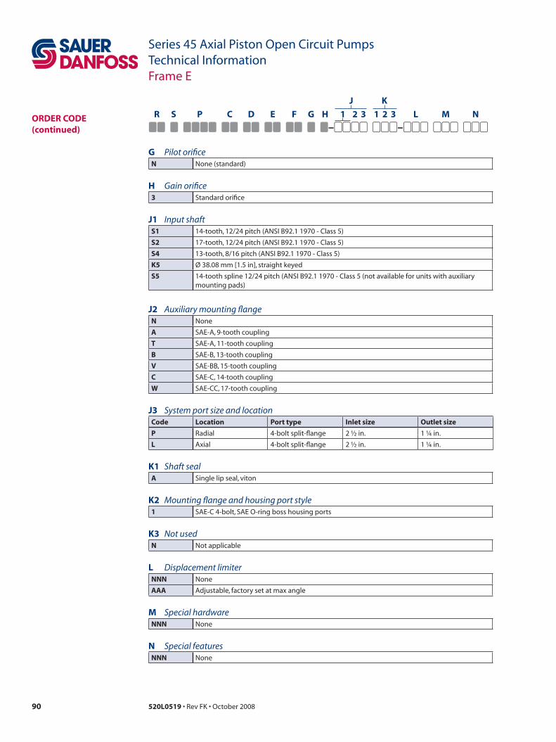
90 520L0519 • Rev FK • October 2008
Series 45 Axial Piston Open Circuit PumpsTechnical InformationFrame E
oRDeR CoDe (continued)
G Pilot orificen None (standard)
H Gain orifice3 Standard orifice
J1 Input shafts1 14-tooth, 12/24 pitch (ANSI B92.1 1970 - Class 5)
s2 17-tooth, 12/24 pitch (ANSI B92.1 1970 - Class 5)
s4 13-tooth, 8/16 pitch (ANSI B92.1 1970 - Class 5)
K5 Ø 38.08 mm [1.5 in], straight keyed
s5 14-tooth spline 12/24 pitch (ANSI B92.1 1970 - Class 5 (not available for units with auxiliary mounting pads)
J2 Auxiliary mounting flangen None
a SAE-A, 9-tooth coupling
t SAE-A, 11-tooth coupling
B SAE-B, 13-tooth coupling
v SAE-BB, 15-tooth coupling
C SAE-C, 14-tooth coupling
w SAE-CC, 17-tooth coupling
J3 System port size and locationCode Location Port type inlet size outlet size
P Radial 4-bolt split-flange 2 ½ in. 1 ¼ in.
L Axial 4-bolt split-flange 2 ½ in. 1 ¼ in.
K1 Shaft seala Single lip seal, viton
K2 Mounting flange and housing port style1 SAE-C 4-bolt, SAE O-ring boss housing ports
K3 Not usedn Not applicable
L Displacement limiternnn None
aaa Adjustable, factory set at max angle
m Special hardwarennn None
n Special featuresnnn None
R s P C D e f G H 1 2 3 1 2 3 L m n
– –
J K
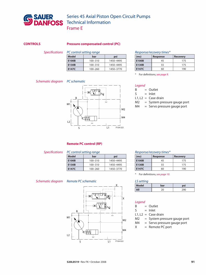
91520L0519 • Rev FK • October 2008
Series 45 Axial Piston Open Circuit PumpsTechnical InformationFrame E
ContRoLs
Remote PC control (RP)
Pressure compensated control (PC)
PC control setting rangemodel bar psi
e100B 100–310 1450–4495
e130B 100–310 1450–4495
e147C 100–260 1450–3770
Response/recovery times*(ms) Response Recovery
e100B 45 175
e130B 55 175
e147C 60 190
* For definitions, see page 9.
Specifications
Schematic diagram
PC control setting rangemodel bar psi
e100B 100–310 1450–4495
e130B 100–310 1450–4495
e147C 100–260 1450–3770
Response/recovery times*(ms) Response Recovery
e100B 45 175
e130B 55 175
e147C 60 190
* For definitions, see page 10.
Specifications
Schematic diagram
LegendB = OutletS = InletL1, L2 = Case drainM2 = System pressure gauge portM4 = Servo pressure gauge port
LegendB = OutletS = InletL1, L2 = Case drainM2 = System pressure gauge portM4 = Servo pressure gauge portX = Remote PC port
Remote PC schematicX
X
M2
M4
L1S
L2
M1
B
P104 022
PC schematic
B
M1
L2
S L1
M4
M2
P104 025
LS settingmodel bar psi
all 20 290
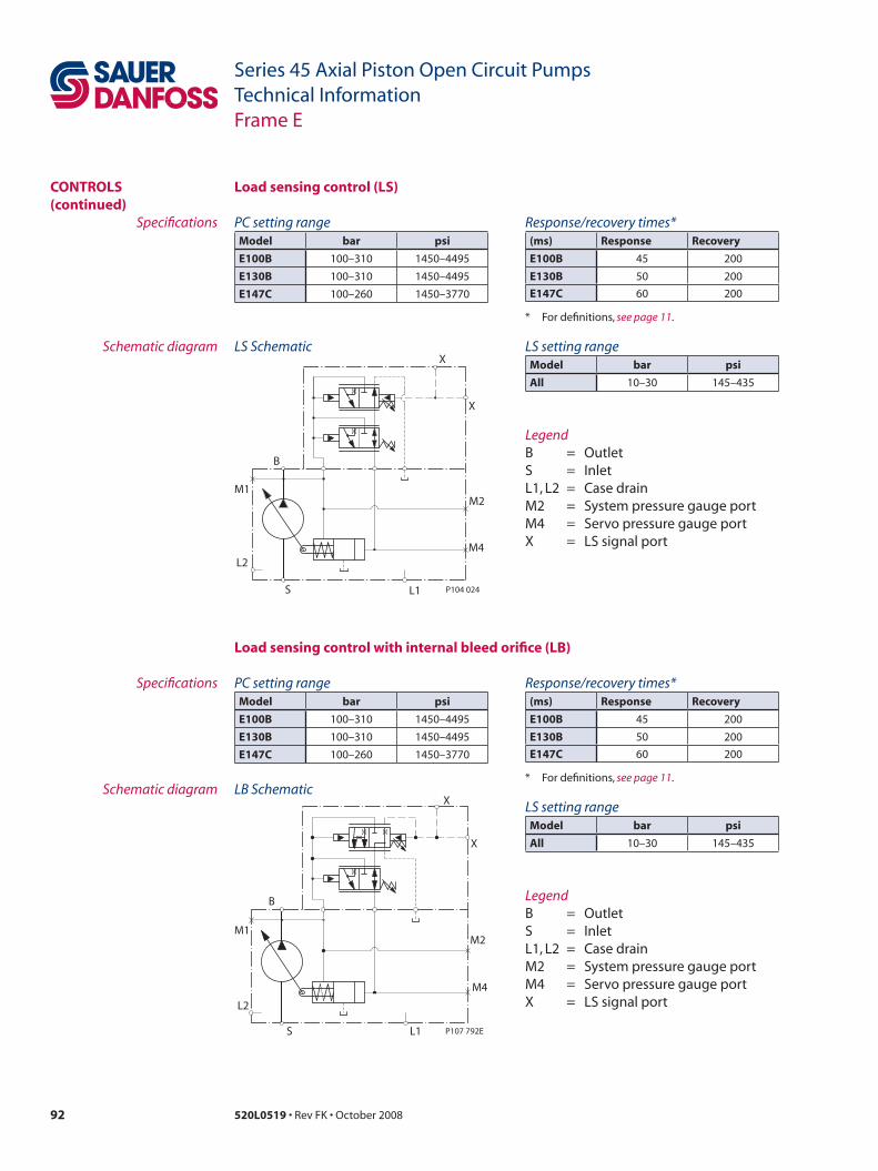
92 520L0519 • Rev FK • October 2008
Series 45 Axial Piston Open Circuit PumpsTechnical InformationFrame E
ContRoLs (continued)
Load sensing control (Ls)
PC setting rangemodel bar psi
e100B 100–310 1450–4495
e130B 100–310 1450–4495
e147C 100–260 1450–3770
Response/recovery times*(ms) Response Recovery
e100B 45 200
e130B 50 200
e147C 60 200
* For definitions, see page 11.
Specifications
Schematic diagram LS setting rangemodel bar psi
all 10–30 145–435
PC setting rangemodel bar psi
e100B 100–310 1450–4495
e130B 100–310 1450–4495
e147C 100–260 1450–3770
Response/recovery times*(ms) Response Recovery
e100B 45 200
e130B 50 200
e147C 60 200
* For definitions, see page 11.
Specifications
Schematic diagramLS setting rangemodel bar psi
all 10–30 145–435
Load sensing control with internal bleed orifice (LB)
LegendB = OutletS = InletL1, L2 = Case drainM2 = System pressure gauge portM4 = Servo pressure gauge portX = LS signal port
LegendB = OutletS = InletL1, L2 = Case drainM2 = System pressure gauge portM4 = Servo pressure gauge portX = LS signal port
LB Schematic
M2
X
X
B
M1
L2
S L1
M4
P107 792E
LS SchematicX
X
M2
M4
L1S
L2
M1
B
P104 024

93520L0519 • Rev FK • October 2008
Series 45 Axial Piston Open Circuit PumpsTechnical InformationFrame E
inPut sHafts
Shaft data
Code Descriptionmaximum torque rating¹N•m [lbf•in] Drawing
s1 14-tooth spline12/24 pitch(ANSI B92.1 1970 - Class 5)
1093 [9675]
48[1.89]
Ø31.14 ± 0.08[1.226 ± 0.003]
33.7 ± 0.5[1.33 ±0.02]
14 TOOTH12/24 PITCH30° PRESSURE ANGLE29.634 [1.167] PITCH |FILLET ROOT SIDE FITCOMPATIBLE WITH ANSI B92.1-1970CLASS 5 ALSO MATES WITHFLAT ROOT SIDE FIT
8 ± 0.8[0.31 ± 0.03]
MAXIMUM FULL SPLINEENGAGEMENTSAUER-DANFOSSRECOMMENDS USINGA COUNTER-BORE INTHE COUPLING TO ENSURESPLINES DO NOTENGAGE BEYOND THISPOINT.
P104 038ECOUPLING MUST NOTPROTRUDE BEYOND THIS POINT
s2 17-tooth spline12/24 pitch(ANSI B92.1 1970 - Class 5)
1044 [9240]
34 ± 0.15
Ø36.66 ± 0.08[1.443 ± 0.003]
[1.339 ± 0.006]
54[2.126]
Ø30.75 [1.211] MAX
8 ± 0.8[0.31 ± 0.03]
COUPLING MUST NOTPROTRUDE BEYONDTHIS POINT
17 TOOTH12/24 PITCH30° PRESSURE ANGLE35.983 [1.417] PITCH DIAFILLET ROOT SIDE FITCOMPATIBLE WITH
CLASS 5 ALSO MATES WITHFLAT ROOT SIDE FIT
ANSI B92.1-1970
P104 036E
s4 13-tooth spline8/16 pitch(ANSI B92.1 1970 - Class 5)
1551 [13 730]
Ø43.94 ± 0.08[1.73 ± 0.003]Ø34.25 [1.348] MAX
42 ± 0.15[1.654 ± 0.006]
67[2.638]
13 TOOTH8/16 PITCH30° PRESSURE ANGLE41.28 [1.625] PITCH DIAFILLET ROOT SIDE FITCOMPATIBLE WITH ANSI B92.1-1970CLASS 5 ALSO MATES WITHFLAT ROOT SIDE FIT
8 ± 0.8[0.31 ± 0.03]
COUPLING MUST NOTPROTRUDE BEYONDTHIS POINTP104 035E
1. See Input shaft torque ratings, page 18 for an explanation of maximum torque.
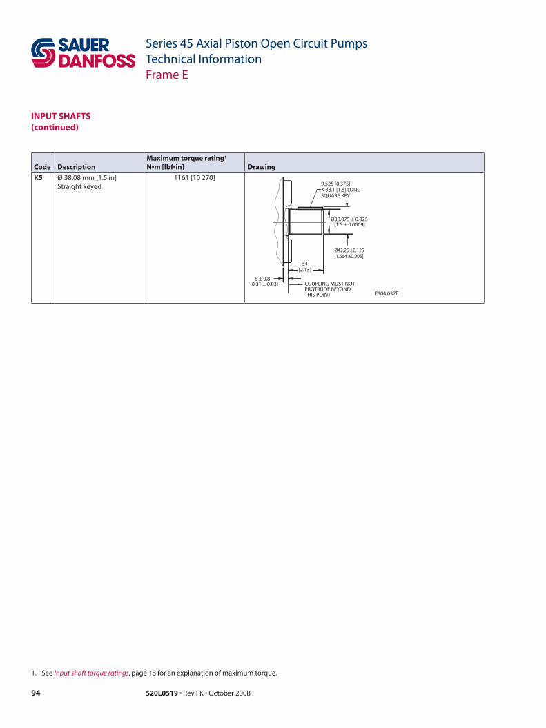
94 520L0519 • Rev FK • October 2008
Series 45 Axial Piston Open Circuit PumpsTechnical InformationFrame E
inPut sHafts(continued)
Code Descriptionmaximum torque rating¹N•m [lbf•in] Drawing
K5 Ø 38.08 mm [1.5 in]Straight keyed
1161 [10 270]
54 [2.13]
9.525 [0.375] X 38.1 [1.5] LONG SQUARE KEY
Ø38.075 ± 0.025
[1.5 ± 0.0009]
8 ± 0.8
[0.31 ± 0.03] COUPLING MUST NOT PROTRUDE BEYOND THIS POINT P104 037E
Ø42.26 ±0.125 [1.664 ±0.005]
1. See Input shaft torque ratings, page 18 for an explanation of maximum torque.

95520L0519 • Rev FK • October 2008
Series 45 Axial Piston Open Circuit PumpsTechnical InformationFrame E
auxiLiaRy mountinG PaDs Dimensions
sae-a auxiliary mounting pad
SpecificationsCoupling 9-tooth 11-tooth
spline minimum engagement
13.5 mm [0.53 in] 13.5 mm [0.53 in]
maximum torque 107 N•m [950 lbf•in] 147 N•m [1300 lbf•in]
Dimensionssae-B auxiliary mounting pad
SpecificationsCoupling 13-tooth 15-tooth
spline minimum engagement
14.2 mm [0.56 in] 16.1 mm [0.63 in]
maximum torque 249 N•m [2200 lbf•in] 339 N•m [3000 lbf•in]
P104 068E
Ø82.6 +0.076 0
[3.252 ] +.003 0
Ø88.62 [3.489]
301.7 [11.878]
1.956 [0.077]
8.1 ± 0.7 [0.319 ±0.028]
COUPLING-SAE A: SPLINE: 11 TOOTH 16/32 PITCH 30° PRESSURE ANGLE 17.463 [0.6875] PITCH DIA FILLET ROOT SIDE FIT PER SAE B92.1-1970 CLASS 6
COUPLING-SAE A: SPLINE: 9 TOOTH 16/32 PITCH 30° PRESSURE ANGLE 4.288 [0.5625] PITCH DIA FILLET ROOT SIDE FIT PER SAE B92.1-1970 CLASS 6
43.261 [1.703] MIN SHAFT CLEARANCE
9.061 [0.357]
MIN COUPLING CLEARANCE
MOUNTING FLANGE
O-RING SEAL REQUIRED REFERENCE 82.22 [3.237] I.D.2.62 [0.103] CROSS SECTIONP/N 5000373
Ø10.4 ± 0.12 3/8-16 UNC-2B THD 18 [0.71] MIN THD DEPTH 4X
53.2 [2.094]
2X 106.4
[4.189] 2X
P104 066E
1.956 [0.077]
328.2 [12.921]
Ø107.82 [4.245]
Ø101.65 +0.076 0
[4.002 ] +.003 0
1/2 -13UNC-2B THD 26.25 [1.03] MIN THD DEPTH 4X
COUPLING-SAE B: SPLINE: 13 TOOTH 16/32 PITCH 30° PRESSURE ANGLE 20.638 [0.8125] PITCH DIA FILLET ROOT SIDE FIT PER SAE B92.1-1970 CLASS 6
COUPLING-SAE B-B: SPLINE: 15 TOOTH 16/32 PITCH 30° PRESSURE ANGLE 23.813 [0.9375] PITCH DIA FILLET ROOT SIDE FIT PER SAE B92.1-1970 CLASS 6
9.761 [0.384] MIN COUPLING CLEARANCE
69.461 [2.735] MIN SHAFT CLEARANCE
MOUNTING FLANGE
O-RING SEALREQUIREDREFERENCE101.27 [3.987] I.D.2.62 [0.103] CROSS SECTIONP/N 5000099
146 [5.748]
2X
73 [2.874]
2X
See page 18 for mating pump pilot and spline dimensions.
See page 18 for mating pump pilot and spline dimensions.
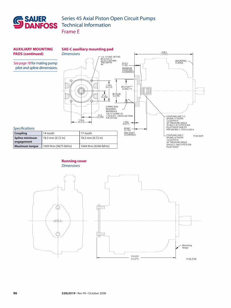
96 520L0519 • Rev FK • October 2008
Series 45 Axial Piston Open Circuit PumpsTechnical InformationFrame E
Dimensionssae-C auxiliary mounting pad
SpecificationsCoupling 14-tooth 17-tooth
spline minimum engagement
18.3 mm [0.72 in] 18.3 mm [0.72 in]
maximum torque 1093 N•m [9675 lbf•in] 1044 N•m [9240 lbf•in]
auxiLiaRy mountinG PaDs (continued)
P104 067E
328.2 [12.921]
69.461 [2.735]
1.956 [0.077]
Ø127.05 +0.076 0
[5.002 ] +.003 0
Ø134.06 [5.278]
57.3 [2.256]
114.6 [4.512]
57.3 [2.256]
114.6 [4.512]
MOUNTING FLANGE 33.011
[1.30] MINIMUM COUPLING CLEARANCE
COUPLING-SAE C-C: SPLINE:17 TOOTH 12/24 PITCH 30° PRESSURE ANGLE35.992 [1.417] PITCH DIA FILLET ROOT SIDE FIT PER SAE B92.1-1970 CLASS 6
COUPLING-SAE C: SPLINE:14 TOOTH 12/24 PITCH 30° PRESSURE ANGLE29.633 [1.1667] PITCH DIA FILLET ROOT
O-RING SEAL REQUIRED REFERENCE 126.72 [4.989] I.D. 1.78 [0.07] P/N 331256
CROSS SECTION
MIN SHAFT CLEARANCE
Ø12.7 ± 0.12 1/2 -13 UNC-2B THD
26.25 [1.03] MIN THD DEPTH 4X See page 18 for mating pump
pilot and spline dimensions.
Running cover
314.222[12.371]
Mountingflange
P106 079E
Dimensions

97520L0519 • Rev FK • October 2008
Series 45 Axial Piston Open Circuit PumpsTechnical InformationFrame E
DisPLaCement LimiteRs E Frame open circuit pumps are available with an optional adjustable displacement limiter. This adjustable stop limits the pump’s maximum displacement.
Setting rangee100B 40 to 100 cm³ [2.44 to 6.1 in³]
e130B 70 to 130 cm³ [4.27 to 7.93 in³]
e147C 87 to 147 cm³ [5.31 to 8.97 in³]
Displacement limiter cross-section
P104 003
Displacement per turne100B 8.4 cm³/rev [0.51 in³/rev]
e130B 8.4 cm³/rev [0.51 in³/rev]
e147C 8.4 cm³/rev [0.51 in³/rev]

98 520L0519 • Rev FK • October 2008
Series 45 Axial Piston Open Circuit PumpsTechnical InformationFrame E
instaLLation DRawinGs
Third-angleprojectionmm [in]
axial ported endcap, clockwise rotation
P106 176E
DISPLACEMENT LIMITER PORT PER ISO 11926-1 SAE J1926/1 3/4 - 16UNF - 2B
PER ISO 11926-1 SAE J1926/1 1-1/16 - 12UN - 2B
PER ISO 11926-1
275 [10.827]
167.4 [6.591]
191.1 [7.524]
R1 MAX [0.04]
282.315 [11.115]
111.9 [4.406]
Ø126.975 ± 0.025 [4.999 ±0.001]
182.9 [7.201]
132[5.197]
12.7 [0.5]
302.7 MAX [11.92]
50 [1.969]
50 [1.969]
27.3 [1.075]
66.7 [2.626]
98 [3.858]
98 [3.858]
52 [2.047]
76 [2.992]
52 [2.047]
161 [6.339]
SYSTEM PORTS S AND B
CASE DRAIN PORT L1 SPOTFACE DEPTH LS SIGNAL
PORT X
7/16-20UNF-2B SAE J1926/1
SERVO PRESSURE PORT M4
SAE J1926/1 9/16-18UNF-2B
ALTERNATE LS SIGNAL PORT X
LS SIGNAL PORT X
CASE DRAIN PORT L1
SAE J1926/1 1 1/16-12UN-2B
SYSTEM PRESSURE GAGE PORT M1
SAE J1926/1 9/16-18UNF-2B
CASE DRAIN PORT L2
19.09 [0.751] 4X
Ø63.5 [2.50] INLET SYSTEM PORT ‘S’ 172 BAR [2500 PSI] SPLIT FLANGE BOSS PER ISO 6162 SAE J518 CODE 61 WITH 1/2 - 13UNC X 30 [1.181] MIN THD
88.9 [3.50]
66.68 [2.63]
31.75 [1.25]
SYSTEM PRESSURE GAGE PORT ‘M2’ PER ISO 11926 - 1 SAE J1926/1 9/16 - 18UNF - 2B
Ø31.8 [1.25] OUTLET SYSTEM PORT ‘B’ 414 BAR [6000 PSI] SPLIT FLANGE BOSS PER ISO 6162 SAE J518 CODE 62 WITH 1/2 - 13UNC X 25 [0.984] MIN THD
PER ISO 11926-1
PER ISO 11926-1
PER ISO 11926-1

99520L0519 • Rev FK • October 2008
Series 45 Axial Piston Open Circuit PumpsTechnical InformationFrame E
P104 076E
1.87[0.074]
5.2[0.205]
57.25[2.254]
114.5[4.508]
57.25[2.254]
114.5[4.508]
111.9[4.406]
148.05[5.829]
191.1[7.524]
167.4[6.591]
LS STANDBYPRESSUREADJUSTMENT
PC PRESSUREADJUSTMENT
CASE DRAINPORT L2 SPOTFACE DEPTH
APPROXIMATECENTER OFGRAVITY
ALTERNATELS SIGNALPORT X
SAE J1926/17/16-20UNF-2B
CW
Ø14.3[0.563]4X
PER ISO 11926-1
axial ported endcap, clockwise rotation (continued)instaLLation DRawinGs (continued)
Third-angleprojectionmm [in]
282.32[11.115]
157.4[6.197]
P104 080
PC control

100 520L0519 • Rev FK • October 2008
Series 45 Axial Piston Open Circuit PumpsTechnical InformationFrame E
instaLLation DRawinGs (continued)
axial ported endcap, counterclockwise rotation
Third-angleprojectionmm [in]
SYSTEM PRESSUREGAGE PORT ‘M2’PERISO 11926 - 1SAE J1926/19/16 - 18UNF - 2B
Ø63.5[2.50]INLETSYSTEM PORT ‘S’172 BAR [2500 PSI]SPLIT FLANGE BOSSPERISO 6162SAE J518CODE 61WITH 1/2 - 13UNCX 30 [1.181]MIN THD
DISPLACEMENTLIMITER PORTPERISO 11926-1SAE J1926/13/4 - 16UNF - 2B
Ø31.8[1.25]OUTLETSYSTEM PORT ‘B’414 BAR [6000 PSI]SPLIT FLANGE BOSSPERISO 6162SAE J518CODE 62WITH 1/2 - 13UNCX 25 [0.984]MIN THD
66.68[2.63]
31.75[1.25]
88.9[3.50]
50.8[2.00]
SERVOPRESSUREPORT M4
SAE J1926/19/16-18UNF-2B
PER ISO 11926-1
LS SIGNALPORT X
7/16-20UNF-2BSAE J1926/1PER ISO 11926-1
12.7[0.5]
R1 MAX[0.04]
Ø126.975 ± 0.025[4.999 ± 0.001]
111.9[4.406]
191.1[7.524]
282.315[11.115]
302.7 MAX[11.92]
132[5.197]
50[1.969]
50[1.969]
52[2.047]
76[2.992]
98[3.858]
98[3.858]
52[2.047]
161[6.339]
BOTH SIDES
167.4[6.591]
BOTHSIDES
SYSTEM PRESSUREGAGE PORT M1
SAE J1926/19/16-18UNF-2B
275[10.827]
SYSTEM PORTS S AND B
CASE DRAINPORT L1 SPOTFACE DEPTH
BOTH SIDES
27.3[1.075]
ALTERNATELS SIGNALPORT X
66.7[2.626]LS SIGNALPORT X
CASE DRAINPORT "L2"
SAE J1926/11 1/16-12UN-2B
19.09[0.751]4X
P106 177E
182.9[7.201]
CASE DRAINPORT L1
SAE J1926/11 1/16-12UN-2B
PER ISO 11926-1
PER ISO 11926-1
PER ISO 11926-1
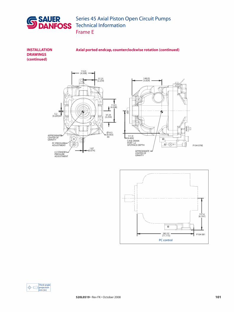
101520L0519 • Rev FK • October 2008
Series 45 Axial Piston Open Circuit PumpsTechnical InformationFrame E
114.5[4.508]
57.25[2.254]
5.2[0.205]
114.5[4.508]
57.25[2.254]
1.87[0.074]
148.05[5.829]
111.9[4.406]
Ø14.3[0.563]4X
APPROXIMATECENTER OFGRAVITY
LS STANDBYPRESSUREADJUSTMENT
PC PRESSUREADJUSTMENT
CASE DRAINPORT L2 SPOTFACE DEPTH
APPROXIMATECENTER OFGRAVITY
CCW
P104 078E
instaLLation DRawinGs (continued)
axial ported endcap, counterclockwise rotation (continued)
Third-angleprojectionmm [in]
282.32[11.115]
157.4[6.197]
P104 081
PC control
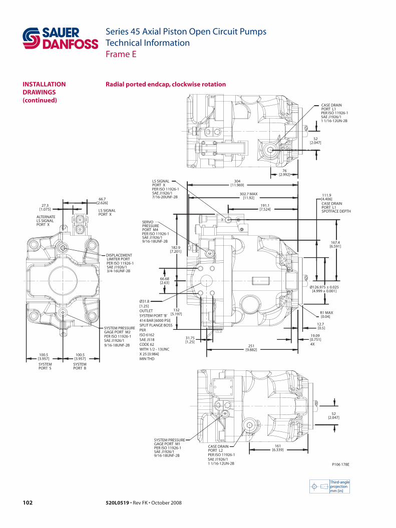
102 520L0519 • Rev FK • October 2008
Series 45 Axial Piston Open Circuit PumpsTechnical InformationFrame E
Third-angleprojectionmm [in]
Radial ported endcap, clockwise rotationinstaLLation DRawinGs (continued)
31.75[1.25]
302.7 MAX[11.92]
111.9[4.406]
167.4[6.591]
Ø126.975 ± 0.025[4.999 ± 0.001]
191.1[7.524]
304[11.969]
251[9.882]
R1 MAX [0.04]
12.7 [0.5]
182.9[7.201]
132[5.197]
27.3[1.075]
66.7[2.626]
100.5[3.957]
100.5[3.957]
52[2.047]
76[2.992]
52[2.047]
161[6.339]
LS SIGNALPORT X
SAE J1926/17/16-20UNF-2B
CASE DRAINPORT L2
SAE J1926/11 1/16-12UN-2B
SYSTEM PRESSUREGAGE PORT M1
SAE J1926/19/16-18UNF-2B
CASE DRAINPORT L1 SPOTFACE DEPTH
SERVOPRESSUREPORT M4
SAE J1926/19/16-18UNF-2B
SYSTEMPORT B
SYSTEMPORT S
ALTERNATELS SIGNALPORT X
LS SIGNALPORT X
DISPLACEMENTLIMITER PORT
SAE J1926/13/4-16UNF-2B
CASE DRAINPORT L1
SAE J1926/11 1/16-12UN-2B
19.09 [0.751]4X
P106 178E
PER ISO 11926-1
SYSTEM PRESSUREGAGE PORT M2
SAE J1926/19/16-18UNF-2B
PER ISO 11926-1
Ø31.8[1.25]OUTLETSYSTEM PORT ‘B’414 BAR [6000 PSI]SPLIT FLANGE BOSSPERISO 6162SAE J518CODE 62WITH 1/2 - 13UNCX 25 [0.984]MIN THD
PER ISO 11926-1
66.68[2.63]
PER ISO 11926-1
PER ISO 11926-1
PER ISO 11926-1
PER ISO 11926-1

103520L0519 • Rev FK • October 2008
Series 45 Axial Piston Open Circuit PumpsTechnical InformationFrame E
57.25[2.254]
114.5[4.508]
57.25[2.254]
114.5[4.508]
2.02 [0.08]
4.86 [0.192]
156.79[6.173]
251[9.882]
191.1[7.524]
167.4[6.591]
111.9[4.406]
LS STANDBYPRESSUREADJUSTMENT
PC PRESSUREADJUSTMENT
CASE DRAINPORT L2 SPOTFACE DEPTH
ALTERNATELS SIGNALPORT X
SAE J1926/17/16-20UNF-2B
APPROXIMATECENTER OFGRAVITY
CW
Ø14.3 [0.563]4X
P104 077E
Ø63.5[2.50]INLETSYSTEM PORT ‘S’172 BAR [2500 PSI]SPLIT FLANGE BOSSPER ISO 6162SAE J518CODE 61WITH 1/2 - 13UNCX 30 [1.181]MIN THD
PER ISO 11926-1
Radial ported endcap, clockwise rotation (continued)instaLLation DRawinGs (continued)
Third-angleprojectionmm [in]
282.32[11.115]
157.4[6.197]
P104 082
PC control
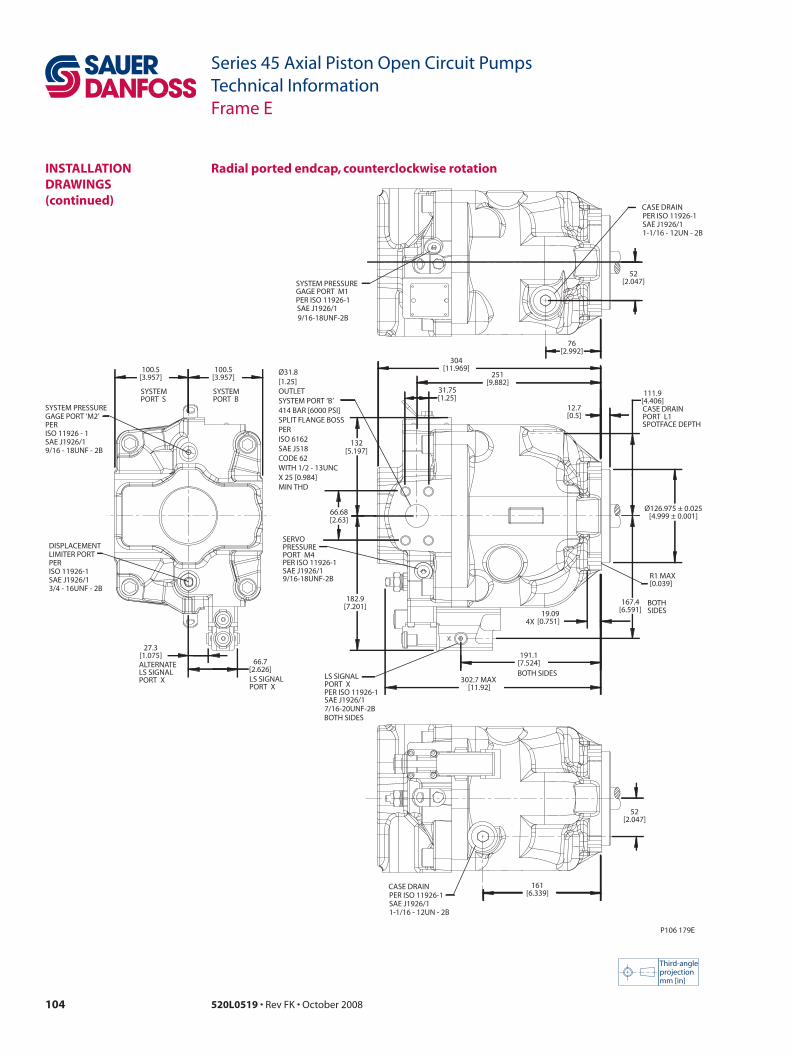
104 520L0519 • Rev FK • October 2008
Series 45 Axial Piston Open Circuit PumpsTechnical InformationFrame E
instaLLation DRawinGs (continued)
Radial ported endcap, counterclockwise rotation
Third-angleprojectionmm [in]
SYSTEM PRESSUREGAGE PORT ‘M2’PERISO 11926 - 1SAE J1926/19/16 - 18UNF - 2B
DISPLACEMENTLIMITER PORTPERISO 11926-1SAE J1926/13/4 - 16UNF - 2B
Ø31.8[1.25]OUTLETSYSTEM PORT ‘B’414 BAR [6000 PSI]SPLIT FLANGE BOSSPERISO 6162SAE J518CODE 62WITH 1/2 - 13UNCX 25 [0.984]MIN THD
SERVOPRESSUREPORT M4
SAE J1926/19/16-18UNF-2B
PER ISO 11926-1
LS SIGNALPORT X
7/16-20UNF-2BSAE J1926/1PER ISO 11926-1
PER ISO 11926-1
SYSTEM PRESSUREGAGE PORT M1
SAE J1926/19/16-18UNF-2B
PER ISO 11926-1SAE J1926/11-1/16 - 12UN - 2B
CASE DRAIN
PER ISO 11926-1SAE J1926/11-1/16 - 12UN - 2B
CASE DRAIN
66.68[2.63]
31.75[1.25]
251[9.882]
182.9[7.201]
132[5.197]
302.7 MAX [11.92]
304[11.969]
167.4[6.591]
12.7[0.5]
Ø126.975 ± 0.025[4.999 ± 0.001]
111.9[4.406]
R1 MAX[0.039]
27.3[1.075]
66.7[2.626]
100.5[3.957]
100.5[3.957]
52[2.047]
76[2.992]
161[6.339]
52[2.047]
19.09[0.751]4X
CASE DRAINPORT L1 SPOTFACE DEPTH
191.1[7.524]BOTH SIDES
BOTHSIDES
BOTH SIDES
ALTERNATELS SIGNALPORT X LS SIGNAL
PORT X
SYSTEMPORT B
SYSTEMPORT S
P106 179E
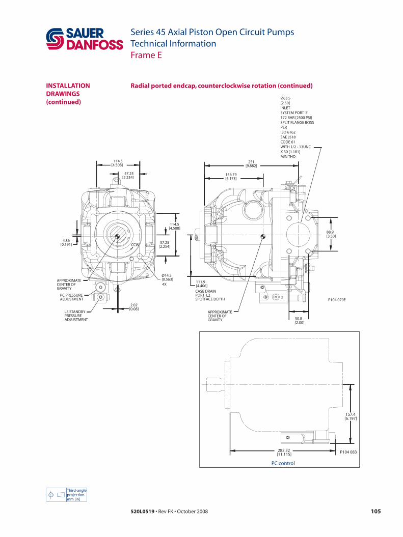
105520L0519 • Rev FK • October 2008
Series 45 Axial Piston Open Circuit PumpsTechnical InformationFrame E
88.9 [3.50]
50.8 [2.00]
2.02 [0.08]
4.86 [0.191] 57.25
[2.254]
114.5 [4.508]
57.25 [2.254]
114.5 [4.508]
111.9 [4.406]
156.79 [6.173]
251 [9.882]
Ø14.3 [0.563] 4X
PC PRESSURE ADJUSTMENT
LS STANDBY PRESSURE ADJUSTMENT
APPROXIMATE CENTER OF GRAVITY
CASE DRAIN PORT L2 SPOTFACE DEPTH
APPROXIMATE CENTER OF GRAVITY
CCW
P104 079E
Ø63.5 [2.50] INLET SYSTEM PORT ‘S’ 172 BAR [2500 PSI] SPLIT FLANGE BOSS PER ISO 6162 SAE J518 CODE 61 WITH 1/2 - 13UNC X 30 [1.181] MIN THD
instaLLation DRawinGs (continued)
Radial ported endcap, counterclockwise rotation (continued)
Third-angleprojectionmm [in]
282.32[11.115]
157.4[6.197]
P104 083
PC control

106 520L0519 • Rev FK • October 2008
Series 45 Axial Piston Open Circuit PumpsTechnical InformationNotes

107520L0519 • Rev FK • October 2008
Series 45 Axial Piston Open Circuit PumpsTechnical InformationNotes

sauer-Danfoss mobile Power and Control systems– market Leaders worldwide
Sauer-Danfoss is a comprehensive supplier providing complete systems to the global mobile market.
Sauer-Danfoss serves markets such as agriculture, construction, road building, material handling, municipal, forestry, turf care, and many others.
We offer our customers optimum solutions for their needs and develop new products and systems in close cooperation and partner ship with them.
Sauer-Danfoss specializes in integrating a full range of system components to provide vehicle designers with the most advanced total system design.
Sauer-Danfoss provides comprehensive worldwide service for its products through an extensive network of Global Service Partners strategically located in all parts of the world.
ouR PRoDuCts
Hydrostatic transmissions
Hydraulic power steering
Electric power steering
Electrohydraulic power steering
Closed and open circuit axial piston pumps and motors
Gear pumps and motors
Bent axis motors
Orbital motors
Transit mixer drives
Proportional valves
Directional spool valves
Cartridge valves
Hydraulic integrated circuits
Hydrostatic transaxles
Integrated systems
Fan drive systems
Electrohydraulics
Microcontrollers and software
Electric motors and inverters
Joysticks and control handles
Displays
Sensors
Local address:
Sauer-Danfoss (US) Company2800 East 13th StreetAmes, IA 50010, USAPhone: +1 515 239-6000Fax: +1 515 239-6618
Sauer-Danfoss ApSDK-6430 Nordborg, DenmarkPhone: +45 7488 4444Fax: +45 7488 4400
Sauer-Danfoss-Daikin LTDSannomiya Grand Bldg. 8F2-2-21 Isogami-dori, Chuo-kuKobe, Hyogo 651-0086, JapanPhone: +81 78 231 5001Fax: +81 78 231 5004
Sauer-Danfoss GmbH & Co. OHGPostfach 2460, D-24531 NeumünsterKrokamp 35, D-24539 Neumünster, GermanyPhone: +49 4321 871-0Fax: +49 4321 871 122
www.sauer-danfoss.com520L0519 • Rev FK • October 2008


