
Art # A-07718
1/3PHASE
208V
230V
460V
400V
POWERMASTER
320SP400SP
Operator Manual
500SP
Version No: AD Issue Date: March 16, 2007 Manual No.: 0-4968Operating Features:

WE APPRECIATE YOUR BUSINESS!Congratulations on your new Thermal Arc product. We are proud tohave you as our customer and will strive to provide you with thebest service and reliability in the industry. This product is backed byour extensive warranty and world-wide service network. To locateyour nearest distributor or service agency call1-800-752-7621, or visit us on the web at www.Thermalarc.com.
This Operating Manual has been designed to instruct you on thecorrect use and operation of your Thermal Arc product. Yoursatisfaction with this product and its safe operation is our ultimateconcern. Therefore please take the time to read the entire manual,especially the Safety Precautions. They will help you to avoid potentialhazards that may exist when working with this product.
YOU ARE IN GOOD COMPANY!The Brand of Choice for Contractors and Fabricators Worldwide.
Thermal Arc is a Global Brand of Arc Welding Products forThermadyne Industries Inc. We manufacture and supply to majorwelding industry sectors worldwide including; Manufacturing,Construction, Mining, Automotive, Aerospace, Engineering, Ruraland DIY/Hobbyist.
We distinguish ourselves from our competition through market-leading, dependable products that have stood the test of time. Wepride ourselves on technical innovation, competitive prices, excellentdelivery, superior customer service and technical support, togetherwith excellence in sales and marketing expertise.
Above all, we are committed to developing technologically advancedproducts to achieve a safer working environment within the weldingindustry.

! WARNINGS
Read and understand this entire Manual and your employer’s safety practices before installing,operating, or servicing the equipment.
While the information contained in this Manual represents the Manufacturer's best judgement,the Manufacturer assumes no liability for its use.
i
Operator Manual Number 0-4968 for:
PowerMaster 320SP Compact W1000102PowerMaster 400SP with Integrated Water Cooler W1000202PowerMaster 400SP Compact W1000304PowerMaster 500SP with Integrated Water Cooler W1000502Wirefeeder SP4000W (Enclosed spool) W3000202Wirefeeder SP4000R (Automation) W3000302
Published by:Thermadyne Industries, Inc.82 Benning StreetWest Lebanon, New Hampshire, USA 03784(603) 298-5711
www.thermadyne.com
Copyright 2007, 2008 byThermadyne Industries, Inc.
All rights reserved.
Reproduction of this work, in whole or in part, without written permission of the publisher is prohibited.
The publisher does not assume and hereby disclaims any liability to any party for any loss or damagecaused by any error or omission in this Manual, whether such error results from negligence, accident,or any other cause.
Original Publication Date: March 16, 2007Revision AD Date: December 23, 2008
Record the following information for Warranty purposes:
Where Purchased: ___________________________________
Purchase Date: ___________________________________
Equipment Serial #: ___________________________________

TABLE OF CONTENTS
SECTION 1:SAFETY INSTRUCTIONS AND WARNINGS ....................................................... 1-1
1.01 Arc Welding Hazards ...................................................................................... 1-11.02 Principal Safety Standards ............................................................................. 1-41.03 Symbol Chart ................................................................................................. 1-51.04 Precautions De Securite En Soudage A L’arc .................................................. 1-61.05 Dangers relatifs au soudage à l’arc ................................................................. 1-61.06 Principales Normes De Securite ..................................................................... 1-91.07 Graphique de Symbole ................................................................................. 1-10
SECTION 2:INTRODUCTION ...................................................................................... 2-1
2.01 How To Use This Manual ................................................................................ 2-12.02 Equipment Identification ................................................................................. 2-12.03 Receipt Of Equipment ..................................................................................... 2-12.04 Machine Components (500SP, 400SP, and SP4000W) .................................. 2-22.05 Machine Components (400SP Compact Model) ............................................. 2-32.06 Machine Components (320SP Compact Model) ............................................. 2-42.07 Lifting Points .................................................................................................. 2-52.08 Power Supply Specifications (part 1) ............................................................. 2-62.09 Power Supply Specifications (part 2) ............................................................. 2-72.10 Wire Feeder Specifications ............................................................................. 2-82.11 Features and Benefits Common to all PowerMaster SP Systems # ................ 2-92.11 Features and Benefits Common to all PowerMaster SP Systems (con't) # .. 2-10
SECTION 3:INSTALLATION ....................................................................................... 3-1
3.01 Location ......................................................................................................... 3-13.02 Transportation and Positioning ....................................................................... 3-13.03 Fitting the Mains Cable into the Cable Gland .................................................. 3-13.04 Voltage Change-over ...................................................................................... 3-23.05 Connecting 3-Phase Input Power to 400SP or 500SP .................................... 3-33.06 Connecting Single-Phase Input Power to 320SP or 400SP or 500SP ............ 3-53.07 Quick Start Set Up .......................................................................................... 3-73.08 Recommended Setup for MIG ........................................................................ 3-73.09 TWECO PULSEMASTER PMA5512 500 AMP Weld Gun .............................. 3-113.10 Installing A New Wire Conduit ...................................................................... 3-12
SECTION 4:OPERATION........................................................................................... 4-1
4.01 General Safety Precautions ............................................................................ 4-14.02 Welding Controls ............................................................................................ 4-24.03 Menu Structure .............................................................................................. 4-44.04 Special functions ............................................................................................ 4-84.05 Smart GMAW, Pulse GMAW & TwinPulse Programs ...................................... 4-94.06 Welding Setting Selection Guide .................................................................. 4-10

TABLE OF CONTENTS (continued)
TABLE OF CONTENTS
SECTION 5:MANUAL GMAW WELDING ........................................................................ 5-1
5.01 Types of Weld Transfer Modes ....................................................................... 5-15.02 Holding and Manipulating the Torch ............................................................... 5-25.03 Basics of Pulsed Arc Welding ......................................................................... 5-45.04 Pulsed Arc Welding Parameters ..................................................................... 5-55.05 Smart, Pulse or TwinPulse GMAW Welding .................................................... 5-65.06 Conventional Manual GMAW/FCAW Welding.................................................. 5-65.07 SMAW/STICK Welding .................................................................................... 5-7
SECTION 6:SERVICE .............................................................................................. 6-1
6.01 Maintenance ................................................................................................... 6-16.02 System Troubleshooting Guide ....................................................................... 6-26.03 Welding Process Troubleshooting Guide ........................................................ 6-36.04 Error Codes .................................................................................................... 6-4
APPENDIX 1: OPTIONAL ACCESSORIES AND CONSUMABLES ...................................... A-1
APPENDIX 2: FEED ROLL INFORMATION ............................................................... A-2
APPENDIX 3: MOUNTING THE TORCH HOLDER ....................................................... A-3
LIMITED WARRANTY
WARRANTY SCHEDULE
GLOBAL CUSTOMER SERVICE CONTACT INFORMATION .......................... Inside Rear Cover


1-1March 16, 2007
POWERMASTER 320SP, 400SP, 500SP
1.01 Arc Welding Hazards
WARNING
ELECTRIC SHOCK can kill.
Touching live electrical parts can cause fatal shocksor severe burns. The electrode and work circuit iselectrically live whenever the output is on. The inputpower circuit and machine internal circuits are alsolive when power is on. In semiautomatic orautomatic wire welding, the wire, wire reel, driveroll housing, and all metal parts touching thewelding wire are electrically live. Incorrectly installedor improperly grounded equipment is a hazard.
1. Do not touch live electrical parts.
2. Wear dry, hole-free insulating gloves and body protection.
3. Insulate yourself from work and ground using dry insulatingmats or covers.
4. Disconnect input power or stop engine before installing orservicing this equipment. Lock input power disconnect switchopen, or remove line fuses so power cannot be turned onaccidentally.
5. Properly install and ground this equipment according to itsOwner’s Manual and national, state, and local codes.
6. Turn off all equipment when not in use. Disconnect power toequipment if it will be left unattended or out of service.
7. Use fully insulated electrode holders. Never dip holder in waterto cool it or lay it down on the ground or the work surface.Do not touch holders connected to two welding machines atthe same time or touch other people with the holder orelectrode.
8. Do not use worn, damaged, undersized, or poorly splicedcables.
9. Do not wrap cables around your body.
10. Ground the workpiece to a good electrical (earth) ground.
11. Do not touch electrode while in contact with the work(ground) circuit.
12. Use only well-maintained equipment. Repair or replacedamaged parts at once.
13. In confined spaces or damp locations, do not use a welderwith AC output unless it is equipped with a voltage reducer.Use equipment with DC output.
14. Wear a safety harness to prevent falling if working abovefloor level.
15. Keep all panels and covers securely in place.
WARNING
ARC RAYS can burn eyes and skin; NOISE candamage hearing. Arc rays from the welding processproduce intense heat and strong ultraviolet rays thatcan burn eyes and skin. Noise from some processescan damage hearing.
1. Wear a welding helmet fitted with a proper shade of filter(see ANSI Z49.1 listed in Safety Standards) to protect yourface and eyes when welding or watching.
2. Wear approved safety glasses. Side shields recommended.
3. Use protective screens or barriers to protect others from flashand glare; warn others not to watch the arc.
4. Wear protective clothing made from durable, flame-resistantmaterial (wool and leather) and foot protection.
5. Use approved ear plugs or ear muffs if noise level is high.
SECTION 1:SAFETY INSTRUCTIONS AND WARNINGS
! WARNING
PROTECT YOURSELF AND OTHERS FROM POSSIBLE SERIOUS INJURY OR DEATH. KEEP CHILDREN AWAY. PACEMAKER WEARERSKEEP AWAY UNTIL CONSULTING YOUR DOCTOR. DO NOT LOSE THESE INSTRUCTIONS. READ OPERATING/INSTRUCTION MANUALBEFORE INSTALLING, OPERATING OR SERVICING THIS EQUIPMENT.
Welding products and welding processes can cause serious injury or death, or damage to other equipment or property, if the operatordoes not strictly observe all safety rules and take precautionary actions.
Safe practices have developed from past experience in the use of welding and cutting. These practices must be learned through studyand training before using this equipment. Some of these practices apply to equipment connected to power lines; other practices applyto engine driven equipment. Anyone not having extensive training in welding and cutting practices should not attempt to weld.
Safe practices are outlined in the American National Standard Z49.1 entitled: SAFETY IN WELDING AND CUTTING. This publicationand other guides to what you should learn before operating this equipment are listed at the end of these safety precautions. HAVE ALLINSTALLATION, OPERATION, MAINTENANCE, AND REPAIR WORK PERFORMED ONLY BY QUALIFIED PEOPLE.
1-2 March 16, 2007
POWERMASTER 320SP, 400SP, 500SP
WARNING
FUMES AND GASES can be hazardous to yourhealth.
Welding produces fumes and gases. Breathingthese fumes and gases can be hazardous to yourhealth.
1. Keep your head out of the fumes. Do not breath the fumes.
2. If inside, ventilate the area and/or use exhaust at the arc toremove welding fumes and gases.
3. If ventilation is poor, use an approved air-supplied respirator.
4. Read the Material Safety Data Sheets (MSDSs) and themanufacturer’s instruction for metals, consumables, coatings,and cleaners.
5. Work in a confined space only if it is well ventilated, or whilewearing an air-supplied respirator. Shielding gases used forwelding can displace air causing injury or death. Be sure thebreathing air is safe.
6. Do not weld in locations near degreasing, cleaning, orspraying operations. The heat and rays of the arc can reactwith vapors to form highly toxic and irritating gases.
7. Do not weld on coated metals, such as galvanized, lead, orcadmium plated steel, unless the coating is removed fromthe weld area, the area is well ventilated, and if necessary,while wearing an air-supplied respirator. The coatings andany metals containing these elements can give off toxic fumesif welded.
WARNING
WELDING can cause fire or explosion.
Sparks and spatter fly off from the welding arc. Theflying sparks and hot metal, weld spatter, hotworkpiece, and hot equipment can cause fires andburns. Accidental contact of electrode or weldingwire to metal objects can cause sparks, overheating,or fire.
1. Protect yourself and others from flying sparks and hot metal.
2. Do not weld where flying sparks can strike flammable material.
3. Remove all flammables within 35 ft (10.7 m) of the weldingarc. If this is not possible, tightly cover them with approvedcovers.
4. Be alert that welding sparks and hot materials from weldingcan easily go through small cracks and openings to adjacentareas.
5. Watch for fire, and keep a fire extinguisher nearby.
6. Be aware that welding on a ceiling, floor, bulkhead, or partitioncan cause fire on the hidden side.
7. Do not weld on closed containers such as tanks or drums.
8. Connect work cable to the work as close to the welding areaas practical to prevent welding current from traveling long,possibly unknown paths and causing electric shock and firehazards.
9. Do not use welder to thaw frozen pipes.
10. Remove stick electrode from holder or cut off welding wireat contact tip when not in use.
WARNING
FLYING SPARKS AND HOT METAL can cause injury.
Chipping and grinding cause flying metal. As weldscool, they can throw off slag.
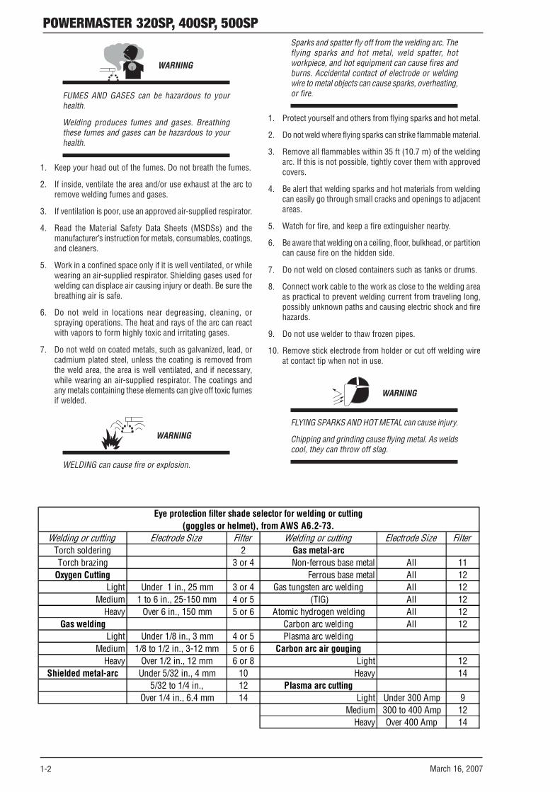
Welding or cutting Electrode Size Filter Welding or cutting Electrode Size FilterTorch soldering 2 Gas metal-arc Torch brazing 3 or 4 Non-ferrous base metal All 11
Oxygen Cutting Ferrous base metal All 12Light Under 1 in., 25 mm 3 or 4 Gas tungsten arc welding All 12
Medium 1 to 6 in., 25-150 mm 4 or 5 (TIG) All 12Heavy Over 6 in., 150 mm 5 or 6 Atomic hydrogen welding All 12
Gas welding Carbon arc welding All 12Light Under 1/8 in., 3 mm 4 or 5 Plasma arc welding
Medium 1/8 to 1/2 in., 3-12 mm 5 or 6 Carbon arc air gougingHeavy Over 1/2 in., 12 mm 6 or 8 Light 12
Shielded metal-arc Under 5/32 in., 4 mm 10 Heavy 145/32 to 1/4 in., 12 Plasma arc cutting
Over 1/4 in., 6.4 mm 14 Light Under 300 Amp 9Medium 300 to 400 Amp 12
Heavy Over 400 Amp 14
Eye protection filter shade selector for welding or cutting(goggles or helmet), from AWS A6.2-73.

1-3March 16, 2007
POWERMASTER 320SP, 400SP, 500SP1. Wear approved face shield or safety goggles. Side shields
recommended.
2. Wear proper body protection to protect skin.
WARNING
CYLINDERS can explode if damaged.
Shielding gas cylinders contain gas under highpressure. If damaged, a cylinder can explode. Sincegas cylinders are normally part of the weldingprocess, be sure to treat them carefully.
1. Protect compressed gas cylinders from excessive heat,mechanical shocks, and arcs.
2. Install and secure cylinders in an upright position by chainingthem to a stationary support or equipment cylinder rack toprevent falling or tipping.
3. Keep cylinders away from any welding or other electricalcircuits.
4. Never allow a welding electrode to touch any cylinder.
5. Use only correct shielding gas cylinders, regulators, hoses,and fittings designed for the specific application; maintainthem and associated parts in good condition.
6. Turn face away from valve outlet when opening cylinder valve.
7. Keep protective cap in place over valve except when cylinderis in use or connected for use.
8. Read and follow instructions on compressed gas cylinders,associated equipment, and CGA publication P-1 listed inSafety Standards.
! WARNING
Engines can be dangerous.
WARNING
ENGINE EXHAUST GASES can kill.
Engines produce harmful exhaust gases.
1. Use equipment outside in open, well-ventilated areas.
2. If used in a closed area, vent engine exhaust outside andaway from any building air intakes.
WARNING
ENGINE FUEL can cause fire or explosion.
Engine fuel is highly flammable.
1. Stop engine before checking or adding fuel.
2. Do not add fuel while smoking or if unit is near any sparks oropen flames.
3. Allow engine to cool before fueling. If possible, check andadd fuel to cold engine before beginning job.
4. Do not overfill tank — allow room for fuel to expand.
5. Do not spill fuel. If fuel is spilled, clean up before startingengine.
WARNING
MOVING PARTS can cause injury.
Moving parts, such as fans, rotors, and belts can cut fingers andhands and catch loose clothing.
1. Keep all doors, panels, covers, and guards closed andsecurely in place.
2. Stop engine before installing or connecting unit.
3. Have only qualified people remove guards or covers formaintenance and troubleshooting as necessary.
4. To prevent accidental starting during servicing,disconnect negative (-) battery cable from battery.
5. Keep hands, hair, loose clothing, and tools away frommoving parts.
6. Reinstall panels or guards and close doors whenservicing is finished and before starting engine.
WARNING
SPARKS can cause BATTERY GASES TO EXPLODE;BATTERY ACID can burn eyes and skin.
Batteries contain acid and generate explosive gases.
1. Always wear a face shield when working on a battery.
2. Stop engine before disconnecting or connecting batterycables.
3. Do not allow tools to cause sparks when working on a battery.
4. Do not use welder to charge batteries or jump start vehicles.
5. Observe correct polarity (+ and –) on batteries.
WARNING
STEAM AND PRESSURIZED HOT COOLANT canburn face, eyes, and skin.
The coolant in the radiator can be very hot and underpressure.

1-4 March 16, 2007
POWERMASTER 320SP, 400SP, 500SP1. Do not remove radiator cap when engine is hot. Allow engine
to cool.
2. Wear gloves and put a rag over cap area when removing cap.
3. Allow pressure to escape before completely removing cap.
! WARNING
This product, when used for welding or cutting,produces fumes or gases which contain chemicalsknow to the State of California to cause birth defectsand, in some cases, cancer. (California Health &Safety code Sec. 25249.5 et seq.)
NOTE
Considerations About Welding And The Effects ofLow Frequency Electric and Magnetic Fields
The following is a quotation from the General Conclusions Sec-tion of the U.S. Congress, Office of Technology Assessment, Bio-logical Effects of Power Frequency Electric & Magnetic Fields -Background Paper, OTA-BP-E-63 (Washington, DC: U.S. Gov-ernment Printing Office, May 1989): “...there is now a very largevolume of scientific findings based on experiments at the cellularlevel and from studies with animals and people which clearlyestablish that low frequency magnetic fields and interact with,and produce changes in, biological systems. While most of thiswork is of very high quality, the results are complex. Currentscientific understanding does not yet allow us to interpret theevidence in a single coherent framework. Even more frustrating,it does not yet allow us to draw definite conclusions about ques-tions of possible risk or to offer clear science-based advice onstrategies to minimize or avoid potential risks.”
To reduce magnetic fields in the workplace, use the followingprocedures.
1. Keep cables close together by twisting or taping them.
2. Arrange cables to one side and away from the operator.
3. Do not coil or drape cable around the body.
4. Keep welding power source and cables as far away frombody as practical.
ABOUT PACEMAKERS:
The above procedures are among those alsonormally recommended for pacemaker wearers.Consult your doctor for complete information.
1.02 Principal Safety Standards
Safety in Welding and Cutting, ANSI Standard Z49.1, fromAmerican Welding Society, 550 N.W. LeJeune Rd., Miami, FL33126.
Safety and Health Standards, OSHA 29 CFR 1910, fromSuperintendent of Documents, U.S. Government Printing Office,Washington, D.C. 20402.
Recommended Safe Practices for the Preparation for Weldingand Cutting of Containers That Have Held Hazardous Substances,American Welding Society Standard AWS F4.1, from AmericanWelding Society, 550 N.W. LeJeune Rd., Miami, FL 33126.
National Electrical Code, NFPA Standard 70, from National FireProtection Association, Batterymarch Park, Quincy, MA 02269.
Safe Handling of Compressed Gases in Cylinders, CGA PamphletP-1, from Compressed Gas Association, 1235 Jefferson DavisHighway, Suite 501, Arlington, VA 22202.
Code for Safety in Welding and Cutting, CSA Standard W117.2,from Canadian Standards Association, Standards Sales, 178Rexdale Boulevard, Rexdale, Ontario, Canada M9W 1R3.
Safe Practices for Occupation and Educational Eye and FaceProtection, ANSI Standard Z87.1, from American NationalStandards Institute, 1430 Broadway, New York, NY 10018.
Cutting and Welding Processes, NFPA Standard 51B, fromNational Fire Protection Association, Batterymarch Park, Quincy,MA 02269.

1-5March 16, 2007
POWERMASTER 320SP, 400SP, 500SP1.03 Symbol Chart
Note that only some of these symbols will appear on your model.
Gas Tungsten Arc Welding (GTAW)
Air Carbon Arc Cutting (CAC-A)
Constant Current
Constant Voltage Or Constant Potential
High Temperature
Fault Indication
Arc Force
Touch Start (GTAW)
Variable Inductance
Voltage Input
Single Phase
Three Phase
Three Phase Static Frequency Converter-Transformer-Rectifier
Dangerous Voltage
Off
On
Panel/Local
Shielded Metal Arc Welding (SMAW)
Gas Metal Arc Welding (GMAW)
Increase/Decrease
Circuit Breaker
AC Auxiliary Power
Remote
Duty Cycle
Percentage
Amperage
Voltage
Hertz (cycles/sec)
Frequency
Negative
Positive
Direct Current (DC)
Protective Earth (Ground)
Line
Line Connection
Auxiliary Power
Receptacle Rating-Auxiliary Power
Art # A-04130
115V 15A
t
t1
t2
%X
IPM
MPM
t
V
Fuse
Wire Feed Function
Wire Feed Towards Workpiece With Output Voltage Off.
Preflow Time
Postflow Time
Spot Time
Spot Weld Mode
Continuous WeldMode
Press to initiate wirefeed and welding, release to stop.
Purging Of Gas
Inches Per Minute
Meters Per Minute
Welding Gun
Burnback Time
Press and hold for preflow, releaseto start arc. Press to stop arc, andhold for preflow.
4 Step TriggerOperation
2 Step TriggerOperation

1-6 March 16, 2007
POWERMASTER 320SP, 400SP, 500SP1.04 Precautions De Securite En Soudage A L’arc
! MISE EN GARDE
LE SOUDAGE A L’ARC EST DANGEREUX
PROTEGEZ-VOUS, AINSI QUE LES AUTRES, CONTRE LES BLESSURES GRAVES POSSIBLES OU LA MORT. NE LAISSEZ PAS LESENFANTS S’APPROCHER, NI LES PORTEURS DE STIMULATEUR CARDIAQUE (A MOINS QU’ILS N’AIENT CONSULTE UN MEDECIN).CONSERVEZ CES INSTRUCTIONS. LISEZ LE MANUEL D’OPERATION OU LES INSTRUCTIONS AVANT D’INSTALLER, UTILISER OUENTRETENIR CET EQUIPEMENT.
Les produits et procédés de soudage peuvent sauser des blessures graves ou la mort, de même que des dommages au reste dumatériel et à la propriété, si l’utilisateur n’adhère pas strictement à toutes les règles de sécurité et ne prend pas les précautionsnécessaires.
En soudage et coupage, des pratiques sécuritaires se sont développées suite à l’expérience passée. Ces pratiques doivent être apprisespar étude ou entraînement avant d’utiliser l’equipement. Toute personne n’ayant pas suivi un entraînement intensif en soudage etcoupage ne devrait pas tenter de souder. Certaines pratiques concernent les équipements raccordés aux lignes d’alimentation alorsque d’autres s’adressent aux groupes électrogènes.
La norme Z49.1 de l’American National Standard, intitulée “SAFETY IN WELDING AND CUTTING” présente les pratiques sécuritairesà suivre. Ce document ainsi que d’autres guides que vous devriez connaître avant d’utiliser cet équipement sont présentés à la fin deces instructions de sécurité.
SEULES DES PERSONNES QUALIFIEES DOIVENT FAIRE DES TRAVAUX D’INSTALLATION, DE REPARATION, D’ENTRETIEN ET D’ESSAI.
5. Veuillez à installer cet équipement et à le mettre à la terreselon le manuel d’utilisation et les codes nationaux,provinciaux et locaux applicables.
6. Arrêtez tout équipement après usage. Coupez l’alimentationde l’équipement s’il est hors d’usage ou inutilisé.
7. N’utilisez que des porte-électrodes bien isolés. Ne jamaisplonger les porte-électrodes dans l’eau pour les refroidir. Nejamais les laisser traîner par terre ou sur les pièces à souder.Ne touchez pas aux porte-électrodes raccordés à deux sourcesde courant en même temps. Ne jamais toucher quelqu’und’autre avec l’électrode ou le porte-électrode.
8. N’utilisez pas de câbles électriques usés, endommagés, malépissés ou de section trop petite.
9. N’enroulez pas de câbles électriques autour de votre corps.
10. N’utilisez qu’une bonne prise de masse pour la mise à laterre de la pièce à souder.
11. Ne touchez pas à l’électrode lorsqu’en contact avec le circuitde soudage (terre).
12. N’utilisez que des équipements en bon état. Réparez ouremplacez aussitôt les pièces endommagées.
13. Dans des espaces confinés ou mouillés, n’utilisez pas desource de courant alternatif, à moins qu’il soit muni d’unréducteur de tension. Utilisez plutôt une source de courantcontinu.
14. Portez un harnais de sécurité si vous travaillez en hauteur.
15. Fermez solidement tous les panneaux et les capots.
1.05 Dangers relatifs au soudage à l’arc
AVERTISSEMENT
L’ELECTROCUTION PEUT ETRE MORTELLE.
Une décharge électrique peut tuer ou brûlergravement. L’électrode et le circuit de soudage sontsous tension dès la mise en circuit. Le circuitd’alimentation et les circuits internes del’équipement sont aussi sous tension dès la miseen marche. En soudage automatique ou semi-automatique avec fil, ce dernier, le rouleau ou labobine de fil, le logement des galets d’entrainementet toutes les pièces métalliques en contact avec lefil de soudage sont sous tension. Un équipementinadéquatement installé ou inadéquatement mis àla terre est dangereux.
1. Ne touchez pas à des pièces sous tension.
2. Portez des gants et des vêtements isolants, secs et non troués.
3 Isolez-vous de la pièce à souder et de la mise à la terre aumoyen de tapis isolants ou autres.
4. Déconnectez la prise d’alimentation de l’équipement ouarrêtez le moteur avant de l’installer ou d’en faire l’entretien.Bloquez le commutateur en circuit ouvert ou enlevez lesfusibles de l’alimentation afin d’éviter une mise en marcheaccidentelle.

1-7March 16, 2007
POWERMASTER 320SP, 400SP, 500SP
AVERTISSEMENT
LE RAYONNEMENT DE L’ARC PEUT BRÛLER LESYEUX ET LA PEAU; LE BRUIT PEUT ENDOMMAGERL’OUIE.
L’arc de soudage produit une chaleur et des rayonsultraviolets intenses, susceptibles de brûler les yeuxet la peau. Le bruit causé par certains procédés peutendommager l’ouïe.
1. Portez une casque de soudeur avec filtre oculaire de nuanceappropriée (consultez la norme ANSI Z49 indiquée ci-après)pour vous protéger le visage et les yeux lorsque vous soudezou que vous observez l’exécution d’une soudure.
2. Portez des lunettes de sécurité approuvées. Des écranslatéraux sont recommandés.
3. Entourez l’aire de soudage de rideaux ou de cloisons pourprotéger les autres des coups d’arc ou de l’éblouissement;avertissez les observateurs de ne pas regarder l’arc.
4. Portez des vêtements en matériaux ignifuges et durables (laineet cuir) et des chaussures de sécurité.
5. Portez un casque antibruit ou des bouchons d’oreilleapprouvés lorsque le niveau de bruit est élevé.
AVERTISSEMENT
LES VAPEURS ET LES FUMEES SONTDANGEREUSES POUR LA SANTE.
Le soudage dégage des vapeurs et des fuméesdangereuses à respirer.
1. Eloignez la tête des fumées pour éviter de les respirer.
2. A l’intérieur, assurez-vous que l’aire de soudage est bienventilée ou que les fumées et les vapeurs sont aspirées àl’arc.
3. Si la ventilation est inadequate, portez un respirateur à ad-duction d’air approuvé.
4. Lisez les fiches signalétiques et les consignes du fabricantrelatives aux métaux, aux produits consummables, auxrevêtements et aux produits nettoyants.
5. Ne travaillez dans un espace confiné que s’il est bien ventilé;sinon, portez un respirateur à adduction d’air. Les gazprotecteurs de soudage peuvent déplacer l’oxygène de l’airet ainsi causer des malaises ou la mort. Assurez-vous quel’air est propre à la respiration.
6. Ne soudez pas à proximité d’opérations de dégraissage, denettoyage ou de pulvérisation. La chaleur et les rayons del’arc peuvent réagir avec des vapeurs et former des gazhautement toxiques et irritants.
Opération de coupage ou soudage
Dimension d'électrode ouEpiasseur de métal ouIntensité de courant
Nuance de filtre oculaire
Opération de coupage ou soudage
Dimension d'électrode ouEpiasseur de métal ouIntensité de courant
Nuance de filtre oculaire
Brassage tendre au chalumeau
toutes conditions 2Soudage á l'arc sous gaz avec fil plein (GMAW)
Brassage fort au chalumeau
toutes conditions 3 ou 4 métaux non-ferreux toutes conditions 11
Oxycoupage métaux ferreux toutes conditions 12
mince moins de 1 po. (25 mm) 2 ou 3Soudage á l'arc sous gaz avecélectrode de tungstène (GTAW)
toutes conditions 12
moyen de 1 á 6 po. (25 á 150 mm) 4 ou 5Soudage á l'hydrogèneatomique (AHW)
toutes conditions 12
épais plus de 6 po. (150 mm) 5 ou 6Soudage á l'arc avecélectrode de carbone (CAW)
toutes conditions 12
Soudage aux gaz Soudage á l'arc Plasma (PAW) toutes dimensions 12
mince moins de 1/8 po. (3 mm) 4 ou 5Gougeage Air-Arc avecélectrode de carbone
moyen de 1/8 á 1/2 po. (3 á 12 mm) 5 ou 6 mince 12
épais plus de 1/2 po. (12 mm) 6 ou 8 épais 14Soudage á l'arc avecélectrode enrobees (SMAW)
moins de 5/32 po. (4 mm) 10 Coupage á l'arc Plasma (PAC)
5/32 á 1/4 po. (4 á 6.4 mm) 12 mince moins de 300 amperès 9plus de 1/4 po. (6.4 mm) 14 moyen de 300 á 400 amperès 12
épais plus de 400 amperès 14
SELECTION DES NUANCES DE FILTRES OCULAIRS POUR LA PROTECTION DES YEUX EN COUPAGE ET SOUDAGE (selon AWS á 8.2-73)

1-8 March 16, 2007
POWERMASTER 320SP, 400SP, 500SP7. Ne soudez des tôles galvanisées ou plaquées au plomb ou
au cadmium que si les zones à souder ont été grattées àfond, que si l’espace est bien ventilé; si nécessaire portez unrespirateur à adduction d’air. Car ces revêtements et tout métalqui contient ces éléments peuvent dégager des fuméestoxiques au moment du soudage.
AVERTISSEMENT
LE SOUDAGE PEUT CAUSER UN INCENDIE OU UNEEXPLOSION
L’arc produit des étincellies et des projections. Lesparticules volantes, le métal chaud, les projectionsde soudure et l’équipement surchauffé peuventcauser un incendie et des brûlures. Le contactaccidentel de l’électrode ou du fil-électrode avecun objet métallique peut provoquer des étincelles,un échauffement ou un incendie.
1. Protégez-vous, ainsi que les autres, contre les étincelles etdu métal chaud.
2. Ne soudez pas dans un endroit où des particules volantes oudes projections peuvent atteindre des matériauxinflammables.
3. Enlevez toutes matières inflammables dans un rayon de 10,7 mètres autour de l’arc, ou couvrez-les soigneusement avecdes bâches approuvées.
4. Méfiez-vous des projections brulantes de soudagesusceptibles de pénétrer dans des aires adjacentes par depetites ouvertures ou fissures.
5. Méfiez-vous des incendies et gardez un extincteur à portéede la main.
6. N’oubliez pas qu’une soudure réalisée sur un plafond, unplancher, une cloison ou une paroi peut enflammer l’autrecôté.
7. Ne soudez pas un récipient fermé, tel un réservoir ou unbaril.
8. Connectez le câble de soudage le plus près possible de lazone de soudage pour empêcher le courant de suivre un longparcours inconnu, et prévenir ainsi les risques d’électrocutionet d’incendie.
9. Ne dégelez pas les tuyaux avec un source de courant.
10. Otez l’électrode du porte-électrode ou coupez le fil au tube-contact lorsqu’inutilisé après le soudage.
11. Portez des vêtements protecteurs non huileux, tels des gantsen cuir, une chemise épaisse, un pantalon revers, des bottinesde sécurité et un casque.
AVERTISSEMENT
LES ETINCELLES ET LES PROJECTIONSBRULANTES PEUVENT CAUSER DES BLESSURES.
Le piquage et le meulage produisent des particulesmétalliques volantes. En refroidissant, la soudurepeut projeter du éclats de laitier.
1. Portez un écran facial ou des lunettes protectricesapprouvées. Des écrans latéraux sont recommandés.
2. Portez des vêtements appropriés pour protéger la peau.
AVERTISSEMENT
LES BOUTEILLES ENDOMMAGEES PEUVENTEXPLOSER
Les bouteilles contiennent des gaz protecteurs soushaute pression. Des bouteilles endommagéespeuvent exploser. Comme les bouteilles fontnormalement partie du procédé de soudage, traitez-les avec soin.
1. Protégez les bouteilles de gaz comprimé contre les sourcesde chaleur intense, les chocs et les arcs de soudage.
2. Enchainez verticalement les bouteilles à un support ou à uncadre fixe pour les empêcher de tomber ou d’être renversées.
3. Eloignez les bouteilles de tout circuit électrique ou de toutsoudage.
4. Empêchez tout contact entre une bouteille et une électrodede soudage.
5. N’utilisez que des bouteilles de gaz protecteur, desdétendeurs, des boyauxs et des raccords conçus pour chaqueapplication spécifique; ces équipements et les piècesconnexes doivent être maintenus en bon état.
6. Ne placez pas le visage face à l’ouverture du robinet de labouteille lors de son ouverture.
7. Laissez en place le chapeau de bouteille sauf si en utilisationou lorsque raccordé pour utilisation.
8. Lisez et respectez les consignes relatives aux bouteilles degaz comprimé et aux équipements connexes, ainsi que lapublication P-1 de la CGA, identifiée dans la liste de docu-ments ci-dessous.
AVERTISSEMENT
LES MOTEURS PEUVENT ETRE DANGEREUX
LES GAZ D’ECHAPPEMENT DES MOTEURSPEUVENT ETRE MORTELS.
Les moteurs produisent des gaz d’échappement nocifs.
1. Utilisez l’équipement à l’extérieur dans des aires ouvertes etbien ventilées.
2. Si vous utilisez ces équipements dans un endroit confiné,les fumées d’échappement doivent être envoyées à l’extérieur,loin des prises d’air du bâtiment.

1-9March 16, 2007
POWERMASTER 320SP, 400SP, 500SP
AVERTISSEMENT
LE CARBURANT PEUR CAUSER UN INCENDIE OUUNE EXPLOSION.
Le carburant est hautement inflammable.
1. Arrêtez le moteur avant de vérifier le niveau ecarburant ou de faire le plein.
2. Ne faites pas le plein en fumant ou proche d’une sourced’étincelles ou d’une flamme nue.
3. Si c’est possible, laissez le moteur refroidir avant de faire leplein de carburant ou d’en vérifier le niveau au début dusoudage.
4. Ne faites pas le plein de carburant à ras bord: prévoyez del’espace pour son expansion.
5. Faites attention de ne pas renverser de carburant. Nettoyeztout carburant renversé avant de faire démarrer le moteur.
AVERTISSEMENT
DES PIECES EN MOUVEMENT PEUVENT CAUSERDES BLESSURES.
Des pièces en mouvement, tels des ventilateurs,des rotors et des courroies peuvent couper doigtset mains, ou accrocher des vêtements amples.
1. Assurez-vous que les portes, les panneaux, les capots et lesprotecteurs soient bien fermés.
2. Avant d’installer ou de connecter un système, arrêtez lemoteur.
3. Seules des personnes qualifiées doivent démonter desprotecteurs ou des capots pour faire l’entretien ou ledépannage nécessaire.
4. Pour empêcher un démarrage accidentel pendant l’entretien,débranchez le câble d’accumulateur à la borne négative.
5. N’approchez pas les mains ou les cheveux de pièces enmouvement; elles peuvent aussi accrocher des vêtementsamples et des outils.
6. Réinstallez les capots ou les protecteurs et fermez les portesaprès des travaux d’entretien et avant de faire démarrer lemoteur.
AVERTISSEMENT
DES ETINCELLES PEUVENT FAIRE EXPLOSER UNACCUMULATEUR; L’ELECTROLYTE D’UNACCUMU-LATEUR PEUT BRULER LA PEAU ET LESYEUX.
Les accumulateurs contiennent de l’électrolyte acideet dégagent des vapeurs explosives.
1. Portez toujours un écran facial en travaillant sur un accumu-lateur.
2. Arrêtez le moteur avant de connecter ou de déconnecter descâbles d’accumulateur.
3. N’utilisez que des outils anti-étincelles pour travailler sur unaccumulateur.
4. N’utilisez pas une source de courant de soudage pour chargerun accumulateur ou survolter momentanément un véhicule.
5. Utilisez la polarité correcte (+ et –) de l’accumulateur.
AVERTISSEMENT
LA VAPEUR ET LE LIQUIDE DE REFROIDISSEMENTBRULANT SOUS PRESSION PEUVENT BRULER LAPEAU ET LES YEUX.
Le liquide de refroidissement d’un radiateur peutêtre brûlant et sous pression.
1. N’ôtez pas le bouchon de radiateur tant que le moteur n’estpas refroidi.
2. Mettez des gants et posez un torchon sur le bouchon pourl’ôter.
3. Laissez la pression s’échapper avant d’ôter complètement lebouchon.
1.06 Principales Normes De Securite
Safety in Welding and Cutting, norme ANSI Z49.1, AmericanWelding Society, 550 N.W. LeJeune Rd., Miami, FL 33128.
Safety and Health Standards, OSHA 29 CFR 1910, Superinten-dent of Documents, U.S. Government Printing Office, Washing-ton, D.C. 20402.
Recommended Safe Practices for the Preparation for Weldingand Cutting of Containers That Have Held Hazardous Substances,norme AWS F4.1, American Welding Society, 550 N.W. LeJeuneRd., Miami, FL 33128.
National Electrical Code, norme 70 NFPA, National Fire Protec-tion Association, Batterymarch Park, Quincy, MA 02269.
Safe Handling of Compressed Gases in Cylinders, document P-1, Compressed Gas Association, 1235 Jefferson Davis Highway,Suite 501, Arlington, VA 22202.
Code for Safety in Welding and Cutting, norme CSA W117.2 As-sociation canadienne de normalisation, Standards Sales, 276Rexdale Boulevard, Rexdale, Ontario, Canada M9W 1R3.
Safe Practices for Occupation and Educational Eye and Face Pro-tection, norme ANSI Z87.1, American National Standards Insti-tute, 1430 Broadway, New York, NY 10018.
Cutting and Welding Processes, norme 51B NFPA, National FireProtection Association, Batterymarch Park, Quincy, MA 02269.

1-10 March 16, 2007
POWERMASTER 320SP, 400SP, 500SP
Soudage á L’arc AvecElectrode Non Fusible(GTAW)
Decoupe Arc Carbone(CAC-A)
Courant Constant
Tension ConstanteOu Potentiel Constant
Haute Température
Force d'Arc
Amorçage de L’arc auContact (GTAW)
Inductance Variable
Tension
Mono Phasé
Trois Phasé
Tri-Phase StatiqueFréquence ConvertisseurTransformateur-Redresseur
Tension dangereuse
Hors Tension
Sous Tension
Panneau/Local
Soudage Arc ElectriqueAvec Electrode Enrobé(SMAW)
Soudage á L’arc AvecFil Electrodes Fusible(GMAW)
Augmentez/Diminuer
Disjoncteur
Source AC Auxiliaire
Distant
Facteur de Marche
Pourcentage
Intensité de Courant
Tension
Hertz (cycles/sec)
Fréquence
Négatif
Positif
Courant Continue (DC)
Terre de Protection
Ligne
Connexion de la Ligne
Source Auxiliaire
Classement de Prise-Source Auxiliaire
Art # A-07639
115V 15A
t
t1
t2
%X
IPM
MPM
tFusible
Déroulement du Fil
Alimentation du Fil Versla Pièce de FabricationHors Tension
Durée de Pré-Dèbit
Durée de Post-Dèbit
Duréc du Pulse
Soudure Par Point
Appuyez pour dèruarerl’alimentation du fils et la soudure,le relâcher pour arrêter.
Purge Du Gaz
Mode Continu deSoudure
Pouces Par Minute
Mètres Par Minute
Torch de Soudage
Probléme de Terre
Maintenez appuyez pour pré-dèbit,relailez pour initier l'arc. Appuyez pour arrêter l'arc, et mainteuir pourpré-dèbit.
Détente à 4-Temps
Détente à 2-Temps
V
1.07 Graphique de Symbole
Seulement certains de ces symboles apparaîtront sur votre modèle.

POWERMASTER 320SP, 400SP, 500SP
March 16, 2007 2-1
SECTION 2:INTRODUCTION
2.02 Equipment Identification
The unit’s identification number (specification or partnumber), model, and serial number usually appearon a nameplate attached to the control panel. In somecases, the nameplate may be attached to the rearpanel. Equipment which does not have a control panelsuch as gun and cable assemblies is identified onlyby the specification or part number printed on theshipping container. Record these numbers on thebottom of page i for future reference.
2.03 Receipt Of Equipment
When you receive the equipment, check it againstthe invoice to make sure it is complete and inspectthe equipment for possible damage due to shipping.If there is any damage, notify the carrier immediatelyto file a claim. Furnish complete informationconcerning damage claims or shipping errors to thelocation in your area listed in the inside back coverof this manual.
Include all equipment identification numbers asdescribed above along with a full description of theparts in error.
Move the equipment to the installation site beforeun-crating the unit. Use care to avoid damaging theequipment when using bars, hammers, etc., to un-crate the unit.
2.01 How To Use This Manual
This Owner’s Manual applies to just specification orpart numbers listed on page i.
To ensure safe operation, read the entire manual,including the chapter on safety instructions andwarnings.
Throughout this manual, the words WARNING,CAUTION, and NOTE may appear. Pay particularattention to the information provided under theseheadings. These special annotations are easilyrecognized as follows:
! WARNING
A WARNING gives information regardingpossible personal injury.
CAUTION
A CAUTION refers to possible equipmentdamage.
NOTE
A NOTE offers helpful informationconcerning certain operating procedures.
Additional copies of this manual may be purchasedby contacting Thermal Arc at the address and phonenumber listed in the inside back cover of this manual.Include the Owner’s Manual number and equipmentidentification numbers.
Electronic copies of this manual can also be down-loaded at no charge in Acrobat PDF format by goingto the Thermal Arc web site listed below and clickingon the Literature Library link:
http://www.thermalarc.com

POWERMASTER 320SP, 400SP, 500SP
2-2 March 16, 2007
2.04 Machine Components (500SP, 400SP, and SP4000W)
(1)
(7)
(3)
(8)
(4)
(9)
(9)(10)
(2)
(16)
(15)
(13)
(12)
(11)
(14)Art # A-07717
(5)
(6)
(17)
1. External Wire Feeder (N/A with compact models)
2. Protective Cover, Operation Panel
3. Secondary Control Operating Panel
4. Primary Control Operating Panel
5. Preview and actual welding current and voltage
6. MIG Torch Connection
7. Red = Hot coolant return
8. Blue = Cool coolant to torch
9. Lifting Points (refer to Section 2.07)
10. Handle
11. Mains On/Off Switch
12. Coolant Tank Cap
13. Air intake
14. Wheeling Gear
15. Positive Connection Socket for Work Lead
16. Negative Connection Socket for Work Lead
17. Gas Cylinder Tray
18. Work Clamp (not shown)
19. MIG Torch (not shown)

POWERMASTER 320SP, 400SP, 500SP
March 16, 2007 2-3
2.05 Machine Components (400SP Compact Model)
(1)(3)
(4)
(7) (7)
(8)
(2)
(12)
(11)
(10)
(9)
(15)
Art # A-07884
(5)
(6)
1. Wire Feeder Door Panel
2. Protective Cover, Operation Panel
3. Secondary Control Operating Panel
4. Primary Control Operating Panel
5. Preview and actual welding current and voltage
6. MIG Torch Connection
7. Lifting Points (refer to Section 2.07)
8. Handle
9. Mains On/Off Switch
10. Air intake
11. Positive Connection Socket for Work Lead
12. Negative Connection Socket for Work Lead
13. Work Clamp (not shown)
14. MIG Torch (not shown)
15. Wheeling Gear

POWERMASTER 320SP, 400SP, 500SP
2-4 March 16, 2007
2.06 Machine Components (320SP Compact Model)
1. Wire Feeder Door Panel
2. Carrying Handle
3. Protective Cover, Operation Panel
4. Handle
5. Torch Holder
6. Secondary Control Operating Panel
7. Primary Control Operating Panel
8. Preview and actual welding current and voltage
(1)
(4)
(7)
(2), (10)
(13)
(14)
(5)
(9)
Art # A-07908
(3)
(8)
(6)
9. MIG Torch Connection
10. Lifting Point (refer to Section 2.07)
11. Mains On/Off Switch (in rear)
12. Air intake (in rear)
13. Negative Connection Socket for Work Lead
14. Positive Connection Socket for Work Lead
13. Work Clamp (not shown)
14. MIG Torch (not shown)
15. Wheeling Gear (in rear)

POWERMASTER 320SP, 400SP, 500SP
March 16, 2007 2-5
2.07 Lifting Points
Art # A-07909
Lifting Point for 320SP and 400SP Compact Art # A-07910
Maximum
Lifting Points for 500SP and 400SP

POWERMASTER 320SP, 400SP, 500SP
2-6 March 16, 2007
2.08 Power Supply Specifications (part 1)
Input Mains Voltage (50/60 Hz) V 208 230 400 460 208 230 400 460 208 230 400 460Mains Voltage Tolerance Range %Max Recommended Circuit Breaker or Time-Delay Fuse 3 Phase A - - - - 45 40 25 20 70 60 35 30Max Recommended Standard Normal Operating Fuse 3 Phase A - - - - 55 50 30 25 80 70 40 35Max Recommended Circuit Breaker or Time-Delay Fuse 1 Phase A 70 60 40 35 100 90 50 45 100 90 50 45Max Recommended Standard Normal Operating Fuse 1 Phase A 80 70 45 40 110 100 60 50 110 100 60 50Power factor at Maximum Output cosMaximum Open Circuit Voltage OCV VVoltage Range for GMAW-P, GMAW, FCAW, MIG U 2min-U 2max VCurrent Range for GMAW-P, GMAW, FCAW, MIG I 2min-I 2max ACurrent Range for SMAW (Stick) I 2min-I 2max AEnclosure Protection Class to EN 60 529 Insulation Class Cooling Method Noise Emission dB (A)
Welding OutputDuty Cycle 100% 3 Phase ADuty Cycle 60% 3 Phase ADuty Cycle at Maximum Current 3 Phase X
Input Mains Voltage (50/60 Hz) 3 Phase V - - - - 208 230 400 460 208 230 400 460Input Power S1 at 100% Duty Cycle 3 Phase kVA - - - - 11 11 12 12 16 16 16 17Input Power S1 at 60% Duty Cycle 3 Phase kVA - - - - 13 13 14 14 24 23 23 24Input Power S1 at Maximum Current 3 Phase kVA - - - - 17 16 17 17 24 23 23 24Generator Requirement with Three Phase 3 Phase kVA Input Current I1 at 100% Duty Cycle 3 Phase A - - - - 32 29 18 16 45 40 23 21 Input Current I1 at 60% Duty Cycle 3 Phase A - - - - 37 33 20 17 66 59 34 30 Input Current I1 at Maximum Output 3 Phase A - - - - 46 41 24 21 66 59 34 30
Welding OutputDuty Cycle 100% 1 Phase ADuty Cycle 60% 1 Phase ADuty Cycle at Maximum Current 1 Phase X
Input Mains Voltage (50/60 Hz) 1 Phase V 208 230 400 460 208 230 400 460 208 230 400 460Input Power S1 at 100% Duty Cycle 1 Phase kVA 9 9 10 10 13 14 14 14 13 14 14 14Input Power S1 at 60% Duty Cycle 1 Phase kVA 11 11 12 12 15 16 16 16 15 16 16 16Input Power S1 at Maximum Output 1 Phase kVA 14 13 15 15 19 20 20 20 19 20 20 20Generator Requirement with Single Phase 1 Phase kVA Input Current I1 at 100% Duty Cycle 1 Phase A 44 40 26 23 65 61 35 30 65 61 35 30 Input Current I1 at 60% Duty Cycle 1 Phase A 52 47 31 26 74 68 40 35 74 68 40 35 Input Current I1 Maximum Output 1 Phase A 70 58 38 32 92 85 50 43 92 85 50 43
30
PowerMaster Power Source Part Numbers
W1000402 W1000602Remote Power Supply with Integrated Torch Water Cooling SystemCompact Power Supply with Integrated Wirefeeder
Automation Power Supply with Integrated Torch Water Cooling SystemW1000502
3023
Electrical Specifications for GMAW-P / GMAW / FCAW / MIG with Three-Phase Input Power
25 35
320SP
400SP 500SP320SP
0.99 0.99 0.9979
14.3 – 3414.3 – 30
W1000202
Input Mains Power
320SP 400SP 500SP
Summary Specifications
320
79
280
W1000102 W1000304
Fan Cooled
5 – 40010-380
-500SP
320400SP
35050%@400A, 34V
60%@500A, 39V
320
Input Mains Power
350
Electrical Specifications for GMAW-P / GMAW / FCAW / MIG with Single-Phase Input Power
250
-
40%@320A, 30V 50%@400A, 34V
79
400500
5 – 50014.3 – 39
IP23
<70
IP23
-
+/- 10
10-300
F Fan Cooled
<70
5 – 320
-
+/- 10
35050%@400A, 34V
+/- 10
F Fan Cooled
10-480
<70
IP23F

POWERMASTER 320SP, 400SP, 500SP
March 16, 2007 2-7
2.09 Power Supply Specifications (part 2)
Welding OutputDuty Cycle 100% 3 Phase A
Duty Cycle 60% 3 Phase ADuty Cycle at Maximum Current 3 Phase X
Input Mains Voltage (50/60 Hz) 3 Phase V - - - - 208 230 400 460 208 230 400 460
Input Power S1 at 100% Duty Cycle 3 Phase kVA - - - - 10 10 11 11 16 16 17 17Input Power S1 at 60% Duty Cycle 3 Phase kVA - - - - 12 12 12 12 23 22 22 23Input Power S1 at Maximum Output 3 Phase kVA - - - - 16 16 16 17 23 22 22 23
Generator Requirement with Three Phase 3 Phase kVA Input Current I1 at 100% Duty Cycle 3 Phase A - - - - 27 26 16 13 44 41 25 22
Input Current I1 at 60% Duty Cycle 3 Phase A - - - - 33 30 17 15 63 56 32 29 Input Current I1 at Maximum Output 3 Phase A - - - - 44 40 24 21 63 56 32 29
Welding OutputDuty Cycle 100% 1 Phase A
Duty Cycle 60% 1 Phase ADuty Cycle at Maximum Current 1 Phase X
Input Mains Voltage (50/60 Hz) 1 Phase V 208 230 400 460 208 230 400 460 208 230 400 460Input Power S1 at 100% Duty Cycle 1 Phase kVA 10 10 12 12 13 14 13 13 13 14 13 13
Input Power S1 at 60% Duty Cycle 1 Phase kVA 12 12 14 13 15 15 15 15 15 15 15 15Input Power S1 at Maximum Output 1 Phase kVA 14 13 15 15 19 19 19 19 19 19 19 19
Generator Requirement with Single Phase 1 Phase kVA Input Current I1 at 100% Duty Cycle 1 Phase A 49 45 29 25 64 59 34 29 64 59 34 29 Input Current I1 at 60% Duty Cycle 1 Phase A 57 52 34 28 73 66 38 33 73 66 38 33
Input Current I1 at Maximum Output 1 Phase A 67 57 38 32 90 83 48 41 90 83 48 41
Torch Cooling System (Where Fitted)
Standard Coolant Flow Rate gallon / min.Maximum Coolant Pressure Psi
Pump Type
Dimensions and WeightsPower Supply Dimension (DxWxH) in
Power Supply Weight lb
25
43.9x17.5x33.7
222
Input Mains Power
50
Centrifugal Pump
320SP
35-
400SP
320SP 400SP 500SP
500SP
0.29
77 201
- 0.29
-
29.3x13.4x19.6
- 50
Centrifugal Pump
43.9x17.5x33.7
22 30 30
40%@300A, 32V 50%@380A, 35.2V 50%@380A, 35.2V
Input Mains Power
230 300 300
260 330 330
320SP 400SP 500SP
Electrical Specifications for SMAW / STICK with Single-Phase Input Power
50%@380A, 35.2V 60%@480A, 39.2V-- 330 480
Electrical Specifications for SMAW / STICK with Three-Phase Input Power
- 300 380320SP 400SP 500SP

POWERMASTER 320SP, 400SP, 500SP
2-8 March 16, 2007
2.10 Wire Feeder Specifications
Wirefeeder Part Numbers SP4000W SP4000RWirefeeder suits water cooled torch W3000102 –Wirefeeder suits Automation Power Source – W3000302
Welding OutputWeldable Wire Steel & Stainless Steel Ø in .023 – .045 .023 – 1/16Weldable Wire Aluminum Ø in .035 - 1/16 .035 – 3/32Wirefeed Speed IPM 4 – 984 4 – 984Wire feed unit Rollers 4 4
Dimensions and weightsSize of wire feed case (DxWxH) in. 25.2x14x19.6 21.3x8.2x7Weight of wire feed case lb. 44.4 18.7
NOTE
Due to variations that can occur in manufactured products, claimed performance, voltages, ratings,all capacities, measurements, dimensions and weights quoted are approximate only. Achievablecapacities and ratings in use and operation will depend upon correct installation, use, applications,maintenance and service.

POWERMASTER 320SP, 400SP, 500SP
March 16, 2007 2-9
2.11 Features and Benefits Common to all PowerMaster SP Systems #
HARDWARE (Standard)
Inverter Design: Heavy duty, highly efficient,environmentally toughened 80KHz design withexceptional dynamic welding performance.
Flow Through Tunnel: Designed to circulate air aroundcomponents that require cooling and not over criticalcircuitry. This reduces metallic dust ingression andimproves reliability.
Intelligent Heat Sensing Fan: Operates only as neededto cool components and further reduce airbornecontaminants from being pulled through the powersource.
Simple, multi-voltage design from 200to 500V for maximum flexibility in a single powersource.
Remote Control CAN-Bus Ports: Allow for easy datatransfer and provide full function remote controlcapability.
4 Roll Drive Systems: All wire feeder drive systemsare high precision, 4 roll systems manufactured toextremely tight tolerances for optimum feed-ability ofboth hard and soft wires. Refer to page 3-8.
Heavy Duty Running Gear: All running gear has beendeveloped for manufacturing / productionenvironments, built heavy-duty and designed to last.
Tweco® Guns and Accessories: Tweco® has a full lineof PulseMaster standard and PulseMaster Smart Gunswith advanced digital controls optimized for thePowerMaster SP range. Gun connections are Tweco®
No. 4 and return leads are Tweco® MPC. Refer to page3-10.
SOFTWARE (Standard)
Links the wire feed speed, arc currentand voltage to deliver the perfect welding parametersand eliminate the guesswork for achieving optimumperformance. Refer to page 4-2 item 52.
Effortless TIG-like weld appearance upto seven times faster on aluminum and stainless steelthan traditional TIG (GTAW).
High Definition Pulse is expertly tailored,optimized wave designs for per fect, digitalmicroprocessor controlled, pulse performance.
Built-in hardware and softwareprotection against accidental incorrect input voltageselection.
JobTool™ is a library of 100 independent,user-defined, job save programs. You can save andrecall welding procedures from a PulseMasterSmartGun or from the front panel at any time. Referto page 4-3 item 62.
Fresh Tip Treatment sharpens the wire at theend of the weld sequence ready for a perfect restart.
Recalls up to 100 personalized jobs withperfect repeatability from the push of a button. Referto page 4-2 item 45 and 47 and to page 4-6 sectionC 1-7.
Pre Programmed: Up to 100 optimized SmartMIG™,PulseMIG and TwinPulse™ programs are standard,delivering optimal performance and versatility.
Down Slope (Crater Fill Mode): The digitallyadjustable parameters reduce arc energy downeliminating any craters that could cause defects.
#Subject to change without notification.

POWERMASTER 320SP, 400SP, 500SP
2-10 March 16, 2007
2.11 Features and Benefits Common to all PowerMaster SP Systems (con't) #
PERFORMANCE (Standard)
Operating Platform: How would you like to use themachine? What is your primary parameter is it Inchesper Minute or Amps? Would you rather just dial upthe material thickness and let the machine do the rest?All can be accommodated.
One Touch Control: Delivers at your fingertips theperfect welding parameters by adjusting the total arcenergy. Set material thickness then start welding.
Hot Start Ignition: The digitally adjustable startparameters combined with FTT™, creep feed speedand an amplified power level applied to the weldingarc at the start of the weld bead ensures perfect fusion.
#Subject to change without notification.
HARDWARE/SOFTWARE (Options)
High Speed Pulse is specialized high speedwave design for maximum productivity.
Push / Pull Gun Capability: “Plug and Play” Python®interface.

POWERMASTER 320SP, 400SP, 500SP
March 16, 2007 3-1
SECTION 3:INSTALLATION
NOTE
Please refer to Sections 3.04 RecommendedEquipment Setup and SECTION 4: ControlPanels for explanations of the controls.
! WARNING
Thermal Arc advises that a suitable MainsPlug and cable be fitted to this equipmentby a qualified electrical trades-person.
3.01 Location
Adequate air circulation is needed at all times in orderto assure proper operation. Provide a minimum of 12inches (305 mm) of free airspace on all sides of theunit. Make sure that the ventilator openings are notobstructed. Ventilation airflow is from rear to side.
3.02 Transportation and Positioning
Properly transporting and positioning the equipmentis important for preventing injury. Move the equipmentin an upright position and pick a flat welding surface.
(END)(END)
(+)(+)
mmmm
SaveSave
EnterEnter
EnterEnter
ModeMode
TiptronicTiptronic
V
HOLDHOLD
A
Art # A-08324_AA
! WARNING
Injury to the operator may occur if themachine’s maximum permissible angle ofinclination is exceeded. The maximumpermissible angle of inclination is 10°.Only transport or position the machinefor welding on a flat and level surface.
3.03 Fitting the Mains Cable into theCable Gland
Refer to the pictures below when connecting themains cable to the cable gland.
Art # A-08325_AA

POWERMASTER 320SP, 400SP, 500SP
3-2 March 16, 2007
! WARNING
The mains cable has to be assembled intothe cable gland as shown in the picture.The electrical technician has to make surethat the cable gland is adjusted to the ex-ternal diameter of the mains cable and themains cable is securely fastened in thecable gland according to IEC 60974-1.
3.04 Voltage Change-over
For proper operation and to prevent damage to themachine, the Voltage Input Select Switch must be setaccording to the incoming AC line voltage.
If this switch is not set to the position that matchesthe input line voltage, the Smart Logic will inhibit thewelding power source from turning on. The VoltageInput Select Switch is located on the rear panel.
Art # A-07856
To set the Voltage Input Select Switch:
1. Rotate the locking screw 90 degrees.2. Lift up the switch cover and set the switch to
the incoming AC line voltage.3. Secure the switch cover.
! WARNING
Do not alter the position of the VoltageInput Select Switch when the ON/OFFSwitch is in the ON position as this willcause two internal auxiliary fuses torupture. These fuses will have to bereplaced before the machine can operate.
! WARNING
ELECTRIC SHOCK CAN KILL.
Open the main wall disconnect switch orbreaker, before removing any covers oraccess panels on the welding machine.Live voltage is still present even with thefront panel control switch OFF. Wait at least10 full minutes after power has beenremoved before removing any covers oraccess panels to allow adequate time forinternal capacitors to discharge.

POWERMASTER 320SP, 400SP, 500SP
March 16, 2007 3-3
3.05 Connecting 3-Phase Input Power to 400SP or 500SP
! WARNINGS
Installation must meet all National and Local Codes - have only qualified persons make thisinstallation.
Disconnect and lockout/tagout input power before connecting input conductors from unit.
Always connect green or green/yellow conductor to supply grounding terminal first, and never to aline terminal. Make input power connections to the welding power source first.
Input Mains Voltage (50/60 Hz) V 208 230 400 460 208 230 400 460Max Recommended Circuit Breaker or Time-Delay Fuse A 45 40 25 20 70 60 35 30Max Recommended Standard Normal Operating Fuse A 55 50 30 25 80 70 40 35Min Input Conductor Size AWG 8 8 12 14 4 6 10 10Min Input Conductor Size AWG 8 8 12 14 6 8 10 10Suggested Input Cord Type Carolprene® Jacketed Type SOOW
90°C 600 Volt UL/CSA Portable Cord
Three-Phase Three-Phase
400SP 500SP
Art: A-07857
Primary Power Cable(not supplied)
Line Fuse
LineDisconnectSwitch
GroundConductor
GroundTerminal
GND/PE
POWERMASTER 320SP, 400SP, 500SP
3-4 March 16, 2007
! WARNING
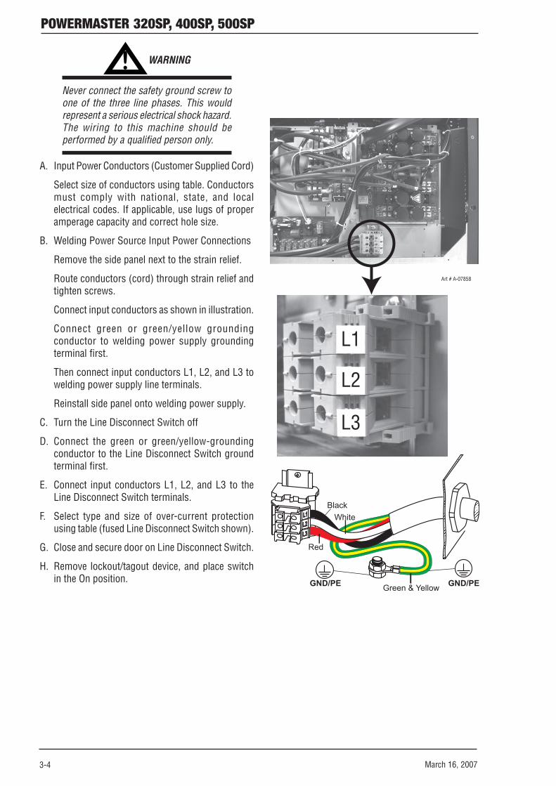
Never connect the safety ground screw toone of the three line phases. This wouldrepresent a serious electrical shock hazard.The wiring to this machine should beperformed by a qualified person only.
A. Input Power Conductors (Customer Supplied Cord)
Select size of conductors using table. Conductorsmust comply with national, state, and localelectrical codes. If applicable, use lugs of properamperage capacity and correct hole size.
B. Welding Power Source Input Power Connections
Remove the side panel next to the strain relief.
Route conductors (cord) through strain relief andtighten screws.
Connect input conductors as shown in illustration.
Connect green or green/yellow groundingconductor to welding power supply groundingterminal first.
Then connect input conductors L1, L2, and L3 towelding power supply line terminals.
Reinstall side panel onto welding power supply.
C. Turn the Line Disconnect Switch off
D. Connect the green or green/yellow-groundingconductor to the Line Disconnect Switch groundterminal first.
E. Connect input conductors L1, L2, and L3 to theLine Disconnect Switch terminals.
F. Select type and size of over-current protectionusing table (fused Line Disconnect Switch shown).
G. Close and secure door on Line Disconnect Switch.
H. Remove lockout/tagout device, and place switchin the On position. GND/PE GND/PE
L1L1L2L2L3L3
Art # A-07858
BlackWhite
Red
Green & Yellow
L1
L2
L3

POWERMASTER 320SP, 400SP, 500SP
March 16, 2007 3-5
3.06 Connecting Single-Phase Input Power to 320SP or 400SP or 500SP
! WARNINGS
Installation must meet all National and Local Codes - have only qualified persons make this instal-lation.
Disconnect and lockout/tagout input power before connecting input conductors from unit.
Always connect green or green/yellow conductor to supply grounding terminal first, and never to aline terminal.
Make input power connections to the welding power source first.
Input Mains Voltage (50/60 Hz) V 208 230 400 460Max Recommended Circuit Breaker or Time-Delay Fuse A 70 60 40 35Max Recommended Standard Normal Operating Fuse A 90 70 45 40Min Input Conductor Size AWG 6 6 10 12Min Input Conductor Size AWG 8 8 10 12Suggested Input Cord Type Carolprene® Jacketed Type
SOOW 90°C 600 Volt UL/CSA Portable Cord
Single-Phase
320SP
Input Mains Voltage (50/60 Hz) V 208 230 400 460 208 230 400 460Max Recommended Circuit Breaker or Time-Delay Fuse A 100 90 50 45 100 90 50 45Max Recommended Standard Normal Operating Fuse A 110 100 60 55 110 100 60 55Min Input Conductor Size AWG 4 4 8 10 4 4 8 10Min Input Conductor Size AWG 6 6 8 10 6 6 8 10Suggested Input Cord Type
Single-Phase
Carolprene® Jacketed Type SOOW 90°C 600 Volt UL/CSA Portable Cord
400SPSingle-Phase
500SP
Art: A-07859
Primary Power Cable
Line Fuse
LineDisconnectSwitch
GroundConductor
GroundTerminal
GND/PE
POWERMASTER 320SP, 400SP, 500SP
3-6 March 16, 2007
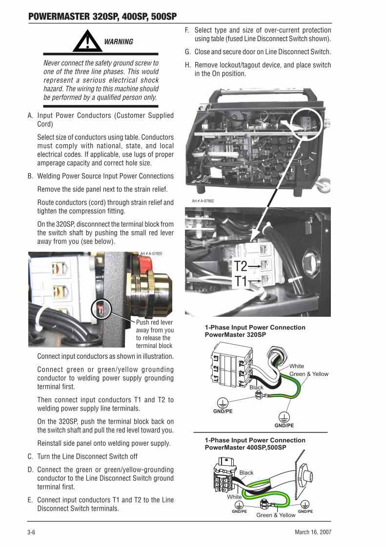
Connect input conductors as shown in illustration.
Connect green or green/yellow groundingconductor to welding power supply groundingterminal first.
Then connect input conductors T1 and T2 towelding power supply line terminals.
On the 320SP, push the terminal block back onthe switch shaft and pull the red level toward you.
Reinstall side panel onto welding power supply.
C. Turn the Line Disconnect Switch off
D. Connect the green or green/yellow-groundingconductor to the Line Disconnect Switch groundterminal first.
E. Connect input conductors T1 and T2 to the LineDisconnect Switch terminals.
1-Phase Input Power ConnectionPowerMaster 400SP,500SP
1-Phase Input Power ConnectionPowerMaster 320SP
GND/PE GND/PE
GND/PE
GND/PE
L1L1L2L2L3L3
Black
Black
White
White
Green & Yellow
Green & Yellow
Art # A-07862
T1T2
! WARNING
Never connect the safety ground screw toone of the three line phases. This wouldrepresent a serious electrical shockhazard. The wiring to this machine shouldbe performed by a qualified person only.
A. Input Power Conductors (Customer SuppliedCord)
Select size of conductors using table. Conductorsmust comply with national, state, and localelectrical codes. If applicable, use lugs of properamperage capacity and correct hole size.
B. Welding Power Source Input Power Connections
Remove the side panel next to the strain relief.
Route conductors (cord) through strain relief andtighten the compression fitting.
On the 320SP, disconnnect the terminal block fromthe switch shaft by pushing the small red leveraway from you (see below).
Push red leveraway from youto release theterminal block
Art # A-07920
F. Select type and size of over-current protectionusing table (fused Line Disconnect Switch shown).
G. Close and secure door on Line Disconnect Switch.
H. Remove lockout/tagout device, and place switchin the On position.

POWERMASTER 320SP, 400SP, 500SP
March 16, 2007 3-7
3.08 Recommended Setup for MIG
A. Torch Connection
1. Open the door panel to the machine byturning the release knobs and pulling thecover outward and up.
2. Route the gun cable through the access holein the front panel.
3. Locate the thumbscrew on the gun adapterinside the unit. Loosen the thumbscrew andinsert the gun cable end into the gun adapteras far as it will go. Tighten the thumbscrew.
4. Align the keyways of the gun switchconnector with the trigger receptacle next tothe gun cable and plug them together. Secureby turning the locking ring to the right(clockwise ).
5. If a coolant cooling system is installed,connect the coolant hoses of the torch withthe coolant sockets on the front panel. Besure to connect the red fittings together andthe blue fittings together.
Art # A-07851
Trigger ReceptacleFront Panel Access Hole
Hot coolant return(Red)
Cool coolant to torch(Blue)
3.07 Quick Start Set Up
NOTE:
Please refer to Sections 3.04 RecommendedEquipment Setup and SECTION 4: ControlPanels for explanations of the controls.
WARNING
Thermal Arc advises that a suitable MainsPlug be fitted to this equipment by aqualified electrical trades-person.
A. Where equipped, place the gas cylinder on thepower supply cylinder tray and secure with thetwo safety chains. If unit is not equipped with thisoption, then ensure that the gas cylinder is securedto a building pillar, wall bracket or otherwisesecurely fixed in an upright position.
B. Remove screw cap from gas cylinder, if fitted, andopen gas cylinder valve briefly to removecontaminants.
C. Connect gas regulator to gas cylinder.
D. Connect gas hose from power supply to gasregulator and open gas cylinder valve.
E. Connect input power, refer to previous WARNINGand the Connecting Input Power Section.
F. Connect work lead to Negative connection (–) andattach Work clamp to workpiece.
G. Fit the correct size feed rollers to wire feeder thenfit the selected welding wire and set the pressurelevers to position 2.
H. Connect torch (central socket, coolant connectionsred-blue) and mount contact tip to fit welding wireselected.
I. Insert welding wire.
J. Turn on main switch.
K. Press push-button and push-button (gas type)(solenoid valve is activated) and adjust gas amounton the gas regulator.
L. Keep the wire inch switch pressed until thewelding wire protrudes approximately 3/8 in. (10mm) out of the MIG torch nozzle.
NOTE
When disconnecting gun switch leadsfrom the machine, loosen the locking ringand grab the connectors and pull. Do notpull on the wires.
6. To remove the gun, reverse these directions.

POWERMASTER 320SP, 400SP, 500SP
3-8 March 16, 2007
B. How To Connect The Work lead
Connect the Work Lead to the Negative Connectionand fasten it by turning the connector to the right.Connect the Work Clamp to the workpiece or thewelding table.
Art # A-06366
NegativeConnection
Work Lead
C. Where to connect the Work Clamp
Fasten the Work clamp (shown as #2 below), near thewelding location; this avoids stray current flow throughmains earthing system.
Art # A-06367
2
1
1
LLLNE
1
Connect the Work Clamp tightly to the welding benchor to the workpiece.
! WARNING
Do not place the Work clamp on the weldingpower supply or gas cylinder as weldingcurrent may be conducted via the mainsearth and will burn it out.
D. How To Connect To The Input Power
Refer to Connecting Input Power Section.
E. How To Install The Wire Spool
Open the wire feed compartment lid on the powersupply or wirefeed case and un-screw the nut fromthe wire support coil hub.
Place wire spool on the hub and ensure that the drivepin engages the mating hole in the wire spool.
Press then release the inch switch to adjust thebrake, the wire spool should not continue to run.
Art # A-06368
Drive pin
Hub
BrakeNut

POWERMASTER 320SP, 400SP, 500SP
March 16, 2007 3-9
F. Insertion Of The Wire Electrode
Screw out the contact tip in the MIG torch handset.Open the wire feed compartment lid on the powersupply or wirefeed case.
The diameter of the wire should correspond to thediameter of the feedrolls. The wire size is on the faceof the feedrolls. Open the pressure lever and threadthe wire through the inlet guide and the outlet guide.
Art # A-06369
Pressure lever
Outlet guide
Inlet guideFeedroll
Close the lever and fasten the pressure rollers.
Art # A-06370
LeverPressureadjustmentscrew
Switch on power supply at main switch (item #11 -see page 2-2), stretch torch cable out straight andpress the inch switch button in the wire feedcompartment. Adjust the pressure at the pressureadjustment screws so the wirefeed rolls drive the wireconsistently without slipping. The wire should not bedeformed.
p p p
Correct Pressure
Pressuretoo High
Wrong SizeFeedrolls
Art # A-06371
Adjust the pressure adjustment knob next to the inletguide to a lower pressure less than the pressureadjustment knob next to the outlet guide. This willensure that the wire will be located correctly in thewirefeed unit.
Press the inch switch button until the wireappears approximately 3/4 in. (20 mm) out of thetorch neck.
Screw in the contact tip corresponding to the wirediameter and cut off any wire sticking out.
G. How To Connect The Gas Cylinder
If the Wheeling Kit option has been installed, position agas cylinder on the rear tray and lock securely to thePower Source cylinder bracket with the chains provided.If this arrangement is not used then ensure that thegas cylinder is secured to a building pillar, wall bracketor otherwise securely fixed in an upright position.
Open the gas valve once to blow out possible dirtparticles.
Connect the gas regulator to the gas cylinder valve.
Connect the gas hose to the gas regulator.
Open the gas cylinder valve and adjust the gas flow onthe gas regulator while pressing the torch trigger switch.
The quantity will be shown at the flowmeter.
This should be approximately:
Wire Size (in) Gas Flow (CFH) .023 13 .030 17 .035 19 .040 21 .045 25 3/64 34
gas regulator
gas cylinder valve
gas cylinder
bracket chain
input gaugeoutput gauge
gas hose
regulator valveArt # A-06372
2 33 32

POWERMASTER 320SP, 400SP, 500SP
3-10 March 16, 2007
H. How To Refill The Cooling Fluid
Only use original MIG/TIG coolant for refill. Itprovides protection against frost down to 4°F(-20°C). If using other coolants, the coolant pumpcould be damaged. Coolant circulation has to bechecked at regular intervals. Reliable coolant returnflow is essential to ensure the coolant is not lost andthe coolant cooled MIG torch is not damaged. Checkthe level of the coolant every day before operating.The coolant must be visible when the tank cap isremoved.
CAUTION
Remove the pin from the breather hole inthe cap of the coolant tank as leaving thepin in the cap may cause a coolant flowerror.
MIG/TIG Coolant 1 Quart (1 L) Part No. W4001402
MIG/TIG Coolant 1 Gallon (5 L) Part No. W4001400
MIG/TIG Coolant 5 Gallon (20 L) Part No. W4001401
I. How To Configure The Power SupplyFor Aluminum Welding
Change the feedrolls to U groove for aluminum wire(refer to the Options and Accessories list in theAppendix).
Change the torch liner to a nylon or teflon liner (referto the Options and Accessories list in the Appendixand to the next section "3.07 Installing a New WireConduit").
Use the correct size outlet guide to suit the wirediameter.
.030 & .035 in. - Steel tube with red lining
.045 & 3/64 in. - Use steel tube with black lining
1/16 in. - Use clear teflon tube
Fasten the torch and insert the wire electrode.
NOTE
The parts required for the torch dependson the type torch and wire diameter.Please refer to the torch spare parts list.
Art # A-06373
CoolantTank Cap

POWERMASTER 320SP, 400SP, 500SP
March 16, 2007 3-11
3.09 TWECO PULSEMASTER PMA5512 500 AMP Weld Gun
The TWECO Pulsemaster PMA5512 500 AMP gun fitted to the PowerMaster offers robust construction,unparalleled reliability and easy replacement of consumable parts. The TWECO Pulsemaster gun has an operatingcapacity in excess of the capacity of the PowerMaster and can be expected to give trouble free service.
Art # A-079221
2
3
4
5 6
7
TWECO Pulsemaster PMA5512 500 AMP Weld Gun
Item Description Part No. Qty1 HEAVY DUTY NOZZLE HD24LP-62-A 12 CONTACT TIP 16RZ-XX-A 13 HEAVY DUTY GAS DIFFUSER MS5416SW-F 14 MACHINED NOZZLE INSULATOR 66J-3A 15 CONDUCTOR TUBE PMA65-45S-F 16 HANDLE ASSY N/A 17 TRIGGER ASSEMBLY PM95-F 1
Original Parts Installed
TWECO Pulsemaster MIG guns may be fitted to many different types of MIG welding Power Supplies so thatyour whole shop can be converted to TWECO Pulsemaster. Not only will this give greater reliability (and hencegreater productivity) but it will reduce stockholding of consumable parts. See your Thermal Arc distributor fordetails.

POWERMASTER 320SP, 400SP, 500SP
3-12 March 16, 2007
3.10 Installing A New Wire Conduit
1. Be sure the MIG gun cable is arranged in a straightline, free from twists, when installing or remov-ing a wire conduit. Remove the old conduit by firstremoving the MIG gun nozzle, contact tip, insula-tor and gas diffuser. Then loosen Allen screws inthe conductor tube and connector plug and pullthe old wire conduit out of the cable assemblyfrom the connector plug end.
2. To install a new conduit, first inspect the o-ringgas seal on the conduit for cuts or damage. Startfrom the connector plug end of the assembly andbegin pushing the conduit through the connectorplug, cable assembly and into the gun. If the con-duit should lodge along the way, gently whip orwork the cable assembly to aid forward move-ment.
When the conduit stop meets the end of the con-nector plug and the new raw end extends throughthe end of the conductor tube on the welding gun,tighten the Allen screw in the connector plug ontothe conduit to prevent its backward movement.
NOTE
When the conduit is fully inserted into thecable assembly and the conduit stop isfirmly against the Connector Plug, the “rawend” of the conduit will protrude out ofthe open end of the gun conductor tube.Trim the conduit as shown below. Thetrimmed end which seats in the GasDiffuser must be filed and reamed smoothon the inside and outside radii so wire feedwill not be obstructed.
3. Replace Gas Diffuser, Contact Tip, Insulator andNozzle.
4. Tighten the Allen screw in the conductor tube.
CAUTION
Do not over tighten the conductor tubescrew as this action will result in thedistortion of the conduit and will lead towire feedability problems.
CONDUCTOR TUBE
CONDUIT LINER
CONDUIT LINER
1 1/16"(27mm)
Art # A-07921
REMOVECONSUMABLES
ALLEN SCREW
O-RINGS
ALLEN SCREW
CONNECTOR PLUG

POWERMASTER 320SP, 400SP, 500SP
March 16, 2007 4-1
SECTION 4:OPERATION
4.01 General Safety Precautions
Read and understand the safety instructions at the beginning of this manual prior to operating this machine.
! WARNING:
Be sure to put on proper protective clothing and eye safeguards (welding coat, apron, gloves, andwelding helmet, with proper lenses installed). See Safety Instructions and Warnings chapter includedin this manual. Neglect of these precautions may result in personal injury.
! WARNING:
Make all connections to the power source including electrode and work cables, as well asremote control cables, with the power source turned off. These connections could be electricallylive with the power switch ON.

POWERMASTER 320SP, 400SP, 500SP
4-2 March 16, 2007
(46) ”Welding wire diameter” push-button
For diameter selection of the wire to bewelded. The push-button is also used for the“End” function, with which you can move backto the previous menu level.
(47) “TT Enter” push-button
For acknowledgment when saving a weldingjob.
(48) “Gas type” push-button
For selection of the gas to be used. The push-button is also used for the “increment” (+)function, e. g., to increase the value of asecondary parameter.
(49) push-button
For switching the Tiptronic process on or off.
(50) Multi-function display
For indication of all parameter values andmessages.
(51) and push-buttons (Enter)
For switching between the individualsecondary parameters. Pressing both push-buttons at the same time is used foracknowledgment (Enter).
(52a) “2 stroke (2T) / 4 stroke (4T)” push-button
For switching between 2T and 4T (Latch)operation process. A lit LED indicates thecurrently selected operating process.
(52b) "Spot Welding Mode" push-button
Activate the Spot Welding Mode by pressingand holding the 2T/4T button for 2 seconds,at which point the 2T and 4T leds will both belit. The "spot welding time" parameter can thenbe adjustedin the main display.
(53) “Smart Power” control knob
Sets welding current or material thickness orwire speed in SmartGMAW, Pulse MIG,
process. OR
“Arc Voltage” control knob Sets welding arcvoltage in ManualGMAW process.
(54) “Digital multifunction” display
Displays the primary parameters such aswelding current, material thickness (in .001),wire feed speed (in inches/min) or arc lengthtrim.
4.02 Welding Controls
This section explains the displays and buttons in theSecondary Control Panel and Primary Control Panel(items # 3 and 4 - see page 2-2).
Art # A-07864
a,b
(43) “Process” push-button
For switching between the operation processes.
ManualGMAW — Conventional GMAW withseparate Voltage and Wirespeed controls
SmartGMAW — Non-pulse GMAW with oneknob (53) control
PulseGMAW — Pulse GMAW with one knob(53) control
— Twin pulse GMAW with oneknob (53) control
SMAW/STICK — Stick electrode welding
(44) “Material” push-button
For selection of the wire material to be welded.The push-button is also used for the“Decremental" (-) function, e. g., to reducethe value of a secondary parameter.
(45) “TT Save” push-button
For saving user-defined, frequently usedwelding jobs.

POWERMASTER 320SP, 400SP, 500SP
March 16, 2007 4-3
(55) “Primary parameter” indicator lights
These lights show which primary parameteris currently displayed in the multifunctiondisplay (54).
(56) “Primary parameter” push-button
For switching between welding current,material thickness, wire feed speed and arclength, as indicated in the digital multifunctiondisplay (54).
(57) “Downslope” push-button
Switches the downslope function on or off. Alit LED next to the push-button indicates thatthe downslope is on.
(58) “Arc length” control knob
To adjust the arc length in SmartGMAW,PulseGMAW, process,
OR
"Wire speed/Inductance" control knob. Toadjust the wire speed or Inductance in ManualMIG process.
(59) “Arc length” LED indication
Indicates the degree of the trim inSmartGMAW, Pulse MIG,process.
OR
”Wire speed” LED indication Indicates the wirespeed in ManualGMAW process.
When the uppermost center LED is lit, theprogrammed arc length/wire speed remainsunchanged; “0” is indicated in themultifunction display (54). Turn the rotarycontrol knob (58) left to shorten the arc length/wire speed; turn the rotary control knob (58)right to lengthen the arc length/wire speed.
Art # A-06376
(60) Smart Torch display
Indicates the welding current or arc length trim;material thickness or arc length trim; wire feedspeed or arc length trim (Linked to the digitalmultifunction display (54)).
In process, the current job set andthe current job number are displayed.
(61) Smart torch rocker
Changes the welding current, materialthickness, arc length to the arc length(depending on which value is being displayedon the digital multifunction display (54)).
In process, the rocker can be usedto switch between the active jobs or job sets.
(62) Smart torch push-button
Has the same function as the “Primaryparameter” push-button (56) on the ControlPanel. In process this push-buttoncan be used to switch between job selectionand job-set selection.
Current / voltage display
The actual welding voltage and welding current valuesare indicated during welding. After the weldingprocedure, the “Hold” LED illuminates and the lastwelding voltage and welding current values areindicated. When the operator changes certain weldingadjustments (e. g. thickness, program, job), the“Hold” LED goes out and the preview values forcurrent and voltage are displayed.
VHOLD
TENIR
A
Art # A-07865

POWERMASTER 320SP, 400SP, 500SP
4-4 March 16, 2007
4.03 Menu Structure
Main Menu Level 1 “Extras” Level 2 Remark
Gas pre-flow 0 – 10 sec.; not in SMAW/STICK electrode process
Start current 20 % – 200 % of the welding current
Start current time 0 – 10 sec.; not in 4-stroke (4T) mode
Twin pulse frequency 0,5 – 5 Hz; only in TwinPulse mode
Twin pulse current change 5 – 50 % of the welding current; only in TwinPulse process
Twin pulse relation 20 % – 80 %; only in TwinPulse process
Welding current Adjustment range depends on the selected material-wire-gas combination
Downslope 10 – 990 A/sec.; not in SMAW/STICK process, only when downslope = on
Crater fill current 10 % – 200 % of the welding current; not in SMAW/STICK process, only when slope = on or in 4 (4T) stroke
Crater fill time 0 – 10 sec.; not in SMAW/STICK process, only for slope = on
Wire burnback time 20 % – 300 % of the programmed value; not in SMAW/STICK process
Gas post-flow 20 % – 200 % of the programmed value; not in SMAW/STICK process
Arc length correction 60 % – 140 % of the programmed value
Inductor effect 20 % – 200 % of the programmed value; only in ManualGMAW process (short arc)
Arc dynamic arc force 0 % – 100 % of the programmed value; only in SMAW/STICK process
Job selection, indication of set and job name
Set and job name are indicated only in Tiptronic mode upon actuation of the „TT Enter“ push-button (47) or the „Tiptronic“ push-button (49)
Edit mode for set and job name
Move the cursor with the and push-buttons (51); change the character with the pushbuttons (48) (+) and (44) (-)
Operating system Master Version number, operating system Master
Operating system Process Version number, operating system process
Operating system DMRs Version number, motor assembly
Welding program version Version number, welding programs
Operating hour counter Indication of the welding duration in h, min, sec
1 Machine data
Configuration Machine type and the recognized power module (with max. current ) are indicated alternately
Last error message Indication of the last three error messages from the error memory (0 = last error, 2 = oldest error)
Module temperatures Temperatures of the power modules in °C
Operating voltages Indication of the operating voltages (15 V / 24 V) of the assembly DPMAPRO
2 Diagnosis
Flow rate, cooling unit Indication of the coolant flow rate in l/min
3 Language Selection of the menu language
4 Display contrast Contrast setting of the LCD display
0 normal cooling unit switches on, as soon as an arc is ignited
1 on cooling unit runs constantly
5 Mode cooling system
2 off cooling unit is deactivated
0 All welding controls can be adjusted by user
1 Only Tiptronic on/off and job selection can be adjusted by user
2 Tiptronic on/off, job selection free
6 Lock function
3 All welding controls locked except menu selection, gas and pump test
Voltage correct arc length with rotary pulse encoder (58) 7 Arc length control
Wire correct wire speed with rotary pulse encoder (58)
Extras
8 Robot interface Menu item is only visible when the machine is equipped
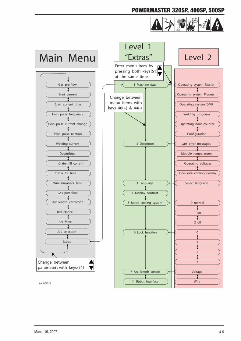
POWERMASTER 320SP, 400SP, 500SP
March 16, 2007 4-5
Twin pulse relation
Welding current
Downslope
Twin pulse current change
Twin pulse frequency
Start current time
Start current
Gas pre- flow
Job selection
Extras
Arc force
Inductance
Gas post- flow
Wire burnback time
Crater fill current
Last error messages
Module temperatures
Operating voltages
Configuration
Operating hour counter
Welding programs
Operating system Process
Operating system Master
0 normal
1 on
Select language
Flow rate cooling system
2 off
2 Diagnoses
1 Machine data
5 Mode cooling system
6 Lock function
4 Display contrast
3 Language
7 Arc length control
11 Robot interface
3
2
1
0
Voltage
Wire
Crater fill time
Arc length correction
Operating system DMR
Main Menu Level 2
Change betweenmenu items with
keys 48(+) & 44(-)
Level 1“Extras”
Enter menu item by pressing both keys (51)at the same time
Change between parameters with keys (51)
Art A-07726

POWERMASTER 320SP, 400SP, 500SP
4-6 March 16, 2007
A. Secondary Parameters (Menu MainLevel)
Art # A-07866
With and (51) push-buttons you can switch tothe secondary parameters. The currently selectedparameter is indicated in the display (50). The GasPre Flow [0.1] value is pre-loaded at the Factory butthe user has increased it to 0.4s using (48) push-button.
Push-button (44) (-) is used to reduce the indicatedparameter and push-button (48) (+) is used toincrease the value of the indicated parameter. Pressingthe push-button (46) (END) saves the parameter andthe system switches back to the material-wire-gascombination display.
B. Extras menu
In addition to the secondary parameters, the Extrasmenu item is also available; it offers the followingfunctions:
Push-buttons (44) (-) and (48) (+) are used to switchbetween the menu items. The different entries of themenu items are called up by pressing the and push-buttons (51) at the same time. Switchingbetween the individual entries is also possible herewith the push-buttons (44) (-) and (48) (+). To return,press push-button (46) (END).
C.
The Tiptronic function provides you with 100independent jobs (10 job set with 10 jobs each). Ajob stores all the settings and corrections on theoperating panel.
The best way to use the Tiptronic function is to assignjob numbers to frequently recurring welding tasks orsave the settings which individual welders usespecifically for “their” jobs.
1. Save/Programming jobs:a. Determine the optimal welding values.
b. Press the “TT Save” button (45) (Save LEDflashes).
c. Select the target job number with the push-buttons (44) (-) and (48) (+) or with the smarttorch rocker, and confirm with the “TT Enter”push-button (47) (if you do not press Enter,the Save LED goes out after 10 seconds afterthe last keystroke and the save operation isaborted).
d. The Save and Enter LEDs flash briefly toconfirm that programming is terminated.
2. Selecting jobs:a. Switch the Tiptronic function on by pressing“Tiptronic” (49) (associated LED comes on).
b. Select the job number with the smart torchrocker (alternatively the job number can beselected with the push-buttons (44) (-) and(48) (+)).
c. To exit the Tiptronic process, press“Tiptronic” (49) (Tiptronic LED goes out). Theparameters are reset to the values that existedbefore you switched on the Tiptronic process.
3. Setting a job inactive:a. Switch the Tiptronic function on by pressing“Tiptronic” (49) (associated LED comes on).
b. Select job number with the smart torchrocker (61) or with the push-buttons (44) (-)and (48) (+) (an active job is indicated in thesmart torch display (60) and in digitalmultifunction display (54) with a decimal pointbetween the job set and the job number).
c. Hold the Enter push-button (47) pressedfor two seconds (the decimal point in the smarttorch display 60 and in the digital display (54)goes out).
4. Setting a job active:a. Switch the Tiptronic function on by pressing“Tiptronic” (49) (associated LED comes on).
b. Select the job number with the push-buttons(44) (-) and (48) (+) (with an inactive job, thedecimal point between job set and job numberis missing).
c. Hold the “TT Enter” push-button (47)pressed for two seconds (the decimal pointbetween the job set and the job number lightsup).

POWERMASTER 320SP, 400SP, 500SP
March 16, 2007 4-7
5. Re-saving/Re-programming jobs:
a. Switch the Tiptronic function on by pressing“Tiptronic” (49) and select a job (see SelectingJobs).
b. Change the settings as required.
c. Press the “TT Save” button (45) (Save LEDflashes).
d. Press “TT Enter” button (47) to confirm.
e. The Save and Enter LEDs flash briefly toconfirm that programming is terminated.
6. Copying jobs:a. Switch the Tiptronic function on by pressing“Tiptronic” (49) and select a job for copying(see Selecting Jobs).
b. Press the “TT Save” button (45) (Save LEDflashes).
c. Select the target job number with the push-buttons (44) (-) and (48) (+) and confirm withthe “TT Enter” pushbutton (47) (if the Enterpushbutton is not actuated, the Save LED goesout 10 seconds after the last pushbuttonactuation and the saving procedure iscancelled). If the target job number has notbeen occupied with a job yet, it is indicated bythe display flashing.
d. The Save and Enter LEDs flash briefly toconfirm that programming is terminated.
The user-defined job texts are also copiedonto the new target job number.
7. Assigning descriptive text to a job:Text can be assigned to each job in order toidentify it more clearly.
a. Switch on the Tiptronic function with the“Tiptronic” pushbutton (49).
b. Select the job number with the push-buttons(44) (-) and (48) (+).
c. Press the and push-buttons (51) atthe same time (a flashing cursor appears inthe display (50)) in order to get into the editmode.
d. The cursor is moved with the and push-buttons (51). At the end of the line, thecursor jumps to the respective next line.
e. Select a character (number, letter or specialcharacter) with push-buttons (44) (-) and (48)(+).
f. The edit mode is ended by pressingpushbutton (46) (END) or by pressing the and push-buttons (51) at the same time.
If you press the “Tiptronic” pushbutton (49)in edit mode (Tiptronic is switched off), thenthe text entries will not be saved.
Texts can be programmed both for the job set(upper line in display (50)) as well as for the job(bottom line in display (50)).

POWERMASTER 320SP, 400SP, 500SP
4-8 March 16, 2007
4.04 Special functions
A. Gas test
Pressing the pushbutton (51) and the “Gas type”pushbutton (48) at the same time activates the gastest function. The solenoid valve of the system isactivated and the gas flow rate can be checked /adjusted. The function remains active for 30 secondsand is then ended automatically. By pushing the “Gastype” pushbutton (48) again, the gas test can beterminated.
B. Pump test (where fitted)
Pressing the pushbutton (51) and the “Material”pushbutton (44) at the same time activates the pumptest function. The coolant pump is switched on andruns for approximately one minute. By pushing the“Material” pushbutton (44), the pump test can beterminated.
C. Resetting Adjustments
Pressing the pushbutton (51) and the “TT Enter”pushbutton (47) at the same time resets all secondaryparameters to the Factory set values. When theTiptronic process is active, the settings of the currentjob are reset. All adjustment in the Extras menu(language, display contrast, etc.) remain unchanged.
D. Code lock function
The lock function in menu Extras is secured with acode lock. A three-digit code must be entered beforethe lock function can be changed. Only after thecorrect code is entered, the lock function can bealtered. After leaving the menu, a new code numbercan be set or the old code number is acknowledged.Code “000” is the default (factory setting) number.
Procedure:
1. Switch to menu Extras, lock function
2. Press button (44) (-) or (48) (+) question“change parameter ?” is displayed
3. Acknowledge with button (51)
4. Set three-digit code number with button (44)(-),(48) (+) or encoder (53)
5. Acknowledge the code number with button (51)
6. Set desired lock function number with buttons(44) (-) or (48) (+)
7. Leave menu with button (46) (END)
8. If requested, set a new code number withbuttons (44) (-) ,(48) (+) or encoder (53)
9. Acknowledge the code number with button (51)

POWERMASTER 320SP, 400SP, 500SP
March 16, 2007 4-9
4.05 Smart GMAW, Pulse GMAW & TwinPulse Programs
ShieldGas
Wiresize
Program Number
Smart GMAW Current Range
Pulse GMAW Current Range
TwinPulse Current Range
Type Name Ar / CO2 / O2 / He in. min - max min - max min - maxM/ Steel 75 / 25 / 0 / 0 .030 1 40-288 N/A N/AM/ Steel 75 / 25 / 0 / 0 .035 2 52-332 N/A N/AM/ Steel 75 / 25 / 0 / 0 .045 3 64-436 N/A N/AM/ Steel 75 / 25 / 0 / 0 .052 4 72-468 N/A N/AM/ Steel 92 / 8 / 0 / 0 .030 5 48-292 24-292 24-292M/ Steel 92 / 8 / 0 / 0 .035 6 52-360 28-360 28-360M/ Steel 92 / 8 / 0 / 0 .045 7 68-440 32-448 32-448M/ Steel 92 / 8 / 0 / 0 .052 8 72-468 48-476 48-476M/ Steel 92 / 8 / 0 / 0 1/16 9 100-500 N/A N/AFC Metal 75 / 25 / 0 / 0 .045 13 76-388 N/A N/AFC Metal 75 / 25 / 0 / 0 .052 14 84-440 N/A N/AFC Metal 75 / 25 / 0 / 0 1/16 15 96-488 N/A N/A
FC E71- T1 75 / 25 / 0 / 0 .045 16 96-340 60-360 60-360FC E71- T1 75 / 25 / 0 / 0 1/16 17 144-480 120-460 120-460
S/S 308/309 81 / 1 / 0 / 18 .030 18 48-280 24-284 24-284S/S 308/309 81 / 1 / 0 / 18 .035 19 52-320 28-320 28-320S/S 308/309 81 / 1 / 0 / 18 .045 20 60-444 32-440 32-440S/S 308/309 98 / 2 / 0 / 0 .030 21 48-280 24-280 24-280S/S 308/309 98 / 2 / 0 / 0 .035 22 52-320 28-320 28-320S/S 308/309 98 / 2 / 0 / 0 .045 23 60-432 32-428 32-428
S/S 316 81 / 1 / 0 / 18 .030 30 48-280 24-280 24-280S/S 316 81 / 1 / 0 / 18 .035 31 52-320 28-320 28-320S/S 316 81 / 1 / 0 / 18 .045 32 60-436 32-432 32-432S/S 316 98 / 2 / 0 / 0 .030 33 48-280 24-280 24-280S/S 316 98 / 2 / 0 / 0 .035 34 52-320 28-320 28-320S/S 316 98 / 2 / 0 / 0 .045 35 60-428 32-420 32-420Al 4043 100 / 0 / 0 / 0 .035 36 48-268 20-260 20-260Al 4043 100 / 0 / 0 / 0 3/64 38 64-348 24-348 24-348Al 4043 100 / 0 / 0 / 0 1/16 39 80-388 32-388 32-388Al 4043 75 / 0 / 0 / 25 3/64 40 68-352 24-352 24-352Al 4043 75 / 0 / 0 / 25 1/16 41 80-388 32-380 32-380Al 5356 100 / 0 / 0 / 0 .035 42 64-228 24-232 24-232Al 5356 100 / 0 / 0 / 0 3/64 44 88-340 28-328 28-328Al 5356 100 / 0 / 0 / 0 1/16 45 100-388 36-380 36-380Al 5356 75 / 0 / 0 / 25 3/64 46 88-340 28-328 28-328Al 5356 75 / 0 / 0 / 25 1/16 47 92-388 36-384 36-384Al 5183 100 / 0 / 0 / 0 .035 48 64-228 24-228 24-228Al 5183 100 / 0 / 0 / 0 3/64 50 88-332 28-320 28-320Al 5183 100 / 0 / 0 / 0 1/16 51 96-380 32-372 32-372Al 5183 75 / 0 / 0 / 25 3/64 52 88-340 28-328 28-328Al 5183 75 / 0 / 0 / 25 1/16 53 92-380 32-372 32-372
Si Bronze 100 / 0 / 0 / 0 .035 56 48-280 24-288 24-288Si Bronze 100 / 0 / 0 / 0 .045 57 64-348 28-352 28-352
Silicone Bronze
Stainless SteelER316
AluminumER4043
AluminumER5356
AluminumER5183
Stainless SteelER308/ER309
Material
Mild Steel ER70S-x
Flux CoredER70C-xx
Flux CoredER71-T1

POWERMASTER 320SP, 400SP, 500SP
4-10 March 16, 2007
4.06 Welding Setting Selection Guide
Fraction
(Inches)Thickness
DecimalThickness
(Thous)
DecimalThickness
(mm)Steel
Gauge
1/32
1/16
5/643/32
9/645/32
11/643/16
9/3219/645/16
21/6411/32
7/1629/6415/3231/64
1/2
19/3239/64
5/841/6421/32
0.610.760.790.910.97
1.591.911.982.38
3.573.974.114.374.76
7.147.547.948.338.73
11.1111.5111.9112.3012.70
15.0815.4815.8816.2716.67
024030031036038
3/641.021.191.211.52
040047048060063075078094
7/641/8
2.662.783.183.42
105109125135141156162172188
13/647/32
15/641/4
17/64
5.165.565.956.356.75
203219234250266281297313328344
23/643/8
25/6413/3227/64
9.139.539.92
10.3210.72
359375391406422438453469484500
33/6417/3235/649/16
37/64
13.1013.5013.8914.2914.68
516532547563578594609625641656
43/6411/1645/6423/3247/64
17.0717.4617.8618.2618.65
672688703719734
3/449/6425/3251/6413/16
19.0519.4519.8420.2420.64
750766781797813
7/8
53/6427/3255/64
57/64
21.0321.4321.8322.2322.62
828844859875891
29/3259/6415/1661/6431/32
23.0223.4223.8124.2124.61
906922938953969
63/64 25.00984
2422
20
1816
14
12
10
8
Base Material Thickness Guide
Refer to Warranty Schedule*
A B C D
E
GH
F
Art # A-07907
320SP 400SP 500SP
Wire SizeShieldMaterialName Gas
Wire Gas Combinations
SiliconBronze
.035” (0.9mm)
.045” (1.1mm)
.035” (0.9mm)
.045” (1.1mm)
.047” (1.2mm)
.062” (1.6mm)Aluminum
5183
75Ar/25CO2
75Ar/25CO2
Argon
Argon
Argon
Argon
81Ar/18He/1CO2
81Ar/18He/1CO2
90Ar/10CO2
92Ar/8CO2
or
75Ar/25CO2
98Ar/2CO2
98Ar/2CO2
75Ar/25He
75Ar/25He
75Ar/25He
.045” (1.1mm)
.047” (1.2mm)
.062” (1.6mm)
Aluminum5356
.035” (0.9mm)
.045” (1.1mm)
.047” (1.2mm)
.062” (1.6mm)
.047” (1.2mm)
.062” (1.6mm)
Aluminum4043
.035” (0.9mm)
.045” (1.1mm)
.047” (1.2mm)
.062” (1.6mm)
.047” (1.2mm)
.062” (1.6mm)
Flux CoredE71-T1
Flux CoredE70C-6M
.045” (1.1mm)
.062” (1.6mm)
StainlessSteel316
.030” (0.8mm)
.035” (0.9mm)
.045” (1.1mm)
.030” (0.8mm)
.035” (0.9mm)
.045” (1.1mm)
StainlessSteel
308-309
.030” (0.8mm)
.035” (0.9mm)
.045” (1.1mm)
.030” (0.8mm)
.035” (0.9mm)
.045” (1.1mm)
.045” (1.1mm)
.052” (1.4mm)
.062” (1.6mm)
.030” (0.8mm)
.035” (0.9mm)
.045” (1.1mm)
.052” (1.4mm)
.030” (0.8mm)
.035” (0.9mm)
.045” (1.1mm)
.052” (1.4mm)
.062” (1.6mm)
Mild SteelER70-S6
SynergicSmart
MIG
Pulse &TwinPulse
SynergicSmart
MIG
Pulse&TwinPulse
SynergicSmart
MIG
Pulse&TwinPulse

POWERMASTER 320SP, 400SP, 500SP
March 16, 2007 4-11
Three Steps To GMAW (MIG) Welding
Now you are ready to weld
A B C D
E
GH
F
1.Set Variables
B) Select Wire Type
C) Select Wire Size
D) Select Shielding Gas
A) Select Process : MANUAL GMAWSMART GMAWPULSE GMAWTWIN PULSE
2.Set FunctionE) Set Trigger to 2T or 4T. 4T= Latch
F) Set Crater fill on or off.
3.Set Thickness
H) Set material thickness Refer to Base Material Thickness Guide
G) Set LED to .000”
Art # A-07907

POWERMASTER 320SP, 400SP, 500SP
4-12 March 16, 2007

POWERMASTER 320SP, 400SP, 500SP
March 16, 2007 5-1
SECTION 5:MANUAL GMAW WELDING
5.01 Types of Weld Transfer Modes
A. Dip transfer mode (short circuit arc)
This type of arc is especially suitable for thin materialsand positional welding due to a relative cool weldingpool welded with very short arc, low arc voltage andlow current. The surface tension of the welding pollhelps to draw the drop into the bath and to reignitethe arc. This cycle is repeated again and again so theshort circuit and the arcing period are constantlyalternating.
NOTE
The transition from the short circuit tospray arc depends on the wire diameterand the gas mixture.
B. Transitional arc
The transitional arc is especially suitable for mediumthickness sheet metals and for vertical-down welding.The transfer of the electrode to the workpiece takesplace partly in short circuit and in free flight. Due tofewer short circuits, the welding pool is hotter thanat the short circuit arc. Welding with transitional arcprovides higher electrode melt rate and is moreeconomic than welding at short circuit arc.
C. Long arc
Long arcs are typically at a higher ampere range undercarbon dioxide and gases with a high CO2 content. Itis not particularly suitable for positional welding. Inthis type of arc large drops are formed which fallsinto the welding pool mainly by force of gravity. Thisresults in occasionally short circuits occurring, whichincreases the current at the moment of the shortcircuit and high spatter levels when the arc is reignited.
D. Spray arc
The spray arc is not suitable for positional welding,due to the extremely liquid nature of the welding pool.The spraying arc forms by welding at the higher rangeof ampere using inert gas or mixtures with high argoncontent. The most typical characteristic of the sprayarc is the transfer of extremely fine molten metaldroplets across the arc.
E. Working range at GMAW welding
Wire diameter inches A V A V A V
.030140… 180
23… 28
110… 150
18… 22
50… 130
14… 18
.035180… 250
24… 30
130… 200
18… 24
70… 160
16… 19
.045 or 3/64 220… 320
25… 32
170… 250
19… 26
120… 200
17… 20
1/16260… 320
26… 34
200… 300
22… 28
150… 200
18… 21
Long arc / Spray arc
Transitional arc
Short circuit arc
Favorable welding characteristics are only possible if voltage and current are correctly adjusted. CO2requires an arc voltage approximately 3 V higher than gas mixtures with a high argon content.
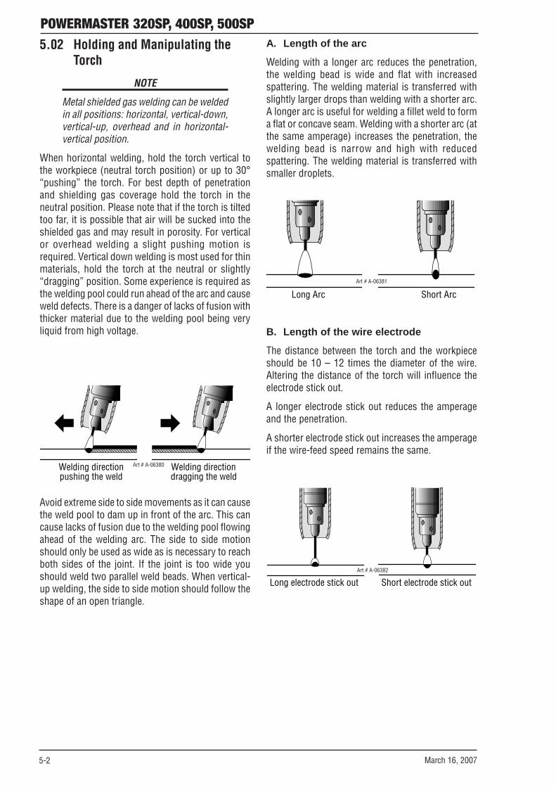
POWERMASTER 320SP, 400SP, 500SP
5-2 March 16, 2007
Art # A-06381 Long Arc Short Arc
B. Length of the wire electrode
The distance between the torch and the workpieceshould be 10 – 12 times the diameter of the wire.Altering the distance of the torch will influence theelectrode stick out.
A longer electrode stick out reduces the amperageand the penetration.
A shorter electrode stick out increases the amperageif the wire-feed speed remains the same.
Art # A-06382
Long electrode stick out Short electrode stick out
5.02 Holding and Manipulating theTorch
NOTE
Metal shielded gas welding can be weldedin all positions: horizontal, vertical-down,vertical-up, overhead and in horizontal-vertical position.
When horizontal welding, hold the torch vertical tothe workpiece (neutral torch position) or up to 30°“pushing” the torch. For best depth of penetrationand shielding gas coverage hold the torch in theneutral position. Please note that if the torch is tiltedtoo far, it is possible that air will be sucked into theshielded gas and may result in porosity. For verticalor overhead welding a slight pushing motion isrequired. Vertical down welding is most used for thinmaterials, hold the torch at the neutral or slightly“dragging” position. Some experience is required asthe welding pool could run ahead of the arc and causeweld defects. There is a danger of lacks of fusion withthicker material due to the welding pool being veryliquid from high voltage.
Art # A-06380Welding direction pushing the weld
Welding direction dragging the weld
Avoid extreme side to side movements as it can causethe weld pool to dam up in front of the arc. This cancause lacks of fusion due to the welding pool flowingahead of the welding arc. The side to side motionshould only be used as wide as is necessary to reachboth sides of the joint. If the joint is too wide youshould weld two parallel weld beads. When vertical-up welding, the side to side motion should follow theshape of an open triangle.
A. Length of the arc
Welding with a longer arc reduces the penetration,the welding bead is wide and flat with increasedspattering. The welding material is transferred withslightly larger drops than welding with a shorter arc.A longer arc is useful for welding a fillet weld to forma flat or concave seam. Welding with a shorter arc (atthe same amperage) increases the penetration, thewelding bead is narrow and high with reducedspattering. The welding material is transferred withsmaller droplets.

POWERMASTER 320SP, 400SP, 500SP
March 16, 2007 5-3
C. Material Transfer
Art # A-06384
Benefits:
• Controlled, short-circuit-proof material transfer without spatter
• Low thermal transfer due to low primary current
Disadvantages:
• Only shielding gases with low CO2 content can be used
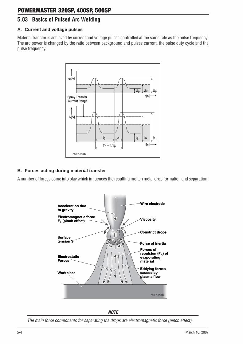
POWERMASTER 320SP, 400SP, 500SP
5-4 March 16, 2007
5.03 Basics of Pulsed Arc Welding
A. Current and voltage pulses
Material transfer is achieved by current and voltage pulses controlled at the same rate as the pulse frequency.The arc power is changed by the ratio between background and pulses current, the pulse duty cycle and thepulse frequency.
Art # A-06383
Spray Transfer Current Range
B. Forces acting during material transfer
A number of forces come into play which influences the resulting molten metal drop formation and separation.
ElectrostaticForces
Workpiece
Surfacetension S
Acceleration due
Electromagnetic forceFL (pinch effect)
Eddying forcescaused by
Forces ofrepulsion (FR) ofevaporating
Force of inertia
Constrict drops
Viscosity
Wire electrode
to gravity
material
plasma flow
ElectrostaticForces
Workpiece
Surfacetension S
Acceleration due
Electromagnetic forceFL (pinch effect)
Eddying forcescaused by
Forces ofrepulsion (FR) ofevaporating
Force of inertia
Constrict drops
Viscosity
Wire electrode
to gravity
material
plasma flow
Art # A-06385
NOTE
The main force components for separating the drops are electromagnetic force (pinch effect).

POWERMASTER 320SP, 400SP, 500SP
March 16, 2007 5-5
5.04 Pulsed Arc Welding Parameters
A. Pulse period tP
The pulse period for separating the droplet is between1.5 and 3.0 ms depending on wire diameter and thepulse current setting IP.
If the pulse period is too long, material transfer onlytakes place during the pulse phase.
Arc formation and drop rate can be affected byadditional pulse stages.
B. Pulse voltage UP and pulse current IP
Since welding with pulsed arc is based on thetemporary utilization of the pinch effect, the drop-separating pulse current must always be large enoughto exceed critical current intensity depending on wirediameter, wire material and shielding gas composition,etc. If this value is not achieved, material transfer takesplace completely or partially in the short circuit withpossible spatter.
C. Wire feed speed vD and pulse frequencyfP
The main condition for a controlled material transferwith one drop per pulse is to set a defined dropvolume. The volume of the melted drop must then beidentical with the volume of the wire electrode fed ineach pulse period. The necessary wire feed speed vDresults from the product of pulse frequency fP andthe wire length “L” melted in each pulse period. Fromthis relationship you see that a change in wire feedspeed requires a linear change in pulse frequency. Arise in electrode melt rate by increasing wire feedspeed needs a higher pulse frequency. The objectivedrop diameter should be about .045" (1.2mm) with awire diameter of .045" (1.2mm).
D. Primary current
Arc length ionization must be maintained during theprimary current phase, whose period results from theselected frequency and pulse period. This requirescurrents ranging between 25 and 80 A depending onwire diameter, material and material thickness. Theprimary current can also be used to affect the arc andmaterial transfer. At a constant ratio of wire feed speedand pulse frequency, the arc length can be changedby varying the primary current and the associatedvoltage. Reducing the primary current causes ashorter arc. This can be used to counteract arcdeflection with fillet welds or at high welding rates.
The time of drop separation can be affected by varyingthe ratio of primary current to pulse current. Normallythe objective is to separate the drop just after thecurrent pulse in the primary current phase (in the thirdpulse current phase). This can be achieved by
increasing the primary current and reducing the pulsecurrent at the same time. Remember that excessivelyhigh primary current will melt the free wire end tooquickly. This will form very large drops which canlead to spatter during the transition to the weldingpool.
E. Pulse MIG applications
The main application for pulse MIG is for precisionMIG welding of aluminum, stainless steel, steel andother weldable materials.
• Spray transfer welding permitted at lower-than-normal average weld currents.
• No spatter or undercut in the majority of weldingapplications.
• Precise control of welding power, to assure beadshape and root penetration rivaling TIG welding.
• High energy arc produced, that virtuallyeliminates the risk of lack of fusion.
• Improved arc control for out-of-position weldingand more effective welding of thin materials,with all the advantages of spray transfer.
• Optimized pulse programs for gas/wirecombinations
• TwinPulse® capabilities.
• Exceptional out-of-position welding fornonferrous materials, including aluminum.
• Effortless TIG-like weld appearance onaluminum and stainless steel
• Deeper weld penetration
• Accurate penetration on sheet metal
• Superior welding characteristics on hard-facingand high alloy steels
• The ability to use larger-than-normal diameterwires on thin base material, providing a costsaving on wire
• Spray arc welding vertical up, giving smootherwelds, better control and deeper penetration
• Improved edge wetting in PulseGMAW processAt the lower end of the performance range the pulsedarc cannot fully replace the dip transfer. The reasonis the continuous arc that occurs in the primarycurrent phase. This phenomenon does not exist withthe short-circuiting arc. An exception to this is whenwelding aluminum and aluminum alloys. Normally,these materials can only be reliably welded using apulsed arc. In the upper performance range, thepulsed arc is preferable to the sprayer arc, in particularfor welding aluminum materials and high-alloy steels.

POWERMASTER 320SP, 400SP, 500SP
5-6 March 16, 2007
5.05 Smart, Pulse or TwinPulseGMAW Welding
The following instructions explain how to set up forSmartGMAW or PulseGMAW or TwinPulse welding.
TTSave
TT Sauver
EnterEntrer
Tiptronic
(END)(FIN)
(+ )
TTEnter
TT Entrer
Process
Processes
Pulse GMAW <P35> Ar/CO2S/S 316 .035 98/2
250
A
B
C
Art # A-07867
A Set Process Process
Processes SmartGMAW = One knob control non-pulsewelding
PulseGMAW = One knob control pulsewelding
TwinPulse = One knob control twin pulsewelding
Wire type Eg. Stainless Steel 316
Wire size Eg. .035 in diameter
Shielding gas Eg. 98% Argon / 2% CO2
ThicknessPress button to select material thickness
B Set Torch trigger operation
2T = Normal Operation
4T = Trigger Latch
C Set Base material thickness 250 Use left hand knob to dial
up base material thickness
Eg. 250 = 0.250” (1/4”)
Art # A-07871
5.06 Conventional Manual GMAW/FCAW Welding
The following instructions explain how to set up forconventional manual GMAW welding.
TTSave
TT Sauver
EnterEntrer
Tiptronic
(END)(FIN)
(+ )
TTEnter
TT Entrer
Process
Processes
Manual GMAW
197
A
B
D C
Art A-07868
A Set Process Process
Processes
To Manual GMAW
B Set Torch trigger operation
2T = Normal Operation OR
4T = Trigger Latch C Adjust Wirefeed
speed knob to the desired IPM
197
D Adjust Arc voltage knob to the desire arc voltage
17.0
C
Art # A-07870
\

POWERMASTER 320SP, 400SP, 500SP
March 16, 2007 5-7
5.07 SMAW/STICK Welding
The following instructions explain how to set up forSMAW/STICK welding.
TTSave
TT Sauver
EnterEntrer
Tiptronic
(END)(FIN)
(+ )
TTEnter
TT Entrer
Process
Processus
SMAW/STICK
120
A
B
C
Art # A-07869
A Set Process Process
Processes To SMAW/STICK
B Press Button To activate SMAW mode
C Set Weld current 120 To the suggested weld current. Refer to electrode manufacturer
Art # A-07872

POWERMASTER 320SP, 400SP, 500SP
5-8 March 16, 2007
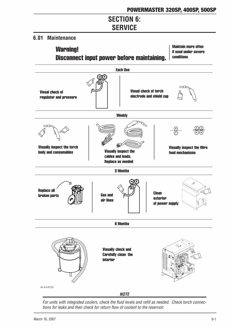
POWERMASTER 320SP, 400SP, 500SP
March 16, 2007 6-1
Warning! Disconnect input power before maintaining.
Each Use
Visual check of regulator and pressure
Visual check of torchelectrode and shield cup
Weekly
Visually inspect the torch body and consumables Visually inspect the
cables and leads.Replace as needed
3 Months
Cleanexteriorof power supply
6 Months
Replace all broken parts
Visually check and Carefully clean the interior
Maintain more oftenif used under severeconditions
Gas andair lines
Art # A-07725
Visually inspect the Wirefeed mechanisms
WARNING
POWER
10A
REMOTE
LOCAL
CONTACTOR
SECTION 6:SERVICE
6.01 Maintenance
NOTE
For units with integrated coolers, check the fluid levels and refill as needed. Check torch connec-tions for leaks and then check for return flow of coolant to the reservoir.

POWERMASTER 320SP, 400SP, 500SP
6-2 March 16, 2007
6.02 System Troubleshooting Guide
Symptom Cause RemedyInsufficient coolant through flow due to pollution in coolant
Flush the coolant hoses of the torch in opposite direction
Contact tip is not tight or the wrong size for the wire used
Check it
Nut of the torch hose is not tight Tighten itNo connection of the control cable in the torch hose Check and change if necessaryOverload of the unit and thermal protection operates Allow unit to cool down at no loadWire electrode is tight at the spool Check and change if necessary
Burr at the wire beginning Cut burr from end of wire
Wrong contact pressure at the wire-feed rolls Adjust it as described in the manualTorch defective Check and change if necessaryNo intermediate guide or is dirty Install or clean the intermediate guideBad quality of welding wire Check and change if necessaryRust formation on the welding wire Check and change if necessaryTorch liner is dirty inside Disconnect the torch from the machine, unscrew
the contact tip and clean the liner with compressed air
Torch liner is defective Check and change if necessaryMotor brake adjusted too strong Adjust as described in the manualDuty cycle overloaded Allow the machine to cool downPoor cooing of internal unit parts Check the air in and outlet
Cooler, hoses or pump are damaged
Frozen systems due to low concentration of recommended coolant in re-circulator
Contact the nearest service facility
Arc or short circuit between contact tip and gas nozzle
Spatter built up inside the gas nozzle Remove it with special pliers
Unstable arc Wrong diameter contact tip or worn out Change contact tipThe Control Panel is completely blank
Primary power phase missing Check the unit at another power outlet. Check power cable and mains fuses/circuit breakers
Gas cylinder empty Replace itDefective torch Check and replace itGas regulator dirty or defective Check and replace itValve of gas cylinder defective Replace the gas cylinder
Shielded gas switches not off
Valve of gas cylinder dirty or does not close Remove torch and gas regulator and clean it with compressed air
Incorrect setting of shielded gas Adjust as described in the manualDirty gas regulator Check valveTorch, gas hose blocked or not air-tight Check and change if necessaryShielded gas is blown away from draft Avoid draftOne of the three phase input power is missing Check the unit at another power outlet. Check
power cable and mains fuses/circuit breakersPoor Work lead connection Ensure good electrical contact between Work
clamp and workpieceWork lead not plugged in right Fasten work lead by turning the plug to the rightDefect torch Repair or replace it
Hot plug of work lead Plug was not tightened by turning to the right CheckWire rolls do not fit the wire diameter Install correct wire rollsWrong contact pressure at wire feeder Adjust as described in the manual
Torch too hot
No function when torch button is pressed
Irregular wire feeding or wire welds to the contact tipIrregular wire feeding or no wire feeding
Higher wire wear out at wire-feeding unit
Unit switches off
No shielded gas
Not enough shielded gas
Decreased welding performance

POWERMASTER 320SP, 400SP, 500SP
March 16, 2007 6-3
6.03 Welding Process Troubleshooting Guide
Symptom Cause RemedyGas mixture in the cylinder has separated due to lack of use
Place protective cap used for storage and transport on cylinder then carefully disconnect the cylinder from the welder and lay it down on the floor. Carefully roll it back and forth to re-mix the gas
Wire is contaminated with oil or the wire quality is uncertain
Contact wire manufacturer / supplier. Keep the wire covered
Work piece is contaminated with grease or oil Degrease with mineral spirits, etc to remove contaminates
Poor current transfer to the wire at the contact tip Use a copper or brass jump liner in the conductor tube to improve current transfer to the wire
Stainless steel weld has a dark burnt finish
Arc length control (58) has been adjusted too high Reduce arc length, control (58)
Inadequate gas coverage Increase gas flow by 10% and check again. Shield arc from drafts. Hold nozzle closer to the work. Replace the damaged nozzle to center contact tip in nozzle
Wire is contaminated with oil Contact wire manufacturer / supplier. Keep the wire covered
Work piece is contaminated with grease or oil Degrease with mineral spirits, etc to remove contaminates
Poor current transfer to the wire at the contact tip Use a copper or brass jump liner in the conductor tube to improve current transfer to the wire
Weld performance is very poor or high spatter levels
Incorrect wire / gas combination selected Set the correct gas / wire combination
Improper work lead connection Reconnect work lead
Contact tip is worn with an oval shape hole or contact tip is black
Replace contact tip
Contact tip is loose Tighten contact tipMaterial build-up in torch liner Replace torch liner
Contact tip is worn or damaged Replace contact tip
Varying arc length when welding
Poor edge wetting on stainless steel welds
Dirty aluminum welds
Poor weld starts

POWERMASTER 320SP, 400SP, 500SP
6-4 March 16, 2007
6.04 Error Codes
In case of a malfunction, an error code is indicated on the digital multifunction display (54) and the corre-sponding error description appears on the LCD display (50). As long as an error code is indicated, weldingoperation is not possible.
*1 Check module temperatures in menu Extras, Diagnosis > Module temperatures *2 Check supply voltages in menu Extras, Diagnosis > Operating voltages *3 Check the flow rate in menu Extras, Diagnosis > Flow rate cooling system
Code Description Cause Remedy E01 Thermal overload Thermal sensor of power unit measures a too
high temperature (>176°F) Let machine cool down in standby (*1) Check temperature sensor (short circuit)
E02 Mains overvoltage Mains voltage too high (24V supply > 36V) Check mains voltage and control transformer (*2)
E03 Secondary over-current Welding current is too high Notify an accredited Thermal Arc Service Provider for repair
E04 Air cooling error Temperature sensor of the power unit detects that the unit heats up too fast
Check fans and their wiring
E05 Cooling system error Flowrate of the cooling liquid is too low (< 0,3 l/min) Pump is not working
Check connectors of flow-meter, level of cooling liquid and flowrate (*3) Check fuse SI7 (2,5A) on pc-board MV-MAPRO
E06 Secondary overvoltage Master detects output voltage is too high (>100V)
Notify an accredited Thermal Arc Service Provider for repair
E07 EEProm checksum error No welding program stored or error during reading from memory
Transfer welding programs to machine again, exchange MV-MAPRO if error still persists
E08 Wire feed / tacho Power consumption of wire feed motor too high No tacho signal No CAN-Bus connection between MAPRO and DMR
Blow out torch package with compressed air Check wire feed unit Check wiring of wire feed motor and PC-board DMR
E09 Error V/A measuring Measuring difference between Master and Process
Check wiring of pc-board LSW, pc-board DP-EMV and PC-board DP-UFI-BO
E11 Remote-control connection Short circuit between remote control cables Check remote control and wiring of remote control socket
E12 Communication Process Process is not responding to Master Switch the machine off and on again Optionally exchange PC-board DP-MAPRO
E13 Temp. sensor error Temp. sensor is defective Notify an accredited Thermal Arc Service Provider for repair
E14 Op. voltages error Supply voltage is too low (< 17V) Check mains voltage and control transformer (*2)
E16 Overcurrent protection1 Power consumption of power unti 1 is too high
Notify an accredited Thermal Arc Service Provider for repair
E17 Op. voltage 18V error 18 V from control transformer missing Check mains supply and control transformer
E18 overload protection Safety shutdown to protect electrical components Temp. sensor is disconnected
Let machine cool down in standby Check temp. sensor
E19 Power module error Chargeup time for capacitors >1 second Check mains input Check MVPWRUP board and it’s wiring
E20 Overvoltage sec. Process reports a too high output voltage or no voltage
Notify an accredited Thermal Arc Service Provider for repair
E21 Output voltage/current External current/voltage or measure-difference between Master and Process
Notify an accredited Thermal Arc Service Provider for repair
E22 Mains undervoltage 1 Power unit 1 reports mains voltage too low Check mains voltage and mains rectifier E23 Mains overvoltage Power unit reports mains voltage too high Check mains voltage E24 Overcurrent protection2 Power consumption of power unti 2 is too
high Notify an accredited Thermal Arc Service Provider for repair
E25 Power module detection DIP-switch on pc-board MVDRV have been set wrong
Notify an accredited Thermal Arc Service Provider for repair
E26 Error voltage symmetry DC-link voltage difference (>50V) between power units
Notify an accredited Thermal Arc Service Provider for repair
E27 No program (DSP) Wrong material-wire-gas combination Welding programs faulty or not available
Select other material-wire-gas combination Transfer welding programs to machine again
E30 Op. voltage 15V error Supply voltage is too low Check mains voltages E31 Communication error Master is not responding to Process Switch the machine off and on again ? A “?“ is shown in the display The display board doesn’t get any data from
the MV-MAPRO Check the flat ribbon cable of the DS20BF Check interpass hose (only machines with separate wire feeder) and it’s connectors Check PC-boards DMR and MV-MAPRO

POWERMASTER 320SP, 400SP, 500SP
March 16, 2007 A-1
APPENDIX 1: OPTIONAL ACCESSORIES AND CONSUMABLES
Wirefeeders Part No. Feature
SP4000W W3000202 Water cooled connections, 4 Roll, suits 400SP/500SP
SP4000R W3000302 Water cooled connections, 4 Roll suits 400SP/500SP Automation
MIG Guns Part No. Feature
PulseMaster 12ft Smart Gun PMA512S-3545 Built in Remote Controls. Heavy Duty 500 Amp Rated. Suits 320SP/400SP/500SP
PulseMaster 15ft Smart Gun PMA515S-3545 Built in Remote Controls. Heavy Duty 500 Amp Rated. Suits 320SP/400SP/500SP
PulseMaster 12ft Gun PMA512-3545 Heavy Duty 500 Amp Rated. Suits 320SP/400SP/500SP
PulseMaster 15ft Gun PMA515-3545 Heavy Duty 500 Amp Rated. Suits 320SP/400SP/500SP Python Gun 15ft W4011301 Python Gun 15ft, PM320SP Python Gun 25ft W4011302 Python Gun 25ft, PM320SP Python Gun 15ft W4011305 Python Gun 15ft, PM400/500SP Python Gun 25ft W4011306 Python Gun 25ft, PM400/500SP
Options
Interconnect Cable Assy, 3ft Long W4000603 3/0 Welding Cable, Water Cooled Hoses & Gas Hose. Suits 400SP/500SP
Interconnect Cable Assy, 16ft Long
W4000604 3/0 Welding Cable, Water Cooled Hoses & Gas Hose. Suits 400SP/500SP
Interconnect Cable Assy, 32ft Long
W4000605 3/0 Welding Cable, Water Cooled Hoses & Gas Hose. Suits 400SP/500SP
Remote Hand Control RC20 W4000000 Small Hand Pocket Pendant, Suits 320SP,
Remote Hand Pendant HR 911 W4000101 Full Control Panel Pendant. Suits 320SP and 400SP/500SP via SP4000W
Cart W4000001 Rugged Construction, Accepts Full Size Cylinder. Suits 320SP
Swivel Unit K14 W4001000 Suits 400SP/500SP with SP4000W Wirefeeder
MIG/TIG Coolant 1 Quart (1L) W4001402 all PM series SP welders
MIG/TIG Coolant 5 Quart (5L) W4001400 all PM SP series welders
MIG/TIG Coolant 5 Gal (20L) W4001401 all PM SP series welders Mobile Cart w/Cylinder Rack W4000300 Mobile Cart w/Cylinder Rack, PM320SP Push/Pull Interface Kit W4010300 Push/Pull Interface Kit, all PM SP series welders Job Tool Software W4010400 Job Tool Software, all PM SP series welders Work Lead 12ft 90940 Work Lead 12ft, PM320SP Work Lead 12ft 90941 Work Lead 12ft, PM400/500SP Pivot Mount W4001000 Pivot Mount, PM400/500SP

POWERMASTER 320SP, 400SP, 500SP
March 16, 2007A-2
APPENDIX 2: FEED ROLL INFORMATION
Part No. DescriptionW6000500 DRIVE RL KIT,2RL,023-030,DS VW6000501 DRIVE RL KIT,2RL,035-035,DS VW6000502 DRIVE RL KIT,2RL,035-045,DS VW6000503 DRIVE RL KIT,2RL,045-045,DS VW6000504 DRIVE RL KIT,2RL,052-1/16,DS VW6000505 DRIVE RL KIT,2RL,035-035,DK VW6000506 DRIVE RL KIT,2RL,035-045,DK VW6000507 DRIVE RL KIT,2RL,045-1/16,DK VW6000508 DRIVE RL KIT,2RL,030-035,DUW6000509 DRIVE RL KIT,2RL,035-045,DUW6000510 DRIVE RL KIT,2RL,045-1/16,DUW6000511 Guide,Inlet,023-1/16,SPW6000512 Guide,Intermideate,023-1/16,SPW6000513 Guide,Outlet,023-035,SPW6000514 Guide,Outlet,035-045,SPW6000515 Guide,Outlet,045-1/16,SP
ORDERING INFORMATION
DRIVE ROLL KITS – 4 ROLLS Description Style 1 Style 2 Style 3
Provides less wire friction in the MIG torch due to the straightening effect of the feed rolls system,
Top Drive Roll Flat Flat Flat
Bottom Drive Roll Double “U” Double Smooth VEE Double Knurled VEE
Wire Type Aluminum (Soft) Wire Solid (Hard) Wire Flux Cored Wire Wire Size .023”, .030” / 0.6, 0.8mm – W6000500 – .035” / 0.9mm – W6000501 – .035”, .045” / 0.9, 1.2mm – W6000502 – .045” / 1.2mm – W6000503 – .052”, 1/16” / 1.4, 1.6mm – W6000504 – .030”, .035” / 0.8, 0.9mm – – W6000505 .035”, .045” / 0.9, 1.2mm – – W6000506 .045” – .052”, 1/16” / 1.2 – 1.4, 1.6mm – – W6000507 .030”, .035” / 0.8, 0.9mm W6000508 – – .035”, 3/64” / 0.9, 1.2mm W6000509 – – 3/64”, 1/16” / 1.2, 1.6mm W6000510 – –

POWERMASTER 320SP, 400SP, 500SP
March 16, 2007 A-3
APPENDIX 3: MOUNTING THE TORCH HOLDER
Art # A-07728

LIMITED WARRANTY
This information applies to Thermal Arc products that were purchased in the USA and Canada.
April 2006
LIMITED WARRANTY: Thermal Arc®, Inc., A Thermadyne Company ("Thermal Arc"), warrants to customers of authorized distributors ("Purchaser") that its products will be free of defects in workmanship or material. Should any failure to conform to this warranty appear within the warranty period stated below, Thermal Arc shall, upon notification thereof and substantiation that the product has been stored, installed, operated, and maintained in accordance with Thermal Arc's specifications, instructions, recommendations and recognized standard industry practice, and not subject to misuse, repair, neglect, alteration, or damage, correct such defects by suitable repair or replacement, at Thermal Arc's sole option, of any components or parts of the product determined by Thermal Arc to be defective.
This warranty is exclusive and in lieu of any warranty of merchantability, fitness for any particular purpose, or other warranty of quality, whether express, implied, or statutory. Limitation of liability: Thermal Arc shall not under any circumstances be liable for special, indirect, incidental, or consequential damages, including but not limited to lost profits and business interruption. The remedies of the purchaser set forth herein are exclusive, and the liability of Thermal Arc with respect to any contract, or anything done in connection therewith such as the performance or breach thereof, or from the manufacture, sale, delivery, resale, or use of any goods covered by or furnished by Thermal Arc, whether arising out of contract, tort, including negligence or strict liability, or under any warranty, or otherwise, shall not exceed the price of the goods upon which such liability is based.
No employee, agent, or representative of Thermal Arc is authorized to change this warranty in any way or grant any other warranty, and Thermal Arc shall not be bound by any such attempt. Correction of non-conformities, in the manner and time provided herein, constitutes fulfillment of thermal’s obligations to purchaser with respect to the product.
This warranty is void, and seller bears no liability hereunder, if purchaser used replacement parts or accessories which, in Thermal Arc's sole judgment, impaired the safety or performance of any Thermal Arc product. Purchaser’s rights under this warranty are void if the product is sold to purchaser by unauthorized persons.
The warranty is effective for the time stated below beginning on the date that the authorized distributor delivers the products to the Purchaser. Notwithstanding the foregoing, in no event shall the warranty period extend more than the time stated plus one year from the date Thermal Arc delivered the product to the authorized distributor.
Warranty repairs or replacement claims under this limited warranty must be submitted to Thermal Arc via an authorized Thermal Arc repair facility within thirty (30) days of purchaser's discovery of any defect. Thermal Arc shall pay no transportation costs of any kind under this warranty. Transportation charges to send products to an authorized warranty repair facility shall be the responsibility of the Purchaser. All returned goods shall be at the Purchaser's risk and expense. This warranty dated April 1st 2006 supersedes all previous Thermal Arc warranties. Thermal Arc® is a Registered Trademark of Thermal Arc, Inc.

WARRANTY SCHEDULE
This information applies to Thermal Arc products that were purchased in the USA and Canada.
April 2006
ENGINE DRIVEN WELDERS WARRANTY PERIOD LABOR Scout, Raider, Explorer
Original Main Power Stators and Inductors ..................................................................................... 3 years 3 years
Original Main Power Rectifiers, Control P.C. Boards ...................................................................... 3 years 3 years
All other original circuits and components including, but not limited to, relays, switches, contactors, solenoids, fans, power switch semi-conductors.............................
................1 year 1 year
Engines and associated components are NOT warranted by Thermal Arc, although most are warranted by the engine manufacturer..............................................................
See the Engine’s Warranty for Details
GMAW/FCAW (MIG) WELDING EQUIPMENT WARRANTY PERIOD LABOR Fabricator 131, 181; 190, 210, 251, 281; Fabstar 4030; PowerMaster 350, 350P, 500, 500P, 320SP, 400SP, 500SP; Excelarc 6045. Wire Feeders; Ultrafeed, Portafeed, PowerMaster
Original Main Power Transformer and Inductor............................................................................... 5 years 3 years Original Main Power Rectifiers, Control P.C. Boards, power switch semi-conductors .................... 3 years 3 years All other original circuits and components including, but not limited to, relays, switches, contactors, solenoids, fans, electric motors......................................................
................1 year
1 year
GTAW (TIG) & MULTI-PROCESS INVERTER WELDING EQUIPMENT WARRANTY PERIOD LABOR 160TS, 300TS, 400TS, 185AC/DC, 200AC/DC, 300AC/DC, 400GTSW, 400MST, 300MST, 400MSTP
Original Main Power Magnetics....................................................................................................... 5 years 3 years Original Main Power Rectifiers, Control P.C. Boards, power switch semi-conductors .................... 3 years 3 years All other original circuits and components including, but not limited to, relays, switches, contactors, solenoids, fans, electric motors......................................................
................1 year
1 year
PLASMA WELDING EQUIPMENT WARRANTY PERIOD LABOR Ultima 150
Original Main Power Magnetics....................................................................................................... 5 years 3 years Original Main Power Rectifiers, Control P.C. Boards, power switch semi-conductors .................... 3 years 3 years Welding Console, Weld Controller, Weld Timer .............................................................................. 3 years 3 years All other original circuits and components including, but not limited to, relays, switches, contactors, solenoids, fans, electric motors, Coolant Recirculator. ..................
................1 year
1 year
SMAW (Stick) WELDING EQUIPMENT WARRANTY PERIOD LABOR Dragster 85
Original Main Power Magnetics........................................................................................................1 year 1 year Original Main Power Rectifiers, Control P.C. Boards .......................................................................1 year 1 year All other original circuits and components including, but not limited to, relays, switches, contactors, solenoids, fans, power switch semi-conductors.............................
................1 year
1 year
160S, 300S, 400S Original Main Power Magnetics....................................................................................................... 5 years 3 years Original Main Power Rectifiers, Control P.C. Boards ...................................................................... 3 years 3 years All other original circuits and components including, but not limited to, relays, switches, contactors, solenoids, fans, power switch semi-conductors.............................
................1 year
1 year
GENERAL ARC EQUIPMENT WARRANTY PERIOD LABOR Water Recirculators ..........................................................................................................................1 year 1 year Plasma Welding Torches................................................................................................................180 days 180 days Gas Regulators (Supplied with power sources) .............................................................................180 days Nil
MIG and TIG Torches (Supplied with power sources).....................................................................90 days Nil Replacement repair parts ................................................................................................................90 days Nil
MIG, TIG and Plasma welding torch consumable items......................................................................Nil Nil


Thermadyne USA2800 Airport RoadDenton, Tx 76207 USATelephone: (940) 566-2000800-426-1888Fax: 800-535-0557Email: [email protected]
Thermadyne Canada2070 Wyecroft RoadOakville, OntarioCanada, L6L5V6Telephone: (905)-827-1111Fax: 905-827-3648
Thermadyne EuropeEurope BuildingChorley North Industrial ParkChorley, LancashireEngland, PR6 7BxTelephone: 44-1257-261755Fax: 44-1257-224800
Thermadyne, ChinaRM 102A685 Ding Xi RdChang Ning DistrictShanghai, PR, 200052Telephone: 86-21-69171135Fax: 86-21-69171139
Thermadyne Asia Sdn BhdLot 151, Jalan Industri 3/5ARawang Integrated Industrial Park - Jln Batu Arang48000 Rawang Selangor Darul EhsanWest MalaysiaTelephone: 603+ 6092 2988Fax : 603+ 6092 1085
Cigweld, Australia71 Gower StreetPreston, VictoriaAustralia, 3072Telephone: 61-3-9474-7400Fax: 61-3-9474-7510
Thermadyne ItalyOCIM, S.r.L.Via Benaco, 320098 S. GiulianoMilan, ItalyTel: (39) 02-98 80320Fax: (39) 02-98 281773
Thermadyne International2070 Wyecroft RoadOakville, OntarioCanada, L6L5V6Telephone: (905)-827-9777Fax: 905-827-9797
GLOBAL CUSTOMER SERVICE CONTACT INFORMATION

World HeadquartersThermadyne Holdings CorporationSuite 300, 16052 Swingley Ridge RoadSt. Louis, MO 63017Telephone: (636) 728-3000FAX: (636) 728-3010Email: [email protected]


