
INSULATIONMONITORING
DEVICES
10 | 2017
RIINSULATIONMONITORING DEVICESContinuous monitoring of IT systems from photovoltaic to industrial applications
HRIMEDICAL INSULATIONMONITORING DEVICESTechnology and safety in hospital segment

To ensure the operational continuity of an electrical system, IEC 60364-4-41 Standard “Low-voltage electrical installa-tions – Protection for safety – Protection against electric shock” requires the system protection from direct and indirect contacts, according to the methods shown in the table. Among all the protection methods identified by the Standard, only IT distribution systems can guarantee greater operational continuityin case of a first fault to earth: in these systems, the circuit-breaker will not trip because the fault current is limited by the high insulation impedance. The IT distribution systems shall avoid the loss of production and ill service that power supply interruption could cause. The first fault to earth should be immediately recovered, because a second fault to earth would cause the tripping of the protection devices (miniature circuit-breakers or residual current circuit-breakers), interrupting the power supply. The Standard requires the installation of an insulation monitoring device to signal the first fault, in order to avoid a second fault that could compromise the required operational continuity. RI range performs continuous monitoring of IT systems insulation, in order to prevent any faults that may reduce operational continuity and, as a result, the efficiency of the system.
OPERATIONAL CONTINUITYWhen installed in an IT network, the insulation monitoring device continuously controls insulation. In case of first fault, it gives warning about the first fault in order to recover it before the miniature circuit breakers interrupt the power supply.
FAULT PREVENTIONRI gives warning when insulation drops below a set value, preventing greater damages to the network.
GREATER EFFICIENCYThanks to TRIP and ALARM thresholds the fault can be managed even before it actually occurs, therefore preventing service interruption. In addition, the unit can be tested and reset remotely by means of a pushbutton.
360° MONITORINGRI range controls a wide variety of IT systems, providing protection to photovoltaic installations, industrial installations, supervision systems, data centers and other applications.
CUTTING MAINTENANCE COSTS AND INEFFICIENCIESThanks to a continuous and timely monitoring of the system, scheduled maintenance operations can be reduced together with overhead costs.
IMMEDIATE INSTALLATIONQuick fixing thanks to 35 mm DIN rail mounting. The front microswitches are preset on the most commonly used settings.
ENSURINGOPERATIONALCONTINUITY
PLENTYOFBENEFITS
INSULATION MONITORING DEVICEContinuous monitoring of IT systems from photovoltaic to industrial applications

inde
x
11
PRODUCTS PAGE
RI INSULATION MONITORING DEVICES ........................................................................................................ 2 TECHNICAL FEATURES
IIII AC/DC NETWORKS
RI-F48 | RI-R48 | RI-R48N ........................................................................................................................................................................................... 4IT NETWORKS INSULATION CONTROL 24-48 VAC/DC
IIII DC NETWORKS
RI-R11 | RI-R11D ...................................................................................................................................................................................................................... 6IT NETWORKS INSULATION CONTROL 110-230 VCC
RI-R15 ..................................................................................................................................................................................................................................................... 8IT NETWORKS INSULATION CONTROL 600 VDC
IIII AC NETWORKS
RI-F22 | RI-R22 .......................................................................................................................................................................................................................... 10IT NETWORKS INSULATION CONTROL 230 VAC
RI-R38 ..................................................................................................................................................................................................................................................... 12IT NETWORKS INSULATION CONTROL 440 VAC
RI-R44 ....................................................................................................................................................................................................................................................... 14IT NETWORKS INSULATION CONTROL 440 VAC, LCD DISPLAY, RS485
RI-R60......................................................................................................................................................................................................................................................... 16IT NETWORKS INSULATION CONTROL 760 VAC
IIII VOLTAGE LESS NETWORKS
RI-SM ........................................................................................................................................................................................................................................................ 18VOLTAGELESS NETWORK INSULATION CONTROL
RI-SM485 ............................................................................................................................................................................................................................................. 20VOLTAGELESS NETWORK INSULATION CONTROL, RS485
IIII ADAPTER
ARI-R15 .................................................................................................................................................................................................................................................. 22IT NETWORKS INSULATION CONTROL 1000 VDC
ARI-R60 .................................................................................................................................................................................................................................................. 23IT NETWORKS INSULATION CONTROL 1000 VAC
HRI MEDICAL INSULATION MONITORING DEVICES ...................................................... 24
HRI-R40 ................................................................................................................................................................................................................................................ 25MEDICAL INSULATION MONITORING DEVICE
HRI-R24 ..................................................................................................................................................................................................................................................... 28MEDICAL INSULATION MONITORING DEVICES FOR SCIALITIC LAMPS
PR-5 ........................................................................................................................................................................................................................................................... 30REMOTE SIGNALLING PANEL
RMS-24 ................................................................................................................................................................................................................................................. 31MULTIROOM MONITORING SYSTEM AND REMOTE MANAGEMENT

2 | INSULATION MONITORING DEVICES
TYPE ACNETWORKS
DCNETWORKS
RI-F48 RI-R48 RI-R48N RI-R11 | RI-R11D RI-R15
Technical Characteristics
Controlled network voltage 24-48VAC/DC
24-48VAC/DC
24-48VAC/DC
100-144 VDCversion RI-R11 115
230 VDCversion RI-R11 230
280-340 VDCversion RI-R15 300
400-600 VDCversion RI-R15 500
1000 VDC(1000 VDC with ADAPTER)
Power consumption 3 VA 3 VA 3 VA 4 VA 6 VA
ALARM threshold setting - - - 30÷300 kΩ -
TRIP threshold setting 10÷60 kΩ 10÷60 kΩ 10÷60 kΩ 10÷100 kΩ 30÷300 kΩ
Tripping delay < 5 sec < 5 sec
Max measuring current 0.5 mA 0.5 mA 0.5 mA 1.8 mA 1.5 mA
Max measuring voltage - - - - -
Internal impedance 50 kΩ 50 kΩ 50 kΩ
100 kΩ L/PEversion RI-R11 115
200 kΩ L/PEversion RI-R11 230
450 L/PE kΩ
TRIP Relay number NO-C-NC 1 1 1 2 1
ALARM Relay number NO-C-NC - - - 2 -
Max relay contact capacity 250V - 5A 250V - 5A
RS485 Serial Interface - - - - -
Operating temperature -10 ÷ 60 °C -10 ÷ 60 °C
Storage temperature -20 ÷ 80 °C -20 ÷ 80 °C
Relative humidity ≤95% ≤95%
Max terminal section 4 mm2 4 mm2 4 mm2 2.5 mm2 2.5 mm2
Protection degree IP40 on front | IP20 housing IP40 on front | IP20 housing
Insulation test 2.5 kV 60 sec | 4 kV imp 1.2/50 μs 2.5 kV 60 sec | 4 kV imp 1.2/50 μs
Modules 3 3 3 6 6
Weight 200 g 200 g 200 g 400 g 400 g
Standards EN 61010-1, EN 61557-8, EN 61326-1
RI - INSULATION MONITORING DEVICES
N E T W O R KS
N E T W O R KS
DC
AC
N E T W O R KS
N E T W O R KS
DC
AC
N E T W O R KS
N E T W O R KS
DC
AC
kΩ
RI range performs continuous of IT systems insulation, in order to prevent any faults that may reduce operational continuity and, as a result, the efficiency of the system.Allows monitoring and protection in the most demanding application enviroments.

INSULATION MONITORING DEVICES | 3
ACNETWORKS
VOLTAGE LESSNETWORKS
RI-F22 RI-R22 RI-R38 RI-R44 | RI-R44-V-485 RI-R60 RI-SM RI-SM-485
230 VAC 230 VAC 440 VAC 440 VAC500-760 VAC
1000 VACwith ADAPTER
- -
3 VA 3 VA 3 VA 2 VA 5 VA 3 VA 2 VA
- - - - 30÷300 kΩ - -
100 kΩ 100 kΩ 10÷150 kΩ 1÷300 kΩ 10÷100 kΩ 100÷10000 kΩ 100÷15000 kΩ
< 5 sec < 5 sec < 2.5 sec < 3 sec < 5 sec < 2.5 sec < 3 sec
0.1 mA 0.1 mA 0.1 mA 0.015 mA 0.240 mA 0.015 mA 0.015 mA
12 VAC 12 VAC 12 VAC 13 VAC 48 VAC 20 VDC 13 VDC
250 kΩ 250 kΩ 250 kΩ 1500 kΩ dc1000 kΩ ac 200 kΩ 1500 kΩ dc
1000 kΩ ac1500 kΩ dc1000 kΩ ac
1 1 1 1 1 1 1
- - - - 1 - -
250V - 5A 250V - 5A
- - - Modbus RTU - - Modbus RTU
-10 ÷ 60 °C -10 ÷ 60 °C
-20 ÷ 80 °C -20 ÷ 80 °C
≤95% ≤95%
4 mm2 4 mm2 4 mm2 2.5 mm2 2.5 mm2 4 mm2 2.5 mm2
IP40 on front | IP20 housing IP40 on front | IP20 housing
2.5 kV 60 sec | 4 kV imp 1.2/50 μs 3 kV 60 sec4 kV imp 1.2/50 μs 2.5 kV 60 sec | 4 kV imp 1.2/50 μs
3 3 3 2 6 3 2
200 g 200 g 200 g 200 g 500 g 200 g 200 g
EN 61010-1, EN 61557-8, EN 61326-1
TECHNICAL FEATURES
N E T W O R KS
N E T W O R KS
DC
AC
N E T W O R KS
VOLTAGELESS
PLANTY OF BENEFITS • OPERATIONAL CONTINUITY• FAULT PREVENTION• GREATER EFFICIENCY• 360° MONITORING• CUTTING MAINTENANCE COSTS AND INEFFICIENCIES• IMMEDIATE INSTALLATION
APPLICATIONS• REFINERIES• IRON, STEEL AND PETROCHEMICAL COMPANIES• PHOTOVOLTAIC SYSTEMS• DATA CENTERS, MOVIE SETS, TV OR RADIO INSTALLATIONS• FIRE-FIGHTING PUMPS, SAFETY CIRCUITS, UPS• ELEVATOR CONTROL SYSTEMS• MOBILE GENERATORS

4 | INSULATION MONITORING DEVICES
N E T W O R KS
N E T W O R KS
DC
AC
N E T W O R KS
N E T W O R KS
DC
AC
Technical characteristics
Controlled network voltage 24-48 VAC/DC
Power consumption 3 VA
ALARM threshold setting -
TRIP threshold setting 10÷60 kΩ (version RI-R48 and version RI-R48N)100kΩ (version RI-F48)
Tripping delay < 5 sec
Max measuring current 0.5 mA
Max measuring voltage -
Internal impedance 50 kΩ
TRIP Relay number NO-C-NC 1
ALARM Relay number NO-C-NC -
Max relay contact capacity 250V - 5A
Operating temperature -10 ÷ 60 °C
Storage temperature -20 ÷ 80 °C
Relative humidity ≤95%
Max terminal section 4 mm2
Protection degree IP40 front | IP20 housing
Insulation test 2.5 kV 60 sec. / 4 kV imp 1.2/50 μs
Modules 3
Weight 200 g
Standards EN 61010-1, EN 61557-8, EN 61326-1
ORDER CODE VERSION Vaux DESCRIPTION CONTROLLED NETWORK VOLTAGE MODULES
RI-F48 TRIP threshold fixed 100kΩ 24-48 VAC/DC IT networks insulation control 24-48 VAC/DC 24-48 VAC/DC 3
RI-R48 TRIP threshold adjustment 24-48 VAC/DC IT networks insulation control 24-48 VAC/DC 24-48 VAC/DC 3
RI-R48N TRIP threshold adjustmentDamaged pole LED 24-48 VAC/DC IT networks insulation control
24-48 VAC/DC 24-48 VAC/DC 3
RI-F48 | RI-R48 | RI-R48NIT NETWORKS INSULATION CONTROL 24-48 VAC/DC
General Characteristics
These devices allows the insulation monitoring to earth of electric networks in alter-nate and direct current 24-48 VAC/DC isolated (IT systems). These devices measure the potential variation of two polarity on earth reference, to signal when the insulation decreasing under a fixed value. Auxiliary supply is taken from under-control network. On the frontal panel there is the signaling of device ON, a TEST and a RESET (ver-sions RI-R48 and RI-R48N) pushbuttons and LEDs to the signaling of tripping (TRIP) and to indicate the polarity (version RI-R48N) of the line under control that has low insulation. The TRIP threshold is regulated by micro-switches (versions RI-R48 and RI-R48N). It’s available a changeover contact relay to use the low insulation signaling in a remote panel.
IIII Features
INSULATION MONITORING OF IT SYSTEMS 24-48 VAC/DC
TRIP MANUAL RESET (VERSIONS RI-R48 AND RI-R48N)
LOW INSULATION LED
DAMAGED POLE LED (VERSION RI-R48N)
TEST PUSHBUTTON
TRIP THRESHOLD SETTING (VERSIONS RI-R48 AND RI-R48N)

INSULATION MONITORING DEVICES | 5
N E T W O R KS
N E T W O R KS
DC
AC
N E T W O R KS
N E T W O R KS
DC
AC
Operators
1 2 3 4 5 6 7 8 9PE
10 11 12AUX1
INSULATED NETWORK 24-48 V ca/cc LOAD
OUT-C OUT-NCOUT-NCRESET RES+TEST
TEST
AUX2
V auxV control
PE
-/N
+/L
RESET
INSULATED NETWORK 24-48 V ac/dc LOAD-/N
+/L
1 2 3 4 5 6 7 8 9PE
10AUX1 OUT-C OUT-NCOUT-NCRESET RES+TEST
TEST
AUX2
V auxV control
PE
RESET
Wiring diagrams
Mechanical dimensions (mm)
52,5 52,5
85
6864
52,5
85 45
5864
68
RI-F48 | RI-R48 | RI-R48NIT NETWORKS INSULATION CONTROL 24-48 VAC/DC
RI-F48 | RI-R48 RI-R48N
DAMAGEDPOLE LED
INDICATION OF FUNCTIONING INSTRUMENT
TESTPUSHBUTTON
RESETPUSHBUTTON
TRIPTHRESHOLD SETTING
INDICATION OF FUNCTIONINGINSTRUMENT
TRIPLED
TRIPTHRESHOLD ADJUSTMENT
TESTPUSHBUTTON
RESETPUSHBUTTON
TRIPLEDTRIP
LED
INDICATION OF FUNCTIONING INSTRUMENT
TESTPUSHBUTTON

6 | INSULATION MONITORING DEVICES
N E T W O R KS
N E T W O R KS
DC
AC
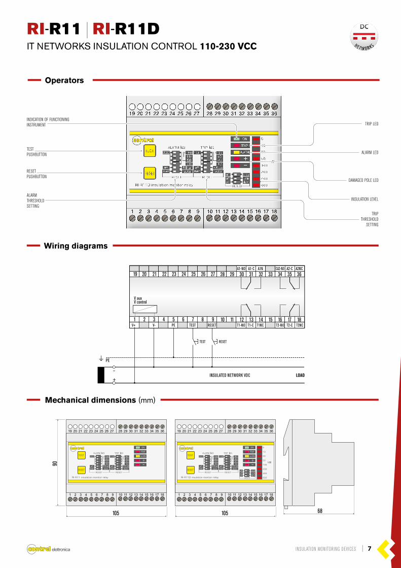
RI-R11 | RI-R11DIT NETWORKS INSULATION CONTROL 110-230 VCC
The RI-R11-115 and RI-R11-230 devices allows the permanent insulation monitoring to earth of electric networks in direct current isolated (IT systems).Insulation resistance monitoring is carried out measuring the potential variation of two polarity on ground reference. Auxiliary supply is taken from under-control network. The threshold of trip is regulated by a series of micro-switches.On the frontal panel there is the signaling of device ON, a TEST and a RESET push-buttons and three red LED to signal the tripping (TRIP) and to indicate the polarity of the line under control that has low insulation. It’s available a changeover contact relay to use the low insulation signaling in a remote panel.
General Characteristics
Controlled network voltage 100-144 VDC (version RI-R11 115)230 VDC (version RI-R11 230)
Power consumption 4 VA
ALARM threshold setting 30÷300 kΩ
TRIP threshold setting 10÷100 kΩ
Tripping delay < 5 sec
Max measuring current 1.8 mA
Max measuring voltage -
Internal impedance 100 kΩ L/PE | 200 kΩ L/PE
TRIP Relay number NO-C-NC 2
ALARM Relay number NO-C-NC 2
Max relay contact capacity 250V - 5A
Operating temperature -10 ÷ 60 °C
Storage temperature -20 ÷ 80 °C
Relative humidity ≤ 95%
Max terminal section 2.5 mm2
Protection degree IP40 front | IP20 housing
Insulation test 2.5 kV 60 sec. / 4 kV imp 1.2/50 μs
Modules 6
Weight 400 g
Standards EN 61010-1, EN 61557-8, EN 61326-1
Technical characteristics
IIII Features
INSULATION MONITORING OF IT SYSTEMS UP TO 230 VDC
TRIP AND ALARM LED
INSULATION LEVEL
DAMAGED POLE LED
TRIP AND ALARM THRESHOLD SETTING
TEST AND RESET PUSHBUTTON
ORDER CODE VERSION Vaux DESCRIPTION CONTROLLED NETWORK VOLTAGE MODULES
RI-R11 115 ALARM and TRIP threshold settingDamaged pole LED 80-180 VDC IT networks insulation control
115 VDC 100-144 VDC 6
RI-R11D 115 ALARM and TRIP threshold setting, damaged pole LED, insulation level display 80-180 VDC IT networks insulation control
115 VDC 100-144 VDC 6
RI-R11 230 ALARM and TRIP threshold settingDamaged pole LED 185-275 VDC IT networks insulation control
230 VDC 230 VDC 6
RI-R11D 230 ALARM and TRIP threshold setting, damaged pole LED, insulation level display 185-275 VDC IT networks insulation control
230 VDC 230 VDC 6
INSULATION MONITORING DEVICES | 7
N E T W O R KS
N E T W O R KS
DC
AC
RI-R11 | RI-R11DIT NETWORKS INSULATION CONTROL 110-230 VCC
Operators
1 2 3 4 5 6 7 8 9 10 11 12 13 14 15 16 17 18
INSULATED NETWORK VDC LOAD
TEST
V auxV control
PE
-
+
RESET
A1-NO
V+ V- PE TEST RESET T1-NO T2-NOT1-C T2-CT1NC T2NC
A1-C A1N CA2-NO A2-C A2NC19 20 21 22 23 24 25 26 27 28 29 30 31 32 33 34 35 36
Wiring diagrams
105 68105
90
INDICATION OF FUNCTIONING INSTRUMENT
DAMAGED POLE LED
TRIPTHRESHOLD
SETTING
TRIP LED
INSULATION LEVEL
Mechanical dimensions (mm)
ALARM LEDTESTPUSHBUTTON
RESETPUSHBUTTON
ALARMTHRESHOLDSETTING
8 | INSULATION MONITORING DEVICES
Controlled network voltage 280-340 VDC (version RI-R15 300)400-600 VDC (version RI-R15 500)
Power consumption 6 VA
ALARM threshold setting -
TRIP threshold setting 30÷300 kΩ
Tripping delay < 5 sec
Max measuring current 1.5 mA
Max measuring voltage -
Internal impedance 450 kΩ L/PE
TRIP Relay number NO-C-NC 1
ALARM Relay number NO-C-NC -
Max relay contact capacity 250V - 5A
Operating temperature -10 ÷ 60 °C
Storage temperature -20 ÷ 80 °C
Relative humidity ≤ 95%
Max terminal section 2.5 mm2
Protection degree IP40 front | IP20 housing
Insulation test 2.5 kV 60 sec. / 4 kV imp 1.2/50 μs
Modules 6
Weight 400 g
Standards EN 61010-1, EN 61557-8, EN 61326-1
N E T W O R KS
N E T W O R KS
DC
AC
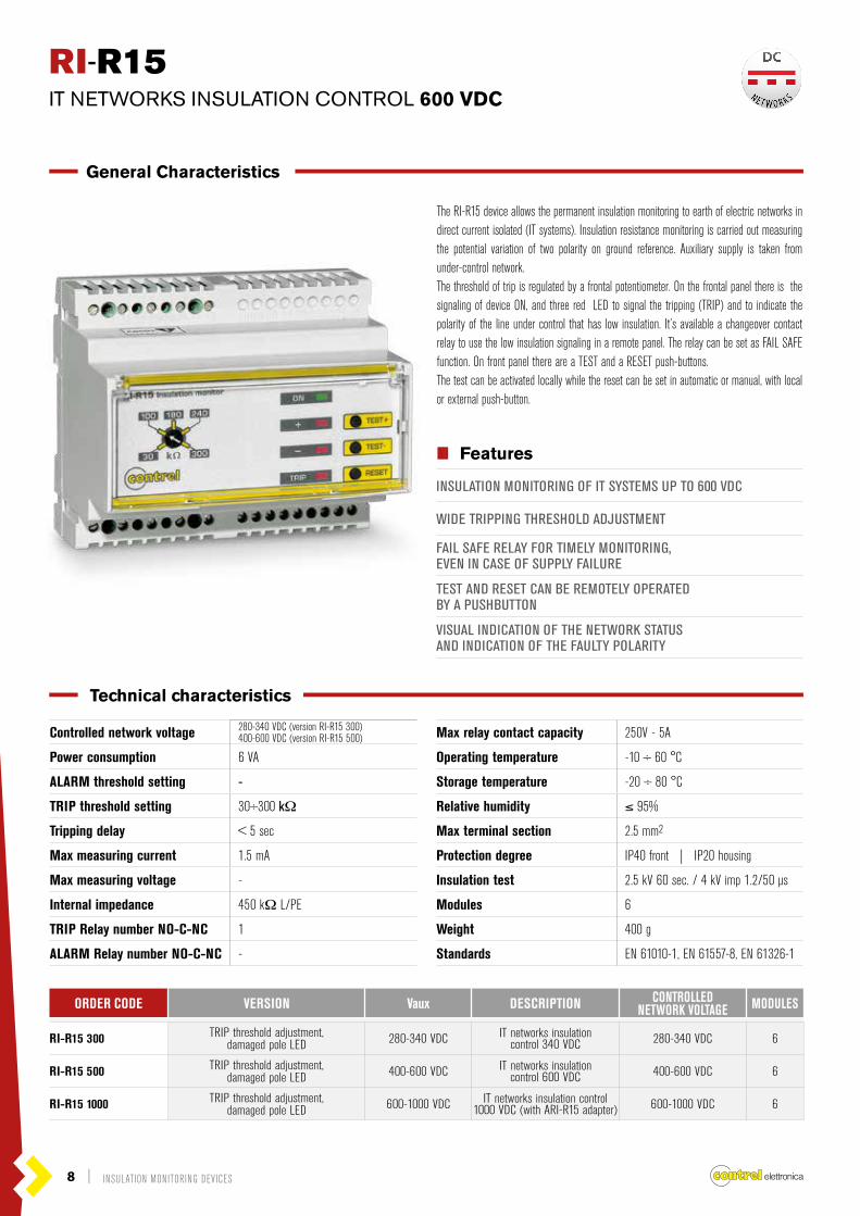
RI-R15IT NETWORKS INSULATION CONTROL 600 VDC
The RI-R15 device allows the permanent insulation monitoring to earth of electric networks in direct current isolated (IT systems). Insulation resistance monitoring is carried out measuring the potential variation of two polarity on ground reference. Auxiliary supply is taken from under-control network. The threshold of trip is regulated by a frontal potentiometer. On the frontal panel there is the signaling of device ON, and three red LED to signal the tripping (TRIP) and to indicate the polarity of the line under control that has low insulation. It’s available a changeover contact relay to use the low insulation signaling in a remote panel. The relay can be set as FAIL SAFE function. On front panel there are a TEST and a RESET push-buttons.The test can be activated locally while the reset can be set in automatic or manual, with local or external push-button.
General Characteristics
IIII Features
INSULATION MONITORING OF IT SYSTEMS UP TO 600 VDC
WIDE TRIPPING THRESHOLD ADJUSTMENT
FAIL SAFE RELAY FOR TIMELY MONITORING,EVEN IN CASE OF SUPPLY FAILURE
TEST AND RESET CAN BE REMOTELY OPERATEDBY A PUSHBUTTON
VISUAL INDICATION OF THE NETWORK STATUSAND INDICATION OF THE FAULTY POLARITY
Technical characteristics
ORDER CODE VERSION Vaux DESCRIPTION CONTROLLED NETWORK VOLTAGE MODULES
RI-R15 300 TRIP threshold adjustment,damaged pole LED 280-340 VDC IT networks insulation
control 340 VDC 280-340 VDC 6
RI-R15 500 TRIP threshold adjustment,damaged pole LED 400-600 VDC IT networks insulation
control 600 VDC 400-600 VDC 6
RI-R15 1000 TRIP threshold adjustment,damaged pole LED 600-1000 VDC IT networks insulation control
1000 VDC (with ARI-R15 adapter) 600-1000 VDC 6

INSULATION MONITORING DEVICES | 9
N E T W O R KS
N E T W O R KS
DC
AC
RI-R15IT NETWORKS INSULATION CONTROL 600 VDC
1 2 3 4 5 6 7 8 9 10 11 12 13 14 15 16 17 18
INSULATED NETWORK VDC
Relay outputTRIP
Fail Safe
Resetremotemanual
LOAD
RESET
PE
-
+
V+
V- PE
PE
RES-RES+ T-NCF.S.- T.C.T1NC T-NO
19 20 21 22 23 24 25 26 27 28 29 30 31 32 33 34 35 36
V au
x *V
cont
rol
105
90
68
kΩ
kΩ
TRIPTHRESHOLD ADJUSTMENT
TRIPLED
Operators
Wiring diagrams
Mechanical dimensions (mm)
DAMAGEDPOLE LED
INDICATIONOF FUNCTIONING
INSTRUMENT
TESTPUSHBUTTON
RESETPUSHBUTTON

10 | INSULATION MONITORING DEVICES
N E T W O R KS
N E T W O R KS
DC
ACRI-F22 | RI-R22IT NETWORKS INSULATION CONTROL 230 VAC
General Characteristics
These devices allow the insulation monitoring to earth of electric networks in alternate current up to 230 VAC isolated (IT systems). Insulation resistance monitoring is carri-ed out applying a measure’s signaling in direct-current between isolated network and heart. Surveying electric leakage set up on earth it’s possible to measure insulation level. It’s available a changeover contact relay to use the low insulation signaling in a remote panel. On frontal panel, devices have signal for activity ON, for TRIP (low insulation), a test button. The TRIP threshold is fixed to 100 kOhm (version RI-F22), or can be regulate by a frontal potentiometer (version RI-R22).
IIII Features
INSULATION MONITORING UP TO 230 VAC
RESET PUSHBUTTON (ONLY FOR RI-R22)
INDICATION OF FUNCTIONING INSTRUMENT
LOW INSULATION LED
TEST PUSHBUTTON
TRIP THRESHOLD SETTING (ONLY FOR RI-R22)
Controlled network voltage 230 VAC
Power consumption 3 VA
ALARM threshold setting -
TRIP threshold setting 100 kΩ (RI-F22) | 25÷100 kΩ (RI-R22)
Tripping delay < 5 sec
Max measuring current 0.1 mA
Max measuring voltage 12 VDC
Internal impedance 250 kΩ
TRIP Relay number NO-C-NC 1
ALARM Relay number NO-C-NC -
Max relay contact capacity 250V - 5A
Operating temperature -10 ÷ 60 °C
Storage temperature -20 ÷ 80 °C
Relative humidity ≤ 95%
Max terminal section 4 mm2
Protection degree IP40 front | IP20 housing
Insulation test 2.5 kV 60 sec | 4 kV imp 1.2/50 μs
Modules 3
Weight 200 g
Standards EN 61010-1, EN 61557-8, EN 61326-1
Technical characteristics
ORDER CODE VERSION Vaux DESCRIPTION CONTROLLED NETWORK VOLTAGE MODULES
RI-F22 115 ALARM and TRIP threshold settingDamaged pole LED 115 VAC IT networks insulation control
230 VAC 220-240 VAC 3
RI-F22 230 ALARM and TRIP threshold setting, damaged pole LED, insulation level display 230 VAC IT networks insulation control
230 VAC 220-240 VAC 3
RI-R22 24 ALARM and TRIP threshold settingDamaged pole LED 24 VDC IT networks insulation control
230 VAC 220-240 VAC 3
RI-R22 115 ALARM and TRIP threshold setting, damaged pole LED, insulation level display 115 VAC IT networks insulation control
230 VAC 220-240 VAC 3
RI-R22 230 ALARM and TRIP threshold setting, damaged pole LED, insulation level display 230 VAC IT networks insulation control
230 VAC 220-240 VAC 3
RI-R22 1000 ALARM and TRIP threshold setting, damaged pole LED, insulation level display 115 or 230 VCA IT networks insulation control
1000 VAC (whith ADAPTER) max 1000 VAC 3

INSULATION MONITORING DEVICES | 11
RI-F22 | RI-R22IT NETWORKS INSULATION CONTROL 230 VAC
N E T W O R KS
N E T W O R KS
DC
AC
LOADMax 230 V L-NNL3L2L1
1 2 3 4 5 6 7 8 9PE RESET
10AUX1 OUT-C OUT-NOOUT-NCVC TESTAUX2
V auxV control
PE
Vaux
TEST RESET
52,552,5
85
6864
RESETPUSHBUTTON
TESTPUSHBUTTON
TESTPUSHBUTTON
INDICATION OFFUNCTIONINGINSTRUMENT
INDICATION OFFUNCTIONINGINSTRUMENT
TRIPLED
TRIPLED
TRIPTHRESHOLD
ADJUSTMENT
Operators
Wiring diagrams
Mechanical dimensions (mm)

12 | INSULATION MONITORING DEVICES
N E T W O R KS
N E T W O R KS
DC
AC
Controlled network voltage 380-415 VAC
Power consumption 3 VA
ALARM threshold setting -
TRIP threshold setting 10÷150 kΩ
Tripping delay < 5 sec
Max measuring current 0.1 mA
Max measuring voltage 12 VDC
Internal impedance 250 kΩ
TRIP Relay number NO-C-NC 1
ALARM Relay number NO-C-NC -
Max relay contact capacity 250V - 5A
Operating temperature -10 ÷ 60 °C
Storage temperature -20 ÷ 80 °C
Relative humidity ≤ 95%
Max terminal section 4 mm2
Protection degree IP40 front | IP20 housing
Insulation test 2.5 kV 60 sec | 4 kV imp 1.2/50 μs
Modules 3
Weight 200 g
Standards EN 61010-1, EN 61557-8, EN 61326-1
RI-R38IT NETWORKS INSULATION CONTROL 440 VAC
The RI-R38 is a device that allows to control the insulation to earth in alternating neutral networks up to 440 VAC (IT systems). Putting a continuous component measure signal between the insulated line and earth it’s possible to control the insulation resistance reading the dispersion current gene-rated to earth. On the frontal panel of RI-R38 there is the signaling of device ON, the signaling of tripping TRIP (low insulation), a test and a reset push-buttons and a series of micro-switches to regulated the threshold of trip. It’s available a changeover contact relay to use the low insulation signaling in a remote panel.
General Characteristics
IIII Features
INSULATION MONITORING UP TO 440 VAC
RESET PUSHBUTTON
INDICATION OF FUNCTIONING INSTRUMENT
LOW INSULATION LED
TEST PUSHBUTTON
TRIP THRESHOLD SETTING
Technical characteristics
ORDER CODE VERSION Vaux DESCRIPTION CONTROLLED NETWORK VOLTAGE MODULES
RI-R38 115 TRIP threshold adjustment 115 VAC IT networks insulation control 440 VAC 380-415 VAC 3
RI-R38 230 TRIP threshold adjustment 230 VAC IT networks insulation control 440 VAC 380-415 VAC 3
RI-R38 1000 TRIP threshold adjustment 115 or 230 VCA IT networks insulation control 1000 VAC (whith ADAPTER) max 1000 VCA 3

INSULATION MONITORING DEVICES | 13
RI-R38IT NETWORKS INSULATION CONTROL 440 VAC
N E T W O R KS
N E T W O R KS
DC
AC
1 2 3 4 5 6 7 8 9PE RESET
10 11 12AUX1
LOAD
OUT-C OUT-NCOUT-NOVCAUX2
V aux
PE
Max 230 V L-NNL3L2L1
* In case of non accessible neutral, connect terminal 5 to the L3
Vaux
52,5
85 45
5864
68
Operators
Wiring diagrams
Mechanical dimensions (mm)
RESETPUSHBUTTON
INDICATION OF FUNCTIONINGINSTRUMENT
TRIPLED
TESTPUSHBUTTON
TRIPTHRESHOLDSETTING

14 | INSULATION MONITORING DEVICES
N E T W O R KS
N E T W O R KS
DC
AC
RI-R44-485 RI-R44-V-485
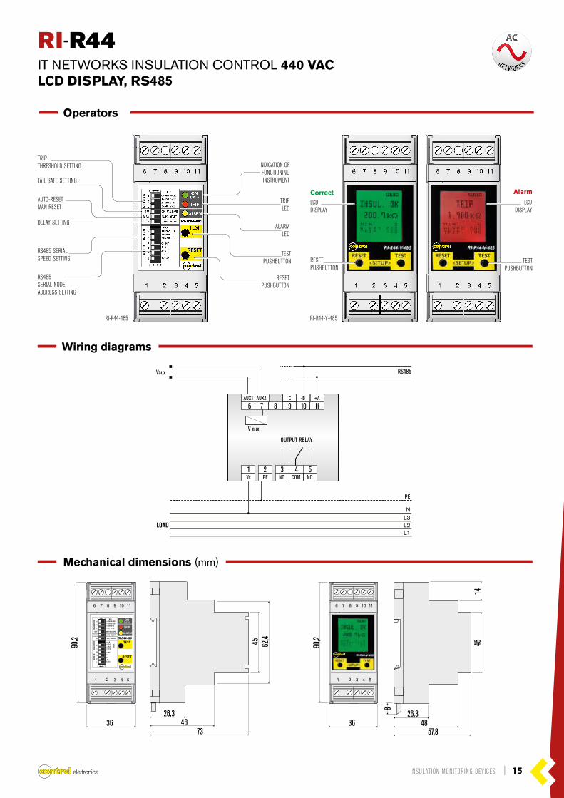
RI-R44IT NETWORKS INSULATION CONTROL 440 VACLCD DISPLAY, RS485
General Characteristics
RI-R44 is a device that allows the insulation monitoring to earth of AC networks up to 440V isolated (IT systems). By applying a DC component measure signal between the insulated line and earth it’s possible to control the insulation resistance by detecting the generated leakage current. Thanks to the LCD display, the device allows the visualization of the instantaneous insulation value. Configurable automatic or manual resetting. It has a TRIP changeover contact configurable normally de-energised or energised.The RI-R44 is also provided with a RS-485 interface with Modbus protocol to consent the integration in supervision systems..
Instantaneous displayLCD display that enables quick alarm viewing of the insulation value. Incorporates illuminated status change for instantaneous detection of the status of the installation.
IIII Features
INSULATION MONITORING OF IT SYSTEMS UP TP 440 VAC
LCD DISPLAY (Alarm or prealarm indicating events)
LOW INSULATION LED
CONFIGURABLE AUTOMATIC OR MANUAL RESETTING
TEST PUSHBUTTON
TRIP THRESHOLD SETTING
TRIP OUTPUT RELAY
RS485 SERIAL INTERFACE (MODBUS RTU)
Controlled network voltage 440 VAC
Power consumption 2 VA
ALARM threshold setting -
TRIP threshold setting 1÷300 kΩ
Tripping delay < 2.5 sec
Max measuring current 0.015 mA
Max measuring voltage 13 VDC
Internal impedance 1.5 MΩ for DC | 1 MΩ for AC
TRIP Relay number NO-C-NC 1
ALARM Relay number NO-C-NC -
Max relay contact capacity 250V - 5A
Operating temperature -10 ÷ 60 °C
Storage temperature -20 ÷ 80 °C
Relative humidity ≤ 95%
Max terminal section 2.5 mm2
Protection degree IP40 front | IP20 housing
Insulation test 2.5 kV 60 sec | 4 kV imp 1.2/50 μs
Modules 2
Weight 200 g
Standards EN 61010-1, EN 61557-8, EN 61326-1
Technical characteristics
ORDER CODE VERSION Vaux DESCRIPTION CONTROLLED NETWORK VOLTAGE MODULES
RI-R44 TRIP threshold adjustment 230 VAC IT networks insulation control 440 VAC 440 VAC 2
RI-R44-485 TRIP threshold adjustment,RS845 serial interface 230 VAC IT networks insulation control
440 VAC 440 VAC 2
RI-R44-V TRIP threshold adjustment, LCD display 230 VAC IT networks insulation control 440 VAC 440 VAC 2
RI-R44-V-485 TRIP threshold adjustment, LCD display, RS845 serial interface 230 VAC IT networks insulation control
440 VAC 440 VAC 2
Correct Alarm
INSULATION MONITORING DEVICES | 15
N E T W O R KS
N E T W O R KS
DC
ACRI-R44IT NETWORKS INSULATION CONTROL 440 VACLCD DISPLAY, RS485
1 2 3 4 5
6 7 8 9 10 11
Vc PE COM
LOAD
NCNO
AUX1 -B +ACAUX2
V aux
OUTPUT RELAY
PE
NL3L2L1
Vaux RS485
26,348
57,836 36
90,2
90,2 45
14
8
26,348
73
62,445
Operators
Wiring diagrams
Mechanical dimensions (mm)
TESTPUSHBUTTON
RI-R44-485 RI-R44-V-485
TESTPUSHBUTTON
RESETPUSHBUTTON
TRIP THRESHOLD SETTING
FAIL SAFE SETTING
DELAY SETTING
AUTO-RESETMAN RESET
RS485SERIAL NODEADDRESS SETTING
ALARMLED
TRIPLED
LCDDISPLAY
LCDDISPLAY
INDICATION OFFUNCTIONINGINSTRUMENT
RESETPUSHBUTTON
RS485 SERIALSPEED SETTING
Correct Alarm Correct Alarm

16 | INSULATION MONITORING DEVICES
N E T W O R KS
N E T W O R KS
DC
AC
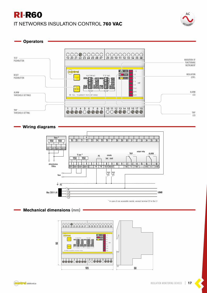
RI-R60 is a device that allows to control the insulation to earth in alternating neutral networks up to 760 V (IT systems).Putting a continuous component measure signal between the insulated line and earth it’s possible to control the insulation resistance reading the dispersion current gene-rated to earth. These devices have two trip thresholds (ALARM and TRIP) adjustable using the frontal micro-switches to signal when the insulation go under the threshold level.The frontal LED signaling the trip. Two free voltage changeover contacts relays allow the remote trip signaling. The relays can be programmed with the fail safe (normally excited).The device is supplied on the front panel of a TEST and a RESET push-buttons. The test can be activated thanks to the push-button on the device or to external push-button while the reset that can be set in manual or in automatic and activated, as the test, with the local or remote push-button. The level of the insulation resistance is displayed on the bar LED on the front panel.
RI-R60IT NETWORKS INSULATION CONTROL 760 VAC
General Characteristics
IIII Features
INSULATION MONITORING UP TO 1000 VAC
DOUBLE MONITORING THRESHOLDFOR MORE EFFECTIVE FAULT PREVENTION
FAIL SAFE DOUBLE RELAY FOR EFFECTIVE SYSTEM CONTROLAND TIMELY MONITORING, EVEN IN CASE OF SUPPLY FAILURE
INSTANT DISPLAY OF INSULATION LEVEL
TEST AND RESET CAN BE REMOTELY OPERATEDBY A PUSHBUTTON
VISUAL INDICATION OF THE NETWORK STATUS
Controlled network voltage 500-760 VAC
Power consumption 5
ALARM threshold setting 30÷300 kΩ
TRIP threshold setting 10÷100 kΩ
Tripping delay < 5 sec
Max measuring current 0.240 mA
Max measuring voltage 48 VDC
Internal impedance 200 kΩ
TRIP Relay number NO-C-NC 1
ALARM Relay number NO-C-NC 1
Max relay contact capacity 250V - 5A
Operating temperature -10 ÷ 60 °C
Storage temperature -20 ÷ 80 °C
Relative humidity ≤ 95%
Max terminal section 2.5 mm2
Protection degree IP40 front | IP20 housing
Insulation test 3 kV 60 sec. / 4 kV imp 1.2/50 μs
Modules 6
Weight 500 g
Standards EN 61010-1, EN 61557-8, EN 61326-1
Technical characteristics
ORDER CODE VERSION Vaux DESCRIPTION CONTROLLED NETWORK VOLTAGE MODULES
RI-R60 ALARM and TRIP threshold setting,insulation level display 110-230 VAC IT networks insulation control
up to 760 VAC 500-760 VAC 6
RI-R60 1000 ALARM and TRIP threshold setting,insulation level display 110-230 VAC IT networks insulation control
up to 1000 VAC (with ARI-R60 adapter) 1000 VAC 6
INSULATION MONITORING DEVICES | 17
N E T W O R KS
N E T W O R KS
DC
ACRI-R60IT NETWORKS INSULATION CONTROL 760 VAC
115V
alimentazione 115Vca
Vaux *115V
AUX-L1 AUX-01 AUX-L2 AUX-02
1 2 3 4 5 6 7 8 9 10 11 12 13 14 15 16 17 18
ALARMautput relay
remote
VauxTEST TEST
TRIP
PE
VC
* In case of non accessible neutral, connect terminal 22 to the L1
AUX-L1 AUX-C1 AUX-L2 AUX-C2 RESETTESTPE PE T-NC A-NCT-C A-CT-NO A-NO
19 20 21 22 23 24 25 26 27 28 29 30 31 32 33 34 35 36
V aux *
LOADMax 230 V L-NNL3L2L1
PEtest reset115V 115V
105
90
68
TESTPUSHBUTTON INDICATION OF
FUNCTIONINGINSTRUMENT
RESETPUSHBUTTON
INSULATIONLEVEL
TRIPTHRESHOLD SETTING TRIP
LED
ALARMTHRESHOLD SETTINGS
ALARMLED
Operators
Wiring diagrams
Mechanical dimensions (mm)

18 | INSULATION MONITORING DEVICES
N E T W O R KS
VOLTAGELESS
RI-SMVOLTAGELESS NETWORK INSULATION CONTROL
The RI-SM allows insulation monitoring to earth of out-voltage networks.This device must carry-out a preventive check of the insulation level for out-voltage devices, not used permanently, in the way to avoid damage when they start to function (ex. fire-engines, lift, etc.).Insulation resistance’s monitoring is carried out applying a measure’s signaling in direct current component between out-voltage isolated network and earth. Surveying leakage current to earth it’s possible to measure the insulation’s level.The instrument is useful for networks and devices from 20 to 700 VAC/DC.A changeover contact relay is available to signal the low insulation to a remote panel.On front panel there is the signaling of device ON, the signaling of TRIP for low insulation, the TEST push-button and the micro-switches to select the tripping threshold and FAIL SAFE function.The RESET of the device is automatic when the condition of low insulation disappears.The device must be connected to the network to survey using a normally closet contact in the way to disconnect from the network when it’s turning on.The output relay can be used to signal the alarm or to avoid the insertion of the load.
General Characteristics
IIII Features
INDICATION OF FUNCTIONING INSTRUMENT
TEST PUSHBUTTON
LOW INSULATION LED
FAIL SAFE SETTING
TRIP THRESHOLD SETTING
Power consumption 3 VA
ALARM threshold setting -
TRIP threshold setting 0,1÷1000 kΩ
Tripping delay < 5 sec
Max measuring current 0.015 mA
Max measuring voltage 20 VDC
Internal impedance 1.5 MΩ DC | 1 MΩ AC
TRIP Relay number NO-C-NC 1
ALARM Relay number NO-C-NC -
Max relay contact capacity 250V - 5A
Operating temperature -10 ÷ 60 °C
Storage temperature -20 ÷ 80 °C
Relative humidity ≤ 95%
Max terminal section 4 mm2
Protection degree IP40 front | IP20 housing
Insulation test 2.5 kV 60 sec | 4 kV imp 1.2/50 μs
Modules 3
Weight 200 g
Standards EN 61010-1, EN 61557-8, EN 61326-1
Technical characteristics
ORDER CODE VERSION Vaux DESCRIPTION MODULES
RI-SM 24 TRIP threshold setting, FAIL SAFE setting 24 VDC Voltageless networks insulation control 3
RI-SM 115 TRIP threshold setting, FAIL SAFE setting 115 VAC Voltageless networks insulation control 3
RI-SM 230 TRIP threshold setting, FAIL SAFE setting 230 VAC Voltageless networks insulation control 3

INSULATION MONITORING DEVICES | 19
N E T W O R KS
VOLTAGELESS
RI-SMVOLTAGELESS NETWORK INSULATION CONTROL
1 2 3 4 5 6 7 8 9PE
10 11 12AUX1
LOAD
OUT-C OUT-NCOUT-NOVCAUX2
V aux
PE
Vaux C
Max 230 V L-NNL3L2L1
* In case of non accessible neutral, connect terminal 5 to the L3
INDICATION OFFUNCTIONINGINSTRUMENT
LOWINSULATION
LED
TRIPTHRESHOLDSETTING
FAILSAFE
SETTING
52,5
85 45
5864
68
Operators
Wiring diagrams
Mechanical dimensions (mm)
TESTPUSHBUTTON

20 | INSULATION MONITORING DEVICES
N E T W O R KS
VOLTAGELESS
RI-SM485VOLTAGELESS NETWORKS INSULATION CONTROL, RS485
The devices allow insulation monitoring to earth of out-voltage networks in order to carry out a preventive monitoring on insulation level of device. Preventive monitoring is really important in case of applications which are not used permanently (for example: motors, fire-engines, and so on). In these applications, humidity and condensate can cause a serious decrease in insulation’s level and obstruct correct functioning at the moment of appli-cation’s activation. Insulation resistance’s monitoring is carried out applying a measure’s signaling in direct-current component between isolated network and earth. Surveying leakage current to earth it’s possible to measure insulation’s level. A very compact housing allows you to place the RI-SM485 in small spaces, optimizing the layout of the installation.The RI-SM485 is also provided with a RS-485 interface with Modbus protocol to consent the integration in supervision systems..
General Characteristics
IIII Features
INDICATION OF FUNCTIONING INSTRUMENT
TEST PUSHBUTTON
LOW INSULATION LED
FAIL SAFE SETTING
TRIP THRESHOLD SETTING
OUTPUT RELAY
RS485 SERIAL INTERFACE (MODBUS RTU)
Power consumption 2 VA
ALARM threshold setting -
TRIP threshold setting 0,1÷1500 kΩ
Tripping delay < 2,5 sec
Max measuring current 0.015 mA
Max measuring voltage 13 VDC
Internal impedance 1.5 MΩ DC | 1 MΩ AC
TRIP Relay number NO-C-NC 1
ALARM Relay number NO-C-NC -
Max relay contact capacity 250V - 5A
Operating temperature -10 ÷ 60 °C
Storage temperature -20 ÷ 80 °C
Relative humidity ≤ 95%
Max terminal section 2,5 mm2
Protection degree IP40 front | IP20 housing
Insulation test 2.5 kV 60 sec | 4 kV imp 1.2/50 μs
Modules 2
Weight 200 g
Standards EN 61010-1, EN 61557-8, EN 61326-1
Technical characteristics
ORDER CODE VERSION Vaux DESCRIPTION MODULES
RI-SM-485 TRIP threshold setting, FAIL SAFE setting,RS485 serial interface 230 VAC Voltageless networks insulation control 2

INSULATION MONITORING DEVICES | 21
INDICATION OFFUNCTIONINGINSTRUMENT
TRIPLED
ALARMLED
TESTPUSHBUTTON
RESETPUSHBUTTON
TRIPTHRESHOLDSETTING
FAIL SAFESETTING
AUTO-RESET | MAN RESET
RS485SERIAL SPEED SETTING
RS485SERIAL NODE ADDRESS SETTING
N E T W O R KS
VOLTAGELESS
RI-SM485VOLTAGELESS NETWORKS INSULATION CONTROL, RS485
V aux
1 2 3 4 5 Vc
6AUX1
7 AUX2
8 9C
10-B
11+A
LOAD
OUTPUT RELAY
NOComNCPE
PE
Vaux RS485
C
NL3L2L1
36
26,348
73
90,4 62,4
45
Operators
Wiring diagrams
Mechanical dimensions (mm)

22 | INSULATION MONITORING DEVICES
N E T W O R KS
N E T W O R KS
DC
AC
ARI-R15 ADAPTERIT NETWORKS INSULATION CONTROL 1000 VDC
General Characteristics
ISOLATED NETWORK Vdc (MAX 700 / 800 / 900 / 1000 V) LOAD
_
PE
+
1 2 3 4 5 6 7 8 9 10 11 12 13 14 15 16 17 18
V+
V+
19 20 21 22 23 24 25 26 27 28 29 30 31 32 33 34 35 36
1 2 3 4 5 6 7 8 9 10 11 12 13 14 15 16 17 18
IN-A IN-A REF
RES+IN-B IN-B RES- T-NCFS + T-CFS- T-NO
19 20 21 22 23 24 25 26 27 28 29 30 31 32 33 34 35 36
ARI-R15
ADAPTERRI-R15 1000V
per r
ete
600÷
V a
uxV
con
trol 70
0Vdc
per r
ete
700÷
800V
dc
per r
ete
800÷
900V
dc
per r
ete
900÷
1000
Vdc
REMOTE relay outoutTRIP
resetmanual
fail Safefunction
Wiring diagrams
105
90
68
ARI-R15 ALLOWS INSULATION MONITORING UP TO 1000 VDC.
THE EXTERNAL ADAPTER ARI-R15 MUST BE USED ONLY WITH RI-R15 1000.
THIS ADAPTER MUST BE POSITIONED BETWEEN THE NETWORKTO CONTROL AND THE DEVICE RI-R15 1000.
Mechanical dimensions (mm)

INSULATION MONITORING DEVICES | 23
N E T W O R KS
N E T W O R KS
DC
ACARI-R60 ADAPTERIT NETWORKS INSULATION CONTROL 1000 VAC
General Characteristics
115V
alimentazione 115Vca
Vaux *115V
AUX-L1 AUX-01 AUX-L2 AUX-02
1 2 3 4 5 6 7 8 9 10 11 12 13 14 15 16 17 18
ALARMautput relay
remote
power supply230Vca
TEST RESET
TRIP
PE
VC
* In case of non accessible neutral, connect terminal 22 to the L1 phase conductor
AUX-L1 AUX-C1 AUX-L2 AUX-C2 RESETTESTPE PE T-NC A-NCT-C A-CT-NO A-NO
19 20 21 22 23 24 25 26 27 28 29 30 31 32 33 34 35 36
V aux *
LOADMax 230 V L-NNL3L2L1
PEtest reset115V 115V
23 9 4
ARI-R60 ADAPTERRI-R60 1000V
157,5
90
68
ARI-R60INSULATION MONITOR VOLTAGE ADAPTER
max 1000Vac
1 2 3 4 5 6 7 8 9 10 11 12 13 14 15 16 17 18 19 20 21 22 23 24 25 26 27
28 29 30 31 32 33 34 35 36 37 38 39 40 41 42 43 44 45 46 47 48 49 50 51 52 53 54
ARI-R60 ALLOWS INSULATION MONITO-RING UP TO 1000 VAC.
THE EXTERNAL ADAPTER ARI-R60 MUST BE USED ONLY WITH RI-R60.THIS ADAPTER MUST BE POSITIONED BETWEEN
THE NETWORK TO CONTROL AND THE DEVICE RI-R60.
Wiring diagrams
Mechanical dimensions (mm)

24 | INSULATION MONITORING DEVICES
HRI medical insulation monitoring device assuring patients and medical staff safety in intensive care units, operating theatres, first aid and day hospital premises, ambulatories, nursing homes, dentist’s and vet’s.
QUALITYThe recognized standard in hospital insulation control.
SPECIALIZATIONProperly designed for hospitals.
COMPLETENESSAll electrical and thermal parameters controlled by a single device.
FLEXIBILITYAdjustable intervention thresholds according to all the parameters monitored.
RELIABILITYSafe monitoring under any operational condition, thanks to the codified signal.
INTEGRATIONAble to interact with supervising systems through modbus-rtu protocol via rs485 serial port.
CONTROLComplete control of any alarm signalled thanks to the programmable relay.
MEDICAL INSULATION MONITORING DEVICE
MEDICAL INSULATION MONITORING DEVICETechnology and safety in hospital segment

INSULATION MONITORING DEVICES | 25
HRI-R40MEDICAL INSULATION MONITORING DEVICE
General Characteristics
QUALITYTHE RECOGNIZED STANDARDIN HOSPITAL INSULATION CONTROL
SPECIALIZATION PROPERLY DESIGNED FOR HOSPITALS
COMPLETENESSALL ELECTRICAL AND THERMAL PARAMETERSCONTROLLED BY A SINGLE DEVICE
FLEXIBILITY
ADJUSTABLE INTERVENTION THRESHOLDS ACCORDINGTO ALL THE PARAMETERS MONITORED
ALARMS SENT UP TO 4 MEDICAL LOCATIONS ATTENDED BYMEDICAL AND HEALTHY STAFF, THANKS TO REMOTE SIGNALLING PANELS
STRENGTH HIGH RESISTANCE TO NETWORK INTERFERENCES
INTEGRATIONABLE TO INTERACT WITH SUPERVISING SYSTEMSTHROUGH MODBUS RTU PROTOCOL VIA RS485 SERIAL PORT
RELIABILITYSAFE MONITORING UNDER ANY OPERATIONAL CONDITION,THANKS TO THE CODIFIED SIGNAL
--- Features
TECH
NOLO
GY AN
D SAFETY IN HOSPITAL SEGMENT
SELF-TESTING SYSTEM
Error-Link Fail system checks device proper functioning and controls wiring presence and properness at the end of the terminal blocks: it prevents the possibility to operate in group 2 medical locations when the insulation moni-toring device is disconnected.
COMPLETE MONITORINGOF ALL ELECTRICAL PARAMETERS
HRI-R40 tests the thermal and electrical overload of the medical insulation transfor-mer, managing two temperature thresholds coming from both PT100 and PTC probes. By controlling temperature, the overload of the transformer can be monitored and the automatic circuit-breaker downstream of the secondary can be avoided.All faulty conditions are remotely controlled thanks to PR-5 remote signalling panels, granting a proper prompt technical supervision.
PROGRAMMING
Through its LCD display and four selection keys, the device offers easy programming possibilities by setting intervention thresholds without making any mistakes.
FUNCTIONING PRINCIPLE
Insulation resistance is measured by applying a direct current signal between insulated line and earth and determining the dispersion current generated.Effective measurement is granted thanks to a digital filter integrated in the device even if interferences and harmonic components occur.
FOR HIGHER SAFETY
Thanks to a codified signal, the HRI-R40 IT networks insulation moni-toring device grants absolute reliability of measurement in any operational condition, even if high network interferences occur. Furthermore it is fitted with a RS485 serial port through which it can be perfectly integrated with communication systems such as PLC/PC by using ModbusRTU protocol. The measurement of network maximum and minimum values enables a wider monitoring and an easier plant checking in case of any fault. Finally, the programmable output relay allows to manage any warning condition signalled in a dedicated way.
HRI-R40 measures the insulation to earth in IT-M network and the thermal and electrical overload of the insulation transformer, in accordance with the international standards: EN 61557-8, IEC EN 64-8/7-710 and UNE 20615.
( * ) Use a direct-current component control signal in order to reduce the problems generated by the presence of direct current components in the line. The device is fitted with a digital filter capable to identify the direct current component present in the line.
ORDER CODE VERSION Vaux DESCRIPTION CONTROLLED NETWORK VOLTAGE MODULES
HRI-R40 TRIP threshold setting, 2 temperature sensors,digit display, output relay 110-230 VAC - 24-230 VAC 6
HRI-R40-485 TRIP threshold setting, 2 temperature sensors, digit display, output relay, RS485 serial interface 110-230 VAC - 24-230 VAC 6
HRI-R40W-485 TRIP threshold setting, 2 temperature sensors, digit display, output relay, RS485 serial interface 110-230 VAC ( * ) 24-230 VAC 6

26 | INSULATION MONITORING DEVICES
HRI-R40MEDICAL INSULATION MONITORING DEVICE TE
CHNO
LOGY
AND SAFETY IN HOSPITAL SEGMENT
Frontal operators functioing
GREEN LED, SETTOOL PROGRAMMING STATUS
3 DIGIT DISPLAY
RED LED. RINSULATION RESISTENCE (KΩ)
RED LED, ZINSULATION INPEDANCEAND LINE CAPACITY
RED LED, T1TRANSFORMER TEMPERATURE
RED LED, T22ND SENSOR TEMPERATURE
RED LED, ILINE CURRENT
YELLOW LED, ALARMTOOL PROGRAMMING STATUS
RED LED, OUTPUT RELAYAUXILIARY RELAY STATUS
RED LED, ERROR/LINK FAILINTERNET FAULT ALARM,
FAULTY WIRING TO THE LINE TO BE CONTROLLED,PT100 TEMPERATURE PROBE
OPEN OR UNDER SHORT-CIRCUIT
TEST | ENTERDEVICE AND REMOTE
SIGNALLING PANELS TESTINGAND SETUP SETTING CONFIRMATION
RESET | ENTERDEVICE PROGRAMMING ACCES ALARM
DISCONNECTIONS AND MEMORIZEDVALUES CANCELLATION
+ | -SELECTION OF THE PARAMETER TO BE DISPLAYED,
SETTING ADJUSTMENT AND MEMORIZEDMAXIMUM AND MINIMUM VALUES DISPLAY
(ONLY FOR ISOLTESTER-DIG-PLUS)
insulation monitor HRI-R40
ALARM OUTPUTRELAY
ERROR /LINK FAIL
SET
TESTRESET
MIN / MAX
ENTERSET+ _
RZT1T2I
[k ]Ω[k ]Ω[°C][°C][A]
EASY PROGRAMMINGBY FOUR PUSHBUTTONS
Wherever it is necessary to guarantee safety and operational continuity andprevent power supply interruptions, such as hospitals and other medical locations, insulation transformers and devices detecting and signalling any first fault to earth have to be used. Risks arising from the use of a traditional insulation monitor:
• IMPOSSIBILITY TO DISTINGUISH BETWEEN INTERFERENCE AND REAL FAULT• CARELESSNESS OF THE MEDICAL STAFF• UNJUSTIFIED INTERVENTION OF SPECIALIZED TECHNICAL STAFF
HRI-R40 is the device for insulation monitoring in IT-M networks. It ensures absolute reliability of measurement by means of a codified signal able to detect interferences generated by common equipment in operating theatres and avoid unwanted alarms signalling.
105
90
68
insulation monitor HRI-R40
ALARM OUTPUTRELAY
ERROR /LINK FAIL
SET
TESTRESET
MIN / MAX
ENTERSET+ _
RZT1T2I
[k ]Ω[k ]Ω[°C][°C][A]
Mechanical dimensions (mm)

INSULATION MONITORING DEVICES | 27
HRI-R40MEDICAL INSULATION MONITORING DEVICE TE
CHNO
LOGY
AND SAFETY IN HOSPITAL SEGMENT
Supply voltage 110 - 230 V/50-60 Hz
Network voltage to be controlled 24 ÷ 230 VAC
Maximum voltage measurement 24 V
Maximum current measurement 1 mA
Insulation voltage 2,5 kV/60 seconds
Control signal type Continuous component with digital filter
Measures
Insulation measurement range0÷999 kΩ/HIGH – resolution 1 kΩ
Temperature measurement by Rd PT100or 2/3-wire thermal-probe – 0÷250°C, accuracy 2%
Impedance measurement 0÷999 kΩ/HIGHResolution 1 kΩ (test signal 2500 Hz)
Intervention threshold
Low insulation 50÷500 kΩ,accuracy 5%, hysteresis 5%, settable delay
Overtemperature 0 ÷ 200°C, accuracy 2%
Current overload 1 ÷ 999 A, accuracy 2%
Low impedance (deactivable)
Device not connectedto the line (Error/Link-Fail)
Available outputs
Up to maximum 4 PR-5 panelsfor remote signalling
Programmable auxiliary relay outputNA-C-NC, 5A, 250 VAC
RS 485 serial output,standard ModbusRTU protocol
Displays
Insulation resistance value signallingover full scale and fault to earth
Measured temperature value0 ÷ 200°C for channel 1
Measured temperature value0 ÷ 200°C for channel 2
Measured current value 0 ÷ 999 A
Insulation impedance value
Setting parameters
Device failing connectionto the line (Error/Link-Fail)
Relay output status
Line-to-earth capacity value
Minimum insulation and maximumtemperature and current values
Connections Maximum linkable section 2,5 mm2
Operating temperature -10...60 °C
Storage temperature -25...70 °C, humidity < 90%
Overall dimensions 6 DIN modules
Weight 0,5 kg
HousingSelf-extinguishing plastic case to be assem-bled on 35 mm DIN rail, with transparent lead-sealable protective front cover
Degree of protection IP20
Self-consumption 5 VA
Reference standards IEC EN 60364-7-710, IEC EN 61557-8,EN 60255-6, UNE 20615
Wiring diagrams
LF-PE1 2 3 4 5 6 7 8 9 10 11 12 13 14 15 16 17 18
LF-L VC-L VC-PEAUX-L1 AUX-01 AUX-02AUX-L2 TEST+ TEST- ACK ACUS OVER COM-P V-P FAULT
Vaux*
PR-5
19 20 21 22 23 24 25 26 27 28 29 30 31 32 33 34 35 36PT2+AA B C PT2+B PT2- PT1+A PT1+B PT1- CT-S2 CT-S1 R-NO R-C R-NC
RS485 input 1PT100
input 2PT100
TA .../5Aoutputrelay
HRI-R40
1 2 3 4 5 6 7 8 9TEST+TEST-
10 11ACKACUS OVER COM-PV-P FAULT
PE
SS
PC IT-M LOADINSULATIONTRANSFORMER
V aux. 230 VAC
115V 115V
L
N
TO O
THER
PR5
PT10
0
PT10
0
COM-S F-S TEST-S
INSULATIONCHECK
LINK FAILCHECK
REMOTE PANEL PR5
Technical characteristics

28 | INSULATION MONITORING DEVICES
Technical characteristics
Network voltage andauxiliary supply 24 V AC/DC
Frequency 50-60 Hz
Maximum self-consumption 3 VA
Maximum measurement current 0,5 mA
Internal impedance 50 kΩ
Intervention threshold 10 ÷ 50 kΩ 4 levels
Intervention delay 1 s
Signals LED ON, LED TRIP
Output maximum 24 V 1 A
Remote signalling panels maximum 2 PR-5
Operating temperature -10 ÷ 60 °C
Storage temperature -20 ÷ 70 °C
Relative humidity ≤ 95%
Insulation test 2,5 kV 60 s / 4 kV imp. 1,2/50 μs
Terminal blocks section 4 mm2
Degree of protection front IP40 with cover / IP20 case
Modules 3
Weight 200 g
Reference standards EN 61010-1; IEC EN 60364-7-710;EN 61326-1
HRI-R24MEDICAL INSULATION MONITORING DEVICESFOR SCIALITIC LAMPS
General Characteristics
HRI-R24 tests the insulation to earth of 24 VAC/DC circuits dedicated to scialitic lamps supply.Scialitic lamps insulation is to be monitored in order to prevent detaching from conductors when being moved.The conductors, by contact with the metal structure of the lamp, may transfer a potential of over 250 V, resulting in damage to equipment and people.
HRI-R24 measures the variation in potential of the two network polarities with reference to earth in order to signal when insulation drops below a set value, through the frontal poten-tiometer, identifying.The output signal can be connected to PR-5 remote signalling panel. The frontal panel of the device carries test and reset pushbutton, status indicator and TRIP LED for low insulation signalling.
TECH
NOLO
GY AN
D SAFETY IN HOSPITAL SEGMENT
IIII Features
TESTS THE INSULATION TO EARTH OF 24 VAC/DCCIRCUITS DEDICATED TO SCIALITIC LAMPS SUPPLY
FLEXIBILITY: PROGRAMMABLE ALARM THRESHOLD
COMPACT SIZE: FITS INTO JUST 3 MODULE
PRACTICALITY: EXTREMELY EASY TO INSTALL AND USE
INTEGRATION: IDEAL COMPLEMENT FOR HRI-R4
ORDER CODE VERSION Vaux CONTROLLED NETWORK VOLTAGE MODULES
HRI-R24 TRIP threshold adjustment, TEST pushbutton 24 VAC/DC 24 VAC/DC 3

INSULATION MONITORING DEVICES | 29
PE
SS
IT-M LOAD
INSULATION TRANSFORMER
L(+)
N(-)
1 2 3 4 5 6 7 8 9TEST+TEST-
10 11ACKACUS OVER COM-PV-P FAULTCOM-S F-S TEST-S
REMOTE PANEL PR5
1 2 3 4 5 6 7 8 9PE
10 OUT-NO OUT-NCV- OUT-CV+
HRI-R24
TO O
THER
PR5
52,5
85
6864
HRI
HRI-R24
HRI-R24MEDICAL INSULATION MONITORING DEVICESFOR SCIALITIC LAMPS
TECH
NOLO
GY AN
D SAFETY IN HOSPITAL SEGMENT
Frontal operators functioing
Wiring diagrams
HRI
HRI-R24
TEST PUSHBUTTON
RESET
GREEN LED, ONAUXILIARY RELAY STATUS
Mechanical dimensions (mm)
TRIP LEDLOW INSULATION LED
TRIPTHRESHOLD ADJUSTMENT
30 | INSULATION MONITORING DEVICES
79
123 7 13 15
E503
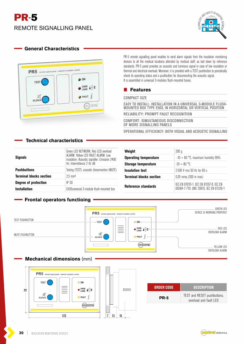
Signals
Green LED NETWORK; Red LED overload ALARM; Yellow LED FAULT ALARM; Low insulation; Acoustic signaller; Emission 2400 Hz; Intermittence 2 Hz dB
Pushbuttons Testing (TEST), acoustic disconnection (MUTE)
Terminal blocks section 2,5 mm²
Degree of protection IP 30
Installation E503universal 3-module flush-mounted box
Weight 200 g
Operating temperature -10 ÷ 60 °C, maximum humidity 95%
Storage temperature -20 ÷ 80 °C
Insulation test 2.500 V rms 50 Hz for 60 s
Terminal blocks section 0,35 mmq (300 m max)
Reference standards IEC-EN 61010-1, IEC EN 61557-8, IEC EN 60364-7-710, UNE 20615, IEC EN 61326-1
PR-5REMOTE SIGNALLING PANEL
General Characteristics
PR-5 remote signalling panel enables to send alarm signals from the insulation monitoring devices to all the medical locations attended by medical staff, as laid down by reference standards. PR-5 panel provides an acoustic and luminous signal in case of low insulation or thermal and electrical overload. Moreover, it is provided with a TEST pushbutton to periodically check its operating status and a pushbutton for disconnecting the acoustic signal.It is assembled in universal 3-modules flush-mounted boxes.
TECH
NOLO
GY AN
D SAFETY IN HOSPITAL SEGMENT
Frontal operators functioing
GREEN LEDDEVICE IS WORKING PROPERLY
YELLOW LEDOVERLOAD ALARM
RED LEDOVERLOAD ALARM
TEST PUSHBUTTON
MUTE PUSHBUTTON
Mechanical dimensions (mm)
Technical characteristics
IIII Features
COMPACT SIZE
EASY TO INSTALL: INSTALLATION IN A UNIVERSAL 3-MODULE FLUSH-MOUNTED BOX TYPE E503, IN HORIZONTAL OR VERTICAL POSITION
RELIABILITY: PROMPT FAULT RECOGNITION
COMFORT: SIMULTANEOUS DISCONNECTIONOF MORE SIGNALLING PANELS
OPERATIONAL EFFICIENCY: BOTH VISUAL AND ACOUSTIC SIGNALLING
ORDER CODE DESCRIPTION
PR-5TEST and RESET pushbuttons,
overload and fault LED

INSULATION MONITORING DEVICES | 31
RMS-24 MULTIROOM MONITORING SYSTEM AND REMOTE MANAGEMENT
General Characteristics
The RMS-24 data concentrator is a device that extend the potential of HRI-R40 family, providing a data collector function togheter with a super-vision interface.
IIII Features
TFT COLOR DISPLAY 320X240 PIXELS
FLUSH-MOUNT, STANDARD 96X96MM HOUSING
VISUALIZATION AND SETTING THROUGH 6 KEYS
BUILT-IN BUZZER
TWO BUILT-IN RS485 INTERFACE
ETHERNET INTERFACE (OPTIONAL)
EASY AND FAST NAVIGATION
TEXTS CUSTOMIZATION BY FRONTAL KEYBOARD
EVENTS STORAGE AND MANAGEMENT
ADVANCED PROGRAMMABLE I/O FUNCTIONS
PROGRAMMING FROM FRONT PANEL
PASSWORD PROTECTION FOR SETTINGS
AUXILIARY SUPPLY
Rated voltage 90 – 250 VAC | 20 – 60 VAC/DC
Frequency 45 – 65 Hz
Power consumption/dissapation <10VA / <3W
RS485 SERIAL INTERFACE COM1
Baud-rate Programmable 9600 – 38400 bps
RS485 SERIAL INTERFACE COM2 - OPTIONAL
Baud-rate Programmable 9600 – 38400 bps
Protocol supported Modbus RTU
ETHERNET INTERFACE - OPTIONAL
Network Interface RJ45 Ethernet 10BASE-Tor 100BASE-TX (auto-sensing)
Protocol supported Modbus TCP
DIGITAL OUTPUTS
Number of outputs 2
Type Solid state (Photo-MOS)
Solid state output rating 10÷300VDC / 12÷250VAC
DISPLAY
Display type TFT color
Format 320x240 pixel
Dimension 3.5“
INSULATION
Insulation voltage 3.7kV for 1 minute
HOUSING
Mouting Flush mount
Dimension L x H 96 x 96 x 100 mm
Cutout 92 x 92 mm
Protection degree IP52 on front | IP20 housing
Weight 450g
AMBIENT CONDITIONS
Operating temperature -10…+50 °C
Storage temperature -15…+70 °C
Relative humidity 5…90%
COMPLIANCE
Reference standards EN 50081-1; EN50082-2; EN 61010-1
Technical characteristics
32 | INSULATION MONITORING DEVICES
RMS-24 MULTIROOM MONITORING SYSTEM AND REMOTE MANAGEMENT
9.8 100
89.5
96
96
RMS-24
ALARM MANAGEMENTON EXCEEDING THRESHOLDIf required, it is possible to enable one or two digital outputs to exceed the thres hold.
COMPLETE MONITORINGOF ALL ELECTRICAL PARAMETERSFree string with a max lentgh of 16 characters that describes the insulation monitor. This string will be shown as the title of the page that views the measures and thresholds of insulation monitor.Example: Bed 1
MEDICAL LOCATIONALPHANUMERICAL DESCRIPTIONFree string with a max lentgh of 16 characters that describes the medical location where the insulation monitors will be installed.Example: Intensive care
FUNCTIONS OF THEDATA CONCETRATORThe RMS-24 can manage up to a maximum of 24 devices for insulation monitoring, called HRI01…24, each with the possibility to associate with a medical location. For each insulation monitor it is possible to define the following characteristics: • Medical location alphanumerical description• Insulation monitor alphanumerical description• Alarm management on exceeding threshold• Alarm logger enable• Buzzer built-in enable
ALARM LOGGER ENABLEFor each measure collected from insulation monitors it’s possible to store:• Measure’s alarm threshold exceeded• The return of the measure of threshold parameterEvery record is marked with a time stamp taken from the real-time clock of built in. When the memory is full, the user can choose to stop the recording (STOP mode) or to continue overwriting the oldest records (LOOP mode).
BUZZER BUILT-IN ENABLEIf required, when exceeding the alarm threshold, you can activate the built-in buzzer. You can choose the type of continous sound (FIX mode) or alternating (DISCONTINOUS mode).
Mechanical dimensions (mm)
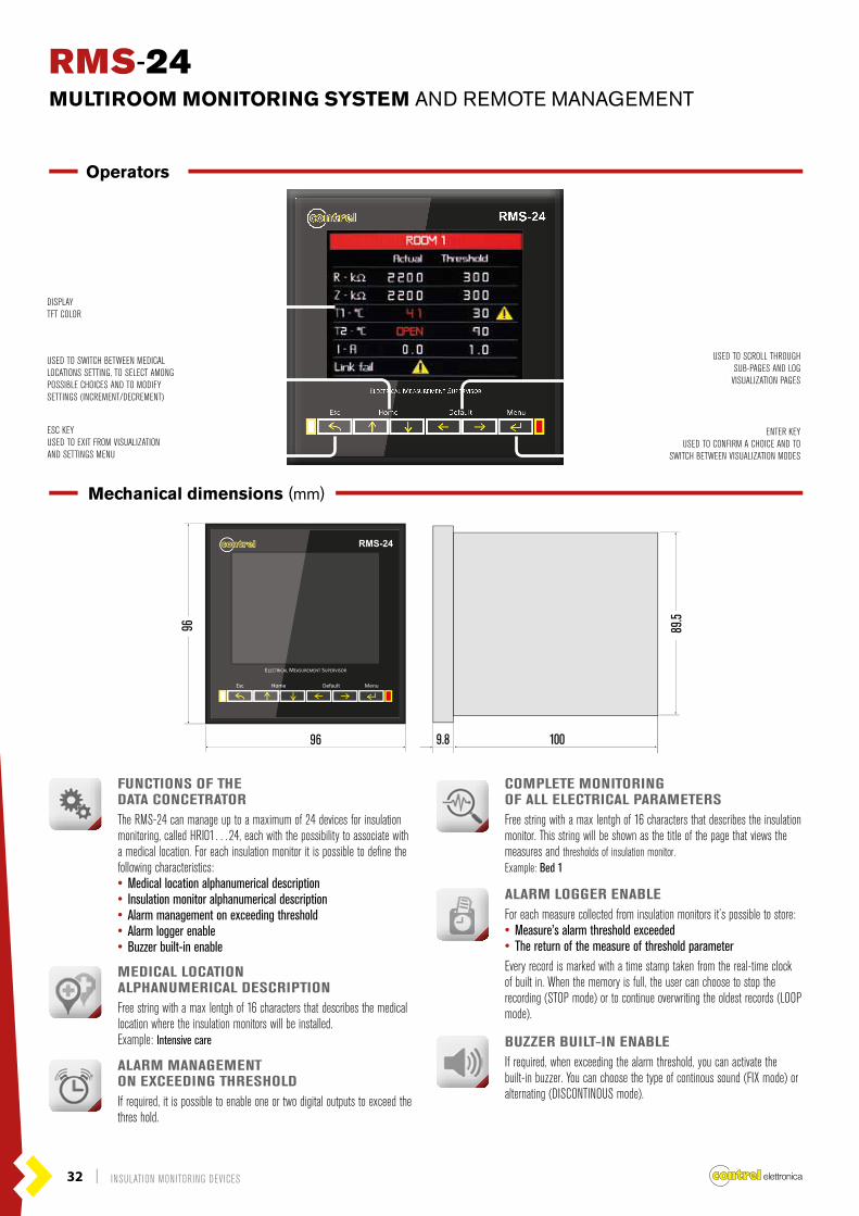
Operators
RMS-24
DISPLAYTFT COLOR
USED TO SWITCH BETWEEN MEDICAL LOCATIONS SETTING, TO SELECT AMONG POSSIBLE CHOICES AND TO MODIFY SETTINGS (INCREMENT/DECREMENT)
ESC KEYUSED TO EXIT FROM VISUALIZATIONAND SETTINGS MENU
USED TO SCROLL THROUGH SUB-PAGES AND LOG VISUALIZATION PAGES
ENTER KEYUSED TO CONFIRM A CHOICE AND TO
SWITCH BETWEEN VISUALIZATION MODES

INSULATION MONITORING DEVICES | 33
RMS-24 MULTIROOM MONITORING SYSTEM AND REMOTE MANAGEMENT
Wiring diagrams
insulation monitor HRI-R40
ALARM OUTPUTRELAY
ERROR /LINK FAIL
SET
TESTRESET
MIN / MAX
ENTERSET+ _
RZT1T2I
[k ]Ω[k ]Ω[°C][°C][A]
insulation monitor HRI-R40
ALARM OUTPUTRELAY
ERROR /LINK FAIL
SET
TESTRESET
MIN / MAX
ENTERSET+ _
RZT1T2I
[k ]Ω[k ]Ω[°C][°C][A]
HRI-R40 HRI-R40
insulation monitor HRI-R40
ALARM OUTPUTRELAY
ERROR /LINK FAIL
SET
TESTRESET
MIN / MAX
ENTERSET+ _
RZT1T2I
[k ]Ω[k ]Ω[°C][°C][A]
insulation monitor HRI-R40
ALARM OUTPUTRELAY
ERROR /LINK FAIL
SET
TESTRESET
MIN / MAX
ENTERSET+ _
RZT1T2I
[k ]Ω[k ]Ω[°C][°C][A]
HRI-R40 HRI-R40
insulation monitor HRI-R40
ALARM OUTPUTRELAY
ERROR /LINK FAIL
SET
TESTRESET
MIN / MAX
ENTERSET+ _
RZT1T2I
[k ]Ω[k ]Ω[°C][°C][A]
insulation monitor HRI-R40
ALARM OUTPUTRELAY
ERROR /LINK FAIL
SET
TESTRESET
MIN / MAX
ENTERSET+ _
RZT1T2I
[k ]Ω[k ]Ω[°C][°C][A]
HRI-R40
SURGICALAMBULATORS
example connections
HRI-R40
CONTROL ROOM
SURGERY 1 SURGERY4
SURGERY 2 SURGERY5
SURGERY 3 SURGERY6
RMS-24

CONTREL elettronica s.r.l.Via San Fereolo, 9 26900 LODI Italia | Tel. +39.0371.30207 | Fax +39.0371.32819
[email protected]@contrel.eu
www.contrel.it
According to the copyright and the civil law, the reproduction
of this catalogue, or any part of this one, by electronic,
mechanical methods, by means of photocopies, microfilms,
recordings or other, is peremptorily forbidden. Rights are
reserved for all countries. Drawings, specifications and
reference numbers may be modified and changed. CONTREL
s.r.l reserves it self the right, to make changes for technical or
quality improvements, without any notice.
Stu
dio
Mas
sim
o C
ovat
iG
RAP
HIC
DES
IGN
STU
DIO
RI-
HR
I U
K -
03 -
© C
ontr
el e
lettr
onic
a - a
ll rig
hts
rese
rved


