
1
What we know (and still don’t) on He II heat transfer through
electrical insulation for accelerator magnets
Bertrand BaudouyCEA, Irfu, SACM
91191 Gif-sur-Yvette Cedex, [email protected]
Mini workshop on thermal modeling and thermal experiments for accelerator magnet30th Sept – 1st Oct
CERN

2
Outline
▫Introduction on He II heat transfer in accelerator magnet coils
▫Heat transfer in All-polyimide electrical insulation
▫Heat transfer in ceramic porous insulation
▫Comparison of “permeable” insulation thermal characteristics
▫Heat transfer in All-impregnated insulation
▫Thermal properties
▫Some ideas and perspectives

3
He II heat transfer in accelerator magnet coils
▫“Wet” magnets with “heat exchanger”◦ Large internal losses and small stored energy
◦ Single phase coolant in contact with conductor
◦ Cooling Source: Internal heat exchanger
▫Heat transfer between the conductor and the cooling source determines the temperature margin
▫Electrical insulation constitutes the largest thermal barrier
▫LHC Electrical Insulation : All-polyimide◦10 mW/cm3 or 0.4 W/m (cable)
◦ΔT<0.3 K with permeable insulation or ΔT~4 K with monolithic insulation (He II)
◦Work mainly focus on the permeability (to He) of the insulation
◦Different wrapping schemes
◦The thermal properties of the insulation not a parameter

44
The heat paths (1/2)
▫Heat transfer configuration◦Volume dissipation in the conductors
◦Collars side is thermally insulated
◦Heat flux goes through the 1st layer and 2nd layer
◦Heat flux has to go through the cable−Conductor
−Insulation
▫Heat paths to be considered◦Small face path
◦Large face path
Open Channels
Channels between insulation

5November 19th 2007
The heat paths (2/2)
Large face : Transverse HT through the insulation and longitudinal HT in the “channels” between conductor insulation
Small face :Transverse HT through the insulation
Conductors
InsulationFirst layer
second layer
▫Transverse HT through insulation
▫“Channels” HT

6
Experimental tools
▫Measurement on coils (CERN)◦Real coil
◦DC current for heating
representative of HT in a coil
▫The “Stack” experiments (KEK, Saclay)◦Dummy Rutherford cables joule Heated
◦Instrumented with temperature sensors
◦5 conductors stack
◦Compression mold
Measurement of the overall thermal resistanceIs it representative of HT in a coil?
▫The “Drum” experiment◦Measurement of 1D transverse HT
Does not represents the real confinement in a coilNo transient measurement possibleBetter understanding of HT

7
Heat transfer in All-Polyimide Electrical Insulation
▫State-of-the-art All-Polyimide Electrical Insulation◦Developed with Kapton, Apical or Upilex
◦Two layers with polyimide glue for binding
◦Polymerisation : ~ 100°C for several hours
Courtesy of D. Tommasini
0.4 W/m
Measurement at 1.9 K, 3 conductors heated
Dry insulation
Increasing permeability
▫New development At CERN

8
He II heat transfer through permeable insulation
▫Coupling with conduction (with drum experiment)◦For large heat flux, He II HT<conduction
◦HT model with He II in “channels” in parallel with conduction with Kapitza−One average diameter of channels with measurement in Landau and Gorter-Mellink regimes−Length = over lapping of wrapping
−deq≈10 μm
0
0,05
0,1
0,15
0,2
0,25
0 0,05 0,1 0,15 0,2 0,25
Mesure
He II :
Conduction :
Calcul :
T i -
T b
(K
)
Q (W)
Qm
Q*
Qisol
QHeII
Qcalcul
QHeII
AL1 3
(T) dTTb
Ti
Q
isol + Q
HeII
Qisol
= ²T/R
0
5 1012
1 1013
1,5 1013
2 1013
1,5 1,6 1,7 1,8 1,9 2 2,1 2,2
0,1 MPa
Pvs
ƒ(T
) (
W3 m
-5K
-1)
Température (K)
First layer
second layer
Kapitza Isolant
Ti Tb
Q
T2 T1
Q HeII
Qcond
Kapitza
Canal n°1
Canal n°N
.
.
.

9
He II heat transfer through permeable insulation
▫Importance of the small face (with the Stack experiment)◦Experiment with artificial holes in a “dry” insulation
◦Experiment with the inner spacer or insulation
0
0,1
0,2
0,3
0,4
0 0,05 0,1 0,15
A16A16tCalcul (A16t)
T con
d -
Tb (
K)
Q (W)
²T
10
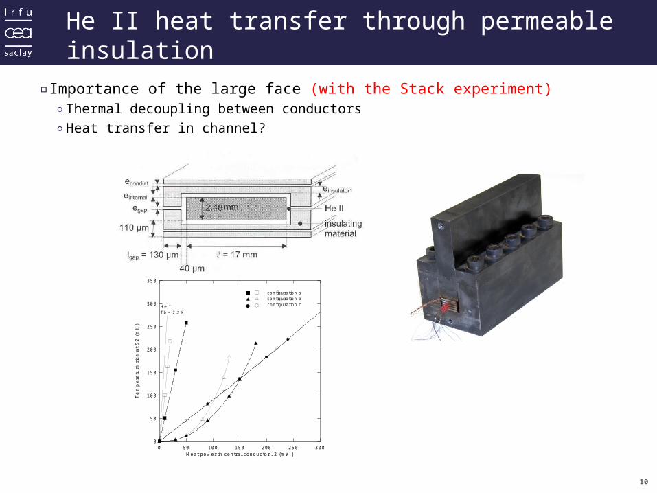
He II heat transfer through permeable insulation
▫Importance of the large face (with the Stack experiment)◦Thermal decoupling between conductors
◦Heat transfer in channel?
0 50 100 150 200 250 300H eat pow er in centra l conductor J2 (m W )
0
50
100
150
200
250
300
350
Tem
pera
ture
ris
e at
S2
(mK
)
H e ITb = 2 .2 K
configuration aconfiguration bconfigura tion c

11
Heat transfer in small channel
•Heat transfer in small channels
– deq [56; 4800] µm
– L [30; 40] mm
•Heat transfer in small slits?– 53 µm x 16 mm
– AGM not modified
– vortex spacing 1 µm
– fully developed turbulence
•Heat transfer in deq of 10 µm range and lower?
– Modification of the Physical law?
– Bulk properties?
– Variable cross-section?
– Transient?
– Phase change?
4 33
( )se
GM n
s Tq e dT
A
N. Kimura, A. terashima, A. Yamamoto, and T. Shintomi, “Heat transfer through narrow cooling channels in pressurized helium II”, presented at CEC 1999, Montréal, CanadaN. Kimura, H. Nakai, M. Murakami, A. Yamamoto, and T. Shintomi, “A study on the heat transfer properties Of pressurized helium II Through fine channels”, Adv. Cryo. Eng. 41A, 2005
12
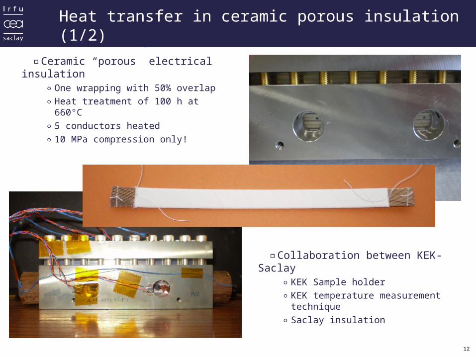
Heat transfer in ceramic porous insulation (1/2)
▫Ceramic “porous” electrical insulation
◦One wrapping with 50% overlap
◦Heat treatment of 100 h at 660°C
◦5 conductors heated
◦10 MPa compression only!
▫Collaboration between KEK-Saclay◦KEK Sample holder
◦KEK temperature measurement technique
◦Saclay insulation
13
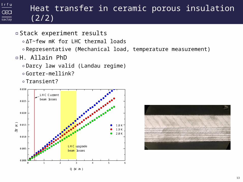
Heat transfer in ceramic porous insulation (2/2)
0 1 2 3 4 5 60.000
0.005
0.010
0.015
0.020
0.025
0.030
LHC upgradebeam losses
B B 1.8 K 1.9 K 2.0 K
T (
K)
Q (W/m)
LHC Currentbeam losses
▫Stack experiment results◦ΔT~few mK for LHC thermal loads
◦Representative (Mechanical load, temperature measurement)
▫H. Allain PhD◦Darcy law valid (Landau regime)
◦Gorter-mellink?
◦Transient?

14
Permeable Insulation Thermal Characteristics
0,0 0,1 0,2 0,3 0,4 0,5 0,6 0,7 0,8 0,9 1,00,00
0,05
0,10
0,15
0,20
0,25
0,30
400 m
155 mT (
K)
Q (W/m)
LHC-type Enhanced LHC-type Ceramic
175 m

15
Heat transfer in All-impregnated insulation (1/3)
▫Two electrical insulation scheme developed during the NED project◦Ceramic porous media
◦All-impregnated electrical insulation
S. Canfer et. al, “Insulation Development for the Next European Dipole”, IEEE Trans. on Applied Superconductivity, 18 issue 2, 2008, pp. 1387-1390
▫The fiberglass epoxy insulation◦Plain weave E glass fiber sheets
◦Mixture of DGEBF epoxy resin, typified by Dow DER354 and DETDA hardener, typified by Albemarle Ethacure 100
▫Impregnation◦Produced using a vacuum
impregnation technique in a similar way to magnet impregnation
◦Curation under 1 MPa pressure at a temperature of 90ºC
◦When the epoxy was gelled the temperature was raised to 130ºC for 16 hours

16
Heat transfer in All-impregnated insulation (2/3)
▫Kapitza resistance and thermal conductivity in He II determination◦4 thicknesses (39, 106, 144 and 293 μm)
◦Profile measurement for real thickness and surface1
2s n
s b K
A T lR
Q n T h k
HWH
W

17
Heat transfer in All-impregnated insulation (3/3)
▫Kapitza resistance and thermal conductivity in He II
▫Thermal conductivity is roughly 5 times larger than the Kapton’s one
▫Kapitza resistance is two times lower than one data found in the literature
0.000
0.010
0.020
0.030
0.040
0.050
1.5 1.6 1.7 1.8 1.9 2 2.1
Temperature (K)
The
rmal
con
duct
ivit
y (W
/m/K
)
0.0002
0.0004
0.0006
0.0008
1.5 1.6 1.7 1.8 1.9 2 2.1
Temperature (K)
RK
(m²K
W-1
)
B. Baudouy and J. Polinski, “Thermal conductivity and Kapitza resistance of epoxy resin fiberglass tape at superfluid helium temperature”, Cryogenics 49, Issue”3-4, March-April 2009, Pages 138-143

18
Thermal properties and coupling
•Kapton– K, Rth in He II known
– Cp or diffusivity?
– Heat transfer coefficient in He I?
– Transient heat transfer coefficient in He II and He I?
•Fiber glass and epoxy resin– K, Rth in He II known
– Cp or diffusivity?
– Heat transfer coefficient in He I?
– Transient heat transfer coefficient in He II and He I?
•Ceramic insulation properties?
•Heat transfer in coupled conduction and He II?– Tortuous small channels

19
Some ideas and perspectives
▫Heat transfer experiment in small channels (10 μm diameter range)◦Coupling between conduction and He II
◦Variable cross-section
◦Channels in parallel
▫Thermal properties measurement for the only insulation◦SS and transient for Cp, h…
▫Ceramic insulation (permeable state) within FJPPL◦Thermal conductivity measurement (KEK within CERN-KEK Collaboration)
◦He II Stack experiment−Continuation of He II exp at Saclay and sHe and bHe at KEK (FJPPL)
◦He II insulation only experiment (Drum experiment)
▫Ceramic insulation (impregnated state)◦Thermal conductivity measurement
◦He II Stack experiment
◦Kapitza experiment


