doublewall frp ug tank brochure
DESCRIPTION
dsfdsTRANSCRIPT

Containment Solutions, Inc.
DOUBLE-WALL FIBERGLASS TANKS
For Belowground Petroleum Storage

Do
ub
le-W
all
Fib
erg
lass
Be
low
gro
un
d S
tora
ge
Tan
ksC
on
tain
me
nt
So
luti
on
s,In
c.
2
Double-Wall Tanks from Containment Solutions
Why our tanks are your best investment.The fiberglass underground storage tank owes its very existence to theshortcomings of steel tanks — and their resulting environmentalproblems.
In the early 1960s, the American Petroleum Institute challenged us (we were then known as the SpecialProducts Division of Owens-Corning) to develop a rustproof underground storage tank that would be safe andstrong enough to satisfy the petroleum industry’s most stringent long-term storage demands.
Our engineers accepted the challenge and pioneered the underground fiberglass tank technology. The majoroil companies responded to our achievement by specifying fiberglass tanks for approximately 95% of theirunderground fuel storage installations. Their keen awareness of the limitations of a steel tank in a corrosiveenvironment and their confidence in fiberglass tank technology helped us earn a reputation for safe, rust-free,long-term underground storage in approximately 250,000 installations over the last 30 years.
Along the way, we’ve earned a leadership position in this industry. Our pioneering design work resulted in theUL 1316 specification which governs fiberglass tank manufacturing.
As the inventors of fiberglass underground storage tank technology, many of the basic patent standards beganwith Owens-Corning and continue with Containment Solutions today and in the future.
Advantages
90%FIBERGLASS
BELOWGROUNDTANKS
10%STEEL
BELOWGROUND TANKS
Table of Contents
Advantages . . . . . . . . . . . . . . . . . . . . . . . . 2
Manufacturing Processes . . . . . . . . . . . . . . . . . . . . . . . . . 4
Research & Development. . . . . . . . . . . . . . . . . . . . . . . 5
Gasoline & Fuel Oil Systems Overviews. . . . . . . . . . . . . . . . . . 6
Monitoring . . . . . . . . . . . . . . . . . . . . . . . 10
Tank Specifications/Drawings . . . . . . . . . 13
Accessories. . . . . . . . . . . . . . . . . . . . . . . 24
Warranty/Specifications . . . . . . . . . . . . . . . . . . . . . 32
Containment Solutions manufactures:
Aboveground and Belowground Storage Tanks
Automotive Oil and Lubricant Storage Tanks
Compartment Tanks
Oil/Water Separators and Interceptors
Water/Wastewater Tanks
Chemical Storage Tanks
ReTank® Retrofit Systems
Fiberglass Manholes and Wetwells
Leak Detection Systems
Our fiberglass tanks have been exhumed after 6, 12, 15 and 21 years of gasoline service and have shown no loss in their original (structural) properties.

Do
ub
le-W
all Fibe
rglass
Be
low
gro
un
d S
torag
e Tan
ksC
on
tainm
en
t So
lutio
ns,In
c.
3
We will continue to lead, far intothe future, thanks to the visionof everyone on our team.Every one of our employees brings atremendous amount of pride to what wedo:
• Our rigorous dedication to research anddevelopment. Our newly expanded R&Dfacility focuses its considerable talentson pushing the limits of what ispossible and practical, to provide youwith products that meet your needs at acompetitive price, while offering thehighest quality.
• Our technologically-superior manufacturing process leverages the finest materials and methods to producehigh-quality products that have led the industry for over three decades.
• Our industry-leading support. We have the most knowledgeable direct field sales force and the only nationalfield service organization staffed by full-time company employees. They, along with our superb insidesales group, are committed to supplying “value-added” service that complements our exceptionalproducts. Our customer service and technical support group promptly and clearly answers any technicalquestion about our products or services.
All of which adds up to Containment Solutions’ people going above and beyond to deliver the highest qualityand best long-term value in underground storage technologies that you can invest in.
Containment Solutions invites you to review our state-of-the-art products at three conveniently locatedmanufacturing facilities in Bakersfield, CA, Conroe, TXand Mt. Union, PA. Only then will you understand thedepth and breadth of our advantages — and our pridewhich is evident in every product we make.
Our tanks carry the Underwriters Laboratories listing.

Do
ub
le-W
all
Fib
erg
lass
Be
low
gro
un
d S
tora
ge
Tan
ksC
on
tain
me
nt
So
luti
on
s,In
c.
4
Processes
The product of precision engineering and forward thinking.The process by which our fiberglass tanks are manufactured speaks volumes about their quality, integrity,safety and longevity.
Since the very first non-corrosive tank was designed back in the 1960s, we have maintained the highest qualitystandards and have leveraged promising technologies to engineer and build the world’s premier fiberglassstorage tank.
Our tanks are made on steel molds from the inside out.We use steel mandrels (cylindrical steel molds) and build our tanks from the inside out. Steel molds provideus with a firm and consistent surface upon which we apply materials to make our tank. The rotation of themandrel and the application of the materials are controlled by a computer, custom designed to manufactureunderground tanks. As the mandrel rotates, resin, glass and specially treated silica are precisely metered ontothe mandrel from above. The result is a closely controlled process and a very consistent tank wall compositionand thickness.
After the tank wall is made, its thickness is precisely determined. Aninstrument that magnetically senses the metal mold surfacethrough the fiberglass reinforced plastic laminate is used toaccurately measure the thickness of the laminate at many points allover the surface of the tank wall. This method of thicknessmeasurement with a metal mold is quick, easy and more exact thanthe ultrasonic methods used by other manufacturers.
Stronger tanks, inside and out.The inside-out approach to building the tank wall has some otheradvantages as well. The first layer of materials forms the insidesurface of the tank. Because of the smooth steel mold, the insidesurface of the tank is very smooth and free of surface variations.
The inside surface is not exposed to air as it cures, which eliminates the air inhibited surface cure problemssometimes associated with other methods. The result is a well cured and very smooth tank interior that willbe exposed to the fuel in the tank.
By applying materials to the outside of the tank, we can easily add additional thickness, reinforcing ribs,filament winding glass in tension, glass woven roving, glass mat, or any other materials in specific locationson the tank wall. With this capability, we use the most efficient materials in the most efficient locations to meetthe design requirements of the finished tank. Additional wall thickness is added exactly where it is needed.Ribs are applied in optimal locations, made in the most efficient shapes, and constructed of the most efficientreinforcing materials. If a different rib shape or height or location would be better, the form or the location ofthe rib can be changed. If the rib form shape was a part of the mandrel, these changes could not be madewithout changing the mandrel itself.

Do
ub
le-W
all Fibe
rglass
Be
low
gro
un
d S
torag
e Tan
ksC
on
tainm
en
t So
lutio
ns,In
c.
5
Engineered and tested corrosion resistance.The Containment Solutions’ tank wall is composed of resin, glass and a specially treated silica that togetherresult in a composite matrix that is compatible with petroleum products, including gasoline, jet fuel, av-gas,motor oil, kerosene, diesel fuel and fuel oil, and up to 100% ethanol and/or methanol blends and oxygenatedmotor fuels.
Containment Solutions pioneered and per-fected the use of a specially treated silica thatis a part of our laminate matrix. The additionof this material has been proven to increaseand improve the performance of our laminatein all fuels, including alcohols.
Our laminate has been thoroughly tested tomeet the requirements of UL 1316. Additionallong-term corrosion testing continues at ourResearch and Development Center. Thistesting is done in conditions that match actualinstallation conditions. This results in datathat can be used to accurately predict thelong-term properties needed for accurate tankdesigns. Data has been accumulated forcurrent fuels and blends as well as its effectson the laminate after a number of years. Thisdata includes tests on current fuels andblends and other oxygenates. We areconstantly testing new products that can bestored in our tanks in the future.
Our R&D Center never stops asking questions.We could never maintain our position on the leading edge of fiberglass tank design without anuncompromising commitment to research and development. Our newly expanded R&D Center gives us theability to look at new and promising ways to improve our products, expand our capabilities and better serveour customer’s ever-changing needs.
Our underground tank test pit helps us perfect our product.Containment Solutions is the only fiberglass tank manufacturer that studies tanks in all buried conditions andconfigurations. To do this, we constructed a full-scale test pit at our Conroe, Texas R&D Center, which allowsus to test various tank designs with different backfill materials, anchoring methods, groundwater conditionsand many other variables.
Processes
Do
ub
le-W
all
Fib
erg
lass
Be
low
gro
un
d S
tora
ge
Tan
ks
6
3
14
10
2
2
1
12
13
15
B
A
7
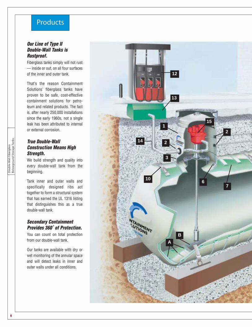
Our Line of Type II Double-Wall Tanks isRustproof.Fiberglass tanks simply will not rust— inside or out, on all four surfacesof the inner and outer tank.
That’s the reason ContainmentSolutions’ fiberglass tanks haveproven to be safe, cost-effectivecontainment solutions for petro-leum and related products. The factis, after nearly 250,000 installationssince the early 1960s, not a singleleak has been attributed to internalor external corrosion.
True Double-WallConstruction Means HighStrength.We build strength and quality intoevery double-wall tank from thebeginning.
Tank inner and outer walls andspecifically designed ribs acttogether to form a structural systemthat has earned the UL 1316 listingthat distinguishes this as a truedouble-wall tank.
Secondary ContainmentProvides 360˚ of Protection.You can count on total protectionfrom our double-wall tank.
Our tanks are available with dry orwet monitoring of the annular spaceand will detect leaks in inner andouter walls under all conditions.
Products
6
4
5
10
8
11
B
16
17D
18
C
9
19
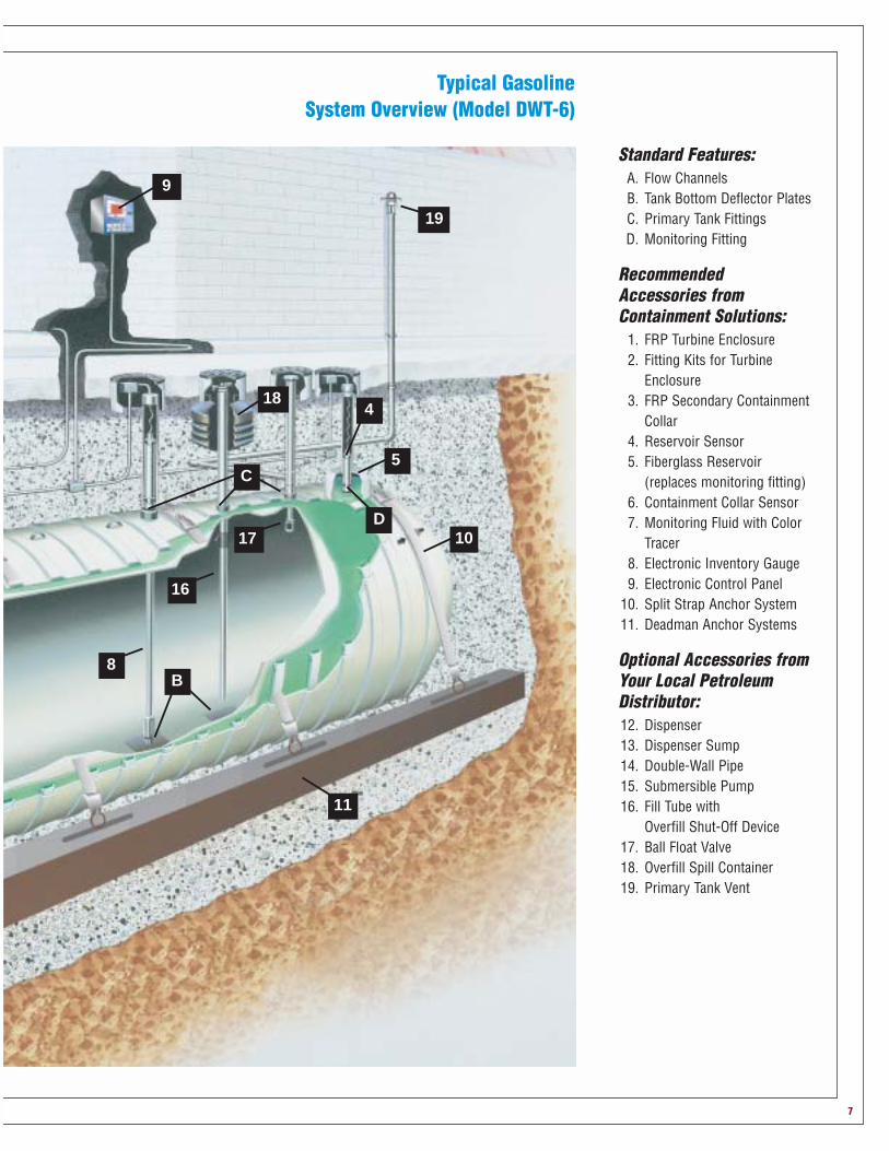
Standard Features:A. Flow ChannelsB. Tank Bottom Deflector PlatesC. Primary Tank FittingsD. Monitoring Fitting
RecommendedAccessories fromContainment Solutions:
1. FRP Turbine Enclosure 2. Fitting Kits for Turbine
Enclosure 3. FRP Secondary Containment
Collar4. Reservoir Sensor5. Fiberglass Reservoir
(replaces monitoring fitting)6. Containment Collar Sensor7. Monitoring Fluid with Color
Tracer8. Electronic Inventory Gauge9. Electronic Control Panel
10. Split Strap Anchor System11. Deadman Anchor Systems
Optional Accessories fromYour Local PetroleumDistributor:12. Dispenser13. Dispenser Sump14. Double-Wall Pipe15. Submersible Pump16. Fill Tube with
Overfill Shut-Off Device17. Ball Float Valve18. Overfill Spill Container19. Primary Tank Vent
Typical Gasoline System Overview (Model DWT-6)
7

Do
ub
le-W
all
Fib
erg
lass
Be
low
gro
un
d S
tora
ge
Tan
ksC
on
tain
me
nt
So
luti
on
s,In
c.
8
Products
Our Double-Wall Tanks deliver state-of-the-art protection.CSI’s advanced double-wall technology gives owners, municipalities, counties and states proven protectionagainst petroleum contamination of underground water supplies. In addition to our UL listing, our tankscomply with the American Petroleum Institute’s recommendation for secondary containment systemswherever underground tanks are located within 300 feet of underground water supplies.
As liabilities associated with leaking fuels soar, UL-listed fiberglass Type II Double-Wall Tanks for undergroundstorage applications provide you with your best long-term protection.
Don’t settle for less than the ultimate in risk management.Type II Double-Wall Tanks give you two levels of protection, so you have twice the assurance and twice therisk management that any single-wall tank can offer. The primary tank is designed to contain your fuel. In theunlikely event that there is a breach in this wall, the secondary wall is designed to contain your product andprevent a spill into the environment.
System testing assures you of product tightness.Continued assurance of the integrity of our double-wall tanks can be determined by testing at the jobsite –prior to and after installation – to prove the durability and product tightness of both the primary and secondary
tanks. With some competitive tanks, the secondary wallsor jackets cannot be tested after the tanks have beeninstalled.
Continuous monitoring and precision tank-testing capabilities are built in.Because it is comforting to be able to test the ongoingintegrity of any storage tank, CSI built into each of ourdouble-wall tanks both continuous monitoring andprecision tank-testing capabilities.
Our Type II Double-Wall Tanks provide a defined annular space to accommodate virtually any type of moni-toring method you choose — wet or dry. Our tanks can be supplied with a factory installed HydrostaticMonitoring System with a brine monitoring fluid. The brine is a dark green color preinstalled in the interstitialspace at the factory and is used to perform visual leak testing during shipment and at the jobsite.
We recommend the Hydrostatic Monitoring System because it offers a leakdetection capability that is superior to other methods. It constantly monitors 100%of both the inner and outer walls under all installed conditions. Most steel tanks donot offer this feature. The Hydrostatic Monitoring System can also double as aprecision tank test, which has been independently tested and validated to meet EPAprecision tank-testing requirements, able to detect leaks as small as 0.1 gallons perhour. The precision tank-testing procedure is easy to perform and consists of a fewsimple steps.
INNER TANK WALL
OUTER TANK WALL
HIGH STRENGTHINTERIOR RIBS
Two walls mean twicethe protectionagainst costlyleaks.

Do
ub
le-W
all Fibe
rglass
Be
low
gro
un
d S
torag
e Tan
ksC
on
tainm
en
t So
lutio
ns,In
c.
9
16
8
1
13
11
4
2
15D
C
7
14
A
B
12
10
5
63
9
Day Tank
FOS FOR
Typical Fuel-Oil System Overview(Model DWT-6)
Standard Features:A. Flow ChannelsB. Tank Bottom
Deflector PlatesC. Primary Tank FittingsD. Monitoring Fitting
RecommendedAccessories fromContainmentSolutions:
1. FRP Turbine Enclosure 2. Fitting Kits for
Turbine Enclosure 3. FRP Secondary
Containment Collar4. Reservoir Sensor5. Containment Collar
Sensor6. Monitoring Fluid with
Color Tracer7. Electronic Inventory
Gauge8. Electronic Control
Panel9. Split Strap Anchor
System10. Deadman Anchor
Systems
Optional Accessoriesfrom Your LocalPetroleum Distributor:11. Double-Wall Pipe12. Fill Tube with Overfill
Shut-Off Device13. Overfill Spill
Container14. Foot Valve15. Ball Float Valve16. Primary Tank Vent
Do
ub
le-W
all
Fib
erg
lass
Be
low
gro
un
d S
tora
ge
Tan
ksC
on
tain
me
nt
So
luti
on
s,In
c.
10
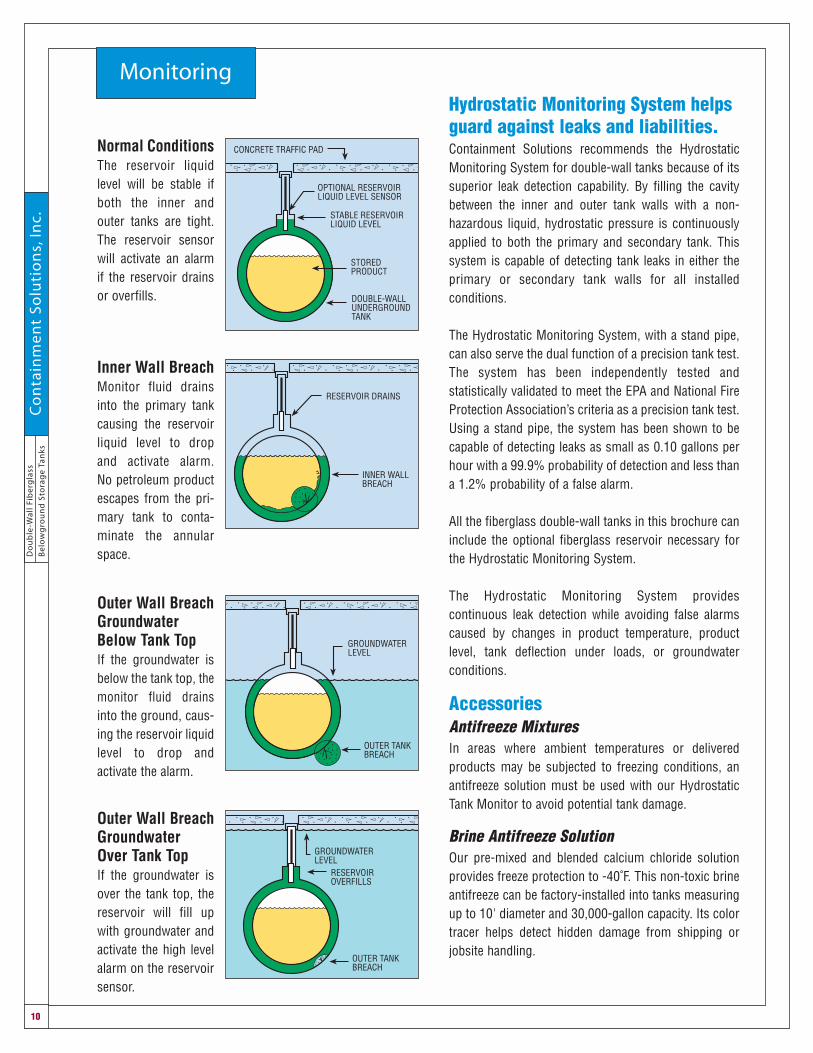
MonitoringHydrostatic Monitoring System helpsguard against leaks and liabilities.Containment Solutions recommends the HydrostaticMonitoring System for double-wall tanks because of itssuperior leak detection capability. By filling the cavitybetween the inner and outer tank walls with a non-hazardous liquid, hydrostatic pressure is continuouslyapplied to both the primary and secondary tank. Thissystem is capable of detecting tank leaks in either theprimary or secondary tank walls for all installedconditions.
The Hydrostatic Monitoring System, with a stand pipe,can also serve the dual function of a precision tank test.The system has been independently tested andstatistically validated to meet the EPA and National FireProtection Association’s criteria as a precision tank test.Using a stand pipe, the system has been shown to becapable of detecting leaks as small as 0.10 gallons perhour with a 99.9% probability of detection and less thana 1.2% probability of a false alarm.
All the fiberglass double-wall tanks in this brochure caninclude the optional fiberglass reservoir necessary forthe Hydrostatic Monitoring System.
The Hydrostatic Monitoring System providescontinuous leak detection while avoiding false alarmscaused by changes in product temperature, productlevel, tank deflection under loads, or groundwaterconditions.
Accessories Antifreeze MixturesIn areas where ambient temperatures or deliveredproducts may be subjected to freezing conditions, anantifreeze solution must be used with our HydrostaticTank Monitor to avoid potential tank damage.
Brine Antifreeze SolutionOur pre-mixed and blended calcium chloride solutionprovides freeze protection to -40˚F. This non-toxic brineantifreeze can be factory-installed into tanks measuringup to 10' diameter and 30,000-gallon capacity. Its colortracer helps detect hidden damage from shipping orjobsite handling.
OPTIONAL RESERVOIRLIQUID LEVEL SENSOR
STABLE RESERVOIRLIQUID LEVEL
STOREDPRODUCT
DOUBLE-WALLUNDERGROUNDTANK
CONCRETE TRAFFIC PAD
RESERVOIR DRAINS
INNER WALLBREACH
OUTER TANKBREACH
RESERVOIROVERFILLS
GROUNDWATERLEVEL
Normal ConditionsThe reservoir liquidlevel will be stable ifboth the inner andouter tanks are tight.The reservoir sensorwill activate an alarmif the reservoir drainsor overfills.
Inner Wall BreachMonitor fluid drainsinto the primary tankcausing the reservoirliquid level to dropand activate alarm. No petroleum productescapes from the pri-mary tank to conta-minate the annularspace.
GROUNDWATERLEVEL
OUTER TANKBREACH
Outer Wall BreachGroundwaterBelow Tank TopIf the groundwater isbelow the tank top, themonitor fluid drainsinto the ground, caus-ing the reservoir liquidlevel to drop andactivate the alarm.
Outer Wall BreachGroundwater Over Tank TopIf the groundwater isover the tank top, thereservoir will fill upwith groundwater andactivate the high levelalarm on the reservoirsensor.

Do
ub
le-W
all Fibe
rglass
Be
low
gro
un
d S
torag
e Tan
ksC
on
tainm
en
t So
lutio
ns,In
c.
11
MonitoringMonitoring System ConfigurationsOur fiberglass double-wall tanks are designed to accommodate wet (hydrostatic) or dry leak-monitoringsystems.
Wet Annular Space
DRY ANNULAR SPACELIQUID SENSING PROBE
RISER PIPE
CONCRETE TRAFFIC PAD
4" ANNULARSPACE FITTING
OPTIONAL RESERVOIRLIQUID LEVEL SENSOR
STABLE RESERVOIRLIQUID LEVEL
STOREDPRODUCT
DOUBLE-WALLUNDERGROUNDTANK
CONCRETE TRAFFIC PAD
RISERPIPE
CONCRETE TRAFFIC PAD
VACUUM OR AIRPRESSURE SENSOR
4" ANNULARSPACE FITTING
WATERSENSOR
RISER PIPE
CONCRETE TRAFFIC PAD
HYDROCARBONVAPOR SENSOR
4" ANNULARSPACE FITTING
Monitoring System with GasolineVapor Sensor Many vapor sensors also include a watersensor.
1. Use the standard monitoring fitting.2. Monitoring cavity can be vented or
sealed.
Monitoring System with Vacuum and Air Pressure 1. Use the standard monitoring fitting.2. Maximum continuous positive air pressure is 3 psi.3. Maximum continuous vacuum is 5 psi.
Monitoring System with Liquid Sensor Typical configuration for an electronic sensor or manual dipstick.
1. Use the standard monitoring fitting.2. Monitoring cavity can be vented or sealed.
Hydrostatic Monitoring System1. Use antifreeze (brine) solution in cold climates.2. Maximum burial depth from tank top is seven feet below grade.3. Monitoring cavity must be vented to the atmosphere. The optional
reservoir sensor includes vent holes to vent the monitoring cavity.4. After installation, set the liquid level in the reservoir so reservoir is half
full.
Dry Annular SpaceContainment Solutions provides a factory-installed “drawstring” at the annular space monitoring fitting, toassist in positioning liquid sensors at the bottom of the annular space. If your tank is ordered with a dryannular space, but fitted with the optional fiberglass reservoir (instead of a monitoring fitting), the drawstringwill be positioned within the reservoir.
The HydrostaticMonitoring Systemis the best at leakdetection because
it’s continuouslymonitoring thecomplete innerand outer tank.
Do
ub
le-W
all
Fib
erg
lass
Be
low
gro
un
d S
tora
ge
Tan
ksC
on
tain
me
nt
So
luti
on
s,In
c.
12
Monitoring
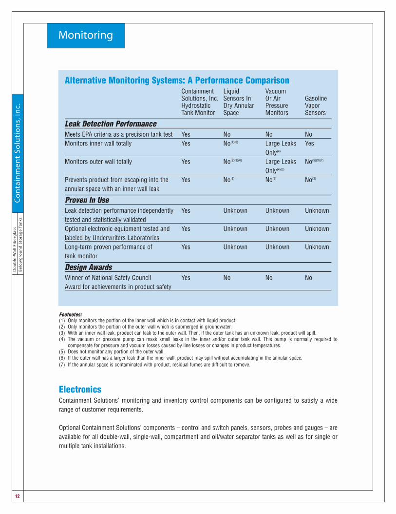
Footnotes:(1) Only monitors the portion of the inner wall which is in contact with liquid product.(2) Only monitors the portion of the outer wall which is submerged in groundwater.(3) With an inner wall leak, product can leak to the outer wall. Then, if the outer tank has an unknown leak, product will spill.(4) The vacuum or pressure pump can mask small leaks in the inner and/or outer tank wall. This pump is normally required to
compensate for pressure and vacuum losses caused by line losses or changes in product temperatures.(5) Does not monitor any portion of the outer wall.(6) If the outer wall has a larger leak than the inner wall, product may spill without accumulating in the annular space.(7) If the annular space is contaminated with product, residual fumes are difficult to remove.
ElectronicsContainment Solutions’ monitoring and inventory control components can be configured to satisfy a widerange of customer requirements.
Optional Containment Solutions’ components – control and switch panels, sensors, probes and gauges – areavailable for all double-wall, single-wall, compartment and oil/water separator tanks as well as for single ormultiple tank installations.
Alternative Monitoring Systems: A Performance ComparisonContainment Liquid VacuumSolutions, Inc. Sensors In Or Air GasolineHydrostatic Dry Annular Pressure VaporTank Monitor Space Monitors Sensors
Leak Detection PerformanceMeets EPA criteria as a precision tank test Yes No No NoMonitors inner wall totally Yes No(1)(6) Large Leaks Yes
Only(4)
Monitors outer wall totally Yes No(2)(3)(6) Large Leaks No(5)(3)(7)
Only(4)(3)
Prevents product from escaping into the Yes No(3) No(3) No(3)
annular space with an inner wall leak
Proven In UseLeak detection performance independently Yes Unknown Unknown Unknowntested and statistically validatedOptional electronic equipment tested and Yes Unknown Unknown Unknownlabeled by Underwriters LaboratoriesLong-term proven performance of Yes Unknown Unknown Unknowntank monitor
Design AwardsWinner of National Safety Council Yes No No NoAward for achievements in product safety

Do
ub
le-W
all Fibe
rglass
Be
low
gro
un
d S
torag
e Tan
ksC
on
tainm
en
t So
lutio
ns,In
c.
13
Tank Specifications
Standard Tank Notes1. The primary tank’s standard pipe fittings are 4" NPT half couplings. All tanks include one manway with
three or more primary tank fittings in the cover. All other primary tank fittings are mounted on the tank.Additional manways and tank fittings are available on a made-to-order basis.
2. Tank bottom deflector plates are standard under every manway and primary tank fitting.
3. An optional fiberglass reservoir for leak monitoring can be integrally bonded to the top of all 6' diameter and larger double-wall tanks. It includes a 4" NPT half-coupling fitting mounted on top of thereservoir, which allows access to the cavity between the inner and outer tank walls. On 6' diameter andlarger tanks with an optional fiberglass reservoir, the reservoir is positioned over the normal monitorfitting position and the tank will not include a separate monitoring fitting. The rib under the reservoir ishollow if the annular space is not factory filled with monitoring liquid.
4. For all double-wall tanks without a reservoir, a 4" NPT annular space fitting is included on the top of thetank for monitoring. It permits access to a hollow rib which accommodates the installation of liquidsensors.
5. Fiberglass reservoirs are not included on 4' diameter tanks. A contractor-supplied 4" diameter riser pipemust be inserted into the 4" diameter annular space fitting to serve as the tank’s reservoir. This riser pipemust be at least 2" longer than the electronic sensor.
6. All primary tanks must be vented. They areintended to be operated with fluid levels nohigher than the tank top. Fiberglass tanksare designed to be operated at atmosphericpressure only – except when using vapor-recovery systems – provided the pressure orvacuum does not exceed 1 psi on theprimary tank. Over-pressurizing the primarytank will result in tank failure. When ventingthe monitoring cavity between the inner andouter tank, it must be vented independentlyfrom the primary tank (annular spaceventing is required for all hydrostaticallymonitored tanks).
See pages 14-22 for standard tank data andconfiguration.

Standard Tanks No. of No. of 4" NPT 4" NPT No. of Hold
Tank Nominal Actual Overall Nominal Nominal Wt. Manway Tank No. of Down Straps Diameter Capacity Capacity Length Weight w/Brine Fittings Fittings Lift Lugs Required
4' 550 543 6' 7" 690 895 5 N/A 1 2
4' 600 606 7' 3" 750 975 4 1 1 2
4' 1,000 966 11' 1" 950 1,235 4 1 1 2
6' 2,500 2,689 13' 9" 2,060 2,660 5 1 2 2
6' 3,000 3,323 16' 9" 2,475 3,200 4 2 1 2
6' 4,000 3,958 19' 9" 2,700 3,500 3 3 1 2
6' 5,000 5,068 25' 0" 3,050 4,000 3 3 2 4
6' 6,000 6,179 30' 3" 3,400 4,500 3 3 2 4
8' 5,000 4,947 16' 9" 2,850 3,750 5 1 1 2
8' 6,000 5,897 19' 6" 3,400 4,500 4 2 1 2
8' 8,000 7,796 25' 0" 4,200 5,600 3 3 2 4
8' 10,000 9,696 30' 6" 5,000 6,700 3 3 2 4
8' 12,000 11,595 36' 0" 6,000 8,000 3 3 2 4
8' 15,000 14,545 44' 6-1/2" 7,500 10,000 3 3 2 6
10’ 10,000 10,257 20' 11-1/2" 5,950 7,900 5 1 4 3
10' 12,000 11,873 23' 8-1/2" 6,600 9,000 4 2 4 4
10' 15,000 15,104 29' 2-1/2" 8,000 11,500 3 3 4 4
10' 20,000 19,951 37' 5-1/2" 9,900 14,500 3 3 4 6
10' 25,000(1) 24,970 46' 0" 11,700 17,500 3 3 4 8
10' 30,000 29,816 54' 3" 13,900 21,000 3 3 8 8
10' 35,000 34,835 62' 9-1/2" 17,000 N/A * * 8 8
10' 40,000 39,854 71' 4" 18,500 N/A * * 8 10
* Made to order(1) If brine filled, 8 lift lugs installed.
Do
ub
le-W
all
Fib
erg
lass
Be
low
gro
un
d S
tora
ge
Tan
ksC
on
tain
me
nt
So
luti
on
s,In
c.
14
Tank Model: DWT-6 Type II

Do
ub
le-W
all Fibe
rglass
Be
low
gro
un
d S
torag
e Tan
ksC
on
tainm
en
t So
lutio
ns,In
c.
15
4' Diameter
Model DWT-6 Type II (4)-550
4'0" I.D.
4'3" O.D.
6'-7"
24-1/4"1/8"
3'-3 7/16"
6'-1/2"
2'-1/2"
4" NPT FTG.
22" MANWAY W/(5) - 4" NPT FITTINGS
4" ANNULAR SPACE FTG.
8" R
OPTIONAL 42" CONTAINMENT COLLAR
1'-124-1/4"
3'-3 7/16"
1/8"1'-1
CL
Model DWT-6 Type II (4)-1,000
4'0" I.D.
4'3" O.D.
11'1"
3'4-1/4" 3'4-1/4"4'2"
5'6-7/16"4'2"
5'6-7/16"
2'2-1/4"2'2-1/4"
7'3/8"3'6"10'1/8"
4" NPT FTG.
4" ANNULAR SPACE FTG.
8" R
OPTIONAL 42" CONTAINMENT COLLAR22" MANWAY W/(4 ) - 4" NPT FITTINGS
Model DWT-6 Type II (4)-600
4'0" I.D.
4'3" O.D.
7'3"
2'6-3/8"
1'8" 2'4"
3'7-7/16" 3'7-7/16"
6'1/2"3'3/4"
2'2-1/4" 2'6-3/8"
1'1-1/8"
2'1-3/4"
4" NPT FTG.
22" MANWAY W/(4 ) - 4" NPT FITTINGS
4" ANNULAR SPACE FTG.
8" R
OPTIONAL 42" CONTAINMENT COLLAR

Do
ub
le-W
all
Fib
erg
lass
Be
low
gro
un
d S
tora
ge
Tan
ksC
on
tain
me
nt
So
luti
on
s,In
c.
16
6' Diameter
Model DWT-6 Type II (6)-2,500 Gallon
6'0" I.D.
2'0-1/2"13'9"
2'0-1/2"9'8"
CL
4" ANNULAR SPACE FTG.
OPTIONAL RESERVOIR
4" NPT FTG.
OPTIONAL 42" CONTAINMENT COLLAR
8" R22" MANWAY W/(5) - 4" NPT FITTINGS
1 2 3 4 65
1'7"16-1/2" TYP.
6'3-1/2" O.D.
Model DWT-6 Type II (6)-3,000 Gallon
6'0" I.D.
16'9"
2'0-1/2"12'8"
CL
4" ANNULAR SPACE FTG.
OPTIONAL RESERVOIR
OPTIONAL 42" CONTAINMENT COLLAR
8" R22" MANWAY W/(4) - 4" NPT FITTINGS
1 2 3 4 87
1'8"
6'3-1/2" O.D.
5 6
8-1/2" 11-1/2"
4" NPT FTGS. (3 TYP.)
2'0-1/2"
Model DWT-6 Type II (6)-4,000 Gallon
6'0" I.D.
6'3-1/2" O.D.
2'0-1/2"19'9"
2'0-1/2"15'8"
CL11-1/2" 16-1/2" TYP.
4" ANNULAR SPACE FTG.OPTIONAL RESERVOIR
4" NPT FTG. (TYP. 3)
OPTIONAL 42" CONTAINMENT COLLAR8" R
22" MANWAY W/(3) - 4" NPT FITTINGS
1 2 3 4 5 6 8 9 107
1'11"

Do
ub
le-W
all Fibe
rglass
Be
low
gro
un
d S
torag
e Tan
ksC
on
tainm
en
t So
lutio
ns,In
c.
17
6' Diameter
Model DWT-6 Type II (6)-5,000 Gallon
6'0" I.D.
2'0-1/2"
25'0"
2'0-1/2"8' 6-1/2"
CL
4" ANNULAR SPACE FTG.
OPTIONAL RESERVOIR
1 2 3 10
6'3-1/2" O.D.
11-1/2"
OPTIONAL 42" CONTAINMENT COLLAR
8" R22" MANWAY W/(3) - 4" NPT FITTINGS
4 5 6 7 8 9
33-1/2"
4' 1-1/2"
11 12 13 14
8' 3"
4" NPT FTGS. (3 TYP.)
8-1/2" 18-1/2" TYP.
Model DWT-6 Type II (6)-6,000 Gallon
33-1/2"
6'0" I.D.
6'3-1/2" O.D.
2'0-1/2" 9'7-1/2"
30'3"
9'7-1/2"6'11"
CL17" 16-1/2" TYP.
4" ANNULAR SPACE FTG.
OPTIONAL RESERVOIR
4" NPT FTG. (TYP. 3)OPTIONAL 42" CONTAINMENT COLLAR8" R
22" MANWAY W/(3) - 4" NPT FITTINGS
1 2 3 4 5 6 7 8 9 10 1211 13 14 15 16 17 18

Do
ub
le-W
all
Fib
erg
lass
Be
low
gro
un
d S
tora
ge
Tan
ksC
on
tain
me
nt
So
luti
on
s,In
c.
18
8' DiameterModel DWT-6 Type II (8)-5,000 Gallon
6
7'8" I.D.
8'0" O.D.
3'3-7/8"16'9"
1'10-1/4"
CL
3'3-7/8"
16-1/2" TYP.
4" ANNULAR SPACE FTG.OPTIONAL RESERVOIR
4" NPT FTG.
OPTIONAL 42" CONTAINMENT COLLAR8" R
22" MANWAY W/(5) - 4" NPT FITTINGS
1 2 3 4 5
10'1-1/4"
11 1/8"
Model DWT-6 Type II (8)-6,000 Gallon
7'8" I.D.
8'0" O.D.
3'3-7/8"19'6"
1'10-1/4"
CL
3'3-7/8"
16-1/2" TYP.
4" ANNULAR SPACE FTG.OPTIONAL RESERVOIR
4" NPT FTG. (TYP. 2)
OPTIONAL 42" CONTAINMENT COLLAR8" R
22" MANWAY W/(4) - 4" NPT FITTINGS
1 2 3 4 5 76
12'10-1/4"
8
Model DWT-6 Type II (8)-8,000 Gallon
38-3/4"
7'8" I.D.
8'0" O.D.
3'3-7/8" 6'10-1/2"25'0"
4'7-1/4"1'10-1/4"
CL
3'3-7/8"
16-1/2" TYP.
4" ANNULAR SPACE FTG.OPTIONAL RESERVOIR
4" NPT FTG. (TYP. 3)
OPTIONAL 42" CONTAINMENT COLLAR8" R
22" MANWAY W/(3) - 4" NPT FITTINGS
1 2 3 4 5 6 7 98 10 11 12
6'10-1/2"
11-1/8"

Do
ub
le-W
all Fibe
rglass
Be
low
gro
un
d S
torag
e Tan
ksC
on
tainm
en
t So
lutio
ns,In
c.
19
8' Diameter
Model DWT-6 Type II (8)-15,000 Gallon
33"
7'8" I.D.
8'0" O.D.
3'3-7/8" 9' 7-1/2"44' 6-1/2"
CL10"
4" ANNULAR SPACE FTG.
OPTIONAL RESERVOIR
4" NPT FTG. (3TYP.)
OPTIONAL 42" CONTAINMENT COLLAR8" R
22" MANWAY W/(3) - 4" NPT FITTINGS
1 2 3 4 5 6 7 8 9 11 1312 14 15 16 17 18 24 2510 19 20 21 22 23
11-1/8"15' 3" 14' 0-1/2"
5' 10-5/8" 6' 10-1/2"
CL10"
5' 10-5/8"
11-1/8"15' 3"
9' 7-1/2"3' 3-7/8"
Model DWT-6 Type II (8)-12,000 Gallon
38-3/4"
7'8" I.D.
8'0" O.D.
3'3-7/8" 11'0"36'0"
11'0"7'4-1/4"1'10-1/4"
CL
3'3-7/8"
11-1/8" 16-1/2" TYP.
4" ANNULAR SPACE FTG.OPTIONAL RESERVOIR
4" NPT FTG. (TYP. 3)
OPTIONAL 42" CONTAINMENT COLLAR8" R
22" MANWAY W/(3) - 4" NPT FITTINGS
1 2 3 4 5 6 7 8 9 10 11 1312 14 15 16 17 18 19 20
Model DWT-6 Type II (8)-10,000 Gallon
38-3/4"
7'8" I.D.
8'0" O.D.
3'3-7/8" 8'3"30'6"
8'3"7'4-1/4"1'10-1/4"
CL
3'3-7/8"
11-1/8" 16-1/2" TYP.
4" ANNULAR SPACE FTG.OPTIONAL RESERVOIR
4" NPT FTG. (TYP. 3)OPTIONAL 42" CONTAINMENT COLLAR8" R
22" MANWAY W/(3) - 4" NPT FITTINGS
1 2 3 4 5 6 7 8 9 1110 12 13 14 15 16

Do
ub
le-W
all
Fib
erg
lass
Be
low
gro
un
d S
tora
ge
Tan
ksC
on
tain
me
nt
So
luti
on
s,In
c.
20
10' Diameter
Model DWT-6 Type II (10)-10,000 Gallon
10'0" I.D.
10'6" O.D.
5'6-1/4" 5'9-1/2"20'11-1/2"
4'1-1/4"
CL
5'6-1/4"
16-1/2" TYP.
4" ANNULAR SPACE FTG.
OPTIONAL RESERVOIR
4" TOP MTD. FTG.
36-1/2"
OPTIONAL 42" CONTAINMENT COLLAR8" R
22" MANWAY W/(5) - 4" NPT FITTINGS
1 2 3 4 5 6
10"
1'8"
Model DWT-6 Type II (10)-12,000 Gallon
10'0" I.D.
10'6" O.D.
5'6-1/4" 5'6"
23'8-1/2"5'6"
CL5'6-1/4"
16-1/2" TYP.
4" ANNULAR SPACE FTG.
OPTIONAL RESERVOIR
4" TOP MTD. FTG. (TYP. 2)
OPTIONAL 42" CONTAINMENT COLLAR8" R
22" MANWAY W/(4) - 4" NPT FITTINGS
1 2 3 5 7 8
10"
1'8"
36-1/2"
4 6CL

Do
ub
le-W
all Fibe
rglass
Be
low
gro
un
d S
torag
e Tan
ksC
on
tainm
en
t So
lutio
ns,In
c.
21
10' Diameter
Model DWT-6 Type II (10)-15,000 Gallon
10'0" I.D.
10'6" O.D.
5'6-1/4" 8'3"29'2-1/2"
8'3"
CL5'6-1/4"
16-1/2" TYP.
4" ANNULAR SPACE FTG .
OPTIONAL RESERVOIR
4" NPT. FTG. (TYP. 3)
OPTIONAL 42" CONTAINMENT COLLAR
8" R22" MANWAY W/(3) - 4" NPT FITTINGS
1 2 3 9 11 12
10"
1'8"
36-1/2"
4 105 6 7 8
Model DWT-6 Type II (10)-20,000 Gallon
8 9
10'0" I.D.
10'6" O.D.
5'6-1/4" 5'6"
37'5-1/2"
8'3"
CL5'6-1/4"
16-1/2" TYP.
4" ANNULAR SPACE FTG.OPTIONAL RESERVOIR
OPTIONAL 42" CONTAINMENT COLLAR8" R
22" MANWAY W/(3) - 4" NPT FITTINGS
1 2 3 12 17 18
10"
1'8"
36-1/2"
4 1310 115 6 7 14 15 16
4'1-1/2"6'10-1/2"
4" NPT. FTG. (TYP. 3)
Do
ub
le-W
all
Fib
erg
lass
Be
low
gro
un
d S
tora
ge
Tan
ksC
on
tain
me
nt
So
luti
on
s,In
c.
22
10' Diameter
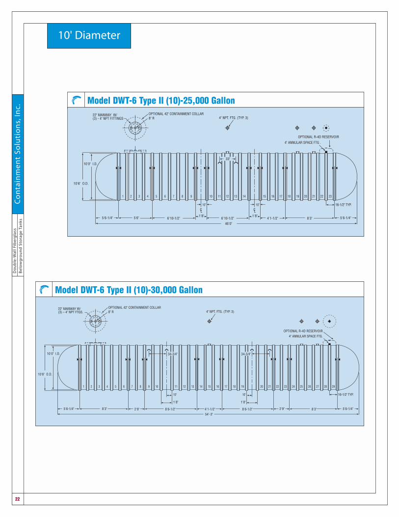
Model DWT-6 Type II (10)-30,000 Gallon
8 9
10'0" I.D.
10'6" O.D.
5'6-1/4" 8'3"
54'-3"
OPTIONAL 42" CONTAINMENT COLLAR8" R
22" MANWAY W/(3) – 4" NPT FTGS.
1 2 3 124 1310 115 6 7 14
2'9" 2'9"
17 1815 16 19
4'1-1/2"8'6-1/2"
21 22 23 24
5'6-1/4"
16-1/2" TYP.
OPTIONAL R-4D RESERVOIR
27 28 29
4" ANNULAR SPACE FTG.
8'6-1/2"
25 26
8'3"
10"
1'8"
20
10"
1'8"
34-3/4" 34-3/4"
4" NPT. FTG. (TYP. 3)
Model DWT-6 Type II (10)-25,000 Gallon
8 9
10'0" I.D.
10'6" O.D.
5'6-1/4" 5'6"
46'0"
CL
OPTIONAL 42" CONTAINMENT COLLAR8" R
22" MANWAY W/(3) - 4" NPT FITTINGS
1 2 3 12
10"
1'8"
4 1310 115 6 7 14
6'10-1/2"
4" NPT. FTG. (TYP. 3)
33"
5'6-1/4"
16-1/2" TYP.
OPTIONAL R-4D RESERVOIR
8'3"
CL
17
10"
1'8"
1815 16 19
4'1-1/2"6'10-1/2"
20 21 22 23
4" ANNULAR SPACE FTG .

Do
ub
le-W
all Fibe
rglass
Be
low
gro
un
d S
torag
e Tan
ksC
on
tainm
en
t So
lutio
ns,In
c.
23
Tank Specifications
Made-to-Order Double-Wall TanksSuggested Fitting LocationsAlthough our standard double-wall tanks are designed to accommodate most storage applications, they canbe modified to include additional manways, tank-mounted fittings or other double-wall tank accessories.Made-to-order tanks require additional lead time for production and are more expensive to purchase.
The standard tanks are shown with tank-mounted fittings in the standard positions. Monitoring fittings,reservoirs, lift lug locations and anchoring strap locations can sometimes be relocated, but require specialapproval prior to any relocation.
In addition to the standard tank notes, the following notes apply:
1. The location of additional and/ormodified tank accessories should bereferenced by the numbered fittingposition between the ribs.
2. The primary tank’s standard pipefittings are 4" NPT half couplings. Alltanks require at least one manway.The manway cover should include atleast one fitting to facilitate futurevolumetric tank testing.
3. Specifying more or larger manwaysthan available on standard tanks mayalter the anchoring strap locations.These can often be relocated, butrequire special approval prior to anyrelocation. Larger manways alsorequire larger containment collars.
4. We recommend that all additional manway covers include at least one fitting to facilitate future volumetricprecision tank testing.
5. Tank bottom deflector plates are standard under every manway and fitting.
6. Monitoring fittings, reservoirs and lift lug locations can sometimes be relocated, but require specialapproval prior to any relocation.

Do
ub
le-W
all
Fib
erg
lass
Be
low
gro
un
d S
tora
ge
Tan
ksC
on
tain
me
nt
So
luti
on
s,In
c.
24
Containment Collars
Optional tank accessories for secondary containment systems.
Fiberglass Secondary Containment CollarAn optional secondary containment collar provides a containment areafor spilled liquids, as well as a location for the leak-monitoring sensor.Collars can be installed around other tank fittings and accessories,where space permits. Collars are constructed of fiberglass and areavailable in 42" diameter (with 22" manways) and 48" diameter (with 22"and 30" manways) sizes.
The secondary containment collar is integrally attached to the tank topto provide a watertight seal. The collar is factory installed and testedprior to shipment. Another collar leak test should be performed at thejobsite by the installing contractor. See CSI installation instructions for details. The secondary containmentcollar must periodically be tested for leaks – at least once each year or after collar maintenance is performed– by adding water to the collar above the tank top. The secondary containment collar must be continuouslymonitored with an electronic sensor for potential spills or piping leaks.
Secondary Containment FittingA 6" FRP threaded secondary coupling is concentrically positionedaround the 4" NPT primary tank fitting. The secondary containmentcoupling is surface-mounted onto the tank and does not penetrate theouter wall. There is no access to the tank annular space at the 6"secondary containment coupling. To directly monitor the cavitybetween the primary and secondary pipe, a fitting with an access portshould be installed.
PRIMARY PIPE
SECONDARYFRP PIPE
STANDARD 4" NPTTANK MOUNTEDFITTING
6" SECONDARYCONTAINMENTFITTING
SECONDARY CONTAINMENT COLLARMANWAY
CONTAINMENTCOLLAR SENSOR
Fiberglass Secondary Containment Collar
Secondary Containment for Fittings

Do
ub
le-W
all Fibe
rglass
Be
low
gro
un
d S
torag
e Tan
ksC
on
tainm
en
t So
lutio
ns,In
c.
25
Turbine Enclosures
Fiberglass Turbine Enclosures provide access to critical equipment andserve as a termination point for piping.
Our turbine enclosures are fiberglass – a proven material for long-term performance. Compared to otherunreinforced plastics and HDPE products, the rigid fiberglass construction minimizes deformation duringbackfilling to help assure liquid-tight seals at fitting penetrations.
Turbine enclosures must be mounted on top of a secondary containment collar. Primary piping is installedfrom the submersible pump to the dispenser. When the double-wall piping is installed over the primary piping,the double-wall pipe connects to the turbine enclosure using optional fittings, available from CSI or yourpetroleum equipment distributor. In the event of an accidental spill from the primary piping, the spilled productwill drain into the turbine enclosure and accumulate in the secondary containment collar. The secondarycontainment collar serves as a basin to allow early detection of leaks of the submersible pump or the productpiping.
When there is concern about the ingress of water at the collar/turbine enclosure seam, the turbine enclosureshould be sealed to the secondary containment collar at the jobsite. Containment Solutions provides analcohol compatible adhesive kit to make this connection. Continuous electronic monitoring of the secondarycontainment collar should be used to warn the operator of the accumulation of petroleum product before theliquid level rises above the collar/turbine enclosure seam.
Turbine enclosures are available in 42" and 48" diameters with a minimum 2' length. To accommodate deeperburial depths, longer turbine enclosures are available in 1' increments. The turbine enclosure can be trimmedat the jobsite to adjust for the final burial depth.
Note: For high groundwater conditions at or above subgrade, a sealable or watertight turbine enclosure shouldbe used to prevent water infiltration.
Warning: When a tank will be equipped with more than one turbine enclosureor manway riser, the tank may require special installation (deeper burial,additional anchor straps, etc.). Contact Tank Technical Support for specificinstallation details. Warning: a turbine enclosure constitutes a confined space.Never enter a turbine enclosure without proper training and OSHA-approvedequipment.
ASPHYXIATION EXPLOSION FIRE

Do
ub
le-W
all
Fib
erg
lass
Be
low
gro
un
d S
tora
ge
Tan
ksC
on
tain
me
nt
So
luti
on
s,In
c.
26
Turbine Enclosures
Turbine EnclosuresTurbine enclosures are available in three models - Non-Sealed (NTE), Watertight (WTE), and Sealed (STE). Forall models, the turbine enclosure body is mounted on the tank collar. If a leakproof joint is required, cementthe enclosure body to the tank collar using the adhesive (Kit AD). (It is recommended that the joint always becemented.) All turbine enclosures are supplied with adhesive kits.
A minimum 36" diameter street box is required with all FRP models to allow the removal of the FRP lid afterthe turbine enclosure is installed. This also allows the removal of the manway cover.
To leak test the turbine enclosure, use a standing water test. DO NOT use an air pressure test.
Non-Sealed FRP Turbine Enclosure (NTE)Friction fit lid to repel water from aboveThe Non-Sealed FRP Turbine Enclosure includes anFRP enclosure body (variable length in 12" increments,42" or 48" ID’s), an FRP reducer (42" x 30" or 48" x 30"ID’s), and a loose fit FRP lid (32.5" OD) with handle.The enclosure body is field cemented to the tank collarusing the supplied adhesive kit (Kit AD). The reducerand the lid fit over the enclosure body with a loose fit.The 30" opening allows for the removal of a 22"manway lid (28" OD).
FIELDSEALEDJOINT
TANK WALL
CONTAINMENT COLLAR
TURBINEENCLOSURE BODY
4-1/2"
L
12"
SEPARATOR MATERIAL (48" X 48" X 2")
FRP REDUCER
Non-Sealed FRP Turbine Enclosure
Model Length (L)
NTE42-2 WTE42-2 STE42B-2 2'
NTE42-3 WTE42-3 STE42B-3 3'
NTE42-4 WTE42-4 STE42B-4 4'
NTE42-5 WTE42-5 STE42B-5 5'
NTE42-6 WTE42-6 STE42B-6 6'
NTE48-2 WTE48-2 STE48B-2 2'
NTE48-3 WTE48-3 STE48B-3 3'
NTE48-4 WTE48-4 STE48B-4 4'
NTE48-5 WTE48-5 STE48B-5 5'
NTE48-6 WTE48-6 STE48B-6 6'

Do
ub
le-W
all Fibe
rglass
Be
low
gro
un
d S
torag
e Tan
ksC
on
tainm
en
t So
lutio
ns,In
c.
27
Turbine Enclosures
Watertight FRP Turbine Enclosure (WTE)Suitable for moderately high groundwaterThe Watertight FRP Turbine Enclosure includes an FRP enclosure body (variable length in 12" increments, 42"or 48" ID), an FRP reducer (42" x 30" or 48" x 30" ID’s) with o-ring groove and o-ring gasket, and a push-onFRP lid (32.5" OD) with 2 handles. The enclosure body is field cemented to the tank collar and the reducer isfield cemented to the enclosure body using the supplied adhesive kits (Kit AD, 2 kits required). The reducer/
enclosure body joint is on the exterior of theenclosure body allowing easy field installation of theadhesive without entering the enclosure.
The lid compresses the lubricated o-ring when it ispushed onto the reducer top, providing a watertightseal with water up to 12" over the lid. The lid can bepushed into position by standing on the lid, which ismade with a non-skid exterior surface. The lidincludes two handles. One is offset to aid in theremoval of the lid and the other is centered on the lid.The 30" opening allows for the removal of a 22"manway lid (28" OD). The enclosure must be ventedat all times (usually accomplished with the double-wall piping).
Sealed FRP Turbine Enclosure (STE)Suitable for extremely high groundwater conditionsThe Sealed FRP Turbine Enclosure includes an FRP enclosure body (variable length in 12" increments, 42" or48" ID’s), an FRP reducer (42" or 48" ID’s) with an oval flanged manway (23" x 29" ID’s), a flat gasket, SS boltswith non-galling silicone-bronze nuts (optional bolt rings can be supplied to replace the bolts), and an ovalFRP lid with handle. The enclosure body is field cemented to the tank collar and the reducer is field cementedto the enclosure body using the optional adhesive kits (Kit AD, 2 kits required). The reducer/enclosure bodyjoint is on the exterior of the enclosure body allowing easy field installation of the adhesive without enteringthe enclosure.
The lid is bolted to the manway with 14 bolts providinga watertight seal with water up to 7' over the lid. Thelid can be supplied with an optional 6" NPT fitting witha plug which can be used as an observation port. Theoval manway allows for the removal of a 22" manwaylid (28" OD). The enclosure must be vented at all times(usually accomplished with the double-wall piping).
FIELDSEALEDJOINT
TANK WALL
CONTAINMENT COLLAR
TURBINEENCLOSURE BODY
4-1/2"
L
15"
SEPARATOR MATERIAL (48" X 48" X 2")
FIELDSEALEDJOINT
FRP REDUCER
Watertight FRP Turbine Enclosure
CONTAINMENT COLLAR
SEPARATOR MATERIAL (48" X 48" X 2")
10.5"
4.5"
LTURBINEENCLOSURE BODY
FIELDSEALEDJOINT
FIELDSEALEDJOINT
TANK WALLSealed FRP Turbine Enclosure

Do
ub
le-W
all
Fib
erg
lass
Be
low
gro
un
d S
tora
ge
Tan
ksC
on
tain
me
nt
So
luti
on
s,In
c.
28
Field-installed piping and electrical fittingsSecondary pipe fittings can be field installed using one of our optional two-piece FRP couplings.
When used for piping connections, the FRP coupling is designed to provide secondary containmentconnections only to the turbine enclosure. Do not use the FRP coupling for primary piping connections to theturbine enclosure.
FRP Coupling Kit (3" or 4")A two-piece field-installed 3" or 4" FRP coupling can be cemented in the turbineenclosure to provide a watertight seal for piping penetrations in high groundwaterenvironments.
The FRP coupling is a two-piece fitting which is cemented to the turbineenclosure. The FRP coupling’s male and female sections are threaded together tohold the fitting in place while the adhesive cures. Each kit (Kit FC-3 or FC-4)includes the adhesive and mixing instructions.
Flexible Entry Boot (FEB)Flexible entry boots are rubber compression type boots installed into the wall ofthe turbine enclosure to seal all pipe and conduit entries. These boots aredesigned to permit up to a 300° angle of flexibility for entries. This flexibility isimportant for aligning pipe connections or as a stress relief for the pipe duringbackfilling and ground movement. The flexible entry boot is available for standard3" and 4" secondary piping and 3/4" conduit lines.
Tank LaddersOur optional tank ladders are available in either carbon steel,aluminum or stainless steel. These ladders are shipped along withthe tank and are field attached to the tank bottom with FRPmounting lugs. Ladders are retained at the top with FRP slip lugson the trunk of the manway to allow for vertical movement of theladder. (Manway and ladder are sold separately.)
Tank ladders are not recommended on 4' diameter tank capacities.Because of limited space, the ladders interfere with tank entry.
Probe DrawstringOn tanks with a dry annular space, we provide a factory-installed“drawstring” at the annular space monitoring fitting to assist in positioning liquid sensors at the bottom of theannular space.
TURBINE ENCLOSURE WALL/INTERIOR
MALE SECTIONFEMALESECTION
ADHESIVE
FRP Coupling Kit(for 3" or 4" OD FRP pipe only)
Flexible Entry Boot
3/8"2 1/2"
22" MANWAY ON 6', 8', & 10' DIAMETER TANKS ONLY
12" TYP.
3/4" RUNG(TYP.)
12"
CARBON STEELLADDER
FRPUNIVERSALMOUNTINGLUG
FRP SLIP LUG
Tank Ladder
Accessories

Do
ub
le-W
all Fibe
rglass
Be
low
gro
un
d S
torag
e Tan
ksC
on
tainm
en
t So
lutio
ns,In
c.
29
Anchoring Systems
Deadmen/TurnbucklesContainment Solutions can provide deadmen anchors and turnbucklesfor selected models of double-wall tanks. Deadmen anchors provide ameans to prevent installed fiberglass tanks from floating out of theground when the tank installation is subject to groundwater around thetank. Deadmen anchors, when used with CSI fiberglass hold down strapsand other CSI or contractor supplied hardware and installed according toCSI installation instructions, prevent tank flotation and cost less than aconcrete pad under the tank.
The CSI deadmen and turnbuckles can usually be shipped with 4', 6'and 8' tanks at no additional charge.
Deadmen are available in various lengths and are designed with andwithout eyebolts. Ask for “Deadmen Anchors and Turnbuckles”publication to select the proper deadmen for a particular tank size.
Split-Strap Anchor SystemContainment Solutions can provide a split-strap anchor system for 6',8' and 10' diameter double-wall tanks. The split-strap anchor systemprovides a method to attach and tighten the tank anchor straps todeadmen or to an anchor pad without entry into the excavation. Thesplit-strap anchor system is safer and less costly than traditionalmethods that require shoring or other hole stabilization techniques toallow entry into the excavation.
Fiberglass Anchoring StrapsWhen mechanical anchoring is specified, fiberglass anchoringstraps are available for all double-wall tanks.
Tank No. of StrapsCapacity Diameter Required
550 4' 2600 4' 2
1,000 4' 22,500 6' 23,000 6' 24,000 6' 25,000 6' 46,000 6' 45,000 8' 26,000 8' 28,000 8' 410,000 8' 412,000 8' 415,000 8' 610,000 10' 312,000 10' 415,000 10' 420,000 10' 625,000 10' 830,000 10' 835,000 10' 840,000 10' 10
Split-Strap Anchor System
WIRE ROPETRIPLE CLAMP
FRP STRAP
STRAP EYELETSEE DETAIL
OPTIONALTURNBUCKLEASSEMBLYH
DEADMANANCHOR SYSTEM
DOUBLE WALLTANK
TANK END VIEW
ANCHOR PAD SYSTEM
12" MINIMUMBACKFILL BED
Split-Strap Anchor System
Deadmen
Turnbuckle
B
STRAP EYELETGALVANIZED
STEEL
FIBERGLASS STRAP
A
Flat Strap Eyelet Detail
Anchor Strap DimensionsTankSize H A B
4' 21" 9/16" 1 1/8"
6' 30" 1 7/9" 2 7/8"
8' 36" 1 7/9" 2 7/8"
10' 49" 1 7/9" 2 7/8"

Do
ub
le-W
all
Fib
erg
lass
Be
low
gro
un
d S
tora
ge
Tan
ksC
on
tain
me
nt
So
luti
on
s,In
c.
30
These fittings let you configure our tanks to your needs.
Tank Fittings
NPT Tank-Mounted FittingsThe standard tank-mounted fitting is a 4" NPT half coupling. The tank-mounted fittingsto the primary tank are placed on the top center line of the tank.
Plate Gusseted Nozzles Fiberglass plate gusseted nozzles are available in 2", 3", 4", 6", 8", 10", 12", 14", 16" and18" diameters and are installed on the top center line of the tank.
Fiberglass ManwaysStandard fiberglass manways are 22" diameter. Optional 30" and 36" manways areavailable.
The standard 22" manway has a maximum load-bearing capacity of 2,400 lbs. Eachcomes with a painted carbon steel cover, a gasket, 24 zinc-coated 1/2" x 1-1/2" boltsand nuts. Fittings in manway lids are 4" steel NPT half couplings.
WARNING: An underground tank constitutes a confined space.Never enter a tank without proper training and OSHA-approvedequipment.
NOTE: The use of manways is not intended to encourage tank entry,which can pose a safety hazard for unqualified mechanics,especially after product has been stored in the tank.
All fiberglass double-wall tanks include one manway. Some of the primary tank fittings are clustered in themanway cover to facilitate secondary containment of the pump and piping.
Stainless Steel Bolt RingsContainment Solutions can provide a stainless steel bolt ring for use with fiberglassmanways and sealed turbine enclosures on double-wall tanks. The bolt ring ismanufactured in two halves and provides a flexible semi-circle of bolts that will stay inposition in a flange and allow the nuts to be tightened without the use of a wrench tokeep the bolt from turning.
The bolt ring is manufactured of 304 or 316 stainless steel with non-galling siliconebronze nuts, providing improved corrosion resistance over plated bolts, nuts andwashers.
Plate Gusseted Nozzle
NPT Tank-Mounted Fitting
Fiberglass Manway
Stainless Steel Bolt Ring
Accessories
ASPHYXIATION EXPLOSION FIRE
Do
ub
le-W
all Fibe
rglass
Be
low
gro
un
d S
torag
e Tan
ksC
on
tainm
en
t So
lutio
ns,In
c.
31
Accessories
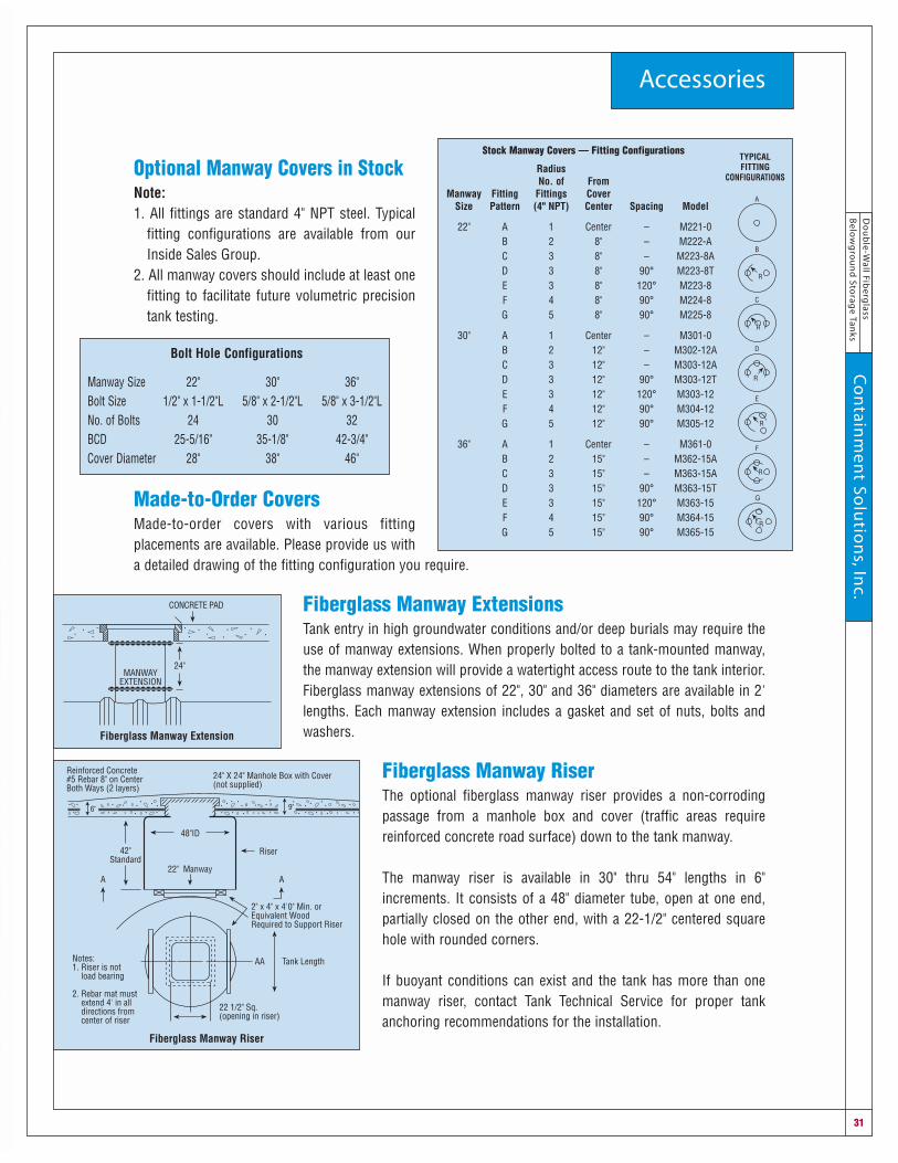
Optional Manway Covers in StockNote: 1. All fittings are standard 4" NPT steel. Typical
fitting configurations are available from ourInside Sales Group.
2. All manway covers should include at least onefitting to facilitate future volumetric precisiontank testing.
Made-to-Order CoversMade-to-order covers with various fittingplacements are available. Please provide us witha detailed drawing of the fitting configuration you require.
Fiberglass Manway ExtensionsTank entry in high groundwater conditions and/or deep burials may require theuse of manway extensions. When properly bolted to a tank-mounted manway,the manway extension will provide a watertight access route to the tank interior.Fiberglass manway extensions of 22", 30" and 36" diameters are available in 2'lengths. Each manway extension includes a gasket and set of nuts, bolts andwashers.
Fiberglass Manway RiserThe optional fiberglass manway riser provides a non-corrodingpassage from a manhole box and cover (traffic areas requirereinforced concrete road surface) down to the tank manway.
The manway riser is available in 30" thru 54" lengths in 6"increments. It consists of a 48" diameter tube, open at one end,partially closed on the other end, with a 22-1/2" centered squarehole with rounded corners.
If buoyant conditions can exist and the tank has more than onemanway riser, contact Tank Technical Service for proper tankanchoring recommendations for the installation.
MANWAYEXTENSION
CONCRETE PAD
24"
24" X 24" Manhole Box with Cover(not supplied)
Reinforced Concrete#5 Rebar 8" on CenterBoth Ways (2 layers)
9"6"
22" Manway
42"Standard
Riser
48"ID
A A
2" x 4" x 4'0" Min. orEquivalent WoodRequired to Support Riser
Tank LengthNotes:1. Riser is not load bearing
2. Rebar mat must extend 4' in all directions from center of riser
22 1/2" Sq.(opening in riser)
AA
Fiberglass Manway Extension
Fiberglass Manway Riser
Stock Manway Covers — Fitting Configurations
RadiusNo. of From
Manway Fitting Fittings CoverSize Pattern (4" NPT) Center Spacing Model
22" A 1 Center – M221-0B 2 8" – M222-AC 3 8" – M223-8AD 3 8" 90° M223-8TE 3 8" 120° M223-8F 4 8" 90° M224-8G 5 8" 90° M225-8
30" A 1 Center – M301-0B 2 12" – M302-12AC 3 12" – M303-12AD 3 12" 90° M303-12TE 3 12" 120° M303-12F 4 12" 90° M304-12G 5 12" 90° M305-12
36" A 1 Center – M361-0B 2 15" – M362-15AC 3 15" – M363-15AD 3 15" 90° M363-15TE 3 15" 120° M363-15F 4 15" 90° M364-15G 5 15" 90° M365-15
A
B
R
C
R
D
R
E
R
F
R
G
R
TYPICALFITTING
CONFIGURATIONS
Bolt Hole Configurations
Manway Size 22" 30" 36"Bolt Size 1/2" x 1-1/2"L 5/8" x 2-1/2"L 5/8" x 3-1/2"LNo. of Bolts 24 30 32BCD 25-5/16" 35-1/8" 42-3/4"Cover Diameter 28" 38" 46"

Do
ub
le-W
all
Fib
erg
lass
Be
low
gro
un
d S
tora
ge
Tan
ksC
on
tain
me
nt
So
luti
on
s,In
c.
32
Double-Wall Tank Warranty
WarrantyDouble-Wall Belowground Petroleum Storage TankContainment Solutions, Inc. ("CSI") warrants that its new manufactured double-wall underground tanks (andsecondary containment collars, if attached) will meet CSI's published specifications and will be free from materialdefects in materials and workmanship for a period of one (1) year following date of original delivery by CSI toOwner. CSI further warrants that if said tank(s) (and collar(s)) are installed, operated and maintained in accordancewith our instructions and applicable state and federal regulatory requirements, said tank(s) (and collar(s)):
I. Will not leak for a period of thirty (30) years from date of original purchase due to natural external corrosion;
II. Will not leak for a period of thirty (30) years from date of original purchase due to internal corrosion, providedthe tank is used solely (with or without tank water bottoms) to store the following products:
A. The following petroleum products, including gasoline, jet fuel, av-gas, motor oil (new or used), kerosene,diesel fuel or fuel oil at temperatures not to exceed 150°F.
B. Alcohol-gasoline blend motor fuels1. Ethanol blends
Gasohol (90% gasoline and 10% ethyl alcohol).2. Methanol blends
Oxinol-50* waiver (90.5% gasoline and 9.5% Oxinol-50* composed of a mixture of 4.75% methanol and4.75% GTBA).DuPont EPA waiver (gasoline with 5% methanol and a minimum of 2.5% cosolvent. The blend may containa maximum concentration of up to 3.7 weight percent oxygen in the final fuel).
C. Oxygenated motor fuelsGasoline with up to 20% (by volume) methyl tertiary butyl ether (MTBE), ethyl tertiary butyl ether (ETBE),tertiary butyl alcohol (TBA), tertiary amyl methyl ether (TAME), or tertiary amyl ethyl ether (TAEE).
D. Any gasoline/water/ethanol or methanol blend including 100% ethanol, methanol, or M85 (85% methanol) atambient temperatures.
III.Will not leak for a period of thirty (30) years from date of original purchase due to structural failure, which shallbe defined as spontaneous breaking or collapse, provided the tank is used in the manner described in thisWarranty and that the original installation and any post-installation repairs or alterations to the tank (and collar)have been (A) carried out in the United States, (B) performed and validated by a contractor educated in propertank installation, who possesses any required registrations, certificates or licenses, to complete the installation,repair or alteration in accordance with recognized industry practices and applicable regulatory requirements,and (C) that the tank system has been operated and maintained in accordance with regulatory requirementsdesigned to minimize the possibility of structural failures and releases of regulated substances. A claimant mustgive CSI the opportunity to observe and inspect the tank prior to removal from the ground or the claim will bebarred.
After initial installation of the tank, the tank installation checklist supplied by CSI must be properly completedby the contractor and the owner's representative, and the owner must retain the complete checklist to verifyproper installation of the tank. The completed checklist must be delivered to CSI at the time of any claim underthis warranty, and failure to so deliver may result in denial of the claim at the discretion of CSI.
If the tank is remanufactured or removed from the ground for any reason prior to the expiration of this warranty,the structural warranty protections of this paragraph III will terminate unless the tank (and collar) are 1)inspected, repaired (as necessary), and recertified by CSI and 2) upon reinstallation, continue to satisfy theother provisions of this paragraph III.
CSI's liability under this warranty shall be limited, at our option, to (i) repair of the defective tank (and collar), (ii)delivery of a replacement tank (and collar) to the point of original delivery, or (iii) refund of the original PURCHASEprice. A claimant must give CSI the opportunity to observe and inspect the tank prior to removal from the groundor the claim will be barred. All claims must be made in writing within one (1) year after tank failure or be foreverbarred. CSI shall not be liable for any labor or other installation costs and shall not be liable for any special, indirect,consequential or other damages except as stated above in connection with such tank (and collar), including,without limitation, costs, expenses or liabilities associated with environmental contamination, fires, explosions orany other consequences allegedly attributable to a breach of the warranty or damages under deceptive tradepractices or similar consumer protection acts. THE FOREGOING CONSTITUTES OUR EXCLUSIVE OBLIGATIONAND CSI MAKES NO EXPRESSED OR IMPLIED WARRANTIES, OR ANY WARRANTY OF MERCHANTABILITY ORFITNESS FOR ANY PARTICULAR PURPOSE WHATSOEVER, EXCEPT AS STATED ABOVE.

Do
ub
le-W
all Fibe
rglass
Be
low
gro
un
d S
torag
e Tan
ksC
on
tainm
en
t So
lutio
ns,In
c.
33
Accessories WarrantyAll double-wall tank accessories and monitoring equipment are warranted to be free frommaterial defects in workmanship and materials for a period of one (1) year following date oforiginal delivery by Containment Solutions.
Containment Solutions’ liability under this warranty shall be limited, at our option, to (i) repairof the defective unit, (ii) delivery of a replacement unit to the point of original delivery, or (iii)refund of the original price. CSI shall not be liable for any labor or other installation costs andshall not be liable for any special, indirect, consequential or other damages except as statedabove in connection with such tanks, including, without limitation, costs, expenses or liabilitiesassociated with environmental contamination, fires, explosions or any other consequencesallegedly attributable to a breach of the warranty or damages under deceptive trade practicesor similar consumer protection acts. THE FOREGOING CONSTITUTES OUR EXCLUSIVEOBLIGATION AND CSI MAKES NO EXPRESSED OR IMPLIED WARRANTIES, OR ANY WARRANTYOF MERCHANTABILITY OR FITNESS FOR ANY PARTICULAR PURPOSE WHATSOEVER,EXCEPT AS STATED ABOVE.
Failure to install the tank accessories or monitoring equipment in accordance with theContainment Solutions’ installation instructions will void the warranty.
Fiberglass Tanks Intended Use Fiberglass petroleum storage tanks are designed for the storage of gasoline, alcohol blendedgasoline (with up to 100% methanol or ethanol), jet fuel, av-gas, motor oil, kerosene, dieselfuel, oxygenated fuels (up to 20% MTBE), or potable water at ambient undergroundtemperatures. Fuel oil may be stored at temperatures not to exceed 150°F.
The storage of other liquids may result in tank failure. Before storing liquids other thanthose listed above, contact Tank Technical Support.
Installation OverviewFiberglass underground tanks must be installed in accordance with the installation instructions(Containment Solutions Pub. No. INST 6001). This document should be part of your tankspecifications. Some key installation steps are highlighted below. See the published installationinstructions for complete details.
Single-wall tanks must be mechanically unloaded from the delivery truck using a backhoe orcrane (using all lift lugs provided to lift the tank).
All tanks must be vented and are intended to be operated with fluid in the tank no higher thanthe tank top. Fiberglass tanks are designed for operation at atmospheric pressure only, exceptwhen using vapor recovery systems, provided the pressure or vacuum does not exceed 1 psimaximum on the primary tank. Overpressurizing of the primary tank will result in tank failure.
For additional details, request Belowground Tank Installations (Containment Solutions Pub.No. INST 6001). Properly installed, fiberglass underground petroleum storage tanks canprovide extended service in storing petroleum products without corrosion-caused leaks andwithout maintenance.
Containment Solutions maintains a listing of over 2,000 independent contractors who havereceived educational materials from Containment Solutions covering the proper installation ofunderground fiberglass tanks. On request, we can provide names of educated contractors.
Fiberglass Tanks For Fuel StorageSpecification: Short FormAuto-cad drawings are available through your local sales representative.The contractor shall provide UL labeled model fiberglass underground storage tanks in sizesand with fittings as shown on the drawings. The tanks shall be manufactured by ContainmentSolutions, Inc.
Tanks shall be tested and installed with pea gravel or approved alternate backfill materialaccording to the current installation instructions (Containment Solutions Pub. No. INST 6001)provided with the tank.
Long Form: Section 13200 Guide Specification ContainmentSolutions Fiberglass Reinforced Polyester Belowground Storage Tanks Auto-cad drawings are available through your local sales representative.
Part I General
1.01 Related Work Specified In Other SectionsA. Cast-in-Place Concrete: Section 03300B. Anchor Bolts: Section 05501C. Plastic Pipe: Section 15064
D. Liquid Level Gauges: Section 15174E. Other Related Work – such as Excavation and Boiler Equipment
1.02 Quality AssuranceA. Acceptable Manufacturers: Containment Solutions, Inc., Conroe, Texas.B. Governing Standards:
1. ASTM Specification D4021. Glass Fiber Reinforced Polyester BelowgroundPetroleum Storage Tanks.
2. UL 1316 Underwriters Laboratories, Inc., Glass Fiber Reinforced Plastic BelowgroundStorage Tanks for Petroleum Products.
3. National Fire Protection Assoc. (NFPA 30) Flammable and Combustible Liquids Codeand (NFPA 31) Standards for Installation of Oil Burning Equipment.
4. General Services Administration, Public Building Service Guide Specification, PBS: 1568.
1.03 Submittals:A. Shop Drawings: Contractors shall submit _______ copies of shop drawings for each
tank. Drawings shall include all critical dimensions and show locations of all fittings andaccessories, i.e., manways, ladders, hold-down straps, heating coils, etc. Materials ofconstruction shall be in accordance with Section 1.02 of this specification.
B. Catalog Data: Contractor shall submit ________ copies of manufacturer’s literature.C. Certification Plate: UL labels shall be affixed to each tank.D. Installation Instructions: Contractors shall submit ________ copies of manufacturer’s
latest installation instructions. E. Calibration Charts: Contractors shall submit copies of manufacturer’s latest
calibration charts.
Part II Products
2.01 Fiberglass Belowground Storage TanksA. Loading Conditions – Tank shall be designed to meet the following design criteria:
1. External hydrostatic pressure: Buried in ground with 7' of over burden over the topof the tank, the hole fully flooded and safety factor of 5:1 against general buckling.
2. Surface loads: When installed according to manufacturer’s installation instructions,tanks will withstand surface H-20 axle loads (32,000 lbs./axle).
3. Internal load: Primary and secondary tanks shall withstand 5 psi air pressure testwith 5:1 safety factor.
4. Tanks shall be designed to support accessory equipment such as heating coils,ladders, drop tubes, etc. when installed according to manufacturer’s recommendations andlimitations.
5. Tank laminate shall include silica treated with silane.
B. Product Storage Requirements:1. All primary tanks must be vented. Tanks are designed for operation at atmospheric
pressure only, except for use with vapor recovery systems at a pressure or vacuumof approximately 1 psi.
2. Tanks shall be capable of storing liquids with specific gravity up to 1.1.3. Maximum temperature: Tank shall be capable of storing gasoline, alcohol blended
gasoline (with up to 100% methanol or ethanol), oxygenated fuels (up to 20%MTBE), av-gas, jet fuel, motor oil, (new or used), kerosene, diesel fuel or potablewater at ambient underground temperatures not to exceed 150°F at the tank interiorsurface.
4. Tanks shall be chemically inert to petroleum products.
C. Dimensional Requirements:(refer to Containment Solutions literature on gallonage):
1. Nominal capacity of the tank shall be _____ gallons.2. Nominal outside diameter of the tank shall be _____ feet.3. Nominal overall length of the tank shall be _____ feet.
D. Monitoring Capabilities:1. Tanks shall have a space between the primary and secondary shell walls to allow for
the free flow and containment of all leaked product from the primary tank.2. The following continuous monitoring conditions shall be compatible with the cavity
between the inner and outer tanks:• Vented to atmosphere• Vacuum – 5 psi maximum• Positive air pressure (5 psi maximum)• External hydrostatic pressure – 7' maximum groundwater head pressure over tank top
Specifications

Do
ub
le-W
all
Fib
erg
lass
Be
low
gro
un
d S
tora
ge
Tan
ksC
on
tain
me
nt
So
luti
on
s,In
c.
34
3. Tanks 6' diameter and larger shall have an integrally mounted reservoir* installed onthe tank for optional hydrostatic monitoring. The reservoir shall be constructed offiberglass reinforced plastic materials and warranted for 30 years against failure dueto internal/external corrosion and when properly installed, against structural failure(same as tank warranty).4' diameter DWT-6 Type II tanks do not include a fiberglass reservoir. A 4" diameterriser pipe screwed into the 4" diameter annular space fitting will serve as thereservoir.
4. Tank shall be designed with one 4" fitting that will access the tank bottom betweenthe primary and secondary walls (annular space).
5. The double-wall tank monitor shall be capable of detecting a breach in the innerand/or outer tank under the following installed conditions:a. When the inner tank is empty.b. When the inner tank is partially or completely full and the groundwater table is
below the tank bottom.c. When the inner tank is partially or completely full and the tank is partially or
completely submerged in groundwater.6. The leak detection performance of the hydrostatic monitoring system shall be
tested and verified by a qualified independent consultant to detect leaks as smallas 0.10 gallons per hour within a one month period.
7. All monitoring equipment, including FRP reservoirs and electronic controls, shall beUL listed or accepted.
8. If hydrostatically monitored, any solution used in the tank annular space shall haveUL approval for compatibility with the tank and be a contrasting color to the tanksurface to facilitate visual inspection of the tank for leaks prior to burial.
2.02 Accessories
Anchor AccessoriesA. Anchor Straps – Provide glass fiber reinforced plastic anchor straps for each tank
shown. Number and location of straps shall be as specified by manufacturer. Each strapshall be capable of withstanding a maximum load for each tank diameter as shown.
4'0 — 4,200 lbs.6'0 — 18,000 lbs.8'0 — 25,000 lbs.
10'0 — 25,000 lbs.Straps shall be standard as supplied by the tank manufacturer.
B. Certification Plate – Underwriters Laboratories label shall be permanently affixedto each tank.
C. Flanged Manways1. The standard manway is 22" ID. The 30" and 36" ID manways are optional. 2. All manways will be furnished complete with U.L. listed gaskets, bolts and covers.3. Location – see standard tank drawings (pages 15-22).4. The steel manway cover is standard with 4" diameter NPT fittings. 22" manway
covers with an even number of fittings will be placed on an 8" radius. Manwaycovers with an odd number of fittings will have one fitting centered and theremaining fittings placed on an 8" radius. 30" manway cover fittings are standard12" radius. 36" manway cover fittings are standard 15" radius.
5. Manway risers 48" in diameter and 42" high will be supplied to provide access to themanway lid. A 24" x 24" galvanized street box with a cover must be provided bycontractor for at-grade installation.
6. Fiberglass manway extension tubes 24" long will be provided for the manways.
D. Fill Tubes – Fill tubes of appropriate design will be supplied by contractor.
E. Hydrostatic Monitor Accessories:1. Brine Antifreeze
Brine Solution Designation: BAS-30Chemical Composition: 30%+ calcium chloride, 1% to 3% potassium chloride,
1% to 2% sodium chloride, Balance water Visual Appearance: Green in color, Odorless fluidSpecific Gravity @ 60°F: 1.272-1.317Factory installed on tanks 30,000 gallon and under. Bulk brine jobsite installed on35,000 gallon and 40,000 gallon tanks.
2. Reservoir Sensor – The FHRB 810 reservoir sensor is specifically designed forinstallation in the reservoirs of CSI double-wall tanks. The components of thesensor are compatible with CSI supplied brine solutions. The sensor is alsocompatible with any other control panel that accepts normally open or closedswitches. The sensor provides two alarm points: high brine and low brine. Thesensor can be wired to a control panel to provide only a single alarm (notdistinguishing between high or low alarms) or it can be wired to report both alarm
conditions.3. Electronic Controllers for Reservoir Sensor – The FHRB 810 reservoir sensor
interfaces with leak control panels Models CPF or inventory panels Models CPI. TheCSI control panels and reservoir sensor shall be UL or Factory Mutual listed asintrinsically safe. The correct number of input circuits must be used, either one ortwo, to provide the type of desired alarm reporting, i.e. single alarm or dual alarm(high brine or low brine). Additional leak detection sensors and inventorymonitoring probes shall be available to interface to the control panels.All control panels shall include:
• Alarm lights for each circuit• Audible alarm with reset button• System test button• NEMA 4 housing• Wall mounting capabilities• Dry contact relay for each input circuit• RS 232 port (inventory panels)• ALPHA numeric display (inventory panels)• Printer option (inventory panels)
Note: All wiring materials are provided by the contractor. Wiring is required fromthe power source to the control panel and from the control panel to the probe andsensor assemblies.
4. Tank Gauge Probe – The IPFW Series tank gauge probe shall be capable ofcontinuously monitoring liquid levels and detecting water in hydrocarbons at thebottom of tanks. The probe shall be compatible with the liquid it is intended to be submerged in and sized properly to fit into the tank without damaging the tankduring installation or operation. The tank gauge probe shall not be rigidly mountedin the tank.
F. Non-Sealed FRP Turbine Enclosure (Model NTE Series) – The non-sealed turbineenclosure consists of a fiberglass reinforced plastic (FRP) enclosure body (variablelength in 12" increments, 42" or 48" ID’s), an FRP reducer (42"x30" or 48"x30" ID’s), anda loose fit FRP lid with handle. The reducer opening must be large enough (minimum28") to allow for the removal of a 22" manway lid. The lid OD must be small enough tobe removed through a 36" street box. The enclosure body must be capable of joining tothe 42" or 48" diameter secondary containment collar with a leaktight adhesive joint. Cutlines for field trimming will be marked on the bottom 12" of the enclosure body in 3"increments.
Model No. Length Model No. LengthNTE42-2 2' NTE48-2 2'NTE42-3 3' NTE48-3 3'NTE42-4 4' NTE48-4 4'NTE42-5 5' NTE48-5 5'NTE42-6 6' NTE48-6 6'
If needed, refer to Section I for the optional adhesive kit (to bond the enclosure body tothe containment collar) and Sections J, K and L for the field installed fitting kits (forelectrical and plumbing connections to the turbine enclosure).
G. Watertight Turbine Enclosure (Model WTE Series) – The watertight turbineenclosure consists of a fiberglass reinforced plastic (FRP) enclosure body (variablelength in 12" increments, 42" or 48" ID’s), an FRP reducer (42"x30" or 48"x30" ID’s) witho-ring groove and o-ring gasket, and a push-on FRP lid with two handles. The reduceropening must be large enough (minimum 28") to allow for the removal of a 22" manwaylid. The lid OD must be small enough to be removed through a 36" street box. Theenclosure body must be capable of joining to the 42" or 48" diameter secondarycontainment collar with a leaktight adhesive joint. The reducer must be capable ofjoining to the enclosure body with an external leaktight adhesive joint to allow for fieldinstallation of the adhesive without entering the enclosure.
With the lid installed, the assembly must provide a watertight seal with water up to 12"over the lid. The lid includes a non-skid exterior surface and must be able to support aperson standing on the lid without damage to the lid. One of the lid handles is to beoffset to aid in the removal of the lid and the other is centered on the lid. Cut lines forfield trimming will be marked on the bottom 12" of the enclosure body in 3" increments.
Model No. Length Model No. LengthWTE42-2 2' WTE48-2 2'WTE42-3 3' WTE48-3 3'WTE42-4 4' WTE48-4 4'WTE42-5 5' WTE48-5 5'WTE42-6 6' WTE48-6 6'
Refer to Section I for the adhesive kit (to bond the enclosure body to the containment
Specifications

Do
ub
le-W
all Fibe
rglass
Be
low
gro
un
d S
torag
e Tan
ksC
on
tainm
en
t So
lutio
ns,In
c.
35
collar and to bond the reducer to the enclosure body) and Sections J, K and L for thefield installed fitting kits (for electrical and plumbing connections to the turbineenclosure).
H. Sealed FRP Turbine Enclosure (Model STE Series)The sealed turbine enclosure consists of a fiberglass reinforced plastic (FRP)enclosure body (variable length, 42" or 48" ID’s), an FRP reducer (42" or 48" ID’s) withan oval flanged manway (23"x29" ID’s), a flat gasket, SS bolts with non-gallingsilicone-bronze nuts (or optional bolt ring), and an oval FRP lid with handle. Thereducer opening must be large enough (minimum 28") to allow for the removal of a22" manway lid. The lid OD must be small enough to be removed through a 36" streetbox. The enclosure body must be capable of joining to the 42" or 48" diametersecondary containment collar with a leaktight adhesive joint. The reducer with ovalflanged manway must be capable of joining to the enclosure body with a leaktightadhesive joint.With the lid installed, the assembly must provide a watertight seal with water up to 7'over the lid. The lid may be supplied with an optional 6" NPT fitting with plug which canbe used as an observation port. Cut lines for field trimming will be marked on thebottom 12" of the enclosure body in 3" increments.
Model No. Length Model No. LengthSTE42-2 2' STE48-2 2'STE42-3 3' STE48-3 3'STE42-4 4' STE48-4 4'STE42-5 5' STE48-5 5'STE42-6 6' STE48-6 6'
Refer to Section I for the adhesive kit (to bond the enclosure body to the containmentcollar and to bond the reducer to the enclosure body) and Sections J, K and L for thefield installed fitting kits (for electrical and plumbing connections to the turbineenclosure).
I. Turbine Enclosure Adhesive Kit – (Kit AD) - When properly installed and cured, theadhesive kit provides a watertight seal to prevent the ingress of water. The adhesive kitincludes 1/2 gallon of adhesive in a one gallon capacity can. The kit also includescatalyst (hardener), a wooden mixing stick, a three inch wide plastic putty knife, 60 gritsandpaper, and installation instructions. One adhesive kit is required for each turbineenclosure; the watertight and sealed turbine enclosures require two kits.
J. Field Entry Boot – (Model FEB-3 or FEB-4) The FEB-3 or FEB-4 is designed to interfacewith 3" or 4" nominal OD FRP pipe.
K. FRP Coupling Kit – (Kit FC-3 or FC-4) - Designed to interface with 3" or 4" nominal ODFRP pipe manufactured by Ameron or Smith Fiberglass. The coupling ID is tapered atboth ends.The two-piece coupling is constructed of fiberglass reinforced plastic and is field-installed using the supplied adhesive. Both pieces of the fitting are threaded together tohold the fitting in position while the adhesive cures.Kit FC-3 or Kit FC-4 includes one 3" or 4" nominal ID FRP coupling, adhesive, catalyst(hardener), plastic mixing stick and applicator, 60 grit sandpaper, and installationinstructions.The contractor must provide the hole saw (4-1/2 or 5-1/2 inch OD) or reciprocating sawto cut the hole in the turbine enclosure prior to installing the FRP coupling.
L. Electrical Coupling Kit – (Kit EC-1)- Designed to interface with one inch steel electricalconduit. The two-piece coupling is constructed of steel and is field installed using thesupplied adhesive. Both pieces of the fitting are threaded together to hold the fitting inposition while the adhesive cures.Kit EC-1 includes two (2) one inch steel couplings, adhesive catalyst (hardener), plasticmixing stick, 60 grit sandpaper, and installation instructions.The contractor must provide a two inch hole saw or reciprocating saw to cut the hole inthe turbine enclosure prior to installing the steel coupling.
M. Secondary Containment Collar – The secondary containment collar shall beconstructed of fiberglass reinforced plastic. Collar shall be 42" or 48" in diameter andwill be factory-installed in accordance with drawings.
N. Containment Collar Sensor is preassembled and ready to wire. All electricalcomponents must be UL listed or accepted. This float switch is capable of detecting a2" or more accumulation of liquid (water or product) in the turbine enclosure.
O. Ladders – Ladders shall be the standard ladder supplied by the tank manufacturer(carbon steel, stainless steel, aluminum). Refer to drawings for location.
P. Tank Lifting Lugs – Provide lifting lug(s) on all tanks. Lifting lug system shall becapable of withstanding weight of tank with a safety factor of 3:1.
Q. Probe Drawstring – Nylon line shall be 150 lb. break strength located at the monitoringfitting nearest the end of the tank. When a reservoir is located at this position, thedrawstring shall be installed within the reservoir. Drawstring length will allow for a 7'tank burial depth.
R. Fittings Threaded – NPT1. All threaded fittings on UL labeled tanks shall be located in a manway lid or a tank
mount within 12" of the tank top center line and be constructed consistent with therequirements of the UL label. Fittings to be supplied with threaded cast iron plugs.
2. All standard threaded fittings to the primary tank and monitoring cavity are 4" indiameter. The standard secondary containment coupling is 6" in diameter. Allstandard threaded fittings are half couplings. Reducers are to be used for smallersizes where specified and provided by contractor.
3. Thread Standards – All threaded fittings shall have machine tolerances inaccordance with the ANSI standard for each fitting size.
4. Strength – Primary tank NPT fittings will withstand a minimum of 150 foot-poundsof torque and 1,000 foot-pounds of bending, both with 2:1 factor of safety.
5. Sizes Standard Reducer SizesInlet 4" ________________ Outlet 4" ________________ Vent 4" ________________ Gauge 4" ________________ Fill 4" ________________
6. Location – Refer to drawings for location.7. Suction Line – Shall be installed on the site by the contractor. Diameter of pipe and
grade and schedule as called out in other sections.8. Return Line – Shall be installed on the site by the contractor. Diameter of pipe and
grade and schedule as called out in other sections.9. All rigid internal piping shall be terminated at least 4" from the bottom of the tank.
3.01, 3.02 Installation And TestingTanks shall be tested and installed according to the current installation instructions providedwith the tank (refer to Containment Solutions Pub. No. INST 6001 and include as part of yourspecification).
While Containment Solutions has taken every precaution as to the accuracy of content anddata presented herein, Containment Solutions cannot be held responsible for the individualinterpretation of the data presented, any loss or damage to any property whatsoever, injury ordeath to any persons whatsoever, or any claims, demands, actions, complaints, proceedings,judgement, losses, damages, compensation, liabilities, costs or charges, however arising fromthe unauthorized undirected use of this handbook or the data it contains.
Specifications

©2002 Containment Solutions, Inc. All rights reserved. The Containment Solutions logo is a trademarkof Containment Solutions, Inc. Litho in U.S.A. GP/2.5M/03-02. Pub. No. TNK1001E.
Containment Solutions Manufactures:Aboveground and Belowground Storage Tanks
Compartment Tanks
Automotive Oil and Lubricant Storage Tanks
Oil/Water Separators and Interceptors
Water/Wastewater Tanks
Chemical Storage Tanks
ReTank® Retrofit Systems
Fiberglass Manholes and Wetwells
Leak Detection SystemsFor most up-to-date information, including specifications and product warranties, please see Containment Solutions website at www.containmentsolutions.com
5150 Jefferson Chemical Road • Conroe, Texas 77301-6834Phone: (800)537-4730 • Fax: (936)756-7766
Website: www.containmentsolutions.com
While Containment Solutions has taken every precaution as to the accuracy of content and data presented herein; Containment Solutions cannot beheld responsible for the individual interpretation or the data presented; any loss or damage to any property whatsoever; injury or death to any persons
whatsoever, or any claims, demands, actions, complaints, proceedings, judgment, losses, damages, compensation, liabilities, costs or charges,however arising from the unauthorized undirected use of this handbook or the data it contains.