double acting type - meson group€¦ · nbr o-rings (standard) ... 32 120 30 143 143 40 72 137 46...
TRANSCRIPT

23:4
SHA/DHYDRAULIC ACTUATOR DOUBLE ACTING TYPE
WORKING PRESSURE: 6.0 MPa to 12.5 MPa
WORKING TEMPERATURE: NBR O-Rings (standard) -20°C to 70°CViton O-Rings (optional) -40°C to 145°C HYDRAULIC OIL: Viscosity range 15 to 64 cSt. acc. to thermal environment
TECHNICAL DATA:Rotation: 90° ± 3° Closing direction: ClockwisePainting 32-63: 2-comp. epoxy primerPainting 80: 1-comp. thick film epoxy coat.Male stud coupling: OD8 to OD12 Two pcs. quick couplings for emergency operation Two pcs. throttle valve for speed regulation OPTIONS: - Male stud coupling in stainless steel. - Electric limit switches IP 65, IP 68, or IP 67 Eex. - Proximity switches IP 68. - Position indication by analog transmitter or potentiometer. - Set for submerged installation. - Electro-hydraulic aggregate. - Special coating for wet conditions.
Item Part Material 1 Material 21 Body 1) EN-GJL250 EN-GJS400-18
2 Cover 1) EN-GJL250 EN-GJS400-18
3 Tie Bolts Stainless Steel 42CrMo4
4 Cylinder Steel Stainless Steel
5 Cap Nuts Stainless Steel Stainless Steel
6 Hexagonal Nuts Stainless Steel Stainless Steel
7 Shaft Stainless Steel Stainless Steel
8 Check Valve Stainless Steel Stainless Steel
9 Lifting Eyes 2) Steel Steel
1) Material of Body and Cover for SHA/D 32: 9S20K.2) Provided only for SHA/D 80.
2) For control pressure 10.5 MPa.
Size Torque 2)
(Nm)Stroke volume
(cm3)L1 L2 L3 L4 H S ISO 5211 Weight
(Kg)
32 120 30 143 143 40 72 137 46 F05/F07 9
40 400 68 196 196 63 88 165 36.5 F07/F10 or F12 25
63 1000 169 196 196 63 94 174 36.5 F10/F14 or F12 or F16 30
80 2600 473 280 280 90 132 261 36 F14 or F16 90
Size □sq Lmax
32 9 10 11 12 14 - 34
40 14 16 17 19 22 27 40
63 22 24 27 30 - - 40
80 24 27 30 36 40 - 60
FOR MOUNTING ON FLANGES ACCORDING TO ISO 5211
SHAFT CONNECTION
SHA/D 32SHA/D 40SHA/D 63
SHA/D 80
0° and 45°All shaft ends: For valves with square shaft end
AC
TU
AT
OR
S
SHA/DHYDRAULIC ACTUATOR DOUBLE ACTING TYPE
23:4
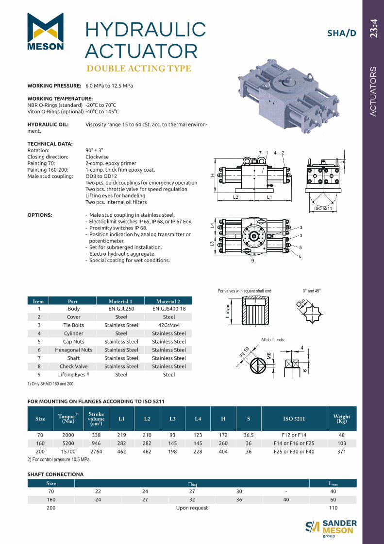
Item Part Material 1 Material 21 Body EN-GJL250 EN-GJS400-18
2 Cover Steel Steel
3 Tie Bolts Stainless Steel 42CrMo4
4 Cylinder Steel Stainless Steel
5 Cap Nuts Stainless Steel Stainless Steel
6 Hexagonal Nuts Stainless Steel Stainless Steel
7 Shaft Stainless Steel Stainless Steel
8 Check Valve Stainless Steel Stainless Steel
9 Lifting Eyes 1) Steel Steel
1) Only SHA/D 160 and 200.
2) For control pressure 10.5 MPa.
Size Torque 2)
(Nm)Stroke volume
(cm3)L1 L2 L3 L4 H S ISO 5211 Weight
(Kg)
70 2000 338 219 210 93 123 172 36.5 F12 or F14 48
160 5200 946 282 282 145 145 260 36 F14 or F16 or F25 103
200 15700 2764 462 462 198 228 404 36 F25 or F30 or F40 371
Size □sq Lmax
70 22 24 27 30 - 40
160 24 27 32 36 40 60
200 Upon request 110
FOR MOUNTING ON FLANGES ACCORDING TO ISO 5211
SHAFT CONNECTIONA
WORKING PRESSURE: 6.0 MPa to 12.5 MPa
WORKING TEMPERATURE: NBR O-Rings (standard) -20°C to 70°CViton O-Rings (optional) -40°C to 145°C HYDRAULIC OIL: Viscosity range 15 to 64 cSt. acc. to thermal environ-ment.
TECHNICAL DATA:Rotation: 90° ± 3° Closing direction: ClockwisePainting 70: 2-comp. epoxy primerPainting 160-200: 1-comp. thick film epoxy coat.Male stud coupling: OD8 to OD12 Two pcs. quick couplings for emergency operation Two pcs. throttle valve for speed regulation Lifting eyes for handeling Two pcs. internal oil filters OPTIONS: - Male stud coupling in stainless steel. - Electric limit switches IP 65, IP 68, or IP 67 Eex. - Proximity switches IP 68. - Position indication by analog transmitter or potentiometer. - Set for submerged installation. - Electro-hydraulic aggregate. - Special coating for wet conditions.
All shaft ends:
0° and 45°For valves with square shaft end
AC
TU
AT
OR
S