donaldson filter
DESCRIPTION
DONALDSON FILTERTRANSCRIPT
Titelondertitel
Titel zijkant
xxx
www.emea.donaldson.com Engine Air Cleaners, Accessoires & Service Parts 51
xxxxxxxxxx
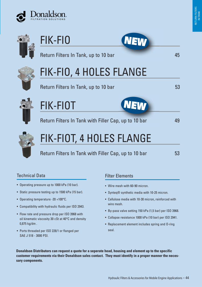
FIK-FIO Return Filters In Tank, up to 10 bar 45
FIK-FIO, 4 HOLES FLANGE Return Filters In Tank, up to 10 bar 53
FIK-FIOT Return Filters In Tank with Filler Cap, up to 10 bar 49
FIK-FIOT, 4 HOLES FLANGE Return Filters In Tank with Filler Cap, up to 10 bar 53
Technical Data
• Operating pressure up to 1000 kPa (10 bar).
• Static pressure testing up to 1500 kPa (15 bar).
• Operating temperature -20 +100°C.
• Compatibility with hydraulic fluids per ISO 2943.
• Flow rate and pressure drop per ISO 3968 with oil kinematic viscosity 30 cSt at 40°C and density 0,875 kg/dm .
• Ports threaded per ISO 228/1 or flanged per SAE J 518 - 3000 PSI.
Filter Elements
• Wire mesh with 60-90 micron.
• Synteq® synthetic media with 10-25 micron.
• Cellulose media with 10-30 micron, reinforced with wire mesh.
• By-pass valve setting 150 kPa (1,5 bar) per ISO 3968.
• Collapse resistance 1000 kPa (10 bar) per ISO 2941.
• Replacement element includes spring and O-ring
seal.
RETU
RN F
ILTE
RSIN
TA
NK
Hydraulic Filters & Accessories for Mobile Engine Applications 44
Donaldson Distributors can request a quote for a seperate head, housing and element up to the specific customer requirements via their Donaldson sales contact. They must identify in a proper manner the neces-sary components.
NEW
, up to 10 bar
NEW

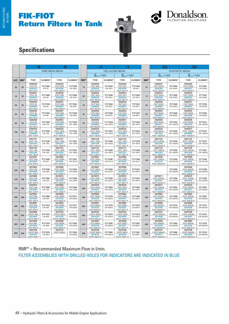
FIK-FIOReturn Filters In Tank
Specifications
RMF* RMF* RMF*
RETU
RN F
ILTE
RSIN
TA
NK
RMF* = Recommanded Maximum Flow in l/min.FILTER ASSEMBLIES WITH DRILLED HOLES FOR INDICATORS ARE INDICATED IN BLUE
45 Hydraulic Filters & Accessories for Mobile Engine Applications
SIZE
325

NEW
25,5
25,5
150
150
FIK-FIOReturn Filters In Tank
SIZE 20-30-50-60-80-100
Additional inlet on requestM18G 1/2
SIZE 150-180-200
SIZE 250-325-330-500
SIZE 600-800
Drilled holes for indicators
Additional inlet on requestIMPORTANT NOTES:
Foresee a hole diameter on top of the tank at a 1. diameter B + 2 mm.
Maintain the filter outlet (ref. diameter2. F) well below the oil level to avoid foam formation.
RETU
RN F
ILTE
RSIN
TA
NK
Hydraulic Filters & Accessories for Mobile Engine Applications 46
D
ING1 1/4
ING1 1/2
45°
45°
Additional inlet on request

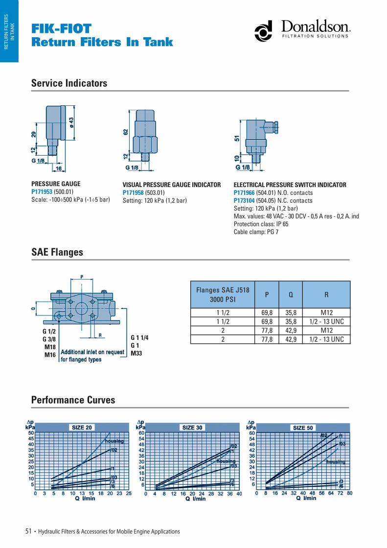
FIK-FIOReturn Filters In Tank
Service Indicators
SAE Flanges
Performance Curves
PRESSURE GAUGEP171953 (500.01)Scale: -100÷500 kPa (-1÷5 bar)
VISUAL PRESSURE GAUGE INDICATORP171958 (503.01)Setting: 120 kPa (1,2 bar)
ELECTRICAL PRESSURE SWITCH INDICATOR P171966 (504.01) N.O. contactsP173104 (504.05) N.C. contactsSetting: 120 kPa (1,2 bar)Max. values: 48 VAC - 30 DCV - 0,5 A res - 0,2 A. indProtection class: IP 65Cable clamp: PG 7
RETU
RN F
ILTE
RSIN
TA
NK
47 Hydraulic Filters & Accessories for Mobile Engine Applications
G 1/2G 3/8M18M16
G 1 1/4G 1M33
FFlanges SAE J518 3000 PSI
P Q R
1 1/2 69,8 35,8 M121 1/2 69,8 35,8 1/2 - 13 UNC
2 77,8 42,9 M122 77,8 42,9 1/2 - 13 UNC

FIK-FIOReturn Filters In Tank RE
TURN
FIL
TERS
IN T
AN
K
Hydraulic Filters & Accessories for Mobile Engine Applications 48
SIZE 325-330
Specifications
RMF* RMF* RMF*
FIK-FIOTReturn Filters In Tank
RETU
RN F
ILTE
RSIN
TA
NK
49 Hydraulic Filters & Accessories for Mobile Engine Applications
SIZE
RMF* = Recommanded Maximum Flow in l/min.FILTER ASSEMBLIES WITH DRILLED HOLES FOR INDICATORS ARE INDICATED IN BLUE

150
150
76
83
76
53
53
65
65
65
65
250
73
73
73
225
225
278
168
242
240
240
294
294
438
434
120
120
120
120
120
120
83
83
83
83
83
SIZE 20-30-50-60-80-100
SIZE 150-180-200
SIZE 250-325-330-500
FIK-FIOTReturn Filters In Tank RE
TURN
FIL
TERS
IN T
AN
K
Hydraulic Filters & Accessories for Mobile Engine Applications 50
Drilled holes for indicators
IMPORTANT NOTES:
Foresee a hole diameter on top of the tank 1. at a diameter B + 2 mm.
Maintain the filter outlet (ref. diameter2. F) well below the oil level to avoid foam formation.
Additional inlet on requestM18G 1/2
D
SIZE 600-800
Additional inlet on request
Additional inlet on request
ING1 1/4
ING1 1/2
NEW
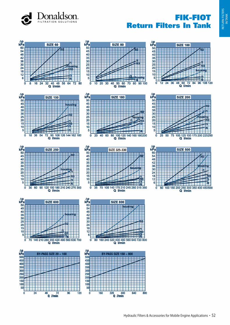
FIK-FIOTReturn Filters In Tank
RETU
RN F
ILTE
RSIN
TA
NK
51 Hydraulic Filters & Accessories for Mobile Engine Applications
Service Indicators
Performance Curves
SAE Flanges
PRESSURE GAUGEP171953 (500.01)Scale: -100÷500 kPa (-1÷5 bar)
VISUAL PRESSURE GAUGE INDICATORP171958 (503.01)Setting: 120 kPa (1,2 bar)
ELECTRICAL PRESSURE SWITCH INDICATOR P171966 (504.01) N.O. contactsP173104 (504.05) N.C. contactsSetting: 120 kPa (1,2 bar)Max. values: 48 VAC - 30 DCV - 0,5 A res - 0,2 A. indProtection class: IP 65Cable clamp: PG 7
G 1/2G 3/8M18M16
G 1 1/4G 1M33
FFlanges SAE J518 3000 PSI
P Q R
1 1/2 69,8 35,8 M121 1/2 69,8 35,8 1/2 - 13 UNC
2 77,8 42,9 M122 77,8 42,9 1/2 - 13 UNC
FIK-FIOTReturn Filters In Tank RE
TURN
FIL
TERS
IN T
AN
K
Hydraulic Filters & Accessories for Mobile Engine Applications 52
SIZE 325-330

FIK-FIO/FIOT, 4 HOLES FLANGESReturn Filters In Tankwith Filler Cap
Specifications FIK-FIO, 4 holes flanges
RMF* RMF* RMF*
RETU
RN F
ILTE
RSIN
TA
NK
53 Hydraulic Filters & Accessories for Mobile Engine Applications
RMF* RMF* RMF*
Specifications FIK-FIOT, 4 holes flanges
SIZE
RMF* = Recommanded Maximum Flow in l/min.FILTER ASSEMBLIES WITH DRILLED HOLES FOR INDICATORS ARE INDICATED IN BLUE
RMF* = Recommanded Maximum Flow in l/min.FILTER ASSEMBLIES WITH DRILLED HOLES FOR INDICATORS ARE INDICATED IN BLUE
SIZE

R = 9 mmQ = ø 126 mmP = ø 115 mm
FIK-FIO/FIOT, 4 HOLES FLANGESReturn Filters In Tank
with Filler Cap RETU
RN F
ILTE
RSIN
TA
NK
Hydraulic Filters & Accessories for Mobile Engine Applications 54
Drilled holes for indicators
R = 9 mmQ = ø 126 mmP = ø 115 mm
Drilled holes for indicators

55 Hydraulic Filters & Accessories for Mobile Engine Applications
RETU
RN F
ILTE
RSIN
TA
NK
Technical Data
• Operating pressure up to 1000 kPa (10 bar).
• Static pressure testing up to 1500 kPa (15 bar).
• Operating temperature -20 +100°C.
• Compatibility with hydraulic fluids per ISO 2943.
• Flow rate and pressure drop per ISO 3968with oil kinematic viscosity 30 cSt at 40°Cand density 0,875 kg/dm³.
• Ports threaded per ISO 228/1
Filter Elements
• Wire mesh with 60-90 micron.
• Synteq® synthetic media with 10-25 micron.
• Cellulose media with 10-30 micron, reinforced with wire mesh.
• By-pass valve setting 150 kPa (1,5 bar) per ISO 3968.
• Collapse resistance 1000 kPa (10 bar) per ISO 2941.
• Replacement element includes spring and O-ring seal.
Hydraulic Filters & Accessories for Mobile Engine Applications 56
RETU
RN F
ILTE
RSIN
TA
NK
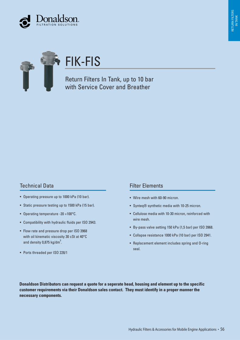
FIK-FIS Return Filters In Tank, up to 10 barwith Service Cover and Breather
Donaldson Distributors can request a quote for a seperate head, housing and element up to the specific customer requirements via their Donaldson sales contact. They must identify in a proper manner the necessary components.

FIK-FISReturn Filters In Tankwith Service Cover and Breather
Specifications
RMF* RMF* RMF*
RETU
RN F
ILTE
RSIN
TA
NK
Air Breather Accessories
57 Hydraulic Filters & Accessories for Mobile Engine Applications
Service Indicators
PRESSURE GAUGEP171953 (500.01)Scale: -100÷500 kPa (-1÷5 bar)
VISUAL PRESSURE GAUGE INDICATORP171958 (503.01)Setting: 120 kPa (1,2 bar)
ELECTRICAL PRESSURE SWITCH INDICATOR P171966 (504.01) N.O. contactsP173104 (504.05) N.C. contactsSetting: 120 kPa (1,2 bar)Max. values: 48 VAC - 30 DCV - 0,5 A res - 0,2 A. indProtection class: IP 65Cable clamp: PG 7
SIZE
RMF* = Recommanded Maximum Flow in l/min. FILTER ASSEMBLIES WITH DRILLED HOLES FOR INDICATORS ARE INDICATED IN BLUE
57
57
93
93
93
O
11
11
13,5
13,5
13,5
98
148
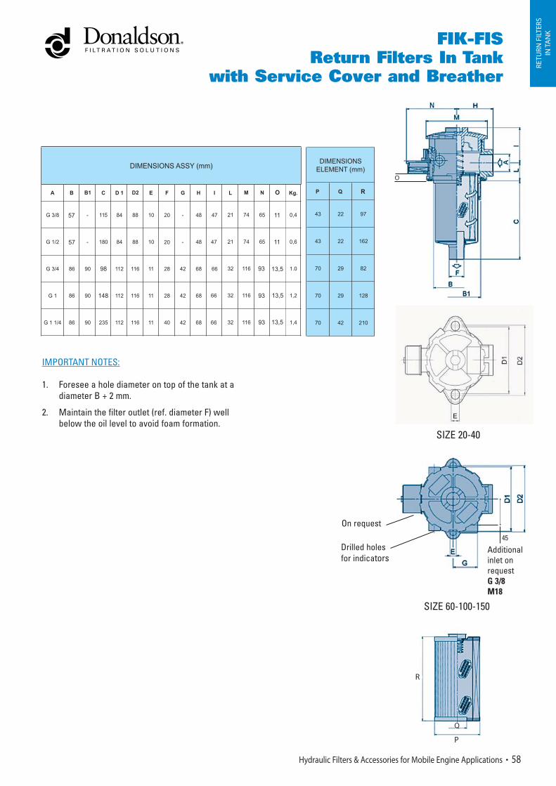
FIK-FISReturn Filters In Tank
with Service Cover and Breather
RETU
RN F
ILTE
RSIN
TA
NK
Hydraulic Filters & Accessories for Mobile Engine Applications 58
IMPORTANT NOTES:
Foresee a hole diameter on top of the tank at a 1. diameter B + 2 mm.
Maintain the filter outlet (ref. diameter2. F) well below the oil level to avoid foam formation.
R
O
On request
Drilled holes for indicators
Additionalinlet on requestG 3/8 M18
SIZE 60-100-150
45
SIZE 20-40
R
Q
P
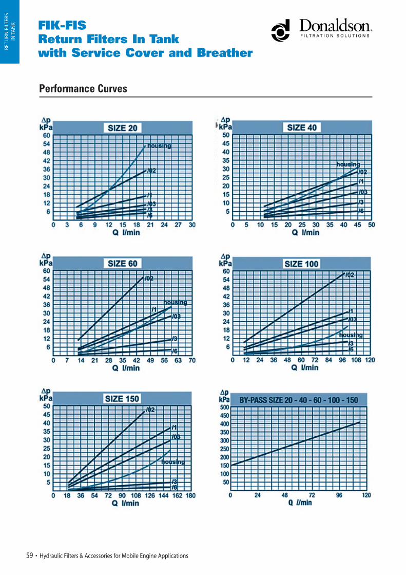
Performance Curves
RETU
RN F
ILTE
RSIN
TA
NK FIK-FIS
Return Filters In Tankwith Service Cover and Breather
59 Hydraulic Filters & Accessories for Mobile Engine Applications

Technical Data
• Operating pressure up to 1000 kPa (10 bar).
• Static pressure testing up to 1500 kPa (15 bar).
• By-pass valve setting 150 kPa (1,5 bar) per ISO 3968.
• Operating temperature -20 +100°C.
• Compatibility with hydraulic fluids per ISO 2943.
• Flow rate and pressure drop per ISO3968with oil kinematic viscosity 30 cSt at 40°Cand density 0,875 kg/dm³.
• Ports threaded per ISO 228/1.
Filter Elements
• Wire mesh 60-90 micron.
• Synteq® synthetic media with 10-25 micron.
• Cellulose media with 10-30 micron, reinforced with wire mesh.
• Collapse resistance 1000 kPa (10 bar) per ISO 2941.
• Replacement element includes spring and O-ring seal.
RETU
RN F
ILTE
RSIN
TA
NK
FHK-FIR Return Filters In Tank for Stationary Applicationwith In Tank Connections
Hydraulic Filters & Accessories for Mobile Engine Applications 60
Donaldson Distributors can request a quote for a seperate head, housing and element up to the specific customer requirements via their Donaldson sales contact. They must identify in a proper manner the necessary components.
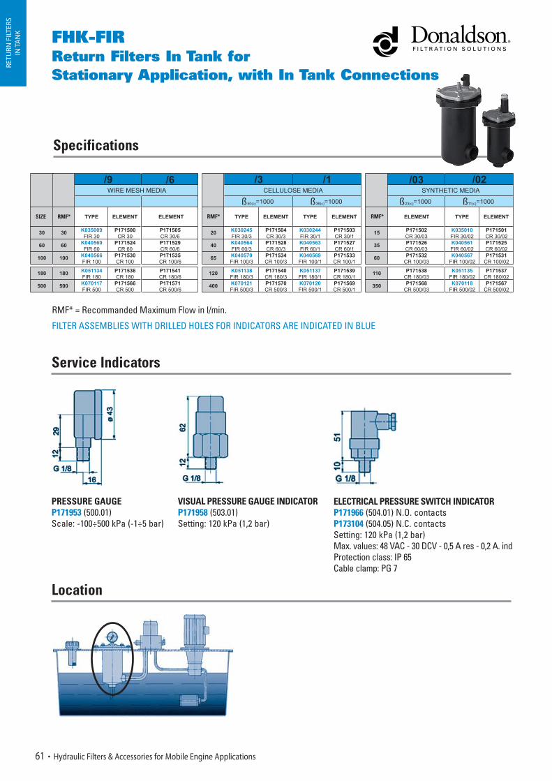
FHK-FIRReturn Filters In Tank for Stationary Application, with In Tank Connections
Specifications
RMF* RMF* RMF*
RETU
RN F
ILTE
RSIN
TA
NK
Service Indicators
PRESSURE GAUGEP171953 (500.01)Scale: -100÷500 kPa (-1÷5 bar)
VISUAL PRESSURE GAUGE INDICATORP171958 (503.01)Setting: 120 kPa (1,2 bar)
ELECTRICAL PRESSURE SWITCH INDICATOR P171966 (504.01) N.O. contactsP173104 (504.05) N.C. contactsSetting: 120 kPa (1,2 bar)Max. values: 48 VAC - 30 DCV - 0,5 A res - 0,2 A. indProtection class: IP 65Cable clamp: PG 7
61 Hydraulic Filters & Accessories for Mobile Engine Applications
Location
SIZE
RMF* = Recommanded Maximum Flow in l/min.
FILTER ASSEMBLIES WITH DRILLED HOLES FOR INDICATORS ARE INDICATED IN BLUE
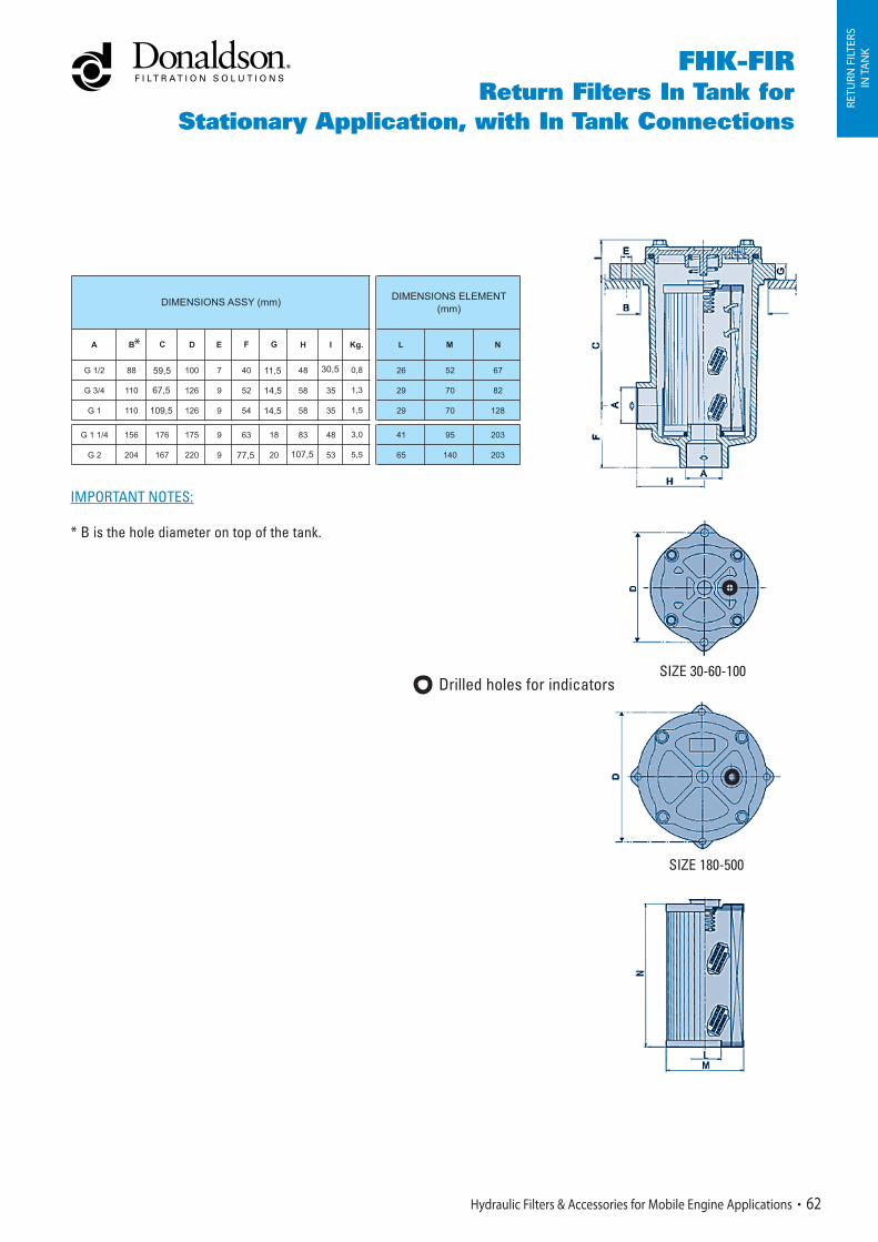
Drilled holes for indicators
SIZE 30-60-100
SIZE 180-500
FHK-FIRReturn Filters In Tank for
Stationary Application, with In Tank Connections
30,559,5
67,5
109,5
77,5 107,5
*
11,5
14,5
14,5
RETU
RN F
ILTE
RSIN
TA
NK
IMPORTANT NOTES:
* B is the hole diameter on top of the tank.
Hydraulic Filters & Accessories for Mobile Engine Applications 62

FHK-FIRReturn Filters In Tank for Stationary Application, with In Tank Connections
Performance Curves
RETU
RN F
ILTE
RSIN
TA
NK
63 Hydraulic Filters & Accessories for Mobile Engine Applications

Hydraulic Filters & Accessories for Mobile Engine Applications 64
RETU
RN &
SU
CTI
ON
FILT
ERS
IN TA
NK
SRK-COMBO 120 Series
In Tank Return & Suction Filters
With Emergency Suction Without Emergency Suction
Predisposition
position
options Same axis ports
Additional G3/8
port on request
Same side ports
Same axis ports
Additional G3/8
port on request
Same side ports
Electrical
Clogging Indicator
K041511 K041595 K041301 K041610
124267P
346367P
Main element
Not Present
256367P
Suction element
Hydraulic Filters & Accessories for Mobile Engine Applications 64
Donaldson Distributors can request a quote for a seperate head, housing and element up to the specific customer requirements via their Donaldson sales contact. They must identify in a proper manner the necessary components.
Not applicable
UNIQUEDESIGNCONCEPT
RETU
RN &
SU
CTI
ON
FILT
ERS
IN T
AN
K
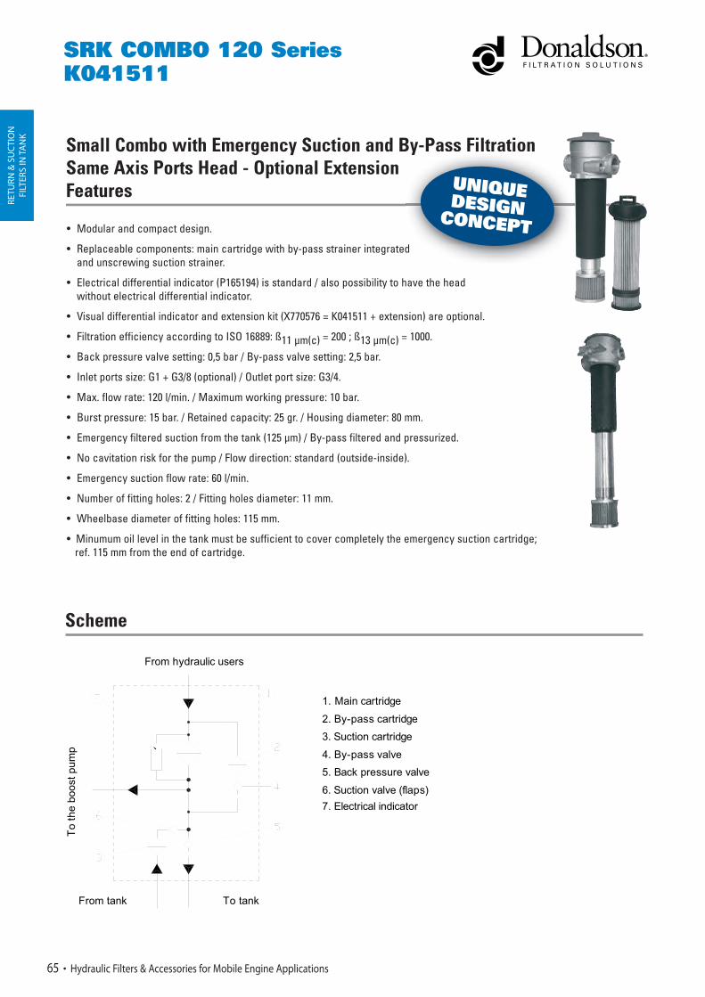
• Modular and compact design.
• Replaceable components: main cartridge with by-pass strainer integrated and unscrewing suction strainer.
• Electrical differential indicator (P165194) is standard / also possibility to have the headwithout electrical differential indicator.
• Visual differential indicator and extension kit (X770576 = K041511 + extension) are optional.
• Filtration efficiency according to ISO 16889: ß11 μm(c) = 200 ; ß13 μm(c) = 1000.
• Back pressure valve setting: 0,5 bar / By-pass valve setting: 2,5 bar.
• Inlet ports size: G1 + G3/8 (optional) / Outlet port size: G3/4.
• Max. flow rate: 120 l/min. / Maximum working pressure: 10 bar.
• Burst pressure: 15 bar. / Retained capacity: 25 gr. / Housing diameter: 80 mm.
• Emergency filtered suction from the tank (125 μm) / By-pass filtered and pressurized.
• No cavitation risk for the pump / Flow direction: standard (outside-inside).
• Emergency suction flow rate: 60 l/min.
• Number of fitting holes: 2 / Fitting holes diameter: 11 mm.
• Wheelbase diameter of fitting holes: 115 mm.
• Minumum oil level in the tank must be sufficient to cover completely the emergency suction cartridge; ref. 115 mm from the end of cartridge.
Small Combo with Emergency Suction and By-Pass Filtration Same Axis Ports Head - Optional Extension Features
To
the
boos
t pum
p
From tank To tank
1. Main cartridge
2. By-pass cartridge
3. Suction cartridge
4. By-pass valve
5. Back pressure valve
6. Suction valve (flaps)
7. Electrical indicator
From hydraulic users
65 Hydraulic Filters & Accessories for Mobile Engine Applications
SRK COMBO 120 SeriesK041511
Scheme
d
have the head
y
UNIQUEDESIGNCONCEPT
RETU
RN &
SU
CTI
ON
FILT
ERS
IN TA
NK
Hydraulic Filters & Accessories for Mobile Engine Applications 66
SRK COMBO 120 SeriesK041511
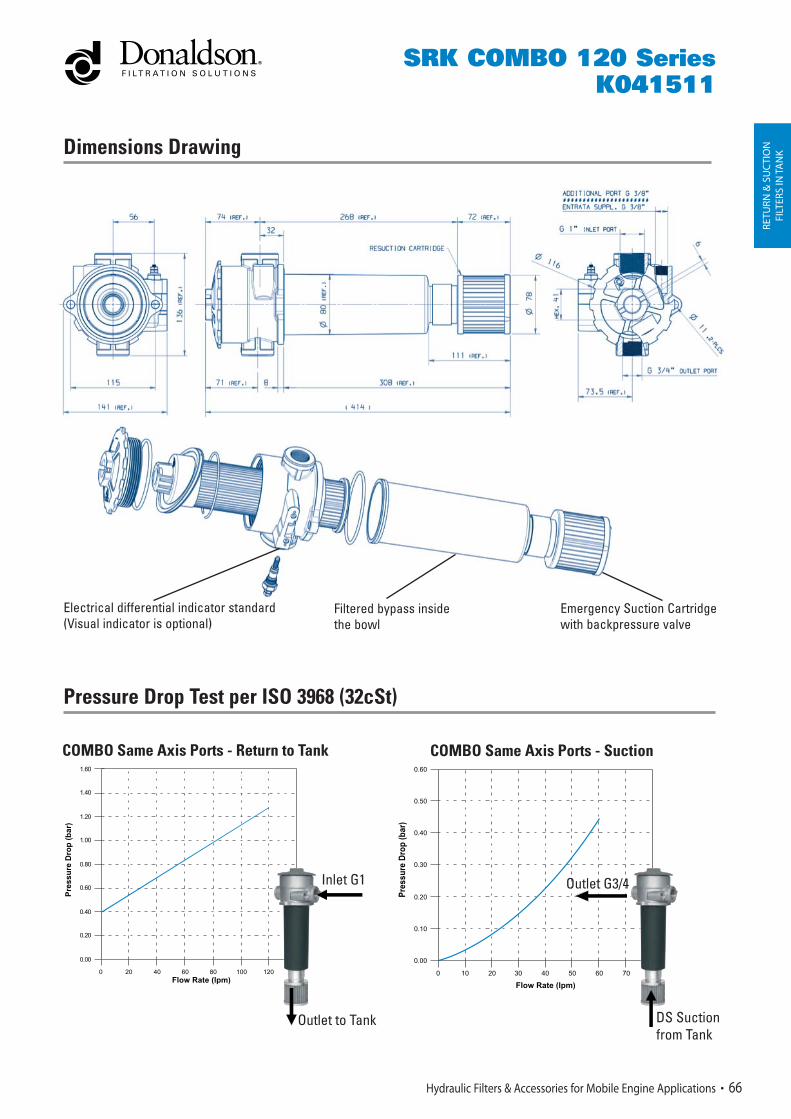
Dimensions Drawing
Electrical differential indicator standard (Visual indicator is optional)
Filtered bypass inside the bowl
Emergency Suction Cartridge with backpressure valve
Pressure Drop Test per ISO 3968 (32cSt)
0 20 40 60 80 100 120 140Flow Rate (lpm)
0.20
0.60
1.00
1.40
0.00
0.40
0.80
1.20
1.60
Pre
ssu
re D
rop
(b
ar)
K041511R.grf
COMBO Same Axis Ports - Return to Tank
Inlet G1
Outlet to Tank
COMBO Same Axis Ports - Suction
0 10 20 30 40 50 60 70 80
Flow Rate (lpm)
0.10
0.30
0.50
0.00
0.20
0.40
0.60
Pre
ssur
e D
rop
(bar
)
k041595Sgrf
Outlet G3/4
DS Suctionfrom Tank
RETU
RN &
SU
CTI
ON
FILT
ERS
IN TA
NK
67 Hydraulic Filters & Accessories for Mobile Engine Applications
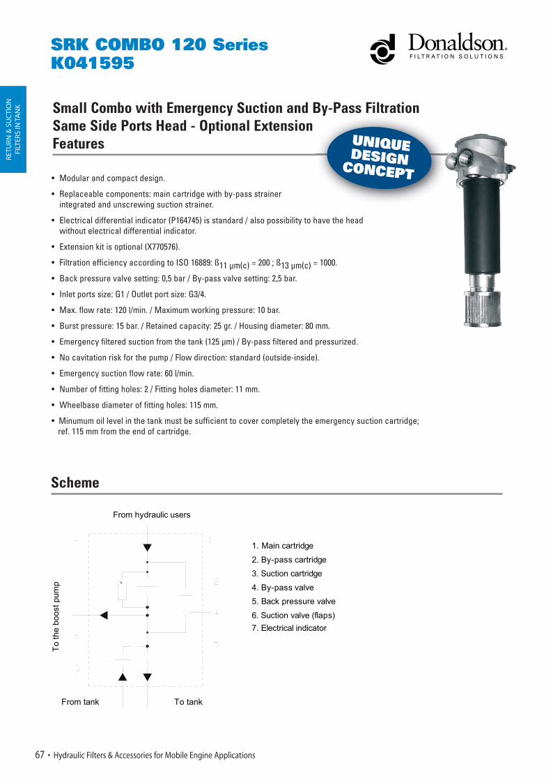
Small Combo with Emergency Suction and By-Pass Filtration Same Side Ports Head - Optional Extension Features
SRK COMBO 120 SeriesK041595
• Modular and compact design.
• Replaceable components: main cartridge with by-pass strainer integrated and unscrewing suction strainer.
• Electrical differential indicator (P164745) is standard / also possibility to have the head without electrical differential indicator.
• Extension kit is optional (X770576).
• Filtration efficiency according to ISO 16889: ß11 μm(c) = 200 ; ß13 μm(c) = 1000.
• Back pressure valve setting: 0,5 bar / By-pass valve setting: 2,5 bar.
• Inlet ports size: G1 / Outlet port size: G3/4.
• Max. flow rate: 120 l/min. / Maximum working pressure: 10 bar.
• Burst pressure: 15 bar. / Retained capacity: 25 gr. / Housing diameter: 80 mm.
• Emergency filtered suction from the tank (125 μm) / By-pass filtered and pressurized.
• No cavitation risk for the pump / Flow direction: standard (outside-inside).
• Emergency suction flow rate: 60 l/min.
• Number of fitting holes: 2 / Fitting holes diameter: 11 mm.
• Wheelbase diameter of fitting holes: 115 mm.
• Minumum oil level in the tank must be sufficient to cover completely the emergency suction cartridge; ref. 115 mm from the end of cartridge.
To
the
boos
t pum
p
From tank To tank
1. Main cartridge
2. By-pass cartridge
3. Suction cartridge
4. By-pass valve
5. Back pressure valve
6. Suction valve (flaps)
7. Electrical indicator
From hydraulic users
Scheme
y
have the head
UNIQUEDESIGNCONCEPT

RETU
RN &
SU
CTI
ON
FILT
ERS
IN TA
NK
Hydraulic Filters & Accessories for Mobile Engine Applications 68
SRK COMBO 120 SeriesK041595
Dimensions Drawing
Electrical differential indicator standard (Visual indicator is optional)
Filtered bypass inside the bowl
Emergency Suction Cartridge with backpressure valve
Pressure Drop Test per ISO 3968 (32cSt)
COMBO Same Side Ports - Return to Tank COMBO Same Side Ports - Suction
0 20 40 60 80 100 120 140Flow Rate (lpm)
0.20
0.60
1.00
1.40
0.00
0.40
0.80
1.20
1.60
Pre
ssu
re D
rop
(b
ar)
K041511R.grf
Inlet G1
Outlet to Tank
0 10 20 30 40 50 60 70 80
Flow Rate (lpm)
0.10
0.30
0.50
0.00
0.20
0.40
0.60
Pre
ssur
e D
rop
(bar
)
k041595Sgrf
Outlet G3/4
Inlet Suctionfrom Tank

RETU
RN &
SU
CTI
ON
FILT
ERS
IN TA
NK
• Modular and compact design.
• Embodied valves available
• Possibility to fit low cost differential pressure indicator
• Serviceable filler cap with clean service.
• Improved pump feeding hydraulic transmission during cold starts.
• Simple interface with the tank: one unique installation hole.
• Outlet with always clean and filtered oilflow to the pressurized (0.5 bar) suction side (boost pump of hydrostatic transmissions).
• Bypass setting: 2,5 bar / No loose parts.
• Flow range up to 120 l/min. / Low pressure drop and high capacity.
• Minimum oil level in tank must be approximately 50 mm above the housing end.
The suction port always gets clean oil. When the element becomes clogged, oil that reaches the suction port is gradually
reduced, so the use of an electrical clogging indicator (P165194) is recommended. Return flow must always be higher than
suction flow.
69 Hydraulic Filters & Accessories for Mobile Engine Applications
SRK COMBO 120 SeriesK041301
Small Combo without Emergency Suction and By-Pass Filtration Same Axis Ports Head Features
Important
4
From hydraulic users
To tank
To t
he b
oost pum
p
1- MAIN CARTRIDGE
2- BY-PASS VALVE
3- BACK PRESSURE VALVE
4- ELECTRICAL INDICATOR
1
2
3
Scheme
UNIQUEDESIGNCONCEPT

0 20 40 60 80 100 120 140Flow Rate (lpm)
0.20
0.60
1.00
1.40
0.00
0.40
0.80
1.20
1.60
Pre
ssu
re D
rop
(b
ar)
K041511R.grf
RETU
RN &
SU
CTI
ON
FIL
TERS
IN TA
NK
Hydraulic Filters & Accessories for Mobile Engine Applications 70
Dimensions Drawing
Electrical differential indicator standard Embodied valves (bypass and backpressure valve)
Pressure Drop Test per ISO 3968 (32cSt)
COMBO Same Axis Ports - Return to Tank COMBO Same Axis Ports - Suction
Inlet G1
Outlet to Tank
0 10 20 30 40 50 60 70 80
Flow Rate (lpm)
0.10
0.30
0.50
0.00
0.20
0.40
0.60
Pre
ssur
e D
rop
(bar
)
k041595Sgrf
Outlet G3/4
Suctionfrom Tank
SRK COMBO 120 SeriesK041301

Small Combo without Emergency Suction and By-Pass Filtration Same Side Ports Head FeaturesRE
TURN
& S
UC
TIO
NFI
LTER
S IN
TAN
K
• Modular and compact design.
• Embodied valves available, possibility to fit low cost differential pressure indicator, serviceable filler cap with clean service.
• Improved pump feeding hydraulic transmission during cold starts.
• Simple interface with the tank: one unique installation hole.
• Outlet with always clean, filtered oilflow to the pressurized (0.5 bar) suction side (boost pump of hydrostatic transmissions).
• Bypass setting: 2,5 bar.
• No loose parts.
• Flow range up to 120 l/min. / Low pressure drop and high capacity.
• Minimum oil level in tank must be approximately 50 mm above the housing end.
Important
The suction port always gets clean oil. When the element becomes clogged, oil that reaches the suction port is gradually
reduced, so the use of an electrical clogging indicator (P164745) is recommended. Return flow must always be higher than
suction flow.
71 Hydraulic Filters & Accessories for Mobile Engine Applications
SRK COMBO 120 SeriesK041610
Scheme
a d y ass a o
l
UNIQUEDESIGNCONCEPT
4
From hydraulic users
To tank
To t
he b
oost pum
p
1- MAIN CARTRIDGE
2- BY-PASS VALVE
3- BACK PRESSURE VALVE
4- ELECTRICAL INDICATOR
1
2
3

RETU
RN &
SU
CTI
ON
FIL
TERS
IN TA
NK
Dimensions
Hydraulic Filters & Accessories for Mobile Engine Applications 72
SRK COMBO 120 SeriesK041610
Electrical differential indicator standard Embodied valves (bypass and backpressure valve)
Pressure Drop Test per ISO 3968 (32cSt)
0 20 40 60 80 100 120 140Flow Rate (lpm)
0.20
0.60
1.00
1.40
0.00
0.40
0.80
1.20
1.60
Pre
ssu
re D
rop
(b
ar)
K041511R.grf
COMBO Same Side Ports - Return to Tank
Outlet to Tank
COMBO Same Side Ports - Suction
0 10 20 30 40 50 60 70 80
Flow Rate (lpm)
0.10
0.30
0.50
0.00
0.20
0.40
0.60
Pre
ssur
e D
rop
(bar
)
k041595Sgrf
Outlet 3/4"
InletSuction from Tank
Inlet G1
Outlet to Boost Pump G3/4

73 Hydraulic Filters & Accessories for Mobile Engine Applications
Indicators
RETU
RN &
SU
CTI
ON
FILT
ERS
IN TA
NK
SRK COMBO 120 Series
AVAILABLE MODEL FOR BY-PASS 350 kPA (3,5 bar):P165194 N.O. contacts, color-coded wascher: red/whiteSettings: 270 kPa (2,7 bar)Max. values: 30 DCV - 0,2 A
AVAILABLE MODEL FOR BY-PASS 250 kPA (2,5 bar):P164745 N.O. contacts, color-coded wascher: red/whiteSettings: 170 kPa (1,7 bar)Max. values: 30 DCV - 0,2 A
NOTE:
Electrical Indicator Data: Circuit: Normally open Voltage: 6 - 30 V D.C. Current: 200 MA max. Contact: 25 +- 2.5 PSID (Circuit Closed) Reset: 17 PSID min. (Circuit Open)

RETU
RN &
SU
CTI
ON
FIL
TERS
IN TA
NK
SUCTION LINE DRILLED HOLES FOR INDICATOR
b K041609 K041607 K041608K041606
With Emergency Suction Without Emergency Suction Position of
drilled holes for indicator - see scheme
(No indicator fitted)
Withoutoptional inlet
port G1
Withoutoptional inlet
port G1
With optional inlet
port G1
With optional
inlet port G1
No predrilled holes
RETURN LINE DRILLED HOLES FOR INDICATOR
891467P 891467P tnemele niaM
381467P tnemele noitcuS Not applicable
K041597 K041596 K041528K041535
a2 K041605 K041603 K041604K041602
a1 K041601 K041599 K041600K041598
SRK-COMBO 200 Series (Big Combo)
Return & Suction Filters In Tank
Hydraulic Filters & Accessories for Mobile Engine Applications 74
Partnumbers according to: With or without emergency suction / Indicator positions / Optional inlet port
Donaldson Distributors can request a quote for a seperate head, housing and element up to the specific customer requirements via their Donaldson sales contact. They must identify in a proper manner the necessary components.
UNIQUEDESIGNCONCEPT

Technical Data
Main Element Suction Element
RETU
RN &
SU
CTI
ON
FILT
ERS
IN TA
NK
• Two filter versions with and without emergency suction from the tank.
• Two versions have the same body but different housings,
thus any retrofit from one version to the other is not possible.
• By-pass flow always filtered / By-pass flow always pressurized.
• Operating Pressure to 1000 kPa (10bar).
• Flow Rate: return 200 l/min.
• Emergency suction flow rate till 70 lpm from the tank.
• Back Pressure valve setting 50kPa (0,5 bar) / By-pass valve setting 250 kPa (2,5 bar).
• Operating Temperature -20 +100 °C.
• Compatibility with hydraulic fluids per ISO 2943.
• Interchangeable with various return and suction filters.
• Flow direction through the element from inside to outside.
• Minumum oil level in the tank must be sufficient to cover completely the emergency suction cartridge for the
versions with emergency suction.
• Minumum oil level in the tank must be approximately 50 mm above the housing end for the versions without emergency suction.
• Synthetic Fiber
• Efficiency Per ISO 16889: ß11μm(c) > 200 ; ß13 μm(c) > 1000
• Dust capacity per ISO 16889 at final Delta P 350 kPa typical value 70g
• By pass strainer integrated into the main element 125 micron wire mesh
• Unique interface with filter assembly
75 Hydraulic Filters & Accessories for Mobile Engine Applications
SRK COMBO 200 SeriesBig ComboWith or Without Emergency Suction
• Only on version with emergency suction
• 125 micron wire mesh
Scheme
With Emergency Suction Without Emergency Suction
tank.
UNIQUEDESIGNCONCEPT
a1: a2; b = pressure indicator ports
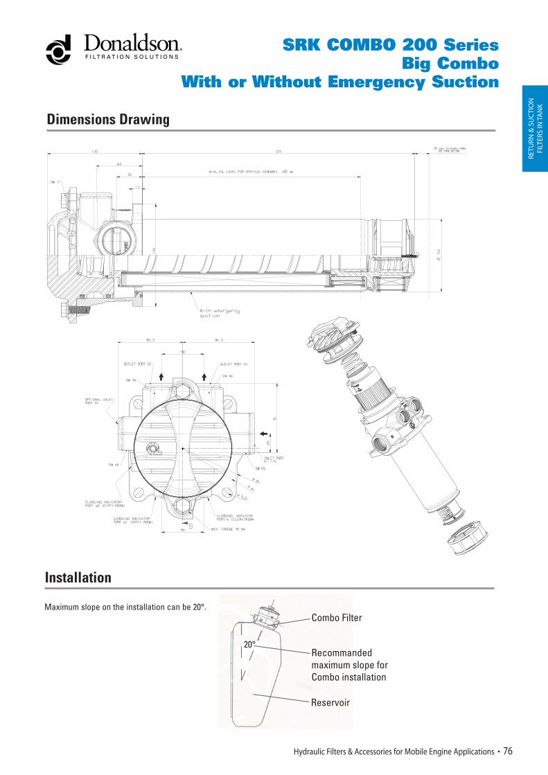
Dimensions Drawing
RETU
RN &
SU
CTI
ON
FILT
ERS
IN TA
NK
Hydraulic Filters & Accessories for Mobile Engine Applications 76
SRK COMBO 200 SeriesBig Combo
With or Without Emergency Suction
Installation
Maximum slope on the installation can be 20°.Combo Filter
20°Recommanded maximum slope for Combo installation
Reservoir
RETU
RN &
SU
CTI
ON
FILT
ERS
IN TA
NK
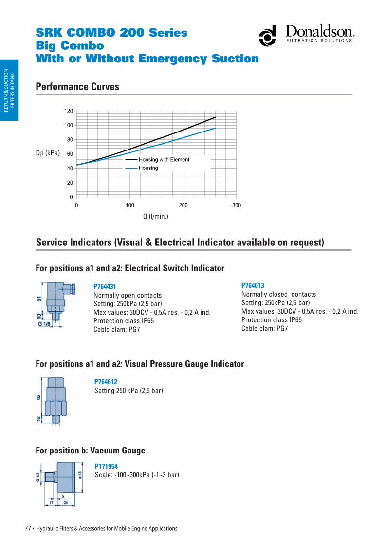
Service Indicators (Visual & Electrical Indicator available on request)
SRK COMBO 200 SeriesBig ComboWith or Without Emergency Suction
For positions a1 and a2: Electrical Switch Indicator
For positions a1 and a2: Visual Pressure Gauge Indicator
For position b: Vacuum Gauge
P764431Normally open contactsSetting: 250kPa (2,5 bar)Max values: 30DCV - 0,5A res. - 0,2 A ind.Protection class IP65Cable clam: PG7
P764612 Setting 250 kPa (2,5 bar)
P171954 Scale: -100~300kPa (-1~3 bar)
Performance Curves
P764613Normally closed contactsSetting: 250kPa (2,5 bar)Max values: 30DCV - 0,5A res. - 0,2 A ind.Protection class IP65Cable clam: PG7
77 Hydraulic Filters & Accessories for Mobile Engine Applications
0
20
40
60
80
100
120
0 100 200 300Q l/min
Housing with Element
Housing
Dp (kPa)
Q (l/min.)

Technical Data
• Operating pressure up to 3000 kPa (30 bar).
• Static pressure testing up to 4500 kPa (45 bar).
• By-pass valve setting 150 kPa (1,5 bar) perISO 3968.
• Operating temperature -20 +100°C.
• Compatibility with hydraulic fluids per ISO 2943.
• Flow rate and pressure drop per ISO 3968with oil kinematic viscosity 30 cSt at 40°C and density 0,875 kg/dm³.
• Ports threaded per ISO 228/1 or flanged per SAE J 518 - 3000PSI.
Filter Elements
• Wire mesh 60-90 micron.
• Synteq® synthetic media with 10-25 micron.
• Cellulose media with 10-30 micron, reinforced with wire mesh.
• Collapse resistance 1000 kPa (10 bar) per ISO 2941.
IN-L
INE
RETU
RN F
ILTE
RS
FLK-FLS Return Filters In-Line with Take Apart Element up to 30 bar
Hydraulic Filters & Accessories for Mobile Engine Applications 78
Donaldson Distributors can request a quote for a seperate head, housing and element up to the specific customer requirements via their Donaldson sales contact. They must identify in a proper manner the necessary components.
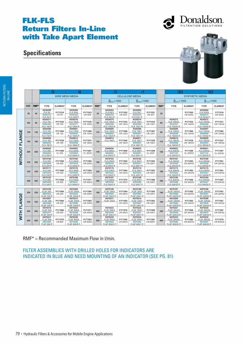
Specifications
RMF* RMF* RMF*RMF*RETU
RN F
ILTE
RSIN
-LIN
E
79 Hydraulic Filters & Accessories for Mobile Engine Applications
FLK-FLSReturn Filters In-Line with Take Apart Element
RMF* = Recommanded Maximum Flow in l/min.
FILTER ASSEMBLIES WITH DRILLED HOLES FOR INDICATORS ARE INDICATED IN BLUE AND NEED MOUNTING OF AN INDICATOR (SEE PG. 81)
SIZE
CL 200/02
496
RETY
RB F
UKT
ERS
IN-L
INE
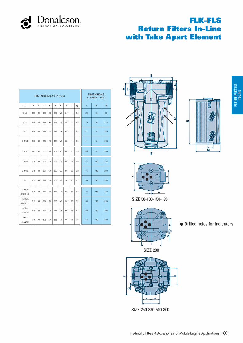
SIZE 50-100-150-180
SIZE 250-330-500-800
SIZE 200
Hydraulic Filters & Accessories for Mobile Engine Applications 80
FLK-FLSReturn Filters In-Line
with Take Apart Element
Drilled holes for indicators

FOR SIZES 250-330-500-600
Service Indicators
RETU
RN F
ILTE
RSIN
-LIN
E
VISUAL DIFFERENTIAL PRESSURE INDICATOR P171950 (502.04)Setting: 140 kPa (1,4 bar)
ELECTRICAL DIFFERENTIAL PRESSURE INDICATOR 3-WIRES, COMPATIBLE WITH MICROPROCESSORSP173944Setting: 140 kPa (1,4 bar)
ELECTRICAL DIFFERENTIAL PRESSURE INDICATOR P162400 N.O. contactsP163839 N.C. contactsSetting: 140 kPa (1,4 bar)
ELECTRICAL DIFFERENTIAL PRESSURE INDICATOR P171961 (501.02)P171963 (501.04) with thermostat 30°CSetting: 140 kPa (1,4 bar)Max. values: 30 ACV - 30 DCV - 0,5 A res. and ind.Protection class: IP 65 - Cable clamp: PG 11
ELECTRICAL DIFFERENTIAL PRESSURE INDICATOR 2-WIRES,PACKARD CONNECTORP171143 N.O. contactsSetting: 140 kPa (1,4 bar)
81 Hydraulic Filters & Accessories for Mobile Engine Applications
FLK-FLSReturn Filters In-Line with Take Apart Element
In case one of the below indicators is needed, contact your Donaldson salesman for the filter assembly partnumber.

SAE Flanges
Performance Curves
RETU
RN F
ILTE
RSIN
-LIN
E
Hydraulic Filters & Accessories for Mobile Engine Applications 82
FLK-FLSReturn Filters In-Line
with Take Apart Element
SIZE 50SIZE 50 SIZE 100SIZE 100 SIZE 150SIZE 150
SIZE 800SIZE 800
BY-PASS SIZE 50-100 BY-PASS SIZE 200 BY-PASS SIZE 150-180-250-330-500-800
RETU
RN F
ILTE
RSIN
-LIN
E
83 Hydraulic Filters & Accessories for Mobile Engine Applications

Technical Data
• Operating pressure up to 1000 kPa (10 bar).
• Static pressure testing up to 1500 kPa (15 bar).
• By-pass valve setting 150 kPa (1,5 bar) or170 kPa (1,7 bar) per ISO 3968.
• Operating temperature -20 +100°C.
• Compatibility with hydraulic fluids per ISO 2943.
• Flow rate and pressure drop per ISO 3968with oil kinematic viscosity 30 cSt at 40°Cand density 0,875 kg/dm³.
• Ports threaded per ISO 228/1.
Filter Elements
• Wire mesh 60-90 micron.
• Synteq® synthetic media with 10-25 micron.
• Cellulose media with 10-30 micron, reinforced with wire mesh.
• Collapse resistance 1000 kPa (10 bar) per ISO 2941.
RETU
RN F
ILTE
RSIN
-LIN
E
Hydraulic Filters & Accessories for Mobile Engine Applications 84
FBK-FRCA Return Spin-On Filters In-Line up to 10 bar
ADDITIONS
Donaldson Distributors can request a quote for a seperate head, housing and element up to the specific customer requirements via their Donaldson sales contact. They must identify in a proper manner the necessary components.

Specifications
RETU
RN F
ILTE
RSIN
-LIN
E
85 Hydraulic Filters & Accessories for Mobile Engine Applications
FBK-FRCAReturn Spin-On Filters In-Line
RMF* = Recommanded Maximum Flow in l/min.
All assemblies are without drilled holes for indicators.
Look at the table on page 87 for which head should be used.
ADDITIONS
ADDITIONS ADDITIONS
108
108
220
250

RETU
RN F
ILTE
RSIN
-LIN
ESIZE 160-200
By-pass valve setting 150 kPa (1,5 bar)
Hydraulic Filters & Accessories for Mobile Engine Applications 86
FBK-FRCAReturn Spin-On Filters In-Line
SIZE 380-400By-pass valve setting 150 kPa (1,5 bar)
SIZE 60-80By-pass valve setting 170 kPa (1,7 bar)
RETU
RN F
ILTE
RSIN
-LIN
E
87 Hydraulic Filters & Accessories for Mobile Engine Applications
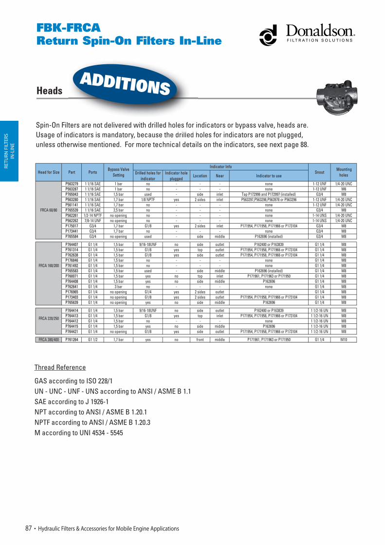
Heads
FBK-FRCAReturn Spin-On Filters In-Line
Spin-On Filters are not delivered with drilled holes for indicators or bypass valve, heads are.Usage of indicators is mandatory, because the drilled holes for indicators are not plugged, unless otherwise mentioned. For more technical details on the indicators, see next page 88.
ters are not delivered with drilled holes for indi t i d t b th d ill d h
ADDITIONS
Thread Reference
GAS according to ISO 228/1UN - UNC - UNF - UNS according to ANSI / ASME B 1.1SAE according to J 1926-1NPT according to ANSI / ASME B 1.20.1NPTF according to ANSI / ASME B 1.20.3M according to UNI 4534 - 5545
DDrilled holes for indicator
Indicator hole plugged
Location Near Indicator to use
P563279 1 1/16 SAE 1 bar no - - - none 1-12 UNF 1/4-20 UNCP563287 1 1/16 SAE 1 bar no - - - none 1-12 UNF M6P765043 1 1/16 SAE 1,5 bar used - side inlet Tap P172996 and P172997 (installed) G3/4 M8P563280 1 1/16 SAE 1,7 bar 1/8 NPTF yes 2 sides inlet P563297,P563298,P563978 or P563296 1-12 UNF 1/4-20 UNCP561141 1 1/16 SAE 1,7 bar no - - - none 1-12 UNF 1/4-20 UNCP765539 1 1/16 SAE 2,5 bar no - - - none G3/4 M8P562261 1/2-14 NPTF no opening no - - - none 1-14 UNS 1/4-20 UNCP562262 7/8-14 UNF no opening no - - - none 1-14 UNS 1/4-20 UNCP175017 G3/4 1,7 bar G1/8 yes 2 sides inlet P171954, P171958, P171966 or P173104 G3/4 M8P173441 G3/4 1,7 bar no - - - none G3/4 M8P765584 G3/4 no opening used - side middle P162696 (installed) G3/4 M8
P764407 G1 1/4 1,5 bar 9/16-18UNF no side outlet P162400 or P163839 G1 1/4 M8P761314 G1 1/4 1,5 bar G1/8 yes top outlet P171954, P171958, P171966 or P173104 G1 1/4 M8P762638 G1 1/4 1,5 bar G1/8 yes side outlet P171954, P171958, P171966 or P173104 G1 1/4 M8P176846 G1 1/4 1,5 bar no - - - none G1 1/4 M8P761492 G1 1/4 1,5 bar no - - - none G1 1/4 M8P765583 G1 1/4 1,5 bar used - side middle P162696 (installed) G1 1/4 M8P760071 G1 1/4 1,5 bar yes no top inlet P171961, P171963 or P171950 G1 1/4 M8P764408 G1 1/4 1,5 bar yes no side middle P162696 G1 1/4 M8P762641 G1 1/4 3 bar no - - - none G1 1/4 M8P176965 G1 1/4 no opening G1/4 yes 2 sides outlet - G1 1/4 M8P173403 G1 1/4 no opening G1/8 yes 2 sides outlet P171954, P171958, P171966 or P173104 G1 1/4 M8P765639 G1 1/4 no opening yes no side middle P162696 G1 1/4 M8
P764414 G1 1/4 1,5 bar 9/16-18UNF no side outlet P162400 or P163839 1 1/2-16 UN M8P764413 G1 1/4 1,5 bar G1/8 yes top inlet P171954, P171958, P171966 or P173104 1 1/2-16 UN M8P764412 G1 1/4 1,5 bar no - - - none 1 1/2-16 UN M8P764415 G1 1/4 1,5 bar yes no side middle P162696 1 1/2-16 UN M8P764421 G1 1/4 no opening G1/8 yes side outlet P171954, P171958, P171966 or P173104 1 1/2-16 UN M8
FRCA 380/400 PP761264 G1 1/2 1,7 bar yes no front middle P171961, P171963 or P171950 G1 1/4 M10
Ports Snout Mounting
holes
Indicator InfoHead for Size Part
Bypass Valve Setting
FRCA 60/80
FRCA 160/200
FRCA 220/250
RETU
RN F
ILTE
RSIN
-LIN
E
Hydraulic Filters & Accessories for Mobile Engine Applications 88
FBK-FRCAReturn Spin-On Filters In-Line
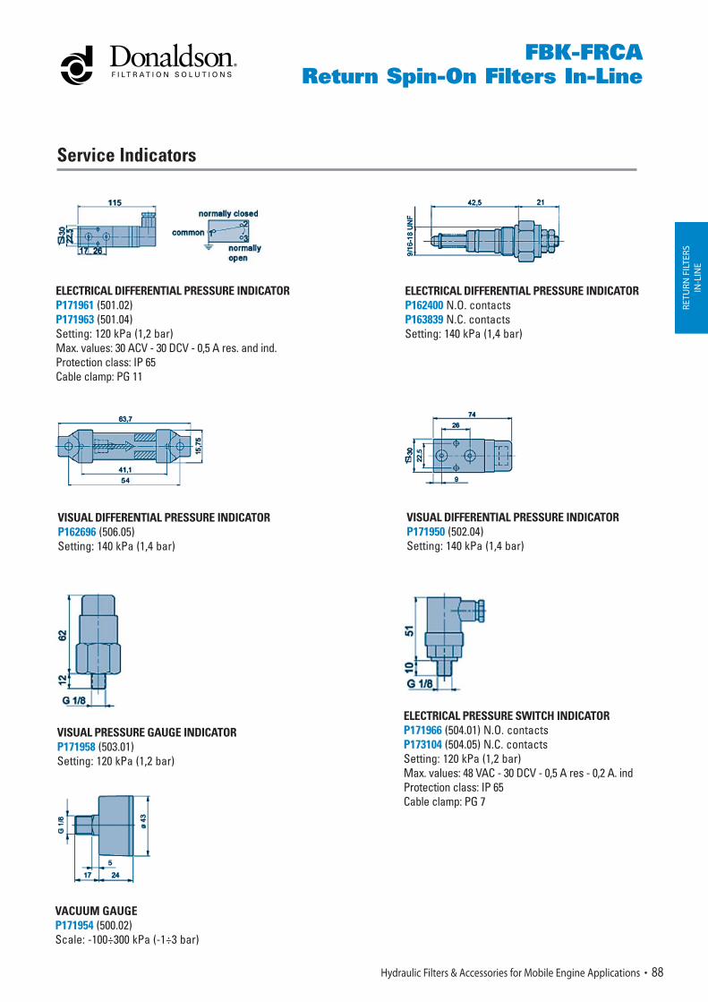
Service Indicators
VISUAL DIFFERENTIAL PRESSURE INDICATOR P162696 (506.05)Setting: 140 kPa (1,4 bar)
ELECTRICAL DIFFERENTIAL PRESSURE INDICATOR P171961 (501.02)P171963 (501.04)Setting: 120 kPa (1,2 bar)Max. values: 30 ACV - 30 DCV - 0,5 A res. and ind.Protection class: IP 65Cable clamp: PG 11
VISUAL DIFFERENTIAL PRESSURE INDICATOR P171950 (502.04)Setting: 140 kPa (1,4 bar)
ELECTRICAL DIFFERENTIAL PRESSURE INDICATOR P162400 N.O. contactsP163839 N.C. contactsSetting: 140 kPa (1,4 bar)
VISUAL PRESSURE GAUGE INDICATORP171958 (503.01)Setting: 120 kPa (1,2 bar)
ELECTRICAL PRESSURE SWITCH INDICATOR P171966 (504.01) N.O. contactsP173104 (504.05) N.C. contactsSetting: 120 kPa (1,2 bar)Max. values: 48 VAC - 30 DCV - 0,5 A res - 0,2 A. indProtection class: IP 65Cable clamp: PG 7
VACUUM GAUGEP171954 (500.02)Scale: -100÷300 kPa (-1÷3 bar)