domo document template - cobham, home
TRANSCRIPT
Page 1 Specifications subject to change without notice
SOLO4 „DropCam‟
User Manual
Users‟ Manual
Version 1.5
27 May 2011
Cobham Tactical Communications and Surveillance The Cobham Centre – Solent, Fusion 2 1100 Parkway Solent Business Park Whiteley, Hampshire PO15 7AB, England T: +44 (0)1489 566 750 F: +44 (0)1489 880 538
2
Table of Contents
Table of Contents .................................................................................................. 2 Change History ...................................................................................................... 3 About this Manual ................................................................................................. 4 Introduction ........................................................................................................... 5 Warranty and Support ........................................................................................... 6
1.1 Warranty Cover ............................................................................................... 6 Safety, Compliance and Approvals ...................................................................... 7
1.1 Safe Operating Procedures ............................................................................. 7 1.2 EMC / Safety and Radio Approvals .................................................................. 7 1.3 CE marking ...................................................................................................... 7
Getting Started and Basic Operation ................................................................... 8 1.1 Which Model do I have? .................................................................................. 8 Controls ..................................................................................................................... 9
Advanced Operation ........................................................................................... 15 1.1 SOLO System PC Controller Application Software ........................................ 15 1.2 Transmitter Control Application ...................................................................... 17
Fault Finding........................................................................................................ 25 Connector Pin Outs............................................................................................. 26
1.1 Power and Control - 7pin Binder 712 Series PN. 99 0422 0007 ..................... 26 Control Protocols ................................................................................................ 27
1.1 RS232 Control – General Principles .............................................................. 27 1.2 Packet Structure Sending (from PC) .............................................................. 27 1.3 Packet Structure Reply (from controlled device) ............................................ 28 1.4 Transmitter Command List ............................................................................. 29
Default Configurations ........................................................................................ 37

3
Change History
Version
Main Changes from Previous Version
Edited By
v1.0 Initial Release MB
V1.1 Updates from NPI MB
V1.2 Updates Lenses MB
V1.3 Update LBand Frequency Range MB
V1.4 Added Maximum charge time MB
4
About this Manual
This manual describes the operation of domo DropCam Transmitter.
The manual is divided into three main sections.
Getting started and basic operation
This section describes to users how to deploy and use a domo
DropCam transmitter.
Advanced operation
This section describes the operation of the equipment in more detail,
concentrating particularly on how to store and recall configurations, with
use of the PC Controller Application.
Technical reference
This section provides technical specification and control protocol data
and will be of interest to those integrating the DropCam into a larger
system.

5
Introduction
The SOLO4 DropCam is a rapid deployment COFDM digital video
transmitter kit. The DropCam incorporates camera, microphone, battery
and battery charger into a robust IP66 housing.
The small size and low power consumption of the SOLO4 DropCam
make it the product of choice for rapid deployment camera scenarios
such as surveillance or building clearance.
The SOLO4 DropCam transmitter employs MPEG2 (MPEG4 is also
available) encoding for excellent image quality retention. Equipped with
integral COFDM modulation, the transmitter is ideal for establishing
rugged wireless video links in all environments including mobile and
urban environments. Offering several user selectable modes that trade
off image quality against range, the SOLO4 transmitter is ideal for all
mission types. Security is ensured with optional in AES128/256
Encryption.
The SOLO4 DropCam transmitter will transmit images in a non line of
sight environment up to 750m depending on mode and frequency;
further range can be achieved with the booster PA.
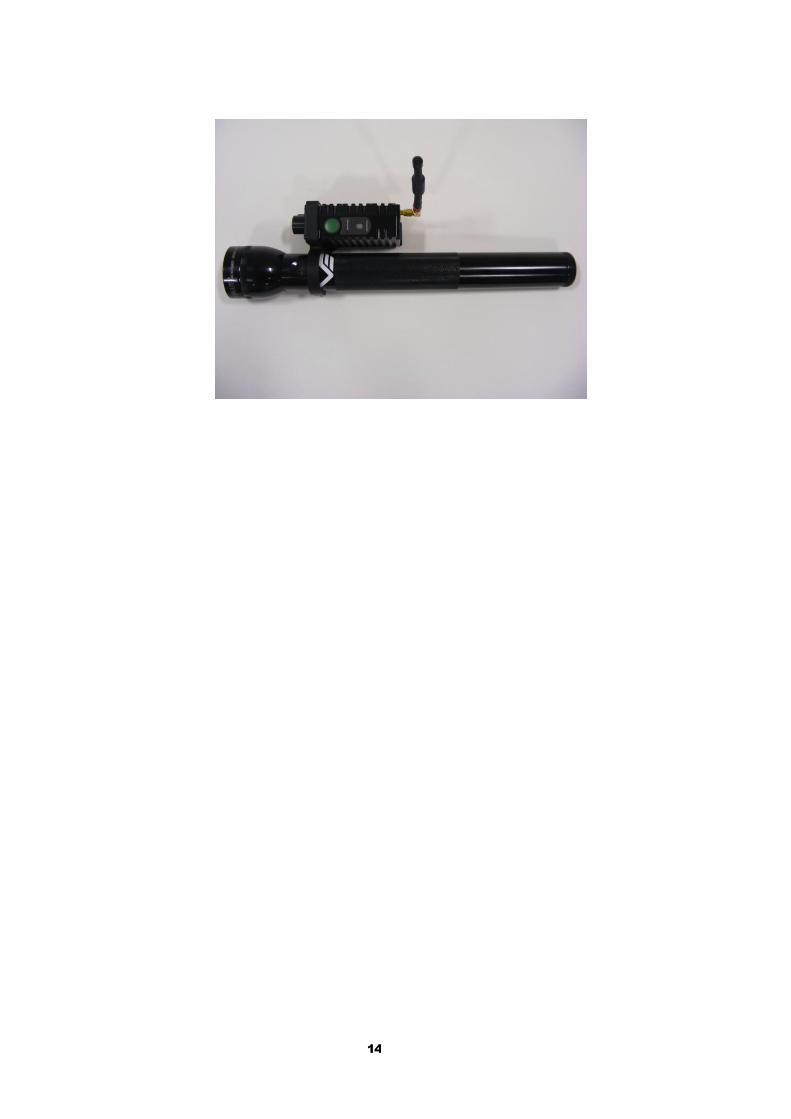
The DropCam can be mounted using a tripod screw in the base, or
using the built in magnetic strip. The DropCam can also be attached to
baton style torches by using the optional torch clip.
IMPORTANT NOTE
The SOLO4 and SOLO2 product range has been specifically designed for government security and
law enforcement users, the equipment will tune across frequencies that are only available to licensed
government users. Non-government users should employ the equipment restricted to the license
exempt bands only typically 1.389 to 1.399GHz, 2.400 to 2.483GHz and 5.725 to 5.875GHz, or in
bands specified by the appropriate authorities.
6
Warranty and Support
1.1 Warranty Cover
domo offers a 12 month standard product warranty. During this period,
should the customer encounter a fault with the equipment we
recommend the following course of action:
Check the support section of the website for information on that product and any software/firmware upgrades. If fault persists;
Battery replacement after the first warranty year is chargeable.
Call our support line and report the fault. If fault persists and you are informed to return the product please obtain an RMA number from the domo support department, and ship the equipment with the RMA number displayed and a description of the fault. Please email the support section the airway bill/consignment number for tracking purposes.
If you have extended warranty provisions then domo will send an immediate advance replacement to you. Under most circumstances this must be returned once the fault item is repaired.
Depending on the nature of the fault domo endeavor to repair the
equipment and return it to the customer within 14 days of the item
arriving at our workshops.
Obviously it is impossible to cater for all types of faults and to manage
100% replacement part availability, and delays are sometimes
inevitable. This is why domo recommend that its customers take out an
extended warranty (which includes advanced replacement of faulty
items), and/or hold a basic level of spare parts, which can be held by
domo on the customer‟s behalf.
Please contact domo for details of packages that can be tailored to meet
your individual needs, whether they are service availability, technical
training, local geographic support or dedicated spares holdings.

7
Safety, Compliance and Approvals
1.1 Safe Operating Procedures
Ensure that the power supply arrangements are adequate to meet the stated requirements of the DROPCAM transmitter.
Operate within the environmental limits specified for the product.
Only authorized, trained personnel should open the product. There are no functions that required the User to gain access to the interior of the product.
The internal battery can not be replaced by customers the unit must be returned to domo for battery replacement.
1.2 EMC / Safety and Radio Approvals
The equipment has been designed to meet and has been tested against
the following harmonized EMC and safety standards:
EN 301 489-1 & EN 301 489-5
EN 61000-3-2:2000
EN 61000-3-3:1995
EN 55022:1998, Class B
EN 61000-4-2:1995
EN 61000-4-3:1996
EN 61000-4-4:1995
EN 61000-4-5:1995
EN 61000-4-6:1996
EN 61000-4-11:1994
EN 60950:2000
1.3 CE marking
The CE mark is affixed to all SOLO4 and SOLO2 products, and the CE
Declaration of Conformity, as well as the technical file are available on
request.

8
Getting Started and Basic Operation
1.1 Which Model do I have?
The DropCam is marked with a product code panel as shown below, the
panel gives the product code, serial number and bar code.
The domo product code can be referenced in the table below.
Product Code Product Accompanying items
SOL4DCAM-P-030450 300-450MHz SOL4DCAM-P-120150 1.2 to 1.5GHz SOL4DCAM-P-2002500 2 to 2.5GHz SOL4DCAM-N-030040 300-450MHz SOL4DCAM-N-120150 1.2 to 1.5GHz SOL4DCAM-N-2002500 2 to 2.5GHz
DropCam kit
P indicates PAL
N indicates
NTSC
1 x Rugged Case 1 x Operator instructions 1 x Control and DC cable 1 x AC to DC adaptors 1 x 8mm Lens 1 x 16mm Lens 1 x Right Angle Magnetic Clip 1 x 2dBi Omni Antenna 1 x tools for lens replacement
TORCP Torch Clip Torch Clip
domo SOL4DCAM-P-200250 SN 123456 Made in the UK CE
9
Controls
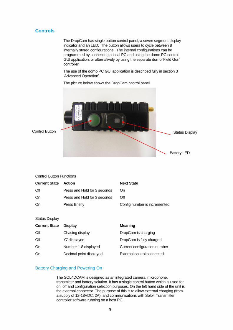
The DropCam has single button control panel, a seven segment display
indicator and an LED. The button allows users to cycle between 8
internally stored configurations. The internal configurations can be
programmed by connecting a local PC and using the domo PC control
GUI application, or alternatively by using the separate domo „Field Gun‟
controller.
The use of the domo PC GUI application is described fully in section 3
„Advanced Operation‟.
The picture below shows the DropCam control panel.
Control Button Functions
Current State Action Next State
Off Press and Hold for 3 seconds On
On Press and Hold for 3 seconds Off
On Press Briefly Config number is incremented
Status Display
Current State Display Meaning
Off Chasing display DropCam is charging
Off „C‟ displayed DropCam is fully charged
On Number 1-8 displayed Current configuration number
On Decimal point displayed External control connected
Battery Charging and Powering On
The SOL4DCAM is designed as an integrated camera, microphone, transmitter and battery solution. It has a single control button which is used for on, off and configuration selection purposes. On the left hand side of the unit is the external connector. The purpose of this is to allow external charging (from a supply of 12-18VDC, 2A), and communications with Solo4 Transmitter controller software running on a host PC.
Control Button Status Display
Battery LED
10
Charging the unit. From the off condition (Display and LED off), insert the external connector and apply external power. The seven segment display will show a „chase‟ display, the LED will give an indication of the charge status, based on current drawn by the battery. Flashing orange indicates the battery is in boost charge mode, flashing green indicates trickle charge mode and solid green indicates fully charged. When fully charged the seven segment display will show „C‟. It is possible to turn on the unit whilst it is being charged (see „Powering on the unit (on external power)‟ below). Typical charge time from fully empty to fully charged is 170 min.
Powering on the unit (on internal battery). Press and hold the button until the turns on, then release the button. The unit will power on in the last configuration it was used on. To change the configuration, repeatedly press button, the configuration number will cycle from 1 to 8 and then back to 1, release the button when you have reached the desired configuration. After approximately 10 seconds the display will shut off, the LED will continue to flash briefly once per second to show battery status. To turn off the unit, press and hold the button, the display will show the configuration number and then turn off, as will the LED.
Powering on the unit (on external power). Press the button, the display will show the last configuration used. To change the configuration, repeatedly press button, the configuration number will cycle from 1 to 8 and then back to 1, release the button when you have reached the desired configuration. After approximately 10 seconds the display will shut off, the LED will continue to flash once per second to show charging status. To turn off the unit, press and hold the button, the display will show the configuration number and then turn off, as will the LED.
Setting the configuration. Connect a PC serial port to the 9 way d-type connector on the external lead, use the Solo4 Transmitter controller software (downloadable from the link below). When external comms are connected the decimal point on the seven segment display will light. With external comms active the button ceases to function.
DC Power Source
The transmitter unit can be powered from a nominal 12V DC supply or
an AC to DC adapted supply.
The connected 12V DC input should have the following characteristics.
Input Voltage Range – 6V to 16V, reverse voltage protected. The internal battery will charge on 12.5V and above.
Current draw - 0.45A at 12V (mode dependant)
The domo „Field Gun‟ controller
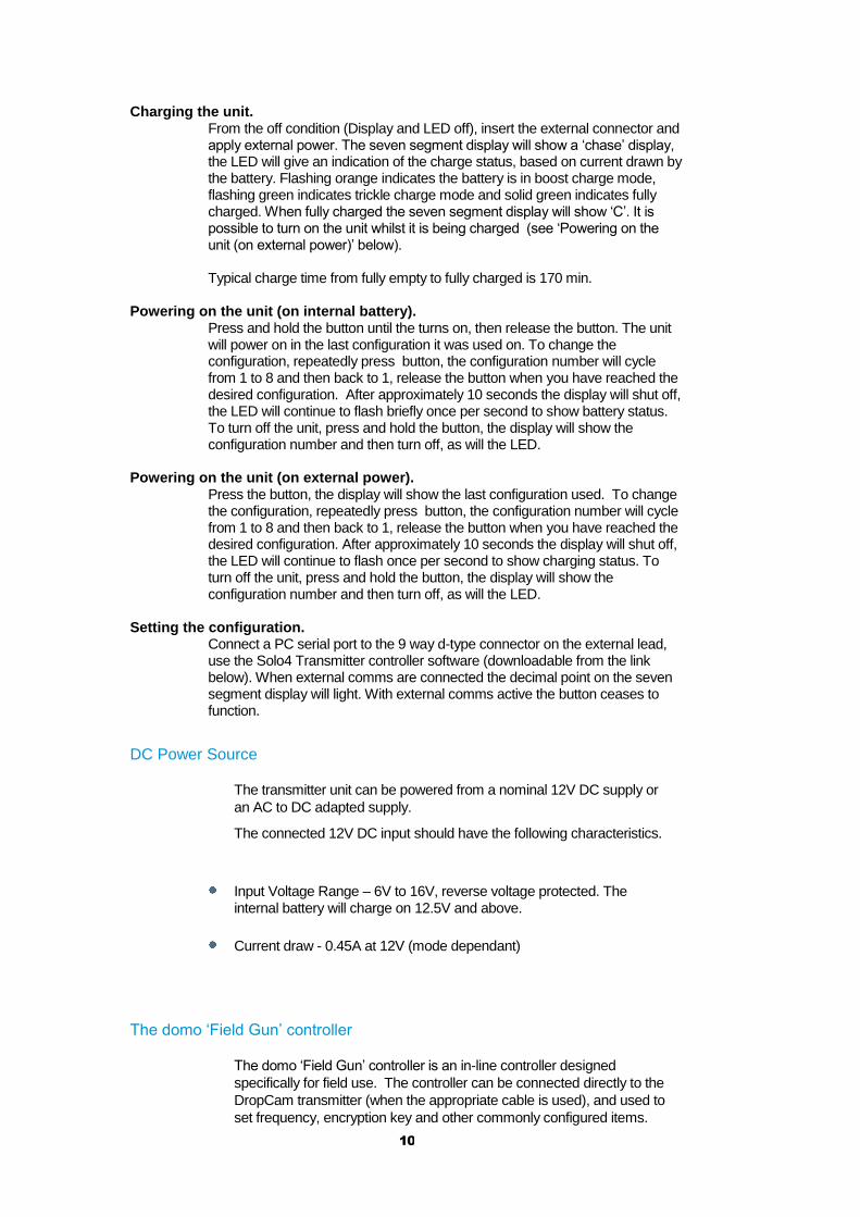
The domo „Field Gun‟ controller is an in-line controller designed
specifically for field use. The controller can be connected directly to the
DropCam transmitter (when the appropriate cable is used), and used to
set frequency, encryption key and other commonly configured items.
11
The use of the „Field Gun‟ controller will be explained in more detail in
the Field Gun manual. If the combination of the Field Gun controller and
DropCam is of interest, contact domo for access to the appropriate
cable.
DC Power Source
The transmitter unit can be powered from a nominal 12V DC supply or
an AC to DC adapted supply.
The connected 12V DC input should have the following characteristics.
Input Voltage Range – 5.9V to 16V, reverse voltage protected.
Current draw - 0.35 to 0.28A at 12V (mode dependant)
domo can supply optional AC to DC converter blocks to power the
transmitter unit, the domo part number is PSU12
Connecting the Antennas
The DropCam is supplied with flexible omni directional antennas with a
nominal gain of 2dBi.
The antenna should be connected to the SMA female connector on the
rear of the unit, care should be taken to not over tighten the SMA.
The supplied antennas are suitable for all general purpose
transmissions, however for longer range transmissions customers may
choose to connect higher gain antennas, and domo has a range of
suitable high gain antennas to offer.

12
Note: The LBand antenna covers 1.2 to 1.5GHz, which is a subset of the whole possible transmitter tuning range of 1 to 1.5GHz, if other LBand antennas are required to cover the wider range contact domo.
Range of Operation
The 100mW COFDM output available from the DropCam will typically
achieve a range of 200 – 500m in a non line of sight urban environment,
and a range of 5km where line of sight is available.
Greater ranges can be achieved by the use external power amplifiers or
directional antennas, for details of this contact domo.
The Camera
The DropCam is equipped with an internal camera.
The camera is either PAL or NTSC depending on the model number of
the DropCam.
Camera Type: ¼‟‟ CMOS Fixed Focal 3.4mm (56deg H-FOV), F2.0 Interchangable Lenses: 8mm and 16mm Pixels: 640*480 Resolution: >460 TVL Sensitivity: 0.05Lux Signal to noise: >46dB
The 3.4mm Lens fitted as standard offers a wide field of view, suitable for surveying a room. However the DropCam has standard M12 lenses and is supplied with additional lenses for longer range surveillance.
Changing the Lens
Interchanging lenses is a user operation, and there is no need to return the equipment to domo to do this.
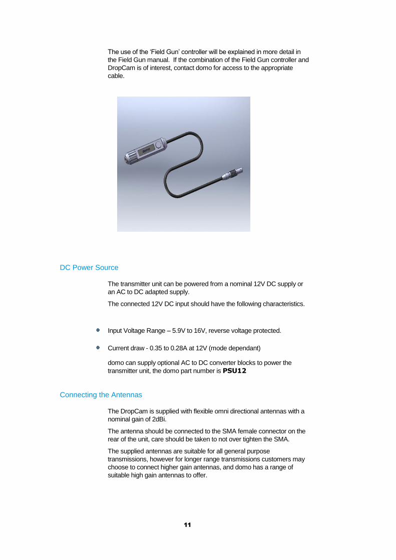
Using the tools provided in the DropCam kit the camera lens cover can
be removed. Removal of the camera lens cover is achieved by
removing the six screws in the cover as shown below.
13
With the camera lens cover removed, simply loosen the „grubber screw‟ that fixes the lens position and unscrew the lens.
New lenses can then be screwed into the camera, users will need to
focus the lens on a target before tightening the grubber screw and
replacing the lens cover.
Lens colour scheme:
3.4mm Lens: Black
8mm Lens: Blue
16mm Lens: Red
The Microphone
The DropCam is equipped with an internal microphone, mounted just
below the camera.
Microphone Type: Omni 50-13KHz
Sensitivity: 60dB +/-3dB
Mounting the DropCam
The DropCam is a rugged device designed for out door deployment in
adverse conditions.
The DropCam unit is supplied with a range of mounting options to
facilitate easy deployment.
1) ¼ „‟ threaded tripod mount in the base of the DropCam facilitates
the connection to general purpose tripods and camera mounts.
2) Magnetic base strip and right angle magnetic bracket, allow the
DropCam to attach to metal surfaces in various orientations.
3) Torch mount bracket. The optional torch bracket allows the
DropCam to be attached to a baton style torch, for use in first
responder applications.
Camera Lens screws, remove all six to expose Lens
14

15
Advanced Operation
1.1 SOLO System PC Controller Application Software
Advanced control of the SOLO4 DropCam system is available by using
PC control applications.
Typically users may want to customize the default configurations to
control settings such as frequency, scrambling keys, modulation
parameters, and video resolution.
The SOLO4 DropCam transmitter products are controlled by the solo_tx_ctrl.exe application available on the CD delivered with the product.
Note that exact file names may change as software version information is a part of domo file names.
A PC is required with two RS232 Serial COM ports to control both a
transmitter and receiver simultaneously. Where changes are to be made
to either a transmitter, or a receiver, at different times, a PC with a single
RS232 Serial COM part can be used.
Installation of the two control programs is as simple as copying them
from the CD to a suitable location on the PC. No install shield routine is
launched. Note that the controllers generate their own log and
initialisation files, so it is best to create a dedicated directory for these
applications, perhaps with links to the applications from the desktop of
the PC.
Use the supplied cables to connect the chosen COM port(s) of the PC
to unit(s) to be configured.
Launch each application in turn by double clicking or using the run
command.
Connection with a SOLO product should be automatic, but the user can
force selection of the correct COM port using the drop down, followed by
the “Connect” button.
Errors such as the following may appear during the connection process
if the PC is unable to automatically ascertain which unit is connected to
which COM port.
Error attempting to read invalid address
Error has occurred during polling, polling has been disabled

16
For both controllers, changes can be made to the unit configuration
using the drop down and data entry fields.
Changes are only applied to the unit when the “Apply” button is clicked.
Current values, as running in the unit, can be read using the “Refresh”
button.
Parameters that are status information only appear in greyed in the
application.
Further engineering and configuration controls can be found within the
“Options” and “File” drop down menus in the application title bars.

17
1.2 Transmitter Control Application
The „Advanced‟ button allows the user to navigate to the controller page
which exposes all available Transmitter settings.
Output Frequency (MHz)
The transmit frequency can be changed by entering the new desired
frequency in this field. Values outside the range supported by a
particular transmitter type will be rounded to the highest of lowest
supported frequency as appropriate.
The transmit frequency can be set in step sizes of 250kHz.
Engineering Menu
Polling Enable
Set Polling Options
Enter an Encryption Key
Enter a Licence key
Restore Factory Defaults
Connectivity Status
Video alarm
RF Output Toggle & status
Current selected Config
All parameter changes must be applied
Communications Connected

18
Bandwidth Mode
The Bandwidth Mode switches the unit between either domo
Narrowband (2.5MHz or 1.25MHz channel bandwidths) or DVB-T 8MHz
bandwidth. To select 6MHz and 7MHx DVB-T modes the user must first
click on „Advanced‟ to enter the Advanced setting page.
Audio
Turns „On‟ or „Off‟ a basic audio setting – the audio settings are
optimised considering the bit-rate of the selected Transmit mode. The
user can set there own audio settings using the „Advanced‟ page, if
required.
Default Transmit Mode
In Narrowband the user has the following pre-defined modes available
from the main window. Note that the Ultra Long Range Mode is only
available to users who have purchased the SOLO4TXUP option
(1.25MHz and MPEG-4 modes). The user can of course define their
own specific FEC, bandwidth and modulation requirements from the
„Advanced‟ page.
Ultra Long Range: 1.25MHz QPSK FEC 1/3 (optional)
Long Range: 2.5MHz QPSK FEC 1/3
Medium Range: 2.5MHz QPSK FEC 2/3
Short Range: 2.5MHz 16QAM FEC 2/3
In DVB-T the available modes are
QPSK ½ FEC 8MHz 1/32 Guard Interval
QPSK ¾ FEC 8MHz 1/32 Guard Interval
16QAM ½ FEC 8MHz 1/32 Guard Interval
Scrambling
If the AES scrambling option has been purchased for the SOLO4
DropCam system in use, then it is possible to encrypt the link.
Scrambling must be enabled at the transmitter by selecting either
AES128 or AES 256 in the scrambling field. The actual scrambling key
can then be entered by clicking on the yellow „key‟ icon.
File Options
Load Config – used for loading a single configuration data from text file.
Save Config - used for saving configuration data to text file.
Load Config Set – used for loading all 8 configurations from a text file
Save Config Set - used for saving all 8 configurations to a text file

19
Advanced TX Controller Window
Output Frequency (MHz)
The transmit frequency can be changed by entering the new desired
frequency in this field. Values outside the range supported by a
particular transmitter type will be rounded to the highest of lowest
supported frequency as appropriate.
The transmit frequency can be set in step sizes of 250kHz.
Modulation Bandwidth
For the SOLO2 transmitter products, the modulation bandwidths 8, 7 or
6MHz can be selected.
For the SOLO4 transmitter products, the modulation bandwidths 8, 7, 6
or 2.5MHz can be selected. If the Ultra Narrow band upgrade has been
purchased the 1.25MHz will also be available to select.
The normal mode of operation is 2.5MHz.
Modulation Output
This control is used to turn on and off the RF output. After a
configuration change, the output always reverts to OFF.
Narrow Band FEC
This option applies to SOLO4 transmitters only. The default FEC is 2/3,
however improved range operation can be achieved by selecting FEC
1/3. FEC 1/3 will improve signal range by 3dB. However FEC 1/3
reduces link capacity to 1.2Mb/s therefore reducing picture quality.
20
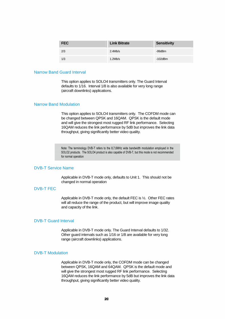
FEC Link Bitrate Sensitivity
2/3 2.4Mb/s -99dBm
1/3 1.2Mb/s -102dBm
Narrow Band Guard Interval
This option applies to SOLO4 transmitters only. The Guard Interval
defaults to 1/16. Interval 1/8 is also available for very long range
(aircraft downlinks) applications.
Narrow Band Modulation
This option applies to SOLO4 transmitters only. The COFDM mode can
be changed between QPSK and 16QAM. QPSK is the default mode
and will give the strongest most rugged RF link performance. Selecting
16QAM reduces the link performance by 5dB but improves the link data
throughput, giving significantly better video quality.
Note: The terminology DVB-T refers to the 8,7,6MHz wide bandwidth modulation employed in the
SOLO2 products. The SOLO4 product is also capable of DVB-T, but this mode is not recommended
for normal operation
DVB-T Service Name
Applicable in DVB-T mode only, defaults to Unit 1. This should not be
changed in normal operation
DVB-T FEC
Applicable in DVB-T mode only, the default FEC is ½. Other FEC rates
will all reduce the range of the product, but will improve image quality
and capacity of the link.
DVB-T Guard Interval
Applicable in DVB-T mode only. The Guard Interval defaults to 1/32.
Other guard intervals such as 1/16 or 1/8 are available for very long
range (aircraft downlinks) applications.
DVB-T Modulation
Applicable in DVB-T mode only, the COFDM mode can be changed
between QPSK, 16QAM and 64QAM. QPSK is the default mode and
will give the strongest most rugged RF link performance. Selecting
16QAM reduces the link performance by 5dB but improves the link data
throughput, giving significantly better video quality.
21
Output Attenuation
This control can be used to make minor adjustments to the output
power level, but in normal operation should be disregarded.
Video Input
This control is used to select the composite video input standard.
Options are PAL, and NTSC both with and without 7.5 IRE pedestal.
The licensed SDI digital video input can also be selected.
MPEG Mode
The default encoding mode is MPEG2, however for SOLO4 products if
the Ultra Narrow Band upgrade has been purchased, then MPEG4 will
also be available. It is recommended that MPEG4 be employed when
the unit is operating at low bitrates (2.5MHz bandwidth FEC1/3 or
1.25MHz bandwidth FEC1/3).
MPEG2 GOP Length
By default MPEG2 GOP length is set to a low delay stripe refresh mode.
This option allows the user to set the GOP length for a standard GOP
structure at the expensive of an additional delay.
MPEG4 Encoding Mode
This option is only available on SOLO4 products installed with the Ultra
Narrow Band Upgrade. This defaults to low delay interlace. Other
modes are available but advice should be sought from domo before
selection.
MPEG4 Frame Rate
This option is only available on SOLO4 products installed with the Ultra
Narrow Band Upgrade. This option allows the user to select lower
frame rate encoding (1/2 frame rate, ¼, 1/8 etc) It is recommended that
MPEG4 reduced frame rates be employed when the unit is operating at
low bitrates (1.25MHz bandwidth FEC1/3).
Video Bitrate
This control can be used to set the video bitrate within the constraints of
capacity available in the channel, but only when “Chaining Input” is set
to ON.
When the Manual radio button is enabled, the user can manually set a
video bitrate upto the maximum value. When manual bitrate is selected,
the user is in control of the video bitrate, this can be usefull when
configuring chaining systems.
22
Horizontal resolution
The video coding resolution can be selected from 704, 528, 480 and
352 pixels. Changing the horizontal resolution to lower values will make
the coded picture softer.
Care should be taken to match the horizontal resolution to the resolution
of the camera connected to the transmitter; this will give best image
results.
Video Profile
This allows the user to select between the default 4:2:0 profile and the
ultra high quality 4:2:2 profile (only of interest to Broadcast customers).
Note 4:2:2 is a licensed feature.
Audio Encoder
The Audio can be turned on and off with this control. Audio is OFF by
default, but there are several audio modes that vary from very high
quality to speech grade that can be selected with this control. Enabling
audio will degrade the video quality, because some of the available data
capacity is diverted away from video to audio. Selecting high fidelity
audio modes will degrade the video quality more than lower fidelity
audio modes. The Audio encoder can also be switched to 32 kHz and
48 kHz MPEG Layer 1/2 modes.
Note: The Solo4 receiver only supports 48 kHz sampling in MPEG Audio mode and bit-rates in the range 192 to 448kbits/s.
Audio Input Level
This control is used to define the audio gain to be applied to the audio
input signal. 0dB is used for line level audio and various options up to
48dB of gain can be applied for microphone inputs.
Unit Name
This field allows the user to enter an identifier for the service that they
wish to transmit. This must match that selected at the receiver for the
service to be decoded. The unit name can be constructed of any eight
ASCII characters.
Sleep Mode
This control allows the unit to be forced into a Sleep Mode where main
functions are disabled, and the power consumption is significantly
reduced.

23
Data
With this ON / OFF control the user can select whether the transmitter
passes serial RS232 data across the RF link to the receiver.
Data Baud Rate
This field is used to select the baud rate of any RS232 serial data
component to be passed from the transmitter to the receiver across the
RF link.
Chaining Input
This control is not used in current SOLO products.
Chain Number
This control is not used in current SOLO products.
Current Config
This field reports the last loaded configuration number. Note that for the
SOLO transmitter, changes applied after the configuration has been
loaded are saved immediately into the current configuration.
Scrambling
If the AES scrambling option has been purchased for the SOLO2 or
SOLO4 system in use, then it is possible to encrypt the link. Scrambling
must be enabled at the transmitter by selecting either AES128 or AES
256 in the scrambling field. At this point the user will need to ensure that
the correct key is in use and this is done by using Options / Write AES
Key.
The key is a 128bit key for AES128 and a 256bit key for AES256 and is
entered as either 32 or 64 ASCII hexadecimal characters (0..F).
Video Locked (Status Only)
This status information indicated whether the transmitter is successfully
locked to the incoming composite video signal. Unlocked status may
indicate cabling faults, or poor quality incoming video feeds to the unit.
Software Version (Status Only)
This status information describes the version of the software running the
SOLO transmitter product.
FPGA Version (Status Only)
This information is for domo engineering use only.

24
Serial Number (Status Only)
This status information is the electronic serial number of the transmitter
PCB. This number can be exchanged with domo to purchase extra
licensable features, such as upgrades to support AES encryption.
Chaining (Status Only)
This field reports the status of the chaining input to the SOLO
transmitter, and is not active in current units.
Options
Engineering – provides access to further diagnostic and calibration
features. The Diagnostic and Power calibration pages must not be
altered. The Advanced Options under the Engineering menu allow the
user to Change RS232 address, which can be useful when connecting
multiple units together via a multi drop RS485 bus for control purposes.
The Serial control dialogue box allows the user to change timeouts
used during the serial communications between the unit and the
controller.
Enable Polling – selecting this option makes the control application
automatically refresh the data presented to the user every few seconds.
Polling Options – selecting this option allows the user to define
parameters to be regularly polled.
Write Encryption Key – opens a dialogue box for entering an ABS or
AES scrambling key, as 32 ASCII hexadecimal characters (0…F)
Write License Code – open a further box for entering license codes for
the activation of licensable features (e.g. AES scrambling) in the
transmitter. Contact domo for support in applying new licenses as
required.
Restore Defaults – restores factory default settings in the transmitter.
File
Set Icon Source, Set logo source, Set logo size and Set application
title – allow the user to define a controller branding
Exit – exits the SOLO receiver control application
25
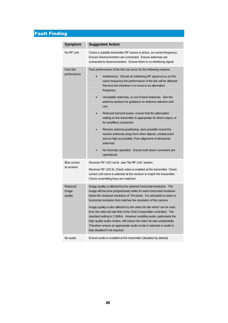
Fault Finding
Symptom Suggested Action
No RF Link Check a suitable transmitter RF source is active, on correct frequency.
Ensure Downconverters are connected. Ensure antennas are
connected to downconverters. Ensure there is no interfering signal.
Poor link
performance
Poor performance of the link can occur for the following reasons.
Interference. Should an interfering RF signal occur on the
same frequency the performance of the link will be affected.
Remove the interferer e or move to an alternative
frequency.
Unsuitable antennas, or out of band antennas. See the
antenna sections for guidance on antenna selection and
use.
Reduced transmit power, ensure that the attenuation
setting on the transmitter is appropriate for direct output, or
for amplifiers connected.
Receive antenna positioning, were possible mount the
receive antennas away from other objects, unobstructed
and as high as possible. Poor alignment of directional
antennas.
No Diversity operation. Ensure both down converters are
operational.
Blue screen
at receiver
Receiver RF LED not lit - see “No RF Link” section
Receiver RF LED lit. Check video is enabled at the transmitter. Check
correct unit name is selected at the receiver to match the transmitter.
Check scrambling keys are matched.
Reduced
Image
quality
Image quality is affected by the selected horizontal resolution. The
image will become progressively softer for each horizontal resolution
below the sharpest resolution of 704 pixels. It is advisable to select a
horizontal resolution that matches the resolution of the camera.
Image quality is also affected by the video bit rate which can be read
from the video bit rate field of the SOLO transmitter controller). The
standard setting is 2.3Mb/s. However enabling audio, particularly the
high quality audio modes, will reduce the video bit rate substantially.
Therefore ensure an appropriate audio mode is selected or audio is
fully disabled if not required.
No audio Ensure audio is enabled at the transmitter (disabled by default).
26
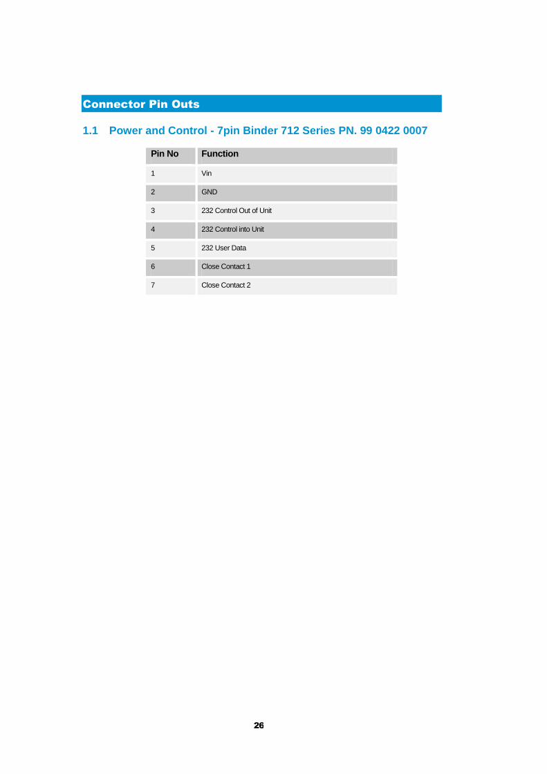
Connector Pin Outs
1.1 Power and Control - 7pin Binder 712 Series PN. 99 0422 0007
Pin No Function
1 Vin
2 GND
3 232 Control Out of Unit
4 232 Control into Unit
5 232 User Data
6 Close Contact 1
7 Close Contact 2

27
Control Protocols
The following section describes the control protocol employed on the
RS232 link for controlling the SOLO transmitters and receiver
equipment.
Connection details are detailed in previous sections.
Note that only features that are licensed for use in the SOLO units can be controlled. The protocols
listed here cover all possible features. Attempting to activate an unlicensed feature will simply result
in the command being ignored by the SOLO unit.
1.1 RS232 Control – General Principles
The physical interface is RS232 but this can be converted to RS 485
with an external adapter where multiple units are controlled over one RS
485 bus.
Normal operation involves sending a packet from the control device
(normally a PC) to the device being controlled. If the packet satisfies an
address integrity check, then the controlled device will action the
command and send a reply.
For compatibility with modems an ASCII style protocol is used.
Ports are set for 8 bits, No parity, 1 stop
1.2 Packet Structure Sending (from PC)
ASCII Value
STX 02h Start byte
0-9 30h-39h 4 byte unit address. In range 0-9999
R 20h-7Eh 1 byte command type. r read, w write or m misc
I 20h-7E 1 byte indicator of internal data block
ABC 20h-7Eh Command –three byte mnemonic
; 3Bh Separator
PQR 20h-7Eh Data –Optional, variable length
; 3Bh Separator
X 20h-7Eh Sum Check
ETX 03h End byte

28
1.3 Packet Structure Reply (from controlled device)
ASCII Value
STX 02h Start byte
0-9 30h-39h 4 byte unit address. In range 0-9999
Z 20h-7Eh Status BYTE
PQR 20h-7Eh Data –Optional, variable length
; 3Bh Separator
X 20h-7Eh Sum Check
ETX 03h End byte
The Sum check byte is the summation of all bytes in the packet, not including the start and end bytes. Higher order bytes are ignored and the final byte result is modified to prevent ASCII control characters being sent. Bit 7 (highest) is forced high.
Status byte will indicate command performed OK, or indicate an error.
ASCII Meaning
1 All OK
E General error, Command could not be actioned
Typically E will be returned if the message is formatted incorrectly (separators in wrong place) or if commands are in upper case, or if commands do not match against the allowed list of commands, or if the checksum is wrong.
Addresses in the range 0001 to 9998 are for general use. Address 0000 is reserved and 9999 is a broadcast address. i.e. any device will reply to this address. Its reply will contain its own specific address.
All data in the transmitter and receiver is stored as one of 5 data types,
Double, String, List, Integer or HexInteger. The data type dictates the
contents of the data section of the reply.
List – 1 byte for sending. Value is hexadecimal coded as ASCII. 2 byte reply. Reply represents index into original choice list. e.g. Reply 02 indicates entry 2 in original list.
Double - variable length. Reply always contains decimal point and 4 decimal places. Can have 1 to 3 digits before decimal.
Integer - 6byte reply. integer value with stuffed with preceding zeros. e.g. GOP reply 000012 = GOP length 12
String - Variable length. Reply is string excluding null terminator
HexInteger – 8byte Hex reply
29
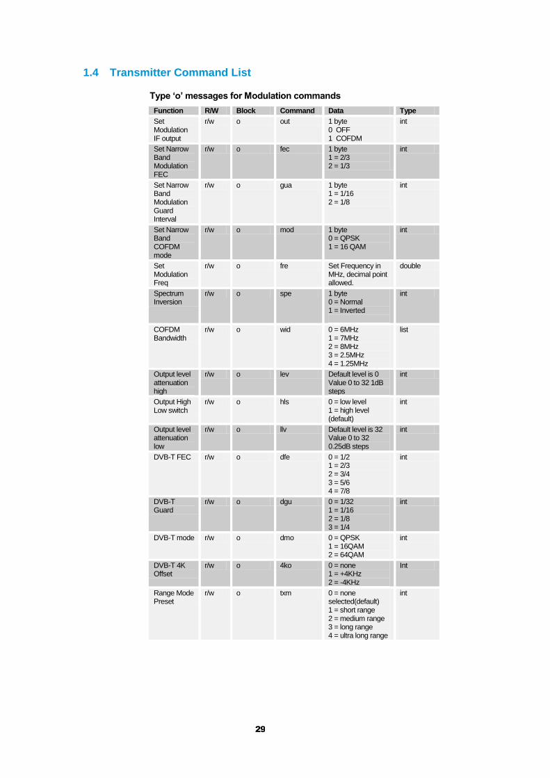
1.4 Transmitter Command List
Type ‘o’ messages for Modulation commands
Function R/W Block Command Data Type
Set Modulation IF output
r/w o out 1 byte 0 OFF 1 COFDM
int
Set Narrow Band Modulation FEC
r/w o fec 1 byte 1 = 2/3 2 = 1/3
int
Set Narrow Band Modulation Guard Interval
r/w o gua 1 byte 1 = 1/16 2 = 1/8
int
Set Narrow Band COFDM mode
r/w o mod 1 byte 0 = QPSK 1 = 16 QAM
int
Set Modulation Freq
r/w o fre Set Frequency in MHz, decimal point allowed.
double
Spectrum Inversion
r/w o spe 1 byte 0 = Normal 1 = Inverted
int
COFDM Bandwidth
r/w o wid 0 = 6MHz 1 = 7MHz 2 = 8MHz 3 = 2.5MHz 4 = 1.25MHz
list
Output level attenuation high
r/w o lev Default level is 0 Value 0 to 32 1dB steps
int
Output High Low switch
r/w o hls 0 = low level 1 = high level (default)
int
Output level attenuation low
r/w o llv Default level is 32 Value 0 to 32 0.25dB steps
int
DVB-T FEC r/w o dfe 0 = 1/2 1 = 2/3 2 = 3/4 3 = 5/6 4 = 7/8
int
DVB-T Guard
r/w o dgu 0 = 1/32 1 = 1/16 2 = 1/8 3 = 1/4
int
DVB-T mode r/w o dmo 0 = QPSK 1 = 16QAM 2 = 64QAM
int
DVB-T 4K Offset
r/w o 4ko 0 = none 1 = +4KHz 2 = -4KHz
Int
Range Mode Preset
r/w o txm 0 = none selected(default) 1 = short range 2 = medium range 3 = long range 4 = ultra long range
int
30
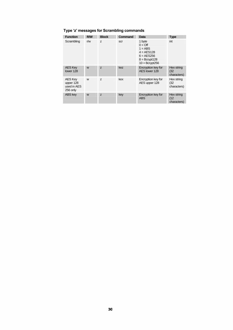
Type ‘z’ messages for Scrambling commands
Function R/W Block Command Data Type
Scrambling
r/w z scr 1 byte 0 = Off 1 = ABS 4 = AES128 6 = AES256 8 = Bcrypt128 10 = Bcrypt256
int
AES Key lower 128
w z kez Encryption key for AES lower 128
Hex string (32 characters)
AES Key upper 128 used in AES 256 only
w z kex Encryption key for AES upper 128
Hex string (32 characters)
ABS key
w z key Encryption key for ABS
Hex string (12 characters)

31
Type ‘v’ and ‘e’ messages for Video commands
Function R/W Block Command Data Type
Video Input r/w v inp 1 byte 0 = Off 2 = PAL 3 = NTSC 4 = NTSC No Pedestal 5 = PAL S-vid 6 = NTSC S-vid 7 = NTSC S-Vid No pedestal 8 = SDI PAL 9 = SDI NTSC
int
Video Locked
r v loc 1 byte 0 = No 1 = Yes
int
Video Bitrate (Only applicable when chain in enabled)
r/w e vid Value in Mbps double
Video Horizontal resolution
r/w e hor 1 byte 0=704 1=528 2=480 3=352
int
Sleep if no video lock
r/w v sle 0 = normal 1 = sleep if no video
int
MPEG mode r/w e enc 0 = MPEG2 1 = MPEG4
int
MPEG2 GOP length
r/w e gop 0 = stripe refresh mode (default) 1 = intra only 2-100 = GOP length in frames
int
MPEG4 frame rate
r/w e frm 0 = full 1 = 1/2 2 = 1/4 3 = 1/8 4 = 1/24
int
MPEG4 encoding option
r/w e cmd 0 = low delay interlaced (default) 1 = standard delay interlaced 2 = low delay progressive 3 = standard delay progressive
MPEG4 video sharpness
r/w e sha 0 = normal (default) 1 = sharp
int
Manual Video Bitrate
r/w e vbr Video bitrate manual over ride 0 = no override (default) Non-zero (sets the video bit-rate in kbps)
int
Video Profile r/w e pro 0 = 4:2:0 1 = 4:2:2
int
Video PID r/w v pid 0 = default Other = value
int
32
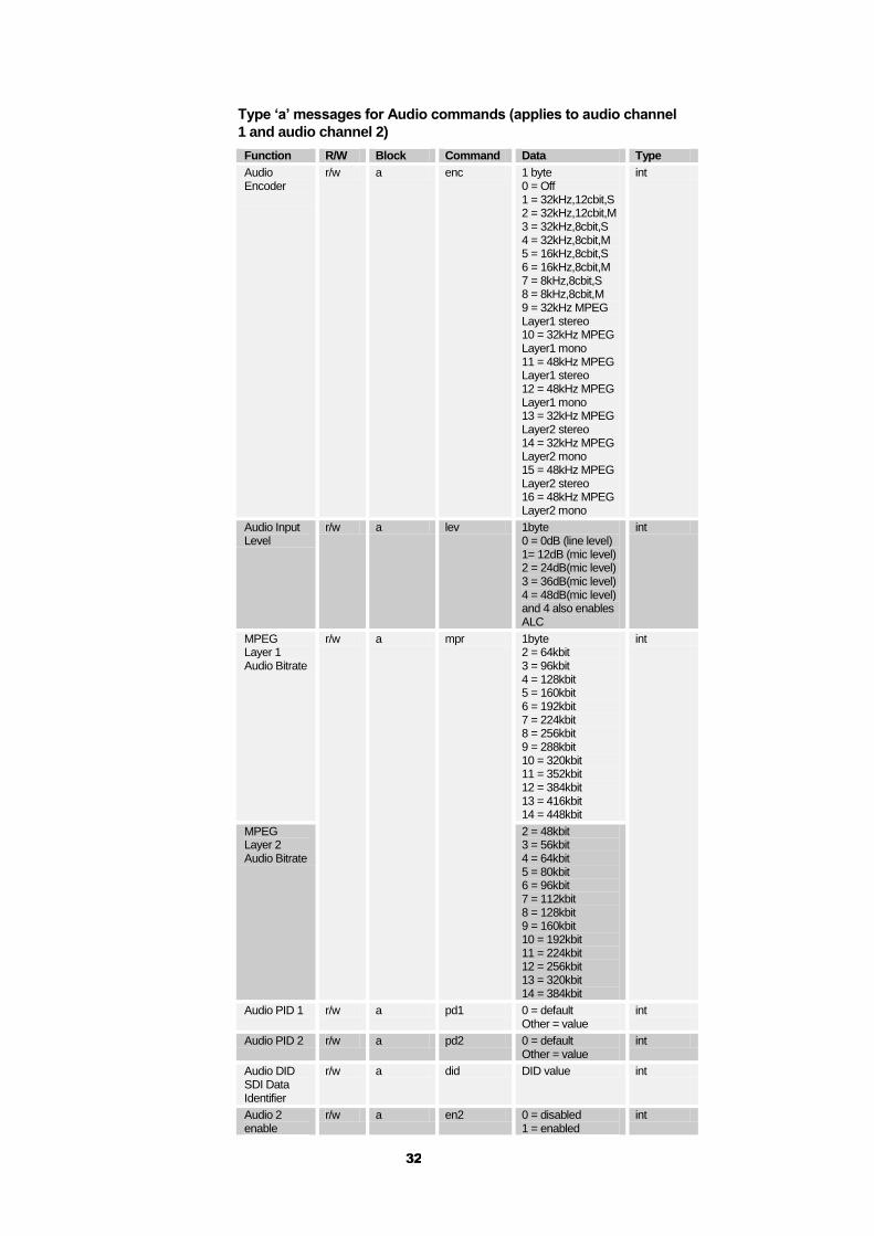
Type ‘a’ messages for Audio commands (applies to audio channel
1 and audio channel 2)
Function R/W Block Command Data Type
Audio Encoder
r/w a enc 1 byte 0 = Off 1 = 32kHz,12cbit,S 2 = 32kHz,12cbit,M 3 = 32kHz,8cbit,S 4 = 32kHz,8cbit,M 5 = 16kHz,8cbit,S 6 = 16kHz,8cbit,M 7 = 8kHz,8cbit,S 8 = 8kHz,8cbit,M 9 = 32kHz MPEG Layer1 stereo 10 = 32kHz MPEG Layer1 mono 11 = 48kHz MPEG Layer1 stereo 12 = 48kHz MPEG Layer1 mono 13 = 32kHz MPEG Layer2 stereo 14 = 32kHz MPEG Layer2 mono 15 = 48kHz MPEG Layer2 stereo 16 = 48kHz MPEG Layer2 mono
int
Audio Input Level
r/w a lev 1byte 0 = 0dB (line level) 1= 12dB (mic level) 2 = 24dB(mic level) 3 = 36dB(mic level) 4 = 48dB(mic level) and 4 also enables ALC
int
MPEG Layer 1 Audio Bitrate
r/w a mpr 1byte 2 = 64kbit 3 = 96kbit 4 = 128kbit 5 = 160kbit 6 = 192kbit 7 = 224kbit 8 = 256kbit 9 = 288kbit 10 = 320kbit 11 = 352kbit 12 = 384kbit 13 = 416kbit 14 = 448kbit
int
MPEG Layer 2 Audio Bitrate
2 = 48kbit 3 = 56kbit 4 = 64kbit 5 = 80kbit 6 = 96kbit 7 = 112kbit 8 = 128kbit 9 = 160kbit 10 = 192kbit 11 = 224kbit 12 = 256kbit 13 = 320kbit 14 = 384kbit
Audio PID 1 r/w a pd1 0 = default Other = value
int
Audio PID 2 r/w a pd2 0 = default Other = value
int
Audio DID SDI Data Identifier
r/w a did DID value int
Audio 2 enable
r/w a en2 0 = disabled 1 = enabled
int
33
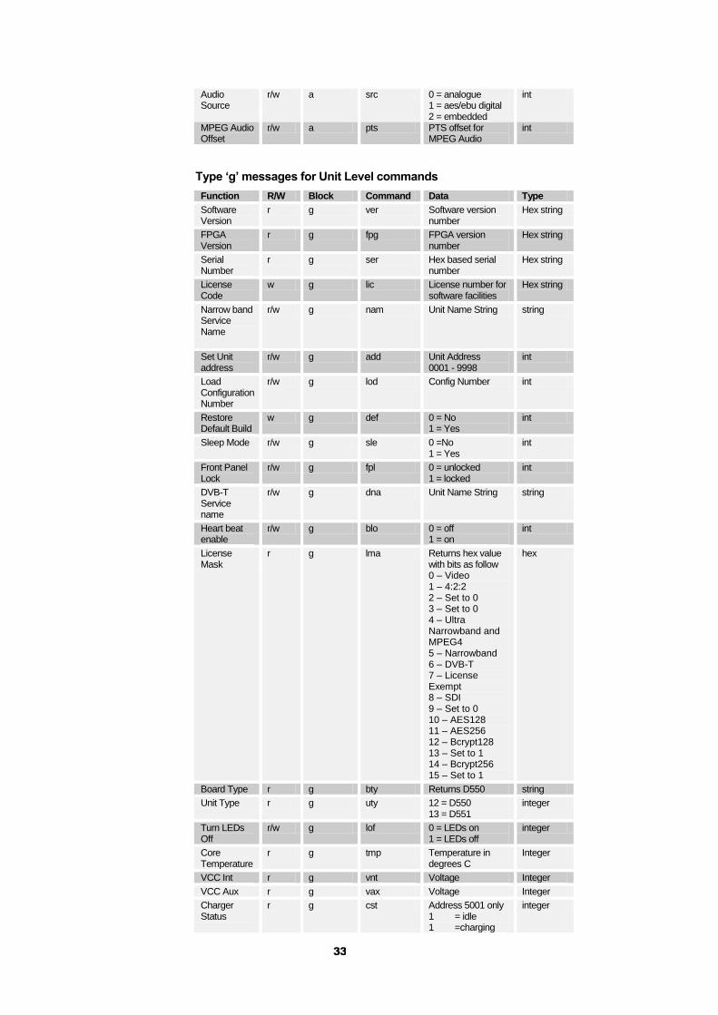
Audio Source
r/w a src 0 = analogue 1 = aes/ebu digital 2 = embedded
int
MPEG Audio Offset
r/w a pts PTS offset for MPEG Audio
int
Type ‘g’ messages for Unit Level commands
Function R/W Block Command Data Type
Software Version
r g ver Software version number
Hex string
FPGA Version
r g fpg FPGA version number
Hex string
Serial Number
r g ser Hex based serial number
Hex string
License Code
w g lic License number for software facilities
Hex string
Narrow band Service Name
r/w g nam Unit Name String string
Set Unit address
r/w g add Unit Address 0001 - 9998
int
Load Configuration Number
r/w g lod Config Number int
Restore Default Build
w g def 0 = No 1 = Yes
int
Sleep Mode r/w g sle 0 =No 1 = Yes
int
Front Panel Lock
r/w g fpl 0 = unlocked 1 = locked
int
DVB-T Service name
r/w g dna Unit Name String string
Heart beat enable
r/w g blo 0 = off 1 = on
int
License Mask
r g lma Returns hex value with bits as follow 0 – Video 1 – 4:2:2 2 – Set to 0 3 – Set to 0 4 – Ultra Narrowband and MPEG4 5 – Narrowband 6 – DVB-T 7 – License Exempt 8 – SDI 9 – Set to 0 10 – AES128 11 – AES256 12 – Bcrypt128 13 – Set to 1 14 – Bcrypt256 15 – Set to 1
hex
Board Type r g bty Returns D550 string
Unit Type r g uty 12 = D550 13 = D551
integer
Turn LEDs Off
r/w g lof 0 = LEDs on 1 = LEDs off
integer
Core Temperature
r g tmp Temperature in degrees C
Integer
VCC Int r g vnt Voltage Integer
VCC Aux r g vax Voltage Integer
Charger Status
r g cst Address 5001 only 1 = idle 1 =charging
integer

34
2= discharging 3=temp fault 4=bad battery
Drop cam voltage
r g vch Voltage in multiples of 100mV
Drop Cam charger current
r g Ccu Current in multiples of 10mA
35
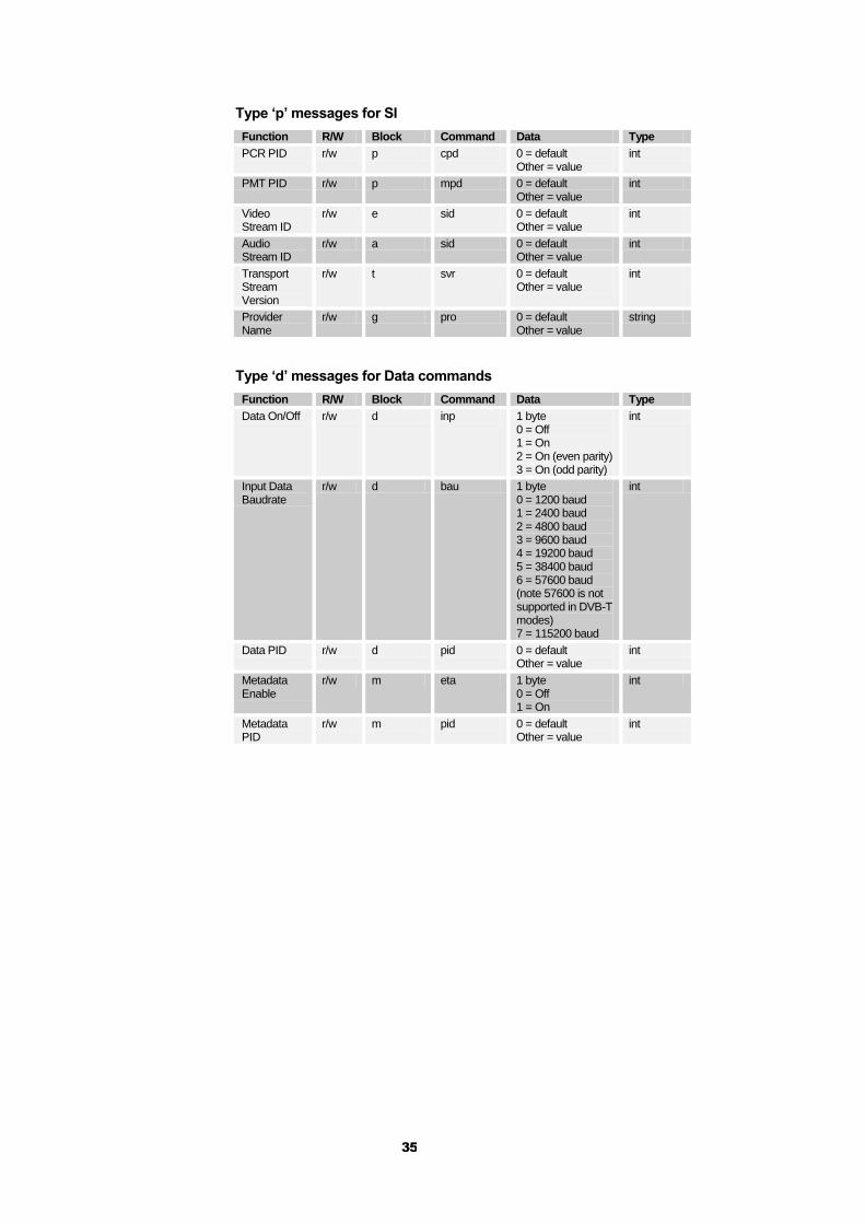
Type ‘p’ messages for SI
Function R/W Block Command Data Type
PCR PID r/w p cpd 0 = default Other = value
int
PMT PID r/w p mpd 0 = default Other = value
int
Video Stream ID
r/w e sid 0 = default Other = value
int
Audio Stream ID
r/w a sid 0 = default Other = value
int
Transport Stream Version
r/w t svr 0 = default Other = value
int
Provider Name
r/w g pro 0 = default Other = value
string
Type ‘d’ messages for Data commands
Function R/W Block Command Data Type
Data On/Off r/w d inp 1 byte 0 = Off 1 = On 2 = On (even parity) 3 = On (odd parity)
int
Input Data Baudrate
r/w d bau 1 byte 0 = 1200 baud 1 = 2400 baud 2 = 4800 baud 3 = 9600 baud 4 = 19200 baud 5 = 38400 baud 6 = 57600 baud (note 57600 is not supported in DVB-T modes) 7 = 115200 baud
int
Data PID r/w d pid 0 = default Other = value
int
Metadata Enable
r/w m eta 1 byte 0 = Off 1 = On
int
Metadata PID
r/w m pid 0 = default Other = value
int
36
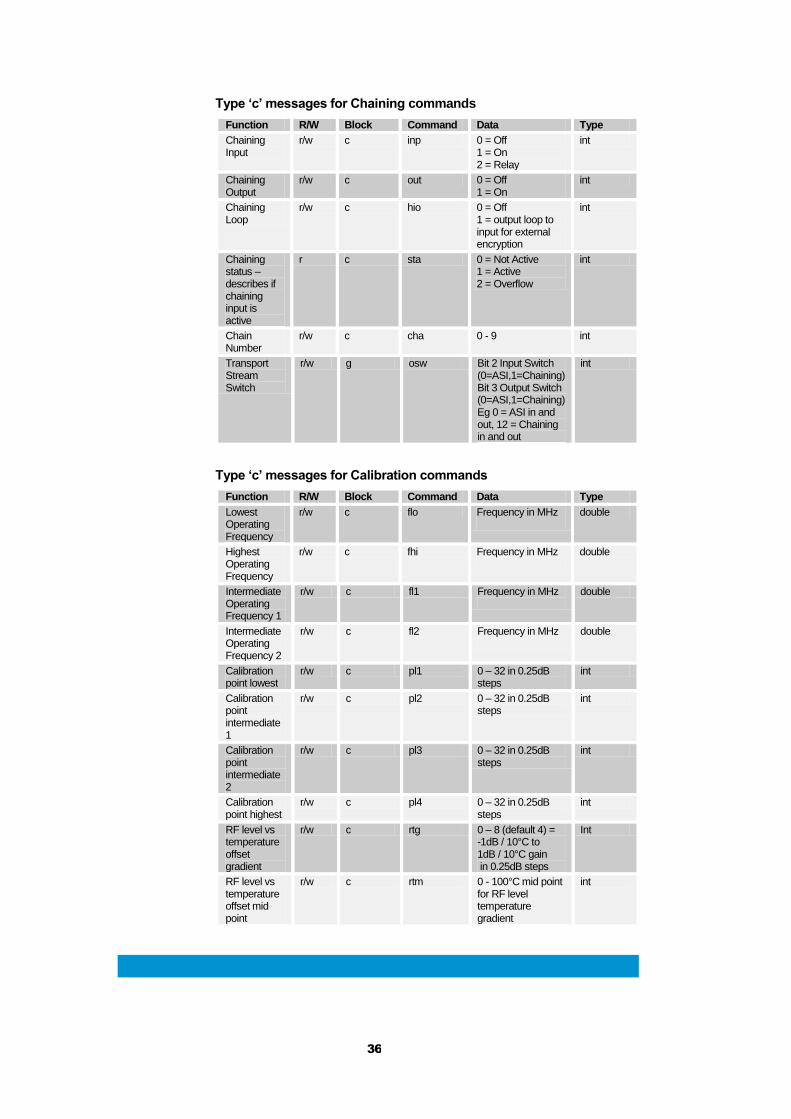
Type ‘c’ messages for Chaining commands
Function R/W Block Command Data Type
Chaining Input
r/w c inp 0 = Off 1 = On 2 = Relay
int
Chaining Output
r/w c out 0 = Off 1 = On
int
Chaining Loop
r/w c hio 0 = Off 1 = output loop to input for external encryption
int
Chaining status –describes if chaining input is active
r c sta 0 = Not Active 1 = Active 2 = Overflow
int
Chain Number
r/w c cha 0 - 9 int
Transport Stream Switch
r/w g osw Bit 2 Input Switch (0=ASI,1=Chaining) Bit 3 Output Switch (0=ASI,1=Chaining) Eg 0 = ASI in and out, 12 = Chaining in and out
int
Type ‘c’ messages for Calibration commands
Function R/W Block Command Data Type
Lowest Operating Frequency
r/w c flo Frequency in MHz
double
Highest Operating Frequency
r/w c fhi Frequency in MHz
double
Intermediate Operating Frequency 1
r/w c fl1 Frequency in MHz
double
Intermediate Operating Frequency 2
r/w c fl2 Frequency in MHz
double
Calibration point lowest
r/w c pl1 0 – 32 in 0.25dB steps
int
Calibration point intermediate 1
r/w c pl2 0 – 32 in 0.25dB steps
int
Calibration point intermediate 2
r/w c pl3 0 – 32 in 0.25dB steps
int
Calibration point highest
r/w c pl4 0 – 32 in 0.25dB steps
int
RF level vs temperature offset gradient
r/w c rtg 0 – 8 (default 4) = -1dB / 10°C to 1dB / 10°C gain in 0.25dB steps
Int
RF level vs temperature offset mid point
r/w c rtm 0 - 100°C mid point for RF level temperature gradient
int

37
Default Configurations
This section tabulates the default configuration settings for domo SOLO
products.
Item DROPCAM-x-200250 (2.0
to 2.5GHz)
DROPCAM-x-100150 (1.0
to 1.5GHz)
RF Output OFF OFF
Frequency 2405MHz 1395MHZ
Modulation QPSK QPSK
Power Maximum Maximum
Standby OFF OFF
Unit Address 0001 0001
Unit name Solo-01 (SOLO4) Unit 1 (SOLO2) Solo-01 (SOLO4) Unit 1 (SOLO2)
Horizontal
Resolution
528 528
Video Input X= P= PAL
X= N= NTSC
X= P= PAL
X= N= NTSC
Audio OFF OFF
Data OFF OFF
Audio Input Line level Line level
Scrambling OFF OFF
AES Key None None