dominion energy kewaunee, inc. dominiondominion energy kewaunee, inc. dominion 5000 dominion...
TRANSCRIPT
DominionDominion Energy Kewaunee, Inc.5000 Dominion Boulevard, Glen Allen, VA 23060
April 30, 2012
U. S. Nuclear Regulatory CommissionAttention: Document Control DeskWashington, DC 20555
Serial No. 12-214LIC/CDS/R6Docket No. 50-305License No. DPR-43
DOMINION ENERGY KEWAUNEE, INC.KEWAUNEE POWER STATIONRESPONSE TO REQUEST FOR ADDITIONAL INFORMATION:LICENSE AMENDMENT REQUEST 244, PROPOSED REVISION TORADIOLOGICAL ACCIDENT ANALYSIS AND CONTROL ROOM ENVELOPEHABITABILITY TECHNICAL SPECIFICATIONS (TAC NO. ME7110)
By application dated August 30, 2011 (Reference 1), Dominion Energy Kewaunee, Inc.(DEK), requested an amendment to Facility Operating License Number DPR-43 forKewaunee Power Station (KPS). This proposed amendment (LAR 244) would revisethe KPS Operating License by modifying the Technical Specifications (TS) and thecurrent licensing basis (CLB) to incorporate changes to the current radiological accidentanalysis (RAA) of record. This amendment would also fulfill a commitment made to theNRC in response to Generic Letter 2003-01, "Control Room Habitability" (References 1and 2) to submit proposed changes to the KPS TS based on the final approved versionof TSTF-448, "Control Room Habitability."
Subsequently, on March 2, 2012 the Nuclear Regulatory Commission (NRC) stafftransmitted a request for additional information (RAI) regarding the proposedamendment (Reference 3). The RAI questions and associated DEK responses areprovided in Attachment 1 to this letter.

Serial No. 12-214LAR 244 RAI Response
Page 2 of 3
If you have any questions or require additional information, please contact Mr. Craig Slyat 804-273-2784.
Sincerely,
PriceV" "eesident - Nuclear Engineering
STATE OF CONNECTICUT
COUNTY OF NEW LONDON
The foregoing document was acknowledged before me, in and for the County and Stateaforesaid, today by J. Alan Price, who is Vice President - Nuclear Engineering, of DominionEnergy Kewaunee, Inc. He has affirmed before me that he is duly authorized to execute and filethe foregoing document in behalf of that Company, and that the statements in the document aretrue to the best of his knowledge and belief.
Acknowledged before me this .' day of /191XZ , ,2012.
My Commission Expires: f6'•?iUA,"; 2? Z01/6-N a
Notary Pub
Attachment:
1. NRC Request for Additional Information Questions and Dominion EnergyKewaunee Responses
Enclosure:
1. Copy of Letter from K. E. Perkins (NRC) to D. C. Hintz (WPS) dated February 16,1988
Commitments made in this letter: None
I
Serial No. 12-214LAR 244 RAI Response
Page 3 of 3
References:
1. Letter from J. A.. Price (DEK) to Document Control Desk (NRC), "LicenseAmendment Request 244, Proposed Revision to Radiological Accident Analysisand Control Room Envelope Habitability Technical Specifications," dated August30, 2011. [ADAMS Accession No. ML11252A521]
2. Letter from Craig W. Lambert (NMC) to Document Control Desk (NRC), "GenericLetter 2003-01; Control Room Habitability - Supplemental Response," dated April1, 2005. [ADAMS Accession No. ML050970303]
3. E-mail from Karl D. Feintuch (NRC) to Craig D. Sly (DEK), "ME7110 KewauneeAmendment Request Re: Chi-over-Q - AADB Request for Additional Information(RAI)," dated March 2, 2012. [ADAMS Accession No. ML12066A008]
cc: Regional Administrator, Region IIIU. S. Nuclear Regulatory Commission2443 Warrenville RoadSuite 210Lisle, IL 60532-4352
Mr. K. D. FeintuchProject ManagerU.S. Nuclear Regulatory CommissionOne White Flint North, Mail Stop 08-H4A11555 Rockville PikeRockville, MD 20852-2738
NRC Senior Resident InspectorKewaunee Power Station
Public Service Commission of WisconsinElectric DivisionP.O. Box 7854Madison, WI 53707

Serial No. 12-214
ATTACHMENT 1
RESPONSE TO REQUEST FOR ADDITIONAL INFORMATION:LICENSE AMENDMENT REQUEST 244, PROPOSED REVISION TO
RADIOLOGICAL ACCIDENT ANALYSIS AND CONTROL ROOM ENVELOPEHABITABILITY TECHNICAL SPECIFICATIONS
NRC REQUEST FOR ADDITIONAL INFORMATION QUESTIONS AND DOMINIONENERGY KEWAUNEE RESPONSES
KEWAUNEE POWER STATION
DOMINION ENERGY KEWAUNEE, INC.

Serial No. 12-214Attachment 1Page 1 of 35
NRC REQUEST FOR ADDITIONAL INFORMATION QUESTIONS AND DOMINIONENERGY KEWAUNEE RESPONSES
On March 2, 2012 the Nuclear Regulatory Commission (NRC) staff transmitted arequest for additional information (RAI) (Reference 3) regarding Dominion. EnergyKewaunee, Inc. (DEK) proposed amendment LAR 244 (Reference 1). The RAIquestions and associated DEK responses are provided below.
1. NRC Question 1 (ME7110-RAII-AADB-Blu.m-001-2012-03-02)
Attachment 4, of the proposed license amendment request (LAR) (Adams PackageNo. ML11252A521), page 91 states:
The dose conversion factors used to calculate the TEDE doses and DE 1-131 forthe Steam Generator Tube Rupture accident were taken from Table 3.2-3 for theisotopes required by Regulatory Guide 1.183 for the SG TR analysis.
Table 3.2-3 provides the effective dose equivalent (EDE) and committed effectivedose equivalent (CEDE) dose conversion factors for iodine. Therefore, according tothe statement above, the total effective dose equivalent (TEDE) is calculated witheither the EDE or CEDE dose conversion factors.
Attachment 1 page 32 of the LAR states:
The dose conversion factors (DCFs) used to determine dose from iodine are fromFederal Guidance Report No. 11 (FGR-11), Table 2.1 committed effective doseequivalent (CEDE) and the calculation of the Dose Equivalent 1-131 from proposedtechnical specification surveillance are from FGR- 11 Table 2.1 Thyroid CommittedDose Equivalent (CDE).
The two cited texts appear to conflict. Please clarify which dose conversion factorsare used for each design basis (DBA) accident (CDE vs. CEDE). Since the TEDE isdefined as the DDE plus the CEDE, please justify use of CDE dose conversionfactors.
DEK Response:
In all of the LAR-244 analyses TEDE dose is calculated using the EDE DCFs fromFGR-12 and CEDE DCFs from FGR-11 listed in LAR-244 Attachment 4 Table 3.2-3.The proposed dose equivalent (DE) 1-131 Technical Specification definition usingThyroid CDE DCFs from Table 2.1 of FGR-11 and proposed 0.1 pCi/gm activity limit
Serial No. 12-214Attachment 1Page 2 of 35
were used to determine the relative amounts of iodine isotopes in the TechnicalSpecification reactor coolant system (RCS) source term. The Technical SpecificationRCS source term was used in the analyses for the LOCA, SGTR, and MSLB.
Although KPS is licensed to 10 CFR 50.67, "Accident source term," the currentdefinition of DE 1-131 requires DE 1-131 to be calculated using ICRP-30 (Reference 4)DCFs. The amendment request proposed that DE 1-131 be calculated with DCFs fromFGR-11, Table 2.1, "Thyroid CDE" (Reference 5). Based on the Reviewer's Note forthe definition of DE 1-131, the use of either Thyroid CDE or CEDE DCFs from FGR-1 1,Table 2.1 is specifically allowed by TSTF-490 (Reference 6) for plants licensed to 10CFR 50.67.
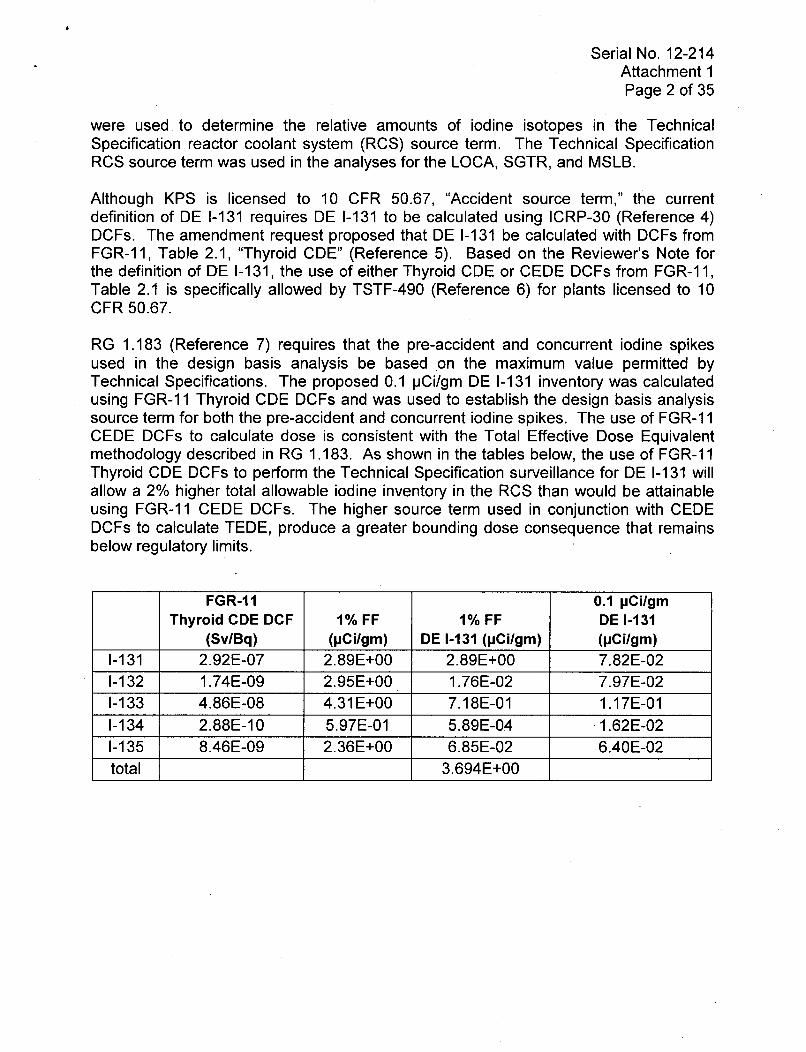
RG 1.183 (Reference 7) requires that the pre-accident and concurrent iodine spikesused in the design basis analysis be based *on the maximum value permitted byTechnical Specifications. The proposed 0.1 pCi/gm DE 1-131 inventory was calculatedusing FGR-1 1 Thyroid CDE DCFs and was used to establish the design basis analysissource term for both the pre-accident and concurrent iodine spikes. The use of FGR-1 1CEDE DCFs to calculate dose is consistent with the Total Effective Dose Equivalentmethodology described in RG 1.183. As shown in the tables below, the use of FGR-11Thyroid CDE DCFs to perform the Technical Specification surveillance for DE 1-131 willallow a 2% higher total allowable iodine inventory in the RCS than would be attainableusing FGR-1 1 CEDE DCFs. The higher source term used in conjunction with CEDEDCFs to calculate TEDE, produce a greater bounding dose consequence that remainsbelow regulatory limits.
FGR-11 0.1 pCi/gmThyroid CDE DCF 1% FF 1% FF DE 1-131
(Sv/Bq) (pCi/gm) DE 1-131 (pCi/gm) (pCi/gm)1-131 2.92E-07 2.89E+00 2.89E+00 7.82E-021-132 1.74E-09 2.95E+00 1.76E-02 7.97E-021-133 4.86E-08 4.31 E+00 7.18E-01 1.17E-011-134 2.88E-10 5.97E-01 5.89E-04 1.62E-021-135 8.46E-09 2.36E+00 6.85E-02 6.40E-02total 3.694E+00

Serial No. 12-214Attachment 1Page 3 of 35
FGR-11 0.1 pCi/gmCEDE DCF 1% FF 1% FF DE 1-131
(Sv/Bq) (pCi/gm) DE 1-131 (pCi/gm) (pCi/gm)1-131 8.89E-09 2.89E+00 2.89E+00 7.64E-021-132 1.03E-10 2.95E+00 3.41E-02 7.79E-021-133 1.58E-09 4.31E+00 7.66E-01 1.14E-011-134 3.55E-11 5.97E-01 2.38E-03 1.58E-021-135 3.32E-10 2.36E+00 8.83E-02 6.25E-02total 3.781 E+00
It is acceptable for the pre-accident and concurrent iodine spike design basis sourceterms to be based on FGR-1 1 Thyroid CDE DCFs and the doses to be calculated usingFGR-1 1 CEDE DCFs because the source term will bound allowable plant operatingparameters as defined in the Technical Specifications, as required by RG 1.183, andresult in bounding dose consequences.
Serial No. 12-214Attachment 1Page 4 of 35
2. NRC Question 2 (ME7110-RAII-AADB-Blum-002-2012-03-02)
Attachment 4, page 45 states:
A reduction in airborne radioactivity in the containment by natural deposition withincontainment is credited. The model used is described in NUREG/CR-6189, "ASimplified Model of Aerosol Removal by Natural Processes in ReactorContainments," (Reference 25) and is incorporated into the RADTRAD-NAIcomputer code. This model is called the Powers model, set for the 10th percentile.
Attachment 4, page 43 also discusses credit for removal of aerosol by containmentsprays. Removal of aerosol by sprays and natural deposition are competingprocesses. Please justify crediting both spray removal and the proposed Powersnatural deposition model. Describe how the Powers natural deposition modelaccounts for removal due to the spray model used. If any further credit for areduction in aerosols is taken for any pathway, please provide a justification for thatcredit while considering the impact of any other removal mechanism credited. Forexample, with respect to spray removal and natural deposition ensure that thesprays do not remove aerosols that are also removed in the Powers model.
DEK Response:
The RADTRAD Powers aerosol natural deposition model was used during the entireevent, including the period when containment sprays were operating. However,. theimpact of the Powers natural deposition model during the period when containmentsprays were operating was negligible. An estimate of the impact of the treatment ofaerosols was made using the same model that was used for the LOCA and turning offthe RADTRAD Powers aerosol natural deposition model and replacing it with manually-calculated natural deposition decontamination coefficients used only after thecontainment sprays terminated. The comparison of results, with and without creditingnatural deposition during spray removal, shows no difference in resulting dose.Additional airborne radioactivity removal during the period of competing processes isnot apparent. Removal due to Powers natural deposition does become apparent duringthe remainder of the accident after sprays are terminated.
Serial No. 12-214Attachment 1Page 5 of 35
3. NRC Question 3 (ME7110-RAII-AADB-Blum-003-2012-03-02)
Attachment 4, page 46 states that the revised LOCA analysis contains somechanges that include:
Replacement of the assumed 1% iodine evolution rate from RWST back-leakageto a conservative DF=100.
Justify this change and describe why it is conservative.
DEK Response:
The current KPS licensing basis for analyzing this release pathway is documented inthe Safety Evaluation (SE) related to KPS License Amendment 166 (Reference 8).Specifically, the leakage water which is at a temperature below 212OF enters the RWSTwhich is significantly below 212'F and enters the tank from the bottom. The evolution ofiodine from sump fluids that leak into the RWST is modeled by assuming 1 percentiodine evolution. The current method treats leakage into the RWST the same as anyother ESF leakage. No credit was taken for dilution into existing 'clean' RWST boricacid fluid that remains in the tank nor release into the gaseous 'unfilled' region of thetank. As specified in the SE for KPS License Amendment 166, "The radiologicalconsequence contribution from this pathway is less significant (less than 2 percent) atthe EAB for the postulated LOCA."
As specified in LAR 244 and discussed with the NRC staff during a telephoneconversation on October 20, 2011, DEK has chosen to model the release ofradioactivity from RWST back-leakage consistent with similar modeling used at otherDominion facilities (References 9 and 10; Millstone Unit 3 TAC Number MC3333; andNorth Anna TAC Numbers MD3197 and MD3198). The applied DF values used tomodel RWST releases for these facilities were 100 and 40, respectively.
Dominion provided previous explanations as to the applicability and appropriateness forthis method in a response to an NRC Request for Additional Information (Reference 11)when the method from LAR 244, Attachment 4, Reference 26 ("Iodine Removal fromContainment Atmospheres by Boric Acid Spray," Report No. BNP-100, BattelleMemorial Institute, Pacific Northwest Laboratories (PNL), Richland, WA 99352 7/19/70,A. K. Postma, L. F. Coleman and R. K. Hilliard) was first employed to estimate iodinepartition coefficients in an RWST for Millstone Unit 3. The emphasis in that responsefocused on the fact that an RWST should be treated as a closed system for theestablishment of achieving equilibrium conditions between the water and air in the tank.The environment in the RWST does not experience high temperature, radiation, orforced ventilation. It is a static environment that will experience partitioning between thehigher iodine concentrations in the water that will drive to achieve equilibrium with theiodine concentration in the air.
Serial No. 12-214Attachment 1
Page 6 of 35
The importance of pH in iodine evolution is understood and was considered in theapplication of iodine release from an RWST. The RWST environment does notexperience high doses which relate to iodine radiolysis discussed in more recent studiesperformed on iodine evolution and the importance of pH control to hinder the formationof 12, (e.g., NUREG/CR-5950 and NUREG/CR-4697). It is the formation of hydrogenperoxide (H20 2) during the irradiation of water that primarily reacts with iodide (I ) toform 12. For pools with sufficient iodine concentration that contend with the interaction ofiodine species and the products of water radiolysis, the effect of pH has been shown tobe a sensitive parameter in iodine evolution, with lower pH promoting higher iodineevolution. Because the RWST does not experience high doses, water radiolysis is not adirect contributor to the evolution of iodine. The BNP-100 study was based on acidicsolutions not including the effects of radiolysis, more applicable to KPS's RWST.Therefore, the partition coefficient curves from the BNP-100 study are directlyapplicable to this configuration.
Dominion's application of the iodine partition coefficient model to calculate releasesfrom back-leakage to KPS's RWST during the recirculation phase of the LOCA accidentcontains assumptions which provide conservatisms that yield higher than expecteddose consequences from this release pathway. The total iodine concentration in theRWST water is the critical factor that determines the partition coefficient. Theconcentration of iodine in the RWST increases over time with the maximum occurring atthe end of the 30 days. The concentration of iodine in the RWST at the end of 30 daysis about 3 milligrams/liter.
The partition coefficient (PC) will be at a minimum when the concentration of iodines inthe RWST is the greatest at the end of 30 days. The smaller the PC, the larger theamount of iodine that will partition from the water phase and enter into the gas phaseand be available for release. The PC corresponding to the maximum iodineconcentration of about 3 milligrams/liter was taken from Figure 8 of the BNP-100 study.The PC is approximately 600. Using the equation from SRP 6.5.2, Revision 2(Reference 15), and the ratio of RWST liquid to air at the end of 30 days ofapproximately 0.6, the DF is calculated to be approximately 360.
DF = 1 + (Vliquid / Vair) x PC
The absolute lowest calculated DF was calculated to occur around 300 hours into theaccident based on the effect of varying liquid to air volumes and a decreasing partitioncoefficient as concentration in the liquid increases with time.
Serial No. 12-214Attachment 1Page 7 of 35
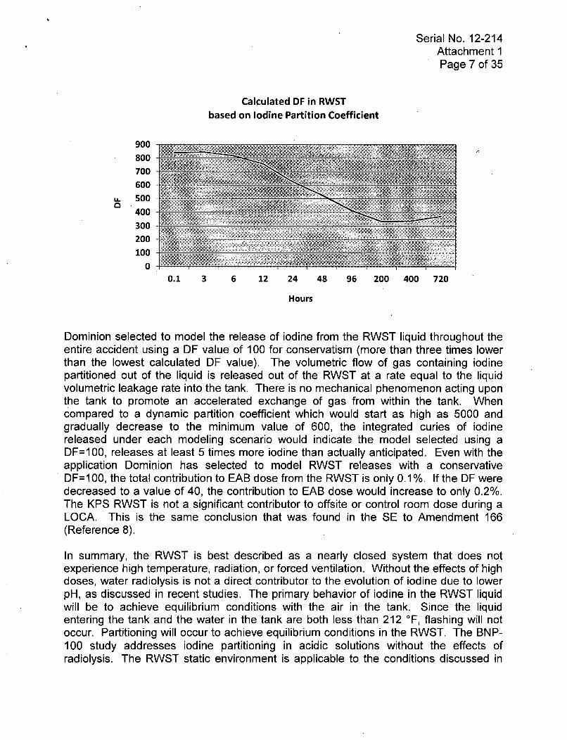
Calculated DF in RWSTbased on Iodine Partition Coefficient
900800 ~700600
400300200100
00.1 3 6 12 24 48 96 200 400 720
Hours
Dominion selected to model the release of iodine from the RWST liquid throughout theentire accident using a DF value of 100 for conservatism (more than three times lowerthan the lowest calculated DF value). The volumetric flow of gas containing iodinepartitioned out of the liquid is released out of the RWST at a rate equal to the liquidvolumetric leakage rate into the tank. There is no mechanical phenomenon acting uponthe tank to promote an accelerated exchange of gas from within the tank. Whencompared to a dynamic partition coefficient which would start as high as 5000 andgradually decrease to the minimum value of 600, the integrated curies of iodinereleased under each modeling scenario would indicate the model selected using aDF=100, releases at least 5 times more iodine than actually anticipated. Even with theapplication Dominion has selected to model RWST releases with a conservativeDF=100, the total contribution to EAB dose from the RWST is only 0.1%. If the DF weredecreased to a value of 40, the contribution to EAB dose would increase to only 0.2%.The KPS RWST is not a significant contributor to offsite or control room dose during aLOCA. This is the same conclusion that was found in the SE to Amendment 166(Reference 8).
In summary, the RWST is best described as a nearly closed system that does notexperience high temperature, radiation, or forced ventilation. Without the effects of highdoses, water radiolysis is not a direct contributor to the evolution of iodine due to lowerpH, as discussed in recent studies. The primary behavior of iodine in the RWST liquidwill be to achieve equilibrium conditions with the air in the tank. Since the liquidentering the tank and the water in the tank are both less than 212 'F, flashing will notoccur. Partitioning will occur to achieve equilibrium conditions in the RWST. The BNP-100 study addresses iodine partitioning in acidic solutions without the effects ofradiolysis. The RWST static environment is applicable to the conditions discussed in

Serial No. 12-214Attachment 1Page 8 of 35
the BNP-100 study. DEK calculated the lowest expected DF based on the lowestcalculated partitioning coefficient over the entire duration of RWST releases. Using aDF value of 100 for the entire modeled release provides at least a factor of fiveconservatism compared to the expected integrated release that would result if dynamicpartitioning were used over the 30-day release period.

Serial No. 12-214Attachment 1Page 9 of 35
4. NRC Question 4 (ME711O-RAII-AADB-Blum-004-2012-03-02)
Attachment 4, page 49 states that whole body dose conversion factors are used inthe LOCA dose calculation and that the reason for the change is Regulatory Guide(RG) 1.183. RG 1.183 does not discuss whole body dose conversion factors.Please clarify what was changed and justify the change.
DEK Response:
Within the industry, the term 'whole body dose' is essentially synonymous with 'effectivedose equivalent' (EDE). The label 'whole body' used in Table 3.2-5 under the 'DoseConversion Factors' parameter heading should ideally be labeled "EDE".
The current analyses of record are Westinghouse proprietary codes and methods withthe exception of the FHA, which is analyzed with RADTRAD-NAI. The WestinghouseTITAN5 code uses dose conversion factors for the 'whole body' derived from ICRP-30(Reference 4) for noble gases and average disintegration energies for the remainder ofthe nuclides. The dose conversion factors used in the revised RADTRAD-NAI accidentanalyses are described in section 1.3.2 of the LAR. The specific discussion F pertainingto the EDE dose conversion factors used is copied here:
"The DDE is nominally equivalent to the Effective Dose Equivalent (EDE) fromexternal exposure if the whole body is irradiated uniformly. Since this is a reasonableassumption for submergence exposure situations, EDE is used in lieu of DDE indetermining the contribution of extemal dose to the TEDE. EDE dose conversionfactors were taken from Table///. 1 of Federal Guidance Report 12 (Reference 16) perSection 4.1.4 of Regulatory Guide 1.183."

Serial No. 12-214Attachment 1
Page 10 of 35
5. NRC Question 5 (ME7110-RAII-AADB-Blum-005-2012-03-02)
Attachment 4, page 46 states that negative pressure in the shield building isestablished within 10 minutes. Please verify that "negative pressure" means > 0.25inch vacuum water gauge with one shield building ventilation system train operating(consistent with Technical Specification SR 3.6.8.2) or justify any proposed change.
DEK Response:
The "negative pressure" assumed in the accident analysis does mean 2! 0.25 inch
vacuum water gauge with one shield building ventilation system train operating.
KPS Technical Specification Surveillance Requirement 3.6.8.2 states:
"Verify the shield building can be maintained at a pressure > 0.25 inch vacuum watergauge in the annulus by one Shield Building Ventilation System train with final flowwith the limits of Figure 3.6.8-1 within 120 seconds after a start signal."
The accident analysis conservatively assumes that for the first 10 minutes following anaccident, shield building ventilation is not credited. 90% of containment leakage isassumed to be released directly to the environment and 10% released through theauxiliary building. For the period between 10 minutes and 30 days following anaccident, 1% of containment leakage is assumed to bypass the shield building and bereleased directly to the environment. Therefore, for the period between 10 minutes and30 days following an accident, the shield building ventilation system is credited.
The KPS USAR, Appendix H.3 describes the drawdown of the shield building using theshield building ventilation system. With one train of the shield building ventilationsystem operating, the annulus pressure reaches -1.0 inch water column (WC) 8.9minutes after the Design Basis Accident. The duration that the annulus is aboveatmospheric pressure is 3.2 minutes.
Therefore, analysis shows that shield building pressure will be > 0.25 inch vacuumwater gauge in less than 10 minutes with one shield building ventilation system trainoperating.

Serial No. 12-214Attachment 1
Page 11 of 35
6. NRC Question 6 (ME7110-RAII-AADB-Blum-006-2012-03-02)
Attachment 4, page 69 states:
The LOCA causes a Safety Injection (SI) signal, which also isolates the controlroom (per current Licensing Basis). The control room is isolated within 10 secondsafter the SI signal. Ba'sed on RG 1.183, the onset of the gap release does not startuntil 30 seconds post-LOCA. Therefore, the control room will be isolated prior tothe arrival of the radioactive release.
Technical Specification 3.4.16, "RCS [reactor coolant system] Specific Activity"allows radioactivity to be present in the RCS prior to an accident. The abovejustification, that states the control room will be isolated before the release ofradioactivity, does not seem to consider that, by design, radioactivity may be presentin the RCS prior to the gap release (at the start of the accident). Please provide acomplete justification for not considering the impact of the RCS activity prior to therelease of gap activity for both the control room and offsite analyses.
DEK Response:
The impact of the RCS activity prior to the release of gap activity was considered forboth the control room and offsite dose analyses. The primary containment vent systemwas modeled as active at the initiation of the accident, prior to the LOCA gap releasephase. RCS coolant radionuclide inventory is released through the primary containmentvent system until the primary containment vent system is isolated on receipt of a safetyinjection (SI) signal. A 90 second delay in the isolation of the primary containment ventsystem conservatively covers the time necessary to receive the SI signal and close thecontainment vent system valves. The control room was assumed to not be isolated forthe first 63 seconds following the accident. Using a conservative containment vent flowrate of 1300 cubic feet per minute (cfm), the resulting contributions to control room,EAB, and LPZ doses were negligible (less than 2 mRem in each case).

Serial No. 12-214Attachment 1Page 12 of 35
7. NRC Question 7 (ME7110-RAII-AADB-Blum-007-2012-03-02)
Attachment 4, page 35 states:
Containment purge isolates within 37 seconds following the LOCA and is aninsignificant contributor to control room and offsite dose.
Attachment 4, page 35 states:
KPS is a licensed leak before-break LBB plant (Reference 9). Per RG 1.183, theonset of gap release can be credited with a 10 minute delay for LBB. Containmentpurge isolation occurs within 37 seconds. Therefore, dose contribution from onlyTS RCS inventory is insignificant.
Reference 9 provides the citation for a letter to the NRC. Please provide a referencefor the NRC safety evaluation which approved LBB methodology. Also, pleaseprovide a justification for applying the LBB methodology to the control room andoffsite dose calculations.
DEK Response:
The safety evaluation approving the application of LBB is documented in a letter from K.E. Perkins (NRC) to D. C. Hintz (WPS) dated February 16, 1988. This document couldnot be located in ADAMS. Therefore, a copy of the letter is provided as Enclosure 1 tothis letter. In the current submittal, credit for LBB methodology was limited to the LOCAanalysis, consistent with the guidance in RG 1.183, Section 3.3 (Reference 7). Theimpact of crediting the LBB methodology in the LOCA analysis was limited to modelingthe onset of the gap release phase after the primary containment vent closes at 37seconds into the event. An estimate of the impact of removing the credit for LBBmethodology on the resulting control room and offsite doses was made using the samemodel that was used for the LOCA, but assuming an additional unfiltered flow of 1300cfm through the primary containment vent for the first seven seconds of the gap releasephase (which begins at 30 seconds). The increase in the control room and offsite doseswas less than 7 mRem. Thus, the impact of crediting the LBB methodology in the LOCAanalysis is negligible.
Serial No. 12-214Attachment 1Page 13 of 35
8. NRC Question 8 (ME711O-RAII-AADB-Blum-008-2012-03-02)
Please explain why switchover to recirculation spray is not credited in the LOCAanalysis. Also, please state if any operator action is credited in the assumption thatthe RWST switchover occurs at 0.91 hours. If operator actions are credited pleaseprovide the NRC staff safety evaluation where these operator actions are approvedfor the design basis LOCA dose calculation.
DEK Response:
The Internal Containment Spray (ICS) system provides clean spray from the RWST tocontainment atmosphere during a design basis LOCA radiological analysis. The sourceof water for spraying recirculated sump fluid inside containment is provided by aligningan operating Residual Heat Removal (RHR) pump to the suction of an operating ICSpump. KPS credits manual realignment of RHR pump suction to the sump after theRWST has been depleted. Recirculation spray is not credited in response to a designbasis accident at KPS. License Amendment 184 to the KPS Technical Specificationswas issued by the Nuclear Regulatory Commission on June 21, 2005 (Reference 12).The amendment removed the requirement for the ICS pumps to draw suction from thecontainment sump via the RHR pumps and supply containment spray when in thecontainment sump recirculation operating mode. This change was made due toconcerns with runout of the RHR and/or ICS pumps when the RHR pumps aresupplying suction to the ICS pumps in the recirculation mode. Therefore, no credit is
.taken in the analyses (containment and radiological) for operation of ICS during therecirculation phase of the LOCA.,
No operator action is credited to terminate ICS flow at 0.91 hours in the LOCAradiological analysis. Ending containment spray early is conservative to dose becauseit results in an increase in the release from containment to the environment from thattime forward by ending one of the removal mechanisms. 0.91 hours represents theearliest time the RWST could reach the level where operator action would be initiated toend ICS flow based on operation of one train of ECCS.

Serial No. 12-214Attachment 1
Page 14 of 35
9. NRC Question 9 (ME7110-RAII-AADB-Blum-009-2012-03-02)
Attachment 4, page 29 states:
As a result of the analyses documented in this LAR, the alternate control roomintake will be restricted from use. This restriction is required because of the X/Qthat would result due to the close proximity of the alternate intake to variousrelease points; one of which is < 10 m from the alternate intake. Administrativecontrols will be in place to assure the alternate control room intake is closed andprohibit its use during normal operation, following an accident, or while movingrecently irradiated fuel. [emphasis added]
Regulatory Position (RP) 5.1.2 of RG 1.183 states:
5.1.2 Credit for Engineered Safeguard Features
Credit may be taken for accident mitigation features that are classified as safetyrelated, are required to be operable by technical specifications, are powered byemergency power sources, and are either automatically actuated or, in limitedcases, have actuation requirements explicitly addressed in emergency operatingprocedures. The single active component failure that results in the most limitingradiological consequences should be assumed. Assumptions regarding theoccurrence and timing of a loss of offsite power should be selected with theobjective of maximizing the postulated radiological consequences.
The licensee's response to Question 5, of a letter dated November 8, 2011 (AdamsAccession No. ML1 1318A205) provides proposed changes to limiting condition foroperation (LCO) 3.7.10 to ensure the Control Room Envelope is isolated duringmovement of recently irradiated fuel. The response to Question 5 and the licenseamendment submittal do not appear to provide a similar provision, consistent withRP 5.1.2 cited above, for ensuring that the alternative control room intake is closedduring normal operation or following an accident.
RG 1.183, RP 5.1.2 provides credit for mitigation features that are required to beoperable by technical specifications. Justify why credit for isolation of the alternativecontrol room intake is assured (during normal operations or following an accident) by.the proposed methods or propose a method consistent with RP 5.1.2.
DEK Response:
The Control Room Ventilation system is operated under Normal Operating ProcedureOP-KW-NOP-ACC-001, "Control Room Air Conditioning System." The currentprocedure allows use of either the normal or alternate air intake although the normal airintake is normally aligned. This procedure will be revised, as part of the implementation
Serial No. 12-214Attachment 1Page 15 of 35
process for this amendment, to only allow the normal air intake to be aligned. Thealternate intake will be required to be maintained shut.
The KPS control room is a neutral pressure control room during design basis events.The control room completely isolates. A Safety Injection, High Radiation or SteamExclusion signal results in both the normal and alternate intakes to shut, if open.Procedure AOP-ACC-001, "Abnormal Control Room A/C System Operation," providesguidance for system operation under design basis accident conditions. The normal andalternate air intakes are verified to be shut if a valid SI, High Radiation or SteamExclusion signal exists. This procedure allows operators to open either intake for ashort duration to provide fresh air to the control room. The fresh air is introducedthrough the control room charcoal and HEPA filters. This procedure will also be revisedas part of the implementation process for this amendment to not allow opening of thealternate intake.
There are also additional procedures identified that allow opening the alternate intakethat will require revision as part of the implementation process for this amendment:
* AOP-FP-003, "Fire in a Dedicated Fire Zone"
" OP-KW-NOP-RM-003, "Control Room Radiation Monitor Functional Checks"
In summary, isolation of the control room alternate intake during normal operation andfollowing an accident will be assured by procedural controls. Appropriate procedureswill be changed during the implementation process for this amendment so that openingof the alternate intake is not allowed.
The design of the alternate intake dampers supports the conclusion that these damperswill remain closed at all times. The alternate intake dampers are redundant safety-grade air-operated isolation dampers. They are designed to close upon receipt of asafety injection, steam exclusion / zone SV signal or a loss of offsite power based onthe operation of a spring. DEK believes that the combination of procedural controlsrequiring the alternate intake to be maintained in a closed position and the design of thedampers will assure that the dampers will remain closed before and after an accident.

Serial No. 12-214Attachment 1Page 16 of 35
10. NRC Question 10 (ME7110-RAII-AADB-Blum-010-2012-03-02)
Attachment 4, page 68 states:
Flows reduced from nominal values ... by a factor equal to the inverse of thepartition coefficient derived from a DF of 100.
Why are the flows reduced by the partition factor rather than by using thedecontamination factor (DF)? How are the DF and partition coefficient defined forthis application (based upon volume or mass)?
DEK Response:
The use of a partition coefficient (PC) rather than a decontamination factor (DF)facilitated the use of a variable-volume liquid space model for the RWST. The liquidvolume of the RWST, and the concentration of iodine in the liquid volume, weremodeled as varying with time. The use of a partition coefficient permitted the iodineconcentration in the air volume to be directly calculated from the iodine concentration inthe liquid volume. The air volumetric flow rate from the RWST (equal to the liquidvolumetric inflow rate) then determined the iodine release rate.
As described in the response to RAI 3 (ME7110-RAII-AADB-Blum-003-2012-03-02), thepartition factor was calculated from a conservative value of the DF using the equation:
PC = (DF - 1) x (VairNliquid), where;
Vair = vapor volume in the tank, andVliquid = the liquid volume in the tank
The conservatism in the calculated partition coefficient was increased by using tankvolumes at the end of the event.

Serial No. 12-214Attachment 1Page 17 of 35
11. NRC Question 11 (ME7110-RAII-AADB-Blum-011-2012-03-02)
Attachment 3, page B 3.9.6-3 and B3.9.6-4 states:
If it is determined that closure of the equipment hatch and/or containmentpenetrations would represent a significant radiological hazard to the personnelinvolved, the decision may be made to forgo [emphasis added] closure of the hatchand/or penetrations.
The above proposed language seems to be contrary to the intent of the TSTF-312[Technical Specification Task Force], "Administratively Control ContainmentPenetrations" [ADAMS Accession No. ML040620147]. TSTF-312 bases approval ofthe TSTF on whether, the hatch "can and will be promptly closed." Per Title 10 ofthe Code of Federal Regulations Section 50.67 (10 CFR 50.67), the fission productrelease assumed for the design calculations are based upon a major accident thatresults in potential hazards "not exceeded by any accident considered credible."
The need for a provision to forgo closure of the hatch appears to acknowledge thatthere is a credible scenario where the design source term is exceeded. Therefore,the source term used for the fuel handling accident does not appear to align with 10CFR 50.67 which specifies the need for a source term that is not exceeded by anycredible accident. Please justify the source term used for the fuel handling accident,remove the proposed provision to allow forgoing closure, or provide a source termfor the fuel handling accident which is not exceeded by any accident consideredcredible.
DEK Response:
DEK had proposed adding this additional statement into the TS Bases (discussing anoption to not close the equipment hatch under certain radiological conditions) to provideoperators with additional flexibility in decision making. However, since there is nocredible scenario where the design source term is exceeded, such a statement is notneeded. Therefore, the originally proposed statement, regarding the proposed provisionto allow forgoing closure, will be removed from the TS 3.9.6 Bases. The originallyproposed statement to be deleted from the TS 3.9.6 Bases is provided below.
"If it is determined that closure of the equipment hatch and/or containmentpenetrations would represent a significant radiological hazard to the personnelinvolved, the decision may be made to forgo closure of the hatch and/or penetrations."

Serial No. 12-214Attachment 1Page 18 of 35
12. NRC Question 12 (ME7110-RAII-AADB-Blum-012-2012-03-02)
For several design basis accidents the assumed time to isolate the control room isdecreased (i.e., Attachment 4, Table 3.2-5, page 58). For example, the Loss ofCoolant Accident assumes the control room isolation damper takes 10 seconds toclose upon receipt of a safety injection signal, but the proposed value for controlroom isolation is zero seconds. Explain and justify why the proposed value forcontrol room isolation for some accidents is less than the 10 seconds to close theisolation damper.
The revised time to isolate the control room for all accidents does not seem toinclude the time to start and load the diesel generators. Please justify that, given theworst case single failure, the isolation of the control room does not require dieselpower and that the time to isolate the control room is not influenced by time to startand load the diesel.
DEK Response:
The time to start and load diesel generators does not impact the operation of the controlroom isolation dampers. The control room supply and exhaust ductwork containsredundant safety grade isolation dampers. Each control room isolation damper closeswithin 10 seconds of either a safety injection (SI) signal, steam exclusion / zone SVsignal or a loss of power based on the operation of a spring. Closure of the controlroom isolation dampers does not require the EDG. The time to isolate the control roomdoes not require diesel power and the time to isolate the control room is not influencedby time to start and load the diesel.
The LOCA and the FHA are the only analyses with control room isolation times lessthan the 10 seconds required for isolation dampers to close. As described in LAR-244,the consequences of the FHA are mitigated by requiring that control room isolationdampers be closed prior to moving recently irradiated fuel.
The LOCA is more complex. As described in LAR-244, Attachment 4, Table 3.2-5, inthe LOCA event a SI signal is achieved nearly coincident with the start of the event andthe control room isolation dampers are closed 10 seconds later. The gap releasebegins 30 seconds after the initiation of the event. Hence the control room is isolatedprior to the beginning of the gap and in-vessel releases. In order to simplify theRADTRAD-NAI model, the control room is modeled to be isolated at the start of the gaprelease for cases that model the containment, ECCS and RWST back-leakage sources.
However, the description of the LOCA also includes, in LAR-244, Attachment 4, Table3.2-5, brief mention of releases of TS coolant activity through the potentially opencontainment purge isolation system to account for a 37 second allowed closing timeafter receipt of a SI signal for a containment purge isolation valve. This case is not

Serial No. 12-214Attachment 1
Page 19 of 35
described in LAR-244 as it resulted in negligible dose consequences, but this case didinclude a 10 second delay for control room isolation due to damper operation andincluded a 90 second release to bound the 37 second allowance for containment purgeisolation valve closure.

Serial No. 12-214Attachment 1Page 20 of 35
13. NRC Question 13 (ME7110-RAII-AADB-Blum-013-2012-03-02)
The Technical Specification "Ventilation Filter and Testing Program," 5.5.9 statesthat the High-Efficiency Particulate Air and charcoal absorbers are allowed to have abypass of 1% by design. How is the allowed bypass of 1% accounted for in thedesign basis radiological calculations? If the bypass is not accounted for in theradiological design calculations please consider it in the design calculations or justifywhy it need not be considered.
DEK Response:
Technical Specification 5.5.9, "Ventilation Filter Testing Program (VFTP)," requires thatinplace testing of high efficiency particulate air (HEPA) filters and charcoal adsorbersshows a penetration and system bypass -< 1.0% when tested in accordance withRegulatory Positions C.5.c and C.5.d, respectively, of Regulatory Guide 1.52, Revision2, and ANSI N510-1975 at specified system flowrates ± 10%. Since filter testing wasfirst included in Technical Specifications, the acceptance criteria for inplace testing offilter media has been either removal of >99% of DOP test aerosol or halogenatedhydrocarbon refrigerant or the current wording that the surveillance shows a penetrationand system bypass < 1.0%.
The HEPA filter efficiency assumed in the accident analyses is 99%. Inplace testing ofHEPA filters typically show > 99.95% removal with a test acceptance criterion of >99.2%for margin to the technical specification limit. The assumption in the accident analysesis consistent with the surveillance requirement in Technical Specification 5.5.9.a thatpenetration and system bypass is < 1.0% without any safety factor included. Theassumption of 99% HEPA filter efficiency is consistent with the existing design basisaccident analyses and has been previously reviewed and approved in the radiologicalanalyses submitted for DEK license amendments 166, 172 and 190 (References 8, 13,14).
The charcoal adsorber filter efficiency assumed in the accident analyses is 95% for theShield Building Ventilation System (SBVS) and Auxiliary Building Special VentilationSystem (ASVS), and 90% for Control Room Post Accident Recirculation System(CRPARS). These filter efficiency assumptions are periodically verified by laboratorytesting in accordance with Technical Specification 5.5.9.c and include a safety factor of2. The proposed RAAs do not account for 1% system penetration and bypass. The 1%penetration and system bypass requirement of Technical Specification 5.5.9.b isaccommodated in the analyses with regard to charcoal adsorbers as allowed byGeneric Letter 83-13. Generic Letter 83-13 states that 1% penetration and systembypass is applicable when a charcoal adsorber efficiency of 95% (or less) is assumed inthe NRC Staff's safety evaluation. The assumed charcoal adsorber filter efficiencies areconsistent with the existing design basis radiological accident analyses, which werepreviously reviewed in KPS license amendments 166, 172 and 190.
Serial No. 12-214Attachment 1
Page 21 of 35
14. NRC Question 14 (ME7110-RAII-AADB-Blum-014-2012-03-02)
Attachment 4, page 63, Figure 3.2-2 provides the effective filter efficiencies forfiltered flow through the Auxiliary Building Special Ventilation zone filters. The 50percent plate-out factor in the Auxiliary Building appears to have been used to derivethe organic iodine filter efficiency. When appropriate, plate out of iodine is typicallyonly associated with elemental iodine and is conservatively not assumed for organiciodine. Please justify adjusting the organic iodine nominal iodine filter efficiencies bythe 50 percent plate-out factor or remove the credit for organic iodine plate out.
DEK Response:
The RADTRAD cases used to model the ECCS and RWST pathways included a 50percent plate-out factor for both organic and elemental iodine. The radioiodine availablefor release to the environment was assumed to be 3 percent organic iodine, consistentwith the guidance of RG 1.183. Given the small fraction of organic iodine in the totalradioiodine available for release, the impact of the 50 percent plate-out factor for organiciodine was expected to be small. An estimate of the impact of the 50 percent plate-outfactor in the ECCS and RWST models was made using the same models that wereused for the LOCA, but removing the 50 percent plate-out factor for organic iodine.Additional RADTRAD cases were run to evaluate the impact of the 50 percent plate-outfactor for the ECCS model and the RWST model. Removing the 50 percent plate-outfactor for organic iodine resulted in LOCA dose increases to the control room, the EAB,and the LPZ of 19 mRem, 0.3 mRem, and 0.1 mRem, respectively. Therefore, the 50percent plate-out factor for organic iodine has a negligible effect on the LOCA doseresults.
Serial No. 12-214Attachment 1
Page 22 of 35
15. NRC Question 15 (ME7110-RAII-AADB-Blum-015-2012-03-02)
Attachment 4, page 68, Figure 3.2-3 states that the unfiltered flow from thecontainment sump to the Reactor Water Storage Tank (RWST) is decreased by 50percent after 24 hours. While the containment sump is in direct contact with thecontainment atmosphere and the pressure of the containment atmosphere maydecrease over time, the RWST backleakage may also be influenced by pumps thatrun during the loss of coolant accident. Please justify the 50 percent decrease inRWST backleakage after 24 hours.
DEK Response:
Backleakage to the RWST at 24 hours after the LOCA accident is influenced bycontainment pressure and by the RHR pump and the ECCS configuration at that time inthe event response. At 24 hours post-LOCA, the EGGS is operating in the containmentsump recirculation mode with only one Residual Heat Removal (RHR) pump running.EGOS systems and components that function earlier in the LOCA accident responseare not needed at this time (e.g. the internal containment spray (ICS) and the safetyinjection (SI) systems are not functioning, the IGS and SI pumps are stopped and theirassociated suction source valves to the RWST are closed). The IGS discharge valvesare also closed. However, leakage to the RWST is possible at this time in the eventthrough several leakage paths that are discussed below.
The KPS System Integrity Program (SIP) is required to be established, implementedand maintained per KPS TS 5.5.2, "Primary Coolant Sources Outside Containment."The SIP requires (in part) that EGGS valves that could potentially contribute tobackleakage to the RWST after an accident be hydrostatically leak rate tested duringeach refueling outage. The SIP is designed to determine leakage for accident EGGSalignments that involve operating IGS and SI systems and SI operation in piggy-backmode with RHR. Individual valves do not have an allowable leak rate but the totalcombined leakrate from all the valves must be less than 3 gpm. The leak rate for eachvalve is measured at a pressure that is greater than or equal to the worst case pressurethat would be experienced during an accident. Any repairs necessary to meet thespecified overall leakrate must be accomplished prior to the affected (SI and ICS)systems being returned to an operable status following a refueling outage.
Backleakage to the RWST is possible through the following leakage paths:
1. Leakage to the RWST is possible through the SI-300 A/B and SI-301 A/B valves
The SI-300 A/B valves are motor operated valves (MOVs) designed to isolate theRHR pump suction from the RWST during containment sump recirculation. The SI-301 A/B valves are check valves (CVs) designed to prevent back flow from the RHRpump suction to the RWST. Each flow path from the RWST to the respective RHR

Serial No. 12-214Attachment 1
Page 23 of 35
pump suction contains one SI-300 motor operated valve and one SI-301 check valvein series.
During the transfer to containment sump recirculation, SI-300A and SI-300B areclosed, isolating the RHR pump suction piping from the RWST. Leakage via thispath would be driven by containment sump head and containment pressure.Containment pressure is significantly reduced at 24 hours after the LOCA comparedto the containment pressure early in the event. (According to KPS USAR Table14.3.5-8, LOCA peak containment pressure is 43.1 psig and at 24 hours it is 10.1psig. The pressure against SI-301A and SI-301B check valves 24 hours after aLOCA will be minimal in comparison to the RHR system pressure during a normalplant shutdown, when RHR cooling is in operation and these valves are held closedat pressures greater than 200 psig. Due to the low induced pressure against the SI-301 A/B check valves during a LOCA accident and the redundant isolationconfiguration (i.e. the SI-300 and 301 valves are in series), a specific leakage test ofSI-301A and SI-301 B is not performed as part of SIP.
2. Leakage to the RWST is possible through the RHR-299 A/B
The RHR-299A/B valves isolate RHR discharge flow from the SI pump suction.Leakage past the RHR-299A/B valves could result in leakage back to the RWSTthrough the SI pump suction piping (through SI-5A/B) or through the SI pumpdischarge piping (through SI-208 and SI-209). Leakage through the RHR-299A/Bvalves is measured by the KPS SIP with the associated RHR pump running at adischarge pressure greater than 200 psig. Recent SIP measurements for RHR-299A/B show leakage results of < 0.01 gpm.
RHR-299 A/B and SI-5 A/B Leakage Path
The RHR-299 A/B and SI-5 A/B valves are motor operated valves in series for theleak path to the RWST. The SI-5 valves are located in the SI pump suction pipingfrom the RWST. Leakage through valves SI-5 A/B is measured by the SIP at a testpressure of 200 psig. Recent SIP measurements for SI-5A/B show leakage resultsof < 0.1 gpm. The low measured leakage results for RHR-299 A/B and SI-5 A/B andthe redundant isolation configuration (RHR-299 and SI-5 valves in series for the leakpath to the RWST) support the LOCA radiological accident analysis RWST leakageassumptions.
RHR-299 A/B and SI-208 or SI-209 Leakage Path
The RHR-299A/B and SI-208 and SI-209 valves are motor operated valves in seriesfor the leak path to the RWST. The SI-208 and SI-209 valves are located in the SIpump discharge mini-flow recirculation line back to the RWST. Leakage through theSI-208 and SI-209 valves is measured by the SIP at a test pressure of 2478 psig.Recent SIP measurements for SI-208 and SI-209 show leakage results of < 0.1

Serial No. 12-214Attachment 1
Page 24 of 35
gpm. The low measured leakage results from RHR-299ANB and SI-208 or SI-209and the redundant isolation configuration (RHR-299 and SI-208 and SI-209 in seriesfor the leak path to the RWST) support the LOCA radiological accident analysisRWST leakage assumptions.
3. Leakage to the RWST is possible through the RHR-400A/B valves
RHR-400A/B valves are motor operated valves located between the RHR pumpdischarge and the ICS pump suction piping. The RHR-400 A/B valve leakage is notmeasured by SIP. The leak path through the RHR-400A/B valves to the RWSTinvolves leakage through the ICS suction piping and the ICS discharge piping.
ICS Suction Piping (RHR-400A/B and ICS-3A/B and ICS-2A/B Leakage Path)
Leakage to the RWST through the RHR-400A/B valves would be though the ICS-3A/B and ICS 2A/B valves. ICS-3A and ICS-3B are check valves that are in serieswith redundant motor operated valves ICS-2A and ICS-2B. The ICS-2A/B valvesare closed during containment sump recirculation. Check valves ICS-3A/B areincluded in the SIP and leakage through these valves is measured at a test pressureof 200 psig. Recent SIP measurements for the ICS- 3A/B valves show leakage of< 0.1 gpm. The low measured leakage results for the ICS-3 A/B valves and theredundant isolation configuration (RHR-400, ICS-3, and ICS-2 valves in series forthe leak path to the RWST) support the LOCA radiological accident analysis RWSTleakage assumptions.
ICS Discharge Piping (RHR-400NAB and ICS-5A/B or ICS-6A/B Leakage Paths)
The leak path through RHR-400A/B valve to the RWST through the discharge pipingof the ICS system involves leakage through the ICS-5A/B or ICS-6A/B valves. ICS-5A/B and ICS-6A/B would be closed during containment sump recirculation.However, these valves are not leak checked. There are two potential leak pathsback to the RWST if leakage goes past RHR-400A/B and past ICS-5A/B or ICS-6A/B (all closed valves for this scenario), through the ICS full flow test line or throughthe ICS recirculation line.
Leak Path 1 -Through ICS Full Flow Test Line (ICS-210A/B)
This leakage path would be through RHR-400A/B (closed valve), ICS-5A/B orICS-6A/B (closed valves) and then through ICS-210A/B (closed valve). TheICS-210A/B valves are manual valves that are normally closed and would notbe repositioned during an accident. Leakage past ICS-210A/B is measured perthe SIP at a test pressure of 500 psig. Recent SIP leak measurements for ICS-21OA/B show leakage of < 0.2 gpm.
* Leak Path 2 - Through ICS Recirculation Line (ICS-201 or ICS-202)
Serial No. 12-214Attachment 1
Page 25 of 35
This leakage path would be through RHR-400A/B (closed valve), ICS-5A/B orICS-6A/B (closed valves) and then through either ICS-201 and ICS-202 (bothclosed valves). ICS-201 and ICS-202 are air operated valves that receive aclosed signal during containment isolation. Leakage past ICS-201 and ICS-202is measured per the SIP at a test pressure of 500 psig. Recent SIP leakmeasurements for ICS-201, ICS-202 show leakage of < 0.51 gpm.
For the two leakage paths identified above through the ICS discharge piping, atleast two closed MOVs are in series prior to the valve that is leakage tested per theSIP. Leakage back to the RWST would need to be through three closed valves. Ineach leakage path, at least one of the closed valves is leakage tested per the SIP.The valves that are leakage tested may not be the boundary valves for this LOCAscenario and for the conditions at 24 hours post-LOCA when operating in thecontainment sump recirculation mode. SIP is designed to determine leakage foraccident ECCS alignments that involve operating ICS and SI systems and SIoperation in piggy-back mode with RHR. As discussed above, at 24 hours intoLOCA the ICS and SI systems are not functioning and many of the valves in thesesystems are closed. Even though the SIP test conditions are conservative withrespect to the expected conditions and configurations at 24 hours post-LOCA thevalves tested in recent SIP testing are shown to provide satisfactory leakageresults to support the LOCA radiological accident analysis assumptions for RWSTleakage at 24 hours post-LOCA.
Summary
The assumption that backleakage to the RWST is reduced by 50% at 24 hours after anaccident is supported by the following:
1. The KPS System Integrity Program (SIP) measures valve leakage at conditionsthat are conservative with respect to conditions 24 hours after a LOCA. The SIPrequires that ECCS valves that could potentially contribute to backleakage to theRWST after an accident be hydrostatically leak rate tested during each refuelingoutage. The SIP is designed to measure leakage for post-accident ECCSalignments that involve operating ICS and SI systems and SI operation in piggy-back mode with RHR. The SIP measured leakage that is used to determine totalRWST backleakage is conservative, in that the valve with the highest measuredleakage in each leakage path is used, without crediting other valves in theleakage path for reducing leakage. The actual expected backleakage to RWSTwould be determined by valve with the least leakage in the path, not the valvewith the most leakage. The SIP acceptance criterion for backleakage is 3.0 gpm.Recent SIP measurements show total worst-case leakage through the affectedvalves is < 1.5 gpm at the bounding test conditions.
2. At 24 hours post-LOCA, the ECCS is operating in the containment sumprecirculation mode with only one Residual Heat Removal (RHR) pump running.ECCS systems and components that function earlier in the LOCA accident

Serial No. 12-214Attachment 1Page 26 of 35
response are not needed at this time (e.g. the internal containment spray (ICS)and the safety injection (SI) systems are not functioning, the ICS and SI pumpsare stopped and their associated suction source valves to the RWST are closed).The ICS discharge valves are also closed.
3. The SIP measured leakage is at a conservative system pressure when comparedto the pressure at 24 hours post-LOCA. (For example, in the case of the SIpump discharge side valves, their leakage is measured at SI pressure, which issignificantly higher than the pressure during containment sump recirculationwhen the SI pump stopped and only one RHR pump running.)
4. At 24 hours post-LOCA, containment pressure, which influences leakage incertain leakage paths, is significantly reduced.
5. At 24 hours post-LOCA, each leakage path from the ECCS to the RWST isisolated by multiple closed valves in series, and at least one of the closed valves(with the exception of the SI-300 and 301 valves) is leakage tested per the SIP.(Note that due to the low induced pressure against the SI-301 A/B check valvesduring a LOCA accident and the redundant isolation configuration (i.e. the SI-300and 301 valves are in series), a specific leakage test of SI-301A and SI-301B isnot performed as part of SIP.)
A Table Summarizing the SIP Test Results for each of the leakage paths discussedabove is provided below.

Serial No. 12-214Attachment 1Page 27 of 35
RWST Backleakaqe Measurements
Number of 2009 2011Closed20901Leakage Path Summary Valves in Measurement MeasurementLeak Path (Test Pressure) (Test Pressure)
Through SI-301A/B and SI-300A/B[Check Valve (CV) and Motor Operated Valve 2 N/A N/A
(MOV) - Not Measured]
SI-5A SI-5A
0.05 gpm 0.09 gpmThrough RHR-299A/B and SI-5AIB 2 (200 psig) (200 psig)
[All MOVs - Each measured] SI-5B SI-5B
0.02 gpm 0.06 gpm(200 psig) (200 psig)
SI-209 SI-208Through RHR-299A/B and SI-208 or SI-209 2
[All MOVs - Each measured] 0.04 gpm 0.05 gpm(2478 psig) (2478 psig)
ICS-3A ICS-3A
Through RHR-400A/B and ICS-3AIB and 0.10 gpm OgpmThrough 3 (200 psig) (200 psig)ICS-2AIB
[MOVs and CVs - Only CV's Measured] ICS-3B ICS-3B
0.10 gpm 0.05 gpm(200 psig) (200 psig)ICS-210A ICS-210A
Through RHR-400A/B and ICS-5AIB or 0.05 gpm 0.05 gpmICS-6AIB and ICS-210A/B (500 psig) (500 psig)
[MOVs and Manual Valves - Only Manual Valves ICS-210B ICS-210BMeasured] 0.10 gpm 0.15 gpm
(500 psig) (500 psig)Through RHR-400A/B and ICS-5AIB or ICS-201 ICS-201
ICS-6AIB and ICS-201 or ICS-202 0.50 gpm 0.25 gpm[MOVs and AOVs - Only AOVs Measured] (500 psig) (500 psig)
TOTAL 0.96 gpm* 0.70gpm*(<1.5 gpm) (<1.5 gpm)
• This value represents the sum of the highest measured leakage value for each of the potential
backleakage paths to the RWST, without credit for other valves in the leakage path which may havelower leakage. The leak rate for each valve is measured at a pressure that is greater than or equal tothe worst-case pressure that would be experienced during an accident.
Serial No. 12-214Attachment 1
Page 28 of 35
16. NRC Question 16 (ME7110-RAII-AADB-Blum-016-2012-03-02)
Attachment 4, page 73 states:
The core curies include a 6% increase to account for fuel management variations(493.6 ± 10% EFPD [effective full power days], average enrichment of 4.5 w/o +10%, and core mass of 49.1 MTU [metric ton uranium] ± 10%).
State whether the burnup of an assembly is limited to 493.6 + 10% EFPD. If not,justify why the assumed burnup is conservative for the fuel handling accident giventhe fuel is allowed to achieve higher burnups.
DEK Response:
The stated limit of 493.6 ± 10% EFPD is a core average cycle burnup limit. This limit,along with the stated enrichment and MTU limits, is used in the development of the coreradionuclide inventory. All three limits are verified on a cycle specific basis as part ofthe reload process. In order to determine the FHA source, the core inventory isadjusted by radial peaking factors from the Core Operating Limits Report (COLR) andgap fractions as directed by RG 1.183, Regulatory Positions 3.1 and 3.2, respectively,except that 25% of the rods in the limiting assembly are modeled as exceeding the RG1.183, footnote 11 requirement (6.3 kW/ft peak rod average power for burnupsexceeding 54 GWD/MTU). Fuel rods exceeding the footnote 11 requirement of RG1.183 were modeled at higher gap fractions that were previously approved in KPSLicense Amendment 190 (Reference 14) (see LAR 244, Attachment 4, Table 3.3-1).The percentage of rods exceeding the RG 1.183, footnote 11 is verified on a cyclespecific basis as part of the reload process.
This is the same method that was used to determine the source term for the FHA aspreviously approved in Amendment 190 with two exceptions. In Amendment 190 thecore curies included a 3% instead of a 6% increase to account for fuel managementvariations and the fuel rods exceeding RG 1.183, footnote 11 was 50% instead of 25%.
The change from 3% to 6% increase to account for fuel management variations allowsthe LOCA, FHA, LRA and REA events to start with the same core inventory and EFPDrange. Previously, the LRA and REA analyses were limited to 493.6 ± 5% EFPD basedon the core inventory calculation with the 3% increase.. The change from 50% to 25%of the rods exceeding footnote 11 simply removes excess conservatism from theanalysis based on verification of the percentage of rods exceeding the RG 1.183footnote 11 on a cycle specific basis as part of the reload process.

Serial No. 12-214Attachment 1Page 29 of 35
17. NRC Question 17 (ME7110-RAII-AADB-Blum-017-2012-03-02)
Attachment 4, page 84 states:
Based on the assumption that the fuel assembly will be horizontal once it comesto rest, it was determined that an assembly lying on the reactor vessel flange willhave approximately 22.35 feet of water above the highest point of the assemblyto the water surface. In the spent fuel pool, greater than 23 feet of water willexist.
The depth of 22.35 feet of water was evaluated to verify an effectivedecontamination factor of 200 using WCAP-7828 (Reference 27). Using themethods defined in the WCAP with conservative assumptions to minimizepredicted decontamination factors for various depths of water, a DF of greaterthan 500 was determined for elemental iodine. The use of an overall effectiveDF of 200 was determined to be appropriate per RG 1.183.
Justify the assumption that the fuel assembly will be horizontal once it comes to restfor the accident in the containment. Are there any obstructions which could preventit from becoming horizontal?
Provide all the input assumptions and the methodology used in the determinationthat a DF of 200 with less than 23' feet of water is appropriate. Justify why WCAP-7828 is appropriate for the fuel used at your facility.
DEK Response:
To address the questions in this RAI regarding the impact of less than 23 feet of water,Dominion has modeled the generally-accepted Burley method as well as the WCAP-7518 method to demonstrate that the two models result in effective DFs that are greaterthan that recommended in Regulatory Guide 1.183 (DF = 200). In this assessment, 22feet of water will be modeled to show the conservatism in using an effective DF of 200.
Based on a drawing review, the tallest obstructions which might prevent a fuel assemblyfrom assuming the horizontal position is the compression plate, used for the cavity seal,which projects approximately two inches above the reactor flange elevation. The top ofthe compression plate stands approximately. two inches above the flange andcircumferentially covers the annulus gap between the reactor vessel flange and thereactor cavity. There are toggle bolts on the plate that stand about 3.5 inches above thereactor vessel flange elevation but due to their size (estimated horizontal dimensions of2.5" x 2.5") represent a highly unlikely obstruction. The compression plate is a relativelylarge obstruction which should be credited.
Serial No. 12-214Attachment 1Page 30 of 35
With a horizontal fuel assembly height of 7.8 inches, the peak height of the assemblywith the additional two inches from the compression plate is approximately 10 inchesabove the reactor vessel flange. Since Technical Specifications require a minimum of23 feet of water above the reactor vessel flange, this leaves only 22.16 feet of waterabove the fuel assembly. As a result of this, Dominion will use 22 feet to ensureconservatism in its assessment.
WCAP-7518, "Radiological Consequences. of a Fuel Handling Accident," June 1970,provides supporting information for WCAP-7828 and for the Burley method (ReferenceB-1 of Regulatory Guide (RG) 1.183) which is used to devel op the approved effectiveDF of 200 discussed in RG 1.183. Both WCAP-7518 and the Burley Report will be usedin the response below, not WCAP-7828.
Per Appendix B of RG 1.183, the following information is provided:
1. Iodine released from the fuel to the pool is assumed to be 95% cesium iodide(CsI), 4.85% elemental iodine and 0.15% organic iodide. The iodine from Csldissociates and re-evolves as elemental.
2. For a water depth of 23 feet, the decontamination factors (DFs) for elemental andorganic species are 500 and 1, respectively.
3. An overall effective DF of 200 is the result.
It has been determined that there is only 22.16 feet of water above the fuel. In thisassessment 22 feet will be conservatively assumed.
After reviewing the Burley method and WCAP-7518, Dominion, concludes that theBurley method assesses bubble diameter based on an analytical method andconservative assumptions. WCAP-7518 assesses bubble diameter based on empiricaldata from actual small and large scale tests, and as a result provides an effective(average) bubble diameter taking into consideration release orifice size and releasepressure. This response primarily addresses bubble diameters used in the calculationof deep water DFs utilizing the Burley method and WCAP-7518. The discussion thatfollows will show that the WCAP and the Burley method provide results that show use ofan effective DF of 200 is conservative.
The WCAP-7518 Approach
Dominion is proposing that information provided in WCAP-7518 can be used todetermine an effective DF based on KPS fuel rod characteristics. This WCAP hasapplicability to the KPS design because test conditions are very similar to KPS withregard to orifice size (fuel rod internal diameter), release pressure (rod internalpressure) and water depth. The resulting effective DF will show that use of a DF of 200per RG 1.183 is bounding.
Serial No. 12-214Attachment 1Page 31 of 35
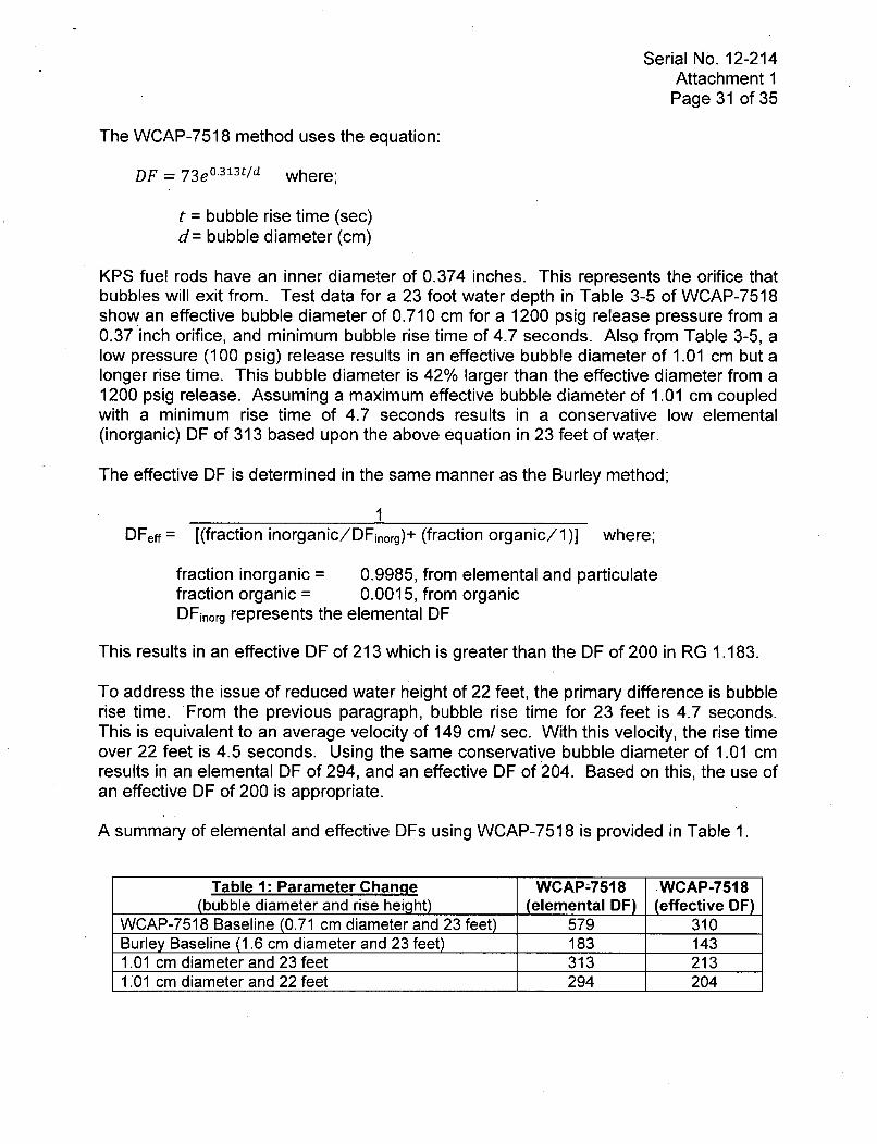
The WCAP-7518 method uses the equation:
DF = 73e° 30 3 t/d where;
t = bubble rise time (sec)d= bubble diameter (cm)
KPS fuel rods have an inner diameter of 0.374 inches. This represents the orifice thatbubbles will exit from. Test data for a 23 foot water depth in Table 3-5 of WCAP-7518show an effective bubble diameter of 0.710 cm for a 1200 psig release pressure from a0.37 inch orifice, and minimum bubble rise time of 4.7 seconds. Also from Table 3-5, alow pressure (100 psig) release results in an effective bubble diameter of 1.01 cm but alonger rise time. This bubble diameter is 42% larger than the effective diameter from a1200 psig release. Assuming a maximum effective bubble diameter of 1.01 cm coupledwith a minimum rise time of 4.7 seconds results in a conservative low elemental(inorganic) DF of 313 based upon the above equation in 23 feet of water.
The effective DF is determined in the same manner as the Burley method;
1DFeff = [(fraction inorganic/DFinorg)+ (fraction organic/I)] where;
fraction inorganic = 0.9985, from elemental and particulatefraction organic = 0.0015, from organicDFinorg represents the elemental DF
This results in an effective DF of 213 which is greater than the DF of 200 in RG 1.183.
To address the issue of reduced water height of 22 feet, the primary difference is bubblerise time. From the previous paragraph, bubble rise time for 23 feet is 4.7 seconds.This is equivalent to an average velocity of 149 cm/ sec. With this velocity, the rise timeover 22 feet is 4.5 seconds. Using the same conservative bubble diameter of 1.01 cmresults in an elemental DF of 294, and an effective DF of 204. Based on this, the use ofan effective DF of 200 is appropriate.
A summary of elemental and effective DFs using WCAP-7518 is provided in Table 1.
Table 1: Parameter Change WCAP-7518 WCAP-7518(bubble diameter and rise height) (elemental DF) (effective DF)
WCAP-7518 Baseline (0.71 cm diameter and 23 feet) 579 310Burley Baseline (1.6 cm diameter and 23 feet) 183 1431.01 cm diameter and 23 feet 313 2131.01 cm diameter and 22 feet 294 204

Serial No. 12-214Attachment 1
Page 32 of 35
The Burley Method
The Burley method uses an analytical approach to determine a conservative bubblediameter. It factors multiple conservatisms (large bubble size and a small partitionfactor) into its determination of DF.
Using the Burley method for 23 feet of water height results in an elemental DF of 133and an effective DF of 100 as discussed on page 26 of RG 1.183, Reference B-1 (itshould be noted that an elemental DF of 133 results in an actual effective DF of 111).Applying the same method for 22 feet of water results in an elemental DF of 108 with aresultant effective DF of 93. All factors (e.g., bubble velocity, bubble size, partitionfactor, etc.) remain the same since the difference of 1 foot will not significantly changethe bubble characteristics. These DFs are extremely conservative relative to the DF of200 provided in RG 1.183.
The Burley method uses the equation;
DFinorg = e(-)(keff)(b) where;
db = bubble diameter (cm)kerr = effective mass transfer coefficientH = rise height (cm)Vb = bubble velocity (cm/ sec)
While this report is not fully specific in the parameters used to determine its conclusionof an inorganic DF of 133, by applying the cited 1.6 cm bubble diameter size andpartition factor of 10, and averaging the laminar and turbulent flow DFs results in aninorganic DF of 133.
Applying the more realistic, but conservative bubble diameter of 1.01 cm (discussedabove) to the Burley method results in an elemental DF of 26000 and is significantlygreater than the WCAP elemental DF of 313. For 23 feet of water the resulting effectiveDF is 650. On this basis, the use of an effective DF of 200 for 23 feet is conservative.
Adjusting the parameters in the Burley method to reflect a 1.01 cm bubble and 4.5second rise time (based on 22 feet of water) results in an elemental DF of 15000. Theresulting effective DF is 638. On this basis, the use of an effective DF of 200 isconservative for a 22 foot water height.
A summary of elemental and effective DFs using the Burley method is provided in Table2 below.
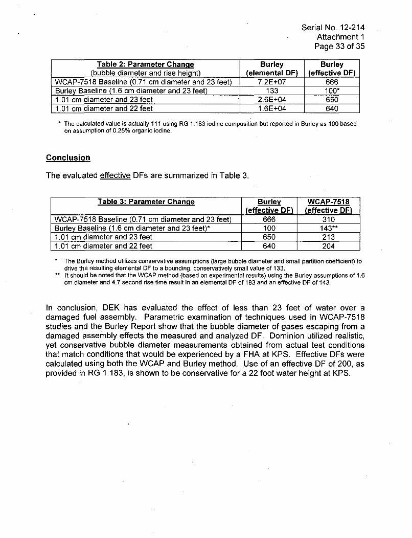
Serial No. 12-214Attachment 1Page 33 of 35
Table 2: Parameter Change Burley Burley(bubble diameter and rise height) (elemental DF) (effective DF)
WCAP-7518 Baseline (0.71 cm diameter and 23 feet) 7.2E+07 666Burley Baseline (1.6 cm diameter and 23 feet) 133 100*1.01 cm diameter and 23 feet 2.6E+04 6501.01 cm diameter and. 22 feet 1.6E+04 640
* The calculated value is actually 111 using RG 1.183 iodine composition but reported in Burley as 100 based
on assumption of 0.25% organic iodine.
Conclusion
The evaluated effective DFs are summarized in Table 3.
Table 3: Parameter Change Burley WCAP-7518(effective DF) (effective DF)
WCAP-7518 Baseline (0.71 cm diameter and 23 feet) 666 310Burley Baseline (1.6 cm diameter and 23 feet)* 100 143**1.01 cm diameter and 23 feet 650 2131.01 cm diameter and 22 feet 640 204
* The Burley method utilizes conservative assumptions (large bubble diameter and small partition coefficient) to
drive the resulting elemental DF to a bounding, conservatively small value of 133.** It should be noted that the WCAP method (based on experimental results) using the Burley assumptions of 1.6
cm diameter and 4.7 second rise time result in an elemental DF of 183 and an effective DF of 143.
In conclusion, DEK has evaluated the effect of less than 23 feet of water over adamaged fuel assembly. Parametric examination of techniques used in WCAP-7518studies and the Burley Report show that the bubble diameter of gases escaping from adamaged assembly effects the measured and analyzed DF. Dominion utilized realistic,yet conservative bubble diameter measurements obtained from actual test conditionsthat match conditions that would be experienced by a FHA at KPS. Effective DFs werecalculated using both the WCAP and Burley method. Use of an effective DF of 200, asprovided in RG 1.183, is shown to be conservative for a 22 foot water height at KPS.

Serial No. 12-214Attachment 1
Page 34 of 35
References
1. Letter from J. A. Price (DEK) to Document Control Desk (NRC), "LicenseAmendment Request 244, Proposed Revision to Radiological Accident Analysisand Control Room Envelope Habitability Technical Specifications," dated August30, 2011. [ADAMS Accession No. ML11252A521]
2. Letter from Craig W. Lambert (NMC) to Document Control Desk (NRC), "GenericLetter 2003-01; Control Room Habitability - Supplemental Response," dated April1, 2005. [ADAMS Accession No. ML050970303]
3. E-mail from Karl D. Feintuch (NRC) to Craig D. Sly, Jack Gadzala (DEK), "ME71 10Kewaunee Amendment Request Re: Chi-over-Q - AADB Request for AdditionalInformation (RAI)," dated March 2, 2011. [ADAMS Accession No. ML12066A008]
4. International Commission on Radiological Protection, Publication 30, "Limits forIntakes of Radionuclides by Workers," 1979.
5. Federal Guidance Report No. 11, "Limiting Values of Radionuclide Intake and AirConcentration and Dose Conversion Factors for Inhalation, Submersion, andIngestion," 1988.
6. TSTF-490, Revision 1, "Deletion of E Bar Definition and Revision to RCS SpecificActivity Tech Spec," dated March 14, 2011. [ADAMS Accession No.ML1 10730473]
7. NRC Regulatory Guide )1.183, "Alternative Radiological Source Terms forEvaluating Design Basis Accidents at Nuclear Power Reactors," dated July 2000.
8. Letter From John Lamb (NRC) to Tom Coutu (NMC), "Kewaunee Nuclear PowerPlant - Issuance of Amendment Regarding Implementation of Alternate SourceTerm (TAC No. MB4596)," dated March 17, 2003. [ADAMS Accession No.ML030210062] (Amendment 166)
9. Letter from V. Nerses (NRC) to D. A. Christian (DNC), "Millstone Power Station,Unit No. 3 - Issuance of Amendment RE: Alternate Source Term (TAC NO.MC3333)," dated September 15, 2006. [ADAMS Accession No. ML0619901351
10. Letter from S. P. Lingam (NRC to D. A. Christian (VEPCO), "North Anna PowerStation, Unit Nos. 1 and 2, Issuance of Amendments Regarding TechnicalSpecification Changes Per Generic Safety Issue (GSI) 191 (TAC NOS. MD3197and MD3198)," dated March 13, 2007. [ADAMS Accession No. ML070720043]
11. Letter from W. R. Matthews (DNC) to NRC Document Control Desk, "Response toRequest for Additional Information Regarding Proposed Technical SpecificationChanges for Implementation of Alternate Source Term," dated March 23, 2005[ADAMS Accession No. ML050950215]
12. Letter from C. F. Lyon (NRC) to M. G. Gaffney (DEK), "Kewaunee Nuclear PowerPlant - Issuance of Emergency Amendment Regarding Containment Spray FlowPath (TAC No. MC7335)," dated June 21, 2005 [ADAMS Accession No.ML051710030]
Serial No. 12-214Attachment 1
Page 35 of 35
13. Letter from John Lamb (NRC) to Tom Coutu (NMC), "Kewaunee Nuclear PowerPlant - Issuance of Amendment Regarding Stretch Power Uprate (TAC No.MB9031)," dated February 27, 2004. [ADAMS Accession No. ML040430633](Amendment 172)
14. Letter from R. F. Kuntz (NRC) to D. A. Christian (DEK), "Kewaunee Power Station- Issuance of Amendment RE: Radiological Accident Analysis and AssociatedTechnical Specifications Change (TAC No. MC9715)," dated March 8, 2007.[ADAMS Accession No. ML070430017] (Amendment 190)
15. NUREG 0800, "NRC Standard Review Plan," Section 6.5.2, "Containment Sprayas a Fission Product Cleanup System," Revision 2, December 1988.
Serial No. 12-214Enclosure 1
ENCLOSURE 1
RESPONSE TO REQUEST FOR ADDITIONAL INFORMATION:LICENSE AMENDMENT REQUEST 244, PROPOSED REVISION TO
RADIOLOGICAL ACCIDENT ANALYSIS AND CONTROL ROOM ENVELOPEHABITABILITY TECHNICAL SPECIFICATIONS
NRC REQUEST FOR ADDITIONAL INFORMATION QUESTIONS AND DOMINIONENERGY KEWAUNEE RESPONSES
Contents:
Copy of Letter from K. E. Perkins (NRC) to D. C. Hintz (WPS) dated February 16,1988
KEWAUNEE POWER STATION
DOMINION ENERGY KEWAUNEE INC.

NUCLEARUNITED STATES-7io 0 (a NUCLEAR REGULATORY COMMISSIONWASHINGTON, D. C. 20555
"4,w ;,February 16, 1988
Docket No. 50-305
Mr. 0. C. HintzVice President - Nuclear PowerWisconsin Public Service
CorporationPost Office Box 19002Green Bay, Wisconsin 54307-9002
Dear Mr. Hintz:
Subject: APPLICATION OF LEAK-BEFORE-BREAK TECHNOLOGY AS A BASIS FORKEWAUNEE NUCLEAR POWER PLANT STEAM GENERATOR SNUBBER REDUCTION
On June 22, 1987, you submitted a request to allow the application of "leak-before-break" (LBB) technology as a basis for a reduction in the number ofsteam generator (SG) upper lateral support hydraulic snubbers from four toone at each of the two steam generators at the Kewaunee Nuclear Plant. Yourletter of November 20, 1987 transmitted a summary report of the Kewaunee SGsnubber reduction analysis for NRC review and approval.
Revised General Design Criterion 4 (GDC-4), 10 CFR Part 50, Appendix Astates, "...the dynamic effects associated with postulated pipe ruptures ofprimary coolant loop piping in pressurized water reactors may be excludedfrom the design basis when analyses demonstrate the probability of rupturingsuch piping is extremely low under design basis conditions." The staff hasreviewed WPSC's submittals and finds the Kewaunee primary loop piping is incompliance with revised GDC-4. Thus, the dynamic effects of postulatedprimary loop ruptures may be eliminated from the design basis of Kewaunee.The staff's safety evaluation is enclosed.
Although the Commission has approved the application of LBB technology toeliminate the dynamic effects of postulated primary loop pipe ruptures fromthe design basis of Kewaunee, a reduction in the number of steam generator(SG) upper lateral support hydraulic snubbers is an unreviewed safety question.The Commission's response to Issue 11 (52 FR 41291) in the Issues Analysissection of the revised GDC-4 rule states, "... removal of a pipe whiprestraint which also serves as a seismic restraint would not be a 'simple'removal of a pipe whip restraint and, therefore, would involve an unreviewedsafety question." Therefore, it is necessary that WPSC submit an appropriatelicense amendment application.
Mr. D. C. Hintz -2-
Because Kewaunee technical specifications (i.e., technical specification3.14) do not require snubber operability when the reactor is subcritical,the proposed snubber reduction modification may be implemented during therefueling outage beginning on or about March 5, 1988. Issuance of thelicense amendment is required, however, before Kewaunee achieves criticalityfollowing the refueling outage.
Sincerely,
Kenneth E. Perkins, DirectorProject Directorate 111-3Division of Reactor Projects - III,
IV, V and Special Projects
Enclosure:Safety Evaluation
cc: See next page

.4Mr. D. C. HintzWisconsin Public Service Corporation
Cc:David Baker, EsquireFoley and LardnerP. 0. Box 2193Orlando, Florida 32082
Stanley LaCrosse, ChairmanTown of CarltonRoute 1Kewaunee, Wisconsin 54216
Mr. Harold Reckelberg, ChairmanKewaunee County BoardKewaunee County CourthouseKewaunee, Wisconsin 54216
ChairmanPublic Service Commission of WisconsinHill Farms State Office BuildingMadison, Wisconsin 53702
Attorney General114 East, State CapitolMadison, Wisconsin 53702
U.S. Nuclear Regulatory CommissionResident Inspectors OfficeRoute #1, Box 999Kewaunee, Wisconsin 54216
Regional Administrator - Region IIIU.S. Nuclear Regulatory Commission799 Roosevelt RoadGlen Ellyn, Illinois 60137
Mr. Robert S. CullenChief EngineerWisconsin Public Service CommissionP.O. Box 7854Madison, Wisconsin 53707
William D. HarveyVice President and Associate
General CounselWisconsin Power and Light Company222 West Washington Ave.P.O. Box 192Madison, Wisconsin 53701-0192
Kewaunee Nuclear Power Plant

0 UNITED STATEST) 0 NUCLEAR REGULATORY COMMISSION
WASHINGTON, 0. C. 20555
SAFETY EVALUATION BY THE OFFICE OF NUCLEAR REACTOR REGULATION
WISCONSIN PUBLIC SERVICE CORPORATIONWISCONSIN POWER AND LIGHT COMPANY
MADISON GAS AND ELECTRIC COMPANY
KEWAUNEE NUCLEAR POWER PLANTDOCKET NO. 50-305
ELIMINATION OF POSTULATED PRIMARY LOOP PIPE RUPTURESAS A DESIGN BASIS
1.0 INTRODUCTION
By letter dated June 22, 1987, the Wisconsin Public Service Corporation, (thelicensee) requested the application of fracture mechanics "leak-before-break"(LBB) technology to eliminate the dynamic effects of postulated primary looppipe ruptures from the design basis of the Kewaunee Nuclear Power Plant, aspermitted by the revised General Design Criterion 4 (GDC-4) of Appendix A to10 CFR Part 50. The licensee's request would permit the redesign of the primaryloop supports because the dynamic effects of postulated primary loop piperuptures would be eliminated from the design basis using LBB. The licenseeindicated that this request would affect an upcoming steam generator largebore snubber reduction program.
The licensee submitted the technical basis for the elimination of primary looppipe ruptures for Kewaunee in Westinghouse report WCAP-11411, Revision 1(Reference 1). By letter dated October 26, 1987, the licensee submittedWCAP-11619 (Reference 2) In response to the staff's request for additionalinformation. The licensee also referenced Westinghouse reports WCAP-10456(Reference 3) and WCAP-10931, Revision 1 (Reference 4), which have beenreviewed previously by the staff as discussed in References 5 and 6,respectively.
The revised GDC-4 is based on the development of advanced fracture mechanicstechnology using the LBB concept. On October 27, 1987, a final rule waspublished (52 FR 41288), effective November 27, 1987, amending GDC-4 ofAppendix A to 10 CFR Part 50. The revised GDC-4 allows the use of analyses toeliminate from the design basis the dynamic effects of postulated piperuptures in high energy piping in nuclear power units. The new technologyreflects an engineering advance which allows simultaneously an increase insafety, reduced worker radiation exposures, and lower construction andmaintenance costs. Implementation permits the removal of pipe whip restraintsand jet impingement barriers as well as other related changes in operatingplants, plants under construction, and future plant designs. Containmentdesign and emergency core cooling requirements are not influenced by thismodification.
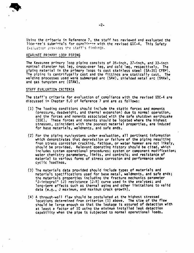
h-I-
Usina the criteria in Reference 7, the staff has reviewed and evaluated thelicereee's subm4ttals for ccnoli'-a with the revised GOC-4. This SafetyEvalI.ation provides the staff's findings.
KEWAUNEE PRIMARY LOOP PIPING
The Kewaunee primary loop piping consists of 35-inch, 37-inch, and 33-inchnominal diameter hot leg, cross-over lea, and cold lea, respectively. Thepiping material in the primary loops is cast stainless steel (SA-351 CF8M).The piping is centrifugally cast and the fittings are statically cast. Thewelding processes used were submerged arc (SAW), shielded metal arc (SMAW),and gas tungsten arc (GTAW).
STAFF EVALUATION CRITERIA
The staff's criteria for evaluation of compliance with the revised GDC-4 arediscussed in Chapter 5.0 of Reference 7 and are as follows:
(1) The loading conditions should include the static forces and moments(pressure, deadweight, and thermal expansion) due to normal operation,and the forces and moments associated with the safe shutdown earthquake(SSE)., These forces and moments should be located where the higheststresses, coincident with the poorest material properties, are inducedfor base materials, weldments, and safe ends.
(2) For the piping run/systems under evaluation, all pertinent informationwhich demonstrates that degradation or failure of the piping resultingfrom stress corrosion cracking, fatigue, or water hammer are not likely,should be provided. Relevant operating history should be cited, whichincludes system operational procedures; system or component modification;water chemistry parameters, limits, and controls; and resistance ofmaterial to various forms of stress corrosion and performance undercyclic loadinas.
(3) The materials data provided should include types of materials andmaterials specifications used for base metal, weldments, and safe ends;the materials properties including the fracture mechanics parameter"J-integral" (J) resistance (J-R) curve used in the analyses; andlong-term effects such as thermal aging and other limitations to validdata (e.g., J maximum, and maximum crack growth).
(4) A through-wall flaw should be postulated at the highest stressedlocations determined from criterion (1) above. The size of the flawshould be large enough so that the leakage is assured of detection withat least a factor of 10 using the minimum installed leak detectioncapability when the pipe is subjected to normal operational loads.
-3-
(5) It should be demonstrated that the postulated leakage flaw is stableunder normal plus SSE loads for long periods of time; that is, crackgrowth,.if any, is minimal during an earthquake. The margin, in terms ofapplied loads, should be at least 1.4 and should be determined by a flawstability analysis, i.e., that the leakage-size flaw will not experienceunstable crack growth even if larger loads (larger than design loads) areapplied. However, the final rule permits a reduction of the marain of1.4 to 1.0 if the individual normal and seismic (pressure, deadweicht,thermal expansion, SSE, and seismic anchor motion) loads are summedabsolutely. This analysis should demonstrate that crack growth is stableand the final flaw size is limited, such that a double-ended pipe breakwill not occur.
(6) The flaw size should be determined by comparing the leakage-size flaw tothe critical-size flaw. Under normal plus SSE loads, it should bedemonstrated that there Is a margin of at least 2 between theleakage-size flaw and the critical-size flaw to account for theuncertainties inherent in the analyses and leakage detection capability.A limit-load analysis may suffice for this purpose; however, anelastic-plastic fracture mechanics (tearing instability) analysis ispreferable.
STAFF EVALUATION
The staff has evaluated the information presented in References I and 2 forcompliance with the revised GDC-4. Furthermore, the staff performedindependent flaw stability computations using an elastic-plastic fracturemechanics procedure developed by the staff (Reference 8).
On the basis of its review, the staff finds the Kewaunee primary loop pipingin compliance with the revised GDC-4. The following paragraphs in thissection present the staff's evaluation.
(1) Normal operating loads, including pressure, deadweight, and thermalexpansion, were used to determine leak rate and leakage-size flaws. Theflaw stability.analyses performed to assess margins against pipe ruptureat postulated faulted load conditions were based on normal plus SSEloads. In the stebility analysis, the individual normal load componentswere summed algebraically and the seismic loads were then addedabsolutely. In the leak rate analysis, the individual normal loadcomponents were summed algebraically. Leak-before-break evaluations wereperformed for the limiting location in the piping.
(2) For Westinghouse facilities, there is no history of cracking failure inreactor coolant system (RCS) primary loop piping. The RCS primary loophas an operating history which demonstrates its inherent stability. Thisincludes a low susceptibility to cracking failure from the effects ofcorrosion (e.g., intergranular stress corrosion cracking), water hammer,or fatigue (low and high cycle). This operating history totals over 450

-4-
reactor-years, including 5 plants each having over 16 years of operationand 15 other plants each with over 11 years of operation.
(3) The material tensile and fracture toughness properties were provided inReferences I and 2. Because there are cast stainless steel piping (andfitting) and associated welds in the Kewaunee vrimary loop, the thermalaging toughness properties of cast stainless steel materials wereestimated according to procedures in References 3 and 4. The materialtensile properties were estimated using generic procedures. For flawstability evaluations, the lower-bound stress-strain properties wereused. For leakage rate evaluations, the averaqe stress-strain propertieswere used.
(4) Kewaunee has a RCS pressure boundary leak detection system which isconsistent with the guidelines of Regulatory Guide 1.45 such that aleakage of one gallon per minute (qpm) can be detected. The calculatedleak rate through the postulated flaw is large relative to the staff'srequired sensitivity of the plant's leak detection systems; the margin Isat least a factor of 10 on leakage and is consistent with the guidelinesof Reference 7.
(5) In the flaw stability analyses, the margin in terms of load for theleakage-size flaw under normal plus SSE loads exceeds 1.4 and isconsistent with the guidelines of Reference 7.
(6) The margin between the leakage-size flaw and the critical-size flaw wasalso evaluated in the flaw stability analyses. The margin In terms offlaw size exceeds 2 and is consistent with the guidelines of Reference 7.
STAFF CONCLUSIONS
The staff has reviewed the information submitted by the licensee and hasperformed independent flaw stability computations. On the basis of itsreview, the staff concludes that the Kewaunee primary loop piping complieswith the revised GDC-4 accordina to the criteria in NUREG-1061, Volume 3(Reference 7). Thus, the probability or likelihood of large pipe breaksoccurring in the primary coolant system loops of Kewaunee is sufficiently lowsuch that dynamic effects associated with postulated pipe breaks need not be adesign basis.
Principal Contributor: S. Lee, Er!TB
Date: February 16, 1988

-5-
REFERENCES
(1) Westinghouse Report WCAP-11411, Revision 1, "Technical Bases forEliminating Large Primary Loop Pipe Rupture as the Structural DesignBasis for Kewaunee," April 1987, Westinghouse Proprietary Class 2.
(2) Westinghouse Report WCAP-11619, "Additional Technical Bases forEliminating Large Primary Loop Pipe Rupture as the Structural DesignBasis for Kewaunee," October 1987, Westinghouse Proprietary Class 2.
(3) Westinghouse Report WCAP-10456, "The Effects of Thermal Aging on theStructural Integrity of Cast Stainless Steel Piping for WestinghouseNuclear Steam Supply Systems," November 1983, Westinghouse ProprietaryClass 2.
(4) Westinghouse Report WCAP-10931, Revision 1, "Toughness Criteria forThermally Aged Cast Stainless Steel," July 1986, Westinghouse ProprietaryClass 2.
(5) Letter from B. J. Youngblood of NRC to M. D. Spence of Texas UtilitiesGenerating Company dated August 28, 1984.
(6) Letter from D. C. Dilanni of NRC to 0. M. Musolf of Northern States PowerCompany dated December 22, 1986.
(7) NUREG-1061, Volume 3, "Report of the U. S. Nuclear Regulatory ComuissionPiping Review Committee, Evaluation of Potential for Pipe Breaks,"November 1984.
(8) NUREG/CR-4572, "NRC Leak-Before-Break (LBB.NRC) Analysis Method forCircumferentially Through-Wall Cracked Pipes Under Axial Plus BendingLoadt.," May 1986.