dolphin pci express mxs824 switchdolphinics.com/download/mx/open_doc/mxs824_users_guide.pdf ·...
TRANSCRIPT

Dolphin PCI Express MXS824 Switch
MXS824 24 ports PCI Express Gen3 switch users guide
Version 1.1
Date: 16th April 2020

MXS824 Users Guide – Dolphin Interconnect Solutions Page 1

MXS824 Users Guide – Dolphin Interconnect Solutions Page 2
Table of Contents
Table of Contents ............................................................................................................................................................... 2
Terms and Acronyms .......................................................................................................................................................... 4
Overview ........................................................................................................................................................................... 5
Software support ........................................................................................................................................................... 5
Revision history .................................................................................................................................................................. 6
Hardware revisions ........................................................................................................................................................ 6
Management Version ..................................................................................................................................................... 6
PCI Express Gen3 Switch - MXS824 ..................................................................................................................................... 7
MXS824 high level specification ..................................................................................................................................... 7
NTB Configuration examples .............................................................................................................................................. 8
6 node PCIe x16 Gen3 NTB Cluster ................................................................................................................................. 8
12 node PCIe x8 Gen3 NTB Cluster ................................................................................................................................. 8
24 node PCIe xx Gen3 NTB Cluster .................................................................................................................................. 8
10 node PCIe x16 Gen3 NTB Cluster ............................................................................................................................... 8
20 node PCIe x8 Gen3 NTB Cluster ................................................................................................................................. 9
Larger NTB Cluster configurations .................................................................................................................................. 9
Transparent PCIe IO expansion – Multiple expansion chassis connected to one server ...................................................... 10
Supported Transparent Configurations..................................................................................................................... 11
Cables .......................................................................................................................................................................... 12
Management processor ............................................................................................................................................... 12
Use cases summary and settings .................................................................................................................................. 12
LEDs ................................................................................................................................................................................. 13
MXS824 Switch Status LEDs .......................................................................................................................................... 13
Port and Link status LEDs ............................................................................................................................................. 13
Port status LEDs ....................................................................................................................................................... 13
Link status LEDs ....................................................................................................................................................... 14
USB Port .......................................................................................................................................................................... 14
SD Card Port ..................................................................................................................................................................... 14
Installation ....................................................................................................................................................................... 15
Safety instructions ....................................................................................................................................................... 15
Installing the Switch in a rack ....................................................................................................................................... 15
Switch desktop use ...................................................................................................................................................... 15
Ethernet ...................................................................................................................................................................... 15
Installing and removing PCIe cables .............................................................................................................................. 15

MXS824 Users Guide – Dolphin Interconnect Solutions Page 3
MXS824 operating modes ............................................................................................................................................ 16
Transparent mode port usage ...................................................................................................................................... 16
NTB mode port usage................................................................................................................................................... 16
Cascading switches ...................................................................................................................................................... 16
Partitioning – mixed transparent and NTB usage .......................................................................................................... 16
Configuring the MXS824 switch ........................................................................................................................................ 17
Status section .............................................................................................................................................................. 17
PCIe Configuration section ........................................................................................................................................... 17
Change configuration ............................................................................................................................................... 18
Upload configuration ............................................................................................................................................... 18
Delete configuration group ...................................................................................................................................... 19
Reset switch ............................................................................................................................................................ 19
Firmware section ......................................................................................................................................................... 19
Software installation, PXH830, PXH820............................................................................................................................. 20
Software installation, MXH830 ......................................................................................................................................... 20
Support ............................................................................................................................................................................ 20
Compliance ...................................................................................................................................................................... 21
EMC compliance .......................................................................................................................................................... 21
Safety compliance ........................................................................................................................................................ 21
RoHS compliance ......................................................................................................................................................... 21
Flammability standard.................................................................................................................................................. 21
WEEE Notice ................................................................................................................................................................ 21
Limited warranty .............................................................................................................................................................. 22
Warranty period .......................................................................................................................................................... 22
Coverage ..................................................................................................................................................................... 22
Service procedure ........................................................................................................................................................ 22
Limitations ................................................................................................................................................................... 22
DISCLAIMER
DOLPHIN INTERCONNECT SOLUTIONS RESERVES THE RIGHT TO MAKE CHANGES WITHOUT FURTHER NOTICE TO ANY OF
ITS PRODUCTS TO IMPROVE RELIABILITY, FUNCTION, OR DESIGN. DOLPHIN INTERCONNECT SOLUTIONS DOES NOT
ASSUME ANY LIABILITY ARISING OUT OF THE APPLICATION OR USE OF ANY PRODUCT.
LIFE SUPPORT POLICY
DOLPHIN INTERCONNECT SOLUTIONS’ PRODUCTS ARE NOT AUTHORIZED FOR USE AS CRITICAL COMPONENTS IN LIFE
SUPPORT DEVICES.

MXS824 Users Guide – Dolphin Interconnect Solutions Page 4
ENVIRONMENTAL POLICY
Dolphin is minimizing the amount of printed documentation and software CDs in its shipments, please download
additional documentation and software from www.dolphinics.com/support/.
Terms and Acronyms Important terms and acronyms used in this manual
AOC Active Optical Cable. PCIe fiber cable assembly.
CMI Cable Management Interface. The 2-wire management interface for communication between
subsystems connected by a PCIe 3.0 cable. Details can be found in the PCI-SIG External Cabling
Specification 3.0. The CMI functionality is optional with the MXS824 switch.
CMI Controller Microcontroller on the MXS824 used to manage and implement the CMI communications. CMI
communication require PCIe 3.0 cables.
eXpressWare Dolphins software stack for PCIe clustering and IO. www.dolphinics.com for more information.
Lane One PCI Express Lane contains a differential pair for transmission and a differential pair for reception.
Link A collection of PCI Express Lanes providing the communication path between an Upstream and
Downstream Port. The MXS824 support links of x4, x8 or x16 width by utilizing lanes from 1,2 or 4 ports.
MiniSAS-HD Standard MiniSAS-HD cable with SFF-8644 connectors.
PCIe 3.0 cable PCIe 3.0 cable with SFF-8644 connectors. Complaint to the new PCI-SIG External Cabling Specification
3.0. Support for CMI.
Chassis Ports The MXS824 has 24 x4 Gen3 SFF-8644 ports, named P1, P2, P3 …, P24. The port numbers are printed on
the front panel below the connectors.
Fabric Port MXS824 ports configured to be used as a link to another MXS824 switch. For standard dual switch
configurations, port P1, P2, P3 and P4 are normally the fabric ports.

MXS824 Users Guide – Dolphin Interconnect Solutions Page 5
Overview This document describes the Dolphin MXS824 PCI Express Gen3 switch used in combination with other Dolphin PCI
Express products. Dolphin is currently providing the following compliant PCI Express products:
• PXH820 PCI Express Gen3 x8 NTB XMC SFF-8644 cable adapter card
• PXH822 PCI Express Gen3 x8 Transparent Host and Target XMC SFF-8644 cable adapter card
• PXH830 PCI Express Gen3 x16 NTB SFF-8644 cable adapter card
• PXH832 PCI Express Gen3 x16 Transparent Host and Target SFF-8644 cable adapter card
• MXH830 PCI Express Gen3 x16 NTB SFF-8644 cable adapter card
• MXH832 PCI Express Gen3 x16 Transparent Host and Target SFF-8644 cable adapter card
The MXS824 switch can be used to create a PCIe fabric or PCIe expansion using the above products or to any product
compliant to the PCI-SIG External Cabling Specification 3.0.
Software support
All Dolphin PXH and MXH PCI Express NTB adapter cards support the complete eXpressWare suite of Dolphin PCI Express
Software including Dolphin SuperSockets™, optimized TCP/IP drivers, SmartIO and SISCI Embedded software.
Dolphin SuperSockets is a Berkeley Sockets compliant library that provides a socket latency below 1 microsecond, and
close to the wire speed streaming bandwidth for networked applications. SuperSockets™ is currently available on Linux
and Windows. It is a 100% transparent plug-and-play solution for commercial and embedded applications.
Dolphin’s optimized TCP/IP driver enables PCI Express to be used as a traditional 10G Ethernet / 40G Ethernet
replacement such as for NFS sharing and legacy networking that does not need the low latency provided by SuperSockets.
The TCP/IP driver supports gateway functionality.
The SISCI software provides a well-defined, easy to use shared memory / reflective memory programming API for PCI
Express over cable.
The SmartIO software enables dynamic sharing of and access to PCIe devices through a PCIe fabric.
More information about eXpressWare at http://www.dolphinics.com/products/dolphin_pci_express_software.html.

MXS824 Users Guide – Dolphin Interconnect Solutions Page 6
Revision history
Hardware revisions
The following table gives a general overview of the hardware capabilities.
Switch revision Capabilities
MXS824-BC • Initial product version
MXS824-CC • Minor cosmetic and manufacturing improvements
MXS824-CD • Minor manufacturing changes
Management Version
The MXS824 is managed by built in processor and contains nonvolatile storage for processor code, Web GUI and PCIe
configuration data. This software / firmware is released as a bundle, please consult the MXH824 Management Release
note for details.
MXS824 Users Guide – Dolphin Interconnect Solutions Page 7
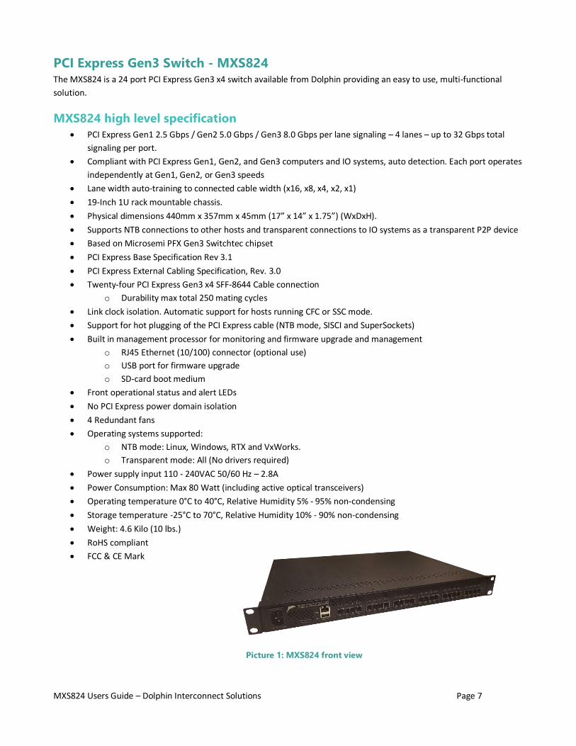
PCI Express Gen3 Switch - MXS824 The MXS824 is a 24 port PCI Express Gen3 x4 switch available from Dolphin providing an easy to use, multi-functional
solution.
MXS824 high level specification
• PCI Express Gen1 2.5 Gbps / Gen2 5.0 Gbps / Gen3 8.0 Gbps per lane signaling – 4 lanes – up to 32 Gbps total
signaling per port.
• Compliant with PCI Express Gen1, Gen2, and Gen3 computers and IO systems, auto detection. Each port operates
independently at Gen1, Gen2, or Gen3 speeds
• Lane width auto-training to connected cable width (x16, x8, x4, x2, x1)
• 19-Inch 1U rack mountable chassis.
• Physical dimensions 440mm x 357mm x 45mm (17” x 14” x 1.75”) (WxDxH).
• Supports NTB connections to other hosts and transparent connections to IO systems as a transparent P2P device
• Based on Microsemi PFX Gen3 Switchtec chipset
• PCI Express Base Specification Rev 3.1
• PCI Express External Cabling Specification, Rev. 3.0
• Twenty-four PCI Express Gen3 x4 SFF-8644 Cable connection
o Durability max total 250 mating cycles
• Link clock isolation. Automatic support for hosts running CFC or SSC mode.
• Support for hot plugging of the PCI Express cable (NTB mode, SISCI and SuperSockets)
• Built in management processor for monitoring and firmware upgrade and management
o RJ45 Ethernet (10/100) connector (optional use)
o USB port for firmware upgrade
o SD-card boot medium
• Front operational status and alert LEDs
• No PCI Express power domain isolation
• 4 Redundant fans
• Operating systems supported:
o NTB mode: Linux, Windows, RTX and VxWorks.
o Transparent mode: All (No drivers required)
• Power supply input 110 - 240VAC 50/60 Hz – 2.8A
• Power Consumption: Max 80 Watt (including active optical transceivers)
• Operating temperature 0°C to 40°C, Relative Humidity 5% - 95% non-condensing
• Storage temperature -25°C to 70°C, Relative Humidity 10% - 90% non-condensing
• Weight: 4.6 Kilo (10 lbs.)
• RoHS compliant
• FCC & CE Mark
Picture 1: MXS824 front view

MXS824 Users Guide – Dolphin Interconnect Solutions Page 8
NTB Configuration examples The MXS824 switch can be used as a standalone PCI Express switch, or several switches can be cascaded to build larger
PCIe expansion systems or PCIe fabrics. It can be combined with compliant PCIe cards available from Dolphin or compliant
customer designs. Some examples can be found below. Please consult the chapter Configuring the MXS824 switch on page
17 for more details. Please note that the Dolphin eXpressWare currently doesn’t support mixing MXHxxx and PXHxxx cards
in a single cluster.
6 node PCIe x16 Gen3 NTB Cluster
Each node has a Dolphin Express MXH830, PXH830 or PXH820
adapter. Up to six systems can be connected to the Dolphin
MXS824 switch using the default firmware configuration. All nodes
connect directly to the switch using up to four x4 cables (x16 link).
This is the switch default configuration.
12 node PCIe x8 Gen3 NTB Cluster
Each node has a Dolphin Express MXH830, PXH830 or PXH820
adapter. Up to twelve systems can be connected to the Dolphin
MXS824 switch. All nodes connect directly to the switch using up to
two x4 cables (x8 link).
24 node PCIe xx Gen3 NTB Cluster
Each node has a Dolphin Express MXH830, PXH830 or PXH820 adapter. Up to twenty-four systems can be connected to
the Dolphin MXS824 switch. All nodes connect directly to the switch using a single x4 cables (x4 link).
10 node PCIe x16 Gen3 NTB Cluster
Each node has a Dolphin Express MXH830, PXH830 or PXH820 adapter. Up to
10 systems can be connected to the Dolphin MXS824 switch. All nodes
connect directly to the switch using up to two x4 cables (x8 link).
The two switches are interconnected using four x4 cables (x16 link).
The cables between the two switches should be connected to port P1, P2, P3
and P4 on both switches.
Figure 1: 6 Node PCIe x16 Cluster
Figure 2: 12 Node PCIe x8 Cluster
Figure 3: 10 Node PCIe x16 Cluster

MXS824 Users Guide – Dolphin Interconnect Solutions Page 9
20 node PCIe x8 Gen3 NTB Cluster
Each node has a Dolphin Express MXH830, PXH830 or PXH820 adapter. Up to
twenty systems can be connected to the Dolphin MXS824 switch. All nodes
connect directly to a switch using up to two x4 cables.
The two switches are interconnected using four x4 cables (x16 link).
The cables between the two switches should be connected to port P1, P2, P3
and P4 on both switches.
Larger NTB Cluster configurations
Currently, the MXS824 can be used to create clusters up to 60 nodes. Some limitations apply, please contact Dolphin for
more information on supported topologies and functionality.
Figure 4: 20 Node PCIe x8 Cluster

MXS824 Users Guide – Dolphin Interconnect Solutions Page 10
Transparent PCIe IO expansion – Multiple expansion chassis connected to
one server The MXS824 can be used for regular Transparent PCIe IO expansion. An adapter card in host transparent mode is
connected to the switch upstream port (port P1, P2, P3 and P4 for a full x16). Transparent target adapters are connected
to the other downstream ports. Figure 5: Transparent PCIe IO Expansion below shows 5 expansion chassis connected to a
single host. The IO devices can be connected using x16, x8 or x4 links depending on the required scale out and
performance requirements.
Please note that the MXS824 Switch shipping default is NTB x16. To enable the switch to be used for standard transparent
IO Expansion, please log into the Web GUI and
select the desired Transparent configuration.
Please consult the chapter “Configuring the
MXS824 switch” on page 17 for more details.
The supported configurations are found in Table
1 : Supported Transparent Configurations on
page 11.
No special device driver is required for the
transparent adapter card or the MXS824 switch.
Any device in the PCI Express IO system will
operate using its standard device driver.
NOTE: Please note that large scale PCIe IO expansion may be limited by your BIOS. Please consult your system vendor
before buying the system.
Figure 5: Transparent PCIe IO Expansion

MXS824 Users Guide – Dolphin Interconnect Solutions Page 11
Supported Transparent Configurations
Management version 1.4.2 supports the configurations found in Table 1 : Supported Transparent Configurations below.
Please note that the Host uplink always is x16.
Table 1 : Supported Transparent Configurations
Configuration Name PCIe Configurations Chassis ports
Transparent x16 One x16 upstream port P1-P4
Five x16 downstream
ports
P5-P8 / P9-P12 / P13-P16 / P17-P20 / P21-24
Transparent x8 One x16 upstream port P1-P4
Ten x8 downstream
ports
P5-P6 / P7-P8 / P9-P10 / P11-P12 / P13-P14 / P15-P16 / P17-
P18 / P19-P20 / P21-P22 / P23-24
Transparent x4 One x16 upstream port P1-P4
Twenty x4 downstream
ports
P5 / P6 / P7 / P8 / P9 / P10 / P11 / P12 / P13 / P14 / P15 / P16 /
P17 / P18 / P19 / P20 / P21 / P22 / P23 / P24
The switch supports automatic PCIe down training to a lower speed and narrower link on each individual link.
If you would like to mix PCIe x4, x8 and x16 links, you need to configure the switch for the widest use case and connect a
reduced number of cables for devices that only need x8 or x4 connectivity.
Support for custom configuration files are available to OEMs. Please contact Dolphin for more information.

MXS824 Users Guide – Dolphin Interconnect Solutions Page 12
Cables
The MXS824 switch supports x4 copper or fiber cables. The maximum cable distance will depend on the actual cable
quality, the device at the other end of the cable, and the cable link speed (Gen1, Gen2 or Gen3). Cables compliant to the
PCI-SIG External Cabling Specification 3.0 (PCIe 3.0 cables) are recommended for transparent use. NTB use cases can use
PCIe 3.0 cables or approved MiniSAS-HD cables available from Dolphin.
Speed and medium, card Max cable length
Gen3, PXH830, PXH832 Copper 5 meters tested, longer TBD
Fiber 100 meters
Gen3, MXH830, MXH832 TBD
Between MXS824 switches (Gen3) TBD
Management processor
The actual configuration of the switch is controlled by the onboard firmware loaded from onboard FLASH memory and will
be enabled immediately after power is applied to the switch. The built-in management processor has no active role in
normal operations except for firmware updates, switch configuration and monitoring.
Use cases summary and settings
The table below gives an overview of the default configuration settings and limitations.
Use Case Description Cable Hot Plug Power Sequence
Requirements
Software/
Driver
Transparent Transparent – Dolphin
adapter card connects
to downstream PCI
Express devices or
PCI Express
expansion systems
through the MXS824
switch
Not supported by
legacy device
drivers
IO system and
MXS824 must
power on before
PC
No driver required
for host card or
MXS824 switch.
Legacy drivers for IO
Devices
NTB NTB configuration. All
connected hosts have
Dolphin adapter card
Fully supported No limitations Dolphin SISCI,
SuperSockets,
TCP/IP, SmartIO
Mixed Switch is portioned.
Behavior depends on
configuration data.
May combine use case
A and B
Table 3: Switch use cases
MXS824 Users Guide – Dolphin Interconnect Solutions Page 13
LEDs The switch has several LEDs on the front side to signal various operating modes and status.
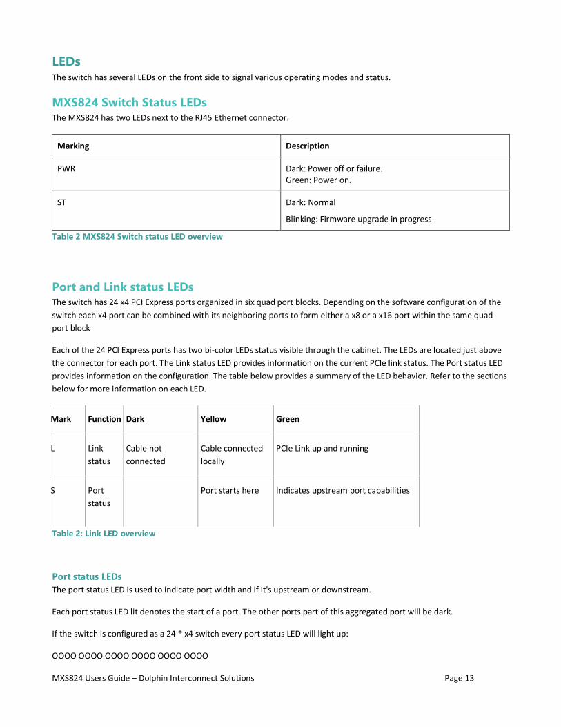
MXS824 Switch Status LEDs
The MXS824 has two LEDs next to the RJ45 Ethernet connector.
Marking Description
PWR Dark: Power off or failure. Green: Power on.
ST Dark: Normal
Blinking: Firmware upgrade in progress
Table 2 MXS824 Switch status LED overview
Port and Link status LEDs
The switch has 24 x4 PCI Express ports organized in six quad port blocks. Depending on the software configuration of the
switch each x4 port can be combined with its neighboring ports to form either a x8 or a x16 port within the same quad
port block
Each of the 24 PCI Express ports has two bi-color LEDs status visible through the cabinet. The LEDs are located just above
the connector for each port. The Link status LED provides information on the current PCIe link status. The Port status LED
provides information on the configuration. The table below provides a summary of the LED behavior. Refer to the sections
below for more information on each LED.
Mark Function Dark Yellow Green
L Link
status
Cable not
connected
Cable connected
locally
PCIe Link up and running
S Port
status
Port starts here Indicates upstream port capabilities
Table 2: Link LED overview
Port status LEDs
The port status LED is used to indicate port width and if it's upstream or downstream.
Each port status LED lit denotes the start of a port. The other ports part of this aggregated port will be dark.
If the switch is configured as a 24 * x4 switch every port status LED will light up:
OOOO OOOO OOOO OOOO OOOO OOOO

MXS824 Users Guide – Dolphin Interconnect Solutions Page 14
If the switch is configured as 12 * x8 every second port status led will be on:
O-O- O-O- O-O- O-O- O-O- O-O-
And if it's configured as 6 * x16 every fourth status led will be on:
O--- O--- O--- O--- O--- O---
It is also possible to have more complex configurations. Let’s say 2 * x16 + 8 * x8:
O--- O--- O-O- O-O- O-O- O-O-
In the examples above the port status LED color is orange which denotes that it is a NTB port or a downstream transparent
port. If the LED is green it indicates that the port is a transparent upstream port.
When the cables are connected, and you have a valid link the port status LED will in both cases turn yellow.
Link status LEDs
Each port has also a separate link status LED. It reflects the cable and link status:
• it will remain dark if no valid cable has been detected in the port
• it will light up orange if the cable is inserted and ok, but there is no valid link established.
• it will be green if the cable is ok and the link is valid.
USB Port The switch has a USB port for firmware updates. Do not try to utilize the USB port unless instructed by Dolphin support.
SD Card Port The switch is delivered with a SD Card. Do not remove the SD-Card unless instructed by Dolphin support. A missing SD-
Card will prevent you from utilizing the management processor services but will not affect the basic PCIe switching
capabilities.

MXS824 Users Guide – Dolphin Interconnect Solutions Page 15
Installation
Safety instructions
Always use caution when working with computers, IO Devices and electrical components.
High voltages are present inside the MXS824 cabinet that may cause severe
harm to your body if opened. Never open the switch cabinet, no user
serviceable parts are available inside the cabinet. Opening the cabinet will
void your warranty.
Static electricity from your clothes or work environment can damage your PCI Express adapter card or your PC.
Always wear a grounded antistatic wrist strap while opening the PC and when Dolphin PCI Express adapter is
removed from the anti-static bag. The MXS824 switch requires no special anti-static protection and should be
handled in line with other electronic equipment.
Special National notes:
Norway: “Apparatet må tilkoples jordet stikkontakt”
Sweden: “Apparaten skall anslutas till jordat uttag”
Finland: "Laite on liitettävä suojamaadoituskoskettimilla varustettuun pistorasiaan"
Installing the Switch in a rack
The MXS824 shipping box includes rack mount ears that can be used to fix the MXS824 into a 19-inch standard rack. The
rack mount ears can be mounted on the front or rear of the switch depending on user requirements.
Switch desktop use
Rubber feet are included and should be applied beneath the switch to avoid scratches in desktop use.
Ethernet
The MXS824 switch supports Ethernet management and monitoring. Please connect an Ethernet cable from the switch
RJ45 plug to a 10/100 Ethernet network. The switch supports both static and DHCP configurations. The switch defaults to
DHCP, the MAC address is available next to the Ethernet port.
Installing and removing PCIe cables
The MXS824 supports approved PCI Express x4 MiniSAS-HD or PCIe 3.0 cables. Installing and removing cables should be
done with both upstream and downstream device powered off. The Dolphin SuperSockets, TCP/IP drivers and SISCI fully
supports hot plugging (Note: installation and removal of cables while the system is running). Standard PCI Express cables
are not designed for a high number of installation and removals; the gold applied to the connector head may wear out and
cause loss of communication. Please contact your Dolphin representative if you intend to continuously connect and
disconnect the PCI Express cables.
MXS824 Users Guide – Dolphin Interconnect Solutions Page 16
1, 2, or 4 cables can be used to create a x4, x8 or x16 connection to other compliant devices. If more than one cable is
used to create a wide link, the first cable must be connected to a width aligned port number.
Connecting a cable
Please carefully install the PCI Express cable connector into the connector housing on the adapter card or MXS824 Switch
box. Computer cables should always use strain relief to protect the connected equipment from excessive force via the
cable. This is especially important for cables between racks.
Disconnecting a cable
Carefully pull the thumb tab in the direction of the cable to release the cable from the connector house and eject the
cable.
MXS824 operating modes
The Dolphin PCI Express MXS824 switch has two main operational modes: Transparent and Non-Transparent Bridge (NTB)
mode. The switch operating mode is controlled by the MXS824 switch management software. The shipping default
configuration is support for 6 ports x16 NTB mode. Please consult the chapter Configuring the MXS824 switch on page 17
for more details.
Transparent mode port usage
In standard transparent mode, Ports P1, P2, P3 and P4 are always configured as a x16 upstream port. Port P1 should
always be used. If you want to create a x8 link, you should use port 1 & 2. To create a x16 link, you shold use port P1, P2,
P3 and P4. All other ports are configured as downstream ports. Separate configuration settings exists for creating 10 x8 or
20 x4 transparent downstream ports.
NTB mode port usage
Any port can be used in any order for all NTB configurations. If more than one cable is used to create a wide link, the first
cable must be connected to a width aligned port number. Separate configuration settings exists and must be enabled for
twelve x8 mode or 24 x4 mode. The six x16 mode is the shipping default.
Dolphins eXpressWare software and adapter cards will auto detect ports and automatically connect at the highest speed
possible. Customers writing their own low-level drivers need to contact Dolphin for further technical information.
Cascading switches
The MXS824 supports cascading multiple switches into larger PCI Express networks. The current firmware supports
connecting two switches.
Partitioning – mixed transparent and NTB usage
The switch supports partitioning into separate switch domains, enabling a single switch to be used as two or more
independent logical switch domains. The switch hardware prevents unintended data communication and reset /
configuration cycles to propagate between separate domains. This configuration requires custom firmware, please contact
Dolphin for more information.

MXS824 Users Guide – Dolphin Interconnect Solutions Page 17
Configuring the MXS824 switch The MXS824 shipping default is NTB six nodes x16. You need to follow the description below to enable other NTB
configurations or PCIe transparent IO configurations.
The MXS824 comes with a Web GUI for monitoring temperature, fan speed, port monitoring and switch configuration
management. This documentation covers the 1.1.0 version of the management firmware.
The GUI currently consist of three sections, all easily accessible by the top menu or by scrolling down the page.
Status section
The status section provide real-time data from the firmware, fans and temperature sensors. Please note that there are 4
fans connected to the switch. The four should be close to 8000 RPM when the switch operates at normal room
temperatures.
New switches are delivered with the standard NTB 6 port x16 link width configuration active, unless you have a specialized
order with a different configuration pre-programmed. The switch’ active configuration is shown under «Firmware» below
the «Status» section of the Web GUI as highlighted in the picture above.
PCIe Configuration section
The PCIe Configuration section enables the user to change the active configuration, upload new Dolphin provided
configurations, erase uploaded configurations and to perform a reset of the PFX switch.
Unless otherwise specified, the switch is delivered with a standard set of configurations for NTB and Transparent
operation. The available selections will appear in the menu.

MXS824 Users Guide – Dolphin Interconnect Solutions Page 18
Change configuration
This section allow you to change the active configuration of the PCIe switch. The section works like a filter for the available
configurations.
Start by selecting a «Group» (Standard, Custom, …), then «Type» (NTB, Transparent, Uploaded, …), and eventually the
configuration. You can then press [Change configuration] where you will be met with a warning message; « Changing the
config will reset the PCIe switch, halting all traffic, and should not be done in a production environment. You must NOT
turn off the switch or leave this page during the burn operation. Are you sure you want to continue?». Pressing [OK]
initiates an erase, write and verification step, all with individual progress bars.
Upload configuration
Additional configurations and special customizations may be provided by Dolphin.

MXS824 Users Guide – Dolphin Interconnect Solutions Page 19
Press the [Browse] button to locate the binary on your disk and press the [Upload] button to perform the upload. You will
be provided with the new file name on successful upload, which will afterwards be present under the «Custom» group
and «Uploaded» type in the «Change» field set.
Uploading and applying configurations not provided or approved by Dolphin may break your hardware and will void your
warranty.
Delete configuration group
The «Delete» field set enable the user to clean up the list of uploaded configurations by deleting the entire «Custom»
group if present. This will only erase the available configurations on the switch and will not affect the PCIe switch and its
active configuration.
Reset switch
Press the «Reset Switch» to initiate a hardware reset of the PCIe switch chip. You will be prompted for confirmation.
Firmware section
The Firmware section is currently reserved for firmware upgrades containing only an «Upgrade» fieldset. Dolphin’s
MXS824 switch is pre-configured during manufacturing and a firmware upgrade is normally not required for default
operations. Please contact Dolphin support before trying to upgrade any firmware. Warranty is void if unauthorized
firmware upgrades are attempted.

MXS824 Users Guide – Dolphin Interconnect Solutions Page 20
Software installation, PXH830, PXH820 No special software is required for the switch, but Dolphin Express PXH adapters need to install eXpressWare 5.7.0 or
newer software releases to enable seamless integration with the MXS824 switch. More information on installing Dolphins
SuperSockets, SISCI or TCP/IP driver software can be found at http://www.dolphinics.com/px.html
Software installation, MXH830 No special software is required for the switch, but Dolphin Express MXH adapters need to install eXpressWare 5.8.0 or
newer software releases to enable seamless integration with the MXS824 switch. More information on installing Dolphins
SuperSockets, SISCI or TCP/IP driver software can be found at http://www.dolphinics.com/mx.html
Support More information about the product, support and software download can be found at http://www.dolphinics.com/.
Please email [email protected] if you have any questions.

MXS824 Users Guide – Dolphin Interconnect Solutions Page 21
Compliance
EMC compliance
The Dolphin PCI Express MXS824 switch has be tested to comply with the following relevant test standards for PCI Express
equipment, Telecommunication and Industry equipment:
• EN 55032:2012
• EN 55024:2010
• EN 61000-3-2:2014
• EN 61000-3-3:2013
This does not ensure that it will comply with these standards in any random configuration or setup. It is the responsibility
of the integrator to ensure that their products are compliant with all regulations where their product will be used.
Safety compliance
The MXS824 PCI Express switch is tested and found to comply with the following safety standards:
• EN 62368-1:2014 + A11:2017
A CB test certificate is available upon request.
RoHS compliance
The Dolphin MXS824 is RoHS compliant. A compliance certificate issued by the Manufacturer is
available upon request.
Flammability standard
The Dolphin MXS824 PWB is UL94V-0 compliant. The board has the 94V-0 mark in its silk screen.
WEEE Notice
This MXS824 is labelled in accordance with European Directive 2002/96/EC concerning waste
electrical and electronic equipment (WEEE). The Directive determines the framework for the return
and recycling of used appliances as applicable throughout the European Union. This label is applied to
various products to indicate that the product is not to be thrown away but returned to your local approved WEEE waste
collector.

MXS824 Users Guide – Dolphin Interconnect Solutions Page 22
Limited warranty Dolphin Interconnect Solutions warrants this Product to be free from manufacturing defects under the following terms:
Warranty period
Dolphin warrants the Product for one (1) year from the date of purchase. Extended warranty may be purchased with the
equipment.
Coverage
To the extent permitted by applicable law, this warranty does not apply to:
• Damages caused by operator error or non-compliance with usage and programming instructions available for the
product.
• Use or attempt to use or program firmware not approved by Dolphin.
• Damage which results from accident, abuse, misuse, neglected improper handling or improper installation;
moisture, corrosive environments, high voltage surges, shipping or abnormal working conditions.
• Damages caused by acts of nature, e.g. floods, storms, fire, or earthquakes.
• Damage caused by any power source out of range.
• Normal wear and tear.
• Attempts to open, repair, modify, or upgrade the product by personnel or agents not authorized by Dolphin.
• Products for which the products serial number has been tampered with or removed.
• Damage to the product caused by products not supplied by Dolphin.
Service procedure
In the event that the product proves defective during the Warranty Period, you should contact the seller that supplied you
with the product, or if you purchased it directly from Dolphin, email [email protected] to obtain a valid
RMA number and instructions. Products returned to Dolphin without a proper RMA number will not be serviced under this
warranty.
Limitations
TO THE FULLEST EXTENT PERMITTED BY LAW, DOLPHIN WILL NOT BE LIABLE FOR ANY INDIRECT, INCIDENTAL, SPECIAL OR CONSEQUENTIAL DAMAGES (INCLUDING LOST PROFITS, LOST DATA, OR LOSS OF USE) ARISING OUT OF ANY USE DOLPHINS PRODUCTS, SOFTWARE OR SERVICE PROVIDED. DOLPHINS MAXIMUM LIABILITY WILL NOT EXCEED THE TOTAL AMOUNT PAID FOR THE PRODUCT BY PURCHASER.