do~/faid-8/n 0 system approach and departure sequencing
TRANSCRIPT

DO~/FAID-8/N N tional AirspaceSystem
0 Approach and DepartureofTwportmeint Sequencing Operational
AduIrmnIAvition ConceptAdmnisratonNAS-SR-1322
N
CD __= ___A
89 11 01 018
DOT/FAAIDS-89/25 National Ai rs pace SystemApproach and Departure
Advanced System Design Service Sequencing OperationalWashington, D.C. 20591 Concept
(NAS-SR-1 322)
Advanced System Design ServiceFederal Aviation AdministrationWashington, D.C. 20591
Acces -sion Fo~r -
NTIS GRA&IDTIC TAB
June 1989 Unanfnounced L
Final Report - / )Dist P i
This document is available to the publicthrough the National Technical InformationService, Spningfield, Virginia 22161.
QUS Departm-entof TronsporlotionFedraul AviationAdminIstration

Technical Report Documentation Page
1. Report No. 2. Government Accession No. 3. Recipient's Catalog No.
NAS-SR- 1322
4. Title and Subtitle 5. Report Dote -
National Airspace System March 1989
Approach and Departure Sequencing 6. Performing Organzaton Code
Operational ConceptOperational Concept
8. Performing Organization Report No.7. Authorls)
Joseph P. ladeluca
9. Performing Organization Name and Address 10. Work Unit No. (TRAIS)
MITRE Corp.7525 Colshire Drive 11. Contact or Grant No.
McLean, VA 22102 DTFAOI-89-C-O000113. Type of Report and Period Covered
12. Sponsoring Agency Name and Address
Federal Aviation Administration
800 Independence Avenue SW 14. Sponsoring Agency CodeWashington, DC 20591
15. Supp!arnenta., No*es
16. Abstruct
This concept of operations is one of many high level documents that will,in total, describe the operations of the National Airspace System (NAS)when the NAS Plan has been implemented, i.e., the "end state." Thesedocuments as a set will assist in linking the requirements specified in NAS
System Requirements Specification (NASSRS) with the 1NAS design. One of thefunctions of the NAS is to support approach and departure sequencing atspecific airports. The objective of this document is to describe therelationship among subsystems,* facilities, information, and operators/usersinvolved in the approach and departure sequencing function. This document
is intended as a tool for system designers, analysts, and test planners.
The document contains several types of block diagramb illustrating ,ytem
connectivity, and operational flow. These diagrams in conjunction with thetext are intended to provide perspective and insight into the NAS "Approach
and Departure Sequencing" function...
17. Key Words 18. Distribution Statement
Approach sequencing; departulre
sequencing; tower; Area Control
Facility (ACF) -
19. Security Clossif. (of this report) 20. Security Classif. (of this page) 21. No. of Pages 22. Price
Unclassified Unclassified 45
Form DOT F 1700.7 (8-72) Reproduction of c,--'!ted page outhorized

TABLE OF CONTENTS
Paqe
LIST OF FIGURES vii
LIST OF TABLES vii
1.0 INTRODUCTION 1-1
1.1 Background 1-1
1.2 Objective 1-1
1.3 Scope 1-1
1.4 Methodology 1-2
1.5 Document Organization 1-4
2.0 OPERATIONS 2-1
2.1 Support 2-1
2.1.1 NAS Facilities/Systems/Positions 2-1
2.1.2 User Systems 2-6
2.2 Information 2-6
2.2.1 Information Processed Through the NAS 2-7
2.2.2 Information Obtained from the Pilot 2-9
2.3 Functions 2-10
2.3.1 Functions of Position 6:
Approach/Departure Controllers 2-10
2.3.2 Functions of Position 9: Local
Controller 2-13
2.3.3 Functions of Position 10: Ground
Controller 2-16
2.3.4 Functions of Position 11: Clearance
Delivery Controller 2-19
2.4 Correlation With Operational Requirement3 2-21
2.5 Operational Sequences 2-21
2.5.1 Arrival Flow Sequencing UsingApproach Control 2-212.5.2 Arrival Flow Sequencing UsingLocal Control 2-272.5.3 Departure Flow Sequencing 2-27
2.6 Operational Scenario 2-30
GLOSSARY GL-l
REFERENCES RE-1

LIST OF FIGURES
Figure Number Page
2-1 Overview of hAS/User Systems for Approach/DepartureSequencing 2-2
2-2 Approach and Departure Sequencing OperationalBlock Diagram 2-3
2-3 Approach/Departure Controller, Position 6:Operational Flow Diagram 2-11
2-4 Local Controller, Position 9: OperationalFlow Diagram 2-14
2-5 Ground Controller, Position 10: OpertionalFlow Diagram 2-17
2-6 Clearance/Delivery Controller, Position 11:Operational Flow Diagram 2-20
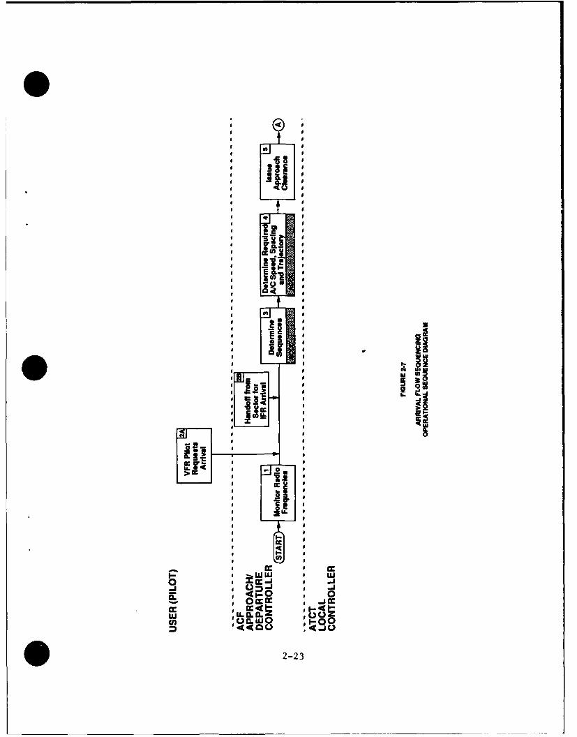
2-7 Arrival Flow Sequencing Operational* Sequence Diagram 2-23
2-8 Departure Flow Sequencing OperationalSequence Diagram 2-28
2-9 Approach Scenario: Approach Sequencing Between VFRand IFR Aircraft in Terminal Airspace 2-31
LIST OF TABLES
Table Number Page
2-1 Approach/Departure Sequencing OperationalRequirements Correlation 2-22
* vii

01.0 INTRODUCTION
1.1 Background
The mission of the Federal Aviation Administration (FAA) is toprovide for the safe and efficient use of the nation's airways. TheNational Airspace System (NAS) System Requirements Specification (NASSRS),NAS-SR-1000, is a compilation of requirements which describe theoperational capabilities of the NAS upon completion of the NAS Plan (end-state system). To provide efficient use of airspace, specialists mustprovide users with instructions which result in the establishment oflanding and departure sequences at specific aerodromes. Sequencingrequires the NAS to provide specialists accurate information on aircraftlocations.
This operational concept document has been developed using anestablished standard format and is consistent in structure with a series ofoperational concepts written about various sections of the NASSRS.
1.2 Objective
The objective of this operational concept is to describe thefunctions involved in approech and departure sequencing in the NAS "end-state" system. More specifically, this paper intends to:
* Provide a common operational perspective across subsystems,operators, and users.
" Show the interrelationships between subsystems, facilities,information, and operators/users.
1.3 Scope
This document covers the Approach and Departure Sequencing asdelineated in Section 3.2.2 of the NASSRS. The operations described arelimited to those associated solely with approach and departure sequencingservices. The paragraphs in NASSRS Section 3.2.2 and their contents are asfollows:
3.2.2.A Aircraft identification, location, altitude, course, speed,and characteristics
3.2.2.B Voice and data communications within assigned airspace3.2.2.C Issuing sequencing and spacing advisories3.2.2.D Receiving and processing departure requests
0 1-1

3.2.2.E Comparing actual flight paths for deviations3.2.2.F Providing recommendations for current runway selection3.2.2.G Providing recommendations for future runway selection
This document considers approach sequencing from the point where theapproach controller for the sect-or monitors the aircraft to the time theaircraft lands on the runway. This document considers departure sequencingfrom the point where clearance to depart is requested from the clearancedelivery controller to the time that the aircraft is handed off to thesector en route controller. Thus, although the En Route Metering is notcovered, programs that affect arrival and departure times are referred toas necessary.
1.4 Methodology
The methodology used to develop the operational concept providedinformation in a number of different ways. The material is presented usingfour different kinds of diagrams with associated descriptions.
1. OPERATIONAL BLOCK DIAGRAM/DESCRIPTION. The operational blockdiagram illustrates the connectivity between major elements of theNAS, i.e., processors, specialists/controllers, and the user forthose elements that support the service. The operational blockdiagram in this Operational Concept is extracted from the overallNAS Operational Block Diagram. Principal features of theoperational block diagram/description include the following:
a. Each specialist/controller is indicated by a number. Thisnumber remains the same in every operational concept.
b. Dotted lines segregate facilities.
c. Solid lines show digital data flow. Voice data flow is notshown.
d. The blocks within each facility are the major processors.
2. OPERATIONAL FLOW DIAGRAMS/DESCRIPTIONS. The operational flowdiagram and associated description for each specialist/controllerprovides more detail about the inputs, processors, outputs, andinterfaces for each operator. Operational flow diagrams are used
1-2
to describe functions of the products and services of individualspecialists or controllers. The diagrams show major actions only.Ancillary actions such as specific requests for information onsystem conditions are not shown. Principal features of anoperational flow diagram include the following:
a. Dotted lines segregate facilities.
b. White boxes indicate specialist, controller, or userfunctions. Shaded boxes indicate machines.
c. The functions listed by lower case alphabetic characters inthe white and shaded boxes are explained in the text.
3. OPERATIONAL SEQUENCE DIAGRAMS/DESCRIPTIONS. The operationalsequence diagram and associated descriptions shows a typicalsequence of steps taken by operators or users in providing theservice. Principal features of an operational sequence diagraminclude the following:
a. Users and specialists or controllers involved with providingor using the service are listed along the vertical axis. Whenrequired for clarity, other FAA facilities may also be listedon the vertical axis.
b. The horizontal axis represents time. Sequential events orfunctions performed by an operator or user are indicatedwithin separate boxes. Events which may occur simultaneouslyor near-simultaneously are indicated by the same number. Thenumbers on the right side of the blocks refer to numbers inthe text.
c. Decision points or points where alternate paths may befollowed are indicated by a diamond shape.
d. Circles are connectors and indicate exit to, or entry from,another diagram. Circles with a numeric character connecteither to another diagram, the relevant figure number islisted underneath if connection is to a different diagram.Further, functions within the boxes preceded by a lower casealphabetic character reference the same functions listed inthe operational flow diagrams. Thus, the relationship betweenoperator/user interactions and relevant NAS subsystems isdepicted.
* 1-3

04. OPERATIONAL SCENARIO(S)/DESCRIPTION(S). The operational sceilario
and associated description depict a specific predefined situationand illustrate a particular subset of the generalized operationalsequence diagrams. Principal features of operational scenariodiagrams include the following:
a. Users and specialists or controllers involved with providingthe service are listed along the vertical axis.
b. The horizontal axis represents time. Sequential events orfunctions performed by an operator or user are indicatedwithin separate boxes. The numbers on the right side of theblocks refer to numbers in the text.
c. Shaded portions of boxes represent machine actions.
1.5 Document Organization
The remainder of this document is organized as follows. Section 2 isthe main body of the document and is divided into six subsections. Section2.1 provides an operational block diagram which illustrates theconnectivity between subsystems, facilities, operators, and users that areinvolved in approach and departure sequencing and provides an operationalsummary of each position. Section 2.2 describes the information requiredor used to provide approach and departure sequencing services. Section 2.3expands the functions performed at each position in operational flowdiagrams and provides more detail about inputs, processes, outputs, and theinterface with the user. It also summarizes NAS subsystems functions.Section 2.4 correlates the NASSRS with this document. Section 2.5 presentsgeneralized time-sequenced operator/user interactions for Area ControlFacility (ACF) controllers and the Airport Traffic Control Tower (ATCT)controllers. Section 2.6 provides a scenario to illustrate a specifichypothetical situation where approach and departure sequencing services areprovided.
1-4 6

2.0 OPERATIONS
2.1 Support
The NAS is required to support approach and departure sequencingactivities, as described in Section 3.2.2 of the NASSRS. Figure 2-1,Overview of NAS/User Systems for Approach/Departure Sequencing, illustratesall the NAS facilities, systems, and user systems that support the approachand departure sequencing functions.
Approach and departure sequencing is supported by Flight Service DataProcessing Systems (FSDPS), Area Control Computer Complexes (ACCC), TowerControl Computer Complexes (TCCC), Air Traffic Control (ATC) Radar BeaconSystems (ATCRBS) (Mode A, Mode C, or Mode S), ATC specialists (includingcontrollers), and pilots.
2.1.1 NAS Facilities/Systems/Positions
The NAS facilities, systems, specialist positions, and majorinformation paths that may be involved in approach and departure sequencingoperations are shown in Figure 2-2, Approach and Departure SequencingOperational Block Diagram. The primary purpose of the ACCC is to providecontinual automated assistance to controllers within an ACF. The ACCCincludes both the equipment and software required to support the control ofaircraft in a volume of airspace under the air traffic jurisdiction of anACF. The ACCC includes computers, computer software, displays,input/output devices, and controller/operator workstations. The ACCCprovides controllers at an ACF with the ability to track all aircraftwithin the responsibility of their region. Controllers interface with theACCC through sector suites.
The ATCT has primary responsibility for control of aircraft arrivingor departing from an airport, operating within the airport traffic controlarea, or taxiing on the airport. The TCCC provides automation support forthose controllers who work in an ATCT. A TCCC include the equipment andsoftware that supports control of aircraft, including the airport surface,under the air traffic jurisdiction of an ATCT. This also includes controlof those airport systems that are related to ATC. ACCCs and TCCCs have thesame equipment and software to the extent possible.
The FSDPS is a data processing system for the Flight Service Stations(FSSs) that is used to process instrument flight rules (IFR) and visualflight rules (VFR) flight plans filed mainly by general aviation pilots.(Commercial aviation flies flight plans directly with the ACF.)
* 2-1

lE
o U0 EVE to
I11 1 1 II iim 0
6i 0IUa u.UU .
NU CdUJ
K -

I 0
ON) fl~
I
- - -I
I
m a.
IX I
___________ IQ
IN'l INI' W
0 0
I Ij
0U u i -0 M U u
(n Cn I <-u
I4 1
2-3

The function provided by each specialist position and a description of
each follows. Included with each description is a reference to the currentprocedures manual for the position and to those NAS projects that are most
likely to affect how the specialist provides the service.
Position 6: Approach/Departure Controller
Function: Provides sequencing instructions-to pilots on approach to and
departure from an airport.
Description: The approach/departure controllers are located in the ACF.Their sequencing responsibilities involve aircraft within the terminalairspace, and include ensuring separation; issuing control instructions;monitoring radios; and accepting and initiating automated hands-off.
Procedures: FAA, "Air Traffic Control (7110.65)"; Chapter 3, Sections5, 8, 9, and 10; Chapter 4, Sections 3, 5, and 7; Chapter
5, Sections 9 and 10; Chapter 6, Sections 2 and 3.
Projects: NAS Plan ATC En Route Systems:Project 12, Advanced Automation System (AAS)Project 13, Automated En Route Air Traffic Control (AERA)Project 14, Integration of Nonradar Approach Control IntoRadar FacilitiesProject 15, Area Control Facilities NAS Plan ATC Terminal
Systems:
Project 15, Combine Radar Approach Control into ARTCC
Position 9: Local Controller
Functions: Provide clearances and advisories to aircraft within theairport traffic area and to aircraft on (or about to be on) the activerunway(s).
Description: The local controller is located in the ATCT. The local
controller provides final instructions to aircraft landing at an airport,and also provides aircraft departure instructions. Local controllerresponsibilities can include departure and arrival spacing, sequencing, and
traffic flow except when these services are provided by theapproach/departure controller. The ATCT local controller's area ofjurisdiction is at least the active runways, and usually the entire airport
2-4

0
traffic area. On departure, the ATCT local controller directs the aircraft
when to contact the ACF departure controller, and thus effects transfer of
control of the aifufL to the departure controller.
Procedures: Same as position 11
Projects: Same as position 11
Position 10: Ground Controller
Functions: The ground controller sequences departing aircraft for takeoff
on the assigned runway.
Description: The ground controller is located in the ATCT. Ground
controllers are supported by the TCCC through the TCCC Position Console
(TPC).
The ground controller issues instructions to departing aircraft to
direct and sequence the aircraft, according to the departure clearance timeand destination, to the current takeoff runway. The ground controller then
releases the aircraft to the local controller for actual departure.
For arriving aircraft, the ground controller directs aircraft to the
appropriate taxiways and gates and may have to sequence aircraft if several
runways are being used for landings.
Procedures: Same as position 11
Projects: Same as position 11
Position 11: Clearance Delivery Controller
Function: The clearance delivery controller issues clearances to departingaircraft.
Description: The clearance delivery controller is located in the ATCT with
the local and ground controllers. The TCCC supports clearance deliverythrough the TCCC Position Console. When ready to depart, the pilotrequests departure clearance. The clearance delivery controller receives
IFR and (less frequently) VFR Flight Plan information from the TCCC. The
clearance delivery controller also receives departure information frompilots who are ready to taxi once they get clearance. The controller may
also receive requests from pilots to amend their previously filed flight
plans.
O 2-5

When the flight plan or departure information is complete, theclearance delivery controller issues the aircraft a departure clearancethat provides the initial sequence for departing traffic. If a clearanceca-nnnt be granted, the clearance delivery controller provides the aircraftdelay information.
Procedures: FAA, "Air Traffic Control (7110.65)"; Chapter 3, Sections1, 8, 9, and 10; Chapter 4, Section 3; Chapter 6, Section
3.
Projects: NAS Plan Air Traffic Control (ATC) Terminal Systems:Project 12, Tower Communications SystemsProject 13, ATCT/TRACON Establishment Replacement, and
ModernizationProject 15, Combine Radar Approach Control Into ARTCC
2.1.2 User Systems
The aircraft in Figure 2-1 shows supporting user systems which include thefollowing:
" Two-way radios for voice communication which could be either VHF,UHF, satellite, or a combination;
" Data c--.iunication transcription systems which could be Mode S,satellite, VHF, or a combination;
• Surveillance transponders such as Air Traffic Control Radar Beacon
System (ATCRBS) (Mode A, C, or S); and
" Navigation equipment including VOR, DME, TACAN, ILS, MLS, and RNAV
such as INS.
Few, if any aircraft have all of the above systems, but most aircrafthave some combination of the above systems.
2.2 Information
This section describes the information required or used in theapproach and departure sequencing service processed through the NAShardware and software systems and also information exchanged directly
between the pilot and controller.
2-6

2.2.1 Information Processed Through the NAS
This subsection describes information required or used for theapproach and departure sequencing service processed through NAS hardwareand software systems.
ACF sector suites and TCCC position consoles display to controllersthe following information for controlled aircraft within assigned airspace:
* Unique aircraft identification
" Position of controlled aircraft
" Reported altitude
" Course
* Speed
" Aircraft performance envelopes
Controllers provide the ACCC with airport acceptance rates, andspecify desired sequence and time at meter fixes on approach or departureroutes for airports. The ACCC generates traffic sequencing and spacingadvisories in response to the above information input by controllers.
Information on significant deviations between actual flight paths of
controlled aircraft in assigned airspace and the flight path assigned bythe specialists is available to controllers. If the aircraft has deviatedbeyond specified limits from its assigned position in a lateral or verticaldirection, the ACCC displays the information to the controller. Flightdata for departing and approaching aircraft, traffic flow data, and variousweather products are available to controllers. Specifically tower
controllers require information on current local traffic flow, localinbound traffic flow, flow metering, flight plans, precipitation, windsaloft, local wind, barometric pressure, and runway surface conditions, inorder to provide runway recommendations.
Much of the information processed by the ACCC and TCCC comes from bulk
data Pntry of flight plans for commercial aircraft, from military base
* 2-7

operations, and from IFR and VFR pilot-submitted flight plans for generalaviation. Information submitted by the pilot thr:.ugh an IER Flight Planincludes the following:
* Aircraft identification
* Aircraft type, special equipment
* Computed true airspeed (TAS)
* Departure airport identifier code
• Proposed departure time
* Requested en route altitude or flight level
* Defined route of flight
" Destination airport identifier code
* Estimated time en route
* Fuel on board in hours in minutes
* Alternate airports for landing
* Total number of persons on board including crew
Information submitted by a pilot through a VFR flight plan includes
the following:
* Aircraft identification
* Aircraft type, special equipment
• TAS
* Departure airport identifier code
* Proposed departure time
• VFR Altitude
2-8

0 Defined route of flight
* Destination airport identifier code
* Estimated time en route
* Fuel on board in hours and minutes
* Alternate airports for landing
• Total number of persons on board including crew
In addition, information is available to controllers from NAS weatherprocessors. Global weather data provides information covering widegeographical areas (e.g., snow or thunderstorms moving through an area)that could limit or prevent approach to or departures from an airport.Also weather data specific to an airport is available (e.g., wind sheardata or wind data) that could be used to notify approaching aircraft not toland or that could be used to change a runway configuration.
2.2.2 Information Obtained from the Pilot
Information required to be supplied by the pilot includes the
following:
* Pilots instructed by ATC to follow another aircraft notify the
controller if they lose sight of the aircraft being followed.
* Pilots notify the ATC controller any time a clearance is not fullyunderstood, or is considered unsafe.
* Pilots who wish to make a "contact approach" receive a clearancefor this approach from ATC (implies that the flight is operatingclear of clouds, has at least one mile visibility, and can expectconditions to continue to the destination airport), and providesATC immediate notification if pilot is unable to continue the
contact approach.
* Pilots notify ATC anytime cruising airspeed varies plus or minus 5percent, or 10 knots, whichever is greater, from that given in theflight plan.
* 2-9

* Pilots notity ATC of minimum fuel status when fuel supply hasreached a point that no delay can be accepted upon reaching thefinal destination.
" Pilots inform controllers if aircraft being followed, or other
traffic alerted to is in sight.
" Pilots notify ATC if they are performing a missed approach.
2.3 Functions
The following paragraphs describe in more detail the functions
provided by the controller positions introduced in 2.1 and by the equipment
that support the controllers. The operational flow diagrams associatedwith each paragraph illustrate the information flow between the controller
and the user and between the controller and data processing equipment. The
functions performed by the controllers are all covered by the requirements
specified in the NASSRS. The pertinent NASSRS paragraphs that specify the
functions being performed by the controller are referenced in each of theparagraphs below.
2.3.1 Functions of Position 6: Approach/Departure Controllers
Figure 2-3 illustrates all of the primary functions performed for
approach and departure sequencing by an approach or departure controller
and the information that flows to and from the controller. Approachcontrollers, at an ACF, sequence IFR and VFR aircraft approaching largerairports within a terminal control area (TCA) or airport radar service area(ARSA) . The approach controller accepts a hand-off from the en route
controller, and after directing the aircraft to the airport, transfers
control of the aircraft to the local controller at the ATCT (whereapplicable). Departure controllers accept a transfer of control from thelocal controller after an IFR or VFR takeoff within an ARSA or TCA, and
directs the aircraft to join its filed route of flight. (However, if anaircraft has taken off from an uncontrolled airport, but enters controlled
airspace, then the departure controller is responsible for sequencingwithin the controlled airspace.) The departure controller hands-off the
aircraft to the en route controller.
On an aircraft's approach to an airport, the approach controller
accepts the hand-off from the en route controller. The approach controllerprovides the pilot vectors and instructions to direct the aircraft from the
outer fix to the final runway approach. The approach controller may also
2-10

.. .. ..
> U
R I
00, DI-
Cc
z a.
LZI-
CU 0
I IL0 Ix I-
*. A J
9L V) IL
U) I 0
'ZOU. E'
2-11

sequence the aircraft using STARs and altitude assignments. The approachcontroller sequences approaching aircraft based on various factors such as,aircraft speed, altitude, current heading, airport noise abatementprocedures, and desired runway (if the pilot has a preference).
On an aircraft's departure from an airport, the departure controlleraccepts the hand-off from the local controller. The departure controllerprovides each aircraft the appropriate vectors, speed, and altitude basedon the aircraft's final destination, traffic separation, and/or standardinstrument departure (SID).
a. ACCC Processing. The ACCC provides automated assistance to theapproach/departure controllers within the area of jurisdictionof the parent ACF. The ACCC processes flight plans, performsroute processing, and provides position information. Theapproach/departure controller interfaces with the ACCC througha sector suite.
NASSRS requirement: 3.2.2.A3.2.2.B3.2.2.D.33.2.2.E
b. Determine Interval Required. The approach and dcpdrturecontrollers, with the assistance of the ACCC, determines theinterval required between aircraft, the point at which it is tobe accomplished, and the speed adjustments required.
NASSRS requirement: 3.2.2.C.1, 2, and 3
c. Plan Initial Sequence. The approach controller determines aninitial sequence for aircraft approaching an airport based onaircraft position, speed, and altitude, as shown on theapproach controller's display. After formulating the sequence,the approach controller establishes the aircraft sequencethrough some combination of vectoring, speed control, holding,and rerouting. The approach controller can direct an aircraftinto a holding pattern in order to establish a sequencingpattern.
NASSRS requirement: 3.2.2.C.2
d. Sequence Aircraft. The approach/departure controllerssequences aircraft based on aircraft configuration, altitude,speed, required spacing, time and distance required to achieveheading changes, relative speed of aircraft preceding and
2-12
0following, and the effect of wind on aircraft tracks, groundspeeds, and turning distances.
NASSRS requirement: 3.2.2.C.2 and 33.2.2.E.1, 2, and 3
e. Hold Aircraft. The approach controller can direct an aircraftinto a holding pattern in order to establish a sequencingpattern. Aircraft approaching an airport may be placed in asequential holding pattern at a specific altitude. Theapproach controller may direct each aircraft in a holdingpattern to descend as their turn to land progresses until theapproach controller can vector the aircraft on a final approachto the runway. Also the approach controller can refusepermission for a VFR aircraft requesting entry to an ARSA dueto traffic overload conditions.
NASSRS requirement: 3.2.2.C.1
f. Provide Aircraft Approach/Departure Trajectory. The approachcontroller with the support of the ACCC provides aircraft notfollowing a STAR or instrument approach a final descenttrajectory into the terminal airspace. The departurecontroller upon acceptance of control from the local controllerand using the ACCC provides each aircraft not using a SID witha trajectory to direct the aircraft to join its filed flightplan route.
NASSRS requirement: 3.2.2.C.23.2.2.E
g. Evaluate Sequence Actions. The approach controller, with thesupport of the ACCC, evaluates sequence actions to determine ifthe desired sequence has been achieved and if any furtheractions are needed to correct or adjust the sequence.
NASSRS requirement: 3.2.2.C.4
3.2.2.E.1 and 2
2.3.2 Functions of Position 9: Local Controller
Figure 2-4 llustrates all of the sequencing functions performed bythe local controller at the ATCT. Normally during both IFR and VFRdepartures, the local controller receives control from the groundcontroller, provides the aircraft departure instructions, and shortly afterthe aircraft has departed the runway, passes control to the
2-13

a a
iozoo ,
E t
490
00 I .., 'i'
C I ii ....- I E
*
2-14
a. S. I
... ......
. ~E .......
IxIUA : )OU) 10
2-1

departure controller at the responsible ACF. Normally for IFR and VFRarrivals, the local controller receives a transfer of control from theapproach controller located at the ACF, and issues landing instructions tothe aircraft approaching the runway. At smaller airports, the localcontroller sequences approaching aircraft after receiving a transfer ofcontrol from the en route controller.
However, if the flight is VFR and entirely confined to the localcontroller's airspace, then the local controller has complete control oversequencing approaches.
a. TCCC Processing. The local controller accesses the TCCC througha position console. The TCCC maintains critical informationrequired by the local controller such as, flight plan data,position data, weather conditions, airport, area, and equipmentdata, and graphic weather data. The local controller inputsdeparture or arrival times, airport acceptance rates, and runwayconfigurations. Metering and sequencing information is passedbetween the ACCC and the TCCC.
NASSRS requirements: 3.2.2.A3.2.2.B
b. Receive Air Traffic Movement Request. The local controllermonitors the radio fo;. air traffic movement requests fromdeparting and arriving aircraft.
NASSRS requirements: 3.2.2.B3.2.2.D.1
c. Issue Departure/Arrival Instructions. The local controllerissues information/instructions to departing aircraft to taxiinto position for takeoff, ensures that the runway is clear ofobstructions, issues departure instructions, and issues takeoffclearances. During arrivals, the local controller ensures thatthe pilot has the current Automatic Terminal Information Service(ATIS) information, and then provides aircraft with specifictraffic pattern instructions establishing aircraft spacing andsequencing (except if spacing and sequencing has been performedby approach control).
NASSRS requirement: 3.2.2.C.13.2.2.c.23.2.2.D.33.2.2.F
2-15

d. Issue Takeoff/Landing Clearances. The local controller issuesthe appropriate takeoff or landing clearance for each aircraftafter ensuring that the runway surface is clear and thatseparation and wake turbulence avoidance standards are met.
NASSRS requirement: 3.2.2.B3.2.2.C.2, 3, and 43.2.2.D.13.2.2.E.1, 2, and 3
e. Issue Runway Traffic Information. The local controller keepsthe arriving aircraft informed of runway traffic informationrelevant to sequencing the aircraft approach.
NASSRS requirement: 3.2.2.F3.2.2.G.1 and 2
f. Hold Aircraft. At smaller airports, the local controllerperforms approach sequencing. The local controller can directan aircraft into a holding pattern in order to establish anapproach sequence. Aircraft approaching an airport may beplaced in a sequential holding pattern at a specific altitude.The local controller may direct each aircraft in a holdingpattern to descend, as their turn to land progresses, until thelocal controller has vectored each aircraft on a final approach
to the runway.
NASSRS requirement: 3.2.2.C.1
g. Provide Recommendations For Future Runway Selection. The localcontroller in consultation with the tower supervisor analyzesall available information that could affect the airport runwayconfiguration, including traffic patterns, weather, and meteringinformation. The local controller in consultation with the
tower supervisor periodically determines the appropriate futurerunway configuration for the airport.
2.3.3 Functions of Position 10: Ground Controller
Figure 2-5 illustrates all of the primary approach and departuresequencing functions performed by the ground controller. Duringdepartures, the ground controller accepts transfer of control from theclearance delivery controller. The ground controller performs the primary
2-16

00
.... .. ........ .....
UNO
uiiI ( 0 e~
uId-I:
M 0
I 9 :::.;:.;:::::$L
II ;
.. .. . .
* z
Z LU
2-17

departure sequencing function by directing each aircraft onto a taxiwayleading to a departure runway, and then transfering control of the aircraftto the local controller. The order in which aircraft are in line to usethe runway generally determines the departure sequence. Departure ;laysmay be initiated by traffic management specialists. These departuredelays, referred to as Estimated Departure Clearance Times (EDCTs), areprocessed by the ACCC and can change the departure sequence. Aircraft aresequenced for takeoff when they are in position on the airport taxiwayleading to the departure runway. However, at some airports, the groundcontrollers have the flexibility to revise an aircraft sequence once theaircraft are lined up. For arrivals, the local controller transferscontrol to the ground controller.
a. TCCC Processing. The ground controller interfaces with theTCCC through a position console. The TCCC provides thecontroller information that is required to be availablecontinuously such as: critical airport, equipment, weatherdata, and processed NOTAMS. EDCTs are processed by the ACCCand are passed to the ground controller through the TCCC.
NASSRS requirement: 3.2.2.A3.2.2.B3.2.2.D.2
b. Receive Ground Movement Requests. The ground controllermonitors the radio for ground movement requests from aircraftparked in terminal areas.
NASSRS requirement: 3.2.2.B3.2.2.D.1
c. Review Display of Required Information. The ground controllerreviews the display of aircraft departures on the positionconsole. The departure list contains a list of aircraft callsigns for all aircraft proposed to depart within a specificnumber of minutes, ordered by proposed departure time.
NASSRS requirement: 3.2.2.D.2
d. Issue Ground Movement Instructions. The ground controllerissues ground movement instructions to the aircraft. Theground controller directs the aircraft from the parking areathrough the airport to the taxiway leading onto the departurerunway. The order of the aircraft along the taxiway normallydetermines
2-18

the sequence in which the local controller allows the aircraftto depart the airport, with the constraint that the localcontroller cannot allow an aircraft to depart before its EDCT.The ground controller directs arriving aircraft from the timeit leaves the active runway to the parking area.
NASSRS requirement: 3.2.2.D.3
e. Record Ground Movement Information. The ground controllerinputs to the TCCC information received directly from the pilotsuch as, changes to flight plans or flight data, or dataobserved, such as departure times.
NASSRS requirement: 3.2.2.D.3
2.3.4 Functions of Position 11: Clearance Delivery Controller
Figure 2-6 illustrates all of the primary departure sequencingfunctions performed by the clearance delivery controller and theinformation that flows to and from this controller. Prior to takeoff, IFRand VFR flight data received from flight plans and VFR departureinformation received from radio are entered into the ACCC. The ACCCprocesses flight clearances, and transmit the clearance or delayinformation to the TCCC. Flight clearances (or delay information whennecessary) are displayed to the clearance delivery controller who reviewsthe information, and then transmits the clearance and instructions to thepilot.
a. TCCC Processing. The TCCC displays arrival and departureflight data clearance delivery lists at the clearance deliverycontroller's position console.
NASSRS requirement: 3.2.2.B3.2.2.D.1
b. Review Clearance Requests. The clearance delivery controllerreviews clearance requests displayed through the positionconsole.
NASSRS requirement: 3.2.2.D.1 and 2
c. Transmit Clearances/Amendments/Instructions To Pilot. Theclearance delivery controller transmits both VFR and IFRclearances to the pilot. The clearance delivery controllertransmits delay information if clearances cannot be obtained.
NASSRS requirement: 3.2.2.D.3
2-19

ItIrl2
* g,
* ~ i
cc~
CL ~ 0 I 0-Lij M 0 .
-. . .. . . . . . . .~~a .. ............ L- 0.
I= E
I CL
Ix N
Iz
2-20i0
02.4 Correlation With Operational Requirements
Table 2-1 summuarizes the correlation of the approach and departuresequencing operational requirements paragraph of NAS-SR-1000 with theparagraphs describing the functions being performed byspecialists/controllers. All the approach and departure sequencingparagraph numbers of NAS-SR-1000 are listed; paragraphs which areintroductory in nature, do not state an explicit operational requirement,or which reference other portions of NAS-SR-1000 are indicated with a dash.The fact that a correlation is shown between a requirements paragraph and aparagraph describing the specialist/controller functions should not beconstrued as indicating that the requirement is completely fulfilled.
2.5 Operational Sequences
Figures 2-7 and 2-8 each illustrate a common sequencing of thefunctions described in section 2.3 and show how the various specialistsinteract with the user, other specialists, and NAS subsystems to providethe approach and departure seque~icing service. Figure 2-7 shows a generalsequence of operator/user interactions within the ACF and ATCT for arrivalflow sequencing. Figuie 2-8 shows a general sequence of operator/userinteractions within the ACF and ATCT for departure flow sequencing. Thenumbers in the upper right hand corner of the action rectangles and uppervertices of the decision diamonds are reference numbers and progress moreor less as time progresses during the operation. The cross hatchingindicates an interaction with, and processing by, automatic data processingequipment (ACCC/TCCC).
2.5.1 Arrival Flow Sequencing Using Approach Control
Refer to Figure 2-7. Approach controllers at ACFs monitor radiofrequencies for incoming aircraft (1). If the aircraft is VFR, the pilotcontacts the approach controller requesting arrival instructions (2A). Ifthe aircraft is IFR, then the approach controller accepts a hand-off fromthe en route controller (2B). The approach controller determines thedesired sequence and required spacing for the aircraft with the support ofthe ACCC (3). Using the ACCC, the approach controller determines therequired aircraft speed, spacing, and trajectory (altitude and direction)needed to properly sequence the approaching aircraft (4). The approach
2-21

ft x xI'S'E'XXZ x x(
t
X x XX XXXXX
z -x XX X Xx0 0 -pE*
z 1 -
z =
LU x
*U !7 >0C; j U w (UXX
(n U)xLaE
WUU ()ZE~ x £xCx C
0 0~ 0
0 CcE ac,
-~ 0
(a Lo)46 0
c 4) uc.;cc c90 000E0. .L (
2-22-m C Xs?2
0LLL 0
op Iw i w000
PSc CCJ-ccp
0 2-23

zU
0~
0 L~
0 IN
U UzS is
e j
2-24

9 a
al w
1 0
1 00
Ua 0
LugU
2-2
controller issues the approach clearance to the aircraft, (5) providing theaircraft pilot with the appropriate speed, spacing, and trajectoryinformation (6). The pilot adjusts the aircraft's speed, heading, andaltitude, as necessary (7). The approach controller then monitors theaircraft's progress (8), using the ACCC, to compare the actual flight pathto the path assigned by the controller. If the ACCC notifies thecontroller that the aircraft has deviated from the assigned speed, spacing,and trajectory (9), then the controller again provides information to thepilot to adjust the speed, spacing, or trajectory (5), and steps (5)throuah (8) repeat. When the approach controller has determined that theaircraft is sequenced correctly, spaced safely with other aircraft, and ona proper trajectory towards the landing runway, the approach controllermonitors the aircraft in preparation for hand-off to the local controller.Before the aircraft enters the local controller's airspace (10), theapproach controller handsoff the aircraft to the ATCT local controller(11). The local controller uses the TCCC to monitor the aircraft'strajectory, comparing the actual flight path with the path assigned (12).If the TCCC notifies the controller that the aircraft has deviated from itsassigned trajectory (13), then the local controller, with the support ofthe TCCC, provides additional instructions to the aircraft to adjust theaircraft trajectory (14). The pilot adjusts the aircraft speed andtrajectory, as necessary (15). Steps (12) through (15) repeats until theaircraft is on a final approach to the runway. The local controller issuesthe aircraft landing information (16). With support from the TCCC, thelocal controller determines whether or not to issue the aircraft a runwayclearance (17). If the local controller decides not to issue a runwayclearance because of some condition (e.g., aircraft on the active runway),the controller evaluates the situation (18). Based on an evaluation of thesituation, the controller may declare a missed approach and direct theaircraft to be resequenced for landing, or the local controller maydetermine that some other course of action is necessary due to airportconditions. If the local controller issues the runway clearance, then thepilot can accept the runway clearance or request a new clearance, (19). Ifthe pilot accepts the runway clearance, the pilot lands the aircraft (20),and the local controller transfers control of the aircraft to the groundcontroller (21). If the pilot requests a new clearance because of asituation clearance that the pilot is aware of, then the local controllereither issues a new clearance or provides further instructions depending onthe immediate situation.
2-26

2.5.2 Arrival Flow Sequencing Using Local Control
Some airports are only tower controlled, that is, the local controllerin the airport tower accepts hands-off directly from the en routecontroller at the ACF and sequences all aircraft approaching the airport.Approach/departure controllers at the ACFs do not control approaches ordepartures for these airports (which are generally smaller and with lesstraffic than ARSAs or TCAs). The operational sequence for a localcontroller sequencing arrival aircraft is essentially the same as in Figure2-8, except that the local controller performs all the functions performedby the approach controller in Figure 2-7.
2.5.3 Departure Flow Sequencing
Refer to Figure 2-8. The pilot requests departure clearance (1). TheATCT clearance delivery controller processes the clearance request via theTCCC (2). When the departure request has been processed, the clearancedelivery controller transfers control of the aircraft to the ATCT groundcontroller (3). The ground controller issues taxi instructions to theaircraft with the support of the TCCC (4). The sequence in which theground controller lines the aircraft along the taxiway leading to therunway determines the aircraft departure sequence. When the aircraft arein sequence on the taxiway, the ground controller transfers control of theaircraft to the local controller for departure clearance (5). The localcontroller grants each aircraft clearance to depart maintaining a specificspacing between each aircraft in a specific departure sequence (6). Thepilot maneuvers the aircraft onto the runway and takeoff (7). The ATCTlocal controller hands-off the aircraft to the ACF departure controller(8). The ACF departure controller monitors the appropriate radiofrequencies (9). The pilot calls the departure controller (10). Thedeparture controller provides each departing aircraft appropriateinstructions necessary to direct the aircraft to its destination (11). Thepilot adjusts the aircraft trajectory as necessary (12). With the supportof the ACCC, the departure controller monitors the aircraft trajectorycomparing the actual flight path to the assigned path (13). If the ACCCshows that the aircraft deviates from the assigned path (14), then thedeparture controller provides further trajectory instructions, with thehelp of the ACCC, to redirect the aircraft on its assigned trajectory (15).If the aircraft is flying IFR, the controller hands-off the aircraft to theen route controller when the departure controller ensures that the aircraftis on a proper trajectory and has left the terminal area (16).
S 2-27

9
4 9 9
9 9 9 H
9 cc
9 9 9 99 9 9 9
9 9u
r. :e 1 0
9 0U
cc U-1
~ ; iZ9 cc O ~C~ M
LU w w M J
j 9j 9j 9U 9j 9j 9j>.4c 0 0 90c
0 cc _j CC n 9
9 99J 9j . m 09) 9j C9 0 H9H
4< 9j 9 9 L
9 9 2-28

US 99
LA occ9
wc
9 9 9 9
9 9 9 9* 9 9F6
9,~ - 9
* 99
B ~Rase iCC
9 9
9u 9cr9
* L # Z* U 0 4 CC
9~c wpU pU 9U CC*j 14 *
A 9.C 9 9! us
CL 0 98 9c9 9L
cc 9
9L 9c 9t()-AC
9 9 2-29

02.6 Operational Scenario
Figure 2-9 presents an operational sequence for a specifichypothetical situation (scenario). It is similar to the sequence diagramin Figures 2-7 and 2-8 in that it shows functional sequences andinteractions between specialists and users and among specialists. Thedifference is that the operational scenario shows more detail and onlyshows one branch where a decision is made. The scenario described isapproach sequencing between VFR and IFR aircraft in terminal airspace.Each row shows the actions of one of the participants and the numbers inthe upper right hand corners of the action rectangles generally representsthe sequence of their occurrence. The connections between rows illustratesthe communications medium.
Figure 2-9 presents an approach scenario: Approach sequencing betweena VFR and several IFR aircraft in an ARSA. A VFR aircraft contacts theapproach controller (1). The ACF approach controller begins radio contactwith the VFR aircraft (2) before the VFR aircraft enters the ARSA (3). Theapproach controller provides the VFR aircraft instructions to sequence theaircraft with IFR aircraft approaching the airport. The approachcontroller provides the aircraft with the appropriate vectors, speed, andaltitude required to approach the airport in the proper sequence, and therunway assignment (4). The aircraft follows the approach controllerinstructions to the airport (5). The ACF approach controller monitors theVFR aircraft trajectory with the information provided through the ACCC (6).
If the aircraft is on a proper trajectory and is within the terminalairspace, then the approach controller performs a hands-off to the localcontroller (7). The ATCT local controller begins radio contact with theVFR aircraft (8). The local controller provides the aircraft with landinginstructions (9). The pilot approaches the airport following the localcontroller's instructions (10). The local controlIer monitors arrivingaircraft through the position console display (11). When the localcontroller has checked the runway for obstructions and winds, thecontroller clears the arriving VFR aircraft for landing (12). The pilotlands the aircraft (13). The ATCT local controller transfers control tothe ground controller in the ATCT (14). After landing and moving off therunway onto the taxiway, the pilot contacts the ground controller forfurther instructions (15). The ATCT ground controller directs the VFRaircraft to its final position for parking (16).
2-30 0

0 0
0 0
9l Z
0 0 ai
.fj z
0 0 9
L 0
e i -u 00
00 450_
2-31
GLOSSARY
Acronyms
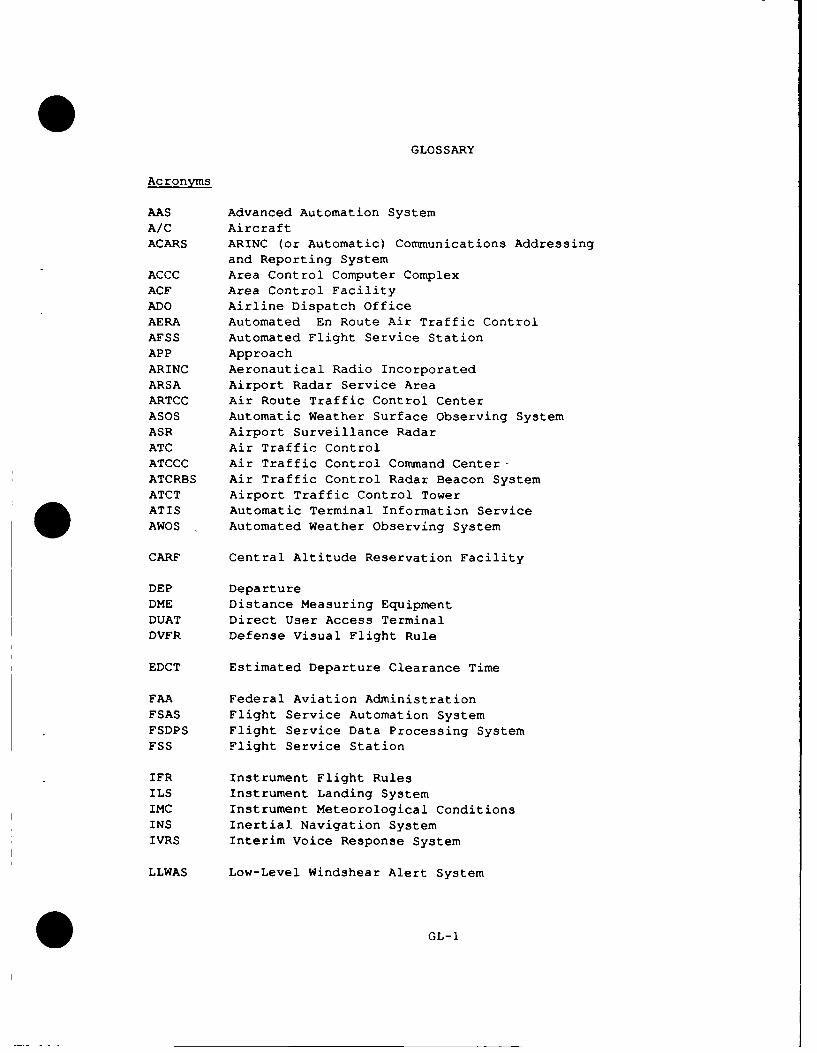
AAS Advanced Automation SystemA/C AircraftACARS ARINC (or Automatic) Communications Addressing
and Reporting SystemACCC Area Control Computer ComplexACF Area Control FacilityADO Airline Dispatch OfficeAERA Automated En Route Air Traffic Control
AFSS Automated Flight Service StationAPP ApproachARINC Aeronautical Radio IncorporatedARSA Airport Radar Service AreaARTCC Air Route Traffic Control CenterASOS Automatic Weather Surface Observing SystemASR Airport Surveillance Radar
ATC Air Traffic ControlATCCC Air Traffic Control Command Center-ATCRBS Air Traffic Control Radar Beacon SystemATCT Airport Traffic Control TowerATIS Automatic Terminal Information ServiceAWOS Automated Weather Observing System
CARF Central Altitude Reservation Facility
DEP DepartureDME Distance Measuring Equipment
DUAT Direct User Access TerminalDVFR Defense Visual Flight Rule
EDCT Estimated Departure Clearance Time
FAA Federal Aviation AdministrationFSAS Flight Service Automation System
FSDPS Flight Service Data Processing SystemFSS Flight Service Station
IFR Instrument Flight RulesILS Instrument Landing SystemIMC Instrument Meteorological Conditions
INS Inertial Navigation SystemIVRS Interim Voice Response System
LLWAS Low-Level Windshear Alert System
GL-I

MBO Military Base OperationsMode A Basic ATCRBSMode C Automatic Altitude Reporting EquipmentMode S Mode Select Beacon SystemMLS Microwave Landing System
NAS National Airspace SystemNASSRS NAS System Requirements SpecificationNOTAM Notice To AirmenNWS National Weather Service
RCF Radio Control FacilityRNAV Area NavigationRVR Runway Visual Range
SID Standard Instrument DepartureSTAR Standard Terminal Arrival Route
TACAN Tactical Air NavigationTAS True Air SpeedTCA Terminal Control AreaTCCC Tower Control Computer ComplexTM Traffic ManagementTMC Traffic Management CoordinatorTMF Traffic Management FacilityTPC TCCC Position ConsoleTRACON Terminal Radar Approach Control FacilityTRSA Terminal Radar Service Area
UHF Ultra High Frequency
VFR Visual Flight RulesVHF Very High FrequencyVOR VHF Omni-directional Range
GL-2

REFERENCES
Federal Aviation Administration, Advanced Automation System, System LevelSpecification, FAA-ER-130-005E, Washington, DC, August 1984.
Federal Aviation Administration, Air Traffic Control, FAA Order 7110.5,Washington, DC, Zl January 1982.
Federal Aviation Administration, Airman's Information Manual,Washington, DC, 25 October 1984.
Federal Aviation Administration, Flight Service Station Procedures, FAA
Order 7110.10H, Washington, DC, 8 May 1986.
Federal Aviation Administration, National Airspace System Level 1 DesignDocument, NAS-DD-1000B, (Includes SCN-1 through SCN-14), Washington, DC,
January 1988.
Federal Aviation Administration, National Airspace System Plan, Facilities,Equipment and Associated Development, Washington, DC, April 1987.
Federal Aviation Administration, National Airspace System, SystemRequirements Specification, NAS-SR-1000 (Change 6), March 1985.
Federal Aviation Administration, Operational Position Standards (Draft),FAA Order 7220.2, 8 September 1987.
Federal Aviation Administration, System Requirements Statement for the AirTraffic Control Computer Replacement Program, FAA Order 1812.4,Washington, DC, 3 December 1981.
Federal Aviation Administration, System Requirements Statement for theMode S Surveillance and Communications System, FAA Order 1812.6,Washington, DC, 9 September 1983.
Kingsbury, James A., Air Traffic Control Automation An AERA for This
Century, The MITRE Corporation, MP-86W28, McLean, VA., October 1986.
Gisch, Ann H., Barbara C. Zimnerman, AERA, Toward Greater En Route AirTraffic Control Automation, The MITRE Corporation,
MP-86W29, McLean, VA., October 1986.
* RE-1