dod ucr 2008 change 3 - disa
TRANSCRIPT

DoD UCR 2008, Change 3 Errata Page
Changes to UCR 2008, Change 2, made by UCR 2008, Change 3 for Section 5.3.2, Assured Services Requirements
SECTION CORRECTION OR NEW REQUIREMENTS EFFECTIVE
DATE 5.3.2.2.1.4 Modified DSCP marking requirements to clarify that AS-SIP
EIs shall populate the marking on their own (i.e. without direction from the LSC at the time a session is established).
Immediate
5.3.2.2.2.1.6 Clarified 3-Way Calling behavior when the conference bridge is provided by the EI.
Immediate
5.3.2.2.2.1.7 Made Hotline Service Conditional for all LSC configurations and removed the MLSC and SLSC distinctions.
Immediate
5.3.2.2.2.2.1 Disallow MLPP preemption of 911 calls. Immediate 5.3.2.2.2.2.5 Modified Tandem Call Trace Public Safety feature to provide
the calling party number instead of the incoming trunk number.
18 Months
5.3.2.3.2.2c Allow configured time interval for SS monitoring of LSCs via an OPTIONS request to be set on a per-LSC basis or for all LSCs (homed to the SS).
Immediate
5.3.2.5.2.1 Modified requirements to allow for a Medium Availability LSC configuration.
Immediate
5.3.2.5.2.2 Added Maximum Downtime requirements for Medium Availability LSCs.
Immediate
5.3.2.6.1.1.1 Clarified requirement to allow any type of pre-recorded audio files to be used for customized ring tones for incoming precedence calls (instead of requiring a WAV file).
Immediate
5.3.2.6.1.1.1 Deleted requirement for Camp On tone. Immediate 5.3.2.6.2 Made display of a session’s precedence level Conditional for
Video EIs and added Conditional requirement for Video EI support of MLPP.
Immediate
5.3.2.6.2.2 Clarified Video EI support for the following codecs: Required: H.263-2000 and H.264 Conditional: H.264 SVC and H.261
Immediate
5.3.2.7 Made Master LSC and Subtended LSC configurations explicitly Conditional.
Immediate
5.3.2.12.12.14 Added requirement that specifies the VoIP codecs that each media gateway shall support, and specified that a media gateway shall be able to simultaneously offer at least five codecs for a given session, unless RFC 4040 is used.
18 Months
5.3.2.14.8 Modified requirement to allow CE Router greater transit time for voice packets if one of the CE Router access interfaces is a T1, E1 or lower.
Immediate

DoD UCR 2008, Change 3 Errata Sheet
SECTION CORRECTION OR NEW REQUIREMENTS EFFECTIVE
DATE 5.3.2.14.9 Added Conditional support for additional CE Router
interfaces. Immediate
5.3.2.15.1 Added requirement that EBCs shall be configurable to disable EBC-based failover from primary to secondary SS.
18 Months
5.3.2.15.5 Clarified EBC codec bandwidth policing requirement to allow session dropping, traffic policing or traffic shaping when a session exceeds the negotiated bandwidth.
Immediate
5.3.2.15.6 Reduced the number of EBC types from four to two, deleting the Conditional High Availability without NLAS and Low Availability versions.
Immediate
5.3.2.16 Made the 94 or 9P (P = 0, 1, 2, or 3) prefix Conditional for dialing Routine or Precedence calls, provided the PEIs and AEIs support a different method (e.g., a softkey) for indicating that a call is Routine or Precedence.
Immediate
5.3.2.20.2 Clarified that the RTS Stateful Firewall (RSF) is a distinct UC APL product and is not part of the LSC SUT, nor SS SUT, nor MFSS SUT. Also added the RSF to Table 5.3.2.1.-1, Summary of Appliances and UC APL Products.
Immediate
5.3.2.21.2.8 Clarifications made regarding where Modem Relay support for V.92 and V.90 is Conditional and Required.
Immediate
5.3.2.22.3.1 Modified Multiple Call Appearances requirements to clarify that AS-SIP EIs shall manage MCAs on their own (i.e. without explicit direction from the LSC).
Immediate
5.3.2.26.4 Removed attendant console role in providing Emergency Interrupt override tone.
Immediate
5.3.2.28 Modified requirements so that LDAP message traffic to and from RTS Routing Databases will be DSCP marked as User Signaling instead of OA&M traffic.
Immediate
5.3.2.28 The separator between the parts of the LDAP Distinguished Name (DN) for an RTS Routing Database entry shall be a comma (,) instead of a semi-colon (;).
Immediate
5.3.2.28 The separator between the primary WAN SS or MFSS CCA-ID and the backup WAN SS or MFSS CCA-ID in the SSCCAID attribute value shall be a comma (,) instead of a semi-colon (;).
Immediate
5.3.2.28.2.4 Added requirement clarifying that each SS needs to support an internal table identifying the CCA IDs for the LSCs and SSs to which it can route AS-SIP sessions via their EBCs.
18 Months

DoD UCR 2008, Change 3 Errata Page
SECTION CORRECTION OR NEW REQUIREMENTS EFFECTIVE
DATE 5.3.2.28.3 Added requirement for the LSC to support a configuration
option to deactivate Commercial Call Avoidance queries for all calls. Note that the setting of this option has no affect on the MRDB updates (Section 5.3.2.28.4) performed by the LSC for Commercial Call Avoidance and Hybrid routing.
18 Months
5.3.2.28.4 The LSC shall support the ability to exclude a given end user from the RTS Routing Database based on a setting that is part of the user information maintained by the LSC when an EI is provisioned.
18 Months
5.3.2.28.4.1 Specified allowed options for the LDAP Search operation performed by an LSC prior to making an LDAP Update.
Immediate
5.3.2.28.4.1.2 Made LDAP Modify Operation Conditional. Immediate 5.3.2.28.4.1.2 Added Conditional requirement that specifies allowed
methods (Add, and Add plus Modify) for adding a new user to the MRDB.
Immediate
5.3.2.28.5.2.2 Changed the LDAP attribute name that identifies the CCA-ID values for the Primary and Backup SSs serving an LSC.
Immediate
5.3.2.28.5.2.3 Specified allowed options for the LDAP Search operation performed by an LSC prior to making a change in the MRDB.
Immediate
5.3.2.28.5.2.5.1 Clarified that the LSC shall maintain a log of attempted LDAP Updates when both the primary and backup MRDBs are down.
Immediate
5.3.2.28.6 Added requirements to support SNMPv3 for network management of the RTS Routing Database. Added a Conditional requirement for SMIv2 support.
18 Months
5.3.2.28.6.7 Made the existing requirements for cache-related measurements at the LSC, MFSS or WAN SS Conditional, and noted that these appliances may support other query- and cache-related measurements. Added a Conditional requirement regarding measurement collection intervals.
Immediate
5.3.2.30.2.2 Throughout the section, changed “– Conditional: Deployable (Tactical) LSC, Fixed (Strategic) LSC” to “– Required: Deployable (Tactical) LSC – Conditional: Fixed (Strategic) LSC”.
18 Months

DoD UCR 2008, Change 3 Errata Sheet
SECTION CORRECTION OR NEW REQUIREMENTS EFFECTIVE
DATE 5.3.2.30.2.2 Additional details provided regarding mid-session session
renegotiation that takes place outside of the AS SIP dialog (e.g., media layer modem based renegotiation of the codec as when some sessions go from in the clear to secure) whereby the bits per second for the session increases. One new requirement: [Required: MFSS, WAN SS – Required: Deployable (Tactical) LSC – Conditional: Fixed (Strategic) LSC] If the product supports an ongoing session, in which the EIs can renegotiate audio or video codec changes at the bearer layer (e.g., modem protocol), the product shall set EISC at the highest bit rate that can be re-negotiated by the EIs mid-session via the bearer layer.
18 Months
5.3.2.30.2.2 Expanded description and specification of the situation where a higher precedence and higher bits per second session attempt requires the pre-emption of two or more lower precedence and lower bits per second sessions. Included a suggested algorithm.
Immediate
5.3.2.30.2.2 Corrected a binary decision error in Figure 5.3.2.3-13 “AS-SIP Triggers for AVSC” from “true or true” to “true or false”. Also expanded the figure to reflect that one new session attempt may sometimes pre-empt two or more active sessions.
Immediate
5.3.2.30.2.2 Corrected the omission of DASAC supporting the tactical audio codecs per section 6.1.7.5.4 Codec Translation Functional.
18 Months
5.3.2.31.8 VoIP System latency requirements specified for MG trunk traffic.
18 Months
5.3.2.32 UC Conference System requirements have been marked according to the types of end instruments supported: AO requirements apply to systems that only support conferences for audio end instruments (i.e., voice phones); VO requirements apply to systems that only support conferences for video end instruments (i.e., video terminals); A/V requirements apply to systems that support both audio and video end instruments; and requirements that apply to all types of conference systems are marked All UCCS. In addition, edits were made throughout the section to improve clarity and eliminate redundancy.
Immediate

DoD UCR 2008, Change 3 Errata Page
SECTION CORRECTION OR NEW REQUIREMENTS EFFECTIVE
DATE 5.3.2.32.1 Text was added that explicitly allows the use of Video EIs that
use both proprietary signaling and media, under certain conditions.
Immediate
5.3.2.32.2 All UC Conference Systems shall meet the Information Assurance requirements of all applicable DISA STIGs.
Immediate
5.3.2.32.3.1.4 Video Performance section edited to clarify that performance related design criteria are guidelines and not requirements.
Immediate
5.3.2.32.3.3 Video conference system requirement to adhere to FTR 1080B made Conditional.
Immediate
5.3.2.32.3.3.6 Text corrected to require audio conferencing to use Secure RTP and Secure RTCP.
Immediate
5.3.2.32.3.3.6 Requirements for audio systems to be able to operate in a DMZ environment and behind NAT/PAT firewalls were deleted.
Immediate
5.3.2.32.4.2 Changes were made to clarify that certain capacity requirements can be met by scaling, including deploying multiple systems and provisioning or load sharing between systems
Immediate
5.3.2.32.5.2 Online Directory requirements were made Conditional for audio-only and audio/video conference systems.
Immediate
5.3.2.33 New Requirements – Mass Notification Warning System Immediate 5.3.2.34 New Requirements – E-911 Management System Immediate

THIS PAGE INTENTIONALLY LEFT BLANK

DoD UCR 2008, Change 3 Table of Contents
i
TABLE OF CONTENTS SECTION PAGE
5.3.2 Assured Services Requirements............................................................199 5.3.2.1 Introduction .........................................................................199
5.3.2.1.1 Requirements Terminology ...........................199 5.3.2.1.2 Network Reference Model .............................200 5.3.2.1.3 General Assumptions .....................................202 5.3.2.1.4 Information Assurance ...................................205 5.3.2.1.5 Functional Reference Terminology – APL
Products and Appliances ................................205 5.3.2.2 Assured Services Product Features and Capabilities ..........211
5.3.2.2.1 Overview of VoIP and Video over IP Product Design Attributes ..............................211 5.3.2.2.1.1 Attributes within the Edge
Segment..................................211 5.3.2.2.1.2 Attributes within the DISN
WAN (Access/Distribution and Core) ................................213
5.3.2.2.1.3 E2E Protocol Planes ...............213 5.3.2.2.1.4 DSCP Packet Marking ...........213
5.3.2.2.2 Assured Services Subsystem..........................214 5.3.2.2.2.1 Voice Features and
Capabilities ............................216 5.3.2.2.2.2 Public Safety Features............234 5.3.2.2.2.3 ASAC – Open Loop ...............236
5.3.2.2.3 Signaling Protocols ........................................245 5.3.2.2.4 Signaling Performance ...................................245
5.3.2.3 Registration, Authentication, and Failover .........................246 5.3.2.3.1 Registration and Authentication ....................246 5.3.2.3.2 LSC and SS Failover Requirements ..............246
5.3.2.3.2.1 General Description ...............247 5.3.2.3.2.1a Subscriptions ..........................247 5.3.2.3.2.1b OPTIONS Requests ...............248 5.3.2.3.2.1c LSC Failover to Secondary
SS ...........................................248 5.3.2.3.2.1d SS Failover to Secondary SS .249 5.3.2.3.2.1e LSC Failover Triggered by
Primary SS Detection of Unreachable LSC ...................249

DoD UCR 2008, Change 3 Table of Contents
ii
5.3.2.3.2.1f LSC Failback to Primary SS ..250 5.3.2.3.2.1g SS Failback to Secondary
SS ...........................................250 5.3.2.3.2.1h LSC Failback Triggered by
Primary SS Detection of Reachable LSC.......................251
5.3.2.3.2.2a LSC Monitors Primary SS for Status ......................................251
5.3.2.3.2.2b Each SS Monitors All Other SSs in the Network.................252
5.3.2.3.2.2c Primary SS Monitors LSC for Status ......................................253
5.3.2.3.2.3 Establish Subscriptions Using Failover Event Package..........254
5.3.2.3.2.4 Subscription Refresh ..............259 5.3.2.3.2.5a LSC Failover to Secondary
SS ...........................................263 5.3.2.3.2.5b SSs Failover to Secondary
SS ...........................................270 5.3.2.3.2.5c LSC Failover to Secondary
SS Triggered by Primary SS ..271 5.3.2.3.2.6a LSC Failback to Primary SS ..271 5.3.2.3.2.6b SSs Failback to Primary SS ...278 5.3.2.3.2.6c LSC Failback to Primary SS
Triggered by Primary SS .......279 5.3.2.3.2.7 Security Considerations .........279 5.3.2.3.2.8 Failover Event Package..........279
5.3.2.4 Product Interface Requirements..........................................286 5.3.2.4.1 Internal Interface Requirements .....................286 5.3.2.4.2 External Physical Interfaces between
Network Components ....................................287 5.3.2.4.3 Interfaces to Other Networks .........................287
5.3.2.4.3.1 Deployable Networks Interface Requirements ..........287
5.3.2.4.3.2 DISN Teleport Site Interface Requirements .........................287
5.3.2.4.3.3 PSTN Interface Requirements .........................287
5.3.2.4.3.4 Allied and Coalition Network Interface Requirements ..........288
5.3.2.4.4 VVoIP NMS Interface Requirements ............288 5.3.2.5 Product Physical, Quality, and Environmental Factors ......288

DoD UCR 2008, Change 3 Table of Contents
iii
5.3.2.5.1 Physical Characteristics .................................288 5.3.2.5.2 Product Quality Factors .................................288
5.3.2.5.2.1 Product Availability ...............289 5.3.2.5.2.2 Maximum Downtimes ...........291
5.3.2.5.3 Environmental Conditions .............................291 5.3.2.5.4 Loss of Packets ..............................................291 5.3.2.5.5 Information-Assurance-Related Quality
Factors ............................................................291 5.3.2.6 End Instruments ..................................................................292
5.3.2.6.1 IP Voice Instrument .......................................292 5.3.2.6.1.1 Tones and Announcements ....293 5.3.2.6.1.2 Audio Codecs .........................297 5.3.2.6.1.3 VoIP PEI or AEI Telephone
Audio Performance Requirements .........................298
5.3.2.6.1.4 Voice over IP Sampling Standard .................................298
5.3.2.6.1.5 Authentication to LSC ...........299 5.3.2.6.1.6 Analog Telephone Support ....299 5.3.2.6.1.7 Softphones..............................300 5.3.2.6.1.8 ISDN BRI Telephone
Support ...................................302 5.3.2.6.2 Video End Instrument ....................................303
5.3.2.6.2.1 Display Messages, Tones, and Announcements ...............304
5.3.2.6.2.2 Video Codecs (Including Associated Audio Codecs) .....304
5.3.2.6.2.3 Authentication to LSC ...........305 5.3.2.6.3 End Instrument to ASLAN Interface .............305 5.3.2.6.4 PEIs, AEIs, TAs, and IADs Using the
V.150.1 Protocol ............................................305 5.3.2.7 Local Session Controller .....................................................306
5.3.2.7.1 LSC Functional Reference Model and Assumptions ...................................................306 5.3.2.7.1.1 Assumptions – LSC ...............309
5.3.2.7.2 Summary of LSC Functions and Features .....310 5.3.2.7.2.1 PBAS/ASAC Requirements...310 5.3.2.7.2.2 Calling Number Delivery
Requirements .........................310 5.3.2.7.2.3 LSC Signaling Requirements .311

DoD UCR 2008, Change 3 Table of Contents
iv
5.3.2.7.2.4 Service Requirements under Total Loss of WAN Transport Connectivity ...........................312
5.3.2.7.2.5 Local Location Server and Directory ................................313
5.3.2.7.2.6 LSC Management Function ...313 5.3.2.7.2.7 LSC Transport Interface
Functions ................................314 5.3.2.7.2.8 LSC-to-NMS Interface...........314 5.3.2.7.2.9 ASAC Requirements for LSC
Related to Voice and Video ...314 5.3.2.7.2.10 LSC to PEI, AEI, and
Operator Console Status Verification ............................315
5.3.2.7.2.11 Line-Side Custom Features Interference ............................315
5.3.2.7.3 Loop Avoidance for LSCs .............................315 5.3.2.7.4 AS-SIP TDM Gateway ..................................315
5.3.2.7.4.1 Overview ................................315 5.3.2.7.4.2 AS-SIP TDM Gateway
Functional Reference Model and Assumptions ....................318
5.3.2.7.4.3 Summary of AS-SIP TDM Gateway Functions and Features ..................................321
5.3.2.7.5 AS-SIP – H.323 Gateway ..............................326 5.3.2.7.5.1 Overview ................................326 5.3.2.7.5.2 AS-SIP – H.323 Gateway
Functional Reference Model and Assumptions ....................331
5.3.2.7.5.3 Summary of AS-SIP – H.323 Gateway Functions and | Features ..................................333
5.3.2.8 Network-Level Softswitches...............................................346 5.3.2.8.1 MFSS Functional Reference Model and
Assumptions ...................................................346 5.3.2.8.1.1 Assumptions – MFSS ............347
5.3.2.8.2 Summary of MFSS Functions and Features ..350 5.3.2.8.2.1 TDM Side EO and Tandem
Requirements .........................350 5.3.2.8.2.2 Global Location Server ..........351 5.3.2.8.2.3 MFSS Signaling Interfaces ....351

DoD UCR 2008, Change 3 Table of Contents
v
5.3.2.8.2.4 SG and MG Requirements for Interactions between TDM Side and SS Side of the MFSS .....................................353
5.3.2.8.2.5 Requirements for External Connections between MFSS and Other Systems .................354
5.3.2.8.2.6 Features of the SS Side of the MFSS .....................................355
5.3.2.8.2.7 ASAC Requirements for the MFSS Related to Voice and Video ......................................355
5.3.2.8.3 Network Management Requirements for the MFSS .............................................................356 5.3.2.8.3.1 Network Management System
Interface .................................356 5.3.2.8.4 WAN-Level Softswitch .................................356
5.3.2.9 Call Connection Agent........................................................359 5.3.2.9.1 Introduction ....................................................359 5.3.2.9.2 Functional Overview of the CCA ..................361
5.3.2.9.2.1 CCA IWF Component ...........363 5.3.2.9.2.2 CCA MGC Component..........363 5.3.2.9.2.3 SG Component .......................364
5.3.2.9.3 CCA Requirements Assumptions ..................365 5.3.2.9.4 Role of the CCA in Network Appliances ......368 5.3.2.9.5 CCA-IWF Signaling Protocol Support
Requirements .................................................369 5.3.2.9.5.1 CCA-IWF Support for
AS-SIP ...................................369 5.3.2.9.5.2 CCA-IWF Support for DoD
CCS7 via an SG .....................369 5.3.2.9.5.3 CCA-IWF Support for PRI,
via MG ...................................371 5.3.2.9.5.4 CCA-IWF Support for CAS
Trunks, via MG ......................374 5.3.2.9.5.5 CCA-IWF Support for PEI
and AEI Signaling Protocols ..379 5.3.2.9.5.6 CCA-IWF Support for VoIP
and TDM Protocol Interworking ...........................380
5.3.2.9.6 CCA Preservation of Call Ringing State during Failure Conditions ..............................383

DoD UCR 2008, Change 3 Table of Contents
vi
5.3.2.10 CCA Interaction with Network Appliances and Functions .............................................................................384 5.3.2.10.1 CCA Interactions between the SS and TDM
Sides of the MFSS .........................................384 5.3.2.10.2 CCA Support for Appliance Management
Functions ........................................................385 5.3.2.10.3 CCA Interactions with Transport Interface
Functions ........................................................385 5.3.2.10.4 CCA Interactions with the EBC .....................387 5.3.2.10.5 CCA Support for Admission Control ............389 5.3.2.10.6 CCA Support for UFS ....................................390 5.3.2.10.7 CCA Support for Information Assurance ......391 5.3.2.10.8 CCA Interactions with Local Location
Service............................................................392 5.3.2.10.9 CCA Interactions with Global Location
Service............................................................393 5.3.2.10.10 CCA Interactions with End Instrument(s) .....394 5.3.2.10.11 CCA Support for Assured Services Voice
and Video .......................................................395 5.3.2.10.12 CCA Interactions with Service Control
Functions ........................................................396 5.3.2.11 CCA Interworking between AS-SIP and DoD CCS7 .........397
5.3.2.11.1 Purpose and Scope .........................................397 5.3.2.11.2 Background ....................................................398 5.3.2.11.3 General Considerations ..................................399 5.3.2.11.4 Interworking for a Call Originating in an
AS-SIP Network toward an ISUP Network ...400 5.3.2.11.4.1 Sending of Initial Address
Message..................................400 5.3.2.11.4.2 Sending of Continuity
Testing....................................412 5.3.2.11.4.3 ACM Received.......................412 5.3.2.11.4.4 Call Progress Message
Received .................................413 5.3.2.11.4.5 Answer Message Received ....413 5.3.2.11.4.6 Confusion Message
Received .................................413 5.3.2.11.4.7 Circuit Identification Code
Query Response Message Received .................................413
5.3.2.11.4.8 Pass Along Message Received .................................414

DoD UCR 2008, Change 3 Table of Contents
vii
5.3.2.11.4.9 Through Connection ..............414 5.3.2.11.4.10 Suspend Message, Network
Initiated Received ..................414 5.3.2.11.4.11 Resume Message, Network
Initiated Received ..................414 5.3.2.11.4.12 Release Procedures ................414
5.3.2.11.5 Interworking for a Call Originating in an ISUP Network toward an AS-SIP Network ...420 5.3.2.11.5.1 Sending of INVITE ................420 5.3.2.11.5.2 18X Response Received ........432 5.3.2.11.5.3 Expiration of TOIW2 and
Sending Early ACM ...............433 5.3.2.11.5.4 Circuit (CIC) Query Response
Message Received ..................433 5.3.2.11.5.5 200 (OK) INVITE Message
Received .................................434 5.3.2.11.5.6 Through Connection, Tones,
and Announcements ...............434 5.3.2.11.5.7 Release Procedures ................435
5.3.2.11.6 Interworking Timer ........................................440 5.3.2.12 Media Gateway Requirements ............................................441
5.3.2.12.1 Introduction ....................................................441 5.3.2.12.2 Overview of the MG and MGC Functions ....443
5.3.2.12.2.1 Primary Trunk Functions and Interfaces ................................443
5.3.2.12.2.2 Primary Access Functions and Interfaces ................................444
5.3.2.12.2.3 MGC Functions ......................444 5.3.2.12.3 Role of the MG in Appliances .......................446
5.3.2.12.3.1 Role of the MG in the LSC ....446 5.3.2.12.3.2 Role of the MG in the MFSS .449
5.3.2.12.4 MG Interaction with NEs and Functions .......453 5.3.2.12.4.1 MG Support for ASAC ..........454 5.3.2.12.4.2 MG and Information
Assurance Functions ..............455 5.3.2.12.4.3 MG Interaction with Service
Control Functions...................456 5.3.2.12.4.4 Interactions with IP Transport
Interface Functions.................457 5.3.2.12.4.5 MG – EBC Interaction ...........458 5.3.2.12.4.6 MG Support for Appliance
Management Functions ..........460
DoD UCR 2008, Change 3 Table of Contents
viii
5.3.2.12.4.7 IP-Based PSTN Interface Requirements .........................461
5.3.2.12.4.8 MG Requirements: Interactions with VoIP EIs .....461
5.3.2.12.4.9 MG Support for User Features and Services ...........................462
5.3.2.12.5 MG Interfaces to TDM NEs in DoD Networks: PBXs, EOs, and MFSs ................462
5.3.2.12.6 MG Interfaces to TDM NEs in Allied and Coalition Partner Networks............................463
5.3.2.12.7 MG Interfaces to TDM NEs in the PSTN in the United States ........................................464
5.3.2.12.8 MG Interfaces to TDM NEs in OCONUS PTT Networks ................................................465
5.3.2.12.9 MG Support for DoD CCS7 Trunks ..............465 5.3.2.12.10 MG Support for ISDN PRI Trunks ................466 5.3.2.12.11 MG Support for CAS Trunks .........................468 5.3.2.12.12 MG Requirements: VoIP Interfaces Internal
to an Appliance ..............................................469 5.3.2.12.12.1 MG Support for VoIP
Interconnection at the Physical and Data Link Layers .............469
5.3.2.12.12.2 MG Support for VoIP Interconnection at the Network Layer .......................470
5.3.2.12.12.3 MG Support for VoIP Interconnection at the Transport Layer ......................470
5.3.2.12.12.4 MG Support for VoIP Interconnection for Media Stream Exchange above the Transport Layer ......................471
5.3.2.12.12.5 MG Support for VoIP Interconnection for Signaling Stream Exchange above the Transport Layer ......................472
5.3.2.12.12.6 MG Support for VoIP Interworking for ISDN PRI Trunks ....................................472
5.3.2.12.12.7 MG Support for VoIP Interworking for CAS Trunks ....................................473

DoD UCR 2008, Change 3 Table of Contents
ix
5.3.2.12.12.8 MG Support for VoIP Codecs for Voice Calls .......................474
5.3.2.12.12.9 MG Support for Group 3 Fax Calls .......................................475
5.3.2.12.12.10 MG Support for Voiceband Data Modem Calls .................479
5.3.2.12.12.11 MG Support for SCIP over IP Calls .......................................479
5.3.2.12.12.12 MG Support for ISDN over IP Calls and 64-kbps Clear Channel Data Streams ............479
5.3.2.12.12.13 MG Support for “Hairpinned” MG Calls ................................481
5.3.2.12.12.14 MG Support for Multiple Codecs for a Given Session ...481
5.3.2.12.13 Echo Cancellation ..........................................482 5.3.2.12.13.1 MG Requirements for Echo
Cancellation ...........................482 5.3.2.12.13.2 Trunk Gateway Echo
Cancellation ...........................482 5.3.2.12.14 MG Requirements for Clock Timing .............485
5.3.2.12.14.1 Synchronization .....................485 5.3.2.12.15 MGC-MG CCA Functions .............................486
5.3.2.12.15.1 MG Support for MGC-MG Signaling Interface .................488
5.3.2.12.15.2 MG Support for Encapsulated National ISDN PRI Signaling ................................489
5.3.2.12.15.3 MG Support for Mapped CAS Trunk Signaling using H.248 Packages for MF and DTMF Trunks ....................................490
5.3.2.12.15.4 MG Support for Glare Conditions on Trunks .............492
5.3.2.12.15.5 MGC and IWF Treatments for PRI-to-AS-SIP Mapping for TDM MLPP......................493
5.3.2.12.15.6 MGC Support for MG-to-MG Calls .......................................495
5.3.2.12.16 MGs Using the V.150.1 Protocol ...................495 5.3.2.12.17 MG Preservation of Call Ringing State
during Failure Conditions ..............................496

DoD UCR 2008, Change 3 Table of Contents
x
5.3.2.12.18 Remote Media Gateway Requirements .........496 5.3.2.12.18.1 EBC at the Remote MG Site ..498 5.3.2.12.18.2 MG Control Protocol and
Media Stream Protocols .........498 5.3.2.12.18.3 Conveying Precedence
Information in H.248.1 ..........498 5.3.2.12.18.4 DSCP Marking of H.248.1
Packets ...................................498 5.3.2.12.18.5 Securing the H.248.1
Protocol ..................................498 5.3.2.13 Signaling Gateway Requirements .......................................499
5.3.2.13.1 Introduction ....................................................499 5.3.2.13.1.1 SG Requirements
Assumptions ...........................499 5.3.2.13.1.2 SG Primary Function and
Interfaces ................................500 5.3.2.13.2 Role of the SG in Appliances.........................500
5.3.2.13.2.1 MFSS Functional Reference Model .....................................500
5.3.2.13.3 SG’s Role – Interacting with MFSS Functions and Elements .................................502 5.3.2.13.3.1 End Office and Tandem Side
of the MFSS ...........................502 5.3.2.13.3.2 SG, CCA, and IWF
Relationships ..........................502 5.3.2.13.3.3 CCA Interactions with SG .....502 5.3.2.13.3.4 SG Interactions with
Appliance Management Functions ................................504
5.3.2.13.4 SG Protocol Design........................................505 5.3.2.13.4.1 SG and CCS7 Network
Interactions .............................506 5.3.2.13.4.2 SG and CCA Interactions.......508 5.3.2.13.4.3 SG Interworking Functions ....509
5.3.2.13.5 Detailed SG Requirements .............................509 5.3.2.13.5.1 SG and CCS7 Network
Interactions .............................509 5.3.2.13.5.2 SG Interactions with CCA .....527 5.3.2.13.5.3 SG Interworking Functions ....528
5.3.2.14 Customer Edge Router Requirements.................................531 5.3.2.14.1 Traffic Conditioning ......................................531 5.3.2.14.2 Differentiated Services Support .....................531

DoD UCR 2008, Change 3 Table of Contents
xi
5.3.2.14.3 Per Hop Behavior Support .............................531 5.3.2.14.4 Interface to the LSC/MFSS for Traffic
Conditioning ..................................................531 5.3.2.14.5 Interface to the LSC/MFSS for Bandwidth
Allocation .......................................................532 5.3.2.14.6 Network Management ....................................532 5.3.2.14.7 Availability ....................................................532 5.3.2.14.8 Packet Transit Time .......................................533 5.3.2.14.9 Customer Edge Router Interfaces and
Throughput Support .......................................533 5.3.2.14.10 Deployable (Tactical) Customer Edge
Router Requirements .....................................535 5.3.2.15 EBC Requirements .............................................................535
5.3.2.15.1 AS-SIP Back-to-Back User Agent .................536 5.3.2.15.2 Call Processing Load .....................................538 5.3.2.15.3 Network Management ....................................538 5.3.2.15.4 DSCP Policing ...............................................538 5.3.2.15.5 Codec Bandwidth Policing ............................539 5.3.2.15.6 Availability ....................................................539 5.3.2.15.7 IEEE 802.1Q Support ....................................539 5.3.2.15.8 Packet Transit Time .......................................540 5.3.2.15.9 H.323 Support ................................................540 5.3.2.15.10 EBC Requirements to Support Remote MG ..540 5.3.2.15.11 Tactical Edge Boundary Controller
Requirements .................................................540 5.3.2.15.12 EBC Assured Services Media Stream
Requirements .................................................541 5.3.2.16 Worldwide Numbering and Dialing Plan ...........................541
5.3.2.16.1 DSN Worldwide Numbering and Dialing Plan ................................................................542 5.3.2.16.1.1 CCA and GLS Support for
Dual Assignment of DSN and E.164 Numbers to MFSS EIs ..........................................549
5.3.2.16.1.2 CCA Differentiation between DSN Numbers and E.164 Numbers .................................549
5.3.2.16.1.3 CCA Use of SIP “phone- context” to Differentiate between DSN and E.164 Numbers .................................551

DoD UCR 2008, Change 3 Table of Contents
xii
5.3.2.16.1.4 Use of SIP URI Domain Name with DSN Numbers and E.164 Numbers .................................551
5.3.2.16.1.5 Domain Directory ..................554 5.3.2.16.1.6 Global Directory Services ......557
5.3.2.17 Management of Network Appliances .................................558 5.3.2.17.1 Voice and Video Network Management
Domain ...........................................................559 5.3.2.17.2 General Management Requirements ..............560 5.3.2.17.3 Requirements for FCAPS Management.........562
5.3.2.17.3.1 Fault Management .................562 5.3.2.17.3.2 Configuration Management ...563 5.3.2.17.3.3 Accounting Management .......564 5.3.2.17.3.4 Performance Management .....564 5.3.2.17.3.5 Security Management ............572
5.3.2.17.4 Data Classification .........................................572 5.3.2.17.5 Management of Appliance Software .............572
5.3.2.18 Network Management Requirements of Appliance Functions .............................................................................572 5.3.2.18.1 NM Requirements for CE Routers and
EBCs ..............................................................572 5.3.2.18.2 Management Requirements for the ASAC ....573 5.3.2.18.3 Management Requirements of the CCA
Function .........................................................574 5.3.2.18.4 Management Requirements of the SG
Function .........................................................574 5.3.2.18.5 Management Requirements of the MG
Function .........................................................574 5.3.2.19 Accounting Management ....................................................574
5.3.2.19.1 Accounting Data ............................................575 5.3.2.19.1.1 Call Connect Data Set ............582 5.3.2.19.1.2 Originating Customer/
Business Group Identification ..........................582
5.3.2.19.1.3 Terminating Customer/ Business Group Identification ..........................583
5.3.2.19.1.4 Call Characteristic ..................583 5.3.2.19.1.5 Bandwidth Reservation ..........583 5.3.2.19.1.6 Call Disconnect Data Set .......583 5.3.2.19.1.7 Billing Agent ..........................584
5.3.2.19.2 Processing of Data Sets ..................................585

DoD UCR 2008, Change 3 Table of Contents
xiii
5.3.2.19.2.1 Call Data ................................585 5.3.2.19.2.2 Record Format .......................592 5.3.2.19.2.3 Storage ...................................601 5.3.2.19.2.4 Outputting Records ................601
5.3.2.20 RTS Stateful Firewall Requirements ..................................602 5.3.2.20.1 Introduction ....................................................602 5.3.2.20.2 Role of the RSF ..............................................602 5.3.2.20.3 Detailed RSF Requirements ...........................602
5.3.2.20.3.1 RSF General Requirements....602 5.3.2.20.3.2 RSF Shall Not Requirements .603
5.3.2.21 V.150.1 Modem Relay Secure Phone Support Requirements ......................................................................604 5.3.2.21.1 Modem Relay for Secure Phone Support.......604
5.3.2.21.1.1 Need for Modem Relay Requirements .........................604
5.3.2.21.1.2 Architecture for Supporting SCIP/V.150.1 Modem Relay .605
5.3.2.21.2 SCIP/V.150.1 Gateway Requirements ...........607 5.3.2.21.2.1 Basic Minimum Essential
Requirements .........................610 5.3.2.21.2.2 Procedural Minimum Essential
Requirements .........................614 5.3.2.21.2.3 SSE and SPRT Message
Content ...................................618 5.3.2.21.2.4 Use of Common UDP Port
Numbers for SRTP, SSE, and SPRT Messages .....................619
5.3.2.21.2.5 UDP Port Number for SRTCP Media Control Packets ...........620
5.3.2.21.2.6 Use of V.150.1 SSE Messages for Media Transitions between Audio and Modem Relay .......621
5.3.2.21.2.7 Modem Relay and VoIP for SCIP/V.150.1 Gateways ........623
5.3.2.21.2.8 Modem Relay Support for V.92 and V.90 Modulation Types ......................................624
5.3.2.21.2.9 Going Secure, Glare Conditions, and Modem Relay Preferred Devices ...................625
5.3.2.21.3 SCIP/V.150.1 EI Requirements .....................626

DoD UCR 2008, Change 3 Table of Contents
xiv
5.3.2.21.3.1 Basic Minimum Essential Requirements (MER) .............627
5.3.2.21.3.2 Procedural MER.....................629 5.3.2.21.3.3 SSE and SPRT Message
Content ...................................631 5.3.2.21.3.4 Use of Common UDP Port
Numbers for SRTP, SSE, and SPRT Messages .....................632
5.3.2.21.3.5 UDP Port Number for SRTCP Media Control Packets ...........633
5.3.2.21.3.6 Use of V.150.1 SSE Messages for Media Transitions between Audio and Modem Relay .......634
5.3.2.21.3.7 Going Secure, Glare Conditions, and Modem Relay Preferred Devices ........635
5.3.2.21.4 SCIP/V.150.1 EI Requirements Using SCIP-214.2 Protocol ................................................636
5.3.2.21.5 NSA DTLS-SRTP Secure EI Requirements ..638 5.3.2.22 AS-SIP End Instrument and Video Codec Requirements ..638
5.3.2.22.1 Framework for Supporting EIs and Video Codecs Using AS-SIP ....................................639
5.3.2.22.2 Requirements for Supporting AS-SIP EIs .....642 5.3.2.22.2.1 Requirements for AS-SIP
Voice EIs ................................645 5.3.2.22.2.2 Requirements for AS-SIP
Secure Voice EIs ....................646 5.3.2.22.2.3 Requirements for AS-SIP
Video EIs ...............................650 5.3.2.22.3 Multiple Call Appearance Requirements
for AS-SIP EIs ...............................................652 5.3.2.22.3.1 Multiple Call Appearances ....652 5.3.2.22.3.2 Multiple Call Appearances –
Interactions with Precedence Calls .......................................655
5.3.2.22.4 AS-SIP Video EI Features .............................657 5.3.2.23 Requirements for Supporting Commercial Cost
Avoidance ...........................................................................659 5.3.2.24 Requirements for Supporting AS-SIP-Based Ethernet
Interfaces for Voicemail Systems, Unified Messaging Systems, and Automated Receiving Devices .....................660

DoD UCR 2008, Change 3 Table of Contents
xv
5.3.2.24.1 Requirements for Supporting AS-SIP Message Waiting Indications on AS-SIP EIs, TAs, and IADs ........................................661
5.3.2.25 UC Precedence Call Diversion ...........................................662 5.3.2.26 Attendant Station Features ..................................................664
5.3.2.26.1 Precedence and Preemption ...........................665 5.3.2.26.2 Call Display ...................................................665 5.3.2.26.3 Class of Service Override ..............................666 5.3.2.26.4 Busy Override and Busy Verification ............666 5.3.2.26.5 Night Service .................................................667 5.3.2.26.6 Automatic Recall of Attendant ......................668 5.3.2.26.7 Calls in Queue to the Attendant .....................668
5.3.2.27 Directory Services (“White Pages”) ...................................669 5.3.2.28 RTS Routing Database Requirements ................................674
5.3.2.28.1 Introduction ....................................................674 5.3.2.28.1.1 Purpose ...................................674 5.3.2.28.1.2 Assumptions ...........................674
5.3.2.28.2 WAN SS or MFSS to LRDB Interface: DB Queries for HR ...............................................677 5.3.2.28.2.1 HR Query from WAN SS/
MFSS .....................................679 5.3.2.28.2.2 DB Response when DSN
Number is Found....................681 5.3.2.28.2.3 DB Response when DSN
Number is Not Found.............682 5.3.2.28.2.4 WAN SS Actions Based on
DB Response ..........................682 5.3.2.28.3 LSC to LRDB Interface: DB Queries for
Commercial Cost Avoidance .........................685 5.3.2.28.3.1 Commercial Cost Avoidance
Query from LSC ....................688 5.3.2.28.3.2 DB Response When
Commercial Number is Found .....................................690
5.3.2.28.3.3 DB Response When Commercial Number is Not Found .....................................691
5.3.2.28.4 LSC to MRDB Interface: DB Updates for Commercial Cost Avoidance and Hybrid Routing ...........................................................693 5.3.2.28.4.1 LDAP Update Operations ......694

DoD UCR 2008, Change 3 Table of Contents
xvi
5.3.2.28.4.2 RTS Routing DB “Opt Out” for LSC End Users .................700
5.3.2.28.5 LRDB and MRDB Requirements ..................700 5.3.2.28.5.1 Overview and Terminology ...700 5.3.2.28.5.2 Routing DB Requirements .....703
5.3.2.28.6 MRDB and LRDB Operations .......................728 5.3.2.28.6.1 Overview ................................728 5.3.2.28.6.2 Trouble Detection and
Reporting................................729 5.3.2.28.6.3 Alarms ....................................729 5.3.2.28.6.4 Logs........................................732 5.3.2.28.6.5 Audits .....................................734 5.3.2.28.6.6 Routing DB Archival .............734 5.3.2.28.6.7 Performance Monitoring ........735 5.3.2.28.6.8 Security Management ............738
5.3.2.28.7 Real Time Services DB: Process, Design, and Performance Improvements ....................739 5.3.2.28.7.1 Traffic Rerouting
Considerations........................739 5.3.2.28.7.2 Facility Considerations ..........740
5.3.2.28.8 Hybrid Routing Requirements for Preventing PRI “Hairpin” Routes ....................................741 5.3.2.28.8.1 SS and MFS Requirements
for TBCT ................................743 5.3.2.28.8.2 SS and MFS Requirements
for DSN HR ...........................750 5.3.2.29 MLSC and SLSC Requirements .........................................753
5.3.2.29.1 Highest Priority Sessions Method ..................755 5.3.2.29.2 Strict Budget for All LSCs Method ...............756 5.3.2.29.3 EMS Access, AS-SIP Signaling, Enclave
Budgets, and MG Connections ......................757 5.3.2.30 MLSC, SLSC, and Dynamic ASAC Requirements in
Support of Bandwidth-Constrained Links ..........................759 5.3.2.30.1 MLSC and SLSC Architecture Overview......760
5.3.2.30.1.1 Master/Subtended Architecture Applies to Both Voice and Video ....................771
5.3.2.30.1.2 MLSC/SLSC and DASAC .....772 5.3.2.30.1.3 Directionalization Budget
Inheritance..............................772

DoD UCR 2008, Change 3 Table of Contents
xvii
5.3.2.30.1.4 Minimum Number of Supportable SLSCs per MLSC .....................................773
5.3.2.30.1.5 MLSC Also an SLSC .............773 5.3.2.30.1.6 Two Budgets per Link per
Media Type ............................773 5.3.2.30.1.7 Distinct Voice and Video
DASAC Budgets ....................773 5.3.2.30.1.8 EBC Anchoring Assured
Services ..................................773 5.3.2.30.1.9 Long Locals ...........................773 5.3.2.30.1.10 Logical LSCs .........................773 5.3.2.30.1.11 EBC and LSC Associations ...774
5.3.2.30.2 Dynamic ASAC Requirements ......................774 5.3.2.30.2.1 Dynamic ASAC .....................774 5.3.2.30.2.2 Detailed Description and
Requirements .........................774 5.3.2.31 Other UC Voice Requirements ...........................................786
5.3.2.31.1 Attendant Features .........................................786 5.3.2.31.1.1 Introduction ............................786 5.3.2.31.1.2 Precedence and Preemption ...787 5.3.2.31.1.3 Call Display ...........................787 5.3.2.31.1.4 Class of Service Override ......787 5.3.2.31.1.5 Busy Override and Busy
Verification ............................787 5.3.2.31.1.6 Night Service .........................787 5.3.2.31.1.7 Automatic Recall of
Attendant ................................787 5.3.2.31.1.8 Calls in Queue to the
Attendant ................................788 5.3.2.31.2 National ISDN 1/2 Basic Access ...................788
5.3.2.31.2.1 Introduction ............................788 5.3.2.31.2.2 Description .............................788
5.3.2.31.3 Multilevel Precedence and Preemption .........789 5.3.2.31.3.1 Introduction ............................789 5.3.2.31.3.2 MLPP Overview ....................789 5.3.2.31.3.3 Preemption in the Network ....791 5.3.2.31.3.4 Precedence Call Diversion .....796 5.3.2.31.3.5 Preempt Signaling ..................796 5.3.2.31.3.6 Analog Line MLPP ................799 5.3.2.31.3.7 ISDN MLPP BRI ...................799 5.3.2.31.3.8 ISDN MLPP PRI....................802

DoD UCR 2008, Change 3 Table of Contents
xviii
5.3.2.31.3.9 MLPP Interactions with Common Optional Features and Services ...........................806
5.3.2.31.3.10 MLPP CCS7...........................811 5.3.2.31.3.11 MLPP Interactions with
Electronic Key Telephone Systems Features ....................819
5.3.2.31.3.12 Backward Compatibility ........821 5.3.2.31.3.13 Network Management
Manual Controls.....................821 5.3.2.31.3.14 Data Collection ......................821
5.3.2.31.4 Signaling ........................................................822 5.3.2.31.4.1 Introduction ............................822 5.3.2.31.4.2 Network Power Systems for
External Interfaces .................822 5.3.2.31.4.3 Line Signaling ........................822 5.3.2.31.4.4 Trunk Supervisory Signaling .823 5.3.2.31.4.5 Control Signaling ...................826 5.3.2.31.4.6 Alerting Signals and Tones ....827 5.3.2.31.4.7 Common Channel Signaling
Number 7 ...............................828 5.3.2.31.4.8 ISDN Digital Subscriber
Signaling System No. 1 Signaling ................................834
5.3.2.31.5 ISDN ..............................................................840 5.3.2.31.5.1 Introduction ............................840 5.3.2.31.5.2 ISDN Overview .....................840 5.3.2.31.5.3 RTS Generic ISDN Features
and Interface Descriptions .....840 5.3.2.31.6 Backup Power ................................................844
5.3.2.31.6.1 Introduction ............................844 5.3.2.31.6.2 Power Components ................844 5.3.2.31.6.3 UPS Requirements .................845 5.3.2.31.6.4 Backup Power
(Environmental) .....................845 5.3.2.31.6.5 Alarms ....................................845
5.3.2.31.7 Echo Canceller Requirements ........................846 5.3.2.31.7.1 Introduction ............................846 5.3.2.31.7.2 Background ............................846 5.3.2.31.7.3 Purpose ...................................846 5.3.2.31.7.4 Applicability ..........................846 5.3.2.31.7.5 Definitions..............................847
DoD UCR 2008, Change 3 Table of Contents
xix
5.3.2.31.7.6 Requirements .........................847 5.3.2.31.8 VoIP System Latency for MG Trunk Traffic 850
5.3.2.32 UC Audio and Video Conference System Requirements ...850 5.3.2.32.1 Introduction ....................................................850 5.3.2.32.2 System Description ........................................852
5.3.2.32.2.1 Overall System Description ...852 5.3.2.32.2.2 System Architecture ...............852 5.3.2.32.2.3 Information Assurance ...........852
5.3.2.32.3 Service Requirements ....................................852 5.3.2.32.3.1 Service Description ................853 5.3.2.32.3.2 Integrated Services .................858 5.3.2.32.3.3 Interoperability
Requirements .........................860 5.3.2.32.3.4 Assured Services ....................868
5.3.2.32.4 Service Performance ......................................870 5.3.2.32.4.1 Quality....................................870 5.3.2.32.4.2 Capacity .................................871
5.3.2.32.5 Service Management ......................................873 5.3.2.32.5.1 System Management ..............873 5.3.2.32.5.2 Online Directory ....................878 5.3.2.32.5.3 Registration System ...............879 5.3.2.32.5.4 Scheduling System .................880 5.3.2.32.5.5 Accounting and Billing ..........881
5.3.2.32.6 Applicable Documents ...................................882 5.3.2.32.6.1 Government Reference
Documents .............................882 5.3.2.32.7 Glossary and Definitions................................886
5.3.2.32.7.1 Notes ......................................886 5.3.2.32.8 Acronym List .................................................886
5.3.2.33 General Mass Notification Warning System (MNWS) Requirements ......................................................................886 5.3.2.33.1 Standby MNWS Platform ..............................889 5.3.2.33.2 [Conditional] Mobile MNWS Platform .........890 5.3.2.33.3 MNWS Database ...........................................891 5.3.2.33.4 Notifications Across MNWSs........................892 5.3.2.33.5 MNWS Operator Requirements .....................893 5.3.2.33.6 Web Interface for Operators and
Subscribers .....................................................894 5.3.2.33.7 Client Software for Subscribers .....................895 5.3.2.33.8 Event Sources.................................................896
5.3.2.33.8.1 External IP-enabled Event Sources ...................................897
DoD UCR 2008, Change 3 Table of Contents
xx
5.3.2.33.8.2 Internal IP-enabled Event Sources ...................................897
5.3.2.33.9 SMTP Delivery ..............................................897 5.3.2.33.10 External Delivery Systems and Services .......898
5.3.2.33.10.1 Telephony Alerting Service ...898 5.3.2.33.10.2 Short Message Service (SMS)
Aggregation Service...............899 5.3.2.33.10.3 Existing IP-Enabled Alert
Delivery Devices ....................899 5.3.2.33.10.4 Installed Unified
Communication (UC) Systems ..................................900
5.3.2.33.10.5 Non-IP Delivery Systems ......901 5.3.2.33.10.6 Integration with Giant Voice
Systems ..................................901 5.3.2.33.10.7 Integration with Indoor Voice
Systems ..................................902 5.3.2.33.10.8 Integration with Fire Alarm
Systems ..................................903 5.3.2.34 E911 Management System .................................................904
5.3.2.34.1 Scope, Assumptions and Terms .....................904 5.3.2.34.2 General E911 Management System
Requirements .................................................905 5.3.2.34.3 Automatic Location Identification (ALI)
Information ....................................................906 5.3.2.34.4 End Instrument Location At Registration ......907 5.3.2.34.5 Support for ELIN Query at 911 Call..............909 5.3.2.34.6 LSC Interfaces with E911 Management
Systems ..........................................................909 5.3.2.34.7 On-Site Notification of 911 Call ....................911 5.3.2.34.8 IPv6 Support ..................................................911 5.3.2.34.9 Information Assurance Requirements............911 5.3.2.34.10 OAM&P .........................................................911

DoD UCR 2008, Change 3 Table of Contents
xxi
LIST OF FIGURES
FIGURE PAGE 5.3.2.1-1 High-Level DISN Assured Services Network Model ..........................................201 5.3.2.1-2 IP-Based Voice Edge Solution in Terms of JITC APL Approved Products .......208 5.3.2.1-3 Functional Reference Model – MFSS..................................................................209 5.3.2.1-4 Functional Reference Model – LSC ....................................................................210 5.3.2.2-1 Overview of VVoIP System Design Attributes ...................................................212 5.3.2.2-2 Assured Services Subsystem Functional Diagram ..............................................215 5.3.2.2-3 Call Forwarding Logic Diagram ..........................................................................218 5.3.2.2-4 Call Hold Scenarios .............................................................................................225 5.3.2.3-1 Call Flow Diagram for Establishing Subscriptions Error Cases Not Included
(Part 1) .................................................................................................................254 5.3.2.3-2 Call Flow Diagram for Establishing Subscriptions Error Cases Not Included
(Part 2) .................................................................................................................255 5.3.2.3-3 Call Flow Diagram for LSC Failover Error Cases Not Included.........................264 5.3.2.3-4 Call Flow Diagram for LSC Failback Error Cases Not Included ........................272 5.3.2.7-1 Simple Overview of LSC Functionality ..............................................................307 5.3.2.7-2 Functional Reference Model – LSC ....................................................................308 5.3.2.7-3 Example of a Hairpin Routing Loop ....................................................................316 5.3.2.7-4 AS-SIP TDM Gateway Topologies .....................................................................317 5.3.2.7-5 Functional Reference Model – AS-SIP TDM Gateway ......................................319 5.3.2.7-6 AS-SIP – H.323 Gateway Topology ....................................................................328 5.3.2.7-7 Functional Reference Model – AS-SIP – H.323 Gateway ..................................332 5.3.2.7-8 CCA Relationships...............................................................................................335 5.3.2.8-1 Functional Reference Model – MFSS..................................................................347 5.3.2.8-2 Functional Reference Model – WAN SS .............................................................357 5.3.2.9-1 CCA Relationships...............................................................................................362 5.3.2.12-1 MGC – MG Layered Interface .............................................................................443 5.3.2.12-2 MG Trunk Function .............................................................................................444 5.3.2.12-3 MG Primary Access Functions and Interfaces .....................................................445 5.3.2.12-4 Functional Reference Model – LSC ....................................................................447 5.3.2.12-5 Functional Reference Model – MFSS..................................................................450 5.3.2.12-6 Example IP Network Echo Control Design .........................................................483 5.3.2.12-7 Remote MG Architecture Diagram ......................................................................497 5.3.2.13-1 Functional Reference Model – MFSS..................................................................501 5.3.2.13-2 SG Protocol Design..............................................................................................505 5.3.2.17-1 Network Appliance Management Model .............................................................559 5.3.2.17-2 Relationship of UC Managements .......................................................................560 5.3.2.21-1 Framework for SCIP Phones Using VoIP ...........................................................608 5.3.2.21-2 Framework for SCIP Phones Using Modem Relay .............................................609
DoD UCR 2008, Change 3 Table of Contents
xxii
5.3.2.22-1 Framework for Proprietary EIs ............................................................................641 5.3.2.22-2 Framework for Proprietary and AS-SIP EIs ........................................................643 5.3.2.27-1 Centralized Directory (White Pages) Service ......................................................670 5.3.2.27-2 Directory Service Attribute Information ..............................................................671 5.3.2.27-3 Directory Service Search and Display Criteria ....................................................672 5.3.2.28-1 Routing DB Architecture: WAN SS ...................................................................675 5.3.2.28-2 Routing DB Architecture: MFSS ........................................................................675 5.3.2.28-3 Reference Architecture for LRDBs .....................................................................701 5.3.2.28-4 Reference Architecture for MRDBs ....................................................................702 5.3.2.28.8-1 SS and MFS HR Call Flow using TBCT – Part 1 ...............................................745 5.3.2.28.8-2 SS and MFS HR Call Flow using TBCT – Part 2 ...............................................746 5.3.2.28.8-3 SS and MFS HR Call Flow using DSN HR .........................................................752 5.3.2.29-1 B/P/C/S-Level Voice over IP LSC Designs.........................................................754 5.3.2.30-1 Deployable (Tactical) Hierarchy..........................................................................760 5.3.2.30-2 Deployable (Tactical) LSCs .................................................................................761 5.3.2.30-3 Deployable (Tactical) Site with All UC Elements ...............................................763 5.3.2.30-4 Highly Distributed Deployable (Tactical) Hierarchy ..........................................764 5.3.2.30-5 Deployable (Tactical) Topology Examples .........................................................765 5.3.2.30-6 Basic Session Setup Deployable (Tactical) Site to Deployable (Tactical) Site
Via JTF.................................................................................................................766 5.3.2.30-7 Deployable (Tactical) to Deployable (Tactical) via JTF SRTP Flows ................767 5.3.2.30-8 Deployable (Tactical) to Deployable (Tactical) via JTF Session Teardown .......768 5.3.2.30-9 Deployable (Tactical) Site to Fixed Site via JTF and UC Backbone Topology
Example ...............................................................................................................769 5.3.2.30-10 Basic Session Setup Deployable (Tactical) Site to Fixed Site via JTF ................770 5.3.2.30-11 Deployable (Tactical) Site to Fixed Site via JTF SRTP Flows ...........................771 5.3.2.30-12 Deployable (Tactical) Site to Fixed Site via JTF Session Teardown ..................772 5.3.2.30-13 AS-SIP Triggers for AVSC .................................................................................778 5.3.2.30-14 Notional System Architecture for Examples 1, 2, and 4 ......................................782 5.3.2.30-15 Notional System Environment for Example 3 (Voice MUX with HAIPE
Tunnel) .................................................................................................................782 5.3.2.31.3-1 Example Hunt Sequence for Method 1 ................................................................794 5.3.2.31.3-2 Example Hunt Sequence for Method 2 ................................................................795 5.3.2.31.3-3 UC Preempt Signals (Part 1) ................................................................................797 5.3.2.31.3-3 UC Preempt Signals (Part 2) ................................................................................798 5.3.2.31.4-1 CCS7 Backbone Network Design ........................................................................829 5.3.2.32-1 UC Conference System Framework ....................................................................851 5.3.2.34-1 E911 Management System Architecture for UC E911 Services .........................904 5.3.2.34-2 Illustrative ALI Database Records .......................................................................905 5.3.2.34-3 Message Flow at EI Registration .........................................................................908 5.3.2.34-4 911 Call Flows .....................................................................................................909
DoD UCR 2008, Change 3 Table of Contents
xxiii
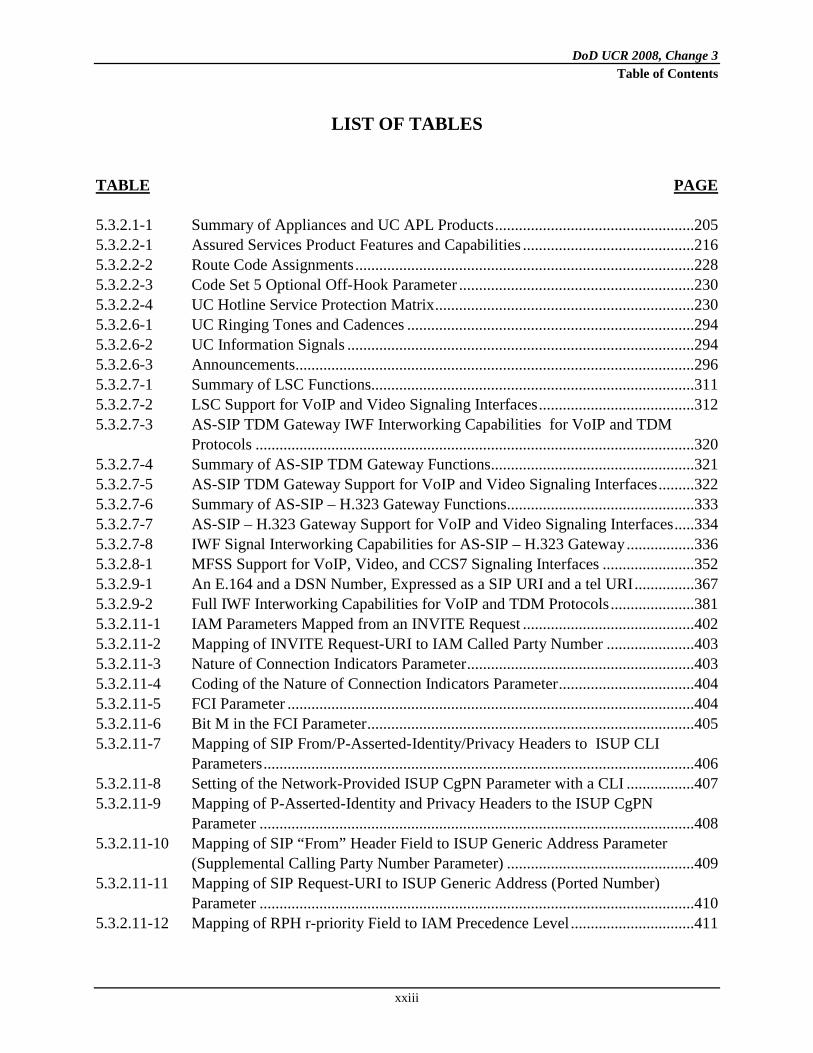
LIST OF TABLES TABLE PAGE 5.3.2.1-1 Summary of Appliances and UC APL Products ..................................................205 5.3.2.2-1 Assured Services Product Features and Capabilities ...........................................216 5.3.2.2-2 Route Code Assignments .....................................................................................228 5.3.2.2-3 Code Set 5 Optional Off-Hook Parameter ...........................................................230 5.3.2.2-4 UC Hotline Service Protection Matrix .................................................................230 5.3.2.6-1 UC Ringing Tones and Cadences ........................................................................294 5.3.2.6-2 UC Information Signals .......................................................................................294 5.3.2.6-3 Announcements....................................................................................................296 5.3.2.7-1 Summary of LSC Functions.................................................................................311 5.3.2.7-2 LSC Support for VoIP and Video Signaling Interfaces .......................................312 5.3.2.7-3 AS-SIP TDM Gateway IWF Interworking Capabilities for VoIP and TDM
Protocols ..............................................................................................................320 5.3.2.7-4 Summary of AS-SIP TDM Gateway Functions...................................................321 5.3.2.7-5 AS-SIP TDM Gateway Support for VoIP and Video Signaling Interfaces .........322 5.3.2.7-6 Summary of AS-SIP – H.323 Gateway Functions...............................................333 5.3.2.7-7 AS-SIP – H.323 Gateway Support for VoIP and Video Signaling Interfaces .....334 5.3.2.7-8 IWF Signal Interworking Capabilities for AS-SIP – H.323 Gateway .................336 5.3.2.8-1 MFSS Support for VoIP, Video, and CCS7 Signaling Interfaces .......................352 5.3.2.9-1 An E.164 and a DSN Number, Expressed as a SIP URI and a tel URI ...............367 5.3.2.9-2 Full IWF Interworking Capabilities for VoIP and TDM Protocols .....................381 5.3.2.11-1 IAM Parameters Mapped from an INVITE Request ...........................................402 5.3.2.11-2 Mapping of INVITE Request-URI to IAM Called Party Number ......................403 5.3.2.11-3 Nature of Connection Indicators Parameter .........................................................403 5.3.2.11-4 Coding of the Nature of Connection Indicators Parameter ..................................404 5.3.2.11-5 FCI Parameter ......................................................................................................404 5.3.2.11-6 Bit M in the FCI Parameter ..................................................................................405 5.3.2.11-7 Mapping of SIP From/P-Asserted-Identity/Privacy Headers to ISUP CLI
Parameters ............................................................................................................406 5.3.2.11-8 Setting of the Network-Provided ISUP CgPN Parameter with a CLI .................407 5.3.2.11-9 Mapping of P-Asserted-Identity and Privacy Headers to the ISUP CgPN
Parameter .............................................................................................................408 5.3.2.11-10 Mapping of SIP “From” Header Field to ISUP Generic Address Parameter
(Supplemental Calling Party Number Parameter) ...............................................409 5.3.2.11-11 Mapping of SIP Request-URI to ISUP Generic Address (Ported Number)
Parameter .............................................................................................................410 5.3.2.11-12 Mapping of RPH r-priority Field to IAM Precedence Level ...............................411
DoD UCR 2008, Change 3 Table of Contents
xxiv
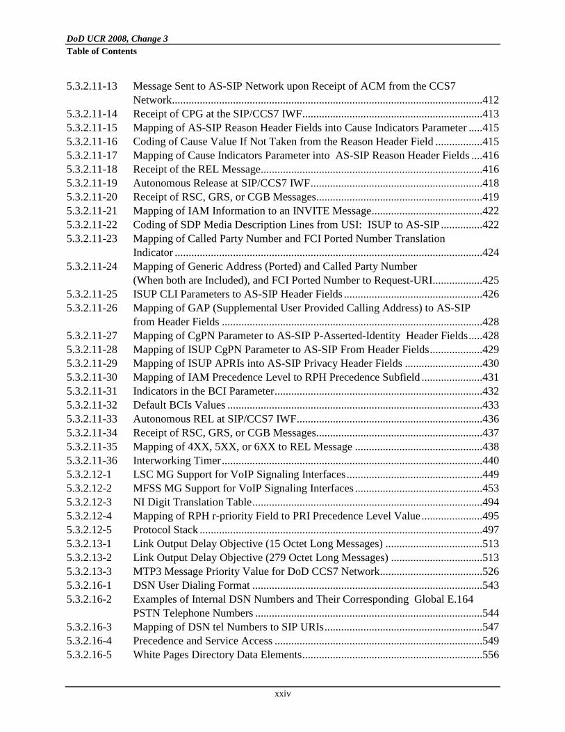
5.3.2.11-13 Message Sent to AS-SIP Network upon Receipt of ACM from the CCS7 Network................................................................................................................412
5.3.2.11-14 Receipt of CPG at the SIP/CCS7 IWF .................................................................413 5.3.2.11-15 Mapping of AS-SIP Reason Header Fields into Cause Indicators Parameter .....415 5.3.2.11-16 Coding of Cause Value If Not Taken from the Reason Header Field .................415 5.3.2.11-17 Mapping of Cause Indicators Parameter into AS-SIP Reason Header Fields ....416 5.3.2.11-18 Receipt of the REL Message................................................................................416 5.3.2.11-19 Autonomous Release at SIP/CCS7 IWF ..............................................................418 5.3.2.11-20 Receipt of RSC, GRS, or CGB Messages............................................................419 5.3.2.11-21 Mapping of IAM Information to an INVITE Message ........................................422 5.3.2.11-22 Coding of SDP Media Description Lines from USI: ISUP to AS-SIP ...............422 5.3.2.11-23 Mapping of Called Party Number and FCI Ported Number Translation
Indicator ...............................................................................................................424 5.3.2.11-24 Mapping of Generic Address (Ported) and Called Party Number
(When both are Included), and FCI Ported Number to Request-URI..................425 5.3.2.11-25 ISUP CLI Parameters to AS-SIP Header Fields ..................................................426 5.3.2.11-26 Mapping of GAP (Supplemental User Provided Calling Address) to AS-SIP
from Header Fields ..............................................................................................428 5.3.2.11-27 Mapping of CgPN Parameter to AS-SIP P-Asserted-Identity Header Fields .....428 5.3.2.11-28 Mapping of ISUP CgPN Parameter to AS-SIP From Header Fields ...................429 5.3.2.11-29 Mapping of ISUP APRIs into AS-SIP Privacy Header Fields ............................430 5.3.2.11-30 Mapping of IAM Precedence Level to RPH Precedence Subfield ......................431 5.3.2.11-31 Indicators in the BCI Parameter ...........................................................................432 5.3.2.11-32 Default BCIs Values ............................................................................................433 5.3.2.11-33 Autonomous REL at SIP/CCS7 IWF ...................................................................436 5.3.2.11-34 Receipt of RSC, GRS, or CGB Messages............................................................437 5.3.2.11-35 Mapping of 4XX, 5XX, or 6XX to REL Message ..............................................438 5.3.2.11-36 Interworking Timer ..............................................................................................440 5.3.2.12-1 LSC MG Support for VoIP Signaling Interfaces .................................................449 5.3.2.12-2 MFSS MG Support for VoIP Signaling Interfaces ..............................................453 5.3.2.12-3 NI Digit Translation Table ...................................................................................494 5.3.2.12-4 Mapping of RPH r-priority Field to PRI Precedence Level Value ......................495 5.3.2.12-5 Protocol Stack ......................................................................................................497 5.3.2.13-1 Link Output Delay Objective (15 Octet Long Messages) ...................................513 5.3.2.13-2 Link Output Delay Objective (279 Octet Long Messages) .................................513 5.3.2.13-3 MTP3 Message Priority Value for DoD CCS7 Network .....................................526 5.3.2.16-1 DSN User Dialing Format ...................................................................................543 5.3.2.16-2 Examples of Internal DSN Numbers and Their Corresponding Global E.164
PSTN Telephone Numbers ..................................................................................544 5.3.2.16-3 Mapping of DSN tel Numbers to SIP URIs .........................................................547 5.3.2.16-4 Precedence and Service Access ...........................................................................549 5.3.2.16-5 White Pages Directory Data Elements .................................................................556

DoD UCR 2008, Change 3 Table of Contents
xxv
5.3.2.17-1 Control Function Crosswalk: TDM to VVoIP ....................................................565 5.3.2.19-1 Call Connect Data Set Information ......................................................................577 5.3.2.19-2 Call Disconnect Data Set .....................................................................................584 5.3.2.19-3 BAF Structure 0625 and Field Populations .........................................................593 5.3.2.28-1 LDAP DIT Attribute Formats ..............................................................................704 5.3.2.30-1 EISC Estimation Parameters ................................................................................775 5.3.2.30-2 Example 1: Current Session Status (No HAIPE Case) .......................................783 5.3.2.30-3 Example 2: AVSC Calculation Assuming the G.711 Session is New (HAIPE
Case) ....................................................................................................................784 5.3.2.30-4 Example 3: Use of Voice MUX with a HAIPE Tunnel ......................................785 5.3.2.30-5 Example 4: Use of Header Compression with a HAIPE Tunnel ........................786 5.3.2.31.3-2 MLPP ISDN PRI Precedence Level Information Element (Code Set 5).............802 5.3.2.31.3-3 Disconnect Message Cause Value .......................................................................803 5.3.2.31.3-4 U.S. National Codepoints for Signal Values .......................................................804 5.3.2.31.3-5 ANSI T1.619a ISDN Setup Message Called Party Number Format ...................804 5.3.2.31.3-6 COI Checks for an Originating Call Request ......................................................809 5.3.2.31.3-7 COI Checks for a Terminating Call Request .......................................................810 5.3.2.31.3-8 CCS7 IAM Precedence Parameter and Subfields ................................................813 5.3.2.31.3-9 Precedence Parameter Subfields Codes ...............................................................813 5.3.2.31.3-10 RELEASE Message Cause Values ......................................................................815 5.3.2.31.3-11 UC Signaling Appliance MLPP CCS7 IAM Called Party Number Format .......815 5.3.2.31.3-12 CAS-to-CCS Trunk Interworking Matrix (EI-to-Trunk and Trunk-to-EI) .........816 5.3.2.31.3-13 CAS-to-CCS Trunk Interworking Matrix (Trunk-to-Trunk) ...............................818 5.3.2.31.4-1 Reselect or Retrial ................................................................................................825 5.3.2.31.4-2 DTMF Generation and Reception from Users and Trunks ..................................827 5.3.2.31.4-3 MF(R1) 2/6 Generation and Reception for Trunks ..............................................827 5.3.2.31.4-4 SETUP Message for MLPP Call..........................................................................837 5.3.2.31.5-1 BRI Access, Call Control, and Signaling.............................................................840 5.3.2.31.5-2 Uniform Interface Configurations for BRIs .........................................................841 5.3.2.31.5-3 BRI Features ........................................................................................................842 5.3.2.31.5-4 PRI Access, Call Control, and Signaling .............................................................843 5.3.2.31.5-5 PRI Features .........................................................................................................844

THIS PAGE INTENTIONALLY LEFT BLANK

DoD UCR 2008, Change 3 Section 5.3.2 – Assured Services Requirements
199
5.3.2 Assured Services Requirements
5.3.2.1 Introduction
This section addresses required functionality, performance, capabilities, and associated technical parameters for the assured services components of the DISN VoIP and Video over IP services. The assured services components described include the PEI, AEI, LSC, MFSS, EBC, and CE Router. In addition, appliance functions associated with the assured services components described and specified in detail include the CCA, MG, SG, NM, and the Open Loop ASAC technique. They are to be used by the product. This section specifies the SBU VVoIP services while Section 6.2, Unique Classified Requirements, specifies the classified VVoIP services. These voice and video services are assumed to be implemented on a converged B/P/C/S LAN and the converged DISN WAN. In this UCR section, “converged” means that all types of services, as defined by the GIG Enterprise Service Profile (GESP), exist simultaneously on the same IP network. Nevertheless, networks still may be separated because of security issues, as specified in Section 5.4, Information Assurance Requirements. However, the UC goal is one “black core” transporting all service types and all classification levels using HAIPE encryption, beginning at the DISN SDNs, then moving to the B/P/C/Ss, and eventually moving to the PEIs, AEIs, and servers. A “call” is a VoIP or Video over IP call that is placed or answered by a PEI/AEI end user, and a “session” is the underlying AS-SIP or Proprietary VoIP session that is processed by the PEI/AEI and the LSC. The human end users see the VoIP or Video over IP “call,” and the assured services network devices, such as the PEI/AEI and the LSC, see the underlying AS-SIP or Proprietary VoIP “session.” “Call” is a “human end-user perspective” term, and “session” is a technical term describing the VoIP signaling and media streams in the appliance that supports an individual end user’s call. The terms PEI and AEI are defined in Appendix A, Definitions, Abbreviations and Acronyms, and References, of this document. In short: 1. A PEI is a user appliance that interacts with the serving appliance (i.e., LSC, MFSS, or
WAN SS) using a proprietary protocol to originate, accept, and/or terminate a voice, video, or data session(s).
2. An AEI is a user appliance that interacts with an associated serving appliance using the AS-SIP to originate, accept, and/or terminate a voice, video, and/or data session(s).
5.3.2.1.1 Requirements Terminology
The terms Required, Conditional, Objective, and Optional are used in this section.

DoD UCR 2008, Change 3 Section 5.3.2 – Assured Services Requirements
200
Requirements are designated as Required or Conditional as defined in Section 5.1.4, General Specification Language. In addition, some requirements may be labeled as “Conditional – Deployable.” This is a variation of the “Conditional” case, where the requirement is Required for Fixed appliances, such as LSCs and MFSSs in Fixed DoD networks, but is Conditional for Deployable appliances, such as LSCs in Deployable DoD networks. In other words, “Conditional – Deployable” means “Required for Fixed appliances, but Conditional for Deployable appliances.” Some requirements refer to, or are based on, Internet Engineering Task Force (IETF) RFCs, American National Standards Institute (ANSI) standards, and International Telecommunications Union (ITU) standards, which allow certain features or capabilities to be designated as Optional for implementation. Vendors or implementers need to be careful to ensure that their products process packets correctly whether or not an Option is actually implemented. For example, in RFC 3711 the Master Key Identifier (MKI) 4-byte field is Optional and may or may not be used in constructing an outgoing voice packet. One end of a voice session may not insert the MKI field into the packet while the other end of the voice session (possibly using a different vendor’s equipment) may choose to insert the MKI field. Since communications in both directions must still be achieved in this situation, it is incumbent on the vendors to process packets correctly whether or not the Option is implemented at each end. The term appliance and its relationship to APL products are defined in Section 5.3.2.1.5, Functional Reference Terminology – APL Products and Appliances.
5.3.2.1.2 Network Reference Model
Figure 5.3.2.1-1, High-Level DISN Assured Services Network Model, shows a typical arrange-ment of an LSC and an MFSS in the DISN assured services voice and video network. This high-level DISN network model was used as the basis for the requirements for the LSC and MFSS in this section. The network is a hierarchical network supporting:
• Local services and features within an Edge Segment (B/P/C/S)
• Global services and features across the UC network
• Services and features to DoD allied networks, DoD coalition networks, and the external PSTN

DoD UCR 2008, Change 3 Section 5.3.2 – Assured Services Requirements
201
Figure 5.3.2.1-1. High-Level DISN Assured Services Network Model
The network consists of UC APL products, such as the LSC and the MFSS. These products are interconnected via the converged IP transport network to support the following necessary functions for global services and features:
• Signaling functions (e.g., call control and feature control signaling)
• Bearer functions (e.g., interworking between packetized voice and TDM voice media streams; support for various media stream Coder/Decoders (codecs))
• Management functions (e.g., appliance fault, configuration, accounting,
performance, and security (FCAPS) management)
• Information assurance functions

DoD UCR 2008, Change 3 Section 5.3.2 – Assured Services Requirements
202
In 2010, the network is expected to allow existing TDM trunk and signaling link connectivity to remain, including
• PRI, CAS, and DoD CCS7 trunks and signaling links between MFSSs, and
• PRI, CAS, and DoD CCS7 trunks and signaling links between LSCs and MFSSs, when needed.
In addition, PRI, CAS, and DoD CCS7 connectivity from MFSSs to other DoD TDM switches will still exist in the network.
5.3.2.1.3 General Assumptions
The following five general assumptions apply to the components described throughout this section (NOTE: The assumptions apply to the CCA, SG, and NM. In addition, the assumptions were used to develop VoIP, Facsimile over IP (FoIP), Modem over IP (MoIP), SCIP over IP, and ISDN over IP requirements for the MG within the UCR.): 1. The LSC and MFSS will support 911 services for VoIP and TDM end users. Within the
United States, 911 calls from VoIP and TDM lines may be routed either to a DoD Emergency Response Center, or to a PSTN 911 Selective Router (SR) and Public Safety Answering Point (PSAP), depending on the LSC or MFSS configuration. The emergency services network that handles DoD and PSTN 911 calls may be TDM based or IP based. Outside the United States, 911 calls from VoIP and TDM lines may be routed to a DoD Emergency Response Center (if one exists within the DoD location), depending on the LSC or MFSS configuration. The details of the 911-service infrastructure within the network are outside the scope of the CCA VoIP and Video over IP requirements in this section.
2. In some cases, a function like an MGC or MG will be labeled as Conditional – Deployable in this section. In these cases, Conditional – Deployable means that normally this function is not used in a Deployable environment, but may be used in that environment under certain conditions. When this function is used in that environment, the function should conform to the MG requirements in this section. For example, an LSC deployed in one camp in a war zone overseas may not use an MGC or an MG, while another LSC deployed in another camp in the same zone may use both of them.
3. The CCA VoIP, FoIP, MoIP, SCIP over IP, and ISDN over IP requirements in this section assume that all functions within an individual appliance (i.e., LSC or MFSS) are provided by the same appliance supplier. Within a collection of network appliances, the same
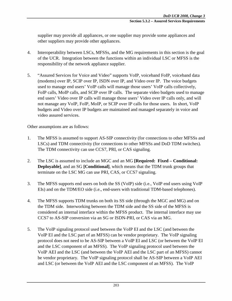
DoD UCR 2008, Change 3 Section 5.3.2 – Assured Services Requirements
203
supplier may provide all appliances, or one supplier may provide some appliances and other suppliers may provide other appliances.
4. Interoperability between LSCs, MFSSs, and the MG requirements in this section is the goal of the UCR. Integration between the functions within an individual LSC or MFSS is the responsibility of the network appliance supplier.
5. “Assured Services for Voice and Video” supports VoIP, voiceband FoIP, voiceband data (modems) over IP, SCIP over IP, ISDN over IP, and Video over IP. The voice budgets used to manage end users’ VoIP calls will manage those users’ VoIP calls collectively, FoIP calls, MoIP calls, and SCIP over IP calls. The separate video budgets used to manage end users’ Video over IP calls will manage those users’ Video over IP calls only, and will not manage any VoIP, FoIP, MoIP, or SCIP over IP calls for those users. In short, VoIP budgets and Video over IP budgets are maintained and managed separately in voice and video assured services.
Other assumptions are as follows: 1. The MFSS is assumed to support AS-SIP connectivity (for connections to other MFSSs and
LSCs) and TDM connectivity (for connections to other MFSSs and DoD TDM switches). The TDM connectivity can use CCS7, PRI, or CAS signaling.
2. The LSC is assumed to include an MGC and an MG [Required: Fixed – Conditional: Deployable], and an SG [Conditional], which means that the TDM trunk groups that terminate on the LSC MG can use PRI, CAS, or CCS7 signaling.
3. The MFSS supports end users on both the SS (VoIP) side (i.e., VoIP end users using VoIP EIs) and on the TDM/EO side (i.e., end-users with traditional TDM-based telephones).
4. The MFSS supports TDM trunks on both its SS side (through the MGC and MG) and on the TDM side. Interworking between the TDM side and the SS side of the MFSS is considered an internal interface within the MFSS product. The internal interface may use CCS7 to AS-SIP conversion via an SG or ISDN-PRI, or CAS via an MG.
5. The VoIP signaling protocol used between the VoIP EI and the LSC (and between the VoIP EI and the LSC part of an MFSS) can be vendor proprietary. The VoIP signaling protocol does not need to be AS-SIP between a VoIP EI and LSC (or between the VoIP EI and the LSC component of an MFSS). The VoIP signaling protocol used between the VoIP AEI and the LSC (and between the VoIP AEI and the LSC part of an MFSS) cannot be vendor proprietary. The VoIP signaling protocol shall be AS-SIP between a VoIP AEI and LSC (or between the VoIP AEI and the LSC component of an MFSS). The VoIP
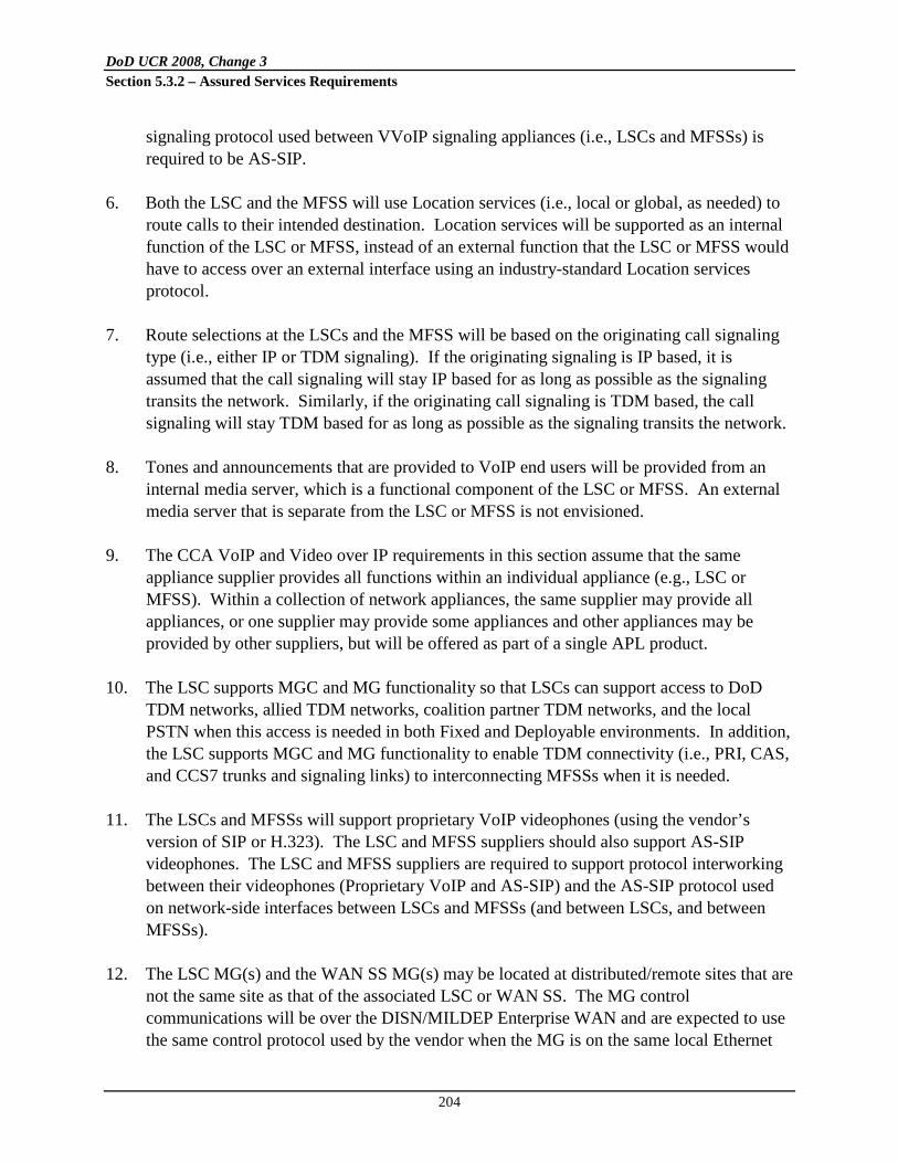
DoD UCR 2008, Change 3 Section 5.3.2 – Assured Services Requirements
204
signaling protocol used between VVoIP signaling appliances (i.e., LSCs and MFSSs) is required to be AS-SIP.
6. Both the LSC and the MFSS will use Location services (i.e., local or global, as needed) to route calls to their intended destination. Location services will be supported as an internal function of the LSC or MFSS, instead of an external function that the LSC or MFSS would have to access over an external interface using an industry-standard Location services protocol.
7. Route selections at the LSCs and the MFSS will be based on the originating call signaling type (i.e., either IP or TDM signaling). If the originating signaling is IP based, it is assumed that the call signaling will stay IP based for as long as possible as the signaling transits the network. Similarly, if the originating call signaling is TDM based, the call signaling will stay TDM based for as long as possible as the signaling transits the network.
8. Tones and announcements that are provided to VoIP end users will be provided from an internal media server, which is a functional component of the LSC or MFSS. An external media server that is separate from the LSC or MFSS is not envisioned.
9. The CCA VoIP and Video over IP requirements in this section assume that the same appliance supplier provides all functions within an individual appliance (e.g., LSC or MFSS). Within a collection of network appliances, the same supplier may provide all appliances, or one supplier may provide some appliances and other appliances may be provided by other suppliers, but will be offered as part of a single APL product.
10. The LSC supports MGC and MG functionality so that LSCs can support access to DoD TDM networks, allied TDM networks, coalition partner TDM networks, and the local PSTN when this access is needed in both Fixed and Deployable environments. In addition, the LSC supports MGC and MG functionality to enable TDM connectivity (i.e., PRI, CAS, and CCS7 trunks and signaling links) to interconnecting MFSSs when it is needed.
11. The LSCs and MFSSs will support proprietary VoIP videophones (using the vendor’s version of SIP or H.323). The LSC and MFSS suppliers should also support AS-SIP videophones. The LSC and MFSS suppliers are required to support protocol interworking between their videophones (Proprietary VoIP and AS-SIP) and the AS-SIP protocol used on network-side interfaces between LSCs and MFSSs (and between LSCs, and between MFSSs).
12. The LSC MG(s) and the WAN SS MG(s) may be located at distributed/remote sites that are not the same site as that of the associated LSC or WAN SS. The MG control communications will be over the DISN/MILDEP Enterprise WAN and are expected to use the same control protocol used by the vendor when the MG is on the same local Ethernet

DoD UCR 2008, Change 3 Section 5.3.2 – Assured Services Requirements
205
LAN as the LSC CCA or WAN SS. This assumption is intended to allow the MILDEPs to use regional LSCs or WAN SSs enterprise architectures. It is the MILDEP’s responsibility to ensure that when such enterprise architectures are employed, the signaling delays and media path delays remain within the requirements specified in Section 5.3.3, Network Infrastructure End-to-End Performance Requirements. In addition, the Information Assurance requirements of Section 5.4, Information Assurance Requirements, including the use of firewalls still apply.
5.3.2.1.4 Information Assurance
Information Assurance Requirements are described in Section 5.4, Information Assurance Requirements. The Information Assurance function within the products and appliance functions ensures that end users, PEIs, AEIs, MGs, SGs, and EBCs that use the appliance are all properly authenticated by the appliance. The Information Assurance function also ensures that VoIP signaling streams and media streams that traverse the appliance and its ASLAN are encrypted properly (using SIP/Transport Layer Security (TLS) and Secure Real Time Protocol (SRTP), respectively).
5.3.2.1.5 Functional Reference Terminology – APL Products and Appliances
This paragraph describes relationships between VoIP and Video over IP network components, appliance functions, and UC products to be tested for APL certification. The term “appliance function” is introduced because IP-based UC APL products will often consist of software functions and features (e.g., appliances) that are distributed over several hardware components connected over a network infrastructure (e.g., LAN), while a TDM-based APL product, such as an EO, consists of a single unit containing all required telephony functions. Appliances operate at the signaling, bearer, and NM planes. Appliance functions are described and referred to throughout the UCR, but are not considered products for APL certification; rather, they are functions and features that form a part of a UC APL product. Table 5.3.2.1-1, Summary of Appliances and UC APL Products, provides a summary of appliances and APL products.
Table 5.3.2.1-1. Summary of Appliances and UC APL Products
ITEM ITEM
CATEGORY ROLE AND FUNCTIONS EI Appliance Appliance part of LSC AEI APL Product Product consisting of a single appliance MG Appliance Media conversion function as part of the LSC and
MFSS SG Appliance Signaling conversion function as part of the LSC and
MFSS

DoD UCR 2008, Change 3 Section 5.3.2 – Assured Services Requirements
206
ITEM ITEM
CATEGORY ROLE AND FUNCTIONS AS-SIP Signaling Appliance Appliance Appliance function within an LSC and MFSS that
provides AS-SIP signaling capability CCA Appliance Appliance function within an LSC and MFSS that
performs parts of session control and signaling functions
Registrar Appliance Appliance function that stores the location of a registrant and its profile
Registrant Appliance Appliance function used to register with the network to seek and gain authority to invoke services or resources from the network
LAN Switch/Router (Access, Distribution, and Core)
APL Products APL products used in an ASLAN
SEI APL Product Product consisting of a single appliance LSC APL Product Product providing many local telephony functions MFSS APL Product Large, complex product providing many local and
WAN-related telephony functions WAN SS APL Product A standalone APL product that acts as an AS-SIP
B2BUA within the UC framework. It provides the equivalent functionality of a commercial SS and has similar functionality to the SS component of an MFSS.
Dual Signaling Softswitch (DSSS)
APL product A WAN SS used in the Classified network that has both H.323 and AS-SIP signaling
Dual Signaling Multipoint Control Unit (DSMCU)
APL product APL product that supports multiple video conferencing signaling protocols, H.320, H.323, and AS-SIP
EBC APL Product Product providing firewall functions. Protects voice and video devices from attacks that originate from outside of the Enclave or B/P/C/S.
RSF APL Product Product providing firewall functions. Protects the LSC, MFSS or WAN SS from attacks that originate from inside of the Enclave or B/P/C/S.
CE Router APL Product Product providing routing functions at the enclave boundary
DISN WAN P/PE Router APL product Product providing routing of IP packets DISN MSPP APL Product Product providing transport access to the DISN
WAN M1-3 Multiplexer APL Product Product providing transport interface to the DISN DISN Optical Switch APL product Product serving as an optical transport node
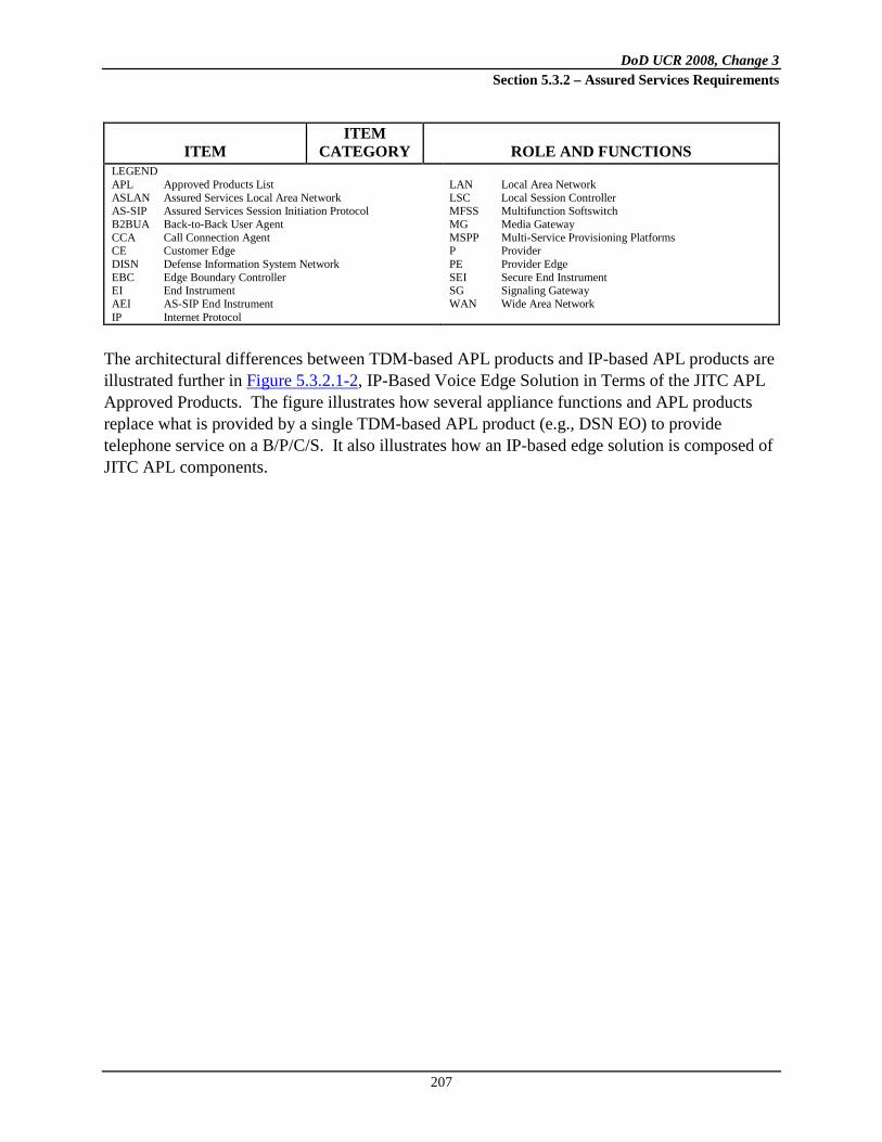
DoD UCR 2008, Change 3 Section 5.3.2 – Assured Services Requirements
207
ITEM ITEM
CATEGORY ROLE AND FUNCTIONS LEGEND APL Approved Products List ASLAN Assured Services Local Area Network AS-SIP Assured Services Session Initiation Protocol B2BUA Back-to-Back User Agent CCA Call Connection Agent CE Customer Edge DISN Defense Information System Network EBC Edge Boundary Controller EI End Instrument AEI AS-SIP End Instrument IP Internet Protocol
LAN Local Area Network LSC Local Session Controller MFSS Multifunction Softswitch MG Media Gateway MSPP Multi-Service Provisioning Platforms P Provider PE Provider Edge SEI Secure End Instrument SG Signaling Gateway WAN Wide Area Network
The architectural differences between TDM-based APL products and IP-based APL products are illustrated further in Figure 5.3.2.1-2, IP-Based Voice Edge Solution in Terms of the JITC APL Approved Products. The figure illustrates how several appliance functions and APL products replace what is provided by a single TDM-based APL product (e.g., DSN EO) to provide telephone service on a B/P/C/S. It also illustrates how an IP-based edge solution is composed of JITC APL components.
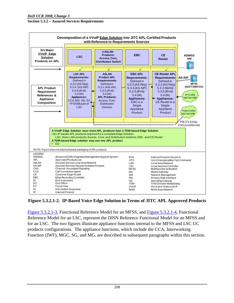
DoD UCR 2008, Change 3 Section 5.3.2 – Assured Services Requirements
208
Figure 5.3.2.1-2. IP-Based Voice Edge Solution in Terms of JITC APL Approved Products Figure 5.3.2.1-3, Functional Reference Model for an MFSS, and Figure 5.3.2.1-4, Functional Reference Model for an LSC, represent the DISN Reference Functional Model for an MFSS and for an LSC. The two figures illustrate appliance functions internal to the MFSS and LSC UC products configurations. The appliance functions, which include the CCA, Interworking Function (IWF), MGC, SG, and MG, are described in subsequent paragraphs within this section.
Decomposition of a VVoIP Edge Solution into JITC APL-Certified Productswith Reference to Requirements Sources
IPv6 Internet Protocol Version 6JITC Joint Interoperability Test Command LAN Local Area NetworkLSC Local Session ControllerMFSS Multifunction SoftswtichMG Media GatewayNM Network ManagementPRI Primary Rate InterfaceSG Signaling GatewayTDM Time Division MultiplexingVVoIP Voice and Video over IPWAN Wide Area Network
PRI (T1.619a),CAS (conditional)
AS-SIP
Six MajorVVoIP Edge
SolutionProducts on APL
APL ProductRequirement References &
Appliance Composition
A VVoIP Edge Solution uses more APL products than a TDM-based Edge Solution• Six IP-based APL products required for a complete Edge Solution.
- LSC, three LAN products: Access, Core, and Distribution switches, EBC, and CE RouterA TDM-based Edge solution may use one APL product• EO
ADIMSSNMLSC
3 ASLAN Products:
Access, Core,Distribution Switch
EBC
ASLANProduct APL
Requirements:Defined in
5.3.1 (ASLAN)5.3.5 (IPv6)
5.4 (IA)APL Products:Access, Core,Distribution
Devices
LSC APLRequirements:
Defined in5.3.2 (AS Req)5.3.4 (AS-SIP)
5.3.5 (IPv6)5.4 (IA)
Appliances:CCA, MG, SG, EI*
*FY2008 part of LSC
EBC APLRequirements:
Def ined in5.3.2 (AS Req) 5.3.4 (AS-SIP)
5.3.5 (IPv6)5.4 (IA)
Appliances:EBC is a Single
ApplianceProduct
CERouter
CE Router APLRequirements:
Def ined in5.3.2 (AS Req)
5.3.3 (WAN)5.3.5 (IPv6)
5.4 (IA)Appliances:
CE Router is a Single
ApplianceProduct
MFSS(SOFTSWITCH)
IP CORENETWORK
TDM CORENETWORK
LEGENDADIMSS Advanced DSN Integrated Management Support SystemAPL Approved Products ListASLAN Assured Service Local Area NetworkAS-SIP Assured Services Session Initiation ProtocolCAS Channel Associated SignalingCCA Call Connection AgentCE Customer Edge RouterEBC Edge Boundary ControllerEI End InstrumentEO End OfficeFY Fiscal YearIA Information AssuranceIP Internet Protocol
NOTE: Figure does not depict physical packaging of APL products.

DoD UCR 2008, Change 3 Section 5.3.2 – Assured Services Requirements
209
Figure 5.3.2.1-3. Functional Reference Model – MFSS
LLS
Softswitch Side
Service Control Functions
AS-SIP
AEI
IA
Managem
ent
MFSS or
WAN SS
EI
MFS
DoD, Allied, orCoalition Partner
ISDN PRI or CAS
Analog or ISDN BRI
CCS7, PRI, or CAS
LSC
AS-SIPIP
MFSS UC Product
CCS7
**
Global Location Service
CCAIWFPSTN
EO or Tandem Switch
Tan-dem
EO
SMEOCCS7**, PRI, or CAS*
ISDN PRI or CAS*
ISDN PRI or CAS*
PBX orSMEO
ISDN PRI or CAS
MFS
CCS7**, PRI, or CAS*MFSS
Session Control and Signaling Functions
Managem
ent
* Support for CAS is
Conditionalfor the
Softswitch side of an
MFSS
USFMediaServer
TDMSide
IP Transport Interface Functions
SG**
MG
WAN-Level ASAC
SIPB2BUA
SIPRegistrar
CCA
IWFMGC
SCS Functions
H.248 orProprietary
PBX orSMEO
EO orMFS
EO
PBX orSMEO
MFS
LEGEND:AEI AS-SIP End InstrumentASAC Assured Service Admission ControlASLAN Assured Services Local Area NetworkAS-SIP Assured Services Session Initiation ProtocolB2BUA Back-to-Back User AgentCAS Channel Associated SignalingCCA Call Connection AgentCCS7 Common Channel Signaling No. 7DoD Department of DefenseEBC Edge Border ControllerEO End OfficeIA Information AssuranceISDN Integrated Services Digital NetworkIWF Interworking FunctionLLC Logical Link Control [sublayer]
LSC Local Session ControllerMFS Multifunction SwitchMFSS Multifunction SoftswitchMG Media GatewayMGC Media Gateway ControllerPBX Private Branch ExchangePEI Proprietary End InstrumentPRI Primary Rate InterfacePSTN Public Switched Telephone NetworkSCS Session Control and SignalingSG Signaling GatewaySIP Session Initiation ProtocolSUT System Under TestTDM Time Division MultiplexerUSF User Service and FeatureWAN Wide Area Network
** Support for an SG
and CCS7 isConditional
for the Softswitch side of an
MFSS
Note: The PEI (using Proprietary VoIP and Video) is part of the MFSS UC Product ; the AEI (using AS-SIP VoIP and Video) is not.
PEI
EBCProprietary VoIP & Video
ASLAN
IP
AS-SIPEBC

DoD UCR 2008, Change 3 Section 5.3.2 – Assured Services Requirements
210
Figure 5.3.2.1-4. Functional Reference Model – LSC
All interfaces between appliances contained with the MFSS and LSC shown in Figure 5.3.2.1-3 and Figure 5.3.2.1-4 are internal, proprietary interfaces. Interfaces between one APL product and functional entities in physically different APL products are standards-based external interfaces.
*Support for an SG & CCS7 is Conditional for an LSC.**Support for CAS is Conditional for an LSC.
DoD, Allied, orCoalitionPartner
CCS7*, PRI,or CAS**
ISDN PRIor CAS**
ISDN PRIor CAS**
AEI
H.248 orProprietary
(ConditionalTactical)
ISDN PRIor CAS**
PSTN
MG
EO
SMEO
PBX
EO
TDM
CCS7*
IWF
SG*CCA
LSC-Level ASAC
SCS Functions
LLS
Service Control Functions
LSC UC ProductTest Configuration
ASLANAS-SIP
MFSS or
WAN SS
EBC
AS-SIP
MGC
LEGEND:AEI AS-SIP End InstrumentASAC Assured Service Admission ControlASLAN Assured Services Local Area NetworkAS-SIP Assured Services Session Initiation ProtocolB2BUA Back-to-Back User AgentCAS Channel Associated SignalingCCA Call Connection AgentCCS7 Common Channel Signaling No. 7DoD Department of DefenseEBC Edge Border ControllerEO End OfficeISDN Integrated Services Digital NetworkIWF Interworking FunctionLLS Local Location Service
LSC Local Session ControllerMFS Multifunction SwitchMFSS Multifunction SoftswitchMG Media GatewayMGC Media Gateway ControllerPBX Private Branch ExchangePEI Proprietary End InstrumentPRI Primary Rate InterfacePSTN Public Switched Telephone NetworkSCS Session Control and SignalingSG Signaling GatewaySIP Session Initiation ProtocolTDM Time Division MultiplexerUC Unified CapabilitiesUFS User Features and Services
MediaServer UFS Information
Assurance M
anagement
SIPB2BUA
SIPRegistrar
Transport Interface Functions
Note: The PEI (using Proprietary VoIP and Video) is part of the LSC UC Product; the AEI (using AS-SIP VoIP and Video) is not.
PEI
ProprietaryVoIP & Video

DoD UCR 2008, Change 3 Section 5.3.2 – Assured Services Requirements
211
5.3.2.2 Assured Services Product Features and Capabilities
5.3.2.2.1 Overview of VoIP and Video over IP Product Design Attributes
A key component of the military robust VoIP and Video over IP product design is the Assured Services subsystem. The Assured Services subsystem addresses Assured Services by replacing the current TDM-based Multilevel Precedence and Preemption (MLPP) functionality with IP-based ASLANs and ASAC. The Assured Services subsystem, in conjunction with the ASLAN subsystem, and the DISN WAN subsystem make up the total product that is required to initiate, supervise, and terminate voice and video, precedence and preemption sessions on an EI-to-EI basis, while functioning within a converged total DoD UC network. The logical location of the major VVoIP attributes within the UC E2E system is shown in Figure 5.3.2.2-1, Overview of VVoIP System Design Attributes. The location of attributes in terms of Edge (B/P/C/S) and the network infrastructure (access and DISN Core) is depicted, and the differentiation between assured service and non-assured service is shown between the top half of the diagram and the bottom half of the diagram, respectively. The functions contained in the boxes located within the top half of Figure 5.3.2.2-1 constitute the scope of the Assured Services subsystem, while the placement of the boxes indicates where in the overall VoIP and Video over IP product design (WAN to Edge) the functions logically reside. Voice, video, and data sessions are converged in the DISN WAN and the ASLAN, while the Assured Services subsystem in 2012 is anticipated to support voice, video, and non-real-time sessions with priority.
5.3.2.2.1.1 Attributes within the Edge Segment
The attributes within the Edge Segment include the following: 1. Nonblocking ASLAN
2.
. At the Edge, the design has an ASLAN that is designed as nonblocking for voice and video traffic.
Traffic Admission Control
3.
. The LSCs on a B/P/C/S use an Open Loop ASAC technique to ensure that only as many user-originated sessions (voice and video) in precedence order are permitted on the traffic-engineered access circuit, consistent with maintaining a voice quality of 4.0 as measured by the MOS method.
Call Preemption
. Lower precedence sessions will be preempted on the access circuit to accept the LSC setup of higher precedence level outgoing or incoming session establishment requests.

DoD UCR 2008, Change 3 Section 5.3.2 – Assured Services Requirements
212
Figure 5.3.2.2-1. Overview of VVoIP System Design Attributes
4. Voice and Video Traffic Service Classification and Priority Queues
Network Infrastructure (SATCOM) for Deployed Customer Edge (B/P/C/S) or Deployed
AS LAN/CAN/MAN DISN Assured Services
• Dual Homing for Mission-Critical Users
• Teleport or Deployed Gateway
• SATCOM Deployed • BW Constrained • Deployed Small
Footprint Driving E2E IP
• Meet AS SLAs (e.g., GoS MOS)
• DSCPs • PHB Determined by DoD
Networks based on RTS SLAs
• MPLS • Encryption: HAIPE Not
Used for SBU• HAIPE used for Classified• MFSs become MFSSs
Assured Service Requirements
Separate Classified & SBU Open
Loop Assured Services
Admission Control
(ASAC) and Signaling
Separate Classified & SBU Assured
Services LANs
Class & SBU Voice, Video,Legacy & IP
End Instrumentswith Precedence
Class & SBU Non-RTS (e.g., DMS,
Collaboration) without Precedence
Non-UC Best EffortHAIPE
UC END-TO-END
Network Core Network Edge
Augmented Legacy Network Management for IP Services with Manual Response to Policy Changes
Signaling & Directory Leverages Investment in Legacy STPs & Accommodates Diversity at theEdge (CCS7, CAS, PRI, H.320, H.323, Proprietary) AS-SIP & IPv6 Introduction
LEGEND:AR Aggregation RouterAS Assured ServicesASAC Assured Services Admission ControlAS-SIP Assured Services SIPBW BandwidthC2 Command and ControlCAN Campus Area NetworkCAS Channel Associated SignalingCCS7 Common Channel Signaling System
No. 7CE Customer Edge RouterDISN Defense Information Systems NetworkDMS Defense Message System
DSCP Differentiated Services Code PointE2E End to EndGIG Global Information GridGOS Grade of ServiceHAIPE High Assurance Internet Protocol
Encryptor IP Internet ProtocolIPv6 Internet Protocol version 6LAN Local Area NetworkMAN Metropolitan Area NetworkMFS Multifunction SwitchMFSS Multifunction SoftswitchMOS Mean Opinion Score
MPLS Multiprotocol Label Switching
OCONUS Outside CONUSPHB Per Hop BehaviorPRI Primary Rate InterfaceS&U Secret and UnclassifiedSATCOM Satellite CommunicationsSBU Sensitive But UnclassifiedSDN Service Delivery NodeSLA Service Level AgreementSTP Signal Transfer Point
S&U AR
S&U CE
. In terms of the CE Router queuing structure, voice and video traffic will be assigned to the higher priority queues by Aggregated Service Class as described in Section 5.3.3, Network Infrastructure End-to-End Performance Requirements.

DoD UCR 2008, Change 3 Section 5.3.2 – Assured Services Requirements
213
5.3.2.2.1.2 Attributes within the DISN WAN (Access/Distribution and Core)
Under the access part of the DISN WAN, dual homing is required between the CE Router and the AR that serve an ASLAN having FO/F users, I/P users, and R users. Dual homing is conditional for cases where only ROUTINE users (I/P (ROUTINE) and non-I/P users) are supported. In 2010, SBU ASLANs do not use HAIPEs. The DISN Core part of the DISN WAN is assumed to be bandwidth rich, i.e., the bandwidth from the AR to AR, for whatever AR queue the voice and video traffic is placed in, is greater than or equal to the voice and video traffic-engineered load/bandwidth required for the voice/video busy-hour traffic in each of the DISN worldwide geographic locations. Since the ASLAN is required to be implemented as non-blocking for voice and video traffic, the access circuit from the Customer Edge Segment to the DISN Core SDN is the only potential bandwidth-limited resource requiring the use of ASAC to prevent session overload from the Edge Segment. The DISN WAN provides high availability (99.96 percent or greater) using dual-homed access circuits and the MPLS fast reroute (FRR) in the Network Core. Naturally, users are provided a lower availability if they choose not to or cannot implement dual homing.
5.3.2.2.1.3 E2E Protocol Planes
End-to-end services are set up, managed, and controlled by a series of functions or protocols that operate in three planes commonly referred to as signaling, bearer, and NM planes. The signaling plane is associated with the signaling and control protocols, such as AS-SIP, H.323, and RSVP. The transport plane is associated with the bearer traffic and protocols, such as SRTP and RTCP. The NM plane is associated with NM protocols and is used to transfer status and configuration information between an NMS and a network appliance. Network management protocols include SNMP, Common Open Policy Service (COPS), and Secure Shell Version 2 (SSHv2).
5.3.2.2.1.4 DSCP Packet Marking
1. [Required: PEI, AEI, LSC, MFSS] As part of the session setup process, the LSC controls what DSCP to use in the subsequent session media stream packets.
For inter-LSC media sessions (across the WAN), and intra-LSC
a. The PEI shall be commanded by the LSC about which DSCP to insert in the session media stream packets, or
media sessions (internal to the enclave),

DoD UCR 2008, Change 3 Section 5.3.2 – Assured Services Requirements
214
b. The PEI shall populate the DSCP marking on its own;
c. The AEI shall populate the DSCP marking on its own. 2. [Required: PEI, AEI, LSC, MFSS] The exact DSCP method used by the implementer
shall comply with Section 5.3.3, Network Infrastructure End-to-End Performance Requirements. The session’s media type (e.g., audio vs. video) and the session’s precedence level (R, P, I, F, or FO) shall be used to determine the media stream DSCP for that session.
This DSCP marking data can be provisioned in the AEI or PEI as part of the information downloaded to the EI from a provisioning server after the EI completes its registration with the LSC.
5.3.2.2.2 Assured Services Subsystem
The Assured Services subsystem, shown in Figure 5.3.2.2-2, Assured Services Subsystem Functional Diagram, the DISN WAN subproduct (see Section 5.3.3, Network Infrastructure End-to-End Performance Requirements), and the ASLAN subproduct (see Section 5.3.1, ASLAN Infrastructure Product Requirements) make up the total system. These subproducts are required to initiate, supervise, and terminate voice and video, precedence and preemption sessions on an EI-to-EI basis, while functioning within a converged DoD network. The functions contained in the Figure 5.3.2.2-2 boxes and the EBC router symbol constitute the scope of the Assured Services subsystem, while the placement of the boxes indicates where in the overall system (WAN to Edge) the functions logically reside. Voice, video, and data sessions are converged in the DISN WAN and the ASLAN, while assured services are provided for voice and video sessions only. The functional behavior and performance metrics for each of the assured services major functions defined by a box in Figure 5.3.2.2-2 and subordinate functions listed within each box are specified in this section. In addition, the interfaces between the major functional groupings (defined by a box) are specified in terms of electrical interfaces, protocols operating over these electrical interfaces, and their associated parameters. Best commercial practices and existing standards will be specified to the maximum extent possible, and any deviations or enhancements to these will be specified in detail. The following list of capabilities and functional elements are defined and specified:
• Legacy and IP EIs with precedence marking capability

DoD UCR 2008, Change 3 Section 5.3.2 – Assured Services Requirements
215
Figure 5.3.2.2-2. Assured Services Subsystem Functional Diagram
• ASAC as part of the LSC functions
• The ability to complete a higher precedence session to a busy PEI or AEI by
interrupting the current session
• EBC (firewall/CE Router)
• Local call control (LSC)
• Session control and signaling (SCS)
• Local and global directories
PHB Per Hop BehaviorSCS Session Control and SignalingSG Signaling GatewaySLA Service Level AgreementU-AR Unsecure Aggregated RouterWAN Wide Area Network
ASLAN& UC
End Instrument •Signaling Client•COS Packet Marking•Precedence
Assignment•LSC Authentication•User Interface
MFSS•LSC •SCS•NM•Global Call Request Routing (Location) Services•MGC•Appliance Authentication & IA Services•SG
Access Circuit
MFSS (WAN Level) ASAC• State of RTS WAN Sessions•Access Layer SLA Enforcer• Precedence Level of each RTS Session• Preemption of Core Segment Sessions (includesBlocking) [Objective]• Process Input from Closed Loop System [Objective]•Directs MFSS SCS to modify resources [Objective]
Trusted Relationships Required Among All Architectural Functions
Media Gateway
Media GatewayLSC
ASAC
MFSSASAC
CE Router•Traffic Conditioning•Bandwidth Management•PHB
EBC•Topology Hiding•Opening and Closing
“Pinholes”
NM/PBNM•Control to MFSS,
LSC, EBC, ASAC & CE Routers
LSC• SCS•NM• Local Location and Directory Services•MGC [Conditional]•Appliance Authentication & IA Services• EI & User Authentication & Authorization•User Features & Services
NMNM
NM
NM
EBC
Customer Edge (B/P/C/S)
AS LAN/CAN/MAN DISN C2 Services
UC END-TO-END
Network Core Network Edge
DISN WAN
LEGENDAS Assured ServicesASAC Assured Service Admission ControlASLAN Assured Service Local Area NetworkB/P/C/S Base/Post/Camp/StationC2 Command and ControlCE Customer Edge RouterCOS Class of ServiceDISN Defense Information Systems Network
EBC Edge Boundary ControllerEI End InstrumentIA Information AssuranceLSC Local Session ControllerMFSS Multifunction SoftswitchMGC Media Gateway ControllerNM Network ManagementPBNM Policy Based NM
LSC Level ASAC• State of Local LAN Sessions• State of Local Access Layer Sessions• Precedence Level Authorized for Each Session• Preemption of LAN and Access Layer Sessions (Includes Blocking)• Local Access Bandwidth Used• Local Access Bandwidth Available•Directs LSC SCS to Modify Resources
U-AR
CE

DoD UCR 2008, Change 3 Section 5.3.2 – Assured Services Requirements
216
• User Features and Services (UFS) (voicemail and attendant services)
• Network level call control (MFSS)
• MGC
• MGs
• Media gatekeeper (H.323)
• NM with PBNM
5.3.2.2.2.1 Voice Features and Capabilities
This section describes assured services capabilities and characteristics together with the design and performance metrics associated with each capability or characteristic. For brevity, the rationale behind the selected metrics is not provided in this section, but references to other sections and documents are provided where available. The Government retains the right to change, modify, or alter any of the specified capabilities or characteristics and performance metrics as requirements and technology mature. Table 5.3.2.2-1, Assured Services Product Features and Capabilities, summarizes the product features and capabilities.
Table 5.3.2.2-1. Assured Services Product Features and Capabilities
FEATURE AND CAPABILITY UCR
SECTION REFERENCE DOCUMENT
1 Precedence Call (Session) Waiting Required: PEI, AEI, LSC, MFSS, WAN SS]
5.3.2.2.2.1.2
Telcordia Technologies GR-571-CORE Telcordia Technologies GR-572-CORE
2 Call (Session) Forwarding [Required with Conditional subfeatures: PEI, AEI, LSC, MFSS, WAN SS]
5.3.2.2.2.1.1
Telcordia Technologies GR-217-CORE Telcordia Technologies GR-580-CORE Telcordia Technologies GR-586-CORE
3 Call (Session) Transfer [Required: PEI, AEI, LSC, MFSS, WAN SS]
5.3.2.2.2.1.3
4 Call (Session) Hold [Required: PEI, AEI, LSC, MFSS, WAN SS]
5.3.2.2.2.1.4
5 UC Conferencing [Required: PEI, AEI, LSC, MFSS, WAN SS]
5.3.2.2.2.1.5
6 3-Way Calling [Required: PEI, AEI, LSC, MFSS, WAN SS]
5.3.2.2.2.1.6

DoD UCR 2008, Change 3 Section 5.3.2 – Assured Services Requirements
217
FEATURE AND CAPABILITY UCR
SECTION REFERENCE DOCUMENT
7 Hotline Service [Conditional: PEI, LSC – Required: MFSS, WAN SS]
5.3.2.2.2.1.7
8 Calling Number Delivery [Required: PEI, AEI, LSC, MFSS, WAN SS]
5.3.2.2.2.1.8
Telcordia Technologies GR-317-CORE
9 Call Pick-Up [Conditional: PEI, AEI, LSC, MFSS, WAN SS]
5.3.2.2.2.1.9
Telcordia Technologies GR-590-CORE
[Required: PEI, AEI, LSC, MFSS, WAN SS] It is expected that all Assured Services products, such as LSCs and MFSSs, will support vendor-proprietary VVoIP features and capabilities, in addition to supporting the required VVoIP features and capabilities that are listed in Table 5.3.2.2-1, Assured Services Product Features and Capabilities. The Assured Services product’s support for these vendor-proprietary VVoIP features and capabilities shall not adversely affect the required operation of the MLPP or ASAC features on that product. The required operation of the MLPP and ASAC features is specified in Section 5.3.2.31.3, Multilevel Precedence and Preemption; this section; and Section 5.3.4, AS-SIP Requirements. In addition, vendor-proprietary VVoIP features and capabilities on Assured Services products shall work with and interact with these MLPP and ASAC features, so that all the UCR requirements for MLPP and ASAC are still met. A vendor-proprietary VVoIP feature or capability shall not cause the MLPP feature to fail, and it shall not cause the ASAC feature to fail.
5.3.2.2.2.1.1 Call Forwarding
The requirements for VVoIP call forwarding (CF) differ from the TDM requirements for CF. The revised VVoIP CF procedure logic is shown in Figure 5.3.2.2-3, Call Forwarding Logic Diagram. In essence, ROUTINE precedence level calls can be call forwarded (assuming CF activation by the EI or craftsperson) without any consideration of TDM MLPP processing rules or CF feature interactions with TDM MLPP as required for TDM switches. The VVoIP CF requirements now make it a Conditional requirement to implement CF for calls above the ROUTINE precedence level with the TDM MLPP call interaction treatment that is required for TDM switches.

DoD UCR 2008, Change 3 Section 5.3.2 – Assured Services Requirements
218
Figure 5.3.2.2-3. Call Forwarding Logic Diagram
Call forwarding implementations (i.e., Call Forwarding Busy (CFB), CF Variable (CFV), CF – Don’t Answer (CFDA), and Selective Call Forwarding (SCF), as described in Section 5.3.2.2.2.1.1.1 (inclusive), Call Forwarding Features and Subfeatures, shall provide a new VVoIP-only feature. It will allow ROUTINE precedence calls destined to a Directory Number (DN) that has any of the stated CF options, to be completed as a ROUTINE call. Call forwarding implementations (i.e., CFB, CFV, CFDA, and SCF) on LSCs/MFSSs/WAN SSs that do not have TDM MLPP interaction capability shall provide a feature allowing any precedence call above the ROUTINE level, destined to a DN that has any of the stated CF options activated, to be completed to the dialed destination DN, and shall not exercise any CF features. Call forwarding is an option that could be activated by the UC appliance system craftsperson or the subscriber, and the feature shall have the following requirements: 1. [Required: PEI, AEI, LSC, MFSS, WAN SS] Calls to a DN that does not have any CF
feature activated shall be delivered to the DN EI IAW the MLPP procedures specified in Section 5.3.2.31.3, Multilevel Precedence and Preemption (inclusive as applies).
2. [Required: PEI, AEI, LSC, MFSS, WAN SS] Call forwarding, when activated on a DN, shall allow any terminating call at a ROUTINE precedence level, to be completed to the designated destination (IAW the call forward options activated), and shall comply with the
Call Forwarding (CF) Logic Diagram
CF Activated?
Incoming Call to DN
Required: Process IAW Section 5.3.2.31.3, MLPP
(inclusive as applies)
No
Routine OnlyRequired
Yes
Required: CF IAWSection 5.3.2.2.2.1.1.1,
Call Forwarding Features(i.e. comply with GRs
217, 580, 586)
Yes
MLPP InteractionCapable
No
Conditional: Do not CF;Deliver to DN IAW
Section 5.3.2.31.3, MLPP(inclusive as applies)
No
Conditional: CF IAWSection 5.3.2.31.3, MLPP,(inclusive as applies) andSection 5.3.2.2.2.1.1.2,
MLPP Interactions With CF
Yes

DoD UCR 2008, Change 3 Section 5.3.2 – Assured Services Requirements
219
requirements as stated in Telcordia Technologies GR-217-CORE, GR-580-CORE, and GR-586-CORE.
3. [Conditional: PEI, AEI, LSC, MFSS, WAN SS] Any LSC/MFSS/WAN SS that is compliant with Telcordia Technologies GR-217-CORE, GR-580-CORE, and GR-586-CORE, and is not compliant with the stated MLPP interaction requirements for CF, as stated in Section 5.3.2.2.2.1.1.2, MLPP Interactions with Call Forwarding, shall comply with the following unique MLPP interaction. Call forwarding (any CF feature type), when activated, shall allow any terminating call that is higher than a ROUTINE precedence level, to be completed to the designated destination DN, and shall not be call forwarded. Calls above the ROUTINE precedence level that encounter a busy DN shall exercise the same preemption sequences as stated in Section 5.3.2.31.3 (inclusive as applies), Multilevel Precedence and Preemption.
4. [Conditional: PEI, AEI, LSC, MFSS, WAN SS] Any LSC/MFSS/WAN SS that is compliant with Telcordia Technologies GR-217-CORE, GR-580-CORE, and GR-586-CORE, and the MLPP interaction requirements for CF, as stated in Section 5.3.2.2.2.1.1.2, MLPP Interactions with Call Forwarding, shall comply with the following MLPP interaction. Call forwarding (any CF feature type), when activated, shall allow any terminating call that is higher than a ROUTINE precedence level, to be completed IAW Section 5.3.2.2.2.1.1.2.
5. [Conditional: PEI, AEI, LSC, MFSS, WAN SS] Telcordia Technologies GR-217-CORE, GR-580-CORE, and GR-586-CORE contain requirements for Reminder Ring for CF. The UC requirements for Reminder Ring are Conditional.
5.3.2.2.2.1.1.1 Call Forwarding Features and Call Forwarding Subfeatures
5.3.2.2.2.1.1.1.1 Call Forwarding Variable
[Required: PEI, AEI, LSC, MFSS, WAN SS] The CFV feature interacts with MLPP. See Section 5.3.2.2.2.1.1.2.1, Call Forwarding at a Busy Station, for specific MLPP interaction requirements. With this feature, ROUTINE precedence calls attempting to terminate to a DN are redirected to another customer-specified DN served by the same office or by another office for UC and/or commercial. The customer activates and deactivates the forwarding function and specifies the desired terminating address (UC and/or commercial) during each activation procedure. When activated, calls forwarded while the DN EI is idle cause a short (about 0.5 second) ring on the forwarding EI as a reminder that the service is active. The user cannot answer the call while this feature is active, but can originate calls.

DoD UCR 2008, Change 3 Section 5.3.2 – Assured Services Requirements
220
If this feature is provided, it shall be IAW Telcordia Technologies GR-580-CORE.
5.3.2.2.2.1.1.1.2 Call Forwarding Busy Line
[Required: PEI, AEI, LSC, MFSS, WAN SS] The Call Forwarding Busy Line (CFBL) feature interacts with MLPP. See Section 5.3.2.2.2.1.1.2.1, Call Forwarding at a Busy Station, for specific MLPP interaction requirements. The CFBL feature provides the capability to associate with a given DN—another DN to which calls shall be forwarded when the given DN is busy. This capability applies to DNs within the same business group, within the same UC appliance, or within the network. If this feature is provided, it shall be IAW Telcordia Technologies GR-586-CORE.
5.3.2.2.2.1.1.1.3 Call Forwarding – Don’t Answer – All Calls
[Required: PEI, AEI, LSC, MFSS, WAN SS] The Call Forwarding – Don’t Answer – All Calls feature interacts with MLPP. See Section 5.3.2.2.2.1.1.2.1, Call Forwarding at a Busy Station, and Section 5.3.2.2.2.1.1.2.2, Call Forwarding – No Reply at Called Station, for specific MLPP interaction requirements. This feature allows calls terminating to an idle EI to ring that EI a customer-specified number of ringing cycles, and if the call is not answered, then route to another EI within the same UC appliance. If the EI to which the call is to be routed is busy, the original EI continues to ring until the originator of the call abandons it or the call is answered. If this feature is provided, it shall be IAW Telcordia Technologies GR-586-CORE.
5.3.2.2.2.1.1.1.4 CLASSSM Feature: Selective Call Forwarding
[Conditional: PEI, AEI, LSC, MFSS, WAN SS] The CLASSSM Feature: Selective Call Forwarding (SCF) feature is conditional because it interacts with MLPP. See Section 5.3.2.2.2.1.1.2.1, Call Forwarding at a Busy Station, and Section 5.3.2.2.2.1.1.2.2, Call Forwarding – No Reply at Called Station, for specific MLPP interaction requirements. This feature allows customers to have only calls from selected calling parties forwarded. The SCF customer specifies the callers who are to receive special treatment by including their DNs on a screening list. If a call is placed from a DN on the customer’s SCF screening list, the call shall be forwarded to the remote station. If this feature is provided, it shall be IAW Telcordia Technologies GR-217-CORE.

DoD UCR 2008, Change 3 Section 5.3.2 – Assured Services Requirements
221
5.3.2.2.2.1.1.2 MLPP Interactions with Call Forwarding
[Required: PEI, AEI, LSC, MFSS, WAN SS] The CF feature is a settable terminating feature that is subscribed to by the called party. This feature shall permit user DNs to direct calls either to another DN or to an attendant. This feature either will be user activated by dialing the appropriate feature code followed by the DN to which calls are to be forwarded or will be assigned by the UC appliance system administrator. Calls forwarded to DNs that have this feature already activated may be forwarded again. The precedence level of calls shall be preserved during the forwarding process. The forwarding address may be any telephone number, subject to the CoS restrictions of the DN activating the feature.
5.3.2.2.2.1.1.2.1 Call Forwarding at a Busy Station
[Required: PEI, AEI, LSC, MFSS, WAN SS] 1. If the incoming call is of a higher precedence level than the established call (or calls, if 3-
Way Calling (TWC) is established) at the busy EI being called, all calls to the busy EI shall be preempted and the incoming call shall be established, i.e., the CF service shall not be invoked.
2. If the incoming call is of an equal or lower precedence level than the established call (or calls, if TWC is established) at a busy EI being called, the CF service shall be invoked.
3. If the called I/P user, F/FO user, or other UC user is non-preemptable (i.e., is not classmarked for preemption), the CF service shall be invoked regardless of the precedence levels of incoming calls and established calls.
4. The precedence level of calls is preserved during the forwarding process, and the forwarded-to user may be preempted.
5. If the CFB feature is activated and a precedence call (i.e., PRIORITY and above) is forwarded (including possible multiple forwarding), and if this forwarded call is not responded to by any forwarded-to party within a specified period (e.g., 30 seconds), the call shall be diverted to an attendant.
5.3.2.2.2.1.1.2.2 Call Forwarding – No Reply at Called Station
[Required: PEI, AEI, LSC, MFSS, WAN SS] 1. The precedence level of calls is preserved during the forwarding process, and the
forwarded-to user may be preempted.

DoD UCR 2008, Change 3 Section 5.3.2 – Assured Services Requirements
222
2. If the CF feature is activated by the called party and the called party has specified a forwarded-to party, the forwarding procedure shall be performed. If a precedence call (i.e., PRIORITY and above) is forwarded (including possible multiple forwarding) and is not responded to by any forwarded-to party (e.g., called party busy with a call of equal or higher precedence level; or called party busy and non-preemptable) within a specified period (e.g., 30 seconds), the call shall be diverted to an attendant.
5.3.2.2.2.1.2 Precedence Call Waiting
[Required: PEI, AEI, LSC, MFSS, WAN SS] The following Precedence Call Waiting (CW) treatment shall apply to precedence levels of PRIORITY and above.
5.3.2.2.2.1.2.1 Busy with Higher Precedence Call
[Required: PEI, AEI, LSC, MFSS, WAN SS] If the precedence level of the incoming call is lower than the existing MLPP call, Precedence CW shall be invoked. If the incoming call is PRIORITY precedence or above, the Precedence CW tone (see Table 5.3.2.6-2, UC Information Signals) shall be applied to the called party.
5.3.2.2.2.1.2.2 Busy with Equal Precedence Call
[Required: PEI, AEI, LSC, MFSS, WAN SS] The EI shall provide the Precedence CW tone (see Table 5.3.2.6-2, UC Information Signals) to the called user. The EI shall apply this tone regardless of other programmed features, such as CF on busy or caller ID. The called EI shall be able to place the current active call on hold, or disconnect the current active call and answer the incoming call.
5.3.2.2.2.1.2.3 Busy with Lower Precedence Call
[Required: PEI, AEI, LSC, MFSS, WAN SS] The UC appliance shall preempt the active call. The active busy station EI receive continuous preemption tone until an “on-hook” signal is received and the other party shall receive a preemption tone for a minimum of 3 seconds. After going “on-hook,” the EI to which the precedence call is directed shall be provided precedence ringing. The EI shall be connected to the preempting call after going “off-hook.”
5.3.2.2.2.1.2.4 No Answer
[Required: PEI, AEI, LSC, MFSS, WAN SS] If, after receiving the Precedence CW signal, the busy called EI does not answer the incoming UC call within the maximum programmed time interval, the LSC/MFSS/WAN SS shall treat the call IAW Section 5.3.2.2.2.1.2.5, Precedence Call Diversion.

DoD UCR 2008, Change 3 Section 5.3.2 – Assured Services Requirements
223
5.3.2.2.2.1.2.5 Precedence Call Diversion
[Required: PEI, AEI, LSC, MFSS, WAN SS] The LSC/MFSS/WAN SS shall provide a global default diversion of all unanswered calls above the ROUTINE precedence to a designated DN (e.g., attendant console), after a specified period, selectable 15–45 seconds and before the voice mail and Automatic Call Distribution (ACD) system diversion. Calls above ROUTINE precedence destined to DNs that are configured with voice mail or ACD systems shall only divert as specified above. ROUTINE precedence calls destined to DNs that are configured with voice mail or ACD systems are allowed and shall be configurable to divert after the global default diversion timer interval. Precedence level calls above the ROUTINE precedence shall not be forwarded to voice mail. Incoming precedence calls to the attendant’s listed DN and incoming calls diverted to an attendant shall signal the attendant by a distinctive visual signal, indicating the precedence level, and shall be placed in queue. Call distribution shall be accomplished to reduce excessive waiting times. Each attendant position shall operate from common queue(s). Incoming calls shall be queued for attendant service by precedence and time of arrival. The highest precedence with the longest holding time call shall be answered first. A recorded message of explanation (e.g., Attendant Queue Announcement (ATQA)) shall be applied automatically to the waiting calls (refer to Table 5.3.2.6-3, Announcements). In some cases, the B/P/C/S where the LSC, MFSS, or WAN SS is located may not have a continuously manned Attendant Station (or set of Attendant Stations). In these cases, Precedence Call Diversion shall provide an announcement back to the calling party (the party whose call was diverted), providing them with a DSN number that gives them access to a continuously manned Attendant Station (or Stations) on another LSC, MFSS, or WAN SS. (In this case, the Attendant Stations associated with the DSN number in the announcement need to be manned on a 24 hours a day, 7 days a week (24/7) basis.)
5.3.2.2.2.1.2.6 Line Active with a Lower Precedence Call
[Required: PEI, AEI, LSC, MFSS, WAN SS] Precedence calls arriving at a busy EI that is classmarked as preemptable shall preempt the active lower precedence call. The active busy EI shall receive a continuous preemption tone until an “on-hook” signal is received and the other party shall receive a preemption tone for a minimum of 3 seconds (see Table 5.3.2.6-2, UC Information Signals). After going “on-hook,” the station to which the precedence call is directed shall be provided precedence ringing (see Table 5.3.2.6-1, UC Ringing Tones and Cadences). The station shall be connected to the preempting call after going “off-hook.” If CW is invoked on the terminating DN, it shall be ignored and the existing lower precedence call shall be preempted.

DoD UCR 2008, Change 3 Section 5.3.2 – Assured Services Requirements
224
5.3.2.2.2.1.2.7 Call Waiting for Single Call Appearance VoIP Phones
The UC CW feature is for single-call-appearance VoIP phones, Analog Terminal Adapters (ATAs), and Integrated Access Devices (IADs) only. It is not a feature for multiple-call-appearance VoIP phones. Multiple-call-appearance phones already support the CW “functionality” since there is an active call on Call Appearance 1 (CA 1) and a “waiting call” on CA 2, or an active call on CA 2 and a held call on CA 1.
5.3.2.2.2.1.3 Call Transfer
[Required: PEI, AEI, LSC, MFSS, WAN SS] Two types of call transfers are normal and explicit. A normal call transfer is a transfer of an incoming call to another party. An explicit call transfer happens when both calls are originated by the same subscriber. The UC signaling appliance shall provide the interactions described in the following paragraphs, with both normal and explicit call transfers.
5.3.2.2.2.1.3.1 Call Transfer Interaction at Different Precedence Levels
[Required: PEI, AEI, LSC, MFSS, WAN SS] When a call transfer is made at different precedence levels, the LSC/MFSS/WAN SS that initiates the transfer shall classmark the connection at the highest precedence level of the two segments of the transfer.
5.3.2.2.2.1.3.2 Call Transfer Interaction at Same Precedence Levels
[Required: PEI, AEI, LSC, MFSS, WAN SS] The LSC/MFSS/WAN SS that initiates a call transfer between two segments that have the same precedence level shall maintain the precedence level upon transfer.
5.3.2.2.2.1.4 Call Hold
[Required: PEI, AEI, LSC, MFSS, WAN SS] Call Hold is a function of the serving UC signaling appliance system and shall be invoked by going “on-hook,” then “off-hook.” Calls on hold shall retain the precedence of the originating call. All DNs are subject to normal preemption procedures. Figure 5.3.2.2-4, Call Hold Scenarios, illustrates three typical call hold scenarios. In each scenario, caller #3 is on hold with caller #1, and caller #1 is talking to caller #2.

DoD UCR 2008, Change 3 Section 5.3.2 – Assured Services Requirements
225
Figure 5.3.2.2-4. Call Hold Scenarios

DoD UCR 2008, Change 3 Section 5.3.2 – Assured Services Requirements
226
In scenario 1, caller #3 receives an incoming, higher precedence call from caller #4. Caller #3 receives a preemption tone. After caller #3 acknowledges the preemption tone by going “on hook,” the call between caller #4 and caller #3 is established when caller #3 answers caller #4. Caller #1 will receive a preemption tone also only if caller #1 attempts to retrieve caller #3 while the preemption tone is being sent to caller #3. (NOTE: The preemption tone shall not be sent to caller #1 while active with caller #2. This would give caller #1 the false indication that the active call with caller #2 is being preempted.) Caller #2 remains connected to caller #1, and caller #1 does not receive any preemption notification. In scenario 2, caller #1 receives an incoming, higher precedence call from caller #4. Caller #1, caller #2, and caller #3 receive a preemption tone (see Table 5.3.2.6-2, UC Information Signals). After caller #1 acknowledges the preemption and then goes “on hook,” the higher precedence call from caller #4 is offered. Callers #2 and #3 are disconnected and the call between caller #4 and caller #1 is established. In scenario 3, caller #2 receives an incoming, higher precedence call from caller #4. Caller #2 receives a preemption tone. Caller #1 receives a preemption tone. The tone indicates to caller #1 that caller #2 is being preempted. After caller #1 goes “on-hook,” caller #1 receives a ringback from the call that is still on hold (caller #3).
5.3.2.2.2.1.5 UC Conferencing
UC Audio and Video Conferencing Bridge Requirements can be found in Section 5.3.2.32, UC Audio and Video Conference Bridge Requirements.
5.3.2.2.2.1.6 3-Way Calling
[Required: PEI, AEI, LSC, MFSS, WAN SS] In TWC, each call shall have its own precedence level. When a three-way conversation is established, each connection shall maintain its assigned precedence level. Each connection of a call resulting from a split operation shall maintain the precedence level that it was assigned upon being added to the three-way conversation. The LSC/MFSS/WAN SS shall classmark the originator of the 3-way call at the highest precedence level of the two segments of the call. Incoming calls to lines participating in TWC that have a higher precedence than the higher of the two segments shall preempt unless the call is marked non-preemptable. When a higher precedence call is placed to any one of the 3-way call participants (including the originator), that participant shall receive the preemption tone (see Table 5.3.2.6-2, UC Information Signals). The other two parties shall receive a conference disconnect tone as

DoD UCR 2008, Change 3 Section 5.3.2 – Assured Services Requirements
227
described in Table 5.3.2.6-2. This tone indicates to the other parties that one of the other 3-way call participants is being preempted. [Required: AEI, LSC, MFSS, WAN SS] If the originator of the 3-way call is on an AEI and is being preempted, the other two parties shall be disconnected from the 3-way call. [Conditional: PEI, LSC, MFSS, WAN SS] If the originator of the 3-way call is on a PEI and is being preempted, the other two parties shall be disconnected from the 3-way call, when the TWC bridge is provided by the PEI. If the TWC bridge is provided by the LSC or a Media Server, the other two parties may remain connected.
5.3.2.2.2.1.6.1 3-Way Calling for AEIs and PEIs
1. [Required: AEI] 3-Way Calling shall be supported by AEIs consistent with Section 5.3.4, AS-SIP Requirements, for TWC and the following sections of RFC 5359:
a. Section 2.10, 3-Way Conference – Third Party is Added and b. Section 2.11, 3-Way Conference – Third Party Joins.
2. [Required: AEI] The TWC mixer/bridge shall be located in the AEI.
For PEIs, the mixer/bridge can be provided by the PEI, LSC, or a Media Server.
5.3.2.2.2.1.7 Hotline Service
1. [Conditional: PEI, TA, IAD, LSC – Required: MFSS, WAN SS] The Hotline Service shall allow an analog subscriber or user to initiate a voice or data call to a predetermined party automatically by going off hook. The PEI or LSC/MFSS/WAN SS shall dial hotline calls automatically when an “off-hook” condition occurs and the MG outpulses the appropriate routing digit, i.e., “5” for voice and “6” for circuit mode data calls when transported on non-ISDN circuits. In addition, the hotline information can be carried in the Information Elements on ISDN circuits. Refer to Table 5.3.2.2-2, Route Code Assignments.
2. [Conditional: PEI, TA, IAD, LSC – Required: MFSS, WAN SS] This service may be allowed for VVoIP end users (on a PEI) or TDM end users (on an analog or ISDN device behind an ATA, IAD, or MG).
3. [Conditional: PEI, LSC – Required: MFSS, WAN SS] The PEI or LSC/MFSS/WAN SS shall have the ability to classmark a designated hotline user with a hotline indicator of either voice or data. The PEI or LSC/MFSS/WAN SS also shall have the ability to make optional a hotline user as follows: origination only, termination only, and both origination

DoD UCR 2008, Change 3 Section 5.3.2 – Assured Services Requirements
228
and termination. Hotline users assigned a hotline indicator of voice shall only be allowed to connect with other hotline users assigned as voice, and hotline users assigned a hotline indicator of data shall be allowed only to connect with other hotline users assigned as data.
Table 5.3.2.2-2. Route Code Assignments
ROUTE CODE ROUTE CODE USE 10 Voice Call (default) 11 Circuit-Switched Data 12 Satellite Avoidance (N/A for CAS and Conditional for CCS) 13 Reserved 14 Reserved *5 Hotline (Off-Hook) Voice Grade *6 Hotline (Off-Hook) Data Grade 17 Reserved 18 Reserved 19 Reserved
* The user does not dial these route codes. The PEI or LSC/MFSS/WAN SS shall dial hotline calls automatically when an off-hook condition occurs and outpulses the appropriate route digit (i.e., hotline voice-5 or hotline data-6).
LEGEND CAS Channel-Associated Signaling CCS Common Channel Signaling N/A Not Applicable
The role of the Master LSC (MLSC), MFSS, and WAN SS in the hotline requirements is to support hotline calls when they receive AS-SIP, PRI, SS7, or CAS signaling from another appliance that supports hotline. The Media Gateway does the interworking of AS-SIP Hotline signaling with DISA PRI, SS7, or CAS Hotline signaling.
5.3.2.2.2.1.7.1 Protected Hotline Calling
1. [Conditional: PEI, LSC; Required: MFSS, WAN SS] The Hotline Service Protection shall be accomplished within the same UC appliance and outside the serving UC appliance as follows:
a. Classmarking the Hotline User for Data or Voice
. This protection shall allow calls to complete only between hotline users with the same hotline indicator (i.e., data or voice).
(1) Only allowing completion of calls from hotline users found in a specified screening list. (This feature is required only between hotline users on the same UC appliance.)
(2) The MLPP interaction between hotline users shall be allowed only between
hotline users classmarked with the same hotline indicator (i.e., voice or data), as described in Section 5.3.2.31.3, Multilevel Precedence and Preemption,

DoD UCR 2008, Change 3 Section 5.3.2 – Assured Services Requirements
229
with the exception that unanswered hotline calls above ROUTINE precedence will not divert as defined in Section 5.3.2.2.2.1.2.5, Precedence Call Diversion. Hotline user calls regardless of precedence level placed between hotline users with unlike hotline indicators (i.e., voice or data) shall receive a Vacant Code Announcement (VCA).
5.3.2.2.2.1.7.2 Hotline Service Protection
1. [Conditional: PEI, LSC – Required: MG, MFSS, WAN SS] The Hotline Service Protection between an UC appliance and a circuit switch shall be accomplished between hotline users as follows:
a. T1/E1 CAS, T1 SS7 ANSI T1.619a, and E1 SS7 Q.735.3 Interfaces
. The Hotline Service Protection via these interfaces shall be accomplished by the use of the Route Digit (i.e., hotline voice-5, hotline data-6). Hotline users classmarked as voice originating a call over these interfaces shall outpulse a Route Digit of 5, and hotline users classmarked as data shall outpulse a Route Digit of 6. Incoming calls, via these trunk types, with a Route Digit of 5 shall be allowed only to terminate at voice classmarked hotline users. Incoming calls with a Route Digit of 6 shall be allowed only to terminate at data classmarked hotline users. The hotline Route Digit of 5 or 6 shall be included in the worldwide numbering and dialing plan.
b. T1 ISDN PRI ANSI T1.619a and E1 ISDN PRI ANSI Q.955.3 Interfaces. The Hotline Service Protection via this interface shall be accomplished by the use of the Optional Off-Hook Indicator parameter in the Setup message. This indicator shall be assigned in Code Set 5 with an element identifier of 01100101 binary (i.e., 65 hexadecimal). The data value within this identifier shall be one of two values: 00000001 (1) for hotline voice or 00000010 (2) for hotline data in Octet 3 as shown in Table 5.3.2.2-3. These parameters will correlate directly to Route Digit 5 (voice) or Route Digit 6 (data), respectively. Interaction between Hotline Voice and Hotline Data Indicator parameters via this interface, and voice and data hotline users shall be the same as described in Section 5.3.2.2.2.1.7.1, Protected Hotline Calling.
c. E1 ISDN PRI ANSI Q.955.3. The Hotline Service Protection via this interface shall
be accomplished by the use of the Optional Off-Hook Indicator parameter in the Setup message. This indicator shall be assigned in Code Set 5 with an element identifier of 01100101 binary (i.e., 65 hexadecimal). The data value within this identifier shall be one of two values: 00000001 (1) for hotline voice or 00000010 (2) for hotline data. These parameters will correlate directly to Route Digit 5 (voice) or Route Digit 6 (data), respectively. Interaction between Hotline Voice and Hotline Data Indicator parameters via this interface, and voice and data hotline users shall be the same as described in Section 5.3.2.2.2.1.7.1, Protected Hotline Calling.

DoD UCR 2008, Change 3 Section 5.3.2 – Assured Services Requirements
230
Hotline Service Protection interaction between hotline user indicators shall be as depicted in Table 5.3.2.2-4, UC Hotline Service Protection Matrix.
Table 5.3.2.2-3. Code Set 5 Optional Off-Hook Parameter
Table 5.3.2.2-4. UC Hotline Service Protection Matrix
CALLED FROM CALLED TO PROTECTION TREATMENT Hotline Data User Hotline Voice User Denied VCA Hotline Data User Hotline Data User Allowed Hotline Voice User Hotline Data User Denied VCA Hotline Voice User Hotline Voice User Allowed Non-Hotline Data User Hotline Voice User Denied VCA Non-Hotline Voice User Hotline Voice User Denied VCA Non-Hotline Data User Hotline Data User Denied VCA Non-Hotline Voice Hotline Data User Denied VCA LEGEND VCA Vacant Code Announcement
The UC Hotline service shall not be allowed to interact with the following services (This restriction shall be applied manually in software or by default when a user is classmarked as a hotline user.):
• Hold (EI denied to put call on “HOLD”) • Three way calling • Normal call transfer • Electronic Key Telephone System (EKTS) • UC conferencing
data01000000
voice10000000
Note 1. Values for Octet 3
See Note 1 for values 3Value
10000000 2Format Descriptor
Element Identifier
10100110 1Optional Off-hook Information
Octet12345678
data01000000
voice10000000
Note 1. Values for Octet 3
See Note 1 for values 3Value
10000000 2Format Descriptor
Element Identifier
10100110 1Optional Off-hook Information
Octet12345678
DoD UCR 2008, Change 3 Section 5.3.2 – Assured Services Requirements
231
5.3.2.2.2.1.7.3 Non-Pair Protected Hotline Calling
[Conditional: PEI, LSC – Required: MFSS, WAN SS ] A Non-Pair Protected Hotline user shall be able to receive calls from any other hotline user with the same hotline indicator (i.e., voice or data) as described in Section 5.3.2.2.2.1.7.1, Protected Hotline Calling. The Non-Pair Protected Hotline user shall originate calls to a specified destination only, called the Designated Called Party (DCP).
5.3.2.2.2.1.7.4 Pair Protected Hotline Calling
[Conditional: PEI, LSC – Required: MFSS, WAN SS ] Pair Protected Hotline users shall only be able to call each other and shall not be allowed to receive calls from a third party. This protection shall be required for intra-UC appliance hotlines. It may be allowed for hotlines between a UC appliance and a circuit switch when end-to-end ISDN is supported between hotline users.
5.3.2.2.2.1.8 Calling Number Delivery
[Required: PEI, AEI, LSC, MFSS, WAN SS] The calling number provided to the called party shall be determined by the dialing plan used by the calling instrument, IAW Telcordia Technologies GR-31-CORE.
• If the incoming call is from another DSN user, the calling number shall be delivered to the called party in 10-digit DSN number format.
• If the incoming call is from a commercial user, the calling number shall be
delivered to the called party in national or international calling number format. If the incoming call is to a 911 service bureau and the 911 caller can access multiple networks (e.g., Federal Technology Service (FTS), PSTN), the calling number delivered to the service bureau shall be only one number, decided on by the requirements of the service bureau, regardless of which network the call was originated. The calling number may be delivered by Automatic Number Identification (ANI) (CAS), Calling Number Delivery (CND) (non-CAS), or Calling Line Identifier (CLID) for individual lines.
5.3.2.2.2.1.8.1 Calling Name Delivery
[Conditional: PEI, AEI, TA, IAD, LSC, MFSS, WAN SS] The UC products shall also support delivery of Calling Name information to LSC end users (served by PEIs, AEIs, TAs, and IADs; in addition to Calling Number information, which is already delivered) on incoming UC calls from
DoD UCR 2008, Change 3 Section 5.3.2 – Assured Services Requirements
232
• The FTS network, when it is accessible from the Media Gateway at the LSC site, and
• The commercial PSTN, when it is accessible from the Media Gateway at the
LSC site. In these cases, the FTS network or PSTN Calling Name information must be delivered to the LSC site by the FTS or PSTN service provider (along with the Calling Number information), for the LSC to deliver this information to LSC end users on PEIs, AEIs, TAs, and IADs. Delivery of Calling Name information on incoming UC calls from other SSs and LSCs in the UC network is not required currently, because there is no UC network framework defined for a Calling Name Delivery service (i.e., using a Calling Name Database), and there is no AS-SIP protocol defined to carry Calling Name information from one LSC or SS to another. However, it still may be possible to deliver Calling Name information to the called users on UC calls within an individual LSC. [Conditional: PEI, AEI, TA, IAD, LSC] The UC products also shall support delivery of Calling Name information to LSC end users (served by PEIs, AEIs, TAs, and IADs) for UC calls within the LSC itself, i.e., from one LSC end user to another. In this case, the LSC needs to store UC Calling Name data for each LSC end user, and deliver that data to the called party EI (PEI, AEI, TA, or IAD) on intra-LSC calls. The format for delivering Calling Name information from the LSC to the called EI is not specified currently in AS-SIP, and therefore is LSC-vendor-proprietary.
5.3.2.2.2.1.8.2 Calling Party Organization and Location Delivery
Delivery of Calling Party Organization and Location information (e.g., the caller’s military unit and location identity) on incoming UC calls from other SSs and LSCs in the UC network is not required currently, because there is no UC network framework defined for this service (i.e., using a Caller Org and Location Database), and there is no AS-SIP protocol defined to carry Caller Org and Location information from one LSC or SS to another. However, it still may be possible to deliver Caller Org and Location information to the called users on UC calls within an individual LSC. [Conditional: PEI, AEI, TA, IAD, LSC] The UC products also shall support delivery of Calling Party Org and Location information to LSC end users (served by PEIs, AEIs, TAs, and IADs) for calls within the LSC itself, i.e., from one LSC end user to another. In this case, the LSC needs to store Organization and Location data for each LSC end user, and deliver that data to the called party EI (PEI, AEI, TA, or IAD) on intra-LSC calls.
DoD UCR 2008, Change 3 Section 5.3.2 – Assured Services Requirements
233
The format for delivering Calling Party Organization and Location information from the LSC to the called EI currently is not specified in AS-SIP, and therefore is LSC-vendor-proprietary.
5.3.2.2.2.1.9 Call Pick-Up
1. [Conditional: PEI, AEI, LSC, MFSS, WAN SS] A user EI is equipped to answer any calls directed to other EI within the user’s own preset pick-up group, as established by an administrative facility, by dialing the appropriate feature code.
a. If a call pick-up group has more than one party in an unanswered condition and the unanswered parties are at different precedence levels, a call pick-up attempt in that group shall retrieve the highest precedence call first. If multiple calls of equal precedence are ringing simultaneously, a call pick-up attempt in that group shall retrieve the longest ringing call first.
b. If a party in a call pick-up group is busy, and an incoming precedence call is placed to
that number, normal MLPP rules shall apply. This call cannot be picked up within the call pick-up group unless it is an unanswered call, provided there are no additional features such as CW or CF.
5.3.2.2.2.1.9.1 Call Pick-Up Features
5.3.2.2.2.1.9.1.1 Call Pick-Up
[Conditional: PEI, AEI, LSC, MFSS, WAN SS] The Call Pick-Up feature is conditional because it interacts with MLPP. See Section 5.3.2.2.2.1.9, Call Pick-Up, for specific MLPP interaction requirements. An EI may answer a call that has been terminated to another EI in its common call pick-up group in a business group. This is accomplished by dialing a pick-up access code while the called EI is being rung. If more than one EI in the group is being rung, the EI that has been ringing longer shall be picked up first. If this feature is provided, it shall be IAW Telcordia Technologies GR-590-CORE.
5.3.2.2.2.1.9.1.2 Directed Call Pick-Up
[Conditional: PEI, AEI, LSC, MFSS, WAN SS] The Directed Call Pick-Up feature is conditional because it interacts with MLPP. See Section 5.3.2.2.2.1.9, Call Pick-Up, for specific MLPP interaction requirements.

DoD UCR 2008, Change 3 Section 5.3.2 – Assured Services Requirements
234
Directed call pick-up permits a user to dial a code and destination number and pick up a call that has been answered or is ringing at another telephone, provided the rung telephone permits dial pick-up. If the other EI has answered, a TWC is established. If this feature is provided, it shall be IAW Telcordia Technologies GR-590-CORE.
5.3.2.2.2.1.9.1.3 Directed Call Pick-Up without Barge-In
[Conditional: PEI, AEI, LSC, MFSS, WAN SS] The Directed Call Pick-Up without Barge-In feature is conditional because it interacts with MLPP. See Section 5.3.2.2.2.1.9, Call Pick-Up, for specific MLPP interaction requirements. This feature is identical to the Directed Call Pick-Up feature, except that if the destination number being picked up has already answered, the party dialing the pick-up code shall be routed to reorder rather than be permitted to barge in on the established connection to create a TWC. If this feature is provided, it shall be IAW Telcordia Technologies GR-590-CORE.
5.3.2.2.2.2 Public Safety Features
5.3.2.2.2.2.1 Basic Emergency Service (911)
[Required: LSC, MFSS] The Basic 911 Emergency Service feature provides a three-digit universal telephone number (911) that gives the public direct access to an emergency service bureau. The emergency service is one way only, terminating to the service bureau. A given local switching system shall serve no more than one emergency service bureau. When the originating line and the emergency service bureau are served by the same switching system, the bureau can hold and disconnect the connection and monitoring the supervisory state, and ringing the originating station back. When the local switching system is in an area with enhanced emergency service (E911) served through a tandem switch, the emergency call is advanced to the tandem switch with calling line Automatic Number Identification (ANI) or Calling Number Delivery (CND). The LSC and MFSS may support 911 services for VoIP and TDM end users. Within the United States, 911 calls from VoIP and TDM lines may be routed either to a DoD Emergency Response Center, or to a PSTN 911 SR and PSAP, depending on the LSC or MFSS configuration. The emergency services network that handles DoD and PSTN 911 calls may be TDM based or IP based. Outside of the United States, 911 calls from VoIP and TDM lines may be routed to a DoD Emergency Response Center (if one exists within the DoD location), depending on the LSC or MFSS configuration.

DoD UCR 2008, Change 3 Section 5.3.2 – Assured Services Requirements
235
Calling 911 from an LSC or MFSS shall not require the use of access codes such as 99. Dialing 911 only shall connect to the public emergency service bureau. If this feature is provided, it shall be IAW Telcordia Technologies GR-529-CORE (FSDs 15-01-0000, 15-03-0000, 15-07-0000), as interpreted for VoIP calls. This feature does not apply to video calls or sessions. In CONUS, calls from UC users to 911 are not subject to Multilevel Precedence and Preemption, i.e., 911 calls shall not be preempted. This requirement also applies to 911 calls OCONUS from UC users in Hawaii, Alaska, and the U.S. overseas territories (e.g., Guam). In EUR, calls from UC users to 112 (the European equivalent of 911) shall not be preempted. The LSC/SS shall allow an administrator to configure a set of phone numbers that when dialed, cannot be preempted. NOTE: This permits the configuration of an emergency number that cannot be preempted. This set of phone numbers can include 911 (for CONUS locations, and OCONUS U.S. locations), 112 (for EUR locations), and other emergency numbers that are used in an individual B/P/C/S or enclave. See Section 5.3.2.34, E911 Management System, for requirements for E911 Management Systems.
5.3.2.2.2.2.2 Tracing of Terminating Calls
[Required: LSC, MFSS] The Tracing of Terminating Calls feature identifies the calling number on intraoffice and interoffice calls terminating to a specified DN. When this feature is activated, the originating DN, the terminating DN, and the time and date are printed out for each call to the specified line. Requirements for this feature shall be IAW Telcordia Technologies GR-529-CORE, FSD 15-03-0000, as interpreted for VoIP calls.
5.3.2.2.2.2.3 Outgoing Call Tracing
[Required: LSC, MFSS] The Outgoing Call Tracing feature allows the tracing of nuisance calls to a specified DN suspected of originating from a given local office. The tracing is activated when the specified DN is entered. A printout of the originating DN, and the time and date, are generated for every call to the specified DN. Requirements for this feature shall be IAW Telcordia Technologies GR-529-CORE, FSD 15-03-0000, as interpreted for VoIP calls.

DoD UCR 2008, Change 3 Section 5.3.2 – Assured Services Requirements
236
5.3.2.2.2.2.4 Tracing of a Call in Progress
[Required: LSC, MFSS] The Tracing of a Call in Progress feature identifies the originating DN for a call in progress. Authorized personnel entering a request that includes the specific terminating DN involved in the call activate the feature. Requirements for this feature shall be IAW Telcordia Technologies GR-529-CORE, FSD 15-03-0000, as interpreted for VoIP calls.
5.3.2.2.2.2.5 Tandem Call Trace
[Conditional: LSC – Required: MFSS, WAN SS] The Tandem Call Trace feature identifies the calling party of a tandem call to a specified office DN. The feature is activated by entering the specified distant office DN for a tandem call trace. A printout of the calling party number and terminating DN, and the time and date, is generated for every call to the specified DN. The Calling Party Number shall be taken from the P-Asserted-Identity, From, or Contact header in the incoming AS-SIP INVITE message for this call. The P-Asserted-Identity header is preferred over the From and Contact headers because the value in the P-Asserted-Identity header is UC-network-validated. For incoming IP calls that reach the LSC/SS enclave via the EBC, the P-Asserted-Identity header should be in the AS-SIP INVITE message. For incoming TDM calls that reach the LSC/SS enclave via the MG, if AS-SIP is used between the LSC/SS and the MG, the P-Asserted-Identity header should be in the AS-SIP INVITE message.
5.3.2.2.2.3 ASAC – Open Loop
[Required: LSC, MFSS] This section presents the ASAC requirements for the LSC and the MFSS. In the execution of ASAC, certain procedures need to be followed, such as (a) actions to be taken if a precedence session request cannot be completed because existing sessions are at equal or higher precedence, or (b) tones to be generated when a session is preempted. Section 5.3.2.31.3, Multilevel Precedence and Preemption, addresses these issues. Section 5.3.4, AS-SIP Requirements, provides a more detailed description of the session control signaling requirements of the LSC and the MFSS.
5.3.2.2.2.3.1 ASAC Requirements for the LSC and MFSS Related to Voice
[Required: LSC, MFSS] One voice session budget unit shall be equivalent to 110 kilobits per second (kbps) of access circuit bandwidth independent of the PEI or AEI codec used. This includes International Telecommunications Union – Telecommunication Standardization Sector (ITU-T) Recommendation G.711 encoding rate plus IPv6 packet overhead plus ASLAN Ethernet overhead. IPv6 overhead, not IPv4 overhead, is used to determine bandwidth equivalents here.

DoD UCR 2008, Change 3 Section 5.3.2 – Assured Services Requirements
237
5.3.2.2.2.3.1.1 ASAC Requirements for LSC Related to Voice
5.3.2.2.2.3.1.1.1 LSC States
The requirements on directionalization in this section are Conditional. The states that the LSC must maintain for ASAC purposes are as follows: 1. Line Side States
a.
. As a minimum, the LSC shall maintain the session state of each local PEI and AEI in its domain as follows:
Busy/Not Busy
. The Busy State includes the session setup phase and the active session phase.
b. Session Precedence
. If the PEI or AEI is busy, the state shall include the precedence level of the session (FO, F, I, P, R).
c. The Line Side States also apply to multi-appearance EIs, but at this time, no more than two line appearances are dealt with, and the procedures are the same as for ISDN BRI instruments.
2. Trunk Side States
a.
. The following applies only to the CE Router to WAN access circuit and not to multi-appearance EIs:
VoIP Session Budget
. If directionalization is not implemented, the LSC and its associated MFSS shall manage the total number of sessions on its IP access link. If directionalization is implemented, the LSC and its associated MFSS shall manage the number of inbound sessions and outbound sessions. An inbound session is one that has been initiated by a PEI or AEI outside the LSC’s domain, whereas an outbound session is one that is initiated by a PEI or AEI within the LSC’s domain. The LSC and its associated MFSS shall be configurable with the following VoIP budgets:
(1) IPB
. The total budget of VoIP sessions plus session attempts in the session setup phase that are allowed on the IP access link.
(2) IPBo
. The budget for outbound VoIP sessions plus session attempts in the session setup phase that are allowed on the IP access link.
(a) IPBo may take any value in the range (0, IPB) or “null.” (b) Null implies that there are no outbound directionalization restrictions.

DoD UCR 2008, Change 3 Section 5.3.2 – Assured Services Requirements
238
(3) IPBi
. The budget for inbound VoIP sessions plus session attempts in the session setup phase that are allowed on the IP access link.
(a) IPBi may take any value in the range (0, IPB) or “null.” (b) Null implies that there are no inbound directionalization restrictions.
(4) Relationship among IPB, IPBo, and IPBi.
(a) IPBi plus IPBo equals IPB, if there is directionalization. (b) IPBi equals null if, and only if, IPBo equals null.
b. VoIP Session Counts
. The LSC and its associated MFSS shall maintain a running session count for the following VoIP sessions:
(1) IPC
. The total number of interbase IP sessions in progress plus the number of session attempts in the session setup phase.
(2) IPCo
. The number of outbound IP sessions in progress plus the number of outbound session attempts in the session setup phase.
(3) IPCi
. The number of inbound IP sessions in progress plus the number of inbound session attempts in the session setup phase.
c. TDM Session Budget
. The following session budget is maintained at each LSC, at its associated gateway, and at the corresponding EO/Small End Office (SMEO)/Private Branch Exchange 1 (PBX1)/Private Branch Exchange 2 (PBX2) (NOTE: The LSC and the associated EO/SMEO/PBX1/PBX2 reside on the same B/P/C/S; hence, no directionalization is required for TDM sessions.):
− TDMB
. The overall number of TDM sessions plus sessions in the session setup phase on the TDM link. This equals the number of digital signal level 0s (DS0s) on the trunk between the LSC MG and the EO/SMEO/PBX1/PBX2.
d. TDM Session Count
. The following session count is maintained at each LSC, at its associated medium gateway, and at the corresponding EO/SMEO/PBX1/PBX2:
− TDMC. The total number of sessions in progress between the TDM switch and the media gateway, plus the total number of session attempts in the session setup phase.

DoD UCR 2008, Change 3 Section 5.3.2 – Assured Services Requirements
239
5.3.2.2.2.3.1.1.2 Session Control Processing with No Directionalization
This section considers the functions carried out by the LSC and the MFSS when IPBo equals IPBi equals null. 1. LSC Processing for an Outbound Session
a.
.
VoIP Session Processing
. If IPBo equals IPBi equals null, the LSC will manage the aggregate session count to ensure that IPC does not exceed IPB. If IPBo and IPBi are not null, then the LSC will process the inbound sessions and the outbound sessions individually and independently to ensure that they do not exceed IPBi and IPBo, respectively. This section describes the processing for the case when IPBo equals IPBi equals null. The alternate case is identical to this, except the LSC performs this function on both the inbound and the outbound VoIP sessions.
Actions taken when an outbound session request is initiated by a local PEI or AEI are as follows:
(1) Users and/or PEIs and/or AEIs that place sessions shall be authenticated as per
Section 5.4, Information Assurance Requirement, before processing the outbound session.
(2) If IPC is less than IPB, the session request shall be forwarded to the WAN
MFSS for forwarding to the sessioned LSC for processing (see item 2, LSC Processing for an Inbound Session).
(3) If IPC equals IPB and all existing sessions are at precedence equal to or
greater than the new session request, then the LSC shall not place the session, and the caller shall receive a Blocked Precedence Announcement (BPA). If it is a ROUTINE call, the caller shall receive a Fast Busy Announcement as per Section 5.3.2.6.1.1.2, Announcements.
(4) If IPC equals IPB and at least one existing session is of lower precedence than
the new session, the LSC shall preempt one of the lowest precedence sessions and shall forward the session INVITE (via the MFSS) to the sessioned LSC for processing. The algorithm for selecting the session to preempt shall be deterministic.
(5) IPC is greater than IPB is not an allowed state. If this occurs, the LSC shall
either:

DoD UCR 2008, Change 3 Section 5.3.2 – Assured Services Requirements
240
(a) Deterministically preempt sessions starting with those of lowest precedence until IPC equals IPB, and then proceed as specified in items (3) and (4) previously, or
(b) Allow the sessions to terminate naturally until IPC equals IPB.
The LSC shall notify the NMS of this fault state.
(6) The LSC shall increment and decrement its IPC as follows:
(a) The LSC increments its IPC upon forwarding a session request to the MFSS, which it received from its local PEI or AEI.
(b) The LSC decrements its IPC upon determining that a session request is
completely terminated or an established session is completely terminated.
2. LSC Processing for an Inbound Session
a. If IPC is less than IPB and the local PEI or AEI is not busy, then the LSC shall place the session.
. Actions taken by the LSC when a new inbound session INVITE is received from a remote LSC are as follows:
b. If IPC is less than IPB and the local PEI or AEI is busy with a session that is of lower
precedence level than the one being placed, the LSC shall preempt the existing session and place the new session.
c. If IPC is less than IPB and the local PEI or AEI is busy with a session that is of an
equal or higher precedence level than the session being placed, the new session is not placed. The caller shall receive a BPA, and if it is a ROUTINE call, the caller shall receive a Fast Busy Announcement as per Section 5.3.2.6.1.1.2, Announcements.
d. If IPC equals IPB and the local PEI or AEI is not busy, and all existing sessions on
the access link are at a precedence level equal to or greater than the new session, the LSC shall not place the new session. The caller shall receive a BPA, and if it is a ROUTINE call, the caller shall receive a Fast Busy Announcement as per Section 5.3.2.6.1.1.2, Announcements.
e. If IPC equals IPB and the local PEI or AEI is not busy, and at least one existing
session on the access link is of a lower precedence level than the new session, the LSC shall deterministically preempt one of the lowest precedence sessions. Then it shall forward the session INVITE to the sessioned LSC via the MFSS for processing.

DoD UCR 2008, Change 3 Section 5.3.2 – Assured Services Requirements
241
f. If IPC equals IPB and the local PEI or AEI is busy with a session that is of a lower precedence level than the new session, then the LSC shall preempt the session and forward the session INVITE to the local PEI or AEI.
g. If IPC equals IPB and the local PEI or AEI is busy with a session that is of an equal to
or higher precedence level than the new session, the LSC shall not place the session. The caller shall receive a BPA, and if it is a ROUTINE call, the caller shall receive a Fast Busy Announcement as per Section 5.3.2.6.1.1.2, Announcements.
h. The IPC is greater than IPB is not an allowed state. If this occurs, the LSC shall
deterministically preempt sessions starting with those of the lowest precedence level until IPC equals IPB, and then proceed as specified in items d, e, f, and g. The LSC shall notify the NMS of this fault state.
3. Incrementing and Decrementing the Session Count
4.
. The LSC shall increment and decrement its IPC as specified in, Section 5.3.4, AS-SIP Requirements.
LSC Processing for a Local Session
a. If the sessioned PEI or AEI is not busy, the LSC shall complete the session.
. A local session is one that is initiated by a local PEI or AEI intended for another local PEI or AEI.
b. If the sessioned PEI or AEI is busy with a session that is of a lower precedence level
than the new session, the LSC shall preempt the session, and then complete the new session.
c. If the call attempt is at a precedence level above ROUTINE and the local PEI or AEI
is busy with a session that is equal to or higher than the precedence level of the new session, the LSC shall not complete it. The caller shall receive a BPA. If the call attempt is a ROUTINE call and the local PEI or AEI is busy with a session, the caller shall receive Station Busy tone as per Section 5.3.2.6.1.1.1, UC Ringing Tones, Cadences, and Information Signals.
d. The LSC does not modify its IPC when local sessions are connected or disconnected
because they do not affect traffic in the access link to the WAN. e. [Conditional] An intrabase session count shall be maintained separately,
independent of precedence, and when this valve is reached no more ROUTINE precedence level session requests shall be processed for intrabase connection. PRIORITY, IMMEDIATE, FLASH, and FLASH OVERRIDE session requests shall be processed as specified in items a, b, and c.

DoD UCR 2008, Change 3 Section 5.3.2 – Assured Services Requirements
242
5.3.2.2.2.3.1.1.3 LSC Session Control Processing with Directionalization
The requirements on directionalization in this section are Conditional. The LSC directionalization requirements are applicable to VoIP sessions transmitted over an IP access link. They are not applicable to TDM sessions because they are transmitted via a local EO/SMEO/PBX1/PBX2. Any directionalization for these sessions will be implemented by the EO/SMEO/PBX1/PBX2. When IPBo and IPBi are not null, the LSC will keep a running count of IPCo and IPCi to ensure that these counts do not exceed their respective budgets. The IPCo processing is carried out independently from that of IPCi. Each process is identical to that carried for IPC for non-directionalization, as specified earlier. Since the IPCo and IPCi control processes are independent, a FLASH OVERRIDE inbound session will not be able to preempt a ROUTINE outbound session.
5.3.2.2.2.3.1.2 ASAC Requirements for the MFSS Related to Voice
The signaling for the TDM voice sessions is processed by the media gateway in conjunction with the EO/SMEO/PBX1/PBX2. The MFSS is not involved with intrabase signaling. Consequently, this section considers only those VoIP sessions that are transmitted over the IP access link. The requirements on directionalization in this section are Conditional. 1. MFSS States
2.
. The MFSS shall be configurable with the IPB, IPBi, and IPBo budget parameters for each LSC in its domain.
MFSS Session Counts
3.
. The MFSS shall maintain a running count of IPC, IPCo, and IPCi for each LSC in its domain. It shall do this by monitoring the AS-SIP messages associated with each of its subordinate LSCs as specified in Section 5.3.4, AS-SIP Requirements.
MFSS Session Processing with no Directionalization
a. For outbound sessions:
. Initially, the IPC for each LSC is set to zero. The MFSS shall increment and decrement the IPC as follows:
(1) After having received a session request (i.e., INVITE) from its local LSC, the
MFSS increments the corresponding IPC upon forwarding that session request to the far-end LSC.
(2) The MFSS decrements its IPC when it determines that a session request is
completely terminated or an established session is completely terminated.

DoD UCR 2008, Change 3 Section 5.3.2 – Assured Services Requirements
243
b. For inbound sessions:
(1) The MFSS increments its IPC upon transmitting to the far-end LSC a “session
accepted” (i.e., 1XX or 2XX) response to an INVITE request that it received from the far-end LSC. (The IPC is not incremented for INVITE requests.)
(2) The LSC decrements its IPC when it determines that a session request is
completely terminated or an established session is completely terminated. 4. MFSS Policing
a. If IPC equals IPB, and an LSC attempts to place another session by forwarding a session INVITE to its MFSS, the MFSS shall not forward the session INVITE and shall send an error message to the NMS. The caller shall receive a busy announcement as per
. The MFSS shall police each LSC in its domain to ensure that the IPC does not exceed IPB.
Section 5.3.2.6.1.1.2, Announcements. b. If IPC equals IPB at an LSCa, and its MFSSa receives a session INVITE intended for
LSCa from another LSCb or another MFSSb, the MFSSa shall forward the session INVITE to LSCa. If LSCa accepts the session (without preempting another session so that IPC would be greater than IPB), the MFSSa shall not forward the “session accepted” to the sessioning LSC, and shall send an error message to the NMS. The caller shall receive a busy announcement as per Section 5.3.2.6.1.1.2, Announcements.
[Required: MFSS] If the MFSS’s count of an IPC is greater than or equal to the
corresponding IPB, and it receives an INVITE request for a precedence session, the MFSS shall preempt a lower priority session (if such a session exists), and then proceed with processing the higher precedence session connect request.
[Required: MFSS] If the MFSS receives a CCA-ID for which there is no entry in
ASAC budget table, the SS will reject the session and generate an alarm for the EMS.
5. MFSS Session Processing with Directionalization. When directionalization is applied, the MFSS shall police IPCi and IPCo to ensure that they do not exceed their respective budgets. The IPCi processing is independent of that for IPCo, and both are identical to that carried out for IPC in the no-directionalization case.

DoD UCR 2008, Change 3 Section 5.3.2 – Assured Services Requirements
244
5.3.2.2.2.3.2 ASAC Requirements for the LSC and the MFSS Related to Video Services
The LSC and the MFSS will process only AS-SIP video. H.323 video will be processed by a gatekeeper appliance, and H.320 video will be processed by TDM appliances. Consequently, this section considers ASAC requirements for LSC and MFSS in processing AS-SIP video. Since the bandwidth of a video session can vary, video sessions will be budgeted in terms of Video Session Units (VSUs). One VSU equals 500 kbps, and bandwidth for video sessions will be allocated in multiples of VSUs. For example, the bandwidth allocated to video sessions may be 500 kbps, 1000 kbps, 2500 kbps, and 4000 kbps. Thus, a video session that requires 2500 kbps will be allocated five VSUs, and a video session that requires 4000 kbps will be allocated eight VSUs. The requirements on directionalization in this section are conditional.
• VSU Budgets
. The LSC and its corresponding MFSS shall be configurable with the following budgets:
− VDB
. The total number of inbound and outbound VSUs plus the in-progress VSU connection attempts that an LSC is allowed to have over the IP access link.
Video and voice will each be allocated adequate bandwidth to support its traffic-engineered budgets. Since each of these two services is allocated its own bandwidth, preemption of low-precedence video sessions by high-precedence voice sessions (and vice versa) will not be necessary and will not be implemented. Voice sessions will strictly preempt within their allocated bandwidth, and video sessions likewise. The LSC processing requirements of video sessions will be similar to its processing of VoIP sessions. For the no-directionalization case (i.e., VDBi equals VDBo equals null), the LSC shall manage VDC to ensure that it does not exceed VDB. For the directionalization case where VDBi and VDBo are not null, the LSC will manage VDCo and VDCi independently to ensure that neither one exceeds its corresponding budget. The preemption rules for video sessions are the same as for voice sessions as specified in Section 5.3.2.31.3, Multilevel Precedence and Preemption. However, some extensions to the rules are required to take into account that video sessions can be of different budgets (i.e., 1, 2, 5, or 8 budgets corresponding to 500 kbps, 1000 kbps, 2500 kbps, and 4000 kbps, respectively). The following rule extensions apply to a video session request of 1, 2, 5, or 8 budgets: 1. Preempt sessions in the process of signaling setup (progress) before preempting active
sessions.
DoD UCR 2008, Change 3 Section 5.3.2 – Assured Services Requirements
245
2. Preempt the minimum number of sessions to accumulate the number of budgets needed to satisfy the video session request.
3. Accumulate the needed number of budgets by preempting all sessions of a lower precedence level (starting at the ROUTINE level) before proceeding to preempt from sessions of the next higher precedence level for the remaining required budgets.
4. When the number of sessions selected for preemption result is more budgets (excess) than are required to satisfy the video session request, return the excess budgets to the ASAC pool.
The MFSS processing requirements of video sessions will be similar to its processing of VoIP sessions. For the no-directionalization case (i.e., VDBi equals VDBo equals null), the MFSS shall police by blocking to ensure that the respective budgets are not exceeded: VDC to ensure that it does not exceed VDB. [Required: MFSS] If necessary, the MFSS will preempt for a session request that is at precedence level FLASH OVERRIDE or FLASH and the counts equal the budgets.
5.3.2.2.3 Signaling Protocols
1. [Required: PEI, LSC, MFSS] The control/management protocol between the PEI and the LSC is, in general, proprietary.
2. [Required: AEI, LSC, MFSS] The control/management protocol between the AEI and the LSC is AS-SIP as specified in Section 5.3.4, AS-SIP Requirements, of this document.
3. [Required: LSC, MFSS] The signaling protocol used on UC IP trunks is AS-SIP as specified in Section 5.3.4, AS-SIP Requirements, of this document.
4. [Required: MFSS] The TDM-side of an MFSS uses DSN CCS7 signaling on CCS7-like trunks.
5. [Required: LSC, MG within the MFSS] The LSC and the MG within the MFSS use DSN T1-619a PRI signaling on DSN PRI trunks.
6. [Conditional: LSC, MG within the MFSS] The LSC and the MG within the MFSS use CAS signaling on CAS trunks.
5.3.2.2.4 Signaling Performance
Call setup times should adhere to the following guidelines:

DoD UCR 2008, Change 3 Section 5.3.2 – Assured Services Requirements
246
1. [Conditional: Intra-Enclave Calls] For intra-enclave calls, the average delay should be
no more than 1 second. For 95 percent of calls, the delay should not exceed 1.5 seconds during normal traffic conditions.
2. [Conditional: Inter-Enclave Calls] For inter-enclave and worldwide calls within the IP environment, average delay should not exceed 6 seconds, with 95 percent of calls not to exceed 8 seconds during normal traffic conditions.
Call tear-down times should adhere to the following guidelines: 1. [Conditional: Intra-Enclave Calls] For intra-enclave calls, the average call tear-down
delay should be no more than 1 second. For 95 percent of calls, the delay should not exceed 1.5 seconds during normal traffic conditions.
2. [Conditional: Inter-Enclave Calls] For inter-enclave and worldwide calls within the IP environment, average call tear-down delay should not exceed 3 seconds, with 95 percent of calls not to exceed 5 seconds during normal traffic conditions.
5.3.2.3 Registration, Authentication, and Failover
5.3.2.3.1 Registration and Authentication
[Required: LSC, MFSS] Registration and authentication between NEs shall follow the requirements set forth in Section 5.4, Information Assurance Requirements.
5.3.2.3.2 LSC and SS1
1. [Required: LSC, MFSS] The LSCs shall be registered to a primary SS and a secondary (backup) SS. In case of failure of the primary SS, the LSC will default to the secondary SS.
Failover Requirements
2. [Required] Each SS shall be provided with the telephony call budget threshold (IPB, IPBo, IPBi)2 and the video call budget (VPB, VPBo, VPBi)3
1 The SS requirements set forth in this section also apply to the MFSS (Multifunction softswitch).
for every LSC for which the SS is the primary SS.
2 See Section 5.3.4.11.1, Policing of Telephony Calls and Call Requests, for more details on telephony call count thresholds and policing of telephony calls and call requests. 3 See Section 5.3.4.11.2, Policing of Video Sessions and Session Requests, for more details on video call count thresholds and policing of video sessions and session requests.
DoD UCR 2008, Change 3 Section 5.3.2 – Assured Services Requirements
247
3. [Required] Each SS shall be provided with the telephony call budget threshold (IPB, IPBo, IPBi) and the video call budget (VPB, VPBo, VPBi) for every LSC for which the SS is a secondary SS.
4. [Required] The LSC and SS failover requirements make use of SUBSCRIBE and NOTIFY requests associated with the failover event package (Section 5.3.2.3.2.8, Failover Event Package). The failover event package is incorporated by reference into these requirements.
5. [Required] The Content-type of the NOTIFY body for every NOTIFY message generated in accordance with the failover package and therefore every NOTIFY message mandated in this section (5.3.2.3.2, LSC and SS Failover Requirements) shall be text/plain; charset=us-ascii. In other words, the Content-Type header is:
Content-Type: text/plain; charset=us-ascii
5.3.2.3.2.1 General Description
This general description provides a summary overview of the failover process. The full set of detailed failover requirements for the LSC and SS begin at Section 5.3.2.3.2.2a, LSC Monitors Primary SS for Status. The SSs are deployed as active primary/secondary pairs, whereby one SS acts as the primary SS for one set of LSCs (set A) and acts as the secondary SS for the LSCs of its active paired SS (set B LSCs). Similarly, its paired SS acts as the primary SS for the set B LSCs and acts as the secondary SS for the set A LSCs. The LSCs shall be assigned to a primary and a secondary (i.e., backup) SS during network configuration. Each LSC is configured with the identity of its primary SS and its secondary SS. This is input by operations personnel during LSC configuration. Each SS in the network is configured with the identity of its secondary paired SS. This is input by operations personnel during SS configuration. Each SS in the network is configured with the identity of every active primary/secondary SS pair. This is input by operations personnel during SS configuration and is modified as new SSs are added to the network.
5.3.2.3.2.1a Subscriptions
Each LSC creates a subscription with its primary SS and with its secondary SS based on the failover event package. The primary SS and the secondary SS each create subscriptions with

DoD UCR 2008, Change 3 Section 5.3.2 – Assured Services Requirements
248
every LSC served by the primary SS and served by the secondary SS based upon the failover event package. The primary SS and the secondary SS create subscriptions with each other based on the failover event package. These subscriptions enable the LSC and the SSs to send and receive the notification messages that trigger failover and failback.
5.3.2.3.2.1b OPTIONS Requests
Each LSC sends periodic OPTIONS requests to its primary SS to detect loss of SIP layer access to the primary SS. Each SS sends periodic OPTIONS requests to every one of the LSCs for which the SS is operating as the primary SS to detect loss of SIP layer access to an LSC. Specifically, these OPTIONS requests are to enable the primary SS to detect loss of the TLS path from the primary SS EBC to the LSC EBC.4
The TLS path from the LSC EBC to the primary SS MAY be operational in which case the LSC cannot detect this outage by the periodic OPTIONS requests the LSC sends to the primary SS.
Each SS in the network sends periodic OPTIONS requests to every other SS in the network (with the exception of its paired SS)5
5.3.2.3.2.1c LSC Failover to Secondary SS
to detect loss of SIP layer accessibility to any other SS.
Whenever the LSC sends a defined configurable number (default equals 2) of successive OPTIONS requests to its primary SS that result in failure responses, then the LSC concludes the primary SS is inaccessible (this may be due to a transport failure or a failure of the primary SS). The LSC sends a ‘failover’ NOTIFY message to the secondary SS informing the secondary SS that the LSC is failing over to the secondary SS. Then the LSC begins sending outbound AS-SIP messages intended for destinations outside the enclave to the secondary SS. Upon receipt of a ‘failover’ NOTIFY message, the secondary SS sends OPTIONS request(s) to the primary SS to determine whether the primary SS is accessible at the SIP layer to the secondary SS. If the OPTIONS request is successful, then the secondary SS sends a ‘failover’ NOTIFY message to the primary SS. The primary SS now sends all its inbound AS-SIP messages intended for the LSC to the secondary SS instead. The secondary SS sends all new inbound
4 This type of outage is NOT directly detectable by the LSC and prevents creation of all inbound sessions originating outside the enclave. 5 A SS does not send periodic OPTIONS requests to its paired SS because failover and failback are triggered by notifications from the LSC.

DoD UCR 2008, Change 3 Section 5.3.2 – Assured Services Requirements
249
INVITEs intended for the LSC and all subsequent AS-SIP messages associated with the new inbound INVITEs to the LSC. If a defined configurable number (default equals 2) of successive OPTIONS requests fail, then the secondary SS concludes that the primary SS is not reachable at the SIP layer to the SSs in the network; therefore, the other SSs will discover the failure of the primary SS through their periodic OPTIONS requests and failover to the secondary SS. Sessions (calls) that were established with the primary SS will remain in progress until SIP keep-alive timers expire and the sessions are closed by the LSC. If desired, the caller can redial the DN and reestablish the session through the secondary SS.
5.3.2.3.2.1d SS Failover to Secondary SS
Whenever a SS sends a defined configurable number (default equals 2) of successive OPTIONS requests to another SS that result in failure responses, then the first SS concludes that the second SS is inaccessible. The first SS looks up the identity of the secondary SS that backs up the failed SS and sends all outbound AS-SIP messages intended for the failed SS to the secondary (backup) SS instead. If the secondary SS has already received a ‘failover’ NOTIFY from the LSC, then the secondary SS forwards the AS-SIP messages intended for the LSC to the LSC. If the secondary SS has NOT yet received a ‘failover’ NOTIFY from the LSC, then the secondary SS forwards the AS-SIP messages to the primary SS until the secondary SS receives the ‘failover’ NOTIFY. NOTE: If the primary SS is inaccessible to the secondary SS at the SIP layer, then the AS-SIP messages forwarded to the primary SS will fail. However, the LSC quickly discovers the loss of the primary SS and sends a ‘failover’ NOTIFY to the secondary SS. From that time onward, the secondary SS forwards the AS-SIP messages intended for the LSC to the LSC.
5.3.2.3.2.1e LSC Failover Triggered by Primary SS Detection of Unreachable LSC
If the primary SS detects successive failures of OPTIONS requests sent to the LSC, then the primary SS sends an ‘LSCunreachable’ NOTIFY message to the secondary SS. The secondary SS sends the ‘LSCunreachable’ NOTIFY message to the LSC. The LSC conducts LSC failover to the secondary SS.
DoD UCR 2008, Change 3 Section 5.3.2 – Assured Services Requirements
250
5.3.2.3.2.1f LSC Failback to Primary SS
The LSC waits a configurable amount of time, and then begins sending periodic OPTIONS requests to the primary SS. Upon a successful response to an OPTIONS request, the LSC communicates failback to the primary SS and secondary SS by means of event notifications (i.e., a series of NOTIFY messages). At the conclusion of the notification message sequence, the LSC is failed back to the primary SS.6
At failback:
• The LSC sends outbound AS-SIP INVITE messages for new sessions (and associated AS-SIP messages) to the primary SS.
• The LSC continues to send outbound AS-SIP messages associated with
sessions set up through the secondary SS during failover to the secondary SS.
• The primary SS sends inbound AS-SIP messages intended for the LSC to the LSC.
• The secondary SS sends inbound AS-SIP INVITE messages for new sessions
(and subsequent associated AS-SIP messages) to the primary SS.
• The secondary SS continues to send inbound AS-SIP messages associated with LSC sessions set up through the secondary SS during failover directly to the LSC.
5.3.2.3.2.1g SS Failback to Secondary SS
After SSs in the network failover to the paired (backup) SS of a failed SS, the SSs continue to send periodic OPTIONS requests to the failed SS. When an SS (e.g., SS A) again receives a successful response to an OPTIONS request sent to the previously failed SS, then SS A concludes that the failed SS is operational again. Softswitch A once again forwards the new INVITE requests (and subsequent AS-SIP messages) intended for the LSCs served by the previously failed SS to the previously failed SS (instead of to the secondary SS). Softswitch A continues to send AS-SIP messages associated with LSC sessions set up through the secondary SS during failover to the secondary SS.
6 If the LSC receives an INVITE from the primary SS, then the LSC immediately begins sending periodic OPTIONS requests regardless of whether the configurable wait time has expired.

DoD UCR 2008, Change 3 Section 5.3.2 – Assured Services Requirements
251
5.3.2.3.2.1h LSC Failback Triggered by Primary SS Detection of Reachable LSC
The primary SS waits a configurable amount of time, and then begins sending periodic OPTIONS requests to the LSC. Upon a successful 200 (OK) response to an OPTIONS request, the SS sends an ‘LSCreachable’ NOTIFY to the LSC. The LSC performs LSC failback to primary SS.
5.3.2.3.2.2a LSC Monitors Primary SS for Status
1. [Required] The LSC shall send an OPTIONS request with a Request-URI identifying the primary SS (the Request-URI does not have a userinfo part) on a configurable periodic time interval (default equals 60 seconds; minimum time interval equals 35 seconds).
2. [Required] It is NOT required that the hostname in the Request-URI of a SIP Request take the form of a fully qualified domain name (FQDN) (see Requirement 5.3.4.7.6.8). Therefore, the hostname of the Request-URI of the OPTIONS request received by an SS may not match the SS’ FQDN. This being the case, an SS that receives an OPTIONS request whose Request-URI does not have a userinfo part shall treat the OPTIONS request as being intended for the SS itself and shall respond to the OPTIONS request.7
3. [Required] When a properly functioning primary SS receives the OPTIONS request from a served LSC, the primary SS shall respond with a 200 (OK) response that includes the Accept header and the Supported header.
4. [Required] If one of the periodic OPTIONS requests sent by the LSC either times out without a response or receives a response other than 200 OK (e.g., 408 (Request Time-Out), 500 (Server Internal Error), 503 (Service Unavailable), 504 (Server Time-Out)) the LSC waits a short configurable time interval (default equals 1 to 10 seconds) and sends a second OPTIONS request.
NOTE: If the LSC fails to receive a 200 (OK) response for this second OPTIONS request, then the LSC concludes that the primary SS currently is unreachable.
5. [Required] The OPTIONS requests sent by the LSC include a route set comprised of two Route Headers, where the first Route Header is the SIP Universal Resource Identifier (URI) for the EBC at the enclave, and the second Route Header is the SIP URI for the EBC serving the primary SS.
7 If and when the hostname in the Request-URI of a SIP Request is required to take the form of an FQDN, then this requirement shall change whereby the SS shall only respond to OPTIONS requests whose Request-URI has a hostname that matches the FQDN of the SS.
DoD UCR 2008, Change 3 Section 5.3.2 – Assured Services Requirements
252
6. [Required] Whenever the LSC sends an INVITE request to its EBC and receives a 408 (Request Time-Out) or 504 (Server Time-Out) response and the LSC is not already awaiting a response to a pending OPTIONS request, then the LSC shall immediately send an OPTIONS request with a Request-URI identifying the primary SS (the Request-URI does not have a userinfo part).
7. [Required] The LSC shall be capable of sending periodic OPTIONS requests to the primary SS, or to both the primary and secondary SSs via a configuration setting.
5.3.2.3.2.2b Each SS Monitors All Other SSs in the Network
1. [Required] Each SS shall send an OPTIONS request to every other SS (with the exception of its own paired SS)8
2. [Required] If one of the periodic OPTIONS requests sent by a first SS to another SS either times out without a response or receives a response other than 200 (OK) response (e.g., 408 (Request Time-Out), 500 (Server Internal Error), 503 (Service Unavailable), 504 (Server Time-Out)), the first SS waits a short configurable time interval (default equals 1 to 10 seconds) and sends a second OPTIONS request.
on a “standard” configurable periodic time interval (default equals 90 seconds; minimum time interval equals 35 seconds). In each OPTIONS request, the Request-URI identifies the destination SS (the Request-URI does not have a userinfo part).
NOTE: If the first SS fails to receive a 200 OK for this second OPTIONS request, then the first SS concludes that the target SS is unreachable currently.
3. [Required] The OPTIONS requests shall include a route set comprised of two Route Headers, where the first Route Header is the SIP URI for the EBC of the SS originating the OPTIONS request, and the second Route Header is the SIP URI for the EBC serving the destination SS.
4. [Required] When a properly functioning SS receives the OPTIONS request, the SS shall respond with a 200 (OK) response that includes the Accept header and the Supported header.
5. [Required] Whenever a first SS sends an INVITE request to another SS and receives either a 408 (Request Time-Out) or 504 (Server Time-Out) response and the first SS is not already awaiting a response to a pending OPTIONS request to the other SS, then the first SS shall immediately send an OPTIONS request with a Request-URI identifying the SS.
8 There is no need for paired SSs to continuously monitor each other. The secondary SS will briefly confirm the operational status of the paired SS at failover and failback.

DoD UCR 2008, Change 3 Section 5.3.2 – Assured Services Requirements
253
The OPTIONS request shall include a route set comprised of two Route Headers, where the first Route Header is the SIP URI for the EBC of the SS originating the OPTIONS request, and the second Route Header is the SIP URI for the EBC serving the destination SS.
5.3.2.3.2.2c Primary SS Monitors LSC for Status
1. [Required] The primary SS shall send an OPTIONS request to each of its served LSCs on a configurable periodic time interval (default equals 240 seconds; minimum time interval equals 60 seconds). Each OPTIONS request shall have a Request-URI identifying the intended LSC (the Request-URI does not have a userinfo part). The Primary SS shall maintain this configurable periodic time interval on either a per-homed-LSC basis (one interval for each homed LSC), or on an all-homed-LSCs basis (one time interval for all homed LSCs).
2. [Required] It is NOT required that the hostname in the Request-URI of a SIP Request take the form of an FQDN (see Requirement 5.3.4.7.6.8). Therefore, the hostname of the Request-URI of the OPTIONS request received by an SS may not match the SS’ FQDN. This being the case, an SS that receives an OPTIONS request whose Request-URI does not have a userinfo part shall treat the OPTIONS request as being intended for the SS itself and shall respond to the OPTIONS request.9
3. [Required] When a properly functioning primary SS receives the OPTIONS request from a served LSC, the primary SS shall respond with a 200 (OK) response that includes the Accept header and the Supported header.
4. [Required] If one of the periodic OPTIONS requests sent by the primary SS to a served LSC either times out without a response or receives a response other than a 200 (OK) (e.g., 408 (Request Time-Out), 500 (Server Internal Error), 503 (Service Unavailable), 504 (Server Time-Out)), the primary SS waits a short configurable time interval (default equals 1 to 10 seconds) and sends a second OPTIONS request. If this second OPTIONS request succeeds, then the primary SS returns to sending the OPTIONS requests on the periodic schedule. If this second OPTIONS request fails, then the primary SS again waits a short configurable time interval (default equals 1 to 10 seconds) and sends a third OPTIONS request.
NOTE: If the primary SS again fails to receive a 200 (OK) response from the LSC for this third OPTIONS request, then the primary SS concludes that the given LSC is unreachable currently.
9 If and when the hostname in the Request-URI of a SIP Request is required to take the form of an FQDN, then this requirement shall change whereby the LSC shall only respond to OPTIONS requests whose Request-URI has a hostname that matches the FQDN of the LSC.
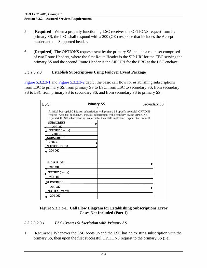
DoD UCR 2008, Change 3 Section 5.3.2 – Assured Services Requirements
254
5. [Required] When a properly functioning LSC receives the OPTIONS request from its primary SS, the LSC shall respond with a 200 (OK) response that includes the Accept header and the Supported header.
6. [Required] The OPTIONS requests sent by the primary SS include a route set comprised of two Route Headers, where the first Route Header is the SIP URI for the EBC serving the primary SS and the second Route Header is the SIP URI for the EBC at the LSC enclave.
5.3.2.3.2.3 Establish Subscriptions Using Failover Event Package
Figure 5.3.2.3-1 and Figure 5.3.2.3-2 depict the basic call flow for establishing subscriptions from LSC to primary SS, from primary SS to LSC, from LSC to secondary SS, from secondary SS to LSC from primary SS to secondary SS, and from secondary SS to primary SS.
Figure 5.3.2.3-1. Call Flow Diagram for Establishing Subscriptions Error
Cases Not Included (Part 1)
5.3.2.3.2.3.1 LSC Creates Subscription with Primary SS
1. [Required] Whenever the LSC boots up and the LSC has no existing subscription with the primary SS, then upon the first successful OPTIONS request to the primary SS (i.e.,
LSC Primary SS Secondary SS
At initial boot-up LSC initiates subscription with primary SS upon 1st successful OPTIONS request. At initial boot-up LSC initiates subscription with secondary SS (no OPTIONS requests). If LSC subscription is unsuccessful then LSC implements exponential back-offSUBSCRIBE
200 OKNOTIFY (ready)
SUBSCRIBE200 OK
200 OK
NOTIFY (ready)200 OK
SUBSCRIBE200 OK
NOTIFY (ready)200 OK
SUBSCRIBE200 OK
NOTIFY (ready)200 OK
LSC Primary SS Secondary SS
At initial boot-up LSC initiates subscription with primary SS upon 1st successful OPTIONS request. At initial boot-up LSC initiates subscription with secondary SS (no OPTIONS requests). If LSC subscription is unsuccessful then LSC implements exponential back-off-SUBSCRIBE
200 OKNOTIFY (ready)
SUBSCRIBE200 OK
200 OK
NOTIFY (ready)200 OK
SUBSCRIBE200 OK
NOTIFY (ready)200 OK
SUBSCRIBE200 OK
NOTIFY (ready)200 OK

DoD UCR 2008, Change 3 Section 5.3.2 – Assured Services Requirements
255
primary SS responds with 200 (OK) response) the LSC creates a subscription with the primary SS based upon the UC event package ‘failover’.
2. [Required] The LSC shall send a SUBSCRIBE message to the primary SS in which the Expires header shall have a value not less than 1,209,600 seconds (14 days) as per the failover event package (see Section 5.3.2.3.2.8.3.3.1, Subscription Creation).
Figure 5.3.2.3-2. Call Flow Diagram for Establishing Subscriptions
Error Cases Not Included (Part 2)
2.1 [Required] If the primary SS is not ready to support the failover/failback process, then the primary SS shall respond with a 500 (Server Internal Error). Then the LSC implements exponential back-off (see Section 5.3.2.3.2.3.2, Exponential Back-Off).
2.2 [Required] If the primary SS is ready to support the failover/failback process, then
the primary SS shall respond to the SUBSCRIBE request with a 200 (OK) response in which the Expires header shall have a value not less than 1,209,600 seconds (14 days) as per the failover event package (see Section 5.3.2.3.2.8.3.3.1, Subscription Creation).
2.2.1 [Required] The primary SS shall immediately send a NOTIFY request with
the body:
Primary SS CCA-ID, ready, LSC CCA-ID
2.2.2 [Required] The LSC shall respond with 200 (OK) response.
At initial boot -up SS creates subscription with its paired SS. Upon completion of subscription, paired SS creates subscription with the 1 st SSIf subscription is unsuccessful then SSs implement exponential back -off
SUBSCRIBE200 OK
NOTIFY (ready)200 OK
SUBSCRIBE200 OKNOTIFY (ready)200 OK
At initial boot -up SS creates subscription with its paired SS. Upon completion of subscription, paired SS creates subscription with the 1st SS. If subscription is unsuccessful then SSs implement exponential back -off
SUBSCRIBE200 OK
NOTIFY (ready)200 OK
SUBSCRIBE200 OKNOTIFY (ready)200 OK

DoD UCR 2008, Change 3 Section 5.3.2 – Assured Services Requirements
256
5.3.2.3.2.3.2 Exponential Back-Off
[Required] In the event a subscription fails, the subscriber shall implement a subscription establishment or refresh scheme using exponential back-off starting at 30 minutes and doubling on each attempt until reaching 240 minutes (i.e., 30, 60, 120, 240). Thereafter, the time interval between subscription establishment attempts stays at 240 minutes until the subscription is completed successfully.
5.3.2.3.2.3.2a Invalid NOTIFY Body
1. [Required] Whenever an LSC or SS receives a NOTIFY message where the syntax does not conform to the requirements set forth in the failover event package or where the failstate parameter is not a member of the enumerated list in the failover event package, then the recipient of the NOTIFY message shall send a 400 response with the Reason-Phrase:
failover NOTIFY body invalid 2. [Required] Whenever an LSC or SS receives a NOTIFY message in which either the
value of the first CCA-ID field (first element) or the second CCA-ID field (third element) either is unknown to the recipient or otherwise invalid, the recipient shall send a 400 response with the Reason-Phrase:
failover NOTIFY body CCA-ID field invalid 3. [Required] The text of the NOTIFY body is case insensitive. The LSC and SS shall not
reject a NOTIFY body simply because a character is either uppercase or lowercase.
5.3.2.3.2.3.3 Primary SS Creates Subscription with LSC
1. [Required] Upon successful completion of the LSC subscription with the primary SS (Section 5.3.2.3.2.3.1, LSC Creates Subscription with Primary SS) and if the primary SS has no existing subscription with the LSC10, then the primary SS shall immediately send a SUBSCRIBE message to the LSC in which the Expires header shall have a value not less than 1,209,600 seconds (14 days) per the failover event package (see Section 5.3.2.3.2.8.3.3.1, Subscription Creation).
10 If the primary SS has an existing subscription with the LSC, then the primary SS refreshes the subscription per Section 5.3.2.3.2.4.2, Primary SS Refreshes Subscription with LSC.

DoD UCR 2008, Change 3 Section 5.3.2 – Assured Services Requirements
257
1.1 [Required] The LSC shall respond to the SUBSCRIBE message with a 200 (OK) response in which the Expires header shall have a value not less than 1,209,600 seconds (14 days) as per the failover event package (see Section 5.3.2.3.2.8.3.3.1, Subscription Creation).
1.2 [Required] The LSC shall immediately send a NOTIFY with the body:
LSC CCA-ID, ready, LSC CCA-ID
1.3 [Required] The primary SS shall respond with a 200 (OK) response.
2. [Required] In the event the subscription fails, then the primary SS uses Exponential back-
off (see Section 5.3.2.3.2.3.2, Exponential Back-Off).
5.3.2.3.2.3.4 LSC Creates Subscription with Secondary SS
1. [Required] Whenever the LSC boots up, and the LSC has no existing subscription with the secondary SS, the LSC creates a subscription with the secondary SS based on the UC event package ‘failover’.
2. [Required] The LSC shall send a SUBSCRIBE message to the secondary SS in which the Expires header shall have a value not less than 1,209,600 seconds (14 days) as per the failover event package (see Section 5.3.2.3.2.8.3.3.1, Subscription Creation).
2.1 [Required] If the secondary SS is not ready to support the failover/failback process, then the secondary SS shall respond with a 500 (Server Internal Error). Then the LSC implements exponential back-off (see Section 5.3.2.3.2.3.2, Exponential Back-Off).
2.2 [Required] If the secondary SS is ready to support the failover/failback process, then
the primary SS shall respond to the SUBSCRIBE message with a 200 (OK) response in which the Expires header shall have a value not less than 1,209,600 seconds (14 days) as per the failover event package (see Section 5.3.2.3.2.8.3.3.1, Subscription Creation).
2.2.1 [Required] The secondary SS shall immediately send a NOTIFY with the
body:
Secondary SS CCA-ID, ready, LSC CCA-ID
2.2.2 [Required] The LSC shall respond with 200 (OK) response.

DoD UCR 2008, Change 3 Section 5.3.2 – Assured Services Requirements
258
5.3.2.3.2.3.5 Secondary SS Creates Subscription with LSC
1. [Required] Upon successful completion of the LSC subscription with the secondary SS (see Section 5.3.2.3.2.3.4, LSC Creates Subscription with Secondary SS) and if the secondary SS has no existing subscription with the LSC11, the secondary SS shall immediately send a SUBSCRIBE message to the LSC in which the Expires header shall have a value not less than 1,209,600 seconds (14 days) as per the failover event package (see Section 5.3.2.3.2.8.3.3.1, Subscription Creation).
2. [Required] The LSC shall respond to the SUBSCRIBE message with a 200 (OK) response in which the Expires header shall have a value not less than 1,209,600 seconds (14 days) as per the failover event package (see Section 5.3.2.3.2.8.3.3.1, Subscription Creation).
3. [Required] The LSC shall immediately send a NOTIFY with body:
LSC CCA-ID, ready, LSC CCA-ID 4. [Required] The secondary SS shall respond with a 200 (OK) response.
5. [Required] In the event the subscription fails, then the secondary SS uses exponential back-off (Section 5.3.2.3.2.3.2, Exponential Back-Off).
5.3.2.3.2.3.6 Paired Softswitches (Active Primary/Secondary) Create Subscriptions with One Another
1. [Required] Whenever an SS boots up and the SS does not have an existing subscription with its paired SS, then the SS creates a subscription with the paired SS based on the UC event package ‘failover’.
2. [Required] The SUBSCRIBE message shall include an Expires header that has a value not less than 1,209,600 seconds (14 days) as per the failover event package (see Section 5.3.2.3.2.8.3.3.1, Subscription Creation).
2.1 [Required] If the paired SS is not ready to support the failover/failback process, then the paired SS shall respond with a 500 (Server Internal Error). Then the SS implements exponential back-off (Section 5.3.2.3.2.3.2, Exponential Back-Off).
11 If the secondary SS has an existing subscription with the LSC, then the secondary SS refreshes the subscription per Section 5.3.2.3.2.4.4, Secondary SS Refreshes Subscription with LSC.

DoD UCR 2008, Change 3 Section 5.3.2 – Assured Services Requirements
259
2.2 [Required] If the paired SS is ready to support the failover/failback process, then the paired SS shall respond to the SUBSCRIBE message with a 200 (OK) response in which the Expires header shall have a value not less than 1,209,600 seconds (14 days) as per the failover event package (see Section 5.3.2.3.2.8.3.3.1, Subscription Creation).
2.2.1 [Required] The paired SS shall immediately send a NOTIFY message with
body:
Paired SS CCA-ID, ready, all
2.2.2 [Required] The SS shall respond with a 200 (OK) response.
2.2.3 [Required] If the paired SS does not have a subscription with the peer SS, then the paired SS shall immediately create a new subscription with its peer per this section.
5.3.2.3.2.4 Subscription Refresh
5.3.2.3.2.4.1 LSC Refreshes Subscription with Primary SS
1. [Required] The LSC shall refresh the subscription12 with the primary SS at between 864,000 seconds (10 days) and 950,400 seconds (11 days) so that the subscription does not lapse. The Expires header of the SUBSCRIBE message shall have a value not less than 1,209,600 seconds (14 days) as per the failover event package (see Section 5.3.2.3.2.8.3.3.1, Subscription Creation, and Section 5.3.2.3.2.8.3.3.2, Subscription Duration).
1.1 [Required] If for some reason the primary SS is unable to support the subscription refresh, then the primary SS shall respond with a 500 (Server Internal Error) response. Then the LSC implements exponential back-off (Section 5.3.2.3.2.3.2, Exponential Back-Off).
1.2 [Required] If the primary SS is ready to support the subscription refresh, then the
primary SS shall respond to the SUBSCRIBE message with a 200 (OK) in which the Expires header shall have a value not less than 1,209,600 seconds (14 days) as per the failover event package (see Section 5.3.2.3.2.8.3.3.1, Subscription Creation).
12 The SUBSCRIBE request has the same dialog ID as the original SUBSCRIBE request that created the subscription.

DoD UCR 2008, Change 3 Section 5.3.2 – Assured Services Requirements
260
1.2.1 [Required] The primary SS shall immediately send a NOTIFY message with the body:
Primary SS CCA-ID, ready, LSC CCA-ID
1.2.2 [Required] The LSC shall respond with a 200 (OK) response.
2. [Required] If the LSC is unable to refresh the subscription before the subscription
expires, then the LSC shall create a new subscription as if the LSC were booting up for the first time (see Section 5.3.2.3.2.3.1, LSC Creates Subscription with Primary SS).
5.3.2.3.2.4.2 Primary SS Refreshes Subscription with LSC
1. [Required] Upon successful completion of the LSC subscription refresh with the primary SS, the primary SS shall immediately refresh its subscription13 with the LSC so that the subscription does not lapse14. The Expires header of the SUBSCRIBE message shall have a value not less than 1,209,600 seconds (14 days) as per the failover event package (see Section 5.3.2.3.2.8.3.3.1, Subscription Creation). The LSC shall respond to the SUBSCRIBE with a 200 (OK) response in which the Expires header shall have a value not less than 1,209,600 seconds (14 days) as per the failover event package (see Section 5.3.2.3.2.8.3.3.1, Subscription Creation).
1.1 [Required] The LSC shall immediately send a NOTIFY request with the body:
LSC CCA-ID, ready, LSC CCA-ID
1.2 [Required] The primary SS shall respond with a 200 (OK) response. 2. [Required] In the event the subscription refresh fails, then the primary SS shall use
exponential back-off (see Section 5.3.2.3.2.3.2, Exponential Back-Off).
3. [Required] If the primary SS is unable to refresh the subscription before the subscription expires, then the primary SS shall create a new subscription (see Section 5.3.2.3.2.3.3, Primary SS Creates Subscription with LSC.)
13 The SUBSCRIBE request has the same dialog ID as the original SUBSCRIBE request that created the subscription. 14 The primary SS performs a subscription refresh upon the LSC’s successful subscription refresh even if the primary SS’s current subscription is less than 864,000 seconds (10 days) old.

DoD UCR 2008, Change 3 Section 5.3.2 – Assured Services Requirements
261
4. [Required] If the current subscription with the LSC exceeds 950,400 seconds (11 days) and the LSC has not conducted a subscription refresh with the primary SS, then the primary SS shall refresh its subscription with the LSC.
5.3.2.3.2.4.3 LSC Refreshes Subscription with Secondary SS
1. [Required] The LSC shall refresh the subscription15 with the secondary SS at between 864,000 seconds (10 days) and 950,400 seconds (11 days) so that the subscription does not lapse. The Expires header of the SUBSCRIBE message shall have a value not less than 1,209,600 seconds (14 days) as per the failover event package (see Section 5.3.2.3.2.8.3.3.1, Subscription Creation, and Section 5.3.2.3.2.8.3.3.2, Subscription Duration).
1.1 [Required] If for some reason the secondary SS is unable to support the subscription refresh, then the secondary SS shall respond with a 500 (Server Internal Error). Then the LSC implements exponential back-off (Section 5.3.2.3.2.3.2, Exponential Back-Off).
1.2 [Required] If the secondary SS is ready to support the subscription refresh, then the
secondary SS shall respond to the SUBSCRIBE message with a 200 (OK) response in which the Expires header shall have a value not less than 1,209,600 seconds (14 days) as per the failover event package (see Section 5.3.2.3.2.8.3.3.1, Subscription Creation).
1.2.1 [Required] The secondary SS shall immediately send a NOTIFY request
with the body:
Secondary SS CCA-ID, ready, LSC CCA-ID
1.2.2 [Required] The LSC shall respond with a 200 (OK) response. 2. [Required] If the LSC is unable to refresh the subscription before the subscription expires,
then the LSC shall create a new subscription as if the LSC were booting up for the first time (see Section 5.3.2.3.2.3.4, LSC Creates Subscription with Secondary SS).
15 The SUBSCRIBE request has the same dialog ID as the original SUBSCRIBE request that created the subscription.

DoD UCR 2008, Change 3 Section 5.3.2 – Assured Services Requirements
262
5.3.2.3.2.4.4 Secondary SS Refreshes Subscription with LSC
1. [Required] Upon successful completion of the LSC subscription refresh with the secondary SS, the secondary SS shall immediately refresh its subscription16 with the LSC so that the subscription does not lapse17. The Expires header of the SUBSCRIBE message shall have a value not less than 1,209,600 seconds (14 days) as per the failover event package (see Section 5.3.2.3.2.8.3.3.1, Subscription Creation). The LSC shall respond to the SUBSCRIBE with a 200 (OK) response in which the Expires header shall have a value not less than 1,209,600 seconds (14 days) as per the failover event package (see Section 5.3.2.3.2.8.3.3.1, Subscription Creation).
1.1 [Required] The LSC shall immediately send a NOTIFY request with the body:
LSC CCA-ID, ready, LSC CCA-ID
1.2 [Required] The secondary SS shall respond with a 200 (OK) response. 2. [Required] In the event the subscription refresh fails, then the secondary SS shall use
exponential back-off (see Section 5.3.2.3.2.3.2, Exponential Back-Off).
3. [Required] If the secondary SS is unable to refresh the subscription before the subscription expires, then the secondary SS shall create a new subscription (see Section 5.3.2.3.2.3.5, Secondary SS Creates Subscription with LSC).
4. [Required] If the current subscription with the LSC exceeds 950,400 seconds (11 days) and the LSC has not conducted a subscription refresh with the secondary SS, then the secondary SS shall refresh its subscription with the LSC.
5.3.2.3.2.4.5 SS Refreshes Subscription with its Paired SS
1. [Required] An SS shall refresh the subscription18 with its paired SS at between 864,000 seconds (10 days) and 950,400 seconds (11 days) so that the subscription does not lapse. The Expires header of the SUBSCRIBE message shall have a value not less than 1,209,600 seconds (14 days) as per the failover event package (see Section 5.3.2.3.2.8.3.3.1, Subscription Creation, and Section 5.3.2.3.2.8.3.3.2, Subscription Duration).
16 The SUBSCRIBE request has the same dialog ID as the original SUBSCRIBE that created the subscription. 17 The secondary SS performs a subscription refresh on the LSC’s successful subscription refresh even if the secondary SS’s current subscription is less than 864,000 seconds (10 days) old. 18 The SUBSCRIBE request has the same dialog ID as the original SUBSCRIBE request that created the subscription.

DoD UCR 2008, Change 3 Section 5.3.2 – Assured Services Requirements
263
1.1 [Required] If the paired SS is not ready to support the failover/failback process, then the paired SS shall respond with a 500 (Server Internal Error). In the event the subscription refresh fails, then the SS shall use Exponential back-off (Section 5.3.2.3.2.3.2, Exponential Back-Off).
1.2 [Required] If the paired SS is ready to support the failover/failback process, then the
paired SS shall respond to the SUBSCRIBE message with a 200 (OK) response in which the Expires header shall have a value not less than 1,209,600 seconds (14 days) as per the failover event package (see Section 5.3.2.3.2.8.3.3.1, Subscription Creation).
1.2.1 [Required] The paired SS shall immediately send a NOTIFY request with
the body:
Paired SS CCA-ID, ready, all
1.2.2 [Required] The SS shall respond with a 200 (OK) response.
1.2.3 [Required] If the paired SS either has no subscription or has an expired subscription with the peer SS, then the paired SS shall immediately create a new subscription with its peer per Section 5.3.2.3.2.3.6, Paired Softswitches (Active Primary/Secondary) Create Subscriptions with One Another.
1.2.4 [Required] If the paired SS has a subscription with its peer SS that is already
beyond 950,400 seconds (11 days), then the paired SS shall immediately refresh its subscription with its peer per Section 5.3.2.3.2.4.5, SS Refreshes Subscription with its Paired SS.
2. [Required] If the SS is unable to refresh the subscription before the subscription expires,
then the SS shall create a new subscription as if the SS were booting up for the first time (see Section 5.3.2.3.2.3.6, Paired Softswitches (Active Primary/Secondary) Create Subscriptions with One Another).
5.3.2.3.2.5a LSC Failover to Secondary SS
Figure 5.3.2.3-3 depicts the basic call flow for LSC failover from the primary SS to the secondary SS.

DoD UCR 2008, Change 3 Section 5.3.2 – Assured Services Requirements
264
Figure 5.3.2.3-3. Call Flow Diagram for LSC Failover Error Cases Not Included
5.3.2.3.2.5a.1 [Required] When the LSC sends to the primary SS a defined configurable number of successive OPTIONS requests (default equals 2) for which there either is no response or a response other than 200 OK (e.g., 408 (Request Time-Out), 500 (Server Internal Error), 503 (Service Unavailable), 504 (Server Time-Out)), then: Step 1 [Required] The LSC shall send a NOTIFY request to the secondary SS with the body:
LSC CCA-ID, failover, LSC CCA-ID
1.a [Required] If the secondary SS recognizes the NOTIFY request as belonging to an active subscription with the LSC, then the secondary SS shall respond with 200 (OK) response.
1.a.1 [Required] The LSC shall send all new outbound SIP messages (with the
exception of OPTIONS requests destined for the primary SS) to the secondary SS.
1.a.2 [Required] The LSC shall wait a configurable time interval (default equals
30–60 minutes), and then resume sending OPTIONS requests to the primary SS per Section 5.3.2.3.2.2a, LSC Monitors Primary SS for Status. However, if the LSC receives an inbound INVITE message from the primary SS before sending an OPTIONS request to the primary SS, then the LSC shall immediately send an OPTIONS request to the primary SS in response to the receipt of the inbound INVITE message. (See Step 1, Section 5.3.2.3.2.6a, LSC Failback to Primary SS).
LSC Primary SS Secondary SS2 consecutive OPTIIONS requests to primary SS fail
NOTIFY (failover)200 OK
OPTIONS? 200 OK ?
If OPTION fails then STOP here
NOTIFY (failover)200 OK
Failover
If OPTION succeeds then:

DoD UCR 2008, Change 3 Section 5.3.2 – Assured Services Requirements
265
1.a.3 [Required] The EBC serving the secondary SS shall respond with a 481 (Call/Transaction Does Not Exist) response upon receipt of any Re-INVITE, UPDATE, or BYE request from the LSC that relates to an existing call that had been established through the primary SS.
1.a.4 [Required] All outbound AS-SIP requests sent by the LSC to its EBC (with
the exception of OPTIONS requests) shall include a route set comprised of two Route headers, where the first Route header is the SIP URI for the EBC at the enclave, and the second Route header is the SIP URI for the EBC serving the secondary SS.
Proceed to step 2.
1.b [Required] (Secondary SS does not have or recognize subscription to LSC) If
the secondary SS does NOT recognize the ‘failover’ NOTIFY request of Step 1 as belonging to an active subscription with the LSC, then the secondary SS shall respond with a 481 (Subscription Does Not Exist) and the LSC shall begin the subscription refresh process by refreshing its existing subscription with the secondary SS.
1.b.1 [Required] (LSC subscription to secondary SS is active; secondary SS
does not have or recognize subscription to LSC) If the LSC’s subscription refresh with the secondary SS is successful, then the secondary SS shall immediately initiate a subscription with the LSC. Upon completion of the secondary SS’ subscription with the LSC, the LSC immediately sends a NOTIFY request to the secondary SS with the body19
:
LSC CCA-ID, failover, LSC CCA-ID
1.b.1.1 [Required] The secondary SS shall respond with 200 (OK) response. The requirements set forth in step 1.a apply. The secondary SS proceeds to step 2.
1.b.1.2 [Required] If the secondary SS does NOT respond with a 200 (OK)
response and the NOTIFY message either times out or the secondary SS responds with a failure response, then the LSC immediately sends a second ‘failover’ NOTIFY message.
19 Normally upon secondary SS refresh of subscription with LSC, the LSC sends the NOTIFY body: LSC CCA-ID, ready, LSC CCA-ID. The secondary SS shall accept either the LSC sending two NOTIFY messages: (the ‘ready’ NOTIFY and the ‘failover’ NOTIFY sent in any order) and the secondary SS shall accept the LSC sending just the ‘failover’ NOTIFY message.

DoD UCR 2008, Change 3 Section 5.3.2 – Assured Services Requirements
266
1.b.1.2.1 [Required] If the secondary SS responds with 200 (OK) response, then failover shall occur and the requirements set forth in step 1.a apply. The secondary SS proceeds to step 2.
1.b.1.2.2 [Required] If the secondary SS does NOT respond with
a 200 (OK) response and the NOTIFY message either times out or the secondary SS responds with a failure response, then the LSC is isolated from both the primary SS and secondary SS. The LSC shall continue to send OPTIONS requests to the primary SS per Section 5.3.2.3.2.2a, LSC Monitors Primary SS for Status, and the LSC shall wait 60–120 seconds and return to step 1.
1.b.1.2.3 [Required] If the LSC receives a 200 (OK) response
from the primary SS before being able to successfully send the ‘failover’ NOTIFY to the secondary SS, then the LSC terminates the failover process. Failover does NOT occur.
1.b.2 [Required] (LSC subscription to secondary SS is not recognized;
secondary SS does not have or recognize subscription to LSC) If the LSC’s SUBSCRIBE request for the subscription refresh with the secondary SS (in 1.b) results in a 481 (Subscription does not exist) response from the secondary SS, then the LSC shall consider its current subscription with the secondary SS to be invalid and shall establish a new subscription with the secondary SS. Upon completion of the LSC’s new subscription with the secondary SS, the secondary SS shall immediately establish a subscription with the LSC. Upon completion of the secondary SS’s subscription with the LSC, the LSC shall send a NOTIFY request to the secondary SS with the body20
:
LSC CCA-ID, failover, LSC CCA-ID
1.b.2.1 [Required] The secondary SS shall respond with 200 (OK) response. The requirements set forth in step 1.a apply. The secondary SS proceeds to step 2.
20 Normally upon secondary SS refresh of subscription with LSC, the LSC sends the NOTIFY body: LSC CCA-ID, ready, LSC CCA-ID. The secondary SS shall accept either the LSC sending two NOTIFY messages: (the ‘ready’ NOTIFY and the ‘failover’ NOTIFY sent in any order) and the secondary SS shall accept the LSC sending just the ‘failover’ NOTIFY message.

DoD UCR 2008, Change 3 Section 5.3.2 – Assured Services Requirements
267
1.b.2.2 [Required] If the secondary SS does NOT respond with a 200 (OK) response and the NOTIFY message either times out or the secondary SS responds with a failure response, then the LSC immediately sends a second ‘failover’ NOTIFY message.
1.b.2.2.1 [Required] If the secondary SS responds with 200 (OK)
response, then failover shall occur and the requirements set forth in step 1.a. apply. The secondary SS proceeds to step 2.
1.b.2.2.2 [Required] If the secondary SS does NOT respond with
a 200 (OK) response and the NOTIFY message either times out or the secondary SS responds with a failure response, then the LSC is isolated from both the primary SS and secondary SS. The LSC shall continue to send OPTIONS requests to the primary SS per Section 5.3.2.3.2.2a, LSC Monitors Primary SS for Status, and the LSC shall wait 60–120 seconds and return to Step 1.
1.b.2.2.3 [Required] If the LSC receives a 200 (OK) response
from the primary SS before being able to successfully send the ‘failover’ NOTIFY message to the secondary SS, then the LSC terminates the failover process. Failover does NOT occur.
1.c [Required] If the secondary SS either does not provide a response to the ‘failover’
NOTIFY request of Step 1 or provides a failure response other than 481 (Subscription Does Not Exist), then the LSC immediately sends a second ‘failover’ NOTIFY message.
1.c.1 [Required] If the secondary SS responds with a 200 (OK) response, then
failover shall occur and the requirements of step 1.a apply. The secondary SS proceeds to step 2.
1.c.2 [Required] If the secondary SS does NOT respond with a 200 (OK) response
and the NOTIFY message either times out or the secondary SS responds with a failure response, then the LSC is isolated from both the primary SS and secondary SS. The LSC shall continue to send OPTIONS requests to the primary SS per Section 5.3.2.3.2.2a, LSC Monitors Primary SS for Status, and the LSC shall wait 60–120 seconds and return to step 1.

DoD UCR 2008, Change 3 Section 5.3.2 – Assured Services Requirements
268
1.c.2.1 [Required] If the LSC receives a 200 (OK) response from the primary SS before being able to successfully send the ‘failover’ NOTIFY message to the secondary SS, then the LSC terminates the failover process. Failover does NOT occur.
Step 2 [Required] Upon responding to the ‘failover’ NOTIFY message from the LSC with a
200 (OK), the Secondary SS shall immediately send an OPTIONS request to the primary SS to determine whether the primary SS is reachable at the SIP layer from the secondary SS.
2.a [Required] If the primary SS responds with a 200 (OK) response, then the secondary
SS shall send a NOTIFY message to the primary SS with a body that has the following content:
Secondary SS CCA-ID, failover, LSC CCA-ID
2.a.1 [Required] If the primary SS responds with 200 (OK) response, then the
primary SS shall forward all inbound AS-SIP messages intended for the designated LSC to the secondary SS.
2.a.1.1 [Required] The EBC serving the secondary SS shall respond with a
481 (Call/Transaction Does Not Exist) response upon receipt of any Re-INVITE, UPDATE, or BYE request from the primary SS that relates to a call that is not established through the secondary SS.
Failover is complete; STOP here.
2.a.2 [Required] (Primary SS does not have or recognize subscription to secondary SS) If the primary SS responds to the ‘failover’ NOTIFY message from the secondary SS (step 2.a) with a 481 (Subscription Does Not Exist), then the secondary SS shall refresh its existing subscription with the primary SS.
2.a.2.1 [Required] (Secondary SS subscription to primary SS is active;
primary SS does not have or recognize subscription to secondary SS) If the secondary SS’s subscription refresh with the primary SS is successful, then the primary SS shall immediately initiate a subscription with the secondary SS. Upon completion of the primary SS’s subscription with the secondary SS, the secondary SS

DoD UCR 2008, Change 3 Section 5.3.2 – Assured Services Requirements
269
immediately sends a NOTIFY message to the primary SS with the body21
:
Secondary SS CCA-ID, failover, LSC CCA-ID
2.a.2.1.1 [Required] If the primary SS response is 200 (OK) response, then failover occurs per step 2.a.1.
2.a.2.2 [Required] (Secondary SS subscription to primary SS is not
recognized; primary SS does not have or recognize subscription to secondary SS) If the primary SS response to the SUBSCRIBE request (for the subscription refresh of step 2.a.2) is 481 (Subscription Does Not Exist), then the secondary SS shall consider its current subscription with the primary SS to be invalid and shall establish a new subscription with the primary SS. Upon completion of the secondary SS’s new subscription with the primary SS, the primary SS shall immediately establish a subscription with the secondary SS. Upon completion of the primary SS’s subscription with the secondary SS, the secondary SS shall send a NOTIFY message to the primary SS with the body22
:
Secondary SS CCA-ID, failover, LSC CCA-ID
2.a.2.2.1 [Required] The primary SS shall respond with 200 (OK) response and the failover occurs per step 2.a.1.
2.b [Required] If the OPTIONS request of step 2 fails, then the secondary SS shall wait
5–10 seconds and shall send a second OPTIONS request to the primary SS. 2.b.1 [Required] If the second OPTIONS request also fails, then the primary SS is
deemed unreachable from the secondary SS as well as from all other SSs. As the other SSs discover that the primary SS is inaccessible, they will begin sending AS-SIP messages intended for the LSCs served by the primary SS to the secondary SS instead. Failover is complete; STOP here.
21 Normally, upon SS refresh of subscription with its paired SS, the paired SS sends the NOTIFY body: Secondary SS CCA-ID, ready, all. The primary SS shall accept either the secondary SS sending two NOTIFY messages: (the ‘ready’ NOTIFY and the ‘failover’ NOTIFY sent in any order) and the primary SS shall accept the secondary SS sending just the ‘failover’ NOTIFY message. 22 Normally, upon SS refresh of subscription with its paired SS, the paired SS sends the NOTIFY body: Secondary SS CCA-ID, ready, all. The primary SS shall accept either the secondary SS sending two NOTIFY messages: (the ‘ready’ NOTIFY and the ‘failover’ NOTIFY sent in any order) and the primary SS shall accept the secondary SS sending just the ‘failover’ NOTIFY message.

DoD UCR 2008, Change 3 Section 5.3.2 – Assured Services Requirements
270
2.b.2 [Required] If the second OPTIONS request succeeds, then the secondary SS shall send a NOTIFY message to the primary SS with a body that has the following content:
Secondary SS CCA-ID, failover, LSC CCA-ID
2.b.2.1 [Required] Upon receipt of the NOTIFY message from the
secondary SS, the primary SS shall respond with a 200 (OK) response and forward all inbound AS-SIP messages intended for the designated LSC to the secondary SS. Failover is complete.
5.3.2.3.2.5b SSs Failover to Secondary SS
1. [Required] Each SS shall be configured with knowledge of every pair of SSs in the network that act as secondary (backup) SS for one another.
2. [Required] When an SS sends a defined configurable number of successive OPTIONS requests (default equals 2) to another SS (let’s say SS B) (that is NOT its paired secondary SS) that either times out or receives a failure response—as opposed to 200 (OK) response (e.g., 408 (Request Time-Out), 500 (Server Internal Error), 503 (Service Unavailable), or 504 (Server Time-Out)), then:
a. [Required] The first SS shall send all INVITE requests corresponding to new call requests intended for LSCs served by the failed SS to the paired secondary SS of the failed SS instead. The AS-SIP requests shall include a route set comprised of two Route headers, where the first Route header is the SIP URI for the EBC at the first SS, and the second Route header is the SIP URI for the EBC serving the paired secondary SS of the failed SS.
b. [Required] The first SS shall continue to send OPTIONS requests to the failed SS as
per the requirements of Section 5.3.2.3.2.2b, Each SS Monitors All Other SSs in the Network. The OPTIONS requests include a route set comprised of two Route headers, where the first Route header is the SIP URI for the first SS, and the second Route header is the SIP URI for the EBC serving the failed SS.
c. [Required] The first SS shall continue to send AS-SIP messages associated with
sessions established through the failed SS to the failed SS.23
23 The Via headers and Record-route headers keep the failed SS in the signaling path for the existing pre-failover calls.
The SIP requests shall include a route set comprised of two Route headers, where the first Route header is

DoD UCR 2008, Change 3 Section 5.3.2 – Assured Services Requirements
271
the SIP URI for the EBC at the first SS, and the second Route header is the SIP URI for the EBC serving the paired secondary SS of the failed SS.
d. [Required] If the first SS incorrectly attempts to forward a SIP request message to
the secondary SS for a session that was established using the failed SS, then the EBC serving the secondary SS shall respond with a 481 (Call/Transaction Does Not Exist).
3. [Required] If the first SS receives a 200 (OK) response to an OPTIONS request from SS
B before the configurable number of successive failures to the OPTIONS requests (default equals 2) has been reached, then no action is taken to failover to the paired SS. For example, using the default of two successive failures, if one OPTIONS request to the SS fails, then the next OPTIONS request receives a 200 (OK) response, no action is taken to failover to the secondary (backup) SS.
5.3.2.3.2.5c LSC Failover to Secondary SS Triggered by Primary SS
1. [Required] When the primary sends to a served LSC a defined configurable number of successive OPTIONS requests (default equals 3) for which there either is no response or a response other than 200 OK response (e.g., 408 (Request Time-Out), 500 (Server Internal Error), 503 (Service Unavailable), 504 (Server Time-Out)), then:
a. [Required] The primary SS shall send a NOTIFY message to the secondary SS with the body:
Primary CCA-ID, LSCunreachable, LSC CCA-ID
b. [Required] The secondary SS shall respond with a 200 (OK) response.
c. [Required] The secondary SS shall send a NOTIFY message to the LSC with the
body:
Secondary CCA-ID, LSCunreachable, LSC CCA-ID
d. [Required] The LSC shall respond with a 200 (OK) response and initiate LSC failover per Section 5.3.2.3.2.5a, LSC Failover to Secondary SS.
5.3.2.3.2.6a LSC Failback to Primary SS
Figure 5.3.2.3-4 depicts the basic call flow for LSC failback to the primary SS from the secondary SS.

DoD UCR 2008, Change 3 Section 5.3.2 – Assured Services Requirements
272
Figure 5.3.2.3-4. Call Flow Diagram for LSC Failback Error Cases Not Included
Step 1 [Required] Per Section 5.3.2.3.2.5a, LSC Failover to Secondary SS, step 1.a, upon
successful LSC failover to the secondary SS, the LSC waits a configurable amount of time (default equals 30–60 minutes) before sending an OPTIONS request to the primary SS UNLESS the LSC receives an inbound INVITE request from the primary SS24
. .
1.1 [Required] If the LSC receives an inbound INVITE request from the primary SS, then the LSC immediately sends an OPTIONS request to the primary SS per the requirements of Section 5.3.2.3.2.5a, LSC Monitors Primary SS for Status.
24 NOTE: This circumstance occurs when the primary SS is unaware of the failover to the secondary SS and upon the primary SS becoming reachable again by other SSs and by the LSC, the primary SS receives an INVITE request intended for the LSC and forwards the INVITE request to the LSC.
LSC Primary SS Secondary SSOPTIONS request to primary SS succeeds or LSC receives INVITEfrom primary SS
NOTIFY (readytofailback)
NOTIFY (readytofailback)200 OK
200 OK
200 OK
Secondary SS sends OPTIONS request to primary SS. If successful then NOTIFY LSC (‘readytofailback’)If NOT successful then NOTIFY LSC (‘notready’) – LSC aborts current failback
NOTIFY (readytofailback)
NOTIFY (readytofailback)200 OK
NOTIFY (failback)200 OKNOTIFY ACKfailback)200 OK
NOTIFY (failback)
200 OK
Failover

DoD UCR 2008, Change 3 Section 5.3.2 – Assured Services Requirements
273
NOTE: The LSC does not complete inbound INVITE processing until the failback process has completed. It is possible that the INVITE message will time out.
1.2 [Required] The OPTIONS requests sent by the LSC shall include a route set
comprised of two Route headers, where the first Route header is the SIP URI for the EBC at the enclave, and the second Route header is the SIP URI for the EBC serving the primary SS.
Step 2 [Required] When the LSC receives a 200 (OK) response to an OPTIONS request from
the primary SS, the LSC shall send a NOTIFY message to the primary SS with the body:
LSC CCA-ID, readytofailback, LSC CCA ID
2.a [Required] Assuming the primary SS subscription with the LSC is active, then the
primary SS shall respond with a 200 (OK) response and send a NOTIFY message to the LSC with the body:
primary SS CCA-ID, readytofailback, LSC CCA ID
2.a.1 [Required] The LSC responds with a 200 (OK) response and proceeds to
step 3.
2.b [Required] (Primary SS does not have or recognize subscription to LSC) If the primary SS responds to the LSC’s ‘readytofailback’ NOTIFY message (of Step 2) with a 481 (Subscription Does Not Exist), then the LSC shall initiate the subscription refresh process by refreshing its existing subscription with the secondary SS.
2.b.1 [Required] (LSC subscription to primary SS is active; primary SS does
not have or recognize subscription to LSC) If the LSC’s subscription refresh with the primary SS is successful, then the primary SS shall immediately refresh its subscription with the LSC. Upon completion of the primary SS’s subscription with the LSC, the LSC immediately sends a NOTIFY message to the primary SS with the body25
:
LSC CCA-ID, readytofailback, LSC CCA-ID
25 Normally, upon primary SS refresh of subscription with the LSC, the LSC sends the NOTIFY body: LSC CCA-ID, ready, LSC CCA-ID. The primary SS shall accept either the LSC sending two NOTIFY messages: (the ‘ready’ NOTIFY and the ‘readytofailback’ NOTIFY sent in any order) and the primary SS shall accept the LSC sending just the ‘readytofailback’ NOTIFY message.

DoD UCR 2008, Change 3 Section 5.3.2 – Assured Services Requirements
274
2.b.1.1 [Required] If the primary SS responds with a 200 (OK) response, then proceed to step 3.
2.b.1.2 [Required] If the NOTIFY message times out or if the primary SS
does not respond with a 200 (OK) response, then the primary SS is not ready for failback and the LSC shall return to Step 1.
NOTE: The LSC again waits a configurable amount of time (30–60 minutes) before sending an OPTIONS request.
2.b.2 [Required] (LSC subscription to primary SS is not recognized; primary
SS does not have or recognize subscription to LSC) If the LSC’s SUBSCRIBE (for subscription refresh) (from step 2.b) sent to the primary SS receives a 481 (Subscription Does Not Exist) response, then the LSC shall consider its current subscription with the primary SS to be invalid and shall establish a new subscription with the primary SS. Upon completion of the LSC’s new subscription with the primary SS, the primary SS shall immediately establish a new subscription with the LSC. Upon completion of the primary SS’s subscription with the LSC, the LSC shall send a NOTIFY message to the primary SS with the body26
:
LSC CCA-ID, readytofailback, LSC CCA-ID
2.b.2.1 [Required] If the primary SS responds with a 200 (OK) response, then proceed to step 3.
2.b.2.2 [Required] If the primary SS does not respond with a 200 (OK)
response, then the primary SS is not ready for failback and the LSC shall return to step 1. NOTE: The LSC again waits a configurable amount of time (30–60 minutes) before sending an OPTIONS request.
2.c [Required] If the LSC’s ‘readytofailback’ NOTIFY message times out or if the
primary SS does not respond with 200 (OK) response (or with a 481 (Subscription Does Not Exist)), then the primary SS is not ready for failback and the LSC shall return to step 1.
26 Normally, upon primary SS refresh of subscription with LSC, the LSC sends the NOTIFY body: LSC CCA-ID, ready, LSC CCA-ID. The primary SS shall accept either the LSC sending two NOTIFY messages: (the ‘ready’ NOTIFY and the ‘readytofailback’ NOTIFY sent in any order) and the primary SS shall accept the LSC sending just the ‘readytofailback’ NOTIFY message.

DoD UCR 2008, Change 3 Section 5.3.2 – Assured Services Requirements
275
NOTE: The LSC again waits a configurable amount of time (30–60 minutes) before sending an OPTIONS request.
Step 3
3.a [Required] If the primary SS is ready to resume servicing the LSC (or if the primary SS was unaware of the LSC failover), then the primary SS sends a NOTIFY message to the LSC with the body:
Primary SS CCA-ID, readytofailback, LSC CCA-ID
3.a.1 [Required] The LSC shall send a 200 (OK) response and proceed to step 4.
3.b [Required] If the LSC does NOT receive either a ‘readytofailback’ NOTIFY
message or a ‘notready’ NOTIFY message from the primary SS within 60 seconds of receipt of the primary SS’s 200 OK to the LSC’s ‘readytofailback’ NOTIFY request, then the LSC shall abort the failback procedure and return to Step 1.
NOTE: The LSC again waits a configurable amount of time (30–60 minutes) before
sending an OPTIONS request.
3.c [Required] If the primary SS is NOT ready to resume servicing the LSC, then the primary SS shall send a NOTIFY message to the LSC with the body:
Primary SS CCA-ID, notready, LSC CCA-ID
3.c.1 [Required] The LSC sends a 200 (OK) response.
3.c.2 [Required] If the triggering event for the failback had been receipt of an
INVITE request from the primary SS and the primary SS sent a ‘notready’ NOTIFY message, then after the LSC sends the 200 (OK) response the LSC shall immediately send a NOTIFY message to the primary SS with the body:
LSC CCA-ID, failover, LSC CCA-ID
3.c.2.1 [Required] The primary SS sends a 200 (OK) response, and shall
cease sending inbound AS-SIP messages to the LSC and instead shall forward the inbound AS-SIP messages intended for the LSC to the secondary SS.
3.c.2.2 [Required] The LSC returns to Step 1.
DoD UCR 2008, Change 3 Section 5.3.2 – Assured Services Requirements
276
NOTE: The LSC again waits a configurable amount of time (30–60 minutes) before sending an OPTIONS request.
3.c.3 [Required] If the triggering event for the failback had been a successful
OPTIONS request sent by the LSC to the primary SS, then:
3.c.3.1 [Required] The LSC returns to Step 1 whereby the LSC again waits a configurable time interval (default equals 30–60 minutes) before sending an OPTIONS request to the primary SS unless the LSC receives another inbound INVITE request from the primary SS.
Step 4 [Required] The LSC shall send a NOTIFY to the secondary SS with body:
LSC CCA-ID, readytofailback, LSC CCA-ID
4.1 [Required] The secondary SS shall respond to the NOTIFY message with a 200 (OK) response and send an OPTIONS request to the primary SS to confirm the primary SS is reachable at the SIP layer from the secondary SS.
4.1.a [Required] If the secondary SS receives a 200 (OK) response to the
OPTIONS request within 60 seconds, then upon receiving the 200 (OK) response the secondary SS shall immediately send a NOTIFY message to the LSC with the body:
Secondary SS CCA-ID, readytofailback, LSC CCA-ID
4.1.a.1 [Required] The LSC sends a 200 OK response and goes to step 5.
4.1.b [Required] If the secondary SS does NOT receive a 200 (OK) response to
the OPTIONS request (from step 4.1) within 60 seconds (i.e., the secondary SS either receives no response to the OPTIONS request or receives a failure response code from the primary SS), then the secondary SS sends a NOTIFY message to the LSC with the body:
Secondary SS CCA-ID, notready, LSC CCA-ID
4.1.b.1 [Required] The LSC sends a 200 (OK) response and returns to Step
1 whereby the LSC again waits a configurable time interval (default equals 30–60 minutes) before sending an OPTIONS request to the primary SS unless the LSC receives another inbound INVITE request from the primary SS.

DoD UCR 2008, Change 3 Section 5.3.2 – Assured Services Requirements
277
4.1.c [Required] If the LSC does NOT receive either a ‘readytofailback’ NOTIFY message or a ‘notready’ NOTIFY message from the secondary SS within 90 seconds of receipt of the secondary SS’s 200 (OK) response to the ‘readytofailback’ NOTIFY message from the LSC at step 4, then the LSC shall abort the failback procedure and return to Step 1.
[Required] NOTE: If at any time during steps 1 to 4 the primary SS again becomes unreachable, then the LSC aborts the failback process at that point and goes back to Step 1.
Step 5 [Required] The LSC shall send a NOTIFY message to the primary SS with the body:
LSC CCA-ID, failback, LSC CCA-ID
5.1 [Required] The primary SS shall send a 200 (OK) response and immediately sends a NOTIFY message to the LSC with the body:
Primary SS CCA-ID, ackfailback, LSC CCA-ID
5.2 [Required] The LSC sends a 200 (OK) response and proceeds to step 6.
[Required] NOTE: If the LSC does NOT receive an ‘ackfailback’ NOTIFY message from the primary SS within 60 seconds of receipt of the 200 (OK) response to the ‘failback’ NOTIFY message, then the LSC shall abort the failback procedure and return to Step 1.
Step 6 [Required] Upon receipt of a timely ‘ackfailback’ NOTIFY message from the primary
SS, the LSC shall send a NOTIFY message to the secondary SS with the body:
LSC CCA-ID, failback, LSC CCA-ID
6.1 [Required] The secondary SS shall send a 200 (OK) response.
[Required] NOTE: If the NOTIFY message (of step 6) times out or the secondary SS does not respond with a 200 (OK) response, then the secondary SS shall resend the ‘failback’ NOTIFY message every 30 seconds until the secondary SS responds with 200 (OK) response.
6.2 [Required] Once the secondary SS responds to the ‘failback’ NOTIFY message with
a 200 (OK) response, then failback has officially occurred and the LSC shall send the outbound INVITE requests corresponding to new call requests to the primary SS and shall continue to send the outbound AS-SIP messages pertaining to existing calls that

DoD UCR 2008, Change 3 Section 5.3.2 – Assured Services Requirements
278
were established through the secondary SS to the secondary SS until those calls terminate normally.
6.3 [Required] At this point, when the primary SS receives inbound INVITEs
corresponding to new call requests intended for the LSC, the primary SS shall send those inbound INVITEs to the LSC.
6.4 [Required] If, during the failover period, the primary SS had been receiving inbound
INVITEs intended for the LSC and forwarding those inbound INVITEs to the secondary SS, then the primary SS shall continue to send the inbound AS-SIP messages pertaining to said existing calls to the secondary SS until those calls terminate normally.
6.5 [Required] At this point, when the secondary SS receives inbound INVITEs
corresponding to new call requests intended for the LSC, the secondary SS shall forward those inbound INVITEs to the primary SS.
6.6 [Required] The secondary SS shall continue to send to the LSC the inbound AS-SIP
messages pertaining to existing calls that were established during the failover period until those calls terminate normally.
6.7 [Required] When the LSC sends new INVITE requests (as well as the subsequent
AS-SIP requests for the new call requests) to destinations outside the enclave, then the new INVITE requests (and the subsequent AS-SIP requests) shall include a route set comprised of two Route headers, where the first Route header is the SIP URI for the EBC at the enclave, and the second Route header is the SIP URI for the EBC serving the primary SS.
6.8 [Required] Upon failback, the LSC continues monitoring the primary SS as set forth
in Section 5.3.2.3.2.2a, LSC Monitors Primary SS for Status.
5.3.2.3.2.6b SSs Failback to Primary SS
1. [Required] Per Section 5.3.2.3.2.5b, SSs Failover to Secondary SS, each SS (except for the paired SS) shall continue to send the OPTIONS requests described in Section 5.3.2.3.2.2b, Each SS Monitors all Other SSs in the Network, to the failed SS.
2. [Required] When an SS receives a 200 (OK) response to an OPTIONS request from a failed SS27
27 that is NOT its paired SS
(i.e., now a newly recovering SS), then the SS shall send the INVITE requests

DoD UCR 2008, Change 3 Section 5.3.2 – Assured Services Requirements
279
corresponding to new call requests intended for LSCs whose primary SS is the newly recovering SS to the newly recovering SS. The new INVITE requests shall include a route set comprised of two Route headers, where the first Route header is the SIP URI for the originating SS, and the second Route header is the SIP URI for the EBC serving the newly recovering SS.
3. [Required] The SS shall continue to send AS-SIP messages pertaining to existing calls that were established through the secondary SS to the secondary SS until those calls terminate normally.
5.3.2.3.2.6c LSC Failback to Primary SS Triggered by Primary SS
1. [Required] The primary SS waits a configurable amount of time (default equals 30–60 minutes) before resuming the periodic OPTIONS request to the unreachable LSC.
2. [Required] When the primary SS resumes sending the periodic requests to the unreachable LSC and receives a 200 (OK) response to an OPTIONS request from the LSC, the primary SS shall send a NOTIFY message to the LSC with the body:
Primary SS CCA-ID, LSCreachable, LSC CCA ID 3. [Required] The LSC shall respond with 200 (OK) response and initiate LSC failback per
Section 5.3.2.3.2.6a, LSC Failback to Primary SS.
5.3.2.3.2.7 Security Considerations
[Required] If the LSC receives a SUBSCRIBE request from an EI that has an Event header with the event type failover, then the LSC shall reject the SUBSCRIBE request with a 403 (Forbidden) response, and the LSC shall NOT forward the SUBSCRIBE to any other signaling platform.
5.3.2.3.2.8 Failover Event Package
A Session Initiation Protocol (SIP) Event Package for Failover Status of This Memo This document specifies a UCR AS-SIP protocol for the Department of Defense community.

DoD UCR 2008, Change 3 Section 5.3.2 – Assured Services Requirements
280
Abstract This document defines a failover event package for AS-SIP signaling appliances using the Session Initiation Protocol (SIP) events framework, along with a data format used in subscriptions and notifications for this package. The failover package enables:
• LSC to notify SSs of impending failover
• LSC to notify primary SS and secondary SS of intent to failback
• Primary SS and secondary SS to notify LSC as to their readiness to engage in failback
• LSC to notify primary SS of failback
• Primary SS to acknowledge failback
• Primary SS to notify secondary SS that an LSC is unreachable and, in turn,
secondary SS to notify LSC that the primary SS cannot reach the LSC
• Primary SS to notify LSC that the LSC is again reachable from the primary SS.
5.3.2.3.2.8.1 Introduction
The Session Initiation Protocol (SIP) events framework [2] defines general mechanisms for subscribing to, and receiving notifications of, events within SIP networks. It introduces the notion of a package, which is a specific “instantiation” of the events framework for a well-defined set of events. Here, we define a SIP event package for the LSC to failover between a primary SS and a secondary SS. This package is used in conjunction with the requirements detailed in UCR. As described in Section 5.3.2.3.2, LSC and SS Failover Requirements, subscriptions are created and refreshed in both directions between the LSC and the primary SS, between the LSC and the secondary SS, and between the primary SS and the secondary SS. The LSC notifies the primary SS of the LSC’s readiness to failback, of LSC failback, and, in some circumstances, of LSC failover. The primary SS notifies the LSC of its readiness to failback and acknowledges failback. The LSC notifies the secondary SS of LSC failover, of the LSC’s readiness to failback, and of LSC failback.

DoD UCR 2008, Change 3 Section 5.3.2 – Assured Services Requirements
281
The secondary SS notifies LSC of readiness to failback and, in some circumstances, notifies primary SS of failover. The primary SS notifies the secondary SS of inability to reach an LSC at the SIP layer. The secondary SS notifies the LSC of the inability of the primary SS to reach the LSC at the SIP layer. The primary SS notifies the LSC of ability to again reach said LSC at the SIP layer. The information provided by this package is comprised of the NOTIFY body syntax and format and the basic notification sequences.
5.3.2.3.2.8.2 Terminology
In this document, the key words “MUST”, “MUST NOT”, “REQUIRED”, “SHALL”, “SHALL NOT”, “SHOULD”, “SHOULD NOT”, “RECOMMENDED”, “MAY”, and “OPTIONAL” are to be interpreted as described in RFC 2119 [1] and indicate requirement levels for compliant implementations.
5.3.2.3.2.8.3 Failover Event Package
The failover event package is intended to facilitate:
• The smooth failover of the LSC from a primary SS that has become unreachable or otherwise incapable of serving the LSC to an operational secondary SS
• The smooth failback of the LSC from the secondary SS to a primary SS that
has once again become reachable and capable of serving the LSC This section provides the details for defining a SIP-specific event notification package, as specified by RFC 3265 [2].
5.3.2.3.2.8.3.1 Event Package Name
The name of this event package is “failover”. This package name is carried in the Event and Allow-Events header, as defined in RFC 3265 [2].

DoD UCR 2008, Change 3 Section 5.3.2 – Assured Services Requirements
282
5.3.2.3.2.8.3.2 Event Package Parameters
RFC 3265 [2] allows event packages to define additional parameters carried in the Event header field. This event package, “failover,” does not define additional parameters.
5.3.2.3.2.8.3.3 Subscription
5.3.2.3.2.8.3.3.1 Subscription Creation
The SUBSCRIBE message MUST have an Expires header whose value is not less than 1,209,600 seconds (14 days). The Expires header of the 200 (OK) response MUST have a value not less than 1,209,600 seconds (14 days).
5.3.2.3.2.8.3.3.1.1 Exponential Back-Off
If the subscription fails, the Subscriber implements a subscription establishment scheme using an exponential back-off starting at 30 minutes and doubling on each attempt until reaching 240 minutes (i.e., 30, 60, 120, 240). Thereafter the time interval between subscription establishment attempts stays at 240 minutes until the subscription is completed successfully.
5.3.2.3.2.8.3.3.2 Subscription Duration
The default expiration time for a subscription for the failover event package is not less than 1,209,600 seconds (14 days). A SUBSCRIBE message MUST be sent to refresh the subscription at between 864000 (10 days) and 950,400 (11 days) so that the subscription does not lapse. If the refresh attempt fails then the Subscriber implements the exponential back-off in Section 5.3.2.3.2.3.2, Exponential Back-Off.
5.3.2.3.2.8.5.3.4 NOTIFY Bodies
According to RFC 3265 [1], the NOTIFY message will contain bodies that describe the state of the subscribed resource. The format for the body of the NOTIFY request is specified in Section 4, NOTIFY Body.

DoD UCR 2008, Change 3 Section 5.3.2 – Assured Services Requirements
283
5.3.2.3.2.8.3.5 Notifier Processing of SUBSCRIBE Requests
All SUBSCRIBE requests are sent over trusted Transport Control Protocol (TCP)/TLS connections between trusted and authenticated signaling platforms therefore no additional authentication mechanism is required.
5.3.2.3.2.8.3.6 Notifier Generation of NOTIFY Requests
Notifications MUST be generated:
• Upon completion of the establishment of a subscription or refresh of a subscription
• By LSC (to the secondary SS) upon LSC decision to conduct failover
• By the secondary SS (to the primary SS) in case of failover in which primary
SS is reachable at the SIP layer by secondary SS
• By LSC (to the primary SS) when the LSC is ready to failback
• By the primary SS (to the LSC) immediately in response to the LSC notification of readiness to failback in order to indicate readiness – or not – of the primary SS to failback
• By the LSC (to the secondary SS) when the LSC is ready to failback
• By the secondary SS (to the LSC) in response to the LSC’s notification of
readiness to failback – secondary SS determines whether to indicate its readiness – or not- to failback
• By the LSC (to the primary SS) to notify the primary SS of failback
• By the primary SS (to the LSC) immediately in response to LSC’s notification
of failback in order to acknowledge failback or to indicate primary SS has reverted to ‘notready’ status
• By the LSC (to the secondary SS) to notify the secondary SS of failback
• By the LSC (to the primary SS) to notify the primary SS of failover when the
LSC is in failover state and the primary SS sends a new INVITE request to the LSC intended for a served end instrument of the LSC and the primary SS

DoD UCR 2008, Change 3 Section 5.3.2 – Assured Services Requirements
284
response to the LSC’s notification of readiness to failback is that the primary SS is not ready to serve the LSC
• By the primary SS (to the secondary SS) to notify secondary SS that the LSC
is unreachable from the primary SS
• By the secondary SS (to the LSC) to notify the LSC that it is unreachable to the primary SS
• By the primary SS (to the LSC) to notify the LSC that is again reachable from
primary SS
5.3.2.3.2.8.3.7 Subscriber Processing of NOTIFY Requests
The NOTIFY requests for the failover package specifically is used to provide the following information:
• The LSC Notifier notifies SSs about its readiness state to conduct failover and failback
• The SS Notifiers notify the LSC and paired SS about its readiness state to
process LSC failover or failback
• The LSC Notifier notifies the SS that it is proceeding with failover, or announcing an intention to failback, or proceeding with failback
• The SS Notifier acknowledges that failback notification of LSC
• The SS Notifier notifies the LSC when the LSC becomes unreachable from
the SS and again becomes reachable from the SS
5.3.2.3.2.8.3.8 Handling of Forked Requests
The SUBSCRIBE requests used for failover do not fork.
5.3.2.3.2.8.3.9 Rate of Notifications
Notifications are always generated in response to the establishment and refresh of relatively long-term subscriptions. Notifications are also generated by rare failover or failback events.

DoD UCR 2008, Change 3 Section 5.3.2 – Assured Services Requirements
285
5.3.2.3.2.8.4 NOTIFY Body
5.3.2.3.2.8.4.1 Format
The MIME content-type used in the NOTIFY body is:
text/plain; charset=us-ascii The Content-type header is:
Content-type: text/plain; charset=us-ascii The NOTIFY body consists of three comma-separated elements. The first element is the CCA-ID of the generator of the NOTIFY request. The second element is the variable ‘failstate’ that has one of the following eight values:
• ready • failover • readytofailback • notready • failback • ackfailback • LSCunreachable • LSCreachable
The third element is the CCA-ID of the LSC that is the intended beneficiary of the failover or failback process associated with the NOTIFY. In the case of the establishment or refresh of the subscriptions between the primary softswitch and the secondary softswitch then the third element consists of the reserved word ‘all’. Example 1. The LSC sends a failover notification to secondary softswitch. Let us say the LSC CCA-ID is WRTPATLSC3. Then the NOTIFY body is:
WRTPATLSC3, failover, WRTPATLSC3 where the LSC (WRTPATLSC3) is the source of the NOTIFY message, the failstate is ‘failover’ and the LSC that is the subject of the NOTIFY message is WRTPATLSC3.

DoD UCR 2008, Change 3 Section 5.3.2 – Assured Services Requirements
286
Example 2. Softswitch 1 establishes a subscription with its paired softswitch and the paired Softswitch immediately sends a NOTIFY ‘ready’ message. Let us say the Softswitch 1 CCA-ID is LEJSS1 and the paired softswitch CCA-ID is SCTSS2. Then the NOTIFY body sent by the paired Softswitch is:
SCTSS2, ready, all where the paired Softswitch is the source of the NOTIFY message and since this is a subscription the third element is ‘all’ because the subscription is intended to enable the paired softswitches to accommodate failover and failback for all LSCs served by the softswitch pair. Example 3. Now the paired Softswitch immediately establishes a subscription with Softswitch 1. Softswitch 1 then immediately sends a NOTIFY ‘ready’ message. Let us say the paired softswitch CCA-ID is SCTSS2 and Softswitch 1 CCA-ID is LEJSS1. Then the NOTIFY body sent by Softswitch 1 is:
LEJSS1, ready, all where Softswitch 1 is the source of the NOTIFY message and since this is a subscription the third element is ‘all’ because the subscription is intended to enable the paired softswitches to accommodate failover and failback for all LSCs served by the softswitch pair.
5.3.2.3.2.8.5 Internet Assigned Numbers Authority Considerations
This document does not register a SIP event package under the existing registry: http://www.iana.org/assignments/sip-parameters.
5.3.2.4 Product Interface Requirements
5.3.2.4.1 Internal Interface Requirements
[Required: PEI, AEI, LSC (including the MG, SG, and Media Server), MFSS, EBC, and CE Router] Internal interfaces are functions that operate internal to a System Under Test (SUT) or UC-approved product (e.g., LSC, MFSS). The interfaces between SCS functions within an LSC, e.g., between the Call Admission Control (CAC), IWF, MGC, MG, and SG, are considered internal to the LSC regardless of the physical packaging. These interfaces are vendor proprietary and unique, especially the protocol used over the interface. Whenever the physical interfaces use Institute of Electrical and Electronics Engineers, Inc. (IEEE) 802.3 Ethernet standards, they shall support auto-negotiation even when the IEEE 802.3 standard has it as optional. This applies to 10/100/1000-T Ethernet standards; i.e., IEEE, Ethernet Standard 802.3, 1993; or IEEE, Fast Ethernet Standard 802.3u, 1995; and IEEE, Gigabit Ethernet Standard 802.3ab, 1999.

DoD UCR 2008, Change 3 Section 5.3.2 – Assured Services Requirements
287
5.3.2.4.2 External Physical Interfaces between Network Components
External physical interfaces between components are functions that cross the demarcation point between SUTs and other external network components. The following subparagraphs provide requirements and specifications for external component physical interfaces. [Required: LSC, MFSS, EBC, CE Router, ASLAN, PEI, AEI] The physical interfaces between an LSC (and its appliances), the EBC, the ASLAN switches/routers, and the CE Router shall be a 10/100/1000-T Mbps Ethernet interface. Whenever the physical interfaces use IEEE 802.3 Ethernet standards, they shall support auto-negotiation even when the IEEE 802.3 standard has it as optional. This applies to 10/100/1000-T Ethernet standards; i.e., IEEE, Ethernet Standard 802.3, 1993; or IEEE, Fast Ethernet Standard 802.3u, 1995; and IEEE, Gigabit Ethernet Standard 802.3ab, 1999.
5.3.2.4.3 Interfaces to Other Networks
Interfaces to other networks are interfaces where traffic flows from one network (e.g., UC) to another network (e.g., PSTN).
5.3.2.4.3.1 Deployable Networks Interface Requirements
[Conditional] The Deployable interface requirements are specified in Section 6.1, Unique Deployed (Tactical) Requirements, and Section 5.3.3, Network Infrastructure E2E Performance Requirements.
5.3.2.4.3.2 DISN Teleport Site Interface Requirements
[Required] The Assured Services subsystem shall interface the Teleport sites on both a TDM basis and an IP basis. A T1.619a MG with PRI signaling will be used for T1 trunks to the Teleport sites. If the Teleport site contains an LSC, then the interface will be via the DISN WAN for both the media and signaling, with the signaling being AS-SIP (Section 5.3.4, AS-SIP Requirements) between the Teleport LSC and the UC MFSS.
5.3.2.4.3.3 PSTN Interface Requirements
[Required] The Assured Services subsystem shall interface with the PSTN and host-nation PTTs via the SG or MG interfaces as specified in Section 5.3.2.12, Media Gateway Requirements, and Section 5.3.2.13, Signaling Gateway Requirements.
DoD UCR 2008, Change 3 Section 5.3.2 – Assured Services Requirements
288
5.3.2.4.3.4 Allied and Coalition Network Interface Requirements
[Conditional] Voice and video interfaces with allied and coalition networks have not yet been defined. Therefore, the interface will remain TDM as specified in Figure 4.4.2-1, DSN Design and Components.
5.3.2.4.4 VVoIP NMS Interface Requirements
[Required] The physical interface between the DISA VVoIP EMS and the network components (i.e., LSC, MFSS, EBC, CE Router) is a 10/100-Mbps Ethernet interface. The interface will work in either of the two following modes using auto-negotiation: IEEE, Ethernet Standard 802.3, 1993; or IEEE, Fast Ethernet Standard 802.3u, 1995. Local management traffic and VVoIP EMS management traffic are required to use separate physical Ethernet interfaces. Redundant VVoIP EMS physical Ethernet interfaces may be used but are not required. Redundant local management physical Ethernet interfaces may be used but are not required. Redundant physical Ethernet interfaces are required for signaling and bearer traffic. If the primary signaling and bearer Ethernet interface fails, then traffic shall be switched to the backup signaling and bearer Ethernet interface. When the primary Ethernet interface fails, the secondary Ethernet interface has to have the same IP address. The failover from the primary to the secondary interface shall comply with the specifications in Section 5.3.1.7.7.2., Dual Product Redundancy. Signaling and bearer traffic may use the same physical Ethernet interface as local or VVoIP EMS management traffic, or it may use a separate physical Ethernet interface. If signaling and bearer traffic shares a physical Ethernet interface with local or VVoIP EMS management traffic, then the signaling and bearer traffic must use a separate VLAN.
5.3.2.5 Product Physical, Quality, and Environmental Factors
5.3.2.5.1 Physical Characteristics
[Required] The physical characteristics of network equipment with respect to weight, dimensions, transportation, storage, durability, safety, and color are required to be those of best commercial practices, and will be specified by the acquiring DoD organization.
5.3.2.5.2 Product Quality Factors
The product quality factors associated with reliability, maintainability, and availability are based on the requirements in Telcordia Technologies GR-512-CORE. The explanation and format for

DoD UCR 2008, Change 3 Section 5.3.2 – Assured Services Requirements
289
these requirements are in GR-512-CORE, Sections 1 through 5. However, the types and values of the following requirements have been modified from the Generic Requirements (GR) document to reflect a judged application to VVoIP products. Equipment capabilities are still expected to meet best commercial practices as reflected in the GR, including those of “carrier grade” or, Central Office (CO) equipment. The following paragraphs outline the availability requirements for the Assured Services subsystem.
5.3.2.5.2.1 Product Availability
1. [Required: LSC, MFSS] The assured services appliance shall have a hardware or software availability of [Required: High Availability LSC, MFSS, SS] 0.99999 (a nonavailability state of no more than 5 minutes per year) and [Required: Medium Availability LSC] 0.9999 (a nonavailability state of no more than 53 minutes per year). The vendor shall provide an availability model for the appliance showing all calculations and showing how the overall availability will be met. [Required: High Availability LSC, MFSS, SS] The subsystem(s) shall have no single point of failure that can cause an outage of more than 96 voice and/or video subscribers. To meet the availability requirements, all subsystem(s) platforms that offer service to more than 96 voice and/or video subscribers shall have a modular chassis that provides, at a minimum, the following:
a. Dual Power Supplies
. The platform shall provide a minimum of two power supplies, each with a power capacity to support the entire chassis’s electrical load.
b. [Conditional: Medium Availability LSC] Dual Processors/Swappable Sparing (Control Supervisors)
. The chassis shall support dual-active processors, or processor card automatic swappable sparing. Failure of any one processor or swappable processor cards shall not cause a loss of any ongoing functions within the chassis (e.g., no loss of active calls).
c. [Conditional: Medium Availability LSC] Termination Sparing
. The chassis shall support an (N+1) sparing capability for available 10/100-Mbps Ethernet modules used to terminate an IP voice or video subscriber.
d. [Conditional: Medium Availability LSC] Redundancy Protocol
. The routing equipment shall support a protocol that allows for dynamic rerouting of IP packets or Ethernet frames so that no single point of failure exists in the Assured Services subsystem.
e. [Conditional: Medium Availability LSC] No Single Failure Point
. No single point shall exist in the subsystem that could cause the loss of voice and/or video service to more than 96 voice or video PEIs or AEIs.

DoD UCR 2008, Change 3 Section 5.3.2 – Assured Services Requirements
290
f. [Conditional: Medium Availability LSC] Switch Fabric or Backplane Redundancy for Active Backplanes
. Active switching platforms within the subsystem components shall support a redundant (1+1) switching fabric or backplane. The second fabric’s backplane shall be in active standby so failure of the first backplane shall not cause the loss of any ongoing events within the platform.
g. Software Upgrades and Patches
. Software upgrades and patches shall be able to be implemented without incurring any subsystem downtime.
h. Backup Power UPS Requirements
. The components that comprise the subsystem for FO/F users, I/P users, and R users shall meet the appropriate Section 5.3.1, Assured Services Local Area Network Infrastructure, switch type backup power UPS requirements (e.g., 8 hours for an MFSS and LSC) for all devices including the PEIs and AEIs. If a base has an automatic UPS switchover 72-hour power capability that feeds all the voice and video equipment, including the PEIs and AEIs, then it naturally meets the 8-hour backup power requirement with no need to do anything special or extra at the LSC or MFSS. Backup power is only required for, as many hours as it will take the base to switch over to backup generator power, but the total combination of backup times shall not be less than 8 hours. [Conditional: Medium Availability LSC] The backup power requirement is a minimum of 1 hour.
i. No Loss of Active Sessions
. In the event of component failure in an appliance subsystem(s), all active sessions shall not be disrupted (namely, the loss of established session connections requiring user redialing to reestablish), and the media path through the network shall be restored within 5 seconds. In addition, when the state information is lost for non-disrupted active sessions, the SRTP media streams will clear when both the called and calling parties hang up their EIs. All components used to implement redundancy shall be capable of handling the entire session processing load in the event that its counterpart device fails. Signaling states during the establishment or disestablishment of a session need not be maintained or continued during the switch over to backup components. However, session establishment or disestablishment states shall be cleared to prevent anomalous conditions such as the EI continues to ring even though the session will not be established or disestablished during the device(s) switch over. When session establishment or disestablishment signaling states are lost when switching over to backup components, it is expected that the subscriber will be required to redial the called number.
In addition, when an Appliance component fails and the backup component takes over, each media stream for each active call shall remain active during the failover, until either 1) timer expirations or lack of state information cause that call to terminate or 2) the EI subscribers on that call naturally terminate the call.

DoD UCR 2008, Change 3 Section 5.3.2 – Assured Services Requirements
291
NOTE: The medium availability LSCs are not designed to support Special C2 users
and should not be used for that purpose.
5.3.2.5.2.2 Maximum Downtimes
[Required: High Availability LSC, MFSS, ASLAN] The performance parameters associated with the ASLAN, MFSS, and High Availability LSC, when combined, shall meet the following maximum downtime requirements:
• IP (10/100 Ethernet) network links – 35 minutes per year • IP subscriber – 12 minutes per year
[Required: Medium Availability LSC, MFSS, ASLAN] The performance parameters associated with the ASLAN, MFSS, and Medium Availability LSC, when combined, shall meet the following maximum downtime requirements:
• IP (10/100 Ethernet) network links – 82 minutes per year • IP subscriber – 60 minutes per year
5.3.2.5.3 Environmental Conditions
[Required] Environmental conditions requirements are contained in Telcordia Technologies GR-63-CORE. This document identifies the minimum generic spatial and environmental criteria for all new telecommunications equipment systems used in a telecommunications network. Included with these equipment systems are associated cable distribution systems, distributing and interconnecting frames, power equipment, operations support systems, and cable entrance facilities. The detailed specifications of this section are those of best commercial practice and will be specified by the acquiring DoD organization.
5.3.2.5.4 Loss of Packets
[Required: PEI, AEI, IAD, ATA, MG] For these VoIP devices, the voice quality shall have a MOS of 4.0 (R-Factor equals 80) or better, as measured IAW the E-Model. Additionally, these devices shall not lose two or more consecutive packets in a minute and shall not lose more than seven voice packets (excluding signaling packets) in a 5-minute period. This only applies to devices that generate media and have a Network Interface Card (NIC).
5.3.2.5.5 Information-Assurance-Related Quality Factors
The following product quality factors requirements are based on the Information Assurance requirements for VVoIP products from Section 5.4, Information Assurance Requirements.

DoD UCR 2008, Change 3 Section 5.3.2 – Assured Services Requirements
292
1. [Required: MFSS, SS, LSC, MG, EBC, RSF, CE Router] The product shall have
robustness through the maximum use of alternative routing and backup.
NOTE: From a vendor’s perspective, this requirement is associated with meeting the reliability numbers for the product.
2. [Required: MFSS, SS, LSC, MG, EBC, RSF, CE Router] The product shall have mechanisms to allow “secure recovery” to reduce vulnerability due to failure or discontinuity making it vulnerable to security compromise.
NOTE: This requirement will ensure that as a system is reestablished it does not reboot in an unsecured mode such as with factory set configurations.
3. [Required: MFSS, SS, LSC, MG, EBC, RSF, CE Router] The product shall have the capability to rebuild the system to a base version and subsequent vendor modifications of that version, if that version and modification are in use currently.
4. [Required: MFSS, SS, LSC, MG, EBC, RSF, CE Router] The product shall have the capability to provide adequate check points in a process flow of the software system so that, upon detection of service deterioration, a recovery to an acceptable level is facilitated.
5.3.2.6 End Instruments
The IP voice and IP video EIs are addressed in this section. Data or PC EIs will not be addressed in this section. Secure IP EIs are addressed in Section 5.3.2.21.3, SCIP/V.150.1 EI Requirements; Section 5.2.2, DoD Secure Communications Devices; and Section 6.2, Unique Classified Unified Capabilities Requirements.
5.3.2.6.1 IP Voice Instrument
There are two types of IP Voice instruments: Proprietary End Instruments (PEIs) and AS-SIP End Instruments (AEIs). The PEIs are provided by the LSC provider, and therefore are associated with the LSC. The AEIs may be provided by the LSC provider or by a separate EI provider. The AEIs may also be associated with an LSC. The PEIs can be included on the APL, along with the LSC that they are associated with. The LSC is the actual APL product in this case. The PEIs are considered Appliances that are part of the LSC Product,

DoD UCR 2008, Change 3 Section 5.3.2 – Assured Services Requirements
293
The AEIs can also be included on the APL. The AEI is the actual APL product in this case; the AEI is an APL Product that consists of a single Appliance. When AEIs are included on the APL, the APL may also identify the LSCs on which successful AEI testing was conducted. See Section 5.4.5.4.6, AS-SIP End Instruments, for further definitions of the PEI and the AEI. An IP voice instrument shall be designed IAW the acquiring activity requirements, but the following capabilities are required specifically as indicated:
• [Conditional] DoD Common Access Card (CAC) reader. (See Section 5.4.6.2.1.5, Authentication Practices, item 1h(1), for LSC and EI requirements on PKI and CAC authentication, and LSC and EI requirements on Username and PIN authentication.)
• [Required] Display calling number. (See Section 5.3.2.2.2.1.8, Calling
Number Delivery, for LSC and EI requirements on the Calling Number Delivery feature.)
• [Required] Display precedence level of the session.
• [Required] Support for Dynamic Host Configuration Protocol (DHCP).
[Required] For multiple line appearance, only two-appearance IP voice instruments are specified and they shall function as specified in Section 5.3.2.22.3, Multiple Call Appearance Requirements for AS-SIP EIs.
5.3.2.6.1.1 Tones and Announcements
[Required: PEI, AEI, LSC, MFSS, WAN SS] Tones and announcements, as required in Section 5.3.2.6.1.1.1, UC Ringing Tones, Cadences, and Information Signals, and Section 5.3.2.6.1.1.2, Announcements, shall be supported, except for the loss of the C2 announcement. These tones and announcements may be generated locally by the PEI or AEI on the command of the LSC, or be generated on the command of the LSC by an internal LSC Media Server or an external Media Server connected to the ASLAN and passed as a media stream to the PEI or AEI. Regardless of how implemented, the Media Server is part of the LSC SUT.

DoD UCR 2008, Change 3 Section 5.3.2 – Assured Services Requirements
294
5.3.2.6.1.1.1 UC Ringing Tones, Cadences, and Information Signals
1. [Required: PEI, AEI, ATA, IAD, MG, LSC, MFSS, WAN SS] The UC EIs and signaling appliances shall implement the ringing tones and cadences shown in Table 5.3.2.6-1, UC Ringing Tones and Cadences.
Table 5.3.2.6-1. UC Ringing Tones and Cadences
SIGNAL FREQUENCIES
(Hz) INTERRUPT
RATE TONE
ON TONE OFF
Alerting (Ring) ROUTINE Calls
20 Hz +/- 1 Hz 10 IPM (Based on an on/off cycle of 6 seconds +/- 600 ms, and 10 on/off cycles per minute)
2000 ms (from 1800 ms to 2200 ms, which is +/- 10%)
4000 ms (from 3600 ms to 4400 ms, which is +/- 10%)
Alerting (Ring) Precedence Calls
20 Hz +/- 1 Hz 30 IPM (Based on an on/off cycle of 2 seconds +/- 200 ms, and 30 on/off cycles per minute)
1640 ms, +/- 10%
360 ms, +/- 10%
LEGEND Hz Hertz IPM Interruptions per Minute
2. [Required: AEI] The AEIs shall also be able to provide customized ring tones for
incoming precedence calls through the use of pre-recorded audio files (e.g. MP3, WAV, WMA, OGG) that are stored in the AEIs. For example, an AEI may store one audio file for use with ringing on incoming PRIORITY calls, another file for use with ringing on incoming IMMEDIATE calls, another file for use with ringing on incoming FLASH calls, and so on. Different audio files can also be associated with different calling numbers when that calling number is used on a Precedence calls (e.g., “This is an IMMEDIATE call from General John Smith.”).
3. [Required: PEI, AEI, ATA, IAD, MG, LSC, MFSS, WAN SS] The EIs and signaling appliances shall implement the UC information signals shown in Table 5.3.2.6-2, UC Information Signals.
Table 5.3.2.6-2. UC Information Signals
SIGNAL FREQUENCIES
(Hz)
SINGLE TONE
LEVEL COMPOSITE
LEVEL INTERRUPT
RATE TONE
ON TONE OFF
Audible Ringback Precedence Call
440 + 480 (Mixed); +/- 0.5 % for each frequency
-19 dBm0, +/- 1.5 dB
-16 dBm0, +/- 1.5 dB
30 IPM (Based on an on/off cycle of 2 seconds +/- 200 ms, and 30 on/off cycles per minute)
1640 ms; +/- 10%
360 ms; +/- 10%

DoD UCR 2008, Change 3 Section 5.3.2 – Assured Services Requirements
295
SIGNAL FREQUENCIES
(Hz)
SINGLE TONE
LEVEL COMPOSITE
LEVEL INTERRUPT
RATE TONE
ON TONE OFF
Preemption Tone
440 + 620 (Mixed); +/- 0.5 % for each frequency
-19 dBm0, +/- 1.5 dB
-16 dBm0, +/- 1.5 dB
Steady on
Call Waiting (Precedence Call)
440; +/- 0.5 %
-13 dBm0, +/- 1.5 dB
Continuous at 6 IPM (300 ms +/- 60 ms of CW tone, plus 9700 ms +/- 1940 ms of no CW tone; yields a nominal 10-second cycle which occurs 6 times per minute)
100 ± 20 ms, Three Bursts
9700 ms +/- 1940 ms
Conference Connect Tone
Vendor-provided ascending tones
Conference Disconnect Tone
852 and 1336 (Alternated at 100 ms intervals); +/- 0.5 % for each frequency
-24 dBm0 +/- 1.5 dB
Steady on 2000 ms +/- 200 ms (per occurrence)
Override Tone
440; +/- 0.5 percent
-13 dBm0, +/- 1.5 dB
Continuous at 6 IPM (2.5 sec +/- 0.25 sec of tone on, plus 7.5 sec +/- 0.75 sec of tone off; yields a nominal 10-second cycle which occurs 6 times per minute)
2000 ms +/- 200 ms (followed by) 500 ms +/- 50 ms on, and 7500 ms +/- 750 ms off
Station Busy 480+620 0.5 sec on, 05. sec off (60 IPM)
All Circuits Busy
480+620 0.25 sec on, 0.25 sec off (120 IPM)
LEGEND CW Call Waiting Hz Hertz IPM Interruptions per Minute sec second
5.3.2.6.1.1.2 Announcements
1. [Required: PEI, AEI, LSC, MFSS, WAN SS] With the exception of the Precedence Access Limitation Announcement (PALA) and the Attendant Queue Announcement (ATQA), the announcements in Table 5.3.2.6-3, Announcements, are required for all UC Appliances and EIs, and all announcements that are associated with a specific NM trunk group and/or code control implementation. Each announcement shall contain a location identification number to be provided by the Government. The appliance playing the announcement (or serving the EI that is playing the announcement) shall be identified by “Switch Name and Location.” Announcements shall be capable of being recorded and changed by Government operations and maintenance (O&M) personnel. Additional local

DoD UCR 2008, Change 3 Section 5.3.2 – Assured Services Requirements
296
messages may be added and optionally activated, deactivated, or modified via administrative or operational controls.
Table 5.3.2.6-3. Announcements ANNOUNCEMENT
CONDITION ANNOUNCEMENT An equal or higher precedence call is in progress
Blocked Precedence Announcement (BPA). “(Switch name and Location). Equal or higher precedence calls have prevented completion of your call. Please hang up and try again. This is a recording. (Switch name, location identification number, and Location).”
Unauthorized precedence level is attempted
Unauthorized Precedence Level Announcement (UPA). “(Switch name and Location). The precedence used is not authorized for your line. Please use an authorized precedence or ask your attendant for assistance. This is a recording. (Switch name, location identification number, and Location).”
No such service or Vacant Code Vacant Code Announcement (VCA). “(Switch name and Location.) Your call cannot be completed as dialed. Please consult your directory and call again or ask your operator for assistance. This is a recording. (Switch name, location identification number, and Location).”
Operating or equipment problems encountered
Isolated Code Announcement (ICA). “(Switch name and Location). A service disruption has prevented the completion of your call. Please wait 30 minutes and try again. In case of emergency, call your operator. This is a recording. (Switch name, location identification number, and Location).”
Precedence Access Threshold (PAT) limitation
Precedence Access Limitation Announcement (PALA). “(Switch name and Location). Precedence access limitation has prevented the completion of your call. Please hang up and try again. This is a recording. (Switch name, location identification number, and Location).”
Busy station not equipped for preemption
Busy Not Equipped Announcement (BNEA). “(Switch name and Location). The number you have dialed is busy and not equipped for CW or preemption. Please hang up and try again. This is a recording. (Switch name, location identification number, and Location).”
Attendant Queue Announcement Attendant Queue Announcement (ATQA). “This is the <site name> [multifunction, end office] switch. All attendants are busy now. Please remain on the line until an attendant becomes available or try your call later. This is a recording. <site name> [multifunction, end office] switch.”
Loss of C2 Features Loss of C2 Features Announcement (LOC2). “This is the (Switch name, location identification number, and Location). This call is leaving the DSN. This is a recording.”
LEGEND ATQA Attendant Queue Announcement BNEA Busy Not Equipped Announcement BPA Blocked Precedence Announcement C2 Command and Control CW Call Waiting DSN Defense Switched Network
ICA Isolated Code Announcement LOC2 Loss of C2 Features PALA Precedence Access Limitation Announcement UPA Unauthorized Precedence Level Announcement VCA Vacant Code Announcement
2. [Required: PEI, AEI, LSC, MFSS, WAN SS] The ATQA is required for an LSC, an
MFSS, and WAN SS, and for PEIs and AEIs served by LSCs, LSCs internal to MFSSs, and LSCs internal to WAN SSs.

DoD UCR 2008, Change 3 Section 5.3.2 – Assured Services Requirements
297
5.3.2.6.1.1.3 Loss of C2 Features Announcement
[Conditional: PEI, AEI, LSC, MFSS, WAN SS] The required conditions for playing the Loss of C2 (LOC2) Features announcement have been changed from those used in DSN switches today. The historical conditions for playing this announcement were as follows:
“The Loss of C2 (LOC2) Features announcement shall be played when the call leaves the MLPP-capable DSN network to a non-MLPP capable location. For example, DSN callers who place calls to locations that permit off-net terminations may be provided with a voice message announcement informing them that they have left the DSN.”
The LOC2 Features announcement only applies to calls placed via an LSC MG or an SS MG to a non-MLPP PRI or CAS trunk. The required conditions are as follows: 1. Play only for calls above the ROUTINE precedence level.
2. Not required for locally originated calls to non-MLPP PRI or CAS trunks (e.g., PSTN).
3. Required for VoIP calls received from the DISN WAN, or calls received from a base MLPP tie trunk via an MG that is destined to tandem via an LSC MG or SS MG to a non-MLPP PRI or CAS trunk (assuming there is an available trunk to connect to). (NOTE: CAS interfaces are conditional for the LSC MG and SS MG.)
4. Play before ringback is provided to the caller.
5. Play before cut-through to the non-MLPP trunk. This prevents ringback from interfering with the announcement.
6. The announcement shall be played into the media stream at the MG point of departure from the DISN to the non-MLPP trunk.
7. The LOC2 announcement is not signaled by AS-SIP.
5.3.2.6.1.2 Audio Codecs
[Required: PEI, AEI, LSC-MG, MFSS-MG] The product shall support the origination and termination of a voice session using the following codecs:
• ITU-T Recommendation G.711, to include both the μ-law and A-law algorithms

DoD UCR 2008, Change 3 Section 5.3.2 – Assured Services Requirements
298
• [Conditional: PEI, AEI] ITU-T Recommendation G.723.1
• ITU-T Recommendation G.729 or G.729A
• ITU-T Recommendation G.722.1 The product is not required to do transcoding between codec types, but must support, via signaling during session setup, the offer/negotiation between origination and destination EIs of the codec type to be used for the session. However, support for A-law/μ-law conversion is required, as needed, by MGs within the product. Transcoding between low-bit-rate codecs like G.729 and higher-bit-rate codecs like G.711 may be performed in Deployed (Tactical) networks. When calls using this transcoding enter Fixed (Strategic) networks, these calls will appear in the Fixed networks as higher-bit-rate codec calls.
5.3.2.6.1.3 VoIP PEI or AEI Telephone Audio Performance Requirements
[Required: PEI, AEI] Voice over IP PEIs or AEIs (i.e., handset, headset, and hands-free types) shall comply with TIA-810-B, November 3, 2006.
5.3.2.6.1.4 Voice over IP Sampling Standard
[Required] For Fixed-to-Fixed calls, the product shall use 20 ms as the default voice sample length, and as the basis for the voice payload packet size. For other call types, e.g., Fixed-to-Deployable calls, the product shall use different voice sample lengths and voice payload packet sizes, as negotiated during call setup via the Session Description Protocol (SDP). As an example, for a Fixed-to-Fixed call using the G.711 codec, the 64-kbps codec rate multiplied by the 20-ms sample length equals 1280 bits, or 160 bytes of voice payload packet size (where payload does not include SRTP, UDP, and IP packet header fields). This results in a packet-per-second rate (where “packet” means payload packet) of one packet every 20 ms equals 50 packets per second (PPS). For a Deployable-to-Fixed call, the Navy may use the G.729 (8-kbps) codec to minimize the bandwidth required on a ship-to-shore satellite link, and may use a 50-ms voice sample length. This results in an 8-kbps codec rate multiplied by a 50-ms sample length equals 400 bits, or 50 bytes of voice packet payload size. This results in a PPS rate of one payload packet every 50 ms equals 20 PPS. Using the 24-kbps version of the G.722.1 codec with a 20-ms voice sample frame length, and two frames per packet, results in a packet-per-second rate of 25 PPS (one packet per every 40 ms). Each packet has 960 bits, or 120 bytes, of payload.

DoD UCR 2008, Change 3 Section 5.3.2 – Assured Services Requirements
299
The 32-kbps G.722.1, with a 20-ms frame length and two frames per packet, also has a 25 PPS rate, but each packet has 1280 bits, or 160 bytes, of payload. The G.723.1 codec has two bit rates: 5.3- and 6.3-kbps. Both use a frame size of 30 ms. At one frame per packet, the PPS rate is 33.3. The payload for the low bit rate version is 20 bytes and the payload for the high bit rate version is 24 bytes.
5.3.2.6.1.5 Authentication to LSC
[Required: PEI, AEI, LSC, MFSS] The PEI or AEI shall be capable of authenticating itself to its associated LSC and vice versa IAW Section 5.4, Information Assurance Requirements.
5.3.2.6.1.6 Analog Telephone Support
Analog instruments, including secure analog EIs, analog facsimile (fax) EIs, and analog modem EIs, shall be supported by the LSC either by a TA or an IAD connected to an Ethernet port. 1. [Required: TA, LSC, MFSS] Terminal Adapter (RJ-11 POTS) telephone to RJ-45
Ethernet interface). The TA shall support G.711 standards.
2. [Conditional: TA, LSC, MFSS] Terminal Adapter (RJ-11 POTS telephone to RJ-45 Ethernet interface). The TA shall support V.150.1 Modem Relay and T.38 Fax Relay standards
3. [Required: IAD, LSC, MFSS] Integrated Access Device (4–16 ports of RJ-11 POTS telephone to one port of RJ-45 Ethernet interface). The IAD shall support G.711 standards.
4. [Conditional: IAD, LSC, MFSS] Integrated Access Device (4–16 ports of RJ-11 POTS telephone to one port of RJ-45 Ethernet interface). The IAD shall support V.150.1 Modem Relay and T.38 Fax Relay standards
5. [Conditional: IAD, LSC, MFSS] Integrated Access Device (17 or more ports of RJ-11 POTS telephone to one port of RJ-45 Ethernet interface). The IAD shall support G.711 standards.
6. [Conditional: IAD, LSC, MFSS] Integrated Access Device (17 or more ports of RJ-11 POTS telephone to one port of RJ-45 Ethernet interface). The IAD shall support V.150.1 Modem Relay and T.38 Fax Relay standards
7. [Required: EI, TA, IAD, LSC, MFSS] Analog telephones, when combined with a TA or IAD, together shall comply with TIA-810-B, November 3, 2006.

DoD UCR 2008, Change 3 Section 5.3.2 – Assured Services Requirements
300
Analog instruments, including secure analog EIs, analog facsimile EIs, and analog modem EIs, shall be supported by the existing twisted-pair cable plant connected to line cards that are part of the LSC MG.
8. [Required: MG Line Card, LSC, MFSS] The line card shall support G.711 standards.
9. [Conditional: MG Line Card, LSC, MFSS] The line card shall support V.150.1 Modem Relay and T.38 Fax Relay standards.
10. [Required: EI, MG Line Card, LSC, MFSS] Analog telephones, when connected to a line card, together shall comply with TIA-810-B, November 3, 2006.
NOTE: The acquiring activity should, based on traffic engineering and vendor prices, determine the required number of TAs, IADs, and MG line cards with and without V.150.1 and T.38 capability. V.150.1 and T.38 are required to support analog secure instruments, fax machines, and data modems.
11. [Conditional: LSC, MFSS] The LSC and MFSS shall support secure analog EIs on analog TAs, IADs, and MG line cards, where the TAs, IADs, and MG line cards support the ITU-T Recommendation V.150.1 standard for Modem Relay. However, every analog TA, IAD, and MG line card on the LSC or MFSS is not required to support secure analog EIs, and is not required to support ITU-T Recommendation V.150.1 Modem Relay.
12. [Conditional: LSC, MFSS] The LSC and MFSS shall support analog facsimile EIs on analog TAs, IADs, and MG line cards, where the TAs, IADs, and MG line cards support the ITU-T Recommendation T.38 standard for Fax Relay. However, every analog TA, IAD, and MG line card on the LSC or MFSS is not required to support analog facsimile EIs, and is not required to support ITU-T Recommendation T.38 Fax Relay.
13. [Conditional: LSC, MFSS] The LSC and MFSS shall support analog modem EIs on analog TAs, IADs, and MG line cards, where the TAs, IADs, and MG line cards support the ITU-T Recommendation V.150.1 standard for Modem Relay. However, every analog TA, IAD, and MG line card on the LSC or MFSS is not required to support analog modem EIs, and is not required to support ITU-T Recommendation V.150.1 Modem Relay.
5.3.2.6.1.7 Softphones
1. [Conditional: PEI, AEI, LSC, MFSS] A softphone is an end-user software application on an approved operating system that enables a general-purpose computer to function as a telephony PEI/AEI. The softphone application is considered an IP PEI/AEI. It is associated with the IP telephone switch and will be tested on an approved operating system as part of the SUT.
DoD UCR 2008, Change 3 Section 5.3.2 – Assured Services Requirements
301
The softphone shall be conceptually identical to a traditional IP “hard” telephone and is required to provide voice features and functionality provided by a traditional IP hard telephone, unless explicitly stated here within this paragraph. The softphone application in conjunction with a general-purpose computer, including its mouse (point and click) interaction, shall support, as a minimum, the following requirements:
a. Section 5.3.2.2.2.1, Voice Features and Capabilities
b. Section 5.3.2.5.2.1, Product Availability (NOTE: The softphone application shall be exempt from these requirements.)
c. Section 5.3.2.6.1, IP Voice Instrument
d. Section 5.3.2.6.1.1, Tones and Announcements
e. Section 5.3.2.6.1.2, Audio Codecs
f. Section 5.3.2.6.1.3, VoIP PEI or AEI Telephone Audio Performance Requirements
g. Section 5.3.2.6.1.4, Voice over IP Sampling Standard
h. Section 5.3.2.6.1.5, Authentication to LSC
i. Section 5.3.2.6.3, End Instrument to ASLAN Interface
j. Section 5.3.3, Network Infrastructure End-to-End Performance Requirements. The
softphone application shall be exempt from the performance (i.e., packet loss, jitter, latency) requirements specified in Section 5.3.3, Network Infrastructure End-to-End Performance Requirements, e.g., the PEI/AEI 50-ms latency for the G.711 codec.
k. Section 5.3.3.3.2, VVoIP Differentiated Services Code Point
l. Section 5.4, Information Assurance Requirements
2. [Conditional: PEI, AEI] The general-purpose computer supporting the softphone
application shall turn off the lock screen capability whenever the softphone application is active (i.e., user is on a call). This is to avoid the situation where the user needs to interact with the softphone application via the mouse or keyboard expeditiously (e.g., respond to a new call) but first needs to re-login. By the time the login process is complete, it may be too late to respond to any incoming request from the softphone application.

DoD UCR 2008, Change 3 Section 5.3.2 – Assured Services Requirements
302
5.3.2.6.1.8 ISDN BRI Telephone Support
1. [Conditional: LSC] The ISDN BRI EIs, including secure ISDN BRI EIs, shall be supported by the LSC. The ISDN BRI EI shall be supported either
a. By a BRI-capable TA or a BRI-capable IAD that is connected to an Ethernet port, or b. By the existing twisted-pair cable plant connected to a BRI-capable line card that is
part of the LSC MG. 2. [Conditional: LSC, TA] The LSC shall support BRI-capable TAs that support standard
(nonsecure) ISDN BRI EIs. These BRI-capable TAs shall support the ITU-T Recommendation G.711 standard. Also, each BRI-capable TA shall support one port with an RJ-11 BRI interface, one port with an RJ-45 BRI interface, and one port with an RJ-45 Ethernet interface.
3. [Conditional: LSC, IAD] The LSC shall support BRI-capable IADs that support standard (nonsecure) ISDN BRI EIs. These BRI-capable IADs shall support the ITU-T Recommendation G.711 standard. Also, each BRI-capable IAD shall support from 4–16 ports with RJ-11 BRI interfaces, from 4–16 ports with RJ-45 BRI interfaces, and one port with an RJ-45 Ethernet interface.
4. [Conditional: LSC, TA] The LSC shall support BRI-capable TAs that support secure ISDN BRI EIs. These BRI-capable TAs shall support both the ITU-T Recommendations G.711 and V.150.1 standards. Also, each BRI-capable TA shall support one port with an RJ-11 BRI interface, one port with an RJ-45 BRI interface, and one port with an RJ-45 Ethernet interface.
5. [Conditional: LSC, IAD] The LSC shall support BRI-capable IADs that support secure ISDN BRI EIs. These BRI-capable IADs shall support both the ITU-T Recommendations G.711 and V.150.1 standards. Also, each BRI-capable IAD shall support from 4–16 ports with RJ-11 BRI interfaces, from 4–16 ports with RJ-45 BRI interfaces, and one port with an RJ-45 Ethernet interface.
6. [Conditional: EI] The ISDN BRI telephones when combined with a BRI-capable TA or BRI-capable IAD shall comply with TIA-810-B, November 3, 2006.
7. [Conditional: LSC MG] The LSC MG shall support BRI-capable MG line cards that support standard (nonsecure) ISDN BRI EIs. These BRI-capable MG line cards shall support the ITU-T Recommendation G.711 standard. Also, each BRI-capable MG line card shall support one port with an RJ-11 BRI interface, and one port with an RJ-45 BRI interface.

DoD UCR 2008, Change 3 Section 5.3.2 – Assured Services Requirements
303
8. [Conditional: LSC MG] The LSC shall support BRI-capable MG line cards that support secure ISDN BRI EIs. These BRI-capable MG line cards shall support both the ITU-T Recommendations G.711 and V.150.1 standards. Also, each BRI-capable MG line card shall support one port with an RJ-11 BRI interface, and one port with an RJ-45 BRI interface.
9. [Conditional: EI] The ISDN BRI telephones when combined with a BRI-capable MG line card shall comply with TIA-810-B, November 3, 2006.
10. [Conditional: LSC, TA, IAD, LSC MG, EI] When the LSC, TA, IAD, and LSC MG support ISDN BRI EIs (both standard and secure), the LSC, TA, IAD, and LSC MG shall support all the DSN ISDN BRI requirements in the following DSN sections:
a. Section 5.3.2.31.2, National ISDN 1/2 Basic Access
b. Section 5.3.2.31.3.7, ISDN MLPP BRI
c. Section 5.3.2.31.3.9, MLPP Interactions with Common Optional Features and Services
d. Section 5.3.2.31.3.11, MLPP Interactions with Electronic Key Telephone Systems
Features
e. Section 5.3.2.31.4, Signaling
f. Section 5.3.2.31.5, ISDN.
5.3.2.6.2 Video End Instrument
Video EIs are considered associated with the LSC and must have been designed in conjunction with the LSC design. An IP video instrument shall be designed IAW the acquiring activity requirements, but the following capabilities are specifically required as indicated: 1. [Conditional] DoD CAC card reader.
2. [Required] Automatic enabling of the video camera is not permitted after video session negotiation or acceptance. The called party must take a positive action to enable the camera.
3. [Required] Display calling number.
4. [Conditional] Display precedence level of the session.

DoD UCR 2008, Change 3 Section 5.3.2 – Assured Services Requirements
304
5. [Conditional] Support for Multilevel Precedence and Preemption (MLPP) feature.
6. [Required] Support for DHCP.
5.3.2.6.2.1 Display Messages, Tones, and Announcements
[Required: PEI, AEI, LSC, MFSS] Tones and announcements, as appropriate for voice and video over IP, and as required, in Section 5.3.2.6.1.1.1, UC Ringing Tones, Cadences, and Information Signals, and Section 5.3.2.6.1.1.2, Announcements, shall be supported by the PEI and AEI. These tones and announcements may be generated locally by the PEI and AEI, or generated by the LSC or a server connected to the ASLAN, and passed as a media stream to the PEI and AEI.
5.3.2.6.2.2 Video Codecs (Including Associated Audio Codecs)
1. [Required: PEI, AEI] The product shall support the origination, maintenance, and termination of a video session using the following codecs: one G.xxx and one H.xxx must be used to create and sustain a video session. (All video and audio capabilities in the PEI or AEI shall be sent to the terminating PEI or AEI for negotiation about which video and audio codec to use for the session.)
2. [Required: PEI, AEI] Video PEIs and AEIs shall support, at a minimum, G.711 PCM, where PCM has a static payload type value of 0 and a clock rate of 8000. The PCM shall support both the µ-law and A-law algorithms.
3. [Conditional: PEI, AEI] It is recommended that video PEIs and AEIs support other audio codecs in addition to G.711 PCM. Recommended audio codecs include:
a. ITU-T Recommendation G.722, where G.722 has a static payload type value of 9 and a clock rate of 8000.
b. ITU-T Recommendation G.722.1, where G.722.1 has the encoding name “G7221”, a
clock rate of 16000, and a standard bit rate of 24 kbps or 32 kbps. c. ITU-T Recommendation G.723.1, where G.723.1 has the encoding name “G723”, a
clock rate of 8000, and standard bit rates of 5.3 kbps and 6.3 kbps. d. ITU-T Recommendation G.729, where G.729 has the encoding name “G729”, a clock
rate of 8000, and a standard bit rate of 8 kbps. e. ITU-T Recommendation G.729 Annex A (G.729A), where G.729A also has the
encoding name “G729”, a clock rate of 8000, and a standard bit rate of 8 kbps.

DoD UCR 2008, Change 3 Section 5.3.2 – Assured Services Requirements
305
4. [Required: PEI, AEI] If a video PEI or AEI is intended for directly establishing video
sessions with other video PEIs or AEIs (in addition to, or in place of, connectivity to a multipoint video conferencing unit), then the video PEI or AEI shall support, at a minimum, the following video codecs:
a. ITU-T Recommendation H.263-2000. b. ITU-T Recommendation H.264 c. [Conditional] ITU-T Recommendation H.264, Scalable Video Coding (SVC) d. [Conditional] ITU-T Recommendation H.261
5. [Required: PEI, AEI] A video PEI or AEI intended for connectivity with a Multipoint
Conferencing Unit (MCU) shall support, at a minimum, the following video codecs:
a. ITU-T Recommendation H.263-2000 b. ITU-T Recommendation H.264 c. [Conditional] ITU-T Recommendation H.264, Scalable Video Coding (SVC) d. [Conditional] ITU-T Recommendation H.261
5.3.2.6.2.3 Authentication to LSC
[Required: PEI, AEI, LSC, MFSS] The PEI and AEI shall be capable of authenticating themselves to their associated LSC and vice versa in accordance, Section 5.4, Information Assurance Requirements.
5.3.2.6.3 End Instrument to ASLAN Interface
[Required: PEI, AEI] The interface to the ASLAN shall be IAW Ethernet (IEEE 802.3) LAN technology. The 10-Mbps and 100-Mbps Fast Ethernet (IEEE 802.3u) shall be supported. Tones and announcements may be generated locally by the PEI or AEI upon command of the LSC, or be generated upon command of the LSC by an internal LSC media server or an external media server (not part of the LSC) connected to the ASLAN and passed as a media stream to the PEI or AEI.
5.3.2.6.4 PEIs, AEIs, TAs, and IADs Using the V.150.1 Protocol
[Required: PEI, AEI, Secure AEI, TA with V.150.1, IAD with V.150.1] Whenever these types of IP EIs, TAs, or IADs use ITU-T Recommendation V.150.1, the following applies: 1. ITU-T Recommendation V.150.1 provides for three states: audio, voiceband data (VBD),
and modem relay. After call setup, inband signaling may be used to transition from one
DoD UCR 2008, Change 3 Section 5.3.2 – Assured Services Requirements
306
state to another. In addition, ITU-T Recommendation V.150.1 provides for the transition to FoIP using Fax Relay per ITU-T Recommendation T.38.
2. When the product uses ITU-T Recommendation V.150.1 inband signaling to transition between audio, FoIP, modem relay, or VBD states or modes, the product shall continue to use the established session’s protocol (e.g., decimal 17 for UDP) and port numbers so that the transition is transparent to the EBC.
5.3.2.7 Local Session Controller
The LSC is a software-based call processing product that provides voice and video services to IP telephones and media processing devices within a local service domain. Additionally, an LSC extends signaling and call control services to allow calls to reach connections outside the local service domain. Connectivity to external networks outside a local service domain is provided via gateways to non-IP networks, or to an IP-based long-haul network. The LSC software and functions may be distributed physically among several high-availability server platforms with redundant call management modules and subscriber tables to provide robustness. The LSC APL product can be configured and certified as a Standalone LSC [Required], a Master LSC [Conditional], or Subtended LSC [Conditional]. See Section 5.3.2.29, MLSC and SLSC Requirements and Section 5.3.2.30, MLSC, SLSC, and Dynamic ASAC Requirements in Support of Bandwidth-Constrained Links, for requirements unique to Master and Subtended LSCs. Figure 5.3.2.7-1, Simple Overview of LSC Functionality, provides a simple overview of an LSC and its functions.
5.3.2.7.1 LSC Functional Reference Model and Assumptions
Figure 5.3.2.7-2, Functional Reference Model – LSC, shows the reference model for the LSC. The LSC consists of several SCS functions performed by the CCA, IWF, MG, MGC, and SG. These are connected via proprietary internal interface functions. Connectivity to other networks, long-haul transport systems (via an ASLAN), and DISA’s VVoIP NMS (ADIMSS) are provided by external interfaces. Generic Requirements for the CCA, MG, and SG functions and NM are provided in separate sections, as follows:

DoD UCR 2008, Change 3 Section 5.3.2 – Assured Services Requirements
307
1. Section 5.3.2.9, Call Connection Agent, contains CCA requirements, including requirements for the CCA-associated Interworking Function (IWF), which apply to both the LSC and the MFSS.
Figure 5.3.2.7-1. Simple Overview of LSC Functionality
OVERVIEW OF AN LSC FUNCTIONALITY AND SIP SIGNALING
1. “A” SENDS DIALED DIGITS TO LSC “INVITE.”2. LSC CALL PROCESSOR PERFORMS TABLE SEARCH; LOCATES ADDRESS OF “B.”3. LSC SENDS “INVITE” MESSAGE TO “B.”4. “B” SENDS RESPONSE TO “A” VIA LSC “200 OK” (ANSWER).5. “A” SENDS RESPONSE TO “B” VIA LSC “ACK.” 6. MEDIA STREAM ESTABLISHED (NOTE: UC WILL USE SRTP).
NOTE: “180” RINGING NOT SHOWN
SERVING DOMAIN OF AN LSC
SIP USER AGENTS
SIP PHONE
1
5
4
LSC FUNCTIONS
SRTP
“A”
“B”
5
2
4
3
6
NMS
SIP “Back-to-Back User Agent”
CALL PROCESSING SOFTWARE:• SCS• ASAC• NM• EI REGISTRATION
• LOCAL DOMAIN DIRECTORY
• SUBSCRIBER LINE TABLES• IA ROUTING TABLES
(LOCATION SERVICE) “TRUNK” TABLES
TERMINOLOGYSIP User Agents: Intelligent IP phones with SIP software that create and manage a SIP session.
SIP Registrar Server: Equivalent to TDM subscriber line database tables and classmarks for all telephones served directly off or by the LSC controlling a domain. In SIP messaging, these servers retrieve and send participant’s IP addresses and other pertinent information to the SIP Back-to-Back User Agent (B2BUA).
(B2BUA): Equivalent to TDM call processing software that detects call for service (“off-hook”),analyzes
address digits received, and based on data contained in translation tables/local subscriber line tables obtains the called telephone addressing information. Then it forwards the session invitation directly to the called telephone if it is located in the same domain, or to another B2BUA if the called telephone resides in another domain.
SIP Redirect Server: Equivalent to TDM routing tables that allow SIP B2BUAs to direct SIP session invitations to external domains. SIP redirect servers may reside in the same hardware as SIP registrars and SIP B2BUAs.
LEGEND:ACK AcknowledgeASAC Assured Service
Admission ControlEI End Instrument
LSC Local Session ControllerNM Network ManagementNMS Network Management SystemSCS Session Control and Signaling
SIP Session Initiation ProtocolSRTP Secure Real-Time
Transport ProtocolTDM Time Division Multiplexing
Connectivity To OtherLocations

DoD UCR 2008, Change 3 Section 5.3.2 – Assured Services Requirements
308
Figure 5.3.2.7-2. Functional Reference Model – LSC
2. Section 5.3.2.12, Media Gateway Requirements, contains MG and MGC requirements.
3. Section 5.3.2.13, Signaling Gateway Requirements, contains SG requirements.
4. Section 5.3.2.17, Management of Network Appliances, contains NM requirements.
*Support for an SG & CCS7 is Conditional for an LSC.**Support for CAS is Conditional for an LSC.
DoD, Allied, orCoalitionPartner
CCS7*, PRI,or CAS**
ISDN PRIor CAS**
ISDN PRIor CAS**
AEI
H.248 orProprietary
(ConditionalDeployable)
ISDN PRIor CAS**
PSTN
MG
EO
SMEO
PBX
EO
TDM
CCS7*
IWF
SG*CCA
LSC-Level ASAC
SCS Functions
LLS
Service Control Functions
LSC UC ProductTest Configuration
ASLANAS-SIP
MFSS or
WAN SS
EBC
AS-SIP
MGC
LEGEND:AEI AS-SIP End InstrumentASAC Assured Service Admission ControlASLAN Assured Services Local Area NetworkAS-SIP Assured Services Session Initiation ProtocolB2BUA Back-to-Back User AgentCAS Channel Associated SignalingCCA Call Connection AgentCCS7 Common Channel Signaling No. 7DoD Department of DefenseEBC Edge Border ControllerEO End OfficeISDN Integrated Services Digital NetworkIWF Interworking FunctionLLS Local Location ServiceLSC Local Session Controller
MFSS Multifunction SoftswitchMG Media GatewayMGC Media Gateway ControllerPEI Proprietary End InstrumentPRI Primary Rate InterfacePSTN Public Switched Telephone NetworkSCS Session Control and SignalingSG Signaling GatewaySIP Session Initiation ProtocolSMEO Small End OfficeTDM Time Division MultiplexerUC Unified CapabilitiesUFS User Features and ServicesVoIP Voice over Internet ProtocolWAN Wide Area Network
MediaServer UFS Information
Assurance M
anagement
SIPB2BUA
SIPRegistrar
Transport Interface Functions
Note: The PEI (using Proprietary VoIP and Video) is part of the LSC UC Product; the AEI (using AS-SIP VoIP and Video) is not.
PEI
ProprietaryVoIP & Video

DoD UCR 2008, Change 3 Section 5.3.2 – Assured Services Requirements
309
5.3.2.7.1.1 Assumptions – LSC
The following assumptions are made based on the LSC reference model: 1. The MGC and IWF are both components of the CCA. The MGC is responsible for
controlling the MG in the LSC and the CAS and ISDN TDM trunk groups that are connected to it. The IWF is responsible for supporting all the VoIP and TDM signaling protocols in the LSC, and for interworking the different protocols together (see Table 5.3.2.7-3, AS-SIP TDM Gateway IWF Interworking Capabilities for VoIP and TDM Protocols) for the full set of IWF capabilities. For example, the IWF is responsible for interworking AS-SIP on the IP network side with ISDN PRI on the TDM side, and interworking Proprietary VoIP on the EI side with AS-SIP on the MFSS side.
2. The MG provides circuit-switched (CS) trunk termination (for DoD PRI and CAS trunks) and TDM/VoIP interworking. The MG is controlled by the MGC. The protocol that the MGC uses to control the MG can be ITU-T Recommendation H.248 (specifically, H.248.1, Gateway Control Protocol, Version 3, September 2005), or a proprietary protocol chosen by the LSC supplier.
3. Figure 5.3.2.7-2, Functional Reference Model – LSC, shows the LSC supporting a single MG on a single ASLAN. In addition, a single LSC can support multiple MGs on multiple ASLANs, where those ASLANs are interconnected to form a MAN or Community of Interest Network (COIN). In this arrangement, it is expected that the set of ASLANs forming the MAN or COIN can meet the single-ASLAN performance requirements in Section 5.3.1, Assured Services Local Area Network Infrastructure. In this case, the LSC supports sessions between an MG on one ASLAN and a PEI, AEI, MG, or EBC on another ASLAN, as long as both ASLANs are part of the same MAN or COIN.
Another way of stating this is that a single LSC is able to support MGs at multiple physical locations. In some deployments, an LSC in one location will serve ASLANs and PEIs or AEIs at distant locations, where both locations are part of the same regional MAN or COIN. In these cases, each distant ASLAN may want to have its own gateway to the local PSTN. In these cases, the LSC supports MGs at multiple locations over MAN or COIN infrastructures that meet the ASLAN performance requirements in the UCR.
4. The LSC support for (and inclusion of) an MGC and an MG is Conditional-Deployable. That is, LSC support for (and inclusion of) an MGC and an MG is required for Fixed products, but conditional for Deployable products.
5. The LSC support for (and inclusion of) an SG is Conditional.

DoD UCR 2008, Change 3 Section 5.3.2 – Assured Services Requirements
310
6. Each functional component in the LSC has associated management-related functions for FCAPS management and audit logs.
7. The signaling requirements and the Proprietary VoIP requirements for the EI-LSC interface are outside the scope of this section, and are left to the supplier’s discretion. The CCA IWF is responsible for interworking the supplier’s Proprietary VoIP EI implementations with DISN-standard AS-SIP on the LSC/MFSS interface. The signaling requirements for the AEI-LSC interface are DISN-standard AS-SIP.
8. The CCA interacts with the Service Control functions using internal interfaces and proprietary protocols that vary from one supplier’s solution to another.
9. The LSC interactions with its EBC are as follows:
a. The EBC controls signaling streams between an LSC (connected to an ASLAN) and an MFSS (whose separate ASLAN is connected to the DISN WAN). In doing so, the EBC also controls media streams between LSC PEIs, AEIs, and MGs (connected to the ASLAN), and PEIs, AEIs, and MGs on other LSCs (whose separate ASLANs are connected to the DISN WAN). The LSC accesses the DISN WAN via the LSC EBC and an associated Provider Edge (PE) Router on the DISN WAN.
b. As a result, it is possible for an LSC MG to direct a VoIP media stream (interworked
from a TDM media stream from the TDM side of that MG) through an EBC to the DISN WAN, and through the DISN WAN to a remote PEI, AEI, or MG.
5.3.2.7.2 Summary of LSC Functions and Features
The LSC provides voice functions and features similar to a DSN EO switching system. Line-Side (Local) Custom Calling features implemented at a vendor’s discretion must not interfere with the functional requirements specified within Table 5.3.2.7-1, Summary of LSC Functions, provides a summary of LSC functions.
5.3.2.7.2.1 PBAS/ASAC Requirements
[Required: LSC] The LSC shall meet all the requirements for PBAS/ASAC, as appropriate for VoIP and Video over IP services, as specified in Section 5.3.2.31.3, Multilevel Precedence and Preemption.
5.3.2.7.2.2 Calling Number Delivery Requirements
[Required: LSC] The LSC shall support CND, as specified in Section 5.3.2.2.2.1.8, Calling Number Delivery.
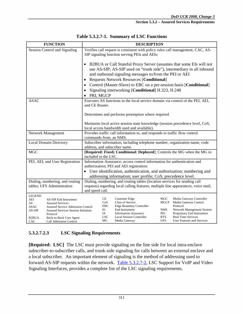
DoD UCR 2008, Change 3 Section 5.3.2 – Assured Services Requirements
311
Table 5.3.2.7-1. Summary of LSC Functions FUNCTION DESCRIPTION
Session Control and Signaling Verifies call request is consistent with policy rules call management, CAC, AS-SIP signaling function serving PEIs and AEIs: • B2BUA or Call Stateful Proxy Server (assumes that some EIs will not
use AS-SIP; AS-SIP used on “trunk side”), intermediary in all inbound and outbound signaling messages to/from the PEI or AEI
• Requests Network Resources [Conditional] • Control (Master-Slave) to EBC on a per-session basis [Conditional] • Signaling interworking [Conditional] H.323, H.248 • PRI, MGCP
ASAC
Executes AS functions in the local service domain via control of the PEI, AEI, and CE Router. Determines and performs preemption where required. Maintains local active session state knowledge (session precedence level, CoS, local access bandwidth used and available).
Network Management Provides traffic call information to, and responds to traffic flow control commands from, an NMS.
Local Domain Directory Subscriber information, including telephone number, organization name, code address, and subscriber name.
MGC [Required: Fixed; Conditional: Deployed]; Controls the MG when the MG in included in the LSC.
PEI, AEI, and User Registration Information Assurance; access control information for authentication and authorization; PEI and AEI registration: • User identification, authentication, and authorization; numbering and
addressing information; user profile; CoS; precedence level. Dialing, numbering, and routing tables; UFS Administration
Dialing, numbering, and routing tables (location services for sending call requests) regarding local calling features, multiple line appearances, voice mail, and speed call.
LEGEND AEI AS-SIP End Instrument AS Assured Services ASAC Assured Service Admission Control AS-SIP Assured Services Session Initiation
Protocol B2BUA Back-to-Back User Agent CAC Call Admission Control
CE Customer Edge CoS Class of Service EBC Edge Boundary Controller EI End Instrument IA Information Assurance LSC Local Session Controller MG Media Gateway
MGC Media Gateway Controller MGCP Media Gateway Control
Protocol NMS Network Management System PEI Proprietary End Instrument RTS Real Time Services UFS User Features and Services
5.3.2.7.2.3 LSC Signaling Requirements
[Required: LSC] The LSC must provide signaling on the line side for local intra-enclave subscriber-to-subscriber calls, and trunk-side signaling for calls between an external enclave and a local subscriber. An important element of signaling is the method of addressing used to forward AS-SIP requests within the network. Table 5.3.2.7-2, LSC Support for VoIP and Video Signaling Interfaces, provides a complete list of the LSC signaling requirements.

DoD UCR 2008, Change 3 Section 5.3.2 – Assured Services Requirements
312
Table 5.3.2.7-2. LSC Support for VoIP and Video Signaling Interfaces
FUNCTIONAL COMPONENT
VoIP AND VIDEO SIGNALING
INTERFACES VoIP AND VIDEO
SIGNALING PROTOCOLS CCA CCA (LSC)-to-
CCA (MFSS) AS-SIP over IP
CCA CCA (LSC)-to-PEI (details outside the scope of this section)
Proprietary VoIP Signaling over IP
CCA CCA (LSC) to AEI AS-SIP over IP CCA/MGC and MG CCA (MGC)-to-MG ITU-T H.248 over IP
(used with DoD CCS7, ISDN PRI, and CAS trunks) [Conditional, not Required]
CCA/MGC and MG CCA (MGC)-to-MG ISDN PRI over IP (North American National ISDN Version, used with ISDN PRI trunks only) [Conditional, not Required]
CCA/MGC and MG CCA (MGC)-to-MG Proprietary Supplier Protocols (used as an alternative to ITU-T Recommendation H.248 over IP and ISDN PRI over IP) (used with DoD CCS7, ISDN PRI, and CAS trunks)
CCA and SG LSC CCA-to-LSC SG DoD CCS7 over IP (used with DoD CCS7 trunks) [Conditional, not Required]
CCA and SG LSC CCA-to-LSC SG Proprietary Supplier Protocols Used as an alternative to DoD CCS7 over IP (used with DoD CCS7 trunks) [Conditional, not Required]
LEGEND AEI AS-SIP End Instrument AS-SIP Assured Services Session Initiation
Protocol CAS Channel Associated Signaling CCA Call Connection Agent CCS7 Common Channel Signaling No. 7 DoD Department of Defense
IP Internet Protocol ISDN Integrated Services Digital
Network ITU-T International Telecommunications
Union – Telecommunication LSC Local Session Controller MFSS Multifunction Softswitch
MG Media Gateway MGC Media Gateway Controller PEI Proprietary End Instrument PRI Primary Rate Interface SG Signaling Gateway VoIP Voice over IP
5.3.2.7.2.4 Service Requirements under Total Loss of WAN Transport Connectivity
[Required: LSC] In the event that a total loss of connectivity to the DISN WAN occurs, the LSC shall provide the following functions:
• Completion of local (intra-enclave) calls
• Routing of calls to the PSTN using a local MG (PRI or CAS as required by the local interface)
• User look-up of local directory information

DoD UCR 2008, Change 3 Section 5.3.2 – Assured Services Requirements
313
5.3.2.7.2.5 Local Location Server and Directory
[Required: LSC] The purpose of the Local Location Server (LLS) is to provide information on call routing and called address translation (where a called address is contained within the called SIP URI in the form of the called number). The CCA uses the routing information stored in the LLS to
• Route internal calls from one LSC PEI or AEI to another PEI or AEI on the same LSC.
• Route outgoing calls from an LSC PEI or AEI to another LSC, an MFSS, or a
TDM network.
• Route incoming calls from another LSC, an MFSS, or a TDM network to an LSC PEI or AEI.
5.3.2.7.2.6 LSC Management Function
[Required: LSC] The LSC Management function supports functions for LSC FCAPS management and audit logs. Collectively, these functions are called FCAPS Management and Audit Logs. A complete description of these requirements is provided in
• Section 5.3.2.17, Management of Network Appliances
• Section 5.3.2.18, Network Management Requirements of Appliance Functions
• Section 5.3.2.19, Accounting Management The CCA interacts with the LSC Management function by 1. Making changes to its configuration and to its end users’ configurations, in response to
commands from the Management function that requests these changes.
2. Returning information to the Management function on its FCAPS, in response to commands from the Management function that requests this information.
3. Sending information to the Management function on a periodic basis (e.g., on a set schedule), keeping the Management function up-to-date on CCA activity. An example of this update would be a periodic transfer of Call Detail Records (CDRs) from the CCA to the Management function, so that the Management function either could store the records locally or transfer them to a remote NMS for remote storage and processing.

DoD UCR 2008, Change 3 Section 5.3.2 – Assured Services Requirements
314
5.3.2.7.2.7 LSC Transport Interface Functions
[Required: LSC] The LSC Transport Interface functions provide interface and connectivity functions with the ASLAN and its IP packet transport network. Examples of Transport Interface functions include the following:
• Network Layer functions: IP, IP security (IPSec) • Transport Layer functions: IP Transport Protocols (TCP, UDP, TLS) • LAN Protocols
The CCA interacts with Transport Interface functions by using them to communicate with PEIs or AEIs and the EBC (and through the EBC to other LSCs and the MFSS) over the ASLAN. The following Local Assured Services Domain elements are all IP end-points on the ASLAN:
• Each PEI or AEI served by the LSC
• Each MG served by the LSC (even though the MG may be physically connected to the CCA/MGC over an internal proprietary interface, instead of being connected logically to the CCA/MGC over the ASLAN)
• The CCA/IWF/MGC itself
• The EBC (for LSC, PEI, AEI, and MG communication with other LSCs,
MFSSs, PEIs, AEIs, and MGs over the DISN WAN) As an example, the CCA interacts with the LSC Transport Interface functions when it uses IP, TLS, TCP, and the native ASLAN protocols to exchange AS-SIP signaling messages with PEIs or AEIs and the EBC over the ASLAN. The MGs controlled by the CCA interact with the LSC Transport Interface functions when they use IP, UDP, and the native ASLAN protocols to route SRTP media streams to and from PEIs or AEIs, other LSC MGs, and the EBC over the ASLAN.
5.3.2.7.2.8 LSC-to-NMS Interface
[Required: LSC] The LSC shall provide an interface to the DISA NMS. The interface consists of a 10/100-Mbps Ethernet connection as specified in Section 5.3.2.4.4, VVoIP Network Management System Interface Requirements.
5.3.2.7.2.9 ASAC Requirements for LSC Related to Voice and Video
[Required: LSC] For ASAC requirements, see Section 5.3.2.2.2.3, ASAC – Open Loop.

DoD UCR 2008, Change 3 Section 5.3.2 – Assured Services Requirements
315
5.3.2.7.2.10 LSC to PEI, AEI, and Operator Console Status Verification
[Required: LSC] Periodically, the LSC shall verify the status of its registered and authenticated IP EIs, including operator (dial service attendant) consoles. The parameter controlling this verification interval shall be configurable. NOTE: The current value configured for LSC deployments is 5 minutes, but could be changed in the future.
5.3.2.7.2.11 Line-Side Custom Features Interference
1. [Conditional: LSC] Vendors may implement unique custom features applicable to the line side of the LSC.
2. [Required: LSC] Line-side custom features must not interfere with the Assured Services requirements.
5.3.2.7.3 Loop Avoidance for LSCs
[Required: LSC] During the call establishment process, the product shall be capable of preventing or detecting and stopping hairpin routing loops over ANSI T1.619a and commercial PRI trunk groups (i.e., T1 PRI and E1 PRI) between a legacy switch (e.g., TDM EO) and an LSC (see Figure 5.3.2.7-3, Example of a Hairpin Routing Loop). The Loop Avoidance mechanism must not block call requests that are legitimately redirected or forwarded between the two interconnected products. In the event that a routing loop is detected, the LSC shall clear the call in the backwards direction, either sending a 404 (Not Found) response to a SIP originator, or an ISDN DISCONNECT message (from the MG) to a TDM originator. The LSC shall provide a VCA to the caller in each case. NOTE: Currently, this feature is not required a WAN SS or MFSS with the following exceptions: (a) if the WAN SS has a Conditional LSC component, this LSC must comply with the Loop Avoidance requirement as defined in this section, and (b) likewise, the LSC component of an MFSS must comply with the Loop Avoidance requirement as defined previously. Operational experience may dictate that the scope of this requirement should be expanded to address “tandem” routing carried out by the WAN SS or the SS component of an MFSS.
5.3.2.7.4 AS-SIP TDM Gateway
5.3.2.7.4.1 Overview
The AS-SIP TDM Gateway is a VVoIP appliance, and its purpose is to enable the interconnection and interoperation of a traditional TDM switch with the DISN UC system. The

DoD UCR 2008, Change 3 Section 5.3.2 – Assured Services Requirements
316
AS-SIP TDM Gateway performs interworking for voice and video sessions in both the signaling plane and the bearer plane.
Figure 5.3.2.7-3. Example of a Hairpin Routing Loop
NOTE: The AS-SIP TDM Gateway does NOT support interworking of IP-based signaling platforms and does NOT support or serve any TDM EIs or IP EIs. Figure 5.3.2.7-4, AS-SIP TDM Gateway Topologies, depicts examples of the two basic topologies that use the AS-SIP TDM Gateway. The first example depicts an enclave having one assured services precedence-capable TDM switch that interfaces with the AS-SIP TDM Gateway over ISDN MLPP PRI trunks. The second example depicts an enclave with multiple TDM switches that may include a PBX2 as well as MLPP-capable TDM switches wherein on assured services precedence-capable TDM switch interfaces with the AS-SIP TDM Gateway over ISDN MLPP PRI trunks, and the other TDM switches interface with the TDM switch connected to the AS-SIP TDM Gateway. The AS-SIP TDM Gateway only interfaces with one assured services precedence-capable TDM switch. When multiple TDM switches are located at an enclave, only one of those TDM switches is permitted to directly interface with the AS-SIP TDM Gateway. A PBX2 (or any other non-assured services precedence-capable TDM switch) is NOT permitted to directly interface with an AS-SIP TDM Gateway. The AS-SIP TDM Gateway does NOT support ASAC and relies on the subtended TDM switch to perform that functionality. It is assumed and expected that appropriate traffic engineering will
EO
Setup
MG
Call Proceeding
LSC
Call Proceeding
Setup
SetupCall Proceeding
EO
Setup
MG
Call Proceeding
LSC
Call Proceeding
Setup
SetupCall Proceeding
EO
Setup
MG
Call Proceeding
LSC
Call Proceeding
Setup
SetupCall Proceeding
EO
Setup
MG
Call Proceeding
LSC
Call Proceeding
Setup
SetupCall Proceeding
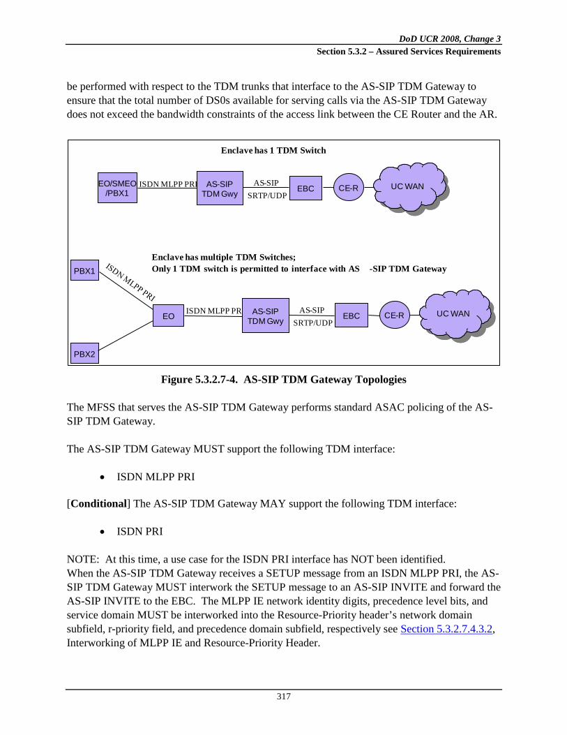
DoD UCR 2008, Change 3 Section 5.3.2 – Assured Services Requirements
317
be performed with respect to the TDM trunks that interface to the AS-SIP TDM Gateway to ensure that the total number of DS0s available for serving calls via the AS-SIP TDM Gateway does not exceed the bandwidth constraints of the access link between the CE Router and the AR.
Figure 5.3.2.7-4. AS-SIP TDM Gateway Topologies
The MFSS that serves the AS-SIP TDM Gateway performs standard ASAC policing of the AS-SIP TDM Gateway. The AS-SIP TDM Gateway MUST support the following TDM interface:
• ISDN MLPP PRI
[Conditional] The AS-SIP TDM Gateway MAY support the following TDM interface:
• ISDN PRI NOTE: At this time, a use case for the ISDN PRI interface has NOT been identified. When the AS-SIP TDM Gateway receives a SETUP message from an ISDN MLPP PRI, the AS-SIP TDM Gateway MUST interwork the SETUP message to an AS-SIP INVITE and forward the AS-SIP INVITE to the EBC. The MLPP IE network identity digits, precedence level bits, and service domain MUST be interworked into the Resource-Priority header’s network domain subfield, r-priority field, and precedence domain subfield, respectively see Section 5.3.2.7.4.3.2, Interworking of MLPP IE and Resource-Priority Header.
EO/SMEO/PBX1
AS-SIPTDM Gwy EBC CE-R RTS WANUC WANISDN MLPP PRI AS-SIP
SRTP/UDP
ISDN MLPP PRIEO
Enclave has 1 TDM Switch
PBX1
PBX2
AS-SIPTDM Gwy EBC CE-R RTS WANUC WANAS-SIP
SRTP/UDP
Enclave has multiple TDM Switches;Only 1 TDM switch is permitted to interface with AS -SIP TDM Gateway

DoD UCR 2008, Change 3 Section 5.3.2 – Assured Services Requirements
318
The AS-SIP TDM Gateway MUST add a CCA-ID parameter to the Contact header. The AS-SIP TDM Gateway MUST add a route set comprising two Route headers where the first Route header is the SIP URI for the EBC at the enclave, and the second Route header is the SIP URI for the EBC serving the MFSS. When the AS-SIP TDM Gateway receives an AS-SIP INVITE from the MFSS via the EBC intended for an ISDN MLPP PRI, the AS-SIP TDM Gateway MUST interwork the INVITE to a SETUP message (including MLPP IE) and forward the SETUP message on the D-channel. The TDM switch is responsible for implementing the assured services Precedence Capability function and the AS-SIP TDM Gateway MUST interwork INVITEs received from the EBC to the TDM switch, even if all DS0s are currently in use. The TDM switch is responsible for either rejecting the call request, conducting preemption, or diverting the call request to an attendant or voicemail system. The AS-SIP TDM Gateway MUST NOT perform directionalization and MUST NOT perform code blocking. Both of these functions are the responsibility of the TDM switch connected to the AS-SIP TDM Gateway.
5.3.2.7.4.2 AS-SIP TDM Gateway Functional Reference Model and Assumptions
Figure 5.3.2.7-5, Functional Reference Model – AS-SIP TDM Gateway, shows the reference model for the AS-SIP TDM Gateway. The AS-SIP TDM Gateway consists of several SCS functions performed by the CCA, IWF, MGC, and MG. These are connected via proprietary internal interface functions. Connectivity to other networks, long-haul transport systems (via an ASLAN), and DISA’s VVoIP NMS (ADIMSS) are provided by external interfaces. Generic Requirements for the CCA and MG functions and NM are provided in separate sections of the UCR, as follows: 1. Section 5.3.2.9, Call Connection Agent, contains CCA requirements, including the CCA-
associated IWF.
2. Section 5.3.2.12, Media Gateway Requirements, contains MG and MGC requirements.
3. Section 5.3.2.17, Management of Network Appliances, contains NM requirements.
5.3.2.7.4.2.1 Assumptions – AS-SIP TDM Gateway
The following assumptions are made based on the AS-SIP TDM Gateway reference model:

DoD UCR 2008, Change 3 Section 5.3.2 – Assured Services Requirements
319
1. The AS-SIP TDM Gateway only interfaces with one TDM switch, and the TDM switch MUST implement assured services precedence capability.
Figure 5.3.2.7-5. Functional Reference Model – AS-SIP TDM Gateway
2. All of the trunks of the assured services precedence-capable TDM switch (i.e. EO, SMEO,
or PBX1) that interface to the AS-SIP TDM Gateway MUST be ISDN MLPP PRI trunks.
3. The TDM switch has no other TDM or IP connectivity to the UC WAN aside from the AS-SIP TDM Gateway. The TDM trunks to the MFS will be eliminated to avoid hybrid routing issues at the MFSS/MFS and WAN SS.
DoD, Allied, or
CoalitionPartner
T1.619a
ISDN PRI(Conditional)
MG
EO
SMEO
PBX
IWF
CCA
SCS Functions
Service Control Functions
AS-SIP TDM Gateway Product
Test Configuration
ASLAN
MFSS or
WAN SS
EBC
AS-SIP
MGC
LEGEND:ASLAN Assured Services Local Area NetworkAS-SIP Assured Services Session Initiation ProtocolCCA Call Connection AgentCE R Customer Edge RouterDoD Department of DefenseEBC Edge Border ControllerEMS Element Management SystemEO End OfficeISDN Integrated Services Digital NetworkIWF Interworking FunctionMFSS Multifunction Softswitch
MG Media GatewayMGC Media Gateway ControllerPBX Private Branch ExchangePEI Proprietary End InstrumentPRI Primary Rate InterfaceSCS Session Control and SignalingSMEO Small End OfficeSRTP Secure Real Time Transport ProtocolSS SoftswitchUDP User Datagram ProtocolWAN Wide Area Network
InformationAssurance
Managem
entAS-SIPSignaling
Transport Interface Functions
EMS
T1.619a
T1.619a
ISDN PRI(Conditional)
ISDN PRI(Conditional)
SRTP/UDPCE R

DoD UCR 2008, Change 3 Section 5.3.2 – Assured Services Requirements
320
4. The MGC and IWF are both components of the CCA. The MGC is responsible for controlling the MG in the AS-SIP TDM Gateway and the ISDN MLPP PRI TDM trunk groups that are connected to it. The IWF is responsible for supporting all the VoIP and TDM signaling protocols in the AS-SIP TDM Gateway, and for interworking the different protocols together (see Table 5.3.2.7-3, which is a subset of the interworking capabilities set forth in Table 5.3.2.9-2, Full IWF Interworking Capabilities for VoIP and TDM Protocols).
Table 5.3.2.7-3. AS-SIP TDM Gateway IWF Interworking Capabilities for VoIP and TDM Protocols
IWF INPUT
PROTOCOL
IWF OUTPUT PROTOCOL AS-SIP
(TO AN EBC) ISDN MLPP PRI ISDN PRI AS-SIP (from an EBC)
No interworking needed
Required Conditional (use case yet to be identified)
ISDN MLPP PRI
Required No interworking needed
N/A
ISDN PRI Conditional (Use case yet to be identified)
N/A No interworking needed
LEGEND: AS-SIP Assured Services Session Initiation
Protocol CAS Channel-Associated Signaling EBC Edge Boundary Controller
ISDN Integrated Services Digital Network IWF Inter Working Function MLPP Multilevel Precedence and Preemption N/A Not Applicable PRI Primary Rate Interface
5. The MG provides CS trunk termination (for ISDN MLPP PRI trunks and [Conditional] for
ISDN PRI trunks) and TDM/VoIP interworking. The MG is controlled by the MGC. The interface between the MGC and MG is internal to the AS-SIP TDM Gateway and the choice of protocol is left to the vendor.
6. The MG functionality is an integral component of the AS-SIP TDM Gateway and the AS-SIP TDM Gateway does not support remote MGs or multiple MGs.
7. The AS-SIP TDM Gateway does NOT include a SG.
8. Each functional component in the AS-SIP TDM Gateway has associated management-related functions for FCAPS management and audit logs.
9. The CCA interacts with the Service Control functions using internal interfaces and proprietary protocols that vary from one supplier’s solution to another.
10. The AS-SIP TDM Gateway interactions with its EBC are as follows:

DoD UCR 2008, Change 3 Section 5.3.2 – Assured Services Requirements
321
a. The EBC controls signaling streams between an AS-SIP TDM Gateway (connected to an ASLAN) and an MFSS (where a separate ASLAN is connected to the UC WAN). The AS-SIP TDM Gateway accesses the UC WAN via the EBC and an associated AR on the UC WAN.
b. As a result, it is possible for an AS-SIP TDM Gateway to direct a VoIP media stream
(interworked from a TDM media stream from the TDM side of that MG) through an EBC to the UC WAN, and through the UC WAN to a remote EI or MG.
5.3.2.7.4.3 Summary of AS-SIP TDM Gateway Functions and Features
Table 5.3.2.7-4, Summary of AS-SIP TDM Gateway Functions, provides a summary of AS-SIP TDM Gateway functions.
Table 5.3.2.7-4. Summary of AS-SIP TDM Gateway Functions
FUNCTION DESCRIPTION Session Control and Signaling • Signaling interworking
• ISDN MLPP PRI • [Conditional] ISDN PRI • AS-SIP • Call stateful, maintains local active session state knowledge
(including precedence level) Network Management • Provides traffic call information to and responds to traffic flow
control commands from, an NMS. MGC • Required MG • Interworking of B-channel PCM with SRTP/UDP/IP packets
• Generation and receipt/processing of SRTCP/UDP/IP packets • Delivery of Q.931 messages • Assignment of appropriate value to DSCP field when generating
SRTP/UDP/IP packets LEGEND AS-SIP Assured Services Session Initiation Protocol DSCP Differentiated Services Code Point IP Internet Protocol ISDN Integrated Services Digital Network MG Media Gateway MGC Media Gateway Controller MLLP Multilevel Precedence and Preemption
NMS Network Management System PCM Pulse Code Modulation PRI Primary Rate Interface SRTCP Secure Real-Time Transport Control Protocol SRTP Secure Real-Time Transport Protocol UDP User Datagram Protocol
5.3.2.7.4.3.1 AS-SIP TDM Gateway Signaling Requirements
The AS-SIP TDM Gateway must provide signal interworking between the connected TDM switch and the designated MFSS. Table 5.3.2.7-5, AS-SIP TDM Gateway Support for VoIP and Video Signaling Interfaces, provides the list of the AS-SIP TDM Gateway signaling requirements.

DoD UCR 2008, Change 3 Section 5.3.2 – Assured Services Requirements
322
Table 5.3.2.7-5. AS-SIP TDM Gateway Support for VoIP and Video Signaling Interfaces
FUNCTIONAL COMPONENT
VoIP AND VIDEO SIGNALING
INTERFACES VoIP AND VIDEO
SIGNALING PROTOCOLS CCA CCA (AS-SIP TDM
Gateway) – to – CCA (MFSS)
AS-SIP over IP
CCA/MGC and MG
CCA (MGC) – to – MG Internal interface to integrated MG functional component (used with ISDN MLPP PRI trunks) (Conditional: ISDN PRI – Use case yet to be identified)
LEGEND AS-SIP Assured Services Session Initiation
Protocol CAS Channel Associated Signaling CCA Call Connection Agent IP Internet Protocol
ISDN Integrated Services Digital Network MFSS Multifunction Softswitch MLPP Multilevel Precedence and
Preemption
MG Media Gateway MGC Media Gateway Controller PRI Primary Rate Interface TDM Time Division Multiplexing VoIP Voice over IP
5.3.2.7.4.3.2 Interworking of MLPP IE and Resource-Priority Header
Per UCR Sections 5.3.4.10.2.1, Resource-Priority Header Field, 5.3.4.10.2.1.1, Namespace; 5.3.4.10.2.1.2, r-priority, 5.3.2.31.3.7.2, Precedence Level Information Elements; and 5.3.4.18.2 Requirements for Interworking AS-SIP Signaling Appliances, when the AS-SIP TDM Gateway receives a SETUP message from an ISDN MLPP PRI trunk then the AS-SIP TDM Gateway interworks: 1. The four network identity digits found in octets 5 and 6 of the MLPP IE into the Network
Domain subfield of the Namespace of the Resource-Priority header of an INVITE message NOTE: From FY 2008–FY 2012, the only valid value for the Network Domain subfield is “uc”.
2. The precedence level specified in bits 1–4 of octet 3 of the MLPP IE to the equivalent representation in the r-priority field of the Resource Priority header of an INVITE message.
3. The MLPP service domain found in octets 7–9 of the MLPP IE into the Precedence-Domain subfield of the Namespace of the Resource-Priority header. NOTE: From FY 2008–FY 2012, the only valid value for the Precedence-Domain subfield is “ 000000”.
Per UCR Sections 5.3.4.10.2.1, Resource-Priority Header Field; 5.3.4.10.2.1.1, Namespace, 5.3.4.10.2.1.2, r-priority; 5.3.4.18.2, Requirements for Interworking AS-SIP Signaling Appliances, and Section 5.3.2.31.3.8.2 Precedence Level Information Elements; and when the

DoD UCR 2008, Change 3 Section 5.3.2 – Assured Services Requirements
323
AS-SIP TDM Gateway receives an AS-SIP INVITE message intended for an ISDN MLPP PRI trunk then the AS-SIP TDM Gateway interworks: 1. The Network Domain subfield of the Namespace of the Resource-Priority header to the
four network identity digits found in octets 5 and 6 of the MLPP IE of a SETUP message NOTE: From FY 2008–2012 the only valid value for the network identity digits of the MLPP IE is the binary coded decimal value “0000.”
2. The precedence level in the r-priority field of the Resource Priority header to the equivalent representation in bits 1-4 of octet 3 of the MLPP IE of a SETUP message.
3. The precedence-domain subfield of the Namespace of the Resource-Priority header to the MLPP service domain in octets 7–9 of the MLPP IE of the SETUP message. NOTE: From 2008–2012, the only valid value for the MLPP service domain is 000000000000000000000000binary (i.e., 0x000000)
5.3.2.7.4.3.3 SIP URI and Mapping of Telephone Number
When the AS-SIP TDM Gateway receives a call request over an ISDN MLPP PRI then the AS-SIP TDM Gateway MUST map the telephony numbers received from the Q.931 SETUP message to SIP URIs IAW UCR Section 5.3.4.14.3, SIP URI and Mapping of Telephony Number into SIP URI, and UCR Section 5.3.4.7.6, SIP URI and Mapping of Telephone Number into SIP URI.
5.3.2.7.4.3.4 AS-SIP TDM Gateway Media Requirements
Summary of Relevant Media Packet Requirements from Other UCR Sections The AS-SIP TDM Gateway MG MUST support the ITU-T Recommendation G.711 (µ-law and A-law) audio codec. The AS-SIP TDM Gateway MG MUST support RFC 4040 and the AS-SIP TDM Gateway MUST support the signaling for establishing the 64kbps unrestricted bearer per Section 5.3.4.7.7, 64 kbps Transparent Calls (Clear Channel). NOTE: The 64 kbps “clearmode” data streams are used to transport individual H.320 video/64 kbps video streams across the IP network from one TDM H.320 end point to another. The AS-SIP TDM Gateway MG is NOT required to participate in the “bonding” of the 64 kbps video streams.
DoD UCR 2008, Change 3 Section 5.3.2 – Assured Services Requirements
324
The AS-SIP TDM Gateway MG does NOT support interworking of H.320 TDM video and IP video. The AS-SIP TDM Gateway MG is NOT required to perform transcoding between codec types but MUST perform A-law/μ-law conversion when needed. The AS-SIP TDM Gateway MG MUST support T.38 Fax Relay (see Section 5.3.2.12.12.9, MG Support for Group 3 Fax Calls. The AS-SIP TDM Gateway MG MUST support the SCIP-216 subset of V.150.1 Modem Relay (see Section 5.3.2.21.2, SCIP/V.150.1 Gateway Requirements) and the AS-SIP TDM Gateway MUST support the AS-SIP signaling requirements in support of modem relay (See Section 5.3.4.13.9.1, AS-SIP Signaling Requirements in Support of Modem Relay-Capable Gateways).
5.3.2.7.4.3.5 Information Assurance Requirements
The AS-SIP TDM Gateway MUST satisfy the Information Assurance requirements in Section 5.4 Information Assurance for a media gateway.
5.3.2.7.4.3.6 Service Requirements under Total Loss of WAN Transport Connectivity
Upon total loss of WAN transport, the AS-SIP TDM Gateway becomes incapable of exchanging either signaling messages or media packets between the connected TDM switch and the UC WAN. The immediate consequence is that the users on the existing voice and video sessions can no longer successfully send or receive media, and will go on-hook. The signaling termination messages (triggered by going on-hook) will fail to transit the WAN due to the loss of WAN transport. In addition, since the AS-SIP TDM Gateway provides the only connectivity to the UC WAN for the TDM switch, the TDM switch loses the ability to establish new calls over the UC WAN until WAN connectivity is restored.
5.3.2.7.4.3.7 AS-SIP TDM Gateway Management Function
The CCA interacts with the AS-SIP TDM Gateway Management function by: 1. Making changes to its configuration in response to commands from the Management
function that requests these changes.
2. Returning information to the Management function on its FCAPS, in response to commands from the Management function that requests this information.
3. Sending information to the Management function on a periodic basis (e.g., on a set schedule), keeping the Management function up-to-date on CCA activity.

DoD UCR 2008, Change 3 Section 5.3.2 – Assured Services Requirements
325
5.3.2.7.4.3.8 AS-SIP TDM Gateway Transport Interface Functions
The AS-SIP TDM Gateway Transport Interface functions provide interface and connectivity with the ASLAN and its IP packet transport network. Examples of Transport Interface functions include the following:
• Network Layer functions: IP, IPSec where IPSec is used to protect NM IP packets
• Transport Layer functions: IP Transport Protocols TCP, UDP, TLS
• LAN Protocols
The CCA interacts with Transport Interface functions by using them to communicate with the EBC (and through the EBC to the MFSS) over the ASLAN. The following Local Domain elements are all IP end points on the ASLAN:
• The MG functional component • The CCA/IWF/MGC itself • The EBC
As an example, the CCA interacts with the AS-SIP TDM Gateway Transport Interface functions when it uses IP, TLS, TCP, and the native ASLAN protocols to exchange AS-SIP signaling messages with the EBC over the ASLAN. The integrated MG controlled by the CCA interacts with the AS-SIP TDM Gateway Transport Interface functions when it uses IP, UDP, and the native ASLAN protocols to route SRTP media streams to and from the EBC over the ASLAN.
5.3.2.7.4.3.9 AS-SIP TDM Gateway-to-NMS Interface
The AS-SIP TDM Gateway MUST provide an interface to the DISA NMS. The interface MUST consist of a 10/100-Mbps Ethernet connection, as specified in Section 5.3.2.4.4, VVoIP NMS Interface Requirements.
5.3.2.7.4.3.10 No ASAC Requirements for AS-SIP TDM Gateway Related to Voice and Video
The AS-SIP TDM Gateway does NOT implement ASAC requirements. The TDM trunks between the connected TDM switch and the AS-SIP TDM Gateway MUST be engineered to limit the maximum traffic flow to fit the bandwidth constraints of the access link.

DoD UCR 2008, Change 3 Section 5.3.2 – Assured Services Requirements
326
5.3.2.7.4.3.11 Additional Features
The AS-SIP TDM Gateway MUST support ITU-T Recommendation V.150.1 Modem Relay (See Section 5.3.4.13.9, Modem on IP Networks, and the NSA specification SCIP-216). The AS-SIP TDM Gateway MUST support ITU-T Recommendation T.38 Fax Relay.
5.3.2.7.4.3.12 Specific Functions and Features NOT Supported
Specifically, the AS-SIP TDM Gateway does NOT support the following functions or requirements:
• A media server • A stateful firewall • Routing database (DB) functions • AS-SIP interfaces for voicemail and unified messaging
5.3.2.7.5 AS-SIP – H.323 Gateway
All of the requirements in this section are [Required] unless they are marked as [Conditional] within the text. The requirements on directionalization in this section are [Conditional].
5.3.2.7.5.1 Overview
The AS-SIP – H.323 Gateway is a VVoIP interworking appliance, and its purpose is to enable the interconnection and interoperation of H.323 IP-based UC signaling platforms and their associated IP EIs with the DISN UC system to support E2E voice and video sessions. The Government has adopted RFC 4123 – Session Initiation Protocol (SIP) – H.323 Interworking Requirements as the document which describes the requirements for the AS-SIP – H.323 Gateway. Internet draft-agrawal-sip-h323-interworking-01.txt is cited as guidance to be used in implementing the AS-SIP – H.323 Gateway. The following contents of this section are additional Government requirements. NOTE: The AS-SIP – H.323 Gateway is not an assured services appliance because H.323 is not an assured services protocol, and its placement in this section is for requirements grouping purposes and should not be interpreted as implying that the AS-SIP – H.323 Gateway is an Assured Services appliance. The AS-SIP – H.323 Gateway SUT is a standalone SUT for testing purposes.

DoD UCR 2008, Change 3 Section 5.3.2 – Assured Services Requirements
327
The AS-SIP H.323 Gateway interfaces to the enclave EBC in both the signaling plane and the bearer plane and is responsible for interworking AS-SIP voice and video signaling with the voice and video signaling of the H.323 UC signaling platform. The AS-SIP – H.323 Gateway is responsible for interworking UCR-compliant voice and video media packets with the voice and video media packets supported by the H.323 UC signaling platform’s IP EIs. Interoperability of UC features and services other than non-assured voice and video services is outside the scope of the required functionality for the AS-SIP – H.323 Gateway and will not be a part of AS-SIP H.323 Gateway SUT interoperability testing. From a signaling perspective, the AS-SIP – H.323 Gateway MUST offer an AS-SIP-compliant signaling interface that provides end-to-end signaling interoperability between the AS-SIP – H.323 Gateway SUT and the AS-SIP signaling appliances of the DISN UC WAN system. From a media perspective, the AS-SIP – H.323 Gateway MUST offer a UCR-compliant bearer interface that provides E2E interoperability for voice and video media packets between the AS-SIP – H.323 Gateway SUT and EBCs, IP EIs of LSC SUTs, MGs, and AS-SIP EIs. The AS-SIP – H.323 Gateway MUST interwork the voice and video media packets generated by the IP EIs served by the IP-based UC signaling platform and intended for a destination outside the H.323 system enclave to UCR-compliant SRTP/UDP packets having the appropriate DSCP. Similarly, UCR-compliant SRTP/UDP voice and video media packets received from the UC WAN and intended for the IP EIs served by the H.323 UC signaling platform MUST be interworked by the AS-SIP – H.323 Gateway into the H.323 media packets supported by the IP EIs. Figure 5.3.2.7-6, AS-SIP – H.323 Gateway Topology, depicts the AS-SIP – H.323 Gateway SUT in relation to the UC WAN where the logical interface is between the AS-SIP – H.323 Gateway and the EBC. The UCR does NOT mandate the connectivity, interface, or protocol requirements within the AS-SIP – H.323 Gateway SUT and the internal signaling and media lines (in blue) represent notional connectivity options. 5.3.2.7.5.1.1 The AS-SIP – H.323 Gateway MUST implement call count thresholds for voice sessions and for video sessions in order to perform Session Admission Control (SAC). See Section 5.3.2.7.5.3.1.4, Session Admission Control, for more details. AS-SIP – H.323 Gateway Call Request Processing Overview 5.3.2.7.5.1.2 When the AS-SIP – H.323 Gateway receives a call request from the H.323 UC signaling platform then the AS-SIP – H.323 Gateway MUST:
a. Check the appropriate (voice or video) call count (and outbound call count in the case of directionalization) to determine whether there are available bandwidth resources to support the call request.

DoD UCR 2008, Change 3 Section 5.3.2 – Assured Services Requirements
328
Figure 5.3.2.7-6. AS-SIP – H.323 Gateway Topology
b. If the new call request would not exceed the appropriate (voice or video) call count
threshold (and outbound call count threshold) then the AS-SIP – H.323 Gateway interworks the call request by:
(1) Incrementing the call count (and outbound call count in the case of
directionalization).
(2) Generating a “routine” level AS-SIP INVITE that advertises equivalent capabilities to those specified in the received call request.
(3) Adding a CCA-ID parameter to the Contact header. (4) Adding a route set comprising two Route headers where the first Route header
is the SIP URI for the EBC at the enclave, and the second Route header is the SIP URI for the EBC serving the WAN SS/MFSS.
(5) Forwarding the INVITE message to the EBC at the enclave
UC WANH.323
UC platformAS-SIP-H.323
-GatewayEBC CE-R
H.323 signaling AS-SIP
SRTP/UDPSRTCP/UDP
RTPMedia pkts
IP EI
IP EI
H.323 signaling
RTP media packets
AS-SIP signaling
SRTP/UDPSRTCP/UDP(UCR compliant)
AS-SIP – H.323 GatewaySystem Under Test
Note: The connectivity, interfaces, and protocols internal to the AS-SIP – H.323 Gateway SUT are left to the vendor

DoD UCR 2008, Change 3 Section 5.3.2 – Assured Services Requirements
329
c. If the appropriate (voice or video) call count (or outbound call count) is at threshold or the call request would cause the AS-SIP – H.323 Gateway to exceed the call count threshold (or outbound call count threshold) then the AS-SIP – H.323 Gateway MUST reject the call.
5.3.2.7.5.1.3 When an AS-SIP – H.323 Gateway receives an initial routine AS-SIP INVITE (i.e., not a re-INVITE) from the WAN SS/MFSS (via the EBC), then the AS-SIP – H.323 Gateway MUST:
a. Check the appropriate (voice or video) call count (and inbound call count in the case of directionalization) to determine whether there are available bandwidth resources to support the call request.
b. If the new call request would not exceed the appropriate (voice or video) call count threshold (and inbound call count threshold) then the AS-SIP – H.323 Gateway increments the appropriate (voice or video) call count (and inbound call count) and interworks the INVITE to H.323.
c. If the appropriate (voice or video) call count (or inbound call count) is at threshold or
the call request would cause the AS-SIP – H.323 Gateway to exceed the appropriate (voice or video) call count threshold (or inbound call count threshold) then the AS-SIP – H.323 Gateway MUST reject the call.
NOTE: The response message is 488 (Not Acceptable Here) and SHOULD include a
Warning header field with warning code 370 (Insufficient Bandwidth) 5.3.2.7.5.1.4 The AS-SIP – H.323 Gateway MUST support the following two methods for processing initial precedence AS-SIP INVITEs received from the WAN SS/MFSS via the EBC and the choice of method MUST be software configurable:
a. Upon receipt of the initial precedence AS-SIP INVITE request the AS-SIP – H.323 Gateway diverts the precedence INVITE to the attendant, or
b. Upon receipt of the initial precedence AS-SIP INVITE request, the AS-SIP – H.323
Gateway determines whether the appropriate (voice or video) call count (or inbound call count in the case of directionalization) is at threshold or whether the call request would cause the AS-SIP – H.323 Gateway to exceed the appropriate (voice or video) call count threshold or inbound call count threshold:
(1) If the precedence AS-SIP INVITE would cause the appropriate (voice or
video) call count threshold (or inbound call count threshold) to be exceeded, then the precedence AS-SIP INVITE is forwarded to the attendant.

DoD UCR 2008, Change 3 Section 5.3.2 – Assured Services Requirements
330
NOTE: The AS-SIP – H.323 Gateway MUST NOT conduct preemption on behalf of an inbound precedence AS-SIP INVITE.
(2) If the precedence AS-SIP INVITE would NOT cause the appropriate call
count threshold (or inbound call count threshold) to be exceeded, then the AS-SIP – H.323 Gateway treats the inbound precedence AS-SIP INVITE request as if it were a routine inbound call request and increments the appropriate (voice or video) call count (and inbound call count) and interworks the INVITE to platform..
WAN SS/MFSS Policing Requirements when Serving an AS-SIP – H.323 Gateway 5.3.2.7.5.1.5 The AS-SIP – H.323 Gateway only sends routine AS-SIP INVITEs to the WAN SS/MFSS, and the WAN SS/MFSS MUST apply the standard ASAC policing rules for outbound routine voice and video requests. See UCR Requirements 5.3.4.11.1.8, 5.3.4.11.1.10 through 5.3.4.11.1.12 for policing routine outbound telephony requests. See UCR Requirements 5.3.4.11.2.9, 5.3.4.11.2.11 through 5.3.4.11.2.13 for policing routine outbound video requests. 5.3.2.7.5.1.6 When a WAN SS/MFSS receives an initial “routine” AS-SIP INVITE request intended for forwarding to a served AS-SIP – H.323 Gateway, the WAN SS/MFSS MUST apply the standard ASAC policing rules for inbound routine voice and video requests. See UCR Requirements 5.3.4.11.1.13, 5.3.4.11.1.13.1, 5.3.4.11.1.13.3 through 5.3.4.11.1.13.5, 5.3.4.11.1.14, 5.3.4.11.1.14.1, 5.3.4.11.1.14.2, 5.3.4.11.1.14.5 through 5.3.4.11.1.14.10, 5.3.4.11.1.15, 5.3.4.11.1.15.1, 5.3.4.11.1.15.3 through 5.3.4.11.1.15.5 for policing inbound routine telephony requests. See UCR Requirements 5.3.4.11.2.14, 5.3.4.11.2.14.1, 5.3.4.11.2.14.3 through 5.3.4.11.2.14.6, 5.3.4.11.2.15, 5.3.4.11.2.15.1, 5.3.4.11.2.15.3 through 5.3.4.11.2.15.6 for policing inbound routine video requests. 5.3.2.7.5.1.7 When a WAN SS/MFSS receives an initial precedence AS-SIP INVITE request intended for forwarding to a served AS-SIP – H.323 Gateway, the WAN SS/MFSS MUST implement one of the following two policing rules: 1. [Preferred] Forward the AS-SIP INVITE to the AS-SIP – H.323 Gateway and if the AS-
SIP – H.323 Gateway responds with either a 1xx response code greater than 100 or a 2xx

DoD UCR 2008, Change 3 Section 5.3.2 – Assured Services Requirements
331
response and the call request would cause the appropriate (voice or video) call count threshold (or inbound call count threshold) to be exceeded, then the WAN SS/MFSS:
a. Sends a 488 (Not Acceptable Here) response code to the remote initiating party of the AS-SIP INVITE that SHOULD include a Warning header field with warning code 370 (Insufficient Bandwidth).
b. Sends a CANCEL request (in the case of a 1xx response code) or a BYE request (in the case of a 2xx response code) to the local AS-SIP – H.323 Gateway.
NOTE: This approach has the WAN SS/MFSS applying the standard ASAC policing
rules for a ROUTINE request to a precedence request. 2. [Alternative] (Standard ASAC Policing Rules for precedence call request) Forward the
AS-SIP INVITE request to the AS-SIP – H.323 Gateway and if the AS-SIP – H.323 Gateway responds with either a 1xx response code greater than 100 or a 2xx response and the call request would cause the appropriate (voice or video) call count threshold (or inbound call count threshold) to be exceeded, then the WAN SS/MFSS applies the standard ASAC policing rules for a precedence call request. That is, the WAN SS/MFSS preempts a ROUTINE or lesser precedence call by sending a BYE request with a Reason header for preemption to the AS-SIP – H.323 Gateway. The AS-SIP – H.323 Gateway MUST ignore the Reason header for preemption, interwork the BYE request to the H.323 UC signaling platform, and respond with a 200 (OK) response. The ROUTINE or lesser precedence call will be terminated and the MFSS will forward the 1xx response greater than 100 or the 2xx response to the precedence inbound call request over the UC WAN.
5.3.2.7.5.2 AS-SIP – H.323 Gateway Functional Reference Model and Assumptions
Figure 5.3.2.7-7, Functional Reference Model – AS-SIP – H.323 Gateway, shows the reference model for the AS-SIP – H.323 Gateway. The AS-SIP – H.323 Gateway consists of several SCS functions performed by the CCA, IWF (for signaling), and IWF (for media). These are connected via H.323 internal interface functions. Connectivity to other networks, long-haul transport systems (via an ASLAN), and DISA’s VVoIP NMS (ADIMSS) are provided by external interfaces.
5.3.2.7.5.2.1 Assumptions – AS-SIP – H.323 Gateway
The following assumptions are made based on the AS-SIP – H.323 Gateway reference model: 1. The AS-SIP – H.323 Gateway interfaces with multiple H.323 systems/EIs.

DoD UCR 2008, Change 3 Section 5.3.2 – Assured Services Requirements
332
Figure 5.3.2.7-7. Functional Reference Model – AS-SIP – H.323 Gateway
2. The H.323 UC signaling platform has no other connectivity to the UC WAN aside from the
AS-SIP – H.323 Gateway.
3. Each functional component in the AS-SIP – H.323 Gateway has associated management-related functions for FCAPS management and audit logs.
4. The CCA interacts with the Service Control functions using internal interfaces and H.323 protocols that vary from one supplier’s solution to another.
5. The AS-SIP – H.323 Gateway interactions with its EBC are as follows:
AS-SIPsignaling
Service Control Functions
IA
AS-SIP – H.323 Gateway ProductM
anagement
CCA
IWF(signaling)
Transport Interface Functions
SCS Functions
ASLANEBC
AS-SIP
SRTP/UDP
ASLAN Assured Services Local Area Network
AS-SIP Assured Services Session Initiation Protocol
B2BUA Back-to-back User Agent
CCA Call Connection AgentEBC Edge Border ControllerIA Information AssuranceIWF Interworking FunctionMG Media Gateway
SCS Session Control And SignalingSIP Session Initiation ProtocolUC Unified Communications
MFSSor
WAN SS
CERouter
AS-SIP
TestConfiguration
Session Admission Control
H.323UC Platform
IP EI
MEDIA
IWF(media) B2BUA*
•B2BUA is applicable when UC platform signaling protocol is SIP
H.323 Signaling
RTP Media Packets
H.323signaling
IA
Media Functions EMS
LEGEND

DoD UCR 2008, Change 3 Section 5.3.2 – Assured Services Requirements
333
a. The EBC controls signaling streams between the AS-SIP – H.323 Gateway (connected to an ASLAN) and a WAN SS/MFSS (where its separate ASLAN is connected to the DISN WAN). The AS-SIP – H.323 Gateway accesses the UC WAN via the EBC and an associated AR on the UC WAN.
b. The EBC controls media streams between the AS-SIP – H.323 Gateway (connected
to the ASLAN) and other AS-SIP – H.323 Gateways, or the EIs and MGs of LSCs (whose separate ASLANs are connected to the DISN UC WAN).
5.3.2.7.5.3 Summary of AS-SIP – H.323 Gateway Functions and Features
The AS-SIP – H.323 Gateway provides interworking functions for the signaling and bearer planes (see Table 5.3.2.7-6, Summary of AS-SIP – H.323 Gateway Functions).
Table 5.3.2.7-6. Summary of AS-SIP – H.323 Gateway Functions
FUNCTION DESCRIPTION SCS Verifies call request is consistent with SAC:
• Signaling interworking (H.323 to AS-SIP; AS-SIP to H.323) SAC
Maintains call thresholds. Maintains active session state knowledge (local access bandwidth used and available, direction, session type: voice, video).
Media IWF Converts H.323 media packets to UCR-compliant IP/UDP/SRTP packets. Converts UCR compliant IP/UDP/SRTP packets to H.323 media packets.
NM Provides traffic call information to, and responds to traffic flow control commands from, an NMS.
LEGEND AS-SIP Assured Services Session Initiation Protocol IP Internet Protocol IWF Interworking Function NM Network Management NMS Network Management System
SAC Session Admission Control SCS Session Control and Signaling SRTP Secure Real-time Transport Protocol UCR Unified Capabilities Requirements UDP User Datagram Protocol
5.3.2.7.5.3.1 AS-SIP – H.323 Gateway SCS Requirements
Table 5.3.2.7-7, AS-SIP – H.323 Gateway support for VoIP and Video Signaling Interfaces, provides a complete list of the AS-SIP – H.323 Gateway signaling requirements.
5.3.2.7.5.3.1.1 CCA Function
The CCA is part of the SCS functions and includes the IWF (signaling) function. The scope of these CCA requirements covers the following areas: 1. AS-SIP signaling protocol implementation for voice and video calls

DoD UCR 2008, Change 3 Section 5.3.2 – Assured Services Requirements
334
Table 5.3.2.7-7. AS-SIP – H.323 Gateway Support for VoIP and Video Signaling Interfaces
FUNCTIONAL COMPONENT
VoIP AND VIDEO SIGNALING
INTERFACES VoIP AND VIDEO
SIGNALING PROTOCOLS CCA CCA (AS-SIP – H.323
Gateway) – to – CCA (WAN SS/MFSS)
AS-SIP over IP
CCA CCA (AS-SIP – H.323 Gateway) – to – proprietary UC signaling platform
Proprietary signaling over IP
LEGEND AS-SIP Assured Services Session Initiation Protocol CCA Call Connection Agent IP Internet Protocol
UC Unified Capabilities WAN SS/MFSS WAN Softswitch/Multifunction Softswitch VoIP Voice over IP
2. H.323 signaling protocol implementation for voice and video calls (where signaling
protocol implementation refers to the signaling being used by the H.323 UC signaling platform)
3. Control of sessions within the AS-SIP – H.323 Gateway including:
a. H.323 sessions between the AS-SIP – H.323 Gateway and the H.323 UC signaling platform
b. AS-SIP sessions between the AS-SIP – H.323 Gateway and the serving WAN
SS/MFSS
4. Support for interactions with other network appliance functions including:
a. Admission control b. Information Assurance c. Media interworking d. Appliance Management functions.
Figure 5.3.2.7-8, CCA Relationships, illustrates the relationship between the CCA and other functional components. The role of the AS-SIP – H.323 Gateway CCA is to provide session control for all VoIP sessions and Video over IP sessions that are originated by, or terminated in, the DISN UC network and are interworked by the AS-SIP – H.323 Gateway on behalf of the H.323 UC signaling platform. The signaling protocol used by the H.323 UC signaling platform is by definition an IP signaling protocol that is not compliant with the UCR AS-SIP requirements.

DoD UCR 2008, Change 3 Section 5.3.2 – Assured Services Requirements
335
Figure 5.3.2.7-8. CCA Relationships
In addition, the CCA interacts with the Media Interworking function to convey the IP addresses/UDP ports of the RTP streams of sessions established by the signaling plane as well as the SRTP master keys exchanged in the SDP bodies to the Media interworking function. When the sessions are terminated the CCA notifies the media interworking function so that the Media Interworking function ceases to interwork the media packets for the terminated sessions.
5.3.2.7.5.3.1.1.1 CCA IWF Component
As illustrated in Table 5.3.2.7-8, IWF Signal Interworking Capabilities for AS-SIP IP Gateway, the role of the IWF within the CCA is to 1. Interwork the messages of the H.323 VoIP signaling protocol into AS-SIP signaling
messages.
2. Interwork AS-SIP signaling messages into messages of the H.323 VoIP signaling protocol.
CCA
CCA IWF MGCMGC
Inter-works
Interacts with
IA
Interacts with
ASAC CCA
CCA IWF
CCA
CCA IWF MGCMGC
Inter-works
Interacts with
IA
Interacts with
AS-SIP RTP
ASACSAC CCACCA
CCA IWFCCA IWF
H.323Signaling
Media IWF
BearerSRTP/UDP
Bearer
AS-SIP Assured Service Session Initiation ProtocolCCA Call Connection AgentEI End InstrumentIA Information Assurance
IWF Internetworking FunctionSAC Session Admission ControlSRTP Secure Real-time Transport ProtocolUDP User Datagram Protocol
LEGEND

DoD UCR 2008, Change 3 Section 5.3.2 – Assured Services Requirements
336
Table 5.3.2.7-8. IWF Signal Interworking Capabilities for AS-SIP – H.323 Gateway
IWF INPUT
PROTOCOL
IWF OUTPUT PROTOCOL AS-SIP
(TO AN EBC) H.323 AS-SIP (from an EBC)
N/A Required
H.323 Required N/A LEGEND: AS-SIP Assured Services Session Initiation
Protocol EBC Edge Boundary Controller
IWF Inter Working Function N/A Not Applicable
The CCA IWF MUST support the AS-SIP consistent with the detailed AS-SIP requirements in Section 5.3.4, AS-SIP Requirements. The CCA IWF MUST secure the AS-SIP protocol using TLS, as described in Section 5.4, Information Assurance Requirements. The CCA IWF component of the AS-SIP – H.323 Gateway MUST ensure that when the supplementary services enumerated in the UCR (i.e., Call Hold, Call Waiting, Precedence Call Waiting, Call Forwarding, Call Transfer) are performed by a served H.323 UC signaling platform that the AS-SIP – H.323 Gateway presents UCR-compliant call flows to the signaling appliances in the UC network per UCR Section 5.3.4.13.
5.3.2.7.5.3.1.2 AS Precedence Capability Requirements and Resource Priority Header
The AS-SIP – H.323 Gateway does NOT conduct preemption. Whenever the AS-SIP – H.323 Gateway receives a H.323 signaling message from the H.323 UC signaling platform that translates it into an INVITE, UPDATE, or REFER request, then the AS-SIP – H.323 Gateway MUST generate a Resource-Priority header having a ROUTINE priority level IAW Section 5.3.4.10.2 Precedence Level Communicated over SIP Signaling. Whenever the AS-SIP – H.323 Gateway receives an INVITE, UPDATE, or REFER request from the WAN SS/MFSS via the EBC, then the AS-SIP – H.323 Gateway MUST process the Resource-Priority header to distinguish a ROUTINE call from a precedence call. In the case of a ROUTINE call the AS-SIP – H.323 Gateway follows the procedure in UCR Requirement 5.3.2.7.5.1.3. In the case of a precedence call, the AS-SIP – H.323 Gateway follows the procedure in UCR Requirement 5.3.2.7.5.1.4.

DoD UCR 2008, Change 3 Section 5.3.2 – Assured Services Requirements
337
5.3.2.7.5.3.1.3 SIP URI and Mapping of Telephone Number
When the AS-SIP – H.323 Gateway receives a call request from the H.323 UC signaling platform, then the AS-SIP – H.323 Gateway MUST map the telephony numbers received from the initial H.323 signaling message to SIP URIs IAW Section 5.3.4.14.3, SIP URI and Mapping of Telephony Number into SIP URI, and UCR Section 5.3.4.7.6, SIP URI and Mapping of Telephone Number into SIP URI.
5.3.2.7.5.3.1.4 Session Admission Control
5.3.2.7.5.3.1.4.1 The AS-SIP – H.323 Gateway MUST conduct SAC as detailed in this section in place of the ASAC required of LSCs. 5.3.2.7.5.3.1.4.2 The AS-SIP – H.323 Gateway MUST support directionalization. [Conditional] NOTE: Whenever the H.323 UC signaling platform supports Directionalization, then directionalization will be performed in the H.323 UC signaling platform and not in the AS-SIP – H.323 Gateway. 5.3.2.7.5.3.1.4.3 The AS-SIP – H.323 Gateway MUST support code blocking. NOTE: Whenever the H.323 UC signaling platform supports code blocking then code blocking will be performed in the H.323 UC signaling platform and not in the AS-SIP – H.323 Gateway. 5.3.2.7.5.3.1.4.4 The AS-SIP – H.323 Gateway MUST support configuration of total voice call thresholds and total video call thresholds. 5.3.2.7.5.3.1.4.5 The AS-SIP – H.323 Gateway MUST support configuration of outbound voice call thresholds, inbound voice call thresholds, outbound video call thresholds, and inbound video call thresholds. 5.3.2.7.5.3.1.4.6 Session Admission Control refers to the enforcement of voice and video session thresholds whereby the AS-SIP – H.323 Gateway MUST:
a. Reject call requests received from the H.323 UC signaling platform that would exceed the appropriate [voice or video) call count threshold (or outbound call count threshold).
b. Reject initial routine INVITEs (i.e., not re-INVITEs) received from the WAN
SS/MFSS that would exceed the appropriate (voice or video) call count threshold or inbound call count threshold.

DoD UCR 2008, Change 3 Section 5.3.2 – Assured Services Requirements
338
c. Per Requirement 5.3.2.7.5.1.4, depending on the desired software configuration of the given AS-SIP – H.323 Gateway either implement Requirement 5.3.2.7.5.1.4 a to divert all precedence INVITEs to the attendant or implement Requirement 5.3.2.7.5.1.4 b(1) if the INVITE would cause the appropriate (voice or video) call count threshold (or inbound call count threshold) to be exceeded and divert the precedence INVITE to the attendant.
5.3.2.7.5.3.1.4.7 Each time the AS-SIP – H.323 Gateway receives a new voice call request the AS-SIP – H.323 Gateway MUST conduct SAC as follows:
a. If the initial INVITE received from the WAN SS/MFSS via the EBC is “routine” and the AS-SIP – H.323 Gateway is not enforcing directionalization,
(1) If the voice call count is not at threshold, then increment the voice call count
by one (the INVITE will be translated to H.323 signaling and sent to the H.323 UC signaling platform).
(2) If the voice call count is at threshold then reject the INVITE.
b. If the initial INVITE received from the WAN SS/MFSS is “routine” and the AS-SIP
– H.323 Gateway is enforcing directionalization, then:
(1) If the voice call count and inbound voice call count are not at threshold, then increment the voice call count by one and increment the inbound voice call count by one (the INVITE will be translated to H.323 signaling and sent to the H.323 UC signaling platform).
(2) If either the voice call count or the inbound voice call count is at threshold,
then reject the INVITE.
c. If the initial INVITE received from the WAN SS/MFSS is a precedence INVITE and the AS-SIP – H.323 Gateway is not enforcing directionalization, then:
(1) If the AS-SIP – H.323 Gateway is configured to divert all precedence
INVITEs to the attendant per Requirement 5.3.2.7.5.1.4 a, then the INVITE is diverted to the attendant.
(2) If the AS-SIP – H.323 Gateway is configured to process the precedence
INVITE per Requirement 5.3.2.7.5.1.4b, then:
(a) If the precedence INVITE would NOT cause the voice call count threshold to be exceeded, then increment the voice call count by one

DoD UCR 2008, Change 3 Section 5.3.2 – Assured Services Requirements
339
(the INVITE will be translated to H.323 signaling and sent to the H.323 UC signaling platform).
(b) If the precedence INVITE would cause the voice call count threshold
to be exceeded then divert the precedence INVITE to the attendant
d. If the initial INVITE received from the WAN SS/MFSS is a precedence INVITE and the AS-SIP – H.323 Gateway is enforcing directionalization, then:
(1) If the AS-SIP – H.323 Gateway is configured to divert all precedence
INVITEs to the attendant per Requirement 5.3.2.7.5.1.4a, then the INVITE is diverted to the attendant
(2) If the AS-SIP – H.323 Gateway is configured to process the precedence
INVITE per Requirement 5.3.2.7.5.1.4b, then
(a) If the precedence INVITE would NOT cause the voice call count threshold or the inbound voice call count threshold to be exceeded, then increment the voice call count by one and the inbound voice call count by one (the INVITE will be translated to H.323 signaling and sent to the H.323 UC signaling platform).
(b) If the precedence INVITE would cause the voice call count threshold
or inbound voice call count threshold to be exceeded, then divert the precedence INVITE to the attendant.
e. If the call request is received from the H.323 UC signaling platform and the AS-SIP –
H.323 Gateway is not enforcing directionalization, then:
(1) If the voice call count is not at threshold, then increment the voice call count by one (the call request will be translated to an INVITE and sent to the WAN SS/MFSS).
(2) If the voice call count is at threshold then reject the INVITE.
f. If the call request is received from the H.323 UC signaling platform and the AS-SIP –
H.323 Gateway is enforcing directionalization, then:
(1) If the voice call count and outbound voice call count are not at threshold, then increment the voice call count by one and the outbound voice call count by one (the call request will be translated to an INVITE and sent to the WAN SS/MFSS).
DoD UCR 2008, Change 3 Section 5.3.2 – Assured Services Requirements
340
(2) If either the voice call count or the outbound voice call count is at threshold, then reject the H.323 call request.
5.3.2.7.5.3.1.4.8 Each time the AS-SIP – H.323 Gateway receives a new video session request, then the AS-SIP – H.323 Gateway MUST conduct SAC as follows:
a. If the initial INVITE received from the WAN SS/MFSS is “routine” and the AS-SIP – H.323 Gateway is not enforcing directionalization, then:
(1) If the video call count is NOT at threshold and the video bandwidth in the
INVITE request would not cause the video call count to exceed threshold, then increment the video call count by the appropriate number of VSUs (the INVITE will be translated to H.323 signaling and sent to the H.323 UC signaling platform).
(2) If the video call count is at threshold or the video bandwidth in the INVITE
request would cause the video call count to exceed threshold, then reject the INVITE.
b. If the initial INVITE received from the WAN SS/MFSS is “routine” and the AS-SIP
– H.323 Gateway is enforcing directionalization, then:
(1) If the video call count and inbound video call count are NOT at threshold and the video bandwidth in the INVITE request would not cause the video call count or the inbound video call count to exceed threshold, then increment the video call count and the inbound video call count by the appropriate number of VSUs (the INVITE will be translated to H.323 signaling and sent to the H.323 UC signaling platform).
(2) If the video call count or inbound video call count is at threshold or the video
bandwidth in the INVITE would cause the video call count or inbound video call count to exceed threshold, then reject the INVITE.
c. If the initial INVITE received from the WAN SS/MFSS is a precedence INVITE and
the AS-SIP – H.323 Gateway is not enforcing directionalization, then:
(1) If the AS-SIP – H.323 Gateway is configured to divert all precedence INVITEs to the attendant per Requirement 5.3.2.7.5.1.4a, then the INVITE is diverted to the attendant.
(2) If the AS-SIP – H.323 Gateway is configured to process the precedence
INVITE per Requirement 5.3.2.7.5.1.4b, then:

DoD UCR 2008, Change 3 Section 5.3.2 – Assured Services Requirements
341
(a) If the video call count is NOT at threshold and the precedence INVITE would NOT cause the video call count threshold to be exceeded, then increment the video call count by the appropriate number of VSUs (the INVITE will be translated to H.323 signaling and sent to the H.323 UC signaling platform).
(b) If the precedence INVITE would cause the video call count threshold
to be exceeded, then divert the precedence INVITE to the attendant.
d. If the initial INVITE received from the WAN SS/MFSS is a precedence INVITE and the AS-SIP – H.323 Gateway is enforcing directionalization, then:
(1) If the AS-SIP – H.323 Gateway is configured to divert all precedence
INVITEs to the attendant per Requirement 5.3.2.7.5.1.4a, then the INVITE is diverted to the attendant.
(2) If the AS-SIP – H.323 Gateway is configured to process the precedence
INVITE per Requirement 5.3.2.7.5.1.4b, then:
(a) If the video call count and inbound video call count are NOT at threshold and the precedence INVITE would NOT cause the video call count threshold or the inbound video call count threshold to be exceeded, then increment the video call count and the inbound video call count by the appropriate number of VSUs (the INVITE will be translated to H.323 signaling and sent to the H.323 UC signaling platform).
(b) If the precedence INVITE would cause the video call count threshold
or inbound video call count threshold to be exceeded, then divert the precedence INVITE to the attendant.
e. If the call request is received from the H.323 UC signaling platform and the AS-SIP –
H.323 Gateway is not enforcing directionalization, then:
(1) If the video call count is not at threshold and the video bandwidth in the call request would not cause the video call count to exceed threshold then increment the video call count by the appropriate number of VSUs (the call request will be translated to an INVITE and sent to the WAN SS/MFSS).
(2) If the video call count is at threshold or the video bandwidth in the call request
would cause the video call count to exceed threshold then reject the call request.

DoD UCR 2008, Change 3 Section 5.3.2 – Assured Services Requirements
342
f. If the call request is received from the H.323 UC signaling platform and the AS-SIP – H.323 Gateway is enforcing directionalization, then:
(1) If the video call count and outbound video call count are not at threshold and
the video bandwidth in the call request would not cause the video call count or the outbound video call count to exceed threshold, then increment the video call count and the outbound video call count by the appropriate number of VSUs (the call request will be translated to an INVITE and sent to the WAN SS/MFSS).
(2) If either the video call count or the outbound video call count is at threshold or
the video bandwidth in the call request would cause the video call count or outbound video call count to exceed threshold, then reject the INVITE.
5.3.2.7.5.3.2 AS-SIP – H.323 Gateway Media Interworking
Summary of Relevant Media Packet Requirements from other UCR Sections: The AS-SIP – H.323 Gateway MUST support the audio Codecs in Section 5.3.2.6.1.2, Video Audio Codecs. The AS-SIP – H.323 Gateway MUST comply with Section 5.3.2.6.1.4, Voice over IP Sampling Standard, for the sampling rates. The AS-SIP – H.323 Gateway MUST support the audio and video Codecs as specified in Section 5.3.2.6.2.2, Video Codecs (Including Associated Audio Codecs). Media Interworking The voice media packets generated by the IP EIs served by the H.323 UC signaling platform that are intended for a destination outside the enclave MUST be interworked by the AS-SIP – H.323 Gateway into UCR-compliant voice packets that MUST be sent to the EBC. The enclave EBC MUST send the UCR-compliant voice media packets received from the UC WAN and intended for the IP EIs served by the H.323 UC signaling platform to the AS-SIP – H.323 Gateway. The AS-SIP – H.323 Gateway MUST interwork the UCR-compliant voice media packets received from the EBC into the H.323 voice media packets used by the IP EIs, and then the H.323 voice media packets MUST be forwarded to the IP EIs.

DoD UCR 2008, Change 3 Section 5.3.2 – Assured Services Requirements
343
NOTE: The UCR does not specify the internal routing path of the voice media packets between the AS-SIP – H.323 Gateway and the IP EIs. The video media packets generated by the IP EIs served by the H.323 UC signaling platform that are intended for a destination outside the enclave MUST be interworked by the AS-SIP – H.323 Gateway into UCR-compliant video packets that MUST be sent to the EBC. The enclave EBC MUST send the UCR-compliant video media packets received from the UC WAN and intended for the IP EIs served by the H.323 UC signaling platform to the AS-SIP – H.323 Gateway. The AS-SIP – H.323 Gateway MUST interwork the UCR-compliant video media packets received from the EBC into the H.323 video media packets employed by the IP EIs and then the H.323 video media packets MUST be forwarded to the IP EIs. NOTE: The UCR does not specify the internal routing path of the video media packets between the AS-SIP – H.323 Gateway and the IP EIs.
5.3.2.7.5.3.3 Information Assurance Requirements
The AS-SIP – H.323 Gateway MUST satisfy the Information Assurance requirements in Section 5.4, Information Assurance Requirements for a media gateway.
5.3.2.7.5.3.4 Service Requirements under Total Loss of WAN Transport Connectivity
Upon total loss of WAN transport the AS-SIP – H.323 Gateway becomes incapable of exchanging signaling messages between the connected H.323 UC signaling platform and the UC WAN and incapable of exchanging interworked media packets between the EIs served by the H.323 UC signaling platform and the UC WAN. The immediate consequence is that the users on the existing voice and video sessions can no longer successfully send or receive media, and will go on-hook. The signaling termination messages (triggered by going on-hook) will fail to transit the WAN due to the loss of WAN transport. In addition, since the AS-SIP – H.323 Gateway provides the only connectivity to the UC WAN for the H.323 UC signaling platform, the H.323 UC signaling platform loses the ability to establish new calls over the UC WAN until WAN connectivity is restored.
5.3.2.7.5.3.5 AS-SIP – H.323 Gateway Management Function
NM Function The following GRs for the NM function are applicable to the AS-SIP – H.323 Gateway:

DoD UCR 2008, Change 3 Section 5.3.2 – Assured Services Requirements
344
• Section 5.3.2.17.1, Voice and Video Network Management Domain
• Section 5.3.2.17.2, General Management Requirements NOTE: The AS-SIP – H.323 Gateway MUST support one pair of Ethernet management interfaces where one management interface is for communication with a local EMS and one management interface is for communication with a remote EMS. In addition, the AS-SIP – H.323 Gateway MUST support at least one additional Ethernet interface for carrying signaling and media streams for VVoIP traffic.
• Section 5.3.2.17.3.1, Fault Management
• Section 5.3.2.17.3.2.1, Read-Write Access to CM Data by the RTS EMS
• Section 5.3.2.17.3.4.1, Near-Real-Time Network Performance Monitoring
• Section 5.3.2.17.3.4.2, Remote Network Management Commands (the LSC
requirements apply to the AS-SIP – H.323 Gateway with the exception of Section 5.3.2.17.3.4.2.14, PEI/GEI Origination Capability Control)
• Section 5.3.2.17.3.5, Security Management
• Section 5.3.2.17.4, Data Classification
• Section 5.3.2.17.5, Management of Appliance Software
• Requirement 5.3.2.18.1, NM Requirements for CE Routers and EBCs
• Section 5.3.2.18.2, Management Requirements for the ASAC (use these
requirements for SAC only)
• Section 5.3.2.18.3.1.1, CCA Support for Capacity Installation, but not including Section 5.3.2.18.3.1.1.1, MG-Related Configuration, and Section 5.3.2.18.3.1.1.2, SG-Related Data)
• Section 5.3.2.18.3.3, CCA Support for Fault Localization
• Section 5.3.2.18.3.4, CCA Support for Testing

DoD UCR 2008, Change 3 Section 5.3.2 – Assured Services Requirements
345
5.3.2.7.5.3.6 AS-SIP – H.323 Gateway Transport Interface Functions
The AS-SIP – H.323 Gateway Transport Interface functions provide interface and connectivity functions with the ASLAN and its IP packet transport network. Examples of Transport Interface functions include the following:
• Network Layer functions: IP, IPSec where IPSec is used to protect NM IP packets
• Transport Layer functions: IP Transport Protocols (TCP, UDP, TLS).
• LAN Protocols
The CCA interacts with Transport Interface functions by using them to communicate over the ASLAN with:
• The H.323 UC signaling platform • The EBC (and through the EBC to the WAN SS/MFSS)
The Media interworking function interacts with Transport Interface functions to communicate over the ASLAN with:
• Each IP EI served by the H.323 UC signaling platform • The EBC
5.3.2.7.5.3.7 AS-SIP – H.323 Gateway-to-NMS Interface
The AS-SIP – H.323 Gateway MUST provide an interface to the DISA NMS. The interface MUST consist of a 10/100-Mbps Ethernet connection as specified in Section 5.3.2.4.4, VVoIP NMS Interface Requirements.
5.3.2.7.5.3.8 Product Quality Factors
The AS-SIP – H.323 Gateway shall meet the product quality factors specified in Section 5.3.2.5.2, Product Quality Factors.
5.3.2.7.5.3.9 Specific Functions/Features NOT Supported
Specifically noted, the AS-SIP – H.323 Gateway does NOT support the following functions or requirements:

DoD UCR 2008, Change 3 Section 5.3.2 – Assured Services Requirements
346
• A media server • An RTS stateful firewall • AS-SIP interfaces for voicemail and unified messaging
5.3.2.8 Network-Level Softswitches
The UC Operational Framework defines the following two network-level SSs: the MFSS and the WAN SS. Network-level SSs are backbone devices that provide long-haul signaling between local service enclaves and other functions as described in Sections 5.3.2.8.1 through 5.3.2.8.4.
5.3.2.8.1 MFSS Functional Reference Model and Assumptions
The MFSS is a complex software-based call processing product that provides the full functionality of a TDM-based DSN MFS, and the full IP-based capabilities of an LSC with additional features, as required, to serve as a network-level SS. In summary, the MFSS consists of a TDM-based tandem function, a TDM-based EO function, and IP-based local and tandem functions. Figure 5.3.2.8-1, Functional Reference Model – MFSS, shows the reference model for the MFSS. The boxes labeled “EO” and “Tandem” represent the TDM-based functions of the MFSS. The IP functionality and features are provided by the MFSS component labeled “Softswitch Side.” The IP functionality is provided by several SCS functions performed by the CCA, IWF, MGC, MG, and SG. These are connected via proprietary internal interface functions. Generic Requirements for the CCA, MG, and SG functions and NM are provided in separate sections of this documents as follows:
• Section 5.3.2.9, Call Connection Agent, including the CCA-associated IWF that applies to both the LSC and the MFSS
• Section 5.3.2.12, Media Gateway Requirements, including MG and MGC
requirements
• Section 5.3.2.13, Signaling Gateway Requirements, including SG requirements
• Section 5.3.2.17, Management of Network Appliances, including NM
requirements

DoD UCR 2008, Change 3 Section 5.3.2 – Assured Services Requirements
347
Figure 5.3.2.8-1. Functional Reference Model – MFSS
5.3.2.8.1.1 Assumptions – MFSS
The following assumptions are made based on the MFSS reference model:
LocalLocationService
Softswitch Side
Service Control Functions
AS-SIP
AEI
InformationAssurance
Managem
ent
MFSS or
WAN SS
EI
MFS
DoD, Allied, orCoalition Partner
ISDN PRI or CAS
Analog or ISDN BRI
CCS7, PRI, or CAS
LSC
AS-SIPIP
MFSS UC Product
CCS7
**
Global Location Service
CCA
H.248 orProprietary
IWFPSTNEO or Tandem Switch
Tan-dem
EO
SMEOCCS7**, PRI, or CAS*
ISDN PRI or CAS*
ISDN PRI or CAS*
PBX orSMEO
ISDN PRI or CAS
MFS
CCS7**, PRI, or CAS*MFSS
Session Control and Signaling Functions
Managem
ent
* Support for CAS is
Conditionalfor the
Softswitch side of an
MFSSUser
Features& Services
MediaServer
TDMSide
IP Transport Interface Functions
SG**
MG
WAN-Level ASAC
SIPB2BUA
SIPRegistrar
CCA
IWFMGC
Session Control and Signaling Functions
H.248 orProprietary
PBX orSMEO
EO orMFS
EO
PBX orSMEO
MFS
LEGEND:AEI AS-SIP End InstrumentASAC Assured Service Admission ControlASLAN Assured Services Local Area NetworkAS-SIP Assured Services Session Initiation ProtocolBRI Basic Rate InterfaceB2BUA Back-to-Back User AgentCAS Channel Associated SignalingCCA Call Connection AgentCCS7 Common Channel Signaling No. 7DoD Department of DefenseEBC Edge Border ControllerEI End InstrumentEO End OfficeIA Information AssuranceIP Internet ProtocolISDN Integrated Services Digital NetworkIWF Interworking Function
LSC Local Session ControllerMFS Multifunction SwitchMFSS Multifunction SoftswitchMG Media GatewayMGC Media Gateway ControllerPBX Private Branch ExchangePEI Proprietary End InstrumentPRI Primary Rate InterfacePSTN Public Switched Telephone NetworkSCS Session Control and SignalingSG Signaling GatewaySIP Session Initiation ProtocolSMEO Small End OfficeSS SoftswitchSUT System Under TestTDM Time Division MultiplexerVoIP Voice over Internet ProtocolWAN Wide Area Network
** Support for an SG
and CCS7 isConditional
for the Softswitch side of an
MFSS
Note: The PEI (using Proprietary VoIP and Video) is part of the MFSS UC Product ; the AEI (using AS-SIP VoIP and Video) is not.
PEI
EBCProprietary VoIP & Video
ASLAN
IP
AS-SIPEBC

DoD UCR 2008, Change 3 Section 5.3.2 – Assured Services Requirements
348
1. Interworking between the TDM side of the MFSS and the SS side of the MFSS is via proprietary internal interfaces. (The interfaces will require media conversion and may be implemented using any one of the MG options at the MFSS supplier’s discretion.)
2. External connections from an MFSS APL product are as follows:
a. Connections to other IP-based products (e.g., LSCs or MFSSs) use AS-SIP signaling b. Connections to other TDM-based products (e.g., MFS, EO, PBX, PSTN) use one of
the following signaling interfaces: ISDN PRI, CCS7, or CAS 3. The role of the CCA in the MFSS is identical to the role of the CCA in the LSC (including
the underlying assumptions, roles of the IWF and MGC, interactions with other LSC components, and VoIP and Video signaling interfaces), with the following exceptions and extensions:
a. The CCA in the MFSS interacts with both LSC-Level ASAC and WAN-Level ASAC Policing. The MFSS supports LSC-Level ASAC for admission control for calls to and from PEIs and AEIs that it directly serves (through its internal LSC). The MFSS also supports WAN-Level ASAC Policing for admission control for calls to and from LSCs that it directly serves.
b. The CCA IWF in the MFSS is conditionally required to support interworking of the
DoD CCS7 protocol with AS-SIP. c. The CCA IWF in the MFSS is required to support interworking of the ISDN PRI
protocol with AS-SIP.
4. The role of the MG in the MFSS is identical to the role of the MG in the LSC (including the underlying assumptions, roles of the MG and MGC, interactions with other LSC components, and VoIP signaling interfaces), with the following exceptions and extensions:
a. The MG in the MFSS assists the MFSS CCA in providing call-denial treatments for CAC, and call-preemption treatments for LSC-Level ASAC and WAN-Level ASAC Policing.
b. The MG in the MFSS is required to support ISDN PRI trunks. c. Support for CAS trunks is Conditional for the MG in the MFSS.
5. Figure 5.3.2.8-1, Functional Reference Model – MFSS, shows the MFSS supporting a single MG on a single ASLAN. A single MFSS also can support multiple MGs on
DoD UCR 2008, Change 3 Section 5.3.2 – Assured Services Requirements
349
multiple ASLANs, where those ASLANs are interconnected to form a MAN or COIN. In this arrangement, it is expected that the set of ASLANs forming the MAN or COIN can meet the single-ASLAN performance requirements in Section 5.3.1, Assured Services Local Area Network Infrastructure. In this case, the MFSS supports sessions between an MG on one ASLAN and a PEI, AEI, MG, or EBC on another ASLAN, as long as both ASLANs are part of the same MAN or COIN.
Another way of stating this is that a single MFSS is able to support MGs at multiple physical locations. In some voice deployments, an MFSS in one location will serve ASLANs and EIs at distant locations, where both locations are part of the same regional MAN or COIN. In these cases, each distant ASLAN may want to have its own gateway to the local PSTN. In these cases, the MFSS supports MGs at multiple locations over MAN or COIN infrastructures that meet the ASLAN performance requirements in the UCR.
6. The MFSS and LSC are not required to support an SG. Support for an SG is Conditional for both the MFSS and LSC. As a result, the MFSS and LSC CCAs are not required to interact with the SG. As a result, support for an SG-CCA interface is Conditional for both the MFSS and LSC. The SG-CCA interface is viewed as an internal, unexposed interface within the MFSS or LSC, and can be based on proprietary protocols or on various SIGTRAN Protocols.
7. The TDM side of the MFSS provides Tandem and EO functions. Tandem functions in the MFSS provide CS network functions that terminate CCS7, PRI, and CAS type TDM trunks. The EO functions terminate ISDN and analog EIs. These EO and Tandem functions can interact with the SS side of the MFSS’s CCA, MG, and SG through industry-standard external interfaces (e.g., CCS7 signaling links and TDM media trunks, as shown in Figure 5.3.2.8-1, Functional Reference Model – MFSS), or through internal interfaces that use protocols that are specific to a supplier’s solution.
8. The MFSS supports Global Location Service functionality, and the LSC does not. The purpose of the Global Location Service is to provide the CCA with information on call routing and called address translation for calls that are directed outside of the MFSS (where a called address is contained within the SIP URI in the form of a called number). For example, the CCA uses the routing information stored in the Global Location Server (GLS) to:
a. Route outgoing calls from MFSS EIs to other MFSSs and LSCs, and b. Route incoming calls from LSCs and other MFSSs to other LSCs and other MFSSs.
However, the MFSS still uses the routing information stored in its LLS to route internal
calls from one MFSS PEI or AEI to another, to route internal calls from an MFSS PEI or

DoD UCR 2008, Change 3 Section 5.3.2 – Assured Services Requirements
350
AEI to an MFSS MG (and vice versa), and to route incoming AS-SIP calls from another MFSS or LSC to local MFSS PEIs or AEIs.
9. The MFSS interactions with its EBC are different from the LSC interactions with its EBCs.
a. In the LSC case, the EBC controls signaling streams between an LSC connected to an ASLAN and an MFSS where its separate ASLAN is connected to the DISN WAN. In this case, the EBC also controls media streams between LSC PEIs/AEIs and MGs connected to the ASLAN, and PEIs/AEIs and MGs on other LSCs where separate ASLANs are connected to the DISN WAN. The LSC accesses the DISN WAN via the LSC EBC and an associated PE Router on the DISN WAN. As a result, it is possible for an LSC MG to direct a VoIP media stream (interworked from a TDM media stream from the TDM side of that MG) through an EBC to the DISN WAN, and through the DISN WAN to a remote PEI, AEI, or MG.
b. In the MFSS case, the EBC controls signaling streams between the MFSS where the
EBC is connected to the DISN WAN and the LSCs that it serves, which are connected to the DISN WAN via their own EBCs and PE Routers. The MFSS EBC also controls signaling streams between the MFSS with its EBC connected to the DISN WAN and other MFSSs that it communicates with (with their own EBCs connected to the DISN WAN). As a result, the MFSS EBC is responsible for boundary control for both MFSS-LSC signaling and MFSS-MFSS signaling.
c. An LSC within an MFSS will serve a set of (MFSS-internal) LSC PEIs/AEIs and
MGs. These LSC EIs and MGs will exchange media streams with EIs and MGs on other LSCs located elsewhere on the DISN WAN. In this case, the MFSS
5.3.2.8.2 Summary of MFSS Functions and Features
EBC also controls these media streams between the (MFSS-internal) LSC EIs and MGs connected to the MFSS ASLAN, and EIs and MGs on other LSCs where separate ASLANs are connected to the DISN WAN.
The MFSS provides functions similar to the current DSN switching system referred to as an MFS, plus functions specified for an LSC with additional features, as required, to serve as a network-level SS.
5.3.2.8.2.1 TDM Side EO and Tandem Requirements
The EO and Tandem functions allow the MFSS to support connectivity to existing TDM switches in DoD networks (i.e., continental United States (CONUS) and Global), allied and coalition networks, and the PSTN worldwide (i.e., CONUS and Global).
DoD UCR 2008, Change 3 Section 5.3.2 – Assured Services Requirements
351
These functions allow the MFSS to connect via EO-based and Tandem-based TDM signaling links and TDM media trunks to DoD networks, allied and coalition networks, and PSTNs worldwide. These EO and Tandem functions extend the DoD CCS7, ISDN PRI, and CAS trunk capabilities for the MFSS CCA, MG, and SG. In addition, the EO function of the MFSS supports both analog EIs and ISDN EIs (e.g., ISDN telephones served by ISDN BRIs, and ISDN PBXs served by ISDN PRIs). This allows the MFSS to support TDM users (i.e., analog and ISDN EIs) on its TDM EO side, and to separately support VoIP and Video users (i.e., AS-SIP and Proprietary VoIP/Video users) on its IP-based SS side.
5.3.2.8.2.2 Global Location Server
The GLS provides global location services and supports call routing where the called address points to a global destination (i.e., outside the MFSS) rather than a local destination (i.e., within the MFSS). A called address is contained within a SIP URI in the form of a called number. Section 5.3.2.10.9, CCA Interactions with Global Location Service, describes how the CCA uses routing information stored in the GLS to route calls between MFSS EIs and
• LSCs served by the MFSS • Other MFSSs • DoD TDM networks • Allied TDM networks • Coalition TDM networks • PSTN (CONUS and Global)
However, the MFSS still uses the routing information stored in its LLS to
• Route internal calls from one MFSS PEI or AEI to another, and • Route incoming calls to local MFSS PEIs or AEIs from
− An LSC − Another MFSS − A DoD TDM network − An allied or coalition TDM network, or − The PSTN (CONUS and Global).
5.3.2.8.2.3 MFSS Signaling Interfaces
1. [Required: MFSS] The MFSS shall support PRI signaling for TDM communication with other systems.

DoD UCR 2008, Change 3 Section 5.3.2 – Assured Services Requirements
352
2. [Required: MFSS] The TDM side of the MFSS shall support CCS7 signaling for communication with other TDM systems.
3. [Required: MFSS] The MFSS shall support AS-SIP signaling for IP communication with other MFSSs and LSCs.
4. [Required: MFSS] The MFSS shall provide internal signaling and media conversion for calls between the TDM side and SS side of the MFSS. The method used for the internal interface is left up to the supplier as long as all TDM-side MLPP and IP-side PBAS/ASAC requirements are met.
5. [Conditional: SS within the MFSS] The SS within the MFSS shall provide support for (and inclusion of) the SG. An SG supports CCS7 signaling. The condition here is that the interface between the TDM side and the SS side of the MFSS is considered internal to the MFSS product. The MFSS supplier may choose to include an SG as the internal interface between the TDM and SS sides in its MFSS product.
6. [Conditional: SS MG within the MFSS] The SS MG within the MFSS shall support CAS signaling as required by local implementations.
The MFSS supports the VoIP, Video, and CCS7 signaling interfaces shown in Table 5.3.2.8-1, MFSS Support for VoIP, Video, and CCS7 Signaling Interfaces.
Table 5.3.2.8-1. MFSS Support for VoIP, Video, and CCS7 Signaling Interfaces
FUNCTIONAL COMPONENT
VoIP AND VIDEO SIGNALING
INTERFACES VoIP AND VIDEO
SIGNALING PROTOCOLS CCA CCA (MFSS) – to –
CCA (LSC) AS-SIP over IP
CCA CCA (MFSS) – to – CCA (Other MFSS)
AS-SIP over IP
CCA CCA (MFSS) – to – MFSS PEI (details outside the scope of this section)
Proprietary VoIP over IP (details outside the scope of this section)
CCA CCA (MFSS) – to – MFSS AEI
AS-SIP over IP
CCA/MGC and MG MFSS CCA (MGC) – to – MFSS MG
ITU-T H.248 over IP (used with DoD CCS7, ISDN PRI, and CAS trunks) [Conditional, not Required]
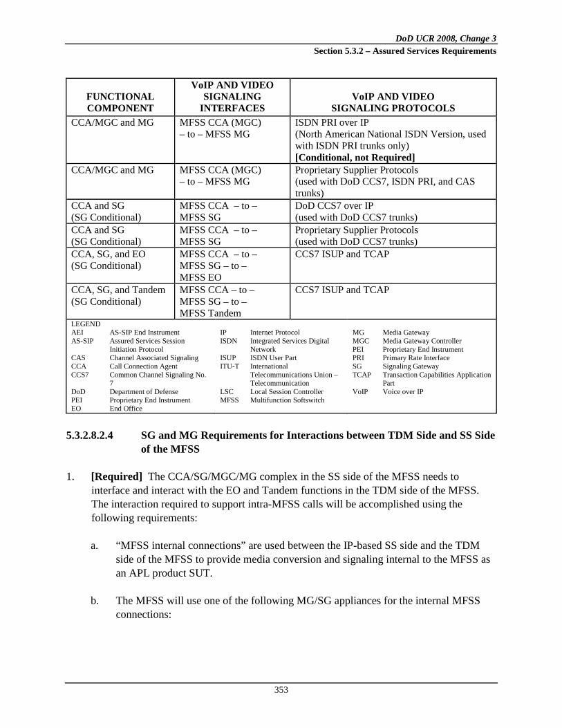
DoD UCR 2008, Change 3 Section 5.3.2 – Assured Services Requirements
353
FUNCTIONAL COMPONENT
VoIP AND VIDEO SIGNALING
INTERFACES VoIP AND VIDEO
SIGNALING PROTOCOLS CCA/MGC and MG MFSS CCA (MGC)
– to – MFSS MG ISDN PRI over IP (North American National ISDN Version, used with ISDN PRI trunks only) [Conditional, not Required]
CCA/MGC and MG MFSS CCA (MGC) – to – MFSS MG
Proprietary Supplier Protocols (used with DoD CCS7, ISDN PRI, and CAS trunks)
CCA and SG (SG Conditional)
MFSS CCA – to – MFSS SG
DoD CCS7 over IP (used with DoD CCS7 trunks)
CCA and SG (SG Conditional)
MFSS CCA – to – MFSS SG
Proprietary Supplier Protocols (used with DoD CCS7 trunks)
CCA, SG, and EO (SG Conditional)
MFSS CCA – to – MFSS SG – to – MFSS EO
CCS7 ISUP and TCAP
CCA, SG, and Tandem (SG Conditional)
MFSS CCA – to – MFSS SG – to – MFSS Tandem
CCS7 ISUP and TCAP
LEGEND AEI AS-SIP End Instrument AS-SIP Assured Services Session
Initiation Protocol CAS Channel Associated Signaling CCA Call Connection Agent CCS7 Common Channel Signaling No.
7 DoD Department of Defense PEI Proprietary End Instrument EO End Office
IP Internet Protocol ISDN Integrated Services Digital
Network ISUP ISDN User Part ITU-T International
Telecommunications Union – Telecommunication
LSC Local Session Controller MFSS Multifunction Softswitch
MG Media Gateway MGC Media Gateway Controller PEI Proprietary End Instrument PRI Primary Rate Interface SG Signaling Gateway TCAP Transaction Capabilities Application
Part VoIP Voice over IP
5.3.2.8.2.4 SG and MG Requirements for Interactions between TDM Side and SS Side of the MFSS
1. [Required] The CCA/SG/MGC/MG complex in the SS side of the MFSS needs to interface and interact with the EO and Tandem functions in the TDM side of the MFSS. The interaction required to support intra-MFSS calls will be accomplished using the following requirements:
a. “MFSS internal connections” are used between the IP-based SS side and the TDM side of the MFSS to provide media conversion and signaling internal to the MFSS as an APL product SUT.
b. The MFSS will use one of the following MG/SG appliances for the internal MFSS
connections:

DoD UCR 2008, Change 3 Section 5.3.2 – Assured Services Requirements
354
(1) [Required] The MFSS MG must support internal MG connections that interconnect the SS side of the MFSS with the EO and Tandem functions on the TDM side of the MFSS.
(2) [Required] The MFSS MG shall interact with the MFSS MGC so that
Internal MG connections between the SS and TDM sides of the MFSS support
(a) Intra-MFSS calls between TDM EIs connected to the TDM side, and PEIs/AEIs connected to the SS side of the MFSS
(b) Incoming and outgoing calls to/from systems external to the MFSS
that require conversion between TDM and IP 2. [Conditional] When a DoD CCS7-based connection is used between the SS and TDM
sides of the MFSS, the MFSS MG shall interact with the MFSS MGC so that DoD CCS7 signaling is used between the SS and TDM sides, and the CCS7 version of the MLPP feature operates correctly between the SS and TDM sides of the MFSS, for both VoIP-to-TDM calls and TDM-to-VoIP calls over this connection.
3. [Required] When a U.S. ISDN PRI-based connection is used between the SS and TDM sides of the MFSS, the MFSS MG shall interact with the MFSS MGC so that U.S. ISDN PRI signaling (National ISDN PRI signaling with the Precedence Level IE and related MLPP IEs included) is used between the SS and TDM sides, and the T1.619/T1.619a version of the ISDN PRI MLPP feature operates correctly between the SS and TDM sides of the MFSS, for both VoIP-to-TDM calls and TDM-to-VoIP calls over this trunk group.
4. [Conditional] When a U.S. CAS-based connection is used between the SS and TDM sides of the MFSS, the MFSS MG shall interact with the MFSS MGC so that
a. U.S. CAS trunk signaling is used between the SS and TDM sides, and b. The DoD version of the CAS Trunk MLPP feature operates correctly between the SS
and TDM sides of the MFSS, for both VoIP-to-TDM calls and TDM-to-VoIP calls over this trunk group.
5.3.2.8.2.5 Requirements for External Connections between MFSS and Other Systems
Calls between the MFSS and a distant-end system will be either TDM based or IP based, as follows: 1. The TDM EO or TDM Tandem component of the MFSS will connect to another MFSS or
EO using TDM-based trunks.

DoD UCR 2008, Change 3 Section 5.3.2 – Assured Services Requirements
355
2. The SS side of an MFSS will connect to the SS side of a distant-end MFSS, or a distant-end (subtending) LSC using AS-SIP and IP transport.
5.3.2.8.2.6 Features of the SS Side of the MFSS
The following feature requirements apply to the SS side of the MFSS: 1. [Required] The SS side of the MFSS shall meet all the requirements for MLPP, as
appropriate for VoIP and Video over IP services, as specified in Section 5.3.2.31.3, Multilevel Precedence and Preemption.
2. [Required] The SS side of the MFSS shall support CND as specified in Section 5.3.2.2.2.1.8, Calling Number Delivery.
3. [Required] The requirements for Session Control and Signaling (SCS) functions (i.e., CCA, IWF, MG, MGC, and SG) and NM are provided in separate sections of this document as follows:
a. Section 5.3.2.9, Call Connection Agent, including the CCA-associated IWF that applies to both the LSC and the MFSS
b. Section 5.3.2.12, Media Gateway Requirements, including MG and MGC
requirements c. Section 5.3.2.13, Signaling Gateway Requirements, including SG requirements d. Section 5.3.2.17, Management of Network Appliances, including NM requirements
4. [Required] The requirements for SCS functions (i.e., CCA, IWF, MG, MGC, and SG) and NM shall be implemented so the Assured Services System Features and Capabilities of Table 5.3.2.2-1, Summary of Appliances and UC APL Products, function correctly for Voice and Video over IP-to-Voice and Video over IP connections, for Voice and Video over IP-to-TDM connections, and for TDM- to -Voice and Video over IP connections.
5.3.2.8.2.7 ASAC Requirements for the MFSS Related to Voice and Video
The ASAC requirements are specified in Section 5.3.2.2.2.3, ASAC – Open Loop.

DoD UCR 2008, Change 3 Section 5.3.2 – Assured Services Requirements
356
5.3.2.8.3 Network Management Requirements for the MFSS
[Required] The NM requirements for the SS side of the MFSS are specified in Section 5.3.2.17, Management of Network Appliances; Section 5.3.2.18, Network Management Requirements of Appliance Functions; and Section 5.3.2.19, Accounting Management.
5.3.2.8.3.1 Network Management System Interface
1. [Required: MFSS] The MFSS shall provide a single, common interface to the DISA NMS. The single interface shall provide access to MFSS features and functions for both the TDM and SS side of the MFSS.
2. [Required: MFSS] The MFSS-to-NMS interface shall be an Ethernet connection as specified in Section 5.3.2.4.4, VVoIP NMS Interface Requirements.
5.3.2.8.4 WAN-Level Softswitch
1. [Required: WAN SS] The WAN SS is a stand-alone APL product that acts as an AS-SIP B2BUA within the UC framework. It provides the equivalent functionality of a commercial SS and has similar functionality to the SS component of an MFSS. Support for the functionality of the LSC is a Conditional requirement, and the support of an SG is not required. The WAN SS product allows the functionality of an MFSS to be achieved by interconnecting two separate appliances (e.g., MFS and WAN SS), possibly provided by different vendors. It provides the Government with flexibility in the roll-out of UC VVoIP capabilities and eases the migration of TDM technology-based services to IP technology-based services. The product shall provide the following functional components as shown in Figure 5.3.2.8-2
a. [Required]
, Functional Reference Model – WAN SS:
Section 5.3.2.8.2.2, Global Location Server
b. [Conditional] Section 5.3.2.7, Local Session Controller c. [Required] Section 5.3.2.9, Call Connection Agent, including the CCA-associated
IWF that applies to both the MFSS and the [Conditional] LSC d. [Required] Section 5.3.2.10.12, CCA Interactions with Service Control Functions,
that addresses media servers

DoD UCR 2008, Change 3 Section 5.3.2 – Assured Services Requirements
357
Figure 5.3.2.8-2. Functional Reference Model – WAN SS
e. [Required] Section 5.3.2.2.2.3.1.2, ASAC Requirements for the MFSS Related to
Voice, and Section 5.3.2.2.2.3.2, ASAC Requirements for the LSC and the MFSS Related to Video Services. These sections address WAN-level ASAC policing requirements
f. [Required] Section 5.3.2.12, Media Gateway Requirements, including MG and
MGC requirements as well as ISDN T1.619a PRI and commercial PRI trunking interfaces. The MGC may connect via the DISN WAN to remotely located MGs.
GlobalLocationService
Service Control Functions
AS-SIP
IA
Internal Ethernet LAN
Managem
ent
MFSS
DoD, Allied, orCoalition Partner
LSC
AS- SIPIP
WAN SS UC Product
CCAIWFPSTN
EO or Tandem Switch
EBC
SMEO
ISDN PRI or CAS*
MFS
Session Control and Signaling Functions
Managem
ent* Support for CAS is
Conditionalfor a WAN-Level SS
MediaServer
IP Transport Interface Functions
MG
WAN-Level ASAC Policing
SIPB2BUA
CCA
IWFMGC
Session Control and Signaling Functions
H.248 or
Proprietary
TDM
EO
MFS
LEGEND:ASAC Assured Service Admission ControlAS-SIP Assured Services Session Initiation ProtocolB2BUA Back-to-Back User AgentCAS Channel Associated SignalingCCA Call Connection AgentCCS7 Common Channel Signaling No. 7DoD Department of DefenseEBC Edge Border ControllerEO End OfficeIA Information AssuranceIP Internet ProtocolISDN Integrated Services Digital NetworkIWF Interworking FunctionLAN Local Area NetworkLSC Local Session ControllerMFS Multifunction Switch
MFSS Multifunction SoftswitchMG Media GatewayMGC Media Gateway ControllerOC-3 Optical Carrier Level 3PBX Private Branch ExchangePRI Primary Rate InterfacePSTN Public Switched Telephone NetworkSCS Session Control and SignalingSG Signaling GatewaySIP Session Initiation ProtocolSS SoftswitchSUT System Under TestTDM Tandem (Switch)UC Unified CapabilitiesWAN Wide Area Network
AS-SIP
WANSS
EBC
ISDN PRI or CAS*
ISDN PRI or CAS*
ISDN PRI or CAS*

DoD UCR 2008, Change 3 Section 5.3.2 – Assured Services Requirements
358
[Conditional: ISDN T1.619A PRIs – Required: Commercial PRIs (ANSI Version)] the Non-Facility Associated Signaling (NFAS) feature of the U.S. National ISDN documents
g. [Required] Section 5.3.2.17, Management of Network Appliances, including NM
requirements h. [Required] Section 5.3.2.18, Network Management Requirements of Appliance
Functions, including NM requirements for the CCA and the MG, but not for the SG i. [Required] Section 5.3.2.7.2.7, LSC Transport Interface Functions, that addresses
the IP Transport Interface functions j. [Required] Section 5.3.2.5.2, Product Quality Factors k. [Required] Section 5.3.4, AS-SIP Requirements l. [Required] Section 5.4, Information Assurance Requirements, for MFSS, MG, and
[Conditional] LSC m. [Conditional] The MG of the WAN SS shall support an OC-3 physical interface for
transport of multiplexed PRI trunk groups between 1) the WAN SS and MFSs in the DISA TDM network, and 2) the WAN SS and EOs in the commercial TDM network (in the case where the WAN SS contains an LSC, and the LSC end users need access to the commercial TDM network). The OC-3 physical interface shall support multiplexing of both T1-based T1.619A PRI trunk groups and T1-based commercial PRI trunk groups (e.g., NI-2 PRI trunk groups in the United States). The OC-3 multiplexing of E1-based Q.955.3 PRI trunk groups and E1-based commercial PRI trunk groups (e.g., ETSI PRI Trunk Groups in Europe) is not required.
n. [Required] The requirements for SCS functions (i.e., CCA, IWF, MG, MGC, and
SG) and NM shall be implemented so the Assured Services System Features and Capabilities of Table 5.3.2.2-1, Summary of Appliances and UC APL Products, function correctly for Voice and Video over IP-to-Voice and Video over IP connections, for Voice and Video over IP-to-TDM connections, and for TDM-to-Voice and Video over IP connections.
The major differences between the WAN SS and the SS part of the MFSS are: 1. The WAN SS does not need to contain an LSC, but may do so as a Conditional capability if
the acquisition agent and vendor so desire.

DoD UCR 2008, Change 3 Section 5.3.2 – Assured Services Requirements
359
2. The WAN SS does not require an SG (it is neither Required nor Conditional).
3. The WAN SS MG is only required to support ISDN T1.619A PRI trunks to the MFS. If the Conditional LSC is supported, the WAN SS MG also needs to support commercial PRI trunks to the local PSTN (or to an adjacent MFS that has its own commercial PRI trunks to the local PSTN).
4. The NM EMS for the WAN SS should be provided as a standalone EMS separate from the MFS EMS.
5. The WAN SS MG(s) may be remotely located from the MGC within the CCA of the WAN SS.
6. The WAN SS does not need to implement an ASLAN; it can use a proprietary switched Ethernet LAN for interconnecting its components within itself, and to the CE Router via an EBC.
NOTE: When using and testing the requirements of the previous applicable sections (and throughout the entire UCR), it is necessary to interpret them in light of the major differences between the WAN SS and the SS part of the MFSS from above. When requirements within these sections refer to the SS part of the MFSS, they are required for the WAN SS. When requirements refer to the MFS part of the MFSS, or interconnection/interoperation with the MFS (including the EO), they no longer apply to the WAN SS. The only connections required between the WAN SS MG and the MFS are ISDN T1.619A PRI and commercial PRI, IAW ANSI Standards T1.619-1992 and T1.619a-1994, plus the U.S. National ISDN documents, which include the NFAS feature. Support for the NFAS feature of the ANSI Standards is a Conditional requirement for T1.619A PRIs and a Requirement for U.S. commercial PRIs.
5.3.2.9 Call Connection Agent
5.3.2.9.1 Introduction
This section provides GRs for the CCA function in the following network appliances:
• LSC • MFSS • WAN SS
Each of these appliances has a DISN-defined design that includes Session Control and Signaling functions. These functions include both a Signaling Protocol IWF and a Media Gateway Controller function.

DoD UCR 2008, Change 3 Section 5.3.2 – Assured Services Requirements
360
The CCA described in the following requirements is part of the SCS functions, and includes both the IWF and the MGC. As a result, the scope of these CCA requirements covers the following areas: 1. Control of AS-SIP sessions within the network appliance, including:
a. AS-SIP sessions from/to AEIs served by an LSC or MFSS appliance (NOTE: Proprietary protocol sessions from/to LSC PEIs and MFSS PEIs are supported also.)
b. AS-SIP sessions from/to LSCs served by an MFSS appliance
c. AS-SIP sessions between MFSS appliances (where sessions span multiple MFSSs)
2. Support for the following PSTN and VoIP signaling protocols:
a. AS-SIP
b. DoD CCS7, including MLPP c. ISDN PRI (North American National ISDN version), including MLPP
d. PSTN CAS, for dual-tone multifrequency (DTMF) and multifrequency (MF) trunks
(North American version)
e. Protocol interworking of the previous signaling protocols (for example, AS-SIP DoD CCS7 interworking) through the CCA IWF
3. Control of MGs that link the network appliance with TDM NEs through the CCA MGC in
the following:
a. DoD networks b. Allied and coalition networks c. PSTN in CONUS d. PSTN Global (i.e., outside the continental United States (OCONUS))
4. CCA support for interactions with other network appliance functions, including:
a. SG b. Admission control c. The following Service Control functions:

DoD UCR 2008, Change 3 Section 5.3.2 – Assured Services Requirements
361
(1) Media servers (2) UFS (3) Information Assurance (4) Local Location Service
d. Appliance Management functions e. GLS (in the MFSS only) f. EBCs
5. CCA support for voice calls and video calls
6. CCA support for Voice and Video services features and capabilities
[Required: LSC, MFSS] A CCA in an MFSS or LSC shall be able to support multiple MGs on a single ASLAN. [Required: LSC, MFSS] A CCA in an MFSS or LSC shall be able to support multiple MGs on multiple ASLANs, where those ASLANs are interconnected to form a MAN or COIN. In this arrangement, it is expected that the set of ASLANs forming the MAN or COIN will meet the single-ASLAN performance requirements in Section 5.3.1, Assured Services Local Area Network Infrastructure. In this case, the LSC shall support sessions between an MG on one ASLAN and an PEI, AEI, MG, or EBC on another ASLAN, as long as both ASLANs are part of the same MAN or COIN. [Required: LSC, MFSS] A CCA in an MFSS or LSC shall be able to support MGs at multiple physical locations. In some deployments, an LSC in one location will serve ASLANs and EIs at distant locations, where both locations are part of the same regional MAN or COIN. In these cases, each distant ASLAN may want to have its own gateway to the local PSTN. In these cases, the LSC shall support MGs at multiple locations over MAN or COIN infrastructures that meet the ASLAN performance requirements in the UCR.
5.3.2.9.2 Functional Overview of the CCA
Figure 5.3.2.9-1, CCA Relationships, illustrates the relationship between the CCA and other functional components. As indicated in the figure, the IWF, MGC, and SG are contained within a CCA. However, it is permissible for the SG to be in an external network appliance.

DoD UCR 2008, Change 3 Section 5.3.2 – Assured Services Requirements
362
Figure 5.3.2.9-1. CCA Relationships
The role of a CCA is to provide session control for all VoIP sessions and Video over IP sessions that are originated by, or terminated in, the voice network. These VoIP and Video sessions can be established using SIP, a Proprietary VoIP protocol, AS-SIP, or some combination of these (e.g., SIP and AS-SIP on an PEI-or-AEI/LSC/EBC/MFSS session). The CCA takes on the role of the SIP B2BUA in the traditional SIP architecture. In addition, the CCA takes on the role of a SIP Registrar for all PEIs, AEIs, MGs, and EBCs served by the LSC, allowing PEIs, AEIs, MGs, and EBCs to register their SIP URIs (i.e., Addresses of Record) and current IP addresses with the CCA. The CCA is responsible for maintaining a SIP-URI-to-IP-address “binding” for each PEI, AEI, MG, and EBC that is active on the LSC at any moment in time. In addition to acting as a SIP B2BUA, the CCA is responsible for providing call control and feature control for VoIP and Video over IP network-based calls and features. Most VoIP and Video over IP features that are provided to LSC PEI and AEI end users, on either a per-call basis or an all-calls basis, are controlled by the CCA.
CCA
CCA IWF MGCMGC
Interacts with Interacts with
Interacts with
MediaServer
UFS InformationAssurance
Interacts with
Interacts with
LSC/CCA
LEGENDASAC Assured Service Admission ControlCCA Call Connection AgentEO End OfficeIWF Internetworking Function
LSC Local Session Controller
MFSS Multifunction SoftswitchMG Media GatewayMGC Media Gateway ControllerSG Signaling Gateway
UFS User Features and Services
MFSS/CCA MG
(Local)DirectoryService
ASAC CCA
CCA IWF SG
EOEO TANDEM

DoD UCR 2008, Change 3 Section 5.3.2 – Assured Services Requirements
363
5.3.2.9.2.1 CCA IWF Component
The role of the IWF within the CCA is to:
• Support all the VoIP and TDM signaling protocols that the LSC supports for EIs, MGs, and EBCs, and
• Interwork all these various signaling protocols with one another.
Specifically, this section requires the CCA IWF to support the following VoIP and TDM signaling protocols:
• [Required: LSC, MFSS, AEI] AS-SIP
• [Conditional: LSC] Proprietary VoIP (for PEIs on the EI-LSC interface; this is conditional and may include supplier-specific SIP, supplier-specific H.323, and other supplier-proprietary protocols)
• [Conditional: LSC, MFSS] DoD CCS7, including MLPP (for SG/MG
trunks; North America Version Conditional; and European or other foreign PRI version Conditional when required by the DoD user)
• [Required: LSC, MFSS] The ISDN PRI, including MLPP (for MG trunks;
North American version Required; and European or other foreign PRI version Conditional when required by the DoD user)
• Facility Associated Signaling (FAS) is required for T1.619A PRIs, and NFAS
is conditional for T1.619A PRIs.
• Both FAS and NFAS are Required for commercial PSTN PRIs, for access to the US PSTN.
• [Conditional: LSC, MFSS] CAS, including MLPP (for MG trunks; North
American version Conditional; European or other foreign CAS trunk version Conditional when required by the DoD user)
5.3.2.9.2.2 CCA MGC Component
The role of the MGC within the CCA is to: 1. Control all MGs within the LSC or MFSS.

DoD UCR 2008, Change 3 Section 5.3.2 – Assured Services Requirements
364
2. Control all trunks (e.g., DoD CCS7, PRI, CAS) within each MG:
a. [Required: LSC, MFSS] Support for DoD ISDN trunks b. [Conditional: LSC, MFSS] Support for CAS trunks
3. Control all signaling and media streams on each trunk within each MG.
4. Accept IP-encapsulated signaling streams from an SG or MG, and return IP-encapsulated signaling streams to the SG or MG accordingly.
• This approach is used for CCS7 signaling to/from an SG [Conditional in both the MFSS and LSC cases], and for PRI signaling to/from an MG.
5. Within the LSC, use either ITU-T Recommendation H.248 or a supplier-proprietary protocol to accomplish these controls.
The MGC and the MG that it controls are considered Conditional – Deployable for the LSC. The SG is considered Conditional for the LSC.
5.3.2.9.2.3 SG Component
The role of the CCA with respect to the SG in the network appliance is to:
• Control all SGs within the network appliance. • Control all signaling links (DoD CCS7) within each SG.
1. [Required: MFSS – Conditional: LSC] The CCA shall be responsible for controlling
all the SGs within the MFSS and LSC. (This covers cases where there is a single SG within the network appliance, and cases that are more complex where there are multiple SGs within the network appliance.)
2. [Required: MFSS – Conditional: LSC] The CCA shall be responsible for controlling each signaling link within each SG within the MFSS or LSC.
3. [Required: MFSS – Conditional: LSC] The CCA shall be responsible for controlling the DoD CCS7 signaling stream(s) within each signaling link within each SG.
4. [Required: MFSS – Conditional: LSC] Within the network appliance (i.e., MFSS and LSC), the CCA shall use either an IETF-standard set of CCS7-over-IP protocols, or a supplier-proprietary protocol to accomplish the above SG, signaling link, and signaling stream controls.

DoD UCR 2008, Change 3 Section 5.3.2 – Assured Services Requirements
365
5.3.2.9.3 CCA Requirements Assumptions
The following assumptions were used to develop VoIP and Video over IP requirements for the CCA: 1. Definitions of terms are given in Appendix A, Section A2, Glossary and Terminology
Description.
2. The network supports voice and video services and features. Support for other services, such as messaging and unified messaging, is not required in the Voice and Video network design initially.
3. The network consists of voice and video APL products that are supported over a converged IP transport network. The APL products include the LSC, MFSS, EBC, CE Router, and terrestrial transport products. Intersystem communication between these products and associated appliance functions is accomplished by VoIP and Video communication (e.g., use of AS-SIP signaling packets and SRTP media packets) over an underlying IP network layer and IP-based transport layer, such as UDP or TCP.
4. The LSC is assumed to be a local APL product located in a local domain (B/P/C/S).
5. The EBC functions are assumed to be external to the LSC and MFSS. The EBC functions are Session Border Controller (SBC)-type functions and firewall-type functions that are provided by network appliances.
6. The CCA requirements in this section support voice and video call control for originating, terminating, and tandem calls, as well as the following end-user features: Call Hold, Call Waiting, Precedence Call Waiting, Call Forwarding, Call Transfer, Hotline Service, and Calling Party and Called Party ID (number only).
7. The CCA requirements in this section support PBAS/ASAC.
8. The CCA requirements in this section assume that CCA call routing decisions are based on call routing data provided by the LLSs and GLSs (other functional components within the LSC and MFSS). How this routing data is established within these Location Servers and/or obtained at these Location Servers is beyond the scope of these CCA requirements.
9. The MFSS is assumed to support AS-SIP connectivity for connections to other MFSSs and LSCs, and TDM connectivity for connections to other MFSSs and DoD TDM switches. The TDM connectivity can use CCS7, PRI, or CAS signaling.
DoD UCR 2008, Change 3 Section 5.3.2 – Assured Services Requirements
366
10. The LSC is assumed to include an MGC and an MG [Required: Fixed – Conditional: Deployable], and an SG (Conditional). This means that the TDM trunk groups that terminate on the LSC MG can use PRI, CAS, or CCS7 signaling.
11. The MFSS supports end users on both the SS side (i.e., VoIP end users using VoIP EIs), and on the TDM side (i.e., traditional end users with traditional DoD telephones).
12. The MFSS also supports TDM trunk group and CCS7 signaling links on both the VoIP side (through the MGC, MG, and SG [SG Conditional]) and the TDM side (through the EO and Tandem Switch).
13. The VoIP signaling protocol used between the VoIP EI and the LSC, and between the VoIP EI and the LSC part of an MFSS, can be vendor proprietary. The VoIP signaling protocol does not need to be AS-SIP between a VoIP PEI and LSC, or between the VoIP PEI and the LSC component of an MFSS. The VoIP signaling protocol used between the AEI and the LSC, and between the AEI and the LSC part of an MFSS, must be AS-SIP. The VoIP signaling protocol used between signaling appliances (i.e., LSC and MFSSs) is required to be AS-SIP.
14. The LSC and the MFSS will both use Location Services (Local or Global, as needed) to route calls to their intended destination. Location Services will be supported as an internal function of the LSC or MFSS, instead of an external function that the LSC or MFSS would have to access over an external interface using an industry-standard Location Services protocol.
15. It is assumed that route selections at the LSCs and the MFSS will be based on the originating call signaling type (i.e., either IP or TDM signaling). If the originating signaling is IP based, it is assumed that the call signaling will stay IP based for as long as possible as the signaling transits the network. Similarly, if the originating call signaling is TDM based, it is assumed that the call signaling will stay TDM based for as long as possible as the signaling transits the network.
16. The LSC and the MFSS will use SIP URIs for addressing and routing, and will not use “tel” URIs for this purpose. See Table 5.3.2.9-1, An E.164 and a DSN Number, Expressed as a SIP URI and a tel URI, for an example of an E.164 and a DSN number, expressed as a SIP URI and a tel URI.
17. Tones and announcements that are provided to VoIP end users will be provided from an internal media server, which is a functional component of the LSC or MFSS. An external media server that is separate from the LSC or MFSS is not envisioned.
18. See Section 5.3.2.2.2.2, Public Safety Features, for a description of 911 call handling.

DoD UCR 2008, Change 3 Section 5.3.2 – Assured Services Requirements
367
Table 5.3.2.9-1. An E.164 and a DSN Number, Expressed as a SIP URI and a tel URI
TELEPHONE NUMBER
TELEPHONE NUMBER AS SIP URI
TELEPHONE NUMBER AS tel URI
+17327582000 (an E.164 number in the United States)
sip:[email protected]; user=phone
tel: +17327582000; user=phone
3144305353 (a DSN number at the Patch Barracks in Germany)
sip:3144305353; phone-context=uc.mil @uc.mil; user=phone (Support for the phone-context tag is conditional.)
tel: 3144305353; phone-context=uc.mil; user=phone (Support for the phone-context tag is conditional.)
19. In some cases, a function like an MGC or MG will be labeled as Conditional – Deployable
in this section. In these cases, Conditional – Deployable means that normally this function is not used in a Deployable environment, but may be used in that environment under certain conditions. When this function is used in that environment, the function should conform to the MGC requirements in this section. For example, an LSC deployed in one camp in a war zone overseas may not use an MGC or an MG, while another LSC deployed in another camp in the same zone may use both of them.
20. The CCA VoIP and Video over IP requirements in this section assume that all the functions within an individual appliance (i.e., LSC or MFSS) are provided by the same appliance supplier. Within a collection of network appliances, all the appliances may be provided by the same supplier, or some appliances may be provided by one supplier and other appliances may be provided by other suppliers.
21. Interoperability between LSCs and MFSSs is the goal of the UCR and the CCA requirements in this section. Integration between the functions within an individual LSC or MFSS is the responsibility of the network appliance supplier.
22. The LSC supports MGC and MG functionality, so that LSCs can support access to DoD TDM networks, allied TDM networks, coalition partner TDM networks, and the local PSTN, when this access is needed in both Fixed and Deployable environments. In addition, the LSC supports MGC and MG functionality to enable TDM connectivity (i.e., PRI, CAS, and CCS7 trunks and signaling links) to interconnecting MFSSs when it is needed.
23. “Voice and Video Assured Services” supports VoIP, Voiceband FoIP, VBD MoIP, SCIP over IP, and Video over IP. The voice budgets used to manage end users’ VoIP calls will collectively manage those users’ VoIP calls, FoIP calls, MoIP calls, and SCIP-over-IP calls. The separate video budgets used to manage end users’ Video-over-IP calls will manage those users’ Video-over-IP calls only, and will not manage any VoIP, FoIP, MoIP,

DoD UCR 2008, Change 3 Section 5.3.2 – Assured Services Requirements
368
or SCIP-over-IP calls for those users. In short, VoIP budgets and Video-over-IP budgets are maintained and managed separately in Voice and Video Assured Services.
24. The LSCs and MFSSs providing Assured Services Voice and Video will support proprietary VoIP videophones (using the vendor’s version of SIP or H.323). The LSC and MFSS suppliers should also support AS-SIP videophones. The LSC and MFSS suppliers are required to support protocol interworking between their videophones (Proprietary VoIP and AS-SIP) and the AS-SIP protocol used on network-side interfaces between LSCs and MFSSs (and between LSCs and between MFSSs).
25. The VoIP signaling protocol used between the VoIP EI and the LSC (and between the VoIP EI and the LSC part of an MFSS) can be vendor proprietary. The VoIP signaling protocol does not need to be AS-SIP between a VoIP PEI and LSC (or between the VoIP PEI and the LSC component of an MFSS). The VoIP signaling protocol used between the AEI and the LSC, and between the AEI and the LSC part of an MFSS, must be AS-SIP. The VoIP signaling protocol used between signaling appliances (i.e., LSCs and MFSSs) is required to be AS-SIP.
5.3.2.9.4 Role of the CCA in Network Appliances
The role of the CCA is to provide session control for all VoIP sessions and Video over IP sessions that are originated by or terminated by EIs on the LSC. These VoIP and Video sessions can be established using either of the following:
• [Conditional] AS-SIP, or • [Conditional] A Proprietary VoIP protocol
The CCA takes on the role of a SIP B2BUA in the traditional SIP architecture. The CCA takes on the role of a SIP Registrar for all EIs, MGs, and EBCs served by the LSC, allowing EIs, MGs, and EBCs to register their SIP URIs (i.e., Addresses of Record) and current IP addresses with the CCA. The CCA is responsible for maintaining a SIP URI-to-IP-address “binding” for each PEI, AEI, MG, and EBC that is active on the LSC at any time. The CCA is responsible for providing call control and feature control for all VoIP and Video–over-IP calls and features that the LSC provides. All VoIP and Video-over-IP calls that are originated by or answered by LSC PEI and AEI end users are controlled by the CCA. All VoIP and Video-over-IP features that are provided to LSC PEI and AEI end users, on either a per-call basis, a per-feature-request basis, or an all-calls basis, are controlled by the CCA. In the current DISN design for an LSC, the CCA includes an IWF and an MGC, and the MGC controls all the TDM interfaces served by the MG (DoD CCS7 trunks, ISDN PRI trunks, and

DoD UCR 2008, Change 3 Section 5.3.2 – Assured Services Requirements
369
CAS trunks (i.e., DTMF and MF)). This section reviews the role of the CCA in the LSC and MFSS reference models, and covers the role of the CCA, IWF, and MGC in each case.
5.3.2.9.5 CCA-IWF Signaling Protocol Support Requirements
This section describes the requirements for the CCA Signaling Protocol IWF to support the various VoIP and TDM signaling protocols used in the LSC and MFSS. In summary, the role of the IWF within the CCA is to support all the VoIP and TDM signaling protocols that are used by the EIs, MGs, and EBCs, and interwork all these various signaling protocols with one another.
5.3.2.9.5.1 CCA-IWF Support for AS-SIP
1. [Required: LSC, MFSS] The CCA IWF shall support the AS-SIP protocol consistent with the detailed AS-SIP protocol requirements in Section 5.3.4, AS-SIP Requirements.
2. [Required: LSC, MFSS] The CCA IWF shall use the AS-SIP protocol on LSC-MFSS and MFSS-MFSS sessions.
3. [Required: LSC, MFSS] When the CCA IWF uses the AS-SIP protocol over the Access Segment between the EBC and the DISN WAN, or over the DISN WAN itself, the CCA IWF shall secure the AS-SIP protocol using TLS, as described in Section 5.4, Information Assurance Requirements.
5.3.2.9.5.2 CCA-IWF Support for DoD CCS7 via an SG
1. [Conditional: LSC, MFSS] The CCA IWF shall support the DoD CCS7 protocol, consistent with the detailed DoD CCS7 protocol requirements in the following DoD and ANSI documents:
• Section 5.3.2.31.3, Multilevel Precedence and Preemption, including:
− Section 5.3.2.31.3.5.3, Common Channel Signaling Number 7 − Section 5.3.2.31.3.10, MLPP CCS7 − Section 5.3.2.31.4.7, Common Channel Signaling Number 7
• ANSI T1.619-1992 (R2005) • ANSI T1.619a-1994 (R1999)
2. [Conditional: LSC, MFSS] When used in the European Theater and in other OCONUS
ETSI-compliant countries, the CCA IWF shall support the ITU-T Recommendation Q.735.3 MLPP extensions to the ITU-T CCS7 protocol, consistent with the UCR and ITU-T Recommendation Q.735.3.

DoD UCR 2008, Change 3 Section 5.3.2 – Assured Services Requirements
370
3. [Conditional: LSC, MFSS] The CCA IWF shall support reception of DoD CCS7 messages from the SG, and transmission of DoD CCS7 messages to the SG, as described in this document. The CCA IWF shall support securing of DoD CCS7 messages to and from the SG, as described in Section 5.4, Information Assurance Requirements.
4. [Conditional: LSC, MFSS] The CCA IWF shall be able to determine the DoD CCS7 signaling link that a CCS7 message was sent or received on (and the MG CCS7 trunk group associated with this signaling link), when processing a CCS7 message sent or received at the SG.
5. [Conditional: LSC, MFSS] The CCA IWF shall be able to support multiple DoD CCS7 signaling links at the SG, where each CCS7 signaling link is connected to a different CCS7 end point (i.e., to a different DoD Signaling Transfer Point (STP), a DoD TDM switch, another MFSS, or another LSC).
6. [Conditional: LSC, MFSS] The CCA IWF shall be able to differentiate between the individual DoD CCS7 signaling links at the SG. The CCA IWF shall know, as part of its configuration data, which DoD STP, DoD TDM switch, other MFSS, or other LSC each SG signaling link is connected to.
7. [Conditional: LSC, MFSS] In conjunction with the SG, the CCA IWF shall support DoD CCS7 signaling links to
• TDM switches and STPs in the DoD TDM network • MFSSs and LSCs in the DoD network • TDM switches and STPs in allied and coalition partners (when those STPs
support DoD CCS7) • TDM EO and Tandem switch components of the MFSS itself
8. [Conditional: LSC, MFSS] The CCA IWF shall be able to associate individual CCS7
link, ISDN User Part (ISUP), and Transaction Capabilities Application Part (TCAP) configuration data with each individual CCS7 link served by the SG and the CCA. The CCA IWF shall not require groups of CCS7 links served by the SG and the CCA to share “common” link, ISUP, and TCAP configuration data.
9. [Conditional: LSC, MFSS] As part of this CCS7 configuration data, the CCA IWF shall know the identity of the CCS7 device at the far end of each CCS7 signaling link. Specifically, the CCA IWF shall know the identity of each interconnected.
DoD UCR 2008, Change 3 Section 5.3.2 – Assured Services Requirements
371
• TDM switch and STP in the DoD TDM network • MFSS and LSC in the DoD network • TDM switch and STP in each allied and coalition partner • TDM EO and Tandem switch component in the MFSS itself
5.3.2.9.5.3 CCA-IWF Support for PRI, via MG
[Required: LSC, MFSS] The CCA IWF shall support the U.S./National ISDN version of the ISDN PRI protocol, consistent with the detailed ISDN PRI protocol requirements in the following DoD and ANSI documents: 1. Section 5.3.2.31.5, ISDN, including Table 5.3.2.31.5-4, PRI Access, Call Control, and
Signaling, and Table 5.3.2.31.5-5, PRI Features.
a. The “MFS” column in these tables shall apply to the MFSS. b. The “PBX1” and “PBX2” columns in these tables shall apply to the LSC.
2. Section 5.3.2.31.3, Multilevel Precedence and Preemption, including:
a. Section 5.3.2.31.4.3, Line Signaling b. Section 5.3.2.31.3.8, ISDN MLPP PRI
3. ANSI T1.619-1992 (R2005).
4. ANSI T1.619a-1994 (R1999).
a. Facility Associated Signaling is required for T1.619A PRIs, and NFAS is Conditional for T1.619A PRIs.
b. Both FAS and NFAS are Required for commercial PSTN PRIs, for access to the U.S.
PSTN. [ETSI PRI: Required – Other Foreign PRIs: Conditional] The appliance supplier (i.e., LSC or MFSS supplier) has the option of supporting one or more foreign versions of the ISDN PRI protocol on its product. As used here, the term “Foreign version of ISDN PRI protocol” means the version of the PRI protocol that is used in the PSTN of a foreign country.
If an appliance supplier supports a foreign version of the ISDN PRI protocol on its product, the CCA IWF in that product shall support that foreign version of the ISDN PRI protocol consistent with the PRI protocol standards that are used in the PSTN of that foreign country.
Examples of these standards include:

DoD UCR 2008, Change 3 Section 5.3.2 – Assured Services Requirements
372
1. ETSI standards on the use of ISDN PRI in European countries (and other countries that also support ETSI PRI standards)
2. Japanese Telecommunication Technology Committee (TTC) and South Korean Telecommunication Technology Association (TTA) standards on the use of ISDN PRI in Japan and South Korea, respectively
3. ITU-T standards on the use of ISDN PRI worldwide (in countries that only support ITU-T standards)
NOTE: The ISDN-PRI/AS-SIP interworking requirements in this document only apply to the U.S. version of ISDN PRI. The ISDN-PRI/AS-SIP interworking requirements for foreign versions of ISDN PRI (e.g., European, Japanese, South Korean) are outside the scope of this document.
NOTE: Support for ETSI PRI is required when the LSC or MFSS is used in the European Theater or in other OCONUS ETSI-compliant countries.
[ETSI PRI: Required] When used in the European Theater and in other OCONUS ETSI-compliant countries, the CCA IWF shall support the ITU-T Recommendation Q.955.3 MLPP extensions to the ITU-T ISDN PRI protocol, consistent with the UCR and ITU-T Recommendation Q.955.3. [Required: LSC, MFSS] The CCA IWF shall support reception of ISDN PRI messages from the MG and transmission of ISDN PRI messages to the MG. [Required: LSC, MFSS] The CCA IWF shall be able to determine the ISDN PRI (and its D-Channel signaling link) that an incoming PRI message was received on, when processing an incoming PRI message from the MG. [Required: LSC, MFSS] The CCA IWF shall be able to identify the ISDN PRI (and its D-Channel signaling link) that an outgoing PRI message will be sent on, when generating an outgoing PRI message to the MG. [Required: LSC, MFSS] The CCA IWF shall be able to support multiple ISDN PRIs (and their D-Channel signaling links) at the MG, where each PRI is connected to a different PRI end point (e.g., to a different DoD PBX, DoD TDM switch, MFSS, LSC, PSTN PBX, or PSTN TDM switch). [Required: LSC, MFSS] The CCA IWF shall be able to differentiate between the individual ISDN PRIs (and their D-Channel signaling links) at the MG. The CCA IWF shall know, as part

DoD UCR 2008, Change 3 Section 5.3.2 – Assured Services Requirements
373
of its configuration data, which DoD PBX, DoD TDM switch, MFSS, LSC, PSTN PBX, or PSTN TDM switch each ISDN PRI (and its D-Channel signaling link) is connected to. [Required: LSC, MFSS] In conjunction with the MG, the CCA IWF shall support ISDN PRIs (and D-Channel signaling links) to
• TDM PBXs and switches in the DoD network (This includes the TDM EO and Tandem components of the local MFSS, in the MFSS CCA/MG case.)
• MFSSs and LSCs in the DoD network • TDM PBXs and switches in the U.S. PSTN • TDM PBXs and switches in allied and coalition partner networks (when those
networks support U.S. “National ISDN” PRI) [Required: LSC, MFSS] The CCA IWF shall support the full set of ISDN MLPP requirements in ANSI T1.619 and ANSI T1.619a, including the following from ANSI T1.619:
• Precedence level • Cause • Notification Indicator • Signal • Call Identity • Information elements in ISDN PRI messages, on ISDN PRIs to
− TDM PBXs in the DoD TDM network
− TDM switches in the DoD TDM network (This includes the TDM EO
and Tandem components of the local MFSS, in the MFSS CCA/MG case.)
− MFSSs in the DoD network
− LSCs in the DoD network
[Required: LSC, MFSS] The CCA IWF shall not support any of the ISDN MLPP requirements in ANSI T1.619 and ANSI T1.619a, on ISDN PRIs to TDM PBXs and switches in the U.S. PSTN. In other words, the MLPP feature and its associated ISDN PRI signaling shall be supported on ISDN PRIs from the CCA/MG to PBXs and switches in the DoD TDM network (or to appliances
DoD UCR 2008, Change 3 Section 5.3.2 – Assured Services Requirements
374
in the network), but shall not be supported on ISDN PRIs from the CCA/MG to PBXs and switches in the U.S. PSTN. [Required: LSC, MFSS] On ISDN PRIs from the CCA/MG to TDM PBXs and switches in allied and coalition partners (where those networks support U.S. “National ISDN” PRI), the CCA IWF shall support a DoD-user-configurable per-PRI option that allows the PRI to support or not support the ANSI T1.619/619a PRI MLPP feature on calls to and from that PRI. [ETSI PRI: Required – Other Foreign PRIs: Conditional] When the appliance supplier supports a foreign ISDN PRI on its product, consistent with the PRI protocol standards used in the PSTN of that foreign country, the CCA IWF (along with the MG) shall support ISDN PRIs and D-Channel signaling links to
• TDM PBXs and switches in the PSTN in that foreign country • TDM PBXs and switches in allied and coalition partner networks (where
those networks support the ISDN PRI used in the home country of the allied or coalition partner)
Support for ETSI PRI is required when the LSC or MFSS is used in the European Theater or in other OCONUS ETSI-compliant countries. [Required: LSC, MFSS] The CCA IWF shall be able to associate individual PRI configuration data with each individual PRI served by the MG and the CCA. The CCA IWF shall not require groups of PRIs served by the MG and the CCA to share “common” PRI configuration data.
5.3.2.9.5.4 CCA-IWF Support for CAS Trunks, via MG
1. [Conditional] The CCA IWF (with the MG) shall support the U.S. version of CAS trunks and trunk signaling, consistent with the CAS trunk and trunk signaling requirements in the following Sections:
a. Section 5.3.2.31.4, Signaling, including
(1) Section 5.3.2.31.4.4, Trunk Supervisory Signaling (2) Section 5.3.2.31.4.5, Control Signaling (3) Section 5.3.2.31.4.6, Alerting Signals and Tones
b. Section 5.3.2.31.3, Multilevel Precedence and Preemption, including
(1) Section 5.3.2.31.3.5.1, Channel-Associated Signaling

DoD UCR 2008, Change 3 Section 5.3.2 – Assured Services Requirements
375
(2) Section 5.3.2.31.3.10, MLPP CCS7, CAS-to-CCS7 trunk interworking in a mixed media network
2. [Conditional] The appliance supplier (i.e., LSC or MFSS supplier) has the option of
supporting one or more foreign versions of CAS trunks and trunk signaling on its product. As used here, the term “foreign version of CAS trunks and trunk signaling,” means the version of CAS trunks and trunk signaling used in the PSTN of a foreign country
If an appliance supplier supports a foreign version of CAS trunks and trunk signaling on its product, the CCA IWF shall support the version of CAS trunks and trunk signaling
.
used in the PSTN of a foreign country, consistent with the CAS trunk standards used in the PSTN of that foreign country
a. ETSI standards on the use of CAS trunks in European countries (and other countries that also support ETSI CAS trunk standards)
. Examples of these standards include:
b. Japanese TTC and South Korean TTA standards on the use of CAS trunks in Japan
and South Korea, respectively
c. ITU-T standards on the use of CAS trunks worldwide (in countries that only support ITU-T standards)
NOTE: The CAS trunk/AS-SIP interworking requirements in this document only apply to
the U.S. version of CAS trunks. The CAS trunk/AS-SIP interworking requirements for foreign versions of CAS trunks (i.e., European, Japanese, South Korean) are outside the scope of this document.
3. [Conditional] The CCA IWF shall support reception of CAS signaling sequences (i.e., Supervisory, Control, and Alerting) from the MG, and transmission of CAS signaling sequences to the MG.
4. [Conditional] The CCA IWF shall be able to determine the MG CAS trunk and CAS trunk group that an incoming CAS signaling sequence was received on when processing an incoming CAS signaling sequence from the MG.
5. [Conditional] The CCA IWF shall be able to identify the MG CAS trunk and CAS trunk group that an outgoing CAS signaling sequence will be sent on when generating an outgoing CAS signaling sequence to the MG.
6. [Conditional] The CCA IWF shall be able to support multiple CAS trunk groups at the MG, where each CAS trunk group is connected to a different end point (e.g., to a different DoD PBX, DoD TDM switch, MFSS, LSC, PSTN PBX, or PSTN TDM switch).

DoD UCR 2008, Change 3 Section 5.3.2 – Assured Services Requirements
376
7. [Conditional] The CCA IWF shall be able to differentiate between the individual CAS trunk groups at the MG. The CCA IWF shall know, as part of its configuration data, which DoD PBX, DoD TDM switch, MFSS, LSC, PSTN PBX, or PSTN TDM switch each CAS trunk group is connected to.
8. [Conditional] In conjunction with the MG, the CCA IWF shall support CAS trunk groups to:
a. TDM PBXs and switches in the DoD TDM network (This includes the TDM EO and Tandem components of the local MFSS, in the MFSS CCA/MG case.)
b. MFSSs and LSCs in the DISN
c. TDM PBXs and switches in the U.S. PSTN
d. TDM PBXs and switches in allied and coalition networks (where those networks
support U.S. CAS trunk groups) 9. [Conditional] The CCA IWF shall support the MLPP signaling requirements for CAS
trunk groups in Section 5.3.2.31.3.5.1, Channel-Associated Signaling. This MLPP signaling support shall include the following four cases:
a. Answered call, Trunk to be reused b. Unanswered call, Trunk to be reused c. Answered call, Trunk not to be reused d. Unanswered call, Trunk not to be reused
10. [Conditional] When the IWF is the appliance sending the preemption request over the
CAS trunk group, the CCA IWF shall generate the measured supervisory signal (preemption signal) causing trunk circuit disconnect, with the following four variations:
a. Answered call, Trunk to be reused b. Unanswered call, Trunk to be reused c. Answered call, Trunk not to be reused d. Unanswered call, Trunk not to be reused
11. [Conditional] When the IWF is the appliance receiving the preemption signal over the
CAS trunk group, the CCA IWF shall be able to receive and act on the measured supervisory signal (preemption signal) causing trunk circuit disconnect, with the following four variations:

DoD UCR 2008, Change 3 Section 5.3.2 – Assured Services Requirements
377
a. Answered call, Trunk to be reused b. Unanswered call, Trunk to be reused c. Answered call, Trunk not to be reused d. Unanswered call, Trunk not to be reused
12. [Conditional] When the IWF is the appliance receiving the preemption request over the
CAS trunk group, the CCA IWF shall generate the Preempt warning tone to the CCA-served party on the preempted call (e.g., a VoIP EI served by the CCA that is active on the preempted call).
13. [Conditional] When the IWF is the appliance receiving the preemption request over the CAS trunk group, the CCA IWF shall detect the Returned disconnect signal from the CCA-served party on the preempted call, and remove the Preempt warning tone from the party after this detection.
14. [Conditional] The CCA IWF shall support the CAS MLPP signaling as described earlier on CAS trunk groups to
a. TDM PBXs and switches in the DoD TDM network ( This includes the TDM EO and Tandem components of the local MFSS, in the MFSS CCA/MG case), and
b. MFSSs and LSCs in the DISN
15. [Conditional] The CCA IWF shall not use the CAS MLPP signaling described earlier on
CAS trunk groups to TDM PBXs and switches in the U.S. PSTN.
In other words, the MLPP feature and its associated CAS signaling shall be supported on CAS trunk groups from the CCA/MG to PBXs and switches in the DoD TDM network (or to appliances in the network), but shall not be supported on CAS trunk groups from the CCA/MG to PBXs and switches in the U.S. PSTN.
16. [Conditional] On CAS trunk groups from the CCA/MG to TDM PBXs, and in allied and coalition partners (where those networks support U.S. CAS trunks), the CCA IWF shall support a DoD-user-configurable per-CAS trunk group option that allows the CAS trunk group to either
a. Support the CAS MLPP feature on calls to and from that trunk group, or
b. Not support the CAS MLPP feature on calls to and from that trunk group. When the “Support” option is configured, the CCA IWF shall support the CAS MLPP
feature for allied and coalition partner calls on that trunk group.

DoD UCR 2008, Change 3 Section 5.3.2 – Assured Services Requirements
378
When the “Not Support” option is configured, the CCA IWF shall not support the CAS MLPP feature for allied and coalition partner calls on that trunk group.
17. [Conditional] When the appliance supplier supports foreign CAS trunk groups on its product, the CCA IWF, along with the MG, shall support CAS trunk groups to
a. TDM PBXs and switches in the PSTN in a foreign country, and
b. TDM PBXs and switches in allied and coalition partner networks (where those networks support the CAS trunk groups used in the home country of the allied or coalition partner).
18. [Conditional] The CCA IWF shall be able to associate individual CAS trunk group
configuration data with each individual CAS trunk group served by the MG and the CCA. The CCA IWF shall not require groups of CAS trunk groups served by the MG and the CCA to share “common” CAS trunk group configuration data.
19. [Conditional] As part of this CAS trunk group configuration data, the CCA IWF shall know the identity of the CAS device at the far end of each CAS trunk group. Specifically, the CCA IWF shall know
a. The identity of each interconnected TDM PBX and switch in the TDM portion of the network (This includes the TDM EO and Tandem components of the local MFSS, in the MFSS CCA/MG case.)
b. The identity of each interconnected MFSS and LSC in the DISN
c. The identity of each interconnected TDM PBX and switch in the U.S. PSTN
d. The identity of each interconnected TDM PBX and switch in each allied and coalition
partner network (when that network supports U.S. CAS trunk groups) 20. [Conditional] When the appliance supplier supports foreign CAS trunk groups on its
product, the CCA IWF shall know, as part of CAS trunk group configuration data, the identity of the foreign CAS device at the far end of each foreign CAS trunk group. Specifically, the CCA IWF shall know
a. The identity of each interconnected TDM PBX and switch in the foreign PSTN
b. The identity of each interconnected TDM switch in the foreign PSTN

DoD UCR 2008, Change 3 Section 5.3.2 – Assured Services Requirements
379
c. The identity of each interconnected TDM PBX and switch in each allied and coalition partner network (when that network supports the foreign CAS trunk group of the allied or coalition partner’s home country)
NOTE: These “foreign” CAS trunk group requirements are included to support DoD users
in interconnecting their MFSSs and LSCs with the networks of foreign PSTNs, U.S. Allies, and U.S. Coalition Partners using CAS trunk groups. Detailed requirements for support of foreign CAS trunk groups are outside the scope of this document.
5.3.2.9.5.5 CCA-IWF Support for PEI and AEI Signaling Protocols
1. [Required: LSC, MFSS] The CCA IWF shall support supplier-proprietary Voice and Video EIs and their associated proprietary EI signaling protocols. Proprietary EI signaling protocols, which may include a supplier’s version of SIP or H.323, are permitted.
2. [Required] The CCA IWF shall support the following Voice and Video EIs, and their associated EI signaling protocols:
a. [Conditional] Voice and Video SIP EIs b. [Conditional] Voice and Video H.323 EIs c. [Required] Voice and Video AS-SIP EIs
3. [Conditional] When the CCA IWF supports Voice and Video SIP EIs, the IWF shall
support these EIs using the set of IETF SIP and SDP RFCs listed in Section 5.3.4, AS-SIP Requirements.
4. [Conditional] When the CCA IWF supports Voice and Video H.323 EIs, the IWF shall support these EIs using ITU-T Recommendation H.323.
NOTE: An LSC or MFSS ASLAN may support two different types of Voice and Video H.323 EIs:
a. H.323 EIs that are served by an H.323 Gatekeeper, which is completely separate from the CCA and its IWF, and
b. H.323 EIs that are served by the CCA and its IWF (where the CCA IWF is,
effectively, an H.323 Gatekeeper for these EIs).
In the first case, the H.323 EIs are completely independent of the CCA, MG, SG, and EBC. It is possible in this case for an H.323 EI on the local ASLAN to set up an H.323 Voice or Video call with another H.323 EI on a remote ASLAN (located elsewhere on the DISN

DoD UCR 2008, Change 3 Section 5.3.2 – Assured Services Requirements
380
WAN), without using any AS-SIP, and without affecting any of the AS-SIP Voice or Video budgets that are used at LSCs or MFSSs.
This first case is an “H.323 Overlay Network” case and is outside the scope of this document.
In the second case, the H.323 EIs are dependent on the CCA, MG, SG, and EBC for interworking with TDM voice networks, for interworking with AS-SIP, and for gaining access to the DISN WAN. When an H.323 EI on the local ASLAN makes an H.323 Voice or Video call to another H.323 EI on a remote ASLAN in this case, the “calling LSC” does H.323/AS-SIP protocol conversion, the called LSC does AS-SIP/H.323 protocol conversion, and the call is treated as an AS-SIP session (with resulting Voice or Video budget impacts) between the calling LSC, the called LSC, and any intermediate MFSSs.
This second case, while unusual, is an “H.323/AS-SIP Interworking” case, and is within the scope of this document, with one major qualification. The CCA and IWF’s use of AS-SIP in this interworking case is within the section’s scope. The details on how the supplier’s CCA and IWF perform the protocol interworking between EI H.323 and CCA AS-SIP are outside this section’s scope.
5. [Conditional] When the CCA IWF supports Voice and Video AS-SIP EIs, the IWF shall support these EIs using the set of AS-SIP protocol requirements in Section 5.3.4, AS-SIP Requirements.
5.3.2.9.5.6 CCA-IWF Support for VoIP and TDM Protocol Interworking
Per Section 5.3.2.9.2.1, CCA IWF Component, the role of the IWF within the CCA is to support all the VoIP and TDM signaling protocols that the appliance supports for PEIs, AEIs, MGs, and EBCs, and interwork all these various signaling protocols with one another. The requirements in this section support the IWF’s interworking of the various VoIP and TDM signaling protocols together. Table 5.3.2.9-2, Full IWF Interworking Capabilities for VoIP and TDM Protocols, summarizes the various interworking capabilities that the appliance is required to support.

DoD UCR 2008, Change 3 Section 5.3.2 – Assured Services Requirements
381
Table 5.3.2.9-2. Full IWF Interworking Capabilities for VoIP and TDM Protocols
IWF INPUT
PROTOCOL
IWF OUTPUT PROTOCOL AS-SIP (TO AN
AEI)
AS-SIP (TO AN
EBC) PV DOD CCS7 ISDN PRI CAS AS-SIP (from an AEI)
No interworking needed
Required Required if PV is supported
Conditional (for MFSS)
Required Conditional
AS-SIP (from an EBC)
Required No interworking needed
Required if PV is supported
Conditional (for MFSS)
Required Conditional
PV Required if PV is supported
Required if PV is supported
No interworking needed
Conditional if PV is supported
Required if PV is supported
Conditional
DoD CCS7 Conditional (for MFSS)
Conditional (for MFSS)
Conditional if PV is supported
No interworking needed
Conditional (for MFSS) (per UCR 2007)
Conditional
ISDN PRI Required Required Required if PV is supported
Conditional (for MFSS) (per UCR 2007)
No interworking needed
Conditional
CAS Conditional Conditional Conditional Conditional Conditional No interworking needed
LEGEND: AEI Generic End Instrument AS-SIP Assured Services Session Initiation Protocol CAS Channel-Associated Signaling CCS7 Common Channel Signaling No. 7 DoD Department of Defense EBC Edge Boundary Controller
ISDN Integrated Services Digital Network MFSS Multifunction Softswitch PRI Primary Rate Interface PV Proprietary VoIP SG Signaling Gateway UCR Unified Capabilities Requirements
1. [Required: FY 2011] This section covers the interworking of six VoIP and TDM “input”
protocols (i.e., AS-SIP on AEIs, Proprietary VoIP on PEIs, AS-SIP on EBCs, DoD CCS7 on SGs, ISDN PRI on MGs, and CAS trunks on MGs) with six VoIP and TDM “output” protocols (i.e., AS-SIP on AEIs, Proprietary VoIP on PEIs, AS-SIP on EBCs, DoD CCS7 on SGs, ISDN PRI on MGs, and CAS trunks on MGs).
Ruling out cases where the “input” and “output” protocols are the same, and combining cases where interworking between input protocol “A” and output protocol “B” also covers interworking between input protocol “B” and output protocol “A,” this leaves 15 separate protocol interworking cases that need to be addressed. The number of cases is further complicated because

DoD UCR 2008, Change 3 Section 5.3.2 – Assured Services Requirements
382
a. Depending on whom they are connected to, ISDN PRIs can connect network appliances to either U.S. ISDN networks or foreign ISDN networks, and can either support or not support MLPP.
b. Depending on whom they are connected to, CAS trunks can connect network
appliances to U.S. TDM networks or foreign TDM networks, and can either support or not support MLPP.
c. An ISDN PRI or CAS trunk may be used to connect a network appliance to the U.S.
PSTN, a foreign PSTN, a point in the worldwide DoD TDM network or DoD network, an allied TDM network, or a coalition partner TDM network.
As a result, this section addresses a wide variety of protocol interworking cases. All cases
included are believed to be relevant to DoD networks worldwide.
In the following requirements, interworking is only required where the network appliance supplier supports both the AS-SIP protocol and the other protocol in the requirement.
2. [Required] When they are present in the network appliance, the CCA IWF shall interwork the protocols for the following cases, which shall include support for both Voice and Video AEIs, unless noted otherwise:
a. AS-SIP protocol via AS-SIP AEIs with the supplier’s proprietary VoIP EI protocol
b. [Conditional: LSC, MFSS] AS-SIP protocol via AS-SIP AEIs with the DoD CCS7 protocol
c. AS-SIP protocol via AS-SIP AEIs with the U.S. ISDN PRI protocol
d. [Required: ETSI PRI – Conditional: Other Foreign PRIs] AS-SIP protocol via
AS-SIP AEIs with the appropriate foreign ISDN PRI protocol.
e. [Conditional] AS-SIP protocol via AS-SIP AEIs with the U.S. CAS trunk protocol
f. [Conditional] AS-SIP protocol via AS-SIP AEIs with the appropriate foreign CAS trunk protocol
3. [Required] When they are present in the network appliance, the CCA IWF shall interwork
the protocols for the following cases, which shall include support for both VoIP and Video PEIs, unless noted otherwise:

DoD UCR 2008, Change 3 Section 5.3.2 – Assured Services Requirements
383
a. [Conditional: LSC, MFSS] Proprietary VoIP EI protocol with the DoD CCS7 protocol
b. Proprietary VoIP EI protocol with the U.S. ISDN PRI protocol
c. [Required: ETSI PRI – Conditional: Other Foreign PRI] Proprietary VoIP EI
protocol with the appropriate foreign ISDN PRI protocol
d. [Conditional] Proprietary VoIP EI protocol with the U.S. CAS trunk protocol
e. [Conditional] Proprietary VoIP EI protocol with the appropriate foreign CAS trunk protocol
4. [Required] When they are present in the network appliance, the CCA IWF shall interwork
the protocols for the following cases, which shall include both VoIP and Video PEIs, unless noted otherwise:
a. AS-SIP protocol via EBCs with the supplier’s Proprietary VoIP EI protocol
b. [Conditional: LSC, MFSS] AS-SIP protocol via EBCs with the DoD CCS7 protocol
c. AS-SIP protocol via EBCs with the U.S. ISDN PRI protocol
d. [Required: ETSI PRI – Conditional: Other Foreign PRI] AS-SIP protocol via
EBCs with the appropriate foreign ISDN PRI protocol
e. [Conditional] AS-SIP protocol via EBCs with the U.S. CAS trunk protocol
f. [Conditional] AS-SIP protocol via EBCs with the appropriate foreign CAS trunk protocol
5.3.2.9.6 CCA Preservation of Call Ringing State during Failure Conditions
[Required: LSC, MFSS, WAN SS] The CCA in the LSC, MFSS, and WAN SS shall not allow AS-SIP sessions that have reached the ringing state (i.e., an AS-SIP 180 (Ringing) message or 183 (Session Progress) has been sent from the called party to the calling party, and the calling party is receiving an audible ringing tone) to fail when an internal failure occurs within the CCA. (As used here, “internal failure” includes cases where one component of the CCA fails, and a failover occurs within the CCA so that a second redundant component is brought into service to replace the first failed component.) Instead, the CCA shall ensure that the “call ringing state” is preserved (rather than dropped) at both the calling party interface (where

DoD UCR 2008, Change 3 Section 5.3.2 – Assured Services Requirements
384
audible ringing tone is being returned to the caller) and the called party interface (where incoming call alerting is being provided to the called party).
5.3.2.10 CCA Interaction with Network Appliances and Functions
This section describes how the CCA interacts with network appliances and appliance functions. These other appliance functions include the following:
• ASAC • Service Control functions • NM (FCAPS and audit logs) • Transport Interface functions • EBC (not part of the LSC, but part of the local assured services domain).
5.3.2.10.1 CCA Interactions between the SS and TDM Sides of the MFSS
The CCA/SG/MGC/MG complex in the MFSS must provide Interoperability between the SS side and the TDM side in the MFSS (using connections based on CCS7, U.S. PRI, or U.S. CAS signaling at the discretion of the vendor). In this case, some high-level requirements for this interworking are needed. These high-level requirements are included in this section. 1. [Required] The MFSS CCA shall be able to support MG connections between the SS side
of the MFSS and the EO and Tandem functions on the TDM side of the MFSS.
2. [Conditional] When a DoD CCS7 connection is used between the SS and TDM sides of the MFSS, the MFSS CCA shall control the MG function and its associated SG signaling link so that
a. DoD CCS7 signaling is used between the SS and TDM sides, and
b. The CCS7 version of the MLPP feature operates correctly between the SS and TDM sides of the MFSS for both VoIP-to-TDM calls and TDM-to-VoIP calls over this trunk group.
3. [Required] When a U.S. ISDN PRI connection is used between the SS and TDM sides of
the MFSS, the MFSS CCA shall control the MG function so that
a. U.S. ISDN PRI signaling (national ISDN PRI signaling, with the Precedence Level IE and related MLPP IEs included) is used between the SS and TDM sides, and

DoD UCR 2008, Change 3 Section 5.3.2 – Assured Services Requirements
385
b. The ANSI T1.619/T1.619a version of the ISDN PRI MLPP feature operates correctly between the SS and TDM sides of the MFSS for both VoIP-to-TDM calls and TDM-to-VoIP calls over this trunk group.
4. [Conditional] When a U.S. CAS connection is used between the SS and TDM sides of the
MFSS, the MFSS CCA shall control the MG function so that
a. U.S. CAS trunk signaling is used between the SS and TDM sides, and
b. The CAS trunk MLPP feature operates correctly between the SS and TDM sides of the MFSS for both VoIP-to-TDM calls and TDM-to-VoIP calls over this trunk group.
4. [Required] The MFSS CCA shall use MG connections between the SS and TDM sides of
the MFSS to support
a. The TDM calls between the TDM EO/Tandem and IP EIs on the MFSS, allowing calls between EO lines and IP EIs, and calls between EO and Tandem trunks and MFSS EIs.
b. The TDM calls between the TDM EO/Tandem and the EBC on the MFSS, allowing
calls between EO lines and other appliances on the DISN WAN, and calls between EO and Tandem trunks and other appliances on the DISN WAN.
c. The TDM calls between the TDM EO/Tandem and other MG trunk groups on the
MFSS, allowing calls between EO lines and these trunk groups, and calls between EO and Tandem trunks and these trunk groups.
5.3.2.10.2 CCA Support for Appliance Management Functions
This section has been deleted.
5.3.2.10.3 CCA Interactions with Transport Interface Functions
The Transport Interface functions in an appliance provide interface and connectivity functions with the ASLAN and its IP packet transport network. High-level requirements for these functions are outlined in this section. The detailed implementation methods for these requirements are left up to each vendor. Examples of Transport Interface functions include:
• Network Layer functions: IP and IPSec
• Transport Layer functions: TCP, UDP, Stream Control Transmission Protocol (SCTP), TLS

DoD UCR 2008, Change 3 Section 5.3.2 – Assured Services Requirements
386
• LAN protocols The CCA interacts with Transport Interface functions by using them to communicate with PEIs, AEIs, the EBC, the MGs, and the SG over the ASLAN. The following appliance elements are all IP end points on the ASLAN:
• Each PEI or AEI
• Each MG and SG (even though the MG or SG may be connected physically to the CCA over an internal proprietary interface, instead of being logically connected to the CCA over the ASLAN)
• The CCA/IWF/MGC itself
• The EBC (for LSC, PEI, AEI, and MG communication with other LSCs,
MFSSs, PEIs, AEIs, and MGs over the DISN WAN) As an example, the CCA interacts with the LSC Transport Interface functions when it uses IP, TLS, TCP, and the native ASLAN protocols to exchange SIP signaling messages with PEIs or AEIs and the EBC over the ASLAN. The MGs controlled by the CCA interact with the LSC Transport Interface functions when they use IP, UDP, and the native ASLAN protocols to route SRTP media streams to and from PEIs, AEIs, other LSC MGs, and the EBC over the ASLAN. 1. [Required] The CCA shall support assignment of the following items to itself:
a. Only one CCA IP address (this one IP address may be implemented in the CCA as either a single logical IP address or a single physical IP address),
b. A CCA FQDN that maps to that IP address, and
c. A CCA SIP URI that uses that CCA FQDN as its domain name, and maps to the “SIP
B2BUA” function within the CCA itself. 2. [Required] The CCA shall support assignment of the following items to each SIP and
AS-SIP PEI and AEI on the Appliance LAN:
a. Only one PEI or AEI IP address, b. A PEI or AEI FQDN that maps to that IP address, and

DoD UCR 2008, Change 3 Section 5.3.2 – Assured Services Requirements
387
c. A PEI or AEI SIP URI that uses that PEI or AEI FQDN as its domain name, and maps to the “SIP User Agent” function within the PEI or AEI.
3. [Required] The CCA shall support assignment of the following items to each MG on the
Appliance LAN:
a. Only one MG IP address (this one IP address may be implemented in the MG as either a single logical IP address or a single physical IP address),
b. An MG FQDN that maps to that IP address, and
c. An MG SIP URI that uses that MG FQDN as its domain name, and maps to the “UC
Signaling and Media End Point” function within the MG. 4. [Required: MFSS – Conditional: LSC] The CCA shall support assignment of the
following items to each SG on the Appliance LAN:
a. Only one SG IP address (this one IP address may be implemented in the SG as either a single logical IP address or a single physical IP address),
b. An SG FQDN that maps to that IP address, and
c. An SG SIP URI that uses that SG FQDN as its domain name, and maps to the “UC
Signaling End Point” function within the SG. 5. [Required] The CCA shall support assignment of the following items to the EBC:
a. Only one EBC IP address (this one IP address may be implemented in the EBC as either a single logical IP address or a single physical IP address),
b. An EBC FQDN that maps to that IP address, and
c. An EBC SIP URI that uses that EBC FQDN as its domain name, and maps to the
“SIP B2BUA” function within the EBC.
5.3.2.10.4 CCA Interactions with the EBC
The EBC provides SBC and firewall capabilities for the ASLAN, the PEIs/AEIs, and the IP-based components of the LSC, including the CCA/IWF/MGC and the MGs.

DoD UCR 2008, Change 3 Section 5.3.2 – Assured Services Requirements
388
The CCA interacts with the EBC by directing AS-SIP signaling packets to it (for signaling messages destined for an MFSS) and by accepting AS-SIP signaling packets from it (for signaling messages directed to the LSC from an MFSS). The LSC EIs and MGs, which are controlled by the CCA, interact with the EBC by directing SRTP media streams to it (for call media destined for EIs and MGs on other LSCs), and by accepting SRTP media streams from it (for call media directed to the LSC PEIs/AEIs and MGs from EIs and MGs on other LSCs). The AS-SIP signaling packets exchanged between the LSC and an MFSS must pass through the EBC. The SRTP media streams exchanged between LSC EIs /MGs and EIs/ MGs on other LSCs must also pass through the EBC. The CCA in the MFSS and LSC needs to interact with AS-SIP functions in the EBC, which
• Mediates AS-SIP signaling between an LSC and an MFSS, and between two MFSSs,
• Supports SBC functions, such as NAT and Network Address and Port
Translation (NAPT), and
• Supports IP firewall functions. High-level CCA requirements are needed for interacting with an EBC. These requirements are as follows: 1. [Required] When directing VoIP sessions to other network appliances providing voice
and video services across the DISN, the CCA shall direct these VoIP sessions to the EBC, so that the EBC can process them before directing them to the network appliances on the DISN WAN.
2. [Required] The CCA shall direct VoIP sessions to other network appliances through the EBC in the following cases:
a. When the CCA is part of an LSC and is directing VoIP sessions to an MFSS on the DISN WAN, which is the “primary” or “backup” MFSS for that LSC,
b. When the CCA is part of an MFSS and is directing VoIP sessions to an LSC on the
DISN WAN, which is a “subtended” LSC for that MFSS,
c. When the CCA is part of an MFSS and is directing VoIP sessions to another MFSS on the DISN WAN

DoD UCR 2008, Change 3 Section 5.3.2 – Assured Services Requirements
389
3. [Required] When accepting VoIP sessions from other network appliances on the DISN, the CCA shall accept these VoIP sessions from the EBC, because the EBC relays them from the network appliances on the DISN WAN.
4. [Required] The CCA shall accept VoIP sessions from other network appliances through the EBC in the following cases:
a. When the CCA is part of an LSC and is accepting VoIP sessions from an MFSS on the DISN WAN, which is the “primary” or “backup” MFSS for that LSC
b. When the CCA is part of an MFSS and is accepting VoIP sessions from an LSC on
the DISN WAN, which is a “subtended” LSC for that MFSS
c. When the CCA is part of an MFSS and is accepting VoIP sessions from another MFSS on the DISN WAN
5.3.2.10.5 CCA Support for Admission Control
The CCA interacts with the ASAC component of the LSC and MFSS to perform specific functions related to ASAC, such as counting internal, outgoing, and incoming calls; managing separate call budgets for VoIP and Video over IP calls; and providing preemption. Requirements for ASAC are handled in two categories: CAC and ASAC. Call Admission Control is defined as follows:
“A process in which a call is accepted or denied entry (blocked) to a network based on the network’s ability to provide resources to support the quality of service (QoS) requirements for the call.”
Call Admission Control is also referred to as SAC, because in the network appliances a VoIP call is also a SIP Voice session, and a Video call is also a SIP Video session. Session Admission Control is limited as follows:
“SAC is typically limited to managing the pre-populated session budgets for each Assured Service (voice and video).”
Assured Services Admission Control includes CAC/SAC and its support for call counting, voice call budgets, and video call budgets. In addition, ASAC includes capabilities for handling calls differently based on their precedence level (e.g., DSN ROUTINE, PRIORITY, IMMEDIATE, FLASH, or FLASH OVERRIDE), and for having calls of a higher precedence level preempt calls of a lower precedence level.

DoD UCR 2008, Change 3 Section 5.3.2 – Assured Services Requirements
390
Two different levels of ASAC are LSC-Level ASAC (supported in the LSC and the MFSS) and WAN-Level ASAC Policing (supported in the MFSS only). The LSC and MFSS are responsible for maintaining the following:
• VoIP session budgets • VoIP session counts • TDM session budgets • TDM session counts • VSU budgets • VSU counts
1. [Required] The LSC and MFSS CCA shall meet all the requirements in Section
5.3.2.2.2.3, ASAC – Open Loop.
2. [Required] The LSC and MFSS CCA shall meet all the requirements in Section 5.3.4.10, Precedence and Preemption.
3. [Required] The LSC and MFSS CCA shall meet all the requirements in Section 5.3.4.11, Policing of Call Count Thresholds.
5.3.2.10.6 CCA Support for UFS
The UFS Server is responsible for providing features and services to VoIP and Video PEIs/AEIs on an LSC or MFSS, where the CCA alone cannot provide the feature or service. In this section, no distinction is made between “features” and “services,” and all features and services, such as Call Hold, Call Waiting, Precedence Call Waiting, Call Forwarding, Call Transfer, Hotline Service, and Calling Party and Called Party ID (number only), are called features. Examples of features that may require the use of a UFS Server are voice mail services; services that use TCAP queries and responses over CCS7 signaling links, such as toll-free 800/888 number services and calling name delivery services; and services that require screening of calling party numbers on incoming calls (e.g., block calls to this VoIP PEI/AEI from these numbers); and screening of called party numbers on outgoing calls (e.g., block calls from this VoIP PEI/AEI to these numbers). The CCA interacts with UFS by relaying end-user requests for feature and service invocation to the UFS, and relaying UFS responses, such as text displays and message waiting indicators, back to PEIs/AEIs and end users. The CCA may relay feature information from the UFS to the EI/AEI and end user without a corresponding feature request from the PEI/AEI or the end user. Examples of this include the UFS text message that tells an PEI that a CW call is available, and the UFS indicator that tells a PEI that there is a message waiting for that PEI.

DoD UCR 2008, Change 3 Section 5.3.2 – Assured Services Requirements
391
1. [Required] The CCA within a network appliance shall support the operation of the following features and capabilities, as listed in Table 5.3.2.2-1, Assured Services Product Features and Capabilities:
a. [Required] The CCA shall generate a redirecting number each time it forwards a VoIP or Video session request as part of a CF feature.
b. The CCA supports the ability to direct VoIP and Video sessions and session requests
to the UFS Server, so that the UFS Server can apply an Appliance VoIP or Video feature, when use of that feature is required by the calling party, the called party, or the appliance itself.
The interface and protocols used to interconnect the CCA with the UFS Server are internal to the network appliance and, therefore, are supplier-specific.
5.3.2.10.7 CCA Support for Information Assurance
The Information Assurance function within the appliance ensures that end users, PEIs, AEIs, MGs, SGs, and EBCs that use the appliance are all properly authenticated and authorized by the appliance. The Information Assurance function ensures that Voice and Video signaling streams that traverse the appliance and its ASLAN are encrypted properly SIP/TLS. 1. [Required] The CCA shall relay received SIP and TLS authentication credentials and
encryption key information from sending end systems (i.e., users, PEIs, AEIs, and EBCs) to the Information Assurance function to support the Information Assurance function’s user, PEI, AEI, and EBC authentication capabilities, and its PEI, AEI, and EBC signaling stream encryption capabilities.
2. [Required: MG – Conditional: SG] The CCA MGC shall relay received H.248 and IPSec (or proprietary-protocol-equivalent) authentication credentials and encryption key information from sending end systems (i.e., MGs and SGs) to the Information Assurance function to support the Information Assurance function’s MG and SG authentication capabilities, and its MG and SG signaling stream encryption capabilities.
3. [Required] The CCA shall relay authentication credentials received in a SIP or AS-SIP REGISTER message from an PEI, AEI, or EBC to the Information Assurance function so the Information Assurance function can validate those credentials and allow that PEI, AEI, or EBC to register with the appliance.
4. [Conditional] The CCA MGC shall relay authentication credentials received with an H.248 message in an IPSec packet from an MG to the Information Assurance function so

DoD UCR 2008, Change 3 Section 5.3.2 – Assured Services Requirements
392
the Information Assurance function can validate those credentials and allow that MG to register with the appliance.
5. [Conditional] The CCA MGC shall relay authentication credentials received in an IPSec packet from an SG to the Information Assurance function so the Information Assurance function can validate those credentials and allow that SG to register with the appliance.
6. [Required] The CCA shall relay TLS encryption key information received from a PEI or AEI to the Information Assurance function so the Information Assurance function can verify that this encryption key information can be used on the signaling streams for voice or video sessions to/from that PEI or AEI.
7. [Required] The CCA shall relay TLS encryption key information received from an EBC to the Information Assurance function so the Information Assurance function can verify that this encryption key information can be used on the signaling streams for the Voice or Video sessions to/from that EBC.
8. [Required] The CCA within the appliance shall support all Information Assurance Appliance requirements in Section 5.4, Information Assurance Requirements, which involve the appliance’s SCS functions and the appliance’s MGC.
The interface and protocols used to interconnect the CCA with the Information Assurance function are internal to the appliance and, therefore, are supplier specific.
5.3.2.10.8 CCA Interactions with Local Location Service
The LLS provides information on called address translation in response to call routing queries from the CCA. The CCA sends call routing queries to the LLS for both outgoing calls from appliance PEIs or AEIs (i.e., LSC and MFSS) and incoming calls to appliance PEIs or AEIs (i.e., LSC and MFSS). The CCA uses the information returned by the LLS to
• Route internal calls from one appliance PEI or AEI to another,
• Route outgoing calls from an appliance PEI or AEI to another appliance (via an EBC), or to a TDM network (via an Appliance MG), and
• Route incoming calls from another appliance (via an EBC), or from a TDM
network (via an Appliance MG), to an LSC PEI or AEI.

DoD UCR 2008, Change 3 Section 5.3.2 – Assured Services Requirements
393
The interface and protocols used to interconnect the CCA with the LLS are internal to the appliance and, therefore, are supplier specific.
5.3.2.10.9 CCA Interactions with Global Location Service
Like the LLS, the GLS provides information on call routing in response to call-routing queries from the CCA. The CCA sends call-routing queries to the GLS for calls where the CCA determines that the call’s destination lies outside the MFSS. Call routing/addressing will involve two basic scenarios: MFSS internal calls or external calls. 1. MFSS internal calls are defined as local calls within the MFSS. These calls are any
combination of calls among and between IP instruments and TDM instruments served either by the TDM side or by the SS side of the MFSS. Calls between the TDM and SS sides of the MFSS are routed over internal, proprietary connections requiring an internal MG.
2. External calls are defined as calls to/from the MFSS and other distant-end systems and networks, including other MFSSs, DSN EOs, PBXs, and the PSTN. Calls to or from TDM-based distant-end systems will route through the TDM side of the MFSS; calls to IP-based distant-end systems (i.e., LSCs, MFSS) will route through the SS side of the MFSS using IP-bearer and AS-SIP signaling.
The CCA may determine call routing based on an analysis of the called address. For example, it does this by finding that this address did not contain a PSTN escape code as a prefix, and by finding that the first six digits of this called address (i.e., the NPA-NXX in the DoD dialing plan) pointed to a location in the DoD network outside the MFSS. The CCA may make this determination based on a previous call-routing response from the MFSS’s LLS that indicated, “This address is not assigned to any PEI, AEI, or MG on the MFSS.” As in the LLS case, the query from the CCA to the GLS identifies the called address for the call in question. It may be embedded within a SIP URI, e.g., sip: [email protected]; user=phone, or sip: [email protected]; user=phone. The response from the GLS identifies either:
• A remote IP address that points to the next appliance (i.e., an LSC or an MFSS) that the call should be routed to, or
• The local IP address of an MFSS MG trunk group that the call should be
routed to. (This case applies when the MG TG connects to a TDM destination outside the MFSS, which can be on the DoD TDM network, an allied or coalition partner TDM network, or on the PSTN (CONUS and Global)).

DoD UCR 2008, Change 3 Section 5.3.2 – Assured Services Requirements
394
5.3.2.10.10 CCA Interactions with End Instrument(s)
The CCA in the MFSS or LSC needs to interact with VoIP PEIs and AEIs served by that MFSS or LSC. The VoIP interface between the PEI and the MFSS or LSC is left up to the network appliance supplier. The VoIP interface between the AEI and the MFSS or LSC is AS-SIP. The following requirements on VoIP EIs are part of the CCA requirements for the MFSS or LSC: 1. [Required] The CCA shall support supplier-proprietary Voice and Video EIs, using EI-
CCA protocols that are proprietary to the LSC or MFSS supplier.
2. [Required] The CCA shall support the following Voice and Video EIs and their associated EI signaling protocols:
a. [Conditional] SIP Voice and Video EIs b. [Conditional] H.323 Voice and Video EIs c. [Required] AS-SIP Voice and Video EIs
3. [Conditional] When the CCA IWF supports H.323 Voice and Video EIs, the IWF shall
support these EIs using ITU-T Recommendation H.323.
NOTE: An LSC or MFSS ASLAN may support two different types of H.323 EIs:
a. “H.323 Overlay Network”: H.323 EIs that are served by an H.323 Gatekeeper, which is completely separate from the CCA.
b. “H.323/AS-SIP Interworking”: H.323 EIs that are served by the CCA (where the
CCA is effectively an H.323 Gatekeeper for these EIs). The first case is outside the scope of this section.
The second case is within the scope of this section, with one qualification. The CCA’s use of AS-SIP is within the section’s scope, but the details on how the supplier’s CCA performs the protocol interworking between EI H.323 and CCA AS-SIP are outside this section’s scope.
4. [Required] When the CCA IWF supports AS-SIP Voice and Video AEIs, the IWF shall support these AEIs using the set of AS-SIP protocol requirements in Section 5.3.2.22, Generic AS-SIP End Instrument and Video Codec Requirements, and Section 5.3.4, AS-SIP Requirements.

DoD UCR 2008, Change 3 Section 5.3.2 – Assured Services Requirements
395
5.3.2.10.11 CCA Support for Assured Services Voice and Video
1. [Required] The Appliance CCA (i.e., LSC or MFSS) shall support both assured Voice and Video services. The CCA shall support both assured Voice and assured Video sessions, and shall support these sessions from both VoIP EIs and Video EIs, as described in Section 5.3.2.10.10, CCA Interactions with End Instrument(s).
2. [Required] The Appliance CCA shall support common procedures and protocol for VoIP and Video session control, with the following clarifications and exceptions:
a. The CCA is required to be able to support “single-rate” TDM video (i.e., 64-kbps TDM video calls) at MG trunk groups that are controlled by the CCA.
b. The CCA is not required to be able to support “multi-rate” TDM video (i.e., Nx64-
kbps TDM video calls, where N runs from 2 to 24) at MG trunk groups that are controlled by the CCA.
The CCA is not required to support protocol interworking between TDM video calls and
a. IP video sessions that originate from or terminate on local Video EIs that are served by the CCA, or
b. IP video sessions that originate from or terminate on remote Video EIs, that reach the
CCA via the EBC, the DISN WAN, and remote appliances. 3. [Required] The Appliance CCA shall support common procedures and protocol for
feature control, for the features and capabilities given in Table 5.3.2.2-1, Assured Services Product Features and Capabilities.
4. [Required] On calls to and from Proprietary VoIP and Proprietary Video EIs, the CCA shall use the appropriate parameters within the appliance supplier’s Proprietary protocol messages to differentiate Proprietary VoIP sessions from Proprietary Video sessions.
5. [Conditional] When H.323 EIs are supported on calls to and from H.323 EIs, the CCA shall use the appropriate parameters within the H.323 protocol messages to differentiate H.323 VoIP sessions from H.323 Video sessions.
6. [Required] When AS-SIP EIs are supported on calls to and from AS-SIP EIs, the CCA shall use the SDP message bodies in AS-SIP INVITE, UPDATE, REFER, and ACK messages, as well as the SDP message bodies in AS-SIP 200 (OK) responses and earlier 1xx provisional responses, to differentiate AS-SIP Voice sessions from AS-SIP Video sessions.
DoD UCR 2008, Change 3 Section 5.3.2 – Assured Services Requirements
396
The CCA’s use of these SDP bodies for VoIP and Video differentiation shall follow the detailed SDP requirements for VoIP and Video in Section 5.3.4, AS-SIP Requirements.
7. [Required] The CCA shall track VoIP sessions against corresponding Appliance VoIP budgets, and shall separately track Video sessions against corresponding Video budgets. The CCA shall maintain the Appliance’s VoIP budgets separate from the Appliance’s Video budget. The CCA shall perform this separate tracking of Appliance VoIP and Video calls and budgets consistent with the CAC/SAC requirements in Section 5.3.2.10.5, CCA Support for Admission Control.
8. [Required] As part of LSC-Level ASAC and WAN-Level ASAC Policing, the CCA shall support PBAS/ASAC for both VoIP sessions and Video sessions, consistent with the ASAC requirements in Section 5.3.2.10.5, CCA Support for Admission Control.
9. [Required] The CCA shall allow an individual PEI (i.e., Proprietary, H.323, or SIP) to support both VoIP and Video sessions. The CCA shall allow an individual EI to have both VoIP and Video sessions active at the same time.
10. [Required] The CCA shall allow an individual AEI (i.e., AS-SIP) to support both VoIP and Video sessions. The CCA shall allow an individual AEI to have both VoIP and Video sessions active at the same time.
11. [Required] The CCA shall support the routing of both VoIP and Video session requests from LSCs to MFSSs, from MFSSs to LSCs, and from MFSSs to MFSSs, using AS-SIP. The CCA shall direct outgoing VoIP and Video session requests to EBCs, and shall accept incoming VoIP and Video session requests from EBCs, consistent with this LSC-to-MFSS routing, MFSS-to-LSC routing, and MFSS-to-MFSS routing.
5.3.2.10.12 CCA Interactions with Service Control Functions
1. [Required] The CCA shall support the ability to remove VoIP and Video sessions and session requests from the media server so the CCA can continue with necessary session processing once the media server has completed its functions. Examples include the following:
a. Removing a calling VoIP PEI or AEI from the media server after in-band audible ringing has been applied and then removed (for a local PEI-to-PEI or AEI-to-AEI call).
b. Removing a called VoIP PEI or AEI from the media server after a Call Preemption
tone or announcement has been applied and then removed.

DoD UCR 2008, Change 3 Section 5.3.2 – Assured Services Requirements
397
The interface and protocols used to interconnect the CCA with the media server are internal to the LSC and MFSS and, therefore, supplier specific. The Media Server function provides tones and announcements that the LSC “plays out” to local and remote end users on VoIP and video calls. In addition, the media server may provide audio and video messages, or “clips,” that the LSC can “play” to local and remote users on video calls. NOTE: It is possible that some tones and announcements may be generated locally by the end user’s PEI or AEI, based on commands from the LSC to the PEI or AEI that mandate the “play” of the tones or announcements. (An example of this is the use of an LSC command that instructs a PEI to “play” dial tone to a calling end user, and then to automatically halt “playing” dial tone upon receipt of the first keypad digit from that end user.) In these cases, the use of a separate media server to provide tones and announcements to end user PEIs or AEIs is up to the LSC vendor. The media server stores these tones, announcements, audio clips, and video clips locally, and “plays them out” to either local or remote end users in response to corresponding requests from the CCA. As part of this “play out” process, the media server may prompt the end users for information (e.g., entry of keypad digits, or vocal answers to media server questions). In this case, the media server collects that information and responds to the CCA indicating what the collected information was, or what action the CCA should take based on the collected information. The CCA is responsible for asking the media server to “play out” tones, announcements, audio clips, and video clips, and for ensuring that the media from the media server is directed to the correct end user. In addition, the CCA is responsible for capturing collected information from the media server, such as the series of keypad digits entered by an end user in response to a media server prompt, and using that information appropriately for call processing or feature processing.
5.3.2.11 CCA Interworking between AS-SIP and DoD CCS7
5.3.2.11.1 Purpose and Scope
This section provides basic requirements for interworking call setup and release signaling between a DoD network using the AS-SIP and a network using DoD CCS7. The interworking is performed at a node with CCA (SIP/CCS7 IWF) functionality that processes/interworks incoming CCS7 messages to outgoing AS-SIP messages, and similarly, incoming AS-SIP messages to outgoing CCS7 messages. All requirements in this section are [Conditional: LSC, MFSS], unless otherwise indicated. This condition is illustrated in Figure 5.3.2.8-1, Functional Reference Model – MFSS.

DoD UCR 2008, Change 3 Section 5.3.2 – Assured Services Requirements
398
The requirements in this section are defined in terms of functionality at a SIP/CCS7 IWF as follows: 1. Section 5.3.2.11.4, Interworking for a Call Originating in an AS-SIP Network toward an
ISUP Network, reviews the protocols that are interworked at the SIP/CCS7 IWF, and includes their scope and their relationship to national standards and requirements documents.
2. Section 5.3.2.11.4.1.3.6.2, Generic Address, discusses the general principles of interworking between the protocols and provides an overview of the design and functionality required at the SIP/SCCS7 IWF.
3. Section 5.3.2.11.5, Interworking for a Call Originating in an ISUP Network toward an AS-SIP Network, provides detailed interworking requirements for a call that is initiated from an AS-SIP network toward a CCS7 network.
4. Section 5.3.2.11.5.1.3, Coding of SDP Media Description Lines from USI, provides detailed interworking requirements for a call that is initiated from a CCS7 network toward an AS-SIP network.
5. Section 5.3.2.12.9, MG Support for DoD CCS7 Trunks, defines conditions for connection of the bearer (voice) path through the MG, including the playing of tones and announcements by the SIP/CCS7 IWF toward the CCS7 network.
6. Section 5.3.2.11.5.3, Expiration of TOIW2 and Sending Early ACM, provides the requirements for the TOIW2 timer, which controls the sending of an early CCS7 Address Complete Message (ACM).
5.3.2.11.2 Background
This section applies to network nodes that meet the requirements for support of the DSN CCS7 and AS-SIP protocols as given in Section 5.3.2.9.5, CCA-IWF Signaling Protocol Support Requirements. In addition, operation of MLPP functionality at the SIP/CCS7 IWF is aligned with the specification of that functionality in ANSI T1.619 and ANSI T1.619a. The functionality described in this section is aligned with that functionality specified in ANSI T1.679. It is assumed that the SIP/CCS7 IWF does not perform number portability (NP) queries for enabling service provider portability. However, the SIP/CCS7 IWF does map NP-related IEs, retaining any knowledge of a prior NP query performed to support service provider portability. Though not a requirement, the SIP/CCS7 IWF may support SIP and CCS7 signaling to enable service portability and geographic portability.

DoD UCR 2008, Change 3 Section 5.3.2 – Assured Services Requirements
399
Every call at the SIP/CCS7 IWF will have an assigned MLPP priority level and domain assigned when the call was originated or when it entered the DoD network.
5.3.2.11.3 General Considerations
[Conditional] The following rules apply to the handling of unrecognized ISUP information: 1. Assuming that no ISUP encapsulation is used, the SIP/CCS7 IWF shall act as a Type A
exchange for ISUP Compatibility procedures.
2. Only the procedures, methods, and elements of information (i.e., messages, parameters, indicators, headers) relevant to interworking are described. Therefore, the procedures, methods, and elements of information that are of local significance (i.e., only relevant to one of the signaling systems: AS-SIP or ISUP) are not interworked.
3. The SIP/CCS7 IWF combined with an ISUP exchange or an MG shall provide interworking between the bearer network connections into the AS-SIP and ISUP networks.
4. Before sending any information into the AS-SIP network, the SIP/CCS7 IWF shall consult its local trust policy (e.g., for authentication and authorization) to determine whether the subsequent node to which the outgoing message is directed is trusted to receive that information. If the adjacent SIP node is not trusted to receive that information, the SIP/CCS7 IWF shall take appropriate action (e.g., omit the information, provide another value, or release the call).
5. Before accepting any information from the AS-SIP network, the SIP/CCS7 IWF shall consult its local trust policy (e.g., for authentication and authorization) to determine whether the node from which the incoming message came is trusted to originate or pass on that information. If the adjacent SIP node is not trusted to provide that information, the SIP/CCS7 IWF shall take appropriate action (e.g., ignore the information, use a default value, or release the call).
[Conditional] The SIP/CCS7 IWF shall establish a one-to-one relationship between each AS-SIP dialog and the corresponding ISUP call/bearer control instance so the SIP/CCS7 IWF interworks all the signaling information associated with a given call. [Conditional] For calls where AS-SIP-to-CCS7 interworking is required, when an AS-SIP message is received for that call, the SIP/CCS7 IWF shall construct an appropriate ISUP message for that call using the information received within the SIP message’s header fields and SDP body, if present.

DoD UCR 2008, Change 3 Section 5.3.2 – Assured Services Requirements
400
Section 5.3.2.11.4, Interworking for a Call Originating in an AS-SIP Network toward an ISUP Network, and Section 5.3.2.11.4.1.3.6.2, Generic Address, provide the interworking specifications for AS-SIP and ISUP networks.
5.3.2.11.4 Interworking for a Call Originating in an AS-SIP Network toward an ISUP Network
This section describes the interworking requirements for a call originating in an AS-SIP network toward an ISUP network.
5.3.2.11.4.1 Sending of Initial Address Message
If an AS-SIP INVITE request is received and the INVITE request cannot be associated with an existing call, the interworking procedures depend on whether the INVITE request contains an SDP offer. Section 5.3.2.11.4.1.1, INVITE Request Received without an SDP Offer, provides detailed interworking procedures for the case when an SDP offer is not contained. Section 5.3.2.11.4.1.2, INVITE Request Received with an SDP Offer, provides detailed interworking procedures for the case when an SDP offer is contained. [Conditional] If an AS-SIP INVITE is received, the Initial Address Message (IAM) resulting from the interworking procedures in Section 5.3.2.11.4.1.1, INVITE Request Received without an SDP Offer, and Section 5.3.2.11.4.1.2, INVITE Request Received with an SDP Offer, as applicable, shall be sent into the CCS7 network. The IAM parameters shall be coded as specified in Section 5.3.2.11.4.1.3, IAM Parameters. If an INVITE request is received that does not have enough digits to route to the CCS7 network, normal SIP procedures apply, and the INVITE request is not interworked.
5.3.2.11.4.1.1 INVITE Request Received without an SDP Offer
[Conditional] Upon receipt of an INVITE request without an SDP Offer, if the INVITE request indicates support for reliable provisional responses, then an SDP Offer including media description shall be sent backward into the AS-SIP network within the first reliable non-failure provisional response (1xx greater than 100): 1. If SIP preconditions are not in use, the IAM shall be sent into the CCS7 network upon
receipt of the SDP answer with media description.
2. If SIP preconditions are in use, the IAM shall be sent into the CCS7 network by continuing on to the procedures in Section 5.3.2.11.4.1.2.2, Received INVITE Request with Preconditions.

DoD UCR 2008, Change 3 Section 5.3.2 – Assured Services Requirements
401
[Conditional] Upon receipt of an INVITE request without an SDP offer, if the INVITE request indicates that reliable provisional responses are not supported, then the IAM shall be sent immediately into the CCS7 network.
5.3.2.11.4.1.2 INVITE Request Received with an SDP Offer
The following subparagraphs describe an INVITE request with an SDP offer with or without preconditions.
5.3.2.11.4.1.2.1 Received INVITE Request without Preconditions
[Conditional] Upon receipt of an INVITE request with an SDP offer, if SIP preconditions are not in use, then the IAM shall be sent immediately into the CCS7 network.
5.3.2.11.4.1.2.2 Received INVITE Request with Preconditions
[Conditional] Upon receipt of an INVITE request with an SDP offer, if SIP preconditions are in use, then 1. If outgoing CCS7 signaling supports the use of the Continuity Check procedure, the IAM
shall be sent immediately into the CCS7 network. The Continuity Check Indicator in the Nature of Connection Indicators parameter shall be set to “continuity check performed on previous circuit,” or “continuity check required on this circuit.” The latter setting shall be used if the continuity check is to be performed on the outgoing circuit.
2. If outgoing ISUP signaling on the subsequent network does not support the use of the Continuity Check procedure, sending of the IAM shall be deferred until all preconditions have been met.
In all cases, Section 5.3.2.11.4.1.3, IAM Parameters, gives specific details related to the population of specific parameters of the IAM. Table 5.3.2.11-1, IAM Parameters Mapped from an INVITE Request, lists the parameters within the IAM message that are interworked from the INVITE message and the associated sections that describe the specific interworking procedures.
5.3.2.11.4.1.3 IAM Parameters
Table 5.3.2.11-1 indicates the IAM parameters that interwork from INVITE.

DoD UCR 2008, Change 3 Section 5.3.2 – Assured Services Requirements
402
Table 5.3.2.11-1. IAM Parameters Mapped from an INVITE Request
PARAMETER SECTION Called Party Number 5.3.2.11.4.1.3.1 Calling Party’s Category 5.3.2.11.4.1.3.2 Nature of Connection Indicators 5.3.2.11.4.1.3.3 Forward Call Indicators 5.3.2.11.4.1.3.4 User Service Information 5.3.2.11.4.1.3.5 Calling Party Number 5.3.2.11.4.1.3.6.1 Generic Address 5.3.2.11.4.1.3.6.2 Hop Counter 5.3.2.11.4.1.3.7 Transit Network Selection1 5.3.2.11.4.1.3.8 Precedence 5.3.2.11.4.1.3.9 NOTES: 1. The Transit Network Selection parameter is not applicable in the DoD network.
See Section 5.3.2.11.4.1.3.8, Transit Network Selection. The Charge Number parameter may also be included in the IAM as a network
option when AS-SIP is used. LEGEND AS-SIP Assured Services Session Initiation Protocol IAM Initial Address Message
5.3.2.11.4.1.3.1 Called Party Number (Required)
In the Request-URI, the incoming INVITE request will contain a sip(s): URI with the user=phone parameter:
• The userinfo part of that URI is an E.164 number encoded as specified by the telephone-subscriber rule of RFC 3966.
To generate the outgoing IAM, the SIP/CCS7 IWF shall use the following principles: 1. If the routing number field is not present in the userinfo component of the Request-URI,
then the geographical telephone number field contained in the userinfo component of the Request-URI shall be mapped to the Called Party Number parameter of the IAM.
2. If the routing number field is present in the userinfo component of the Request-URI, the routing number field contained in the userinfo component of the Request-URI shall be mapped to the Called Party Number parameter of the IAM. For the mapping of the geographical telephone number field contained in the userinfo component of the Request-URI, refer to Table 5.3.2.11-2, Mapping of INVITE Request-URI to IAM Called Party Number.

DoD UCR 2008, Change 3 Section 5.3.2 – Assured Services Requirements
403
Table 5.3.2.11-2. Mapping of INVITE Request-URI to IAM Called Party Number
INVITE REQUEST-URI
IAM CALLED PARTY
NUMBER CONDITIONS Geographical number in userinfo
Address Signal If the routing number field is not present in the userinfo component
Routing number in userinfo (following “rn=“)
Address Signal If the routing number field is present in the userinfo component
LEGEND IAM Initial Address Message URI Universal Resource Identifier
[Conditional] The SIP/CCS7 IWF shall map the information contained in the userinfo component of the Request-URI to the Called Party Number parameter of the IAM message. Table 5.3.2.11-2 summarizes this mapping.
5.3.2.11.4.1.3.2 Calling Party’s Category (Required)
[Conditional] If the incoming INVITE request uses AS-SIP, the default coding of the Calling Party’s Category field shall be 0 (“binary 0000 0000,” “Calling party’s category unknown”). Other codes such as “ordinary subscriber,” “NS/EP call,” or “emergency service call” may be used in the Calling Party’s Category parameter based on the interworking configuration and on additional information received in the SIP INVITE request.
5.3.2.11.4.1.3.3 Nature of Connection Indicators (Required)
[Conditional] The Nature of Connection Indicators parameter in the outgoing IAM shall be set as shown in Table 5.3.2.11-3, Nature of Connection Indicators Parameters.
Table 5.3.2.11-3. Nature of Connection Indicators Parameter
BITS NATURE OF CONNECTION INDICATORS PARAMETER AB Satellite indicator DC Continuity Check indicator (ISUP) E Outgoing echo control device LEGEND ISDN Integrated Services Digital Network ISUP ISDN User Part
Other Nature of Connection Indicators shall use the values specified in ANSI T1.113.3. The codes in Table 5.3.2.11-4, Coding of the Nature of Connection Indicators Parameter, shall be used as the default in the Nature of Connection Indicators parameter field.

DoD UCR 2008, Change 3 Section 5.3.2 – Assured Services Requirements
404
5.3.2.11.4.1.3.4 Forward Call Indicators (Required)
[Conditional] The Forward Call Indicators (FCI) parameter and its default values in the outgoing IAM shall be set as shown in Table 5.3.2.11-5, Forward Call Indicators Parameter. Other FCI should follow ANSI T1.113. The appropriate values of the FCIs are determined based on analysis of various parameters (i.e., signaling, internal states, or configurations) at the SIP/CCS7 IWF.
Table 5.3.2.11-4. Coding of the Nature of Connection Indicators Parameter
BITS CODES MEANING CONDITIONS AB 01 One satellite circuit in the connection If AS-SIP is not used
DC* 00 Continuity check not required Without pending precondition request (all profiles)
10 Continuity check performed on a previous circuit
With pending precondition request (all profiles)
E 1 Outgoing echo control device included
Use of this value assumes that the DoD network supports echo control
* The SIP/CCS7 IWF creates COT, as required. See Section 5.3.2.13.4.2, SG and CCA Interactions. LEGEND AS-SIP-T Assured Services Session Initiation Protocol for
Telephones CCA Call Connection Agent CCS7 Common Channel Signaling System No. 7 COT Customer Originated Trace
DoD Department of Defense IWF Interworking Function SG Signaling Gateway SIP Session Initiation Protocol
Table 5.3.2.11-5. FCI Parameter
BITS INDICATORS IN FCI
PARAMETER DEFAULT
CODE MEANING D Interworking indicator 1 Interworking encountered F ISUP indicator 0 ISUP not used all the way
HG ISUP Preference indicator 01 ISUP not required all the way I ISDN Access indicator 0 Originating access non-ISDN
M Ported Number Translation indicator
See Table 5.3.2.11-1, IAM Parameters Mapped from an INVITE Request
LEGEND FCI Forward Call Indicators IAM Initial Address Message
ISDN Integrated Services Digital Network ISUP ISDN User Part
The value of the M bit is set depending on whether an NP Database Dip Indicator (npdi) parameter is present in the userinfo component of the Request-URI, as shown in Table 5.3.2.11-6, Bit M in the FCI Parameter.

DoD UCR 2008, Change 3 Section 5.3.2 – Assured Services Requirements
405
Table 5.3.2.11-6. Bit M in the FCI Parameter
BIT CODE MEANING CONDITIONS M 0 Number not translated LNP dip not performed (npdi not present) M 1 Number translated LNP dip performed (npdi present)
LEGEND LNP Local Number Portability npdi Number Portability Database Dip Indicator
5.3.2.11.4.1.3.5 User Service Information (Required) and Higher Layer Compatibility IE within Access Transport Parameter (Optional)
[Conditional] If the incoming INVITE request uses AS-SIP, either 1. The User Service Information (USI) parameter is set to 3.1 kilohertz (kHz) audio and
transcoding is applied when required, or
2. If SDP is received from the remote peer before the IAM is sent, and if transcoding is not supported by the SIP/CCS7 IWF, then the USI parameter shall be derived from SDP, as described in Table 4/T1.679 of ANSI T1.679. Otherwise, they shall be set IAW local policy.
Table 4/T1.679 in ANSI T1.679 reflects the following considerations: 1. The SDP Media Description Part received by the SIP/CCS7 IWF should indicate only one
media stream.
2. Only the “m=“, “b=“, and “a=“ lines of the SDP Media Description Part are considered to interwork with the IAM USI and High Layer Compatibility (HLC) parameters.
3. The first subfield (i.e., <media>) of the “m=“ line will indicate one of the currently defined values: “audio,” “video,” “application,” “data,” “image,” or “control”.
5.3.2.11.4.1.3.6 Calling Line Identification Parameters
Table 5.3.2.11-7, Mapping of SIP From/P-Asserted-Identity/Privacy Headers to ISUP CLI Parameters, summarizes the cases for mapping from the SIP INVITE header fields to the ISUP Calling Line Identification (CLI) parameters.

DoD UCR 2008, Change 3 Section 5.3.2 – Assured Services Requirements
406
Table 5.3.2.11-7. Mapping of SIP From/P-Asserted-Identity/Privacy Headers to ISUP CLI Parameters
HAS A “P-ASSERTED -IDENTITY”
HEADER FIELD CONTAINING A URI
1 WITH AN
IDENTITY IN THE FORMAT
“+CC”+ “NDC”+ “SN” BEEN
RECEIVED?
HAS A “FROM” HEADER FIELD
2
CONTAINING A URI WITH
AN IDENTITY IN THE
FORMAT “+CC”+ “NDC”+
“SN” BEEN RECEIVED?
CALLING PARTY
NUMBER PARAMETER
ADDRESS SIGNALS
CALLING PARTY
NUMBER PARAMETER
APRI
GENERIC ADDRESS
(SUPPLEMENTAL USER PROVIDES
CALLING ADDRESS –
NOT SCREENED)
ADDRESS SIGNALS
GENERIC ADDRESS
PARAMETER APRI
No No Network option to either include a network-provided E.164 number (see Table 5.3.2.11-8) or omit the Address Signals.
If a Privacy header field was received, set APRI as indicated in Table 5.3.2.11-9; otherwise, Network option to set APRI to “presentation restricted” or “presentation allowed.”
Parameter not included.
Not applicable.
No Yes Network option to either include a network-provided E.164 number (see Table 5.3.2.11-8) or omit the Address Signals.
If a Privacy header field was received, set APRI as indicated in Table 5.3.2.11-9; otherwise, Network option to set APRI to “presentation restricted” or “presentation allowed.”
Network option either to omit the parameter (if CgPN has been omitted) or derive from the “From” header (see Table 5.3.2.11-9)3.
(See Table 5.3.2.11-10.)
Yes No Derive from P-Asserted-Identity (see Table 5.3.2.11-8).
APRI equals “presentation restricted” or “presentation allowed,” depending on SIP Privacy header (see Table 5.3.2.11-9).
Not included.
Not applicable.

DoD UCR 2008, Change 3 Section 5.3.2 – Assured Services Requirements
407
HAS A “P-ASSERTED -IDENTITY”
HEADER FIELD CONTAINING A URI
1 WITH AN
IDENTITY IN THE FORMAT
“+CC”+ “NDC”+ “SN” BEEN
RECEIVED?
HAS A “FROM” HEADER FIELD
2
CONTAINING A URI WITH
AN IDENTITY IN THE
FORMAT “+CC”+ “NDC”+
“SN” BEEN RECEIVED?
CALLING PARTY
NUMBER PARAMETER
ADDRESS SIGNALS
CALLING PARTY
NUMBER PARAMETER
APRI
GENERIC ADDRESS
(SUPPLEMENTAL USER PROVIDES
CALLING ADDRESS –
NOT SCREENED)
ADDRESS SIGNALS
GENERIC ADDRESS
PARAMETER APRI
NOTES 1. It is possible that the P-Asserted-Identity header field includes both a tel: URI and a sip: URI. The handling of
this case is for further study. 2. The “From” header may contain an “Anonymous URI.” An Anonymous URI includes information that does
not point to the calling party. RFC 3261 recommends that the display-name component contain “Anonymous.” RFC 3323 recommends that the Anonymous URI itself have the value [email protected].
3. This mapping effectively gives the equivalent of Special Arrangement (Network Option) to all SIP UACs with access to the SIP/CCS7 IWF.
LEGEND APRI Address Presentation Restricted Indicator CCS7 Common Channel Signaling System No. 7 CgPN Calling Party Number IWF Interworking Function
RFC Request for Comments SIP Session Initiation Protocol UAC User Agent Client URI Uniform Resource Identifier
5.3.2.11.4.1.3.6.1 Calling Party Number
Table 5.3.2.11-8, Setting of the Network-Provided ISUP CgPN Parameter with a CLI, provides details for when the Calling Party Number (CgPN) is given a network-provided value.
Table 5.3.2.11-8. Setting of the Network-Provided ISUP CgPN Parameter with a CLI
ISUP CgPN PARAMETER FIELD VALUE Screening Indicator “network provided” Number Plan Indicator “ISDN (Telephony) numbering plan (Recommendation
E.164)” Address Presentation Restricted Indicator Presentation allowed/restricted (see Table 5.3.2.11-7) Nature of Address Indicator If next ISUP node is located in the same country, set to
“national (significant) number”; otherwise, set to “international number.”
Address signals If NOA is “national (significant) number,” no country code should be included. If NOA is “international number,” then the country code of the network-provided number should be included.
LEGEND CgPN Calling Party Number ISDN Integrated Services Digital Network
ISUP ISDN User Part NOA Nature of Address
Table 5.3.2.11-9, Mapping of P-Asserted-Identity and Privacy Headers to the ISUP CgPN Parameter, provides details for CgPN mapping in other cases.

DoD UCR 2008, Change 3 Section 5.3.2 – Assured Services Requirements
408
Table 5.3.2.11-9. Mapping of P-Asserted-Identity and Privacy Headers to the ISUP CgPN Parameter
SOURCE SIP HEADER FIELD & COMPONENT
SOURCE COMPONENT
VALUE CgPN PARAMETER
FIELD DERIVED VALUE OF PARAMETER FIELD
– – Numbering Plan Indicator
“ISDN (Telephony) numbering plan (Recommendation E.164)”
P-Asserted-Identity header field, appropriate global number portion of the URI, assumed to be in the form of “+” CC+NDC+SN1
CC Nature of Address Indicator
If CC is equal to the country code of the country where the SIP/CCS7 IWF is located, AND the next ISUP node is located in the same country, then set to “national (significant) number”; otherwise, set to “international number.”
Privacy, priv-value component2
Privacy header field absent
APRI “presentation allowed”
“none” “presentation allowed” “header” “presentation restricted” “user” “presentation restricted” “id” “presentation restricted”
– – Screening Indicator “network provided” P-Asserted-Identity header field, appropriate global number portion of the URI, assumed to be in the form of “+” CC+NDC+SN1
CC, NDC, SN Address Signals If NOA is “national (significant) number,” then set to NDC + SN. If NOA is “international number,” then set to CC+NDC+SN.
NOTES 1. It is possible that the P-Asserted-Identity header field includes both a tel: URI and a sip: URI. The handling
of this case is for further study. 2. It is possible to receive two priv-values, one of which is “none,” the other “id.” In this case, APRI shall be
set to “presentation restricted.” LEGEND APRI Address Presentation Restricted Indicator CCS7 Common Channel Signaling System No. 7 CgPN Calling Party Number ISDN Integrated Services Digital Network ISUP ISDN User Part
IWF Interworking Function NOA Nature of Address SIP Session Initiation Protocol URI Uniform Resource Indicator
Table 5.3.2.11-10, Mapping of SIP from Header Field to ISUP Generic Address Parameter, provides details for mapping to a Generic Address, when this is possible. [Conditional] The SIP/CCS7 IWF shall apply the mappings shown in Tables 5.3.2.11-7 through 5.3.2.11-10 when generating the ISUP CLI parameter. If any discrepancy occurs in privacy settings during the alignment process, the strongest privacy shall be used.

DoD UCR 2008, Change 3 Section 5.3.2 – Assured Services Requirements
409
5.3.2.11.4.1.3.6.2 Generic Address
[Conditional] The SIP/CCS7 IWF shall map the SIP From header field to the ISUP Generic Address parameter for supplemental CgPN, as shown in Table 5.3.2.11-10.
Table 5.3.2.11-10. Mapping of SIP “From” Header Field to ISUP Generic Address Parameter (Supplemental Calling Party Number Parameter)
SOURCE SIP HEADER FIELD & COMPONENT
SOURCE COMPONENT
VALUE
GENERIC ADDRESS
PARAMETER FIELD
DERIVED VALUE OF PARAMETER FIELD
– – Type of Address “supplemental user provided calling address – not screened”
From, userinfo component of URI assumed to be in the form of “+” CC+NDC+SN
CC Nature of Address Indicator
If CC is equal to the country code of the country where I-IWU is located, AND the next ISUP node is located in the same country, then set to “national (significant) number”; otherwise, set to “international number.”
– – Numbering Plan Indicator
“ISDN (Telephony) numbering plan (Recommendation E.164)”
– – APRI Use same setting as for CgPN. From, userinfo component assumed to be in the form of “+” CC+NDC+SN
CC, NDC, SN Address Signals If NOA is “national (significant) number,” then set to NDC + SN. If NOA is “international number,” then set to CC+NDC+SN.
NOTE: The “Geographical telephone number” in the userinfo component refers to the initial telephone number (immediately following “sip:”) in the Request-URI. LEGEND APRI Address Presentation Restricted Indicator CgPN Calling Party Number I-IWU Incoming Interworking Unit ISDN Integrated Services Digital Network
ISUP ISDN User Part NOA Nature of Address SIP Session Initiation Protocol URI Uniform Resource Identifier
[Conditional] In the presence of the routing number and npdi fields in the userinfo component of the Request-URI, the geographical telephone number field contained in the userinfo component of the Request-URI shall be mapped to the GAP of the IAM. The coding of the GAP set by the SIP/CCS7 IWF is as specified in Table 5.3.2.11-11, Mapping of SIP Request-URI to ISUP Generic Address (Ported Number) Parameter.

DoD UCR 2008, Change 3 Section 5.3.2 – Assured Services Requirements
410
Table 5.3.2.11-11. Mapping of SIP Request-URI to ISUP Generic Address (Ported Number) Parameter
SOURCE SIP HEADER FIELD & COMPONENT
SOURCE COMPONENT
VALUE GENERIC ADDRESS PARAMETER FIELD
DERIVED VALUE OF PARAMETER FIELD
– – Type of Address “ported number” –
“+” CC+NDC+SN – Nature of Address
Indicator “national (significant) number”
– – Numbering Plan Indicator
“ISDN (Telephony) numbering plan (Recommendation E.164)”
Geographical number in userinfo component
+CC, NDC, SN from the URI
Address Signal Set to NDC + SN
LEGEND ISDN Integrated Services Digital Network
SIP Session Initiation Protocol
URI Uniform Resource Identifier
5.3.2.11.4.1.3.7 Hop Counter
[Conditional] If the incoming INVITE request uses AS-SIP, the Hop Counter parameter shall be set to an integer equal to the value from the Max-Forwards header field value divided by a factor (F), rounded down. The value of F shall be derived by the SIP/CCS7 IWF using the following principles: 1. The Hop Counter parameter for a given message shall never increase, and shall decrease by
at least one with each successive visit to an SIP/CCS7 IWF, regardless of intervening interworking. The same is true for Max-Forwards header field in the SIP domain.
2. The initial and successively mapped values of Max-Forwards header field should be large enough to accommodate the maximum number of hops that might be expected of a validly routed call.
3. The factor used to map from the Max-Forwards header field to the Hop Counter parameter for a given call will depend on call origin and call destination, and will be provisioned at the SIP/CCS7 IWF based on network topology, trust domain rules, and bilateral agreement.
5.3.2.11.4.1.3.8 Transit Network Selection
The DSN is the only transit network visible to the SIP/CCS7 IWF. Therefore, the SIP/CCS7 IWF does not expect to receive a Transit Network Selection parameter, and interworking for this parameter is not specified here.

DoD UCR 2008, Change 3 Section 5.3.2 – Assured Services Requirements
411
5.3.2.11.4.1.3.9 Precedence
The modeling of the SIP/CCS7 IWF assumes that preemption of a call will occur at a node in the AS-SIP network or in the CCS7 network. The role of the SIP/CCS7 IWF is limited to interworking the signaling that indicates the relative priority of the calling party. NOTE: If the SIP/CCS7 IWF controls the bearer path, it may perform preemption as described in Section 5.3.2.11.3, General Considerations. [Conditional] If the incoming INVITE request uses AS-SIP, the RPH shall be used to derive the Precedence parameter, as shown in Section 5.3.2.11.4, Interworking for a Call Originating in an AS-SIP Network toward an ISUP Network, or Section 7.1.1.2.1 of ANSI T1.619a in the outgoing IAM, as follows: 1. The network domain in the RPH is expected to be “uc.” However, the Network Identity
(NI) in the Precedence parameter shall be coded as “0000” (corresponding to the uc domain), independent of the received network domain.
2. The six-character precedence domain in the RPH shall be converted to binary to populate the MLPP service domain in the Precedence parameter.
3. If the received network domain in the RPH is “uc,” then the SIP/CCS7 IWF shall map the received decimal value in the r-priority field in the RPH, to the precedence level in the Precedence parameter. Some elements of this table are specified in Table 5.3.2.11-12, Mapping of RPH r-priority Field to IAM Precedence Level.
Table 5.3.2.11-12. Mapping of RPH r-priority Field to IAM Precedence Level
RECEIVED DECIMAL VALUE IN r-priority FIELD
IN RPH CALL PRIORITY PRECEDENCE LEVEL IN
IAM 0 ROUTINE 0 1 0 0 2 PRIORITY 0 0 1 1 4 IMMEDIATE 0 0 1 0 6 FLASH 0 0 0 1 8 FLASH OVERRIDE 0 0 0 0
LEGEND IAM Initial Address Message
RPH Resource Priority Header
4. If the received network domain is not “uc,” the precedence level in the Precedence
parameter shall be coded as “0100” (“routine”).
[Conditional] For an incoming AS-SIP, the precedence level in the outgoing IAM shall be derived as follows:

DoD UCR 2008, Change 3 Section 5.3.2 – Assured Services Requirements
412
[Conditional] Network domains other than “uc” may be configured as valid domains in the SIP/CCS7 IWF. When the SIP/CCS7 IWF receives the AS-SIP message, it is conditional that the IWF check whether the network domain is recognized. If the network domain is recognized, then the IWF shall map the network domain to the appropriate NI in the Precedence parameter according to configuration data, and shall translate the value of the r-priority field in the RPH to the precedence level bits in the Precedence parameter. The six-character precedence domain in the RPH shall be converted to binary to populate the MLPP service domain in the Precedence parameter. If the network domain is not recognized, then the IWF shall populate the Precedence parameter according to configuration data.
5.3.2.11.4.2 Sending of Continuity Testing
[Conditional] When the preconditions on the incoming AS-SIP side have been met, and any continuity tests on the outgoing CCS7 side have been completed successfully, the SIP/CCS7 IWF shall send the Continuity Testing (COT) message coded as “Continuity check successful.”
5.3.2.11.4.3 ACM Received
Table 5.3.2.11-13, Message Sent to AS-SIP Network upon Receipt of ACM from the CCS7 Network, provides a summary of how the ACM is interworked by the SIP/CCS7 IWF to be sent into an AS-SIP network. Table 5.3.2.11-13. Message Sent to AS-SIP Network upon Receipt of ACM from the CCS7
Network
MESSAGE SENT TO AS-SIP NETWORK
ACM RECEIVED FROM CCS7 NETWORK: BCI PARAMETER, CALLED PARTY’S STATUS INDICATOR
183 Session Progress 00 – No indication 180 Ringing 01 – Subscriber free LEGEND ACM Address Complete Message AS-SIP Assured Services Session Initiation Protocol
BCI Backwards Call Indicator CCS7 Common Channel Signaling No. 7
[Conditional] On receipt of the ACM, the backward SIP response sent by the SIP/CCS7 IWF depends on the value of the Called Party’s Status Indicator in the Backwards Call Indicator (BCI) parameter of the ACM, as follows: 1. If the BCI (Called Party’s Status Indicator) is set to “subscriber free,” then a 180 (Ringing)
SIP response code shall be sent.

DoD UCR 2008, Change 3 Section 5.3.2 – Assured Services Requirements
413
2. If the BCI (Called Party’s Status Indicator) is set to “no indication” or any value other than “subscriber-free,” and if ISUP encapsulation is not used (i.e., interworking with an AS-SIP network), the ACM shall not be interworked.
NOTE: A backward path is available as soon as the IAM is sent and the appropriate SDP is received from the calling end. NOTE: When the ACM is not interworked, protection against indefinite prolongation of the call is provided by timers specified in ANSI T1.113.
5.3.2.11.4.4 Call Progress Message Received
[Conditional] A Call Progress Message (CPG) with an Event Indicator of “progress” or “in-band information” shall not be interworked with AS-SIP. A CPG with an Event Indicator of “alerting” shall be interworked with AS-SIP, as shown in Table 5.3.2.11-14, Receipt of CPG at the SIP/CCS7 IWF.
Table 5.3.2.11-14. Receipt of CPG at the SIP/CCS7 IWF
MESSAGE SENT TO THE AS-SIP NETWORK
CPG EVENT INFORMATION PARAMETER RECEIVED EVENT INDICATOR RECEIVED
180 Ringing 000 0001 (alerting) Not interworked 000 0010 (progress) or
000 0011 (in-band information or an appropriate pattern is now available)
LEGEND AS-SIP Assured Services Session Initiation Protocol
CPG Call Progress Message
5.3.2.11.4.5 Answer Message Received
[Conditional] On receipt of an Answer message (ANM), the SIP/CCS7 IWF shall send a 200 OK INVITE request to the AS-SIP network. If no offer was received in the initial INVITE request, and reliable provisional responses were not supported, the 200 OK INVITE request shall include an SDP offer consistent with the USI used on the CCS7 side.
5.3.2.11.4.6 Confusion Message Received
[Conditional] A received Confusion message shall be discarded by the SIP/CCS7 IWF.
5.3.2.11.4.7 Circuit Identification Code Query Response Message Received
[Conditional] After sending a Circuit Identification Code (CIC) Query message, the SIP/CCS7 IWF expects to receive a Circuit (CIC) Query Response message. The SIP/CCS7 IWF shall
DoD UCR 2008, Change 3 Section 5.3.2 – Assured Services Requirements
414
process the Circuit (CIC) Query Response message as described in ANSI T1.113.4, Clause 2.8.2A. The ISUP procedures may result in the release of a call.
5.3.2.11.4.8 Pass Along Message Received
On receipt of a Pass Along Message (PAM), the actions taken toward the CCS7 network are based on the contents of the PAM. [Conditional] A received PAM shall be discarded by the SIP/CCS7 IWF.
5.3.2.11.4.9 Through Connection
Through connection of bearer path is applicable only to an SIP/CCS7 IWF that controls the bearer path. [Conditional] Through connection at the SIP/CCS7 IWF shall follow the ANSI T1.113 through connection procedures for the originating exchange.
5.3.2.11.4.10 Suspend Message, Network Initiated Received
[Conditional] If the SIP/CCS7 IWF is the controlling exchange for the Suspend procedure, the actions taken toward the CCS7 network upon receipt of the Suspend message (SUS) shall be as described in ANSI T1.113, Clause 2.5.1.3. The SUS is not interworked, and no action is taken toward the AS-SIP network.
5.3.2.11.4.11 Resume Message, Network Initiated Received
[Conditional] If the SIP/CCS7 IWF is the controlling exchange for the Resume procedure, the actions taken toward the CCS7 network upon receipt of the Resume message (RES) shall be as described in ANSI T1.113, Clause 2.4.2c. The RES is not interworked, and no action is taken toward the AS-SIP network.
5.3.2.11.4.12 Release Procedures
5.3.2.11.4.12.1 Receipt of BYE or CANCEL
[Conditional] On receipt of an AS-SIP BYE or CANCEL message, the SIP/CCS7 IWF shall send an ISUP Release message (REL). [Conditional] If AS-SIP is being used, and if the Reason header field is included in the BYE or CANCEL message, then the cause value may be mapped to the ISUP cause value field in the ISUP REL message, as shown in Table 5.3.2.11-15, Mapping of AS-SIP Reason Header Fields
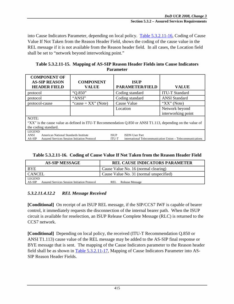
DoD UCR 2008, Change 3 Section 5.3.2 – Assured Services Requirements
415
into Cause Indicators Parameter, depending on local policy. Table 5.3.2.11-16, Coding of Cause Value If Not Taken from the Reason Header Field, shows the coding of the cause value in the REL message if it is not available from the Reason header field. In all cases, the Location field shall be set to “network beyond interworking point.”
Table 5.3.2.11-15. Mapping of AS-SIP Reason Header Fields into Cause Indicators Parameter
COMPONENT OF AS-SIP REASON HEADER FIELD
COMPONENT VALUE
ISUP PARAMETER/FIELD VALUE
protocol “Q.850” Coding standard ITU-T Standard protocol “ANSI” Coding standard ANSI Standard protocol-cause “cause = XX” (Note) Cause Value “XX” (Note) Location Network beyond
interworking point NOTE: “XX” is the cause value as defined in ITU-T Recommendation Q.850 or ANSI T1.113, depending on the value of the coding standard. LEGEND ANSI American National Standards Institute AS-SIP Assured Services Session Initiation Protocol
ISUP ISDN User Part ITU-T international Telecommunication Union – Telecommunications
Table 5.3.2.11-16. Coding of Cause Value If Not Taken from the Reason Header Field
AS-SIP MESSAGE REL CAUSE INDICATORS PARAMETER BYE Cause Value No. 16 (normal clearing) CANCEL Cause Value No. 31 (normal unspecified) LEGEND AS-SIP Assured Services Session Initiation Protocol
REL Release Message
5.3.2.11.4.12.2 REL Message Received
[Conditional] On receipt of an ISUP REL message, if the SIP/CCS7 IWF is capable of bearer control, it immediately requests the disconnection of the internal bearer path. When the ISUP circuit is available for reselection, an ISUP Release Complete Message (RLC) is returned to the CCS7 network. [Conditional] Depending on local policy, the received (ITU-T Recommendation Q.850 or ANSI T1.113) cause value of the REL message may be added to the AS-SIP final response or BYE message that is sent. The mapping of the Cause Indicators parameter to the Reason header field shall be as shown in Table 5.3.2.11-17, Mapping of Cause Indicators Parameter into AS-SIP Reason Header Fields.

DoD UCR 2008, Change 3 Section 5.3.2 – Assured Services Requirements
416
Table 5.3.2.11-17. Mapping of Cause Indicators Parameter into AS-SIP Reason Header Fields
CAUSE INDICATORS
PARAMETER FIELD VALUE OF
PARAMETER FIELD
COMPONENT OF AS-SIP REASON HEADER FIELD COMPONENT VALUE
Coding standard ITU-T Standard protocol “Q.850” Coding standard ANSI Standard protocol “ANSI” Cause Value “XX”1 protocol-cause “cause= XX”1 reason-text Should be filled with the
definition text as given in ITU-T Q.850 or ANSI T1.1132
NOTES 1. “XX” is the cause value as defined in ITU-T Recommendation Q.850 or ANSI T1.113. 2. Because the Cause Indicators parameter does not include the definition text as defined in ITU-T
Recommendation Q.850 or ANSI T1.113, this is based on provisioning in the SIP/CCS7 IWF. LEGEND ANSI American National Standards Institute AS-SIP Assured Services Session Initiation Protocol
ITU-T International Telecommunication Union – Telecommunications
[Conditional] On receipt of a REL message before receiving an ANM, the SIP/CCS7 IWF shall send the appropriate SIP status code in an AS-SIP final response, as shown in Table 5.3.2.11-18, Receipt of the REL Message. The ISUP cause codes not appearing in the table shall have the same mapping as the appropriate ANSI T1.113 class defaults.
Table 5.3.2.11-18. Receipt of the REL Message
AS-SIP MESSAGE REL CAUSE INDICATORS PARAMETER Cause Values with Coding Standard Field Set to 00 (ITU-T Standard)1 404 Not Found Cause Value No. 1 (unallocated (unassigned) number) 500 Server Internal Error Cause Value No. 2 (no route to network) 500 Server Internal Error Cause Value No. 3 (no route to destination) 500 Server Internal Error Cause Value No. 4 (send special information tone) No Mapping (No procedure specified for this cause value in U.S. networks)
Cause Value No. 5 (misdialed trunk prefix) (No procedures specified for this cause value in U.S. networks)
See Section 5.3.4, AS-SIP Requirements, which references RFCs 4411 & 3326
Cause Value No. 8 (preemption-circuit is not to be reused)
See Section 5.3.4, AS-SIP Requirements, which references RFCs 4411 & 3326
Cause Value No. 9 (preemption-circuit is reserved for reuse)
486 Busy Here Cause Value No. 17 (user busy) 480 Temporarily Unavailable Cause Value No. 18 (no user responding) 480 Temporarily Unavailable Cause Value No. 19 (no answer from the user) 480 Temporarily Unavailable Cause Value No. 20 (subscriber absent) 480 Temporarily Unavailable Cause Value No. 21 (call rejected) 410 Gone Cause Value No. 22 (number changed) No Mapping (due to redirection procedures)
Cause Value No. 23 (redirect to a new destination)

DoD UCR 2008, Change 3 Section 5.3.2 – Assured Services Requirements
417
AS-SIP MESSAGE REL CAUSE INDICATORS PARAMETER 502 Bad Gateway Cause Value No. 27 (destination out of order) 484 Address Incomplete Cause Value No. 28 (invalid number format) (address
incomplete) 500 Server Internal Error Cause Value No. 29 (facility rejected) 480 Temporarily Unavailable Cause Value No. 31 (normal unspecified) (Class default) 480 Temporarily Unavailable Cause Value in the Class 010 (resource unavailable, Cause
Value No. 34) 500 Server Internal Error Cause Value in the Class 010 (resource unavailable, Cause
Value Nos. 38-47) (47 is class default) 500 Server Internal Error Cause Value No. 50 (requested facility not subscribed) 500 Server Internal Error Cause Value No. 57 (bearer capability not authorized) 500 Server Internal Error Cause Value No. 58 (bearer capability not presently
available) 500 Server Internal Error Cause Value No. 63 (service option not available,
unspecified) (Class default) 500 Server Internal Error Cause Value in the Class 100 (service or option not
implemented Cause Value Nos. 65-79) (79 is class default) 500 Server Internal Error Cause Value No. 88 (incompatible destination) 404 Not Found Cause Value No. 91 (invalid transit network selection) 500 Server Internal Error Cause Value No. 95 (invalid message) (Class default) 500 Server Internal Error Cause Value No. 97 (message type non-existent or not
implemented) 500 Server Internal Error Cause Value No. 99 (IE/parameter non-existent or not
implemented) 480 Temporarily Unavailable Cause Value No. 102 (recovery on timer expiry) 500 Server Internal Error Cause Value No. 103 (parameter non-existent or not
implemented, passed on) 500 Server Internal Error Cause Value No. 110 (message with unrecognized
parameter, discarded) 500 Server Internal Error Cause Value No. 111 (protocol error, unspecified) (Class
default) 480 Temporarily Unavailable Cause Value No. 127 (interworking unspecified) (Class
default) Cause Values with Coding Standard Field Set to 01 (ANSI Standard) 1 404 Not Found Cause Value No. 23 (unallocated destination number) 500 Server Internal Error Cause Value No. 24 (unknown business group) 500 Server Internal Error Cause Value No. 25 (exchange routing error) 404 Not Found1 Cause Value No. 26 (misrouted call to a ported number) No Mapping (No procedure specified for this cause value in U.S. networks)
Cause Value No. 27 (NP QoR – number not found) (No procedures are specified for this cause value in U.S. networks.)
Not Applicable Cause Value in the Class 010 (resource unavailable, Cause Value Nos. 45 & 46) NOTE: Cause Value No. 45 is superseded by Cause Values 8 and 9 in codeset 0; Cause Value No. 46 is in codeset 1.

DoD UCR 2008, Change 3 Section 5.3.2 – Assured Services Requirements
418
AS-SIP MESSAGE REL CAUSE INDICATORS PARAMETER 500 Server Internal Error Cause Value in the Class 011 (service or option not
available, Cause Value Nos. 51 & 54) NOTE 1. The Coding Standard field in the Cause Indicators parameter in the received REL message may be set to either
“ITU-T Standard” or “ANSI Standard.” This table is separated into two sections pertaining to each of these values of the Coding Standard field.
LEGEND ANSI American National Standards
Institute AS-SIP Assured Services Session
Initiation Protocol IE Information Element
ITU-T International Telecommunication
Union – Telecommunications NP Number Portability QoR Query on Release
REL Release Message RFC Request for Comment UCR Unified Capabilities Requirements
[Conditional] On receipt of a REL message after receiving an ANM, the SIP/CCS7 IWF shall send a BYE message.
5.3.2.11.4.12.3 Autonomous REL at SIP/CCS7 IWF
Table 5.3.2.11-19, Autonomous Release at SIP/CCS7 IWF, shows the trigger events at the SIP/CCS7 IWF and the release initiated by the SIP/CCS7 IWF when the call is traversing from AS-SIP to ISUP.
Table 5.3.2.11-19. Autonomous Release at SIP/CCS7 IWF
AS-SIP SIDE TRIGGER EVENT
REL ON THE CCS7 SIDE
CAUSE PARAMETER 484 Address Incomplete
Determination that insufficient digits received
Not applicable
480 Temporarily Unavailable Congestion at the SIP/CCS7 IWF Not applicable BYE ISUP procedures result in release
after answer According to ISUP procedures
500 Server Internal Error Call release due to the ISUP compatibility procedure
According to ISUP procedures
484 Address Incomplete Call release due to expiry of T7 within the ISUP procedures
According to ISUP procedures
480 Temporarily Unavailable Other ISUP procedures result in release before answer
According to ISUP procedures
LEGEND AS-SIP Assured Services Session Initiation
Protocol CCS7 Common Channel Signaling No. 7
ISDN Integrated Services Digital Network ISUP ISDN User Part IWF Interworking Function
REL Release Message SIP Session Initiation Protocol
[Conditional] If an automatic repeat attempt initiated by the SIP/CCS7 IWF is unsuccessful (because the call is not routable), the SIP/CCS7 IWF shall send a 480 (Temporarily Unavailable) response code to the AS-SIP side. No actions on the ISUP side are required.

DoD UCR 2008, Change 3 Section 5.3.2 – Assured Services Requirements
419
[Conditional] If, after answer, ISUP procedures result in an autonomous REL message from the SIP/CCS7 IWF, then a BYE message shall be sent on the AS-SIP side. [Conditional] If the SIP/CCS7 IWF receives unrecognized backward ISUP signaling information and determines that the call needs to be released based on the coding, the SIP/CCS7 IWF shall send a 500 (Internal Server Error) response code on the AS-SIP side. Depending on local policy, a Reason header field containing the (ITU-T Recommendation Q.850 or ANSI T1.113) cause value of the REL message sent by the SIP/CCS7 IWF may be added to the AS-SIP message (BYE or final response) sent by the AS-SIP side of the SIP/CCS7 IWF.
5.3.2.11.4.12.4 Reset Circuit, Circuit Group Reset, or Circuit Group Blocking Message Received
Table 5.3.2.11-20, Receipt of RSC, GRS, or CGB Messages, shows the AS-SIP message sent by the SIP/CCS7 IWF upon receipt of an ISUP Reset Circuit message (RSC), Circuit Group Reset message (GRS), or Circuit Group Blocking message (CGB) with the Circuit Group Supervision Message Type Indicator coded as “hardware failure oriented,” when at least one backward ISUP message relating to the call has already been received. The SIP/CCS7 IWF sends a BYE message if it has already received an ACK message for the 200 OK INVITE request it had sent. If it has sent a 200 OK INVITE request, but has not received an ACK message for the 200 OK INVITE request, then the SIP/CCS7 IWF shall wait until it receives the ACK message for the 200 OK INVITE request before sending the BYE message. Otherwise, it sends a 500 (Server Internal Error) response. On receipt of a GRS or CGB, one AS-SIP message is sent for each call association. Therefore, multiple AS-SIP messages may be sent on receipt of a single GRS or CGB message.
Table 5.3.2.11-20. Receipt of RSC, GRS, or CGB Messages
MESSAGE SENT TO AS-SIP NETWORK MESSAGE RECEIVED FROM ISUP 500 Server Internal Error or BYE RSC 500 Server Internal Error or BYE GRS 500 Server Internal Error or BYE CGB with the Circuit Group Supervision Message
Type Indicator coded “hardware failure oriented” LEGEND AS-SIP Assured Services Session
Initiation Protocol CGB Circuit Group Blocking Message
GRS Circuit Group Reset Message ISDN Integrated Services Digital
Network
ISUP ISDN User Part RSC Reset Circuit Message
[Conditional] The SIP/CCS7 IWF shall process a received CCS7 RSC, GRS, or CGB message as shown in Table 5.3.2.11-20, Receipt of RSC, GRS, or CGB Messages.

DoD UCR 2008, Change 3 Section 5.3.2 – Assured Services Requirements
420
5.3.2.11.5 Interworking for a Call Originating in an ISUP Network toward an AS-SIP Network
This section describes the interworking requirements for a call originating in an ISUP network toward an AS-SIP network.
5.3.2.11.5.1 Sending of INVITE
[Conditional] After performing the normal ISUP handling for a received IAM and choosing to route the call to the AS-SIP network, the procedures at the SIP/CCS7 IWF will depend on whether preconditions are used in the AS-SIP network as follows: 1. Procedures to send an INVITE request without precondition upon receipt of an ISUP IAM
are given in Section 5.3.2.11.5.1.1, Sending INVITE without Precondition for a Received ISUP IAM.
2. Procedures to send an INVITE request with precondition upon receipt of an ISUP IAM are given in Section 5.3.2.11.5.1.2, Sending INVITE with Precondition for a Received ISUP IAM.
3. Coding of the IAM received and the INVITE request sent by the SIP/CCS7 IWF are specified in Section 5.3.2.11.5.1.3, Coding of SDP Media Description Lines from USI.
4. Timer (TOIW2) is started when the INVITE request is sent.
5. If timer (TOIW2) expires, an early ACM is sent to the CCS7 network. See Section 5.3.2.11.5.3, Expiration of TOIW2 and Sending Early ACM.
5.3.2.11.5.1.1 Sending INVITE without Precondition for a Received ISUP IAM
Normal outgoing AS-SIP procedures for when an INVITE request is sent apply with the following clarifications and exceptions: 1. [Conditional] An INVITE request shall be sent immediately when an ISUP IAM is
received and the Continuity Check Indicator in the Nature of Connection Indicators parameter in the IAM is set to indicate “continuity check not required.”
2. [Conditional] Sending of the INVITE request shall be delayed if the Continuity Check Indicator in the Nature of Connection Indicators parameter in the IAM is set to indicate either “continuity check required on this circuit” or “continuity check performed on previous circuit.” The INVITE request shall be sent on receipt of the Continuity message with the Continuity Indicators parameter set to “continuity check successful.” The INVITE

DoD UCR 2008, Change 3 Section 5.3.2 – Assured Services Requirements
421
request shall not be sent if the Continuity message is received with the Continuity Indicators parameter set to “continuity check failed,” or the ISUP timer T8 expires.
5.3.2.11.5.1.2 Sending INVITE with Precondition for a Received ISUP IAM
[Conditional] An INVITE request with a precondition shall be sent on receipt of an ISUP IAM. Incoming ISUP procedures apply, with the following clarifications and exceptions about when a confirmation of the precondition being met is sent. NOTE: Configured procedures may delay the INVITE request until local resources have been reserved on the outgoing bearer path. 1. [Conditional] The SIP/CCS7 IWF initiates the precondition signaling procedure using the
SDP Offer in the INVITE request. The precondition signaling is concluded upon sending (within an SDP Offer-Answer exchange) the confirmation of a precondition being met. The SDP Offer or SDP Answer carrying the confirmation of a precondition being met shall be sent when the following occur:
a. If the Continuity Check Indicator in the Nature of Connection Indicators parameter in the incoming IAM is set to indicate either “continuity check required on this circuit” or “continuity check performed on previous circuit,” the Continuity message with the Continuity Indicators parameter set to “continuity check successful” shall be received.
b. The requested preconditions are met in the SIP network.
NOTE: As a network option, the signaling of a precondition being met may only
occur within the SDP Offer in an UPDATE message.
2. [Conditional] A CANCEL or BYE message shall be sent if the Continuity message is received with the Continuity Indicators parameter set to “continuity check failed,” or if ISUP timer T8 expires.
3. [Conditional] The REL message with Cause Value No. 47 (resource unavailable, unspecified) shall be sent by the SIP/CCS7 IWF to the ISUP network, and a CANCEL or BYE message shall be sent to the AS-SIP network if internal resource reservation was unsuccessful.
Table 5.3.2.11-21, Mapping of IAM Information to an INVITE Message, provides a summary of how the header fields within the outgoing INVITE message are populated. When the coding of the received Calling Party Category (CPC) is “NS/EP call” or “emergency service call,” additional information may be sent in the INVITE request.

DoD UCR 2008, Change 3 Section 5.3.2 – Assured Services Requirements
422
Table 5.3.2.11-21. Mapping of IAM Information to an INVITE Message
IAM INVITE REFERENCE Called Party Number Request-URI
To 5.3.2.11.5.1.4 5.3.2.11.5.1.4
Calling Party Number P-Asserted-Identity Privacy
5.3.2.11.5.1.5 5.3.2.11.5.1.5
From 5.3.2.11.5.1.5 GAP (Supplemental User Provided Calling Address)
From 5.3.2.11.5.1.5
GAP (Ported Number) Request-URI FCI (ported Number Translation Indicator)
5.3.2.11.5.1.4 Request-URI 5.3.2.11.5.1.4
Hop Counter Max-Forwards USI
5.3.2.11.5.1.6 Message Body (application/SDP)
Precedence 5.3.2.11.5.1.3
Resource Priority Header LEGEND
5.3.2.11.5.1.7
FCI Forward Call Indicator IAM Initial Address Message
SDP Session Description Protocol URI Uniform Resource Indicator
USI User Service Information
5.3.2.11.5.1.3 Coding of SDP Media Description Lines from USI
[Conditional] If present, the USI parameter in the IAM indicates user-requested bearer service characteristics. The USI codes shall be mapped to the AS-SIP SDP information. ANSI T1.113.3 provides an exhaustive list of the available codes in the USI. In principle, any combination of those codes can be mapped into any SDP information as long as transcoding is available. [Conditional] The SIP/CCS7 IWF, as a network option, may also encode the SDP for the Adaptive Multi-Rate (AMR) codec, which is specified in RFC 4867. [Conditional] If ITU-T Recommendation G.711 encoding may be used, then the SIP/CCS7 IWF shall send an SDP Offer with both “G.711 µ-law” and “G.711 A-law” included in the media description, and “G.711 µ-law” shall take precedence over “G.711 A-law.” [Conditional] If transcoding is not available at the SIP/CCS7 IWF, the SIP/CCS7 IWF shall use the mapping relations in Table 5.3.2.11-22, Coding of SDP Media Description Lines from USI: ISUP to AS-SIP, from USI codes to SDP media description lines.
Table 5.3.2.11-22. Coding of SDP Media Description Lines from USI: ISUP to AS-SIP USI
PARA-METER
USI PARA-
METER
USI PARA-
METER
USI PARA-
METER HLC IE IN
ATP M= LINE B= LINE A= LINE Information Transfer Rate
Rate Multi-plier
Informa-tion Transport Capability
User Informa-tion Layer 1 Protocol Indicator
High Layer Characteris-tics Identifica-tion
<media> <transport> <fmt-list> <modifier>: <bandwidth-value>
rtpmap:<dynamic-PT> <encoding name>/<clock rate>[/encoding parameters>

DoD UCR 2008, Change 3 Section 5.3.2 – Assured Services Requirements
423
USI PARA-
METER
USI PARA-
METER
USI PARA-
METER
USI PARA-
METER HLC IE IN
ATP M= LINE B= LINE A= LINE speech Speech G.711
μ-law “Ignore” audio RTP/AVP 0 (&
possibly 8)1
AS:64 rtpmap:0 PCMU/8000(& possibly rtpmap:8 PCMA/8000)1
speech Speech G.711 μ-law
“Ignore” audio RTP/AVP Dynamic PT (& possibly a 2nd Dy-namic PT)
AS:64 rtpmap:<dynamic-PT> PCMU/8000(and possibly rtpmap:8 PCMA/8000)1
3.1 kHz audio 3.1 kHz audio
G.711 μ-law
Telephony or “HLC absent”
audio RTP/AVP 0 AS:64 rtpmap:0 PCMU/8000
3.1 kHz audio 3.1 kHz audio
Facsimile Group 2/3
image udptl t38 AS:64 Based on T.38
3.1 kHz audio 3.1 kHz audio
Facsimile Group 2/3
image tcptl t38 AS:64 Based on T.38
64 kbps unrestricted
Unrestrict-ed digital informa-tion with tone/ announcement
N/A “Ignore” audio RTP/AVP 9 AS:64 rtpmap:9 G.722/8000
64 kbps unrestricted
Unrestrict-ed Digital Informa-tion
N/A “Ignore” audio RTP/AVP Dynamic PT
AS:64 rtpmap:<dynamic-PT> CLEARMODE/80002
2 x 64 kbps unrestricted
2 Unrestrict-ed Digital Informa-tion
N/A “Ignore” Note 3 Note 3 Note 3 Note 3 Note 3
384 kbps unrestricted
Unrestrict-ed digital Informa-tion
N/A “Ignore” Note 3 Note 3 Note 3 Note 3 Note 3
NOTES: 1. Both PCMA and PCMU required under the conditions stated in Section 5.3.2.11.5.1.3. 2. CLEARMODE has not yet been standardized. 3. No standard is defined at this time. LEGEND ATP Acceptance Test Procedure/Plan AVP Audio/Video Profile HLC High Layer Compatibility IE Information Element
kbps Kilobits per Second kHz Kilohertz N/A Not Applicable PCMA Paired Carrier Multiple Access
PCMU Pulse Code Modulation mu-law RTP Real Time Protocol USI User Service Information
5.3.2.11.5.1.4 Request-URI and To Header Field
The Called Party Number parameter of the IAM contains the forward address information to derive the userinfo component of the INVITE Request-URI. The SIP/CCS7 IWF follows existing ISUP procedures to select the outgoing route. [Conditional] If a new Called Party Number parameter is derived for the outgoing route, then the newly derived Called Party Number parameter shall be mapped into the userinfo component of the INVITE Request-URI.

DoD UCR 2008, Change 3 Section 5.3.2 – Assured Services Requirements
424
For a basic call, the address information contained in the Called Party Number parameter is considered as the identification of the called party. Therefore, this information is used to derive the addr-spec component of the To header field. If the Request-URI or the To header field contains a sip uri, it shall include the “user=phone” URI parameter. It is assumed that the SIP/CCS7 IWF does not perform NP queries. However, it does map NP-related IEs. [Conditional] When the Called Party Number parameter is included in the received IAM and the GAP for the ported number is not present, the mapping of this parameter and of the FCI Ported Number Indicator to the Request-URI shall be as shown in Table 5.3.2.11-23, Mapping of Called Party Number and FCI Ported Number Translation Indicator. Table 5.3.2.11-23. Mapping of Called Party Number and FCI Ported Number Translation
Indicator
ISUP PARAMETER/ FIELD VALUE SIP COMPONENT VALUE
Called Party Number Digits Request-URI userinfo Address Signal Either NCD + SN
(national number) or CC + NCD + SN (international number)
userinfo’s geographical number
If national number, prepend +CC to Address signal digits, as in: “+CC” “NCD” “SN.” If international number, prepend “+”.
FCI Ported Number Translation Indicator
userinfo’s npdi parameter
If Ported Number Translation Indicator is equal to “1,” append “;npdi” to userinfo.
LEGEND ISDN Integrated Services Digital
Network ISUP ISDN User Part
FCI Forward Call Indicator NP Number Portability
npdi NP Database Dip Indicator SIP Session Initiation Protocol
[Conditional] When the Generic Address (ported number) and Called Party Number parameters are both included in the received IAM, the mapping of these parameters and of the FCI Ported Number Indicator to the Request-URI shall be as shown in Table 5.3.2.11-24, Mapping of Generic Address (Ported) and Called Party Number (When Both are Included), and FCI Ported Number to Request-URI. NOTE: The ISUP Transit Network Selection parameter is not expected to be received at the SIP/CCS7 IWF. Therefore, this document does not specify interworking of the parameter.

DoD UCR 2008, Change 3 Section 5.3.2 – Assured Services Requirements
425
Table 5.3.2.11-24. Mapping of Generic Address (Ported) and Called Party Number (When both are Included), and FCI Ported Number to Request-URI
ISUP PARAMETER/
FIELD VALUE SIP COMPONENT VALUE Generic Address Type of Number
“ported number” Request-URI
userinfo
Address Signal Since NOA is “national (significant) number,” then the format of the address signals is NCD + SN
userinfo’s geographical number
Add +CC to Address Signal digits, as in: “+CC” “NCD” “SN”
FCI Ported Number Translation Indicator
userinfo’s npdi parameter
“;npdi” is added to userinfo
Called Party Number Address Signal
Since NOA is “national (significant) number,” then the format of the address signals is NCD + SN
userinfo’s routing number
“;rn=routing number” is added to userinfo, with +CC being prefixed to Address Signal’s NCD+SN
LEGEND FCI Forward Call Indicator ISDN Integrated Services Digital
Network
ISUP ISDN User Part NOA Nature of Address
SIP Session Initiation Protocol
5.3.2.11.5.1.5 P-Asserted-Identity, From, and Privacy Header Fields
[Conditional] The SIP/CCS7 IWF shall follow the mapping in Table 5.3.2.11-25, ISUP CLI Parameters to AS-SIP Header Fields, when mapping from the ISUP Calling Party Number and Generic Address parameters to the AS-SIP P-Asserted-Identity, From, and Privacy header fields in the INVITE message.

DoD UCR 2008, Change 3 Section 5.3.2 – Assured Services Requirements
426
Table 5.3.2.11-25. ISUP CLI Parameters to AS-SIP Header Fields
Has a CgPN Parameter with Complete E.164 Number, with
Screening Indicator = UPPS or NP1, and with APRI = “Presentation
Allowed” or “Presentation
Restricted” Been Received?
Has a Generic Address
(Supplemental User Provided Calling
Address – Not Screened) with a Complete E.164
Number, and with APRI =
“Presentation Allowed” Been
Received?
P-Asserted-Identity
Header Field
From Header Field: display-name (Optional)
and addr-spec Privacy Header
Field No No Header field
not included. Unavailable@Hostportion Header field not
included. No2 Yes Header field
not included.
display-name derived from Generic Address (supplemental calling address) if possible. addr-spec derived from Generic Address (supplemental calling address) address signals or uses network-provided value.
Header field not included.
Yes1 No Derived from CgPN parameter address signals (see Table 5.3.2.11-27).
If APRI = “allowed,” display-name derived from CgPN if possible. If APRI = “restricted,” display-name is “Anonymous.” If APRI = “allowed,” addr-spec is derived from CgPN parameter address signals (see Table 5.3.2.11-28) or uses network-provided value. If APRI = “restricted,” addr-spec is set to “Anonymous URI.”4
If CgPN parameter APRI = “restricted,” then priv-value =; “id.” For other APRI settings, Privacy header is not included or, if included, “id” is not included (see Table 5.3.2.11-29).

DoD UCR 2008, Change 3 Section 5.3.2 – Assured Services Requirements
427
Has a CgPN Parameter with Complete E.164 Number, with
Screening Indicator = UPPS or NP1, and with APRI = “Presentation
Allowed” or “Presentation
Restricted” Been Received?
Has a Generic Address
(Supplemental User Provided Calling
Address – Not Screened) with a Complete E.164
Number, and with APRI =
“Presentation Allowed” Been
Received?
P-Asserted-Identity
Header Field
From Header Field: display-name (Optional)
and addr-spec Privacy Header
Field Yes1 No Derived from
CgPN parameter address signals (see Table 5.3.2.11-27).
display-name may be derived from Generic Address3 addr-spec is derived from Generic Address signals (see Table 5.3.2.11-26).
If CgPN parameter APRI = “restricted,” then priv-value =; “id”. For other APRI settings, Privacy header is not included or if included, “id” is not included (see Table 5.3.2.11-29).
NOTES 1. A network-provided CLI in the CgPN parameter may occur on a call from an analog access line. Therefore, to
allow the “display” of this network-provided CLI, it must be mapped into the AS-SIP From header. It is also considered suitable to map into the P-Asserted-Identity header.
2. This combination of CgPN and supplemental calling address is an error case, but is shown here to ensure consistent mapping across different implementations.
3. It may be possible to derive the Display name from the Generic Address parameter. 4. The From header may contain an “Anonymous URI,” which would not point to the calling party. RFC 3261
recommends that the display-name component contain “Anonymous.” Anonymous URI itself has the value “[email protected].”
LEGEND APRI Address Presentation Restricted Indicator AS-SIP Assured Services Session Initiation Protocol CgPN Calling Party Number CLI Calling Line Identification
NP Network Provided RFC Request for Comment UPPS User Provided Passed Screening URI Uniform Resource Identifier
[Conditional] The SIP/CCS7 IWF shall follow the detailed mapping in Table 5.3.2.11-26, Mapping of GAP (Supplemental User Provided Calling Address) to AS-SIP From Header Fields, when mapping from the ISUP Generic Address parameter to the AS-SIP From header field.

DoD UCR 2008, Change 3 Section 5.3.2 – Assured Services Requirements
428
Table 5.3.2.11-26. Mapping of GAP (Supplemental User Provided Calling Address) to AS-SIP from Header Fields
ISUP PARAMETER/
FIELD VALUE AS-SIP
COMPONENT VALUE Generic Address Number Qualifier Indicator
“supplemental user provided calling address – not screened”
From header field display-name (optional) and addr-spec
Nature of Address Indicator
“national (significant) number”
addr-spec Add CC (of the country where the SIP/CCS7 IWF is located) to GAP address signals, then map to AS-SIP URI.
“international number” Map complete GAP address signals to AS-SIP URI.
Address Signal If NOA is “national (significant) number,” then the format of the address signal is NDC + SN. If NOA is “international number,” then the format of the address signal is CC + NDC + SN.
display-name display-name shall be mapped from address signal, if possible, and if network policy allows it.
addr-spec “+CC” “NDC” “SN” mapped to the appropriate global number portion of URI scheme used.
LEGEND AS-SIP Assured Services Session
Initiation Protocol CCS7 Common Channel Signaling
System No. 7
ISDN Integrated Services Digital
Network ISUP ISDN User Part IWF Interworking Function
NOA Nature of Address SIP Session Initiation Protocol URI Uniform Resource Identifier
[Conditional] The SIP/CCS7 IWF shall follow the detailed mapping in Table 5.3.2.11-27, Mapping of CgPN Parameter to AS-SIP P-Asserted-Identity Header Fields, when mapping from the ISUP Calling Party Number parameter to the AS-SIP P-Asserted-Identity.
Table 5.3.2.11-27. Mapping of CgPN Parameter to AS-SIP P-Asserted-Identity Header Fields
ISUP PARAMETER/
FIELD VALUE SIP
COMPONENT VALUE Calling Party Number
P-Asserted-Identity header field
display-name (optional) and addr-spec
Nature of Address Indicator
“national (significant) number”
addr-spec Add CC (of the country where the SIP/CCS7 IWF is located) to CgPN address signals, then map to URI.

DoD UCR 2008, Change 3 Section 5.3.2 – Assured Services Requirements
429
ISUP PARAMETER/
FIELD VALUE SIP
COMPONENT VALUE “international number” Map complete CgPN
address signals to URI. Address Signal If NOA is “national
(significant) number,” then the format of the address signals is NDC + SN. If NOA is “international number,” then the format of the address signals is CC + NDC + SN.
display-name display-name shall be mapped from address signal, if possible, and if network policy allows it.
addr-spec “+CC” “NDC” “SN” mapped to the appropriate global number portion of URI scheme used.
LEGEND CgPN Calling Party Number CCS7 Common Channel Signaling
System No. 7 ISDN Integrated Services Digital
Network
ISUP ISDN User Part IWF Interworking Function NOA Nature of Address SIP Session Initiation Protocol
SS7 Signaling System No. 7 URI Uniform Resource Identifier
[Conditional] The SIP/CCS7 IWF shall follow the detailed mapping in Table 5.3.2.11-28, Mapping of ISUP CgPN Parameter to AS-SIP from Header Fields, when mapping from the ISUP CgPN parameter to the AS-SIP From header field.
Table 5.3.2.11-28. Mapping of ISUP CgPN Parameter to AS-SIP From Header Fields
ISUP PARAMETER
/ FIELD VALUE SIP
COMPONENT VALUE Calling Party Number
From header field
display-name (optional) and addr-spec
Nature of Address Indicator
“national (significant) number” addr-spec Add CC (of the country where the SIP/CCS7 IWF is located) to CgPN address signals, then map to user portion of URI scheme used.
“international number” Map complete CgPN address signals to user portion of URI scheme used.
Address Signal If NOA is “national (significant) number,” then the format of the address signals is NDC + SN. If NOA is “international number,” then the format of the address signals is CC + NDC + SN.
display-name display-name shall be mapped from Address Signal, if possible and network policy allows it.
addr-spec “+CC” “NDC” “SN” mapped to user portion of URI scheme used
LEGEND CgPN Calling Party Number CCS7 Common Channel Signaling System No. 7 ISDN Integrated Services Digital Network
ISUP ISDN User Part IWF Interworking Function NOA Nature of Address
SIP Session Initiation Protocol URI Uniform Resource Identifier

DoD UCR 2008, Change 3 Section 5.3.2 – Assured Services Requirements
430
[Conditional] The SIP/CCS7 IWF shall follow the detailed mapping in Table 5.3.2.11-29, Mapping of ISUP APRIs into AS-SIP Privacy Header Fields, when mapping from the ISUP Address Presentation Restricted Indicator (APRI) subfield of the Calling Party Number parameter to the AS-SIP Privacy header field.
Table 5.3.2.11-29. Mapping of ISUP APRIs into AS-SIP Privacy Header Fields
ISUP PARAMETER/
FIELD VALUE SIP
COMPONENT VALUE Calling Party Number
Privacy header field
priv-value
APRI “presentation restricted” priv-value “id,” but only included if the P-Asserted-Identity header is included in the AS-SIP INVITE request.
“presentation allowed” priv-value Omit Privacy header or Privacy header without “id” if other privacy service is needed.
NOTE: When the CgPN parameter is received, the P-Asserted-Identity header is always derived from it as shown in Table 5.3.2-34.
LEGEND APRI Address Presentation Restricted Indicator AS-SIP Assured Services Session Initiation Protocol CgPN Calling Party Number
ISDN Integrated Services Digital Network ISUP ISDN User Part SIP Session Initiation Protocol
[Conditional] If the From or the P-Asserted-Identity header field is sent with a sip uri, it shall include the “user=phone” URI parameter.
5.3.2.11.5.1.6 Hop Counter (Max-Forwards)
[Conditional] If the outgoing INVITE message uses AS-SIP, then the Max-Forwards header field value from the Hop Counter value shall be set to an integer equal to the received Hop Counter value multiplied by a factor (F) rounded down. The value of F should be derived by the SIP/CCS7 IWF using the following principles: 1. The Max-Forwards header field for a given message shall never increase, and shall
decrease by at least one with each successive visit to an SIP/CCS7 IWF, regardless of intervening interworking. The same is true for the Hop Counter value in the ISUP domain.
2. The initial and successively mapped values of the Max-Forwards header field should be large enough to accommodate the maximum number of hops that might be expected of a validly routed call.

DoD UCR 2008, Change 3 Section 5.3.2 – Assured Services Requirements
431
Since the value of F must take into account the topology of the networks that are traversed, it will depend on call origin and destination, and it will be provisioned at the SIP/CCS7 IWF based on network topology, trust domain rules, and bilateral agreement.
5.3.2.11.5.1.7 Precedence
The modeling of the SIP/CCS7 IWF assumes that preemption of a call will occur at a node either in the AS-SIP network or in the CCS7 network. The role of the SIP/CCS7 IWF is limited to interworking the signaling that indicates the relative priority of the calling party. NOTE: If the SIP/CCS7 IWF controls the bearer path, it may perform preemption as described in Section 5.3.2.10.5, CCA Support for Admission Control. [Conditional] The SIP/CCS7 IWF shall populate the RPH in the outgoing AS-SIP INVITE message as follows: 1. If the NI in the received Precedence parameter is “0000,” corresponding to “uc,” the
network domain in the RPH shall be coded as “uc.”
2. If the NI in the received Precedence parameter is not “0000,” corresponding to “uc,” then the network domain in the RPH shall be coded as “uc.”
3. The binary MLPP service domain in the received Precedence parameter shall be converted to six characters (0-F, one character per half-octet) and shall be used to populate the precedence-domain in the RPH.
4. If the NI in the received Precedence parameter is “0000,” then the r-priority field in the RPH shall be populated as shown in Table 5.3.2.11-30, Mapping of IAM Precedence Level to RPH Precedence Subfield.
5. If the NI in the received Precedence parameter is not “0000,” then the r-priority field in the RPH shall be coded as “0” (“Routine”).
Table 5.3.2.11-30. Mapping of IAM Precedence Level to RPH Precedence Subfield
ISUP PARAMETER/ FIELD VALUE
SIP COMPONENT VALUE
Calling Party Number Privacy header field
priv-value
“presentation restricted”
priv-value “id,” but only included if the P-Asserted-Identity header is included in the AS-SIP INVITE message.
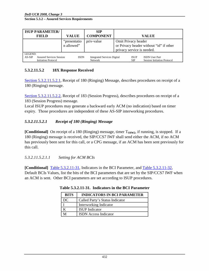
DoD UCR 2008, Change 3 Section 5.3.2 – Assured Services Requirements
432
ISUP PARAMETER/ FIELD VALUE
SIP COMPONENT VALUE
“presentation allowed”
priv-value Omit Privacy header or Privacy header without “id” if other privacy service is needed.
LEGEND: AS-SIP Assured Services Session
Initiation Protocol
ISDN Integrated Services Digital
Network
ISUP ISDN User Part SIP Session Initiation Protocol
5.3.2.11.5.2 18X Response Received
Section 5.3.2.11.5.2.1, Receipt of 180 (Ringing) Message, describes procedures on receipt of a 180 (Ringing) message. Section 5.3.2.11.5.2.2, Receipt of 183 (Session Progress), describes procedures on receipt of a 183 (Session Progress) message. Local ISUP procedures may generate a backward early ACM (no indication) based on timer expiry. Those procedures are independent of these AS-SIP interworking procedures.
5.3.2.11.5.2.1 Receipt of 180 (Ringing) Message
[Conditional] On receipt of a 180 (Ringing) message, timer TOIW2, if running, is stopped. If a 180 (Ringing) message is received, the SIP/CCS7 IWF shall send either the ACM, if no ACM has previously been sent for this call, or a CPG message, if an ACM has been sent previously for this call.
5.3.2.11.5.2.1.1 Setting for ACM BCIs
[Conditional] Table 5.3.2.11-31, Indicators in the BCI Parameter, and Table 5.3.2.11-32, Default BCIs Values, list the bits of the BCI parameters that are set by the SIP/CCS7 IWF when an ACM is sent. Other BCI parameters are set according to ISUP procedures.
Table 5.3.2.11-31. Indicators in the BCI Parameter
BITS INDICATORS IN BCI PARAMETER DC Called Party’s Status Indicator I Interworking Indicator K ISUP Indicator M ISDN Access Indicator

DoD UCR 2008, Change 3 Section 5.3.2 – Assured Services Requirements
433
Table 5.3.2.11-32. Default BCIs Values
PARAMETER BITS CODES MEANING Interworking Indicator I 1 Interworking Encountered ISUP Indicator K 0 ISUP/BICC not used all the way ISDN Access Indicator M 0 Terminating Access Non-ISDN LEGEND BCI Backward Call Indicator BICC Bearer-Independent Call Control
ISDN Integrated Services Digital
Network
ISUP ISDN User Part
5.3.2.11.5.2.1.2 Settings for Event Information in CPG
[Conditional] On receipt of a 180 (Ringing) message, the SIP/CCS7 IWF shall send a CCS7 CPG message with the Event Indicator bits G F E D C B A set to “alerting” (0 0 0 0 0 0 1) in the Event Information parameter.
5.3.2.11.5.2.2 Receipt of 183 (Session Progress) Message
[Conditional] On receipt of an AS-SIP 183 (Session Progress) message, no ISUP message is sent backward, and ISUP procedures shall continue.
5.3.2.11.5.3 Expiration of TOIW2 and Sending Early ACM
[Conditional] When timer TOIW2 expires, the SIP/CCS7 IWF shall return an ACM to the CCS7 network. In the case where the continuity check is performed, the SIP/CCS7 IWF shall withhold sending an ACM until a successful continuity indication has been received. [Conditional] When returning an ACM to the CCS7 network, the SIP/CCS7 IWF shall return an awaiting answer indication (e.g., ringing tone) toward the calling party. [Conditional] The Called Party’s Status Indicator (Bit DC) of the BCI parameter in the ACM shall be set to “no indication.” The other BCI indicators shall be set as described in Section 5.3.2.11.5.2.1.1, Setting for ACM BCIs.
5.3.2.11.5.4 Circuit (CIC) Query Response Message Received
[Conditional: SIP/CCS7 IWF] After sending a Circuit (CIC) Query message, the SIP/CCS7 IWF expects to receive a Circuit (CIC) Query Response message. [Conditional] The SIP/CCS7 IWF shall process the Circuit (CIC) Query Response message as described in ANSI T1.113.4, Clause 2.8.2A. If the ISUP procedures result in release of a call, appropriate actions shall be taken on the AS-SIP side.

DoD UCR 2008, Change 3 Section 5.3.2 – Assured Services Requirements
434
5.3.2.11.5.5 200 (OK) INVITE Message Received
[Conditional] On receipt of a 200 (OK) INVITE message, the SIP/CCS7 IWF shall stop Timer TOIW2 if it is running. [Conditional] If the 200 (OK) INVITE message uses AS-SIP, the SIP/CCS7 IWF shall 1. Send an ANM as determined by ISUP procedures. If an ANM is sent as the first backward
message on the CCS7 side, the BCI parameter shall be coded with the Called Party’s Status Indicator (Bits DC) set to “no indication,” and the other BCI parameter indicators shall be set as described in Section 5.3.2.11.5.2.1.1, Setting for ACM BCIs.
2. Stop any existing “awaiting answer indication” (e.g., ringing tone).
5.3.2.11.5.6 Through Connection, Tones, and Announcements
Through connection of bearer path is applicable only to a SIP/CCS7 IWF that controls the bearer path. [Conditional] For AS-SIP, through connection at the SIP/CCS7 IWF shall follow the ANSI T1.113.4 procedures for the destination exchange if this functionality is not available at the adjacent AS-SIP node. If the adjacent AS-SIP node does support the ANSI T1.113.4 procedures for through connection at a destination exchange, the SIP/CCS7 IWF shall follow these procedures: 1. Through connection of the bearer path shall be completed dependent on whether
preconditions are in use on the AS-SIP side of the call.
2. The bearer path shall be connected in both directions on completion of the bearer setup on the AS-SIP side. This event is indicated by the receipt of an SDP Answer acceptable to the SIP/CCS7 IWF, and an indication that all mandatory preconditions, if any, have been met.
3. The bearer path shall be connected in the forward direction no later than on receipt of a 200 (OK) INVITE message.
[Conditional] For AS-SIP, the following conditions shall result in a ringing tone being played from the SIP/CCS7 IWF:
• 180 (Ringing) received
• ISUP procedures indicate that ringing tone can be applied

DoD UCR 2008, Change 3 Section 5.3.2 – Assured Services Requirements
435
• The local arrangements assign the role of destination exchange to the SIP/CCS7 IWF rather than the associated AS-SIP entity
Ringing tone or a progress announcement may already be playing because of TOIW2 expiry. See Section 5.3.2.11.5.3, Expiration of TOIW2 and Sending Early ACM. [Conditional] In the case of ringing tones being played because of TOIW2 expiry, no additional ringing tone shall be played. NOTE: If the associated AS-SIP entity performs the functions of the destination exchange, other tones or announcements may be received from the AS-SIP network.
5.3.2.11.5.7 Release Procedures
5.3.2.11.5.7.1 Receipt of Forward REL
[Conditional] Upon receipt of an ISUP REL message: 1. If a REL message is received before the INVITE request has been sent, the SIP/CCS7 IWF
shall take no action on the AS-SIP side other than to terminate local procedures, if any, that are in progress.
2. If a REL message is received before any response has been received to the INVITE request, the SIP/CCS7 IWF shall hold the REL message until an AS-SIP response has been received. At that point, it shall take appropriate release actions.
3. If a REL message is received before a response has been received that establishes a confirmed dialog or early dialog, the SIP/CCS7 IWF shall send a CANCEL request. If the SIP/CCS7 IWF later receives a 200 (OK) INVITE request, then it shall send an ACK message for the 200 (OK) INVITE request and, later, send a BYE request after the ACK message has been sent.
4. If a REL message is received at the SIP/CCS7 IWF after a response has been received that establishes a confirmed dialog or early dialog, the SIP/CCS7 IWF shall send a BYE request. For cases in which no encapsulation is used, for an early dialog only, CANCEL may be used instead.
5. If a REL message is received after the 200 (OK) INVITE request, but before the outgoing side of the SIP/CCS7 IWF has sent the ACK message, then the SIP/CCS7 IWF shall send the ACK message before sending a BYE request.

DoD UCR 2008, Change 3 Section 5.3.2 – Assured Services Requirements
436
NOTE: Depending on local policy, a Reason header field containing the received (ITU-T Recommendation Q.850 or ANSI T1.113) cause value of the REL message may be added to the CANCEL or BYE request. If the Coding Standard field of the Cause Indicators parameter is set to “ANSI Standard,” the Protocol parameter of the Reason header is set to “ANSI,” and if the Coding standard is set to “ITU-T Standard,” the Protocol parameter is set to “Q.850.” The mapping of the Cause Indicators parameter to the Reason header is shown in Table 5.3.2.11-20, Receipt of RSC, GRS, or CGB Messages.
5.3.2.11.5.7.2 Receipt of Backward BYE
[Conditional] On receipt of an AS-SIP BYE request, the SIP/CCS7 IWF shall send a CCS7 REL message. [Conditional] For the AS-SIP case, if a Reason header with a Protocol parameter set to either “Q.850” or “ANSI” is included in the BYE request, then the appropriate cause value may be mapped to the cause value field in the REL message depending on the local policy. The mapping of the Reason header to the Cause Indicators parameter is shown in Table 5.3.2.11-15, Mapping of AS-SIP Reason Header Fields into Cause Indicators Parameter (see Section 5.3.2.11.4.12.1, Receipt of BYE or CANCEL). In case a value is not available from the Reason header field, the Cause Indicators parameter shall be encoded as “normal clearing” (Cause Value No. 16).
5.3.2.11.5.7.3 Autonomous REL at the SIP/CCS7 IWF
Table 5.3.2.11-33, Autonomous REL at SIP/CCS7 IWF, shows the trigger events at the SIP/CCS7 IWF and the release initiated by the SIP/CCS7 IWF when the call is traversing from ISUP to AS-SIP. [Conditional] If, after answer, ISUP procedures result in autonomous REL message from the SIP/CCS7 IWF, then a BYE request shall be sent on the AS-SIP side.
Table 5.3.2.11-33. Autonomous REL at SIP/CCS7 IWF
REL ON THE CCS7 SIDE CAUSE PARAMETER TRIGGER EVENT AS-SIP SIDE
As determined by ISUP procedure
COT received with the Continuity Indicators parameter set to “continuity check failed,” or the ISUP timer T8 expires.
Send CANCEL or BYE request according to the rule described in Section 5.3.2.11.5.7.1.
REL message with Cause Value No. 47 (resource unavailable, unspecified)
Internal resource reservation unsuccessful.
As determined by AS-SIP procedure.

DoD UCR 2008, Change 3 Section 5.3.2 – Assured Services Requirements
437
REL ON THE CCS7 SIDE CAUSE PARAMETER TRIGGER EVENT AS-SIP SIDE
As determined by ISUP procedure.
ISUP procedures result in generation of autonomous REL message on the ISUP side.
Send CANCEL or BYE request, according to the rule described in Section 5.3.2.11.5.7.1.
Depending on the AS-SIP release reason
AS-SIP procedures result in a decision to release the call.
As determined by AS-SIP procedure.
LEGEND AS-SIP Assured Services Session Initiation Protocol CCS7 Common Channel Signaling No. 7
COT Customer Originated Trace ISDN Integrated Services Digital Network
ISUP ISDN User Part REL Release
5.3.2.11.5.7.4 Reset Circuit, Circuit Group Reset, or Circuit Group Blocking Message Received
Table 5.3.2.11-34, Receipt of RSC, GRS, or CGB Messages, shows the message sent by the SIP/CCS7 IWF upon receipt of an ISUP RSC message, GRS message, or CGB message with the Circuit Group Supervision Message Type Indicator coded as “hardware failure oriented.” On receipt of a GRS or CGB message, one AS-SIP message is sent for each call association. Therefore, multiple AS-SIP messages may be sent on receipt of a single GRS or CGB message.
Table 5.3.2.11-34. Receipt of RSC, GRS, or CGB Messages
MESSAGE RECEIVED FROM ISUP MESSAGE SENT TO AS-SIP
NETWORK RSC CANCEL or BYE GRS CANCEL or BYE CGB with the Circuit Group Supervision Message Type Indicator coded “hardware failure oriented”
CANCEL or BYE
LEGEND AS-SIP Assured Services Session Initiation Protocol CGB Circuit Group Blocking Message GRS Circuit Group Reset Message
ISDN Integrated Services Digital Network ISUP ISDN User Part RSC Reset Circuit Message
[Conditional] The SIP/CCS7 IWF shall process received CCS7 RSC, GRS, or CGB messages as shown in Table 5.3.2.11-34, Receipt of RSC, GRS, or CGB Messages. The SIP/CCS7 IWF shall send a CANCEL or BYE message according to the rule described in Section 5.3.2.11.5.7.1, Receipt of Forward REL. Depending on local policy, a Reason header field containing the (ITU-T Recommendation Q.850 or ANSI T1.113) cause value of the REL message sent by the SIP/CCS7 IWF may be added to the AS-SIP message (BYE or CANCEL).

DoD UCR 2008, Change 3 Section 5.3.2 – Assured Services Requirements
438
5.3.2.11.5.7.5 3XX, 4XX, 5XX, or 6XX Response INVITE Received
[Conditional] The SIP/CCS7 IWF shall handle receipt of a 3XX Redirection message, if received in a response as part of a valid dialog, according to the AS-SIP protocol, resulting in invocation of the local routing function. The remainder of this section applies only to the 4XX, 5XX, and 6XX response cases. [Conditional] If a Reason header is included in a received 4XX, 5XX, or 6XX message, then the SIP/CCS7 IWF shall map the cause value of the Reason header to the ISUP Cause Value field in the CCS7 REL message. The mapping of the Reason header to the Cause Indicators parameter shall be as shown in Table 5.3.2.11-15, Mapping of AS-SIP Reason Header Fields into Cause Indicators Parameter. [Conditional] If no Reason header is included in a received 4XX, 5XX, or 6XX message, then the SIP/CCS7 IWF shall use the mapping of the status code to cause value on receipt of a 4XX, 5XX, or 6XX final response to the INVITE request into the AS-SIP network side, as shown in Table 5.3.2.11-35, Mapping of 4XX, 5XX, or 6XX to REL Message.
Table 5.3.2.11-35. Mapping of 4XX, 5XX, or 6XX to REL Message
REL (CAUSE CODE) 4XX/5XX/6XX SIP MESSAGE REMARKS 127 Interworking 400 Bad Request 127 Interworking 401 Unauthorized Note 1 127 Interworking 402 Payment Required 127 Interworking 403 Forbidden 1 Unallocated number 404 Not Found 127 Interworking 405 Method Not Allowed 127 Interworking 406 Not Acceptable 127 Interworking 407 Proxy Authentication Required Note 1 127 Interworking 408 Request Timeout 22 Number changed (without diagnostic) 410 Gone 127 Interworking 413 Request Entity Too Long Note 1 127 Interworking 414 Request-URI Too Long Note 1 127 Interworking 415 Unsupported Media Type Note 1 127 Interworking 416 Unsupported URI Scheme Note 1 127 Interworking 420 Bad Extension Note 1 127 Interworking 421 Extension Required Note 1 127 Interworking 423 Interval Too Brief 20 Subscriber absent 480 Temporarily Unavailable 127 Interworking 481 Call/Transaction Does Not Exist 127 Interworking 482 Loop Detected 127 Interworking 483 Too Many Hops 28 Invalid Number format 484 Address Incomplete Note 1

DoD UCR 2008, Change 3 Section 5.3.2 – Assured Services Requirements
439
REL (CAUSE CODE) 4XX/5XX/6XX SIP MESSAGE REMARKS 127 Interworking 485 Ambiguous 17 User busy 486 Busy Here 127 Interworking or no mapping (Note 3) 487 Request Terminated Note 2 127 Interworking 488 Not Acceptable Here No mapping. 491 Request Pending Note 2 127 Interworking 493 Undecipherable 127 Interworking 500 Server Internal Error 127 Interworking 501 Not Implemented 127 Interworking 502 Bad Gateway 127 Interworking 503 Service Unavailable Note 1 127 Interworking 504 Server Timeout 127 Interworking 505 Version Not Supported Note 1 127 Interworking 513 Message Too Large Note 1 127 Interworking 580 Precondition Failure Note 1 17 User busy 600 Busy Everywhere 21 Call rejected 603 Decline 1 Unallocated number 604 Does Not Exist Anywhere 127 Interworking 606 Not Acceptable NOTES 1. This response may be handled entirely on the AS-SIP side; if so, it is not interworked. 2. This response does not terminate an AS-SIP dialog, but only a specific transaction within it. 3. No mapping if the SIP/CCS7 IWF previously issued a CANCEL request for the INVITE. LEGEND AS-SIP Assured Services Session Initiation Protocol CCS7 Common Channel Signaling No. 7 IWF Interworking Function
REL Release SIP Session Initiation Protocol URI Uniform Resource Identifier
[Conditional] When the response to the INVITE request results in the sending of a REL message with a Cause Code No. 127, Interworking, the Location field shall be set to “network beyond interworking point.” In all cases where AS-SIP itself or this section specifies additional AS-SIP behavior related to the receipt of a particular INVITE response, these procedures should be followed in preference to the immediate sending of a REL message to the CCS7 network. [Conditional] If there are no AS-SIP procedures associated with this response, the REL message shall be sent to the CCS7 network immediately. It is possible that receipt of certain 4XX, 5XX, and 6XX responses to an INVITE request will not result in any REL message being sent to the CCS7 network. For example, if a 401 (Unauthorized) response is received and the SIP/CCS7 IWF successfully initiates a new INVITE request containing the correct credentials, the call will proceed. If no further reference is given in the Remarks column, then this means that the AS-SIP response is interworked to a CCS7 REL message sent on the ISUP side of the SIP/CCS7 IWF with the

DoD UCR 2008, Change 3 Section 5.3.2 – Assured Services Requirements
440
cause value indicated within the table. In cases where further reference is indicated, the behavior of the SIP/CCS7 IWF is described within the referred-to clause. However, Table 5.3.2.11-36, Interworking Timer, indicates the “eventual” behavior of the SIP/CCS7 IWF in the case that further measures taken on the AS-SIP side of the call (to try to sustain the call) fail, resulting in the requirement to send a REL message into the CCS7 network with the cause value indicated.
Table 5.3.2.11-36. Interworking Timer
TIME-OUT VALUE
CAUSE FOR INITIATION
NORMAL TERMINATION AT EXPIRY
4-14 seconds (default of 4 seconds)
Sending of INVITE request unless the ACM has already been sent
On reception of 180 (Ringing), 183 (Session Progress) with encapsulated ACM, or 200 (OK) INVITE request
Send early ACM. For AS-SIP case, send the awaiting answer indication (e.g., ring tone) or appropriate progress announcement to the calling party.
LEGEND ACM Address Complete Message
AS-SIP Assured Services Session Initiation Protocol
5.3.2.11.6 Interworking Timer
The SIP/CCS7 IWF requires one timer that is specific to its interworking functionality. Table 5.3.2.11-36, Interworking Timer, summarizes the timer TOIW2. The value of TOIW2 is set between 4 and 14 seconds (with a default value of 4 seconds). The timer is started when an INVITE request is sent (unless an ACM has already been sent for this call). The timer is stopped on receipt of any of the following messages:
• 180 (Ringing) • 183 (Session Progress) with an encapsulated ACM • 200 (OK) INVITE
[Conditional] The SIP/CCS7 IWF shall initiate the timer when an INVITE request is sent, unless an ACM has already been sent for this call. [Conditional] At the expiry of the timer, the SIP/CCS7 IWF shall send an early ACM into the CCS7 network. [Conditional] For the AS-SIP case only, the SIP/CCS7 IWF shall send the awaiting answer indication (e.g., ring tone) or appropriate progress announcement to the calling party.

DoD UCR 2008, Change 3 Section 5.3.2 – Assured Services Requirements
441
5.3.2.12 Media Gateway Requirements
5.3.2.12.1 Introduction
This section provides Generic System Requirements (GSRs) for the MG function in the following network appliances:
• LSC • MFSS • WAN SS
The LSC and MFSS have defined designs that include an MGC function and one or more MG functions. The scope of these MG requirements covers the following areas: 1. Physical interfaces and protocols supported on the TDM side of the MG include the
following:
a. DoD CCS7 trunks (The TDM media trunks terminate on the MG; the TDM signaling links terminate on the separate SG, which is discussed in Section 5.3.2.13, Signaling Gateway Requirements.)
b. ISDN PRI trunks (The TDM media (B channels) channels and the TDM signaling
channels (D channels) both terminate on the MG.) c. CAS trunks (Both DTMF and MF; the TDM channel that carries both the media and
the signaling terminates on the MG.) 2. VoIP interfaces and protocols supported on the IP side of the MG include the following:
a. Interface to the IP router network and the LAN (ASLAN, LANs internal to a UC product) that the network appliance is connected to
b. VoIP protocol stacks supporting IP, IPSec, UDP, TCP, SCTP, and SRTP
c. Secure VoIP media streams, packetized using IP, UDP, and SRTP, IAW Section 5.4,
Information Assurance Requirements
d. Secure VoIP signaling messages, packetized using IPSec, and UDP or TCP or SCTP, IAW, Section 5.4, Information Assurance Requirements

DoD UCR 2008, Change 3 Section 5.3.2 – Assured Services Requirements
442
(1) H.248 signaling messages, for MGC control of DoD CCS7, ISDN PRI, and CAS trunks, if the supplier supports ITU-T Recommendation H.248
(2) ISDN PRI signaling messages, for MGC control of ISDN PRI trunks
3. Support for the following VoIP codecs, at a minimum, on the IP side of the MG:
a. ITU-T Recommendation G.711 (uncompressed voice, both North American (μ-law and International A-law))
b. ITU-T Recommendation G.723.1
c. ITU-T Recommendation G.729
4. Support for FoIP on the IP side of the MG
5. Support for voiceband MoIP on the IP side of the MG. The following terms define “Modem over IP” traffic, as used in the UCR. The terms are listed here to clarify that SCIP over IP streams are a subset of all possible modem relay streams. In the UCR, the term SCIP over IP can be considered synonymous with the transmission of SCIP over V.150.1 Modem Relay. These terms also appear in Appendix A, Definitions, Abbreviations and Acronyms, and References.
a. Modem over IP
. The transport of modem data across an IP network, via either modem relay or modem passthrough techniques.
b. Modem Relay
. A subset of MoIP, in which modem termination is used at gateways, thereby allowing only the baseband data to reach the packet network.
c. Voiceband Data (Modem Passthrough)
. A subset of MoIP in which modem signals are transmitted over a Voiceband Data channel in a packet network.
d. SCIP over IP
. The transport of SCIP information over an IP network. The SCIP traffic can be transmitted over an IP network in many ways, but currently, the U.S. Government requires SCIP devices to support transmission of SCIP on IP networks via V.150.1 Modem Relay.
6. Support for SCIP over IP on the IP side of the MG. As noted previously, SCIP over IP streams are a subset of all possible modem relay streams. In the UCR, the term SCIP over IP is synonymous with the transmission of SCIP over V.150.1 Modem Relay. For SCIP over IP calls, the MG supports V.150.1 Modem Relay traffic IAW ITU Recommendation V.150.1 and NSA document SCIP 216 on the IP side of the MG.

DoD UCR 2008, Change 3 Section 5.3.2 – Assured Services Requirements
443
7. Support for 64-kbps unrestricted digital information (clear channel) ISDN over IP on the IP side of the MG.
5.3.2.12.2 Overview of the MG and MGC Functions
Media Gateway is a generic term for a Trunk Gateway (TG) and for an Access Gateway (AG). Thus, MG requirements apply to TGs and to AGs. Figure 5.3.2.12-1, MGC – MG Layered Interface, illustrates the relationship between the MGC, a component of the CCA, and a generic MG.
Figure 5.3.2.12-1. MGC – MG Layered Interface
Figure 5.3.2.12-2, MG Trunk Function, illustrates the MG trunk function.
5.3.2.12.2.1 Primary Trunk Functions and Interfaces
An MG may support a trunk-side interface to CS telephone networks. It terminates CS trunks in the CS networks and packet flows in the DISN Core network and, thus, provides functions such as media translation. The MG can set up and manage media flows through the Core network when instructed by the CCA. It is associated with a specific CCA that provides it with the necessary call control instructions.
MGControl Interface
MGC
IP
TCP/UDP
H.248.x
MG Applications
TLS
OSI Layer 2/ Layer 1
LEGENDIP Internet ProtocolMG Media GatewayMGC Media Gateway ControllerOSI Open Systems Interconnection
TCP Transmission Control ProtocolTLS Transport Layer SecurityUDP User Datagram Protocol

DoD UCR 2008, Change 3 Section 5.3.2 – Assured Services Requirements
444
Figure 5.3.2.12-2. MG Trunk Function
5.3.2.12.2.2 Primary Access Functions and Interfaces
An MG may support line-side and trunk-side interfaces to the voice network end users. Traditional telephones and PBXs currently used in the PSTN, as well as ISDN BRI telephones, ISDN BRI terminals, and ISDN-capable PBXs using PRIs, can access the DISN Core network through the MG. The MG provides functions, such as packetization and echo control, for its end users’ information streams, and is associated with a specific CCA that provides the necessary call control and service control instructions. On receiving the appropriate commands from its CCA, the MG provides Call Control functions such as audible ringing and power ringing, as well as Service Control functions. The MG also is capable of setting up transport connections through the DISN Core network when instructed to do so by the CCA (see Figure 5.3.2.12-3, MG Primary Access Functions and Interfaces).
5.3.2.12.2.3 MGC Functions
The requirements in this section allow for two options for the Gateway Control Protocol in the MGC and the MG as follows:
VoIPProtocols
Translation Applications
SRTP/SRTCP
TCP/UDP
IP
Layer 2 / Layer 1
Translation ApplicationsTranslation Applications
TrunkProtocols
Trunk GatewayFunction
......Trunk Gateway
FunctionTG
Function...
...
TrunksMedia Flows
ASLAN
LEGENDASLAN Assured Service Local Area
NetworkIP Internet ProtocolMG Media GatewaySRTCP SRTP Control Protocol
SRTP Secure Real-Time Transport ProtocolTCP Transmission Control ProtocolTG Trunk GroupUDP User Datagram ProtocolVoIP Voice over Internet Protocol

DoD UCR 2008, Change 3 Section 5.3.2 – Assured Services Requirements
445
Figure 5.3.2.12-3. MG Primary Access Functions and Interfaces
1. An industry-standard Gateway Control Protocol, using an open interface between the MGC
and the MG. This protocol assumes MG-to-MGC communication over IP and the LAN that the appliance is connected to. This LAN is the ASLAN for the LSC and MFSS. (In some cases, this LAN may be the Internal LAN of the UC product, where the UC product also contains the LSC or the MFSS. In these cases, the Internal LAN of the UC product is not an ASLAN.)
The industry-standard Gateway Control Protocol used in these requirements is ITU-T Recommendation H.248.1.
2. A supplier-specific Gateway Control Protocol, using a closed (supplier-proprietary) interface between the MGC and the MG. This supplier-specific protocol may use MGC-to-MG communication over IP and the LAN that the appliance is connected to (ASLAN or Internal LAN for the UC product), or it may use separate physical, data link, and network layer interfaces that are also proprietary to the supplier.
The MGC function is part of the CCA function in the LSC and MFSS, which in turn is part of the SCS functions in these appliances. The MG function is a standalone appliance function in the LSC and MFSS, and is not part of any other appliance function.
LEGENDAG Access GatewayASLAN Assured Service Local Area NetworkIP Internet ProtocolLSC Local Session ControllerMFSS Multifunction SoftswitchOSI Open Systems Interconnection
PBX Private Branch ExchangeSRTCP SRTP Control ProtocolSRTP Secure Real-Time Transport ProtocolTCP Transmission Control ProtocolUDP User Datagram ProtocolVoIP Voice over Internet Protocol
VoIPProtocols
Translation Applications
SRTP/SRTCP
TCP/UDP
IP
OSI Layer 2/Layer 1
Translation Applications
AccessLines
Protocols
PBXTrunk
Protocols
Translation Applications
Trunk GatewayFunction
Trunk GatewayFunction
PBX Trunks
Media Flows
LSC or MFSSASLAN
.
.....
... AGFunction
Access Lines

DoD UCR 2008, Change 3 Section 5.3.2 – Assured Services Requirements
446
The role of the MGC within an LSC and MFSS is to 1. Control all MGs within the LSC and MFSS.
2. Control all trunks (e.g., DoD CCS7, PRI, or CAS) within each MG.
3. Control all signaling and media streams on each trunk within each MG.
4. Accept IP-encapsulated signaling streams from an SG or MG, and return IP-encapsulated signaling streams to the SG or MG accordingly.
The MGC and the MG that it controls are considered “Conditional – Deployable” for the LSC, and “Required” for the MFSS.
5.3.2.12.3 Role of the MG in Appliances
The MG provides CS trunk termination for DoD CCS7, PRI, and CAS trunks, and TDM/VoIP interworking. The MG is controlled by the MGC. The protocol that the MGC uses to control the MG can be ITU-T Recommendation H.248 (specifically, H.248.1) or a proprietary protocol chosen by the LSC supplier.
5.3.2.12.3.1 Role of the MG in the LSC
Figure 5.3.2.12-4, Functional Reference Model – LSC, illustrates the reference model for the LSC, including the VoIP MG and MGC. The roles of the MG within the LSC are as follows: 1. The MG terminates all TDM trunks that interconnect the LSC with TDM networks,
including the following:
a. DoD TDM networks (e.g., DSN, including EO and Tandem switches within the DSN), both in the United States and worldwide
b. PSTNs, both in the United States and worldwide
c. Allied and U.S. coalition partner TDM networks
2. The MG terminates all TDM trunks that interconnect the LSC with TDM PBXs within the
same DoD B/P/C/S.

DoD UCR 2008, Change 3 Section 5.3.2 – Assured Services Requirements
447
3. The MG supports the physical interconnection of the following TDM trunk groups with the LSC:
Figure 5.3.2.12-4. Functional Reference Model – LSC
a. [Conditional: LSC] DoD CCS7 trunk groups b. ISDN PRI trunk groups (for both U.S. PRI and foreign country PRI)
*Support for an SG & CCS7 is Conditional for an LSC.**Support for CAS is Conditional for an LSC.
DoD, Allied, orCoalitionPartner
CCS7*, PRI,or CAS**
ISDN PRIor CAS**
ISDN PRIor CAS**
AEI
H.248 orProprietary
(ConditionalDeployable)
ISDN PRIor CAS**
PSTN
MG
EO
SMEO
PBX
EO
TDM
CCS7*
IWF
SG*CCA
LSC-Level ASAC
SCS Functions
LLS
Service Control Functions
LSC UC ProductTest Configuration
ASLANAS-SIP
MFSS or
WAN SS
EBC
AS-SIP
MGC
LEGEND:AEI AS-SIP End InstrumentASAC Assured Service Admission ControlASLAN Assured Services Local Area NetworkAS-SIP Assured Services Session Initiation ProtocolB2BUA Back-to-Back User AgentCAS Channel Associated SignalingCCS7 Common Channel Signaling No. 7DoD Department of DefenseEBC Edge Border ControllerEO End OfficeISDN Integrated Services Digital NetworkIWF Interworking FunctionLLS Local Location ServiceLSC Local Session ControllerMFSS Multifunction SoftswitchMG Media Gateway
MGC Media Gateway ControllerPBX Private Branch ExchangePEI Proprietary End InstrumentPRI Primary Rate InterfacePSTN Public Switched Telephone NetworkSCS Session Control and SignalingSG Signaling GatewaySIP Session Initiation ProtocolSMEO Small End OfficeSS SoftswitchTDM Time Division MultiplexerUC Unified CapabilitiesUFS User Features and ServicesVoIP Voice over Internet ProtocolWAN Wide Area Network
MediaServer UFS Information
Assurance
Managem
ent
SIPB2BUA
SIPRegistrar
Transport Interface Functions
Note: The PEI (using Proprietary VoIP and Video) is part of the LSC UC Product; the AEI (using AS-SIP VoIP and Video) is not.
PEI
ProprietaryVoIP & Video

DoD UCR 2008, Change 3 Section 5.3.2 – Assured Services Requirements
448
c. [Conditional: U.S. and foreign country CAS] CAS trunk groups Media gateway support for these TDM trunk groups is expected to be identical to the
support for these trunk groups in DoD TDM PBXs, EOs, Tandem switches, and MFSs today.
4. [Conditional] In the DoD CCS7 case , the MG is responsible for terminating the TDM media trunks (on the TDM side), and for terminating the VoIP/FoIP/MoIP media streams (on the VoIP side). In these cases, the separate SG is responsible for terminating the TDM CCS7 signaling links and the VoIP/FoIP/MoIP signaling streams.
5. In the PRI and CAS cases, the MG is responsible for terminating the TDM media trunks and signaling links on the TDM side, and for terminating the VoIP/FoIP/MoIP media streams and
6. On calls that traverse the MG, the MG converts TDM media streams to VoIP, FoIP, or MoIP media streams, and converts VoIP, FoIP, or MoIP media streams to TDM media streams.
signaling streams on the VoIP side.
7. The MG supports interconnection of VoIP, FoIP, and MoIP media streams with the following LSC functions and end-user devices:
a. [Required: LSC MG] The LSC media server, which provides tones and announcements for LSC calls and LSC features
b. [Conditional: LSC MG] Proprietary VoIP, FoIP, and MoIP EIs on the LSC (when
these EIs are supported on the LSC)
c. [Conditional: LSC MG] Proprietary SIP EIs on the LSC (when these EIs are supported on the LSC)
d. [Conditional: LSC MG] Proprietary H.323 EIs on the LSC (when these EIs are
supported on the LSC)
e. [Required: LSC MG] AS-SIP VoIP, FoIP, and MoIP AEIs on the LSC 8. On ISDN PRI calls that traverse the MG, the MG converts TDM signaling streams to VoIP
signaling streams, and it converts VoIP signaling streams to TDM signaling streams. When H.248 control is used, the MG will send and receive encapsulated PRI signaling to and from the CCA.
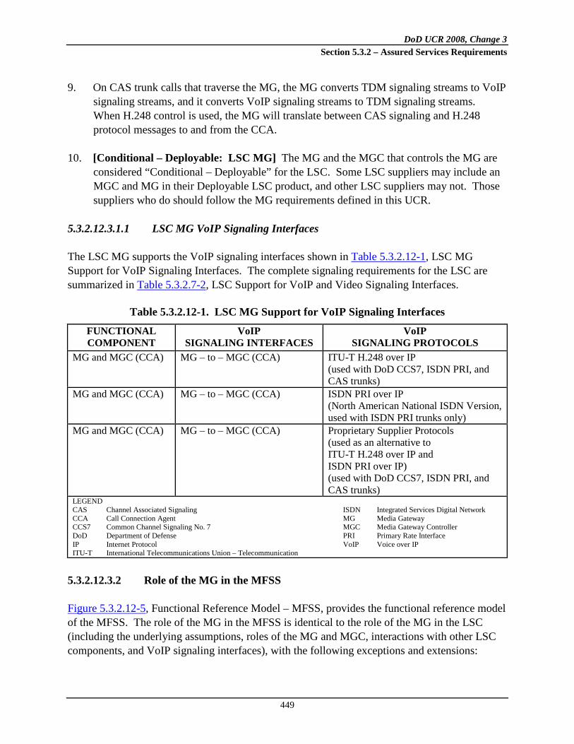
DoD UCR 2008, Change 3 Section 5.3.2 – Assured Services Requirements
449
9. On CAS trunk calls that traverse the MG, the MG converts TDM signaling streams to VoIP signaling streams, and it converts VoIP signaling streams to TDM signaling streams. When H.248 control is used, the MG will translate between CAS signaling and H.248 protocol messages to and from the CCA.
10. [Conditional – Deployable: LSC MG] The MG and the MGC that controls the MG are considered “Conditional – Deployable” for the LSC. Some LSC suppliers may include an MGC and MG in their Deployable LSC product, and other LSC suppliers may not. Those suppliers who do should follow the MG requirements defined in this UCR.
5.3.2.12.3.1.1 LSC MG VoIP Signaling Interfaces
The LSC MG supports the VoIP signaling interfaces shown in Table 5.3.2.12-1, LSC MG Support for VoIP Signaling Interfaces. The complete signaling requirements for the LSC are summarized in Table 5.3.2.7-2, LSC Support for VoIP and Video Signaling Interfaces.
Table 5.3.2.12-1. LSC MG Support for VoIP Signaling Interfaces
FUNCTIONAL COMPONENT
VoIP SIGNALING INTERFACES
VoIP SIGNALING PROTOCOLS
MG and MGC (CCA) MG – to – MGC (CCA) ITU-T H.248 over IP (used with DoD CCS7, ISDN PRI, and CAS trunks)
MG and MGC (CCA) MG – to – MGC (CCA) ISDN PRI over IP (North American National ISDN Version, used with ISDN PRI trunks only)
MG and MGC (CCA) MG – to – MGC (CCA) Proprietary Supplier Protocols (used as an alternative to ITU-T H.248 over IP and ISDN PRI over IP) (used with DoD CCS7, ISDN PRI, and CAS trunks)
LEGEND CAS Channel Associated Signaling ISDN Integrated Services Digital Network CCA Call Connection Agent MG Media Gateway CCS7 Common Channel Signaling No. 7 MGC Media Gateway Controller DoD Department of Defense PRI Primary Rate Interface IP Internet Protocol VoIP Voice over IP ITU-T International Telecommunications Union – Telecommunication
5.3.2.12.3.2 Role of the MG in the MFSS
Figure 5.3.2.12-5, Functional Reference Model – MFSS, provides the functional reference model of the MFSS. The role of the MG in the MFSS is identical to the role of the MG in the LSC (including the underlying assumptions, roles of the MG and MGC, interactions with other LSC components, and VoIP signaling interfaces), with the following exceptions and extensions:

DoD UCR 2008, Change 3 Section 5.3.2 – Assured Services Requirements
450
Figure 5.3.2.12-5. Functional Reference Model – MFSS
1. The MG in the MFSS assists the MFSS CCA in providing call denial treatments for CAC,
and call preemption treatments for LSC-Level ASAC and WAN-Level ASAC Policing. The MFSS supports LSC-Level ASAC for admission control for calls to and from EIs that
LocalLocationService
Softswitch Side
Service Control Functions
AS-SIP
AEI
InformationAssurance
Managem
ent
MFSS or
WAN SS
EI
MFS
DoD, Allied, orCoalition Partner
ISDN PRI or CAS
Analog or ISDN BRI
CCS7, PRI, or CAS
LSC
AS-SIPIP
MFSS UC Product
CCS7
**
Global Location Service
CCA
H.248 orProprietary
IWFPSTNEO or Tandem Switch
Tan-dem
EO
SMEOCCS7**, PRI, or CAS*
ISDN PRI or CAS*
ISDN PRI or CAS*
PBX orSMEO
ISDN PRI or CAS
MFS
CCS7**, PRI, or CAS*MFSS
Session Control and Signaling Functions
Managem
ent
* Support for CAS is
Conditionalfor the
Softswitch side of an
MFSSUser
Features& Services
MediaServer
TDMSide
IP Transport Interface Functions
SG**
MG
WAN-Level ASAC
SIPB2BUA
SIPRegistrar
CCA
IWFMGC
Session Control and Signaling Functions
H.248 orProprietary
PBX orSMEO
EO orMFS
EO
PBX orSMEO
MFS
LEGEND:AEI AS-SIP End InstrumentASAC Assured Service Admission ControlASLAN Assured Services Local Area NetworkAS-SIP Assured Services Session Initiation ProtocolB2BUA Back-to-Back User AgentBRI Basic Rate InterfaceCAS Channel Associated SignalingCCA Call Connection AgentCCS7 Common Channel Signaling No. 7DoD Department of DefenseEBC Edge Border ControllerEI End InstrumentEO End OfficeIA Information AssuranceIP Internet ProtocolISDN Integrated Services Digital NetworkIWF Interworking FunctionLSC Local Session Controller
MFS Multifunction SwitchMFSS Multifunction SoftswitchMG Media GatewayMGC Media Gateway ControllerPBX Private Branch ExchangePEI Proprietary End InstrumentPRI Primary Rate InterfacePSTN Public Switched Telephone NetworkSCS Session Control and SignalingSG Signaling GatewaySIP Session Initiation ProtocolSMEO Small End OfficeSS SoftswitchSUT System Under TestTDM Time Division MultiplexerUC Unified CapabilitiesVoIP Voice over Internet ProtocolWAN Wide Area Network
** Support for an SG
and CCS7 isConditional
for the Softswitch side of an
MFSS
Note: The PEI (using Proprietary VoIP and Video) is part of the MFSS UC Product ; the AEI (using AS-SIP VoIP and Video) is not.
PEI
EBCProprietary VoIP & Video
ASLAN
IP
AS-SIPEBC

DoD UCR 2008, Change 3 Section 5.3.2 – Assured Services Requirements
451
it serves directly. The MFSS also supports WAN-Level ASAC Policing for admission control for calls to and from LSCs that it serves directly.
2. The MG in the MFSS supports DoD CCS7 trunks [Conditional], in addition to supporting ISDN PRI [Required] and CAS trunks [Conditional]. Support for these DoD CCS7 trunks is a conditional requirement for the MFSS MG and the LSC MG.
NOTE: An LSC within an MFSS will serve a set of (MFSS-internal) LSC EIs and MGs. These LSC EIs and MGs will exchange media streams with EIs and MGs on other LSCs located elsewhere on the DISN WAN. In addition, the MFSS EBC controls these media streams between the (MFSS-internal) LSC EIs and MGs connected to the MFSS ASLAN, and EIs and MGs on other LSCs, where separate ASLANs are connected to the DISN WAN.
5.3.2.12.3.2.1 MG Requirements for Interactions between the Softswitch and TDM Sides of the MFSS
The TDM side of the MFSS provides EO and Tandem functions that allow the MFSS to support connectivity to existing TDM switches in DoD networks (i.e., CONUS and Global), allied and coalition networks, and the PSTN worldwide (i.e., CONUS and Global). In addition, the EO function of the TDM side of the MFSS supports TDM users (i.e., analog and ISDN EIs). The SS side of the MFSS provides the IP-based features of an LSC with additional features as required to serve as a network-level SS. The CCA/SG/MGC/MG complex in the MFSS must provide Interoperability between the SS side and TDM side in the MFSS, using connections based on CCS7, U.S. PRI, or U.S. CAS signaling. In this case, some high-level requirements for this interworking are needed. These high-level requirements are included in this section. Internal MG connections are used when connecting the SS and the TDM sides of an MFSS. An “external MG trunk group” is an MFSS trunk group that connects an MFSS MG with the following:
• The TDM EO or TDM Tandem component of another MFSS in the network • The MGC/MG component of an LSC or another MFSS in the network • A TDM PBX, SMEO, EO, Tandem, or MFS in a DoD TDM network • A TDM PBX, EO, or Tandem in the U.S. PSTN or a foreign country PSTN
[Required] The MFSS MG shall be able to support MG trunk groups (referred to as internal MG connections) that either interconnects the SS (VoIP) side of the MFSS with the EO or Tandem functions on the TDM side of the MFSS.

DoD UCR 2008, Change 3 Section 5.3.2 – Assured Services Requirements
452
[Conditional] When a DoD CCS7 connection is used between the SS and TDM sides of the MFSS, the MFSS MG shall interact with the MFSS MGC so that
• DoD CCS7 signaling is used between the SS and TDM sides.
• The CCS7 version of the MLPP feature operates correctly between the SS and TDM sides of the MFSS for both VoIP-to-TDM calls and TDM-to-VoIP calls over this connection.
[Required] When a U.S. ISDN PRI connection is used between the SS and TDM sides of the MFSS, the MFSS MG shall interact with the MFSS MGC so that 1. U.S. ISDN PRI signaling (National ISDN PRI signaling, with the precedence level IE and
related MLPP IEs included) is used between the SS and TDM sides.
2. The T1.619/T1.619a version of the ISDN PRI MLPP feature operates correctly between the SS and TDM sides of the MFSS for both VoIP-to-TDM calls and TDM-to-VoIP calls over this connection.
[Conditional] When a U.S. CAS trunk group is used between the SS and TDM sides of the MFSS, the MFSS MG shall interact with the MFSS MGC so that 1. U.S. CAS trunk signaling is used between the SS and TDM sides.
2. The DoD version of the CAS trunk MLPP feature operates correctly between the SS and TDM sides of the MFSS for both VoIP-to-TDM calls and TDM-to-VoIP calls over this trunk group.
[Required] The MFSS MG shall interact with the MFSS MGC so that internal MG connections between the SS and TDM sides of the MFSS support:
• TDM calls between the TDM EO/Tandem and VoIP PEIs/AEIs on the MFSS, allowing calls from EO lines to MFSS PEIs/AEIs, and calls from EO and Tandem trunks to MFSS PEIs/AEIs.
• TDM calls between the TDM EO/Tandem and the EBC on the MFSS,
allowing calls from EO lines to the EBC (and other appliances on the DISN WAN), and calls from EO and Tandem trunks to the EBC (and other appliances on the DISN WAN).

DoD UCR 2008, Change 3 Section 5.3.2 – Assured Services Requirements
453
• TDM calls between the TDM EO/Tandem and external MG trunk groups on the MFSS, allowing calls from EO lines to external MG trunk groups, and calls from EO and Tandem trunks to external MG trunk groups.
• TDM calls between the TDM EO/Tandem and local MG trunk groups on the
MFSS, allowing calls from EO lines to local MG trunk groups, and calls from EO and Tandem trunks to local MG trunk groups. (This last case applies when the MFSS supports local MG trunk groups from its MG to subordinate PBX1s and PBX2s, when the subordinate PBX1s and PBX2s have not been migrated to VoIP.)
5.3.2.12.3.2.2 MFSS MG VoIP Signaling Interfaces
The MFSS MG supports the VoIP signaling interfaces shown in Table 5.3.2.12-2, MFSS MG Support for VoIP Signaling Interfaces.
Table 5.3.2.12-2. MFSS MG Support for VoIP Signaling Interfaces
FUNCTIONAL COMPONENT
VoIP AND VIDEO SIGNALING
INTERFACES VoIP AND VIDEO
SIGNALING PROTOCOLS MG and MGC MFSS MG
– to – MFSS MGC
ITU-T H.248 over IP (used with DoD CCS7, ISDN PRI, and CAS trunks)
MG and MGC MFSS MG – to –
MFSS MGC
ISDN PRI over IP (North American National ISDN Version, used with ISDN PRI trunks only)
MG and MGC MFSS MG – to –
MFSS MGC
Proprietary Supplier Protocols
LEGEND CCS7 Common Channel Signaling No. 7 DoD Department of Defense ISDN Integrated Services Digital Network ITU-T International Telecommunications Union –
Telecommunication
MFSS Multifunction Softswitch MG Media Gateway MGC MG Controller IP Internet Protocol PRI Primary Rate Interface VoIP Voice over IP
Unless stated otherwise, all requirements for an “Appliance MG” are for both the LSC and the MFSS.
5.3.2.12.4 MG Interaction with NEs and Functions
The MG is responsible for interacting with elements and functions of the LSC and MFSS to support end-user calls, end-user features, and other operational capabilities needed by the DoD users (i.e., the Army, Navy, Air Force, and Marines). These other elements include the following:

DoD UCR 2008, Change 3 Section 5.3.2 – Assured Services Requirements
454
• ASAC • Service Control functions (Information Assurance and media server) • Management (FCAPS and audit logs) • Transport Interface functions • EBC (not part of the LSC, but part of the Local Assured Services Domain)
5.3.2.12.4.1 MG Support for ASAC
The MG interacts with the CCA, which in turn interacts with the ASAC component of the LSC and MFSS to perform specific functions related to ASAC, such as providing denial treatments for calls that are denied admission to the LSC and/or MFSS, and preemption treatments for calls that are preempted by PBAS/ASAC. Requirements for ASAC are handled in two categories: CAC and ASAC. In addition, this section covers two different levels of ASAC: LSC-Level ASAC, which is supported in the LSC and the MFSS, and WAN-Level ASAC Policing, which is supported in the MFSS only. The MG assists the CCA in performing CAC (i.e., call blocking based on budget restrictions) for outgoing TDM calls at MGs and for incoming TDM calls at MGs. The MG assists the CCA in performing ASAC (i.e., call preemption based on per-call precedence levels) for outgoing TDM calls at MGs and for incoming TDM calls at MGs. In addition, please see Section 5.3.2.2.2.3, ASAC – Open Loop, and Section 5.3.4.10, Precedence and Preemption, for detailed requirements on how ASAC is supported by CCAs in LSCs and MFSSs.
5.3.2.12.4.1.1 MG Call Denial Treatments to Support CAC
When the CCA determines that a VoIP session request should be blocked because an Appliance CAC restriction applies (e.g., the VoIP session count equals the VoIP session limit for the type of session being requested), the CCA will deny the session request and apply a Call Denial treatment (i.e., a busy signal or call denial announcement) to the calling party on that request. If the calling party is a TDM calling party whose call enters the appliance at an MG trunk group, the MG is responsible for applying the Call Denial treatment also. [Required] On incoming call requests to a TDM trunk group, where the CCA/MGC applies a CAC Call Denial treatment to that call request, the MG shall connect the TDM called party on the incoming call request to the appropriate CAC Call Denial tone or announcement when instructed to do so by the MGC.

DoD UCR 2008, Change 3 Section 5.3.2 – Assured Services Requirements
455
5.3.2.12.4.1.2 MG Call Preemption Treatments to Support ASAC
When the CCA determines that an existing VoIP session or VoIP session request should be cleared because an Appliance ASAC preemption applies (e.g., a CAC limit applies and a call of a higher precedence level needs to complete within the appliance), the CCA will clear the existing session or session request and apply a Call Preemption treatment (i.e., a Call Preemption tone or announcement) to both the calling and called parties on that request. If the calling party is a TDM calling party whose call entered the appliance at an MG trunk group, or the called party is a TDM called party whose call left the appliance at an MG trunk group, the MG is responsible for applying the Call Preemption treatment also. [Required] On incoming calls or call requests to a TDM trunk group, where the CCA/MGC applies an ASAC Call Preemption treatment to that call or call request, the MG shall connect the TDM calling party on the incoming call or call request to the appropriate ASAC Call Preemption tone or announcement when instructed to do so by the MGC. [Required] On outgoing calls or call requests from a TDM trunk group, where the CCA/MGC applies an ASAC Call Preemption treatment to that call or call request, the MG shall connect the TDM called party on the outgoing call or call request to the appropriate ASAC Call Preemption tone or announcement when instructed to do so by the MGC.
5.3.2.12.4.2 MG and Information Assurance Functions
The MG interaction with Information Assurance function is consistent with the DoD Information Assurance requirements in Section 5.4, Information Assurance Requirements. The Information Assurance function within the appliance ensures that end users, PEIs, AEIs, MGs, SGs, and EBCs that use the appliance are all properly authenticated by the appliance. The Information Assurance function also ensures that VoIP signaling streams and media streams that traverse the appliance and its ASLAN are properly encrypted, using SIP/TLS and SRTP, respectively. Requirements for CCA and MGC interaction with the Information Assurance server are found in Section 5.3.2.10.7, CCA Support for Information Assurance. These requirements, therefore, apply to the MG. [Required] Each MG within an appliance shall support all the appliance requirements in Section 5.4, Information Assurance Requirements, that involve an Appliance MG. The MG performs the following authentication and encryption functions in conjunction with the CCA and Information Assurance:
DoD UCR 2008, Change 3 Section 5.3.2 – Assured Services Requirements
456
1. When the MG registers with the MGC in the CCA, the MG exchanges authentication credentials with the CCA and, through the CCA, with Information Assurance.
2. The MG exchanges encryption keys with the CCA and, through the CCA, with Information Assurance, before exchanging H.248 messages and encapsulated PRI messages with the MGC in the CCA.
3. The MG uses the exchanged encryption keys to (1) encrypt H.248 messages and encapsulated PRI messages sent in the MG => CCA => Information Assurance direction, and (2) decrypt H.248 messages and encapsulated PRI messages sent in the Information Assurance => CCA => MG direction. The encryption and decryption are performed at the IP layer using IPSec packets, instead of being done at the message layer using H.248 messages or PRI messages.
4. The MG also performs the following encryption functions in conjunction with PEIs or AEIs, and the media server in the LSC (NOTE: These functions may or may not use Information Assurance, depending on the internal design of the LSC.):
a. The MG exchanges encryption keys with local PEIs or AEIs and local MGs, remote PEIs or AEIs and remote MGs, and the media server, before exchanging encrypted VoIP media streams with these devices.
b. The MG uses the exchanged encryption keys to (1) encrypt VoIP SRTP media
streams sent in the MG => PEI/AEI/other MG/media server direction, and (2) decrypt VoIP SRTP media streams received in the PEI/AEI/other MG/media server => MG direction. The encryption and decryption are performed above the UDP Transport Layer using SRTP packets.
5.3.2.12.4.3 MG Interaction with Service Control Functions
The media server is responsible for playing tones and announcements to calling and called parties on VoIP calls, and for playing audio/video clips (similar to tones and announcements) to calling and called parties on video calls. In addition, the media server may provide “play announcement and collect digits” functionality to calling and called parties on VoIP and video calls when this functionality is required by certain features that the CCA supports. Depending on the complexity of those features, the media server may act as a full Interactive Voice Response (IVR) system for Appliance PEIs/AEIs and other assured services end users, providing IVR-like features to local and remote VoIP callers, and providing video-enhanced IVR-like features to local and remote video callers. The MG is responsible for routing individual VoIP, FoIP, and MoIP media streams to the media server when instructed to do so by the CCA/MGC. When instructed to do so by the CCA/MGC,

DoD UCR 2008, Change 3 Section 5.3.2 – Assured Services Requirements
457
the MG is responsible for removing individual VoIP, FoIP, and MoIP media streams from the media server, and for either disconnecting them entirely, or routing them on to other LSC end users (e.g., VoIP or video EIs).
[Required] When instructed to do so by the MGC, the MG shall direct TDM calls and call requests to the media server, so that the media server can 1. Play tones and announcements to TDM parties on TDM calls and call requests (e.g., busy
tone or announcement; call preemption tone or announcement).
2. Provide “play announcement and collect digits” functionality when required by an Appliance VoIP feature.
3. Provide full IVR-like functionality when required by an Appliance VoIP feature.
The interface and protocols used to interconnect the MG with the media server are internal to the appliance and are, therefore, supplier-specific.
5.3.2.12.4.4 Interactions with IP Transport Interface Functions
The Transport Interface functions in the LSC provide interface and connectivity functions with the ASLAN and its IP packet transport network. This section outlines high-level requirements for these functions. The detailed implementation methods for these requirements are left up to the vendor. Examples of Transport Interface functions include:
• Network Layer functions: IP, IPSec • Transport Layer functions: IP Transport Protocols (e.g., TCP, UDP), TLS • LAN protocols
The MG interacts with Transport Interface functions by using them to communicate with PEIs or AEIs and the EBC (and through the EBC to remote PEIs or AEIs and MGs served by other LSCs and MFSSs) over the ASLAN. The following LSC elements and Local Assured Services Domain elements are all IP endpoints on the ASLAN:
• Each PEI or AEI served by the LSC
• The MG itself
• Any other MGs that are served by the LSC (even though the other MGs may be connected physically to the CCA/MGC over an internal proprietary interface, instead of being logically connected to the CCA/MGC over the ASLAN)

DoD UCR 2008, Change 3 Section 5.3.2 – Assured Services Requirements
458
• The CCA and its IWF and MGC
• The EBC As an example, the MG interacts with the LSC Transport Interface functions when it uses IPsec, UDP/TCP/SCTP, and the native ASLAN protocols to exchange H.248 and PRI signaling messages with the CCA/MGC over the ASLAN. The MG interacts with the LSC Transport Interface functions when it uses IP, UDP, and the native ASLAN protocols to route SRTP media streams to and from EIs, GEIs, other LSC MGs, and the EBC over the ASLAN. [Required] Since each Appliance MG is an IP endpoint on the Appliance LAN, each MG shall support assignment of the following items to itself:
• Only one MG IP address (This one IP address may be implemented in the CCA as either a single logical IP address or a single physical IP address.)
• An MG FQDN that maps to that IP address
• An MG SIP URI that uses that MG FQDN as its domain name, and maps to a
“SIP User Agent” function within the MG. [Required] The MG shall interact with the Transport Interface functions in the appliances in the following cases:
• When the MG uses the native LAN protocols, IP, and UDP to exchange SRTP media streams with PEIs, AEIs, other MGs, and the EBC over the Appliance LAN
• [Conditional] When the MG uses the native LAN protocols, IPSec, and
UDP, TCP, or SCTP to exchange H.248 signaling messages with the MGC over the Appliance LAN
• [Conditional] When the MG uses the native LAN protocols, IPSec, and
UDP, TCP, or SCTP to exchange encapsulated PRI messages with the MGC over the Appliance LAN
5.3.2.12.4.5 MG – EBC Interaction
The EBC provides SBC and firewall capabilities for the ASLAN, the PEIs, AEIs, and the IP-based components of the LSC, including the CCA, and its IWF and MGC, and the MGs.

DoD UCR 2008, Change 3 Section 5.3.2 – Assured Services Requirements
459
The MG interacts with the EBC by sending SRTP media streams to it (for call media destined for a PEI, AEI, or MG that is served by another appliance outside the LSC), or by accepting SRTP media streams from it (for call media arriving from a PEI, AEI, or MG that is served by another appliance outside the LSC). The SRTP media streams exchanged between the LSC MG and a remote PEI, AEI, or MG must pass through the EBC. The EBC modifies these SRTP media streams by doing NAT/NAPT on them. The VoIP MG in the MFSS or LSC needs to interact with VoIP Media Transfer functions in the EBC. The EBC 1. Transfers media streams between the PEIs or AEIs and MGs on the appliance, and PEIs or
AEIs and MGs on remote appliances, located elsewhere on the DISN WAN.
2. Supports SBC functions, such as NAT and NAPT.
3. Supports IP firewall functions.
High-level MG requirements are needed for interacting with an EBC. These requirements are as follows: [Required] When sending VoIP media streams to PEIs or AEIs and MGs served by other network appliances, the MG shall direct these VoIP media streams to the EBC so the EBC can process them before sending them on to the remote PEIs or AEIs and MGs via the DISN WAN. The MG shall use the network-level IP addresses of the destination PEIs or AEIs and MGs, rather than the local IP address of the EBC, when directing the VoIP media streams through the EBC to the DISN WAN and the remote PEIs or AEIs and MGs. [Required] The MG shall direct VoIP media streams to remote PEIs or AEIs and MGs through the EBC in the following cases:
• When the MG is part of an LSC and is directing VoIP media streams to PEIs or AEIs and MGs on another LSC on the DISN WAN
• When the MG is part of an LSC and is directing VoIP media streams to PEIs
or AEIs and MGs on an MFSS on the DISN WAN
• When the MG is part of an MFSS and is directing VoIP media streams to PEIs or AEIs and MGs on an LSC on the DISN WAN
DoD UCR 2008, Change 3 Section 5.3.2 – Assured Services Requirements
460
• When the MG is part of an MFSS and is directing VoIP media streams to PEIs or AEIs and MGs on another MFSS on the DISN WAN
[Required] When accepting VoIP media streams from PEIs or AEIs and MGs served by other network appliances, the MG shall accept these VoIP media streams from the appliance EBC, because the EBC relays them from the DISN WAN and the remote PEIs or AEIs and MGs on the DISN WAN. The MG shall recognize and act on the network-level IP addresses of the remote PEIs or AEIs and MGs, when accepting the VoIP sessions through the EBC from the DISN WAN and the remote PEIs or AEIs and MGs. [Required] The MG shall accept VoIP media streams from remote PEIs or AEIs and MGs through the EBC in the following cases:
• When the MG is part of an LSC and is accepting VoIP media streams from PEIs or AEIs and MGs on another LSC on the DISN WAN
• When the MG is part of an LSC and is accepting VoIP media streams from
PEIs or AEIs and MGs on an MFSS on the DISN WAN
• When the MG is part of an MFSS, and is accepting VoIP media streams from PEIs or AEIs and MGs on an LSC on the DISN WAN
• When the MG is part of an MFSS, and is accepting VoIP media streams from
PEIs or AEIs and MGs on another MFSS on the DISN WAN
5.3.2.12.4.6 MG Support for Appliance Management Functions
The Management function in the EBC, LSC, and MFSS supports functions for EBC/LSC/MFSS FCAPS management and audit logs. The MG interacts with the Appliance Management function by 1. Making changes to its configuration and to its trunks’ configuration in response to
commands from the Management function that request these changes.
2. Returning information to the Management function on its FCAPS in response to commands from the Management function that request this information.
3. Sending information to the Management function on a periodic basis (e.g., on a set schedule), keeping the Management function up-to-date on MG activity. An example of this update would be a periodic transfer of trunk media error logs from the MG to the

DoD UCR 2008, Change 3 Section 5.3.2 – Assured Services Requirements
461
Management function so that the Management function could either store the records locally or transfer them to a remote NMS for remote storage and processing.
5.3.2.12.4.7 IP-Based PSTN Interface Requirements
[Conditional] Voice and Video over IP interfaces from the UC network to the PSTN have not been defined. Therefore, the LSC and MFSS to PSTN interface will remain TDM. Interfaces from an LSC or MFSS to the PSTN will be via an MG with TDM interfaces.
5.3.2.12.4.8 MG Requirements: Interactions with VoIP EIs
The MG in the MFSS or LSC needs to interact with VoIP EIs served by that MFSS or LSC, and with VoIP EIs served by other MFSSs or LSCs. The VoIP signaling interface between the PEI and the MFSS or LSC is left up to the network appliance supplier. The VoIP signaling interface between the AEI and the MFSS or LSC is AS-SIP per Section 5.3.2.22, AS-SIP End Instrument and Video Codec Requirements, of this document. Detailed requirements for this VoIP interface are beyond the scope of this section. However, the following high-level requirements on VoIP EIs do apply and are part of the MG requirements for the MFSS and LSC: 1. [Required] The MG shall support the exchange of VoIP media streams with the following
voice PEIs and AEIs both on the local appliance and on remote network appliances:
a. Supplier-proprietary voice PEIs b. Voice SIP EIs, when the appliance supplier supports these EIs c. Voice H.323 EIs, when the appliance supplier supports these EIs d. Voice AS-SIP AEIs
2. [Conditional] When the MG supports the exchange of voice media streams with voice
H.323 EIs (both on the local network appliance and on remote network appliances), the MG shall support a mechanism for interworking the G.7xx/SRTP/UDP/IP-based VoIP media streams that the MG uses with the H.323-based VoIP media streams that the H.323 EI uses.

DoD UCR 2008, Change 3 Section 5.3.2 – Assured Services Requirements
462
5.3.2.12.4.9 MG Support for User Features and Services
[Required] The MG shall support the operation of the following features for VoIP and Video end users, consistent with the operation of this feature on analog and ISDN lines in DoD TDM switches today:
• Call Hold • Music on Hold • Call Waiting • Precedence Call Waiting • Call Forwarding Variable • Call Forwarding Busy Line • Call Forwarding No Answer • Call Transfer • 3-way calling • Hotline Service • Calling Party and Called Party ID (number only) • Call Pickup
5.3.2.12.5 MG Interfaces to TDM NEs in DoD Networks: PBXs, EOs, and MFSs
[Required] Each appliance MG shall support TDM trunk groups that can interconnect with the following NEs in DoD networks, in the United States and worldwide:
• PBXs • SMEOs • EOs • MFSs
[Required] Each appliance MG shall support TDM trunk groups that can interconnect with DISN and DoD NEs in the United States and worldwide using the following types of trunk groups:
• [Conditional: LSC, MFSS] DoD CCS7, where the MG handles the media trunks and the SG handles the signaling links.
− ANSI T1.619 and T1.619a support is required for CCS7 MLPP
signaling.
• [Required: LSC, MFSS] U.S. National ISDN PRI, where the MG handles both the media channels and the signaling channel.

DoD UCR 2008, Change 3 Section 5.3.2 – Assured Services Requirements
463
− ANSI T1.619 and T1.619a support is required for PRI MLPP signaling.
− Facility Associated Signaling is required for T1.619A PRIs, and NFAS
is Conditional for T1.619A PRIs.
− Both FAS and NFAS are required for commercial PSTN PRIs, for access to the US PSTN.
• [Conditional: LSC, MFSS] U.S. CAS trunks, where the MG handles both
media and signaling on the same channel.
− CAS MLPP signaling is required when a U.S. CAS trunk is supported. [Required] Media Gateway support for these TDM trunk groups shall be identical to the support for these trunk groups in DoD TDM PBXs, EOs, Tandem switches, and MFSs today.
5.3.2.12.6 MG Interfaces to TDM NEs in Allied and Coalition Partner Networks
The appliance suppliers should support TDM trunk groups on their MG product that can interconnect with NEs in U.S. allied and coalition partner networks worldwide. [Conditional] The MG shall support foreign country CCS7 trunk groups where the MG handles the media trunks, and the SG handles the signaling links as follows: 1. For interconnection with an allied or coalition partner network, using foreign CCS7 from
the network of the allied or coalition partner.
2. Support for MLPP using CCS7, per ITU-T Recommendation Q.735.3, is conditional on LSC and MFSS trunk groups when these trunk groups are used to connect to an allied or coalition partner from an OCONUS ETSI-compliant country.
[Required] The MG shall support foreign country ISDN PRI trunk groups where the MG handles both the media channels and the signaling channel as follows: 1. For interconnection with an allied or coalition partner network, using foreign ISDN PRI
from the network of the allied or coalition partner.
2. Support for MLPP using ISDN PRI, per ITU-T Recommendation Q.955.3, is required on LSC trunk groups when these trunk groups are used to connect to an allied or coalition partner from a U.S. OCONUS ETSI-compliant country.

DoD UCR 2008, Change 3 Section 5.3.2 – Assured Services Requirements
464
3. Support for MLPP using ISDN PRI, per ITU-T Recommendation Q.955.3, is required on MFSS trunk groups when these trunk groups are used to connect to an allied or coalition partner from a U.S. OCONUS ETSI-compliant country.
[Conditional] The MG shall support foreign country CAS trunk groups where the MG handles both media and signaling on the same channel as follows: 1. For interconnection with an allied or coalition partner network, using foreign CAS trunk
groups from the network of the allied or coalition partner.
2. Support for MLPP using CAS trunk signaling is not required on these trunk groups.
[Conditional] When appliance suppliers support allied and coalition partner network TDM trunk groups on their MG, MG support for these trunk groups shall be identical to the support for these trunk groups in DoD TDM PBXs, EOs, Tandem Switches, and MFSs today.
5.3.2.12.7 MG Interfaces to TDM NEs in the PSTN in the United States
[Required] Each appliance MG shall support TDM trunk groups that can interconnect with NEs in the PSTN in the United States, including CONUS, Alaska, Hawaii, and U.S. Caribbean and Pacific Territories. [Required] Each appliance MG shall support TDM trunk groups that can interconnect with the U.S. PSTN, using the following types of trunk groups: 1. [Required] U.S. National ISDN PRI, where the MG handles both the media channels and
the signaling channel:
a. This is required for U.S. PSTN NEs nationwide. b. Support for MLPP using ISDN PRI is not required on these trunk groups. c. Support for both FAS and NFAS is required on these trunk groups.
2. [Conditional] U.S. CAS trunks, where the MG handles both media and signaling on the
same channel:
a. This is conditional for U.S. PSTN NEs nationwide. b. Support for MLPP using CAS trunk signaling is not required on these trunk groups.
[Required] Media Gateway support for these TDM trunk groups to the U.S. PSTN shall be identical to the support for these trunk groups in DoD TDM PBXs, EOs, Tandem Switches, and MFSs today.

DoD UCR 2008, Change 3 Section 5.3.2 – Assured Services Requirements
465
5.3.2.12.8 MG Interfaces to TDM NEs in OCONUS PTT Networks
The appliance supplier (i.e., LSC or MFSS supplier) should support TDM trunk groups on its MG product that can interconnect with NEs in foreign country PTT networks (OCONUS) worldwide. [Required] The MG shall support foreign country ISDN PRI, where the MG handles both the media channels and the signaling channel: 1. For interconnection with a foreign country PSTN, using foreign country ISDN PRI, from
the country where the DoD user’s B/P/C/S is located.
2. Support for ETSI PRI is required on LSC trunk groups when the LSC is used in OCONUS ETSI-compliant countries.
3. Support for ETSI PRI is required on MFSS trunk groups when the MFSS is used in OCONUS ETSI-compliant countries.
4. Support for MLPP using ISDN PRI is not required on the above trunk groups.
[Conditional] The MG shall support foreign country CAS trunks, where the MG handles both media and signaling on the same channel: 1. For interconnection with a foreign country PSTN, using foreign country CAS trunk groups
from the country where the DoD user’s B/P/C/S is located.
2. Support for MLPP using CAS trunk signaling is not required on foreign country CAS trunk groups.
[Conditional] If an appliance supplier supports foreign country PSTN TDM trunk groups on its MG, MG support for these trunk groups shall be identical to the support for these trunk groups in DoD TDM PBXs, EOs, Tandem Switches, and MFSs today.
5.3.2.12.9 MG Support for DoD CCS7 Trunks
[Conditional: LSC, MFSS] The MG shall support TDM trunk groups that are controlled by a separate CCA-to-SG signaling link that carries DoD CCS7 protocol. The MG shall support these TDM trunk groups, and the SG shall support DoD CCS7 signaling, conformant with the detailed DoD CCS7 trunk and protocol requirements in the following DoD and ANSI documents:
• Section 5.3.2.31.3, Multilevel Precedence and Preemption, including:

DoD UCR 2008, Change 3 Section 5.3.2 – Assured Services Requirements
466
− Section 5.3.2.31.3.5.3, Common Channel Signaling Number 7 − Section 5.3.2.31.3.10, MLPP CCS7 − Section 5.3.2.31.4.7, Common Channel Signaling Number 7 − ANSI T1.619-1992 (R2005) − ANSI T1.619a-1994 (R1999)
[Conditional: LSC, MFSS] When used in OCONUS ETSI-compliant countries, the MG shall also support DoD CCS7 trunk groups that support ITU-T Recommendation Q.735.3 for MLPP. [Conditional: LSC, MFSS] The MG shall support multiple CCS7 trunk groups based on the needs of the DoD user deploying the appliance. The MG shall allow each CCS7 trunk group at the MG to connect to a different DoD TDM or IP NE (i.e., LSC, MFSS) based on the interconnection needs of the DoD user. The MG shall have knowledge of which DoD TDM NE (i.e., SMEO, EO, MFS, MFSS EO, MFSS Tandem) or DoD IP NE (i.e., LSC, MFSS) each CCS7 MG trunk group is connected.
5.3.2.12.10 MG Support for ISDN PRI Trunks
[Required] The MG shall support ISDN PRI trunk groups that carry the U.S./National ISDN version of the ISDN PRI protocol. The MG shall support these U.S. PRI trunk groups conformant with the detailed U.S. ISDN PRI requirements in the following DoD and ANSI documents: 1. Section 5.3.2.31.5, ISDN, including Table 5.3.2.31.5-4, PRI Access, Call Control, and
Signaling, and Table 5.3.2.31.5-5, PRI Features.
a. The “MFS” column in these tables shall apply to the MFSS. b. The “PBX1” column in these tables shall apply to the LSC.
2. Section 5.3.2.31.3, Multilevel Precedence and Preemption, including
a. Section 5.3.2.31.3.5.2, Primary Rate Interface b. Section 5.3.2.31.3.8, ISDN MLPP PRI c. ANSI T1.619-1992 (R2005) d. ANSI T1.619a-1994 (R1999) e. FAS is required for T1.619 PRIs, and NFAS is conditional for T1.619 PRIs. f. Both FAS and NFAS are required for commercial PSTN PRIs, for access to the U.S.
PSTN.
[Required: MFSS, LSC for ETSI PRI – Conditional: MFSS, LSC for Other Foreign PRI] The appliance supplier (i.e., LSC or MFSS supplier) has the option of supporting one or more
DoD UCR 2008, Change 3 Section 5.3.2 – Assured Services Requirements
467
foreign versions of the ISDN PRI protocol on its product. As used here, the term “foreign version of ISDN PRI protocol” means the version of the PRI protocol that is used in the PSTN of a foreign country. If an appliance supplier supports a foreign version of the ISDN PRI protocol on its product, the MG shall support ISDN PRI trunk groups that support the version of the PRI protocol that is used in the PSTN of a foreign country. The MG shall support these foreign PRI trunk groups conformant with the PRI protocol standards that are used in the PSTN of that foreign country. Examples of these standards include ETSI standards and ITU-T standards. When used in OCONUS ETSI-compliant countries, the MG shall support ISDN PRI trunk groups that support ITU-T Recommendation Q.955.3 for MLPP. [Required] The MG shall support multiple U.S. PRI trunk groups based on the needs of the DoD user deploying the appliance. The MG shall allow each U.S. PRI trunk group at the MG to connect to: TDM EO and tandem components of the local MFSS; a different U.S. PSTN TDM NE (e.g., PBX, TDM switch); a different DoD TDM NE (e.g., PBX, TDM switch); or a different DoD IP NE (e.g., LSC, MFSS), based on the interconnection needs of the DoD user. The MG shall have knowledge of which U.S. PSTN TDM, DoD TDM, and DoD IP NE each U.S. PRI trunk group is connected. [Required: MFSS, LSC for ETSI PRI – Conditional: MFSS, LSC for Other Foreign PRI] When the appliance supplier supports foreign ISDN PRIs, the MG shall support multiple foreign PRI trunk groups based on the needs of the DoD user deploying the appliance. The MG shall allow each foreign PRI trunk group at the MG to connect to a different foreign PSTN TDM, a different allied network element, or a coalition partner TDM network element (e.g., PBX, switch), based on the interconnection needs of the DoD user. The MG shall have knowledge of which foreign PSTN TDM, or allied or coalition partner TDM NE each foreign PRI trunk group is connected. [Required] The MG shall support reception of ISDN PRI messages from the CCA MGC and transmission of ISDN PRI messages to the CCA MGC. The mechanisms that the MG uses to exchange ISDN PRI messages with the CCA MGC (i.e., use of vendor-proprietary protocols with security protection, or use of ISDN User Adaptation Layer protocols over Transport Layer Protocols over IPSec) are described in Section 5.3.2.12.12.6, MG Support for VoIP Interworking for ISDN PRI Trunks.

DoD UCR 2008, Change 3 Section 5.3.2 – Assured Services Requirements
468
5.3.2.12.11 MG Support for CAS Trunks
[Conditional: LSC, MFSS] The MG shall support CAS trunk groups that carry the U.S. version of the CAS protocol. The MG shall support these U.S. CAS trunk groups conformant with the detailed CAS trunk and CAS trunk signaling requirements in the following DoD documents:
• Section 5.3.2.31.4, Signaling, including
− Section 5.3.2.31.4.4, Trunk Supervisory Signaling − Section 5.3.2.31.4.5, Control Signaling − Section 5.3.2.31.4.6, Alerting Signals and Tones
• Section 5.3.2.31.3, Multilevel Precedence and Preemption, including
− Section 5.3.2.31.3.5.1, Channel-Associated Signaling
− Section 5.3.2.31.3.10.6, MLPP CCS7 IAM Called Party Number
Format, including CAS-to-CCS Trunk Interworking Matrix (Line-to-Trunk and Trunk-to-Line), and Table 5.3.2.31.3-13, CAS-to-CCS Trunk Interworking Matrix (Trunk-to-Trunk)
[Conditional] The appliance supplier (i.e., LSC or MFSS supplier) has the option of supporting one or more foreign versions of CAS trunks and trunk signaling on its product. As used here, the term “foreign version of CAS trunks and trunk signaling” means the version of CAS trunks and trunk signaling that is used in the PSTN of a foreign country. If an appliance supplier supports a foreign version of CAS trunks and trunk signaling on its product, the CCA IWF shall support the version of CAS trunks and CAS trunk signaling that is used in the PSTN of a foreign country, conformant with the CAS trunk standards that are used in the PSTN of that foreign country. Examples of these standards include ETSI CAS trunk standards and ITU-T CAS trunk standards. The MG shall support multiple U.S. CAS trunk groups based on the needs of the DoD user deploying the appliance. The MG shall allow each U.S. CAS trunk group at the MG to connect to: a TDM EO and Tandem components of the local MFSS; a different U.S. PSTN TDM NE (i.e., PBX, TDM Switch); a different DoD TDM NE (i.e., PBX, TDM switch); or a different DoD IP NE (i.e., LSC, MFSS), based on the interconnection needs of the DoD user. The MG shall have knowledge of which U.S. PSTN TDM, DoD TDM, or DoD IP NE (i.e., LSC, MFSS) each U.S. CAS trunk group is connected.

DoD UCR 2008, Change 3 Section 5.3.2 – Assured Services Requirements
469
[Conditional] When the appliance supplier supports foreign CAS trunk groups, the MG shall support multiple foreign CAS trunk groups based on the needs of the DoD user deploying the appliance. The MG shall allow each foreign CAS trunk group at the MG to connect to a different foreign PSTN, or allied or coalition partner TDM network element (e.g., PBX, TDM switch), based on the interconnection needs of the DoD user. The MG shall have knowledge of which foreign PSTN TDM, or allied or coalition partner TDM network element each foreign CAS trunk group is connected. [Conditional] The MG shall support reception of U.S. CAS trunk signaling sequences (i.e., Supervisory, Control, and Alerting) from the CCA MGC, and transmission of U.S. CAS trunk signaling sequences to the CCA MGC. [Conditional: LSC, MFSS] The MG shall support the requirements for MLPP Trunk Selection (Hunting) in Section 5.3.2.31.3.3.3, MLPP Trunk Selection (Hunting). The MG shall support these MLPP Trunk Selection requirements on MG CAS trunk groups to DSN EOs and DSN MFSs. The MG shall also support these requirements on MG CAS trunk groups to DSN SMEOs, PBX1s, and PBX2s (when supported). To meet the above requirements, the MG shall support the definitions of Precedence Level/Calling Area (PL/CA), classmarks, voice-grade trunk groups, data-grade trunk groups, route digit, direct route, alternative route, preemptive search, and friendly search.
5.3.2.12.12 MG Requirements: VoIP Interfaces Internal to an Appliance
The requirements in the following section assume that a supplier-specific Gateway Control Protocol is used on the MGC-MG interface. In this case, these requirements assume that the protocol layers below the application layer that carries the supplier-specific Gateway Control Protocol either can be industry standard (in the following paragraph) or supplier specific, which is outside the scope of this document. When the H.248 Gateway Control Protocol is used over the open interface between the MG and the MGC, this open interface supports industry-standard protocol layers (i.e., physical, data link, network, and transport) below the application layer that carries the Gateway Control Protocol. The support for these protocol layers is identified as Conditional.
5.3.2.12.12.1 MG Support for VoIP Interconnection at the Physical and Data Link Layers
[Required] The MG shall connect to the ASLAN of the appliance using the physical layer and data link layer protocols of the ASLAN. In this case, the MG shall appear to the MGC, EBC,
DoD UCR 2008, Change 3 Section 5.3.2 – Assured Services Requirements
470
and appliance PEIs/AEIs as a physical layer and data link layer endpoint on a LAN switch in the ASLAN.
5.3.2.12.12.2 MG Support for VoIP Interconnection at the Network Layer
[Required] The MG shall connect to the ASLAN of the appliance using the IP as a Network Layer Protocol. In this case, the MG shall appear to the MGC, EBC, and appliance PEIs/AEIs as an IP endpoint on an IP router on the ASLAN. [Required] The MG shall support IPv4 as a Network Layer Protocol, conformant with RFC 791. [Required] The MG shall also support IPv6 as a Network Layer Protocol, conformant with RFC 2460. [Required] Conformant with Section 5.3.5, IPv6 Requirements, the MG shall support dual IPv4 and IPv6 stacks (i.e., support both IPv4 and IPv6 in the same IP end point) as described in RFC 4213. [Conditional] When an open H.248 MGC-MG interface is used, the MG shall support IPSec for use with securing IP packets containing H.248 signaling messages and encapsulated ISDN PRI signaling messages. The MG support for IPSec shall be conformant with the appliance IPSec requirements in Section 5.4, Information Assurance Requirements. NOTE: The MG is not required to support IPSec for use in IP packets containing SRTP media streams for VoIP, FoIP, and MoIP calls.
5.3.2.12.12.3 MG Support for VoIP Interconnection at the Transport Layer
The following requirements apply when an open MGC-MG interface, which is conditional, is supported: [Conditional] When an open MGC-MG interface is used, the MG shall support transport of H.248 signaling messages and encapsulated ISDN PRI signaling messages using the TCP as a Transport Layer Protocol. In this case, the MG shall support TCP conformant with RFC 793. [Conditional] When an open MGC-MG interface is used, the MG shall support transport of H.248 signaling messages and encapsulated ISDN PRI signaling messages using the UDP as a Transport Layer Protocol. In this case, the MG shall support UDP conformant with RFC 768.

DoD UCR 2008, Change 3 Section 5.3.2 – Assured Services Requirements
471
[Conditional] When an open MGC-MG interface is used, the MG shall support transport of H.248 signaling messages and encapsulated ISDN PRI signaling messages using the SCTP as a Transport Layer Protocol. In this case, the MG shall support SCTP conformant with RFC 4960. [Conditional] When an open MGC-MG interface is used, the MG shall support a per-MG parameter that controls which of the three Transport Layer Protocols (i.e., UDP, TCP, or SCTP) is used to exchange H.248 signaling messages and encapsulated PRI signaling messages with the MGC. This parameter shall support the following values: 1. When this parameter is set to “TCP,” the MG shall exchange application layer messages
with the MGC using TCP.
2. When this parameter is set to “UDP,” the MG shall exchange application layer messages with the MGC using UDP.
3. When this parameter is set to “SCTP,” the MG shall exchange application layer messages with the MGC using SCTP.
NOTE: The MG is not required to support TLS at the Transport Layer for securing H.248 signaling messages or encapsulated PRI signaling messages that are exchanged with the MGC using UDP, TCP, or SCTP. IPSec, which provides security at the Network Layer, is used in these cases instead of TLS, which provides security at the Transport Layer. Transport Layer Security is used elsewhere in the appliance to secure AS-SIP signaling messages on the appliance-to- AEI and appliance-to-appliance interfaces, but it is not used to secure H.248 or PRI signaling messages on the MG-to-MGC interface. NOTE: The SCTP is used in other telecommunication industry documents as the Transport Layer Protocol for communication between VoIP SSs and their MGs.
5.3.2.12.12.4 MG Support for VoIP Interconnection for Media Stream Exchange above the Transport Layer
[Required] The MG shall support exchange of VoIP media streams with appliance PEIs/AEIs, other appliance MGs, and the appliance EBC (and through the appliance EBC, with other PEIs/AEIs and MGs on other network appliances) using the following IETF-defined Media Transfer Protocols:
• SRTP, conformant with RFC 3711 • SRTCP, conformant with RFC 3711
DoD UCR 2008, Change 3 Section 5.3.2 – Assured Services Requirements
472
[Required] The MG shall secure all VoIP media streams exchanged with appliance PEIs/AEIs, other appliance MGs, and the appliance EBC (and through the EBC, with PEIs/AEIs and MGs on other network appliances) using SRTP and SRTCP. [Required] The MG shall use UDP as the underlying Transport Layer Protocol, and IP as the underlying Network Layer Protocol, when SRTP is used for media stream exchange.
5.3.2.12.12.5 MG Support for VoIP Interconnection for Signaling Stream Exchange above the Transport Layer
[Conditional] When an open MGC-MG interface is used, the MG shall support exchange of VoIP signaling streams with the appliance MGC. When the VoIP signaling streams contain ISDN PRI signaling messages at the Application Layer, the MG shall use the ISDN User Adaptation (IUA) Protocol between the Transport Layer and the Application Layer (the ISDN PRI signaling). The MG shall support the IUA Protocol consistent with RFC 4233. NOTE: The IUA Protocol is used in other telecommunication industry documents as the ISDN Adaptation Layer Protocol above the SCTP Transport Layer Protocol for ISDN communication between VoIP SSs and their MGs. [Required] When the VoIP signaling streams contain supplier-proprietary protocol messages instead of H.248 or ISDN PRI messages, the MG shall secure the proprietary protocol message exchange with the MGC using mechanisms that are as strong as, or stronger than, the use of IPSec to secure H.248 and PRI message exchange.
5.3.2.12.12.6 MG Support for VoIP Interworking for ISDN PRI Trunks
[Required] When an MG interworks a TDM call from an ISDN PRI trunk group with a VoIP session within the network appliance, the MG shall perform the following: 1. [Required] Convert between the ISDN media stream on the ISDN PRI B-Channel and the
VoIP SRTP/Transport Layer/IP media stream within the appliance.
2. [Conditional] Convert between ISDN signaling messages (ITU-T Recommendation Q.931 messages in Q.921 frames) on the ISDN PRI D-Channel and encapsulated ISDN signaling messages (ITU-T Recommendation Q.931 messages in IUA frames) in a VoIP IUA/Transport Layer/IPSec signaling stream within the appliance.
NOTE: The method of converting PRI signaling into VoIP signaling and the method of conveying this information to and from the CCA are dependent on the MGC protocol used. Some protocols will not use encapsulation at all. If H.248 is used, signaling is encapsulated between the MG and CCA.

DoD UCR 2008, Change 3 Section 5.3.2 – Assured Services Requirements
473
5.3.2.12.12.6.1 MG Support for VoIP Interworking for National ISDN PRI
[Conditional] For U.S. ISDN PRI trunks carrying National ISDN PRI signaling, the MG shall interwork the National ISDN PRI Data Link Layer Protocol (the National ISDN version of ITU-T Recommendation Q.921) with the IETF IUA Protocol and the underlying Transport Layer and IPSec protocols.
5.3.2.12.12.7 MG Support for VoIP Interworking for CAS Trunks
The MG needs to read and understand incoming CAS signaling sequences before translating them into MGC messages and sending them to the MGC using IP. Similarly, the MG has to understand and generate outgoing CAS signaling sequences after receiving signaling messages from the MGC using IP and translating the signaling messages into the appropriate CAS signaling sequences. The method of converting CAS signaling into VoIP signaling and the method of conveying this information to and from the CCA are dependent on the MG control protocol used. The H.248 protocol provides a standard way of doing this.
5.3.2.12.12.7.1 MG Support for VoIP Interworking for U.S. CAS Trunks
[Conditional] When an MG interworks a TDM call from a CAS trunk with a VoIP session within the appliance, the MG shall perform the following: 1. Convert between the TDM media stream on the CAS trunk and the VoIP SRTP/Transport
Layer/IP media stream within the appliance.
2. Convert between the CAS signaling sequences on the CAS trunk and the VoIP signaling sequences within the appliance.
5.3.2.12.12.7.2 MG Support for VoIP Interworking for Foreign CAS Trunks
[Conditional] When the MG supplier supports foreign CAS trunks, an MG shall interwork a TDM call from a CAS trunk with a VoIP Session within the appliance and shall perform the following: 1. Convert between the TDM media stream on the foreign CAS Trunk and the VoIP
SRTP/Transport Layer/IP media stream within the appliance.
2. Convert between the CAS signaling sequences on the foreign CAS trunk and the VoIP signaling sequences within the appliance.

DoD UCR 2008, Change 3 Section 5.3.2 – Assured Services Requirements
474
5.3.2.12.12.8 MG Support for VoIP Codecs for Voice Calls
The MG must support a set of internationally standard and DISN-standard VoIP codecs for use in converting TDM media streams to VoIP media streams, and in converting VoIP media streams to TDM media streams. [Required] The MG shall support TDM voice streams using the following:
• ITU-T 64 kbps G.711 µ-law PCM over digital trunks
• ITU-T 64 kbps G.711 A-law PCM over digital trunks
• North American 56 kbps G.711 µ-law PCM over digital trunks
• North American analog voice transmission over analog trunks on TDM trunk groups on the TDM side of the MG
[Required] The MG shall convert between North American 56 kbps G.711 µ-law PCM and ITU-T 64 kbps G.711 µ-law PCM in cases where North American 56 kbps TDM voice trunks are used on the TDM side of the MG. [Required] The MG shall convert between North American analog voice transmission and ITU-T 64 kbps G.711 µ-law PCM in cases where North American analog voice trunks are used on the TDM side of the MG. [Conditional] When the MG supplier supports analog foreign CAS trunks, the MG shall support TDM voice streams using international (foreign) analog voice transmission over analog trunks on TDM trunk groups on the TDM side of the MG. [Conditional] When the MG supplier supports analog foreign CAS trunks, the MG shall convert between international (foreign) analog voice transmission and ITU-T 64 kbps G.711 A-law PCM in cases where international (foreign) analog voice trunks are used on the TDM side of the MG.
5.3.2.12.12.8.1 Support for Uncompressed, Packetized VoIP per ITU-T Recommendation G.711
[Required] The MG shall support uncompressed, packetized VoIP streams using ITU-T Recommendation G.711 µ-law PCM and ITU-T Recommendation G.711 A-law PCM (ITU-T Recommendation G.711, November 1998, plus Appendix I, September 1999, and Appendix II, September 2000) over the IP network on the VoIP side of the MG.

DoD UCR 2008, Change 3 Section 5.3.2 – Assured Services Requirements
475
[Required] The MG shall packetize/depacketize G.711 media streams received or sent between its TDM side and its VoIP side. [Required] The MG shall transport each packetized G.711 VoIP stream to and from the destination local PEI, local AEI, local MG, remote PEI (via an EBC), remote AEI (via an EBC), or remote MG (via an EBC) using SRTP, UDP, and IP protocol layers on the VoIP side of the MG. [Required] The MG shall support the use of uncompressed, packetized G.711 µ-law and A-law VoIP media streams for both Fixed and Deployable applications.
5.3.2.12.12.8.2 Support for Compressed, Packetized VoIP per ITU-T Recommendation G.72x
[Required] The MG shall support compressed, packetized VoIP streams over the IP network on the VoIP side of the MG, according to the following international standards:
• ITU-T Recommendation G.723.1
• ITU-T Recommendation G.729, plus Erratum 1, and Annexes A through J, and Appendices I, II, and III
The MG shall use internal G.723.1 and G.729 codecs to perform this compression and decompression. These compressed VoIP codecs are referred to collectively as G.72x in this section. The MG shall use these internal codecs to 1) compress G.711 TDM media to G.72x VoIP media, for media transfer in the TDM-to-IP direction, and 2) decompress G.72x VoIP media to G.711 TDM media, for media transfer in the IP-to-TDM direction. [Required] The MG shall transport each packetized G.72x VoIP stream to and from the destination local PEI, local AEI, local MG, remote PEI (via an EBC), remote AEI (via an EBC), or remote MG (via an EBC) using SRTP, UDP, and IP protocol layers on the VoIP side of the MG. [Required] The MG shall support the use of packetized G.72x VoIP media streams for both Deployable and Fixed applications.
5.3.2.12.12.9 MG Support for Group 3 Fax Calls
[Required] The MG shall support Group 3 Facsimile (G3 Fax) calls between TDM trunk-side interfaces on the MG, PEIs, AEIs, TAs, IADs, TDM line-side interfaces on the MG, and EBCs. The MG shall support G3 Fax calls on TDM trunks for the following TDM trunk types:

DoD UCR 2008, Change 3 Section 5.3.2 – Assured Services Requirements
476
• [Conditional: LSC, MFSS]: DoD CCS7
• U.S. ISDN PRI
• U.S. CAS trunk (Conditional: when the MG supplier supports U.S. CAS trunks)
• Foreign ISDN PRI (Required: When the MG supplier supports ETSI PRI –
Conditional: when the MG supplier supports other foreign ISDN PRIs) [Required] The MG support for G3 Fax calls on the TDM trunk types listed in this section shall be identical to the support for G3 Fax calls on these trunk groups in DoD TDM PBXs, EOs, Tandem switches, and MFSs today. [Required] The MG support for G3 Fax calls on the TDM trunk types listed in this section shall allow G3 Fax calls to: 1. Originate from a PEI, AEI, TA, IAD, or MG line card that supports G3 Fax, and terminate
on a G3 Fax device in a TDM network (i.e., DoD; U.S. or foreign PSTN; allied or coalition partner), via an MG trunk card.
2. Originate from a G3 Fax device in a TDM network (i.e., DoD; U.S. or foreign PSTN; allied or coalition partner) via an MG trunk card, and terminate on a PEI, AEI, TA, IAD, or MG line card supporting G3 Fax.
3. Originate from a G3 Fax device in a TDM network, and terminate to a G3 Fax device in a TDM network, where either TDM network can be DoD, U.S. or foreign PSTN, or allied or coalition partner, when the VVoIP network is used as a tandem network in between the originating TDM network and the terminating TDM network.
[Required] The MG shall support a mechanism to detect FoIP calls, to distinguish them from VoIP calls, and to treat them differently from VoIP calls. The MG shall support this FoIP detection mechanism on both TDM-to-FoIP calls (i.e., inbound from a TDM network to the IP appliance) and FoIP-to-TDM calls (i.e., outbound from the IP appliance to a TDM network). [Required] The MG shall not rely on called number screening or calling number screening for detecting inbound TDM-to-FoIP calls or outbound FoIP-to-TDM calls. In other words, the IP appliance administrator should not be required to maintain a list of calling and called fax numbers that are local to the IP appliance (representing FoIP end points within the appliance), and a list of calling and called fax numbers that are outside the IP appliance

DoD UCR 2008, Change 3 Section 5.3.2 – Assured Services Requirements
477
(representing G3 Fax and FoIP end points outside of the appliance) to determine whether the call is an FoIP call. [Required] The MG, in conjunction with the MGC, shall support two separate options for “Handling of FoIP calls within the IP appliance:”
• Handle FoIP calls as G.711 VoIP calls (Fax Passthrough Calls)
• Handle FoIP calls as ITU-T Recommendation T.38 FoIP calls (Fax Relay Calls)
The MG and the MGC shall allow the IP appliance administrator to set the value of this option on a per-MG basis. Compression of FoIP calls via ITU-T Recommendation G.723.1 or G.729 is not recommended. [Required] In the case where an FoIP call enters the IP appliance MG over one TDM trunk or line card, and then leaves the same IP appliance MG over another TDM trunk or line card, the MG shall support the ability to interconnect the two-way TDM media streams from the first trunk/line card directly with the two-way TDM media streams from the second trunk/ line card, without performing any TDM-to-FoIP and FoIP-to-TDM conversions on those two TDM media streams.
5.3.2.12.12.9.1 MG Option to “Handle FoIP Calls as G.711 VoIP Calls” (Fax Passthrough Calls)
[Required] When the MG is configured to “Handle FoIP calls as G.711 VoIP Calls,” the MG shall support the use of uncompressed, packetized G.711 µ-law and A-law FoIP media streams for both Fixed and Deployable applications. [Required] When the MG is configured to “Handle FoIP calls as G.711 VoIP Calls,” the MG shall handle FoIP calls within the appliance in exactly the same way it handles G.711 VoIP calls within the appliance (e.g., the MG shall not allow compression of the media streams on these calls), with these clarifications: 1. The MG shall still disable ECs for a FoIP call being handled as a G.711 VoIP call, when
the MG detects an “EC disabling” tone from either the TDM side or the FoIP side of the call (see Section 5.3.2.12.13, Echo Cancellation).
2. The MG may disable silence suppression on the FoIP side of the call.

DoD UCR 2008, Change 3 Section 5.3.2 – Assured Services Requirements
478
[Required] When the MG is configured to “Handle FoIP calls as G.711 VoIP Calls,” the MG shall support uncompressed, packetized FoIP streams using ITU-T Recommendation G.711 µ-law PCM and G.711 A-law PCM over the IP network on the FoIP side of the MG. [Required] When the MG is configured to “Handle FoIP calls as G.711 VoIP Calls,” the MG shall transport each packetized G.711 FoIP stream to and from the local EI/TA/IAD, local MG, remote EI/TA/IAD (via an EBC), or remote MG (via an EBC) using SRTP, UDP, and IP protocol layers on the FoIP side of the MG. NOTE: That end-to-end (E2E) synchronization of the calling and called fax machines (or fax-equipped devices) is not guaranteed on a fax passthrough call. Even though a fax passthrough call may complete between these two devices (i.e., a successful AS-SIP signaling INVITE/200 OK/ACK exchange can occur, and G.711 media can be exchanged over SRTP, UDP, and IP), there is no guarantee that the two devices will be able to synchronize and exchange fax data using the resulting G.711 media streams. Even if the two devices do synchronize and exchange fax data, there is no guarantee that this synchronization and exchange will be maintained over time, or that the synchronization and exchange will result in a data throughput that matches what would be provided by a Fax Relay call, or by an E2E TDM fax call in a TDM voice network. Because of this, there are no requirements in this section for the reliability of fax synchronization, reliability of data exchange, or rate of data transfer on fax passthrough calls. It is expected that these calls will complete using AS-SIP signaling and SRTP media exchange like VoIP calls do. However, it is not expected that the resulting synchronization and data exchange will be 100 percent reliable, or that the data rate provided will match what would be provided on a Fax Relay call or a TDM fax call under the same conditions.
5.3.2.12.12.9.2 MG Option to “Handle FoIP Calls as T.38 FoIP Calls” (Fax Relay Calls)
[Required] When the MG is configured to “Handle FoIP Calls as T.38 FoIP Calls,” the MG shall not handle FoIP calls within the appliance in the same way it handles G.711 VoIP calls within the appliance. Instead, upon detection that a VoIP call request is actually a FoIP call request, the MG shall direct the FoIP call request to a “T.38 Fax Server” that is internal to the appliance. NOTE: This “T.38 Fax Server” may be part of the MG, part of the separate UFS Server in the appliance, or part of the separate media server in the appliance. [Required] The T.38 Fax Server shall support the full set of procedures and protocols for Fax Relay in ITU-T Recommendation T.38. [Required] The T.38 Fax Server shall support the full set of procedures and protocols for Group 3 Fax reception and transmission in ITU-T Recommendation T.4.

DoD UCR 2008, Change 3 Section 5.3.2 – Assured Services Requirements
479
[Required] The T.38 Fax Server shall support adequate T.38 Fax Relay resources so at least 10 percent of the total number of calls that pass through the trunk-side interfaces of the MG (from TDM end points to IP end points, or from IP end points to TDM end points) can receive Fax Relay treatment, instead of receiving Fax Passthrough treatment. NOTE: The acquiring activity for the MG and T.38 Fax Server should also determine, based on traffic engineering and vendor prices, the required number of MG Fax Relay resources (e.g., Fax-Relay-equipped trunk cards, or Fax Relay Digital Signal Processing (DSP) cards) that will support T.38 Fax Relay. T.38 Fax Relay is needed to support IP fax devices on an LSC or MFSS, and analog fax devices behind TAs, IADs, and MG line cards on an LSC or MFSS.
5.3.2.12.12.10 MG Support for Voiceband Data Modem Calls
The previous requirements in this section have been deleted. Please see Section 5.3.2.21, V.150.1 Modem Relay Secure Phone Support Requirements, for the most recent V.150.1 Modem Relay requirements for UC Media Gateways.
5.3.2.12.12.11 MG Support for SCIP over IP Calls
The previous requirements in this section have been deleted. Please see Section 5.3.2.21, V.150.1 Modem Relay Secure Phone Support Requirements, for the most recent SCIP-216 Modem Relay requirements for UC MGs.
5.3.2.12.12.12 MG Support for ISDN over IP Calls and 64-kbps Clear Channel Data Streams
The MG is expected to support ISDN over IP calls and 64 kbps unrestricted digital information (i.e., 64-kbps Clear Channel Data) streams from ISDN interfaces, in addition to the other types of voice streams (i.e., FoIP, MoIP, SCIP over IP) described in the previous sections. For 64-kbps Clear Channel Data, the MG is not expected to perform any media processing for TDM IP conversion other than packetization and depacketization. In this case, the MG’s main role is to provide a transparent relay of a 64-kbps Clear Channel Data stream across the IP network using RTP packets. RFC 4040 specifies the SDP coding that should be used to support this scenario. [Required] The MG shall support 64-kbps Clear Channel Data on TDM trunks for the following TDM trunk types:
• U.S. ISDN PRI
• [Required: When the MG supplier supports ETSI PRIs – Conditional: When the MG supplier supports other foreign ISDN PRIs] Foreign ISDN PRI
DoD UCR 2008, Change 3 Section 5.3.2 – Assured Services Requirements
480
[Required] Media Gateway support for 64-kbps Clear Channel Data calls on the TDM trunk types listed in this section shall be identical to the support for 64-kbps Clear Channel Data on these trunk groups in DoD TDM PBXs, EOs, Tandem Switches, and MFSs today. [Required] Media Gateway support for 64-kbps Clear Channel Data calls on the trunk types listed in this section shall allow 64-kbps Clear Channel Data calls to originate or terminate between an EI supporting 64-kbps Clear Channel Data and an ISDN terminal supporting 64-kbps Clear Channel Data in a TDM network (i.e., DoD, U.S. or foreign PSTN, allied or coalition partner). This includes the case when both the calling and called ISDN terminals are on TDM networks, and the IP network is used as a tandem network in between the originating TDM network and the terminating TDM network. [Required] The MG shall support a mechanism to detect 64-kbps Clear Channel Data calls; to distinguish them from VoIP, FoIP, MoIP, and SCIP over IP calls; and to treat them differently from VoIP, FoIP, MoIP, and SCIP over IP calls. The MG shall support this 64-kbps Clear Channel Data detection mechanism on both TDM-to-IP calls (i.e., inbound from a TDM network to the IP appliance) and IP-to-TDM calls (i.e., outbound from the IP appliance to a TDM network). [Required] When a 64-kbps Clear Channel Data call enters the IP appliance MG over one TDM trunk, and then leaves the same IP appliance MG over another TDM trunk, the MG shall support the ability to interconnect the two-way TDM media streams from the first trunk directly with the two-way TDM media streams from the second trunk, without performing any TDM-to-IP and IP-to-TDM conversions. [Required] The MG shall support the procedures and protocols for carrying 64-kbps Clear Channel Data streams over IP, UDP, and RTP as described in RFC 4040. This shall include the coding of SDP MIME parameters in the following manner (as excerpted from RFC 4040): 1. MIME media type name: audio.
2. MIME subtype name: clearmode.
3. Optional parameters: ptime, maxptime.
a. “ptime” gives the length of time in milliseconds represented by the media in a packet, as described in RFC 4566.
b. “maxptime” represents the maximum amount of media that can be encapsulated in
each packet, expressed as time in milliseconds, as described in RFC 4566. 4. Encoding considerations: This type is only defined for transfer via RTP.
DoD UCR 2008, Change 3 Section 5.3.2 – Assured Services Requirements
481
5. Parameter mapping considerations:
a. The MIME type (audio) goes in the SDP “m=“ attribute as the media name.
b. The MIME subtype (clearmode) goes in the SDP “a=rtpmap” attribute as the encoding name.
c. The optional parameters “ptime” and “maxptime” go in the SDP “a=ptime” and
“a=maxptime” attributes, respectively.
5.3.2.12.12.13 MG Support for “Hairpinned” MG Calls
[Required] The MG shall support VoIP sessions between trunks on the same MG, including all combinations of TDM call legs and VoIP media end points. [Required] In the TDM-to-TDM sessions, the MG shall not establish any IP, UDP/TCP/SCTP, RTP, or VoIP codec communication between the “call-originating” and “call-terminating” side of the MG. In addition, the MG shall not establish any TDM-to-VoIP media conversion, or VoIP-to-TDM media conversion, on either side of the MG, for either direction of media transmission.
5.3.2.12.12.14 MG Support for Multiple Codecs for a Given Session
[Required] Each media gateway shall support at least ten audio and voiceband data codecs, including the eight identified below.
• ITU-T G.711 u-law • ITU-T G.711 A-law • ITU-T G.722.1 • ITU-T G.723.1 • ITU-T G.729 or G.729A • IETF RFC 4040 (G.711 clear mode) • ITU-T T.38 Fax Relay • ITU-T V.150.1 Modem Relay
The media gateway shall be capable of simultaneously offering at least five codecs for a given session, except when RFC 4040 is used.

DoD UCR 2008, Change 3 Section 5.3.2 – Assured Services Requirements
482
5.3.2.12.13 Echo Cancellation
5.3.2.12.13.1 MG Requirements for Echo Cancellation
The following basic requirements for MG Echo Cancellation are based on the commercial VoIP network Echo Cancellation requirements in Telcordia Technologies GR-3054-CORE (for the TG serving CCS7 trunk groups) and GR-3055-CORE (for the AG serving ISDN PRI and CAS trunk groups).
5.3.2.12.13.2 Trunk Gateway Echo Cancellation
In any 2-wire or combination 2- and 4-wire telephone circuit, echo is caused by impedance mismatch. Echo Cancellers are voice-operated devices placed in the 4-wire portion of a circuit, which may be an individual circuit path or a path carrying a multiplexed signal, and are used for reducing the echo by subtracting an estimated echo from the circuit echo. The ECs are assumed to be “half” ECs, i.e., those in which cancellation takes place only in the send path due to signals present in the receive path. In particular, echo cancellation should be enabled for all voice calls. The ITU-T requirements for echo cancellation are specified in ITU-T Recommendation G.168.
5.3.2.12.13.2.1 Echo Control Design
An example MG echo control design is illustrated in Figure 5.3.2.12-6, Example IP Network Echo Control Design.

DoD UCR 2008, Change 3 Section 5.3.2 – Assured Services Requirements
483
Figure 5.3.2.12-6. Example IP Network Echo Control Design
The EC function in MG A (controlled by LSC A) is pointing toward the PRI interface to the PBX, canceling voice-frequency (VF) echo returning from the local PBX and the telephone end users behind that PBX. The EC function in MG B (controlled by LSC B) is pointing toward the CAS interface to the other PBX, canceling VF echo returning from the local PBX and the telephone end users behind that PBX. On a call between Party A and Party B, the EC function in MG A protects the “far-end party” (Party B) from excessive acoustical echo from the “near-end party” (Party A). Similarly, the EC function in MG B protects the “far-end party” (Party A) from excessive acoustical echo from the “near-end party” (Party B).
LEGENDASLAN Assured Services Local Area NetworkCAS Channel Associated SignalingDISN Defense Information Systems NetworkEBC Edge Boundary ControllerEC Echo Canceller
PBX Private Branch ExchangePRI Primary Rate InterfacePSTN Public Switch Telephone NetworkWAN Wide Area Network
PBX
EBC
PRI CAS
E1
PBX CASE2
Party A
Party B
MFSS
EBC
PRI MGA
ECA
PSTNEOE3
PSTNEOE3
PBXE1
E1 EchoGenerated,
Sent Back toMG A
PBX CASE2
Party C
DISNWAN
Party A
LCC ALSC A
EBC
ASLAN
ASLAN
LCC ALSC B
EBC
ASLAN
E1 EchoCancelled by
EC A
E2 EchoGenerated,
Sent Back toMG B
E2 EchoCancelled by
EC B
MGB
ECB
E3 EchoCancelled by
EC C MG C
EC C
E3 EchoGenerated,
Sent Back toMG C
EO End OfficeLSC Local Session ControllerMFSS Multifunction SoftswitchMG Media Gateway
DoD UCR 2008, Change 3 Section 5.3.2 – Assured Services Requirements
484
In addition, the EC function in MG C (controlled by the MFSS) is pointing toward the PRI or CAS interface to the PSTN EO, canceling VF echo returning from that EO and the telephone end users behind that EO. On a connection between Party A and Party C (a PSTN-served customer), the EC function in MG C is protecting the IP-network-served party (Party A) from excessive acoustical echo. Similarly, the EC function in MG A is controlling the VF echo returned toward the PSTN-served party (Party C).
5.3.2.12.13.2.2 Echo Cancellation Criteria
The echo path capacity of an EC is the maximum echo path delay for which the device is designed to operate. [Required] The MG shall provide an EC capability with an echo path capacity (echo tail length) of at least 64 ms. [Conditional] It is conditional that the MG shall provide an EC capability with an echo path capacity (echo tail length) of at least 128 ms. According to ITU Recommendation G.168, ECs may remain active for several types of non-voice calls as well; in particular, for G3 Fax calls and VBD modem calls. [Required] The MG shall provide echo cancellation for voice, G3 Fax, and VBD modem fax calls. (In the G3 Fax and VBD modem call cases, the MG shall provide echo cancellation if an “echo canceller disabling signal” is not sent by any end user’s equipment on the G3 Fax or modem call.) This echo cancellation shall conform to the echo cancellation requirements specified in ITU-T Recommendation G.168. [Required] Each MG EC shall be equipped with an “echo canceller disabling signal” tone detector. This tone detector shall detect and respond to an in-band EC disabling signal from an end user’s G3 Fax or VBD modem device. The EC disabling signal detected shall consist of a 2100-Hz tone with periodic phase reversals inserted in that tone. [Required] The MG tone detector/EC disabler shall detect the “echo canceller disabling signal” and disable the MG EC when, and only when, that signal is present for G3 Fax or VBD modem. Media Gateways serving DoD CCS7 trunk groups need to perform CCS7 Continuity Checks on individual trunks within those trunk groups. As part of these continuity checks, the MGs send and receive in-band tones on the individual CCS7 trunks. The presence of active ECs on these trunk circuits interferes with the exchange of these in-band tones, and therefore, interferes with the CCS7 Continuity Checks. As a result, it is necessary for the MG to disable the ECs on trunk circuits during CCS7 Continuity Checks, and to re-enable the ECs on these circuits after the CCS7 Continuity Checks have been completed.

DoD UCR 2008, Change 3 Section 5.3.2 – Assured Services Requirements
485
[Conditional] The MG shall disable its MG EC on an individual trunk circuit while a CCS7 Continuity Check is being run on that circuit ( without requiring that the EC disabling signal be detected on either the send path or receive path on that circuit). [Required] The MG shall support all DSN Echo Cancellation requirements in Section 5.3.2.31.7, Echo Canceller Requirements. In the case of a discrepancy between the DSN Echo Cancellation requirements in Section 5.3.2.31.7 and the VVoIP Echo Cancellation requirements here, the VVoIP Echo Cancellation requirements here shall take precedence.
5.3.2.12.14 MG Requirements for Clock Timing
[Required] The MG shall derive its clock timing from a designated T1 or PRI interface.
5.3.2.12.14.1 Synchronization
The use of digital switching systems and UC MGs directly interconnected with digital transmission facilities as an integral part of the DSN requires the use of techniques for synchronizing clock rates. The term synchronization refers to an arrangement for operating digital switching systems at a common (or uniform) clock rate where the data signal is accompanied by a phase-related clock. Improperly synchronized clock rates result in the loss of portions of the bit streams and a concomitant loss of information. The DISN Timing and Synchronization (T&S) subsystem uses Navigation Satellite Timing and Ranging (NAVSTAR) Global Positioning System (GPS) transmissions from which a precise frequency is derived. This precise frequency timing signal is phase related (referenced) to Universal Time Coordinated (UTC). The T&S subsystem frequency multiplier accepts precise frequency signals from a primary source or, in case of failure, switches to an alternate source provided by atomic clocks, e.g., cesium beam or rubidium, if available. The Clock Distribution System disseminates timing through the equipment hierarchy. The DSN switches and UC MGs also may receive system timing via digital transmission facilities to locations having direct access to (synchronized to) the timing sources already described. This section provides the requirements for network synchronization within the DSN.
5.3.2.12.14.1.1 Timing Modes
[Required: MG] The MGs shall meet the external timing mode requirements specified in the Telcordia Technologies GR-518-CORE, Paragraph 18.1. Most SMEOs and PBX1s will only support line timing.

DoD UCR 2008, Change 3 Section 5.3.2 – Assured Services Requirements
486
5.3.2.12.14.1.1.1 External Timing Mode
5.3.2.12.14.1.1.1.1 External Timing Mode
[Required: MG] The MGs shall support external timing modes as defined in Telcordia Technologies TR-NWT-001244.
5.3.2.12.14.1.1.1.2 Line Timing Mode
[Required: MG] The MGs shall support line timing modes as defined in Telcordia Technologies TR-NW-001244.
5.3.2.12.14.1.1.2 Internal Clock Requirements
5.3.2.12.14.1.1.2.1 General
[Required: MG] The MGs shall provide internal clock requirements as described in the Telcordia Technologies GR-518-CORE, Paragraph 18.2.
5.3.2.12.14.1.1.2.2 Stratum 4 Clock
[Required: MG] The MGs shall provide a stratum 4 or better internal clock.
5.3.2.12.14.1.2 Synchronization Performance Monitoring Criteria
[Required: MG] The MGs shall meet the synchronization performance monitoring criteria as described in Telcordia Technologies GR-518-CORE, Paragraph 18.3.
5.3.2.12.14.1.3 DS1 Traffic Interfaces
[Required: MG] The MGs shall meet the DS 1 traffic interfaces as described in the Telcordia Technologies GR-518-CORE, Paragraph 18.4.
5.3.2.12.14.1.4 DS0 Traffic Interconnects
[Required: MGs] The MGs shall meet the DS0 traffic interconnects as described in the Telcordia Technologies GR-518-CORE, Paragraph 18.5.
5.3.2.12.15 MGC-MG CCA Functions
Per Section 5.3.2.9.2.2, CCA MGC Component, the role of the MGC within the CCA is to

DoD UCR 2008, Change 3 Section 5.3.2 – Assured Services Requirements
487
• Control all MGs within the LSC or MFSS.
• Control all trunks (DoD CCS7, PRI, CAS) within each MG:
− [Required: LSC, MFSS] Support for DoD ISDN trunks. − [Conditional: LSC, MFSS] Support for CAS trunks.
• Control all signaling and media streams on each trunk within each MG.
• Accept IP-encapsulated signaling streams from an SG or MG, and return IP-
encapsulated signaling streams to the SG or MG accordingly.
− This approach is used for CCS7 signaling to/from an SG [Conditional: in both the MFSS and LSC cases], and for PRI signaling to/from an MG.
• Within the LSC, use either ITU-T Recommendation H.248 or a supplier-
proprietary protocol to accomplish these controls. The MGC and the MG that it controls are Conditional – Deployable for the LSC (Conditional for Deployable LSC locations), but are Required for the MFSS. The MGC and the MG that it controls are Required for Fixed LSC locations.
[Required] The MGC within the CCA shall be responsible for controlling all the MGs within the LSC or MFSS. [Required] The MGC within the CCA shall be responsible for controlling all the trunks (i.e., DoD CCS7, PRI, or CAS) within each MG within the LSC or MFSS. [Required] The MGC within the CCA shall be responsible for controlling all media streams on each trunk within each MG. [Required] The MGC within the CCA shall accept IP signaling streams from an MG, conveying received PRI or CAS trunk signaling. The MGC shall return IP signaling streams to the MG accordingly, for conversion to transmitted PRI or CAS trunk signaling. [Conditional] When the appliance supplier supports foreign PRI or CAS trunks on its product, the CCA shall know which national variant of PRI or CAS signaling (e.g., ETSI/TTC/TTA; Germany/Japan/South Korea) the Foreign PRI or CAS Trunk supports.

DoD UCR 2008, Change 3 Section 5.3.2 – Assured Services Requirements
488
[Required] Within the appliance (i.e., LSC or MFSS), the MGC shall use either ITU-T Recommendation H.248 (Gateway Control Protocol Version 3) or a supplier-proprietary protocol to accomplish the MG, trunk, and media stream controls described previously.
5.3.2.12.15.1 MG Support for MGC-MG Signaling Interface
An open MGC-MG interface that involves ITU-T Recommendation H.248 is optional (i.e., a closed MGC-MG interface can be used instead). [Conditional] The MGC shall use ITU-T Recommendation H.248 for MG control. [Required] The MGC protocol for MG control (MG Control Protocol) shall support the following: 1. Control message exchanges that are functionally equivalent to the control message
exchanges used in ITU-T Recommendation H.248.
2. Transport Layer functionality, including message sequencing, detection of message loss, and recovery from message loss, which are functionally equivalent to the sequencing, loss detection, and loss recovery mechanisms in TCP and SCTP.
3. Strong security for the exchange of gateway control messages and their underlying Transport Layer packets and Network Layer packets, so security controls (i.e., MG and MGC authentication, encryption and decryption of exchanged messages down to the Network Layer) are at least as strong as the IPSec security protection used when ITU-T Recommendation H.248 is used as the MGC-MG protocol. This strong security shall be supported consistent with the H.248-over-IPSec requirements in Section 5.4, Information Assurance Requirements.
[Required] The CCA and MGC shall be able to select the VoIP codec used by the MG to match the type of end point (i.e., PEI, AEI, EBC) and service requested (i.e., uncompressed VoIP; compressed VoIP, FoIP, MoIP, SCIP over IP; or video over IP). [Required] The CCA and MGC shall ensure that both endpoints of each VVoIP session use the same VVoIP codec for both directions of media stream transmission between the MG and the peer EBC, PEI, AEI, or other MG. (“VVoIP session,” as used here, includes VoIP sessions, FoIP sessions, MoIP sessions, SCIP over IP sessions, and video over IP sessions.) [Required] If the VoIP codec requested by a calling or called PEI, AEI, or EBC end point does not match any of the VVoIP codecs supported by a called or calling MG end point (based on CCA signaling with the EI or EBC, and MGC signaling with the MG), the CCA shall reject the

DoD UCR 2008, Change 3 Section 5.3.2 – Assured Services Requirements
489
VVoIP media “offer” from this calling or called end point, and indicate to the calling or called end point which VVoIP codec(s) should be used to send compatible VVoIP media to that MG. “EBC end point,” as used here, means a remote PEI, AEI, or MG endpoint served by another appliance elsewhere on the DISN WAN, where signaling and media streams enter the Local Assured Services Domain from the DISN WAN via that domain’s EBC. “VVoIP codec,” as used here, includes VoIP codecs, FoIP codecs, MoIP codecs, SCIP over IP codecs, and video over IP codecs. “VVoIP media,” as used here, includes VoIP media, FoIP media, MoIP media, SCIP over IP media, and video over IP media. [Required] Since the CCA and MGC support selection and negotiation of VoIP codecs on calls to and from MGs, the CCA and MGC shall support, at a minimum, the following set of ITU-T standard VoIP codecs:
• ITU-T Recommendation G.711, both North American µ-law and international A-law variants
• ITU-T Recommendation G.723.1
• ITU-T Recommendation G.729
5.3.2.12.15.2 MG Support for Encapsulated National ISDN PRI Signaling
[Required] The MG shall transport ISDN PRI signaling messages between the MG and the MGC. In this case, the MG shall support the following:
• Transparent passing of ISDN PRI messages between the MG and MGC
• Preservation of correct message sequences, in both directions of transmission
• Detection of message loss and recovery from message loss (e.g., by retransmission of lost messages), in both directions of transmission
• Detection of message errors and correction of message errors (e.g., by
retransmission of errored messages), in both directions of transmission
• Securing of ISDN PRI messages using MG and MGC encryption, in both directions of transmission

DoD UCR 2008, Change 3 Section 5.3.2 – Assured Services Requirements
490
The MG shall support all these capabilities over the supplier-specific protocol so the resulting exchange of ISDN PRI messages (and security of exchanged ISDN PRI messages) is identical to what would occur if IUA, UDP/TCP/SCTP, and IPSec were used. When an open protocol is used to support the transport of ISDN PRI signaling messages between the MG and MGC, the following conditional requirement applies: 1. [Conditional] The MG shall use the following protocol stack to support encapsulation of
ISDN PRI signaling messages sent from the MG to the MGC, and de-encapsulation of ISDN PRI signaling messages sent from the MGC to the MG when an open interface is used:
a. National ISDN PRI signaling messages, as described in Telcordia Technologies SR-4994.
b. IUA frames, where IUA shall be supported as defined in RFC 4233. c. One of the following IETF-standard Transport Layer Protocols:
(1) TCP (2) UDP (3) SCTP
d. IPSec packets, secured using mutual MGC and MG encryption, at the IP Network
Layer. This encryption shall be performed consistent with the MGC and MG encryption of encapsulated ISDN PRI messages described in Section 5.4, Information Assurance Requirements.
5.3.2.12.15.3 MG Support for Mapped CAS Trunk Signaling using H.248 Packages for MF and DTMF Trunks
[Conditional] The MG shall transport the CAS trunk signaling between the MG and the MGC. In this case, the MG shall still support the following:
• Transparent passing of CAS trunk signaling (or indications of CAS trunk signaling) using supplier-specific messages between the MG and MGC
• Preservation of correct message sequences, in both directions of transmission
• Detection of message loss and recovery from message loss (e.g., by
retransmission of lost messages), in both directions of transmission

DoD UCR 2008, Change 3 Section 5.3.2 – Assured Services Requirements
491
• Detection of message errors and correction of message errors (e.g., by retransmission of errored messages), in both directions of transmission
• Securing of supplier-specific messages using MGC and MG encryption, in
both directions of transmission The MG shall support all these capabilities over the supplier-specific protocol so the resulting exchange of CAS trunk signaling (and security of the messages carrying the CAS trunk signaling) is identical to what would occur if H.248, UDP/TCP/SCTP, and IPSec were used. When an open protocol is used to support the transport of CAS signaling messages between the MG and MGC, the following requirements apply: 1. [Conditional] The MGC shall use the following protocol stack to support encapsulation of
CAS trunk signaling sent from the MG to the MGC, and de-encapsulation of CAS trunk signaling sent from the MGC to the MG:
a. ITU-T Recommendation H.248 signaling messages carrying indications of MGC-to-MG and MG-to-MGC signaling for DTMF trunks and MF trunks. This H.248 signaling message shall include DTMF, MF, and CAS information from the following H.248 packages:
(1) Basic DTMF Generator Package (from ITU-T Recommendation H.248.1) (2) DTMF Detection Package (from ITU-T Recommendation H.248.1)
(3) Multi-Frequency Tone Generation and Detection Packages (from ITU-T
Recommendation H.248.24)
(4) Basic CAS Packages (from ITU-T Recommendation H.248.25)
(5) International CAS Packages (from ITU-T Recommendation H.248.28)
b. One of the following IETF-standard Transport Layer Protocols:
(1) TCP (2) UDP (3) SCTP
c. IPSec packets, secured using mutual MG and MGC encryption, at the IP Network
Layer. This encryption shall be performed consistent with the MG and MGC

DoD UCR 2008, Change 3 Section 5.3.2 – Assured Services Requirements
492
encryption of H.248 messages described in Section 5.4, Information Assurance Requirements.
[Conditional] The MGC shall support the following set of CAS trunk signals, consistent with their use in Telcordia Technologies GR-3055-CORE (for the MG) and GR-3051-CORE (for the MGC): 1. Seizure Signal
2.
. A signal, sent from the originating switching system (or MGC/MG) to the terminating switching system (or MGC/MG), that defines the transition from the trunk idle state to the trunk seizure state.
Addressing Control Signal
a.
. A signal that marks the transition from the seizure state to the addressing state. Two addressing control methods of operation exist:
Wink Start
. After receiving a seizure signal, the terminating switching system (or MGC/MG) sends an off-hook signal with a defined duration (wink) to indicate that it is prepared to receive address information.
b. Immediate-Dial
. No addressing control signal is used. The originating switching system (or MGC/MG) waits for a specified time after sending a seizure signal before sending the first address digit.
3. Answer Signal
4.
. A signal that defines the transition from the call-processing state to the communications state, and persists for the duration of the communications state.
Transfer of address digits using DTMF signaling for DTMF trunk groups
5.
.
Transfer of address digits using MF signaling for MF trunk groups
6.
.
Disconnect Signal
5.3.2.12.15.4 MG Support for Glare Conditions on Trunks
. A signal that defines the transition from the call-processing state or the communications state to the idle state.
In DSN switching systems, glare occurs when both interfaces of switching systems connected to the same inter-switching-system facility (trunk) apply a seizure signal at approximately the same time. In this section, at least one of the “switching systems connected to the same inter-switching-system facility (trunk)” is an LSC or MFSS MG, as represented by a CAS trunk group. Note that MG support for CAS trunks is conditional.

DoD UCR 2008, Change 3 Section 5.3.2 – Assured Services Requirements
493
[Conditional: LSC, MFSS] The MG shall provide functions required to handle a glare situation on CAS trunks as specified in Telcordia Technologies GR-506-CORE, Section 11.5, Glare Resolution.
5.3.2.12.15.5 MGC and IWF Treatments for PRI-to-AS-SIP Mapping for TDM MLPP
[Required] In conjunction with the IWF, the MGC shall support the following mapping of PRI-signaled MLPP information to AS-SIP-signaled RPH information on calls or sessions that involve TDM MLPP and PRI/AS-SIP interworking: 1. The four NI digits received in octets 5 and 6 of the ISDN PRI precedence level IE shall be
mapped to the network-domain subfield of the Namespace field in the AS-SIP RPH.
2. The “MLPP Service domain” information received in octets 7, 8, and 9 of the ISDN PRI precedence level IE shall be mapped to the precedence-domain subfield of the Namespace field in the AS-SIP RPH.
3. The “Precedence level” information received in bits 4 through 1 of octet 4 of the ISDN PRI precedence level IE shall be mapped to the “Resource-Priority (r-priority)” field in the AS-SIP RPH.
In the absence of a received ISDN PRI precedence level IE: 1. [Required] The MGC/IWF shall use a default network-domain value of “uc” in the
Namespace field in the AS-SIP RPH.
2. [Required] The MGC/IWF shall use a default precedence-domain value of “000000” in the Namespace field in the AS-SIP RPH.
3. [Required] The MGC/IWF shall use a default Resource Priority value of “0 (Routine)” in the “r-priority” field in the AS-SIP RPH.
[Required] The MGC/IWF shall support mapping of the four NI digits to the network-domain subfield of the Namespace field in the RPH as follows: 1. Until the 2012 timeframe, the MGC/IWF shall always use the value “uc” in the network-
domain subfield, independent of the NI digits received.
2. For the 2012-and-onwards timeframe, the MGC/IWF shall first check the NI digits translation table that is configured in the CCA for the PRI on which the precedence level IE was received. Table 5.3.2.12-3, NI Digit Translation Table, contains a set of valid NI digit sequences (e.g., 0000, 0001, 0002) that the MGC/IWF will accept on that PRI, and the

DoD UCR 2008, Change 3 Section 5.3.2 – Assured Services Requirements
494
corresponding set of RPH network-domain values (e.g., “uc,” “cuc,” “dod,” “nato”) that the valid NI digit sequences map to.
Table 5.3.2.12-3. NI Digit Translation Table
LEVEL IE NI DIGITS OUTPUT SIP RPH NETWORK DOMAIN 0000 uc 0001 cuc 0002 dod 0003 nato
LEGEND IE Information Element NI Network Identifier
RPH Resource Priority Header SIP Session Initiation Protocol
3. For the 2012-and-onwards timeframe, the MGC/IWF shall set the value in the network-
domain subfield to the network-domain value that is configured for the received NI digits in this translation table for the PRI in question.
If the received NI digits are not included in the translation table for this PRI, the MGC/IWF shall use a default network-domain value of “uc” for this call. [Required] The MGC/IWF shall support mapping of the PRI “MLPP Service domain” field to the precedence-domain subfield of the Namespace field in the RPH as follows: 1. The MGC/IWF shall convert the three-octet hexadecimal values from the three-octet PRI
MLPP service domain field into a text string consisting of six text characters. The MGC/IWF shall use this six-character string as the precedence-domain subfield of the Namespace field in the RPH. For example:
• For the 2012-and-onwards timeframe, the MGC/IWF shall set the NI digits value to the NI digits value that is configured for the received network-domain value in this translation table for the PRI in question.
2. If the received network-domain value is not included in the translation table for this PRI,
the MGC/IWF shall use a default NI digits value of “0000” for this call.
[Required] The MGC/IWF shall support mapping of the precedence-domain subfield of the Namespace field in the RPH to the PRI MLPP service domain field as follows:
• The MGC/IWF shall replace the six-character text string from the RPH precedence-domain with the hexadecimal-encoded number “000000” in the three-octet PRI MLPP service domain field. The MGC/IWF shall use this three-octet hexadecimal-encoded number, “000000,” in the MLPP service domain field in the ISDN PRI precedence level IE.

DoD UCR 2008, Change 3 Section 5.3.2 – Assured Services Requirements
495
[Required] The MGC/IWF shall support mapping of the Resource-Priority field of the RPH to the PRI Precedence Level field (a semi-octet) as follows: 1. If the network-domain field in the RPH is “uc,” then the MGC/IWF shall set the
Precedence Level field in the ISDN PRI precedence level IE according to Table 5.3.2.12-4, Mapping of RPH r-priority Field to PRI Precedence Level Value.
Table 5.3.2.12-4. Mapping of RPH r-priority Field to PRI Precedence Level Value
MLPP PRECEDENCE LEVEL
PRI PRECEDENCE LEVEL VALUE (DECIMAL
NUMBER, SEMI-OCTET)
RPH FIELD (SINGLE CHARACTER,
TEXT) ROUTINE 4 0 PRIORITY 3 2 IMMEDIATE 2 4 FLASH 1 6 FLASH OVERRIDE 0 8 Spare, not used 5 through 15 0 LEGEND MLPP Multilevel Precedence and Preemption
PRI Proprietary End Instrument
RPH Resource Priority Header
2. If the network-domain field in the RPH is any value other than “uc,” then the MGC/IWF
shall set the Precedence Level field in the ISDN PRI precedence level IE to the value of “0 1 0 0” (4, meaning Routine).
5.3.2.12.15.6 MGC Support for MG-to-MG Calls
[Required] The MGC shall be able to support multiple MGs. [Required] The MGC shall support VoIP sessions between trunk/line cards on the same or different MGs of the MGC, without requiring them to route to a VoIP EI on the appliance, or requiring them to be routed through the appliance’s EBC to the DISN WAN. [Required] For MG-to-MG sessions where a single MG is involved, the MGC shall handle MG-to-MG calls within a single MG as TDM-to-TDM calls that are local to the MG, rather than as TDM-to-VoIP-to-TDM calls that use VoIP resources within the MG and other appliance components. In this case, the MGC shall instruct the MG to connect the TDM media locally from the one TDM leg of the call, to the TDM media from the other TDM leg of the call, for both directions of TDM media transmission.
5.3.2.12.16 MGs Using the V.150.1 Protocol
[Required: MG] Whenever the MG uses ITU-T Recommendation V.150.1, the following applies:

DoD UCR 2008, Change 3 Section 5.3.2 – Assured Services Requirements
496
ITU-T Recommendation V.150.1 provides for three states: audio, VBD, and modem relay. After call setup, inband signaling may be used to transition from one state to another. In addition, V.150.1 provides for the transition to FoIP using Fax Relay per ITU-T Recommendation T.38. When the MG uses V.150.1 inband signaling to transition between audio, FoIP, modem relay, or VBD states or modes, the MG shall continue to use the established session’s protocol (e.g., decimal 17 for UDP) and port numbers so that the transition is transparent to the EBC.
5.3.2.12.17 MG Preservation of Call Ringing State during Failure Conditions
[Required: LSC MG, MFSS MG, WAN SS MG] The LSC MG, MFSS MG, and WAN SS MG shall not allow AS-SIP sessions that have reached the ringing state (i.e., an AS-SIP 180 (Ringing) message or 183 (Session Progress) has been sent from the called party to the calling party, and the calling party is receiving an audible ringing tone) to fail when an internal failure occurs within that MG. (“Internal failure” as used here includes cases where one component of the MG fails, and a failover occurs within the MG so a second redundant component is brought into service to replace the first failed component.) Instead, the MG shall ensure that the “call ringing state” is preserved (rather than dropped) at both the calling party interface (where audible ringing tone is being returned to the caller) and the called party interface (where incoming call alerting is being provided to the called party).
5.3.2.12.18 Remote Media Gateway Requirements
[Conditional: Remote MG] A Remote Media Gateway (MG) appliance is a media gateway that is geographically separated from the LSC/WAN SS media gateway controller (MGC) that controls it. The Remote MG may be controlled by an LSC or a WAN SS. An LSC/WAN SS MGC may control several MGs with some local to the MGC and some remote to the MGC. The Remote MG connects to its MGC via an IP CAN/MAN/WAN. Implementing a remote MG architecture allows more architectural richness in the implementation of UC solutions: 1. A WAN SS can be combined with an MFS at a different geographical location, effectively
creating a “virtual MFSS” by remoting the SS MG to the MFS site.
2. Replacing existing TDM trunks between a TDM EO and its serving MFSS/SS with IP connectivity, thus extending IP closer to the end point.
3. In the case of a large geographical serving area, you can retain the current TDM-based switches and serve them with a remote MG via an IP CAN/MAN/WAN from a single LSC. This may be the case in Europe; e.g., Mannheim-Heidelberg area where today we have

DoD UCR 2008, Change 3 Section 5.3.2 – Assured Services Requirements
497
several EOs with their own TDM interfaces transitioning to IP trunking by employing multiple remote MGs and single regional LSC.
4. In the case of regional enterprise solutions, the LSC would be centrally located with the MGs distributed at the MILDEP locations to allow for local PSTN access.
The architecture of a remote MG application is shown in Figure 5.3.2.12-7, Remote MG Architecture Diagram.
Figure 5.3.2.12-7. Remote MG Architecture Diagram
The protocol stack for Figure 5.3.2.12-7 is shown in Table 5.3.2.12-5. Note that the H.248/UDP/IPSec signaling streams and the SRTP/IP media streams both flow through both EBCs (the LSC EBC and the Remote MG EBC) in the above architecture. The following specific requirements address the EBC, the MG control protocol, the DSCP for the control packets, and the security aspects.
Table 5.3.2.12-5. Protocol Stack
SIGNALING MEDIA
H.248.1 with IPSec Codec UDP SRTP
MGC*
LocalMFS
CERCER
ISDN PRI
LocalMG
RJ- 45H.248 orProprietary
Internal Ethernet
RJ-45
CA
N/M
AN
/WA
N
RemoteMG
RemoteMFS/EO/
SMEO/PBX
ISDN PRI
H.248/UDP/IPSec
* Tones and Announcement Servers arepart of the MG and are commanded bythe MGC
LSC/WAN SS
EBC EBC
H.248/UDP/IPSec
or ASLAN or ASLAN

DoD UCR 2008, Change 3 Section 5.3.2 – Assured Services Requirements
498
IP IP OSI Layer 2/Layer 1 OSI Layer 2/Layer 1 LEGEND IP Internet Protocol IPSEC Internet Protocol Security OSI Open Systems Interconnection
SRTP Secure Real-Time Transport Protocol UDP User Datagram Protocol
5.3.2.12.18.1 EBC at the Remote MG Site
[Conditional: Remote MG] The SRTP media stream and the H.248.1 control packets shall pass through an EBC deployed as part of the Remote MG SUT. The H.248.1 protocol uses well known UDP ports: MG port 2727 and MGC port 2427. Within the IPSec channel, these two ports shall be left open by the EBC, which shall only allow authenticated LSCs and SSs to access these port numbers. The requirements for the EBC are given in Section 5.3.2.15.10, EBC Requirements to Support Remote MG.
5.3.2.12.18.2 MG Control Protocol and Media Stream Protocols
[Conditional: LSC, WAN SS, Remote MG] The signaling/control protocol between the LSC/WAN SS MGC and the remote MG shall be ITU-T Recommendation H.248.1, Media Gateway Control Protocol. Proprietary protocols for controlling remote MGs are not permitted. The MG VVoIP media stream protocol shall be SRTP.
5.3.2.12.18.3 Conveying Precedence Information in H.248.1
[Conditional: LSC, WAN SS, Remote MG] The precedence level information for each session shall be contained in the SDP part of H.248.1 messages, as specified in Section 5.3.4.10, Precedence and Preemption.
5.3.2.12.18.4 DSCP Marking of H.248.1 Packets
[Conditional: LSC, WAN SS, Remote MG] The H.248.1 protocol packets are a form of signaling packets with respect to their placement in the CE Router QoS queues. Consequently, when transiting the IP CAN/MAN/WAN the H.248.1 packets shall be marked with DSCP 40, as described in Section 5.3.3.3.2, Differentiated Services Code Point Assignments.
5.3.2.12.18.5 Securing the H.248.1 Protocol
[Conditional: LSC, WAN SS, Remote MG, EBC] The IP Sec with H.248.1 shall be used on the MGC to MGC EBC channel, the MGC EBC to remote MG EBC channel, and on the remote MG EBC to Remote MG channel to secure the MG control protocol packets as specified in Section 5.4.6, Confidentiality (i.e. IKE version 1, AES 128, Oakley Group 2048 support, etc. Multiple Remote MGs can be controlled by a single MGC. A single IPSec channel shall be used

DoD UCR 2008, Change 3 Section 5.3.2 – Assured Services Requirements
499
between the MGC and the MGC EBC to encapsulate the multiple H.248.1 control streams. The MGC EBC shall establish separate IPSec channels to each of the Remote MG EBCs, and use the H.248.1 packet header IP address information to route the H.248.1 packets (using NAT if used) to the corresponding IPSec channel to each of the remote MG EBCs. The Remote MG EBC shall unencapsulate the IPSec channel, use the control information to open and close media stream pinholes, apply NAT if used, and reencapsulate the H.248.1 packets into the IPSec channel to the MG.
5.3.2.13 Signaling Gateway Requirements
5.3.2.13.1 Introduction
This section provides GSRs for the SG. The SG is a conditional functional component in the MFSS and LSC. The scope of these SG requirements covers CCS7 signaling connectivity for DSN (DoD) CCS7.
5.3.2.13.1.1 SG Requirements Assumptions
The SG functional requirements are based on the following key assumptions: 1. The SG, together with the CCA, is modeled as a Signaling End Point (SEP) in the CCS7
network.
2. The SG is assigned a unique Signaling Point Code (SPC) in the CCS7 network.
3. The SG connects to a pair of mated STPs in the CCS7 network using two Access Link Sets (A-link sets).
4. The SG supports Message Transfer Part 2 (MTP2) links (56 kbps or 64 kbps based on the interconnected CCS7 network).
5. Depending on vendor-specific implementation, the SG can be physically combined with the CCA, or physically separated and located in a different location from the CCA.
6. The requirements in this section assume that the SG and CCA are part of the same solution platform.
7. The SG-CCA interface is assumed to be an internal, unexposed interface. This interface could be based on proprietary protocols or standard protocols defined for such an interface (e.g., IETF SIGTRAN Adaptation protocols over the SCTP/IP).

DoD UCR 2008, Change 3 Section 5.3.2 – Assured Services Requirements
500
8. An MFSS may support multiple SGs for reliability and scalability.
5.3.2.13.1.2 SG Primary Function and Interfaces
The primary function of the SG is to provide CCS7 signaling interface functions on the CCS7 network side, provide connectivity to IP transport, and relay CCS7 signaling messages to and from the CCA. These functions can be grouped based on the following two main interfaces of the SG:
• SG-CCS7 interface (CS side) • SG-CCA interface (IP side)
The SG-CCS7 network interface provides CCS7 link and network connectivity functions facilitating E2E exchanges of CCS7 call control (i.e., ISUP – [Required]) and services control (e.g., TCAP – [Conditional]) signaling messages between the CCA and SEPs in interconnected TDM networks. The SG will provide signaling connectivity with DoD CCS7 networks. The SG-CCA interface provides transport functions to convey CCS7 information between the SG and CCA functional components.
5.3.2.13.2 Role of the SG in Appliances
The SG described in the following requirements is part of the SCS functions of the MFSS and LSC products. The primary function of the SG is to provide the necessary functions for CCS7 signaling connectivity to CS networks. The SG, together with the CCA and the MG, will provide the products and functions necessary for interconnection between the IP packet network and CS network. Specifically, the SG will provide the necessary functions to facilitate call and service control signaling for CCS7 control trunks (bearer connections) to the MG.
5.3.2.13.2.1 MFSS Functional Reference Model
Figure 5.3.2.13-1, Functional Reference Model – MFSS, shows the functional reference model for the MFSS. It shows the functional components of the MFSS (e.g., SG, CCA, MGC, and MG) and the relationships between the various components. For a description of the different functional components of the MFSS, please refer to Section 5.3.2.8, Multifunction Softswitch.

DoD UCR 2008, Change 3 Section 5.3.2 – Assured Services Requirements
501
Figure 5.3.2.13-1. Functional Reference Model – MFSS
LocalLocationService
Softswitch Side
Service Control Functions
AS-SIP
AEI
InformationAssurance
Managem
ent
MFSS or
WAN SS
EI
MFS
DoD, Allied, orCoalition Partner
ISDN PRI or CAS
Analog or ISDN BRI
CCS7, PRI, or CAS
LSC
AS-SIPIP
MFSS UC Product
CCS7
**
Global Location Service
CCA
H.248 orProprietary
IWFPSTNEO or Tandem Switch
Tan-dem
EO
SMEOCCS7**, PRI, or CAS*
ISDN PRI or CAS*
ISDN PRI or CAS*
PBX orSMEO
ISDN PRI or CAS
MFS
CCS7**, PRI, or CAS*MFSS
Session Control and Signaling Functions
Managem
ent
* Support for CAS is
Conditionalfor the
Softswitch side of an
MFSSUser
Features& Services
MediaServer
TDMSide
IP Transport Interface Functions
SG**
MG
WAN-Level ASAC
SIPB2BUA
SIPRegistrar
CCA
IWFMGC
Session Control and Signaling Functions
H.248 orProprietary
PBX orSMEO
EO orMFS
EO
PBX orSMEO
MFS
LEGEND:AEI AS-SIP End InstrumentASAC Assured Service Admission ControlASLAN Assured Services Local Area NetworkAS-SIP Assured Services Session Initiation ProtocolB2BUA Back-to-Back User AgentBRI Basic Rate InterfaceCAS Channel Associated SignalingCCA Call Connection AgentCCS7 Common Channel Signaling No. 7DoD Department of DefenseEBC Edge Border ControllerEI End InstrumentEO End OfficeIA Information AssuranceIP Internet ProtocolISDN Integrated Services Digital NetworkIWF Interworking FunctionLSC Local Session Controller
MFS Multifunction SwitchMFSS Multifunction SoftswitchMG Media GatewayMGC Media Gateway ControllerPBX Private Branch ExchangePEI Proprietary End InstrumentPRI Primary Rate InterfacePSTN Public Switched Telephone NetworkSCS Session Control and SignalingSG Signaling GatewaySIP Session Initiation ProtocolSMEO Small End OfficeSS SoftswitchSUT System Under TestTDM Time Division MultiplexerUC Unified CapabilitiesVoIP Voice over Internet ProtocolWAN Wide Area Network
** Support for an SG
and CCS7 isConditional
for the Softswitch side of an
MFSS
Note: The PEI (using Proprietary VoIP and Video) is part of the MFSS UC Product ; the AEI (using AS-SIP VoIP and Video) is not.
PEI
EBCProprietary VoIP & Video
ASLAN
IP
AS-SIPEBC

DoD UCR 2008, Change 3 Section 5.3.2 – Assured Services Requirements
502
5.3.2.13.3 SG’s Role – Interacting with MFSS Functions and Elements
5.3.2.13.3.1 End Office and Tandem Side of the MFSS
The TDM side of the MFSS supports EO and Tandem Switch functionality. The EO and Tandem functions in the MFSS provide CS network functions that terminate CCS7/TDM trunks, ISDN lines, and analog lines. The SG interacts with the EO and Tandem functions through industry-standard external interfaces (e.g., CCS7 signaling links and TDM media trunks, as shown in the MFSS functional model), or through internal interfaces that use protocols that are specific to an appliance supplier’s solution.
5.3.2.13.3.2 SG, CCA, and IWF Relationships
The role and functions of the CCA including the IWF are described in Section 5.3.2.9, Call Connection Agent. The SG does not provide call processing or call control and service control functions. The primary role of the SG is to transfer the call control and service control signaling messages to the CCA of the MFSS where these functions are provided. The SG interacts with the CCA component of the MFSS as follows: 1. Transfers CCS7 call and service control-signaling messages to and from the CCA in
support of DoD CCS7 trunk connections supported by the MG of the MFSS. The SG is responsible for conveying the CCS7 call control signaling and service control signaling to the CCA IWF for processing. The CCA IWF in the MFSS supports the necessary interworking of the DoD CCS7 protocols with AS-SIP, and with ISDN PRI and CAS protocols for TDM trunk signaling.
2. Needs to support consistent procedures for encapsulation and de-encapsulation of DoD CCS7 messages in IP packets for transport to and from the CCA in the MFSS.
5.3.2.13.3.3 CCA Interactions with SG
[Conditional: LSC, MFSS] The role of the CCA with respect to the SG in the appliance is as follows:
• Controls all SGs within the appliance. • Controls all signaling links (DoD CCS7) within each SG.
[Conditional: LSC, MFSS] The CCA shall be responsible for controlling all of the SGs within the MFSS and LSC. (NOTE: This covers cases where there is a single SG within the appliance, and cases that are more complex where there are multiple SGs within the appliance.)
DoD UCR 2008, Change 3 Section 5.3.2 – Assured Services Requirements
503
[Conditional: LSC, MFSS] The CCA shall be responsible for controlling each signaling link within each SG within the MFSS or LSC. [Conditional: LSC, MFSS] The CCA shall be responsible for controlling the DoD CCS7 signaling stream(s) within each signaling link within each SG. [Conditional: LSC, MFSS] Within the appliance (the MFSS and LSC), the CCA shall use either an IETF-standard set of CCS7-over-IP protocols or a supplier-proprietary protocol to accomplish the previously discussed SG, signaling link, and signaling stream controls.
5.3.2.13.3.3.1 CCA Support for CCA SG Signaling Interface
[Conditional] The CCA shall use IETF-standard CCS7-over-IP protocols for SG control. In this case, the CCA shall transport the CCS7 messages that it exchanges with the SG using one of the following IETF-standard Transport Layer Protocols:
• TCP • UDP • SCTP
[Conditional] When the CCA uses IETF-standard CCS7-over-IP protocols for SG control, the CCA shall secure the CCS7-over-IP information that it exchanges with the SG using IPSec at the IP Network Layer, consistent with the Information Assurance requirements in Section 5.4, Information Assurance Requirements, in this document. [Conditional: LSC, MFSS] For SG control, the CCA shall 1. Support Transport Layer functionality, including message sequencing, detection of
message loss, and recovery from message loss, which are functionally equivalent to the sequencing, loss detection, and loss recovery mechanisms in TCP and SCTP.
2. Support strong security for the exchange of CCS7 messages and any underlying Transport Layer packets and Network Layer packets, so the security controls (SG and CCA authentication, encryption, and decryption of exchanged messages down to the Network Layer) are at least as strong as the security controls used when UDP/TCP/SCTP and IPSec are used to transport CCS7 messages over IP. This strong security shall be supported consistent with the IPSec requirements in Section 5.4, Information Assurance Requirements, in this document.
[Conditional: MFSS, LSC] When CCS7 ISUP messages are transported between the CCA and SG, the CCA shall support

DoD UCR 2008, Change 3 Section 5.3.2 – Assured Services Requirements
504
• Transparent passing of CCS7 ISUP messages between the SG and CCA
• Preservation of correct message sequences, in both directions of transmission
• Detection of message loss and recovery from message loss (e.g., by retransmission of lost messages), in both directions of transmission
• Detection of message errors and correction of message errors (e.g., by
retransmission of errored messages), in both directions of transmission
• Securing of CCS7 ISUP messages using CCA and SG encryption, in both directions of transmission
The CCA shall support all these capabilities so the resulting exchange of CCS7 ISUP messages and the security of exchanged CCS7 ISUP messages are identical to what would occur if IETF-standard CCS7-over-IP protocols were used.
5.3.2.13.3.3.2 CCA Support for SG-to-CCA-to-SG Signaling Paths
[Conditional: LSC, MFSS] The CCA shall be able to support multiple SGs. [Conditional: LSC, MFSS] Since the CCA supports per-call ISUP signaling that enters the appliance on one SG signaling link, and then leaves the appliance on another SG signaling link, the CCA shall support SG-to-CCA-to-SG ISUP signaling paths within the appliance, which link per-call ISUP signaling on a signaling link on one SG with per-call ISUP signaling on a signaling link on the same or another SG.
5.3.2.13.3.4 SG Interactions with Appliance Management Functions
The Management function in the MFSS supports functions for MFSS FCAPS management and audit logs. The SG interacts with the MFSS Management function by 1. Making changes to its configuration in response to the Management function commands
that request these changes.
2. Returning information to the Management function on its FCAPS, in response to the Management function commands that request this information.
3. Sending information to the Management function on a periodic basis (e.g., on a set schedule), keeping the Management function up-to-date on SG activity. An example of

DoD UCR 2008, Change 3 Section 5.3.2 – Assured Services Requirements
505
this update would be a periodic transfer of audit reports from the SG to the Management function, so that the Management function could either store the report locally, or transfer it to a remote NMS for remote storage and processing.
5.3.2.13.4 SG Protocol Design
Figure 5.3.2.13-2, SG Protocol Design, shows the protocol design for the SG, and the relationship with the CCA and signaling points in the interconnected CCS7 network.
Figure 5.3.2.13-2. SG Protocol Design
The SG can be viewed as a functional component with two primary interfaces providing application-level connectivity between CCS7 SEPs and the CCA. The protocol stack interfacing with the CCS7 signaling network is a standard CCS7 protocol stack. The protocol stack interfacing with the CCA is an internal, unexposed interface that can be based on proprietary protocols or IETF SIGTRAN protocols. For example, the interface between the SG and the CCA can use SIGTRAN Adaptation protocols (i.e., Signaling Connection Control Protocol (SCCP) User Adaptation (SUA) specified in RFC 3868; Message Transfer Part 3 (MTP3) User Adaptation (M3UA) specified in RFC 4666; MTP2 Peer-to-Peer Adaptation (M2PA) specified in RFC 4165; or MTP2 User Adaptation (M2UA) specified in RFC 3331) over SCTP/IP. An
SG
DoD CCS7 NetworkSoftswitch
CCAIWF STP SEP
End Office orTandemSwitch
MTP1MTP2
MTP3
Interworking
MTP1MTP2
MTP3
MTP1
MTP2MTP3
ISUPTCAP
SCCPSCCP
ISUP TCAP
Proprietaryor
SIGTRANProtocols
Internal
Unexposed
Interface
SCCPProprietaryor
SIGTRANProtocols
CCA Call Connection AgentCCS7 Common Channel Signaling System No. 7DoD Department of DefenseISND Integrated Services Digital NetworkISUP ISDN User PartIWF Interworking FunctionMTP1 Message Transfer Part 1MTP2 Message Transfer Part 2
MTP3 Message Transfer Part 3SCCP Signaling Connection Control PartSG Signaling GatewaySEP Signaling End PointSIGTRAN Signaling TransportSTP Signaling Transfer Point TCAP Transaction Capabilities
Application Protocol

DoD UCR 2008, Change 3 Section 5.3.2 – Assured Services Requirements
506
Interworking Layer is required at the SG to act as a mediation function between the two interfaces as shown in the diagram.
5.3.2.13.4.1 SG and CCS7 Network Interactions
5.3.2.13.4.1.1 SG-CCS7 Interface Functions
The SG provides the following primary functions on the CCS7 network side: 1. CCS7 Network Connectivity
2.
. Standard CCS7 link connectivity to the DSN CCS7 network. This includes the necessary link and data link functions and procedures.
CCS7 Message Transfer Network Functions
a. Receiving CCS7 messages over a set of links from a CCS7 node (e.g., an STP).
. These functions include the following:
b. Encapsulating or translating the user information contained in the message (i.e., ISUP
information for call setup and service-related signaling, or SCCP/TCAP information for other service-related signaling) for delivery to the CCA.
c. Processing the received encapsulated ISUP, SCCP/TCAP, and MTP information from
the CCA. d. Transferring the message to the interconnecting CCS7 node after stripping off the IP
packet information. e. Populating the lower layer CCS7 information in the message.
3. CCS7 MTP3 NM Functions
4.
. These functions include receiving MTP3 NM messages from interconnected CCS7 networks and performing the necessary network management functions and procedures. This includes flow control-related functions between the CCS7 interface and the CCA interface.
Transport Protocol Interworking Functions
5.
. These functions include providing necessary transport protocol interworking between the CCS7 transport protocols (i.e., Message Transfer Part (MTP) protocols) on the CCS7-SG interface and IP transport protocols (i.e., SIGTRAN or proprietary protocols) on the SG-CCA interface.
CCS7 Network Gateway Screening and Security Functions. These functions include providing gateway screening functions to inspect fields and parameters of received CCS7 messages, and providing signaling network monitoring capabilities and functions for security.

DoD UCR 2008, Change 3 Section 5.3.2 – Assured Services Requirements
507
5.3.2.13.4.1.2 SG-CCS7 Interface Protocols
MTP Level 1, MTP Level 2, and MTP Level 3 of the CCS7 protocol stack shall be used by the SG for connectivity between the SG and the DISN CCS7 network. The CCS7 MTP protocols are specified in ANSI T1.111. MTP Level 1 (Signaling Data Link Functions) defines the physical, electrical, and functional characteristics of a signaling data link and the means to access it. The Level 1 element provides a bearer for a signaling link. Signaling Data Link is specified in ANSI T1.111, Chapter T1.111.2, Signaling Data Link. MTP Level 2 (Signaling Link Functions) defines the functions and procedures for, and relating to, the transfer of signaling messages over one individual Signaling Data Link. The Level 2 functions, together with a Level 1 Signaling Data Link as a bearer, provide a signaling link for reliable transfer of signaling messages between two points. A signaling message delivered by the higher levels is transferred over the signaling link in variable length signal units. For proper operation of the signaling link, the signal unit comprises transfer control information in addition to the information content of the signaling message. Signaling Link functions include the following:
• Delimitation of signal unit by flags.
• Flag imitation prevention by bit stuffing.
• Error detection by check bits included in each signal unit.
• Error correction by retransmission and signal unit sequence control by explicit sequence numbers in each signal unit and explicit continuous acknowledgments.
• Signaling link failure detection by signal unit error rate monitoring and
signaling link recovery by special procedures The protocol specification for signaling link functions is given in ANSI T1.111, Chapter T1.111.3, Signaling Link. MTP Level 3 (Signaling Network Functions) defines the transport functions and procedures that are common to, and independent of, the operation of individual signaling links. These functions fall into two major categories:

DoD UCR 2008, Change 3 Section 5.3.2 – Assured Services Requirements
508
1. Signaling Message Handling Functions
2.
. These functions, at the actual transfer of a message, direct the message to the proper signaling link or higher level function.
Signaling Network Management Functions
The protocol specification for MTP3 (Signaling Network Functions) is given in ANSI T1.111, Chapter T1.111.4, Signalling Network Functions and Messages. Some means for testing and maintenance of the signaling network are given in ANSI T1.111, Chapter T1.111.7, Testing and Maintenance.
. These functions, based on predetermined data and information about the status of the signaling network, control the current message routing and configuration of signaling network facilities. In the event of changes in the status, they control reconfigurations and other actions to preserve or restore the normal message transfer capability.
The SCCP provides additional functions to the MTP to provide both connectionless, as well as connection-oriented, network services to transfer circuit-related and non-circuit-related signaling information and other types of information. The SCCP protocol is specified in ANSI T1.112.
5.3.2.13.4.2 SG and CCA Interactions
5.3.2.13.4.2.1 SG-CCA Interface Functions
The SG provides the following primary functions on the CCA side: 1. Connectivity to the CCA
2.
. Provides connectivity to the CCA via an internal, unexposed interface within a vendor solution platform.
Message Transfer Functions
a. Delivery of encapsulated user information contained in CCS7 messages received from the CCS7 side (i.e., ISUP information for call setup and service-related signaling, or SCCP/TCAP information for other service-related signaling) to the CCA.
.
b. Receipt of encapsulated ISUP, SCCP/TCAP, and MTP information from the CCA,
stripping off the IP packet information, populating the lower layer CCS7 information in the message, and transferring the message to the interconnecting CCS7 node.

DoD UCR 2008, Change 3 Section 5.3.2 – Assured Services Requirements
509
3. SG-CCA Transport Network Management Functions
5.3.2.13.4.2.2 SG-CCA Interface Protocols
. Provide necessary transport network management functions on the SG-CCA interface based on events on the CCS7 network side (e.g., network congestion and signaling node failure).
The protocol stack interfacing with the CCA is an internal, unexposed interface that can be based on proprietary protocols or IETF SIGTRAN protocols. For example, this interface can use applicable IETF SIGTRAN Adaptation protocols over the SCTP/IP.
5.3.2.13.4.3 SG Interworking Functions
To enable seamless operation of the peer-to-peer CCS7 call control and service control protocols (i.e., ISUP and TCAP) in the CCS7 SEPs and the CCA, the SG will provide the necessary interworking functions between the transport protocols on the CCS7 side and the CCA side. The interworking function’s purpose is to deliver the CCS7 information received from the CCS7 interface in an appropriate form to be conveyed to the CCA. This internal SG function delivers CCS7 messages received from the CCA to the CCS7 interface, after the appropriate NAT, mapping, and appropriate formatting for routing. This function is viewed as an implementation-specific function, depending on vendor-specific solutions.
5.3.2.13.5 Detailed SG Requirements
The requirements identified in this section are [Conditional: LSC, MFSS].
5.3.2.13.5.1 SG and CCS7 Network Interactions
5.3.2.13.5.1.1 General Functional Requirements
[Conditional] The SG shall support signaling connectivity to the DoD CCS7 network. NOTE: The detailed requirements for the SG described in the following sections are based on ANSI CCS7 standards.
5.3.2.13.5.1.2 CCS7 Network Protocol Interface
This section describes the MTP requirements for the SG to interface with the DoD CCS7 network using MTP2 signaling links.

DoD UCR 2008, Change 3 Section 5.3.2 – Assured Services Requirements
510
5.3.2.13.5.1.2.1 Signaling Data Link Functions (MTP Level 1)
A “signaling data link” is a bidirectional transmission path for signaling, comprising two “data transmission paths” operating together in opposite directions at the same data rate. It is the lowest functional level (Level 1) in the CCS7 functional hierarchy. [Conditional] The SG shall support the physical, electrical, and functional characteristics of a Signaling Data Link as specified in ANSI T1.111, Chapter T1.111.2, Signalling Data Link, for a 56-kbps data rate.
5.3.2.13.5.1.2.2 Signaling Link Functions (MTP Level 2)
The Signaling Link functions, together with the data link as bearer, provide a signaling link for the reliable transfer of signaling messages between two directly connected signaling points (e.g., the SG and an STP). Signaling messages received from the MTP3 are transferred over the signaling link in variable-length “signal units.” The Signaling Link function comprises the following:
• Signal unit delimitation • Signal unit alignment • Signal unit error detection • Signal unit error correction • Signaling link initial alignment • Signaling link error monitoring • Flow control
5.3.2.13.5.1.2.2.1 Signaling Unit Format, Delimitation, and Alignment
[Conditional] The SG shall support the signaling unit formats and coding as specified in ANSI T1.111, Chapter T1.111.3, Signalling Link. [Conditional] The SG shall perform the protocol procedures as specified in ANSI T1.111, Chapter T1.111.3, Signalling Link, for signaling unit delimitation and alignment.
5.3.2.13.5.1.2.2.2 Signaling Unit Acceptance and Error Detection
[Conditional] The SG shall perform the procedures for signaling unit acceptance and signaling unit error detection as specified in ANSI T1.111, Chapter T1.111.3, Signalling Link.

DoD UCR 2008, Change 3 Section 5.3.2 – Assured Services Requirements
511
5.3.2.13.5.1.2.2.3 Error Correction
[Conditional] The SG shall support MTP Signaling Link functions for both terrestrial and satellite signaling links. This involves supporting both of the MTP2 error correction methods specified in ANSI T1.111.3, Signalling Link: the basic error correction method and the preventive cyclic retransmission error correction methods.
5.3.2.13.5.1.2.2.4 Signaling Link Initial Alignment
The procedure for signaling link initial alignment is used for activation and restoration of the signaling link. [Conditional] The SG shall perform the procedure for signaling link initial alignment as specified in ANSI T1.111, Chapter T1.111.3, Signalling Link.
5.3.2.13.5.1.2.2.5 Signaling Link Error Monitoring
ANSI T1.111 specifies two types of error rate monitor, as follows: 1. The alignment error rate monitor is used while a signaling link is in the proving state of the
initial alignment procedure.
2. The signal unit error rate monitor is used while a signaling link is in service and provides one of the criteria for taking the link out of service.
[Conditional] The SG shall support the procedures for alignment error rate monitor as specified in ANSI T1.111, Chapter T1.111.3, Signalling Link. The alignment error rate monitor procedures shall be performed while a link is in the proving state of the initial alignment procedure. [Conditional] The SG shall support the procedures for signal unit error rate monitor as specified in ANSI T1.111, Chapter T1.111.3, Signalling Link. The signal unit error rate monitor shall be employed for each active signaling link.
5.3.2.13.5.1.2.2.6 Level 2 Flow Control
The procedure for Level 2 flow control is used to control congestion situations at MTP2. [Conditional] The SG shall support the procedures for Level 2 flow control as specified in ANSI T1.111, Chapter T1.111.3, Signalling Link.

DoD UCR 2008, Change 3 Section 5.3.2 – Assured Services Requirements
512
5.3.2.13.5.1.2.2.7 Processor Outage
A processor outage condition occurs when the use of a link is precluded due to factors at a functional level higher than MTP2. An example of this would be if Level 2 could not transfer signaling messages to Level 3. Though one possible cause for this condition is central processor failure, it is possible that the condition would not affect all links in the SG. Furthermore, it is still possible that MTP3 would be able to control the operation of the signaling link, even if it cannot communicate to the other levels. The goal of the processor outage procedures in different signaling points is to remove the affected link from service when a processor outage condition occurs, and return the link to service when the processor outage condition ceases, all in a coordinated manner between signaling points. These procedures use the changeover and changeback procedures to divert traffic to and from other links. [Conditional] The SG shall support the processor outage procedures as specified in ANSI T1.111, Chapter T1.111.3, Signalling Link. [Conditional] The SG shall support the requirements for processor outage that are applicable to a CCS7 SEP, as specified in Telcordia Technologies GR-606-CORE, Section 2.7, Processor Outage.
5.3.2.13.5.1.2.2.8 Provisional Values for Level 2 Timers
[Conditional] The SG shall support the provisional values for MTP2 Timers as specified in Telcordia Technologies GR-606-CORE, Table 1-1, Provisional Values for Level 2 Timers.
5.3.2.13.5.1.2.2.9 Link Performance
1. Signaling Link Availability
2.
. Signaling link availability depends on the absence of failures, not only for the link itself, but also for its associated signaling link terminals. The SG should have sufficient connections to STPs to meet an availability objective (99.9996 percent) of not more than 2 minutes per year downtime for network access. Unavailability of network access would occur if the SG became isolated because all signaling links between the SG and the STPs (or EO or Tandem) on which it is connected became unavailable.
Link Output Delay. Link output delay is defined as the interval beginning when the message has been placed in the output signaling link terminal buffer and ending when the last bit of the message has been transmitted on the outgoing signaling data link.

DoD UCR 2008, Change 3 Section 5.3.2 – Assured Services Requirements
513
Link output delay is the sum of queuing delay and message emission time. Message emission time is a function of the signaling data link speed, message length distribution, and modem delay. Queuing delay is a function of message emission time and link occupancy. The SG signaling link terminals should meet the message transmission delay objectives stated in Table 5.3.2.13-1, Link Output Delay Objective (15 Octet Long Messages), and Table 5.3.2.13-2, Link Output Delay Objective (279 Octet Long Messages), which are based on the following assumptions:
Table 5.3.2.13-1. Link Output Delay Objective (15 Octet Long Messages)
LINK LOAD MEAN 95 PERCENTILE 0.4 Erlangs 4 ms 6 ms 0.8 Erlangs 7 ms 18 ms
Table 5.3.2.13-2. Link Output Delay Objective (279 Octet Long Messages)
LINK LOAD MEAN 95 PERCENTILE 0.4 Erlangs 56 ms 105 ms 0.8 Erlangs 122 ms 323 ms
1. Message retransmissions are not considered when calculating transmission delay.
2. The signaling link is normally loaded to 40 percent of its signaling information transmission capacity (.4 Erlangs traffic loading). The signaling link load under failure conditions is considered to be eight Erlangs (twice normal loading).
3. Signaling data link speed is 56 kbps.
4. There is no modem delay for the 56-kbps signaling links.
5. Message Signaling Units (MSUs) are a minimum of 15 octets and a maximum of 279 octets in length (see Table 5.3.2.13-1, Link Output Delay Objective (15 Octet Long Messages), and Table 5.3.2.13-2, Link Output Delay Objective (279 Octet Long Messages)). These message length limits are derived from the message formatting principles described in ANSI T1.111. Link output delay objectives are stated only for messages of minimum and maximum length; the actual message transmission delays present at the SG will depend on message length distributions, but should be less than that indicated for messages of maximum length (i.e., 279 octets).
5.3.2.13.5.1.2.2.10 False Link Congestion
See Section 5.3.2.13.5.1.2.4.6, False Link Congestion.

DoD UCR 2008, Change 3 Section 5.3.2 – Assured Services Requirements
514
5.3.2.13.5.1.2.3 Signaling Network Functions and Messages (MTP3)
The MTP3 protocol specifies the functions and procedures that are common to, or independent of, the operation of individual signaling links. Level 3 functions fall into two main categories: signaling message handling and signaling network management functions. The MTP3 protocol is specified in ANSI T1.111, Chapter T1.111.4, Signalling Network Functions and Messages.
5.3.2.13.5.1.2.3.1 CCS7 Message Formatting
Specific guidelines for CCS7 message formatting are specified in ANSI T1.111, Chapter T1.111.4, Signalling Network Functions and Messages. [Conditional] The SG shall adhere to the rules and specifications for formatting of CCS7 messages and coding of the fields and subfields as specified in ANSI T1.111, Chapter T1.111.4, Signalling Network Functions and Messages. [Conditional] The SG shall be capable of verifying that messages received from interconnected CCS7 networks are of the proper formats and adhere to the rules for coding of the fields and subfields as specified in ANSI T1.111, Chapter T1.111.4, Signalling Network Functions and Messages.
5.3.2.13.5.1.2.3.2 Message Handling
[Conditional] The SG shall support the procedures for message handling as specified in ANSI T1.111, Chapter T1.111.4, Signalling Network Functions and Messages.
5.3.2.13.5.1.2.3.3 Handling of Messages under Signaling Link Congestion
[Conditional] The SG shall support the procedures for the handling of messages under signaling link congestion for U.S. networks, as specified in Section 2.3.5.2, ANSI T1.111, Chapter T1.111.4, Signalling Network Functions and Messages.
5.3.2.13.5.1.2.3.4 Message Discrimination and Distribution
Message discrimination is the determination of whether the SG receiving a message is the correct destination signaling node. All messages received at the SG should be addressed to the SG. [Conditional] The SG shall examine each message received to verify that the Destination Point Code (DPC) is valid.

DoD UCR 2008, Change 3 Section 5.3.2 – Assured Services Requirements
515
[Conditional] If the DPC of a received message does not correspond to the point code assigned to the SG (and CCA), the SG shall report the event to the Management function and should discard the message without further processing. After the discrimination validates the DPC, the message distribution function is used to deliver the received message to the appropriate MTP user for further processing. The information required for message distribution is contained in the Service Information Octet (SIO). The CCS7 User Part protocols (e.g., ISUP and TCAP) are not deployed at the SG. Therefore, in theory, after the discrimination function verifies that the DPC of the message is the SG, the MTP distribution function shall deliver the message to the vendor-specific IWF for further processing and transfer to the CCA.
5.3.2.13.5.1.2.3.5 Message Routing
The MTP message routing involves selecting an outgoing signaling link that will deliver a message to its proper destination node. [Conditional] Before transmitting an MSU, the SG shall identify the normal (combined) link sets on which the message should be transported. A link set is the set of links from the SG that terminate at a particular signaling point. Link sets of equal ranking or equal preference for carrying a particular signaling message are referred to as a “combined link set.” The preferred link set or preferred combined link set with the highest priority for signaling messages to a particular destination is referred to as the “normal link set.” A (combined) link set of lower priority could be identified at the SG in the event that all links in the normal (combined) link set are unavailable. A link set or a combined link set with a lower priority than the normal link set that is used as a backup route to the same destination is referred to as an “alternate link set.” The (combined) link set being used at any given time for traffic to a given destination is referred to as the “current (combined) link set.” This could be either the normal link set or an alternate link set, but not both.
5.3.2.13.5.1.2.3.6 Backup Routing Procedures
For messages having a DPC uniquely associated with a signaling point that is at the remote end of a signaling link set connected to the SG, the normal link set should consist of the single link set that directly connects the two signaling points. For such messages, the SG should be able to identify a link set or combined link set of lower priority to be used in case all links in the normal link set are unavailable. For other messages, the normal combined link set should consist of at least two link sets between the SG and STPs.

DoD UCR 2008, Change 3 Section 5.3.2 – Assured Services Requirements
516
[Conditional] The SG shall support backup routing procedures as specified in ANSI T1.111, Chapter T1.111.4, Signalling Network Functions and Messages. [Conditional] The SG shall support the requirements for backup routing procedures as specified in Telcordia Technologies GR-606-CORE, Section 3.3, Message Routing.
5.3.2.13.5.1.2.3.7 Loadsharing
The purpose of loadsharing is to distribute traffic evenly over the links of a link set (combined link set). The loadsharing method to be used on the CCS7 links is specified in ANSI T1.111, Chapter T1.111.5, Section 7.3, Signalling Network Structure. As specified in ANSI T1.111, loadsharing of messages over available links in a link set is done by using the 8-bit Signaling Link Selection (SLS) field and is referred to as “modified SLS rotation.” [Conditional] The SG shall support procedures for loadsharing as specified in ANSI T1.111, Chapter T1.111.5, Signalling Network Structure. [Conditional] The SG shall provide loadsharing of messages over all available links in the current (combined) link set by the method of modified SLS rotation. The 256 possible values of the 8-bit SLS field shall be mapped to the available links so that the total number of values assigned to each link shall differ by no more than one. Previously, the ANSI CCS7 standard used a 5-bit SLS for loadsharing. Therefore, the SG may have to interconnect to signaling points using a 5-bit SLS field. [Conditional] The SG shall be capable of interconnecting and operating with signaling points using a 5-bit SLS field. [Conditional] The SG shall be capable of supporting link set sizes of up to 16 links per link set.
5.3.2.13.5.1.2.3.8 Message Sequencing
The CCS7 signaling link protocol is designed to ensure that all messages sent over the same signaling link will be received at the destination point in the order transmitted, since messages are retransmitted in their original order. Signaling network management procedures are designed with the intent that messages having a common SLS assignment, as well as identical destinations, will be delivered to the destination point in the original order of transmission. Message sequencing for such messages is normally retained even with changes in signaling link availability.

DoD UCR 2008, Change 3 Section 5.3.2 – Assured Services Requirements
517
It is assumed that the SLS value is generated by the upper layer CCS7 protocols at the CCA (e.g., ISUP) and provided along with the other information (e.g., DPC and Originating Point Code (OPC)) for the SG to format the outgoing CCS7 message.
5.3.2.13.5.1.2.4 MTP3 Signaling Network Management Functions
5.3.2.13.5.1.2.4.1 Signaling Traffic Management
Signaling traffic management functions are used to divert signaling traffic from a link or route to one or more different links or routes, or to temporarily slow down signaling traffic in the case of congestion at a signaling point. [Conditional] The SG shall support the following signaling traffic management procedures as specified in ANSI T1.111, Chapter T1.111.4, Signalling Network Functions and Messages:
• Changeover • Changeback • Forced rerouting • Controlled rerouting • Management inhibiting • Signaling traffic flow control
[Conditional] The SG shall support the requirements for the following traffic management procedures as specified in Telcordia Technologies GR-606-CORE, Section 4, Signaling Network Management:
• Changeover • Changeback • Forced rerouting • Controlled rerouting • Management inhibiting • Signaling traffic flow control
5.3.2.13.5.1.2.4.2 MTP Restart
The MTP restart is described in ANSI T1.111, Chapter T1.111.4, Section 9, MTP Restart. The MTP restart procedure can be separated into actions for being adjacent to a restarting node and actions for a restarting node. The SG is required to perform the actions for being adjacent to a restarting node and to perform procedures for a restarting node is an SG conditional requirement.
DoD UCR 2008, Change 3 Section 5.3.2 – Assured Services Requirements
518
[Conditional Requirement for a Restarting SG] At an SG, the full MTP restart procedures provide value because the SG cannot perform effectively until it has re-established signaling links to at least a significant fraction of its adjacent signaling points. Without the MTP restart procedures, each adjacent signaling point in the CCS7 network will send signaling messages to the SG as soon as a signaling link to the SG becomes available, but a call cannot be completed unless the connection to the CCA is established. The MTP restart procedure shields the SG from user traffic (ISUP) until signaling links have been established to sufficient adjacent nodes. Thus, the SG shall perform MTP restart procedures for a restarting node. [Conditional] The SG shall support MTP restart procedures for a restarting node as specified in ANSI T1.111, Chapter T1.111.4, Section 9, MTP Restart. [Conditional] An unavailable SG that is ready to resume operation by making links available and resuming the exchange of signaling traffic shall initiate the MTP restart procedures corresponding to a restarting node when the first link(s) becomes available at Level 3. Requirements for an SG adjacent to a restarting signaling point:
• Since the SG will be connected to STPs and EOs that may be supporting the MTP restart procedures, it is necessary that the SG satisfy the requirements for being adjacent to a restarting node.
[Conditional] The SG shall support MTP restart procedures for being adjacent to a restarting node as specified in ANSI T1.111, Chapter T1.111.4, Section 9, MTP Restart.
5.3.2.13.5.1.2.4.3 Signaling Link Management
Signaling link management is used to control the locally connected signaling links. The function provides controls to restore failed links, to activate idle links, and to deactivate aligned links. [Conditional] The SG shall support the signaling link management procedures for signaling link activation, restoration, and deactivation, and signaling link set activation as specified in ANSI T1.111, Chapter T1.111.4, Signalling Network Functions and Messages, for automatic allocation of signaling data links and signaling terminals.
5.3.2.13.5.1.2.4.4 Signaling Route Management
Signaling route management is used to distribute information about signaling network status and to control signaling routes.

DoD UCR 2008, Change 3 Section 5.3.2 – Assured Services Requirements
519
[Conditional] The SG shall support the following signaling route management procedures as specified in ANSI T1.111, Section T1.111.4, Signalling Network Functions and Messages:
• Transfer-prohibited • Transfer-allowed • Transfer-restricted • Signaling-route-set-test • Transfer-controlled • Signaling-route-set-congestion
[Conditional] The SG shall support the requirements for the following signaling route management procedures as specified in Telcordia Technologies GR-606-CORE, Section 4, Signaling Network Management:
• Transfer-prohibited • Transfer-allowed • Transfer-restricted • Signaling-route-set-test • Transfer-controlled • Signaling-route-set-congestion
5.3.2.13.5.1.2.4.5 Message Priority and Congestion Control
Message priorities are indicated in the subservice field of the SIO for CCS7 messages, allowing up to four priority levels. The CCS7 message priorities are not intended to indicate which messages should be processed first, but instead are used to determine which messages should be discarded in the event of signaling network congestion. Messages assigned priority level “0” are of the lowest priority, while priority level “3” is used for messages of the highest priority. Network management messages, with the exception of signaling-route-set-congestion-test messages, are assigned the highest priority. [Conditional] The SG shall adhere to the message priority scheme as specified in ANSI T1.111, Section T1.111.5, Signalling Network Structure, Annex A. [Conditional] The SG shall provide nine congestion thresholds for each signaling link: three congestion thresholds set at each of the three levels. There shall be no congestion thresholds assigned that affect transmission of priority 3 messages. The types of congestion thresholds that shall be used are congestion onset, congestion discard, and congestion abatement. Congestion onset thresholds are used to detect overload conditions, whereas congestion abatement thresholds detect recovery from congestion.

DoD UCR 2008, Change 3 Section 5.3.2 – Assured Services Requirements
520
[Conditional] As the transmit buffer occupancy is increasing and a congestion onset threshold is exceeded, or the buffer occupancy drops below a congestion abatement threshold, the SG shall update the congestion status of the signaling link. [Conditional] If the condition above causes the congestion status of the signaling route set for a destination to be updated, the SG shall notify the MTP user (via the IWF) of the change in congestion status for affected destinations. [Conditional] The congestion status of the signaling route set for a destination, which indicates the degree of congestion in a signaling route set, shall be maintained by the SG for destinations to which the SG routes messages. [Conditional] The congestion status of the signaling route set shall be determined as defined in ANSI T1.111, Chapter T1.111.4, Section 3.8.4. [Conditional] Messages received from local Level 4 (the IWF) with congestion priorities lower than the current signaling route set congestion status shall be discarded by the SG MTP (see ANSI T1.111, Chapter T1.111.4, Section 11.2.4). The congestion discard threshold is used in combination with the buffer occupancy to determine the signaling link discard status. The signaling link discard status determines whether, during overload conditions, a message from Level 3 should be transmitted or discarded. [Conditional] The current signaling link discard status shall be determined by the highest discard threshold exceeded by the current buffer occupancy. [Conditional] If the current buffer occupancy does not exceed discard threshold 1, then the current signaling link discard status shall be zero. [Conditional] The SG shall discard all messages from Level 3 with a priority lower than the signaling link discard status, but shall continue to transmit messages from Level 3 that are assigned a priority higher than or equal to the signaling link discard status.
5.3.2.13.5.1.2.4.6 False Link Congestion
False link congestion is a condition where a CCS7 link stays in service, but is effectively transmitting or receiving few or no messages. For example, an SG may erroneously believe a link is congested when it is not, or is available when it has failed. There could be more than one root cause of the symptomatic state of an in-service link not effectively transmitting or receiving traffic and not being taken out of service automatically. The effect is harmful, regardless of the root cause: the transmitting end of the link will experience transmit congestion and invoke congestion control Level 3 procedures to stop CCS7 traffic at its source, affecting customer calls

DoD UCR 2008, Change 3 Section 5.3.2 – Assured Services Requirements
521
and resulting in customer reattempts that increase the call processing and signaling traffic load. One common characteristic of a link experiencing false link congestion is that it stays in one signaling link congestion status for a relatively long period. Therefore, if a link is in the same signaling link congestion status for a given period, it should be removed from service, as described in the following requirement. The link should be removed from service even if the removal causes a destination to be isolated. [Conditional] The SG shall support the requirements for false link congestion as specified in Telcordia Technologies GR-606-CORE, Section 2.10.
5.3.2.13.5.1.2.4.7 Signaling Link Tests
The CCS7 protocol provides procedures for testing of operational signaling links. The SG should transmit the signaling link test message upon receiving the request from maintenance personnel. [Conditional] The SG shall support the signaling link test procedure as specified in ANSI T1.111, Chapter T1.111.7, Testing and Maintenance. 1. The SG shall perform the signaling link test when a signaling link is activated or restored.
2. The SG shall perform the signaling link test every T1.111.7/T2 seconds on links while they are in the available state.
3. The SG shall support an option to turn on or turn off the periodic signaling link tests on a per-SG basis.
4. The SG shall route signaling link test and signaling link test acknowledgment messages only on the link being tested (there shall be no loadsharing of messages based on their SLS values).
5.3.2.13.5.1.2.4.8 MTP User Flow Control
The procedure for MTP user flow control is used to control MTP User Part traffic flow when unavailability of an MTP user (e.g., ISUP) is detected. It is assumed that the procedure for MTP user flow control is not widely supported by SEPs (e.g., EOs and Tandems). Therefore, the SG itself will not be required to perform User Part Unavailability (UPU) procedures in the CCS7 network. For example, the SG is not required to send UPU messages. However, the SG should be capable of receiving and accepting a valid UPU message. [Conditional] The SG shall be capable of receiving and accepting valid UPU messages.

DoD UCR 2008, Change 3 Section 5.3.2 – Assured Services Requirements
522
In the SG-CCA CCS7 protocol design, the MTP and SCCP protocols are located at the SG, while the ISUP and TCAP protocols are located at the CCA. In this document, failure or unavailability of any of the protocols above MTP3 (i.e., SCCP, TCAP, and ISUP) is considered to be equivalent to loss of connectivity to the CCA, and the procedures in Section 5.3.2.13.5.1.2.4.10, Actions for Loss of Connectivity to the CCA, apply.
5.3.2.13.5.1.2.4.9 MTP3 Timers
[Conditional] The SG shall support the provisional values and ranges for MTP3 timers as specified in Telcordia Technologies GR-606-CORE, Table 1-2.
5.3.2.13.5.1.2.4.10 Actions for Loss of Connectivity to the CCA
Depending on the implementation design and deployment conditions of the connectivity between the SG and CCA, loss of connectivity to the CCA may occur in certain failure scenarios. When all SG connectivity to the CCA is lost, the MTP in the SG should be notified, based on an implementation-dependent method via the SG IWF. When this occurs, corresponding action must be taken on the CCS7 interface to restrict the traffic being received from the CCS7 network. The corresponding action to be taken on the CCS7 side should be to apply the Processor Outage procedures on all the CCS7 links. This should cause the adjacent STPs (and EOs and Tandems) to stop sending traffic to the SG without having to fail the links on the CCS7 side of the SG. NOTE: Unavailability of the SCCP, TCAP, and ISUP protocols between the SG and the CCA is considered equivalent to loss of SG connectivity to the CCA. [Conditional] The SG shall be capable of detecting loss of connectivity to the CCA and detecting when connectivity to the CCA is restored. [Conditional] The SG shall send the Status Indication Processor Outage (SIPO) message on all CCS7 links when loss of connectivity to the CCA is detected. The method for detecting this loss and performing this action is implementation dependent. [Conditional] Upon notification that connectivity to the CCA is restored, the SG shall perform the procedures related to cessation of a local processor outage condition as specified in ANSI T1.111, Chapter T1.111.4, Signalling Network Functions and Messages. The method for obtaining the notification and performing this action is implementation dependent.

DoD UCR 2008, Change 3 Section 5.3.2 – Assured Services Requirements
523
5.3.2.13.5.1.2.5 SCCP
Support for TCAP is not a requirement; therefore, support for the underlying SCCP is not a requirement. No services or features requiring the utility of TCAP have been identified as required.
5.3.2.13.5.1.2.5.1 Overview
The SCCP protocol provides special message transport capabilities for non-circuit-related information exchange. The SCCP transport capabilities provide additional functions to the MTP protocol. All SCCP information is contained in the signaling information field of the message. The SCCP information consists of an MTP Routing Label, mandatory and optional SCCP message parameters, and a data field. The information contained in the data field is provided by an SCCP user, such as TCAP. The SCCP protocol supports both connectionless and connection-oriented services. However, the SG is only required to support connectionless services. Specifically, the SG is required to support the following protocol classes for connectionless services: 1. Class 0 – Basic Connectionless Class
2.
. This protocol class provides datagram transport. It is appropriate for MSUs that may be transported independent of all other messages. No attempt is made to guarantee a relationship between two or more messages from the same node.
Class 1 – Sequenced (MTP) Connectionless Class
5.3.2.13.5.1.2.5.2 SCCP Messages and Parameters
. This class is similar to protocol class 0 except that related messages are encoded with identical SLS values to determine the signaling path used. Protocol class 1 represents an improved quality of service over protocol class 0 in that message sequencing will be maintained under normal conditions.
[Conditional] The SG shall support the SCCP messages and parameters for connectionless service as specified in ANSI T1.112, Section T1.112.3:
• Unitdata (UDT) • Extended Unitdata (XUDT) • Unitdata Service (UDTS) • Extended Unitdata Service (XUDTS)
[Conditional] The SG shall support the SCCP management messages and parameters for connectionless service as specified in ANSI T1.112, Section T1.112.3:

DoD UCR 2008, Change 3 Section 5.3.2 – Assured Services Requirements
524
• Subsystem-Allowed (SSA) • Subsystem-Prohibited (SSP) • Subsystem Status Test (SST)
[Conditional] The SG shall adhere to the coding and addressing rules for SCCP parameters and fields as specified in ANSI T1.112, Section T1.112.3.
5.3.2.13.5.1.2.5.3 SCCP Connectionless Procedures
Since the SG together with the CCA of the MFSS or LSC is viewed as a SEP from the CCS7 network perspective, the SG is only required to support SCCP connectionless procedures that are necessary for a SEP. [Conditional] The SG shall support connectionless procedures necessary for a SEP originating and receiving SCCP messages in the CCS7 network as specified in ANSI T1.112, Section T1.112.4, for
• Data transfer • Message return • Syntax error
5.3.2.13.5.1.2.5.4 SCCP Management Procedures
[Conditional] The SG shall support SCCP management procedures necessary for a SEP originating and receiving SCCP messages in the CCS7 network as specified in ANSI T1.112, Section T1.112.4, for
• Signaling Point Status Management • Subsystem Status Management
[Conditional] The SG shall support the requirements specified in Telcordia Technologies GR-606-CORE, Section 5.4, for the following SCCP management procedures:
• Signaling Point Status Management • Subsystem Status Management
5.3.2.13.5.1.2.6 CCS7 Gateway Screening and Security Functions
5.3.2.13.5.1.2.6.1 CCS7 Message Screening
ANSI T1.111, Chapter T1.111.5, Signalling Network Structure, specifies procedures to prevent unauthorized messages on the CCS7 network. These procedures are commonly referred to as

DoD UCR 2008, Change 3 Section 5.3.2 – Assured Services Requirements
525
“gateway screening.” Gateway screening is performed by the STP in CCS7 networks to check the contents of the incoming message and to determine whether the message should be accepted or rejected (i.e., whether it is authorized) based on criteria specified by the CCS7 network administrator. Typically in CCS7 networks (and as specified in ANSI T1.111), screening at the STP is focused on lower layer protocol information (e.g., MTP and SCCP information). However, screening of ISUP and TCAP information is performed at the CCS7 application level in SEPs. Since the SG is acting as a gateway network element between the interconnected CCS7 network and VoIP packet network, the SG should support screening functions to minimize the risks (e.g., address spoofing or masquerading) from interconnected CCS7 networks. The screening requirements specified in this document do not impose any solution constraint that the requirements have to be supported by the SG network element itself. However, the SG together with the CCA shall be capable of supporting these requirements. [Conditional] The SG and CCA shall support procedures to identify unauthorized CCS7 messages (i.e., screening procedures) as specified in ANSI T1.111, Chapter T1.111.5, Section 8, Procedures to Prevent Unauthorized Use of an STP. [Conditional] In addition, the SG and CCA shall support signaling and control procedures as defined in Alliance for Telecommunications Industry Solution (ATIS) ATIS-PP-1000012.2006. [Conditional] It shall be possible to establish and implement SG and CCA CCS7 message screening rules for CCS7 at each network interconnection at the SG.
5.3.2.13.5.1.2.6.2 CCS7 Message Monitoring
CCS7 message screening cannot detect certain types of intrusion (e.g., message deletion, insertion, and replay). Therefore, the SG, together with the CCA, should support implementation-specific CCS7 message monitoring systems or tools with functions to detect intrusions and attacks that cannot be detected by CCS7 message screening. [Conditional] The SG and the CCA shall support an implementation-specific solution for CCS7 message monitoring, or tools capable of detecting CCS7 attacks or intrusions that cannot be detected by CCS7 message screening. Implementation-specific solutions should be designed to detect attacks and problems (e.g., Denial of Service (DoS) events, misuse of management messages) through observation and analysis of message patterns (e.g., frequency, contents, message types). For example, baseline traffic characteristics (norms) can be established, and algorithms can be defined to monitor network traffic. The monitored CCS7 message pattern can be compared with the established norms to identify abnormal events. The pattern algorithms could be keyed to the generic CCS7

DoD UCR 2008, Change 3 Section 5.3.2 – Assured Services Requirements
526
information, such as message types (e.g., MTP, SCCP, ISUP, and TCAP message types), information in the message header (e.g., OPC, DPC, and Service Indicator (SI)), or to detailed application-level information (e.g., TCAP and ISUP parameters). Implementation-specific solutions may involve, but are not limited to, the following considerations:
• Monitoring at the network level, individual network element level, component or system level, individual protocol level, and the application/service level.
• Monitoring of generic CCS7 information, such as message types (e.g., MTP,
SCCP, ISUP, or TCAP), address information (e.g., OPC, DPC, and SI), and application-level information (ISUP and TCAP parameters) against established norms.
• Monitoring of CCS7 traffic volume against established norms.
These solutions may be applied globally to all types of CCS7 message traffic, or may be applied selectively to specific types of CCS7 traffic, based on the identified source of the CCS7 traffic.
5.3.2.13.5.1.2.7 Requirements for MLPP
The MTP message priority values used in the PSTN CCS7 network are different from those used in the DoD CCS7 MLPP network. The SG and CCA are required to adhere to the message priority codes and values specified for DoD CCS7 MLPP. [Conditional] The SG, together with the CCA, shall adhere to the guidelines and rules for coding of the MTP message priority values for the CCS7 network as shown in Table 5.3.2.13-3, MTP3 Message Priority Value for DoD CCS7 Network.
Table 5.3.2.13-3. MTP3 Message Priority Value for DoD CCS7 Network
IAM MLPP PRECEDENCE LEVEL MTP PRIORITY VALUE
FLASH OVERRIDE 3 FLASH 3
IMMEDIATE 2 PRIORITY 1 ROUTINE 0
LEGEND IAM Initial Address Message MLPP Multilevel Precedence and Preemption
MTP Message Transfer Part

DoD UCR 2008, Change 3 Section 5.3.2 – Assured Services Requirements
527
5.3.2.13.5.2 SG Interactions with CCA
The SG and CCA are considered part of the same solution platform, and the SG-CCA interface is viewed as an internal unexposed interface. Since this interface can be based on proprietary protocols or on variants of SIGTRAN protocols, the requirements in this section are not based on industry protocol specifications as the SG-CCS7 interface requirements are. Instead, this section provides general functional requirements on the SG-CCA interface without placing any constraint on the protocol solution for the interface.
5.3.2.13.5.2.1 General Requirements
The primary functions of the SG-CCA interface are as follows: 1. Transporting and delivering user information contained in CCS7 messages received from
the CCS7 side (i.e., ISUP information for call setup and service-related signaling, or TCAP information for other service-related signaling) to the CCA.
2. Transporting and delivering ISUP, SCCP/TCAP, and MTP information from the CCA to the SG for routing to the interconnecting CCS7 node.
Reliability, integrity, and in-sequence delivery is required for the CCS7 information flow over the SG-CCA connection. [Conditional] The SG shall support a supplier-specific interface to the CCA for interactions between the SG and CCA. The protocol solution for this interface is implementation specific and can be based on IETF’s SIGTRAN protocol solution (e.g., use of adaptation protocols over SCTP/IP). [Conditional] The signaling message flows and interactions on the supplier-specific SG-CCA interface shall be supported over a reliable transport connection providing message sequencing, integrity, detection of message loss, and recovery from message loss, which are functionally equivalent to the sequencing, loss detection, and loss recovery mechanisms in TCP and SCTP. [Conditional] The signaling message flows and interactions on the supplier-specific SG-CCA interface shall be supported over a secure transport connection. The SG-CCA connection shall support strong security functions for authentication, confidentiality, and integrity IAW Section 5.4, Information Assurance Requirements.

DoD UCR 2008, Change 3 Section 5.3.2 – Assured Services Requirements
528
5.3.2.13.5.2.2 Congestion Control
[Conditional] The transport connection between the SG and CCA shall support congestion control procedures. The congestion control mechanism shall be equivalent to the mechanisms used in TCP or SCTP and SIGTRAN Adaptation protocols.
5.3.2.13.5.2.3 Performance
The vendor solution for the SG-CCA interface and connection is required to take into consideration CCS7 performance requirements for the E2E CCS7 message flow. This means that any delays, errors, or message loss introduced by the SG-CCA connection should not result in the E2E CCS7 performance requirements being missed between the CCA and the interconnection CCS7 SEP. For example, MTP3 peer-to-peer procedures require MTP message response times within 500 to 1200 ms. This response time value includes round-trip time and processing time at the remote end. Failure to meet this limitation will result in the initiation of error procedures for expiration of specific timers, e.g., ANSI T1.111.4, timer T4. Similarly, the requirement for E2E call setup delay in ISUP is that an E2E response message (ACM, Answer message (ANS)) be received within 20 to 30 seconds of the sending of the IAM. (NOTE: While this is the ISUP protocol guard timer value, end users will expect faster response time.) [Conditional] The SG and CCA shall support the message delay requirements (described as protocol guard timers) for MTP, SCCP, ISUP, and TCAP, as specified in ANSI T1.111, T1.112, T1.113, and T1.114, respectively, for the E2E CCS7 message path including the SG-CCA connection. [Conditional] The SG and CCA shall support the performance requirements for message loss, sequence error, message errors, and availability specified for MTP in ANSI T1.111, Chapter T1.111.6, Message Transfer Part Signalling Performance, for the E2E CCS7 message path including the SG-CCA connection.
5.3.2.13.5.3 SG Interworking Functions
5.3.2.13.5.3.1 General
The SG will terminate CCS7 links on its CCS7 side and transport the CCS7 call control and service control protocols (i.e., ISUP and TCAP) to the CCA. Similarly, the SG will receive CCS7 call control and service control messages from the CCA. The SG is responsible for the appropriate formatting of the messages for transmission on the CCS7 links. To enable seamless operation E2E, the SG will provide the necessary IWFs between the transport protocols on its CCS7 side and its CCA side. This includes necessary functions to interwork the MTP network management procedures on its CCS7 side with the management procedures of the transport

DoD UCR 2008, Change 3 Section 5.3.2 – Assured Services Requirements
529
connection between the SG and the CCA. This function is viewed as an implementation-specific function, depending on vendor-specific solutions. [Conditional] The SG shall support vendor-implementation-specific functions to enable seamless interworking between the CCS7 transport protocols (i.e., MTP and SCCP) on its CCS7 side and the transport connection between the SG and CCA. Specifically, the SG shall take specific actions based on management events in the CCS7 network, provide the necessary interworking actions on the transport connections to the CCA, and inform the CCA to take certain actions depending on these interworking actions.
5.3.2.13.5.3.2 Detection and Notification of Loss of Connectivity to CCS7 Network
If conditions in the CCS7 network change, loss of connectivity to the CCS7 network may occur. In addition, local failure of the SG’s MTP may occur, which results in loss of connectivity to the CCS7 network. If loss of connectivity to the CCS7 network occurs, appropriate actions must be taken on the SG-CCA interface and the CCA to stop the traffic. NOTE: The notification from MTP3 that CCS7 connectivity has been lost and the detection of local MTP failure are implementation dependent. The following requirements describe the procedures necessary for detection and notification of loss of connectivity to the CCS7 network: 1. [Conditional] The SG (i.e., the SG IWF) shall monitor the status of the local MTP3
availability. Upon detection of MTP3 failure (and thus loss of connectivity to the CCS7 network), the SG shall notify the CCA that connectivity to the CCS7 network has been lost. The methods for monitoring the local MTP3 and providing notifications to the CCA are implementation dependent.
2. [Conditional] Upon detection of restoral of the local MTP3, which had previously failed, the SG (i.e., the SG IWF) shall notify the CCA that connectivity to the CCS7 network has been restored. The methods for monitoring the local MTP3 and providing notifications to the CCA are implementation dependent.
5.3.2.13.5.3.3 Detection and Notification of Loss of Connectivity to CCA
Depending on certain events, the SG may lose connectivity to the CCA. The following requirements describe the procedures necessary for notification of loss of connectivity to the CCA: 1. [Conditional] The SG (i.e., the SG IWF) shall be capable of detecting loss of connectivity
to the CCA and notifying the MTP3 of the loss of connectivity. The methods for detection of connectivity loss and providing notifications to MTP3 are implementation dependent.

DoD UCR 2008, Change 3 Section 5.3.2 – Assured Services Requirements
530
2. [Conditional] The SG (i.e., the SG IWF) shall be capable of detecting that connectivity has been restored to the CCA (which was previously inaccessible) and notifying the MTP3 of the restored connectivity. The methods for detecting of connectivity restoral and providing notification to the MTP3 are implementation dependent.
NOTE: See Section 5.3.2.13.5.1.2.4.10, Actions for Loss of Connectivity to the CCA, for actions to be taken on the CCS7 side because of loss of CCA connectivity.
5.3.2.13.5.3.4 Internal Flow Control Functions
Situations can arise in which the signaling message handling functions at an SG cannot handle messages at the rate at which they are received at the SG. Such situations may result, for example, from a surge of signaling traffic (either to or from the CCA) or from failures that reduce message handling capacity (e.g., MTP2 link set failures). An SG should be able to control the traffic that is destined for the overloaded resources by performing message handling functions in these situations. The CCS7 protocol provides some procedures that may be used to deal with such overload situations. Likewise, the transport connection between the SG and CCA is required to support congestion control procedures. Precise criteria for using each of these procedures in overload situations are dependent on the particular implementation, but some guidelines, objectives, and requirements can be given. An SG’s first defense against an overload of the message handling functions is to reduce the rate at which incoming messages are accepted, to the rate that the message handling functions can process without overload. For interconnection to the CCS7 network, this may result in the invocation of the MTP2 flow control procedures (described in ANSI T1.111, Chapter T1.111.3, Section 9, Level 2 Flow Control), and possibly a triggering of the transfer-controlled procedures or the signaling flow control procedures at adjacent nodes. Use of the Level 2 flow control procedures may be most suitable if there is an overload of the message handling resources associated with a particular incoming link, or if there is a fairly uniform overload of message handling resources at the SG (i.e., the SG-CCA connection has become congested). If the Level 2 flow control procedure is used, it should be designed so that the potential for timer T1.111.3/T6 expiration is not increased. [Conditional] The SG shall be able to detect when the resources associated with signaling message handling are in danger of becoming overloaded. The method used to detect overload, while supplier dependent, shall be so congestion controls can be performed by the SG. The following two congestion cases apply: 1. If the congestion occurs for traffic directed toward the CCA (from the CCS7 network), the
SG shall execute the MTP2 flow control procedures on the signaling links to the CCS7 network nodes causing the congestion.
DoD UCR 2008, Change 3 Section 5.3.2 – Assured Services Requirements
531
2. If congestion occurs for traffic directed toward the CCS7 network (from the CCA), the SG shall execute congestion control procedures on the transport connection to the CCA.
5.3.2.14 Customer Edge Router Requirements
5.3.2.14.1 Traffic Conditioning
[Required: CE Router] The product shall be capable of performing traffic conditioning (policing and shaping) on inbound and outbound traffic. This may involve the dropping of excess packets or the delaying of traffic to ensure conformance with SLAs. [Required: CE Router] The product shall be capable of traffic conditioning the bandwidth associated with a service class.
5.3.2.14.2 Differentiated Services Support
[Required: CE Router] The product shall be capable of supporting DiffServ IAW RFCs 2475 and 2474. NOTE: The DSCP requirements are specified in Section 5.3.3, Wide Area Network Requirements, of this document.
5.3.2.14.3 Per Hop Behavior Support
[Required: CE Router] The product shall be capable of supporting the Per Hop Behaviors (PHBs). NOTE: The PHB requirements are specified in Section 5.3.3, Wide Area Network Requirements, of this document. [Required: CE Router] The product shall be capable of supporting EF PHBs IAW RFC 3246. [Required: CE Router] The product shall be capable of supporting the AF PHB IAW RFC 2597.
5.3.2.14.4 Interface to the LSC/MFSS for Traffic Conditioning
[Conditional: CE Router] The CE Router shall be capable of interfacing to the LSC/MFSS in real time to adjust traffic conditioning parameters based on the updated LSC/MFSS budgets.

DoD UCR 2008, Change 3 Section 5.3.2 – Assured Services Requirements
532
NOTE: For example, if the LSC budget decreases from ten Voice sessions to five Voice sessions, then the traffic conditioning parameters should change from 10 x 110 equals 1100 kbps to 5 x 110 equals 550 kbps in both directions. Initially, the process will be a manual process to configure the PHB allocations statically. This assumes that traffic conditioning occurs before applying the PHBs.
5.3.2.14.5 Interface to the LSC/MFSS for Bandwidth Allocation
[Conditional: CE Router] The product shall be capable of interfacing to the LSC/MFSS in real time to adjust the PHB bandwidth allocations based on the updated LSC/MFSS budgets. NOTE: For example, if the LSC budget decreases from ten Voice sessions to five Voice sessions, then the EF queue bandwidth allocation should change from 10 x 110 equals 1100 kbps to 5 x 110 equals 550 kbps in both directions. Initially, the process will be a manual process to configure the PHB allocations statically. This assumes that traffic conditioning occurs before applying the PHBs.
5.3.2.14.6 Network Management
[Required: CE Router] The product shall support FCAPS Network Management functions as defined in the Section 5.3.2.17, Management of Network Appliances, in this document.
5.3.2.14.7 Availability
The four types of CE Routers are High Availability, Medium Availability without System Quality Factors (SQF), Medium Availability with SQF, and Low Availability. Defining four types of CE Routers is driven by cost factors, and the availability that can be provided by COTS products. Locations serving FO/F users and I/P users and R users with PRIORITY and above precedence service should install High Availability CE Routers. The Medium Availability (two types) and Low Availability CE Router provide a cost-effective solution for locations that serve R users. [Required: High Availability CE Router] The product shall have an availability of 99.999 percent, including scheduled hardware and software maintenance (non-availability of no more than 5 minutes per year). The product shall meet the requirements specified in Section 5.3.2.5.2, Product Quality Factors, in this document. [Required: Medium Availability CE Router without SQF] The product shall have an availability of 99.99 percent, including scheduled hardware and software maintenance (non-availability of no more than 52.5 minutes per year). The product does not need to meet the requirements specified in Section 5.3.2.5.2, Product Quality Factors.

DoD UCR 2008, Change 3 Section 5.3.2 – Assured Services Requirements
533
[Conditional: Medium Availability CE Router with SQF] The product shall have an availability of 99.99 percent, including scheduled hardware and software maintenance (non-availability of no more than 52.5 minutes per year). The product shall meet the requirements specified in Section 5.3.2.5.2, Product Quality Factors. [Conditional: Low Availability CE Router] The product shall have an availability of 99.9 percent, including scheduled hardware and software maintenance (non-availability of no more than 8.76 hours per year). The product does not need to meet the requirements specified in Section 5.3.2.5.2, Product Quality Factors. NOTE: The vendor will provide a reliability model for the product showing all calculations for how the availability was met.
5.3.2.14.8 Packet Transit Time
[Required: CE Router] The CE Router shall be capable of receiving, processing, and transmitting a voice packet (from the Assured Voice service class):
• Within 2 ms or less, with no variance, if both of the CE Router access interfaces (input and output) are 10BT, DS3, 100 BT, or higher, and
• Within 15 ms or less, with no variance, if one of the CE Router access
interfaces (input and output) is T1, E1, or lower. These packet transit time requirements are for Assured Voice service class traffic using the EF queue as defined in UCR Section 5.3.3, Network Infrastructure E2E Performance Requirements. At this time, no CE Router packet transit time or latency requirements are defined for other UC service classes. This transit time shall be in addition to the serialization delay for voice packets as measured from the input interface to output interface under congested conditions (as described in Section 5.3.1.4.1.1, ASLAN Voice Services Latency) to include all internal functions. For example, the serialization delay of a 100BT Interface is 0.017 ms, which would allow for a voice packet latency from input to Ethernet output under congested conditions of 2.017 ms. NOTE: Internal functions do not include Domain Name System (DNS) lookups and other external actions or processes.
5.3.2.14.9 Customer Edge Router Interfaces and Throughput Support
The CE Router supports an ASLAN-side connection to the EBC and a WAN-side connection to the DISN WAN.

DoD UCR 2008, Change 3 Section 5.3.2 – Assured Services Requirements
534
[Required: CE Router] The ASLAN-side interface shall be an Ethernet interface (10 BT, 100 BT, [Conditional] 1 Gigabit Ethernet, or [Conditional] 10 Gigabit Ethernet) full duplex, and at least one of the WAN-side interfaces shall be an Ethernet interface (10 BT, 100BT, [Conditional] 1 Gigabit Ethernet, or [Conditional] 10 Gigabit Ethernet) full duplex. [Conditional: CE Router] The WAN-side access connection interface can also be TDM based (i.e., DS1, DS3, or E1). These are all full-duplex interfaces, and support two-way simultaneous information exchange at the “line rate” for the interface (i.e., 1.5 Mbps for DS1, 45 Mbps for DS3, 2.0 Mbps for E1). [Conditional: CE Router] The WAN-side access connection interface can also be SONET based (i.e., OC3, OC12, OC48 or OC192). These are all full-duplex interfaces, and support two-way simultaneous information exchange at the “line rate” for the interface. The CE Router needs to support information “throughput” in two directions: from the ASLAN side to the WAN side, and from the WAN side to the ASLAN side. The CE Router also needs to support this throughput in full-duplex mode, which means that the CE Router needs to support the maximum possible throughput on the WAN-side interface for packets sent in the ASLAN-to-WAN direction. At the same time, the CE Router needs to support the maximum possible throughput on the WAN-side interface for packets sent in the WAN-to-ASLAN direction. The maximum possible throughput for an interface is the maximum line rate for that interface, as provisioned on the CE Router. A CE Router may support multiple interfaces on the ASLAN side, such as two 100 BTs to an EBC and a data firewall, and on the WAN side, such as two DS1s to two different DISN SDNs. These requirements assume that the CE Router only has one WAN-side interface active. They also assume that the line rate for the WAN-side interface is less than or equal to the sum of the line rates for the ASLAN-side interfaces. [Required: CE Router] The CE Router shall support the maximum possible throughput on the WAN-side interface for a full traffic load of all traffic types sent in the ASLAN-to-WAN direction. [Required: CE Router] The CE Router shall support the maximum possible throughput on the WAN-side interface for a full traffic load of all traffic types sent in the WAN-to-ASLAN direction. [Required: CE Router] The CE Router shall support the maximum possible throughput on the WAN side interface in a full-duplex mode, for a full traffic load of UC packets sent simultaneously in both the ASLAN-to-WAN and WAN-to-ASLAN directions.

DoD UCR 2008, Change 3 Section 5.3.2 – Assured Services Requirements
535
[Required: CE Router] The Maximum Possible Throughput (MPT) on the WAN-side interface shall be the maximum line rate that the WAN-side interface is provisioned for on the CE Router. The following MPTs shall apply for the different WAN-side interfaces:
• 10 BT: 10 Mbps • 100 BT: 100 Mbps • 1 Gigabit Ethernet: 1 Gbps [Conditional] • 10 Gigabit Ethernet: 10 Gbps [Conditional] • DS1: 1.5 Mbps [Conditional] • DS3: 45 Mbps [Conditional] • E1: 2.0 Mbps [Conditional] • OC3: 155 Mbps [Conditional] • OC12: 622 Mbps [Conditional] • OC48: 2.5 Gbps [Conditional] • OC192: 9.6 Gbps [Conditional]
These MPTs may not be attainable on some interfaces on some products. If a vendor cannot meet one of the MPTs listed, they should identify the actual MPT that their product supports. If this actual MPT depends on frame size, the vendor should document how the frame size should be used to calculate the actual MPT.
5.3.2.14.10 Deployable (Tactical) Customer Edge Router Requirements
The requirements in this Section apply to both a Deployable (Tactical) CE Router and a fixed (strategic) CE Router. [Required: Deployable (Tactical) CE Router, Fixed (Strategic) CE Router] Within an ASLAN, Deployable (Tactical) or Fixed (Strategic), all inbound packets that enter the CE Router from outside of the LAN, and that are marked with the DSCP Assured Service values associated with the Granular Service Classes of Assured Voice and Assured Multimedia Conferencing per Tables 5.3.3-1 and 5.3.3-2 , must be routed to the EBC.
5.3.2.15 EBC Requirements
[Required: EBC] The EBC shall present one or more signaling IP addresses to each network side (one to the LAN [red] side and one to the network [black] side). The EBC shall also present one or more media IP addresses to each network side (one to the LAN [red] side and one to the network [black] side). In both the signaling and media cases, each individual IP address may be implemented in the EBC as either a single logical IP address or a single physical IP address. [Required: EBC] The EBC shall still meet all of the VVoIP Intrusion Detection System (IDS) monitoring requirements in this configuration (multiple signaling IP address and multiple media

DoD UCR 2008, Change 3 Section 5.3.2 – Assured Services Requirements
536
IP addresses on each network side). The EBC IDS monitoring requirements are in Section 5.4.6.2.1.4, Ancillary Equipment. The functionality that each VVoIP IDS/Intrusion Prevention System (IPS) must provide is specified in Section 5.8.4.5, IPS Functionality, and Section 5.8.4.6, IPS VVoIP Signal and Media Inspection Requirements.
5.3.2.15.1 AS-SIP Back-to-Back User Agent
[Required: EBC] The product shall act as an AS-SIP B2BUA for interpreting the AS-SIP messages to meet its functions. NOTE: The requirements of the product to secure the AS-SIP messages properly are specified in Section 5.4, Information Assurance Requirements, and the proper processing of an AS-SIP message is found in this section and Section 5.3.4, AS-SIP Requirements. 1. [Required: EBC] The product shall be capable of bidirectionally anchoring (NAT and
NAPT) the media associated with a voice or video session that originates or terminates within its enclave.
a. [Required: EBC] The product shall assign a locally unique combination of “c” and “m” lines when anchoring the media stream.
b. [Required: EBC] If an INVITE request is forwarded to a product fronting an MFSS
for which the INVITE request is not destined (i.e., the MFSS will forward the INVITE request downstream to another MFSS or LSC), the product shall be capable of anchoring the media upon receipt of the INVITE request, but shall restore the original “c” and “m” lines upon receipt of the forwarded INVITE request from the MFSS.
NOTE: The MFSS will not modify the “c” and “m” lines. The reason why the
anchoring occurs upon receipt of the message is that the product does not know at that point whether the session will terminate within the enclave.
c. [Required: EBC] If a session is forwarded or transferred so the session is external
to the enclave (i.e., the session no longer terminates or originates within the enclave), then the product shall restore the original received “c” and “m” lines to the forwarding/transfer message, as appropriate, to ensure that the media is no longer anchored to that product.
2. [Required: EBC] The EBC shall be capable of processing Route headers IAW RFC
3261, Sections 20.34, 8.1.2, 16.4, and 16.12.

DoD UCR 2008, Change 3 Section 5.3.2 – Assured Services Requirements
537
[Required: MFSS] The MFSS will generate Route headers for the product to tell the product the next hop for the AS-SIP message. [Conditional: LSC, MFSS] Both the LSC and the MFSS will be required to generate Route headers for the product.
3. [Required: EBC] The product shall preserve/pass the CCA-ID field in the Contact
header.
4. [Required: EBC] The product shall always decrement the Max-Forward header.
5. [Required: EBC] The product shall modify the Contact header to reflect its IP address to ensure it is in the return routing path.
6. [Required: EBC] The product fronting an LSC shall be capable of maintaining a persistent TLS session between the EBC fronting the primary MFSS and the EBC fronting the secondary MFSS. Persistent means the TLS session is established when the product joins the signaling network, and it is not established on a session-by-session basis.
a. [Required: EBC] The EBC shall be capable of distinguishing between the primary (associated with the primary MFSS) and a secondary (associated with the secondary MFSS) TLS path for the purposes of forwarding AS-SIP messages.
b. [Required: EBC] With the exception of OPTIONS requests, the EBC shall forward
all AS-SIP messages received from the LSC across the secondary TLS path if the primary TLS path fails, or a notification arrives at the product indicating that the primary MFSS has failed. If the primary TLS path is available, then the EBC MUST continue to send OPTIONS requests received from the LSC to the EBC serving the primary MFSS. Once the primary TLS path is restored or the primary MFSS recovers, the product shall forward all AS-SIP messages corresponding to new call requests across the primary TLS paths. The AS-SIP messages associated with existing calls that were established in conjunction with the secondary MFSS MUST continue to be sent to the EBC for the secondary MFSS to facilitate a non-disruptive failback to the primary MFSS.
(1) [Required: EBC] The EBC shall fail over to the secondary TLS path when
the product receives an AS-SIP message indicating a (408) Request Timeout, (503) Service Unavailable, or (504) Server Timeout response.
(2) [Required: EBC] The EBC shall fail over to the secondary TLS path when
it detects a configurable number of AS-SIP OPTIONS request failures. The default number of failures shall be two.

DoD UCR 2008, Change 3 Section 5.3.2 – Assured Services Requirements
538
NOTE: A failure is indicated by a lack of a response or a failure notice.
(3) [Required: EBC] The EBC shall return to forwarding all new calls on the
primary TLS path (to the primary MFSS) upon receipt of a 200 (OK) response from the primary MFSS to an OPTIONS request issued by its LSC.
(4) [Required: EBC] The EBC fronting a secondary MFSS shall respond with a
(481) Call/Transaction Does Not Exist when it receives a RE-INVITE, UPDATE, or BYE AS-SIP message for which it has no match (because the session was established via the primary MFSS).
c. [Required: EBC] The EBC shall be configurable to disable the failover capability
specified in item 6b, immediately above. NOTE: The ability to disable EBC failover when the primary TLS path fails allows for LSC-based failover per Section 5.3.2.3.2, LSC and SS Failover Requirements.
d. [Required: EBC] The EBC initiates a session toward its subtended LSC
(SLSC)/MFSS (arriving from the WAN) when receiving an incoming INVITE AS-SIP message from the WAN.
5.3.2.15.2 Call Processing Load
[Required: EBC] The product shall be capable of handling the aggregated WAN call processing load associated with its SLSCs and MFSSs. NOTE: For instance, if the B/P/C/S has three LSCs within the B/P/C/S and each LSC is expected to handle 50 WAN calls per minute, then the EBC shall handle 150 calls per minute.
5.3.2.15.3 Network Management
[Required: EBC] The product shall support FCAPS Network Management functions as defined in Section 5.3.2.17, Management of Network Appliances, of this document.
5.3.2.15.4 DSCP Policing
[Required: EBC] The EBC shall be capable of ensuring that media streams associated with a particular session use the appropriate DSCP based on the information in the AS-SIP RPH.

DoD UCR 2008, Change 3 Section 5.3.2 – Assured Services Requirements
539
NOTE: This requires that the product maintain a table of the appropriate DSCP for an RPH marking. The mapping between precedence and DSCP is found in Section 5.3.3, Wide Area Network Requirements, of this document.
5.3.2.15.5 Codec Bandwidth Policing
[Required: EBC] The EBC shall be capable of ensuring that the media streams associated with a particular session use the appropriate codec (bandwidth) based on the SDP information in the AS-SIP message. The EBC is allowed to drop any session with an associated media stream that exceeds the negotiated bandwidth, or it may perform traffic policing or shaping. NOTE: For example, if an AS-SIP message signals that the media session will use a G.729a codec, the product may traffic shape that session to 44 kbps (39.2 kbps (codec) plus 4.8 kbps (safety margin and signaling)). The 39.2 kbps assumes 20 ms samples or 50 pulses per second (pps). Payload is 8000 bits/50 pps equals 160 bits per packet (20 bytes). The IP overhead (40 bytes) plus Ethernet overhead (38 bytes) plus 160 bits per packet/8 bits per byte equals 98 bytes per packet. The 98 bytes per packet * 50 pps * 8 bits/byte equals 39.2 kbps for IPv4. The IPv6 calculations would occur in the same manner.
5.3.2.15.6 Availability
There are two types of EBCs: High Availability and Medium Availability. High Availability EBCs support No Loss of Active Sessions and are recommended for locations that serve FO/F users, I/P users, and R users with PRIORITY and above precedence service. It is also noted that Medium Availability EBCs provide a cost-effective solution for locations that serve R users. [Required: High Availability EBC] The product shall have an availability of 99.999 percent (non-availability of no more than 5 minutes per year). The product shall meet the requirements specified in Section 5.3.2.5.2, Product Quality Factors, of this document. [Required: Medium Availability EBC] The product shall have an availability of 99.99 percent. The product shall meet the requirements specified in Section 5.3.2.5.2.1, Product Availability, except for Item i, No Loss of Active Sessions. NOTE: The vendor will provide a reliability model for the product showing all calculations for how the availability was met.
5.3.2.15.7 IEEE 802.1Q Support
[Required: EBC] The product shall be capable of supporting the IEEE 802.1Q 2-byte TCI Field 12-bit Virtual VID.

DoD UCR 2008, Change 3 Section 5.3.2 – Assured Services Requirements
540
NOTE: The VID field has 12 bits and allows the identification of 4096 (212) VLANs. Of the 4096 possible VIDs, a VID value of 0 and 4095 (Hexadecimal FFF) are reserved, so the maximum possible VIDs are 4094. The component must be capable of distinctly tagging each media (i.e., voice, video, data, signaling, and NM) with any of the 4094 VIDs.
5.3.2.15.8 Packet Transit Time
[Required: EBC] The product shall be capable of receiving, processing, and transmitting an UC packet within 2 ms to include executing all internal functions. NOTE: Internal functions do not include DNS lookups and other external actions or processes.
5.3.2.15.9 H.323 Support
[Conditional: EBC] If the EBC supports H.323 video, then the product shall be capable of processing and forwarding H.323 messages IAW Section 5.4, Information Assurance Requirements, of this document.
5.3.2.15.10 EBC Requirements to Support Remote MG
[Conditional: EBC] The media stream encapsulated in SRTP, and the H.248.1 control packets encapsulated with IPSec shall pass through an EBC deployed as part of the Remote MG SUT. Within the IPSec channel, the H.248.1 protocol uses well-known UDP ports: MG port 2727 and MGC port 2427. The MG EBC shall act as an Application Layer Gateway on H.248.1 sessions, in the same manner as it acts as a B2BUA on AS-SIP sessions, to open and close pinholes for authorized and authenticated bearer sessions.
5.3.2.15.11 Tactical Edge Boundary Controller Requirements
The requirements in this apply to both a Deployable (Tactical) EBC and a Fixed (Strategic) EBC. [Conditional: Deployable (Tactical) EBC, Fixed (Strategic) EBC] The product shall support more than one LSC. NOTE: A physical EBC may house two or more logical EBCs supporting two or more LSCs. Each logical EBC is a software based partition of the single physical EBC asset. Each logical EBC will have its own IP address. Virtual machine middleware may be employed for the partitioning of the physical EBC into two or more logical EBCs.

DoD UCR 2008, Change 3 Section 5.3.2 – Assured Services Requirements
541
5.3.2.15.12 EBC Assured Services Media Stream Requirements
Every ASLAN, whether Fixed (Strategic) or Deployable (Tactical), has an associated EBC. All outgoing VVoIP media packets within the ASLAN, that are marked for Assured Services and destined for points outside of the ASLAN, must be delivered to this EBC. All incoming VVoIP media packets on the WAN Access Circuit serving the ASLAN, that are marked for Assured Services and destined for points within the ASLAN, must be delivered to the EBC. [Required: Fixed (Strategic) EBC, Deployable (Tactical) EBC] Upon receipt of VVoIP media packets that are marked for Assured Services (i.e., that use Media Stream DSCP values for Assured Services), the EBC shall confirm that these media packets have an associated AS-SIP based session. If they do not, the EBC shall ensure that these media packets do not receive Assured Services treatment, by changing their DSCP values to the DSCP values used for non-Assured Services. If these packets were received with a DSCP used for Assured Voice, the EBC shall change their DSCP to the DSCP used for Non-Assured Voice (per Table 5.3.3-1, DSCP Assignments). If these packets were received with a DSCP used for Assured Multimedia Conferencing (Voice, Video, and Data), then the EBC shall change their DSCP to the DSCP used for Broadcast Video (per Table 5.3.3-1).
5.3.2.16 Worldwide Numbering and Dialing Plan
1. [Required: LSC, MFSS; Conditional: PEI, AEI] The precedence level and dialed number input to the PEI or AEI shall be as specified in the following paragraphs. [Conditional: PEI, AEI], when used below, means that PEIs and AEIs may support a different method (e.g., a softkey) for indicating that a call is Routine or Precedence, and are not required to use 94 dialing or 9P dialing (P = 0, 1, 2, or 3) to indicate this.
In the following text, “intra-LSC” means both “within the same LSC” and “between an LSC and an EO/PBX on the same B/P/C/S.” In the following text, “inter-LSC” means both “from one LSC on one B/P/C/S to another LSC on another B/P/C/S” and “from one LSC on one B/P/C/S to an EO/PBX on another B/P/C/S.”
These definitions are for Fixed cases. For Deployed cases, the term “enclave” replaces the term “B/P/C/S.”
2. [Required: PEI, AEI, LSC, MFSS, WAN SS] Seven-digit intra-LSC dialing options as well as 7- and 10-digit inter-LSC dialing shall be supported by UC EIs and signaling appliances.

DoD UCR 2008, Change 3 Section 5.3.2 – Assured Services Requirements
542
3. [Required: PEI, AEI, LSC, MFSS, WAN SS] Seven-digit dialing shall consist of using the seven digits of the LSC code and line number to establish either inter-LSC or intra-LSC calls within the same numbering plan area. Number assignments for this plan shall be of the form KXX-XXXX, where X is any digit 0–9 and K is any digit 2–8. The specific KXX of each LSC will be assigned by DISA to preclude conflicts with other LSC codes. Access to the local attendant shall be obtained by dialing zero. The UC ROUTINE precedence 7-digit inter-LSC or intra-LSC calls are initiated by dialing the appropriate sequence of (1X) KXX-XXXX or [Conditional: PEI, AEI] 94 (1X) KXX-XXXX. [Conditional: PEI, AEI] The UC calls above the ROUTINE precedence are initiated by the appropriate sequence of 9P (1X) KXX-XXXX, where P is the precedence digit (0, 1, 2, or 3). Access to other Government and/or commercial services is obtained by dialing 9 followed by the appropriate service digit(s).
4. [Required: PEI, AEI, LSC, MFSS, WAN SS] Ten-digit dialing shall consist of using ten digits comprising the area code, LSC code, and line number to establish inter-LSC calls where the number plan area of the calling party is different from the number plan area of the called party.
Number assignments for this plan shall be of the form KXX-KXX-XXXX, where K is any digit 2–8, and X is any digit 0–9. The ROUTINE precedence 10-digit interswitch calls are initiated by dialing the appropriate sequence of (1X) KXX-KXX-XXXX or [Conditional: PEI, AEI] 94 (1X) KXX-KXX-XXXX. [Conditional: PEI, AEI] The calls above the ROUTINE precedence are initiated by the appropriate sequence of 9P (1X) KXX- KXX-XXXX, where P is the precedence digit (0, 1, 2, 3 or 4). Access to other Government and/or commercial services is obtained by dialing 9 followed by the appropriate service digit(s).
5.3.2.16.1 DSN Worldwide Numbering and Dialing Plan
[Required: LSC, MFSS] The DSN Worldwide Numbering and Dialing Plan will be used as the addressing schema within the current DSN and its migration into the SIP environment. The highlights of the DSN Worldwide Numbering and Dialing Plan are summarized in the following paragraphs. The LSC shall operate with the dialing format illustrated in Table 5.3.2.16-1, DSN User Dialing Format. The digits shown in parentheses may not be dialed by the DSN user on all calls.
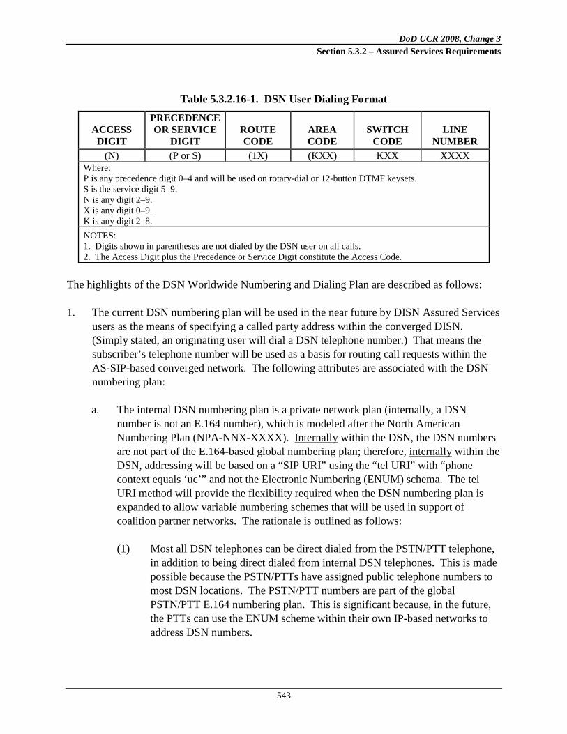
DoD UCR 2008, Change 3 Section 5.3.2 – Assured Services Requirements
543
Table 5.3.2.16-1. DSN User Dialing Format
ACCESS DIGIT
PRECEDENCE OR SERVICE
DIGIT ROUTE CODE
AREA CODE
SWITCH CODE
LINE NUMBER
(N) (P or S) (1X) (KXX) KXX XXXX Where: P is any precedence digit 0–4 and will be used on rotary-dial or 12-button DTMF keysets. S is the service digit 5–9. N is any digit 2–9. X is any digit 0–9. K is any digit 2–8. NOTES: 1. Digits shown in parentheses are not dialed by the DSN user on all calls. 2. The Access Digit plus the Precedence or Service Digit constitute the Access Code.
The highlights of the DSN Worldwide Numbering and Dialing Plan are described as follows: 1. The current DSN numbering plan will be used in the near future by DISN Assured Services
users as the means of specifying a called party address within the converged DISN. (Simply stated, an originating user will dial a DSN telephone number.) That means the subscriber’s telephone number will be used as a basis for routing call requests within the AS-SIP-based converged network. The following attributes are associated with the DSN numbering plan:
a. The internal DSN numbering plan is a private network plan (internally, a DSN number is not an E.164 number), which is modeled after the North American Numbering Plan (NPA-NNX-XXXX). Internally within the DSN, the DSN numbers are not part of the E.164-based global numbering plan; therefore, internally
within the DSN, addressing will be based on a “SIP URI” using the “tel URI” with “phone context equals ‘uc’” and not the Electronic Numbering (ENUM) schema. The tel URI method will provide the flexibility required when the DSN numbering plan is expanded to allow variable numbering schemes that will be used in support of coalition partner networks. The rationale is outlined as follows:
(1) Most all DSN telephones can be direct dialed from the PSTN/PTT telephone, in addition to being direct dialed from internal DSN telephones. This is made possible because the PSTN/PTTs have assigned public telephone numbers to most DSN locations. The PSTN/PTT numbers are part of the global PSTN/PTT E.164 numbering plan. This is significant because, in the future, the PTTs can use the ENUM scheme within their own IP-based networks to address DSN numbers.

DoD UCR 2008, Change 3 Section 5.3.2 – Assured Services Requirements
544
(2) The DSN telephone number is the fundamental and globally unique address element of both the TDM- based real-time DSN and the VoIP- (e.g., SIP) based real-time UC network.
Examples of internal DSN telephone numbers and their corresponding numbers, which are used when dialing through the PSTN, are illustrated in Table 5.3.2.16-2, Examples of Internal DSN Numbers and Their Corresponding Global E.164 PSTN Telephone Numbers.
Table 5.3.2.16-2. Examples of Internal DSN Numbers and Their Corresponding
Global E.164 PSTN Telephone Numbers
COUNTRY/ DSN LOCATION
CIVILIAN E.164 NUMBERS
DSN INTERNAL PRIVATE NUMBER
U.S./Scott AFB +(1) 618-229-xxxx (312) 779-xxxx U.S./Wheeler AAF +(1) 808-656-xxxx (315) 456-xxxx Germany/Patch Barracks +(49) 711-68639-xxxx (314) 430-xxxx Bahrain/TCCC +(973) 1785-xxxx (318) 439-xxxx Korea/Yongsan Main +(822) 7913-xxxx (315) 723-xxxx
2. Next, it is important to understand the relationship between basic SIP addressing,
subscriber identification, and the existing DSN addressing plan and how it will be used as part of the SIP signaling messages.
NOTE: The following examples use the SIP connotation.
a. The simplest form of a SIP signaling message is:
This is sgtbill’s sip identity
. (Note the absence of a telephone number.)
b. The sip identity
is a type of URI called a SIP URI (RFC 3261, Section 19.1, SIP and SIPS (Session Initiation Protocol Secure) Uniform Resource Indicators (URI)).
c. The SIP URI has a form similar to an e-mail address, typically containing a username and a host name. In the above example, patch.eur.uc.mil is the domain of sgtbill’s SIP service provider (e.g., the LSC at Patch Barracks in the European Theater UC network within the .mil top-level domain).
3. The addressing system needs to correlate sgtbill’s telephone number as part of the SIP URI
(sip:[email protected]). This can be accomplished by analyzing the SIP URI format outlined as follows (RFC 3261, Section 19.1, SIP and SIPS Uniform Resource Indicators):

DoD UCR 2008, Change 3 Section 5.3.2 – Assured Services Requirements
545
a. The SIP URI general form is as follows:
sip:user;password@host:port;uri-parameters?headers
(1) User: This is the identifier of a particular resource at the host being addressed.
The userinfo part of a URI consists of the following: User field, Password field, and the @ sign following them. NOTE: The RFC does not recommend using the Password field.
(2) The “Host” field represents the host (LSC) providing the SIP resources. The Host field contains an FQDN, an IPv4 address, or an IPv6 address. The RFC recommends using an FQDN for the Host field.
NOTE: Support for IETF FQDNs implies that UC also supports IETF DNS, which uses domain name servers and allows FQDNs to be resolved to IP addresses (and vice versa). The UC support for DNS is not a requirement in the UCR. Instead, UC support for DNS is conditional..
(3) Because we are addressing hosts that can process telephone numbers (e.g., an
LSC), we will use a “telephone-subscriber” field to populate the “user” field. [RFC 3966] This is accomplished by using the tel URI.
(a) The tel URI specifies the telephone number as an identifier. (b) The termination point of the tel URI telephone number is not
restricted. It can be in the public telephone network, a private telephone network, or the internet.
(c) It can be fixed or wireless and address a fixed-wired, mobile, or
nomadic terminal. (d) The terminal addressed can support any electronic communication
service, including voice, data, and fax. (e) The tel URI specifies the telephone number as an identifier, which can
be either globally unique, or only valid within a local context.
DoD UCR 2008, Change 3 Section 5.3.2 – Assured Services Requirements
546
In summary, the tel URI allows us to bring a DSN telephone number into the internal DSN SIP addressing schema.
4. RFC 3966 defines the extent to which a telephone number is valid within a private network (e.g., a “local” number), or as a number part of the global public telephone system (e.g., a “global” number).
a. The DSN, being a private line network (although geographically it is a global network), with an internal standard numbering plan recognized by all DSN voice service locations, allows the definition of the entire DSN numbering plan as “local” telephone numbers at all LSCs IAW RFC 3966.
b. Local telephone numbers must have a “phone context” parameter that identifies the
scope of their validity. Standard 10-digit DSN numbers are valid throughout the DSN and the UC network, and thus, the phone context parameter in the UC network becomes phone-context=uc.mil.
Therefore, an example of a SIP URI containing a 10-digit DSN number becomes:
sip:3144301123;phone-context=uc.mil
Finally, there are two ways for SIP signaling to search for the called subscriber.
sip:[email protected] becomes:
sip:3144301123;[email protected];user=phone 5. There are two ways of using the SIP URI to direct the network-wide search for the SIP end
point address, i.e., by NPA NNX or by a combination of a “username” (sgtbill) in conjunction with the FQDN assigned to an LSC (patch.eur.uc.mil). In the near future, call requests will be forwarded (routed) based on the telephone number contained within the SIP request. Therefore, in the near future the 10 digit DSN number within the SIP URI will be used to route calls to their destination. The “phone-context=uc.mil” required by the SIP syntax is included strictly to indicate that the phone number is part of the UC network. In the long term future, the UC network may be enhanced to route calls based on FQDN within the SIP URI in addition to routing on the DSN number.
Table 5.3.2.16-3, Mapping of DSN tel Numbers to SIP URIs, provides examples of DSN numbers using SIP URIs that use the syntax defined in RFC 3966 and referenced in RFC 3261, Section 19.1.6.

DoD UCR 2008, Change 3 Section 5.3.2 – Assured Services Requirements
547
Table 5.3.2.16-3. Mapping of DSN tel Numbers to SIP URIs
ALIAS TYPE SIP URI 7-digit intradomain (LSC enclave) call
sip:4305335;[email protected];user=phone
7-digit interdomain (LSC enclave) call within same area code
sip:4801235;[email protected];user=phone
10-digit interdomain (LSC enclave) call to another area code
sip:3157261135;[email protected];user=phone
[Required: LSC, MFSS] The CCA shall allow session requests from LSC, MFSS EIs, other appliances, and MFSS MGs to contain
• Called addresses including DSN numbers from the DSN numbering plan • Called addresses including E.164 numbers from the E.164 numbering plan
NOTE: The LSC and MFSS may require the use of a DSN escape code, such as “98” or “8,” as a prefix to a DSN number from the DSN numbering plan. NOTE: The LSC and MFSS may require the use of a PSTN escape code, such as “99” or “9,” as a prefix to an E.164 number from the E.164 numbering plan. [Required: LSC, MFSS] When a session request’s called address includes a DSN number from the DSN numbering plan, the CCA shall determine whether the called DSN number is local to the LSC or MFSS, or external to the LSC or MFSS. If the called DSN number is local to the LSC or MFSS, the CCA shall complete the session request within the LSC or MFSS. If the called DSN number is external to the LSC or MFSS, the CCA shall route the session request outside of the LSC or MFSS, using one of the following:
• The external IP address of the next appliance (i.e., LSC or MFSS) that should handle the session request, or
• The local IP address of the LSC or MFSS MG and MG trunk group that
should handle the session request. [Required: LSC, MFSS] When a session request’s called address includes an E.164 number from the E.164 numbering plan, the CCA shall determine whether the called E.164 number is local to the LSC or MFSS, or external to the LSC or MFSS.

DoD UCR 2008, Change 3 Section 5.3.2 – Assured Services Requirements
548
If the called E.164 number is local to the LSC or MFSS, the CCA shall complete the session request within the LSC or MFSS. If the called E.164 number is external to the LSC or MFSS, the CCA shall route the session request outside of the LSC or MFSS, using one of the following:
• The external IP address of the next signaling appliance that should handle the session request, or
• The local IP address of the LSC or MFSS MG and MG trunk group that
should handle the session request. Access Code [Required: LSC, MFSS] The access code shall include the access digit, followed by the precedence digit or the service digit. Access Digit [Required: LSC, MFSS] The access digit (e.g., 9) shall provide the indication to the LSC/MFSS that the following digits will indicate either UC call precedence, selected egress to the services of other systems or networks, or selected access to special UC features, such as individual trunk tests. Precedence Digit [Required: LSC, MFSS] The precedence digit (0, 1, 2, 3, or 4) shall permit a UC user to dial an authorized UC precedence level from properly classmarked 12-button telephone instruments. When the 7-digit intraLSC dialing option is used, it is not necessary to dial or key the precedence access digit for ROUTINE precedence calls. The assignment of precedence digits is shown in Table 5.3.2.16-4, Precedence and Service Access. Service Digits [Required: LSC, MFSS] The service digits, 5 through 9, shall provide information to the LSC/MFSS to connect calls to Government or public telephone services or networks that are not part of the UC. The UC LSC/MFSS will collect the access code and all routing and address digits before attempting to route a call to prevent numbering ambiguities between the access codes and the 2-digit abbreviated dial codes. The assignment of service access codes is shown in Table 5.3.2.16-4, Precedence and Service Access.
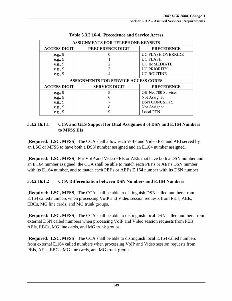
DoD UCR 2008, Change 3 Section 5.3.2 – Assured Services Requirements
549
Table 5.3.2.16-4. Precedence and Service Access
ASSIGNMENTS FOR TELEPHONE KEYSETS ACCESS DIGIT PRECEDENCE DIGIT PRECEDENCE
e.g., 9 e.g., 9 e.g., 9 e.g., 9 e.g., 9
0 1 2 3 4
UC FLASH OVERRIDE UC FLASH UC IMMEDIATE UC PRIORITY UC ROUTINE
ASSIGNMENTS FOR SERVICE ACCESS CODES ACCESS DIGIT SERVICE DIGIT PRECEDENCE
e.g., 9 e.g., 9 e.g., 9 e.g., 9 e.g., 9
5 6 7 8 9
Off-Net 700 Services Not Assigned DSN CONUS FTS Not Assigned Local PTN
5.3.2.16.1.1 CCA and GLS Support for Dual Assignment of DSN and E.164 Numbers to MFSS EIs
[Required: LSC, MFSS] The CCA shall allow each VoIP and Video PEI and AEI served by an LSC or MFSS to have both a DSN number assigned and an E.164 number assigned. [Required: LSC, MFSS] For VoIP and Video PEIs or AEIs that have both a DSN number and an E.164 number assigned, the CCA shall be able to match each PEI’s or AEI’s DSN number with its E.164 number, and to match each PEI’s or AEI’s E.164 number with its DSN number.
5.3.2.16.1.2 CCA Differentiation between DSN Numbers and E.164 Numbers
[Required: LSC, MFSS] The CCA shall be able to distinguish DSN called numbers from E.164 called numbers when processing VoIP and Video session requests from PEIs, AEIs, EBCs, MG line cards, and MG trunk groups. [Required: LSC, MFSS] The CCA shall be able to distinguish local DSN called numbers from external DSN called numbers when processing VoIP and Video session requests from PEIs, AEIs, EBCs, MG line cards, and MG trunk groups. [Required: LSC, MFSS] The CCA shall be able to distinguish local E.164 called numbers from external E.164 called numbers when processing VoIP and Video session requests from PEIs, AEIs, EBCs, MG line cards, and MG trunk groups.

DoD UCR 2008, Change 3 Section 5.3.2 – Assured Services Requirements
550
[Conditional: LSC, MFSS] On SIP and AS-SIP calls from PEIs or AEIs and the EBC, the CCA (and its LLS and GLS Servers) shall use the contents of the phone-context parameter in the called SIP URI to determine
• Whether the session request is intended for a DSN number or an E.164 number, and
• In the E.164 case, whether the E.164 number is locally significant, nationally
significant, or internationally significant. [Conditional: LSC, MFSS] On DoD CCS7 calls from an MG, the CCA shall use the contents of the Nature of Address Indicator and Numbering Plan fields in the ISUP Called Party Number parameter in the IAM to determine
• Whether the call request is intended for a DSN number or an E.164 number, and
• In the E.164 case, whether the E.164 number is locally significant, nationally
significant, or internationally significant. [Required: LSC, MFSS] On ISDN PRI calls from an MG, the CCA shall use the contents of the Type of Number and Numbering Plan Identification fields in the ISDN Called Party Number IE in the SETUP message to determine
• Whether the call request is intended for a DSN number or an E.164 number, and
• In the E.164 case, whether the E.164 number is locally significant, nationally
significant, or internationally significant. [Conditional: LSC, MFSS] On CAS trunk calls from an MG, the CCA shall use the identity of the trunk group that the call was received on (and the presence or absence of prefix digits in the received Called Party Number) to determine
• Whether the call request is intended for a DSN number or an E.164 number, and
• In the E.164 case, whether the E.164 number is locally significant, nationally
significant, or internationally significant.

DoD UCR 2008, Change 3 Section 5.3.2 – Assured Services Requirements
551
5.3.2.16.1.3 CCA Use of SIP “phone-context” to Differentiate between DSN and E.164 Numbers
[Conditional: LSC, MFSS] On SIP and AS-SIP calls from PEIs or AEIs and other appliances, the CCA shall use the contents of the “phone-context” parameter in the called SIP URI to distinguish DSN numbers from E.164 numbers as follows: 1. If the “phone-context” parameter in the “User” portion of the called SIP URI indicates
“uc.mil” (or a subordinate domain name built on “uc.mil”), then the CCA shall treat the 10-digit number that precedes the “phone-context” parameter as a DSN number.
2. If the “phone-context” parameter in the “User” portion of the called SIP URI indicates a sequence of digits, possibly prefixed with a “+” character, then the CCA shall treat the variable length number that precedes the “phone-context” parameter as an E.164 number.
[Conditional: LSC, MFSS] On SIP and AS-SIP calls from MFSS PEIs or AEIs and other appliances, the CCA shall use the contents of the “phone-context” parameter in the called SIP URI to distinguish local, national, and international E.164 numbers from one another as follows: 1. If there is no “phone-context” parameter in the “User” portion of the called SIP URI, then
the CCA shall treat the variable length number in the “User” portion of this URI as an international E.164 number.
2. If the “phone-context” parameter in the “User” portion of the called SIP URI contains a “+” character followed by an E.164 country code, but no area code or city code, then the CCA shall treat the variable length number that precedes the “phone-context” parameter as a national E.164 number (for the country identified by the country code).
3. If the “phone-context” parameter in the “User” portion of the called SIP URI contains a “+” character followed by an E.164 country code and
5.3.2.16.1.4 Use of SIP URI Domain Name with DSN Numbers and E.164 Numbers
an area code or city code, then the CCA shall treat the variable length number that precedes the “phone-context” parameter as a local E.164 number (for the country identified by the country code, and the area or city identified by the area code or city code).
The SIP URIs used for VVoIP calls contain both a username (with a numeric Called Party Number and an optional “phone-context” parameter) and a domain name, such as “patch.eur.uc.mil” or “ysm.pac.uc.mil.” Signaling appliances need some mechanism to accept, reject, or overwrite the domain name values received as part of Called SIP URIs in each VoIP and Video session request.

DoD UCR 2008, Change 3 Section 5.3.2 – Assured Services Requirements
552
NOTE: Support for IETF Domain Names implies that UC also supports IETF DNS, which uses domain name servers and allows Domain Names to be resolved to IP addresses (and vice versa). The UC support for DNS is not a requirement in UCR. Instead, UC support for DNS is conditional. [Conditional: LSC, MFSS] Each signaling appliance shall support a configurable per-appliance parameter that indicates how the appliance handles domain names received in VoIP and Video session requests. This parameter, named “Domain Name Treatment for Session Requests,” shall support the following values:
• Overwrite with Network Domain Name • Overwrite with Appliance FQDN • Passthrough
The default value shall be Overwrite with Network Domain Name. To meet this requirement, the appliance must support all three of these options, and must support the default parameter value of “Overwrite with Network Domain Name.” The appliance must allow the option selected to be software-configurable. [Conditional: LSC, MFSS] When the value of the Domain Name Treatment for Session Requests parameter for the signaling appliance is Overwrite with Network Domain Name, the appliance CCA shall discard all domain names received in called SIP URIs in session requests, and overwrite them with the Domain Name of the DoD network that the appliance belongs to. [Conditional: LSC, MFSS] The appliance shall support a per-appliance parameter called the “UC Network Domain Name,” to be used in overwriting the received domain names in this case. (Support for this additional parameter is not a requirement for UC Spiral 1.) The value of this parameter shall be a text string that identifies the Domain Name of the DoD network that the appliance belongs to, for domain name overwriting purposes. At a minimum, the following FQDNs for DoD networks (i.e., UC, Classified UC[CUC]) shall be supported: “uc.mil” and “cuc.mil.” [Conditional: LSC, MFSS] When the value of the Domain Name Treatment for Session Requests parameter for the appliance is Overwrite with Appliance FQDN, the appliance CCA shall discard all domain names received in called SIP URIs in session requests, and overwrite them with the FQDN of the appliance.

DoD UCR 2008, Change 3 Section 5.3.2 – Assured Services Requirements
553
[Conditional: LSC, MFSS] The appliance shall support a per-appliance parameter called the “Appliance FQDN,” to be used in overwriting the received domain names in this case. The value of this parameter shall be a text string that identifies the FQDN of the appliance, for domain name overwriting purposes. Examples of possible FQDNs for appliances (i.e., LSCs, MFSSs) are as follows:
• “lsc10.mfss20.patch.germany.eur.uc.mil” (i.e., LSC 10, subordinate to MFSS 20, located at the Patch Barracks in Germany in the European Theater on the UC network)
• “lsc20.lsc30.mfss40.ysm.korea.pac.uc.mil” (i.e., LSC 20, subordinate to LSC
30, subordinate to MFSS 40, located at Yongsan Main in South Korea in the Pacific Theater on the UC network)
• “mfss50.scott.cent.conus.uc.mil” (i.e., MFSS 50, located at Scott Air Force
Base in Central CONUS on the UC network) [Conditional: LSC, MFSS] When the value of the Domain Name Treatment for Session Requests parameter for the appliance is “Passthrough,” the appliance CCA shall transparently passthrough all domain names received in called SIP URIs in session requests, without altering them.
5.3.2.16.1.4.1 SIP URI Domain Names in UC Spiral 1
[Required: LSC, MFSS] The MFSS or LSC is only required to support one network FQDN for use with SIP URI domain names: “uc.mil” if that appliance is used for SBU traffic, and “cuc.mil” if that appliance is used for classified traffic. [Required: LSC, MFSS] The MFSS or LSC is required to ensure that all AS-SIP session requests entering or leaving that appliance use the network FQDN of that appliance (i.e., “uc.mil” for SBU traffic, or “cuc.mil” for Classified traffic) as the domain name in called SIP URIs. In cases where a received called SIP URI in a received AS-SIP message has a domain name other than “uc.mil” (for SBU traffic) or “cuc.mil” (for Classified traffic), the MFSS or LSC shall either 1. Reject the AS-SIP session request that contained the unexpected domain name, or
2. Accept the AS-SIP session request that contained the unexpected domain name, but overwrite the received domain name with “uc.mil” (for SBU traffic) or “cuc.mil” (for Classified traffic).

DoD UCR 2008, Change 3 Section 5.3.2 – Assured Services Requirements
554
Future versions of the UCR document will give additional detail on requirements for the support of SIP URI domain names that are different from “uc.mil” and “cuc.mil.”
5.3.2.16.1.5 Domain Directory
Before discussing directories and directory services, it is important to understand that within the IP telephony environment, directories and directory services are not required or used for processing and routing of telephone call requests. Rather, the term directory services refers to the capability of using an IP telephone or other voice and/or video end points for looking up user information directly to obtain a user’s telephone numbers (often referred to as “white pages” service). This eliminates the need for dialing an operator or using a hard-copy telephone book to obtain this information. Traditionally, the subscriber assignment information contained within telephone switching systems consisted of just the subscriber telephone number, line equipment assignment, and subscriber attributes classmarks. Typically, data elements, such as the subscriber name, physical address, e-mail address, or department code, were not part of the subscriber line assignment information. An internal table structure, rather than embedded databases, was used by the switching system to store this information. Most new IP-based VoIP systems have the capability to store subscriber name, physical address, e-mail address, and/or department code in addition to the basic traditional assignment information as part of the subscriber information. Rather than using a table structure, the new systems store this information as embedded databases, often referred to as “directories” as part of the LSC complex. An example of the embedded subscriber line database would be a Lightweight Directory Access Protocol (LDAP)-compliant format. This arrangement of a subscriber line database represents a more “open standard” than a current TDM system’s unique arrangement of using a table-based internal call processing structure. The discussion of LDAP-based subscriber line databases here applies to Fixed appliances only, and not to Deployable appliances. Requirements for subscriber line databases for Deployable appliances are candidates for a future version of this document. When the LSC uses an LDAP (or other open standard)-based structure to store subscriber line data, this data can be imported easily from, or exported to, other external LDAP-based structures. The LDAP-based directories are extensible and multiple entries of “telephony” data can be added in batch mode, or additional attributes can be added to an existing LDAP directory using LDAP Interchange Format (LDIF) files. Consequently, when installing a new VoIP system, a subset of the subscriber line information can be extracted from an existing corporate directory (if it contains subscriber telephone number information) and automatically loaded into a new VoIP system. This represents a labor saving over having to build a portion of the subscriber information database manually.

DoD UCR 2008, Change 3 Section 5.3.2 – Assured Services Requirements
555
Pure IP-based systems often have a built-in feature allowing importing and exporting of relevant telephone subscriber information between the VoIP system and an existing external “enterprise directory.” Telephony-related data usually is stored in a single branch of the enterprise directory (referred to as the IP Telephony Network Branch). This enterprise directory is often a corporate e-mail directory. To facilitate data transfer, both the VoIP system subscriber database and the external corporate directory conform to a common standard. Most VoIP systems provide instruments that can provide access to a “directory” function. These telephones have a display where alphanumeric information, such as telephone numbers and subscriber names, can be shown. A user can access the directory function via a dedicated button or soft keys. The VoIP system connects the telephone to the directory portion of the subscriber line database. Then the user can initiate a directory search from the telephone. This search is performed against subscriber data contained within the LSC where the telephone is registered. Additionally, VoIP systems have a feature allowing their instruments to access a Web browsing capability. Since a VoIP telephone is connected to a LAN to obtain voice services through the LSC, a VoIP telephone also may be allowed to access an external directory server. This opens up possibilities: If the external directory server is accessible from the LAN, the IP telephone user may be allowed to browse to the corporate directory and perform a search of that directory, as well as the LSC-contained directory. It is anticipated that long-range functionality should be provided so that the “telephone part” of the LSC directory can be imported to an external “corporate” (e-mail) directory. (NOTE: It is anticipated that the external DSN directory will be a branch of the UC directory under development by the Joint Enterprise Directory Services (JEDS) effort.) This function will require that the external directory is based on common standards, for example LDAP, and that the administrator in charge of the external directory extends the directory schema to add new object classes for storing the user telephony information. Likewise, the LSC must have stored the subscriber directory information previously in an LDAP-based system as outlined in item 1f. Under these conditions, an LDIF file can be used to facilitate the upload of multiple entries in batch mode, or add the telephony attributes to the existing external LDAP directory. The material here on exporting an LSC directory to an external “corporate” directory (and storing subscriber directory information in an LDAP-based format) applies to Fixed (Strategic) appliances only, and not to Tactical (Deployable) appliances. Requirements for LSC directory exports for Tactical (Deployable) appliances are candidates for a future version of this document. 1. [Required: LSC, MFSS] All voice and video systems, TDM or IP technology-based,
must contain subscriber assignment information, in the form of a domain directory. A domain directory shall support the following functions:

DoD UCR 2008, Change 3 Section 5.3.2 – Assured Services Requirements
556
a. Allow a user assigned to an LSC to look up the telephone numbers of other users assigned to (served by) that common LSC. This function is referred to as “white pages” services, and it should not be confused with call routing tables used for forwarding SIP call requests.
b. For security reasons, the Directory Look-Up function will only be available from a
user’s IP telephone instrument, not via the Internet. The IP telephone instrument will contain a small display and function keys that facilitate the Directory Look-Up function.
c. Access to the Directory Look-Up function shall be controlled by assigned attributes.
There may be specific reasons for denying this privilege to certain users. d. The LSC shall allow the system administrator to update the directory database in
response to service order activity (i.e., subscriber adds, moves, changes, or removals). The LSC shall update the white pages data automatically as well as subscriber line information contained as part of the Directory Look-Up function.
e. [Conditional: LSC, MFSS] When automatic instrument registration is supported, a
service order “flag” shall be sent to the system administrator terminal so the administrator can update the subscriber’s location information as necessary.
f. The data elements shown in Table 5.3.2.16-5, White Pages Directory Data Elements,
shall be incorporated as part of the white pages directory portion of the LSC subscriber database.
Table 5.3.2.16-5. White Pages Directory Data Elements
DATA ITEM EXAMPLE USER 10-DIGIT DSN TELEPHONE NUMBER 315-454-1192 USER ORGANIZATION CODE SCX ORGANIZATION NAME 1st Comm Squadron USER GEOGRAPHIC LOCATION Langley AFB USER NAME Civ Bill Smith
g. [Conditional: LSC, MFSS] In the near-term planning horizon, the local directory
contained within an LSC is not required to send updates automatically to a “global directory” database, but planning should allow for this in the future. If the vendors choose to implement an automatic update capability, then that capability shall be performed at a defined interval (e.g., weekly) using an automated electronic transfer of data. The transfer will be under the control of a system administrator responsible for the global directory.

DoD UCR 2008, Change 3 Section 5.3.2 – Assured Services Requirements
557
h. The user shall be offered the following ways of searching for local (domain) directory information:
(1) User access to the local domain directory is provided by a “directory” feature
available on the VoIP instrument. Directory search will be limited to information contained within the LSC subscriber information.
(2) The basic search shall be made based on Last Name, First Name.
(3) [Conditional: LSC, MFSS] The advanced search utility, if provided, shall
have a built-in Boolean logic to perform searches using OR with multiple entries in a single field AND across fields.
5.3.2.16.1.6 Global Directory Services
A global directory service should not be confused with the directory itself, which is the database that holds the information about objects that are to be managed by the directory service. The global directory service is the interface to the directory and provides access to the data that is contained in that directory. It acts as a central authority that can securely authenticate resources and manage identities and relationships between them. A directory service is highly optimized for reads and provides advanced search on the many different attributes that can be associated with objects in a directory. The data that is stored in the directory is defined by an extendable and modifiable schema. Directory services use a distributed model for storing their information, and that information is usually replicated between directory servers. [Conditional: MFSS] A global directory services system shall allow the following functions and interfaces: 1. Allow a DSN user to perform a DSN-wide telephone number look-up for a user assigned
anywhere on the DSN. This function is referred to as white pages services, and it should not be confused with call routing tables used for forwarding of SIP call requests.
2. For security reasons, the telephone directory look-up function will only be available from a user’s telephone instrument, not via the Internet.
3. Access to the Directory Look-Up function shall be controlled by subscriber classmarks. There may be specific reasons for denying this privilege to certain users.

DoD UCR 2008, Change 3 Section 5.3.2 – Assured Services Requirements
558
4. A global search capability will require multivendor Interoperability among LSCs. This will be made feasible by using standardized formats (e.g., LDAP based) for storing directory data within an LSC.
5. A global search capability should allow a user to search using the basic or advanced search methods outlined in Section 5.3.2.16.1.5, Domain Directory, item 9, as well as by specifying the “name” of an LSC (e.g., patch.eur.uc.mil). This capability will require that an LSC extend a directory search request through the signaling network.
6. In the near-term planning horizon, the local directory contained within an LSC will not be required to send updates automatically to a “global directory” database, but planning should allow for this in the future. Then the automatic update shall be performed at a defined interval (e.g., weekly) using an automated electronic transfer of data. The transfer will be under the control of a system administrator responsible for the global directory.
7. It is anticipated that long-range functionality should be provided so the “telephone part” of the local directory can be imported to an external local “corporate” e-mail directory. (NOTE: It is anticipated that the external DSN directory will be a branch of the UC directory under development by the NCES effort.) This function will require that the external directory is based on a common standard (e.g., LDAP), and that the administrator in charge of the external directory extends the directory schema to add new object classes for storing the user telephony information. Likewise, the LSC must store the subscriber directory information outlined previously under item 6 using a common standard (e.g., LDAP based). Under these conditions, an LDIF file can be used to facilitate the upload of multiple entries in batch mode, or add the telephony attributes to the existing external directory.
8. In the near-term planning horizon, the domain directories will not be required to send updates automatically to a global directory database, but planning should allow for this in the future. The automatic update shall be provided at a defined interval (e.g., weekly) using an automated electronic transfer of data.
9. The location and administration responsibilities and standard to be used for the global directory database and server have yet to be determined.
5.3.2.17 Management of Network Appliances
Figure 5.3.2.17-1, Network Appliance Management Model, is a logical view of a network appliance with an emphasis on its management functions. The internal implementations of the management functions are determined by the appliance supplier and may or may not align with Figure 5.3.2.17-1.

DoD UCR 2008, Change 3 Section 5.3.2 – Assured Services Requirements
559
This document makes no assumptions about the number of physical components that constitute a network appliance or of the spatial distribution of these components. All internal interactions are determined by the supplier and are out of the scope of this document.
Figure 5.3.2.17-1. Network Appliance Management Model
Figure 5.3.2.17-1, Network Appliance Management Model, is a functional model and does not require that the Network Appliance Management functions be internal to the appliance. However, the figure does imply that interfaces between the management functions and the appliance’s hardware and software elements are closed. In this section, the management requirements are frequently specified in terms of network appliances, or NEs. It is understood that these requirements refer to the management functions associated with the network appliance, or NE.
5.3.2.17.1 Voice and Video Network Management Domain
Management of DoD’s UC Voice and Video services requires each UC product have a minimum of two separate management domains. Typically, one domain will provide local, on-site craft person type support, typically referred to as OAM&P, while the other domain will provide a remote, centralized management capability, typically referred to as NM. There is no attempt to delineate the responsibilities between these two functions in this section. The essential point of this OAM&P/NM construct is that two separate domains must have simultaneous access to the
FCAPS &ManagementApplications
Date andTime
ManagementData
LocalAlarms
Media andSignals
ApplianceHardware
AndSoftware
Transport Interface Functions
Date and TimeFunctions
LEGENDFCAPS Fault, Configuration, Accounting, Performance, and Security
ManagementInformation Base
Transport Interface Functions

DoD UCR 2008, Change 3 Section 5.3.2 – Assured Services Requirements
560
UC products to effectively perform the DoD’s E2E UC Management function. Where necessary, for clarification, the remote NM system will be referred to as the VVoIP EMS and the local OAM&P system will be referred to as the Local EMS. See Figure 5.3.2.17-2, Relationship of UC Managements.
Figure 5.3.2.17-2. Relationship of UC Managements
5.3.2.17.2 General Management Requirements
This document assumes that all voice and video network switching appliances meet the following requirement. [Required: LSC, MFSS, WAN SS] LSCs and SSs must be capable of providing the following NM data to the E2E RTS EMS:
• Alarm/log data • Performance data (e.g., traffic data) • Accounting data (e.g., call detail recording)
[Required: LSC, MFSS, WAN SS] LSCs and SSs must allow the E2E RTS EMS to have access to perform LSC/SS datafill administration and network controls. [Required: LSC, MFSS, WAN SS] Except where otherwise specified (e.g., the SNMPv3 requirement below), Telcordia Technologies GR-740-CORE shall guide the interface between the network appliances (or components) and the external VVoIP EMS. [Required: LSC, MFSS, WAN SS] The preferred approach to managing the DoD VVoIP is using SNMP and MIBs. The two applicable IETF Standards are Standard 58 and 62. These two standards are composed of the following RFCs:
• [Conditional: LSC, MFSS, WAN SS] Standard 58, Structure of Management Information Version 2 (SMIv2)
− RFC 2578 − RFC 2579 − RFC 2580
RTS EMS
Local EMS
UC Systems
Remote
Connection
Local
Connection RTS EMS
Local EMS
UC Systems
Remote
Connection
Local
Connection VVoIP EMS
Local EMS
UC Systems
Remote
Connection
Local
Connection

DoD UCR 2008, Change 3 Section 5.3.2 – Assured Services Requirements
561
• [Required: LSC, MFSS, WAN SS] Standard 62, Simple Network
Management Protocol Version 3 (SNMPv3)
− RFC 3411 − RFC 3412 − RFC 3413 − RFC 3414 − RFC 3415 − RFC 3416 − RFC 3417 − RFC 3418
In addition to the two standards listed earlier, RFC 1213, still contains much of the Management Information Base II (MIB-II) definition. [Required: LSC, MFSS, WAN SS] There shall be a local craftsperson interface (Craft Input Terminal (CIT)) for OAM&P for all VVoIP network components. The CIT is a supplier-provided input/output device that is locally connected to a network component. The CIT may be connected to the Local EMS, which is in turn connected to the VVoIP component using the Local EMS Ethernet management interface. The CIT may be connected directly to the VVoIP network component also, using the Ethernet management interface on the component that would otherwise be used by the Local EMS (there is no Local EMS in this case). The CIT may be connected directly to the VVoIP network component using a separate serial interface. [Required: LSC, MFSS, WAN SS] Communications between VVoIP EMS and the VVoIP network appliances shall be via IP. Where an EMS is the interface with a VVoIP component, the TCP/IP-based communications between the VVoIP EMS and the Local EMS shall be via
• [Required: NM] Extensible Markup Language (XML) [Required: LSC, MFSS, WAN SS] A network appliance shall issue state change notifications for changes in the states of replaceable components, including changes in operational state or service status, and detection of new components. [Required: LSC, MFSS, WAN SS] A network appliance shall be provisioned by the VVoIP EMS with the address and Transport Layer port information associated with its Core Network interfaces.

DoD UCR 2008, Change 3 Section 5.3.2 – Assured Services Requirements
562
[Required: LSC, MFSS, WAN SS] A network appliance shall be capable of maintaining and responding to VVoIP EMS requests for resource inventory, configuration, and status information concerning Core Network interface resources (e.g., IP or MAC addresses) that have been installed and placed into service. [Required: LSC, MFSS, WAN SS] A network appliance shall be capable of setting the Administrative state and maintaining the Operational state of each Core Network interface, and maintaining the time of the last state change. [Required: LSC, MFSS, WAN SS] A network appliance shall generate an alarm condition upon the occurrence of any of the following failure conditions, as defined in ITU-T Recommendation M.3100:
• Power loss • Environmental condition not conductive to normal operation • Loss of data integrity
[Required: LSC, MFSS, WAN SS] A network appliance shall be capable of maintaining and responding to requests for physical resource capacity information for installed components. This information includes the following:
• Component type and model • Shelf location • Rack location • Bay location
5.3.2.17.3 Requirements for FCAPS Management
General requirements for the five management functional areas are defined in the following sections.
5.3.2.17.3.1 Fault Management
Fault Management supports the detection, isolation, and correction of abnormal operating conditions in a telecommunications network and its environment. Fault Management provides the functions to manage service problems, to support customer interactions associated with service troubles, and to support business policies related to service problems. Faults will be reported IAW IETF RFC 1215.
5.3.2.17.3.1.1 Alarm Messages
[Required: NM] Alarm messages must be distinguishable from administrative log messages.

DoD UCR 2008, Change 3 Section 5.3.2 – Assured Services Requirements
563
5.3.2.17.3.1.2 Self-Detection of Fault Conditions
[Required: NM] The NEs shall detect their own fault (alarm) conditions.
5.3.2.17.3.1.3 Alarm Notifications
[Required: NM] The NEs shall generate alarm notifications.
5.3.2.17.3.1.4 Near-Real-Time Alarm Messages
[Required: NM] The network elements shall send the alarm messages in NRT. More than 99.95 percent of alarms shall be detected and reported in NRT. Near Real Time is defined as event detection and alarm reporting within 5 seconds of the event, excluding transport time.
5.3.2.17.3.1.5 SNMP Version 3 Format Alarm Messages
The network components shall send alarm messages in: [Required: NM] SNMPv3 format This requirement does not apply to any legacy components of an MFSS or LSC. For the purpose of this requirement, “legacy” is defined as any TDM-based component that has been previously tested and listed on the APL.
5.3.2.17.3.2 Configuration Management
Configuration Management (CM) exercises control over, identifies, collects data from, and provides data to NEs and the connections between NEs. Configuration Management is responsible for the planning and installation of NEs and their interconnection into a network. Configuration Management includes the establishment of customer services that use the network, all services and product planning, and business policy level functions related to service establishment. [Conditional: VVoIP NEs] All CM information shall be presented IAW RFCs 1213 and 3418.
5.3.2.17.3.2.1 Read-Write Access to CM Data by the VVoIP EMS
[Required: NM] Capability to access and modify configuration data by the VVoIP EMS shall be controllable by using an access privileges function within the network appliance.

DoD UCR 2008, Change 3 Section 5.3.2 – Assured Services Requirements
564
5.3.2.17.3.3 Accounting Management
Accounting Management enables the network service usage to be measured and the costs for such use to be determined. It provides facilities to collect accounting records and to set billing parameters for the usage of services and for access to the network. It also includes functionality to exercise control over the proper flow of funds within the enterprise and between the enterprise and its owners and creditors. Detailed requirements for Accounting Management, including requirements related to call quality, are found in Section 5.3.2.19, Accounting Management.
5.3.2.17.3.4 Performance Management
Performance Management (PM) evaluates and reports the effectiveness with which the network and its NEs support assigned services. Performance Management provides mechanisms to measure service quality and provides the business policy functions for quality control. [Conditional: VVoIP NEs] All PM information shall be presented IAW RFCs 1213 and 3418.
5.3.2.17.3.4.1 Near-Real-Time Network Performance Monitoring
Near-real-time network performance monitoring is a subset of PM. The VVoIP EMS collects alarm messages in real time and selected performance data from the NEs on a NRT basis in 5- or 15-minute intervals. Network control personnel evaluate the alarm and performance data and, to minimize the effect on network traffic caused by a network anomaly, the control personnel implement traffic flow (NM) controls. The NEs must be capable of receiving and responding to NM controls from the VVoIP EMS. The next section defines requirements for traffic flow (NM) controls.
5.3.2.17.3.4.2 Remote Network Management Commands
[Required: VVoIP NEs] The VVoIP NEs shall be able to receive and respond to remote NM commands. The commands are described in the following sections.
5.3.2.17.3.4.2.1 Comparison of Controls for CS and IP-Based Environments
The IP-based voice solution shall be able to exercise protective and expansive NM controls. (NOTE: Some controls used in the CS environment are not applicable in the IP-based voice environment because of the fundamental differences in how the two network environments operate.) The set of applicable IP-based traffic control capabilities and actions are outlined in the following paragraphs. The following descriptions and Table 5.3.2.17-1, Control Function Crosswalk: TDM to VVoIP, indicate which IP control actions (singularly and in combination), across the IP-based Voice solution, are necessary to mitigate or resolve the underlying situation for which each TDM equivalent control exists.

DoD UCR 2008, Change 3 Section 5.3.2 – Assured Services Requirements
565
Table 5.3.2.17-1. Control Function Crosswalk: TDM to VVoIP
IP REAL TIME SERVICES CONTROL FUNCTIONS ROUTER
FUNCTION LSC FUNCTIONS Existing TDM Control
CE BW Allocation ASAC Budget EI Origination EI Destination
ACC X (bearer stream only)
X (bearer stream only)
X (from other LSCs/EIs – like Code Controls)
SILC X (bearer stream only)
X (bearer stream only)
Code Controls X Total Office Manual Control Removal
X X X X
Directionalization X Reroute N/A to VVoIP – Handled via MPLS Functionality in DISN Core Single via Reroute N/A to VVoIP – Handled via MPLS Functionality in DISN Core Multiple via Reroute N/A to VVoIP – Handled via MPLS Functionality in DISN Core Overflow vs. Immediate Reroute
N/A to VVoIP – Handled via MPLS Functionality in DISN Core
LEGEND ACC Automatic Congestion Controls ASAC Assured Service Admission Control ASLAN Assured Service Local Area
Network BW Bandwidth CANF Cancel From CANT Cancel To
CE Customer Edge Router DISN Defense Information Systems
Network EI End Instrument ESP Essential Service Protection IP Internet Protocol LSC Local Session Controller
MPLS Multiprotocol Label
Switching N/A Not Applicable VVoIP Voice and Video over IP SILC Selective Incoming Load
Control TDM Time Division Multiplexing
5.3.2.17.3.4.2.2 Automatic Congestion Controls
Within an IP network, the LSC handles only call signaling, while the IP network connecting the two communicating end instruments handles the bearer stream. The LSC congestion resulting from an overload of SIP requests must be detected and controlled. Bearer stream congestion will affect non-real-time as well as real-time bearer traffic, making it an IP NM concern. While good traffic engineering and the presence of an MPLS router core mitigates much of the traffic congestion within LAN and WAN environments, congestion at the boundaries between these domains is of concern and needs specific detection and control actions to mitigate the congestion. The LSC congestion occurs when the volume of AS-SIP messages exceeds the LSC’s capacity to process them. While a particular vendor’s LSC solution may threshold and alarm on congestion, a simpler approach may be monitoring the Central Processing Unit (CPU) utilization on the LSC host. Alarms generated from CPU utilization threshold violations could be the trigger events necessary for the VVoIP EMS to take the appropriate pre-emptive policy-based management

DoD UCR 2008, Change 3 Section 5.3.2 – Assured Services Requirements
566
action to execute PEI/AEI destination controls, limiting other LSCs and their PEIs/AEIs from sending SIP (or proprietary protocol) messages to the overloaded LSC. From the viewpoint of these other LSCs, in effect, a code control would be executed on them. Detection of network congestion at the edge of the LANs and WAN (DISN Core) resides with the performance management tools in place over those networks. These performance management tools must detect and report (via SNMP or syslog events) bandwidth utilization threshold violations in each of the CE Router, NIPRNet AR traffic queues. For the AR Routers, this must be by a southbound (CE connected) interface. From these events, each domain’s policy-based management system must take the appropriate (precoordinated) control actions to mitigate the congestion. Given no change in the physical resources (i.e., a larger bandwidth connection between the LAN and WAN), three basic actions can be taken to reduce congestion at the network edge: 1. Reallocate the queue bandwidth on the CE and PE Routers.
2. Change the call budget on the LSC, with a corresponding change in the VVoIP queue bandwidths on the CE and PE Routers.
3. Place a code control on other LSCs to reduce the load of SIP messages sent through the overloaded edge (although this would have minimal effect on reducing the bearer traffic, unless done in conjunction with a call budget and bandwidth change).
4. [Required: LSC, MFSS, WAN SS] When ASAC budgets are reduced, by NM action, below the current budget allocation, any previous sessions (regardless of precedence level) in excess of the new budget shall either
a. Be allowed to terminate naturally Or b. Be deterministically preempted starting with those of lowest precedence until the
number of sessions in progress equals the new budget allocation. This assumes that the CE Router queue bandwidths would not be reduced until the LSC session count fell below or equal to the newly commanded reduced budget, to prevent the corruption of existing sessions.
In summary, three control actions can help reduce congestion in the IP-based voice network: implementing EI destination controls, call budget changes, and router queue bandwidth allocations. Each control action is described in detail in the following paragraphs.

DoD UCR 2008, Change 3 Section 5.3.2 – Assured Services Requirements
567
5.3.2.17.3.4.2.3 Selective Incoming Load Controls
Like Automatic Congestion Controls (ACCs), Selective Incoming Load Controls (SILCs) are designed to protect the switches and their connecting circuits from overload (congestion) conditions when CCS7 is not available to signal the overload condition to the connected switches. Within the IP environment, the same two forms of congestion that apply to ACC are of concern: LSC processor congestion, and congestion across the LAN/WAN edge. The control solution that applies is similar to that of ACC. While under SILC, LSC signaling of its congestion state to other LSCs cannot occur. Since LSC congestion can be detected and reported without SIP being involved, the alarms generated from CPU utilization threshold violations could be the trigger events necessary for the VVoIP EMS to take the appropriate policy-based management action to execute call destination controls (i.e., limiting other LSCs and their PEIs/AEIs from sending SIP (or proprietary protocol) messages to the overloaded LSC). From the viewpoint of these other LSCs, in effect, a code control would be executed on them. This does not mitigate a mass dialing event on base, where the PEI- or AEI-generated SIP (or proprietary protocol) messages would fill the base LSC’s messaging queue, awaiting processing. This makes its handling effectively the same as under ACC. Congestion across the LAN/WAN edge is detected and handled the same way as under ACC.
5.3.2.17.3.4.2.4 Trunk Reservation
This section has been deleted.
5.3.2.17.3.4.2.5 Precedence Access Threshold
This section has been deleted.
5.3.2.17.3.4.2.6 Essential Service Protection
This section has been deleted.
5.3.2.17.3.4.2.7 Destination Code Controls
The TDM code controls are manual protective controls that restrict calls having code prefixes for destinations that have been temporarily designated as difficult or impossible to reach. [Required: LSC, MFSS, WAN SS] Within the IP environment, Destination Code Control functionality is applied at the LSC or MFSS to prevent or limit the number of calls (session

DoD UCR 2008, Change 3 Section 5.3.2 – Assured Services Requirements
568
requests) to reach a specific destination. Destination code controls are applied to reduce calls to a specific area or location that has been temporarily designated as “difficult to reach” due to several circumstances. Within the DISN, call completion “difficulties” may include fixed or deployable situations for which a commander may want to minimize traffic to a given destination or set of destinations, such as a theater of operations. Given this, Minimize (currently a behavioral control to reduce traffic to a particular destination or region) initiated by a commander’s order could be enforced using code controls, and set up to allow only FLASH and FLASH OVERRIDE traffic to be passed to the minimized destination. [Required] Destination Code Controls
• An entire Numbering Plan Area (NPA).
shall be implemented based on specifying:
• A group of specific NNX codes within an NPA. (The following is an example
of when this control becomes necessary: when a large military base having multiple NNX codes becomes isolated.)
• A single NNX.
• An NNX-D (hundred group within an NNX. Reason: There are locations
within CONUS that share an NNX.) [Required] The LSC, MFSS, and WAN SS shall have the capability of setting the percentage of calls to be blocked to the designated destination(s). [Required] FLASH and FLASH OVERRIDE calls shall not be affected by Destination Code Controls. [Required] The LSC, MFSS, and WAN SS shall play the "No Circuit Available" (NCA) announcement back towards the calling party on call attempts where the calling party is on the UC IP network, and DCC causes call blocking. [Required] The content of the NCA announcement shall be as follows: "Network service disruption has prevented the completion of your call. Please hang-up and try your call later. In case of emergency, please contact your Attendant or Operator." [Required] On LSC, MFSS, or WAN SS calls where the calling party is on the DISA TDM network, and the LSC, MFSS, or WAN SS MG is located in the session path between the IP called party and the TDM calling party, the MG shall return the Q.850 Cause Code Number 27,

DoD UCR 2008, Change 3 Section 5.3.2 – Assured Services Requirements
569
Destination out of order, in the DCC call rejection message sent towards the calling party on the T1.619A PRI between the MG and the DISA TDM network. This cause code indicates that the destination indicated by the calling user cannot be reached because the interface to the destination is not functioning correctly.
5.3.2.17.3.4.2.8 SKIP, Cancel To, Cancel From
This section has been deleted.
5.3.2.17.3.4.2.9 Total Office Manual Control Removal
The ability to remove all controls that were put in place is equally applicable to TDM- and IP-based voice systems.
5.3.2.17.3.4.2.10 Directionalization
Directionalization is intended to control the relative volume of call initiation from on base to off base, or vice versa (i.e., control the sourcing direction). [Conditional] Within IP, directionalization is controlled by designating all or part of the call budget as inbound (i.e., local destination) and/or outbound (i.e., local origination). The default is no designation (i.e., calls up to the total budget can be inbound or outbound in any combination). It does not change the total budget, only the sourcing direction of the budget; therefore, there is no impact to the router queue bandwidths.
5.3.2.17.3.4.2.11 Reroute (with All Subcontrols)
Within TDM, Reroute restricts offered calls from those routes known to be congested or failed, and provides substitute routes that have a higher probability of call completion. [Required: MPLS] Within IP, the routing of all traffic (i.e., VVoIP and non-VVoIP) is handled via MPLS in the DISN core. The MPLS automatically finds the most effective route for the traffic.
5.3.2.17.3.4.2.12 IP Queue Control Capabilities
An important control unique to the IP-based environment is queue bandwidth allocations. The following requirements are for queue management: 1. Setting the queue bandwidth allocations on the CE Router and its connected port on the
Aggregation Router involves setting the amount (or percentage) of bandwidth allocated to

DoD UCR 2008, Change 3 Section 5.3.2 – Assured Services Requirements
570
each of the (currently) four queues on the CE Router and connected PE Router. Two bandwidth allocation actions/functions can be performed as follows:
a. [Required: CE Router, AR] Setting the bandwidth allocations by router queue, and b. [Required: CE Router, AR] Setting the drop probabilities within each queue if the
router supports this functionality.
5.3.2.17.3.4.2.13 Call Budget Control
Setting the Call Budgets on the MFSS, WAN SS, and LSC involves setting the maximum number of calls (voice and video) that may be in service at one time within, and/or to/from a local service area (i.e., military installation). Two call budget actions or functions can be performed: Setting the total call budget, and designating all or part of the call budget as inbound (local destination) and/or outbound (i.e., local origination) (to be able to implement an IP equivalent of directionalization). The default for the directionalization is no designation (i.e., calls can be inbound or outbound in any combination). [Required: MFSS, WANS SS] The above defined call budget actions for the MFSS and WAN SS will be applied to the WAN-level ASAC. The WAN-level ASAC must be able to account for each SLSC under its control. Therefore, the MFSS and WAN SS ASAC must be able to set call budgets for multiple LSC locations via the VVoIP EMS and local EMS access points. The MFSS and WAN SS shall be able to set call budgets for a SLSC while there are active calls to/from that LSC. The MFSS, WAN SS and LSC shall be able to swap between directionalization and no directionalization on an AS-SIP trunk group while there are active calls on the trunk group. [Required: LSC] The above defined call budget actions for the LSC will be applied to the LSC-level ASAC. The LSC-level ASAC is required to only account for itself. Therefore, the LSC ASAC must be able to set call budgets for only the PEI/AEIs under its control via the VVoIP EMS and local EMS access points. The LSC shall be able to set call budgets while there are active calls to/from the LSC. The MFSS and WAN SS WAN-level ASAC and the LSC-level ASAC session budgets and counts area as follows:
• VoIP Session Budgets
− IPB
. The total budget of VoIP sessions plus session attempts in the session setup phase that are allowed on the IP access link.

DoD UCR 2008, Change 3 Section 5.3.2 – Assured Services Requirements
571
− [Conditional] IPBo
. The budget for outbound VoIP sessions plus session attempts in the session setup phase that are allowed on the IP access link.
− [Conditional] IPBi
. The budget for inbound VoIP sessions plus session attempts in the session setup phase that are allowed on the IP access link.
• TDM Session Budget
− TDMB
. The overall number of TDM sessions plus sessions in the session setup phase on the TDM link. This equals the number of DS0s on the trunk between the LSC MG and the EO/SMEO/PBX1/PBX2.
• VSU Budgets
− VDB
. The total number of inbound and outbound VSUs plus the in-progress VSUs connection attempts that an LSC is allowed to have over the IP access link.
− [Conditional] VDBi
. The total number of inbound VSUs plus the in-progress inbound VSUs connection attempts that an LSC is allowed to have over the IP access link.
− [Conditional] VDBo
5.3.2.17.3.4.2.14 PEI/AEI Origination Capability Control
. The total number of outbound VSUs plus the in-progress outbound VSUs connection attempts that an LSC is allowed to have over the IP access link.
Setting the PEI and AEI origination capability involves setting the parameters for the precedence and destinations of a call that may be originated from a PEI or AEI.
[Required: LSC] The product shall have the capability of setting a PEI/AEI’s maximum allowed precedence level for originating a call. This is a “subscriber class mark feature,” which is controlled by the LSC system administrator. [Required: LSC] The product shall have the capability of controlling the destination(s) that a PEI or AEI is restricted from calling. This is a subscriber class mark feature that is controlled by the LSC system administrator. This action or function can be performed by: 1. [Required] Setting the destinations to which calls are to be blocked by:

DoD UCR 2008, Change 3 Section 5.3.2 – Assured Services Requirements
572
a. [Required] NPA/NNX b. [Conditional] Blocked by a specific 7-digit directory number (NPA-NNX Dxxx)
Table 5.3.2.17-1, Control Function Crosswalk: TDM to IP VVoIP, summarizes the traffic flow controls that will be implemented in the IP environment along with the equivalent TDM-based controls.
5.3.2.17.3.5 Security Management
Security management provides for prevention and detection of improper use or disruption of network resources and services, for the containment of and recovery from theft of services or other breaches of security, and for security administration. The VVoIP EMS is required to use the security services of access control, confidentiality, integrity, availability, and non-repudiation as specified in Section 5.4, Information Assurance Requirements. [Required] All management interactions shall meet the Information Assurance requirements in Section 5.4, Information Assurance Requirements.
5.3.2.17.4 Data Classification
This section has been deleted.
5.3.2.17.5 Management of Appliance Software
This section has been deleted.
5.3.2.18 Network Management Requirements of Appliance Functions
5.3.2.18.1 NM Requirements for CE Routers and EBCs
The NM requirements for the various functions of the CE Router and EBC are contained in this section. [Required: CE Router, EBC] Faults will be reported IAW RFCs 1215 and 3418. [Required: CE Router, EBC] Standard CM information shall be presented IAW RFCs 1213 and 3418. [Required: CE Router, EBC] Standard PM information shall be presented IAW RFCs 1213 and 3418.

DoD UCR 2008, Change 3 Section 5.3.2 – Assured Services Requirements
573
[Conditional: CE Router, EBC] Nonstandard (vendor-specific) CM and PM information shall be presented as private vendor MIBs, as defined by the applicable RFCs. [Required: NM] SNMPv3 format. [Required: CE Router] The CE Router QOS queues must be readable and settable by the VVoIP EMS.
5.3.2.18.2 Management Requirements for the ASAC
The MFSS, WAN SS, and LSC-ASAC must permit the reading of the following counts from the VVoIP EMS:
• VoIP Session Counts
− IPC
. The total number of interbase IP sessions in progress plus the number of session attempts in the session setup phase.
− [Conditional] IPCo
. The number of outbound IP sessions in progress plus the number of outbound session attempts in the session setup phase.
− [Conditional] IPCi
. The number of inbound IP sessions in progress plus the number of inbound session attempts in the session setup phase.
• TDM Session Counts
− TDMC
. The total number of sessions in progress between the TDM switch and the MG plus the total number of session attempts in the session setup phase.
• VSU Counts
− VBC
. The total number of interbase VSU sessions in progress plus the number of session attempts in the session setup phase.
− [Conditional] VBCo
. The number of outbound VSU sessions in progress plus the number of outbound session attempts in the session setup phase.

DoD UCR 2008, Change 3 Section 5.3.2 – Assured Services Requirements
574
− [Conditional] VBCi
. The number of inbound VSU sessions in progress plus the number of inbound session attempts in the session setup phase.
[Required] The ASAC must provide the separate counts for voice and video, in 5-minute intervals. The MFSS and WAN SS ASAC must provide these counts for each of the SLSCs under its control, while the LSC is only to provide these counts for the PEIs/AEIs that it controls.
5.3.2.18.3 Management Requirements of the CCA Function
This section has been deleted.
5.3.2.18.4 Management Requirements of the SG Function
This section has been deleted.
5.3.2.18.5 Management Requirements of the MG Function
This section has been deleted.
5.3.2.19 Accounting Management
This section provides the minimum set of requirements to capture the basic call information for accounting purposes. Additional information on this call accounting is contained in Telcordia Technologies GR-3058-CORE. Accounting management identifies a set of events during which call detail information is collected. These events are call connect, call attempt, and call disconnect. When these events are detected, specific call data will be provided by the network appliances that were involved in the event. Each appliance has a certain function within the network, therefore will be in the natural position to have knowledge of particular call data. The collections of this call information from all appliances will provide the data necessary to formulate a billing record. The requirements provided in this section allow for the functional elements to be individual components within the network, or be packaged together in an integrated system solution. In either case, each component will have a certain role in the call and be privy to specific call data that is needed to construct a billing record. This section assumes that the Media Server function, the UFS function, and the Directory function together provide the necessary information and services needed for billing and jointly provide the functional equivalent to a Service Agent (SA). An SA is defined as follows:

DoD UCR 2008, Change 3 Section 5.3.2 – Assured Services Requirements
575
• The SA supports the execution of service logic both for transactions that occur completely within the IP network, and for those that require signaling to CCS7 SEPs (e.g., SG, SCP) that are external to the IP network. The SA may be part of the network appliance that provides CCA functionality, or it may be deployed in a separate appliance that communicates with the CCA.
It is assumed that an LSC, MFSS, and WAN SS each has its own means of gathering call information (e.g., originating party, terminating party, time of call, date of call, call answered, call unanswered) and process the information into a call record. This function is equivalent to that of a Billing Agent (BA). A BA is defined as follows:
• A BA supports much of the billing functionality needed in the VoIP network. It collects the necessary call data from the CCAs and other network appliances, and processes them for use by downstream billing systems.
This section assumes that the VVoIP EMS will provide the same functionality as that of the BA. Therefore, throughout the remainder of this document, reference to the BA should be viewed as the functional equivalent that resides within the VVoIP EMS. The communications between the functional entities (e.g., CCA, MGC) and the BA will be internal to the appliance, and all the necessary accounting data is assumed to be made readily available to the BA. However, there may be network appliances that are externally linked to the SSs (e.g., an external MG connecting into the MGC of the LSC). Depending on the purpose of these network appliances, they may be in the best position to obtain specific accounting data on calls that involve the use of this external network appliance. Therefore, this data should be provided to the BA (whether this information is passed to the BA directly, or passed to the CCA or MGC, which then passes it to the BA). The following section lists the requirements for accounting data that should be provided by the functional entities to the BA. The Section 5.3.2.19.2, Processing of Data Sets, applies to external network appliances (e.g., MG) that need to provide accounting data to the BA. As mentioned before, functional entities within a network appliance are assumed to have their own means of sharing accounting data; however, the requirements in the following section can be used to ensure that the specific data is made available to the BA (within the internal communications and sharing) so that the proper accounting can be accomplished.
5.3.2.19.1 Accounting Data
[Conditional] A network appliance shall support the data sets described in this section for supplying accounting information to the necessary functional entity that will generate call detail recordings.

DoD UCR 2008, Change 3 Section 5.3.2 – Assured Services Requirements
576
The call data captured for calls that are detected by the CCA and other functional entities are the individual pieces of data that, when logically assembled by the BA, provide the details required to account for the use of a service. Some of this call data is captured based on call events, usually determined from the content of received signaling messages. Other call data is determined from local information maintained at the CCA. Whenever the CCA or other functional entities generate call data, the CCA or other functions would package the call data into what is known as a DS, which is then transmitted to the BA. A Data Set is another name for a Protocol Data Unit (PDU), which is specified in Telcordia Technologies GR-3058-CORE. NOTE: The term Data Set (or PDU) is used in the generic sense to describe a unit of related information, and is not meant to imply the use of any specific protocol for the communications between the functional entities and the BA. The actual protocol for communications between the functional entities and the BA is considered to be a vendor decision. The functional entities generate the data sets based on an event. The following three events generate the data sets:
• Call Connect • Call Disconnect • Call Attempt (e.g., call was attempted, but unsuccessful)
The following lists the three data sets:
• Call Connect Data Set
. Used for call data that represents a call connection event.
• Call Disconnect Data Set
. Used for call data that represents a call disconnection event.
• Call Attempt Data Set
. Used for call data that represents a call attempt event.
A successful voice call would have two events (each of which would result in data sets): the Call Connection event and the Call Disconnection event. For unsuccessful voice calls, the call event would result in the generation of the Call Attempt Data Set(s). This can also apply to a Video session. For example, when a user wants to open a Video session, a connection attempt will need to be made to the application that will provide the video.
Either a Call Connection Data Set (if the video connection is made) or a Call Attempt Data Set (if the video connection is attempted, but is not successfully connected) would be generated. If a

DoD UCR 2008, Change 3 Section 5.3.2 – Assured Services Requirements
577
video connection is made and the video is played, a Call Disconnect Data Set will be generated once the video connection is over. The following subsections provide the formatting and field definitions for the Call Connect Data Set (the Call Attempt Data Set has the same format as the Call Connect Data Set) and the Call Disconnect Data Set. The formatting is provided in Table 5.3.2.19-1, Call Connect Data Set Information, with the following column headings:
Table 5.3.2.19-1. Call Connect Data Set Information
USAGE DATA ELEMENT D
EPE
ND
R
EQ
’D/
OPT
ION
AL
FIX
ED
/ V
AR
IAB
LE REFERENCE
SECTION IN GR-3058-
CORE POPULATION
SUMMARY PRI SEC Call Event Type R
F 3.3.6 1 = Call Completion 3 = Call Attempt
CCA MG MGC
Correlation ID R F 3.3.6.2 UUID = 128 bits (Variable depending on implementation) Unique value for each call composed of: 1. Network Component Network Appliance ID 2. Timestamp 3. Random Number
CCA MG MGC
Element Identifier
R F 3.3.6 Range of 000001 through 999999
CCA MG MGC
Directional Indicator
R F 3.3.6.4 1 = Egress (originating) 2 = Ingress (terminating) 3 = Transiting (MGC) 4 = Intra-gateway (AGW)
CCA MG MGC
Study/Test Indicator
R F 3.3.7.1 Default = zeros (or null-value) CCA MG MGC
Timing Guard R F 3.3.7.1 0 = no timing irregularities detected 2 = timing irregularities detected
CCA MG MGC
Customer Connect Date Customer Connect Time
R F 3.3.7.2 MMDDYYYY - Month, Day, and Full Year HHMMSSms – Hours, Minutes, Seconds, and milliseconds (depending on implementation).
MG CCA MGC
Incoming Destination Number
R V 3.3.8.7 For services other than toll-free – destination routing address (if NANP based, this is pre-NP query – NOT the LRN)
MG CCA MGC

DoD UCR 2008, Change 3 Section 5.3.2 – Assured Services Requirements
578
USAGE DATA ELEMENT D
EPE
ND
R
EQ
’D/
OPT
ION
AL
FIX
ED
/ V
AR
IAB
LE REFERENCE
SECTION IN GR-3058-
CORE POPULATION
SUMMARY PRI SEC For toll-free – NANP routing number (pre-NP query – NOT the LRN) returned from toll-free query
Destination Address [IN and AIN queries only]
R V 3.3.9.1 For toll-free – NANP routing number (pre-LNP query – NOT the LRN) returned from toll-free query
CCA SA MGC
Calling Station ID
R V 3.3.7.6 Used for CPN MG CCA MGC
Called Station ID up to 15 digits
R V 3.3.7.7 3.3.10.4
Egress calls Ingress calls dealing with NP
MG CCA MGC
Overseas Indicator
R F 3.3.7.7 0 = North America World Zone 1 1 = International (01 or 011 prefix dialed)
MG CCA MGC
Operator Involvement
R F 3.3.7.7 0 = No Involvement 1 = 0+ or 0- dialed
MG CCA MGC
Dialing Indicator R F 3.3.7.7 0 = No CAC 1 = 10XXXX dialed
MG CCA
Dialed Carrier Identification Code
R F 3.3.7.7 Carrier Identification Code (if dialed) Default = zeros (or null-value)
MG CCA MGC
Presubscription Indicator
R F 3.3.7.7 0 = No presubscription on line 1 = PIC present
MG CCA
PIC - Presubscribed Carrier Identification Code
R F 3.3.7.7 Carrier Identification Code when PIC = 1 Default = zeros (or null-value)
MG CCA MGC
ANI (Charge Number)
R F 3.3.7.9 ANI for Originating Call ChN received for transiting and terminating calls
MG MGC
Service Provider Identification – Switching System ID
R V 3.3.7.10 Operating Company Number of CCA owner
MG CCA MGC
Service Provider Information – Account Owner
R V 3.3.7.10 Operating Company Number of the Calling Station’s Service Provider
MG CCA MGC

DoD UCR 2008, Change 3 Section 5.3.2 – Assured Services Requirements
579
USAGE DATA ELEMENT D
EPE
ND
R
EQ
’D/
OPT
ION
AL
FIX
ED
/ V
AR
IAB
LE REFERENCE
SECTION IN GR-3058-
CORE POPULATION
SUMMARY PRI SEC Service Feature R F 3.3.7.11 Reference Table 12 of
GR-1100-CORE for a representative list of service features that could be provisioned on a line at the AG. A few notable features of importance are: 7 Call Forwarding 8 Call Hold 9 Call Transfer 10 Call Waiting 11 Conference Call
MG CCA MGC
Calling Station Porting Status
R F 3.3.10.1 0 = Not Ported 1 = Ported 2 = Not on AG
MG CCA MGC
Called Number Porting Status
R F 3.3.10.1 0= Not Ported 1 = Ported 2 = Not on AG
MG SA
Incoming Calling Party Number
R V 3.3.7.9 CPN parameter in CCS7 or functional equivalent
MGC CCA MGC
Facility Allocation Date Facility Allocation Time
R F 3.3.7.3 MMDDYYYY – Month, Day, and Full Year HHMMSSms – Hours, Minutes, Seconds, and milliseconds (depending on implementation)
MGC CCA
Service Type R F 3.3.7.5 1 = No CS-PSTN Interface 2 = Interface to CS-PSTN (via MGC)
MGC CCA
Called Party Offhook
R F 3.3.7.8 0 = Called Party Offhook detected 1 = Called Party Offhook not detected
MGC CCA
Egress Trunk Group Number
R F 3.3.8.1 Provisioned TG number at MGC (TG)
MGC CCA
Egress Trunk Group Designation
R F 3.3.8.1 See Table 3-3 in GR-3058-CORE
MGC CCA
Egress Signaling Protocol
R F 3.3.8.4 See Table 3-4 in GR-3058-CORE
MGC CCA
Egress Interfacing Network ID
R V 3.3.8.2 Operating Company Number assigned to the interfacing Network Provider
MGC CCA

DoD UCR 2008, Change 3 Section 5.3.2 – Assured Services Requirements
580
USAGE DATA ELEMENT D
EPE
ND
R
EQ
’D/
OPT
ION
AL
FIX
ED
/ V
AR
IAB
LE REFERENCE
SECTION IN GR-3058-
CORE POPULATION
SUMMARY PRI SEC Egress Trunk Group Billing Number
R F 3.3.8.2 Billing Number assigned to the facility
MGC CCA
Egress QoS Statistics
R F 3.3.8.5 Variable – See Table 3-5 in GR-3058-CORE
MGC CCA
Ingress Trunk Group Number
R F 3.3.8.1 Provisioned TG number at MGC (TG)
MGC CCA
Ingress Trunk Group Designation
R F 3.3.8.1 See Table 3-3 in GR-3058-CORE
MGC CCA
Ingress Signaling Protocol
R F 3.3.8.4 See Table 3-4 in GR-3058-CORE
MGC CCA
Ingress Interfacing Network Id
R V 3.3.8.2 Operating Company Number assigned to the interfacing Network Provider
MGC CCA
Ingress Trunk Group Billing Number
R V 3.3.8.2 Billing Number assigned to the facility
MGC CCA
Ingress QoS Statistics
R V 3.3.8.5 Variable – See Table 3-5 in GR-3058-CORE
MGC CCA
Release Cause R V 3.3.8.6 Variable – See Table 3-6 in GR-3058-CORE for examples
MGC CCA
Jurisdiction Designation of MGC
R F 3.3.8.3 NPA-NXX representative of the Jurisdiction of the MGC
MGC CCA
CCA-LRN R F 3.3.10.2 When Directional Indicator = 1, then LRN of the originating CCA-MGC-AG combination When Directional Indicator = 2 or = 3, then zeros
MGC CCA
Incoming JIP R F 3.3.10.3 When Directional Indicator = 2 or = 3, then the digits contained in the JIP parameter (CCS7) or equivalent
MGC CCA
Toll-Free Query Indicator
R F 3.3.9.1 141 = Handoff to IC 142 = LEC Transport
SA CCA
Toll-Free CIC R F 3.3.9.1 Toll-Free Transport provider
SA CCA
LRN – DB R F 3.3.10.2 3.3.10.3 3.3.10.4
Ported = LRN of destination switch Non-Ported – Called Number
SA CCA

DoD UCR 2008, Change 3 Section 5.3.2 – Assured Services Requirements
581
USAGE DATA ELEMENT D
EPE
ND
R
EQ
’D/
OPT
ION
AL
FIX
ED
/ V
AR
IAB
LE REFERENCE
SECTION IN GR-3058-
CORE POPULATION
SUMMARY PRI SEC LNP Query Status
R F 3.3.10.2 3.3.10.3 3.3.10.4
See Table 3-7 in GR-3058-CORE
SA CCA
Originating Customer/ Business Group Identification
R F 7.1.1.1 10-Digit Originating Customer/Business Group Identification number
MG CCA MGC
Terminating Customer/ Business Group Identification
R F 7.1.1.2 10-Digit Terminating Customer/Business Group Identification number
MG CCA MGC
CCA IPv4 Address
R F 3.3.7.10 IPv4 address assigned to the CCA
CCA CCA
CCA IPv6 Address
R F 3.3.7.10 IPv6 address assigned to the CCA
CCA CCA
Bearer Capability/Call Type
R V 3.3.7.12 Bearer call type and bearer capabilities delivered to the user
MG CCA MGC
Network Interworking
R V 3.3.7.12 Identifies the different interworking situations encountered by the user’s call
MGC
CCA
Signaling or Supplementary Service Capabilities Usage
R V 3.3.7.12 Records the use of signaling or supplementary service capabilities on a yes/no or other outcome basis, and it is designed to record one, all, or any combination of these capabilities in a single record.
MGC
CCA
Call Characteristic
R F 7.1.1.3 1 = Voice 2 = Video
MG CCA MGC
Bandwidth Reservation
R V 7.1.1.4 Used to indicate the rate (in kbps/sec) that is reserved for this session (e.g., a voice call or a Video session may have a fixed amount of bandwidth).
MGC CCA AGW
Service Level Priority
R F 3.3.7.14 Value used to indicate the service level of the call
MGC CCA AGW
1. The first column identifies the call data.
2. The second column identifies whether this data is conditionally required (C) or optional (O) for the DISN.

DoD UCR 2008, Change 3 Section 5.3.2 – Assured Services Requirements
582
3. The third column specifies the call data as either fixed (F) or variable (V) in length.
4. The fourth column identifies the section in Telcordia Technologies GR-3058-CORE that provides more information on the fields.
5. The fifth column provides a summary of how the field is populated.
6. The sixth column reflects what is currently believed to be the most appropriate network component for each data element. “PRI” indicates the NC network appliance that is considered the “primary” source for the data element.
7. The seventh column reflects what is currently believed to be the “secondary” source or source of the data for that particular element. It is labeled as “SEC.”
The fifth column, Population Summary, does not necessarily preclude the vendor from using the CCA as the sole source of the data elements and have all other functional elements provide data to the CCA for population in the PDUs sent to the BA. The data elements in the PDU need to arrive at the BA to generate an accurate, timely, and verifiable CDR. The choice of the particular method to get the data elements to the BA is left to the vendor. NOTE: For a field that has been designated as conditionally required, the field should be populated with the appropriate data if that data is available and applicable to the call. For example, if a call originates from the PSTN and terminates into the VoIP network, the MGC would be used in completing this call. This means that information (e.g., the Ingress Trunk Group number) would be available. Since the Data Set field for the Ingress Trunk Group number is required, that field should be populated with the trunk group number.
5.3.2.19.1.1 Call Connect Data Set
Table 5.3.2.19-1, Call Connect Data Set Information, provides the formatting and fields for the Call Connect Data Set. [Conditional] For every call attempt, call completion, and transiting call detected by the CCA, the CCA and any other functional entities (if applicable) shall provide information to properly populate the Call Connect Data Set following the rules outlined in Table 5.3.2.19-1, Call Connect Data Set Information.
5.3.2.19.1.2 Originating Customer/Business Group Identification
The Originating Customer/Business Group identification identifier is a 10-digit value that identifies the Customer or Business Group associated with a service. This ID is usually provided

DoD UCR 2008, Change 3 Section 5.3.2 – Assured Services Requirements
583
through some service application or some database. If this is available, it will be populated in the Originating Customer/Business Group Identification field.
[Conditional] If an Originating Customer/Business Group Identification number is available, it will be populated in the Originating Customer/Business Group Identification field.
5.3.2.19.1.3 Terminating Customer/Business Group Identification
The Terminating Customer/Business Group Identification identifier is a 10-digit value that identifies the customer or business group associated with a service. This ID is usually provided through some service application or some database. If this is available, it will be populated in the Terminating Customer/Business Group Identification field.
[Conditional] If a Terminating Customer/Business Group Identification number is available, it will be populated in the Terminating Customer/Business Group Identification field.
5.3.2.19.1.4 Call Characteristic
The Call Characteristic identifies how a particular call is set up. For example, the Call Characteristic will identify whether the call is a voice call or a video call.
[Conditional] The Call Characteristic field will be populated with a value of one (1) to indicate that this particular data set represents a Voice call.
[Conditional] The Call Characteristic field will be populated with a value of two (2) to indicate that this particular data set represents a Video session.
5.3.2.19.1.5 Bandwidth Reservation
On VoIP voice calls or calls that use video calls, there is a need to record the bandwidth that is allocated for the type of service call. This information can be used for maintenance or for projections on future usage and growth. This field bandwidth is measured in units of kbps.
[Conditional] The Bandwidth Reservation field will be populated with the amount of bandwidth reserved in kbps.
5.3.2.19.1.6 Call Disconnect Data Set
Table 5.3.2.19-2, Call Disconnect Data Set, provides the formatting and fields for the Call Disconnect Data Set.

DoD UCR 2008, Change 3 Section 5.3.2 – Assured Services Requirements
584
Table 5.3.2.19-2. Call Disconnect Data Set
USAGE DATA ELEMENT
REQUIRED/ OPTIONAL
FIXED/ VARIABLE
REFERENCE SECTION IN
GR-3058-CORE
POPULATION SUMMARY PRI SEC
Call Event Type R F 3.3.6.1 1 = Call Completion 2 = Call Disconnect 3 = Call Attempt
CCA MG MGC
Correlation ID R F 3.3.6.2 UUID = 128 bits (Variable depending on implementation) Unique value for each call composed of: 1. Network Component Network Appliance Id 2. Timestamp 3. Random Number
CCA MG MGC
Element Identifier
R F 3.3.6.3 Range of 000001 through 999999
CCA MG MGC
Directional Indicator
R F 3.3.6.4 1 = Egress (originating) 2 = Ingress (terminating) 3 = Transiting (MGC) 4 = Intra-gateway (AGW)
CCA MG MGC
Service Type R F 3.3.7.5 1 = No CS-PSTN Interface 2 = Interface to CS-PSTN (via MGC)
CCA MG MGC
Timing Guard R F 3.3.7.1 0 = no timing irregularities detected 2 = timing irregularities detected
CCA MG
Disconnect Detection Date Disconnect Detection Time
R F 3.3.7.4 MMDDYYYY – Month, Day, and Full Year HHMMSSms – Hours, Minutes, Seconds, and Milliseconds (depending on implementation).
CCA MG MGC
Release Cause R V 3.3.8.6 Variable – See Table 3-6 for examples
CCA MG MGC
[Conditional] For every call disconnect detected by the CCA, the CCA and any other network appliances (if applicable) shall provide information to properly populate the Call Connect Data Set following the rules outlined in Table 5.3.2.19-2, Call Disconnect Data Set.
5.3.2.19.1.7 Billing Agent
The functions of the BA are to provide processing, formatting, storage, and outputting of usage records for delivery to downstream processing systems. In the VoIP product design, it may be so

DoD UCR 2008, Change 3 Section 5.3.2 – Assured Services Requirements
585
the functional entities (e.g., CCA, MGC) of a network appliance are responsible for generating the call data and transmitting this data to the BA in the form of a data set or through the network appliance’s internal means of communication and data sharing (assuming all these functional entities are internally connected). It is then up to the BA to gather all the accounting data and process it to determine the proper recording format.
The BA may be a separate entity within a network; or, it may be internally connected to the other functional entities within a network appliance. In either case, the BA should be able to process, format, store, and output generated usage records based on either the data sets or the accounting data that it will receive. If the network uses data sets as defined in Section 5.3.2.19.1, Accounting Data, the Dependent Requirements in Section 5.3.2.19.2.1, Call Data, and the requirements in the rest of Section 5.3.2.19.2.2, Record Format, shall apply. Otherwise, only the requirements in Section 5.3.2.19.2.2, Record Format, shall apply.
5.3.2.19.2 Processing of Data Sets
To process data sets, the BA must have the capability to match and correlate multiple data sets (generated from multiple functional entities) that are associated with the same call. In addition, a Call Connect Data Set will often have a corresponding Call Disconnect Data Set that will be delivered at one point or another. The BA must be able to correlate these sets of records together. The ability to correlate all these data sets is made possible by the use of the Correlation ID. Telcordia Technologies GR-3058-CORE has additional information about the format and use of the Correlation ID.
As the BA processes the data sets, it assembles the call data from the various data sets, formats it into an appropriate record, and stores it in the appropriate format. Processing of assembled call data for a particular call is activated immediately upon receipt of the Call Disconnect Data Set for that call. The following requirements are taken from Telcordia Technologies GR-3058-CORE, and they pertain to the processing and assembling of the call data:
1. [Conditional] The BA shall activate usage assembly within 250 ms of receiving a disconnect Data Set from the network component network appliances.
2. [Conditional] The BA shall correlate all usage measurements related to a single VoIP call to produce the appropriate usage record(s).
5.3.2.19.2.1 Call Data
Regardless of the recording format that is chosen, there is information that is important for proper billing and accounting. Also, there is information that may be necessary for one type of call, but may not be necessary for another type of call. The following requirement lists the call data that are needed in the recording. (Of course, there are other call data that are also desired

DoD UCR 2008, Change 3 Section 5.3.2 – Assured Services Requirements
586
and should be captured in the record; however, the data items listed in the following requirement are the call data that must be provided.):
[Required] For the selected recording format that is chosen, of all the call information that will be provided, the following call data shall be provided in the record data:
1. Host Name of the CCA controlling the call processing.
2. Start Date of call (In Julian or Calendar).
3. Start Time of Call (Hour + Minute + Second).
4. Elapsed Time of Call and/or Stop Time of call.
5. Calling Number.
6. Called Number (included all dialed digits).
7. [Conditional] Call Answered/Unanswered Indicator.
8. Precedence level of call. (NOTE: This may be accomplished either by a specific precedence level designation field in the call, or by providing the dialed precedence level access digits in the called number field.)
9. [Conditional] Indication of either a VoIP or Video over IP “call.”
10. [Conditional] Indication of the assigned bandwidth for the entire duration of the Video over IP “call.”
[Required] For the selected recording format that is chosen, of all the call information that will be provided, the following call data shall be provided in the record data if it applies to the call:
1. [Required] Conference Call Indicator.
2. [Conditional] Customer/Business Group Identification.
The Conference Call Indicator is used to identify callers that are participants in a conference call. This will be useful for tracking purposes, or if there is special billing associated for conference calls.
For Customer/Business Group identification, the originating party (or even the terminating party) may be part of a customer or business group. Special billing or charges may apply to a member
DoD UCR 2008, Change 3 Section 5.3.2 – Assured Services Requirements
587
of a particular group; thus, for calls where the originating party and/or terminating party is assigned a Customer/Business Group Identification, the Customer/Business Group Identification information should be provided in the CDR as per the previous requirement.
The following subsections describe the types of VoIP calls (e.g., PSTN to IP, IP to PSTN), and provide additional call information that should be captured in the CDR.
5.3.2.19.2.1.1 Quality of Service
For VoIP calls, compression of voice traffic is used to conserve bandwidth. However, compression at one end and decompression at the other end usually results in a degradation of voice quality. Since stronger compression usually results in further degradation of voice quality, service providers need to find a balance between the two. To determine if the voice quality is sufficient to warrant the level of compression, there needs to be some means by which the quality of the call can be measured.
The “product” in the following requirements is the combination of the LSC, MFSS, or WAN SS, and the set of PEIs and AEIs that it serves.
1. [Required: LSC, MFSS, WAN SS, PEI, AEI] The product shall provide a voice quality record at the completion of each voice session. The voice quality record shall be included in the CDR that the LSC, MFSS, or WAN SS generates for that session, and shall conform to the E-Model, as described in TIA TSB-116-A and ITU-T Recommendation G.107. The voice quality record shall contain the calculated R-Factor for the voice session per TIA TSB-116-A. The allowable error for the voice quality calculations shall be ±3 IAW TIA TSB-116-A.
NOTE: This requirement is only related to VoIP EIs and is not applicable to MGs.
2. [Required: LSC, MFSS, WAN SS, PEI, AEI] As part of the voice quality record, the product shall provide the raw voice session statistics that are used to make the R-Factor calculation to include, as a minimum, the latency, packet loss, Equipment Impairment Factor (Ie), and the Weighted Terminal Coupling Loss (TCLw). (Definitions of latency and packet loss are found in Appendix A, Definitions, Abbreviations and Acronyms, and References, and the methods of calculation are described in Section 5.3.3, Network Infrastructure End-to-End Performance Requirements.)
3. [Required: LSC, MFSS, WAN SS, PEI, AEI] As part of the voice quality record, the product shall provide the jitter for the session. (See Appendix A, Definitions, Abbreviations and Acronyms, and References, for the definition of jitter. The method of calculation is described in Section 5.3.3, Network Infrastructure End-to-End Performance Requirements.)
DoD UCR 2008, Change 3 Section 5.3.2 – Assured Services Requirements
588
4. [Required: LSC, MFSS, WAN SS, AEI] For AEIs, the voice quality record shall be transmitted at the completion of a session to the CCA, in an AS-SIP BYE message if the AEI ends the call, or an AS-SIP 200 (OK) response to a BYE message if the LSC ends the call.
5. [Conditional: LSC, MFSS, WAN SS, AEI] In either case, the EI shall use one of the following SIP Quality of Service Statistics (QoS Stats) headers to convey the loss, latency, and jitter information in the AS-SIP BYE message or the AS-SIP 200 (OK) response.
• X-RTP-Stat
• P-RTP-Stat
(These QoS Stats headers do not currently include the Ie or TCLw values.) The LSC CCA shall also be able to interpret these SIP QoS Stats headers upon receipt of them from the AEI in the BYE message or the 200 OK response. The CCA shall also be able to extract the relevant voice quality record from these SIP QoS Stats headers, and write this record into the Call Detail Record for that call.
For example, at the end of an EI voice session, the EI can generate an initial voice quality record that contains the latency, packet loss, Ie, TCLw, and jitter values, but not the R-Factor. The EI can use the voice media packets that it sent and received over the duration of the voice session to compute these values. The EI can send this initial voice quality record to its LSC, MFSS, or WAN SS as part of the EI signaling that ends the voice session.
The LSC, MFSS, or WAN SS can use this initial voice quality record to calculate the R-Factor for the session. The LSC, MFSS, or WAN SS can generate a final voice quality record containing the latency, packet loss, Ie, TCLw, and jitter values received from the EI, and the R-Factor that it calculated. Then the LSC, MFSS, or WAN SS can generate a CDR for the session that contains the final voice quality record.
This example shows how the EI and LSC, MFSS, or WAN SS can jointly generate the voice quality record and the CDR, and meet the previous product requirements.
1. [Required: LSC, MFSS, WAN SS, PEI, AEI] The Ie, is associated with the EI’s Codec (e.g. G.711) and the operating rate (e.g., 64 kbps), as documented in Table 1 of TIA TSB-116A and Table I.1 of ITU-T Recommendation G.113. The Ie value can either be stored in the EI and signaled to the LSC (when the EI CDR is sent to the LSC), or stored in the LSC and added to the LSC CDR (after the EI CDR is received from the EI). In the latter case, the LSC shall maintain a manually populated Table of Codec, Operating Rate, and Ie values consistent with Table 1 in TIA TSB-116A and Table I.1 of ITU-T Recommendation G.113.

DoD UCR 2008, Change 3 Section 5.3.2 – Assured Services Requirements
589
2. [Required: LSC, MFSS, WAN SS, PEI, AEI] The TCLw, is associated with the EI
itself. Like the Ie value, the TCLw value can either be stored in the EI and signaled to the LSC (when the EI CDR is sent to the LSC), or stored in the LSC and added to the LSC CDR (after the EI CDR is received from the EI). In the latter case, the LSC shall maintain a manually populated Table of EI types and corresponding TCLw values. The TCLw for IP phone EIs should be greater than or equal to 52 decibels (dB) IAW TIA TSB-116A.
3. [Required: LSC, MFSS, WAN SS, PEI, AEI] The LSC CDR record for each call shall contain the Ie value for the codec and the operating rate, the TCLw value for the EI, and the R-Factor for that call or session.
4. [Required: LSC, MFSS, WAN SS] The product shall generate an alarm to the VVoIP EMS when the session R-Factor calculation in the CDR fails to meet a configurable threshold. By default, the threshold shall be an R-Factor value of 80, which is equivalent to an MOS value of 4.0.
5.3.2.19.2.1.2 VoIP to PSTN
The VoIP to PSTN calls refer to calls routed to the PSTN from a VoIP network. An example of this is a call that originates in the VoIP network and uses the PSTN to complete the call. Another example could be a call that originates from another network (be it a PSTN or another VoIP network), enters this VoIP network, and transits out to the PSTN.
For the transiting case, there may be two CDRs generated. One CDR would represent the incoming call into the VoIP network, and the other CDR would represent the outgoing call to the PSTN. For information on what call data to capture for the incoming portion of the call, please refer to Section 5.3.2.19.2.1.3, PSTN to VoIP, for incoming calls from the PSTN, and Section 5.3.2.19.2.1.4, VoIP to VoIP, for calls incoming from a VoIP network.
When a call originates in the VoIP network and continues into the PSTN for completion, there is certain information related to the PSTN that should be captured in the CDR, which is generated in the VoIP network. The following requirement indicates the specific call information:
1. [Required] In addition to the call data specified previously, the following call data must be provided in the record data for calls that are routed to the PSTN from the VoIP network:
a. IP address of originating subscriber (if the call originated from the subscriber on the VoIP network)
b. IP address of the gateway connecting to the PSTN

DoD UCR 2008, Change 3 Section 5.3.2 – Assured Services Requirements
590
c. Outgoing trunk group of the call d. Outgoing trunk group member of the call
In the PSTN environment, calls are routed from one network to another via a trunk. A trunk group is a group of trunks and is normally identified by a specific number. Similarly, a member of a trunk group is identified by another specific number. Identification of these trunk groups and trunk group members may be important for billing purposes (depending on the tariffs agreed upon between the VoIP service providers and the PSTN service providers), as well as for troubleshooting purposes.
5.3.2.19.2.1.3 PSTN to VoIP
PSTN to VoIP refers to the type of call where the call that originates in the PSTN network enters the VoIP network for completion. An example of this would be a call that originates from the PSTN network and terminates to a subscriber in the VoIP network. Another example would be a call from the PSTN that enters the VoIP network, but transits to another VoIP network or back out to the PSTN. For these cases, there may be two separate CDRs. One CDR would represent the incoming call into the VoIP network, and another CDR would represent the call outgoing to the PSTN or to another VoIP network.
This section addresses the incoming part of the call to the VoIP network. For the call data related to the outgoing part of the call, refer to Section 5.3.2.19.2.1.2, VoIP to PSTN, for calls to the PSTN, and to Section 5.3.2.19.2.1.4, VoIP to VoIP, for calls to another VoIP network.
As was the case for VoIP to PSTN scenario calls, there is certain information related to the PSTN that should be captured in the CDR that is generated in the VoIP network. The following requirement indicates the specific call information: 1. [Required] In addition to the call data specified above, the following call data must be
provided in the record data for calls that are routed from the PSTN to the VoIP network:
a. IP address of terminating subscriber (if the call terminates to a subscriber on the VoIP network).
b. IP address of the gateway connecting to the PSTN. c. Incoming trunk group of the call. d. Incoming trunk group member of the call.

DoD UCR 2008, Change 3 Section 5.3.2 – Assured Services Requirements
591
In the PSTN environment, calls are routed from one network to another network via a trunk. A trunk group is a group of trunks and is identified by a specific number. Similarly, a member of a trunk group is identified by a specific number. Identification of these trunk groups and trunk group members may be important for billing purposes (depending on the tariffs agreed upon between the VoIP service providers and the PSTN service providers) as well as for troubleshooting purposes.
5.3.2.19.2.1.4 VoIP to VoIP
A VoIP to VoIP call can be one of the following three basic scenarios: 1. Subscriber in this VoIP network originates a call to another VoIP network.
2. Subscriber in this VoIP network originates a call and terminates in the same VoIP network.
3. Call from another VoIP network that terminates a call to a subscriber that belongs in this VoIP network.
The first scenario could result in a CDR that captures originating type information. The second scenario could result in a CDR that captures terminating type information. Finally, the third scenario could result in two separate CDRs (i.e., one for originating, and another for terminating), or one CDR that captures both the originating and terminating information. The next requirement identifies the call information that should be captured in the CDR that is generated for the originating call. 1. [Required] In addition to the call data specified previously, the following call data must
be provided in the record data for calls that originate from the VoIP network and terminate to another VoIP network:
a. IP address of originating subscriber b. IP address of the gateway connecting to the other VoIP network (if applicable)
The following requirement identifies the call information that should be captured in the CDR that is generated for incoming calls from another VoIP network: 1. [Required] In addition to the call data specified previously, the following call data must
be provided in the record data for calls that originate in one VoIP network, and terminate in another VoIP network:
a. IP address of terminating subscriber b. IP address of the gateway connecting to the other VoIP network (if applicable)

DoD UCR 2008, Change 3 Section 5.3.2 – Assured Services Requirements
592
For the third scenario, if there are two separate CDRs generated, one CDR would represent the originating part of the call, and the other CDR would represent the terminating part of the call. In this case, the originating CDR would contain the same call information as required previously for calls that originate in the VoIP network. The terminating CDR would contain the same call information as defined previously for calls that terminate in the VoIP network. However, if the third scenario resulted in one CDR to capture both the originating and terminating information of the call, then the following requirement identifies the call information that should be captured in that singular CDR: 1. [Required] In addition to the call data specified previously, the following call data must
be provided in the CDR (that captures both the originating and terminating information) for calls that originate from the VoIP network and terminate within the same VoIP network:
a. IP address of originating subscriber b. IP address of terminating subscriber
5.3.2.19.2.2 Record Format
The actual format of the CDRs that the BA will create (either based on the call data acquired from the processing and assembly of the data sets, or through internal call data sharing between functional entities) will be the format that is agreed upon between the DoD Network and the vendors of the BA. If the agreed upon format is Bellcore Automatic Message Accounting (AMA) Format (BAF), then the requirements in Telcordia Technologies GR-3058-CORE on the use of BAF will apply. For further information on the use of BAF, please refer to GR-3058-CORE, Section 4.3. The following subsections provide some of the basic formatting found in GR-3058-CORE. [Conditional] If BAF is chosen as the Call Detail Recording format, the BAF requirements in GR-3058-CORE shall apply, with the noted exception in the following subsections.
5.3.2.19.2.2.1 BAF Structure 0625
Originating and terminating calls (whether they are voice or video) that originate in another service provider’s network or terminate in another service provider’s network, or calls that use the PSTN, would result in a Structure Code 0625. Structure Code 0625 is used to capture the call information for
• Calls that originate from the VoIP network and terminate in the PSTN, • Calls that originate from the PSTN and terminate in the VoIP network, and • Calls that both originate and terminate within the VoIP network.

DoD UCR 2008, Change 3 Section 5.3.2 – Assured Services Requirements
593
Table 5.3.2.19-3, BAF Structure 0625 and Field Populations, shows the format of Structure Code 0625 and the requirements on the field population. Further details on field population can be found in Telcordia Technologies GR-3058-CORE.
Table 5.3.2.19-3. BAF Structure 0625 and Field Populations
FIELDS OF THE STRUCTURE
REFERENCE SECTION IN
GR-3058-CORE BAF
TABLE POPULATION SUMMARY Record Descriptor Word
4.3.3.1 000 Populate as described in GR-1100-CORE
Hexadecimal Identifier
4.3.3.2 00 Populate as described in GR-1100-CORE
Structure Code 4.3.3.3 0 00625 if no Module Codes are appended to this Structure 40625 if Module Codes are appended to this Structure
Call Type 4.3.6 4.3.7 4.3.8 4.3.9 4.3.15
1 Use the following: 110 = Originating Access Service 119 = Terminating Access Service 589 = Originating Connecting Network Access Service 720 = Terminating Connecting Network Access Service 060 = Basic Long Distance Service - Ingress 529 = VoIP Unidentified Call
Sensor Type 4.3.3.4 2 Sensor Type value associated with the network appliance
Sensor Identification
4.3.3.5 3 Populate Character 1 as described in GR-1100-CORE. Populate Characters 2-7 with the value of the Element Identifier in the Element Identifier usage element of the network component that is identified in the Sensor Type.
Recording Office Type
4.3.3.6 4 Value assigned for the specific network appliance that contains the BA functionality that generated this record.
Recording Office Identification
4.3.3.7 5 Populate Character 1 as described in GR-1100-CORE. Populate Characters 2-7 with the value of the Recording Office ID.

DoD UCR 2008, Change 3 Section 5.3.2 – Assured Services Requirements
594
FIELDS OF THE STRUCTURE
REFERENCE SECTION IN
GR-3058-CORE BAF
TABLE POPULATION SUMMARY Connect Date 4.3.3.8 6 Populate Character 1 with the least
significant digit of the year represented in the date the connection is made by the customer. Populate Characters 2-3 with the month represented in the date the connection is made by the customer. Populate Characters 4-5 with the day represented in the date the connection is made by the customer.
Timing Indicator 4.3.3.9 7 If timing irregularities have been detected, the BA shall populate Timing Indicator (Table 7) to indicate that a Timing Guard condition exists.
Study Indicator 4.3.3.10 8 Populate Characters 1 through 4 with the value of the Study/Test Indicator usage element. Populate Character 5 with 0. Populate Character 6 as follows: — with 0, if complete originating and terminating numbers were received — with 1, if an all-zero originating number and a non-all-zero terminating number were received — with 3, if an all-zero terminating number and a non-all-zero originating number were received — with 4, if an all-zero originating number and an all-zero terminating number were received — with 5, if a terminating number with an all-zero station number and an originating number with a non-all-zero station number were received — with 6, if an originating number with an all-zero station number and a terminating number with a non-all-zero station number were received — with 7, if a terminating number with an all-zero station number and an originating number with an all-zero station number were received. Populate Character 7 with 0.

DoD UCR 2008, Change 3 Section 5.3.2 – Assured Services Requirements
595
FIELDS OF THE STRUCTURE
REFERENCE SECTION IN
GR-3058-CORE BAF
TABLE POPULATION SUMMARY Called Party Off-Hook Indicator
4.3.3.11 9 Populate Called Party Off-Hook (Answer) Indicator (Table 9) with 0, if call was completed, and 1, if call was not completed.
Service Observed/Traffic Sampled
4.3.3.12 10 Populate Service-Observed/Traffic-Sampled Indicator (Table 10) with the “default” value per GR-1100-CORE.
Operator Action 4.3.3.13 11 Populate Operator Action (Table 11) to indicate no operator involvement per GR-1100-CORE.
Service Feature 4.3.3.14 12 Populate Service Feature Code (Table 12) with the value in Table 12 of GR-1100-CORE that maps to the service that applies to the call (e.g., 012 for Call Forwarding, 056 = Call Waiting, 605 = Call Hold, 160 = Call Transfer, etc.)
Originating NPA 4.3.3.15 4.3.9
13 Populate Originating NPA (Table 13) as follows: — NPA of the ANI (Charge Number) if non-zero; otherwise, use the NPA of the Calling Station Id. This is when the ANI (or the CPN if ANI is not available) is 10 or less digits. — Per fill procedures described in GR-1100-CORE if the ANI (or CPN if ANI is not available) is 11 digits or higher. See the section related to Ingress Trunk Group Billing Number in GR-3058-CORE when using the Ingress Trunk Group Billing Number usage element.
Originating Number
4.3.3.16 4.3.9
14 Populate Originating Number (Table 14) as follows: — NXX-XXXX of the ANI if non-zero; otherwise, use the CPN (this is when ANI (or CPN if ANI is not available) is 10 digits or less]. — Per fill procedures described in GR-1100-CORE if the ANI (or CPN if ANI is not available) is 11 digits or higher. See the section related to Ingress Trunk Group number in GR-3058-CORE when using the Ingress Trunk Group

DoD UCR 2008, Change 3 Section 5.3.2 – Assured Services Requirements
596
FIELDS OF THE STRUCTURE
REFERENCE SECTION IN
GR-3058-CORE BAF
TABLE POPULATION SUMMARY Overseas (International Call) Indicator
4.3.3.17 15 Populate Overseas Indicator (Table 15) with the value: 0 = North America World Zone 1. 1 = International (01 or 011 prefix dialed).
Terminating NPA 4.3.3.18 16 Populate Terminating NPA (Table 16) as follows: — If the value is 12 digits or less, the Called Station Id as per GR-1100-CORE — per fill, procedures described in GR-1100-CORE if the Called Station Id is 13 digits or more.
Terminating Number
4.3.3.19 17 Populate Terminating Number (Table 17) as follows: — If the value is 12 digits or less, the Called Station Id as per GR-1100-CORE. — Per fill procedures described in GR-1100-CORE if the Called Station Id is 13 digits or more.
Connect Time 4.3.3.20 18 Populate Characters 1-2 with the hour represented in the rounded value of the Customer Connect Time or Circuit Seizure Time usage element. Populate Characters 3-4 with the minute represented in the rounded value of the Customer Connect Time or Circuit Seizure Time usage element. Populate Characters 5-6 with the second represented in the rounded value of the Customer Connect Time or Circuit Seizure Time usage element. Populate Character 7 with the tenth-of-second represented in the rounded value of the Customer Connect Time or Circuit Seizure Time usage element.
Elapsed Time 4.3.3.21 19 Populate Character 1 with 0. Populate Characters 2-6 with the number of minutes of the rounded value of the customer-elapsed time of the call. Populate Characters 7-8 with the number of seconds of the rounded value of the customer-elapsed time of the call. Populate Character 9 with the number of tenths-of-seconds of the rounded value of the customer-elapsed time of the call.

DoD UCR 2008, Change 3 Section 5.3.2 – Assured Services Requirements
597
FIELDS OF THE STRUCTURE
REFERENCE SECTION IN
GR-3058-CORE BAF
TABLE POPULATION SUMMARY IC/INC Prefix 4.3.6.1 57 Populate Characters 1-4 with the value
of the CIC that was used in the call. If there is no CIC available, then the fill procedure in GR-1100-CORE shall be implemented. Populate Character 5 with the value of: 0 if operator was involved 1 if operator was not involved.
Carrier Connect Date
4.3.6.2 6 Populate Character 1 with the least significant digit of the year represented in the date the call attempt is made by the customer. Populate Characters 2-3 with the month represented in the date the call attempt is made by the customer. Populate Characters 4-5 with the day represented in the date the call attempt is made by the customer.
Carrier Connect Time
4.3.6.3 18 Populate Characters 1-2 with the hour represented in the rounded value of the call attempt time or Circuit Seizure Time usage element. Populate Characters 3-4 with the minute represented in the rounded value of the call attempt time or Circuit Seizure Time usage element. Populate Characters 5-6 with the second represented in the rounded value of the call attempt time or Circuit Seizure Time usage element. Populate Character 7 with the tenth-of-second represented in the rounded value of the call attempt time or Circuit Seizure Time usage element.
Carrier Elapsed Time
4.3.6.4 19 Populate Character 1 with 0. Populate Characters 2-6 with the number of minutes of the rounded value of the carrier-elapsed time of the call. Populate Characters 7-8 with the number of seconds of the rounded value of the carrier-elapsed time of the call. Populate Character 9 with the number of tenths-of-seconds of the rounded value of the carrier-elapsed time of the call.

DoD UCR 2008, Change 3 Section 5.3.2 – Assured Services Requirements
598
FIELDS OF THE STRUCTURE
REFERENCE SECTION IN
GR-3058-CORE BAF
TABLE POPULATION SUMMARY IC/INC Call Event Status
4.3.6.5 58 Populate as follows: — If the call has been completed, the BA shall populate BAF Table 58 with the value = 010. — If the call has been attempted, but not completed, the BA shall populate BAF Table 58 with the value = 007.
Trunk Group Number
4.3.6.6 83 Populate Character 1 with the value = 9 to indicate Signaling type not specified. Populate Characters 2-5 with the value of the Trunk Group Number. If there is no Trunk Group Number available, this table should use the BAF fill procedure (e.g., Hex-F).
Routing Indicator 4.3.6.7 59 If the call involved the PSTN, this table shall be populated with the value - 0 = if the call was direct to the PSTN - 1 = if the call was Tandem. Otherwise, the BAF fill procedure should be used for this table (e.g., Hex-F).
Dialing and Presubscription Indicator
4.3.6.8 85 Used to indicate whether the calling party dialed a Carrier Access Code. The BA shall populate Table 85 with the values that best match the dialing pattern as per GR-1100-CORE.
ANI/CPN Indicator
4.3.6.9 60 Populate as per - 0 = Neither ANI nor CPN was provided in the signaling. - 1 = Only ANI was provided in the signaling. - 2 = Only CPN was provided in the signaling. - 3 = Both ANI and CPN were provided in the signaling.
[Conditional] The BA shall generate BAF Structure 0625 and populate the fields as per Table 5.3.2.19-1, BAF Structure 0625 and Field Populations, for the following types of calls:
• Calls that terminate into another service provider’s network • Calls that originated from another service provider’s network • Calls that used the PSTN • IP calls that cannot be identified

DoD UCR 2008, Change 3 Section 5.3.2 – Assured Services Requirements
599
Toll-free calls are calls that are placed to toll-free numbers (in the format 8YY-NXX-XXXX, where YY = 88, 77, 66). They will cause the CCA to launch a query to the toll-free database to determine how to transport the call. In the requirements in this section, it is assumed that an IN/1 query/response format is used to follow the requirements found in Telcordia Technologies GR-533-CORE. However, it is assumed that the DISN voice network will not be providing toll-free queries using the IN/1 query/response; instead, it will be sending the calls to toll-free numbers to the PSTN to determine the final routing information. Calls to toll-free numbers should generate Structure Code 0625 as if the toll-free number was a typical, normally dialed number.
5.3.2.19.2.2.1.1 Precedence Level of a Call
As identified in the previous section, one of the required items to be provided in an AMA record is the precedence level of the call. The precedence level can be identified in one of two ways: 1) a specific Precedence Level Designation field in the call, and 2) providing the dialed precedence level access digits in the called number field. If the first method is used to identify the precedence level, then this information can be contained in Module Code 616. [Conditional] Module Code 616 shall be used to capture the precedence level if there is a specific Precedence Level Designation field in the call. In Module Code 043, 1. Table 569 will be populated with the value that indicates the precedence level of a call in
Characters 1-2, and Character 3 will give the number of significant digits in Table 803.
2. Table 803 will be populated with either the precedence level designation or the dialed precedence level access digits.
5.3.2.19.2.2.2 VoIP/Video over IP
[Conditional] In the VoIP environment, a call can be a VoIP or a Video over IP. For Video over IP calls, the BA would append Module Code 610 to BAF Structure 0625 and populate it as per the following dependent requirements. [Conditional] Module Code 204 shall be used to indicate that the BAF record represents a Video over IP “call.” As such, BAF Table 610 of Module Code 204 shall be populated with a value specified in Telcordia Technologies GR-1100-CORE that indicates a Video call. For Video calls, the BA may have the option of appending Module Code 611, which will identify the assigned bandwidth of the Video call.

DoD UCR 2008, Change 3 Section 5.3.2 – Assured Services Requirements
600
[Conditional] The BA may have an option to provide an indication in the AMA record that will identify the assigned bandwidth of a Video call. [Conditional] If the call is a Video call, then the BA shall append Module Code 611 to indicate the assigned bandwidth of the Video call. The BA shall populate. 1. BAF Table 237 of Module Code 611 with a value code specified in Telcordia Technologies
GR-1100-CORE that indicates the assigned bandwidth values.
2. BAF Table 126 of Module Code 611 with the corresponding assigned bandwidth value code.
5.3.2.19.2.2.3 Customer/Business Group Identification
It may be necessary to capture the Customer/Business Group Identification information related to a call. Module Code 027 should be used to capture this information. [Conditional] Module Code 027 shall be used to capture the Customer/Business Group Identification. In Module Code 027, Table 87 shall be populated according to Telcordia Technologies GR-1100-CORE.
5.3.2.19.2.2.4 BAF Structure 0588
BAF Structure 0588 is used to capture the usage information (e.g., the name of the service provided) when a service is activated, deactivated, or has an instance of use by the SA. Additional information on the generation and population rules can be found in Telcordia Technologies GR-3058-CORE. [Conditional] If a functional entity equivalent to the SA has usage information to be recorded, the BA shall generate BAF Structure 0588 according to the requirements defined in Telcordia Technologies GR-3058-CORE. The population of BAF Structure 0588 shall follow the population requirements in GR-3058-CORE.
5.3.2.19.2.2.5 BAF Structure 9000
If there is a need to generate AMA records for time changes (e.g., Daylight savings), then the BA should use BAF Structure 9000. [Conditional] If there is a need to record time changes, the BA shall generate BAF Structure 9000. The population of BAF Structure 9000 shall follow the population requirements in Telcordia Technologies GR-3058-CORE.

DoD UCR 2008, Change 3 Section 5.3.2 – Assured Services Requirements
601
5.3.2.19.2.3 Storage
Once the BA has generated the call records of a chosen format, it may need to retain or store those records until it is time to provide them to the downstream processing. Normally, these records are stored together as files and wait to be transported for downstream processing. The process of transporting or sending the records to downstream processing systems is left to be agreed upon between the DoD and the vendors. While in retention, additional CDRs may accumulate in this storage area. The BA must have enough storage capacity to store a reasonable quantity of CDRs. In addition, the storage device must be non-volatile, so the CDRs are protected from power disturbances and other transient conditions. [Required] The mass storage in the BA must be non-volatile. [Required] The mass storage in the BA must be able to retain at least five average-busy-season business days of AMA data. (NOTE: This is needed to provide adequate capacity for high-volume storage of CDRs.)
5.3.2.19.2.4 Outputting Records
Once the BA has the records stored in files, these files, at some time, will need to be outputted for downstream processing. Outputting the call records is the process of delivering those files to a processing center within the network that specializes in processing the record for billing and accounting purposes. Electronic transfer of those records would provide the most convenient method of transfer. However, electronic transfer must have security measures to prevent unauthorized access to the record during transfer. One security measure is to transfer the file over a secured protocol, such as SSHv2. [Required] The BA should be able to output the records electronically over a secured connection. NOTE: This is needed to allow transfer of CDRs from one location to another in a secure manner (e.g., to prevent intruder detection, theft, and/or manipulation of CDRs). In addition to electronic transfer, it may become necessary to transfer the records to a physical media that is also removable, such as a tape or CD. Such situations may include a third party that requires access to the records, but an electronic transfer to that third party is not an option. Thus, the following requirement should apply. [Required] The BA should have the ability to transfer the records to a physical storage media that is also removable.

DoD UCR 2008, Change 3 Section 5.3.2 – Assured Services Requirements
602
NOTE: This is needed to allow manual transfer of CDRs from one location to another in the case where automated electronic transfer is not available (e.g., there is an IP network outage between the CDR source and the CDR destination).
5.3.2.20 RTS Stateful Firewall Requirements
5.3.2.20.1 Introduction
An RTS Stateful Firewall (RSF) is discussed in other UCR sections. For example, the placement of the RSF within the local area network topology is displayed in Figure 5.4.5-2, Notional Example of Voice, Video, Softphone, Videophone, and Data ASLAN Segmentation. However, the RSF requirements are not specified. The purpose of this section is to specify these requirements.
5.3.2.20.2 Role of the RSF
The UCR contains the specifications for a voice and video firewall called an EBC. The EBC is placed at the edge of the enclave B/P/C/S and sits between the LANs and the WAN. The EBC protects voice and video devices from attacks that originate outside of the enclave. The EBC requirements are presented in Section 5.3.2.15, EBC Requirements. The role of the RSF is to protect an LSC, SS, or MFSS from attacks that originate from inside of the enclave. JITC has validated that LSCs, SSs, and MFSSs have acceptable Information Assurance risks for most deployments. Therefore, the use of the RSF is not a mandatory requirement. However, some sites may determine that additional protection is required because of the risks associated with their unique scenario. When this occurs, the RSF may be deployed to provide additional protection. The RSF is considered a UC APL product. UC APL products are also called Systems Under Test (SUTs). The RSF is a standalone APL product and therefore a standalone SUT. The RSF SUT is not part of the LSC SUT, the SS SUT, or the MFSS SUT.
5.3.2.20.3 Detailed RSF Requirements
5.3.2.20.3.1 RSF General Requirements
1. [Required: RSF] The RSF shall meet all EBC requirements with the exception of the requirements specified in Section 5.3.2.20.3.2, RSF Shall Not Requirements.
2. [Required: RSF] The RSF shall maintain a persistent TLS session with the EBC within the RSF’s enclave. Persistent means that the TLS session is established when the RSF

DoD UCR 2008, Change 3 Section 5.3.2 – Assured Services Requirements
603
system joins the signaling network and is not established on a VVoIP/AS-SIP session-by-session basis.
3. [Required: RSF] The RSF shall fulfill the same availability requirements as the LSC that the RSF is protecting. If the LSC’s availability requirement is 99.999, then the RSF’s availability requirement is also 99.999.
NOTE: With a few exceptions, the RSF and the EBC perform the same functions. The functions performed by the RSF are a very large subset of the functions performed by the EBC. These functions are performed by the same hardware and software on both the RSF and the EBC. Although the software is the same, the RSF’s software configuration is a little different from the EBC’s software configuration. The hardware configuration used at a specific site is determined by the site’s specific availability requirements, as defined in Section 5.3.2.15.6, Availability. At a specific site, both the RSF and the EBC are subject to the same availability requirements. Although the availability requirements are the same, appliances from different vendors may be used. Using the same vendor’s appliance for the RSF and the EBC is not required. The EBC functions that the RSF shall not perform are presented in Section 5.3.2.20.2, Role of the RSF. Because the RSF is part of the LSC, SS, or MFSS SUT, the RSF shall not participate in the SS failover process and shall not perform NAT/NAPT.
5.3.2.20.3.2 RSF Shall Not Requirements
1. [Shall Not: RSF] The RSF shall not take any corrective actions upon the LSC failover from the primary SS to the secondary SS. The EBC-required actions upon failover from the primary SS to the secondary SS are described in Sections 5.3.2.3.2.6-2b and 3b. The RSF shall not perform these actions.
2. [Shall Not: RSF] The RSF shall not bidirectionally anchor (NAT and/or NAPT) the media associated with a voice or video session that originates or terminates within its enclave. The EBC requirements for bidirectionally anchoring the media are described in Sections 5.3.2.15.1-1a, 1b, and 1c. The RSF shall not perform these actions.
3. [Shall Not: RSF] The RSF shall not maintain a persistent TLS session with EBCs that are outside of the RSF’s enclave. The EBC’s requirements for maintaining persistent TLS connections with EBCs that are outside of the local enclave are described in Sections 5.3.2.15.1-6a and 6b. The RSF shall not perform these actions.
DoD UCR 2008, Change 3 Section 5.3.2 – Assured Services Requirements
604
5.3.2.21 V.150.1 Modem Relay Secure Phone Support Requirements
This section provides an architecture and requirements for “V.150.1 Modem Relay Secure Phone Support,” to ensure that UC MGs can support SCIP-based secure phones for all scenarios required by the NSA. V.150.1 Secure Phone Support relies on
• SCIP-216 Modem Relay capabilities in UC MGs, TAs, and IADs
• SCIP-215 Modem Relay capabilities in UC SEI. V.150.1 is an ITU Recommendation that describes different methods for carrying Modem traffic over IP networks. SCIP-215 and SCIP-216 are the NSA’s technical documents on “V.150.1 Minimum Essential Requirements (MER) for VoIP Gateways” and “V.150.1 MER for VoIP Secure Phones,” respectively. V.150.1 supports three different methods or modes for carrying modem traffic over IP networks:
• Audio,
• Voiceband Data (VBD), and
• Modem Relay. The SCIP-216 and SCIP-215 requirements are added here to improve support for calls between secure DoD SCIP phones in DISA’s UC Network.
5.3.2.21.1 Modem Relay for Secure Phone Support
5.3.2.21.1.1 Need for Modem Relay Requirements
The previous UCR supports TAs, IADs, and MGs that support voice calls using the G.711 uncompressed, G.723 compressed, and G.729 compressed VoIP codecs. The previous UCR also contains high-level requirements for the LSC and MFSS MG (for trunk-side DSN and PSTN terminations only) that support SCIP Modem Relay per NSA SCIP-216, and commercial modem relay per ITU Recommendation V.150.1. The MG trunk-side requirements for SCIP-216 are extended here to support SCIP calls fully on UC. The MG trunk-side requirements for V.150.1 also are extended here to better support commercial modem calls on UC (e.g., V.90 and V.92 calls to/from 56k modems).

DoD UCR 2008, Change 3 Section 5.3.2 – Assured Services Requirements
605
Terminal Adapter, IAD, and MG line-side requirements for SCIP-216 Modem Relay are added here to allow end users with analog SCIP phones to use these phones behind TAs, IADs, and MG line-side connections (e.g., analog lines that interconnect analog SCIP phones with MG analog line cards via existing twisted-pair copper-wire plant on a B/P/C/S). Internet Protocol-capable SCIP phones (based on NSA SCIP-215) may be available to UC users, but there is also a need to support analog SCIP phones behind TAs, IADs, and the line sides of MGs using modem relay.
5.3.2.21.1.2 Architecture for Supporting SCIP/V.150.1 Modem Relay
The architecture change needed to support SCIP phones and V.150.1 is to add Modem Relay capabilities wherever VoIP (Audio) capabilities are already supported. This means that Modem Relay capabilities should be added to (or enhanced in) the following UC NEs:
1. Media Gateway – Trunk Side (MG-TS)
2.
The portion of the MG that provides trunk-side connections to the DSN and the PSTN using ISDN PRI (Required), DoD CCS7 (Conditional), and CAS (Conditional) Trunk Groups. Support for Modem Relay in the MG-TS is Required in the UCR.
Media Gateway – Line Side (MG-LS)
3.
The portion of the MG that provides line-side connections to analog phones, analog secure phones, analog fax machines, and analog modems on the B/P/C/S, using analog line cards at the MG and the existing twisted-pair copper-wire plant at the B/P/C/S. Support for Modem Relay in the MG-LS is Conditional in the UCR.
Analog Terminal Adapter (ATA)
4.
A device on the UC end user’s premise that supports interconnection between the ASLAN and the end user’s analog phone, analog secure phone, analog fax machine, or analog modem. This device supports a single RJ-45 Ethernet interface on the ASLAN side and a single analog RJ-11 interface on the end user side. Support for modem relay in the ATA is Conditional in the UCR.
Integrated Access Device (IAD)
5.
. A device on the end user’s premise that supports interconnection between the ASLAN and multiple end user analog telephones, analog secure telephones, analog fax machines, and analog modems. This device supports a single Ethernet RJ-45 interface on the ASLAN side, and multiple (from 4 up to 16) analog RJ-11 interfaces on the end user side. Support for modem relay in the IAD is Conditional in the UCR.
AS-SIP Components of the LSC and MFSS. The LSC and MFSS CCAs need to be enhanced to support new AS-SIP and SDP signaling for modem relay calls. This is not an extensive change since it requires that SDP lines for the modem relay media type be added to existing SDP lines for the audio media type in AS-SIP INVITE, UPDATE, 180

DoD UCR 2008, Change 3 Section 5.3.2 – Assured Services Requirements
606
(Ringing), 183 (Session Progress), 200 (OK), and ACK messages, but it is a necessary change.
Modem relay capabilities do not need to be added to the following network element:
• Edge Boundary Controller (EBC)
. The EBCs only need to ensure the transparent passing of the V.150.1 Simple Packet Relay Transport (SPRT) and State Signaling Event (SSE) messages in modem relay media streams. This can be accomplished in UC by having the modem relay endpoints (MGs, TAs, IADs, and IP SCIP Phones) make secure SCIP calls using the same UDP port and protocol numbers for the nonsecure portion of the call (which uses Secure Real Time Protocol (RTP) for media transfer and Secure RTCP for media control) and the secure portion of the call (which uses SPRT and SSE for media transfer and does not use Secure RTCP for media control). Having the modem relay end points use the same UDP port and protocol numbers for the unsecure and secure portions of the call should make passing of modem relay SPRT and SSE messages transparent to EBCs.
When a nonsecure call is established between two IP media endpoints (MGs, TAs, IADs, and IP SCIP Phones), a Secure RTP media stream is established using one UDP port number and a Secure RTCP media control stream is established using a second UDP port number. The EBC (when the media traverses an EBC) opens a UDP pinhole for the Secure RTP traffic and another UDP pinhole for the Secure RTCP traffic. When the call transitions from nonsecure (clear) voice using SRTP to secure voice using SPRT, the SPRT media stream reuses the UDP port number and EBC pinhole that were previously used by the SRTP media stream. The SRTCP is turned off during this transition but the UDP port number used for the SRTCP media control stream is maintained by the IP media endpoints and the UDP pinhole for the SRTCP media control stream is maintained by the EBC until the call is terminated. The port number and pinhole are maintained so that if the call transitions back to nonsecure voice, the RTCP port number and RTCP pinhole can be reused. In other words, if the call transitions from secure voice using SPRT back to nonsecure voice using SRTP, the new SRTP media stream reuses the UDP port number and EBC pinhole that were previously used by the original SRTP media stream. There also is a new SRTCP media control stream after this transition and the separate UDP port number for SRTCP is reused by the IP endpoints and the separate pinhole for SRTCP is reused by the EBC. One other architecture change is the addition of Secure IP Phones to the UC Network. Here, these Secure IP Phones are called IP SCIP Phones also.
Figure 5.3.2.21-1, Framework for SCIP Phones in Using VoIP, and Figure 5.3.2.21-2, Framework for SCIP Phones Using Modem Relay, show the framework for supporting analog and IP SCIP Phones in a VoIP network (using audio media and either proprietary Phone LSC signaling or AS-SIP Phone LSC signaling ) and a Modem Relay network (using modem relay media and either proprietary Phone LSC signaling or AS-SIP Phone LSC signaling). The

DoD UCR 2008, Change 3 Section 5.3.2 – Assured Services Requirements
607
Modem Relay network continues to support audio media in MGs, ATAs, IADs, LSCs, and EBCs for backward compatibility with VoIP network operation.
5.3.2.21.2 SCIP/V.150.1 Gateway Requirements
This section contains the SCIP/V.150.1 Gateway requirements for the UCR, based on the NSA document.
• SCIP-216 All references to “SCIP-216” that follow are references to SCIP-216, Revision 2.1. In this section, a “SCIP Gateway” is any VoIP Gateway that conforms to SCIP-216. The SCIP Gateways may be used on the PSTN or on the DSN. An example of a SCIP Gateway is a VoIP Trunk Gateway that supports SCIP-216, is connected to a base IP LAN, and receives trunk-side service from a TDM switch on the Base. In this section, an “SCIP/V.150.1 Gateway” is a VoIP Gateway that conforms to SCIP-216, conforms to the requirements in this section, and is served by an LSC. Media Gateways, ATAs, and IADs that support SCIP-216 and are served by an LSC are examples of SCIP/V.150.1 Gateways. One key difference between the SCIP Gateway and the SCIP/V.150.1 Gateway is that the SCIP Gateway only supports trunk-side connections to the PSTN and the DSN. The SCIP/V.150.1 Gateway not only supports these trunk-side connections, but also supports line-side connections to analog phones, analog secure phones, analog fax machines, and analog modems. These requirements cover four different types of SCIP/V.150.1 Gateways: 1. Media Gateway – Trunk-Side (MG-TS). This is the portion of the LSC or MFSS MG that
supports trunk-side connections to the DSN and the PSTN via ISDN PRI trunk groups (which are required), DoD Common CCS7 trunk groups (which are Conditional), and CAS trunk groups (which are Conditional). Support for Modem Relay in the MG-TS is Required in UCR.
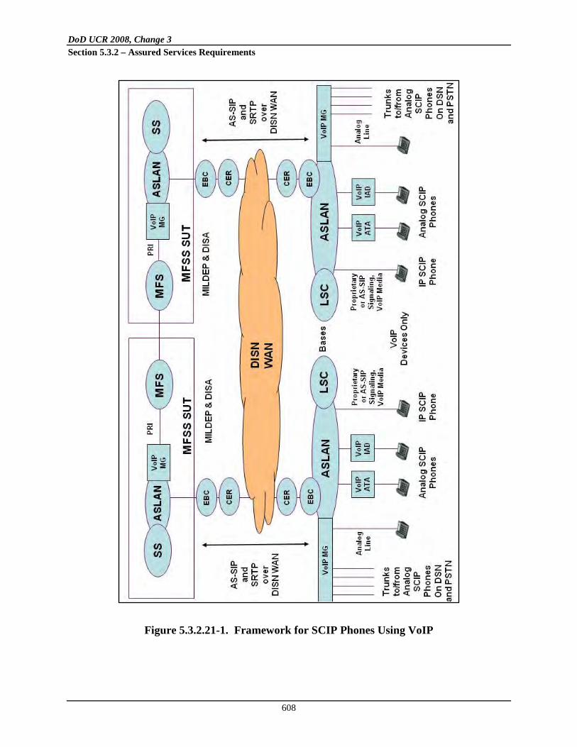
DoD UCR 2008, Change 3 Section 5.3.2 – Assured Services Requirements
608
Figure 5.3.2.21-1. Framework for SCIP Phones Using VoIP

DoD UCR 2008, Change 3 Section 5.3.2 – Assured Services Requirements
609
Figure 5.3.2.21-2. Framework for SCIP Phones Using Modem Relay 2. Media Gateway – Line-Side (MG-LS). This is the portion of the LSC or MFSS MG that
supports line-side connections to analog phones, analog secure phones, analog fax machines, and analog modems (which are Required), and ISDN BRI phones and secure

DoD UCR 2008, Change 3 Section 5.3.2 – Assured Services Requirements
610
phones (when supported) (which are Conditional). These line-side connections are provided by the existing twisted-pair copper-wire plant on the B/P/C/S where the LSC or MFSS is located. Support for Modem Relay in the MG-LS is Conditional in UCR.
NOTE: Newer B/P/C/Ss may not need an MG-LS if they are fully IP-based and do not have any existing copper-wire plant.
3. Analog Terminal Adapter (ATA)
This device supports a single RJ-45 Ethernet interface on the ASLAN side, and a single analog RJ-11 interface on the end user side. The Ethernet side of the ATA gives the analog-side devices VoIP connectivity to the LSC, MG, and EBC on the ASLAN on the B/P/C/S.
. This is a device on the UC end user’s premise that supports interconnection between the ASLAN and the end user’s analog phone, analog secure phone, analog fax machine, or analog modem. Support for Modem Relay in the ATA is Conditional in UCR
Support for Modem Relay in the ATA is Conditional in UCR.
4. Integrated Access Device (IAD)
Support for Modem Relay in the IAD is Conditional in UCR.
. This is a device on the UC end user’s premise that supports interconnection between the ASLAN and multiple end-user analog phones, analog secure phones, analog fax machines, and analog modems. This device supports a single Ethernet RJ-45 interface on the ASLAN side, and multiple (from 4 up to 16) analog RJ-11 interfaces on the end-user side. Like the ATA, the Ethernet side of the IAD gives the analog-side devices VoIP connectivity to the LSC, MG, and EBC on the ASLAN on the B/P/C/S.
The following SCIP/V.150.1 Gateway requirements apply to both SCIP/V.150.1 Gateways in Strategic (Fixed) Networks, and to SCIP/V.150.1 Gateways in Tactical (Deployable) networks.
5.3.2.21.2.1 Basic Minimum Essential Requirements
The following requirements are based on the Basic Minimum Essential Requirements in SCIP-216 Section 3.

DoD UCR 2008, Change 3 Section 5.3.2 – Assured Services Requirements
611
5.3.2.21.2.1.1 IP Transport Layer Protocol Requirements
[Required: MG-TS – Conditional: MG-LS, ATA, IAD] The SCIP/V.150.1 Gateway shall meet all the requirements for “IP Transport Layer Protocol” in SCIP-216, Section 3.1.
[Required: MG-TS – Conditional: MG-LS, ATA, IAD] The SCIP/V.150.1 Gateway shall support V.150.1 Simple Packet Relay Transport (SPRT) for reliable IP transport of the demodulated modem signals, per SCIP-216, Section 3.1.
5.3.2.21.2.1.2 V.150.1 Operational Mode Requirements
[Required: MG-TS – Conditional: MG-LS, ATA, IAD] The SCIP/V.150.1 Gateway shall meet all the requirements for “V.150.1 Operational Mode” in SCIP-216, Section 3.2.
[Required: MG-TS – Conditional: MG-LS, ATA, IAD] The SCIP/V.150.1 Gateway shall support the V.150.1 Audio and Modem Relay (MR) modes, per SCIP-216, Section 3.2.
5.3.2.21.2.1.3 Modem Relay Gateway Type Requirements
[Required: MG-TS – Conditional: MG-LS, ATA, IAD] The SCIP/V.150.1 Gateway shall meet all the requirements for “Modem-Relay Gateway Type” in SCIP-216, Section 3.3.
[Required: MG-TS – Conditional: MG-LS, ATA, IAD] The SCIP/V.150.1 Gateway shall support the V.32 and V.34 duplex modulation types in the MR mode, per SCIP-216, Section 3.3.
[Required: MG-TS – Conditional: MG-LS, ATA, IAD] The SCIP/V.150.1 Gateway shall also support the V.90 digital and V.92 digital modulation types in the MR mode, per SCIP-216, Section 3.3 (where they are optional) and ITU-T Recommendation V.150.1, Section 9.1, where they are required.
[Conditional: MG-TS, MG-LS, ATA, IAD] The SCIP/V.150.1 Gateway shall also support the V.90 Analog and V.92 analog modulation types in the MR mode, per SCIP-216, Section 3.3 (where they are optional) and ITU-T Recommendation V.150.1, Section 9.1 (where they are also optional).
5.3.2.21.2.1.4 Simple Packet Relay Transport Requirements
The following requirements are based on the SPRT requirements in SCIP-216, Section 3.4.
[Required: MG-TS – Conditional: MG-LS, ATA, IAD] The SCIP/V.150.1 Gateway shall meet all the requirements for “Transport Channel” in SCIP-216, Section 3.4.1.
DoD UCR 2008, Change 3 Section 5.3.2 – Assured Services Requirements
612
[Required: MG-TS – Conditional: MG-LS, ATA, IAD] The SCIP/V.150.1 Gateway shall support SPRT Transport Channels TC0, TC2, and TC3 for the exchange of ACKs and control messages, per SCIP-216, Section 3.4.1.
[Required: MG-TS – Conditional: MG-LS, ATA, IAD] The SCIP/V.150.1 Gateway shall support the “Suggested values for SPRT timers” for Timers TA01, TA02, and TR03, and for Transport Channel TC2, per Table B.3 in Section B.2.3.6 of ITU-T Recommendation V.150.1.
[Required: MG-TS – Conditional: MG-LS, ATA, IAD] The SCIP/V.150.1 Gateway shall meet all the requirements for “SPRT Modem Relay Messages” in SCIP-216, Section 3.4.2. [Required: MG-TS – Conditional: MG-LS, ATA, IAD] In the MR mode, the SCIP/V.150.1 Gateway shall meet all the requirements for the INIT, JM-INFO, CONNECT, MR_EVENT, I_OCTET, and I_OCTET-CS MR messages, as described in Table 3-3 in SCIP-216, Section 3.4.2. [Required: MG-TS – Conditional: MG-LS, ATA, IAD] The SCIP/V.150.1 Gateway shall meet all the requirements for “SPRT Timers” in Section 3.4.3 of SCIP-216.
5.3.2.21.2.1.5 State Signaling Event Requirements
The following requirements are based on the “State Signaling Event (SSE)” requirements in Section 3.5 of SCIP-216.
[Required: MG-TS – Conditional: MG-LS, ATA, IAD] The SCIP/V.150.1 Gateway shall use the SSE protocol to transition between the Audio (native state) and MR modes of operation, per Section 3.5 of SCIP-216.
[Required: MG-TS – Conditional: MG-LS, ATA, IAD] The SCIP/V.150.1 Gateway shall meet all the requirements for “SSE Call Discrimination Messages” in Section 3.5.1 of SCIP-216. [Required: MG-TS – Conditional: MG-LS, ATA, IAD] The SCIP/V.150.1 Gateway shall meet all the requirements for “SSE Reliability” in Section 3.5.2 of SCIP-216. [Required: MG-TS – Conditional: MG-LS, ATA, IAD] The SCIP/V.150.1 Gateway shall meet all the requirements for “SSE Reason Identifier Codes” in Section 3.5.3 of SCIP-216. [Required: MG-TS – Conditional: MG-LS, ATA, IAD] The SCIP/V.150.1 Gateway shall meet all the requirements for “SSE Timers” in Section 3.5.4 of SCIP-216.

DoD UCR 2008, Change 3 Section 5.3.2 – Assured Services Requirements
613
5.3.2.21.2.1.6 Call Setup Protocol Requirements
The following requirements are based on the “Call Setup Protocol Requirements for Negotiating Specific V.150.1 Capabilities” in Section 3.6 of SCIP-216. [Required: MG-TS – Conditional: MG-LS, ATA, IAD] The SCIP/V.150.1 Gateway shall meet all the requirements for “V.150.1 Version Declaration” in Section 3.6.1 of SCIP-216. [Required: MG-TS – Conditional: MG-LS, ATA, IAD] The SCIP/V.150.1 Gateway shall advertise a V.150.1 version number of “1” or higher, per Section 3.6.1 of SCIP-216. [Required: MG-TS – Conditional: MG-LS, ATA, IAD] The SCIP/V.150.1 Gateway shall meet all the requirements for “Transcompression Capability” in Section 3.6.2 of SCIP-216. [Required: MG-TS – Conditional: MG-LS, ATA, IAD] The SCIP/V.150.1 Gateway shall meet all the requirements for “Modem Relay Type Declaration” in Section 3.6.3 of SCIP-216. [Required: MG-TS – Conditional: MG-LS, ATA, IAD] The SCIP/V.150.1 Gateway shall meet all the requirements for “Modulation Support Indication” in Section 3.6.4 of SCIP-216. [Required: MG-TS; Conditional: MG-LS, ATA, IAD] The SCIP/V.150.1 Gateway shall meet all the requirements for “RFC 2833 Events” in Section 3.6.5 of SCIP-216. [Required: MG-TS – Conditional: MG-LS, ATA, IAD] In the Audio state, the SCIP/V.150.1 Gateway shall declare support for the four Answer events listed in Table 3-8 of Section 3.6.5 in SCIP-216, using the procedures defined in RFC 2833 (RTP Payload for DTMF Digits, Telephony Tones and Telephony Signals).
NOTE: “Support” means that the SCIP/V.150.1 Gateway shall be able to:
• Transmit the RFC 2833 Event over its IP interface after detecting the corresponding Answer event on its Data Communications Equipment (DCE) interface, and
• Transmit the Answer event on its DCE interface after detecting the corresponding RFC 2833 Event on its IP interface.
[Conditional: MG-TS, MG-LS, ATA, IAD] The SCIP/V.150.1 Gateway shall meet all the requirements for “SPRT Payload and Window Size Parameter” in Section 3.6.6 of SCIP-216. [Required: MG-TS – Conditional: MG-LS, ATA, IAD] The SCIP/V.150.1 Gateway shall meet all the requirements for “JM Delay Support” in Section 3.6.7 of SCIP-216.

DoD UCR 2008, Change 3 Section 5.3.2 – Assured Services Requirements
614
[Required: MG-TS – Conditional: MG-LS, ATA, IAD] The SCIP/V.150.1 Gateway shall meet all the requirements for “Call Discrimination Mode Parameters” in Section 3.6.8 of SCIP-216. [Required: MG-TS – Conditional: MG-LS, ATA, IAD] The SCIP/V.150.1 Gateway shall meet all the requirements for “SSE Capability Indications” in Section 3.6.9 of SCIP-216. [Required: MG-TS – Conditional: MG-LS, ATA, IAD] The SCIP/V.150.1 Gateway shall meet all the requirements for “SPRT Protocol Support Parameters” in Section 3.6.10 of SCIP-216. [Required: MG-TS – Conditional: MG-LS, ATA, IAD] The SCIP/V.150.1 Gateway shall meet all the requirements for “NoAudio Support” in Section 3.6.11 of SCIP-216.
5.3.2.21.2.1.7 Data Communications Equipment (DCE) Interface Requirements
The following requirements are based on the “DCE Interface Requirements” in Section 3.7 of SCIP-216. [Conditional: MG-TS, MG-LS, ATA, IAD] The SCIP/V.150.1 Gateway shall meet all the requirements for “V.14” in Section 3.7.1 of SCIP-216. The I_RAW-OCTET requirements in this section are Conditional. [Required: MG-TS – Conditional: MG-LS, ATA, IAD] The SCIP/V.150.1 Gateway shall meet all the requirements for “Answer Tone Generation” in Section 3.7.2 of SCIP-216. [Required: MG-TS – Conditional: MG-LS, ATA, IAD] The SCIP/V.150.1 Gateway shall meet all the requirements for “Absence of V.42” in Section 3.7.3 of SCIP-216.
5.3.2.21.2.2 Procedural Minimum Essential Requirements
The following requirements are based on the “Procedural Minimum Essential Requirements” in Section 4 of SCIP-216.
5.3.2.21.2.2.1 SSE State Transition Requirements
[Required: MG-TS – Conditional: MG-LS, ATA, IAD] The SCIP/V.150.1 Gateway shall meet all the requirements for SSE State Transition in Section 4.1 of SCIP-216. [Required: MG-TS – Conditional: MG-LS, ATA, IAD] The SCIP/V.150.1 Gateway shall meet all the requirements for SSE State Transitions defined in ITU-T Recommendation V.150.1, Annex C, to coordinate the transition between media states.

DoD UCR 2008, Change 3 Section 5.3.2 – Assured Services Requirements
615
5.3.2.21.2.2.2 SPRT Procedures Requirements
The following requirements are based on the “SPRT Procedures Requirements” in Section 4.2 of SCIP-216. [Conditional: MG-TS – Conditional: MG-LS, ATA, IAD] The SCIP/V.150.1 Gateway shall meet all the requirements for Modem Relay Data Type Selection in Section 4.2.1 of SCIP-216. The I_RAW-OCTET requirements in this section are also Conditional. [Required: MG-TS; Conditional: MG-LS, ATA, IAD] The SCIP/V.150.1 Gateway shall meet all the requirements for “SPRT Message Ordering” in Section 4.2.2 of SCIP-216. [Required: MG-TS – Conditional: MG-LS, ATA, IAD] In the MR mode, the SCIP/V.150.1 Gateway shall transmit the INIT message first, followed by the MR_EVENT message and/or the CONNECT message, as described in Section 4.2.2 of SCIP-216. [Conditional: MG-TS, MG-LS, ATA, IAD] The SCIP/V.150.1 Gateway shall meet all the requirements for “SPRT Window and Payload Size Negotiation” in Section 4.2.3 of SCIP-216. [Required: MG-TS – Conditional: MG-LS, ATA, IAD] The SCIP/V.150.1 Gateway shall use the MR_EVENT and CONNECT messages to indicate the data rate in bps, as described in Section 4.2.3 of SCIP-216 (which follows the Data Matching Rule defined in ITU-T Recommendation V.150.1). [Required: MG-TS – Conditional: MG-LS, ATA, IAD] The SCIP/V.150.1 Gateway shall meet all the requirements for SPRT Data Signaling Rate Indication in Section 4.2.4 of SCIP-216. [Required: MG-TS – Conditional: MG-LS, ATA, IAD] The SCIP/V.150.1 Gateway shall use the MR_EVENT and CONNECT messages to indicate the data rate negotiated on its DCE interface in bits per second (bps), per Section 4.2.4 of SCIP-216. The SCIP/V.150.1 Gateway shall also adhere to the Rate Matching Rule defined in Section 12.3.2.1 of ITU-T Recommendation V.150.1.
5.3.2.21.2.2.3 RFC 2833 Event Transmission Procedures
[Required: MG-TS – Conditional: MG-LS, ATA, IAD] The SCIP/V.150.1 Gateway shall meet all the requirements for RFC 2833 Event Transmission Procedures in Section 4.3 of SCIP-216.

DoD UCR 2008, Change 3 Section 5.3.2 – Assured Services Requirements
616
5.3.2.21.2.2.4 Native Session to Modem-Based Session Transition Procedures
The following requirements are based on the “Native Session to Modem-Based Session Transition Procedures” in Section 4.4 of SCIP-216. [Required: MG-TS – Conditional: MG-LS, ATA, IAD] The SCIP/V.150.1 Gateway shall use the SSE protocol to transition between the Audio (native state) and MR modes of operation, per Section 4.4 of SCIP-216.
[Required: MG-TS – Conditional: MG-LS, ATA, IAD] The SCIP/V.150.1 Gateway SSE state shall always start in the Audio mode, per Section 4.4.1 of SCIP-216.
[Required: MG-TS – Conditional: MG-LS, ATA, IAD] The SCIP/V.150.1 Gateway shall meet all the requirements for “SSE Audio to Modem Relay Transitions” in Section 4.4.1 of SCIP-216. [Required: MG-TS – Conditional: MG-LS, ATA, IAD] The SCIP/V.150.1 Gateway shall meet all the requirements for “Procedures for SPRT Modem Relay Setup” in Section 4.4.2 of SCIP-216.
5.3.2.21.2.2.5 Modem-Based Session to Native Session Transition (Cleardown) Procedures
The following requirements are based on the “Modem-Based Session to Native Session Transition (Cleardown) Procedures” in Section 4.5 of SCIP-216. [Required: MG-TS – Conditional: MG-LS, ATA, IAD] The SCIP/V.150.1 Gateway shall meet all the requirements for “Procedures for PSTN Initiated Cleardown” in Section 4.5.1 of SCIP-216. [Required: MG-TS – Conditional: MG-LS, ATA, IAD] The SCIP/V.150.1 Gateway shall meet all the requirements for “Procedures for IP Initiated Cleardown” in Section 4.5.2 of SCIP-216.
5.3.2.21.2.2.6 Transition to On-Hook While in a Modem-Based Session
The following requirements are based on the “Transition to On-Hook While in a Modem-Based Session” in Section 4.6 of SCIP-216. [Required: MG-TS – Conditional: MG-LS, ATA, IAD] The SCIP/V.150.1 Gateway shall meet all the requirements for “Procedures for IP Initiated On-Hook” in Section 4.6.1 of SCIP-216.

DoD UCR 2008, Change 3 Section 5.3.2 – Assured Services Requirements
617
[Required: MG-TS – Conditional: MG-LS, ATA, IAD] The SCIP/V.150.1 Gateway shall meet all the requirements for “Procedures for PSTN Initiated On-Hook” in Section 4.6.2 of SCIP-216.
5.3.2.21.2.2.7 SPRT CLEARDOWN Procedures
[Conditional: MG-TS, MG-LS, ATA, IAD] The SCIP/V.150.1 Gateway shall meet all the requirements for “SPRT CLEARDOWN Procedures” in Section 4.7 of SCIP-216.
5.3.2.21.2.2.8 Call Menu – Joint Menu Procedures
[Required: MG-TS – Conditional: MG-LS, ATA, IAD] The SCIP/V.150.1 Gateway shall meet all the requirements for “Call Menu (CM) – Joint Menu (JM)” Procedures in Section 4.8 of SCIP-216.
5.3.2.21.2.2.9 NoAudio Payload Type Requirements for SCIP-216 Compliant Gateways
[Required: MG-TS – Conditional: MG-LS, ATA, IAD] The SCIP/V.150.1 Gateway shall meet all the requirements for NoAudio Payload Type in Section 4.9 of SCIP-216. [Required: MG-TS – Conditional: MG-LS, ATA, IAD] The SCIP/V.150.1 Gateway shall support a NoAudio payload type for “Modem-Relay-Preferred” end points, per Section 4.9 of SCIP-216.
The SCIP-216 defines a “Modem-Relay-Preferred” end point as a SCIP-216 end point that immediately transitions to the Modem Relay state without transmitting information in the Audio state.
5.3.2.21.2.2.10 Transfer of Application Data between the IP and DCE Interfaces
The following requirements are based on the “Transfer of Application Data between the IP and DCE Interfaces” requirements in Section 4.10 of SCIP-216. [Conditional: MG-TS, MG-LS, ATA, IAD] The SCIP/V.150.1 Gateway shall meet all the requirements for “Processing of Data Received on the DCE Interface” in Section 4.10.1 of SCIP-216. I_RAW-OCTET requirements in this section are conditional.
[Required: MG-TS – Conditional: MG-LS, ATA, IAD] The SCIP/V.150.1 Gateway shall support the formatting of data received from the DCE (modem) interface into the I_OCTET and I_OCTET-CS Modem Relay data types sent on the IP interface, according to Section 4.10.1 of SCIP-216.

DoD UCR 2008, Change 3 Section 5.3.2 – Assured Services Requirements
618
[Conditional: MG-TS – MG-LS, ATA, IAD] The SCIP/V.150.1 Gateway shall meet all the requirements for “Processing of Data Received on the IP Interface” in Section 4.10.2 of SCIP-216. I_RAW-OCTET requirements in this section are conditional. [Required: MG-TS – Conditional: MG-LS, ATA, IAD] The SCIP/V.150.1 Gateway shall support the conversion of data received in the I_OCTET and I_OCTET-CS Modem Relay data types on the IP interface into asynchronous V.14 data characters sent on the DCE (modem) interface, according to Section 4.10.2 of SCIP-216.
[Required: MG-TS – Conditional: MG-LS, ATA, IAD] The SCIP/V.150.1 Gateway shall meet all the requirements for “Lost Packet Processing with I_OCTET-CS” in Section 4.10.3 of SCIP-216.
5.3.2.21.2.3 SSE and SPRT Message Content
The following requirements are based on the “SSE and SPRT Message Content” requirements in Section 5 of SCIP-216.
5.3.2.21.2.3.1 SSE Messages
The following requirements are based on the “SSE Messages” requirements in Section 5.1 of SCIP-216. [Required: MG-TS – Conditional: MG-LS, ATA, IAD] The SCIP/V.150.1 Gateway shall meet all the requirements for the SSE Audio Message in Section 5.1.1 of SCIP-216.
[Required: MG-TS – Conditional: MG-LS, ATA, IAD] The SCIP/V.150.1 Gateway shall meet all the requirements for the ”SSE Modem Relay Message” in Section 5.1.2 of SCIP-216.
5.3.2.21.2.3.2 SPRT Messages
The following requirements are based on the “SPRT Messages” requirements in Section 5.2 of SCIP-216. [Required: MG-TS – Conditional: MG-LS, ATA, IAD] The SCIP/V.150.1 Gateway shall meet all the requirements for the “SPRT INIT Message” in Section 5.2.1 of SCIP-216. [Required: MG-TS – Conditional: MG-LS, ATA, IAD] The SCIP/V.150.1 Gateway shall meet all the requirements for the “SPRT JM_INFO Message” in Section 5.2.2 of SCIP-216. [Required: MG-TS – Conditional: MG-LS, ATA, IAD] The SCIP/V.150.1 Gateway shall meet all the requirements for the “SPRT CONNECT Message” in Section 5.2.3 of SCIP-216.

DoD UCR 2008, Change 3 Section 5.3.2 – Assured Services Requirements
619
[Required: MG-TS – Conditional: MG-LS, ATA, IAD] The SCIP/V.150.1 Gateway shall meet all the requirements for the “SPRT MR_EVENT Message” in Section 5.2.4 of SCIP-216. [Required: MG-TS – Conditional: MG-LS, ATA, IAD] The SCIP/V.150.1 Gateway shall meet all the requirements for the “SPRT CLEARDOWN Message” in Section 5.2.5 of SCIP-216. NOTE: Transmission of this message is optional in SCIP-216, but reception of this message is required. [Conditional: MG-TS, MG-LS, ATA, IAD] If the SPRT I_RAW-OCTET Message is supported, the SCIP/V.150.1 Gateway shall meet all the requirements for that Message in Section 5.2.6 of SCIP-216. (Support for the I_RAW-OCTET data type is currently optional in SCIP-216, but may become a requirement later.)
[Required: MG-TS – Conditional: MG-LS, ATA, IAD] The SCIP/V.150.1 Gateway shall meet all the requirements for the SPRT I_OCTET Message in Section 5.2.7 of SCIP-216. [Required: MG-TS – Conditional: MG-LS, ATA, IAD] The SCIP/V.150.1 Gateway shall meet all the requirements for the SPRT I_OCTET-CS Message in Section 5.2.8 of SCIP-216.
5.3.2.21.2.4 Use of Common UDP Port Numbers for SRTP, SSE, and SPRT Messages
[Required: MG-TS – Conditional: MG-LS, ATA, IAD] The SCIP/V.150.1 Gateway shall use the same UDP port numbers and protocol numbers for
• The SRTP media packets sent and received during the Audio mode (when the call is “in the clear”),
• The SSE media packets sent and received during transitions between the
Audio and Modem Relay modes (when the call is moving between “in the clear” and “secure”), and
• The SPRT media packets sent and received during the Modem Relay mode
(when the call is “secure”). The UDP port numbers shall be the UDP port numbers negotiated by the SCIP/V.150.1 Gateway and the remote party (SCIP/V.150.1 EI or remote SCIP/V.150.1 Gateway) using SDP during AS-SIP session establishment. The UDP protocol number (the protocol number used in IP packets to indicate that the UDP protocol is being transported) shall be protocol number 17, as registered with the Internet Assigned Numbers Authority (IANA). Per the IANA Web site page on Assigned Internet Protocol Numbers (http://www.iana.org/assignments/protocol-numbers/):

DoD UCR 2008, Change 3 Section 5.3.2 – Assured Services Requirements
620
“In the Internet Protocol version 4 (IPv4) [RFC 791] there is a field called “Protocol” to identify the next level protocol. This is an 8-bit field. In Internet Protocol version 6 (IPv6) [RFC 2460], this field is called the “Next Header” field.”
[Required: MG-TS – Conditional: MG-LS, ATA, IAD] When an SCIP/V.150.1 Gateway transitions the media stream between a normal session using SRTP and a secure session using SPRT, the SCIP/V.150.1 Gateway shall use the same UDP port numbers and UDP protocol number (17) for both the normal session and the secure session, so that the media stream transition is transparent to the EBC (when the EBC is located in the media stream for those sessions). [Required: MG-TS – Conditional: MG-LS, ATA, IAD] The SCIP/V.150.1 Gateway shall not use AS-SIP and SDP to negotiate a new UDP port number when the call is changing from audio mode (SRTP) and modem relay mode (SPRT), or from modem relay mode back to audio mode.
[Required: MG-TS – Conditional: MG-LS, ATA, IAD] The SCIP/V.150.1 Gateway shall not use AS-SIP and SDP to negotiate multiple UDP port numbers (one for Audio (SRTP), another for mode transitions (SSE), and yet another for modem relay (SPRT)) during AS-SIP session establishment. The SCIP-216 allows this multiple UDP port number approach, but the SCIP/V.150.1 Gateway shall not use this approach because it adds complexity to session establishment and has a negative effect on EBCs.
5.3.2.21.2.5 UDP Port Number for SRTCP Media Control Packets
1. [Required: MG-TS – Conditional: MG-LS, ATA, IAD] The SCIP/V.150.1 Gateway shall maintain, for the duration of a call, the UDP port number used for the SRTCP media control packets that are sent and received during the Audio mode (when the call is “in the clear”).
This UDP port number shall be the UDP port number negotiated for SRTCP media control packets by the SCIP/V.150.1 Gateway and the remote party (SCIP/V.150.1 EI or remote SCIP/V.150.1 Gateway) using SDP during AS-SIP session establishment.
2. [Required: MG-TS – Conditional: MG-LS, ATA, IAD] When a call transitions from Audio mode to Modem Relay mode, the SCIP/V.150.1 Gateway shall stop sending SRTCP packets, but shall maintain the UDP port number that had been used for exchanging SRTCP packets.

DoD UCR 2008, Change 3 Section 5.3.2 – Assured Services Requirements
621
3. [Required: MG-TS – Conditional: MG-LS, ATA, IAD] If a call transitions from Audio mode to Modem Relay mode, and then later back to Audio mode, the SCIP/V.150.1 Gateway shall resume sending and receiving SRTCP packets using the same UDP port number that was previously used in Audio mode for those packets.
5.3.2.21.2.6 Use of V.150.1 SSE Messages for Media Transitions between Audio and Modem Relay
[Required: MG-TS – Conditional: MG-LS, ATA, IAD] Per Section 5.4, Information Assurance Requirements, SCIP/V.150.1 Gateways shall protect audio and video media streams using SRTP, when exchanging these media streams with SCIP/V.150.1 Phones and other SCIP/V.150.1 Gateways. (When SCIP/V.150.1 Gateways exchange modem relay media streams with SCIP/V.150.1 Phones and other gateways, the modem relay media streams are sent over SPRT, and not sent over SRTP. As a result, these modem relay media streams are not protected by SRTP.) [Required: MG-TS – Conditional: MG-LS, ATA, IAD] When SCIP/V.150.1 Gateways exchange RFC 2833 Events and V.150.1 SSE messages with SCIP/V.150.1 Phones and other Gateways, these RFC 2833 Events and SSE messages shall also be protected using SRTP. These messages and events shall not be exchanged using SPRT, and they shall not be exchanged using RTP without SRTP. [Required: MG-TS – Conditional: MG-LS, ATA, IAD] For all IP-TDM and TDM-IP interworking calls, SCIP/V.150.1 Gateways shall declare that they support audio, modem relay, SRTP, SSE, and SPRT in the original SDP offer (AS-SIP INVITE message) and SDP answer (200 OK response) for each call. SCIP/V.150.1 Gateways shall not reserve or allocate a modem relay resource at this point because the call will typically begin as an audio call, which does not require a modem relay resource. [Required: MG-TS – Conditional: MG-LS, ATA, IAD] After one end of the call (the TDM SCIP phone or IP SCIP phone) decides to go secure, the SCIP/V.150.1 Gateway shall begin the process of changing the established media stream from audio media to modem relay media. On the IP portion of this call, the SCIP/V.150.1 Gateway shall begin this processing by exchanging SSE messages with the SCIP/V.150.1 Phone, EBC, or other SCIP/V.150.1 Gateway, per ITU-T Recommendation V.150.1 and SCIP-216. [Required: MG-TS – Conditional: MG-LS, ATA, IAD] As part of the Audio-media-to-Modem-Relay-media conversion process, the SCIP/V.150.1 Gateway shall not send an outgoing AS-SIP re-INVITE message that requests Audio-to-Modem-Relay media conversion.

DoD UCR 2008, Change 3 Section 5.3.2 – Assured Services Requirements
622
[Required: MG-TS – Conditional: MG-LS, ATA, IAD] As part of the Audio-media-to-Modem-Relay-media conversion process, the SCIP/V.150.1 Gateway shall not require the receipt of an incoming AS-SIP re-INVITE message that requests Audio-to-Modem-Relay media conversion. [Required: MG-TS – Conditional: MG-LS, ATA, IAD] The SCIP/V.150.1 Gateway shall not reserve and allocate one of its modem relay resources for the media stream for this call, until the SSE message exchange for Audio-to-Modem-Relay media conversion has begun. [Required: MG-TS – Conditional: MG-LS, ATA, IAD] After one end of the call (the TDM SCIP phone or IP SCIP phone) decides to return to “voice in the clear,” the SCIP/V.150.1 Gateway shall begin the process of changing the established media stream from modem relay media to Audio media. On the IP portion of this call, the SCIP/V.150.1 Gateway shall begin this processing by exchanging SSE messages with the SCIP/V.150.1 Phone, EBC, or other SCIP/V.150.1 Gateway, per ITU-T Recommendation V.150.1 and SCIP-216. [Required: MG-TS – Conditional: MG-LS, ATA, IAD] As part of the Modem-Relay-media-to-Audio-media conversion process, the SCIP/V.150.1 Gateway shall not send an outgoing AS-SIP re-INVITE message that requests Modem-Relay-to-Audio media conversion. [Required: MG-TS – Conditional: MG-LS, ATA, IAD] As part of the Modem-Relay-media-to-Audio-media conversion process, the SCIP/V.150.1 Gateway shall not require the receipt of an incoming AS-SIP re-INVITE message that requests Modem-Relay-to-Audio-media conversion. [Required: MG-TS – Conditional: MG-LS, ATA, IAD] The SCIP/V.150.1 Gateway shall not release and de-allocate its modem relay resource for the media stream for this call until the SSE message exchange for Modem-Relay-to-Audio media conversion has begun. [Required: MG-TS – Conditional: MG-LS, ATA, IAD] The SCIP/V.150.1 Gateways shall still be able to send and receive AS-SIP re-INVITE messages during an audio call. (For example, the gateway can use the AS-SIP re-INVITE message to request an Audio codec change during the audio/clear voice portion of a call, when the Gateway is using G.711 for audio media but then asks the far end to use G.729 for Audio media instead.) When the Gateway includes modem relay media information in an AS-SIP re-INVITE message, the Gateway shall make sure that this is the same modem relay information that was present in the initial AS-SIP INVITE message or 200 OK response that established the call. In this way, the AS-SIP re-INVITE message is not used to request an Audio-to-Modem-Relay transition.

DoD UCR 2008, Change 3 Section 5.3.2 – Assured Services Requirements
623
5.3.2.21.2.7 Modem Relay and VoIP for SCIP/V.150.1 Gateways
[Required: MG-TS; Conditional: MG-LS, ATA, IAD] When an SCIP/V.150.1 Gateway is unable to provide modem relay on an MoIP call (e.g. because the remote end is not modem relay capable, or the remote end is modem relay capable but does not currently have any modem relay resources available), then the SCIP/V.150.1 Gateway shall instead provide VoIP treatment for that call. In this case, the SCIP/V.150.1 Gateway shall handle the MoIP call in the LSC or MFSS in the same way that it would handle a G.711 VoIP call in the LSC or MFSS, with these clarifications: 1. The Gateway shall still disable EC for the MoIP call being handled as a G.711 VoIP call,
when the Gateway detects an “EC disabling” tone from either the TDM side or the MoIP side of the call (see Section 5.3.2.12.13, Echo Cancellation).
2. The Gateway may disable silence suppression on the MoIP side of the call.
If the Gateway also supports Voiceband Data codecs (proprietary and/or V.152) then the Gateway may provide VBD treatment for the MoIP call instead of providing VoIP treatment for that call. NOTE: End-to-end synchronization of the calling and called modems (or modem-equipped SCIP phones) is not guaranteed on a VoIP call. Even though a VoIP call may complete between these two modems (i.e., a successful AS-SIP signaling INVITE/200 OK/ACK exchange can occur, and G.711 media can be exchanged over SRTP, UDP, and IP), there is no guarantee that the two modems will be able to synchronize and exchange data using the resulting G.711 media streams. Even if the two modems do synchronize and exchange data, there is no guarantee that this synchronization and exchange will be maintained over time, or that the synchronization and exchange will result in a data throughput that matches what would be provided by a modem relay call, or by an E2E TDM call in a TDM voice network. Because of this, there are no requirements in this section for the reliability of modem synchronization, reliability of data exchange, or rate of data transfer on VoIP calls. It is expected that these calls will complete using AS-SIP signaling and SRTP media exchange like VoIP calls do. But it is not expected that the resulting synchronization and data exchange will be 100 percent reliable, or that the data rate provided will match what would be provided on a modem relay call or TDM modem call under the same conditions. [Required: MG-TS] The SCIP/V.150.1 Gateway shall support adequate V.150.1/SCIP-216 modem relay resources so that 10 percent of the maximum number of calls that can pass through the trunk-side interfaces of the MG (from TDM end points to IP end points, and from IP end points to TDM end points) can receive modem relay treatment, instead of receiving VoIP treatment.

DoD UCR 2008, Change 3 Section 5.3.2 – Assured Services Requirements
624
NOTE: The acquiring activity for the SCIP/V.150.1 Gateway should also determine, based on traffic engineering and vendor prices, the required number of MG modem relay resources (e.g. Modem-Relay-equipped trunk cards, or modem relay DSP cards) that will support V.150.1/SCIP-216 modem relay. V.150.1/SCIP-216 modem relay is needed to support IP SCIP phones (SCIP-215 phones) on an LSC or MFSS, and analog SCIP phones behind TAs, IADs, and MG line cards on an LSC or MFSS.
5.3.2.21.2.8 Modem Relay Support for V.92 and V.90 Modulation Types
[Required: MG-TS] On SCIP-216 modem relay calls where the V.92 Digital modulation type (UCR Required) is used, the TDM side of the MG-TS shall act as the digital interface to the remote V.92 Server modem. [Conditional: MG-LS, ATA, IAD] On SCIP-216 modem relay calls where the V.92 Analog modulation type (UCR Conditional) is used, and the TDM side of the MG-LS, ATA, or IAD shall act as the analog interface to the local V.92 client modem (e.g., a V.92 modem on an RJ-11 port on a DoD laptop computer). [Required: MG-TS – Conditional: MG-LS, ATA, IAD] The SCIP-216 modem relay communication between the MG-TS and the MG-LS, ATA, or IAD shall support V.92-Server-modem-to-V.92-Client-modem communication in the MG-TS-to-MG-LS/TA/IAD direction, and V.92-Client-modem-to-V.92-Server-modem communication in the MG-LS/TA/IAD-to-MG-TS direction. [Required: MG-TS – Conditional: MG-LS, ATA, IAD] The data rate supported in the V.92-Server-modem-to-V.92-Client-modem direction shall be greater than 33.6 kbps and less than 53.3 kbps (the U.S. PSTN limit on 56 kbps data communication). The data rate supported in the V.92-Client-modem-to-V.92-Server-modem direction shall be greater than 33.6 kbps and less than 53.3 kbps also. [Required: MG-TS] On SCIP-216 modem relay calls where the V.90 digital modulation type (UCR Required) is used, the TDM side of the MG-TS shall act as the digital interface to the remote V.90 server modem. [Conditional: MG-LS, ATA, IAD] On SCIP-216 modem relay calls where the V.90 analog modulation type (UCR Conditional) is used, the TDM side of the MG-LS, ATA, or IAD shall act as the analog interface to the local V.90 client modem (e.g., a V.90 modem on an RJ-11 port on a DoD laptop computer). [Required: MG-TS – Conditional: MG-LS, ATA, IAD] The SCIP-216 modem relay communication between the MG-TS and the MG-LS, ATA, or IAD shall support V.90-Server-

DoD UCR 2008, Change 3 Section 5.3.2 – Assured Services Requirements
625
modem-to-V.90-Client-modem communication in the MG-TS-to-MG-LS/TA/IAD direction, and V.90-Client-modem-to-V.90-Server-modem communication in the MG-LS/TA/IAD-to-MG-TS direction. [Required: MG-TS – Conditional: MG-LS, ATA, IAD] The data rate supported in the V.90-Server-modem-to-V.90-Client-modem direction shall be greater than 33.6 kbps and less than 53.3 kbps (the U.S. PSTN limit on 56 kbps data communication). The data rate supported in the V.90-Client-modem-to-V.90-Server-modem direction shall be greater than 28.8 kbps and less than or equal to 33.6 kbps.
5.3.2.21.2.9 Going Secure, Glare Conditions, and Modem Relay Preferred Devices
1. [Required: MG-TS – Conditional: MG-LS, ATA, IAD] The calling or called SCIP/V.150.1 Gateway shall be able to initiate going secure. The calling or called SCIP/V.150.1 Gateway shall be able to send an ANS signal toward the far-end SCIP endpoint (MG or EI).
2. [Required: MG-TS – Conditional: MG-LS, ATA, IAD] If a glare condition results from an SCIP/V.150.1 Gateway initiating going secure and sending an ANS signal toward the far-end SCIP endpoint (MG or EI) at the same time that the far endpoint initiates going secure and sends an ANS signal to the SCIP/V.150.1 Gateway, then the SCIP/V.150.1 Gateway and the far end SCIP endpoint both shall back off their request and try again later.
3. [Required: MG-TS – Conditional: MG-LS, ATA, IAD] An SCIP/V.150.1 Gateway operating as a SCIP Modem Relay Preferred (MRP) device shall transition automatically from the audio state to the modem relay state upon the SCIP call being answered. This means that the first media stream packet sent by the MRP device shall be a Secure RTP (SRTP) packet containing an IETF RFC 2833 message indicating that an ANS, /ANS, ANSam, or /ANSam Event is being signaled. This also means that the first media stream packet received by the MRP device (i.e., sent to the MRP device by the other V.150.1 device on the call) shall be an SRTP packet containing an SSE message indicating a transition from audio to modem relay (Event Code 3). Once this transition is successful, the MRP device shall begin sending SPRT packets containing SCIP protocol information (secure voice or secure data media). If the MRP device receives an RFC 233 message containing an ANS, /ANS, ANSam, or /ANSam Event before that device sends its own RFC 2833 message and ANS, /ANS, ANSam, or /ANSam Event, the MRP device shall send an SRTP packet back to the other V.150.1 device, containing an SSE message indicating a transition from audio to modem relay (Event Code 3). Once this transition is successful, the MRP device shall begin
DoD UCR 2008, Change 3 Section 5.3.2 – Assured Services Requirements
626
sending SPRT packets containing SCIP protocol information (secure voice or secure data media).
5.3.2.21.3 SCIP/V.150.1 EI Requirements
This section contains the SCIP/V.150.1 EI requirements for UCR, based on the following NSA document:
• SCIP-215, Revision 2.1 All references to “SCIP-215” in the following paragraphs are references to SCIP-215, Revision 2.1. In this section, a “SCIP EI” is any Secure IP Phone that conforms to SCIP-215. The SCIP EIs may be used on commercial VoIP networks or on the DSN. An example of a SCIP EI is a Secure IP Phone that supports SCIP-215, is connected to a base IP LAN, and receives line-side VoIP service from a TDM DSN switch on the base. In this section, an “SCIP/V.150.1 EI” is a Secure IP Phone that conforms to SCIP-215, conforms to the requirements in this section, and is served by an LSC. An SCIP/V.150.1 EI also communicates with the LSC using either
• Vendor-proprietary signaling and transport protocols or • AS-SIP signaling over TLS
A SCIP EI might communicate only with a TDM switch on the base (which provides DSN line-side VoIP) using vendor-proprietary signaling and transport protocols. An SCIP/V.150.1 EI also exchanges media with other EIs, MGs, ATAs, and IADs using SRTP over UDP during the audio part of the call (“talking in the clear”), and using SSE and SPRT over UDP during the modem relay part of the call (“talking secure”). An SCIP EI on a commercial VoIP network or the DSN might instead exchange media with other SCIP end points using RTP over UDP during the audio part of the call, and using SSE and SPRT over UDP during the modem relay part of the call. NOTE: The requirements for an SCIP/V.150.1 EI to support AS-SIP signaling over TLS are included in Section 5.3.2.22, Generic AS-SIP End Instrument and Video Codec Requirements. This section provides generic AS-SIP EI requirements for UC Phones, UC Secure Phones (SCIP/V.150.1 EIs), and UC Video Phones. The requirements for an SCIP/V.150.1 EI to support SSE and SPRT media over UDP are included in the following paragraphs, as part of this section.

DoD UCR 2008, Change 3 Section 5.3.2 – Assured Services Requirements
627
The following SCIP/V.150.1 EI requirements apply to both SCIP/V.150.1 EIs in Strategic (Fixed) Networks, and to SCIP/V.150.1 EIs in Tactical (Deployable) networks.
5.3.2.21.3.1 Basic Minimum Essential Requirements (MER)
The following requirements are based on the basic MER in Section 4 of SCIP-215.
5.3.2.21.3.1.1 IP Transport Layer Protocol Requirements
[Required: SCIP/V.150.1 EI] The SCIP/V.150.1 EI shall meet all the requirements for “IP Transport Layer Protocol” in Section 4.1 of SCIP-215.
5.3.2.21.3.1.2 V.150.1 Operational Mode Requirements
[Required: SCIP/V.150.1 EI] The SCIP/V.150.1 EI shall meet all the requirements for “V.150.1 Operational Mode” in Section 4.2 of SCIP-215.
5.3.2.21.3.1.3 Modem-Relay Gateway Type Requirements
[Required: SCIP/V.150.1 EI] The SCIP/V.150.1 EI shall meet all the requirements for “Modem-Relay Gateway Type” in Section 4.3 of SCIP-215.
5.3.2.21.3.1.4 Simple Packet Relay Transport Requirements
The following requirements are based on the SPRT requirements in Section 4.4 of SCIP-215.
[Required: SCIP/V.150.1 EI] The SCIP/V.150.1 EI shall meet all the requirements for “Transport Channel” in Section 4.4.1 of SCIP-215. [Required: SCIP/V.150.1 EI] The SCIP/V.150.1 EI shall meet all the requirements for “SPRT Modem Relay Messages” in Section 4.4.2 of SCIP-215. [Required: SCIP/V.150.1 EI] The SCIP/V.150.1 EI shall meet all the requirements for “SPRT Timer” in Section 4.4.3 of SCIP-215.
5.3.2.21.3.1.5 SSE Requirements
The following requirements are based on the SSE requirements in Section 4.5 of SCIP-215.
[Required: SCIP/V.150.1 EI] The SCIP/V.150.1 EI shall meet all the requirements for “SSE Call Discrimination Messages” in Section 4.5.1 of SCIP-215.

DoD UCR 2008, Change 3 Section 5.3.2 – Assured Services Requirements
628
[Required: SCIP/V.150.1 EI] The SCIP/V.150.1 EI shall meet all the requirements for “SSE Reliability” in Section 4.5.2 of SCIP-215. [Required: SCIP/V.150.1 EI] The SCIP/V.150.1 EI shall meet all the requirements for “SSE Reason Identifier Code” in Section 4.5.3 of SCIP-215. [Required: SCIP/V.150.1 EI] The SCIP/V.150.1 EI shall meet all the requirements for “SSE Timer” in Section 4.5.4 of SCIP-215.
5.3.2.21.3.1.6 Call Setup Protocol Requirements
The following requirements are based on the “Call Setup Protocol Requirements for Negotiating Specific V.150.1 Capabilities” in Section 4.6 of SCIP-215. [Required: SCIP/V.150.1 EI] The SCIP/V.150.1 EI shall meet all the requirements for “V.150.1 Version Declaration” in Section 4.6.1 of SCIP-215. [Required: SCIP/V.150.1 EI] The SCIP/V.150.1 EI shall meet all the requirements for “Transcompression Capability” in Section 4.6.2 of SCIP-215. [Required: SCIP/V.150.1 EI] The SCIP/V.150.1 EI shall meet all the requirements for “Modem Relay Type Declaration” in Section 4.6.3 of SCIP-215. [Required: SCIP/V.150.1 EI] The SCIP/V.150.1 EI shall meet all the requirements for “Modulation Support Indication” in Section 4.6.4 of SCIP-215. [Required: SCIP/V.150.1 EI] The SCIP/V.150.1 EI shall meet all the requirements for “RFC 2833 Events” in Section 4.6.5 of SCIP-215. [Conditional: SCIP/V.150.1 EI] The SCIP/V.150.1 EI shall meet all the requirements for “SPRT Payload and Window Size Parameter” in Section 4.6.6 of SCIP-215. [Required: SCIP/V.150.1 EI] The SCIP/V.150.1 EI shall meet all the requirements for “JM Delay Support” in Section 4.6.7 of SCIP-215. [Required: SCIP/V.150.1 EI] The SCIP/V.150.1 EI shall meet all the requirements for “Call Discrimination Mode Parameter” in Section 4.6.8 of SCIP-215. [Required: SCIP/V.150.1 EI] The SCIP/V.150.1 EI shall meet all the requirements for “SSE Capability Indication” in Section 4.6.9 of SCIP-215.

DoD UCR 2008, Change 3 Section 5.3.2 – Assured Services Requirements
629
[Required: SCIP/V.150.1 EI] The SCIP/V.150.1 EI shall meet all the requirements for “SPRT Protocol Support Parameters” in Section 4.6.10 of SCIP-215. [Required: SCIP/V.150.1 EI] The SCIP/V.150.1 EI shall meet all the requirements for “NoAudio Support” in Section 4.6.11 of SCIP-215.
5.3.2.21.3.1.7 SCIP Operational Mode Requirements
[Required: SCIP/V.150.1 EI] The SCIP/V.150.1 EI shall meet all the requirements for “SCIP Operational Mode” in Section 4.7 of SCIP-215.
5.3.2.21.3.1.8 V.14 Requirements
[Conditional: SCIP/V.150.1 EI] The SCIP/V.150.1 EI shall meet all the requirements for “V.14” in Section 4.8 of SCIP-215.
5.3.2.21.3.2 Procedural MER
The following requirements are based on the Procedural MER in Section 5 of SCIP-215.
5.3.2.21.3.2.1 SSE State Transition Requirements
[Required: SCIP/V.150.1 EI] The SCIP/V.150.1 EI shall meet all the requirements for “SSE State Transition” in Section 5.1 of SCIP-215.
5.3.2.21.3.2.2 SPRT Procedures Requirements
The following requirements are based on the “SPRT Procedures Requirements” in Section 5.2 of SCIP-215. [Conditional: SCIP/V.150.1 EI] The SCIP/V.150.1 EI shall meet all the requirements for modem relay “Data Type Selection” in Section 5.2.1 of SCIP-215. The I_RAW-OCTET requirements in this section are conditional. [Required: SCIP/V.150.1 EI] The SCIP/V.150.1 EI shall meet all the requirements for “SPRT Message Ordering” in Section 5.2.2 of SCIP-215. [Conditional: SCIP/V.150.1 EI] The SCIP/V.150.1 EI shall meet all the requirements for “SPRT Window and Payload Size Negotiation” in Section 5.2.3 of SCIP-215. [Required: SCIP/V.150.1 EI] The SCIP/V.150.1 EI shall meet all the requirements for “SPRT Data Signaling Rate Indication” in Section 5.2.4 of SCIP-215.

DoD UCR 2008, Change 3 Section 5.3.2 – Assured Services Requirements
630
5.3.2.21.3.2.3 RFC 2833 Event Transmission Procedures
[Required: SCIP/V.150.1 EI] The SCIP/V.150.1 EI shall meet all the requirements for “RFC 2833 Event Transmission Procedures” in Section 5.3 of SCIP-215.
5.3.2.21.3.2.4 Clear-to-SCIP Traffic Transition Procedures
The following requirements are based on the “Clear-to-SCIP Traffic Transition Procedures” in Section 5.4 of SCIP-215. [Required: SCIP/V.150.1 EI] The SCIP/V.150.1 EI shall meet all the requirements for SSE Audio to modem relay Transitions in Section 5.4.1 of SCIP-215. [Required: SCIP/V.150.1 EI] The SCIP/V.150.1 EI shall meet all the requirements for Procedures for SPRT modem relay Setup in Section 5.4.2 of SCIP-215.
5.3.2.21.3.2.5 SCIP Traffic-to-Clear Transition (Cleardown) Procedures
The following requirements are based on the “SCIP Traffic-to-Clear Transition (Cleardown) Procedures” in Section 5.5 of SCIP-215. [Required: SCIP/V.150.1 EI] The SCIP/V.150.1 EI shall meet all the requirements for “Procedures for PSTN Initiated Cleardown” in Section 5.5.1 of SCIP-215. [Required: SCIP/V.150.1 EI] The SCIP/V.150.1 EI shall meet all the requirements for “Procedures for IP Initiated Cleardown” in Section 5.5.2 of SCIP-215.
5.3.2.21.3.2.6 Transition to On-hook while in a Modem-Based Session
The following requirements are based on the “Transition to On-Hook While Exchanging SCIP Information” requirements in Section 5.6 of SCIP-215. [Required: SCIP/V.150.1 EI] The SCIP/V.150.1 EI shall meet all the requirements for Procedures for IP Initiated On-hook in Section 5.6.1 of SCIP-215. [Required: SCIP/V.150.1 EI] The SCIP/V.150.1 EI shall meet all the requirements for “Procedures for PSTN Initiated On-Hook” in Section 5.6.2 of SCIP-215.
5.3.2.21.3.2.7 SPRT CLEARDOWN Procedures
[Conditional: SCIP/V.150.1 EI] The SCIP/V.150.1 EI shall meet all the requirements for “SPRT CLEARDOWN Procedures” in Section 5.7 of SCIP-215.
DoD UCR 2008, Change 3 Section 5.3.2 – Assured Services Requirements
631
5.3.2.21.3.2.8 Call Menu (CM) – Joint Menu (JM) Procedures
[Required: SCIP/V.150.1 EI] The SCIP/V.150.1 EI shall meet all the requirements for “Call Menu (CM) – Joint Menu (JM) Procedures” in Section 5.8 of SCIP-215.
5.3.2.21.3.2.9 Use of the NoAudio Payload Type by “Modem Relay-Preferred” Terminals
[Required: SCIP/V.150.1 EI] The SCIP/V.150.1 EI shall meet all the requirements for “Use of the NoAudio Payload Type By ‘Modem Relay-Preferred’ Terminals” in Section 5.9 of SCIP-215.
5.3.2.21.3.2.10 Bandwidth Negotiation Requirements
[Required: SCIP/V.150.1 EI] The SCIP/V.150.1 EI shall meet all the requirements for “Bandwidth Negotiation” in Section 5.10 of SCIP-215.
5.3.2.21.3.3 SSE and SPRT Message Content
The following requirements are based on the “SSE and SPRT Message Content” requirements in Section 6 of SCIP-215.
5.3.2.21.3.3.1 SSE Messages
The following requirements are based on the “SSE Messages” requirements in Section 6.1 of SCIP-215. [Required: SCIP/V.150.1 EI] The SCIP/V.150.1 EI shall meet all the requirements for the “SSE Audio Message” in Section 6.1.1 of SCIP-215.
[Required: SCIP/V.150.1 EI] The SCIP/V.150.1 EI shall meet all the requirements for the “SSE modem relay Message” in Section 6.1.2 of SCIP-215.
5.3.2.21.3.3.2 SPRT Messages
The following requirements are based on the “SPRT Messages” requirements in Section 6.2 of SCIP-215. [Required: SCIP/V.150.1 EI] The SCIP/V.150.1 EI shall meet all the requirements for the “SPRT INIT Message” in Section 6.2.1 of SCIP-215. [Required: SCIP/V.150.1 EI] The SCIP/V.150.1 EI shall meet all the requirements for the “SPRT JM_INFO Message” in Section 6.2.2 of SCIP-215.

DoD UCR 2008, Change 3 Section 5.3.2 – Assured Services Requirements
632
[Required: SCIP/V.150.1 EI] The SCIP/V.150.1 EI shall meet all the requirements for the “SPRT CONNECT Message” in Section 6.2.3 of SCIP-215. [Required: SCIP/V.150.1 EI] The SCIP/V.150.1 EI shall meet all the requirements for the “SPRT MR_EVENT” message in Section 6.2.4 of SCIP-215. [Required: SCIP/V.150.1 EI] The SCIP/V.150.1 EI shall meet all the requirements for the “SPRT CLEARDOWN” message in Section 6.2.5 of SCIP-215. NOTE: Transmission of this message is optional in SCIP-215, but reception of this message is required. [Conditional: SCIP/V.150.1 EI] If the SPRT I_RAW-OCTET message is supported, the SCIP/V.150.1 EI shall meet all the requirements for that message in Section 6.2.6 of SCIP-215. (Support for the I_RAW-OCTET data type is currently optional in SCIP-215, but may become a requirement later.)
[Required: SCIP/V.150.1 EI] The SCIP/V.150.1 EI shall meet all the requirements for the “SPRT I_OCTET” message in Section 6.2.7 of SCIP-215. [Required: SCIP/V.150.1 EI] The SCIP/V.150.1 EI shall meet all the requirements for the “SPRT I_OCTET-CS” message in Section 6.2.8 of SCIP-215.
5.3.2.21.3.4 Use of Common UDP Port Numbers for SRTP, SSE, and SPRT Messages
1. [Required: SCIP/V.150.1 EI] The SCIP/V.150.1 EI shall use the same UDP port and protocol numbers for SRTP media packets sent and received during the Audio mode (when the call is “in the clear”), SSE media packets sent and received during transitions between the Audio and modem relay modes (when the call is moving between “in the clear” and “secure”), and
SPRT media packets sent and received during the modem relay mode (when the call is “secure”).
The UDP port numbers shall be the UDP port numbers negotiated by the SCIP/V.150.1 EI and the remote party (SCIP/V.150.1 Gateway or other SCIP/V.150.1 EI) using SDP during AS-SIP session establishment.
The UDP protocol number (the protocol number used in IP packets to indicate that UDP protocol is being transported) shall be protocol number 17, as registered with Internet Assigned Numbers Authority (IANA).

DoD UCR 2008, Change 3 Section 5.3.2 – Assured Services Requirements
633
2. [Required: SCIP/V.150.1 EI] When an SCIP/V.150.1 EI transitions the media stream between a normal session using SRTP and a secure session using SPRT, the SCIP/V.150.1 EI shall use the same UDP port numbers and UDP protocol number (17) for both the normal session and the secure session, so that the media stream transition is transparent to the EBC (when the EBC is located in the media stream for those sessions).
3. [Required: SCIP/V.150.1 EI] The SCIP/V.150.1 EI shall not use AS-SIP and SDP to negotiate a new UDP port number when the call is changing from Audio mode (SRTP) and Modem Relay mode (SPRT), or from Modem Relay mode back to Audio mode.
4. [Required: SCIP/V.150.1 EI] The SCIP/V.150.1 EI shall not use AS-SIP and SDP to negotiate multiple UDP port numbers (one for audio (SRTP), another for mode transitions (SSE), and another for modem relay (SPRT)) during AS-SIP session establishment. The SCIP-215 allows this multiple UDP port number approach, but the SCIP/V.150.1 EI shall not use this approach because it adds complexity to session establishment, and has a negative effect on EBCs.
5.3.2.21.3.5 UDP Port Number for SRTCP Media Control Packets
1. [Required: SCIP/V.150.1 EI] The SCIP/V.150.1 EI shall maintain, for the duration of a call, the UDP port number used for the SRTCP media control packets that are sent and received during the Audio mode (when the call is “in the clear”).
This UDP port number shall be the UDP port number negotiated for SRTCP media control packets by the SCIP/V.150.1 EI and the remote party (SCIP/V.150.1 EI or remote SCIP/V.150.1 Gateway) using SDP during AS-SIP session establishment.
2. [Required: SCIP/V.150.1 EI] When a call transitions from Audio mode to Modem Relay mode, the SCIP/V.150.1 EI shall stop sending SRTCP packets, but maintain the UDP port number that had been used for exchanging SRTCP packets.
3. [Required: SCIP/V.150.1 EI] If a call transitions from Audio mode to Modem Relay mode, and then later back to the Audio mode, the SCIP/V.150.1 EI shall resume sending and receiving SRTCP packets using the same UDP port number previously used in Audio mode for those packets.

DoD UCR 2008, Change 3 Section 5.3.2 – Assured Services Requirements
634
5.3.2.21.3.6 Use of V.150.1 SSE Messages for Media Transitions between Audio and Modem Relay
1. [Required: SCIP/V.150.1 EI] Per Section 5.4, Information Assurance Requirements, SCIP/V.150.1 EIs shall protect audio and video media streams using SRTP when exchanging these media streams with SCIP/V.150.1 Gateways and other SCIP/V.150.1 EIs.
NOTE: When SCIP/V.150.1 EIs exchange modem relay media streams with SCIP/V.150.1 Gateways and other EIs, the modem relay media streams are sent over SPRT, and not sent over SRTP. As a result, these modem relay media streams are not protected by SRTP.
2. [Required: SCIP/V.150.1 EI] When SCIP/V.150.1 EIs exchange RFC 2833 events and V.150.1 SSE messages with SCIP/V.150.1 Gateways and other EIs, these RFC 2833 events and SSE messages shall also be protected using SRTP. These messages and events shall not be exchanged using SPRT, and they shall not be exchanged using RTP without SRTP.
3. [Required: SCIP/V.150.1 EI] For all IP-TDM interworking, TDM-IP interworking, and IP-IP calls, SCIP/V.150.1 EIs shall declare that they support audio, modem relay, SRTP, SSE, and SPRT in the original SDP offer (AS-SIP INVITE message) and SDP answer (200 OK response) for each call. The SCIP/V.150.1 EIs shall not reserve any modem relay resource at this point, because the call will typically begin as an audio call, which does not require a modem relay resource.
4. [Required: SCIP/V.150.1 EI] Once one end of the call decides to go secure, the SCIP/V.150.1 EI shall begin the process of changing the established media stream from audio media to modem relay media. The SCIP/V.150.1 EI shall begin this processing by exchanging SSE messages with the SCIP/V.150.1 Gateway or other SCIP/V.150.1 EI, per V.150.1 and SCIP-215.
5. [Required: SCIP/V.150.1 EI] As part of the Audio-media-to-Modem-Relay-media conversion process, the SCIP/V.150.1 EI shall not send an outgoing AS-SIP re-INVITE message that requests Audio-to-Modem-Relay media conversion.
6. [Required: SCIP/V.150.1 EI] As part of the Audio-media-to-modem-relay-media conversion process, the SCIP/V.150.1 EI shall not require the receipt of an incoming AS-SIP re-INVITE message that requests Audio-to-Modem-Relay media conversion.
7. [Required: SCIP/V.150.1 EI] The SCIP/V.150.1 EI shall not reserve and allocate its modem relay resources for the media stream for this call until the SSE message exchange for Audio-to-Modem-Relay media conversion has begun.

DoD UCR 2008, Change 3 Section 5.3.2 – Assured Services Requirements
635
8. [Required: SCIP/V.150.1 EI] Once one end of the call decides to return to “voice in the clear,” the SCIP/V.150.1 EI shall begin the process of changing the established media stream from modem relay media to audio media. The SCIP/V.150.1 EI shall begin this processing by exchanging SSE messages with the SCIP/V.150.1 Gateway or other SCIP/V.150.1 EI, per V.150.1 and SCIP-215.
9. [Required: SCIP/V.150.1 EI] As part of the Modem-Relay-media-to-Audio-media conversion process, the SCIP/V.150.1 EI shall not send an outgoing AS-SIP re-INVITE message that requests Modem-Relay-to-Audio media conversion.
10. [Required: SCIP/V.150.1 EI] As part of the Modem-Relay-media-to-Audio-media conversion process, the SCIP/V.150.1 EI shall not require the receipt of an incoming AS-SIP re-INVITE message that requests Modem-Relay-to-Audio media conversion.
11. [Required: SCIP/V.150.1 EI] The SCIP/V.150.1 EI shall not release and de-allocate its modem relay resource for the media stream for this call, until the SSE message exchange for Modem-Relay-to-Audio media conversion has begun.
12. [Required: SCIP/V.150.1 EI] The SCIP/V.150.1 EIs shall still be able to send and receive AS-SIP re-INVITE messages during an audio call. (For example, the EI can use the AS-SIP re-INVITE message to request an audio codec change during the audio/clear voice portion of a call when the EI is using G.711 for audio media but then asks the far end to use G.729 for audio media instead.) When the EI includes modem relay media information in an AS-SIP re-INVITE message, the EI shall make sure that this is the same modem relay information that was present in the initial AS-SIP INVITE message or 200 (OK) response that established the call. In this way, the AS-SIP re-INVITE message is not used to request an Audio-to-Modem-Relay transition.
5.3.2.21.3.7 Going Secure, Glare Conditions, and Modem Relay Preferred Devices
1. [Required: SCIP/V.150.1 EI] The calling or called SCIP/V.150.1 EI shall be able to initiate going secure. The calling or called SCIP/V.150.1 EI shall be able to send an ANS signal towards the far-end SCIP endpoint (MG or EI).
2. [Required: SCIP/V.150.1 EI] If a glare condition results from an SCIP/V.150.1 EI initiating going secure and sending an ANS signal toward the far-end SCIP endpoint (MG or EI) at the same time that the far endpoint initiates going secure and sending an ANS signal to the SCIP/V.150.1 EI, then the SCIP/V.150.1 EI and the far-end SCIP endpoint should both back off their request and try again later.
3. [Required: SCIP/V.150.1 EI] An SCIP/V.150.1 EI operating as a SCIP MRP device shall automatically transition from the audio state to the modem relay state upon the SCIP

DoD UCR 2008, Change 3 Section 5.3.2 – Assured Services Requirements
636
call being answered. This means that the first media stream packet sent by the MRP device shall be a Secure RTP (SRTP) packet containing an IETF RFC 2833 message indicating that an ANS, /ANS, ANSam, or /ANSam Event is being signaled. This also means that the first media stream packet received by the MRP device (i.e., sent to the MRP device by the other V.150.1 device on the call) shall be an SRTP packet containing an SSE message indicating a transition from audio to modem relay (Event Code 3). Once this transition is successful, the MRP device shall begin sending SPRT packets containing SCIP protocol information (secure voice or secure data media). If the MRP device receives an RFC 233 message containing an ANS, /ANS, ANSam, or /ANSam Event before that device sends its own RFC 2833 message and ANS, /ANS, ANSam, or /ANSam Event, the MRP device shall send an SRTP packet back to the other V.150.1 device, containing an SSE message indicating a transition from audio to modem relay (Event Code 3). Once this transition is successful, the MRP device shall begin sending SPRT packets containing SCIP protocol information (secure voice or secure data media).
5.3.2.21.4 SCIP/V.150.1 EI Requirements Using SCIP-214.2 Protocol
The SCIP/V.150.1 EI requirements in the previous section were based on SCIP-215, which is compatible with SCIP-216 and based on V.150.1 Modem Relay. It is also possible for two SCIP/V.150.1 EIs to communicate with one another over the UC VVoIP network using the SCIP-214.2 protocol, as defined in the following NSA document:
• SCIP 214.2, Secure Communication Interoperability Protocol (SCIP) over Real-Time Transport Protocol (RTP), Revision 1.0, January 2010.
Unlike SCIP-216 and SCIP-215, SCIP-214.2 does not use V.150.1 Modem Relay, SPRT, or SSE to exchange media over a VVoIP network. Instead, the SCIP media stream packets are sent from one EI to another over the VVoIP network, and do not traverse any SCIP/V.150.1 Gateways (MG-TS, MG-LS, ATAs, or IADs). Before the call “goes secure,” the media stream packets are exchanged between the two EIs using a VoIP codec (like G.711 or G.729) over Secure RTP. After the call goes secure, the media stream packets are exchanged between the two EIs using SCIP over Secure RTP, instead of using SCIP over SPRT. This means that the “clear voice to secure voice” transition only involves a change from a VoIP codec to the SCIP protocol; Secure RTP is used for media transport both before and after the transition. In addition, this means that EI transitions from “clear voice” to “secure voice” and back again are transparent to EBCs, because SRTP is used to transport the media packets (and SRTCP is

DoD UCR 2008, Change 3 Section 5.3.2 – Assured Services Requirements
637
used to transport the media control packets) both in “clear voice” mode and in “secure voice” mode. The SCIP-214.2 support is being made Conditional for SCIP/V.150.1 EIs in the UCR. Since SCIP-214.2 was not designed for MGs, ATAs, or IADs, support for SCIP-214.2 neither is Required nor Conditional for SCIP/V.150.1 Gateways in the UCR. The following SCIP/V.150.1 EI requirements for SCIP-214.2 apply to both SCIP/V.150.1 EIs in Strategic (Fixed) Networks, and to SCIP/V.150.1 EIs in Tactical (Deployable) networks. 1. [Conditional: SCIP/V.150.1 EI] If the SCIP/V.150.1 EI supports secure communication
using SCIP over Secure RTP, the SCIP/V.150.1 EI shall support all of the mandatory requirements in NSA document SCIP 214.2 with the following qualification:
a. SCIP 214.2 allows RTP to be used as the media transport protocol for the two EIs. Since UC uses Secure RTP (SRTP) as the media transport protocol instead of RTP, SCIP/V.150.1 EIs shall also use SRTP as the media transport protocol, when exchanging SCIP media with another using SCIP-214.2. In other words, SCIP/V.150.1 EIs shall support SCIP over RTP per SCIP-214.2, except that SRTP shall be used to carry SCIP instead of RTP.
2. [Conditional: SCIP/V.150.1 EI] The SCIP/V.150.1 EI shall use the payload type of
“scip” in SDP attachments in AS-SIP signaling to indicate that it supports SCIP over SRTP media using SCIP-214.2.
3. [Conditional: SCIP/V.150.1 EI] Consistent with SCIP-214.2, the SCIP/V.150.1 EI shall “go secure” when one of the following conditions is met:
a. When the two EIs negotiate the “scip” payload type to be the only selected codec, or b. When the two EIs negotiate the “scip” payload type to be one of several selected
codecs, and the first RTP packet with payload type “scip” is received from the other EI.
4. [Conditional: SCIP/V.150.1 EI] Consistent with SCIP-216 and SCIP-215 requirements
preventing the use of AS-SIP re-INVITE or UPDATE messages for “clear voice” to “secure voice” transitions, the SCIP/V.150.1 EI shall not use AS-SIP re-INVITE or UPDATE messages to perform “clear voice” to “secure voice” transitions, or to perform “secure voice” to “clear voice” transitions. The SCIP/V.150.1 EIs shall use the media stream methods defined in SCIP-214.2 to perform these transitions, and shall not use AS-SIP signaling messages for this purpose.
DoD UCR 2008, Change 3 Section 5.3.2 – Assured Services Requirements
638
As a result, SCIP/V.150.1 EIs that support SCIP-214.2 shall declare support for the “scip” payload type in the first AS-SIP message in the SDP Offer-Answer exchange (e.g., in the INVITE message or in the 180 (Ringing) response).
5. [Conditional: SCIP/V.150.1 EI] The SCIP/V.150.1 EIs shall use:
a. One UDP port number for SRTP media packets for both “clear voice” and “secure voice,” and
b. A separate UDP port number for SRTCP media control packets for both “clear voice”
and “secure voice.”
The SCIP/V.150.1 EIs shall use SRTCP continuously during SCIP-214.2 calls over UC, since SRTP is used continuously during SCIP-214.2 calls over UC.
5.3.2.21.5 NSA DTLS-SRTP Secure EI Requirements
At the time of this document’s writing, the NSA is investigating the use of Datagram Transport Layer Security (DTLS)-SRTP as a protocol for securing communications between Secure EIs. This section serves as a placeholder for any future UC requirements in support of these terminals. [Conditional] If the Secure EI uses the DTLS-SRTP, the product shall do so IAW all applicable NSA guidance and publications.
5.3.2.22 AS-SIP End Instrument and Video Codec Requirements
This section provides an framework and requirements for “AS-SIP End Instruments and Video Codecs” to ensure that AS-SIP voice EIs, secure voice EIs, and video codecs (also known as video EIs) can connect to and interoperate with any VVoIP vendor’s LSC. This section contains LSC and AS-SIP EI requirements to support a generic, multivendor-interoperable interface between a VVoIP LSC and an AS-SIP VVoIP EI, which can be a voice EI, a secure voice EI, or a video EI. This generic, multivendor-interoperable interface uses AS-SIP protocol instead of the various vendor-proprietary LSC EI protocols. NOTE: ITU Recommendation H.323 and IETF SIP (commercial SIP, not DISA-specified AS-SIP) are both considered vendor-proprietary LSC EI protocols here.

DoD UCR 2008, Change 3 Section 5.3.2 – Assured Services Requirements
639
5.3.2.22.1 Framework for Supporting EIs and Video Codecs Using AS-SIP
This section provides the framework for supporting AS-SIP voice EIs (both hardphone EIs and softphone EIs), AS-SIP secure voice EIs (hardphone EIs only), and AS-SIP video EIs (video codecs, both hardphone EIs and softphone EIs) on LSCs, using the AS-SIP signaling protocol between the LSC and the AS-SIP EIs. The basic change needed to support AS-SIP EIs is to add LSC-to-AS-SIP-EI interfaces where proprietary LSC-to-EI interfaces are currently supported. Therefore, AS-SIP EI capabilities need to be added to the following VVoIP Network Elements:
• The LSC CCA (called just the LSC here)
• The Voice EI (Voice EI, for both the hardphone EI and the softphone EI)
• The Secure Voice EI (Secure Voice EI, for the hardphone EI only)
• The Video EI (Video EI, for both the Hardphone EI and the Softphone EI), also known as the Video Codec
Secure video EIs (e.g., Video EIs that use SCIP to encrypt video media streams) are outside the scope of this section. The AS-SIP EI capabilities do not need to be added to the following VVoIP NEs:
• The MG-TS and MG - MG-LS • ATAs • IADs
The signaling interfaces between the LSC CCA and the MG-TS, between the LSC CCA and the MG-LS, between the LSC CCA and the ATA, and between the LSC CCA and the IAD are vendor-proprietary and will still be vendor-proprietary here. The “line-side” AS-SIP EI enhancements described here are required for voice EIs, secure voice EIs, and video EIs, and are not required for MG-TSs, MG-LSs, ATAs, or IADs. NOTE: The LSC-to-EBC interface already uses AS-SIP as the signaling protocol. As a result, the AS-SIP EI requirements here have no effect on the LSC-to-EBC interface. This section uses three new terms to distinguish vendor-proprietary EIs from AS-SIP EIs: 1. An AS-SIP Voice EI is a UC Voice phone (hardphone or softphone) that uses AS-SIP
signaling instead of vendor-proprietary signaling. A voice EI is a voice phone that uses vendor-proprietary signaling.

DoD UCR 2008, Change 3 Section 5.3.2 – Assured Services Requirements
640
2. An AS-SIP secure voice EI is a UC secure voice phone (hardphone only) that uses AS-SIP signaling instead of vendor-proprietary signaling. A secure voice EI is a secure voice phone that uses vendor-proprietary signaling.
NOTE: The AS-SIP secure voice EIs and (proprietary) secure voice EIs both use V.150.1 modem relay for secure voice media transfer, per the Government’s SCIP-215 specification and ITU Recommendation V.150.1. The AS-SIP secure voice EIs also operate in the same manner as AS-SIP voice EIs, during nonsecure parts of the voice call where E2E voice communication is done “in the clear.”
3. An AS-SIP video EI is a UC video phone (hardphone or softphone) that uses AS-SIP signaling instead of vendor-proprietary signaling. A video EI is a video phone that uses vendor-proprietary signaling.
NOTE: The AS-SIP video EIs and (proprietary) video EIs are video phones (hardphones or softphones), and are not MCUs. MCUs are more complex than video phones, and involve point-to-multipoint video conferences instead of point-to-point video calls. As a result, the AS-SIP EI requirements here apply to video phones (hardphone and softphones), but do not apply to video MCUs.
Another aspect of this framework is that the AS-SIP EIs (voice, secure voice, and video) are required to follow all the preexisting requirements for EIs (Voice and video, with secure voice EIs following the existing requirements for voice EIs), except for those requirements that involve vendor-proprietary LSC-to-EI signaling. The preexisting requirements for EIs include, but are not limited to, the following capabilities: 1. Display of the Calling Number and Precedence Level on incoming sessions.
2. Use of DSCPs in signaling and media streams.
3. Support for audio (G.711, G.722.1, G.723.1, G.729, G.729A) and Video (H.261, H.263-2000, H.264, H.264 SVC) codecs.
4. Support for 10/100-T Mbps Ethernet interfaces to the ASLAN.
5. Support for locally generated tones and announcements (e.g., tones generated by the EI and not by the LSC or its Media Server).
6. Support for LSC-generated tones and announcements (e.g., announcements generated by the LSC and its Media Server, and not by the EI itself).

DoD UCR 2008, Change 3 Section 5.3.2 – Assured Services Requirements
641
7. Compliance with ANSI/TIA-810-B requirements for Send Loudness Rating and Receive Loudness Rating (RLR).
Figure 5.3.2.22-1, Framework for Proprietary EIs, shows the support for vendor-proprietary EIs in a UC network (using vendor-proprietary LSC–EI signaling).
Figure 5.3.2.22-1. Framework for Proprietary EIs

DoD UCR 2008, Change 3 Section 5.3.2 – Assured Services Requirements
642
Figure 5.3.2.22-2, Framework for Proprietary and Generic AS-SIP EIs, shows the support for AS-SIP EIs in a UC network (using multivendor-interoperable AS-SIP LSC-EI signaling). The UC network still supports vendor-proprietary EIs using vendor-proprietary LSC-EI signaling. As a result, both proprietary EIs using proprietary signaling and AS-SIP EIs using AS-SIP signaling are shown in Figure 5.3.2.22-2. The LSC, AS-SIP EI, and LSC-to-AS-SIP-EI interface requirements here are also applicable to SSs within MFSSs. SSs support internal LSCs, and these internal LSCs support voice, secure voice, and video EIs. These SS-internal LSCs should also support AS-SIP voice EIs, AS-SIP secure voice EIs, and AS-SIP video EIs, per the requirements here.
5.3.2.22.2 Requirements for Supporting AS-SIP EIs
This section provides the requirements for supporting an AS-SIP interface between LSCs and AS-SIP EIs. This section focuses on what capabilities need to be added to LSCs and AS-SIP EIs to support a generic AS-SIP interface between them. (Instances of SS here refer to the internal LSC within the SS.) [Required: LSC, SS, AS-SIP Voice EI, AS-SIP Secure Voice EI, AS-SIP Video EI] The AS-SIP EIs (voice, secure voice, and video) shall follow all of the preexisting requirements for EIs (voice and video, with secure voice EIs following the preexisting requirements for voice EIs), except for those requirements that involve vendor-proprietary LSC-to-EI signaling. The preexisting requirements for EIs include, but are not limited to, the following capabilities: 1. Display of the Calling Number and Precedence Level on incoming sessions.
2. Use of DSCPs in signaling and media streams.
3. Support for Audio (G.711, G.722.1, G.723.1 (Conditional), G.729, G.729A) codecs on Voice and Secure Voice EIs.
4. Support for Audio (G.711, G.722 (Conditional)), G.722.1 (Conditional), G.723.1 (Conditional), G.729 (Conditional), G.729A (Conditional)) codecs and Video (H.261 (Conditional), H.263 2000, H.264, H.264 SVC (Conditional)) codecs on Video EIs.
5. Support for 10/100-T Mbps Ethernet interfaces to the ASLAN.
6. Support for locally generated tones and announcements (e.g., tones generated by the EI and not by the LSC or its Media Server).
7. Support for LSC-generated tones and announcements (e.g., announcements generated by the LSC and its Media Server, and not by the EI itself).
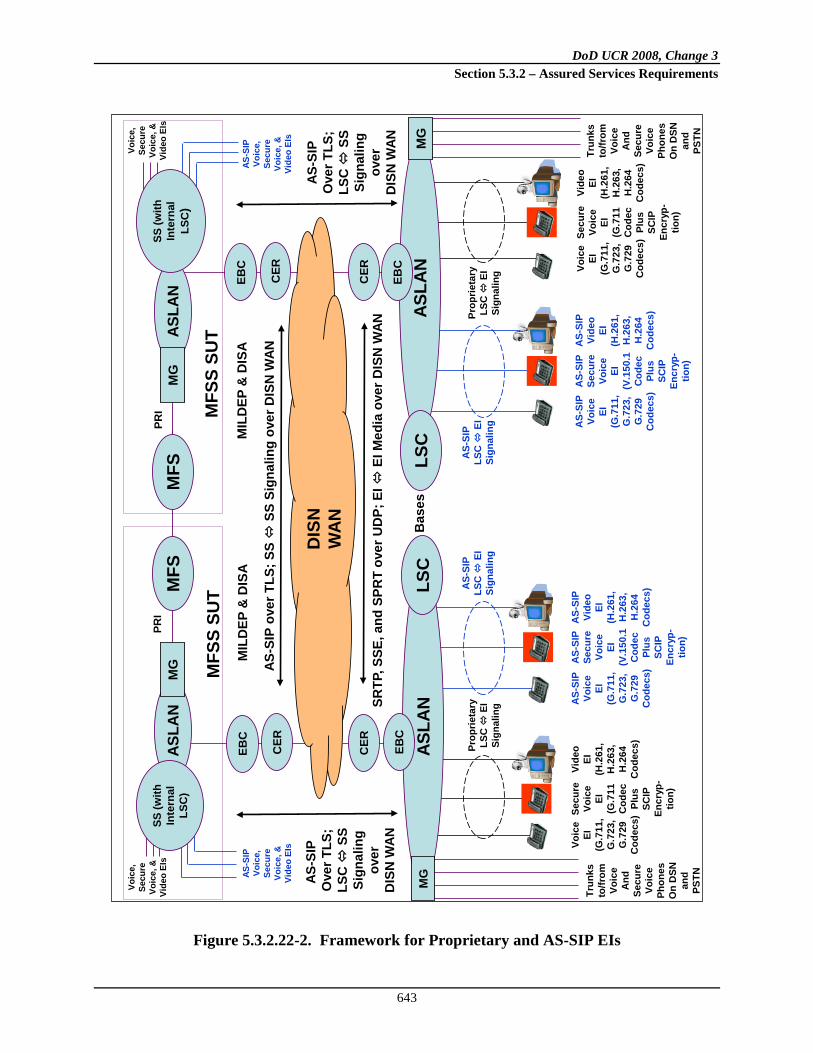
DoD UCR 2008, Change 3 Section 5.3.2 – Assured Services Requirements
643
Figure 5.3.2.22-2. Framework for Proprietary and AS-SIP EIs
AS-S
IP
Ove
r TLS
;LS
C
SSSi
gnal
ing
over
DIS
N W
AN
Bas
es
MIL
DEP
& D
ISA
ASLA
NLS
CM
G
AS-
SIP
Voic
eEI
(G.7
11,
G.7
23,
G.7
29C
odec
s)
AS-
SIP
Vide
oEI
(H
.261
,H
.263
,H
.264
Cod
ecs)
EBC
CER
EBC
CER
Trun
ks
to/fr
omVo
ice
And
Se
cure
Voic
ePh
ones
On
DSN
an
d PS
TN
AS-S
IPO
ver T
LS;
LSC
SS
Sign
alin
gov
erD
ISN
WAN
MIL
DEP
& D
ISA
CER
EBC
CER
Trun
ks
to/fr
omVo
ice
And
Secu
reVo
ice
Phon
esO
n D
SN
and
PSTN
DIS
N
WAN
AS-
SIP
LSC
EI
Sign
alin
g
AS-
SIP
Secu
reVo
ice
EI(V
.150
.1C
odec
Plus
SCIP
Encr
yp-
tion)
AS-S
IP o
ver T
LS; S
S
SS S
igna
ling
over
DIS
N W
AN
SRTP
, SSE
, and
SPR
T ov
er U
DP;
EI
EI M
edia
ove
r DIS
N W
AN
Voic
eEI
(G.7
11,
G.7
23,
G.7
29C
odec
s)
Vide
oEI
(H.2
61,
H.2
63,
H.2
64C
odec
s)
Secu
reVo
ice
EI(G
.711
Cod
ecPl
usSC
IPEn
cryp
-tio
n)
Prop
rieta
ryLS
C
EISi
gnal
ing
AS-
SIP
Voic
eEI
(G.7
11,
G.7
23,
G.7
29C
odec
s)
AS-
SIP
Vide
oEI
(H
.261
,H
.263
,H
.264
Cod
ecs)
AS-
SIP
LSC
EI
Sign
alin
g
AS-
SIP
Secu
reVo
ice
EI(V
.150
.1C
odec
Plus
SCIP
Encr
yp-
tion)
Voic
eEI
(G.7
11,
G.7
23,
G.7
29C
odec
s)
Vide
oEI
(H.2
61,
H.2
63,
H.2
64C
odec
s)
Secu
reVo
ice
EI(G
.711
Cod
ecPl
usSC
IPEn
cryp
-tio
n)
Prop
rieta
ryLS
C
EISi
gnal
ing
ASLA
NEB
C
LSC
MG
PRI
MFS
S SU
T
ASLA
NM
GM
FSSS
(with
In
tern
al
LSC
)
PRI M
FSS
SUTAS
LAN
MG
MFS
SS (w
ith
Inte
rnal
LSC
)
Voic
e,
Secu
re
Voic
e, &
Vide
o EI
s
Voic
e,
Secu
reVo
ice,
&Vi
deo
EIs
AS-S
IP
Voic
e,
Secu
re
Voic
e, &
Vide
o EI
s
AS-S
IP
Voic
e,
Secu
reVo
ice,
&Vi
deo
EIs

DoD UCR 2008, Change 3 Section 5.3.2 – Assured Services Requirements
644
[Required: LSC, SS, AS-SIP Voice EI, AS-SIP Secure Voice EI, AS-SIP Video EI] The LSCs and AS-SIP EIs (voice, secure voice, and video) shall support mutual authentication using AS-SIP and TLS signaling instead of vendor-proprietary signaling. That is, each AS-SIP EI should authenticate itself with its serving LSC using AS-SIP and TLS signaling, and each LSC should authenticate itself with the AS-SIP EIs that it serves using AS-SIP and TLS signaling. [Required: LSC, SS] The LSC shall allow a single AS-SIP EI to support voice, secure voice, and video capabilities. In this case, the LSC shall support that EI using the combined requirements for a AS-SIP voice EI, a AS-SIP secure voice EI, and a AS-SIP video EI, as given below. The LSC shall also allow a single AS-SIP EI to support the following subset of these three capabilities:
• Voice and Secure Voice • Voice and Video
[Conditional: AS-SIP Voice EI, AS-SIP Secure Voice EI, AS-SIP Video EI] A single AS-SIP EI may support voice, secure voice, and video capabilities. In this case, the EI shall support those capabilities IAW the combined requirements for an AS-SIP voice EI, an AS-SIP secure voice EI, and an AS-SIP video EI, as given in Section 5.3.2.22.2.1, Requirements for AS-SIP Voice EIs; Section 5.3.2.22.2.2, Requirements for AS-SIP secure voice EIs; and Section 5.3.2.22.2.3, Requirements for AS-SIP video EIs. [Conditional: AS-SIP Voice EI, AS-SIP Secure Voice EI] A single AS-SIP EI may support both voice and secure voice capabilities. In this case, the EI shall support those capabilities IAW the combined requirements for an AS-SIP voice EI and an AS-SIP secure voice EI, as given in Section 5.3.2.22.2.1, Requirements for AS-SIP Voice EIs, and Section 5.3.2.22.2.2, Requirements for AS-SIP Secure Voice EIs. [Conditional: AS-SIP Voice EI, AS-SIP Video EI] A single AS-SIP EI may support both Voice and Video capabilities. In this case, the EI shall support those capabilities IAW the combined requirements for an AS-SIP voice EI and an AS-SIP video EI, as given in Section 5.3.2.22.2.1, Requirements for AS-SIP Voice EIs, and Section 5.3.2.22.2.3, Requirements for AS-SIP Video EIs. [Required: AS-SIP Secure Voice EI] An AS-SIP secure voice EI shall also support the capabilities of an AS-SIP Voice EI IAW the AS-SIP voice EI requirements given in Section 5.3.2.22.2.1, Requirements for AS-SIP Voice EIs. The AS-SIP secure voice EI shall support these capabilities for “voice communication in the clear” using the Audio media type and the G.7XX codecs.

DoD UCR 2008, Change 3 Section 5.3.2 – Assured Services Requirements
645
NOTE: (If an AS-SIP Secure Voice EI is a “Modem Relay Preferred” EI and only supports Audio media using the “NoAudio” payload type, then the AS-SIP secure voice EI is not required to support the G.7XX codecs.)
5.3.2.22.2.1 Requirements for AS-SIP Voice EIs
[Required: LSC, SS] The LSCs shall support AS-SIP voice EIs that use AS-SIP for EI LSC signaling. The LSCs shall support these AS-SIP voice EIs using the AS-SIP LSC-to-AS-SIP-EI interface defined in Section 5.3.2.22.3.1, Multiple Call Appearances, and in Section 5.3.4, AS-SIP Requirements. [Required: AS-SIP Voice EI] The AS-SIP voice EIs shall support AS-SIP for EI LSC signaling. These AS-SIP voice EIs shall support the AS-SIP LSC-to-AS-SIP-EI interface defined in Section 5.3.2.22.3.1, Multiple Call Appearances, and in Section 5.3.4, AS-SIP Requirements. [Required: LSC, SS, AS-SIP Voice EI] The LSCs and AS-SIP Voice EIs shall support the following supplementary services for voice calls on AS-SIP voice EIs, consistent with Section 5.3.2.2.2.1, Voice Features and Capabilities.
• Precedence Call Waiting [Required] • Call Forwarding [Required] • Call Transfer [Required] • Call Hold [Required] • UC Conferencing [Conditional] • 3-Way Calling [Required] • Calling Party and Called Party ID (number only) [Required] • Call Pickup [Conditional for Voice EIs (both Proprietary and AS-SIP)]
NOTE: Support for Hotline Service for AS-SIP voice EIs is neither required nor conditional. The LSCs and AS-SIP Voice EIs shall support these supplementary services using AS-SIP signaling. [Required: LSC, SS, AS-SIP Voice EI] The LSCs and AS-SIP voice EIs shall support a mechanism to limit the total number of voice calls at that EI at any given time. The LSC shall keep track of the total number of voice calls at the AS-SIP voice EI at all times, where this total number includes active calls, calls on hold, additional calls that are being offered to the EI using CW, and additional calls that are being originated by the EI using Call Transfer or TWC. The LSC shall compare this total number of calls to the voice call limit for that EI, and

DoD UCR 2008, Change 3 Section 5.3.2 – Assured Services Requirements
646
shall block further voice call requests to and from the AS-SIP EI once this voice call limit is reached. [Required: LSC, SS, AS-SIP Voice EI] For AS-SIP voice EIs, the voice call limit depends on the number of voice call appearances supported on the EI. The AS-SIP voice EIs are required to support two voice call appearances for one DSN number in this document (per Section 5.3.2.22.3.1, Multiple Call Appearances). But one of these call appearances may not be used, because the LSC is only configured to support one voice call appearance for one DSN number on this EI. As a result, the voice call limit that the LSC maintains for the AS-SIP voice EI depends on whether the LSC is configured to support one call appearance or two call appearances for that EI. 1. When the LSC is configured to support two call appearances on an AS-SIP voice EI, the
LSC shall use a voice call limit of “Two” for that EI.
2. When the LSC is configured to support one call appearance on an AS-SIP voice EI (even though the EI may support two call appearances), the LSC shall use a voice call limit of “One” for that EI.
5.3.2.22.2.2 Requirements for AS-SIP Secure Voice EIs
[Required: LSC, SS] The LSCs shall support AS-SIP secure voice EIs that use AS-SIP for EI LSC signaling. The LSCs shall support these AS-SIP secure voice EIs using the AS-SIP LSC-to-AS-SIP-EI interface defined in Section 5.3.2.22.3.1, Multiple Call Appearances, and in Section 5.3.4, AS-SIP Requirements. [Required: AS-SIP Secure Voice EI] AS-SIP Secure Voice EIs shall support AS-SIP for EI LSC signaling. These AS-SIP secure voice EIs shall support the AS-SIP LSC-to-AS-SIP-EI interface defined in Section 5.3.2.22.3.1, Multiple Call Appearances, and in Section 5.3.4, AS-SIP Requirements. [Required: LSC, SS] The LSCs and SSs shall support the following supplementary services for voice calls on AS-SIP secure voice EIs, consistent with Section 5.3.2.2.2.1, Voice Features and Capabilities:
• Precedence Call Waiting [Required] • Call Forwarding [Required] • Call Transfer [Required] • Call Hold [Required] • UC Conferencing [Conditional] • 3-Way Calling [Required] • Calling Party and Called Party ID (number only) [Required]

DoD UCR 2008, Change 3 Section 5.3.2 – Assured Services Requirements
647
• Call Pickup [Conditional for Voice EIs (both Proprietary and AS-SIP)] NOTE: Hotline Service for AS-SIP secure voice EIs is neither required nor conditional. The LSCs shall support these supplementary services using AS-SIP signaling. NOTE: LSCs and SSs, which are in the session signaling path but not in the session media path, cannot make any distinctions between voice calls (“clear voice” calls) and secure voice calls at an AS-SIP secure voice EI. This limitation occurs because a secure voice call always starts off as a voice call first, and then later converts from a voice call to a secure voice call after an E2E exchange of V.150.1 SSE messages in the media path (and not in the signaling path). As a result, if an LSC provides a supplementary service to an AS-SIP EI for voice calls, the LSC also provides that supplementary service to the AS-SIP EI for secure voice calls, since the LSC on its own cannot distinguish between a voice call at an AS-SIP EI and a secure voice call at that AS-SIP EI. An AS-SIP Secure voice EI, however, can distinguish between a voice call (a call in “clear-voice” mode) and a secure voice call. So the AS-SIP secure voice EI can prevent the use of a supplementary service on secure voice calls (like Call Hold, Call Transfer, or TWC), where the use of that service can “break” the media path between the calling and called EIs (SCIP end points) and cause the secure voice call to fail. But the secure voice EI can also allow the use of a supplementary service on secure voice calls by requiring the end user to return the secure voice call to a voice call (a “clear-voice” call) so that the supplementary service can be used. This is the approach supported at the AS-SIP secure voice EI in the following requirements. [Required: AS-SIP Secure Voice EI] An AS-SIP secure voice EI is not required to support any supplementary services for secure voice calls (calls using SCIP/modem relay media). [Required: AS-SIP Secure Voice EI] An AS-SIP secure voice EI shall be able to operate as an AS-SIP voice EI for voice calls (calls using Audio media and not SCIP/modem relay media). [Required: AS-SIP Secure Voice EI] An AS-SIP secure voice EI shall be able to operate as an AS-SIP voice EI for the portions of calls where Audio media is used (and SCIP/modem relay media is not used). This AS-SIP secure voice EI requirement applies during the time before a call converts from Audio media to SCIP/modem relay media, and during the time after a call converts from SCIP/modem relay media back to Audio media. This requirement also applies to a call that never converts to SCIP/modem relay media, and uses Audio media for the lifetime of the call. [Required: AS-SIP Secure Voice EI] An AS-SIP Secure Voice EI shall not allow the end user to activate any supplementary services when a call on that EI is operating in “Secure Voice” mode, and SCIP/modem relay media is being used.
DoD UCR 2008, Change 3 Section 5.3.2 – Assured Services Requirements
648
When an end user tries to use a supplementary service when a call on the EI is operating in secure voice mode, the EI shall prevent the user from activating the service, and shall return an error indication (i.e., a locally generated tone and a visual display) back to that user. The error indication shall indicate that the end user must return the secure voice call to a “Clear Voice” call before the supplementary service can be used. [Required: AS-SIP Secure Voice EI] Whenever the local end user returns the Secure Voice call to a Clear Voice call, or the remote end user returns the secure voice call to a clear voice call, the AS-SIP secure voice EI shall return a “clear voice confirmation” indication (i.e., a locally generated tone and a visual display) to the local end user. This lets the local end user know that the call has returned from secure voice mode to clear voice mode. It also lets them know that they are no longer communicating in secure voice mode, and lets them know that they can activate supplementary services if desired. [Required: AS-SIP Secure Voice EI] An AS-SIP secure voice EI shall support supplementary services when all calls on that EI are operating in clear voice mode, and Audio media alone is being used. When an end user tries to use a supplementary service when all calls on the EI are operating in clear voice mode, the EI shall allow the user to activate the service, and shall process the service request accordingly. This requirement shall also apply after the user has returned a secure voice call to a clear voice call (e.g., in response to an error indication from the EI during the secure voice call), and then tries to use a supplementary service on the clear voice call. [Required: AS-SIP Secure Voice EI] When operating as an AS-SIP voice EI (i.e., all EI calls are in clear voice mode), an AS-SIP secure voice EI shall support the following supplementary services for voice calls, as an extension of the requirement to support these services for voice calls in Section 5.3.2.2.2.1, Voice Features and Capabilities:
• Precedence Call Waiting [Required] • Call Forwarding [Required] • Call Transfer [Required] • Call Hold [Required] • UC Conferencing [Conditional] • 3-Way Calling [Required] • Calling Party and Called Party ID (number only) [Required] • Call Pickup [Conditional for Voice EIs (both Proprietary and AS-SIP)]
Note that Hotline Service for AS-SIP secure voice EIs is neither required nor conditional. The AS-SIP Secure Voice EI shall support these supplementary services using AS-SIP signaling.

DoD UCR 2008, Change 3 Section 5.3.2 – Assured Services Requirements
649
[Required: AS-SIP Secure Voice EI] When an AS-SIP secure voice EI has a secure voice call active, the LSC sends that EI a Precedence CW or ROUTINE CW indication, and the EI user attempts to place the secure voice call on hold and answer the waiting call, the EI shall send an error indication (tone and display) to the user as described previously. If the user converts the secure voice call back to a clear voice call, and then tries to place the clear voice call on hold and answer the waiting call, the EI shall accept the user’s request and relay it to the LSC. [Required: AS-SIP Secure Voice EI] When an AS-SIP secure voice EI has a secure voice call active, and the EI user attempts to activate Call Transfer by placing the secure voice call on hold and setting up another call, the EI shall send an error indication (tone and display) to the user as described previously. If the user converts the secure voice call back to a clear voice call, and then tries to activate Call Transfer by placing the clear voice call on hold and setting up another call, the EI shall accept the user’s request and relay it to the LSC. [Required: AS-SIP Secure Voice EI] When an AS-SIP secure voice EI has a secure voice call active, and the EI user attempts to activate Call Hold by placing the secure voice call on hold, the EI shall send an error indication (tone and display) to the user as described previously. If the user converts the secure voice call back to a clear voice call, and then tries to activate Call Hold by placing the clear voice call on hold, the EI shall accept the user’s request and relay it to the LSC. [Required: AS-SIP Secure Voice EI] When an AS-SIP secure voice EI has a secure voice call active, and the EI user attempts to activate TWC by placing the secure voice call on hold and setting up another call, the EI shall send an error indication (tone and display) to the user as described previously. If the user converts the secure voice call back to a clear voice call, and then tries to activate TWC by placing the clear voice call on hold and setting up another call, the EI shall accept the user’s request and relay it to the LSC. [Required: AS-SIP Secure Voice EI] When an AS-SIP secure voice EI has a secure voice call active, and the LSC sends that EI a Precedence CW or Routine CW indication and provides Calling Party ID and Precedence Level information within the CW indication, the AS-SIP Secure Voice EI shall display both the Calling Party ID and Precedence Level information to the called user at the EI, as part of the CW indication that the EI delivers to the called user. (This gives the called users a basis for deciding whether to answer or ignore a “waiting” voice call when they have a secure voice call active on their EI. “Ignore,” as used here, means that the user allows the call to be forwarded by the CFDA feature or deflected by the Precedence Call Diversion feature.) [Required: LSC, SS, AS-SIP Secure Voice EI] The LSC and the AS-SIP secure voice EI shall support a mechanism to limit the total number of voice and secure voice calls at that EI at any given time. (For example, it is possible for an EI to have a voice call (Audio media) on hold and a secure voice call (Modem Relay media) active at the same time.)

DoD UCR 2008, Change 3 Section 5.3.2 – Assured Services Requirements
650
The LSC shall keep track of the total number of active voice and secure voice calls at the EI at all times. (The LSC does not need to separately track the total number of voice calls and the total number of secure voice calls at the EI, since this would require the LSC to know which calls are voice calls using Audio media, and which calls are secure voice calls using modem relay media.) The LSC shall compare this total number of voice and secure voice calls to the configured voice call limit for that EI, and shall block further voice call requests to and from the AS-SIP EI once this call limit is reached. [Required: LSC, SS, AS-SIP Secure Voice EI] For AS-SIP secure voice EIs (which can also operate as AS-SIP Voice EIs), the voice/secure voice call limit depends on the number of voice call appearances supported on the EI. Like AS-SIP voice EIs, AS-SIP secure voice EIs are required to support two voice call appearances for one DSN number in this document (per Section 5.3.2.22.3.1, Multiple Call Appearances). But one of these call appearances may not be used because the LSC is only configured to support one voice call appearance for one DSN number on this EI. As a result, the voice/secure voice call limit that the LSC maintains for the AS-SIP secure voice EI depends on whether the LSC is configured to support one call appearance or two call appearances for that EI. 1. When the LSC is configured to support two call appearances on an AS-SIP secure voice EI,
the LSC shall use a voice/secure voice call limit of “Two” for that EI.
2. When the LSC is configured to support one call appearance on an AS-SIP secure voice EI (even though the EI may support two call appearances), the LSC shall use a voice/secure voice call limit of “One” for that EI.
5.3.2.22.2.3 Requirements for AS-SIP Video EIs
[Required: LSC, SS] LSCs shall support AS-SIP Video EIs that use AS-SIP for EI LSC signaling. The LSCs shall support these AS-SIP Video EIs using the AS-SIP LSC-to-AS-SIP-EI interface defined in Section 5.3.2.22.3.1, Multiple Call Appearances, and in Section 5.3.4, AS-SIP Requirements. [Required: AS-SIP Video EI] The AS-SIP Video EIs shall support AS-SIP for EI LSC signaling. These AS-SIP Video EIs shall support the AS-SIP LSC-to-AS-SIP-EI interface defined in Section 5.3.2.22.3.1, Multiple Call Appearances, and in Section 5.3.4, AS-SIP Requirements. [Conditional: LSC, SS, AS-SIP Video EI] It is conditional that LSCs, SSs, and AS-SIP Video EIs support the following supplementary services for video calls, as an extension of the

DoD UCR 2008, Change 3 Section 5.3.2 – Assured Services Requirements
651
requirement to support these services for voice calls in Section 5.3.2.2.2.1, Voice Features and Capabilities:
• Precedence Call Waiting [Required for voice calls] • Call Forwarding [Required for voice calls] • Call Transfer [Required for voice calls] • Call Hold [Required for voice calls] • UC Conferencing [Conditional for voice calls] • 3-Way Calling [Required for voice calls] • Calling Party and Called Party ID (number only) [Required for voice calls] • Call Pickup [Conditional for voice calls]
• Far-End Camera Control [Conditional] The LSC and the AS-SIP video EI
shall support the transmission of H.281 far-end camera control (FECC) messages when used in conjunction with video systems (e.g., MCUs and VTC bridges) that employ far-end camera control capabilities. The specific requirements for implementing this capability are provided in Section 5.3.4.9.7.3, General H.224 Control Channel for Far-End Camera Control Messages, and in Section 5.3.4.9.7.4, FECC.
• Binary Floor Control Protocol [Conditional] The LSC and the AS-SIP Video EI shall support (when used in multipoint conferences) the Binary Floor Control Protocol (BFCP) that uses a floor control server to manage the control of media streams that are shared resources (i.e., “floors”) as specified in RFC 4582. The specific requirements for implementing this capability are provided in Section 5.3.4.9.7.5, SDP Attributes for Binary Floor Control Protocol Streams.
NOTE: Hotline Service for AS-SIP video EIs is neither Required nor Conditional. The LSCs, SSs, and AS-SIP Video EIs shall support these supplementary services using AS-SIP signaling. [Required: LSC, SS, AS-SIP Video EI] The LSCs and AS-SIP video EIs shall support a mechanism to limit the total number of video calls at that EI at any given time. The LSC shall keep track of the total number of video calls at the AS-SIP video EI at all times. The LSC shall compare this total number of calls to the configured video call limit for that EI, and shall block further video call requests to and from the AS-SIP EI once this video call limit is reached.

DoD UCR 2008, Change 3 Section 5.3.2 – Assured Services Requirements
652
For AS-SIP video EIs, the configured call limit for that EI shall be “one video call.” This is all that is required of AS-SIP video EIs in the UCR. [Required: LSC, SS, AS-SIP Video EI] The LSC and the AS-SIP video EI shall support a mechanism to identify the amount of video call bandwidth (counted as Video Session Units) in use at that EI at any given time. The LSC and the AS-SIP video EI shall keep track of the total amount of video call bandwidth (in VSU) in use at the AS-SIP video EI at all times. (A 500-kbps video call shall use one VSU of bandwidth, a 1-Mbps video call shall use two VSUs of bandwidth, a 2.5-Mbps video call shall use five VSU of bandwidth, and a 4.0-Mbps video call shall use eight VSUs of bandwidth.) [Required: LSC, SS, AS-SIP Video EI] The LSC and the AS-SIP video EI shall also support the conversion of a lower-bandwidth video call to a higher-bandwidth video call (and vice-versa), using AS-SIP re-INVITE messages on the LSC-to-AS-SIP-EI interface to signal the bandwidth change. [Required: LSC, SS, AS-SIP Video EI] The LSC and the AS-SIP video EI shall also support the conversion of a video call to a voice call (and vice-versa), using AS-SIP re-INVITE messages on the LSC-to-AS-SIP-EI interface to signal the media change.
5.3.2.22.3 Multiple Call Appearance Requirements for AS-SIP EIs
5.3.2.22.3.1 Multiple Call Appearances
Section 5.3.4, AS-SIP Requirements, contains requirements on “Multiple Appearances” in Sections 5.3.4.10.3.2.2.1a through 5.3.4.10.3.2.2.3. The first of these requirements is as follows:
“IP end instruments MUST be limited to two (2) appearances per DN and limited to, at most, two (2) DNs.”
This requirement applies for both voice (audio) sessions and for video sessions. An “appearance” or “call appearance” on an IP EI can be used to originate or terminate either a voice session or a video session. An existing voice session on an EI call appearance can be preempted by a new incoming video session of higher precedence, and an existing video session on an EI call appearance can be preempted by a new incoming voice session of higher precedence. This requirement is being extended to AS-SIP EIs here, with two exceptions: 1. On AS-SIP EIs, support for two appearances per DN and one DN per phone is required.
But support for two appearances per DN and two DNs per phone is not required.

DoD UCR 2008, Change 3 Section 5.3.2 – Assured Services Requirements
653
2. On AS-SIP EIs, support for call appearances is required for voice calls on AS-SIP Voice EIs, and for Secure voice calls on AS-SIP Secure Voice EIs. But support for call appearances is not required for video calls on AS-SIP Video EIs.
An AS-SIP Video EI is only required to support one DN, and to support one video call on that DN at a time. An AS-SIP Video EI is not required to use a call appearance to support this single video call. An AS-SIP Video EI that is also an AS-SIP Voice EI (and supports voice calls and two voice call appearances) is not required to use either of its voice call appearances to support this video call. The following requirements and recommendations also apply to the LSCs that serve the AS-SIP EIs, and to the LSC-to-AS-SIP-EI interface: 1. An AS-SIP Voice EI must be able to support two simultaneous voice calls (media type
equals Audio) using two call appearances of the same DN (10-digit DSN number).
2. When operating as an AS-SIP Voice EI (no Secure voice calls active), an AS-SIP Secure Voice EI must be able to support two simultaneous voice calls (media type equals Audio) using two call appearances of the same DN.
3. When operating as an AS-SIP Secure Voice EI (one secure voice call active), an AS-SIP Secure Voice EI must be able to support one Secure voice call (media type equals modem relay) using one of its two call appearances. The EI may also support a voice call (media type equals Audio) on Hold using its other call appearance in this case.
4. An AS-SIP Video EI must be able to support one video call (media type equals Video). If the AS-SIP EI is also an AS-SIP Voice EI or AS-SIP Secure Voice EI, the EI is not required to use either of its voice call appearances to support the video call.
[Required: AS-SIP Voice EI, AS-SIP Secure Voice EI] An AS-SIP EI shall allow multiple call appearances of the same DN (10-digit DSN number) to be assigned to it. An AS-SIP EI shall allow at least two appearances of the same DN to be assigned to it. This requirement does not apply to AS-SIP Video EIs. [Required: AS-SIP Voice EI, AS-SIP Secure Voice EI] An AS-SIP EI shall allow each call appearance of a DN to be used for voice and secure voice calls to and from that DN. This requirement does not apply to AS-SIP Video EIs. Dedication of call appearances on an EI to a particular call type (Voice, Secure Voice, or Video) is not a requirement. [Required: AS-SIP Video EI] An AS-SIP EI shall support one DN for video calls, and support one video call on that DN at a time. An AS-SIP Video EI is not required to use a call appearance to support this single video call. An AS-SIP Video EI that is also an AS-SIP Voice EI (and supports voice calls and two voice call appearances) is not required to use either of its voice call appearances to support this video call.

DoD UCR 2008, Change 3 Section 5.3.2 – Assured Services Requirements
654
[Required: AS-SIP Voice EI] An AS-SIP Voice EI shall be able to support two simultaneous voice calls (media type equals Audio) using two call appearances of the same DN (10-digit DSN number). [Required: AS-SIP Secure Voice EI] When operating as an AS-SIP Voice EI (no Secure voice calls active), an AS-SIP Secure Voice EI shall be able to support two simultaneous voice calls (media type equals Audio) using two call appearances of the same DN. [Required: AS-SIP Secure Voice EI] When operating as an AS-SIP Secure Voice EI (one Secure voice call active), an AS-SIP Secure Voice EI shall be able to support one Secure voice call (media type equals modem relay) using one of its two call appearances. The EI may also support a voice call (media type equals Audio) on Hold using its other call appearance in this case. [Required: AS-SIP Video EI] An AS-SIP Video EI shall be able to support one video call (media type equals Video). If the AS-SIP EI is also an AS-SIP Voice EI or AS-SIP Secure Voice EI, the EI is not required to use either of its voice call appearances to support the video call [Required: LSC, SS, AS-SIP Voice EI, AS-SIP Secure Voice EI] The AS-SIP EI and LSC shall allow multiple media types to be requested (as part of SDP capability declaration) in the same EI-to-LSC INVITE message. For example, INVITE messages from a voice call appearance on an AS-SIP Secure Voice EI can contain both an Audio media declaration (with G.711, G.722.1, G.723, and G.729 codecs indicated), and a V.150.1 modem relay media declaration (with SSE and SPRT protocols indicated). [Required: LSC, SS, AS-SIP Voice EI, AS-SIP Secure Voice EI] The LSC and AS-SIP EI shall allow multiple media types to be requested (as part of SDP capability declaration) in the same LSC-to-EI INVITE message. [Required: AS-SIP Voice EI, AS-SIP Secure Voice EI] An AS-SIP EI shall only allow one voice call (voice or secure voice) to be associated with one call appearance at a time. An AS-SIP EI shall not allow multiple calls (e.g., one active call and one held call) to be associated with the same call appearance at the same time. [Required: AS-SIP Voice EI, AS-SIP Secure Voice EI] An AS-SIP EI shall allow multiple voice calls to be associated with itself, as long as each call is associated with one, and only one, call appearance on that AS-SIP EI. An AS-SIP EI shall allow each call associated with the EI to be in either an “active” state, a “held” state, or a “call in progress” state (a call in the process of being established).

DoD UCR 2008, Change 3 Section 5.3.2 – Assured Services Requirements
655
[Required: AS-SIP Secure Voice EI] An AS-SIP secure voice EI shall only allow one secure voice call (media equals modem relay) to be associated with the EI at a time, and allow that call to be associated with one call appearance on that EI. The AS-SIP EI shall only allow this secure voice call to be in an “active” state, and not in a “held” state, or a “call in progress” state. [Required: AS-SIP Secure Voice EI] When a secure voice call is active, the AS-SIP secure voice EI shall also allow an additional voice call (media equals Audio) to be associated with the EI, and allow that call to be associated with the second call appearance on that EI. The AS-SIP EI shall only allow this additional voice call to be in a “held” state or a “call in progress” state (a call in the process of being established), and not in an “active” state. For example, if the CW feature is assigned, the EI shall allow an active Secure voice call on one call appearance and an incoming “in progress” voice call on the other call appearance. [Required: AS-SIP Voice EI, AS-SIP Secure Voice EI] An AS-SIP EI shall allow a call on a single call appearance to transition from one media type to another, using an in-band media message for a media change (like a V.150.1 modem relay SSE message). An AS-SIP EI shall support transitions from voice media to secure voice media, and transitions from secure voice media to voice media.
5.3.2.22.3.2 Multiple Call Appearances – Interactions with Precedence Calls
This section describes the requirements for handling incoming precedence calls (i.e., PRIORITY, IMMEDIATE, FLASH, and FLASH OVERRIDE) on the LSC-to-AS-SIP-EI interface, for an AS-SIP Voice EI or AS-SIP Secure Voice EI that supports multiple appearances of a single DN. These requirements are not currently applicable to AS-SIP video EIs because these EIs do not support multiple call appearances of a single DN. These LSC, AS-SIP Voice EI, and AS-SIP secure voice EI requirements are based on the corresponding requirements for handling incoming precedence calls on the DSN-switch-to-ISDN-BRI interface, for an ISDN BRI station set that supports multiple appearances of a single DN. These requirements are found in Section 5.3.2.31.3.7.3, Single B Channel, Multiple Appearances, Single Directory Number. [Required: AS-SIP Voice EI, AS-SIP Secure Voice EI] When offering an incoming precedence call is offered on a multiple-call-appearance AS-SIP EI, the EI shall do to the following: 1. Play a precedence ringing tone for that call.
2. Offer the call on the next available call appearance for the indicated DN.
3. Provide a visual precedence level display to the end user.

DoD UCR 2008, Change 3 Section 5.3.2 – Assured Services Requirements
656
[Required: AS-SIP Voice EI, AS-SIP Secure Voice EI] The LSC AS-SIP EI shall then give the called user the option of either of the following: 1. Placing the currently active call (on the currently active call appearance) on hold and
picking up the incoming precedence call on the new call appearance.
2. Ignoring the incoming precedence call on the new call appearance. “Ignoring,” as used here, means that the called user allows the call to be forwarded by the CFDA feature, or deflected by the Precedence Call Diversion feature.
[Required: AS-SIP Secure Voice EI] If the AS-SIP EI is a secure voice EI and the currently active call is a secure voice call using modem relay media, the EI shall require the called user to convert the callback to a voice call using Audio media before placing it on hold. The AS-SIP EI shall not allow a Secure voice call using modem relay media to be placed on hold. [Required: AS-SIP Voice EI, AS-SIP Secure Voice EI] The AS-SIP voice EI shall offer subsequent incoming precedence calls to the end user, up to the total number of call appearances supported by the EI. For each additional incoming precedence call, the AS-SIP EI shall offer the call as described previously, and allow the end user to place the existing active call on hold (if it is a voice call using Audio media) and answer the precedence call as described previously. This process of offering a new precedence call, placing an existing call on hold, and answering the precedence call shall remain the same until the AS-SIP EI is saturated (i.e., all of its call appearances are in use). [Required: AS-SIP Voice EI, AS-SIP Secure Voice EI] When an AS-SIP EI is saturated, and an incoming precedence call is made to that EI, the EI shall determine the lowest precedence call from all of the calls on all of the EI’s call appearances (including those calls that are on hold), and shall preempt that call. [Required: AS-SIP Voice EI, AS-SIP Secure Voice EI] If this lowest precedence call is a call on hold, then the EI shall send a preemption tone to the remote party on the held call (the party on hold). [Required: AS-SIP Voice EI, AS-SIP Secure Voice EI] The AS-SIP EI shall also send a preemption tone to the local party on this held call by playing this tone on the EI call appearance for this call. [Required: AS-SIP Voice EI, AS-SIP Secure Voice EI] After a preset period, the AS-SIP EI shall clear this call on hold, and shall play a precedence ringing tone and provide a precedence level display on the call appearance where the held call has been cleared.

DoD UCR 2008, Change 3 Section 5.3.2 – Assured Services Requirements
657
As a result, the called user should hear the preemption tone followed by the precedence ringing tone (indicating that the call on hold has been dropped), and see the precedence level of the new call on the AS-SIP EI’s display. [Required: AS-SIP Voice EI, AS-SIP Secure Voice EI] The AS-SIP EI shall then give the called user the option of answering the call, or letting it forward to an alternate party (if CFDA is assigned), or letting it divert to an attendant (e.g., if Precedence Call Diversion is assigned). [Required: AS-SIP Voice EI, AS-SIP Secure Voice EI] If the lowest precedence call is not a call on hold, but instead is the active call at the EI, the AS-SIP EI shall send a preemption tone to both the remote party and the local party on the active call (the local party on the active call appearance). [Required: AS-SIP Voice EI, AS-SIP Secure Voice EI] When the local party on the active call appearance goes “on hook,” the AS-SIP EI shall offer the incoming precedence call to that party by playing a precedence ringing tone and providing a precedence level display on the call appearance where the active call has been cleared. [Required: AS-SIP Voice EI, AS-SIP Secure Voice EI] The AS-SIP EI shall then give the called user the option of answering the call, or letting it forward to an alternate party (if CFDA is assigned), or letting it divert to an attendant (if Precedence Call Diversion is assigned). [Required: AS-SIP Voice EI, AS-SIP Secure Voice EI] In both of the previous cases (held call preempted and active call preempted), the AS-SIP EI shall not preempt any of the other calls that are on hold (on any other the other call appearances), and shall allow the end user to retrieve any of those calls at any time. [Required: LSC, SS, AS-SIP Voice EI, AS-SIP Secure Voice EI] In both previous cases above where the end user ignores the precedence call, and lets it either forward to an alternate party (via Call Forward Don’t Answer) or divert to an attendant (via Precedence Call Diversion), the LSC and the AS-SIP EI shall follow the requirements in Section 5.3.2.2.2.1.1, Call Forwarding, that define the interaction between VVoIP precedence calls and CF.
5.3.2.22.4 AS-SIP Video EI Features
[Conditional: AS-SIP Video EI] If the AS-SIP Video EI also supports FECC based on:
• ITU-T Recommendation H.224
• ITU-T Recommendation H.281

DoD UCR 2008, Change 3 Section 5.3.2 – Assured Services Requirements
658
Then the EI shall support all the AS-SIP and SDP protocol requirements for FECC in
• Section 5.3.4.9.7.3, General H.224 Control Channel for Far End Camera Control Messages.
[Conditional: AS-SIP Video EI] If the AS-SIP Video EI also supports BFCP based on
• RFC 4582 and
• RFC 4583 Then the EI shall support all the AS-SIP and SDP protocol requirements for BFCP Streams in
• Section 5.3.4.9.7.5, SDP Attributes for Binary Floor Control Protocol Streams.
[Conditional: AS-SIP Video EI] If the AS-SIP Video EI also supports Video Channel Flow Control [VCFC] based on
• RFC 4585 Then the EI shall support all the AS-SIP and SDP protocol requirements for VCFC in
• Section 5.3.4.9.7.6, Video Channel Flow Control. This UCR section requires support for the following sections of RFC 4585:
• Section 3.1, Compound RTCP Feedback Packets
• Section 3.2, Algorithm Outline
• Section 3.3, Modes of Operation
• Section 3.4, Definitions and Algorithm Overview
• Section 3.5, AVPF RTCP Scheduling Algorithm, and all subsections 3.5.1 – 3.5.4, inclusive
• Section 3.6.1, ACK Mode
• Section 3.6.2, NACK Mode

DoD UCR 2008, Change 3 Section 5.3.2 – Assured Services Requirements
659
• Section 4.1, Profile Identification
• Section 4.2, RTCP Feedback Capability Attribute
• Section 4.3, RTCP Bandwidth Modifiers
• Section 5, Interworking and Coexistence of AVP and AVPF Entities
• Section 6, Format of RTCP Feedback Messages
• Section 6.1, Common Packet Format for Feedback Messages
• Section 6.2, Transport Layer Feedback Messages (including 6.2.1 Generic NACK)
• Section 6.3, Payload-Specific Feedback Messages, including: − Section 6.3.1, Picture Loss Indication (PLI) and its subsections
− Section 6.3.2, Slice Loss Indication (SLI) and its subsections
− Section 6.3.3, Reference Picture Selection Indication (RPSI) and its
subsections
• Section 6.4, Application Layer Feedback Messages [Conditional: AS-SIP Video EI] If the AS-SIP Video EI also supports Video Channel Fast Update Requests [VCFUR] based on
• RFC 5104 then the EI shall support all the AS-SIP and SDP protocol requirements for VCFUR in
• Section 5.3.4.9.7.7, Video Channel Fast Update Requests. The Full Intra Request (FIR) payload-specific feedback message is the method adopted in this UCR section for implementing VCFUR.
5.3.2.23 Requirements for Supporting Commercial Cost Avoidance
The Commercial Cost Avoidance requirements are in:

DoD UCR 2008, Change 3 Section 5.3.2 – Assured Services Requirements
660
• Section 5.3.2.28.3, LSC to LRDB Interface: DB Queries for Commercial Cost Avoidance, and
• Section 5.3.2.28.4, LSC to MRDB Interface: DB Updates for Commercial
Cost Avoidance and Hybrid Routing.
5.3.2.24 Requirements for Supporting AS-SIP-Based Ethernet Interfaces for Voicemail Systems, Unified Messaging Systems, and Automated Receiving Devices
The following Conditional Requirements were added to the UCR to add LSC, MFSS, and WAN SS support for AS-SIP-Based Ethernet Interfaces for voicemail systems, Unified Messaging systems, and ARDs. The condition here is that the LSC, MFSS, and WAN SS support an AS-SIP-based Ethernet interface for interconnection with a standalone voicemail system, Unified Messaging system, or ARD. This interface is in addition to any vendor-proprietary interface that the LSC, MFSS, or WAN SS may already support for interconnection with a vendor-proprietary voicemail system, Unified Messaging system, or ARD. [Conditional: LSC, MFSS, WAN SS] The LSC, MFSS, and WAN SS shall support all mandatory requirements in RFC 3842. Per this RFC:
“Message Waiting Indication is a common feature of telephone networks. It typically involves an audible or visible indication that messages are waiting, such as playing a special dial tone (which in telephone networks is called message-waiting dial tone), lighting a light or indicator on the phone, displaying icons or text, or some combination”. This RFC “describes a Session Initiation (SIP) event package to carry message waiting status and message summaries from a messaging system to an interested User Agent.”
[Conditional: LSC, MFSS, WAN SS] The LSC, MFSS, and WAN SS shall support the use of RFC 3842 Message Waiting Indication (MWI) for “tandeming” message waiting indications between Voicemail Systems (and Unified Messaging Systems and ARDs), SSes, and LSCs that are subtended from the SSes. The LSC, MFSS, and WAN SS shall support transmission of RFC 3842 MWIs in the Voicemail System => SS => LSC direction, and transmission of any RFC 3842 MWI responses in the LSC => SS => Voicemail System direction. [Conditional: MLSC, SLSC] Master LSCs and SLSCs shall also support RFC 3842 MWI for “tandeming” message waiting indications between SSes, M LSCs, and SLSCs. Master LSCs and SLSCs shall support transmission of RFC 3842 MWIs in the SS => MLSC => SLSC direction, and transmission of any RFC 3842 MWI responses in the SLSC => MLSC => SS direction.

DoD UCR 2008, Change 3 Section 5.3.2 – Assured Services Requirements
661
[Conditional: LSC, MFSS, WAN SS] The LSC, MFSS, and WAN SS shall support all mandatory requirements in IETF Internet RFC 5806, Diversion Indication in SIP. Per this Internet RFC:
“This document proposes an extension to the Session Initiation Protocol (SIP). This extension provides the ability for the called SIP User Agent to identify from whom the call was diverted and why the call was diverted. The extension defines a general header, Diversion, which conveys the diversion information from other SIP user agents and proxies to the called user agent. This extension allows enhanced support for various features, including Unified Messaging, Third-Party Voicemail, and Automatic Call Distribution (ACD). SIP user agents and SIP proxies which receive diversion information may use this as supplemental information for feature invocation decisions.”
[Conditional: LSC, MFSS, WAN SS] The LSC, MFSS, and WAN SS shall support all the mandatory requirements in RFC 4244. Per this RFC:
“This document defines a standard mechanism for capturing the history information associated with a Session Initiation Protocol (SIP) request. This capability enables many enhanced services by providing the information about how and why a call arrives at a specific application or user. This RFC defines a new optional SIP header, History-Info, for capturing the history information in requests.”
[Conditional: LSC, MFSS, WAN SS] The LSC, MFSS, and WAN SS shall support all of the mandatory requirements in RFC 3725. Per this RFC:
“Third party call control refers to the ability of one entity to create a call in which communication is actually between other parties. Third party call control is possible using the mechanisms specified within the Session Initiation Protocol (SIP). However, there are several possible approaches, each with different benefits and drawbacks. This RFC provides best current practices for the usage of SIP for third party control.”
5.3.2.24.1 Requirements for Supporting AS-SIP Message Waiting Indications on AS-SIP EIs, TAs, and IADs
[Conditional: LSC, AEI, TA, IAD] The LSC, AEI, TA, and IAD shall support all of the mandatory requirements in:
• RFC 3842 for SIP Message Waiting Indication, • RFC 5806 for Diversion Indication in SIP, and

DoD UCR 2008, Change 3 Section 5.3.2 – Assured Services Requirements
662
• RFC 4244 for SIP Request History Information. In the case of TAs and IADs, this requirement only applies to TAs and IADs that support AS-SIP on their IP side for signaling with the LSC. LSCs shall be able to exchange SIP MWIs, SIP Diversion Indications, and SIP Request History Information with the AS-SIP EIs, TAs, and IADs that they serve. AS-SIP EIs, TAs, and IADs shall be able to accept SIP MWIs, SIP Diversion Indications, and SIP Request History Information from the LSCs that serve them, and relay the information in those SIP fields on to their end users. For example, if an AS-SIP EI, TA, or IAD receives an RFC 3842 SIP MWI from its LSC, that AEI, TA, or IAD shall be able to provide a visual MWI (light a lamp, display an icon) and/or an audible MWI (burst of ringing, stutter dial tone) to the UC end user.
5.3.2.25 UC Precedence Call Diversion
These requirements are based on the DSN requirements for Precedence Call Diversion (PCD) in Section 5.3.2.2.2.1.2.5, Precedence Call Diversion. The following limitations apply: 1. Support for Precedence Call Diversion from one UC EI to another UC EI on the same LSC
(or internal LSC within an MFSS or WAN SS) is required.
2. Support for Precedence Call Diversion from an UC EI on one LSC to an UC EI on another LSC is required.
3. Support for Precedence Call Diversion from an UC EI on an LSC to a DSN EI (on an EO, SMEO, PBX1, or PBX 2) is not required.
4. Support for Precedence Call Diversion from a DSN EI (on an EO, SMEO, PBX1, or PBX 2) to an UC EI on an LSC is not required.
[Required: LSC, MFSS – Conditional: WAN SS] The AS-SIP signaling appliance shall divert ALL unanswered UC VoIP calls above the ROUTINE precedence level to a designated UC DN for PCD (e.g., the number of an attendant console or group of attendant consoles). This diversion shall occur after a specified PCD time period, selectable from 15–45 seconds, and configurable at the per-appliance level. This PCD time period shall be configurable to be less than the CF time period for unanswered calls that are forwarded to voicemail and ACD systems. [Required: LSC, MFSS – Conditional: WAN SS] Unanswered UC VoIP calls above the ROUTINE precedence level shall not be forwarded to voicemail, and shall not be forwarded to ACD systems. Instead, they should divert to the PCD DN when the PCD time period expires.

DoD UCR 2008, Change 3 Section 5.3.2 – Assured Services Requirements
663
[Required: LSC, MFSS – Conditional: WAN SS] Unanswered UC VoIP calls at the ROUTINE precedence level shall still be forwarded to voicemail or to ACD systems (when CFDA is assigned to the called UC DN), even though PCD is enabled and configured for the AS-SIP signaling appliance. [Required: LSC, MFSS – Conditional: WAN SS] Calls above the ROUTINE precedence level that are destined to (directly dialed to) DNs assigned to voicemail or ACD systems shall only divert to the PCD DN as specified above (i.e., when they are unanswered at the voicemail or ACD system, and the PCD time period expires). [Required: LSC, MFSS – Conditional: WAN SS] ROUTINE precedence level calls that are destined to (directly dialed to) DNs assigned to voicemail or ACD systems shall be allowed. The AS-SIP signaling appliance shall support a per-appliance configuration option that, when activated, also diverts these ROUTINE calls to the PCD DN, if they go unanswered and the PCD time period expires. These calls shall keep their ROUTINE precedence level after they are diverted by PCD. When this configuration option is not used, unanswered ROUTINE calls shall continue to be offered to the voicemail or ACD system (e.g., until the separate CFDA feature for that system’s DN takes over), and shall not be diverted by PCD. Precedence Call Diversion may divert calls to the DN of an Attendant Console (or group of attendant consoles). End users can also place precedence calls directly to this attendant console (or group of attendant consoles) by dialing its number from their EIs. The following requirements cover the handling of these precedence calls in these cases. Each attendant console is an UC EI served by an LSC in the subsequent requirements. [Required: LSC, MFSS – Conditional: WAN SS] Incoming precedence calls to the attendant’s listed DN, and incoming calls that are diverted to this attendant DN, shall be placed in a queue for the attendant console (or group of attendant consoles). A distinctive visual signal indicating the precedence level of the call (including ROUTINE, when a ROUTINE call is placed or diverted to the attendant’s DN) shall be sent to the attendant console (or group of attendant consoles) when this call is queued. [Required: LSC, MFSS – Conditional: WAN SS] When a group of attendant consoles on the same LSC is used, and calls are either placed or diverted to the attendant console DN, call distribution across the Console Group shall be used to reduce excessive caller waiting times. Each attendant console in the group shall operate from a common queue (or common set of queues) associated with the Console DN. [Required: LSC, MFSS – Conditional: WAN SS] Incoming calls (placed and diverted) to the console DN shall be queued for attendant service by call precedence and time of arrival. The

DoD UCR 2008, Change 3 Section 5.3.2 – Assured Services Requirements
664
highest precedence call with the longest holding time in the queue shall be offered to an attendant first. [Required: LSC, MFSS – Conditional: WAN SS] A recorded message of explanation (e.g., ATQA) shall be applied automatically to all the waiting calls in the attendant console queue (refer to Table 5.3.4-9, Announcements). NOTE: In the set of announcements in Section 5.3.4, AS-SIP Requirements, Table 5.3.4-9 (i.e., BPA, Unauthorized Precedence Announcement (UPA), BNEA, ATQA), ATQA is now a UCR requirement.
5.3.2.26 Attendant Station Features
These requirements are based on the DSN requirements for Attendant Station features in Section 5.3.2.31.1, Attendant Features. The following limitations apply: 1. In these requirements, the attendant station (attendant console) is an EI that serves other EIs
on the same LSC, MFSS, or WAN SS. In the MFSS case, the attendant station is an EI on the IP side of the MFSS (the SS), and serves other EIs on the IP side of the MFSS.
2. Support for an attendant station that serves other EIs on other LSCs, MFSSs, or WAN SSs, or serves DSN EIs on DSN switches, is not required.
3. Support for the Class of Service Override and Busy Override and Busy Verification features, in cases where the served EI and the attendant station EI are on the same LSC, MFSS, or WAN SS, is required.
4. Support for the Class of Service Override and Busy Override and Busy Verification features, in cases where the served EI and the attendant station EI are on different LSCs, MFSSs, or WAN SSs (or one is on a DSN switch and the other is on an LSC, MFSS, or WAN SS), is not required. This is due to limitations in AS-SIP and T1.619A PRI signaling that prevent these features from being provided on an LSC-to-LSC or LSC-to-EO basis.
5. In these requirements, the attendant station can either be a proprietary EI or an AS-SIP EI.
Attendant features in this section apply to attendant consoles that are provided as part of the local LSC, MFSS, or WAN SS SUT, or provided by an external CPE attendant console, as implemented by the MILDEP acquisition agent. 1. [Required: LSC, MFSS, WAN SS] The attendant console shall be an EI that serves other
EIs on the same LSC, MFSS, or WAN SS (when the WAN SS contains an internal LSC).

DoD UCR 2008, Change 3 Section 5.3.2 – Assured Services Requirements
665
In the MFSS case, the attendant station shall be an EI on the IP side of the MFSS (the SS) and shall serve other EIs on the IP side of the MFSS.
In the MFSS case, the Attendant Console is not required to serve DSN EIs that are served by the TDM side of the MFSS (i.e., are served by the DSN MFS). This means that the attendant console is not required to bridge calls between the TDM and IP sides of the MFSS. For example, the attendant console is not required to bridge a call to or from a DSN EI on the MFS with another call to or from another DSN EI on that MFS.
5.3.2.26.1 Precedence and Preemption
1. [Required: LSC, MFSS, WAN SS] The attendant console shall interoperate with PBAS/ASAC as described in
a. Section 5.3.2.7.2.1, PBAS/ASAC Requirements b. Section 5.3.2.2.2.3, ASAC – Open Loop c. Section 5.3.4.10, Precedence and Preemption
The console shall be able to initiate all levels of precedence calls (i.e., ROUTINE through
FLASH OVERRIDE).
2. [Required: LSC] The attendant console shall interoperate with MLPP as described in Section 5.3.2.31.3, Multilevel Precedence and Preemption.
3. [Required: LSC, MFSS, WAN SS] When the attendant console receives a call at Precedence A and the attendant transfers the call to a destination at Precedence B, the resulting call should have the higher precedence between A and B.
5.3.2.26.2 Call Display
1. [Required: LSC, MFSS, WAN SS] The attendant console shall provide a visual display of each precedence level and the calling number, for incoming direct dialed calls to the attendant, and diverted calls to the attendant (e.g., calls that reach the attendant through PCD).
The AS-SIP trunks and T1.619A PRI trunks support delivery of precedence level and calling number information on incoming calls to LSCs. This means that the precedence level and the calling number should be available to the attendant console, for incoming calls that originate from outside of the LSC.
2. [Conditional: LSC, MFSS, WAN SS] If the LSC, MFSS, or WAN SS supports assignment of a CoS to an individual EI, then the attendant console also shall provide a

DoD UCR 2008, Change 3 Section 5.3.2 – Assured Services Requirements
666
visual display of the calling EI’s CoS, for incoming direct dialed calls to the attendant and diverted calls to the attendant. The AS-SIP trunks and T1.619A PRI trunks do not support delivery of CoS information on incoming calls to LSCs. This means that CoS information will not be available to the attendant console for incoming calls that originate from outside of the LSC. The CoS information may be available to the attendant console for calls that originate within the LSC.
A similar situation also occurs for :
a. Calls where the EI is served by an LSC, but the attendant console is served by a DSN EO or MFS, and
b. Calls where the EI is served by an DSN EO, but the attendant console is served by an
LSC, MFSS, or WAN SS. Because AS-SIP and T1.619A PRI trunks do not support delivery of CoS information, this
information will not be available to DSN Attendant Consoles on calls from EIs, or to attendant consoles on calls from DSN EIs.
5.3.2.26.3 Class of Service Override
[Conditional: LSC, MFSS, WAN SS] If the LSC, MFSS, or WAN SS supports assignment of a Class of Service (CoS) to an individual EI, then this appliance and the attendant console shall give the attendant the ability to override any incoming call’s calling party CoS (based on calling area or precedence) on a call-by-call basis. The appliance and the attendant console shall also give the attendant the ability to override any diverting call’s calling party CoS (based on calling area or precedence) on a call-by-call basis.
5.3.2.26.4 Busy Override and Busy Verification
[Required: LSC, MFSS, WAN SS] The appliance and the attendant console shall give the attendant the ability to verify and override a busy line condition. In commercial VoIP networks, attendant verification of a busy line is called Busy Line Verification (BLV), and attendant override of a busy line is called Emergency Interrupt. In the network, support for these BLV and Emergency Interrupt capabilities is
• Required when the “busy line” is an UC EI served by the local UC appliance.

DoD UCR 2008, Change 3 Section 5.3.2 – Assured Services Requirements
667
• Conditional when the “busy line” is an UC EI served by a remote UC appliance.
− The condition here is that the Attendant’s appliance, the remote
appliance, and any intermediate appliances all have to support the SIP requirements for BLV and Emergency Interrupt signaling in RFC 3603. In RFC 3603, the “P-DCS-OSPS: BLV” header indicates an attendant’s request for BLV, and the “P-DCS-OSPS: EI” header indicates an attendant’s request for Emergency Interrupt.
• Not required when the “busy line” is a DSN EI served by a DSN switch.
[Required: LSC, MFSS, WAN SS] If the attendant uses BLV on a called line, and that called line (called EI) is busy, the appliance and the attendant console shall give an audible and visual “called line busy” indication back to the attendant. The appliance and attendant console shall also allow the attendant to request the Emergency Interrupt feature in this case. [Required: LSC, MFSS, WAN SS] The appliance and the attendant console shall prevent an attendant from activating BLV or Emergency Interrupt to called lines and called numbers that are located in the commercial network (the PSTN). [Required: LSC, MFSS, WAN SS] The appliance and the attendant console shall give the attendant the ability to use Emergency Interrupt to interrupt an existing call on a busy line, and inform the busy user of a new incoming call. The appliance shall provide an override tone to the busy user before the attendant enters the conversation, and they shall repeat the tone periodically for as long as the attendant is connected to the busy user. The override tone can either be signaled from the appliance to the busy user’s EI and generated locally by that EI, or generated by the appliance’s media server and injected into the media streams to and from the busy user’s EI. [Required: LSC, MFSS, WAN SS] The appliance shall give selected destination EIs the ability to be exempt from Emergency Interrupt and attendant break-in. In particular, it shall be possible for the appliance to preclude the BLV and Emergency Interrupt services from being applied to selected destination EIs (e.g., EIs that provide secure voice service).
5.3.2.26.5 Night Service
[Required: LSC, MFSS, WAN SS] The appliance and the attendant console shall have the ability to route all calls that are normally directed to the console to a separate night service

DoD UCR 2008, Change 3 Section 5.3.2 – Assured Services Requirements
668
deflection number. The night service deflection number shall be a fixed (preconfigured) or manually-selected DN.
5.3.2.26.6 Automatic Recall of Attendant
[Required: LSC, MFSS, WAN SS] When an attendant redirects an incoming call to a destination station, and that station is either busy or does not answer the call within a preset time, the appliance and the attendant console shall ensure that calling party on the redirected call is recalled automatically to the console. [Required: LSC, MFSS, WAN SS] In this case, the appliance shall ensure that that the “recalled” call is returned to the console that originally processed the call. If that console is busy, the appliance shall ensure that the “recalled” calls are placed into the queue for that console. But if that console is out of service, then the appliance shall ensure that the “recalled” call is routed to another console on that appliance, if another console is available.
5.3.2.26.7 Calls in Queue to the Attendant
[Required: LSC, MFSS, WAN SS] The appliance and the attendant console shall have the ability to place calls (both directed to the attendant and diverted to the attendant) into a waiting queue. The appliance and the attendant console shall ensure that calls placed in queue to the attendant are retrieved by the attendant in order of their precedence level (i.e., FLASH OVERRIDE first, ROUTINE last) and the longest holding time within that precedence level. [Required: LSC, MFSS, WAN SS] The appliance and the attendant console shall ensure that calls in the attendant queue are not lost when a console is placed out of service or has its calls forwarded to a night service deflection number. When the console is placed out of service or forwarded to night service while calls are in queue, the appliance and the console shall be capable of one of the following solutions to ensure that calls are not lost: 1. All the existing calls in the queue shall be forwarded first to a separate DN for the
centralized attendant (i.e., a different attendant at a different attendant console), and then on to the night service DN ( if the centralized attendant activated night service deflection).
2. All subsequent calls placed to the attendant console shall be forwarded first to the separate DN for the centralized attendant, and then on to the night service DN (if the centralized attendant activated night service deflection). For the existing calls in the queue, the attendant remains at the console and answers all these remaining calls (even though the attendant placed the console out of service or forwarded the console to night service deflection), thereby preventing any of the calls from being lost.

DoD UCR 2008, Change 3 Section 5.3.2 – Assured Services Requirements
669
5.3.2.27 Directory Services (“White Pages”)
The CVVoIP will have a directory services capability for searching White pages that allow subscribers to look up specific and applicable user information assigned to other CVVoIP subscribers. This was considered an FY 2012 Conditional requirement and was initially included for consideration by LSC/SS product development teams. The directory system will be of the same design and hardware as for SBU VVoIP, but for security reasons, this will be a separate implementation. At the end of FY 2010, a centralized, multivendor supported, standards-based, directory schema based on Microsoft Active Directory will be implemented. Figure 5.3.2.27-1, Centralized Directory (White Pages) Service, illustrates the white pages directory arrangement. The following general requirements have been defined for the centralized directory (white pages) service: 1. Use of External and Centralized “Corporate” Directory.
a. Location and Architecture Design. The global Directories Services architecture will be consolidated and external to all other attached subscriber “telephony systems.” The architecture will be distributed in design to support redundancy and survivability as illustrated in Figure 5.3.2.27-1. All telephony user information will reside within the centralized Directory Services’ Active Directory database and will not be part of any independent LSC/SS.

DoD UCR 2008, Change 3 Section 5.3.2 – Assured Services Requirements
670
Figure 5.3.2.27-1. Centralized Directory (White Pages) Service
b. Maintenance, Administrative, and Management Responsibility
. The overall responsibility to maintain the global Directory Services’ user’s database structure will reside with DISA; with management of individual Active Directory organizational units being delegated to each individual LSC/SS telephony system administrator. This decentralized administrative responsibility within the Active Directory schema will ensure a constant and updated database of user information.
c. Synchronization with the Local (LSC/SS) and DRSN Directories
. The local LSC/SS user database for each Active Directory organizational unit will be automatically synchronized within the larger Directory Services’ Active Directory server architecture as soon as the LSC/SS administrator provisions the user information within the system. Individual LSC/SS administrators are responsible for provisioning user information at the same time the provisioning of phone devices is accomplished. This ensures a constantly maintained, real-time database repository of user information for the white pages search and lookup functionality.
The DRSN directory information will be the responsibility of DISA and will be statically updated as DRSN systems are modified and user information is updated

DoD UCR 2008, Change 3 Section 5.3.2 – Assured Services Requirements
671
from the field. As a minimum, this is expected to be accomplished at least once a year.
d. Redundancy, Survivability, and Recovery
. Redundancy and survivability, as well as disaster recovery, are designed into the Directory Service architecture. DISA is responsible for the design, maintenance, and backup of the system.
2. Definition of Multivendor Standards Items.
a. Active Directory Defined Attributes (Common Set of Fields). Figure 5.3.2.27-2, Directory Service Attribute Information, provides attribute details.
b. Length and ACSII Characters of Each Attribute Field. ASCII characters supported
by Active Directory will be limited to characters that are supported by both LSC/SS enclaves and the DRSN system. These are necessary to ensure proper display of white pages’ results. Alphanumeric characters that are supported are: (0123…, abcd…, ABCD), periods (.), dashes (-), and commas (,).
Length of fields is set within Active Directory and is the basis of what is supported. c. “Ownership,” administration, and management responsibility of each organizational
unit and its fields.
Figure 5.3.2.27-2. Directory Service Attribute Information

DoD UCR 2008, Change 3 Section 5.3.2 – Assured Services Requirements
672
Each individual LSC/SS administrator will “own” and be responsible for the
administration and management of each user’s information governed by its telephony system. As each phone is provisioned and assigned within this system, the applicable user information will be added, modified, and/or deleted to the assigned Directory Service Active Directory organizational unit within the domain. Each LSC/SS administrator will use the designed provisioning tool DISA has developed that simplifies the task and ensures continuity of required user database information.
3. Search Criteria and Display Presentation for EIs (Computers and IP Phones). Figure
5.3.2.27-3, Directory Service Search and Display Criteria, provides the details.
Figure 5.3.2.27-3. Directory Service Search and Display Criteria
a. LDAP Criteria and Browser (Display) Functionality
Standardized browser support for computer white pages functionality (parsing and display of search results) is restricted to secure Web protocols (TLS/HTTPS) only. This is part of the Directory Services architecture capability and ensures the privacy and security of user information to authorized viewers.
. Industry standard LDAP connection protocols (port 389) are used and supported.
Standardized browser support for IP phone white pages functionality (parsing and display of search results) is mandatory so Web-based (HTML/XHTM) user information can be displayed. Until FY 2012, display of unsecure Web protocols is supported (HTTP). After FY 2012, only secure Web protocols (TLS/HTTPS) will be supported.
4. Definition of EI Display Fields.

DoD UCR 2008, Change 3 Section 5.3.2 – Assured Services Requirements
673
a. Browser Requirements. End Instruments (e.g., IP Phones) will support HTML/XHTML-based (http://www.w3.org/TR/xhtml1/) rendering of content. Computers (e.g., Web browsers) with HTML-based applications, such as Microsoft Internet Explorer version 7.X and 8.X, are recommended.
b. Character Fields (Attributes). See Figure 5.3.2.27-3, Directory Service Search and Display Criteria, for details.
c. Length of Attribute Fields
.
(1) Web Browsers
. The length of the displayed fields on the Web interface of a computer are matched and validated with the limitations/policies imposed by the underlying directory server schema definition. Search results are presented in multiple lines with more display information available because of the size of the screening area. On each line, the Web browser will display the data representing the attributes for the matched (found) entries as concatenated together using various delimiters (such as “,”, “-“, “/”). The length of the information being displayed on the Web browser interface can be configured to be truncated to preset values on a per-attribute basis. This is accomplished using the Directory Service Web-based administrative interface. If attributes with additional characters are stored in the underlying directory server, the Web-based user interface will truncate the displayed content to the limits imposed by the Directory Service application configuration parameters. All these parameters have been set to optimal lengths given the size of the screening area computers offer.
(2) End Instruments
. Search results are presented in multiple lines. On each line, the phone will display the data representing the matched entries attributes as concatenated together using various delimiters (such as “,”, “-“, “/”) with a maximum of 64 characters per line. If attributes with additional characters are stored in the underlying directory server, the phone user interface will truncate the displayed content to the limits imposed by the phone device and as defined in the Directory Service application configuration parameters.
d. How Many/Which Fields of Identification. See Figure 5.3.2.27-3, Directory Service Search and Display Criteria, for details.
e. Soft/Hard Key Functions (such as a “directory access button”). The LSC/SS
manufacturers are required to provide a single action, “directory access” function through either software and/or hardware on all supported, JITC-certified IP Phones. Through these methods, the action has to be a programmable, Web-based function
DoD UCR 2008, Change 3 Section 5.3.2 – Assured Services Requirements
674
key that can have a URL. This will allow users the capability to use one button to start all actions when using the Directory Service.
5.3.2.28 RTS Routing Database Requirements
5.3.2.28.1 Introduction
5.3.2.28.1.1 Purpose
This section specifies DISA requirements for the Real-Time Services (RTS) Routing Database, the Commercial Cost Avoidance (CCA) feature, and the Hybrid Routing (HR) feature. These requirements apply to these UC Approved Product List (APL) Products:
• The WAN-Level Softswitch (WAN SS) • The multifunction softswitch (MFSS) • The Local Session Controller (LSC) • The Local RTS Routing Database (LRDB) • The Master RTS Routing Database (MRDB)
These requirements are organized into four areas:
• SS-to- LRDB queries for HR • LSC-to- LRDB queries for Commercial Cost Avoidance • LSC-to- MRDB updates (for DSN numbers and commercial numbers) • LRDB and MRDB functional requirements
Figure 5.3.2.28-1, Routing DB Architecture: WAN SS, and Figure 5.3.2.28-2, Routing DB Architecture: MFSS, show the basic architecture that is used for these initial RTS Routing DB requirements. This architecture and these requirements are intended to be generic, and to support interoperability between multiple WAN SS, MFSS, LSC, and Routing DB vendors. A multi-vendor-interoperable protocol is used between network elements from different vendors (e.g., a WAN SS or LSC from one vendor, and a LRDB from another vendor).
5.3.2.28.1.2 Assumptions
The LSC, LRDB, and MRDB requirements in this section are based on the following assumptions:
• These requirements assume that a Multi-Vendor-Interoperable (MVI) Protocol is used on the following interfaces:

DoD UCR 2008, Change 3 Section 5.3.2 – Assured Services Requirements
675
Figure 5.3.2.28-1. Routing DB Architecture: WAN SS
Figure 5.3.2.28-2. Routing DB Architecture: MFSS
LSCT1.619A PRI
PRITrunks
AS-SIPover
DISN WAN
Base
DISA
End User (IP) after their DSN Number is moved
AS-SIPoverDISNWAN
SS7Trunks
WANSS
(Serving LSC)
MG
LSC Number Data EO
PRIor
SS7
End User (TDM) before their DSN Number is moved
SS7Trunks
MFS(Serving
EO)
STPSTP
MFS(Serving WAN SS)
SS7 A-Links
DB QueriesFor HR
LSC-to-DBUpdates
(DSN AndCommercialNumbers)
DB-to-DB Synchronization
Master RTS Routing
Database
MG
Commercial PRIs
PSTN
DB Queries
For CCA
DSN andCommercial
Number Updates
From Other LSCs
Local RTS Routing
Database
DB-to-DB SynchronizationWith other Local Routing DBs
LSCT1.619A PRI
PRITrunks
AS-SIPoverDISN WAN
Base
DISA
End User (IP) after their DSN Number is moved
MFSS SUT
AS-SIPoverDISNWAN
SS7Trunks
SS(Serving
LSC)
MG
LSC Number Data EO
PRIor
SS7
End User (TDM) before their DSN Number is moved
SS7Trunks
MFS(Serving
EO)
STPSTP
MFS(Serving
SS)
SS7 A-Links
DB QueriesFor HR
LSC-to-DBUpdates
(DSN AndCommercialNumbers)
DB-to-DB Synchronization
Master RTS Routing
Database
MG
Commercial PRIs
PSTN
DB Queries
For CCA
DSN andCommercial
Number UpdatesFrom
Other LSCs
Local RTS Routing
Database
DB-to-DB SynchronizationWith other Local Routing DBs
DoD UCR 2008, Change 3 Section 5.3.2 – Assured Services Requirements
676
− Figure 5.3.2.28-1, Routing DB Architecture: WAN SS, depicts the interface between the WAN SS and the LRDB for HR queries and responses. In Figure 5.3.2.28-2, Routing DB Architecture: MFSS, the MFSS supports the same interface to the LRDB for HR queries and responses.
− The interface between the LSC and the LRDB for Commercial Cost
Avoidance queries and responses.
− The interface between the LSC and the MRDB for DB updates (transfers of DSN and commercial numbers from the LSC to the MRDB).
− The interface between the LRDB and MRDB for DB-to-DB
synchronization.
The MVI Protocol used here is Lightweight Directory Access Protocol Version 3 (LDAPv3), as defined in the following RFCs: RFC 2251, RFC 2252, RFC 2253, RFC 2254, RFC 2255, RFC 2256, RFC 2829, RFC 2830, RFC 4510, RFC 4511
• A routing DB “data schema” is needed to specify the “information elements”
that are included in the DB queries for HR (SS LRDB), the DB queries for Commercial Cost Avoidance (LSC LRDB), the DB updates (LSC MRDB), and the DB synchronization messages (LRDB MRDB). For these requirements, this data schema is based on LDAPv3.
• Examples of information that needs to be included in the various DB queries,
DB responses, and DB updates are as follows: − The DB queries for HR need to contain the full 10-digit DSN called
number.
− The DB responses for HR either need to indicate “number not found,” or indicate “number found” along with an identifier for the destination LSC for that DSN called number. (The LSC identifier could also be absent when the number is found, which means the number is located on an EO). The responses also should contain an identifier for the primary WAN SS or MFSS that serves that LSC, and an identifier for the backup WAN SS or MFSS that serves that LSC. The Call Connection Agent Identifier (CCA-ID) is the required identifier for the

DoD UCR 2008, Change 3 Section 5.3.2 – Assured Services Requirements
677
destination LSC, the primary WAN SS or MFSS, and the backup WAN SS or MFSS in this case.
− The DB queries for Commercial Cost Avoidance need to contain the full internationally-significant commercial called number (in the format of “Country Code (CC) plus Nationally Significant Number (NSN)”).
− The DB responses for Commercial Cost Avoidance either need to indicate “number not found,” or contain the full 10-digit DSN called number that matches the commercial called number.
− The DB updates (LSC-to-MRDB) need to contain the full DSN called number, the full commercial called number, the identifier of the source LSC, the identifier of the primary WAN SS or MFSS for that LSC, and the identifier of the backup WAN SS or MFSS for that LSC. The CCA-ID from is the recommended identifier for the LSC, primary WAN SS or MFSS, and backup WAN SS or MFSS in this case.
5.3.2.28.2 WAN SS or MFSS to LRDB Interface: DB Queries for HR
The requirements in this section apply to the WAN SS, the MFSS, and the LRDB. The LRDB can be located in a site that is physically remote from the WAN SS or MFSS site. 1. [Required: WAN SS, MFSS, LRDB] The WAN SS, the MFSS, and the LRDB shall
support the Hybrid Routing (HR) feature per the requirements in this section.
2. [Required: WAN SS, MFSS] The WAN SS and the MFSS shall support an interface to a LRDB to support DB queries and DB responses for the HR feature.
3. [Required: LRDB] The LRDB shall support an interface to the WAN SS and the MFSS to support DB queries and DB responses for the HR feature.
4. [Required: WAN SS, MFSS, LRDB] The query-response interface between the WAN SS or MFSS and the LRDB shall be LDAPv3 over TLS over IP. On the WAN SS and MFSS, this LDAPv3 interface shall be compliant with RFC 4511. On the LRDB, see the LDAPv3 interface requirement in Section 5.3.2.28.5.2.1.
5. [Required: WAN SS, MFSS, LRDB] The encoding of the LDAPv3 messages and data schema used on the DB query interface between the WAN SS or MFSS and the LRDB shall follow the Basic Encoding Rules (BER) of Abstract Syntax Notation One (ASN.1). On the WAN SS and MFSS this encoding shall be consistent with Section 5.1, Protocol

DoD UCR 2008, Change 3 Section 5.3.2 – Assured Services Requirements
678
Encoding, of RFC 4511, June 2006, as referenced by RFC 4510. On the LRDB, see the LDAPv3 interface requirement in Section 5.3.2.28.5.2.1.
6. [Required: WAN SS, MFSS, LRDB] The interface between the WAN SS or MFSS and the LRDB shall be secured using TLS, consistent with the requirements for securing AS-SIP messages using TLS in Section 5.4, Information Assurance Requirements. This security shall provide mutual authentication between the WAN SS or MFSS and the LRDB, message confidentiality for the DB query and DB response, and message integrity for the DB query and DB response.
7. [Required: WAN SS, MFSS, LRDB] The interface between the WAN SS or MFSS and the LRDB shall traverse the data firewalls (and not the EBC firewall) at both the WAN SS or MFSS and the LRDB sites.
8. [Required: WAN SS, MFSS, LRDB] The interface between the WAN SS or MFSS and the LRDB shall traverse the CE Router at both the WAN SS or MFSS and the LRDB sites, using the Differentiated Services Code Point (DSCP) for User Signaling traffic, and the associated CE Router queue.
9. [Required: WAN SS, MFSS] The interface between the WAN SS or MFSS and the LRDB shall terminate on the Ethernet interface used for VVoIP signaling traffic at the WAN SS or MFSS, as described in Section 5.4, Information Requirements.
10. [Required: WAN SS, MFSS] The WAN SS or MFSS shall allow HR to be activated for all calls going through the SS. The WAN SS or MFSS also shall allow HR to be activated only for calls going through the SS to a specific set of DSN numbers. In this second case, the WAN SS or MFSS shall allow DISA to configure the set of DSN numbers that HR is activated for.
11. [Required: WAN SS, MFSS] The DISA-configurable set of DSN numbers for HR shall support the following elements:
a. Individual 10-digit numbers from the UC numbering plan. b. Ranges of 10-digit numbers from the UC numbering plan.
Each range shall be configurable, so that DISA can specify the first and last numbers in the
range.
12. [Required: WAN SS, MFSS] The WAN SS and MFSS shall allow a configurable range to include:
a. An entire DSN Area Code (first three digits specified),

DoD UCR 2008, Change 3 Section 5.3.2 – Assured Services Requirements
679
b. An entire DSN Area Code and Office Code (first six digits specified), c. A “thousands group” within a DSN Area Code and Office Code (first seven digits
specified), d. A “hundreds group” within a DSN Area Code and Office Code (first eight digits
specified), or e. A “tens group” within a DSN Area Code and Office Code (first nine digits specified).
DISA also shall be able to independently specify the first and last numbers in a range,
without having to limit that range to a single Area Code, a single Office Code, a single thousands group, a single hundreds group, or a single tens group.
13. [Required: WAN SS, MFSS] The WAN SS and MFSS shall allow DISA to configure
a. Up to 20 individual DSN numbers, and b. Up to 20 ranges of DSN numbers,
within the set of DSN numbers that HR is activated for.
14. [Required: WAN SS] When the HR feature is activated for all calls and when the HR
feature is activated for calls to a specific set of DSN numbers, the WAN SS shall apply the HR feature on calls that enter the SS on all line or LAN-side and trunk or WAN-side interfaces, both TDM and VoIP.
15. [Required: MFSS] When the HR feature is activated for all calls and when the HR feature is activated for calls to a specific set of DSN numbers, the MFSS shall apply the HR feature on calls that enter the SS side of the MFSS on all line or LAN-side and trunk or WAN-side interfaces, both TDM and VoIP.
5.3.2.28.2.1 HR Query from WAN SS/MFSS
1. [Required: WAN SS, MFSS] When the HR feature is activated for all calls, the WAN SS or MFSS shall make an HR query to the LRDB for each call that is placed to a DSN number. When the HR feature is activated for calls to a specific set of DSN numbers, the WAN SS or MFSS shall make an HR query to the LRDB for each call that is placed to a DSN number within that set of DSN numbers. In both cases, the WAN SS or MFSS shall not make HR queries for calls that are placed to

DoD UCR 2008, Change 3 Section 5.3.2 – Assured Services Requirements
680
PSTN numbers or PSTN service codes like 911 (in the United States), 112 (in Europe), or 411 (in the United States).
The WAN SS or MFSS also may use cached data from a previous HR query and HR response to process an HR call, instead of making an HR query to the LRDB on that call. The cached HR response data must be associated with the DSN called number for the call in this case. The WAN SS or MFSS vendor also must support mechanisms for expiration of old cache entries and limits to the size of cached data in this case.
2. [Required: WAN SS, MFSS] The HR query that the WAN SS or MFSS sends to the LRDB will contain the full 10-digit DSN called number for that call. The HR query will be sent in the LDAPv3 Search Request message. This Search Request message will contain the following fields in ASCII format:
a. A Base Object field containing an LDAP Distinguished Name containing the Domain Components “uc” and “mil” (dc=uc, dc=mil)
b. A Scope field containing the value “wholeSubtree” c. A Filter field containing the following:
(1) A Directory Number field containing the 10-digit DSN called number.
3. [Required: LRDB] The LRDB shall accept and process the previous HR query from the
WAN SS or MFSS containing the full 10-digit DSN called number.
4. [Required: LRDB] The LRDB shall store the following information in its DB record for each 10-digit DSN number:
a. The CCA-ID of the LSC serving that DSN number (the “destination LSC”) b. The CCA-ID of the primary WAN SS or MFSS serving the destination LSC c. The CCA-ID of the backup WAN SS or MFSS serving the destination LSC d. The full internationally significant commercial number matching that DSN number (if
this commercial number exists). NOTE: The CCA-IDs may be absent from the record in cases where the DSN and
commercial numbers in the record are associated with a DSN end user who is served by a DSN EO or PBX.

DoD UCR 2008, Change 3 Section 5.3.2 – Assured Services Requirements
681
5.3.2.28.2.2 DB Response when DSN Number is Found
1. [Required: LRDB] When the LRDB finds a database record that matches the DSN number in the HR query, the LRDB shall return an HR response to the WAN SS or MFSS containing the following information, taken from that record:
a. The CCA-ID of the destination LSC b. The CCA-ID of the primary WAN SS or MFSS serving the destination LSC c. The CCA-ID of the backup WAN SS or MFSS serving the destination LSC d. The full internationally significant commercial number matching that DSN number (if
this commercial number exists). NOTE: The CCA-IDs may be absent from the record in cases where the DSN and
commercial numbers in the record are associated with a DSN end user who is served by a DSN EO or PBX.
2. [Required: LRDB] The LRDB shall send this HR response in the LDAPv3 Search Result Entry and Search Result Done messages.
The Search Result Entry message shall contain the following fields in ASCII format:
a. An Object Name field containing an LDAP Distinguished Name containing: •
(1) A User ID component containing the commercial number (e.g., UID=7038821234)
(2) The Domain Components “uc” and “mil” (dc=uc, dc=mil)
The commercial number in the UID field may be represented in either national or
international format (which will depend on the LSC that uploads the number in the DB).
b. An Attributes field containing the following attributes:
(1) A UID field containing the commercial number (2) An Object Class field containing “mobSLR” (3) A Subscriber Type field containing “asftswtch”

DoD UCR 2008, Change 3 Section 5.3.2 – Assured Services Requirements
682
(4) A SIP Alias field containing the full commercial called number followed by “@uc.mil” (e.g., [email protected])
(5) A Sip User Name field containing the UID (i.e., commercial number)
followed by “@uc.mil” (e.g., [email protected]) (6) A Directory Number field containing the 10-digit called DSN number (7) An LSCCCAID field containing the CCA-ID of the destination LSC (8) An SSCCAID field containing the CCA-IDs of the primary WAN SS or
MFSS and the backup WAN SS or MFSS serving the destination LSC, separated by a comma
(9) The LRDB also can include other attribute fields here, which the WAN
SS/MFSS may ignore The commercial number in the UID field may be represented in either national or
international format, which will depend on the LSC that uploads the number in the DB.
The Search Result Done message shall contain the following field in ASCII format:
• A Result Code field indicating “Success”
5.3.2.28.2.3 DB Response when DSN Number is Not Found
1. [Required: LRDB] When the LRDB finds no DB record that matches the DSN number in the HR query, the LRDB shall return an HR response to the WAN SS or MFSS containing a “number not found” indication.
2. [Required: LRDB] The LRDB shall send this HR response in the LDAPv3 Search Result Done message. The Search Result Done message shall contain the following field in ASCII format:
• A Result Code field indicating “Success”
5.3.2.28.2.4 WAN SS Actions Based on DB Response
1. [Required: WAN SS, MFSS] In the Number Found case, the WAN SS or MFSS shall accept and process the previous HR response from the LRDB containing the LSC CCA-ID, the primary SS CCA-ID, and the backup SS CCA-ID.

DoD UCR 2008, Change 3 Section 5.3.2 – Assured Services Requirements
683
2. [Required: WAN SS, MFSS] In the Number Found case, the WAN SS or MFSS shall accept and process HR responses from the LRDB not containing any CCA-IDs.
3. [Required: WAN SS, MFSS] In the Number Not Found case, the WAN SS or MFSS also shall accept and process the previous HR response from the LRDB containing the “number not found” indication.
4. [Required: WAN SS, MFSS] In the Number Found case, if the HR response contains CCA-ID values, the WAN SS or MFSS shall route the call to the LSC specified by the LSC CCA-ID in the HR response.
If that LSC is not subtended by the WAN SS or MFSS, the WAN SS or MFSS shall route the call to the WAN SS or MFSS specified by the primary SS CCA-ID in the HR response.
If the primary WAN SS or MFSS is not accessible from the WAN SS or MFSS that sent the query and received the response (e.g., because the primary WAN SS or MFSS is out of service), that querying WAN SS or MFSS shall route the call to the WAN SS or MFSS specified by the backup SS CCA-ID in the HR response.
The WAN SS or MFSS shall support an internal table (configurable by DISA or the MILDEP) that lists the CCA-IDs of all the LSCs that are served by that WAN SS/MFSS, and the CCA-IDs of all of the other WAN SSs and MFSSs in the UC network that this WAN SS/MFSS can route AS-SIP sessions to. For each CCA-ID listed in this table, this WAN SS/MFSS shall allow DISA or the MILDEP to store the DISN WAN IP address of the EBC that fronts the LSC, WAN SS, or MFSS associated with that CCA-ID. This WAN SS/MFSS shall use this internal table to resolve CCA-IDs returned by the LRDB into destination LSC, WAN SS, and MFSS EBC IP addresses on the DISN WAN. This WAN SS/MFSS shall use these destination LSC, WAN SS, and MFSS EBC IP addresses to route calls to the destination LSCs, WAN SSs, and MFSSs, per the requirements above.
5. [Required: WAN SS] In the Number Not Found case or in the Number Found case when the HR response does not contain a value (i.e., CCA-IDs are absent), the WAN SS shall use the route specified in its internal routing tables for the called DSN number to route the call request to either
a. The destination LSC (by an outgoing AS-SIP route) b. Another WAN SS or an MFSS (by an outgoing AS-SIP route) c. An MFS connected to the MG of that WAN SS (by an outgoing T1.619a PRI route),
or

DoD UCR 2008, Change 3 Section 5.3.2 – Assured Services Requirements
684
d. The destination EI (AEI, PEI, or analog EI) served by an LSC that is internal to the SS (when an internal LSC is supported)
6. [Required: MFSS] In the Number Not Found case and in the Number Found case when
the HR response does not contain a value for the CCA-IDs (i.e., absent), the SS side of the MFSS shall use the route specified in its internal routing tables for the called DSN number to route the call request to either
a. The destination LSC (by an outgoing AS-SIP route), b. Another MFSS or a WAN SS (by an outgoing AS-SIP route), c. The MFS within that MFSS (by an outgoing internal MFSS route), or d. The destination EI (AEI, PEI, or analog EI) served by an LSC that is internal to the
SS (when an internal LSC is supported) 7. [Required: WAN SS] In the Number Not Found case and in the Number Found case
when the HR response does not contain a value for the CCA-IDs (i.e., CCA-ID is absent), when the WAN SS determines that the call to the DSN number previously arrived at the WAN SS from an incoming T1.619a PRI route from an MFS, and then determines that the call should be routed back to that MFS over an outgoing T1.619a PRI route using the same PRI, the WAN SS shall use a “route optimization” procedure on that PRI to 1) return the call to the MFS and 2) remove the incoming PRI B-Channel and outgoing PRI B-Channel from the call path, so that these two B-Channels are not kept in use for the remainder of the call.
This “route optimization” procedure shall be MVI, and shall work with MFS products from other vendors (besides the WAN SS vendor), without requiring any enhancements or software patches to the other vendors’ MFS products. The WAN SS vendor shall identify for DISA what this MVI route optimization procedure is, so that DISA can share it with other MFS vendors, and perform interoperability testing on it using the WAN SS and MFS products from other vendors.
8. [Required: MFSS] In the Number Not Found case and in the Number Found case when the HR response does not contain a value (i.e., a null value) for the CCA-IDs, when the SS side of the MFSS determines that the call to the DSN number previously arrived at the SS from an incoming T1.619a PRI route from the MFS side of the MFSS, and then determines that the call should be routed back to that MFS side over an outgoing T1.619a PRI route using the same PRI, the SS side of the MFSS shall use a route optimization procedure on that PRI to 1) return the call to the MFS side and 2) remove the incoming PRI B-Channel

DoD UCR 2008, Change 3 Section 5.3.2 – Assured Services Requirements
685
and outgoing PRI B-Channel from the call path, so that these two B-Channels are not kept in use for the remainder of the call.
Typically, the WAN SS or MFSS consults the cache data before launching a Search request to the LRDB. If after launching a Search request to the LRDB, the WAN SS or MFSS encounters DB failure, then Failover procedures, described in Section 5.3.2.28.5, LRDB and MRDB Requirements, should be followed. If that does not yield any results, then internal tables should be used.
9. [Required: WAN SS, MFSS] If the WAN SS or MFSS determines that it has lost connectivity with the LRDB (e.g. because that DB has failed), the WAN SS or MFSS shall apply the Failover to Secondary LRDB procedures, per the requirements in Section 5.3.2.28.5.2.5, Failover Procedures.
As a last resort,
a. [Required: WAN SS, MFSS] If the WAN SS or MFSS does not receive the necessary routing information from the secondary LRDB, the WAN SS/MFSS shall use its internal routing data tables.
b. [Required: WAN SS, MFSS] If the WAN SS or MFSS supports caching of DB
responses for the HR feature, and the WAN SS or MFSS loses TLS connectivity with the LRDB, the WAN SS or MFSS may first check the current HR cache data for Number Found information matching the called DSN number, on each call where HR treatment is required.
If this current HR cache data contains Number Found information for the called DSN
number, the WAN SS or MFSS may complete that call using the CCA-IDs (LSC, primary WAN SS or MFSS, and backup WAN SS or MFSS) in that HR cache data.
If this current HR cache data contains Number Found information for the called DSN number, but no CCA-IDs, the WAN SS or MFSS shall assume a Number Not Found case, and apply the Number Not Found treatment described in the previous requirements.
If the current HR cache data does not contain Number Found information for the called DSN number, the WAN SS or MFSS shall assume a Number Not Found case, and apply the Number Not Found treatment described in the previous requirements.
5.3.2.28.3 LSC to LRDB Interface: DB Queries for Commercial Cost Avoidance
The requirements in this section apply to the LSC and the LRDB. The LRDB can be located in a site that is physically remote from the LSC site.

DoD UCR 2008, Change 3 Section 5.3.2 – Assured Services Requirements
686
1. [Required: LSC, LRDB] The LSC and the LRDB shall support the Commercial Cost
Avoidance feature per the requirements in this section.
2. [Required: LSC] The LSC shall support an interface to a LRDB to support DB queries and DB responses for the Commercial Cost Avoidance feature.
3. [Required: LRDB] The LRDB shall support an interface to the LSC to support DB queries and DB responses for the Commercial Cost Avoidance feature.
4. [Required: LSC, LRDB] The query-response interface between the LSC and the LRDB shall be LDAPv3 over TLS over IP. On the LSC, this LDAPv3 interface shall be compliant with IETF RFC 4511 and RFC 4510. On the LRDB, see the LDAPv3 interface requirement in Section 5.3.2.28.5.2.1, General Architecture, Protocols and Interfaces.
5. [Required: LSC, LRDB] The encoding of the LDAPv3 messages and data schema used on the DB query interface between the LSC and the LRDB shall follow the BER of ASN.1. On the LSC this encoding shall be consistent with Section 5.1, Protocol Encoding, of RFC 4511. On the LRDB, see the LDAPv3 interface requirement in Section 5.3.2.28.5.2.1, General Architecture, Protocols and Interfaces .
6. [Required: LSC, LRDB] The interface between the LSC and the LRDB shall be secured using TLS, consistent with the requirements for securing AS-SIP messages using TLS in Section 5.4, Information Assurance Requirements. This security shall provide mutual authentication between the LSC and the LRDB, message confidentiality for the DB query and DB response, and message integrity for the DB query and DB response.
7. [Required: LSC, LRDB] The interface between the LSC and the LRDB shall traverse the data firewalls (and not the EBC firewalls) at both the LSC and LRDB sites.
8. [Required: LSC, LRDB] The interface between the LSC and the LRDB shall traverse the CE Routers at both the LSC and LRDB sites, using the DSCP for User Signaling traffic, and the associated CE Router queues.
9. [Required: LSC] The interface between the LSC and the LRDB shall terminate on the Ethernet interface used for VVoIP signaling traffic at the LSC, as described in Section 5.4, Information Assurance Requirements.
10. [Required: LSC] The LSC shall allow Commercial Cost Avoidance to be activated for all calls that are
a. Originated by EIs or MGs on the LSC and

DoD UCR 2008, Change 3 Section 5.3.2 – Assured Services Requirements
687
b. Placed to commercial called numbers instead of DSN called numbers. This is the “activated for all commercial numbers” option for Commercial Cost Avoidance.
11. [Required: LSC] The LSC shall also allow Commercial Cost Avoidance to be activated for all calls that are
a. Originated by EIs or MGs on the LSC, b. Placed to commercial called numbers instead of DSN called numbers, and c. Placed to numbers within a specific set of commercial numbers.
In this second case, the LSC shall allow DISA to configure the set of commercial numbers
that Commercial Cost Avoidance is activated for.
This is the “activated for select commercial numbers” option for Commercial Cost Avoidance.
12. [Required: LSC] The DISA-configurable set of commercial numbers for Commercial Cost Avoidance shall support the following elements:
a. Individual numbers from the worldwide E.164 commercial numbering plan b. Ranges of numbers from the worldwide E.164 commercial numbering plan.
Each range shall be configurable so DISA can specify the first and last numbers in the
range.
13. [Required: LSC] The LSC shall allow a configurable range to include:
a. An entire E.164 CC (e.g., CC1 for the United States and Canada; CC49 for Germany; CC 82 for South Korea)
b. CC 1 and an entire three-digit Area Code (e.g., in the US or Canada) c. CC 1 and an entire three-digit Area Code and three-digit Office Code d. A range of numbers within CC 1, a single Area Code, and a single Office Code (e.g.,
a thousands group, hundreds group, or tens group within CC 1, the Area Code, and the Office Code)
e. For countries outside CC 1, an entire E.164 CC and City Code

DoD UCR 2008, Change 3 Section 5.3.2 – Assured Services Requirements
688
f. For countries outside CC 1, a range of numbers within an E.164 CC and City Code (e.g., a thousands group, hundreds group, or tens group within that CC and City Code).
DISA also shall be able to independently specify the first and last numbers in a range,
without having to limit that range to a single Area Code, a single Office Code, a single thousands group, a single hundreds group, or a single tens group.
14. [Required: LSC] The LSC shall allow DISA to configure
a. Up to 20 individual commercial numbers, and b. Up to 20 ranges of commercial numbers,
within the set of commercial numbers that Commercial Cost Avoidance is activated for.
15. [Required: LSC] The LSC shall support a configuration option to deactivate Commercial Cost Avoidance queries for all calls. Note that the scope of this setting is limited to interaction between the LSC and the LRDB at the invocation of the Commercial Cost Avoidance feature when calls are made. It shall have no impact on the MRDB database updates performed by the LSC for both Commercial Cost Avoidance and Hybrid Routing (as specified in Section 5.3.2.28.4, LSC to MRDB Interface: DB Updates for Commercial Cost Avoidance and Hybrid Routing).
5.3.2.28.3.1 Commercial Cost Avoidance Query from LSC
1. [Required: LSC] When the Commercial Cost Avoidance feature is activated for all commercial numbers, the LSC shall make a Commercial Cost Avoidance query to the LRDB for each call that is placed to a commercial number. The LSC shall not make Commercial Cost Avoidance queries for calls that are placed to PSTN service codes like 911 (in the United States), 112 (in Europe), or 411 (in the United States).
2. [Required: LSC] When the Commercial Cost Avoidance feature is activated for a select set of commercial numbers, the LSC shall make a Commercial Cost Avoidance query to the LRDB for each call that is placed to a commercial number within that DISA-configured set. The LSC shall not make Commercial Cost Avoidance queries for calls that are placed to PSTN service codes like 911 (in the United States), 112 (in Europe), or 411 (in the United States).
3. [Required: LSC] The LSC shall query the LRDB on “99 dialed commercial PSTN number” and “98 dialed commercial FTS number” call requests from LSC end users. When the DB responds to this query with a DSN number that matches the dialed PSTN number, the LSC shall route the call request over the appropriate IP (AS SIP) or TDM

DoD UCR 2008, Change 3 Section 5.3.2 – Assured Services Requirements
689
(T1.619A PRI) path, using the DSN number returned by the DB. When the DB responds with a “number not found” indication, the LSC shall route the call request to the local TDM PSTN trunk group (PRI or CAS) on the LSC’s MG, using the originally dialed commercial number.
4. [Required: LSC] The Commercial Cost Avoidance query that the LSC sends to the LRDB shall contain the full internationally-significant commercial called number (CC + Nationally Significant Number) for that call. The Commercial Cost Avoidance query shall be sent in the LDAPv3 Search Request message. This Search Request message shall contain the following fields in ASCII format:
a. A Base Object field containing an LDAP Distinguished Name containing the Domain Components “uc” and “mil” (dc=uc, dc=mil)
b. A Scope field containing the value “wholeSubtree” c. A Filter field containing the following:
(1) A SIP Alias field containing the full commercial called number followed by “@uc.mil” (e.g., [email protected])
5. [Required: LRDB] The LRDB shall accept and process the Commercial Cost Avoidance
queries from the LSC that contain the full internationally-significant commercial called number.
6. [Required: LRDB] The LRDB shall accept Commercial Cost Avoidance queries from the LSC, where this query contains the PSTN called number from the 99 dialed PSTN number and 98 dialed PSTN number call request from the LSC end user. The LRDB shall be able to accept these queries for both CONUS “PSTN called numbers” (where the called number is from the 10-digit North American Numbering Plan [NANP]) and OCONUS PSTN called numbers (where the called number is either from outside of the NANP, or from within the NANP and located in Alaska, Hawaii, or the U.S. overseas territories).
7. [Required: LRDB] The LRDB shall be capable of storing associations of PSTN numbers with 10-digit DSN numbers from the DSN numbering plan. The DB shall be capable of storing these associations for both CONUS PSTN numbers and OCONUS PSTN numbers, as described in the previous requirement.
8. [Required: LRDB] The LRDB shall store the following information in its database record for each commercial number:
a. The full 10-digit DSN number matching that commercial number

DoD UCR 2008, Change 3 Section 5.3.2 – Assured Services Requirements
690
b. The CCA-ID of the LSC serving that DSN number (the “destination LSC”) c. The CCA-ID of the primary WAN SS or MFSS serving the destination LSC d. The CCA-ID of the backup WAN SS or MFSS serving the destination LSC
NOTE: The CCA-IDs may be absent from the record in cases where the DSN and commercial numbers in the record are associated with a DSN end user who is served by a DSN EO or PBX.
5.3.2.28.3.2 DB Response When Commercial Number is Found
1. [Required: LRDB] When the LRDB finds a database record that matches the commercial called number in the Commercial Cost Avoidance query, the LRDB shall return a Commercial Cost Avoidance response to the LSC containing the following information, taken from that record:
a. The full 10-digit DSN number matching the commercial number. The LRDB shall send this Commercial Cost Avoidance response in the LDAPv3 Search
Result Entry and Search Result Done messages.
2. [Required: LRDB] The Search Result Entry message shall contain the following fields in ASCII format:
a. An Object Name field containing an LDAP Distinguished Name containing
(1) A User ID component containing the commercial number (e.g., UID=7038821234)
(2) The Domain Components “uc” and “mil” (dc=uc, dc=mil) The commercial number in the UID field may be represented in either national
or international format, which will depend on the LSC that uploads the number in the DB.
b. An Attributes field containing the following attributes:
(1) A User ID field containing the commercial number (2) An Object Class field containing “mobSLR” (3) A Subscriber Type field containing “asftswtch”

DoD UCR 2008, Change 3 Section 5.3.2 – Assured Services Requirements
691
(4) A SIP Alias field containing the full commercial called number, followed by “@uc.mil” (e.g., [email protected])
(5) A Sip User Name field containing the UID (i.e., commercial number)
followed by “@uc.mil” (e.g., [email protected]) (6) A Directory Number field containing the full 10-digit DSN number (7) An LSCCCAID field containing the CCA-ID of the destination LSC serving
the DSN number (8) An SSCCAID field containing the CCA-IDs of the primary WAN SS or
MFSS and the backup WAN SS or MFSS serving the destination LSC, separated by a comma
(9) Other attribute fields that the LSC may ignore The commercial number in the UID field may be represented in either national
or international format, which will depend on the LSC that uploads the number in the DB.
The Search Result Done message shall contain the following field in ASCII format:
A Result Code field indicating “Success”
5.3.2.28.3.3 DB Response When Commercial Number is Not Found
1. [Required: LRDB] When the LRDB finds no database record that matches the commercial number in the Commercial Cost Avoidance query, the LRDB shall return a Commercial Cost Avoidance response to the LSC containing a Number Not Found indication.
2. [Required: LRDB] The LRDB shall send this Commercial Cost Avoidance response in the LDAPv3 Search Result Done message. The Search Result Done message shall contain the following field in ASCII format:
A Result Code field indicating “Success” 3. [Required: LSC] In the Number Found case, the LSC shall accept and process the
Commercial Cost Avoidance response from the LRDB containing the DSN number that matches the commercial called number.
DoD UCR 2008, Change 3 Section 5.3.2 – Assured Services Requirements
692
4. [Required: LSC] In the Number Not Found case, the LSC shall also accept and process the Commercial Cost Avoidance response from the LRDB containing the “number not found” indication.
5. [Required: LSC] In the Number Found case, the LSC shall use the route specified in its internal routing tables for the digits of the returned DSN number, to route the call request to either
a. The primary or backup WAN SS or MFSS for that LSC (by an outgoing AS-SIP route)
b. The DSN EO connected to the MG of that LSC (by an outgoing T1.619a PRI route),
or c. An UC EI or MG served by that LSC (if the returned DSN number identifies an EI on
that LSC, or an subscriber located behind the MG of that LSC). 6. [Required: LSC] In the Number Not Found case, the LSC shall use the route specified in
its internal routing tables for the original commercial called number, to route the call request to
a. The PSTN EO connected to the MG of that LSC (by an outgoing commercial PRI or CAS trunk route).
7. [Required: LSC] If the LSC determines that it has lost connectivity with the LRDB (e.g.,
because that DB has failed), the LSC shall apply the Failover to Secondary LRDB procedures, per the requirements in Section 5.3.2.28.5.2.5, Failover Procedures.
8. [Required: LSC] On Commercial Cost Avoidance call requests that are rerouted to DSN numbers by the LRDB, the LSC shall respond to WAN SS or MFSS signaling indicating that the call attempt to the DSN number was rejected (i.e., an AS-SIP 4xx, 5xx, or 6xx response to an AS-SIP INVITE message) by overflowing these calls from the local AS-SIP trunk group to the local TDM PSTN trunk group (PRI or CAS). The LSC shall signal the originally dialed commercial number to the PSTN when overflowing this call to the PSTN trunk group.
9. [Required: LSC] On Commercial Cost Avoidance call requests that are rerouted to DSN numbers by the LRDB, the LSC shall respond to DSN EO signaling indicating that the call attempt to the DSN number was rejected (i.e., an ISDN DISCONNECT, RELEASE, or RELEASE COMPLETE response to an ISDN SETUP message) by overflowing these calls from the local T1.619a PRI trunk group to the local TDM PSTN trunk group (PRI or CAS).

DoD UCR 2008, Change 3 Section 5.3.2 – Assured Services Requirements
693
The LSC shall signal the originally dialed commercial number to the PSTN, when overflowing this call to the PSTN trunk group.
5.3.2.28.4 LSC to MRDB Interface: DB Updates for Commercial Cost Avoidance and Hybrid Routing
The requirements in this section apply to the LSC and the MRDB. The MRDB can be located in a site that is physically remote from the LSC site. 1. [Required: LSC, MRDB] The LSC and the MRDB shall support the routing DB update
feature per the requirements in this section and Section 5.3.2.28.5, LRDB and MRDB Requirements, and Section 5.3.2.28.6, MRDB and LRDB Operations.
2. [Required: LSC] The LSC shall support an interface to a MRDB to support DB updates for the Commercial Cost Avoidance and HR features.
3. [Required: MRDB] The MRDB shall support an interface to the LSC to support DB updates for the Commercial Cost Avoidance and HR features.
4. [Required: LSC, MRDB] The DB update interface between the LSC and the MRDB shall be LDAPv3 over TLS over IP. On the LSC, this LDAPv3 interface shall be compliant with RFC 4511 and all the LDAP technical specifications listed in Section 1 of RFC 4510. On the LRDB, see the LDAPv3 interface requirement in Section 5.3.2.28.5.2.1, General Architecture, Protocols and Interfaces.
5. [Required: LSC, MRDB] The encoding of the LDAPv3 messages and data schema used on the DB update interface between the LSC and the MRDB shall follow the BER of ASN.1. On the LSC, this encoding shall be consistent with Section 5.1, Protocol Encoding, of RFC 4511. On the LRDB, see the LDAPv3 interface requirement in Section 5.3.2.28.5.2.1, General Architecture, Protocols and Interfaces.
6. [Required: LSC, MRDB] The DB update interface between the LSC and the MRDB shall be secured using TLS, consistent with the requirements for securing AS-SIP messages using TLS in Section 5.4, Information Assurance Requirements. This security shall provide mutual authentication between the LSC and the MRDB, message confidentiality for the DB updates, and message integrity for the DB updates.
7. [Required: LSC, MRDB] The DB update interface between the LSC and the MRDB shall traverse the data firewalls (and not the EBC firewalls) at both the LSC and MRDB sites.

DoD UCR 2008, Change 3 Section 5.3.2 – Assured Services Requirements
694
8. [Required: LSC, MRDB] The DB update interface between the LSC and the MRDB shall traverse the CE Routers at both the LSC and MRDB sites, using the DSCP for User Signaling traffic, and the associated CE Router queues.
9. [Required: LSC] The DB update interface between the LSC and the MRDB shall terminate on the Ethernet interface used for VVoIP signaling traffic at the LSC, as described in Section 5.4, Information Assurance Requirements.
5.3.2.28.4.1 LDAP Update Operations
Before sending an Update operation (Add or Modify) to the DB, the LSC is expected to perform a Search operation to the DB using the Distinguished Name for the record to be updated (see Section 5.3.2.28.5.2.3, Request Processing, for additional requirements). The Search operation can be either:
• The LDAP Search Request message for HR queries, specified in requirement 2 in Section 5.3.2.28.2.1, HR Query from WAN SS/MFSS (in this case, the Search Request message contains a Directory Number field containing the 10-digit DSN called number), or
• The LDAP Search Request message for CCA queries, specified in requirement 4 in Section 5.3.2.28.3.1, Commercial Cost Avoidance Query from LSC (in this case, the Search Request message contains SIP Alias field containing the full commercial called number followed by “@uc.mil” [e.g., [email protected]]).
• If no record is found, the LSC will proceed with the Update using an Add
operation.
• If the record is found and the CCA-ID of the requesting LSC matches the LSC CCA-ID in that record, the LSC will be allowed to perform the necessary modifications and will proceed with the Update using a Modify operation.
• If the record is found but the CCA-ID of the requesting LSC does not match
the LSC CCA-ID in that record (or if there is no LSC CCA-ID in that record), the LSC will not perform the update and will issue the necessary warnings or alerts to indicate such an operation is not allowed until further intervention by network craftspeople or administrators.
• For example, the network craftsperson at the requesting LSC may contact
another network craftsperson at the LSC identified in the DB record, and ask the other craftsperson to delete the “old” LSC’s record from the routing DB so that the “new” LSC’s record can be added.
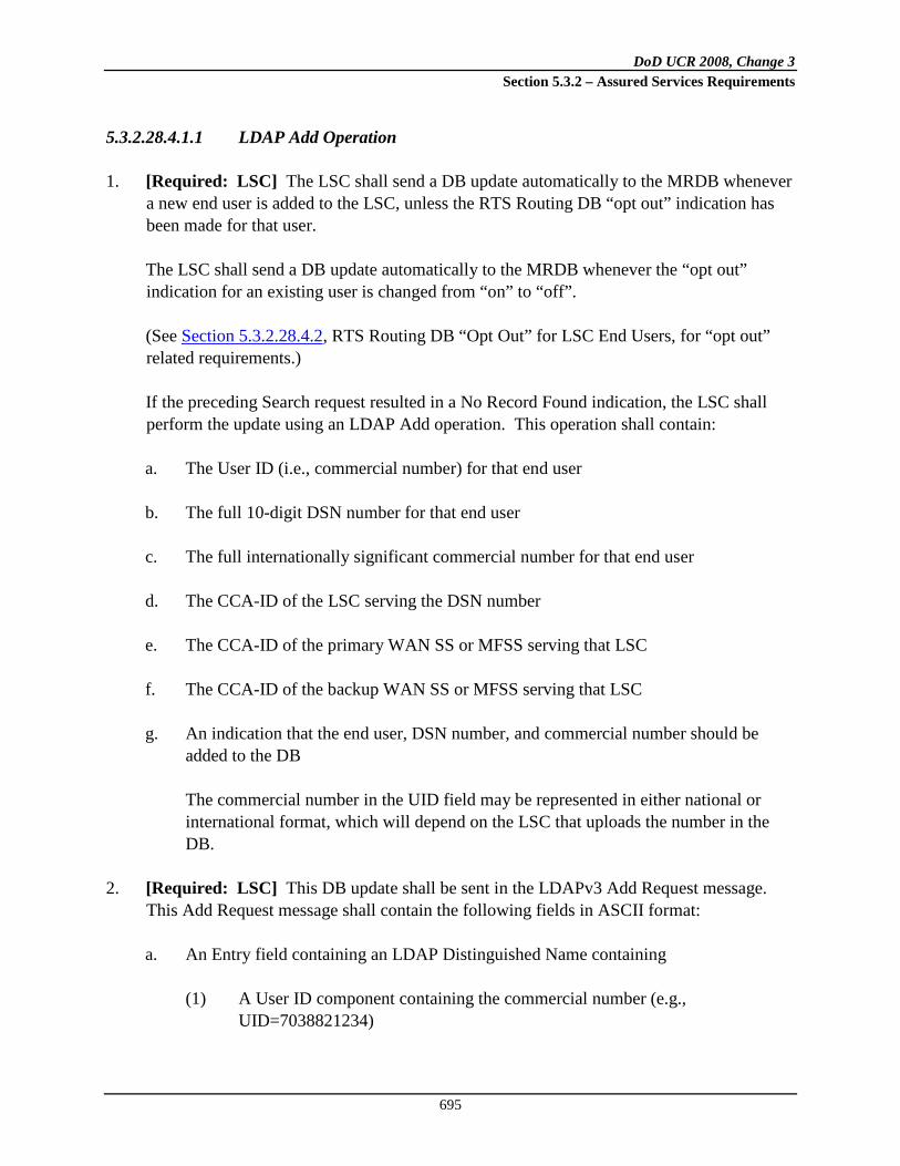
DoD UCR 2008, Change 3 Section 5.3.2 – Assured Services Requirements
695
5.3.2.28.4.1.1 LDAP Add Operation
1. [Required: LSC] The LSC shall send a DB update automatically to the MRDB whenever a new end user is added to the LSC, unless the RTS Routing DB “opt out” indication has been made for that user.
The LSC shall send a DB update automatically to the MRDB whenever the “opt out” indication for an existing user is changed from “on” to “off”.
(See Section 5.3.2.28.4.2, RTS Routing DB “Opt Out” for LSC End Users, for “opt out” related requirements.)
If the preceding Search request resulted in a No Record Found indication, the LSC shall perform the update using an LDAP Add operation. This operation shall contain:
a. The User ID (i.e., commercial number) for that end user b. The full 10-digit DSN number for that end user c. The full internationally significant commercial number for that end user d. The CCA-ID of the LSC serving the DSN number e. The CCA-ID of the primary WAN SS or MFSS serving that LSC f. The CCA-ID of the backup WAN SS or MFSS serving that LSC g. An indication that the end user, DSN number, and commercial number should be
added to the DB The commercial number in the UID field may be represented in either national or
international format, which will depend on the LSC that uploads the number in the DB.
2. [Required: LSC] This DB update shall be sent in the LDAPv3 Add Request message.
This Add Request message shall contain the following fields in ASCII format:
a. An Entry field containing an LDAP Distinguished Name containing
(1) A User ID component containing the commercial number (e.g., UID=7038821234)

DoD UCR 2008, Change 3 Section 5.3.2 – Assured Services Requirements
696
(2) The Domain Components “uc” and “mil” (dc=uc, dc=mil)
The commercial number in the UID field may be represented in either national or international format, which will depend on the LSC that uploads the number in the DB.
b. An Attributes field containing the following attributes:
(1) A User ID field containing the commercial number (2) An Object Class field containing “mobSLR” (3) A Subscriber Type field containing “asftswtch” (4) A SIP Alias field containing the full commercial called number followed by
“@uc.mil” (e.g., [email protected]) (5) A Sip User Name field containing the UID (i.e., commercial number)
followed by “@uc.mil” (e.g., [email protected]) (6) A Directory Number field containing the full 10-digit DSN number (7) An LSCCCAID field containing the CCA-ID of the destination LSC serving
the DSN number (8) An SSCCAID field containing the CCA-IDs of the primary WAN SS or
MFSS and the backup WAN SS or MFSS serving the destination LSC, separated by a comma
The commercial number in the UID field may be represented in either national
or international format, which will depend on the LSC that uploads the number in the DB.
5.3.2.28.4.1.2 LDAP Modify Operation
[Conditional: LSC] The LSC shall automatically send a DB update to the MRDB whenever an existing users’ number data (DSN and/or commercial) is modified at the LSC and the RTS Routing DB “opt out” indication for that user has not been set. If the preceding Search request resulted in a “record found/matching LSC CCA-ID” indication, the LSC shall perform the update using an LDAP Modify Replace operation. This operation shall contain:
• The User ID (i.e., commercial number) for that end user
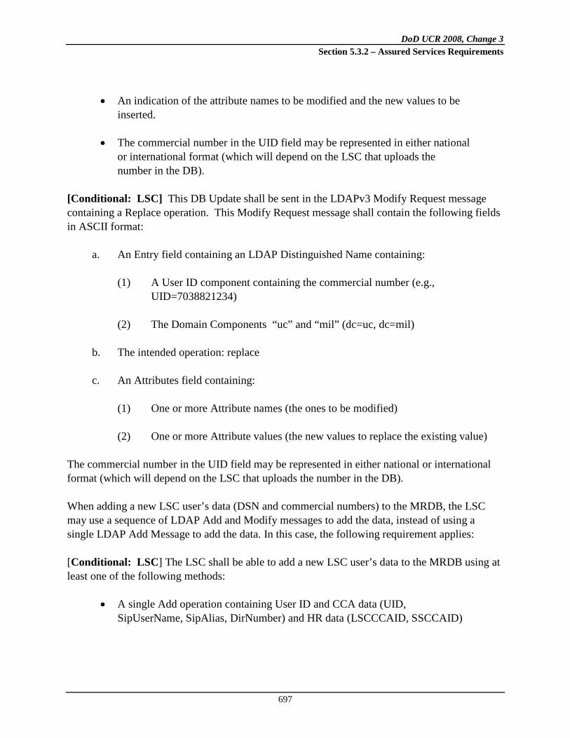
DoD UCR 2008, Change 3 Section 5.3.2 – Assured Services Requirements
697
• An indication of the attribute names to be modified and the new values to be
inserted.
• The commercial number in the UID field may be represented in either national or international format (which will depend on the LSC that uploads the number in the DB).
[Conditional: LSC] This DB Update shall be sent in the LDAPv3 Modify Request message containing a Replace operation. This Modify Request message shall contain the following fields in ASCII format:
a. An Entry field containing an LDAP Distinguished Name containing:
(1) A User ID component containing the commercial number (e.g., UID=7038821234)
(2) The Domain Components “uc” and “mil” (dc=uc, dc=mil)
b. The intended operation: replace
c. An Attributes field containing:
(1) One or more Attribute names (the ones to be modified) (2) One or more Attribute values (the new values to replace the existing value)
The commercial number in the UID field may be represented in either national or international format (which will depend on the LSC that uploads the number in the DB). When adding a new LSC user’s data (DSN and commercial numbers) to the MRDB, the LSC may use a sequence of LDAP Add and Modify messages to add the data, instead of using a single LDAP Add Message to add the data. In this case, the following requirement applies: [Conditional: LSC] The LSC shall be able to add a new LSC user’s data to the MRDB using at least one of the following methods:
• A single Add operation containing User ID and CCA data (UID, SipUserName, SipAlias, DirNumber) and HR data (LSCCCAID, SSCCAID)

DoD UCR 2008, Change 3 Section 5.3.2 – Assured Services Requirements
698
• An Add operation containing User ID and CCA data (UID, SipUserName, SipAlias, DirNumber), followed by a Modify operation containing HR data (LSCCCAID, SSCCAID)
• An Add operation containing User ID data (UID, SipUserName ), followed by
a Modify operation containing CCA data (SipAlias, DirNumber) and HR data (LSCCCAID, SSCCAID)
5.3.2.28.4.1.3 LDAP Delete Operation
1. [Required: LSC] The LSC shall send a DB update automatically to the MRDB whenever an existing end user is deleted from the LSC, unless the RTS Routing DB “opt out” indication has been made for that user.
The LSC shall send a DB update automatically to the MRDB whenever the “opt out” indication for an existing user is changed from “off” to “on”.
If the preceding Search request resulted in a “record found/matching LSC CCA-ID” indication, the LSC shall perform the update using an LDAP Delete operation. This operation shall contain:
a. The commercial number (i.e., User ID) for that end user b An indication that the end user, DSN number, and commercial number should be
deleted from the DB. 2. [Required: LSC] This DB Update shall be sent in the LDAPv3 Delete Request message.
This Delete Request message shall contain the following field in ASCII format:
a. An LDAP Distinguished Name containing
(1) A User ID component containing the commercial number (e.g., UID=7038821234)
(2) The Domain Components “uc” and “mil” (dc=uc, dc=mil)
3. [Required: LSC] If the Search response preceding the Delete operation indicates that
there is no LSC CCA-ID in the record, or that the LSC CCA-ID in the record does not match the CCA-ID of the requesting LSC, the LSC shall halt the Delete operation but shall still delete the end user data from the LSC. The LSC shall issue the appropriate alerts or notification to the network craftspeople/administrators in this case, as manual intervention will be necessary to complete this operation at the DB itself.

DoD UCR 2008, Change 3 Section 5.3.2 – Assured Services Requirements
699
For example, the network craftsperson at the requesting LSC may contact the network craftsperson at the MRDB, and notify the DB craftsperson that his or her request to delete the LSC’s record failed. Then the DB craftsperson can check the DB for all DB records that contain the LSC’s deleted number, and remove any of those records that are redundant or out-of-date.)
5.3.2.28.4.1.4 LDAP Confirmation Responses
1. [Required: MRDB] The MRDB shall accept and process the DB updates from the LSC for added end users, modified end users, and deleted end users, as listed in the previous requirements. In addition, the MRDB should return a confirmation response to the LSC whenever a new end user is added to the DB, an existing user’s data is modified in the DB, and an existing end user is deleted from the DB.
2. [Required: MRDB] In the “added end user” case, the MRDB shall send this confirmation response to the LSC in the LDAPv3 Add Response message. The Add Response message shall contain the Result Code field in ASCII format indicating “Success.”
3. [Required: MRDB] In the “modified end user data” case, if all the modifications requested to the record were successful, the MRDB shall send this confirmation response to the LSC in the LDAPv3 Modify Response message. The Modify Response message shall contain the Result Code field in ASCII format indicating “Success.”
4. [Required: MRDB] In the “modified end user data” case, if any modification requested to the record were not successful, the MRDB
a. Shall not perform any other modification in that message, and b. Shall send a rejection response to the LSC in the LDAPv3 Modify Response message
indicating the reason for failure. The Modify Response message shall contain the Result Code field in ASCII format indicating the reason for the failure (e.g., noSuchAttribute, invalidAttributeSyntax).
5. [Required: MRDB] In the “deleted end user” case, the MRDB shall send this
confirmation response to the LSC in the LDAPv3 Delete Response message. The Delete Response message shall contain the Result Code field in ASCII format indicating “Success.”
5.3.2.28.4.1.5 Multiple DB Update Interfaces to Multiple LSCs
1. [Required: MRDB] The MRDB shall be capable of maintaining multiple DB update interfaces to different LSCs at the same time. Each individual DB update interface shall

DoD UCR 2008, Change 3 Section 5.3.2 – Assured Services Requirements
700
support the requirements in this document for the protocols, data schemas, and security mechanisms used between an individual LSC and the MRDB. The MRDB shall support 20 interfaces with multiple LSCs, simultaneously.
2. [Conditional: MRDB] It is strongly recommended that the MRDB be capable of supporting 40 interfaces with multiple LSCs, simultaneously.
5.3.2.28.4.2 RTS Routing DB “Opt Out” for LSC End Users
It is desired that an entry in the RTS Routing DB not be made for certain UC LSC end users. To support this goal, an “opt out” indication is required, as follows: [Required: LSC] The user information maintained by an LSC for an EI provisioned on that LSC shall include an indication to exclude an entry for that user from the RTS Routing DB. It shall be possible to set or change this indication for an end user in the same way, and at the same time, that any other provisioning information for an end user can be set or changed. The default state for this setting shall be “off”. That is, in the absence of explicitly making this indication, this setting should remain off, and an entry for that end user shall be included in the RTS Routing DB. The LSC shall consider the setting of this indication when performing an LDAP Add, Modify or Delete operation with the MRDB, as specified above in Section 5.3.2.28.4.1, LDAP Update Operations. The changing of this indication from “on” to “off” shall trigger an LDAP Add operation from the LSC to the MRDB, as specified above in Section 5.3.2.28.4.1.1, LDAP Add Operation. The changing of this indication from “off” to “on” shall trigger an LDAP Delete operation from the LSC to the MRDB, as specified above in Section 5.3.2.28.4.1.3, LDAP Delete Operation.
5.3.2.28.5 LRDB and MRDB Requirements
5.3.2.28.5.1 Overview and Terminology
Each theater is expected to have two or more LRDBs handling the LDAPv3 Search operations (Commercial Cost Avoidance queries and Hybrid Routing queries) originating from the LSCs, MFSSs, and WAN-level SSs in that theater. The LRDB(s) will be responsible for (1) performing the Search requests from the MFSSs and WAN SSs (for HR queries) and Search requests from the LSCs (for Commercial Cost Avoidance queries) within the local theater, and (2) maintaining synchronization with the primary MRDB.

DoD UCR 2008, Change 3 Section 5.3.2 – Assured Services Requirements
701
One predetermined theater, CONUS (to be referred to as the primary theater), will have a primary MRDB that will be responsible for (1) receiving Update operations (DSN and commercial number updates) from all LSCs across all theaters, including its own, (2) performing the synchronization updates to all LRDBs in all theaters, and (3) performing synchronization with its backup MRDB in that primary theater. The requirements and objectives in this section follow the architecture described in Figure 5.3.2.28-3, Reference Architecture for LRDBs, and Figure 5.3.2.28-4, Reference Architecture for MRDBs. An extension to the primary Master architecture may be considered in the future. It is conceivable that a “regional” MRDB could be added to each theater. Each regional MRDB would contain a regional copy of all of the data stored in the primary MRDB in the primary theater. The regional MRDB would be responsible for receiving Update operations from all LSCs in that theater, and relaying those updates to the primary MRDB. This regional MRDB would synchronize its contents periodically with the contents of the primary MRDB (e.g., by a data “push” from the primary MRDB to the regional MRDB). The regional MRDB could synchronize its contents with the contents of each LRDB in that theater (e.g., by a data “push” from the regional MRDB to each LRDB).
Figure 5.3.2.28-3. Reference Architecture for LRDBs

DoD UCR 2008, Change 3 Section 5.3.2 – Assured Services Requirements
702
Such a tiered topology offers administrative advantages for DISA, especially for large scale DB implementations involving millions of records. Centralizing the DB update functions within each theater could help relieve the primary MRDB from handling the continuous streams of updates initiated by all of the LSCs from all the theaters. Instead, the updates would be consolidated within each theater and would be sent periodically from each regional MRDB to the primary MRDB. It is also possible that regional MRDBs could filter the updates by uploading only the “delta” records that underwent any changes since the last update, plus any newly created records.
Figure 5.3.2.28-4. Reference Architecture for MRDBs
In such a topology, utilizing the regional MRDBs, the primary MRDB would act as the ultimate repository for all routing data across theaters, but it would be responsible for fewer DB update and synchronization functions, which could potentially enhance its reliability and free it to perform other functions for DISA.
LEGENDDB Database LSC Local Session Controller

DoD UCR 2008, Change 3 Section 5.3.2 – Assured Services Requirements
703
In the following requirements, “bulk update” refers to a method where number records are updated at the MRDB “in bulk,” rather than updated individually using LDAP Write operations (like Add, Modify, and Delete). The source of the data for the “bulk updates” may be a set of LSCs containing number records, or it may be another database that is a copy of the MRDB (e.g., the backup MRDB). Bulk updates may be used during the initial provisioning of the MRDB (e.g., population of the MRDB from multiple LSCs that already contain number records), or during full reloads of the DB (e.g., population of the MRDB from the backup MRDB, after a loss of data at the MRDB). An example of a “bulk update” technique is transfer of LDIF files from the LSCs to the MRDB, using e-mail messages or FTP sessions to carry the LDIF files from the sources to the destination. LDIF file transfer implies a manual export of LDIF data at the source end (LSCs or backup MRDB) and a manual import of LDIF data at the receiving end (MRDB). Other bulk update techniques can also be used, if supported by the MRDB vendor and the LSC vendors.
5.3.2.28.5.2 Routing DB Requirements
This section contains requirements for the LRDB and MRDB.
5.3.2.28.5.2.1 General Architecture, Protocols and Interfaces
1. [Required: LRDB, MRDB] The LRDB and MRDB shall support the following LDAPv3 RFCs:
RFC 2251, RFC 2252, RFC 2253, RFC 2254, RFC 2255, RFC 2256, RFC 2829, RFC 2830
2. [Required: LRDB] Each LRDB shall be implemented as an independent, stand-alone replica of the data in the MRDB, where that data is not distributed among several physical LRDBs.
3. [Required: MRDB] Each MRDB shall be implemented as an independent, stand-alone DB, where the DB data is not distributed among several physical DBs.
NOTE: It is acceptable if multiple disks are used within each LRDB or MRDB platform to improve performance. This is different from the scenario excluded in the above requirements, where the total set of data records would be distributed or divided among multiple physical databases.

DoD UCR 2008, Change 3 Section 5.3.2 – Assured Services Requirements
704
5.3.2.28.5.2.2 Capacity and Record Structure
1. [Required: LRDB, MRDB] The LRDB and MRDB shall be able to store up to three million records, where each record length ranges from 500–2,000 characters.
It is expected that each database will grow over time, from an initial size of roughly 10,000 small records to a target size of 3 million large records. Therefore, the following requirements and objectives apply.
2. [Required: LRDB, MRDB] The LRDB and MRDB shall support an initial capacity of 10,000 records.
3. [Conditional: LRDB, MRDB] The LRDB and MRDB shall support a capacity of 3 million records, while adhering to the same performance and availability requirements listed in this document.
4. [Required: LRDB, MRDB] The LRDB and MRDB shall support the standard LDAP Directory Information Tree (DIT) format for their entries. The required attributes in each entry shall be as shown in Table 5.3.2.28-1, LDAP DIT Attribute Formats.
Table 5.3.2.28-1. LDAP DIT Attribute Formats
ATTRIBUTE DESCRIPTION EXAMPLE dn
Alphanumeric ASCII string: Distinguished Name; uid containing the commercial number, followed by dc=uc, dc=mil
uid=7038821234,dc=uc,dc=mil
uid
Alphanumeric ASCII string: Unique user ID; commercial number
7038821234
objectClass Alphanumeric ASCII string: value is “mobSLR” for Routing DB
mobSLR
subscriberType Alphanumeric ASCII string: value is “asftswtch” for Routing DB
Asftswtch
sipAlias
Alphanumeric ASCII string; Full internationally significant commercial number matching the DSN number [PSTN [email protected]]
[email protected] (also OCONUS commercial numbers are allowed)
sipUserName
Alphanumeric ASCII string; UID (i.e., commercial number matching the DSN number) followed by ”@uc.mil”
[email protected] (also OCONUS commercial numbers are allowed)
dirNumber Alphanumeric ASCII string; 10-digit DSN telephone number
3123811234 (DISA Skyline example)
LSCCCAID Alphanumeric ASCII string; CCA-ID of PentagonLSC.uc.mil

DoD UCR 2008, Change 3 Section 5.3.2 – Assured Services Requirements
705
ATTRIBUTE DESCRIPTION EXAMPLE the LSC serving the DSN number SSCCAID Alphanumeric ASCII string; CCA-ID of
the Primary and Backup WAN SSs or MFSSs serving this LSC
ScottMFSS.uc.mil, LacklandMFSS.uc.mil
serverHome null isMobile false LEGEND ASC II American Standard Code for Information Interchange CCA Call Connection Agent DB Database DISA Defense Information Systems Agency DSN Defense Switched Network ID Identification
LSC Local Session Controller MFSS Multifunction Softswitch OCONUS Outside Continental United States PSTN Public Switched Telephone Network UID User Input Data
5.3.2.28.5.2.3 Request Processing
The LSCs, MFSSs, or WAN SSs are expected to direct their LDAP Search requests to the LRDBs for call processing purposes. The LSC is expected to perform updates to the MRDB; it could add a new entry, delete an existing entry, or modify values of attributes in an existing entry. Adding new attributes that are not predefined in the schema is not allowed. For the update operations, the LSC must check whether the record exists in the MRDB before it inserts or deletes any records or applies any modifications. 1. [Required: LSC] The LSC shall formulate its updates to the MRDB (or backup MRDB)
in the following sequence:
a. Send Search operation on the record to be updated requesting the entire entry.
The Search operation can be one of the following: • The LDAP Search Request message for HR queries, specified in requirement 2 in
Section 5.3.2.28.2.1, HR Query from WAN SS/MFSS, or
• The LDAP Search Request message for CCA queries, specified in requirement 4 in Section 5.3.2.28.3.1, Commercial Cost Avoidance Query from LSC.
b. If the entry is found and returned, the LSC shall send the intended Update operation
(Delete or Modify). c. If the entry is not found, the LSC shall
(1) Either perform the intended Add operation, or

DoD UCR 2008, Change 3 Section 5.3.2 – Assured Services Requirements
706
(2) Abandon the Update operation The requesting LSC will not be allowed to perform updates on a record where the CCA-ID of the record does not match its own CCA-ID. Please consult Section 5.3.2.28.4.1, LDAP Update Operations, for more detailed requirements.
5.3.2.28.5.2.3.1 Client Time-Out
If an LDAP operation does not return results within a preset time, the LDAP client (LSC or MFSS, or WAN SS) should be able to terminate (time-out) the session in a reasonable amount of time. 1. [Required: LSC, MFSS, WAN SS] The LSC, MFSS, or WAN SS shall allow the setting
of a time-out interval between 1 – 5 seconds, adjusted in increments of 1 second [default 2 seconds].
Setting a time-out interval helps terminate an otherwise indefinite “hang” situation.
2. [Required: LSC, MFSS, WAN SS] The LSC, MFSS, or WAN SS shall terminate the pending request (Search, Update, or Modify) via an Abandon operation, if the time-out interval expires and no response was received from the database.
5.3.2.28.5.2.3.2 Bind over TLS
The LDAP standards allow for different methods of authentication:
• Anonymous access is obtained by providing no name and no password in the Bind operation,
• Unauthenticated access is obtained by providing a name but no password, and
• Authenticated access is obtained by providing a valid name and password.
With this method, the name and password may still be transported in the clear and unprotected.
For UC, confidentiality and integrity protection are required. Transport Layer Security (defined in RFC 5246) provides confidentiality and integrity protection. Available implementations of LDAP, such as OpenLDAP, support TLS. The name of the standard LDAP operation for initiating TLS/Secure Socket Layer (SSL) is startTLS. Upon successful completion of this LDAP operation, TLS/SSL is initiated.

DoD UCR 2008, Change 3 Section 5.3.2 – Assured Services Requirements
707
All DBs and clients (LSC, MFSS and WAN SS) are required to have valid X.509 certificates to be able to use the TLS framework. With TLS, none of the connections would be opened in the clear. 1. [Required: LSC, MFSS, WAN SS] All connections between the LSC, MFSS or WAN
SS to any of the DBs shall use TLS by default.
2. [Required: LSC, MFSS, WAN SS] An Anonymous or Unauthenticated Bind request shall be disallowed by default on all connections from the LSC, MFSS and WAN SS to any of the DBs.
3. [Required: MRDB, Backup MRDB, LRDB] The MRDB, backup MRDB, and LRDB shall not accept or process an Anonymous or Unauthenticated Bind request.
The time that a TLS connection stays open is to be determined by the network administrator.
4. [Required: MRDB, Backup MRDB, LRDB] The MRDB, backup MRDB, and LRDB shall allow the setting of an Idle Time-out Timer Tidle (range: 5–30 minutes; increments of 5 minutes; default 10 minutes). When Tidle expires, the DB shall shut down the TLS connection.
5.3.2.28.5.2.3.3 LRDB Request Processing
1. [Required: LRDB] The LRDB shall be able to recognize and perform the following LDAP operations originating from LSCs, MFSSs, and WAN SSs for Commercial Cost Avoidance and HR queries, respectively:
a. Bind Request and Response b. Unbind Request c. Search Request and Response d. Abandon Request
The LRDB is not required to support Update (LDAP Write) requests from the LSCs,
MFSSs, or WAN SSs. However, the LRDB is expected to support these Update requests for purposes of data population and provisioning through administrative LDAP interfaces, per the following requirement.
NOTE: Detailed requirements for these administrative LDAP interfaces are not included in this section.

DoD UCR 2008, Change 3 Section 5.3.2 – Assured Services Requirements
708
2. [Required: LRDB] The LRDB shall be able to recognize and perform the following LDAP operations when received from the MRDB, a DB craftsperson station, or the database administrator (DBA) over an administrative LDAP interface:
a. Bind request and response b. Unbind request c. Search request and response d. Add request and response e. Delete request and response f. Modify request and response g. Abandon request
3. [Required: LRDB] When the LRDB successfully locates the entry for an LDAP Search operation, it shall generate and return the appropriate LDAP response message, containing at a minimum:
a. The dirNumber (DSN telephone number), LSCCCAID, and SSCCAID values, for responses to HR queries; and
b. The dirNumber (DSN telephone number), sipAlias (commercial number), and
sipUserName (commercial number) values, for responses to Commercial Cost Avoidance queries.
4. [Required: LRDB] When the LRDB fails to locate the entry for a Search operation, it
shall generate and return the appropriate LDAP Result Code, which includes but are not limited to:
a. Result Code 0 (indicating “Success”), with no arguments b. Result Code 16 LDAP_NO_SUCH_ATTRIBUTE (indicating the specified attribute
does not exist in the entry) c. Result Code 32 LDAP_NO_SUCH_OBJECT (indicating the DB server cannot find
the entry specified in the request) It is expected that the LSCs, MFSSs and WAN SSs will process the different LDAP Result
Codes based on the logic for the type of call (Commercial Cost Avoidance or HR). It is expected that if no DB entry was found or if timeouts occur at either side (the database side or the client side), or if other LDAP errors are encountered, the Commercial Cost Avoidance logic will route the call to the commercial number. In the HR logic, if no DB entry is found, or if timeouts occur, the call is either (a) processed by internal SS routing tables, or (b) is returned to an MFS and subsequently to an End Office for call completion.

DoD UCR 2008, Change 3 Section 5.3.2 – Assured Services Requirements
709
5.3.2.28.5.2.3.4 MRDB Request Processing
The MRDB is required to support Update (LDAP Write) requests from all LSCs in all theaters. The MRDB is not intended to serve real-time Query requests (LDAP Searches) from LSCs, MFSSs, and WAN SSs for HR and Commercial Cost Avoidance purposes. However, occasionally a DB craftsperson station, a DBA station, or provisioning logic in the LSC, MFSS, or WAN SS may launch an LDAP Search request to the MRDB to determine the existence of specific records there. As a result, the MRDB is expected to support those LDAP Search requests. NOTE: Detailed DB requirements for administrative LDAP interfaces (e.g., used by DB craftspeople and DBA to administer the DB from their workstations) are not included in this section. [Required: MRDB] The MRDB shall be able to recognize and perform the following LDAP operations:
a. Bind request and response b. Unbind request c. Search request and response d. Add request and response e. Delete request and response f. Modify request and response g. Abandon request
[Required: MRDB] When the MRDB successfully locates the entry for an LDAP Search operation, it shall generate and return the appropriate LDAP response message for that message, containing the dirNumber (DSN telephone number), LSCCCAID, SSCCAID, sipAlias (Commercial number), and sipUserName (Commercial number) values. [Required: MRDB] When the MRDB fails to locate the entry for a Search operation, it shall generate and return the appropriate LDAP Result Code. For example:
a. Result Code 0 (indicating “Success”), with no arguments b. Result Code 16 (indicating “Attribute not found”) c. Result Code 32 (indicating “Object not found”)
These Search requests are not used for routing calls (Commercial Cost Avoidance or HR);
instead, they are used to verify the existence of a record. It is, therefore expected that LSC administrators will use subsequent logic within their LSCs to launch applicable Update requests to the MRDB (after the Search requests are completed). For example, if no DB entry were found for a DSN number, the LSC might initiate an Add operation for that

DoD UCR 2008, Change 3 Section 5.3.2 – Assured Services Requirements
710
number. Conversely, if a DB entry were found for that DSN number, the LSC would not initiate an Add operation for that number, but might instead initiate a Delete or Modify operation for that number. If other LDAP errors were encountered, the LSC LDAP logic could (a) reattempt the Update operation again for that number (Add, Delete, Modify), or (b) issue a report indicating multiple unsuccessful attempts that require administrative intervention.
5.3.2.28.5.2.4 Performance and Availability
Performance characteristics of a database, such as query throughput and bulk update times, are highly dependent on the design and configuration of the hardware for that database, including, but not limited to:
• Processor speed • LDAP cache (memory) size • Number and size of hard disks used
The performance requirements for the LRDB and MRDB in this document can be met with various hardware configurations, as indicated earlier (e.g., processors, cache, and hard disks), through optimization techniques and other vendor-specific guidelines or products. Specifically, the MRDB needs to be optimized for processing LDAP Update requests while the LRDB needs to be optimized for processing LDAP Search requests. Each LSC, MFSS and WAN SS is expected to direct its Search requests to a prespecified LRDB in its theater. The load-sharing architecture will be determined by the DISA network engineers in each theater, based on the projected traffic volume originating from each LSC, MFSS, or WAN SS in that theater (i.e., the number of Search requests directed to each LRDB will vary between LRDBs and from one theater to another. The LRDBs in each theater are expected to store a very recent image of the data stored in the MRDB. These copies should be almost identical in content, based on the time each LRDB received its synchronization update from the MRDB. Creating and using these “local” copies, the LRDB in each theater should also reduce latency issues for the LSCs, MFSSs and WAN SSs, and should make the routing data available to them in a reasonable amount of time. In addition, to ensure data availability and redundancy, the architecture requires support for both a primary MRDB and a backup MRDB (where the backup MRDB contains a complete copy of the primary MRDB). While the MRDB primarily focuses on Updates, the following availability requirements apply to all the LDAP requests.

DoD UCR 2008, Change 3 Section 5.3.2 – Assured Services Requirements
711
1. [Required: LRDB, MRDB] Under normal operating conditions (i.e., there is no DB overload or scheduled downtime for DB maintenance), the LRDB and MRDB shall process 99.99 percent of all LDAP requests received (i.e., Bind, Search, Add, Modify, Delete).
2. [Required: LRDB] The unavailability time for each LRDB shall not exceed 0.01 percent of 1 year (which translates into 1 hour per year; approximately 5 minutes per month). The unavailable time shall apply only to failure situations and does not comprise preventive maintenance or scheduled upgrade times.
It is expected that when one of the LRDBs in the theater is unavailable, the other LRDB(s) in the theater will be available. It is not expected that all the LRDBs in a given theater will be unavailable at the same time.
3. [Required: MRDB, Backup MRDB] The unavailability time for each MRDB and backup MRDBs shall not exceed 0.01 percent of 1 year, which translates into 1 hour per year; approximately 5 minutes per month. The unavailable time applies only to failure situations and does not comprise preventive maintenance or scheduled upgrade times.
4. [Required: LRDB, MRDB, Backup MRDB] The LRDB, MRDB, and backup MRDB shall each support a minimum of 2000 LDAP Search operations per second.
5. [Required: LRDB, MRDB, Backup MRDB] The LRDB, MRDB, and backup MRDB shall each support a minimum of 200 LDAP Update (Add, Delete, and Modify) operations per second under normal operation. (Bulk updates during the initial provisioning of the database and bulk updates during full reloads of the database are not considered normal operation.)
6. [Required: LRDB, MRDB, Backup MRDB] When the LSC sends an LDAP Update operation to the primary MRDB, the primary MRDB shall relay this update to a prespecified group of databases (configured in the primary MRDB), including the backup MRDB and multiple LRDBs, immediately. The total time from the initialization of a given LDAP Update by the LSC, propagation of the data, and receipt of the updates in the prespecified DBs shall not exceed 5 minutes.
The primary and backup MRDBs also support synchronization procedures, of partial and full database content, with each other and with the local DBs. These procedures are discussed later in Section 5.3.2.28.5.2.7, Synchronization between Primary and Backup MRDBs, and Section 5.3.2.28.5.2.8, Synchronization between LRDB and MRDB.
In the application, the Search requests serve real-time call setup. Therefore, the response times are important.

DoD UCR 2008, Change 3 Section 5.3.2 – Assured Services Requirements
712
7. [Required: LRDB, MRDB, Backup MRDB] The LRDB, MRDB, and backup MRDB’s processing time for an LDAP Bind request shall not exceed 2 ms. This excludes the round-trip network delays as the Bind requests from LSCs transit the Defense Information Systems Network (DISN)
8. [Required: LSC, MFSS, WAN SS, LRDB, MRDB, Backup MRDB] The total connect time including all the following plus network transit time shall not exceed 20 ms:
a. Initializing the LDAP port at the LSC, MFSS, or WAN SS b. Preparing the Bind request at the LSC, MFSS, or WAN SS c. Processing the LDAP Bind request at the DB (authenticating the DN and password) d. Processing the Bind result at the LSC, MFSS, or WAN SS
9. [Required: LRDB, MRDB, Backup MRDB] The LRDB, MRDB, and backup MRDB’s
processing time for an LDAP Search request shall not exceed 10 ms. This excludes the round-trip network delays as the Search requests from LSCs transit the DISN.
10. [Required: LRDB, MRDB, Backup MRDB] The LRDB, MRDB, and backup MRDB’s processing time for an LDAP Update request shall not exceed 100 ms. This excludes the round-trip network delays as the Update requests from LSCs transit the Defense Information Systems Network (DISN).
5.3.2.28.5.2.4.1 LDAP Directory Considerations
Indexing of LDAP servers reduces search times by facilitating the location of the entry without having to check every single entry for a match. Index tuning is a recommended tool that a database vendor could provide to improve performance. Other factors that affect the performance of the database server and the processing time of a query include (a) the layout of the DIT, and (b) the complexity of the Search request. The LDAP applications will perform better if simple operations are used as much as possible. Therefore, Search requests should only ask for the attributes needed and not retrieve all attributes from every entry, because that slows the database processing, significantly. Some ideas for improving LDAP performance include the following practices:
• Flat directory trees yield quicker response times than deep ones.
− One-level Searches are recommended.
− Simple search filters (exact filters) should be used more frequently than wildcard filters.

DoD UCR 2008, Change 3 Section 5.3.2 – Assured Services Requirements
713
1. [Conditional: LRDB] It is recommended that, in designing the DIT, frequently accessed
entries be placed closer to the root of the dc=uc tree, to help speed access to the different entries and their attributes.
2. [Conditional: LSC, MFSS] It is recommended that Search requests launched to the local DB be optimized to search only for the necessary data and reduce the use of wildcard filters that return multiple entries.
5.3.2.28.5.2.4.2 Data Caching
One means of boosting query throughput is to implement a cache for frequently retrieved data since typically, accessing memory is faster than disk access. Caches can be implemented at the client site (in this case at the LSC, MFSS, or WAN SS). 1. [Required: LSC, MFSS, WAN SS] The LSC, MFSS, or WAN SS shall implement
storage buffers that are capable of supporting LDAP entry caches. This capability shall be configurable; the caching or buffering option shall be turned on or off as needed.
2. [Required: LSC, MFSS, WAN SS] The LSC, MFSS, or WAN SS shall be able to support caching at minimum 3000 entries/records and a maximum of up to 50 percent of the database entries, settable by DISA. The amount of record storage shall be settable based on utilization trends. The required memory size shall be provisioned accordingly.
3. [Required: LSC, MFSS, WAN SS] If the entry is not found in the cache, the Search request shall be routed to the LRDB.
4. [Required: LSC, MFSS, WAN SS] The cache retention period shall be settable in increments of 30 minutes and shall not exceed 48 hours. When the predefined period expires, the contents of the cache shall be cleared/purged.
While caching offers the advantage of improving throughput, the common disadvantage is the possibility of aged data. Therefore, the network administrators, with the assistance of the vendor, will need to inspect the cache periodically to determine the ideal expiration time and tune the contents of the cache accordingly.
5.3.2.28.5.2.5 Failover Procedures
Under normal operations, the LSC communicates the LDAP Updates directly to the primary MRDB. The backup MRDB is synchronized with the primary MRDB periodically to be able to stand in for the primary MRDB when the latter experiences downtime.

DoD UCR 2008, Change 3 Section 5.3.2 – Assured Services Requirements
714
The LSCs will maintain communication with both the primary and backup MRDBs via periodic “keep-alive” messages. Lack of response from either DB will indicate to the LSC that the DB is potentially experiencing a failure. A set of procedures are described in this section’s requirements to help (1) minimize loss of update information intended for the MRDB, and (2) automatically redirect the Update requests to an available MRDB (primary or backup), and (3) alert network personnel of the failed DB. After the DB has been repaired, the network administrator or DBA will be able to initiate updates of the downtime transactions to the repaired DB. The administrator will ensure the DB is not returned to service until its data records are updated. After that is completed, the DBA will be able to reset the DB addresses in the LSCs, MFSSs and WAN SSs to the appropriate setup; i.e., the redirection to the backup DB (master or local) will take place automatically, but the restoration of the primary DB to service will require administrator involvement. NOTE: The LSCs exchange keep-alive messages with all DBs (MRDB, backup MRDB, and LRDB). The MFSSs and WAN SSs exchange keep-alive messages with the LRDBs only. 1. [Required: LSC, MFSS, WAN SS] The LSC, MFSS, or WAN SS shall use keep-alive
messages to verify that the MRDB (or the backup MRDB) and the LRDBs are available.
a. The frequency of the keep-alive messages shall be settable (Timer Ta) by the network administrators based on traffic volumes, with a default of Ta= 5 minutes.
b. The value of Ta shall range from 0–30 minutes and shall be settable in increments of
5 minutes 2. [Required: LSC, MFSS, WAN SS] The keep-alive messages sent from the LSC, MFSS,
or WAN SS to the LRDB or MRDB shall consist of the following sequence:
a. Bind request b. Search request on a predetermined distinguished name c. Unbind request
Upon receiving a successful Bind response with resultCode == 0, the LSC, MFSS, or WAN SS shall issue a Search request for a predetermined LDAP DN. It is expected that the LDAP DN selected by the administrator for these preset keep-alive messages is always populated in the DB to avoid errors.
When the LSC receives a Search response message indicating that the entry is found, the keep-alive message is considered successful and the LSC shall complete the operation by sending an Unbind request and shall reset Ta.

DoD UCR 2008, Change 3 Section 5.3.2 – Assured Services Requirements
715
3. [Required: LSC, MFSS, WAN SS] The LSC, MFSS, or WAN SS shall keep track of the last status for each LRDB or MRDB that it sent a keep-alive message. The status shall indicate if the DB is functional or is out of service. This status will be used in subsequent determinations of applying failover procedures.
4. [Required: MRDB, Backup MRDB, LRDB] The MRDB, backup MRDB, and LRDB shall support the processing of keep-alive messages from the LSCs, MFSSs and WAN SSs.
5.3.2.28.5.2.5.1 MRDB Failover
During failover operation, when the primary MRDB becomes unavailable and the backup MRDB becomes the active MRDB, the LSCs send their updates (individual or bulk) to the backup MRDB, and the backup MRDB queues these updates for later transmission to the primary MRDB (i.e., when the primary MRDB is restored to service). The backup and primary MRDBs support periodic synchronization procedures to ensure their data content is consistent. 1. [Required: MRDB, Backup MRDB, LSC] Each LSC that accesses the primary and
backup MRDBs shall support the configuration of two DISA network IP addresses for those MRDBs: one for the primary MRDB (used when the primary is active) and another for the backup MRDB (used when the primary has failed).
a. Primary Master Down, Backup Master Active
(1) [Required: LSC] If the LSC does not receive a response from the primary MRDB within 2 seconds of sending a keep-alive message or a valid LDAP message (update or search), the LSC shall retry sending another keep-alive message or resend the same LDAP message.
(2) [Required: MRDB, Backup MRDB, LSC] If no response is received from
the primary MRDB within 5 seconds of the retry attempt, the LSC shall
(a) Stop sending LDAP Updates to the primary MRDB, (b) Establish, if necessary, an LDAPv3 over TLS connection with the
backup MRDB, (c) If the most recent status of the backup MRDB is “functional,” continue
with step (d). Otherwise, the LSC shall withhold any updates and continue sending keep-alive messages to both primary and backup MRDBs until one responds,

DoD UCR 2008, Change 3 Section 5.3.2 – Assured Services Requirements
716
(d) Send all subsequent LDAP Update operations (additions and deletions of DSN or commercial number pairs) to the backup MRDB instead, and
(e) Continue keep-alive messages with the primary and backup MRDBs.
(3) [Required: MRDB, Backup MRDB] The backup MRDB shall always
queue the LDAP Updates it receives from the LSC. Updates received by the backup MRDB are most likely to occur during
periods of the primary MRDB’s unavailability.
(4) [Required: LSC, MRDB, Backup MRDB] The LSC shall continue sending the LDAP Updates to the backup MRDB until it receives a successful response to a keep-alive message from the primary MRDB.
The primary MRDB shall not send a successful response to any keep-alive
messages until it had been loaded with the queued updates from the backup MRDB and/or the LSC. This should be ensured by the network personnel performing the necessary repairs on the DBs before returning the DBs back online.
After the cause of failure has been resolved and the primary MRDB has
regained functionality,
(5) [Required: MRDB, Backup MRDB, LSC] The primary MRDB shall support a request to transfer the downtime queued update, for a given time period specified by the network administrator, from both the backup MRDB and the LSCs.
(6) [Required: LSC] The LSC shall support the capability to upload the queued
updates (e.g., via LDIF files) accumulated during the primary MRDB’s downtime, upon request (from the DBA). The LSC shall concurrently send and/or include new update requests with the queued updates in its upload to the primary MRDB.
Network Administrators and DBAs will return the primary MRDB to service
after all the “downtime” updates have been integrated in its files successfully. The goal is to ensure the primary MRDB is not placed back in service until it has been updated with the recent modifications that took place while it was out of service. When the primary MRDB is ready to handle requests, the DBA could (a) change the address in the LSC from the backup MRDB to that

DoD UCR 2008, Change 3 Section 5.3.2 – Assured Services Requirements
717
of the primary MRDB, thus redirecting traffic immediately to the primary MRDB, or (b) wait for the primary MRDB to reply to the next keep-alive message from the LSC.
(7) [Required: MRDB, Backup MRDB, LSC] The LSC shall provide the
network administrator the capability to change the address to which the LSC updates should be directed, on demand.
(8) [Required: LSC] When the DB address in the LSC is reset to the primary
MRDB, or when the LSC receives a successful response to the keep-alive message from the primary MRDB, the LSC shall
(a) Stop sending LDAP Updates to the backup MRDB, (b) Reestablish an LDAPv3 over TLS connection with the primary
MRDB, and (c) Resume sending LDAP Updates to the primary MRDB, and (d) Continue sending keep-alive messages to the primary and backup
MRDBs according to timer Ta.
(9) [Required: Backup MRDB] During failover (when the primary MRDB is out-of-service and the backup MRDB stands in), authorized DISA personnel (craftspeople, network managers, DBA) shall be able to access the backup MRDB and perform LDAP Search operations, LDAP Update operations, and LDIF file imports on it.
It is expected that the backup MRDB will be capable of handling the LDAP
Update traffic load during failover conditions.
b. Primary Master Down, Backup Master Down
Although unlikely, it is possible that the backup MRDB would either:
• Be already down when the primary MRDB fails, or
• It would experience a failure shortly after it starts to stand in for the primary MRDB.
(1) [Required: LSC] During failover mode to the backup MRDB, if the LSC
does not receive a response from the backup MRDB within 2 seconds of

DoD UCR 2008, Change 3 Section 5.3.2 – Assured Services Requirements
718
sending a keep-alive message or an LDAP Update request, the LSC shall retry sending the message to the backup MRDB.
(2) [Required: LSC] If no response is received from the backup MRDB for the
retry message within 5 seconds (i.e., both primary and backup MRDBs are now out of service), the LSC shall
(a) Report alarms for a critical error to the network administrator, (b) Queue subsequent LDAP Update operations, and (c) Initiate Ta and continue sending keep-alive messages to both primary
and backup MRDBs until it receives notification that either the primary or backup MRDB has been restored to service.
(3) [Required: LSC] While both the primary and backup MRDB are down, the
LSC shall maintain a log of the LDAP Updates that it tries to send to the primary and backup MRDBs. The log shall contain the address of the destination DB, timestamps, the target LDAP DN, and the Update transaction.
The log will serve as a reference for audits.
5.3.2.28.5.2.5.2 LRDB Failover
Each theater is expected to have one or more LRDBs serving the HR or Commercial Cost Avoidance LDAP Search requests from the LSCs, MFSSs or WAN SSs. In that topology, the LRDBs are expected to act as potential backups for each other. If an LRDB (e.g., DB #1) fails, the LSC will reroute LDAP requests destined for DB #1 to another LRDB (e.g., DB #2), defined here as the “secondary.” The rerouting continues until DB #1 is returned to service. The LSCs, MFSSs, and WAN SSs will maintain communication with both primary and secondary LRDBs via periodic keep-alive messages. Lack of response from either DB will indicate to the LSC that the DB is potentially experiencing a failure. A set of procedures are described in this section’s requirements to help (1) realize the cost savings of the Commercial Cost Avoidance feature, (2) reduce any call setup delays for the HR feature, and (3) automatically redirect the Search requests to an available DB for prompt processing. 1. [Required: LRDB, LSC, MFSS, WAN SS] Each LSC, MFSS, or WAN SS that accesses
LRDBs shall support the configuration of two DISA network IP addresses for those routing DBs: one for a primary LRDB and another for a secondary LRDB (used when the primary has failed).

DoD UCR 2008, Change 3 Section 5.3.2 – Assured Services Requirements
719
As noted in Failover requirements, each LSC, MFSS and WAN SS shall use an independent Timer Ta to schedule sending the keep-alive messages to its primary and secondary LRDBs.
a. Primary Local Down, Secondary Local Active
(1) [Required: LRDB, LSC, MFSS, WAN SS] If the LSC, MFSS or WAN SS does not receive a response from the primary LRDB within 0.5 second of sending a keep-alive message or an LDAP Search request, the LSC, MFSS, or WAN SS shall retry sending another keep-alive message or resend the same LDAP message.
(2) [Required: LRDB, LSC, MFSS, WAN SS] If no response is received from
the primary LRDB for the retry message within 0.5 second, the LSC, MFSS, or WAN SS shall
(a) Stop sending LDAP Search requests to the primary LRDB, (b) Redirect the LDAP Search requests to the secondary LRDB
immediately, (c) Continue keep-alive messages with the primary and secondary
LRDBs, and (d) If the most recent status of the secondary LRDB is “functional,”
continue with step (d). Otherwise, the LSC, MFSS or WAN SS shall utilize commercial number routing, instead of Commercial Cost Avoidance, and internal lookup tables, instead of HR.
(3) [Required: LRDB, LSC, MFSS, WAN SS] The LSC, MFSS, or WAN SS
shall continue sending the LDAP Search operations to the secondary LRDB until they receive a successful response to a keep-alive message from the primary LRDB.
The primary LRDB shall not send a successful response to any keep-alive
messages until it had been synchronized with the latest data from the MRDB. This should be ensured by the network personnel performing the necessary repairs on the DBs before returning the DB back online.
(4) [Required: MRDB, Backup MRDB, Local DB] The primary LRDB shall
be able to request a partial synchronization from the MRDB, specifying the

DoD UCR 2008, Change 3 Section 5.3.2 – Assured Services Requirements
720
start time as that time the DB went out of service. The MRDB (or backup MRDB) shall support that request.
Network administrators or DBAs will return the primary LRDB to service
after all “downtime” updates have been integrated successfully in its files. The goal is to ensure the primary LRDB is not returned to service until it has been updated with the recent modifications that took place while it was out of service. When the primary LRDB is ready to handle Search requests, the DBA could (a) change the address in the LSC from the secondary LRDB to that of the primary LRDB, thus redirecting traffic immediately to the primary LRDB, or (b) wait for the primary LRDB to reply to the next keep-alive message from each LSC, MFSS, and WAN SS.
(5) [Required: LRDB, LSC, MFSS, WAN SSF] The LSC shall provide the
network administrator the capability to change the address to which the LSC Search requests should be directed, on demand.
(6) [Required: LSC, MFSS, WAN SS] When the local DB address in the LSC
is reset to the primary LRDB, or when the LSC receives a successful response to the keep-alive message from the primary LRDB, the LSC, MFSS, or WAN SS shall:
(a) Stop sending LDAP Searches to the secondary LRDB, (b) Resume sending LDAP Searches to the primary LRDB, and (c) Continue sending keep-alive messages to the primary and secondary
LRDBs according to timer Ta.
It is expected that the secondary LRDB will be capable of handling the LDAP Search traffic load during failover conditions.
b. Primary Local Down, Secondary Local Down
Although unlikely, it is possible that the secondary LRDB is out of service at the
same time as the primary LRDB. In that case,
(1) [Required: LRDB, LSC, MFSS, WAN SS] Following the failure of the primary LRDB, if no response is received from the secondary LRDB within 2 seconds of sending a keep-alive message or an LDAP Search request, the LSC, MFSS, or WAN SS shall retry sending the message to the secondary LRDB.

DoD UCR 2008, Change 3 Section 5.3.2 – Assured Services Requirements
721
(2) [Required: LRDB, LSC, MFSS, WAN SS] If no response is received from
the secondary LRDB for the retry message within 5 seconds, the LSC shall
(a) Report alarms for a critical error to the network administrator, (b) Stop sending LDAP requests to the LRDBs, (c) Start Timer Ta, and (d) Maintain keep-alive messages with both primary and secondary
LRDBs using Ta.
The failure of LRDB s affects HR call routing and defeats the cost savings intended from Commercial Cost Avoidance. Therefore, it is important to return at least one LRDB back to service or have more than one secondary LRDB provisioned for each LSC, MFSS, or WAN SS. After the DBs are restored, the LSC, MFSS, or WAN SS will be notified so it can start sending its Search requests to the appropriate LRDB. Network administrators or DBAs will return the primary LRDB to service after all the downtime updates have been integrated successfully in its files. The goal is to ensure the primary LRDB is not returned to service until it has been updated with the recent modifications that took place while it was out of service. When the primary LRDB is ready to handle Search requests, the DBA could (a) change the address in the LSC from the secondary LRDB to that of the primary LRDB, thus redirecting traffic immediately to the primary LRDB, or (b) wait for the primary LRDB to reply to the next keep-alive message from the LSC, MFSS, or WAN SS.
(3) [Required: LRDB, LSC, MFSS, WAN SS] When the LSC, MFSS, or
WAN SS receives a successful response to the keep-alive message, the LSC, MFSS, or WAN SS shall:
(a) Stop sending LDAP Search requests to the secondary LRDB, (b) Resume sending LDAP Search requests to the primary LRDB, and (c) Resume sending keep-alive messages to the primary and secondary
LRDBs based on Ta.

DoD UCR 2008, Change 3 Section 5.3.2 – Assured Services Requirements
722
5.3.2.28.5.2.6 Provisioning
In the following requirements, “bulk upload” refers to a method where number records are uploaded into the LRDB or MRDB “in bulk,” rather than uploaded individually using LDAP Update operations (like Add, Modify, and Delete). For a LRDB, the source of the data for the “bulk uploads” may be a set of LSCs containing number records (in the case where the LRDB accepts number uploads from the LSCs that it serves), or it may be the MRDB or the backup MRDB. For a MRDB, the source of the data for the “bulk uploads” may be a set of LSCs containing number records, or it may be another database that is a copy of the MRDB (e.g., the backup MRDB). Bulk uploads may be used during the initial provisioning of the LRDB or MRDB (e.g., population of the MRDB from multiple LSCs that already contain number records), or during full reloads of that DB (e.g., population of LRDB records from the MRDB, after a loss of data). An example of a “bulk upload” technique is transfer of LDAP Data Interchange Format (LDIF) files from the MRDB to the LRDB, using e-mail messages or FTP sessions. LDIF file transfer implies a manual export of LDIF data at the source end (e.g., MRDB) and manual import of LDIF data at the receiving end (e.g., LRDB). Other bulk upload techniques can also be used, if supported by the LRDB, MRDB, and LSC vendors. Commercial experience with bulk uploads for DBs containing millions of records has shown that the time needed to perform a bulk upload goes down as the size of the upload transactions (the data “chunks”) used in the bulk upload goes up. In other words, the time needed for bulk uploading records is inversely proportional to the size of the upload transactions or “chunks” used to perform the bulk-upload. For example, it takes less time to bulk-upload a three million record database in a single transaction (e.g. a single LDIF file import) than it does to upload that same database in three different transactions (e.g. three separate LDIF file imports) where each transaction contains one million records, or six different transactions where each transaction contains half a million records. It is therefore recommended that the MRDB and LRDB include as many DB records as possible within each “bulk upload” transaction to reduce the “bulk upload” provisioning time at the LRDB or MRDB. It is also recommended that a small number of high-volume transactions be used for “bulk uploads,” instead of a large number of low-volume transactions. 1. [Required: LRDB] The LRDB shall support a maximum bulk upload time of from 1 to 4
hours for a Database size of 3 million records, as follows:
a. The DB shall support no more than 1 hour of bulk upload time, using a single bulk upload transaction that contains all three million records, and

DoD UCR 2008, Change 3 Section 5.3.2 – Assured Services Requirements
723
b. The DB shall support no more than 4 hours of bulk upload time, using multiple bulk upload transactions where each transaction contains a fraction of the three million records.
2. [Required: MRDB, Backup MRDB] The MRDB and backup MRDB shall be able to
accept a bulk update of the full set of three million DB records (via LDIF file transfer or other methods) within a period of no more than 1 hour.
3. [Required: LRDB] In addition to supporting bulk uploads, the LRDB shall support user interfaces (e.g., a Web-based Graphical User Interface (GUI), and a text-based command line interface) that allow end users to configure and update the DB. The LRDB shall allow DISA to make these interfaces available to local DISA craftspeople, remote DISA craftspeople, and remote DISA Operations Systems (like the RTS EMS).
4. [Required: LRDB] The LRDB shall allow an authorized craftsperson, DBA, or remote DISA Operations System to access the LRDB for reading record data, writing record data, and updating record data.
5. [Required: LRDB] The LRDB shall allow an authorized craftsperson, DBA, or remote DISA Operations System to access the LRDB for
a. configuring DoD PKI certificates (used with TLS authentication) for both the DB itself and for the various DB clients (i.e., LSCs, MFSSs, and WAN SSs in that theater), and
b. configuring LDAP User Names and Passwords (used with LDAP Bind message
authentication) for the various DB clients (LSCs, MFSSs, and WAN SSs in that theater).
It is important to establish strong guidelines for DISA DBAs to follow if they decide to use
the previously mentioned user interfaces to perform LDAP Updates (writing and updating of data records) at the LRDBs. These guidelines must recognize that DBA updates that are manually loaded into one LRDB should be relayed to the MRDB as soon as possible, to (1) avoid data discrepancies among the different LRDBs (replicas) in the various DISA theaters, and (2) ensure that the Administrator’s update is not overwritten by the MRDB during the next scheduled synchronization process between the MRDB and that LRDB.
5.3.2.28.5.2.7 Synchronization between Primary and Backup MRDBs
In each theater, the LRDBs are expected to act as backups for each other. The primary MRDB also has one backup MRDB. The purpose of this backup MRDB is to provide a most recent duplicate of the primary MRDB, in case of an outage, data loss, or catastrophic failure at the

DoD UCR 2008, Change 3 Section 5.3.2 – Assured Services Requirements
724
primary MRDB. This allows LSCs sending DB updates to “fail over” from the primary to the backup MRDB when the primary MRDB is out of service. 1. [Required: MRDB, Backup MRDB] The primary MRDB shall support full data updates
(full data backups) to the backup MRDB during non-busy hours (based on the primary MRDB’s local time zone).
2. [Required: MRDB] The primary MRDB shall support the performance requirements listed in this document (i.e., minimum operations per second and maximum processing time) during the “full data backup” process with the backup MRDB. This means that the primary MRDB shall be able to support bulk updates from LSCs, LDAP Search operations from LSCs, and LDAP Update operations from LSCs, while simultaneously performing a full data backup with the backup MRDB.
3. [Required: MRDB, Backup MRDB] The primary MRDB shall support the performance of full data backups with the backup MRDB on a configurable scheduled basis. The primary MRDB shall support scheduled full data backup settable frequencies of every 6 hours, every 12 hours, and every 24 hours.
4. [Required: Backup MRDB] The backup MRDB shall be coupled with the primary MRDB via redundant, physically diverse, high throughput, TLS over IP connections, and shall function as a “hot standby” for the primary MRDB. These master-to-master connections shall be secured using TLS with DoD PKI certificates, consistent with the requirements for securing exchange of LDAPv3 messages over TLS.
5. [Required: MRDB, Backup MRDB] The primary and backup MRDBs shall give DISA the ability to initiate a “full data backup” at any time, independent of when the last scheduled full data backup was performed.
5.3.2.28.5.2.8 Synchronization between LRDB and MRDB
The requirements in this section apply to the LRDB and MRDB. In general, the LRDB and MRDB are located in physically separate sites. 1. [Required: LRDB, MRDB] The LRDB shall support an interface to the MRDB, and the
MRDB shall support an interface to the LRDB, to support DB synchronization for the Commercial Cost Avoidance and HR features.
2. [Required: LRDB, MRDB] The DB synchronization interface between the LRDB and the MRDB shall be LDAPv3 over TLS over IP. This LDAPv3 interface shall be compliant with RFC 4510.

DoD UCR 2008, Change 3 Section 5.3.2 – Assured Services Requirements
725
3. [Required: LRDB, MRDB] The LDAPv3 Data schema used on the DB synchronization interface between the LRDB and MRDB shall include all of the following information fields:
a. An Entry field containing an LDAP Distinguished Name containing
(1) A User ID component containing the commercial number (e.g., UID=7038821234) of the end user.
(2) The Domain components “uc” and “mil” (dc=uc, dc=mil).
b. An Attributes field containing the following attributes:
(1) A User ID field containing the commercial number of the end user (2) A SIP Alias field containing the full international format commercial called
number of the end user followed by “@uc.mil” (3) A SIP User Name field containing the UID (i.e., commercial number)
followed by “@uc.mil” (4) A Directory Number field containing the full 10-digit DSN number of the end
user (5) An LSCCCAID field containing the CCA-ID of the LSC serving the end user (6) An SSCCAID field containing the CCA-IDs of the primary WAN SS or
MFSS, and the backup WAN SS or MFSS serving this LSC, separated by a comma
(7) An Object Class field containing “mobSLR”
4. [Required: LRDB, MRDB] The encoding of the LDAPv3 messages and data schema
used on the DB synchronization interface between the LRDB and MRDB shall follow the BER of ASN.1.
5. [Required: LRDB, MRDB] The DB synchronization interface between the LRDB and MRDB shall be secured using TLS, consistent with the requirements for securing AS-SIP messages using TLS in Section 5.4, Information Assurance Requirements. This security shall provide mutual authentication between the LRDB and MRDB, message confidentiality for the DB synchronization messages, and message integrity for the DB synchronization messages.

DoD UCR 2008, Change 3 Section 5.3.2 – Assured Services Requirements
726
6. [Required: LRDB, MRDB] The DB synchronization interface between the LRDB and MRDB shall traverse the data firewalls at both the LRDB and MRDB sites.
7. [Required: LRDB, MRDB] The DB synchronization interface between the LRDB and MRDB shall traverse the CE Routers at both the LRDB and MRDB sites, using the DSCP for User Signaling traffic, and the associated CE Router queues.
8. [Required: MRDB] The MRDB shall be capable of maintaining multiple DB synchronization interfaces to different LRDBs at the same time. Each individual DB synchronization interface shall support the previous requirements for the protocols, data schemas, and security mechanisms used between an individual LRDB and the MRDB.
Typically, DB synchronization methods are vendor-proprietary, and are not expected to have an effect on DB performance for this Routing DB implementation within DISA. The primary and backup MRDBs are expected to be the ultimate data sources that are available to the various LRDBs for synchronization purposes. The DB synchronization requirements for 2010 call for a master-subordinate configuration, where the MRDBs are the “masters,” and the LRDBs are the “subordinates.”
9. [Required: LRDB, MRDB, Backup MRDB] The MRDBs shall be able to perform their DB synchronization with the LRDBs through a “push” model, where data records are downloaded from one MRDB to the LRDBs on a programmable schedule.
a. Under normal operation, the data push shall be from the primary MRDB to the various LRDBs.
b. Under MRDB failover operation, the data push shall be from the backup MRDB to
the various LRDBs, since the primary MRDB is out-of-service. 10. [Required: LRDB] The LRDB shall be able to support LSC, MFSS, and WAN SS
Search requests during its synchronization process with the MRDB.
11. [Conditional: LRDB, MRDB, Backup MRDB] The MRDBs shall be able to perform their DB synchronization with the LRDBs through a pull model, where data records are downloaded from one MRDB to the LRDB, based on a pull request from the LRDB (e.g., in case of data loss at the LRDB).
a. Under normal operation, the data pull shall be from the primary MRDB to the LRDBs (as initiated by the LRDB).
b. Under failover operation, the data pull shall be from the backup MRDB to the LRDBs
(as initiated by the LRDB), since the primary MRDB is out-of-service.

DoD UCR 2008, Change 3 Section 5.3.2 – Assured Services Requirements
727
12. [Required: MRDB, Backup MRDB] The MRDB shall maintain a status on each of the
LRDBs that it is responsible for synchronizing. At minimum, the status information shall include or record the following:
a. The timestamp for the last update for each LRDB b. The type of update (full or incremental).
13. [Required: MRDB, Backup MRDB] The DB synchronization process between the
MRDB and LRDB shall be possible through full or incremental updates. Incremental updates only deliver the records that were modified or created since the last known update.
14. [Required: MRDB, Backup MRDB] The MRDB shall perform full and incremental updates according to a settable schedule or on an on-demand basis.
It is expected that incremental synchronizations will take place more frequently than full database synchronizations as the size of the database grows. Typically, full synchronizations are more appropriate in the case of a database reload after data loss while incremental updates pose minimal effect on traffic and resources within the DB architecture.
15. [Required: LRDB, MRDB, Backup MRDB] The MRDB (or backup MRDB) shall be able to synchronize its data with two LRDBs simultaneously.
16. [Conditional: MRDB, Backup MRDB] It is strongly recommended that the MRDB (or backup MRDB) be able to perform synchronization with four LRDBs simultaneously.
It is important to complete the synchronization of the MRDB with all LRDBs within a short time, in order for all Commercial Cost Avoidance and HR queries from the various clients (i.e., LSCs, MFSSs, WAN SSs) to receive consistent responses from all local DBs.
17. [Required: LRDB, MRDB, Backup MRDB] Under normal operations (no DB failover scenarios and no DB scheduled maintenance), the simultaneous synchronization between the MRDB and every pair of LRDBs shall be completed within a period of no longer than 1 hour. The MRDB, backup MRDB, and LRDB shall support the number of interfaces necessary to perform the synchronization within the required period.
18. [Required: MRDB, Backup MRDB] If the MRDB attempts a synchronization with a LRDB, and the target LRDB is out of service at the scheduled time (e.g., a communication error is received from the LRDB), the MRDB shall reattempt the synchronization again in 30 minutes from the original scheduled time. If this second attempt fails, the MRDB shall reattempt the synchronization again one last time in 60 minutes after the original start time.

DoD UCR 2008, Change 3 Section 5.3.2 – Assured Services Requirements
728
19. [Required: MRDB, Backup MRDB] If the MRDB’s third and final attempt at synchronization with any LRDB fails, the MRDB shall notify the DBA by issuing an alarm identifying the address of the LRDB that failed to receive synchronization updates from the primary or backup MRDB and the time of the last attempt.
If a LRDB was not available for synchronization, the next scheduled synchronization is expected to take place
a. At regular scheduled times after the DB has been repaired and returned to service, or b. Per the administrator’s request (as soon as the local DB is repaired).
5.3.2.28.6 MRDB and LRDB Operations
5.3.2.28.6.1 Overview
The objective of a routing DB operations plan is to preserve DB integrity and to provide high-quality service. Operations, administration, and maintenance guidelines are provided by the equipment vendors and should be followed as directed for robust performance. This section addresses the majority of the requirements and objectives for the functional areas of the routing DBs and NEs (master and local DBs, LSCs, MFSSs, WAN SSs) that support the Commercial Cost Avoidance and HR features. Other sections containing related requirements will be referenced throughout this section. The functional areas are:
• Trouble Detection and Reporting
. The functions necessary to detect, send notification of, and log failure conditions
• Performance Monitoring
. Measurements and data collection on utilization, errors, and availability to improve capacity planning and detect traffic overload conditions
• Routing DB Archival
. The functions necessary to provision additional backup in the form of a static archive
• Security Management
. Access rights and logs
The preferred approach to managing the routing DB is using SNMP and MIBs. The two applicable IETF Standards are Standard 58 and 62. These two standards are composed of the following RFCs:

DoD UCR 2008, Change 3 Section 5.3.2 – Assured Services Requirements
729
• [Conditional: MRDB, Backup MRDB, and LRDB] Standard 58, Structure of Management Information Version 2 (SMIv2)
− RFC 2578, RFC 2579, RFC 2580
• [Required: MRDB, Backup MRDB, and LRDB] Standard 62, Simple
Network Management Protocol Version 3 (SNMPv3)
− RFC 3411, RFC 3412, RFC 3413, RFC 3414, RFC 3415, RFC 3416, RFC 3417, RFC 3418
Much of the CM requirements are covered in Section 5.3.2.28.5, LRDB and MRDB Requirements. Provisioning a routing DB including bulk updates to initially load the database and configuring security settings is discussed in Section 5.3.2.28.5.2.6, Provisioning. Requirements for synchronization data between a primary and backup MRDB are in Section 5.3.2.28.5.2.7, Synchronization between Primary and Backup MRDBs. Requirements for synchronization between an LRDB and an MRDB are in Section 5.3.2.28.5.2.8, Synchronization between LRDB and MRDB.
5.3.2.28.6.2 Trouble Detection and Reporting
It is important for operations personnel to detect failure conditions before the conditions affect customer service. If customers do report a problem with their service, there should be a record of events that can be referenced by operations personnel to help investigate the trouble. This section discusses alarms, event logs, and audits that are used by operations personnel to detect and resolve trouble conditions.
5.3.2.28.6.3 Alarms
Alarms provide near real-time surveillance of the network to alert operations personnel of failures that need manual attention. When there is a failure in the routing DB hardware, an alarm should be generated that identifies the hardware component that has failed. Some of the hardware may be redundant, so when an active hardware component fails, the backup component is activated and service is not affected. However, the alarm informs operations personnel that the failed component needs to be replaced or fixed to restore a redundant configuration. The hardware configuration is supplier specific and this section does not address individual hardware alarms. The routing DB supplier is expected to issue alarms when replaceable hardware components fail. This section covers requirements for alarms to be issued by the routing DB or the LSC, MFSS, or WAN SS when conditions exist on the LDAP interface between an LSC, MFSS, or WAN SS and a routing DB that may be symptomatic of a hardware or software failure.

DoD UCR 2008, Change 3 Section 5.3.2 – Assured Services Requirements
730
In addition to failures, alarms may be issued when there are resource or performance degradation issues caused, for example, by excessive traffic. Based on performance measurement thresholds configured by the network administrator and DBA, notifications and alarms are generated. 1. [Required: LSC, MFSS, WAN SS] The LSC, MFSS, or WAN SS shall support the
generation and reporting of alarms for the following scenarios:
a. The LSC, MFSS, or WAN SS detects loss of connectivity with any of the LRDBs or MRDBs (e.g., no response to a ping): the alarm message shall contain the identity of the affected DB, timestamp, and error type, if applicable.
b. The number of LDAP error messages received from a LRDB exceeds a threshold
during a 5-minute interval: the alarm message shall contain the identity of the affected DB, timestamp, and error types. The thresholds set by each network administrator will vary depending on the volume of traffic each DB is expected to support.
c. The number of LDAP error messages from the primary or backup MRDB exceeds a
threshold during a 5-minute interval: the alarm message shall contain the identity of the affected DB, timestamp and error types. The thresholds set by each administrator will vary depending on the volume of traffic each DB is expected to support.
d. The LSC, MFSS, or WAN SS determines that it should reroute LDAP Search
requests to a secondary LRDB, i.e., a failover (refer to Section 5.3.2.28.5.2, Routing DB Requirements, for detailed requirements on the conditions triggering these alarms).
e. The LSC determines that it should reroute LDAP Update requests from the primary
MRDB to the backup MRDB (failover); this indicates the primary MRDB is out of service and requires attention.
f. The LSC does not receive responses to retry messages from the backup MRDB
(indicating both primary and backup MRDBs have failed). g. The LSC, MFSS, or WAN SS encounters a time-out on a Search request, attempts to
end the Search twice and still the response time exceeds the set threshold. h. The LSC encounters a time-out on a Update request, attempts to send the Update
request twice and still the response time exceeds the set threshold.

DoD UCR 2008, Change 3 Section 5.3.2 – Assured Services Requirements
731
i. The LSC, MFSS, or WAN SS receives an error response LDAP_INVALID_CREDENTIALS (49) on three consecutive Bind attempts within 30 seconds; this could signal an unauthorized access attempt to the database(s).
j. The LSC, MFSS, or WAN SS receives an improperly formatted response from a
routing DB on the first attempt and two subsequent retries: this could point to errors in the DB processing or DB data integrity.
k. The LSC attempts an update (modify or delete) where the pilot Search result shows
the CCA-ID of the LSC does not match that of the target record or is missing. 2. [Required: MRDB, Backup MRDB, and LRDB] The primary MRDB, backup MRDB,
and LRDB shall support the generation and reporting of alarms for the following scenarios as described:
a. A primary or backup MRDB fails to synchronize with a LRDB at the scheduled time and/or on reattempts: the alarm message shall contain the identities or addresses of the primary or backup MRDB and the LRDB in question, and time stamp of the attempt (refer to Section 5.3.2.28.5.2, Routing DB Requirements, for detailed requirements on the conditions triggering these alarms).
b. The average routing DB LDAP response time for Search requests, measured over a
5-minute interval, exceeds a preset threshold (set by the network administrator). c. The number of LDAP error responses returned on Bind requests due to invalid
credentials, during a 5-minute interval, exceeds a threshold (set by the network administrator)
d. The average LDAP Bind time, over a 5-minute interval, exceeds a threshold (set by
the network administrator). e. The routing DB average CPU utilization for an individual processor or all processors
in a given DB exceeds 90 percent for a 5-minute interval. f. The number of LDAP requests that are not formatted properly from an LSC, MFSS,
or WAN SS exceeds a preset threshold (set by the network administrator) during a 5-minute interval; this could point to errors in the LSC, MFSS, or WAN SS processing.
3. [Required: MRDB, Backup MRDB, and LRDB] The primary MRDB, backup MRDB,
and LRDB shall support Simple Network Management Protocol version 3 (SNMPv3) interfaces to remote network management systems for the reporting of alarms.

DoD UCR 2008, Change 3 Section 5.3.2 – Assured Services Requirements
732
5.3.2.28.6.4 Logs
Logs capture events over a time interval. Logs can be useful for diagnostics and troubleshooting as well as other NM activities. 1. [Required: MRDB, Backup MRDB, and LRDB] The MRDB, backup MRDB, and
LRDB shall support the generation of logs that span settable periods (default 1 week). The MRDB, backup MRDB, and LRDB shall allow the administrators to set that period.
2. [Required: MRDB, Backup MRDB, and LRDB] The MRDB, backup MRDB, and LRDB shall support the memory requirements necessary to store log files that span a period of 6 months.
3. Required: MRDB, Backup MRDB, and LRDB] The Database Management System (DBMS) governing the MRDB, backup MRDB, and LRDB shall support the generation of a downtime log for each DB. The downtime log shall store an event record each time a routing DB goes out of service or returns to service. Each event shall include
a. The identity of the DB b. The date and time the DB failure or restoration occurred
4. [Required: MRDB, Backup MRDB, and LRDB] The MRDB, backup MRDB, and
LRDB shall support the generation of an LDAP Error log documenting the LDAP error response messages returned to its clients. Each log record shall include:
a. The identity of the database b. The identity of the LDAP client receiving the error c. Type of error d. Date and timestamps for each message sent
Database access is allowed only to pre-authorized entities. Therefore, unauthorized
attempts should be reported. Access logs should record key access incidents and repeated unauthorized attempts.
5. [Required: MRDB, Backup MRDB, and LRDB] The MRDB, backup MRDB, and LRDB each shall support the generation of a security access log documenting all access that requires credentials: both manual and unauthorized access (this would include, for example, all Bind responses where an error response was returned due to invalid credentials). Each access log(s) record shall contain the following details:
a. The date and time of access b. User ID or system ID (e.g., LSC ID)
DoD UCR 2008, Change 3 Section 5.3.2 – Assured Services Requirements
733
c. Credentials received by the DB from the accessing entity d. Response sent back from DB
It is not recommended or encouraged to perform nonstandard or emergency “manual”
updates to any routing DB, on a regular basis. However, if it does occur through an authorized craftsperson station or DBA station, it is required to be sent directly to the master or backup DB (depending on which one is active at the time). For data integrity and auditing purposes, a nonstandard update should be logged and promptly entered in the master DB.
6. [Required: MRDB, Backup MRDB, and LRDB] The MRDB, backup MRDB, and LRDB shall support the creation of a manual update log. Each log record shall contain the following:
a. Time and date of manual update b. Source: IP address from which the update originated c. Authorization information to identify administrator or craftsperson originating the
manual update d. Distinguished Name of the DB record updated e. The attribute or entry updates made
Each administrator could use the log to identify updates that originated from his or her
theater and perform random checks to ensure updates are in effect. The MRDB DBA will be able to view the amount of updates originating from each theater and perform the necessary checks to ensure the MRDB is updated.
7. [Required: MRDB, Backup MRDB, and LRDB] The MRDB, backup MRDB, and LRDB shall support logging the following events along with the time and date for each:
a. Synchronization attempt with another routing DB b. Synchronization result for each attempt (successful and failed attempts) c. Full data backups performed by DISA personnel on each DB
8. [Required: LSC, MFSS, WAN SS] The LSC, MFSS, or WAN SS shall support logging
the following events:

DoD UCR 2008, Change 3 Section 5.3.2 – Assured Services Requirements
734
a. Every failover to a secondary LRDB and restoration to the primary LRDB, along with the date and time of the failover or restoration and the original and alternate database addresses or identity
b. For LSCs only, every failover to a backup MRDB and restoration to the primary
MRDB, along with the date and time of the failover or restoration and the original and alternate database addresses or identity
5.3.2.28.6.5 Audits
1. [Required: MRDB, Backup MRDB, and LRDB] The MRDB, backup MRDB, and LRDB shall be capable of performing an audit request on demand or on a scheduled basis from authorized DBAs. The audit request shall either
a. Perform a partial comparison of entries in the MRDB and the LRDB for a range of DNs, or
b. Perform a full comparison of all entries between the MRDB and the LRDB
While the primary MRDB is out of service, updates are redirected to the backup MRDB. For the purposes of audits, a separate log of those updates should be maintained by the backup MRDB to be compared later to the actual data entries that are in both primary and backup MRDBs. 2. [Required: Backup MRDB] The backup MRDB shall maintain a log of all the updates
received from the LSCs when the primary MRDB is out of service. The update log shall be available to authorized DBAs for viewing and auditing. Each update log record should contain the following:
a. Data and time of the update b. LSC ID requesting the update c. DN of the record being updated, added, or deleted d. Set of attributes and values that are being updated
5.3.2.28.6.6 Routing DB Archival
The data in the MRDB is critical to the Commercial Cost Avoidance and HR services. There are several measures that have been put in place to return the DBs online as soon as possible if a routing DB failure occurs or the data becomes corrupted. In addition to the redundancy, synchronization and failover requirements discussed in Section 5.3.2.28.5, LRDB and MRDB Requirements, this section recommends that a static archive be kept of the MRDB as another means of quickly restoring the data in a MRDB.

DoD UCR 2008, Change 3 Section 5.3.2 – Assured Services Requirements
735
1. [Conditional: MRDB, Backup MRDB] The primary and backup MRDBs shall perform
a partial or full update to the archive at least every 6 hours. The primary and backup MRDBs shall provide the capability to perform these updates automatically on a configurable schedule and manually on demand. The backup to the archive should be done while still meeting the MRDB throughput requirements in Section 5.3.2.28.5, LRDB and MRDB Requirements.
Archival backups could be transported physically (e.g., via courier) from the primary location to the backup site. However, that could cause recovery delays of at least 1 day in case that data is needed for a total reload of the database. Electronic backup would consume much less time.
2. [Required: MRDB] If archive backups are adopted, the primary MRDB shall be able to transmit the backup files electronically to the hardware hosting the archive over a high-bandwidth connection (via a protocol such as FTP).
3. [Required: MRDB] The primary MRDB shall access the archival backup copies electronically via high-bandwidth connections to restore the DB. This shall be done manually by an authorized network administrator.
It is recognized that the archive will be, at most, 6 hours out of synch with the primary MRDB but could nonetheless serve as the latest available copy of the primary MRDB in case the primary and backup MRDBs undergo extensive damage. Optionally, the LRDB queued updates could be integrated into the archive copies in case the primary and backup MRDBs fail for an extended period.
5.3.2.28.6.7 Performance Monitoring
In addition to monitoring a routing DB for failures, operations personnel need to monitor a routing DB to ensure that it has been engineered with the resources needed to meet the traffic demands. The routing DB needs to keep resource utilization and traffic measurements to help determine when additional capacity may be needed. Performance measurements are used to help determine when there is an impairment resulting in performance that is below expectations (e.g., slower response time). Some performance measurements have associated thresholds that if exceeded, will result in an alarm being generated. Database administrators can tune the database performance and resources based on the reported measurements. 1. [Required: MRDB, Backup MRDB, and LRDB] The MRDB, backup MRDB, and
LRDB shall be capable of sending traffic and performance measurements to the network administrator on a predetermined schedule (as set by the DBA) or when polled by the authorized DBA.
DoD UCR 2008, Change 3 Section 5.3.2 – Assured Services Requirements
736
Visual-based tools can assist DBAs in their overall management role.
2. [Conditional: MRDB, Backup MRDB, and LRDB] It is desirable that the DB management system for the MRDB, backup MRDB, and LRDB be able to support a visual or GUI interface to display the performance metrics of all the databases in all the theaters.
3. [Required: MRDB, Backup MRDB, and LRDB] The following measurements and statistics shall be stored and be made available for retrieval at any time by the network administrators for each database:
a. Disk utilization for the DB and log files updated every 24 hours. b. Average “total” CPU utilization in a 5-minute interval. c. Average “individual” CPU utilizations in a 5-minute interval. d. Number of TLS connections available between the DB and the LSC, MFSS, or WAN
SS in a period of 1 hour. e. Number of active TLS connections in a period of 1 hour. f. Number of active LDAP sessions between the client and the DB in a period of 1 hour. g. Number of Bind operations received in a 5-minute interval. h. Number of Unbind operations received in a 5-minute interval. i. Number of successful Binds processed in a 5-minute interval. j. Average LDAP Bind time measured in a 5-minute interval. k. Number of LDAP Search request messages received in a 5-minute interval. l. Number of LDAP Search response messages sent in a 5-minute interval. m. Average LDAP Search response time in a 5-minute interval. n. Number of entries returned to clients (LSC, MFSS, or WAN SS) in a 5-minute
interval. o. Number of LDAP Update request messages received in a 5-minute interval with a
breakdown for the number of (a) Update Add, (b) Update Delete, or (c) Modify.

DoD UCR 2008, Change 3 Section 5.3.2 – Assured Services Requirements
737
p. Number of LDAP Update response messages sent in a 5-minute interval. q. Average LDAP Update response time in a 5-minute interval. r. Number of LDAP Error messages returned in a 5-minute interval. s. Number of pending synchronizations; this may point to extended outages for either
the MRDB, backup MRDB, or LRDB.
4. [Conditional: LSC, MFSS, WAN SS] The following measurements shall be available to the network administrators:
a. Percentage Cache Hit Rate
: Percentage of Search requests handled by the cache updated every 24 hours
b. Cache Size
: Actual data store in the memory cache (the full portion of the cache)
c. Age of Cache Records
: Time stamp when record was last modified
d. Percentage Cache Miss Rate
: Percentage of Search requests that were not served by the cache in a period of 1 hour
e. Latency
: Average latency to process requests in a 5-minute interval
f. Up and Down times
: Specifies the time the cache was available or not available every 24 hours
g. Active Sessions
: Average number of connections to the cache in a 5-minute interval
LSC, MFSS, and WAN SS products may support other query- and cache-related measurements different than the ones identified above.
5. [Conditional: LSC, MFSS, WAN SS] Measurements shall be collected every 1 hour. Other intervals shall also be allowed, including: 5-min, 15-min, 30-min, and daily.
6. [Required: MRDB, Backup MRDB, and LRDB] The primary MRDB, backup MRDB, and LRDB shall support Simple Network Management Protocol version 3 (SNMPv3) interfaces to remote network management systems for the reporting of performance monitoring measurements and statistics.

DoD UCR 2008, Change 3 Section 5.3.2 – Assured Services Requirements
738
5.3.2.28.6.8 Security Management
This section discusses some of the security features that should be provided by a routing DB. This includes authentication and authorization of operations personnel as well as the SSs that send LDAP messages to the routing DB. Both remote and local accesses to the routing DBs are discussed here. The MRDB and LRDB perform different functions. The MRDB and its backup are primarily “write” databases, where updates on HR and Commercial Cost Avoidance routing are centrally aggregated and managed for distribution to the local DBs. The latter, in turn, are responsible for all the “lookups” or LDAP Search requests launched by the soft switches to determine the correct routing paths. For both types, read and write, the DBs contain important information that should only be made available to authorized personnel. Database administrators are expected to implement a password policy and different levels of access. Database administrators also create authorization lists for each database. Only entities with credentials that match entries on the authorization list will be allowed access. 1. [Required: MRDB, Backup MRDB, and LRDB] The MRDB, backup MRDB, and
LRDB shall be configured with an “authorization list” that contains authorized users and their access levels. The list shall support user IDs and passwords for authorized personnel - as well as IP addresses and certificates for LSCs, MFSSs, and WAN SSs.
The use of certificates by the LSC, MFSS, or WAN SS is strongly recommended in its communications with the DBs. However, negotiation of a TLS session or a dedicated connection could be used instead of certificates as a means to authenticate the LSC, MFSS, or WAN SS to the DB.
2. [Required: MRDB, Backup MRDB, and LRDB] The MRDB, backup MRDB, and LRDB shall only accept and process requests with LDAP Bind authorizations that match credentials on the “authorized” list.
3. [Required: MRDB, Backup MRDB, and LRDB] The DBMS interfaces (e.g., crafts workstations) managing the MRDB, backup MRDB, and LRDB shall not store, transmit, or display any passwords in the clear.
The MRDB serves as the ultimate source of routing information for all theaters. It provides the necessary data downloads to all the LRDBs in all the theaters at preset scheduled times via a push update model. Primarily, the LRDBs are responsible for the HR and Commercial Cost Avoidance lookups or queries originating from the local SSs. The MRDB does not attend to those Search queries. However, the administrators within other

DoD UCR 2008, Change 3 Section 5.3.2 – Assured Services Requirements
739
theaters may need access to other theater DBs for various reasons, such as testing, auditing, or editing. It is, therefore, expected that some level of remote access be available to authorized personnel within and outside each theater.
It is less likely that administrators outside a theater would need to gain access to a LRDB, but the capability should exist for remote access needs within a theater from a remote site.
4. [Required: MRDB, Backup MRDB, and LRDB] The MRDB, backup MRDB, and LRDB shall support the capability to provide remote, high bandwidth access to authorized craftsperson or administrator stations. The DBAs shall be able to configure an authorization list specifying the authorized identities and the type of access or transactions allowed for each identity.
5. [Required: MRDB, Backup MRDB, and LRDB] The MRDB, backup MRDB, and LRDB shall support the capability to provide a visual GUI display for remote, high-bandwidth access to authorized craftsperson or administrator stations.
5.3.2.28.7 Real Time Services DB: Process, Design, and Performance Improvements
This section provides additional guidelines that extend beyond the database system requirements. The goal is to highlight areas that can affect the overall quality of the Commercial Cost Avoidance and HR features.
5.3.2.28.7.1 Traffic Rerouting Considerations
The capacity requirements for each of these databases (maximum number of LDAP updates per second at the MRDB, and maximum number of LDAP queries per second at the LRDB) should be able to support a DB failure scenario where the LDAP traffic load in updates per second or queries per second is doubled or possibly even tripled at a given MRDB or LRDB. (Tripling, for example, is possible when there are three LRDBs in a theater, two of them fail, and the third one needs to handle failover traffic that is normally destined for the two DBs that have failed.) To improve DB responsiveness and to avoid bottlenecks in handling LDAP traffic that is rerouted from a failed DB to its backup DB, it is recommended that high-throughput LDAPv3 over TLS links be allocated between the LSCs, MFSSs, or WAN SSs and their backup DBs. It is also recommended that the throughput used over the LDAPv3/TLS link between each LSC, MFSS, or WAN SS and its backup DB be the same as the throughput used over the LDAPv3/TLS link between each LSC, MFSS, or WAN SS and its primary DB. These high-throughput links could be set up between the LSC and its secondary LRDB for LDAP Search requests (Commercial Cost Avoidance queries), and between the LSC and the

DoD UCR 2008, Change 3 Section 5.3.2 – Assured Services Requirements
740
backup MRDB for LDAP Update requests (addition or deletion of DSN and commercial numbers). These high-throughput links could be setup between the MFSS or WAN SS and its secondary LRDB for LDAP Search requests (HR queries). An alternative to setting up high-throughput links between LSCs, MFSSs, or WAN SSs and their backup or secondary DBs is to set up low-throughput links between these network elements for normal operation, and then to manually upgrade these low-throughput links to high-throughput links when a primary DB fails and a backup or secondary DB takes its place. This conserves network throughput when the primary DB is active, but requires manual action by DISA craftspeople to increase network throughput when the primary DB fails and the backup or secondary DB takes its place. If the manual action is delayed, there may be a period when failover LDAP traffic to the backup or secondary DB experiences congestion, which could results in poor performance of the Commercial Cost Avoidance and HR features at the affected LSCs, MFSSs, or WAN SSs.
5.3.2.28.7.2 Facility Considerations
5.3.2.28.7.2.1 Power Supply
Utility power input to the MRDB, backup MRDB, and LRDB should use UPS that provide continuous power to each DB for a minimum of 6 hours operation. The UPSs are different from emergency power systems in providing the power protection with almost no interruption in power; hence, providing protection to electronic circuitry, data centers, and computers.
5.3.2.28.7.2.2 Archive Considerations
The archival copy may assist in recovery if both the primary MRDB and its backup encounter problems for an extended period. In that case, the archive could be used as the last available copy of the primary MRDB. The concept of archives can be implemented in a variety of ways. Costs will vary as more archives and sites are added or used. Costs are highest for zero data loss (i.e., near real-time archiving) implementations. The number of archives (one or more) will be determined based on the perceived critical value of the data. The complexity and type of the implementation will be determined based on how soon the recovery is expected to take place. The selection of the media used for archiving the full primary MRDB (e.g., hard disks, DVD arrays, tapes) will depend on the total size of the DB files being backed up. The archival backup files should be stored in a secure site or vault location. For survivability purposes, the archival copies should be stored offsite, preferably in a secure facility that is physically separated from the primary MRDB site, in case a disaster occurs at that site, e.g., 2,700 miles away from the master DB in CONUS.

DoD UCR 2008, Change 3 Section 5.3.2 – Assured Services Requirements
741
5.3.2.28.8 Hybrid Routing Requirements for Preventing PRI “Hairpin” Routes
This section provides requirements for WAN softswitches and DSN multifunction switches (MFSs) to support Hybrid Routing calls over T1.619A PRI interfaces. The requirements apply to WAN SSs, WAN SS Media Gateways, and MFSs. The requirements also apply to the SS, SS MG, and MFS components of a UC MFSS, but only apply when the SS-to-MFS interface within the MFSS is a T1.619A PRI. The goal of these requirements is to prevent PRI “hairpinning” of Hybrid Routing calls, when those calls are routed from the MFS to the SS MG (so that the SS can query the RTS Routing DB on those calls), and then routed back from the SS MG back to the MFS again for call completion. The reason that the SS returns the call to the MFS is:
• The Routing DB responds to the SS’s HR query for the DSN number, and indicates “Number not found”; or
• The DB responds to the SS’s HR query for the DSN number, and indicates
“Number found,” but provides no LSC CCA-ID or SS CCA-ID values. A routing “hairpin” would occur if the MFS routed the call to the SS MG on one ISDN PRI B-Channel, and the SS MG then routed the call back to the MFS on another ISDN PRI B-Channel. This would tie up two PRI B-Channels for the duration of each Hybrid Routing call that was originated on the TDM DSN, routed to an SS for access to the Routing DB, and then returned to the MFS for completion to a destination EO, SMEO, or PBX. Since the goal is to not to tie up any PRI B-Channels for the duration of each TDM-originated-and-TDM-terminated HR call, a feature is needed that eliminates these routing “hairpins” on the T1.619A PRI between the SS MG and the MFS. This Section provides requirements for two features that eliminate these routing hairpins:
• ISDN PRI Two B-Channel Transfer (TBCT), and • DSN Hybrid Routing (DSN HR).
Both of these features are existing MFS PRI features (or enhancements to existing MFS PRI features) that are available on DISA MFSs today. SSs and their MGs are required to support both of these features, so that they will be interoperable with the various MFSs in the DISA TDM network today for HR calls. The MFSs are required to support at least one of these features, so that they support at least one mechanism for eliminating PRI routing hairpins on MFS-to-SS-to-MFS Hybrid Routing calls.

DoD UCR 2008, Change 3 Section 5.3.2 – Assured Services Requirements
742
The short marking [Required: SS, SS MG, MFS] in this section is an abbreviated version of this longer marking: [Required: WAN SS, WAN SS MG, MFSS SS, MFSS MG, MFS]. The longer marking means that the requirement is applicable to the WAN SS, the WAN SS MG, the SS within the MFSS (the MFSS SS), the MG within the MFSS (the MFSS MG), and the MFS (which can either be a separate appliance in the WAN SS case, or the MFS part of the MFSS appliance in the MFSS case). The “SS” in this short marking applies to both the WAN SS and the MFSS SS. The “MG” in this short marking applies to both the WAN SS MG and the MFSS MG. [Required: SS, SS MG, MFS]: These network appliances shall not perform any T1.619A PRI routing hairpins on HR calls that are originated on the DISA TDM network, processed by the SS using the RTS Routing DB, and then terminated on the DISA TDM network. These network appliances shall use “routing hairpin elimination” features to prevent these routing hairpins from occurring on these HR calls. [Required: SS, SS MG]: The SS and its MG shall support both of the following “routing hairpin elimination” features on its T1.619A PRIs (the PRIs between the MG and the MFS):
• ISDN PRI TBCT (per the SS requirements in Section 5.3.2.28.8.1, SS and MFS Requirements for TBCT), and
• DSN HR (per the SS requirements in Section 5.3.2.28.8.2, SS and MFS
Requirements for DSN HR). [Required: SS, SS MG]: The SS and its MG shall support these features on both Routine calls and Precedence calls. The SS and its MG shall also allow these Routing and Precedence calls to be pre-empted by the PRI MLPP feature, when these “routing hairpin elimination” features are in use on these calls. [Required: MFS]: The MFS shall support at least one of the following “routing hairpin elimination” features on its T1.619A PRIs (the PRIs between the MFS and the SS MG):
• ISDN PRI TBCT (per the MFS requirements in Section 5.3.2.28.8.1, SS and MFS Requirements for TBCT), and
• DSN HR (per the MFS requirements in Section 5.3.2.28.8.2, SS and MFS
Requirements for DSN HR). [Required: MFS]: The MFS shall support these features on both Routine calls and Precedence calls. The MFS shall also allow these Routing and Precedence calls to be pre-empted by the PRI MLPP feature, when these “routing hairpin elimination” features are in use on these calls.

DoD UCR 2008, Change 3 Section 5.3.2 – Assured Services Requirements
743
[Required: MFS]: Any preexisting MFS restrictions that prevent the PRI TBCT feature from being used with Precedence calls or the PRI MLPP feature shall be removed for HR calls, so that the above requirements can be met.
5.3.2.28.8.1 SS and MFS Requirements for TBCT
5.3.2.28.8.1.1 SS Requirements for TBCT
[Required: SS, SS MG]: The SS and its MG shall support the ISDN PRI TBCT feature, per the following Telcordia requirements document:
• GR-2865-CORE, Generic Requirements for ISDN PRI Two B-Channel Transfer, Issue 3, March 2000.
[Required: SS, SS MG]: The SS and its MG shall support these requirements for both Routine calls and for Precedence calls. The SS and its MG shall also allow these Routing and Precedence calls to be pre-empted by the PRI MLPP feature, when the TBCT feature is in use on these calls. [Required: SS, SS MG]: The SS and its MG shall also support these requirements on the DISA T1.619A PRI, even though the requirements were originally written for commercial US National ISDN PRIs. [Required: SS, SS MG]: GR-2865-CORE describes TBCT operation on two sides on the ISDN PRI: the “network side” (the “Stored Program Control Switch (SPCS)”) and the “user side” (the “TBCT controller”). The SS and its MG shall follow the GR-2865-CORE requirements for the “user-side” of the PRI TBCT feature (the MFS operates as the “network-side”). [Required: SS, SS MG]: The SS and its MG shall also support the “user-side” TBCT requirements for the “TBCT controller” in the following Telcordia document:
• SR-4994, 2000 Version of National ISDN Primary Rate Interface (PRI) Customer Premises Equipment Generic Guidelines, Issue 1, December 1999. − Section 11.5, PRI Two B-Channel Transfer.
The SR-4994, Section 11.5 “user-side” TBCT requirements are more specific than the GR-2856-CORE “user-side” TBCT requirements.
5.3.2.28.8.1.2 MFS Requirements for TBCT
The requirements in this section are Conditional for the MFS. If the MFS supports the ISDN PRI TBCT feature as a mechanism for eliminating PRI routing hairpins, then the following requirements apply.
DoD UCR 2008, Change 3 Section 5.3.2 – Assured Services Requirements
744
[Conditional: MFS] The MFS shall support the ISDN PRI TBCT feature, per Telcordia GR-2865-CORE. [Conditional: MFS] The MFS shall support these requirements for both Routine calls and for Precedence calls. The MFS shall also allow these Routing and Precedence calls to be pre-empted by the PRI MLPP feature, when the TBCT feature is in use on these calls. [Conditional: MFS] The MFS shall also support these requirements on the DISA T1.619A PRI, even though the requirements were originally written for commercial US National ISDN PRIs. [Conditional: MFS] GR-2865-CORE describes TBCT operation on two sides on the ISDN PRI: the “network side” and the “user side”. The MFS shall follow the requirements for the “network-side” of the PRI TBCT feature (the SS and its MG operate as the “user-side”).
5.3.2.28.8.1.3 SS and MFS HR Call Flow using TBCT
The following Requirements apply when PRI TBCT is used between the SS (and its MG) and the MFS to prevent routing hairpins. The MFS is assumed to support the ISDN PRI TBCT feature in this case. [Required: SS, SS MG, MFS] The SS, the SS MG, and the MFS shall support the entire following call flow for completion of HR calls and hairpin prevention using PRI TBCT. The call flow consists of both the following figures and the numbered steps that follow the figures. Figure 5.3.2.28.8-1 and Figure 5.3.2.28.8-2 show the first part of the SS and MFS HR call flow using TBCT. 1. The MFS receives an incoming call to a DSN number from a calling party on a line-side
interface, or a trunk-side interface that is different from the T1.619A PRI trunk group that connects the MFS and the SS MG.
2. The MFS checks its routing tables for the called DSN number, for the case where the call arrived on a line-side interface or a trunk-side interface that is different from the T1.619A PRI connecting the MFS and the SS MG. The MFS then determines that the outgoing route for that number is the T1.619A PRI trunk group that connects the MFS and the SS MG.
3. The MFS routes the call request to the SS MG using this T1.619A PRI trunk group. This “first leg” of the call request is established using an ISDN SETUP message, and uses one ISDN B-Channel and one ISDN call reference on that T1.619A PRI.

DoD UCR 2008, Change 3 Section 5.3.2 – Assured Services Requirements
745
4. The SS MG accepts this call request from the MFS and directs the call request to the SS for further routing. The SS inspects the called number value and determines that an HR query to the RTS Routing DB is required. The SS performs this HR query per the requirements in Section 5.3.2.28.2, WAN SS or MFSS to LRDB Interface: DB Queries for HR.
Figure 5.3.2.28.8-1. SS and MFS HR Call Flow using TBCT – Part 1
CALLINGEO/SMEO/PBX
CALLEDEO/SMEO/PBX MFS SS AND MG
RTSROUTING DB
1. ISDN PRI SETUPDSN Called Number
3. ISDN PRI SETUPDSN Called NumberCall Ref #1; Ch. B1
4. LDAP HR QueryDSN Called Number
5. LDAP HR Responsea. Number not found,
orb. Number found,
no CCA-ID7. ISDN PRI SETUP
DSN Called NumberCall Ref #2; Ch. B2
9. ISDN PRI SETUPDSN Called Number
10. ISDN PRI ALERTING10. ISDN PRI ALERTING
Call Ref #2; Ch. B2
11. ISDN PRI ALERTINGCall Ref #1; Ch. B1
11. ISDN PRI ALERTING
2
8
6

DoD UCR 2008, Change 3 Section 5.3.2 – Assured Services Requirements
746
Figure 5.3.2.28.8-2. SS and MFS HR Call Flow using TBCT – Part 2
5. The RTS Routing DB responds to the HR query with one of the following two results:
a. Number not found b. Number found, but no LSC CCA-ID or SS CCA-ID is available.
6. In both cases, the SS determines that the HR call needs to be returned to the SS MG,
T1.619A PRI, and MFS for call completion, since the DB response indicated that the called number was not served by an LSC on the UC network. The SS then returns the call to the SS MG.
7. The SS MG routes the call request back to the MFS using the same T1.619A PRI trunk group that the call entered the MG on. This “second leg” of the call request is established using a second ISDN SETUP message, and uses a second ISDN B-Channel and a second ISDN call reference on that T1.619A PRI.
CALLINGEO/SMEO/PBX
CALLEDEO/SMEO/PBX MFS SS AND MG
RTSROUTING DB
10. ISDN PRI CONNECT12. ISDN PRI CONNECT
Call Ref #2; Ch. B2
12. ISDN PRI CONNECTCall Ref #1; Ch. B1
12. ISDN PRI CONNECT
13. ISDN PRI FACILITYInvoke (TBCTCall Ref #2)Call Ref #1
15. ISDN PRI FACILITYReturn Result(TBCT Complete)Call Ref #1
16. ISDN PRI DISCONNECT“Normal Call Clearing”Call Ref #1
16. ISDN PRI DISCONNECT“Normal Call Clearing”Call Ref #2
14
17
18

DoD UCR 2008, Change 3 Section 5.3.2 – Assured Services Requirements
747
8. At this point, the MFS receives an incoming call to the called DSN number from the T1.619A PRI trunk group that connects the MFS and the SS MG. From the MFS standpoint, this is a completely separate call request from the previous call request that it directed to the SS MG, even though the two call requests have the same DSN called number. The MFS then checks its routing tables for the called DSN number, for the case where the call arrived on a trunk-side interface that is the T1.619A PRI connecting the MFS and the SS MG.
This means that the MFS must maintain two distinct outgoing routes for calls to the DSN called number: one for use when the call enters the MFS on a line-side interface or a trunk-side interface that is different from the MFS-to-SS-MG PRI, and another for use when the call enters the MFS on a trunk-side interface that is the MFS-to-SS-MG PRI. The MFS needs to maintain these two distinct outgoing routes independent of whether it supports PRI TBCT or supports DSN HR. The first outgoing route is used to route calls from the MFS towards the RTS Routing DB. The second outgoing route is used to route calls from the MFS to the destination EO, SMEO, or PBX in the DISA TDM network after the RTS Routing DB has processed the call. The second outgoing route is also used (and is needed) in the case where an IP end user on an LSC in the UC network calls the DSN number, the call is routed to the WAN SS by AS-SIP trunks, the WAN SS sends an HR query to the RTS Routing DB, the DB indicates “Number not found” (or “LSC and SS CCA-ID” not found), the WAN SS routes the call over to the DSN MFS for call completion, and the MFS routes the call to the destination EO, SMEO, or PBX. Note that there is no need to use either PRT TBCT or DSN HR in this case, because the call originates on the UC network and completes on the DISA TDM network.
9. After checking its routing tables for the second call request to the DSN called number, the MFS determines that the outgoing route for that number is a route towards the destination EO, SMEO, or PBX on the DISA TDM network (which is different from the T1.619A PRI route back towards the SS MG). This destination EO, SMEO, or PBX may be directly accessible from the MFS, or it may accessible from another MFS (or pair of MFSs) in the DISA TDM network. In the latter case, the MFS has to then route the second call request towards this destination via that other MFS in the network.
10. Once the second call request is routed to the destination EO, SMEO, or PBX, that EO/SMEO/PBX will return an ISDN ALERTING or PROGRESS message (indicating that the call is ringing), followed by an ISDN CONNECT message (indicating that the call is answered). The MFS providing TBCT receives these ISDN messages back from the

DoD UCR 2008, Change 3 Section 5.3.2 – Assured Services Requirements
748
destination EO, SMEO, or PBX, and then relays them to the SS MG using the second ISDN call reference on the T1.619A PRI between the MFS and the SS MG.
11. Once the SS MG receives an ISDN ALERTING or PROGRESS message from the MFS using the second ISDN Call reference, it relays that ISDN ALERTING or PROGRESS message back to the MFS using the first ISDN call reference. (The ISDN ALERTING message is analogous to the AS-SIP 180 Ringing response. The ISDN PROGRESS message is analogous to the AS-SIP 183 Session progress response.)
12. Once the SS MG receives an ISDN CONNECT message from the MFS using the second ISDN Call reference, it relays that ISDN CONNECT message back to the MFS using the first ISDN call reference. (The ISDN CONNECT message is analogous to the AS-SIP 200 OK response.)
13. Since the two PRI call legs are both “answered,” the SS MG now requests TBCT, by sending an ISDN FACILITY message to the MFS. This message contains a Facility Information Element which contains an Invoke component which contains the “TBCT” operation (the “enhancedExplicitEctExecute” operation), per GR-2865-CORE and SR-4994, Section 11.5. If the SS MG sends this FACILITY message using the first ISDN call reference, the TBCT operation must contain a “link ID” parameter that contains the value of the second ISDN call reference. If the SS MG sends this FACILITY message using the second ISDN call reference, the PRI TBCT operation must contain a “link ID” parameter, which contains the value of the first ISDN call reference. (PRI TBCT requires at least one of the two call legs to be answered before the two call legs can be transferred together. For HR calls, it is simpler if both call legs are answered before the two call legs are transferred together, since an answer condition on one call leg immediately causes an answer condition on the other call leg.)
14. Upon receipt of the ISDN FACILITY message from the SS MG containing the “TBCT” operation, the MFS internally transfers the two call legs together. Specifically, the MFS transfers the first call leg (established MFS-to-MG, using the first ISDN B-Channel and the first ISDN call reference) and the second call leg (established MG-to-MFS, using the second ISDN B-Channel and the second ISDN call reference) together, using an internal MFS transfer capability.

DoD UCR 2008, Change 3 Section 5.3.2 – Assured Services Requirements
749
At this point, the signaling and media paths for the end-to-end call are completely within the DISA TDM network, and the two PRI call legs can be removed from the T1.619A PRI between the MFS and the SS MG.
15. The MFS returns a second ISDN FACILITY message to the SS MG containing a Facility Information element containing a Return Result component. This Return Result components indicates the successful completion of the “TBCT” operation. The MFS sends this second ISDN FACILITY message to the SS MG using the same ISDN call reference that the first MG-to-MFS ISDN FACILITY message was received on.
16. The MFS then returns a first ISDN DISCONNECT message to the SS MG using the first ISDN call reference, and at the same time returns a second ISDN DISCONNECT message to the SS MG using the second ISDN call reference. Both ISDN DISCONNECT messages contain Cause Code #16, “Normal call clearing”. If the MFS-to-MG DISCONNECT message sent on the first call reference is followed by the receipt of an MG-to-MFS DISCONNECT message on the same call reference, the MFS has to be able to resolve the two competing DISCONNECT messages and still disconnect that call leg. If the MFS-to-MG DISCONNECT message sent on the second call reference is followed by the receipt of an MG-to-MFS DISCONNECT message on the same call reference, the MFS has to be able to resolve the two competing DISCONNECT messages and still disconnect that call leg.
17. After receipt of the first ISDN DISCONNECT message from the MFS using the first ISDN call reference, the SS MG completes the disconnection of the MFS-to-MG call leg on its side of the T1.619A PRI. After receipt of the second ISDN DISCONNECT message from the MFS using the second ISDN call reference, the SS MG completes the disconnection of the MG-to-MFS call leg on its side of the T1.619A PRI.
18. Once the two call legs between the MFS and the SS MG have been disconnected, the SS and its MG are removed from the end-to-end answered call to the DSN called number. This end-to-end call is now completely within the DISA TDM network, and the signaling and media paths for that call are completely within the DISA TDM network.

DoD UCR 2008, Change 3 Section 5.3.2 – Assured Services Requirements
750
5.3.2.28.8.2 SS and MFS Requirements for DSN HR
5.3.2.28.8.2.1 SS Requirements for DSN HR
[Required: SS, SS MG] The SS and its MG shall support the DSN HR feature. The details of DSN HR feature operation are in Section 5.3.2.28.8.2.3, SS and MFS HR Call Flow using DSN HR. The key differences between DSN HR and PRI TBCT are as follows:
• DSN HR uses a single ISDN call leg, single ISDN B-Channel, and single ISDN call reference between the SS MG and the MFS.
• DSN HR uses an ISDN DISCONNECT message with Cause Code #1, Unallocated (unassigned) number, in the SS-MG-to-MFS direction. There is no SS-MG-to-MFS SETUP message (establishing a second call leg) or SS-MG-to-MFS FACILITY message (transferring two call legs together) in this case.
• In DSN HR, MFS routing of the call request toward the destination EO, SMEO, or PBX is based on the receipt of the ISDN DISCONNECT message with Cause Code #1 from the SS MG, instead of receipt of a second ISDN SETUP message with the DSN called number from the SS MG.
• DSN HR requires that the MFS support an “Alternate Routing” capability, where the primary MFS route for the DSN called number is the T1.619A PRI between the MFS and the SS MG, and the alternate MFS route for the DSN called number is the DISA TDM network route from that MFS to the destination EO, SMEO, or PBX. Calls leave the MFS for the MG using the primary route, and are “route advanced” to the alternate route (towards the destination EO/SMEO/PBX) upon receipt of the ISDN DISCONNECT message with Cause Code #1 from the MG. The “alternate route” may also be an ordered set of routes (secondary route, tertiary route, etc.) that lead to different TDM network paths from the “DSN HR” MFS towards the destination EO, SMEO, or PBX. Alternate routes are typically used in cases where the primary route is busy or out of order, and the call needs to be routed using an alternate route. In the DSN HR feature, alternate routes are also used when the call is offered to the primary route, and the primary route returns an indication that the call attempt has been rejected because the

DoD UCR 2008, Change 3 Section 5.3.2 – Assured Services Requirements
751
called number is unallocated/unassigned (ISDN DISCONNECT message, Cause Code 1).
• In DSN HR, the MFS-to-SS-MG call leg is cleared by the ISDN DISCONNECT message that the SS MG sends to the MFS, using the single ISDN call reference on the single ISDN call leg. In PRI TBCT, the MFS is responsible for clearing both of the ISDN call legs, using two separate MFS-to-MG ISDN DISCONNECT messages on two separate ISDN call references.
[Required: SS, SS MG] The SS and its MG shall support the DSN HR requirements for both Routine calls and for Precedence calls. The SS and its MG shall also allow these Routing and Precedence calls to be pre-empted by the PRI MLPP feature, when the DSN HR feature is in use on these calls. [Required: SS, SS MG] The SS and its MG shall support the DSN HR requirements on the DISA T1.619A PRI. The DSN HR feature is not applicable to commercial US National ISDN PRIs.
5.3.2.28.8.2.2 MFS Requirements for DSN HR
The requirements in this section are all Conditional for the MFS. If the MFS supports the DSN HR feature as a mechanism for eliminating PRI routing hairpins, then the following requirements apply. [Conditional: MFS] The MFS shall support the DSN HR feature. The details of DSN HR feature operation are in Section 5.3.2.28.8.2.3, SS and MFS HR Call Flow using DSN HR. [Conditional: MFS] The MFS shall support the DSN HR requirements for both Routine calls and for Precedence calls. The MFS shall also allow these Routing and Precedence calls to be pre-empted by the PRI MLPP feature, when the DSN HR feature is in use on these calls. [Conditional: MFS] The MFS shall support the DSN HR requirements on the DISA T1.619A PRI. The DSN HR feature is not applicable to commercial US National ISDN PRIs.
5.3.2.28.8.2.3 SS and MFS HR Call Flow using DSN HR
The following requirements apply when DSN HR is used between the SS (and its MG) and the MFS to prevent routing hairpins. The MFS is assumed to support the DSN HR feature in this case.

DoD UCR 2008, Change 3 Section 5.3.2 – Assured Services Requirements
752
[Required: SS, SS MG, MFS] The SS, the SS MG, and the MFS shall support the entire following call flow for completion of HR calls and hairpin prevention using DSN HR. The call flow consists of both Figure 5.3.2.28.8-3 and the numbered steps that follow it.
Figure 5.3.2.28.8-3. SS and MFS HR Call Flow using DSN HR
Steps 1 through 6 in this call flow are identical to Steps 1 through 6 in the PRI TBCT call flow in Section 5.3.2.28.8.1.3, SS and MFS HR Call Flow using TBCT. The last three paragraphs from Step 8 in the TBCT call flow also apply. 7. The SS MG returns the call to the MFS by sending the MFS an ISDN DISCONNECT
message containing Cause Code #1, unallocated (unassigned) number. The MG sends this ISDN DISCONNECT message on the SS-MG-to-MFS PRI, using the same ISDN call reference that the MFS used to send the previous ISDN SETUP message to the MG. The MG also disconnects of the MFS-to-MG call leg on its side of the T1.619A PRI.
CALLINGEO/SMEO/PBX
CALLEDEO/SMEO/PBX MFS SS AND MG
RTSROUTING DB
1. ISDN PRI SETUPDSN Called Number
3. ISDN PRI SETUPDSN Called NumberCall Ref #1; Ch. B1 4. LDAP HR Query
DSN Called Number
5. LDAP HR Responsea. Number not
found, orb. Number found,
no CCA-ID7. ISDN PRI DISCONNECT
Cause Code #1Unallocated NumberCall Ref #1; Ch. B1
9. ISDN PRI SETUPDSN Called Number
ISDN PRI ALERTING
ISDN PRI CONNECT
ISDN PRI ALERTING
ISDN PRI CONNECT
2
3
8
6

DoD UCR 2008, Change 3 Section 5.3.2 – Assured Services Requirements
753
This ISDN DISCONNECT message removes the HR call request from the MFS-to-MG interface, and returns the call to the MFS for further routing. At this point, the SS and the SS MG are completely removed from the call request to the DSN called number.
8. Upon receipt of the ISDN DISCONNECT message with Cause Code #1, the MFS “DSN HR” feature uses the MFS “Alternate Routing” feature to route the call request toward the destination EO, SMEO, or PBX in the DISA TDM network. The “Alternate Routing” feature is set up so that the primary MFS route for the DSN called number is the T1.619A PRI between the MFS and the SS MG, and the alternate MFS route for the DSN called number is the TDM network route from that MFS towards the destination EO, SMEO, or PBX. The “alternate MFS route” may also be an ordered set of routes that represent different TDM network paths from the “DSN HR” MFS towards the destination EO, SMEO, or PBX.
This destination EO, SMEO, or PBX may be directly accessible from the MFS, or it may accessible from another MFS (or pair of MFSs) in the DISA TDM network. In the latter case, the MFS has to then route the call request towards this destination via the other MFS in the network. If the DSN HR feature were not used in the MFS, the receipt of the ISDN DISCONNECT message with Cause Code #1 from the SS MG would result in rejection of the call request on the DISA TDM network, and the playback of a call denial announcement to the calling party (e.g., “Your call cannot be completed as dialed. Please check the number and try again.”). The use of DSN HR in MFS allows call requests receiving these “DISCONNECT/Cause Code 1” treatment to be “route advanced” to other network routes using Alternate Routing, instead of being rejected and connected to a call denial announcement.
9. The MFS then routes the call request to the destination EO, SMEO, or PBX on the DISA TDM network. The call request is handled on the DISA TDM network from this point forward, and may be answered, forwarded, diverted to an attendant, or rejected at the called party interface. The signaling and media paths for this call remain completely within the DISA TDM network, because the SS MG removed the UC network from the call request when it returned the ISDN DISCONNECT message to the MFS.
5.3.2.29 MLSC and SLSC Requirements
The following MLSC and SLSC requirements apply to MLSCs and SLSCs in Strategic (Fixed) networks, and to MLSCs and SLSCs in Tactical (Deployable) networks.
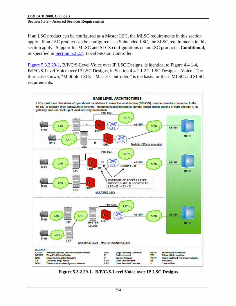
DoD UCR 2008, Change 3 Section 5.3.2 – Assured Services Requirements
754
If an LSC product can be configured as a Master LSC, the MLSC requirements in this section apply. If an LSC product can be configured as a Subtended LSC, the SLSC requirements in this section apply. Support for MLSC and SLCS configurations on an LSC product is Conditional, as specified in Section 5.3.2.7, Local Session Controller. Figure 5.3.2.29-1, B/P/C/S-Level Voice over IP LSC Designs, is identical to Figure 4.4.1-4, B/P/C/S-Level Voice over IP LSC Designs, in Section 4.4.1.1.2.2, LSC Designs – Voice. The third case shown, “Multiple LSCs – Master Controller,” is the basis for these MLSC and SLSC requirements.
Figure 5.3.2.29-1. B/P/C/S-Level Voice over IP LSC Designs

DoD UCR 2008, Change 3 Section 5.3.2 – Assured Services Requirements
755
Per Section 4.5.1.1.2.2, “The third case requires the design and implementation of an LSC cluster concept where a master LSC, as shown in the figure, has a master directory of all users on the base. Under this arrangement, service order activity at one LSC will be reflected automatically at all LSCs in the cluster, including the master LSC. …The [third case] will require custom engineering of the base design (including the use of the LSC portion of an MFSS where an MFSS is located on a base) to ensure interoperability and acceptable performance between the various on-base LSC arrangements and vendors.” The general requirements for MLSCs and SLSCs are identified here. Additional MLSC and SLSC requirements may be added to this section in future UCR releases. In addition, as “stand-alone LSC” is defined here as an LSC that “stands alone” and does not act as either a MLSC or a SLSC. 1. [Required: MLSC, SLSC] All LSC requirements in this section and in all other sections
apply to both MLSCs and SLSCs, unless an individual requirement indicates otherwise.
2. [Required: MLSC, SLSC, PEI, AEI, ATA, IAD] End instruments that are served by a MLSC shall be treated just like EIs that are served by SLSCs. The MLSC shall treat its EIs (i.e., PEIs, AEIs, ATAs, IADs) in the same way that it would if it were operating as a SLSC. The SLSC shall treat its EIs (i.e., PEIs, AEIs, ATAs, IADs) in the same way that it would if it were operating as a MLSC.
3. [Required: MLSC] The MLSC shall adjudicate the enclave budget (the enclave ASAC budget between the MLSC and its primary MFSS or WAN SS) between its SLSCs. The MLSC shall adjudicate the enclave ASAC budget in cases where this budget is nondirectional [Required] and directional [Conditional].
4. [Required: MLSC] The MLSC shall support at least one of two methods for adjudicating the enclave ASAC budget between its SLSCs: the “Highest Priority Sessions” method and the “Strict Budget for All LSCs” method. Support for either of these two methods is acceptable.
5.3.2.29.1 Highest Priority Sessions Method
1. [Required: MLSC] When processing outgoing call requests from its EIs, MGs, and its SLSCs, and incoming call requests to its EIs, MGs, and its SLSCs, the MLSC shall always ensure that the highest precedence level sessions (i.e., P, I, F, FO) are served first over the MLSC-to-SS interface. When call requests are received from or directed to the SLSCs, the MLSC shall always ensure that the highest precedence level sessions (i.e., P, I, F, FO) are served first, regardless of where the SLSC is originated or terminated.

DoD UCR 2008, Change 3 Section 5.3.2 – Assured Services Requirements
756
For example, assume a MLSC with three SLSCs, where the MLSC-to-SS ASAC budget for voice is 28 voice sessions with no directionalization. Also, assume that each LSC is allowed up to 10 voice sessions (with no directionalization) on its subtended-LSC-to-MLSC interface. The SLSCs could not all simultaneously be allowed up to 10 voice sessions on the MLSC-to-SS interface in this case; two requests would be blocked.
2. [Required: MLSC] When the access link from the MLSC to the SS is “full,” the MLSC shall allow additional higher precedence sessions (destined for outside of the enclave, or arriving from outside of the enclave) to succeed by preempting existing lower precedence sessions on the access link. The MLSC shall preempt the lower precedence sessions and establish the higher precedence sessions, independent of whatever SLSC originated these sessions.
3. [Required: MLSC] In this case, the MLSC shall block ROUTINE precedence sessions on the access link that are
a. to or from end users on the MLSC, or b. to or from end users on any of the SLSCs, once the access link session budget (ASAC budget) is met.
5.3.2.29.2 Strict Budget for All LSCs Method
1. [Required: MLSC] When processing outgoing call requests from its EIs, MGs, and its SLSCs, and incoming call requests to its EIs, MGs, and its SLSCs, the MLSC shall always ensure that each SLSC is “guaranteed” a fixed subset of the ASAC budget on the MLSC-to-SS access link. When call requests are received from or directed to the SLSCs, the MLSC shall always ensure that calls to or from each SLSC are allowed to complete, as long as the source or destination LSC is below its subset of the ASAC budget (its “Strict Budget”) for the access link.
2. [Required: MLSC] When the source or destination LSC is at or above its Strict Budget for the access link, the MLSC shall
a. Block all ROUTINE voice session requests on the access link that are to or from end users on that LSC, as long as the LSC is at or above its Strict Budget.
b. Allow any precedence session requests to or from end users on that LSC, but only if
there is an existing session within that LSC’s Strict Budget that is of a lower precedence level and can, therefore be preempted.
DoD UCR 2008, Change 3 Section 5.3.2 – Assured Services Requirements
757
c. If there is no existing lower precedence session that can be preempted, the MLSC shall block the precedence session request, even if there are lower precedence sessions established to or from the other SLSCs that could be preempted.
For example, assume a MLSC with three SLSCs, where the master-LSC-to-SS ASAC
budget for voice is 30 voice sessions with no directionalization. Also assume that each LSC is allowed up to 10 voice sessions (with no directionalization) on its subtended-LSC-to-master-LSC interface. Each of the SLSCs could also be allowed up to 10 voice sessions on the master-LSC-to-SS interface in this case. No session requests to or from a SLSC would be blocked, unless that SLSC was operating at or above its “Strict Budget” of 10 voice sessions for the access link.
3. [Required: MLSC] When the access link from the MLSC to the SS is “full,” the MLSC shall allow additional higher precedence sessions (destined for outside of the enclave, or arriving from outside of the enclave) to succeed by preempting existing lower precedence sessions on the access link, but only if the higher and lower precedence sessions are both within the same Strict Budget and associated with the same SLSC. If these sessions are associated with the same SLSC, then the MLSC shall preempt the lower precedence sessions and establish the higher precedence sessions. If these sessions are not associated with the same SLSC, then the MLSC shall block the higher precedence sessions, even though the access link ASAC budget may be able to support them.
4. [Required: MLSC] In this case, the MLSC shall also block ROUTINE precedence voice sessions to or from one of the SLSCs, once the Strict Budget for that SLSC is met.
5. [Required: MLSC] In this case, the MLSC shall not allow precedence sessions to or from one of the SLSCs to complete, if the Strict Budget for that SLSC is met, and there are no existing lower precedence sessions within that Strict Budget that can be preempted. The MLSC shall block the precedence session in this case, even if the Strict Budgets for the other SLSCs served by that MLSC have not been filled (or have been filled but have calls in them with lower precedence than that of the new session request).
5.3.2.29.3 EMS Access, AS-SIP Signaling, Enclave Budgets, and MG Connections
1. [Required: MLSC, SLSC] The MLSC and the SLSCs shall all be capable of directly connecting to both
a. Local EMS, and b. Remote VVoIP EMS

DoD UCR 2008, Change 3 Section 5.3.2 – Assured Services Requirements
758
2. [Required: MLSC, SLSC] The MLSC is not required to provide the local or remote EMS with an aggregated NM view of the SLSCs. The MLSC shall provide the local or remote EMS with an individual NM view of itself. Each SLSC shall provide the local or remote EMS with an individual NM view of itself.
3. [Required: MLSC, SLSC] The MLSC and the SLSCs shall be capable of communicating with each other using an AS-SIP protocol per Section 5.3.4, AS-SIP Requirements.
In cases where the MLSC and the SLSC are from the same LSC vendor, the MLSC and the SLSCs may communicate with each other using a proprietary signaling protocol.
4. [Required: MLSC, SLSC] All AS-SIP signaling that either 1) leaves the enclave for an external destination, or 2) arrives at the enclave from an external source shall pass through the MLSC. The SLSCs shall not support their own AS-SIP or proprietary signaling links to locations outside the enclave. The SLSCs shall exchange all AS-SIP or proprietary signaling with the MLSC within the enclave, and the MLSC shall exchange all AS-SIP signaling with locations outside the enclave.
This approach allows for both 1) multiple LSC vendors within the enclave and 2) a single LSC vendor’s integrated solution within the enclave.
5. [Required: MLSC] Each MLSC shall maintain two separate enclave budget counts as follows:
a. Intraenclave Budget Count
NOTE: This count shall be based on local traffic engineering for the enclave, and shall not be associated with the access link budget on the master-LSC-to-SS interface.
. This shall be a count of all VVoIP calls traversing the MLSC that both originate and terminate within the enclave. This count shall include both calls within the MLSC itself (EI-to-EI calls, EI-to-MG calls), and calls to or from all of the SLSCs within the enclave.
b. Interenclave Budget Count
. This shall be a count of all VVoIP calls that either enter the MLSC and originated from outside the enclave, or leave the MLSC and terminate outside of the enclave. This count shall include incoming and outgoing calls to or from the MLSC itself, and incoming and outgoing calls to or from all SLSCs within the enclave.
6. [Required: MLSC, SLSC] It is desired that connections between the enclave and the local PSTN only be made through the MG of the MLSC. (This simplifies location services that are based on the commercial PSTN numbers of the various EIs in the enclave). In this

DoD UCR 2008, Change 3 Section 5.3.2 – Assured Services Requirements
759
case, all EIs on the MLSC, and all EIs on each SLSCs shall be able to originate and receive commercial calls from the PSTN PRI/CAS trunk group at the MLSC’s MG.
7. [Required: MLSC, SLSC] It is also possible that connections are made between the enclave and the local PSTN through the MGs of SLSCs (this is an exception situation and is not desired). In this case, only the EIs of a single SLSC shall be able to originate and receive calls from the PSTN PRI/CAS trunk group at that SLSC’s MG.
8. [Required: MLSC, SLSC] The MLSC in an enclave shall provide the only TDM connection (T1.619 PRI, CAS, or SS7 trunk group) to the TDM infrastructure (i.e., DSN MFSs, Tandems, EOs, SMEOs, or PBXs) in the enclave. The SLSCs in an enclave shall not provide any TDM connections to the TDM infrastructure (i.e., DSN MFSs, Tandems, EOs, SMEOs, or PBXs) in the enclave. (This simplifies location services that are based on the DSN numbers of the various EIs in the enclave).
5.3.2.30 MLSC, SLSC, and Dynamic ASAC Requirements in Support of Bandwidth-Constrained Links
This section provides requirements for MLSCs, SLSCs, and Dynamic Assured Services Admission Control (DASAC), and as such augments the following:
• Section 4.5.1.1.2.2, LSC Designs – Voice • Section 5.3.2.2.2.3, ASAC – Open Loop • Section 5.3.2.29, MLSC and SLSC Requirements
The LSC requirements apply to both MLSCs and SLSCs unless indicated otherwise. This section focuses on the Deployable (Tactical) use of the MLSC/SLSC architecture and the introduction of DASAC. Dynamic ASAC enables an LSC to admit, block, or preempt new voice and video calls based on the communications capacity (bps) required for the call and the link capacity available to support the call. Dynamic ASAC will augment the current ASAC approach in which LSCs admit calls based on a call budget. Dynamic ASAC will be applied independently to voice and video calls. The requirements for an MLSC and its SLSCs in support of bandwidth-constrained links apply to both Deployable (Tactical) LSCs and Fixed (Strategic) LSCs (i.e., the requirements are not unique to Deployable LSCs). Please note that “bandwidth” has two definitions per the online version of Merriam-Webster’s dictionary (http://www.merriam-webster.com/dictionary/bandwidth):

DoD UCR 2008, Change 3 Section 5.3.2 – Assured Services Requirements
760
“1: a range within a band of wavelengths, frequencies, or energies… 2: the capacity for data transfer of an electronic communications system … <a bandwidth of 56 kilobits per second>”
The Deployed (Tactical) wireless UC community will be one of the primary audiences for this section. This community generally uses “bandwidth” per the first definition but this section uses “bandwidth” per the second definition according to its usage throughout the rest of this section.
5.3.2.30.1 MLSC and SLSC Architecture Overview
Within Deployable (Tactical) domains, calls typically involve multiple bandwidth constrained links. Each such link must be subject to DASAC. These links typically are wireless (e.g. satellite, radio) in nature. Deployable (Tactical) sites generally exist within a tiered command and control hierarchy. The Deployable (Tactical) site hierarchy is shown in Figure 5.3.2.30-1, Deployable (Tactical) Hierarchy.
Figure 5.3.2.30-1. Deployable (Tactical) Hierarchy
Dynamic ASAC budgets are required for the WA, XA, YB, ZB, AJ, BJ, and JM links in Figure 5.3.2.30-1, Deployable (Tactical) Hierarchy. Links between Component headquarters locations
HeadquartersSite J
Unit Headquarters
Site X
ComponentHeadquarters
Site A
FDISN Core
STEP TeleportSite M
Unit Headquarters
Site W
Unit Headquarters
Site Z
ComponentHeadquarters
Site B
Unit Headquarters
Site Y
Link WA Link XA Link YB Link ZB
Link AJ Link BJ
Link JM
EnterpriseB/P/C/S
Sites

DoD UCR 2008, Change 3 Section 5.3.2 – Assured Services Requirements
761
and headquarters locations support aggregated traffic. Further traffic aggregation occurs between headquarters and standardized tactical entry point (STEP) sites. The MLSC/SLSC architecture enables DASAC budgets to span multiple Deployable (Tactical) links. Each Deployable (Tactical) link is bounded by an MLSC/SLSC pair. The C2 hierarchy determines whether an LSC is “Master” or “Subtended.” For a given link, the LSC in the “higher” site in the C2 hierarchy is designated the MLSC. For the same link, the LSC in the “lower” site in the C2 hierarchy is designated the SLSC. The SLSC and its MLSC independently and in parallel apply their DASAC budgets to the shared link. The MLSC aggregates traffic from one or more SLSCs. Note that the two DASAC budgets for the shared link may differ, each reflecting the requirement of the given LSC’s administrator. Figure 5.3.2.30-2, Deployable (Tactical) LSCs, shows Deployable (Tactical) LSCs and their master/subtended relationship.
Figure 5.3.2.30-2. Deployable (Tactical) LSCs
• LSCs W and A provide the DASAC audio and video budgets for Link WA.
Subtended LSC W is subtended to the MLSC A.
• LSCs X and A provide the DASAC audio and video budgets for Link XA. Subtended LSC X is subtended to the MLSC A.
Link WA Link XA Link YB Link ZB
Link AJ Link BJ
Link JM
LSC W LSC X LSC Y LSC Z
LSC A LSC B
LSC J
FDISN Core
STEP TeleportSite M
EnterpriseB/P/C/S
Sites

DoD UCR 2008, Change 3 Section 5.3.2 – Assured Services Requirements
762
• LSCs Y and B provide the DASAC audio and video budgets for Link YB. Subtended LSC Y is subtended to the MLSC B.
• LSCs Z and B provide the DASAC audio and video budgets for Link ZB.
Subtended LSC Z is subtended to the MLSC B.
• LSCs A and J provide the DASAC audio and video budgets for Link AJ. Subtended LSC A is subtended to the MLSC J. Recall that LSC A also is the MLSC to SLSCs W and X.
• LSCs B and J provide the DASAC audio and video budgets for Link BJ.
Subtended LSC B is subtended to the MLSC J. Remember LSC B also is the MLSC to SLSCs Y and Z.
• LSC J provides the DASAC audio and video budgets for Link JM. Remember
LSC J also is the MLSC to SLSCs A and B. Note that LSCs A and B play the role of both a Master LSC and a Subtended LSC as a function of the tiered C2 hierarchy. For reasons of scaling, the MLSC/SLSC architecture also may be used within a Deployable (Tactical) site. Deployable (Tactical) LANs may simultaneously support both UC voice and video assured services and non-UC voice and video services. The LAN’s routers must route all packets marked with the DSCP assured service values to its EBC. In turn, the EBC will determine if an AS-SIP session is associated with all such packets marked for Assured Service. If such a session does not exist, the DSCP value for such packets will be reset to a value other than that of Assured Service. Note that the tactical LAN associated with an MLSC and the Tactical LAN associated with an SLSC may or may not share the same IP address space. When the IP address spaces differ, an EBC will provide the NAT or NAPT function. Figure 5.3.2.30-3, Deployable (Tactical) Site with All UC Elements, depicts a conventional Deployable (Tactical) LAN where all the UC elements reside together. The real-time multiplexer (RMUX) is a type of real-time IP link accelerator for UC. It bundles multiple concurrent voice or video calls into packets to save on overhead. Alternative implementations may involve IP, UDP, SRTP header compression or may involve transcoding to extremely low bandwidth codecs or may involve yet other bandwidth (bps capacity) saving techniques. These accelerators tend to manipulate call flows only for the transport across the bandwidth constrained link; once the flow is transported over the link, the manipulations to the

DoD UCR 2008, Change 3 Section 5.3.2 – Assured Services Requirements
763
flows are undone. In the subsequent DASAC requirements for LSCs, an IP-based voice Multiplexer (MUX) is used as the example for a real-time IP link accelerator.
Figure 5.3.2.30-3. Deployable (Tactical) Site with All UC Elements
A Deployable (Tactical) site’s UC elements could be deployed remotely from the site. For example, Figure 5.3.2.30-4, Highly Distributed Deployable (Tactical) Hierarchy, is a depiction of Deployable (Tactical) site X’s LSC and EBC assets physically residing at Deployable (Tactical) site Y. Remote elements enable Deployable (Tactical) sites to reduce costs, footprint, weight, and power. Remote placement also enables the movement of critical UC elements to what might be a safer location relative to the battle zone. If elements are deployed remotely, intrasite calls would rely on these remote elements. Intrasite calls would incur additional setup delays and/or media delays. Also, intrasite calls would rely on the availability and the capacity of wide area links (e.g., satellite links, radio links). The handling of NAT and NAPT becomes more complex when a Tactical LAN’s IP space address differs from that of the remotely deployed elements. All the tradeoffs must be considered carefully before adopting such an approach. An EBC or LSC could be deployed in several forms. The element might be shared and identified by a single IP address. The element might be partitioned, with each partition having its own IP address. Virtual machine middleware technology might be used.

DoD UCR 2008, Change 3 Section 5.3.2 – Assured Services Requirements
764
Figure 5.3.2.30-4. Highly Distributed Deployable (Tactical) Hierarchy
Figure 5.3.2.30-5, Deployable (Tactical) Topology Examples, depicts an LSC and an EBC at every Deployable (Tactical) site. This simple UC network example will serve as the basis for several subsequent illustrative MLSC/SLSC AS-SIP call flows and SRTP flows. In this example, each Tactical LAN has its own IP address space; consequently, NAT/NAPT will have to occur at any IP space address boundary.
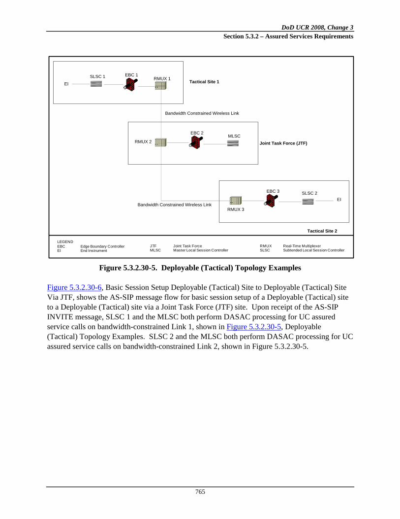
DoD UCR 2008, Change 3 Section 5.3.2 – Assured Services Requirements
765
Figure 5.3.2.30-5. Deployable (Tactical) Topology Examples
Figure 5.3.2.30-6, Basic Session Setup Deployable (Tactical) Site to Deployable (Tactical) Site Via JTF, shows the AS-SIP message flow for basic session setup of a Deployable (Tactical) site to a Deployable (Tactical) site via a Joint Task Force (JTF) site. Upon receipt of the AS-SIP INVITE message, SLSC 1 and the MLSC both perform DASAC processing for UC assured service calls on bandwidth-constrained Link 1, shown in Figure 5.3.2.30-5, Deployable (Tactical) Topology Examples. SLSC 2 and the MLSC both perform DASAC processing for UC assured service calls on bandwidth-constrained Link 2, shown in Figure 5.3.2.30-5.
SLSC 1 EBC 1RMUX 1
RMUX 2
EBC 2MLSC
RMUX 3
EBC 3 SLSC 2EI
EI Tactical Site 1
Tactical Site 2
Joint Task Force (JTF)
Bandwidth Constrained Wireless Link
Bandwidth Constrained Wireless Link
LEGENDEBC Edge Boundary ControllerEI End Instrument
JTF Joint Task ForceMLSC Master Local Session Controller
RMUX Real-Time MultiplexerSLSC Subtended Local Session Controller
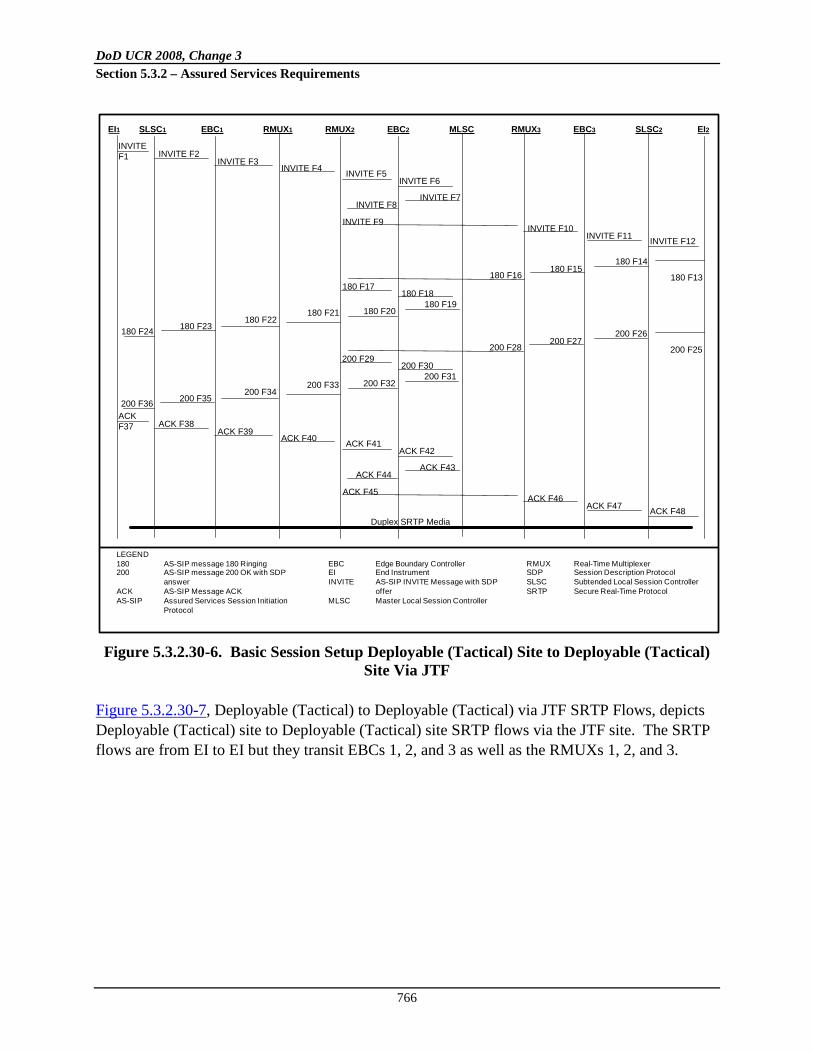
DoD UCR 2008, Change 3 Section 5.3.2 – Assured Services Requirements
766
Figure 5.3.2.30-6. Basic Session Setup Deployable (Tactical) Site to Deployable (Tactical)
Site Via JTF Figure 5.3.2.30-7, Deployable (Tactical) to Deployable (Tactical) via JTF SRTP Flows, depicts Deployable (Tactical) site to Deployable (Tactical) site SRTP flows via the JTF site. The SRTP flows are from EI to EI but they transit EBCs 1, 2, and 3 as well as the RMUXs 1, 2, and 3.
EI1 SLSC1 EBC1 RMUX1 RMUX2 EBC2 MLSC RMUX3 EBC3 SLSC2 EI2
INVITE F1 INVITE F2
INVITE F3INVITE F4 INVITE F5
INVITE F6
INVITE F7INVITE F8
INVITE F9INVITE F10
INVITE F11 INVITE F12
180 F24 180 F23180 F22
180 F21 180 F20180 F19
180 F18180 F17
180 F16180 F15
180 F14
180 F13
200 F36 200 F35200 F34
200 F33 200 F32200 F31
200 F30200 F29
200 F28200 F27
200 F26
200 F25
ACK F37 ACK F38
ACK F39ACK F40 ACK F41
ACK F42
ACK F43ACK F44
ACK F45ACK F46
ACK F47 ACK F48Duplex SRTP Media
LEGEND180 AS-SIP message 180 Ringing200 AS-SIP message 200 OK with SDP
answerACK AS-SIP Message ACKAS-SIP Assured Services Session Initiation
Protocol
EBC Edge Boundary ControllerEI End InstrumentINVITE AS-SIP INVITE Message with SDP
offerMLSC Master Local Session Controller
RMUX Real-Time MultiplexerSDP Session Description ProtocolSLSC Subtended Local Session ControllerSRTP Secure Real-Time Protocol

DoD UCR 2008, Change 3 Section 5.3.2 – Assured Services Requirements
767
Figure 5.3.2.30-7. Deployable (Tactical) to Deployable (Tactical) via JTF SRTP Flows
The AS-SIP flow for Deployable (Tactical) site to Deployable (Tactical) site via JTF session teardown is shown in Figure 5.3.2.30-8, Deployable (Tactical) to Deployable (Tactical) via JTF Session Teardown. Upon receipt of the AS-SIP 200 (OK) message, SLSC 2 and the MLSC both perform DASAC processing for UC Assured Service calls on bandwidth-constrained Link 2 from Figure 5.3.2.30-5, Deployable (Tactical) Topology Examples. SLSC 1 and the MLSC both perform DASAC processing for UC assured service calls on bandwidth-constrained Link 1.
EI1 EBC1 RMUX1 RMUX2 EBC2 RMUX3 EBC3 EI2
Duplex SRTP Media
Poi
nt o
f tra
nsit
Poi
nt o
f tra
nsit
Poi
nt o
f tra
nsit
Poi
nt o
f tra
nsit
Poi
nt o
f tra
nsit
Poi
nt o
f tra
nsit
LEGENDEBC Edge Boundary ControllerEI End Instrument
RMUX Real-Time Multiplexer SRTP Secure Real-Time Protocol

DoD UCR 2008, Change 3 Section 5.3.2 – Assured Services Requirements
768
Figure 5.3.2.30-8. Deployable (Tactical) to Deployable (Tactical) via JTF Session
Teardown Figure 5.3.2.30-9, Deployable (Tactical) Site to Fixed Site via JTF and UC Backbone Topology Example, depicts a deployed Deployable (Tactical) site to a Fixed (Strategic Enterprise) site via the JTF and the UC backbone network. This simple UC network example will serve as the basis for several subsequent illustrative MLSC/SLSC AS-SIP call flows and SRTP flows. In this example, the Deployed (Tactical) site, JTF, and the Fixed (Strategic) Enterprise site each have their own IP address space; consequently, NAT/NAPT will have to occur at the IP address space boundaries.
EI1 SLSC1 EBC1 RMUX1 RMUX2 EBC2 MLSC RMUX3 EBC3 SLSC2 EI2
BYE F1BYE F2
BYE F3BYE F4 BYE F5
BYE F6
BYE F7BYE F8
BYE F9BYE F10
BYE F11 BYE F12
200 F24 200 F23200 F22
200 F21 200 F20200 F19
200 F18200 F17
200 F16200 F15
200 F14 200 F13
LEGEND200 AS-SIP message 200 OK with SDP
answerBYE AS-SIP Message BYEAS-SIP Assured Services Session Initiation
Protocol
EBC Edge Boundary ControllerEI End InstrumentMLSC Master Local Session Controller
RMUX Real-Time MultiplexerSDP Session Description ProtocolSLSC Subtended Local Session Controller

DoD UCR 2008, Change 3 Section 5.3.2 – Assured Services Requirements
769
Figure 5.3.2.30-9. Deployable (Tactical) Site to Fixed Site via JTF and UC Backbone
Topology Example Upon receipt of the AS-SIP INVITE message, SLSC 1 and the MLSC both perform DASAC processing for UC Assured Service calls on bandwidth-constrained Link 1 shown in Figure 5.3.2.30-9, Deployable (Tactical) Site to Fixed Site via JTF and UC Backbone Topology Example. The MLSC and MFSS 1 both perform DASAC processing for UC assured service calls on bandwidth-constrained Link 2. The LSC, with WAN-level ASAC policing from MFSS 2, performs traditional ASAC processing on Link 3. The AS-SIP message flow for this case is shown in Figure 5.3.2.30-10, Basic Session Setup Deployable (Tactical) Site to Fixed Site via JTF.
SLSC 1EBC 1RMUX 1
RMUX 2
EBC 2MLSC
EI1 Deployed Tactical Site
Joint Task Force (JTF)
Bandwidth Constrained Wireless Link
EBC 3MFSS 1 MFSS 2
Bandwidth Constrained Wireless Link
EBC 4
LSCEBC 5 EI2Fixed Strategic Enterprise Site
UC Backbone
LEGENDEBC Edge Boundary ControllerEI End InstrumentJTF Joint Task Force
LSC Local Session ControllerMFSS Multifunction SoftswitchMLSC Master Local Session Controller
RMUX Real-Time MultiplexerSLSC Subtended Local Session ControllerUC Unified Capabilities

DoD UCR 2008, Change 3 Section 5.3.2 – Assured Services Requirements
770
Figure 5.3.2.30-10. Basic Session Setup Deployable (Tactical) Site to Fixed Site via JTF
Figure 5.3.2.30-11, Deployable (Tactical) Site to Fixed Site via JTF SRTP Flows, illustrates the SRTP flows for a Deployable (Tactical) site to a Fixed site via the JTF site. The SRTP flows are from EI to EI but they transit EBCs 1, 2, and 5 as well as the RMUXs 1 and 2. There are only two “media-anchoring” EBCs in the end-to-end VVoIP media flow: one at the MLSC site (EBC 2), and the other at the Strategic LSC site (EBC 5). The EBC at the MLSC site (EBC 2) performs media anchoring and the EBC at the SLSC site (EBC 1) does not. The VVoIP media flow in Figure 5.3.2.30-10, Basic Session Setup Deployable (Tactical) Site to Fixed Site via JTF, traverses all three EBCs (Subtended, Master, and Strategic), but is only anchored at two of them (Master and Strategic).
LEGEND180 AS-SIP message 180 Ringing200 AS-SIP message 200 OK with SDP
answerACK AS-SIP Message ACKAS-SIP Assured Services Session Initiation
Protocol
EBC Edge Boundary ControllerEI End InstrumentINVITE AS-SIP INVITE Message with SDP
offerMFSS Multifunction SoftswitchMLSC Master Local Session Controller
RMUX Real-Time MultiplexerSDP Session Description ProtocolSLSC Subtended Local Session ControllerSRTP Secure Real-Time Protocol
EI1 SLSC1 EBC1 RMUX1 RMUX2 EBC2 MLSC EBC3 MFSS1 EBC4 MFSS2 EBC5 LSC EI2INVITEF1
INVITE F2 INVITE F3 INVITE F4INVITE F5INVITE F6
INVITE F7INVITE F8 INVITE F9
INVITE F10INVITEF11
INVITE F12INVITE F13
INVITE F14 INVITEF15
INVITEF16
180 F32 180 F31 180 F30 180 F29 180 F28 180 F27180 F26
180 F25 180 F24180 F23
180 F22180 F20
180 F21
180 F19 180 F18 180 F17
200 F48 200 F47 200 F46 200 F45 200 F44 200 F43200 F42
200 F41 200 F40200 F39
200 F38200 F36
200 F37
200 F35 200 F34 200 F33
ACK F49 ACK F50 ACK F51 ACK F52ACK F53 ACK F54
ACK F55ACK F56 ACK F57
ACK F58ACKF11
ACK F59ACK F60
ACK F61 ACK F62 ACK F63Duplex SRTP Media
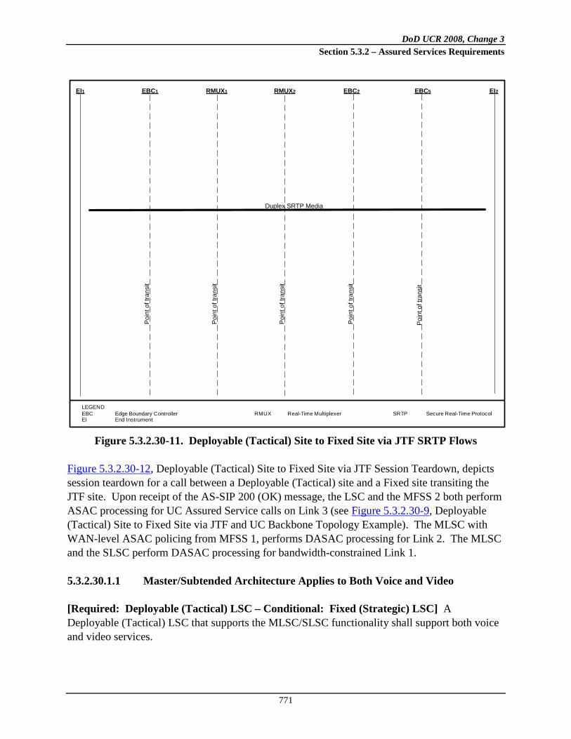
DoD UCR 2008, Change 3 Section 5.3.2 – Assured Services Requirements
771
Figure 5.3.2.30-11. Deployable (Tactical) Site to Fixed Site via JTF SRTP Flows
Figure 5.3.2.30-12, Deployable (Tactical) Site to Fixed Site via JTF Session Teardown, depicts session teardown for a call between a Deployable (Tactical) site and a Fixed site transiting the JTF site. Upon receipt of the AS-SIP 200 (OK) message, the LSC and the MFSS 2 both perform ASAC processing for UC Assured Service calls on Link 3 (see Figure 5.3.2.30-9, Deployable (Tactical) Site to Fixed Site via JTF and UC Backbone Topology Example). The MLSC with WAN-level ASAC policing from MFSS 1, performs DASAC processing for Link 2. The MLSC and the SLSC perform DASAC processing for bandwidth-constrained Link 1.
5.3.2.30.1.1 Master/Subtended Architecture Applies to Both Voice and Video
[Required: Deployable (Tactical) LSC – Conditional: Fixed (Strategic) LSC] A Deployable (Tactical) LSC that supports the MLSC/SLSC functionality shall support both voice and video services.
LEGENDEBC Edge Boundary ControllerEI End Instrument
RMUX Real-Time Multiplexer SRTP Secure Real-Time Protocol
EI1 EBC1 RMUX1 RMUX2 EBC2 EBC5 EI2
Duplex SRTP Media
Poin
t of t
rans
it
Poin
t of t
rans
it
Poin
t of t
rans
it
Poin
t of t
rans
it
Poin
t of t
rans
it

DoD UCR 2008, Change 3 Section 5.3.2 – Assured Services Requirements
772
Figure 5.3.2.30-12. Deployable (Tactical) Site to Fixed Site via JTF Session Teardown
5.3.2.30.1.2 MLSC/SLSC and DASAC
[Required: Deployable (Tactical) LSC – Conditional: Fixed (Strategic) LSC] The product shall support DASAC; see Section 5.3.2.30.2.1, Dynamic ASAC.
5.3.2.30.1.3 Directionalization Budget Inheritance
[Conditional: Deployable (Tactical) LSC, Fixed (Strategic) LSC] The product shall inherit the voice directionalization ASAC budget requirements (i.e., IPB, IPBi, IPBo) from Sections 5.3.2, Assured Services Requirements, and 5.3.4, AS-SIP Requirements, for both voice and video.
LEGEND200 AS-SIP message 200 OK with SDP
answerBYE AS-SIP Message BYEAS-SIP Assured Services Session Initiation
Protocol
EBC Edge Boundary ControllerEI End InstrumentMFSS Multifunction Softswitch
MLSC Master Local Session ControllerRMUX Real-Time Multiplexer
EI1 SLSC1 EBC1 RMUX1 RMUX2 EBC2 MLSC EBC3 MFSS1 EBC4 MFSS2 EBC5 LSC EI2
BYE F1 BYE F2 BYE F3 BYE F4BYE F5 BYE F6
BYE F7BYE F8 BYE F9
BYE F10BYEF11
BYE F12BYE F13
BYE F14 BYEF15
BYEF16
200 F32 200 F31 200 F30 200 F29 200 F28 200 F27200 F26
200 F25 200 F24200 F23
200 F22200 F20
200 F21
200 F19 200 F18 200 F17

DoD UCR 2008, Change 3 Section 5.3.2 – Assured Services Requirements
773
5.3.2.30.1.4 Minimum Number of Supportable SLSCs per MLSC
[Required: Deployable (Tactical) LSC – Conditional: Fixed (Strategic) LSC] A product that supports the MLSC functionality shall support DASAC for a minimum of 10 SLSCs.
5.3.2.30.1.5 MLSC Also an SLSC
[Required: Deployable (Tactical) LSC – Conditional: Fixed (Strategic) LSC] A product that acts as an MLSC shall be capable of acting simultaneously as an SLSC.
5.3.2.30.1.6 Two Budgets per Link per Media Type
[Required: Deployable (Tactical) LSC – Conditional: Fixed (Strategic) LSC, MFSS, WAN SS] A MLSC/SLSC pair will apply their respective DASAC budgets to their respective ends of the shared link. Likewise, the MFSS/MLSC pair will apply their respective DASAC budgets to their respective ends of the shared link. Likewise, the WAN SS/MLSC pair will apply their respective DASAC budgets to their respective ends of the shared link. During AS-SIP call processing a given link and its budget are inferred by the combination of the sender’s CCA-ID and the receiver’s CCA-ID.
5.3.2.30.1.7 Distinct Voice and Video DASAC Budgets
[Required: Deployable (Tactical) LSC – Conditional: Fixed (Strategic) LSC] The product must be able to support an independent DASAC budget for voice and an independent DASAC budget for video.
5.3.2.30.1.8 EBC Anchoring Assured Services
See Section 5.3.2.14.10, Deployable (Tactical) Customer Edge Router Requirements, for requirements involving Deployable (Tactical) CE Routers and Deployable (Tactical) EBCs anchoring assured services.
5.3.2.30.1.9 Long Locals
[Conditional: Deployable (Tactical) LSC] The product shall support long locals where the EIs and the LSC physically reside at separate sites. The Deployable (Tactical) LAN’s LSC and EBC also may reside at separate sites.
5.3.2.30.1.10 Logical LSCs
[Conditional: Deployable (Tactical) LSC] A single physical product may provide two or more logical LSCs supporting two or more Deployable (Tactical) sites. Each logical LSC is a

DoD UCR 2008, Change 3 Section 5.3.2 – Assured Services Requirements
774
software-based partition of the single physical LSC asset. Each logical LSC will have its own IP address and its own CCA-IDs.
5.3.2.30.1.11 EBC and LSC Associations
See Section 5.3.2.15.11, Deployable (Tactical) Edge Boundary Controller Requirements, for requirements involving Deployable (Tactical) EBC and LSC associations.
5.3.2.30.2 Dynamic ASAC Requirements
5.3.2.30.2.1 Dynamic ASAC
This section defines requirements for providing the DASAC capability. Dynamic ASAC enables an LSC to admit, block, or preempt new voice and video sessions based on the bandwidth (bits/sec) required for the session and the link capacity available to support the session. Dynamic ASAC will augment the ASAC approach described earlier in Section 5.3.2.2.2.3, ASAC – Open Loop, in which LSCs admit sessions based on a session budget, either 110 kbps for voice, or a multiple of 500 kbps for video. The DASAC will be applied independently to voice and video sessions.
5.3.2.30.2.2 Detailed Description and Requirements
The method for ASAC described in the previous sections could unnecessarily limit the number of sessions on capacity-constrained communications links, such as are common in Deployable (Tactical) networks and in some Fixed (Strategic) networks. For example, the current approach provisions 110 kbps for each voice session, but some Deployable (Tactical) sessions only need 30 kbps for good quality. The 110 kbps number is based on the assumption that a voice session will use a G.711 codec, will be encapsulated in an IP packet, and also might be encapsulated in an IP/HAIPE tunnel. These are reasonable conservative assumptions in a Fixed (Strategic) environment, but are not appropriate for a Deployable (Tactical) environment or a constrained Strategic environment, where lower bit rate codecs are used and link capacity is limited. Dynamic ASAC will provide a more realistic estimate of capacity needed for a voice or video session and admit, block, or preempt sessions based on this estimate. However, parameter determination for DASAC can be quite complex. Some session packets might be tunneled over a communications link, others might not be; others might have header compression and some packets might be aggregated in a voice multiplexer also called a “voice mux.” Engineering analysis and traffic analysis are required to determine the overheads on the LSC Path (the path between cooperating LSCs and SSs). The LSC, MFSS, and WAN SS (the “product” in the following requirements) must analyze each session initiation and session modification request to determine which overheads are appropriate,

DoD UCR 2008, Change 3 Section 5.3.2 – Assured Services Requirements
775
and the codec rate and packets per second (PPS) negotiated between the EIs involved in the session. This rate could change during a session; an example being a mid-session codec change; a factor that must be monitored by these devices if the change information is conveyed in AS-SIP messages. This may not be the case for all types of sessions; in some sessions the change information is conveyed in the bearer traffic. A bearer-based example would be a mid-session codec renegotiation via a modem protocol. In such cases, precautions during DASAC processing must be taken to ensure that there is sufficient capacity to accommodate the highest possible codec rate that could be renegotiated via the bearer mid-session. This could include using static, table driven parameters for session capacity, where these parameters represent the highest bits per second session capacity supported by the EI. Ideally, in lieu of the static table driven parameters, DASAC would process any bearer-based mid-session re-negotiation but such details are not presently specified in this version of the UCR. Associated tables may also be needed to capture link aspects such as tunneling, header compression, and packet aggregation. Also note that a higher precedence session setup with a relatively higher bits per second codec may preempt one or more ongoing sessions in the setup or active (post setup) states. [Required: MFSS, WAN SS – Required: Deployable (Tactical) LSC – Conditional: Fixed (Strategic) LSC] The product shall manage the DASAC budget in a manner similar to that described in Section 5.3.2.2.2.3, ASAC – Open Loop, except that the budget shall be based on the amount of bandwidth (bps) available to support a new session. [Required: MFSS, WAN SS – Required: Deployable (Tactical) LSC – Conditional: Fixed (Strategic) LSC] The product shall use a method of establishing and managing the DASAC budget per LSC Path. The capacity calculation shall be based on the bottleneck communications link along the LSC Path. The DASAC budget shall be based on the following metrics derived from the parameters shown in Table 5.3.2.30-1, EISC Estimation Parameters. A product with DASAC capability shall support an EI Session Capacity (EISC) estimation table for each LSC Path and each codec class that operates on the LSC Path. A codec class is defined by the codec type PPS produced by the codec.
Table 5.3.2.30-1. EISC Estimation Parameters
# PARAMETER SOURCE COMMENT 1 Codec Rate
(bps) Product extracts from SDP message; stored per codec class
Could change on a session-by-session basis per EI and within a session.

DoD UCR 2008, Change 3 Section 5.3.2 – Assured Services Requirements
776
# PARAMETER SOURCE COMMENT 2 Packet Rate
(PPS) Product extracts from information in SDP message
Could change on a session-by-session basis per EI and within a session. When the respective EIs support bearer-based mid-session renegotiation and if the product lacks the ability to process this bearer layer information, the PPS parameter needs to be set to the highest bits per second rate option available to the bearer-based mid-session renegotiation capability.
3 Number of Sessions in Progress
Number of sessions in progress for this codec class. This includes sessions in both the setup and active states. Running account kept by product
Initial value equals zero. Incremented upon successful session connection. Decremented upon successful session completion.
4 Tunnel Overhead Factor (bytes)
Pre-provisioned and entered into product
Indicates the number of overhead bytes that must be added to the IP packet size to account for encryption or other types of tunnels. If some sessions are tunneled and others are not, use the number of bytes associated with the largest overhead tunnel. Default is 100 bytes. Minimum 0 bytes. Maximum 512 bytes.
5 IP Overhead (bytes)
Pre-provisioned and entered into product, includes IP, UDP, and RTP or SRTP overhead associated with packet flow over the target link
If IPv6, use 60 bytes. If IPv4, use 40 bytes. Default is 60 bytes.
6 Layer 2 Overhead (bytes)
Pre-provisioned and entered into product
Sized according to layer 2 protocol used on target link—this parameter is the same for all packets in all codec classes. Default is 20 bytes.
7 Safety Factor (%)
Pre-provisioned and entered into product
This parameter is used to provide a margin of error for the EISC calculation. Default is 10%.
8 Voice MUX Overhead per Packet (bytes)
Pre-provisioned and entered into product
This parameter is used on a per packet basis if a voice MUX is used. There is no default value. Minimum 0 bytes. Maximum 512 bytes.
9 Overhead per Voice MUX Sample (bytes)
Pre-provisioned and entered into product
This parameter is an overhead that is applied to each voice sample bundled in an output voice packet. There is no default value. Minimum 0 bytes. Maximum 512 bytes.
The parameters in each EISC estimation table shall be used to determine the following: 1. EI Session Capacity (EISC)—the bandwidth required (in bps) for a session. The EISC
shall be computed by the product each time it detects signaling for a new session or a change in codec parameters for an ongoing session.

DoD UCR 2008, Change 3 Section 5.3.2 – Assured Services Requirements
777
2. Transmission Link Session Capacity (TLSC)—the capacity (bps) of the bottleneck link associated with the LSC Path. The TLSC is a pre-provisioned parameter entered for each LSC Path link via NM commands. The TLSC does not include an allocation for session signaling. Session signaling must be provisioned separately as part of traffic engineering for the bottleneck link on the path.
3. Available Link Session Capacity (AVSC)—the capacity (bps) currently available for sessions on the LSC Path. The AVSC shall be calculated each time during:
a. The session establishment AS-SIP dialog (specifically the AS-SIP message containing the SDP answer)
b. Mid-session re-INVITE dialog based on a mid-session codec change (specifically the
AS-SIP message containing the new SDP answer to the new offer) c. Session teardown (specifically based on LSC detecting the AS-SIP 200 (OK) for the
BYE) The AVSC is calculated as follows:
AVSC = TLSC—the sum of EISCs for all sessions in progress and in the process of being established on the LSC Path
4. Determination of TLSC depends on the following:
a. The allocation of capacity to the bottleneck router queue within the LSC Path. b. The portion of that capacity that is reserved for voice and video applications that is
not under the control of the LSC28
Parameters 1 through 3 in Table 5.3.2.30-1, EISC Estimation Parameters, are dynamic; the product must calculate these parameters on a session-by-session basis. Parameters 4 through 9 are preloaded into the product based on traffic engineering analysis of the link. Figure 5.3.2.30-13, AS-SIP Triggers for AVSC, illustrates the AS-SIP triggers for the AVSC calculations. For reasons of simplification, it assumes the EIs are AS-SIP enabled. It is also assumes that only one session is preempted to enable a new session to be accepted. This is not
28 It is possible that there will be non-UC applications supported in the same router queues that support DASAC flows. These will not be under the control of the LSC. Traffic engineering must account for the capacity that is guaranteed to these flows. This value must be subtracted from the total capacity allocated to the router queue. The non-UC traffic must be controlled via admission control or router policing to ensure that the capacity allocated to the UC traffic is protected.

DoD UCR 2008, Change 3 Section 5.3.2 – Assured Services Requirements
778
meant to preclude the preemption of multiple lower precedence setup and/or active sessions collectively, with a higher than or equal to, bits per second bearer rate, to allow a new, higher precedence session with a lower than or equal to, bits per second bearer rate to be admitted. When a “200 OK” is received by the product, the bandwidth previously reserved for this session is released and thereby the AVSC is increased. The “SDP Answer” message indicates the results of the codec negotiation between the EIs involved in the session request. The product processes the SDP Answer to determine whether there is sufficient capacity to support the new session. If so, the product will reserve bandwidth for the session and continue with AS-SIP session processing. If a Cancel or a 3xx, 4xx, 5xx, or 6xx message is received after the SDP Answer is processed but before the session setup is completed, the reserved capacity will be released and the AVSC increased accordingly.
Generated or Received AS SIP Message
200 OK to BYE?
True
CANCEL or3xx, 4xx,
5xx, 6xx afterhaving processed the
SDP answer
False
Increase AVSC,continue AS SIP
session processing
True
ContainsSDP answer?
False
Link’s AVSCsufficient for
call?Increase AVSC,continue AS SIP
session processing
Decrease AVSC,continue AS SIP
session processing
True
True
Pre-emptable setup and/or active
session(s)?
Continue AS SIP session processing
False
False
Pre-empt selected setup and/or active
session(s) with appropriate treatment,
adjust AVSC, continue AS SIP
session processing for the new session setup
attempt
True
FalseGenerate
Response 488,continue AS SIP
session processing
Figure 5.3.2.30-13. AS-SIP Triggers for AVSC
If after receiving an SDP answer, the product determines if there is insufficient bandwidth for the new session. The product will review all sessions in progress, which includes those that are being set up (“setup sessions”) and those that are active, to determine if any have lower precedence than the new session. If there are none, the new session will be blocked. If lower precedence sessions do exist, the product will use the algorithm specified below or its equivalent to determine if the new session must be blocked or alternately admitted after the preemption of one or more setup and/or active sessions:

DoD UCR 2008, Change 3 Section 5.3.2 – Assured Services Requirements
779
1. The product will determine the precedence level (P) of the new session attempt, where P is an integer between 1 and 5, representing increasing levels of precedence. The lowest precedence is Routine, with P =1. The precedence level of the new session attempt is P = N.
a. If N=1, the new session attempt is blocked because a new session can only preempt a lower precedence session. The product will exit this algorithm.
b. If N is >1, the product will determine if EISC(N), the capacity of the new session, is
=< AVSC (where AVSC is the available capacity):
(1) If so, the product will accept the new session, set AVSC to = AVSC - EISC(N) and exit this algorithm.
(2) If not, the product will set P = 1. The product will continue to the next step.
2. The product will determine if there is any combination of setup sessions at precedence level P that, if preempted along with all sessions at a lower precedence, would provide sufficient capacity to support the new session.
a. If so, the “optimum” combination of setup sessions will be preempted and the new session will be accepted. The optimum combination is the one that provides the required capacity with the least number of preempted setup sessions. The product will set AVSC = AVSC plus the capacity of all preempted calls (including all sessions at lower precedence levels) minus EISC(N). The product will exit this algorithm.
b. If not, the product will determine if there is some optimum combination of one or
more active sessions at P which, if preempted along with all setup sessions at P and all current sessions at a lower precedence than P, will provide sufficient capacity for the new session. The optimum combination is the one that provides the required capacity with the least number of preempted active sessions at P. The combination of all preemptible sessions is called the “identified sessions”.
(1) If there is such an optimum combination, all identified sessions will be
preempted and the new session will be accepted. The product will set the new AVSC to equal AVSC plus the capacity of the identified sessions minus EISC(N). The product will exit this algorithm.
(2) If not, the product will continue processing as described in the next step.
3. The product will increment P by 1.

DoD UCR 2008, Change 3 Section 5.3.2 – Assured Services Requirements
780
a. If P = N, the setup attempt will be blocked. The product will exit this algorithm. b. If P < N, the product will re-execute step 2.
If one or more preemptions occur and the new session is established, the resulting AVSC may be larger or smaller than before the preemption(s). If the preempting session’s bandwidth requirement is less than that of the preempted session or sessions, the AVSC increases. If the preempting session’s bandwidth requirement is more than that of the preempted session or sessions, the AVSC decreases. If one or more preemptions occur and the new session is established, the resulting AVSC may be larger or smaller than before the preemption(s). If the preempting session’s bandwidth requirement is less than that of the preempted session or sessions, the AVSC increases. If the preempting session’s bandwidth requirement is more than that of the preempted session or sessions, the AVSC decreases. [Required: MFSS, WAN SS – Required: Deployable (Tactical) LSC – Conditional: Fixed (Strategic) LSC] The product shall support DASAC for the following types of session packet flows:
• Pass-through flows, where the bearer packets are not modified after they are generated in either an LSC or EI
• Voice/Video multiplexed flows where payloads from different flows are
combined in a new packet to reduce the effect of IP overhead before transmission on a bottleneck link
• Header compressed flows where all or some of the IP/UDP/RTP headers are
compressed before transmission on a bottleneck link
• Tunneled flows, where the packet flows described earlier are also subject to tunneling, for example, using IPSec
[Required: MFSS, WAN SS – Required: Deployable (Tactical) LSC – Conditional: Fixed (Strategic) LSC] The product shall use parameters 1 through 9 in Table 5.3.2.30-1, EISC Estimation Parameters, as appropriate, to calculate the total EISC and AVSC. Parameter values 1 through 3 shall be determined by the product (LSC, MFSS, or WAN SS). Parameters 4 through 9, as appropriate, shall be determined before operation and loaded into the product (LSC, MFSS, or WAN SS) database. These values shall be chosen conservatively to ensure that there is no case where more sessions are admitted than can be supported by the LSC Path. [Required: MFSS, WAN SS – Required: Deployable (Tactical) LSC – Conditional: Fixed (Strategic) LSC] The product shall, on a session-by-session basis, scan the SDP messages,

DoD UCR 2008, Change 3 Section 5.3.2 – Assured Services Requirements
781
extract the EISC codec rate and PPS parameters from each SDP Answer message, and store these parameters in the appropriate DASAC table, for each session in progress. [Required: MFSS, WAN SS – Required: Deployable (Tactical) LSC – Conditional: Fixed (Strategic) LSC] The product shall be able to support all codecs defined in Section 5.3.2.6.1.2, Audio Codecs, Section 5.3.2.6.2.2, Video Codecs (Including Associated Audio Codecs), and Section 6.1.7.5.4 Codec Translation Functional. [Required: MFSS, WAN SS – Required: Deployable (Tactical) LSC – Conditional: Fixed (Strategic) LSC] If the product does not have an entry for the negotiated audio codec or for the PPS for the session, the product shall set EISC at 110 kbps. [Required: MFSS, WAN SS – Required: Deployable (Tactical) LSC – Conditional: Fixed (Strategic) LSC] If the product supports an ongoing session in which the EIs can re-negotiate audio or video codec changes at the bearer layer (e.g., modem protocol), the product shall set EISC at the highest bit rate that can be re-negotiated by the EIs mid-session via the bearer layer. [Required: MFSS, WAN SS – Required: Deployable (Tactical) LSC – Conditional: Fixed (Strategic) LSC] If the values of parameters 4 through 7 are not explicitly entered in the table, the product shall use the default parameters listed in Table 5.3.2.30-1, EISC Estimation Parameters. [Required: MFSS, WAN SS – Required: Deployable (Tactical) LSC – Conditional: Fixed (Strategic) LSC] The product shall not use silence suppression, also known as voice activity detection, as a factor in calculating EISC for voice sessions. [Required: MFSS, WAN SS – Required: Deployable (Tactical) LSC – Conditional: Fixed (Strategic) LSC] Each DASAC product also shall be provisioned with session budget parameters which provide an absolute limit on the number of voice and video sessions accepted in either direction for each link. Examples of notional EISC calculation for voice sessions are given in Tables 5.3.2.30-2 through 5.3.2.30-5. The environment for Examples 1, 2, and 4 is shown in Figure 5.3.2.30-14, Notional System Architecture for Examples 1, 2, and 4. The environment for Example 3 is shown in Figure 5.3.2.30-15, Notional System Environment for Example 3 (Voice MUX with HAIPE Tunnel). The example environments consist of 20 VoIP phones, each of which can support G.711, G.729, G.723, and 2400 bps MELPe codecs. The TLSC for the controlled link is 256 kbps full duplex. The examples differ in the number and types of communication devices that are used to support UC traffic flow. Point-to-Point Protocol (PPP) is used as the layer 2 protocol. It provides a 7-byte layer 2 overhead per packet.

DoD UCR 2008, Change 3 Section 5.3.2 – Assured Services Requirements
782
Figure 5.3.2.30-14. Notional System Architecture for Examples 1, 2, and 4
In Tables 5.3.2.30-2 through 5.3.2.30-5, the bolded, non-italicized numbers represent parameters that have been pre-entered into the product via NM commands. The bolded, italicized numbers are calculated by the product based on inspection of signaling packets. The non-bolded numbers are the calculations made by the product as part of the AVSC determination.
Figure 5.3.2.30-15. Notional System Environment for Example 3
(Voice MUX with HAIPE Tunnel)
LSC
EBC
CE R
Example 1
EI
EI EI
EI
LSC
EBC
CE R
Example 2
EI
EI EI
EI
H256 Kbps (full duplex) Voice Allocation on 1 Mbps PPP link
1 Gigabit Ethernet

DoD UCR 2008, Change 3 Section 5.3.2 – Assured Services Requirements
783
Example 1 (Table 5.3.2.30-2, Example 1: Current Session Status (No HAIPE Case)) shows a case where there is no HAIPE or voice MUX. There are eight sessions in progress. Five of these are MELPe sessions29
with one session each for the other codecs. The total EISC for these sessions is 176.8 kbps, as shown in Table 5.3.2.30-2. The AVSC is 79.2 kbps, based on a TLSC of 256 kbps. In this case, the LSC could admit a new session using any of the codec types except G.711. If the next session offers a G.711 codec, the LSC must block the session unless there is a lower precedence session that can be preempted.
Example 2 (Table 5.3.2.30-3, Example 2: AVSC Calculation assuming the G.711 Session is new (HAIPE Case) shows a case where a HAIPE is used to encrypt packets traversing the bottleneck link. In this example, there are seven sessions in progress: five MELPe sessions, one session for G.723.1, and one session for G.729. Also shown is one “potential” (new) G.711 session. The AVSC calculation takes place just after an INVITE request for a new G.711 session is generated. The LSC calculates the AVSC for the G.711 session at negative 7.3 kbps (see Table 5.3.2.30-3). The LSC will reject the new session if it cannot preempt one of the existing sessions.
Table 5.3.2.30-2. Example 1: Current Session Status (No HAIPE Case)
29 In these examples, the calculations for MELPe capacity requirements include an overhead factor of 1.037 to account for padding the MELP codec bits to fit into a 7 octet voice sample.
TLCC IPV4TLCC= 256 Kbps
ID Codec Type MELPe G723.1 G729 G711 1 Codec Rate Kbps 2.4 5.3 8 642 Packet Rate Packets per Second 11.1 33.3 50.0 50.03 Number of Voice Sessions in Progress 5 1 1 14 Tunnel Overhead Bytes 0 0 0 05 IP Overhead Bytes 40 40 40 406 Layer 2 Overhead Rate Bytes 7 7 7 77 Safety Factor % 10% 10% 10% 10%8 Payload Size Bytes 28 20 20 1609 Packet Size Bytes 68 60 60 20010 Packet Rate Kbps 6.0 16.0 24.0 80.011 Layer 2 Overhead Kbps 0.6 1.9 2.8 2.812 Average Data Rate for Payload and Overhead Kbps 6.7 17.8 26.8 82.813 EICC (including Safety Factor) per Session Kbps 7.3 19.6 29.5 91.114 Total EICC for all Sessions in Codec Group Kbps 36.7 19.6 29.5 91.115 Total EICC for all Sessions on Link Kbps 176.8
Grand Total Sessions 8AVCC Kbps 79.2

DoD UCR 2008, Change 3 Section 5.3.2 – Assured Services Requirements
784
Table 5.3.2.30-3. Example 2: AVSC Calculation Assuming the G.711 Session is New (HAIPE Case)
Example 3 (Table 5.3.2.30-4, Example 3: Use of Voice MUX with a HAIPE Tunnel) shows the case where a voice MUX is used to reduce the EISC per voice session. The environment for this example is given in Figure 5.3.2.30-15, Notional System Environment for Example 3 (Voice MUX with HAIPE Tunnel). The TLSC is 256 kbps (full duplex). The network also contains a HAIPE device. Eight sessions are active: five MELPe sessions and one session each based on G.723.1, G.729, and G.711 codecs.
HAIPE TUNNELIPV4TLCC= 256 Kbps
ID Codec Type MELPe G723 G729 G711 1 Codec Rate Kbps 2.4 5.3 8 642 Packet Rate Packets per Second 11.1 33.3 50.0 50.03 Number of Voice Sessions in Progress 5 1 1 14 Tunnel Overhead Bytes 52 52 52 525 IP Overhead Bytes 40 40 40 406 Layer 2 Overhead Rate Bytes 7 7 7 77 Safety Factor % 10% 10% 10% 10%8 Payload Size Bytes 28 20 20 1609 Packet Size Bytes 120 112 112 25210 Packet Rate Kbps 10.7 29.8 44.8 100.811 Layer 2 Overhead Kbps 0.6 1.9 2.8 2.812 Average Data Rate for Payload and Overhead Kbps 11.3 31.7 47.6 103.613 EICC (including Safety Factor) per Session Kbps 12.4 34.9 52.4 114.014 Total EICC for all Sessions in Codec Group Kbps 62.1 34.9 52.4 114.015 Total EICC for all Sessions on Link Kbps 263.3
Grand Total Sessions 8AVCC Kbps -7.3

DoD UCR 2008, Change 3 Section 5.3.2 – Assured Services Requirements
785
Table 5.3.2.30-4. Example 3: Use of Voice MUX with a HAIPE Tunnel
The calculation takes into account two types of overhead; one for each output packet generated by the voice MUX; the other for each voice sample in the output packet. The per-packet overhead consists of the IP, tunnel and voice MUX byte overheads for each output packet. This overhead is multiplied by the output packet rate to determine the overhead rate in kbps. The output packet rate is set at the highest rate of the codecs supported by the EIs on the LSC side of the LSC Path. The voice sample overhead is the number of bytes that the voice mux appends to each voice sample encapsulated in the output packet. The number of bytes per sample is multiplied by the voice sample rate of the input packets, to determine the overhead rate in kbps. The EISC, for this example, is 133.7 kbps. The AVSC is 122.3 kbps, based on a TLSC of 256 kbps. In this case the LSC could admit a new session from any of the codec types. Compared to Table 5.3.2.30-3, Example 2: AVSC Calculation Assuming the G.711 Session in New (HAIPE Case), the use of the voice mux reduces the bandwidth demand from 263.3 kbps to 133.7 kbps, based on the notional numbers used in the examples. Example 4 (Table 5.3.2.30-5, Example 4: Use of Header Compression with a HAIPE Tunnel) shows the case where header compression and HAIPEs are used. This example is based on the environment used in Example 2 with one addition: the CE Router supports header compression on the bottleneck link. The IP overhead parameter has been modified to account for a header compression mechanism that, on average, transmits 95 percent of packets with a compressed header of two bytes, and 5 percent of packets with a full IP, UDP, and RTP header of 40 bytes. This gives an average header size of 3.9 bytes, which has been rounded up to 5 bytes to provide a
Voice Mux Calls IPV4Per Codec Type Calculations TLCC= 256 Kbps
ID Codec Type Packet MELPe G723 G729 G711 1 Codec Rate Kbps 2.4 6.4 8 642 Packet Rate PPS 11.1 33.3 50.0 50.03 Number of Voice Sessions in Progress 5 1 1 14 Overhead for voice mux sample Bytes 7 7 7 75 Payload size Bytes 28 24 20 1606 Payload traffic rate Kbps 2.49 6.40 8.00 64.007 Voice mux overhead traffic rate Kbps 3.1 1.9 2.8 2.88 Voice mux and payload traffic rate Kbps 91.5 5.6 8.3 10.8 66.8
Per Packet Overhead Calculation9 Tunnel overhead Bytes 5210 IP overhead Bytes 2811 Voice mux overhead per packet Bytes 412 Layer 2 overhead Bytes 1213 Safety Factor % 10% Packet rate is calculated 14 Total per packet overhead rate Kbps 42.24 as the maximum Packet15 Total EICC for all Sessions in progress Kbps 133.7 Rate above (ID=2)
Grand Total Sessions 8AVCC Kbps 122.3

DoD UCR 2008, Change 3 Section 5.3.2 – Assured Services Requirements
786
margin of safety. An approximate overhead factor of 4 percent has been added to account for MELPe overhead.
Table 5.3.2.30-5. Example 4: Use of Header Compression with a HAIPE Tunnel
The AVSC is 50.9 kbps, which would enable the LSC to accept any new session request without preemption or blocking, except for a session that requires a G.711 codec.
5.3.2.31 Other UC Voice Requirements
5.3.2.31.1 Attendant Features
5.3.2.31.1.1 Introduction
This section contains an import and revision of historical circuit-switched requirements from UCR 2008, 22 January 2009, Section 5.2.1.2, Attendant Features. The revision converts these historical DSN requirements into current UC requirements. Attendant features in this section apply to attendant consoles that are provided with the local LSC and/or centralized attendant services.
HAIPE TUNNELIPV4TLCC= 256 Kbps
ID Codec Type MELPe G723 G729 G711 1 Codec Rate Kbps 2.4 5.3 8 642 Packet Rate Packets per Second 11.1 33.3 50.0 50.03 Number of Voice Sessions in Progress 5 1 1 14 Tunnel Overhead Bytes 52 52 52 525 IP Overhead Bytes 5 5 5 56 Layer 2 Overhead Rate Bytes 7 7 7 77 Safety Factor % 10% 10% 10% 10%8 Payload Size Bytes 28 20 20 1609 Packet Size Bytes 85 77 77 21710 Packet Rate Kbps 7.6 20.5 30.8 86.811 Layer 2 Overhead Kbps 0.6 1.9 2.8 2.812 Average Data Rate for Payload and Overhead Kbps 8.2 22.4 33.6 89.613 EICC (including Safety Factor) per Session Kbps 9.0 24.6 37.0 98.614 Total EICC for all Sessions in Codec Group Kbps 45.0 24.6 37.0 98.615 Total EICC for all Sessions on Link Kbps 205.1
Grand Total Sessions 8AVCC Kbps 50.9

DoD UCR 2008, Change 3 Section 5.3.2 – Assured Services Requirements
787
5.3.2.31.1.2 Precedence and Preemption
[Required: LSC, MFSS, WAN SS] The attendant console shall interoperate with MLPP as described in Section 5.3.2.31.3, Multilevel Precedence and Preemption. The console shall be able to initiate all levels of precedence calls (i.e., ROUTINE through FLASH OVERRIDE).
5.3.2.31.1.3 Call Display
[Required: LSC, MFSS, WAN SS] The attendant console shall provide a visual display of each precedence level, the calling number, and CoS for incoming direct dialed calls and diverted calls to the attendant.
5.3.2.31.1.4 Class of Service Override
[Required: LSC, MFSS, WAN SS] The attendant shall provide the capability to override any CoS (calling area or precedence) of the calling party on a call-by-call basis.
5.3.2.31.1.5 Busy Override and Busy Verification
[Required: PEI, AEI, LSC, MFSS, WAN SS] The attendant shall have the capability to override a busy EI condition. If the called EI being verified is busy, “off-hook supervision” shall be given to the attendant performing the busy verification. When a verification code is used, all digits of the code must be dialed before cut-through to the EI can be accomplished. Connections to commercial CO access lines shall be restricted from busy verification access. The attendant shall have the capability to enter an existing busy EI to inform the user of an incoming call. An override tone shall be provided to the busy user before the attendant entering the conversation, and the tone shall be repeated periodically as long as the attendant is connected. Selected EIs may be classmarked to deny attendant break-in. In particular, it shall be possible to classmark EI types (e.g., all data and secure voice) to preclude the busy verification or busy override being applied to the EIs.
5.3.2.31.1.6 Night Service
[Required: LSC, MFSS, WAN SS] The attendant console shall have the ability to route all calls normally directed to the console to a night service deflection. The night service deflection shall be a fixed or manually selected DN.
5.3.2.31.1.7 Automatic Recall of Attendant
[Required: LSC, MFSS, WAN SS] When an attendant extends a call to an EI that is busy or does not answer within a preset time, the extended party shall be recalled automatically to the console. Recalls shall be transferred to the console that originally processed the call. If that

DoD UCR 2008, Change 3 Section 5.3.2 – Assured Services Requirements
788
console is busy, the recall shall be placed into the console queue; but if the console is out of service, the recall shall be routed to another console.
5.3.2.31.1.8 Calls in Queue to the Attendant
[Required: LSC, MFSS, WAN SS] The attendant console shall have the capability to place calls in a waiting queue. Calls placed in queue to the attendant console shall be retrieved by the attendant in order of precedence level (i.e., FLASH OVERRIDE first, ROUTINE last) and longest holding time. Calls in queue shall not be lost when a console is placed out of service or forwarded to night service deflection. When the console is placed out of service or forwarded to night service while calls are in queue, the console shall be capable of one of the following solutions: 1. All calls in queue shall be forwarded first to the centralized attendant, and then night
service, or
2. All subsequent calls placed to the attendant console shall be forwarded first to the centralized attendant, and then night service. The attendant console shall be able to answer all remaining calls in queue preventing any calls from being lost.
5.3.2.31.2 National ISDN 1/2 Basic Access
5.3.2.31.2.1 Introduction
This section contains an import and revision of historical circuit-switched requirements from UCR 2008, 22 January 2009, Section 5.2.1.3.3, National ISDN 1/2 Basic Access. The revision converts these historical DSN requirements into current UC requirements.
5.3.2.31.2.2 Description
[Conditional: TA, IAD, LSC, MFSS, WAN SS] The LSC, TA, and IAD shall include both S/T and U interfaces for ISDN Basic Access. The ISDN Basic Access interface allows the simultaneous transmission of voice and CS data between an EI and an LSC. Specifically, the ISDN Basic Access allows the provisioning of two 64- kbps B-channels, which may be used to carry voice or CS data, and a 16-kbps D-channel, which can carry signaling and packet information. Requirements for this feature shall be IAW Telcordia Technologies references SR-NWT-002120, SR-NWT-002343, and TR-NWT-001268. The MLPP service capability requirements for this interface shall be IAW ANSI T1.619-1992 (R1999) and ANSI T1.619a-1994 (R1999).
DoD UCR 2008, Change 3 Section 5.3.2 – Assured Services Requirements
789
5.3.2.31.3 Multilevel Precedence and Preemption
5.3.2.31.3.1 Introduction
This section contains an import and revision of historical circuit-switched requirements from UCR 2008, 22 January 2009, Section 5.2.2, Multilevel Precedence and Preemption. The revision converts these historical DSN requirements into current UC requirements. This section covers the MLPP requirements for UC signaling appliance systems. It discusses precedence levels, cause values, preemption in the network, interface requirements for MLPP with ISDN, and MLPP interactions with other features and services. No feature or function specifically identified in the UCRor in the referenced standards shall prevent the completion or connection of a PRIORITY or higher precedence call IAW this section.
5.3.2.31.3.2 MLPP Overview
5.3.2.31.3.2.1 Description
[Required: AEI, LSC, MFSS, WAN SS – Conditional: PEI] The MLPP service applies to the MLPP service domain only. Connections and resources that belong to a call from an MLPP subscriber shall be marked with a precedence level and domain identifier (refer to Section 5.3.2.31.3.8, ISDN MLPP PRI, and Section 5.3.2.31.3.10, MLPP CCS7) and shall only be preempted by calls of higher precedence from MLPP users in the same MLPP service domain. The maximum precedence level of a subscriber is set at the subscription time by the UC network administrator based on the subscriber’s validated need. The subscriber may select a precedence level up to and including the maximum authorized precedence level on a per call basis. Precedence provides preferred handling of MLPP service requests. It involves assigning and validating priority levels to calls, and prioritized treatment of MLPP service requests. Precedence calls (i.e., PRIORITY and above) that are not responded to by the called party (e.g., call unanswered) shall be diverted IAW Section 5.3.2.31.3.3, Precedence Call Diversion. If precedence call waiting has been invoked, these calls shall be handled IAW Section 5.3.2.31.3.9.1, Precedence Call Waiting. Unanswered calls placed at a ROUTINE precedence level shall continue to ring. Preemption may take one of two forms. First, the called party may be busy with a lower precedence call that must be preempted in favor of completing the higher precedence call from the calling party. Second, the network resources may be busy with calls; some of which are of lower precedence than the call requested by the calling party. One or more of these lower precedence calls shall be preempted to complete the higher precedence call. The four characteristics of preemption are as follows:

DoD UCR 2008, Change 3 Section 5.3.2 – Assured Services Requirements
790
1. Any party whose connection was terminated, whether that resource is reused or not, shall
receive a distinctive preemption notification (see Table 5.3.2.6-2, UC Information Signals).
2. Any called party of an active call that is being preempted by a higher precedence call shall be required to acknowledge the preemption by going “on-hook,” before being connected to the new calling party.
3. When there are no idle resources, preemption of the lowest of these lower level precedence resources shall occur.
4. A call can be preempted any time after the precedence level of the call has been established and before call clearing has begun.
5.3.2.31.3.2.2 Precedence Levels
[Required: AEI, LSC, MFSS, WAN SS – Conditional: PEI] The LSC, MFSS, WAN SS, PEI and AEI shall provide five precedence levels. The precedence levels listed from lowest to highest are ROUTINE, PRIORITY, IMMEDIATE, FLASH, and FLASH OVERRIDE.
5.3.2.31.3.2.3 Announcements
NOTE: The text in this section has been updated and moved to Section 5.3.2.6.1.1.2, Announcements, and Section 5.3.2.6.1.1.3, Loss of C2 Features Announcement, of this document. Table 5.3.2.31.3-1 is now Table 5.3.2.6-3, Announcements, of this document.
5.3.2.31.3.2.4 Invocation and Operation
[Required: AEI, LSC, MFSS, WAN SS – Conditional: PEI] The precedence level of a call is selected by the subscriber on a per call basis. The subscriber may select any precedence level up to and including his or her maximum authorized precedence level. The network at the subscriber’s originating interface ensures that the selected precedence level does not exceed the maximum level assigned to that telephone number. Once set for a call, this precedence level cannot be changed. In addition, a connection between two UC subscribers shall not have different precedence levels. A call will default automatically to the ROUTINE precedence unless a higher precedence is dialed. The DSN Worldwide Numbering and Dialing Plan is described in Section 5.3.2.16.1, DSN Worldwide Numbering and Dialing Plan. During a call setup, if there is a shortage of network resources, the LSC, MFSS, and/or WAN SS shall determine whether resources are held by calls of lower precedence. If there is a shortage, the LSC, MFSS, and/or WAN SS shall release the lowest of these lower precedence call(s) and

DoD UCR 2008, Change 3 Section 5.3.2 – Assured Services Requirements
791
seize the resources required to set up the higher precedence call. These resources include calls on trunks between an LSC and a DSN circuit switch. The preemption operation depends on whether the LSC/MFSS/WAN SS needs to preempt a common network resource, such as one of the LSC to DSN switch trunks that is currently being used by a different subscriber than the intended called subscriber. If a called user is to be preempted, both the called party and its connected-to parties shall be, at a minimum, audibly notified of the preemption using the preemption tone in Table 5.3.2.6-2, UC Information Signals, and the existing MLPP call shall be cleared immediately. The called party must acknowledge the preemption by going “on-hook” or pressing a feature button, before the higher precedence call is completed. Then the called party is offered the new MLPP call. After attempting a precedence call, the calling party shall receive an audible ringback precedence call tone when the call is offered successfully to the called party as a precedence call. These alerting tones are provided in Table 5.3.2.6-2, UC Information Signals. The calling party shall receive a BPA, as shown in Table 5.3.2.6-3, Announcements, for the following reasons: 1. Equal or higher precedence calls have prevented completion.
2. No idle network resources are available to make a connection to the dialed number and the called subscriber belongs to a network that does not support preemption.
If the requested precedence level is not subscribed to, the calling party shall receive a UPA, as shown in Table 5.3.2.6-3, Announcements. The calling party shall receive a BNEA, as shown in Table 5.3.2.6-3, Announcements, if the called party is assigned as nonpreemptable. Precedence calls (i.e., PRIORITY and above) that are not responded to by the called party (e.g., call unanswered) shall be diverted IAW Section 5.3.2.2.2.1.2.5, Precedence Call Diversion. If precedence call waiting has been invoked, these calls shall be handled IAW Section 5.3.2.31.3.9.1, Precedence Call Waiting. Unanswered calls placed at a ROUTINE precedence level shall continue to ring.
5.3.2.31.3.3 Preemption in the Network
[Required: AEI, TA, IAD, LSC, MFSS, WAN SS – Conditional: PEI] The following sections describe the treatment for precedence calls at the called party’s interface and applies to both analog and digital (ISDN and non-ISDN) terminating CPE.

DoD UCR 2008, Change 3 Section 5.3.2 – Assured Services Requirements
792
5.3.2.31.3.3.1 Network Facilities Active with Lower Precedence Calls
[Required: AEI, LSC, MFSS, WAN SS – Conditional: PEI] For PRIORITY precedence calls and above, during call setup, if there is a shortage of a network resource, then the network shall determine whether resources are held by calls of lower precedence. The network shall release the lowest of these lower precedence call(s) and seize the necessary resources that are required to set up the higher precedence call. These resources include calls on trunks between an LSC and a DSN circuit switch. When a common network resource is preempted, all existing parties shall receive a preemption tone (see Table 5.3.2.6-2, UC Information Signals) and the existing connection is disconnected. The new higher precedence call is set up using the preempted resource.
5.3.2.31.3.3.1.1 CANCEL To/CANCEL From
[Required: LSC, MFSS, WAN SS] Requirements for the CANCEL to/CANCEL from feature shall be IAW Telcordia Technologies GR-477-CORE, Section 6, NTM Manual Controls. In addition, FLASH and FLASH OVERRIDE calls shall be exempted from these controls. The application of any LSC/SS to circuit-switch trunk group control shall not prevent precedence calls from performing a preemptive search on all trunk groups that were friendly searched previously.
5.3.2.31.3.3.2 Network Facilities Active with Equal or Higher Precedence Call
[Required: AEI, LSC, MFSS, WAN SS – Conditional: PEI] If all network resources required to complete a precedence call are busy with equal or higher precedence calls, the calling user shall be sent the BPA (see Table 5.3.2.6-3, Announcements).
5.3.2.31.3.3.3 MLPP Trunk Selection (Hunting)
[Required: LSC MG, MFSS MG, WAN SS MG] The UC route selections shall be based on Precedence Level/Calling Area (PL/CA) classmarks for both voice-grade and data-grade trunk groups. The UC hunting sequence shall be capable of being varied depending on the route. Hunt sequences shall be capable of scanning data-grade trunk groups for voice-grade calls. The hunting sequence shall be capable of searching all trunks. First, the hunting sequence shall examine the route digit so that, for data calls only, data-grade trunks shall be searched. For voice-grade calls, all trunks shall be searched.

DoD UCR 2008, Change 3 Section 5.3.2 – Assured Services Requirements
793
5.3.2.31.3.3.3.1 Hunt Sequence for Trunks
[Required: LSC MG, MFSS MG, WAN SS MG] The LSCs/MFSSs/WAN SSs shall route UC calls to trunks that have classmarks to indicate the maximum PL/CA permitted. Calls shall not be originated over trunk groups when the call attempt exceeds the precedence level or calling area.
5.3.2.31.3.3.3.1.1 ROUTINE Precedence Calls
[Required: LSC MG, MFSS MG, WAN SS MG] For ROUTINE precedence calls, the LSC/MFSS/WAN SS shall use an idle search on all programmed routes to the call destination. Failing to find an idle trunk, the LSC/MFSS/WAN SS shall provide a trunk busy tone to the caller.
5.3.2.31.3.3.3.1.2 Precedence Calls Above ROUTINE Precedence
[Required: LSC MG, MFSS MG, WAN SS MG] The LSC/MFSS/WAN SS shall provide for two methods of trunk route selection for precedence level calls above the ROUTINE precedence. Either method can be assigned to a destination route based on the UC Area Code (KXX) and/or UC Switch Code (KXX) of the call. In each method, trunks shall be tested individually for idle or busy conditions. If preemption is required, only a call of the lowest level of precedence, lower than the dialed precedence, shall be preempted.
5.3.2.31.3.3.3.1.2.1 Method 1
[Required: LSC MG, MFSS MG, WAN SS MG] In method 1, the LSC/MFSS/WAN SS shall perform an idle search on the direct route and all alternative routes, as shown in Figure 5.3.2.31.3-1, Example Hunt Sequence for Method 1. Failing to find an idle trunk, the LSC/MFSS/WAN SS shall enter the preemptive search. In the preemptive search, the LSC/MFSS/WAN SS shall search again for an idle trunk in the direct route, and if so, shall select any idle trunk found. If no idle trunk exists in the direct route, the LSC/MFSS/WAN SS shall preempt the call of the lowest precedence in the direct route, provided the precedence of the call selected for preemption is lower than the precedence of the call being processed. Failing to complete the call on the direct route, the LSC/MFSS/WAN SS shall advance the preemptive search to the next alternate route, and repeat the preemptive search process described here. This process will continue through all possible alternate routes. When the LSC/MFSS/WAN SS is unable to preempt, it shall route the caller to the BPA.

DoD UCR 2008, Change 3 Section 5.3.2 – Assured Services Requirements
794
Figure 5.3.2.31.3-1. Example Hunt Sequence for Method 1
5.3.2.31.3.3.3.1.2.2 Method 2
[Required: LSC MG, MFSS MG, WAN SS MG] In method 2, the LSC/MFSS/WAN SS shall directly enter a friendly, then a preemptive search of the direct route before searching the next alternate route choice, as shown in Figure 5.3.2.31.3-2, Example Hunt Sequence for Method 2. In the preemptive search, the LSC/MFSS/WAN SS shall search for an idle trunk in the direct route, and if so, shall select any idle trunk found. If no idle trunk exists in the direct route, the LSC/MFSS/WAN SS shall preempt the call of the lowest precedence in the direct route, provided the precedence of the call selected for preemption is lower than the precedence of the call being processed. Failing to complete the call on the direct route, the LSC/MFSS/WAN SS shall advance the preemptive search to the next alternate route, and repeat the preemptive search process described here. This process will continue through all possible alternate routes. When the LSC/MFSS/WAN SS is unable to preempt, it shall route the caller to the BPA.

DoD UCR 2008, Change 3 Section 5.3.2 – Assured Services Requirements
795
Figure 5.3.2.31.3-2. Example Hunt Sequence for Method 2
5.3.2.31.3.3.4 MLPP Interworking with Other Networks
5.3.2.31.3.3.4.1 Calls from Non-MLPP Networks
[Required: MG, LSC, MFSS, WAN SS] Calls from non-MLPP networks that enter UC shall be assigned the lowest precedence level and the MLPP service domain identification at the network boundary and may be preempted within UC.
5.3.2.31.3.3.4.2 Precedence Calls to Non-MLPP Networks
[Required: LSC, MFSS, WAN SS] When a precedence call leaves the UC network and enters a network (i.e., PSTN, North American Treaty Organization (NATO), Enhanced Mobile Satellite Systems (EMSS), etc.) or a non-MLPP device (e.g., ARD) that does not support the MLPP service, the call is treated as a non-MLPP call. The LSC/MFSS/WAN SS that is directly

DoD UCR 2008, Change 3 Section 5.3.2 – Assured Services Requirements
796
connected to the non-MLPP network shall send an LOC2 announcement to the call originator as described in Section 5.3.2.31.3.2.3, Announcements. The LSC/MFSS/WAN SS MGs shall be capable of terminating incoming calls above ROUTINE to trunk groups classmarked as non-preemptable (e.g., to a PBX2, PSTN, or other non-UC network). The LSC/MFSS/WAN SS shall be capable of providing the following capabilities: 1. The LSC/MFSS/WAN SS shall divert the precedence call to an alternate DN or location
capable of handling the precedence level of the call.
2. The LSC/MFSS/WAN SS/MG shall pass the precedence call, including MLPP information element for ISDN/SS7, to the distant switch (e.g., PSTN). That call shall be preemptable and maintain its precedence level within its domain of the UC network.
NOTE: Any network that does not support the MLPP service shall convey, if technically possible, the parameters of the MLPP service (e.g., precedence level, domain, etc.) intact. In this case, the network shall pass them on with no action taken.
3. The LSC/MFSS/WAN SS/MG shall extend the precedence call as routine (i.e., no T1.619a IEs) to the PBX2 or a non-MLPP network.
5.3.2.31.3.4 Precedence Call Diversion
NOTE: The text in this section has been updated and moved to Section 5.3.2.2.2.1.2.5, Precedence Call Diversion, of this document.
5.3.2.31.3.5 Preempt Signaling
5.3.2.31.3.5.1 Channel-Associated Signaling
[Conditional: LSC MG, MFSS MG, WAN SS MG] Preemption on CAS trunks is accomplished at a UC signaling appliance by sending a measured supervisory signal toward both the calling user and the called user of an established or ringing call connection. The supervisory signal is recognized at the UC signaling appliance, causing the release of the call. Following call release a, a preempt warning tone of 440 + 620 Hz is applied to each end user. The preempt warning tone is introduced by the terminating UC signaling appliance at a composite level of -16 dBm, measured at the zero transmission level point (TLP). The preempt warning tone is maintained until a disconnect signal (“off hook” or feature button on EI) is returned to the UC signaling appliance. The trunk that was selected for Preemption for Reuse is reused to serve the waiting precedence call. Four preemption signals exist, depending on the circuit condition and intended disposition. They are Answered Call: Circuit to be Reused, Unanswered Call: Circuit

DoD UCR 2008, Change 3 Section 5.3.2 – Assured Services Requirements
797
to be Reused, Answered Call: Circuit Not to be Reused, and Unanswered Call: Circuit Not to be Reused, and are illustrated in Figure 5.3.2.31.3-3, UC Preempt Signals.
Figure 5.3.2.31.3-3. UC Preempt Signals (Part 1)

DoD UCR 2008, Change 3 Section 5.3.2 – Assured Services Requirements
798
Figure 5.3.2.31.3-3. UC Preempt Signals (Part 2)
Preemption for Reuse can be exercised only on classmarked trunks in a preemptable group. Preemption Not for Reuse may occur on any classmarked trunk when another link in the established connection is preempted for reuse. The UC signaling appliance MG shall apply a preemption warning tone to dial pulse (DP) and DTMF access trunks that do not use Wink Start signaling for supervision. Trunks that use Wink Start supervision must conform to the preempt signals, as shown in Figure 5.3.2.31.3-3, UC Preempt Signals. Trunks using common channel supervision (i.e., D-channel signaling) shall apply the preemption warning tone to the user that is preempted. The LSC/MFSS/WAN SS that supports MF(R1) signaling shall be capable of interpreting and responding to the four preempt signals, as shown in Figure 5.3.2.31.3-3.
5.3.2.31.3.5.2 Primary Rate Interface
[Required: LSC MG, MFSS MG, WAN SS MG] Requirements for MLPP PRI signaling shall be IAW ANSI Standards T1.619-1992 and T1.619a-1994, and Section 5.2.1.3.4, ISDN Primary Access.

DoD UCR 2008, Change 3 Section 5.3.2 – Assured Services Requirements
799
5.3.2.31.3.5.3 Common Channel Signaling Number 7
[Conditional: LSC, MFSS, WAN SS] Requirements for MLPP Common Channel Signaling Number 7 (CCS7) signaling shall be IAW ANSI Standards T1.619-1992 and T1.619a-1994.
5.3.2.31.3.6 Analog Line MLPP
5.3.2.31.3.6.1 Busy at the Called Party’s Interface
[Required: TA, IAD, LSC, MFSS, WAN SS] The following busy line treatment at the called party’s interface for precedence calls applies to analog terminating lines (i.e., lines off of a TA or IAD). The line treatments apply to inter-LSC calls or calls between users on the same LSC.
5.3.2.31.3.6.1.1 Line Active with a Lower Precedence Call
NOTE: The text in this section has been updated and moved to Section 5.3.2.2.2.1.2.6, Line Active with a Lower Precedence Call, of this document.
5.3.2.31.3.6.1.2 Line Active with an Equal or Higher Precedence Call above ROUTINE Precedence
[Required: TA, IAD, LSC, MFSS, WAN SS] Precedence calls arriving at a party that is busy with an equal or higher precedence call shall be routed to a BPA (see Table 5.3.2.6-3, Announcements). If the called party has activated call forwarding, the LSC/MFSS/WAN SS shall attempt to complete the call to the forward destination.
5.3.2.31.3.7 ISDN MLPP BRI
5.3.2.31.3.7.1 General Description
[Conditional: TA, IAD, LSC, MFSS, WAN SS] The ISDN MLPP BRI allows the simultaneous transmission of voice and CS data over a single customer line connecting CPE and a TA/IAD. Specifically, the basic access allows the provision of two 64-kbps B-channels, which may be used to carry voice or CS data, and a one 16-kbps D-channel, which can carry signaling and packet information. The MLPP requirements for this feature shall be IAW ANSI Standard ANSI T1.619-1992 and T1.619a-1994, and Section 5.3.2.31.2, National ISDN 1/2 Basic Access.
DoD UCR 2008, Change 3 Section 5.3.2 – Assured Services Requirements
800
5.3.2.31.3.7.2 Single B-Channel, Single Appearance, Single Directory Number
[Conditional: TA, IAD, LSC, MFSS, WAN SS] The following busy line treatment at the called party’s interface for precedence calls applies to digital (ISDN and non-ISDN) terminating lines on an IAD or TA. The line treatments also apply to inter-LSC calls and calls between users on the same LSC.
5.3.2.31.3.7.2.1 Line Active with a Lower Precedence Call
[Conditional: TA, IAD, LSC, MFSS, WAN SS] Precedence calls arriving at a busy user that is classmarked as preemptable shall preempt the active lower precedence call. The active busy user shall receive a continuous preemption tone until an “on-hook” signal is received and the other party shall receive a preemption tone for a minimum of 3 seconds (see Table 5.3.2.6-2, UC Information Signals). After going “on-hook,” the user to which the precedence call is directed shall be provided precedence ringing (Table 5.3.2.6-1, UC Ringing Tones and Cadences). The user shall be connected to the preempting call after going “off-hook.” If call waiting is invoked by the terminating user, it shall be ignored and the existing lower precedence call shall be preempted (refer to Section 5.3.2.2.2.1.2.3, Busy with Lower Precedence Call).
5.3.2.31.3.7.2.2 Line Active with an Equal or Higher Precedence Call
[Conditional: TA, IAD, LSC, MFSS, WAN SS] Precedence calls arriving at a user that is busy with an equal or higher precedence call shall be routed to a BPA (see Table 5.3.2.6-3, Announcements). If the called user has activated call forwarding, the call shall be forwarded to the new number at the same precedence level.
5.3.2.31.3.7.3 Single B-Channel, Multiple Appearances, Single Directory Number
[Conditional: TA, IAD, LSC, MFSS, WAN SS] This section describes the requirements for processing precedence calls over a single B-channel ISDN interface with a station set that has multiple appearances and one DN. Incoming precedence calls to a multiple appearance ISDN station set shall provide a precedence ringing tone on the next available button as well as a visual display of the precedence level on the station set. Then the called party shall have the option of either placing the current call on hold and picking up the incoming precedence call, or ignoring the call. This process of placing a call on hold and answering a precedence call shall remain the same until the BRI is saturated (i.e., all call appearances are in use). When an incoming precedence

DoD UCR 2008, Change 3 Section 5.3.2 – Assured Services Requirements
801
call is made to a saturated BRI, the lowest precedence call, including those on hold, shall be preempted. If a call on hold has the lowest precedence, the LSC/MFSS/WAN SS shall send a preemption tone to the call on hold caller. The LSC/MFSS/WAN SS/IAD/TA sends a preemption tone to the corresponding appearance on the station set of the destination DN that has placed the call on hold. After a preset time the call is cleared and the LSC/MFSS/WAN SS sends a precedence ring to the corresponding appearance on the station set of the destination DN. Next, the destination DN user hears the precedence ringing, indicating that the call on hold has been dropped. The DN user sees the precedence level of this new call on the station set display also. The DN user shall have the option of answering the call, letting it forward to an alternate party, and/or letting it divert to an attendant. If the active call has the lowest precedence, the LSC/MFSS/WAN SS shall send a preemption tone to the active call and the destination directory number. When the destination directory number goes “on hook,” a precedence ring is received indicating the incoming precedence call. In these two cases, the other calls on hold are not preempted, and they may be retrieved at any time.
5.3.2.31.3.7.4 Two B Channels, Multiple Appearances, Single Directory Number
[Conditional: TA, IAD, LSC, MFSS, WAN SS] The requirements for processing precedence calls over a two B-channel ISDN interface, with a station set that has multiple appearances and one DN, shall be identical to that in Section 5.3.2.31.3.7.3, Single B-Channel, Multiple Appearances, Single Directory Number (i.e., precedence calls over a single B-channel ISDN interface with a station set that has multiple appearances and one DN). In addition, this interface is limited by the number of possible appearances on the ISDN station set.
5.3.2.31.3.7.5 Two B-Channels, Two Directory Numbers (Data Mode Only)
[Required: TA, IAD, LSC, MFSS, WAN SS] This section describes the requirements for processing precedence calls over a two B-channel ISDN interface with two DNs. When an ISDN call appearance is set up as data-mode only (i.e., one or two B-channels equipped for data), preemption by incoming voice calls shall not be permitted. Any incoming higher precedence voice calls placed to a BRI in data-mode shall receive a BNEA or divert IAW Section 5.3.2.2.2.1.2.5, Precedence Call Diversion.

DoD UCR 2008, Change 3 Section 5.3.2 – Assured Services Requirements
802
5.3.2.31.3.8 ISDN MLPP PRI
[Required: LSC MG, MFSS MG, WAN SS MG, LSC, MFSS, WAN SS] Requirements for ISDN MLPP PRI shall be IAW ANSI Standards T1.619-1992 and T1.619a-1994. [Conditional: LSC MG, MFSS MG, WAN SS MG, LSC, MFSS, WAN SS] Requirements for European Telecommunications Standards Institute (ETSI) ISDN MLPP PRI shall be IAW ITU-T Standard Q.955.3-1993.
5.3.2.31.3.8.1 Definitions
Definitions of terms can be found in Appendix A, Section A2, Glossary and Terminology Description.
5.3.2.31.3.8.2 Precedence Level Information Elements
[Required: LSC MG, MFSS MG, WAN SS MG, LSC, MFSS, WAN SS] The MLPP ISDN PRI Setup Message shall contain the Precedence Level IE in Code Set 5, as shown in Table 5.3.2.31.3-2. Table 5.3.2.31.3-2. MLPP ISDN PRI Precedence Level Information Element (Code Set 5)
Octet 3:
Bit: 8 7 6 5 4 3 2 1 Precedence Level Information Octet 1 0 1 0 0 0 0 0 1 Element Identifier 2 Length of Precedence Level Contents
3 1 Ext Coding Standard Spare Precedence Level
4 0/1 Ext Spare
Change Value
Spare LFB Indication
5 1st Network Identity Digit 2nd Network Identity Digit 6 3rd Network Identity Digit 4th Network Identity Digit 7 Most Significant Bit (DSN MLPP Service Domain 1st Octet) 8 DSN MLPP Service Domain (2nd Octet) 9 Least Significant Bit (DSN MLPP Service Domain 3rd Octet)
Bit 8 Set to 1 as an extension bit
Bits: 7-6 (Coding standard) 0 0 CCITT standardized coding 1 0 National Standard* *The coding standard for DSN shall be assigned as “National.”

DoD UCR 2008, Change 3 Section 5.3.2 – Assured Services Requirements
803
Bits 4 3 2 1 (Precedence level) 0 0 0 0 (FLASH OVERRIDE – highest) 0 0 0 1 (FLASH) 0 0 1 0 (IMMEDIATE) 0 0 1 1 (PRIORITY) 0 1 0 0 (ROUTINE – lowest) 0 1 0 1 to (Spare) 1 1 1 1
Octet 4:
Bit 8 Set to 0/1 as an extension bit
Bits 7-6-5 (Spare)
Bit 4 (Change value) 0 Precedence level coding privilege may be changed at network boundaries 1 Precedence level coding privilege may not be changed at network boundaries
Bit 3 (Spare)
Bits 2-1 (Look Forward Busy (LFB) application) 00 LFB allowed 01 LFB not allowed 10 Path preserved 11 Spare
Octets 5-6 (Network Identity (NI)):
Each digit is coded in a binary decimal representation from 0 to 9. The first NI digit is coded 0. The Telephony Country Code (TCC) follows in the second to the fourth NI digits (the most significant TCC digit is in the second NI digit). If the TCC is one or two digits long, the excess digit(s) is inserted with the code for RPOA or network identification, if necessary. If octet 6 is not required, it is coded all zeros.
Octets 7-9 (DSN MLPP Service Domain)
A code expression in pure binary, the number allocated to a DSN MLPP Service Domain to identify a customer domain uniquely across multiple ISDN networks. Bit 8 of octet 7 is the most significant bit and bit 1 of octet 9 is the least significant bit.
5.3.2.31.3.8.3 Disconnect Message Information Cause Values
[Required: LSC MG, MFSS MG, WAN SS MG, LSC, MFSS, WAN SS] The MLPP ISDN PRI Q.931 Disconnect message shall contain the following cause values, shown in Table 5.3.2.31.3-3, as defined in the ANSI Standards T1.619-1992 and T1.619a-1994.
Table 5.3.2.31.3-3. Disconnect Message Cause Value
DISCONNECT MESSAGE CAUSE VALUE DESCRIPTION
8 Answered or Unanswered Call; Circuit is Not to be Reused 9 Answered or Unanswered Call; Circuit is to be Reused 46 Unavailable Resources; Precedence Call is Blocked with Equal or
Higher Precedence Calls

DoD UCR 2008, Change 3 Section 5.3.2 – Assured Services Requirements
804
5.3.2.31.3.8.4 Signal Information Element
[Required: LSC MG, MFSS MG, WAN SS MG, LSC, MFSS, WAN SS] For providing tones and announcements, the Signal IE, as described in 4.5.24 of ANSI T1.607, shall be used with the following two U.S. national codepoints for signal values, as shown in Table 5.3.2.31.3-4, U.S. National Codepoints for Signal Values.
Table 5.3.2.31.3-4. U.S. National Codepoints for Signal Values
SIGNAL VALUE EXPLANATION NORTH AMERICAN PRACTICE 9 Preemption tone is on Precise tone is a continuous 440 Hz tone added to a
620 Hz tone - Precedence call alerting
ringback tone on Ringback tone (audible ringing tone) is a 440 Hz tone added to a 480 Hz tone repeated in a 1.64 s on, 0.36 s off pattern
66 Precedence call alerting 1.64 s on, 0.36 s off Note – No signal value is assigned to “precedence call alerting ringback tone on” since the tone is always applied by the destination exchange. This ringback tone is as indicated in the table. Signal value (Octet 3) Bits 8 7 6 5 4 3 2 1 0 0 0 0 1 0 0 1 (9) Preemption tone 0 1 0 0 0 0 1 0 (66) Alerting on-pattern 2 (Special/priority alerting)
5.3.2.31.3.8.5 ANSI T1.619a Setup Message Called Party Number Format
[Required: LSC MG, MFSS MG, WAN SS MG, LSC, MFSS, WAN SS] The ANSI T1.619a ISDN Setup Message called party number format shall be as shown in Table 5.3.2.31.3-5.
Table 5.3.2.31.3-5. ANSI T1.619a ISDN Setup Message Called Party Number Format
ACCESS DIGIT
PRECEDENCE DIGIT
ROUTE CONTROL DIGIT AREA CODE
SWITCH CODE
LINE NUMBER
(N)1,3 (P)1
[Y]2 (KXX)3 KXX XXXX LEGEND N is any digit from 2–9. P is any digit 0–4. X is any digit 0–9. K is any digit 2–8. Y is any digit 0–3. NOTES 1. The Access and Precedence digits may only be present on CPE interfaces that do not support ANSI T1.619a
interfaces (e.g., Integrated Access and Video Teleconferencing services). The switching system shall process the precedence level of the call based on the precedence digit outpulsed in the Called Party Information Element in lieu of the Precedence Information Element in Code Set 5.
2. Digits shown in brackets [ ] are required only for TS and MFS switches and are not present on all calls. 3. Digits shown in parenthesis ( ) are not present on all calls.
DoD UCR 2008, Change 3 Section 5.3.2 – Assured Services Requirements
805
5.3.2.31.3.8.6 ANSI T1.619a and Non-ANSI T1.619a Interaction
[Required: TA, IAD, LSC MG, MFSS MG, WAN SS MG, LSC, MFSS, WAN SS] 1. Trunk-to-Trunk Tandem Calls
2.
. The LSC/MFSS/WAN SS shall have the capability to assign a default MLPP service domain to an ANSI T1.619a trunk (i.e., ISDN PRI, SS7) that tandems from a non-ANSI T1.619a trunk (i.e., T1/E1 CAS, analog E&M, ISDN PRI, SS7). The default MLPP service domain shall be assigned by the LSC/MFSS/WAN SS via the administration terminal, and shall be a range from 00 00 00 to FF FF FF in hexadecimal.
Trunk-to-EI Calls
3.
. The LSC/MFSS/WAN SS shall have the capability to assign a MLPP service domain on a per user basis. The LSC/MFSS/WAN SS shall have the capability to assign a default MLPP service domain to a user that terminates an incoming non-ANSI T1.619a trunk call.
EI-to-Trunk Calls
4.
. The LSC/MFSS/WAN SS shall have the capability to assign a default MLPP service domain to an ANSI T1.619a trunk that originates from an EI that is not assigned a MLPP service domain. The LSC/MFSS/WAN SS shall allow calls placed from an EI with or without an assigned MLPP service domain to route over non-ANSI T1.619a trunks.
Interaction between Unlike MLPP Service Domains
a. The LSC/MFSS/WAN SS shall allow connection between unlike MLPP service domains when resources are available.
. The following rules apply for calls placed between unlike MLPP service domains:
b. When a call is placed between unlike MLPP service domains, the LSC/MFSS/WAN
SS shall classmark the MLPP service domain of the connection based on the MLPP service domain that entered the LSC/MFSS/WAN SS.
(1) Example 1 – EI-to-EI
. If an intraLSC call is placed between two subscribers with different MLPP service domains, the LSC shall classmark the connection with the MLPP service domain of the originator.
(2) Example 2 – Trunk-to-Trunk. If an incoming call is placed to an LSC/MFSS/WAN SS via a non-ANSI T1.619a trunk (i.e., T1/E1 CAS, analog E&M, SS7, ISDN PRI) that tandems to an ANSI T1.619a trunk, the LSC/MFSS/WAN SS shall assign the default MLPP service domain to the outbound ANSI T1.619a trunk, and classmark the connection as the LSC/MFSS/WAN SS-assigned default MLPP service domain.

DoD UCR 2008, Change 3 Section 5.3.2 – Assured Services Requirements
806
(3) Example 3 – Trunk-to-EI
. If an incoming call is placed to a LSC/MFSS/ WAN SS via a non-ANSI T1.619a trunk (i.e., T1/E1 CAS, analog E&M, SS7, ISDN PRI) that terminates to an EI, the LSC/MFSS/WAN SS shall assign the default MLPP service domain to the EI and classmark the connection as the LSC/MFSS/WAN SS-assigned default MLPP service domain.
(4) Example 4 – EI-to-Trunk
. If a call is originated from a subscriber over a non-ANSI T1.619a trunk (i.e., T1/E1 CAS, analog E&M, SS7, ISDN PRI), the LSC/MFSS/WAN SS shall classmark the MLPP service domain of the connection as the MLPP service domain of the originator.
5. The MLPP interaction shall not be allowed between unlike MLPP service domains.
5.3.2.31.3.9 MLPP Interactions with Common Optional Features and Services
This section describes the requirements for MLPP interactions with other features and services. These features and services shall not interact adversely with mandatory MLPP features.
5.3.2.31.3.9.1 Precedence Call Waiting
NOTE: The text in this section has been updated and moved to Section 5.3.2.2.2.1.2, Precedence Call Waiting, through Section 5.3.2.2.2.1.2.4, No Answer, of this document.
5.3.2.31.3.9.2 Call Forwarding
NOTE: The text in this section has been updated and moved to Section 5.3.2.2.2.1.1.2, MLPP Interactions with Call Forwarding, of this document.
5.3.2.31.3.9.3 Call Transfer
NOTE: The text in this section has been updated and moved to Section 5.3.2.2.2.1.3, Call Transfer, of this document.
5.3.2.31.3.9.4 Call Hold
NOTE: The text in this section has been updated and moved to Section 5.3.2.2.2.1.4, Call Hold, of this document.

DoD UCR 2008, Change 3 Section 5.3.2 – Assured Services Requirements
807
5.3.2.31.3.9.5 3-Way Calling
NOTE: The text in this section has been updated and moved to Section 5.3.2.2.2.1.6, 3-Way Calling, of this document.
5.3.2.31.3.9.6 Call Pick-Up
NOTE: The text in this section has been updated and moved to Section 5.3.2.2.2.1.9, Call Pick-Up, of this document.
5.3.2.31.3.9.7 Conferencing
NOTE: The text in this section has been updated and moved to Section 5.3.2.2.2.1.5, UC Conferencing, of this document.
5.3.2.31.3.9.8 Multiline Hunt Service
[Conditional: PEI, AEI, LSC, MFSS, WAN SS] 1. Pilot Line Hunt
2.
. This hunting feature is a group of EIs arranged so that a lead published number, the pilot number is called first. If the first EI (pilot number) is busy, the call goes to the second and subsequent EIs until an idle, or the last EI in the hunt group is called. If all EIs are busy, the calling party will receive a busy tone (unless other forwarding, etc., features are present on the EI).
Distributed Hunt
3.
. This hunting feature is a group of EIs arranged so that incoming calls are sent to the EI in the group that has been idle the longest.
Circular Hunt
4.
. This hunt feature is a group of EIs arranged so that if any EI in the hunt group is busy, hunting starts at the next EI, and continues through the rest of the group. This hunting feature will rotate or search the idle status of the EIs in the group at least once (one cycle) before a busy tone is sent.
MLPP Interactions, EI Hunting
A BPA is returned only when all remaining EIs in the hunt group are found busy with calls of equal or higher precedence.
. If no EI is available and one or more existing calls are of lower precedence level than that of the incoming call, an existing call of the lowest precedence level within the group shall be preempted.
If this feature is provided, it shall be in accordance with Telcordia Technologies GR-569-CORE.

DoD UCR 2008, Change 3 Section 5.3.2 – Assured Services Requirements
808
5.3.2.31.3.8.9 Community of Interest
[Required: PEI, AEI, LSC, MFSS – Conditional: WAN SS] The Community of Interest (COI) service enables users to form groups, to and from which access is subject to special restrictions and privileges. The service is primarily provided for users who generate the majority of their traffic to each other. The COI service is provided as a LSC based feature as opposed to a network-wide feature (i.e., no COI information is transported between LSCs). The COI service is provided by specific COI screening for originating and terminating call requests. The screening is based on the COI group information and user classmarks. Members of a specific COI can communicate among themselves, but not, in general, with users external to the COI group. Specific COI members can have additional capabilities that allow them to originate calls external to the COI group and/or to receive calls external to the COI group. Specific COI groups can be configured with additional capabilities that prevent the COI members from originating calls to other members of the COI group, or from receiving calls from other members of the COI group. The COI service also provides specific COI precedence treatment for calls originating from a COI member and/or calls received by a COI member.
5.3.2.31.3.8.9.1 Definition of Terms
Definitions of terms are given in Appendix A, Section A2, Glossary and Terminology Description
5.3.2.31.3.8.9.2 Feature Requirements
The COI feature enables users to form groups, to and from which access is subject to special restrictions and privileges. A user that has a COI group assigned is defined as being a member of that COI group. A specific user may be a member of up to eight different COI groups. The LSC shall support a minimum of 24 COI groups. Essentially, normal call establishment procedures apply, but to provide the COI service the LSC screens the call request in conjunction with the COI information of the calling and/or the called user together with the COI user classmarks. As a result of this analysis, the call either fails (i.e., routed to intercept) for COI reasons or is allowed to proceed. Depending on whether the call fails due to a precedence check or a destination screening check, the intercept treatment applied is either “precedence blocked” or “destination not allowed.”

DoD UCR 2008, Change 3 Section 5.3.2 – Assured Services Requirements
809
5.3.2.31.3.8.9.2.1 COI Screening Treatment for Originating Call Requests
[Required: PEI, AEI, LSC, MFSS – Conditional: WAN SS] To provide COI service for outgoing calls, the LSC analyzes the call request in conjunction with the COI data, i.e., the maximum precedence level allowed and calling area of the calling user. If the call is internal to the COI, i.e., the dialed destination matches a code in the user’s COI screening list, then the COI group classmarks are used to either fail the call or allow it to proceed. In cases where a user is a member of more than one COI, the call is screened against each COI screening list, in the order the COIs were assigned to the user, until a match of the dialed destination and precedence is found. If a match is found, the call is treated as being internal to that COI and the COI group classmarks are used to either fail the call or allow it to proceed. If there is no such match, then the first COI that has a match on the dialed destination is chosen as the COI. If there is no COI that has a match on the dialed destination, then the call is deemed external to the COI. If the call is external to any of the COIs assigned to the user, then the user’s classmarks are used to either fail the call or allow it to proceed. Table 5.3.2.31.3-6, COI Checks for an Originating Call Request, describes the COI screening treatment for the different COI group classmarks and the COI member classmarks for an originating call request. If the COI members’ classmarks indicate that incoming access is allowed only with COI precedence calls, then the called user’s COI(s) precedence is used to determine if access is allowed or denied. In cases where a called user is member of more than one COI, the call is screened against each COI screening list, in the order the COIs were assigned to the user, until a match of the call precedence is found. If a match is found, the call is allowed, otherwise it is denied.
Table 5.3.2.31.3-6. COI Checks for an Originating Call Request
CALLING USER
INTERNAL/ EXTERNAL
TO COI COI GROUP
OG CLASSMARK
CALLED PARTY COI MEMBER
DISPOSITION OF ORIGINATING CALL
CLASSMARK REQUEST COI Member
Internal None X Allowed – User can exercise normally authorized precedence level
OG Precedence Allowed
X Allowed – User can exercise up to and including the COI precedence level
OG Precedence Mandatory
X Allowed – Only with the COI precedence level, else denied
OG Calls Barred X Denied – COI restriction

DoD UCR 2008, Change 3 Section 5.3.2 – Assured Services Requirements
810
CALLING USER
INTERNAL/ EXTERNAL
TO COI COI GROUP
OG CLASSMARK
CALLED PARTY COI MEMBER
DISPOSITION OF ORIGINATING CALL
CLASSMARK REQUEST within COI
External X None Denied – COI restriction COI OG Access
Allowed – User can exercise normally authorized precedence level
No COI Assigned
X X Normal call and precedence handling
X = No Impact If the call is internal to the COI (i.e., calls from local users who are members of the same COI group as the called user), the COI’s group classmarks are used to fail the call for COI reasons or allow the call to proceed. Table 5.3.2.31.3-7, COI Checks for a Terminating Call Request, describes the COI screening treatment for the different COI group classmarks and the COI member classmarks for a terminating call request.
5.3.2.31.3.8.9.2.2 COI Screening Treatment for Terminating Call Requests
[Required: PEI, AEI, LSC, MFSS Conditional: WAN SS] To provide COI service for incoming calls, the LSC analyzes the call request in conjunction with the COI data of the called user and calling user for local calls and the COI data of the called user for calls external to the LSC. If the call is external to the COI, the called COI member’s classmarks, are used to either fail the call for COI reasons or allow it to proceed. The following calls are external to the COI:
• Calls incoming on MG to circuit switch trunk facilities • Calls from local users who are not members of any COI groups • Calls from local users who are not members of the called users COI group
Table 5.3.2.31.3-7. COI Checks for a Terminating Call Request
CALLED USER
INTERNAL/ EXTERNAL
TO COI
COI GROUP IC
CLASSMARK
CALLED PARTY COI MEMBER CLASSMARK
DISPOSITION OF TERMINATING CALL REQUEST
No COI Assigned
X X Normal call and precedence handling
COI Member
Internal None X Allowed – Precedence handling per normal

DoD UCR 2008, Change 3 Section 5.3.2 – Assured Services Requirements
811
CALLED USER
INTERNAL/ EXTERNAL
TO COI
COI GROUP IC
CLASSMARK
CALLED PARTY COI MEMBER CLASSMARK
DISPOSITION OF TERMINATING CALL REQUEST
IC Precedence Mandatory
X Allowed only if call precedence matches COI precedence
IC Calls Barred within COI
X Denied – COI restriction
External (Local Calls)
X None Denied – COI restriction COI IC Access Allowed – Precedence
handling per normal COI IC Access with Precedence
Allowed only if call precedence matches COI precedence
External Trunk Calls
X X Allowed – These calls are handled as normal. No COI screening is performed for these calls.
X = No Impact
5.3.2.31.3.8.9.2.3 Billing
Call detail recording already records the call precedence level, which may be escalated due to the COI service. There are no additional call detail recording requirements for the COI feature.
5.3.2.31.3.8.9.2.4 Traffic
There are no additional traffic requirements for the COI service.
5.3.2.31.3.10 MLPP CCS7
[Conditional: LSC, MFSS, WAN SS] Requirements for MLPP CCS7 shall be IAW ANSI Standards T1.619-1992 and T1.619a-1994.
5.3.2.31.3.10.1 General Description
Common Channel Signaling System No. 7 (i.e., SS7 or CCS7) is a global standard for telecommunications defined by the ITU-T. The standard defines the procedures and protocol by which network elements in the PSTN exchange information over a digital signaling network to effect wireless (cellular) and wire line call setup, routing and control. The ITU definition of SS7 allows for national variants, such as the ANSI and Telcordia Technologies (Bell Communications Research) standards used in North America, and the ETSI standard used in Europe.

DoD UCR 2008, Change 3 Section 5.3.2 – Assured Services Requirements
812
The SS7 network and protocol are used for the following:
• Basic call setup, management, and tear down
• Wireless services, such as personal communications services (PCS), wireless roaming, and mobile subscriber authentication
• Local number portability (LNP)
• Toll-free (800/888) and toll (900) wire line services
• Enhanced call features, such as call forwarding, calling party name/number
display, and 3-Way Calling
• Efficient and secure worldwide telecommunications
5.3.2.31.3.10.2 Definitions
Definitions of terms can be found in Appendix A, Section A2, Glossary and Terminology Description.
5.3.2.31.3.10.3 Look-Ahead for Busy
[Conditional: LSC, MFSS, WAN SS] Look-Ahead for Busy (LFB) is an information unit used to find out whether network resources are available to support the higher precedence call. The LSC/MFSS/WAN SS shall provide the LFB feature IAW ANSI Standards T1.619-1992 and T1.619a-1994.
5.3.2.31.3.10.4 Precedence Parameters
[Conditional: LSC, MFSS, WAN SS] The MLPP CCS7 IAM shall contain the Precedence parameter and subfields, as shown in Table 5.3.2.31.3-8. The subfields in the Precedence parameter identify the precedence level, the network identification, and domain, and whether a path has been reserved or path reservation is allowed.

DoD UCR 2008, Change 3 Section 5.3.2 – Assured Services Requirements
813
Table 5.3.2.31.3-8. CCS7 IAM Precedence Parameter and Subfields
In the case of congestion, IAMs carrying FLASH or FLASH OVERRIDE precedence calls shall be assigned Level 3, IMMEDIATE precedence calls shall be assigned Level 2, PRIORITY precedence calls shall be assigned Level 1, and ROUTINE precedence calls shall be assigned Level 0 in the CCS7. Table 5.3.2.31.3-9, Precedence Parameter Subfields Codes, shows the codes used in the Precedence parameter subfields.
Table 5.3.2.31.3-9. Precedence Parameter Subfields Codes
Octet 1
Bit 8 (Spare)
Bits 7-6 (Look Forward Busy (LFB) application) 00 LFB allowed 10 LFB not allowed 01 Path reserved 11 Spare
Bit 5 (Spare)
Bits 4 3 2 1 (Precedence level) 0 0 0 0 (FLASH OVERRIDE – highest) 0 0 0 1 (FLASH) 0 0 1 0 (IMMEDIATE) 0 0 1 1 (PRIORITY) 0 1 0 0 (ROUTINE – lowest) 0 1 0 1 to (Spare) 1 1 1 1
Octets 2-3 contain a code for Network Identity (NI). Each digit is coded in binary coded decimal representation from 0 to 9. The first digit of this field is coded 0. The Telephony Country Code (TCC) follows in the second to fourth NI digits (the most significant TCC digit is in the second NI digit). If the TCC is one or two digits long, the excess digit(s) is inserted with the code for RPOA or network identification, if necessary. If octet 3 is not required, it is coded all zeros.
Octets 4-6 contain a code expressing in pure binary representation the number allocated to an MLPP service domain. These numbers are allocated from the set of National Business Group Identifier codes in accordance with the procedures in Annex B, in chapter T1.119.9 of ANSI T1.113.
OCTET BIT 8 7 6 5 4 3 2 1 1 Spare LFB Spare Precedence Level 2 1st Network Identity Digit 2nd Network Identity Digit 3 3rd Network Identity Digit 4th Network Identity Digit 4 Most Significant Bit DSN MLPP Service Domain (1st Octet) 5 DSN MLPP Service Domain (2nd Octet) 6 Least Significant Bit DSN MLPP Service Domain (3rd Octet)

DoD UCR 2008, Change 3 Section 5.3.2 – Assured Services Requirements
814
5.3.2.31.3.10.4.1 Actions Required at Originating Exchange
[Conditional: LSC, MFSS, WAN SS] Routing information in the MLPP CCS7 shall be supplied by the originating exchange. However, the design shall not preclude requests to a remote database for routing information.
5.3.2.31.3.10.4.2 MLPP CCS7 TCAP – Definitions and Functions of Transaction Capability Operations, Parameters, and Error Codes
[Conditional: LSC, MFSS, WAN SS] The MLPP CCS7 functions and encoding for the Operation, Parameter, and Error Code elements used by the Transaction Capability Application Part (TCAP) Protocol shall be as specified in ANSI T1.114.5-2000. The UC-specific requirements not covered by the ANSI standards are specified in the following paragraphs, citing the applicable sections of the ANSI standard.
5.3.2.31.3.10.4.2.1 Parameters
[Conditional: LSC, MFSS, WAN SS] Several UC-specific parameters needed to support the MLPP service are specified in the following paragraphs, citing the applicable sections in the ANSI standard if they exist:
5.3.2.31.3.10.4.2.1.1 Bearer Capability Supported – 10010011
[Conditional: LSC, MFSS, WAN SS] The Bearer Capability Supported parameter indicates whether a requested bearer capability is supported and is used to indicate the reason a bearer capability requested was not available. The format of the parameter is illustrated in Figure 18 of ANSI T1.114.5. The contents of this parameter are defined and coded as follows:
1 00000001 – Bearer capability is not supported. 2 00000010 – Bearer capability is supported. 3 00000011 – Bearer capability is not authorized. 4 00000100 – Bearer capability is not presently available. 5 00000101 – Bearer capability is not implemented.
5.3.2.31.3.10.4.2.1.2 Circuit Identification Code – 10011010
[Conditional: LSC, MFSS, WAN SS] The Circuit Identification Code parameter is used to identify the physical path between two exchanges. The parameter is coded contextual, is two octets in length, and is of the type OCTET STRING. The format and coding is as described in ANSI T1.113.3, Section 1.2.

DoD UCR 2008, Change 3 Section 5.3.2 – Assured Services Requirements
815
5.3.2.31.3.10.4.2.1.3 Call Reference – 10011100
[Conditional: LSC, MFSS, WAN SS] The Call Reference parameter is used to identify a particular MLPP call within an exchange independent of the physical circuits. The parameter is six octets in length and is of the type OCTET STRING. The format contents are as specified in ANSI T1.113.3, Section 3.5, and Figure 7/T1.113.3.
5.3.2.31.3.10.5 RELEASE Message Cause Values
[Conditional: LSC, MFSS, WAN SS] The MLPP CCS7 RELEASE message shall contain the following cause values as defined in the ANSI Standards T1.619-1992 and T1.619a-1994, and shown in Table 5.3.2.31.3-10, RELEASE Message Cause Values.
Table 5.3.2.31.3-10. RELEASE Message Cause Values
RELEASE MESSAGE CAUSE VALUE DESCRIPTION
8 Answered or Unanswered Call; Circuit is Not to be Reused 9 Answered or Unanswered Call; Circuit is to be Reused
46 Unavailable Resources; Precedence Call is Blocked with Equal or Higher Precedence Calls
5.3.2.31.3.10.6 MLPP CCS7 IAM Called Party Number Format
[Conditional: LSC, MFSS, WAN SS] The MLPP CCS7 IAM called party number format shall be as shown in Table 5.3.2.31.3-11.
Table 5.3.2.31.3-11. UC Signaling Appliance MLPP CCS7 IAM Called Party Number Format
ROUTE DIGIT
ROUTE CONTROL DIGIT AREA CODE SWITCH CODE LINE NUMBER
X [Y] (KXX) KXX XXXX LEGEND: X is any digit 0–9.
K is any digit 2–8.
Y is any digit 0–3.
NOTE: Digits shown in brackets [ ] are only required for tandem and multifunction LSCs/MFSSs/WAN SSs, and are not present on all calls. Digits shown in parenthesis ( ) are not present on all calls.
Mixed-media backbone utilizes various modes of signaling consisting of intra- or inter-LSC/MFSS/WAN SS terminations that will ensure clear-channel data transmission of speeds up to 56 kbps on a network basis. UC also supports Switched 64 kbps (SW64) clear-channel transmission through selective routing using CAS on PCM-30 (E-1) terminations and CCS

DoD UCR 2008, Change 3 Section 5.3.2 – Assured Services Requirements
816
protocols, such as ISDN PRI and SS7 on both PCM-24 (bipolar with eight-zero substitution (B8ZS)/Extended Superframe (ESF)) and PCM-30 terminations. The LSC/MFSS/WAN SS shall support the required call-processing treatment/handling of call types (i.e., EI-to-trunk, trunk-to-EI, and trunk-to-trunk) in a mixed-media backbone by the use of the DSN World Wide Numbering and Dialing Plan (WWNDP), as shown in Table 5.3.2.31.3-12 and Table 5.3.2.31.3-13. The LSC/MFSS/WAN SS shall support this call-processing treatment/handling of calls with the DSN WWNDP formats. The LSC/MFSS/WAN SS shall support the call-processing treatment/handling of calls, as shown in Table 5.3.2.31.3-12 and Table 5.3.2.31.3-13, using CAS MF(R1) 2/6 signaling.
Table 5.3.2.31.3-12. CAS-to-CCS Trunk Interworking Matrix (EI-to-Trunk and Trunk-to-EI)
REF NO.
ORIGINATING (TERM/TRUNK)
ROUTE DIGIT
BEARER CAPABILITY
TERMINATING (TERM/TRUNK)
ROUTE DIGIT
BEARER CAPABILITY
EI-to-Trunk 1 Analog User 0/5 N/A T1 CAS 0/5 N/A 2 Analog User 0/5 N/A T1 SS7* 0/5 SP 3 Analog User 0/5 N/A E1 CAS 0/5 N/A 4 Analog User 0/5 N/A E1 SS7* 0/5 SP 5 Analog User 0/5 N/A T1 PRI N/A SP 6 Analog User 0/5 N/A E1 PRI N/A SP 7 Analog User 1/6 N/A T1 CAS 1/6 N/A 8 Analog User 1/6 N/A T1 SS7* 1/6 SP 9 Analog User 1/6 N/A E1 CAS 1/6 N/A 10 Analog User 1/6 N/A E1 SS7* 1/6 SP 11 Analog User 1/6 N/A T1 PRI N/A SP 12 Analog User 1/6 N/A E1 PRI N/A SP 13 ISDN BRI 0/5 SP T1 CAS 0/5 N/A 14 ISDN BRI 0/5 SP T1 SS7* 0/5 SP 15 ISDN BRI 0/5 SP E1 CAS 0/5 N/A 16 ISDN BRI 0/5 SP E1 SS7* 0/5 SP 17 ISDN BRI 0/5 SP T1 PRI N/A SP 18 ISDN BRI 0/5 SP E1 PRI N/A SP 19 ISDN BRI 1/6 SP T1 CAS 1/6 N/A 20 ISDN BRI 1/6 SP T1 SS7* 1/6 SP 21 ISDN BRI 1/6 SP E1 CAS 1/6 N/A 22 ISDN BRI 1/6 SP E1 SS7* 1/6 SP 23 ISDN BRI 1/6 SP T1 PRI N/A SP 24 ISDN BRI 1/6 SP E1 PRI N/A SP 25 ISDN BRI 0/5 56K CMD T1 SS7* 1/6 56K CMD 26 ISDN BRI 0/5 56K CMD E1 CAS 1/6 N/A 27 ISDN BRI 0/5 56K CMD E1 SS7* 1/6 56K CMD 28 ISDN BRI 0/5 56K CMD T1 PRI N/A 56K CMD
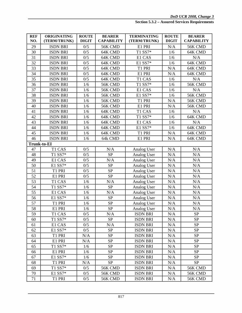
DoD UCR 2008, Change 3 Section 5.3.2 – Assured Services Requirements
817
REF NO.
ORIGINATING (TERM/TRUNK)
ROUTE DIGIT
BEARER CAPABILITY
TERMINATING (TERM/TRUNK)
ROUTE DIGIT
BEARER CAPABILITY
29 ISDN BRI 0/5 56K CMD E1 PRI N/A 56K CMD 30 ISDN BRI 0/5 64K CMD T1 SS7* 1/6 64K CMD 31 ISDN BRI 0/5 64K CMD E1 CAS 1/6 N/A 32 ISDN BRI 0/5 64K CMD E1 SS7* 1/6 64K CMD 33 ISDN BRI 0/5 64K CMD T1 PRI N/A 64K CMD 34 ISDN BRI 0/5 64K CMD E1 PRI N/A 64K CMD 35 ISDN BRI 0/5 64K CMD T1 CAS 1/6 N/A 36 ISDN BRI 1/6 56K CMD T1 SS7* 1/6 56K CMD 37 ISDN BRI 1/6 56K CMD E1 CAS 1/6 N/A 38 ISDN BRI 1/6 56K CMD E1 SS7* 1/6 56K CMD 39 ISDN BRI 1/6 56K CMD T1 PRI N/A 56K CMD 40 ISDN BRI 1/6 56K CMD E1 PRI N/A 56K CMD 41 ISDN BRI 1/6 64K CMD T1 CAS 1/6 N/A 42 ISDN BRI 1/6 64K CMD T1 SS7* 1/6 64K CMD 43 ISDN BRI 1/6 64K CMD E1 CAS 1/6 N/A 44 ISDN BRI 1/6 64K CMD E1 SS7* 1/6 64K CMD 45 ISDN BRI 1/6 64K CMD T1 PRI N/A 64K CMD 46 ISDN BRI 1/6 64k CMD E1 PRI N/A 64K CMD
Trunk-to-EI 47 T1 CAS 0/5 N/A Analog User N/A N/A 48 T1 SS7* 0/5 SP Analog User N/A N/A 49 E1 CAS 0/5 N/A Analog User N/A N/A 50 E1 SS7* 0/5 SP Analog User N/A N/A 51 T1 PRI 0/5 SP Analog User N/A N/A 52 E1 PRI 0/5 SP Analog User N/A N/A 53 T1 CAS 1/6 N/A Analog User N/A N/A 54 T1 SS7* 1/6 SP Analog User N/A N/A 55 E1 CAS 1/6 N/A Analog User N/A N/A 56 E1 SS7* 1/6 SP Analog User N/A N/A 57 T1 PRI 1/6 SP Analog User N/A N/A 58 E1 PRI 1/6 SP Analog User N/A N/A 59 T1 CAS 0/5 N/A ISDN BRI N/A SP 60 T1 SS7* 0/5 SP ISDN BRI N/A SP 61 E1 CAS 0/5 N/A ISDN BRI N/A SP 62 E1 SS7* 0/5 SP ISDN BRI N/A SP 63 T1 PRI N/A SP ISDN BRI N/A SP 64 E1 PRI N/A SP ISDN BRI N/A SP 65 T1 SS7* 1/6 SP ISDN BRI N/A SP 66 E1 PRI 1/6 SP ISDN BRI N/A SP 67 E1 SS7* 1/6 SP ISDN BRI N/A SP 68 T1 PRI N/A SP ISDN BRI N/A SP 69 T1 SS7* 0/5 56K CMD ISDN BRI N/A 56K CMD 70 E1 SS7* 0/5 56K CMD ISDN BRI N/A 56K CMD 71 T1 PRI 0/5 56K CMD ISDN BRI N/A 56K CMD

DoD UCR 2008, Change 3 Section 5.3.2 – Assured Services Requirements
818
REF NO.
ORIGINATING (TERM/TRUNK)
ROUTE DIGIT
BEARER CAPABILITY
TERMINATING (TERM/TRUNK)
ROUTE DIGIT
BEARER CAPABILITY
72 E1 PRI 0/5 64K CMD ISDN BRI N/A 64K CMD 73 T1 SS7* 0/5 64K CMD ISDN BRI N/A 64K CMD 74 E1 SS7* 0/5 64K CMD ISDN BRI N/A 64K CMD 75 T1 PRI 0/5 64K CMD ISDN BRI N/A 64K CMD 76 E1 PRI 0/5 64K CMD ISDN BRI N/A 64K CMD 77 T1 CAS 1/6 N/A ISDN BRI N/A 56K CMD 78 T1 SS7* 1/6 56K CMD ISDN BRI N/A 56K CMD 79 E1 SS7* 1/6 56K CMD ISDN BRI N/A 56K CMD 80 T1 PRI N/A 56K CMD ISDN BRI N/A 56K CMD 81 E1 PRI N/A 56K CMD ISDN BRI N/A 56K CMD 82 T1 SS7* 1/6 64K CMD ISDN BRI N/A 64K CMD 83 E1 CAS 1/6 N/A ISDN BRI N/A 64K CMD 84 E1 SS7* 1/6 64K CMD ISDN BRI N/A 64K CMD 85 T1 PRI N/A 64K CMD ISDN BRI N/A 64K CMD 86 E1 PRI N/A 64K CMD ISDN BRI N/A 64K CMD
*Signaling System No.7 (SS7) for the SMEO is conditional. LEGEND 56K/64K 56/64 Kilobits per Second CMD Circuit Mode Data
N/A Not Applicable SP Speech or 3.1K Bearer Capability
Table 5.3.2.31.3-13. CAS-to-CCS Trunk Interworking Matrix (Trunk-to-Trunk)
REF NO.
INCOMING TRUNK
ROUTE DIGIT
BEARER CAPABILITY
OUTGOING TRUNK
ROUTE DIGIT
BEARER CAPABILITY
Trunk-to-Trunk 1 E1 CAS 1/6 N/A T1/E1 SS7* 1/6 64K CMD 2 E1 CAS 0/5 N/A T1/E1 SS7* 0/5 SP 3 T1 CAS 1/6 N/A T1/E1 SS7* 1/6 56K CMD 4 T1 CAS 0/5 N/A T1/E1 SS7* 0/5 SP 5 E1 CAS 1/6 N/A T1/E1 PRI N/A 64K CMD 6 E1 CAS 0/5 N/A T1/E1 PRI N/A SP 7 T1 CAS 1/6 N/A T1.E1 PRI N/A 56K CMD 8 T1 CAS 0/5 N/A T1/E1 PRI N/A SP 9 T1/E1 PRI N/A 56/64K CMD E1 CAS 1 N/A 10 T1/E1 PRI N/A SP E1 CAS 0 N/A 11 T1/E1 PRI N/A 56/64K CMD T1 CAS 1 N/A 12 T1/E1 PRI N/A SP T1 CAS 0 N/A 13 T1/E1 SS7* 1/6 56/64K CMD T1 CAS 1/6 N/A 14 T1/E1 SS7* 1/6 SP T1 CAS 1/6 N/A 15 T1/E1 SS7* 1/6 56/64K CMD E1 CAS 1/6 N/A 16 T1/E1 SS7* 1/6 SP E1 CAS 1/6 N/A 17 T1/E1 SS7* 0/5 SP E1 CAS 0/5 N/A 18 T1/E1 SS7* 0/5 56/64K CMD E1 CAS 1/6 N/A 19 T1/E1 SS7* 0/5 SP T1 CAS 0/5 N/A 20 T1/E1 SS7* 0/5 56/64K CMD T1 CAS 1/6 N/A 21 T1/E1 SS7* 1/6 56/64K CMD T1/E1 PRI N/A 56/64K CMD

DoD UCR 2008, Change 3 Section 5.3.2 – Assured Services Requirements
819
REF NO.
INCOMING TRUNK
ROUTE DIGIT
BEARER CAPABILITY
OUTGOING TRUNK
ROUTE DIGIT
BEARER CAPABILITY
22 T1/E1 SS7* 1/6 SP T1/E1 PRI N/A SP 23 T1/E1 SS7* 0/5 56/64K CMD T1/E1 PRI N/A 56/64K CMD 24 T1/E1 SS7* 0/5 SP T1/E1 PRI N/A SP
* Signaling System No.7 (SS7) for the SMEO is conditional. LEGEND: 56K/64K 56/64 Kilobits per Second N/A Not Applicable CMD Circuit Mode Data SP Speech or 3.1K Bearer Capability
Route selection for CCS data routes (circuit mode data) and CAS data routes with route digits 1 (Switched Data) or 6 (Hotline Data) shall not include:
• Analog trunks • Trunks with data compression • A-law to µ-law and/or µ-Law to A-Law conversions – Data restrictions
If the bearer capability (BC) of speech or 3.1K audio conflicts with data route digits 1 or 6, then no A-law to µ-law or µ-Law to A-Law conversions will be performed. If a BC of 56 kbps (restricted or unrestricted) or 64 kbps (restricted or unrestricted) conflicts with a voice route digit of 0 or 5, then no conversion will be performed. ISDN PRI call handling/treatment does not use the dialed route digit in accordance with the DSN WWNDP; however, when the originator dials the data route code the LSC/MFSS/WAN SS shall assign the appropriate bearer capability (i.e., 56 kbps data, 64 kbps data). All tandem calls of the same media type (i.e., SS7-to-SS7, CAS-to-CAS, PRI-to-PRI) are transparent. Tandem calls of different media type shall follow the treatment/call handling in accordance with Table 5.3.2.31.3-12, CAS-to-CCS Trunk Interworking Matrix (EI-to-Trunk and Trunk-to-EI), and Table 5.3.2.31.3-13, CAS-to-CCS Trunk Interworking Matrix (Trunk-to-Trunk).
5.3.2.31.3.11 MLPP Interactions with Electronic Key Telephone Systems Features
5.3.2.31.3.11.1 Electronic Key Telephone Systems
[Conditional: TA, IAD, LSC, MFSS, WAN SS] Electronic Key Telephone Systems functions shall be provided by the UC appliance as described in Telcordia Technologies GR-205-CORE. Additional MLPP requirements are listed in the following paragraphs.
5.3.2.31.3.11.1.1 Call Appearances
[Conditional: TA, IAD, LSC, MFSS, WAN SS] A call appearance shall be shared by all EKTS users. There shall not be separate call appearances for MLPP calls. All users shall be able to originate the authorized precedence level and receive all levels of precedence on a single call appearance for each directory number. Each EKTS call appearance shall comply with the MLPP functionality specified in Section 5.3.2.31.3, Multilevel Precedence and Preemption.

DoD UCR 2008, Change 3 Section 5.3.2 – Assured Services Requirements
820
5.3.2.31.3.11.1.2 Hold
[Conditional: TA, IAD, LSC, MFSS, WAN SS] The EKTS Hold function shall comply with the requirements of Section 5.3.2.2.2.1.4, Call Hold.
5.3.2.31.3.11.1.3 Directory Number Bridging
[Conditional: TA, IAD, LSC, MFSS, WAN SS] The EKTS Directory Number Bridging function shall comply with the requirements of Section 5.3.2.2.2.1.6, 3-Way Calling.
5.3.2.31.3.11.1.4 Intercom Calling
[Conditional: TA, IAD, LSC, MFSS, WAN SS] The EKTS Intercom Calling feature shall not prevent the offering of an MLPP call to any of the parties involved in an intercom call.
5.3.2.31.3.11.1.5 Abbreviated or Delayed Ringing Treatment on Incoming Calls
[Conditional: TA, IAD, LSC, MFSS, WAN SS] Incoming MLPP calls shall be considered as “distinctive alerting” and shall not be affected by the Abbreviated or Delayed Ringing Treatment. Precedence Alerting (see Table 5.3.2.6-1, UC Ringing Tones and Cadences) shall be applied to the call DN appearance and the call handled as described in Section 5.3.2.31.3.7, ISDN MLPP BRI. If the call is not answered and the EKTS-T1 time expires, the call shall be diverted to an operator. If Call Forwarding-No Reply is invoked by the called DN, then the Call Forwarding procedures of Section 5.3.2.2.2.1.1.2.2, Call Forwarding – No Reply at Called Station, apply at the expiration of the EKTS-T1 timer.
5.3.2.31.3.11.1.6 Bridged Call Exclusion
[Conditional: TA, IAD, LSC, MFSS, WAN SS] The Bridged Call Exclusion (BCE) feature (automatic or manual) shall not degrade or prevent the MLPP interactions described in this section.
5.3.2.31.3.11.1.7 Non-ISDN Users
[Conditional: TA, IAD, LSC, MFSS, WAN SS] Non-ISDN users (analog telephone) can be assigned as members of the EKTS group. The non-ISDN user will share a call appearance with other members of the EKTS group and shall be able to originate the authorized precedence level and receive all levels of precedence on that shared appearance.

DoD UCR 2008, Change 3 Section 5.3.2 – Assured Services Requirements
821
5.3.2.31.3.12 Backward Compatibility
This section details the requirements for UC interoperability using the old cause values and precedence parameters. These requirements are needed only until all UC signaling appliances have been upgraded with the ANSI T1.619a signaling.
5.3.2.31.3.12.1 Precedence Parameter
[Conditional: LSC, MFSS, WAN SS] New UC signaling appliances must interoperate with both the current 1992/1994 ANSI T1.113 MLPP CCS7 IAM, which contains the Precedence Parameter 6-octet field shown in Table 5.3.2.31.3-8, CCS7 IAM Precedence Parameter and Subfields.
5.3.2.31.3.12.2 Cause Values and Location Codes
[Conditional: LSC, MFSS, WAN SS] The supplement to ANSI T1.619-1992, ANSI T1.619a-1994, revised the standard so that the exchange-to-exchange signaling is consistent with ITU-T Recommendations, which were approved after the publication of ANSI T1.619-1992. The use of Cause Value #45, preemption, shall continue to be used as described in ANSI T1.619-1992. This shall not conflict with the use of Cause Values #8 and #9 as described in ANSI T1.619a-1994 (supplement to ANSI T1.619-1992). The corresponding location code for each cause value (45, 8, and 9) shall operate as described in ANSI T1.619-1992 and ANSI T1.619a-1994.
5.3.2.31.3.13 Network Management Manual Controls
[Required: LSC, MFSS, WAN SS] Call gapping shall not apply to FLASH and FLASH OVERRIDE calls. In addition, FLASH and FLASH OVERRIDE calls shall be exempt from Cancel to (CANT) and Cancel from (CANF). See Section 5.2.8, Network Management, for details.
5.3.2.31.3.14 Data Collection
[Required: LSC, MFSS, WAN SS] The settable fields for Call Detail Recording (CDR) shall be as shown in Table 5.2.8-1, CDR Data. All UC call data must identify the precedence level of the call.

DoD UCR 2008, Change 3 Section 5.3.2 – Assured Services Requirements
822
5.3.2.31.4 Signaling
5.3.2.31.4.1 Introduction
This section contains an import and revision of historical circuit-switched requirements from UCR 2008, 22 January 2009, Section 5.2.4, Signaling. The revision converts these historical DSN requirements into current UC requirements. This section covers the signaling requirements for UC signaling appliance systems. The requirements are based on Telcordia Technologies GR-506-CORE; ANSI T1.619 (1992); ANSI T1.619a (1994); ANSI T1.110 (1999); ANSI T1.116 (1996); ANSI T1.116a (1998); ANSI T1.111 (1996); ANSI T1.114 (2000); ANSI T1.112 (1996); and ANSI 1.113 (1995). Requirements for analog signaling also apply to digital circuits using CAS.
5.3.2.31.4.2 Network Power Systems for External Interfaces
[Required: TA, IAD, LSC, MFSS, WAN SS – Conditional: MG] The UC signaling appliance systems shall meet the network power systems requirements specified in the Telcordia Technologies GR-506-CORE, Paragraph 2.1.
5.3.2.31.4.3 Line Signaling
5.3.2.31.4.3.1 Loop Start Line
[Required: TA, IAD] In a loop start line arrangement, the TA/IAD supplies battery between the ring and the tip conductors. The TA/IAD detects a loop closure from the customer station as a seizure, after which it provides dial tone on the tip and ring conductors as a start dial signal. The UC signaling appliance systems shall meet this requirement in accordance with the “R” requirements in Telcordia Technologies GR-506-CORE, Paragraphs 3 through 3.4.7, 6.2.1, 6.3.1, 13.6.1.1, 13.6.2.1, 13.6.3.1, and 13.7.1.
5.3.2.31.4.3.2 Ground Start Line
[Required: TA, IAD] In a ground start line arrangement, the TA/IAD provides battery through a ground detector to the ring conductor and leaves the tip conductor open. The customer station seizes the line by applying a ground to the ring conductor. The TA/IAD responds by returning ground on the tip conductor and dial tone across the tip and ring as start dial signals. When the tip ground is detected from the TA/IAD, the customer station changes to loop closure for the off-hook state. Alerting the customer is done by connecting 20-Hz ringing to the ring conductor and ground to the tip conductor.

DoD UCR 2008, Change 3 Section 5.3.2 – Assured Services Requirements
823
The UC signaling appliance systems shall meet this requirement in accordance with the “R” requirements in Telcordia Technologies GR-506-CORE, Paragraphs 4 through 4.4.8, 13.2.2, 13.6.1.1, 13.6.2.2, 13.6.3.2, and 13.7.2.
5.3.2.31.4.4 Trunk Supervisory Signaling
5.3.2.31.4.4.1 Reverse Battery
[Conditional: LSC MG, MFSS MG, WAN SS MG] The trunk circuit at one end of a variety of loop signaling trunks applies battery and ground through suitable resistances to the tip and ring conductors. One polarity on the tip and ring leads is used for the on-hook state, and the reverse is used for the off-hook state. The UC signaling appliance systems shall meet this requirement in accordance with the “R” requirements in Telcordia Technologies GR-506-CORE, Paragraphs 7 and 8.
5.3.2.31.4.4.2 Immediate Start
[Conditional: LSC MG, MFSS MG, WAN SS MG] Immediate start (by-link) is a feature that provides intersystem address signaling between the MG and a system that transmits and/or receives address signals without special address control signals. For the reception of digits from offices requiring immediate start, the system shall be prepared to recognize the first dial pulse promptly after the connect signal is received. For transmission of address information to an office requiring immediate start, the system shall delay outpulsing after sending the connect signal to ensure that the distant office is ready. It is desirable that the transmitting office verifies that battery and ground are of the proper polarity at the time of seizure. Failure to detect the proper condition shall result in a retry of the call and a failure recorded. The UC signaling appliance systems shall meet this requirement in accordance with the “R” requirements in Telcordia Technologies GR-506-CORE, Paragraph 11.2.2.
5.3.2.31.4.4.3 Normal and Abnormal Wink Start Operation
5.3.2.31.4.4.3.1 Normal Operation
5.3.2.31.4.4.3.1.1 Normal Wink Start Operation
[Conditional: LSC MG, MFSS MG, WAN SS MG] Wink start is a feature that provides control for address signaling between systems arranged with wink start as a special address control signal. The wink start signal is applicable to specified incoming, outgoing, and two-way trunks and is used to inform the calling office that the called office is prepared to receive address
DoD UCR 2008, Change 3 Section 5.3.2 – Assured Services Requirements
824
signals. For wink start operation, the transmitting office shall test for the detection of the brief off-hook as a signaling integrity check. The UC signaling appliance systems shall provide wink start operation in accordance with the requirements in Telcordia Technologies GR-506-CORE, Paragraph 11.2.1.
5.3.2.31.4.4.3.1.2 Glare Operation
[Conditional: LSC MG, MFSS MG, WAN SS MG] Glare occurs when both interfaces of switching systems connected to the same inter-switching-system facility (trunk) apply a seizure signal at approximately the same time. The UC signaling appliance systems shall provide glare detection and resolution IAW the requirements in Telcordia Technologies GR-506-CORE, Paragraph 11.5.
5.3.2.31.4.4.3.2 Abnormal Operation
5.3.2.31.4.4.3.2.1 Wink Start
[Conditional: LSC MG, MFSS MG, WAN SS MG] After the connect signal is sent over the trunk, the originating office can normally expect to receive a wink start (timed off-hook) signal indicating that the terminating office is ready to receive address signaling. When the end of the wink start signal is received, the originating office may begin outpulsing. The duration of the off-hook wink returned by the terminating office will be 140 to 290 ms. However, because of distortion in the trunk facilities, the duration of the wink received by the originating office may vary (refer to Figure 5.3.2.31.3-3, UC Preempt Signals). If the wink is shorter than the minimum allowable interval, it shall be ignored. If it is greater than the maximum interval, the call shall be considered to be in a glare condition as described in Section 5.3.2.31.4.4.3.2.2, Glare Resolution.
5.3.2.31.4.4.3.2.2 Glare Resolution
[Conditional: LSC MG, MFSS MG, WAN SS MG] The UC signaling appliances shall meet the glare resolutions requirements defined in Telcordia Technologies GR-506-CORE, Paragraph 11.5 and subparagraphs.
5.3.2.31.4.4.4 Delay Dial
[Conditional: LSC MG, MFSS MG, WAN SS MG] If this feature is provided, it shall be in accordance with Telcordia Technologies GR-506-CORE.

DoD UCR 2008, Change 3 Section 5.3.2 – Assured Services Requirements
825
5.3.2.31.4.4.5 Call for Service Timing
[Conditional: LSC MG, MFSS MG, WAN SS MG] The MG shall ignore as a “hit” any transient off-hook signal whose duration is less than 35 milliseconds on an incoming trunk. Off-hook signals greater than 60 milliseconds shall be considered as a valid seizure. Signals that are 15 to 60 milliseconds in length are considered invalid seizures.
5.3.2.31.4.4.6 Guard Timing
[Conditional: LSC MG, MFSS MG, WAN SS MG] The UC signaling appliance systems shall meet guard requirements in accordance with Telcordia Technologies GR-506-CORE.
5.3.2.31.4.4.7 Satellite Interface
[Conditional: LSC MG, MFSS MG, WAN SS MG] The UC signaling appliance system shall accommodate the use of single satellite-derived trunk facilities. The only interface parameter that must be modified is the guard timing. This interval shall be extended from 1050 to 1250 milliseconds to compensate for propagation delay.
5.3.2.31.4.4.8 Disconnect Control
[Conditional: LSC MG, MFSS MG, WAN SS MG] The UC signaling appliance systems shall meet the Disconnect Control requirements in Telcordia Technologies GR-506-CORE, Paragraph 13 and all subparagraphs.
5.3.2.31.4.4.9 Reselect or Retrial
[Conditional: LSC MG, MFSS MG, WAN SS MG] The actions that shall be taken by the MG are summarized in the following table based on the direction of the circuit (outgoing or two-way), the method of controlled outpulsing (wink start or delay dial), and the method of glare resolution on two-way circuit (hold or release). The MG shall reselect or retry on circuit supervision faults as shown in Table 5.3.2.31.4-1.
Table 5.3.2.31.4-1. Reselect or Retrial
FAULT RECOMMENDED OPERATION 1. Glare detected to glare release Release once in same trunk group. If glare again detected or
the group is all trunk busy (ATB), route advance. 2. Start signal reception timeout on glare
hold Reselect once in the same trunk group. If no circuits are idle or preemptable, route advance. If a circuit is idle or preemptable and the failure occurs on the retrial, route advance.

DoD UCR 2008, Change 3 Section 5.3.2 – Assured Services Requirements
826
FAULT RECOMMENDED OPERATION 3. Digit sending timeout occurs on an
outgoing delay dial circuit Same as item 2.
4. Integrity check failure on a delay dial circuit
Reselect once in the same group. If fault is detected or if route is ATB, route advance.
5. No wink received on a wink start circuit
Same as item 2.
6. Wink exceeds 350 ms on an outgoing wink start circuit
Same as item 2.
7. Unexpected stop dial on an MF circuit Same as item 2.
5.3.2.31.4.4.10 Off-Hook Supervision Transitions (Unexpected Stop)
[Conditional: LSC MG, MFSS MG, WAN SS MG] The UC signaling appliances shall detect and react to unexpected off-hook supervisory transitions while outpulsing on trunks, after receipt of the start-dial indication and until completion of the outpulsing. An unexpected stop is defined as an off-hook supervision transition whose duration exceeds the “hit” timing interval. When an unexpected stop is detected, the system shall reselect another trunk.
5.3.2.31.4.5 Control Signaling
Control signaling is used for the reception and outpulsing of address, precedence, and routing information. Three types of outpulsing are DP, DTMF, and Multifrequency 2/6. The UC signaling appliances shall support as applicable the following signaling combinations: DTMF 2way, DP 2way, DTMF in-DP out, DP in-DTMF out, MF(R1) 2/6 2way. Audible tones shall be IAW Telcordia Technologies GR-506-CORE, Paragraph 17.
5.3.2.31.4.5.1 Dial-Pulse Signals
[Required: TA, IAD] The UC DP signaling requirements are the same as those specified in Telcordia Technologies GR-506-CORE, Paragraph 10.
5.3.2.31.4.5.2 DTMF Signaling
[Required: TA, IAD – Conditional: LSC MG, MFSS MG, WAN SS MG] The UC signaling appliance system shall be capable of outpulsing and interpretation of DTMF digits on outgoing or two-way trunks as specified in Telcordia Technologies GR-506-CORE, Paragraph 15, and Table 5.3.2.31.4-2.

DoD UCR 2008, Change 3 Section 5.3.2 – Assured Services Requirements
827
Table 5.3.2.31.4-2. DTMF Generation and Reception from Users and Trunks
Low Group Frequencies Nominal Frequency in Hz
HIGH GROUP FREQUENCIES NOMINAL FREQUENCY IN Hz
1209 Hz 1336 Hz 1477 Hz 1633 Hz 697 Hz 1 2 3 FO (A) 770 Hz 4 5 6 F (B) 852 Hz 7 8 9 I (C) 941 Hz * 0 A or # P (D)
5.3.2.31.4.5.2.1 Standard Digit Format for Precedence
[Required: TA, IAD – Conditional: LSC MG, MFSS MG, WAN SS MG] In addition, the UC signaling appliance system shall be capable of outpulsing and interpretation of DTMF precedence digits in digit 0 through 4 format (i.e., 0=FLASH OVERRIDE, 1=FLASH, 2=IMMEDIATE, 3=PRIORITY, and 4=ROUTINE).
5.3.2.31.4.5.3 Multifrequency (MF(R1) 2/6) Signaling
[Conditional: LSC MG, MFSS MG, WAN SS MG] The UC signaling appliance system shall be capable of outpulsing and reception of multifrequency (MF)(R1) 2/6 signaling requirements IAW Telcordia Technologies GR-506-CORE, Paragraph 16 and its subparagraphs, and Table 5.3.2.31.4-3, MF(R1) 2/6 Generation and Reception for Trunks.
5.3.2.31.4.6 Alerting Signals and Tones
Alerting signals are applied by an EI or IAD/TA to inform the end-user of an incoming call.
5.3.2.31.4.6.1 Ringing
NOTE: The text in this section has been updated and moved to Section 5.3.2.6.1.1.1, UC Ringing Tones, Cadences, and Information Signals, of this section. Table 5.3.2.31.4-4 is now Table 5.3.2.6-1, UC Ringing Tones and Cadences, of this section.
Table 5.3.2.31.4-3. MF(R1) 2/6 Generation and Reception for Trunks
DIGITS AND CONTROL
CODES NOMINAL
FREQUENCIES (HZ) PRECEDENCE DIGITS 0 1300 + 1500 (FO) FLASH OVERRIDE 1 700 + 900 (F) FLASH 2 700 + 1100 (I) IMMEDIATE 3 900 + 1100 (P) PRIORITY 4 700 + 1300 (R) ROUTINE

DoD UCR 2008, Change 3 Section 5.3.2 – Assured Services Requirements
828
DIGITS AND CONTROL
CODES NOMINAL
FREQUENCIES (HZ) PRECEDENCE DIGITS 5 900 + 1300 6 1100 + 1300 7 700 + 1500 8 900 + 1500 9 1100 + 1500
KP 1100 + 1700 S/T 1500 + 1700
5.3.2.31.4.6.2 RTS Information Signals
NOTE: The text in this section has been updated and moved to Section 5.3.2.6.1.1.1, UC Ringing Tones, Cadences, and Information Signals, of this section. Table 5.3.2.31.4-5 is now Table 5.3.2.6-2, UC Information Signals, of this section.
5.3.2.31.4.7 Common Channel Signaling Number 7
The CCS7 system shall perform signaling functions between a UC signaling appliance and a circuit switch. The following requirements represent the set of features standardized for CCS7. [Conditional: LSC, MFSS, WAN SS] The CCS7 shall be IAW the SS7 requirements specified in the most current ANSI T1.100 series of standards and shall be capable of internetworking with ITU-T SS7 networks. Exceptions to these standards are explicitly noted in this section. Only those CCS7 requirements that differ from their corresponding ANSI common channel signaling standard section are included.
5.3.2.31.4.7.1 CCS7 Network Structure
[Conditional: LSC, MFSS, WAN SS] The CCS7 network shall serve as a separate call control and management network that is overlaid on the UC network for UC to interconnect with other networks (e.g., PSTN, DSN) that support CCS7. The CCS7 network structure is a one-level hierarchy composed of multiple mated pairs of STPs and their associated Service Switching Points (SSPs) and signaling links IAW ANSI T1.110 – ANSI T1.116, all inclusive. The UC End Office, Multifunction, and Tandem signaling appliance systems shall be CCS7 Signaling Points (SPs). The CCS7 network structure is shown in Figure 5.3.2.31.4-1, CCS7 Backbone Network Design. The CCS7 network consists of mated STP pairs connected by “C-links,” these mated pairs may be grouped into “quads” with “B-links.” Signal Transfer Points shall be implemented external to the UC signaling appliances.

DoD UCR 2008, Change 3 Section 5.3.2 – Assured Services Requirements
829
Figure 5.3.2.31.4-1. CCS7 Backbone Network Design
5.3.2.31.4.7.2 Functional Description of the Signaling System Message Transfer Part
[Conditional: LSC, MFSS, WAN SS] The CCS7 message transfer part (MTP) shall be as specified in ANSI T1.111-1996, chapters 1–8. Specific requirements for UC applications are given in the following subsections.
5.3.2.31.4.7.2.1 Signaling System Structure – Functional Levels
The fundamental principle of the signaling system structure is the division of functions into separate modules or entities.
5.3.2.31.4.7.2.1.1 Signaling Data Link Functions (Level 1)
[Conditional: LSC, MFSS, WAN SS] The signaling data link is a bidirectional digital transmission path comprised of digital signaling links. A maximum of 72 digital signaling links shall be supported at an individual UC signaling point. Because of its worldwide scope, the CCS7 shall support both terrestrial and satellite transmission for the signaling data links at bit rates of 56 or 64 kbps.

DoD UCR 2008, Change 3 Section 5.3.2 – Assured Services Requirements
830
5.3.2.31.4.7.2.1.2 Signaling Link Functions (Level 2)
[Conditional: LSC, MFSS, WAN SS] The CCS7 signaling link functions apply to both terrestrial and satellite transmission. These shall require the implementation of both types of error correction methods specified in SS7 (the basic error correction method for use on terrestrial signaling data links and the preventive cyclic retransmission method for use on satellite signaling data links).
5.3.2.31.4.7.3 Signaling Network Functions and Messages
5.3.2.31.4.7.3.1 Routing Label
[Conditional: LSC, MFSS, WAN SS] The CCS7 uses the U.S. national routing label structure (specified in ANSI T1.111.4) for signaling messages between CCS7 signaling points. The routing label shall also be used for routing signaling messages to other U.S. networks that comply with the ANSI SS7 standard. The CCS7 routing label shall comply with the routing label structure for the U.S. networks as shown in Figures 3A and 3B of the T1.111.4. Signaling point codes in the CCS7 are assigned by the network administrator IAW ANSI guidelines.
5.3.2.31.4.7.3.2 Handling Messages Under Signaling Link Congestion
[Conditional: LSC, MFSS, WAN SS] Criteria for the determination of CCS7 signaling congestion status shall be as specified by ANSI T1.111.4, Section 3.8, for U.S. networks. Initial Address Messages carrying FLASH or FLASH OVERRIDE precedence calls shall be assigned Level 3, IMMEDIATE precedence calls shall be assigned Level 2, PRIORITY precedence calls shall be assigned Level 1, and ROUTINE precedence calls shall be assigned Level 0 in the CCS7.
5.3.2.31.4.7.3.3 Message Discrimination and Distribution Functions
[Conditional: LSC, MFSS, WAN SS] The message discrimination function examines the Destination Point Code (DPC) of a received signaling message to determine whether or not it is destined to the receiving signaling point. Message distribution determines to which user of the MTP a received signaling message will be directed. This function is also required in all CCS7 signaling nodes.
5.3.2.31.4.6.3.4 Signaling Network Management
[Conditional: LSC, MFSS, WAN SS] The UC signaling appliance systems shall meet the signaling NM requirements in the Telcordia Technologies GR-606-CORE, Paragraph 4.

DoD UCR 2008, Change 3 Section 5.3.2 – Assured Services Requirements
831
5.3.2.31.4.6.3.4.1 Changeback
[Conditional: LSC, MFSS, WAN SS] The objective of the changeback procedure is to ensure that signaling is diverted from the alternative signaling link(s) to the signaling link made available as quickly as possible, while avoiding message loss or duplication. The UC signaling appliance systems shall not use sequence control procedures to perform changeback. The last sentence of the third requirement in the Telcordia Technologies GR-606-CORE, Paragraph 4.3, is changed to read as follows: The UC signaling appliance system shall use the time-controlled diversion procedure.
5.3.2.31.4.7.4 Non-Circuit-Related Information Exchange – Signaling Connection Control Part
[Conditional: LSC, MFSS, WAN SS] The UC signaling appliance systems shall meet the signaling connection control part (SCCP) requirements in the Telcordia Technologies GR-606-CORE, Paragraph 5 and its subparagraphs.
5.3.2.31.4.7.5 Additional Procedures for Switch-to-Switch/SCP TCAP Messages
[Conditional: LSC, MFSS, WAN SS] The UC signaling appliance systems equipped for CCS7 shall meet the requirements for switch-to-switch/ SCP TCAP messaging requirements in the Telcordia Technologies GR-606-CORE, Paragraph 6 and its subparagraphs.
5.3.2.31.4.7.6 Message Transfer Part Restart
[Conditional: LSC, MFSS, WAN SS] The MTP Restart procedure shall be as specified in ANSI T1.111 (1996), Paragraph 9 and its subparagraphs.
5.3.2.31.4.7.7 Signaling Link Management
[Conditional: LSC, MFSS, WAN SS] There are three signaling link management methods specified in ANSI T1.111.4: 1) basic signaling link management procedures, 2) signaling link management procedures based on automatic allocation of signaling terminals, and 3) signaling link management procedures based on automatic allocation of signaling data links and signaling terminals. The automatic allocation of signaling data links and signaling terminals shall be the method implemented in the CCS7.
5.3.2.31.4.7.8 Signaling Route Management
[Conditional: LSC, MFSS, WAN SS] The CCS7 signaling point nodes shall be capable of responding appropriately to the receipt of signaling route management messages. For example, a
DoD UCR 2008, Change 3 Section 5.3.2 – Assured Services Requirements
832
CCS7 signaling point node may be required to alter its routing information in response to a transfer prohibited, restricted, or allowed message.
5.3.2.31.4.7.9 Common Characteristics of Message Signal Unit Formats
The service information octet of the message signal unit (MSU) contains the service indicator and subservice field.
5.3.2.31.4.7.9.1 Service Indicator
[Conditional: LSC, MFSS, WAN SS] Requirements for the Service Indicator Codings shall be as specified in ANSI T1.111 (1996), Paragraph 14.2.1.
5.3.2.31.4.7.9.2 Subservice Field
[Conditional: LSC, MFSS, WAN SS] The CCS7 shall use the network code (10) as specified in ANSI T1.111.4. The CCS7 messages originating and terminating within the CCS7 or another network conforming to the ANSI standard shall be coded with the national network code (10). Requirements for the Subservice Field shall be as specified in ANSI T1.111 (1996), Paragraph 14.2.2.
5.3.2.31.4.7.10 Formats and Codes of Signaling Network Management Messages
[Conditional: LSC, MFSS, WAN SS] The following paragraphs specify CCS7 requirements for the formats and codes of CCS7 signaling NM messages: 1. The signal link code (SLC), used to identify one of 16 possible signaling links between
each pair of adjacent (directly connected) signaling nodes, indicates the identity of a signaling link to which an NM message pertains.
2. Each pair of adjacent signaling nodes shall coordinate the assignment of SLCs to ensure compatibility.
3. The SLC may be used in the CCS7 to identify the preferred order of signaling data link selection from among the interexchange circuits. Normally, one associated signaling link between two CCS7 signaling points will be implemented and designated with an SLC at both ends of 0000. The order of selection of backup signaling data links to be obtained from the interexchange circuit group may be precoordinated and prioritized at both ends. The SLC 0001 is assigned to the circuit normally selected first as a backup signaling link. The remaining SLCs are assigned to interexchange circuits in the order of their selection as signaling data links. This order of selection shall not be interpreted as prioritizing the

DoD UCR 2008, Change 3 Section 5.3.2 – Assured Services Requirements
833
signaling links. Any circuit selected to serve as a signaling link remains in service for that purpose until it becomes unavailable (e.g., by failure or management withdrawal).
4. This preassignment can be overridden when communication between both CCS7 signaling points over alternative links is possible. In this case, a signaling data link connection order message may be used to indicate that an Interswitch Trunk (IST) will be assigned as a signaling data link and which corresponding SLC will be used.
5.3.2.31.4.7.11 Numbering of SPCs
[Conditional: LSC, MFSS, WAN SS] The CCS7 numbering of SPCs shall be as specified in ANSI T1.111.8. UC meets the ANSI requirements for a large network, and it has been granted a network code value of 241. ANSI T1.111.8, Table B1, shows the current list of assigned large network codes. Signaling point codes in the CCS7 are assigned by the network administrator IAW ANSI guidelines.
5.3.2.31.4.7.12 Functional Descriptions of ISDN User Part
5.3.2.31.4.7.12.1 Scope, Purpose, and Application
[Conditional: LSC, MFSS, WAN SS] The ISDN User Part (ISUP) specifies the signaling functions, codes, messages, and procedures needed to provide services for CS voice and data services in the CCS7.
5.3.2.31.4.7.12.2 End-To-End Signaling
[Conditional: LSC, MFSS, WAN SS] End-to-end signaling transports signaling information between the endpoints of a CS connection or between any two points in the signaling network. Pass along message (PAM), ANSI T1.111, and SCCP, ANSI T1.112, end-to-end signaling methods shall be supported in CCS7.
5.3.2.31.4.7.13 Formats and Codes – ISUP Parameters
[Conditional: LSC, MFSS, WAN SS] The ISUP specifies the signaling functions, codes, and procedures needed to provide services for CS voice and data services. The CCS7 switching services shall meet the requirements in the Telcordia Technologies GR-317-CORE, except as modified in the following subparagraphs.
5.3.2.31.4.7.13.1 Notification Indicator
[Conditional: LSC, MFSS, WAN SS] The following code shall be added to indicate a delay may be experienced in completing the call: 0000100 call completion delay.

DoD UCR 2008, Change 3 Section 5.3.2 – Assured Services Requirements
834
5.3.2.31.4.7.13.2 ISUP Messages
[Conditional: LSC, MFSS, WAN SS] The CCS7 shall use the messages in the Telcordia Technologies, GR-317-CORE, Appendix A. In addition, CCS7 shall meet the requirements in ANSI T1.113.2 and T1.619a for messages that are not specified in the Telcordia Technologies generic requirements.
5.3.2.31.4.7.13.3 ISUP Parameters
[Conditional: LSC, MFSS, WAN SS] The CCS7 shall use the ISUP parameters specified in the Telcordia Technologies,, GR-317-CORE, Appendix B. In addition, CCS7 shall use ISUP parameters specified in ANSI T1.113.3 for parameters not specified in the Telcordia Technologies generic requirements.
5.3.2.31.4.8 ISDN Digital Subscriber Signaling System No. 1 Signaling
5.3.2.31.4.8.1 UC ISDN User-to-Network Signaling
The objective of this UC ISDN user-to-network signaling requirement is to provide digital out-of-band signaling on an ISDN interface. The UC ISDN user-to-network signaling requirement, which captures protocols under the umbrella of Digital Subscriber Signaling System No. 1 (DSS1), is intended to provide a signaling protocol that will allow signaling over an ISDN interface to support: 1. User access to UC signaling appliances equipped with the CCS7.
2. Circuit-switched calls (both data and voice).
3. Supplementary services that include unique UC features.
4. Future UC access signaling requirements for other network services, including public and private network interworking in intracountry and intercountry environments, as applicable, and interoperability with other DoD Networks.
5.3.2.31.4.8.1.1 Application
[PRI: Required: MG, LSC, MFSS, WAN SS – BRI: Conditional: TA, IAD, LSC, MFSS, WAN SS] This section is the UC signaling appliance requirements for user-to-network signaling over an ISDN interface. It specifies the interface signaling protocol for application throughout the UC network and defines the requirements of the UC user-to-network signaling for exchanging information between CPE, including terminal equipment (TE) and PBXs, and UC network signaling appliances. The exchange of signaling information between CPE and UC

DoD UCR 2008, Change 3 Section 5.3.2 – Assured Services Requirements
835
network signaling appliances shall be over the D-channel of the ISDN interface. The D-channel may be used either for associated signaling or non-associated signaling as defined in ANSI T1.607, Annex F. In-band information and tones sent over the B-channel shall be allowed, when applicable. In the UC host countries, UC connections may be made with public, private, and military CPE and networks. Protocol and/or SG conversions shall be required in some instances to provide the desired UC connections. Such translations shall be handled on a case-by-case basis as detailed in site-specific contracts.
5.3.2.31.4.8.1.2 Physical Layer
[PRI: Required: MG, LSC, MFSS, WAN SS – BRI: Conditional: TA, IAD, LSC, MFSS, WAN SS] The UC user-to-network signaling physical layer specification for the BRI shall be ANSI T1.605 and ANSI T1.601 or ITU Recommendation I.430, as required, for OCONUS applications. The UC user-to-network signaling physical layer specification for the PRI operating at 1.544 Mbps shall be ANSI T1.408. The UC user-to-network signaling specification for the PRI operating at 2.048 Mbps shall be ITU Recommendation I.431.
5.3.2.31.4.8.1.2.1 S/T Reference Point
[Conditional: TA, IAD] For the BRI at the S/T reference point, B-channels shall have the capability of either restricted or unrestricted operation. The restricted capability is necessary for backward compatibility with networks that support the restricted 64 kbps operation. The D channel shall have unrestricted capability.
5.3.2.31.4.8.1.3 Data-Link Layer
[PRI: Required: MG, LSC, MFSS, WAN SS – BRI: Conditional: TA, IAD, LSC, MFSS, WAN SS] The UC user-to-network signaling data-link layer shall be as specified in the ANSI T1.602, which is a pointer document completely aligned with the ITU-T Recommendations Q.920 and Q.921.
5.3.2.31.4.8.1.3.1 Data-Link Connections
[PRI: Required: MG, LSC, MFSS, WAN SS – BRI: Conditional: TA, IAD, LSC, MFSS, WAN SS] Point-to-point, broadcast, and multipoint data-link connections shall be provided for UC applications. The ANSI T1.602 depicts examples of point-to-point and broadcast data-link connections. Other point-to-point applications of this specification shall be allowed, such as the support of multiple terminals at the user-to-network interface. A data-link layer management entity shall be provided to support UC management.

DoD UCR 2008, Change 3 Section 5.3.2 – Assured Services Requirements
836
5.3.2.31.4.8.1.3.2 Peer-to-Peer Procedures of Data-Link Layer
[PRI: Required: MG, LSC, MFSS, WAN SS – BRI: Conditional: TA, IAD, LSC, MFSS, WAN SS] Within the UC network, peer-to-peer procedures of the data-link layer shall follow the procedures described in the ANSI T1.602, with the additions provided in this paragraph. The network administration shall have the responsibility to determine the system parameter values on the UC user-to-network interface. These parameters shall initially be set to the default values of the ANSI standard. A means is available in ITU-T Recommendation Q.921, Appendix IV to change the assignment of the system parameters within the range of values specified by the ANSI standard. The UC TE shall support other values of T200 to allow for multiple terminals on the user side, together with satellite connections, in UC user-to-network transmission.
5.3.2.31.4.8.1.4 Layer 3 UC User-to-Network Signaling
[PRI: Required: MG, LSC, MFSS, WAN SS – BRI: Conditional: TA, IAD, LSC, MFSS, WAN SS] The Layer 3 protocols specify the messages and IEs, coding and formats, and procedures used on the user-to-network interface to establish, maintain, and terminate network connections across an ISDN.
5.3.2.31.4.8.1.4.1 Overview of Layer 3
The overview of Layer 3 of the UC user-to-network signaling layer 3 shall be as specified in ANSI T1.615. The ANSI standard is consistent with the seven-layer model described in ITU Recommendation I.320. ANSI T1.615 describes, in general terms, the D-channel Layer 3 DSS1 functions and protocol used across an ISDN user-to-network interface.
5.3.2.31.4.8.1.4.2 RTS User-to-Network Signaling for Circuit-Switched Bearer Service
[PRI: Required: MG, LSC, MFSS, WAN SS – BRI: Conditional: TA, IAD, LSC, MFSS, WAN SS] The UC user-to-network signaling Layer 3 specification for CS bearer service (or CS-Basic Call) shall be as specified in the ANSI T1.607 for ISDN PRI and BRI. ANSI T1.607 is aligned with the ITU Recommendation Q.931 (to the extent possible), and it covers U.S. unique requirements for CS-Basic Call.
5.3.2.31.4.8.1.4.3 Sequence of Messages for UC CS Calls
[PRI: Required: MG, LSC, MFSS, WAN SS – BRI: Conditional: TA, IAD, LSC, MFSS, WAN SS] Call establishment involves SETUP, SETUP ACK, CALL PROCEEDING, ALERTING, CONNECT, and CONNECT ACK messages. The PROGRESS message shall be used with interworking or with in-band information and patterns to indicate the progress of a call. A three-step call clearing phase shall use the DISCONNECT, RELEASE, and RELEASE

DoD UCR 2008, Change 3 Section 5.3.2 – Assured Services Requirements
837
COMPLETE messages. The miscellaneous messages—INFORMATION, STATUS ENQUIRY (and STATUS), and NOTIFY—shall be used for the purposes described in ANSI T1.607.
5.3.2.31.4.8.1.4.4 Message Functional Definitions and Content
[PRI: Required: MG, LSC, MFSS, WAN SS – BRI: Conditional: TA, IAD, LSC, MFSS, WAN SS] The Layer 3 messages used by the UC user-to-network signaling for CS connections shall be as specified by the ANSI T1.607, except for messages modified in the following paragraph. SETUP Message. The SETUP message is sent by the calling user to the network or by the network to the called user to initiate call establishment. The UC calls shall use the SETUP message specified in ANSI T1.607. The Channel Identification, Calling Party Number (when available), and Called Party Number are mandatory IEs. For an MLPP call (invoking an MLPP feature) on the UC user-to-network interface, the SETUP message shall include the Precedence Level IE. It also shall contain other IEs, such as the business group (BG) IE for the COI feature, when such unique UC features are required and the call identity IE (as defined in ITU Recommendation Q.931) for the MLPP feature. The Precedence Level and MLPP service domain (both contained in the Precedence Level IE) and Calling Party Number (contained in the Calling Party Number IE), shall be used to mark the circuit (identified in the Channel Identification IE) to be preempted as “reserved” for reuse by the preempting call when the LFB option is exercised on the UC user-to-network interface. Table 5.3.2.31.4-4, SETUP Message for MLPP Call, shows the SETUP message content for an MLPP call; important differences from the SETUP message in ANSI T1.607 are specified in the following paragraphs.
5.3.2.31.4.8.1.4.5 General Message Format and Information Elements Coding
[PRI: Required: MG, LSC, MFSS, WAN SS – BRI: Conditional: TA, IAD, LSC, MFSS, WAN SS] The guidelines specified in the ANSI T1.607 shall be followed in this specification. 1. Application of Codesets within UC
Table 5.3.2.31.4-4. SETUP Message for MLPP Call
. UC unique IEs, if any, shall use the following order of preference in using the codesets:
MESSAGE TYPE: SETUP SIGNIFICANCE: GLOBAL
DIRECTION: BOTH
INFORMATION ELEMENT ANSI T1.607
REFERENCE DIRECTION TYPE Protocol Discriminator 4.2 both M Call Reference 4.3 both M Message Type 4.4 both M

DoD UCR 2008, Change 3 Section 5.3.2 – Assured Services Requirements
838
MESSAGE TYPE: SETUP SIGNIFICANCE: GLOBAL
DIRECTION: BOTH
INFORMATION ELEMENT ANSI T1.607
REFERENCE DIRECTION TYPE Repeat Indicator 4.5 both O (Note 1) Bearer Capability 4.5 both M (Note 2) Channel Identification 4.5 both M (Note 3) Progress Indicator 4.5 both O (Note 4) Network Specific Facilities 4.5 both O (Note 5) Display 4.5 n-u O (Notes 6 & 7) Keypad Facility 4.5 u-n O (Note 8) Signal 4.5 n-u O (Note 9) Calling Party Number 4.5 both M (Note 10) Calling Party Subaddress 4.5 both O (Note 11) Called Party Number 4.5 both M (Note 12) Called Party Subaddress 4.5 both O (Note 13) Transit Network Selection 4.5 u-n O (Note 14) Lower Layer Compatibility 4.5 both O (Note 15) High Layer Compatibility 4.5 both O (Note 16) User-User 4.5 both O (Notes 17 & 18) Locking Shift (Note1) 4.5 u-n O (Note 19) Operator System Access 4.6 u-n O (Note 20) Precedence Level Note2 both M NOTE: Notes 1 through 20 and references of the ANSI T1.607 IE are not repeated for this table but still apply. Refer to ANSI T1.607 IE for detailed notes and references. 1. The Locking Shift IE to identify IEs in U.S. National Codeset 5. 2. The Precedence Level IE is in U.S. National Codeset 5 and is defined in ANSI T1.619 (1992) and T1-619a
(1994). LEGEND: M Mandatory O Optional Elements
a. Codeset 0 – highest b. Codeset 5 c. Codeset 6 – lowest
2. Application of IEs in UC
a.
. The UC user-to-network signaling protocol shall maximize the use of codeset “00” (ITU standardized coding) and codeset “10” (national standard) IEs (when codeset “00” is not possible). Following are guidelines for the specific use of such IEs in the UC network:
Called Party Number IE
. The Called Party Number IE, which identifies one called party of a call, shall accommodate the DSN numbering plan. The variable length number digits parameter in the IE may carry the area code, switch code, and line number from the DSN numbering plan.

DoD UCR 2008, Change 3 Section 5.3.2 – Assured Services Requirements
839
b. Calling Party Number IE
. The Calling Party Number IE, which identifies the origin of a call, shall accommodate the DSN WWNDP as stated for the Called Party Number IE.
c. Keypad Facility IE
. The Keypad Facility IE, which conveys ASCII characters entered by means of a terminal keypad (when used), shall contain the digits entered by a UC user.
d. Channel Identification IE
. The Channel Identification IE identifies a channel within the interface(s) controlled by the signaling procedures. The channel number/slot map parameter within it identifies the B-channel controlled by a particular message. The following two methods of B-channel identification are available for use in the UC network: 1) binary channel number assigned to the channel and 2) a slot map that identifies the time slots used by the channel. The parameter shall be coded exclusively for one method depending on the number/map parameter information. Both PRIs, 1.544 Mbps and 2.048 Mbps, shall be supported IAW the slot map in ITU-T Q.931.
e. Transit Network Selection IE
. The Transit Network Selection IE identifies one requested transit network. It may be repeated in a message to select a sequence of transit networks through which a call must pass. For example, the element may be used in a SETUP message to specify one or a sequence of transit networks (other than the user-assigned transit network) through which a call must pass. In the case of UC user-to-network signaling, this IE shall be used to specify the UC network or a network other than the UC network as a transit network. (DoD networks and foreign PTTs are examples.)
f. Cause IE
. The Cause IE shall be IAW ANSI T1.619a.
g. Signal IE
. The Signal IE shall be IAW ANSI T1.619a. The signal shall be included in the DISCONNECT, PROGRESS, and SETUP messages, as appropriate, for the MLPP feature.
h. Notification Indicator IE
5.3.2.31.4.8.1.4.6 Supplementary Services
. The Notification Indicator IE, which indicates information pertaining to a call, shall contain the notification description code of “0 0 0 0 1 0 0” (value 4) for the MLPP feature to indicate to the calling user a possible call completion delay when an LFB query is invoked in response to an MLPP call setup.
[Conditional: TA, IAD, MG, LSC, MFSS, WAN SS] If provided, Supplementary Services shall be IAW the following standards:

DoD UCR 2008, Change 3 Section 5.3.2 – Assured Services Requirements
840
ANSI T1.607-1998 ANSI T1.613-1992 ANSI T1.616-1992
ANSI T1.621-1992 ANSI T1.632-1993 ANSI T1.642-1993
ANSI T1.643-1995 ANSI T1.647-1995
5.3.2.31.5 ISDN
5.3.2.31.5.1 Introduction
This section contains an import and revision of historical CS requirements from UCR 2008, 22 January 2009, Section 5.2.9, Integrated Services Digital Network. The revision converts these historical DSN requirements into current UC requirements.
5.3.2.31.5.2 ISDN Overview
The ISDN is a digital network technology capable of providing a wide variety of user applications. National ISDN is the Telcordia Technologies recommended implementation of ISDN to provide customer access to multiple services over a set of uniform interfaces. The first step of National ISDN-1 (NI-1) was the initial deployment of National ISDN in 1992 and addressed the BRI. The second step of National ISDN-2 (NI-2), which expanded the BRI interface requirements and added PRI requirements, was introduced in 1993. The National ISDN-3 (NI-3), introduced an additional set of services for addressing “mass market” and other market needs. The UC ISDN generic requirements are based on Telcordia Technologies National ISDN documentation summarized in Telcordia Technologies Special Report, SR-3476. The SR-3476 lists the features and functions of NI-1 and NI-2.
5.3.2.31.5.3 RTS Generic ISDN Features and Interface Descriptions
The UC signaling appliance systems shall provide the ISDN BRI and PRI capabilities shown in Tables 5.3.2.31.5-1 through 5.3.2.31.5-5. Tables 3-1 through 3-5 of Telcordia Technologies SR-3476 provide the specific requirements for features and capabilities listed in Tables 5.3.2.31.5-1 through 5.3.2.31.5-5. The MLPP interactions with ISDN are identified in Section 5.3.2.31.3, Multilevel Precedence and Preemption.
Table 5.3.2.31.5-1. BRI Access, Call Control, and Signaling
TA/IAD LSC MG
MFSS MG
WAN SS MG LSC MFSS
WAN SS FEATURE OR CAPABILITY
C C C C ISDN BRI Layer 1 C C C C 4:1 Time Division Multiplex Method
for ISDN Basic Access

DoD UCR 2008, Change 3 Section 5.3.2 – Assured Services Requirements
841
TA/IAD LSC MG
MFSS MG
WAN SS MG LSC MFSS
WAN SS FEATURE OR CAPABILITY
C C C C ISDN BRI Layer 2 C C C C BRI Circuit-Mode Call Control
Basic Call Control C C C C BRI Terminal initialization C C C C Service Profile Identifier C C C C Parameter Downloading C C C C Default Services for Terminals C C C C BRI Interworking with SS7 C C C C ISDN BRI Packet
User Originated, On-Demand B-Channel Packet Conditional Notification
LEGEND BRI Basic Rate Interface C Conditional: the feature/function is optional. However, if
the feature/function is provided, it must adhere to the specific UCR requirements.
IAD Integrated Access Device ISDN Integrated Services Digital Network LSC Local Session Controller
MFSS Multifunction Softswitch MG Media Gateway SS Softswitch SS7 Signaling System No. 7 TA Terminal Adapter WAN Wide Area Network
Table 5.3.2.31.5-2. Uniform Interface Configurations for BRIs
TA/ IAD
LSC MG
MFSS MG
WAN SS MG LSC MFSSS
WAN SS FEATURE OR CAPABILITY
C C C C Uniform Interface Configurations for BRIs. Single User with Multiple Applications Two Users Sharing a BRI
C C C C More than two B-Channel Terminals on a BRI (Passive Bus)
C C C C Associated Group Indicator C C C C DN Sharing over Multiple Call Types on an
Integrated Terminal C C C C Non-Initializing Terminals
LEGEND BRI Basic Rate Interface C Conditional: the feature/function is optional. However, if the feature/function
is provided, it must adhere to the specific UCR requirements. DN Directory Number IAD Integrated Access Device LSC Local Session Controller
MFSS Multifunction Softswitch MG Media Gateway SS Softswitch SS7 Signaling System No. 7 TA Terminal Adapter WAN Wide Area Network

DoD UCR 2008, Change 3 Section 5.3.2 – Assured Services Requirements
842
Table 5.3.2.31.5-3. BRI Features
TA/ IAD
LSC MG
MFSS MG
WAN SS MG LSC MFSSS
WAN SS FEATURE OR CAPABILITY
C C C C Electronic Key Telephone Systems Multiple DNs per Terminal Analog Member of an EKTS Group Multiple DN Appearances per Call Appearance Call Handling Hold/Retrieve Bridging/DN-Bridging Intercom Calling Membership in a Multiline Hunt Group Abbreviated and Delayed Ringing Automatic and/or Manual Bridged Call Exclusion
C C C C Call Forwarding C C C C Call Forwarding Variable
Courtesy Call Reminder Notification Call Forwarding Interface Busy Call Forwarding Don’t Answer Call Forwarding Intragroup Only Call Forwarding Interface Busy Incoming Only Call Forwarding Don’t Answer Incoming Only
C C C C ISDN Call Hold Hold and Retrieve
C C C C Flexible Calling Three-Way and Six-Way Calling Consultation Hold Conference Hold and Retrieve
C C C C ISDN Display Service Protocol and Procedures Uniform Text (for NI-2 Uniform Services)
C C C C Basic Business Group Denied Originating Denied Terminating Distinctive Alerting Indication
C C C C Business Group Dial Access Features C C C C Dial Access to Automatic Flexible Routing C C C C Customer Access Treatment Code
Restriction C C C C Code Restriction and Diversion C C C C Direct Outward Dialing C C C C Direct Inward Dialing C C C C ISDN Call Pickup C C C C ISDN Directed Call Pickup

DoD UCR 2008, Change 3 Section 5.3.2 – Assured Services Requirements
843
TA/ IAD
LSC MG
MFSS MG
WAN SS MG LSC MFSSS
WAN SS FEATURE OR CAPABILITY
C C C C Access To Analog Attendant Access Station Message Detail Recording Tracing of Terminating Calls Tandem Call Tracing Trace of a Call In Progress Bulk Calling Line Identification Selective Call Acceptance Selective Call Forwarding Selective Call Rejection
C C C C Limitations and Restrictions for 911 PSAP – Call Hold Not Allowed for a 911 Call
LEGEND BRI Basic Rate Interface C Conditional: the feature/function is optional. However, if the feature/function
is provided, it must adhere to the specific UCR requirements. DN Directory Number EKTS Electronic Key Telephone System IAD Integrated Access Device ISDN Integrated Services Digital Network LSC Local Session Controller
MFSS Multifunction Softswitch MG Media Gateway NI-2 National ISDN-2 PSAP Public Safety Answering Point SS Softswitch SS7 Signaling System No. 7 TA Terminal Adapter WAN Wide Area Network
Table 5.3.2.31.5-4. PRI Access, Call Control, and Signaling
TA/ IAD
LSC MG
MFSS MG
WAN SS MG LSC MFSSS
WAN SS FEATURE OR CAPABILITY
R R R R R R PRI Layer 1 R R R R R R PRI Layer 2 (Circuit) R R R R R R PRI Call Control and Signaling R R R R R R Basic Call Control for Circuit Mode Calls R R R R R R Multiple DS1 Facilities Controlled by a
Single D-Channel R R R R R R Access to Selected Primary Rate Services on
a Per-Call Basis R R R R R R PRI Interworking with SS7 R R R R R R PRI Packet-Mode Call Control
LEGEND DN Directory Number DS1 Digital Signal Level 1 IAD Integrated Access Device ISDN Integrated Services Digital Network LSC Local Session Controller MFSS Multifunction Softswitch MG Media Gateway
PRI Primary Rate Interface R Required: the feature/function is required in a candidate switch. It must
adhere to the specific UCR requirements. SS Softswitch SS7 Signaling System No. 7 TA Terminal Adapter WAN Wide Area Network

DoD UCR 2008, Change 3 Section 5.3.2 – Assured Services Requirements
844
Table 5.3.2.31.5-5. PRI Features
TA/ IAD
LSC MG
MFSS MG
WAN SS MG LSC MFSSS
WAN SS FEATURE OR CAPABILITY
R R R R R R Call-by-Call Service Selection FX Non-ISDN Tie IN WATS OUT WATS Non-ISDN ETN
R R R R R R Interworking with Private Networks LEGEND ETN Enterprise Telecommunications Network FX Foreign Exchange IAD Integrated Access Device ISDN Integrated Services Digital Network LSC Local Session Controller MFSS Multifunction Softswitch MG Media Gateway
R Required: the feature/function is required in a candidate switch. It
must adhere to the specific UCR requirements. SS Softswitch SS7 Signaling System No. 7 TA Terminal Adapter WAN Wide Area Network WATS Wide Area Telecommunications Service
5.3.2.31.6 Backup Power
5.3.2.31.6.1 Introduction
This section contains an import and revision of historical Circuit-Switched Requirements from UCR 2008, 22 January 2009, Section 5.2.11.3, Backup Power. The revision converts these historical DSN requirements into current UC requirements. [Required: TA, IAD, MG, LSC, MFSS, WAN SS] UC shall have backup power to maintain continuous operation whenever the primary source of power is disrupted. Back-up power design and implementation shall be incorporated into the design to assure that UC meets the reliability requirements of UCR 2008, 22 January 2009, Section 5.2.11, Reliability. General power requirements are described in Telcordia Technologies GR-513-CORE. The reliability requirements in Section 5.2.11 have little, if any, allocation for power-related downtime. Following the risk avoidance guidance in Telcordia Technologies GR-513-CORE, the backup power design shall minimize the probability of a complete loss of UC appliance system power. NOTE: In the CONUS the commercial carriers, following the guidance in the LSSGR, have made a practice of implementing backup power with a combination of battery power systems, auto-start generators with at least 72 hours of fuel reserve and fuel replenishment plans, and alarm systems.
5.3.2.31.6.2 Power Components
[Required: TA, IAD, MG, LSC, MFSS, WAN SS] The current UPS used in the UC network is comprised of three components. The first component is a battery. The second component is

DoD UCR 2008, Change 3 Section 5.3.2 – Assured Services Requirements
845
an engine-operated generator. The third component is an alarm system. A combination of current and other technologies in power storage and generation may be used in the implemented power design. The design goal is a power system that shall support continuous operation whenever the primary source of power is disrupted.
5.3.2.31.6.3 UPS Requirements
[Required: LSC, MFSS, WAN SS] These requirements for UPS in the following paragraphs are bare minimum requirements and may not assure the design goal of continuous operation is attained. The following requirements should be increased by following the guidance in Telcordia Technologies GR-513-CORE to meet site operational requirements and extenuating characteristics of the application environment.
5.3.2.31.6.3.1 UPS Load Capacity
[Required: TA, IAD, MG, LSC, MFSS, WAN SS] The UPS shall provide greater than 8 hours of mission busy hour current load requirements (rated in Ampere hours) plus at least 10 percent for UC equipment to include ancillary equipments. NOTE: Although there is no specific requirement for UPS protection for environmental (air handling, lighting, etc.) systems, the provisions of Section 5.3.2.31.6.4, Backup Power (Environmental), must be met.
5.3.2.31.6.4 Backup Power (Environmental)
[Required: LSC, MFSS, WAN SS] The backup power system shall have the capacity to operate environmental systems required to sustain continuous operation of UC appliance systems equipment to include ancillary equipments. Power to the environmental systems may not need to be continuous.
5.3.2.31.6.5 Alarms
[Required: TA, IAD, MG, LSC, MFSS, WAN SS] Power system alarms shall be generated to an attended monitoring location whenever there is a loss of power and shall remain until the power is restored. Power alarms shall remain active until the condition that activated the alarm is corrected.

DoD UCR 2008, Change 3 Section 5.3.2 – Assured Services Requirements
846
5.3.2.31.7 Echo Canceller Requirements
5.3.2.31.7.1 Introduction
This section contains an import and revision of historical CS requirements from UCR 2008, 22 January 2009, Section 5.2.12.1, Echo Canceller Requirements. The revision converts these historical DSN requirements into current UC requirements.
5.3.2.31.7.2 Background
This UCR section describes the requirements that should be met by echo canceller (EC) devices used in MGs for the MG to be certified and used in the UC network.
5.3.2.31.7.3 Purpose
The purpose of this section is to specify MG EC requirements so the MG can be certified for use in the UC network. Echo cancellers are voice-operated devices placed in the 4-wire portion of a circuit (which may be an individual circuit path or a path carrying a multiplexed signal) and are used for reducing the echo by subtracting an estimated echo from the circuit echo. Echo cancellers are typically implemented in a split manner, with one on each of the two sides of a transmission path. A properly designed EC does not degrade the bearer channel signal. Echo cancellers are used to minimize echo in circuits containing hybrids that convert 4-wire to 2-wire connections. They compensate for the effect of high, end-to-end delay that results in unacceptable voice listening performance. In general, ECs are needed on long terrestrial trunks and on all trunks routed via satellite. They mitigate echo mainly by estimating the voice signal’s pattern, making a model of that pattern, storing it, and subtracting it from the echo returning from the distant end, while leaving intact the information flow coming from the distant end. Echo cancellers in UC may be implemented as devices integrated into the transmission interfaces of MGs. As a minimum, compliance to the policies and instruction given in this UCR to include the following requirements that are features and capabilities considered necessary for an MG to support warfighter missions in the DoD will require certification before introduction into the UC network.
5.3.2.31.7.4 Applicability
This section applies to all MG ECs used in the UC network. In addition, this section applies to upgrades and new software loads for existing equipment.

DoD UCR 2008, Change 3 Section 5.3.2 – Assured Services Requirements
847
The UCR is the governing requirements document that takes precedence over the explicit or implicit requirements of subsidiary or reference documents, standards, and specifications. In the event of conflict, the explicit requirements of the UCR take precedence over the explicit or implicit requirements of the LSSGR and Generic Requirements.
5.3.2.31.7.5 Definitions
Definitions of terms can be found in, Appendix A, Section A2, Glossary and Terminology Description.
5.3.2.31.7.6 Requirements
This section provides the requirements for echo control equipment in the UC network. All MG EC devices are required to meet the requirements in the following paragraphs.
5.3.2.31.7.6.1 EC Functionality
[Required: LSC MG, MFSS MG, WAN SS MG] The EC shall meet the requirements of ITU-T Recommendation G.165, ITU-T Recommendation G.168, and Telcordia Technologies Special Report, SR-2275, Section 7, Transmission. [Required: LSC MG, MFSS MG, WAN SS MG] The EC shall support at least 64 ms echo tail length. [Required: LSC MG, MFSS MG, WAN SS MG] The MOS technique, if applicable, and the perceptual evaluation of speech quality (PESQ) measurement, ITU-T Recommendation P.862 shall be used to assess the clarity of end-to-end voice circuits on which ECs are installed. The voice quality shall have an MOS of 4.0 or better, as measured IAW DISR voice quality standards. [Required: LSC MG, MFSS MG, WAN SS MG] The MG EC shall be able to determine when a new call is being established and apply echo cancellation IAW this section. [Required: LSC MG, MFSS MG, WAN SS MG] The EC shall have, at a minimum, the following two operational states and they shall be settable by the NMS (see Section 5.3.2.31.7.6.5, Device Management), local control interface, or front/back control panel on a per DS0 basis: 1. Normal. Echo cancellation will remain in the enabled state between calls and during calls
unless it is disabled as defined in this section.

DoD UCR 2008, Change 3 Section 5.3.2 – Assured Services Requirements
848
2. Forced Off
5.3.2.31.7.6.2 2100-Hertz EC Disabling Tone Capability
. In this state the echo canceller shall not enable echo cancellation until the forced-off state has been changed.
[Required: LSC MG, MFSS MG, WAN SS MG] On a per-channel basis, a 2100 Hertz (Hz) disabling tone shall be recognized by the EC, causing the EC to disable, as specified in ITU-T Recommendation G.168. [Required: LSC MG, MFSS MG, WAN SS MG] Re-enabling the EC, after the echo cancellation function has been disabled by the tone, it shall remain in a disabled state until one of the following events occurs. 1. No single-frequency sinusoid is present as defined in ITU-T Recommendation G.168,
Section 7.
2. The end of the call is detected.
3. The end of data transmission is detected. This may be detected either by the lack of modem or fax tones on the channel, or by some proprietary method.
[Required: LSC MG, MFSS MG, WAN SS MG] Echo cancellers shall be capable of determining when a channel is in use (i.e., a call is active on the channel) or not. This function shall not interfere in any manner with an active call. [Required: LSC MG, MFSS MG, WAN SS MG] The 2100 Hz disabling tone shall override all other control functions and shall disable echo cancellation for that particular call.
5.3.2.31.7.6.3 EC Hardware
[Required: LSC MG, MFSS MG, WAN SS MG] The EC shall be able to be connected to either analog and/or digital transmission facilities. [Conditional: LSC MG, MFSS MG, WAN SS MG] An analog trunk interface shall be able to provide echo cancellation on a per-trunk basis. [Conditional: LSC MG, MFSS MG, WAN SS MG] A digital trunk interface shall be implemented on a digital basis without conversion to analog. The digital EC shall treat all DS0 channels (PCM-24, PCM-30, or more for SONET) independently.

DoD UCR 2008, Change 3 Section 5.3.2 – Assured Services Requirements
849
5.3.2.31.7.6.4 Echo Cancellation on PCM Circuits
[Required: LSC MG, MFSS MG, WAN SS MG] The PCM-24 or PCM-30 interfaces shall be IAW the requirements in ANSI T1.102, “Digital Hierarchy – Electrical Interfaces” (for PCM-25) and ITU-T Recommendations G.703 and G.732 (for PCM-30). [Required: LSC MG, MFSS MG, WAN SS MG] When the bearer channel is used for 56 or 64 kbps digital data or submultiples of 64 kbps, the digital ECs shall not cause a loss of bit integrity. . [Required: LSC MG, MFSS MG, WAN SS MG] Echo cancellers inserted in a PCM-24 path using CAS (i.e., “robbed bit”) shall have a selectable setting to exclude the signaling bits from the cancellation process. [Required: LSC MG, MFSS MG, WAN SS MG] The EC shall be capable of performing echo cancellation for speech and audio bearer capability calls on the full 64 kbps signal. [Required: LSC MG, MFSS MG, WAN SS MG] Echo cancellers shall not interfere with the functionality of CCS7 continuity check tones.
5.3.2.31.7.6.5 Device Management
[Required: LSC MG, MFSS MG, WAN SS MG] All UC EC devices will be monitored and managed by the RTS end-to-end EMS, as described in Section 5.3.2.17.3, Requirements for FCAPS Management. [Required: LSC MG, MFSS MG, WAN SS MG] Echo cancellers shall be capable of performing a self-test diagnostic function on nonactive and active channels on a noninterference basis and report any failures to the assigned NMS. [Required: LSC MG, MFSS MG, WAN SS MG] The EC shall program its echo cancellation capability based on input via a direct connection to the external communications port, or using the front/ back programming panel, or by MG datafill.
5.3.2.31.7.6.6 Reliability
[Required: LSC MG, MFSS MG, WAN SS MG] The EC reliability and availability shall conform to Section 5 of Telcordia Technologies GR-512-CORE, as specified for individual devices. The vendor shall provide a reliability model for the system, showing all calculations along with how the overall availability will be met, if requested.
DoD UCR 2008, Change 3 Section 5.3.2 – Assured Services Requirements
850
5.3.2.31.8 VoIP System Latency for MG Trunk Traffic
The System defined for the requirements in this section is the combination of the LSC/MFSS/WAN SS and its MGs, PEIs and AEIs, IADs, and ATAs. The requirements in this section apply to the system as a whole and not to the individual components of the system. [Required: LSC System, MFSS System, WAN SS System] When bearer traffic exits the system via a TDM MG trunk interface, the one-way system latency shall not be greater than 65 ms averaged over any 5-minute period. The latency shall be measured from the EI handset to egress from the system via a TDM trunk. This latency shall be measured for all types of EIs offered by the System. [Required: LSC System, MFSS System, WAN SS System] When bearer traffic enters the system via a TDM MG trunk interface, the one-way system latency shall not be greater than 85 ms averaged over any 5-minute period. The latency shall be measured from the system TDM ingress to the EI handset. This latency shall be measured for all types of EIs offered by the System.
5.3.2.32 UC Audio and Video Conference System Requirements
UC Conference System (UCCS) requirements in this section that are marked AO apply to systems that only support conferences for audio end instruments (i.e., voice phones). Requirements that are marked VO apply to systems that only support conferences for video end instruments (i.e., video terminals). Requirements for systems that support conferences for both audio and video end instruments are marked A/V. Requirements that apply to all types of conference systems are marked All UCCS. NOTE: An A/V conference system can be implemented as an integrated audio and video product, or as a combination of an audio conference system and a video conference system.
5.3.2.32.1 Introduction
This section addresses required functionality, performance, capabilities, and associated technical parameters for the assured services audio and video conference system components of the DISN VoIP and Video over IP services. This section’s focus is real-time conferencing functions and features that meet the operational needs of the warfighter and the Government. The concept for including conference systems into the UC DISN voice and video assured services framework is depicted in Figure 5.3.2.32-1, UC Conference System Architecture.

DoD UCR 2008, Change 3 Section 5.3.2 – Assured Services Requirements
851
Figure 5.3.2.32-1. UC Conference System Framework
The conference system can be viewed as a peripheral device to the LSC. At the vendor’s option it can be implemented as a standalone appliance; i.e., its own SUT, or as an integrated part of the LSC SUT. The primary difference between the two options is that a proprietary interface may be used when the network interface component is an integral part of the LSC in the same SUT. When implemented as a standalone SUT, AS-SIP will be the required interface between the conference system and the LSC. When made part of an existing APL LSC, the LSC will require a new APL certification. The acquisition agent working with the vendors will decide whether to acquire the conference system’s network interface as a standalone appliance or as part of an LSC. There are no hardware packaging requirements or restrictions on how the vendor chooses to implement the UC Conference System. A standalone audio conference system can be deployed, a standalone video conference system can be deployed, an audio conference system product can be combined with a separate video conference system product, or an integrated audio/video product can be deployed. H.320 and H.323 gateway devices may be used, but are not required. Note that Proprietary Video EIs (Proprietary Signaling, Proprietary Media/CODECs) can be supported on the “line side” of Video Conference System in cases where the Proprietary Video EI and the Video Conference System are from the same vendor. It is assumed that these
Adobe ITA
LSC
EI
EBC LSC
A/V ConferenceSystem
ASSRTP
Proprietary
AEIAudio
AEIVideo
PEIAudio
PEIVideo
MediaSRTPRTP*
SignalingAS -SIPH.323*H.320*
* Conditional
ASSRTP
ASSRTP
ProprietarySRTP
ProprietarySRTP
SignalingMedia
Audio Video
Control
Network & Management
Content
Adobe ITAWAN
LSC
EI
EBCAS-SIP
LSCAS-SIP
A/V ConferenceSystem
AS-SIP
AEIAudio
AEIVideo
PEIAudio
PEIVideo
MediaSRTPRTP*
SignalingAS -SIPH.323*H.320*
* Conditional
AS-SIPSRTP
AS-SIPSRTP
ProprietarySRTP
ProprietarySRTP
Media
Audio Video
Control
Network & Management
Content
AS-SIP requires Encrypted Signaling (TLS) & media (SRTP)
SignalingMedia
PEIVideo
Proprietary
PEIVideo
ProprietaryProprietaryProprietary
Optional
FILLER

DoD UCR 2008, Change 3 Section 5.3.2 – Assured Services Requirements
852
Proprietary Video EIs are connected directly to the Video Conference System over IP in this case, and that there is no LSC in the signaling path between the Video EI and the Video Conference System. The Video Conference System can provide “normalization” from the proprietary protocol on the EI side to AS-SIP on the LSC side, in this case. Proprietary Video EIs and Video Conference Systems can also communicate through an LSC using proprietary protocols, if the Video EI, Video Conference System, and LSC all support the same proprietary protocol. Proprietary Video EIs and Video Conference Systems can also communicate with each other through a set of LSCs and SSs, but the LSCs must provide “normalization” from the proprietary protocol to AS-SIP, in this case.
5.3.2.32.2 System Description
5.3.2.32.2.1 Overall System Description
The UC Conference System is intended to provide global real-time audio and video conferencing service capabilities for the DoD. Services include non-secure audio add on, video recording, archive and retrieval, bandwidth management, and seamless connectivity of users and resources. Furthermore, the conference system shall provide reservation and reservation-less based scheduling conferencing management capabilities.
5.3.2.32.2.2 System Architecture
[Required: All UCCS] The conference system shall provide as a minimum an Ethernet based interface to the network.
5.3.2.32.2.3 Information Assurance
[Required: All UCCS] The conference system shall meet the Information Assurance requirements of all applicable DISA STIGs. Please see Section 5.3.2.32.5.1.6, Security Management, for conference system security management requirements.
5.3.2.32.3 Service Requirements
This section describes the service requirements of the conference system.

DoD UCR 2008, Change 3 Section 5.3.2 – Assured Services Requirements
853
5.3.2.32.3.1 Service Description
This subsection describes the service requirements for the conference system. The system provides a range of conferencing services that allow two or more locations to communicate by means of audio and/or video.
5.3.2.32.3.1.1 Registration
[Required: All UCCS] All EIs, external and internal systems, and devices directly utilizing the conferencing system shall be required to register with the System in order to use conferencing services. This registration requirement is not meant to exclude non-registered EIs and external parties from participating in a conference to which they have been invited by the registered subscriber that scheduled the conference. Please see Section 5.3.2.32.5.3, Registration System, for conference services registration system requirements.
5.3.2.32.3.1.2 Point-to-Point Conferencing
[Required: All UCCS] The conference system shall provide IP-based point-to-point conferencing. Point-to-point conferencing consists of two participants with fully interactive audio and/or video capabilities. The system shall support EIs that are registered with the system to initiate point-to-point, fully interactive audio and video capability communications. This capability shall be supported through conferencing services that enable the resolution of resource conflicts by calendaring and scheduling system APIs with enterprise scheduling systems. It is desired that the UCCS shall provide real-time conferencing status capability, e.g. busy, online, offline. 1. [Required: All UCCS] The conference system shall support IP-based solutions using AS-
SIP, [Conditional] H.323, and [Conditional] dial-up ISDN H.320 endpoint support
2. [Required: All UCCS] The conference system shall support interactive conferences using IP and [Conditional] ISDN transport. These conferences may consist of Proprietary and AS-SIP EIs only, H.323 EIs only, H.320 EIs only, or a combination of H.323 EIs Proprietary and AS-SIP EIs, and H.320 EIs.
NOTE: ISDN transport only applies to conferences involving non-IP EIs.

DoD UCR 2008, Change 3 Section 5.3.2 – Assured Services Requirements
854
5.3.2.32.3.1.3 Multipoint Conferencing
[Required: All UCCS] The conference system shall provide multipoint conferencing. A multipoint conference consists of three or more EIs in a conference call and shall include the following functions and features: 1. [Required: All UCCS] The conference system shall distribute fully interactive video
and/or audio streams among multiple participants according to the channel bandwidth of each participant. [Required: VO CS, A/V CS] The conference system shall accommodate users on the same conference at different video rates, resolutions, and frame rates according to EI capability and not at the lowest common denominator level.
2. [Required: All UCCS] The conference system shall provide interactive, multipoint conferences using IP transport and [Conditional] ISDN transport. These conferences may consist of Proprietary and AS-SIP EIs only, H.323 EIs only, H.320 EIs only, or a combination of H.323 EIs Proprietary and AS-SIP EIs, and H.320 EIs.
NOTE: ISDN transport only applies to conferences involving non-IP EIs.
5.3.2.32.3.1.4 Video Performance
This section describes the criteria and metrics required to ensure audio/video quality during multi-party conferences as well as point-to-point calls. For planning purposes, the conference system should be designed in accordance with the following guidelines. Bit Error Rate – Excess bit errors degrade voice quality by creating erroneous voice patterns in the conversation and create bad video blocks during the video decoding process. It is essential for the system to control bit error rate at the lowest possible level. In severe bit error conditions, the network circuit may lose the proper timing information leading to call drops. Packet loss is a normal phenomenon on packet networks. Loss can be caused by many different reasons, including, e.g., overloaded links, excessive collisions on a LAN, physical media errors. Once packets get lost during transmission, there may be gaps or audible problems in the decoded voice/video signal. Packet loss becomes a problem when the percentage of the lost packets exceeds a certain threshold (roughly 5 percent of the packets), or when packet losses are grouped together in large packet bursts. Latency is packet transit delay. It is highly desirable to minimize latency.

DoD UCR 2008, Change 3 Section 5.3.2 – Assured Services Requirements
855
Jitter is a variation in packet transit delay caused by queuing, contention, and serialization effects on the path through the network. In general, higher levels of jitter are more likely to occur on either slow or heavily congested links. Packet Loss –The end-to-end network design guideline for packet loss percentage is less than 1 percent and may include the use of packet loss concealment. NOTE: The 1 percent packet loss design guideline is also supported by industry standard document TIA/EIA/TSB116. Latency –ITU-T Recommendation G.114 recommends that no more than 50 milliseconds be allocated for each of the national and international segments of network transmission. In the international case, there is one originating and one terminating national segment, as well as one international segment resulting in the end-to-end one-way delay limit of 150 milliseconds. In the domestic case, there is one originating and one terminating national segment, resulting in the end-to-end one-way delay limit of 100 milliseconds for domestic connections.
The end-to-end one-way delay guidelines is:
• Less than 150 milliseconds for international connections, and • Less than 100 milliseconds for domestic connections.
Jitter –Jitter buffers, that temporarily store arriving packets in order to minimize delay variations, shall be employed.
5.3.2.32.3.1.5 In-Conference Control
[Required: All UCCS] The conference system shall provide in-conference control. In-conference control shall include the following functions and features: 1. [Required: VO CS, A/V CS] The conference system shall provide a banner for each
conference.
2. [Required: All UCCS] The conference system shall provide notification of participants joining and leaving a conference, and provide an end-of-conference warning to all participants.
3. [Required: All UCCS] The conference system shall provide the ability to extend conferences, without disruption, to conferences in-progress.
4. [Required: VO CS, A/V CS] The conference system shall support presentation capability for different screen layouts locally, manageable by each individual host.
5. The conference system shall provide the following conferencing chair control functionality:

DoD UCR 2008, Change 3 Section 5.3.2 – Assured Services Requirements
856
a. [Required: VO CS, A/V CS] Voice-activated switching b. [Required: All UCCS] Broadcast mode c. [Required: All UCCS] Lecture mode d. [Required: VO CS, A/V CS] Video switching with H.243 control e. [Required: VO CS, A/V CS] Continuous presence f. [Required: All UCCS] Mute – audio/video
5.3.2.32.3.1.6 Transcoding
Transcoding converts audio and video media streams, allowing conference participants to communicate with each other even though their EIs are equipped with different encoding/decoding capabilities. 1. [Required: VO CS, A/V CS] The conference system shall provide transcoding
availability regardless of the data speeds, the number of concurrent video calls, and the number of concurrent conferences, video sizes, frame rates, and the conference modes (voice switching or continuous presence) without downgrading the conference to a lowest common denominator protocol.
2. [Required: VO CS, A/V CS] The conference system shall provide automatic video transcoding without downgrading the conference to a lowest common denominator protocol.
3. [Required: AO CS, A/V CS] The conference system shall provide automatic audio transcoding without downgrading the conference to a lowest common denominator protocol.
5.3.2.32.3.1.7 Variable Data Rates
[Required: VO CS, A/V CS] The conference system shall provide support for variable data rates, the rate at which data (bits) is transmitted, usually expressed in bps per Conferencing Terminal Unit (CTU). The system shall support data rates of at least 64 kbps per CTU. The system shall provide speed matching and down speeding to facilitate adjustable data rates. The system shall provide bandwidth management of IP services through gatekeeper policies to restrict the bandwidth used by active call connections to the bandwidth installed and available in the network access connections.
DoD UCR 2008, Change 3 Section 5.3.2 – Assured Services Requirements
857
5.3.2.32.3.1.8 Audio Add-On
[Required: A/V CS] The conference system shall provide audio add-on features for audio only participants in video conferences and support an external VoIP audio conference connecting to the video conference session.
5.3.2.32.3.1.9 Interactive Graphics Exchange
[Conditional: VO CS, A/V CS] The UCCS shall provide content sharing capability for participants to interact during VTC sessions that allow participants to view and displaythe same presentation material at the same time. The system shall provide a dedicated live video stream and a presentation video stream and still-frame graphics as specified in Section 5.3.2.32.3.3.1, Compression Algorithms and Audio/Video Protocols. The system shall provide Interactive Graphics Exchange with the following functions and features: 1. [Conditional: VO CS, A/V CS] The conference system shall provide a means to allow
participants to interactively view images from external sources with all or any of the participants in the conference.
2. [Conditional: VO CS, A/V CS] The conference system shall provide real-time participation of any combination of EIs. The system shall provide still image exchange as specified in Section 5.3.2.32.3.3.1, Compression Algorithms and Audio/Video Protocols.
3. [Conditional: VO CS, A/V CS] Interactive graphics exchange capabilities shall include the following:
a. Point-to-point and multipoint conferencing services b. Interoperability with different vendor EIs and variable graphic resolutions c. Connections among participants using any video EIs, connection types, and at any
rates
5.3.2.32.3.1.10 Audio Conferencing
The conference system shall be able to support audio conferencing and provide the following functions and features: 1. [Required: A/V CS] The system shall be capable of accepting audio-only participants
into a conference call for both scheduled and ad hoc video conferences.

DoD UCR 2008, Change 3 Section 5.3.2 – Assured Services Requirements
858
2. [Required: VO CS, A/V CS] The system shall provide an interface to an external audio conferencing system to allow cascading between a multi-point VTC call with a multi-point audio call through the use of the interface to an external audio conferencing system.
3. [Required: AO CS, A/V CS] The system shall provide internal conferencing capabilities for the support of audio-only participants.
5.3.2.32.3.2 Integrated Services
This subsection describes services that are to be integrated in a means that provides the customer a user-friendly presentation, request, and access.
5.3.2.32.3.2.1 Web Access to Conference System
[Required: All UCCS] The conference system shall provide a web-based portal for customer access to the UC conferencing services, features, and capabilities. As the conferencing services change, the web-based portal shall reflect those changes. Additionally, the conferencing services web portal shall support the following: 1. Provide an enterprise-wide service for the identification and other pertinent information
about users, conferencing services, and resources, and makes it accessible from any place at any time.
2. Provide users at all levels (strategic, operational, and Tactical) with awareness of relevant, accurate information about the conferencing service.
3. Provide an integrated scheduling system that provides users the ability to schedule one or a combination of video and audio conference services in one web interface.
5.3.2.32.3.2.2 Recorded Content Retrieval and Management
The following subsections describe the Video and Audio Conferencing Recorded Content Retrieval and Management services to be provided by the system.
5.3.2.32.3.2.2.1 Video Conferencing Recorded Content Retrieval
[Conditional: VO CS, A/V CS] The conference system shall provide a video conferencing recorded content request and retrieval system IAW the following requirements. 1. [Conditional: VO CS, A/V CS] The system shall provide the user the ability to view and
listen to the recorded video conferences using a web browser to retrieve streaming video.

DoD UCR 2008, Change 3 Section 5.3.2 – Assured Services Requirements
859
2. [Conditional: VO CS, A/V CS] The system shall provide a web-based system for the meeting moderator to access the recorded video conference call.
3. [Conditional: VO CS, A/V CS] The system shall inform the meeting moderator of the recorded video conference access information immediately after the completion of the video conference.
4. [Conditional: VO CS, A/V CS] The system shall provide web-based interfaces for users to search recorded content based on the combination of the following information: meeting topic, meeting date/time, keywords provided by meeting moderators, meeting leader name, meeting language, and meeting leader organization.
5. [Conditional: VO CS, A/V CS] The web interface shall provide a link to the content retrieval launch page.
6. [Conditional: VO CS, A/V CS] The content retrieval launch page shall authenticate the users using PKI and prompt users to enter passwords defined by the meeting moderators during the meeting scheduling phase.
7. [Conditional: VO CS, A/V CS] The content retrieval launch page shall maintain a record of every content request. The record of each request shall include the name, email address, and E.164 number or IP address of the requester , the identification of the recording, and the date and time of the request.
8. [Conditional: VO CS, A/V CS] The content retrieval launch page shall allow users to choose which format, of the supported streaming media formats, to use when playing back the retrieved content.
9. [Conditional: VO CS, A/V CS] The system shall provide the end user controls during streaming to pause/resume and select segments to play.
10. [Conditional: VO CS, A/V CS] The content retrieval launch page shall allow users to download the stored content of a conference meeting, if this option is permitted by the meeting’s moderator.
11. [Conditional: VO CS, A/V CS] The streaming shall comply with the Streaming Service Protocol Requirements described in Section 5.3.2.32.3.3.1, Compression Algorithms and Audio/Video Protocols.
12. [Conditional: VO CS, A/V CS] The system shall ensure the compatibility of stored content with the latest versions of media player clients.

DoD UCR 2008, Change 3 Section 5.3.2 – Assured Services Requirements
860
5.3.2.32.3.2.2.2 Audio Conferencing Recorded Content Management
[Conditional: AO CS, A/V CS] The conference system shall provide a content management system IAW the following requirements: 1. [Conditional: AO CS, A/V CS] The content management system shall comply with DoD
5200.1R with clear marking and labeling.
2. [Conditional: AO CS, A/V CS] The content management system shall maintain recorded audio conferencing content ready for users to retrieve anytime for a period of 30 days after the completion of the conferences.
3. [Conditional: AO CS, A/V CS] The content management system shall archive recorded audio conferencing content into permanent storage after 30 days.
4. [Conditional: AO CS, A/V CS] The content management system shall allow users to request stored content from archive. The wait time to retrieve archived material shall be less than one working day.
5. [Conditional: AO CS, A/V CS] The archive material shall be kept at the same fidelity levels of the original recordings. Lossy compression is not an acceptable encoding scheme for archive material.
5.3.2.32.3.3 Interoperability Requirements
[Required: All UCCS] This subsection describes the interoperability requirements of the system. The system shall maximize the use of standards-based interfaces. The system shall use functions, protocols, and formats that are publicly available. Section 5.3.2.32.6, Applicable Documents, lists applicable documents essential for system services. [Conditional: VO CS, A/V CS] For video equipment, the conference system shall adhere to Federal Telecommunications Recommendation 1080B-2002 (FTR-1080B).
5.3.2.32.3.3.1 Compression Algorithms and Audio/Video Protocols
1. [Required: VO CS, A/V CS] The conference system shall support the following audio and video standards for video conferencing:
AUDIO PROTOCOLS VIDEO PROTOCOLS G.711 H.261 [Conditional] G.722 H.263-2000 G.722.1 H.264
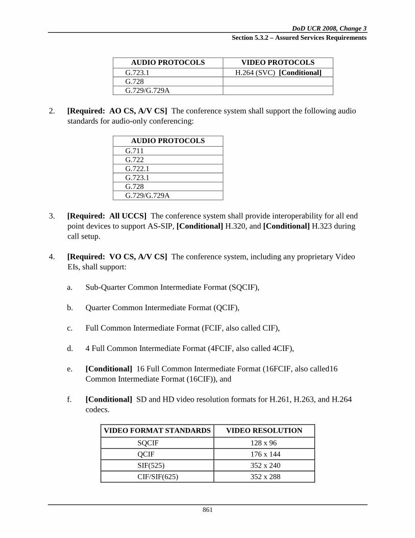
DoD UCR 2008, Change 3 Section 5.3.2 – Assured Services Requirements
861
AUDIO PROTOCOLS VIDEO PROTOCOLS G.723.1 H.264 (SVC) [Conditional] G.728 G.729/G.729A
2. [Required: AO CS, A/V CS] The conference system shall support the following audio
standards for audio-only conferencing:
AUDIO PROTOCOLS G.711 G.722 G.722.1 G.723.1 G.728 G.729/G.729A
3. [Required: All UCCS] The conference system shall provide interoperability for all end
point devices to support AS-SIP, [Conditional] H.320, and [Conditional] H.323 during call setup.
4. [Required: VO CS, A/V CS] The conference system, including any proprietary Video EIs, shall support:
a. Sub-Quarter Common Intermediate Format (SQCIF), b. Quarter Common Intermediate Format (QCIF), c. Full Common Intermediate Format (FCIF, also called CIF), d. 4 Full Common Intermediate Format (4FCIF, also called 4CIF), e. [Conditional] 16 Full Common Intermediate Format (16FCIF, also called16
Common Intermediate Format (16CIF)), and f. [Conditional] SD and HD video resolution formats for H.261, H.263, and H.264
codecs.
VIDEO FORMAT STANDARDS VIDEO RESOLUTION SQCIF 128 x 96 QCIF 176 x 144 SIF(525) 352 x 240 CIF/SIF(625) 352 x 288

DoD UCR 2008, Change 3 Section 5.3.2 – Assured Services Requirements
862
VIDEO FORMAT STANDARDS VIDEO RESOLUTION 4SIF(525) 704 x 480 4CIF/4SIF(625) 704 x 526 16CIF 1408 x 1152 DCIF 528 x 384 SD 720 x 480 HD(720p) 1280 x 720 HD (1080p) 1920 x 1080
5. [Required: VO CS, A/V CS] The conference system shall ensure that the freeze-frame
image feature is compliant with ITU-T H.239 and with H.261 Annex D.
6. [Required: VO CS, A/V CS] The system’s freeze-frame image size shall support 4FCIF (4CIF), VGA, SVGA, XGA, HD, SVTGA and WSXGA+ when using H.239. When using H.261 Annex D, the freeze-frame image size shall support 4FCIF (4CIF).
5.3.2.32.3.3.2 H.320 and H.323 Protocols
[Conditional: VO CS, A/V CS] The conference system that supports H.323/H.320 protocols shall meet the following ISDN/PRI, H.323 V4, chair control, serial interfaces, content sharing VTC endpoint protocol requirements: 1. ISDN PRI on ISDN interfaces (including Alcatel-Lucent 5ESS PRI, GENBAND DMS
PRI, and National ISDN PRI)
2. European E1 ISDN standards
3. ISDN bonding up to 1.5 Mbps on T1 and 2 Mbps on E1 per ISO 13871
4. H.323/320 V4
5. Far end camera control (FECC) H.281 and H.323 Annex Q
6. Resource Availability Indicator (RAI)/Resource Availability Confirmation (RAC) for load balancing
7. Chair control messages per H.246, H.242/H.243
8. Direct, H.225 routed, and H.225-H.245 routed modes of H.323 gatekeeper operations
9. Quality of Service (QoS) support using DSCP marking of IP packets
DoD UCR 2008, Change 3 Section 5.3.2 – Assured Services Requirements
863
10. Automatic downspeed to available ISDN/IP bandwidth
11. Automatic rate detection to match incoming video calls
12. V.35/RS-449/EIA-530 Data Terminating Equipment (DTE) and Data Circuit-Terminating Equipment (DCE) interfaces (The implementation shall use EIA-530 interfaces, and the use of V.35 and RS-449 interfaces shall be phased out where multiple interfaces are supported in equipment. RS-366 interfaces shall also be supported for dial signaling bypass devices.)
13. H.239 for additional video channels or still images
5.3.2.32.3.3.3 AS-SIP
The system shall ensure all conferencing equipment meets the following protocol requirements: 1. [Required: All UCCS] The AS-SIP audio and video signaling conferencing requirements
are specified in Section 5.3.4.13.8c, Audio and Video Conference Services.
2. [Conditional: VO CS, A/V CS] FECC H.281 and H.323 Annex Q
3. [Conditional: VO CS, A/V CS] Chair control messages per H.246, H.242/H.243
4. [Required: All UCCS] QoS support using DSCP marking of IP packets
5. [Required: VO CS, A/V CS] Automatic downspeed to available IP bandwidth
6. [Required: VO CS, A/V CS] Automatic rate detection to match incoming video calls
7. [Conditional: All UCCS] Support T.140 for text messages
8. [Conditional: VO CS, A/V CS] H.261 Annex D for still images
5.3.2.32.3.3.4 Video Mixing Modes
The conference system shall ensure that all video mixing modes meet the following standards. 1. [Required: VO CS, A/V CS] Video Switching Mode—The system shall ensure that the
system supports video switching according to H.243 and H.323. The design shall minimize the time to switch and the disruption of video when switching from one video source to another.

DoD UCR 2008, Change 3 Section 5.3.2 – Assured Services Requirements
864
2. [Required: VO CS, A/V CS] Video Mixing (Picture Composition or Continuous Presence Mode)—The system shall ensure that the system supports video mixing functions according to H.243 and H.323. The system shall support enhanced continuous presence multiple video mixing to include the 7 plus 1 format.
5.3.2.32.3.3.5 In-Conference Chair Control
The conference system shall ensure the system supports chair control standards as defined in H.230, H.246, H.242, H.243 and H.245 including standards supporting Broadcast and Lecture mode capabilities. The following shall be supported: 1. [Conditional: VO CS, A/V CS] H.320 chair control messages and procedures as defined
in H.230, H.242, H.243 and H.245.
2. [Conditional: VO CS, A/V CS] H.323 MCUs shall support chair control messages and procedures as defined in H.323 and as carried forward to H.323 from H.243.
3. [Conditional: VO CS, A/V CS] H.323 – H.320 gateways shall follow the H.246 message translation tables related to chair control functions.
5.3.2.32.3.3.6 Audio Conferencing Requirements
The conference system shall ensure audio systems support the following requirements: 1. [Required: AO CS, A/V CS] Audio systems shall support in-dial and out-dial IAW the
DISN World Wide Numbering Plan and the PSTN North American dialing plans.
2. TDM requirements include:
a. [Conditional: AO CS, A/V CS] The audio system’s PSTN interfaces shall support T1/E1 (AT&T TR62411 or Telcordia TR-NWT-000170).
b. [Conditional: AO CS, A/V CS] The audio system’s CAS interfaces shall support
Alcatel-Lucent 5ESS and GENBAND DMS switches. c. [Conditional: AO CS, A/V CS] The audio system’s T1 PRI interfaces shall support
Non-Facility Associated Signaling (NFAS) and D-channel backup, if the audio system supports more than two PRIs.
d. [Conditional: AO CS, A/V CS] The audio system’s T1 interface shall support ESF
framing and with B8ZS/ alternate mark inversion (AMI) coding.

DoD UCR 2008, Change 3 Section 5.3.2 – Assured Services Requirements
865
e. [Conditional: AO CS, A/V CS] The audio system’s PSTN signaling module shall support ISDN PRI (5ESS, DMS, and National ISDN), and the PRI flavors of foreign countries such as Germany, Japan, and Korea.
f. [Conditional: AO CS, A/V CS] The audio system shall support the Dialed Number
Identification Service (DNIS) feature where the original dialed numbers are presented as generic address parameters (GAP).
g. [Conditional: AO CS, A/V CS] The audio system shall support the ANI feature and
use it to identify a calling party, if applicable.
3. VoIP requirements include the following:
a. [Required: AO CS, A/V CS] The audio system IP interfaces shall support static assignment of the IP address, mask, default router, and Domain Name Service (DNS) entries.
b. [Required: AO CS, A/V CS] The audio system shall support multiple DNS entries.
If the primary DNS server does not respond to a DNS request, a secondary DNS server shall be queried.
c. [Required: AO CS, A/V CS] The audio system shall support configurable TCP
ports for AS-SIP messaging. d. [Required: AO CS, A/V CS] The audio system shall be able to set the IPv4/IPv6
Precedence Field bits of the Type of Service (TOS) byte and DSCP bits for media streams and signaling streams.
e. [Required: AO CS, A/V CS] The audio system shall support Network Time
Protocol (NTP), version 3. [RFC 1305] f. [Required: AO CS, A/V CS] The audio system shall support SNMPv3. [RFC
3414] g. [Required: AO CS, A/V CS] The audio system shall support Secure Real-Time
Transport Protocol (SRTP) and Secure Real-Time Transport Control Protocol (SRTCP). [RFC 3711]
h. [Required: AO CS, A/V CS] The audio system shall support SRTCP and
accurately report jitter, delay, and packet loss information to the far end using RTP Control Protocol Extended Reports (RTCP XR). [RFC 3611]

DoD UCR 2008, Change 3 Section 5.3.2 – Assured Services Requirements
866
i. [Required: AO CS, A/V CS] The audio system’s AS-SIP signaling module shall support RFC 3261including loose route.
j. [Required: AO CS, A/V CS] The audio system’s AS-SIP signaling module shall
allow AS-SIP URLs for both incoming and outgoing calls. This includes all alphanumeric characters allowed in legal SIP URLs.
k. [Required: AO CS, A/V CS] The audio system’s AS-SIP signaling module shall
support SDP as defined in RFC 2327. l. [Required: AO CS, A/V CS] The audio system’s AS-SIP signaling module shall
implement user “hold” feature by using a=inactive or a= sendonly, or by sending a mid-call INVITE that includes a session description that is the same as in the original request, but the “c” destination addresses for the media streams to be put on hold are set to zero:c=IN IP4 0.0.0.0.
m. [Required: AO CS, A/V CS] The AS-SIP signaling module shall support AS-SIP
Digest Authentication. [RFCs 3261 and 3310] n. [Required: AO CS, A/V CS] The AS-SIP signaling module shall be able to reject
incoming INVITE messages when the message does not come from pre-provisioned proxies.
o. [Required: AO CS, A/V CS] The AS-SIP signaling module shall support call
transfer as specified in Section 5.3.4.13.8, Call Transfer. p. [Required: AO CS, A/V CS] Audio systems shall support ENUM service
registration for SIP (AS-SIP) Addresses-of-Record. [RFC 3764]
4. Voice medium requirements include the following:
a. [Required: AO CS, A/V CS] The audio system shall support DTMF Generation/Recognition per Telcordia GR-181-CORE.
b. [Required: AO CS, A/V CS] The audio system shall support G.711 µ/A law (PCM)
and G.729. c. [Required: AO CS, A/V CS] The audio system’s total media processing time shall
be less than 50 ms including delays from jitter buffer, transcoding, mixing, packetization, and algorithm look ahead.

DoD UCR 2008, Change 3 Section 5.3.2 – Assured Services Requirements
867
d. [Required: AO CS, A/V CS] The audio system shall support G.168 compliance EC with 128 ms echo path.
e. [Required: AO CS, A/V CS] The audio system shall support Audio and Video
Transport (AVT) payload type 0 and 8. [G.711 a/mu law]. f. [Required: AO CS, A/V CS] The audio system shall support AVT payload 18.
[G.729]. g. [Required: AO CS, A/V CS] The audio system shall be able to accept in-band
DTMF tones. h. [Required: AO CS, A/V CS] The audio system shall be able to send DTMF
specified by RFC 2833. i. [Required: AO CS, A/V CS] The audio system shall be able to conceal 1 percent of
packet loss without appreciable quality degradation. j. [Required: AO CS, A/V CS] The audio system shall be able to tolerate 40 ms of
jitter for audio without appreciable quality degradation. k. [Required: AO CS, A/V CS] The audio system shall implement adaptive jitter
buffers instead of static fix jitter buffers. l. [Required: AO CS, A/V CS] All hardware shall meet Network Equipment Building
System-3 (NEBS-3) requirements.
5.3.2.32.3.3.7 Reduced Maximum Transmission Unit IP Environment
[Required: VO CS, A/V CS] This subsection addresses the Maximum Transmission Unit (MTU) requirements for an IP network environment. An MTU is the maximum size of an IP packet that will be accepted for transmission without fragmenting it into a smaller datagram. The MTU size shall be configurable to optimize video traffic. As a result of devices such as encryption units, the typical MTU size shall be changed to minimize the effect of fragmentation due to the additional overhead of the encryption. 1. [Required: All UCCS] The conference system shall ensure that all conferencing services
provide signaling and media streams, and are capable of configuring the MTU.
2. [Required: All UCCS] The conference system shall ensure that all supporting services to video and audio services, including, but not limited to, reservation, monitoring, billing,
DoD UCR 2008, Change 3 Section 5.3.2 – Assured Services Requirements
868
administration, operator interface, and meeting control are capable of working in the configurable MTU IP environment.
5.3.2.32.3.3.8 IPv6 Support
1. [Required: All UCCS] The conference system shall comply with the IPv6 requirements contained in Section 5.3.5, IPv6 Requirements.
5.3.2.32.3.3.9 AS-SIP Support
[Required: All UCCS] The conference system shall comply with the AS-SIP requirements contained in Section 5.3.4, AS-SIP Requirements.
5.3.2.32.3.4 Assured Services
This subsection describes assured services as the set of capabilities that ensure mission-critical calls are set up and remain connected.
5.3.2.32.3.4.1 Quality of Service
[Required: All UCCS] The system or network device shall be able to set DSCPs on both signaling packets and media streams for both IPv4 and IPv6 as specified in Section 5.3.3.3.2, Differentiated Services Code Points.
5.3.2.32.3.4.2 Assured Service Requirements
The conference system shall ensure that the design and services satisfy the following requirements.
5.3.2.32.3.4.2.1 Congestion Response Requirements
[Required: All UCCS] The system shall provide measures to monitor bandwidth resource usage and to activate congestion management as needed within a timely fashion.
5.3.2.32.3.4.2.2 Accounting
[Required: All UCCS] The system shall maintain a call summary of conference sessions. This will include the conference attendee identification, access methods, IP address, E.164 numbers, time and date of the call, call duration, and the total number of participants. The summaries shall be maintained for 30 days or IAW Information Assurance security requirements.

DoD UCR 2008, Change 3 Section 5.3.2 – Assured Services Requirements
869
5.3.2.32.3.4.2.3 Multilevel Precedence and Preemption
[Conditional: All UCCS] The system shall operate IAW the MLPP rules and procedures specified in Section 5.3.2.31.3, Multilevel Precedence and Preemption (inclusive as applies). [Conditional: All UCCS] Preset Conferencing – Each conferee shall be dialed at its designated precedence level. Each conferee may have a different precedence level. The conference host must be dialed at the highest precedence level of any conferee. [Conditional: All UCCS] Meet-Me Conferencing – When a priority session requests connection to a conference that is at conference maximum, then one of the lowest precedence conferees shall be preempted, selected through any deterministic method. (Conference maximum is the maximum number of conferees authorized for the same conference.) When a priority session requests connection to a conference that is not at conference maximum, but the system is at system maximum, then one of the lowest precedence conferees on another conference will be preempted; selected through any deterministic method. Note that the selection method shall not consider any ad hoc conferees for preemption, if an allocation of system resources dedicated to ad hoc conferences has been configured per item 9 in Section 5.3.2.32.4.2.1, Video Conference Capacity. (System maximum occurs when the maximum number of ports or resources are provisioned on the system.) Preempted conferees shall receive a preemption notification tone and be preempted. All remaining conferees on the system shall receive a conference disconnect tone (see Table 5.3.2.6-2, UC Information Signals). [Conditional: All UCCS] Ad hoc Conferencing – When either party of a two party session brings in a third party an ad hoc conference is created at the highest precedence level of the dialed conferees. Thereafter, any party of an ad hoc conference can attempt to add an additional conferee at any time. If that party is dialed at a precedence level higher than any of the current conferees, then the conference precedence level shall be elevated to a higher precedence level. If an allocation of system resources dedicated to ad hoc conferences has been configured per item 9 in Section 5.3.2.32.4.2.1, and there are no ad hoc system resources available to add on a conferee, a conferee from the lowest precedence ad hoc conference will be preempted so that the conferee can be brought into the higher precedence ad hoc conference. If an allocation of system resources dedicated to ad hoc conferences has not been configured, but the system is at system maximum, then one of the lowest precedence conferees on another conference will be preempted; selected through any deterministic method, so that the conferee can be brought into the higher precedence ad hoc conference. [Conditional: All UCCS] Ad hoc Conferencing – When a higher precedence session (i.e., higher than the conference precedence level) is placed to any of the conferees, that conferee receives a preemption notification tone (see Table 5.3.2.6-2, UC Information Signals). The other remaining conferees shall receive a conference disconnect tone, as described in Table 5.3.2.6-2.

DoD UCR 2008, Change 3 Section 5.3.2 – Assured Services Requirements
870
This tone indicates to the other parties that one of the conference call participants is being preempted.
5.3.2.32.4 Service Performance
[Required: All UCCS] This section provides the service performance criteria and metrics for the system. The service performance criteria shall apply during simultaneous operation of the respective EIs. The system shall design and implement redundancy, failover, and fault tolerance at the component, subsystem, and system levels to support achieving service availability requirements in the presence of failures at the component, subsystem, and system levels. The system shall meet the requirements specified in Section 5.3.2.5, Product Physical, Quality, and Environmental Factors.
5.3.2.32.4.1 Quality
5.3.2.32.4.1.1 Video Conference Quality
For video conferencing services implemented and provided by the conference system, video quality requirements are as follows (that are based upon commercial standards for supporting video conferencing): 1. [Required: VO CS, A/V CS] The conference system shall ensure that all video
equipment used in designs can operate in the presence of minimal packet loss without degrading video quality below acceptable levels.
2. [Required: VO CS, A/V CS] The conference system shall ensure all video equipment used in the design provide adequate jitter buffer sizing to ensure an optimal end-to-end video conferencing performance..
5.3.2.32.4.1.2 Audio Conference Quality
For audio conferencing services provided by the conference system, voice quality requirements are as follows: 1. [Required: AO CS, A/V CS] The conference system shall ensure that the MOS on the
voice path meets the MOS requirements in Section 5.3.3, Network Infrastructure E2E Performance Requirements.
2. [Required: AO CS, A/V CS] The conference system shall ensure that the implemented design possesses the adequate performance capacity and resources to support conference access processing requirements identified in Section 5.3.2.32.4.2, Capacity.

DoD UCR 2008, Change 3 Section 5.3.2 – Assured Services Requirements
871
3. [Conditional: AO CS, A/V CS] The conference system shall ensure the time needed to compile polling statistics to adequately support the audio conference capability.
5.3.2.32.4.2 Capacity
This subsection describes the capacity requirements of the conference system.
5.3.2.32.4.2.1 Video Conference Capacity
1. [Required: VO CS, A/V CS] The number of concurrent conferences shall only be limited by available ports, regardless of access methods, features, or number of participants in each conference.
2. [Required: VO CS, A/V CS] The system shall have the capacity to support at least 1,000 concurrent 384 kbps video calls.
3. [Required: VO CS, A/V CS] The system shall provide sufficient speed matching capacity to support that capability regardless of the access methods, algorithms, speeds, or the feature sets being used.
4. [Required: VO CS, A/V CS] The system shall provide enough transcoding capacity to support that capability regardless of the access methods, algorithms, speeds, or the feature sets being used.
5. [Conditional: VO CS, A/V CS] The system shall provide sufficient H.323 gateway capacity to support that capability regardless of the access methods, algorithms, speeds, or the feature sets being used.
6. [Required: VO CS, A/V CS] The system shall provide enough H.239 capacity to support that capability regardless of the access methods, algorithms, speeds, or the feature sets being used. The system shall provide enough H.261 Annex D capacity to support that capability regardless of the access methods, algorithms, speeds, or the feature sets being used.
7. [Required: VO CS, A/V CS] The system shall support a minimum of 200 EIs for each multipoint conference.
8. [Required: A/V CS] The system shall provide at least four audio added-on ports for each conference without the use of external audio systems or by cascading conference systems. The system shall ensure that audio added-on does not compromise other capacity requirements.

DoD UCR 2008, Change 3 Section 5.3.2 – Assured Services Requirements
872
9. [Conditional: VO CS, A/V CS] A configurable percentage (0 to 100 percent, default 20 percent) of system ports/resources shall be allocated for ad hoc video conferences. Meet-me conferences shall not use resources allocated to ad hoc conference and vice versa.
5.3.2.32.4.2.2 Audio Conference Capacity
The conference system shall provide the following audio conferencing capacity: 1. [Required: AO CS, A/V CS] The system shall be capable of scaling up to 2,500
concurrent audio calls.
2. [Required: AO CS, A/V CS] The system shall support up to 200 participants in a single conference session.
3. [Required: AO CS, A/V CS] The system shall be capable of scaling up to 500 concurrent conferences and more than 500 conference control web sessions.
4. [Required: AO CS, A/V CS] The audio conference system shall be capable of scaling to support more than 10,000 reservations.
5. [Conditional: AO CS, A/V CS] The audio conference system shall support more than 50 concurrent recordings.
6. [Conditional: AO CS, A/V CS] A configurable percentage (0 to 100 percent; default 20 percent) of system ports and resources shall be allocated for ad hoc audio conferences. Meet-me conferences shall not use resources allocated to ad hoc conferences and vice versa.
NOTE: Scaling can be provided by deploying multiple systems and provisioning or load sharing between systems.
5.3.2.32.4.2.3 Registration, Admission, Status, and Routing Function
[Required: All UCCS] The conference system shall have the capability to provide bandwidth management, EI registrations, admissions, status, routing functions. Furthermore, the system shall be capable of scaling to support at a minimum of 1,000 concurrent conference calls and 10,000 concurrent registrations of EIs. NOTE: Scaling can be provided by deploying multiple systems and provisioning or load sharing between systems.
DoD UCR 2008, Change 3 Section 5.3.2 – Assured Services Requirements
873
5.3.2.32.4.2.4 Scalability
The conference system shall support a nominal growth of services without requiring major overhaul or major replacement of equipment. 1. [Required: VO CS, A/V CS] The system architecture supporting the dedicated IP-based
video services capability shall be able to scale to accommodate increase growth in dedicated IP-based video services EIs.
2. [Required: VO CS, A/V CS] The system architecture supporting the dial-up video services capability shall be designed to support up to a 50 percent increase in dial-up video services.
3. [Conditional: VO CS, A/V CS] The system shall be able to scale to accommodate increased growth to support increases in connections to ISDN networks. Additional capacity in regards to this item will only be used to support ISDN dial-up video traffic.
4. [Required: AO CS, A/V CS] Audio add-on and audio conference service shall be able to scale to accommodate increased growth in call volume and EIs.
5.3.2.32.5 Service Management
This section describes service management. The conference system shall provide reservation, scheduling, and registration services. The conferencing system service applications shall integrate or provide interfaces with Government network services and management applications. The conference system shall provide management functions to ensure continuous operations and accessibility of services with a data feed into the Government network services systems. The equipment and software applications shall be configurable to allow alarm and log file transmissions to be selective with the activation of a specific feature set.
5.3.2.32.5.1 System Management
5.3.2.32.5.1.1 General System Management
1. [Required: All UCCS] The conference system shall provide services management and monitoring for the Operation, Administration, Maintenance, and Provisioning (OAM&P) of conferencing services.
2. [Required: All UCCS] The conference system shall provide a service monitor and management system to actively monitor elements and critical components within the system.

DoD UCR 2008, Change 3 Section 5.3.2 – Assured Services Requirements
874
3. [Required: All UCCS] Report data shall be in a form that is capable of being managed by the Government network services applications and network elements, which are based upon commercial and industry standards. The data transmitted shall comply with industry standard management protocols and/or data formats. Such industry standard protocols for data exchange include, but are not limited to, Syslog, Common Object Request Broker Architecture (CORBA), SNMPv3, Transaction Language 1 (TL1), Java 2 Platform, Enterprise Edition (J2EE), and Extensible Markup Language (XML).
4. [Required: All UCCS] The conference system shall be responsible for managing and monitoring the following services and related resources. Furthermore, the system shall provide real-time, read-write continuous NM capabilities. The level of monitoring shall be sufficient to be able to track the status, through standard interfaces and protocols, of individual discrete hardware and software components used to deliver the service to enable visibility of individual incidents affecting the service delivery.
a. Equipment and associated services b. Point-to-point and multipoint video services c. Audio services d. Reservation and scheduling e. Gateways and interfaces f. Conferencing center web site g. Support systems
5. [Required: All UCCS] The conference system shall furnish and maintain a service monitor and management system with external interfaces or feeds into Government management application and monitoring systems. These interfaces shall provide the Government the capability to monitor the performance and status of video and audio services. These interfaces shall provide for the importing and exporting of video and audio management services and monitoring information. The Government shall have real-time access to all video and audio services management and monitoring data collected and stored by the system. These interfaces are further specified in Section 5.3.2.17.2, General Management Requirements.
5.3.2.32.5.1.2 Fault Management
1. [Required: All UCCS] The conference system shall provide fault management for services and resources. The system shall provide the Government with all the fault information needed electronically to effectively manage all conferencing services.
2. [Required: All UCCS] The fault management system shall include the following minimum requirements:

DoD UCR 2008, Change 3 Section 5.3.2 – Assured Services Requirements
875
a. Power status shall be provided for individual shelf, rack, or controller units b. Functional/Fault/Online/Offline status c. Input/loss of input signal, or signal below working threshold d. Output/loss of output signal e. Input/Output signal outside of specified range f. Intrusion detected
3. [Required: All UCCS] The fault management function shall perform the following:
a. Detect and identify faults—The fault management service provided shall monitor dedicated and dial-up video services resources, audio conferencing service status, support services status, and conduct alarm surveillance, maintain error logs, and analyze monitored or logged errors or events to anticipate faults.
(1) Faults shall be detected within 10 seconds of their occurrence. (2) Faults shall be identified within 10 seconds of being detected. (3) Faults shall be correlated within 10 seconds of identification. (4) The Government shall be notified of service affecting faults within 10 seconds
of fault correlation.
b. Isolate faults to include correlation of alarms—The fault management service provided shall initiate diagnostic testing and evaluate diagnostic results to determine the nature, severity, and the specific cause(s) of the fault and isolate the fault to the video, audio, and support services at a component level.
c. Temporary corrective action when a fault occurs—The fault management service
provided shall reroute a conference call or service request to other hubs, circuits, or equipment in the case of a fault, including through the use of redundancy and failover capabilities.
d. Correct faults—The fault management service provided shall implement corrective
actions on faults to restore services to proper working order and complete resource/service restoration when the fault is with equipment or services provided by the conference system. This process shall incorporate backup and recovery capabilities to restore configurations and services to operational service.

DoD UCR 2008, Change 3 Section 5.3.2 – Assured Services Requirements
876
5.3.2.32.5.1.3 Fault Management Information Requirements
1. [Required: All UCCS] The conference system shall provide the Government with real-time monitoring of service-affecting events related to hardware and software components and subcomponents that comprise the conference system. These service-effecting events impacting the scheduling and operation of system services include, but are not limited to, the following:
a. Outages for all conferencing services elements to be exported into the existing trouble tracking system.
b. Any hazardous condition, as specified in DISA Circular 310-55-1, that may cause
loss of service
2. [Required: All UCCS] The conference system shall be able to update all service management thresholds, as required.
3. [Required: All UCCS] The conference system shall maintain historical records of all fault alarm data and be able to export this data into the Government management application systems.
5.3.2.32.5.1.4 Performance Management
[Conditional: All UCCS] The conference system shall provide a performance management system. The performance management system shall monitor and control all service performance and the quality of the services and features supporting the conference system. Performance management shall perform the following functions: 1. [Conditional: All UCCS] Monitor, analyze, and characterize performance—The
conference system shall monitor, analyze, and gather performance-related data to detect and characterize normal and degraded performance and be able to trend this data over time for metrics purposes. Section 5.3.2.32.4, Service Performance, defines normal performance requirements. The system shall provide notification if the service resources are being stressed with excess traffic loads.
2. [Conditional: All UCCS] Tune and control performance in areas of control: the conference system shall activate controls to tune all services performance to restore degraded resources/services to acceptable performance levels. If control actions will cause any user service disturbance, then these actions shall be approved by the Government before execution.

DoD UCR 2008, Change 3 Section 5.3.2 – Assured Services Requirements
877
3. [Conditional: All UCCS] Maintain all services supporting the conference system through an operations database – The conference system shall maintain a database or be exportable to a Government network management tool supporting all conferencing services operational information, both real-time and historical, including, for example, traffic characterization data, performance data, and information on usage of resources/services. Historical records shall be kept of all performance data for a designated period of time.
4. [Conditional: All UCCS] Evaluate performance of services and features—The conference system shall continuously assess and monitor the performance of all conferencing services and features, according to the performance parameters identified in Section 5.3.2.32.4, Service Performance, to ensure that the performance levels of Government services and features meet the specification requirements of Section 5.3.2.32.3, Service Requirements, and Section 5.3.2.32.4, Service Performance.
5.3.2.32.5.1.5 Government Performance Management Information Requirements
This subsection describes Government performance management information requirements. [Conditional: All UCCS] The conference system shall provide notification of events, exceptions, or measures related to the performance of services’ resources, and associated service-effecting conditions, to Government platforms, as required. Performance degradation notification shall include, at a minimum, the following: The conferencing services are comprised of servers, applications and network services, appliances, and network devices responsible for supporting video services globally throughout the DoD community. The conferencing service is of time-sensitive nature and one of the services that is being offered with the convergence of IP on the backbone. There are two parts to the network management of this service; transport monitoring and video stream monitoring. First, the underlying network elements and servers need to be included in fault management and performance management activities at the physical layers and IP layers. Second, the video service needs to have instrumentation included that would be able to monitor the conferencing user’s experience, in order to isolate problems and reveal if the video service is meeting specific service level requirements. [Conditional: VO CS, A/V CS] The performance management toolset should be able to collect information from the video device managers. The information it should collect would include, but not be limited to the number of participants, duration of a session, video burst measurements, and capacity measurements.
DoD UCR 2008, Change 3 Section 5.3.2 – Assured Services Requirements
878
5.3.2.32.5.1.6 Security Management
This subsection describes the security management requirements. 1. [Required: All UCCS] Certification and Accreditation – The conference system shall
ensure that all systems and subsystems in UC conferencing undergo Certification and Accreditation (C&A) IAW the DIACAP and associated audits.
2. [Required: All UCCS] Best Security Practices – The conference system shall incorporate best security practices such as single sign-on, PKE, smart card, and biometrics in system security design of DoD information, but does not limit to certain security mechanisms.
3. [Required: All UCCS] Enterprise Security Management – The conference system shall implement enterprise management of security devices and applications such as:
a. Firewalls and boundary protection b. Intrusion detection systems c. Operating systems, network devices, and applications security d. Vulnerability management
4. [Required: All UCCS] Security Configuration Specifications – The conference system shall comply with DoD reference documents such as STIGs or security recommendation guides from DISA FSO that are pertinent to the UCCS or subcomponents.
5.3.2.32.5.2 Online Directory
1. [Required: VO CS, Conditional AO CS, A/V CS] The system shall provide an online directory service to support scheduling that shall include general information about all registered DoD video and audio users including, but not limited to, a user’s point of contact, location, supported data rates, organization name, unit capabilities, and software versions.
2. [Required: VO CS, Conditional AO CS, A/V CS] The system shall update the online directory within 24 hours of learning of a new EI receiving service, a change in an existing EI’s service status, or notification by DISA of any other change with regard to an EI.
3. [Required: VO CS, Conditional AO CS, A/V CS] The system shall provide a secure web interface that implements a public key enablement application, allowing registered users with a valid DoD PKI or ECA certificate and internet connectivity to access the online directory.

DoD UCR 2008, Change 3 Section 5.3.2 – Assured Services Requirements
879
4. [Required: VO CS, Conditional AO CS, A/V CS] The online directory shall support more than 1,000,000 data entries and shall support more than 500 concurrent users at the same time.
5. [Required: VO CS, Conditional AO CS, A/V CS] The online directory shall be web-based using modern and open technologies and provide interfaces, such as XML, Simple Object Access Protocol (SOAP), Web Service Description Language (WSDL), and Universal Discovery Description Interface (UDDI), allowing external data sources from others to perform directory lookups, queries, and updates as specified by “Horizontal Fusion Standards and Specifications,” 3 November 2004, and DoD Joint Technical Architecture, Version 6, Volumes I & II, 3 October 2003.
6. [Required: VO CS, Conditional AO CS, A/V CS] The online directory shall support the discovery service that provides processes for discovery of information content or services that exploit metadata descriptions of information technology resources stored in directories, registries, and catalogs (to include search engines) as specified by “Horizontal Fusion Standards and Specifications”, 03 November 2004, and “DoD Joint Technical Architecture”, Version 6, Volumes I & II, 03 October 2003. Directory services shall be designed to meet Protected Personal Information/Personally Identifiable Information protection requirements and Privacy Act requirements.
7. [Required: VO CS, Conditional AO CS, A/V CS] The system shall provide on-line directory service to allow authorized registered users to search system-wide for other authorized, registered service users in the directory and/or to update data entries.
5.3.2.32.5.3 Registration System
[Required: All UCCS] UCCS customers will be required to follow a registration process to subscribe to the service. One component shall be an automated registration system that prospective customers can access online using a standard web browser. All data shall be encrypted using Secure Socket Layer (SSL)/TLS technology, as a minimum, with DoD PKI certificate authentication and validation. 1. [Required: All UCCS] The automated registration system shall collect all data necessary
to comply with provisioning requirements.
2. [Required: All UCCS] The automated registration system shall collect all data necessary for connection approval by the program office.
3. [Required: All UCCS] The automated registration system shall collect all data necessary to authorize users for access to operational systems including scheduling and reservations.

DoD UCR 2008, Change 3 Section 5.3.2 – Assured Services Requirements
880
4. [Required: All UCCS] The automated registration system shall collect all data necessary to support the operational requirements of UC conferencing services. Upon connection approval and completion of verification and interoperability tests, all data shall be available to the operational systems for the scheduling and activation of conferences.
5. [Required: All UCCS] The automated registration system shall be the authoritative source of conference subscribers’ data. The system shall provide the necessary tools to allow authorized users to maintain and update user and endpoint information. The system shall support Privacy Act statements where required by Information Assurance policy.
5.3.2.32.5.4 Scheduling System
1. [Required: All UCCS] The primary component for requesting a conference shall be by an automated scheduling system that authorized users can access online using a standard web browser. All data shall be encrypted using SSL/TLS technology, as a minimum, with DoD PKI certificate authentication and validation.
2. [Required: All UCCS] The automated scheduling system shall resolve the availability of all requested participants and conferencing resources. The customer shall be able to schedule a conference immediately or schedule it for some time in the future. Immediate start requests for conferences shall be activated in less than 5 minutes of confirmation of available resourcesand participants. The system shall support scheduling conferences with the conference size larger than the number of initially invited or scheduled endpoints. A unique identification number shall be assigned to each conference event to facilitate conference control and management. E-mail notifications shall be provided to all conference participants to facilitate event coordination. E-mail content shall be editable as a configuration feature. The system shall support encrypted e-mail for notifications. Scheduled conference information also shall be available through the scheduling web interface.
3. [Required: All UCCS] The original requester shall serve as the conference manager for all conferences. The system shall have the capability to assign other system users to act as surrogates for the original requester. This may include peers and/or workflow superiors. Conference management and control shall include the ability to make changes to a scheduled or active conference. Supported changes to active conferences shall include, but are not limited to, the addition or deletion of participants, ending a conference early, and extending the conference beyond the originally scheduled end time. Additions, deletions, and extensions of conferences shall occur without interruption to the existing conference, other than pre-emptive precedence calls. Additions and extensions to conferences shall be executed in less than 5 minutes of confirmation of available resources. Deletions and ending of conferences shall be executed in less than 5 minutes of the request by the conference manager. The system shall support scheduling of recurring conferences.

DoD UCR 2008, Change 3 Section 5.3.2 – Assured Services Requirements
881
5.3.2.32.5.5 Accounting and Billing
1. [Required: All UCCS] The conference system shall provide an Accounting Management function. The Accounting Management function will serve two purposes:
a. It will provide accounting information to the Government regarding all conferencing services provided; and,
b. It shall provide all conferencing services data to the Government at a level of detail
that allows the Government to bill conferencing services customers based on usage. 2. [Required: All UCCS] The Accounting Management function shall enable charges to be
established for the use of dedicated and dial-up conferencing services resources.
3. [Required: All UCCS] The conference system Accounting Management function shall provide for the collection, aggregation, storage, and reporting of all conferencing service usage data. The accounting management function shall consist of systems to activate and monitor customer accounts and to collect, aggregate, and report on usage data.
4. [Required: All UCCS] The conference system shall provide the capability to perform the following Accounting Management functions.
a. Collect usage data from a Call Detailed Record (CDR), (i.e., at the level of the authorization code).
b. Aggregate and combine data for generating reports as specified by the Government. c. Maintain conference records per individual customer’s account. d. Ensure continuous (24 hours per day, 7 days per week) monitoring, processing, and
recording for all video services-related events and customer activity data. e. Maintain a database of various conference reports per individual customer account,
including conference detail summary, completion summary, and exception reports. f. Archive data for possible later retrieval by the Government (e.g., in response to
customer inquiries or to audit the data).
5. [Required: All UCCS] The conference system shall provide the capability to transmit usage data to the EMS system. The frequency of data transfer shall be, determined by the Government, based on volume of data collected. The system shall maintain all accounting data for at least one billing cycle.

DoD UCR 2008, Change 3 Section 5.3.2 – Assured Services Requirements
882
5.3.2.32.6 Applicable Documents
The Government documents and industry standards applicable to this section can be found in Appendix A, Section A4, References. These documents form a part of this section. In the event of conflict between these documents and the content of this section, the content of this section shall be considered as a superseding requirement unless otherwise specified. The referenced documents are subject to revision. The conference system shall comply with any recent editions of the documents listed in this section upon the Government’s request.
5.3.2.32.6.1 Government Reference Documents
Systems and subsystems supporting UC conferencing shall comply with all GIG guidance and direction, specifically including the following documents: 1. CJCS Standing Execute Order for Computer Network Attack and Computer Network
Defense, January 20, 2004.
2. CJCSI 6212.01E, “Interoperability and Supportability of Information Technology and National Security Systems,” 15 December 2008, accessed 8 November 2010: http://www.dtic.mil/cjcs_directives/cdata/unlimit/6212_01.pdf.
3. CJCSI 6510.01E, “Information Assurance (IA) and Computer Network Defense (CND),” 15 August 2007, accessed 8 November 2010: http://www.dtic.mil/cjcs_directives/cdata/unlimit/6510_01.pdf.
4. CJCSM 3150.07A, “Joint Reporting Structure Status Communications,” 19 April 19 2001, accessed 8 November 2010: http://www.dtic.mil/doctrine/jel/cjcsd/cjcsm/m315007a.pdf.
5. CJCSM 3500.04C, “Universal Joint Task List (UJTL),” Version 4.0, 1 July 2002, accessed 8 November 2010: http://www.dtic.mil/doctrine/jel/cjcsd/cjcsm/m350004c.pdf.
6. CJCSM 6231.01C, “Manual for Employing Joint Communications Systems: Joint Tactical Systems Management,” June 20, 2003.
7. Defense Intelligence Agency, Defense Intelligence Agency Manual (DIAM) 50-3, “Physical Security Standards for Construction of Sensitive Compartmented Information Facilities.”
8. Department of Defense 5200.2, “DOD Information Security Program Regulation,” 9 April 1997.

DoD UCR 2008, Change 3 Section 5.3.2 – Assured Services Requirements
883
9. Department of Defense 5200.40, “DOD Information Technology Security Certification and Accreditation (CandA) Process (DITSCAP),” 30 December 1997.
10. Department of Defense 8510.1-M, DOD Information Technology Security Certification and Accreditation Process (DITSCAP), July 31, 2000.
11. Department of Defense Collaboration Interoperability Standards, J.P. Stenbit, Memorandum of 1 November 2002.
12. (SECRET) Department of Defense Directive (DoDD) C-3222.5, “Electromagnetic Compatibility (EMC) Management Program for SIGINT Sites (U),” 22 April 1987.
13. Department of Defense Directive (DoDD) 4630.05, “Interoperability and Supportability of Information Technology (IT) and National Security Systems (NSS),” 5 May 2004, Certified Current as of 23 April 2007, accessed 8 November 2010: http://www.dtic.mil/whs/directives/corres/pdf/463005p.pdf.
14. Department of Defense Directive (DoDD) 8000.01, “Management of Department of Department Information Enterprise,” 10 February 2009, accessed 8 November 2010: http://www.dtic.mil/whs/directives/corres/pdf/800001p.pdf.
15. Department of Defense Directive (DoDD) 8100.1, “Global Information Grid (GIG) Overarching Policy,” 19 September 2002. Certified Current as of 21 November 2003, http://www.dtic.mil/whs/directives/corres/html/81001.htm.
16. Department of Defense Directive (DoDD) 8320.02, “Data Sharing in a Net-Centric Department of Defense,” 2 December 2004. accessed 8 November 2010: http://www.dtic.mil/whs/directives/corres/pdf/832002p.pdf
17. Department of Defense Directive (DoDD) 8500.01E, “Information Assurance (IA),” October 24, 2002, Certified Current as of April 23, 2007, accessed 8 November 2010: http://www.dtic.mil/whs/directives/corres/pdf/850001p.pdf.
18. Department of Defense Directive (DoDD) 8500.2, “Information Assurance Implementation,” 6 February 2003.
19. DoD Directive 8520.1, "Protection of Sensitive Compartmented Information (SCI)," December 20, 2001.
20. (FOUO) Department of Defense Directive (DoDD) O-8530.1, “Computer Networking Defense (CND),”8 January 2001.

DoD UCR 2008, Change 3 Section 5.3.2 – Assured Services Requirements
884
21. (FOUO) Department of Defense Directive (DoDD) O-8530.2, “Computer Networking Defense (CND),” 1 April 2004.
22. Department of Defense Instruction (DoDI) 8260.01, “Support for Strategic Analysis,” 11 January 2007,accessed 8 November 2010.
23. Department of Defense Security Technical Implementation Guides (STIGs).
24. Defense Information Systems Agency Instruction 630-230-19, “Automated Data Processing Information Systems Security Program,” 9 July 1996.
25. DF v2.1, “Common Criteria for Information Technology Security Evaluation: Protection Profile for Switched and Routers,” as prepared by Booze-Allen & Hamilton, Inc., February 2001.
26. Reserved.
27. Department of Defense Instruction (DoDI) 8551.1, “Ports, Protocols, and Services Management (PPSM),” 13 August 2004, accessed 8 November 2010: http://www.dtic.mil/whs/directives/corres/pdf/855101p.pdf.
28. “DoD Internet Protocol Version 6 (IPv6) Interim Transition Guidance,” 29 September 2003.
29. “Department of Defense Joint Technical Architecture (JTA),” Version 6.0, Volumes I & II, 3 October 2003.
30. “DoD Policy for Enterprise-wide Deployment of IPv6,” 9 June 2003.
31. Director of Central Intelligence Directive 6/3, DCID 6/3, “Protecting Sensitive Compartmented Information within Information Systems,” 1999.
32. FTR 1080B-2002, Federal Telecommunications Recommendation for Video Teleconferencing Services.
33. “GIG Architecture Master Plan,” Final Draft, 29 November 2002.
34. “GIG Architecture Project Management Plan,” 14 August 2002.
35. “GIG NetOps Guidance and Policy Memorandum No. 10-8460, “Network Operations,” 24 August 2000.

DoD UCR 2008, Change 3 Section 5.3.2 – Assured Services Requirements
885
36. “Global Information Grid Enterprise Services,” DISA web page.
37. “Horizontal Fusion Standards and Specifications,” 3 November 2004.
38. National Security Agency, “INFOSEC System Security Products and Services Catalog,” October 1990.
39. Joint Chiefs of Staff, “Joint Vision 2020,” May 1996.
40. Joint Publication 0-2, “Unified Action Armed Forces (UNAAF),” 24 February 1995.
41. National Security Agency, “Commercial COMSEC Endorsement Program Procedures,” 31 August 1987.
42. National Security Agency, “Common Criteria Protection Profile for Switches and Routers (CCPPSR),” Draft 2.1, 22 February 2001.
43. National Security Telecommunications and Information System Security (NSTISS), NACSIM 5100A, “Compromising Emanations Laboratory Test Requirements, Electromagnetics.”
44. National Security Telecommunications and Information System Security (NSTISS), “TEMPEST/1-92, Electromagnetics.”
45. National Security Telecommunications and Information Systems Security Authority Manual (NSTISSAM), “Compromising Emanations Laboratory Test Requirements.”
46. National Security Telecommunications and Information Systems Security Instruction, NSTISSI 7000, “TEMPEST Countermeasures for Facilities,” 7 October 1988
47. National Security Telecommunications and Information Systems Security Policy, NSTISSP 300 “National Policy on the Control of Compromising Emanations,” 3 October 1988.
48. “Net-Centric Operations and Warfare (NCOW) Reference Model (RM),” Draft, Version 0.9 (v0.9).
49. “Network Centric Warfare,” 2nd Edition Revised, Alberts, Garstka, and Stein, February 2000.
50. OPNAVINST 3000.12A, “Operational Availability Handbook,” March 2003.

DoD UCR 2008, Change 3 Section 5.3.2 – Assured Services Requirements
886
51. “Policy Guidance for use of Mobile Code Technologies in Department of Defense (DOD) Information Systems,” November 7, 2000.
52. Terms of Reference for the Implementation of UCP 02 Ch-2 Revision 1, 10 December 2003.
53. Title 10, United States Code.
54. Unified Command Plan 2002, with Changes 1 and 2, 10 January 2003.
5.3.2.32.7 Glossary and Definitions
5.3.2.32.7.1 Notes
Definitions of terms used in this section shall be as specified in FED-STD-1037C. Those definitions unique to this section and not defined in FED-STD-1037C are provided in Appendix A, Section A2, Glossary and Terminology Description. Also see the Telecom Glossary 2000 (ANSI T1-523-2000) and Newton’s Telecom Dictionary for additional terms used in this document.
5.3.2.32.8 Acronym List
All the abbreviations and acronyms used in this section are defined in Appendix A, Section A3, Acronyms and Abbreviations. Further references can be found in Appendix A, Section A4, References, for example, FED-STD-1037C and the Telecom Glossary 2000 (ANSI T1-523-2000).
5.3.2.33 General Mass Notification Warning System (MNWS) Requirements
1. The MNWS shall provide the following functionality:
a. [Required] Alert activation: MNWS shall provide dissemination of alert notifications to target authorized subscribers by means of multiple notification devices, including but not limited to:
(1) Personal devices – including networked desktop popups, PKI signed emails,
text messaging, pagers, voice telephone calls, and other existing communication infrastructure such as UC/VoIP systems
(2) Mass notification devices – including Giant Voice system, indoor voice
systems, Land Mobile Radios (LMRs), integration with AM/FM/TV broadcast systems, fire/EVAC systems and with Social Networks

DoD UCR 2008, Change 3 Section 5.3.2 – Assured Services Requirements
887
b. [Required] Tracking and reporting: MNWS shall track and report alert delivery in
real time, track and report subscriber responses to alert notifications in real time, and report on the operational status of delivery devices and services.
c. [Required] Database: MNWS shall establish and maintain a comprehensive database
of subscribers served by the installation’s MNWS.
d. [Required] Group Management: MNWS shall offer unfettered flexibility to place target subscribers into groups that can then be targeted for specified alerts. The types of groups that can be created include, but are not limited to, groups based on organization, rank, roles and responsibilities, location, device delivery preference, phone number, IP address, etc. In addition, the groups can be static (“rosters”) or dynamic (based on subscriber data attributes).
e. [Required] Permission Management: Access to MNWS functions, assets, and
resources are governed by the permissions assigned to each operator and subscriber. The MNWS shall be capable of assigning permissions on a group-wide role basis such that each member of the group receives identical permission to MNWS functions, assets, and resources.
f. [Required] Delivery Device Management: MNWS shall ensure operational status of
delivery devices, provide appropriate data to delivery devices in order for delivery devices to send the desired alerts to the correct set of designated target subscribers, and MNWS shall track performance of delivery devices in conjunction with alert notifications.
g. [Required] Self-service: MNWS shall support the ability for subscribers to update
their personal information to ensure up-to-date contact information for purposes of emergency alert notification.
2. [Required] The MNWS shall be Section 508 compliant and provide effective alerting to
members of the special needs community.
3. [Required] The MNWS shall comply with all pertinent DoD information assurance and security requirements including, e.g., CAC-enabled devices, PKI servers, prohibition on group passwords.
a. The MNWS shall archive all alerts that are sent in order to maintain an audit trail in compliance with all DoD information assurance requirements, including logins, failed logins, data updates and alert activations.
DoD UCR 2008, Change 3 Section 5.3.2 – Assured Services Requirements
888
b. In the case of OCONUS deployments, the MNWS shall meet host nation requirements for emergency systems.
4. [Required] The MNWS shall be capable of delivering installation-wide alert notification
to all targeted personnel at minimum of within 10 minutes, per DoDI 6055.17 requirements, or as needed, faster delivery time per the specific needs of the installation.
5. [Required] The MNWS service shall be capable of delivering regional alert notification to all targeted personnel at least within 10 minutes, per DoDI 6055.17 requirements, or as needed, faster delivery time per the requirements of the specific region.
6. [Required] The MNWS service shall scale to support command-wide alert notifications involving over 500,000 subscribers at over 100 installations.
7. [Required] The MNWS service shall be capable of delivering command-wide alert notification to all personnel within 10 minutes, per DoDI 6055.17 requirements, or as needed, faster delivery time per the requirements of the command.
8. Reserved.
9. [Required] The MNWS shall provide a high availability service having a complete set of redundant primary and standby platforms and this redundant configuration shall have an availability of 99.95%.
10. [Required] The MNWS shall support the use of standard and open protocols including the Common Alerting Protocol (CAP) and XML in order to interface with various event sources and delivery devices.
11. [Required] The MNWS shall meet all applicable Security Technical Implementation Guides (STIGs) and have current and applicable information assurance Certification/Accreditation.
12. [Required] The MNWS shall provide supervision and monitoring capability of MNWS components and of delivery systems and provide operators with notification of a failure of a MNWS component or delivery system within 200 seconds of the occurrence of the failure.
13. [Required] The MNWS shall be IPv6 compliant per the requirements of UCR Section 5.3.5, IPv6 Requirements.

DoD UCR 2008, Change 3 Section 5.3.2 – Assured Services Requirements
889
5.3.2.33.1 Standby MNWS Platform
1. [Required] A MNWS system shall have both a primary MNWS platform and a standby MNWS platform.
NOTE: In this context a ‘platform’ refers to a complete working instance of MNWS equipment and may consist of a number of distinct physical boxes or elements including, e.g., application servers, database servers.
2. [Required] The standby MNWS platform shall be deployed at a geographically diverse location from the primary MNWS platform.
3. [Required] The standby MNWS platform shall fully replicate the hardware, software, database and connectivity to event sources and delivery devices of the primary MNWS platform.
4. [Required] The standby MNWS platform shall maintain standby connections with the complete set of event sources and delivery devices to which the primary MNWS platform is connected.
5. [Required] When the standby MNWS platform loses contact with the primary MNWS platform and is unable to reestablish connectivity within a pre-configured time interval (default = 60 seconds) then the standby MNWS platform shall notify a predefined list of operators that the standby MNWS platform has lost connectivity to the primary MNWS platform. The standby MNWS platform shall periodically attempt to reconnect with the primary MNWS platform.
NOTE: The operators contacted by the standby MNWS platform confirm the status of the primary MNWS platform. If the primary MNWS platform is operational then the operators keep the standby MNWS platform in standby status and address the loss of connectivity between the primary MNWS platform and standby MNWS platform. If the operators determine that the primary MNWS platform has failed then the operators notify the standby MNWS platform that it is now the acting primary MNWS platform and the standby MNWS platform replaces the primary with respect to all operations and functionality.
NOTE: When the primary MNWS platform fails then the existing sessions of all operators and subscribers logged into the primary MNWS platform will fail. It is recommended that the client software and Web-based user interface automatically redirect a login request to the standby MNWS platform in the event the client software or Web-based user interface is unable to reach the primary MNWS platform. Once an authorized operator has notified the standby MNWS platform that the standby MNWS platform has temporarily assumed the
DoD UCR 2008, Change 3 Section 5.3.2 – Assured Services Requirements
890
role of the primary MNWS platform then subscriber attempts to log into the standby MNWS platform will succeed.
6. [Required] When the primary MNWS platform comes back up and a connection is reestablished between the primary MNWS platform and the standby MNWS platform (temporarily acting as the primary MNWS platform) then the primary MNWS platform shall resynchronize its database to the database of the standby MNWS platform and reestablish connections with the complete set of event sources and delivery devices.
7. [Required] When the two MNWS platforms are fully synchronized the designated operators direct the fail-back to the primary MNWS platform. Operators currently using the standby MNWS platform are notified of the pending fail-back prior to execution of fail-back. Upon fail-back the standby MNWS platform will once again continuously synchronize with the primary MNWS platform.
5.3.2.33.2 [Conditional] Mobile MNWS Platform
1. [Conditional] The vendor shall offer a mobile instance of the MNWS software designed to run on a ruggedized laptop or equivalent mobile platform.
2. [Conditional] The mobile MNWS platform shall periodically synchronize its database with the active MNWS platform (i.e. the primary MNWS platform unless the primary is currently failed over to the standby MNWS platform).
3. [Conditional] The communication between the mobile MNWS platform and the primary MNWS platform or the mobile MNWS platform and the standby MNWS platform shall be secured using Secure HTTP employing a 2-way exchange of certificates or an alternative security protocol providing at least equivalent authentication, confidentiality, and integrity mechanisms.
4. [Conditional] The mobile MNWS platform shall have at least a FIPS 140-2 level 1 compliant encrypted hard drive and, it is of particular importance that the subscriber database on the mobile MNWS platform be encrypted.
5. [Conditional] In the event the primary MNWS platform and standby MNWS platform are both inaccessible or inoperative then the mobile MNWS platform shall interface remotely with the telephony, e-mail, and SMS services in order to deliver alert notifications. Recommended network connectivity methods for the mobile MNWS platform include LAN, 802.11b/g/n, broadband, and satellite.
6. [Conditional] The communication between the mobile MNWS platform and the external delivery devices and services, specifically telephony alerting services, MNWS SMTP

DoD UCR 2008, Change 3 Section 5.3.2 – Assured Services Requirements
891
server, and SMS aggregators, shall be secured using Secure HTTP employing a 2-way exchange of certificates or an alternative security protocol providing equivalent or better authentication, confidentiality, and integrity mechanisms.
7. [Conditional] The controller at the mobile MNWS platform is required to generate the alerts to the various remote delivery devices. There is no requirement that operators on remote computers be able to access the mobile MNWS platform.
8. [Conditional] The mobile MNWS platform shall track alert delivery progress and collect alert responses.
5.3.2.33.3 MNWS Database
1. [Required] The MNWS shall maintain a comprehensive database of subscribers including all contact information necessary for the MNWS to send alert notifications to the subscribers.
NOTE: A representative but non-exhaustive list of the types of information maintained for each subscriber includes personal information such as name, usernames, group profiles identifying the groups to which the subscriber belongs for alert notification purposes, organizational affiliations, rank, categories of roles and responsibilities, a list of preferred and mandatory delivery devices and the contact information necessary to reach the subscriber via each delivery device, location, and categories of alerts applicable to the subscriber. In addition, subscriber information shall include DEROS (Date Eligible for Return From Overseas) expiration date so that subscriber can be automatically removed from the alert notification set when they leave the theater.
2. [Required] The MNWS database shall integrate with the relevant existing subscriber databases such as the Military Personnel Data System (MilPDS) and the Civilian Personnel Data System (CivPDS) in order to periodically synchronize subscriber data, including subscriber attributes and contact details, and to ensure accurate and up-to-date targeting of the appropriate subscriber population.
a. [Required] The frequency with which the MWNS system synchronizes its database with other relevant existing DOD databases shall be configurable. At minimum, it is anticipated that synchronization will occur on a daily basis unless the local command specifies otherwise.
3. [Required] The MNWS shall be capable of accessing Active Directory databases and
shall support the Lightweight Directory Access Protocol (LDAP).
4. [Required] MWNS system access to the existing subscriber databases shall be read-only.
DoD UCR 2008, Change 3 Section 5.3.2 – Assured Services Requirements
892
5. [Required] Operators having the requisite authorization shall be able to define any number of subscriber attributes and contact information fields for the MNWS subscriber database including user attributes and contact details, organizational hierarchy, groups and distribution lists.
6. [Required] Operators having the requisite authorization shall be able to manually add subscribers to the database, update the contact information, update the mandatory and preferred delivery devices for a given subscriber, and other fields of a subscriber record, and remove subscribers from the MNWS database.
7. [Required] MWNS shall be capable of storing database tables in an external, installation provided database server.
8. Reserved.
5.3.2.33.4 Notifications Across MNWSs
1. [Required] A MNWS shall be able to convey alerts to other MNWSs to support cross-organizational alert notifications, multiple installation alert notifications, regional alert notifications, and command-wide alert notifications. In addition, a MNWS belonging to one service shall have the capability to convey alerts to one or more MNWS(s) belonging to one or more different services and COCOM MNWSs shall be able to cascade appropriate alerts to their Service component MNWSs.
2. [Required] Connections between MNWSs shall be secured using Secure HTTP employing a 2-way exchange of certificates or an alternative security protocol providing at least equivalent authentication, confidentiality, and integrity mechanisms.
3. [Required] MNWSs that share notifications shall exchange distribution lists of subscriber groups and associated targeting details including location and organizational affiliation.
4. [Required] Operator roles and permissions will dictate whether an operator can share a notification with a particular peer MNWS, the nature of the alerts that the operator is allowed to share with a peer MNWS, and the target groups belonging to the peer MNWS that the operator is authorized to alert.
5. [Required] An MNWS that publishes an alert to a second MNWS shall collect alerting tracking data and subscriber responses from the second MNWS.

DoD UCR 2008, Change 3 Section 5.3.2 – Assured Services Requirements
893
5.3.2.33.5 MNWS Operator Requirements
1. [Required] Operators authorized to perform group management tasks shall be able to create groups, assign individual subscribers to new or existing groups, assign groups of subscribers to new or existing groups, remove subscribers and groups from existing groups, and delete groups without deleting the subscribers and groups comprising the deleted group.
a. [Required] Operators authorized to perform group management tasks shall be able to define Static subscriber groups comprised of a selected list of subscribers (“roster”) that may include nested static groups.
b. [Required] Operators authorized to perform group management tasks shall be able
to define Dynamic subscriber groups comprised of lists of subscribers based on data queries on their database attributes
2. [Required] Operators having the requisite authorization shall be able to assign preferred
and mandatory delivery devices to be used when alerting a subscriber or a group.
3. [Required] Operators having the requisite authorization shall be able to generate pre-defined alert notification scenarios for subscribers and groups. These scenarios include the content of the alert, multiple response options for the subscriber to choose from, the targets subscribers and mass communication devices, the preferred and mandatory personal delivery devices to be used when alerting the target subscriber(s) and/or group(s).
4. Reserved.
5. [Required] Operators having the requisite authorization shall be able to manually activate pre-defined alert scenarios to trigger alert notification. The operator shall be able to specify the timing of the alert (e.g., immediately, at a certain time, on a recurring basis)
6. [Required] Operators having the requisite authorization shall be able to create and activate alerts on the fly.
a. When an operator creates an alert on the fly then the operator designates the target subscribers and/or groups, the preferred and mandatory delivery devices, the contents of the alert message, and the timing of the alert (e.g., immediately, at a certain time).
7. [Required] Operators having the requisite authorization shall be able to target subscribers
for alert notification based on organizational structure, distribution lists, physical location (over a GIS map or by specifying zone code(s) or location name(s)), individual name, dynamic database query, roles and responsibilities, phone number, IP address, etc.

DoD UCR 2008, Change 3 Section 5.3.2 – Assured Services Requirements
894
8. [Required] Operators having the requisite authorization shall be able to block or remove subscribers or groups from a pre-built alert notification scenario or from a pending alert notification.
9. [Required] Operators having the requisite authorization shall be able to define scheduled activation of test alerts.
10. [Required] Operators having the requisite authorization shall be able to track the delivery of events and subscriber multiple responses.
11. [Required] For any given alert, operators having the requisite authorization shall be able to retrieve and display the count of targeted recipients, the actual number of recipients and the number of recipients who acknowledged receipt of the alert.
12. [Required] For any given alert, operators having the requisite authorization shall be able to retrieve and display the count of targeted recipients and view the coverage of existing contact details per the selected notification devices against the count of targeted recipients prior to activating the alert.
13. [Required] Operators having the requisite authorization shall be able to geo-target alert notification by selecting geographic areas, perimeters and locations on electronic maps.
5.3.2.33.6 Web Interface for Operators and Subscribers
1. [Required] The MNWS shall have a Web-based operator interface for operators to publish and track alerts and perform administrative tasks including, but not limited to, the management of subscribers, delivery devices and pre-built alert scenarios.
a. [Required] The operator Web-based interface shall be role and permission based and only those capabilities allowed by the operator’s authorization will be available.
b. [Required] All operator activities shall be centrally audited, including failed logins.
At a minimum the audit trail shall record the following details per action: login-id, object type, action taken, and source IP address. Web based audit reports shall only be available to authorized operators. Audit trail reports shall be exportable.
2. [Required] The MNWS shall have a Web-based subscriber interface for subscribers
(“self-service”) to view alerts and view and update their personal information including their contact information and device preferences relating to event notification.
3. [Required] Using the Web-based subscriber interface, subscribers shall be able to view the alerts to which they are subscribed as well as the list of all the alerts for which the

DoD UCR 2008, Change 3 Section 5.3.2 – Assured Services Requirements
895
subscriber is eligible but not subscribed. The subscriber shall be able to opt-in to types of alerts for which the subscriber is eligible but not subscribed and opt-out of non-mandatory types of alerts for which the subscriber is subscribed.
4. [Required] The Web-based user interface shall work on personal computers running DoD approved operating systems and on DoD approved Web browsers.
5. Reserved.
6. Reserved.
7. [Required] The Web-based session between the browser and the MNWS Web server shall be secured using Secure HTTP. The MNWS Web server is required to authenticate itself to the operator or subscriber using its server certificate.
8. [Required] Operators shall authenticate to the MNWS Web server using username and strong password. The session times out after a configurable period of inactivity and the operator shall establish a new Web-based session with the MNWS Web server.
9. [Required] Subscribers shall authenticate to the MNWS Web server using either a Common Access Card (CAC) or Active Directory Windows authentication or using an authentication method that is at least as secure as either of the two previous methods.
5.3.2.33.7 Client Software for Subscribers
1. [Required] The MNWS shall provide client software that runs on subscriber computers the purpose of which is to furnish alert notifications.
2. [Required] When an alert occurs that is intended for the subscriber then the client software shall provide an audio alert accompanied by a persistent visual display of the alert message on the computer until the alert is cancelled; no user action will be required to receive desktop notifications.
3. [Required] When the client software receives multiple concurrent alerts then the alert notifications are displayed vertically and horizontally on the desktop in a tiered fashion.
4. [Required] If a subscriber logs into the computer and runs the client software after one or more alerts have been sent but while the alert or alerts are still active then the client software provides an audio alert accompanied by a persistent visual display of the currently active alert message(s) on the computer until the subscriber responds to the alert(s).
5. Reserved.

DoD UCR 2008, Change 3 Section 5.3.2 – Assured Services Requirements
896
6. [Required] When the client software displays an alert on the computer the subscriber shall be presented with response options enabling the subscriber to select a response option. When the subscriber selects a response option, the client software shall transmit the subscriber response to the MNWS server. The MNWS server stores the subscriber response and the subscriber response is accessible to authorized operators.
7. [Required] The connection between the MNWS client and MNWS server shall be secured using Secure HTTP. The MNWS server is required to authenticate itself to the client using its server certificate. The subscriber shall authenticate to the MNWS server using a CAC card or Active Directory Windows authentication or using an authentication method that is at least as secure as either of the two previous methods.
8. [Required] The MNWS service shall furnish warning notification apps for the mobile devices commonly used by subscribers (e.g., warning notification apps for iPhone, Android, Blackberry, iPads).
a. [Required] The applications shall provide audio and visual warning notifications to the user of the mobile device
b. [Required] The applications shall provide for user response.
c. [Required] The applications shall use device location (subject to all applicable
privacy rules) to perform real-time location-based alert targeting and tag user alert responses with real-time location information.
5.3.2.33.8 Event Sources
[Required] For any particular event, operators having the requisite authorization shall be able to define that upon notice of occurrence of the particular event by an event source, the MNWS is to implement one of the following behaviors: 1. [Required] The MNWS shall automatically trigger alert notification to target subscribers,
or
2. [Required] The MNWS shall test the event data against a pre-defined rule set and if the event conforms to the requirements of the rule set then the MNWS shall trigger alert notification to target subscribers, or
3. [Required] The MNWS shall test the event data against a pre-defined rule set and if the event conforms to the requirements of the rule set then the event shall be reported to the authorized operators who in turn will decide the action to be taken.

DoD UCR 2008, Change 3 Section 5.3.2 – Assured Services Requirements
897
5.3.2.33.8.1 External IP-enabled Event Sources
1. [Required] The MNWS shall support automatic activation by IP-enabled external sources (such as the National Weather Service, local and regional security forces RSS, and local and state emergency Common Alerting Protocol (CAP) feeds).
2. [Required] The MNWS shall monitor external sources for new events. If an event from an external source meets pre-defined emergency criteria then the default action is for the MNWS to apprise operators of the event. The operators qualify the event and when appropriate initiate an alert to the pertinent target subscribers.
5.3.2.33.8.2 Internal IP-enabled Event Sources
1. [Required] The MNWS shall be capable of interfacing with internal IP-enabled event sources such as fire alarms, video surveillance, data collection systems, and chemical detectors.
2. [Required] The MNWS shall monitor IP-enabled internal sources for new events. For any given IP-enabled internal event source the MNWS either queries the event source to determine when an event occurs or the event source notifies the MNWS that an event has occurred in which case the MNWS shall authenticate the alert before acting upon it.
3. [Required] For each IP-enabled internal event source, the MNWS shall either specify that the MNWS trigger an alert upon detection or notification of an event from the given source or specify that the MNWS process the event information from the given source against a predefined rule set such that an alert is triggered only when the event meets the criteria set forth in the rule set.
5.3.2.33.9 SMTP Delivery
1. [Required] The MNWS shall include a SMTP server that sends outbound e-mail alerts to the installation’s host SMTP servers that, in turn, employ SMTP relay to deliver the e-mail alerts to the set of target subscribers.
2. [Required] The MNWS SMTP server shall:
a. Send PKI-signed e-mail alerts to subscribers via host SMTP servers using SMTP relay
b. Send e-mail alert cancellation messages to either a subset of subscribers or all
subscribers as appropriate via host SMTP servers using SMTP relay

DoD UCR 2008, Change 3 Section 5.3.2 – Assured Services Requirements
898
c. Receive incoming e-mail responses (selecting one of multiple response options) from subscribers via host SMTP servers
3. [Required] The MNWS shall:
a. Report e-mail alert delivery events b. Report on the operational status of the MNWS SMTP server
4. [Required] The MNWS SMTP server shall authenticate to the host SMTP server before
sending outbound alert messages.
5. [Required] The host SMTP server shall authenticate to the MNWS SMTP server before the MNWS server will accept inbound messages from the host SMTP server. Alternatively, incoming SMTP traffic may be routed directly to the MNWS SMTP server by designated MX record.
5.3.2.33.10 External Delivery Systems and Services
5.3.2.33.10.1 Telephony Alerting Service
1. [Required] The MNWS shall be capable of interfacing with external commercial telephone alerting services (a.k.a. “dialers”) for the purpose of:
a. Sending telephony alerts to a set of target subscribers b. Canceling alerts to specific recipients or to all recipients c. Obtaining reports of event alert delivery and subscriber responses d. Obtaining reports of the operational status for the telephony alerting service
2. [Required] The connection between the MNWS and the external telephone alerting
service shall be secured using Secure HTTP employing a 2-way exchange of certificates or an alternative security protocol providing equivalent or better authentication, confidentiality, and integrity mechanisms.
3. [Required] In order to instruct the telephony alerting service to send phone alerts, the MNWS shall provide the minimum set of data items necessary for telephony alert dissemination including user names, phone numbers, and (optionally) PINs for user authentication to the telephony alerting service.

DoD UCR 2008, Change 3 Section 5.3.2 – Assured Services Requirements
899
4. [Required] The telephony alerting service shall anonymize and then delete the contact information provided by the MNWS once the alert notification has been disseminated.
5.3.2.33.10.2 Short Message Service (SMS) Aggregation Service
1. [Required] The MNWS shall be capable of interfacing with SMS aggregation services for the purpose of:
a. Sending text message alerts to a set of target subscribers b. Sending text messages canceling alerts to specific recipients or to all recipients c. Obtaining reports of event alert delivery and obtaining subscriber responses to text
alerts (selecting one of multiple response options) d. Obtaining reports of the operational status for the SMS aggregation service
2. [Required] The connection between the MNWS and the SMS aggregation service shall be
secured using Secure HTTP employing a 2-way exchange of certificates or an alternative security protocol providing equivalent or better authentication, confidentiality, and integrity mechanisms.
3. [Required] In order to instruct the SMS aggregation service to send text alerts, the MNWS shall provide the minimum set of data items necessary including user names and SMS addresses (e.g. mobile phone numbers).
4. [Required] The MNWS shall be capable of sending at least 10,000 SMS messages per minute.
5.3.2.33.10.3 Existing IP-Enabled Alert Delivery Devices
1. [Required] The MNWS shall integrate with the existing IP-enabled alert delivery devices at the installation including telephony alerting systems associated with existing IP PBXs, IP enabled Large Voice systems, Land-based Mobile Radios (LMRs), and digital displays.
2. [Required] The MNWS shall be able to create Really Simple Syndication (RSS) feeds that are delivered to RSS aggregators such as enterprise Web portals deployed at the installation.
3. [Required] The MNWS shall support, at minimum, XML, CAP, RSS over secure HTTP in order to integrate with existing IP-enabled alert delivery devices.

DoD UCR 2008, Change 3 Section 5.3.2 – Assured Services Requirements
900
4. [Required] The MNWS shall interface with existing IP-enabled alert delivery devices for the purpose of:
a. Sending alerts to a set of target recipients b. Canceling an alert to a recipient or to all recipients c. Reporting event alert delivery and subscriber responses d. Reporting on the operational status of a delivery device
5.3.2.33.10.4 Installed Unified Communication (UC) Systems
1. [Required] The MNWS shall interface with installed UC systems in order to deliver alert notifications in the form of voice calls, instant messages, and by means of other collaboration tools or capabilities available on the UC system that prove useful for disseminating alerts to the target subscribers.
NOTE: It is recognized that the MNWS will most likely need to employ different protocols and interface to a different set of APIs for each UC system. However, in each case the communication between the MNWS and the UC system shall provide for authentication, authorization, integrity, and confidentiality.
2. [Required] The MNWS shall:
a. Send alerts to sets of recipients or devices b. Cancel a specific alert to a recipient or to all recipients c. Report on event alert delivery and subscriber responses d. Obtain the operational status for the UC system and the various functional
components the MNWS is relying upon to deliver the alerts
[Required] In the event of a theater-wide alert, the MNWS shall have the capability to instruct the UC systems to initiate up to 10,000 simultaneous “99” phone calls theater-wide.
[Required] MWNS shall be compatible with the Installation Information
Infrastructure Modernization Program (I3MP) selected system. 3. [Conditional] The UC system shall provide a panic button that enables subscribers to send
real time alerts to the MNWS. There shall be no indication or response in the subscriber’s environment to the use of the panic button. The use of the panic button is by its very nature a secret act. The MNWS shall immediately notify authorized operators as to the specific

DoD UCR 2008, Change 3 Section 5.3.2 – Assured Services Requirements
901
panic button that has been activated and the MNWS runs any pre-built alert notification scenarios designed for this event.
4. [Conditional] The UC system shall support remote viewing of Web cameras by UC display devices and by authorized operators logged into the MNWS.
5. [Conditional] The UC system shall support remote viewing of UC device cameras by authorized operators logged into the MNWS. NOTE: This would only occur in the context of an emergency event.
5.3.2.33.10.5 Non-IP Delivery Systems
1. [Required] The MNWS shall interface with the legacy non-IP delivery systems located at an installation such as non-IP Giant Voice systems, public address (PA) systems, and non-IP land mobile radio systems.
2. [Required] The MNWS shall interface with the non-IP delivery systems for the purpose of:
a. Sending alerts b. Canceling alerts c. Reporting on alert delivery status d. Reporting on the status of the non-IP delivery system
3. [Required] The MNWS shall connect to the non-IP delivery devices using legacy physical interfaces such as:
a. Serial interface (RS-232, RS-485) b. Dry contacts c. Audio-out d. Dual-Tone Multifrequency (DTMF)
5.3.2.33.10.6 Integration with Giant Voice Systems
1. [Required] The MNWS shall be able to connect with an installation’s IP and non-IP Giant Voice systems.

DoD UCR 2008, Change 3 Section 5.3.2 – Assured Services Requirements
902
a. [Required] In case of IP-based integration, the Giant Voice system and the APIs on both systems shall comply with all required information assurance certifications
b. [Required] In case of non-IP integration, the requirements of Section 5.3.2.10.5,
CCA Support for Admission Control, shall apply
2. [Required] The MNWS integration with Giant Voice systems shall not replace the existing Giant Voice activation method, but rather augment it for unified notification scenarios
3. [Required] The MNWS integration with Giant Voice systems shall enable authorized operators to specify the message to be activated including pre-recorded voice/tone and text-to-speech.
a. [Required] If a Giant Voice system supports activation of specific zones/speakers then authorized MNWS operators shall have the ability to activate specific zones/speakers of the Giant Voice system.
4. [Required] The MNWS integration with Giant Voice systems shall comply with the
Unified Facilities Criteria (UFC) requirements for Mass Notification Systems (MNS) integration.
5.3.2.33.10.7 Integration with Indoor Voice Systems
1. [Required] The MNWS shall be able to connect with an installation’s IP and non-IP Indoor Voice systems.
a. [Required] In case of IP-based integration, the Indoor Voice system and the APIs on both systems shall comply with all required information assurance certifications
b. [Required] In case of non-IP integration, the requirements of Section 5.3.2.10.5,
CCA Support for Admission Control, shall apply 2. [Required] The MNWS integration with Indoor Voice systems shall not replace the
existing Indoor Voice activation method, but rather augment it for unified notification scenarios.
3. [Required] The MNWS integration with Indoor Voice systems shall enable authorized operators to specify the message to be activated including pre-recorded voice/tone and text-to-speech.

DoD UCR 2008, Change 3 Section 5.3.2 – Assured Services Requirements
903
a. [Required] If an Indoor Voice system supports activation of specific zones/speakers then authorized MNWS operators shall have the ability to activate specific zones/speakers of the Indoor Voice system.
b. [Required] Authorized MNWS operators shall have the ability to activate the strobe
lights (if available). 4. [Required] The MNWS integration with Indoor Voice systems shall comply with the
Unified Facilities Criteria (UFC) requirements for Mass Notification Systems (MNS) integration.
5.3.2.33.10.8 Integration with Fire Alarm Systems
1. [Required] The MNWS shall be able to connect with an installation’s IP and non-IP Fire Alarm systems.
a. [Required] In case of IP-based integration, the Fire Alarm system and the APIs on both systems shall comply with all required information assurance certifications
b. [Required] In case of non-IP integration, the requirements of Section 5.3.2.10.5,
CCA Support for Admission Control, shall apply 2. The MNWS integration with Fire Alarm systems shall not replace the existing Fire Alarm
activation method, but rather augment it for unified notification scenarios
3. The MNWS integration with Fire Alarm systems shall enable authorized operators to specify the message to be activated including pre-recorded voice/tone and text-to-speech.
a. If a Fire Alarm system supports activation of specific zones/speakers then authorized MNWS operators shall have the ability to activate specific zones/speakers of the Fire Alarm system.
b. Authorized MNWS operators shall have the ability to activate the strobe lights (if
available). 4. The MNWS integration with Fire Alarm systems shall comply with the Unified Facilities
Criteria (UFC) requirements for Mass Notification Systems (MNS) integration and with National Fire Protection Association (NFPA) 72, National Fire Alarm and Signaling code.

DoD UCR 2008, Change 3 Section 5.3.2 – Assured Services Requirements
904
5.3.2.34 E911 Management System
Standalone E911 Management Systems are UC appliances that enable a reliable user location to be provided to emergency response dispatch centers when a 911 call is made from a UC End Instrument.
5.3.2.34.1 Scope, Assumptions and Terms
As illustrated as follows in Figure 5.3.2.34-1, E911 Management System Architecture for UC E911 Services, E911 Management Systems are intended to support wireline E911 service, including support for UC subscribers using softphones and subscribers connected via wireless LAN interfaces, such as IEEE 802.11b/g/n. Public Safety Answering Point (PSAP) is the term used in these requirements for any emergency response dispatch center that is a terminating point for a 911 call, including those operated by a MILDEP. The term Automatic Line Identification (ALI) database is used for any database of location information queried by a PSAP to determine the location of a 911 caller, regardless of who operates the database or the database’s implementation details.
Figure 5.3.2.34-1. E911 Management System Architecture for UC E911 Services

DoD UCR 2008, Change 3 Section 5.3.2 – Assured Services Requirements
905
As shown in Figure 5.3.2.34-2, Illustrative ALI Database Records, each record in an ALI database is assumed to include, at a minimum, a location – comprised of a street address and Emergency Response Location (ERL) – and an associated Emergency Location Identification Number (ELIN). An ERL identifies a specific physical location, area or zone at the street address to which an emergency responder can be sent, e.g., the northeast quadrant of the third floor. An ELIN is a 10-digit telephone number that uniquely identifies the location (i.e., each ELIN is associated with one and only location).
Figure 5.3.2.34-2. Illustrative ALI Database Records
A PSAP attempts to match the calling party number received with an ELIN in the ALI database. If there is a match, the associated street address and ERL information is used as the location of the 911 caller. Properly constructed and maintained ALI databases enable reliable location information to be determined based on the calling party number. These requirements assume a Default Location ALI database entry will be defined and maintained for each LSC. A Default Location, and associated ELIN, identifies a location to which emergency responsers can be sent in circumstances when a more precise location for an EI cannot be determined. B/P/C/S 911 services supported by E911 Management Systems should comply with Federal, State and Local 911 regulations for the regions where these systems are deployed. This compliance may require additional capabilities beyond what is required in this section. For example, State and Local agencies serving a B/P/C/S location may impose certain rules regarding the format of location and ELIN data stored in their ALI databases.
5.3.2.34.2 General E911 Management System Requirements
[Required: E911 Management System] The E911 Management System shall support signaling interfaces to UC LSC products from at least two different vendors, and shall use these interfaces for signaling with those LSCs for EI registrations and processing of 911 calls from EIs.

DoD UCR 2008, Change 3 Section 5.3.2 – Assured Services Requirements
906
NOTE: A system that only interoperates with a single LSC can be certified as part of the LSC, but since it has not demonstrated multivendor interoperability it cannot be certified as a standalone product. [Conditional: E911 Management System] If the UC LSC product supports a proprietary signaling interface for E911 Management System interconnection, the E911 Management System shall support that interface, per the LSC vendor’s proprietary interface specifications. [Conditional: E911 Management System] If the UC LSC product supports a standardized signaling interface for E911 Management System interconnection, the E911 Management System shall support that interface, per standardized interface specifications identified by the LSC vendor.
5.3.2.34.3 Automatic Location Identification (ALI) Information
[Required: E911 Management System] The E911 Management System shall maintain, for each LSC to which it interfaces, an appropriate set of location data, and corresponding ELINs, that identify the physical locations of each of the EIs served by the LSC. NOTE: The level of detail in the location data depends on the B/P/C/S or enclave’s E911 wiremap and the approach chosen by the 911 administrator for mapping physical locations to ERLs. [Required: E911 Management System] The E911 Management System shall also maintain any additional data items required by the ALI databases supporting the PSAPs serving the B/P/C/S or enclave. These PSAPs are responsible for handling 911 calls from the EIs served by the LSCs to which the E911 Management System interfaces. NOTE: Sources for the ALI data maintained by the E911 Management System may include the LSCs with which it interfaces, LSC service provisioning systems and direct manual entry. [Required: E911 Management System] The E911 Management System shall be capable of exporting, to a file, ALI data in .csv or NENA Version 2.0, or later, formats. [Conditional: E911 Management System] If the B/P/C/S or enclave requires ALI data be provided in a proprietary format, the E911 Management System shall be capable of exporting, to a file, the ALI data in the required proprietary format. If the E911 Management System supports direct, secure electronic transfer of ALI data to a target ALI database (or to an intermediary application or service that in turn updates the ALI database), and the B/P/C/S or enclave supports and allows such a transfer, a direct electronic export of ALI data may be made in lieu of exporting the data to a file.

DoD UCR 2008, Change 3 Section 5.3.2 – Assured Services Requirements
907
[Required: E911 Management System] The E911 Management System shall be capable of exporting ALI data: 1. On a periodic, scheduled basis;
2. In response to a configurable event (i.e. the creation of a new ERL and ELIN in the system); and
3. In response to an administrator’s request, on an ad hoc basis.
5.3.2.34.4 End Instrument Location At Registration
[Required: E911 Management System] When notified by an LSC of an EI registration, the E911 Management System shall: 1. Determine the physical location of the EI, based on IP address assigned to the EI and any
additional information provided by the LSC at registration notification;
2. Determine the ERL assigned to that location;
3. Keep an internal record of the EI registration that includes the ELIN for the ERL assigned to the EI’s location; and
4. Acknowledge receipt of the registration notification to the LSC, and include the EI’s ELIN in that acknowledgement.
How the E911 Management System determines the physical location of a registered EI is not specified in these requirements. It may use network endpoint discovery techniques; it may reference an internally maintained mapping of IP addresses to locations/zones; or it may use some other approach provided that the B/P/C/S or enclave fully supports the approach used.

DoD UCR 2008, Change 3 Section 5.3.2 – Assured Services Requirements
908
Figure 5.3.2.34-3. Message Flow at EI Registration
If the E911 Management System is unable to determine the location of a registered EI, it shall use the ELIN of the Default Location assigned to the notifying LSC as the EI’s ELIN, for both its internal record of the EI’s registration and in the notification acknowledgement reponse. NOTE: The ELIN associated with an EI, as determined by the E911 Management System will be used by the LSC as the calling party number in the event a 911 call is made from that EI while it is registered with the LSC. The LSC may maintain the ELIN received in the notification acknowledgement or it may query the E911 Management System for the ELIN as part of processing a 911 call.

DoD UCR 2008, Change 3 Section 5.3.2 – Assured Services Requirements
909
Figure 5.3.2.34-4. 911 Call Flows
5.3.2.34.5 Support for ELIN Query at 911 Call
[Required: E911 Management System] When queried by an LSC processing a 911 call from a registered EI, the E911 Management System shall provide the LSC with the ELIN associated with that EI in its internal record.
5.3.2.34.6 LSC Interfaces with E911 Management Systems
LSCs are not required to support interfaces to standalone E911 Management Systems. The burden is on the E911 solution to interface to the LSC. If an LSC does support interfaces to E911 Management Systems, the requirements in this section apply. Furthermore, the requirements in this section only apply to LSCs that are connected to an active E911 Management System.

DoD UCR 2008, Change 3 Section 5.3.2 – Assured Services Requirements
910
[Required: LSC] The LSC shall notify the E911 Management System whenever an EI registers with the LSC. The LSC shall provide the EI’s IP address and a unique identifier for the registration to the E911 Management System with the registration notification. The LSC may provide additional information, such as the EI’s MAC address, to the E911 Management System with the registration notification. [Conditional: LSC] If the LSC supports receiving and storing, at the EI-level, an ELIN provided by an E911 Management System in a response message to a registration notification, the LSC shall: 1. Receive the ELIN provided and store it as part of the information maintained for that EI
with respect to the registration process; and
2. Populate the Calling Party Number information element in the ISDN PRI setup message, that is sent over the commercial PRI from the LSC’s MG to the PSTN, with that ELIN, if a 911 call is made from that EI.
If the E911 Management system does not respond to an EI’s registration notification, or does not provide a valid ELIN in its response, and a 911 call is made from that EI, the LSC shall populate the Calling Party Number information element with the ELIN configured to identify the Default Location for that LSC. [Conditional: LSC] If the LSC supports querying an E911 Management System during 911 call processing in order to determine the ELIN for the EI from which the 911 call was made, the LSC shall: 1. Request the E911 Management System to provide the ELIN for that EI, based on the
unique identifier for that EI provided at registration notification; and
2. The LSC shall receive the ELIN provided by the E911 Management System, and populate the Calling Party Number information element in the ISDN PRI setup message, that is sent over the commercial PRI from the LSC’s MG to the PSTN, with that ELIN.
If the E911 Management system does not provide a valid ELIN within a configurable time period, the LSC shall use the ELIN that was configured to identify the Default Location for that LSC as the Calling Party Number information element. [Required: LSC] If a 911 call is made from an unregistered EI, the LSC shall populate the Calling Party Number information element in the ISDN PRI setup message, that is sent over the
DoD UCR 2008, Change 3 Section 5.3.2 – Assured Services Requirements
911
commercial PRI from the LSC’s MG to the PSTN, with the ELIN configured to identify the Default Location ERL for that LSC.
5.3.2.34.7 On-Site Notification of 911 Call
[Conditional: E911 Management System, LSC] If the E911 Management System supports notification of a 911 call to a configurable entity within the B/P/C/S or enclave other than a PSAP, such as a front desk or security command center, and the LSCs to which the E911 Management System interfaces support notifying the E911 Management System when processing a 911 call, the E911 Management System shall provide a notification message to a configured non-PSAP entity when a 911 call is made. Allowed notification methods include automated voice call, e-mail, and text messaging.
5.3.2.34.8 IPv6 Support
[Required: E911 Management System] Conformant with Section 5.3.5, IPv6 Requirements, the E911 Management System shall support dual IPv4 and IPv6 stacks (i.e., support both IPv4 and IPv6 in the same IP end point) as described in RFC 4213. [Required: E911 Management System] The E911 Management System shall meet all of the IPv6 protocol requirements for NA/SS products in Section 5.3.5, IPv6 Requirements, including the requirements in Table 5.3.5-4, UC Network Appliances and Simple Servers (NA/SS)
5.3.2.34.9 Information Assurance Requirements
[Required: E911 Management System] E911 Management Systems shall meet the Information Assurance requirements of all applicable DISA STIGs.
5.3.2.34.10 OAM&P
[Required: E911 Management System] The E911 Management System shall allow an administrator to read, add, delete and modify the ERL/ELIN entries maintained in the system. [Required: E911 Management System] The E911 Management System shall allow an administrator to configure authentication credentials so that the system can authenticate the LSCs to which it interfaces, and the LSCs can authenticate the E911 Management System. [Conditional: E911 Management System] If the E911 Management System supports direct, secure electronic transfer of ALI data to a target ALI database, the E911 Management System shall allow an administrator to configure the address of an ALI database, along with

DoD UCR 2008, Change 3 Section 5.3.2 – Assured Services Requirements
912
authentication credentials so that the system can authenticate the ALI database, and the ALI database can authenticate the E911 Management System. Note that in this requirement “target ALI database” means the database proper or any intermediary application or service, that in turn updates the target ALI database.