documentation kl3403 - beckhoff · 5.6.2example 2: writing to an user register ... it is essential...
TRANSCRIPT

Documentation
KL3403
3-Phase Power Measurement Terminals
3.0.02017-08-10
Version:Date:


Table of contents
KL3403 3Version: 3.0.0
Table of contents1 Foreword .................................................................................................................................................... 5
1.1 Notes on the documentation........................................................................................................... 51.2 Safety instructions .......................................................................................................................... 61.3 Documentation issue status............................................................................................................ 7
2 Product overview....................................................................................................................................... 92.1 Introduction ..................................................................................................................................... 92.2 LEDs ............................................................................................................................................. 102.3 Basic function principles ............................................................................................................... 112.4 Technical data .............................................................................................................................. 162.5 Current transformer ...................................................................................................................... 17
3 Mounting and wiring ............................................................................................................................... 193.1 Installation on mounting rails ........................................................................................................ 193.2 Connection.................................................................................................................................... 21
3.2.1 Connection system........................................................................................................... 213.2.2 Wiring............................................................................................................................... 233.2.3 Connection....................................................................................................................... 25
3.3 Application examples.................................................................................................................... 263.3.1 Application examples for alternating current .................................................................... 273.3.2 Application example for DC ............................................................................................. 293.3.3 Application example with frequency converter................................................................. 303.3.4 Application example for KL3403-0014 ............................................................................. 31
4 KS2000 Configuration Software ............................................................................................................ 334.1 KS2000 - Introduction ................................................................................................................... 334.2 Parameterization with KS2000 ..................................................................................................... 344.3 Settings......................................................................................................................................... 36
5 Access from the user program .............................................................................................................. 395.1 Process image .............................................................................................................................. 395.2 Control and status bytes ............................................................................................................... 405.3 Reading the process data............................................................................................................. 435.4 Register overview ......................................................................................................................... 445.5 Register description ...................................................................................................................... 455.6 Examples of Register Communication.......................................................................................... 48
5.6.1 Example 1: reading the firmware version from Register 9 ............................................... 485.6.2 Example 2: Writing to an user register ............................................................................. 49
6 Appendix .................................................................................................................................................. 526.1 Error correction ............................................................................................................................. 526.2 Measuring error due to input overload.......................................................................................... 536.3 Measuring error for DC voltage measurement ............................................................................. 566.4 Support and Service ..................................................................................................................... 57

Table of contents
KL34034 Version: 3.0.0

Foreword
KL3403 5Version: 3.0.0
1 Foreword
1.1 Notes on the documentation
Intended audience
This description is only intended for the use of trained specialists in control and automation engineering whoare familiar with the applicable national standards.It is essential that the documentation and the following notes and explanations are followed when installingand commissioning these components.It is the duty of the technical personnel to use the documentation published at the respective time of eachinstallation and commissioning.
The responsible staff must ensure that the application or use of the products described satisfy all therequirements for safety, including all the relevant laws, regulations, guidelines and standards.
Disclaimer
The documentation has been prepared with care. The products described are, however, constantly underdevelopment.
We reserve the right to revise and change the documentation at any time and without prior announcement.
No claims for the modification of products that have already been supplied may be made on the basis of thedata, diagrams and descriptions in this documentation.
Trademarks
Beckhoff®, TwinCAT®, EtherCAT®, Safety over EtherCAT®, TwinSAFE®, XFC® and XTS® are registeredtrademarks of and licensed by Beckhoff Automation GmbH.Other designations used in this publication may be trademarks whose use by third parties for their ownpurposes could violate the rights of the owners.
Patent Pending
The EtherCAT Technology is covered, including but not limited to the following patent applications andpatents: EP1590927, EP1789857, DE102004044764, DE102007017835 with corresponding applications orregistrations in various other countries.
The TwinCAT Technology is covered, including but not limited to the following patent applications andpatents: EP0851348, US6167425 with corresponding applications or registrations in various other countries.
EtherCAT® is registered trademark and patented technology, licensed by Beckhoff Automation GmbH,Germany
Copyright
© Beckhoff Automation GmbH & Co. KG, Germany.The reproduction, distribution and utilization of this document as well as the communication of its contents toothers without express authorization are prohibited.Offenders will be held liable for the payment of damages. All rights reserved in the event of the grant of apatent, utility model or design.

Foreword
KL34036 Version: 3.0.0
1.2 Safety instructions
Safety regulations
Please note the following safety instructions and explanations!Product-specific safety instructions can be found on following pages or in the areas mounting, wiring,commissioning etc.
Exclusion of liability
All the components are supplied in particular hardware and software configurations appropriate for theapplication. Modifications to hardware or software configurations other than those described in thedocumentation are not permitted, and nullify the liability of Beckhoff Automation GmbH & Co. KG.
Personnel qualification
This description is only intended for trained specialists in control, automation and drive engineering who arefamiliar with the applicable national standards.
Description of symbols
In this documentation the following symbols are used with an accompanying safety instruction or note. Thesafety instructions must be read carefully and followed without fail!
DANGER
Serious risk of injury!Failure to follow the safety instructions associated with this symbol directly endangers thelife and health of persons.
WARNING
Risk of injury!Failure to follow the safety instructions associated with this symbol endangers the life andhealth of persons.
CAUTION
Personal injuries!Failure to follow the safety instructions associated with this symbol can lead to injuries topersons.
Attention
Damage to the environment or devicesFailure to follow the instructions associated with this symbol can lead to damage to the en-vironment or equipment.
Note
Tip or pointerThis symbol indicates information that contributes to better understanding.

Foreword
KL3403 7Version: 3.0.0
1.3 Documentation issue statusVersion Comment3.0.0 • Migration2.1.0 • Register description updated
• Chapter KS2000 settings updated
• Chapter Control and status byte updated
• Technical data updated2.0.1 • Firmware versions updated
• Numerical values for KL3403-0022 corrected2.0.0 • Permitted ambient temperature range for KL3403-0000 and KL3403-0010 extended
• Technical data updated
• Chapter Basic function principles expanded1.9.0 • UL notes updated
• Technical data updated1.8.0 • UL notes added
• Technical data updated1.7.0 • Application example with frequency converter updated
• Technical data updated1.6.0 • Description of KL3403-0014 added
• Mounting description expanded1.5.0 • Description of KL3403-0021, KL3403-0022, KL3403-0025 and KL3403-0026 added
• Description of the flexible process image added
• Energy meter can be inverted (for generator mode)
• Min. values of current, voltage and power
• Automatic deletion of the minimum and maximum values1.4.1 • Feature register extended1.4 • KL3403-0020 (20 mA) added
• Chapter Measuring error due to input overload added
• Chapter Measuring error with DC voltage measurement added1.3 • Information on current, power and energy measurement resolution for KL3403-0010 terminal version corrected.1.2 • Description of control and status bytes extended: Process data index for frequency measurement amended
• Description of the KL3403 parameterization with the KS2000 software updated
• Channel numbering in the descriptions adapted to the display in TwinCAT and KS2000
• Default value for measuring cycle time corrected to 50 ms
• Application example with frequency converter added1.1 • Technical data updated
• Description of KL3403-0010 (5A version) added
• DC application example added1.0 • Description of KL3403 parameterization via KS2000 software added
• Register description amended- Commands amended- Feature register description added- Description of the undervoltage threshold register added
• Examples for register communication added
• Description of control and status bytes extended:- Further process data indices amended
• Technical data updated0.4 • Technical data added
• Application examples revised
• Description of control and status bytes extended:
• English version available0.3 • Notes on measuring interval revised0.2 • Further application example added
• Description of the connections added
• Register description amended0.1 • First preliminary version

Foreword
KL34038 Version: 3.0.0
Firmware and hardware versions
Documen-tation,Version
KL3403-0000 KL3403-0010 KL3403-0014 KL3403-0020 KL3403-0021,KL3403-0022
KL3403-0025,KL3403-0026
Firmw.
Hardw.
Firmw.
Hardw.
Firmw.
Hardw.
Firmw.
Hardw.
Firmw. Hardw.
Firmw. Hardw.
3.0.0 3L 17 3L 17 4K 17 4K 17 4K 15 3L 172.1.0 3L 15 3L 15 4K 16 4K 15 4K 15 3L 152.0.1 3L 15 3L 15 4K 15 4K 15 4K 15 3L 152.0.0 3K 15 3K 15 4J 15 4J 15 4J 15 3K 151.9.0 3K 15 3K 15 4J 15 4J 15 4J 15 3K 151.8.0 3K 15 3K 15 4J 15 4J 15 4J 15 3K 151.7.0 3J 15 3J 14 4i 15 4i 15 4i 15 3J 151.6.0 3H 10 3H 10 3H 10 4G 10 3H 10 3H 101.5.0 3G 10 3G 10 - - 4F 10 4F 10 3G 101.4.1 3F 10 3F 10 4E 10 - - - -1.4 3E 10 3E 10 4D 101.3 3E 10 3E 04 - -1.2 3D 09 3D 031.1 3B 06 3B 001.0 2E 03 - -
The firmware and hardware versions (delivery state) can be taken from the serial number printed on the sideof the terminal.The current firmware version is also displayed by the KS2000 [} 36] configuration software.
Syntax of the serial number
Structure of the serial number: WW YY FF HH
WW - week of production (calendar week)YY - yearFF - firmware versionHH - hardware version
Example with ser. No.: 35 04 2E 03:
35 - week of production 3504 - year of production 20042E - firmware version 2E03 - hardware version 03

Product overview
KL3403 9Version: 3.0.0
2 Product overview
2.1 Introduction
Fig. 1: KL3403
The 3-phase Power Measurement Terminal KL3403 enables the measurement of the electrical data of athree-phase supply network:
• The voltage is measured via the connection of the network at the terminal points L1, L2, L3 and N.
• The current of the three phases is fed in via current transformers [} 17] at the terminal points IL1, IL2, IL3
and IN.
Non-sinusoidal voltage and current curves can also be read in with a practical accuracy of 1 % to 5 %,depending on the shape of the curve. The limit frequency of the calculations amount to 2 kHz. As the timeinterval for calculating the values can be adjusted, optimization is possible under a very wide range ofcircumstances.
Pre-processing of the KL3403 provides rms values in the process image, without requiring high computingpower on the controller. From the effective values for voltage (U) and current (I), the KL3403 calculates theactive power (P), the energy consumption (W) and the power factor (cos φ) for each phase. From thesevalues the apparent power (S) and the phase shift angle (j), for example, can easily be derived.
The KL3403 thus enables a comprehensive network analysis to be carried out via the fieldbus. Based on thevalues for voltage, current, active power, apparent power and loading condition, the plant operator canoptimize the supply of a drive or a machine and protect the plant from damage and downtime.

Product overview
KL340310 Version: 3.0.0
Versions
Several variants of the KL3403 are available.
Name Comment Nominalvalue
KL3403-0000KS3403-0000
Standard version 1 A
KL3403-0026 Like KL3403-0000, but without EMC leakage capacitor between terminalpoints 4/8 [} 25] and the grounding contact for the mounting rail.
1 A
KL3403-0010KS3403-0010
Power measurement terminal with higher-capacity current circuits. 5 A
KL3403-0014 Power measurement terminal with 3 additional voltage circuits instead of thecurrent circuits. For connecting external shunts.
60 mV
KL3403-0020 Power measurement terminal with more sensitive current circuits. 20 mAKL3403-0021 Power measurement terminal with more sensitive current circuits, optimized
for electronic current transformers.50 mA
KL3403-0022 Power measurement terminal with 6 current circuits, otherwise likeKL3403-0020.
20 mA
KL3403-0025 Power measurement terminal with more sensitive current circuits. 250 mA
Further details can be found in chapter Technical data [} 16].
2.2 LEDs
Fig. 2: LEDs
LED No.: DisplayK-Bus run(green)
A K-Bus data transfer
ERR L1 (red) B Voltage between L1 and N less than 10 V(default*)
*) For each channel theundervoltage threshold valuecan be modified with its registerR36 [} 47].
ERR L2 (red) C Voltage between L2 and N less than 10 V(default*)
ERR L3 (red) D Voltage between L3 and N less than 10 V(default*)
For pin assignment see Connecting the KL3403 [} 25].
Product overview
KL3403 11Version: 3.0.0
2.3 Basic function principles
Measuring principle
The KL3403 works with 6 analog/digital converters for recording the current and voltage values of all3 phases. The values are sampled with a time grid of approximately 16 µs.
Recording and processing is synchronous and identical for the 3 phases. The signal processing for onephase is described below. This description applies correspondingly for all 3 phases. The total power and thetotal energy consumption represent the sum of the 3 phases, the mean current represents the average.
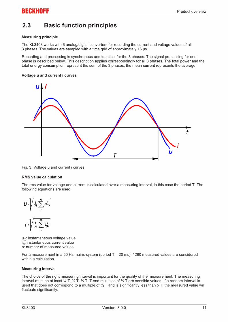
Voltage u and current i curves
Fig. 3: Voltage u and current i curves
RMS value calculation
The rms value for voltage and current is calculated over a measuring interval, in this case the period T. Thefollowing equations are used:
u(t): instantaneous voltage valuei(t): instantaneous current valuen: number of measured values
For a measurement in a 50 Hz mains system (period T = 20 ms), 1280 measured values are consideredwithin a calculation.
Measuring interval
The choice of the right measuring interval is important for the quality of the measurement. The measuringinterval must be at least ¼ T. ¼ T, ½ T, T end multiples of ½ T are sensible values. If a random interval isused that does not correspond to a multiple of ½ T and is significantly less than 5 T, the measured value willfluctuate significantly.

Product overview
KL340312 Version: 3.0.0
The default setting for the measuring interval is 50 ms, corresponding to 2.5 T in a 50 Hz mains system and3 T in a 60 Hz mains system. Experience shows that this is a good compromise between measuring speedand stability. Deviations from this value are only advisable in the event of particular measurementrequirements (e.g. high measuring speed, low signal frequencies or special current curves).
Power measurement
Active power measurement
The KL3403 measures the active power P according to the following equation
P: Active powern: number of samples (64000 samples / s)u(t): Instantaneous voltage valuei(t): instantaneous current value
Power s(t) curve
Fig. 4: Power s(t) curve
In the first step, the power s(t) is calculated at each sampling instant:
The mean value over the measuring interval is calculated. Here too, the correct choice of the intervals isimportant, as described in section RMS value measurement (the interval can only be changedsimultaneously for U, I and P).
The power frequency is twice that of the corresponding voltages and currents.
Apparent power measurement
In real networks, not all consumers are purely ohmic. Phase shifts occur between current and voltage. Thisdoes not affect the methodology for determining the rms values of voltage and current as described above.
The situation for the active power is different: Here, the product of effective voltage and effective current isthe apparent power.

Product overview
KL3403 13Version: 3.0.0
The active power is smaller than the apparent power.
S: Apparent powerP: Active powerQ: Reactive powerφ: Phase shift angle
u(t), i(t), p(t) curves with phase shift angle φ
Fig. 5: u(t), i(t), p(t) curves with phase shift angle φ

Product overview
KL340314 Version: 3.0.0
In this context, further parameters of the mains system and its consumers are significant:
• apparent power S• reactive power Q• power factor cos φ
The KL3403 determines the following values:
• active power P• effective voltage U• effective current I
From these values, the required parameters can be calculated:
• apparent power:
• reactive power:
• Power factor:
Sign for power measurement
The sign of the active power P and of the power factor cos φ provide about information the direction of theenergy flow. A positive sign indicates the motor mode, a negative sign indicates generator mode.
In addition, the sign of the reactive power Q indicates the direction of the phase shift between current andvoltage. The diagram Four-quadrant representation of active/reactive power in motor and generator modeillustrates this. In motor mode (quadrant I & IV) a positive reactive power indicates an inductive load, anegative reactive power indicates a capacitive load. In generator mode (quadrant II & III), an inductive actinggenerator is indicated by a positive reactive power, a capacitive acting generator by a negative reactivepower.

Product overview
KL3403 15Version: 3.0.0
Fig. 6: Four-quadrant representation of active/reactive power in motor and generator mode
Peak current measurement
A distinction has to be made between the peak instantaneous value and the peak rms value. The peak rmsvalue always refers to the peak value within the specified measuring interval.
Frequency measurement
The KL3403 can measure the frequency of the input signals at the voltage circuits (L1, L2, L3). Themeasurement takes 5 seconds (measuring interval).
Measuring error
Frequency < 70 Hz ≥ 70 Hz ≥ 75 Hz ≥ 80 Hz ≥ 90 Hz ≥ 100 HzMeasuringerror
< 0.0 % < 0.2 % < 0.5 % < 1.5 % < 2.0 % < 3.0 %

Product overview
KL340316 Version: 3.0.0
2.4 Technical dataTechnical data KL3403-...
KS3403-...0000 0010 0014 0020 0022 0021 0025 0026
Measured values U, I U, I U1 U, I I2 U, I U, I U, ICalculated parameters Active power, energy, power factor (cosj)Measuring voltage max. 500 VAC 3~ - max. 500 VAC 3~Measuring voltage according toUL specifications (see UL compli-ance)
max. 300 VAC 3~ - max. 300 VAC 3~
Measur-ing cur-rent(continu-ous oper-ation)
direct (max.) 1 A 5 A 60 mV1 20 mA 20 mA 50 mA 250 mA 1 Avia current transform-ers with transforma-tionratio R (max.)
R x 1 A R x 5 A - R x 20 mA R x 20 mA R x 50 mA R x 250 mA R x 1 A
Voltage circuit input resistance(typical)
500 kΩ 500 kΩ 500 kΩ 500 kΩ 10 Ω2 500 kΩ 500 kΩ 500 kΩ
Current circuit input resistance(typical)
33 mΩ 6.8 mΩ approx.10 kΩ1
10 Ω 10 Ω 4 Ω 100 mΩ 33 mΩ
Resolution 16 bit (internal 21 bit)Frequency range 10 Hz to 500 Hz
0 Hz to 500 Hz (with deactivated DC filter [} 36] and with current transformers [} 17], which sup-port this frequency range)
Limit frequency approx. 2 kHzSignal type any (taking into account the frequency range and the limit frequency)Measuring accuracyfor sinusoidal current/voltage (total mea-suring range, basedon the full scalevalue)
Voltage 0.5% 0.5% 0.5% 0.5% - 0.5%Current 0.5%
3.0%31.0%3.0%3
- 0.5% 0.5% 0.5%
Power(calcu-lated)
1.0%4.0%3
1.5%4.0%3
- 1.0% - 1.0%
Measuring procedure True RMS with 64000 samples / sMeasuring cycle time freely configurable (50 ms per measured value pre-set)Dielectric strength 1500 V (terminal/K-Bus)Bit width in the input process im-age
72 bits inputs (3 x 8 bits status, 3 x 16 bits data)
Bit width in the output process im-age
72 bits outputs (3 x 8 bits control, 3 x 16 bits data)
Power supply for the electronics via the K-busCurrent consumption from K-bus typically 115 mAPluggable wiring at all KSxxxx series terminalsPermissible ambient temperaturerange during operation
-25°C ... + 60°C 0°C ... + 55°C
Permissible ambient temperaturerange during storage
-40°C ... + 85°C -25°C ... + 85°C
Permissible relative air humidity 95%, no condensationVibration / shock resistance conforms to EN 60068-2-6 / EN 60068-2-27EMC immunity / emission conforms to EN 61000-6-2 / EN 61000-6-4Weight approx. 75 gDimensions (W x H x D) approx. 15 mm x 100 mm x 70 mm (width aligned: 12 mm)Mounting on 35 mm mounting rail conforms to EN 60715Installation position variableProtection class IP20Approvals CE, cULus CE
1) for KL3403-0014: three additional voltage circuits instead of the current circuits: 60 mV for connection ofexternal shunts2) for KL3403-22: three additional current circuits instead of the voltage circuits: also 20 mA3) the measuring accuracy is reduced, if the extended temperature range is used (-25°C ... + 60°C)

Product overview
KL3403 17Version: 3.0.0
2.5 Current transformerIn principle, the choice of current transformer for the KL3403 is not critical. The internal resistance within thecurrent circuit of the KL3403 is so small that it is negligible for the calculation of the total resistances of thecurrent loop. The transformers should be able to produce a secondary rated current of 1 A. The primaryrated current Ipn can be selected arbitrarily. The common permissible overload of 1.2 x Ipn is no problem forthe KL3403, but may lead to small measuring inaccuracies.
Accuracy
Please note that the overall accuracy of the set-up consisting of KL3403 and current transformers to a largedegree depends on the accuracy class of the transformers.
Note
Approval and certificationA set-up with a class 0.5 current transformer cannot be approved or authenticated. TheKL3403 is not an approved billing meter according to the electricity meter standard(DIN 43 856).
Current types
The KL3403 can measure any current type up to a limiting proportion of 2 kHz. Since such currents arefrequently created by inverters and may contain frequencies of less than 50 Hz or even a DC component,electronic transformers should be used for such applications. The KL3403 is also available as a specialversion with an interface for ±20 mA.
Overcurrent limiting factor FS
The overcurrent limiting factor FS of a current transformer indicates at what multiple of its primary ratedcurrent the current transformer changes to saturation mode, in order to protect the connected measuringinstruments.
Attention
Please note the rated current!The KL3403 must not be subjected to more than 5 A for a prolonged period of time! Forsystems in which the over-current limiting factors of the transformers allow secondary cur-rents of more than 5 A, additional intermediate transformers with a ratio of 5A/1A or 1A/5Ashould be used!
Protection against dangerous touch voltages
During appropriate operation of the KL3403 with associated current transformers, no dangerous voltagesoccur. The secondary voltage is in the range of a few Volts. However, the following faults may lead toexcessive voltages:
• Open current circuit of one or several transformers• Neutral conductor cut on the voltage measurement side of the KL3403• General insulation fault
WARNING
Ensure accidental-contact protection!The complete wiring of the KL3403 must be protected against accidental contact andequipped with associated warnings! The insulation should be designed for the maximumconductor voltage of the system to be measured!
The KL3403 allows a maximum voltage of 500 V for normal operating conditions. The conductor voltage onthe current side must not exceed 500 V! For higher voltages, an intermediate transformer stage should beused!
On the voltage measurement side, a KL3403 is equipped with a protection impedance of 500 kΩ. If theneutral conductor is not connected and only one connection on the side of the voltage measurement is live,the resulting voltage against earth in a 3-phase system with a phase-to-phase voltage of 400 VAC is 230 VAC.This should also be measured on the side of the current measurement using a multimeter with an internalresistance of 10 MΩ, which does not represent an insulation fault.

Product overview
KL340318 Version: 3.0.0
Additional measuring instruments in the current circuit
Please note that the addition of additional measuring instruments (e.g. ammeters) in the current circuit canlead to a significant increase in the total apparent power.
Furthermore, connection IN of the KL3403 must represent a star point for the three secondary windings.Additional measuring instruments therefore have to be potential-free and must be wired accordingly.

Mounting and wiring
KL3403 19Version: 3.0.0
3 Mounting and wiring
3.1 Installation on mounting rails
WARNING
Risk of electric shock and damage of device!Bring the bus terminal system into a safe, powered down state before starting installation,disassembly or wiring of the Bus Terminals!
Assembly
Fig. 7: Attaching on mounting rail
The Bus Coupler and Bus Terminals are attached to commercially available 35 mm mounting rails (DIN railsaccording to EN 60715) by applying slight pressure:
1. First attach the Fieldbus Coupler to the mounting rail.2. The Bus Terminals are now attached on the right-hand side of the Fieldbus Coupler. Join the compo-
nents with tongue and groove and push the terminals against the mounting rail, until the lock clicksonto the mounting rail.If the Terminals are clipped onto the mounting rail first and then pushed together without tongue andgroove, the connection will not be operational! When correctly assembled, no significant gap shouldbe visible between the housings.
Note
Fixing of mounting railsThe locking mechanism of the terminals and couplers extends to the profile of the mountingrail. At the installation, the locking mechanism of the components must not come into con-flict with the fixing bolts of the mounting rail. To mount the mounting rails with a height of7.5 mm under the terminals and couplers, you should use flat mounting connections (e.g.countersunk screws or blind rivets).

Mounting and wiring
KL340320 Version: 3.0.0
Disassembly
Fig. 8: Disassembling of terminal
Each terminal is secured by a lock on the mounting rail, which must be released for disassembly:
1. Pull the terminal by its orange-colored lugs approximately 1 cm away from the mounting rail. In doingso for this terminal the mounting rail lock is released automatically and you can pull the terminal out ofthe bus terminal block easily without excessive force.
2. Grasp the released terminal with thumb and index finger simultaneous at the upper and lower groovedhousing surfaces and pull the terminal out of the bus terminal block.
Connections within a bus terminal block
The electric connections between the Bus Coupler and the Bus Terminals are automatically realized byjoining the components:
• The six spring contacts of the K-Bus/E-Bus deal with the transfer of the data and the supply of the BusTerminal electronics.
• The power contacts deal with the supply for the field electronics and thus represent a supply rail withinthe bus terminal block. The power contacts are supplied via terminals on the Bus Coupler (up to 24 V)or for higher voltages via power feed terminals.
Note
Power ContactsDuring the design of a bus terminal block, the pin assignment of the individual Bus Termi-nals must be taken account of, since some types (e.g. analog Bus Terminals or digital 4-channel Bus Terminals) do not or not fully loop through the power contacts. Power FeedTerminals (KL91xx, KL92xx or EL91xx, EL92xx) interrupt the power contacts and thus rep-resent the start of a new supply rail.
PE power contact
The power contact labeled PE can be used as a protective earth. For safety reasons this contact mates firstwhen plugging together, and can ground short-circuit currents of up to 125 A.

Mounting and wiring
KL3403 21Version: 3.0.0
Fig. 9: Power contact on left side
Attention
Possible damage of the deviceNote that, for reasons of electromagnetic compatibility, the PE contacts are capacitativelycoupled to the mounting rail. This may lead to incorrect results during insulation testing orto damage on the terminal (e.g. disruptive discharge to the PE line during insulation testingof a consumer with a nominal voltage of 230 V). For insulation testing, disconnect the PEsupply line at the Bus Coupler or the Power Feed Terminal! In order to decouple furtherfeed points for testing, these Power Feed Terminals can be released and pulled at least10 mm from the group of terminals.
WARNING
Risk of electric shock!The PE power contact must not be used for other potentials!
3.2 Connection
3.2.1 Connection system
WARNING
Risk of electric shock and damage of device!Bring the bus terminal system into a safe, powered down state before starting installation,disassembly or wiring of the Bus Terminals!
Overview
The Bus Terminal system offers different connection options for optimum adaptation to the respectiveapplication:
• The terminals of ELxxxx and KLxxxx series with standard wiring include electronics and connectionlevel in a single enclosure.
• The terminals of ESxxxx and KSxxxx series feature a pluggable connection level and enable steadywiring while replacing.
• The High Density Terminals (HD Terminals) include electronics and connection level in a singleenclosure and have advanced packaging density.

Mounting and wiring
KL340322 Version: 3.0.0
Standard wiring (ELxxxx / KLxxxx)
Fig. 10: Standard wiring
The terminals of ELxxxx and KLxxxx series have been tried and tested for years.They feature integrated screwless spring force technology for fast and simple assembly.
Pluggable wiring (ESxxxx / KSxxxx)
Fig. 11: Pluggable wiring
The terminals of ESxxxx and KSxxxx series feature a pluggable connection level.The assembly and wiring procedure for the KS series is the same as for the ELxxxx and KLxxxx series.The KS/ES series terminals enable the complete wiring to be removed as a plug connector from the top ofthe housing for servicing.The lower section can be removed from the terminal block by pulling the unlocking tab. Insert the new component and plug in the connector with the wiring. This reduces the installation time andeliminates the risk of wires being mixed up.
The familiar dimensions of the terminal only had to be changed slightly. The new connector adds about 3mm. The maximum height of the terminal remains unchanged.
A tab for strain relief of the cable simplifies assembly in many applications and prevents tangling of individualconnection wires when the connector is removed.
Conductor cross sections between 0.08 mm2 and 2.5 mm2 can continue to be used with the proven springforce technology.
The overview and nomenclature of the product names for ESxxxx and KSxxxx series has been retained asknown from ELxxxx and KLxxxx series.
High Density Terminals (HD Terminals)
Fig. 12: High Density Terminals
The Bus Terminals from these series with 16 terminal points are distinguished by a particularly compactdesign, as the packaging density is twice as large as that of the standard 12 mm Bus Terminals. Massiveconductors and conductors with a wire end sleeve can be inserted directly into the spring loaded terminalpoint without tools.

Mounting and wiring
KL3403 23Version: 3.0.0
Note
Wiring HD TerminalsThe High Density (HD) Terminals of the ELx8xx and KLx8xx series doesn't support plug-gable wiring.
Ultrasonically "bonded" (ultrasonically welded) conductors
Note
Ultrasonically “bonded" conductorsIt is also possible to connect the Standard and High Density Terminals with ultrasonically"bonded" (ultrasonically welded) conductors. In this case, please note the tables concern-ing the wire-size width below!
3.2.2 Wiring
WARNING
Risk of electric shock and damage of device!Bring the bus terminal system into a safe, powered down state before starting installation,disassembly or wiring of the Bus Terminals!
Terminals for standard wiring ELxxxx/KLxxxx and for pluggable wiring ESxxxx/KSxxxx
Fig. 13: Connecting a cable on a terminal point
Up to eight terminal points enable the connection of solid or finely stranded cables to the Bus Terminal. Theterminal points are implemented in spring force technology. Connect the cables as follows:
1. Open a terminal point by pushing a screwdriver straight against the stop into the square openingabove the terminal point. Do not turn the screwdriver or move it alternately (don't toggle).
2. The wire can now be inserted into the round terminal opening without any force.3. The terminal point closes automatically when the pressure is released, holding the wire securely and
permanently.
See the following table for the suitable wire size width.

Mounting and wiring
KL340324 Version: 3.0.0
Terminal housing ELxxxx, KLxxxx ESxxxx, KSxxxxWire size width (single core wires) 0.08 ... 2.5 mm2 0.08 ... 2.5 mm2
Wire size width (fine-wire conductors) 0.08 ... 2.5 mm2 0,08 ... 2.5 mm2
Wire size width (conductors with a wire end sleeve) 0.14 ... 1.5 mm2 0.14 ... 1.5 mm2
Wire stripping length 8 ... 9 mm 9 ... 10 mm
High Density Terminals (HD Terminals [} 22]) with 16 terminal points
The conductors of the HD Terminals are connected without tools for single-wire conductors using the directplug-in technique, i.e. after stripping the wire is simply plugged into the terminal point. The cables arereleased, as usual, using the contact release with the aid of a screwdriver. See the following table for thesuitable wire size width.
Terminal housing High Density HousingWire size width (single core wires) 0.08 ... 1.5 mm2
Wire size width (fine-wire conductors) 0.25 ... 1.5 mm2
Wire size width (conductors with a wire end sleeve) 0.14 ... 0.75 mm2
Wire size width (ultrasonically “bonded" conductors) only 1.5 mm2
Wire stripping length 8 ... 9 mm

Mounting and wiring
KL3403 25Version: 3.0.0
3.2.3 Connection
WARNING
Risk of injury through electric shock and damage to the device!Bring the Bus Terminals system into a safe, de-energized state before starting mounting,disassembly or wiring of the Bus Terminals!
Fig. 14: Connection
Terminalpoint
No.:
Connection for Comment
L1 1 Phase L1 Connections for thevoltage measurement.(See note under [} 26]Make sure terminalpoint N is zeroed orgrounded!)
L2 2 Phase L2L3 3 Phase L3N 4 Neutral conductor N (internally connected to terminal point IN,
capacitively connected to the grounding contact for themounting rail)
IL1 5 Current transformer at L1 Connections for thecurrent transformers.(See note under [} 26]Operate the currenttransformer asintended!)
IL2 6 Current transformer at L2IL3 7 Current transformer at L3IN 8 Star point of the current transformers
(internally connected to terminal point N,capacitively connected to the grounding contact for themounting rail)
*) The KL3403-0026 has no capacitive connection to the grounding contact of the mounting rail!

Mounting and wiring
KL340326 Version: 3.0.0
CAUTION
Make sure terminal point N is zeroed or grounded!If you do not connect the terminal point N with the neutral conductor of your mains supply(e.g. if the KL3403 is used purely for current measurements [} 29]), terminal point Nshould be earthed, in order to avoid dangerous overvoltages in the event of a current trans-former fault!
CAUTION
Operate the current transformer as intended!Please note that many manufacturers do not permit their current transformers to be oper-ated in no-load mode! Connect the KL3403 to the secondary windings of the current trans-formers before using the current transformer!
UL compliance
Follow the instructions indicated below, in order to comply with the specifications of UnderwritersLaboratories.
Intended useThe terminals are exclusively intended for application with the UL-listed I/O systems of theseries BKxxxx, BCxxxx, BXxxxx, LCxxxx, CXxxxx, KLxxxx, KSxxxx or KMxxxx from Beck-hoff.
cULus verificationFor the cULus verification, the Beckhoff I/O system only examined for risk of fire or electricshock (in accordance with UL508 and CSA C22.2 No. 142).
Phase voltage according to UL specifications 300 V max.The maximum phase voltage of 500 V described in the technical data should be limited to300 V for applications requiring UL approval.
Current transformerCurrent measurement inputs with the IDs IL1, IL2, IL3, N may only be connected to isolat-ing current transformers, which limit the available current to max. 5 A, 20 V.
No extended temperature rangeThe limited temperature range applies, if the KL3403-0000 / KS3403-0000 are used ac-cording to UL conditions (see Technical data [} 16]).
3.3 Application examples
Overview• Application example for alternating current [} 27]
• Application example for DC [} 29]
• Application example with frequency converter [} 30]
• Application example for KL3403-0014 [} 31] (without internal shunts for current measurement)

Mounting and wiring
KL3403 27Version: 3.0.0
3.3.1 Application examples for alternating current
WARNING
Risk of injury through electric shock and damage to the device!Bring the Bus Terminals system into a safe, de-energized state before starting mounting,disassembly or wiring of the Bus Terminals!
CAUTION
Operate the current transformer as intended!Please note that many manufacturers do not permit their current transformers to be oper-ated in no-load mode! Connect the KL3403 to the secondary windings of the current trans-formers before using the current transformer!
Power measurement at a machine• The voltage is measured via connections L1, L2, L3 and N.
• The current is measured via three current transformers [} 17] and the connections IL1, IL2, IL3 and IN (starpoint of the current transformers).
Attention
Do not confuse current and voltage circuit!Avoid confusing the current and voltage circuit during connection, since the direct connec-tion of mains voltage to the terminal points for the current transformers (typical input resis-tance 33 mΩ) would destroy the power measurement terminal!
Fig. 15: Application example - power measurement at a machine
Note
Polarity of the current transformersIf negative power values are measured on a circuit, please check whether the associatedcurrent transformer circuit is connected correctly.

Mounting and wiring
KL340328 Version: 3.0.0
Current measurement on a motor
CAUTION
Make sure terminal point N is zeroed or grounded!If you do not connect the terminal point N with the neutral conductor of your mains supply(e.g. if the KL3403 is used purely for current measurements), terminal point N should beearthed, in order to avoid dangerous overvoltages in the event of a current transformerfault!
Fig. 16: Application example - current measurement at a motor

Mounting and wiring
KL3403 29Version: 3.0.0
3.3.2 Application example for DC
WARNING
Risk of injury through electric shock and damage to the device!Bring the Bus Terminals system into a safe, de-energized state before starting mounting,disassembly or wiring of the Bus Terminals!
Note
Switch off the DC filter for DC measurementsSwitch off the DC filters for the KL3403 (using the configuration software KS2000 [} 36] orthe register communication (register R32.4 [} 46])) for measuring direct voltage and DC.
Power measurement at a fieldbus station
The example illustrates power measurement at three circuits of the fieldbus station. The terminal measuresthe:
• Power consumption of the Bus Coupler and K-Bus supply• Power consumption of the power contacts• Power consumption of the AS-i power supply terminal (KL9528)
Attention
Note rated current!In the example, the special type KL3403-0010 [} 16] is used with an extended current mea-suring range (5 A max.). The standard KL3403 type is not suitable for this application ex-ample because the current measuring range is too small (1A)!
Fig. 17: Application example - power measurement at a fieldbus station

Mounting and wiring
KL340330 Version: 3.0.0
3.3.3 Application example with frequency converter
WARNING
Risk of injury through electric shock and damage to the device!Bring the Bus Terminals system into a safe, de-energized state before starting mounting,disassembly or wiring of the Bus Terminals!
The example illustrates power measurement at several three-phase motors that are controlled by afrequency converter (AC converter), e.g. at a conveyor system. Each motor is monitored by a KL3403.
Fig. 18: Application example with frequency converter
The electrical isolation of the three-phase-transformer (Yy0) operated by the voltage circuit of the powermeasurement terminals enables measurement after the frequency converter.
Note
Measuring error in the lower frequency rangeIf the power measurement takes place after the frequency converter, a larger measuring er-ror is possible in the lower frequency range, particularly for voltage measurement. This er-ror also affects the power calculation.
The three-phase transformer should have a ratio of 1:1. It must not cause a phase shift of the signal! Sincehigh-frequency components only have little influence on the motors, any distortions caused by the three-phase transformer have little effect on the practical measurement during the transfer of the harmonicscreated by the frequency converter.
The power distribution is mapped very well by using a dedicated power measurement terminal for eachmotor. Excessive current consumption of an individual motor can be detected in good time.
It is not possible to use this method for measuring direct voltage/DC (e.g. holding currents of synchronousmotors)! Practical results can be obtained for voltages/currents with a frequency above 5 Hz, depending onthe three-phase transformer and current transformers used.

Mounting and wiring
KL3403 31Version: 3.0.0
CAUTION
The terminal points N must be grounded!Due to the electrical isolation through the three-phase transformer, the terminal points N ofthe power measurement terminals have to be grounded, in order to avoid dangerous over-voltages in the event of a fault in a current transformer!
3.3.4 Application example for KL3403-0014
WARNING
Risk of injury through electric shock and damage to the device!Bring the Bus Terminals system into a safe, de-energized state before starting mounting,disassembly or wiring of the Bus Terminals!
The KL3403-0014 has no internal shunts for current measurement. It allows the use of external shunts.Instead of the three current circuits, the additional voltage circuits UI1, UI2 and UI3 are available for thispurpose.
Connection
Cables are used to connect the voltage drop at the external shunts to terminal points UI1, UI2 and UI3 of theKL3403-0014.
Fig. 19: Application example for KL3403-0014
The example shows a power measurement for three incandescent lamps. Three external shunts are used forthe current measurement.

Mounting and wiring
KL340332 Version: 3.0.0
Note
Voltage drop on the cables between the shuntsNote that the voltage drop on the cables between the shunts (shown in red in the diagram)distorts the measurement. It is therefore imperative that short cables with large cross-sec-tions and as low-resistance as possible are used for these connections, in order to keep themeasuring error to a minimum. Otherwise the measuring errors could be significant, sincethe voltage drop on this cables can be comparatively high and could result in a large errorin the power calculation.
Dimensioning of the shunts
A voltage drop of 60 mV / x A is typically indicated for the shunts.
Examples
Nominal value of the shunt 60 mV / 1 A 60 mV / 25 A 60 mV / 100 ASample current 1 A 25 A 100 ACurrent output value of the terminal 25000dec (0x61A8) 25000dec (0x61A8) 25000dec (0x61A8)

KS2000 Configuration Software
KL3403 33Version: 3.0.0
4 KS2000 Configuration Software
4.1 KS2000 - IntroductionThe KS2000 configuration software permits configuration, commissioning and parameterization of buscouplers, of the affiliated bus terminals and of Fieldbus Box Modules. The connection between bus coupler /Fieldbus Box Module and the PC is established by means of the serial configuration cable or the fieldbus.
Fig. 20: KS2000 configuration software
Configuration
You can configure the Fieldbus stations with the Configuration Software KS2000 offline. That means, settingup a terminal station with all settings on the couplers and terminals resp. the Fieldbus Box Modules can beprepared before the commissioning phase. Later on, this configuration can be transferred to the terminalstation in the commissioning phase by means of a download. For documentation purposes, you are providedwith the breakdown of the terminal station, a parts list of modules used and a list of the parameters you havemodified. After an upload, existing fieldbus stations are at your disposal for further editing.
Parameterization
KS2000 offers simple access to the parameters of a fieldbus station: specific high-level dialogs are availablefor all bus couplers, all intelligent bus terminals and Fieldbus Box modules with the aid of which settings canbe modified easily. Alternatively, you have full access to all internal registers of the bus couplers andintelligent terminals. Refer to the register description for the meanings of the registers.

KS2000 Configuration Software
KL340334 Version: 3.0.0
Commissioning
The KS2000 software facilitates commissioning of machine components or their fieldbus stations: Configuredsettings can be transferred to the fieldbus modules by means of a download. After a login to the terminalstation, it is possible to define settings in couplers, terminals and Fieldbus Box modules directly online. Thesame high-level dialogs and register access are available for this purpose as in the configuration phase.
The KS2000 offers access to the process images of the bus couplers and Fieldbus Box modules.
• Thus, the coupler's input and output images can be observed by monitoring.• Process values can be specified in the output image for commissioning of the output modules.
All possibilities in the online mode can be used in parallel with the actual fieldbus mode of the terminalstation. The fieldbus protocol always has the higher priority in this case.
4.2 Parameterization with KS2000Connect the configuration interface of your fieldbus coupler with the serial interface of your PC via theconfiguration cable and start the KS2000 Configuration Software.
Click on the Login button. The configuration software will now load the information for theconnected fieldbus station.In the example shown, this is
• a BK9000 Ethernet Coupler• a KL1xx2 digital input terminal• a KL3403 Power Measurement Terminal• a KL9010 bus end terminal

KS2000 Configuration Software
KL3403 35Version: 3.0.0
Fig. 21: Display of the fieldbus station in KS2000
The left-hand KS2000 window displays the terminals of the fieldbus station in a tree structure.The right-hand KS2000 window contains a graphic display of the fieldbus station terminals.
In the tree structure of the left-hand window, click on the plus-sign next to the terminal whose parametersyou wish to change (item 2 in the example).
Fig. 22: KS2000 branch for channel 1 of the KL3403

KS2000 Configuration Software
KL340336 Version: 3.0.0
For each of the three channels, the branches Register, Settings and ProcData are displayed:
• Register enables direct access to the channel registers.
• The dialog mask for the parameterization of the KL3403 can be found under Settings [} 36].• ProcData shows the process data of the KL3403.
4.3 SettingsThe dialog mask for the parameterization of the KL3403 can be found under Settings.
Fig. 23: Settings via KS2000
Header
Pos.: Position of the terminal in the Bus Terminal block.
Type: Terminal type
Firmware: Firmware version [} 8] installed on the terminal.
Operation mode
User scaling active (R32.0 [} 46])
You can activate user scaling here (default: deactivated).

KS2000 Configuration Software
KL3403 37Version: 3.0.0
Watchdog timer active (R32 [} 46].2)
You can deactivate the watchdog timer here (the default is activated).
DC filter active (R32.4 [} 46])
Here you can disable the DC filter (default: enabled).
CosPhi, signed (R32.5 [} 46])
Here you can disable the signed representation for CosPhi (default: enabled).
Energy measurement inverted (R32.6 [} 46])
Here you can enable sign inversion for the energy measurement (default: disabled).
Flexible process image active (R32.3 [} 46])
Here you can enable/disable the flexible process image [} 43] (default:
• disabled for KL3403-0000, KL3403-0010, KL3403-0025, KL3403-0026,• enabled for KL3403-0020, KL3403-0021, KL3403-0022)
Automatically clear minimum and maximum values (R32.7 [} 46])
Here you can enable automatic deletion of the minimum and maximum current, voltage and power values(default: disabled).
Register values
Energy consumption scaling (R35 [} 47])
Here you can change the scaling of the energy consumption measurement (default: KL3403-0000:0.01 kWh, KL3403-0010: 0.05 kWh).
Minimum input voltage - undervoltage threshold (R36 [} 47])
Here you can change the undervoltage threshold (resolution: 0.1 V).If the mains voltage falls below the specified undervoltage threshold (default: 10 V), the red error LED istriggered, and the error bit (SB1.6 [} 41]) is set in status byte 0.
Current transformer ratio (R37 [} 47])
The KL3403 can take the transformer ratio of a connected current transformer into account for the measuredvalue output.Here you can select the transformer ratio of a connected current transformer and enable this scaling with theoption field User scaling (R32.0 [} 46]).
Note
Note the permissible range of the measured value outputThe KL3403 should only take the transformer ratio into account if the calculated resultingcurrent does not exceed the value 65535! If the calculated result does exceed 65535, the transformer ratio should be taken into ac-count in the PLC.
Measuring cycle time (R39 [} 48])
Here you can change the measuring cycle time (resolution: 1 ms) (default: 200 ms).

KS2000 Configuration Software
KL340338 Version: 3.0.0
deletion time (R38 [} 48])
Here you can change the time constant (resolution: 10 ms) for automatic deletion of the minimum andmaximum current, voltage and power values (default: 2000 ms).
Password
Here you change can the password for the KL3403 (default: 4661dec), in order to prevent unauthorizeddeletion of the energy consumption:
• Enter the old password in the field at the top.• Enter the new password in the field in the center.• Repeat the new password in the field at the bottom and click Change password
Note
PasswordIn this dialog box, you have to enter the passwords in decimal form! You can also use thepassword change register (R5 [} 45]) to change the password.
Energy consumption
Here you can clear the stored energy consumption. Enter the password and click Delete.
Note
Deleting the energy consumptionOnce the energy consumption has been deleted, the value cannot be restored!

Access from the user program
KL3403 39Version: 3.0.0
5 Access from the user program
5.1 Process imageThe KL3403 is represented in the process image with a minimum of 9 bytes of input data and 9 bytes ofoutput data. These are organized as follows:
Byte offset (withoutword alignment*)
Byte offset (with wordalignment*)
Format Input data Output data
0 0 Byte Status byte 1 (SB1[} 41])
Control byte 1 (CB1[} 40])
1 2 Word DataIN1 DataOUT13 4 Byte Status byte 2 (SB2
[} 42])Control byte 2 (CB2[} 42])
4 6 Word DataIN2 DataOUT26 8 Byte Status byte 3 (SB3
[} 42])Control byte 3 (CB3[} 42])
7 10 Word DataIN3 DataOUT3
*) Word alignment: The Bus Coupler places values on even byte addresses
Note
No compact process imageThe KL3403 cannot be operated with compact process image (without control and statusbytes), since control and status bytes are required for process data operation of theKL3403 to function correctly. Even if your Bus Coupler is set to compact process image,the KL3403 is represented with its complete process image!
Output values
Terminal type Nominal value (effective) Output for nominal valueKL3403-0000 1.0 A 1000dec
KL3403-0010 5.0 A 1000dec
KL3403-0014 60 mV 25000dec
KL3403-0020 20 mA 1000dec
KL3403-0021 50 mA 1000dec
KL3403-0022 20 mA 4000dec
KL3403-0025 250 mA 1000dec
KL3403-0026 1.0 A 1000dec

Access from the user program
KL340340 Version: 3.0.0
5.2 Control and status bytes
Control and status byte of the first channel (L1)
Process data mode
Control byte 1 in process data mode
Control byte 1 (CB1) is located in the output image [} 39], and is transmitted from the controller to theKL3403. Note the assignment of the control bytes to the process input data words.
Bit CB1.7 CB1.6 CB1.5 CB1.4 CB1.3 CB1.2 CB1.1 CB1.0Name RegAccess R/W ChannelIdx ProcDatIdx
KeyBit Name DescriptionCB1.7 RegAccess 0bin Register communication off (process data mode)CB1.6 R/W 0bin Read access
(1bin) Since the process data registers of the KL3403 can only be read, write access is notsensible.
CB1.5 toCB1.4
ChannelIdx5 Enter the channel index of the channel, from which you want to read a measured value with input dataword 1 (DataIN1 [} 39]).00bin Channel 101bin Channel 210bin Channel 311bin reserved
CB1.3 toCB1.0
ProcDatIdx Enter the process data index of the measured value, which you want to read with input data word 1(DataIN1 [} 39]). The following process data indices are supported:Index Symbol Measured value Resolution0000bin 0x0 Irms Current [} 11] (rms
value)0.001 A (KL3403-0000, KL3403-0026)0.005 A (KL3403-0010)20 µA (KL3403-0020)5 µA (KL3403-0022)50 µA (KL3403-0021)250 µA (KL3403-25)
0001bin 0x1 Urms Voltage [} 11] (rmsvalue)
0.1 V
0010bin 0x2 P Active power [} 12] 0.1 W (KL3403-0000, KL3403-0026)0.5 W (KL3403-0010)2 mW (KL3403-0020)flexible, max. 16,000 digit (KL3403-0022)6
5 mW (KL3403-0021)25 mW (KL3403-0025)
0011bin 0x3 cos φ power factor [} 12] 4 0.01
0100bin 0x4 W Energy consumption1 default3: 0.01 kWh (KL3403-0000,KL3403-0026)default3: 0.05 kWh (KL3403-0010)default3: 0.2 Wh (KL3403-0020)flexible (KL3403-0022)6
default3: 0.5 Wh (KL3403-21)default3: 2.5 Wh (KL3403-25)
0101bin 0x5 Imax Peak current value2 see index 0dec
0110bin 0x6 Umax Peak voltage value2 see index 1dec
0111bin 0x7 Pmax Peak active powervalue2
see index 2dec
1000bin 0x8 f Frequency [} 15] 0.1 Hz (measuring interval: 5 s)
1001bin 0x9 Imin Minimum currentvalue2
see index 0dec
1010bin 0xA Umin Minimum voltagevalue2
see index 1dec
1011bin 0xB Pmin Minimum activepower value2
see index 2dec
further reserved

Access from the user program
KL3403 41Version: 3.0.0
1) The energy consumption is counted in RAM and saved every 15 minutes in the EEPROM.It is retained there even if the KL3403 is switched off. The command-register (R7 [} 45]) can be used to clear the energy value orto save it manually within 15 minutes.
2) The minimum and peak current value is deleted when the KL3403 is switched off.It is recommended to clear the minimum and peak values from the user program once the terminal has started up, because it ispossible that incorrect values may have been stored during the startup, i.e. before the terminal measurements have stabilized.
3) The resolution of the energy consumption can be scaled for each channel with its register R35 [} 47].4) The power factor (cos φ) can be displayed with or without sign (see bit R32.5 [} 46] of the feature register).5) The flexible process image must be enabled (R32.3 [} 46] = 1), in order to be able to read measured values from each channel
with input data word 1 (DataIN1 [} 39])!With the simple process image (R32.3 [} 46] = 0), input data word 1 (DataIN1) can only read the first channel (in this case, bitsCB1.5, CB1.4 or SB1.5 and SB1.4 are not active).
6) The read values depend on the voltages and currents connected to the current transformer. They have to be converted by the ap-plication.
Note
Service life of the EEPROMThe energy consumption is stored in an EEPROM. The EEPROM manufacturer specifies aminimum of 100000, typically 1 million possible write operations for this function block. Theresulting service life of the energy consumption memory at continuous operation, assumingthat the energy consumption is written to the EEPROM every 15 minutes, is:
• 2.85 years min.• 28.5 years typical
Status byte 1 in process data mode
The status byte 1 (SB1) is located in the input image [} 39], and is transmitted from the KL3403 to thecontroller. Pay attention to the assignment of the control bytes to the process input data words in processdata mode.
Bit SB1.7 SB1.6 SB1.5 SB1.4 SB1.3 SB1.2 SB1.1 SB1.0Name RegAccess ERR L1 ChannelIdx ProcDatIdx
Key
Bit Name DescriptionSB1.7 RegAccess 0bin Acknowledgment for process data modeSB1.6 ERR L1 0bin Voltage between L1 and N greater than undervoltage threshold
(R36 [} 47]).1bin Voltage between L1 and N smaller than undervoltage threshold
(R36 [} 47]). The ERR L [} 9]1 LED is on.SB1.5 to SB1.4 ChannelIdx 00bin The input data word 1 (DataIN1 [} 39]) was used to read a
measured value from channel 1.01bin The input data word 1 (DataIN1 [} 39]) was used to read a
measured value from channel 2.10bin The input data word 1 (DataIN1 [} 39]) was used to read a
measured value from channel 3.11bin reserved
SB1.3 to SB1.0 ProcDatIdx Index of the measured value [} 40] that was read with input data word 1(DataIN1 [} 39]).
Register communication
Control byte 1 in register communication
Control byte 1 (CB1) is located in the output image [} 39], and is transmitted from the controller to theKL3403.

Access from the user program
KL340342 Version: 3.0.0
Bit CB1.7 CB1.6 CB1.5 CB1.4 CB1.3 CB1.2 CB1.1 CB1.0Name RegAccess R/W Reg. no.
Key
Bit Name DescriptionCB1.7 RegAccess 1bin Register communication switched onCB1.6 R/W 0bin Read access
1bin Write accessCB1.5 to CB1.0 Reg. no. Register number:
Enter the number of the register [} 44] that you want to- read with input data word 1 read, or- write with output data word 1.
CAUTION
No process data access during register communication!It is not possible to access the data registers during register communication! Process datathat may still be displayed is not valid!
Status byte 1 in register communication
The status byte 1 (SB1) is located in the input image [} 39], and is transmitted from the KL3403 to thecontroller.
Bit SB1.7 SB1.6 SB1.5 SB1.4 SB1.3 SB1.2 SB1.1 SB1.0Name RegAccess R Reg. no.
Key
Bit Name DescriptionSB1.7 RegAccess 1bin Acknowledgment for register accessSB1.6 R 0bin Read accessSB1.5 to SB1.0 Reg. no. Number of the register that was read or written.
Control and status byte of the second channel (L2)
Control byte 2 (CB2) is in output image [} 39] and is transferred by the controller to the KL3403 (structureand application see Control byte 0 [} 40]). Pay attention to the assignment of the control bytes to the processinput data words in process data mode.
Status byte 2 (SB2) is in the input image [} 39] and is transferred from the KL3403 to the controller(configuration and application see Status byte 0 [} 41]).
Control and status byte of the third channel (L3)
Control byte 3 (CB3) is in output image [} 39] and is transferred by the controller to the KL3403 (structureand application see Control byte 0). Pay attention to the assignment of the control bytes to the process inputdata words in process data mode.
Status byte 3 (SB3) is in the input image [} 39] and is transferred from the KL3403 to the controller(configuration and application see Status byte 0).

Access from the user program
KL3403 43Version: 3.0.0
5.3 Reading the process data
Simple process image (compatibility mode)
Supported by all firmware versions.
In the simple process image, each process data word is assigned to a fixed channel and can only readmeasured values of this channel!
Channel Control byte Associated process data word1 Control byte 1 [} 39] DataIN1 [} 39]2 Control byte 2 [} 39] DataIN2 [} 39]3 Control byte 3 [} 39] DataIN3 [} 39]
If a process data index is entered into a control byte in process data mode, the process record is returned inthe associated process data word.The process data indices are listed in chapter Control and status bytes [} 40].
Examples for the simple process image
Reading the voltage (RMS value) of phases L1, L2 and L3• Enter process data index [} 40] 0x1 in control byte 1.
The voltage (rms value) of phase L1 is returned in process data word DataIN1.• Enter process data index 0x1 in control byte 2.
The voltage (rms value) of phase L2 is returned in process data word DataIN2.• Enter process data index 0x1 in control byte 3.
The voltage (rms value) of phase L3 is returned in process data word DataIN3.
Reading the voltage (RMS value) of phase L1, reading the active power of phase L2, and reading thepower factor of phase L3
• Enter process data index 0x1 in control byte 1.The voltage (rms value) of phase L1 is returned in process data word DataIN1.
• Enter process data index 0x2 in control byte 2.The effective power of phase L2 is returned in process data word DataIN2.
• Enter process data index 0x3 in control byte 3.The power factor of phase L3 is returned in process data word DataIN3.
Flexible process image
Supported from firmware version [} 8] 3G by the KL3403-0000, KL3403-0010, KL3403-0025 andKL3403-0026.Supported from firmware version 4F by the KL3403-0020, KL3403-0021 and KL3403-0022.
With the flexible process image, a process data word can read measured values from any channel.The flexible process image is enabled/disabled with KS2000 [} 37] or bit R32.3 [} 46] of the feature register.
Examples for the flexible process image
Reading current (RMS value), voltage (RMS value) and active power of phase L2• Enter 0x10 in control byte 1 (channel index [} 40] 01bin, process data index [} 40] 0000bin).
The current (RMS value) of phase L2 is returned in process data word DataIN1.• Enter 0x11 in control byte 2 (channel index 01bin, process data index 0001bin).
The voltage (rms value) of phase L2 is returned in process data word DataIN2.• Enter 0x12 in control byte 3 (channel index 01bin, process data index 0010bin).
The effective power of phase L2 is returned in process data word DataIN3.

Access from the user program
KL340344 Version: 3.0.0
Reading current (RMS value), voltage (RMS value) of phase L1 and voltage of phase L2• Enter 0x00 in control byte 1 (channel index 00bin, process data index 0000bin).
The current (RMS value) of phase L1 is returned in process data word DataIN1.• Enter 0x01 in control byte 2 (channel index 00bin, process data index 0001bin).
The voltage (rms value) of phase L1 is returned in process data word DataIN2.• Enter 0x11 in control byte 3 (channel index 01bin, process data index 0001bin).
The voltage (rms value) of phase L2 is returned in process data word DataIN3.
5.4 Register overviewThese registers are used for the parameterization of the power measurement terminal and exist for eachchannel. They can be read or written by means of register communication.
Register no. Comment Default value R/W MemoryR0 [} 45] Overflow register for energy consumption 0x0000 0dec R/W Flash
R1 reserved - - - -... ... ... ... ... ...R4 reserved - - - -
R5 [} 45] Password change register - - - -
R6 Diagnostic register - - R RAM
R7 [} 45] Command register - - - -
R8 [} 46] Terminal type 0x0D4B 3403dec R ROM
R9 [} 46] Firmware version e.g. 0x3143 12611dec R ROM
R10 Multiplex shift register 0x0230 / 0x0318 560dec / 792dec R ROMR11 Signal channels 0x0318 792dec R ROMR12 Minimum data length 0x1818 6168dec R ROMR13 Data structure 0x0007 7dec R ROMR14 reserved - - - -R15 Alignment register - - R/W RAMR16 Hardware version e.g. 0x0000 e.g. 0dec R/W Flash
R17 [} 46] Voltage gain compensation e.g. 0x0400 e.g. 1024dec R/W Flash
R18 [} 46] Current gain compensation e.g. 0x0400 e.g. 1024dec R/W Flash
R19 reserved - - - -... ... ... ... ... ...R29 Terminal type, special identification e.g. 0x000 e.g. 0dec
R30 reserved - - - -
R31 [} 46] Code word register 0x0000 0dec R/W RAM
R32 [} 46] Feature reg-ister
KL3403-0000, KL3403-0010,KL3403-0025, KL3403-0026
0x0020 32dec R/W Flash
KL3403-0014, KL3403-0020,KL3403-0021, KL3403-0022
0x0030 48dec
R33 reserved - - - -R34 reserved - - - -
R35 [} 47] Scaling factor for the energy measurement 0x0004 4dec R/W Flash
R36 [} 47] Undervoltage threshold value 0x0064 100dec R/W Flash
R37 [} 47] Divisor of the current transformer ratio 0x0001 1dec R/W Flash
R38 [} 48] Time constant for automatic deletion of the mini-mum and maximum values
0x00C8 200dec R/W Flash
R39 [} 48] Measuring cycle time 0x0032 50dec R/W Flash
R40 reserved - - - -... ... ... ... ... ...R63 reserved - - - -

Access from the user program
KL3403 45Version: 3.0.0
5.5 Register descriptionThese registers are used for the parameterization of the power measurement terminal and exist for eachchannel. They can be read or written by means of register communication.
R0: Overflow register for energy consumption
If the register for the energy consumption (read via process data index [} 40] 0x4) overflows, this overflowregister is incremented. 32 bits are thus available for storing the energy consumption. The overflow registerfor the energy consumption must be read via the register communication.
R5: Password change register
You can change the password for the KL3403 (default: 1235hex), in order to prevent unauthorized deletion ofthe energy consumption.
The password can be changed as follows:
1. Enter the old password (default: 1235hex) in the password-register (R31).2. Enter the new password in the password change register (R5).3. Repeat the new password in the command register (R7).
The new password is now active without resetting the terminal!
R7: Command register
Command 0x1004: Deleting the energy consumption (user password must be set)
Write the value 0x1004 into the command register, in order to delete the energy consumption stored in theprocess data (process data index [} 40] 0x4) and the overflow register for the energy consumption (R0[} 45]).
Command 0x1005: delete maximum current
Write the value 0x1005 into the command register, in order to clear the maximum current stored in theprocess data (process data index [} 40] 0x5).
Command 0x1006: clear maximum voltage
Write the value 0x1006 into the command register, in order to clear the maximum voltage stored in theprocess data (process data index [} 40] 0x6).
Command 0x1007: clear maximum active power
Write the value 0x1007 into the command register, in order to clear the maximum active power stored in theprocess data (process data index [} 40] 0x7).
Command 0x1009: clear minimum current
Write the value 0x1009 into the command register, in order to clear the minimum current stored in theprocess data (process data index [} 40] 0x9).
Command 0x100A: clear minimum voltage
Write the value 0x100A into the command register, in order to clear the minimum voltage stored in theprocess data (process data index [} 40] 0xA).
Command 0x100B: clear minimum active power
Write the value 0x100B into the command register, in order to clear the minimum active power stored in theprocess data (process data index [} 40] 0xB).

Access from the user program
KL340346 Version: 3.0.0
Command 0x1014: store energy consumption early
The KL3403 logs the energy consumption in the RAM and cyclically saves the values in the EEPROM every15 minutes. If you want to switch off the KL3403 without losing the energy consumption measured since thelast cyclic save operation, you can use this command to manually save the current value in the EEPROM.
Command 0x1020: clear all minimum and maximum values
Write the value 0x1020 into the command register, in order to clear all minimum and maximum values.
Command 0x7000: Restore Factory Settings
Entering 0x7000 in register R7 restores the delivery state for the following registers:
R32 [} 46]: 0x0020 for KL3403-0000, KL3403-0010, KL3403-0025, KL3403-0026 or 0x0030 forKL3403-0014, KL3403-0020, KL3403-0021, KL3403-0022R35 [} 47]: 4R36 [} 47]: 100dec
R37 [} 47]: 1R38 [} 48]: 200dec
R39 [} 48]: 50dec
Repeating the new password
Repeat the new password in the command register when you change the password (see password changeregister description R5 [} 45]).
R8: Terminal description
Register R8 contains the terminal identifier in hexadecimal coding. KL3403: 0x0D4B (3403dec)
R9: Firmware version
Register R9 contains the firmware revision level of the terminal in hexadecimal coding, e. g. 0x3144 (12611dec).
R17: Voltage gain compensation
These registers contain the compensation values determined at production, and cannot be changed.
R18: Current gain compensation
These registers contain the compensation values determined at production, and cannot be changed.
R31: Code word register• If you write values into the user registers without previously having entered the user code word
(0x1235) in the code word register, these values are only stored in the RAM registers, but not in theEEPROM registers and are therefore lost if the terminal is restarted.
• If you write values into the user registers and have previously entered the user code word (0x1235) inthe code word register, these values are stored in the RAM registers and in the SEEPROM registersand are therefore retained if the terminal is restarted.
The code word is reset if the terminal is restarted.
R32: Feature register
The feature register specifies the terminal's operation mode.

Access from the user program
KL3403 47Version: 3.0.0
Bit Feature Value Explanation DefaultR32.15 to R32.8 - - reserved 0bin
R32.7 enClrMinMaxValues 1bin Automatic deletion of the minimum and maximumcurrent, voltage and power values enabled(process data index [} 40] 0x5, 0x6, 0x7, 0x9, 0xAand 0xB)
0bin
R32.6 invEnergySign 1bin The energy consumption measurement inverted(generator mode)
0bin
R32.5 signCosPhi 0bin CosPhi (cos φ) is always shown positive 1bin
1bin CosPhi (cos φ) is shown signed:- inductive load: cos φ has positive sign- capacitive load: cos φ has negative sign
R32.4 skipDcFilter 0bin DC filter active 0bin
1bin DC filter is bypassedR32.3 enFlexProcImage 0bin Simple process image [} 43] (compatibility mode) 0bin/1bin*
1bin Flexible process image [} 43]R32.2 disWdTimer 0bin Watchdog timer active: The watchdog is triggered,
if no process data were received for 100 ms0bin
1bin Watchdog timer not activeR32.1 - - reserved 0bin
R32.0 enUserScaling 0bin User scaling is switched off (ratio is 1:1) 0bin
1bin User scaling is switched on (ratio is 1/R37)
*) 0bin (KL3403-0000, KL3403-0010, KL3403-0025, KL3403-0026) 1bin (KL3403-0020, KL3403-0021, KL3403-0022)
R35: Scaling factor for the energy measurement
This register can be used for scaling the energy measurement. Default: 4dec (KL3403-0000 / -002x:0.01 kWh, KL3403-0010: 0.05 kWh). To change the scaling factor, you first have to set the user code word inregister R31 [} 46]!
Entry 0dec 1dec 2dec 3dec 4dec 5dec 6dec ...Scalingfactor
KL3403-0000,KL3403-002x
1 mWh 0.01 Wh 0.1 Wh
1 Wh 0.01 kWh 0.1 kWh 1 kWh reserved
KL3403-0010 5 mWh 0.05 Wh 0.5 Wh
5 Wh 0.05 kWh 0.5 kWh 5 kWh reserved
R36: Undervoltage threshold
If the mains voltage is below the undervoltage threshold the stored in register R36 (resolution: 0.1 V, default:100dec=10 V), the error bit (SB1.6 [} 41]) is set in status byte 0, and the red error LED is triggered.
R37: Divisor of the current transformer ratio
The KL3403 can take the transformer ratio of a connected current transformer into account for the measuredvalue output. Enter the divisor for the transformation ratio of a connected current transformer here, andenable this scaling with bit R32.0 [} 46] of the feature register.
Note
Note the permissible range of the measured value outputThe KL3403 should only take the transformer ratio into account if the calculated resultingcurrent does not exceed the value 65535! If the calculated result does exceed 65535, the transformer ratio should be taken into ac-count in the PLC.

Access from the user program
KL340348 Version: 3.0.0
R38: Time constant for automatic deletion of the minimum and maximum values
If bit R32.7 [} 46] is enabled, the minimum and maximum current, voltage and power values of the respectivephase are cleared after the set time.
• Default value: 2000 ms (R38 = 200)• Resolution: 10 ms• Range of values: 10 ms to 655350 ms
R39: Measuring cycle time
With this register, the measuring cycle time of the A/D converter is set:
• Default value: 50 ms• Resolution: 1 ms• Range of values: 1 ms to 65535 ms
The correct setting of the measuring interval depends on the mains frequency, among other factors (seechapter Basic function principles [} 11]).
5.6 Examples of Register CommunicationThe numbering of the bytes in the examples corresponds to the display without word alignment.
5.6.1 Example 1: reading the firmware version from Register 9
Output Data
Byte 0: Control byte Byte 1: DataOUT1, high byte Byte 2: DataOUT1, low byte0x89 (1000 1001bin) 0xXX 0xXX
Explanation:
• Bit 0.7 set means: Register communication switched on.• Bit 0.6 not set means: reading the register.• Bits 0.5 to 0.0 specify the register number 9 with 00 1001bin.• The output data word (byte 1 and byte 2) has no meaning during read access. To change a register,
write the required value into the output word.
Input Data (answer of the bus terminal)
Byte 0: Status byte Byte 1: DataIN1, high byte Byte 2: DataIN1, low byte0x89 0x33 0x41
Explanation:
• The terminal returns the value of the control byte as a receipt in the status byte.• The terminal returns the firmware version 0x3341 in the input data word (byte 1 and byte 2). This is to
be interpreted as an ASCII code:◦ ASCII code 0x33 represents the digit 3◦ ASCII code 0x41 represents the letter A
The firmware version is thus 3A.

Access from the user program
KL3403 49Version: 3.0.0
5.6.2 Example 2: Writing to an user register
Note
Code wordIn normal mode all user registers are read-only with the exception of Register 31. In orderto deactivate this write protection you must write the code word (0x1235) into Register 31. Ifa value other than 0x1235 is written into Register 31, write protection is reactivated. Pleasenote that changes to a register only become effective after restarting the terminal (power-off/power-on).
I. Write the code word (0x1235) into Register 31.
Output Data
Byte 0: Control byte Byte 1: DataOUT1, high byte Byte 2: DataOUT1, low byte0xDF (1101 1111bin) 0x12 0x35
Explanation:
• Bit 0.7 set means: Register communication switched on.• Bit 0.6 set means: writing to the register.• Bits 0.5 to 0.0 specify the register number 31 with 01 1111bin.• The output data word (byte 1 and byte 2) contains the code word (0x1235) for deactivating write
protection.
Input Data (answer of the bus terminal)
Byte 0: Status byte Byte 1: DataIN1, high byte Byte 2: DataIN1, low byte0x9F (1001 1111bin) 0xXX 0xXX
Explanation:
• The terminal returns a value as a receipt in the status byte that differs only in bit 0.6 from the value ofthe control byte.
• The input data word (byte 1 and byte 2) is of no importance after the write access. Any values stilldisplayed are invalid!
II. Read Register 31 (check the set code word)
Output Data
Byte 0: Control byte Byte 1: DataOUT1, high byte Byte 2: DataOUT1, low byte0x9F (1001 1111bin) 0xXX 0xXX
Explanation:
• Bit 0.7 set means: Register communication switched on.• Bit 0.6 not set means: reading the register.• Bits 0.5 to 0.0 specify the register number 31 with 01 1111bin.• The output data word (byte 1 and byte 2) has no meaning during read access.
Input Data (answer of the bus terminal)
Byte 0: Status byte Byte 1: DataIN1, high byte Byte 2: DataIN1, low byte0x9F (1001 1111bin) 0x12 0x35
Explanation:
• The terminal returns the value of the control byte as a receipt in the status byte.

Access from the user program
KL340350 Version: 3.0.0
• The terminal returns the current value of the code word register in the input data word (byte 1 and byte2).
III. Write to Register 32 (change contents of the feature register)
Output data
Byte 0: Control byte Byte 1: DataIN1, high byte Byte 2: DataIN1, low byte0xE0 (1110 0000bin) 0x00 0x02
Explanation:
• Bit 0.7 set means: Register communication switched on.• Bit 0.6 set means: writing to the register.• Bits 0.5 to 0.0 indicate register number 32 with 10 0000bin.• The output data word (byte 1 and byte 2) contains the new value for the feature register.
CAUTION
Observe the register description!The value of 0x0002 given here is just an example! The bits of the feature register change the properties of the terminal and have a differentmeaning, depending on the type of terminal. Refer to the description of the feature registerof your terminal (chapter Register description) regarding the meaning of the individual bitsbefore changing the values.
Input data (response from the Bus Terminal)
Byte 0: Status byte Byte 1: DataIN1, high byte Byte 2: DataIN1, low byte0xA0 (1010 0000bin) 0xXX 0xXX
Explanation:
• The terminal returns a value as a receipt in the status byte that differs only in bit 0.6 from the value ofthe control byte.
• The input data word (byte 1 and byte 2) is of no importance after the write access. Any values stilldisplayed are invalid!
IV. Read Register 32 (check changed feature register)
Output Data
Byte 0: Control byte Byte 1: DataOUT1, high byte Byte 2: DataOUT1, low byte0xA0 (1010 0000bin) 0xXX 0xXX
Explanation:
• Bit 0.7 set means: Register communication switched on.• Bit 0.6 not set means: reading the register.• Bits 0.5 to 0.0 indicate register number 32 with 10 0000bin.• The output data word (byte 1 and byte 2) has no meaning during read access.
Input Data (answer of the bus terminal)
Byte 0: Status byte Byte 1: DataIN1, high byte Byte 2: DataIN1, low byte0xA0 (1010 0000bin) 0x00 0x02
Explanation:
• The terminal returns the value of the control byte as a receipt in the status byte.• The terminal returns the current value of the feature register in the input data word (byte 1 and byte 2).

Access from the user program
KL3403 51Version: 3.0.0
V. Write Register 31 (reset code word)
Output Data
Byte 0: Control byte Byte 1: DataOUT1, high byte Byte 2: DataOUT1, low byte0xDF (1101 1111bin) 0x00 0x00
Explanation:
• Bit 0.7 set means: Register communication switched on.• Bit 0.6 set means: writing to the register.• Bits 0.5 to 0.0 specify the register number 31 with 01 1111bin.• The output data word (byte 1 and byte 2) contains 0x0000 for reactivating write protection.
Input Data (answer of the bus terminal)
Byte 0: Status byte Byte 1: DataIN1, high byte Byte 2: DataIN1, low byte0x9F (1001 1111bin) 0xXX 0xXX
Explanation:
• The terminal returns a value as a receipt in the status byte that differs only in bit 0.6 from the value ofthe control byte.
• The input data word (byte 1 and byte 2) is of no importance after the write access. Any values stilldisplayed are invalid!

Appendix
KL340352 Version: 3.0.0
6 Appendix
6.1 Error correctionThe following table shows typical errors and how to fix them.
Error Cause RemedyThe KL3403 indicatesnegative powerconsumption, despite thefact that a consumer isconnected.
• The connection of one or severalcurrent circuits is reversed.
• Current and voltage circuits arenot connected correspondingly.Example: Phase L1 is connectedto the voltage circuit for L1(terminal point 1 [} 25]), but thecurrent transformer connected tophase L1 is connected to IL2
(terminal point 6 [} 25]).
Check the wiring!
An upstream residualcurrent circuit breakertrips.
A phase is connected to the neutralconductor.
Check the wiring!
They want to measureDC, but the KL3403 doesnot show any meaningfulvalues.
The DC filter of the KL3403 areswitched on (delivery state).
Switch off the DC filters for the KL3403(using the configuration software KS2000[} 36] or the register communication(register R32.4 [} 46])) for measuringdirect voltage and DC.
Measuring inaccuraciesoccur with large currents.
Overload at the current inputs of theterminal (see chapter Measuring errordue to input overload [} 53]).
• Use a terminal type with higherrated current (e.g. KL3403-0010[} 16])
• Use current transformers with ahigher ratio.
Measuring inaccuraciesoccur when measuringlow DC voltages.
In the range 10 to 20 V, the voltage inputs of the KL3403 exhibit a small non-linearity (see chapter Measuring error with DC voltage measurement [} 56]).

Appendix
KL3403 53Version: 3.0.0
6.2 Measuring error due to input overloadThe various variants of the KL3403 differ only in terms of input configuration. The output value for thenominal value (full scale) is the same for most variants (see process data [} 39]).
Terminal type KL3403-...0000 0010 0014* 0020 0022** 0021 0025 0026
Nominal value 1 A 5 A 60 mV 20 mA 20 mA 50 mA 250 mA 1 AOutput for RMS value atnominal value
1000dec 1000dec 25000dec 1000dec 4000dec 1000dec 1000dec 1000dec
*) for KL3403-0014: three additional voltage circuits instead of the current circuits: 60 mV for connection ofexternal shunts
**) for KL3403-0022: three additional current circuits instead of the voltage circuits: also 20 mA
Current and sampling curve for input signals within the permitted measuring range
If the current input values are within the permitted range, i.e. not above the rated current for the terminal, avalid measured value (≤ 1414dec) is read for each interpolation point.
Fig. 24: Current and sampling curve for input signals within the permitted measuring range
In the example shown (full scale), the terminal outputs the value 1000dec for the RMS value of the current.
Current and sampling curve for 20% overload
If the input current exceeds the rated terminal current, the terminal also outputs the value 1414dec for thepeak values (which are greater than the rated current times root 2). For this interpolation points a measuringerror occurs due to input overload.

Appendix
KL340354 Version: 3.0.0
Fig. 25: Current and sampling curve for 20% overload
In the example shown, the terminal outputs a value of approx. 1150dec for the RMS value of the current. Thisvalue is already subject to a small error.
Current and sampling curve for 50% overload
The higher the input overload, the more interpolation points are subject to an ever greater measuring errordue to the input overload.
Fig. 26: Current and sampling curve for 50% overload
In the example shown, the terminal outputs a value of approx. 1250dec for the RMS value of the current. Thisvalue is subject to a relevant error.
The measuring error increases with the degree of overload
With increasing overload, the RMS value "I" calculated from the interpolation points still increases with theinput voltage "î", but it no longer increased linearly with the input signal, and the measuring error "∆"increases quickly!

Appendix
KL3403 55Version: 3.0.0
Fig. 27: Increase in measuring error "∆" with increasing overload
The output values indicated for input overloads of 20% and 50% are typical values. They may differ to somedegree, due to component tolerances between terminals.

Appendix
KL340356 Version: 3.0.0
6.3 Measuring error for DC voltage measurementMeasurements of small DC voltages may be subject to small measuring inaccuracies, since the voltageinputs are subject to a small non-linearity.
Fig. 28: Measuring error for DC voltage measurement
This stepped drop is approx. 1 to 2 V and typically occurs between 10 and 20 V.

Appendix
KL3403 57Version: 3.0.0
6.4 Support and ServiceBeckhoff and their partners around the world offer comprehensive support and service, making available fastand competent assistance with all questions related to Beckhoff products and system solutions.
Beckhoff's branch offices and representatives
Please contact your Beckhoff branch office or representative for local support and service on Beckhoffproducts!
The addresses of Beckhoff's branch offices and representatives round the world can be found on her internetpages:http://www.beckhoff.com
You will also find further documentation for Beckhoff components there.
Beckhoff Headquarters
Beckhoff Automation GmbH & Co. KG
Huelshorstweg 2033415 VerlGermany
Phone: +49(0)5246/963-0Fax: +49(0)5246/963-198e-mail: [email protected]
Beckhoff Support
Support offers you comprehensive technical assistance, helping you not only with the application ofindividual Beckhoff products, but also with other, wide-ranging services:
• support• design, programming and commissioning of complex automation systems• and extensive training program for Beckhoff system components
Hotline: +49(0)5246/963-157Fax: +49(0)5246/963-9157e-mail: [email protected]
Beckhoff Service
The Beckhoff Service Center supports you in all matters of after-sales service:
• on-site service• repair service• spare parts service• hotline service
Hotline: +49(0)5246/963-460Fax: +49(0)5246/963-479e-mail: [email protected]

List of illustrations
KL340358 Version: 3.0.0
List of illustrationsFig. 1 KL3403 ........................................................................................................................................ 9Fig. 2 LEDs ............................................................................................................................................ 10Fig. 3 Voltage u and current i curves ..................................................................................................... 11Fig. 4 Power s(t) curve........................................................................................................................... 12Fig. 5 u(t), i(t), p(t) curves with phase shift angle φ ............................................................................... 13Fig. 6 Four-quadrant representation of active/reactive power in motor and generator mode................ 15Fig. 7 Attaching on mounting rail ........................................................................................................... 19Fig. 8 Disassembling of terminal............................................................................................................ 20Fig. 9 Power contact on left side............................................................................................................ 21Fig. 10 Standard wiring............................................................................................................................ 22Fig. 11 Pluggable wiring .......................................................................................................................... 22Fig. 12 High Density Terminals................................................................................................................ 22Fig. 13 Connecting a cable on a terminal point ....................................................................................... 23Fig. 14 Connection................................................................................................................................... 25Fig. 15 Application example - power measurement at a machine ........................................................... 27Fig. 16 Application example - current measurement at a motor .............................................................. 28Fig. 17 Application example - power measurement at a fieldbus station................................................. 29Fig. 18 Application example with frequency converter ............................................................................ 30Fig. 19 Application example for KL3403-0014......................................................................................... 31Fig. 20 KS2000 configuration software.................................................................................................... 33Fig. 21 Display of the fieldbus station in KS2000 .................................................................................... 35Fig. 22 KS2000 branch for channel 1 of the KL3403............................................................................... 35Fig. 23 Settings via KS2000 .................................................................................................................... 36Fig. 24 Current and sampling curve for input signals within the permitted measuring range .................. 53Fig. 25 Current and sampling curve for 20% overload ............................................................................ 54Fig. 26 Current and sampling curve for 50% overload ............................................................................ 54Fig. 27 Increase in measuring error "∆" with increasing overload ........................................................... 55Fig. 28 Measuring error for DC voltage measurement ............................................................................ 56