xy400 –2a maintenance manual - jawa 660
TRANSCRIPT
XY400 –2A Maintenance Manual Foreword
1
Foreword
With the ever increasing varieties of motorcycles, new structures and new techniques have increasingly been applied. To
help SHINERAY users and maintenance personnel better understand the maintenance, adjustment and repair techniques of
XY400-2A motorcycle, we prepared this maintenance manual. This manual is expected to facilitate the SHINERAY users and
maintenance personnel and provide technical guidance for them.
The masterstroke of the manual is the XY400-2A motorcycle, and the contents in Chapter 1-Chapter 3 are applicable to the
adjustment of various parts of the motorcycle. Chapter 4-18 describes various constituting parts of the motorcycle respectively.
Chapter 19 contains the electrical system diagram.
The standard maintenance procedures, maintenance precautions and general maintenance knowledge are not covered in
this manual. Any user or maintenance personnel who needs the above information may refer to the related materials
All materials, charts and various data, as well as performance indices referenced herein, are for the latest model in our product
family at the date this manual is printed. SHINERAY Co., Ltd. Shall have the right to, at any time; amend this manual without
prior notice. The copyright of all parts of this manual belongs to China SHINERAY Co., Ltd. and no units or individuals are
allowed to reprint it the without consent of our company.
We hope you will enjoy the comfort and pleasure it brings to you during your driving!
XY400 –2A Maintenance Manual Contents
2
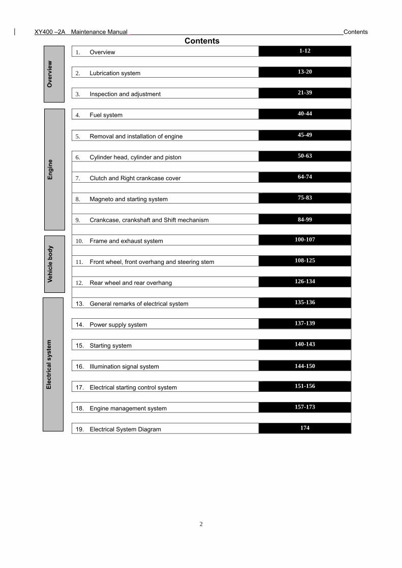
Contents 1. Overview 1-12
2. Lubrication system 13-20
3. Inspection and adjustment 21-39
4. Fuel system 40-44
5. Removal and installation of engine 45-49
6. Cylinder head, cylinder and piston 50-63
7. Clutch and Right crankcase cover 64-74
8. Magneto and starting system 75-83
9. Crankcase, crankshaft and Shift mechanism 84-99
10. Frame and exhaust system 100-107
11. Front wheel, front overhang and steering stem 108-125
12. Rear wheel and rear overhang 126-134
13. General remarks of electrical system 135-136
14. Power supply system 137-139
15. Starting system 140-143
16. Illumination signal system 144-150
17. Electrical starting control system 151-156
18. Engine management system 157-173
19. Electrical System Diagram 174
Ove
rvie
w
En
gin
e V
ehic
le b
od
y E
lect
rica
l sys
tem
XY400 –2A Maintenance Manual Overview
1
1. Overview
Engine Number Position Bar Tool
About Motorcycle Maintenance Maintenance Period Table
Technical Data of Main Performance Symbol Descriptions
Standard Torque Values
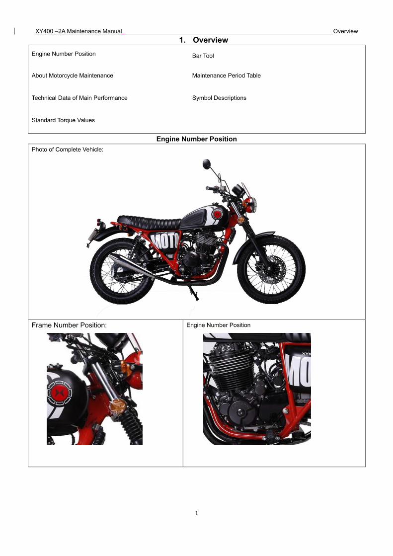
Engine Number Position
Photo of Complete Vehicle:
Frame Number Position: Engine Number Position
XY400 –2A Maintenance Manual Overview
2
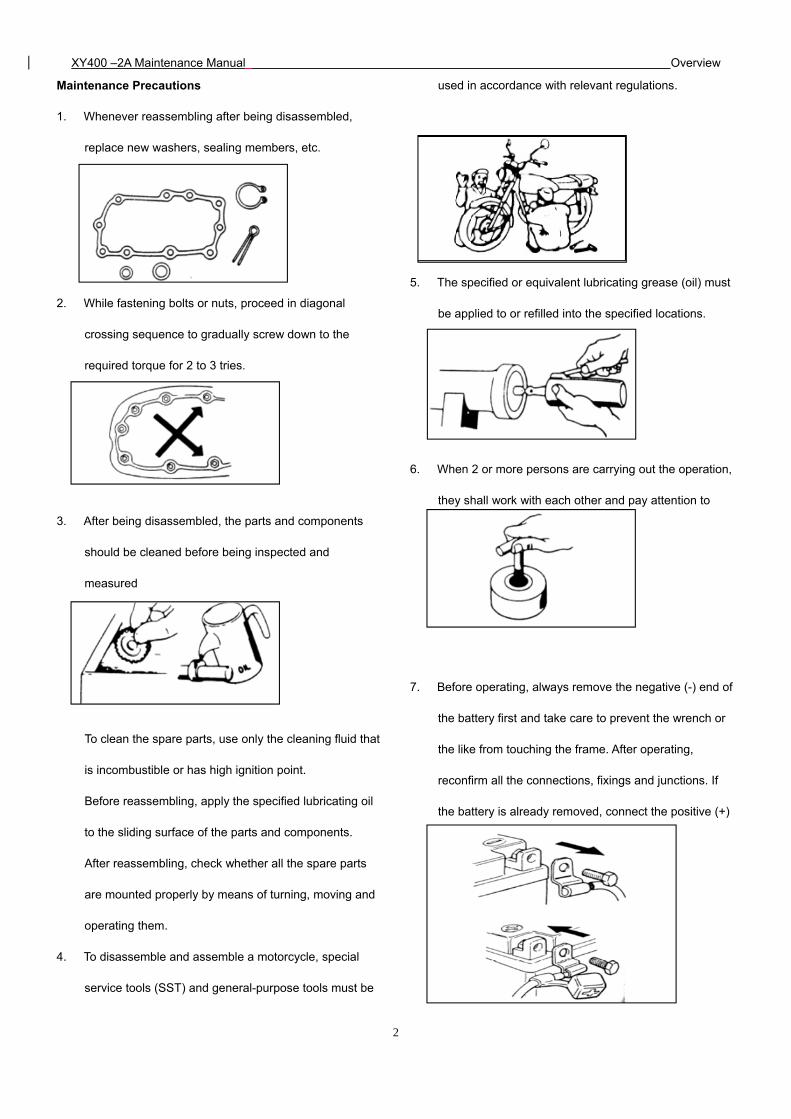
Maintenance Precautions
1. Whenever reassembling after being disassembled,
replace new washers, sealing members, etc.
2. While fastening bolts or nuts, proceed in diagonal
crossing sequence to gradually screw down to the
required torque for 2 to 3 tries.
3. After being disassembled, the parts and components
should be cleaned before being inspected and
measured
To clean the spare parts, use only the cleaning fluid that
is incombustible or has high ignition point.
Before reassembling, apply the specified lubricating oil
to the sliding surface of the parts and components.
After reassembling, check whether all the spare parts
are mounted properly by means of turning, moving and
operating them.
4. To disassemble and assemble a motorcycle, special
service tools (SST) and general-purpose tools must be
used in accordance with relevant regulations.
5. The specified or equivalent lubricating grease (oil) must
be applied to or refilled into the specified locations.
6. When 2 or more persons are carrying out the operation,
they shall work with each other and pay attention to
safety.
7. Before operating, always remove the negative (-) end of
the battery first and take care to prevent the wrench or
the like from touching the frame. After operating,
reconfirm all the connections, fixings and junctions. If
the battery is already removed, connect the positive (+)
end first.
XY400 –2A Maintenance Manual Overview
3
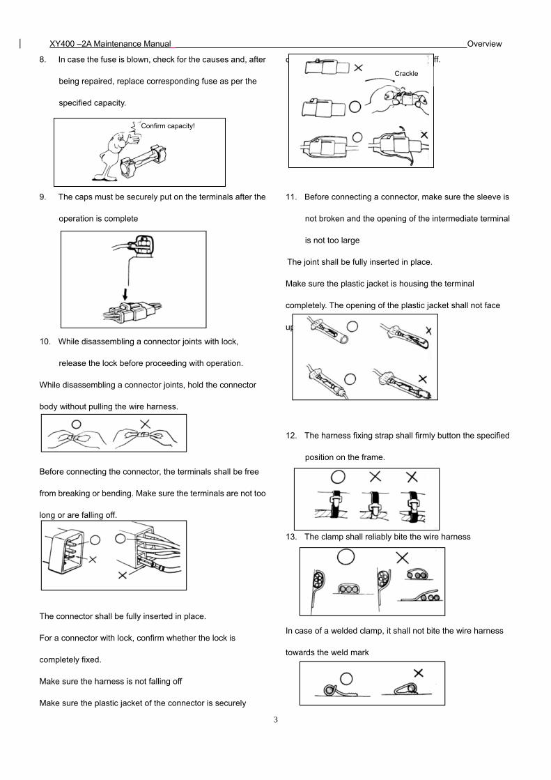
8. In case the fuse is blown, check for the causes and, after
being repaired, replace corresponding fuse as per the
specified capacity.
9. The caps must be securely put on the terminals after the
operation is complete
10. While disassembling a connector joints with lock,
release the lock before proceeding with operation.
While disassembling a connector joints, hold the connector
body without pulling the wire harness.
Before connecting the connector, the terminals shall be free
from breaking or bending. Make sure the terminals are not too
long or are falling off.
The connector shall be fully inserted in place.
For a connector with lock, confirm whether the lock is
completely fixed.
Make sure the harness is not falling off
Make sure the plastic jacket of the connector is securely
covering the connector without scaling off.
11. Before connecting a connector, make sure the sleeve is
not broken and the opening of the intermediate terminal
is not too large
The joint shall be fully inserted in place.
Make sure the plastic jacket is housing the terminal
completely. The opening of the plastic jacket shall not face
up.
12. The harness fixing strap shall firmly button the specified
position on the frame.
13. The clamp shall reliably bite the wire harness
In case of a welded clamp, it shall not bite the wire harness
towards the weld mark
Crackle
Confirm capacity!
XY400 –2A Maintenance Manual Overview
4
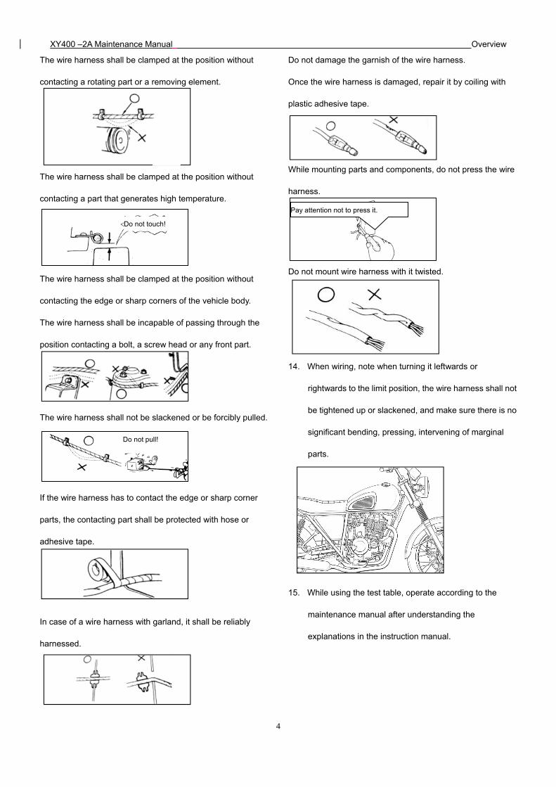
The wire harness shall be clamped at the position without
contacting a rotating part or a removing element.
The wire harness shall be clamped at the position without
contacting a part that generates high temperature.
The wire harness shall be clamped at the position without
contacting the edge or sharp corners of the vehicle body.
The wire harness shall be incapable of passing through the
position contacting a bolt, a screw head or any front part.
The wire harness shall not be slackened or be forcibly pulled.
If the wire harness has to contact the edge or sharp corner
parts, the contacting part shall be protected with hose or
adhesive tape.
In case of a wire harness with garland, it shall be reliably
harnessed.
Do not damage the garnish of the wire harness.
Once the wire harness is damaged, repair it by coiling with
plastic adhesive tape.
While mounting parts and components, do not press the wire
harness.
Do not mount wire harness with it twisted.
14. When wiring, note when turning it leftwards or
rightwards to the limit position, the wire harness shall not
be tightened up or slackened, and make sure there is no
significant bending, pressing, intervening of marginal
parts.
15. While using the test table, operate according to the
maintenance manual after understanding the
explanations in the instruction manual.
Do not touch!
Pay attention not to press it.
Do not pull!
XY400 –2A Maintenance Manual Overview
5
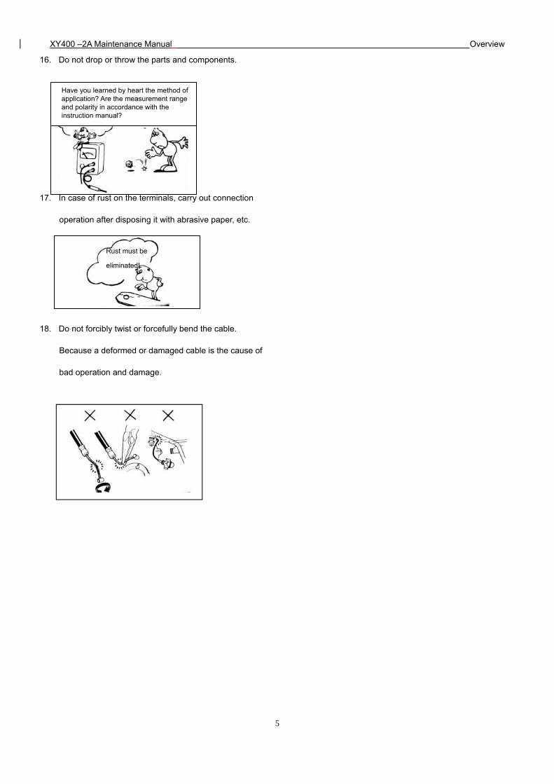
16. Do not drop or throw the parts and components.
17. In case of rust on the terminals, carry out connection
operation after disposing it with abrasive paper, etc.
18. Do not forcibly twist or forcefully bend the cable.
Because a deformed or damaged cable is the cause of
bad operation and damage.
Have you learned by heart the method of application? Are the measurement range and polarity in accordance with the instruction manual?
Rust must be
eliminated!
XY400 –2A Maintenance Manual Overview
6
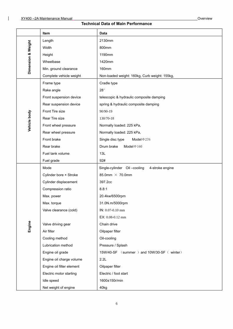
Technical Data of Main Performance
Item Data D
imen
sio
n &
Wei
gh
t Length
Width
Height
Wheelbase
Min. ground clearance
Complete vehicle weight
2130mm
800mm
1190mm
1420mm
160mm
Non-loaded weight: 160kg, Curb weight: 155kg,
Veh
icle
bo
dy
Frame type
Rake angle
Front suspension device
Rear suspension device
Front Tire size
Rear Tire size
Front wheel pressure
Rear wheel pressure
Front brake
Rear brake
Fuel tank volume
Fuel grade
Cradle type
28°
telescopic & hydraulic composite damping
spring & hydraulic composite damping
90/90-19
130/70-18
Normally loaded: 225 kPa,
Normally loaded: 225 kPa,
Single disc type ModelΦ276
Drum brake ModelΦ160
13L
92#
En
gin
e
Mode
Cylinder bore × Stroke
Cylinder displacement
Compression ratio
Max. power
Max. torque
Valve clearance (cold)
Valve driving gear
Air filter
Cooling method
Lubrication method
Engine oil grade
Engine oil charge volume
Engine oil filter element
Electric motor starting
Idle speed
Net weight of engine
Single-cylinder Oil –cooling 4-stroke engine
85.0mm × 70.0mm
397.2cc
8.8:1
20.4kw/6500rpm
31.0N.m/5000rpm
IN: 0.07-0.10 mm
EX: 0.08-0.12 mm
Chain drive
Oilpaper filter
Oil-cooling
Pressure / Splash
15W/40-SF (summer )and 10W/30-SF( winter)
2.2L
Oilpaper filter
Electric / foot start
1600±150r/min
40kg
XY400 –2A Maintenance Manual Overview
7
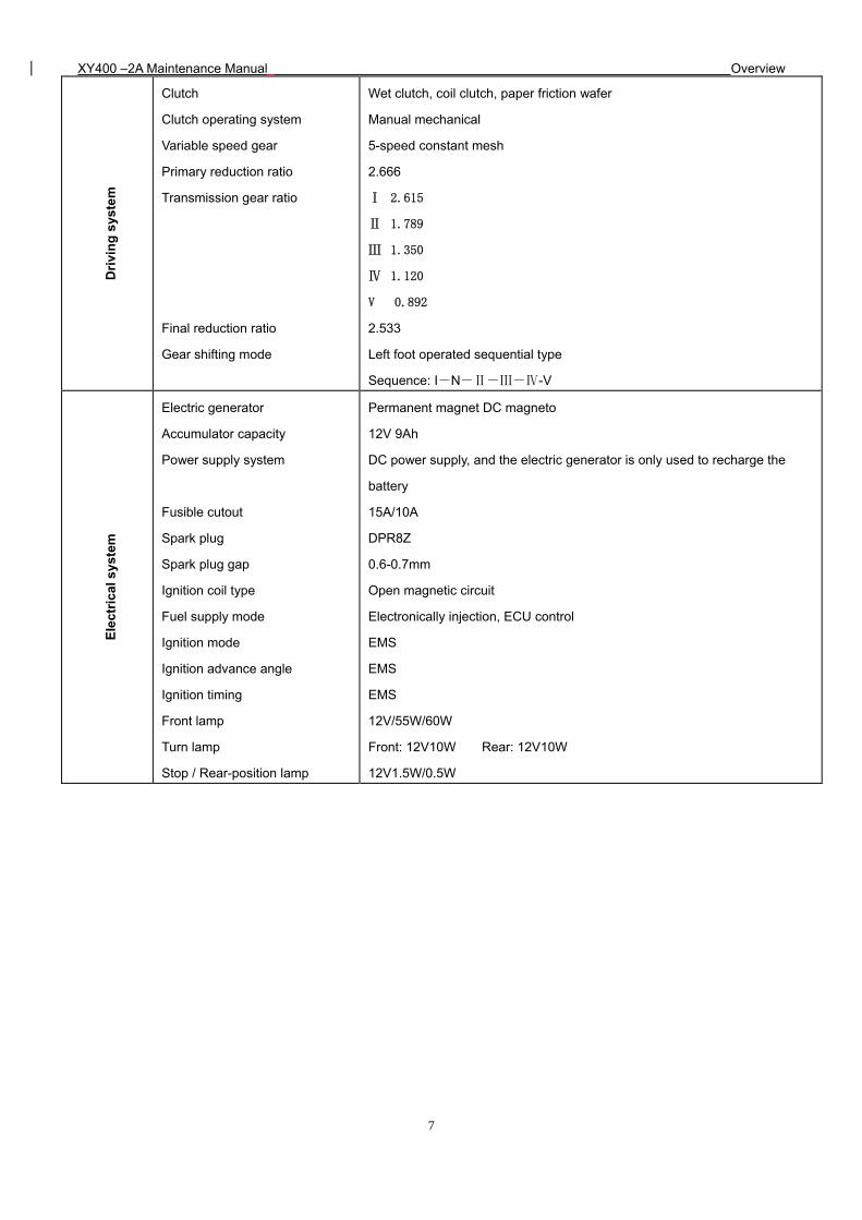
Dri
vin
g s
yste
m
Clutch
Clutch operating system
Variable speed gear
Primary reduction ratio
Transmission gear ratio
Final reduction ratio
Gear shifting mode
Wet clutch, coil clutch, paper friction wafer
Manual mechanical
5-speed constant mesh
2.666
Ⅰ 2.615
Ⅱ 1.789
Ⅲ 1.350
Ⅳ 1.120
V 0.892
2.533
Left foot operated sequential type
Sequence: I-N-Ⅱ-Ⅲ-Ⅳ-V
Ele
ctri
cal s
yste
m
Electric generator
Accumulator capacity
Power supply system
Fusible cutout
Spark plug
Spark plug gap
Ignition coil type
Fuel supply mode
Ignition mode
Ignition advance angle
Ignition timing
Front lamp
Turn lamp
Stop / Rear-position lamp
Permanent magnet DC magneto
12V 9Ah
DC power supply, and the electric generator is only used to recharge the
battery
15A/10A
DPR8Z
0.6-0.7mm
Open magnetic circuit
Electronically injection, ECU control
EMS
EMS
EMS
12V/55W/60W
Front: 12V10W Rear: 12V10W
12V1.5W/0.5W
XY400 –2A Maintenance Manual Overview
8
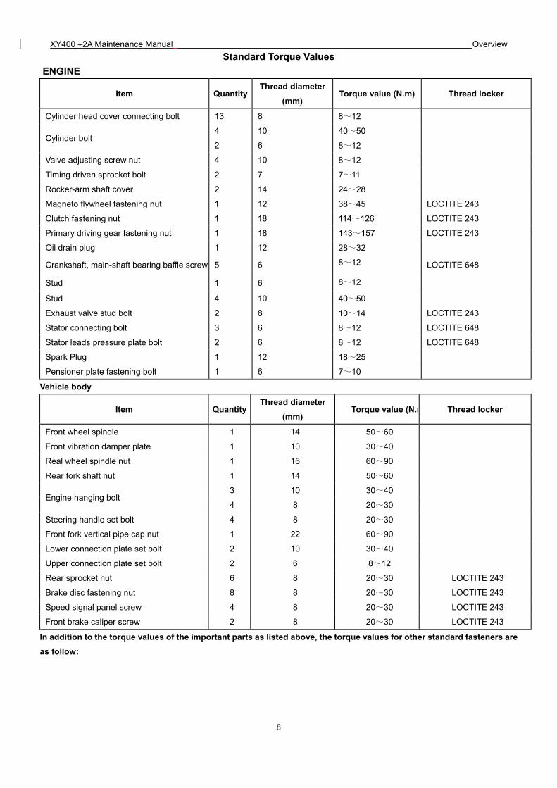
Standard Torque Values
ENGINE
Item QuantityThread diameter
(mm) Torque value (N.m) Thread locker
Cylinder head cover connecting bolt 13 8 8~12
Cylinder bolt 4 10 40~50
2 6 8~12
Valve adjusting screw nut 4 10 8~12
Timing driven sprocket bolt 2 7 7~11
Rocker-arm shaft cover 2 14 24~28
Magneto flywheel fastening nut 1 12 38~45 LOCTITE 243
Clutch fastening nut 1 18 114~126 LOCTITE 243
Primary driving gear fastening nut 1 18 143~157 LOCTITE 243
Oil drain plug 1 12 28~32
Crankshaft, main-shaft bearing baffle screw 5 6 8~12 LOCTITE 648
Stud 1 6 8~12
Stud 4 10 40~50
Exhaust valve stud bolt 2 8 10~14 LOCTITE 243
Stator connecting bolt 3 6 8~12 LOCTITE 648
Stator leads pressure plate bolt 2 6 8~12 LOCTITE 648
Spark Plug 1 12 18~25
Pensioner plate fastening bolt 1 6 7~10
Vehicle body
Item QuantityThread diameter
(mm) Torque value (N.m Thread locker
Front wheel spindle 1 14 50~60
Front vibration damper plate 1 10 30~40
Real wheel spindle nut 1 16 60~90
Rear fork shaft nut 1 14 50~60
Engine hanging bolt 3 10 30~40
4 8 20~30
Steering handle set bolt 4 8 20~30
Front fork vertical pipe cap nut 1 22 60~90
Lower connection plate set bolt 2 10 30~40
Upper connection plate set bolt 2 6 8~12
Rear sprocket nut 6 8 20~30 LOCTITE 243
Brake disc fastening nut 8 8 20~30 LOCTITE 243
Speed signal panel screw 4 8 20~30 LOCTITE 243
Front brake caliper screw 2 8 20~30 LOCTITE 243
In addition to the torque values of the important parts as listed above, the torque values for other standard fasteners are
as follow:
XY400 –2A Maintenance Manual Overview
9
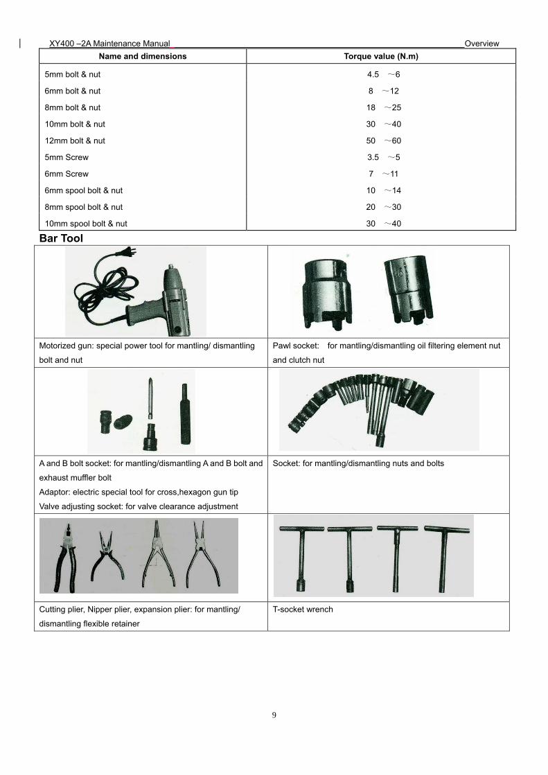
Name and dimensions Torque value (N.m)
5mm bolt & nut 4.5 ~6
6mm bolt & nut 8 ~12
8mm bolt & nut 18 ~25
10mm bolt & nut 30 ~40
12mm bolt & nut 50 ~60
5mm Screw 3.5 ~5
6mm Screw 7 ~11
6mm spool bolt & nut 10 ~14
8mm spool bolt & nut 20 ~30
10mm spool bolt & nut 30 ~40
Bar Tool
Motorized gun: special power tool for mantling/ dismantling
bolt and nut
Pawl socket: for mantling/dismantling oil filtering element nut
and clutch nut
A and B bolt socket: for mantling/dismantling A and B bolt and
exhaust muffler bolt
Adaptor: electric special tool for cross,hexagon gun tip
Valve adjusting socket: for valve clearance adjustment
Socket: for mantling/dismantling nuts and bolts
Cutting plier, Nipper plier, expansion plier: for mantling/
dismantling flexible retainer
T-socket wrench
XY400 –2A Maintenance Manual Overview
10
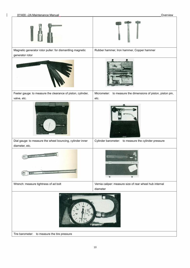
Magnetic generator rotor puller: for dismantling magnetic
generator rotor
Rubber hammer, Iron hammer, Copper hammer
Feeler gauge: to measure the clearance of piston, cylinder,
valve, etc.
Micrometer: to measure the dimensions of piston, piston pin,
etc.
Dial gauge: to measure the wheel bouncing, cylinder inner
diameter, etc.
Cylinder barometer: to measure the cylinder pressure
Wrench: measure tightness of ad bolt Vernia caliper: measure size of rear wheel hub internal
diameter
Tire barometer: to measure the tire pressure
XY400 –2A Maintenance Manual Overview
11
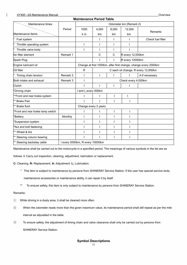
Maintenance Period Table
Maintenance times
Maintenance Items
Period
Odometer km (Remark 2)
1000
k m
4,000
km
8,000
km
12,000
km Remarks
* Fuel system I I I Check fuel filter
* Throttle operating system I I I I
* Throttle valve body I I I I
Air filter element Remark 1 C C R every 12,000km
Spark Plug I I R every 12000km
Engine lubricant oil Change at first 1000km, after first change, change every 2000km
Oil filter R C each oil change, R every 12,000km
* Timing chain tension Remark 3 I I I I A if necessary
Both intake and exhaust Remark 3 I Check every 4,000km
Clutch I I I I
*Driving chain I and L every 500km
**Front and rear brake system I I I I
** Brake Pad I I I I
** Brake fluid Change every 2 years
*Front and rear brake lamp switch I I I I
*Battery Monthly I I I I
*Suspension system I I I I
*Nut and bolt fastening I I I I
** Wheel & tire I I I I
** Steering column bearing I I I I
** Steering backstay cable I every 5000km, R every 10000km
Maintenance shall be carried out to the motorcycle in a specified period. The meanings of various symbols in the list are as
follows: I: Carry out inspection, cleaning, adjustment, lubrication or replacement.
C: Cleaning. R: Replacement. A: Adjustment. L: Lubrication.
* This item is subject to maintenance by persons from SHINERAY Service Station. If the user has special service tools,
maintenance accessories or maintenance ability, it can repair it by itself.
** To ensure safety, this item is only subject to maintenance by persons from SHINERAY Service Station.
Remarks:
① While driving in a dusty area, it shall be cleaned more often.
② When the odometer reads more than the given maximum value, its maintenance period shall still repeat as per the mile
interval as stipulated in the table.
③ To ensure safety, the adjustment of timing chain and valve clearance shall only be carried out by persons from
SHINERAY Service Station.
Symbol Descriptions
XY400 –2A Maintenance Manual Overview
12
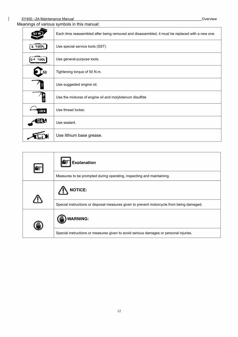
Meanings of various symbols in this manual:
Each time reassembled after being removed and disassembled, it must be replaced with a new one.
Use special service tools (SST)
Use general-purpose tools.
Tightening torque of 50 N.m.
Use suggested engine oil.
Use the mixtures of engine oil and molybdenum disulfide
Use thread locker.
Use sealant.
Use lithium base grease.
Measures to be prompted during operating, inspecting and maintaining.
Special instructions or disposal measures given to prevent motorcycle from being damaged.
Special instructions or measures given to avoid serious damages or personal injuries.
Explanation
NOTICE:
WARNING:
XY400 –2A Maintenance Manual Lubrication system
13
2. Lubrication system
Maintenance notice Inspection of lubricating oil
Troubleshooting Replacement of lubricating oil
Lubricating Position of Complete Vehicle Cleaning of Lubricating Oil Strainer
Lubrication of Control Lines Cleaning and Replacement of Lubricating Oil Filter
Engine Lubrication System Diagram Oil Pump
Maintenance notice
This section introduces the inspection and replacement method of engine lubricating oil as well as the cleaning method of
lubricating oil strainer and lubricating oil filter. It also introduces various lubricating positions of the complete vehicle of this model.
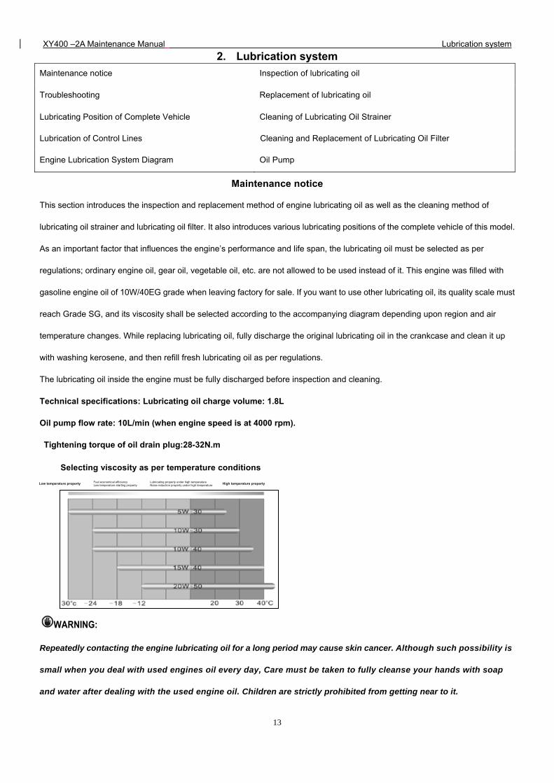
As an important factor that influences the engine’s performance and life span, the lubricating oil must be selected as per
regulations; ordinary engine oil, gear oil, vegetable oil, etc. are not allowed to be used instead of it. This engine was filled with
gasoline engine oil of 10W/40EG grade when leaving factory for sale. If you want to use other lubricating oil, its quality scale must
reach Grade SG, and its viscosity shall be selected according to the accompanying diagram depending upon region and air
temperature changes. While replacing lubricating oil, fully discharge the original lubricating oil in the crankcase and clean it up
with washing kerosene, and then refill fresh lubricating oil as per regulations.
The lubricating oil inside the engine must be fully discharged before inspection and cleaning.
Technical specifications: Lubricating oil charge volume: 1.8L
Oil pump flow rate: 10L/min (when engine speed is at 4000 rpm).
Tightening torque of oil drain plug:28-32N.m
WARNING:
Repeatedly contacting the engine lubricating oil for a long period may cause skin cancer. Although such possibility is
small when you deal with used engines oil every day, Care must be taken to fully cleanse your hands with soap
and water after dealing with the used engine oil. Children are strictly prohibited from getting near to it.
Low temperature property Fuel economical efficiency Lubricating property under high temperature High temperature property Low temperature starting property Noise reduction property under high temperature
Selecting viscosity as per temperature conditions
XY400 –2A Maintenance Manual Lubrication system
14
Troubleshooting
Lubricating oil contaminated
1. Fail to replace lubricating oil according to the
maintenance period table;
2. The pouring orifice thread is damaged thus causing
poor seal;
3. The piston ring is worn.
Lubricating oil pressure low
1. The oil level is too low;
2. Oil through, orifice port or oil strainer is clogged;
3. Oil pumps failure.
Lubricating oil consumes too fast
1. There is leakage with the engine;
2. The piston ring is worn.
3. The inlet/exhaust valve guide is worn;
4. The oil shield is worn or damaged.
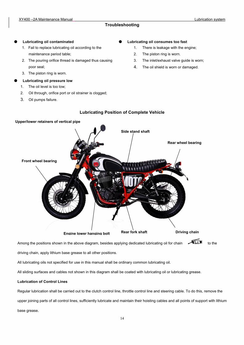
Lubricating Position of Complete Vehicle
Among the positions shown in the above diagram, besides applying dedicated lubricating oil for chain to the
driving chain, apply lithium base grease to all other positions.
All lubricating oils not specified for use in this manual shall be ordinary common lubricating oil.
All sliding surfaces and cables not shown in this diagram shall be coated with lubricating oil or lubricating grease.
Lubrication of Control Lines
Regular lubrication shall be carried out to the clutch control line, throttle control line and steering cable. To do this, remove the
upper joining parts of all control lines, sufficiently lubricate and maintain their hoisting cables and all points of support with lithium
base grease.
Front wheel bearing
Rear wheel bearing
Engine lower hanging bolt Rear fork shaft
Side stand shaft
Driving chain
Upper/lower retainers of vertical pipe
XY400 –2A Maintenance Manual Lubrication system
15
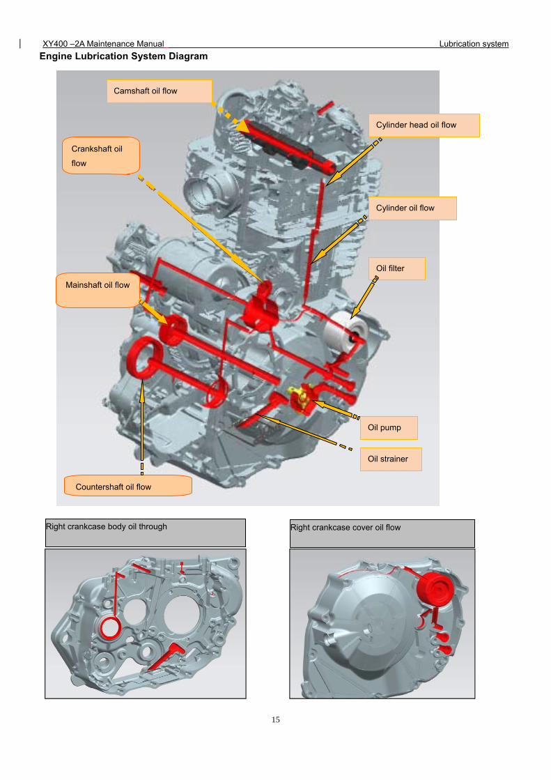
Engine Lubrication System Diagram
Right crankcase body oil through Right crankcase cover oil flow
Crankshaft oil
flow
Mainshaft oil flow
Countershaft oil flow
Camshaft oil flow
Cylinder head oil flow
Cylinder oil flow
Oil filter
Oil pump
Oil strainer
XY400 –2A Maintenance Manual Lubrication system
16
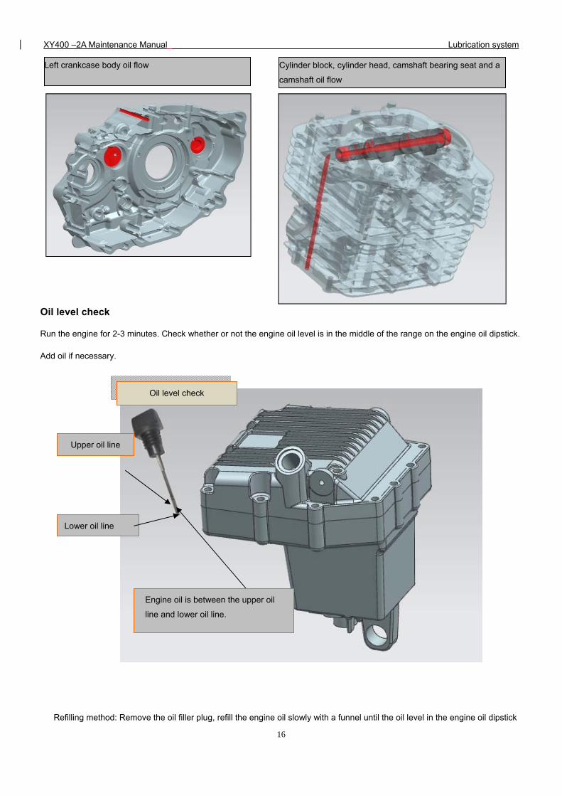
Oil level check
Run the engine for 2-3 minutes. Check whether or not the engine oil level is in the middle of the range on the engine oil dipstick.
Add oil if necessary.
Refilling method: Remove the oil filler plug, refill the engine oil slowly with a funnel until the oil level in the engine oil dipstick
Left crankcase body oil flow
Cylinder block, cylinder head, camshaft bearing seat and a
camshaft oil flow
Upper oil line
Engine oil is between the upper oil
line and lower oil line.
Lower oil line
Oil level check
XY400 –2A Maintenance Manual Lubrication system
17
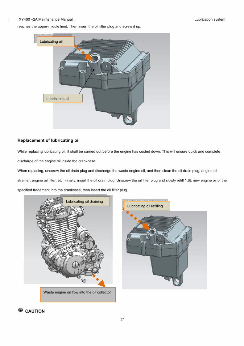
reaches the upper-middle limit. Then insert the oil filter plug and screw it up.
Replacement of lubricating oil
While replacing lubricating oil, it shall be carried out before the engine has cooled down. This will ensure quick and complete
discharge of the engine oil inside the crankcase.
When replacing, unscrew the oil drain plug and discharge the waste engine oil, and then clean the oil drain plug, engine oil
strainer, engine oil filter, etc. Finally, insert the oil drain plug. Unscrew the oil filter plug and slowly refill 1.8L new engine oil of the
specified trademark into the crankcase, then insert the oil filter plug.
CAUTION
Lubricating oil
Lubricating oil
Waste engine oil flow into the oil collector
Lubricating oil draining Lubricating oil refilling
XY400 –2A Maintenance Manual Lubrication system
18
Application of engine oil of poor quality will have an impact on the functional performance and life span of the
motorcycle engine.
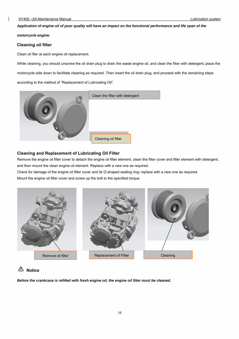
Cleaning oil filter
Clean oil filer at each engine oil replacement.
While cleaning, you should unscrew the oil drain plug to drain the waste engine oil, and clean the filter with detergent; place the
motorcycle side down to facilitate cleaning as required. Then insert the oil drain plug, and proceed with the remaining steps
according to the method of “Replacement of Lubricating Oil".
Cleaning and Replacement of Lubricating Oil Filter
Remove the engine oil filter cover to detach the engine oil filter element, clean the filter cover and filter element with detergent,
and then mount the clean engine oil element. Replace with a new one as required.
Check for damage of the engine oil filter cover and its O-shaped sealing ring; replace with a new one as required.
Mount the engine oil filter cover and screw up the bolt to the specified torque.
Notice
Before the crankcase is refilled with fresh engine oil, the engine oil filter must be cleaned.
Clean the filter with detergent
Cleaning Remove oil filter Replacement of Filter
Cleaning oil filter
XY400 –2A Maintenance Manual Lubrication system
19
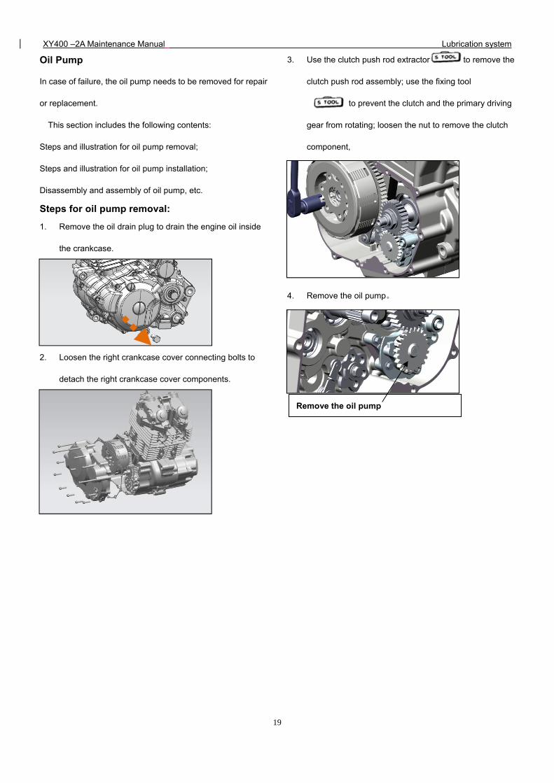
Oil Pump
In case of failure, the oil pump needs to be removed for repair
or replacement.
This section includes the following contents:
Steps and illustration for oil pump removal;
Steps and illustration for oil pump installation;
Disassembly and assembly of oil pump, etc.
Steps for oil pump removal:
1. Remove the oil drain plug to drain the engine oil inside
the crankcase.
2. Loosen the right crankcase cover connecting bolts to
detach the right crankcase cover components.
3. Use the clutch push rod extractor to remove the
clutch push rod assembly; use the fixing tool
to prevent the clutch and the primary driving
gear from rotating; loosen the nut to remove the clutch
component,
4. Remove the oil pump。
Remove the oil pump
XY400–2A Maintenance Manual Lubrication system
20
Steps for oil pump installation:
The installation procedures are the removal procedures in reverse order. Pay attention to the following points during the
installation:
1、 The spare parts shall be clean and intact;
2、 Install clutch assembly, and the retaining nut M18 shall be coated with thread retaining adhesive LOCTITE243;
tightening torque: 114N.m -126N.m;
3、Install clutch push rod assembly;
4、 After the right crankcase cover is mounted in place, the angle and position of the clutch operating lever may
possibly change; readjustment shall be carried out to accommodate the adjustment of clutch control line;
5、 The seal washer at the bolt under the oil pump, shall be replaced with new ones.;
6、Remember to refill engine oil after all these are completed.。
CAUTION
The clutch retaining nut must be screwed up to the specified tightening torque,must be applied to prevent the nut
from getting loose.
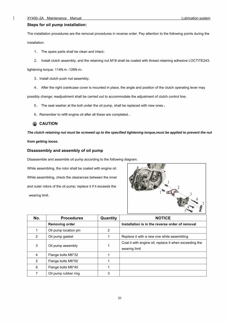
Disassembly and assembly of oil pump
Disassemble and assemble oil pump according to the following diagram.
While assembling, the rotor shall be coated with engine oil.
While assembling, check the clearances between the inner
and outer rotors of the oil pump; replace it if it exceeds the
wearing limit.
No. Procedures Quantity NOTICE
Removing order Installation is in the reverse order of removal
1 Oil pump location pin 2
2 Oil pump gasket 1 Replace it with a new one while assembling
3 Oil pump assembly 1 Coat it with engine oil; replace it when exceeding the
wearing limit
4 Flange bolts M6*32 1
5 Flange bolts M6*50 1
6 Flange bolts M6*40 1
7 Oil pump rubber ring 3
XY400–2A Maintenance Manual Inspection and adjustment
21
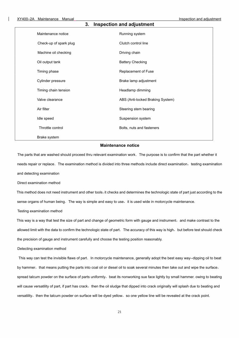
3. Inspection and adjustment
Maintenance notice Running system
Check-up of spark plug Clutch control line
Machine oil checking Driving chain
Oil output tank Battery Checking
Timing phase Replacement of Fuse
Cylinder pressure Brake lamp adjustment
Timing chain tension Headlamp dimming
Valve clearance
Air filter
Idle speed
Throttle control
Brake system
ABS (Anti-locked Braking System)
Steering stem bearing
Suspension system
Bolts, nuts and fasteners
Maintenance notice
The parts that are washed should proceed thru relevant examination work.The purpose is to confirm that the part whether it
needs repair or replace.The examination method is divided into three methods include direct examination,testing examination
and detecting examination
Direct examination method
This method does not need instrument and other tools,it checks and determines the technologic state of part just according to the
sense organs of human being.The way is simple and easy to use,it is used wide in motorcycle maintenance.
Testing examination method
This way is a way that test the size of part and change of geometric form with gauge and instrument,and make contrast to the
allowed limit with the data to confirm the technologic state of part.The accuracy of this way is high,but before test should check
the precision of gauge and instrument carefully and choose the testing position reasonably.
Detecting examination method
This way can test the invisible flaws of part.In motorcycle maintenance, generally adopt the best easy way--dipping oil to beat
by hammer,that means putting the parts into coal oil or diesel oil to soak several minutes then take out and wipe the surface,
spread talcum powder on the surface of parts uniformly,beat its nonworking sue face lightly by small hammer. owing to beating
will cause versatility of part, if part has crack,then the oil sludge that dipped into crack originally will splash due to beating and
versatility,then the talcum powder on surface will be dyed yellow,so one yellow line will be revealed at the crack point.
XY400–2A Maintenance Manual Inspection and adjustment
22
Explanation:
Unless expressly stated or indicated in the maintenance period table, check and adjust all parts of the XY400-C
motorcycle according to the contents hereof before using it.
Technical specifications
Throttle bar free stroke: 2-6mm
Recommended spark plug: DPR8Z
Spark plug gap: 0.6-0.7mm
Valve clearance (cold) IN)0.07-0.10mm
EX)0.08-0.12mm
Idle speed: 1500±50(rpm)
Cylinder pressure: ≥0.8MPa(300rpm)
Driving chain tension: 15~25mm
Rear brake pedal free stroke 20~30mm
Front brake operating handle free stroke 10~20mm
Clutch operating handle free stroke 10~20mm
XY400–2A Maintenance Manual Inspection and adjustment
23
1. Check-up of spark plug
①Remove the spark plug cap. Remove the spark plug with a
socket wrench. Visually check whether there is any damage
with the spark plug insulator and ablation with the electrodes.
If yes, replace them.
②Check the spark plug electrode gap with a plug gauge.
Spark plug electrode gap 0.6 -0.7mm. Carefully adjust the
electrode gap. Then clear away the accumulated carbon and
contaminants with a spark plug cleaner or string wire. Check
that the spark plug sealing gasket is in good condition.
③To mount the spark plug, manually screw up the spark plug
first, and then tighten it with a socket wrench. Put on the
spark plug cap.
The spark plug of the designated type should be used.
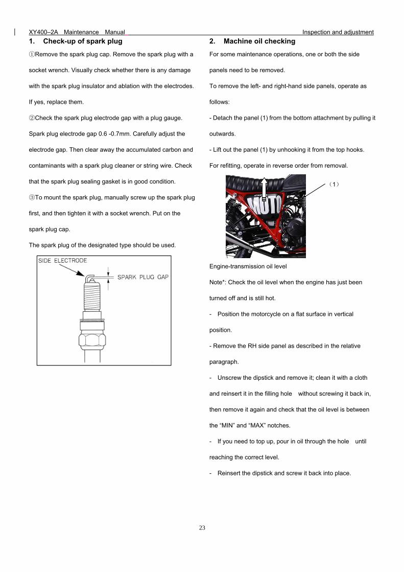
2. Machine oil checking
For some maintenance operations, one or both the side
panels need to be removed.
To remove the left- and right-hand side panels, operate as
follows:
- Detach the panel (1) from the bottom attachment by pulling it
outwards.
- Lift out the panel (1) by unhooking it from the top hooks.
For refitting, operate in reverse order from removal.
Engine-transmission oil level
Note*: Check the oil level when the engine has just been
turned off and is still hot.
- Position the motorcycle on a flat surface in vertical
position.
- Remove the RH side panel as described in the relative
paragraph.
- Unscrew the dipstick and remove it; clean it with a cloth
and reinsert it in the filling hole without screwing it back in,
then remove it again and check that the oil level is between
the “MIN” and “MAX” notches.
- If you need to top up, pour in oil through the hole until
reaching the correct level.
- Reinsert the dipstick and screw it back into place.
(1)
XY400–2A Maintenance Manual Inspection and adjustment
24
Caution
The insufficiency or poor quality of the engine oil will
lead to the premature wear-out of the engine.
Replacement of lubricating oil
While replacing lubricating oil, it shall be carried out
before the engine has cooled down. This will ensure quick
and complete discharge of the engine oil inside the
crankcase.
When replacing, unscrew the oil drain plug and
discharge the waste engine oil, and then clean the oil drain
plug, engine oil strainer, engine oil filter, etc. Finally, insert the
oil drain plug. Unscrew the oil filter plug and slowly refill 1.8L
new engine oil of the specified trademark into the crankcase,
then insert the oil filter plug.
Caution
Application of engine oil of poor quality will have an
impact on the functional performance and life span of the
motorcycle engine.
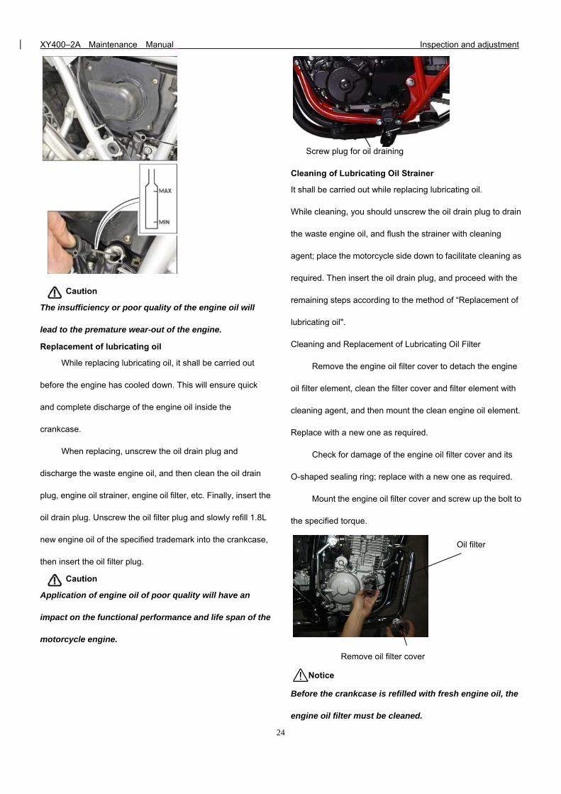
Cleaning of Lubricating Oil Strainer
It shall be carried out while replacing lubricating oil.
While cleaning, you should unscrew the oil drain plug to drain
the waste engine oil, and flush the strainer with cleaning
agent; place the motorcycle side down to facilitate cleaning as
required. Then insert the oil drain plug, and proceed with the
remaining steps according to the method of “Replacement of
lubricating oil".
Cleaning and Replacement of Lubricating Oil Filter
Remove the engine oil filter cover to detach the engine
oil filter element, clean the filter cover and filter element with
cleaning agent, and then mount the clean engine oil element.
Replace with a new one as required.
Check for damage of the engine oil filter cover and its
O-shaped sealing ring; replace with a new one as required.
Mount the engine oil filter cover and screw up the bolt to
the specified torque.
Notice
Before the crankcase is refilled with fresh engine oil, the
engine oil filter must be cleaned.
Screw plug for oil draining
Remove oil filter cover
Oil filter
XY400–2A Maintenance Manual Inspection and adjustment
25
Oil output Oil-in line
Oil-out line
Engine cycle tube
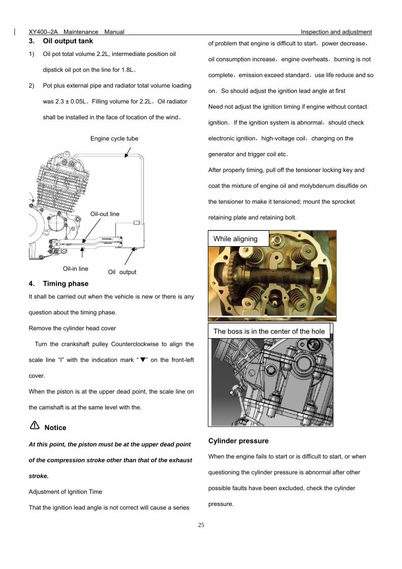
3. Oil output tank
1) Oil pot total volume 2.2L, intermediate position oil
dipstick oil pot on the line for 1.8L。
2) Pot plus external pipe and radiator total volume loading
was 2.3 ± 0.05L。Filling volume for 2.2L。Oil radiator
shall be installed in the face of location of the wind。
4. Timing phase
It shall be carried out when the vehicle is new or there is any
question about the timing phase.
Remove the cylinder head cover
Turn the crankshaft pulley Counterclockwise to align the
scale line “I” with the indication mark “ ” on the front-left
cover.
When the piston is at the upper dead point, the scale line on
the camshaft is at the same level with the.
Notice
At this point, the piston must be at the upper dead point
of the compression stroke other than that of the exhaust
stroke.
Adjustment of Ignition Time
That the ignition lead angle is not correct will cause a series
of problem that engine is difficult to start,power decrease,
oil consumption increase,engine overheats,burning is not
complete,emission exceed standard,use life reduce and so
on.So should adjust the ignition lead angle at first
Need not adjust the ignition timing if engine without contact
ignition.If the ignition system is abnormal,should check
electronic ignition,high-voltage coil,charging on the
generator and trigger coil etc.
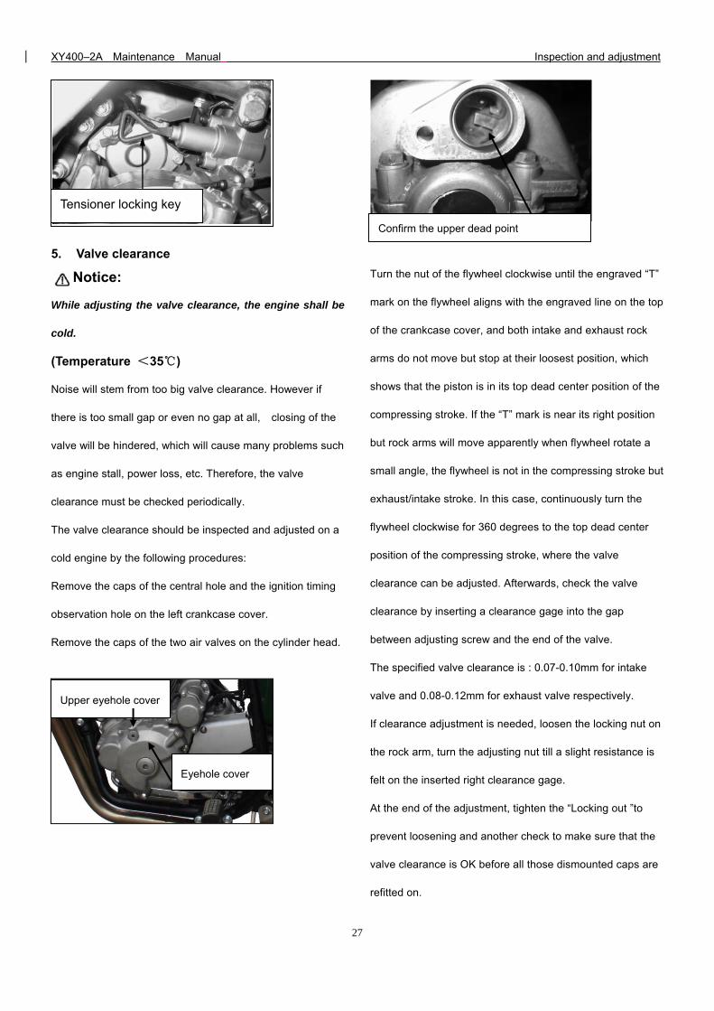
After properly timing, pull off the tensioner locking key and
coat the mixture of engine oil and molybdenum disulfide on
the tensioner to make it tensioned; mount the sprocket
retaining plate and retaining bolt.
Cylinder pressure
When the engine fails to start or is difficult to start, or when
questioning the cylinder pressure is abnormal after other
possible faults have been excluded, check the cylinder
pressure.
The boss is in the center of the hole
While aligning
XY400–2A Maintenance Manual Inspection and adjustment
26
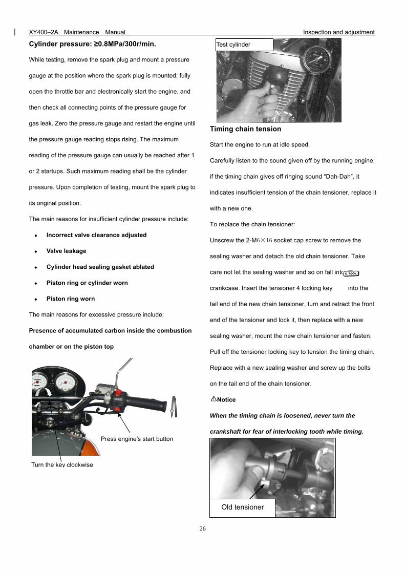
Cylinder pressure: ≥0.8MPa/300r/min.
While testing, remove the spark plug and mount a pressure
gauge at the position where the spark plug is mounted; fully
open the throttle bar and electronically start the engine, and
then check all connecting points of the pressure gauge for
gas leak. Zero the pressure gauge and restart the engine until
the pressure gauge reading stops rising. The maximum
reading of the pressure gauge can usually be reached after 1
or 2 startups. Such maximum reading shall be the cylinder
pressure. Upon completion of testing, mount the spark plug to
its original position.
The main reasons for insufficient cylinder pressure include:
Incorrect valve clearance adjusted
Valve leakage
Cylinder head sealing gasket ablated
Piston ring or cylinder worn
Piston ring worn
The main reasons for excessive pressure include:
Presence of accumulated carbon inside the combustion
chamber or on the piston top
Timing chain tension
Start the engine to run at idle speed.
Carefully listen to the sound given off by the running engine:
if the timing chain gives off ringing sound “Dah-Dah”, it
indicates insufficient tension of the chain tensioner, replace it
with a new one.
To replace the chain tensioner:
Unscrew the 2-M6×16 socket cap screw to remove the
sealing washer and detach the old chain tensioner. Take
care not let the sealing washer and so on fall into the
crankcase. Insert the tensioner 4 locking key into the
tail end of the new chain tensioner, turn and retract the front
end of the tensioner and lock it, then replace with a new
sealing washer, mount the new chain tensioner and fasten.
Pull off the tensioner locking key to tension the timing chain.
Replace with a new sealing washer and screw up the bolts
on the tail end of the chain tensioner.
Notice
When the timing chain is loosened, never turn the
crankshaft for fear of interlocking tooth while timing.
Test cylinder
Old tensioner
Turn the key clockwise
Press engine’s start button
XY400–2A Maintenance Manual Inspection and adjustment
27
5. Valve clearance
Notice:
While adjusting the valve clearance, the engine shall be
cold.
(Temperature <35)
Noise will stem from too big valve clearance. However if
there is too small gap or even no gap at all, closing of the
valve will be hindered, which will cause many problems such
as engine stall, power loss, etc. Therefore, the valve
clearance must be checked periodically.
The valve clearance should be inspected and adjusted on a
cold engine by the following procedures:
Remove the caps of the central hole and the ignition timing
observation hole on the left crankcase cover.
Remove the caps of the two air valves on the cylinder head.
Turn the nut of the flywheel clockwise until the engraved “T”
mark on the flywheel aligns with the engraved line on the top
of the crankcase cover, and both intake and exhaust rock
arms do not move but stop at their loosest position, which
shows that the piston is in its top dead center position of the
compressing stroke. If the “T” mark is near its right position
but rock arms will move apparently when flywheel rotate a
small angle, the flywheel is not in the compressing stroke but
exhaust/intake stroke. In this case, continuously turn the
flywheel clockwise for 360 degrees to the top dead center
position of the compressing stroke, where the valve
clearance can be adjusted. Afterwards, check the valve
clearance by inserting a clearance gage into the gap
between adjusting screw and the end of the valve.
The specified valve clearance is : 0.07-0.10mm for intake
valve and 0.08-0.12mm for exhaust valve respectively.
If clearance adjustment is needed, loosen the locking nut on
the rock arm, turn the adjusting nut till a slight resistance is
felt on the inserted right clearance gage.
At the end of the adjustment, tighten the “Locking out ”to
prevent loosening and another check to make sure that the
valve clearance is OK before all those dismounted caps are
refitted on.
Tensioner locking key
Upper eyehole cover
Eyehole cover
Confirm the upper dead point
XY400–2A Maintenance Manual Inspection and adjustment
28
While adjusting, unscrew the retaining nut and then turn the
adjusting screw until you feel that the clearance gauge is
slightly pulled. Then secure the adjusting screw using the
valve adjusting tool , and then screw the retaining
screw. And finally, check the valve clearance.
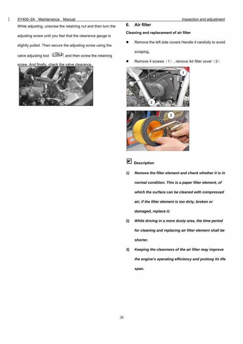
6. Air filter
Cleaning and replacement of air filter
Remove the left side covers Handle it carefully to avoid
scraping.
Remove 4 screws(1), remove Air filter cover(2)
Description
1) Remove the filter element and check whether it is in
normal condition. This is a paper filter element, of
which the surface can be cleaned with compressed
air; if the filter element is too dirty, broken or
damaged, replace it;
2) While driving in a more dusty area, the time period
for cleaning and replacing air filter element shall be
shorter.
3) Keeping the cleanness of the air filter may improve
the engine’s operating efficiency and prolong its life
span.
XY400–2A Maintenance Manual Inspection and adjustment
29
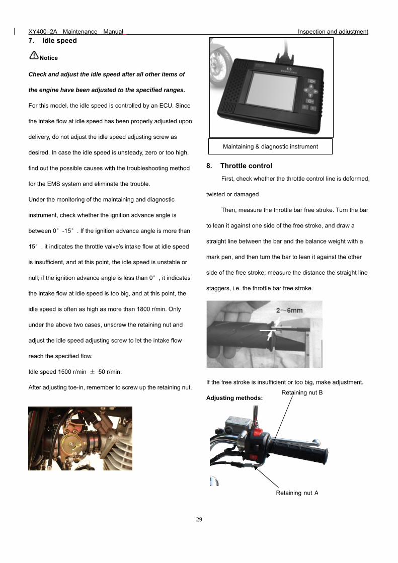
7. Idle speed
Notice
Check and adjust the idle speed after all other items of
the engine have been adjusted to the specified ranges.
For this model, the idle speed is controlled by an ECU. Since
the intake flow at idle speed has been properly adjusted upon
delivery, do not adjust the idle speed adjusting screw as
desired. In case the idle speed is unsteady, zero or too high,
find out the possible causes with the troubleshooting method
for the EMS system and eliminate the trouble.
Under the monitoring of the maintaining and diagnostic
instrument, check whether the ignition advance angle is
between 0°-15°. If the ignition advance angle is more than
15°, it indicates the throttle valve’s intake flow at idle speed
is insufficient, and at this point, the idle speed is unstable or
null; if the ignition advance angle is less than 0°, it indicates
the intake flow at idle speed is too big, and at this point, the
idle speed is often as high as more than 1800 r/min. Only
under the above two cases, unscrew the retaining nut and
adjust the idle speed adjusting screw to let the intake flow
reach the specified flow.
Idle speed 1500 r/min ± 50 r/min.
After adjusting toe-in, remember to screw up the retaining nut.
8. Throttle control
First, check whether the throttle control line is deformed,
twisted or damaged.
Then, measure the throttle bar free stroke. Turn the bar
to lean it against one side of the free stroke, and draw a
straight line between the bar and the balance weight with a
mark pen, and then turn the bar to lean it against the other
side of the free stroke; measure the distance the straight line
staggers, i.e. the throttle bar free stroke.
Free stroke 2-6mm.
If the free stroke is insufficient or too big, make adjustment.
Adjusting methods:
Maintaining & diagnostic instrument
Retaining nut A
Retaining nut B
XY400–2A Maintenance Manual Inspection and adjustment
30
Fine adjustment:
Pull open the rubber lagging, unscrew the retaining nut
A, and turn the adjusting solenoid to adjust to a satisfied free
stroke. And then screw up the retaining nut A and mount the
protective rubber lagging.
Coarse adjustment:
If the fine adjustment is not satisfying, separate the
throttle control line with throttle valve body and unscrew the
retaining nut B to make adjust the free stroke in a larger range.
Screw up the retaining but B after the adjustment.
Check whether the throttle can turn smoothly from full
open to full close at any position. If there is clogging, adjust or
replace it.
Use not full throttle to the free stroke motorcycle is a
dangerous operation, rotating the handle, not full throttle
to the free stroke can make the engine speed increases
suddenly.
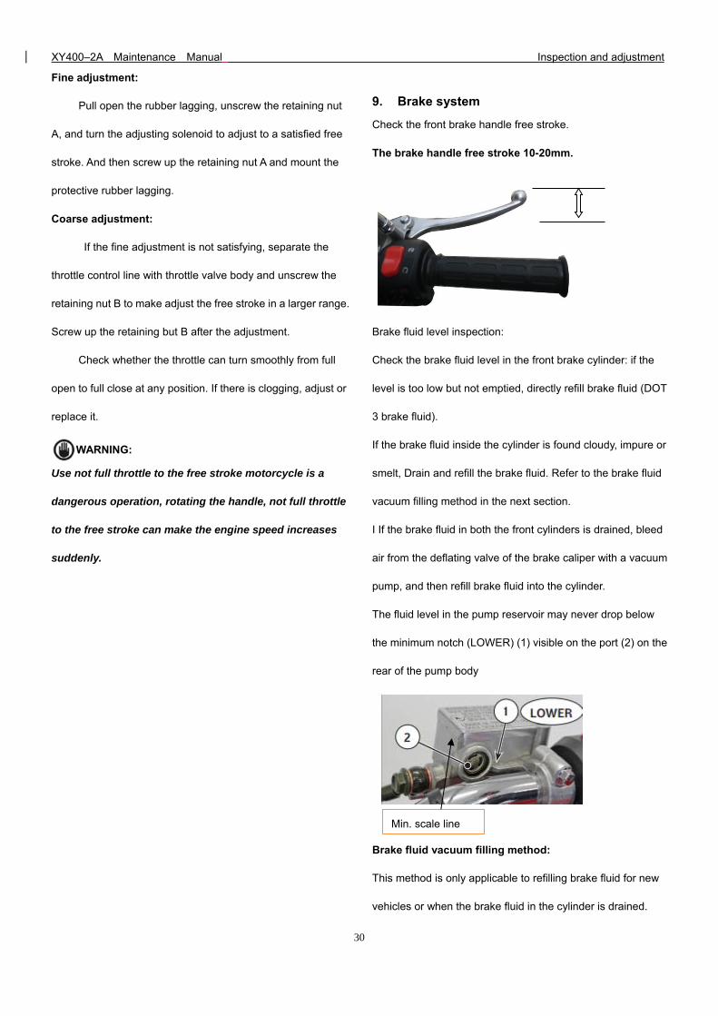
9. Brake system
Check the front brake handle free stroke.
The brake handle free stroke 10-20mm.
Brake fluid level inspection:
Check the brake fluid level in the front brake cylinder: if the
level is too low but not emptied, directly refill brake fluid (DOT
3 brake fluid).
If the brake fluid inside the cylinder is found cloudy, impure or
smelt, Drain and refill the brake fluid. Refer to the brake fluid
vacuum filling method in the next section.
I If the brake fluid in both the front cylinders is drained, bleed
air from the deflating valve of the brake caliper with a vacuum
pump, and then refill brake fluid into the cylinder.
The fluid level in the pump reservoir may never drop below
the minimum notch (LOWER) (1) visible on the port (2) on the
rear of the pump body
Brake fluid vacuum filling method:
This method is only applicable to refilling brake fluid for new
vehicles or when the brake fluid in the cylinder is drained.
WARNING:
Min. scale line
XY400–2A Maintenance Manual Inspection and adjustment
31
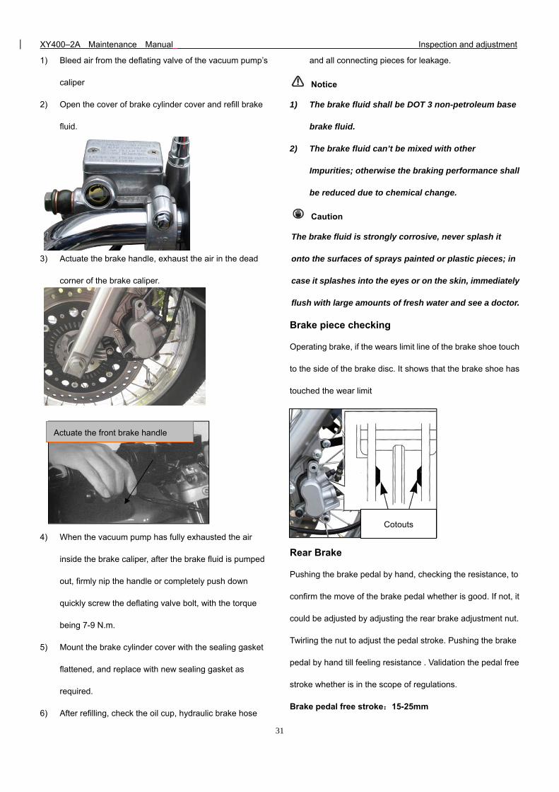
1) Bleed air from the deflating valve of the vacuum pump’s
caliper
2) Open the cover of brake cylinder cover and refill brake
fluid.
3) Actuate the brake handle, exhaust the air in the dead
corner of the brake caliper.
4) When the vacuum pump has fully exhausted the air
inside the brake caliper, after the brake fluid is pumped
out, firmly nip the handle or completely push down
quickly screw the deflating valve bolt, with the torque
being 7-9 N.m.
5) Mount the brake cylinder cover with the sealing gasket
flattened, and replace with new sealing gasket as
required.
6) After refilling, check the oil cup, hydraulic brake hose
and all connecting pieces for leakage.
Notice
1) The brake fluid shall be DOT 3 non-petroleum base
brake fluid.
2) The brake fluid can’t be mixed with other
Impurities; otherwise the braking performance shall
be reduced due to chemical change.
Caution
The brake fluid is strongly corrosive, never splash it
onto the surfaces of sprays painted or plastic pieces; in
case it splashes into the eyes or on the skin, immediately
flush with large amounts of fresh water and see a doctor.
Brake piece checking
Operating brake, if the wears limit line of the brake shoe touch
to the side of the brake disc. It shows that the brake shoe has
touched the wear limit
Rear Brake
Pushing the brake pedal by hand, checking the resistance, to
confirm the move of the brake pedal whether is good. If not, it
could be adjusted by adjusting the rear brake adjustment nut.
Twirling the nut to adjust the pedal stroke. Pushing the brake
pedal by hand till feeling resistance . Validation the pedal free
stroke whether is in the scope of regulations.
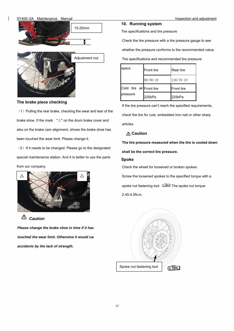
Brake pedal free stroke:15-25mm
Cotouts
Actuate the front brake handle
XY400–2A Maintenance Manual Inspection and adjustment
32
The brake piece checking
(1)Pulling the rear brake, checking the wear and tear of the
brake shoe. If the mark "" on the drum brake cover and
also on the brake cam alignment, shows the brake shoe has
been touched the wear limit. Please change it.
(2)If it needs to be changed. Please go to the designated
special maintenance station. And it is better to use the parts
from our company.
Caution
Please change the brake shoe in time if it has been
touched the wear limit. Otherwise it would cause
accidents by the lack of strength.
10. Running system
Tire specifications and tire pressure
Check the tire pressure with a tire pressure gauge to see
whether the pressure conforms to the recommended value.
Tire specifications and recommended tire pressure:
specs Front tire Rear tire
90/90-19 130/70-18
Cold tire air
pressure
Front tire Front tire
225kPa 225kPa
If the tire pressure can’t reach the specified requirements,
check the tire for cuts, embedded iron nail or other sharp
articles.
Caution
The tire pressure measured when the tire is cooled down
shall be the correct tire pressure.
Spoke
Check the wheel for loosened or broken spokes.
Screw the loosened spokes to the specified torque with a
spoke nut fastening tool .The spoke nut torque:
2.45-4.0N.m.
If any spoke is broken or cracked, replace it as soon as
possible
15-25mm
Adjustment nut.
Spoke nut fastening tool
XY400–2A Maintenance Manual Inspection and adjustment
33
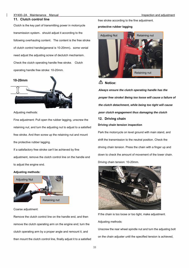
11. Clutch control line
Clutch is the key part of transmitting power in motorcycle
transmission system,should adjust it according to the
following overhauling content.The content is the free stroke
of clutch control handle(general is 10-20mm),some venial
need adjust the adjusting screw of declutch mechanism.
Check the clutch operating handle free stroke. Clutch
operating handle free stroke: 10-20mm.
Adjusting methods:
Fine adjustment: Pull open the rubber lagging, unscrew the
retaining nut, and turn the adjusting nut to adjust to a satisfied
free stroke. And then screw up the retaining nut and mount
the protective rubber lagging.
If a satisfactory free stroke can't be achieved by fine
adjustment, remove the clutch control line on the handle end
to adjust the engine end.
Adjusting methods:
Coarse adjustment:
Remove the clutch control line on the handle end, and then
remove the clutch operating arm on the engine end; turn the
clutch operating arm by a proper angle and remount it, and
then mount the clutch control line, finally adjust it to a satisfied
free stroke according to the fine adjustment.
protective rubber lagging
Notice:
Always ensure the clutch operating handle has the
proper free stroke! Being too loose will cause a failure of
the clutch detachment, while being too tight will cause
poor clutch engagement thus damaging the clutch
12. Driving chain
Driving chain tension inspection
Park the motorcycle on level ground with main stand, and
shift the transmission to the neutral position. Check the
driving chain tension. Press the chain with a finger up and
down to check the amount of movement of the lower chain.
Driving chain tension: 10-20mm.
If the chain is too loose or too tight, make adjustment.
Adjusting methods:
Unscrew the rear wheel spindle nut and turn the adjusting bolt
on the chain adjuster until the specified tension is achieved,
10-20mm
Adjusting Nut
Retaining nut
Retaining nut
Retaining nut
Adjusting Nut
XY400–2A Maintenance Manual Inspection and adjustment
34
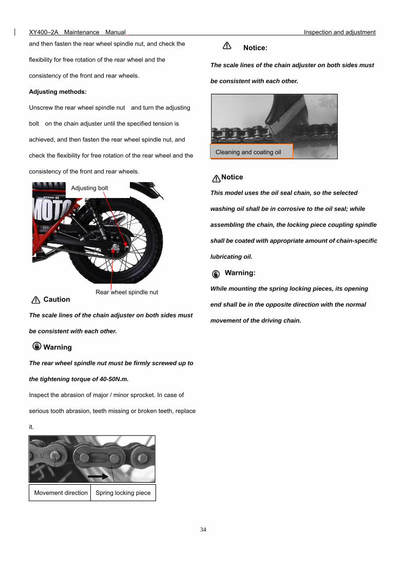
and then fasten the rear wheel spindle nut, and check the
flexibility for free rotation of the rear wheel and the
consistency of the front and rear wheels.
Adjusting methods:
Unscrew the rear wheel spindle nut and turn the adjusting
bolt on the chain adjuster until the specified tension is
achieved, and then fasten the rear wheel spindle nut, and
check the flexibility for free rotation of the rear wheel and the
consistency of the front and rear wheels.
Caution
The scale lines of the chain adjuster on both sides must
be consistent with each other.
Warning
The rear wheel spindle nut must be firmly screwed up to
the tightening torque of 40-50N.m.
Inspect the abrasion of major / minor sprocket. In case of
serious tooth abrasion, teeth missing or broken teeth, replace
it.
Notice:
The scale lines of the chain adjuster on both sides must
be consistent with each other.
Notice
This model uses the oil seal chain, so the selected
washing oil shall be in corrosive to the oil seal; while
assembling the chain, the locking piece coupling spindle
shall be coated with appropriate amount of chain-specific
lubricating oil.
Warning:
While mounting the spring locking pieces, its opening
end shall be in the opposite direction with the normal
movement of the driving chain.
Movement direction Spring locking piece
Cleaning and coating oil
Adjusting bolt
Rear wheel spindle nut
XY400–2A Maintenance Manual Inspection and adjustment
35
13. Battery Checking
The sealed battery does not require any maintenance. When
electrolyte leaks, or other failure of the electrical system is
detected, apply to the SHINERAY Dealer.
If the vehicle remains unused for long periods, it is
recommended to disconnect the battery from the electrical
system and store it in a dry place.
- After an intensive use of the battery, it is advisable to carry
out a standard slow charging cycle.
- Quick charging is advised only in situations of extreme
necessity since the life of lead elements is drastically reduced
by such cycle.
Detach the panel from the bottom attachment by pulling it
outwards.
Lift out the panel by unhooking it from the top hooks.
Clean away dust and corrosive from the surface of the
battery.
Remove the negative, then the positive pole of the
accumulator; unscrew and remove the loosen battery strap
.The battery is free of maintenance. There is no need to
check the electrolyte level. Clean the battery terminals
regularly.
The condition of charging will significantly influence the life
length of the battery.
Seriously corroded conductor connectors of the battery shall
be replaced.
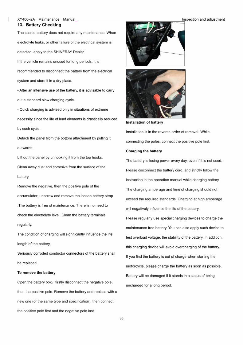
To remove the battery
Open the battery box,firstly disconnect the negative pole,
then the positive pole. Remove the battery and replace with a
new one (of the same type and specification), then connect
the positive pole first and the negative pole last.
Installation of battery
Installation is in the reverse order of removal. While
connecting the poles, connect the positive pole first.
Charging the battery
The battery is losing power every day, even if it is not used.
Please disconnect the battery cord, and strictly follow the
instruction in the operation manual while charging battery.
The charging amperage and time of charging should not
exceed the required standards. Charging at high amperage
will negatively influence the life of the battery.
Please regularly use special charging devices to charge the
maintenance free battery. You can also apply such device to
test overload voltage, the stability of the battery. In addition,
this charging device will avoid overcharging of the battery.
If you find the battery is out of charge when starting the
motorcycle, please charge the battery as soon as possible.
Battery will be damaged if it stands in a status of being
uncharged for a long period.
XY400–2A Maintenance Manual Inspection and adjustment
36
Caution
1) In this model, both the startup and EMS system are
completely powered with accumulator. Therefore, it
is quite important to ensure sufficient electric
quantity of accumulator, otherwise, startup is
impossible.
2) Never fill in tap water, because this will shorten the
accumulator’s life span.
3) To dismantle battery ,disconnect the
negative(-)electrode before the positive(+)one, and
vice versa in installation .Ensure against any
contact of the positive(+)electrode with the vehicle
body.
4) Never have the electrolyte level come over the upper
mark line when adding distilled water .Otherwise
overflow and corrosion will occur.
5) The electrolyte contains sulfuric acid and will cause
serious hurt to skin and eyes by contact. In case of
contact with it, wash it off for 5 minutes and see a
doctor immediately.
6) Foreign matter should be prevented from entering
into the battery during dismounting and installation.
7) The breathing pipe must be kept unblocked.
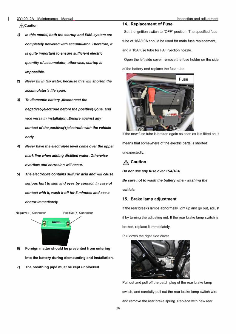
14. Replacement of Fuse
Set the ignition switch to “OFF” position. The specified fuse
tube of 15A/10A should be used for main fuse replacement,
and a 10A fuse tube for FAI injection nozzle.
Open the left side cover, remove the fuse holder on the side
of the battery and replace the fuse tube.
If the new fuse tube is broken again as soon as it is fitted on, it
means that somewhere of the electric parts is shorted
unexpectedly.
Caution
Do not use any fuse over 15A/10A
Be sure not to wash the battery when washing the
vehicle.
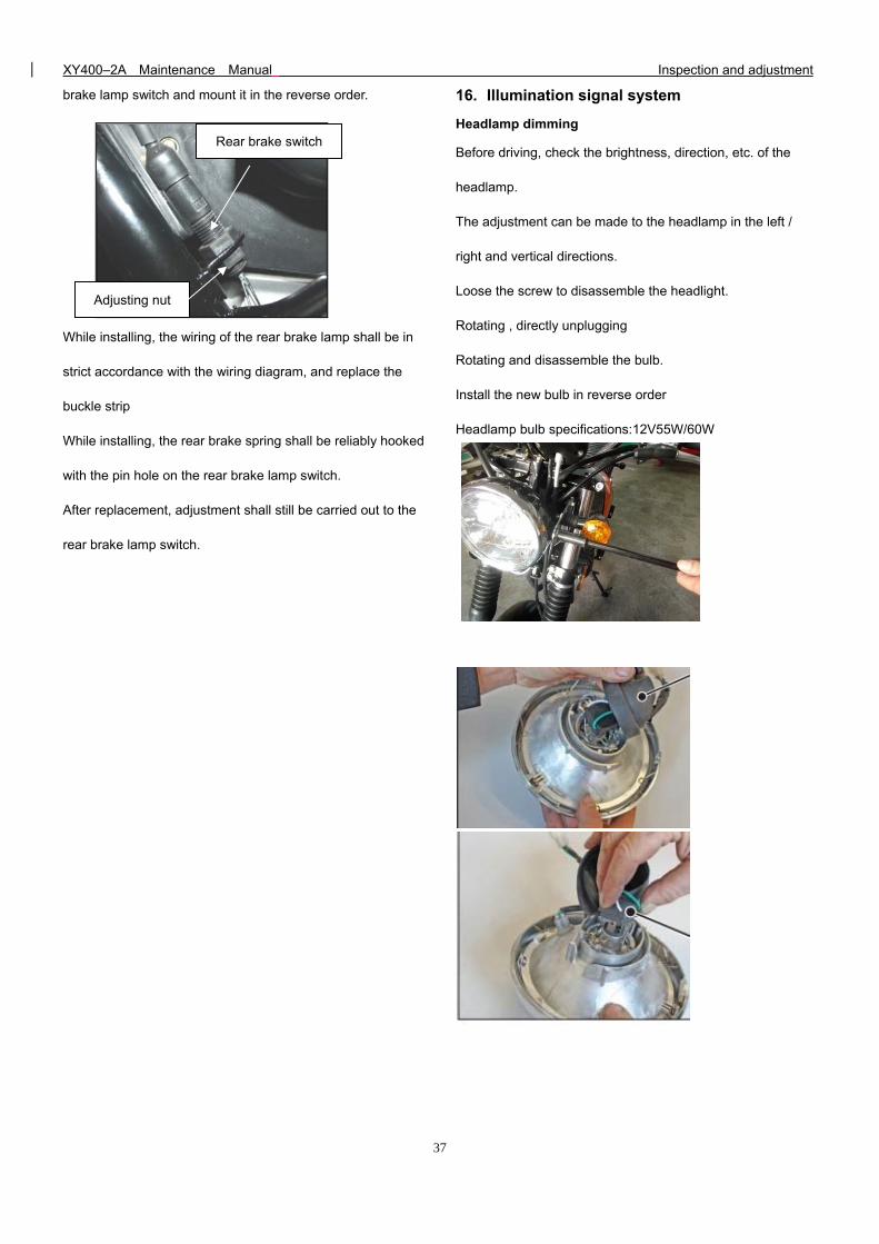
15. Brake lamp adjustment
If the rear breaks lamps abnormally light up and go out, adjust
it by turning the adjusting nut. If the rear brake lamp switch is
broken, replace it immediately.
Pull down the right side cover
Pull out and pull off the patch plug of the rear brake lamp
switch, and carefully pull out the rear brake lamp switch wire
and remove the rear brake spring. Replace with new rear
Fuse
Negative (-) Connector Positive (+) Connector
XY400–2A Maintenance Manual Inspection and adjustment
37
brake lamp switch and mount it in the reverse order.
While installing, the wiring of the rear brake lamp shall be in
strict accordance with the wiring diagram, and replace the
buckle strip
While installing, the rear brake spring shall be reliably hooked
with the pin hole on the rear brake lamp switch.
After replacement, adjustment shall still be carried out to the
rear brake lamp switch.
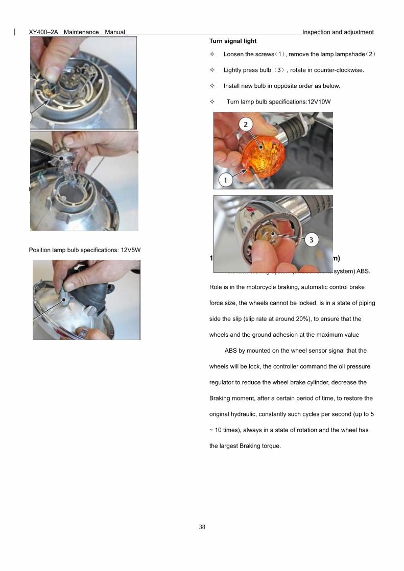
16. Illumination signal system
Headlamp dimming
Before driving, check the brightness, direction, etc. of the
headlamp.
The adjustment can be made to the headlamp in the left /
right and vertical directions.
Loose the screw to disassemble the headlight.
Rotating , directly unplugging
Rotating and disassemble the bulb.
Install the new bulb in reverse order
Headlamp bulb specifications:12V55W/60W
Adjusting nut
Rear brake switch
XY400–2A Maintenance Manual Inspection and adjustment
38
Position lamp
Unplugging the sidelight seat
Position lamp bulb specifications: 12V5W
Turn signal light
Loosen the screws(1), remove the lamp lampshade(2)
Lightly press bulb(3), rotate in counter-clockwise.
Install new bulb in opposite order as below.
Turn lamp bulb specifications:12V10W
17. ABS (Anti-locked Braking System)
Anti lock braking system (antilock brake system) ABS.
Role is in the motorcycle braking, automatic control brake
force size, the wheels cannot be locked, is in a state of piping
side the slip (slip rate at around 20%), to ensure that the
wheels and the ground adhesion at the maximum value
ABS by mounted on the wheel sensor signal that the
wheels will be lock, the controller command the oil pressure
regulator to reduce the wheel brake cylinder, decrease the
Braking moment, after a certain period of time, to restore the
original hydraulic, constantly such cycles per second (up to 5
~ 10 times), always in a state of rotation and the wheel has
the largest Braking torque.
XY400–2A Maintenance Manual Inspection and adjustment
39
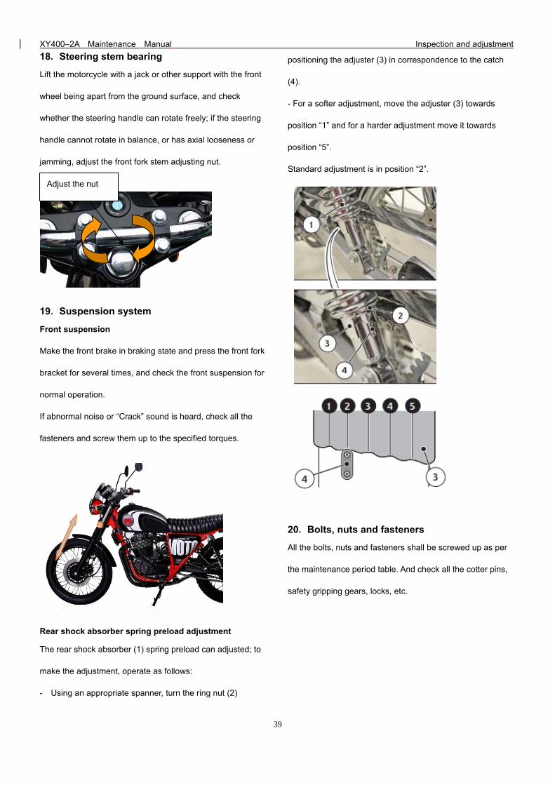
18. Steering stem bearing
Lift the motorcycle with a jack or other support with the front
wheel being apart from the ground surface, and check
whether the steering handle can rotate freely; if the steering
handle cannot rotate in balance, or has axial looseness or
jamming, adjust the front fork stem adjusting nut.
19. Suspension system
Front suspension
Make the front brake in braking state and press the front fork
bracket for several times, and check the front suspension for
normal operation.
If abnormal noise or “Crack” sound is heard, check all the
fasteners and screw them up to the specified torques.
Rear shock absorber spring preload adjustment
The rear shock absorber (1) spring preload can adjusted; to
make the adjustment, operate as follows:
- Using an appropriate spanner, turn the ring nut (2)
positioning the adjuster (3) in correspondence to the catch
(4).
- For a softer adjustment, move the adjuster (3) towards
position “1” and for a harder adjustment move it towards
position “5”.
Standard adjustment is in position “2”.
20. Bolts, nuts and fasteners
All the bolts, nuts and fasteners shall be screwed up as per
the maintenance period table. And check all the cotter pins,
safety gripping gears, locks, etc.
Adjust the nut
XY400–2A Maintenance Manual Fuel system
40
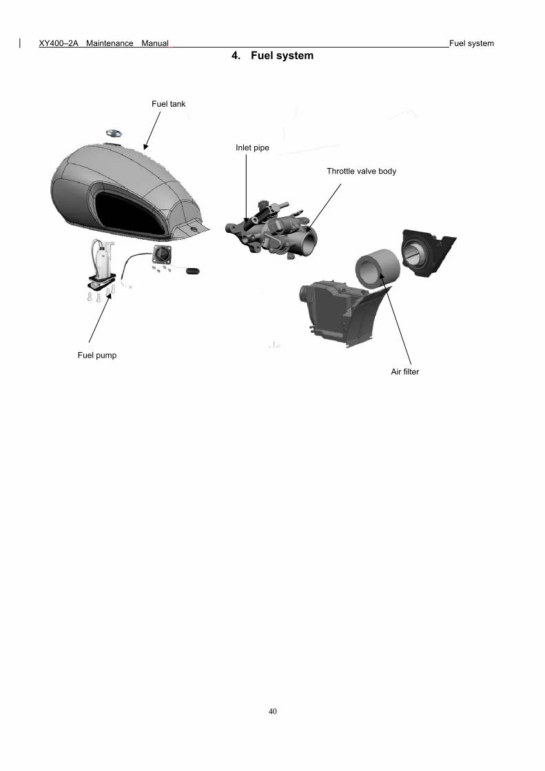
4. Fuel system
Fuel tank
Throttle valve body
Air filter
Fuel pump
Inlet pipe
XY400–2A Maintenance Manual Fuel system
41
Fuel system
Maintenance notice Disassembly and assembly of fuel tank
Troubleshooting Removal and installation of air filter
Removal and installation of fuel tank Removal and installation of carburetor
Maintenance notice
This section introduces the knowledge related to the fuel system.
CAUTION
Pay special attention to fire prevention while dealing with gasoline!
Take care of the mounting position of such sealing members as the O-ring while removing various parts of the fuel system. While
reassembling, always use new sealing members such as an O-ring.
Technical specifications
Throat opening diameter Φ40mm equivalent
Idle speed 1500r/min ± 50 r/min
Throttle handle free stroke 2~6mm
Troubleshooting
Engine ignition is ok, but it does not start
1 No fuel or insufficient fuel in the fuel tank
2 Too much fuel enters the cylinder;
3 Air filter is clogged;
4 Spark plug fails;
5 Fuel tube does not flow well;
6 Fuel quality problem (containing moisture);
7 Fuel is stored too long;
8 Fuel pump failure;
9 Injector failure (clogged)
XY400–2A Maintenance Manual Fuel system
42
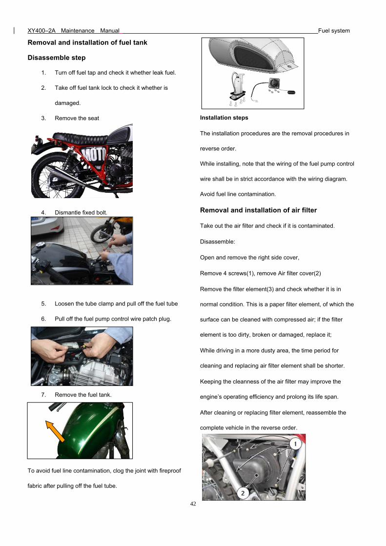
Removal and installation of fuel tank
Disassemble step
1. Turn off fuel tap and check it whether leak fuel.
2. Take off fuel tank lock to check it whether is
damaged.
3. Remove the seat
4. Dismantle fixed bolt.
5. Loosen the tube clamp and pull off the fuel tube
6. Pull off the fuel pump control wire patch plug.
7. Remove the fuel tank.
To avoid fuel line contamination, clog the joint with fireproof
fabric after pulling off the fuel tube.
Installation steps
The installation procedures are the removal procedures in
reverse order.
While installing, note that the wiring of the fuel pump control
wire shall be in strict accordance with the wiring diagram.
Avoid fuel line contamination.
Removal and installation of air filter
Take out the air filter and check if it is contaminated.
Disassemble:
Open and remove the right side cover,
Remove 4 screws(1), remove Air filter cover(2)
Remove the filter element(3) and check whether it is in
normal condition. This is a paper filter element, of which the
surface can be cleaned with compressed air; if the filter
element is too dirty, broken or damaged, replace it;
While driving in a more dusty area, the time period for
cleaning and replacing air filter element shall be shorter.
Keeping the cleanness of the air filter may improve the
engine’s operating efficiency and prolong its life span.
After cleaning or replacing filter element, reassemble the
complete vehicle in the reverse order.
XY400–2A Maintenance Manual Fuel system
43
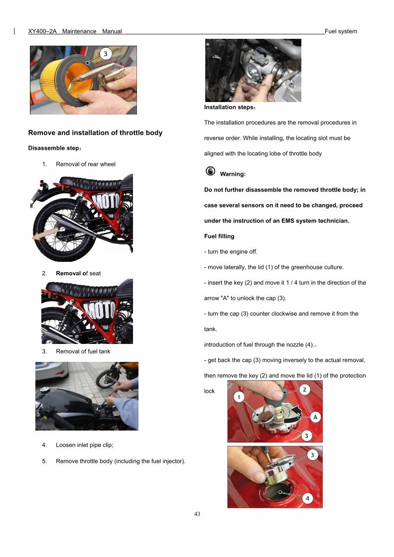
Remove and installation of throttle body
Disassemble step:
1. Removal of rear wheel
2. Removal of seat
3. Removal of fuel tank
4. Loosen inlet pipe clip;
5. Remove throttle body (including the fuel injector).
Installation steps:
The installation procedures are the removal procedures in
reverse order. While installing, the locating slot must be
aligned with the locating lobe of throttle body
Warning:
Do not further disassemble the removed throttle body; in
case several sensors on it need to be changed, proceed
under the instruction of an EMS system technician.
Fuel filling
- turn the engine off.
- move laterally, the lid (1) of the greenhouse culture.
- insert the key (2) and move it 1 / 4 turn in the direction of the
arrow "A" to unlock the cap (3).
- turn the cap (3) counter clockwise and remove it from the
tank.
introduction of fuel through the nozzle (4).。
- get back the cap (3) moving inversely to the actual removal,
then remove the key (2) and move the lid (1) of the protection
lock
XY400–2A Maintenance Manual Fuel system
44
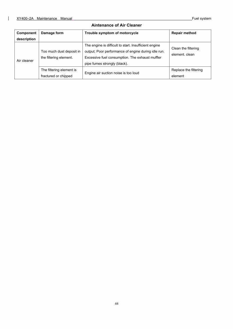
Aintenance of Air Cleaner
Component
description
Damage form Trouble symptom of motorcycle Repair method
Air cleaner
Too much dust deposit in
the filtering element.
The engine is difficult to start. Insufficient engine
output; Poor performance of engine during idle run.
Excessive fuel consumption. The exhaust muffler
pipe fumes strongly (black).
Clean the filtering
element. clean
The filtering element is
fractured or chipped Engine air suction noise is too loud
Replace the filtering
element
XY400–2A Maintenance Manual Clutch and Right crankcase cover
45
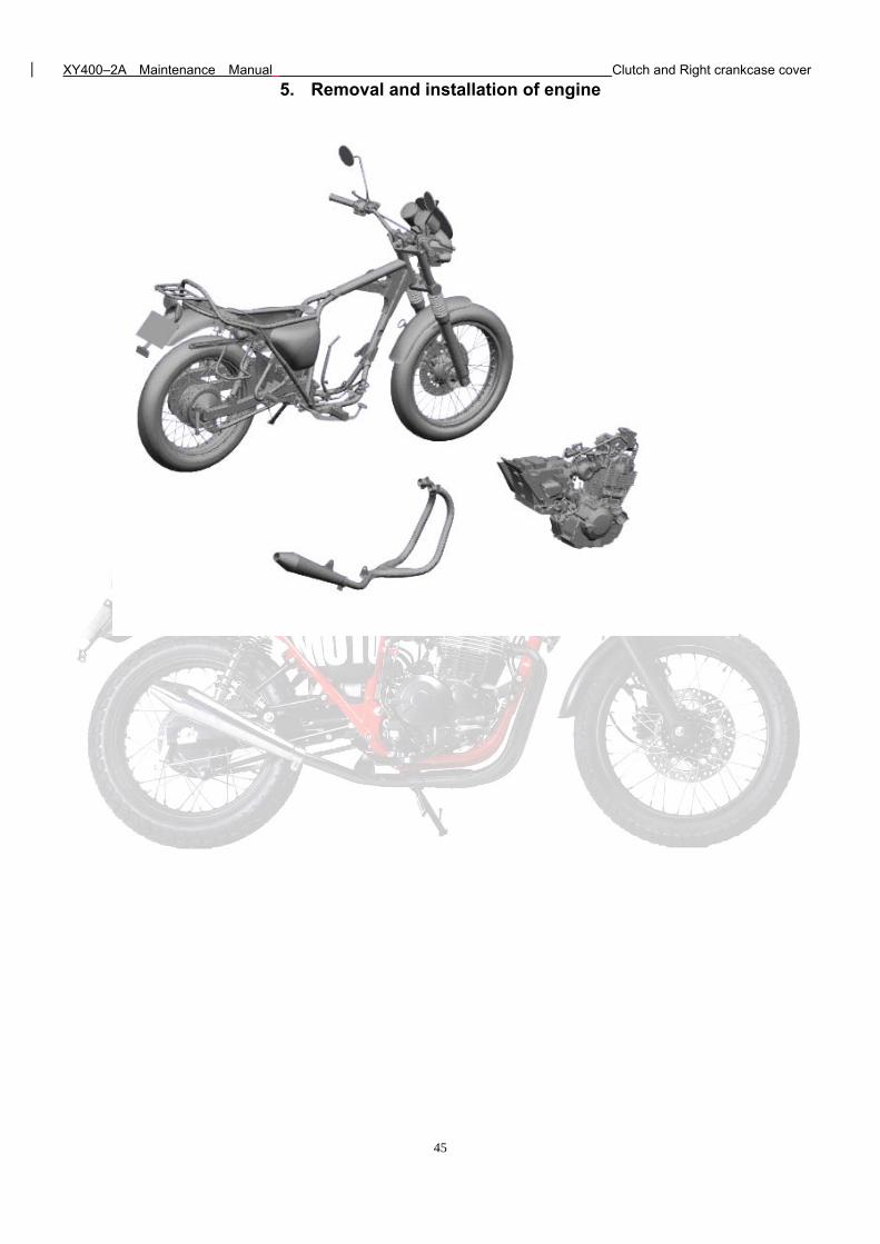
5. Removal and installation of engine
XY400–2A Maintenance Manual Clutch and Right crankcase cover
46
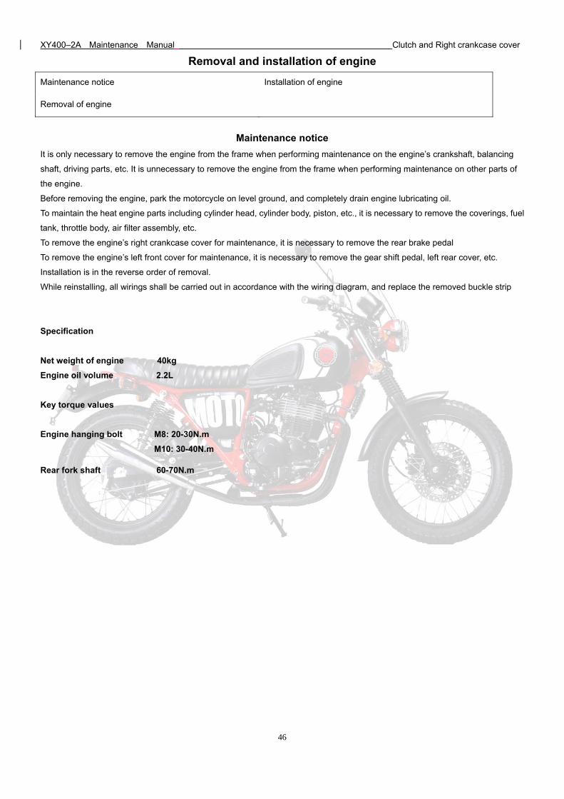
Removal and installation of engine
Maintenance notice Installation of engine
Removal of engine
Maintenance notice
It is only necessary to remove the engine from the frame when performing maintenance on the engine’s crankshaft, balancing
shaft, driving parts, etc. It is unnecessary to remove the engine from the frame when performing maintenance on other parts of
the engine.
Before removing the engine, park the motorcycle on level ground, and completely drain engine lubricating oil.
To maintain the heat engine parts including cylinder head, cylinder body, piston, etc., it is necessary to remove the coverings, fuel
tank, throttle body, air filter assembly, etc.
To remove the engine’s right crankcase cover for maintenance, it is necessary to remove the rear brake pedal
To remove the engine’s left front cover for maintenance, it is necessary to remove the gear shift pedal, left rear cover, etc.
Installation is in the reverse order of removal.
While reinstalling, all wirings shall be carried out in accordance with the wiring diagram, and replace the removed buckle strip
Specification
Net weight of engine 40kg
Engine oil volume 2.2L
Key torque values
Engine hanging bolt M8: 20-30N.m
M10: 30-40N.m
Rear fork shaft 60-70N.m
XY400–2A Maintenance Manual Clutch and Right crankcase cover
47
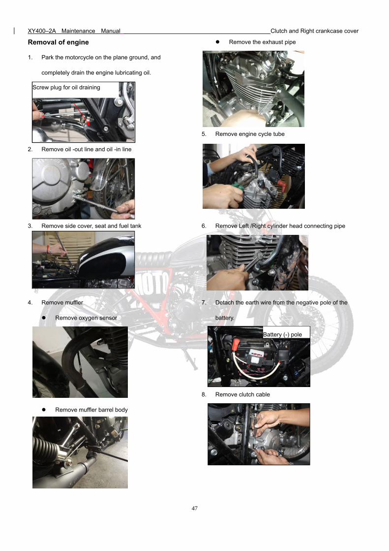
Removal of engine
1. Park the motorcycle on the plane ground, and
completely drain the engine lubricating oil.
2. Remove oil -out line and oil -in line
3. Remove side cover, seat and fuel tank
4. Remove muffler
Remove oxygen sensor
Remove muffler barrel body
Remove the exhaust pipe
5. Remove engine cycle tube
6. Remove Left /Right cylinder head connecting pipe
7. Detach the earth wire from the negative pole of the
battery.
8. Remove clutch cable
Screw plug for oil draining
Battery (-) pole
XY400–2A Maintenance Manual Clutch and Right crankcase cover
48
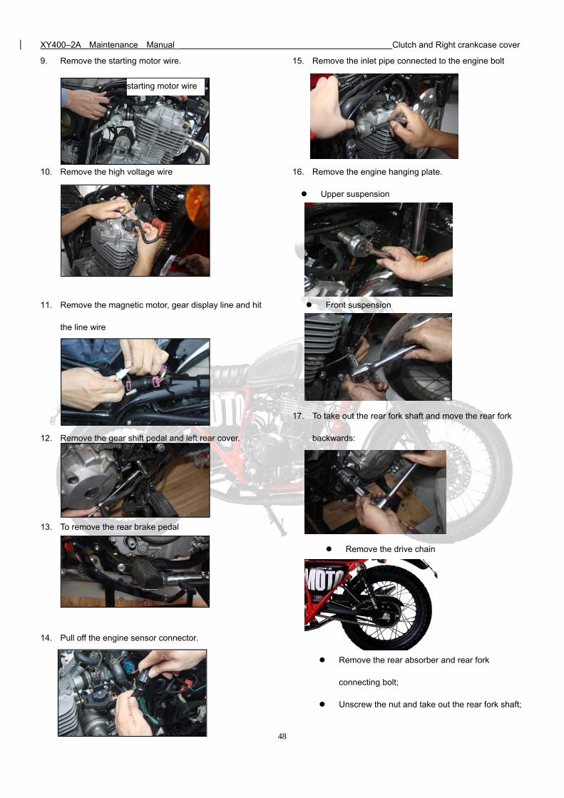
9. Remove the starting motor wire.
10. Remove the high voltage wire
11. Remove the magnetic motor, gear display line and hit
the line wire
12. Remove the gear shift pedal and left rear cover.
13. To remove the rear brake pedal
14. Pull off the engine sensor connector.
15. Remove the inlet pipe connected to the engine bolt
16. Remove the engine hanging plate.
Upper suspension
Front suspension
17. To take out the rear fork shaft and move the rear fork
backwards:
Remove the drive chain
Remove the rear absorber and rear fork
connecting bolt;
Unscrew the nut and take out the rear fork shaft;
starting motor wire
XY400–2A Maintenance Manual Clutch and Right crankcase cover
49
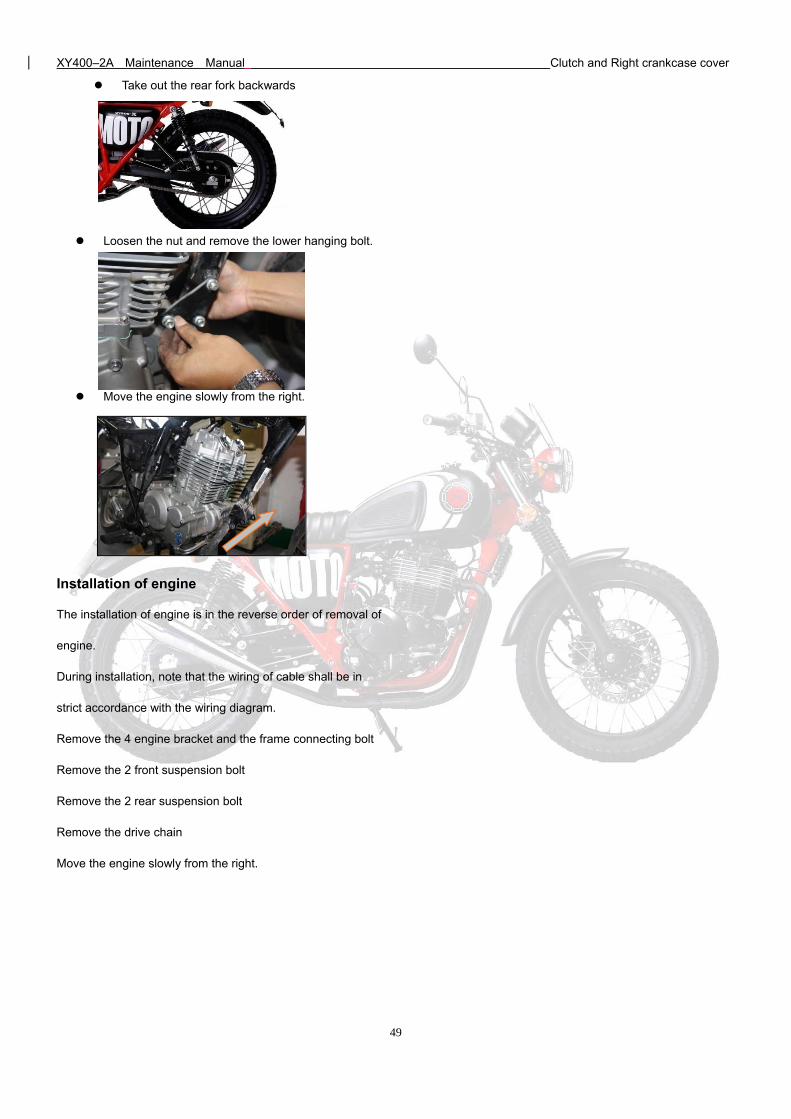
Take out the rear fork backwards
Loosen the nut and remove the lower hanging bolt.
Move the engine slowly from the right.
Installation of engine
The installation of engine is in the reverse order of removal of
engine.
During installation, note that the wiring of cable shall be in
strict accordance with the wiring diagram.
Remove the 4 engine bracket and the frame connecting bolt
Remove the 2 front suspension bolt
Remove the 2 rear suspension bolt
Remove the drive chain
Move the engine slowly from the right.
XY400–2A Maintenance Manual Clutch and Right crankcase cover
50
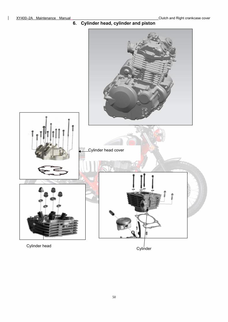
6. Cylinder head, cylinder and piston
Cylinder head cover
Cylinder head Cylinder
XY400–2A Maintenance Manual Clutch and Right crankcase cover
51
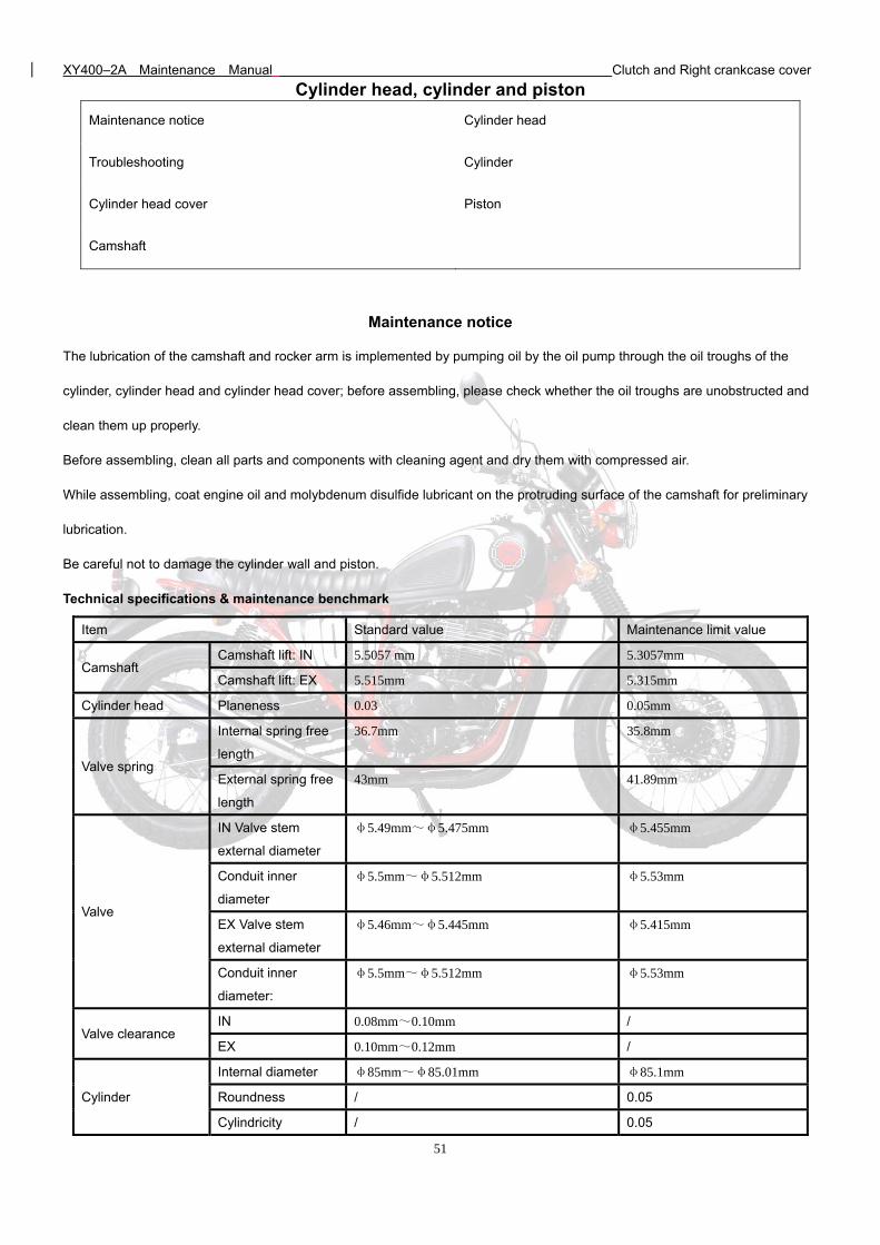
Cylinder head, cylinder and piston
Maintenance notice Cylinder head
Troubleshooting Cylinder
Cylinder head cover Piston
Camshaft
Maintenance notice
The lubrication of the camshaft and rocker arm is implemented by pumping oil by the oil pump through the oil troughs of the
cylinder, cylinder head and cylinder head cover; before assembling, please check whether the oil troughs are unobstructed and
clean them up properly.
Before assembling, clean all parts and components with cleaning agent and dry them with compressed air.
While assembling, coat engine oil and molybdenum disulfide lubricant on the protruding surface of the camshaft for preliminary
lubrication.
Be careful not to damage the cylinder wall and piston.
Technical specifications & maintenance benchmark
Item Standard value Maintenance limit value
Camshaft Camshaft lift: IN 5.5057 mm 5.3057mm
Camshaft lift: EX 5.515mm 5.315mm
Cylinder head Planeness 0.03 0.05mm
Valve spring
Internal spring free
length
36.7mm 35.8mm
External spring free
length
43mm 41.89mm
Valve
IN Valve stem
external diameter
φ5.49mm~φ5.475mm φ5.455mm
Conduit inner
diameter
φ5.5mm~φ5.512mm φ5.53mm
EX Valve stem
external diameter
φ5.46mm~φ5.445mm φ5.415mm
Conduit inner
diameter:
φ5.5mm~φ5.512mm φ5.53mm
Valve clearance IN 0.08mm~0.10mm /
EX 0.10mm~0.12mm /
Cylinder
Internal diameter φ85mm~φ85.01mm φ85.1mm
Roundness / 0.05
Cylindricity / 0.05
XY400–2A Maintenance Manual Clutch and Right crankcase cover
52
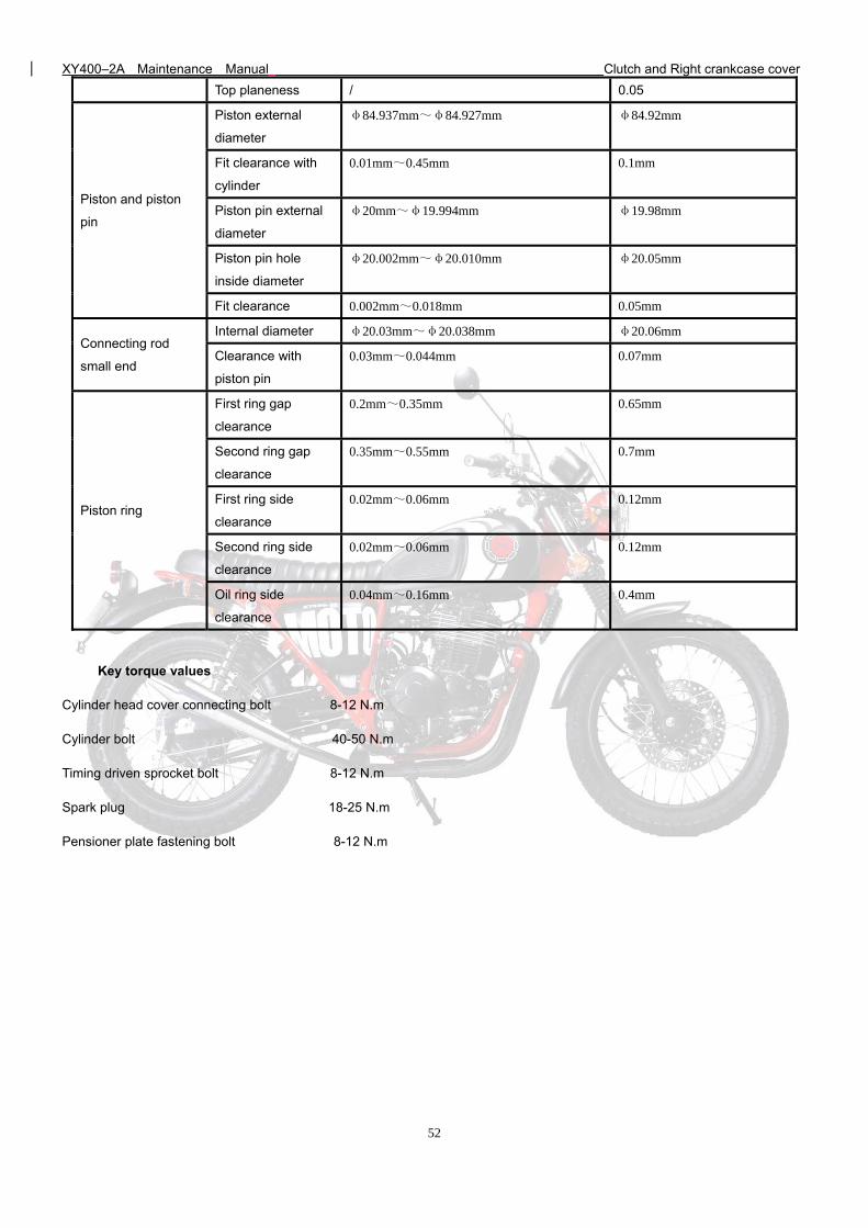
Top planeness / 0.05
Piston and piston
pin
Piston external
diameter
φ84.937mm~φ84.927mm φ84.92mm
Fit clearance with
cylinder
0.01mm~0.45mm 0.1mm
Piston pin external
diameter
φ20mm~φ19.994mm φ19.98mm
Piston pin hole
inside diameter
φ20.002mm~φ20.010mm φ20.05mm
Fit clearance 0.002mm~0.018mm 0.05mm
Connecting rod
small end
Internal diameter φ20.03mm~φ20.038mm φ20.06mm
Clearance with
piston pin
0.03mm~0.044mm 0.07mm
Piston ring
First ring gap
clearance
0.2mm~0.35mm 0.65mm
Second ring gap
clearance
0.35mm~0.55mm 0.7mm
First ring side
clearance
0.02mm~0.06mm 0.12mm
Second ring side
clearance
0.02mm~0.06mm 0.12mm
Oil ring side
clearance
0.04mm~0.16mm 0.4mm
Key torque values
Cylinder head cover connecting bolt 8-12 N.m
Cylinder bolt 40-50 N.m
Timing driven sprocket bolt 8-12 N.m
Spark plug 18-25 N.m
Pensioner plate fastening bolt 8-12 N.m
XY400–2A Maintenance Manual Clutch and Right crankcase cover
53
Troubleshooting
Low cylinder pressure
1) Valve:
--Incorrect valve clearance adjusted;
--Valve ablated or bent;
--Valve sealing failure;
--Incorrect valve timing;
--Valve spring damaged.
2) Cylinder head:
--Spark plug sealing failure;
--Cylinder head gasket leaked or damaged;
--Cylinder head cracked or blistered.
3) Cylinder and piston:
--Piston ring clearance too big or cracked;
--Piston cracked or damaged;
--Cylinder / piston ring worn.
Black smoke from exhaust
1) Valve guide worn;
2) Oil shield leaked or damaged;
3) Cylinder / piston / piston ring worn;
4) Piston ring clearance too big;
5) Piston ring incorrectly installed;
6) Piston or cylinder wall scratched or scuffed.
Excessive noise
1) Incorrect valve adjustment;
2) Valve jammed or valve spring broken;
3) Camshaft worn or damaged;
4) Timing chain too long, worn or damaged;
5) Timing chain tensioned failure;
6) Timing driven sprocket worn;
7) Cylinder / piston worn;
8) Rocker arm / Rocker-arm shaft worn;
9) Piston pin bore / piston pin worn.
Overheat / knocking (cylinder pressure too high)
1) Too much carbon deposited in combustion chamber.
XY400–2A Maintenance Manual Clutch and Right crankcase cover
54
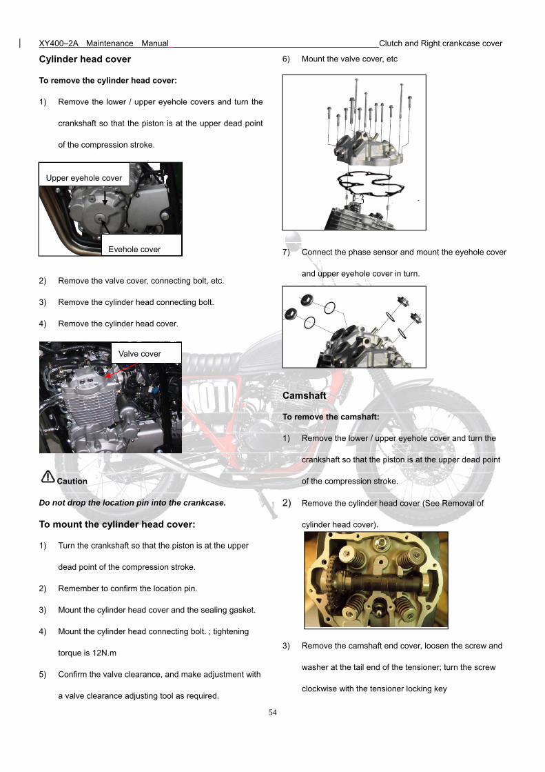
Cylinder head cover
To remove the cylinder head cover:
1) Remove the lower / upper eyehole covers and turn the
crankshaft so that the piston is at the upper dead point
of the compression stroke.
2) Remove the valve cover, connecting bolt, etc.
3) Remove the cylinder head connecting bolt.
4) Remove the cylinder head cover.
Caution
Do not drop the location pin into the crankcase.
To mount the cylinder head cover:
1) Turn the crankshaft so that the piston is at the upper
dead point of the compression stroke.
2) Remember to confirm the location pin.
3) Mount the cylinder head cover and the sealing gasket.
4) Mount the cylinder head connecting bolt. ; tightening
torque is 12N.m
5) Confirm the valve clearance, and make adjustment with
a valve clearance adjusting tool as required.
6) Mount the valve cover, etc
7) Connect the phase sensor and mount the eyehole cover
and upper eyehole cover in turn.
Camshaft
To remove the camshaft:
1) Remove the lower / upper eyehole cover and turn the
crankshaft so that the piston is at the upper dead point
of the compression stroke.
2) Remove the cylinder head cover (See Removal of
cylinder head cover).
3) Remove the camshaft end cover, loosen the screw and
washer at the tail end of the tensioner; turn the screw
clockwise with the tensioner locking key
Valve cover
Upper eyehole cover
Eyehole cover
XY400–2A Maintenance Manual Clutch and Right crankcase cover
55
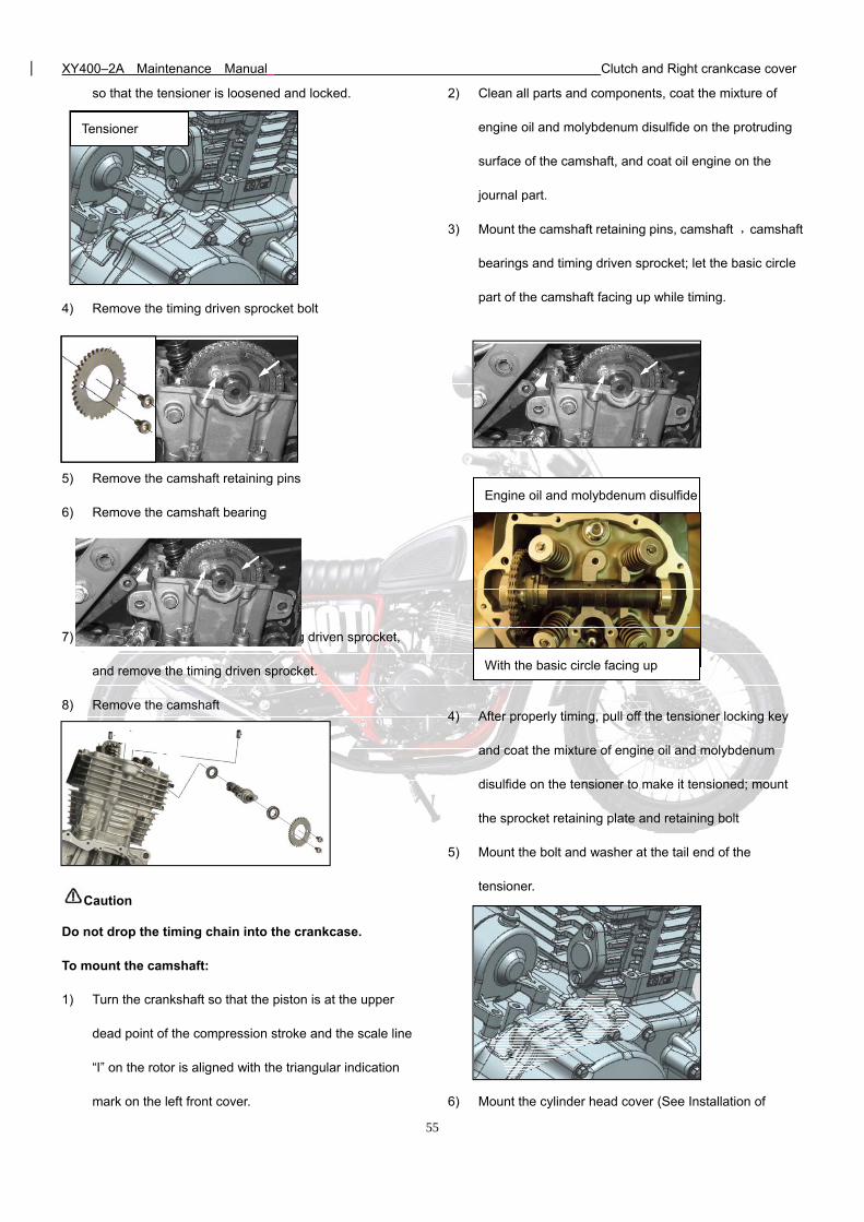
so that the tensioner is loosened and locked.
4) Remove the timing driven sprocket bolt
5) Remove the camshaft retaining pins
6) Remove the camshaft bearing
7) Strip the timing chain from the timing driven sprocket,
and remove the timing driven sprocket.
8) Remove the camshaft
Caution
Do not drop the timing chain into the crankcase.
To mount the camshaft:
1) Turn the crankshaft so that the piston is at the upper
dead point of the compression stroke and the scale line
“I” on the rotor is aligned with the triangular indication
mark on the left front cover.
2) Clean all parts and components, coat the mixture of
engine oil and molybdenum disulfide on the protruding
surface of the camshaft, and coat oil engine on the
journal part.
3) Mount the camshaft retaining pins, camshaft ,camshaft
bearings and timing driven sprocket; let the basic circle
part of the camshaft facing up while timing.
4) After properly timing, pull off the tensioner locking key
and coat the mixture of engine oil and molybdenum
disulfide on the tensioner to make it tensioned; mount
the sprocket retaining plate and retaining bolt
5) Mount the bolt and washer at the tail end of the
tensioner.
6) Mount the cylinder head cover (See Installation of
Tensioner
Engine oil and molybdenum disulfide
With the basic circle facing up
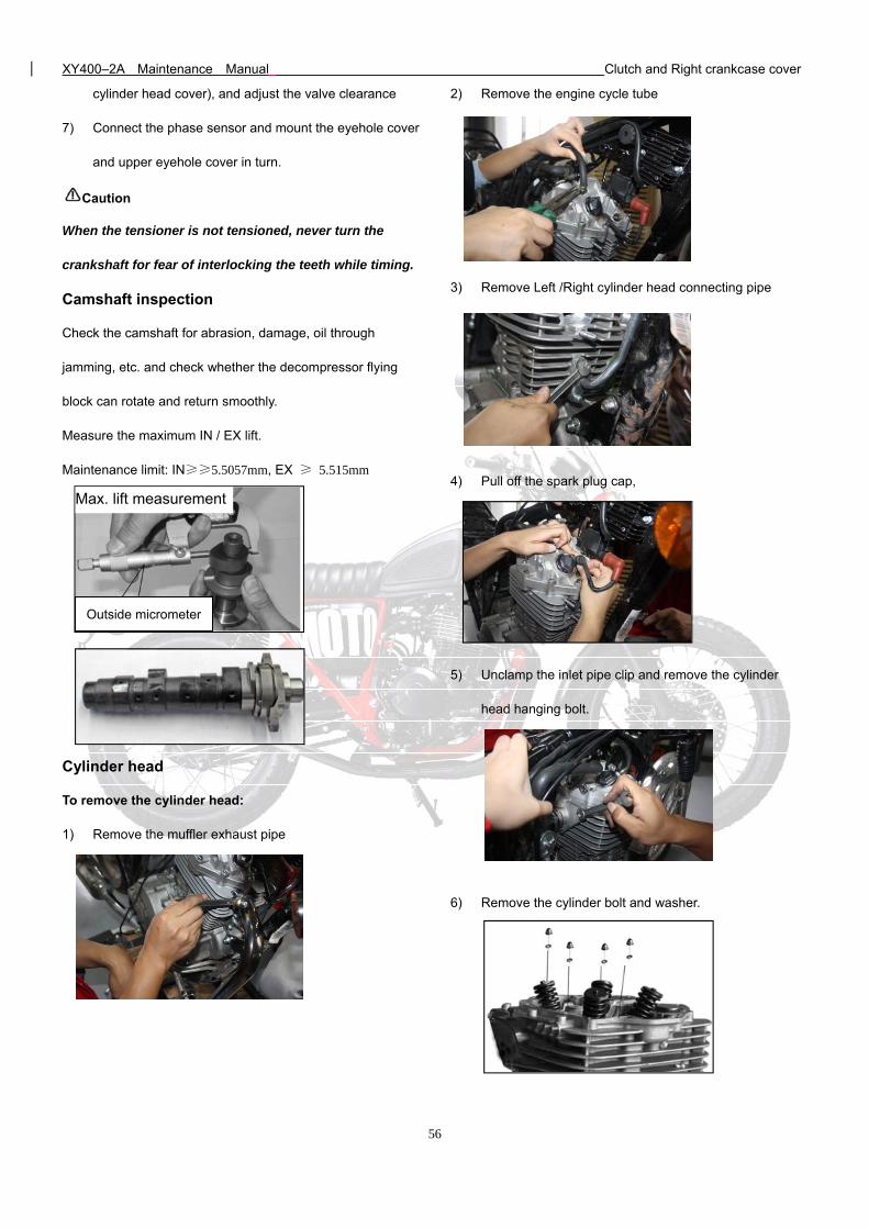
XY400–2A Maintenance Manual Clutch and Right crankcase cover
56
cylinder head cover), and adjust the valve clearance
7) Connect the phase sensor and mount the eyehole cover
and upper eyehole cover in turn.
Caution
When the tensioner is not tensioned, never turn the
crankshaft for fear of interlocking the teeth while timing.
Camshaft inspection
Check the camshaft for abrasion, damage, oil through
jamming, etc. and check whether the decompressor flying
block can rotate and return smoothly.
Measure the maximum IN / EX lift.
Maintenance limit: IN≥≥5.5057mm, EX ≥ 5.515mm
Cylinder head
To remove the cylinder head:
1) Remove the muffler exhaust pipe
2) Remove the engine cycle tube
3) Remove Left /Right cylinder head connecting pipe
4) Pull off the spark plug cap,
5) Unclamp the inlet pipe clip and remove the cylinder
head hanging bolt.
6) Remove the cylinder bolt and washer.
Max. lift measurement
Outside micrometer
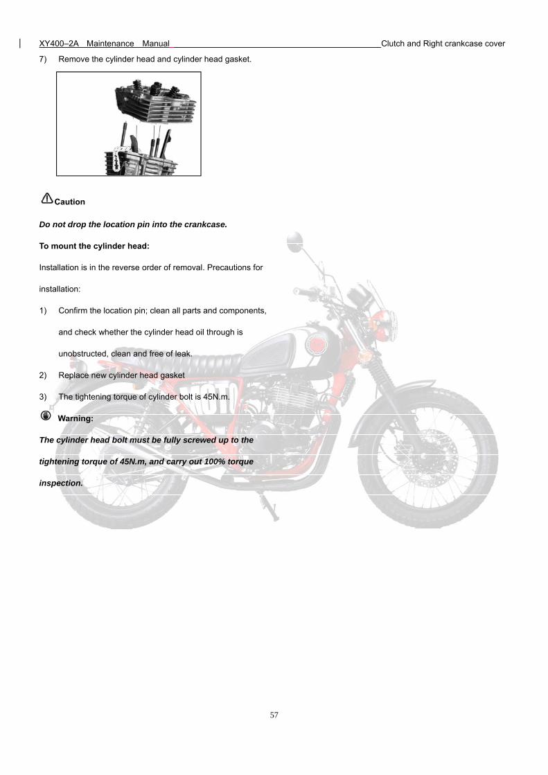
XY400–2A Maintenance Manual Clutch and Right crankcase cover
57
7) Remove the cylinder head and cylinder head gasket.
Caution
Do not drop the location pin into the crankcase.
To mount the cylinder head:
Installation is in the reverse order of removal. Precautions for
installation:
1) Confirm the location pin; clean all parts and components,
and check whether the cylinder head oil through is
unobstructed, clean and free of leak.
2) Replace new cylinder head gasket
3) The tightening torque of cylinder bolt is 45N.m.
Warning:
The cylinder head bolt must be fully screwed up to the
tightening torque of 45N.m, and carry out 100% torque
inspection.
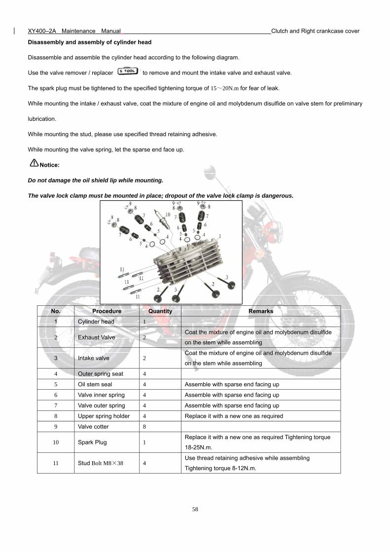
XY400–2A Maintenance Manual Clutch and Right crankcase cover
58
Disassembly and assembly of cylinder head
Disassemble and assemble the cylinder head according to the following diagram.
Use the valve remover / replacer to remove and mount the intake valve and exhaust valve.
The spark plug must be tightened to the specified tightening torque of 15~20N.m for fear of leak.
While mounting the intake / exhaust valve, coat the mixture of engine oil and molybdenum disulfide on valve stem for preliminary
lubrication.
While mounting the stud, please use specified thread retaining adhesive.
While mounting the valve spring, let the sparse end face up.
Notice:
Do not damage the oil shield lip while mounting.
The valve lock clamp must be mounted in place; dropout of the valve lock clamp is dangerous.
No. Procedure Quantity Remarks
1 Cylinder head 1
2 Exhaust Valve 2 Coat the mixture of engine oil and molybdenum disulfide
on the stem while assembling
3 Intake valve 2 Coat the mixture of engine oil and molybdenum disulfide
on the stem while assembling
4 Outer spring seat 4
5 Oil stem seal 4 Assemble with sparse end facing up
6 Valve inner spring 4 Assemble with sparse end facing up
7 Valve outer spring 4 Assemble with sparse end facing up
8 Upper spring holder 4 Replace it with a new one as required
9 Valve cotter 8
10 Spark Plug 1 Replace it with a new one as required Tightening torque
18-25N.m.
11 Stud Bolt M8×38 4 Use thread retaining adhesive while assembling
Tightening torque 8-12N.m.
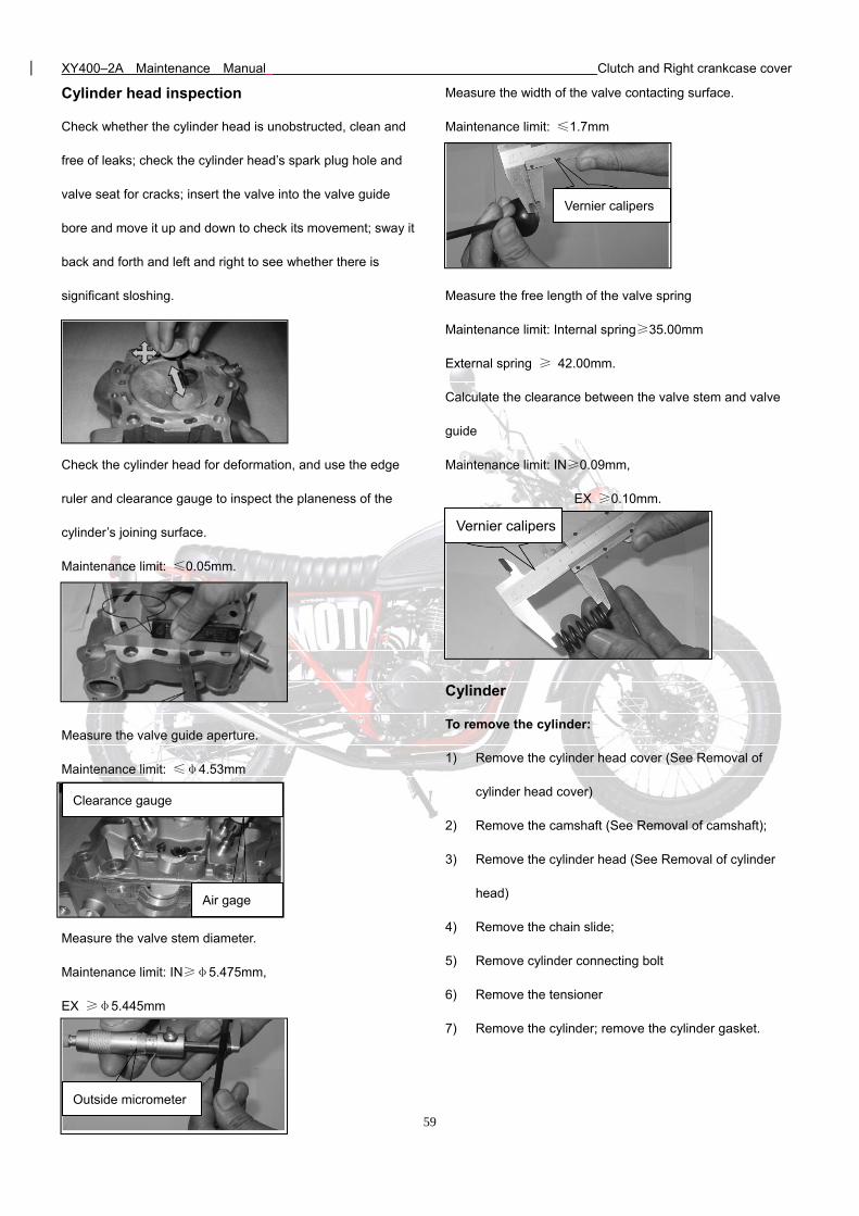
XY400–2A Maintenance Manual Clutch and Right crankcase cover
59
Cylinder head inspection
Check whether the cylinder head is unobstructed, clean and
free of leaks; check the cylinder head’s spark plug hole and
valve seat for cracks; insert the valve into the valve guide
bore and move it up and down to check its movement; sway it
back and forth and left and right to see whether there is
significant sloshing.
Check the cylinder head for deformation, and use the edge
ruler and clearance gauge to inspect the planeness of the
cylinder’s joining surface.
Maintenance limit: ≤0.05mm.
Measure the valve guide aperture.
Maintenance limit: ≤φ4.53mm
Measure the valve stem diameter.
Maintenance limit: IN≥φ5.475mm,
EX ≥φ5.445mm
Measure the width of the valve contacting surface.
Maintenance limit: ≤1.7mm
Measure the free length of the valve spring
Maintenance limit: Internal spring≥35.00mm
External spring ≥ 42.00mm.
Calculate the clearance between the valve stem and valve
guide
Maintenance limit: IN≥0.09mm,
EX ≥0.10mm.
Cylinder
To remove the cylinder:
1) Remove the cylinder head cover (See Removal of
cylinder head cover)
2) Remove the camshaft (See Removal of camshaft);
3) Remove the cylinder head (See Removal of cylinder
head)
4) Remove the chain slide;
5) Remove cylinder connecting bolt
6) Remove the tensioner
7) Remove the cylinder; remove the cylinder gasket.
Clearance gauge
Air gage
Outside micrometer
Vernier calipers
Vernier calipers
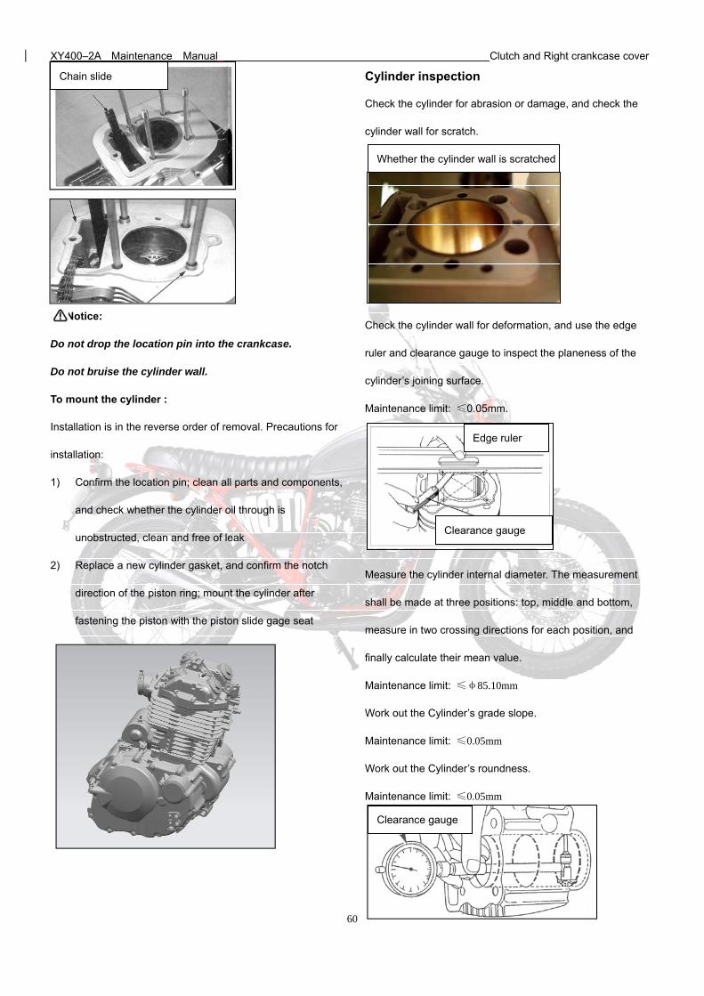
XY400–2A Maintenance Manual Clutch and Right crankcase cover
60
Notice:
Do not drop the location pin into the crankcase.
Do not bruise the cylinder wall.
To mount the cylinder :
Installation is in the reverse order of removal. Precautions for
installation:
1) Confirm the location pin; clean all parts and components,
and check whether the cylinder oil through is
unobstructed, clean and free of leak
2) Replace a new cylinder gasket, and confirm the notch
direction of the piston ring; mount the cylinder after
fastening the piston with the piston slide gage seat
Cylinder inspection
Check the cylinder for abrasion or damage, and check the
cylinder wall for scratch.
Check the cylinder wall for deformation, and use the edge
ruler and clearance gauge to inspect the planeness of the
cylinder’s joining surface.
Maintenance limit: ≤0.05mm.
Measure the cylinder internal diameter. The measurement
shall be made at three positions: top, middle and bottom,
measure in two crossing directions for each position, and
finally calculate their mean value.
Maintenance limit: ≤φ85.10mm
Work out the Cylinder’s grade slope.
Maintenance limit: ≤0.05mm
Work out the Cylinder’s roundness.
Maintenance limit: ≤0.05mm
Chain slide
Whether the cylinder wall is scratched
Clearance gauge
Edge ruler
Clearance gauge
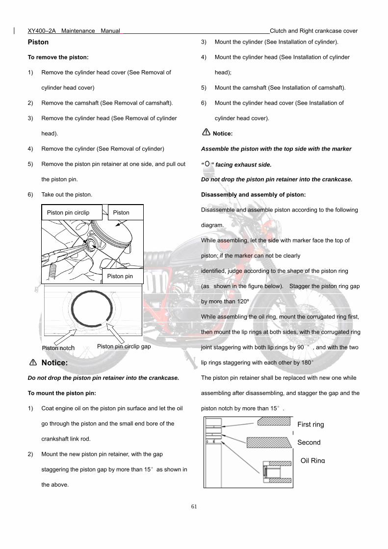
XY400–2A Maintenance Manual Clutch and Right crankcase cover
61
Piston
To remove the piston:
1) Remove the cylinder head cover (See Removal of
cylinder head cover)
2) Remove the camshaft (See Removal of camshaft).
3) Remove the cylinder head (See Removal of cylinder
head).
4) Remove the cylinder (See Removal of cylinder)
5) Remove the piston pin retainer at one side, and pull out
the piston pin.
6) Take out the piston.
Notice:
Do not drop the piston pin retainer into the crankcase.
To mount the piston pin:
1) Coat engine oil on the piston pin surface and let the oil
go through the piston and the small end bore of the
crankshaft link rod.
2) Mount the new piston pin retainer, with the gap
staggering the piston gap by more than 15°as shown in
the above.
3) Mount the cylinder (See Installation of cylinder).
4) Mount the cylinder head (See Installation of cylinder
head);
5) Mount the camshaft (See Installation of camshaft).
6) Mount the cylinder head cover (See Installation of
cylinder head cover).
Notice:
Assemble the piston with the top side with the marker
“ ” facing exhaust side.
Do not drop the piston pin retainer into the crankcase.
Disassembly and assembly of piston:
Disassemble and assemble piston according to the following
diagram.
While assembling, let the side with marker face the top of
piston; if the marker can not be clearly
identified, judge according to the shape of the piston ring
(as shown in the figure below). Stagger the piston ring gap
by more than 120º
While assembling the oil ring, mount the corrugated ring first,
then mount the lip rings at both sides, with the corrugated ring
joint staggering with both lip rings by 90 °, and with the two
lip rings staggering with each other by 180°
The piston pin retainer shall be replaced with new one while
assembling after disassembling, and stagger the gap and the
piston notch by more than 15°.
Piston
Piston pin
Piston pin circlip
Piston notch Piston pin circlip gap
First ring
Second
Oil Ring
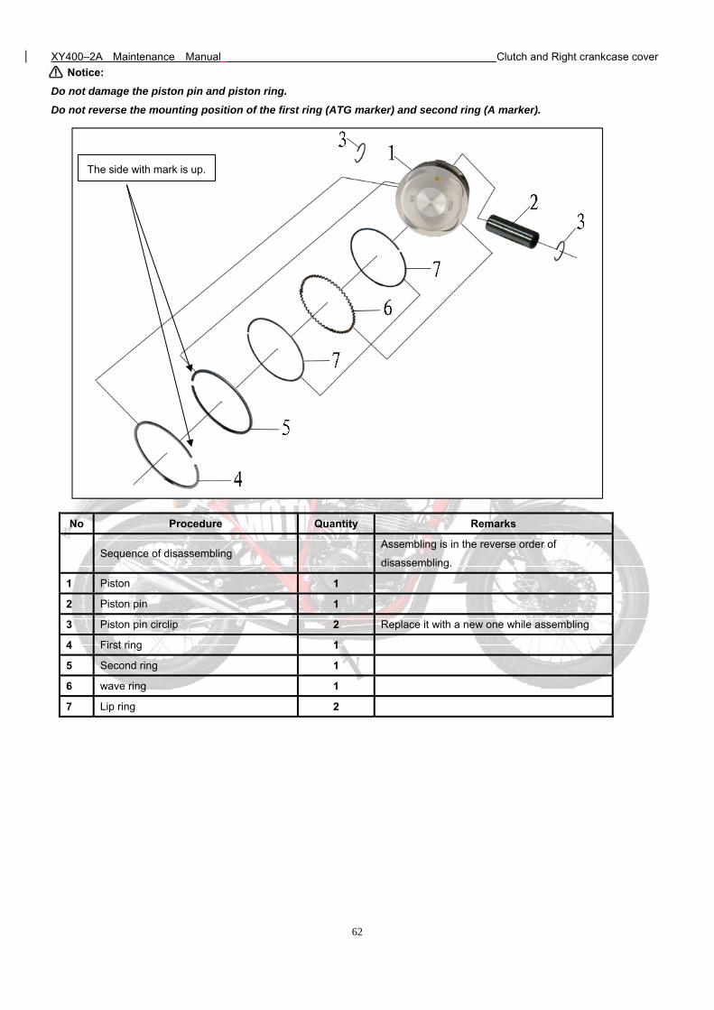
XY400–2A Maintenance Manual Clutch and Right crankcase cover
62
Notice:
Do not damage the piston pin and piston ring.
Do not reverse the mounting position of the first ring (ATG marker) and second ring (A marker).
No Procedure Quantity Remarks
Sequence of disassembling Assembling is in the reverse order of
disassembling.
1 Piston 1
2 Piston pin 1
3 Piston pin circlip 2 Replace it with a new one while assembling
4 First ring 1
5 Second ring 1
6 wave ring 1
7 Lip ring 2
The side with mark is up.
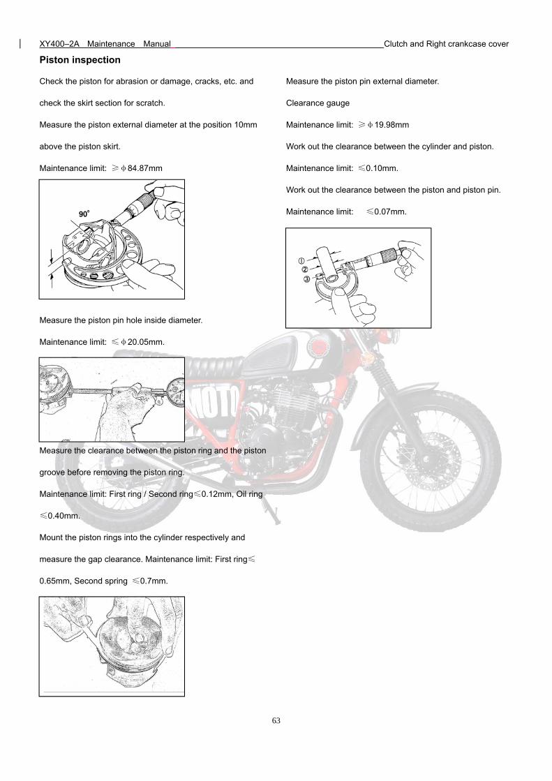
XY400–2A Maintenance Manual Clutch and Right crankcase cover
63
Piston inspection
Check the piston for abrasion or damage, cracks, etc. and
check the skirt section for scratch.
Measure the piston external diameter at the position 10mm
above the piston skirt.
Maintenance limit: ≥φ84.87mm
Measure the piston pin hole inside diameter.
Maintenance limit: ≤φ20.05mm.
Measure the clearance between the piston ring and the piston
groove before removing the piston ring.
Maintenance limit: First ring / Second ring≤0.12mm, Oil ring
≤0.40mm.
Mount the piston rings into the cylinder respectively and
measure the gap clearance. Maintenance limit: First ring≤
0.65mm, Second spring ≤0.7mm.
Measure the piston pin external diameter.
Clearance gauge
Maintenance limit: ≥φ19.98mm
Work out the clearance between the cylinder and piston.
Maintenance limit: ≤0.10mm.
Work out the clearance between the piston and piston pin.
Maintenance limit: ≤0.07mm.
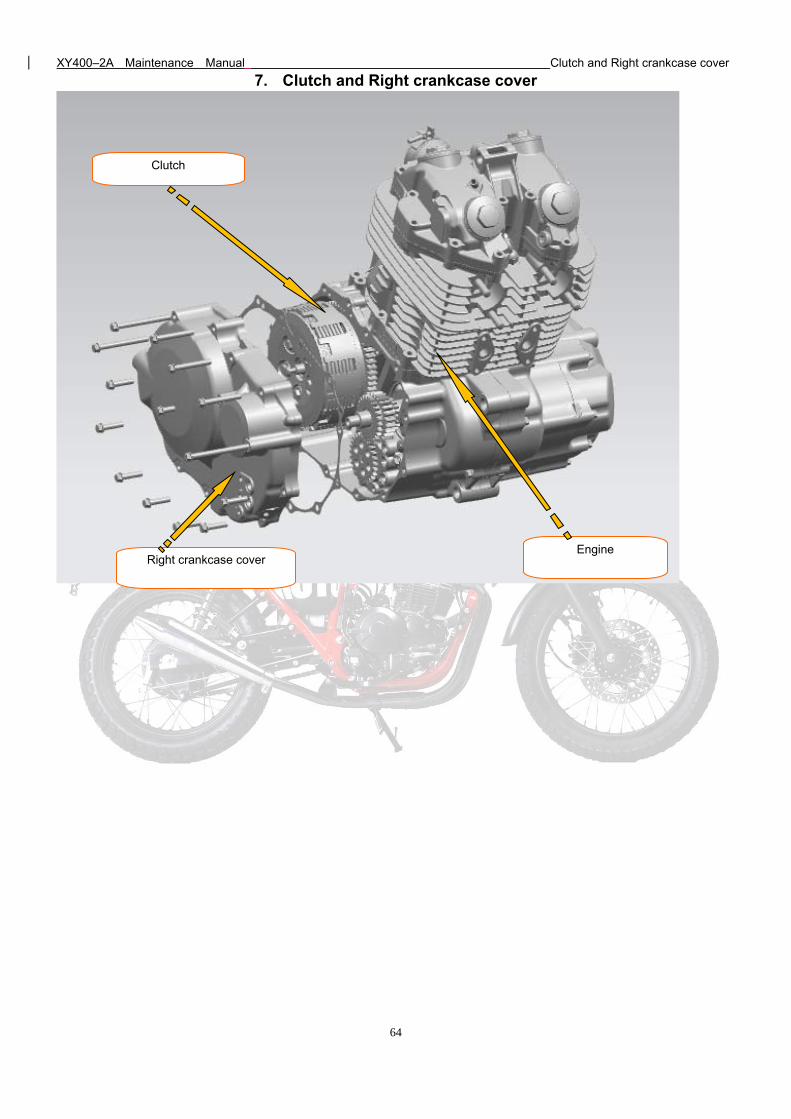
XY400–2A Maintenance Manual Clutch and Right crankcase cover
64
7. Clutch and Right crankcase cover
Clutch
Right crankcase cover Engine
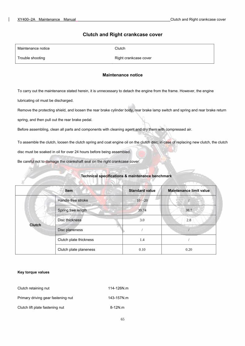
XY400–2A Maintenance Manual Clutch and Right crankcase cover
65
Clutch and Right crankcase cover
Maintenance notice Clutch
Trouble shooting Right crankcase cover
Maintenance notice
To carry out the maintenance stated herein, it is unnecessary to detach the engine from the frame. However, the engine
lubricating oil must be discharged.
Remove the protecting shield, and loosen the rear brake cylinder body, rear brake lamp switch and spring and rear brake return
spring, and then pull out the rear brake pedal.
Before assembling, clean all parts and components with cleaning agent and dry them with compressed air.
To assemble the clutch, loosen the clutch spring and coat engine oil on the clutch disc; in case of replacing new clutch, the clutch
disc must be soaked in oil for over 24 hours before being assembled.
Be careful not to damage the crankshaft seal on the right crankcase cover.
Technical specifications & maintenance benchmark
Item Standard value Maintenance limit value
Clutch
Handle free stroke 10~20 /
Spring free length 39.74 38.7
Disc thickness 3.0 2.8
Disc planeness / /
Clutch plate thickness 1.4 /
Clutch plate planeness 0.10 0.20
Key torque values
Clutch retaining nut 114-126N.m
Primary driving gear fastening nut 143-157N.m
Clutch lift plate fastening nut 8-12N.m
XY400–2A Maintenance Manual Clutch and Right crankcase cover
66
Troubleshooting
Clutch
In case of clutch operation failure, a better correction may usually achieved by adjusting the clutch handle free stroke.
Clutch slipping while accelerating
1) Insufficient free stroke;
2) Clutch disc abrasion;
3) Clutch plate deformed or bent;
4) Clutch spring failure.
Excessive handle pressure
1) Clutch cable galling, damaged or dirty;
2) Clutch push rod damaged or jammed.
Hard clutch operation
There is burr on clutch housing chute.
Shift lever can’t return
1) Return spring cracked or slipped;
2) Transmission shaft plate convenes with crankcase or crankcase cover.
Vehicle moves slowly upon firmly grabbing the handle
1) Excessive handle free stroke
2) Clutch plate deformed or bent.
Hard shifting or impossible to shift
1) Locating plate bent;
2) Stopping plate assembly damaged or cracked;
3) Shifting yoke cracked or slipped;
4) Clutch improperly adjusted.
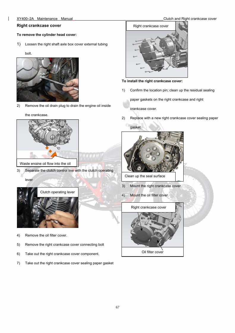
XY400–2A Maintenance Manual Clutch and Right crankcase cover
67
Right crankcase cover
Oil filter cover
Right crankcase cover
To remove the cylinder head cover:
1) Loosen the right shaft axle box cover external tubing
bolt.
2) Remove the oil drain plug to drain the engine oil inside
the crankcase.
3) Separate the clutch control line with the clutch operating
lever
4) Remove the oil filter cover.
5) Remove the right crankcase cover connecting bolt
6) Take out the right crankcase cover component.
7) Take out the right crankcase cover sealing paper gasket
To install the right crankcase cover:
1) Confirm the location pin; clean up the residual sealing
paper gaskets on the right crankcase and right
crankcase cover.
2) Replace with a new right crankcase cover sealing paper
gasket.
3) Mount the right crankcase cover.
4) Mount the oil filter cover.
Clutch operating lever
Right crankcase cover
Waste engine oil flow into the oil
Clean up the seal surface
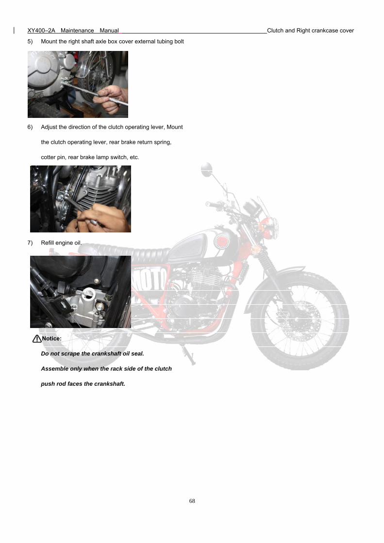
XY400–2A Maintenance Manual Clutch and Right crankcase cover
68
5) Mount the right shaft axle box cover external tubing bolt
6) Adjust the direction of the clutch operating lever, Mount
the clutch operating lever, rear brake return spring,
cotter pin, rear brake lamp switch, etc.
7) Refill engine oil.
Notice:
Do not scrape the crankshaft oil seal.
Assemble only when the rack side of the clutch
push rod faces the crankshaft.
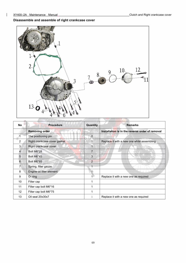
XY400–2A Maintenance Manual Clutch and Right crankcase cover
69
Disassemble and assemble of right crankcase cover
No Procedure Quantity Remarks
Removing order Installation is in the reverse order of removal
1 The positioning pin 2
2 Right crankcase cover gasket 1 Replace it with a new one while assembling
3 Right crankcase cover 1
4 Bolt M6*28 7
5 Bolt M6*45 3
6 Bolt M6*65 2
7 Spring, filter gauze 1
8 Engine oil filter element 1
9 O- ring 1 Replace it with a new one as required
10 Filter cap 1
11 Filter cap bolt M6*16 1
12 Filter cap bolt M6*75 1
13 Oil seal 20x30x7 1 Replace it with a new one as required
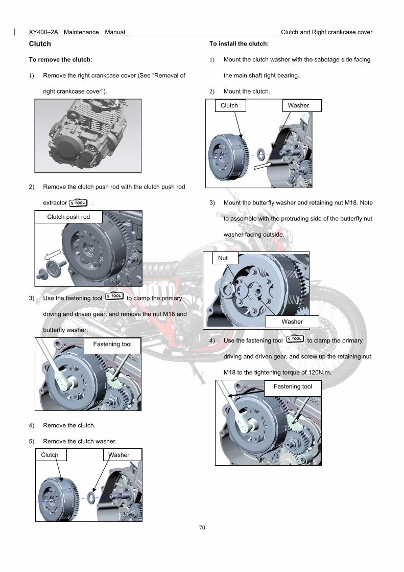
XY400–2A Maintenance Manual Clutch and Right crankcase cover
70
Clutch
To remove the clutch:
1) Remove the right crankcase cover (See “Removal of
right crankcase cover").
2) Remove the clutch push rod with the clutch push rod
extractor .
3) Use the fastening tool to clamp the primary
driving and driven gear, and remove the nut M18 and
butterfly washer.
4) Remove the clutch.
5) Remove the clutch washer.
To install the clutch:
1) Mount the clutch washer with the sabotage side facing
the main shaft right bearing.
2) Mount the clutch.
3) Mount the butterfly washer and retaining nut M18. Note
to assemble with the protruding side of the butterfly nut
washer facing outside.
4) Use the fastening tool to clamp the primary
driving and driven gear, and screw up the retaining nut
M18 to the tightening torque of 120N.m.
Clutch push rod
Nut
Washer
Clutch Washer
Clutch Washer
Fastening tool
Fastening tool
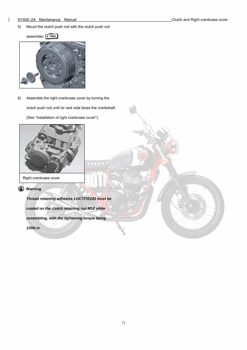
XY400–2A Maintenance Manual Clutch and Right crankcase cover
71
5) Mount the clutch push rod with the clutch push rod
assembler .
6) Assemble the right crankcase cover by turning the
clutch push rod until its rack side faces the crankshaft.
(See “Installation of right crankcase cover").
Warning
Thread retaining adhesive LOCTITE243 must be
coated on the clutch retaining nut M18 while
assembling, with the tightening torque being
120N.m.
Right crankcase cover
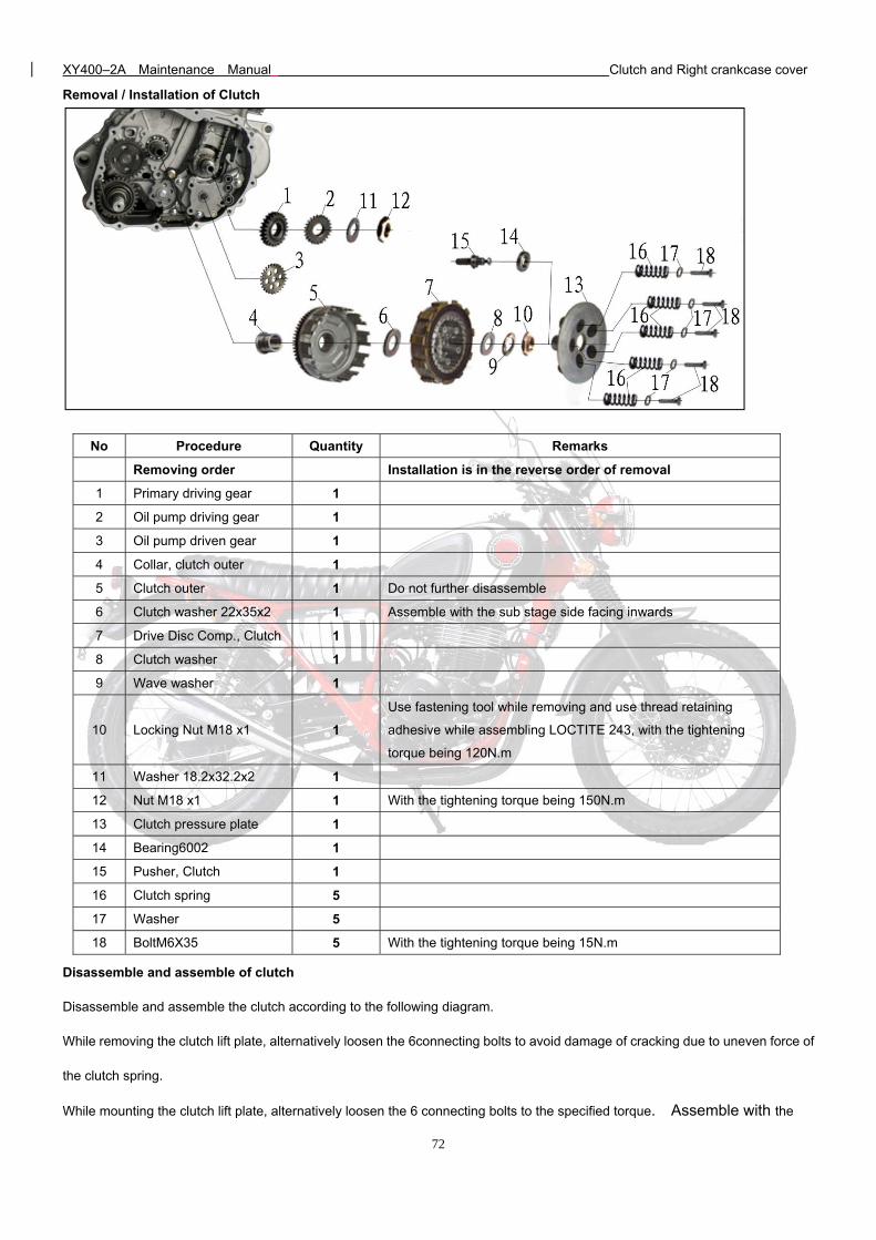
XY400–2A Maintenance Manual Clutch and Right crankcase cover
72
Removal / Installation of Clutch
No Procedure Quantity Remarks
Removing order Installation is in the reverse order of removal
1 Primary driving gear 1
2 Oil pump driving gear 1
3 Oil pump driven gear 1
4 Collar, clutch outer 1
5 Clutch outer 1 Do not further disassemble
6 Clutch washer 22x35x2 1 Assemble with the sub stage side facing inwards
7 Drive Disc Comp., Clutch 1
8 Clutch washer 1
9 Wave washer 1
10 Locking Nut M18 x1 1
Use fastening tool while removing and use thread retaining
adhesive while assembling LOCTITE 243, with the tightening
torque being 120N.m
11 Washer 18.2x32.2x2 1
12 Nut M18 x1 1 With the tightening torque being 150N.m
13 Clutch pressure plate 1
14 Bearing6002 1
15 Pusher, Clutch 1
16 Clutch spring 5
17 Washer 5
18 BoltM6X35 5 With the tightening torque being 15N.m
Disassemble and assemble of clutch
Disassemble and assemble the clutch according to the following diagram.
While removing the clutch lift plate, alternatively loosen the 6connecting bolts to avoid damage of cracking due to uneven force of
the clutch spring.
While mounting the clutch lift plate, alternatively loosen the 6 connecting bolts to the specified torque. Assemble with the
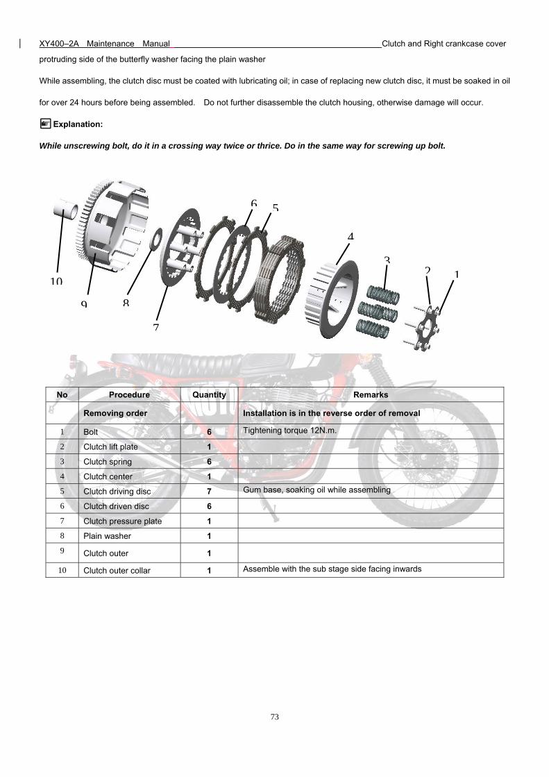
XY400–2A Maintenance Manual Clutch and Right crankcase cover
73
protruding side of the butterfly washer facing the plain washer
While assembling, the clutch disc must be coated with lubricating oil; in case of replacing new clutch disc, it must be soaked in oil
for over 24 hours before being assembled. Do not further disassemble the clutch housing, otherwise damage will occur.
Explanation:
While unscrewing bolt, do it in a crossing way twice or thrice. Do in the same way for screwing up bolt.
No Procedure Quantity Remarks
Removing order Installation is in the reverse order of removal
1 Bolt 6 Tightening torque 12N.m.
2 Clutch lift plate 1
3 Clutch spring 6
4 Clutch center 1
5 Clutch driving disc 7 Gum base, soaking oil while assembling
6 Clutch driven disc 6
7 Clutch pressure plate 1
8 Plain washer 1
9 Clutch outer 1
10 Clutch outer collar 1 Assemble with the sub stage side facing inwards
123
4
56
7
89
10
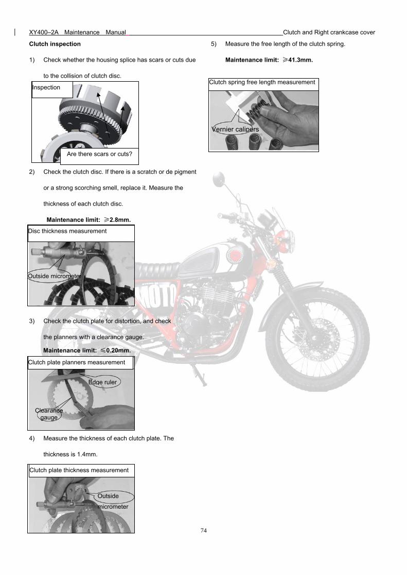
XY400–2A Maintenance Manual Clutch and Right crankcase cover
74
Edge ruler
Clearance gauge
Clutch inspection
1) Check whether the housing splice has scars or cuts due
to the collision of clutch disc.
2) Check the clutch disc. If there is a scratch or de pigment
or a strong scorching smell, replace it. Measure the
thickness of each clutch disc.
Maintenance limit: ≥2.8mm.
3) Check the clutch plate for distortion, and check
the planners with a clearance gauge.
Maintenance limit: ≤0.20mm.
4) Measure the thickness of each clutch plate. The
thickness is 1.4mm.
5) Measure the free length of the clutch spring.
Maintenance limit: ≥41.3mm.
Clutch plate planners measurement
Clutch plate thickness measurement
Outside
micrometer
Inspection
Are there scars or cuts?
Disc thickness measurement
Outside micrometer
Clutch spring free length measurement
Vernier calipers
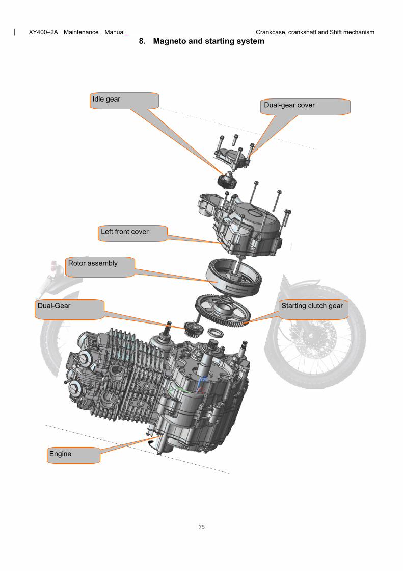
XY400–2A Maintenance Manual Crankcase, crankshaft and Shift mechanism
75
8. Magneto and starting system
Engine
Dual-Gear
Rotor assembly
Left front cover
Idle gear
Starting clutch gear
Dual-gear cover
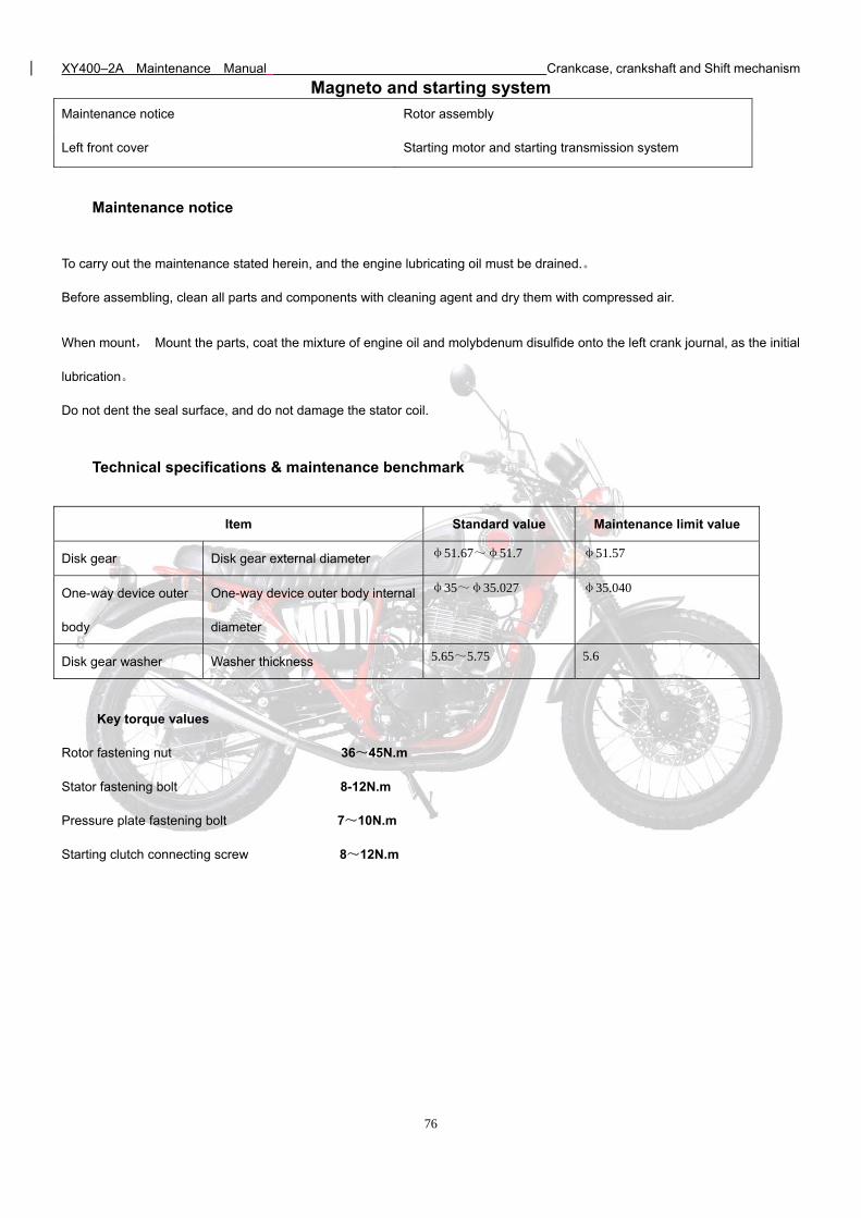
XY400–2A Maintenance Manual Crankcase, crankshaft and Shift mechanism
76
Magneto and starting system
Maintenance notice Rotor assembly
Left front cover Starting motor and starting transmission system
Maintenance notice
To carry out the maintenance stated herein, and the engine lubricating oil must be drained.。
Before assembling, clean all parts and components with cleaning agent and dry them with compressed air.
When mount, Mount the parts, coat the mixture of engine oil and molybdenum disulfide onto the left crank journal, as the initial
lubrication。
Do not dent the seal surface, and do not damage the stator coil.
Technical specifications & maintenance benchmark
Item Standard value Maintenance limit value
Disk gear Disk gear external diameter φ51.67~φ51.7 φ51.57
One-way device outer
body
One-way device outer body internal
diameter
φ35~φ35.027 φ35.040
Disk gear washer Washer thickness 5.65~5.75 5.6
Key torque values
Rotor fastening nut 36~45N.m
Stator fastening bolt 8-12N.m
Pressure plate fastening bolt 7~10N.m
Starting clutch connecting screw 8~12N.m
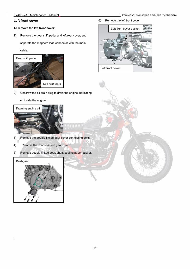
XY400–2A Maintenance Manual Crankcase, crankshaft and Shift mechanism
77
Left front cover
To remove the left front cover:
1) Remove the gear shift pedal and left rear cover, and
separate the magneto lead connector with the main
cable.
2) Unscrew the oil drain plug to drain the engine lubricating
oil inside the engine
3) Remove the double-linked gear cover connecting bolts
4) Remove the double-linked gear cover..
5) Remove double-linked gear, shaft, sealing paper gasket.
]
6) Remove the left front cover.
Dual-gear
Left front cover gasket
Left front cover
Draining engine oil
Left rear plate
Gear shift pedal
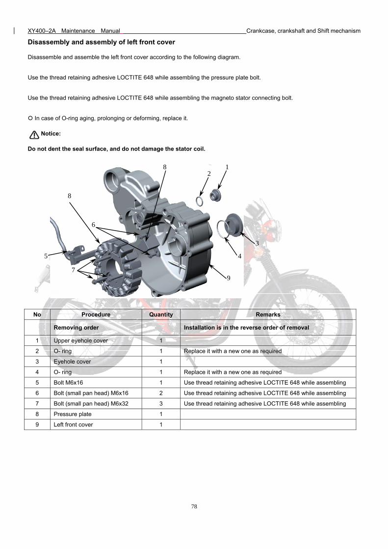
XY400–2A Maintenance Manual Crankcase, crankshaft and Shift mechanism
78
Disassembly and assembly of left front cover
Disassemble and assemble the left front cover according to the following diagram.
Use the thread retaining adhesive LOCTITE 648 while assembling the pressure plate bolt.
Use the thread retaining adhesive LOCTITE 648 while assembling the magneto stator connecting bolt.
In case of O-ring aging, prolonging or deforming, replace it.
Notice:
Do not dent the seal surface, and do not damage the stator coil.
No Procedure Quantity Remarks
Removing order Installation is in the reverse order of removal
1 Upper eyehole cover 1
2 O- ring 1 Replace it with a new one as required
3 Eyehole cover 1
4 O- ring 1 Replace it with a new one as required
5 Bolt M6x16 1 Use thread retaining adhesive LOCTITE 648 while assembling
6 Bolt (small pan head) M6x16 2 Use thread retaining adhesive LOCTITE 648 while assembling
7 Bolt (small pan head) M6x32 3 Use thread retaining adhesive LOCTITE 648 while assembling
8 Pressure plate 1
9 Left front cover 1
7
5
6
8
8 1 2
3
4
9
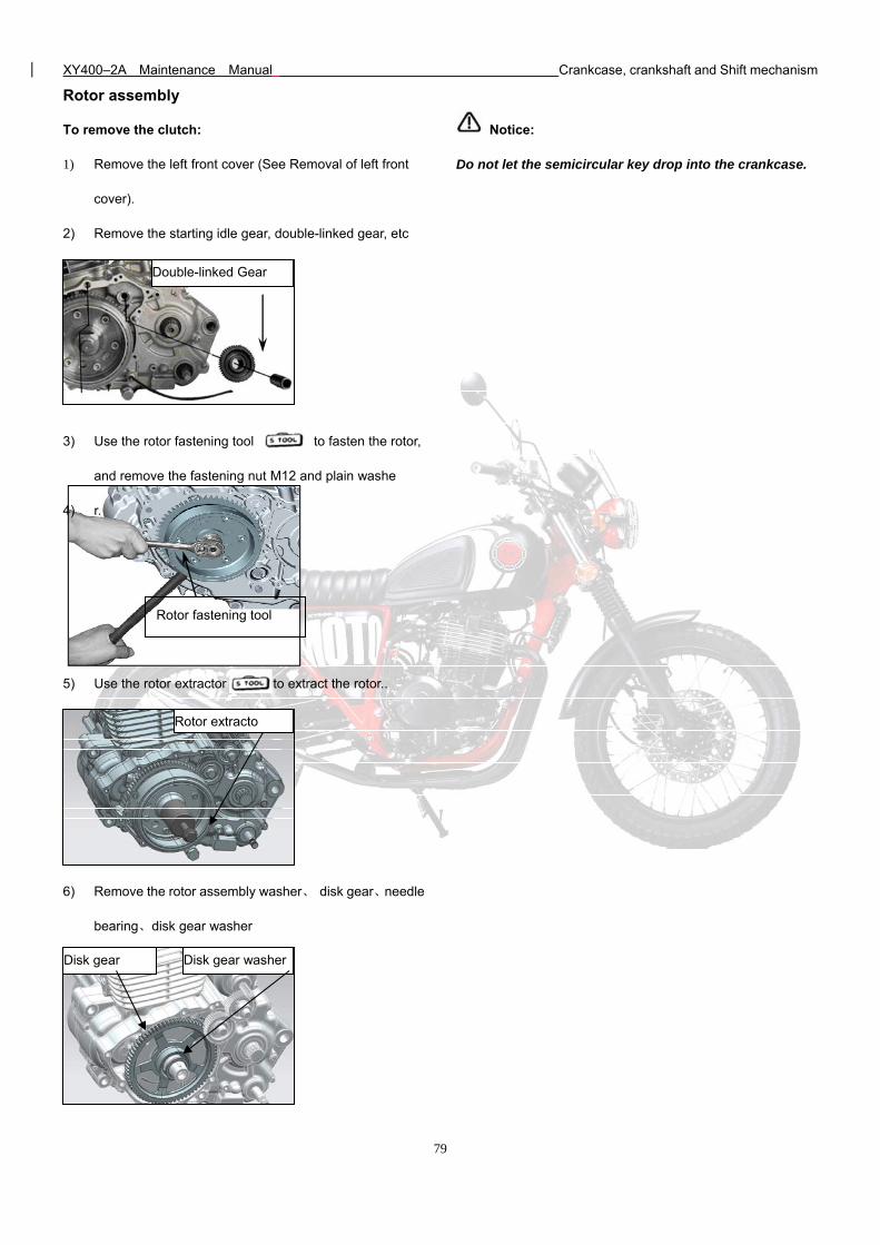
XY400–2A Maintenance Manual Crankcase, crankshaft and Shift mechanism
79
Rotor assembly
To remove the clutch:
1) Remove the left front cover (See Removal of left front
cover).
2) Remove the starting idle gear, double-linked gear, etc
3) Use the rotor fastening tool to fasten the rotor,
and remove the fastening nut M12 and plain washe
4) r.
5) Use the rotor extractor to extract the rotor..
6) Remove the rotor assembly washer、 disk gear、needle
bearing、disk gear washer
Notice:
Do not let the semicircular key drop into the crankcase.
Double-linked Gear
Rotor fastening tool
Rotor extracto
Disk gear Disk gear washer
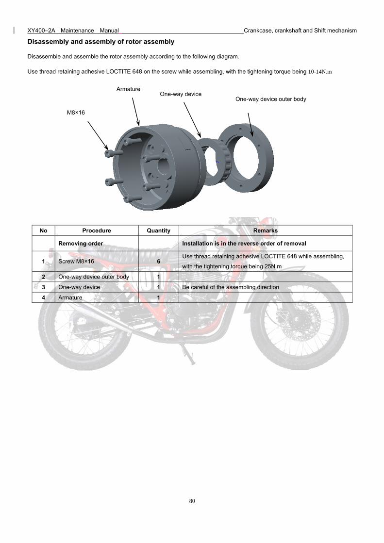
XY400–2A Maintenance Manual Crankcase, crankshaft and Shift mechanism
80
Disassembly and assembly of rotor assembly
Disassemble and assemble the rotor assembly according to the following diagram.
Use thread retaining adhesive LOCTITE 648 on the screw while assembling, with the tightening torque being 10-14N.m
No Procedure Quantity Remarks
Removing order Installation is in the reverse order of removal
1 Screw M8×16 6 Use thread retaining adhesive LOCTITE 648 while assembling,
with the tightening torque being 25N.m
2 One-way device outer body 1
3 One-way device 1 Be careful of the assembling direction
4 Armature 1
M8×16
Armature One-way device
One-way device outer body
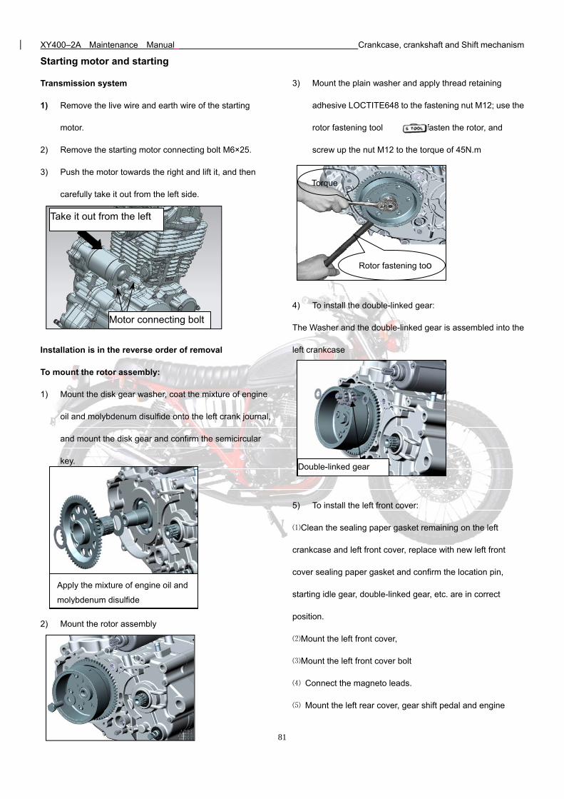
XY400–2A Maintenance Manual Crankcase, crankshaft and Shift mechanism
81
Starting motor and starting
Transmission system
1) Remove the live wire and earth wire of the starting
motor.
2) Remove the starting motor connecting bolt M6×25.
3) Push the motor towards the right and lift it, and then
carefully take it out from the left side.
Installation is in the reverse order of removal
To mount the rotor assembly:
1) Mount the disk gear washer, coat the mixture of engine
oil and molybdenum disulfide onto the left crank journal,
and mount the disk gear and confirm the semicircular
key.
2) Mount the rotor assembly
3) Mount the plain washer and apply thread retaining
adhesive LOCTITE648 to the fastening nut M12; use the
rotor fastening tool to fasten the rotor, and
screw up the nut M12 to the torque of 45N.m
4) To install the double-linked gear:
The Washer and the double-linked gear is assembled into the
left crankcase
5) To install the left front cover:
⑴Clean the sealing paper gasket remaining on the left
crankcase and left front cover, replace with new left front
cover sealing paper gasket and confirm the location pin,
starting idle gear, double-linked gear, etc. are in correct
position.
⑵Mount the left front cover,
⑶Mount the left front cover bolt
⑷ Connect the magneto leads.
⑸ Mount the left rear cover, gear shift pedal and engine
Take it out from the left
Motor connecting bolt
Torque
Rotor fastening too
Apply the mixture of engine oil and
molybdenum disulfide
Double-linked gear
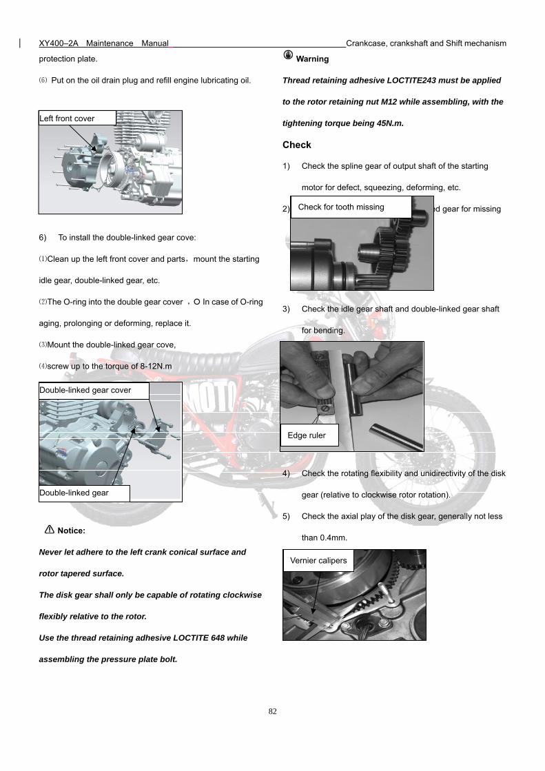
XY400–2A Maintenance Manual Crankcase, crankshaft and Shift mechanism
82
Edge ruler
protection plate.
⑹ Put on the oil drain plug and refill engine lubricating oil.
6) To install the double-linked gear cove:
⑴Clean up the left front cover and parts,mount the starting
idle gear, double-linked gear, etc.
⑵The O-ring into the double gear cover , In case of O-ring
aging, prolonging or deforming, replace it.
⑶Mount the double-linked gear cove,
⑷screw up to the torque of 8-12N.m
Notice:
Never let adhere to the left crank conical surface and
rotor tapered surface.
The disk gear shall only be capable of rotating clockwise
flexibly relative to the rotor.
Use the thread retaining adhesive LOCTITE 648 while
assembling the pressure plate bolt.
Warning
Thread retaining adhesive LOCTITE243 must be applied
to the rotor retaining nut M12 while assembling, with the
tightening torque being 45N.m.
Check
1) Check the spline gear of output shaft of the starting
motor for defect, squeezing, deforming, etc.
2) Check the idle gear and double-linked gear for missing
teeth, etc.
3) Check the idle gear shaft and double-linked gear shaft
for bending.
4) Check the rotating flexibility and unidirectivity of the disk
gear (relative to clockwise rotor rotation).
5) Check the axial play of the disk gear, generally not less
than 0.4mm.
Left front cover
Double-linked gear cover
Double-linked gear
Vernier calipers
Check for tooth missing
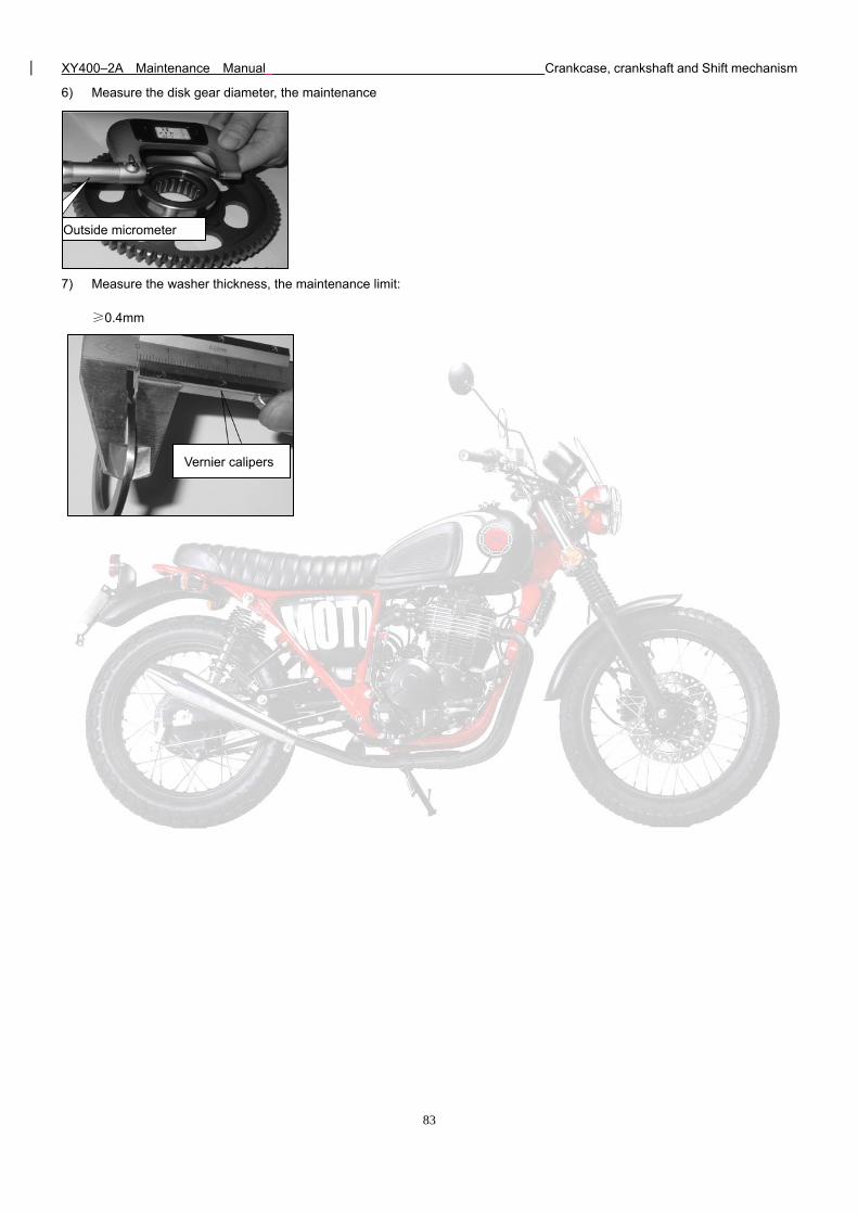
XY400–2A Maintenance Manual Crankcase, crankshaft and Shift mechanism
83
6) Measure the disk gear diameter, the maintenance
limit: ≥φ42.084mm
7) Measure the washer thickness, the maintenance limit:
≥0.4mm
Outside micrometer
Vernier calipers
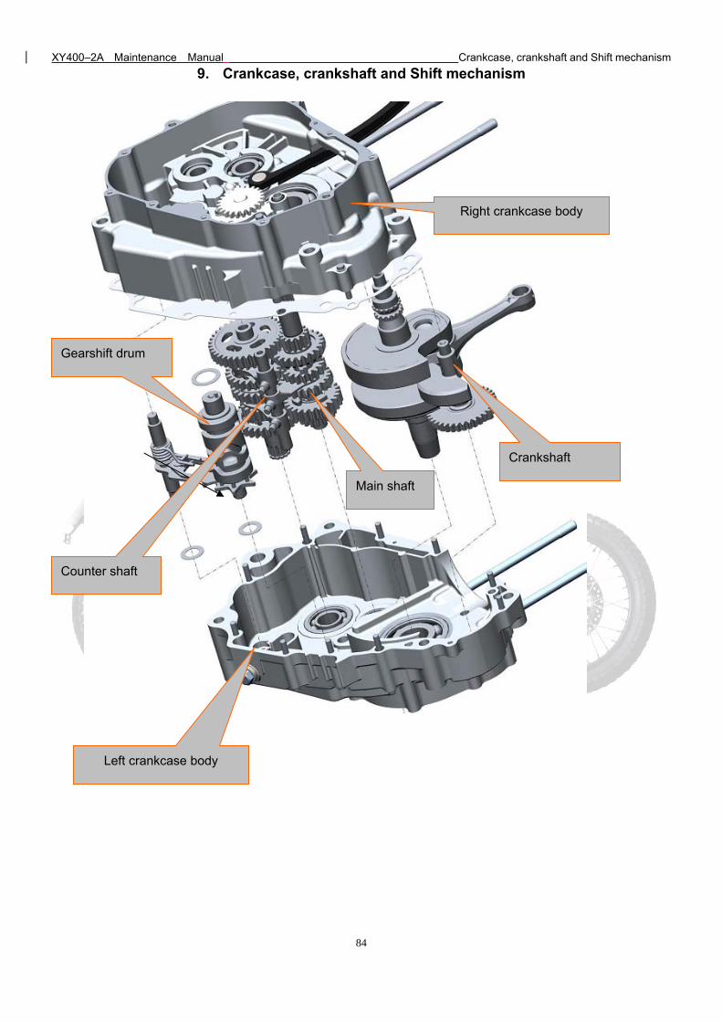
XY400–2A Maintenance Manual Crankcase, crankshaft and Shift mechanism
84
9. Crankcase, crankshaft and Shift mechanism
Right crankcase body
Crankshaft
Gearshift drum
Counter shaft
Main shaft
Left crankcase body
XY400–2A Maintenance Manual Crankcase, crankshaft and Shift mechanism
85
Crankcase, crankshaft and Shift mechanism
Maintenance notice Crankshaft and balance shaft
Troubleshooting Variable transmission system
Crankcase
Maintenance notice
To carry out the maintenance stated herein, the engine must be removed from the frame.
To repair the crankshaft, balance shaft or variable transmission system, the left hand crankcase and the right hand crankcase
must be separated, which is known as crankcase dissection. Before crankcase dissecting, the following parts and components of
the engine shall be removed:
1) Right hand crankcase, clutch, gear shifter
2) Cylinder head cover, camshaft, cylinder head, cylinder and piston (See “Cylinder head, cylinder and piston”);
3) Left front cover, rotor assembly, electrical starting transmission system (See “Magneto and electrical starting system”);
4) Driving drive sprocket, shift switch.
Before assembling, clean all parts and components with cleaning agent and dry them with compressed air.
Technical specifications & maintenance benchmark
Item Standard value Maintenance limit value
Shift fork claw
thickness Gear shift fork
6.05~5.40 5.80
Crankshaft
Connecting rod small end bore
diameter
Ф20.03~Ф20.038 Ф20.063
Disc planeness 0.028~0.042 0.06
Connecting rod big end radial
clearance
0.30~0.60 0.80
Radial runout 0.03 0.10
Left crank journal Ф29.959~Ф29.98 Ф29.87
XY400–2A Maintenance Manual Crankcase, crankshaft and Shift mechanism
86
Troubleshooting
Noise from engine
1) Crankshaft bearing worn;
2) Connecting rod big end bearing worn;
3) Driving/driven shaft bearings worn;
4) Balance shaft supplementary tooth spring failure.
Driving/driven shaft gears engaged badly
1) Shift fork bent or damaged;
2) Shift fork shaft bent;
3) Gearshift drum badly machined or bearing shifted;
4) Driving/driven shaft bearings shifted.
Gear shift trouble
1) Shift fork bent or damaged;
2) Shift fork shaft bent;
3) Gearshift drum guiding slot worn or damaged;
4) Clutch improperly adjusted.
5) Locking plate bend or fray;
6) Five star plate assy broken
7) Pin broken or slip off
Gear shaft cannot return back
1) Sping broken or slip off
2) Variable-speed shaft plate interfere crankcase or crankcase cover。
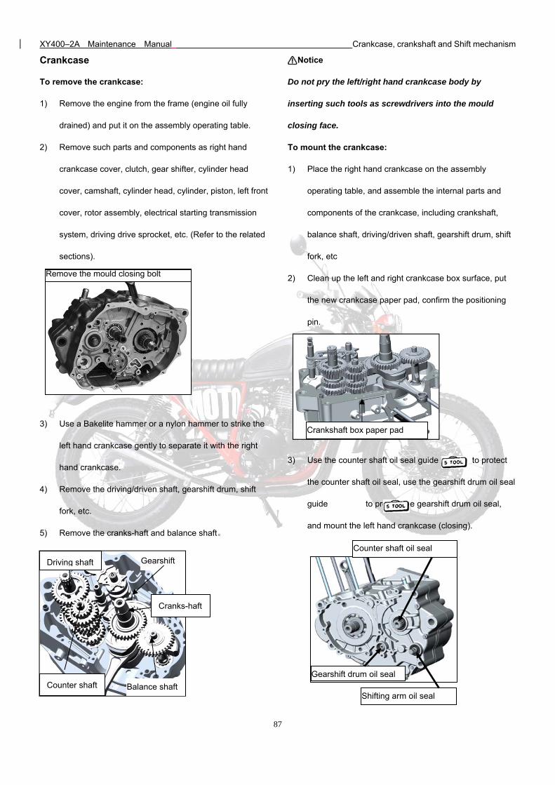
XY400–2A Maintenance Manual Crankcase, crankshaft and Shift mechanism
87
Crankcase
To remove the crankcase:
1) Remove the engine from the frame (engine oil fully
drained) and put it on the assembly operating table.
2) Remove such parts and components as right hand
crankcase cover, clutch, gear shifter, cylinder head
cover, camshaft, cylinder head, cylinder, piston, left front
cover, rotor assembly, electrical starting transmission
system, driving drive sprocket, etc. (Refer to the related
sections).
3) Use a Bakelite hammer or a nylon hammer to strike the
left hand crankcase gently to separate it with the right
hand crankcase.
4) Remove the driving/driven shaft, gearshift drum, shift
fork, etc.
5) Remove the cranks-haft and balance shaft。
Notice
Do not pry the left/right hand crankcase body by
inserting such tools as screwdrivers into the mould
closing face.
To mount the crankcase:
1) Place the right hand crankcase on the assembly
operating table, and assemble the internal parts and
components of the crankcase, including crankshaft,
balance shaft, driving/driven shaft, gearshift drum, shift
fork, etc
2) Clean up the left and right crankcase box surface, put
the new crankcase paper pad, confirm the positioning
pin.
3) Use the counter shaft oil seal guide to protect
the counter shaft oil seal, use the gearshift drum oil seal
guide to protect the gearshift drum oil seal,
and mount the left hand crankcase (closing).
Remove the mould closing bolt
Balance shaft
Gearshift
Crankshaft box paper pad
Driving shaft
Counter shaft
Cranks-haft
Counter shaft oil seal
Gearshift drum oil seal
Shifting arm oil seal
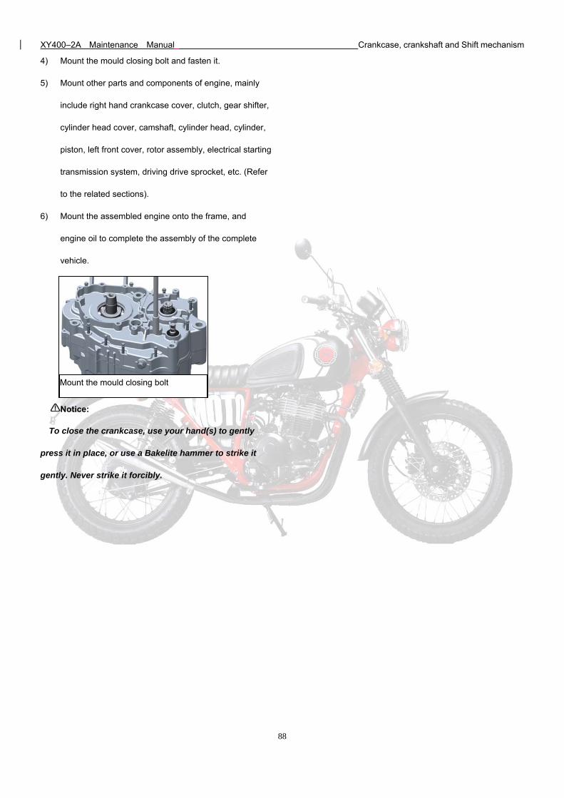
XY400–2A Maintenance Manual Crankcase, crankshaft and Shift mechanism
88
4) Mount the mould closing bolt and fasten it.
5) Mount other parts and components of engine, mainly
include right hand crankcase cover, clutch, gear shifter,
cylinder head cover, camshaft, cylinder head, cylinder,
piston, left front cover, rotor assembly, electrical starting
transmission system, driving drive sprocket, etc. (Refer
to the related sections).
6) Mount the assembled engine onto the frame, and
engine oil to complete the assembly of the complete
vehicle.
Notice:
To close the crankcase, use your hand(s) to gently
press it in place, or use a Bakelite hammer to strike it
gently. Never strike it forcibly.
Mount the mould closing bolt
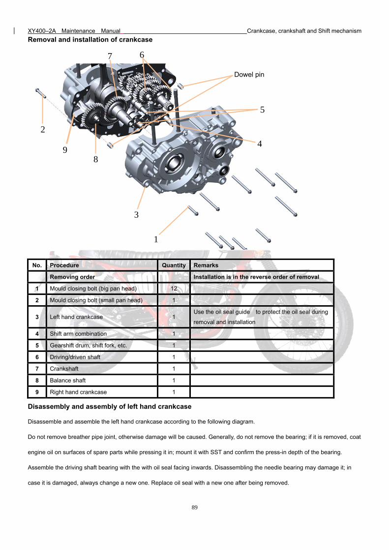
XY400–2A Maintenance Manual Crankcase, crankshaft and Shift mechanism
89
Removal and installation of crankcase
No. Procedure Quantity Remarks
Removing order Installation is in the reverse order of removal
1 Mould closing bolt (big pan head) 12
2 Mould closing bolt (small pan head) 1
3 Left hand crankcase 1 Use the oil seal guide to protect the oil seal during
removal and installation
4 Shift arm combination 1
5 Gearshift drum, shift fork, etc. 1
6 Driving/driven shaft 1
7 Crankshaft 1
8 Balance shaft 1
9 Right hand crankcase 1
Disassembly and assembly of left hand crankcase
Disassemble and assemble the left hand crankcase according to the following diagram.
Do not remove breather pipe joint, otherwise damage will be caused. Generally, do not remove the bearing; if it is removed, coat
engine oil on surfaces of spare parts while pressing it in; mount it with SST and confirm the press-in depth of the bearing.
Assemble the driving shaft bearing with the with oil seal facing inwards. Disassembling the needle bearing may damage it; in
case it is damaged, always change a new one. Replace oil seal with a new one after being removed.
Dowel pin
4
1
3
2
5
6 7
8 9
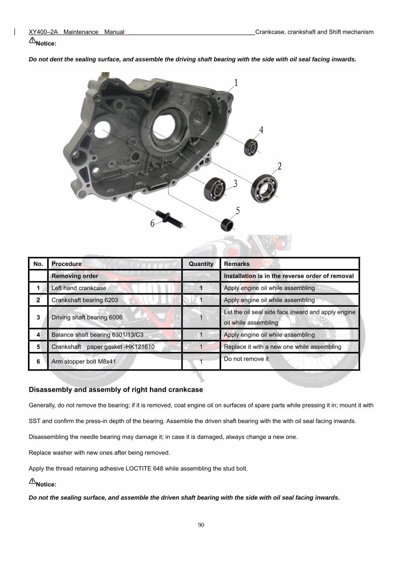
XY400–2A Maintenance Manual Crankcase, crankshaft and Shift mechanism
90
Notice:
Do not dent the sealing surface, and assemble the driving shaft bearing with the side with oil seal facing inwards.
No. Procedure Quantity Remarks
Removing order Installation is in the reverse order of removal
1 Left hand crankcase 1 Apply engine oil while assembling
2 Crankshaft bearing 6203 1 Apply engine oil while assembling
3 Driving shaft bearing 6006 1 Let the oil seal side face inward and apply engine
oil while assembling
4 Balance shaft bearing 6301/13/C3 1 Apply engine oil while assembling
5 Crankshaft paper gasket -HK121610 1 Replace it with a new one while assembling
6 Arm stopper bolt M8x41 1 Do not remove it
Disassembly and assembly of right hand crankcase
Generally, do not remove the bearing; if it is removed, coat engine oil on surfaces of spare parts while pressing it in; mount it with
SST and confirm the press-in depth of the bearing. Assemble the driven shaft bearing with the with oil seal facing inwards.
Disassembling the needle bearing may damage it; in case it is damaged, always change a new one.
Replace washer with new ones after being removed.
Apply the thread retaining adhesive LOCTITE 648 while assembling the stud bolt.
Notice:
Do not the sealing surface, and assemble the driven shaft bearing with the side with oil seal facing inwards.
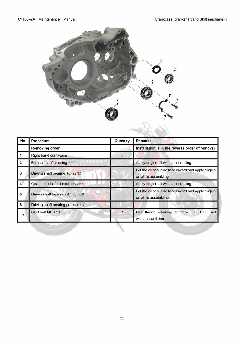
XY400–2A Maintenance Manual Crankcase, crankshaft and Shift mechanism
91
No. Procedure Quantity Remarks
Removing order Installation is in the reverse order of removal
1 Right hand crankcase 1
2 Balance shaft bearing 6302 1 Apply engine oil while assembling
3 Driving shaft bearing 62/22/C3 1 Let the oil seal side face inward and apply engine
oil while assembling
4 Gear shift shaft oil seal 18x34x5 1 Apply engine oil while assembling
5 Driven shaft bearing 60/18RLYAB 1 Let the oil seal side face inward and apply engine
oil while assembling
6 Driving shaft bearing pressure plate 1
7 Stud bolt M6×16 2 Use thread retaining adhesive LOCTITE 648
while assembling
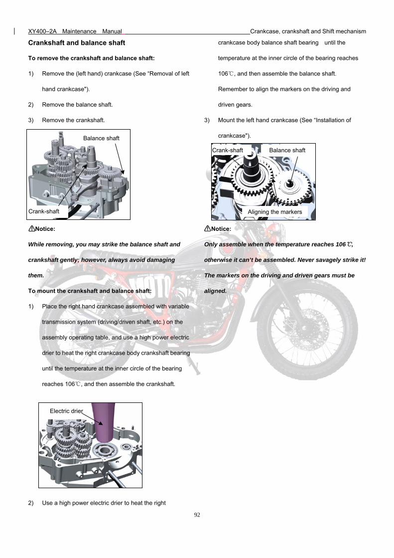
XY400–2A Maintenance Manual Crankcase, crankshaft and Shift mechanism
92
Crank-shaft
Balance shaft
Crankshaft and balance shaft
To remove the crankshaft and balance shaft:
1) Remove the (left hand) crankcase (See “Removal of left
hand crankcase").
2) Remove the balance shaft.
3) Remove the crankshaft.
Notice:
While removing, you may strike the balance shaft and
crankshaft gently; however, always avoid damaging
them.
To mount the crankshaft and balance shaft:
1) Place the right hand crankcase assembled with variable
transmission system (driving/driven shaft, etc.) on the
assembly operating table, and use a high power electric
drier to heat the right crankcase body crankshaft bearing
until the temperature at the inner circle of the bearing
reaches 106, and then assemble the crankshaft.
2) Use a high power electric drier to heat the right
crankcase body balance shaft bearing until the
temperature at the inner circle of the bearing reaches
106, and then assemble the balance shaft.
Remember to align the markers on the driving and
driven gears.
3) Mount the left hand crankcase (See “Installation of
crankcase").
Notice:
Only assemble when the temperature reaches 106,
otherwise it can’t be assembled. Never savagely strike it!
The markers on the driving and driven gears must be
aligned.
Electric drier
Balance shaft Crank-shaft
Aligning the markers
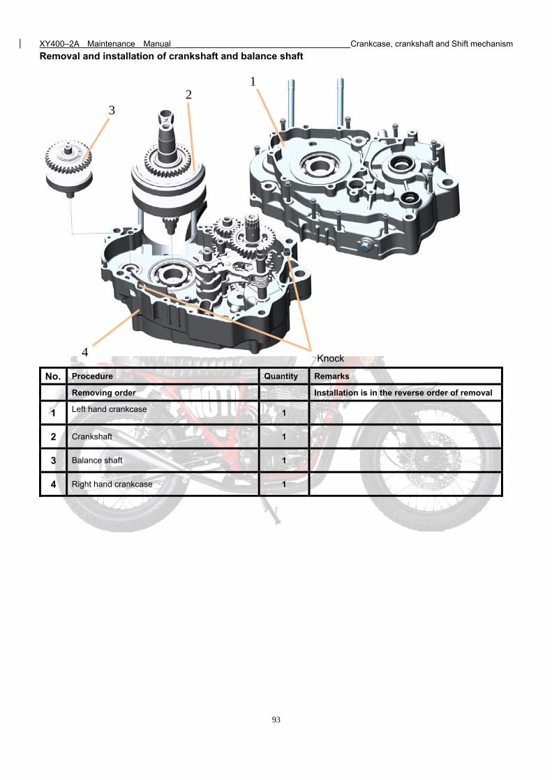
XY400–2A Maintenance Manual Crankcase, crankshaft and Shift mechanism
93
Removal and installation of crankshaft and balance shaft
No. Procedure Quantity Remarks
Removing order Installation is in the reverse order of removal
1 Left hand crankcase 1
2 Crankshaft 1
3 Balance shaft 1
4 Right hand crankcase 1
4
3 2
1
Knock
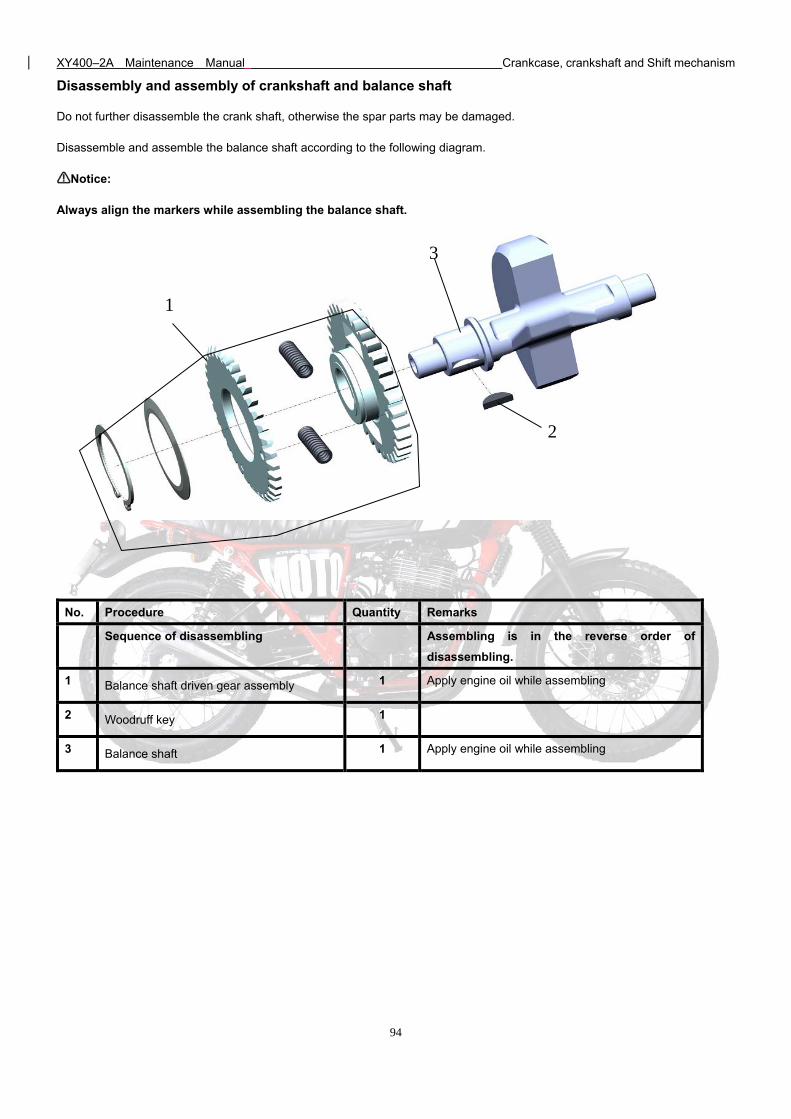
XY400–2A Maintenance Manual Crankcase, crankshaft and Shift mechanism
94
Disassembly and assembly of crankshaft and balance shaft
Do not further disassemble the crank shaft, otherwise the spar parts may be damaged.
Disassemble and assemble the balance shaft according to the following diagram.
Notice:
Always align the markers while assembling the balance shaft.
No. Procedure Quantity Remarks
Sequence of disassembling Assembling is in the reverse order of
disassembling.
1 Balance shaft driven gear assembly 1 Apply engine oil while assembling
2 Woodruff key 1
3 Balance shaft 1 Apply engine oil while assembling
1
2
3
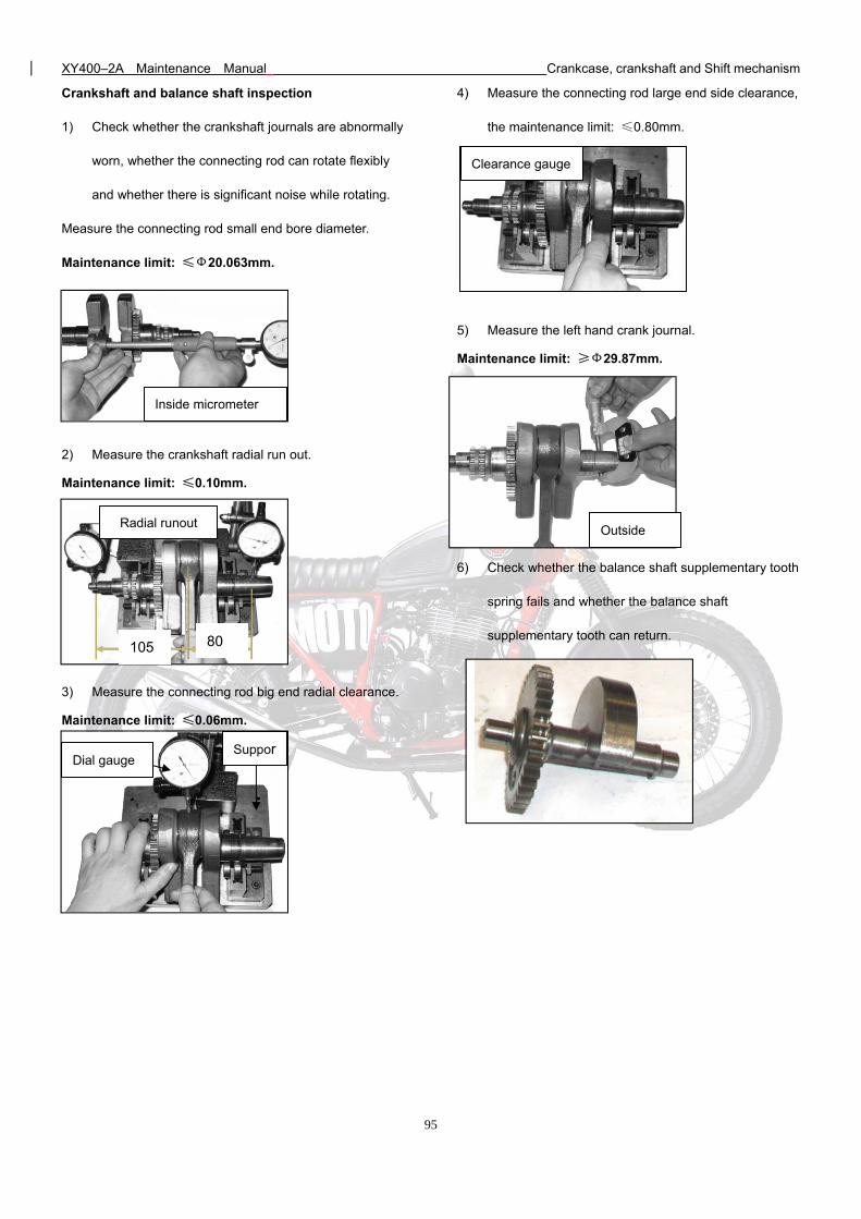
XY400–2A Maintenance Manual Crankcase, crankshaft and Shift mechanism
95
Crankshaft and balance shaft inspection
1) Check whether the crankshaft journals are abnormally
worn, whether the connecting rod can rotate flexibly
and whether there is significant noise while rotating.
Measure the connecting rod small end bore diameter.
Maintenance limit: ≤Ф20.063mm.
2) Measure the crankshaft radial run out.
Maintenance limit: ≤0.10mm.
3) Measure the connecting rod big end radial clearance.
Maintenance limit: ≤0.06mm.
4) Measure the connecting rod large end side clearance,
the maintenance limit: ≤0.80mm.
5) Measure the left hand crank journal.
Maintenance limit: ≥Ф29.87mm.
6) Check whether the balance shaft supplementary tooth
spring fails and whether the balance shaft
supplementary tooth can return.
Inside micrometer
105 80
Radial runout
Dial gauge Suppor
Outside
Clearance gauge
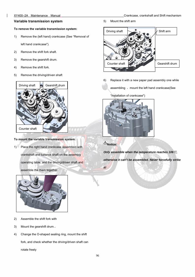
XY400–2A Maintenance Manual Crankcase, crankshaft and Shift mechanism
96
Variable transmission system
To remove the variable transmission system:
1) Remove the (left hand) crankcase (See “Removal of
left hand crankcase").
2) Remove the shift fork shaft.
3) Remove the gearshift drum.
4) Remove the shift fork.
5) Remove the driving/driven shaft
To mount the variable transmission system:
1) Place the right hand crankcase assembled with
crankshaft and balance shaft on the assembly
operating table, and the driving/driven shaft and
assemble the them together.
2) Assemble the shift fork with
3) Mount the gearshift drum.。
4) Change the O-shaped sealing ring, mount the shift
fork, and check whether the driving/driven shaft can
rotate freely
5) Mount the shift arm
6) Replace it with a new paper pad assembly one while
assembling ,mount the left hand crankcase(See
“Installation of crankcase")
Notice:
Only assemble when the temperature reaches 106,
otherwise it can’t be assembled. Never forcefully strike
it!
Driving shaft
Counter shaft
Gearshift drum
Driving shaft
Counter shaft Gearshift drum
Shift arm
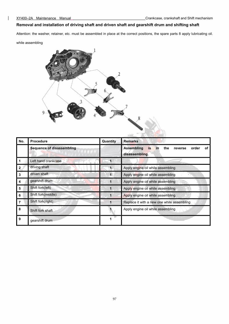
XY400–2A Maintenance Manual Crankcase, crankshaft and Shift mechanism
97
Removal and installation of driving shaft and driven shaft and gearshift drum and shifting shaft
Attention: the washer, retainer, etc. must be assembled in place at the correct positions, the spare parts 8 apply lubricating oil.
while assembling
No. Procedure Quantity Remarks
Sequence of disassembling Assembling is in the reverse order of
disassembling.
1 Left hand crankcase 1
2 driving shaft 1 Apply engine oil while assembling
3 driven shaft 1 Apply engine oil while assembling
4 gearshift drum 1 Apply engine oil while assembling
5 Shift fork(left) 1 Apply engine oil while assembling
6 Shift fork(middle) 1 Apply engine oil while assembling
7 Shift fork(right) 1 Replace it with a new one while assembling
8 Shift fork shaft 1 Apply engine oil while assembling
9 gearshift drum 1
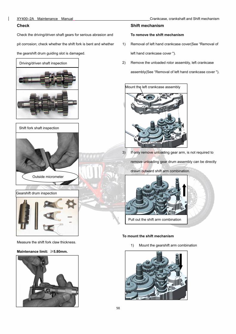
XY400–2A Maintenance Manual Crankcase, crankshaft and Shift mechanism
98
Check
Check the driving/driven shaft gears for serious abrasion and
pit corrosion; check whether the shift fork is bent and whether
the gearshift drum guiding slot is damaged.
Measure the shift fork claw thickness.
Maintenance limit: ≥5.80mm.
Shift mechanism
To remove the shift mechanism
1) Removal of left hand crankcase cover(See “Removal of
left hand crankcase cover ").
2) Remove the unloaded rotor assembly, left crankcase
assembly(See “Removal of left hand crankcase cover ").
3) If only remove unloading gear arm, is not required to
remove unloading gear drum assembly can be directly
drawn outward shift arm combination.
To mount the shift mechanism
1) Mount the gearshift arm combination
Driving/driven shaft inspection
Gearshift drum inspection
Shift fork shaft inspection
Outside micrometer
Pull out the shift arm combination
Mount the left crankcase assembly
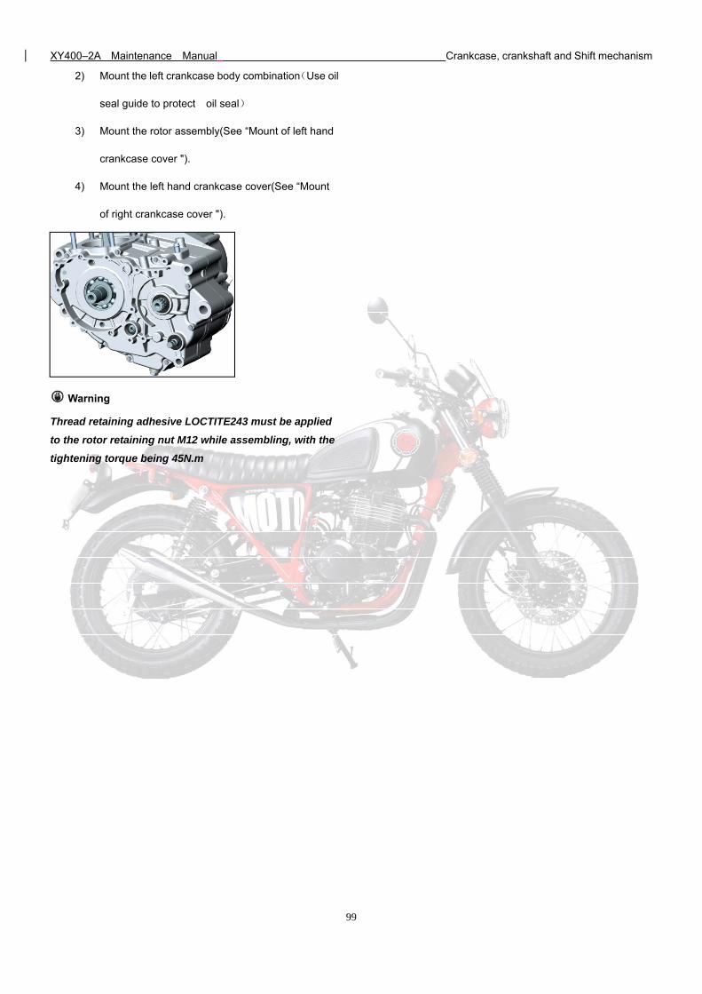
XY400–2A Maintenance Manual Crankcase, crankshaft and Shift mechanism
99
2) Mount the left crankcase body combination(Use oil
seal guide to protect oil seal)
3) Mount the rotor assembly(See “Mount of left hand
crankcase cover ").
4) Mount the left hand crankcase cover(See “Mount
of right crankcase cover ").
Warning
Thread retaining adhesive LOCTITE243 must be applied
to the rotor retaining nut M12 while assembling, with the
tightening torque being 45N.m
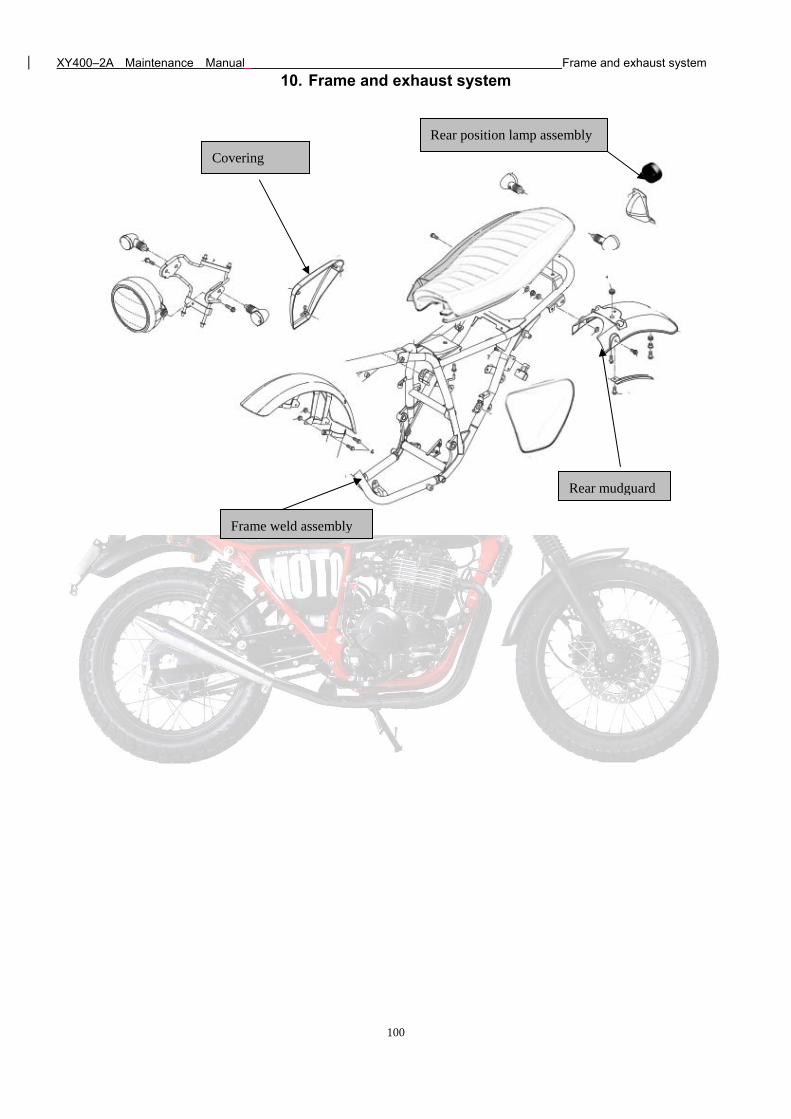
XY400–2A Maintenance Manual Frame and exhaust system
100
10. Frame and exhaust system
Frame weld assembly
Rear mudguard
Rear position lamp assembly
Covering
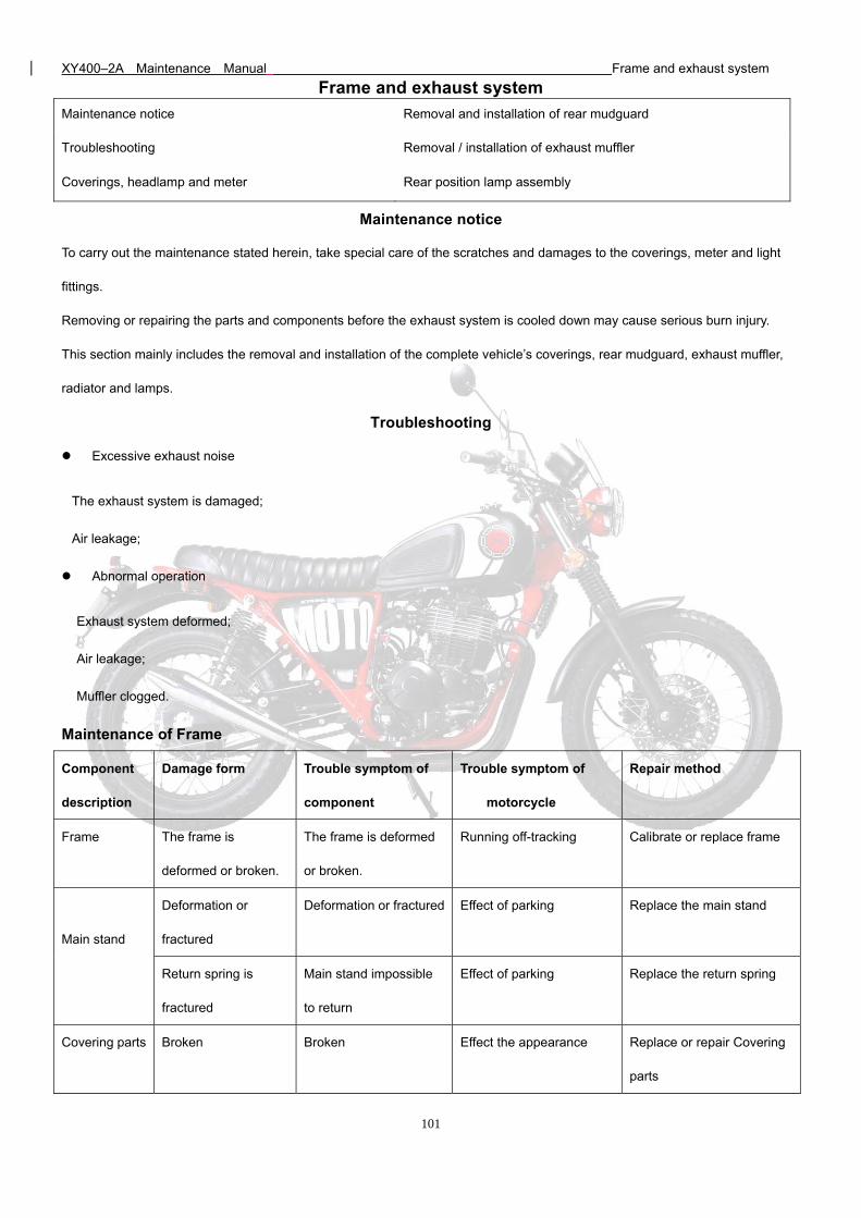
XY400–2A Maintenance Manual Frame and exhaust system
101
Frame and exhaust system
Maintenance notice Removal and installation of rear mudguard
Troubleshooting Removal / installation of exhaust muffler
Coverings, headlamp and meter Rear position lamp assembly
Maintenance notice
To carry out the maintenance stated herein, take special care of the scratches and damages to the coverings, meter and light
fittings.
Removing or repairing the parts and components before the exhaust system is cooled down may cause serious burn injury.
This section mainly includes the removal and installation of the complete vehicle’s coverings, rear mudguard, exhaust muffler,
radiator and lamps.
Troubleshooting
Excessive exhaust noise
The exhaust system is damaged;
Air leakage;
Abnormal operation
Exhaust system deformed;
Air leakage;
Muffler clogged.
Maintenance of Frame
Component
description
Damage form Trouble symptom of
component
Trouble symptom of
motorcycle
Repair method
Frame The frame is
deformed or broken.
The frame is deformed
or broken.
Running off-tracking Calibrate or replace frame
Main stand
Deformation or
fractured
Deformation or fractured Effect of parking Replace the main stand
Return spring is
fractured
Main stand impossible
to return
Effect of parking Replace the return spring
Covering parts Broken Broken Effect the appearance Replace or repair Covering
parts
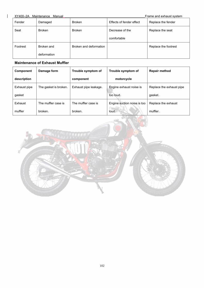
XY400–2A Maintenance Manual Frame and exhaust system
102
Fender Damaged Broken Effects of fender effect Replace the fender
Seat Broken Broken Decrease of the
comfortable
Replace the seat
Footrest Broken and
deformation
Broken and deformation Replace the footrest
Maintenance of Exhaust Muffler
Component
description
Damage form Trouble symptom of
component
Trouble symptom of
motorcycle
Repair method
Exhaust pipe
gasket
The gasket is broken. Exhaust pipe leakage. Engine exhaust noise is
too loud.
Replace the exhaust pipe
gasket.
Exhaust
muffler
The muffler case is
broken.
The muffler case is
broken.
Engine suction noise is too
loud.
Replace the exhaust
muffler.
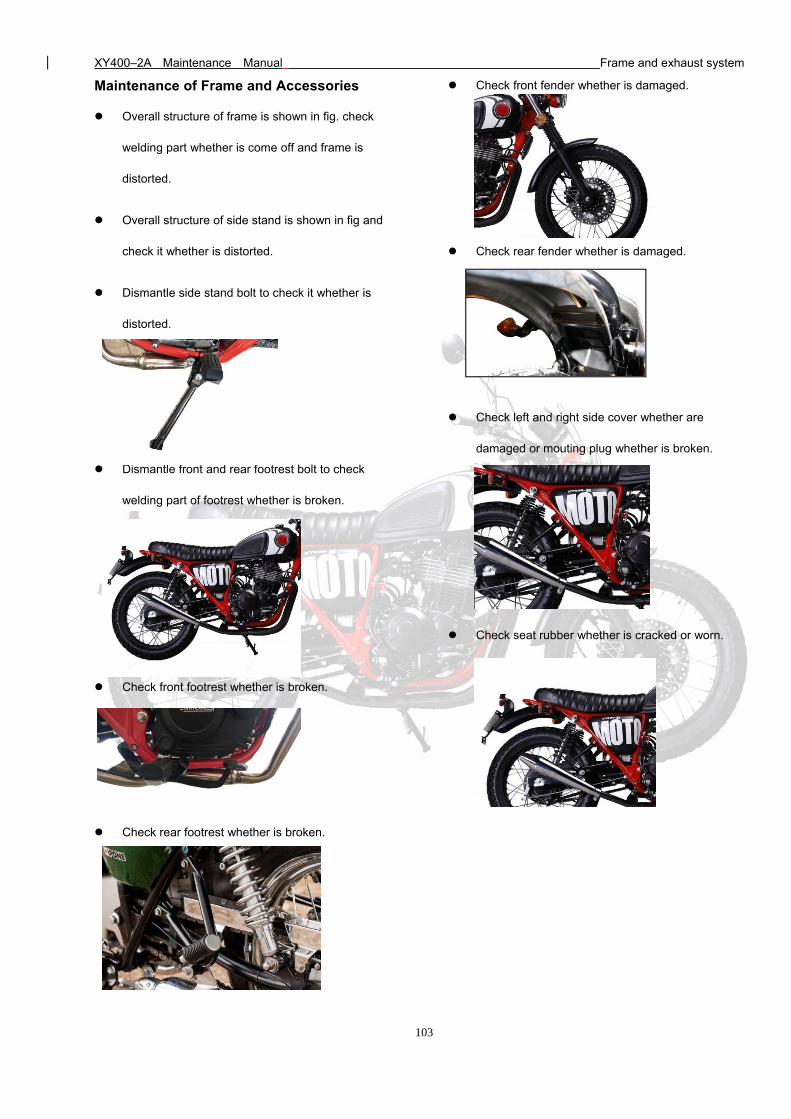
XY400–2A Maintenance Manual Frame and exhaust system
103
Maintenance of Frame and Accessories
Overall structure of frame is shown in fig. check
welding part whether is come off and frame is
distorted.
Overall structure of side stand is shown in fig and
check it whether is distorted.
Dismantle side stand bolt to check it whether is
distorted.
Dismantle front and rear footrest bolt to check
welding part of footrest whether is broken.
Check front footrest whether is broken.
Check rear footrest whether is broken.
Check front fender whether is damaged.
Check rear fender whether is damaged.
Check left and right side cover whether are
damaged or mouting plug whether is broken.
Check seat rubber whether is cracked or worn.
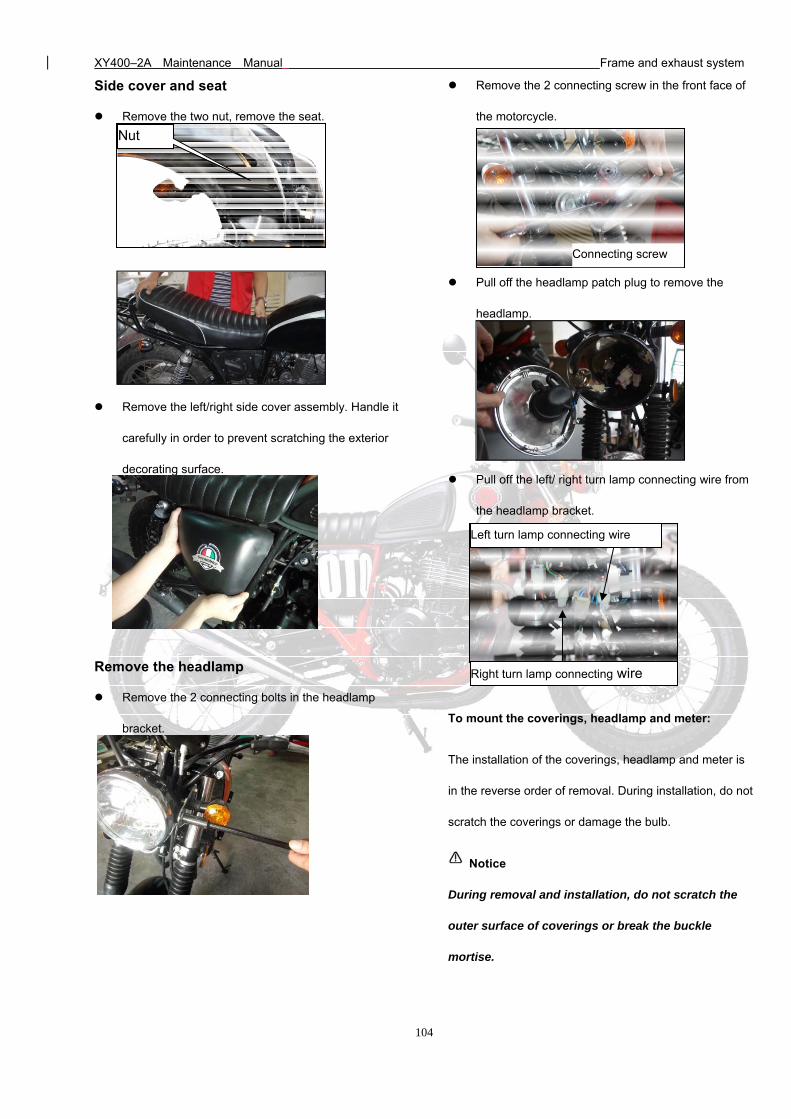
XY400–2A Maintenance Manual Frame and exhaust system
104
Side cover and seat
Remove the two nut, remove the seat.
Remove the left/right side cover assembly. Handle it
carefully in order to prevent scratching the exterior
decorating surface.
Remove the headlamp
Remove the 2 connecting bolts in the headlamp
bracket.
Remove the 2 connecting screw in the front face of
the motorcycle.
Pull off the headlamp patch plug to remove the
headlamp.
Pull off the left/ right turn lamp connecting wire from
the headlamp bracket.
To mount the coverings, headlamp and meter:
The installation of the coverings, headlamp and meter is
in the reverse order of removal. During installation, do not
scratch the coverings or damage the bulb.
Notice
During removal and installation, do not scratch the
outer surface of coverings or break the buckle
mortise.
Nut
Connecting screw
Connecting bolt
Right turn lamp connecting wire
Left turn lamp connecting wire
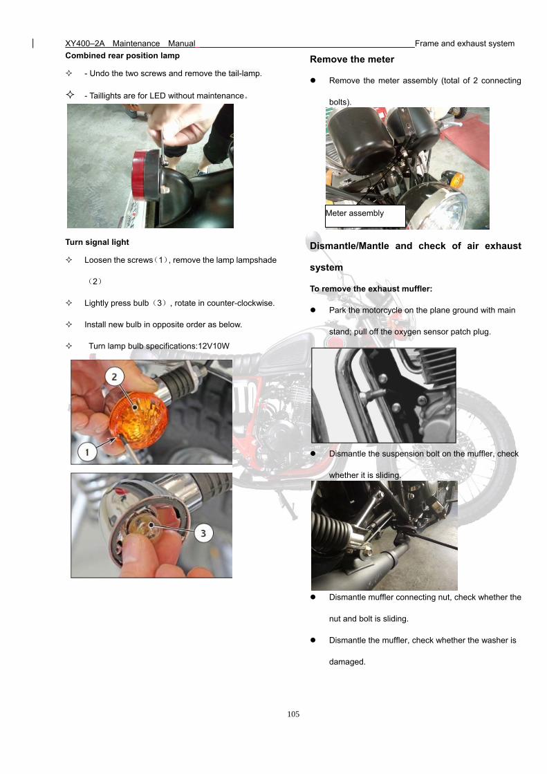
XY400–2A Maintenance Manual Frame and exhaust system
105
Combined rear position lamp
- Undo the two screws and remove the tail-lamp.
- Taillights are for LED without maintenance。
Turn signal light
Loosen the screws(1), remove the lamp lampshade
(2)
Lightly press bulb(3), rotate in counter-clockwise.
Install new bulb in opposite order as below.
Turn lamp bulb specifications:12V10W
Remove the meter
Remove the meter assembly (total of 2 connecting
bolts).
Dismantle/Mantle and check of air exhaust
system
To remove the exhaust muffler:
Park the motorcycle on the plane ground with main
stand; pull off the oxygen sensor patch plug.
Dismantle the suspension bolt on the muffler, check
whether it is sliding.
Dismantle muffler connecting nut, check whether the
nut and bolt is sliding.
Dismantle the muffler, check whether the washer is
damaged.
Meter assembly
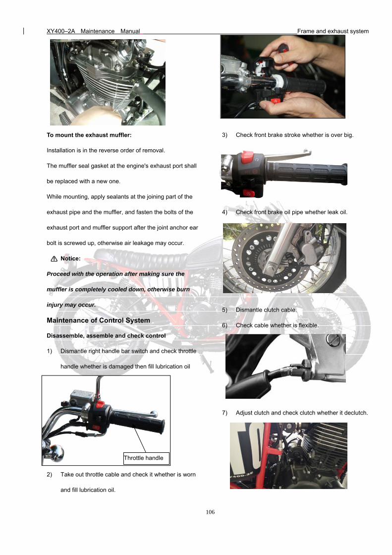
XY400–2A Maintenance Manual Frame and exhaust system
106
To mount the exhaust muffler:
Installation is in the reverse order of removal.
The muffler seal gasket at the engine's exhaust port shall
be replaced with a new one.
While mounting, apply sealants at the joining part of the
exhaust pipe and the muffler, and fasten the bolts of the
exhaust port and muffler support after the joint anchor ear
bolt is screwed up, otherwise air leakage may occur.
Notice:
Proceed with the operation after making sure the
muffler is completely cooled down, otherwise burn
injury may occur.
Maintenance of Control System
Disassemble, assemble and check control
1) Dismantle right handle bar switch and check throttle
handle whether is damaged then fill lubrication oil
2) Take out throttle cable and check it whether is worn
and fill lubrication oil.
3) Check front brake stroke whether is over big.
4) Check front brake oil pipe whether leak oil.
5) Dismantle clutch cable.
6) Check cable whether is flexible.
7) Adjust clutch and check clutch whether it declutch.
Throttle handle
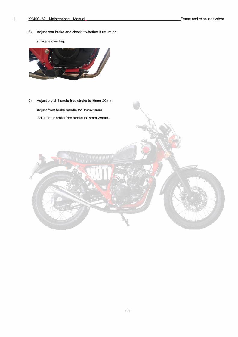
XY400–2A Maintenance Manual Frame and exhaust system
107
8) Adjust rear brake and check it whether it return or
stroke is over big.
9) Adjust clutch handle free stroke to10mm-20mm.
Adjust front brake handle to10mm-20mm.
Adjust rear brake free stroke to15mm-25mm。
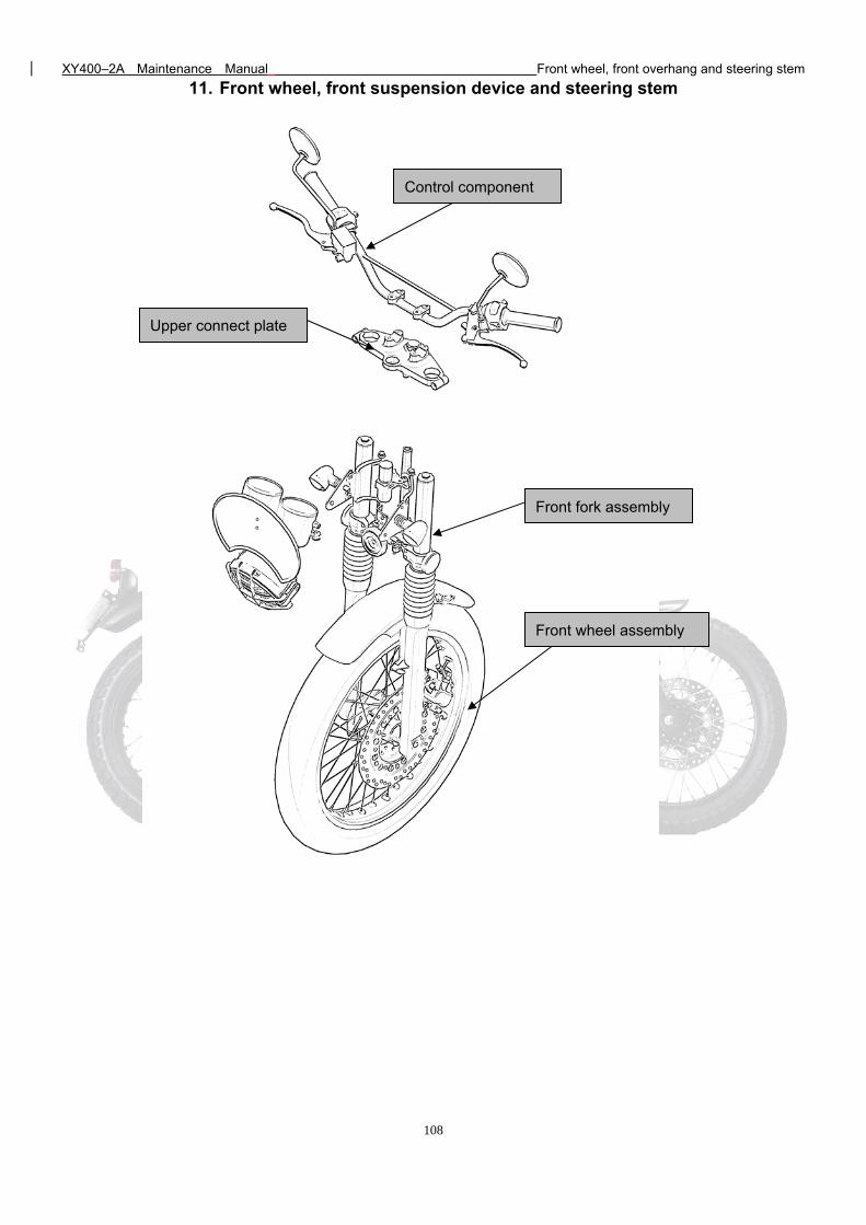
XY400–2A Maintenance Manual Front wheel, front overhang and steering stem
108
11. Front wheel, front suspension device and steering stem
Control component
Front fork assembly
Upper connect plate
Front wheel assembly
XY400–2A Maintenance Manual Front wheel, front overhang and steering stem
109
Front wheel, front suspension device and steering stem
Maintenance notice Front suspension device
Troubleshooting Front brake
Control subassembly Steering stem
Front wheel
Maintenance notice
This section introduces the removal, installation and maintenance of the front wheel, front suspension device (front fork), front
brake and steering stem. While repairing the front wheel, reliably support the motorcycle from under the engine with a jack or
other supports to lift the front wheel above the ground.
Key torque values
Front wheel spindle 50N·m -60N·m
Steering handle set bolt 20~30N.m
Front fork vertical pipe cap nut 50~60N.m
Upper / lower connection plate set bolt 8~12N.m
Brake disc fastening nut 20~30N.m
Troubleshooting
Steering unstable
1) Vertical pipe bearing failure
2) Tire pressure insufficient
3) Tire damaged
4) Wheel bush damaged
Driving directions to the side or not to walk in a straight line
1) Left / Right damper adjustment uneven
2) Front fork bent
3) Front wheel spindle bent or wheel mounted improperly
4) Wheel bearing damaged
5) Wheel bush damaged
XY400–2A Maintenance Manual Front wheel, front overhang and steering stem
110
Front wheel run out
1) Rim bent or deformed
2) Wheel bearing worn
3) Wheel spoke deformed or slacked
4) Front wheel spindle slacked
5) Tire damaged
Wheel hard to rotate
1) Wheel bearing or bush damaged
2) Adjusting nut over-fastened
3) Tire pressure insufficient
4) Shift fork bent or damaged.
Insufficient suspension device rigidity
1) Insufficient front fork spring
2) Insufficient hydraulic oil refilled in the front fork
Poor brake performance
1) The brake is not adjusted as per regulations
2) Brake shoe worn
3) Brake shoe has water or oil stain
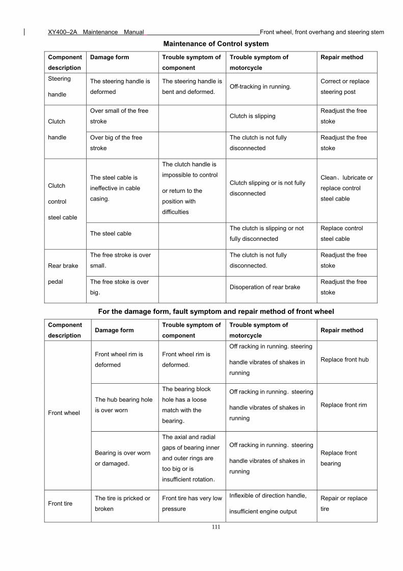
XY400–2A Maintenance Manual Front wheel, front overhang and steering stem
111
Maintenance of Control system
Component
description
Damage form Trouble symptom of
component
Trouble symptom of
motorcycle
Repair method
Steering
handle
The steering handle is
deformed
The steering handle is
bent and deformed. Off-tracking in running.
Correct or replace
steering post
Clutch
handle
Over small of the free
stroke Clutch is slipping
Readjust the free
stoke
Over big of the free
stroke
The clutch is not fully
disconnected
Readjust the free
stoke
Clutch
control
steel cable
The steel cable is
ineffective in cable
casing.
The clutch handle is
impossible to control
or return to the
position with
difficulties
Clutch slipping or is not fully
disconnected
Clean、lubricate or
replace control
steel cable
The steel cable The clutch is slipping or not
fully disconnected
Replace control
steel cable
Rear brake
pedal
The free stroke is over
small.
The clutch is not fully
disconnected.
Readjust the free
stoke
The free stoke is over
big. Disoperation of rear brake
Readjust the free
stoke
For the damage form, fault symptom and repair method of front wheel
Component
description Damage form
Trouble symptom of
component
Trouble symptom of
motorcycle Repair method
Front wheel
Front wheel rim is
deformed
Front wheel rim is
deformed.
Off racking in running. steering
handle vibrates of shakes in
running
Replace front hub
The hub bearing hole
is over worn
The bearing block
hole has a loose
match with the
bearing.
Off racking in running.steering
handle vibrates of shakes in
running
Replace front rim
Bearing is over worn
or damaged.
The axial and radial
gaps of bearing inner
and outer rings are
too big or is
insufficient rotation.
Off racking in running.steering
handle vibrates of shakes in
running
Replace front
bearing
Front tire The tire is pricked or
broken
Front tire has very low
pressure
Inflexible of direction handle,
insufficient engine output
Repair or replace
tire
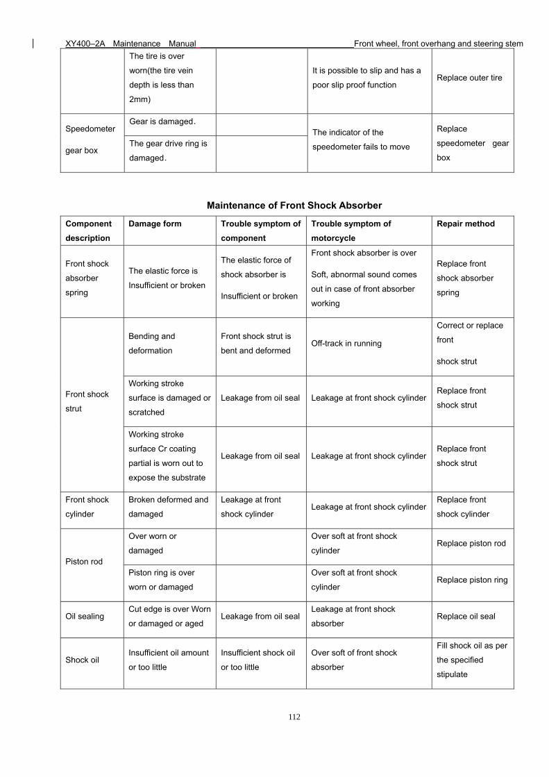
XY400–2A Maintenance Manual Front wheel, front overhang and steering stem
112
The tire is over
worn(the tire vein
depth is less than
2mm)
It is possible to slip and has a
poor slip proof function Replace outer tire
Speedometer
gear box
Gear is damaged. The indicator of the
speedometer fails to move
Replace
speedometer gear
box
The gear drive ring is
damaged.
Maintenance of Front Shock Absorber
Component
description
Damage form Trouble symptom of
component
Trouble symptom of
motorcycle
Repair method
Front shock
absorber
spring
The elastic force is
Insufficient or broken
The elastic force of
shock absorber is
Insufficient or broken
Front shock absorber is over
Soft, abnormal sound comes
out in case of front absorber
working
Replace front
shock absorber
spring
Front shock
strut
Bending and
deformation
Front shock strut is
bent and deformed Off-track in running
Correct or replace
front
shock strut
Working stroke
surface is damaged or
scratched
Leakage from oil seal Leakage at front shock cylinder Replace front
shock strut
Working stroke
surface Cr coating
partial is worn out to
expose the substrate
Leakage from oil seal Leakage at front shock cylinder Replace front
shock strut
Front shock
cylinder
Broken deformed and
damaged
Leakage at front
shock cylinder Leakage at front shock cylinder
Replace front
shock cylinder
Piston rod
Over worn or
damaged
Over soft at front shock
cylinder Replace piston rod
Piston ring is over
worn or damaged
Over soft at front shock
cylinder Replace piston ring
Oil sealing Cut edge is over Worn
or damaged or aged Leakage from oil seal
Leakage at front shock
absorber Replace oil seal
Shock oil Insufficient oil amount
or too little
Insufficient shock oil
or too little
Over soft of front shock
absorber
Fill shock oil as per
the specified
stipulate
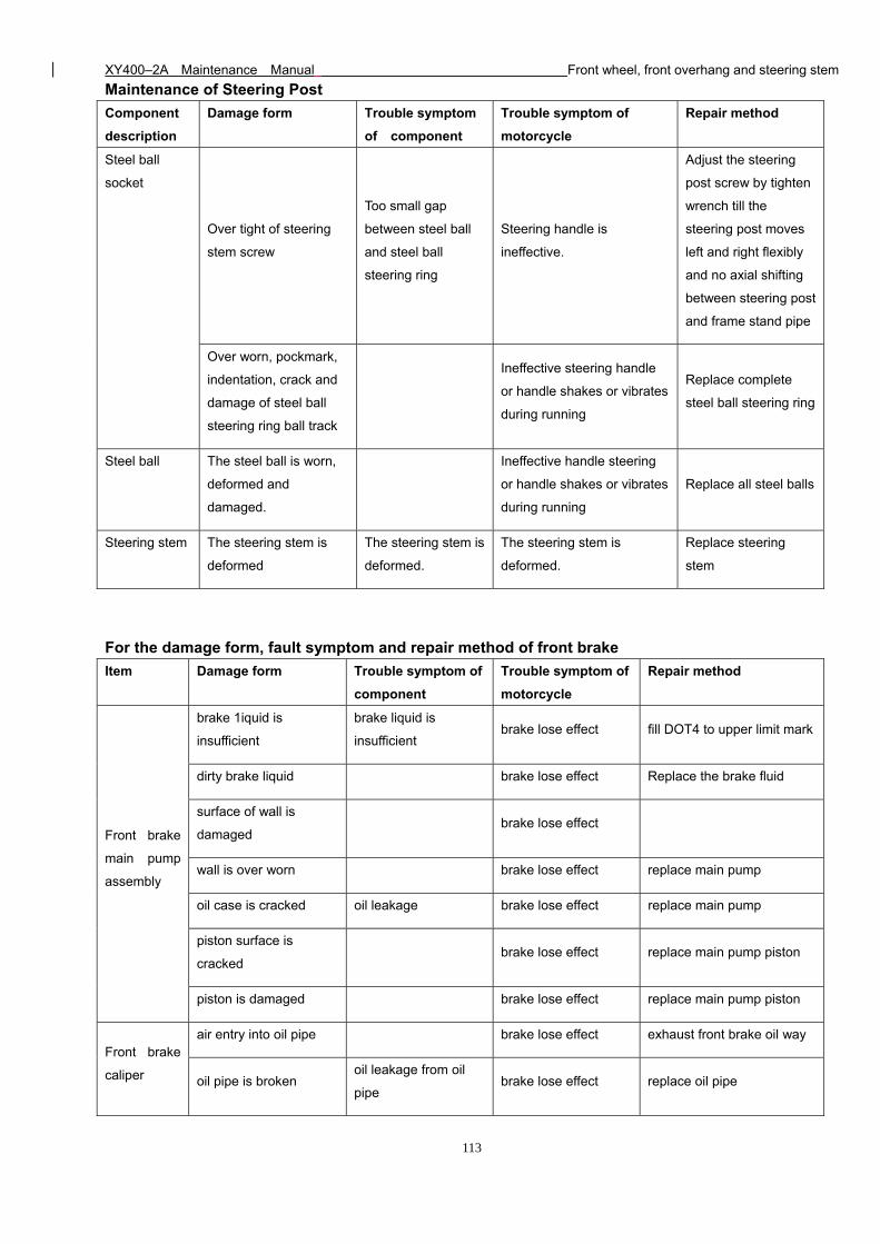
XY400–2A Maintenance Manual Front wheel, front overhang and steering stem
113
Maintenance of Steering Post
Component
description
Damage form Trouble symptom
of component
Trouble symptom of
motorcycle
Repair method
Steel ball
socket
Over tight of steering
stem screw
Too small gap
between steel ball
and steel ball
steering ring
Steering handle is
ineffective.
Adjust the steering
post screw by tighten
wrench till the
steering post moves
left and right flexibly
and no axial shifting
between steering post
and frame stand pipe
Over worn, pockmark,
indentation, crack and
damage of steel ball
steering ring ball track
Ineffective steering handle
or handle shakes or vibrates
during running
Replace complete
steel ball steering ring
Steel ball The steel ball is worn,
deformed and
damaged.
Ineffective handle steering
or handle shakes or vibrates
during running
Replace all steel balls
Steering stem The steering stem is
deformed
The steering stem is
deformed.
The steering stem is
deformed.
Replace steering
stem
For the damage form, fault symptom and repair method of front brake
Item Damage form Trouble symptom of
component
Trouble symptom of
motorcycle
Repair method
Front brake
main pump
assembly
brake 1iquid is
insufficient
brake liquid is
insufficient brake lose effect fill DOT4 to upper limit mark
dirty brake liquid brake lose effect Replace the brake fluid
surface of wall is
damaged brake lose effect
wall is over worn brake lose effect replace main pump
oil case is cracked oil leakage brake lose effect replace main pump
piston surface is
cracked brake lose effect replace main pump piston
piston is damaged brake lose effect replace main pump piston
Front brake
caliper
air entry into oil pipe brake lose effect exhaust front brake oil way
oil pipe is broken oil leakage from oil
pipe brake lose effect replace oil pipe
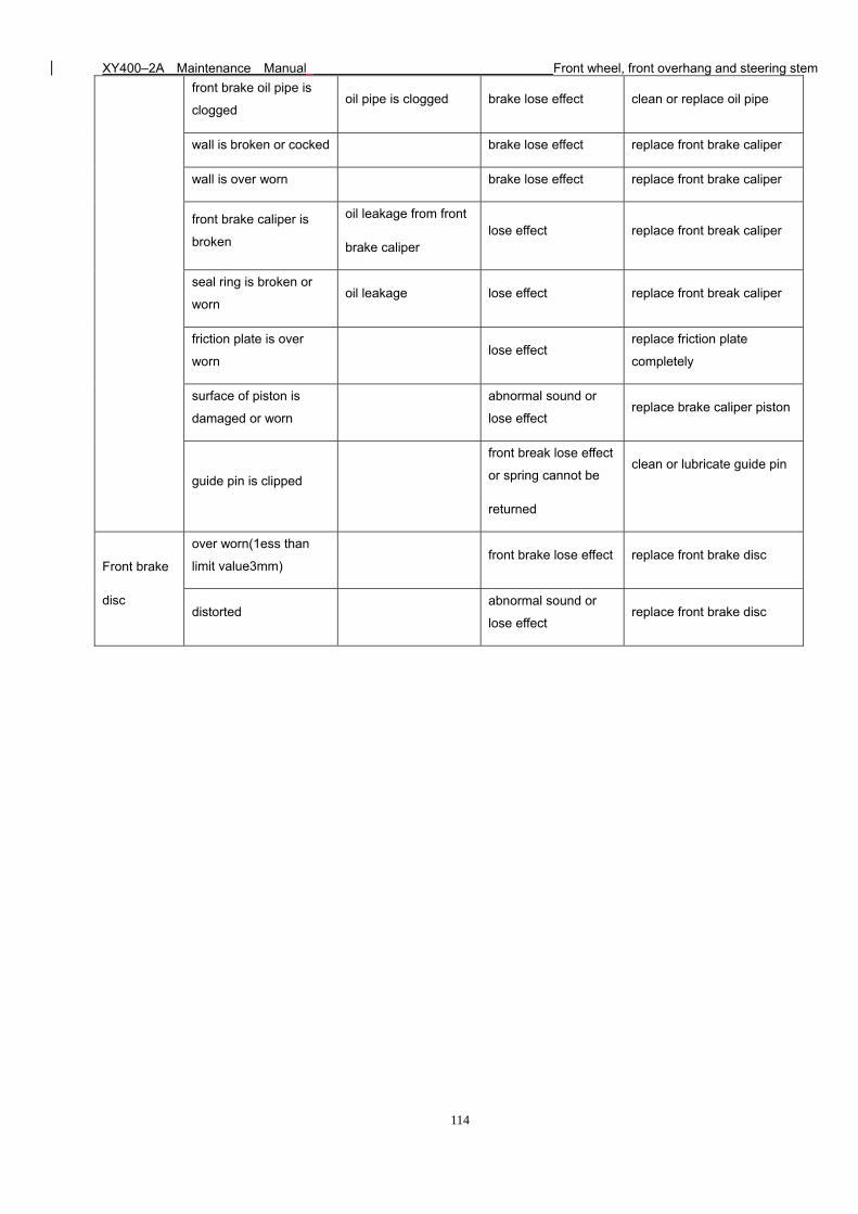
XY400–2A Maintenance Manual Front wheel, front overhang and steering stem
114
front brake oil pipe is
clogged oil pipe is clogged brake lose effect clean or replace oil pipe
wall is broken or cocked brake lose effect replace front brake caliper
wall is over worn brake lose effect replace front brake caliper
front brake caliper is
broken
oil leakage from front
brake caliper lose effect replace front break caliper
seal ring is broken or
worn oil leakage lose effect replace front break caliper
friction plate is over
worn lose effect
replace friction plate
completely
surface of piston is
damaged or worn
abnormal sound or
lose effect replace brake caliper piston
guide pin is clipped
front break lose effect
or spring cannot be
returned
clean or lubricate guide pin
Front brake
disc
over worn(1ess than
limit value3mm) front brake lose effect replace front brake disc
distorted abnormal sound or
lose effect replace front brake disc
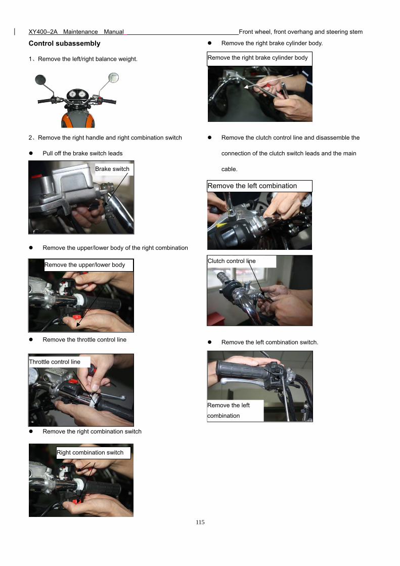
XY400–2A Maintenance Manual Front wheel, front overhang and steering stem
115
Control subassembly
1、Remove the left/right balance weight.
2、Remove the right handle and right combination switch
Pull off the brake switch leads
Remove the upper/lower body of the right combination
switch
Remove the throttle control line
Remove the right combination switch
Remove the right brake cylinder body.
Remove the clutch control line and disassemble the
connection of the clutch switch leads and the main
cable.
Remove the left combination switch.
Brake switch
Remove the upper/lower body
Throttle control line
Right combination switch
Remove the right brake cylinder body
Remove the left combination
Clutch control line
Remove the left
combination
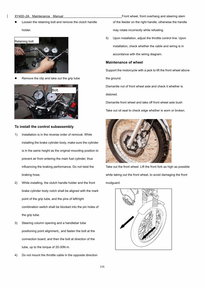
XY400–2A Maintenance Manual Front wheel, front overhang and steering stem
116
Loosen the retaining bolt and remove the clutch handle
holder.
Remove the clip and take out the grip tube
To install the control subassembly
1) Installation is in the reverse order of removal. While
installing the brake cylinder body, make sure the cylinder
is in the same height as the original mounting position to
prevent air from entering the main fuel cylinder, thus
influencing the braking performance. Do not twist the
braking hose.
2) While installing, the clutch handle holder and the front
brake cylinder body notch shall be aligned with the mark
point of the grip tube, and the pins of left/right
combination switch shall be blocked into the pin holes of
the grip tube.
3) Steering column opening and a handlebar tube
positioning point alignment,, and fasten the bolt at the
connection board, and then the bolt at direction of the
tube, up to the torque of 20-30N.m.
4) Do not mount the throttle cable in the opposite direction
of the feeder on the right handle, otherwise the handle
may rotate incorrectly while refueling.
5) Upon installation, adjust the throttle control line. Upon
installation, check whether the cable and wiring is in
accordance with the wiring diagram.
Maintenance of wheel
Support the motorcycle with a jack to lift the front wheel above
the ground.
Dismantle nut of front wheel axle and check it whether is
distored.
Dismantle front wheel and take off front wheel axle bush
Take out oil seal to check edge whether is worn or broken.
Take out the front wheel. Lift the front fork as high as possible
while taking out the front wheel, to avoid damaging the front
mudguard.
Retaining bolt
Bolt.
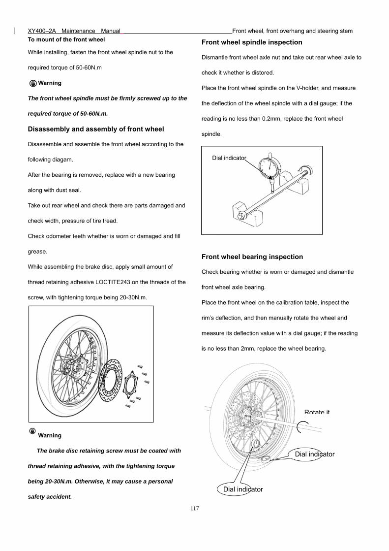
XY400–2A Maintenance Manual Front wheel, front overhang and steering stem
117
To mount of the front wheel
While installing, fasten the front wheel spindle nut to the
required torque of 50-60N.m
Warning
The front wheel spindle must be firmly screwed up to the
required torque of 50-60N.m.
Disassembly and assembly of front wheel
Disassemble and assemble the front wheel according to the
following diagam.
After the bearing is removed, replace with a new bearing
along with dust seal.
Take out rear wheel and check there are parts damaged and
check width, pressure of tire tread.
Check odometer teeth whether is worn or damaged and fill
grease.
While assembling the brake disc, apply small amount of
thread retaining adhesive LOCTITE243 on the threads of the
screw, with tightening torque being 20-30N.m.
Warning
The brake disc retaining screw must be coated with
thread retaining adhesive, with the tightening torque
being 20-30N.m. Otherwise, it may cause a personal
safety accident.
Front wheel spindle inspection
Dismantle front wheel axle nut and take out rear wheel axle to
check it whether is distored.
Place the front wheel spindle on the V-holder, and measure
the deflection of the wheel spindle with a dial gauge; if the
reading is no less than 0.2mm, replace the front wheel
spindle.
Front wheel bearing inspection
Check bearing whether is worn or damaged and dismantle
front wheel axle bearing.
Place the front wheel on the calibration table, inspect the
rim’s deflection, and then manually rotate the wheel and
measure its deflection value with a dial gauge; if the reading
is no less than 2mm, replace the wheel bearing.
Dial indicator
Dial indicator
Rotate it
Dial indicator
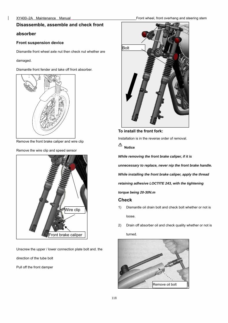
XY400–2A Maintenance Manual Front wheel, front overhang and steering stem
118
Disassemble, assemble and check front
absorber
Front suspension device
Dismantle front wheel axle nut then check nut whether are
damaged.
Dismantle front fender and take off front absorber.
Remove the front brake caliper and wire clip
Remove the wire clip and speed sensor
Unscrew the upper / lower connection plate bolt and. the
direction of the tube bolt
Pull off the front damper
To install the front fork:
Installation is in the reverse order of removal.
Notice
While removing the front brake caliper, if it is
unnecessary to replace, never nip the front brake handle.
While installing the front brake caliper, apply the thread
retaining adhesive LOCTITE 243, with the tightening
torque being 20-30N.m
Check
1) Dismantle oil drain bolt and check bolt whether or not is
loose.
2) Drain off absorber oil and check quality whether or not is
turned.
Front brake caliper
Wire clip
Bolt
Remove oil bolt
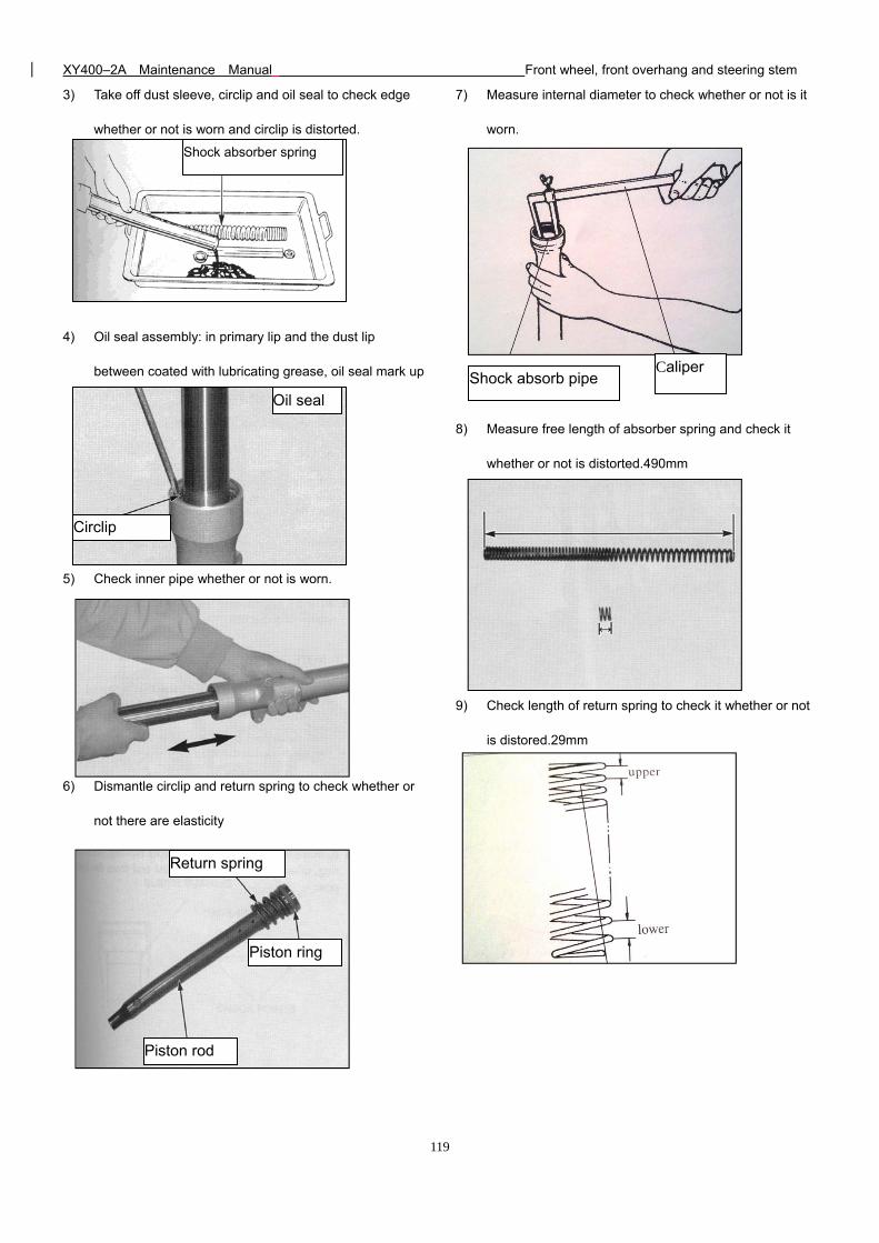
XY400–2A Maintenance Manual Front wheel, front overhang and steering stem
119
3) Take off dust sleeve, circlip and oil seal to check edge
whether or not is worn and circlip is distorted.
4) Oil seal assembly: in primary lip and the dust lip
between coated with lubricating grease, oil seal mark up
5) Check inner pipe whether or not is worn.
6) Dismantle circlip and return spring to check whether or
not there are elasticity
7) Measure internal diameter to check whether or not is it
worn.
8) Measure free length of absorber spring and check it
whether or not is distorted.490mm
9) Check length of return spring to check it whether or not
is distored.29mm
Shock absorber spring
Oil seal
Circlip
Return spring
Piston ring
Piston rod
Caliper Shock absorb pipe
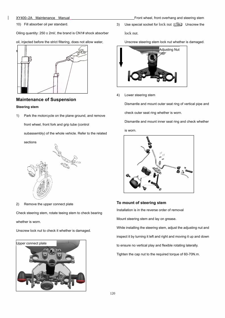
XY400–2A Maintenance Manual Front wheel, front overhang and steering stem
120
10) Fill absorber oil per standard.
Oiling quantity: 250 ± 2ml/, the brand is CN1# shock absorber
oil, injected before the strict filtering, does not allow water,
sand and other foreign bodies into the
Maintenance of Suspension
Steering stem
1) Park the motorcycle on the plane ground, and remove
front wheel, front fork and grip tube (control
subassembly) of the whole vehicle. Refer to the related
sections
2) Remove the upper connect plate
Check steering stem, rotate teeing stem to check bearing
whether is worn.
Unscrew lock nut to check it whether is damaged.
3) Use special socket for lock nut Unscrew the
lock nut.
Unscrew steering stem lock nut whether is damaged.
4) Lower steering stem
Dismantle and mount outer seat ring of vertical pipe and
check outer seat ring whether is worn.
Dismantle and mount inner seat ring and check whether
is worn.
To mount of steering stem
Installation is in the reverse order of removal
Mount steering stem and lay on grease.
While installing the steering stem, adjust the adjusting nut and
inspect it by turning it left and right and moving it up and down
to ensure no vertical play and flexible rotating laterally.
Tighten the cap nut to the required torque of 60-70N.m.
Upper connect plate
Adjusting Nut
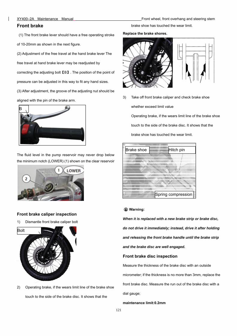
XY400–2A Maintenance Manual Front wheel, front overhang and steering stem
121
Front brake
(1) The front brake lever should have a free operating stroke
of 10-20mm as shown in the next figure.
(2) Adjustment of the free travel at the hand brake lever The
free travel at hand brake lever may be readjusted by
correcting the adjusting bolt【B】. The position of the point of
pressure can be adjusted in this way to fit any hand sizes.
(3) After adjustment, the groove of the adjusting nut should be
aligned with the pin of the brake arm.
The fluid level in the pump reservoir may never drop below
the minimum notch (LOWER) (1) shown on the clear reservoir
Front brake caliper inspection
1) Dismantle front brake caliper bolt
2) Operating brake, if the wears limit line of the brake shoe
touch to the side of the brake disc. It shows that the
brake shoe has touched the wear limit.
Replace the brake shores.
3) Take off front brake caliper and check brake shoe
whether exceed limit value
Operating brake, if the wears limit line of the brake shoe
touch to the side of the brake disc. It shows that the
brake shoe has touched the wear limit.
Warning:
When it is replaced with a new brake strip or brake disc,
do not drive it immediately; instead, drive it after holding
and releasing the front brake handle until the brake strip
and the brake disc are well engaged.
Front brake disc inspection
Measure the thickness of the brake disc with an outside
micrometer; if the thickness is no more than 3mm, replace the
front brake disc. Measure the run out of the brake disc with a
dial gauge;
maintenance limit:0.2mm
Brake shoe
Spring compression
Hitch pin
Bolt
B
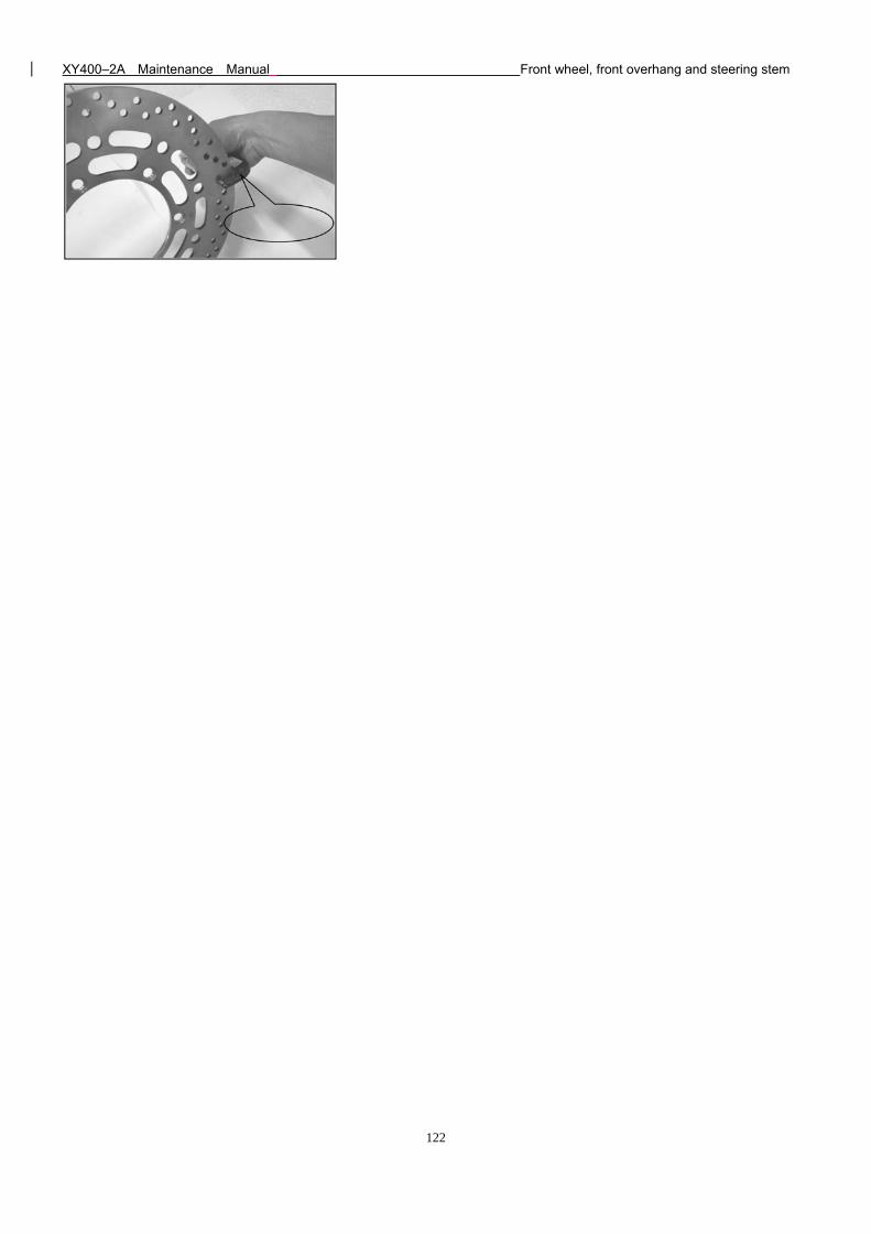
XY400–2A Maintenance Manual Front wheel, front overhang and steering stem
122
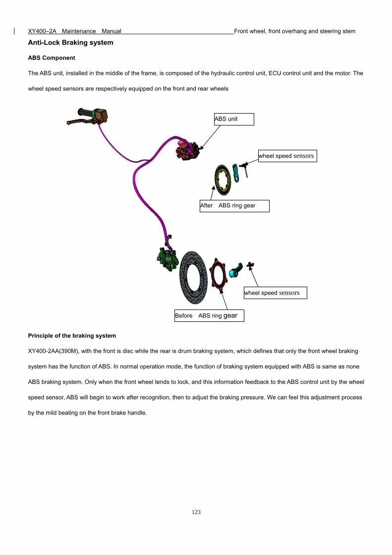
XY400–2A Maintenance Manual Front wheel, front overhang and steering stem
123
Anti-Lock Braking system
ABS Component
The ABS unit, installed in the middle of the frame, is composed of the hydraulic control unit, ECU control unit and the motor. The
wheel speed sensors are respectively equipped on the front and rear wheels
Principle of the braking system
XY400-2AA(390M), with the front is disc while the rear is drum braking system, which defines that only the front wheel braking
system has the function of ABS. In normal operation mode, the function of braking system equipped with ABS is same as none
ABS braking system. Only when the front wheel tends to lock, and this information feedback to the ABS control unit by the wheel
speed sensor, ABS will begin to work after recognition, then to adjust the braking pressure. We can feel this adjustment process
by the mild beating on the front brake handle.
Before ABS ring gear
After ABS ring gear
wheel speed sensors
wheel speed sensors
ABS unit
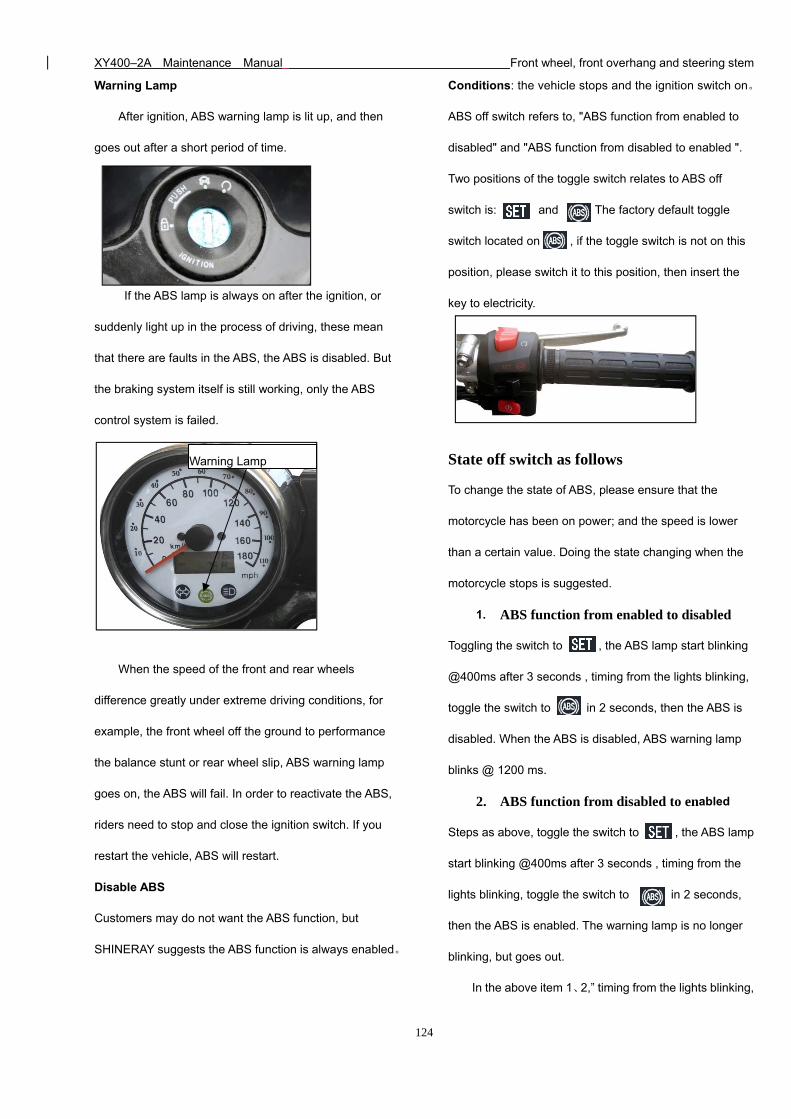
XY400–2A Maintenance Manual Front wheel, front overhang and steering stem
124
Warning Lamp
After ignition, ABS warning lamp is lit up, and then
goes out after a short period of time.
If the ABS lamp is always on after the ignition, or
suddenly light up in the process of driving, these mean
that there are faults in the ABS, the ABS is disabled. But
the braking system itself is still working, only the ABS
control system is failed.
When the speed of the front and rear wheels
difference greatly under extreme driving conditions, for
example, the front wheel off the ground to performance
the balance stunt or rear wheel slip, ABS warning lamp
goes on, the ABS will fail. In order to reactivate the ABS,
riders need to stop and close the ignition switch. If you
restart the vehicle, ABS will restart.
Disable ABS
Customers may do not want the ABS function, but
SHINERAY suggests the ABS function is always enabled。
Conditions: the vehicle stops and the ignition switch on。
ABS off switch refers to, "ABS function from enabled to
disabled" and "ABS function from disabled to enabled ".
Two positions of the toggle switch relates to ABS off
switch is: and . The factory default toggle
switch located on , if the toggle switch is not on this
position, please switch it to this position, then insert the
key to electricity.
State off switch as follows
To change the state of ABS, please ensure that the
motorcycle has been on power; and the speed is lower
than a certain value. Doing the state changing when the
motorcycle stops is suggested.
1. ABS function from enabled to disabled
Toggling the switch to , the ABS lamp start blinking
@400ms after 3 seconds , timing from the lights blinking,
toggle the switch to in 2 seconds, then the ABS is
disabled. When the ABS is disabled, ABS warning lamp
blinks @ 1200 ms.
2. ABS function from disabled to enabled
Steps as above, toggle the switch to , the ABS lamp
start blinking @400ms after 3 seconds , timing from the
lights blinking, toggle the switch to in 2 seconds,
then the ABS is enabled. The warning lamp is no longer
blinking, but goes out.
In the above item 1、2,” timing from the lights blinking,
Warning Lamp
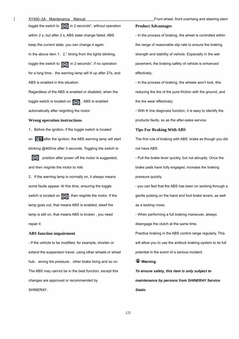
XY400–2A Maintenance Manual Front wheel, front overhang and steering stem
125
toggle the switch to in 2 seconds”, without operation
within 2 s, but after 2 s, ABS state change failed, ABS
keep the current state, you can change it again.
In the above item 1、2,” timing from the lights blinking,
toggle the switch to in 2 seconds”, if no operation
for a long time,the warning lamp will lit up after 27s, and
ABS is enabled in this situation.
Regardless of the ABS is enabled or disabled, when the
toggle switch is located on , ABS is enabled
automatically after reigniting the motor.
Wrong operation instructions
1、Before the ignition, if the toggle switch is located
on , after the ignition, the ABS warning lamp will start
blinking @400ms after 3 seconds. Toggling the swtich to
position after power off the motor is suggested,
and then reignite the motor to ride.
2、If the warning lamp is normally on, it always means
some faults appear. At this time, ensuring the toggle
switch is located on , then reignite the motor. If the
lamp goes out, that means ABS is enabled; elseif the
lamp is still on, that means ABS is broken , you need
repair it.
ABS function impairment
- If the vehicle to be modified, for example, shorten or
extend the suspension travel、using other wheels or wheel
hub、wrong tire pressure、other brake lining and so on.
The ABS may cannot be in the best function, except this
changes are approved or recommended by
SHINERAY。
Product Advantages
- In the process of braking, the wheel is controlled within
the range of reasonable slip rate to ensure the braking
strength and stability of vehicle. Especially in the wet
pavement, the braking safety of vehicle is enhanced
effectively;
- In the process of braking, the wheels won't lock, this
reducing the tire of the pure friction with the ground, and
the tire wear effectively;
- With K line diagnosis function, it is easy to identify the
products faults, so as the after-sales service.
Tips For Braking With ABS
The first rule of braking with ABS: brake as though you did
not have ABS.
- Pull the brake lever quickly, but not abruptly. Once the
brake pads have fully engaged, increase the braking
pressure quickly.
- you can feel that the ABS has been on working through a
gentle pulsing on the hand and foot brake levers, as well
as a tacking noise.
- When performing a full braking maneuver, always
disengage the clutch at the same time.
Practice braking in the ABS control range regularly. This
will allow you to use the antilock braking system to its full
potential in the event of a serious incident.
Warning
To ensure safety, this item is only subject to
maintenance by persons from SHINERAY Service
Statio
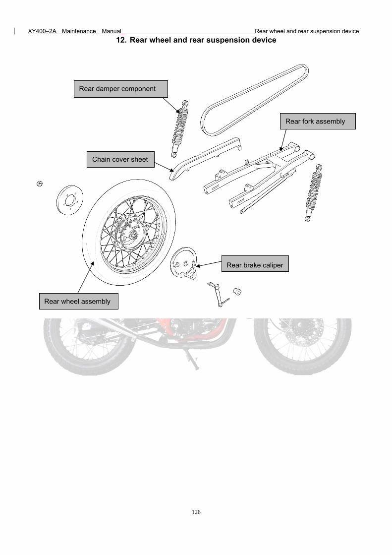
XY400–2A Maintenance Manual Rear wheel and rear suspension device
126
12. Rear wheel and rear suspension device
Rear damper component
Rear wheel assembly
Rear fork assembly
Rear brake caliper
Chain cover sheet
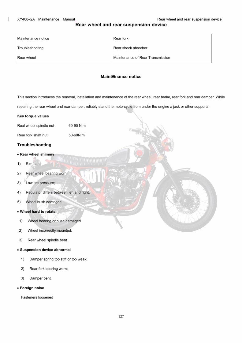
XY400–2A Maintenance Manual Rear wheel and rear suspension device
127
Rear wheel and rear suspension device
Maintenance notice Rear fork
Troubleshooting Rear shock absorber
Rear wheel Maintenance of Rear Transmission
Maintenance notice
This section introduces the removal, installation and maintenance of the rear wheel, rear brake, rear fork and rear damper .While
repairing the rear wheel and rear damper, reliably stand the motorcycle from under the engine a jack or other supports.
Key torque values
Real wheel spindle nut 60-90 N.m
Rear fork shaft nut 50-60N.m
Troubleshooting
Rear wheel shimmy
1) Rim bent;
2) Rear wheel bearing worn;
3) Low tire pressure;
4) Regulator differs between left and right;
5) Wheel bush damaged.
Wheel hard to rotate
1) Wheel bearing or bush damaged
2) Wheel incorrectly mounted;
3) Rear wheel spindle bent
Suspension device abnormal
1) Damper spring too stiff or too weak;
2) Rear fork bearing worn;
3) Damper bent.
Foreign noise
Fasteners loosened
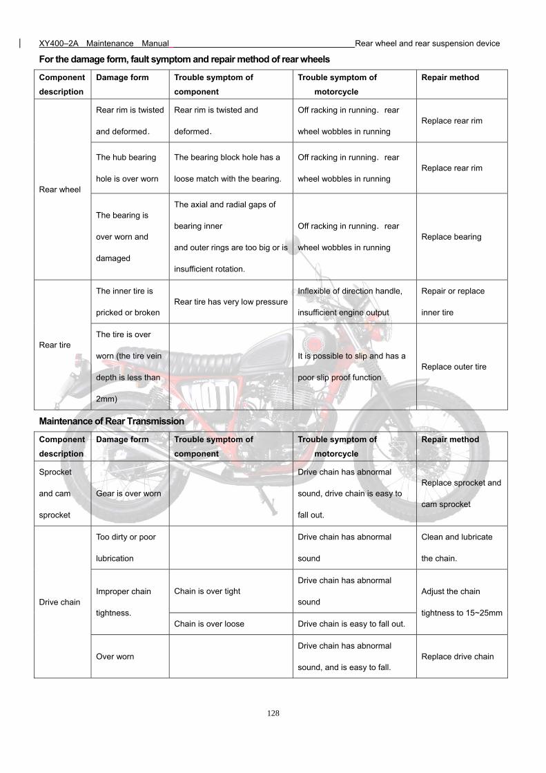
XY400–2A Maintenance Manual Rear wheel and rear suspension device
128
For the damage form, fault symptom and repair method of rear wheels
Component
description
Damage form Trouble symptom of
component
Trouble symptom of
motorcycle
Repair method
Rear wheel
Rear rim is twisted
and deformed.
Rear rim is twisted and
deformed.
Off racking in running.rear
wheel wobbles in running Replace rear rim
The hub bearing
hole is over worn
The bearing block hole has a
loose match with the bearing.
Off racking in running.rear
wheel wobbles in running Replace rear rim
The bearing is
over worn and
damaged
The axial and radial gaps of
bearing inner
and outer rings are too big or is
insufficient rotation.
Off racking in running.rear
wheel wobbles in running Replace bearing
Rear tire
The inner tire is
pricked or broken Rear tire has very low pressure
Inflexible of direction handle,
insufficient engine output
Repair or replace
inner tire
The tire is over
worn (the tire vein
depth is less than
2mm)
It is possible to slip and has a
poor slip proof function Replace outer tire
Maintenance of Rear Transmission
Component
description
Damage form Trouble symptom of
component
Trouble symptom of
motorcycle
Repair method
Sprocket
and cam
sprocket
Gear is over worn
Drive chain has abnormal
sound, drive chain is easy to
fall out.
Replace sprocket and
cam sprocket
Drive chain
Too dirty or poor
lubrication
Drive chain has abnormal
sound
Clean and lubricate
the chain.
Improper chain
tightness.
Chain is over tight Drive chain has abnormal
sound Adjust the chain
tightness to 15~25mm Chain is over loose Drive chain is easy to fall out.
Over worn Drive chain has abnormal
sound, and is easy to fall. Replace drive chain
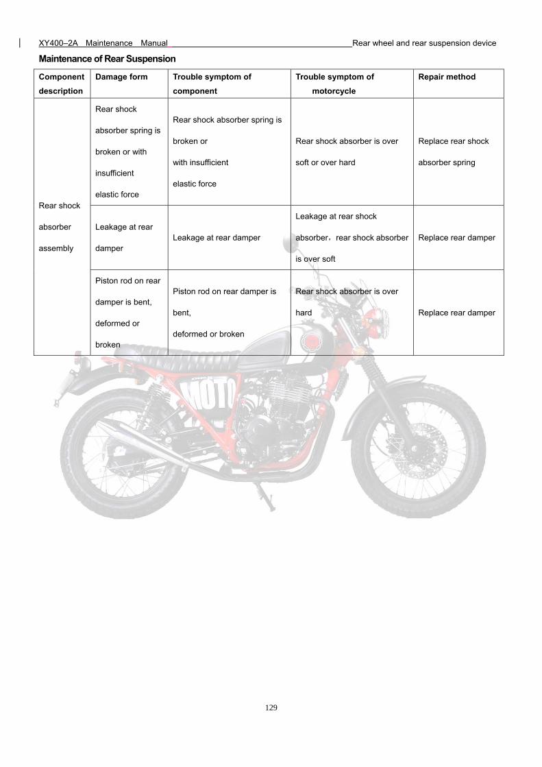
XY400–2A Maintenance Manual Rear wheel and rear suspension device
129
Maintenance of Rear Suspension
Component
description
Damage form Trouble symptom of
component
Trouble symptom of
motorcycle
Repair method
Rear shock
absorber
assembly
Rear shock
absorber spring is
broken or with
insufficient
elastic force
Rear shock absorber spring is
broken or
with insufficient
elastic force
Rear shock absorber is over
soft or over hard
Replace rear shock
absorber spring
Leakage at rear
damper Leakage at rear damper
Leakage at rear shock
absorber,rear shock absorber
is over soft
Replace rear damper
Piston rod on rear
damper is bent,
deformed or
broken
Piston rod on rear damper is
bent,
deformed or broken
Rear shock absorber is over
hard
Replace rear damper
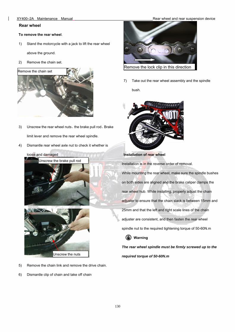
XY400–2A Maintenance Manual Rear wheel and rear suspension device
130
Rear wheel
To remove the rear wheel.
1) Stand the motorcycle with a jack to lift the rear wheel
above the ground.
2) Remove the chain set.
3) Unscrew the rear wheel nuts、the brake pull rod、Brake
limit lever and remove the rear wheel spindle.
4) Dismantle rear wheel axle nut to check it whether is
loose and damaged
5) Remove the chain link and remove the drive chain.
6) Dismantle clip of chain and take off chain
7) Take out the rear wheel assembly and the spindle
bush.
Installation of rear wheel
Installation is in the reverse order of removal.
While mounting the rear wheel, make sure the spindle bushes
on both sides are aligned and the brake caliper clamps the
rear wheel hub. While installing, properly adjust the chain
adjuster to ensure that the chain slack is between 15mm and
25mm and that the left and right scale lines of the chain
adjuster are consistent, and then fasten the rear wheel
spindle nut to the required tightening torque of 50-60N.m
Warning
The rear wheel spindle must be firmly screwed up to the
required torque of 50-60N.m
Remove the chain set Remove the lock clip in this direction
Unscrew the nuts
Unscrew the brake pull rod
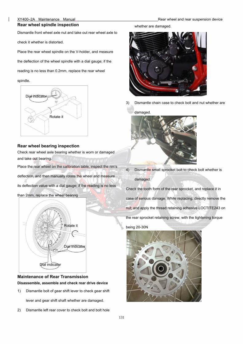
XY400–2A Maintenance Manual Rear wheel and rear suspension device
131
Rear wheel spindle inspection
Dismantle front wheel axle nut and take out rear wheel axle to
check it whether is distorted.
Place the rear wheel spindle on the V-holder, and measure
the deflection of the wheel spindle with a dial gauge; if the
reading is no less than 0.2mm, replace the rear wheel
spindle.
Rear wheel bearing inspection
Check rear wheel axle bearing whether is worn or damaged
and take out bearing.
Place the rear wheel on the calibration table, inspect the rim’s
deflection, and then manually rotate the wheel and measure
its deflection value with a dial gauge; if the reading is no less
than 2mm, replace the wheel bearing
Maintenance of Rear Transmission
Disassemble, assemble and check rear drive device
1) Dismantle bolt of gear shift lever to check gear shift
lever and gear shift shaft whether are damaged.
2) Dismantle left rear cover to check bolt and bolt hole
whether are damaged.
3) Dismantle chain case to check bolt and nut whether are
damaged.
4) Dismantle small sprocket bolt to check bolt whether is
damaged.
Check the tooth form of the rear sprocket, and replace it in
case of serious damage. While replacing, directly remove the
nut; and apply the thread retaining adhesive LOCTITE243 on
the rear sprocket retaining screw, with the tightening torque
being 20-30N
Dial indicator
Rotate it
Dial indicator
Dial indicator
Rotate it
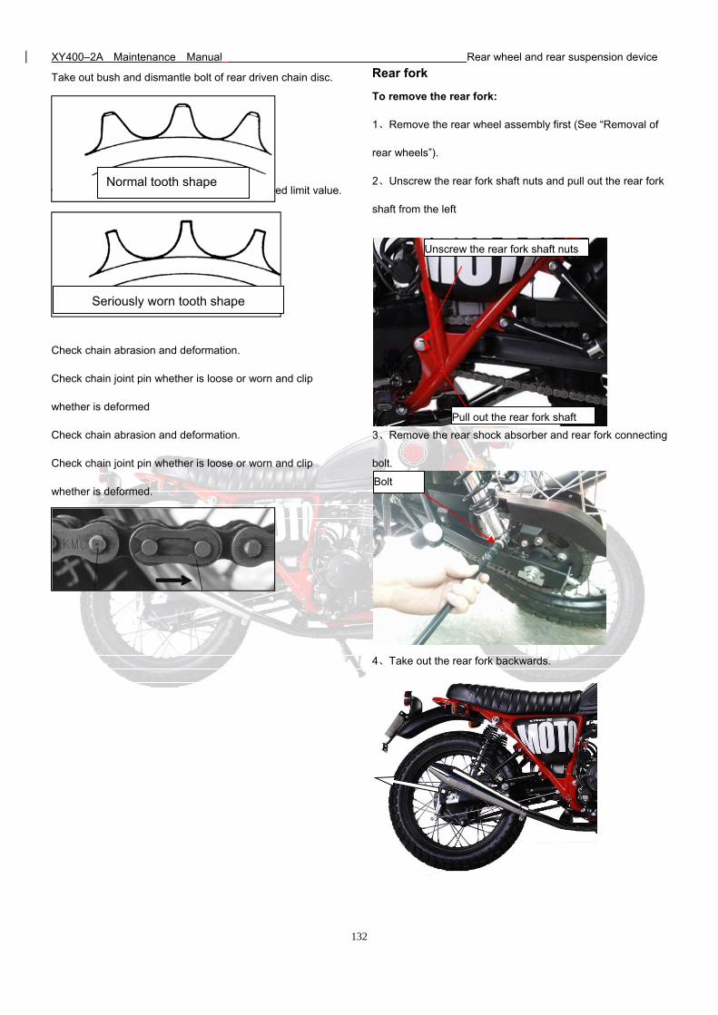
XY400–2A Maintenance Manual Rear wheel and rear suspension device
132
Take out bush and dismantle bolt of rear driven chain disc.
Check rear driven chain disc whether it is exceed limit value.
Check chain abrasion and deformation.
Check chain joint pin whether is loose or worn and clip
whether is deformed
Check chain abrasion and deformation.
Check chain joint pin whether is loose or worn and clip
whether is deformed.
Rear fork
To remove the rear fork:
1、Remove the rear wheel assembly first (See “Removal of
rear wheels”).
2、Unscrew the rear fork shaft nuts and pull out the rear fork
shaft from the left
3、Remove the rear shock absorber and rear fork connecting
bolt.
4、Take out the rear fork backwards.
Normal tooth shape
Seriously worn tooth shape
Bolt
Unscrew the rear fork shaft nuts
Pull out the rear fork shaft
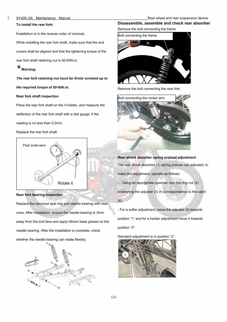
XY400–2A Maintenance Manual Rear wheel and rear suspension device
133
To install the rear fork:
Installation is in the reverse order of removal..
While installing the rear fork shaft, make sure that the end
covers shall be aligned and that the tightening torque of the
rear fork shaft retaining nut is 50-60N.m,
Warning:
The rear fork retaining nut must be firmly screwed up to
the required torque of 50-60N.m.
Rear fork shaft inspection
Place the rear fork shaft on the V-holder, and measure the
deflection of the rear fork shaft with a dial gauge; if the
reading is no less than 0.2mm,
Replace the rear fork shaft.
Rear fork bearing inspection
Replace the removed seal ring and needle bearing with new
ones. After installation, ensure the needle bearing is 3mm
away from the end face and apply lithium base grease on the
needle bearing. After the installation is complete, check
whether the needle bearing can rotate flexibly.
Disassemble, assemble and check rear absorber
Remove the bolt connecting the frame
Remove the bolt connecting the rear fork.
Rear shock absorber spring preload adjustment
The rear shock absorber (1) spring preload can adjusted; to
make the adjustment, operate as follows:
- Using an appropriate spanner, turn the ring nut (2)
positioning the adjuster (3) in correspondence to the catch
(4).
- For a softer adjustment, move the adjuster (3) towards
position “1” and for a harder adjustment move it towards
position “5”.
Standard adjustment is in position “2”.
Rotate it
Dial indicator
Bolt connecting the rocker arm
Bolt connecting the frame
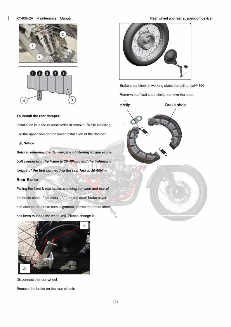
XY400–2A Maintenance Manual Rear wheel and rear suspension device
134
To install the rear damper:
Installation is in the reverse order of removal. While installing,
use the upper hole for the lower installation of the damper.
Notice:
Before removing the damper, the tightening torque of the
bolt connecting the frame is 30-40N.m, and the tightening
torque of the bolt connecting the rear fork is 30-40N.m
Rear Brake
Pulling the front & rear brake, checking the wear and tear of
the brake shoe. If the mark "" on the drum brake cover
and also on the brake cam alignment, shows the brake shoe
has been touched the wear limit. Please change it.
Disconnect the rear wheel
Remove the brake on the rear wheels
Brake shoe block in working state, the cylindricalФ160
Remove the fixed shoe circlip, remove the shoe
circlip Brake shoe
XY400–2A Maintenance Manual General remarks of electrical system
135
13. General remarks of electrical system
Precautions for circuit inspection System principle and composition
Precautions for circuit inspection
1) While disengaging or engaging the patch plug, turn the ignition switch to OFF position, otherwise the electrical elements
may be damaged.
2) While checking the circuit, use a stylus that can be inserted from the front and rear ends of the connector and can contact
the terminals reliably.
3) To carry out the line on/off inspection, turn off the power supply and the related electrical elements.
4) To carry out inspection with voltage, check the accumulator voltage first.
5) In case of electrical system failure, diagnose according to the following steps:
A. Observe the failed behavior to determine which sub-system fails.
B. According to the circuit schematic drawing, use the process of elimination (POE) to narrow down the possible failure
scope.
C. Check the sub-system line for open circuit, short circuit or wrong connection.
D. Check the related components for failure or damage.
1) While looking up the line failures, check where the removal is convenient first following the principle of “searching from easy
to difficulty”. Both the parameter detection method and the parts replacement method are acceptable. However, if the parts
replacement method is used, you should confirm whether or not overload has occurred in the line, as this may damage the
new spare parts.
2) A multicenter must be permanently available for the circuit inspection.
3) Most of the instant electrical failures are caused by cable connector or electric wire failure.
System principle and composition
The electrical system is an important guaranty for the motorcycle’s running, safety running, reliable running and efficient
running. It involves many aspects, including contents of several subjects, including electric machine, electrical, electronics,
computer, electrochemistry, acoustics, optical material, etc. The development of electronics will especially influence the
motorcycle’s electrical system significantly. XY400-2AA’s electrical system uses a lot of advanced vehicle electronics
technologies that are much more complicated then the traditional motorcycle. It comprises the following sub-systems:
• Power supply system
• Starting system
• Engine management system
• Illumination signal system
XY400–2A Maintenance Manual General remarks of electrical system
136
• Information display system
We shall give detailed explanations separately in the following sections
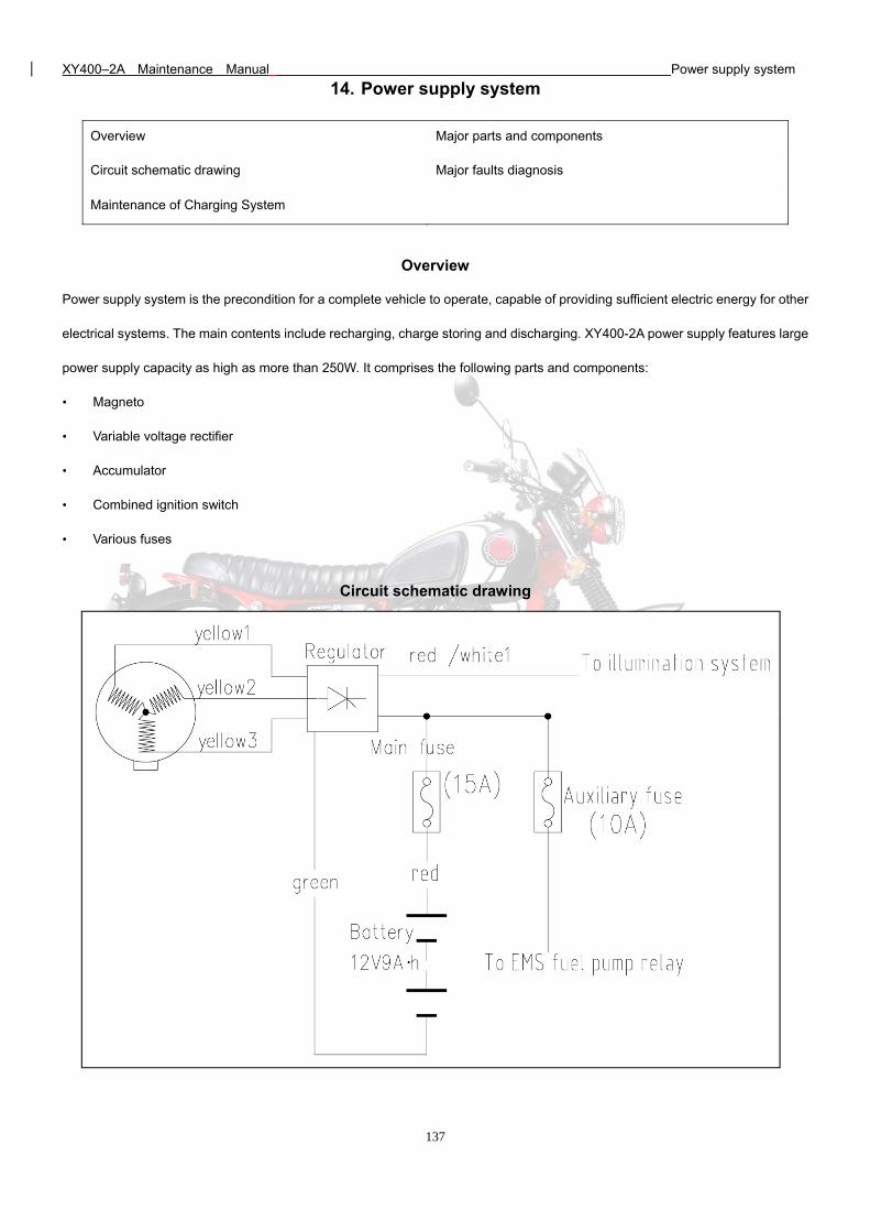
XY400–2A Maintenance Manual Power supply system
137
14. Power supply system
Overview
Power supply system is the precondition for a complete vehicle to operate, capable of providing sufficient electric energy for other
electrical systems. The main contents include recharging, charge storing and discharging. XY400-2A power supply features large
power supply capacity as high as more than 250W. It comprises the following parts and components:
• Magneto
• Variable voltage rectifier
• Accumulator
• Combined ignition switch
• Various fuses
Circuit schematic drawing
Overview Major parts and components
Circuit schematic drawing Major faults diagnosis
Maintenance of Charging System
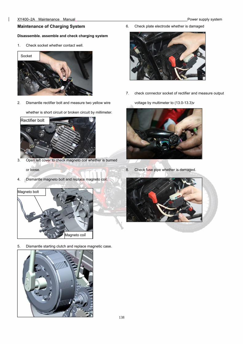
XY400–2A Maintenance Manual Power supply system
138
Maintenance of Charging System
Disassemble. assemble and check charging system
1. Check socket whether contact well.
2. Dismantle rectifier bolt and measure two yellow wire
whether is short circuit or broken circuit by millimeter.
3. Open left cover to check magneto coil whether is burned
or loose.
4. Dismantle magneto bolt and replace magneto coil.
5. Dismantle starting clutch and replace magnetic case.
6. Check plate electrode whether is damaged
7. check connector socket of rectifier and measure output
voltage by multimeter to (13.0-13.3)v
8. Check fuse pipe whether is damaged.
Socket
Rectifier bolt
Magneto coil
Magneto bolt
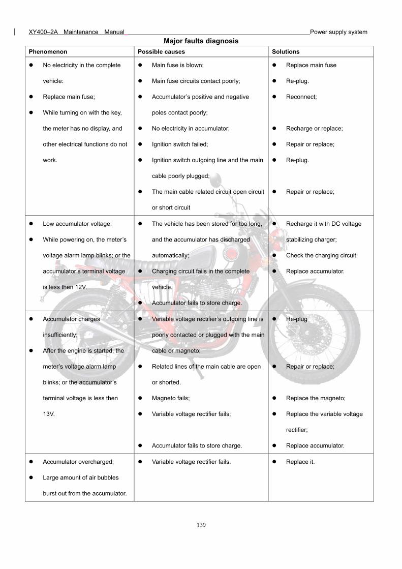
XY400–2A Maintenance Manual Power supply system
139
Major faults diagnosis
Phenomenon Possible causes Solutions
No electricity in the complete
vehicle:
Replace main fuse;
While turning on with the key,
the meter has no display, and
other electrical functions do not
work.
Main fuse is blown;
Main fuse circuits contact poorly;
Accumulator’s positive and negative
poles contact poorly;
No electricity in accumulator;
Ignition switch failed;
Ignition switch outgoing line and the main
cable poorly plugged;
The main cable related circuit open circuit
or short circuit
Replace main fuse
Re-plug.
Reconnect;
Recharge or replace;
Repair or replace;
Re-plug.
Repair or replace;
Low accumulator voltage:
While powering on, the meter’s
voltage alarm lamp blinks; or the
accumulator’s terminal voltage
is less then 12V.
The vehicle has been stored for too long,
and the accumulator has discharged
automatically;
Charging circuit fails in the complete
vehicle.
Accumulator fails to store charge.
Recharge it with DC voltage
stabilizing charger;
Check the charging circuit.
Replace accumulator.
Accumulator charges
insufficiently;
After the engine is started, the
meter’s voltage alarm lamp
blinks; or the accumulator’s
terminal voltage is less then
13V.
Variable voltage rectifier’s outgoing line is
poorly contacted or plugged with the main
cable or magneto;
Related lines of the main cable are open
or shorted.
Magneto fails;
Variable voltage rectifier fails;
Accumulator fails to store charge.
Re-plug
Repair or replace;
Replace the magneto;
Replace the variable voltage
rectifier;
Replace accumulator.
Accumulator overcharged;
Large amount of air bubbles
burst out from the accumulator.
Variable voltage rectifier fails. Replace it.
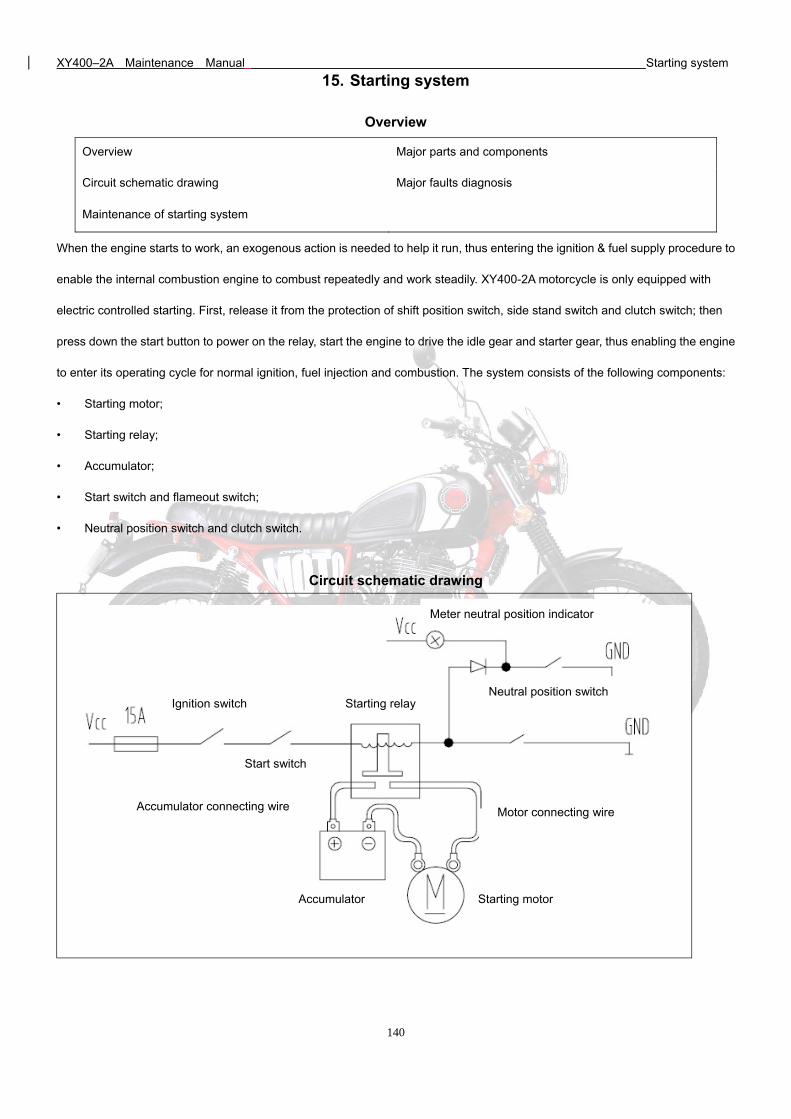
XY400–2A Maintenance Manual Starting system
140
15. Starting system
Overview
When the engine starts to work, an exogenous action is needed to help it run, thus entering the ignition & fuel supply procedure to
enable the internal combustion engine to combust repeatedly and work steadily. XY400-2A motorcycle is only equipped with
electric controlled starting. First, release it from the protection of shift position switch, side stand switch and clutch switch; then
press down the start button to power on the relay, start the engine to drive the idle gear and starter gear, thus enabling the engine
to enter its operating cycle for normal ignition, fuel injection and combustion. The system consists of the following components:
• Starting motor;
• Starting relay;
• Accumulator;
• Start switch and flameout switch;
• Neutral position switch and clutch switch.
Circuit schematic drawing
Overview Major parts and components
Circuit schematic drawing Major faults diagnosis
Maintenance of starting system
Clutch switch
Neutral position switch
Accumulator Starting motor
Starting relay
Start switch
Ignition switch
Motor connecting wire Accumulator connecting wire
Meter neutral position indicator
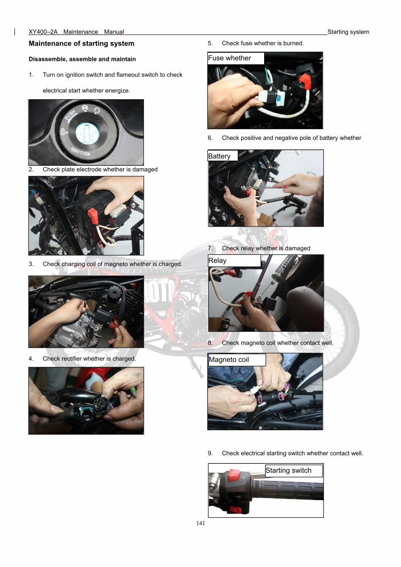
XY400–2A Maintenance Manual Starting system
141
Maintenance of starting system
Disassemble, assemble and maintain
1. Turn on ignition switch and flameout switch to check
electrical start whether energize.
2. Check plate electrode whether is damaged
3. Check charging coil of magneto whether is charged.
4. Check rectifier whether is charged.
5. Check fuse whether is burned.
6. Check positive and negative pole of battery whether
contact well
7. Check relay whether is damaged
8. Check magneto coil whether contact well.
9. Check electrical starting switch whether contact well.
Fuse whether
Battery
Relay
Magneto coil
Starting switch
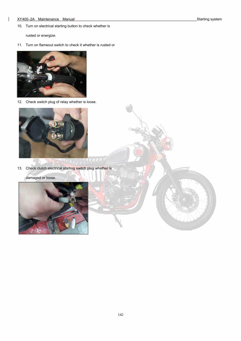
XY400–2A Maintenance Manual Starting system
142
10. Turn on electrical starting button to check whether is
rusted or energize.
11. Turn on flameout switch to check it whether is rusted or
loose
12. Check switch plug of relay whether is loose.
13. Check clutch electrical starting switch plug whether is
damaged or loose.
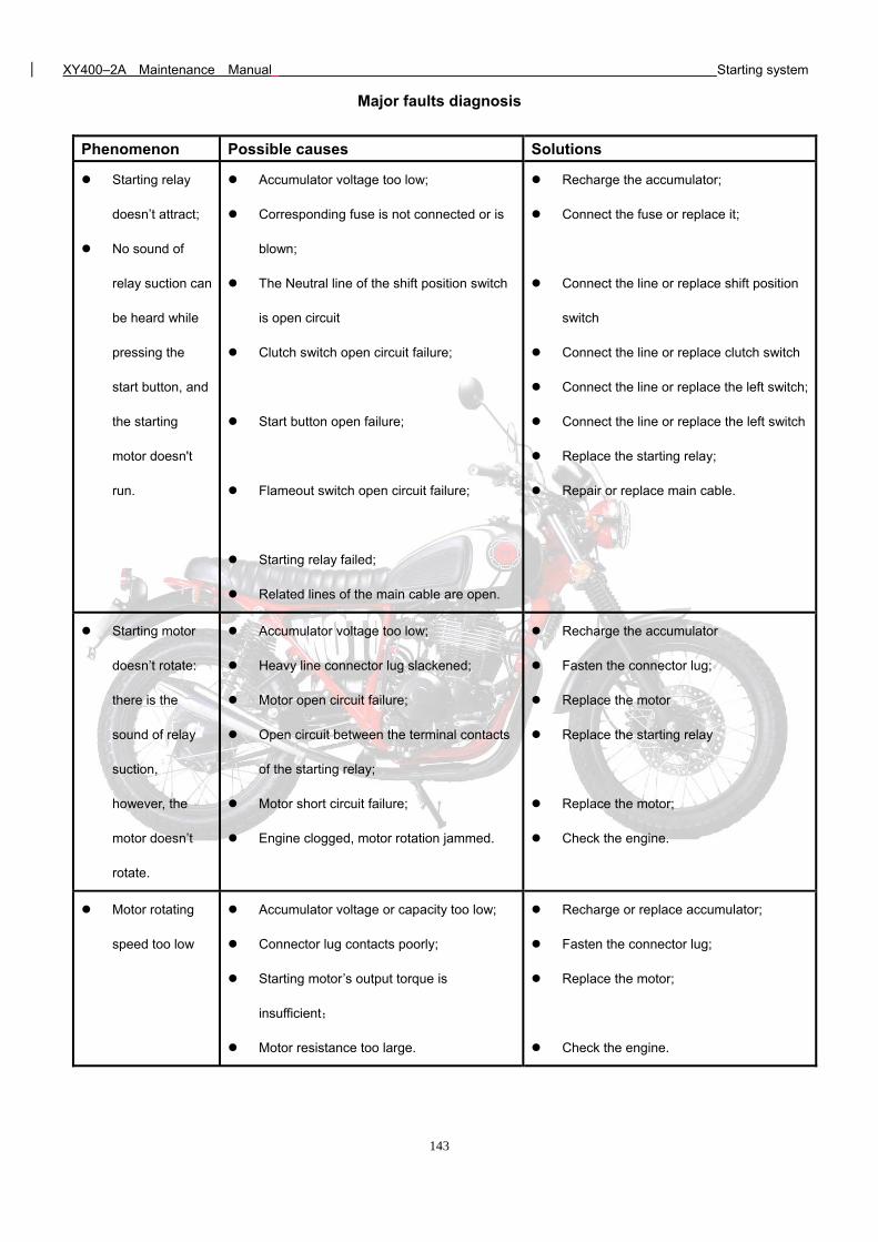
XY400–2A Maintenance Manual Starting system
143
Major faults diagnosis
Phenomenon Possible causes Solutions
Starting relay
doesn’t attract;
No sound of
relay suction can
be heard while
pressing the
start button, and
the starting
motor doesn't
run.
Accumulator voltage too low;
Corresponding fuse is not connected or is
blown;
The Neutral line of the shift position switch
is open circuit
Clutch switch open circuit failure;
Start button open failure;
Flameout switch open circuit failure;
Starting relay failed;
Related lines of the main cable are open.
Recharge the accumulator;
Connect the fuse or replace it;
Connect the line or replace shift position
switch
Connect the line or replace clutch switch
Connect the line or replace the left switch;
Connect the line or replace the left switch
Replace the starting relay;
Repair or replace main cable.
Starting motor
doesn’t rotate:
there is the
sound of relay
suction,
however, the
motor doesn’t
rotate.
Accumulator voltage too low;
Heavy line connector lug slackened;
Motor open circuit failure;
Open circuit between the terminal contacts
of the starting relay;
Motor short circuit failure;
Engine clogged, motor rotation jammed.
Recharge the accumulator
Fasten the connector lug;
Replace the motor
Replace the starting relay
Replace the motor;
Check the engine.
Motor rotating
speed too low
Accumulator voltage or capacity too low;
Connector lug contacts poorly;
Starting motor’s output torque is
insufficient;
Motor resistance too large.
Recharge or replace accumulator;
Fasten the connector lug;
Replace the motor;
Check the engine.
XY400–2A Maintenance Manual Illumination signal system
144
16. Illumination signal system
Overview
Illumination signal system is an important guaranty for the safe driving of the vehicle. It includes the headlamp illumination system,
signal lamp control system and horn system.
Headlamp illumination system:
We need to use the headlamp to illuminate the road surface and inform the surrounding vehicles or people of its presence while
driving at night; use the high-beam while driving at intermediate or high speed, and use the low-beam while meeting other
vehicles; the low-beam shall be anti-dazzled
Signal lamp control systems:
In a turning drive, the vehicle shall prompt the surrounding vehicles and people to dodge by the flash of the turn lamp; while
driving at night, it shall inform of its presence by the tail lamp’s front / rear position lamp, and illuminate the number on the license
plate; while braking, it shall illuminate the brake lamp to inform the vehicle behind of its braking deceleration. The flash of the turn
lamp is controlled by a switch and a flasher, and the illuminations of other lamps are controlled only by a switch.
Horn system:
When there are other surrounding vehicles or pedestrians are or will likely hinder your driving, use horn to alert them for safe
driving. The operation of the horn is controlled by the horn button.
Constituting parts and components:
• Head lamp
• Combined rear position lamp
• Horn
• Front brake lamp switch
• Rear brake lamp switch
• Left / Right combination switch
Overview Major parts and components
Circuit schematic drawing Major faults diagnosis
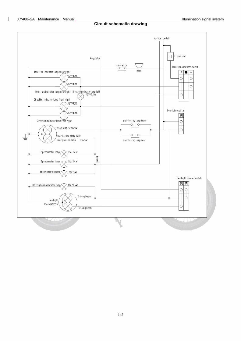
XY400–2A Maintenance Manual Illumination signal system
145
Circuit schematic drawing
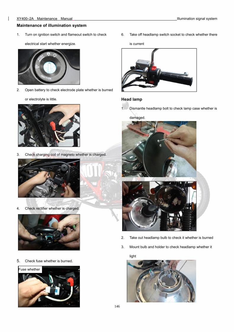
XY400–2A Maintenance Manual Illumination signal system
146
Maintenance of illumination system
1. Turn on ignition switch and flameout switch to check
electrical start whether energize.
2. Open battery to check electrode plate whether is burned
or electrolyte is little.
3. Check charging coil of magneto whether is charged.
4. Check rectifier whether is charged.
5. Check fuse whether is burned.
6. Take off headlamp switch socket to check whether there
is current
Head lamp
1. Dismantle headlamp bolt to check lamp case whether is
damaged.
2. Take out headlamp bulb to check it whether is burned
3. Mount bulb and holder to check headlamp whether it
light
Fuse whether
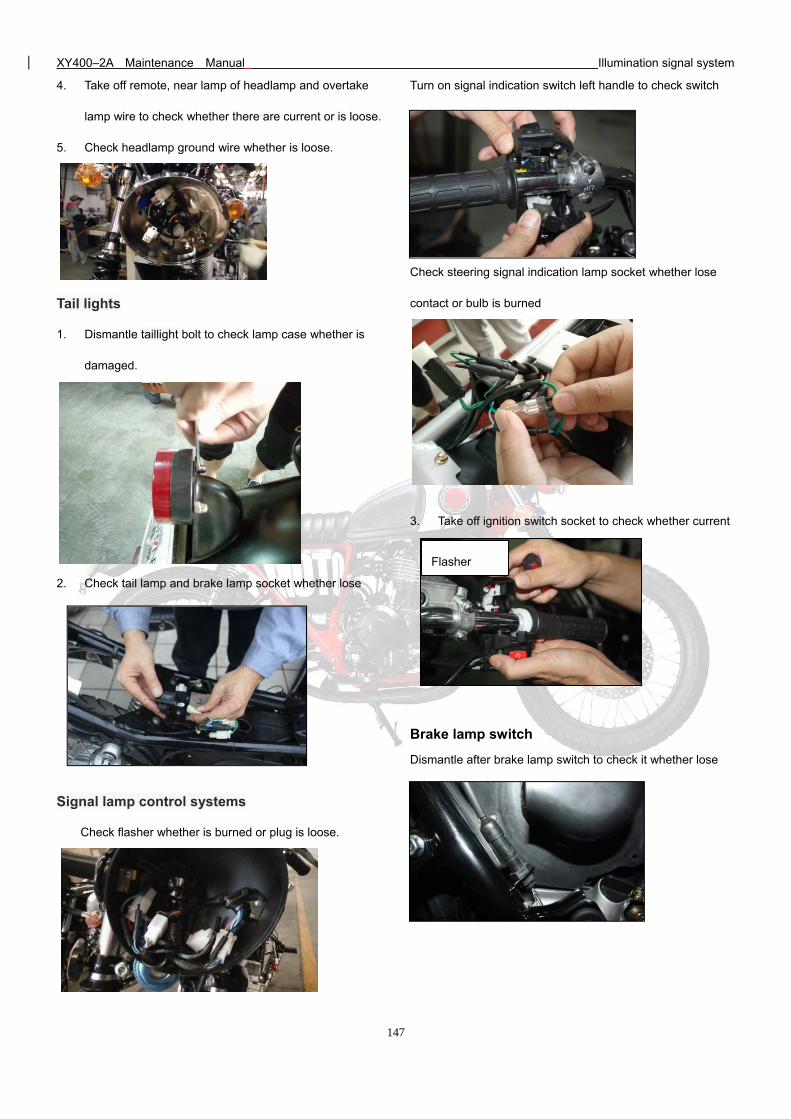
XY400–2A Maintenance Manual Illumination signal system
147
4. Take off remote, near lamp of headlamp and overtake
lamp wire to check whether there are current or is loose.
5. Check headlamp ground wire whether is loose.
Tail lights
1. Dismantle taillight bolt to check lamp case whether is
damaged.
2. Check tail lamp and brake lamp socket whether lose
contact or bulb is burned
Signal lamp control systems
Check flasher whether is burned or plug is loose.
Turn on signal indication switch left handle to check switch
whether is rusted or lose contact.
Check steering signal indication lamp socket whether lose
contact or bulb is burned
3. Take off ignition switch socket to check whether current
input headlamp switch
Brake lamp switch
Dismantle after brake lamp switch to check it whether lose
contact.
Flasher
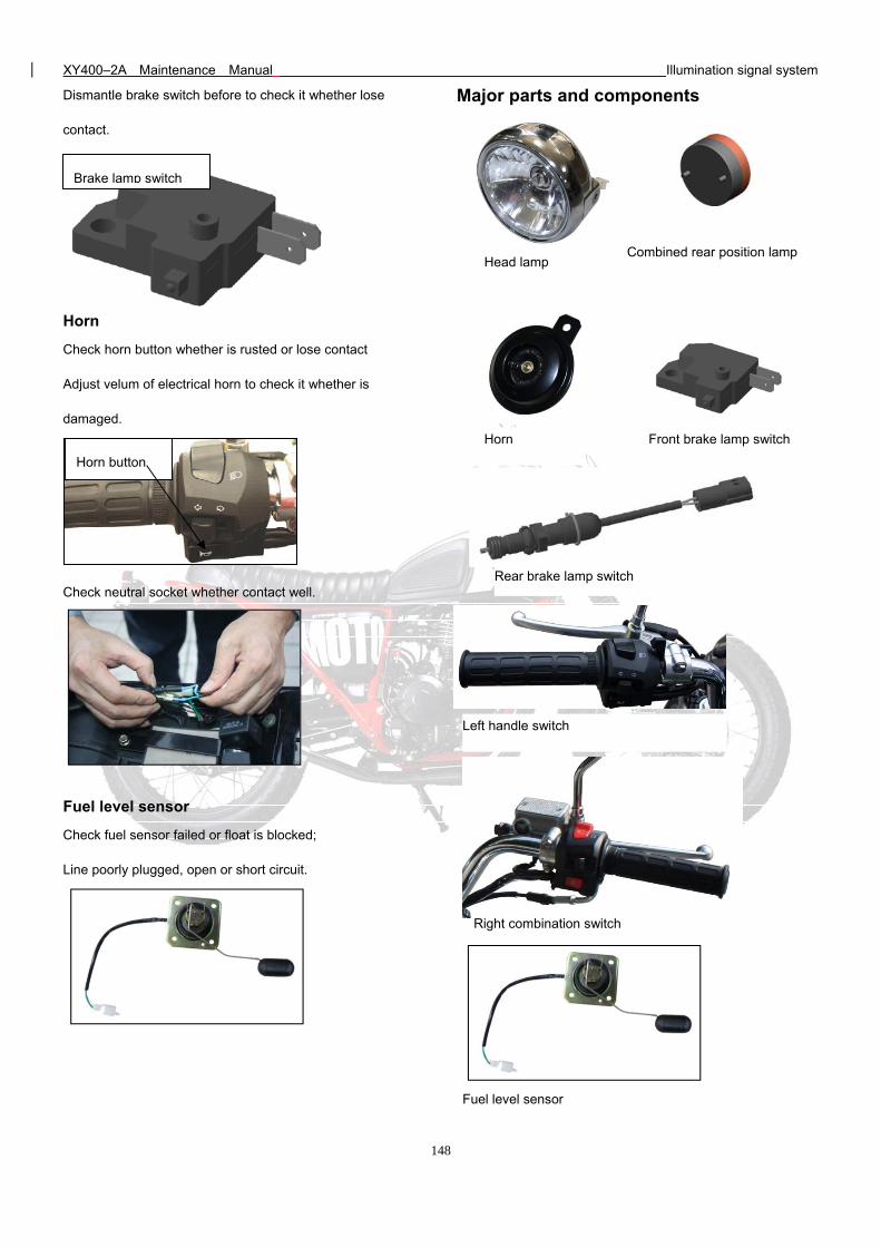
XY400–2A Maintenance Manual Illumination signal system
148
Dismantle brake switch before to check it whether lose
contact.
Horn
Check horn button whether is rusted or lose contact
Adjust velum of electrical horn to check it whether is
damaged.
Check neutral socket whether contact well.
Fuel level sensor
Check fuel sensor failed or float is blocked;
Line poorly plugged, open or short circuit.
Major parts and components
Brake lamp switch
Horn button
Head lamp Combined rear position lamp
Front brake lamp switch
Rear brake lamp switch
Horn
Right combination switch
Left handle switch
Fuel level sensor
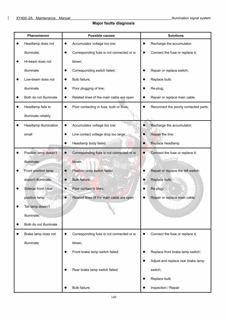
XY400–2A Maintenance Manual Illumination signal system
149
Major faults diagnosis
Phenomenon Possible causes Solutions
Headlamp does not
illuminate;
Hi-beam does not
illuminate
Low-beam does not
illuminate
Both do not illuminate
Accumulator voltage too low;
Corresponding fuse is not connected or is
blown;
Corresponding switch failed;
Bulb failure;
Poor plugging of line;
Related lines of the main cable are open
Recharge the accumulator;
Connect the fuse or replace it;
Repair or replace switch;
Replace bulb;
Re-plug;
Repair or replace main cable.
Headlamp fails to
illuminate reliably
Poor contacting in fuse, bulb or lines; Reconnect the poorly contacted parts;
Headlamp illumination
small
Accumulator voltage too low;
Line contact voltage drop too large;
Headlamp body failed
Recharge the accumulator;
Repair the line;
Replace headlamp
Position lamp doesn’t
illuminate:
Front position lamp
doesn’t illuminate:
Sidecar front / rear
position lamp
Tail lamp doesn’t
illuminate;
Both do not illuminate
Corresponding fuse is not connected or is
blown;
Position lamp switch failed;
Bulb failure;
Poor contact in lines;
Related lines of the main cable are open
Connect the fuse or replace it;
Repair or replace the left switch;
Replace bulb;
Re-plug;
Repair or replace main cable.
Brake lamp does not
illuminate
Corresponding fuse is not connected or is
blown;
Front brake lamp switch failed;
Rear brake lamp switch failed;
Bulb failure;
Connect the fuse or replace it;
Replace front brake lamp switch’;
Adjust and replace rear brake lamp
switch;
Replace bulb
Inspection / Repair
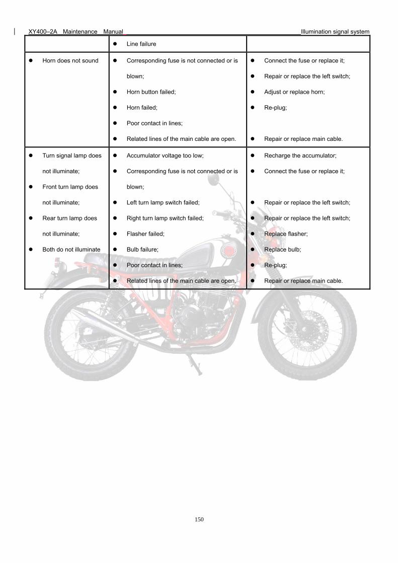
XY400–2A Maintenance Manual Illumination signal system
150
Line failure
Horn does not sound Corresponding fuse is not connected or is
blown;
Horn button failed;
Horn failed;
Poor contact in lines;
Related lines of the main cable are open.
Connect the fuse or replace it;
Repair or replace the left switch;
Adjust or replace horn;
Re-plug;
Repair or replace main cable.
Turn signal lamp does
not illuminate;
Front turn lamp does
not illuminate;
Rear turn lamp does
not illuminate;
Both do not illuminate
Accumulator voltage too low;
Corresponding fuse is not connected or is
blown;
Left turn lamp switch failed;
Right turn lamp switch failed;
Flasher failed;
Bulb failure;
Poor contact in lines;
Related lines of the main cable are open.
Recharge the accumulator;
Connect the fuse or replace it;
Repair or replace the left switch;
Repair or replace the left switch;
Replace flasher;
Replace bulb;
Re-plug;
Repair or replace main cable.
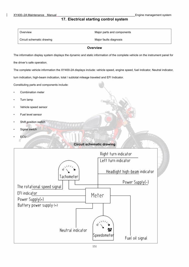
XY400–2A Maintenance Manual Engine management system
151
17. Electrical starting control system
Overview
The information display system displays the dynamic and static information of the complete vehicle on the instrument panel for
the driver’s safe operation.
The complete vehicle information the XY400-2A displays include: vehicle speed, engine speed, fuel indicator, Neutral indicator,
turn indication, high-beam indication, total / subtotal mileage traveled and EFI Indicator.
Constituting parts and components include:
• Combination meter
• Turn lamp
• Vehicle speed sensor
• Fuel level sensor
• Shift position switch
• Signal switch
• ECU
Circuit schematic drawing
Overview Major parts and components
Circuit schematic drawing Major faults diagnosis
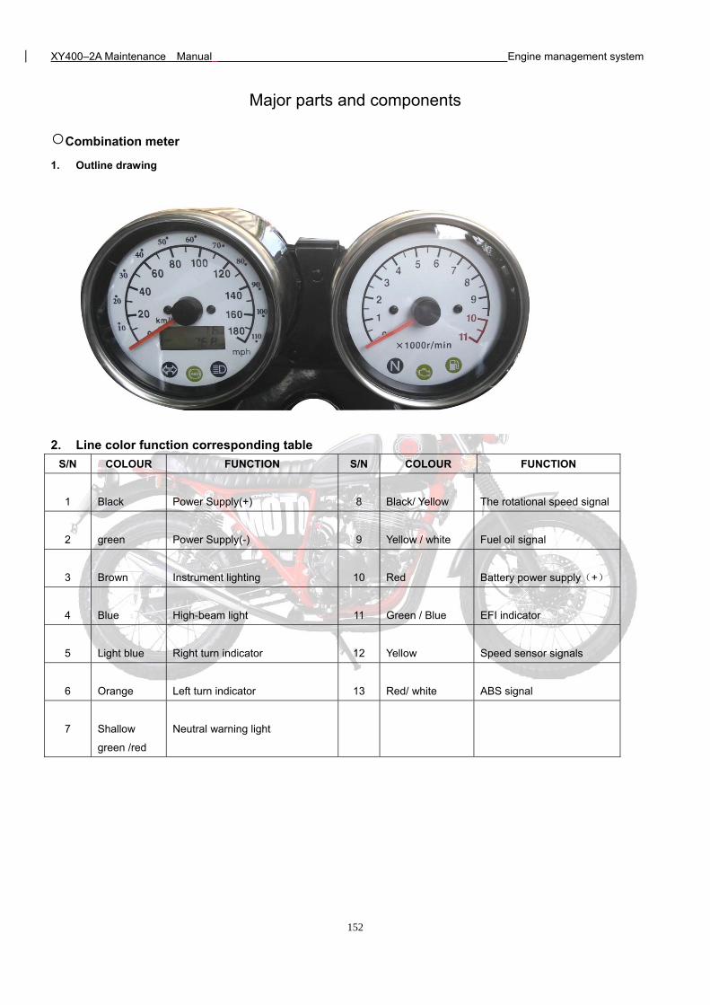
XY400–2A Maintenance Manual Engine management system
152
Major parts and components
Combination meter
1. Outline drawing
2. Line color function corresponding table
S/N COLOUR FUNCTION S/N COLOUR FUNCTION
1 Black Power Supply(+) 8 Black/ Yellow The rotational speed signal
2 green Power Supply(-) 9 Yellow / white Fuel oil signal
3 Brown Instrument lighting 10 Red Battery power supply(+)
4 Blue High-beam light 11 Green / Blue EFI indicator
5 Light blue Right turn indicator 12 Yellow Speed sensor signals
6 Orange Left turn indicator 13 Red/ white ABS signal
7 Shallow
green /red
Neutral warning light
XY400–2A Maintenance Manual Engine management system
153
3. Meter reading and usage
1) Speedometer
Indicate motorcycle speed (Km/h). Do not exceed legal
rate-limiting to assure safe riding.
2) Turning indicator light
(R)right turn,twinkle when turn to right(Green).
(L)left turn,twinkle when turn to left(Green).
3) High-beam light
The light comes on when activating the high-beam
light using the control on the left-hand switch.
4) Neutral warning light .
The light comes on when the gear shift lever is in
neutral position (no gear engaged).
5) Engine failure warning light
When the ignition key is turned, the engine control
unit runs a self-test, the light comes on for a few
seconds and then goes off if no fault is found.
If the light comes on while the engine is running, it
means that there is an engine or injection system
failure.
- Stop and turn off the engine
- Wait a few minutes and restart the engine; if the
light comes on again, contact your nearest SWM
dealer to have the self-test system checked
6) Fuel reserve warning ligh
When the ignition key is turned, the light comes on
for a few seconds and then goes off.
If the light comes on while riding the motorcycle, it
means that the fuel has gone into reserve ( 3 litres)
and you need to refuel as soon as possible
7) Odometer
Indicate riding distance (Km).
8) Tachometer
It shows the speed(rpm) of the engine.
9) Trip meter
It shows the mileage of trip in kilometers.
10) Trip meter knob
Indicate distance from Zero, by rotating Zero Knob to the
Direction of Arrow can return it to Zero
11) ABS Lamp
When the ignition key is turned, the ABS unit runs a self-test,
the light comes on for a few
seconds and then goes off if no fault is found.
If the light comes on while the engine is running, it
means that there is ABS system failure.
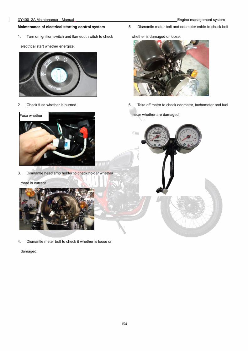
XY400–2A Maintenance Manual Engine management system
154
Maintenance of electrical starting control system
1. Turn on ignition switch and flameout switch to check
electrical start whether energize.
2. Check fuse whether is burned.
3. Dismantle headlamp holder to check holder whether
there is current.
4. Dismantle meter bolt to check it whether is loose or
damaged.
5. Dismantle meter bolt and odometer cable to check bolt
whether is damaged or loose.
6. Take off meter to check odometer, tachometer and fuel
meter whether are damaged.
Fuse whether
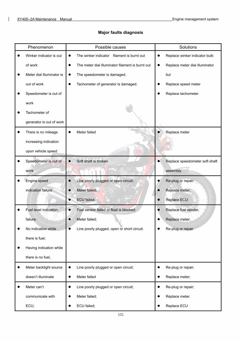
XY400–2A Maintenance Manual Engine management system
155
Major faults diagnosis
Phenomenon Possible causes Solutions
Winker indicator is out
of work
Meter dial illuminator is
out of work
Speedometer is out of
work
Tachometer of
generator is out of work
The winker indicator filament is burnt out
The meter dial illuminator filament is burnt out
The speedometer is damaged.
Tachometer of generator is damaged.
Replace winker indicator bulb
Replace meter dial illuminator
bul
Replace speed meter
Replace tachometer
There is no mileage
increasing indication
upon vehicle speed
Meter failed Replace meter
Speedometer is out of
work
Soft shaft is broken Replace speedometer soft shaft
assembly
Engine speed
indication failure
Line poorly plugged or open circuit;
Meter failed;
ECU failed;
Re-plug or repair;
Replace meter;
Replace ECU
Fuel level indication
failure:
No indication while
there is fuel;
Having indication while
there is no fuel,
Fuel sensor failed or float is blocked;
Meter failed;
Line poorly plugged, open or short circuit.
Replace fuel sender;
Replace meter;
Re-plug or repair.
Meter backlight source
doesn’t illuminate
Line poorly plugged or open circuit;
Meter failed
Re-plug or repair;
Replace meter;
Meter can’t
communicate with
ECU;
Line poorly plugged or open circuit;
Meter failed;
ECU failed;
Re-plug or repair;
Replace meter.
Replace ECU
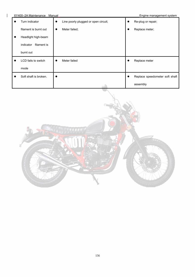
XY400–2A Maintenance Manual Engine management system
156
Turn indicator
filament is burnt out
Headlight high-beam
indicator filament is
burnt out
Line poorly plugged or open circuit;
Meter failed;
Re-plug or repair;
Replace meter;
LCD fails to switch
mode
Meter failed Replace meter
Soft shaft is broken. Replace speedometer soft shaft
assembly
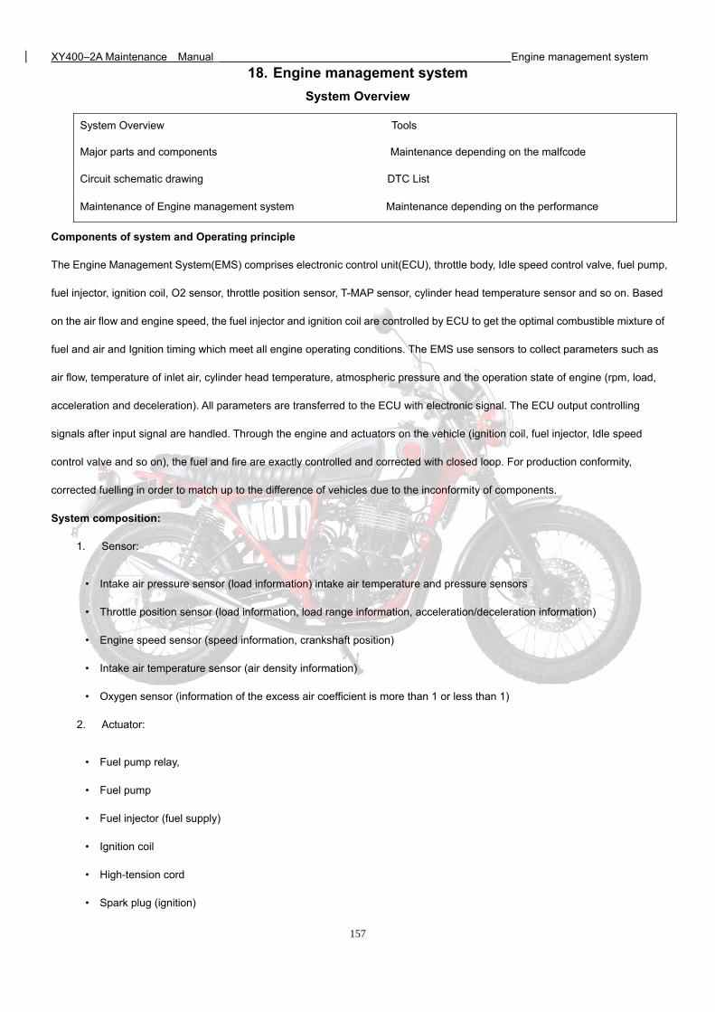
XY400–2A Maintenance Manual Engine management system
157
18. Engine management system
System Overview
Components of system and Operating principle
The Engine Management System(EMS) comprises electronic control unit(ECU), throttle body, Idle speed control valve, fuel pump,
fuel injector, ignition coil, O2 sensor, throttle position sensor, T-MAP sensor, cylinder head temperature sensor and so on. Based
on the air flow and engine speed, the fuel injector and ignition coil are controlled by ECU to get the optimal combustible mixture of
fuel and air and Ignition timing which meet all engine operating conditions. The EMS use sensors to collect parameters such as
air flow, temperature of inlet air, cylinder head temperature, atmospheric pressure and the operation state of engine (rpm, load,
acceleration and deceleration). All parameters are transferred to the ECU with electronic signal. The ECU output controlling
signals after input signal are handled. Through the engine and actuators on the vehicle (ignition coil, fuel injector, Idle speed
control valve and so on), the fuel and fire are exactly controlled and corrected with closed loop. For production conformity,
corrected fuelling in order to match up to the difference of vehicles due to the inconformity of components.
System composition:
1. Sensor:
• Intake air pressure sensor (load information) intake air temperature and pressure sensors
• Throttle position sensor (load information, load range information, acceleration/deceleration information)
• Engine speed sensor (speed information, crankshaft position)
• Intake air temperature sensor (air density information)
• Oxygen sensor (information of the excess air coefficient is more than 1 or less than 1)
2. Actuator:
• Fuel pump relay,
• Fuel pump
• Fuel injector (fuel supply)
• Ignition coil
• High-tension cord
• Spark plug (ignition)
System Overview Tools
Major parts and components Maintenance depending on the malfcode
Circuit schematic drawing DTC List
Maintenance of Engine management system Maintenance depending on the performance
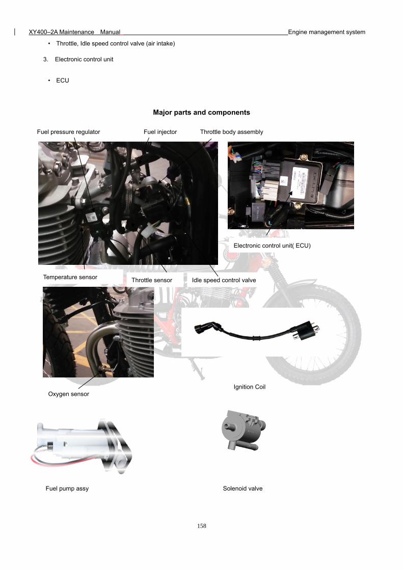
XY400–2A Maintenance Manual Engine management system
158
• Throttle, Idle speed control valve (air intake)
3. Electronic control unit
• ECU
Major parts and components
Temperature sensor Throttle sensor
Fuel injector
Idle speed control valve
Fuel pressure regulator Throttle body assembly
Electronic control unit( ECU)
Oxygen sensor Ignition Coil
Solenoid valve Fuel pump assy
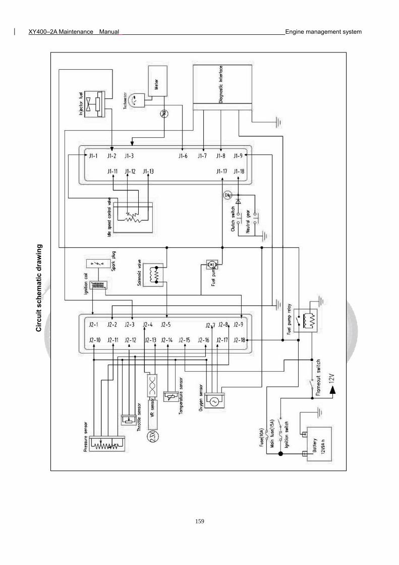
XY400–2A Maintenance Manual Engine management system
159
Cir
cuit
sch
em
atic
dra
win
g
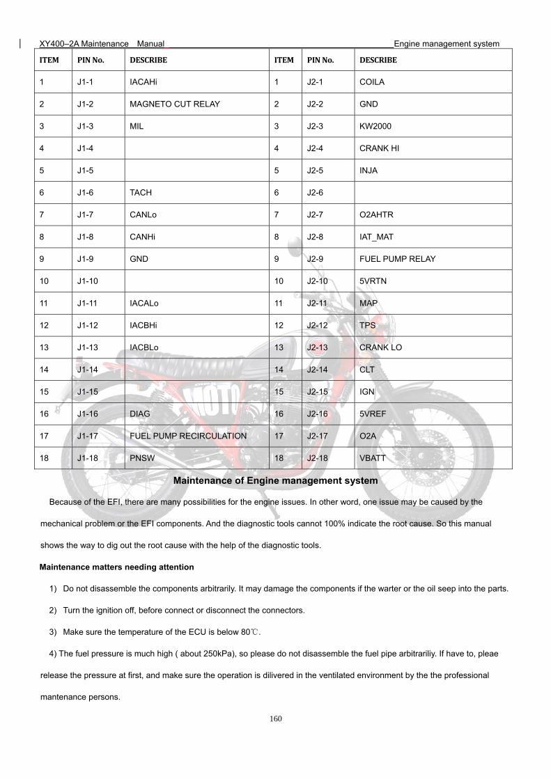
XY400–2A Maintenance Manual Engine management system
160
ITEM PINNo. DESCRIBE ITEM PINNo. DESCRIBE
1 J1-1 IACAHi 1 J2-1 COILA
2 J1-2 MAGNETO CUT RELAY 2 J2-2 GND
3 J1-3 MIL 3 J2-3 KW2000
4 J1-4 4 J2-4 CRANK HI
5 J1-5 5 J2-5 INJA
6 J1-6 TACH 6 J2-6
7 J1-7 CANLo 7 J2-7 O2AHTR
8 J1-8 CANHi 8 J2-8 IAT_MAT
9 J1-9 GND 9 J2-9 FUEL PUMP RELAY
10 J1-10 10 J2-10 5VRTN
11 J1-11 IACALo 11 J2-11 MAP
12 J1-12 IACBHi 12 J2-12 TPS
13 J1-13 IACBLo 13 J2-13 CRANK LO
14 J1-14 14 J2-14 CLT
15 J1-15 15 J2-15 IGN
16 J1-16 DIAG 16 J2-16 5VREF
17 J1-17 FUEL PUMP RECIRCULATION 17 J2-17 O2A
18 J1-18 PNSW 18 J2-18 VBATT
Maintenance of Engine management system
Because of the EFI, there are many possibilities for the engine issues. In other word, one issue may be caused by the
mechanical problem or the EFI components. And the diagnostic tools cannot 100% indicate the root cause. So this manual
shows the way to dig out the root cause with the help of the diagnostic tools.
Maintenance matters needing attention
1) Do not disassemble the components arbitrarily. It may damage the components if the warter or the oil seep into the parts.
2) Turn the ignition off, before connect or disconnect the connectors.
3) Make sure the temperature of the ECU is below 80.
4) The fuel pressure is much high ( about 250kPa), so please do not disassemble the fuel pipe arbitrariliy. If have to, pleae
release the pressure at first, and make sure the operation is dilivered in the ventilated environment by the the professional
mantenance persons.
XY400–2A Maintenance Manual Engine management system
161
5) When disassmeble the fuel pump from the pump, make sure the power is off. Or it may casue the fire.
6) The fuel pump cannot work in air or water, it will shorten the service life. And the positive and negative connecters cannot be
exchanged.
7) The ignition system check only could be delivered when it is nessasary. When check the spark plug out of the engine, if
start the engine, please make sure the throttle is closed. Or too much unburned gasoline coming to the catalyst may damage the
catalyst.
8) The idle speed is adjusted by the ECU. The idle pintle is not alowed to adjust.
9) The Positive and Negative of the battery cannot be reversed. It may damage the EFI components.
10) It is forbidden to remove the battery when the eninge is running.
11) Cannot messure the signal by pierce the harness.
Tools
1) Multimeter: messure the voltage, the resistance and the harness connection.
2) Diagnostic tool: reading the malfcode, and engine parameters.
3) Oil pressure garge: messure the fuel pressure.
4) Cylinder pressure garge: messure the pressure garge.
Maintenance depending on the malfcode.
Description
1) If the issure cannot repeat, the issure analysis may be wrong.
2) The multimeter below means the digital type. Pointer-type is forbidden. 3) If the malfcode shows the voltage is low, it means maybe the wire is short to ground. If the malfcode shows the voltage
is high, it means maybe the wire is short to battery. If the malfcode shows the components signal abnormal, it means
the wire is open or short to other wires. Diagnostichelp:
1) If the malfcode shows again after clearence, check whether the connector is connected well.
2) Do not ignore the affect of the engine maintenance situation, the cylinder pressure, and the mechanical ignition timing.
3) Change another ECU to do the test. If the malfcode disappears, the root cause is the ECU. If the malfcode is still there,
then use the old ECU to do the test.
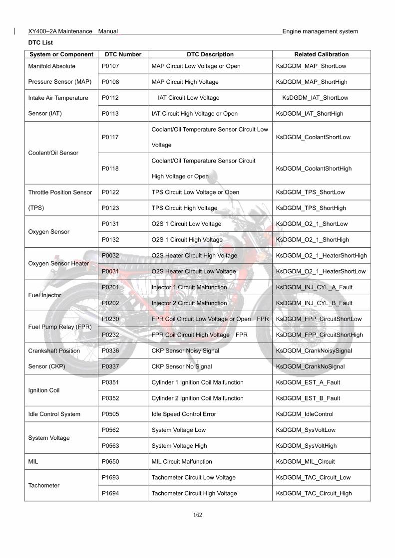
XY400–2A Maintenance Manual Engine management system
162
DTC List
System or Component DTC Number DTC Description Related Calibration
Manifold Absolute
Pressure Sensor (MAP)
P0107 MAP Circuit Low Voltage or Open KsDGDM_MAP_ShortLow
P0108 MAP Circuit High Voltage KsDGDM_MAP_ShortHigh
Intake Air Temperature
Sensor (IAT)
P0112 IAT Circuit Low Voltage KsDGDM_IAT_ShortLow
P0113 IAT Circuit High Voltage or Open KsDGDM_IAT_ShortHigh
Coolant/Oil Sensor
P0117 Coolant/Oil Temperature Sensor Circuit Low
Voltage KsDGDM_CoolantShortLow
P0118 Coolant/Oil Temperature Sensor Circuit
High Voltage or Open KsDGDM_CoolantShortHigh
Throttle Position Sensor
(TPS)
P0122 TPS Circuit Low Voltage or Open KsDGDM_TPS_ShortLow
P0123 TPS Circuit High Voltage KsDGDM_TPS_ShortHigh
Oxygen Sensor P0131 O2S 1 Circuit Low Voltage KsDGDM_O2_1_ShortLow
P0132 O2S 1 Circuit High Voltage KsDGDM_O2_1_ShortHigh
Oxygen Sensor Heater P0032 O2S Heater Circuit High Voltage KsDGDM_O2_1_HeaterShortHigh
P0031 O2S Heater Circuit Low Voltage KsDGDM_O2_1_HeaterShortLow
Fuel Injector P0201 Injector 1 Circuit Malfunction KsDGDM_INJ_CYL_A_Fault
P0202 Injector 2 Circuit Malfunction KsDGDM_INJ_CYL_B_Fault
Fuel Pump Relay (FPR) P0230 FPR Coil Circuit Low Voltage or Open FPR KsDGDM_FPP_CircuitShortLow
P0232 FPR Coil Circuit High Voltage FPR KsDGDM_FPP_CircuitShortHigh
Crankshaft Position
Sensor (CKP)
P0336 CKP Sensor Noisy Signal KsDGDM_CrankNoisySignal
P0337 CKP Sensor No Signal KsDGDM_CrankNoSignal
Ignition Coil P0351 Cylinder 1 Ignition Coil Malfunction KsDGDM_EST_A_Fault
P0352 Cylinder 2 Ignition Coil Malfunction KsDGDM_EST_B_Fault
Idle Control System P0505 Idle Speed Control Error KsDGDM_IdleControl
System Voltage P0562 System Voltage Low KsDGDM_SysVoltLow
P0563 System Voltage High KsDGDM_SysVoltHigh
MIL P0650 MIL Circuit Malfunction KsDGDM_MIL_Circuit
Tachometer P1693 Tachometer Circuit Low Voltage KsDGDM_TAC_Circuit_Low
P1694 Tachometer Circuit High Voltage KsDGDM_TAC_Circuit_High
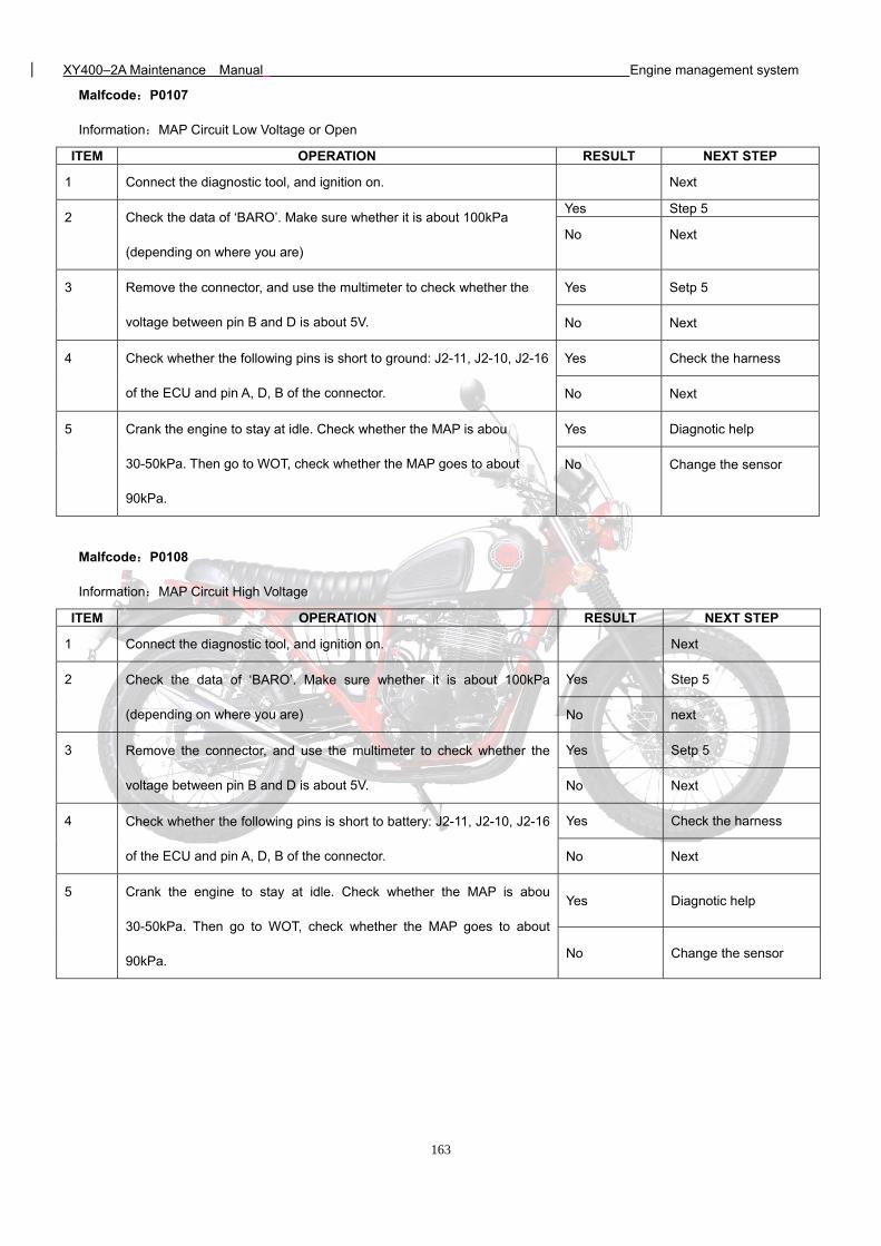
XY400–2A Maintenance Manual Engine management system
163
Malfcode:P0107
Information:MAP Circuit Low Voltage or Open
ITEM OPERATION RESULT NEXT STEP
1 Connect the diagnostic tool, and ignition on. Next
2 Check the data of ‘BARO’. Make sure whether it is about 100kPa
(depending on where you are)
Yes Step 5
No Next
3 Remove the connector, and use the multimeter to check whether the
voltage between pin B and D is about 5V.
Yes Setp 5
No Next
4 Check whether the following pins is short to ground: J2-11, J2-10, J2-16
of the ECU and pin A, D, B of the connector.
Yes Check the harness
No Next
5 Crank the engine to stay at idle. Check whether the MAP is abou
30-50kPa. Then go to WOT, check whether the MAP goes to about
90kPa.
Yes Diagnotic help
No Change the sensor
Malfcode:P0108
Information:MAP Circuit High Voltage
ITEM OPERATION RESULT NEXT STEP
1 Connect the diagnostic tool, and ignition on. Next
2 Check the data of ‘BARO’. Make sure whether it is about 100kPa
(depending on where you are)
Yes Step 5
No next
3 Remove the connector, and use the multimeter to check whether the
voltage between pin B and D is about 5V.
Yes Setp 5
No Next
4 Check whether the following pins is short to battery: J2-11, J2-10, J2-16
of the ECU and pin A, D, B of the connector.
Yes Check the harness
No Next
5 Crank the engine to stay at idle. Check whether the MAP is abou
30-50kPa. Then go to WOT, check whether the MAP goes to about
90kPa.
Yes Diagnotic help
No Change the sensor
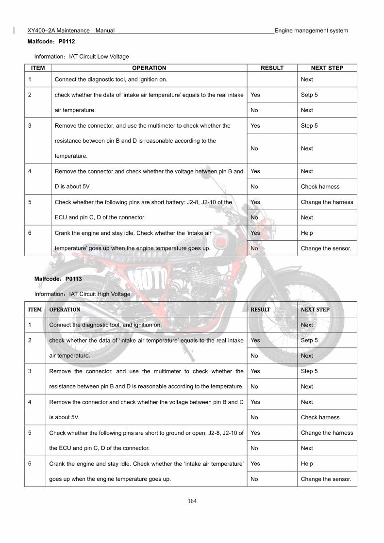
XY400–2A Maintenance Manual Engine management system
164
Malfcode:P0112
Information:IAT Circuit Low Voltage
ITEM OPERATION RESULT NEXT STEP
1 Connect the diagnostic tool, and ignition on. Next
2 check whether the data of ‘intake air temperature’ equals to the real intake
air temperature.
Yes Setp 5
No Next
3 Remove the connector, and use the multimeter to check whether the
resistance between pin B and D is reasonable according to the
temperature.
Yes Step 5
No Next
4 Remove the connector and check whether the voltage between pin B and
D is about 5V.
Yes Next
No Check harness
5 Check whether the following pins are short battery: J2-8, J2-10 of the
ECU and pin C, D of the connector.
Yes Change the harness
No Next
6 Crank the engine and stay idle. Check whether the ‘intake air
temperature’ goes up when the engine temperature goes up.
Yes Help
No Change the sensor.
Malfcode:P0113
Information:IAT Circuit High Voltage
ITEM OPERATION RESULT NEXTSTEP
1 Connect the diagnostic tool, and ignition on. Next
2 check whether the data of ‘intake air temperature’ equals to the real intake
air temperature.
Yes Setp 5
No Next
3 Remove the connector, and use the multimeter to check whether the
resistance between pin B and D is reasonable according to the temperature.
Yes Step 5
No Next
4 Remove the connector and check whether the voltage between pin B and D
is about 5V.
Yes Next
No Check harness
5 Check whether the following pins are short to ground or open: J2-8, J2-10 of
the ECU and pin C, D of the connector.
Yes Change the harness
No Next
6 Crank the engine and stay idle. Check whether the ‘intake air temperature’
goes up when the engine temperature goes up.
Yes Help
No Change the sensor.
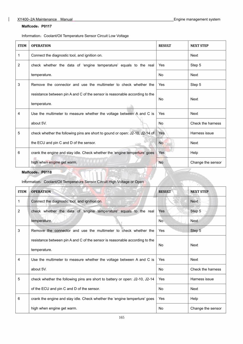
XY400–2A Maintenance Manual Engine management system
165
Malfcode:P0117
Information:Coolant/Oil Temperature Sensor Circuit Low Voltage
ITEM OPERATION RESULT NEXTSTEP
1 Connect the diagnostic tool, and ignition on. Next
2 check whether the data of ‘engine temperature’ equals to the real
temperature.
Yes Step 5
No Next
3 Remove the connector and use the multimeter to check whether the
resistance between pin A and C of the sensor is reasonable according to the
temperature.
Yes Step 5
No Next
4 Use the multimeter to measure whether the voltage between A and C is
about 5V.
Yes Next
No Check the harness
5 check whether the following pins are short to gound or open: J2-10, J2-14 of
the ECU and pin C and D of the sensor.
Yes Harness issue
No Next
6 crank the engine and stay idle. Check whether the ‘engine temperture’ goes
high when engine get warm.
Yes Help
No Change the sensor
Malfcode:P0118
Information:Coolant/Oil Temperature Sensor Circuit High Voltage or Open
ITEM OPERATION RESULT NEXTSTEP
1 Connect the diagnostic tool, and ignition on. Next
2 check whether the data of ‘engine temperature’ equals to the real
temperature.
Yes Step 5
No Next
3 Remove the connector and use the multimeter to check whether the
resistance between pin A and C of the sensor is reasonable according to the
temperature.
Yes Step 5
No Next
4 Use the multimeter to measure whether the voltage between A and C is
about 5V.
Yes Next
No Check the harness
5 check whether the following pins are short to battery or open: J2-10, J2-14
of the ECU and pin C and D of the sensor.
Yes Harness issue
No Next
6 crank the engine and stay idle. Check whether the ‘engine temperture’ goes
high when engine get warm.
Yes Help
No Change the sensor
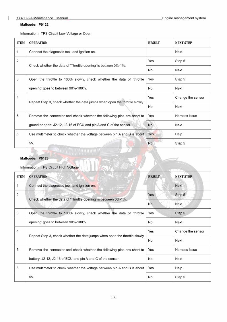
XY400–2A Maintenance Manual Engine management system
166
Malfcode:P0122
Information:TPS Circuit Low Voltage or Open
ITEM OPERATION RESULT NEXTSTEP
1 Connect the diagnostic tool, and ignition on. Next
2 Check whether the data of ‘Throttle opening’ is bettwen 0%-1%.
Yes Step 5
No Next
3 Open the throttle to 100% slowly, check whether the data of ‘throttle
opening’ goes to between 90%-100%.
Yes Step 5
No Next
4 Repeat Step 3, check whether the data jumps when open the throttle slowly.
Yes Change the sensor
No Next
5 Remove the connector and check whether the following pins are short to
gound or open: J2-12, J2-16 of ECU and pin A and C of the sensor.
Yes Harness issue
No Next
6 Use multimeter to check whether the voltage between pin A and B is about
5V.
Yes Help
No Step 5 Malfcode:P0123
Information:TPS Circuit High Voltage
ITEM OPERATION RESULT NEXTSTEP
1 Connect the diagnostic tool, and ignition on. Next
2 Check whether the data of ‘Throttle opening’ is between 0%-1%.
Yes Step 5
No Next
3 Open the throttle to 100% slowly, check whether the data of ‘throttle
opening’ goes to between 90%-100%.
Yes Step 5
No Next
4 Repeat Step 3, check whether the data jumps when open the throttle slowly
Yes Change the sensor
No Next
5 Remove the connector and check whether the following pins are short to
battery: J2-12, J2-16 of ECU and pin A and C of the sensor.
Yes Harness issue
No Next
6 Use multimeter to check whether the voltage between pin A and B is about
5V.
Yes Help
No Step 5
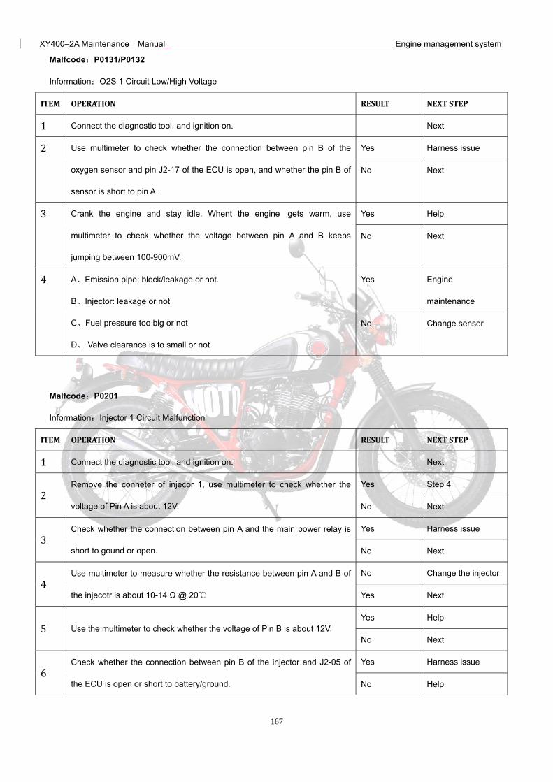
XY400–2A Maintenance Manual Engine management system
167
Malfcode:P0131/P0132
Information:O2S 1 Circuit Low/High Voltage
ITEM OPERATION RESULT NEXTSTEP1 Connect the diagnostic tool, and ignition on. Next 2 Use multimeter to check whether the connection between pin B of the
oxygen sensor and pin J2-17 of the ECU is open, and whether the pin B of
sensor is short to pin A.
Yes Harness issue
No Next
3 Crank the engine and stay idle. Whent the engine gets warm, use
multimeter to check whether the voltage between pin A and B keeps
jumping between 100-900mV.
Yes Help
No Next
4 A、Emission pipe: block/leakage or not.
B、Injector: leakage or not
C、Fuel pressure too big or not
D、 Valve clearance is to small or not
Yes Engine
maintenance
No Change sensor
Malfcode:P0201
Information:Injector 1 Circuit Malfunction
ITEM OPERATION RESULT NEXTSTEP1 Connect the diagnostic tool, and ignition on. Next
2 Remove the conneter of injecor 1, use multimeter to check whether the
voltage of Pin A is about 12V.
Yes Step 4
No Next
3 Check whether the connection between pin A and the main power relay is
short to gound or open.
Yes Harness issue
No Next
4 Use multimeter to measure whether the resistance between pin A and B of
the injecotr is about 10-14 Ω @ 20
No Change the injector
Yes Next
5 Use the multimeter to check whether the voltage of Pin B is about 12V. Yes Help
No Next
6 Check whether the connection between pin B of the injector and J2-05 of
the ECU is open or short to battery/ground.
Yes Harness issue
No Help
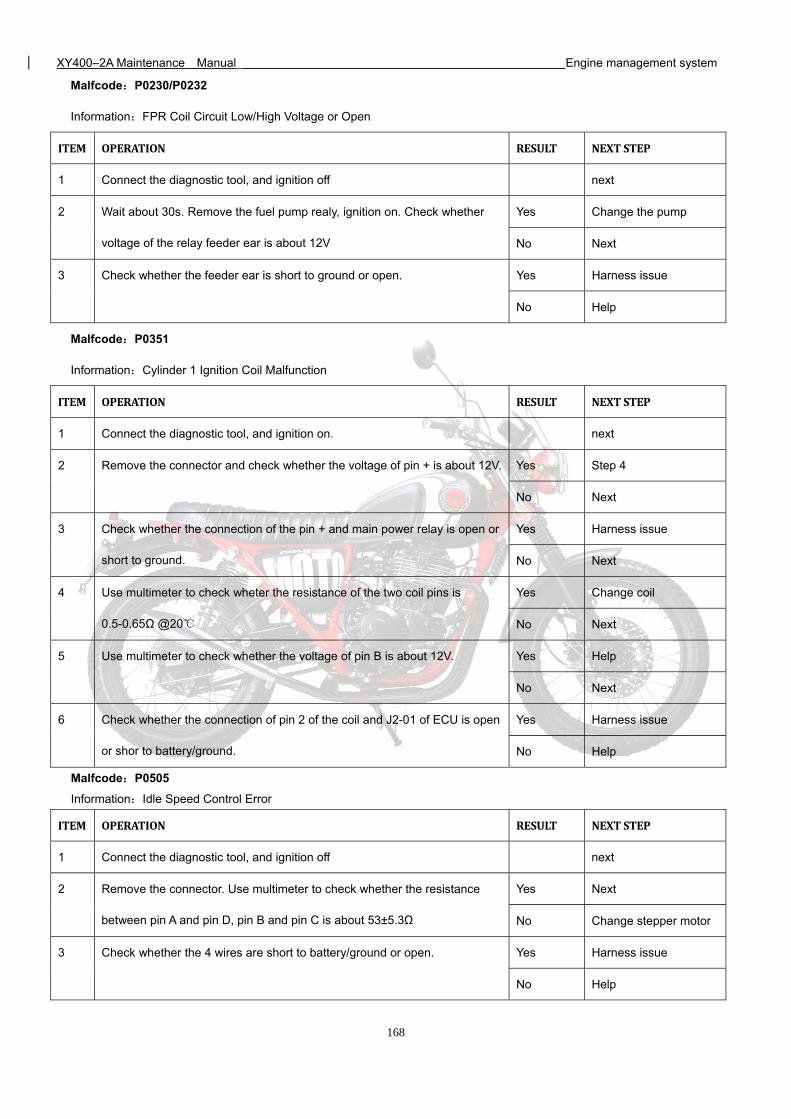
XY400–2A Maintenance Manual Engine management system
168
Malfcode:P0230/P0232
Information:FPR Coil Circuit Low/High Voltage or Open
ITEM OPERATION RESULT NEXTSTEP
1 Connect the diagnostic tool, and ignition off next
2 Wait about 30s. Remove the fuel pump realy, ignition on. Check whether
voltage of the relay feeder ear is about 12V
Yes Change the pump
No Next
3 Check whether the feeder ear is short to ground or open. Yes Harness issue
No Help
Malfcode:P0351
Information:Cylinder 1 Ignition Coil Malfunction
ITEM OPERATION RESULT NEXTSTEP
1 Connect the diagnostic tool, and ignition on. next
2 Remove the connector and check whether the voltage of pin + is about 12V. Yes Step 4
No Next
3 Check whether the connection of the pin + and main power relay is open or
short to ground.
Yes Harness issue
No Next
4 Use multimeter to check wheter the resistance of the two coil pins is
0.5-0.65Ω @20
Yes Change coil
No Next
5 Use multimeter to check whether the voltage of pin B is about 12V. Yes Help
No Next
6 Check whether the connection of pin 2 of the coil and J2-01 of ECU is open
or shor to battery/ground.
Yes Harness issue
No Help
Malfcode:P0505
Information:Idle Speed Control Error
ITEM OPERATION RESULT NEXTSTEP
1 Connect the diagnostic tool, and ignition off next
2 Remove the connector. Use multimeter to check whether the resistance
between pin A and pin D, pin B and pin C is about 53±5.3Ω
Yes Next
No Change stepper motor
3 Check whether the 4 wires are short to battery/ground or open. Yes Harness issue
No Help
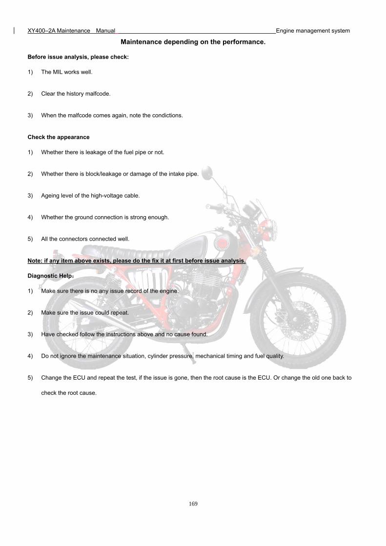
XY400–2A Maintenance Manual Engine management system
169
Maintenance depending on the performance.
Before issue analysis, please check:
1) The MIL works well.
2) Clear the history malfcode.
3) When the malfcode comes again, note the condictions.
Check the appearance
1) Whether there is leakage of the fuel pipe or not.
2) Whether there is block/leakage or damage of the intake pipe.
3) Ageing level of the high-voltage cable.
4) Whether the ground connection is strong enough.
5) All the connectors connected well.
Note: if any item above exists, please do the fix it at first before issue analysis.
Diagnostic Help:
1) Make sure there is no any issue record of the engine.
2) Make sure the issue could repeat.
3) Have checked follow the instructions above and no cause found.
4) Do not ignore the maintenance situation, cylinder pressure, mechanical timing and fuel quality.
5) Change the ECU and repeat the test, if the issue is gone, then the root cause is the ECU. Or change the old one back to
check the root cause.
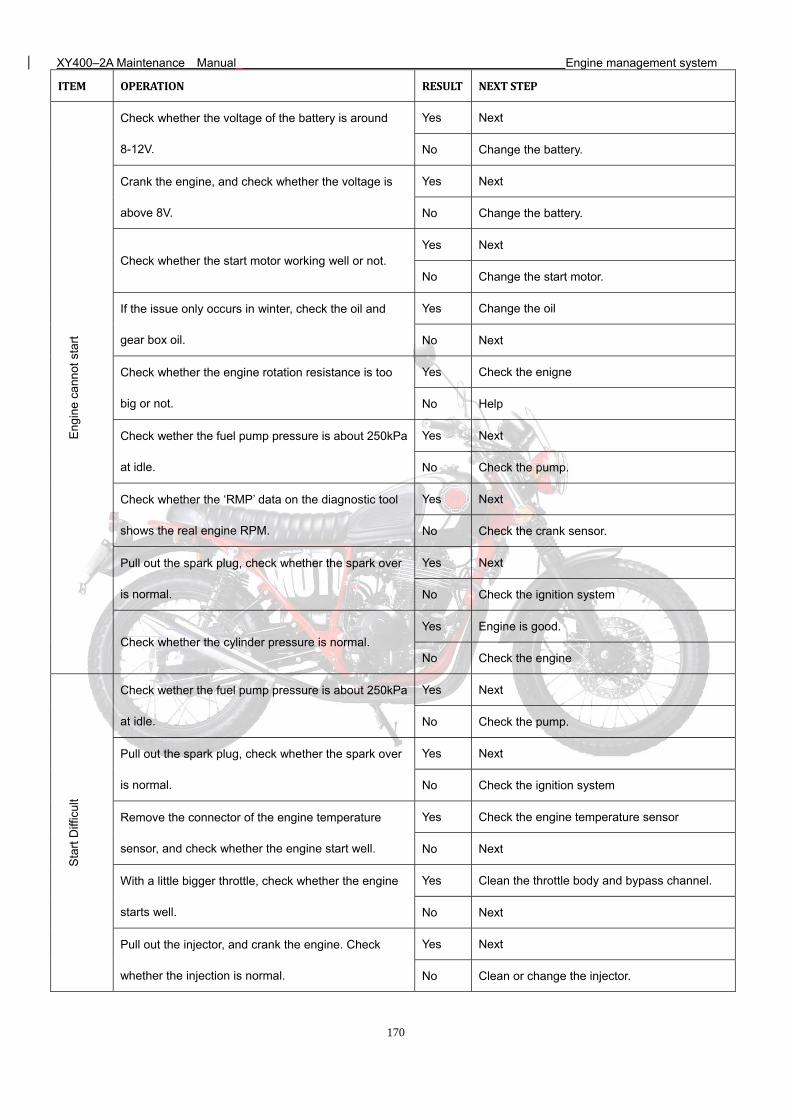
XY400–2A Maintenance Manual Engine management system
170
ITEM OPERATION RESULT NEXTSTEPE
ngin
e ca
nnot
sta
rt
Check whether the voltage of the battery is around
8-12V.
Yes Next
No Change the battery.
Crank the engine, and check whether the voltage is
above 8V.
Yes Next
No Change the battery.
Check whether the start motor working well or not. Yes Next
No Change the start motor.
If the issue only occurs in winter, check the oil and
gear box oil.
Yes Change the oil
No Next
Check whether the engine rotation resistance is too
big or not.
Yes Check the enigne
No Help
Check wether the fuel pump pressure is about 250kPa
at idle.
Yes Next
No Check the pump.
Check whether the ‘RMP’ data on the diagnostic tool
shows the real engine RPM.
Yes Next
No Check the crank sensor.
Pull out the spark plug, check whether the spark over
is normal.
Yes Next
No Check the ignition system
Check whether the cylinder pressure is normal. Yes Engine is good.
No Check the engine
Sta
rt D
iffic
ult
Check wether the fuel pump pressure is about 250kPa
at idle.
Yes Next
No Check the pump.
Pull out the spark plug, check whether the spark over
is normal.
Yes Next
No Check the ignition system
Remove the connector of the engine temperature
sensor, and check whether the engine start well.
Yes Check the engine temperature sensor
No Next
With a little bigger throttle, check whether the engine
starts well.
Yes Clean the throttle body and bypass channel.
No Next
Pull out the injector, and crank the engine. Check
whether the injection is normal.
Yes Next
No Clean or change the injector.
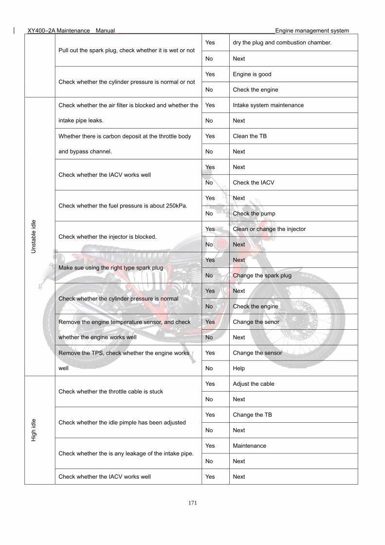
XY400–2A Maintenance Manual Engine management system
171
Pull out the spark plug, check whether it is wet or not Yes dry the plug and combustion chamber.
No Next
Check whether the cylinder pressure is normal or not Yes Engine is good
No Check the engine
Uns
tab
le id
le
Check whether the air filter is blocked and whether the
intake pipe leaks.
Yes Intake system maintenance
No Next
Whether there is carbon deposit at the throttle body
and bypass channel.
Yes Clean the TB
No Next
Check whether the IACV works well Yes Next
No Check the IACV
Check whether the fuel pressure is about 250kPa. Yes Next
No Check the pump
Check whether the injector is blocked. Yes Clean or change the injector
No Next
Make sue using the right type spark plug Yes Next
No Change the spark plug
Check whether the cylinder pressure is normal Yes Next
No Check the engine
Remove the engine temperature sensor, and check
whether the engine works well
Yes Change the senor
No Next
Remove the TPS, check whether the engine works
well
Yes Change the sensor
No Help
Hig
h id
le
Check whether the throttle cable is stuck Yes Adjust the cable
No Next
Check whether the idle pimple has been adjusted Yes Change the TB
No Next
Check whether the is any leakage of the intake pipe. Yes Maintenance
No Next
Check whether the IACV works well Yes Next
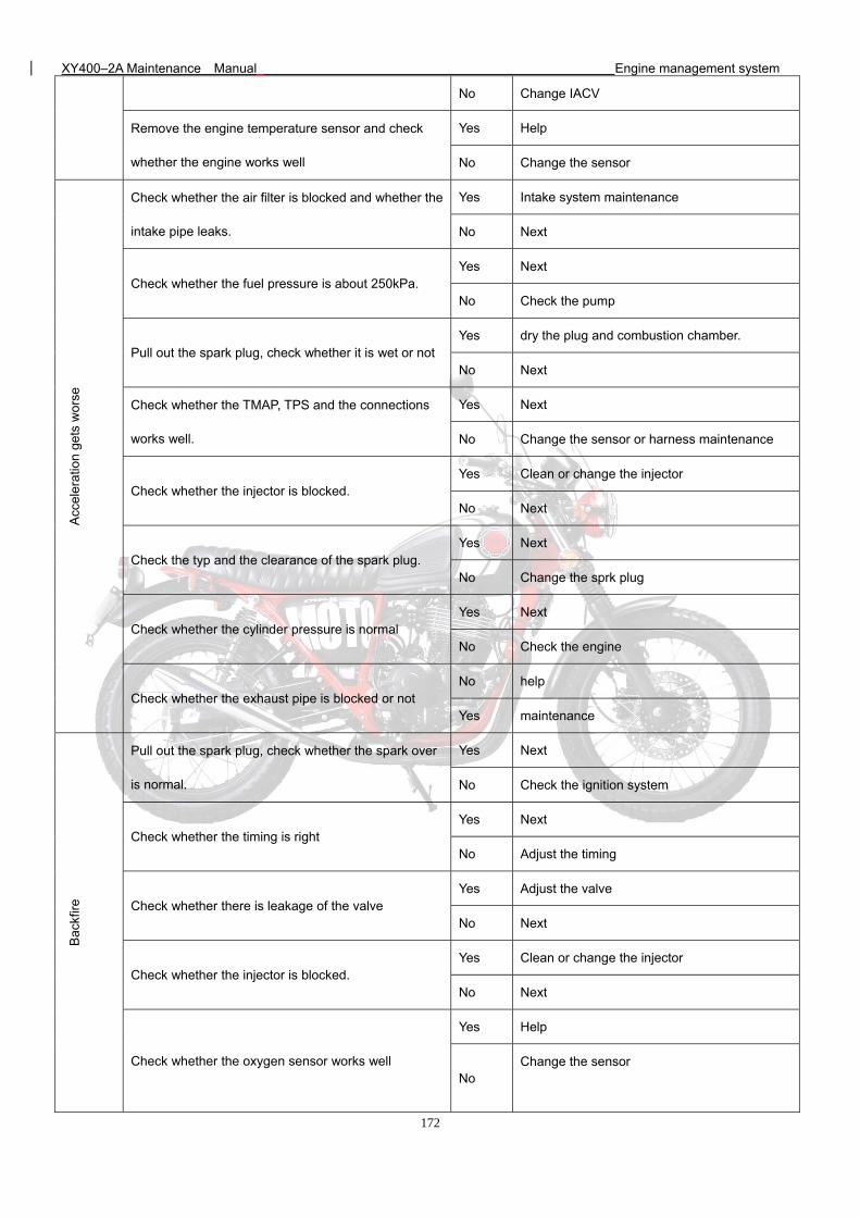
XY400–2A Maintenance Manual Engine management system
172
No Change IACV
Remove the engine temperature sensor and check
whether the engine works well
Yes Help
No Change the sensor
Acc
eler
atio
n ge
ts w
orse
Check whether the air filter is blocked and whether the
intake pipe leaks.
Yes Intake system maintenance
No Next
Check whether the fuel pressure is about 250kPa. Yes Next
No Check the pump
Pull out the spark plug, check whether it is wet or not Yes dry the plug and combustion chamber.
No Next
Check whether the TMAP, TPS and the connections
works well.
Yes Next
No Change the sensor or harness maintenance
Check whether the injector is blocked. Yes Clean or change the injector
No Next
Check the typ and the clearance of the spark plug. Yes Next
No Change the sprk plug
Check whether the cylinder pressure is normal Yes Next
No Check the engine
Check whether the exhaust pipe is blocked or not No help
Yes maintenance
Bac
kfire
Pull out the spark plug, check whether the spark over
is normal.
Yes Next
No Check the ignition system
Check whether the timing is right Yes Next
No Adjust the timing
Check whether there is leakage of the valve Yes Adjust the valve
No Next
Check whether the injector is blocked. Yes Clean or change the injector
No Next
Check whether the oxygen sensor works well
Yes Help
No Change the sensor
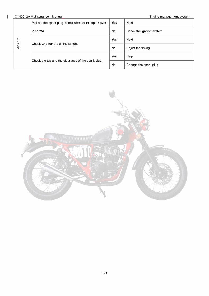
XY400–2A Maintenance Manual Engine management system
173
Mis
s fir
e
Pull out the spark plug, check whether the spark over
is normal.
Yes Next
No Check the ignition system
Check whether the timing is right Yes Next
No Adjust the timing
Check the typ and the clearance of the spark plug. Yes Help
No Change the spark plug
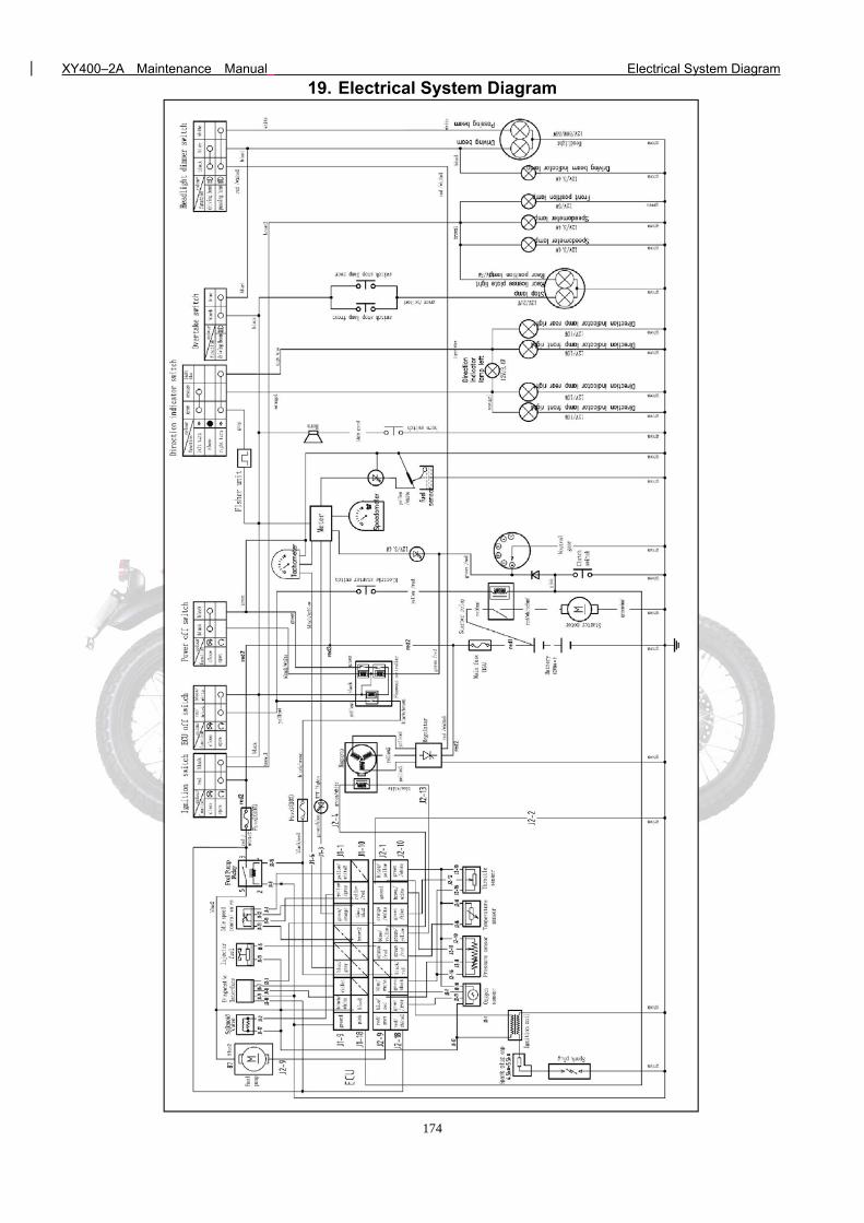
XY400–2A Maintenance Manual Electrical System Diagram
174
19. Electrical System Diagram