wimax 802.16e indoor gateway - 192.168.1.1 – wireless
TRANSCRIPT
USER GUIDE
WIMAX 802.16E INDOOR GATEWAYRG300
Federal Communication Commission Interference Statement
This equipment has been tested and found to comply with the limits for a Class B digital device, pursuant to Part 15 of the FCC Rules. These limits are designed to provide reasonable protection against harmful interference in a residential installation. This equipment generates, uses and can radiate radio frequency energy and, if not installed and used in accordance with the instructions, may cause harmful interference to radio communications. However, there is no guarantee that interference will not occur in a particular installation. If this equipment does cause harmful interference to radio or television reception, which can be determined by turning the equipment off and on, the user is encouraged to try to correct the interference by one of the following measures: - Reorient or relocate the receiving antenna. - Increase the separation between the equipment and receiver. - Connect the equipment into an outlet on a circuit different from that
to which the receiver is connected. - Consult the dealer or an experienced radio/TV technician for help. FCC Caution: Any changes or modifications not expressly approved by the party responsible for compliance could void the user's authority to operate this equipment. This device complies with Part 15 of the FCC Rules. Operation is subject to the following two conditions: (1) This device may not cause harmful interference, and (2) this device must accept any interference received, including interference that may cause undesired operation. IMPORTANT NOTE: Radiation Exposure Statement:
This equipment complies with FCC radiation exposure limits set forth for an uncontrolled environment. This equipment should be installed and operated with minimum distance 20cm between the radiator & your body.
This transmitter must not be co-located or operating in conjunction with any other antenna or transmitter.
Note: The country code selection showed in User's guide is for non-US model only and is not available to all US model. Per FCC regulation, all WiFi product marketed in US must fixed to US operation channels only.
Europe – EU Declaration of Conformity This device complies with the essential requirements of the R&TTE Directive 1999/5/EC. The following test methods have been applied in order to prove presumption of conformity with the essential requirements of the R&TTE Directive 1999/5/EC:
EN 60950-1 :2006 + A11:2009 Safety of Information Technology Equipment
EN 50385 : (2002-08) Product standard to demonstrate the compliance of radio base stations and fixed terminal stations for wireless telecommunication systems with the basic restrictions or the reference levels related to human exposure to radio frequency electromagnetic fields (110MHz - 40 GHz) - General public
EN 300 328 V1.7.1: (2006-10) Electromagnetic compatibility and Radio spectrum Matters (ERM); Wideband Transmission systems; Data transmission equipment operating in the 2,4 GHz ISM band and using spread spectrum modulation techniques; Harmonized EN covering essential requirements under article 3.2 of the R&TTE Directive EN 301 489-1 V1.8.1: (2008-04) Electromagnetic compatibility and Radio Spectrum Matters (ERM); ElectroMagnetic Compatibility (EMC) standard for radio equipment and services; Part 1: Common technical requirements EN 301 489-17 V1.3.2 (2008-04) Electromagnetic compatibility and Radio spectrum Matters (ERM); ElectroMagnetic Compatibility (EMC) standard for radio equipment and services; Part 17: Specific conditions for 2,4 GHz wideband transmission systems and 5 GHz high performance RLAN equipment EN 302 326-2 V1.2.2(2007-06) Fixed Radio Systems; Multipoint Equipment and Antennas; Part 2: Harmonized EN covering the essential requirements of article 3.2 of the R&TTE Directive for Digital Multipoint Radio Equipment EN 302 544 V1.1.2: 2010 Broadband Data Transmission Systems operating in the2 500 MHz to 2 690 MHz frequency band; Part 2: TDD User Equipment Stations;Harmonized EN covering the essential requirementsof article 3.2 of the R&TTE Directive EN 55022: 2006 A1:2007 Information technology equipment - Radio disturbance characteristics - Limits and methods of measurement

EN 55024: 2010 Information technology equipment — Immunity characteristics — Limits and methods of measurement
This device is a 2.3G & 2.5G Wimax + 2.4G Wifi wideband transmission system (transceiver), intended for use in all EU member states and EFTA countries, except in France and Italy where restrictive use applies. In Italy the end-user should apply for a license at the national spectrum authorities in order to obtain authorization to use the device for setting up outdoor radio links and/or for supplying public access to telecommunications and/or network services. This device may not be used for setting up outdoor radio links in France and in some areas the RF output power may be limited to 10 mW EIRP in the frequency range of 2454 – 2483.5 MHz. For detailed information the end-user should contact the national spectrum authority in France.
0560
Česky
[Czech] [Jméno výrobce] tímto prohlašuje, že tento [typ zařízení] je ve shodě se základními požadavky a dalšími příslušnými ustanoveními směrnice 1999/5/ES.
Dansk [Danish]
Undertegnede [fabrikantens navn] erklærer herved, at følgende udstyr [udstyrets typebetegnelse] overholder de væsentlige krav og øvrige relevante krav i direktiv 1999/5/EF.
Deutsch [German]
Hiermit erklärt [Name des Herstellers], dass sich das Gerät [Gerätetyp] in Übereinstimmung mit den grundlegenden Anforderungen und den übrigen einschlägigen Bestimmungen der Richtlinie 1999/5/EG befindet.
Eesti [Estonian]
Käesolevaga kinnitab [tootja nimi = name of manufacturer] seadme [seadme tüüp = type of equipment] vastavust direktiivi 1999/5/EÜ põhinõuetele ja nimetatud direktiivist tulenevatele teistele asjakohastele sätetele.
English Hereby, [name of manufacturer], declares that this [type of equipment] is in compliance with the essential requirements and other relevant provisions of Directive 1999/5/EC.
Español [Spanish]
Por medio de la presente [nombre del fabricante] declara que el [clase de equipo] cumple con los requisitos esenciales y cualesquiera otras disposiciones aplicables o exigibles de la Directiva 1999/5/CE.
Ελληνική [Greek]
ΜΕ ΤΗΝ ΠΑΡΟΥΣΑ [name of manufacturer] ΔΗΛΩΝΕΙ ΟΤΙ [type of equipment] ΣΥΜΜΟΡΦΩΝΕΤΑΙ ΠΡΟΣ ΤΙΣ ΟΥΣΙΩΔΕΙΣ ΑΠΑΙΤΗΣΕΙΣ ΚΑΙ ΤΙΣ ΛΟΙΠΕΣ ΣΧΕΤΙΚΕΣ ΔΙΑΤΑΞΕΙΣ ΤΗΣ ΟΔΗΓΙΑΣ 1999/5/ΕΚ.
Français [French]
Par la présente [nom du fabricant] déclare que l'appareil [type d'appareil] est conforme aux exigences essentielles et aux autres dispositions pertinentes de la directive 1999/5/CE.
Italiano [Italian]
Con la presente [nome del costruttore] dichiara che questo [tipo di apparecchio] è conforme ai requisiti essenziali ed alle altre disposizioni pertinenti stabilite dalla direttiva 1999/5/CE.
Latviski [Latvian]
Ar šo [name of manufacturer / izgatavotāja nosaukums] deklarē, ka [type of equipment / iekārtas tips] atbilst Direktīvas 1999/5/EK būtiskajām prasībām un citiem ar to saistītajiem noteikumiem.
Lietuvių [Lithuanian]
Šiuo [manufacturer name] deklaruoja, kad šis [equipment type] atitinka esminius reikalavimus ir kitas 1999/5/EB Direktyvos nuostatas.
Nederlands [Dutch]
Hierbij verklaart [naam van de fabrikant] dat het toestel [type van toestel] in overeenstemming is met de essentiële eisen en de andere relevante bepalingen van richtlijn 1999/5/EG.
Malti [Maltese]
Hawnhekk, [isem tal-manifattur], jiddikjara li dan [il-mudel tal-prodott] jikkonforma mal-ħtiġijiet essenzjali u ma provvedimenti oħrajn relevanti li hemm fid-Dirrettiva 1999/5/EC.
Magyar [Hungarian]
Alulírott, [gyártó neve] nyilatkozom, hogy a [... típus] megfelel a vonatkozó alapvetõ követelményeknek és az 1999/5/EC irányelv egyéb elõírásainak.
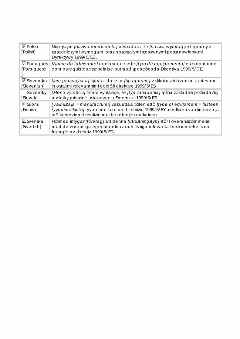
Polski [Polish]
Niniejszym [nazwa producenta] oświadcza, że [nazwa wyrobu] jest zgodny z zasadniczymi wymogami oraz pozostałymi stosownymi postanowieniami Dyrektywy 1999/5/EC.
Português [Portuguese]
[Nome do fabricante] declara que este [tipo de equipamento] está conforme com os requisitos essenciais e outras disposições da Directiva 1999/5/CE.
Slovensko [Slovenian]
[Ime proizvajalca] izjavlja, da je ta [tip opreme] v skladu z bistvenimi zahtevami in ostalimi relevantnimi določili direktive 1999/5/ES.
Slovensky [Slovak]
[Meno výrobcu] týmto vyhlasuje, že [typ zariadenia] spĺňa základné požiadavky a všetky príslušné ustanovenia Smernice 1999/5/ES.
Suomi [Finnish]
[Valmistaja = manufacturer] vakuuttaa täten että [type of equipment = laitteen tyyppimerkintä] tyyppinen laite on direktiivin 1999/5/EY oleellisten vaatimusten ja sitä koskevien direktiivin muiden ehtojen mukainen.
Svenska [Swedish]
Härmed intygar [företag] att denna [utrustningstyp] står I överensstämmelse med de väsentliga egenskapskrav och övriga relevanta bestämmelser som framgår av direktiv 1999/5/EG.
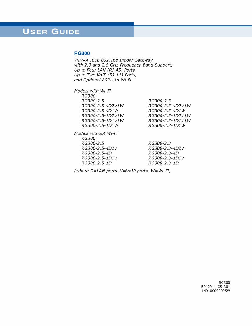
USER GUIDE
RG300WiMAX IEEE 802.16e Indoor Gatewaywith 2.3 and 2.5 GHz Frequency Band Support,Up to Four LAN (RJ-45) Ports,Up to Two VoIP (RJ-11) Ports,and Optional 802.11n Wi-Fi
Models with Wi-Fi RG300 RG300-2.5 RG300-2.5-4D2V1W RG300-2.5-4D1W RG300-2.5-1D2V1W RG300-2.5-1D1V1W RG300-2.5-1D1W
RG300-2.3RG300-2.3-4D2V1WRG300-2.3-4D1W RG300-2.3-1D2V1WRG300-2.3-1D1V1WRG300-2.3-1D1W
Models without Wi-Fi RG300 RG300-2.5 RG300-2.5-4D2V RG300-2.5-4D RG300-2.5-1D1V RG300-2.5-1D
RG300-2.3RG300-2.3-4D2VRG300-2.3-4D RG300-2.3-1D1VRG300-2.3-1D
(where D=LAN ports, V=VoIP ports, W=Wi-Fi)
RG300E042011-CS-R01149100000095W
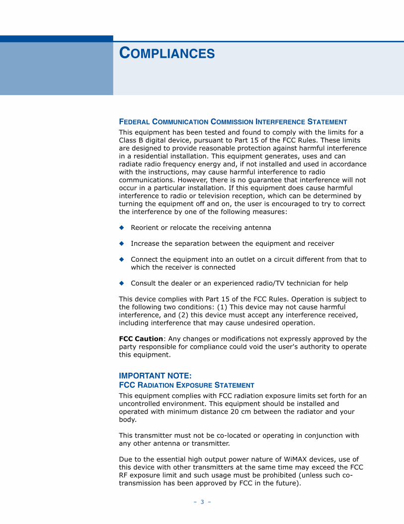
COMPLIANCES
FEDERAL COMMUNICATION COMMISSION INTERFERENCE STATEMENT
This equipment has been tested and found to comply with the limits for a Class B digital device, pursuant to Part 15 of the FCC Rules. These limits are designed to provide reasonable protection against harmful interference in a residential installation. This equipment generates, uses and can radiate radio frequency energy and, if not installed and used in accordance with the instructions, may cause harmful interference to radio communications. However, there is no guarantee that interference will not occur in a particular installation. If this equipment does cause harmful interference to radio or television reception, which can be determined by turning the equipment off and on, the user is encouraged to try to correct the interference by one of the following measures:
◆ Reorient or relocate the receiving antenna
◆ Increase the separation between the equipment and receiver
◆ Connect the equipment into an outlet on a circuit different from that to which the receiver is connected
◆ Consult the dealer or an experienced radio/TV technician for help
This device complies with Part 15 of the FCC Rules. Operation is subject to the following two conditions: (1) This device may not cause harmful interference, and (2) this device must accept any interference received, including interference that may cause undesired operation.
FCC Caution: Any changes or modifications not expressly approved by the party responsible for compliance could void the user's authority to operate this equipment.
IMPORTANT NOTE:FCC RADIATION EXPOSURE STATEMENT
This equipment complies with FCC radiation exposure limits set forth for an uncontrolled environment. This equipment should be installed and operated with minimum distance 20 cm between the radiator and your body.
This transmitter must not be co-located or operating in conjunction with any other antenna or transmitter.
Due to the essential high output power nature of WiMAX devices, use of this device with other transmitters at the same time may exceed the FCC RF exposure limit and such usage must be prohibited (unless such co-transmission has been approved by FCC in the future).
– 3 –
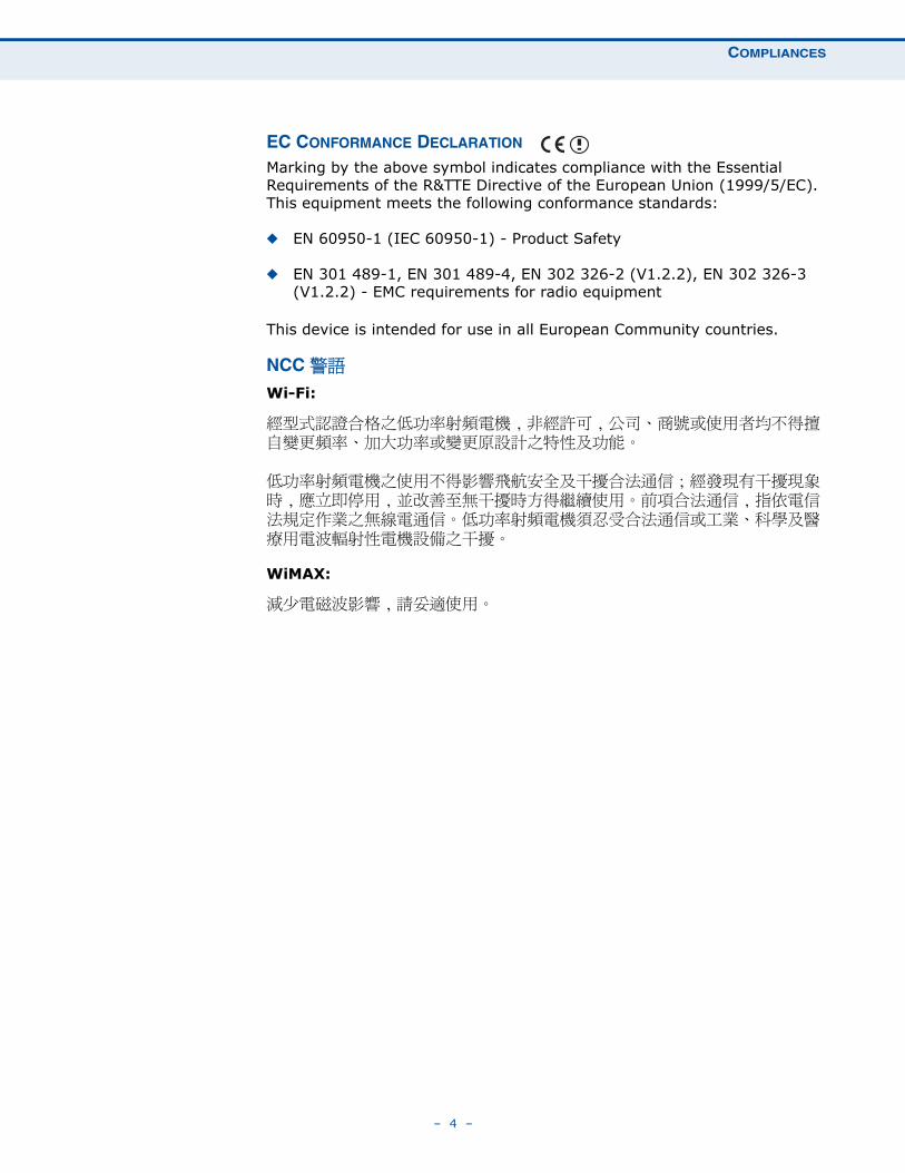
COMPLIANCES
EC CONFORMANCE DECLARATION Marking by the above symbol indicates compliance with the Essential Requirements of the R&TTE Directive of the European Union (1999/5/EC). This equipment meets the following conformance standards:
◆ EN 60950-1 (IEC 60950-1) - Product Safety
◆ EN 301 489-1, EN 301 489-4, EN 302 326-2 (V1.2.2), EN 302 326-3 (V1.2.2) - EMC requirements for radio equipment
This device is intended for use in all European Community countries.
NCC 警語 Wi-Fi:
經型式認證合格之低功率射頻電機 ,非經許可 , 公司、商號或使用者均不得擅自變更頻率、加大功率或變更原設計之特性及功能。
低功率射頻電機之使用不得影響飛航安全及干擾合法通信 ; 經發現有干擾現象時 , 應立即停用 , 並改善至無干擾時方得繼續使用。前項合法通信 , 指依電信法規定作業之無線電通信。低功率射頻電機須忍受合法通信或工業、科學及醫療用電波輻射性電機設備之干擾。
WiMAX:
減少電磁波影響 , 請妥適使用。
– 4 –
ABOUT THIS GUIDE
PURPOSE This guide details the hardware features of the RG300 WiMAX 802.16e Indoor Gateway, including its physical and performance-related characteristics, and how to install the device and use its configuration software.
AUDIENCE This guide is for PC users with a working knowledge of computers. You should be familiar with Windows operating system concepts.
CONVENTIONS The following conventions are used throughout this guide to show information:
NOTE: Emphasizes important information or calls your attention to related features or instructions.
CAUTION: Alerts you to a potential hazard that could cause loss of data, or damage the system or equipment.
WARNING: Alerts you to a potential hazard that could cause personal injury.
RELATED PUBLICATIONS The following publication gives basic information on how to install and use the WiMAX 802.16e Indoor Gateway.
Quick Installation Guide
Also, as part of the WiMAX 802.16e Indoor Gateway’s configuration software, there is online help that describes all management features.
REVISION HISTORY This section summarizes the changes in each revision of this guide.
APRIL 2011 REVISIONThis is the first revision of this guide. This guide is valid for software version 1.0.2.0.
– 5 –
CONTENTS
COMPLIANCES 3
ABOUT THIS GUIDE 5
CONTENTS 6
FIGURES 10
TABLES 12
SECTION I GETTING STARTED 13
1 INTRODUCTION 14
RG300 Hardware Description 15
Wi-Fi Option 15
Power Status LED 16
Wi-Fi Status LED 17
WiMAX Signal LEDs 17
LAN Ports 17
VoIP Phone Ports 18
Power Adapter Socket 18
Reset Button 18
2 INSTALLING THE RG300 20
Package Checklist 20
Installation Overview 20
Select a Location 20
Cable Connections 21
3 INITIAL CONFIGURATION 23
Accessing the Web Management Interface 23
Home Page 24
Using the Basic Setup Wizard 25
The Advanced Setup Menu 27
– 6 –
CONTENTS
Common Web Page Buttons 28
SECTION II WEB CONFIGURATION 29
4 SYSTEM SETTINGS 30
System Status 31
Administrator Settings 32
Firmware Upgrade 33
Configuration Tools 34
System Time 35
System Log 36
Reset 37
5 WAN CONFIGURATION 38
WAN Settings 39
Dynamic IP Address 40
Static IP Settings 40
L2TP Settings 41
PPTP Settings 41
DNS 42
DDNS 43
6 LAN CONFIGURATION 44
LAN Settings 45
DHCP Client List 46
7 NAT CONFIGURATION 47
NAT Settings 48
Port Mapping 49
DMZ 50
ALG 51
8 FIREWALL CONFIGURATION 52
Firewall Settings 53
Client Filtering 54
Port Filtering 55
MAC Filtering 56
URL Filtering 57
– 7 –
CONTENTS
Host Filtering 58
9 ROUTING CONFIGURATION 59
Routing Table 60
Static Route 61
10 UPNP CONFIGURATION 62
UPnP 63
11 VOIP SETTINGS 64
SIP Account 65
SIP Settings 66
Speed Dial 67
Dial Plan 68
Call Feature 70
Phone Settings 72
Codecs 73
12 WI-FI SETTINGS 75
Basic Wireless Settings 76
Advanced Wireless Settings 78
Wireless Security 79
Wired Equivalent Privacy (WEP) 80
WPA Pre-Shared Key 81
ACL Settings 83
13 QOS CONFIGURATION 84
QoS Settings 85
SECTION III APPENDICES 86
A TROUBLESHOOTING 87
Diagnosing LED Indicators 87
Cannot Connect to the Internet 87
Cannot Access Web Management 88
Forgot or Lost the Password 88
Resetting the Unit 88
B HARDWARE SPECIFICATIONS 89
– 8 –
CONTENTS
Physical Specifications 89
WiMAX Specifications 90
VoIP Specifications 90
Wi-Fi Specifications 91
Compliances 92
C CABLES AND PINOUTS 93
Twisted-Pair Cable Assignments 93
10/100BASE-TX Pin Assignments 93
Straight-Through Wiring 94
Crossover Wiring 95
RJ-11 Port 96
GLOSSARY 97
INDEX 102
– 9 –
FIGURES
Figure 1: Front of the RG300 15
Figure 2: RG300 LED Indicators 16
Figure 3: Back of the RG300 18
Figure 4: Base of the RG300 19
Figure 5: RG300 Connections 21
Figure 6: Login Page 23
Figure 7: Home Page 24
Figure 8: WiMAX Account Login 25
Figure 9: Confirm Settings 26
Figure 10: Setup Wizard Finished 26
Figure 11: Advanced Setup 27
Figure 12: Common Web Page Buttons 28
Figure 13: System Status – Internet 31
Figure 14: System Status – Gateway 31
Figure 15: System Status – Information 32
Figure 16: Setting a Password 32
Figure 17: Firmware Upgrade 33
Figure 18: Configuration Tools 34
Figure 19: Restore Configuration Settings 34
Figure 20: System Time 35
Figure 21: System Log 36
Figure 22: Reset Unit 37
Figure 23: WAN Settings 39
Figure 24: Dynamic IP Address 40
Figure 25: Static IP Settings 40
Figure 26: L2TP Settings 41
Figure 27: PPTP Settings 41
Figure 28: DNS Settings 42
Figure 29: DDNS Settings 43
Figure 30: LAN Settings 45
Figure 31: DHCP Client List 46
– 10 –
FIGURES
Figure 32: NAT Settings 48
Figure 33: Port Mapping 49
Figure 34: DMZ Settings 50
Figure 35: ALG Settings 51
Figure 36: Firewall Settings 53
Figure 37: Client Filtering Settings 54
Figure 38: Port Filtering 55
Figure 39: MAC Filtering 56
Figure 40: URL Filtering 57
Figure 41: Host Filtering 58
Figure 42: Routing Table 60
Figure 43: Static Route 61
Figure 44: UPnP Setting 63
Figure 45: SIP Account Settings 65
Figure 46: SIP Settings 66
Figure 47: Speed Dial 67
Figure 48: Dial Plan Settings 68
Figure 49: Call Features 70
Figure 50: Phone Settings 72
Figure 51: VoIP Codecs 73
Figure 52: Wireless Settings 76
Figure 53: Advanced Wireless Settings 78
Figure 54: Security Mode Options 80
Figure 55: Security Mode - WEP 80
Figure 56: Security Mode - WPA-PSK 81
Figure 57: ACL Settings 83
Figure 58: QoS Settings 85
Figure 59: RJ-45 Connector 93
Figure 60: Straight Through Wiring 94
Figure 61: Crossover Wiring 95
Figure 62: RJ-11 Port Pinout 96
– 11 –
TABLES
Table 1: Power Status LED 16
Table 2: Wi-Fi Status LED 17
Table 3: WiMAX Signal Status LEDs 17
Table 4: LAN Port Status LED 18
Table 5: Dial Plan Elements 68
Table 6: Troubleshooting Chart 87
Table 7: 10/100BASE-TX MDI and MDI-X Port Pinouts 94
Table 8: RJ-11 Port Pinout 96
– 12 –
SECTION I
GETTING STARTED
This section provides an overview of the RG300, and describes how to install and mount the unit. It also describes the basic settings required to access the management interface and run the setup Wizard.
This section includes these chapters:
◆ “Introduction” on page 14
◆ “Installing the RG300” on page 20
◆ “Initial Configuration” on page 23
– 13 –
1 INTRODUCTION
The RG300 WiMAX 802.16e Indoor Gateway is a WiMAX subscriber station designed to provide Internet access for a home or small office. The unit provides a gateway function between a WiMAX service provider and a local Ethernet LAN. The device enables a service provider to deliver last mile broadband wireless access as an alternative to wired DSL or cable modems.
The RG300 includes up to four RJ-45 Ethernet ports for LAN connections and up to two RJ-11 Voice over IP (VoIP) phone ports. Units also support an IEEE 802.11b/g/n Wi-Fi module that provides a local Wi-Fi access point service.
The RG300 offers a user-friendly web-based management interface for the configuration of all the unit’s features. Any PC directly attached to the unit can access the management interface using a web browser, such as Internet Explorer (version 6.0 or above) or Firefox (version 1.5 or above).
– 14 –
CHAPTER 1 | IntroductionRG300 Hardware Description
RG300 HARDWARE DESCRIPTION
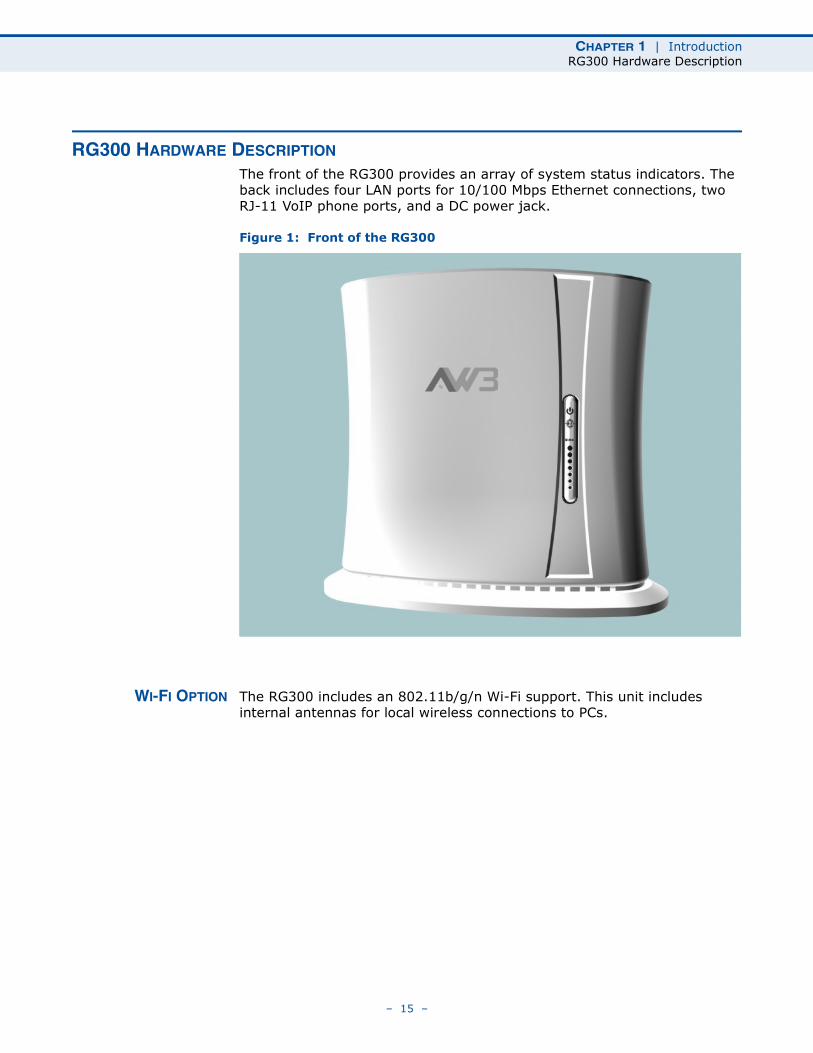
The front of the RG300 provides an array of system status indicators. The back includes four LAN ports for 10/100 Mbps Ethernet connections, two RJ-11 VoIP phone ports, and a DC power jack.
Figure 1: Front of the RG300
WI-FI OPTION The RG300 includes an 802.11b/g/n Wi-Fi support. This unit includes internal antennas for local wireless connections to PCs.
– 15 –
CHAPTER 1 | IntroductionRG300 Hardware Description
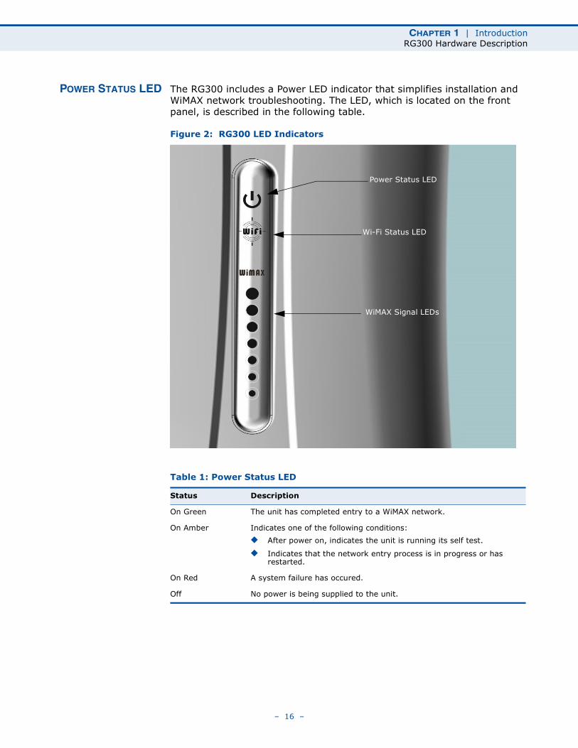
POWER STATUS LED The RG300 includes a Power LED indicator that simplifies installation and WiMAX network troubleshooting. The LED, which is located on the front panel, is described in the following table.
Figure 2: RG300 LED Indicators
Table 1: Power Status LED
Status Description
On Green The unit has completed entry to a WiMAX network.
On Amber Indicates one of the following conditions:
◆ After power on, indicates the unit is running its self test.
◆ Indicates that the network entry process is in progress or has restarted.
On Red A system failure has occured.
Off No power is being supplied to the unit.
Power Status LED
Wi-Fi Status LED
WiMAX Signal LEDs
– 16 –
CHAPTER 1 | IntroductionRG300 Hardware Description
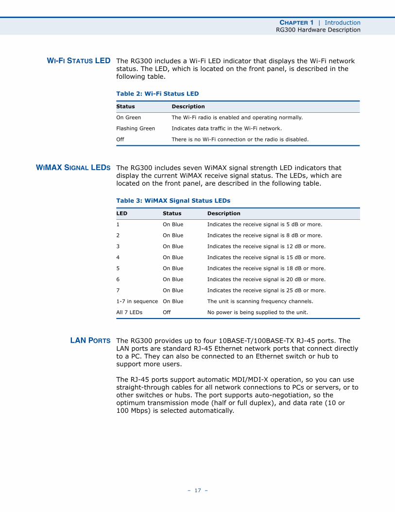
WI-FI STATUS LED The RG300 includes a Wi-Fi LED indicator that displays the Wi-Fi network status. The LED, which is located on the front panel, is described in the following table.
WIMAX SIGNAL LEDS The RG300 includes seven WiMAX signal strength LED indicators that display the current WiMAX receive signal status. The LEDs, which are located on the front panel, are described in the following table.
LAN PORTS The RG300 provides up to four 10BASE-T/100BASE-TX RJ-45 ports. The LAN ports are standard RJ-45 Ethernet network ports that connect directly to a PC. They can also be connected to an Ethernet switch or hub to support more users.
The RJ-45 ports support automatic MDI/MDI-X operation, so you can use straight-through cables for all network connections to PCs or servers, or to other switches or hubs. The port supports auto-negotiation, so the optimum transmission mode (half or full duplex), and data rate (10 or 100 Mbps) is selected automatically.
Table 2: Wi-Fi Status LED
Status Description
On Green The Wi-Fi radio is enabled and operating normally.
Flashing Green Indicates data traffic in the Wi-Fi network.
Off There is no Wi-Fi connection or the radio is disabled.
Table 3: WiMAX Signal Status LEDs
LED Status Description
1 On Blue Indicates the receive signal is 5 dB or more.
2 On Blue Indicates the receive signal is 8 dB or more.
3 On Blue Indicates the receive signal is 12 dB or more.
4 On Blue Indicates the receive signal is 15 dB or more.
5 On Blue Indicates the receive signal is 18 dB or more.
6 On Blue Indicates the receive signal is 20 dB or more.
7 On Blue Indicates the receive signal is 25 dB or more.
1-7 in sequence On Blue The unit is scanning frequency channels.
All 7 LEDs Off No power is being supplied to the unit.
– 17 –
CHAPTER 1 | IntroductionRG300 Hardware Description
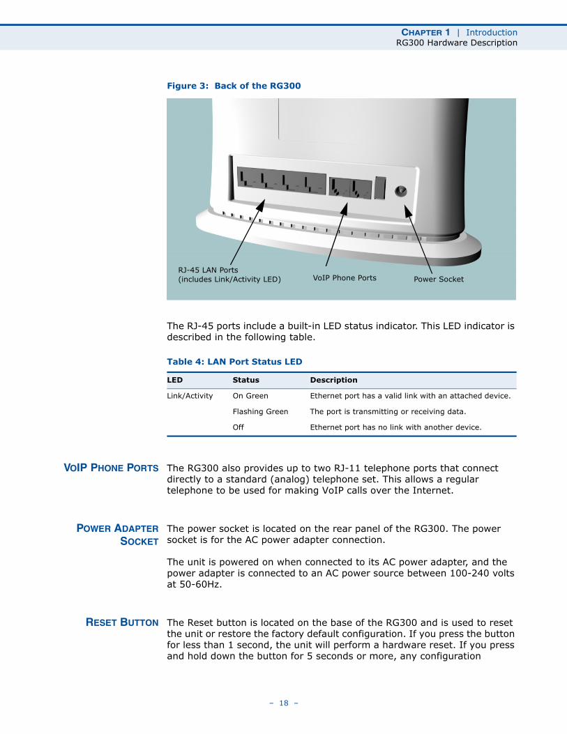
Figure 3: Back of the RG300
The RJ-45 ports include a built-in LED status indicator. This LED indicator is described in the following table.
VOIP PHONE PORTS The RG300 also provides up to two RJ-11 telephone ports that connect directly to a standard (analog) telephone set. This allows a regular telephone to be used for making VoIP calls over the Internet.
POWER ADAPTERSOCKET
The power socket is located on the rear panel of the RG300. The power socket is for the AC power adapter connection.
The unit is powered on when connected to its AC power adapter, and the power adapter is connected to an AC power source between 100-240 volts at 50-60Hz.
RESET BUTTON The Reset button is located on the base of the RG300 and is used to reset the unit or restore the factory default configuration. If you press the button for less than 1 second, the unit will perform a hardware reset. If you press and hold down the button for 5 seconds or more, any configuration
Table 4: LAN Port Status LED
LED Status Description
Link/Activity On Green Ethernet port has a valid link with an attached device.
Flashing Green The port is transmitting or receiving data.
Off Ethernet port has no link with another device.
RJ-45 LAN Ports(includes Link/Activity LED) VoIP Phone Ports Power Socket
– 18 –
CHAPTER 1 | IntroductionRG300 Hardware Description
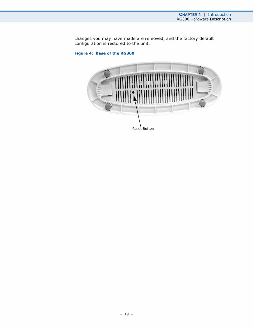
changes you may have made are removed, and the factory default configuration is restored to the unit.
Figure 4: Base of the RG300
Reset Button
– 19 –
2 INSTALLING THE RG300
This section describes how to install and connect the RG300 WiMAX 802.16e Indoor Gateway.
PACKAGE CHECKLIST
The RG300 package includes:
◆ RG300 unit (RG300-2.3 or RG300-2.5)
◆ RJ-45 Category 5 network cable
◆ AC power adapter
◆ Quick Installation Guide
◆ User Guide CD
INSTALLATION OVERVIEW
Before installing the RG300, verify that you have all the items listed in the package checklist above. If any of the items are missing or damaged, contact your local dealer. Also, be sure you have all the necessary tools and cabling before installing the RG300.
SELECT A LOCATION
The RG300 can be installed indoors on any horizontal surface, such as a desktop or shelf.
When selecting a suitable location for the device, consider these guidelines:
◆ Select a cool, dry place, which is out of direct sunlight.
◆ The device should have adequate space (approximately two inches) on all sides for proper air flow.
◆ The device must be near an AC power outlet that provides 100 to 240 V, 50 to 60 Hz.
– 20 –
CHAPTER 2 | Installing the RG300Cable Connections
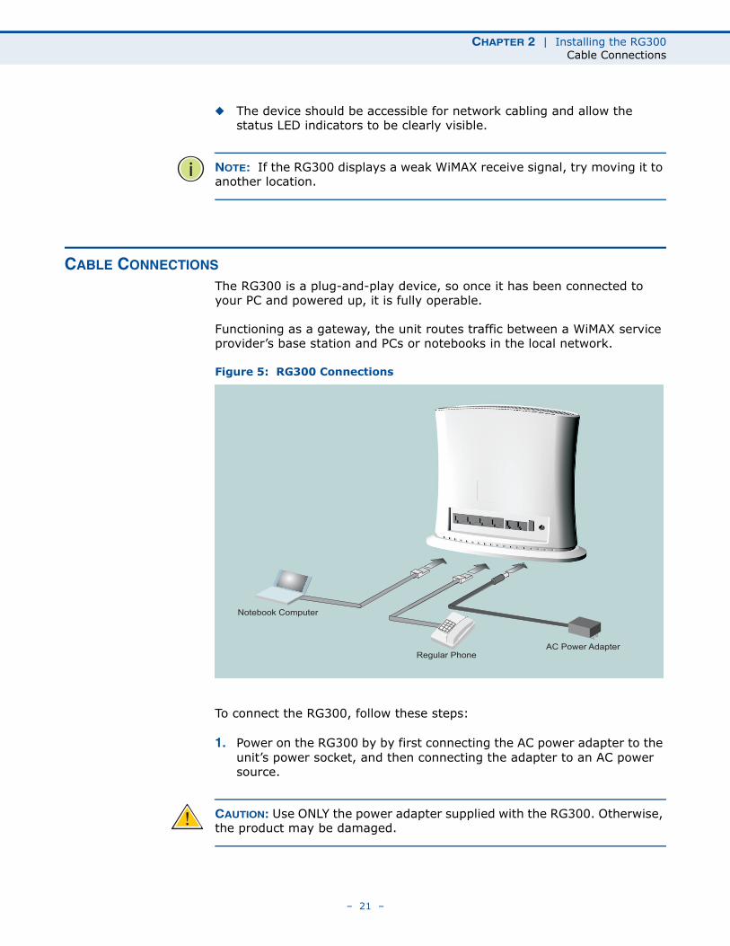
◆ The device should be accessible for network cabling and allow the status LED indicators to be clearly visible.
NOTE: If the RG300 displays a weak WiMAX receive signal, try moving it to another location.
CABLE CONNECTIONS
The RG300 is a plug-and-play device, so once it has been connected to your PC and powered up, it is fully operable.
Functioning as a gateway, the unit routes traffic between a WiMAX service provider’s base station and PCs or notebooks in the local network.
Figure 5: RG300 Connections
To connect the RG300, follow these steps:
1. Power on the RG300 by by first connecting the AC power adapter to the unit’s power socket, and then connecting the adapter to an AC power source.
CAUTION: Use ONLY the power adapter supplied with the RG300. Otherwise, the product may be damaged.
Notebook Computer
Regular PhoneAC Power Adapter
– 21 –
CHAPTER 2 | Installing the RG300Cable Connections
2. Observe the Indicator LEDs. When you power on the RG300, verify that the Power LED turns on and that the other LED indicators start functioning as described under “RG300 Hardware Description” on page 15.
3. Connect Category 5 or better Ethernet cables from the RG300’s LAN ports to the network ports of your PCs. Alternatively, you can connect the LAN port to an Ethernet switch or other device. Make sure the length of each cable does not exceed 100 meters (328 ft).
If a PC is powered on, the RJ-45 LAN port LED on the RG300 will turn on to indicate a valid link.
4. (Optional) Connect a standard (analog) telephone set to one of the RG300’s VoIP ports using standard telephone cable with RJ-11 plugs.
The RG300 enables VoIP calls to be made through the unit using a standard (analog) telephone set connected to the VoIP port, or from PCs or other network devices connected to the LAN ports. Standard Session Initiation Protocol (SIP) technology is used to make VoIP calls. You must access the web interface and configure settings for your SIP service provider before being able to make VoIP calls.
5. Use your PC’s web browser to access the unit’s management interface and run the Setup Wizard to make any configuration changes. For more information, see Chapter 3, “Initial Configuration.”
– 22 –
3 INITIAL CONFIGURATION
The RG300 initial configuration steps can be made through its web management interface using the Setup Wizard. It is recommended to make the initial changes by connecting a PC directly to one of the RG300’s LAN ports.
ACCESSING THE WEB MANAGEMENT INTERFACE
The RG300 has a default IP address of 192.168.1.1 and a subnet mask of 255.255.255.0. If your PC is set to have an IP address assigned by DHCP (Dynamic Host Configuration Protocol), you can connect immediately to the web management interface. Otherwise, you must first check if your PC’s IP address is set on the same subnet as the RG300 (that is, the PC’s IP address starts 192.168.1.x).
NOTE: If your RG300 unit is not configured with the standard default IP address and login Username/Password, use the default values on the label affixed to the unit.
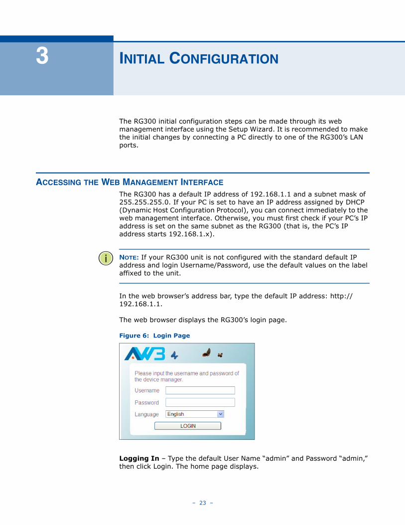
In the web browser’s address bar, type the default IP address: http://192.168.1.1.
The web browser displays the RG300’s login page.
Figure 6: Login Page
Logging In – Type the default User Name “admin” and Password “admin,” then click Login. The home page displays.
– 23 –
CHAPTER 3 | Initial ConfigurationAccessing the Web Management Interface
Language – Selects English or Traditional Chinese as the web interface language.
NOTE: It is recommended that you configure a user password as the first step under “Administrator Settings” on page 32 to control management access to the unit.
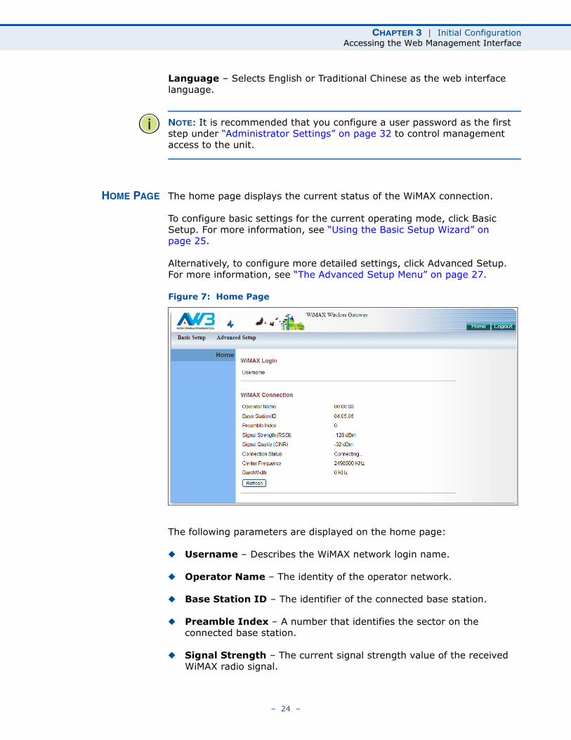
HOME PAGE The home page displays the current status of the WiMAX connection.
To configure basic settings for the current operating mode, click Basic Setup. For more information, see “Using the Basic Setup Wizard” on page 25.
Alternatively, to configure more detailed settings, click Advanced Setup. For more information, see “The Advanced Setup Menu” on page 27.
Figure 7: Home Page
The following parameters are displayed on the home page:
◆ Username – Describes the WiMAX network login name.
◆ Operator Name – The identity of the operator network.
◆ Base Station ID – The identifier of the connected base station.
◆ Preamble Index – A number that identifies the sector on the connected base station.
◆ Signal Strength – The current signal strength value of the received WiMAX radio signal.
– 24 –
CHAPTER 3 | Initial ConfigurationUsing the Basic Setup Wizard
◆ Signal Quality – An indication of the carrier-to-interference-plus-noise-ratio (CINR), which measures the strength of the receive signal compared to other interference and noise.
◆ Connection Status – The current status of the WiMAX connection.
◆ Central Frequency – The center frequency of the WiMAX signal.
◆ Bandwidth – The bandwidth of the WiMAX signal.
USING THE BASIC SETUP WIZARD
The Basic Setup Wizard takes you through the basic configuration steps for the RG300.
Launching the Basic Setup Wizard – To perform basic configuration, click Basic Setup on the home page.
When configuring the unit through the Setup Wizard you will need to proceed through the following steps:
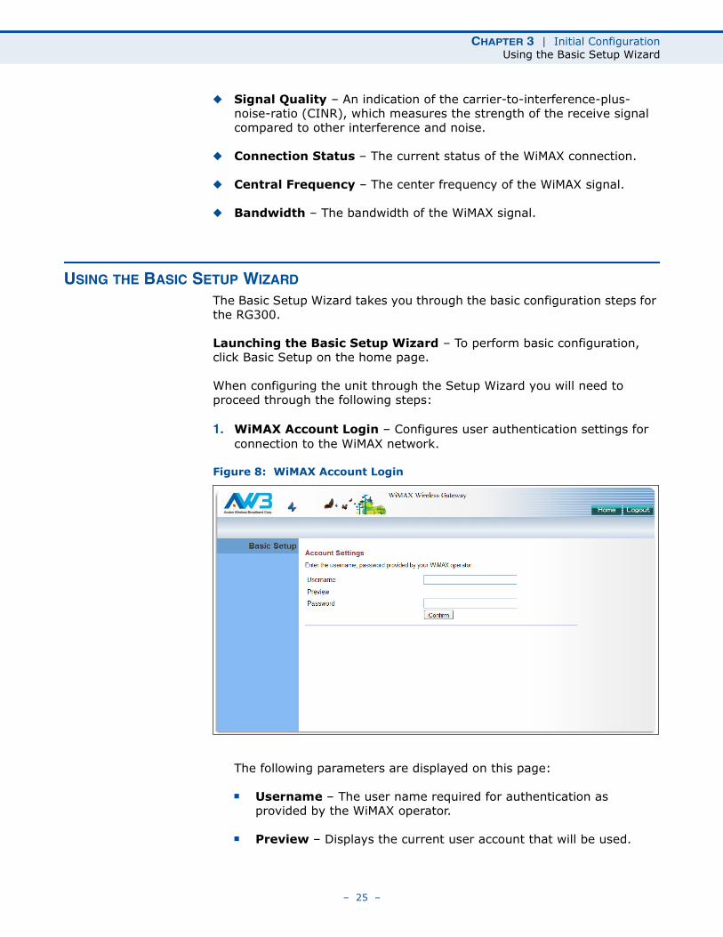
1. WiMAX Account Login – Configures user authentication settings for connection to the WiMAX network.
Figure 8: WiMAX Account Login
The following parameters are displayed on this page:
■ Username – The user name required for authentication as provided by the WiMAX operator.
■ Preview – Displays the current user account that will be used.
– 25 –
CHAPTER 3 | Initial ConfigurationUsing the Basic Setup Wizard
■ Password – The user password required for authentication as provided by the WiMAX operator.
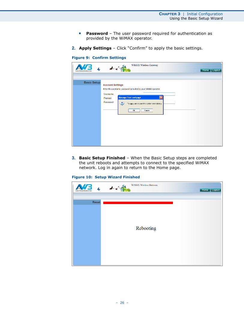
2. Apply Settings – Click “Confirm” to apply the basic settings.
Figure 9: Confirm Settings
3. Basic Setup Finished – When the Basic Setup steps are completed the unit reboots and attempts to connect to the specified WiMAX network. Log in again to return to the Home page.
Figure 10: Setup Wizard Finished
– 26 –
CHAPTER 3 | Initial ConfigurationThe Advanced Setup Menu
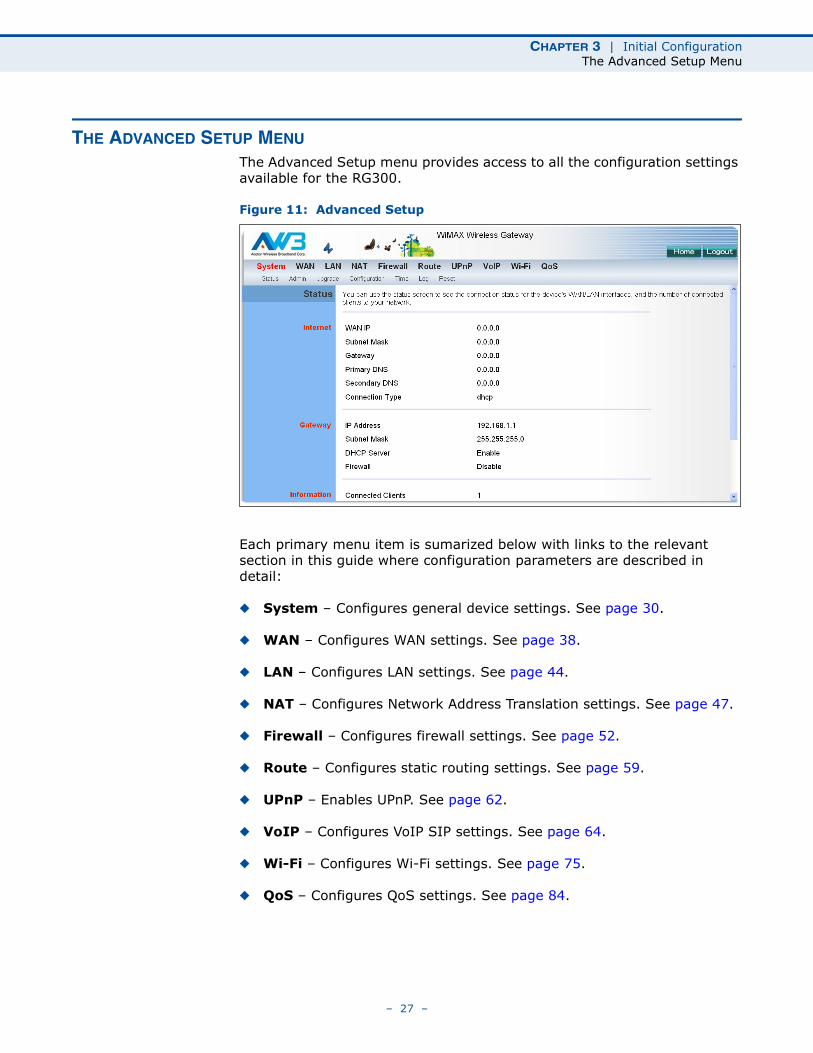
THE ADVANCED SETUP MENU
The Advanced Setup menu provides access to all the configuration settings available for the RG300.
Figure 11: Advanced Setup
Each primary menu item is sumarized below with links to the relevant section in this guide where configuration parameters are described in detail:
◆ System – Configures general device settings. See page 30.
◆ WAN – Configures WAN settings. See page 38.
◆ LAN – Configures LAN settings. See page 44.
◆ NAT – Configures Network Address Translation settings. See page 47.
◆ Firewall – Configures firewall settings. See page 52.
◆ Route – Configures static routing settings. See page 59.
◆ UPnP – Enables UPnP. See page 62.
◆ VoIP – Configures VoIP SIP settings. See page 64.
◆ Wi-Fi – Configures Wi-Fi settings. See page 75.
◆ QoS – Configures QoS settings. See page 84.
– 27 –
CHAPTER 3 | Initial ConfigurationCommon Web Page Buttons
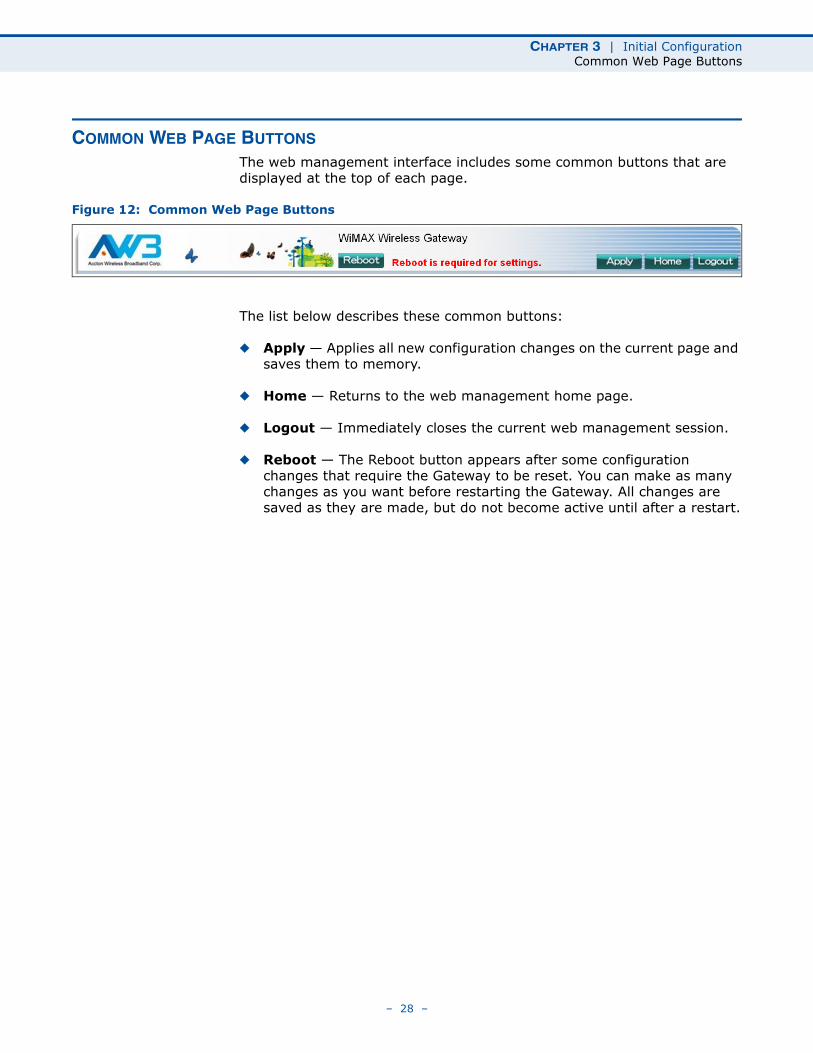
COMMON WEB PAGE BUTTONS
The web management interface includes some common buttons that are displayed at the top of each page.
Figure 12: Common Web Page Buttons
The list below describes these common buttons:
◆ Apply — Applies all new configuration changes on the current page and saves them to memory.
◆ Home — Returns to the web management home page.
◆ Logout — Immediately closes the current web management session.
◆ Reboot — The Reboot button appears after some configuration changes that require the Gateway to be reset. You can make as many changes as you want before restarting the Gateway. All changes are saved as they are made, but do not become active until after a restart.
– 28 –
SECTION II
WEB CONFIGURATION
This section provides details on configuring the RG300 using the web browser interface.
This section includes these chapters:
◆ “System Settings” on page 30
◆ “WAN Configuration” on page 38
◆ “LAN Configuration” on page 44
◆ “NAT Configuration” on page 47
◆ “Firewall Configuration” on page 52
◆ “Routing Configuration” on page 59
◆ “UPnP Configuration” on page 62
◆ “VoIP Settings” on page 64
◆ “Wi-Fi Settings” on page 75
◆ “QoS Configuration” on page 84
– 29 –
4 SYSTEM SETTINGS
The RG300’s System menu allows you to perform general management functions for the unit, including setting the system time, configuring an access password, and upgrading the system software.
The System configuration pages include the following options:
◆ “System Status” on page 31
◆ “Administrator Settings” on page 32
◆ “Firmware Upgrade” on page 33
◆ “Configuration Tools” on page 34
◆ “System Time” on page 35
◆ “System Log” on page 36
◆ “Reset” on page 37
– 30 –
CHAPTER 4 | System SettingsSystem Status
SYSTEM STATUS
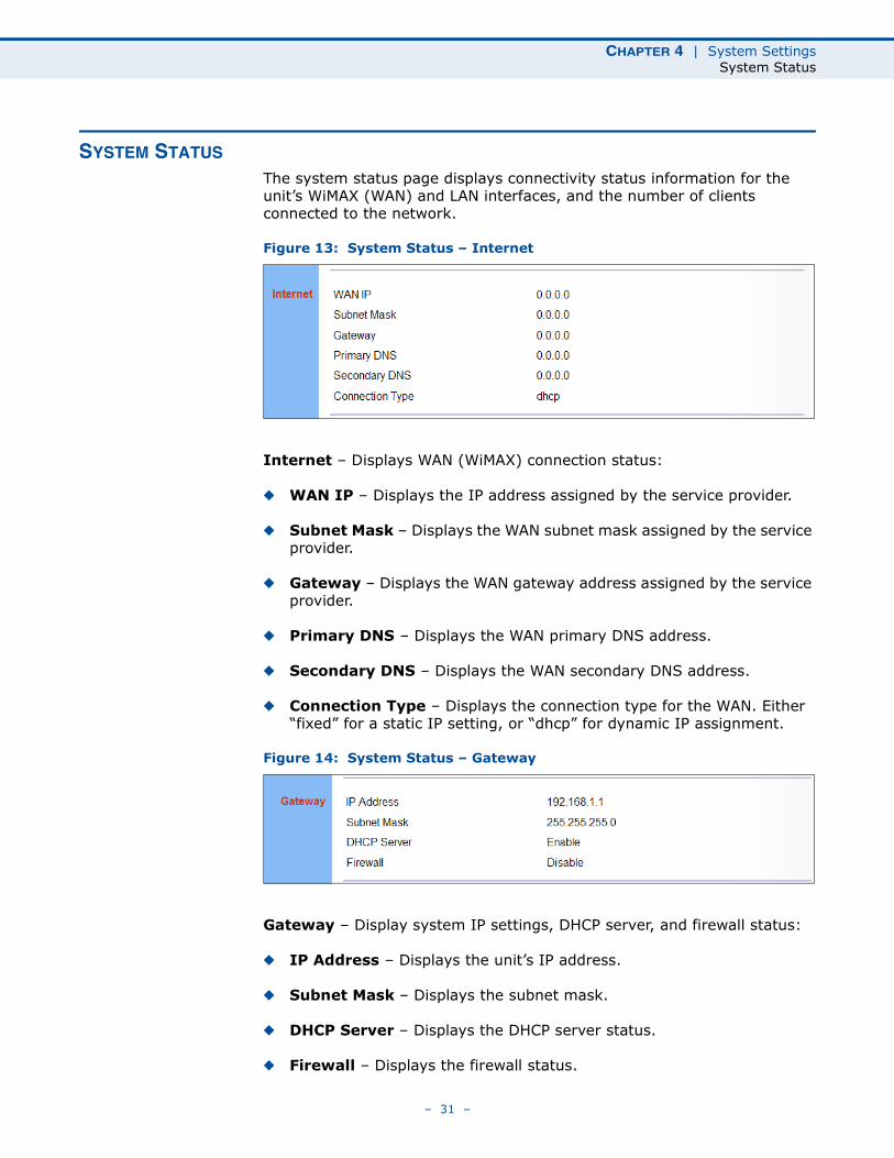
The system status page displays connectivity status information for the unit’s WiMAX (WAN) and LAN interfaces, and the number of clients connected to the network.
Figure 13: System Status – Internet
Internet – Displays WAN (WiMAX) connection status:
◆ WAN IP – Displays the IP address assigned by the service provider.
◆ Subnet Mask – Displays the WAN subnet mask assigned by the service provider.
◆ Gateway – Displays the WAN gateway address assigned by the service provider.
◆ Primary DNS – Displays the WAN primary DNS address.
◆ Secondary DNS – Displays the WAN secondary DNS address.
◆ Connection Type – Displays the connection type for the WAN. Either “fixed” for a static IP setting, or “dhcp” for dynamic IP assignment.
Figure 14: System Status – Gateway
Gateway – Display system IP settings, DHCP server, and firewall status:
◆ IP Address – Displays the unit’s IP address.
◆ Subnet Mask – Displays the subnet mask.
◆ DHCP Server – Displays the DHCP server status.
◆ Firewall – Displays the firewall status.
– 31 –
CHAPTER 4 | System SettingsAdministrator Settings
Figure 15: System Status – Information
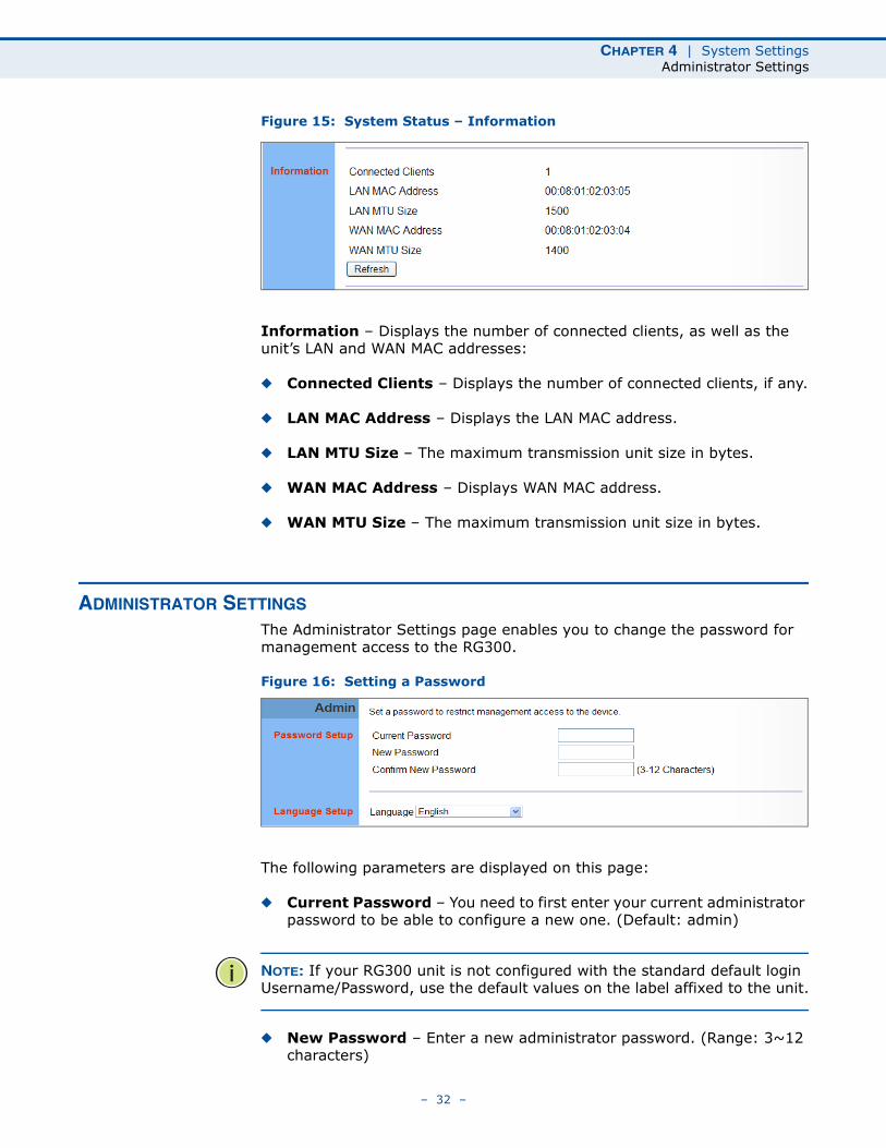
Information – Displays the number of connected clients, as well as the unit’s LAN and WAN MAC addresses:
◆ Connected Clients – Displays the number of connected clients, if any.
◆ LAN MAC Address – Displays the LAN MAC address.
◆ LAN MTU Size – The maximum transmission unit size in bytes.
◆ WAN MAC Address – Displays WAN MAC address.
◆ WAN MTU Size – The maximum transmission unit size in bytes.
ADMINISTRATOR SETTINGS
The Administrator Settings page enables you to change the password for management access to the RG300.
Figure 16: Setting a Password
The following parameters are displayed on this page:
◆ Current Password – You need to first enter your current administrator password to be able to configure a new one. (Default: admin)
NOTE: If your RG300 unit is not configured with the standard default login Username/Password, use the default values on the label affixed to the unit.
◆ New Password – Enter a new administrator password. (Range: 3~12 characters)
– 32 –
CHAPTER 4 | System SettingsFirmware Upgrade
◆ Confirm New Password – Enter the new password again for verification. (Range: 3~12 characters)
◆ Language – Selects English or Traditional Chinese as the web interface language.
FIRMWARE UPGRADE
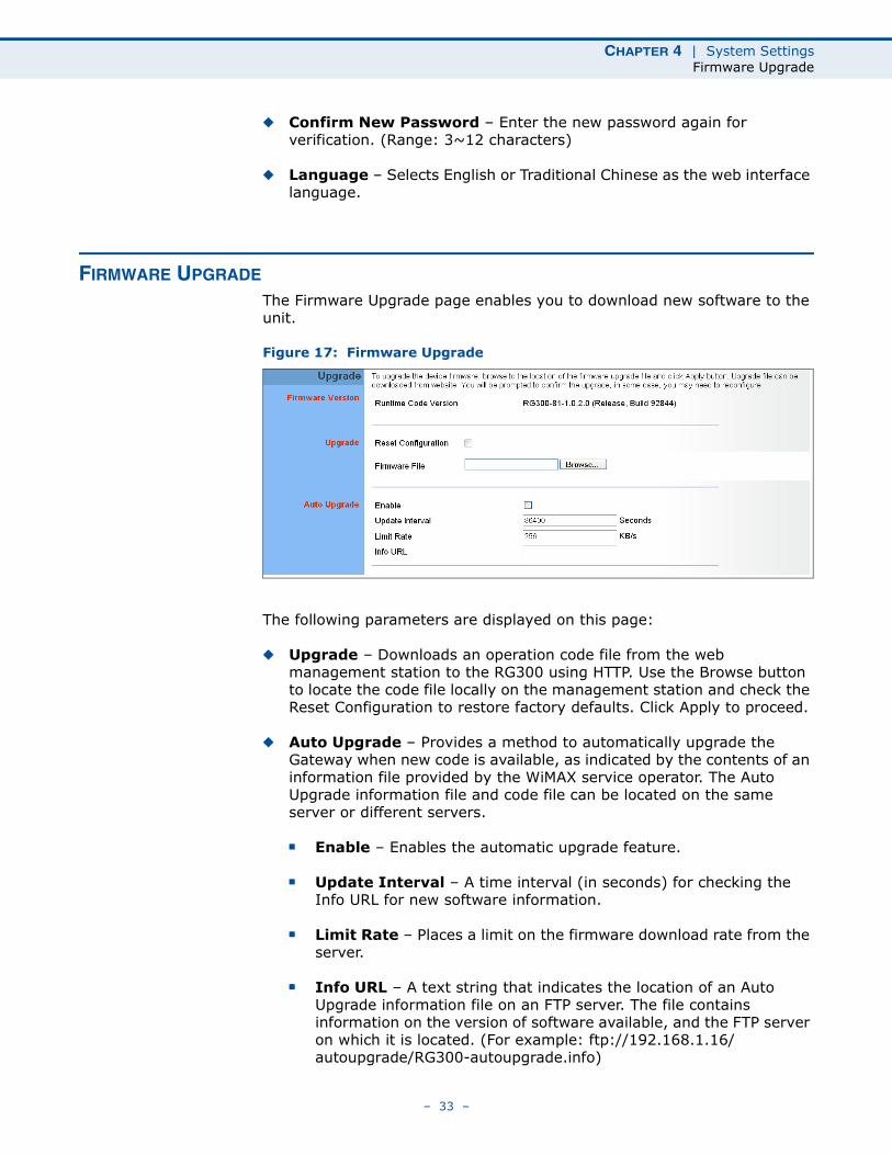
The Firmware Upgrade page enables you to download new software to the unit.
Figure 17: Firmware Upgrade
The following parameters are displayed on this page:
◆ Upgrade – Downloads an operation code file from the web management station to the RG300 using HTTP. Use the Browse button to locate the code file locally on the management station and check the Reset Configuration to restore factory defaults. Click Apply to proceed.
◆ Auto Upgrade – Provides a method to automatically upgrade the Gateway when new code is available, as indicated by the contents of an information file provided by the WiMAX service operator. The Auto Upgrade information file and code file can be located on the same server or different servers.
■ Enable – Enables the automatic upgrade feature.
■ Update Interval – A time interval (in seconds) for checking the Info URL for new software information.
■ Limit Rate – Places a limit on the firmware download rate from the server.
■ Info URL – A text string that indicates the location of an Auto Upgrade information file on an FTP server. The file contains information on the version of software available, and the FTP server on which it is located. (For example: ftp://192.168.1.16/autoupgrade/RG300-autoupgrade.info)
– 33 –
CHAPTER 4 | System SettingsConfiguration Tools
CONFIGURATION TOOLS
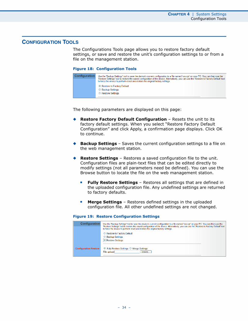
The Configurations Tools page allows you to restore factory default settings, or save and restore the unit’s configuration settings to or from a file on the management station.
Figure 18: Configuration Tools
The following parameters are displayed on this page:
◆ Restore Factory Default Configuration – Resets the unit to its factory default settings. When you select “Restore Factory Default Configuration” and click Apply, a confirmation page displays. Click OK to continue.
◆ Backup Settings – Saves the current configuration settings to a file on the web management station.
◆ Restore Settings – Restores a saved configuration file to the unit. Configuration files are plain-text files that can be edited directly to modify settings (not all parameters need be defined). You can use the Browse button to locate the file on the web management station.
■ Fully Restore Settings – Restores all settings that are defined in the uploaded configuration file. Any undefined settings are returned to factory defaults.
■ Merge Settings – Restores defined settings in the uploaded configuration file. All other undefined settings are not changed.
Figure 19: Restore Configuration Settings
– 34 –
CHAPTER 4 | System SettingsSystem Time
SYSTEM TIME
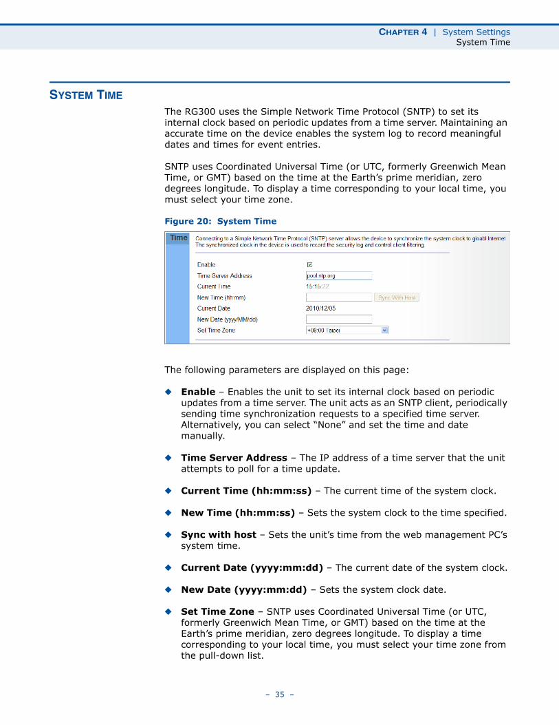
The RG300 uses the Simple Network Time Protocol (SNTP) to set its internal clock based on periodic updates from a time server. Maintaining an accurate time on the device enables the system log to record meaningful dates and times for event entries.
SNTP uses Coordinated Universal Time (or UTC, formerly Greenwich Mean Time, or GMT) based on the time at the Earth’s prime meridian, zero degrees longitude. To display a time corresponding to your local time, you must select your time zone.
Figure 20: System Time
The following parameters are displayed on this page:
◆ Enable – Enables the unit to set its internal clock based on periodic updates from a time server. The unit acts as an SNTP client, periodically sending time synchronization requests to a specified time server. Alternatively, you can select “None” and set the time and date manually.
◆ Time Server Address – The IP address of a time server that the unit attempts to poll for a time update.
◆ Current Time (hh:mm:ss) – The current time of the system clock.
◆ New Time (hh:mm:ss) – Sets the system clock to the time specified.
◆ Sync with host – Sets the unit’s time from the web management PC’s system time.
◆ Current Date (yyyy:mm:dd) – The current date of the system clock.
◆ New Date (yyyy:mm:dd) – Sets the system clock date.
◆ Set Time Zone – SNTP uses Coordinated Universal Time (or UTC, formerly Greenwich Mean Time, or GMT) based on the time at the Earth’s prime meridian, zero degrees longitude. To display a time corresponding to your local time, you must select your time zone from the pull-down list.
– 35 –
CHAPTER 4 | System SettingsSystem Log
SYSTEM LOG
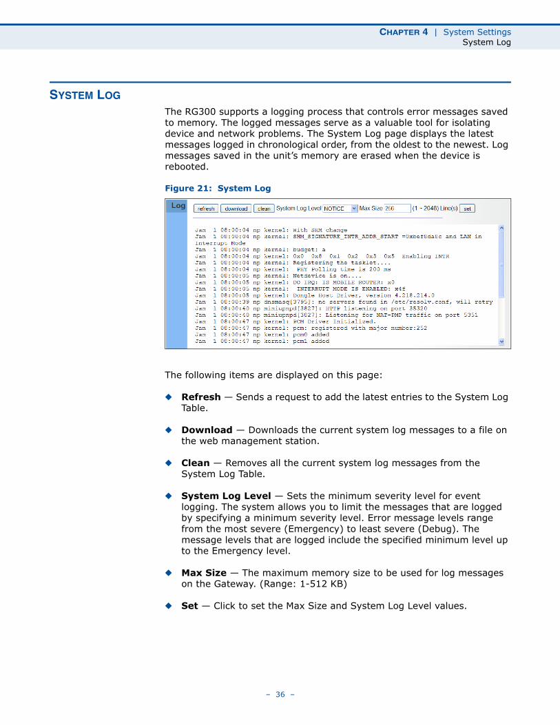
The RG300 supports a logging process that controls error messages saved to memory. The logged messages serve as a valuable tool for isolating device and network problems. The System Log page displays the latest messages logged in chronological order, from the oldest to the newest. Log messages saved in the unit’s memory are erased when the device is rebooted.
Figure 21: System Log
The following items are displayed on this page:
◆ Refresh — Sends a request to add the latest entries to the System Log Table.
◆ Download — Downloads the current system log messages to a file on the web management station.
◆ Clean — Removes all the current system log messages from the System Log Table.
◆ System Log Level — Sets the minimum severity level for event logging. The system allows you to limit the messages that are logged by specifying a minimum severity level. Error message levels range from the most severe (Emergency) to least severe (Debug). The message levels that are logged include the specified minimum level up to the Emergency level.
◆ Max Size — The maximum memory size to be used for log messages on the Gateway. (Range: 1-512 KB)
◆ Set — Click to set the Max Size and System Log Level values.
– 36 –
CHAPTER 4 | System SettingsReset
RESET
The Reset page allows you to restart the device’s software. If the unit stops responding correctly or in some way stops functioning, performing a reset can clear the condition.
Figure 22: Reset Unit
Reset – Resets the unit. All current settings are retained.
– 37 –
5 WAN CONFIGURATION
The information in this chapter covers the configuration options for the RG300’s WAN connection.
The WAN configuration pages include the following options:
◆ “WAN Settings” on page 39
◆ “DNS” on page 42
◆ “DDNS” on page 43
– 38 –
CHAPTER 5 | WAN ConfigurationWAN Settings
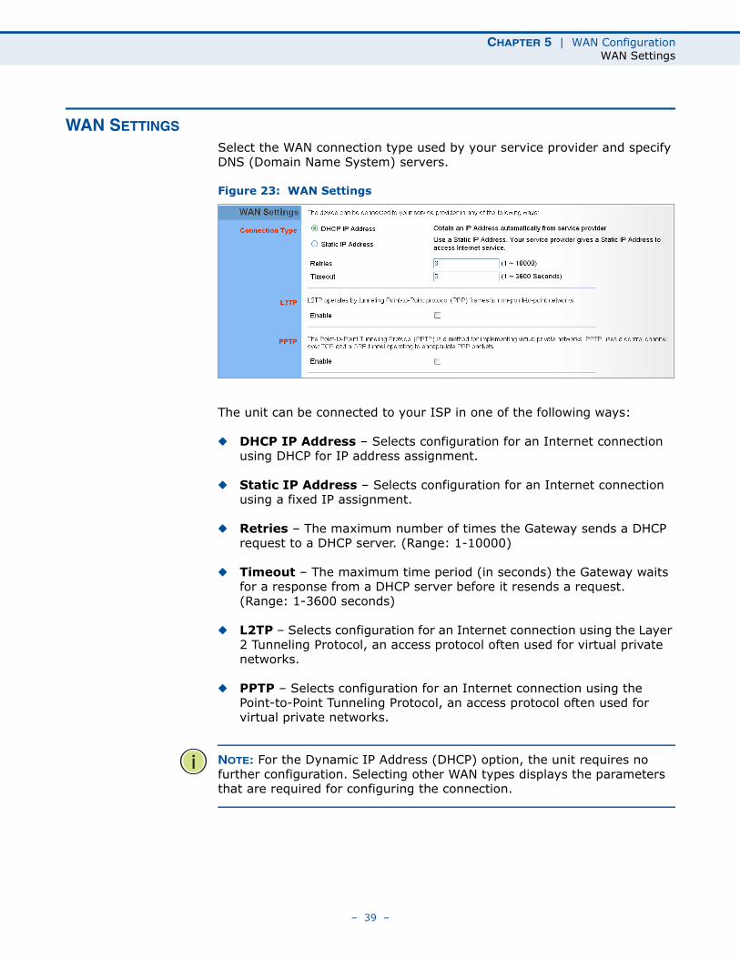
WAN SETTINGS
Select the WAN connection type used by your service provider and specify DNS (Domain Name System) servers.
Figure 23: WAN Settings
The unit can be connected to your ISP in one of the following ways:
◆ DHCP IP Address – Selects configuration for an Internet connection using DHCP for IP address assignment.
◆ Static IP Address – Selects configuration for an Internet connection using a fixed IP assignment.
◆ Retries – The maximum number of times the Gateway sends a DHCP request to a DHCP server. (Range: 1-10000)
◆ Timeout – The maximum time period (in seconds) the Gateway waits for a response from a DHCP server before it resends a request. (Range: 1-3600 seconds)
◆ L2TP – Selects configuration for an Internet connection using the Layer 2 Tunneling Protocol, an access protocol often used for virtual private networks.
◆ PPTP – Selects configuration for an Internet connection using the Point-to-Point Tunneling Protocol, an access protocol often used for virtual private networks.
NOTE: For the Dynamic IP Address (DHCP) option, the unit requires no further configuration. Selecting other WAN types displays the parameters that are required for configuring the connection.
– 39 –
CHAPTER 5 | WAN ConfigurationWAN Settings
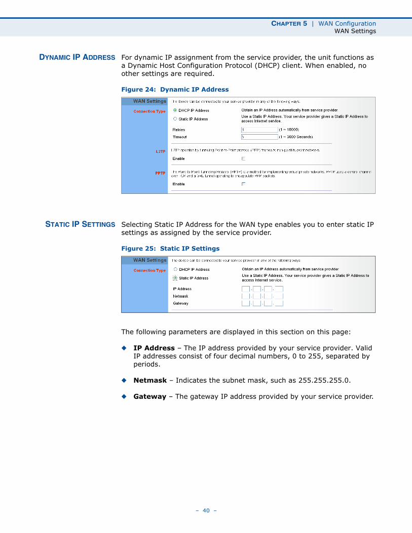
DYNAMIC IP ADDRESS For dynamic IP assignment from the service provider, the unit functions as a Dynamic Host Configuration Protocol (DHCP) client. When enabled, no other settings are required.
Figure 24: Dynamic IP Address
STATIC IP SETTINGS Selecting Static IP Address for the WAN type enables you to enter static IP settings as assigned by the service provider.
Figure 25: Static IP Settings
The following parameters are displayed in this section on this page:
◆ IP Address – The IP address provided by your service provider. Valid IP addresses consist of four decimal numbers, 0 to 255, separated by periods.
◆ Netmask – Indicates the subnet mask, such as 255.255.255.0.
◆ Gateway – The gateway IP address provided by your service provider.
– 40 –
CHAPTER 5 | WAN ConfigurationWAN Settings
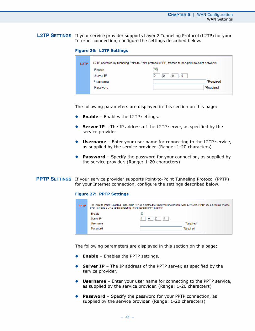
L2TP SETTINGS If your service provider supports Layer 2 Tunneling Protocol (L2TP) for your Internet connection, configure the settings described below.
Figure 26: L2TP Settings
The following parameters are displayed in this section on this page:
◆ Enable – Enables the L2TP settings.
◆ Server IP – The IP address of the L2TP server, as specified by the service provider.
◆ Username – Enter your user name for connecting to the L2TP service, as supplied by the service provider. (Range: 1-20 characters)
◆ Password – Specify the password for your connection, as supplied by the service provider. (Range: 1-20 characters)
PPTP SETTINGS If your service provider supports Point-to-Point Tunneling Protocol (PPTP) for your Internet connection, configure the settings described below.
Figure 27: PPTP Settings
The following parameters are displayed in this section on this page:
◆ Enable – Enables the PPTP settings.
◆ Server IP – The IP address of the PPTP server, as specified by the service provider.
◆ Username – Enter your user name for connecting to the PPTP service, as supplied by the service provider. (Range: 1-20 characters)
◆ Password – Specify the password for your PPTP connection, as supplied by the service provider. (Range: 1-20 characters)
– 41 –
CHAPTER 5 | WAN ConfigurationDNS
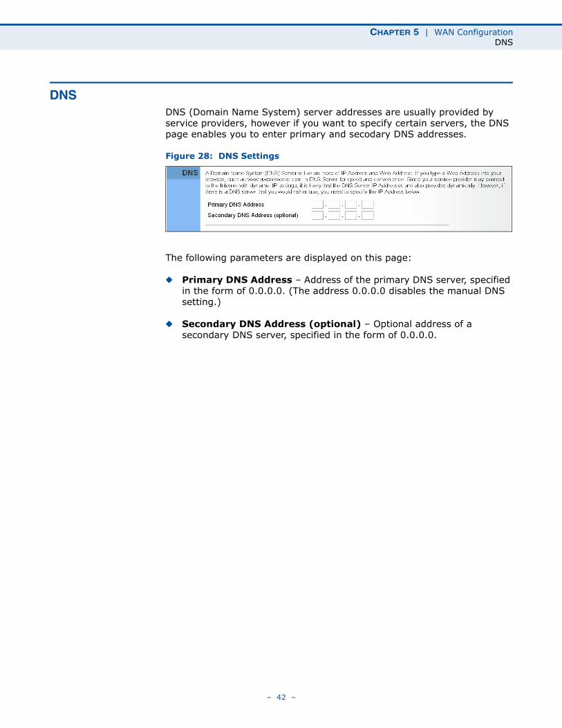
DNSDNS (Domain Name System) server addresses are usually provided by service providers, however if you want to specify certain servers, the DNS page enables you to enter primary and secodary DNS addresses.
Figure 28: DNS Settings
The following parameters are displayed on this page:
◆ Primary DNS Address – Address of the primary DNS server, specified in the form of 0.0.0.0. (The address 0.0.0.0 disables the manual DNS setting.)
◆ Secondary DNS Address (optional) – Optional address of a secondary DNS server, specified in the form of 0.0.0.0.
– 42 –
CHAPTER 5 | WAN ConfigurationDDNS
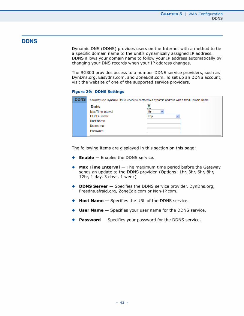
DDNSDynamic DNS (DDNS) provides users on the Internet with a method to tie a specific domain name to the unit’s dynamically assigned IP address. DDNS allows your domain name to follow your IP address automatically by changing your DNS records when your IP address changes.
The RG300 provides access to a number DDNS service providers, such as DynDns.org, Easydns.com, and ZoneEdit.com. To set up an DDNS account, visit the website of one of the supported service providers.
Figure 29: DDNS Settings
The following items are displayed in this section on this page:
◆ Enable — Enables the DDNS service.
◆ Max Time Interval — The maximum time period before the Gateway sends an update to the DDNS provider. (Options: 1hr, 3hr, 6hr, 8hr, 12hr, 1 day, 3 days, 1 week)
◆ DDNS Server — Specifies the DDNS service provider, DynDns.org, Freedns.afraid.org, ZoneEdit.com or Non-IP.com.
◆ Host Name — Specifies the URL of the DDNS service.
◆ User Name — Specifies your user name for the DDNS service.
◆ Password — Specifies your password for the DDNS service.
– 43 –
6 LAN CONFIGURATION
The information in this chapter covers the configuration options for the RG300’s LAN functions.
The LAN configuration pages include the following options:
◆ “LAN Settings” on page 45
◆ “DHCP Client List” on page 46
– 44 –
CHAPTER 6 | LAN ConfigurationLAN Settings
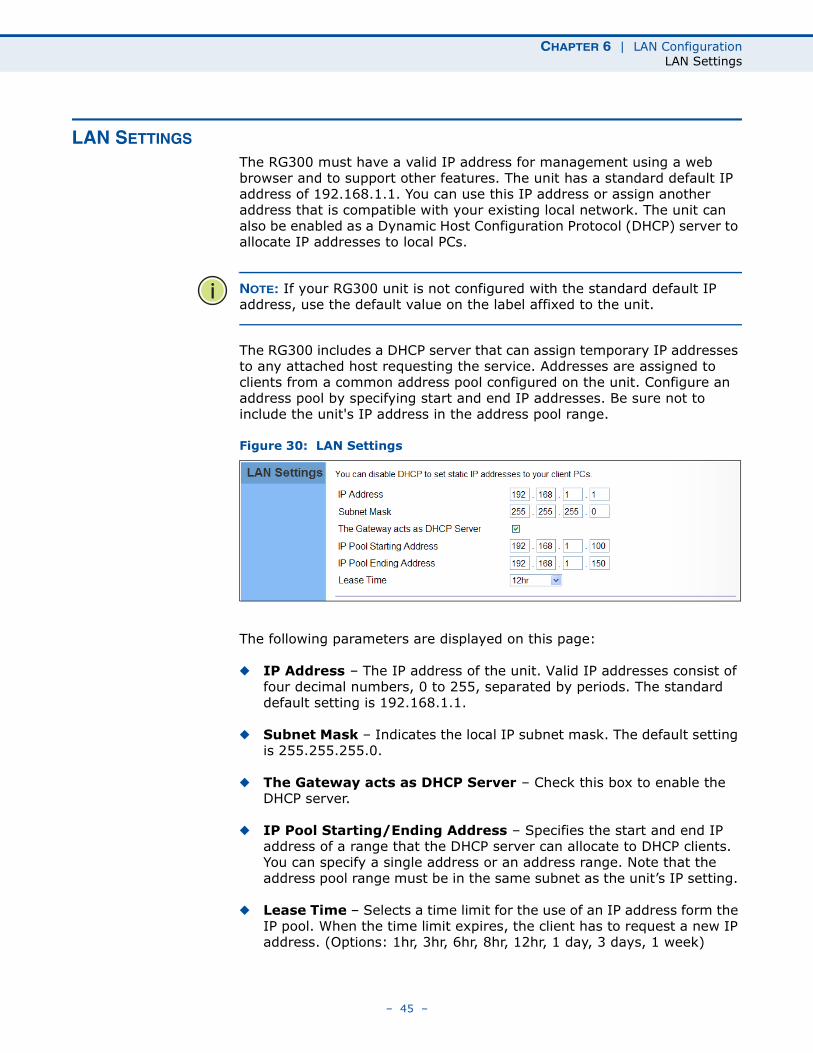
LAN SETTINGS
The RG300 must have a valid IP address for management using a web browser and to support other features. The unit has a standard default IP address of 192.168.1.1. You can use this IP address or assign another address that is compatible with your existing local network. The unit can also be enabled as a Dynamic Host Configuration Protocol (DHCP) server to allocate IP addresses to local PCs.
NOTE: If your RG300 unit is not configured with the standard default IP address, use the default value on the label affixed to the unit.
The RG300 includes a DHCP server that can assign temporary IP addresses to any attached host requesting the service. Addresses are assigned to clients from a common address pool configured on the unit. Configure an address pool by specifying start and end IP addresses. Be sure not to include the unit's IP address in the address pool range.
Figure 30: LAN Settings
The following parameters are displayed on this page:
◆ IP Address – The IP address of the unit. Valid IP addresses consist of four decimal numbers, 0 to 255, separated by periods. The standard default setting is 192.168.1.1.
◆ Subnet Mask – Indicates the local IP subnet mask. The default setting is 255.255.255.0.
◆ The Gateway acts as DHCP Server – Check this box to enable the DHCP server.
◆ IP Pool Starting/Ending Address – Specifies the start and end IP address of a range that the DHCP server can allocate to DHCP clients. You can specify a single address or an address range. Note that the address pool range must be in the same subnet as the unit’s IP setting.
◆ Lease Time – Selects a time limit for the use of an IP address form the IP pool. When the time limit expires, the client has to request a new IP address. (Options: 1hr, 3hr, 6hr, 8hr, 12hr, 1 day, 3 days, 1 week)
– 45 –
CHAPTER 6 | LAN ConfigurationDHCP Client List
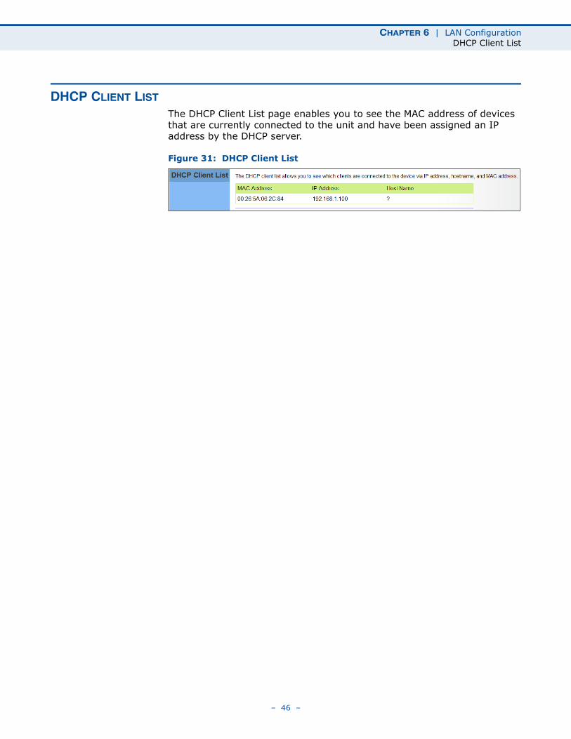
DHCP CLIENT LIST
The DHCP Client List page enables you to see the MAC address of devices that are currently connected to the unit and have been assigned an IP address by the DHCP server.
Figure 31: DHCP Client List
– 46 –
7 NAT CONFIGURATION
The information in this chapter covers the configuration options for the RG300’s Network Address Translation (NAT) functions.
The NAT configuration pages include the following options:
◆ “NAT Settings” on page 48
◆ “Port Mapping” on page 49
◆ “DMZ” on page 50
◆ “ALG” on page 51
– 47 –
CHAPTER 7 | NAT ConfigurationNAT Settings
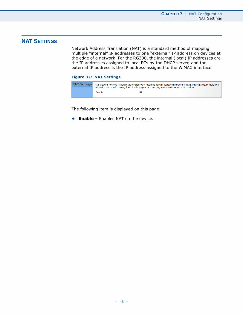
NAT SETTINGS
Network Address Translation (NAT) is a standard method of mapping multiple “internal” IP addresses to one “external” IP address on devices at the edge of a network. For the RG300, the internal (local) IP addresses are the IP addresses assigned to local PCs by the DHCP server, and the external IP address is the IP address assigned to the WiMAX interface.
Figure 32: NAT Settings
The following item is displayed on this page:
◆ Enable – Enables NAT on the device.
– 48 –
CHAPTER 7 | NAT ConfigurationPort Mapping
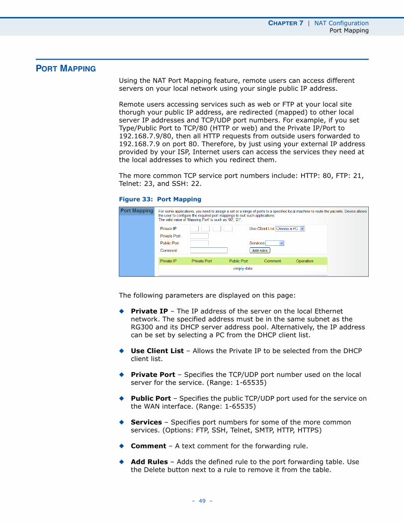
PORT MAPPING
Using the NAT Port Mapping feature, remote users can access different servers on your local network using your single public IP address.
Remote users accessing services such as web or FTP at your local site thorugh your public IP address, are redirected (mapped) to other local server IP addresses and TCP/UDP port numbers. For example, if you set Type/Public Port to TCP/80 (HTTP or web) and the Private IP/Port to 192.168.7.9/80, then all HTTP requests from outside users forwarded to 192.168.7.9 on port 80. Therefore, by just using your external IP address provided by your ISP, Internet users can access the services they need at the local addresses to which you redirect them.
The more common TCP service port numbers include: HTTP: 80, FTP: 21, Telnet: 23, and SSH: 22.
Figure 33: Port Mapping
The following parameters are displayed on this page:
◆ Private IP – The IP address of the server on the local Ethernet network. The specified address must be in the same subnet as the RG300 and its DHCP server address pool. Alternatively, the IP address can be set by selecting a PC from the DHCP client list.
◆ Use Client List – Allows the Private IP to be selected from the DHCP client list.
◆ Private Port – Specifies the TCP/UDP port number used on the local server for the service. (Range: 1-65535)
◆ Public Port – Specifies the public TCP/UDP port used for the service on the WAN interface. (Range: 1-65535)
◆ Services – Specifies port numbers for some of the more common services. (Options: FTP, SSH, Telnet, SMTP, HTTP, HTTPS)
◆ Comment – A text comment for the forwarding rule.
◆ Add Rules – Adds the defined rule to the port forwarding table. Use the Delete button next to a rule to remove it from the table.
– 49 –
CHAPTER 7 | NAT ConfigurationDMZ
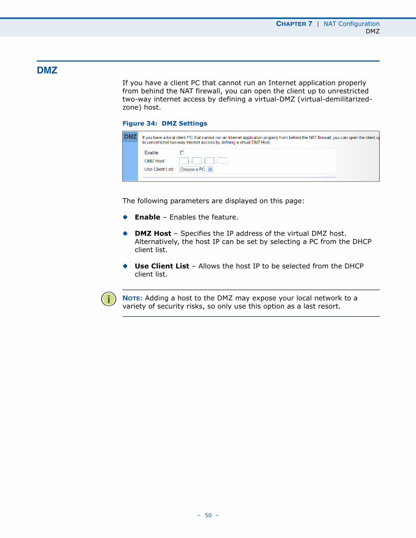
DMZIf you have a client PC that cannot run an Internet application properly from behind the NAT firewall, you can open the client up to unrestricted two-way internet access by defining a virtual-DMZ (virtual-demilitarized-zone) host.
Figure 34: DMZ Settings
The following parameters are displayed on this page:
◆ Enable – Enables the feature.
◆ DMZ Host – Specifies the IP address of the virtual DMZ host. Alternatively, the host IP can be set by selecting a PC from the DHCP client list.
◆ Use Client List – Allows the host IP to be selected from the DHCP client list.
NOTE: Adding a host to the DMZ may expose your local network to a variety of security risks, so only use this option as a last resort.
– 50 –
CHAPTER 7 | NAT ConfigurationALG
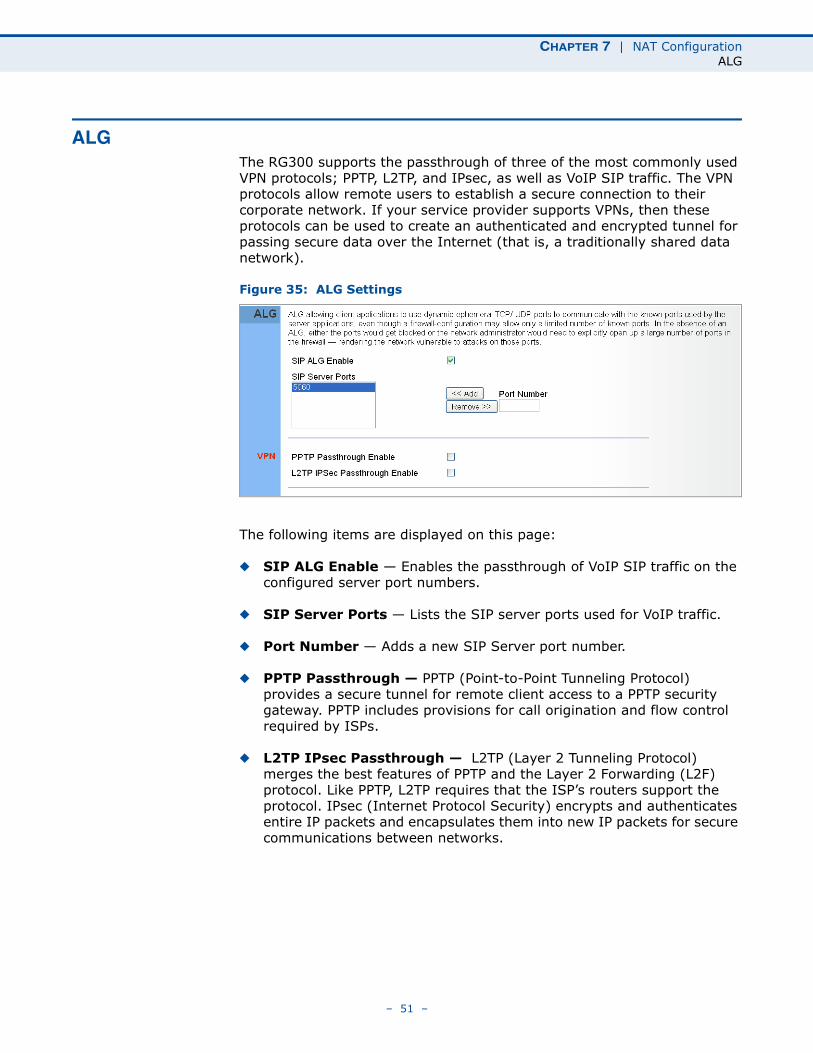
ALGThe RG300 supports the passthrough of three of the most commonly used VPN protocols; PPTP, L2TP, and IPsec, as well as VoIP SIP traffic. The VPN protocols allow remote users to establish a secure connection to their corporate network. If your service provider supports VPNs, then these protocols can be used to create an authenticated and encrypted tunnel for passing secure data over the Internet (that is, a traditionally shared data network).
Figure 35: ALG Settings
The following items are displayed on this page:
◆ SIP ALG Enable — Enables the passthrough of VoIP SIP traffic on the configured server port numbers.
◆ SIP Server Ports — Lists the SIP server ports used for VoIP traffic.
◆ Port Number — Adds a new SIP Server port number.
◆ PPTP Passthrough — PPTP (Point-to-Point Tunneling Protocol) provides a secure tunnel for remote client access to a PPTP security gateway. PPTP includes provisions for call origination and flow control required by ISPs.
◆ L2TP IPsec Passthrough — L2TP (Layer 2 Tunneling Protocol) merges the best features of PPTP and the Layer 2 Forwarding (L2F) protocol. Like PPTP, L2TP requires that the ISP’s routers support the protocol. IPsec (Internet Protocol Security) encrypts and authenticates entire IP packets and encapsulates them into new IP packets for secure communications between networks.
– 51 –
8 FIREWALL CONFIGURATION
The information in this chapter covers the configuration options for the RG300’s firewall functions.
The Firewall configuration pages include the following options:
◆ “Firewall Settings” on page 53
◆ “Client Filtering” on page 54
◆ “Port Filtering” on page 55
◆ “MAC Filtering” on page 56
◆ “URL Filtering” on page 57
◆ “Host Filtering” on page 58
– 52 –
CHAPTER 8 | Firewall ConfigurationFirewall Settings
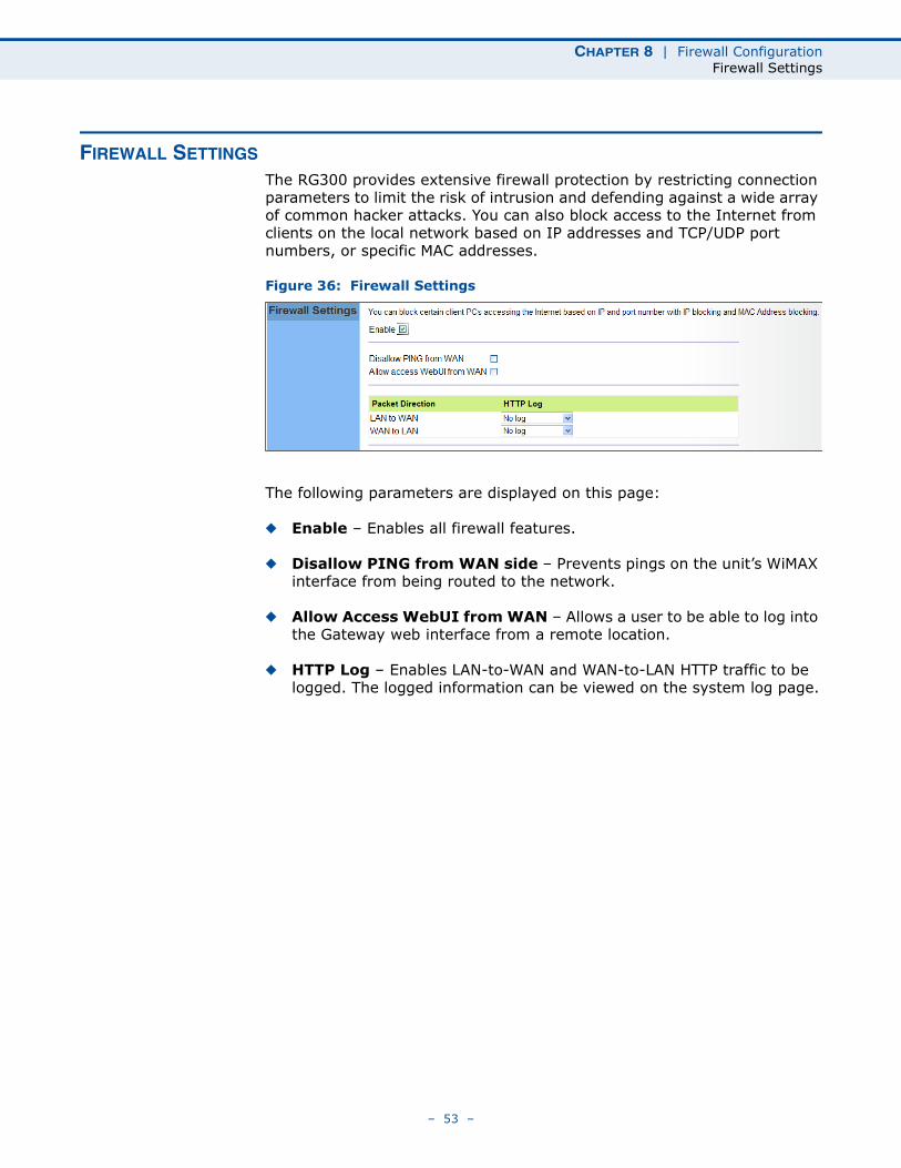
FIREWALL SETTINGS
The RG300 provides extensive firewall protection by restricting connection parameters to limit the risk of intrusion and defending against a wide array of common hacker attacks. You can also block access to the Internet from clients on the local network based on IP addresses and TCP/UDP port numbers, or specific MAC addresses.
Figure 36: Firewall Settings
The following parameters are displayed on this page:
◆ Enable – Enables all firewall features.
◆ Disallow PING from WAN side – Prevents pings on the unit’s WiMAX interface from being routed to the network.
◆ Allow Access WebUI from WAN – Allows a user to be able to log into the Gateway web interface from a remote location.
◆ HTTP Log – Enables LAN-to-WAN and WAN-to-LAN HTTP traffic to be logged. The logged information can be viewed on the system log page.
– 53 –
CHAPTER 8 | Firewall ConfigurationClient Filtering
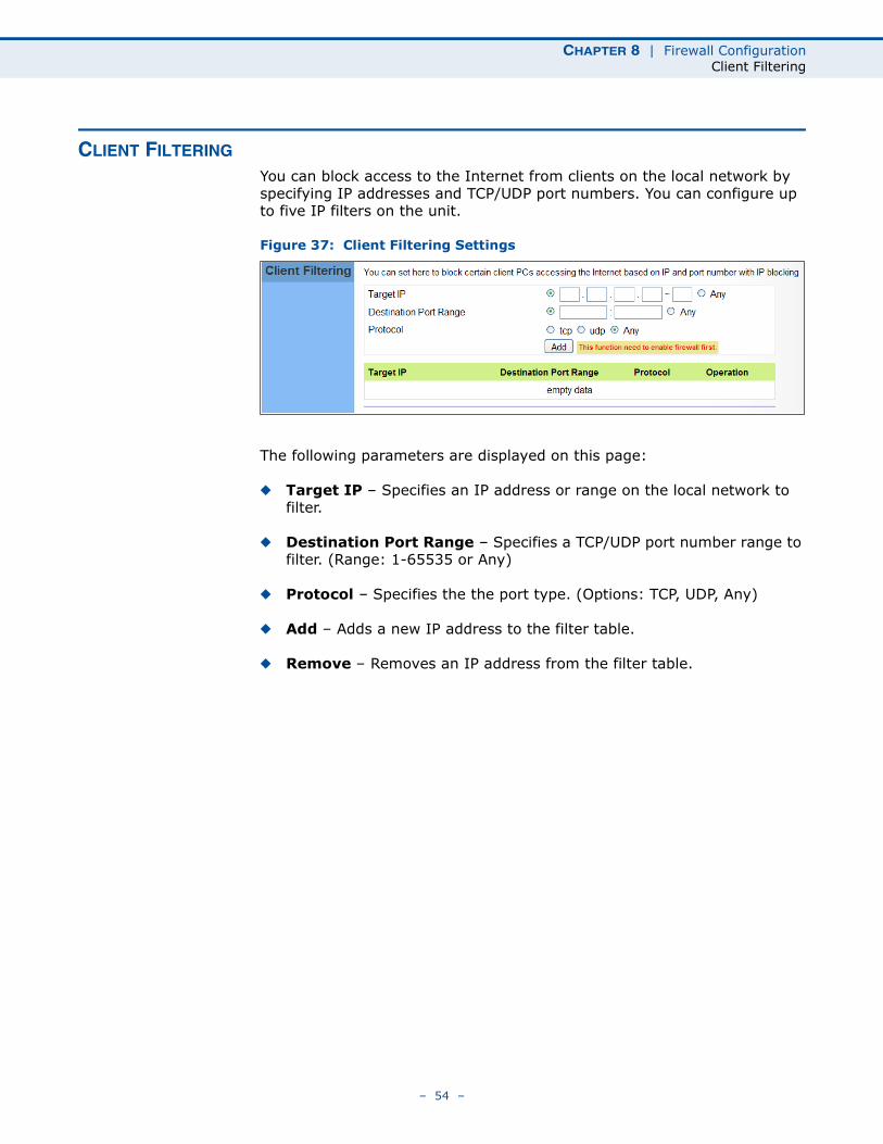
CLIENT FILTERING
You can block access to the Internet from clients on the local network by specifying IP addresses and TCP/UDP port numbers. You can configure up to five IP filters on the unit.
Figure 37: Client Filtering Settings
The following parameters are displayed on this page:
◆ Target IP – Specifies an IP address or range on the local network to filter.
◆ Destination Port Range – Specifies a TCP/UDP port number range to filter. (Range: 1-65535 or Any)
◆ Protocol – Specifies the the port type. (Options: TCP, UDP, Any)
◆ Add – Adds a new IP address to the filter table.
◆ Remove – Removes an IP address from the filter table.
– 54 –
CHAPTER 8 | Firewall ConfigurationPort Filtering
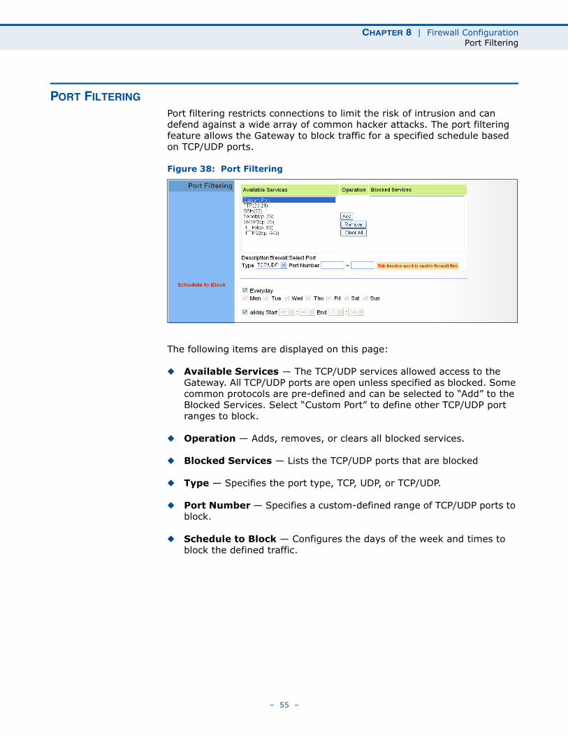
PORT FILTERING
Port filtering restricts connections to limit the risk of intrusion and can defend against a wide array of common hacker attacks. The port filtering feature allows the Gateway to block traffic for a specified schedule based on TCP/UDP ports.
Figure 38: Port Filtering
The following items are displayed on this page:
◆ Available Services — The TCP/UDP services allowed access to the Gateway. All TCP/UDP ports are open unless specified as blocked. Some common protocols are pre-defined and can be selected to “Add” to the Blocked Services. Select “Custom Port” to define other TCP/UDP port ranges to block.
◆ Operation — Adds, removes, or clears all blocked services.
◆ Blocked Services — Lists the TCP/UDP ports that are blocked
◆ Type — Specifies the port type, TCP, UDP, or TCP/UDP.
◆ Port Number — Specifies a custom-defined range of TCP/UDP ports to block.
◆ Schedule to Block — Configures the days of the week and times to block the defined traffic.
– 55 –
CHAPTER 8 | Firewall ConfigurationMAC Filtering
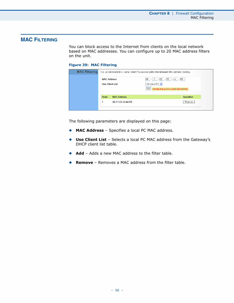
MAC FILTERING
You can block access to the Internet from clients on the local network based on MAC addresses. You can configure up to 20 MAC address filters on the unit.
Figure 39: MAC Filtering
The following parameters are displayed on this page:
◆ MAC Address – Specifies a local PC MAC address.
◆ Use Client List – Selects a local PC MAC address from the Gateway’s DHCP client list table.
◆ Add – Adds a new MAC address to the filter table.
◆ Remove – Removes a MAC address from the filter table.
– 56 –
CHAPTER 8 | Firewall ConfigurationURL Filtering
URL FILTERING
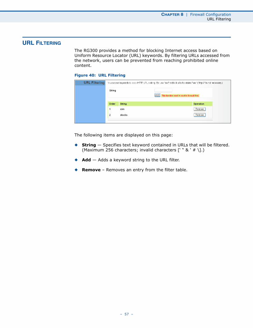
The RG300 provides a method for blocking Internet access based on Uniform Resource Locator (URL) keywords. By filtering URLs accessed from the network, users can be prevented from reaching prohibited online content.
Figure 40: URL Filtering
The following items are displayed on this page:
◆ String — Specifies text keyword contained in URLs that will be filtered. (Maximum 256 characters; invalid characters [‘ “ & ' # \].)
◆ Add — Adds a keyword string to the URL filter.
◆ Remove – Removes an entry from the filter table.
– 57 –
CHAPTER 8 | Firewall ConfigurationHost Filtering
HOST FILTERING
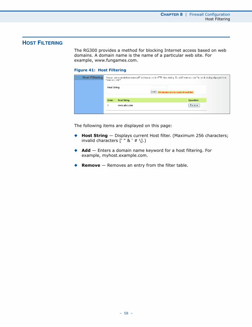
The RG300 provides a method for blocking Internet access based on web domains. A domain name is the name of a particular web site. For example, www.fungames.com.
Figure 41: Host Filtering
The following items are displayed on this page:
◆ Host String — Displays current Host filter. (Maximum 256 characters; invalid characters [‘ “ & ' # \].)
◆ Add — Enters a domain name keyword for a host filtering. For example, myhost.example.com.
◆ Remove — Removes an entry from the filter table.
– 58 –
9 ROUTING CONFIGURATION
The information in this chapter covers the configuration options for the RG300’s Routing functions.
The Routing configuration pages include the following options:
◆ “Routing Table” on page 60
◆ “Static Route” on page 61
– 59 –
CHAPTER 9 | Routing ConfigurationRouting Table
ROUTING TABLE
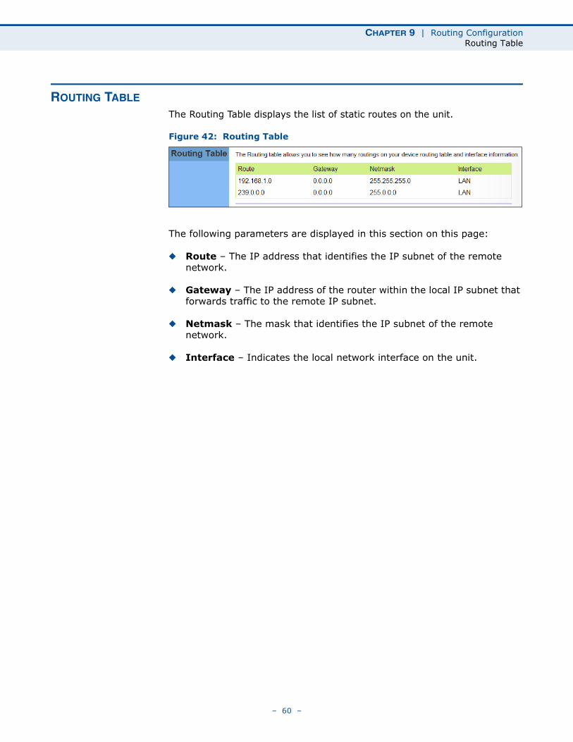
The Routing Table displays the list of static routes on the unit.
Figure 42: Routing Table
The following parameters are displayed in this section on this page:
◆ Route – The IP address that identifies the IP subnet of the remote network.
◆ Gateway – The IP address of the router within the local IP subnet that forwards traffic to the remote IP subnet.
◆ Netmask – The mask that identifies the IP subnet of the remote network.
◆ Interface – Indicates the local network interface on the unit.
– 60 –
CHAPTER 9 | Routing ConfigurationStatic Route
STATIC ROUTE
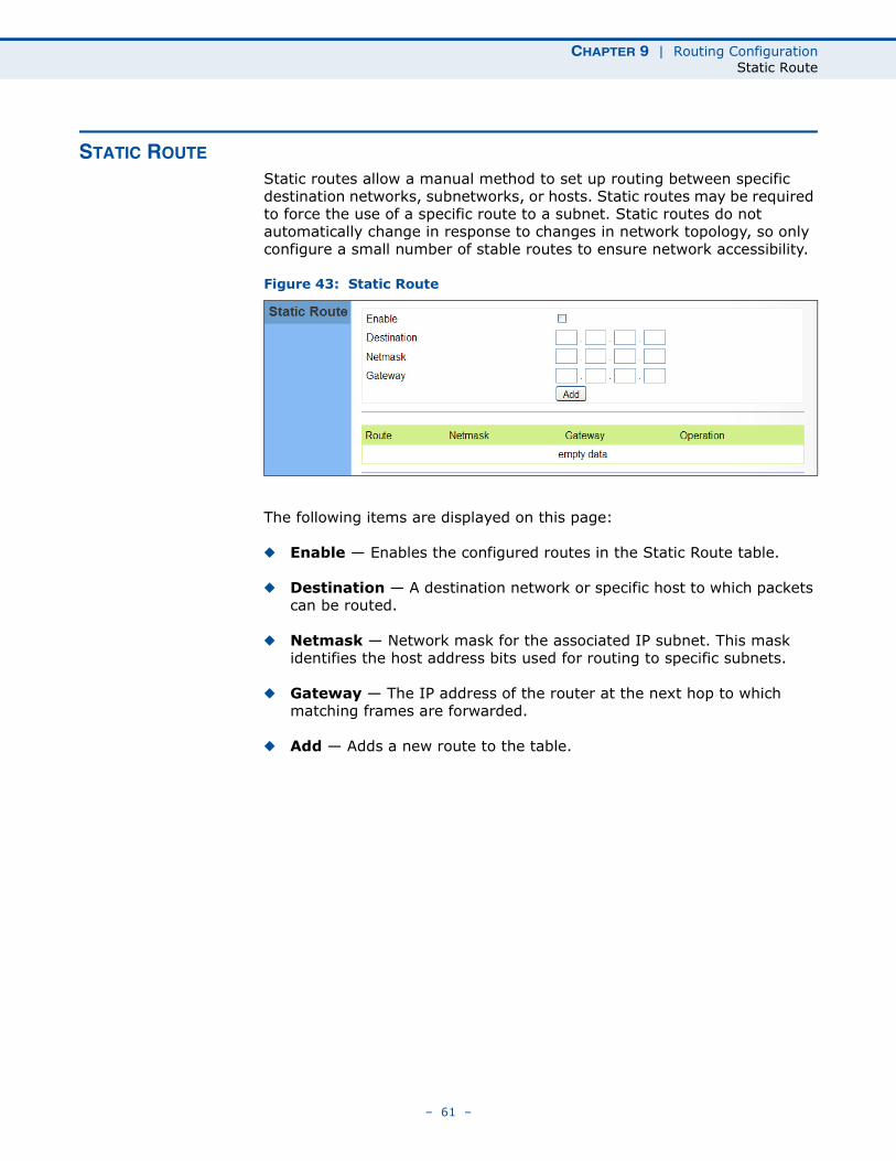
Static routes allow a manual method to set up routing between specific destination networks, subnetworks, or hosts. Static routes may be required to force the use of a specific route to a subnet. Static routes do not automatically change in response to changes in network topology, so only configure a small number of stable routes to ensure network accessibility.
Figure 43: Static Route
The following items are displayed on this page:
◆ Enable — Enables the configured routes in the Static Route table.
◆ Destination — A destination network or specific host to which packets can be routed.
◆ Netmask — Network mask for the associated IP subnet. This mask identifies the host address bits used for routing to specific subnets.
◆ Gateway — The IP address of the router at the next hop to which matching frames are forwarded.
◆ Add — Adds a new route to the table.
– 61 –
10 UPNP CONFIGURATION
The information in this chapter covers the configuration options for the RG300’s Universal Plug and Play Forum (UPnP) feature.
The UPnP configuration pages include the following options:
◆ “UPnP” on page 63
– 62 –
CHAPTER 10 | UPnP ConfigurationUPnP
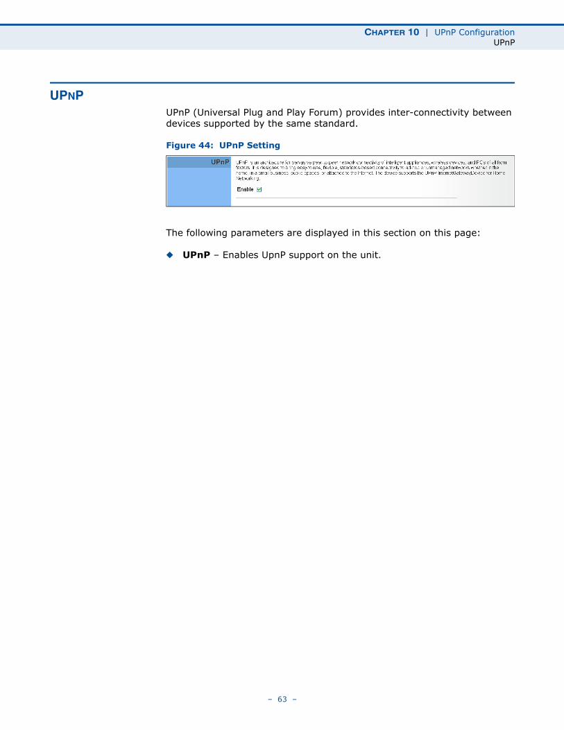
UPNPUPnP (Universal Plug and Play Forum) provides inter-connectivity between devices supported by the same standard.
Figure 44: UPnP Setting
The following parameters are displayed in this section on this page:
◆ UPnP – Enables UpnP support on the unit.
– 63 –
11 VOIP SETTINGS
Voice over Internet Protocol (VoIP) technology is a way of using the Internet to make phone calls. Phone calls can be tranmitted over the Internet by encoding a voice call into data packets at one end and then decoding it back into voice calls at the other end. This encoding and decoding is from a analog signal (your voice) into a digital signal (data packets) and then back into an analog signal.
The RG300 uses Session Initiation Protocol (SIP) as the control mechanism that sets up, initiates, and terminates calls between a caller and a called party. The SIP messaging makes use of “Proxy,” “Redirect,” and “Registration” servers to process call requests and find the location of called parties across the Internet. When SIP has set up a call between two parties, the actual voice communication is a direct peer-to-peer connection using the standard Real-Time Protocol (RTP), which streams the encoded voice data across the network.
You can make VoIP calls by connecting a regular phone to one of the RG300’s RJ-11 Phone ports. The RG300 allows up to two RJ-11 Phone ports to be configured separately with different settings.
The VoIP configuration pages include the following options:
◆ “SIP Account” on page 65
◆ “SIP Settings” on page 66
◆ “Speed Dial” on page 67
◆ “Dial Plan” on page 68
◆ “Call Feature” on page 70
◆ “Phone Settings” on page 72
◆ “Codecs” on page 73
– 64 –
CHAPTER 11 | VoIP SettingsSIP Account
SIP ACCOUNT
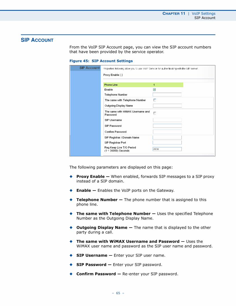
From the VoIP SIP Account page, you can view the SIP account numbers that have been provided by the service operator.
Figure 45: SIP Account Settings
The following parameters are displayed on this page:
◆ Proxy Enable — When enabled, forwards SIP messages to a SIP proxy instead of a SIP domain.
◆ Enable — Enables the VoIP ports on the Gateway.
◆ Telephone Number — The phone number that is assigned to this phone line.
◆ The same with Telephone Number — Uses the specified Telephone Number as the Outgoing Display Name.
◆ Outgoing Display Name — The name that is displayed to the other party during a call.
◆ The same with WiMAX Username and Password — Uses the WiMAX user name and password as the SIP user name and password.
◆ SIP Username — Enter your SIP user name.
◆ SIP Password — Enter your SIP password.
◆ Confirm Password — Re-enter your SIP password.
– 65 –
CHAPTER 11 | VoIP SettingsSIP Settings
◆ SIP Registrar/Domain Name — Enter the IP address or server domain name of the SIP server.
◆ SIP Registrar Port — Enter the port associated with SIP server traffic.
◆ SIP Proxy Address/Domain Name — Address of the VoIP service provider SIP proxy server.
◆ SIP Proxy Port — The TCP port number used by the VoIP service provider’s SIP proxy server.
◆ Reg Keep Alive I/O Period — The maximum time (in seconds) between keep-alive messages sent to the SIP register server.
SIP SETTINGS
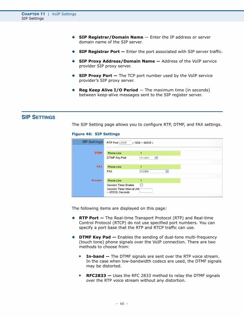
The SIP Setting page allows you to configure RTP, DTMF, and FAX settings.
Figure 46: SIP Settings
The following items are displayed on this page:
◆ RTP Port — The Real-time Transport Protocol (RTP) and Real-time Control Protocol (RTCP) do not use specified port numbers. You can specify a port base that the RTP and RTCP traffic can use.
◆ DTMF Key Pad — Enables the sending of dual-tone multi-frequency (touch tone) phone signals over the VoIP connection. There are two methods to choose from:
■ In-band — The DTMF signals are sent over the RTP voice stream. In the case when low-bandwidth codecs are used, the DTMF signals may be distorted.
■ RFC2833 — Uses the RFC 2833 method to relay the DTMF signals over the RTP voice stream without any distortion.
– 66 –
CHAPTER 11 | VoIP SettingsSpeed Dial
◆ FAX — Selects the method to use when sending fax messages over the VoIP network from a fax machine connected to one of the RJ-11 Phone ports on the Gateway.
■ FAX T.38 — The SIP protocol sets up the VoIP call, then the T.38 Fax Relay protocol sends the fax data over the network.
■ FAX Pass-Through — Enables voice calls and faxes to be sent from the Phone port connection. For this option, fax signals are sent over the VoIP network using the voice codec, just as if it were a voice call.
◆ Session Timer Enable — Enables a limit on the duration of VoIP calls.
◆ Session Timer Interval — Sets the maximum time limit for VoIP calls.
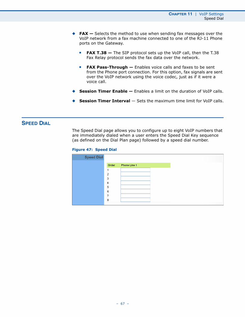
SPEED DIAL
The Speed Dial page allows you to configure up to eight VoIP numbers that are immediately dialed when a user enters the Speed Dial Key sequence (as defined on the Dial Plan page) followed by a speed dial number.
Figure 47: Speed Dial
– 67 –
CHAPTER 11 | VoIP SettingsDial Plan
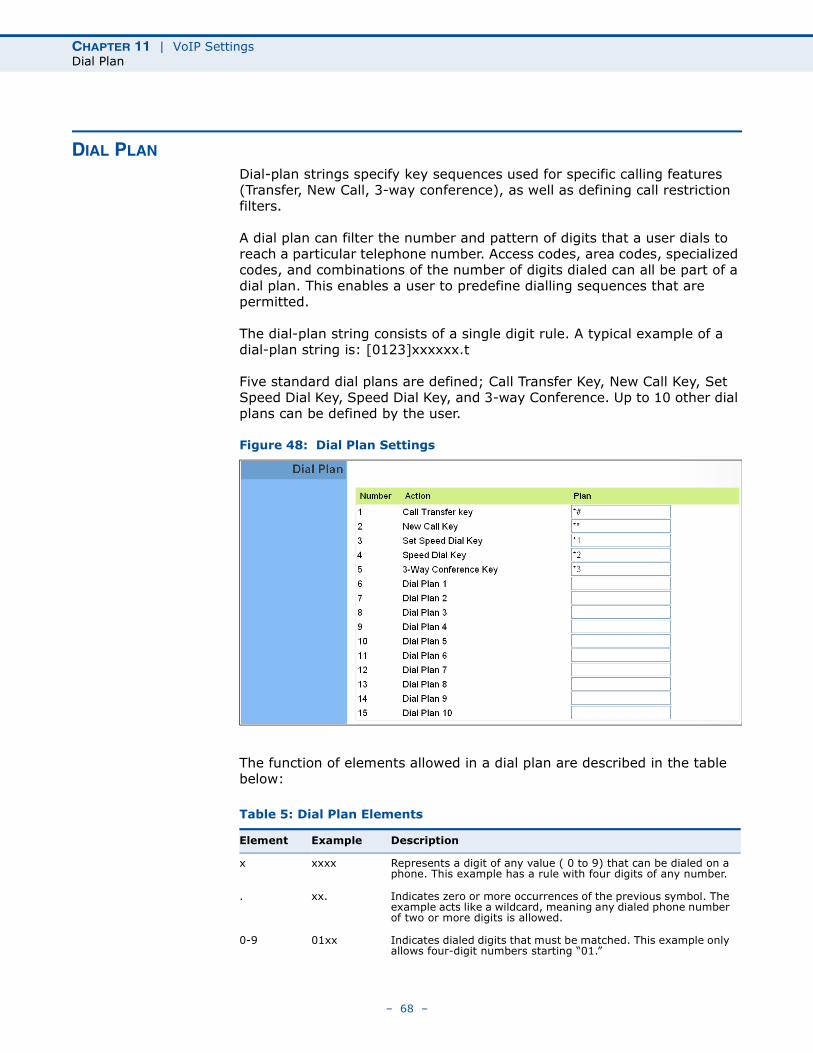
DIAL PLAN
Dial-plan strings specify key sequences used for specific calling features (Transfer, New Call, 3-way conference), as well as defining call restriction filters.
A dial plan can filter the number and pattern of digits that a user dials to reach a particular telephone number. Access codes, area codes, specialized codes, and combinations of the number of digits dialed can all be part of a dial plan. This enables a user to predefine dialling sequences that are permitted.
The dial-plan string consists of a single digit rule. A typical example of a dial-plan string is: [0123]xxxxxx.t
Five standard dial plans are defined; Call Transfer Key, New Call Key, Set Speed Dial Key, Speed Dial Key, and 3-way Conference. Up to 10 other dial plans can be defined by the user.
Figure 48: Dial Plan Settings
The function of elements allowed in a dial plan are described in the table below:
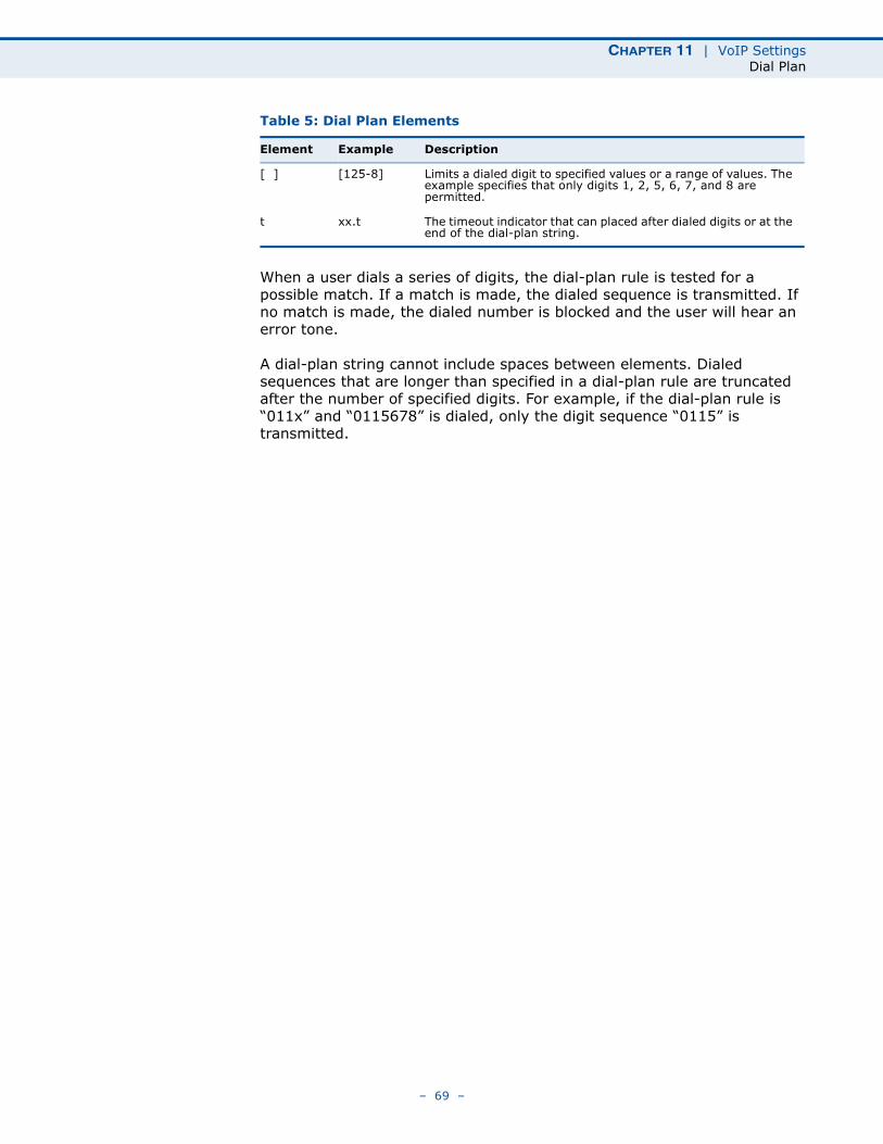
Table 5: Dial Plan Elements
Element Example Description
x xxxx Represents a digit of any value ( 0 to 9) that can be dialed on a phone. This example has a rule with four digits of any number.
. xx. Indicates zero or more occurrences of the previous symbol. The example acts like a wildcard, meaning any dialed phone number of two or more digits is allowed.
0-9 01xx Indicates dialed digits that must be matched. This example only allows four-digit numbers starting “01.”
– 68 –
CHAPTER 11 | VoIP SettingsDial Plan
When a user dials a series of digits, the dial-plan rule is tested for a possible match. If a match is made, the dialed sequence is transmitted. If no match is made, the dialed number is blocked and the user will hear an error tone.
A dial-plan string cannot include spaces between elements. Dialed sequences that are longer than specified in a dial-plan rule are truncated after the number of specified digits. For example, if the dial-plan rule is “011x” and “0115678” is dialed, only the digit sequence “0115” is transmitted.
[ ] [125-8] Limits a dialed digit to specified values or a range of values. The example specifies that only digits 1, 2, 5, 6, 7, and 8 are permitted.
t xx.t The timeout indicator that can placed after dialed digits or at the end of the dial-plan string.
Table 5: Dial Plan Elements
Element Example Description
– 69 –
CHAPTER 11 | VoIP SettingsCall Feature
CALL FEATURE
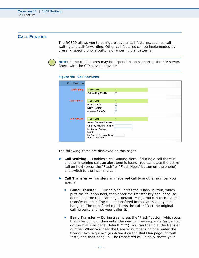
The RG300 allows you to configure several call features, such as call waiting and call-forwarding. Other call features can be implemented by pressing specific phone buttons or entering dial patterns.
NOTE: Some call features may be dependent on support at the SIP server. Check with the SIP service provider.
Figure 49: Call Features
The following items are displayed on this page:
◆ Call Waiting — Enables a call waiting alert. If during a call there is another incoming call, an alert tone is heard. You can place the active call on hold (press the “Flash” or “Flash Hook” button on the phone) and switch to the incoming call.
◆ Call Transfer — Transfers any received call to another number you specify.
■ Blind Transfer — During a call press the “Flash” button, which puts the caller on hold, then enter the transfer key sequence (as defined on the Dial Plan page; default “*#”). You can then dial the transfer number. The call is transfered immediately and you can hang up. The transfered call shows the caller ID of the original calling party and not your caller ID.
■ Early Transfer — During a call press the “Flash” button, which puts the caller on hold, then enter the new call key sequence (as defined on the Dial Plan page; default “**”). You can then dial the transfer number. When you hear the transfer number ringtone, enter the transfer key sequence (as defined on the Dial Plan page; default “*#”) and then hang up. The transfered call initially shows your
– 70 –
CHAPTER 11 | VoIP SettingsCall Feature
caller ID when the transferee phone is ringing, but then shows the original calling party ID as soon as you hang up.
■ Attended Transfer — During a call press the “Flash” button, which puts the caller on hold, then enter the new call key sequence (as defined on the Dial Plan page; default “**”). You can then dial the transfer number and talk to the transferee. After speaking to the transferee, enter the transfer key sequence (as defined on the Dial Plan page; default “*#”) and then hang up to transfer the call. The transfered call shows your caller ID and not the caller ID of the original calling party.
◆ Call Forward — Configures settings that control various call forwarding features.
■ Always Forward Number — Forwards an incoming call to another number.
■ On Busy Forward Number — When Call Waiting is disabled, specifies another phone number to which incoming calls are forwarded when the phone is busy.
■ No Answer Forward Number — Another phone number to which incoming calls are forwarded when there is no answer.
■ No Answer Forward Timer — The time a call waits for an answer before being forwarded to the No Answer Forward Phone Number. (Must be less than or equal to the value of Answer Timeout; Range: 0~20 seconds)
– 71 –
CHAPTER 11 | VoIP SettingsPhone Settings
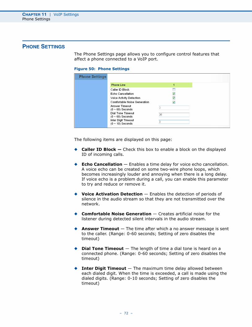
PHONE SETTINGS
The Phone Settings page allows you to configure control features that affect a phone connected to a VoIP port.
Figure 50: Phone Settings
The following items are displayed on this page:
◆ Caller ID Block — Check this box to enable a block on the displayed ID of incoming calls.
◆ Echo Cancellation — Enables a time delay for voice echo cancellation. A voice echo can be created on some two-wire phone loops, which becomes increasingly louder and annoying when there is a long delay. If voice echo is a problem during a call, you can enable this parameter to try and reduce or remove it.
◆ Voice Activation Detection — Enables the detection of periods of silence in the audio stream so that they are not transmitted over the network.
◆ Comfortable Noise Generation — Creates artificial noise for the listener during detected silent intervals in the audio stream.
◆ Answer Timeout — The time after which a no answer message is sent to the caller. (Range: 0-60 seconds; Setting of zero disables the timeout)
◆ Dial Tone Timeout — The length of time a dial tone is heard on a connected phone. (Range: 0-60 seconds; Setting of zero disables the timeout)
◆ Inter Digit Timeout — The maximum time delay allowed between each dialed digit. When the time is exceeded, a call is made using the dialed digits. (Range: 0-10 seconds; Setting of zero disables the timeout)
– 72 –
CHAPTER 11 | VoIP SettingsCodecs
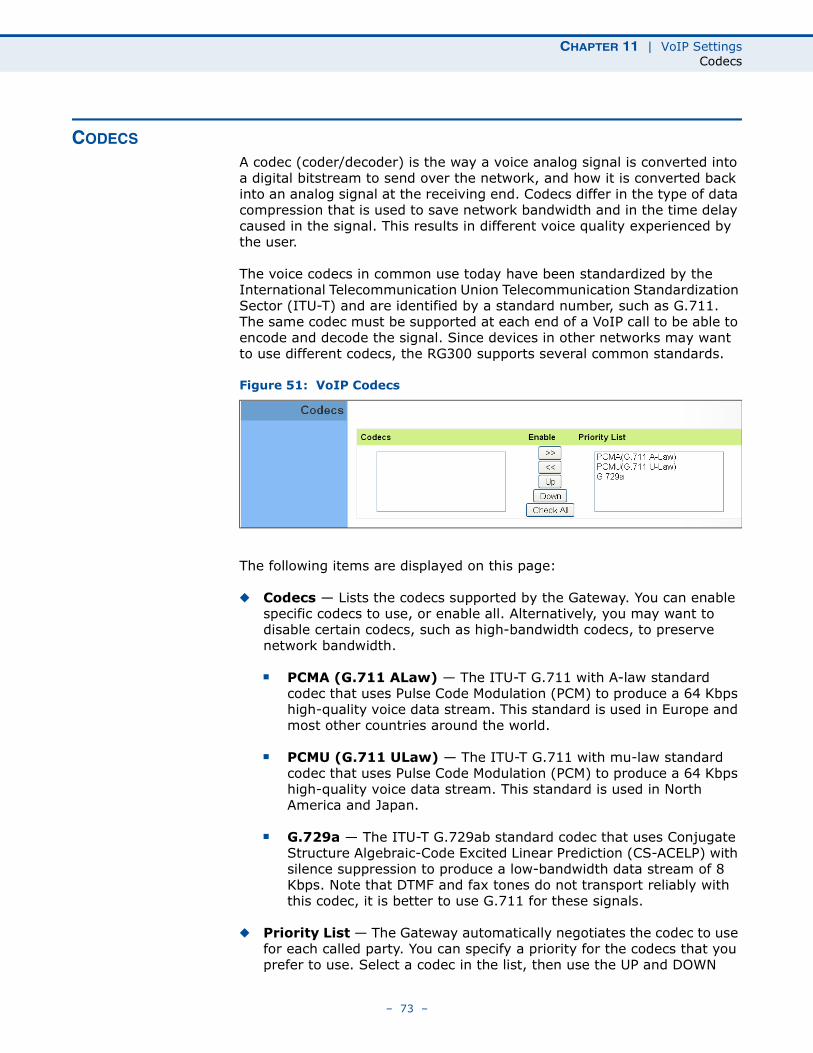
CODECS
A codec (coder/decoder) is the way a voice analog signal is converted into a digital bitstream to send over the network, and how it is converted back into an analog signal at the receiving end. Codecs differ in the type of data compression that is used to save network bandwidth and in the time delay caused in the signal. This results in different voice quality experienced by the user.
The voice codecs in common use today have been standardized by the International Telecommunication Union Telecommunication Standardization Sector (ITU-T) and are identified by a standard number, such as G.711. The same codec must be supported at each end of a VoIP call to be able to encode and decode the signal. Since devices in other networks may want to use different codecs, the RG300 supports several common standards.
Figure 51: VoIP Codecs
The following items are displayed on this page:
◆ Codecs — Lists the codecs supported by the Gateway. You can enable specific codecs to use, or enable all. Alternatively, you may want to disable certain codecs, such as high-bandwidth codecs, to preserve network bandwidth.
■ PCMA (G.711 ALaw) — The ITU-T G.711 with A-law standard codec that uses Pulse Code Modulation (PCM) to produce a 64 Kbps high-quality voice data stream. This standard is used in Europe and most other countries around the world.
■ PCMU (G.711 ULaw) — The ITU-T G.711 with mu-law standard codec that uses Pulse Code Modulation (PCM) to produce a 64 Kbps high-quality voice data stream. This standard is used in North America and Japan.
■ G.729a — The ITU-T G.729ab standard codec that uses Conjugate Structure Algebraic-Code Excited Linear Prediction (CS-ACELP) with silence suppression to produce a low-bandwidth data stream of 8 Kbps. Note that DTMF and fax tones do not transport reliably with this codec, it is better to use G.711 for these signals.
◆ Priority List — The Gateway automatically negotiates the codec to use for each called party. You can specify a priority for the codecs that you prefer to use. Select a codec in the list, then use the UP and DOWN
– 73 –

CHAPTER 11 | VoIP SettingsCodecs
buttons to set the priority. The Gateway attempts to use the codec highest in the list before trying the next lower one.
– 74 –
12 WI-FI SETTINGS
The RG300 includes an IEEE 802.11n radio interface for local Wi-Fi communications. The Wi-Fi set up pages include configuration options for the radio signal characteristics and Wi-Fi security.
The Wi-Fi configuration pages include the following options:
◆ “Basic Wireless Settings” on page 76
◆ “Advanced Wireless Settings” on page 78
◆ “Wireless Security” on page 79
◆ “ACL Settings” on page 83
– 75 –
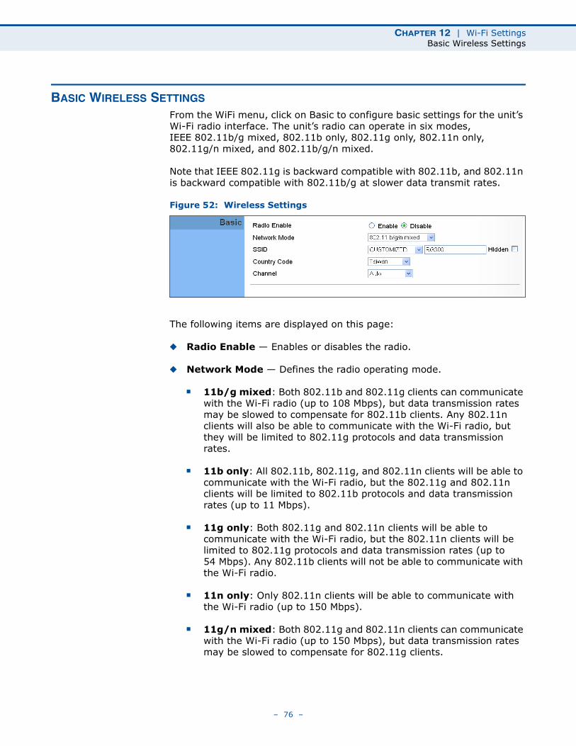
CHAPTER 12 | Wi-Fi SettingsBasic Wireless Settings
BASIC WIRELESS SETTINGS
From the WiFi menu, click on Basic to configure basic settings for the unit’s Wi-Fi radio interface. The unit’s radio can operate in six modes, IEEE 802.11b/g mixed, 802.11b only, 802.11g only, 802.11n only, 802.11g/n mixed, and 802.11b/g/n mixed.
Note that IEEE 802.11g is backward compatible with 802.11b, and 802.11n is backward compatible with 802.11b/g at slower data transmit rates.
Figure 52: Wireless Settings
The following items are displayed on this page:
◆ Radio Enable — Enables or disables the radio.
◆ Network Mode — Defines the radio operating mode.
■ 11b/g mixed: Both 802.11b and 802.11g clients can communicate with the Wi-Fi radio (up to 108 Mbps), but data transmission rates may be slowed to compensate for 802.11b clients. Any 802.11n clients will also be able to communicate with the Wi-Fi radio, but they will be limited to 802.11g protocols and data transmission rates.
■ 11b only: All 802.11b, 802.11g, and 802.11n clients will be able to communicate with the Wi-Fi radio, but the 802.11g and 802.11n clients will be limited to 802.11b protocols and data transmission rates (up to 11 Mbps).
■ 11g only: Both 802.11g and 802.11n clients will be able to communicate with the Wi-Fi radio, but the 802.11n clients will be limited to 802.11g protocols and data transmission rates (up to 54 Mbps). Any 802.11b clients will not be able to communicate with the Wi-Fi radio.
■ 11n only: Only 802.11n clients will be able to communicate with the Wi-Fi radio (up to 150 Mbps).
■ 11g/n mixed: Both 802.11g and 802.11n clients can communicate with the Wi-Fi radio (up to 150 Mbps), but data transmission rates may be slowed to compensate for 802.11g clients.
– 76 –
CHAPTER 12 | Wi-Fi SettingsBasic Wireless Settings
■ 11b/g/n Mixed: All 802.11b/g/n clients can communicate with the Wi-Fi radio (up to 150 Mbps), but data transmission rates may be slowed to compensate for 802.11b/g clients.
◆ SSID — The name of the wireless network service provided by the Wi-Fi radio. Clients that want to connect to the network must set their SSID to the same as that of the Wi-Fi radio. Select “CUSTOMIZED” to set a specific text string, or select “MAC” to use the device MAC address as the SSID. (Range: 1-32 characters)
◆ Hidden — By default, the Wi-Fi radio always broadcasts the SSID in its beacon signal. Disabling the SSID broadcast increases security of the network because wireless clients need to already know the SSID before attempting to connect.
◆ Country Code — The country code restricts operation of the Wi-Fi radio to the channels and transmit power levels permitted for Wi-Fi networks in the specified region. You must set the correct Country Code to be sure the radio conforms to local regulations. (Options: United States, Japan, France, Taiwan, Ireland)
CAUTION: You must set the country code to the country of operation. Setting the country code restricts operation of the access point to the radio channels and transmit power levels permitted for wireless networks in the specified country.
◆ Channel — The radio channel that the Wi-Fi radio uses to communicate with wireless clients. When multiple access points are deployed in the same area, set the channel on neighboring access points at least five channels apart to avoid interference with each other. For example, you can deploy up to three access points in the same area using channels 1, 6, 11. Note that wireless clients automatically set the channel to the same as that used by the Wi-Fi radio to which it is linked. Selecting Auto Select enables the Wi-Fi radio to automatically select an unoccupied radio channel.
NOTE: If you experience poor performance, you may be encountering interference from another wireless device. Try changing the channel, as this may eliminate interference and increase performance. Channels 1, 6, and 11, as the three non-overlapping channels in the 2.4 GHz band, are preferred.
– 77 –
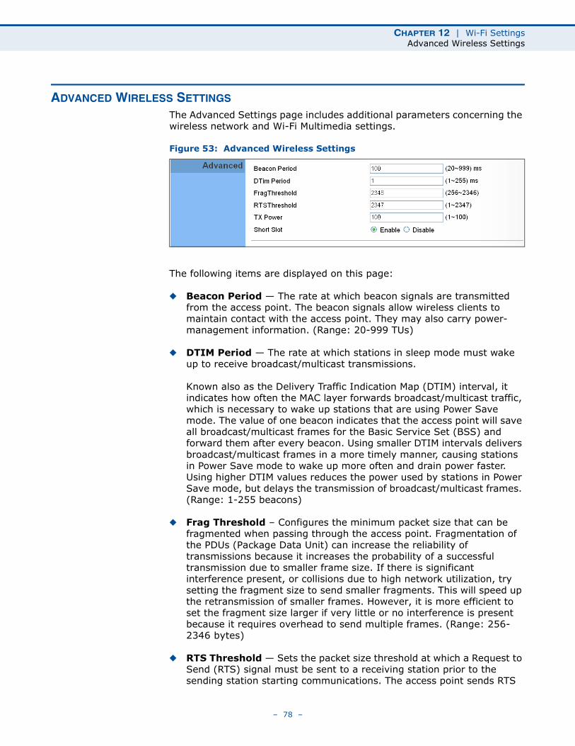
CHAPTER 12 | Wi-Fi SettingsAdvanced Wireless Settings
ADVANCED WIRELESS SETTINGS
The Advanced Settings page includes additional parameters concerning the wireless network and Wi-Fi Multimedia settings.
Figure 53: Advanced Wireless Settings
The following items are displayed on this page:
◆ Beacon Period — The rate at which beacon signals are transmitted from the access point. The beacon signals allow wireless clients to maintain contact with the access point. They may also carry power-management information. (Range: 20-999 TUs)
◆ DTIM Period — The rate at which stations in sleep mode must wake up to receive broadcast/multicast transmissions.
Known also as the Delivery Traffic Indication Map (DTIM) interval, it indicates how often the MAC layer forwards broadcast/multicast traffic, which is necessary to wake up stations that are using Power Save mode. The value of one beacon indicates that the access point will save all broadcast/multicast frames for the Basic Service Set (BSS) and forward them after every beacon. Using smaller DTIM intervals delivers broadcast/multicast frames in a more timely manner, causing stations in Power Save mode to wake up more often and drain power faster. Using higher DTIM values reduces the power used by stations in Power Save mode, but delays the transmission of broadcast/multicast frames. (Range: 1-255 beacons)
◆ Frag Threshold – Configures the minimum packet size that can be fragmented when passing through the access point. Fragmentation of the PDUs (Package Data Unit) can increase the reliability of transmissions because it increases the probability of a successful transmission due to smaller frame size. If there is significant interference present, or collisions due to high network utilization, try setting the fragment size to send smaller fragments. This will speed up the retransmission of smaller frames. However, it is more efficient to set the fragment size larger if very little or no interference is present because it requires overhead to send multiple frames. (Range: 256-2346 bytes)
◆ RTS Threshold — Sets the packet size threshold at which a Request to Send (RTS) signal must be sent to a receiving station prior to the sending station starting communications. The access point sends RTS
– 78 –
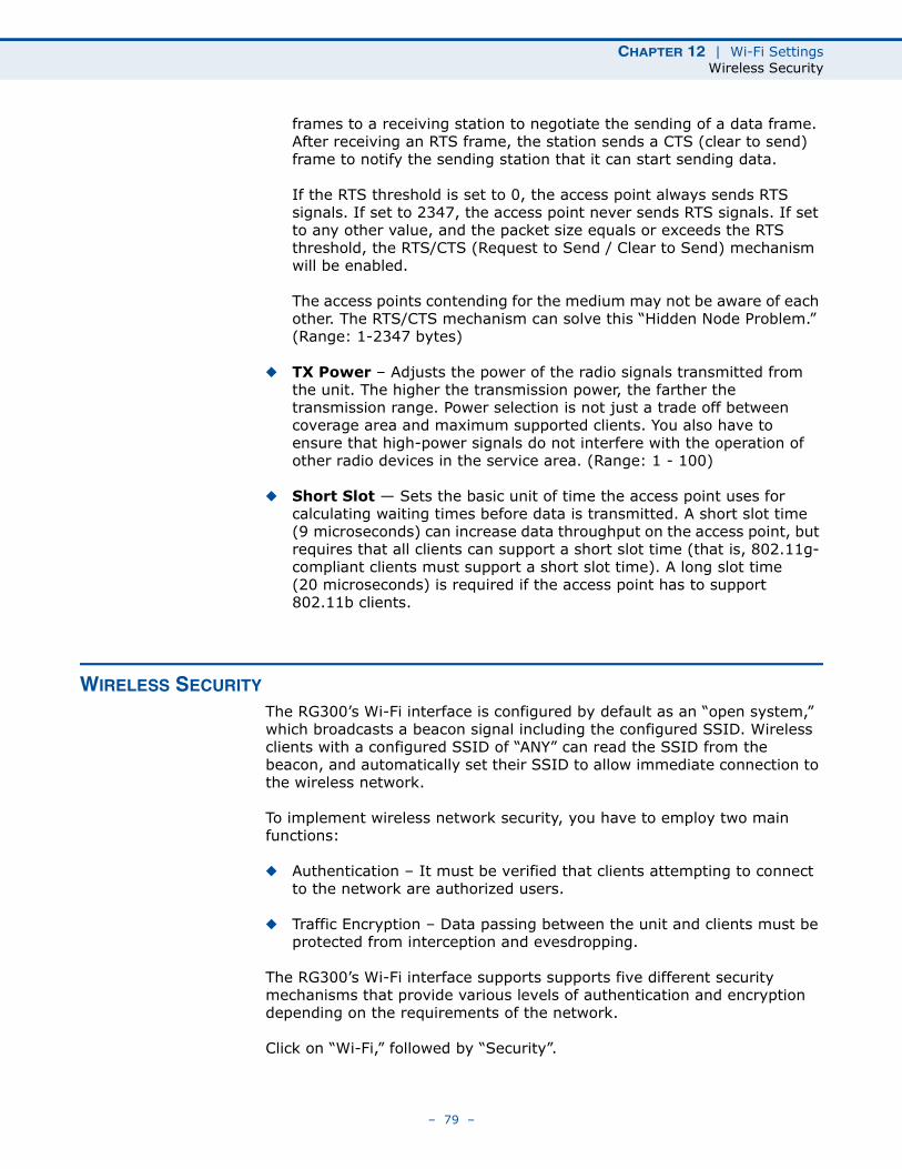
CHAPTER 12 | Wi-Fi SettingsWireless Security
frames to a receiving station to negotiate the sending of a data frame. After receiving an RTS frame, the station sends a CTS (clear to send) frame to notify the sending station that it can start sending data.
If the RTS threshold is set to 0, the access point always sends RTS signals. If set to 2347, the access point never sends RTS signals. If set to any other value, and the packet size equals or exceeds the RTS threshold, the RTS/CTS (Request to Send / Clear to Send) mechanism will be enabled.
The access points contending for the medium may not be aware of each other. The RTS/CTS mechanism can solve this “Hidden Node Problem.” (Range: 1-2347 bytes)
◆ TX Power – Adjusts the power of the radio signals transmitted from the unit. The higher the transmission power, the farther the transmission range. Power selection is not just a trade off between coverage area and maximum supported clients. You also have to ensure that high-power signals do not interfere with the operation of other radio devices in the service area. (Range: 1 - 100)
◆ Short Slot — Sets the basic unit of time the access point uses for calculating waiting times before data is transmitted. A short slot time (9 microseconds) can increase data throughput on the access point, but requires that all clients can support a short slot time (that is, 802.11g-compliant clients must support a short slot time). A long slot time (20 microseconds) is required if the access point has to support 802.11b clients.
WIRELESS SECURITY
The RG300’s Wi-Fi interface is configured by default as an “open system,” which broadcasts a beacon signal including the configured SSID. Wireless clients with a configured SSID of “ANY” can read the SSID from the beacon, and automatically set their SSID to allow immediate connection to the wireless network.
To implement wireless network security, you have to employ two main functions:
◆ Authentication – It must be verified that clients attempting to connect to the network are authorized users.
◆ Traffic Encryption – Data passing between the unit and clients must be protected from interception and evesdropping.
The RG300’s Wi-Fi interface supports supports five different security mechanisms that provide various levels of authentication and encryption depending on the requirements of the network.
Click on “Wi-Fi,” followed by “Security”.
– 79 –
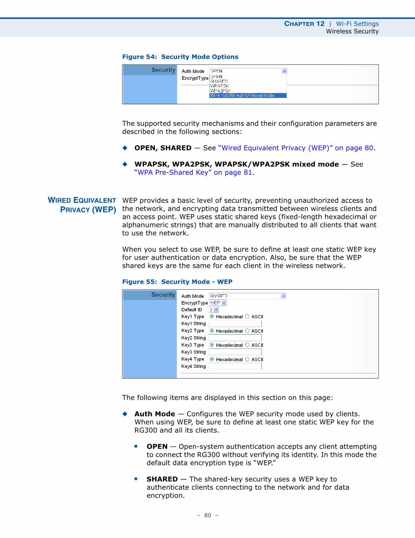
CHAPTER 12 | Wi-Fi SettingsWireless Security
Figure 54: Security Mode Options
The supported security mechanisms and their configuration parameters are described in the following sections:
◆ OPEN, SHARED — See “Wired Equivalent Privacy (WEP)” on page 80.
◆ WPAPSK, WPA2PSK, WPAPSK/WPA2PSK mixed mode — See “WPA Pre-Shared Key” on page 81.
WIRED EQUIVALENTPRIVACY (WEP)
WEP provides a basic level of security, preventing unauthorized access to the network, and encrypting data transmitted between wireless clients and an access point. WEP uses static shared keys (fixed-length hexadecimal or alphanumeric strings) that are manually distributed to all clients that want to use the network.
When you select to use WEP, be sure to define at least one static WEP key for user authentication or data encryption. Also, be sure that the WEP shared keys are the same for each client in the wireless network.
Figure 55: Security Mode - WEP
The following items are displayed in this section on this page:
◆ Auth Mode — Configures the WEP security mode used by clients. When using WEP, be sure to define at least one static WEP key for the RG300 and all its clients.
■ OPEN — Open-system authentication accepts any client attempting to connect the RG300 without verifying its identity. In this mode the default data encryption type is “WEP.”
■ SHARED — The shared-key security uses a WEP key to authenticate clients connecting to the network and for data encryption.
– 80 –
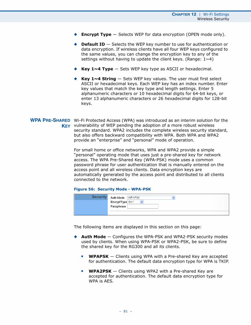
CHAPTER 12 | Wi-Fi SettingsWireless Security
◆ Encrypt Type — Selects WEP for data encryption (OPEN mode only).
◆ Default ID — Selects the WEP key number to use for authentication or data encryption. If wireless clients have all four WEP keys configured to the same values, you can change the encryption key to any of the settings without having to update the client keys. (Range: 1~4)
◆ Key 1~4 Type — Sets WEP key type as ASCII or hexadecimal.
◆ Key 1~4 String — Sets WEP key values. The user must first select ASCII or hexadecimal keys. Each WEP key has an index number. Enter key values that match the key type and length settings. Enter 5 alphanumeric characters or 10 hexadecimal digits for 64-bit keys, or enter 13 alphanumeric characters or 26 hexadecimal digits for 128-bit keys.
WPA PRE-SHAREDKEY
Wi-Fi Protected Access (WPA) was introduced as an interim solution for the vulnerability of WEP pending the adoption of a more robust wireless security standard. WPA2 includes the complete wireless security standard, but also offers backward compatibility with WPA. Both WPA and WPA2 provide an “enterprise” and “personal” mode of operation.
For small home or office networks, WPA and WPA2 provide a simple “personal” operating mode that uses just a pre-shared key for network access. The WPA Pre-Shared Key (WPA-PSK) mode uses a common password phrase for user authentication that is manually entered on the access point and all wireless clients. Data encryption keys are automatically generated by the access point and distributed to all clients connected to the network.
Figure 56: Security Mode - WPA-PSK
The following items are displayed in this section on this page:
◆ Auth Mode — Configures the WPA-PSK and WPA2-PSK security modes used by clients. When using WPA-PSK or WPA2-PSK, be sure to define the shared key for the RG300 and all its clients.
■ WPAPSK — Clients using WPA with a Pre-shared Key are accepted for authentication. The default data encryption type for WPA is TKIP.
■ WPA2PSK — Clients using WPA2 with a Pre-shared Key are accepted for authentication. The default data encryption type for WPA is AES.
– 81 –
CHAPTER 12 | Wi-Fi SettingsWireless Security
■ WPAPSK/WPA2PSK mixed mode — Clients using WPA or WPA2 with a Pre-shared Key are accepted for authentication. The default data encryption type is TKIP/AES.
◆ EncryptType — Selects the data encryption type to use. (Default is determined by the Security Mode selected.)
■ TKIP — Uses Temporal Key Integrity Protocol (TKIP) keys for encryption. WPA specifies TKIP as the data encryption method to replace WEP. TKIP avoids the problems of WEP static keys by dynamically changing data encryption keys.
■ AES — Uses Advanced Encryption Standard (AES) keys for encryption. WPA2 uses AES Counter-Mode encryption with Cipher Block Chaining Message Authentication Code (CBC-MAC) for message integrity. The AES Counter-Mode/CBCMAC Protocol (AES-CCMP) provides extremely robust data confidentiality using a 128-bit key. Use of AES-CCMP encryption is specified as a standard requirement for WPA2. Before implementing WPA2 in the network, be sure client devices are upgraded to WPA2-compliant hardware.
■ TKIPAES — Uses either TKIP or AES keys for encryption. WPA and WPA2 mixed modes allow both WPA and WPA2 clients to associate to a common SSID. In mixed mode, the unicast encryption type (TKIP or AES) is negotiated for each client.
◆ Pass Phrase — The WPA Preshared Key can be input as an ASCII string (an easy-to-remember form of letters and numbers that can include spaces) or Hexadecimal format. (Range: 8~63 ASCII characters, or exactly 64 Hexadecimal digits)
– 82 –
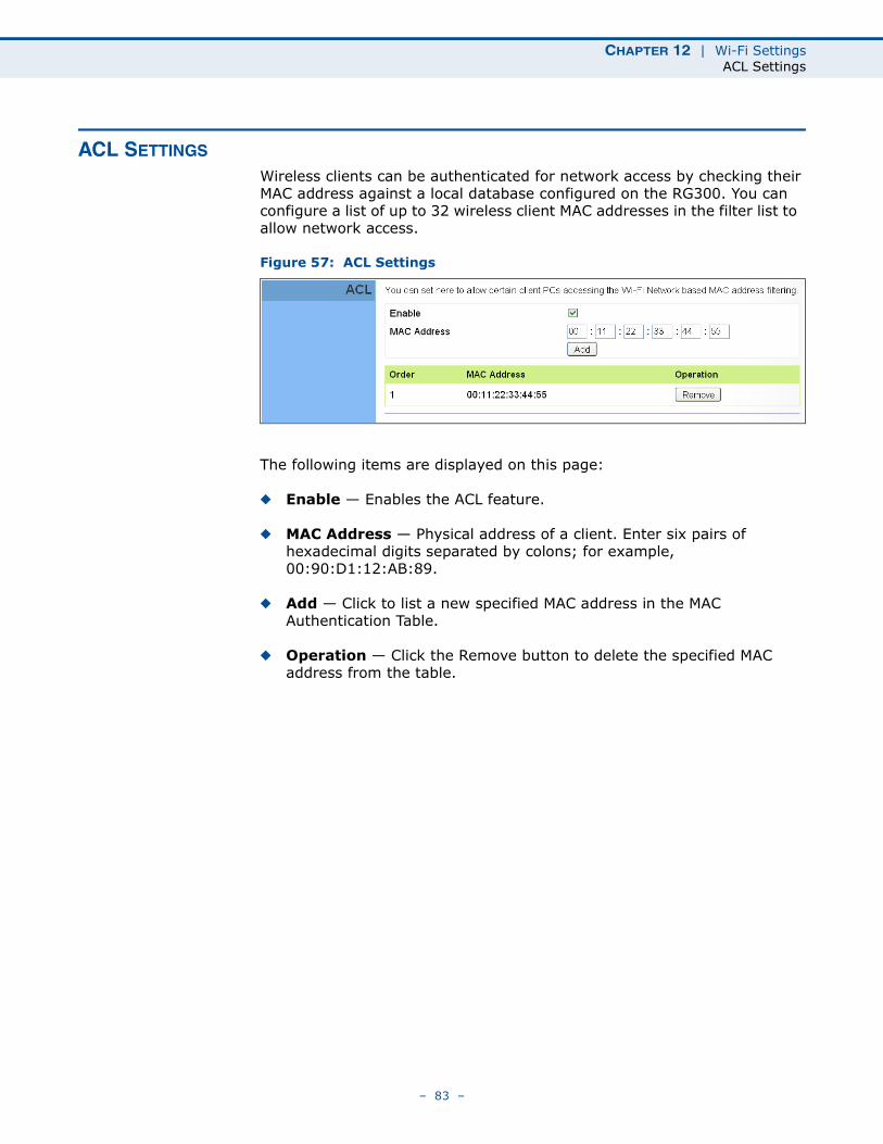
CHAPTER 12 | Wi-Fi SettingsACL Settings
ACL SETTINGS
Wireless clients can be authenticated for network access by checking their MAC address against a local database configured on the RG300. You can configure a list of up to 32 wireless client MAC addresses in the filter list to allow network access.
Figure 57: ACL Settings
The following items are displayed on this page:
◆ Enable — Enables the ACL feature.
◆ MAC Address — Physical address of a client. Enter six pairs of hexadecimal digits separated by colons; for example, 00:90:D1:12:AB:89.
◆ Add — Click to list a new specified MAC address in the MAC Authentication Table.
◆ Operation — Click the Remove button to delete the specified MAC address from the table.
– 83 –
13 QOS CONFIGURATION
The RG300 supports Quality of Service (QoS) settings that enable traffic rate limits to be set for all or specific LAN clients.
The QoS configuration pages include the following options:
◆ “QoS Settings” on page 85
– 84 –
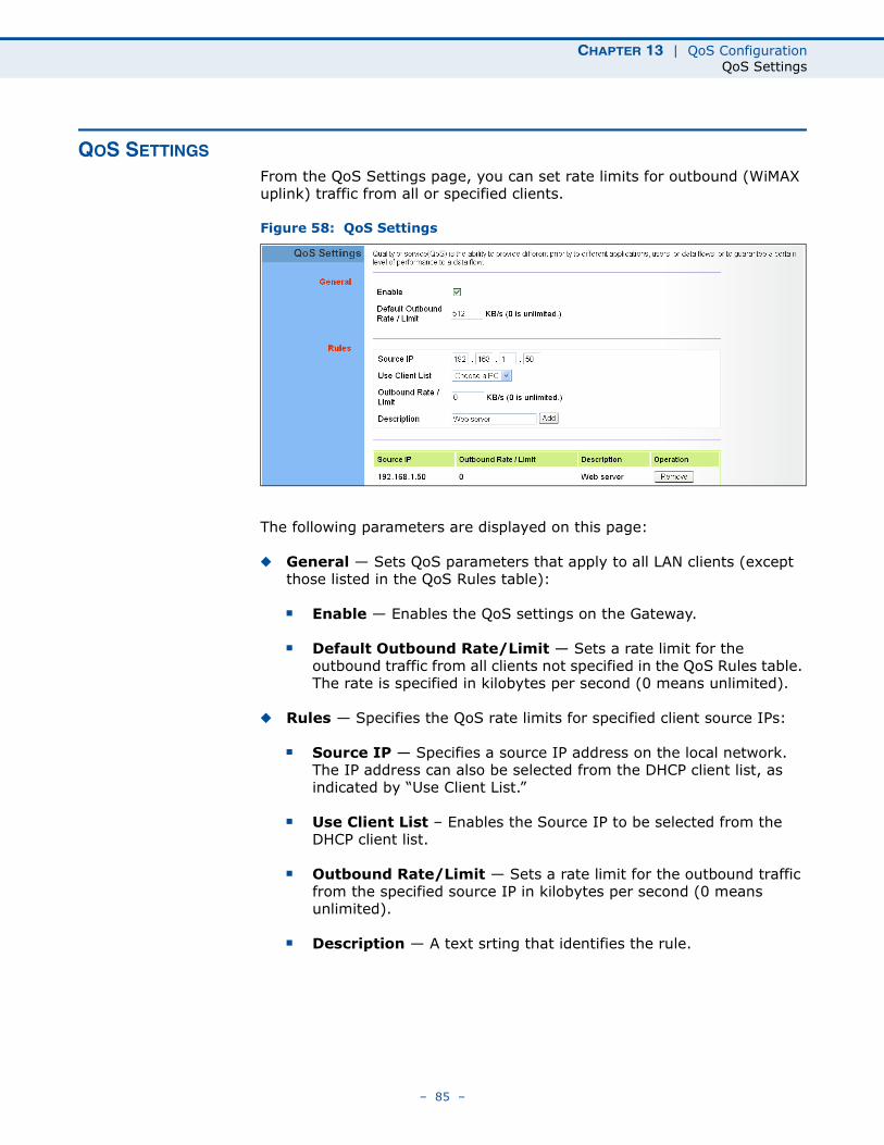
CHAPTER 13 | QoS ConfigurationQoS Settings
QOS SETTINGS
From the QoS Settings page, you can set rate limits for outbound (WiMAX uplink) traffic from all or specified clients.
Figure 58: QoS Settings
The following parameters are displayed on this page:
◆ General — Sets QoS parameters that apply to all LAN clients (except those listed in the QoS Rules table):
■ Enable — Enables the QoS settings on the Gateway.
■ Default Outbound Rate/Limit — Sets a rate limit for the outbound traffic from all clients not specified in the QoS Rules table. The rate is specified in kilobytes per second (0 means unlimited).
◆ Rules — Specifies the QoS rate limits for specified client source IPs:
■ Source IP — Specifies a source IP address on the local network. The IP address can also be selected from the DHCP client list, as indicated by “Use Client List.”
■ Use Client List – Enables the Source IP to be selected from the DHCP client list.
■ Outbound Rate/Limit — Sets a rate limit for the outbound traffic from the specified source IP in kilobytes per second (0 means unlimited).
■ Description — A text srting that identifies the rule.
– 85 –
SECTION III
APPENDICES
This section provides additional information and includes these items:
◆ “Troubleshooting” on page 87
◆ “Hardware Specifications” on page 89
◆ “Cables and Pinouts” on page 93
– 86 –
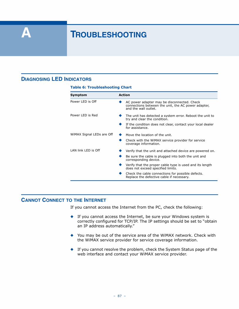
A TROUBLESHOOTING
DIAGNOSING LED INDICATORS
CANNOT CONNECT TO THE INTERNET
If you cannot access the Internet from the PC, check the following:
◆ If you cannot access the Internet, be sure your Windows system is correctly configured for TCP/IP. The IP settings should be set to “obtain an IP address automatically.”
◆ You may be out of the service area of the WiMAX network. Check with the WiMAX service provider for service coverage information.
◆ If you cannot resolve the problem, check the System Status page of the web interface and contact your WiMAX service provider.
Table 6: Troubleshooting Chart
Symptom Action
Power LED is Off ◆ AC power adapter may be disconnected. Check connections between the unit, the AC power adapter, and the wall outlet.
Power LED is Red ◆ The unit has detected a system error. Reboot the unit to try and clear the condition.
◆ If the condition does not clear, contact your local dealer for assistance.
WiMAX Signal LEDs are Off ◆ Move the location of the unit.
◆ Check with the WiMAX service provider for service coverage information.
LAN link LED is Off ◆ Verify that the unit and attached device are powered on.
◆ Be sure the cable is plugged into both the unit and corresponding device.
◆ Verify that the proper cable type is used and its length does not exceed specified limits.
◆ Check the cable connections for possible defects. Replace the defective cable if necessary.
– 87 –
APPENDIX A | TroubleshootingCannot Access Web Management
CANNOT ACCESS WEB MANAGEMENT
If the management interface cannot be accessed using a web browser:
◆ Be sure the management station is correctly configured for TCP/IP. The IP settings should be set to “obtain an IP address automatically.”
◆ Try a Ping command from the management station to the unit’s IP address to verify that the entire network path between the two devices is functioning correctly.
◆ Check that the management station has a valid network connection and that the Ethernet port that you are using has not been disabled.
◆ Check the network cabling between the management station and the unit. If the problem is not resolved, try using a different port or a different cable.
FORGOT OR LOST THE PASSWORD
Set the unit to its default configuration by pressing the reset button on the base for 5 seconds or more. Then use the default password to access the management interface.
RESETTING THE UNIT
If all other recovery measures fail and the unit is still not functioning properly, take either of these steps:
◆ Reset the unit using the web interface, or through a power reset.
◆ Reset the unit to its factory default configuration by pressing the reset button on the base for 5 seconds or more. Then use the default password to access the management interface.
– 88 –
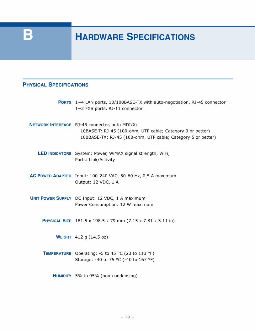
B HARDWARE SPECIFICATIONS
PHYSICAL SPECIFICATIONS
PORTS 1~4 LAN ports, 10/100BASE-TX with auto-negotiation, RJ-45 connector1~2 FXS ports, RJ-11 connector
NETWORK INTERFACE RJ-45 connector, auto MDI/X:10BASE-T: RJ-45 (100-ohm, UTP cable; Category 3 or better)100BASE-TX: RJ-45 (100-ohm, UTP cable; Category 5 or better)
LED INDICATORS System: Power, WiMAX signal strength, WiFi,Ports: Link/Activity
AC POWER ADAPTER Input: 100-240 VAC, 50-60 Hz, 0.5 A maximumOutput: 12 VDC, 1 A
UNIT POWER SUPPLY DC Input: 12 VDC, 1 A maximumPower Consumption: 12 W maximum
PHYSICAL SIZE 181.5 x 198.5 x 79 mm (7.15 x 7.81 x 3.11 in)
WEIGHT 412 g (14.5 oz)
TEMPERATURE Operating: -5 to 45 °C (23 to 113 °F)Storage: -40 to 75 °C (-40 to 167 °F)
HUMIDITY 5% to 95% (non-condensing)
– 89 –
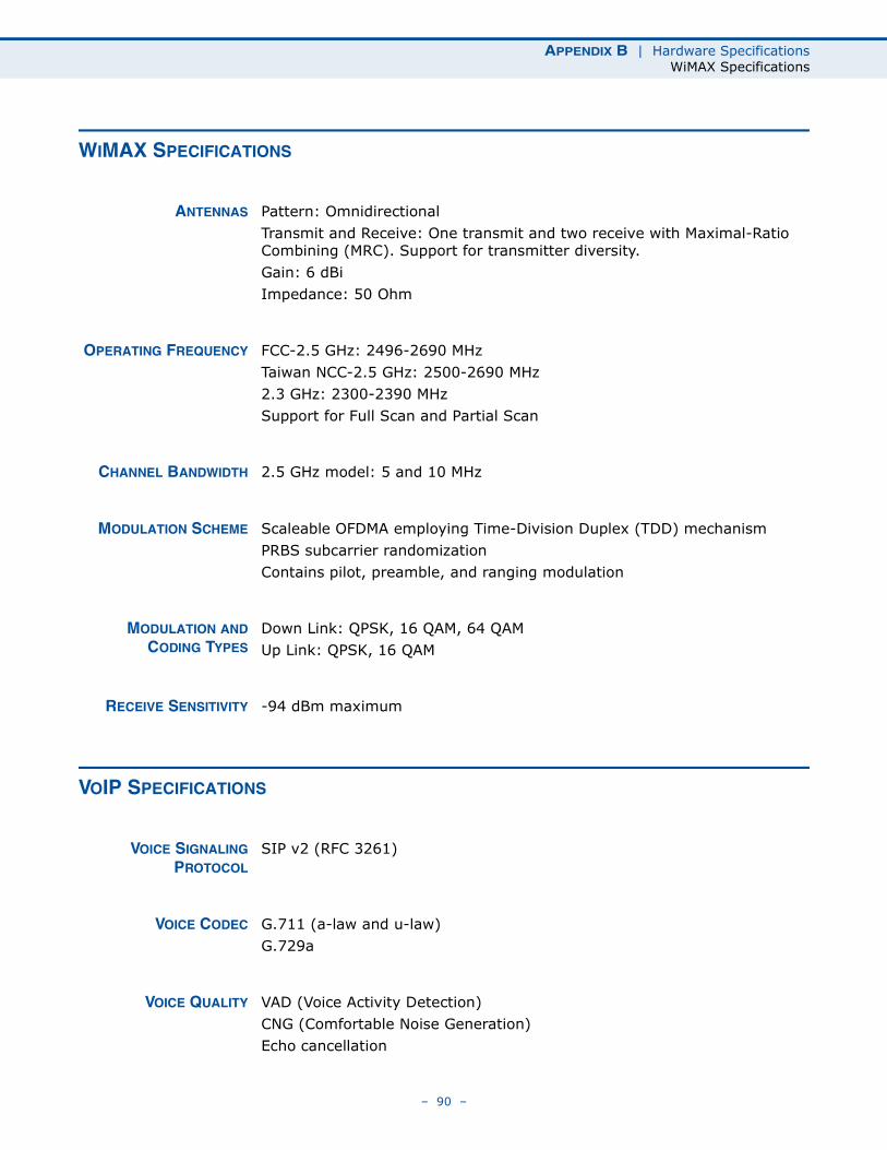
APPENDIX B | Hardware SpecificationsWiMAX Specifications
WIMAX SPECIFICATIONS
ANTENNAS Pattern: OmnidirectionalTransmit and Receive: One transmit and two receive with Maximal-Ratio Combining (MRC). Support for transmitter diversity.Gain: 6 dBi Impedance: 50 Ohm
OPERATING FREQUENCY FCC-2.5 GHz: 2496-2690 MHzTaiwan NCC-2.5 GHz: 2500-2690 MHz2.3 GHz: 2300-2390 MHzSupport for Full Scan and Partial Scan
CHANNEL BANDWIDTH 2.5 GHz model: 5 and 10 MHz
MODULATION SCHEME Scaleable OFDMA employing Time-Division Duplex (TDD) mechanismPRBS subcarrier randomizationContains pilot, preamble, and ranging modulation
MODULATION ANDCODING TYPES
Down Link: QPSK, 16 QAM, 64 QAMUp Link: QPSK, 16 QAM
RECEIVE SENSITIVITY -94 dBm maximum
VOIP SPECIFICATIONS
VOICE SIGNALINGPROTOCOL
SIP v2 (RFC 3261)
VOICE CODEC G.711 (a-law and u-law)G.729a
VOICE QUALITY VAD (Voice Activity Detection)CNG (Comfortable Noise Generation)Echo cancellation
– 90 –
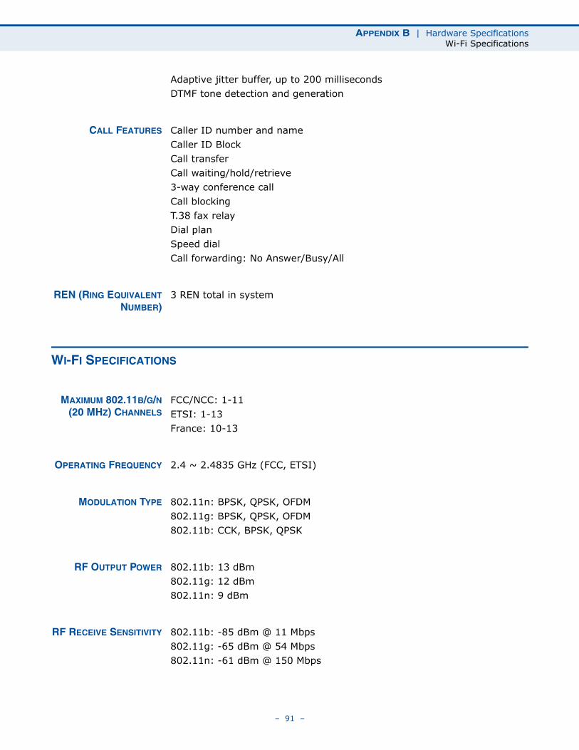
APPENDIX B | Hardware SpecificationsWi-Fi Specifications
Adaptive jitter buffer, up to 200 millisecondsDTMF tone detection and generation
CALL FEATURES Caller ID number and nameCaller ID BlockCall transferCall waiting/hold/retrieve3-way conference callCall blockingT.38 fax relayDial planSpeed dialCall forwarding: No Answer/Busy/All
REN (RING EQUIVALENTNUMBER)
3 REN total in system
WI-FI SPECIFICATIONS
MAXIMUM 802.11B/G/N(20 MHZ) CHANNELS
FCC/NCC: 1-11ETSI: 1-13 France: 10-13
OPERATING FREQUENCY 2.4 ~ 2.4835 GHz (FCC, ETSI)
MODULATION TYPE 802.11n: BPSK, QPSK, OFDM802.11g: BPSK, QPSK, OFDM802.11b: CCK, BPSK, QPSK
RF OUTPUT POWER 802.11b: 13 dBm802.11g: 12 dBm802.11n: 9 dBm
RF RECEIVE SENSITIVITY 802.11b: -85 dBm @ 11 Mbps802.11g: -65 dBm @ 54 Mbps802.11n: -61 dBm @ 150 Mbps
– 91 –
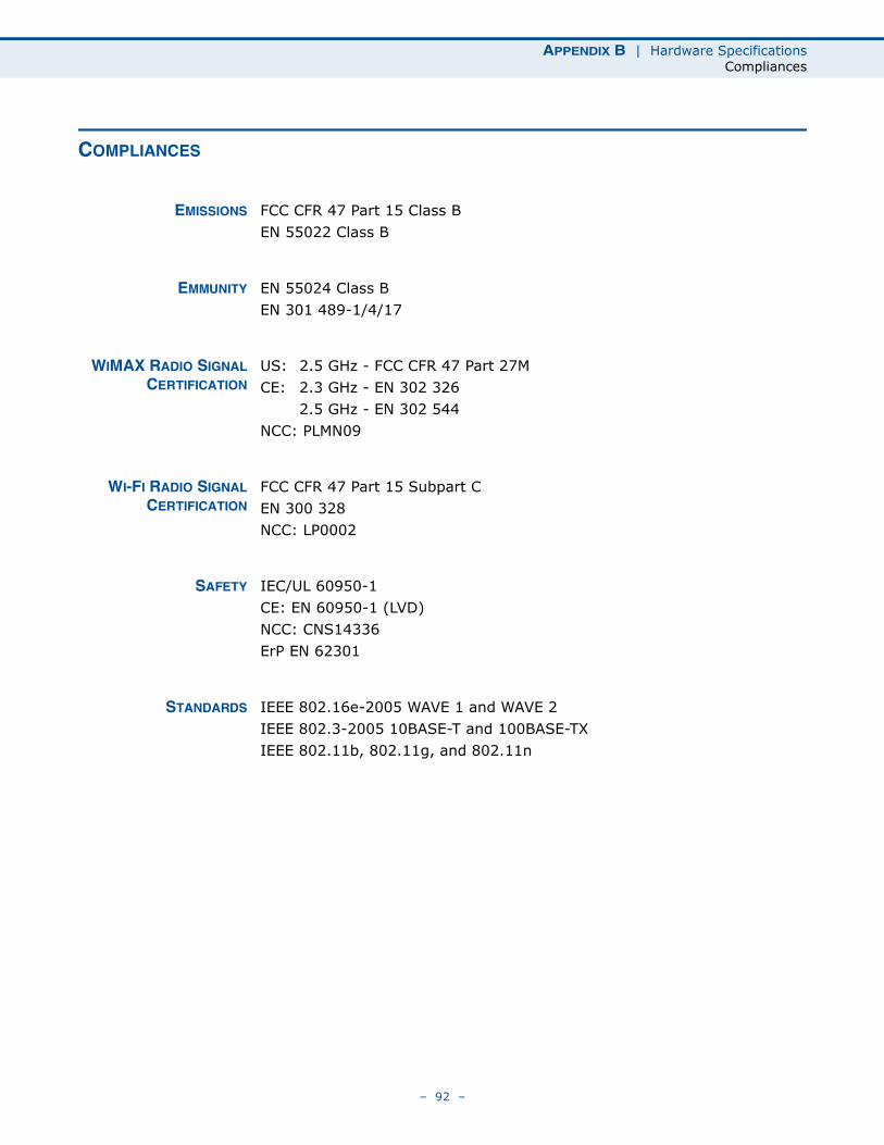
APPENDIX B | Hardware SpecificationsCompliances
COMPLIANCES
EMISSIONS FCC CFR 47 Part 15 Class BEN 55022 Class B
EMMUNITY EN 55024 Class BEN 301 489-1/4/17
WIMAX RADIO SIGNALCERTIFICATION
US: 2.5 GHz - FCC CFR 47 Part 27MCE: 2.3 GHz - EN 302 326
2.5 GHz - EN 302 544NCC: PLMN09
WI-FI RADIO SIGNALCERTIFICATION
FCC CFR 47 Part 15 Subpart CEN 300 328NCC: LP0002
SAFETY IEC/UL 60950-1CE: EN 60950-1 (LVD)NCC: CNS14336ErP EN 62301
STANDARDS IEEE 802.16e-2005 WAVE 1 and WAVE 2IEEE 802.3-2005 10BASE-T and 100BASE-TX IEEE 802.11b, 802.11g, and 802.11n
– 92 –
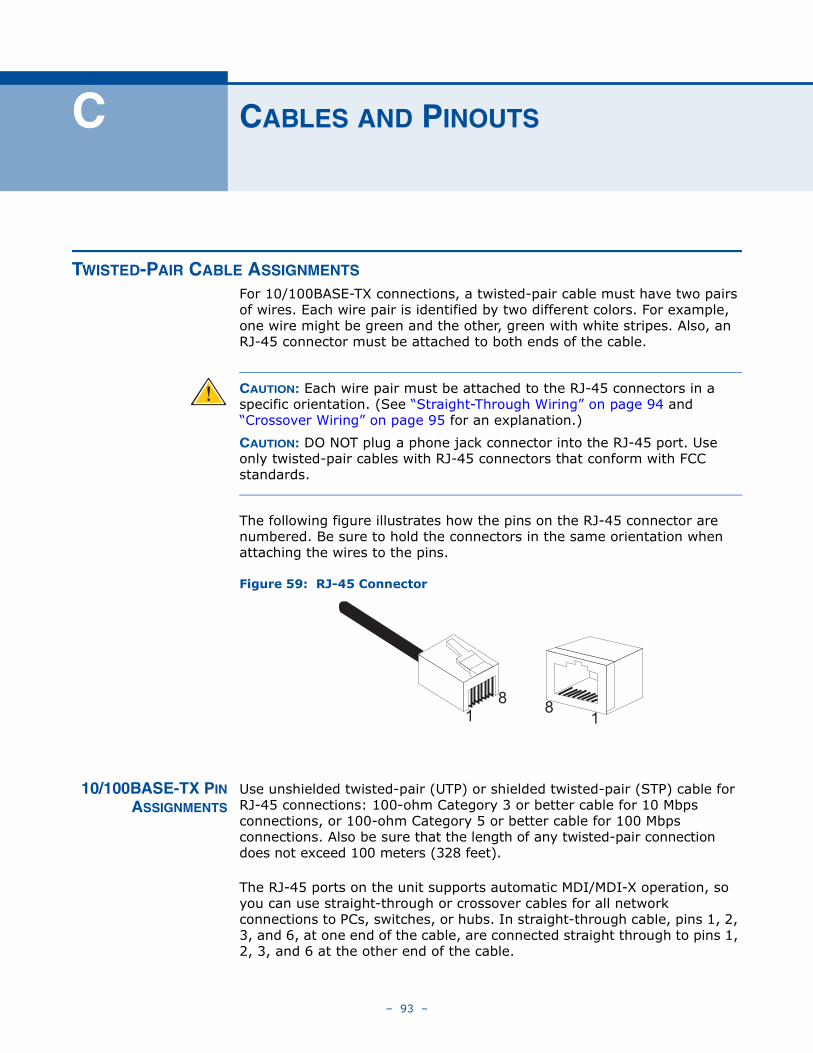
C CABLES AND PINOUTS
TWISTED-PAIR CABLE ASSIGNMENTS For 10/100BASE-TX connections, a twisted-pair cable must have two pairs of wires. Each wire pair is identified by two different colors. For example, one wire might be green and the other, green with white stripes. Also, an RJ-45 connector must be attached to both ends of the cable.
CAUTION: Each wire pair must be attached to the RJ-45 connectors in a specific orientation. (See “Straight-Through Wiring” on page 94 and “Crossover Wiring” on page 95 for an explanation.)
CAUTION: DO NOT plug a phone jack connector into the RJ-45 port. Use only twisted-pair cables with RJ-45 connectors that conform with FCC standards.
The following figure illustrates how the pins on the RJ-45 connector are numbered. Be sure to hold the connectors in the same orientation when attaching the wires to the pins.
Figure 59: RJ-45 Connector
10/100BASE-TX PINASSIGNMENTS
Use unshielded twisted-pair (UTP) or shielded twisted-pair (STP) cable for RJ-45 connections: 100-ohm Category 3 or better cable for 10 Mbps connections, or 100-ohm Category 5 or better cable for 100 Mbps connections. Also be sure that the length of any twisted-pair connection does not exceed 100 meters (328 feet).
The RJ-45 ports on the unit supports automatic MDI/MDI-X operation, so you can use straight-through or crossover cables for all network connections to PCs, switches, or hubs. In straight-through cable, pins 1, 2, 3, and 6, at one end of the cable, are connected straight through to pins 1, 2, 3, and 6 at the other end of the cable.
18
81
– 93 –
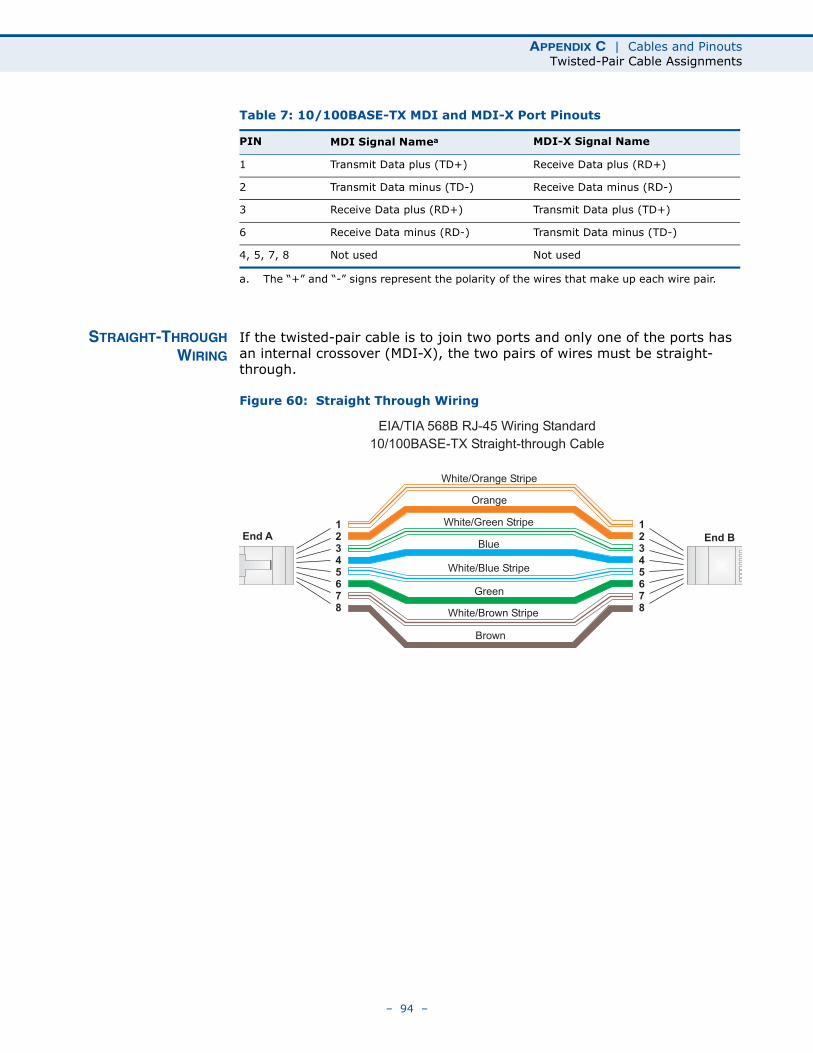
APPENDIX C | Cables and PinoutsTwisted-Pair Cable Assignments
STRAIGHT-THROUGHWIRING
If the twisted-pair cable is to join two ports and only one of the ports has an internal crossover (MDI-X), the two pairs of wires must be straight-through.
Figure 60: Straight Through Wiring
Table 7: 10/100BASE-TX MDI and MDI-X Port Pinouts
PIN MDI Signal Namea
a. The “+” and “-” signs represent the polarity of the wires that make up each wire pair.
MDI-X Signal Name
1 Transmit Data plus (TD+) Receive Data plus (RD+)
2 Transmit Data minus (TD-) Receive Data minus (RD-)
3 Receive Data plus (RD+) Transmit Data plus (TD+)
6 Receive Data minus (RD-) Transmit Data minus (TD-)
4, 5, 7, 8 Not used Not used
White/Orange Stripe
Orange
White/Green Stripe
Green
1
2
3
4
5
6
7
8
1
2
3
4
5
6
7
8
EIA/TIA 568B RJ-45 Wiring Standard
10/100BASE-TX Straight-through Cable
End A End BBlue
White/Blue Stripe
Brown
White/Brown Stripe
– 94 –
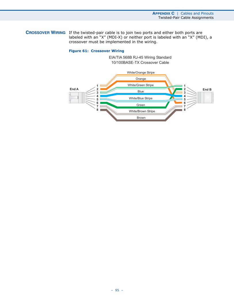
APPENDIX C | Cables and PinoutsTwisted-Pair Cable Assignments
CROSSOVER WIRING If the twisted-pair cable is to join two ports and either both ports are labeled with an “X” (MDI-X) or neither port is labeled with an “X” (MDI), a crossover must be implemented in the wiring.
Figure 61: Crossover Wiring
White/Orange Stripe
Orange
White/Green Stripe1
2
3
4
5
6
7
8
1
2
3
4
5
6
7
8
EIA/TIA 568B RJ-45 Wiring Standard
10/100BASE-TX Crossover Cable
End A End B
Green
Blue
White/Blue Stripe
Brown
White/Brown Stripe
– 95 –
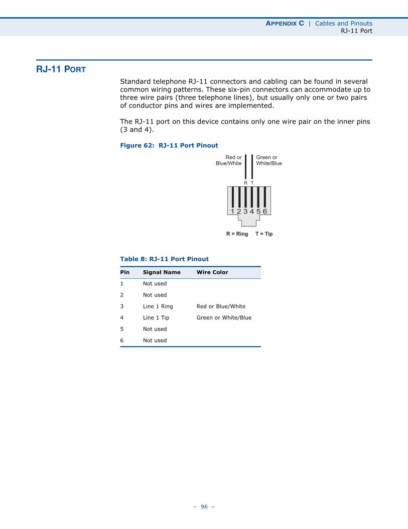
APPENDIX C | Cables and PinoutsRJ-11 Port
RJ-11 PORT
Standard telephone RJ-11 connectors and cabling can be found in several common wiring patterns. These six-pin connectors can accommodate up to three wire pairs (three telephone lines), but usually only one or two pairs of conductor pins and wires are implemented.
The RJ-11 port on this device contains only one wire pair on the inner pins (3 and 4).
Figure 62: RJ-11 Port Pinout
Table 8: RJ-11 Port Pinout
Pin Signal Name Wire Color
1 Not used
2 Not used
3 Line 1 Ring Red or Blue/White
4 Line 1 Tip Green or White/Blue
5 Not used
6 Not used
1 2 3 4 5 6
Red orBlue/White
Green orWhite/Blue
R T
R = Ring T = Tip
– 96 –
GLOSSARY
10BASE-T IEEE 802.3-2005 specification for 10 Mbps Ethernet over two pairs of Category 3 or better UTP cable.
100BASE-TX IEEE 802.3-2005 specification for 100 Mbps Fast Ethernet over two pairs of Category 5 or better UTP cable.
ACCESS POINT An Wi-Fi internetworking device that seamlessly connects wired and wireless networks.
AUTHENTICATION The process to verify the identity of a client requesting network access.
AUTO-NEGOTIATION Signalling method allowing each node to select its optimum operational mode (speed and duplex mode) based on the capabilities of the node to which it is connected.
BASE STATION A WIMAX service provider’s equipment that is installed at a fixed location to provide network connectivity for subscriber stations within a defined service area.
BEACON A signal periodically transmitted from a Wi-Fi access point that is used to identify the network and maintain contact with wireless clients.
CINR Carrier-to-Interference-Plus-Noise Ratio. A measurement of the channel quality in a WiMAX link. Subscriber stations measure the received CINR and send the information back to the base station. The base station can then adjust modulation and coding for the link to optimize throughput.
CENTER FREQUENCY The radio frequency at the center of a WiMAX channel. WiMAX channels can be of different widths (the channel bandwidth) and the transmitted radio signal is spread across the full width of the channel.
CHANNEL BANDWIDTH The range of frequencies occupied by a WiMAX radio signal. The amount of information that can be transmitted in a radio signal is related to the channel bandwidth, which is measured in Megahertz (MHz). WiMAX supports a range of channel bandwidths that can be defined by the service
– 97 –
GLOSSARY
operator depending on performance requirements, operating preferences, and regulatory constraints.
CPE Customer-Premises Equipment. Terminal equipment provided by a service provider that is located at a subscriber’s premises and supports a communication channel between a customer and the service provider.
DNS Domain Name System. A system used for translating host names for network nodes into IP addresses.
DHCP Dynamic Host Configuration Protocol. Provides a framework for passing configuration information to hosts on a TCP/IP network. DHCP is based on the Bootstrap Protocol (BOOTP), adding the capability of automatic allocation of reusable network addresses and additional configuration options.
ENCRYPTION Data passing between a base station and subscribers uses encryption to protect from interception and evesdropping.
ETHERNET A popular local area data communications network, which accepts transmission from computers and terminals.
EAP Extensible Authentication Protocol. An authentication protocol used to authenticate subscribers. EAP is used with TLS or TTLS authentication to provide “mutual authentication” between a subscriber and a WiMAX network.
HTTP Hypertext Transfer Protocol. HTTP is a standard used to transmit and receive all data over the World Wide Web.
ICMP Internet Control Message Protocol. A network layer protocol that reports errors in processing IP packets. ICMP is also used by routers to feed back information about better routing choices.
IEEE 802.11B The Wi-Fi wireless standard that supports communications in the 2.4 GHz band using Direct Sequence Spread Spectrum (DSSS). The standard provides for data rates of 1, 2, 5.5, and 11 Mbps.
IEEE 802.11G The Wi-Fi wireless standard that supports communications in the 2.4 GHz band using using Orthogonal Frequency Division Multiplexing (OFDM). The standard provides for data rates of 6, 9, 11, 12, 18, 24, 36, 48, 54 Mbps. IEEE 802.11g is also backward compatible with IEEE 802.11b.
– 98 –
GLOSSARY
IEEE 802.16E The WiMAX standard that provides mobile broadband wireless access using Scalable Orthogonal Frequency Division Multiple Access (SOFDMA).
IP ADDRESS The Internet Protocol (IP) address is a numerical identification assigned to a device that communicates in a network using the Internet Protocol.
ISP Internet Service Provider. A company that offers an access service that connects customers to the Internet.
LED Light emitting diode. Used for indicating a device or network condition.
LAN Local Area Network. A group of interconnected computer and support devices.
MAC ADDRESS The physical layer address used to uniquely identify network nodes.
MS-CHAPV2 Microsoft’s version 2 of the Challenge-Handshake Authentication Protocol. Introduced by Microsoft with Windows 2000, MS-CHAPV2 (defined in RFC 2759) provides mutual authentication between peers using user names and passwords.
ODFM Orthogonal Frequency Division Multiplexing. The air interface defined for IEEE 802.11g Wi-Fi. OFDM allows multiple users to transmit in an allocated band by dividing the bandwidth into many narrow bandwidth carriers.
RJ-45 CONNECTOR A connector for twisted-pair wiring.
RSSI Receive Signal Strength Indicator. A measurement of the strength of a received wireless signal. The higher the RSSI value, the stronger the received signal from the antenna.
ROAMING The process where a WiMAX subscriber can move onto another operator’s network while maintaining a continuous connection.
SOFDMA Scalable Orthogonal Frequency Division Multiple Access. The air interface defined for mobile WiMAX. SOFDMA is a multiple access method that allows simultaneous transmissions to and from several users, employing a subchannel structure that scales with bandwidth.
SERVICE PROVIDER See Internet Service Provider.
– 99 –
GLOSSARY
SSID Service Set Identifier. A name that is sent in packets over a Wi-Fi network, which functions as a password for clients connecting to the network. The SSID differentiates one Wi-Fi network from another.
SNTP Simple Network Time Protocol. SNTP allows a device to set its internal clock based on periodic updates from a Network Time Protocol (NTP) server. Updates can be requested from a specific NTP server, or can be received via broadcasts sent by NTP servers.
SIM Subscriber Identity Module. A standard for a small removable integrated circuit card that securely stores information used to identify a mobile wireless subscriber.
SUBSCRIBER STATION A general term for a customer’s WIMAX terminal equipment that provides connectivity with a base station.
TCP/IP Transmission Control Protocol/Internet Protocol. Protocol suite that includes TCP as the primary transport protocol, and IP as the network layer protocol.
TLS Transport Layer Security. An standard defined in RFC 5216, EAP-TLS is an authentication protocol that provides strong security through the use of client-side certificates.
TTLS Tunneled Transport Layer Security. EAP-TTLS is a protocol extension of EAP-TLS. The authentication server is authenticated to the client using its Certification Authority certificate, this establishes a secure “tunnel” through which the client is then authenticated.
URL Uniform Resource Locator. An easy-to-read character string that is used to represent a resource available on the Internet. For example, “http://www.url-example.com/.”
UTP Unshielded twisted-pair cable.
WEP Wired Equivalent Privacy. WEP is the Wi-Fi security based on the use of RC4 encryption keys. Wi-Fi devices without a valid WEP key are excluded from the network.
PSK WPA Pre-shared Key. PSK security can be used for small Wi-Fi networks that may not have the resources to configure and maintain a RADIUS
– 100 –
GLOSSARY
server. WPA provides a simple operating mode that uses just a pre-shared password for network access.
WIMAX The IEEE 802.16 standard for Worldwide Interoperability for Microwave Access. The IEEE 802.16-2004 standard, known as “fixed WiMAX,” supports only point-to-point links and has no support for mobility. The IEEE 802.16e-2005 standard, known as “mobile WiMAX,” is an amendment to IEEE 802.16-2004 and supports mobility. Note that mobile WiMAX standard is not backward compatible with the fixed WiMAX standard.
– 101 –
INDEX
AAC power adapter 18administrator password, setting 32administrator settings 32Advanced Setup menu 27AES encryption 82authentication
type 79authentication options 80auto-logout time 33
Bbeacon interval 78button, Reset 18
Ccable assignments 93cable connections 21channel setting 77channels, maximum 91checklist 20client filter, enable 54Codec 73configuration, basic 25contents, package 20
Ddata beacon rate 78default Key, WEP 81default settings, restore 34defaults, factory 34DHCP server 45discard ping 53downloading software 33DTIM setting 78dynamic DNS 43dynamic IP, cable modem 39
Eencryption 79encryption options 80Ethernet ports 17
Ffactory defaults, restoring 34firewall protection 53firmware update 33fixed-IP xDSL 39fragmentation threshold 78frequency setting 77
GGateway address 40, 60gateway function 21
Hhacker attack, prevention 53hardware, description 15
IIEEE 802.11g 75
configuring interface 76initial configuration 23installation, connecting cables 21installing the device 20IP address 40, 45IP filters 54IPsec 51
LL2TP 39, 51LAN status information 31language selection 24, 33LEDs 16, 17logging, system 36login, web 23lost password, recovery 88
MMAC address filters 56MDI/MDI-X, automatic 17messages, logging 36
NNAT setting 48network name, wireless 77
– 102 –
INDEX
Oopen system 79operating frequency 90, 91
Ppackage checklist 20panels, front and rear 15password, setting 32phone settings 72ping discard 53port indicators 16, 17power socket 18power supply, specifications 89PPTP 39, 51private IP 49private port 49proxy server port 66
Rradio mode 76rear panel sockets 18reboot unit 37, 88Reset button 18resetting the unit 37, 88RJ-45 ports 17RTS threshold 78
Ssecurity, options 79Setup Wizard
launching 25Simple Network Time Protocol See SNTPSIP settings 66slot time 79SNTP 35
enabling client 35software update 33SSID 77static routing table 61subnet mask 40, 45, 60subscriber station 14system clock, setting 35system indicators 16, 17system information 32system log 36system time 35
Ttime updates 35TKIP encryption 82
Uupgrading software 33
WWAN connection type 31web management interface
access 23login 23troubleshooting 88
WEP security 80wireless network mode 76Wizard, setup 25WPA pre-shared key 81
– 103 –

RG300E042011-CS-R01149100000095W