william edward, jr. articulated, performance-based
TRANSCRIPT
ED 230 819
AUTHOR*. TITLE
INSTITUTI6N
SPONS AGENCY
PUB DATEkCONTRACTNOTE
PUB TYPE
,
DOCUMENT RESUME
CE 036 367.
Hendersoh/ William Edward, Jr. .
Articulated, Performance-Based Instruction Guide forDrafting II. Final Document. Revised.Greenville County School DistrAct, Greenville, S.C.;Greenville Technical Coll., S.C. f,South Carolina Appilachian Council of Governments,'Greenville.
\- may 83ARC-211-B216p.; For related documents, see ED 220 579-585, CE036 366-368, and CE 036 370-372.Guides Classroom Use - Guides (For Teachers) (052)-- Tests/Evaluation Instruments,(160)
EDRS PRICE MFa1/PC09 Plus Postage.'.
DESCRIPTORS *Architectural Drafting; Articulation. (Education);t Behavibral Objectives; Competency Based Education;Criterion Referenced Tests; Curriculum Guides;*Engideering-Drawing; HighSdhools; Industrial Arts; '
Secondary Education; *Trade and Industrial .
EducatioaIDENTIFIERS *Strpctural Drafting
ABSTRACT --
Developed.during a projeci'designed to providecontinuous, performance-based vocational training at the secondaryand postsecondary levels,,this_instructional guide,is intended tohelp teachers implement A laterally-and vertically.articulatedsecondary level drafting II prog'ram. In'odj.ctory materia include adescription of Drafting II, suggestions for o um successDrafting II, Drafting II options, minimum perforMance standards orDrafting II, discussibri of sample tests provided in ie-,,guide, ansuggested instructional time. Four units are provided. Ihe's-first is 'sNan introduction to Draftifig II and to the three Dsalting II 4tions.The next three,units cover-tbese three OPtions/specializations:fl--)architectural ?rafting, (2) mechanical draftihg, and (3). structuraldrafting. Suggested instructional time and task listings begin eachunit. For each task in a unit, some or all of,the following areprovided: performance objectives, performance actions, performIncestandards, recommended sources, relatgd technical information, andother information the teacher might need. Suggestedoutcome-referenced tests are included. Appendixes includesupplemental topicsand oldtional tasks for DraLt4-4 II, articulationagreements, and test directions. (YLB)
********************************************* ********************,**---*>---Reproduc-tions_ supplied by EDRS e the b that can be made
froth the origina ócument.********4***************************-w**********************************
01.
V.
FINAL DOCUMENTFOR ARTICULATION OF DRAFTING II
Project No. 82-1361Contract No. ARC 211-B
4-1-M-:---M-Ward-Henklerson, Jr.
Coordinator, OcCupational Education Articulation ProgramThe.School District of Greenville CountyP. O. Box 2848 - 301-Camperdown WayGreenville, South Carolina 29602
it
ARTICULATED, PERFORMANCE-BASEDINSTRUCTION GUIDE FOR DRAFTING II
May, 1983
U.S. DEPARTMENT OF EDUCATIONNATIONAL INSTITUTE OF EDUCATION
EDUCATIONAL RESOURCES INFORMATION
CENTER IERIC)) This document tus been reproduced as.mined from the person or organizationonomatmon
.1: Minor changes ,tuve been made to Improvereproduction quality
Points of view or opinions stated in ttusdocumint do not necessarily represent official NiEPosition or policy
"PERMISSION' TO REPRODUCE THISMATERIAL HAS BEEN GRANTED BY
TO THE EDUCATIONALRESOURCES
INFORMATION CENTER (ERIC) "
Occupational Education Articulation Programof The School District of Greenville Countyand Greenville Technical CollegeFunded fn part bySouth Carolina.Appalachian Council of Governments
-*,
IN
ARTICULATED,'PERFORMANCE-BASED CURRICULUM GUIDE
THE SCHOOL DISTRICT OF GREENVILLE COUNTY
DR. J. FLOYD HALLSUPERINTENDENT ,
DR. NORMAN MULLINSASSOCIATE SUPERINTENDENT FOR EDUC ONAL DEVELOPMENT
MRS. DORIS CLANTONDIRECTOR, INSTRUCTIONAL SERVICES
MR. O. RICHARD COTHRAN, JR.CONSULTANT, VOCATIONAL EDUCATION
THE SCHOOL DISTRICTOF GREENVILLE COUNTY
. f
ARTICULATION GUIDE
ANDGREENVILLE
IIECHNICAL COLLEG
7HE SCHOOL DISTRICT OF GREENVILLE COUtkYGREENVILLE,'SOUTH CAROLINA
REVISED)1983
,v
<
Leer
4,
,pISCRIMINA ION P1RIBITED - Title VI of the Civil Rights Act of 1964states: " p person In the United States, shall, on the groundi of race, .
.color, or nhtiopal originybe excluded from participation in, be deniedthe benefit of or be subjected to discriminitiOn.under.any program oractivity receiving federal.financial assistance." Therefore, the Oc--cupational Education ArticulatiOn Program, like all other programs.oractivities receiving fivancial assistance from the Appalachian'CounciLof GovelOPments must be operated in compliance with this law.
V
,The opinions expressed herein .do not nétessarily reflect the positign or, !
'policy of tbe Appalachian Council of Goveriments and no officialendorsemInt by- hat agency should be inferred. -
et
Li 441,
BIAS STATEME
This articulated, performance-based instruction guide has been developedbased upon the tasks (objectivei) and task actionsl(enabling objectives)important to the success of entry level workers in the vocation.) The .
objectives were derived f om task analysis andavailable tasks listssuch as V-TEC Catalogs. he standards of performances are thoseexpected by local busines es and industries for job success. Testsamples are included to represent valid and reliable measures of the ,
mastery of objectives.,
(This articulated, per ormance-based instruction guide has been designedto comply with the requirements of Pl. 94-482 Educational Amendments of1976; Title II, which is intended to "...enente that...cutricula odo notreflect stereotypes based upon sex,,race,'or national'Origin..."
COPYRIGHTED DISCLOSURE S EMENT, A
Every effort has leen made to appropriately, docudie t any copyrightedmaterial psed in this articulated; performance7based trUCtion guide.
,
k
The objectives'and task actions in this guidi'were developed bscon-tributed by task force committee (instructor) participants based-'on,their expertise and on task lists from resources such as CatarbStandards ipcluded in this guide are those identified by local'businesses and industries as important to the sucgess,of entry levelworkers. Sample knowledge and performance tests are included for thepuipose ofrepresenting valid and reliable test items that may be usedto measure mastery of objectives. Test samples taken fram,texts orworkbooks are typically of,those being used locally and appropriatedocumentation has been included.
Wm. Edward Henderson, Jr., CoordinatorOccupational,Education Articulation Program .
The School Dietrict 9f Greenville County19'82
Henderson, 'Wm. Edward, Jr., ed. Articulated, Pe;formancebasedInstruction Guide for Drafting II, Greenville, SC: The SchoolDistrict of Greenville County (Occupational Education ArticulationProgram funded by the South Carolina Appalachian Council ofGovernments), 1983.
ACRNOWLEDGEMENt
This ArticUlated, Performancebased Instruction Guide,for Drafting II is,tqle product of the work of-the following Drafting instructorsrepresenting th eecondary level program of The Sdhool District of .
Greenville Coun y:
- Buford C. GarrettAl WatersJerry SparksRichard Davis
GoldenStrip Vocational CenterDonaldsbn Vocational CenterEnoree Vocational CenterFoothills Vocational Center
The cooperation of these instructors and others representing Tile SchoolDistrict of Greenville County and Greenville Technical College isappreciated.
A
V
ABSTRACT
Title of Project: Occupational Education ArticulaLon Program
Project Coordinator:,
Contracting Agency:
Project Period:
PUR2OSE:
METHOD:
Wm. Edward Henderson, Jr.
The School District of Greenville County401 Camperdown WayP. O. Box 2848Greenville, South Carolina 29602
March 1, 1982 throug February 28, 1983
To develop a continuous program of vocational training intdrafting so that students nay continue their educationthe secondery and post-secondary levels without lossoftime or waste of effRFt in repeating tasks that have beenmastered previously.
To remove unnecessary gaps or overlap in student'learningwhen the student completes a-secondary level program andcontinues career developnent at the post-secondarytechnical...education level.
To provide a system whereby teachers can cooperateeffectively in providing a continuous occupationaldevelopment program-Where the levels and types oftraining that lead to entry-level employment skills willbe clear to students, edueators, and potential employers.
Drafting4nstructors from,the, vocational educationcenters of the secondary,level program of The SchoolDistrict of Greenville County and drafting instructorsfrom the post-secondary level program of GreenvilleTechnical College were brought together in Task ForceCommittee meetings and Wqrkshopi to survey similardrafting training programs and to'identify possibleoverlap or gaps which might be encountered by students asthey continue drafting training from the secondary levelto the post-secondary levil. The kerformance-basedInstruct!onal objectivegiguide developed by the Committee'served as tile main vehicle for articulation. The TaskForce Committee on Drafting, by the task analys4s
'
process, identified diefting competencies for Drafting Iessential for the student desiring to continue-draftingtrainingtor for initial entry into the labor market in --drafting. Performance identified were pl'aced in anappropriate sequential order and assigned instruCtionaltime and performance standards according to theirimportance. Finally, Sample outcome-referenced measuresof those,competenCies were developed for use as. a guidein articulation. .
;
iv
RESULTS: -As a result of this project, ehe product, ArticulatedInstruction Objectives Guide for DraftingL_Kas developed.The Guidg, however, is not an end-product since it mustbe field trial iksted and revised. Modification andimprovement to the Guide are expected,since the processof-education must be .continually reiriewed to ensureobjectives are valid,and are being met as best they canbe met.
,-
In addition, a Policies and Procedures Manual wasdeveloped to assist in continuing and future articulationefforts. Two.subproducts, workshop guides, were,assembled to assist ..Torkshop leaders/coordAnators and
participants in the process of writing objectives,_performance actions, standards, and outcomereferenc9dmeasures in the development of performancebasedcurriculum material.
2'
.4 It t,
fr
I 4e.
Of
PREFACE TO DRAFTING II
The time al/ocated during Phase 0 - March, 1981, to February, 1982) ofthe Ociupational Education A tulation Program did not permit thedevelopment of a perform e-based descrip,tion of Drafting II. TheDrafting Task ForceConittee met from May to December, 1981, and com-pleted the Arti ated, Performance-based Instruction Guide for Drafting_
The Phas One document articUlated the firSt year of secondarydrafting training with the Engineering Graphics Technology Courses 111,121, and'131 at GreenVille Technical College. During Phase One, anintroduction to Drafting II was written and included as an appendix inthe Phase One aocumente
_During Phase Two (March, 1982, to February, 1983), the performance-baseddescription for Drafting II was developed. Drafting II includesArchitectural Drafting and Mechanical Drafting Options which representthejprimary training offered during the second year, secondary levelpragram.
The Articulated, Performance-based Instruction Guide for Drafting IIencompasses the following:
a. The guide spmmarizes the typical second ear of draftingtraining at the secondary vocational center level, The SchoolDistrict of Greenville COunty.
b. Drafting II options currently include (1) Architectural, (2)Mechanical, (3), Struc:tural.
c, Included are upplemental tasks (competency-objectives) forelectrical, etc., drafting silitable for students at anadvanced level of training.
d. It represents agreement among the four_secondary vocatlonalcenter instructors cdncerning the objectives, m2jor actions toreach the objectives, .standards, and outcome-referenced teststhat willguide Drafting II instruction.
e. The skillsand knowledge needed by graduates for entry levelemploymsnt are-clarified.
.f. At best, it is an initial description of Drafting II whichwill be field trial evalu4ed and modified to improvevalidity.
While there is general agreement concerning the description of DraftingII, secondary instructors suggest that many students might benefit-frompartial instruction in architectural and mechanical drafting during thesedond year, and students with exceptional abilities or interests maybenefit more from individualized performance-based instruction laesigned
. for their skills,and interests. -
, 9vi
CONTENTS
Drafting II - Secondary
Suggeationslor Optimum Success in Drafting II
Drafting IfOptions
4.
2
4
5
Minimum perforMance Standards for Drafting II
Sample OutcomeReferenced Tests 7
Suggested Instruction Time. . . . 8
D afting II - Unit 6 0 11
Sug d*Instruction Time -4 12
Task Lis ingsJ
Drafting II N:',.,, 14
Introductidn to Drafting II Options, 14
Upgrade Techtqcal Drawing Skills ' 15
Option Specialization: FamiAarization and Selection . . . . ' 16
.
Architectural prafting Option - Unit 7.0 A-1
Recommended Tasks for Architectdral Drafting AL4
Suggested Instruction Time A-5
Task_Listings A-7
Fundamentals of Architectural Dr fting A-10Introduction to Achitectur 1 Drafting A-I0Architectural Lettering . A-11Architectural Symbols A-f2Interpret Basic Surveying o Site;
Search and Verify Title and Deed A-13Residental Site Planning Considerations A-14Draw Plot Plans A-16Draw Floor Plans A-18Draw.Foundation Plans A-20Draw Basement Plans A-21'Draw Piers, Columns, and lasters A-22Sketch and Draw Exteriof Elevations A-23Draw Interior Elevations and Details A-24Draw Framing Rlans A-25Draw Typical Wall Sections A-26Draw Roof Sections A-27Draw Stair Sections A-28
w /Draw Fireplace/Chimney Sections A-30Design and Draw Door and Window Schedules A-31
,Draw Schedules A-32'Check Drawings, Plans, and Specifications A-33
/,' Build Presentation Models A-35
.
Draw New Residentiai COnstruction Working Drawings A-3411^x Identify Key Parts of Contractual Specifications
Proficiency Report A-39
References . , 'A-42
Mechanical Drafting. Option - Unit 8.0 M-1
Standards -forjMechanical Drafting Option M-4
\-
Suggested Instruction Time- .0 M-5
- vqask Listings M-6P .
Mechanical'Drafting M-8Introduction to Mechanical Drafting
as a Speciality M-8Cams (Motion Transfer) M-9
c
,
Gears (Motion Transfer)Fluid.Power,MechanicS,Shop ProcessesHardware Classification and CertificationDevelopnents and Tntersections
,
Draw Electr cal Power Systems and SchematicsShop Proce ses - WeldingDesign and Draw Working Drawings
Q,
Proficiency'R ort
ReferenCes1,
Sttuctutal Drafting - Unit 9.0T,
Structutal Drafting (Option) , ...
Suggest6d Instruction Time ........ : .. . . .
Task Listings
. .
M-10B.41.
M-12-.
M-13M-I5
. . . M-16M-18M-20
. . . M-21
M-24
S-1
. . . . S-2
. S-3
S-4
Structural DraftingDraw and Analyze Constr4ction ApplicationS of Wood
_Draw and Analyze Construction Applications of-ConcreDraw The Top, Front, and End Views of Given
Steel Shapes Showing Rivets, Welds, and Bolts .
Draw and Analyze Construction Applications of StructSteel
Layout Foundation PlanLayout Supported Floor,Plan
. S-6.
. S-6
. S-7
. . S-8
. . . S-10S-11
. , S-12
3
4
,.
Draw:and Interpret Prints of Three- : Types of Framing . . S-13
Detail ReinfOcing Steel on Foundations, Walls,Columns, Stairs and ,F/oor Slabs .
D S-14Describe and Draw Structural Systems C6Mftion to
Commercial Construction S-16
Proficiency Report S-18
End of Training Task. 18
1
r'
/ ./ 4
. ix 12_
01.
Appendix, A
Appendix B,
--Appendix C
AppenOix D
Appendix E
,Appendix F
_Appendix C
f-A. .. r
APPE IXES
IDRAFT/IN LI
Standardb Publication's
Supplementary Topics for Drafting II
Optional Tasks
Joint-Articulation'Agreement
Instructor's Signed- greement to Articulste
Philos phy of Articulaion Guide'Design
Purpo os otArticulation 'Guide,
.Appendix H y.e 4\ Definitions cff Terms
Appendix,I
Appendix J
Appendix.K
Directions for Tests
Responsibility Sheet
Bin4er Design
\\'N
,1
COMPETENCBASED -INSTRUCTION GUIDE
For
DRAFTING II
-._
PROJECT PERIO
March, 1982 - Februari,, t3
PREPARED WyOCCUPATIONAL EDUCATION ARTICULATION PROGtt_AM
TASK FORCE COMMITTEE,ON DRAFTINGREPRESENTIlic_
THE SCHOOL DISTRICT OF GREENYILLE COUNTY ,
AND
GI9mtp,LE TECHNICAL COLLEGE--GREENVILLE, SOUTH CAROLINA
OCCUkTIONAL EDUCATION ARTI6LATION PROGRAMFUNDED BY
SOUTH CAROLINA APPALACHIAN COUNCIL OF GOVERNMENTS
,
FEBRUARY, 1983
-
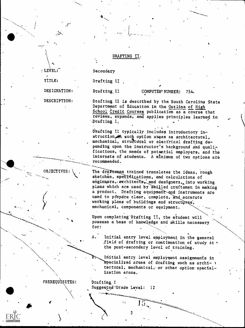
DRAFTING n.
:LE EL:- Secondary
or.
TITLE: Drafting II
DESIGNATION: Drafting.II COMPUTER NUMBER: 754-
DESCRIPTION: Drafting II is described by the South Carolina StateDepartment of Education in the Outline of HighSchool Credit Courses publication as a course thatreviews, expands; and applies principles learned in
'-prafting I. '
,
Diafting II typically includes introductory in-struction401 such option aroas as architectural,mechanical, strAdral or elecerical drafting de-pending upon the instructor's background indfications, the needs of potential employers, and theinterests of students. A mtnimum of two options arerecommended.
OBJECTIVES: 71:1-1;7"-eriftes n trained translates the ideas, roughsketchils, spe ations, and calculations ofengineArsvacchitec 'and designers,.,into working
PREREQU
$
plans which are used byIki3ed craftsmen in making
workingmechanical, components or equipment.
plans of buildings and structused to ptepdre clear, complete, accurate
a product, Drafting equipmen nd instruments aroa
Upon completing-Dr...lifting II, the student willpossess a base of knawiedgo and skills necessaryfor:
A. Initial entry level employmene in the generalfield of drafting or continuation,of study itthe post-secondary level' of training.
Initial entry level employment assignment's inecialized areas of drafting such as archi-
tectural, mechanical, or other option-special-ization areas.
ITES: Drafting ISuggest_O -Grade Leyel: 12
a
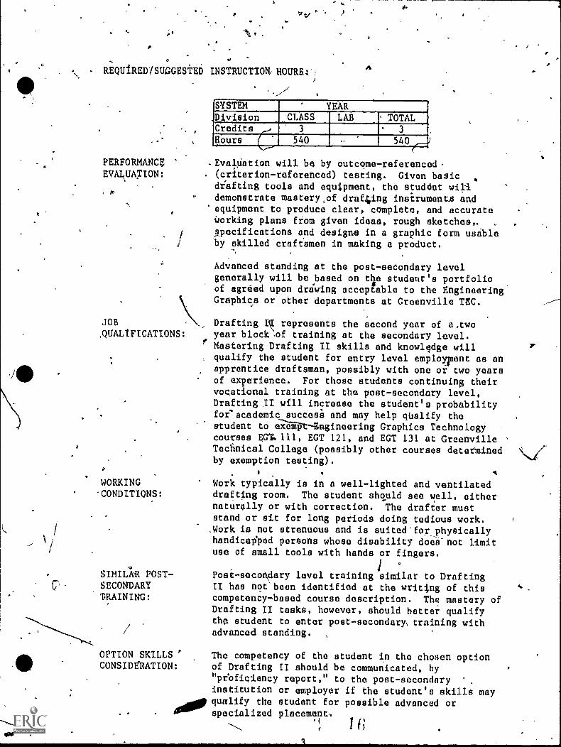
REQUfRED1SUGGESTED INSTRUCTION/ HOURBA--
SYSTEM YEAR.
Division CLASS LAB ' TOTAL'Credits ,.. 3 3
HOurs ( 540 540
PERFORMANCE .EvalUation will be by outcome-referenced-EVALUATION: . (criterion-referenced) testing. Given basic
diafting tools and equipment, the studdnt willdemonstrate mastery,of draf4ing insirumenta andequipment to produce clear, complete, and accurateWorking plans from given ideas, rough sketches,. ,
rapecifications and designs in a graphic form usableby skilled craftamen in making 4 product.
Advanced standing at the post-secondary levelgenerally will be based on die student's portfolioof agreed upon drawing acceptable to the EngineeringGraphics or other departments at Greenville TtC.
JOB N Drafting I represents the second year of a.two,QUALIFICATIONS: year block ,of training at the secondary level.
Mastering Drafting II skills and knowledge will, qualify the student for entry level employinent as an
apprentice draftsman, possibly with one or two yearsof experience. For those students continuing theirvocational training at the post-secondary level,Drafting II will increase the student's probabilityfor'academic succesh and may help qUalify thestudent to a-apt-Engineering Graphics Technologycourses EGT. 111, EGT 121, and EGT 131 at GreenvilleTechnical College (possibly other courses determinedby exemption testing).
4WORKING Work typically is in a well-lighted and ventilated.CONDITIONS: drafting room. The student should see well, either
naturally or with correction. The drafter muststand or sit for long periods doing tedious work..Work is not strenuous and is suited'for physicallyhandicaliped persons whose disability doee-not limituse of small tools with hands or fingers.
SIMIL1R POST- Post-secondary level training similar to DraftingSECONDARY II has not been identified at the writing of thisTRAINING: competency-based course description. The mastery of
Drafting II tasks, however, should better qualifythe student to enter post-secondary, training with
,/ advanced standing. ,
OPTION SKILLS ' The competency of the student in the chosen optionCONSIDtRATION: of Drafting II should be communicated, by
"peoficiency report," to the post-secondary '
institution or employer if the student's skills may400, qualify the student for possible advanced or
specialized placement,
I
/
f
'.
The following stuggestions for drafting-st ts were developed byguidance counselors, The School District of eenvfl4e County.
SUGGESTIONS FOR OFTI SUCCESS IN tRAFTIN
The drafting student 'should like:- To work independently in office environm Ots.
1.4
- 'Activities which involve machines, proc sses and methods.. /- Doing precise, neat, and very acturate ork. N
- Activities of a scientific dr technica1. nature.- Drawing with scales, protractdrs, and/compasses. \\
The drafting student should be able to: '1
Uuderstand and apply technical knowfedge and theoritical"/principle.
1- Solve arithmetic problems iuvolving fractions and decimals.- Practice various exercises many times !Without frustration.- Turn in consistently neat work tl3at is within precise limits
or standards of accuracy? ,
- Concentrate for long periods of/time on detailed work.- Follow instructions exactly. /
- Work under pressure.
following math skills will contribute to optimum success in DraftingThe
- Ability to accurately make l4near measurements using variousscales (e.g., Engineer'; an
- Able to fractions. ,- Able to work ith angles.
Able to understand geometric shapes and terms.
irlpful courses to the drafting.stddent include:- General'Mathematics- Geometry- Algebri Iand II
Archltect's Scales). ---
1101
\\ %
J.For optimum success, ttie'dt, g student\should possess.the ollowingverbal skills:
- Comprehend and writ ii. technical noteh.- Follow written, dia,grammatic, and verb.al instructions.- Read and comprehend on grade levpl.
4
r
-DRAFTING II OPTIONS
The 1970 _Drafting_ Curriculum Gtide'of the South Carolina.Department ofEducation reoommends that the s.econd year of secondary.level draftingconsist. of "the opportunity to choose the area of specialization thestudent desires to pursue." Speciali;ation in one of the followingoptional areas of drafting training is recommenddd.
'OPTION MODULEArchitectural Drafting 7 0
Mechanical Drafting 8 0
St4mctural Drafting 9 0
The opttons which a setondary level vocational education ceeFiter m It /
offer to sudents will depend on several factors.* 4
*The choice of which options should be offered should:
(a) be reachyd joittly by the instructor and local.. DraftingAdvisory Committee,
(b) meet local employment needs (b'asedon the availability of joboppoOhulities>,
(c) topsider local regional trend in the drafting profession,and ,
(d) consider'wint the tustructor,will be comfortable teaching.
A school May beeVen more optiondepending upon pl
Drafting, for xampalustify it being offere
o offer only o.os optfon or it might offer two orsuggested opti>14,may be modified or eXpanays
needs of the loc31-.. rafting market (Electricalht be included..if the is sufficient need to
y,
N.
te
,
5s
>
MINIMUM PERFORMANCE STANDARDS *17OR DRAFTING II
All standards applicable to Drafting I apply to Drafting II training'(See pages D-8 - 0-10, Articulated, Performance-based Instruction Guide ,
for prafting I)-
/A
Minimum performance standards are those recommeride,d for entry level jobsuccess. Performance-standards encoueage lateral and.,yerttealarticulation.
In addition to standards listed in Drafting I, minimum standirr a areincluded in ANSI Manuals and applicable AIA references, as well_a othersources of technical data and standards.
Typica y rafting II performance objectives actions will omit de-scriptdons preliminary steps of setting up drawings as well as termi-nating steps of checking drawings, etc.,,for brevity.
o-
Qiven mateeials (conditions) typiOally will omit mention of necessary,drafting Instruments and supplies to demonstrate skills and knowledge.
Drawings.must communicate the intended inforMatio to the user (The userMVst be able to successfully answer 4 set ofirpn omly drawn questionsconcerning the intended content of the drawing.).
Drawings must be executed within'time limits considered acceptable forinitial employment.
4k
I
SAMPLEOUT6ME-REFERENCED TESTS
DROTING
This articulated, performance-based instruction guide is designed tohnswer three critical questions necessary for quality instruction.
First., what should be taught?
The objectives of the articulated, performance---based education
vocational education program are based onreXtensive task analysisand validation.
The task Objectives represent what employers in business andindustry sayiis imiortant for entry level job success.
Second, how should,it 1)e taught?
It should be taught usitg.the latest,"state-of-the-greinstructional technology incorporated into each unit.
Students pre taught the knowledges, skills, and attitudes neededfor successful and productive employment.
Thixd,,how should students be 'evaluated?
Students are evaluated using a validated competency-based approachto determine student prpficiency in vocational knowledges andskills.
The minimum standards are those requi94 for successful entry inthe next high level of training or iIir successful employment.
The sample tests are included to illustrate how the student's competencyin vocational skills and knowledges may be measured with validity andreliability. In-addition, the test samples are included to promote,_stahdardization in the evaluation of vocational students in similarprograms.
.
..,
Test items have been constructed solely from the objectives of thevocational program. The statement of the objectives indicate the levelof knowledge or skill to be tetitted. Task force_committee partAcipants
'I
have attempted to write tests that agree with objectives in the behaviorrequested, the given conditions, a d the desired standards ofperformance. .
1/
NOTE1 Unless the test page is marked "Revised" or "R," the teatshould be considered a, field trial edition currently underreview and revision.
- .;;;;111
7
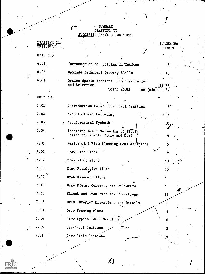
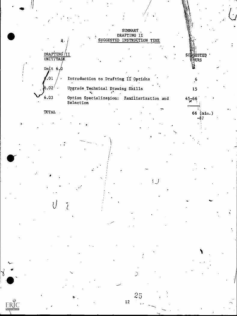
'SUMMARYDRAFTING II
SUFZSTED INSTRUCTION TIMg
DRAFTING II, SUGGESTEDHOURSUNIT/TASK
Unit 6.0
6.01 Introduc.tion to Drafting II 'Options 6
6.02 Upgrade Technical Drawing Skills 15
4
6.03 Option Specialization: Familiarizationand Selection 45-66
TOTAL liOURS 66 (min-.) 717
Unit 7.0
7.01
7.02
7.03
Introduction to Architectural Drafting
Architectural Lettering
Architectural Symbol 's
7.04 Interpret Basic SurveyingSearch and Verify Title and Deed 7
7.05 Residential Site Planning,Consider ions
7.06 Draw Plot. Plans
7.07 _Draw Floor Plans
7.08 Draw Foundvion Plans
7.09 Draw Basement Plans
7.10 Draw Piers, Columns, and Pilasters
7.11 Sketch and Draw Exterior Elevations
7.12 Draw Interior Elevations and Details
7.13 Draw Framing Plans
7.14 Draw Typical Wall Sections
7.15 Draw'Roof Sections
7.16 Draw StaiiOns
9
5
9.
30
15
6
3
moo.
2,
'od
-
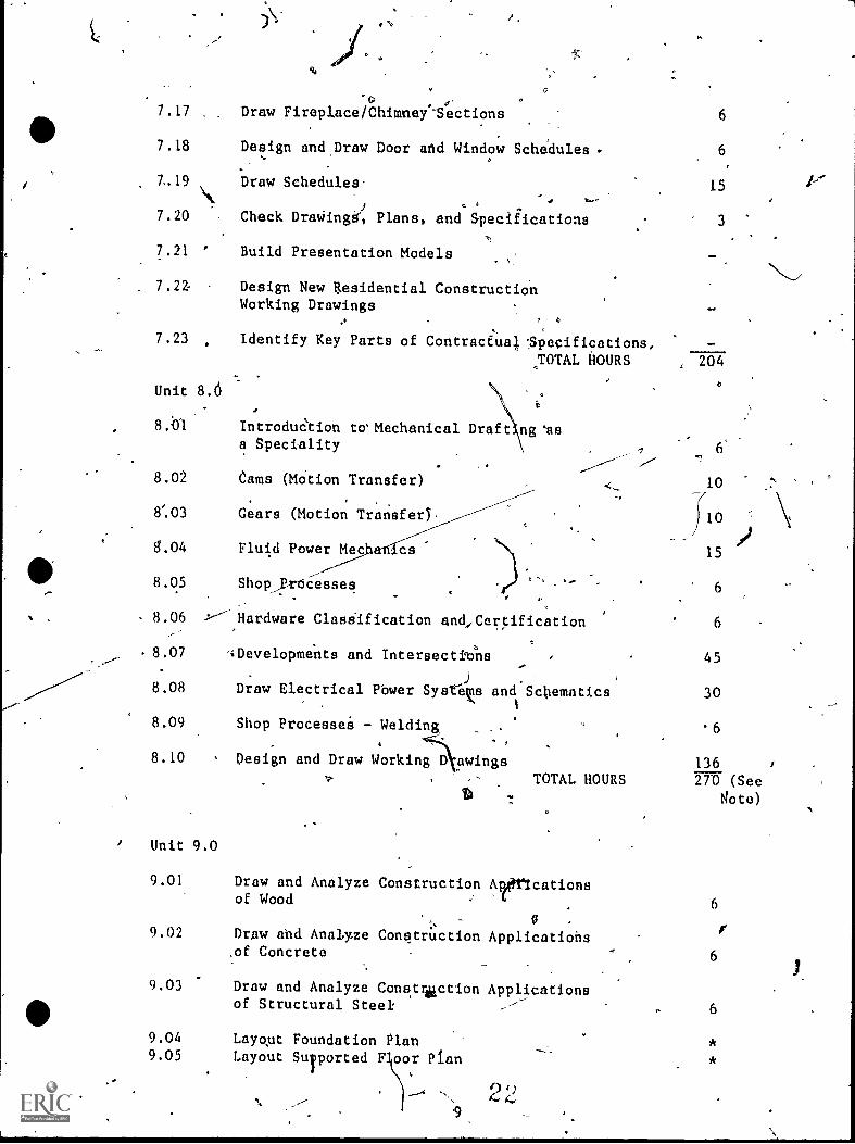
7.17 Draw Fireplace/Chimney-Sections
7.18 Design and DraW Door and Window Schedules
T.19 Draw Schedules-
7.20 Check DraWingal, Plans, and Specifications
7.21 ' Build Presentation Models
7.22- Design New Residential ConstructionWorking Drawings
°
7.23 Identify Key Parts of Contracfual. 'Specifications,
TOTAL HOURS
Unit 8.6
8.O1 IntroduCtion to' Mechanical Draft asa Speciality
8.02 Gams (lOtion Transfer)-
8/.03
8.04
8.05
8.06
8.07
8.08
8.09
8.10
/ Unit 9.0
Gears (Motion Transfer) .
Fluid Power Mecs cs
Shopjrbcesseq
Hardware Clasiification and,Certification
'iDevelopments and Intersectib6
Draw Electrical Pbwer SysteKs and Schematics
Shop Processei - Welding
Design and Draw Working awingsTOTAL HOURS
6
6
15
3
204
6
10
10/
15
6
6
45
30
6
136
270 (See
Rote)
9.01 Draw and Analyze Construction Aptericationsof Wood 6
0 .
9.02 Draw and Analyze Conqtruction Applications.of Concrete 6
9.03 Draw and Analyze Conatrolction Applicationsof Structural Steel: 6
9.04 Layqut Foundation Plan9.05 Layout Suported F oor Plan
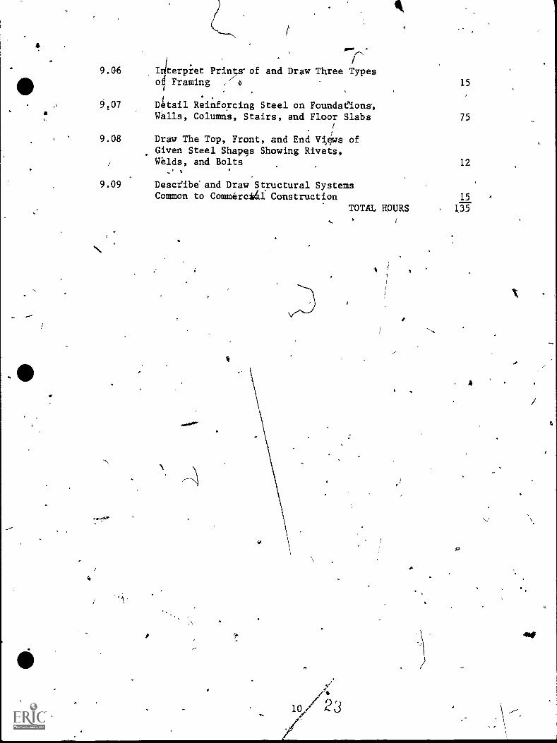
9.06
9107
9.08
Incerpiet Printo of and Draw Three Typeso# Framing ,'/1,
DItail Reinforcing Steel on Foundaeions,Walls, Column's, Stairs, and Floor Slabs
Draw The Top, Front, and End V1,4ws ofGiven Steel Shapes Showing Rivets,Wilds, and Bolts
15
75
12
9.09 Descfib& and Draw Structural SystemsCommon to Commercida Construction 15
TOTAL HOURS . 135
. t
1/'ji10 23
9
A
441,
tl
DRAFTING IIUNITYTAS
Unit
6.02
6.03
TOTAL
SUMMARYDRAFTING II
SUGGESTED INSTRUCTION TIME
introduction to Drafting if pptidns
Upgrade Technical Drawing SkillsN4
Option Specializoion: Familiarization andSelection
6
15
45-660 ,
11
66 (min.).g7
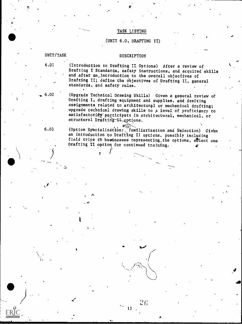
TASK LISTING
,(UNIT 6.0, DRAFTING It)
UNIT/TASK DESCRIPTION
6.01 (Introduction to Drafting II Options) After a review of,Drafting t,Standards, safety instructions, and acquired skillsand after an_introduction to the overall objecEives ofDrafting II; define the Objectives of Drafting II, generalstandards, and safety rules.
, 6.02
6.03
(Upgrade Technical Drawing Skills) Given a general review ofDrafting I, drafting.equipment and supplies, and draftingassignments,related to architecturol or mechanical drafting;upgrade technical drawing skills to p level Of proficianCy tosatisfacioridleparticipate in architectural, mechanical, orstructural Draftin options.
(Option Svacializit16:. Familiarization nnd S41ect1on) Givbnan introduction to Drafting II options, possibly includingfield trips tb busdnesses representing,the options, sOlect onoDrafting II optio for continued training. 4'
tos
13
444
4
,/-----\
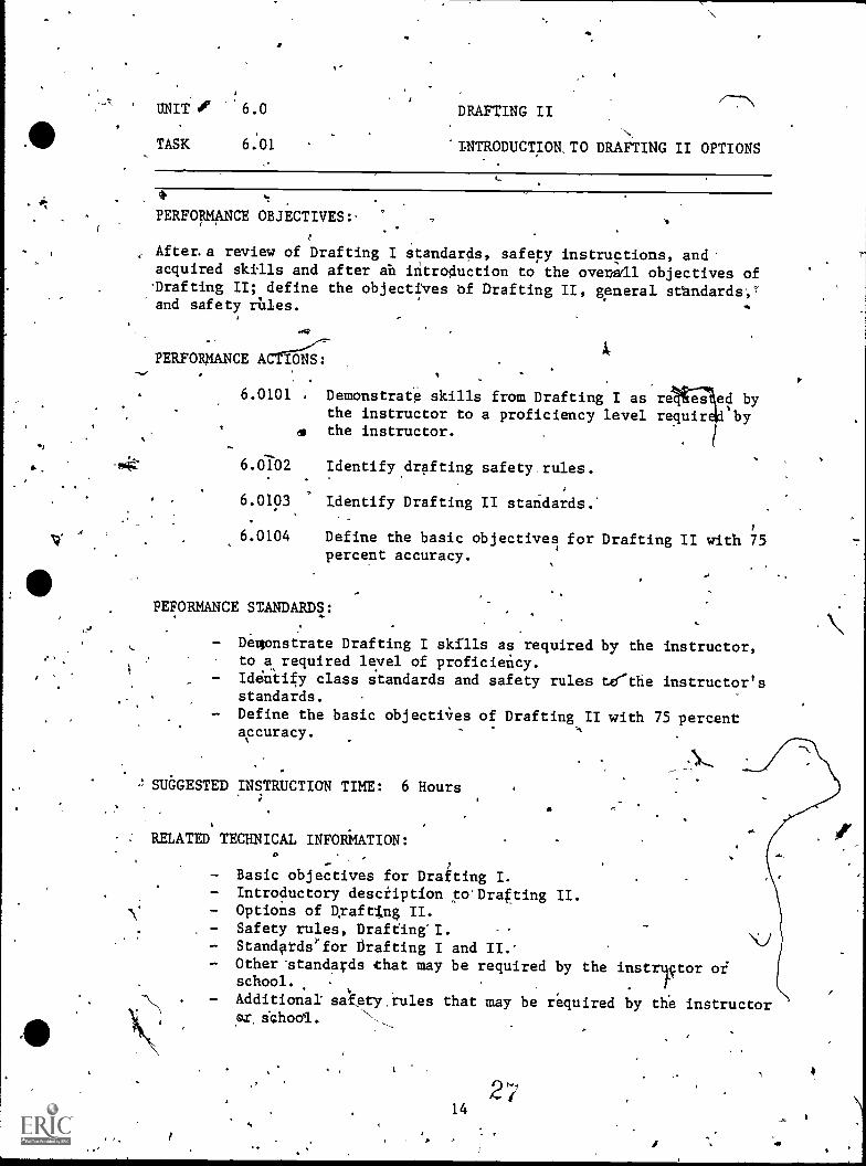
' MT', '6.0 DRAFTING II
All TASK 6:N
'INTRODUCTION,TO DRAFTING II OPTIONS,
01.
diPERFORMANCE OBJECTIVES:
,
After.a review of Drafting I standards, safety instructions, and'acquired skills and after ah introduction to the ovenall objectives of'Drafting II; define the objectives bf Drafting II, general ständards',''and safety rhles. *
PERFORMANCE ACrfoiC
6.0101 Demonstrate skills from Drafting I as re ed bythe instructor to a proficiency level requir4 by
0 the instructor.
ai(
6.6102
6.0103
6.0104
Identify drafting safety.rules.
Identify Drafting II standards.'
Define the basic objectives for Drafting II with 75percent accuracy.
PEFORMANCE STANDARDS:
Deupinstrate Drafting I skills as required by the instructor,to a, required level of proficiency.
Idintify class standards and safety rules tethe instructor'sstandards.
- Define the basic objectiVes of Drafting II with 75 percentaccuracy.
SUbGESTED INSTRUCTION TIME: 6 Hours;
. RELATED TECHNICAL INFORkATION:
N.
,
- Basic objectives for Drafting I.- Introductory description to'Drafting II.- Options of Araft#$ II.- Safety rules, Draffing'I.- Standardefor Drafting I and II.-- Other atandards that may be required by the insfru-qtor oi
school.- Additional sahty,rules that may be required by the instructor
ar ichool. N.
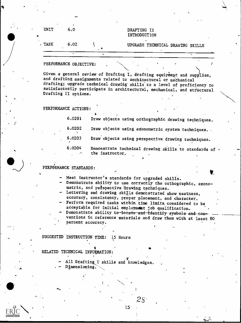
UNIT 6.0 DRAFTING IIINTRODUCTION
TASK 6.024
UPGRADE TECHNICAL DRAWING SKILLS
PERFORMANCE OBJECTIVE:
Given a general review of Drafting I, drafting equipMentand drafting assignments related to architectural or mehdrafting; upgrade technical drawing' skills' to a level ofsatisfactorily participate in architectural, mechanical,Drafting II options.
PERFORMANCE ACTIONS:
6.0201
6.0202
6.0203
Draw objects
Draw objects
Draw'objects
and sug)lies,anicalproficiency toand stinctural
using orthographic drawing techniques.
using aXonometric system techniques.
using perspective drawing techniques.
6.0204 Demonstrate technical drawing skills to standards of -
the instructor.
PERFORMANCE STANDARDS:
Meet instructor's standards for upgraded skills.Demonstrate ability to use correctly the orthographic, axono-metric, and petspective drawing techniques.Lettering and drawing skills demonstrated show neatness,accuracy, consistency, proper placement, and character.Perform required tasks within, time limits, considered to beacceptable for initial employmdgt job qualification.
- Demonstrate ability to-locate-and-i-dentify-symbols-and-oonventions in reference materials and draw them with at least 80percent accuracy.
SUGGESTED INSTRUCTION TIME: 15 Hours
RELATED TECHNICAL INFOIIMATION:
- All Drafting,I'skills and knowledges.- D4mensioning.'--
,-/UNIT 6.0 DRAFTING II
TASK p.03 0PTI0N4PEtIALTZATIOFAMILIARIZATION'AND S ECTION
PERFORMANCE 0EJECTIVE4
Given an introduction to Drafting/II options, possibly'including field'trips to businesses representing the options, select one DTafting IIoption for continued training.
PERFORMANCE ACTIONS:
-
6.0301 Describe the option choices at the individual vocational center, for the yenr of training (optionchoices may vary from year to year).
6.0302 Identify important facets ordrafting work in thevarious options offered during selected field_trips,etc. (An observation guide or check'14t of what.tolook for during orientation is rekommen d.)
6.0303 Compare the various options offered with rega'I4tothe student's skills and vocational interests.Possibly...a. Consult,with instructor to define the student's
skills, strengths, and weaknesses.b. Obtain the instructor's recommendations
concerning option choices.c.' Consult with counselors, drafting
professionals, or others concerning the optionchoices.
6.0304 Select an option choice.
6.0305 Select an o tion choice alte'rnative, if applicable.
SUGGESTED INSTRUCTION TIME: 45-66 Hours
PERFORMANCE STANDARDd:
Student will select an option in Drafting II in which itappears (to student and instructor) that the gtudent cansucceed and i n which the student has interegt.
16
UNIT 6.0 DRAFTING II
TASK 6.03 QPTION SPECIALIZATION:I
. FAMILIARIZATION AND SELECTION.(Con't.)
RELATED TECiipTICAL INFORMATION:
,
Orientation to Drafting II options:- Architectural Drafting. ,
- Mechanical Drafting.- Structural Drafting.- Others supplemental tasks that may be offe-r.e-a-by-'the-
individual vocational center.
'
f
UNIT 7.0
DRAFTING IIHITEgTDRAL DRAFTING OPTION
NNN,N
J
N.
INTRODUCTION:
'ARCHITECTURAL DRAFT/NG OPTIONDRAFTING II.
The Arohitectural Drafting Option, Drafting II, '
represdnts agreement (lateral articulation) amongthe four secondary vocational center draftinginstructors, The School District-of GreenvilleCounty, concerning the objectives, content, andstandards of the program.
While the basic program is similar at the fourvocational centers, some variation may be expecteddue to the training and experience of theinstructors in architectural drafting, the specificneeds of potential employers, or the inthrests sodabilities of students.
The Architectural Drafting Option includes:NConcurrent instruction to upgrade'letteringtechniques, drafting skills, and the application ofindustry standards; architectural materials andmethods of construction such as.identifying bUildingmaterials, using reference materials, drawingconventions, and symbols used in constructiondrafting; consi ering applicable codes, safety, andenvironmental p otection regulations in planning anddrawing; conduct ng site planning and layoutincluding surveyi g, drawing contours, titlesearching, interpreting property"lines from legaldescriptions, planning foundationsi, calculating cutand fill requirements, and drawing site profiles;and correctly drafting new residentialoonstructionworking drawings or rehabilitation drawing for olderbuildings.
The content of the rchitectural Drafting Option isdetermined by tas analysis of the needs of localprospec'tive employers and by the recommendatidns ofthe 1980 Sooth Carolina revision of the V-TECCatalog, Architectural Drafter. The tasks includedin the Architectural Drafting Option represent thoseconsidered minimum for the student to be successfulin entry level employment in the architecturaldrafting field.
/The Architectural Drafting description follows theAIA suggel3tion of emphSsizing residential construc-ttOn dralfting for initial-skill development andpossibly light commercial conStruction fdradditional architectural drafting-study.
_ PERFORMANCE aluation will be by outcome-referenceEVALUATION: (c terion-referenced)testing. Minimum performance
stan ards should represent recommended entry=levelcompe ncy levels for job success.
-1
STANDARDS!' Appropriate handbooks, codes, AIA Manuals, etc.,which contain the necessary technical data/standardsshould..>be consulted.
Drawings of architectural systems Apuld meet AIA orother industry standards.
Drawingsmust be prepared within job qualificationtime lipits.
Orthographics,'axonometric, and perspective drawingtechniques must be correct and to entry-leveletployment perforiance. Lettering must be
4appropriate for arOhitectural work, and drawingsmust,be neit, accurate, and consistent with properplacement and character.
JOB Architectural Drafting by itself may n4 provideQUALIFICATION: a specific job qualification; however, graduates who
have proven competency in architectural drafting atthe secondary level may qualify for entry-levelemployment as'an Architectural Drafting Technicianin residential or light conmercial design or as aBuilding Trades Drafter.
N,
The Architectural Drafting Option has not beenarticulated with a specific course at GreenvilleTEC; however, the skills and knowledge developedfrom'this second year option course may help thegraduate qualify for exemption of t4,, post-secondarylevel courses described in Drafting,I.
33.
A-3
RECOMM1VDED TASKS #OR ARCHITECTURAL D
4'. -4079-1980Y.From V-TEC_Catalog, ArchiteCtural Drafting
4
Vocational education (secohdary) instructars in South Carolina reviewedthe V-TEO Catalog, Architectural Drafter, developed by Maryland StateDepartment of Education in 19794 and revised it for use in SouthCarolina's secondary level drafting training in the architecturaloption.
Architectural drafting tasis more appropriate flir post-secondarytraining were identifie'd nd remaining tasks in the V-TEC Catalog werelisted as representing afoundation to architectural drafting trainingat the secondary level.
*
The recommended tasks,for secondary drafting instrudtion include:
1. Sketch preliminary site layout..
2. Sketch preliminary site plan layouts.3. Sketch preliminary site elevations.4. Sketch preliminary site section.5. Draw plot plans.6. Check site and plot plans.7. Draw floor plan.8. Reproduce common plan features.9. Draw basement plan.
10. Draw foundation plan.11. Draw framing plan.12. Check plan dimensions.13. Draw foundation sections.14. Draw floor sections. '
15. Draw typical wall sections.16. Draw attic sections.17. Draw stair sections.18. Dimensions section drawings.19. Check section drawing.20. Draw exterior elevations.21. Draw interior elevations.22. Check eleyation drawings.23. Dimension plans.24. Add title block information to drawings.25. Indicate on plans the location of section views.26. Draw door and window schedules.27. Draw finish schedule.28., Draw architectural plans.
This fecommended list of_arehitectural drafting to-sks h-i-S-ceen includedin the development-of-Module 7.0, Architectural Drafting,Performahde-based Instruction-Guide for Drafting II.
"r--
A-4
34
A "4
DRAFTINGUNIT/TASK
Unit 7.0
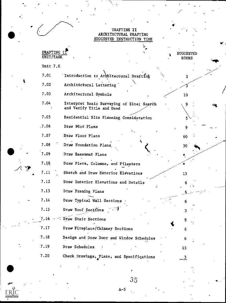
7.01
7.02
7.03
7.04
DRAFTING IIARCHITECTURAL DRAFTING
SUGGESTED INSTRUCTION TIME
Introduction to Aitecturai DraftInt
Architéctural Let-teing
Architectural Symbols
Interpret Basic Surveyingand Verify Title and Deed
7.05 Residential Site Planning
.7.06 Draw Plot Plans
7.07 Draw Floor Plans
7.08 Draw Foundation Plans,
7.09
7.1A
a 7.11
7.12
7.13
7.14
7.15
Draw Basement Plans
of Site; Se rh
Consideration
Draw Piers, Columns, and Pilasters
Sketch and Draw Eiterior Elevations
Draw Interior Elevations and Details
Draw Framing Plans
Draw Typical Wall.Sections
Draw Roof SectiOns
. 7.16_ tiraw Stair Sections
7.17
7.18
7.19
7.20
DrawFireplace/Chimney Sections
Design and Draw Door and Window Schedules
Draw Schedules
Check Drawings,4Plans, and Specifications
A-5
a
SUGGESTEDHOURS
'31*
15
6
6
3
9
6
6
15
3
or,
7.22/
Build Presentation Models
Draw New Residential ConstructionWorking Drawings -.
7.23 Identify Key Parts bf ContractualSpecifications
SNGGESTED TOTAL HOURS 270(Balance of second Year-ayailable for additiona.1 op4aa 'study.)
_2=71
*Time combined with related task.
**Optiona]:
411,
36A-6
Jr.
/tIT/TASK
it 7.0
7.02
7.05
TASK LISTINGSD TING II
DESC TION
(Introduction to Architectural Drafting) Given an intro-duction to architectural drafting, describe the-job of thearchitectural draftsman to the standards of the instruCtor.State the,importance of the work of the architettural,.draftsman to the satisfactory caapletion of residential or .light commercial building. _
----(Architectural_Lettering) Given introduction,in leteering forarchitectural drafting, perform architectural1 ieteri4 to thequality expected of an entry leVel draftsman in an arc itect'soffice..
.
(Architectural Symbols) Gived In introduction toarchitectural symbols, appropriate references, and, practicalassignment, read and properly draw commonly used symbols, anduse architectural symbols to abbreviate properly in-drawingsto the instructor's standards.
(InterPret Basic Surveying bf Site;'Search and VerifY\Titleand Deed) Given instructions concertiing basic surveAng,method of'searching title and deed, surveying equipment andinstrument, additional helper fpr surveying; search and verifytitle'and deed and interpret survey of site, .surveying site asneeded.
(Residential Site Planning Considerations) Given anintroduction to residential site layout, plot planning; andconsiderations that influence the location of a givenresidential structurd-on an existing site; using an existingsite plan, Burl* drawing, or written legaldesofiption--sketch the layout of the site to the instructor'sstandards applying the rulles of good architectural drafting.
7.06 (Draw Plot Plans) Given a sutvey drawing, a written legaldescription, drafting equipment; draw a plot plan. -
7.07 (Draw Floor Plans) Given architectural design data, prelimi-nary plan layouts, and architectural drafting equipment; drawfloor plans for a given residgptial structure. The floor planmust communicate the intended information to a 'user.(ALTgRNATE) Given a problem'situation, solve tloor plan-nesignproblems.
-"-
N,A-7 37
;
7.08 (Draw Foundation Plans) Given architectural/engineeringdesign data, floor plan, sketches, drafting equipment; drawfoundation plan. The'plan must communicate the intendedinformation to the user.
7.09 (Draw Basement Plans) Given architectural/engineering designdata, floor plan, sketches, architectural drafting equipment;draw a basement plan for a residential sttucture.
17.10 (Draw Piers, Columns, and Pilasters) Upon completion ofAn-
structions, given drafting instruments and a'typical arcl.tectural drafting assignment, draw correctly (piers, columnO,and pilasters;'to the standards of the instructor and meeOrequired specifications or standards.
7.11 (Sketch and Draw Exterfor, levations) .Given a plot plan:floor plan, specifications, dation plans, basic exteriodesign, wall section, sketch,of reliminary elevations, anddrafting equipment; draw exterio elevations.
list of rials, specifications, supply catalogs, and are i-
(Draw Interio--Elevations and'Details) Given a floor plan,7.12
tectural drafting equipment; draw the interjor elevationa, nd'details.
\ .
1.
.1......, ,, ., I
7.13 (Draw Framingqlans Given working drawings, engineering '-\,design data skstche , and drafting equipment; draw a framing \\plan.
,'s
7.14 (Draw Typical Wall Sections)- ,Given a plan and specifications,--1 ---and architectural drafting equipment; draw a typical wall -i
.;section. ,,
Is
,
7.15 (Draw Roof )(Sections) Given a plan'and spec fications and.,
4drafting eqnipment; draw an attic section, ,
1
7.16 (Draw Stair Sections) Given a plan and specifications, anddrafting equipment; draw a stair section.
7.17 (Draw Fireplace/Chimney Sections) Given a plan and specifi-cations; draw a fireplace and chimney.
7.18 (Design-anaDraw Door and Window Schedules) Given specificprograms requirements concerning doors and windows an'cl,drafting equipment; draw doer and window schedules.
7.19 (Dtaw Schedules) Given a set of architectutal plans, interiorelevations, and-specifications and program requirements, andarchitectural drafting equipment; draw required schedules.,
7.20 (Check Drawings, Plans, and Specifications) Given site and\ pldt plan, list of specifications, list df specific\ requirements, and features, and a copy of local buildingt,.
' Codes; check site and plot plan, correcting all errors and\omissions.
)'A-8 38 7
Given plans, specifications, and check'prints of exterior andinteriOr elevations; check elevations for line quality,symbolizidg, dimensions, neatness, and equipment of specialfeatures.called for in specifications.
_Given-architectural/engineering notes, sketches, design dataand client requirements; check plans and specifications.
. t
/ 17.21 ) ( nild Presentation Models) Given preliminary desIgn
dr ings, specific instruction, ne-Cessary drafting- equipmentincludins scale, cutting tOol, metal stra ghtedge, adhesive,and matboard; build a presentation model
7.22 (Draw New le-Sideneial Construction Working Drawings) Given
t'
existing information and showings for a particular residence,decide whether Or not it provides appro riate information:forthe builder. Obtain and provide any necessary additional in-formation.
7.23 (Identify Key parts of Contractual Specifications) \Given in-,structiOns; demOnstratevithe ability to differentiate between
, codes, speciXications, Ad contract documents; state theirpurpose's, provisions, general format, parts, administration,
. and responsible agencies for enforcement with at least 70percent accuracy. -
a
F
tip 411"
UNIT 7.0 FUNDAMENTALS OV ARCHITECTURALDRAFTING, DRAFTING II, (Option)
TASK 7.01 INTRODUCTION TO ARCHITECTURAL,
DRAFTING'
PERFORMANCE OBJECTIVE:
-,
Given an introduction to architectural drafting, da'scribe the job of thearchitectural Araftsman to the standards of ghtinstiTctor. State the ,
importance of the Work of the architgctural alliltsman't.o.thesatisfactory completion of residential or light commer4al,buildings. \.
--*
\
4t0 ..
PERFORMANCE ACTIONS: -
\;, A . '
7.0101 Identify similarities and differences,between archi- \-__..t,tectural drafting and basic.dr4ting techniques;
\1,
7.0102 Dascribehthe role of,the.architectiral draftsman in
,the drafting team. Indicate how the architectural
g draftsman's role differs from the architects,mechanical engineers, etc.
7.0103 State the tyPical duties of the architecturaldraftsman.
7.0104 Identify architectural drafting as a career thoice.
PERFORMANCE STANDARDS:
- Describe or identify the job of the architectural draftsman to'the standards of the instructor, obtaining a minimum of 9,0percent accuracy on knowledge tests. .
SUGGES_TED__INSTRUCTION_TIMEI__ 3 Hours
RELATED TECHNICAL INFORMATION:,
1.
- Duties of the architect Ili residential construction or lightcommercial constiuclion.Vuties'of the mechnital engineer in residential.or lightcommercial construction.
- Duties of the electrical engineer and others in residential orillight commercial construction.
4A-10
UNIT 7.0 FUNDAMENTALS OF ARCHITECTURALDRAFTING, DRAFTING II, (Option)
A
,
TASK 7.02 ARCHITECTURAL LETTERING
PERFOIIMANCEIWECTIVE:
Given introduction in lettering fdi architectural drafting', petforma chitectural lettering to the quality expected of acCentry 1 eldr ftsman in an architect's office.
PEREORMANCE ACTIONS:
/ 7.0201 Describe impbrtance of lettering in,architecturaldrafting.
-.7.0202 Identify basic types of letterin yles'A- architectural drafting and demonstrate mastery-6i
tliOse styles.
71:0203 Indicate the similarities and differences betweenengineering letteiing and,architectural lettering.
7.0204 Develop an& demonptrate lettering techniquessuitable for qualification for employment inarchitectural drafting.
PERFOMAANCE STANDARDS:
- Able to use typical architectural lettering techniques to a.,..._c_ompetency level expec ed fôr entty level employment in thetypical architect's of as interRreted by the instru tor.
SUGGESTED INSTRUCTION TIME: 3 Hours,
RELATED TECHNICAL INFORMATION:
'
- Mechanical drafting lettering techniques.Architectural letter'styles. ,r,
Pressure sensitive lettering and letter devices.- Spacing.
41
tire -FUNDAMENTALS OF ARCHITECTURALDRAFTING, DRAFTING II, (Option)
TASK 7.03 ( ARCHITECTURAL SYMBOLS
PERFORMANCE OBJECTIVE:
Given an introduction to architectural symbols, appropriate references,and practical assignment, read and properly draw commonly used symbols,
- and use architectural symbols to abbreviate propeily in drawings to theinstructor's standards. !
-/
ir...
14,-11EFORMANCE ACTIONS:
^
PERFO
7.030 State the purpose and necessity for architeCturalsymbols.
7.030 Describe why ardization of symbolp and abbre-- kviations is necessa
7 .0303 Identif the standard, symbols and abbreviation forarchite tural_Arafting.
7.0304 symbols and applY abbreviations. Use eCorrectly drawsymbols for:a. Building materials e. Plumbingb. Walls t f. Kitchenc. Floors g. Heatingd. Electridal h. Elevations
STANDARDS:
Able to apply symbols and abbreviations typical toarchitectural drafting to practical exercises with,100 percentaccuracy and meetinig instructor's standards. Minimum:of 90
, percent apCuracy knowledge tests.
SUGGESTED INSTRUCTION TIME: 10 Hours
RELATED TECHNICAL INFORMATION:
-; Construction terminblogy.- Building material terminology and product identification.
42A-12
=1.

UNIT 7.0 FUNDAMENTALS OF ARCHITECTURALDRAFTING, DRAFTING II, (Option)
TASK 7.04. INTERPRET BASIC SURVEYING OF SITE;SEARCH AND VERIFY TITLE AND DEED /
.SS--PERFORMANC OBJECTIVE:
Given instructions toncerning.basic surveying, Method of serching titleand deed, surveying equipment and instrument, additional helpet forsurveying; search and verify title and deed and interpret survey of'sitesurveying site as needed.
PERFORMANCE\ACTIONS:
7.0401 Defina,-and interpret survey terms.
47.0402 Identify surveyorts duties.
7.0403 Use surveying equipment to measure distance andangles.
7.0404 -Perform a land survey of the construction site.
7.0405 Draw property lines frotrlegal descriptions%,
7.0406 Perform user maintenance and care of surveyingequipment.
7.0407 - Search and veilfIr site deed.
PERFORMANCE STANDARDS:
- Perform survey tasks within-accep ed error limits for entryIevel/drafter'in arChitectural office. s,
- Uses and'maintains equipment properly.- Performs deed and title search es predtribed.-' Calculations 80 percent accurate.- Demonstrates ability.to use terms, definitions, and symbols
with.80'percent accuracy.- Executes drawings neatly and accurately, in a professional
manner.
SUGGESTEDANSTRUCTION TIME: 9 Hoursof.
RELATED TECHNICAL INFORMATION:-1
- Heading evaluations.SUGGESTED: Field trip to Block Book-Room, County Court House.
AAL.;13 43411i
thin '7.0 . _FuNDAmarvisr-or.AKHITEGTITRAI,...,_ --------
DRAFTING, DRAFTING II, (Option)
TASK 7.05 RSIIENTIAL SITE PLANNINGCONSThERATIONS
,
PERFORMANCE OBJECTIVE:
Given an introduction to residential site layout, plot planning, andconsideration that influence the location of a given residential struc;ture on an existing site; using an existing site plan, survey drawing,or written lega14descriptión--sketch the layout of the site to theinstructor's standards'applYing the rules of good architectural' -
drafting.
XERFORMANCE ACTIONS:
7.0501 ;Ise terms associated witlr-:tite selection.
7.0502 Review neighborhood factors:a. Facilitiesb. Physical featuresc. Lodal ordinancesd. Restrictions
7.0503 Research community considerations:a. Zoning restrictions which influence the'
election of a building siteb. Review protective covenants
7.0504 Sketch the layout of the site.
7.0505 keview design data, notelsite and house.relation-.
ship.
7.0506 Scale and block-out boundaries and site features.
7.0507 Layout,structure on site.
7.0508 Note natural and physical limitations.,,
7.0509 Indicate modifications'of any existing site ele-vations.
7.6510 ' Indicate desired landscaping.
PERFORMANCE STANDARDS:
stery will be evidenced by scoring a minimum/of 83 percenton knowledge tests of terminology and considerations that in-fluence site selection. The site layout sketch Must be drawn
A-14
4 4
p.
'7*
UNIT. 7.0 FUNDAMENTALS,OF-ARCHITEGTURALDRAYTING, DRAFTING II, (Option)
TASK ' 705 RESIDENTIAL SITE PLANNINGCONSIDERATIONS (Con't.)
4f.
PERFORMANCE STANDARDS .(Con't.):
applying the rules of good architectural drafting and mustInd cate to the instructor a competency level as expected for
level into architectural drafti7 office..
en
SUGGESTED INSTRUCTION TIME:_. 5 Hours
TECHNICAL DNFORMATION:
Sources of data concerning neighbol7ind'communities.Zoning codes and regulatOfdinances.and restr1ions.Searching title and de'ed.
A-15
I.
UNIT . 7.0 EUNDAMENTALS-0P-ARCHITECtURAL
IIIA DRAFTING, DRAFTING II (Option),
TASK 7.06 DRAW PLOT PLANS'
PERFORMANCE OBJECTIVE:
Given a aurvey drawing, a written legal descriptiqn, drafting equipment;draw a plot plan.
PERFORMANCE ACTIONS:
7.0601
.7.0602
+4*
Continue previous tasks as applicable.
Select,the most advantageous location and Ositionfor the structure.
7.0603 Place the structure on the aite.-
7.0604 , Draw suppie-intary construCtionl'extending beyond theexterior walls of the structure.
7.0605 Indicate recreational areas.
Determine and indicate locations of exterior circu-latory features.
7.0607 a. \Draw existing and proposed contour lines and.indicate graae elevations.
b. Calculate cut and fill requirements and draw,profile of site.
7.0608 -, Indicate Water drainage and storage systems.7 ,
7.0609 Loaate existing arid proposed utilities.
\Note existing,natural f urea.
..\
, 7.0610
./
7.0611 Indicate modificaions of any existing site elements.
\
7.0612 Dimension boundaries of site and,give-bearing.
7.0613 jlimension exteriar limits of structure,andmenta constru t on,
"444.\
70614 !Indicate constru tion materials.
7.0615. !Locate and dimensio easements and establishsetbacks
UNIT 7.0
I
/4UNDAMENTALS,OF.
'1 DRAFTING, DRAF ING IIT
, Optio
TASK 7.06 DRAW PLOT .PLANS (Con't.)
PERFORMANCE ACTIONS (Con't.):
7.0616 Indicate existing and.proposed landscape.ileatures.
7.0617 Indicate nor th arrow.
7.0618 Add border-lines and title block infstrmation.
7.0619 Check 'plans.
PERFORMANCE STANDARDS:
- Executes drawings neatly and accurately in a professionalmanner.
- pemonetrates ability to correctly use terminology and symbolswith 80 percent accdracy.
SUGGESTED INSTRUCTION TIME: 9 H urs
RELATED TECHNICAL LNFOEMATION:
- Prepare plans to compensate for problems that surface duringsite evaluation and other'subsequent actions that nie siterelated.
UNIT 7.0 TUNDAMENTALS OF ARCHITECTURALDRAFTING, DRAFrING II, (Optio.n)
TASK 7.07 DRAW FLOOR PLANS,Aeol-
PERFORMANCE OBJECTIVE:
Given architectural design data, preliminary plaarchitectUral drafting equipment; draw floorresidential structure. The floor plan musinformation to a user. (ALTERNATE) Gil."floor plan design problems.
1110,-
PERFORMANCE ACTIONS:
ayeuts, andpIán a,givencommunicate the intended
a problems-situation,,solve
1.0701 Rériew preliminary sketches and notes.
--7.0 2 \N Layout-exterior limits of the structure.
7.0703 Laf out rooms:and interior w . \
7.0704 Indicate interior cirrlatory features.
7.0705 Drt kitchen andbathrOom features.
\.
7.0706 Locate openings in exterior and ilIeridt walls.
7.0707 Indicate supplementary constructions extendIngbeyond the exterier walls f the structure.
7.0708
7.0709
7.0710
Determine water drainage an storage systems.
Indicate utilities.
Add.ditiensions, notes,a.nd r
7.0711 'Indicate section lines.
\\7.0712 Draw material symbols.
7 0713 Check drawing.
ALTERNATE--In a given floor plan,design problem
\1.0701 Traffic circulation.
7. 02 \Orientation for solor, wind, view, 'etc.,t \
\ Considerations.
,
rences.
\\
-k7.0703 Privacy in living area.
.0 '1' A-18
nsider:
J.
UNIT 7.0 FUNDAMENTALS-OF ARCHITECTURP---DRAFTING, DRAFTING II, (Option)
TASK 7.07 DRAW tL00R PLANS (Con't.)
PERFORMANCE ACTIONS (Con't.)
7.0704 Arrangement of roam furnishings.
7.0705 Flexibility for expansion.
7.0706 Openings: Door, window, etc.
PERFORMANCE STANDARDS:\ ,
- Base on given data, solve problems of deSign using rules oft 'good ar iteetural design. Eighty-five percent.mastery bf
knowledge sts.
- Drawings mus eet instructor's criteria for entrTlevelcompetency in a architectural office.
- Able to.justify, b instructor's satlsfactio design orredesiga of floor p 'an.
SUGGESTED INSTRUCTION TIME: 60 Rours.,,,
RELATED TECHNICAL INFORMATION:
- Solor, wind, view, etc. considerations.
Y.
0::.1
4A-19 LOS
UNIT 7.0 , FUNDAMENTALS OF ARLHITECTURALDRAFTING, DRAFTING II, (Option)
,
TASK 7.08 DRAW FOUNDATION PLANS
PERFORMANCE OBJECTIVE:
, 4.
Given architectural/engineeiing design data,.floor plan, sketches,drafting equipment; draw foundation plan.,-The.plan must communicate the
- intended information to the user.
PERFORMANCE ACTIONS:'
7.0801 R view the floor plan, sketches, and Iotes.
7.0802 ,Tra d.common features from floor plan.
7.0803
7.0804
7.0805
.*
Locate and draw structural supports.
Draw .foundation details and sections.
Outline foundation construction extending beyond theexterioryalls.
7.0806 Adid dimensions.Oa
7.0807' Indicate labels, notes, and, symbols.
7.0808 Check drawing.
PERFORMANCE STANDARDS.:ittp
- Drawings must be to standards required by the instructor,apply rules of go architectural drafting, with correctdetails, and,p rect dimensioning. .
SUGGESTED INSTR6C-;-[0 TIME:)*30 Hours (Total for,basements andfoundationt)
--4
RELATED TECHNICAL INFORMATION:
, \ \-. . ntify frost line information for the area.
01 -..7 erpret concrete specifications.
5A-20
4
UNIT/ 7.0 FUNDAMENTALS OF ARCHITECTURALDRAFTING, DRAFTING II, (Option)
'TASK 7.09 DRAW BASEMENT PLANS
PERFORMANCE OBJECTIVE:
Given architectural/engineering design data, floor plan, sketches,architedtural diafting equipment; draw a basement planflOr a residentialstructure.
PERFORMANCE ACTIONS:
7.0901 Revfw the floor plan, preliminary sketches, andnotes.
7.0902 Trace common features fram the loor plan.
7.0903 Locate and draw structurat suppo ts.
7.0904 Draw. interior(walls.
7.0905 Locate openings in_exterior walls.
7.0906, Locate openings in interior walls.
7.0907 Indicate utilities.
*7.0908 Determine water drainage and storage systgms.
7.0909 Add labels, notes and dimensions.
7.0910 Indicae material symbols.
7.0911 Check drawing.
PERFORMANCE STANDARDS:
Drawing must exhibit rules of good ar itectural drafting,with correct dimensioning.
SUGGESTED INSTRUCTION TIME: *See Foundations
RELATED TECHNICAL INFORMATION:lk
IdentifY basement vater4ro qiet techniques.Describe methods used t combat termites.Describe typical method of correcting basement water leakingdue to faults in struct re or percolation.
A 21--
UNIT 7.0/
FUNDAMENTALrOF ARCHITECTURAL'DRAFTING, DRAFTING II, (Option)
TASK 7.10 DRAW PIERS,,COLUMNS, AND PILASTERS
PERFORMANCE OBJECTIVE:
Upon completion of instruction,--given drafting instruments and a typicaarchitectural drafting assignment, draw corredtly piers, columns, andpilasters; to the standards of the instructor and meet required specifcations oristandards.
PERFTMANCE AGTIO4
7.1001 Distinguish.between piers and columns.
7.1002 DiscUss-pier design:
7.1003 Discuss the use of pilasters:High or long wall use.
7.1004 i)
Draw piers, indicating actual sizes and,spacing forproject.
7.1005 Draw,columns.
7.1006 Draw pilasters and indicateothe dimensions of apilaster of poured concrete.
't
PERFORMANCE STANDARDS:4
- Drawing must exhibit rules,of-' ood architectural drafting,with correct dimensipning.
0SUGGESTED INSTRUCTION TIME:, *See,Foundatidns
RELATED TECHNICAL INFORMATION:
, - Foundations.- Pier materials.7 Curtain walls.- Toured concrete specifications.
t.
A-22
04,
p.
r
e
UNIT 7.0 FUNDAMENTALS OF/ARCHITECTURAL'DRAFTING, DRAFTING II, (Option) .
TASK 7.11 SKETCH AND DRAW EXTERIOR ELEVATIONS
1
PERFORMANCE OBJECTIVE:
\ Given a plot plan, floor plan, specifications, foundation plans, basicexterior design, wall section, sketch of preliminary elevations, anddrafting equipment; draw exterior-elevations. /
PERFORMANCE ACTIONS:
7.1101 Review design data and layouts.
7.1102 Indicate footings.
7-1103 Indicate foun ations walls.
7.1104 Show grade ine.
7.1105 Indicate finished floor line.
7.1106, Indicate ceiling and window leVel.
7.1107 Indicate supplementary strudturaL,perftrations.
7.1108 Sketch and draw exterior elevatiOns.
'PERFORMANCE STANDARDS:
- Drawings must be to the instructor's standards.//- Rules of good architectural practices apply.
,/
SUGGESTED INSTRUCTTON TIME: 15 Hours
, RELATED TECHNICAL INFORMATION:4
- Building materials. %.- Construction process:g- Architectural style.
5 3'A-23
ft
A
04:434
UNIT
TASK, 7.12
FUND ALS-OF ARCHITECTURALDRAFTI G,DRAFTING II, (Option)
DRAW INTERIOR ELEVATIORS AND DETAILS
PERFORMANCE OBJECTIVE:.
Given a' floor plan, list of materialS, specifications, suppli catalogs,and,architectural drafting equipment; draw the interior elevations, anddetails..
PERFORMANCE ACTIONS:
/ 7.1201 Review design data and laYouts.4
7.1202 Indicate true width of walls.
Indicate all openings in interior or exterior, walls.
7.1204 Indicate.true height or width of openings.
7.1205 Indicate typical elevations of,millwork.
7.1206 Call out wall materials.
4Q\7.1207 In;ICatd air circulatory systems.
A. 7.1208 Indicate utilities.
7.1209 Indicate 4rim an@ molding.
7.1210 Shaw:typical building section and.other details as'required.
PERFORMANCE STANDARDS:
- Use good architectural practices,in drawing interiorelevations.
- Instructor's standards.
SUGGESTED INSTRUCTION TIME: 6 Hotirs
RELATED TECHNICAL INFORMATION:
- Specifidations.- Building construction materials.- Supply catalogs.-- Floor plans. .
5 4
" Ar24
UNIT
V
TASK 7.13
FUNDAMENTALS OF ARCHITECTURAL. DRAFTING, DRAFTING II, (Option)
DRAW FRAMING PUNS
PERFORMANCE OBJECTIVE:
Given working drawings, engineering.design data sketches, and drafting .
equipment; draw a framing plan. .
PERFORMANCE ACTIONS:
7.1301 Review working drawings, sketches, notes, and engi-neering data. .
7.1302 Tractorajor exterior bearing walls.
7.1303 Locate and dtaw structural supports.
7.1304 Draw joiats and headers.
1305 Locate and drawridge boards.
7.1306 Locate and draw rafters and trusses.
7.1307 Locate and draw double headers and trimmers.
7.1308 Indicate location of blocking/bridging.
PERFORMANCE STANDARDS:
Frame drawings muakbe to acceptable building standards.- Drawings must be acceptable to instructor.
SUbGESTED INSTRUCTIW TIME: 6 Hours
RELATED TECHNICAL INFORMATION:
Building codes.'- Material specification:
5
A-25
..,7.--'I',-.
5.
S.
'UNIT 7.0
TASK 7.14
FUNDAMENTALS OF ARCHITECT6AI.DRAFTING, DRAFTING II,(Option)
DRAW TYPICAL WALL SECTIONS A\
PERFORMANCE OBUECTIVE:
*Given a plan and specifications, and architectural drafting equipment,draw a tyPIcal wall section.
PERFORMANCE ACTIONS:
0
7.1401
7.1402
7.1403
Review desip.data, layouts, select scale:
Confirm the size and type of exterior wall openings.
Indicate the size and type of floor materials.4
7.1404 Show proper coursing of wall materials.
.7.1405 Indicate elevations.
7.1406, Draw )the waterproofing and flashing above and belowwall openings.
7.1407 Indicate method of insulating the wall.
7.1408 Indicate termite shield.
".1409 Call out ai1 finish. "Allomplift
7./410 Indicate cutting plane lines on thy plan view.
7.1411 Add dimensions and potes.
PERFORMANCE STANDARDS;
InstructoD's standards.
SUGGESTED INSTRUCTION TIME: 6 Hours
5 6
4726
UNIT 7.0 FUNDAMENTALS OF ARCHITECTURALDRAFTING,DRAFTING II, (Option) .
TASK 7.15 DRAW ROOF SECTIONS'
PERFORMANCE OBJECTIVE:
4,00k
Given a plan-and specifications and drafting equipment, draw an atticsection.
4
PERFORMANCE ACTIONS:
/ ACIF 7.1501 Review desigit data and select scale.
7.1502 Confirm the size of major elements and the stppe ofthe roof.
7.1503 Show the method of securing the ceiling joists androof rafters to the suppOrfing wall.
7,1504 Draw the type and slim/ the placement of bildging.- between joists.
711i1505 Show the insulation at the proper thickness, type,.and placement.
7.150A , Show the roof construction, throver hang, gutterlocation, and the method of ventilation.
7.1507 Indicate cutting plane lines on the plan view.
7.1508
7.1509
Add dieensions and notes.
Check drawing.
PERFORMANCE STANDARDS:
- Instructoi's standards.
SUGGESTED INSTRUCTION TIME: 3 Hours
5 7A-27
4.,
UNIT 7.0
TASK 7.16 DRAW, STAIR SECTIONS
. FUNDAMENTALS OF ARCHITECTURALDRAFTING, DRAFTING II, (Option)
PERFORMANCE OBJECTIVE:
Given a plan and specifications, an drafti equiliment; draw a stainsection.
PERFORMANCE ACTIONS: -
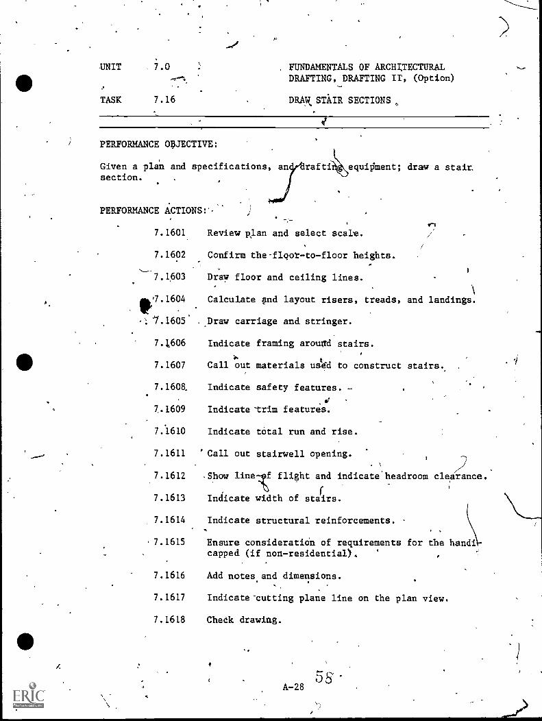
7.1601
7.1602
7.1603
Review Alan and select scake.
Confirm the-flqot-to-floor heights.
Draw floor and ceiling lines.
"7.1604 Calculate 1[1(1 layout risers, treads, and landings.
1.1605* . .Draw carriage and stringer.
7.1606 Indicate framing arouad stairs.
7.1607 Call out materials usk'dd to construct stairs..
7.1608. Indicate safety features. -
7.1609 Indicate-trim features.
7.1610 Indicate total run and rise.
7.1611 'Call out stairwell opening.
7.1612 .Show line f flight and indicate headroom cle rance.
7.1613 Indicate width of stacrs.
7.1614 Indicate structural reinforcements.
7.1615
c.
Ensure consideration of requirements for the hand\.Icapped (if non-residential).
7.1616 Add notes.and dimensions.
7.1617 Indicate-cutting plane line on the plan view.
7.1618 Cheek drawing.
A-28
UNIT 7.0 FUNDAMENTALS OF ARCHITECTURAL'',... DRAFTING, DRAFTING II, (Option)
.
. 1
TASK ..,7,;16T
DRAW STAIR SECTIONS (Cont.)a,
PERFORMANdE STANDARDS:
\
Trelad risers and slopes mist be reasonably within standards.- To i,nstructor's standards.
---S;1-G-agTED INK" CTION'TIME: 9 Hours
oft.
A-29(59
. #
c.
UNIT
TASK 7.17
PERFORMANCE OBJECTIVE:
''UNDAMENT OF ARCHITEtTURALDRAFTING, D (Option)\
Given a plan and specifications; draw a fireplaceA
'PERFORMANCE ACTIONS:
7.1701
7.1702
'SECTIONS\
and chimne .
Review design 'data and select-sCale.,
nfitni-the type*\size, and location of the fireplace and chimney.
7.1703 Show the properhearth.
7.1704
7.1705
7.1706
7.1707
7.1708
7.1709
7.1710
Indicate fireb
material and ektension of the
Determine chimney and lining diza.
Show mani , ductwork, cleanout, and damper.
Show finished trim.'
Indicate cutting plane line on the'plan view.
Add notes and dimensions.
Che'dk,,drawing.
PERFORMANCE STANDARDS:
- Instructor's dards.- Good architectural practices.
SUGGESTED INSTRUCTION TIME: 6 Hours
RELATED TECHNICAL INFORMATION:
SUGGESTED: Field trip to masonry glass in vôcational centerOr technical college for the purpose of observing actual con-struction of fireplaces (fireplaces possibly designed bydrafting'students).
UNIT 7.0
I.FUNDAMENTALS OF ARCHITECTURALDRAFTING, RAFTING II,COption) .
TASK 7..18 DESIGN AND DRAW DOOR AND WINDOWSCHEDULES
PERFORMANCE OBJECTIVE:
Given specific program requirements concerning doors and windows.snddrafting equipment; draw door and window schedules.
PWORMANCE ACTIONS:
..%4/74,1801 Collect notes aild sYmbols pertaining to the sche-
.dules. e
I7.1802 Make headings for,window sdhedule.
'i
\7.1803 1Make headings for door schedule.
). r,
.1804 LayOut schedules for the available space..
72\805 Layout ldt,tering-guidelines.
7.18 6 Letter A447d-uAs.
7.1807, Check for accuracy.
PERFORMANCE-STANDARDS:
- Schedules will appear on the same pages(s) in parallelcolumns.
- To instructor's standards.
SUGGESTED INSTRUCTION TIME: 6 Hours
A-31
.15
UNIT, 7.0 FUNDAMENTALS OF ARCHITiCTURALDRAFTING, DRAFTING II; (Option)
DRAW SCHEDULESTASK 7.19,,
PERFORMANCE_ oi.TECTIVE:. \
Given a set of architectural plans, interior elevations, ana speci-""fations and program requirements, and'architectural drafting equip7/ment; draw required schedules.
PERFORMANCE ACTIONS:
7.1901 Collect.inforination from plans, e evation$ andspecifications for plumbing, electrical, haragare
Nand finish schedules.
7.1902 Make a set of headings for,each schedule.\
7.1903 Layout schedule to fit the given location.
7.1904 Provide key f6r abbreviation explanation.
(
7.1905 Check' for- accuracy.
CE TANDARDS:
Instructor's standards.
SUVESTED INSTRUCTION TIME: 15 Hours
RELATED TECHNICAL INFORMATION:
- Sweet's Catalog.- Vendor Publications.
4
,
t/
A-32 62
I
/
UNIT 7.0 FUNDAMENTALS OF ARCHITECTURALDRAFTING,.,
DRAFTING II, (Optional)----",,-
TASK 7.20 .CHECK DRAWINGS, PLANS, ANDSPECIFICATIONS
.
\
PERFORMANCE OBJECTIVES/
/Given site and plplan,1t st Of specifications, list of specificrequirements and/features, an a copy of local building codes; checksite and plot la , correcting,all errors and omissions.
\Giv n plans, pecifications, and die& prints of exterior and interiorelev tions; heck-elevations/for line quilit , symbolizing, dimensiorm,neatn ss, nd equipment of'apecial tuEes lled for in
\speci ca ions.
Given ak itectural/engineering notes; sketche design data\and clientrequire ; check plans and specifications.
001 Check site and plot plans:a. Review design data, local codes, and
rigulations.b. CMck'boundaries and site,festures.c. Check lycation of structures on site.d. Check layout of recre#tional areas.e. Check contour lines and elevations.f. Check water drainage and storage systems.g. Check natural and physical limitations.
-h. Check circulatory features.i. Check modifications of existing site ements. Ajb.. Check utilities.k. Check legal dest_tiRtAnn oLrprt1. Cheek labels, notei;-: and dimensions.
7.2002 Check elevation drawings: ,
a. Check dimensions, labels, mind notes.b2 Check grade; floor, and/ ceiling lines.,c. Check schedules.d. _Check,footing and foundatlon lines.e. 'theck-roof slope symbol and.call out of
material.f. Check cutting plane lines and detail
identifications.
NOTE: For additional performance actions aee theV-TEC catalog; Architectuial Draftsman.
*- A-33)7'
(33
UNIT 7.0 FUNDAMENTALS OF AittHITECTURALDRAFTING, DRAFTING II (Optional)
TASK 7.20 CHECK.DRAWINGS, PLANS, ANDSPECIFICATIONS
'PERFO CE ACTIONS (Con't.):
7.2003'
Check Architectural plans and specifications:a. Compare plan with notes, sketches, design, and
specifications (requirements) architect's/engineer's or given data. .
b. Check and verify dimensJia2s.
C. Check and verify notes, 7ffttering, andreferences.
d. Check architectural conventions and symbols.e. Check and verify title block information.f. Check plan fqr line quallty and
reproducibility.
PERFORMANCE STANDARDS:
sts-
l- The findings of the checker Cstudent) must concurWith thefindings of the instructor.
SUGGESTED INSTRecTION TIME: -3 Hou;s
rA-34.
411..
UNIT 7.0 FUNDAMENTALS OF ARCHITECTURALDRAFTING, DRAFTING II, (-Option)
TASK 7:2140ptiOnal) BUILD PRESENTATION MODELSa
:Yr.\
PERFORMANCE OBJECTIVE.
Given preliminary design drawings, specific instruction, necessarydrafting equipment includ ng scale, cuttin&tool, metal straightedge,adhesive, and matboard; b ild a presentation model.
PERFORMANCE ACTIONS:
7.2101 Rev ex:7 model specifications and requirements.
7.2102: La out boards tb be used at large work station.
7.2101 C a large, solid 'section of material to be used-ast e base.
7.2104 raw the plan of the building'on the top of thease.
7.2105 Layout the shape of the walls, roof, and floorsurfacesof the proposed project dnto the boards.'
i
.
2106 Cut out the shapes from the boards.
7.21 Cut out any wall openings.= the individual shapes.
7.2 08 Assemble model elements.
7 2109 Add surface materials.
7.2110 -Add title, nofth arrow, 'and grdphic scale.
Add periphery embellishments:-
PER ORMANCE STANDARDS:
- Instructor's standards.- To given scale.
SUGGESTED INSTRUCTION TIME: Optional
A-35
65_
UNIT 7.0 FUNDAMENTALS OF ARCHITECTURALDRAFTING, DAAFTING II, (Option) ,
//
USK 7:22 (Optional) DRAW NEW RESIDENTIAL CONSTRUCTION,(ACCZIZEATEDATUDENTE) WORKING-DRAWINGS
pERF9ANCE OBJECTIVE:
Given.existing information and 'Nrwings for a particular residence,deqide whether_or not it Oovides appropriate information for thebuilder. Mtain and provide any necessary additional inform2tion.
PERFORMANCE ACTIONS:
7.2201 Describe the purpose and order of working_drawings./
6
7.2202
7.2203
7.2204
./205
,
Select correct sheet size fot working drakfings.
Layout working drawing!.
Identify'points of emp4sis of working drawings.
Use correctly symbols and conventions.forconstruction materials and construction views shownin detail drawings, by referring to Sweets Catalogs,AIA Manuals, and/or other techn 1 references forinformation.
7.2206- Prepare final working drawings,-a, Floor plias g.b. Elevations h.
f
c. Sectionsd. Detailse. Mechanical pf. Electrica plan
I
j
Plumbing plan_Foundations
andmiscellaneous,details
Site plan andtitle sheet'
PERFORMANCE STANDARDS:
Task performed within time limits consideredfor initial employmentrjob qualification.Meets instructor's standards. .
LetWing and drafting skills ahould show neatness,conirgtency, proper placement, and character.Draws working drawings correctleeting entry level-- .
employment requirements for an architedtural drafting office.
to be acceptable
, .
accuracy,
4
SUGGEgTED IN'ETRUCTION TIME: Opt onal
6 6"./ A-36
, UNIT 7.0
TASK 7.23 (Optional)
-
FUNDAMENTALS OF ARCHITECTURALDRAFTING, DRAFTING IT, (Option)
IDENTIFY KEY PARTS OF CONTRACTUALSPECIFICATIONS-
a
PERFORMANCE OBJECTIVE:
Given instructions, a set of specifications for a residential construc-tion;, dembnstrate the ability to differentiate between codes, specifi-cations, and contract documents; state their purposes, provlaions,general format, parts, administration, and responsible agencies forenforcement with at least 70 percent accuracy.
NOTE: This is an Orientation task.'
PERFORMANCE ACTIONS:-
7.2301 Identify CONTRACTUAL DIVISION of specificatibn:'a. Provisions and proceures for contract
adv9rtisement.b. ProVisions for instruntion to bidders.c. Provisions for contrac proposal procedures.d. Provisions for general ènditions.e. Provisions for amendment to general
conditions.G f. Provisions for cohtract *su lementary general
.conditions and definition procedures forgeneral requirements of the p\rofect.
7.2302 State types of contract documents 'o include:a. Contract agreements.b. Performance bonds.C. Insurance policies.
7.2301 Identify purpose and content of speci ications:a. General contract specifications.b. Format and outline for specifications.c. Outlines of typical specifications.
7.2304 List or match.the'parts of contract specificationsto include:
a. Title page.b. Table of contentso
/I-f- c. - Contractual or biddihg requirements.
d: General contract. 4
e. Mechanical specifications (plumbing, heating,and refrigeration).
f. Electrical contracts.C---"S'Oecial separate contracts (special Auipment,
.
sewage disposal, water system, siie utilities,
h. Addendum .(phrpose and formht).
Ar.37 Ii
'
UNIT 7.0
TASK 7.23 (Optional)
'FUNDAMENTALS OF ARCHITECTURALDRAFTING, DRAFTING II, (Option)
IDENTIFY KEY PARTS OF CONTRACTUALSPECIFICATIONS (Con't.)*
t ,
PERFORMANCE AC ONS (Con't.):
7.:2305
-
Identify the agencies 'responsible for building codeenforceuent to include:
Local. .
State.Federal.Zoning.. NO'
Building inspector, health department, etc.1
/
a.
b.
C.
PERFORMANCE STANDARDS:
Demonstrate the a Blility to differentiate b tween codes,Specifications, and contract/documents; s te the purpose,pravisions, general format, parts, administration andresponsible agencies for enforcement with at least 70 percentaccuracy.
SUGGESTED INSTRUCTION-TIME: Optional
RELATED TECHNTCAL INFOEMATION:
Building codes.Zoning.
- Contracts.
0
A-38*
13.v
" '
et
.
4
.PitOVICIENCY REPORT
,
114
1
t
-A-739
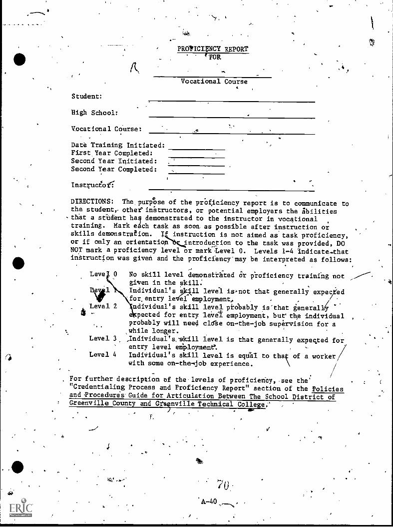
PROtICIPTCY REPORT1FOR
. :4
Vocational Course4
Student:
High School:
Vocational Course:
Date Training Initiated:First Year Completed:Second Year Initiated:Second Year Completed:
InstpicioI
DIRECTIONS: The purpOse of the prOf.iciency report is to communicate tothe studente other'intructors, or potential employers the ibilitiesthat a stUdent haq demonstrated to the instructor in vocationaltraining. Mark eAch task as soca as possible after instruction or ,
skills demonstration. I instruction is not aimed as task proficiency,or if only an orientation introduction to the task was provided, DONOT mark a proficiency level or mark 'Level 0. Levels 1-4 indicate...thatinatruction was given and the proficiency-may be interpreted as follows:
,Leve 0 No skill level demonstrhted Or iroficiency training not
given in the skill:Diil Individual's 0411 level is,not that generally expec/ied
for,entry leVai employment, . , .
Level 2 ndividual's skill level prObably is'that generalkAr - pected for entry leVei employment, butsthe individual
,
,,probably will need chile on-the-job supervision for a
% ,while longer..
Level 3 ,Individual's.skill level is that generally expected forentry level eMployment: ,
Level 4 IndiVidual's skill level is eqUhl to thaç of a workerwith some on-the-4job experience.
//, For further description of the-levels of proficiericy,.see the'"Credentialing Process and Proficiency Report" section of the Policiesand ,ProcedureaGuide for Articulation Between The School District ofGreenville County and Grenvil1e Technical College.'
. aw-
T. ,
-
A-40
70
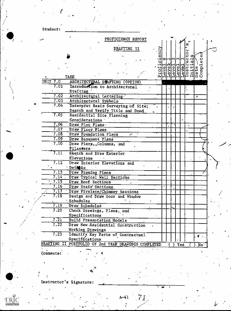
Student:
ZW
..-1
.244WWWW344-1W04
0s..1wwwwwczoO,
0,t>
r--I
ri(i-i>
C1
>
Crl
e-4
>
e
01
i--k
.>;(1)..-14.)
W
w
.S) CI)
() r--4Z RIW -.-1
crr'''.4.1
Wr-4
E
.
DRAFTING II
,
#.
,
.
,.', TASK
UNIT 7.0 ARCHITECT1AL DVAFTING (OPTION)
.
7.01 IntrodU ion to Architectural .
- Drafting' 7.02 Architectval Lettering:' . 6,
703 Architectural Symbols7.04 Interpret Basic Surveying:of Site:.
Search and Verify Title and Deed,
7.05 Residential Site ylanningConsiderations'
.
7.06 Draw Plot Plans- I7.07 Draw Floor Plans .
7.08 Draw Foundation Plans7.09 Draw Basement Plans .
7.10 Draw PieraColumns, andPilasters--
1
7.11 Sketch and Draw ExteriorElevations
7.12 Draw Interior ElevatiOns and.
- -DetAtis7.13 Draw Praming Plans7.14 Draw Typical Wall Sections
' 7.15 Draw Roof Sections .
7.16 Draw Stair'Sections.
.
: 7.17 Draw Firelace/Chimney Sections7.18 Design and Draw Door and Window
, -.Schedules7.19 Draw Schedulei .,7.20 Check Drawings, Plans,,and
Specifications
_
7.21 Build Presentation Models .
7.22 Draw New-Residential ConstructionWorking Drawings
.
7.23 Identify Key 'Parts of ContractualSpeciffcations
.1
DRAF.TING II PORTFOLIO OF 2nd YEAR DRAWINGS COMPLETED ( ) Yes ( ) N
Comments:
Instructor's Signature:^
A-41
faF
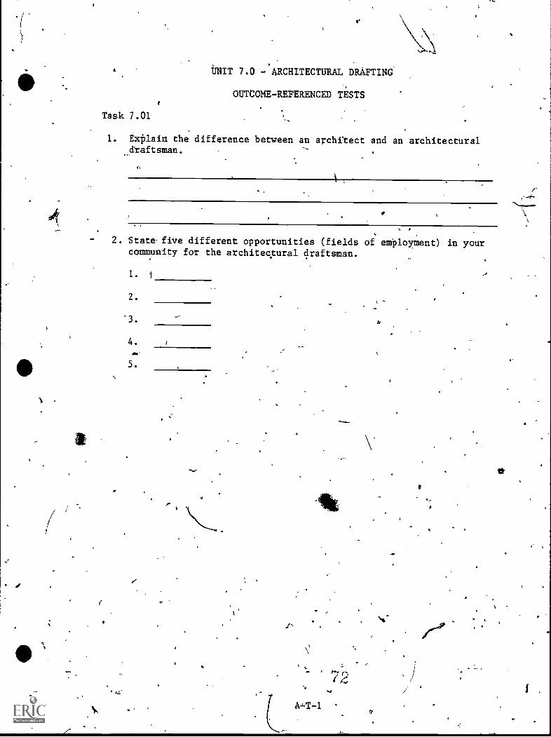
40
1
UNIT 7.0 - ARCHITECTURAL DRAFTING
OUTCOME-REFERENCED TESTS
Task 7.01
1. ExPlain the difference between an archftect and an architectural&raftsman.
2. Stata five different opportunities (fields of employment) in yourcommunity for the architectural draftsman.
1. 1
2.
'3. *
4.
5.
A,-T-1
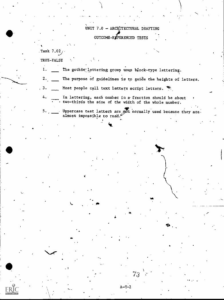
4
%
.Task
TRUE-FALSE
UNIT 7.0 - ARCIATECTURAL DRAFTING
OUTCOME-RieERENCED TESTS
1. the gothic:lettering group usas bZock-type lettering.
2. The purpose Of guidelines is tp guide the heights of letters.
3. Most people call text letters script letters.
4. In lettering, each nmmber in a. fraction should be abouttwo-thirds the size of the wddth of the whole number.
5., Uppercase test lette;t arezoot.normally used because they are,almost impossible to rea'd.'''
a.
4%
4.
A-T-2
73
I.
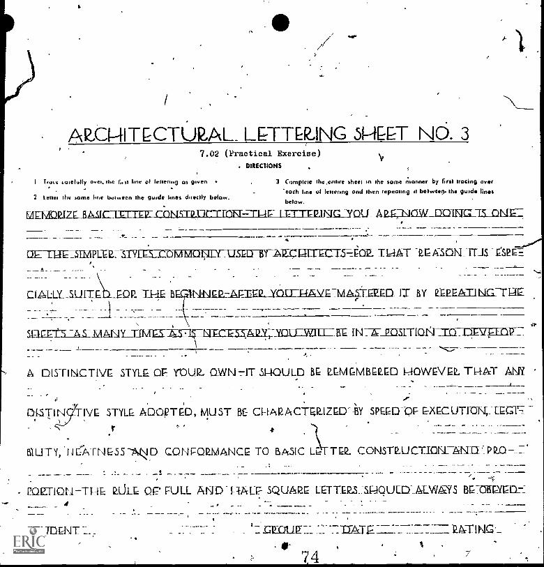
ARE1-11MCTUVAL LP-TER,ING SHLET Nb. 37.02 (Practical Exercise)
DIRECTIONS
lime sateluIly meet. the lost line of lettering as green 3 Complete thcenttre sheet in the some nionner by first tracing Overeoch hne of lettering and then repeating ti betweea- the guide lines
2 letter the some Ime between the gutcle lines directly beta.,below.
MEMMIZE... BASIC-Lla-ITEEilL13114=TONE----1-1-1E_LET=INGIYOU- A 2...EJACIW_DO1E11..,
CIE-DAET.-SERIPLEISTYI=E:Er.ONIVONLYTISED-IgTNEPAII. 6 C. .1,54CIP-TIAAT VSPE.F._
cLialUITE _EDP, TH B
suai-ffLiLLIA
NINEE:-AnEIL YOu-s4A,v.E-I/14712ZED IT BY P:EPEAT.114G-TI1E
- a-c IN7A-Jasman m vitt
A DISTINCTIVE STYLE OF. YOUR- OWN-HT SHOULD BE REMEMBERED 1,10WEVEL TL---E&T ANY
0
IVE STYLE. ADOpTED, MUST BE- CHARACTELIZED--aY SPEED-OP EXECUTIOK:LEGTE
B1UTY,ATN5D CONFORMANCE TO BASIC LE TER. CONSTEUCTIOU-ANDTPR.O-,
I.
PCIILTION -TI-IE RULE 0E. FULL AN D 1---IA LP SQUARE LETTERZ.:SPI. QUICi_.ALWALYS BE-rofiL1Ea-7.-_I
STUDENT . ..GPIYUff T.:* 7:DATE =7:17.= 12ATING._e.
7 4
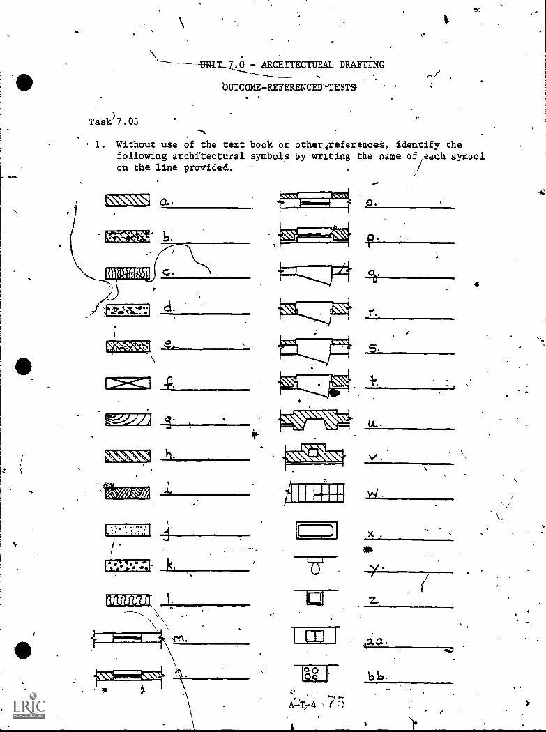
- ARCHITECTURAL DRAFTING
'OUTCOME-REFERENCED-TESTS'
Task'17.03
"-
1. Without use of the text book or otherireferenceb, identify thefollowing architectural symbols by writing the name of each symbolon the line provided.
-P.
E=f:1
h.
k,
0
U..
v.
I"00
otr
b
4
Unit 7.0 - Architectural Drafting (Con'te)
Task 7.03
2. From given AIA architectural symbols selected by the iiistructor,ident\ify the standard symbol1s with 90 percent accuracy.
3. Given sn assignment by the instructor, correctly draw architectural
symbola and apply abbreviations as required by the instructor with100 percent accuracy.
44
A-1-5
PO
-
41'
UNIT 7.0 - ARCflITECTURAL DRAFTING
OUTCOMBREFERENCED .TESTS
Task 7.04
/AT Give an a
4
ignment by tfre'instructor, the necessary surveying
i.)
.equiptien and helper are required; measure required distances andangles to within acceptable error limits for entry level drafter inarchite tural office (to the instructor's standards).
2. Gie an assignment bir the instructor, the necessary surveyingquipment, helper(s) as needed, and necesaarydinformation; survela
' given site with 80 percent accuracy in calcul4tio?..6. and measure--ments.
3. Outl4ne the basic steps necessary to search and verify a site deed'in Greenville County, SC. Theisteps outlined must be 100 percentcorrect and must meet-the instructor's'standards.
A-T-6
41r),
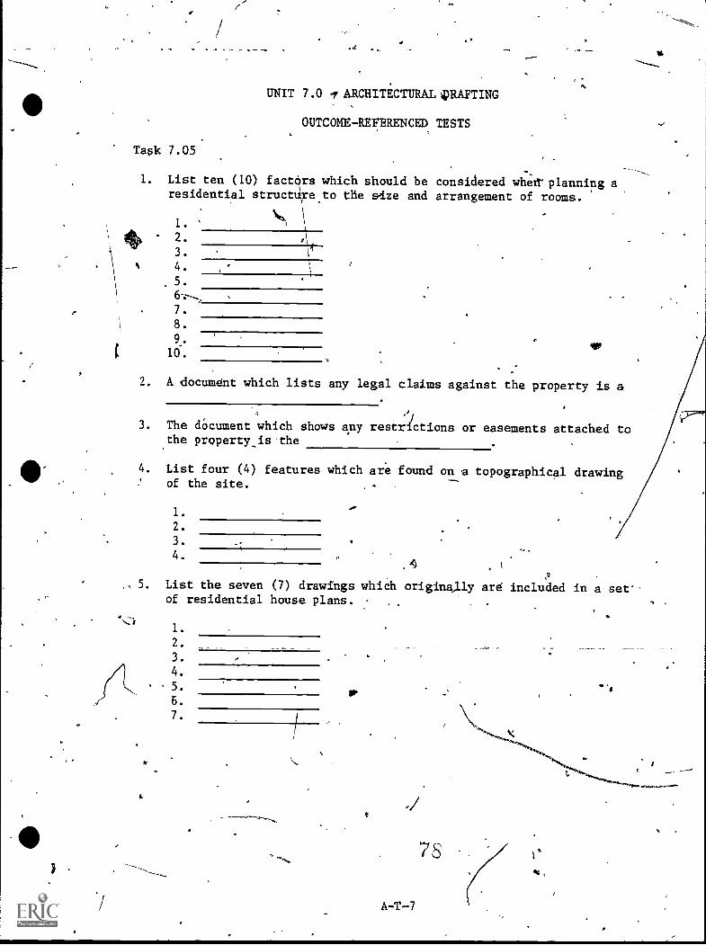
UNIT 7.0 I ARCHITECTURAL QRAFTING
OUTCOME-REFERENCED, TESTS
Task 7.05
1. List ten (10) factOrs which should be considered whet!' planning aresidential structd,re.to the adze and arrangement of rooms.
1.
2.
3.
4.
5.
7.
8.
9.
10.
2. A document which lists any legal claims against the property is a
3. The dOcument which shows any restrictions or easements attached to.the property,is the
4. List four (4) features which are found on topographical drawingof the site.
.
1.
2.
3.
4.,
, 5. List the seven (7) drawings which originally are included in a set'.of residential house plans. ,
1.
2.
3.
4.
5.
6.
7.
A-T-7
.,.<4.*....
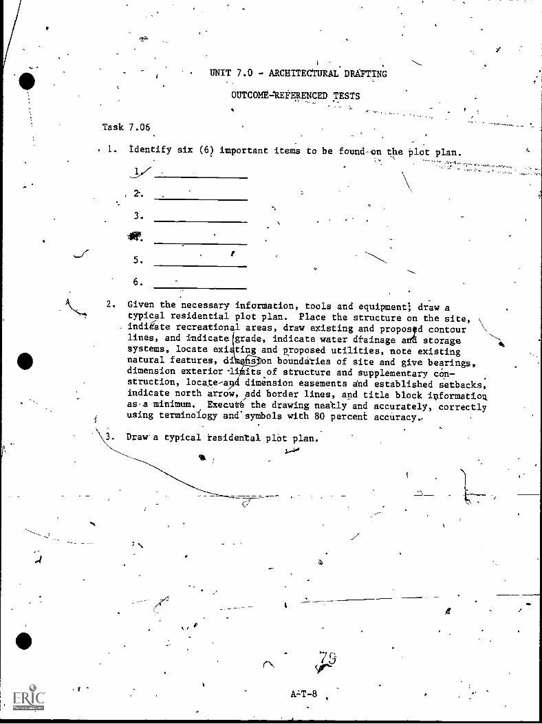
)
UNIT 7.0 - ARCHITECTURAL DRAFTING
OUTCOMEAE#ERENCED TESTS
Task 7.06
s,_
, 1. identify six (6) important items to be found-on the plot plan.
, 2.
3.
5.
6.
2. Given the necessary inforMation, tools and equipment; dr-aw atypical residential plot plan. Place the structure on the site,indiCate recreational areas, draw existing and propos d contour
N,lines, and indicate grade, indicate water dtainage arts storage
-`4
systems, locate exi tisg and proposed utilities, note existingnatural features, dio-Aflon boundaries of site and, give bearings,dimension exterior id itsof structure and supplementary cOrt-struction, locate-a2 dimension easements and established setbacks,indicate north arrow,jadd border lines, and title block informatioqas,a minimum. Executé the drawing neastly and accurately, correctlyusing terminology and'symbols with 80 percent accUracy. ,
Draw'a typical residental,plOt plan.
1-40ik
r
r\
a)
79Yr-
A.LT -8 '
f*G.
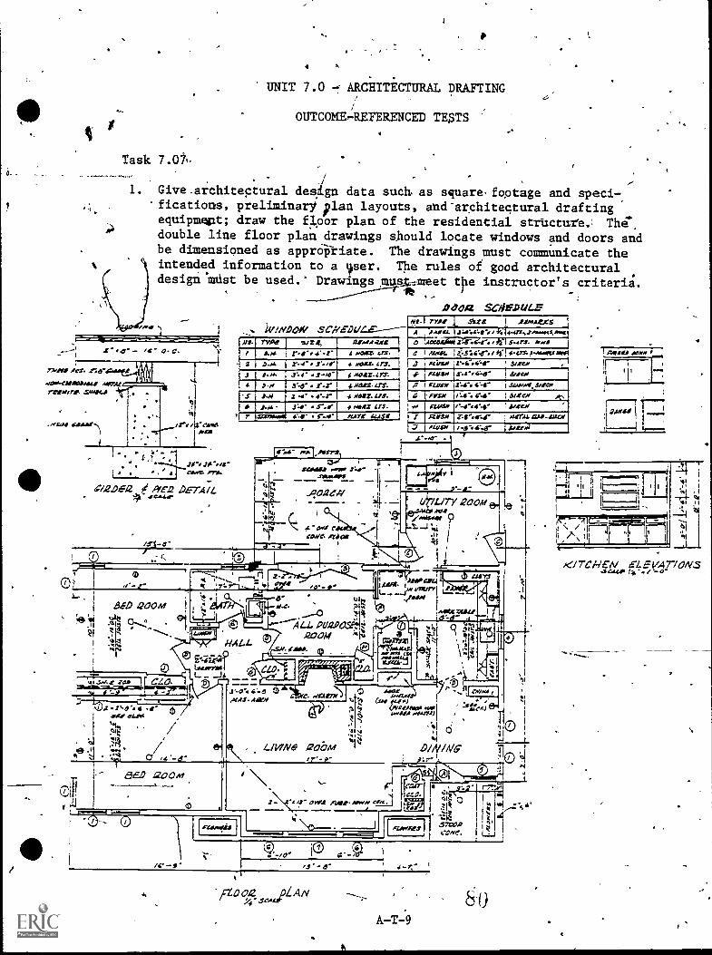
UNIT 7.0 ARCHITECTURAL DRAFTING
OUTCaME,4EFERE10ED TE$TS
Task 7.07t,
1. Give.architectural desXgn data such as square.footage and speci-,'fications, preliminary plan layouts, and-architectural draftingequipmant; draw the fl,00r plan of the residential structure The-,
double line floor plan drawings should locate windows and doors andbe dimensioned as apprOkiate. The drawings must communicate theintended information to a var. The rules of good architecturaldesiga.MUst be used. DrawingsjRiqt4,meet tpe instructor's criteria.
0404 SCMCPULE
73,141 Act- .n.5-
O C. ;412CIII01.441' .14,3:41resAllr. YMCA
/To /4.4vetN42.
I
, Caor.6 Pria.Jr. .211.41--
-41.2.912 Plea DETAIL.
ite,W,041W,vs.1 rrog Art .,,w.a.ers
Spite-P------- -.4 A.4.w.u. .1:4r44,11-0/41;r4.413.,........sto.04,11.44.21(13 1 7-i:744:024-.4.1,S-4rs. .....4
4 ..023. crs. , e I mac 1441,4tr./ 41 -0.s. 0.....oes awes' sized, ,
SCHML
3
4
IVA!, w24:
I2'.4" ..1.-mrI:4" 1.40'.
.3N-.s.
.e.rz .4- 4%-r t
.01113. irs. 1 4,7 ?
NOtz..47T. 1. la:- 4"-erHAIM as. 1
4 moss.11S.
iA4 34' 5-.0'SarAj 0.111' 3--
ONLY in.
Amem
Ar 1 nuns le-dr. i =omit, ilea,VWS,N C".11.0S e-44%
./LAYZ 41.4$3 , I
mal,1STS
LdheC/1
AMC,/hum, CAP.SOCII
/WAN /
se.0S J=d1.4.44/441114. I
0.-
CCOI/C fac
AiALL
E-cifFrf64..72.4
4'-el 0.1.444,11)
4teaC
WI ices)&WM., AAA, :Vert)
0,46,71)
L.1117N6 ,20i7A4
0
D/N/NG
ae.D 200mCairCZO.
RV"
ICZOO/2 ILANSCA
A-T
.171-711,1
I.
/
/t/TCHEA/ et VAT / ONS4.
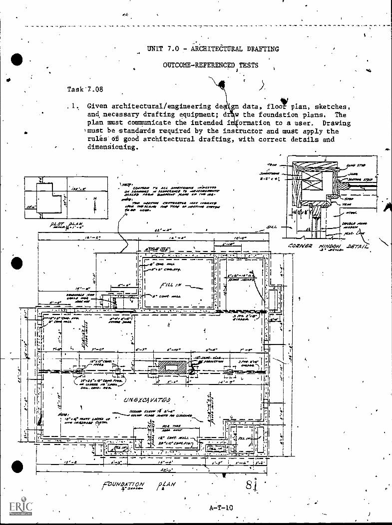
UNIT 7.0 7 AildlITEdTURAL DRAFTING
OUTCOME-REFERENCpiTESTS
Task'7.08
1. Given architectural/engineering degn data, floOtiplan, sketches,and,necessary drafting equipment; d w the foundation plans. Theplan must communicate the intended in ormation to a user. Drawing+must be-standards required by the instructor and must apply theruleS.Of good architectural drafting, with correct details anddimensioning.
1.2s
,PLD7 e1014.1.
1141.GZSAWIMA ra ott4 JAWMIt/41. I.40(41114.
O. JAPLYWat AISACCIMPA077-wares,. "Rao Immoram 'Omar Ala
//4#4,TM/ MAIIMNI CAPATVAIIMIA otIAY tlWW711
AoNs rso *tame "eV Mar ea meow.* "yew*?ar IMMO.
-am
.AwarmwZt'y
,4)
JANII
IL
AW7WIS 1771#
111111.11.1
L;151'
'45°J7ragP
ummilC004/.6Z .74/L.
...VCA441.
SAC/.
aysoc
AftWOmmeemo0Mo,staf
a.1121011441 NUMammo ova
Mot yof.. +.1 L I
T77-7 r,
_ _arvi - , -
IIVANKAL yen%a. Cal mem AIkt I
.41.1
4-
COM mta.emomla
/
core. muo
f resinAVIS
L.Irste a" dant fires.
caw>. .1.4141.&WI At O.
s newt matela vs,mry mmessroar elsom
o-4.- r -r
t1 I."someway .1. j"ess aSo
r i meows') !I 7=7reEr..!."AMON;
..... -I t--,1 t,.' - s'
XCelVA7..D
344A'""...."4141 AZIIIIt Awry' Aar csoOssra
FM4
.414 ?AR!ANA
.14
Ax- taw. ocac
: 1
I 1'7 I. ..., Pa. pi....,4 it /4Pi/O'ClOt..er" 1 . ' '-' l, / , i
...,-...,4. -T. ,,,,,- ; r 4- I4.-Y. '
I
fan,kV A7 I N /IA A/'N
i
A7T -101
.
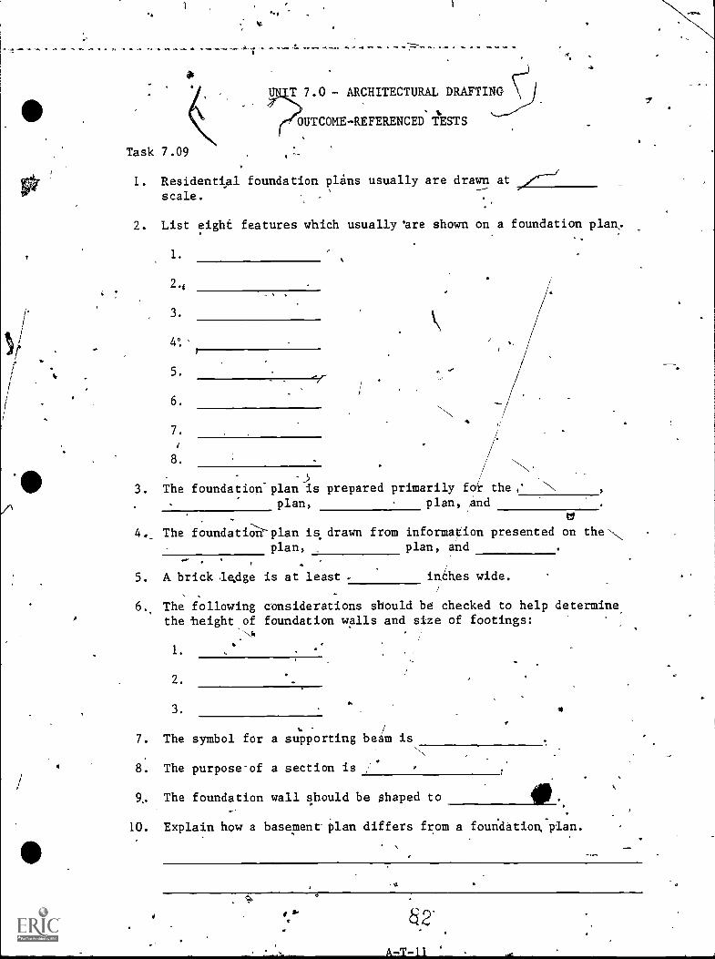
-a 4-
Task 7.09
T 7.0 - ARCHITECTURAL DRAFTING
OUTCM4E-REFERENCED TESTS
a
1. Residential foundation plans usually are drawn at
scale.
2. List eight features which usually 'are shown on a foundation plan,
5.
6.
7.
3.
.3The foundation-plan is prepared primarily for the,'
plan, plan, and
4. The foundatiplan is drawn from information presented on theNplan, plan, and
,
5. A brick le,dge is at least . inehes wide.
r
6., The following considerations should be checked to help determine,the baight of foundation walls and size of footings:
1.
2.
3.
7. The symbol for a supporting beaM isu
N,
81 The purpose-of a section is
9, The foundation wall should be shaped to
10. Explain how a basement plan differs from a foundatioA plan.
u
';;,
A-T.-11
Task 7.09 (Con't.)
411. .Given,architeotural/engineerilig design data, floor plan, sketches,
ardhitectural drafting,equipinent; ;yaw a basement plan for a resi-dential atructnre. The finished drawing must exhibit the rules'ofgood architectural drafting, with correct dimerisioning.,
.4
,
tr.*
s.
'/
4
, t, ^
1 ,
4_
14
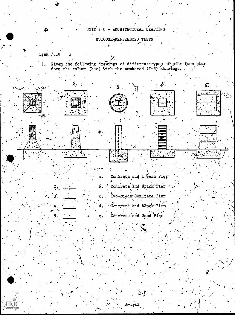
I
T4sic 7.10 A
I
UNIT' 7 .0 - ARCHITECTURAL iRAFTING.
0UTC0ME4EFERENCED TESTS
1; Given the following dracings of different-type9 of..pir from.,pier,' form the column Ca-e) 'with ,the numbered (:-5)'cltacriitgs.
4; . -
I
.3.'
: a,. ConCrete and I 4eam Pier', .
. , .,. b. -4 Concrete -and. 13'ricit'itier
t,... , $ . , .,
c. 2, Two-plece Concrete Pier, , . ,,
. ld'. Concrete 'and Altooi.:Pier,- A
_COnerete'aid Wood Pier4.
a
' .
r,
,t
t
,,
(
,Task 7.,11
,14 4
UNIT 7.0 - ARCHITECTURAL DRAFTING
OUTC0ME-REFERINCED TESTS 0
v
1. Raven a plät plan, floor plan, specifications, foundation plans,b'asic exterior design, well-.section, sketch of preliminary ele-vations and,drafting equipment; draw exterior elevations for a
residential structure selected by the instructor. Drawings mustapply ehe rules of good architectural practices and-drawings must,meet the instructor's standards. -
.(Instructor to supply iiven infornati6
TV,JE-FALSE,
.1*2. Three (3) elevations are tied to shaw the exterior of the
average house.
3- The side elevation usuelly is drawn first.
4. The roofir?f'a elevation vie; is.blac*d in%y ocating the.,ridge and cond.ces.
,
a,.
5. Doors and windows-...are located on the elevation view by. theircenterlines:
6.
*/
. 4.
,
SymbOls,ere used on,elevation views to'illustrate tbe types pf ,
winchiwslto.be*ed. P
*to'
, A-T-14
+or
11.
UNIT 7.0 - AHICT1JRAL DRAFTING
0UTC0ME-REFERECED TESV
Task7.12
1. Given.a floor plan, list 4 materi ls, specific ions, suiTly.catalbgs, and architectlioral drafting equipment; a w interiorelevations and details as required by instructor'for 'A selected
-4 residential structurer Indicate: True width offwalls, all open-ings in interior and exterior walls, true heights or-width-ofopenings, typical elevations of millwofk, air.ciroulatory systems,utilities, .trim and molding and other details as required. Fin-ished drawings must meet initxuctor's standards.
(Instructor to supplysiven information.)
TRUE-FALSE.a
2. todetail is any part that is drawn to show sections!,
3. A detail Of a slairway is unnecessary when the stairway is amanufactured, sfock
4.. A horizontal section, vertical section, ana front elevationusually 'are needed when detailing a fireplace.,
5. Bathroom lavatory cabinets and'built-ins in bedropms,usUallyao not need details.
6. The dimension reqUired on the typical gtair detail are therise, tread and riserisizes,.headrodecrearance, and the' sizesof the balustOts,and the newel posts irthey are used.
a ,
,
,A -T -15
.10
.
'410
-0'
UNIT 7.0 - ARCHI:TECTURAL DRAFTING
OUTCOME-REFERENCED TESTS
Task 7.13 -
,l. Given working dtawings,.engineering design data, sketches, and.,drafting cluipment; draw g'framing plan. Show exterior bearingwall, structural supports, joisfs and headers, ridge boards,rafters and trusses, double headers and timmers and indicate
' location 'of bridging. The finished drawing must be to acceptablebuilding,stafidards, and must be acceptable to the instructor:
(InStructor to_s4ply given items.)
TRUE-FALSE
2. -When selecting a proper joist spe, the total load, type ofmaterial, and distance the joist must span must be considered.
3. Roof pitch influences the span of the rafters.
4. If the design load for a joist exceeds the normal figures for
110residences, maximum spans should be doubled to prevent over-stressing.
5. A rafter must be able to carry the nOrmal live loads imposed
I
upon. it, as well'as the dead lAd of its own weight.
6. A collar is installed between two ,truss members that are heldtogether with bolts. ,
A-T-I6
7
I.
\K
, Taqk 7.14
,
1. Given f plan and sRecifilations and architectnral drafting equip-'ment; draw typical wall section to instructor's standards.Indicate size and type of floor matecial, show proper coursing of
f wall materials, indicate elevations, draw waterproofing apid flash-ing above and below wall opening, inldicate method of insulatingwall, indicate termite shield, 'indicate plan lines on the planview, and add dimensions and notes. Finished drawing must Meetinstructor's standards.
UNIT 7.0 - ARCHITECTURAL DRAFTING
OUTCOME-REFERENCED TESTS
1
TRUE-FALSE
2.
ro, *
Floor,joists typically are boltedto the sill
The sill is typiCally fastened to the foundation by nailing onr, either side%, , . ... 1
4. Exterior wall studs usually are placed 12 inches on center.
5. Wall Atuds.are doubled aroUnd any-wening in a bearing parq--tion.,
6. When an interior partition meets an exterior wall, there is nonailing,space provided for lath or drywall sheets, so an extra-stud is added to the exterior wall.
7. Shea'thing,strengthens the wall by resisting lateral movement-.-
of
Bridging on a house consist of rows of small,, diagonal braces,,nailed between the studs. ,
A
9. ,'Bridging distributea the load on the floor over a widdt-aTea-ij'stiffdins tflr, and helps prevent warping.
Of10. A heircler is us4i to 'support cut.joists when 411 opening has
been cut.;" 4
z
-11. ° Wood siding must be nailed through the sheathing into the istuds.
,
p.4 ,
A-T-17
#
4'tt
t
c
r
;
Task 7.15
1. Given a plan and sp,cifications'and datafting equipMent;, aw anattit section to instructor's sSandeyds. ShoT4 the. methbd'of
securing the ceiling joists and roof rafters to the %port wall;draw the type and show the Tlacement of bri4ing'betw%en joists;show the insulation; showthe roof construction including overhand,gutter locations, and ventilation; indicate cutting plane 1 ee onthe plan view; and add dimensions and notes.'
\
))/UNIT 7.0 - ARCHITECTURAL DRAFTING
OUTCOME-REFERENCED TESTS
fh-t3
TRUE-FALSE ,
2.
3.
The span of rafter is the clear distance from ,the center ofthe roof to the point supporting therafter.
Rooff Tdtch is the angle of the roof from the ridge pole to the° plate.
4. Slope is the ratio between rise and'run.
lot'plan.is to locate the5. 'Thejoain°purpo of a 'roof a dhouse on the lo
6.. Lending instit tions insist t.
septic tanks,Aor sewer lines.roof and pfot plan. .
' 0
'4
at the locationstpf wells,if ex/sting) be reprded on the
4
, 4,\,..Nee
4
1e
1
0
7.":4
A-T-18 . / oft ,
-
4 -
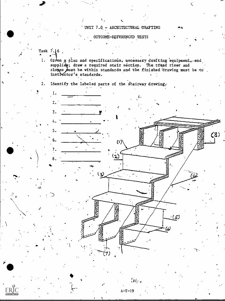
'UNIT 74.- ARCHITECTURAL-DRAFTING
OUTCOME-REFERENCED:TESTS
Task f.
91, 4
1. Given a plan and specifications, necessary drafting 'equipmeni.,-andsuppli ; draw a required stair section. The tread riser andsb es st be within standardsand the finished 'drawing must be to'last ctor's standards.
2. Identify the labeled parts of the ftairway draringy
1.
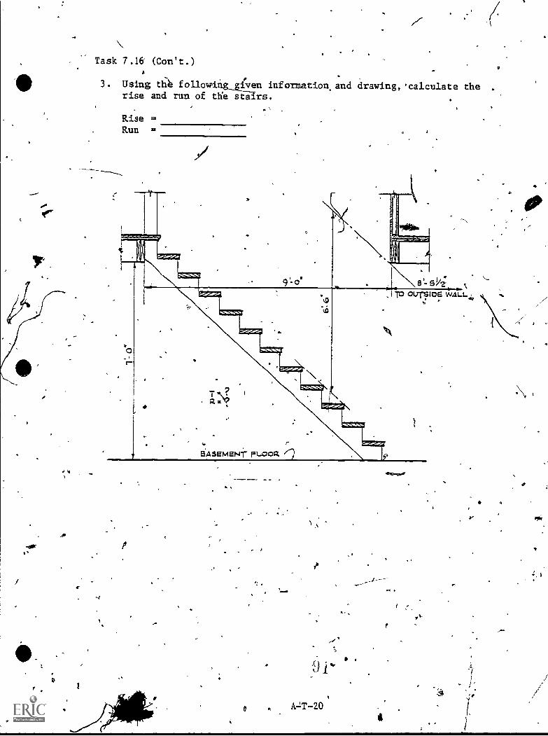
.44
A
Task 7.16 (Can't.)
3. Using t1.1 followl' 1!;.ren'information.and drawing,'calculate therise and rim of the sta rs.
1
Rise =Run =
A.J.T -20
I

--
,Task 7.17,
I
UNIT 7.0 - ARCEINTURAL DRAFTING
OUT0OME-REFERENCED TESTS.
. .
1. Given a-pla and specifications, draw a fireplace and chinney.,- ShowProper material and extension of the hearth; indicate fire-
bfick;,show chimney and lining size; ,show mantel, ductwork," clean-.
' out and damper; show finished trim; indicate cutting plan line of- plan view, and dotes and,dimensions. The completed drawing mugt
reflect good architectural practices and meet instructor's %tali-,- dards. '
41%.
TRUE-FALSE
/2t A chimney wail should be at leasi,4 incheS-I4ck.'
13. An air space of 6 inches should be ,alrowed between the chimneywall and framing members of a building.
4: A chimney should project,24 inches above the ridge of theroof.
411, The entire fireplace hearth is supported by the chimney
footings and foundation.
a
6. A fireplace hearth should b a least 12 inches in front.of,
the fifeplace opening and at leas A inches on each side ofthe opening, '
4
<,
A-T-21
7t4
1
9
4
-Pr
0.`
UNIT 7.0 - ARCHITECTURAL DRAFTING'
OUTCOME-REFERENCED TESTS
Task 7.18
1. Given spectfic requirements concerning doors arid windows' andnecessary drafting equipment; draw door and window sehedirles.
.
FirrIshed schedules must appear on ame page(s) in parallel columns,
ti#
must be -lecurate/Properly letter d to meet minimum iequirements ofgood architectural drafting prac ices, and must meet instructor'sstandards.
fr
(
A-T-22
'1
4."
,
+
Ar
Task 7.19
UNIT 7:0 - ARCHITECTURAL DRAFTING
OUTCOME-REFERENCED TESTSt
,/
1. Given,a set of archigectural plans,:interior elevations, andsPecifications and program requirements, and architectural draf,tingequipment; draw required schedules. Make a heiding for eachschedule, layout schedule to fkt the given location, proyide a keyfor abbreviatiot explanation. Finished schedule must meet,instruc-tor's standards.
-
'1a
.A -T -23

F
UNIT 7.0 ARCHITECTURAL DRAFTING
OUTCOMELREFERENCED TESTS
1
Task 7.20 - 7:23 P.
TRUE-FALSE
Specificationaare written to describe items that cannot beclearly shown.on the drawings.
2. To umke a bid on A house, a conFactor must have a,completegtt of detailed specifications.
3. The first part of the specifications is called "GeneralConditions."
4. The first division of a set of specifications deals withAschedules.
4
5.. Typically, specifications states that umsonry jOints should be3/8 inches wide. %
6. (--SpecificatiOns should state that the excavation must be keptfree from water and that water should not be conducted ontoprivate property:.
4
A-T.124
1
9
Unit 7.0 - Architectural .Drafting
/"--Answér Sheet),
. Task 7.01
1. (Possible answer) 1
"The architectural draftsman typically wor6 for and under theI,
supevision of an architect and primarily draws pictorial andworking.plahs for'structures such as houses.
e draftsman may be responsible for copying details fran therings and with,more txperience for detailed planning such as,
the ize 'of 'structural parts and methods of joining them.
The chitectur"al draftsm4n shoula have a *minimum of two years.of,trai ing in a high school drafting program but completion of a
A. two-1 ear technical education training program will better qualify'41 the raftsman.
2. (Short answer)
Tas.k. .02
1. true
2. true
3. fa14e (Old English)
4. true
. 5. true
TIsk 7-.03
4
t
N
N.
Unit 7.0 - Architecturali Drafting (Con't.)
Task 7.03 (Con't.)
j,k,
j.k.
1:
m.
n.
0.
0.
q,
r,
S.
t.
U.
V.
w.
x.
Y.z.
aa.
bb.
2. Performance test
3. Performance test
Task 7.04
1. Performance test'*kw
2. Performance test
3: Performance test
YIP
A-T-26
I.
C
Q
, . C
)
Unit 7.0 - Architectural Drafting (Con't.).
Task 7.05
,.,
1. 1.
2.
3.
4.
5.
. 6.
7.
8.
3.
-,
-
9.
10.
' i--2.
3.
4. 1.
2.
. 3.
. 4., e
5. 1. ,
2.
. 3.
4.
,
5.
6. .
7.
.-
1
Task 7.06
1. 1.
2.
3.
4.
5.
6.
i 0
sidewalk a
building lines
building ,
underground utilities
Ilandscaping
0
structural identification (sewer and water lilies)
2. Performance-test-
'
'I
Is
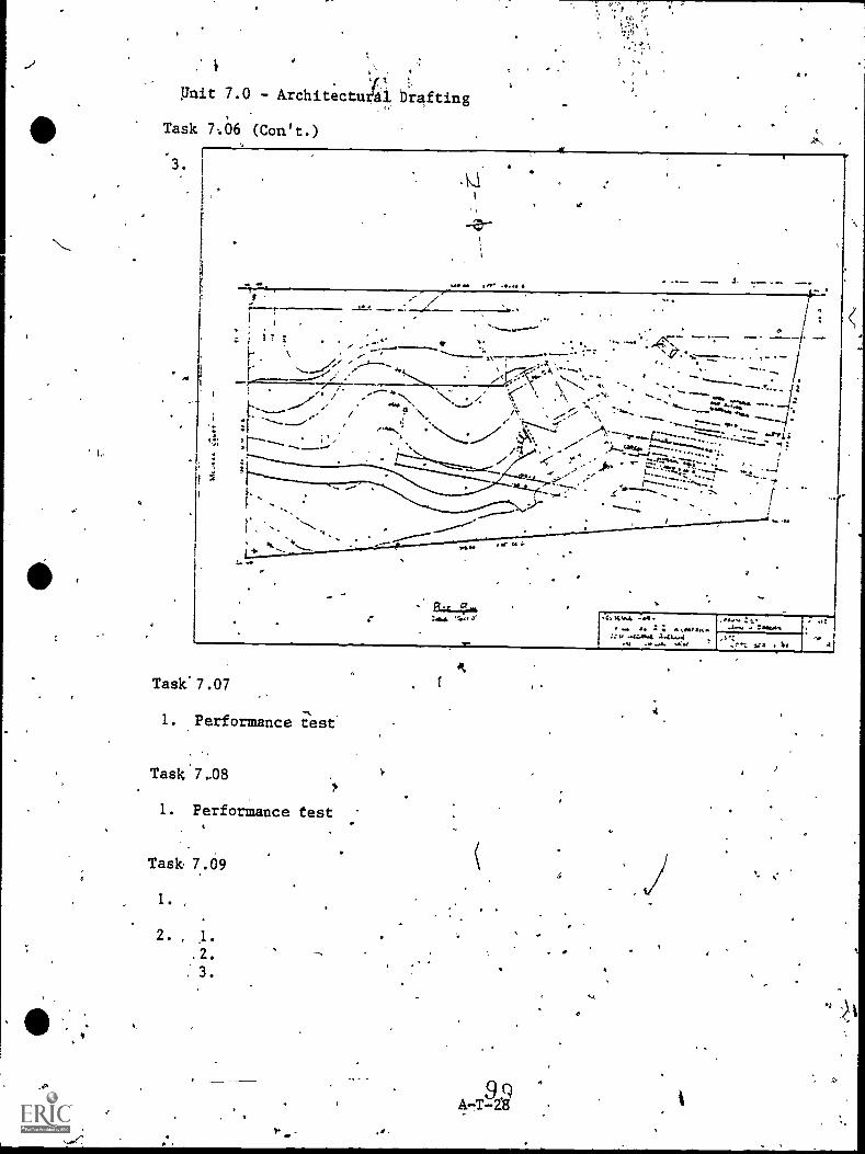
t
sr*
:
Pnit 7.0 - Architectugi Drafting
Task 7:06 (Con't.)
3.
.4
re or. ir
.----r1 ,
,.. ; : 7 ;`..
1- . /r--.....27,1 -.5....16.........
t
t ......" . ''......... /; ..-:1- '`........._.,"
/.1; ' r---' ----a --- __.....e
, b.\
":"-....5
eft.\
,. ' `;:"*'--- 'T. ,.\ -.......:........-: ",..,
-...': NN,-...... S\-. - . ---.4. cz,.--_,....--,:...- ..-...:- ...en a....-.. i. ..."... J....M.1/4. f"'"*-- ............ .
S`t......, I
.< . - . j.. - ..- ;:.:F.":12..4.-;;;:- - -. - .....1.; ------...........--....z.f..... ---41:..7.7 "j-.---",....... ' 1
1 4.4.---1: 4:
'''''''".'''..."'1/4)'..
- flu
.1 :MIsi.f arc
.44,4454 ....A.
...V
33 S $1,
Task'7.07
1. Performance test
Task.7-08
1. Performance test
Task 7..09
1 .
St
-
,,,
Unit 7.0 - Architectural Drafting
,Task 7.09 (Con't.)
.
.4.
5.
6.
7.
8; .
3. 1.
2.
3.
5(4
k4:, 1.
2.
5.
6.
,
1.
ri2.
3.
,
7.
. 8.
9.
,
e 10: (Short answer)
-11. (See following sheet for sample answer)
o
Task ,7 .10h
..
1. 1. e
2. c
'3. a
4. b
5. d
f
1, Oli
A-T-29
\
C..
.4.
474.
-
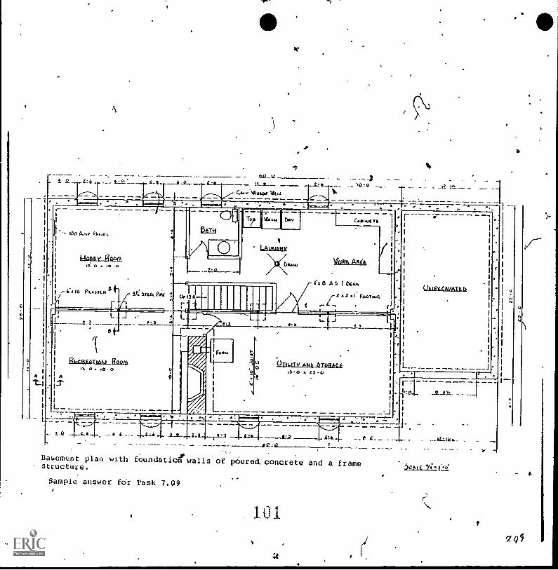
se
/I. 'a - 3.-:ge_ -- 1-"-Q-_.-----4-1._.- .i-2.----.- L:1.--__ .11-2. -- .2:_......... - - 'le f P. -_ . _ _a a>._ __ _
1.--- - A
CASAJC
r- CA16 PL.5TER 8 41 5r Ttfa. Pio%
' LAVklbRV
11111111
VOHS AIA
rIf a A 6 164,04
Z FpoiwGQuEY.rAvAtc
L L. -15
$
1i ' t1 tL I. r
RLCREATI.M.1 Reg)/4-
OTILITS, ^Mk 6TIAME15.0 25-0
_
-
Basement plan with foundation walls of poured, concrete and a framestructuce.
Sample answer fOr Task 7.09
101
1
715
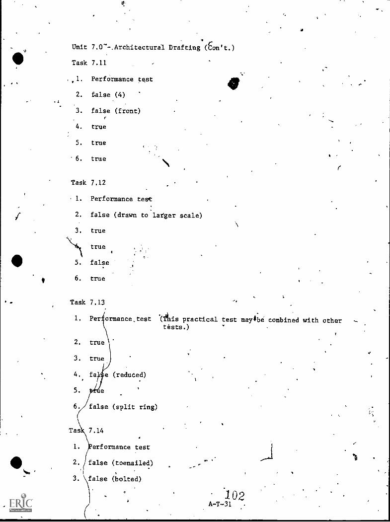
Unit 7.0--.Architectura1 Drafting (Cron't.)
Task 7.11
, ,I. Performance test
2. false (4)
3. false (front)
4. true
5. true
6. true
Task 7.12
1. Performance test
2. false (drawn to lafger scale)
3. true
\14\true
5. false
6. true
Task 7.13
I. Per ormancestest .(tilis practical test may$be combined with other
2. true
3. true
4.
5.
reduced)
false (split ring)
Tas 7.14
1. erformance test
2. false (toenailed)
3. false (bolted)
tests.)
.1 02A-T-31 ..
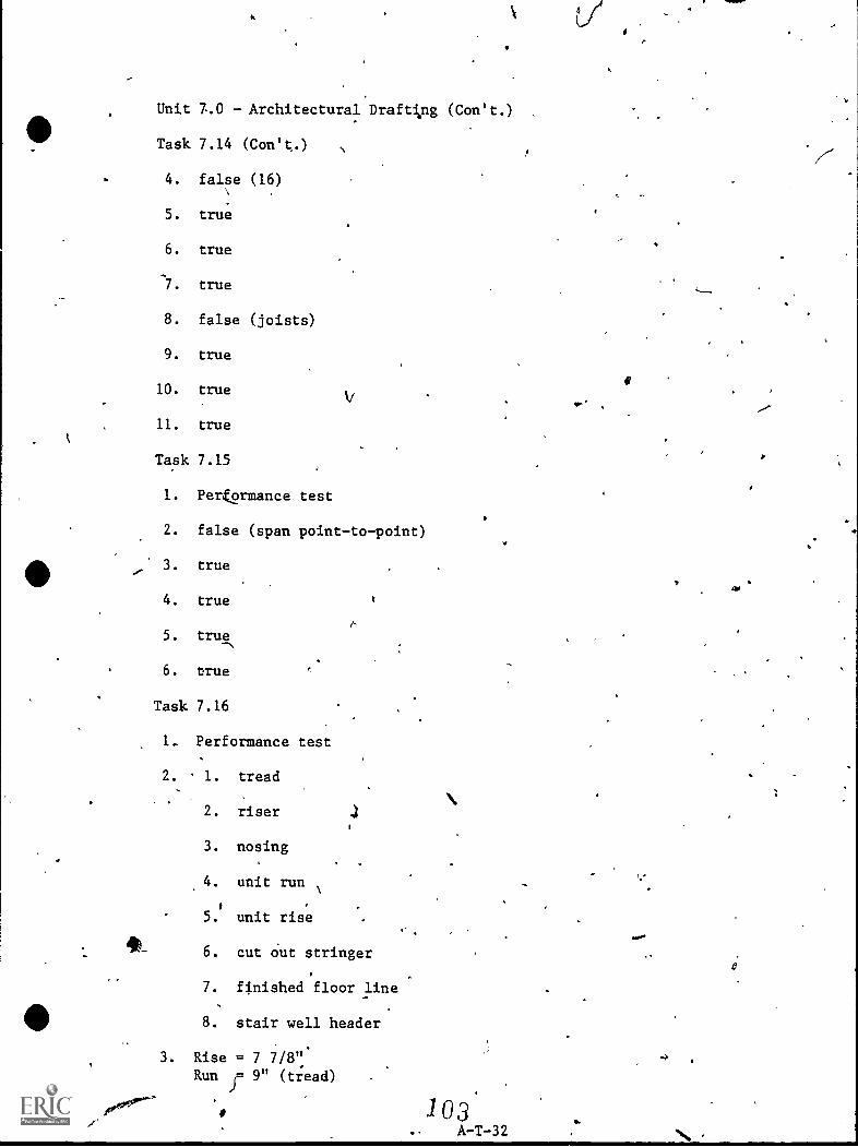
do_
Unit 7.0 - Architectural Draftng (Con't.)
Task 7.14 (Con't..)
4. false (16)
5. true
6. true
7. true
8. false (joists)
9. true
10. true
11. true
Task 7.15
1. Perkormance test
2. false (span point-to-point)
3. true
4. true
5. true
6. true
Task 7.16
1_ Performance test
2. 1. tread
2. riser
3. nosing
4. unit run
5. unit rise
6. cut Out stringer
7. finished floor line
8. stair well header
3. Rise = 7 7/8"Run j= 9" (tread)
1 (93.. A-T-32
f
1 -1111111P4
xl
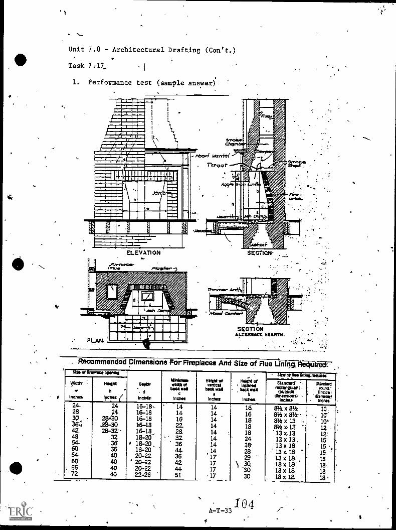
.\A
im
IIA
!V
-4411112111Ef
ank&k,\skpiim
mim
wei
Ern
II,
_solim
min.
il-1
wpriddrei
..
1"II -I 1-12;,....1.----011 w
1ii 1111111,01 A
mm
on'II
.1 1 1_
1"iiiiiiiiiiiiiiiiiiiiiii illiiiil.
A.,.
I I
11111111nW1/4,
N%
A.
z111
4
441.1111
.4
1141.4
a a a
44
ti
"'1
IIM
I411
A.
Unit 7.0 - Architectural Drafting (Con't.)-
III Task 7.17 (Con't.)
-
2. true ,
3. false (2 inches)
,
4. true
5. true
k
N,
6. false (16 inches, 8 Anches)
Task 7.18
1. Performance test ,
Task 7.19
1. Performance test ,
,
Task 7.20 - 7.23
. 1. true
2. false (and complete set of working drawings)
3. true
4. false (excavating, filling, and grading)
5. true
6. true
,
I.
-
I
.1
s
. 4P.
i
*
A-T-34
\
o -.
r
w\
nA
a".
n
\
44
-,0
f..
41
a
REFERENCES
.. /
I
/
(yt
9
...
,,.4 0
. .. .:
I,
...
0
a
1
I
,
N
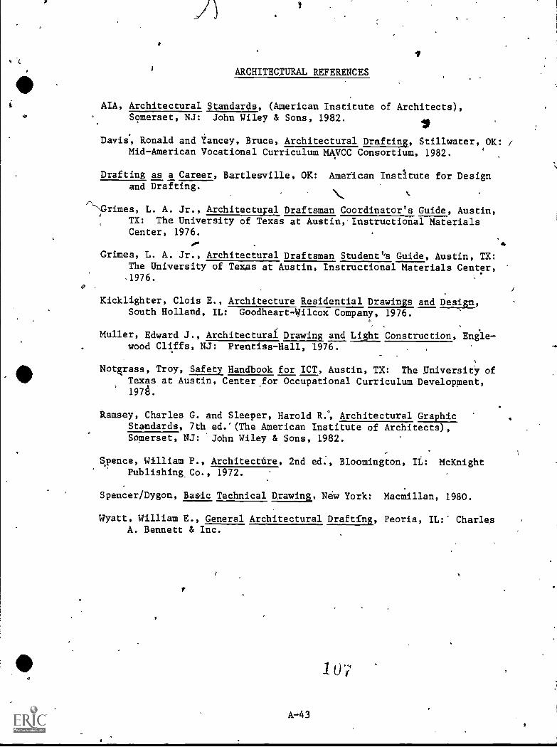
ARCHITECTURAL REFERENCES
AIA, Architectural Standards, (American Institute of Architects),Somerset, NJ: John Wiley & Sons, 1982.
Davis% Ronald and Yancey, Bruce, Architectural Drafting, Stillwater, OK: /Mid-American Vocational Curriculum MAVCC Consortium, 1982.
Drafting as a Career, Bartlesville, OK: American Instltute for Designand Drafting.
r\--NGrimes, L. A.
TX: TheCenter,
Jr., Architectuyal Draftsman Coordinator's Guide, Austin,University of Texas at Austin,.Instructional Materials1976.
Grimes, L. A. Jr., Architectural Draftsman Student''s Guide, Austin, TX:The University of Texas at Austin, Instructional Materials Center,.1976.
4
Kicklighter, Clois E., Architecture Residential Drawings and Design,South Holland, IL: Goodheart-Wilcox Company, 1976.
Muller, Edward J., Architecturai Drawing and Light Construction, Engle-. wood Cliffs, NJ: Prentiss-Hall, 1976.
Notgrass, Troy, Safety, Handbook for ICT, Austin, TX: The :Universify ofTexas at Austin, Center.for Occupational Curriculum Development,1976.
Ramsey, Charles G. and Sleeper, Harold R.°, Architectural Graphic,Standards, 7th ed.'(The American Institute of Architects),Somerset, NJ: John Wiley & Sons, 1982.
Spence, William P., Architectdre, 2nd ed., Bloomington, It: McKnightPublishing Co., 1972.
Spencer/Dygon, Basic Technical Dxawing, New York: Macmillan, 1980.
Wyatt, William E., General Architectural Drafting, Peoria, IL: CharlesA. Bennett & Inc.
A-43
t
UN T 8.0
DRAFTING II
a
MECHANICAL DRAFTING OPTION
v.
l s
M-1
MECHANICAL DRAFTIN6 OPTIONDRAFTING II
(Unit AO)
INTRODUCTION: The. Mechanical Drafting Option description of Drafting II.represents agreement (lateral articu atiop) mnong thesecondary level drafting instructors The SchoolDistrict of Greenville County, concerning tie objectives,content, and standards of the Mechanical afting Option,.Drafting II.
so:4(
The theory of the Mechanical Drafting Option is thatprogram graduates should receive-an orientation to themechanical drafting skills and knowledge areas needed bynew and expanding industries in the Greenville area.
The Mechanical Drafting Option tay vary slightly in'fOcusand emphasis in each of the .four vocational educationcenter programs depending upon the individualinstructor's training and experience, the needs ofpotential employers as determined by tasks analysis, andthe career interests and drafting abilities of thestudents.
'
GENERAL _ The Mechanical Drafting Option', Drafting II, is designedOBJECTIVES: to provide job qualification,competencies required to
peFform detailed entry-level working drawings (industrialdrafting) of-Mhchinery and mechanical devices, includJog;dimensioning and notes., tolerances, shop processes,fasteners, intersections and developments, cams.and gears(motion transfer), castings, and joining requirements.The graduate will draft multiple-view assembly andsub-assemhly drawings as required for manufacture andrepair of mechanisms.
Mechanical Drafting may include problem solvingprocedures, layout and design sketching skills, and modelmaking: AL will be possible for individual student orclass projects to encomiass all tasks in the Mechanical1Drafting Option. Use of handbooks, tables, ANSI andrelated menals as references will be stressed.
The Mechanical Drafting Option will providethe graduatewith knowledge of basic terminology end concepts ofmechanisms. Graduates will.develop the skills necessaryfor drafting room and mathematical solutions of problemsinvolving.the principles of machine elements.
PERFORMANCE Evaluation will be by competency-based (performance-EVALUATION: . based) testing directed to determine that the program
graduate is job qualified to perform successfully at theentry-level in mechanical (industrial) drafting.
M_21prs.
Performance standards are the minimum necessary forsuccess in initial employmeht
'JOB The Mechanical Drafting Option does dot provide a specificQUALIFICATION: industrial job qualification. It, however, is designed
to prepare thg secondary level vocational program
,graduate for entry-level employment as a Mechanical(Industrial) Drafter.
Mechanical Drafting reviews and uses most of the skills1and techniques acquired in the basic first year,
secondary level, training _program, Drafting I.
i1-4"-- M-3
STANDARDS FOR MECHANICAL DRAFTING OPTION
1. All applicable standards of Drafting I apply to Drafting II.
2. Execute drawings within time limits considered gcceptable foriniti41,amployment.
3. Perform required mechanical draftipg tasks in the proper sequence.
4. When applicable, freehand sketching and drawing, and layout (compo-sition) techniques must 1)4' properly applied.
5. Use appropriate reference technical manuals, tables, and catalogscorrectly.
6. Drawings must conform to applicable-standards as contained_ n ANSIManuals and other appropriate technical manu4s and tables.
7. Demonstrate knawledge of related technical information, applic tionof theories and procedures, symbols and.conventions, andterminoldfy with a minimut of 80 percent accuracy.
8. Models, j.f built, must be well executed and must.portray objectsaccurately.
6.
M-4
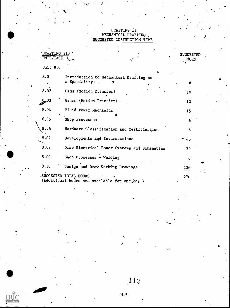
DRAFTING IIMECHANICAL DRAFTING .
'SUGGESTED INSTRUCTION TIME
'DRAFTING II'UNIT/TASK
Uhit 8.0
s8.01 Introduction to Mechanical Drafting.asa Speciality.
SUGGESTED.HOURS
6
8.02 Cams (Mbtion Transfer) '10
, 40003 Gears (Motion Transfer) 10
8.04 Fluid Power Mechanics 15
8.05 Shop Processes 6
\\8.06 . Hardware Classificat'ion and Certification 6
8.07 Developments and Intersections 45
8.08 Draw Electrical Power Systems and Schematics 30
8.09 Shop Processes - Welding
8.10 Design and Draw Working Drawings 136
-SUGGESTED TOTAL HOURS 270(AdditiOnal hotirs are available for options.)
M-5
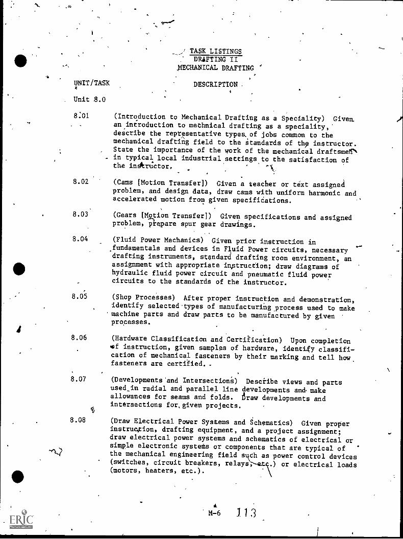
4
/ TASK LISTINGS_
: DRAFTING II1ECHANICAL DRAFTING
UNIT/TASK DESCRIPTION .4
Unit 8.0
8:01 (Introduction to Mechanical Drafting as a Speciality) Giveman introduction to methnical drafting as a speciality,'decribe the repr,esentative types..of jobs common to themechazical drafting field to the standards of thp instructor.State the importance of the work of the mechanical draftsmerin typical local industrial settings to the satisfaction oftha inArUctor,
8.02 (Cams [Motion Transfer]) Given a teacher or text assigneaproblem, and design data, draw cams with uniform harmonic andaccelerated motion from given specifiCations.
8.03. (Gears [Motion Transfer]) Given specifications and assignedproblem, prepare spur gear drawings.
8.04 (Fluid Power Mechanics) Given prior instruttion in.fundamentals and devices in Fluid Power circuits, necessarydrafting instruments, standard drafting room environment, anassigament with appropriate imptruction; draw diagrams ofhydraulic fluid power circuit and pneumatic fluid powercircuits to the standards of the instructor.
8.05 (Shop Processes) After proper instruction and demonstration,identify selected.types of manufacturing.process used to makemachine parts and draw parts to be manufactured by givenprocesses.
8.06 (Hardware Classification and Certiiication) Upon completionef instruction, given samples of hardware, identgy classification of mechanical fasteners by their marking and tell howfasteners are certified. .
8.07 (Developments'and Intersection) Desciibe views and partsused_in radial and parallel line developments and, makeallowances for seams and folds. Law developments andintersections for,given projects.
4
8.08 (Draw Electrical Power Systems and Schematics) Given properinstruc,tion, drafting equipment, and a project assignment;draw electrical power systems and schematics of electrical orsimple electronic systets or components that are typical ofthe mechanical engineering field s ch as power control devices(switches, circuit breakers, relays .) or electrical loads(motors, heaters, etc.).
113
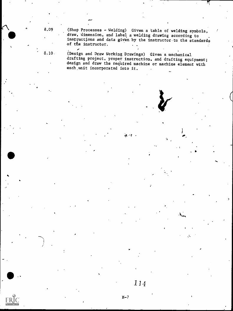
8.09
Th
(Shop Processes - Welding) Given a table of welding symbols,draw, dimension, and label a welding drawing according toinstructl.ons and data given by the instructor to the standardsof tte instructor.
(Design and Draw Working Drawings) Given a mechanicaldrafting project, proper instruction, and drafting equipment;design and draw the reqUired machine or machine element witheach.unit incorporated into it.
4.
M-7
11 4
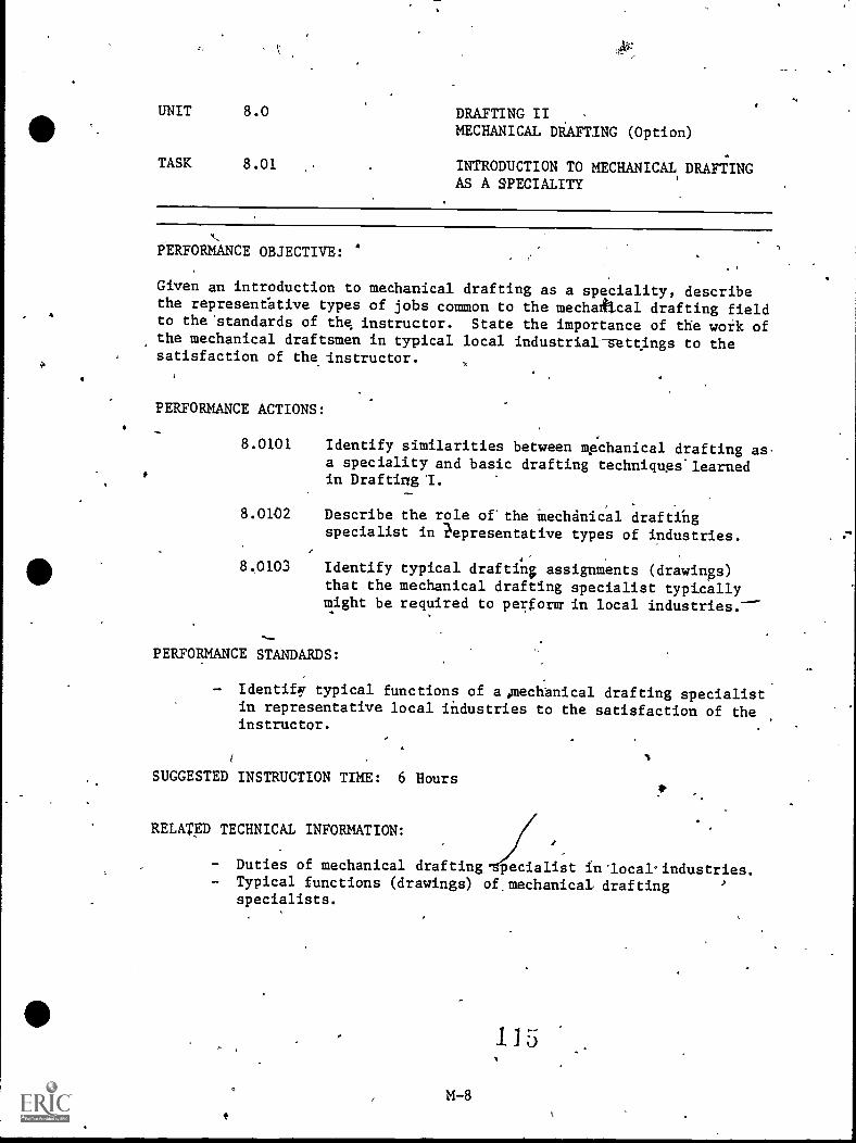
UNIT 8.0 DRAFTING IIMECHANICAL DRAFTING (Option)
TASK 8.01 INTRODUCTION TO MECHANICAL, DRAFTINGAS A SPECIALITY
PERFORMANCE OBJECTIVE:
Given an introduction to mechanical drafting as a speciality, describethe represeneative types of jobs common to the mechatitcal drafting fieldto the 'standards of the instructor. State the importance of the work ofthe mechanical draftsmen in typical local industrial-sttings to thesatisfaction of the instructor.
PERFORMANCE ACTIONS:
8.0101 Identify similarities between Apchanical drafting as .
a speciality and basic drafting techniqugs.learnedin Drafting 'I.
-^,
8.0102 Describe the role of'the Mechinical draftingspecialist in ?epresentative types of industries.
8.0103 Identify typical draftin; assignments (drawings)that the mechanical drafting specialist typicallymight be required to perform in local industries.'
,PERFORMANCE STANDARDS:
- Identify typical functions of apechanical drafting specialistin representative local industries to the satisfaction of theinstructor.
SUGGESTED INSTRUCTION TIME: 6 Hours
RELATED TECHNICAL INFORMATION:
- Duties of mechanical drafting pecialist inlocal'industries.- Typical functions (drawings) of,mechanical drafting
specialists.
M-8
115
4,
'UNIT 8.0 DRAFTING II \MECHANICAL DiAPTING (Option)
TASK '8.02 CAMS (Motion,Transfer)
PERFORMANCE OBJECTIVE:
Given a teacher or tehIct assigned problem, and design data, draw camswith uniform harmonic and accelerated motion frOm given specificapions.
PERFORMANCE ACTfONS:
8.0201
8.0202
Determine necessary space allocations.
Make the required cam motion diagram from givenspecifications.
./"" 8.0203 Draw the require4 cam dtirve outline.
E.0204 Add pecessary dimensions.
8.0205 Check drawing for completeness and accuracy.
PERFORMANCE STANDARDSi
Draw cat motion diagram and cam curve outline from assignedproblems.
To instructor's standards based on entry-level competencerequirements of the drafting field.
SUGGESTED INSTRUCTION TIME: 10 Hours
RELATED TECHNICAL INFORMATION:
Cam terminology.Radial cams.Cylindrical cams.Yoke cams.Cam motio diagrams.Uniform motion cams.HarmOnic motion cams.Accelerated motion cams.Cam curve outlines.
OUTCOME-REFERENCED MEASURE:
- Figure 19-9, page 347, Mechanical Drawing, by French.
m-9 6
UNIT 8.0 DRAFTING IIMECHANICAL DRAFTING (Option)
TASK 8.03 GEARS (flotion Transfer)
PERFORMANCE OBJECTIVf:
Given specifications and assigned problems, draw gear trains.
PERFORMANCE ACTIONS:
8.0301 Determine necessary space allocations.
8.0302 Make the required gear train drawing.
8.0303 Add necessary dimensions.
.8.0304 Add necessary lettering.
8.0305 Check drawing for completeness and accuracy.
PERFORMANCE STANDARDS:
- Prepare gear train drawings from given specifications andassignment.
- To instrIctor's standards based on entry-levei competencerequirements of the drafting field.
SUGGESTED INSTRUCTION TIME: 10 Hours
RELATED TECHNICAL INFORMATION:
- Metric systems (Including European,DIN)- Gear termifiology.- Gear formulae.- Gear tooth curves.- Dimensioning gears.- Drawing - spur gear.- Drawing - rack.- Drawing - bevel gear.'- Precision Instrument Reading, Quality Control (possible
optional task)
ADDITIONAL RELATED TOPICS: (AS INTEREST AP TIME ALLOW).
- Identify worm gear terminology and cbmponentsi calculate anddraw worms and worm gears.
- Identify standard tYpes of gear trains.- Identify and draw standard pulleys and belts.- Identify and draw standard chain and sprockec,drives.
11 7
IP
4..
e
UNIT 8.0 DRAFTING:IIMECHANICAL DRAFTING (Option)
>TASk 8.04 FLUID POWER MECHANICS,
PERFORMANCE OBJECTIVE:
:Given prior pistruction in fundamentals.and devices in Fluid Powerc1rcuit6, necessary drafting instruments, standard drafting roomenvironment, an assignment 4ith appropriate instruction; dra14 diagramsof hydraulic fluid'power circuit and pneumatic fluid power cirouits,tothe standards of the instrucpit. %
PERFORMANCE ACTIONS:
80401
8.0402
Identify ana drali fluid Power symbols properly.
Demonstrate.understanding of pneumatic and bydraulicfluid powersTsteis and devices on written knowledgetests.
8.0403 fIdenti or-aescribe various types of fluid powercylinde , valves, and other components.
, .
8.0404 Combin luid power_symbols.and lines to form a .-given fluidpower circuit.
PERFORMANCE STANDARDS: '
Answer writEeQ questions to 75 percent accuracy.Draw schematic of fiuid power diagrams to instructor's stan-dards.
SUGGESTED INSTRUCTION' 15 HoursT
RELATED TECHNICAL INFORAATION:
Vendors catalog for d power devices.Tables of fluid power symbols from ANSI 32.10 "Symbols forFluid Power Diagram".
- ANSI 14:17 PoWkr Diagrams".Fluid Power:- cylinders
1filtersrestwoir'gauges
116
UNIT ( DRAFTING II '
MECHANICAL DRAFTING (Option)
TASK 7;115.5's A SHOP PROCESSES
PERFORMANCE OVCTIVE:
After proper ,instruction and demonstration, identify selected types of ,
manufacturing process used to make machine parts and draw parts to be4
manufactured ,by given processes.
PERFORMANCE ACTIONS:
8.0501 . Observe part being made by sand casting.
8.0502 Draw a part and indicate sand casting process.
8.0503 Observe part being made by forging.
8.0504 Draw a part indicating foreng required./*/
8.0505 -Observe a heat traating process.
8.0506 Draw a part itdicating heat treaiing,reguired.
8.0507 Observe p4rt being formed by extruding process%
8.0508 Draw an/extruding die.
PERFORMANCE STANDARD,W
7- Draw,prts to be manufactured by given process:- Meaiurements and notes to instructor's standards.
*
StGGESTED INSTRUCTION TIME: 6-Hours
RELATED TECHNICAL INFORMATION:
- Use and care of drawing inqruments.- Proper lettering.
ADDITIONAL TOPfCS IF RELEVANT:
- Capabilities and limitationSof common machine shop machines;flow charts, terms, notes, and symbols on working drawingejtoindicate machining symbols, madhine shop terms and basicoperations, drilllng and boring of holes-notes, andmiscellaneous machine shop operations.
M-12 j /
UNIT 8.0
TASK 8.06
4.5*DRAFTING II .
MECHANICAL DRAFT NG (Option)
, HARDWARE GLASSIFCERTIFICATION
CATION,AND
PERFORMANCE OBJECTIVE:
Upon completion of instruction, 'given samples Of hardware, identifyclassification of mechanical fasteners by their marking, tell howfasteners are certified, and draw and specify hardware in a mechanical .
assembl .
.04
7.221ZyCE ACTIONS: \\__
8:0601 Identify types of hardware, washers, nuts, bolts,rivets, etc.
8.0602 Identify nuts and bolts by markings. 1
8.0603 Describe the hardware certification process::'
8.0604 Draw and specify hardware in sa mechanical assembly(note certification if required).
PERFORMANCE STANDARDS:
- Draw and sRecify hardware in a mechanical assembly and notecertification if required.
- ANSI standards.- Instructor's standards.
SUGGESTED INSTRUCTION TIME: 6 Hours
RELATED TECHNICAL INFORMATION:
- Metric DIN system of classtfying metric hardwaie ANS014.5and 14.5M.
- Appropriate reference:catalogs.
ADDITIONAL TOPICS IF RELEVANT:
- Select, specify, and draw pope,r fastener(s) flt5r projectrequirement.
- Identify, select, and,draw pro r screw threaa(s) for projectrequirements. -
- Describe screw thread development from beginning throigh\standardizations. ..
120M-13
S.
UNIT 8.0 DRAFTING IIMECHANICAL DRAFTING (Option)
TASK 8:06 HARDWARE'CLASSIFICATION ANDCERTIFICATION
ADDITIONAL TOPICS IF'RELEVANT (Con't.):
Identify, use, and draw various terms and symbols pertainingto threads to include: thread form, series, class of 'fit,multiplicity, direction of turn and length.Draw preads as required: acme, square, regular square boltsand nuts, hex-head bolts and nuts.Use thread t'ables.
Identify, use, specify, and draw standard keys, keyway's,rivets, and springs.
1ZiM-14
-
(
Po
UNIT 8.0 '
,TASK . 8.07
DRAFTING IIMECHANICAL DRAFTING (Option)
.DEVELOPMENTS AND INTERSECTIONS
4%,
PE ORMANCE OBJECTIVE:
Descand
secti
ibe views and parts used 1n radial and parallel line developmentske allowa es for seams and folds. Draw developments and inter-s fo ven projects.
PERFORMANCE ACTIONS:
.Draw stretch-out view of assigned project.-(Pyramid, Bends)
8.0702. Make templates to check for accuracy. '
8.0703 Identify different sheet.me.tal edges and seams.
6'
8.07914 Draw different elbow's.
8.0705 Explain and draw transitions.
RERFORMANCE STANDARDS:.
- Draw developments, neatly and accuratelstandards set byinstructor.
"IISUGGESTED INSTRUCTION ME: 45 Hours
RE4ATED TECHNICAL INFORMATION:
- Parallel line development (prldms and cylinders).- Radial line development (pyramids and cones).- Terms,related to development.- Developments:
- pipes, ducts- pans- boppers- bins- buckets- cartons
M-15
41.
/---\8./0 ,,----1141;TING II
'
UNIT.
MECHANICAL DRAFTING (OPtion) ,
TASK 81; DRAW ELECTRICAL POWER SYSTEMS ANDSCHEMATICS
PERFORMANCE OBJECTIVE:
Given proper instruction, drafting equipment; and a project assignment;draw electrical power systems and schematics of electrical or simpleelectronic systems or components that are typical of the mechnical
...__?gineering field such as power control devices (switches, circuiteakers, relays, etc.) or electrical loads (motors, heaters, etc.).
k
PERFORMANCE ACTIONS:
8.0801 Interpret electrical/electronic terminology asrequired:
8.0802 Identify types and uses of electrical/electroniccomponents:a. Electrical power control devices and moniioring
devicesb. Electrical loads
8.0803 Refer to refer ence material and select properelectrical/electronic device symbols for drawing.
8.0804 Use electrical/electronic terminology anddemonstrate a basec. ability to identify varioustypes of electrical/ elecfronic.components.
8.0805 'Apply requirements as containedin the-NationalElectrical Code or ANSI Standards, as'applicable.
---8.0806 Given a project and freehand sketcli, draw electrical
systems or electricaUelectronic schematics with 90'percent accuracy, referring-to-aMWEk517-4,references as needed.
8.0807 Check for -completeness and'accuracy.
PERFORMANCE STANDARDS:
- Draw electrical systema or electrical/electronic schematicsfor a given project with 90 percent 'accuracy properly using'symbols and meeting appropriate craft atandards.
- Drawing must be.neat, consistent, and properly placed, meetinginstructor's standards.
M-16 1 23
UNIT 8.0 DRAFTING IIMECHANICAL DRAFTING (Option)
TASK 8.08 DRAW ELEICAL POWER SYSTEMS ANDSCHEMATI (aon't.)
PERFORMANCE STANDARDS (Con't.):
Drawing.must be completed within time limits considered 'to beacceptable for initial employment job qualifications. .
SUGGESTED INSTRUCTION TIME: 30 HOurS
RELATAI TECENIGAL INFORMATION:
- Electrical/electronic symbols.- -National Electrical Code, Local Codes.- ANSI Standards: Y32.2 and Y32.9.
l- ElA rical/electronip abbreviations.- Re ence designations (such as component values).
441.
14-0
124
4
UNIT 8.0 DRAFTING IIMECHANICAL DRAFTING (Option) -
TASK 8.09 SHOP PROCESSES - WELDING
PERFORMANCE OBJECTIVE:
Given a table.of welding symbols, draw, dimension, and'label a weldingdrawing according to instructions and ,data given by the instructor tothe standards of the instructor.
PERFORMANCE ACTIONS:
80901
8.0902
8.0903
Identify,the basic welding processes.
Identify the basic types of welded jOints.
Descriminate between the fundamental welds.Identify the appropriate symbols for basic welds.a. Arc and Gas weld symbols.b. Resistance weld symbols.
8.0904 Identify the parts of the ,complete welding symbol(ideograph) to the instructor's standards.a. Reference line.b. Arrow.
Basic weld symbols.d. Dimensions and other data.e. Supplementary symbols.f. Finish symbols.g. Tail. ,h. Specification process or other references.
8.0805 Draw welding symbols for a given diagram of typicalwelded joints (section views).
8.0806 Given a set of specifications and n assignment bythe instructor, develop working drawings to indicatethe desired welding operation and include the ap-pf-opriate specifications or informationvith thesymbols.,
SUGGESTED INSTRUCTION TIME: 6 Hours
PERFORMANCE STANDARDS:
- Complete knowledge test t with.a-minimum of 75 percent accuracyand performance teat to the standards of the instructor.
- Identify how and where,to find, welding symbols, 'the standardlocation of the elements of the symbols and symbril meaning in)rafting standards.
125
UNIT 8.0 DRAFTING II
0 MECHANICAL DRAFTING (Dption)
TASK 8.09- SHOP PROCESSES - WELDING (Con't.)
RELATED TECHNICAL INFORMATION:
- American Standards Association Z32.2.1, Graphical Symbols forWelding.
- American Welding Society-Standard Welding Symbols.
a.
4
UNIT 8.0 DRAFTINGMECRANICAL DRAFTING (Option)
TASK 8.10 DESIGN AND DRAW WOVING DRAWINGS
PERFORMANCE OBJECTIVE:
Given a mechanical drafting project, proper instruction, and draftingequipment; design and draw the required machine or machine element witheach unit incorporated into it.
PERFORMANCE ACTIONS:
8.1001 Assemble necessary data; engineer's sketches andcalculations, design layout, general specifications,etc.
8.1002 ,Perform detaildrawings showing notes and specifi-cations (including: finishes, heat treatments,tolerances, stock sizes, titles and revisions,etc.).
8.1003 Perform assembly drawings as required,by theinstructor (Multiview, exploded, etc.).
8.1004 Develop complete set of drawings.
8.1005 Develop bill of materials, if required.
PERFORMANCE STANDARDS:
- Design and draw mechanical project from given dataincorvrating motion transfer, luid power, electrical,,welding, foundry-and-other ses as required to produceasseMbly drawings that meet standards of craft andspecifications.
- Must be to instructor's standards.- MuSt be completed within time limit acceptable for initial
employment in mechanical drafting.
SUGGESTED INSTRUCTION TIME: 136 Hours
RELATED TECHNICAL INFORMATION:
Orthographic theory.- Purpose of working drawings.- Measuring and dimensioning.- Conventions.- ANSI Standards.
127M-20
0.
PROFICIENCY REPORT
14-21
1 2S
`-v
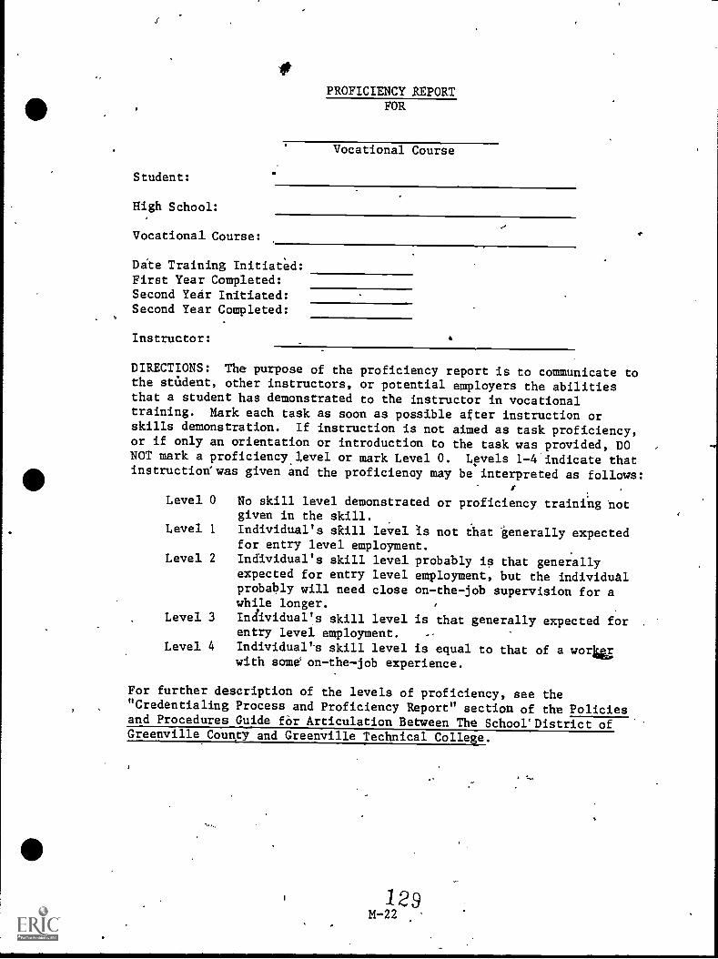
Student:
High School:
Vocational Course:
PROFICIENCY REPORTFOR
Vocational Course
Dite Training Initiated:First Year Completed:Second Year Initiated:Second Year Completed:
Instructor:
DIRECTIONS: The purpose of the proficiency report is to communicate tothe stAdent, other instructors, or potential employers the abilitiesthat a student has demonstrated to the instructor in vocationaltraining. Mark each task as soon as possible after instruction orskills demonstration. If instruction is not aimed as task proficiency,or if only an orientation or introduction to the task was provided, DONOT mark a proficiency.level or mark Level O. Levels 1-4'indicate thatinstructionswas given and the proficiency may be interpreted as follows:
No skill level demonstrated or proficiency trainfng totgiven in the skill.
Individual's skill level is not that ienerally expectedfor entry level employment.
IndIvidual's skill level probably is that generallyexpected for entry level employment, but the individualprobably will need close on-the-job supervision for awhile longer.
Individual's skill level is that generally expected for .
entry level employment.
Individual's skill level is equal to that of a wortrawith some on-the-job experience.
Level 0
Level 1
Level 2
Level 3
Level 4
For further description of the levels of proficiency, see the"Credentialing Process and Proficiency Report" section of the Policiesand Procedures Guide far Articulation Between The SchoorDistrict ofGreenville County and Greenville Technical College.
129M-22
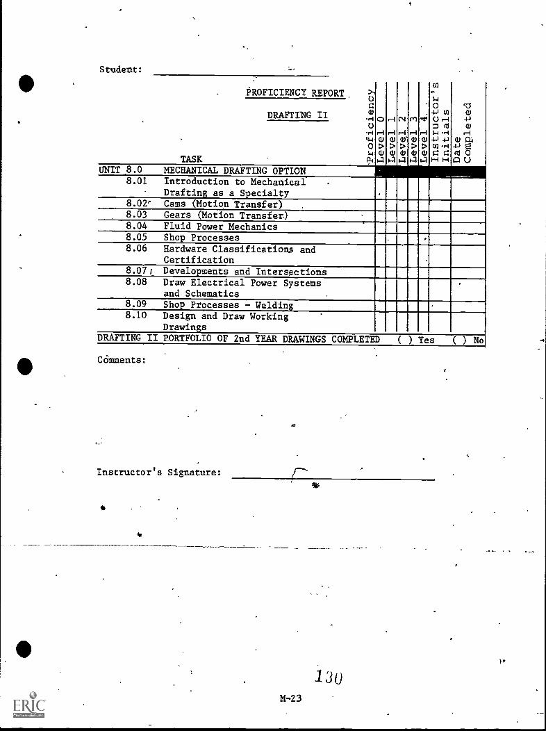
Student:
. PROFICIENCY REPORT >1
0H
>
HHHHH>wwww
cq
>
cel
>
.*41
>
m
4-) WC.) H= as
14 H
(1)..-1CZ
a)
4-)a)
H
4-) E0:10
WDRAFT ING II.r.i.
c)
.ri
0.icuTASK-
UNIT 8.0 MECHANICAL DRAFTING OPTDON8.01 Introduction to Mechanical .
Drafting as a Specialty8.02' Cams (Motion Transfer)8.03 Gears (Motion Transfer)
.
8.04 Fluid Power Mechanics8.05 Shop Processes8.06 Hardware Classifications and
Certification8.07, Developments and Intersections8.08 Draw Electrical Power Systems
and Schematics.
.
8.09 Shop Processes - Welding8.10 Design and Draw Working
DrawingsDRAFTING II PORTFOLIO OF 2nd YEAR DRAWINGS COMPLETED ( ) Yes ( ) No
COmments:
Instructor's Signature:
130M-23
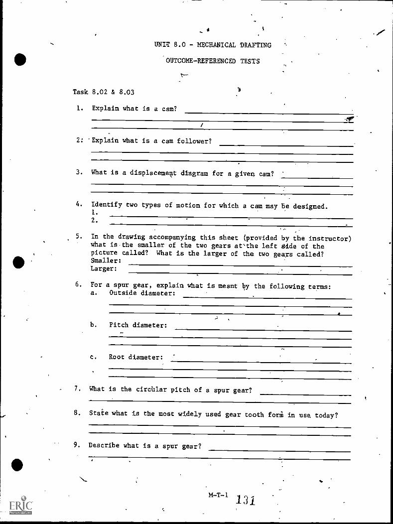
UNIT 8.0 - MECHANICAL DRAFTING
'OUTCOME-REFERENCED TESTS
Task 8.02 & 8.03
1. Explain what is a cam?
2: 'Explain what is a cam follower?
3. What is a displacement diagram for a given cam?
4. Identify two types of motion for which a cam may be designed.1.
2.
5. In the drawing accompanying this sheet (provided by the instructor)what is.the smaller of the two gears at"the left Aide of thepicture called? What is the larger of the two geaxs called?Smaller:
Larger:
6. For a spur gear, explain what is meant by the following terms:a. Outside diameter:
b. Pitch diameter:
c. Root diameter:
7. What is the circular pitch of a spur gear?
8. State what is the most widely used gear tooth fori in use, today?
9. Describe what is a spur gear?
M-I-1
.Unit 8.0 - Mechanical Drafting (Con'to)
Task 8.02 &'8.03.(Con't.)
10. On a working drawing, how are the-teeth of a spur gear shown andwhy?
-7`.
132
M-T -2
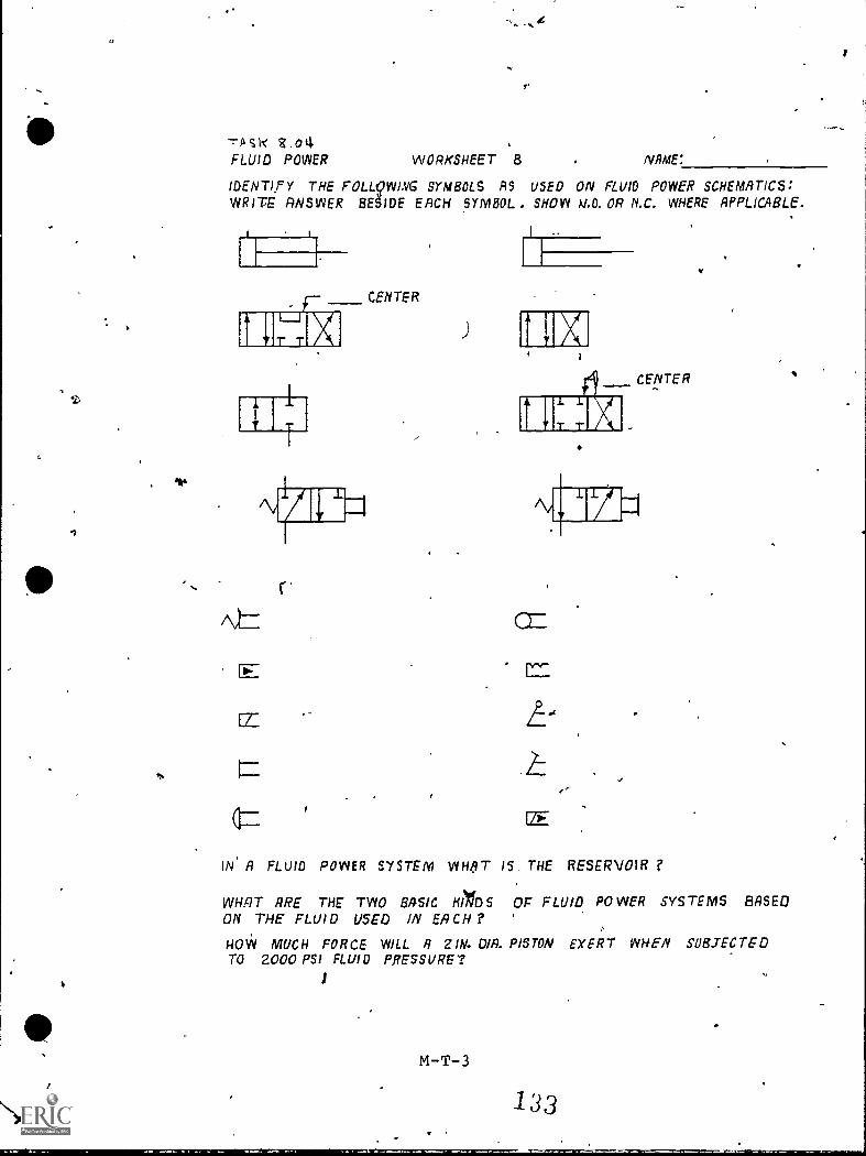
III
St.
TA SI< $.04FLUID POWER WORKSHEET 8 NAME:
IDENTIFY THE FOLL9WING SYMBOLS AS USED ON FLUID POWER SCHEMATICS:WRITE: ANSWER BESIDE EACH SYMBOL . SHOW H.O. OR N.C. WHERE APPLICABLE.
CENTER
CENTER
IN' A FLUID POWER SYSTEM WHAT IS THE RESERVOIR ?
WHAT RRE THE TWO BASIC HIVDSON THE FLUID USED IN EACH ?
HOW MUCH FORCE WILL R 21W. umTO 2000 PSI FLUID PRESSURE'?
M-T-3
OF FLUID POWER SYSTEMS BASED
PISTON EXERT WHEN SUBJECTED
133
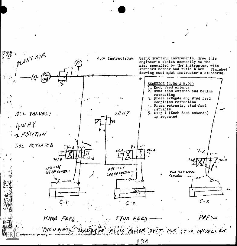
1
1
8.04 Instruotions: Using drafting instruments, draw thisengineer's sketch coprectly to thesize specified by thd instructor, withstandard border and title black. Finisheddrawing must,meet instructor's standards,
P.
L V 41-Ve 5
.P5ft 7?i/V
Sot.. 4C7u/27
A
-4)44 A ,,t I O. '' ; ).a , ,
To' 471r (fe' 411:141294 Of: 'fi4.4),4 (A)teit: 9 .5 rx.r. fa"( sT-ui /40'7,41 ,<,
N
SEQUENCE (8.04 & 8.08)1, Knob feed extends2. Stud feed extends and begins
retracting3. Press extdnds and stud feed
completes retraction4. Preso retracts, stud-feed
retracts5. Step 1 (Knob feed extends)
ip repeated
sot 41-7
WI
010. '44-1ix/Ago evilAW-.:
C-I
ALA
.
ayg k)4 p.1.11'
1
C- 3
Pees-sf<4/041 f4e40 $7kip Pc5p
".
.1 34
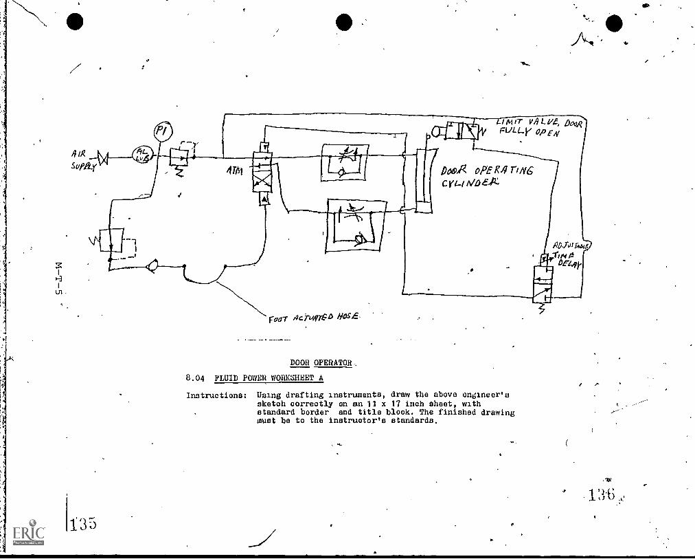
41R
135
-7
41#1
INILME
111
PVT ,Ici140715D Nosh'
I Ai IT VA L. 1/4, Dool?FLA Li/ OPEN
PAAR opER4rof6co-(
DOOR OPERATOR,.
8.04 FLUID POWER WORKSHEET A
Instructions: Using drafting instruments, draw the above engineer'ssketch correctly on an 11 x 17 inch sheet, withstandard border and title block. The finished drawingmust be to the instructor's standards.
A.
ofolo
UNIT 8.0 - MECHANICAL DRAFTING
OUTCOME-REFERENCED TESTS
Task 8.07
1. Referring to Fig. 17722, page 355, of the textbook, Basic TechnicalDrawing by Spencer/Dygdon, 1st Edition, draw ail the bend lines inthe development for a small round to large rectangular transition
,piece. Label all points when found. Using piece of aluminum wire
ii
'to simulate flexible curve, d ow in the curved side of the develop-ment., Drawing is to be'accom shed, without,supervision andwithout exchanging informatio with others. Completed drawingsmust meet the instructor's standards-.
(See_ drawings 1, 2,. and 3)
NB.
-4-r
137 .
M-T -6
e

)-,DElifLOPEMENTS, *WIT* 'SMALL R0U410 TO LARGE RiCIGULAR
1.g.
24:"
tit
rr
138
. .;!;*'` -
.0 a: 4 a, " .."1.*.'.V-":,1,, ' t
.1,
;: ...V0 .1" P ft
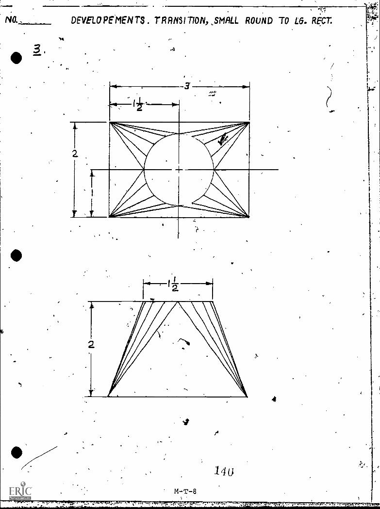
AO.
3 .
*r4
01
DEVELOPEMENTS. TRRIISITION,,SMALL ROUND TO L6. Rt:CT.
3'
or
M-T-8
..117111I
/4
l U
4
ihau T.1..SOCW8026.:14.
UNIT 8.0 - MECHANICAL DRAFTING
OUTCOME-REFERENCED TESTS
Task 8.68
1. Given the attached engineer's sketch of an electrical circuit,correctly draw the circuit using proper symbols and abbreviations.The drawing must ba 100 percent accurate and must meet the instruc-tor's standards.
ell
fat, f -01,tn
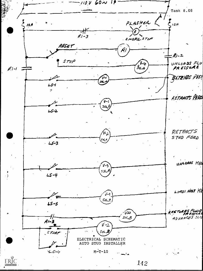
RAcer'41)/fr
S' rap
4.00v
.4rRI-3 /
Eislig4. $ rdda.
Task 8.08
OA'
OS"irsfaAt
Mgr OP
la -5
r rrztrELECTRICAL SCHEMATICAUTO STUD INSTALLER
I ,+111
142
Xer4,407
R)57-1M7755 "rg!) FZZ2
SI
um. Mos Kly
Le,,gms deo'
1(47"atfir.; faltrip y,t1 A/C.415- sr /.
Unit 8.0 - Mechanical Drafting
Answer Sheet
Task 8.02 & 8.03
1. Short answer 6. Short. answer
2. Short answer 7. Short answer.
3. Short answer 8. Short answer'
4. Short 'answer 9. Short answer
Shorr answer 10. Short answer
Task 8.04
1. Performance test
-r,fts 11P-4191114110"..."Treb., Witwag...r.-rzi*V220wwt-vntmume.ve
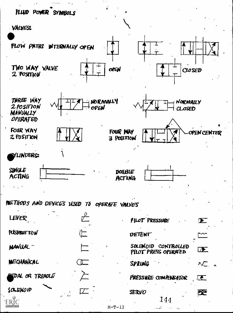
RIO Pore?' Smen.$
VALvEst
FLoW PATILT Wrzoodly opal
fllo toty VALVE2 'Nana
/MEE Pay2 postrioWmimaiviyDPEnve
FoUR WAYZ Foginal
SitiaLtAciTAIG
tioRmALL'iopal
WorauttacLoseo
row? NAY3 posmoif
mowAcrota
NaTIODS 14Wo DEVIC.S WED Th OpERNT V/fiWg
LEVER,
Kisusurreaf
miwaAL
VAL Tits4tui
$a*MialP
(.=
fLor PREssuir
PET-air3
501 .910 ID CoKniouEDnun- PREss OfFitgeb
Spluola
PRasugE comPase-ce
SPItyo
-
144
OFR/CENTER
12E.
\ ,
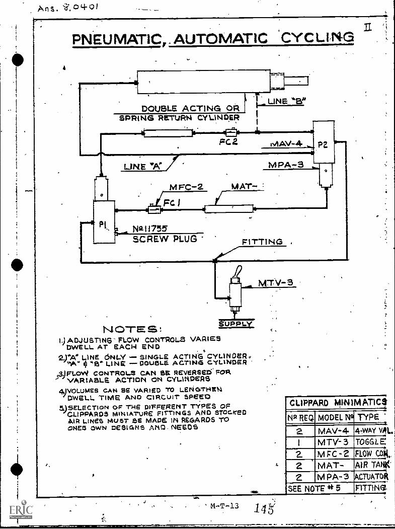
PNEUMATIC,. AUTOMATIC .CYC LIN-3 31
DOUBLE ACTING ORSPRING RETURN CYLINRER
UNE "B"
_is IE.2_11
FC.2 netAV-4
fs 1
LINE *A"
MFC-2 MAT
Nial 1755
MPA-3
PZ
SCREW PLUG FITTING
MTV-3
SUPPLYN OTE S :OADJUSTING FLOW CONTROL.S VARIES
DWELL AT EACH END0
VA" LINE ONLY SINGLE ACTING CYLINDER"A" 4 LINE DOUSLS ACTING CYLINDER
.33)FLOW CONTROLS CAN SE REVERSEO' FORVARIABLE ACTION ON CYLINDERS
4,)VOLuMES CAN BE VARIED TO LeriGMEINI'DWELL TIME AND CIRCUIT 5PEEO
S)SELECT1ON or THE DIFFERENT TYPES OFCLIPPARDS MINIATURE FITTINGS AND STOCKEDAIR LINES MU5T SE MADE IN REGARDS ToONES OwN DESIGNS AND. NEEDS
61
CLIPPARD MIN IM ATI C4
N2 REQ..
a
Z.
;
*WAY \rips.
MTV- 3 TOGGLM FC -2 FLOW COM,MAT AIR TANKMPA-3 ACTUATORE 5 FITTING!.
MODEL N TYPEg
MAV-4
SEE NOT
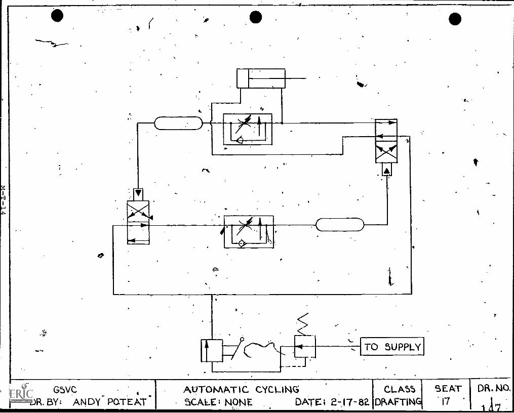
404.4,
11 4 6 GSVC
oza
TO SUPPLY
4.
DR. BY: ANDY POTEATAUTOMAT IC CYCI-ING CLASS SEATSCALE NONE DATE ; 717- 82. DMFTING 17
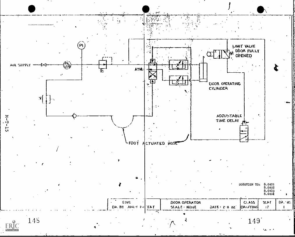
AIR SUPPLY t,<1
14S
LUNi
PI .LIMIT VALVEDbOR FULLY6Paito
4
ATM:
_
CW(.1
C. BY ANVi 1:.)
C.TUATED 140
DOOR OPERATINGCYLINDER
ADSU5TABLETIME. DELAY tit
Le
SOLUTION TO: 8.04018.04028.04038.0404
:EATDOOR OPERATOR CLASSSEALE NONE DATE 2 84' 19R1.17TIN
-)
149
9EAT D.
a.
.)
REFERENCES
A
) 150
\ M-24
TECHNICAL RgFERENCES
MECHANICAL DRAFTINaPOPTION
Electrical and Electronics Diagrpms, USAS Y14.15-1966f New York,AY:American Society of Mechanical Engineers '(345 'East 47th St.,
m#.10017)..
fluid Power Educational Kit, (Fit), Cincinnatti, OH: .ClippardLaboratory,-inc'., (7390 Coleman Road., 45239).
Graphic Symbols for Electrical and EYectronics Diagrams, ANSIY32.2-I975, New York, NY: The-Institute of Electri'tal and-EleCtronic Engineers (345 East 47th'St., 10017). .
Grimes, L. A. Jr., Mechanical Drafter Student's Manual, Austin'TX: TheUniversi.ty of Texas at Austin, Instructional Materials Center,Division of Continuing Education, 1965.
Grimes, L. A. 4:Mechanical Draftsman Coordinator's Guide, Austin, Tx:The Universitl'of Texas at Austin, Instructional Materials Centpr;Division of Continuing Education, 1965., .
Hodges, Charles S., Industrial Fluid Power,. Vols. I, II, & III, DallasTX: Womack Educational Publications, (2110 Shea Road., 75235),.
Interconnection Diagrams, ANSI YI4.15a-1971, New York, NY: McGraw-HillBook Company.
Oster, Jan, Basic Applied Fluid PoWer: Hydraulics, New-York,.NY:McGraw-Hill Book Company.
Vickers Industrial Hydraulics Manual 735100-A, Troy, MI: Sperry RandCorporation, (48084).
To initiate a program in Mechanical Drafting, the following publicationis recommended.
4-
McCIdlin, Gerald R., Mechanical Drafting, Stillwater, OK: Mid-AmericanVocational Curriculum Consortium, inc.,. 1982. (ZIP 74074, 973pages, CBVE Currieulum/Resource Guide featuring layouts and workingdrawings,,ditensioning and tolerancing, fareners and.hardware,presentation drawings, materials and specifications, manufacturingprocesses, sheet tetal developments, and%power transmission).
(NOTE: This publication is available through the ArticulationProgram Library.)
1
1.51.M-25
I
al
UNIT 9.. 0
DRAFTING IISTRUCTURAL DRAFTING
..,7
4 r,
S-1
DRAFTING II
STRUdTURAL DRAFTING- (OFTION)
This Structural Drafting option is designed to provide and enhance job"qualification competencies required to perform Architectur;l Draftingtasks involving the analysis and drawing of structural systems appli-cations of steel, wood, and concrete. Structural Drafting, may be.con-.sidered a sPecialized continuation of the Architectural Drafting option.
A
,
Emphasis in Structural Drafting will be on detailing, performing basicstructuTal calculations, and the design of fasteners and connectors.
Currently, Structural Drafting only is offered at one vocationaleducation center in The School District of Greenville County.
153-S-2
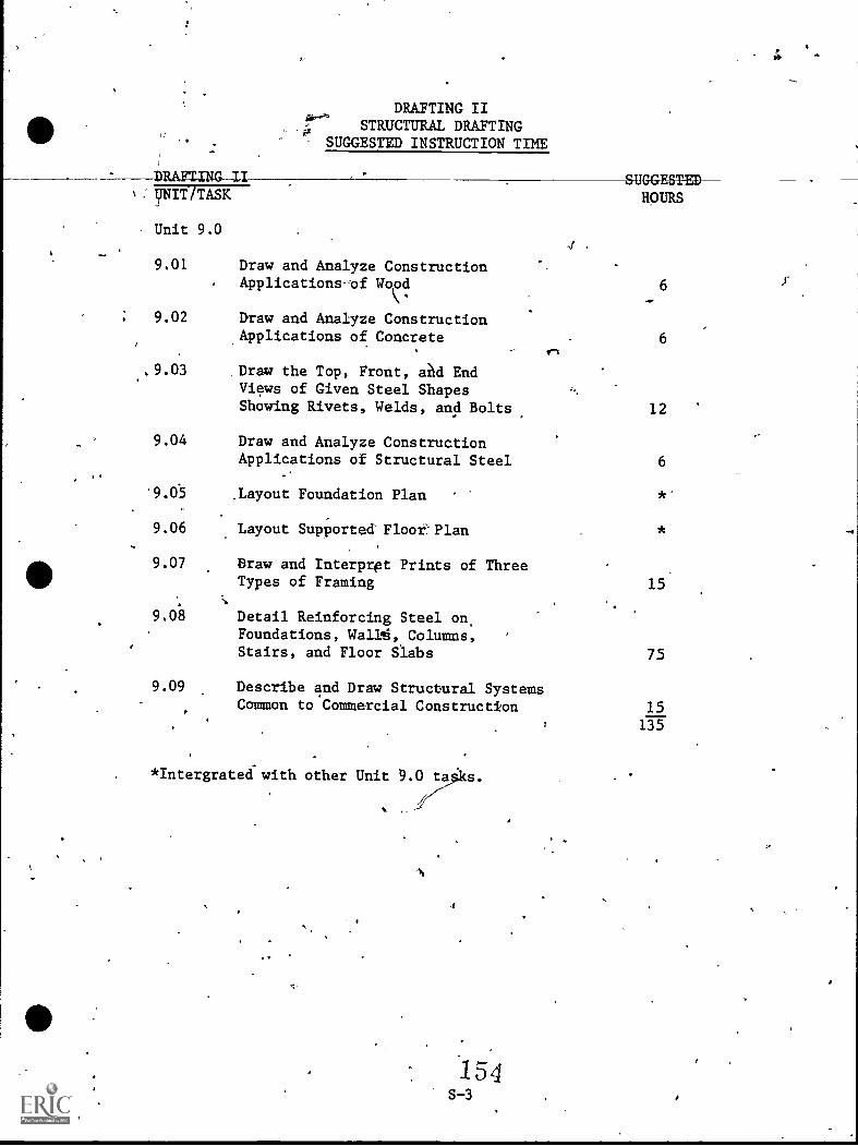
DRAFTING IISTRUCTURAL DRAFTING
SUGGESTED INSTRUCTION TIME
SUGGESTED: ynt/ TASK HOURS
Unit 9.0
9.01 Draw and Analyze ConstructionApplications-'of Wood
9.02 Draw and Analyze ConstructionApplications of Concrete
..9.03 .Draw the Top, Front, aAd EndViews of Given Steel ShapesShowing Rivets, Welds, and Bolts
6
6
12
9.04 Draw and Analyze ConstructionApplications of Structural Steel 6
,Layout Foundation Plan
9.06 Layout SupPorted Floor-Plan
9.07 Draw and Interpret Prints of ThreeTypes of Framing
9.08 Detail Reinforcing Steel on,Foundations, Wallg,,Columns,Stairs, and Floor Slabs
9.09 Describe and Draw Structural SystemsCommon to Commercial Construction
*Intergrated with other Unit 9.0 ta
1 54S-3
15.
75
15
135
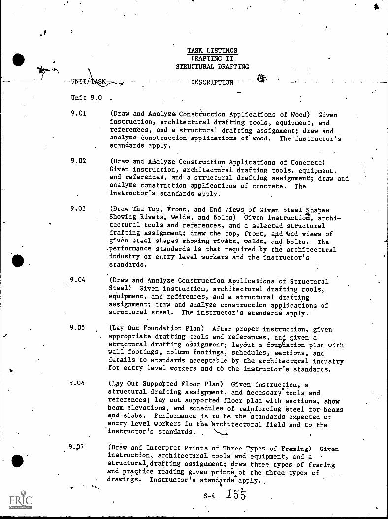
K
Unit 9.0
TASK LISTINGSDRAFTING II
STRUCTURAL DRAFTING
DESCRIPTION
9.01 (Draw and Analyze Constimction Applications of Wood) Giveninstruction, architectural drafting tools, equipment, andreferentes, and a structural drafting assignment; draw andanalyze Construction applications of' wood. The'instructor'sstandards apply.
9.02 (Draw and Analyze Construction Applications of Concrete)Given instruction, architectural drafting tools, equipment,and references, and a structural drafting assignment; draw andanalyze construction applications of concrete. Theinstructor's standards apply.
9.03 (Draw The Top, Front, and End Views.of Given Steel lhapesShowing Rivets, Welds, and Bolts) Given instruction, archi-tectural tools and references, and a selected structuraldrafting assignment; draw the top, front, and 'end views ofgiven steel shapes showing rivets, welds, and bolts. Theperformance standards'is that requiredby the architecturalindustry or entry level workers and the instructor'sstandards.
.9.04 (Draw and Analyze Construction Applications 'of StructuralSteel) Given instruction, architectural drafting tools,equipment, and references,,and a structural draftingassignment; draw and analyze construction applications ofstructural steel. The instructor's standards apply.
9.05 (Lay Out Foundation Plan) After proper instruction, given. appropriate drafting tools and references, and given a
structural drafting aisignment; layout a fouddation plan withwall footings, column footings, schedules, sections, anddetails to standards acceptable by the architectural industryfor entry level workers and to the instructor's standards.
9.06 (Lay Out Supported Floor Plan) Given instrucpion, astructural.drafting assigpment, and necessary tools andreferences; lay out supported floor plan with sections, showbeam elevations, and schedules of reinforcing Steel fon beamsand slabs. Performance is to be the standards expected of.entry level workers in the rchitectural field and to theinstructor's standards.
9.97 (Draw and Interpret Prints of Three Types of Framing) Giveninstruction, architectural tools and equipment, and astructuralAdrafting assignment; draw three types of framingand pragtfce reading given prints4of the three types of
, drawings. Instructor's standvds apply.
S-4 1 5
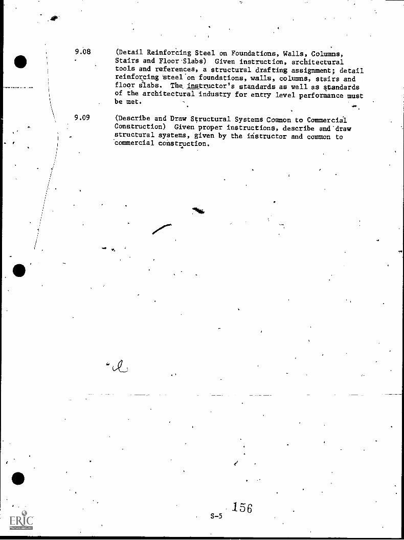
9.08 (Detail Reinforcing Steel on Foundations, Walls, Columns,Stairs and Floor.Slabs) Given instruction, architecturaltools and references, a structural drafting assignment; detailreinforcing steel'on foundations, walls, columns, stairs andfloor aabs. The instructor's standards as well as-Oandardsof the architectural industry for entry level performance mustbe met.
9.09 (Describe and Draw Structural Systems Common to CommercialConstruction) Given proper instructions, describe and'drawstructural systems, given by the instructor and common tocommercial construction.
156S-5
9
UNIT 9.0 DRAFTING IISTRUCTURAL DRAFTING
TASK 9.01 DRAW AND ANALYZE CONSTRUCTIONAPPLICATIONS OF WOOD
PERFORMANCE OBJECTIVE:
Given instruction, architectural drafting tools, e4uipment, andreferences, and a structural drafting assigmment; draw and analyzeconstruction applications of woo4. The instructor's standards apply.
PERFORMANC ACTIONS:
9.0101 Describe cheavy timb
9.0102 Describewood in 1
9.0103
- 9.0104
List conswood in co
Acteristics andr construction.
aracteristics andht construction.
api)lications and draw
draw applications of
erations to be applied in applications ofstruction.
Identify t es, characteristics, and how to drawapplications of laminated'wood in construction.
9.0105 Identify characteristics, types, applications, anddraw wood connections.
9.0106 Explain wood applications fabrication procedures.
9.0107 Describe wood applications erection procedures.
PERFORMANCE STANDARDS:
- Eighty percent accuracy on wiitten knowledge tests.- Executes diawings accurately, neatly, with professional styles
within an acceptable time for entry-level employment.
SUGGESTED INSTRUCTION TIME: 6 Hours
UNIT 9.0 DRAFTING IISTRUCTURAL DRAFTING
TASK 9.02 DRAW AND ANALYZE CONSTRUCTIONAPPLICATIONS OF CONCRETE
PERFORMAliCE OBJECTIVE:
Given instruction, architectural drafting tools, equipment, andreferences, and a structural drafting assignment; draw and analyzeconstruction applications of concrete. The instructor's standards
' apply.
PERFORMANCE ACTIONS:
\ 9.0201 Identify typts, characteristics, and how to drawapplications of concrete structural systems.
9.0202 List considerations to be'applied in applications ofconcrete structural systems.
9.0203 Describe types, characteristicsdraw connections used in condresystems.
, applicae structu
9.0204 Describe methods of fabrication ostrudtural systems.
ons, andal
ete
9.0205 Explain concrete structural system erectionprocedures.
PERFORMANCE STANDARDS:
7 Eighty perfent accuracy on written knpwledge tests.- Executes dlawingd accurately, neatl, with professional style
within-en acceptable time for entry-level employment.
SUGGESTED INSTRUCTION TIME: 6 Hours
UNIT 9.0 DRAFTING IISTRUCTURAL DRAFTING
TASK 9.03 DRAW THE TOP, FRONT, AND ENDVIEWS OF GIVEN STEEL SHAPESSWAM-RIVETS, WELDS, ANDBOLTS
PERFORMANCE OBJECTIVE:
Given instruction, architectural tools and references, and ,a selectedstructural drafting assignment; draw the top, front, and end views ofgiven steel shapes showing riyets, welds, and bolts. Performancestandards required by the architectural industry for entry level Workersand theinstructor's standards apply.
PERFORMANCE ACTIONS:
9.0301
9.0302
(
4
9.0303
.;:
Identify various shapes.
Identify Fai,ricating Practices:a. Material handling and cuttihgb. Templatesc. Layoutsd. Punching and drillinge. Boltingf. Rivetingg. Weldingh. Finishing,-cleaning, and paintingi. Inspection
Show Method of Representation:a. Structural sharesb. Bolts (Unfinished & High strength)
(1) Shop bolts(2) #'eld bolts(3) Sliacing
c. Welding(1) Shop welds(2)- Field welds
d. Shop rivets
9..0305t Identify Gages. ,
9.0305 Develop a Billof Material.
9.0306 Show Methods of Connecting:4 - a. Welding -
b. Rivetingc. Bolting
59S-8
,5)
UNIT 9.0
TASK 9.03
DRAFTING IISTRUCTURAL DRAFTING
DRAW THE TOP, FRONT, AND ENDEWS-0E-GIIIEWS4rEE1S-11APES
SHOWING RIVETS, WELDS, ANDBOLTS (Con't.)
PERFORMANCE ACTIONS (Con't.): 0
9.0307 Include beam and connection design.
9.0308 Indicate tolerances.
9.0309 Show beam and column marking.
PERFORMANCE STANDARDS: '
- For a given structural drafting assignment, draw, the top,front, and end views of given steel shapes showing rivets,welds, and bolts.
'SUGGESTED INSTRUCTION TIME: 12 Hours
160S-9
UNIT 9.0
TASK 9.04
Ng,
DRA ING IISTR CTURAL DRAYTING
AND ANALYZE CONSTRUCTIONLICATIONS-CI-STRUCTURAIrSIELL
PERFORMANCE OBJECTIVE:
Given instruction, architectural drafting tools, equipment, andreferences, and a structural drafting assignment; drawand analyzeconstruction applications of structdral steel. The ins ru tor'sstandards dpply.
PERFORMANCE ACTIONS:
9.0401
9.0402
Identify and draw conventional structural steelshapes.
List considerations in applications of structuralsteel.
9.0403 Describe,and draw common types of structural steelconnections.
9.0404 Identification structural steel fabrication.
procedures.
PERFORMANCE STANDARDS:
- Eighty.percent accuracy on written knowledge tests. --- Executes drawings accurately, neatly, with professional style
within an acceptable time for entry-level employment.
SUGGESTED INSTRUCtION TIME: 6 Hours
->
1 61S-10
/L,
44-
UNIT 9.0 DRAFTING IISTRUCTURAL DRAFTING
TASK 9.05 LAYOUT FOUNDATION PLAN
PERFORMANCE OBJECTIVE:
After proper instxnction, given appropriate drafting tools andreferences, and giVen a structural drafting assignment; layout a
-loundation plan with wall footings, column footings, schedules,sections, and details to standards acceptable by the architectural
N industry for entry level workers: and to the instructor's standards.
PERFORMANCE ACTIONS:
9.0/01 Draw coluMn footings.
9.0502 Draw piers.
4t.
9.0503 Draw wall footings.
9.0504 praw wa
9.0505 Draw grade beams.
0
9.0506 Drae typical sectijs.
ERFORMANCE STANDARD):
For a given structural drafting assignment, layout a foun-dation plan with wall footings; colump footings, schedules,sectiotts, and details to standaras acheptable by the arehi-ftectural industry for entry level worters and to theiristruq--tor's standards.
4
SUGGESTED I STRUCTION TIME: Integrated with other UN,t 9.0 tasks
RELATED TECHNICAL INFORMATION:
- Sweets Catalogs and other approtriate references.
''162
s
UNIT 9.0
TASK 9.0
DRAFTING IISTRUCTURAL DRAFTING
LAYOUT SUPPORTED FLOOR PLAN
PERFORMANCE OBJECTIVE:
Given instruction, a structural drafting assignment, a necessary toolsand references; lay out supported floor plan with sec_ions, show beamelevations, and schedules of reinforcing Steel for beams ana.sslabs.Performance is to be to the standards expected of entry level workers inthe architectural field and to the instructor's standards.
PERFORMANCE ACTIONS:
9.0601
9.0602
0
Identify various bar sizes.
Identify the scales most commonly used in draftingreinforced concrete buildings.
9.0603 Show methods of Dimensioning.
9.0604 Draw Columns.
9.0605 Draw Beams and Girderg.
9:0606 Draw Slabs:a. Joist slabb. Flat slabc. Two-way slabd. Waffle slab
9.0t07 Detail Stairs.
9.0608 Show Schedules.
PERFORMANCE STANDARDS:
- Layout supported floor plan with sections, show, beam ele-vations, and schedules of reinforcing steel for beams andslabs.
- Performance is to be to the standards expected of entry levelworkers in the architectural field and to the insiruptor'sstandards.
4
SUGGESTED INSTRUCTIOil TIME: Integrated with other Unit 9.0 tasks
s-11. 63
1
. UNIT 9.0 pAFTING IISTRUCTURAL DRAFTING
TASK 9.07 DRAW ANDINTERPRET PRINT1 OF THREE.,.TYPES OF FRAMING s
-../.
6
PERFORMANCE OBJECTIVE:
Given insttuction, architectural tools and equipment, and a structural. drafting assignment; draw three types of framing and practice readinggiven prints of the three types of dfawings. Instructor's ata Aardsapply.
PERFORMANCE ACTIONS:
9.0701 Draw dolumns.
9.0702 Interpret and draw the three types of framing:a. Beams and girders
Bar jointsc. Trusses
9.0703 Draw a Framing Plan.*
9.0704 Draw Sections and miscellaneous detaili.*'
9.0705 Include Schedules.
9.0706 Identify riveting, welding, and bolting and theadvantages cl.f each.'
PEFORMANCE STANDARDS:*
- Draw and interpret prints of three types of framing.- The instructor's standards must be met.
'SUGGESTED INSTRUCTION TIME: 15 Hours
*Emphasis of training.
4.
it 4S-13
)
,
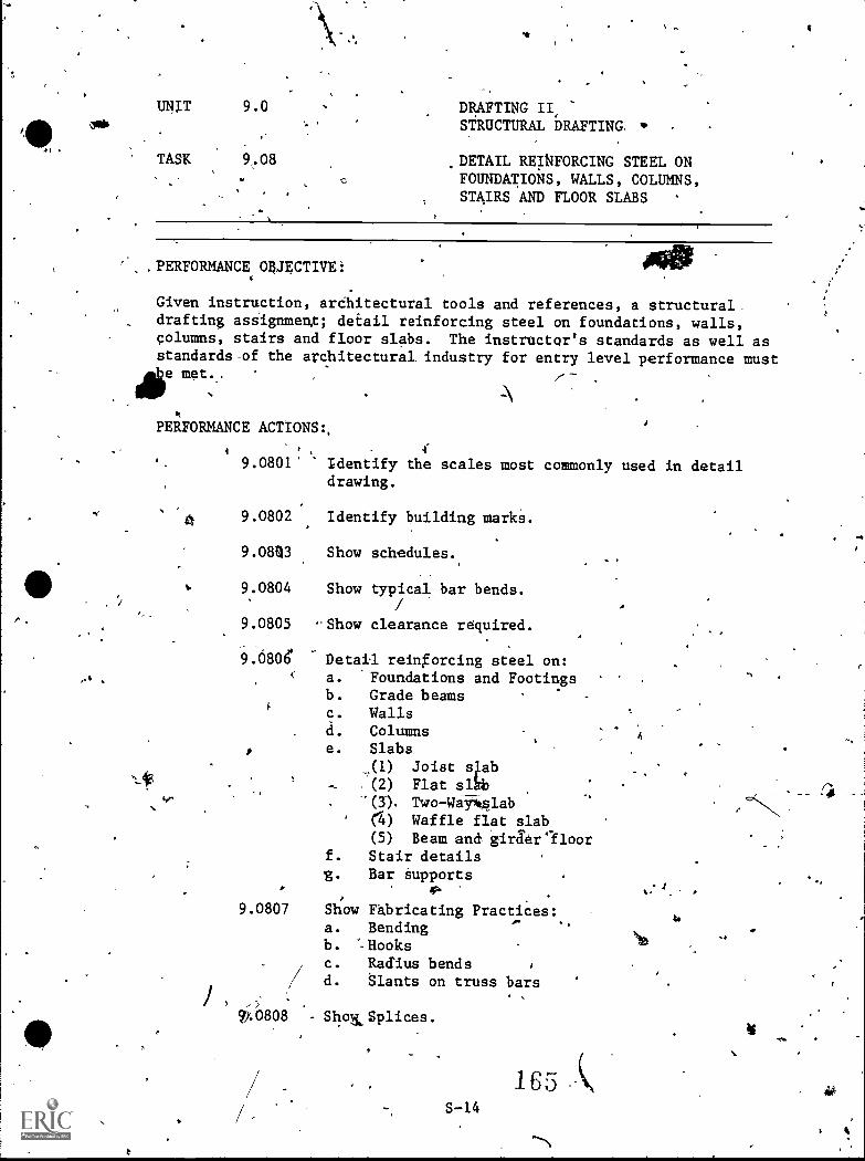
4 1
UNIT 9.0 DRAFTING II,ow* STRUCTURAL DRAFTING,
TASK 9.08
0DETAIL REINFORCING STEEL ONFOUNDATIOiTS, WALLS, COLUMNS,STAIRS AND FLOOR SLABS
PERFORMANCE OBJECTIVE: sagGiven instruction, arChitectural tools and references, a structural .
drafting asaignmenX; detail reinforcing steel on foundations, walls,columns, stairs and floor slabs. The instructgr's standards as well asstandards-of the architectural industry for entry level performance must
St
PERFORMANCE ACTIONS:,
4e,
4
9.0801 Identify the scales most commonly used in detaildrawing.
4 9.0802 Identify building marks.
9.08%3 Show schedules.
9:0804 Show typical bar bends.
9.0805 -Show clearance required.
9.680e Detail reingorcing steel on:a. -Foundations and Footingsb. Grade beams -
c. Wallsd. Columnse. Slabs
,(1) Joist 4ab, (2) Flat slhb-(3). Two-Way*glab(4) Waffle flat slab(5) Beam and, gira'er'lloor
f. Stair details%. Bar Supports
9.0807 Show Fabricating Practices:a. Bendingb. --Hooks
c. Radius bends/ r
d. Slants on truss bars
808 Sho&Splices.
.
S-14
165 (4
.1
" 4
UNIT 9.0 *
TASK. 9.08
DRAFTING IISTRUCTURAL DRAYTING
DETAIf REINFORCING STEEL ONFOUNDATION8, WALLS, COLUMNS,
4 STAIRS AND4L00R SLABS (Con't.)
PERFORMANCE ACTIONS (Con't.):
9.08.09 Show Bar Lists.
9.0810 Identify Wire Fabric.
1.PERFORMANCE STANDARDS:
For a, given structural.drafting assignment, detail reinforcing
steel on foundations, walls, columns, stairs, ahd floor slabs..Performance must be tp standards gcceptable to thearchitectural indusiry fOr entry level workers and to-thestandards of the instructor.
SUGGESTETRUCTION'TIME: 75 Hours
N.
cto,
er
1 CC'S-15
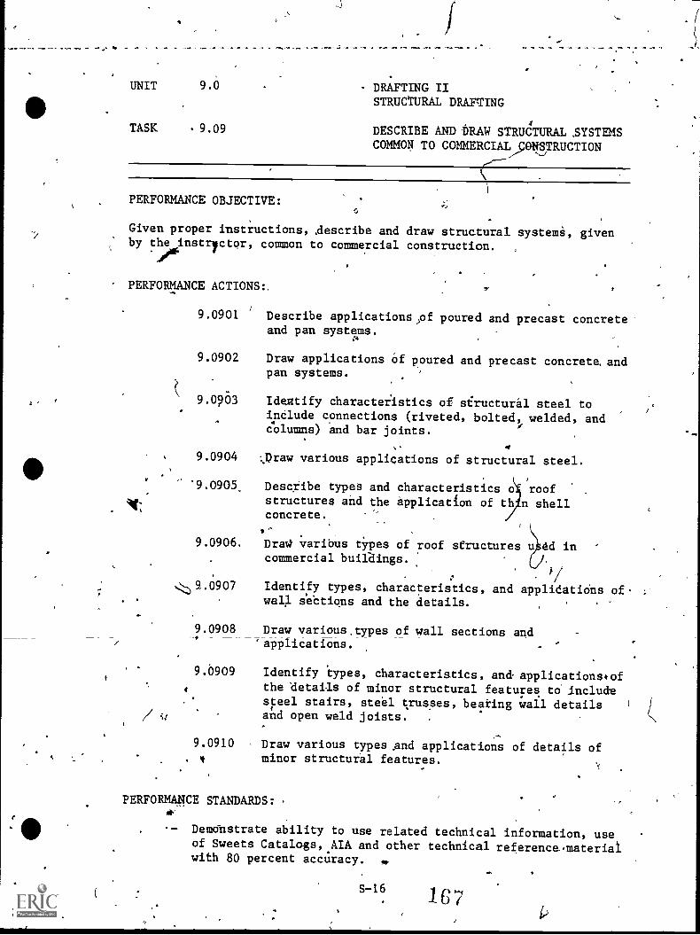
UNIT 9.0 DRAFTING IISTRUCTURAL DRAFTING
TASK .9.09 DESCRIBE AND-DRAW STRUCTURAL ,SYSTEMSCOMMON TO COMMERCIAL,00/TRUCTION
1
PERFORMANCE OBJECTIVE:
Given proper instructions, Aescribe and draw structural systema, givenby the instryctqr, common to commercial construction. .
PERFORMANCE ACTIONS:.
9.0901 Describe applicationspf poured and precast concreteand pan systems.
9.0902 Draw applications Of poured and precast concrete.andpan systems.
9.0203 Ideatify characteristics of siructural steel toindlude connections (riveted, bolted, welded, andCVlumns) and bar joints.
9.0904 ',Draw various applications of structural steel.
'9.0905. Describe types and characteristics o roofstructures and the Application of th n shellconcrete.
9.0906. Drac4 varibus types of roof structures u dd incommercial buiLaings.
Identify types, characteristics, and applidatiOns of.well sebtions and the details.
9.0908 Draw various.types of wall sections and'applications.
9.0909 Identify types, characteristics, an& applications*of4 the'details of minor structural features to. ,include
steel stairs, steel trusses, beating wall detailsand open weld joists. .
9.0910 , Draw various types And applications of details of. f minor structural features.
PERFORMWE STANDARDS: .
4'
Demdnstrate ability to use related technical information, useof Sweets Catalogs,.AIA and other technical reference,materialwith 80 percent accuracy. 4P
S-16 167ao,
41'
4 UNIT' 9.0
TASK 9.09
DRAFTING IISTRUCTURAL DRAFTING
DESCRIBE AND DRAI4 STRUCTURAL.SYSTEMSCOMMON TO COMMERCIAL CONSTRUCTION(Con!t.)
PERFORMANCE STANDARDS (Coneit.):,
PrOduce neat, accurate,'and complete drawings, profe.iSionalaPpearance and layout.
- Draw.symbols And conventitns accurately and.cork.ecay.Peitorm required drawings,within the time 4mits consideredappropriate for initial employment job qualification.Lettering and drafting skills demonstrated must show neatness,accuiacy, consistency, proper placement, and character.
in
SUGGESTED INSTRUCTION TIME: 15 Hours.
RELATED TECHNICAL IWORMATION:
- Sweets Caiglogs.- AIA and other references.
,/-
0,
I.
, '
,
tt
eff
-
t,
*
,
\
,
..
*1 .
of.
PROFIOIENCY REPORT
c
44
,
,. ,4
44. r.-------,-4--1
......___
\
,
I
*
- S-18
o
169.
..-
.
_..
r
,
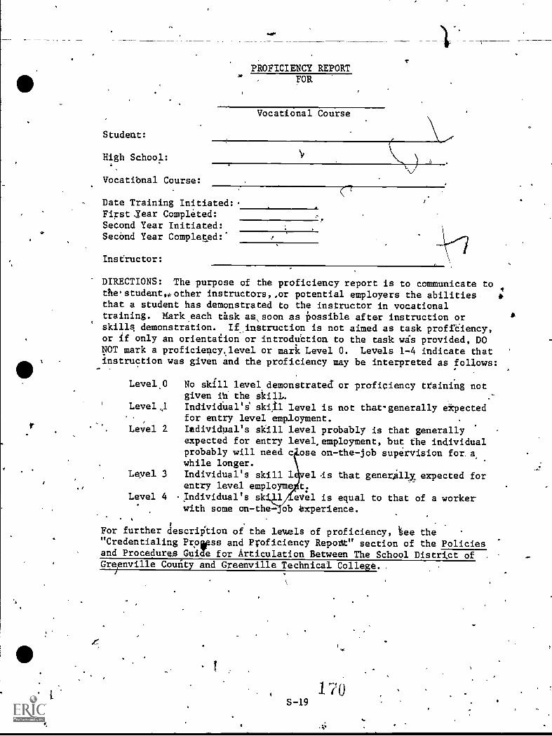
a
Student:
High School:
Vocatibnal Course:
r
PROFICIENCY REPORTFOR
Vocational Course
Date Training Initiated:.Firstjear Completed:Second Year Initiated:SecOnd Year Completed:.
Insfructor:
DIRECTIONS: The purpose of the proficiency report is to communicate tothestudent,,kother instructorsor potential employers the abilities *that a student has demonstrated to the instructor in vocationaltraining. MArk,each task as,soon as Possible after instruction orskills demonstration. If_instruction is not aimed as task proff6iency,or if only an orientation or introdugtion to the task wis provided, DONOT mark a proficiency,Jevel or mark Level O. Levels 1-4 indicate thatinstruction was given and the proficiency may be interpreted as follows:
Leve1.0 No skill level demonstrated or proficiency training notgiven ita the skilL. .-
Leve1,1 Individual'i skal level is not that-generally ekpected. for entry level employment.Level 2. Iadividual's skill level probably is that generally
expected for entry level,employment, but the individualprobably will need c ose on-the-job supervision for a,while longer.
Leyel 3 Individual's skill 1 el ds that generally expected forentry level employme t.
Level 4 ..Individual's sk 1 eVel is equal to that of a workerwith some on-the- ob experience.
For further descri&ion of the leuels of proficiency, 6e the"Credentialing Proapss and Proficiency Report" section of the Policiesand Procedures Guide for Articulation Between The School Distrigt of ,
Greenville Comity and Greenville Technical College.
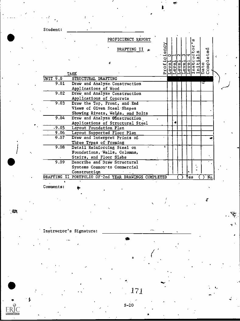
f4.
Student:
.PROFICIENCY REPORT
0
w
r-I
we
C \I elr-Iwa)4.54-1(1)04
:M
r-I
w-
s..1
04J VIW r--1Z al
5-i ,-I
ro
W4-1
Wr-I
...
>1o
DRAFTING II * zeu
.4-1
- U.4-1
a 4.4
wwwwwwc=00TASk
UNIT 9.0 STRUCTURAL DRAFTING9.01 Draw and Analyze. Construction
Applications of Wood9.02 Draw and Analyze Construction
Applications of Concrete9.03 Draw the Top, Front, and-End
Views of Given Steel'ShapesShowing.Rivets, Welds, and Bolts
.
9.04 Draw and Analyze G6nstructian. .
Applications of Structural Steel.
4
.9.05 Layout Foundation Plan9.06 Layout Supported Floor Plan9.07 Draw and Interpret Prints of
Three Types of'Framing9.08 Detail Reinforcing Steel on .
Foundations,'Walls, Columns,. Stairs, and Floor Slabs
.
.
9.09 Describe and Draw Structural.
Systems Common.to CommercialConstructiqn .
.
..
.
.
.
DRAFTING II PORTFOLIO OF`2nd YEAR DRAWINGS COMPLETED ( ) Yes ( ) No,
Comments:
Instructor's Signature:
171
S-20
'Row
.#
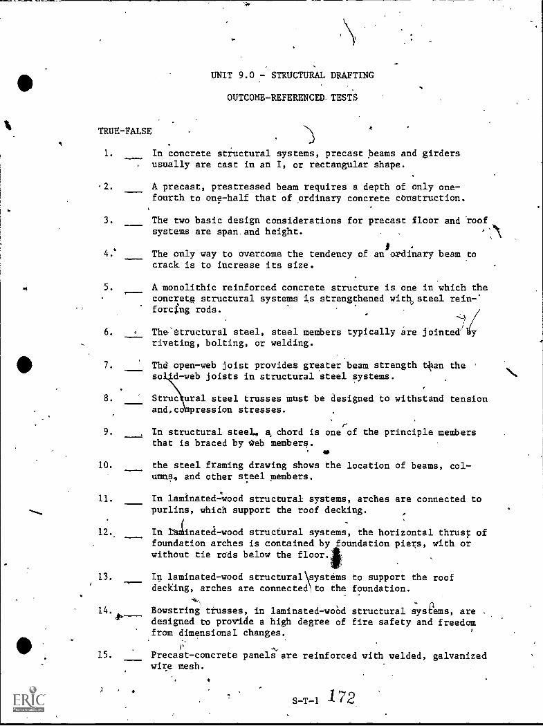
TRUE-FALSE
1.
I.
UNIT 9.0 - STRUCTURAL DRAFTING
OUTCOME-REFERENCED TESTS
In concrete structural systems, precast beams and girdersusually are cast in an I, or rectangular shape.
-2. A precast, prestressed beam requires a depth of only one-fourth to one-half that of ordinary concrete cbustruction.
3. The two basic design considerations for precast floor and roofsystems are span.and height.
4.* The only way to overcome the tendency of an ordinary beam tocrack is to increase its size.
5. A monolithic reinforced concrete structure is, one in which theconcret.e structural systems is strengthened with,steel rein-.forcl.ng rods.
6. The'structural steel, steel members typically are jointed' yriveting, bolting, or welding.
7. The open-web joist provides greater beam strength t#an the '
so d-web joists in structural steel systems.
8. Struc ural steel trusses must be designed to withstand tensionand,co pression stresses.
9. In structural steel, a chord is one of the principle membersthat is braced by *eb members.
10. the steel framing drawing shows the location of beams, col-umns, and other steel members.
11. In laminated-:wood structural systems, arches are connected topurlins, which support the roof decking.
12. In Iblinated-wood structural systems, the horizontal thrust of-
foundation arches is contained by foundation piers, with orwithout tie rads below the floor.
13. In laminated-wood structural systems to support the roofdecking, arches are connected to the foundation.
n14. Bowstring trusses, in laminated-woOd structural systems, are .
44- designed to provide a high degree of fire safety and freedomfrom dimensional changes.
15. Precast-concrete panels are reinforced with welded, galvanizedwire mesh.
S-T-1 172
Unit 9.0 - Structural Drafting (Con't.)
. ,
16. Describe thc.duties of various drafting room employees in a struc-tural steel fabrication shop with 70 percent accuracy according-tothe instructor's standards.
a. Drawing checker:
b. Detailer:
c. Chief draftsmat:
ao
-;
d. Billing and Weights Clerk:
173S -T -2
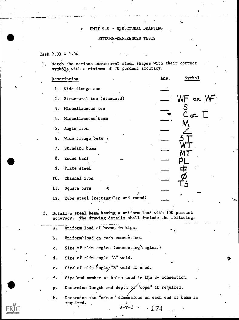
7 UNIT' 9.0 ViBCTURAL DRAFTING
OUTCOMEREFERENCED TESTS
Task 9.03 & 9.04
.1°. Match the various structural steel shapes with their correctsymbo4s.with a minimum of 70 percent accuracy.
Description
1. Wide flange tee
2. Structural tee (standard)
3. Miscellaneous tee
4. Miscellaneous' beam
5. Angle iron
6. Wide flange beam
7. Standard beam
8, Round bars
9. Plate steel
10. Channel iron
11. Square bars
12. Tube steel (rectangular and round)
Ans. Symbol
111
1111111=0
.m.1
.101
VIF Wt. V\FS
Olt E
Z..5 7'WT
PL
ce
2. Detail-a steel beam having a uniform load with 100 percent
accuracy. The drawing details shall include the following:
a. Upiform load of beams in kips.
b. Uniforer/oad on each conneetion.
c. Size of clip angles (connecting`.angles.)
d. Size oi clip angle "A" weld.-
e. Size of clip /augl5/"B" weld if uaed.
. f. Size'and number of bolts used in the B connection.
g. Determine length and depth cope" if required.
h. Determine the "minus" dim nsions on each end'of beam 4srequired.
S T 3 7 4
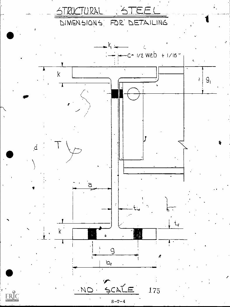
_6-racraat.. 'TEED1NVEMb101\14: FOIL. I.E7A.ILINIL
Hic.= 172 vtiab 4 1/16"C.
9,
be
. .
SCN.LE 175
s-T- 4
0
Unit 9.0 - Structural Drafting
Task 9.03 & 9.04 (Con't.)
3. Given an engineer's sketch showing column locations, gtd sizes oicolumns, girders, and filler,beams; draw a structural steel: layoutwith 90 perent accuracy, -
-
Sob
S -T -5
176
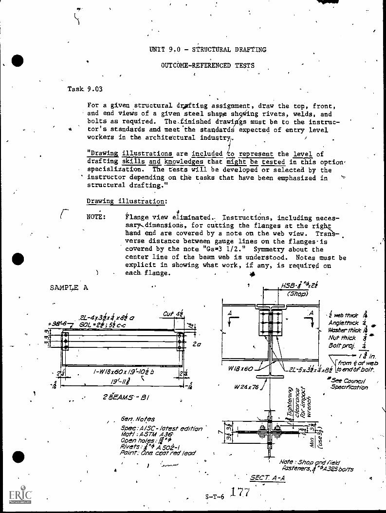
UNIT 9.0 - STRUCTURAL DRAFTING
4
OUTCOME-RE FERENCED TESTS
Task 9.03
. .
For a given ,structural d;pfting assignment, draw the top', front,and end views of a given steel shapg sh iiing rivets, welds, andbolts as required. The,Einished drawi gs must be to the instruc-tor's standards and meet"the standards expected of entry levelworkers in the architettural industry. /
"Drawing illustrations are included o represent the level ofdrafting skills and knowledges that might be tested in this option-specialization. The tests will be developed or selected by the
' instructor depending on the tasks that have been emphasized instructural drafting."
Drawing illustiation:
NOTE: Flange view elimdnated. InstructiOns, including neces-sary...dimensiona, for cutting the flanges at the righthand end are cavered by a note on the web view. Tranb-.verse distance between gauge lines on the flanges.iscovered by the note "Ga=3 1/2." Symmetry about thecenter line of the beam web is understood. Notes must beexplicit in shawing what work, if any, is required oneach flange. 41
H.58-1.vidSAMPLE A
1 23EAM5"-
6en. NotesSpec : A/SC- latest editionMat/ : AST41 436Poen ho/es:roRi'vets foiff0 A 50E-IPoint: ne coat red lead
A
(Shop)
Wid x60
,iKebthIck 4AnglethickMieherthickANut thickBoll' prOl
in.from of web
A..2L...3-5xix xl3i 10 end bolt
W 24 x 76
.+1).
62 3
°Se Couna/Spec/r7thtion
N. al IL _"IN I
S-T-6 7 7
A
Note Shop 9`17;:i Cieldtrasteners,f "0.4..3e5 bolts
SECT. A-A
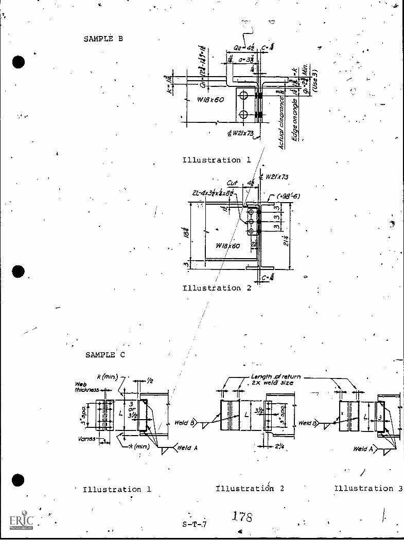
S AMP LE B
SAMPLE C
k (min)Webthidcneur
Vanes
Illustration 1
Cat 4
2L-4x3ixixe0
WeAr73
(#98=6)
(Z9.
Illustration 2
Weld ,6
C...k (min) Weld A
Length .of return2X weld 3Ize
Ir.
.
Illustration 1
S-T-3
Illustratian 2
vs
Illustration 3
I.
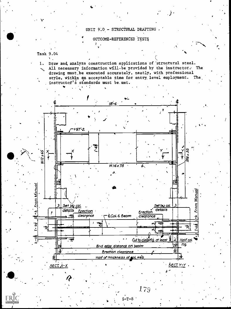
Vt.
Task 9.04
UNIT 910,- STRUCTURAL DRAFTING
4OUTCOME-REFERENCED TESTq
.4 ,
1, Draw and, analyze construction applications of 'structural steel.
% All necessary information will.be provided by the Instructor: The
drawing must:be executed accurately, neatly, with professionalstyle, within an acceptable ttme for entry level employment. The,
instructot'a sandards must be.met.
kr°1'N
A"-
It.
'X'
44_
lests
rt971-2,
W/6x78
3 SetdetW6
col.
Erectionclear?nce cl Evan,
Set col.details
Eredloncledrance
" ' eat to .c.1 0. at least
eclOr\clistanth Cr7 beairr
erection clearance
;13
0
0
Half col.4.2 "q
1* Plaif of thichne.ss ofrl. 71'
SECT,* X
'1 75
:SECT Y-Y .
t °
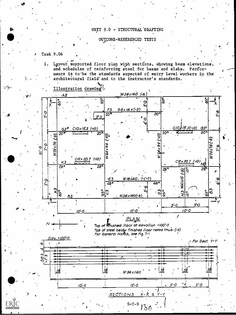
A Task 9.06 I.
UNIT 9.0 - STRUCTURAL'DRAFTING
OUTcOME -REFERENCED TESTS
1. ',pout supported floor plan wiph sectifons, stowing beam elevations,and sAedules of reinforcing steel for beams'and slabs-. Perfor-mance is to)be the standards expected of entry level workers in thearchitectural field'and to the instructor's stand'ards.
Illustration drawin
W.36x160
1:9-.
x
_
co
-F3
7:1
58 x 18.4(-2).
.
.
G34
x
os'r--
.
,
. 1.2...1,. i
G3de C10x16.3 (-I0
20 k
1..
*
'63
.s a
... ..,
. . C10 I.53(-10)
,
0.1
a..,r
...-.
!..,,,
k0N
N
.
20k- J------1 a
Cax 2,0.7 (-101, 1<3 , 4-.7.7.7=
,
. .
.
.
<
,W 16i40. (-1'4)
, ,'1.
4814
20k
1:7
1...Ne17N3
,
.1r..
20k <
-
-
,
Cl2r20.7 pa).
.t
28k,
.
-
n8 2 Crt
......4,4...
tQ.
°
ch,
28
(---"Th
elQ
c0
NO
..%6
I
48
.
.
. r .0
W36x160(-8),
Elev. e 100-0
,c01 a .
.5to 30lo'-o
PLANTop of kshed flbor'ot elevoiion #100=0Toler of steel beloiv finished floor noted thu.S: (-8)For eeneral Notts, see Fig. 7-1
t- For 5ect.
t*4,40
to-o
, W36 x160
12.-0
414'4.).
- 1SE CTIO N - Y-Y
S-T-9 11S(*)
4.
s.
x
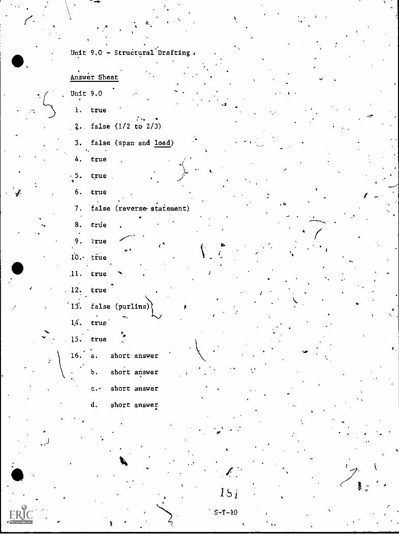
Unit 9.0 - Struétural *Drafting ,
Answer Sheet
Unit 9.0
1. true
false (112 to 2/3)
3. false (span and load)
4. true
5. true
6. true
7. false (reverse, staiement)
8. trde
9. true
6fo . true
,11. true
12. true
131. false (purlins)
11. true
15. true
16. a. short answer
b. short answer
c. short answer
d. short answer
S
I t
Ar
-
fa.
"4"--
END OF CAREER OPPORTUNITIESTRAINING 1ASK
.6
IDENTIFY POST-SECONDARY CAREERDEVELOPMENT OPPORTURITIES'
1.
e
PERFORMANCE OFtCTIVE:
Given an orientation to similar post-scondary vocational educationprograms, Primarily the Drafting program at Greenville Technical Collegeand evening development programs for the drafti4 trade, a report.of,skill competencies development.during secondary training and informationas necessary; identify..post-secondary career development opp tunities.
PERFORMANCE'A ;IONS: ,
1. Identify:
a. Need foi, additional training at the post-secondary level.b. Benefits\from additional training:
e
2. t. Identify post-secondary Eraining programs available atGTC. .
b. Identify how post-secohdary (GTC) training differs frmnsecondary training. in drafting.
3- Visit GTC programs of possible interest. Talk withinstructor, department head, or admisions counielor at GTC.
4; Determine with secondary and post-secondary assistance ifexemptaon of,post-seehAry level training is recommended.
.,,
ACcompliph'the rdquired steps Ito apply or test for exemption., (Optional)
FERFORMANCE ,STANDARDS:
Identify post-secondary training.opportunities in drafting ora related area at GTC.
-SUGGESTED IgSTRUCTION TIM2: Typically, integrated throughout entitepriram.
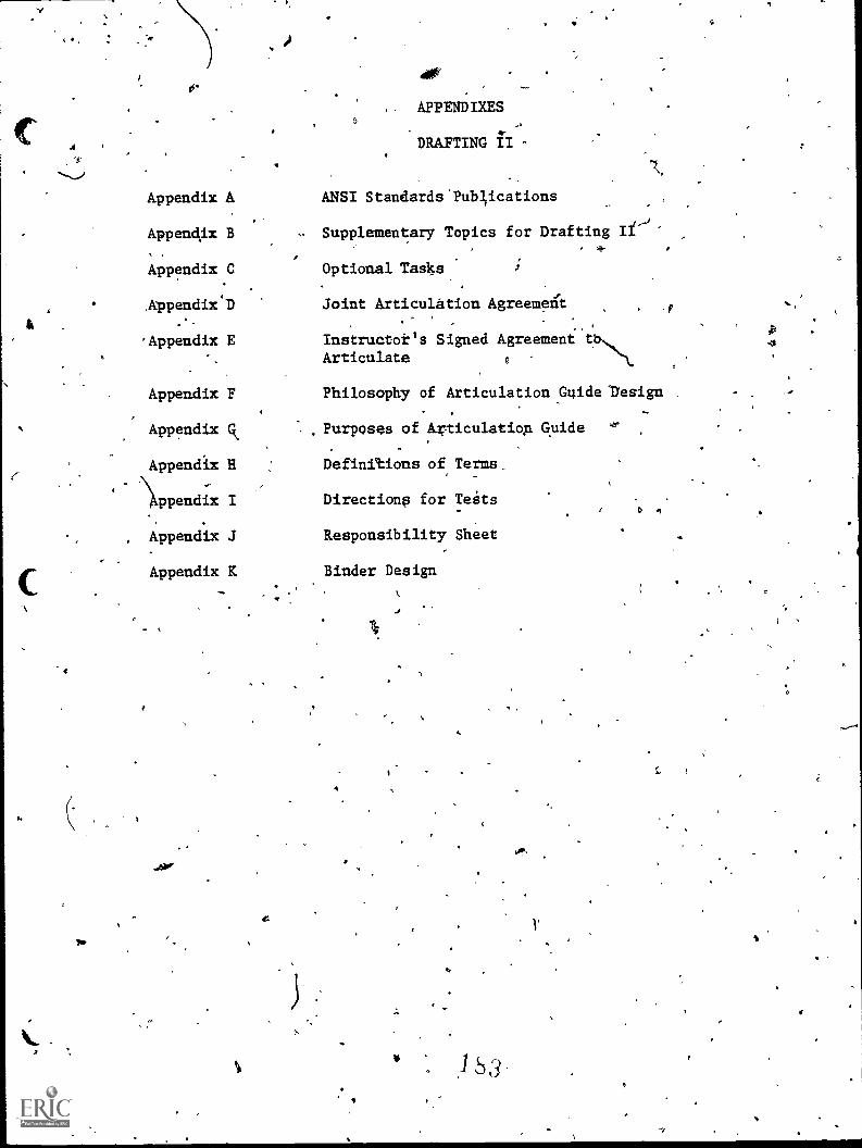
"-J
,
. APPENDIXES
4.DRAYTING II -
Appendix A ANSI Standards.Pub;ications
Appen4x B Supplementary Topics for Drafting II-j
Appendix.0 Optional TasIss
Joint Articulation AgreemelA
.*-
'Appendix E Instructor's Signed Agreement tbArticulate
4
Appendix F
Appendix
Appendix H
')ippendix I
, Appendix J
Appendix K
Philosophy of Articulation GuidelYesign
Purposes of Articulation guide
Definitions of, Terms_
Directiona for Teats
Responsibility Sheet
Binder Design
0
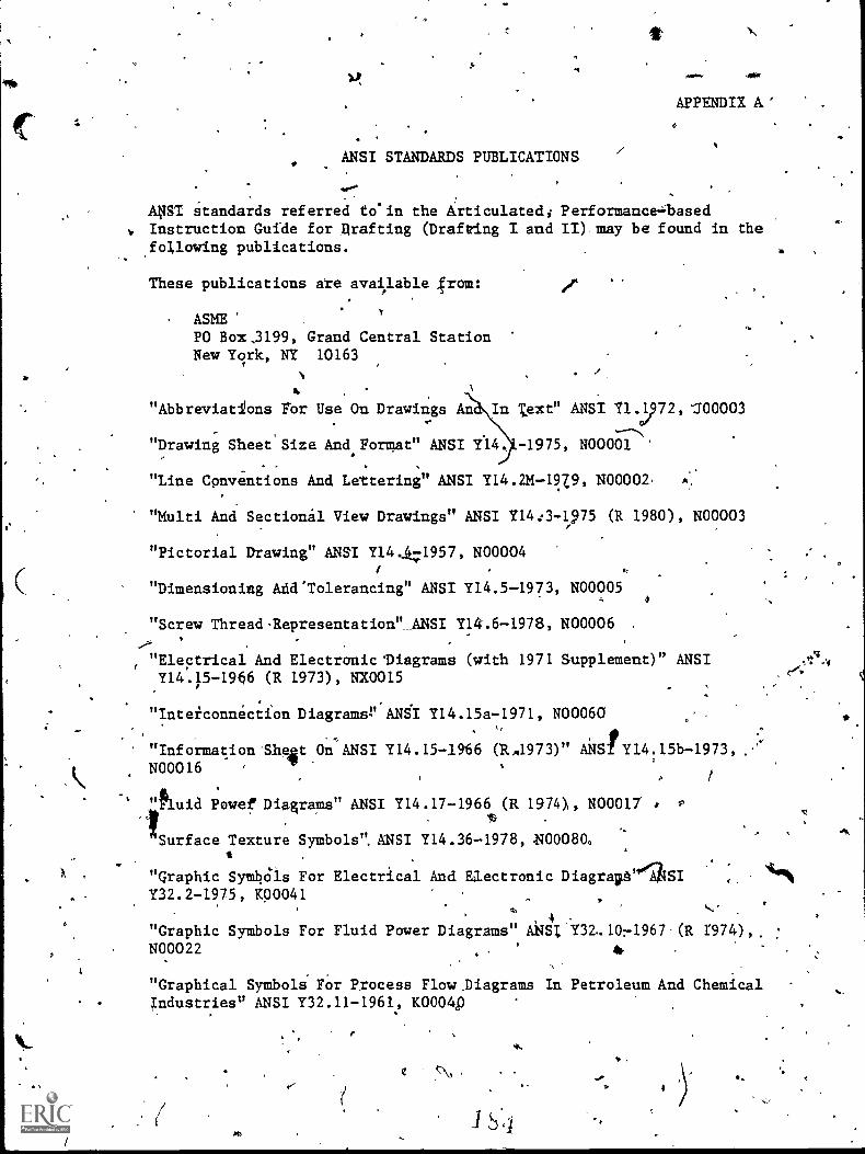
11,
APPENDIX A'
ANSI STANDARDS PUBLICATIMS
ApT standards referred to'in the Articulated; Performance=basedv. Instruction Guide for Drafting (Drafting I and II).may be found in the
fo4lowing publications.
These publications ate avai,lable from:
ASMEPO Box,3199, Grand Central StationNew York, NY 10163
4
"Abbreviat/ons For Use On Drawings An ';ext" ANSI Y1.01/972,100003
"Drawing Sheet'Size And,Format" ANSI Y14 -1975, NO0001
"Line Conventions And Lettering" ANSI Y14.2*-12Z9, N00002,
"Multi And Sectional View Drawings" ANSI Y14:3-1975 (R 1980), N00003
"Pictorial Drawing" ANSI Y14.1/471957, N00004
"Dimensioning And'Tolerancing" ANSI Y14.5-1973, N00005
"Screw Thread-Representation" ANSI Y14.6-1978, N00006
"Electrical And Electranic'Diagrams (with 1971 Supplement)" ANSIY14.15-1966 (R 1973), NX0015
"Inteiconnecon Diagrams.V.ANft Y14.15a-1971, N000604
Sr
at,On ANSI Y14.15-1966 (RA1973)" ANS/P"Information-Sh Y14:15b-1973,N00016
1uid Powef Diagrams" ANSI Y14.17-1966 (R 1970, N00017
Surface Texture Symbols", ANSI Y14.36-1978, M0080.
"graphic Symbdis For Electrical And Electronic Diagrapt"'ISIY32.2-1975, 1(00041
4"Graphic Symbols For Fluid Power Diagrams" ANSI1132.1071967-(R I974),.N00022
"Graphical Symboli For Process FlowDiagrams In Petroleum And ChemicalIndustries" ANSI Y32.11-1961, mow
Av.
,1/4
.4
fr0
SUPPLEMENTARY TOPICS
APPENDIX B -1
1°TOR
DRAFTING II. fi sr
Given available raining time, studeht interest, and po ntial employer
need, the second year of drafting tfaining (Drafting I )Aigilt include
6 .
all or part of the following supplemental instruction:
I. Electrical Drafting.
II.,Electronic Drafting,
III. Piping Drafting
I. Welding Drafting
A1tho4gh designate4 as supplementary training topics for the second ye:lir
of drafting, these topics couldioe employed at the end of the first year, b ,
of trainin 4 * .
. . e'. .
,
* ,
s
"",
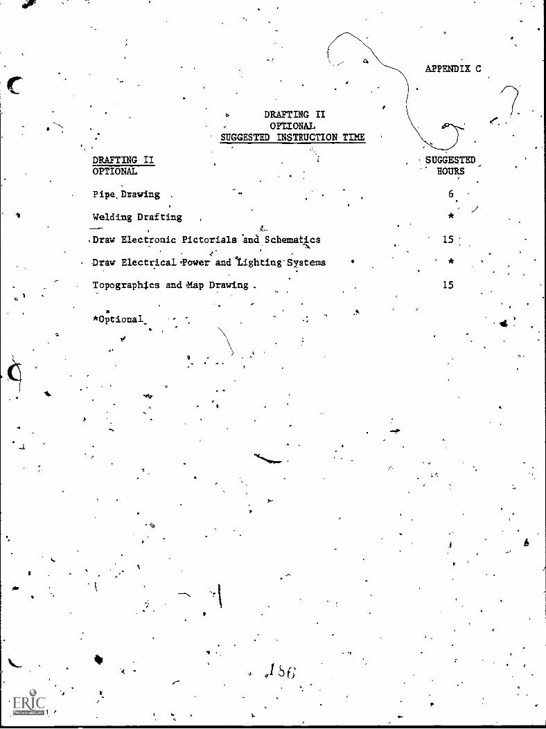
APPENDIX C
DRAFTING IIOPSIONAL
SUGGESTED INSTRUCTION TINE
DRAFTING II SUGGESTEDOPTIONAL HOURS
,
Pipe,Drawing . 6
Welding Drafting1-
.Draw Electronic Pictorials 'and Schematics
Draw ElectricalTawer andlaighting'Systems
Topographics and Map Drawing.
*Optional_
Nr9..
6
s
15
15
itt
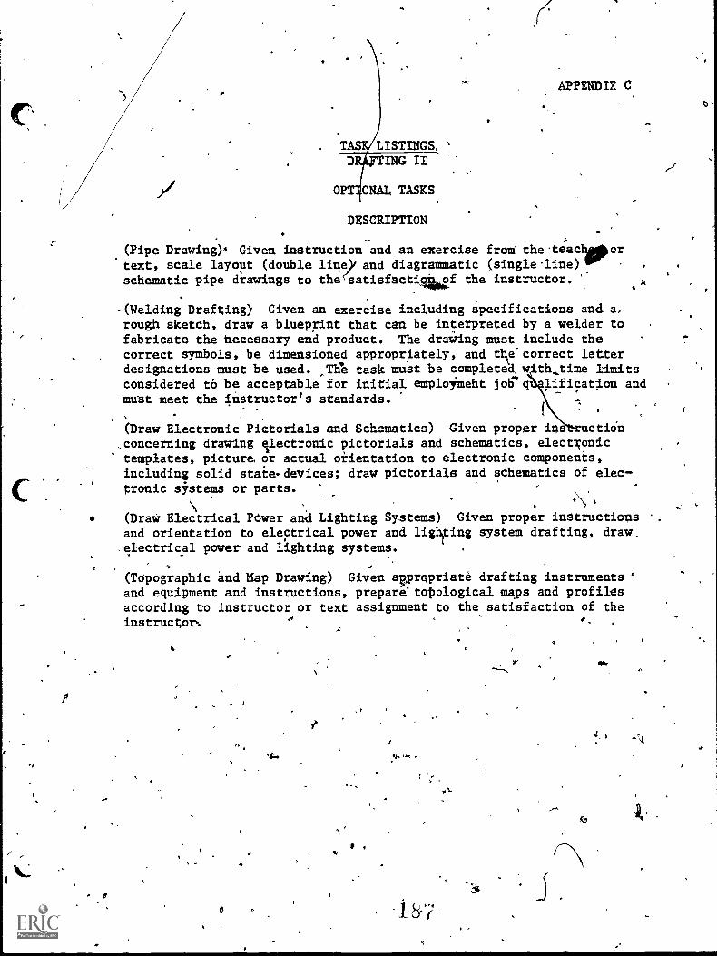
Cs
.1
TAS LISTINGS,
D ING II
OPT ONAL TASKS
DESCRIPTION
(Pipe Drawing) Given instruction and an exercise fram the.teachipportext, scale layout (double line)i and diagrammatic (single-line) .
schematic pipe drawings to the(satisfactiae the instructor. k
APPENDIX C
.(Welding Drafting) Given an exercise including specifications and a,rough sketch, draw a blueprint that can be interpreted by a welder tofabricate the hecessary end product. The draiing must include thecorrect symbols, be dimensioned appropriately, and the'correct letterdesignations must be used. ,T% task must be completed, th,time limitsconsidered to be acceptable for initial emploYmeht jobrq lification andmust meet the instructor's standards.
(Draw Electronic Pictorials and Schematics) Given proper ins ctioh
,concerning drawing electronic pictorials and schematics, electNonictemplates, picture or actual orientation to electronic camponents,including solid staie.devices; draw pictorials and schematics of elec
.
tranic s5,stems or parts.
(Draw Electrical Power anCi Lighting Systems) Given proper instructionsand orientation to electrical power and ligr.ng system drafting, draw,electrical payer and lighting systems.
- if
(Topographic and Map Drawing) Given apropriate drafting instruments 'and equipment and instructions, prepare'totological maps and profilssaccording to instructor or text assignment to the satisfaction of theinstructor%
Irk
0-
sv fffst
AIR
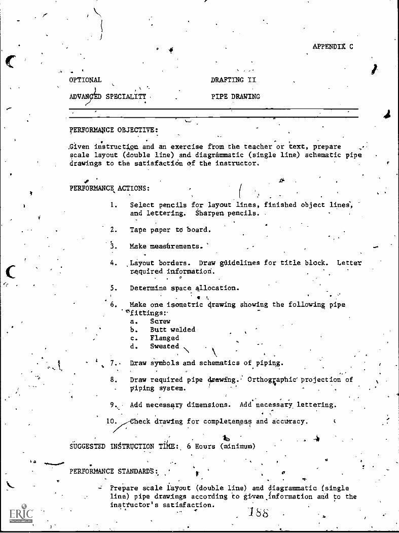
OPTIONAL
ADVANCED SPECIALITY .
DRAFTING II
PIPE DRAWING
APPENDIX C
PERFORMA$CE OBJECTIVE:
,Given instruction and an exercise from the teacher or text, preparescale layout (double line) and diagrammatic (single line) schematic pipedrawings to the satisfactiOn of the instructor.
. .10 .1)
3 .PERFORMANCE ACTIONS: ,
1 1. Select pencils for layout lines, finished object lines',and lettering. Sharpen pencils. .
2. Tape paper to board.
3. Make measfirements.
4. ,Layout borders. Draw guidelines for title block. Letterrequired information.
0
5. Determine space allocation..
6. Make one isometric drawing showing the following pipe°fittings:-
-
a. Screwb. Butt weldedc. Flangedd. Sweated
4 7.. Draw SYmbols and schematics of piping.
8. Draw required pipe- piping system.
g. Orthogiaphieprojection of
9. , Add necessary dimensions. Add necessary lettering.. ,
lO. eck drawing for completene$s and accaracy.
lw
SUGGESTED INSTRUCTION TikE: 6 Hours (minimum)
PERFORMANCE STANDARDS:. . 0.
-; Prepare stale layout (double line) and diagrammatic fsingleline) pipe drawings according to given,fnformation and to theinsttuctor's satisfaction.
A.*
OPTIONAL DRAFTING II
ADVAiCED SPECIALITY PIPE,DRAWING (Con't.)
RELATED TECHNICAL INFORMAT ON:
- Pipe termino1og.Pipe sizes,Pipe fittings.Piping symbcils.
Single line pipe drawings.Double line pipe drawings.
- ,Use of handbooks.- ASA Bulletins.
Piph catalogs.
OPTIONAL
ADVANCED SPECIALITY
DRAFTING II -
WELDING DRAFTING
APPENDIX C
PERFORMANCE OBJECTIVE:
Given an exercise including specifications and a rough sketch, draw ablueprint-that 'can be interpreted by a welder to fabricate the necessapyend product. The drawing must include the correct symbols, bedimensioned appropriately, and the correct letter designations must beused. The task must be complet With time li- ts considered to beacceptable for initial employm job qualifiCat ntand must meet theinstructor's standards.
PERFORMANCE ACTIONS:
1. Preliminary to welding drafting, review or de onstrateability to use:a. Views to shaw the shape of an object for fabrication
purposes.b. Lines to shaw val'ous views of an object.c. Crqss sectioning for materials bols:
(1) Cast iron and (general terial)
(2) Steellit
(3) Copper, bronze, bra(4) Zinc, lead, and alloys(5) Aluminum, aluminum alloys, and manesium
f-- (6) Rubber, plastic, dhd electrical insulationDimensioning.Thread fasteners.
. Fabrication prints.
2. Interpret basic welding terms.
3. Describe typically used welding processes:a.
h. ArF:C. GMAW (Mig).d. GRAW (Tig).
4. Identify welding symbols:' a. Base of a weld symbol.
b. Basic welding symbols and their locationsignificance:
(1) Fillet(2) Plug oi sld't
(3) Spot of projection(4) Seam(5) Back dr backing
.
(6) Surfacing 9 ()
A
vas
A
OPTIONAL
ADVANCED SPECIALITY
4
DiAFTING II
\WELDING DRAFTING (Con't)
AP15ENDIX C
PERFORMANCE ACTIONS (Con't.):
;,'
C.
(7) Flange:
(l) edge
(b) corner
Basic welding symbols wad their locationsigniaicance:
(1) Square
(2) V
(3) Bevel(4) U
(5)
(6) Flair,V(7) 'Flairbevel
t.
5. Ih given drawing assignments or situations, .specify weld
sizes:
,a: Show how siig.of:fillet welds aie indicated.
b. Sho how length of fillet welds are indiepated:
c.' Shp tow length and pitch of tatermittent fillerwel re indicated.
d. Show ow dimensions apply to plug welds.
f. Dimensiong. Dimension
.(1)
slot welds.arcspot welds.seam welds:Show size, length, wad pitch of resistanceseam weld
(2) Show extent of Gas TungstenArc Seam Weldh. Dimension gtoove bevel depth and effective thrqat
sie' Show how root Opening and included angle are shown
for groove welds. (AWS)
J. Show application of break in arrow to show member'oto
be bevelled.
6.. Illustrate how tail is used when some special data.is
A needed.
7. Locate reference for designation of.welded and appliedprocesses by letters. (See Symbols for Welding andNondestructive Testing, American Welding Society or anygood referende source). .
OPTIONAL DRAFTING IL
ADVANCED SPECIALITY WELDING DRAFTING (Con't)
APP6DIX C
PERFORMANCE ACTIONS (Con't):
8. Draw symbols to show how bead contourlfinish is
indicated.
9. Given an exercise including specificationa and a roughsketch, draw a blueprint that can be interpreted bY a '
welder to fabriCate the necessary end praduct.'llsecorrect symbols, dimenaion appropfiately, and applycorrect letter designatiOns.
PERFORMANCE STANDARDS:
7 arawing must.be accurately dimetsioneC use.correct letterdesignationa, and correCt-symbols for.the welding processes.The task must be performed with;n time limits considered to beacceptable for initial employMqnt job,qualification.Lettering and drafting,agtlls demonatrated must reflect'utneatness, accuracy,'consistency, Octopv Rlacement, ancr
character.,,Must meet.instructor's standards for advanced speciality
.
drawing.
SWGESTED INSTRUCTION'TIME: Optional
,RELATED TECHNICAL INFORMATION:
American Welding Society sQ,-talards.
Structural steel or metal fabrication terminology (as
appropriate).
1,
=;.1 Tz
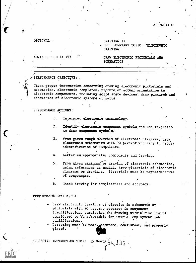
-
OPTIONAL
ADVANCED SPECIALITY
_
AppENDIX C
DRAFTING II... SUPPLEMENTARY TOPIC:-'ELECTRONICDRAFTINd
1--
DR4LE;LECTRONIC PICTORIALS ANDS TICS
/PERFORMANCE OBJECTIVE: .
Given proper instruction concerning drawing electronic pictorials andschematics, electronic templates, pictum or actual orientation toelectionic components, including solid state devices; draw picture's andschematics of electronic aystems or Parts.
<
PERFORMANCE ACTIONS:
1. Interpret electronic terminology.
2. IdentifY electronic component symbols.and use templatesto draw component Symbols.
3. From given rough sketche's of electronic diagrams, drawelectronic schematics with 90 percent'accuracy in properidentification of, components.
4. Letter as appropriate, components and drawing.
5. From given sketches or drawing of electronic schematics,using referenceS as needed, draw pictorials of electronicdiagrams or'drawings. Pictorials must be representativeof components.
6. Check drawing for completeness and accuracy.
PERFORMANCT STANDARDS:
Draw electronic drawings of circuits in schematic orpictorialsWith 90 percent accuracy in componentidentification, completing the drawing within'time limitsconsidered to be adteptable for initial employment jobqualifications.
- Lettering must be neat, ccurate, consistent, an d properlyplaced.
.SUGGESTED INSTRUCTION TIME: 15 Bours 1 9 3
4
OPTfONAL
ADVANCED SPECIALITY
APPENDIX C
DRAFTING IISUPPLEMENTARY' TOPIC: ELECTRONICDRAftNG
DRAW ELECTRONIC PICTORIALS Ale'SCEEMATICS (Can't.)
RELATED TECHNICAL INFORMATION:
Symbols for electronic Orawings.Electronic abbreviptions.Reference designation (such as campogent valves.),Interconnection diagrams.
NOTE: Training may be expanded to include chassie fabrication,variaus cannectot diagrats, terminals, switches and relays,etc.
rm.*,
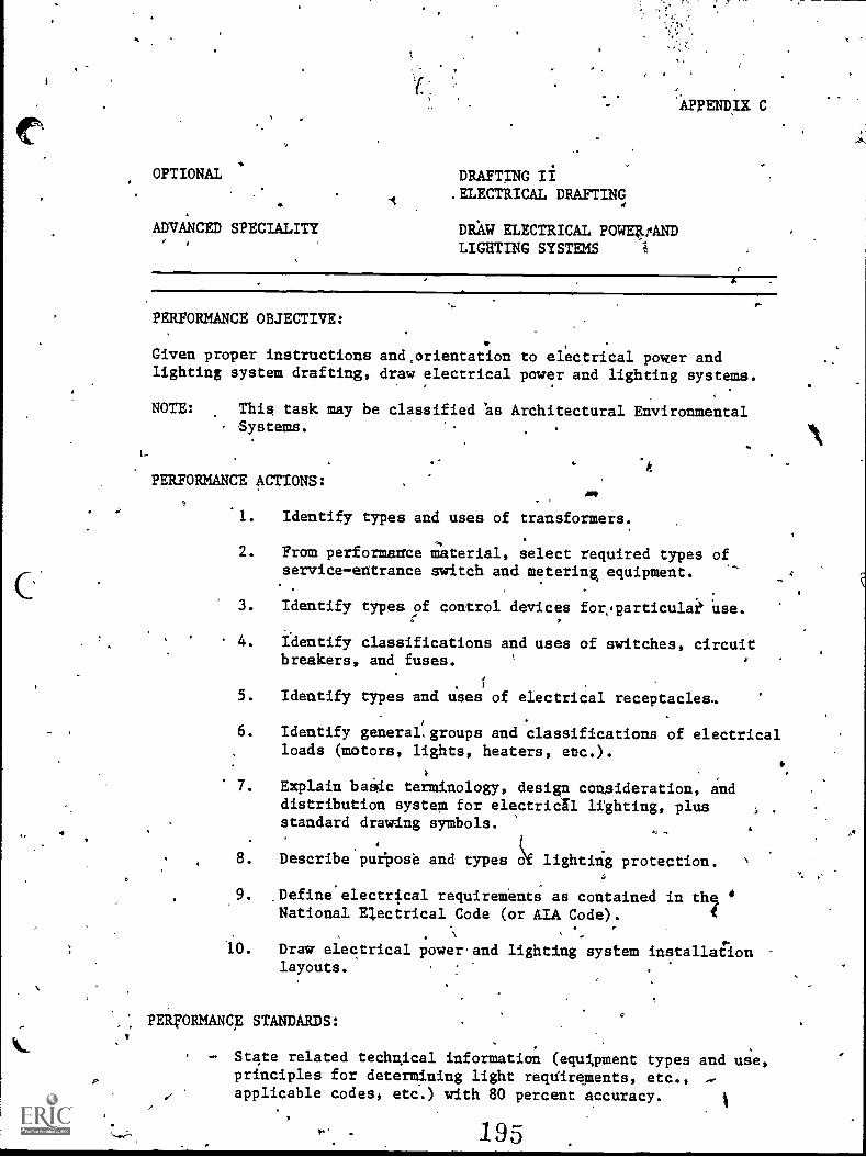
OPTIONAL
ADVANCED SPECIALITY
DRAFTING II. ELECTRICAL DRAFTING
DRAW ELECTRICAL POWE4FANDLIGHTING SYSTEMS i
APPENDIX C
PERFORMANCE OBJECTIVE:
Given proper instructions and,orientation to electrical power andlighting system drafting, draw electrical power and lighting systems.
NOTE: This task may be classified es Architectural EnvironmentalSystems.
PERFORMANCE ACTIONS:IMP
.1. Identify types and uses of transformers.
2. Fram performance M'aterial, select required types ofserviceentrance switch and metering equipment.
3. Identify types of control devices for,particulai' Use.
4. Identify classifications and uses of switches, circuitbreakers, and fuses.
5. Identify types and uses of electrical receptacles.
6. Identify general,groups and classifications of electricalloads (motors, lights, heaters, etc.).
7. Explain baSic terminology, design consideration, anddistribution system for electricil lighting, plusstandard drawing symbols.
8. Describe'puiPose and types lef lighting protection.
9. Define electrical requirements as contained in t h eNational Electrical Code (or AIA Code).
,
10. Draw electrical power'and lighting system installdionlayouts.
PERFORMANCE STANDARDS:
State related technical information (equipment types and use,principles for determining light reqVirements, etc.,applicable codes, etc.) with 80 percent accuracy.
195
4
k
OPTIONAL
A
\
VANCED SPECIALITY
.APPENDIk'T. C
DRA NG IIELECTRICAL DRAFTIkG
DRAW-ELECTRICAL POWER ANI5LEGHTING SYSTEMS (Con't.)
PERFORMANCE. STANDARDS (Con't.):
- Draw electrical systems according to AIA and otherindustry standards. ,
- Neatness and'accuracy apply Where appropriate.- Drawings are prepared with job qualification time
limits.
SUGGESTED INSTRUCTION TIME: Optional,
RELATED TECHNICAL INFORMATION:9
- Appropriate handbooks.- Codes.- AIA manuals.
410.
196
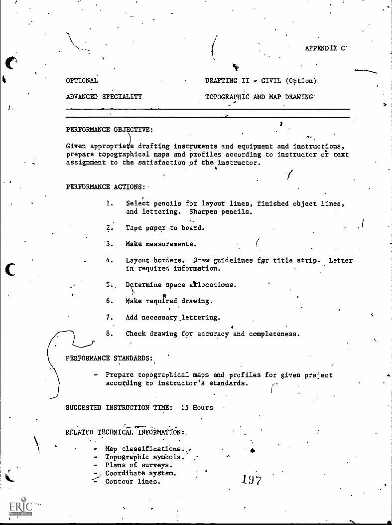
4
).
OPTIONAL
ADVANCED SPECIALITY
APPENDIX C'
DRAFTING II - CIVIL (Option)
TOPOGRAPHIC AND MAP DRAWING'
PERFORMANCE OBJECTIVE:
)Given appropria e drafting instruments and equipment and instructions,prepare topographical maps and profiles according to instructor Oi textassignMent to the satisfaction pf the instructor.
PERFORMANCE ACTIONS:
1. Select pencils for layout lines, finished object lines,and lettering. Sharpen pencils.
Tape paper to board.
3. Make measurements.
4. Layouti,orders. Draw guidelines fig title strip. .Letterin required information.
5.. Drermine space allocations.
6. Make required drawing.
7. Add necessary,lettering.
4
8. Check drawing for accuracy and completeness.
PERFORMANCE STANDARDS:.
- Prepare topographical maps and profiles for given projectaccording to instructor's standards.
r.
SUGGESTED INSTRUCTION TIME: 15 Hours
RELATED TECHNICAL -11ifieRMAT.f6N:,
- Map classificatiOne.,.- Topographic symbols.- Plans of surveys.
Coordihate syetam.- Contour lines. 197
ro,
3r
oOPTIONAL
ar
ADVANCED SPECIALITY
APPENDIX C
DRAFTING 4,- CIVIL (Option5
TOPOGRAPHIC AND MAP 'DRAWING
RELATED,TECHNICAL INFORMATION (Con't.):
Profileta walla:.
. rr.
aA power lines.
a
. 4
-1*
198
,r
=
I.
a
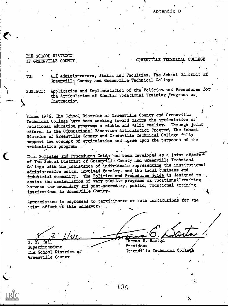
Sc
Appendix D
THE SCHOOL DISTRICT "OF GREENVILLE COUNTY-. . GREENVILLE TECHNICAL COLLEGE
1
TO: kll Administrators, Stiffs and Faculties, The School Di.Strizt of
Greenville County and Greenville Technical College ,
SUBJECT: Application and Implementation of the'Policies and Procedures for
the Articulation of Similar Vocational Training Frograms of, -
Instruction11.
Since 1976, The School Di.strict,of Greenville County and. GreenvilleTechnical College have beam working tomard mAking the articulatian of
vocational educatian programs a.viable and valid reality. Through joint
efforts in the 04tupational Education Articulation Prograd, The School
District of Greenville County and Greenville Technical College fully
support the concept of articulation and agree upon the purposes of the
articulation program.,
This, Policies and Procedurei Gui'de has been. developed as a joint efrferft--77
of The School District of Green7ille County and Greenville Technical
College with the assistance of individuals representing the institutionil
aAmintstrative un3ts, involved faculty, and the Local business and
induttrial community. The Pg/icies and ProCedures Guide is desigaed to,
assist the articulation Of very similar programs of vocational4tiain4ng
between the-secondary and post-secondary, public, vocational trPintng
institutions in Greenville County.
Appreciation is expressed to participants at. both institutianS far the
joint effort af this endeavor. , ,.
I. . RaIL
SuperinsendentThe School District ofGreenville County
4.
Thomas E. BartonPresidentGreeniille Technical Cpii
199
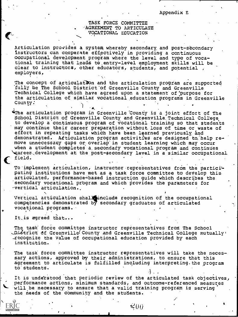
Appendix E
TASK FORCE COMMITTEE:AGREEMENT TO ARTICULATEVOPATIONAL EDUCATION,
Articulation provides a systeg whereby secondary, and post-s4condaryinstructors can cooperate effectively in providing a continuousoccupational development program where the level and type of voca-tional training that leads to,entry-leVel employment skills will beclear to instructors, other educators, students, and potential ,
employers,
The concept of articulaaOn and the articulation progtam are supported'fully he The Schbol District'of Greenville County and GreenvilleTechnical College which have agreed upon a statement' of:purpose forthe articulation of similar vocational education programs in GreenvilleCounty.'
*The articulation program in Greenville '0ounty is a joint effort of TheSchool District of Greenville County and Greenville.Technical College,to develop a continuous program of Vocational training so that studentsmay continue their career preparation without loss of time or waste ofeffort in repeating tasks which tiave been learned previously anddemonstrated. Atticulation program activities are designed to:help re-move unnecessary gaps or overlap'in student learning which may occurwhen a student completes a,secondaty vocational program and continues\careetdevelopment at the post-secondary level in a similar occUpational
4: field..
_ .
To-implement articulation, instructorrepreSentatives frOm the partici=pating institutions have met as a task force committee to deVelop this.articulated, performancebased instruction guide which describes the'secondary vocational prbgram and which Provides the parameters for-vertical articulation..
Vertical articulation shal4kinclude recognition of the occupationalcompetencies demonstrated b7 secondary graduates of articulatedvocational programs.
3
It,is agreed that...
The task force committee instructor repiesentatives from The SchoolJDJAtrict df Greenville(County and Greenville Technical College mutually'-recognize the value of occupational education provided by eachinstitution. .
The task force committee instructor representatives will take the neces-sary actions, approcmd by their administrations, to ensure that thisagreement to articulate is fulfilled including interpreting.the programto.students.
.
It is unddrstood that periodic review of the articulated task objectives,performance actions, minimum standards, and outcome-referenced measures
L- will be necessary to ensure that a valid training program is servingthe needs of the cOmmunity and the students.
'40 0,
$
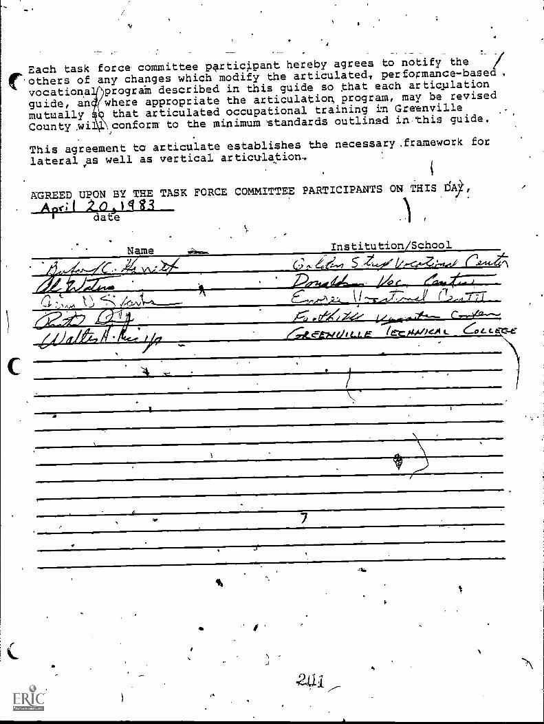
Each task force committee participant hereby agrees to notify the
(others of any changes which modify the articulatedl performance-base .
vocationa progra-m described in this guide so kiat each artiqplation
guide, an where appropriate the articulation program, may be revised
mutually that articulated occupational training ill Greenville
County .wil conform to the minimum kstandards outlined in,this guide.
This agreement ta articulate establishes the necessary,framework for
lateral:vas well as vertical articula0.on..
AGREED UPON BY THE TASK FORCE COMMITTEE PARTICIPANTS ON THIS 1591
AK; 1 2-0 3 El t.3date
Name Institution/School
A
aid/A
/la
(7,-4 7.7;71
1 t...LE er_1404//ed t. -cc
7
6
481
,\APPENDIX F
1
PHILOSOPHY OF ARTICULATED, PERFORMANCE -BAED INSTRUCTION,gpDE,DESIGN
The design of the articulated, performance-based instructiOiguides and.the articukation program is based on a philosophy that the vocational .
education cuiiiculum should be for.career training with few fringe brnon-related subjecta% The student-should be given the basis to douseful skilled work upon graduation and employment. The vocationalprogram graduate should have a ba1çround which will allowdlim/her tolearn and advance as rapidly as poss the job, but 1E should notinclude subject matter witich will not be\applicable"to his/her work for,years. When subject matter is introduced'that will not be applicable to
" the graduate's-Work for years, it may put the graduate outofperspective. The result might be.that the graduate may try to fetcsapplications which do not exist, simply because the informiation is inhis/hsr repertoire. Thus, the purpose of vocational training by the .
articUlated, performance-based instruction guides is to preparegradufttes for successful entry into 'a skilled tradt.
'To ensure thItt the design of the articulated, performance-basedinstruction guides is conforming to the philosophies of both the.secondary and post-secondary institutional participants, a-periodicreview of the guide design and philosophy is recommended;
4111
202
Appendix G
PURPOSES OF THE ARTICULATED INSTRUCTION GUIDE
The articnlated instractian objectives guide are is erpected to servethe following purposes:
1. Th.guide serves as the primaiy vehicle for the articulation ofsubject matter ia similar vocational training programs between thevocatianal education centers,-high schools, gad Greenville TechnicAlCollege thraugh use by instructors at both levels,as a reference inpreparing instruction.
2. `9The. gnide provides a, listing of the minim= tasks that a student orworker is etcpected to perforn in the conduct of a specific leVel.job in the area of vocational trnfni-Ig or work pf concern.
4
3. The guidé identifT ;he primary detailed instruction objectives,yerforman e objectives which are based upon the-task listings. The
tasks. listed in the sequence of complexity, with the leastcomplex ts* being listed'first, eiCept where a task must be performedas a'prerequisite to performance of another-task.
2.
The guides identify tht tasks performed '(actions, steps, sets of-'skills) and. related techatcal informatiaa which must be taught and
ed.to accomplish each major instruction objectiVe: The tasks .
pe ormed represent the minim= skills and related informationrequired for-adequate occupatianal proficiency in the-performanceobjectiveS.
The guides designate the instructional cantact hours necessary toprovide the required instruction, as required,by apPropriateeducational agencies or offices and as estimated by the instructorparticipants on the Vocational Articulation Project Task ,Forces,aAd based on the time required to teach the average learner toperform the task. The time estimated is based aa having the essentialequipment, facilitiesand instructional aids required to providethe instruction,r whenever the class size is limited to an acceptable
. number.
6. The guides identify the performance standards to be met for occupatianal proficiency,in the task: Performance standards used are
those considered to be minim= business or industry standards. Theability to meat the Listed standards of performance will be consideredas qualification for advanced instruction in the vocational program.
7. The guides prOvide direction in the conduct of sequential vocationalcompetency instruction by modules'or job tasks, resulting in qualification by the learner to perform limit
3skill specialist jobs of
Appendix G
progres1 sively higher lictlls until the prograp objective is revhed.(i.a., file clark,tb sxecutive secretary, etc.). Is the student '
becomes proficient in the performance of t4scs in successively more'complex modules, cote marketable competen 'es ara gaLuad and may be.idenillird as the lower 'job qualifications coi' a spei-fA141t.
Through'this procedure, even the slower stUdent is provided Sn,appor=ity to aventuaLLy gain sufficient s)vills to performadequately as a specialist at same level. in the vocational fiel ,
effea il the student is.unabla to complete the total program oftraining. I
The standardized. sequence ofTaCtivities of.the'vocationalistrrntion modules will facilitate lateral irciculation betweenvocatignal education centers La the Schoal pistrict and,wili
verticalfarticulation when training ,is continued anlGreenville Technical-College articulating to employers.
8. *.The guides provide a descriptive listing of' equipment requiredConduct the progrsn of vocational training.( The equipment liltedis considered. to be the. type sad quantity'es ential for the conduct
- of instruCtion to prepare students for entry level employment illthe:vocational field. It may be necessary t delay teaching sometasks involving apecial iquipment, if tha't uipment is Wat availahle at L1 instructiona sites, or to move tudants and eqlmipimmrttogetheras necessary to teach sktIll.
St. ' Ther,gu.ida. proAdes ihformation about tect
that eipically are involyed in the perform=environmental onnditiogs and physical. d
the task.'
:
ts or limitationsog the task,
, and able to perform
10. Ills guides provide a list of standtrdizisi:peand. outcome-referenced measure4 to be usedvocational proficiency. AIT,long as.the apethe:tact items Listed cannot be compromisedis study guides.
11. Mae tasks listed tm tha.guida are the requirementS'for jobqualification mader average circumstances in a regional market. 1t, .
is understood that theremay be mil{sted tas that saute employersmay require'the worker to do La the occupati , when.in theiremployment. In 34d:triton, there may be ted tasks, stch asmental process tasks, that are not stated hit diatMayoceur andthat should be considered in iastructional planning or iestillg.:
"ormance test items/,
tivit determination of
ics are not pritvid.ed,
ily and.could serve
Instructors may teach skillq and related technical:informationother than what is shows tm the gui4es. Provision of additionalimfdimation should be limitel to the students who have completedthe requirements for the tasks empiasized., in;the instructionalguides. The change of tasis La theiuides should be based on task,force committee agreement to ensure lateral ahd verticalarticulation. y
2Q4
virb
Appendix G4t,
12. It is expected that ther will be updating and correction of items
in the articulated initruction guide. Participants are to be surethat the contents are valid and consistent with business aad indus=7
requirements. Recommendations should belaubmitted to the VocationalArticulatiaa Program office which' will aggemble and present them tothe appropriate commiktee for review and possible adoption.
13. Typically, the teacher/instructor should adt plan to conduct instruction
in a given articulated module unless the capability exists'toconduct all of the instruction to aeet the instructional objectives,with the result that the successful student is'qrAlified perform
the tasks tdentified within the,module.
14. An underlying philosophy in vocational, training is that it is
better to prepame the student Io be fully qualifiel to perform allof the tasks in a limited grouf of modules in a vocational field
and be qualifi at a lower job level rather than Is be only familiar
with a large II MS: r of task descriptians or-dIaes and qualified to
perform none of them fully. For higher levels of job qualificationbOodd the secondary level, the student or worker is encouraged toenroll at Greenville Teebnical College.
'1.5. Generally, vocational programs*will include certain basic modules
or courses of instruction without which the student would not be
considered vocationally qualilied'at any level. Basic modules
typically will be identified and taught early in the programsequqfte.
The_instruction gnides provides information essehtial to help thevocational student who campletes training at the secondary leveland _caatinues &reer devel.agmeniktrPqring at the post secandarylevel in a similar-program idceive appropriate credit for thearticulated vocational training that has been Mastered at the
secondary level.
205
.00
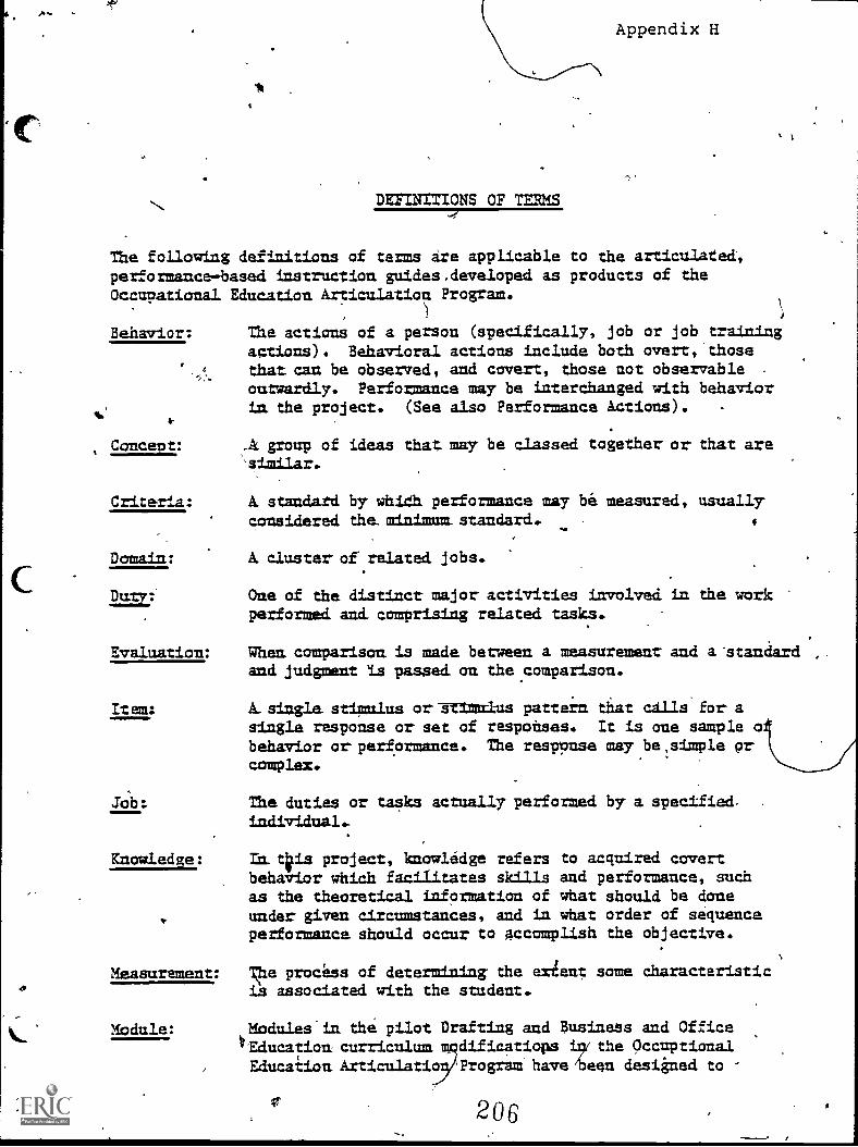
1 -
DEFINITIONS OF TERMS
Appendix H
The followiag definitions of terms ire applicable to the articulated,performance-based iastructian guides.developed as products of theOccupational Education Articulation Frogram.
Behavior: The actions of a person (specifically, job or job trainingactions). Behavioral actions include both overt, thosethat can be observed, and covert, those not observable .
outwardly. Performance may be interchanged with behaviorLm the project. (See also Performance Actions). -
4-
ConceD t : .41 group of ideas that may be classed together or that aremi r.
Criteria: A. standard by whiCh performance may be measured, usuallyconsidered the. artnimum standard. 4
Domain: A. cluster of related jobs.
221I: One of the distinct major activities imvolved in the workperformed ami comprising related tasks.
Evaluation: Wham camparisan is made between a measurement and a-standardand judgment is passed. an the comparison.
Item: A.single. stimulus or-grin:taus pattern that calls for asingle response or set of responses. It is one sample obehavior orperformance. The response may be,simple prcomplex.
Job: The duties or tasks actually performed by a specifiedindividual.
Knowledge: In. tips project, knowledge refers to acquired covertbehavior which facilitates skills and performance, suchas the theoretical information of what should be doneunder given circumstances, and in what order of sequenceperformance should occur to accomplish the objective.
Measurement: She process of determining the ex4ent same characteristicis associated with the student.
Module: Modules Li the pilot Drafting and Business and OfficeEducatioa curriculum mqdi.ficatiops lay the Occuptiaaal
EducaiionAtticulatio Program have/been designed to
206/
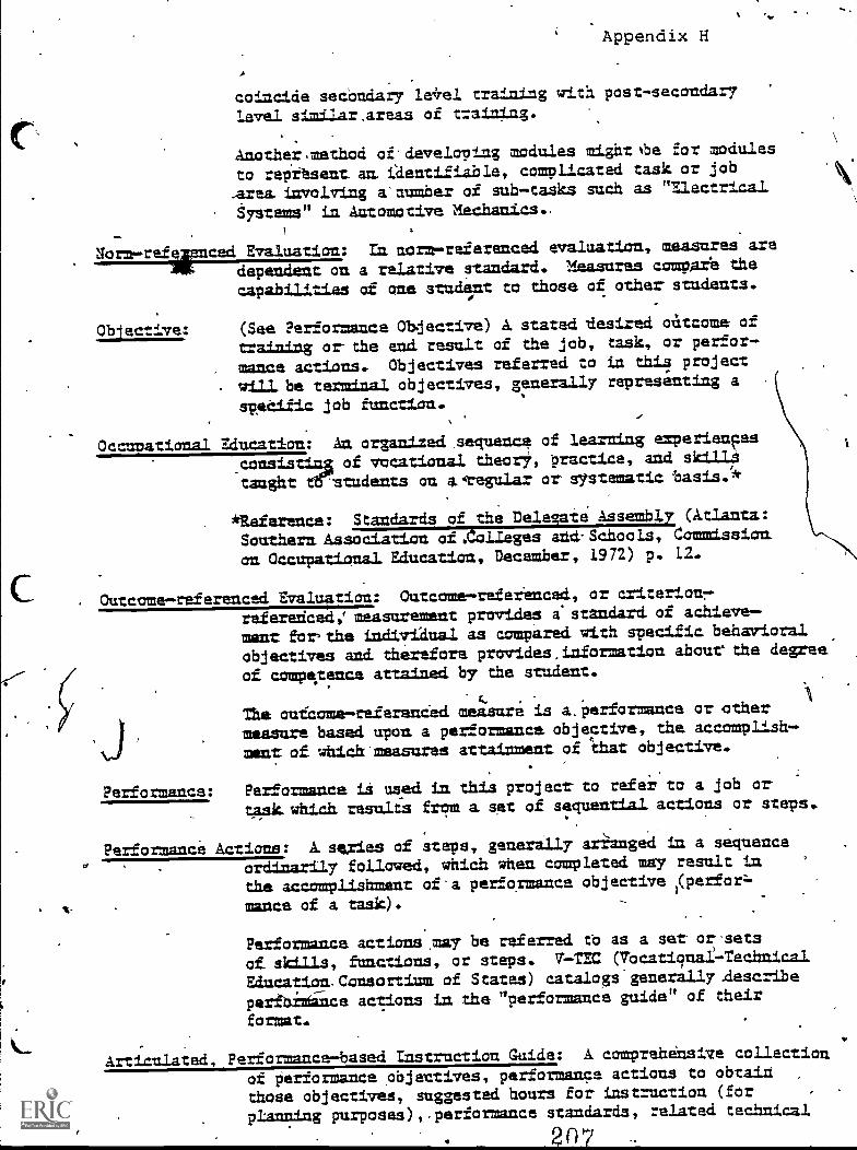
Appendix H
coincide secandary train(lg with post-secondary
level similar,areas of t-aining.
Another,method of.developing modules mightbe for modules
to repttsent am identifiable, complicated task or job
Area. involving a'aumber of sub-tasks such as "Electrinal
Systems" in Automotive aechanics..
Uorm-reilirnced Evaluation: En oorm-referenced evaluation, measures are
dependent on a relative standard. Measures camper's the
capabilities of one student to those of other-students.
Ob ective: (See Performance Obdective) A stated .desired oatcome of
trAinimg or- the end resolt of the job, task, or perfor-
mance actions. Objectives referred to ia tnis project
will.be termimal objectives, generally representing a
spetilic job tmoctiao.
Occunational Education: An organized sequence of learniog ezperiences
.consistilla of vocational. thearY, practice, and skIll?
taught tt'students To avegular or systematic basis.*
*Reference: Standards of the Delegate AssemblY Cktlanta:Southern Association of .(olieges and-Schools, Commission.
an Occupational &lunation, December, 1972) p. 12.
Outcome-referenced Evaluation: Outcome-referenced, or criterionr.
referenced: measurement provides istaodard of achieve-
ment for,the indiviaual as compared with specific behavioral
objectives and therefore provides,information. abourthe degree
of compe,tence attained by the student.
The ourcome-referanCed measure is a.p erformance or other
measure based upon a performance objective, the accomplish-
ment of which'measures attainment of r.hat objective.
Performance: Performmoce is used to this project- to refer to a job or-
task.which results from a. set of sequential actions or steps.
Performance Actions: A series of steps, generally arilanged ia a sequence
ordinarily followed, which when completed may result in
tne accomplishment of.a performance objective )( perforl.
mance of a task).
Performance actions.may be referred tb as a ser or-sets
of skills, functions, or steps. T-TEC (Tocationai-Terhnical
Education.Consortium of States) catalogs-generally .describe
peribrtance actions in the "performance guide" of their
format.
Articulated, Performance-based Instruction Guide: I compreheasive collection
of performance objentives, performance actions to obtain ,
those objectives, suggested hours for instruction (for
ptAnTrung purposes), performance standards, related technical
2n7
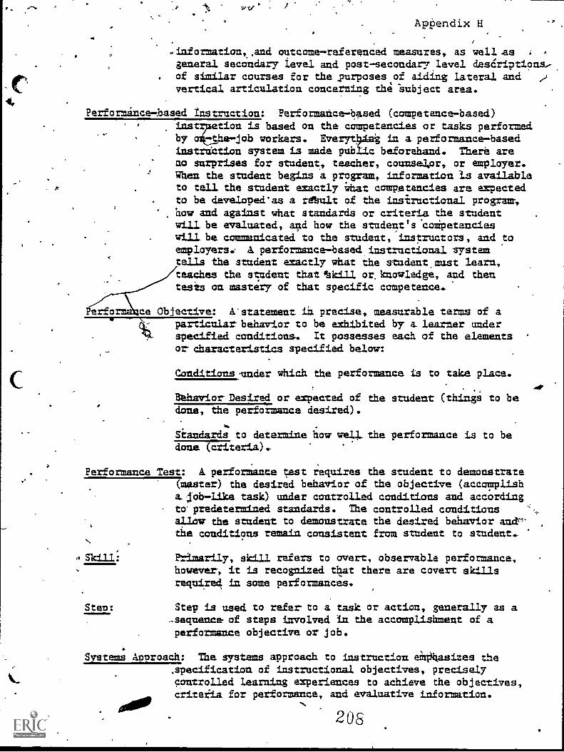
wv -
Aptendix H
.information,,and outcome-referenced measures, as well .asgeneral secondary ievel and post-secondary.level desCriptionsof similar courses for the ,purposes of aiding Lateral and 2vertical articulation concerning the 'Subject area.
Performance-based Instruction: Performance-based (competence-based)is based on the campetencies or tasks performed
by o -the-job workers. Everyt0Ant in a performance-based
,
instrtection system is made public beforehand. Therd areno surprises for student, teacher, counsea,or, or employer.When the stadent begins a program, information Is available
. to tall the stadent exactly idiat competencies are expectedto be developeeas a retult of the insiructional program,haw and against what standards or criteria the studentwill be evaluated, and how the studenes.coipetencieswill be commanicated to the student, instructors, and toemployers: A performance-based instructional systemtells the student exactly what ihe student,must learn,teaches the st,adent thatfskill or.knowledge, and thentesis an mastery of that specific.competence.
erfo ce Objective: A'statemeat ia precise, measurable terms of ar
14,
particular behavior to be exhibited by a learner underspecified conditions. It possesses each of the elementsor characteristics specified below:
(:Conditions under which the performance is to take place.
Bthavior Desired or expected of the student (things to bedame, the performance desired).
Siandards to determine how well. the performance is to bedame (criteria).
Performance Test: A performance test requires the student to demonstrate(master) the desired behavior of the objective (accomplisha. lob-like task) under controlled conditions and accordingto predetermined standards. The controlled conditionsallow the student to demonstrate the desired behavior ane-the conditions remain consistent from student to student.
4 Ski 11:
Sten:
Primarily, skill refers to avert, observable performance,however, it is recognized that there are covert skillsrequired ia some performances.
Step is used to refer to a task or action, generally as a..sequence of steps Lavolved in the accomplishment of aperformance objective or job.
Systems Approach: The systems approach to instruction eM0hasizes thespecification of instructional objectives, preciselycontrolled learning experiences to achieve the objectives,criteria for performance, and evaluative information.
208
Appendix H
Tas.sk: A.task is i sat of_skills (set or sets of functions,actions, or steps) the student must perform to accomplishthe. job (training),. A. task may be described AS a logically related set'of-actions becessry or required tocomplete the_ job 'objective. Several tasks could be ,
referred to as a datY.
Task_An*Lysis: Teak analysis is breakiag dawn a Learniag task (objective)into component tasks each.ot which must be mastered. as aprerwialsite to mastery of the total job.
Task,List: A Listing of tasks (performance obj cti ) periormed bTincumbent ex, rkers (students La r xithia a danain.
of interest (coursp of study).
Test:
0
ArLeveut daring which.the Trade= is asked te, demonstrateacme aspect of knowledge or skill is a test.. It cam...be i
siTegla test itpn, but Dismally it conpists of several
items. .
205
Appendix I
411,
INSTRUCTIONS FOR ANSWERING OUTCOME-REFERENCED TEST ITEMS
Typic ily, eleven (11) different types of outcome-referenced estitems may be used in the competency test.
1. True-False2. Completion (Fill-in Blanks)3. A Combiaation of True-False and Completion4. Multiple-Choice5. Matching6. Inentification7. Short Answer.6. Long Answer9. Program 15roduct of Performance Test
10. Simulated Performance Test11. Actual Performance Test
An example of each type of.test item is included. Carefully studythe illustration test item .and the directions for answering thequestion. These directions will not be given again. Your testquestions may vany_saightly in the 'format, hbc4ever, the instructionshould be applicable. Where necessary, the instructor will supple-ment these instructions for anSwering outcome-referenced test items.
Do not guess. Guessing does not add to.ibur knowle8ge, even f youhappen to guess right. If you do not know the answer skip the testitem and go to the next question. Remember: Enter your answers inthe blanks provided on the separate answer sheet, if used.
. TRUE-FALSE
Directions:
Example:
2. COMPLETLON (Fill-in Blanks)
Read the statement carefully. Decide-whetherit is true or false. Answer by marking T or Fin the blank provided to the right (or, if answersheet requires,-mark "X" in the appropriate (T)or (F) parenthesis, or "cirp;e" T or F).
Lumber shrinks across the grainof the board. (T) (F)
Directions: Complete the statement by pr.inting on the blankline the word or words which make a completeand correct statement.
Propec edge spac.ing will restrict? and ensure good weld
penetration.
Example:
21
distortion
3. COMBINATION OF TRUE-FALSE/COMPLETION
Directions: If the statement is correct, in the parenthesismark (T) or answer true, as required. If thestatement is incorrect, mark (F) in the are,n-thesis and fill in the blank provi wkth theapproprlate word or,term which, i su itutedfor' the underlined word, would make the
\statement correct.
Example: A pantry chef usually is the headchefs first assistant. (T) (F)
MULTIPLE-CEOICE
a. DieEbtions: \You are given three or four choices from which\to make a complete and correct statement. Inthe blank answer space provided, write in the"letter" indicate the best choice.
Example: The head chef's first assistant isa ? .
a. junior chefb. sous chefc. pantry cook
b. Negtive Anwer Multiple-Choice
Directions: If the multiple-choice question included theword EXCEPT, you should look far the choicethat does not fit the question. Read the entirequestion carefully before you choose youranswer.
Example: All of these could cause highstarter current draw EXCEPT:
a. work starter bushingb. bad statter.relayc. grounded field coilsd. grounded armature
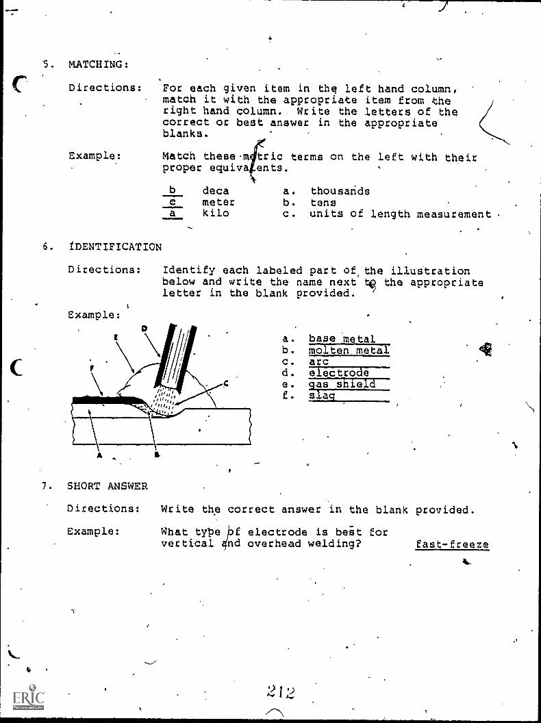
5. MATCHING:
Directions: For each given item in the left hand column,match it with the appropriate item from theright hand column.. Write the letters of thecorrect or best answer in the appropriateblanks.
Example: Match these-m tric terms on the left with theirproper equiva ents.
6. IDENTIFICATION
b deca a. thousandsc meter b. tensa kilo c. units of length measurement .
Directions: Identify each labeled part of,the illustrationbelow and write the name next tip the appropriateletter in the blank provided. 1
Example:
a. base metalb. molten metalc. arcd. electrodee azia_RALSILL-f s aq
7. SHORT ANSWER
Directions: Write tne correct answer in the blank provided.
Example: What type f electrode is beit forvertical 4nd overhead welding? fast-freeze
2 I 2
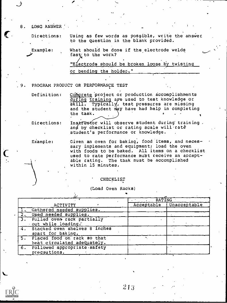
J
8. LONG ANSWER
DireCtions:
4,7ample:
Using as few words as possible, write the ansWerto the question in the blank provided.
What should be done if the.electrode weldsfasztto the work?
'Electrode should be broken loose by twisting
or bending the holder.."
. PROGRAM PRODUCT OR PERFORMANCE TEST
Definition:
Directions:
Eiample:
CONrete prolect or production accomplishmentse used to test knowledge ortest pressures are missing
y have had help in completing-
during training askill. Typicalland the studentthe task.
Ins or will observe student during' training ,by checklist or rating scale will-rat
student's performance or knowledge.
Given an oven for baking, food items, and neces-sary implements and equipment; load the ovenwith foods to be baked. All items on a checklistused to rate performance mubt receive an accept-able rating. The task must be accomplished_within 15 minutes.
CHECKLIS5
(Load Oven Racks)ft
'
ACTIVITY .
RATINGAcceritable Unacceptable
1. Gathered needed supplies.2. Used needed supplies.3. Pulled ovem rack partially
-cut while loading:.
.
_
4. Stacked oven shelves 8 inches.
apart for baking.5. Placed food on rack so Jlat
heat circulated adequately.
,
.
6. Followed appropriate-safetyprecautions.
2 1 :3
w
10. SIMULATED PERFORMANCE
'Definition: Contrived situation, resembling tasks the /
graduate will be required to do on_the job:This f9rm of-test-As useful for evaluatingtransferable kills uch aa reasoning,, attitudes,and psychomotor skills necessary for occupationalsuccess.'
11. ACTUAL PERFORMANCE TEST
Definition:
Example:
Exhibits the advtoo late to helpvocationalspro
Given an auaccess toparts, andseal ac
C
ntage og realism, but may beithet the student.or the
mzorrect failures.
mobile, with a leaking pintion seal, ,
dper ools and equipment, keplacementvice manual: replace the pinionto manufacturer's recommended,
procedures. The job 'should be completed withih2 hours:' The manufacturer's specificationsmust be mat and.the cdmpleted job must meet theinstructor's st dards.
S.
r
1
6
,
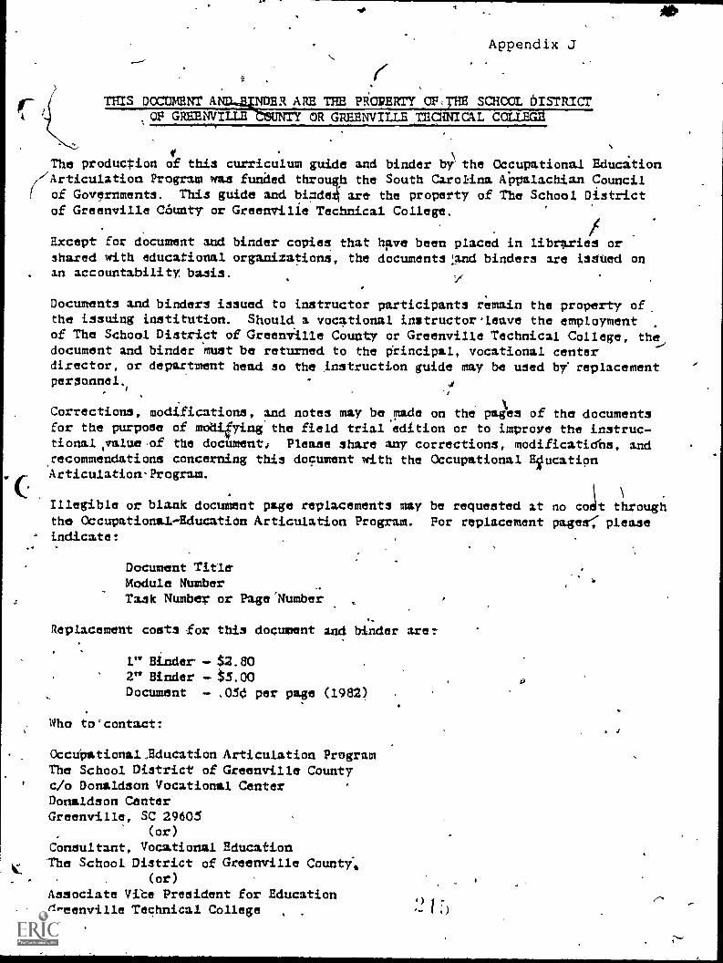
Appendix J
THIS DCCTIMEIC ANJNDER ARE THE PROPERTY OF,THE SCHCOL DISTR/CT.OF GREENVILLE UNY OR GREENVILLE TEC:MIMI. CCLLEGE
M .
\The production of this curriculum guide and binder by the Occupational Education//Articulation Program was funded through the South Carokina APpalachian Councill of Governments. This guide and bi;cleck are the property of The School District
of Greenville C45unty or Greenville Technical College. I.Except for documnnt and binder copies that have been placed in libraries orshared with educational organizations, the documents:and binders are isSted onan accountability, basis.
Documents and binders issued to instructor participants remain the property ofthe issuing institution. Should a vocational instructor-leave the employmentof The School District of GreenvIlle County or Greenville Technical College, the,document and binder must be returned to the Principal, vocational centerdirector, or department head so the nstruction guide nay be used by replacementpersonnel, 4
#
Corrections, codifications, and notes may be nide on the pages of the documentsfor the purpose of modifying the field trial edition or to improve the instruc-tional,ralue of the document Please share any corrections, nodificatidbs, and,recommendations concerning this document with the Occupational EgucatipnArticulation-Program..Ar
%." 1
Illegible or blank document page replacements nay be requested at no cot throughthe Occupational-Education Articulation Program. For replacement pages pleaseindicate:
,
Document TitleModule NumberTask Number or Fage'Number
Replacement costa for this document and binder are:
I." Binder - $2.802" Binder - $5.00Document - .050 per page (1982)
Who to'contact:
OccUOational.,Education Articulation ProgramThe School District of Greenville Countyc/o Donaldson Vocational CenterDonaldson CenterGreenville, SC 29605
(or)
Consultant, Vocational EducationThe School District of Greenville Counti*
(or)
Associate Vibe Preeident for EducationGreenville Technical College
Appendii K'
BINDER DESIGN
(Occupational Education Articulation Program)'
The binder design i simple and straightforward.
Two triangular figures, in balance, represent the two institutionsparticipating in articulativ.A.
Two "levels of training are represented by the placement of thetriangular f,Figures and the idenfication 'of the two institut ns.
.N/Horizonal .`and vertical lines represent lateral and verticaarticulation.
The diagonal across the design represents the progressive movementin carebOdevelopment for successful job performance.
The two figures ate not closed when they face, but allow forinteraction and.are linked by the document title: Articulated,Performance-bad Instruction Guide. .
9
Jim 11.
2 1 f;
v