volume-ii - wapcos limited
TRANSCRIPT
Setting Up of Inspection and Certification Center including Operations for 2 Years and Annual
Maintenance Contract for 5 Years in Leh, Ladakh on EPC Mode
Volume-II
Setting Up of Inspection and Certification Center
including Operations for 2 Years and Annual
Maintenance Contract for 5 Years in Leh, Ladakh
on EPC Mode
Tender No.: WAP/BD,R&R/LADAKH/ICC/EPC/2020-21
Date: 19-03-2020
Bidding Documents
Volume-II
Technical Specifications
Project In Charge (Construction Works) WAPCOS Limited
(A Govt. of India Undertaking) The Kunzang Guest House,
Upper Tukcha Road, Changspa, Leh, Union Territory of Ladakh-194101 Email: [email protected]
Setting Up of Inspection and Certification Center including Operations for 2 Years and Annual
Maintenance Contract for 5 Years in Leh, Ladakh on EPC Mode
Volume-II
TABLE OF CONTENT
S. No. Description
1. Design Overview
2. Specification: Civil Works
3. Specification: Electrical Work
4. Specifications for Equipment
5. Specification: Plumbing and Fire Fighting
6. List of Approved Makes
Setting Up of Inspection and Certification Center including Operations for 2 Years and Annual
Maintenance Contract for 5 Years in Leh, Ladakh on EPC Mode
Volume-II
1. DESIGN OVERVIEW
Setting Up of Inspection and Certification Center including Operations for 2 Years and Annual
Maintenance Contract for 5 Years in Leh, Ladakh on EPC Mode
Volume-II
1. DESIGN OVERVIEW The developer shall prepare detailed Architectural plans; interior layout plans for furniture and equipment, reflected ceiling plans, etc. and seek approval from Employer and then prepare corresponding servicing plan for the provision of light points, power sockets, wet points, wash basins, drainage points, etc. for the construction drawings. The contractor shall have an Expert on board & ensure that the final designs & drawings executed are in tune with all the norms & regulation of the concerned authorities, councils etc. The agency has to ensure that the constructed buildings are fit for accreditation & others required NOC’s& compliance etc. for the Center to get operational & working.
Volume II 1
Setting Up of Inspection and Certification Center including Operations for 2 Years and Annual
Maintenance Contract for 5 Years in Leh, Ladakh on EPC Mode
Volume-II
2. SPECIFICATIONS (CIVIL WORKS)
Volume II 2
Setting Up of Inspection and Certification Center including Operations for 2 Years and Annual
Maintenance Contract for 5 Years in Leh, Ladakh on EPC Mode
Volume-II
2.1 GENERAL The Contractor shall be responsible for furnishing all materials required for execution of the Works. The Contractor shall submit the source and method of execution for the Employer’s review before any execution. All materials used in the construction of permanent works required under this Contract shall be of 1st class quality as specified herein and comply with the latest IS Codes or equivalent. The material shall be tested before bringing it to the site. This specification establishes and defines the requirements of various materials to be used in Civil and Structural works. Whenever any reference to IS Codes is made, the same shall be taken as the latest revision (with all amendments issued there to) as on the date of submission of the Tender. Apart from the IS Codes mentioned in particular in various clauses of this specification, all other relevant codes related to specific job under consideration regarding quality, tests, testing and/or inspection procedures shall be applicable. Reference to some of the codes in various clauses of this specification does not limit or restrict the scope of applicability of other referred or relevant codes. In case of any variation/contradiction between the provision of IS Codes and this section, the provision given in this section shall be followed, unless the Employer agrees/consents to follow IS codes or other proposal of the Contractor as provided in the Contract. All materials shall be of standard quality and shall be procured from renowned sources/manufacturers approved by the Employer. It shall be the responsibility of the Contractor, to get all materials/ manufacturers approved by the Employer prior to procurement and placement of order. Wherever brand is not mentioned, Contractor shall take prior approval of brand complying with the tender specification shown over, mentioning the brand considered in the Bid submission shall prevail specified earlier. Whenever called for by the Employer, all tests of the materials as specified by the relevant IS Codes shall be carried out by the Contractor in an approved laboratory and test reports duly authenticated by the laboratory, shall be submitted to the Employer for his approval. If so desired by the Employer, tests shall be conducted in the presence of his authorized nominee. Quality and acceptability of materials not covered under this section shall be governed by the relevant IS Codes. In case IS code is not available for the particular material, other codes e.g. B.S. or DIN or API/ASTM etc. shall be considered. The decision of Employer in this regard shall be final and binding on the Contractor. Whenever asked for, the Contractor shall submit representative samples of materials to the Employer for his inspection and approval. Approval of any samples does not necessarily exempt the Contractor from submitting necessary test reports for the approved material, as per the specification/relevant IS Codes. The Contractor shall submit manufacturer’s test reports on quality and suitability of any material procured from them and their recommendation on storage, application,
Volume II 3
Setting Up of Inspection and Certification Center including Operations for 2 Years and Annual
Maintenance Contract for 5 Years in Leh, Ladakh on EPC Mode
Volume-II
workmanship etc. for the intended use. Submission of manufacturer’s test reports does not restrict the Employer from asking fresh test results from an approved laboratory of the actual material supplied from an approved manufacturer/source at any stage of execution of work. All costs relating to or arising out of the tests and submission of test reports and or samples to the Employer for his approval till the date of issuance of Performance Certificate shall be borne by the Contractor. Materials for approval shall be separately stored and marked, as directed by the Employer and shall not be used in the Works till these are approved. All rejected materials shall be immediately removed from the site by the Contractor at his own cost.
2.2 GENERAL STANDARDS
The new facilities shall be completed to high standards of construction and specification. The facilities shall be technically and functionally suitable to meet the Employer's objectives: i. The Architectural finishes shall be of such quality that will ensure better hygienic
conditions. ii. The design of building shall ensure control of noise due to walking, movement of
trolley sand banging of doors etc. iii. The architectural design should take into account the requirements of physically
challenged persons. iv. All the material procured or to be used should be to the satisfaction of the
Engineer before being used for the works intended to. v. All sanitary/ water supply fixture and fittings shall be of approved make
confirming to IS specifications and with ISI Marks. vi. There should be separate inlets for hot and cold water in all the buildings. The
buildings should have sufficient number of water coolers and filters points to cater to the needs of different users.
vii. The design should provide for underground & overhead water tank with necessary pumping arrangement for both potable and firefighting requirements.
viii. The design should incorporate fire fighting system with pumps, hydrants, sprinklers, fire extinguishers and fire alarm system in accordance with the rules and regulations of the local fire authority and that of the Tariff Advisory Committee (TAC) of the Insurance Association of India, as amended upto date.
ix. Lighting should confirm to NBC for Lighting. All electrical system, fixtures, fittings etc. should confirm to CPWD specifications, latest IS code etc.
x. The Contractor shall create parking, approach roads and other requirements for the building.
xi. Provision should be made for internal and external signages, display boards, public address system in the required area.
xii. Finishing of all buildings should be complete in all respects including, communication networking for up to the terminal point of service provider, power points etc.
xiii. All the buildings should have power backup systems for emergency services.
Volume II 4
Setting Up of Inspection and Certification Center including Operations for 2 Years and Annual
Maintenance Contract for 5 Years in Leh, Ladakh on EPC Mode
Volume-II
xiv. Mechanical services shall be designed and installed with provisions to contain noise and the transmission of vibration generated by moving plant and equipment schedules to achieve acceptable noise and vibration with respect to human beings specified by ISO standards.
xv. All moving plant, machinery and apparatus be statically and dynamically balanced at manufactures work and certificate issued.
xvi. All aspects, if any, issued by the Ministry of Environment and Forest, Government of India should be addressed in the provision for waste Management.
2.3 STATUTORY, INDUSTRY AND LOCAL STANDARDS
The following standards shall apply unless otherwise stated: • The standards set out in National Building Code of India 2016 & BIS Codes. • The relevant Development Control Rules/ Planning Act/ Development Act/ Municipal
Act/ any other applicable statutes and local by-laws • The National Electrical Code,1985 • The Indian Electricity Act 2003 • Requirements of the local Water Supply Department, Electricity Supply Company/
Department • Requirements of the Pollution Control Board, Environment clearances, NOC from
Fire department, Forest Department for tree cutting, Lift license, Explosive department, Aviation authorities if applicable
• Any other statutory requirement for execution of work and to occupy the buildings and run the services in all respects.
• Contractor shall organize all inspections of concerned authorities & obtain the NOC’s within the time for completion.
• The Contractor is required to submit the relevant drawings like completion Drawings and any other statutory documentary requirements of local bodies in copies as per requirement to obtain the approval etc. at their own cost.
2.4 UNACCEPTABLE MATERIALS AND PROCESSES
The materials and processes given below must not be used in the New Facilities or in connection with the New Facilities. • High alumina cement in structural elements • Calcium chloride as a concrete additive • Sea dredged aggregates or aggregates for use in reinforced concrete • Asbestos cement products; or asbestos in any other form including vermiculite
containing asbestos fibrous dust • Lead or any products containing lead for use in connection with drinking water • Materials which are generally composed of mineral fibres either man made or
naturally occurring which have a diameter of 3 microns or less and a length of 200 microns or less or which contain any fibres not scaled or otherwise stabilised to ensure that fibre migration is prevented
• Urea formaldehyde • Plastics for water storage and delivery that release toxic materials • Materials containing vinyl chloride unless risk form carcinogens shown to be
negligible. • Vermiculite containing asbestos fibrous dust • Cellulose fibre
Volume II 5
Setting Up of Inspection and Certification Center including Operations for 2 Years and Annual
Maintenance Contract for 5 Years in Leh, Ladakh on EPC Mode
Volume-II
• Polyurethane foam or polyisocyanurate foam unless the risk is shown to be negligible.
• Plywood with glues, resins and surface treatments that produce irritant volatiles • Decorative finishes containing lead or asbestos • Materials containing Chloro Fluoro Carbons (CFCs) • Paints and wood preservatives containing penta chlorophenois (PCPs) tributyl tin
oxide (TBTO) or Lindane • Any treatment of materials either before or after installation which give rise to toxic or
hazardous emissions or particles • Any other substances generally known at the time of use to be deleterious to health
and safety or to the durability of the works in the particular circumstances they are used.
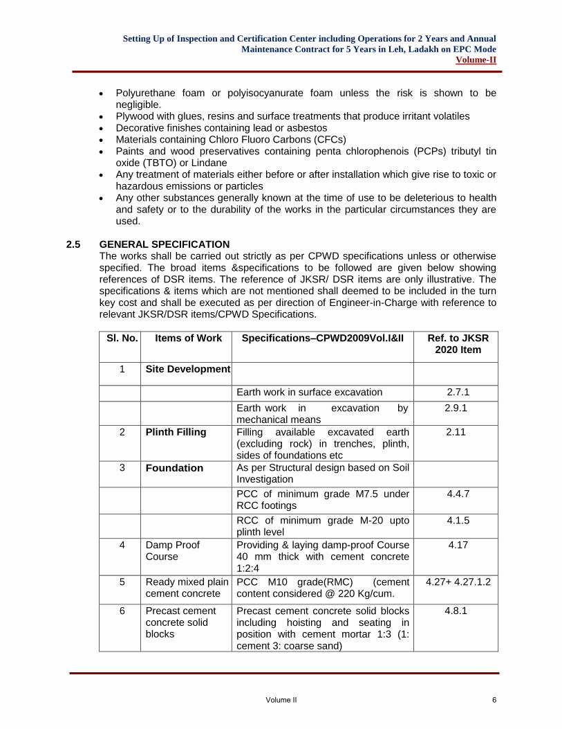
2.5 GENERAL SPECIFICATION
The works shall be carried out strictly as per CPWD specifications unless or otherwise specified. The broad items &specifications to be followed are given below showing references of DSR items. The reference of JKSR/ DSR items are only illustrative. The specifications & items which are not mentioned shall deemed to be included in the turn key cost and shall be executed as per direction of Engineer-in-Charge with reference to relevant JKSR/DSR items/CPWD Specifications.
Sl. No. Items of Work Specifications–CPWD2009Vol.I&II Ref. to JKSR 2020 Item
1 Site Development
Earth work in surface excavation 2.7.1
Earth work in excavation by mechanical means
2.9.1
2 Plinth Filling Filling available excavated earth (excluding rock) in trenches, plinth, sides of foundations etc
2.11
3 Foundation As per Structural design based on Soil Investigation
PCC of minimum grade M7.5 under RCC footings
4.4.7
RCC of minimum grade M-20 upto plinth level
4.1.5
4 Damp Proof Course
Providing & laying damp-proof Course 40 mm thick with cement concrete 1:2:4
4.17
5 Ready mixed plain cement concrete
PCC M10 grade(RMC) (cement content considered @ 220 Kg/cum.
4.27+ 4.27.1.2
6 Precast cement concrete solid blocks
Precast cement concrete solid blocks including hoisting and seating in position with cement mortar 1:3 (1: cement 3: coarse sand)
4.8.1
Volume II 6
Setting Up of Inspection and Certification Center including Operations for 2 Years and Annual
Maintenance Contract for 5 Years in Leh, Ladakh on EPC Mode
Volume-II
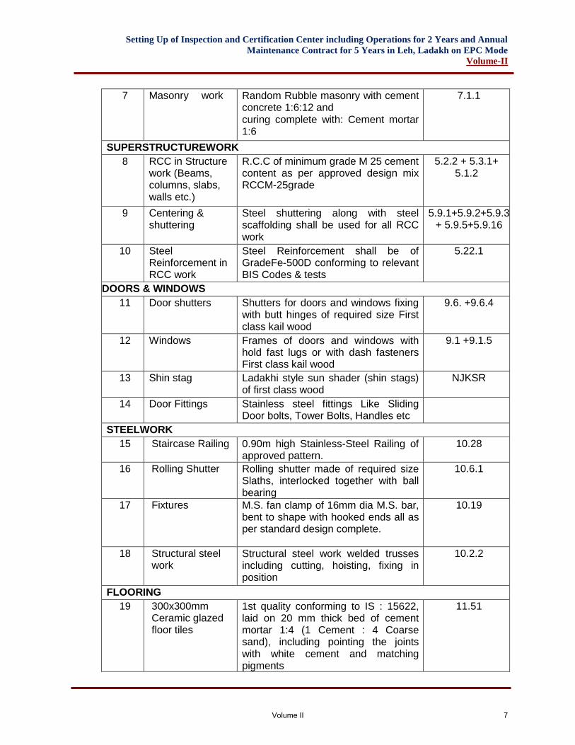
7 Masonry work in foundation & plinth Random Rubble masonry with cement concrete 1:6:12 and curing complete with: Cement mortar 1:6
7.1.1
SUPERSTRUCTUREWORK
8 RCC in Structure work (Beams, columns, slabs, walls etc.)
R.C.C of minimum grade M 25 cement content as per approved design mix RCCM-25grade
5.2.2 + 5.3.1+ 5.1.2
9 Centering & shuttering
Steel shuttering along with steel scaffolding shall be used for all RCC work
5.9.1+5.9.2+5.9.3+ 5.9.5+5.9.16
10 Steel Reinforcement in RCC work
Steel Reinforcement shall be of GradeFe-500D conforming to relevant BIS Codes & tests
5.22.1
DOORS & WINDOWS
11 Door shutters Shutters for doors and windows fixing with butt hinges of required size First class kail wood
9.6. +9.6.4
12 Windows Frames of doors and windows with hold fast lugs or with dash fasteners First class kail wood
9.1 +9.1.5
13 Shin stag Ladakhi style sun shader (shin stags) of first class wood
NJKSR
14 Door Fittings Stainless steel fittings Like Sliding Door bolts, Tower Bolts, Handles etc
STEELWORK
15 Staircase Railing 0.90m high Stainless-Steel Railing of approved pattern.
10.28
16 Rolling Shutter Rolling shutter made of required size Slaths, interlocked together with ball bearing
10.6.1
17 Fixtures M.S. fan clamp of 16mm dia M.S. bar, bent to shape with hooked ends all as per standard design complete.
10.19
18 Structural steel work
Structural steel work welded trusses including cutting, hoisting, fixing in position
10.2.2
FLOORING
19 300x300mm Ceramic glazed floor tiles
1st quality conforming to IS : 15622, laid on 20 mm thick bed of cement mortar 1:4 (1 Cement : 4 Coarse sand), including pointing the joints with white cement and matching pigments
11.51
Volume II 7
Setting Up of Inspection and Certification Center including Operations for 2 Years and Annual
Maintenance Contract for 5 Years in Leh, Ladakh on EPC Mode
Volume-II
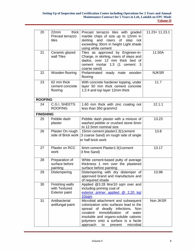
20 22mm thick Precast terrazzo tiles
Precast terrazzo tiles with graded marble chips of size up to 12mm in skirting and risers of step not exceeding 30cm in height Light shade using white cement
11.23+ 11.23.1
21 Ceramic glazed wall Tiles
Tiles as approved by Engineer-in-Charge, in skirting, risers of steps and dados, over 12 mm thick bed of cement mortar 1:3 (1 cement: 3 coarse sand)
11.50A
22 Wooden flooring Prelaminated ready mate wooden flooring
NJKSR
23 62 mm thick cement concrete flooring
With concrete hardener topping, under layer 50 mm thick cement concrete 1:2:4 and top layer 12mm thick
11.7
ROOFING
24 C.G.I. SHEETS ROOFING
1.60 mm thick with zinc coating not less than 350 gram/m2
12.1.1
FINISHING
25 Pebble dash plaster
Pebble dash plaster with a mixture of washed pebble or crushed stone 6mm to 12.5mm nominal size
13.23
26 Plaster On rough side of Brick work
15mm cement plaster1:3(1cement :3 coarse Sand) on rough side of single
or half brick work
13.8
27 Plaster on RCC work
6mm cement Plaster1:3(1cement :3 fine Sand)
13.17
28 Preparation of surface before painting
White cement-based putty of average thickness 1 mm over the plastered surface before painting
29 Distempering Distempering with dry distemper of approved brand and manufacture and of required shade
13.98
30 Finishing walls with Textured Exterior paint
Applied @3.28 litre/10 sqm over and including priming coat of exterior primer applied @ 2.20 kg/ 10sqm
31 Antibacterial antifungal paint
Microbial attachment and subsequent colonization onto surfaces lead to the spread of deadly infections. Non covalent immobilization of water insoluble and organo-soluble cationic polymers onto a surface is a facile approach to prevent microbial
Non JKSR
Volume II 8
Setting Up of Inspection and Certification Center including Operations for 2 Years and Annual
Maintenance Contract for 5 Years in Leh, Ladakh on EPC Mode
Volume-II
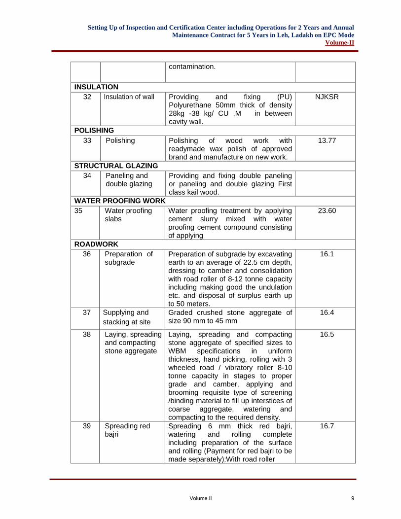
contamination.
INSULATION
32 Insulation of wall
Providing and fixing (PU) Polyurethane 50mm thick of density 28kg -38 kg/ CU .M in between cavity wall.
NJKSR
POLISHING
33 Polishing Polishing of wood work with readymade wax polish of approved brand and manufacture on new work.
13.77
STRUCTURAL GLAZING
34 Paneling and double glazing
Providing and fixing double paneling or paneling and double glazing First class kail wood.
WATER PROOFING WORK
35 Water proofing slabs
Water proofing treatment by applying cement slurry mixed with water proofing cement compound consisting of applying
23.60
ROADWORK
36 Preparation of subgrade
Preparation of subgrade by excavating earth to an average of 22.5 cm depth, dressing to camber and consolidation with road roller of 8-12 tonne capacity including making good the undulation etc. and disposal of surplus earth up to 50 meters.
16.1
37 Supplying and
stacking at site
Graded crushed stone aggregate of size 90 mm to 45 mm
16.4
38 Laying, spreading and compacting stone aggregate
Laying, spreading and compacting stone aggregate of specified sizes to WBM specifications in uniform thickness, hand picking, rolling with 3 wheeled road / vibratory roller 8-10 tonne capacity in stages to proper grade and camber, applying and brooming requisite type of screening /binding material to fill up interstices of coarse aggregate, watering and compacting to the required density.
16.5
39 Spreading red bajri
Spreading 6 mm thick red bajri, watering and rolling complete including preparation of the surface and rolling (Payment for red bajri to be made separately):With road roller
16.7
Volume II 9
Setting Up of Inspection and Certification Center including Operations for 2 Years and Annual
Maintenance Contract for 5 Years in Leh, Ladakh on EPC Mode
Volume-II
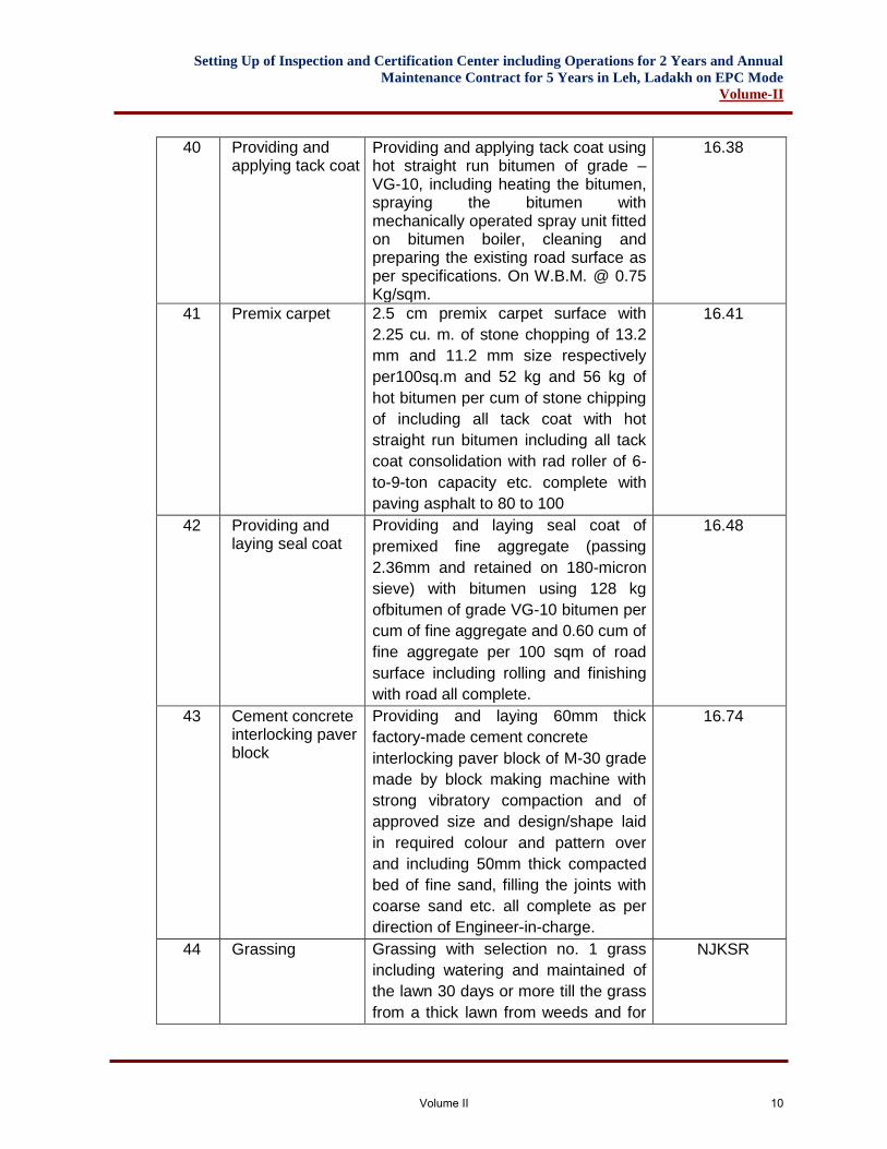
40 Providing and applying tack coat
Providing and applying tack coat using hot straight run bitumen of grade – VG-10, including heating the bitumen, spraying the bitumen with mechanically operated spray unit fitted on bitumen boiler, cleaning and preparing the existing road surface as per specifications. On W.B.M. @ 0.75 Kg/sqm.
16.38
41 Premix carpet 2.5 cm premix carpet surface with
2.25 cu. m. of stone chopping of 13.2
mm and 11.2 mm size respectively
per100sq.m and 52 kg and 56 kg of
hot bitumen per cum of stone chipping
of including all tack coat with hot
straight run bitumen including all tack
coat consolidation with rad roller of 6-
to-9-ton capacity etc. complete with
paving asphalt to 80 to 100
16.41
42 Providing and laying seal coat
Providing and laying seal coat of
premixed fine aggregate (passing
2.36mm and retained on 180-micron
sieve) with bitumen using 128 kg
ofbitumen of grade VG-10 bitumen per
cum of fine aggregate and 0.60 cum of
fine aggregate per 100 sqm of road
surface including rolling and finishing
with road all complete.
16.48
43 Cement concrete interlocking paver block
Providing and laying 60mm thick
factory-made cement concrete
interlocking paver block of M-30 grade
made by block making machine with
strong vibratory compaction and of
approved size and design/shape laid
in required colour and pattern over
and including 50mm thick compacted
bed of fine sand, filling the joints with
coarse sand etc. all complete as per
direction of Engineer-in-charge.
16.74
44 Grassing Grassing with selection no. 1 grass
including watering and maintained of
the lawn 30 days or more till the grass
from a thick lawn from weeds and for
NJKSR
Volume II 10
Setting Up of Inspection and Certification Center including Operations for 2 Years and Annual
Maintenance Contract for 5 Years in Leh, Ladakh on EPC Mode
Volume-II
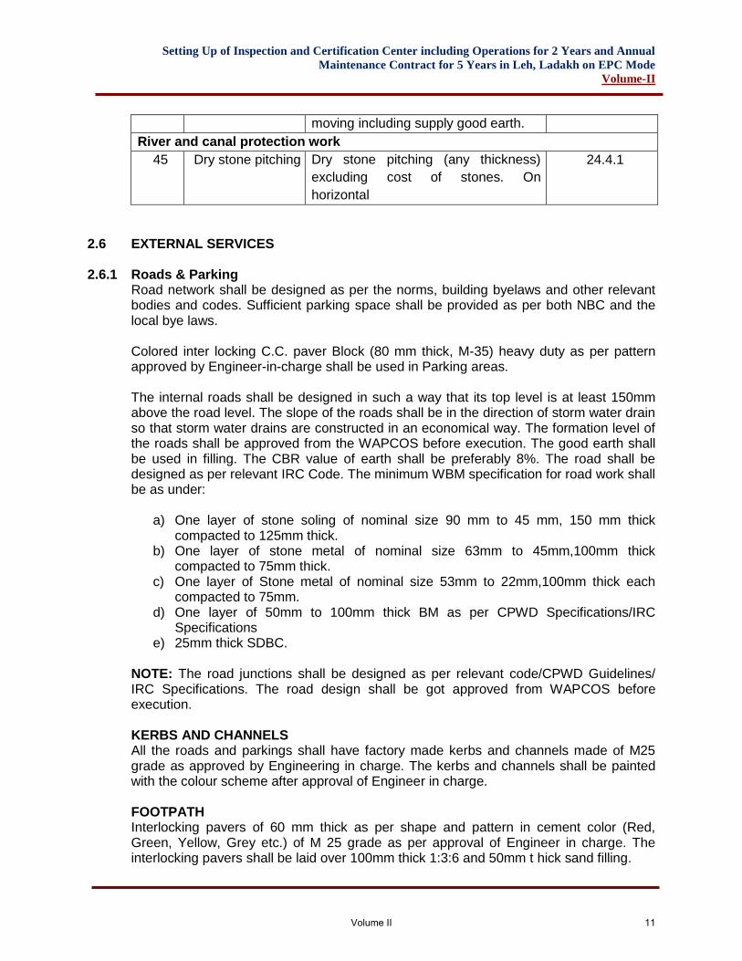
moving including supply good earth.
River and canal protection work
45 Dry stone pitching Dry stone pitching (any thickness)
excluding cost of stones. On
horizontal
24.4.1
2.6 EXTERNAL SERVICES
2.6.1 Roads & Parking Road network shall be designed as per the norms, building byelaws and other relevant bodies and codes. Sufficient parking space shall be provided as per both NBC and the local bye laws. Colored inter locking C.C. paver Block (80 mm thick, M-35) heavy duty as per pattern approved by Engineer-in-charge shall be used in Parking areas. The internal roads shall be designed in such a way that its top level is at least 150mm above the road level. The slope of the roads shall be in the direction of storm water drain so that storm water drains are constructed in an economical way. The formation level of the roads shall be approved from the WAPCOS before execution. The good earth shall be used in filling. The CBR value of earth shall be preferably 8%. The road shall be designed as per relevant IRC Code. The minimum WBM specification for road work shall be as under:
a) One layer of stone soling of nominal size 90 mm to 45 mm, 150 mm thick compacted to 125mm thick.
b) One layer of stone metal of nominal size 63mm to 45mm,100mm thick compacted to 75mm thick.
c) One layer of Stone metal of nominal size 53mm to 22mm,100mm thick each compacted to 75mm.
d) One layer of 50mm to 100mm thick BM as per CPWD Specifications/IRC Specifications
e) 25mm thick SDBC. NOTE: The road junctions shall be designed as per relevant code/CPWD Guidelines/ IRC Specifications. The road design shall be got approved from WAPCOS before execution. KERBS AND CHANNELS All the roads and parkings shall have factory made kerbs and channels made of M25 grade as approved by Engineering in charge. The kerbs and channels shall be painted with the colour scheme after approval of Engineer in charge. FOOTPATH Interlocking pavers of 60 mm thick as per shape and pattern in cement color (Red, Green, Yellow, Grey etc.) of M 25 grade as per approval of Engineer in charge. The interlocking pavers shall be laid over 100mm thick 1:3:6 and 50mm t hick sand filling.
Volume II 11
Setting Up of Inspection and Certification Center including Operations for 2 Years and Annual
Maintenance Contract for 5 Years in Leh, Ladakh on EPC Mode
Volume-II
ROAD PAINTING Painting road surface marking with adequate nos of coats to give uniform finish with ready mixed road marking paint conforming to IS: 164, on bituminous surface in white/yellow shade, including cleaning the surface of all dirt, scales, oil, grease and foreign material etc. complete.
2.6.2 Water Supply System
i. External water supply shall be designed based on total water requirement for the individual building. All water supply lines are to designed based on Indian Standards and Manuals with latest editions and correction slip, if any.
ii. Design Standards a) CPHEEO:1999–Manual on water supply and treatment b) CPHEEO:1993–Manual on sewage and sewage treatment c) SP35:1987–Handbook on water supply and Drainage d) NBC2016 e) UPC–India:2011 or Latest f) Relevant Indian Standards
iii. The ultimate source of water supply for the proposed buildings shall be Municipal Water supply. The external pipeline upto underground water tank shall be designed keeping in view the water supply demand. However, during construction period and till the municipal water supply is available, the source of water supply shall be Tubewells/ Borewells. If water is not found suitable for construction, Contractor shall make alternate arrangements forgetting water fit for constructions at his cost. Nothing extra shall be paid for the same.
iv. The Borewell will be installed inside the identified land of the proposed Center having sufficient number of bore holes with adequate yield capacity to meet the daily water requirement, which shall be included in scope of work. Moreover, arranging water supply from local Municipal Corporation and other approvals is the responsibility of the Contractor.
v. Water requirement of the center per day shall be calculated. vi. Overhead Tank (OHT) and Underground Tank (UGT) will be designed
accordingly. vii. UGT shall be having capacity of one day of daily water requirement plus
requirement of fire-fighting water and OHT shall be half day capacity of daily water requirement. Suitable arrangement for disinfection of bore water shall be made on the basis of chemical analysis and bacteriological report. Disinfection with the help of bleaching powder/gas chlorination should be done.
viii. Submersible pump will be used for pumping raw water from borewell to UGT and monobloc VFD hydropneumatics pumps for pumping water from UGT to OHT of the building. Capacity of pumps will be determined based on standard practice and stipulation of relevant IS code.
ix. Domestic water supply distribution from OHT shall be formed, as a loop/branch network by gravity and upper two floors feed by separate booster pumps.
x. The external pipeline shall be designed in such a way that lying of parallel/duplicate pipe is avoided.
Volume II 12
Setting Up of Inspection and Certification Center including Operations for 2 Years and Annual
Maintenance Contract for 5 Years in Leh, Ladakh on EPC Mode
Volume-II
xi. The external pipeline shall be of S&S (Socket and Spigot) Ductile Iron pipe of Grade K9.
xii. Fittings shall be of S&S D.I. Standard fittings (Heavy Class) xiii. Sluice Valve/ Fire breeching shall be of C.I. complete with bolts and nuts,
rubber insertion etc. The chambers for Sluice Valve/Fire breeching shall be as per requirement of CPWD specifications.
xiv. Thrust Blocks shall be of M25grade. xv. The structural design of external sewerage pipe shall be done as per relevant
IS Code and CPWD Specifications. SW Pipe of Grade A quality shall be used. Suitable Manholes of suitable size as per relevant IS Code/CPWD Guidelines shall be provided at all the junctions and along the roads/parking area at an interval not exceeding 30m distance.
xvi. External storm water shall be designed keeping in view the run off as 25 mm/hour with coefficient as per relevant local bye-laws and IS codes. The diameter of the pipe shall be taken as per hydraulic design calculation and specification of pipe to be adopted such as NP-3 or NP-4 etc Shall be taken as per structural design calculation keeping in view the earth load and relevant IS code etc. Minimum RCC Pipe shall be of grade NP-3. In order to dispose of the storm water from roads and parking areas, it is proposed to provide road gullies of stable size as per the site requirement at the junctions and along the road/ parking at an interval not exceeding 30 m. The road gullies shall be connected with main storm water line through 400 diameter NP-3 RCC Pipe. Vertical or horizontal or both type road gullies shall be provided as per site requirement. The road gullies shall be covered with SFRC gratings. Structural design of the storm water line and road gullies shall be done as per relevant IS Code/ CPWD Guidelines and same shall be got approved from WAPCOS before execution.
2.6.3 Water
Water used in construction for all civil & structural works shall be clean and free from injurious amount of oil, acids, alkalis, organic matters or other harmful substances, which may be deleterious to concrete, masonry or steel. The PH value of water sample shall be not less than 6. Potable water shall be considered satisfactory. Tests on water samples shall be carried out in accordance with IS:3025 and they shall fulfill all the guidelines and requirements given in IS:456. The Employer may require the Contractor to prove, that the concrete prepared with water, proposed to be used, shall not have average 28 days compressive strength lower than 90% of the strength of concrete prepared with distilled water. The Contractor is required to get the water tested from an approved laboratory before starting the construction work and in case the water contains any oil/organic matter or an excess of acid, alkalis or any injurious amount of salts etc., beyond the permissible maximum limits given in IS:456, the Employer may refuse to permit its use. In case there is any change in source of water, water samples shall be tested again to meet the specified requirements. Water shall be stored in tin barrels, steel tanks or water tight reservoirs made with bricks/stone or reinforced concrete. Brick/stone masonry reservoirs shall have RCC
Volume II 13
Setting Up of Inspection and Certification Center including Operations for 2 Years and Annual
Maintenance Contract for 5 Years in Leh, Ladakh on EPC Mode
Volume-II
base slab and shall be plastered inside, with 1 part of cement and 4 parts of sand and finished with neat cement punning. These reservoirs shall be of sufficient capacity to meet the water requirements, at any stage of construction. Water for curing shall be of the same quality as used for concreting and masonry works. Sea water shall not be used for preparation of cement mortar, concrete as well as for curing of plain/reinforced concrete and masonry works. Sea water shall not be used for hydro testing and checking the leakage of liquid retaining structures also.
2.6.4 Cement Portland Pozzalanic cement (grade43) conforming to IS1489 Part1 shall be used.
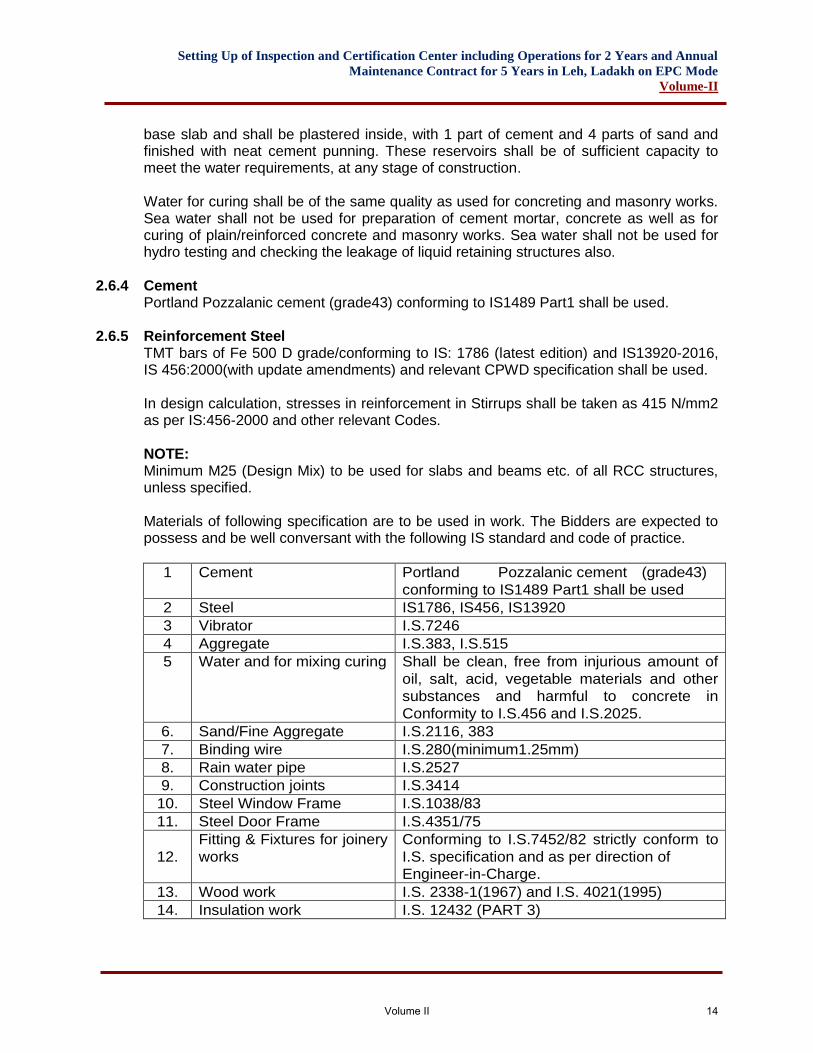
2.6.5 Reinforcement Steel TMT bars of Fe 500 D grade/conforming to IS: 1786 (latest edition) and IS13920-2016, IS 456:2000(with update amendments) and relevant CPWD specification shall be used. In design calculation, stresses in reinforcement in Stirrups shall be taken as 415 N/mm2 as per IS:456-2000 and other relevant Codes. NOTE: Minimum M25 (Design Mix) to be used for slabs and beams etc. of all RCC structures, unless specified. Materials of following specification are to be used in work. The Bidders are expected to possess and be well conversant with the following IS standard and code of practice.
1 Cement Portland Pozzalanic cement (grade43)
conforming to IS1489 Part1 shall be used
2 Steel IS1786, IS456, IS13920
3 Vibrator I.S.7246
4 Aggregate I.S.383, I.S.515
5 Water and for mixing curing Shall be clean, free from injurious amount of
oil, salt, acid, vegetable materials and other
substances and harmful to concrete in
Conformity to I.S.456 and I.S.2025.
6. Sand/Fine Aggregate I.S.2116, 383
7. Binding wire I.S.280(minimum1.25mm)
8. Rain water pipe I.S.2527
9. Construction joints I.S.3414
10. Steel Window Frame I.S.1038/83
11. Steel Door Frame I.S.4351/75
12.
Fitting & Fixtures for joinery
works
Conforming to I.S.7452/82 strictly conform to
I.S. specification and as per direction of
Engineer-in-Charge.
13. Wood work I.S. 2338-1(1967) and I.S. 4021(1995)
14. Insulation work I.S. 12432 (PART 3)
Volume II 14
Setting Up of Inspection and Certification Center including Operations for 2 Years and Annual
Maintenance Contract for 5 Years in Leh, Ladakh on EPC Mode
Volume-II
Note: For road work (Internal Road) specification as per road and bridges (latest edition) published by I.R.C& MoRTH shall be followed. In case of any doubt and absence of provision, regarding specification I.S. shall be referred (Indian standard). Item of Work:
1. Plain and Reinforced Concrete shall be with conformity to I.S.456 and relevant BIS Codes/CPWD Guidelines.
2. Foundation shall be with conformity to I.S.1080 and relevant BIS Codes/ CPWD Guidelines.
3. Stone masonry (R.R.) shall be with conformity to I.S.1597 (Part-I) and relevant BIS Codes/ CPWD Guidelines.
4. C.R. Masonry shall be with conformity to I.S.1597 and relevant BIS Codes/ CPWD Guidelines.
5. Brick masonry shall be with conformity to I.S.2212 and relevant BIS Codes/CPWD Guidelines.
6. Cement plastering shall be with conformity to I.S.9103 & 6925 and relevant BIS Codes/CPWD Guidelines.
7. Mortar shall be with conformity to I.S.2250 and relevant BIS Codes/CPWD Guidelines.
8. White and color washing shall be with conformity to I.S.6278 and relevant BIS Codes/CPWD Guidelines.
9. CC in foundation shall be with conformity to I.S.2571 and relevant BIS Codes/CPWD Guidelines.
10. Anti-Termite Treatment shall be with conformity to I.S.6813. (Part I & Part II) and relevant BIS Codes/CPWD Guidelines.
11. Painting to all surfaces shall be with conformity to I.S.2395(Part–I & Part–II) 12. DPC shall be with conformity to I.S.3067 and relevant BIS Codes/CPWD
Guidelines. 13. Tar felt treatment should be with conformity to I.S.1346 and relevant BIS
Codes/CPWD Guidelines. 14. Mosaic flooring with conformity to I.S.2114 and relevant BIS Codes/CPWD
Guidelines. 15. Steel painting shall be with conformity to I.S.1477 (Part–I & Part–II) I.S.1661 and
relevant BIS Codes/CPWD Guidelines. All works shall be executed as per latest CPWD specification document withup to date correction slips (if any). Specifications not covered in CPWD specifications are as under.
A. PRESSED CERAMIC TILE FLOORING The tiles shall be of approved make and shall generally conform to IS 15622. They shall be flat, and true to shape and free from blisters crazing, chips, welts, crawling or other imperfections detracting from their appearance. The tiles shall be tested as per IS 13630. Classification and Characteristics of pressed ceramic tiles shall be as per IS 13712. The tiles shall be square or rectangular of nominal size. Table 1,3,5, and 7 of IS 15622 give the modular preferred sizes and table 2,4,6 and 8 give the most common non modular sizes. Thickness shall be specified by the manufacturer. It includes the profiles
Volume II 15
Setting Up of Inspection and Certification Center including Operations for 2 Years and Annual
Maintenance Contract for 5 Years in Leh, Ladakh on EPC Mode
Volume-II
on the visible face and on the rear side. Manufacturer/supplier and party shall choose the work size of tiles in order to allow a nominal join width up to 2mm for unrectified floor tiles and up to 1mm for rectified floor tiles. The joint in case of spacer lug tile shall be as per spacer. The tiles shall conform to table10 of IS 15622 with water absorption 3 to 6% (Group BII). The top surface of the tiles shall be glazed. Glaze shall be either glossy or matt as specified. The underside of the tiles shall not have glaze on more than 5% of the area in order that the tile may adhere properly to the base. The edges of the tiles shall be preferably free from glaze. However, any glaze if unavoidable, shall be permissible on only up to 50 per cent of the surface area of the edges.
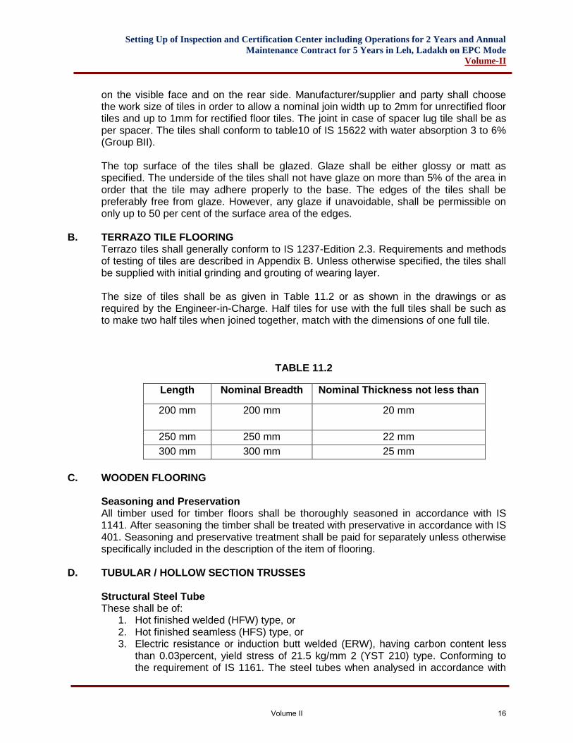
B. TERRAZO TILE FLOORING Terrazo tiles shall generally conform to IS 1237-Edition 2.3. Requirements and methods of testing of tiles are described in Appendix B. Unless otherwise specified, the tiles shall be supplied with initial grinding and grouting of wearing layer. The size of tiles shall be as given in Table 11.2 or as shown in the drawings or as required by the Engineer-in-Charge. Half tiles for use with the full tiles shall be such as to make two half tiles when joined together, match with the dimensions of one full tile.
TABLE 11.2
Length Nominal Breadth Nominal Thickness not less than
200 mm 200 mm 20 mm
250 mm 250 mm 22 mm
300 mm 300 mm 25 mm
C. WOODEN FLOORING
Seasoning and Preservation All timber used for timber floors shall be thoroughly seasoned in accordance with IS 1141. After seasoning the timber shall be treated with preservative in accordance with IS 401. Seasoning and preservative treatment shall be paid for separately unless otherwise specifically included in the description of the item of flooring.
D. TUBULAR / HOLLOW SECTION TRUSSES Structural Steel Tube These shall be of:
1. Hot finished welded (HFW) type, or 2. Hot finished seamless (HFS) type, or 3. Electric resistance or induction butt welded (ERW), having carbon content less
than 0.03percent, yield stress of 21.5 kg/mm 2 (YST 210) type. Conforming to the requirement of IS 1161. The steel tubes when analysed in accordance with
Volume II 16
Setting Up of Inspection and Certification Center including Operations for 2 Years and Annual
Maintenance Contract for 5 Years in Leh, Ladakh on EPC Mode
Volume-II
the method specified in IS 228 shall show not more than 0.06 percent sulphur, and not more than 0.06 per cent phosphorous.
Tubes shall be designated by their nominal bore. These shall be light, medium or heavy as specified depending upon the wall thickness. The standard size and weights of tubes are listed in Appendix C. Hollow sections shall be as per IS 4923. Tubes shall be clean finished and reasonably free from scale. They shall be free from cracks, surface flaws, laminations and other defects. The ends shall be cut clean and square with axis of tube, unless otherwise specified.
E. CGI SHEET ROOFING Surface of C.G.I. sheets of ridge and hip sections and the roofing sheets which overlap each other shall be painted with a coat of approved primer and two coats of approved paint suitable for painting G.S. Sheets before they are fixed in place.
F. ROLLING SHUTTERS Rolling shutters shall conform to IS 6248. These shall include necessary locking arrangement and handles etc. These shall be suitable for fixing in the position as specified i.e. outside or inside on or below lintel or between jambs of the opening. The door shall be either push and pull type or operated with mechanical device supplied by the firm. Shutters upto 10 sq. meters shall be of push and pull type and shutters with an area of over 10 sq. meters shall generally be provided with reduction gear operated by mechanical device with chain or handle, if bearings are specified for each of operation, these shall be paid for separately.
SCOPE OF WORK 1. Preliminary Requirements:
• The Contractor shall design, test, fabricate, deliver, install and guarantee all construction necessary for the proposed building, all in conformity with the drawings as shown.
• Specification and all relevant construction regulations including providing any measures that may be required to that end, notwithstanding any omissions or inadequacies of the drawings.
• The Contractor shall also be responsible for providing the following: o Co-ordination with the work of other trade. o Protection. o As built record drawings and photographs. o Guarantees and warranties. o All hoisting, scaffolding, staging and temporary services
2. Quality Consideration and Other Activities
• The Contractor while submitting the detailed design calculations should submit the following information on the quality of materials to be used and other aspects as detailed below:
o Metal quality, finishes and thickness o Glass quality, coating and thickness and proposed manufacturer’s brand
names o Arrangement and jointing of components.
Volume II 17
Setting Up of Inspection and Certification Center including Operations for 2 Years and Annual
Maintenance Contract for 5 Years in Leh, Ladakh on EPC Mode
Volume-II
o Field connections especially mullion to mullion and transom to mullion. o Fixing and anchorage system of typical wall unit together with structural
calculations. o Provisions for thermal movements. o Sealant and sealing methods. o Glazing method. o Wind load and seismic load and any other specific load considered in the
design
• The maximum permissible structural tolerances of the building that the system has been designed to accommodate in case these tolerances exceed those specified in the specification.
3. Test of Wind Pressure
• The equivalent load of wind pressure or wind suction shall be given to the test unit as increasing or decreasing the inside pressure in the “pressure chamber” at which the test unit is fixed.
• The static wind pressure shall be applied up to 1.5 kpa at maximum wind pressure.
• The variation of dynamic pressure shall be of any approximate sine curve line.
• Deflection on each observational points of the test unit shall be observed and recorded under static pressure as described above.
• Any damage and harmful permanent deformation on any parts except sealing materials shall not be found at maximum wind pressure.
• The deflection on the main structural parts in this condition shall not exceed: o 1/175 of the span between supports or 20mm, whichever is less for
vertical elements. o 1/250 of the span between supports for horizontal elements. o The extent of recovery of deformation, 15 minutes after the removal of the
test load, is to beatleast95%. 4. Test of Lateral Deflection per Floor Height
• Lateral deflection per floor height shall occur on the test unit, when the structural frame which fixes the test unit is deflected horizontally.
• The deflection of every+2.5mm shall be increased upto+13mm on the test unit (static deflection test)
• The dynamic deflection shall be applied upto+13mm.
• The variation of dynamic deflection shall be of an approximate sine curve line, on period of 3 seconds.
• The dimensions of the deflection on each observational point of the test unit shall be measured under the condition as described above and the dame shall be observed.
• Any damage and harmful permanent deformation shall not be found in any parts of the curtain wall except the damage to sealant at maximum deflection.
5. Water Tightness Test
• Water shall be sprinkled to the ‘Test Unit ‘under wind pressure.
• Pressure shall not be applied to the test unit
Volume II 18
Setting Up of Inspection and Certification Center including Operations for 2 Years and Annual
Maintenance Contract for 5 Years in Leh, Ladakh on EPC Mode
Volume-II
• The volume of the sprinkling water in one minute shall be 5 liters per sq mt minimum (01.gal/sq.ft.)
• All water leakage and drainage system at the joint and the openable sash of the curtain wall system shall be observed from the outside of the chamber.
• Hold the test two times, in sequence as described below, conforming to the above-mentioned conditions. o Install the test unit. o Hold first water tightness test o Hold test of wind pressure as described above o Hold second water tightness test. o Lateral deflection test
• Water leakage shall not be observed inside at all parts of the test unit during first water tightness test.
a. Anti Termite Treatment: Providing anti‐termite treatment using approved quality of
chemical emulsion, spraying the mixture uniformly by sprayer as pre‐constructional anti termite treatment and creating a chemical barrier under and around the column pits, wall trenches, top surface of plinth filling, junction of walls & floors along with external perimeter of the building, expansion joints ,surrounding the pipes and conduits etc. complete at the rate as directed by the manufacturer confirming to IS:6313 (Part‐II) and as per direction of Engineer‐in‐charge including cost of all
materials , labour, taxes , sundries, T&P etc. complete.) Note: ‐The Contractor shall have to furnish 10 years Guarantee to maintain the anti‐termite treated area/ structures free from termite.
b. Anti-Skid Vitrified Floor Tiles: Fixing of Anti-skid Vitrified floor tiles of premium
grade having minimum thickness 10mm confirming to IS 13756 of size 60cm x 60cm colored/ printed series in floors, Trades of steps & Landing over 20mm thick bed of cement mortar 1:4 jointed with cement slurry mixed with pigments to match the shade of the tiles, including rubbing & polishing etc complete
c. Wooden Laminate Flooring: Providing & fixing of EGGER laminate wooden
flooring-Class32(AC4) conforming to EN 13329 standards, (No Asian Manufacturing), thickness of plank minimum 8 mm, size of plank-1291mmx193mm, HDF core board to be swell stop plus with minimum density of930 kg/m3 according to and conforming to EN622 type 5 standard. Product to be PEFC, FSC & Blue Angel certifications. Fixing to be done using 2mm PE foam and 0.2mm vapor barrier. Product to offer 20 years Guarantee for Residential/domestic use and 5 years Guarantee for commercial usage according to manufacturer’s guarantee document (Equivalent to Floor Master). Laminated wooden flooring should be glue less Just Click patented locking system. Classification of use 32/23 with a surface abrasion resistance of class AC4/IP > 4.00, slip resistance class R- 10conforming to DIN EN 51130 standard, Impact Resistance IC 2, Formaldehyde Emission E1, Light fastness Level 6, Flame resistance-Cfl, Castor chair Type W, heat passing resistance0.07 m2 K/W, static indentation EN 433 < 0.01, surface soundness EN 13329>1.4,e of plank size 1291x193x8 mm laminated flooring will be Laid over hard surface(Cement sand aggregate screed).
Volume II 19
Setting Up of Inspection and Certification Center including Operations for 2 Years and Annual
Maintenance Contract for 5 Years in Leh, Ladakh on EPC Mode
Volume-II
6. Granite Wall lining & Dado: Granite work gang saw cut (polished and machine cut) of thickness 18mm for wall lining, skirting and dado (veneer work) in cementmortar1:3 (1 cement:3 coarse sand) including pointing with white cement mortar 1:2 (1 white cement: 2 marble dust) with an admixture of pigment to match the marble shade:(To be secured to the backing by means of cramps.) a. General Granite Stone shall be of the type specified and the material promptly in accordance with specifications, its shall be hard sound durable and tough free from cracks, and defects like cavities cracks flaws holes etc. Before starting the work the contractor shall get the sample approved by the Engineer–in–Charge. b. Materials Granite Standard: Granite shall comply Standard Specification for material characteristics, physical requirements, and sampling for selection of granite. All granite shall be of standard architectural grade, free of cracks, seams, or starts, which may impair its structural integrity or function. Color or other visual characteristics indigenous to the particular material and adequately demonstrated in the sampling will be accepted provided they do not compromise the structural or durability capabilities of the material. Texture and finish shall be within the range of samples approved by the Engineer–in-charge. c. Shop Drawings The Contractor shall submit: copies of required shop drawings to the Engineer-in-charge for approval. These drawings shall show all bedding, bonding, jointing and anchoring details, and the dimensions of each piece of granite. No final sizing or finishing shall be done until the shop drawings for that part of the work have been approved. d. Stone Installation Proceed with the installation of the stonework in accordance with Drawings and using skilled mechanics capable of proper handling of the setting of the stone and able to field cut where necessary with sharp and true edges. Set stone with joints uniform in appearance and stone edges and faces aligned tolerances indicated. Clean surfaces that are dirty or stained. Scrub with fiber brushes, and then rinse with clear water. Provide expansion, control, and pressure-relieving joints of widths and at locations shown on Drawings. Cleaning After installation and pointing or caulking are completed, the contractor shall carefully clean the granite, removing all dirt, excess mortar, weld splatter, stains, and/or other site incident defacements Stainless steel wire brushes or wool may be used, but the use of other wire brushes or of acid or other solutions which may cause discoloration is expressly prohibited. Fabricator should be contacted before cleaners other than detergents are used.
7. Protection of Finished Work
Volume II 20
Setting Up of Inspection and Certification Center including Operations for 2 Years and Annual
Maintenance Contract for 5 Years in Leh, Ladakh on EPC Mode
Volume-II
After the granite work is installed, the granite shall be properly and adequately protected from damage. Boxing or other suitable protection shall be provided wherever required, but no lumber which may stain or deface the granite shall be used. All nails used shall be non-corrosive. All granite work in progress shall be protected at all times during construction by use of a suitable strong, impervious film or fabric securely held in place. a. Granite Flooring: Granite stone flooring with 18mm thick stone flooring (sample
shall be approved by Engineer-in-charge) over 20 mm (average) thick base of cement mortar 1:4 (1 cement: 4 coarse sand) laid and jointed with grey cement slurry including rubbing and polishing complete with:
▪ General Granite Stone shall be of the type specified and the material promptly in accordance with specifications, it shall be hard sound durable and tough free from cracks, and defects like cavities cracks flaws holes etc. before starting the work the contractor shall get the sample approved by the Engineer–in–Charge.
▪ Materials Granite Standard: Granite shall comply Standard Specification for material characteristics, physical requirements, and sampling for selection of granite.
All granite shall be of standard architectural grade, free of cracks, seams, or starts, which may impair its structural integrity or function. Color or other visual characteristics indigenous to the particular material and adequately demonstrated in the sampling will be accepted provided they do not compromise the structural or durability capabilities of the material. Texture and finish shall be within the range of samples approved by the Engineer–in-charge. b. Shop Drawings The Contractor shall submit: copies of required shop drawings to the Engineer-in-charge for approval. These drawings shall show all bedding, bonding, jointing details, and the dimensions of each piece of granite. No final sizing or finishing shall be done until the shop drawings for that part of the work have been approved. c. Stone Installation Proceed with the installation of the stonework in accordance with Drawings and using skilled mechanics capable of proper handling of the setting of the stone and able to field cut where necessary with sharp and true edges. Set stone with joints uniform in appearance and stone edges and faces aligned tolerances indicated. Clean surfaces that are dirty or stained. Scrub with fiber brushes, and then rinse with clear water. Provide expansion, control, and pressure-relieving joints of widths and at locations shown on Drawings. d. Cleaning After installation and pointing or caulking are completed, the contractor shall carefully clean the granite, removing all dirt, excess mortar, weld splatter, stains, and/ or other site incident defacements Stainless steel wire brushes or wool may be used, but the use of other wire brushes or of acid or other solutions which may cause discoloration is
Volume II 21
Setting Up of Inspection and Certification Center including Operations for 2 Years and Annual
Maintenance Contract for 5 Years in Leh, Ladakh on EPC Mode
Volume-II
expressly prohibited. Fabricator should be contacted before cleaner soother than detergents are used. e. Automatic Sensor Door Frameless Glass door with censor operated madewith12mm Clear Toughened Glass with SS patch fittings Of Ozone/ Dorma make or equivalent complete with all necessary fittings such as handles, Lock, Floor Springs. All complete (inclusive of taxes etc.) f. Frameless Glass door with patch fitting Frameless Glass door made with 12mm Clear Toughened Glass with SS patch fittings of Ozone/ dorma make or equivalent complete with all necessary fittings such as handles, Lock, Floor Springs. All complete (inclusive of taxes etc.) g. Metal Fire Door Providing & Fixing of Fire Door made from Hollow metal CE Marked fire rated doors from ISO 9001-2008 certified Manufacturer .Fire doors should be as per IS 3614 part-II & part-2 and BS 476 part 2. Fire doors should be tested at CBRI Roorkee for maximum rating of 2 hrs with vision panel. Pressed Galvanized steel Single/Double leaf door, shutter, in fill and finish as detailed below and conforming to IS 277 complete as per directions of Engineer-in-charge. Door frame shall be double rebate profile made out of 1.60 mm (16 gauge) thick galvanized steel sheet. Door Frames shall have butt joint and field assembled with self tabs / nut bolts. All provision should be mortised, drilled and tapped for receiving appropriate hardware. Frames should be provided with back plate bracket and anchor fasteners for installation on a finished plastered masonry wall opening. Door to be fixed with fire rated hinges 5 Knuckle,2 bearing but thing es size 4"x3"x3mm,in SS 304 and in satin stainless steel. As per EN 1935, CE Marked. Suitable for door weights upto120kgs, Panic bar as per door leaf (single leaf/ double leaf) Panic Hardware consisting of Main Panic Latch component, End Component, Push bar, Striker Kit, end caps, complete set with screws & fixing accessories, External trim, having fire rated door closer TS 71/68 rack and pinion door closer EN size 3/4, with std. arm and with two independent closing valves and latching speed adjustable by arm. Full plastic cover should be as per EN 1154 life cycle 500,000 with seals and door stopper of approved make. h. Excluded Hollow Clay Façade Tile Providing and fixing of Extruded Hollow Clay /Terracotta Ventilated Rain screen Façade Tiles of approved make of grid dimensions 300mm(c/c) x600mm(c/c) x16mm thickness in a horizontal direction on the building facade. The extruded hollow clay tile cladding material shall be rigid and of adequate strength and shall have a minimum total thickness of 16 mm (±10%). The tiles shall be installed using the ventilated rain screen principle, with provision for natural ventilation of the space between the façade tiles and the structural wall. The clay tiles shall be of the hollow type, fixed to a supporting Aluminum framework consisting of vertical tubular/'T'/'L'-sections measuring 40x40x2 mm/80x60x2 mm spaced at maximum 1200 mm c/c intervals and continuous horizontal Aluminum 'C'-sections/runners fixed on top of the vertical sections.
Volume II 22
Setting Up of Inspection and Certification Center including Operations for 2 Years and Annual
Maintenance Contract for 5 Years in Leh, Ladakh on EPC Mode
Volume-II
The vertical tubular/'T'/'L'-sections shall be fixed to the wall using HDG Steel L-brackets and Hilti/ Fischer stainless steel anchor fasteners for brickwork/ RCC as applicable, spaced at maximum1500mmc/c vertically (actual spacing to be based on a structural/ static calculation). The brackets shall be fixed to the vertical Aluminum tubular/ T profiles using two stainless-steel self-drilling/ self-tapping screws of dimensions 5.5x25mm. Continuous horizontal Aluminum 'C'-sections/ runners measuring 56x25x2.5 mm shall be fixed on top of the vertical Aluminum tubular/'T'/'L'-sections from front using stainless steel self-drilling/ self-tapping screws at maximum 1200mm intervals horizontally and at maximum 300mm c/c intervals vertically matching to the tile-grid. The tiles shall be mounted on the continuous horizontal C-sections such that the tiles are continuously supported along their length at top and bottom. The tiles shall be additionally secured to the horizontal channels using special c-shaped stainless steel clips which shall be screwed to be channels holding the tiles. In certain cases, instead of fixing with clips, the tiles shall be glued at points to the horizontal channels using MS Polymer Sealent adhesive. The vertical joint between adjacent tiles to be a 6mm open groove. i. Wall Panelling Providing and fixing wall panelling consisting well seasoned hardwood sections, treated with preservatives, minimum 50x25mm,at suitable horizontal/vertical spacing not exceeding 600 mm c/c. applying both way finished with 1.5 mm thick laminate/ 4 mm veneer of same or combination shades of approved brand over 12 mm thick BWR grade ply with grooves / pattern all complete as per direction of Engineer-in-charge. j. Wooden False Ceiling Providing and fixing wooden false ceiling consisting well seasoned hardwood sections, treated with preservatives, minimum 50x50 mm, at suitable horizontal/vertical spacing not exceeding 600mmc/c. applying finished with 1 mm thick laminate of same or combination shades of approved brand over 12 mm thick BWR grade ply with grooves / pattern all complete as per drawings and direction of Engineer-in-charge, including, cutting / making, opening for services like diffusers, grills, light fittings, fixtures, smoke detector set c wherever, required. k. Lacquer Glass Providing and fixing of 6mm thick humid resistance & polyurethane lacquer glass of approved make and colour by architect with clear neutral silicon of make GE winsil 20/ silpruf or Dow Corning 995 on a perfectly levelled water proof non conventional plywood (preferably marine plywood) of minimum 12mm thickness mounted on the RCC wall/any other structure complete as per, drawings and direction of Engineer-in-charge. l. Carpet Providing and Fixing Carpet (Tip-Sheared Loop Pattern/Pattern Cut pile or Pattern scroll) make of yarn content Avalar/ Aqua approved SD Nylon with Puralex /Continuous Filament 6.6 Nylon, yarn weight 26 to 36 oz/sq yd, with Primary backing of Master line/Polypropylene and Secondary backing of Woven Polypropylene with Post consumer Recycled content.1/8,1/10and1/12 gauge,7.3 to 14 stitches/inch, The carpet shall be flame resistant as per DOC FF-I-70,Smoke density should be less than 450(ASTM E-662),Soil resistant as per commercial Anti-Soil Protection and Carpet is CRI Green Label
Volume II 23
Setting Up of Inspection and Certification Center including Operations for 2 Years and Annual
Maintenance Contract for 5 Years in Leh, Ladakh on EPC Mode
Volume-II
plus certified#GLP7078 The carpet shall be pasted with appropriate adhesive suitable for pasting on existing floor, complete job as per manufacturer's specifications. m. Glass Block Providing& fixing in position glass block of Size 180mm x 180mm/approved size partition with approved make of glass block of approved sizes given with approved design & colour, including fixing & grouting the joints with white cement and matching pigments etc., complete. Rate to include all glass blocks, joints, plastic spacers if required, etc. complete in all respects as per manufactures specifications and direction of Engineer-in-Charge n. Designer Cement Tile Designer cement tiles work in cladding / dado/skirting (upto 2 m height) over 12 mm thick bed of cement mortar 1:3(1 cement :3 coarses and) and jointed with grey cement [email protected]/sum including pointing in white cement mixed with pigment of matching
shade complete. o. Polycarbonate Sheet Providing & fixing 10 mm thick multi-wall polycarbonate sheet skylight over the cutouts& other locations as shown on drawings, fixing the polycarbonate sheets to the MS closed structure by means of Aluminum extruded sections, EPDM gasket screwed to the steel structure & sealing the joints completely with approved sealant to make them waterproof, inclusive of closing the vertical gaps with the same sheet, cleaning, finishing neat, scaffolding up to any height etc. complete in all respects as per manufactures specifications and direction of Engineer-in-Charge. The rate to include for all the laps & wastages, flashings etc. Only net laid area of the sheet shall be measured for payment.
8. Murals and Signages: i. Murals and planters shall be designed of appropriate shape, size, area and material
as directed by Engineer-in-Charge and provided at the entrance lobbies of building blocks and on the external walls near the building entrances. Sculptures and artifacts shall be provided in the premises at strategic locations from the aesthetic point of view. The overall scheme shall be in tune with the architectural design of the building and landscape.
ii. Providing & fixing Solid letters made of SS sheet of 5 mm/1.5 mm thickness as
required in all heights and locations Letters made up of Stainless steel, grade316 of approved make made out of laser cut shape in required design, language & font, including buffing, polishing and fixing by sufficient numbers of fastener high quality chemical tape/ adhesive/fast of approved make, all complete as per architectural drawings and direction of Engineer in charge.
iii. Providing & fixing pictograms in 304 grade 2 mm thick brush finished Stainless steel
at all levels and locations prepared using silk printing technology/etching, filling with industrial paint in required colors and baking to the required condition at required temperature for obtaining desired shine and gloss, in required font, design, pattern and size including buffing, polishing etc. and fixing by high quality chemical tape/adhesive of approved make on prepared surface, all complete as per architectural drawings and direction of Engineer in charge.
Volume II 24
Setting Up of Inspection and Certification Center including Operations for 2 Years and Annual
Maintenance Contract for 5 Years in Leh, Ladakh on EPC Mode
Volume-II
iv. Providing & fixing at all levels and locations, informatory/ directional/ warning
signages in required font, design, pattern and size made of 4 mm thick odourless Acrylic sheets of make Cast/ Acrylite/ or approved equivalent, conforming to specific gravity of 1.19,tensile strength of 69MPA,percentage elongation of 4.2 %, modulus of elasticity 2800 MPA (ASTM –D638), refractive indexof149,(ASTM-D542)Rock well hardness of M94 (ASTM–D785),water absorption of 0.2 % (ASTM- D570) total light transmission of 92 % (ASTM –D1003) chemical, UV & weather resistant ,having excellent insulation properties, abrasions resistant of approved color, of approved quality and make, with beveled edges having self adhesive self luminescent vinyl sheet(film thickness >150 micron, luminescent duration 4-6 hours) of make 3M/Avery or approved equivalent over which the signage/letter cut out made of vinyl sheet (film thickness > 80 micron) of make 3M/ Avery or approved equivalent is pasted in required colour, font, design, pattern, including fixing over walls/ partition/glass etc, fixing by high quality chemical tape of make 3M/ Avery or approved equivalent on prepared surface, all complete as per architectural drawings and direction of Engineer in charge.
v. Providing and fixing of signages, modular curved frame technology, of various widths
and lengths, to form suggested usages, made of Aluminum extruded sections, duly anodised, all signages shall be provided with 0.6-0.8mmpolycarbonate protecting film over the prints, of appropriate size, as per approved make or Equivalent.
UPVC Doors and Windows: All openable and fixed window/door system shall have minimum 3 hollow chambers from front to back. The sliding system frames shall have minimum 3 chambers from front to back. The sliding systems ashes shall have minimum one chamber from front to back. All sections of the frame and sash shall be reinforced in accordance with the system supplier’s recommendations with minimum thickness of 1.5mm using galvanized mild steel in a single continuous length.
9. General Requirements The profile is to be extruded from a compound that has been blended to ensure quality and consistency. The material shall be pristine white high impact modified window grade UPVC and shall be color fast and conform to BSEN 12608:2003 as follows:
Description of Material Required Value
Flexural modulus of Elasticity Shall not be less than 2200N/mm2
Resistance to impact by falling massat.
10°C for Class II (falling mass 1000g;
falling height 1500mm–as per BS EN
12608:2003)
Not more than 1 test specimen shall
show rupture in wall
Mean Breaking Stress for welded
Corners
Shall not be less than 35N/mm2 for
compression bending test or 25N/mm2
for tensile bending test
Volume II 25
Setting Up of Inspection and Certification Center including Operations for 2 Years and Annual
Maintenance Contract for 5 Years in Leh, Ladakh on EPC Mode
Volume-II
a) Fabrication of window/ door
i. The window units shall be designed with all corner/mullion/transom joints can be mechanical joined or welded as per system supplier recommendation
ii. All excess material is to be neatly trimmed and neatly feature grooved/raised nib finish at corners, transom joints and mullion joints.
iii. No polishing flush of any joints will be permitted. iv. The window units shall be designed so that the route of drainage is prevented
from passing through the reinforcement chamber. v. The finished product shall be free from all sharp edges, burrs and the like that
may be hazardous to the user. vi. Thedimensionaltolerancesonthefinishedouterframeheightandwidthshall be +/-
3mm. Frame assemblies shall be such that they can be installed square within a maximum difference in the diagonals of 4mm.
vii. Minimumoverlapofsashonframeshallbe8mm viii. In all window units, adequate drainage should be provided to permit the
escape of water from platforms or horizontal members beneath each sealed unit. The drainage slots shall not penetrate into the reinforcement chambers.
b) Reinforcement
i. Reinforcement shall be made from galvanized mild steel of not less then 1.5mm thickness as per strength requirement unless otherwise approved by Engineer in Charge.
ii. Steel reinforcement shall conform to IS 277:2003 or equivalent – Base material of steel shall conform to IS 513:2008. Drawing Grade
iii. The reinforcement shall be installed in accordance with the recommended actions. The reinforcement shall conform to the wind load requirements of IS 875: Part3. The reinforcement shall be in one continuous length and should be installed minimum 5mm and maximum10mm from the face of the profile to be welded.
iv. The reinforcement shall be secured to the profile so that it does not move or rattle and it maintains the structural integrity of the frame and satisfactory thermal separation. Reinforcement is to be fixed at a maximum of 100mm from the ends and then at a maximum of 300mmcenters.
10. Glazing and Weather seals a) Glazing
i. Window/door shall be such that glazing or re-glazing on site is possible without the need to remove the outer frames from the structure of the building.
ii. Window shall be such that glazing or re-glazing on site is possible without the need to remove the outer frames from the structure of the building.
iii. All glazing is to be packed in accordance with the system supplier’s recommendations to prevent any kind of damage during handling
iv. All beads will be cut at the correct degree recommended by the manufacturer. Glass retention clips shall be fitted in accordance with the Systems supplier’s recommendations. Windows will be with 21mm thick hermetically sealed glass units having 6-10-5 arrangement
Volume II 26
Setting Up of Inspection and Certification Center including Operations for 2 Years and Annual
Maintenance Contract for 5 Years in Leh, Ladakh on EPC Mode
Volume-II
b) Weather Seals
The weather seals shall be EPDM/ Silicone seals. ASTM- D412 and ASTM-D 2240 are standard specifying test methods for Tensile strength and Hardness of the gasket whereas the required value shall be specified
c) Ultimate tensile strength min>7.5N/mm2
The weather seals are to be fitted in continuous lengths and grooves. The joints in the vent weather seal are to be positioned at the bottom and in the outer frames at the top.
d) Security and Safety
Fasteners shall be designed so that they cannot be released from the outside by the insertion of a thin blade.
No opening light shall be openable or removable from the outside, when it is fastened in the closed position, except by use of special tools or breaking part of the window. Profile Properties a) Appearance and Finish
The color of the profile shall be uniform and the color of all profiles in a system shall be uniform. The profile shall be free from foreign bodies, cracks or sink marks when viewed by normal corrected vision at 90o to the surface and at a distance of 1meter in normal diffused north light.
b) Dimensions and Weights
The profiles shall be straight such that the longitudinal axis of the profile, as measured on the face surfaces, may deviate from the straight line by no more than 1mm per meter. The cross section of the profile shall conform in shape and dimensions and may deviate by no more than +/- 0.5mm; glazing channels and seal grooves may deviate by not more than +/- 0.3mm. The weight of the profile per meter shall not be more than 5% below the nominal value.
Resistance to wind load All load bearing members shall be adequately reinforced so as to resist the wind load requirements of IS 875: Part 3. Calculations shall be submitted for all window designs.
11. Installation of Frame
i. Before installation the Installation Team is to make sure that the opening has been prepared and any repair work has been carried out. Allow a 5mm gap between the frame and the opening. The new window shall be set in the prepared opening. Allow for suitable packing blocks. The dimension tolerance on the aperture opening should be +/ - 5mm. any deviation in opening shall be brought in knowledge of contractor by installation team. The contractor should repair the same within specified dimension tolerance
Volume II 27
Setting Up of Inspection and Certification Center including Operations for 2 Years and Annual
Maintenance Contract for 5 Years in Leh, Ladakh on EPC Mode
Volume-II
ii. The window shall be fixed into the aperture, by drilling and fixing through the outer frame, to the existing structure using 10x100 mm with white cap in existing pre-finished wall.
iii. The fixings shall be between 150mm–200mm and no more than 700mm from corners or transoms/mullions and at no more than 600mm centers.
iv. When the frame is securely fixed in position then fit glass and glazing beads. Allow for any necessary glazing blocks and glass lock devices.
v. Check windows for correct operation before proceeding with making good.
vi. No fixings are to penetrate the drainage channels.
vii. The windows shall be first treated with Polyurethane Foam (PU Foam) to enhance insulation against heat and Noise. The gap between masonry and the frame is to be filled with Neutral Cure Silicon (exposed to sun surface) and/or Acrylic Sealant (only for the internal surface). The windows shall be first treated with Polyurethane Foam (PU Foam) to enhance insulation against heat and Noise
viii. Window/Door shall be installed only after first coat of paint. Making Good Making good to the external surface of the window frame and finish with a compatible approved low modular silicone sealant to BS5889. All trims and quadrants are to be approved by the Engineer-in-Charge prior to fixing. Guarantees Manufacturer to offer a warrantee on the window profile used in the manufacture of UPVC window/door systems for a period of 10 years from the date of installation. The Warrantee has to cover all abnormal defects in workmanship/quality. The guarantee has to be underwritten by a Company nominated Executive and also signed by the contractor. The contractor should ensure that no damage is caused after the installation of Window/Door at site. Window Hardware All door/windows are to be provided with multi point locking arrangement with/without key locking facility as per the requirement. The hardware to be of approved make. Casement window friction stays are to be of approved make of appropriate
Volume II 28
Setting Up of Inspection and Certification Center including Operations for 2 Years and Annual
Maintenance Contract for 5 Years in Leh, Ladakh on EPC Mode
Volume-II
3. SPECIFICATIONS (ELECTRICAL WORKS)
Volume II 29
Setting Up of Inspection and Certification Center including Operations for 2 Years and Annual
Maintenance Contract for 5 Years in Leh, Ladakh on EPC Mode
Volume-II
TECHNICAL SPECIFICATIONS FOR INTERNAL ELECTRICAL WORK INSTALLATION & ALLIED WORK
3.0 GENERAL
The electrical installation work shall be carried out in accordance with Indian Standard Code of Practice. It shall also be in conformity with the current Indian Electricity rules and regulations of local Electricity Rules. Fire Insurance Rules, I.S. Codes and Indian Electricity Rules. General Specifications for Electrical Works.
- Part – I - Part – II - Part – IV
- Internal Work - External Work - Substations Work
- 2005 - 2007 - 2007
Wherever this specifications calls for a higher standard of material and or workmanship than those required by any of the above mentions regulations and specification then the specification here under shall take precedence over the said regulations and standards. The details of scope of work subhead wise are given in the subsequent paras. The quantities worked out in schedule of quantities are based on particular equipment considered at design stage. The contractor is required to recheck the quantities based on equipment offered by him to achieve required parameters
Volume II 30
Setting Up of Inspection and Certification Center including Operations for 2 Years and Annual
Maintenance Contract for 5 Years in Leh, Ladakh on EPC Mode
Volume-II
TECHNICAL SPECIFICATION FOR L.T CABELS 3.1 GENERAL
L.T. Cables shall be supplied, inspected, laid tested and commissioned in accordance with drawings, specifications, relevant Indian Standards specifications and cable manufacturer’s instructions. The cable shall be delivered at site in original drums with manufacturer’s name clearly written on the drums. The recommendations of the cable manufacturer with regard to jointing and sealing shall be strictly followed.
3.2 MATERIALS The L.T. Power cables shall be XLPE insulated PVC sheathed type Aluminum conductor armoured cable conforming to IS : 7098 : 1988 (Part-I) with upto date amendments where as control cable shall be XLPE insulated and PVC sheathed copper conductor armoured/ unarmoured cable conforming to IS:7098 (Part-I) 1988
3.3 INSTALLATION OF CABLES Cables shall be laid directly in ground, pipes, masonry ducts, on cable tray, surface of wall/ceiling etc. as indicated on drawings and/or as per the direction of Engineer-In-Charge. Cable laying shall be carried out as per CPWD specifications.
3.4 INSPECTION All cables shall be inspected at site and checked for any damage during transit.
3.5 JOINTS IN CABLES The Contractor shall take care to see that the cables received at site are apportioned to various locations in such a manner as to ensure maximum utilization and avoiding of cable joints. This apportioning shall be got approved from Engineer-In-Charge before the cables are cut to lengths.
3.6 LAYING CABLES IN GROUND Cables shall be laid by skilled experienced workmen using adequate rollers to minimize stretching of the cables. The cable drums shall be placed on jacks before unwinding the cable. With great care it shall be unrolled on over wooden rollers placed in trenches at intervals not exceeding 2 metres. Cables shall be laid at depth of 0.75 metres below ground level. A cushion of sand total of 250mm shall be provided both above and below the cable, joint boxes and other accessories. Cable shall not be laid in the same trench or along side a water main. The cable shall be laid in excavated trench over 80mm layer of sand cushion. The relative position of the cables, laid in the same trench shall preserved. At all changes in direction in horizontal and vertical planes, the cables shall be bent smooth with a radius of bent not less than 12 times the diameter of cables. Minimum 3 metre long loop shall be provided at both end of cable.
Volume II 31
Setting Up of Inspection and Certification Center including Operations for 2 Years and Annual
Maintenance Contract for 5 Years in Leh, Ladakh on EPC Mode
Volume-II
Distinguishing marks may be made on the cable ends for identifications of phases. Insulation tapes of appropriate voltage and in red, yellow and blue colours shall be wrapped just below the sockets for phase identifications.
3.7 PROTECTION OF CABLES The cables shall be protected by bricks laid on the top layer of the sand for the full length of underground cable. Where more than one cables is laid in the same trench, the bricks shall cover all the cables and shall project a minimum of approximately 80mm on either side of the cables. Cable under road crossings and any other places subject to heavy traffic, shall be protected by running them through Hume Pipes of suitable size.
3.8 EXCAVATION & BACK FILL All excavation and back fill required for the installation of the cables shall be carried out by the Contractor in accordance with the drawings and requirements laid down elsewhere. Trenches shall be dug true to line and grades. Back fill for trenches shall be filled in layer not exceeding 150mm. Each layer shall be properly rammed and consolidated before laying the next layer. The Contractor shall restore all surface, roadways, side walks, kerbs wall or the works cut by excavation to their original condition to the satisfaction of the Engineer-In-Charge.
3.9 LAYING OF CABLES ON CABLE TRAY/ SURFACE OF WALL/ CELING Cable shall be laid on perforated M.S. Cable tray. Cables shall be properly dressed before cable ties/clamps are fixed. Wherever cable tray is not proposed, cables shall be fixed on surface of wall or ceiling slab by suitable MS clamps/ saddles. Care shall be taken to avoid crossing of cable.
3.10 CABLES ON HANGERS OR RACKS The Contractor shall provide and install all iron hangers racks or racks with die cast cleats with all fixings, rag bolts or girder clamps or other specialist fixing as required. Where hangers or racks are to be fixed to wall sides, ceiling and other concrete structures, the Contractor shall be responsible for cutting away, fixing and grouting in rag bolts and making good. The hangers or racks shall be designed to leave at least 25mm clearance between the cables and the face to which it is fixed. Multiple hangers shall have two or more fixing holes. All cables shall be saddled at not more than 150mm centres. These shall be designed to keep provision of some spare capacity for future development.
3.11 CALES TAGS Cable tags shall be made out of 2mm thick Aluminum sheets, each tag 1-1/2 inch in dia with one hole of 2.5mm dia, 6mm below the periphery. Cable designations are to be punched with letter/number punches and the tags are to be tied inside the panels beyond the glanding as well as below the glands at cable entries. Trays tags are to be tied at all bends. On straight lengths, tags shall be provided at every 5 metres / at both ends only.
Volume II 32
Setting Up of Inspection and Certification Center including Operations for 2 Years and Annual
Maintenance Contract for 5 Years in Leh, Ladakh on EPC Mode
Volume-II
3.12 TESTING OF CABLES Prior to installation, burying of cables, following tests shall be carried out. Insulation test between phases, phase & neutral, phase & earth for each length of cable.
a. Before laying. b. After laying. c. After jointing.
On completion of cable laying work, the following tests shall be conducted in the presence of the Engineer-In-Charge.
a. Insulation Resistance Test (Sectional and overall). b. Continuity Resistance Test. c. Earth Test.
All tests shall be carried out in accordance with relevant Indian Standard code of practice and Indian Electricity Rules. The Contractor shall provide necessary instruments, equipments and labour for conducting the above tests & shall bear all expenses of conducting such tests.
TECHNICAL SPECIFICATION FOR CABLE TRAY
3.13 CABLE TRAY The cable tray shall be fabricated out of slotted/perforated MS sheets as channel, sections, single or double bended. The channel sections shall be supplied in convenient lengths and assembled at site to the desired lengths. These may be galvanized or painted to the desired lengths. Alternatively, where specified, the cable tray may be fabricated by two angle irons of 50mm x 50mm x 6mm as two longitudinal members, with crosses bracings between them by 50mm x 5mm flats welded/bolted to the angles at 1 m spacing. 2mm thick MS perforated sheet shall be suitably welded/bolted to the base as well as on the two sides. Typically, the dimensions, fabrication details etc. are shown in CPWD General Specification for Electrical Works - Part II -External, 1994. The jointing between the sections shall be made with coupler plates of the same material and thickness as the channel section. Two coupler plates, each of minimum 200mm length, shall be bolted on each of the two sides of the channel section with 8mm dia round headed bolts, nuts and washers. In order to maintain proper earth continuity bond, the paint on the contact surfaces between the coupler plates and cable tray shall be scraped and removed before the installation. The maximum permissible uniformly distributed load for various sizes of cables trays and for different supported span are as per CPWD General Specification of Electrical Work Part II -1994. The sizes shall be specified considering the same. The width of the cable tray shall be chosen so as to accommodate all the cable in one tier, plus 30 to 50% additional width for future expansion. This additional width shall be minimum 100mm. The overall width of one cable tray shall be limited to 800mm.
Volume II 33
Setting Up of Inspection and Certification Center including Operations for 2 Years and Annual
Maintenance Contract for 5 Years in Leh, Ladakh on EPC Mode
Volume-II
Factory fabricated bends, reducers, tee/cross junctions, etc. shall be provided as per good engineering practice. Details are typically shown in figure 3 of CPWD General Specification of Electrical Work Part-II -1994. The radius of bends, junctions etc. shall not be less than the minimum permissible radius of bending of the largest size of cable to be carried by the cable tray. The cable tray shall be suspended from the ceiling slab with the help of 10mm dia MS rounds or 25mm x 5mm flats at specified spacing as per of CPWD General Specification of Electrical Work Part II -1994. Flat type suspenders may be used for channels upto 450mm width bolted to cable trays. Round suspenders shall be threaded and bolted to the cable trays or to independent support angles 50mm x 50mm x 5mm at the bottom end as specified. These shall be grouted to the ceiling slab at the other end through an effective means, as approved by the Engineer-In-Charge, to take the weight of the cable tray with the cables. The entire tray (except in the case of galvanized type) and the suspenders shall be painted with two coats of red oxide primer paint after removing the dirt and rust, and finished with two coats of spray paint of approved make synthetic enamel paint. The cable tray shall be bonded to the earth terminal of the switch boards at both ends. The cable trays shall be measured on unit length basis, along the center line of the cable tray, including bends, reducers, tees, cross joints, etc, and paid for accordingly. Cable laid on cable tray shall be clamped on the tray at suitable intervals as per CPWD specifications.
TECHNICAL SPECIFICATION OF POINT WIRING
3.14 SCOPE This section covers the general technical requirements and measurement of the various component in Internal Electrical Installation Works.
3.15 TERMINOLOGY The definition of terms shall be accordance with IS 732: 1989 (Indian Standard Code of Practice for Electrical Wiring), except for the definitions of point, circuit and submain wiring, which are defined in Clause 1.2, 1.3 and 1.3.2 hereunder.
3.16 POINT WIRING
3.16.1 Definition: A point (other than socket outlet point) shall include all works necessary in complete wiring to the following outlets from the controlling switch or MCB. The scope of wiring for a point shall, however, includes the wiring work necessary in tapping from another point in the same distribution circuit: - a. Ceiling rose or connector (in the case of points for ceiling/ exhaust fan points, pre-
wired light fittings and call bells) b. Ceiling rose (in case of pendants except stiff pendants)
Volume II 34
Setting Up of Inspection and Certification Center including Operations for 2 Years and Annual
Maintenance Contract for 5 Years in Leh, Ladakh on EPC Mode
Volume-II
c. Back plate (in the case of stiff pendants) d. Lamp holder (in the case of gooseneck type wall brackets, batten holders and fittings
which are not pre-wired.
3.16.2 In the case of call bell points, the words “from the controlling switch or MCB” shall be read as “from the ceiling rose meant for connection to bell push”.
3.16.3 Scope i. Following shall be deemed to be included in point wiring :
a. Conduit, accessories for the conduit and wiring cables between the switch box and point outlet, loop protective earthing of each fan/ light fixture.
b. All fixing accessories such as clips, nails, screws, Phil plug, rawl plug etc. as required.
c. Metal switch boxes for control switches, regulators, sockets etc. recessed or surface type and phenolic laminated sheet covers in case of piano type switches and outer & inner cover plates in case of modular type switches.
d. Outlet boxes, junction boxes, pull-through boxes etc. but excluding metal boxes if any, provided with switchboards for loose wires/ conduit terminations.
e. Control switch or MCB as specified. f. Ceiling rose or connector as required. g. Connections to ceiling rose, connector, lamp holder, switch etc. h. Interconnection wiring between points on the same circuit, in the same switch
box or from another. i. Protective (loop earthing) conductor from one metallic switch box to another in
the distribution circuits, and for socket outlets. (The length of protective conductor run alongwith the circuits/ submains is excluded form the scope of points)
j. Based conduit or porcelain tubing where wiring cables pass through wall etc. ii. Following shall be deemed to be included in group control point wiring : Conduit, accessories for the conduit and wiring cables between the Switchboard/ MCBDB to the first point or wiring cable between points forming a group including loop protective earthing of each fan/ light fixture. (Providing MCB/Switch is not included in this scope and will be measured separately]. All fixing accessories such as clips, nails, screws, Phil plug, raw plug etc. as required. Junction boxes, pull-through boxes etc. but excluding metal boxes if any, provided with Switchboard/ MCBDB for loose wires/ conduit terminations. Ceiling rose or connector as required. Connections to ceiling rose, connector & Switch/ MCB etc. Bushed conduit or porcelain tubing where wiring cables pass through wall etc.
3.17 MEASUREMENT
Volume II 35
Setting Up of Inspection and Certification Center including Operations for 2 Years and Annual
Maintenance Contract for 5 Years in Leh, Ladakh on EPC Mode
Volume-II
3.17.1 Point Wiring (Other Than Socket Outlet Point) Unless and otherwise specified, there shall be no linear measurement for point wiring for light points, fan points, exhaust fan points and call bell points. These shall be measured on unit basis by counting. No separate measurement will made for interconnections between points in the same distribution circuit and for the circuit protective (loop earthing) conductors between metallic switch boxes.
3.17.2 Point Wiring For Socket Outlet Points i. The light plug (5 / 6 Amp) point and power(15 / 16 Amp) point wiring shall be
measured on linear basis, from the respective tapping point of live cable, namely, switchbox, another socket outlet point, or the Sub distribution board as the case may be, upto the socket outlet.
ii. The metal box with covers, switch/ MCB, socket outlet and other accessories shall be measured and paid as separate item.
iii. The power point may be 15/5 Amp or 16/6 Amp 6 pin socket outlet, where so specified in the Tender documents. (2 pin or 5 pin socket outlet shall not be permitted.)
3.17.3 Switch Control Grou Point Wiring i. In the case of points with more than one point controlled by one switch, such
points shall be measured in part i.e. from switch to the first point outlet as one point and (from switch to first point of group controlled point). Subsequent looping points i.e. one point to another point in the same group will be measured under group controlled point (from one point to another point).
ii. No recovery shall be made for non provision of more than one switch in such cases.
3.17.4 MCB Control Group Point Wiring i. In the case of points with more than one point controlled by one MCB, such
points shall be measured in part i.e. from MCB to the first point outlet as one point and will be measured under group controlled point (from MCB to first point of group controlled point). Subsequent looping points i.e one point to another point in the same group will be measured under group controlled point (from one point to another point).
ii. Providing MCB is not covered in this scope and will be measured separately and shall be separately paid for.
3.17.5 Twin Control Light Points Wiring
i. A light point controlled by two numbers of two way switches shall be measured as two points from the fitting to the switches on either side.
ii. No recovery shall be made for non-provision of more than one ceiling rose or connector in such cases.
3.18 CIRCUIT AND SUBMAIN WIRING 3.18.1 Circuit Wiring
Volume II 36
Setting Up of Inspection and Certification Center including Operations for 2 Years and Annual
Maintenance Contract for 5 Years in Leh, Ladakh on EPC Mode
Volume-II
Circuit wiring shall mean the wiring from the distribution board upto the tapping point for the nearest first point of that distribution circuit, viz. upto the nearest first switch box.
3.18.2 Submain Wiring Submain wiring shall mean the wiring from one Main/Distribution switchboard to another. Measurement of circuit and submain wiring.
i. Circuit and submain shall be measured on linear basis along the run of the wiring. The measurement shall include all lengths from end to end of conduit exclusive of interconnections inside the switchboard etc. The increase on account of diversion or slackness shall not be included in the measurement
ii. The length of circuit wiring with two wires shall be measured from the distribution board to the first nearest switch box in the circuit irrespective of whether the neutral conductor is take to switch box or not.
iii. When wires of different circuit are grouped in as single conduit the same shall be measured on linear basis depending on the actual numbers and sizes of wires run.
iv. When circuit wires and wires of point wiring are run in the same conduit, circuit wiring shall be measured on linear basis depending on the actual number and sizes of wires run in the existing conduit. As far as, practicable circuit wiring and point wiring shall be drawn in different conduit.
v. Circuit wiring and submain shall not be run in the same conduit. vi. Protective (loop earthing) conductors, which are run along the circuit wiring and
the submain wiring, shall be measured on linear basis and paid for separately.
3.19 OTHER WIRING WORKS i. Except as specified above for point wiring, circuit wiring and submain wiring,
other types of wiring shall be measured separately on linear basis alongwith the run of wiring depending on the actual number and sizes of wires run.
3.20 SYSTEM OF DISTRIBUTION AND WIRING
The main distribution board and branch distribution board shall be controlled or provided with linked switch fuse unit or miniature circuit breaker (MCB) of specified rating on the phase or live conductor or combined phase and neutral control gear for incoming and outgoing as indicated in the BOQ. Distribution of submain and circuits. As per final approved single line diagram.
3.20.1 Balancing of Circuits i. The balancing of circuits in three wire or poly phase installations shall be
arranged before handling to the satisfaction of the Engineer-In-Charge.
3.20.2 Wiring System i. Unless and otherwise specified in the tender documents, wiring shall be done
only by the “Looping System”. Phase of live conductors shall be looped at the switch boxes and neutral conductors at the point outlets.
Volume II 37
Setting Up of Inspection and Certification Center including Operations for 2 Years and Annual
Maintenance Contract for 5 Years in Leh, Ladakh on EPC Mode
Volume-II
ii. Lights, fans and call bell shall be wired in the ‘lighting’ circuits. 15/ 16 Amp socket outlets and other power outlets shall be wired in the ‘Power’ circuits. 5/ 6Amp socket outlets shall be wired in the ‘lighting circuits’.
iii. The wiring throughout the installation shall be such that there is no break in the neutral wire except in the form of linked switchgear
3.20.3 Run of Wiring
The type of wiring shall be as specified in tender document, i.e. conduit. Surface wiring shall run, as far as possible, along the walls and ceiling so as to be easily accessible for inspection. In no case, the open wiring shall be run above the false ceiling without the approval of Engineer-In-Charge. In all types of wiring, due consideration shall be given for neatness, good appearance and safety.
3.20.4 Passing through walls of floors When wiring cables are to pass through a wall, these shall be taken through a protection (Steel/PVC) pipe or porcelain tube of suitable size such that they pass through in a straight line without twist or cross in them on either end of such holes. The ends of metallic pipe shall be neatly bushed with porcelain, PVC or other approved material. Where a wall pipe passes outside a building so as to be exposed to weather, the outer end shall be bell mouthed and turned downwards and properly bushed on the open end. All floor openings for carrying any wiring shall be suitably sealed after installation.
3.20.5 Joints in wiring i. No bare conductor in phase and/or neutral or twisted joints in phase, neutral,
and/or protective conductors in wiring shall be permitted. ii. There shall be no joints in the through runs of cables. If the length of final circuit
or submain is more than the length of a standard coil, thus necessitating a through joint, such joints shall be made by means of approved mechanical connectors in suitable junction boxes.
iii. Termination of multi-stranded conductors shall be done using suitable crimping type thimbles.
3.21 CONFORMITY TO IE ACT, IE RULES AND STANDARDS i. All electrical works shall be carried out in accordance with the provisions of
Indian Electricity Act, 1910 and Indian Electricity Rules, 1956, amended up to date and a certificate to this effect shall be submitted by the contractor to the Owners.
ii. The works shall also conform to relevant Indian Standard Codes of Practice shall be followed.
3.22 GENERAL REQUIREMENTS OF COMPONENTS
3.22.1 Quality of Materials
Volume II 38
Setting Up of Inspection and Certification Center including Operations for 2 Years and Annual
Maintenance Contract for 5 Years in Leh, Ladakh on EPC Mode
Volume-II
All material and equipments supplied by the Contractor shall be new. They shall be of such design, size and materials as to satisfactorily function under the rated conditions of operation and to withstand the environmental conditions at site.
3.22.2 Conformity of Standards a. All components shall conform to relevant Indian Standard Specification, wherever
existing. However, for conduits, wiring cables, piano switches and socket outlets, ISI marked materials shall only be permitted.
b. The Indian Standards, including amendments or revisions thereof upto the date of tender acceptance, shall be applicable.
3.22.3 Interchangeability Similar parts of all switches, lamp holders, distribution fuse boards, switchgears, ceiling roses, brackets, pendants, fans and all other fittings of the same type shall be interchangeable in each installation.
3.23 CABLES
3.23.1 Wiring Cables
Conductors of wiring cables (other than flexible cables) shall be of Aluminum or copper, as specified. Stranded Aluminum conductor shall not be used in wiring cables upto and including 6 Sq.mm. size. Unless and otherwise specified, copper conductor of size 1.5 Sq.mm. and above used for wiring shall be stranded.
3.23.2 Flexible Cables i. Conductor of flexible cables shall be of copper. The minimum cross sectional
area of conductor for flexible cable shall be 0.0006 Sq. inch (14/.0076” or 14/0.193 mm).
ii. Only 3 core flexible cables shall be used for connecting single-phase appliances. iii. Unless armour, or tough rubber, or PVC sheath mechanically protects the flexible
cables, these shall not be used in workshops and other places where they are liable to mechanical damage.
iv. Flexible cable connection to bell push from ceiling rose shall be taken through steel conduit/ metallic casing and capping.
3.23.3 WIRING ACCESSORIES
3.23.4 Control Switches for Points i. Combined switch cum socket shall not be permitted. ii. Control switch shall be placed only in the live conductor of the circuit. No single
pole switch or fuse shall be inserted in the protective (earth) conductor, or earthed neutral conductor of the circuit.
3.23.5 Socket Outlets
Volume II 39
Setting Up of Inspection and Certification Center including Operations for 2 Years and Annual
Maintenance Contract for 5 Years in Leh, Ladakh on EPC Mode
Volume-II
i. 5/ 6Amp and 15/ 16Amp 6 Pin socket outlets shall be installed at the following positions, unless otherwise specified.
a) Kitchen/ Pantry 23 cm above working platform and away from the likely positions of stove and sink.
b) Toilets in non-residential building – 1.25 mt. Above floor level. c) At all other places – 23 cm above floor level.
3.23.6 Switch Box Cover
Phenolic laminated sheet of 3 mm thick of approved shade shall be used for switch box covers in case of piano type switches. For modular type switches/sockets suitable outer and inner cover plates as specified shall be provided over the standard box as recommended by the manufacturers of modular type switch/ sockets and no separate sheet cover is required to be provided.
3.23.7 Ceiling Rose i. A ceiling rose shall not be used on circuit the voltage of which normally exceeds
250 Volts. ii. Only one flexible cord shall be connected to ceiling rose. Specially designed
ceiling roses shall be used for multiple pendants. iii. A ceiling rose shall not embody fuse terminal as an integral part of it.
3.24 FITTINGS The type of fittings shall be as specified in BOQ of tender documents.
3.24.1 Indoor Type Fittings i. The contractors shall supply the specified model and make of the fittings. The
standard constructional features of specified make and model as given in the tender document are acceptable.
ii. Where conductors are required to be drawn through tube or channel leading to the fitting, the tube or channel must be free from sharp angles or projection edge, and of such size as will enable them to be wired with the conductors used for the final circuit without removing the braiding or sheathing. A far as possible all such tubes or channels should be of sufficient size to permit looping back.
iii. Pendants in verandahs and similar situations exposed to wind shall be of fixed rod type.
iv. Fittings using discharge lamps shall be complete with power factor correction capacitors, either integrally or externally. An earth terminal with suitable marking shall be provided for each fitting for discharge lamps.
v. Fittings shall be installed such that the lamp is at a height specified in approved drawings or as directed by the Engineer-In-Charge.
3.25 ATTACHMENT OF FITTINGS AND ACCESSORIES
3.25.1 Conducting Wiring System
i. All accessories like switches, socket outlets, call bell pushed and regulators shall be fixed in flush pattern inside the switch/ regulator boxes. Accessories like ceiling roses, brackets, batten holders, stiff pendants etc. shall be fixed on metal outlet boxes.
Volume II 40
Setting Up of Inspection and Certification Center including Operations for 2 Years and Annual
Maintenance Contract for 5 Years in Leh, Ladakh on EPC Mode
Volume-II
ii. Brass screws shall be used to fix the accessories to their bases. iii. The switch box/ regulator box shall normally be mounted with their bottom 1.25 m
from floor level, unless otherwise directed by the Engineer-In-Charge.
3.25.2 Fixing of Walls and Ceiling
3.25.3 Ceiling Fans i. Ceiling fans including their suspension shall conform to relevant Indian
Standards. ii. Any additional hardware items required for installation of ceiling fans including
fan hooks/ clamps as specified below, shall be provided as specified in BOQ as a separate item.
iii. All ceiling fans shall be wired to ceiling roses or to special connector boxes, and suspended from hooks or shackles, with insulators between hooks and suspension rods. There shall be no joint in the suspension rod.
iv. For wooden or steel joists and beams, the suspension shall consist of MS flat of size not less than 40mm x 6mm, secured on the sides of the joists or beams by means of two coach screws of size not less than 5 cm for each flat. Where there is space above the beam, a through bolt of size not less than 1.5cm dia shall be placed above the beam from which the flats are suspended. In the latter case, the flats shall be secured from movements by means of another bolt and nut at the bottom of the beam. A hook consisting of MS rod of size not less than 1.5 cm dia shall be inserted between the MS flat through oval holes on their sides. Alternatively, the flats may be bent inwards to hold tightly between them by means of a bolt and nut, a hook of ‘S’ form.
v. In the case of ‘I’ beams, flats shall be shaped suitably to catch the flanges and shall be held together by means of a long bolt and nut.
vi. For concrete roofs, a 12mm dia. MS rod in the shape of ‘U’ with their vertical legs bent horizontally at the top at least 19cm on either side and bound to the top reinforcement of the roof shall be used.
vii. In buildings with concrete roofs having a low ceiling height, where the fan clamp mentioned under sub clause (vi) above cannot be used, or wherever specified, recessed type fan clamp inside a metallic box shall be used. The metallic box shall suitably be covered with 3mm thick phenolic laminated sheet.
viii. Canopies on top of suspension rod shall effectively hide the suspension. ix. The leading in wire shall be of copper and nominal cross sectional area not less
than 1.5 Sq.mm. and shall be protected from abrasion. x. All ceiling fans shall be hung at a height as directed by the Engineer-In-Charge. xi. In the case of measurement of extra down rod for ceiling fan including wiring, the
same shall be measured in units of 10 cm. Any length less than 5cm shall be ignored.
xii. The wiring of extra down rod shall be paid as supplying and drawing cable in existing conduit.
3.25.4 Exhaust Fans
i. Exhaust fans shall conform to relevant Indian Standards. ii. Exhaust fans shall be erected at the places indicated by the Engineer-In-Charge
additional hardware items required for installation of ceiling fans including fan
Volume II 41
Setting Up of Inspection and Certification Center including Operations for 2 Years and Annual
Maintenance Contract for 5 Years in Leh, Ladakh on EPC Mode
Volume-II
hooks/ clamps as specified below, shall be provided as specified in BOQ as a separate item.
3.25.4.1 Regulators
The metallic body of regulators of ceiling fans / exhaust fans shall be connected to earth by protective conductor.
3.25.4.2 Workmanship Good workmanship is an essential requirement to be complied with. The entire work of manufacture/ fabrication, assembly and installation shall conform to sound engineering practice. The work shall be carried out under the direct supervision of an engineer, employed by the contractor, who shall rectify then and there the defects pointed out by the Engineer-In-Charge during the progress of work. The qualification of engineer or supervisor for over all supervision and to take instructions from the Engineer-In-Charge shall be as specified in the special conditions.
3.26 TESTING OF INSTALLATION
All the completed installations shall be tested as per specification for “Testing of Installation”.
3.26.1 Drawings i. The work shall be carried out in accordance with the drawings enclosed with the
tender documents and also in accordance with modification thereto from time to time as approved by the Engineer-In-Charge or as per the drawing prepared by the contractor based on inventory and approved by Engineer-In-Charge.
ii. All wiring diagrams shall be deemed to be ‘Drawings’ within the meaning of the term as used in the Conditions of Contract. They shall indicate the main switchboard, the distribution boards (with circuit numbers controlled by them), the runs of various mains and submains and the position of all points with their controls.
iii. All circuits shall be indicated and numbered in the wiring diagram and all points shall be given the same number as the, circuit to which they are electrically connected.
3.27 COMMISSIONING OF COMPLETION
3.27.1 Before the workman leaves the work finally, he must make sure that the
installation is commissioned, after due testing.
3.27.2 Completion Plan and Completion Certificate i. For all work completion certificate after completion of work as required by Owner
shall be submitted to the Engineer-In-Charge. ii. Completion plan drawn to a suitable scale in tracing sheet with three blue print
copies of the same shall also be submitted. a) General Layout of the building. b) Locations of main switchboard and distribution boards.
Volume II 42
Setting Up of Inspection and Certification Center including Operations for 2 Years and Annual
Maintenance Contract for 5 Years in Leh, Ladakh on EPC Mode
Volume-II
c) Position of all points and their controls indicating the circuit numbers controlled by them.
d) Types of fittings, viz. C.F.L., L.E.D. bracket fans, Exhaust fans etc. e) Name of work, job number, accepted tender reference, actual date of
completion, names of Division/Sub-Division, and name of the firm who executed the work with their signature.
3.28 NON-METALLIC CONDUIT WIRING SYSTEM
3.28.1 SCOPE This section covers the detailed requirements for wiring work in non metallic conduits. This section covers both surface and recessed types of works.
3.28.2 Applications Conduit system used shall be Rigid. Flexible conduits may only be permitted for interconnections between switchgear & DBs and conduit terminations in wall.
3.28.3 MATERIALS
3.28.4 Conduits i. All rigid conduit pipes shall be of Heavy grade F.R.L.S. PVC. The wall thickness
shall be 1.6mm (16 SWG) for conduits upto 32mm dia. and 2mm (14 SWG) for conduits above 32mm dia and as per IS. These shall be solid drawn or reamed by welding, and finished with galvanized or stove enameled surface.
ii. The maximum number of PVC insulated cables conforming to IS: 694-1990 that can be drawn in one conduit is given size wise in TableI., and the number of cables per conduit shall not be exceeded. Conduit sizes shall be selected accordingly in each run.
iii. No conduits less than 20mm in diameter shall be used.
3.28.5 Conduits Accessories
i. The conduit wiring system shall be complete in all respects, including their accessories.
ii. All conduit accessories shall be of slip joint type, and under no circumstances pin grip type or clamp grip accessories shall be used.
iii. Bends, couplers etc. shall be solid type in recessed type of works and may be solid or inspection type as required, in surface type of works.
iv. a) Saddles for surface conduit work on wall shall not be less than 0.55mm (24 gauge) for conduits upto 25mm dia and not less than 0.9mm (20 gauge) for larger diameter. The corresponding widths shall be 19mm and 25mm. b) The minimum width and the thickness of girder clips used for fixing conduits to steel joints, and clamps shall be as per Table-II.
3.28.6 Outlets
Volume II 43
Setting Up of Inspection and Certification Center including Operations for 2 Years and Annual
Maintenance Contract for 5 Years in Leh, Ladakh on EPC Mode
Volume-II
i. The switch box regulator box shall be made of metal on all sides, except on the front. In case of welded mild steel sheet boxes the wall thickness shall not be less than 1.2mm (18 gauge) for boxes upto a size of 20 cm x 30 cm and above this size 1.6mm (16 gauge) thick MS boxes shall be used. The metallic boxes shall be duly painted with anticorrosive paint before erection as per painting specification.
ii. a) Outlet boxes for light/ power sockets shall be of standard size of manufacturer to accommodate required number of modular switches, socket outlet. b) Where a large number of control switches and/ or fan regulators are required to be installed at one place, these shall be installed in more than one outlet box adjacent to each other for ease of maintenance.
iii. An earth terminal with stud and metal washers shall be provided in each DB/MS box for termination of protective conductor and for connection to socket outlet/ metallic body of fan regulator etc.
iv. A metal strip shall be welded/ screwed, to the metal box as support if fan regulators are to be fixed herein.
v. Clear depth of the box shall not be less than 50mm, and this shall be increased suitably to accommodate mounting of fan regulators in flush pattern.
vi. The fan regulators can also be mounted on the switch box covers, if so directed by the Engineer-In-Charge.
vii. The size of the switchbox in case of piano type switches shall be as below a. Without any fan regulator/ Dimmer on the Switch box:- The size of the
switch box shall be minimum 75mm x 75mm x 60mm deep to accommodate the number of switches meeting spacing requirements mentioned below.
b. With electronic/ resistance type fan regulator on the Switch box:- The size of the switch box shall be minimum 75mm x 75mm x 60mm to accommodate the number of switches and fan regulators meeting spacing requirements mentioned below.
Spacing Requirements The spacing between any edge of live terminal of Switch/ socket and the body shall not be less than 26mm at any point.
viii. The size of the switch box in case of modular type switches shall be as per manufacturer’s standard.
3.29 INSTALLATION
3.29.1 Common Aspects for Recessed and Surface Conduit Works. i) Conduit Joints
a) The conduit work in each circuit or section shall be completed before the cables
are drawn in. b) Conduit pipes shall be joined by means of slip joints and using proper adhesive
Volume II 44
Setting Up of Inspection and Certification Center including Operations for 2 Years and Annual
Maintenance Contract for 5 Years in Leh, Ladakh on EPC Mode
Volume-II
c) Cut ends of conduit pipes shall have no sharp edges, nor any burrs left to avoid damage to the insulation of the conductors while pulling them through such pipes.
d) The Engineer-In-Charge, with a view to ensuring that the above provision has been carried out, may require that the separate lengths of conduit etc. after they have been prepared shall be submitted for inspection before being fixed.
ii) Bends in Conduit a) All necessary bends in the system, including diversion, shall be done either by
neatly bending the pipes without cracking with bending radius of not less than 7.5 cm., or alternatively, by inserting suitable solid or inspection type normal bends, elbows or similar fittings, or by fixing cast iron inspection boxes, whichever is most suitable.
b) No length of conduit shall have more than the equivalent of four quarter bends from outlet to outlet.
c) Conduit fittings shall be avoided as far as possible on conduit system exposed to weather. Where necessary, solid type fittings shall be used.
iii) Outlets
a) All outlets such as switches, wall sockets etc. may be either flush mounting type,
or of surface mounting type, as specified in the additional specifications if any or as directed by the Engineer-In-Charge.
b) All piano type switches and accessories shall be fixed on the phenolic laminated sheet covers in flush pattern.
iv) Fixing Conduit on Surface
Conduit pipes shall be fixed by saddles, secured to suitable approved plugs with screws in an approved manner at an interval of not more than one metre, but on either side of the couplers or bends or similar fittings, saddles shall be fixed at a distance of 30 cm from the centre of such fittings. Where conduit pipes are to be laid along the trusses, steel joists etc. the same shall be secured by means of saddles or girder clips or clamps as required by the Engineer-In-Charge. In long distance straight run of conduit, inspected type couplers at reasonable intervals shall be provided, or running threads with couplers and jam nuts shall be provided.
v) Fixing Outlet Boxes Only a portion of the switch box shall be sunk in the wall, the other portion being projected out for suitable entry of conduit pipes into the box.
3.29.2 Additional Requirements for Recessed Conduit Works i) Making Chase
Volume II 45
Setting Up of Inspection and Certification Center including Operations for 2 Years and Annual
Maintenance Contract for 5 Years in Leh, Ladakh on EPC Mode
Volume-II
a) The chase in the wall shall be neatly made, and of ample dimensions to permit the conduit to be fixed in the manner desired.
b) In the case of building under construction, the conduits shall be buried in the
wall before plastering, and shall be finished neatly after erection of conduit.
c) In chase of exposed brick/ rubber masonry work, special care shall be taken
to fix the conduit and accessories in position along with the building work.
ii) Fixing Conduits in Chase
a) The conduit pipe shall be fixed by means of staples, J-hooks, or by means of
saddles, not more than 60 cm apart, or by any other approved means of
fixing.
b) All threaded joints of conduit pipes shall be treated with some approved
preservative compound to secure protection against trust.
iii) Fixing Conduits in RCC Work
a) The conduit pipes shall be laid in position and fixed to the steel reinforcement
bars by steel binding wires before the concreting is done. The conduit pipes
shall be fixed firmly to the steel reinforcement bars to avoid their dislocation
during pouring of cement concrete and subsequent tamping of the same.
b) Fixing of standard bends or elbows shall be avoided as far as practicable,
and all curves shall be maintained by bending the conduit pipe itself with all
long radius, which all permit easy drawing in of conductors.
iv) Fixing Inspection Boxes
Suitable inspection boxes to the minimum requirement shall be provided to permit inspection, and to facilitate replacement of wires, if necessary. The distance between inspection/ junction boxes shall not exceed 12.5 mts in straight run. Location of inspection/ junction boxes in RCC work should be identified by suitable means to avoid unnecessary chipping of the RCC slab subsequently to locate these boxes. These shall be mounted flush with the wall or ceiling concrete. Minimum 65mm depth junction boxes shall be used in roof slabs and the depth of the boxes in other places shall be as per IS : 2667-1977. Suitable phenolic laminated sheet cover shall be provided on the inspection box. Suitable ventilating holes shall be provided in the inspection box covers.
v) Fixing Switch Boxes and Accessories Switch boxes shall be mounted flush with the wall. All outlets such as switches, socket outlets etc. shall be flush mounting type, unless otherwise specified.
vi) Fish Wire To facilitate subsequent drawing of wires in the conduit, GI fish wire of 1.6mm / 1.2mm (16/ 18 SWG) shall be provided alongwith the laying of the recessed conduit.
Volume II 46
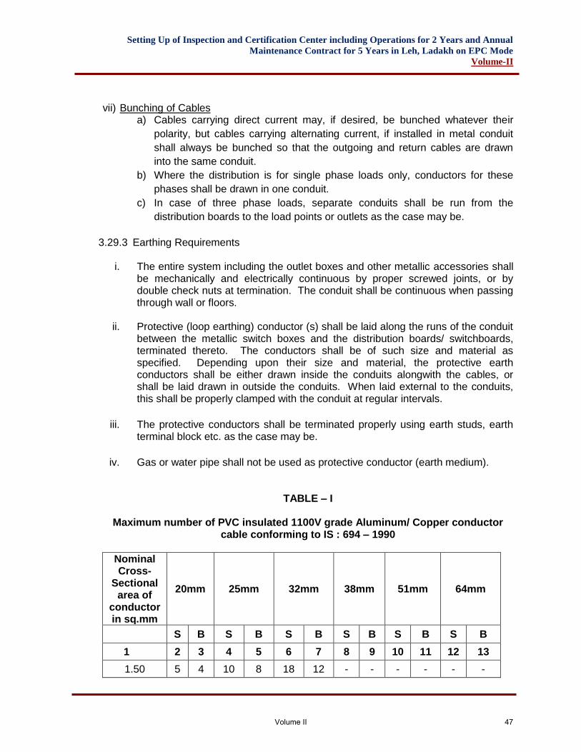
Setting Up of Inspection and Certification Center including Operations for 2 Years and Annual
Maintenance Contract for 5 Years in Leh, Ladakh on EPC Mode
Volume-II
vii) Bunching of Cables
a) Cables carrying direct current may, if desired, be bunched whatever their
polarity, but cables carrying alternating current, if installed in metal conduit
shall always be bunched so that the outgoing and return cables are drawn
into the same conduit.
b) Where the distribution is for single phase loads only, conductors for these
phases shall be drawn in one conduit.
c) In case of three phase loads, separate conduits shall be run from the
distribution boards to the load points or outlets as the case may be.
3.29.3 Earthing Requirements
i. The entire system including the outlet boxes and other metallic accessories shall be mechanically and electrically continuous by proper screwed joints, or by double check nuts at termination. The conduit shall be continuous when passing through wall or floors.
ii. Protective (loop earthing) conductor (s) shall be laid along the runs of the conduit between the metallic switch boxes and the distribution boards/ switchboards, terminated thereto. The conductors shall be of such size and material as specified. Depending upon their size and material, the protective earth conductors shall be either drawn inside the conduits alongwith the cables, or shall be laid drawn in outside the conduits. When laid external to the conduits, this shall be properly clamped with the conduit at regular intervals.
iii. The protective conductors shall be terminated properly using earth studs, earth terminal block etc. as the case may be.
iv. Gas or water pipe shall not be used as protective conductor (earth medium).
TABLE – I
Maximum number of PVC insulated 1100V grade Aluminum/ Copper conductor cable conforming to IS : 694 – 1990
Nominal Cross-
Sectional area of
conductor in sq.mm
20mm 25mm 32mm 38mm 51mm 64mm
S B S B S B S B S B S B
1 2 3 4 5 6 7 8 9 10 11 12 13
1.50 5 4 10 8 18 12 - - - - - -
Volume II 47
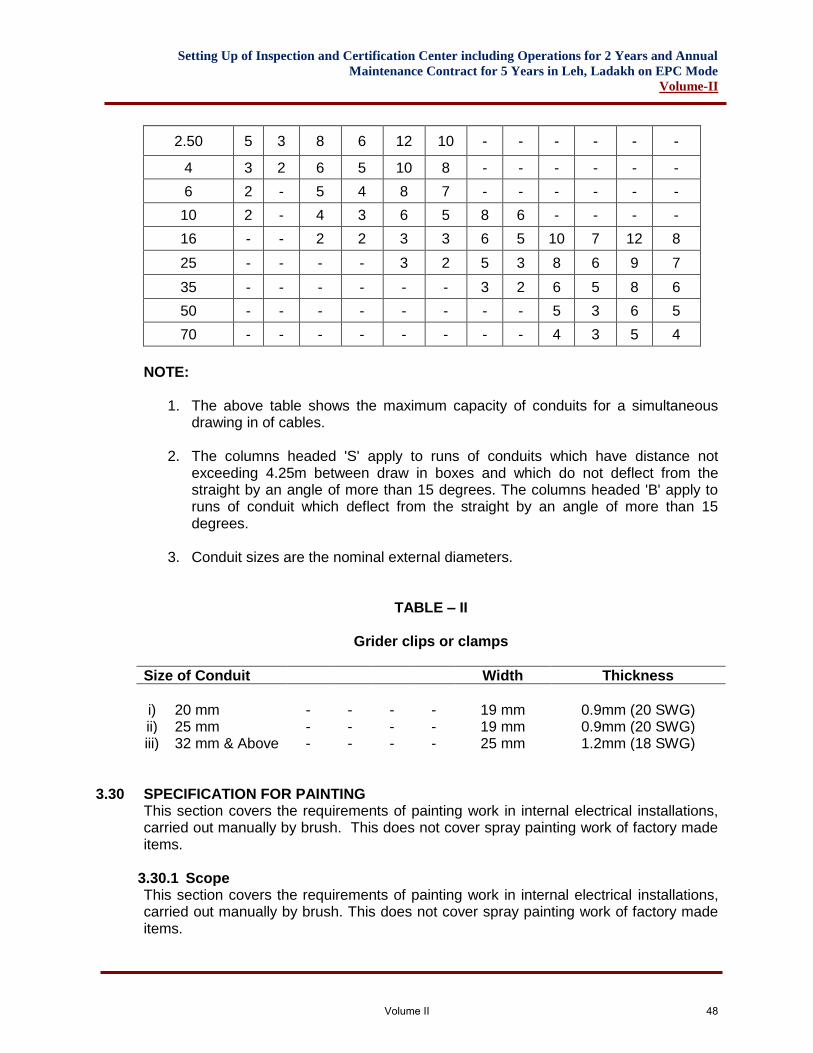
Setting Up of Inspection and Certification Center including Operations for 2 Years and Annual
Maintenance Contract for 5 Years in Leh, Ladakh on EPC Mode
Volume-II
2.50 5 3 8 6 12 10 - - - - - -
4 3 2 6 5 10 8 - - - - - -
6 2 - 5 4 8 7 - - - - - -
10 2 - 4 3 6 5 8 6 - - - -
16 - - 2 2 3 3 6 5 10 7 12 8
25 - - - - 3 2 5 3 8 6 9 7
35 - - - - - - 3 2 6 5 8 6
50 - - - - - - - - 5 3 6 5
70 - - - - - - - - 4 3 5 4
NOTE:
1. The above table shows the maximum capacity of conduits for a simultaneous drawing in of cables.
2. The columns headed 'S' apply to runs of conduits which have distance not exceeding 4.25m between draw in boxes and which do not deflect from the straight by an angle of more than 15 degrees. The columns headed 'B' apply to runs of conduit which deflect from the straight by an angle of more than 15 degrees.
3. Conduit sizes are the nominal external diameters.
TABLE – II
Grider clips or clamps
Size of Conduit Width Thickness
i)
20 mm
-
-
-
-
19 mm
0.9mm (20 SWG)
ii) 25 mm - - - - 19 mm 0.9mm (20 SWG) iii) 32 mm & Above - - - - 25 mm 1.2mm (18 SWG)
3.30 SPECIFICATION FOR PAINTING This section covers the requirements of painting work in internal electrical installations, carried out manually by brush. This does not cover spray painting work of factory made items.
3.30.1 Scope This section covers the requirements of painting work in internal electrical installations, carried out manually by brush. This does not cover spray painting work of factory made items.
Volume II 48
Setting Up of Inspection and Certification Center including Operations for 2 Years and Annual
Maintenance Contract for 5 Years in Leh, Ladakh on EPC Mode
Volume-II
3.30.2 Painting Work in General
3.30.3 Paints Paints, oils, vanishes etc. of approved make, in original tin to the satisfaction of the Engineer-In-Charge shall only be use.
3.30.4 Preparation of the surface The surface shall be thoroughly cleaned and made free from dust or foreign matter before painting is started. The proposed surface may be inspected by the Engineer-In-Charge before the paint is applied.
3.30.5 Application i. Paint shall be applied with brush. The paint shall be spread as smooth and even
as possible. Particular care shall be paid to rivets, nuts, bolts and over-lapping. Before drawing out in small containers, it shall be continuously stirred with a smooth stick, while painting work is taken up.
ii. Primary coat of anti-corrosive paint shall be given in the case of steel work, after preparation the surface. In all cases of painting work, finishing shall be with 2 coats of paint in approved shade.
iii. Each coat shall be allowed to dry out sufficiently before a subsequent coat is applied.
3.30.6 Precautions All furniture, fixture, glazing, floors etc. shall be protected by suitable covering. Al stains, smears splashing, dropping etc. shall be removed. While painting of wiring etc. it shall be ensured that the painting of wall and ceiling etc. is not spoiled in any way.
TESTING OF INSTALLATION
3.31 SCOPE This section describes the details of test to be conducted in the completed internal electrical installation, before commissioning.
3.32 GENERAL
3.32.1 Test On completion of installation, the following tests shall be carried out :-
i. Insulation resistance test. ii. Polarity test of switch. iii. Earth continuity test. iv. Earth electrode resistance test.
3.32.2 Witnessing of Tests Testing shall be carried out for the completed installations, in the presence of and to the satisfaction of the Engineer-In-Charge by the Contractor. All test results shall be recorded and submitted to the Department.
Volume II 49
Setting Up of Inspection and Certification Center including Operations for 2 Years and Annual
Maintenance Contract for 5 Years in Leh, Ladakh on EPC Mode
Volume-II
3.33 INSULATION RESISTANCE
The tests described below shall be made before the installation is permanently connected to the supply. For these tests large installations may be divided into groups of outlets, each containing not less than 50 outlets. For the purposes of this code the term ‘outlet’ includes every point and every switch except that a socket outlet, appliance or luminaire incorporating a switch is regarded as one outlet. The test voltage for insulation resistance measurement shall be 1000 V. When measured with all fuse links in place, all switches (including, if practicable, the main switch) closed and, all poles or phases of the wiring electrically connected together, the insulation resistance to earth shall be not less than 1 mega ohm. When measured between all the conductors connected to any one phase or pole of the supply and, in turn, all conductors connected to each other phase or pole the insulation resistance shall be not less than 1 mega ohm. Wherever practicable, so that all parts of the wiring may be tested, all lamps shall be removed and all current-using equipment shall be disconnected and all local switches controlling such lamps or other equipment shall be closed. Where the removal of lamps and/or the disconnection of current-using equipment is impracticable, the local switches controlling such lamps and/or equipment shall be open. Particular attention shall be given to the presence of electronic devices connected in the installation and such devices shall be isolated so that the test voltage does not damage them. Where equipment is disconnected for the tests prescribed above, and the equipment has exposed conductive parts required by these clauses to be connected to protective conductors, the insulation resistance between the exposed conductive parts and all live parts of the equipment shall be measured separately and shall comply with requirements of the appropriate Indian Standard and the insulation resistance shall not less than 0.5 megaohm.
3.34 POLARITY TEST OF SWITCH In a two wire installation, a test shall be made to verify that all the switches in every circuit have been fitted in the same conductor, throughout, and such conductor, shall be labeled or marked for connection to the phase conductor, or to the non-earthed conductors of the supply. In a three wire or a four wire installation, a test shall be made to verify that every non-linked single pole switch is fitted in a conductor which is labeled, or marked for connection to one of the phase conductors of the supply. The installation shall be connected to the supply for testing. The terminals of all switches shall be tested by a test lamp, one lead of which is connected to earth. Glowing of test lamp to its full brilliance, when the switch is in ‘ON’ position irrespective of appliance in position or not, shall indicate that the switch is connected to the right polarity.
3.35 TESTING OF EARTH CONTINUITY PATH
Volume II 50
Setting Up of Inspection and Certification Center including Operations for 2 Years and Annual
Maintenance Contract for 5 Years in Leh, Ladakh on EPC Mode
Volume-II
The earth continuity conductor, including metal conduits and metallic envelops of cables in all cases, shall be tested for electric continuity. The electrical resistance of the same alongwith the earthing lead, but excluding any added resistance, or earth leakage circuit breaker, measured from the connection with the earth electrode to any point in the earth continuity conductor in the completed installation shall not exceed one ohm.
3.36 MEASUREMENT OF EARTH ELECTRODE RESISTANCE Two auxiliary earth electrodes, besides the test electrode, are placed at suitable distance from the test electrode. A measured current is passed between the electrode ‘A’ to be tested and an auxiliary current electrode ‘C’ and the potential difference between the electrode ‘A’ and auxiliary potential ‘B’ is measured. The resistance of the test electrode ‘a’ is then given by R = V/I Where, R- Resistance of the test electrode in ohms V- Reading of the voltmeter in volts I- Reading of the ammeter in amps
3.36.1 i) Stray currents flowing in the soil may produce serious errors in the
measurement of earth resistance. To eliminate this, hand driven generator is used.
ii) If the frequency of the supply of hand driven generator coincides with the frequency of stray current, there will be wandering of instrument pointer. An increase or decrease of generator speed will cause this to disappear.
3.36.2 At the time of test, the test electrode shall be separated from the earthing system.
3.36.3 The auxiliary electrodes shall be of 13mm diameter mild steel rod driven upto 1 m into the ground.
3.36.4 All the three electrodes shall be so placed that they are independent of the resistance area of each other. If the test electrode is in the form of a rod, pipe or plate, the auxiliary current electrode C shall be placed at least 30 m away from it and the auxiliary potential electrode ‘B’ shall be placed mid-way between them.
3.36.5 Unless three consecutive readings of test electrode resistance agree, the test shall be repeated by increasing the distance between electrodes A and C upto 50 m, and each time placing the electrode B mid-way between them.
3.36.6 On these principles, “Megger Earth Tester” containing a direct reading ohm-meter, a hand driven generator and auxiliary electrodes are manufactured for direct reading of earth resistance of electrodes
Volume II 51
Setting Up of Inspection and Certification Center including Operations for 2 Years and Annual
Maintenance Contract for 5 Years in Leh, Ladakh on EPC Mode
Volume-II
3.37 TEST CERTIFICATE On completion of an electrical installation or an extension to an installation, a certificate shall be furnished by the Contractor, countersigned by the competent Engineer PMC Rep.
FORM OF COMPLETION CERTIFICATE
I/We certify that the installation detailed below has been installed by me/us and tested and that best of my/ our knowledge and belief it complies with Indian Electricity Rules 1956, as well as the Contract Specifications. Electrical Installation at ______________________________________ Voltage and system of supply _________________________________
TECHNICAL SPECIFICATION FOR DIESEL GENERATING SETS
3.38 GENERAL
This section deals with unloading procedures, location, standard capacities and climatic conditions for DG set installation to be followed /carried out by contractor.
• Unloading
• Location
• DG Sets with acoustic enclosure DG sets upto 1000 KVA capacity are required to be supplied with acoustic enclosure as per CPCB norms. DG set with acoustic enclosure shall be installed inside the building & location shall be finalized in consultation with the Engineer-in-charge. Associated AMF panel/Electrical panel of the DG set can be located inside the acoustic enclosure or outside the acoustic enclosure as per manufacturer standard. In case, AMF/Electrical panel has to be installed outside the acoustic enclosure, location of room to house AMF/Electrical panel should be decided in consultation with the Engineer-in-charge so that it shall be as near to the acoustic enclosure as possible. Specially, in case of connection through bus trunking, care should be taken for aesthetics.
• DG set with Acoustic enclosures are provided with lifting hooks.
• Climatic Conditions
The output of DG Set shall be specified in tender documents under following climatic conditions to be in conformity with CPCB approved type tests:
i. Outside Maximum Ambient Temperatures : Refer last 5 years min and max ii. Height above Mean Sea Level : 2500-3500 Meter iii. RH : 50%
Volume II 52
Setting Up of Inspection and Certification Center including Operations for 2 Years and Annual
Maintenance Contract for 5 Years in Leh, Ladakh on EPC Mode
Volume-II
3.39 DIESEL ENGINE
Scope: This section covers engine rating, standard components of a diesel engine including exhaust piping.
• Diesel Engine
• Engine Rating The engine shall be of standard design of the original manufacturers. It should be 4 stroke cycles, Radiator cooled, naturally aspirated/turbo charged (as per manufacturer standard), diesel engine developing suitable BHP for giving a power rating as per ISO 8528-Part-1 in KVA at the load terminals of alternator at 1500 rpm at ambient temperature of 40 Deg C, for height at 1000 Meter above MSL and at 50% RH. The engine shall be capable for delivering specified continuous Power rating at variable loads for PF of 0.8 lag with 10% overload available in excess of specified output for one hour in every 12 hours. The average load factor of the engine over period of 24 hours shall be 0.85 (85%) for continuous power output.
The engine shall conform to IS: 10000/IOS 3046/BS; 649/BS 5514 amended upto date.
• Necessary certificate indicating the compliance of the above capacity for the engine model so selected along with compliance of the above capacity requirement for the engine model so selected along with compliance of Noise and Emission norms as per latest CPCB guidelines for DG set capacity upto 1000 KVA, should be furnished from the manufacturers by successful tenderer.
• Te engine shall be fitted with following accessories subject to the design of the manufacturer: i. Dynamically balanced fly-wheel. ii. Necessary flexible coupling and guard for alternator and engine
(applicable only for double bearing alternator). iii. Air cleaner (dry/oil bath type) as per manufacturer standard. iv. A electronic governor to maintain engine speed at all conditions of load. v. Daily fuel service tank of minimum capacity as per table below,
fabricated from M.S. sheet with inlet, outlet connections air vent tap, drain plug and level indicator (gauge) M.S. fuel piping from tank to engine with valves, unions, reducers, flexible hose connection and floor mounting pedestals, twin fuel filters and fuel injectors. The location of the tank shall depend on standard manufacturers design.
TABLE – I
Recommended minimum capacity of daily fuel service tank
Sl. No. Capacity of DG set Minimum Fuel Tank Capacity
1. Upto 25 KVA 100 Litres
Volume II 53
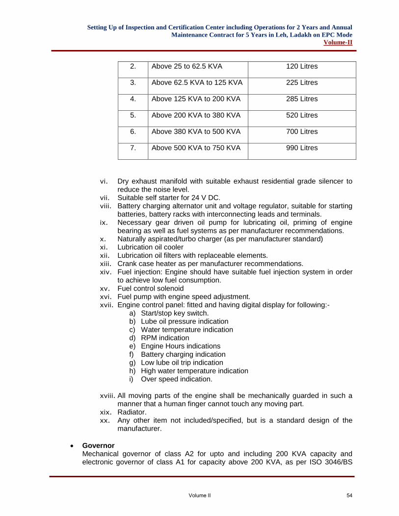
Setting Up of Inspection and Certification Center including Operations for 2 Years and Annual
Maintenance Contract for 5 Years in Leh, Ladakh on EPC Mode
Volume-II
vi. Dry exhaust manifold with suitable exhaust residential grade silencer to reduce the noise level.
vii. Suitable self starter for 24 V DC. viii. Battery charging alternator unit and voltage regulator, suitable for starting
batteries, battery racks with interconnecting leads and terminals. ix. Necessary gear driven oil pump for lubricating oil, priming of engine
bearing as well as fuel systems as per manufacturer recommendations. x. Naturally aspirated/turbo charger (as per manufacturer standard) xi. Lubrication oil cooler xii. Lubrication oil filters with replaceable elements. xiii. Crank case heater as per manufacturer recommendations. xiv. Fuel injection: Engine should have suitable fuel injection system in order
to achieve low fuel consumption. xv. Fuel control solenoid xvi. Fuel pump with engine speed adjustment. xvii. Engine control panel: fitted and having digital display for following:-
a) Start/stop key switch. b) Lube oil pressure indication c) Water temperature indication d) RPM indication e) Engine Hours indications f) Battery charging indication g) Low lube oil trip indication h) High water temperature indication i) Over speed indication.
xviii. All moving parts of the engine shall be mechanically guarded in such a
manner that a human finger cannot touch any moving part. xix. Radiator. xx. Any other item not included/specified, but is a standard design of the
manufacturer.
• Governor Mechanical governor of class A2 for upto and including 200 KVA capacity and electronic governor of class A1 for capacity above 200 KVA, as per ISO 3046/BS
2. Above 25 to 62.5 KVA 120 Litres
3. Above 62.5 KVA to 125 KVA 225 Litres
4. Above 125 KVA to 200 KVA 285 Litres
5. Above 200 KVA to 380 KVA 520 Litres
6. Above 380 KVA to 500 KVA 700 Litres
7. Above 500 KVA to 750 KVA 990 Litres
Volume II 54
Setting Up of Inspection and Certification Center including Operations for 2 Years and Annual
Maintenance Contract for 5 Years in Leh, Ladakh on EPC Mode
Volume-II
5514 wit actuator shall be provided as per standard design of manufacturer. Governor shall be a self-contained unit capable of monitoring speed.
• Frequency variation Te engine speed shall be so maintained that frequency variation at constant load including no load shall remain within a band of 1% rated frequency.
• Fuel System It shall be fed through engine driven fuel pump. A replaceable element of fuel filter shall be suitably located to permit easy servicing. The daily service tank shall be complete with necessary supports, gauges, connecting pipe work etc. In case of top mounted tanks, non return valves are must in fuel supply and return line. Pipe sealant should be used for sealing all connections. No Teflon tape is to be used. If piping length is more than 10 meters, detail engineering is required in consultation with OEM/Manufacturers.
• Lubricating oil system It shall be so designed that when the engine starts after a long suit down lubrication failure does not occur. Necessary priming pump for the lub. oil circuit as per recommendation of manufacturer shall be installed, to keep bearings primed. This pump shall be normally automatically operative on AC/DC supply available with the set.
• Starting system This shall comprise of necessary set of heavy duty batteries 12V/24V DG (as per manufacturer standard), and suitable starter motors and axial type gear to match with the toothed ring on the fly wheel. A timer in the control panel to protect the starter motor from excessively long cranking runs shall be suitably integrated with the engine protection system and shall be included within the scope of the work. Battery capacity shall be suitable for meeting the needs of starting system (as three attempt starting), as well as the requirements of control panel, indications and auxiliaries such as priming pump as applicable etc. The scope shall cover all cabling, terminals, including initial charging etc. The system shall be capable of starting the DG set within 10 seconds, even in winter condition with an ambient temperature down to 0 deg. C.
• Battery Charger The battery charger shall be suitable to charge required numbers of batteries at 24 Volts complete with, transformer, rectifier, charge rate selector switch, indicating ammeter & voltmeter etc. Connections between the battery charger & batteries shall be provided with suitable copper leads with lugs etc.
• Piping Work All pipe lines, fittings and accessories requirement inside the room/enclosure and outside for exhaust piping shall be provided by the contractor. This shall include necessary flexible pieces in the exhaust, fuel, lub. Oil and water lines as are necessary in view of the vibration isolation requirement in the installation. Piping of adequate size shall be used for lub. Oil of the material as per manufacturer standard. However, only M.S. pipes for the exhaust and fuel oil line shall be used. The pipe
Volume II 55
Setting Up of Inspection and Certification Center including Operations for 2 Years and Annual
Maintenance Contract for 5 Years in Leh, Ladakh on EPC Mode
Volume-II
work shall be inclusive of all fittings and accessories required such as bends, reducers, elbows, flanges, flexible connections, necessary hardware etc. The installation shall cover clamps, supports, hangers etc. as are necessary for completing the work. However, the work shall be sectionalized with flanged connections as are necessary for easy isolation for purposes for maintenance of unit as approved by Engineer-in-charge.
• Common bed plate Engine and alternator shall be coupled by means of flexoplate/ flexible coupling as per manufacturer standard design and both units shall be mounted on a common bed plate together with all auxiliaries to ensure perfect alignment of engine and alternator with minimum vibrations. The bed plate shall be suitable for installation on suitable anti-vibration mounting system.
3.40 EXHAUST SYSTEM
• Exhaust piping. All M.S. Pipes for exhaust line shall be conforming to relevant IS. The runs forming part of factory assembly on the engine flexible connections upto exhaust silencer shall be exclusive of exhaust piping item. The work includes necessary cladding of exhaust pipe work using 50mm thick glass wool/mineral wool/rockwool, density not less than 46 kg/m sq. and Aluminum cladding (0.80mm thick) for the complete portion. The exhaust pipe work includes necessary supports, foundation etc. to avoid any load & stress on turbo charger/exhaust piping. The exhaust pipe support structure shall be got approved by engineer-in-charge before execution.
a) Exhaust system should create minimum back pressure. b) Number of bends should be kept minimum and smooth bends should be used to
minimize back pressure. c) Pipe sleeve of larger dia should be used while passing the pipe through concrete
wall & gap should be filled with felt lining. d) Exhaust piping inside the Acoustic Enclosure/Genset room should be lagged with
asbestos rope along with Aluminum sheet cladding to avoid heat input to the room.
e) Exhaust flexible shall have it’s free length when it is installed. For bigger engines, two flexible bellows can be used.
f) For engines upto 500 KVA, only one bellow is required. However, if exhaust pipe length is more than 7m, then additional bellow/provision for expansion should be provided.
g) Class B MS pipes and long bend/elbows should be used. h) The exhaust outlet should be in the direction of prevailing winds and should not
allow exhaust gases to enter air inlet/windows etc. i) When tail end is horizontal, 45 Degree downward cut should be given at the end
of the pipe to avoid rain water entry into exhaust piping. j) When tail end is vertical, there should be rain trap to avoid rain water entry. If rain
cap is used, the distance between exhaust pipe and rain cap should be higher than diameter of pipe. Horizontal run of exhaust piping should slope downwards away from engine to the condensate trap. Silencer should be installed with drain plug at bottom.
Volume II 56
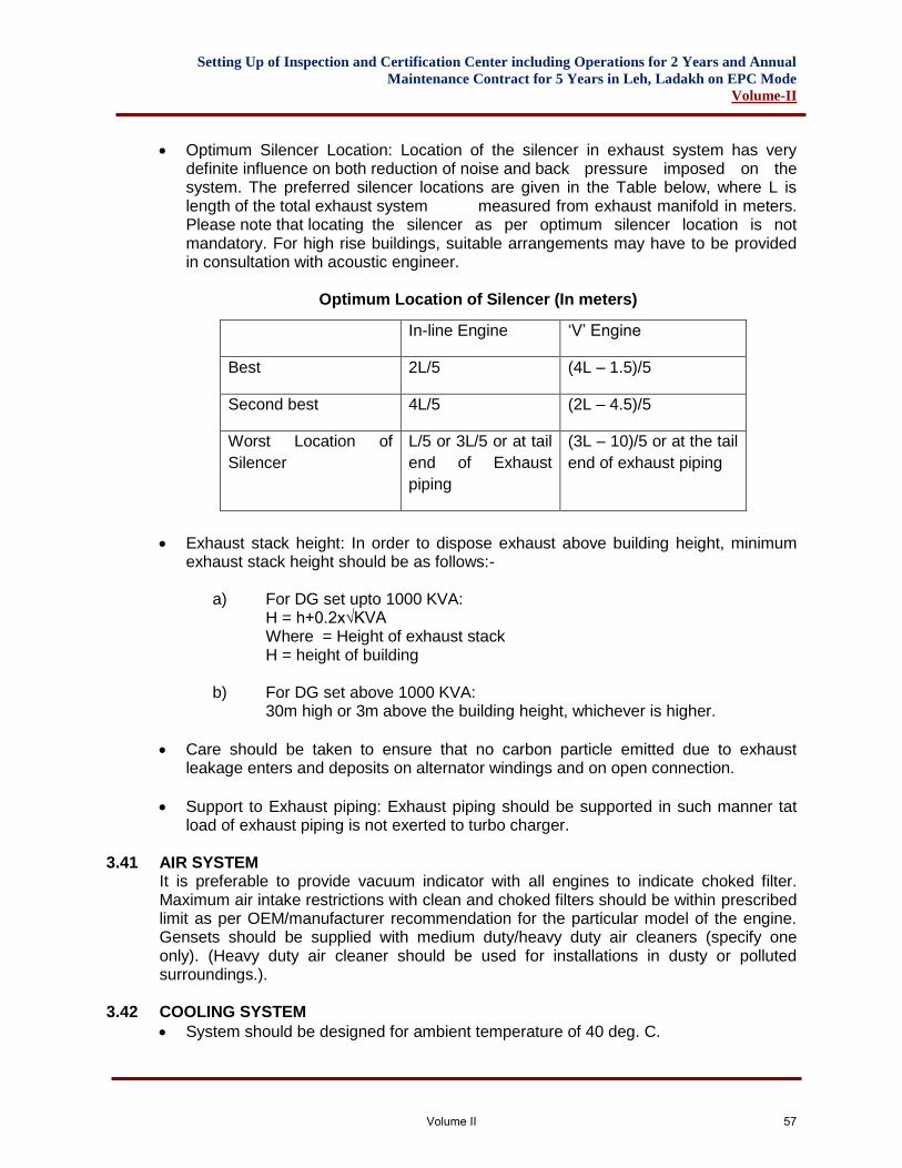
Setting Up of Inspection and Certification Center including Operations for 2 Years and Annual
Maintenance Contract for 5 Years in Leh, Ladakh on EPC Mode
Volume-II
• Optimum Silencer Location: Location of the silencer in exhaust system has very definite influence on both reduction of noise and back pressure imposed on the system. The preferred silencer locations are given in the Table below, where L is length of the total exhaust system measured from exhaust manifold in meters. Please note that locating the silencer as per optimum silencer location is not mandatory. For high rise buildings, suitable arrangements may have to be provided in consultation with acoustic engineer.
Optimum Location of Silencer (In meters)
• Exhaust stack height: In order to dispose exhaust above building height, minimum exhaust stack height should be as follows:-
a) For DG set upto 1000 KVA: H = h+0.2x√KVA Where = Height of exhaust stack H = height of building
b) For DG set above 1000 KVA:
30m high or 3m above the building height, whichever is higher.
• Care should be taken to ensure that no carbon particle emitted due to exhaust leakage enters and deposits on alternator windings and on open connection.
• Support to Exhaust piping: Exhaust piping should be supported in such manner tat load of exhaust piping is not exerted to turbo charger.
3.41 AIR SYSTEM It is preferable to provide vacuum indicator with all engines to indicate choked filter. Maximum air intake restrictions with clean and choked filters should be within prescribed limit as per OEM/manufacturer recommendation for the particular model of the engine. Gensets should be supplied with medium duty/heavy duty air cleaners (specify one only). (Heavy duty air cleaner should be used for installations in dusty or polluted surroundings.).
3.42 COOLING SYSTEM
• System should be designed for ambient temperature of 40 deg. C.
In-line Engine ‘V’ Engine
Best 2L/5 (4L – 1.5)/5
Second best 4L/5 (2L – 4.5)/5
Worst Location of
Silencer
L/5 or 3L/5 or at tail
end of Exhaust
piping
(3L – 10)/5 or at the tail
end of exhaust piping
Volume II 57
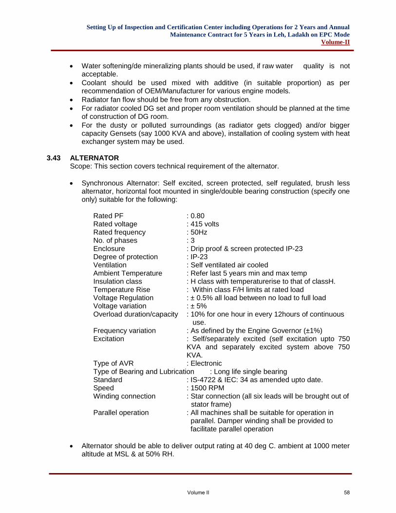
Setting Up of Inspection and Certification Center including Operations for 2 Years and Annual
Maintenance Contract for 5 Years in Leh, Ladakh on EPC Mode
Volume-II
• Water softening/de mineralizing plants should be used, if raw water quality is not acceptable.
• Coolant should be used mixed with additive (in suitable proportion) as per recommendation of OEM/Manufacturer for various engine models.
• Radiator fan flow should be free from any obstruction.
• For radiator cooled DG set and proper room ventilation should be planned at the time of construction of DG room.
• For the dusty or polluted surroundings (as radiator gets clogged) and/or bigger capacity Gensets (say 1000 KVA and above), installation of cooling system with heat exchanger system may be used.
3.43 ALTERNATOR Scope: This section covers technical requirement of the alternator.
• Synchronous Alternator: Self excited, screen protected, self regulated, brush less alternator, horizontal foot mounted in single/double bearing construction (specify one only) suitable for the following:
Rated PF : 0.80 Rated voltage : 415 volts Rated frequency : 50Hz No. of phases : 3 Enclosure : Drip proof & screen protected IP-23 Degree of protection : IP-23 Ventilation : Self ventilated air cooled Ambient Temperature : Refer last 5 years min and max temp Insulation class : H class with temperaturerise to that of classH. Temperature Rise : Within class F/H limits at rated load Voltage Regulation : ± 0.5% all load between no load to full load Voltage variation : ± 5% Overload duration/capacity : 10% for one hour in every 12hours of continuous use. Frequency variation : As defined by the Engine Governor (±1%)
Excitation : Self/separately excited (self excitation upto 750 KVA and separately excited system above 750 KVA.
Type of AVR : Electronic Type of Bearing and Lubrication : Long life single bearing Standard : IS-4722 & IEC: 34 as amended upto date. Speed : 1500 RPM
Winding connection : Star connection (all six leads will be brought out of stator frame)
Parallel operation : All machines shall be suitable for operation in parallel. Damper winding shall be provided to facilitate parallel operation
• Alternator should be able to deliver output rating at 40 deg C. ambient at 1000 meter altitude at MSL & at 50% RH.
Volume II 58
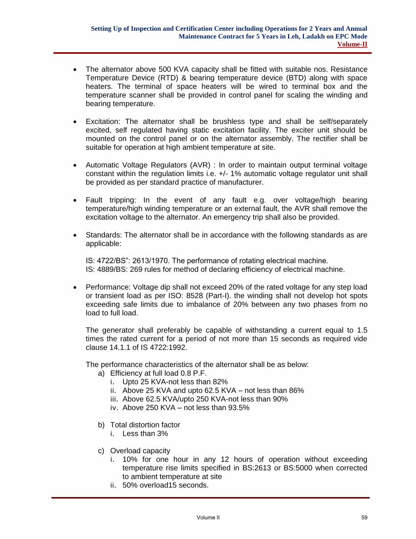
Setting Up of Inspection and Certification Center including Operations for 2 Years and Annual
Maintenance Contract for 5 Years in Leh, Ladakh on EPC Mode
Volume-II
• The alternator above 500 KVA capacity shall be fitted with suitable nos. Resistance Temperature Device (RTD) & bearing temperature device (BTD) along with space heaters. The terminal of space heaters will be wired to terminal box and the temperature scanner shall be provided in control panel for scaling the winding and bearing temperature.
• Excitation: The alternator shall be brushless type and shall be self/separately excited, self regulated having static excitation facility. The exciter unit should be mounted on the control panel or on the alternator assembly. The rectifier shall be suitable for operation at high ambient temperature at site.
• Automatic Voltage Regulators (AVR) : In order to maintain output terminal voltage constant within the regulation limits i.e. +/- 1% automatic voltage regulator unit shall be provided as per standard practice of manufacturer.
• Fault tripping: In the event of any fault e.g. over voltage/high bearing temperature/high winding temperature or an external fault, the AVR shall remove the excitation voltage to the alternator. An emergency trip shall also be provided.
• Standards: The alternator shall be in accordance with the following standards as are applicable:
IS: 4722/BS”: 2613/1970. The performance of rotating electrical machine. IS: 4889/BS: 269 rules for method of declaring efficiency of electrical machine.
• Performance: Voltage dip shall not exceed 20% of the rated voltage for any step load or transient load as per ISO: 8528 (Part-I). the winding shall not develop hot spots exceeding safe limits due to imbalance of 20% between any two phases from no load to full load.
The generator shall preferably be capable of withstanding a current equal to 1.5 times the rated current for a period of not more than 15 seconds as required vide clause 14.1.1 of IS 4722:1992.
The performance characteristics of the alternator shall be as below:
a) Efficiency at full load 0.8 P.F. i. Upto 25 KVA-not less than 82% ii. Above 25 KVA and upto 62.5 KVA – not less than 86% iii. Above 62.5 KVA/upto 250 KVA-not less than 90% iv. Above 250 KVA – not less than 93.5%
b) Total distortion factor i. Less than 3%
c) Overload capacity i. 10% for one hour in any 12 hours of operation without exceeding
temperature rise limits specified in BS:2613 or BS:5000 when corrected to ambient temperature at site
ii. 50% overload15 seconds.
Volume II 59
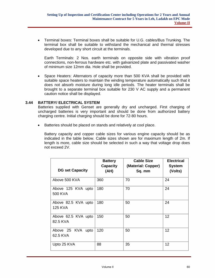
Setting Up of Inspection and Certification Center including Operations for 2 Years and Annual
Maintenance Contract for 5 Years in Leh, Ladakh on EPC Mode
Volume-II
• Terminal boxes: Terminal boxes shall be suitable for U.G. cables/Bus Trunking. The terminal box shall be suitable to withstand the mechanical and thermal stresses developed due to any short circuit at the terminals.
Earth Terminals: 2 Nos. earth terminals on opposite side with vibration proof connections, non-ferrous hardware etc. with galvanized plate and passivated washer of minimum size 12mm dia. Hole shall be provided.
• Space Heaters: Alternators of capacity more than 500 KVA shall be provided with suitable space heaters to maintain the winding temperature automatically such that it does not absorb moisture during long idle periods. The heater terminals shall be brought to a separate terminal box suitable for 230 V AC supply and a permanent caution notice shall be displayed.
3.44 BATTERY/ ELECTRICAL SYSTEM
Batteries supplied with Genset are generally dry and uncharged. First charging of uncharged batteries is very important and should be done from authorized battery charging centre. Initial charging should be done for 72-80 hours.
• Batteries should be placed on stands and relatively at cool place.
Battery capacity and copper cable sizes for various engine capacity should be as indicated in the table below. Cable sizes shown are for maximum length of 2m. If length is more, cable size should be selected in such a way that voltage drop does not exceed 2V.
DG set Capacity
Battery
Capacity
(AH)
Cable Size
(Material: Copper)
Sq. mm
Electrical
System
(Volts)
Above 500 KVA 360 70 24
Above 125 KVA upto
500 KVA
180 70 24
Above 82.5 KVA upto
125 KVA
180 50 24
Above 62.5 KVA upto
82.5 KVA
150 50 12
Above 25 KVA upto
62.5 KVA
120 50 12
Upto 25 KVA 88 35 12
Volume II 60
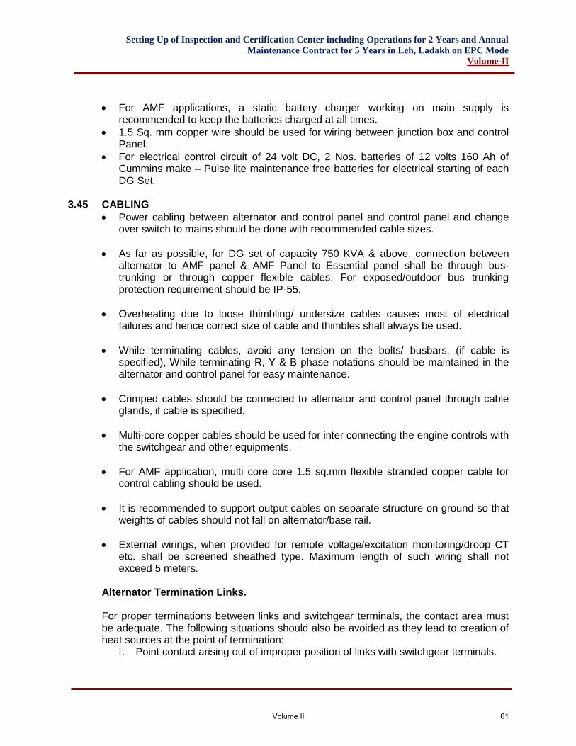
Setting Up of Inspection and Certification Center including Operations for 2 Years and Annual
Maintenance Contract for 5 Years in Leh, Ladakh on EPC Mode
Volume-II
• For AMF applications, a static battery charger working on main supply is recommended to keep the batteries charged at all times.
• 1.5 Sq. mm copper wire should be used for wiring between junction box and control Panel.
• For electrical control circuit of 24 volt DC, 2 Nos. batteries of 12 volts 160 Ah of Cummins make – Pulse lite maintenance free batteries for electrical starting of each DG Set.
3.45 CABLING
• Power cabling between alternator and control panel and control panel and change over switch to mains should be done with recommended cable sizes.
• As far as possible, for DG set of capacity 750 KVA & above, connection between alternator to AMF panel & AMF Panel to Essential panel shall be through bus-trunking or through copper flexible cables. For exposed/outdoor bus trunking protection requirement should be IP-55.
• Overheating due to loose thimbling/ undersize cables causes most of electrical failures and hence correct size of cable and thimbles shall always be used.
• While terminating cables, avoid any tension on the bolts/ busbars. (if cable is specified), While terminating R, Y & B phase notations should be maintained in the alternator and control panel for easy maintenance.
• Crimped cables should be connected to alternator and control panel through cable glands, if cable is specified.
• Multi-core copper cables should be used for inter connecting the engine controls with the switchgear and other equipments.
• For AMF application, multi core core 1.5 sq.mm flexible stranded copper cable for control cabling should be used.
• It is recommended to support output cables on separate structure on ground so that weights of cables should not fall on alternator/base rail.
• External wirings, when provided for remote voltage/excitation monitoring/droop CT etc. shall be screened sheathed type. Maximum length of such wiring shall not exceed 5 meters.
Alternator Termination Links. For proper terminations between links and switchgear terminals, the contact area must be adequate. The following situations should also be avoided as they lead to creation of heat sources at the point of termination: i. Point contact arising out of improper position of links with switchgear terminals.
Volume II 61
Setting Up of Inspection and Certification Center including Operations for 2 Years and Annual
Maintenance Contract for 5 Years in Leh, Ladakh on EPC Mode
Volume-II
ii. Gaps between busbars/links and terminals being remedied by connecting bolt / stud In such
iii. cases the bolt will carry the load current. Normally these bolts/studs are made of MS and hence are not designed to carry currents.
Adequate clearance between bus bars/ links at terminals should be maintained (IS: 4232 may be referred to for guidelines). Improper termination will lead to local heat generation which may lead to failure.
3.46 FOUNDATION Genset with acoustic enclosure: A PCC foundation (1:2;4, M-20 grade) of approximate depth of 300mm is required so as to provide leveled surface for placement of the acoustic enclosure. About 150mm foundation height shall be above ground level and shall be provided by contractor. The length and breadth of foundation shall be at least 250mm more than the size of the enclosure. Genset shall be mounted on AVM’s inside the enclosure. In case manufacturer’s recommendations require more depth/ width etc than manufacturers recommendation shall be followed.
3.47 ACOUSTIC ENCLOSURE As per CPCB norms, restriction has been imposed for new DG sets upto 1000 KVA for noise level. Therefore, in terms of these norms, acoustic enclosure should be type tested at the climatic conditions specified in para 1.1.4 through one of the authorized laboratory.
3.47.1 Installation Acoustic enclosures are supplied with built in Anti Vibration Mountings (AVMs). As such Genset can be installed directly on the leveled surface. Exhaust piping outlet should not be turned towards window/ventilator of home or occupied building. Provision of rain cap should be ensured. The acoustic enclosure placement should be such that there is no restriction in front of air inlet and outlet from canopy Service Accessibility
a) Genset / Engine control panel should be visible from outside the enclosure. b) Routine/periodical check on engine/alternator (filter replacement and tappet
setting etc.) should be possible without dismantling acoustic enclosure. c) For major repairs/overhaul, it may be required to dismantle the acoustic
enclosure. d) Sufficient space should be available around the Genset for inspection and
service.
3.47.2 General Design Guidelines.
a) To avoid re-circulation of hot air, durable sealing between radiator and canopy is must.
Volume II 62
Setting Up of Inspection and Certification Center including Operations for 2 Years and Annual
Maintenance Contract for 5 Years in Leh, Ladakh on EPC Mode
Volume-II
b) Exhaust piping inside the enclosure must be lagged (except bellow). c) Temperature rise inside the enclosure should not be more than 5 deg. C for
maximum ambient above 40 deg C and it should be below 10 deg C for ambient below 40 deg. C.
d) There should be provision for oil, coolant drain and fill. Fuel tank should have provision for cleaning.
3.47.3 Specifications for Acoustic Enclosure The acoustic enclosure shall be designed and manufactured confirming to relevant standards suitable for outdoor installation exposed to weather conditions, and to limit overall noise level to 75 dB (A) at a distance of 1 mtr. from the enclosure as per upto date CPCB norms under free field conditions. The construction should be such that it prevents entry of rain water splashing into the enclosure and allow free & quick flow of rain water to the ground in the event of heavy rain. The detailed construction shall confirm to the details as under. The enclosure shall be fabricated out of the CRCA sheet of thickness not less than 1.6mm on the outside cover with inside cover having not less than 0.6mm thick perforated powder coated CRCA sheet. The hinged doors shall be made from not less than 16 SWG (1.6mm) thick CRCA sheet and will be made air tight with neoprene rubber gasket and heavy duty locks. All sheet metal parts should be processed through 7-tank process. The enclosure should be powder coated. The batteries should be accommodated in the enclosure in battery rack. The canopy should be provided with high enclosure temperature safety device. The acoustic lining should be made up of high quality insulation material i.e. glass/mineral wool of minimum 50mm thickness upto 500 KVA capacity and 100mm above 500 KVA capacity and 75 kg/cubic metre to 100 kg/cubic meter for sound absorption as per standard design of manufacturer’s to reduce the sound level as per CPCB norms. The insulation material shall be covered with fine glass fiber cloth and would be supported by perforated M.S. Sheet duly powder coated. The enclosure shall be provided with suitable size and No. of hinged type doors along the length of the enclosure on each side for each access inside the acoustic enclosure for inspection, operation and maintenance purpose. Sufficient space will be provided inside the enclosure on all sides of the DG set for inspection, easy maintenance and repairs. The canopy should be as compact as possible with good aesthetic look. The complete enclosure shall be of modular construction.
Volume II 63
Setting Up of Inspection and Certification Center including Operations for 2 Years and Annual
Maintenance Contract for 5 Years in Leh, Ladakh on EPC Mode
Volume-II
The forced ventilation shall be as per manufacturer design using either engine radiator fan or additional blower fan(s). If the acoustic enclosure is to be provided with forced ventilation then suitable size of axial flow fan (with motor and auto-start arrangement) and suitable size axial flow exhaust fan to take the hot air from the enclosure complete with necessary motors and auto start arrangement should be provided. The forced ventilation arrangement should be provided with auto stop arrangement to stop after 5 minutes of the stopping of DG sets. The acoustic enclosure should be suitable for cable connection/connection through bus-trunking. Such arrangements on acoustic enclosure should be water proof and dust-[proof conforming to IP-65 protection.
3.48 INSPECTION AND TESTING
The successful tenderer will arrange staff/fuel/POL for test run at his cost. Inspection and Testing of DG sets of capacity more than 200 KVA For DG sets of capacity more than 200 KVA, testing shall necessarily be carried out at factory/ manufacture premises in presence of representative of the Department. For testing, following procedure will be followed: All major items/ equipments i.e. engine & alternator in assembled condition, associated electrical control panels etc. shall be offered for inspection and testing at factory/ manufacturers works. The successful tenderer shall give a notice of minimum two weeks for carrying out such tests. The Engineer-in-charge / or his authorized representative shall witness such inspection & testing at mutually agreed date. The cost of the representative’s visit to the factory will be borne by the Department. The department also reserves the right to inspect the fabrication job at factory and the successful tenderer has to make arrangement for the same. DG set will be tested on load of unity power for the rated KW rating. During testing, each of the DG sets covered under scope of work, shall be operated for a period of 2 hours on the rated KW at DG set’s KW rating including one hour on 10% overload after continuous run of the 2 hours. During testing all controls/operations safeties will be checked and proper record will be maintained. Any defect/ abnormality noticed during testing shall be rectified. The testing will be declared successful only when no abnormality/ failure is noticed during the testing. The DG set will be cleared for dispatch to site only when the testing is declared successful by authorized representative/ Engineer-in-charge.
3.48.1 Site Trial Run/ Running-in-Period After successful testing of the DG set, a trial run at available load will be carried out for 18 Hours (6 hrs each day). The DG set will be operated and a log of all relevant parameters will be maintained during this period. The arrangement of staff for trial run/
Volume II 64
Setting Up of Inspection and Certification Center including Operations for 2 Years and Annual
Maintenance Contract for 5 Years in Leh, Ladakh on EPC Mode
Volume-II
running in period will be made by the successful tenderer. However, diesel shall be provided by the successful tenerer. The cost of diesel shall be reimbursed by AAI on production of documentary evidence. The contractor will be free to carry out necessary adjustments. The DG set will be said to have successfully completed the trial run, if no break down or abnormal/ unsatisfactory operation of any component of the entire installation included in the scope of work of the contractor, occurs during this period. After this the DG set will be made available for beneficial use. After the DG set has operated without any major break down/trouble, it shall be taken over by the department subject to guarantee clause of this contract. This date of taking over of the DG set, after trouble free operation during the trial run/ running-in period, shall be the date of acceptance/ taking over.
TECHNICAL SPECIFICATIONS FOR EXTERNAL ELECTRICAL INSTALLATION & ALLIED WORKD
3.49 GENERAL The electrical Installation work shall be carried out in accordance with Indian Standard Code of Practice. It shall also be in conformity with the current Indian Electricity rules and regulations and requirements of the Local Electricity Supply Authority and Fire Insurance regulations, so far as these become applicable to the installation. Electrical work in general shall be carried out as per following CPWD Specifications amended upto date. General Specifications for Electrical Works. - Part -I - Internal Work - 2005. - Part -II - External Work - 2007. - Part -IV - Substation Work - 2007. Wherever this specifications calls for a higher standard of material and or workmanship than those required by any of the above mentions regulations and specification then the specification here under shall take precedence over the said regulations and standards. The details of scope of work subhead wise are given in the subsequent paras. The quantities worked out in schedule of quantities are based on particular equipment considered at design stage. The contractor is required to recheck the quantities based on equipment offered by him to achieve required parameters.
3.50 SPECIFICATION FOR TWO POLE STRUCTURE 3.51 TWO POLE STRUCTURE
Two pole structures shall be as per standards and complete with foundation material. This shall include gang operated 3-pole 400 Amp. Isolators, cross arms, drop out fuses, lightning arrestors, strain type insulators, flexible jumpers, outdoor type cable and terminations, meter box etc. All steel structures shall be rigid in construction and
Volume II 65

Setting Up of Inspection and Certification Center including Operations for 2 Years and Annual
Maintenance Contract for 5 Years in Leh, Ladakh on EPC Mode
Volume-II
complete with G.I. Anti-climbing device etc. to the satisfaction of the Department. Stays shall normally consist of 1800 mm long 19mm GI stay rod, 300 x 300 x 6 mm anchor plate, 7/8 SWG galvanized stay wire. Double stay shall be provided dead ends and supported over a 150 mm thick concrete bed. Erected pole shall be encased in 700 x 700 x 1500 mm concrete block below ground. Red enameled danger/caution plates of approved type shall be provided on each structure. All structures shall be painted with two coats of Aluminum paint over a base coat of red oxide primer. Before applying primer coat, the metal surface shall be thoroughly cleaned and degreased to remove mill scale, rust, grease and dirt.
3.51.1 Erection of Poles The steel Pole shall be erected using cement concrete foundation. All steel Pole shall be erected over a Cement Concrete 1:2:4 (1 cement:2 coarse sand:4 graded stone aggregate of 40 mm nominal size) bed of 15 cm thick either cast at site or pre-cast and laid in excavated pit. The area of this concrete bed shall be 0.5 m2 for steel Pole. All metal supports and steel. Pole of overhead lines and metallic fittings attached there to shall be permanently and efficiently earthed and for this purpose a continuous earth wire shall be run and in case of steel. Poles all insulator brackets, cross arms, stays and all other metallic fittings shall be bonded to the continuous earth wire.
3.52 ANTI-CLIMBING DEVICE Necessary arrangement for preventing unauthorized persons from ascending any of the supports carrying H.V. Lines without the aid of a ladder or special appliances shall be made as directed by the Engineer-in-Charge. Unless otherwise specified, barbed wire conforming to IS-278-1969 having 4 point barbs spaced 75+ 12mm apart and weighting 108/125 gm/mtr. shall be wrapped helically with a pitch of 75mm around the limb of the support and tide firmly commencing from a height of 3.5 mtr. and up to a height of 5 or 6 mtr. as directed by the Engineer-in-charge. All bolts, nuts and washers for complete work should be of hot dip G.I. All structures shall be painted with two coats of aluminum paint over a base coat of red oxide primer. Before applying primer coat, the metal surface shall be thoroughly cleaned and degreased to remove scale rust, grease and dirt.
3.53 OUTDOOR CABLE END TERMINATION The outdoor cable end termination shall be resin cast heat Shrinkable type complete
with mould spacers etc. as required. The end termination shall be supported on the 2
pole structure with the help of necessary clamps. The termination shall be suitable for
the cables mentioned in the schedule of quantities. The manufactures instruction shall
be followed while doing the termination.
3.54 AIR BREAK SWITCH Air break switches shall be of triple pole 400 A manually gang operated, suitable for
mounting on a two pole structure. The air breaker switches shall be vertical tilting type.
Volume II 66
Setting Up of Inspection and Certification Center including Operations for 2 Years and Annual
Maintenance Contract for 5 Years in Leh, Ladakh on EPC Mode
Volume-II
The switch shall be capable of operating through a system of levers and rods by a single
person standing on ground. It shall be capable of being padlocked in open and close
positions. Expansion type terminal connectors shall be provided at each end for
connecting switch terminal to standard ACSR leads as required. Switch shall be
provided with arcing horns of ample section and approved shape. All the iron and steel
parts shall be hot dip galvanized.
3.55 INSULATORS Strain insulators shall be suitable for system voltage made from high grade porcelain
and shall be uniformly brown glazed. The porcelain shall be homogenous, free from
laminations, cavities and other flaws or imperfections that might affect the mechanical or
dielectric quality and shall be thoroughly vitrified, tough and impervious to moisture when
operated at nominal rated voltage, there shall be no electric discharge which would
cause erosion or injury to conductors, insulators or supports by the formation of
substances produced by chemical action. The hardware’s shall be hot dip galvanized the
insulator design shall conform to IS 2486, 731, 2544. Strain insulators shall consist of
standard discs and shall be ball and socket type.
3.56 DROP OUT FUSES The unit shall be single pole outdoor type, adequately rated to provide full protection to
the connected load. It shall be provided with suitable attachments to the insulators for
holding in tension the fuse element which is carried between top and bottom contacts
inside an insulated tube. The fuse shall be held in the latched position while the element
is intact and shall open and shall switch down automatically after the blowing off the fuse
due to the release of tension in the fuse element. Necessary operating rod of adequate
length shall be supplied having brass earthing chain with a crocodile clip rod which
should provide adequate protection for safe operation at rated voltage. All hardware
shall be hot dip galvanized.
3.57 STAY/ STRUT
3.57.1 Stay A stay set shall consist of stay rod, anchor plate, bow tightner or turn buckle, thimbles,
stay wire and strain insulator. The stay rod shall be with stay grip in case turn buckle is
used instead of bow tightner. The entire stay assembly shall be galvanized. The stay
wire shall be either 7/4.00 mm dia. or 7/3.15 mm dia G.I as specified in the contract
conforming to IS 2141 - 1968 grades 2. The anchor plate shall be of MS galvanized and
not less than 30 cm x 30 cm x 6.4 mm thick and the size of stay rod shall be not less
than 1.80 m (6 ft.) long and 19mm dia.
3.57.2 Strut A strut shall generally consist of a pole of the same section which it supports or slightly
lighter as specified in the contract.
Volume II 67
Setting Up of Inspection and Certification Center including Operations for 2 Years and Annual
Maintenance Contract for 5 Years in Leh, Ladakh on EPC Mode
Volume-II
3.58 INSULATOR The porcelain insulator shall conform to IS 1445-1966 suitable for overhead power lines
below 1000 volts and IS 731-1971 for overhead power lines with a nominal voltage
greater than 1000 volts. This shall be vitreous throughout and non-absorbent. The
exposed surface shall be glazed. Insulator shall have adequate mechanical strength,
high degree of resistance to electrical puncture and resistance to climatic and
atmospheric attack.
The of shackle insulator shall be 90 mm dia. x 75 mm high as per item of work.
The size of pin insulator shall be 65mm dia. x 100mm high. The pin insulator shall be
suitable for 12mm cordeau thread and shall be complete with G.I. pin, nuts and washers.
TECHNICAL SPECIFICATION FOR H.T.CABLE
3.59 H.T. CABLES
3.60 CONSTRUCTION
All H.T. Cables shall be of 11 KV grade 3 Core XLPE insulated Aluminum Conductor
armoured U.G Cables with electrical purity Aluminum conductor, shall be manufactured
& tested in accordance with IS : 7098 (Part II). H.T. Cable shall be of earthed, grade
and shall be of stranded construction, comply to IS 8130. The conductor screen &
insulation screen shall both be of extruded semi conducting compound and shall be
applied along with XLPE insulation in a single operation of triple extrusion process so as
to obtain continuously smooth interphase. The metallic screen of each core shall consist
of copper wires or tape. The method of curing shall be dry curing/ gas curing / steam
curing. Metallic screen shall be suitable for carrying the fault current of minimum 26.2KA
for one second. Outer sheath shall be of tough, PVC compound as per IS: 5831 and
shall be extruded over the armouring. Cables shall be tested for type tested & routine
tested in accordance with IS: 7098 (Part II). Laying of H.T. Cable shall be with all
required accessories and shall deemed to be included in quoted laying rate of cable.
3.61 TERMINATION JOINTS
Terminal joints shall be carried out inside the cable end boxes fixed on the equipment.
Lugs shall be fitted by the means of bolts and nuts with the terminal studs. On the
glands, armour of the cable shall be fixed by means of clamps which shall be grounded.
Heat shrink/push-on type cable termination kit shall be used for terminations.
3.62 INSTALLATION OF CABLES Cables in the HT Rooms of the Sub-Station shall be laid in Existing trenches (Provided
by Owner). All cables shall be bent in radius not less than 15 times the diameter of
cables or as prescribed by the manufacturer whichever is higher. Cable laying shall be
carried out as per CPWD specifications/ IS 1255 .
Volume II 68
Setting Up of Inspection and Certification Center including Operations for 2 Years and Annual
Maintenance Contract for 5 Years in Leh, Ladakh on EPC Mode
Volume-II
TECHNICAL SPECIFICATION FOR L.T CABELS
3.63 GENERAL L.T. Cables shall be supplied, inspected, laid tested and commissioned in accordance with drawings, specifications, relevant Indian Standards specifications and cable manufacturer’s instructions. The cable shall be delivered at site in original drums with manufacturer’s name clearly written on the drums. The recommendations of the cable manufacturer with regard to jointing and sealing shall be strictly followed.
3.64 MATERIALS The L.T. Power cables shall be XLPE insulated PVC sheathed type Aluminum conductor armoured cable conforming to IS : 7098 : 1988 (Part-I) with upto date amendments where as control cable shall be XLPE insulated and PVC sheathed copper conductor armoured/ unarmoured cable conforming to IS:7098 (Part-I) 1988.
3.65 INSTALLATION OF CABLES Cables shall be laid directly in ground, pipes, masonry ducts, on cable tray, surface of wall/ceiling etc. as indicated on drawings and/or as per the direction of Engineer-In-Charge. Cable laying shall be carried out as per CPWD specifications.
3.66 INSPECTION
All cables shall be inspected at site and checked for any damage during transit.
3.67 JOINTS IN CABLES The Contractor shall take care to see that the cables received at site are apportioned to various locations in such a manner as to ensure maximum utilization and avoiding of cable joints. This apportioning shall be got approved from Engineer-In-Charge before the cables are cut to lengths.
3.68 LAYING CABLES IN GROUND Cables shall be laid by skilled experienced workmen using adequate rollers to minimize stretching of the cables. The cable drums shall be placed on jacks before unwinding the cable. With great care it shall be unrolled on over wooden rollers placed in trenches at intervals not exceeding 2 metres. Cables shall be laid at depth of 0.75 metres below ground level. A cushion of sand total of 250mm shall be provided both above and below the cable, joint boxes and other accessories. Cable shall not be laid in the same trench or along side a water main. The cable shall be laid in excavated trench over 80mm layer of sand cushion. The relative position of the cables, laid in the same trench shall preserved. At all changes in direction in horizontal and vertical planes, the cables shall be bent smooth with a radius of bent not less than 12 times the diameter of cables. Minimum 3 metre long loop shall be provided at both end of cable. Distinguishing marks may be made on the cable ends for identifications of phases. Insulation tapes of appropriate voltage and in red, yellow and blue colours shall be wrapped just below the sockets for phase identifications.
Volume II 69
Setting Up of Inspection and Certification Center including Operations for 2 Years and Annual
Maintenance Contract for 5 Years in Leh, Ladakh on EPC Mode
Volume-II
3.69 PROTECTION OF CABLES The cables shall be protected by bricks laid on the top layer of the sand for the full length of underground cable. Where more than one cables is laid in the same trench, the bricks shall cover all the cables and shall project a minimum of approximately 80mm on either side of the cables. Cable under road crossings and any other places subject to heavy traffic, shall be protected by running them through Hume Pipes of suitable size.
3.70 EXCAVATION & BACK FILL All excavation and back fill required for the installation of the cables shall be carried out by the Contractor in accordance with the drawings and requirements laid down elsewhere. Trenches shall be dug true to line and grades. Back fill for trenches shall be filled in layer not exceeding 150mm. Each layer shall be properly rammed and consolidated before laying the next layer. The Contractor shall restore all surface, roadways, sidewalks, kerbs wall or the works cut by excavation to their original condition to the satisfaction of the Engineer-In-Charge.
3.71 LAYING OF CABLES ON CABLE TRAY/ SURFACE OF WALL/ CEILING Cable shall be laid on perforated M.S. Cable tray. Cables shall be properly dressed before cable ties/clamps are fixed. Wherever cable tray is not proposed, cables shall be fixed on surface of wall or ceiling slab by suitable MS clamps/ saddles. Care shall be taken to avoid crossing of cable.
3.72 CABLES ON HANGERS OR RACKS The Contractor shall provide and install all iron hangers racks or racks with die cast cleats with all fixings, rag bolts or girder clamps or other specialist fixing as required. Where hangers or racks are to be fixed to wall sides, ceiling and other concrete structures, the Contractor shall be responsible for cutting away, fixing and grouting in rag bolts and making good. The hangers or racks shall be designed to leave at least 25mm clearance between the cables and the face to which it is fixed. Multiple hangers shall have two or more fixing holes. All cables shall be saddled at not more than 150mm centres. These shall be designed to keep provision of some spare capacity for future development.
3.73 CABLES TAGS Cable tags shall be made out of 2mm thick Aluminum sheets, each tag 1-1/2 inch in dia with one hole of 2.5mm dia, 6mm below the periphery. Cable designations are to be punched with letter/number punches and the tags are to be tied inside the panels beyond the glanding as well as below the glands at cable entries. Trays tags are to be tied at all bends. On straight lengths, tags shall be provided at every 5 metres.
3.74 TESTING OF CABLES Prior to installation, burying of cables, following tests shall be carried out. Insulation test between phases, phase & neutral, phase & earth for each length of cable.
a) Before laying. b) After laying. c) After jointing.
Volume II 70
Setting Up of Inspection and Certification Center including Operations for 2 Years and Annual
Maintenance Contract for 5 Years in Leh, Ladakh on EPC Mode
Volume-II
On completion of cable laying work, the following tests shall be conducted in the presence of the Engineer-In-Charge.
a) Insulation Resistance Test (Sectional and overall). b) Continuity Resistance Test. c) Earth Test.
All tests shall be carried out in accordance with relevant Indian Standard code of practice and Indian Electricity Rules. The Contractor shall provide necessary instruments, equipments and labour for conducting the above tests & shall bear all expenses of conducting such tests.
TECHNICAL SPECIFICATION FOR EARTHING
3.75 CHEMICAL GEL, COPPER EARTHING (CU)
1. The system should be of SINGLE PIPE TECHNOLOGY (COPPER)
2. The electrode shall be of COPPER construction Single Pipe technology with the lead terminal at the top. The outer shell shall be 63mm dia. with lead terminal of 32x10mm at the top and For The outer shell shall be 50mm dia with the lead terminal of 32x10mm at the top.
3. The electrode shall be surrounded by resistance lowering grounding minerals to
increase the overall conductive surface area in order to lower the ohmic value and also to minimize the corrosion process.
4. The electrode shall be of highly conductive Copper.
5. The electrode should be able to carry the peak short circuit withstand current and
fault currents.
6. The earth electrode manufacturer shall be ISO 9001:2008 & ISO 14001:2004 certified company.
7. Resistance lowering grounding minerals should be of specially developed
electrolytic gel which should be of highly conductive and shall be made of natural minerals - mixture of Sulphate, Silica, Alumina, Iron Oxide, Titanium Oxide, Calcium Oxide, Magnesium Oxide, Sodium Oxide, Zinc Oxide, Potassium Oxide, Chloride, Nickel Oxide, etc and it absorbs the moisture from the surrounding soil and is non corrosive.
8. The loss on ignition by mass of the chemical compound shall be less than 20%.
9. The chemical compound used for back filling around the earth electrode shall be
duly tested and certified by any International accredited and BIS (Bureau of Indian Standards), Govt of India accredited laboratory.
Volume II 71

Setting Up of Inspection and Certification Center including Operations for 2 Years and Annual
Maintenance Contract for 5 Years in Leh, Ladakh on EPC Mode
Volume-II
10. The testing laboratory should be ISO 9001 & ISO 14001 certified.
11. At any cost, usage of Salt & Charcoal with the CHEMRODE is strictly not
permitted.
3.76 Chemical Gel, G.I Earthing (G.I)
1. The system should be of DUAL PIPE TECHNOLOGY (GI)
2. The chemical earth electrode should be tested in CPRI (Central Power Research Institute) for Peak & RMS current.
3. The earth electrode manufacturer shall be ISO 9001:2008 & ISO 14001:2004 certified company.
4. The electrode shall be of GI construction Dual Pipe technology with the galvanization of 80-100 microns. For the outer shall be 76-80mm dia and the inner shall be 47-50mm dia with the lead terminal of 50x10mm at the top &For the outer shall be 46-50mm dia and the inner shall be 23-25mm dia with the lead terminal of 32x10mm at the top.
5. The electrode shall be surrounded by resistance lowering grounding minerals to increase the overall conductive surface area inorder to lower the ohmic value and also to minimize the corrosion process.
6. The electrode shall be highly conductive and non-corrosive.
7. The electrode should be able to carry the peak short circuit withstand current of minimum 30KA and duly tested and certified by CPRI.
8. Resistance lowering grounding minerals should be of specially developed electrolytic gel which should be of highly conductive and shall be made of natural minerals - mixture of Sulphate, Silica, Alumina, Iron Oxide, Titanium Oxide, Calcium Oxide, Magnesium Oxide, Sodium Oxide, Zinc Oxide, Potassium Oxide, Chloride, Nickel Oxide, etc and it absorbs the moisture from the surrounding soil and is non corrosive.
9. The loss on ignition by mass of the chemical compound shall be less than 20%.
10. The chemical compound used for back filling around the earth electrode shall be duly tested and certified by any International accredited and BIS (Bureau of Indian Standards), Govt of India accredited laboratory. The testing laboratory should be ISO 9001 & ISO 14001 certified.
11. Between the inner & outer pipes, it should be adequately filled with special composition of highly conductive metallic compound which will have the continuity for fast conduction & highly resistive to corrosion.
Volume II 72
Setting Up of Inspection and Certification Center including Operations for 2 Years and Annual
Maintenance Contract for 5 Years in Leh, Ladakh on EPC Mode
Volume-II
12. At any cost, usage of Salt & Charcoal with the electrode is strictly not permitted
3.77 Earth Conductor In the case of plate earth electrodes, the earthing conductor shall be securely terminated on to the plate with two bolts, nuts, check nuts and washers. In the case of pipe earth electrodes, wire type earthing conductor shall be secured as indicated in drawing using a through bolts, nuts and washers and terminating socket. The earthing conductor from the electrode upto the building shall be protected from mechanical injury by a medium class, 15mm dia GI pipe in the case or wire, and by a minimum of 40mm dia, medium class GI pipe in the case of strip. The protection pipe in ground shall be buried at least 30 cm deep (to be increased to 60 cm in case of road crossing and pavements). The portion within the building shall be fixed on walls. The earthing conductor shall be securely connected at the other end to the earth stud/ earth bar provided on the switch board by; Soldered or preferably crimped lug, bolt, nut and washer in the case of wire, and, Bolt nut and washer in case of strip conductor.
3.78 Earth Bus and Main Earthing Terminal In all installations, main earthing terminal shall be provided at the main switchboard. This may be in the form of earth stud or single earth bar depending on the type of the switchboard. Following conductors shall be terminated on to the main earthing terminal.
a) Earth connection from electric supply company (where provided) b) Earthing conductor from electrode. c) Protective conductors d) Equi-potential bonding conductors.
3.78.1 Protective (Loop Earthing/ Earth Continuity) Conductor Earth terminal of every switchboard in the distribution system shall be bonded to the earth bar/ terminal of the upstream switchboard by protective conductors. Two protective conductors shall be provided for a switchboard carrying a 3 phase switchgear thereon.
3.78.2 Earth Resistance The earth resistance at each electrode shall be measured. No earth electrode shall have a greater ohmic resistance than 5 ohms as measured by an approved earth testing apparatus. In rocky soil the resistance may by upto 8 ohms. Where the above stated earth resistance is not achieved, necessary improvement shall be made by additional provisions, such as additional electrode (s), different type of
Volume II 73
Setting Up of Inspection and Certification Center including Operations for 2 Years and Annual
Maintenance Contract for 5 Years in Leh, Ladakh on EPC Mode
Volume-II
electrode, or artificial chemical treatment of soil etc., as may be directed by the Engineer-In-Charge, at additional cost as per the provisions of the contract.
Marking i. Earth bars/ terminals at all switch board shall be marked permanently, as ‘E’. ii. Main earthing terminal shall be marked ‘SAFETY EARTH- DO NOT
DISCONNECT’. TESTING OF INSTALLATION
3.79 SCOPE
This section describes the details of test to be conducted in the completed internal electrical installation, before commissioning.
3.80 General
3.80.1 Test On completion of installation, the following tests shall be carried out :- i. Insulation resistance test. ii. Polarity test of switch. iii. Earth continuity test. iv. Earth electrode resistance test
3.80.2 Witnessing of Tests Testing shall be carried out for the completed installations, in the presence of and to the satisfaction of the Engineer-In-Charge by the Contractor. All test results shall be recorded and submitted to the Department.
3.81 INSULATION RESISTANCE The tests described below shall be made before the installation is permanently connected to the supply. For these tests large installations may be divided into groups of outlets, each containing not less than 50 outlets. For the purposes of this code the term ‘outlet’ includes every point and every switch except that a socket outlet, appliance or luminaire incorporating a switch is regarded as one outlet. The test voltage for insulation resistance measurement shall be 1000 V. When measured with all fuse links in place, all switches (including, if practicable, the main switch) closed and, all poles or phases of the wiring electrically connected together, the insulation resistance to earth shall be not less than 1 mega ohm. When measured between all the conductors connected to any one phase or pole of the supply and, in turn, all conductors connected to each other phase or pole the insulation resistance shall be not less than 1 mega ohm. Wherever practicable, so that all parts of the wiring may be tested, all lamps shall be removed and all current-using equipment shall be disconnected and all local switches controlling such lamps or other equipment shall be closed. Where the removal of lamps and/or the disconnection of current-using equipment is impracticable, the local switches controlling such lamps and/or equipment shall be open. Particular attention shall be given to the presence of electronic devices
Volume II 74
Setting Up of Inspection and Certification Center including Operations for 2 Years and Annual
Maintenance Contract for 5 Years in Leh, Ladakh on EPC Mode
Volume-II
connected in the installation and such devices shall be isolated so that the test voltage does not damage them. Where equipment is disconnected for the tests prescribed above, and the equipment has exposed conductive parts required by these clauses to be connected to protective conductors, the insulation resistance between the exposed conductive parts and all live parts of the equipment shall be measured separately and shall comply with requirements of the appropriate Indian Standard and the insulation resistance shall not less than 0.5 mega ohm.
3.82 POLARITY TEST OF SWITCH In a two wire installation, a test shall be made to verify that all the switches in every circuit have been fitted in the same conductor, throughout, and such conductor, shall be labeled or marked for connection to the phase conductor, or to the non-earthed conductors of the supply. In a three wire or a four wire installation, a test shall be made to verify that every non-linked single pole switch is fitted in a conductor which is labeled, or marked for connection to one of the phase conductors of the supply. The installation shall be connected to the supply for testing. The terminals of all switches shall be tested by a test lamp, one lead of which is connected to earth. Glowing of test lamp to its full brilliance, when the switch is in ‘ON’ position irrespective of appliance in position or not, shall indicate that the switch is connected to the right polarity.
3.83 TESTING OF EARTH CONTINUITY PATH The earth continuity conductor, including metal conduits and metallic envelops of cables in all cases, shall be tested for electric continuity. The electrical resistance of the same alongwith the earthing lead, but excluding any added resistance, or earth leakage circuit breaker, measured from the connection with the earth electrode to any point in the earth continuity conductor in the completed installation shall not exceed one ohm.
3.83.1 MEASUREMENT OF EARTH ELECTRODE RESISTANCE
3.83.2 Two auxiliary Two auxiliary earth electrodes, besides the test electrode, are placed at suitable distance from the test electrode. A measured current is passed between the electrode ‘A’ to be tested and an auxiliary current electrode ‘C’ and the potential difference between the electrode ‘A’ and auxiliary potential ‘B’ is measured. The resistance of the test electrode ‘a’ is then given by R = V/I Where, R - Resistance of the test electrode in ohms V - Reading of the voltmeter in volts
I - Reading of the ammeter in amps
Volume II 75
Setting Up of Inspection and Certification Center including Operations for 2 Years and Annual
Maintenance Contract for 5 Years in Leh, Ladakh on EPC Mode
Volume-II
3.83.3 i) Stray currents flowing in the soil may produce serious errors in the
measurement of earth resistance. To eliminate this, hand driven generator is used.
ii) if the frequency of the supply of hand driven generator coincides with the frequency of stray current, there will be wandering of instrument pointer. An increase or decrease of generator speed will cause this to disappear.
3.83.4 At the time of test, the test electrode shall be separated from the earthing system.
3.83.5 The auxiliary electrodes shall be of 13mm diameter mild steel rod driven upto 1 m into the ground.
3.83.6 All the three electrodes shall be so placed that they are independent of the
resistance area of each other. If the test electrode is in the form of a rod, pipe or plate, the auxiliary current electrode C shall be placed at least 30 m away from it and the auxiliary potential electrode ‘B’ shall be placed mid-way between them.
3.83.7 Unless three consecutive readings of test electrode resistance agree, the test
shall be repeated by increasing the distance between electrodes A and C upto 50 m, and each time placing the electrode B mid-way between them.
3.83.8 On these principles, “Megger Earth Tester” containing a direct reading ohm-meter,
a hand driven generator and auxiliary electrodes are manufactured for direct reading of earth resistance of electrodes.
3.84 TEST CERTIFICATE
On completion of an electrical installation or an extension to an installation, a certificate shall be furnished by the Contractor, countersigned by the competent supervisor duly approved by Govt. of Haryana under whose direct supervision the installation was carried out. The certificate shall be in the prescribed form in addition to test certificate required by the local Electricity supply authorities. FORM OF COMPLETION CERTIFICATE I/We certify that the installation detailed below has been installed by me/us and tested and that best of my/ our knowledge and belief it complies with Indian Electricity Rules 1956, as well as the Contract Specifications. Electrical Installation at ______________________________________ Voltage and system of supply _________________________________
EXTERNAL ILLUMINATION The specification covers the supply, installation testing and commissioning of the following items of work.
Volume II 76
Setting Up of Inspection and Certification Center including Operations for 2 Years and Annual
Maintenance Contract for 5 Years in Leh, Ladakh on EPC Mode
Volume-II
i. Street/ Boundary lighting poles ii. ii. Street lighting/Boundary light fixtures/ yard lighting/ contour lighting iii. Wiring of street lighting fixtures. iv. Cable laying, earthing and interconnection. v. Foundations of poles and erection.
The components of street lighting shall be supplied and installed, complete in all respects. All the equipments and materials used for installation shall be brand new and of high quality in design and performance. Unless otherwise specified, all the items should be tested and installed as per the latest Indian Standards Specification.
3.85 POWER SUPPLY The voltage available for the street lighting and security lighting will be 415 volts three phase and neutral 50Hz AC from the main external lighting board located in out door area.
3.86 WIRING OF LIGHT FIXTURES The street light fixtures shall be wired from terminal block by means of flexible (3 * 2.5 sq mm) copper conductor, PVC insulated cable through a rewireable fuse and neutral or suitable sized MCB.
3.87 CABLE All cables shall be aluminimum conductor (unless copper wire is specifically asked for), PVC insulated, PVC sheathed, armoured of 1100 V grade. The wire of different colours should be used for quick identification of phase wire and neutral. The cable shall be of approved make as specified in the list of makes
3.88 GENERAL All light luminaires shall conform to the relevent Indian Standard Specification. The assembly of light luminaires shall be such that it is easy to handle, install, operate and maintain them. The equipment shall be reliable in operation. All the hardware used in the assembly of the luminaires, shall be either galvansied or painted with corrosive paint. The internal wiring of the luminaires, from the junction box shall be done with wires of adequate size. All the accessories of the fittings shall be clamped/supported suitably at the entry to the luminaires. All light luminaires and the associated control gear shall be rated for operation at 230 V, 50 Hz. A.C. supply unless otherwise specified in this specification. The supplier shall supply all the technical features, light distribution diagrams, zonal luminaous flux diagram and isocandala diagram of the luminaries. A dimensional drawing giving the overall dimension of the luminaires shall also be supplied. The lighting circuits are generally of three phase and neutral 500 V distribution with Aluminum conductor PVC insulated armoured cables.
Volume II 77
Setting Up of Inspection and Certification Center including Operations for 2 Years and Annual
Maintenance Contract for 5 Years in Leh, Ladakh on EPC Mode
Volume-II
Installation price of cables buried underground shall include excavation and back filling, supplying of sand, brick, protective cover, identification tags. Termination of lighting cables at both ends,putting road markers and all accessories are grouped together The installation price of lighting poles shall include all necessary foundation work including concreting, mounting of loop-in and loop-out box. Lighting luminaires fixing along with a PVC insulated copper conductor cable from the loopin and loop-out box to fittings is taken together in one item. The installation price of earthing electrode shall include burying of the electrode and the termination of the earthing conductor. For all the installation work necessary materials, accessories, hardware etc. as required to make the installation complete in all respects shall be included in the offer. While loading, transporting, unloading and erecting the poles, care shall be taken so that the poles do not get bent out of shape and where necessary, such defects shall be rectified before the poles are erected in position. The poles shall be erected in plumb line and correct level as indicated in drawing and to the satisfaction of the Engineer-in-charge. They shall be kept in this position with the help of manila ropes until the foundations are constructed, (for a minimum period of 7 days) and the backfilling is complete. At road crossing, the cables shall be taken through RCC Hume pipe to be buried at a depth of 1 meter below the finished round level and shall cover and run below the drainages on both sides of the road. The trenches excavated for embedding the RCC Hume pipe shall be back filled with the excavated earth and compacted to same degree as that of the surrounding area. The protection of cement mortar for brick work to be used shall be CM:1:4 for covering the hume pipe at the road crossing.
3.89 ROUTE MAKER Cable route marker marked "CABLE" shall be provided along route of the cable and location of loops. The route markers shall be of tapered concrete slab of 60 * 60cm at bottom and 50 * 50cm at top having a thickness of 10cm having 1:2:4 mix. Cable marker shall be mounted parallel to and 50 cm away from the edge of the trench. The concrete marker shall be laid over the trench projecting over the surrounding surface.
3.90 STEEL TUBULAR POLES The steel tubular poles shall be swaged type, welded poles and shall conform to IS:2713 latest amended. The designation of the poles shall be as indicated in the Bill of Quantities. All poles shall be complete with base plate of 6mm thick steel welded at bottom and suitable for mounting SON flood luminaires and shall be of overall length as specified in the bill of quantities. For mounting the street light, lighting luminaires, of size and length as specified in the Bill of Quantities shall be provided along with all the
Volume II 78
Setting Up of Inspection and Certification Center including Operations for 2 Years and Annual
Maintenance Contract for 5 Years in Leh, Ladakh on EPC Mode
Volume-II
neessary clamps, bolts etc. for fixing the bracket on the pole and in luminaire to the bracket. The poles shall be painted with two coats of oxide primer on both outside and portion of the pole below the ground before erection and two coats of Aluminum paint after erection over the exposed portion. The poles shall be provided with M.S fuse terminal box for looping-in and looping-out of cables and shall consist of kit-kat fuses as specified in the bill of quantities. The looping box shall be suitable for outdoor installation and complete with all hardware such as clamps, bolts, earthing studs, lockable doors etc. The box shall be painted in the same manner as specified for poles with primer of oxide and two coats of Aluminum paint. The poles shall be provided with two numbers G.I pipe of suitable dia at the bottom of the looping box for incoming and outgoing cables. The street lighting luminaires shall be wired from the looping box by means of suitable Aluminum conductor, PVC insulated, PVC sheathed, single core cables. Pole base plate shall be fixed over 15 cm thick concrete bed. It shall be fixed in cement concrete of same proportion as bed. Foundation shall be made with cement concrete (1 :3 :6) not less than 20 cm thick all round the foundation shall be continued upto 30 cm or more above ground level as per location of the pole to avoid ingress of water logging etc. The foundation shall be tapered suitably into a collar. The excavated portion shall be filled back with earth and consolidated. The cement concrete foundation shall be cured properly by covering the same with water soaked or moist gunny bags.
3.91 TESTS The supplier, before handing over the installation to the Engineer-in-charge, shall carry out tests on all fittings and cables as per IS Specifications. The test shall include: i. Megger test ii. Continuity test. iii. Phase sequence and polarity test.
3.91.1 CABLE INSTALLATION WORK The cable installation work shall be as per relevant section of Cable Work.
3.91.2 ERECTION OF STEEL TUBULAR POLES All the poles shall be correctly aligned before concreting and the back filling of the pit with excavated earth. The poles, shall be erected over a bed of cement concrete 150 mm thick of 1:3:6 proportions (1 cement : 3 sand : 6 and laid in excavated pit irrespective of the use of a base plate. The remaining shall be done in layers of 200 mm. Necessary quantities of water shall be used during this operation. The sectional area of the consolidated tallest foundation shall not be less than 0.5 Sq m including the area
Volume II 79
Setting Up of Inspection and Certification Center including Operations for 2 Years and Annual
Maintenance Contract for 5 Years in Leh, Ladakh on EPC Mode
Volume-II
occupied by support itself and shall be maintained upto the ground level. After concreting the excavated earth shall be back filled and well consolidated in layers of 200mm watering of concreted foundation above ground level and, curing for at least two weeks shall be done by using moist bags etc. before loading the pole. The contractor shall be responsible for erection, testing and commissioning of all the equipments, materials supplied by him against this specification including earthing in compliance of the Indian Electricity rules to the complete satisfaction of the Engineer-in-charge and the Government Electrical inspector. All sundry items such as clamps, bolts, nuts, racks, support miscellaneous wiring etc., required to make the installation complete shall be taken while quoting for major items. The installation price of lighting poles shall include all necessary foundation work including concreting, mounting of kitkat box and lighting fitting along with connectors, one three core 2.5 Sq mm (AT) PVC insulated three core cables from kitkat box to the fitting and termination of all cables properly.
3.91.3 ERECTION OF LIGHT FIXTURES Each light fixture shall be connected to the supply through kitkat/ MCB of 5 A capacity in the accessories box. The fittings shall be fixed to the pole properly and securely
3.91.4 PRE COMMISSIONING AND COMMISSIONING TEST a) - Check erection and alignment of poles
b) - Incoming and outgoing cables are brought with ample clearance.
c) - Junction box is tightly held to pole
d) - Terminal strip and connection are O. Kay.
e) - Meggar of incoming and outgoing cable and wire going to pole.
f) - Junction box covers are water tight
g) - Foundations are firm
h) - Load balancing is properly carried out.
PREAMBLES TO SCHEDULE OF QUANTITIES NOTES: These preambles apply to all the sections of schedule of quantities and tendered rates shall take into account all these provisions in additions to various provisions in other parts of the tendered documents.
Volume II 80
Setting Up of Inspection and Certification Center including Operations for 2 Years and Annual
Maintenance Contract for 5 Years in Leh, Ladakh on EPC Mode
Volume-II
(i) The quantities given in this schedule are provisional. The contractor will be paid for the actual quantity of work executed at site at the rates quoted in his tender. The owner reserves the right to increase or decrease any of the quantities or to totally omit any item of work. Any claim by the contractor on these accounts will not be entertained.
(ii) All the items of work given in this schedule of quantities shall be executed strictly
in accordance with the Indian Electricity Act. The Indian Electricity Rules and requirements of the Electric supply authority read in conjunction with the relevant drawings, specifications and the appropriate Indian Standards.
(iii) All measurements shall be taken in accordance with the Indian standard
Electrical installation in buildings method of measurement of IS unless otherwise specified.
(iv) The contractor shall visit the site of work and shall satisfy himself if as to
conditions under which the work is to be performed. No extra claim consequence of ignorance or on grounds of insufficient description will be allowed at a later date.
(v) No alternation whatsoever is to be made to the text or quantities of this
schedule of quantities unless alteration is authorized in writing by the owner. Any such alterations notes or additions shall unless authorized in writing the disregarded when tender documents are considered.
(vi) In the event of error occurring to the amount column of the schedules, as a
result of wrong extension of unit rate and quantity the unit rates quoted by the tenderer shall be regarded as firm and the extensions shall be amended on the basis of rates.
(vii) Any error in descriptions or in quantity or omission of items from the contract
schedule shall not vitiate this contract but shall be corrected and deemed to be a variation required by the owner.
TECHNICAL SPECIFICATION FOR COMPACT SUBSTATION
3.92 CODE & STANDARDS
(i) All equipment and material shall be designed manufactured and tested in
accordance with the latest applicable Indian Standard / IEC standard.
(ii) Equipment and material confirming to any other standard which ensures equal or better quality may be accepted. In such case copies of English version of the standard adopted shall be submitted.
(iii) The electrical installation shall met the requirement of Indian Electricity Rules as amended upto date relevant IS code of practice and Indian electricity act.
Volume II 81
Setting Up of Inspection and Certification Center including Operations for 2 Years and Annual
Maintenance Contract for 5 Years in Leh, Ladakh on EPC Mode
Volume-II
(iv) The Unitized Sub-station offered shall in general comply with the latest issues including amendments of the following standards but not restricted to it.
Title Indian
Standards
High Voltage Low Voltage Pre-Fabricated Substation IEC:62271-202
11 kV Switchgear cubicles IS:13118, IS:3427, IEC:60694. IEC:62271-200
H.T.V.C.B 11 kv grade IS:9920, IEC:60265
Code of practice for selection, installation and maintenance of Switchgear
IS:10118
Distribution Transformer IS: 1180
Indian Electricity Rules 1956
Indian Electricity Act 1910
3.93 DESIGN CRITERIA
3.93.1 Compact Sub-station shall consist of 11KV H.T.V.C.B. Circuit Breaker as protection to transformer + Transformer + L.T. Switchgear with all connection accessories, fitting & auxiliary equipment in an pre-fabricated Enclosure to supply Low-voltage energy from high-voltage system as detailed in this specification. The complete unit shall be installed on a substation plinth (base) as Outdoor substation. 11KV Load Break Cable Switches controls incoming-outgoing feeder cables of the 11KV ring/radial distribution system. The HTVCB Circuit Breaker shall be used to control and isolate the 11kV/415V Distribution transformer. The transformer’s L.T. side shall be connected to L.T. switchgear by means of Aluminum busbar. The connection cables to consumer shall be taken out from the L.T. switchgear.
3.93.2 The pre-fabricated unitized substation shall be designed for
a) Compactness, b) Fast installation, c) Maintenance free operation, d) Safety for worker/operator & public.
3.93.3 The Switchgear and component thereof shall be capable of withstanding the
mechanical and thermal stresses of short circuit listed in ratings and requirements clause without any damage or deterioration of the materials.
3.93.4 For continues operation at specified ratings temperature rise of the various
switchgear components shall be limited to permissible values stipulated in the relevant standard and / or this specification.
Volume II 82
Setting Up of Inspection and Certification Center including Operations for 2 Years and Annual
Maintenance Contract for 5 Years in Leh, Ladakh on EPC Mode
Volume-II
3.93.5 Service Conditions:
The equipment offered shall be suitable for continuous satisfactory operation in tropical area of Installation. The Enclosure consisting of High Voltage switchgear-control gear, Low Voltage switchgear-control gear & Transformer of the Unitized substation shall be designed to be used under normal outdoor service condition. The enclosure should take minimum space for the installation including the space required for approaching various doors & equipment inside. The enclosure construction shall be such that it fully protects ingress of rain water & rusting.
3.94 SPECIFIC REQUIREMENT
3.94.1 The main components of a prefabricated-unitized substation are transformer, High-voltage switchgear-control gear, Low-voltage switchgear-control gear, corresponding interconnections (cable, busbars) & auxiliary equipment. The components shall be enclosed, by either common enclosure or by an assembly of enclosure. All the components shall comply with their relevant IS/IEC standards.
Ratings:
Description Unit Value
Rated Voltage/ Operating Voltage kV rms 11
Rated frequency & Number of phases Hz & nos. 50 & 3
Rated maximum power of substation kVA 250 KVA (Oil Type Transformer)
Rated Ingress protection class of Enclosure
IP: IP: 44 for LT Switchgear & HT Switchgear compartments and IP-33 for Transformer compartment.
HV Insulation Level
Rated withstand voltage at power frequency of 50 Hz
kV rms 28
Rated Impulse withstand Voltage kV peak 75
HV Network & Busbar
RMU 3WAY/ 2WAY
Rated current Amp 630A
Rated short time withstand current kA rms / 3sec
21
Making capacity for switch-disconnector & earthing switches
kA peak 52.5kA
Breaking capacity of Isolators ( rated full load)
A 630A
LV Network
LV : As per BOQ
Volume II 83
Setting Up of Inspection and Certification Center including Operations for 2 Years and Annual
Maintenance Contract for 5 Years in Leh, Ladakh on EPC Mode
Volume-II
3.94.2 OUTDOOR ENCLOSURE: The enclosure shall be made of CRCA/ Galvanished Sheet Steel tropicalised to meet Indian weather condition
i. The base of the enclosure shall ensure rigidity for easy transport & installation.
ii. The structure of the substation shall be capable of supporting the gross weight of all the
equipment & the roof of the substation compartment shall be designed to support adequate loads.
iii. There shall be proper / adequate ventilation inside the enclosure so that hot air inside
enclosure are directed out by help of duct. Louvers apertures shall be provided so that there is circulation of natural air inside the enclosure.
iv. The complete design shall be Compartmentalized design. v. Public Nuisance Protection: There shall be preferably no bolting arrangement on the
doors and sides (periphery) so that there is no access of water, dust inside. This also ensures that the unit is well protected from outside from public nuisance owing to its being located in a crowded and compact places.
vi. Interconnection: The connection of HT switchgear to Transformer shall be with the help of suitable size of cables from Transformer to LT switchgear with the help of suitable size of Aluminum busbars.
vii. Internal Fault: Failure within the unitized substation due either to a defect, an exceptional
service condition or mal-operation may initiate an internal arc. Such an event may lead to the risk of injury, if persons are present. It is desirable that the unit shall be tested for Internal Arc fault test as per latest IEC 62271-202.
viii. Covers & Doors: Covers & doors are part of the enclosure. When they are closed, they
shall provide the degree of protection specified for the enclosure. All covers, doors or roof shall be provided with locking facility or it shall not be possible to open or remove them before doors used for normal operation have been opened. The doors shall open outward at an angle of at least 90 & be equipped with a device able to maintain them in an open position. The top cover shall be slightly inclined so that there is no accumulation of water during rainy season or otherwise. Proper padlocking facility shall be provided for doors of each compartment.
ix. Earthing: All metallic components shall be earthed to a common earthing point. It shall be
terminated by an adequate terminal intended for connection to the earth system of the installation, by way of flexible jumpers/strips & Lug arrangement. The continuity of the earth system shall be ensured taking into account the thermal & mechanical stresses caused by the current it may have to carry. The components to be connected to the earth system shall include :
a) The enclosure of Unitized / prefabricated substation,
Volume II 84
Setting Up of Inspection and Certification Center including Operations for 2 Years and Annual
Maintenance Contract for 5 Years in Leh, Ladakh on EPC Mode
Volume-II
b) The enclosure of High voltage switchgear & control gear from the terminal provided for the purpose,
c) The metal screen & the high voltage cable earth conductor, d) The transformer tank or metal frame of transformer, e) The frame &/or enclosure of low voltage switchgear,
x. Internal Illumination: There shall be arrangement for internal lighting activated by associated switch on doors for HV, Transformer & LV compartments separately.
xi. Labels: Labels for warning, manufacturer’s operating instructions etc. & those according to
local standards & regulations shall be pasted / provided inside and shall be durable & clearly legible.
xii. Painting and Fabrication process :
a) The paints shall be carefully selected to withstand tropical heat rain. The paint shall not scale off or crinkle or be removed by abrasion due to normal handling. For this purpose powder coating shall be used.
b) Special care shall be taken by the manufacturer to ensure against rusting of nuts, bolts and fittings during operation. All bushings and current carrying parts shall be cleaned properly after final painting.
c) The fabrication process shall ensure that there are no sharp edges on the GI sheets used.
3.94.2 Enclosure GTP:
1 Ambient Temperature Refer last 5 years low and high temp of respective location
2 Type of Ventilation for a) Normal Condition b) Hot Condition
- Natural - Natural
3 Compartmentalized Yes
4 Rated temperature enclosure class 10
5 Degree of protection for external enclosure IP33 Transformer Compartment. IP44 MV & LV Compartment
6 Applicable Standard IEC 62271-202
7 Approx. Dimension ( L x D x H ) 3300 x 2000 x 2400
8 Enclosure material Galvanized sheet Steel
9 Thickness of sheet 2mm for enclosure. 4mm for PSS Base.
3.94.3 11KV Switchgear 3.94.4 Non-extensible HTVCB Insulated Compact Switchgear as required shall consist of
following items:
3.94.5 Load Break Cable Switch with integral earth switch having full making capacity shall be used for Incoming cables.
Volume II 85
Setting Up of Inspection and Certification Center including Operations for 2 Years and Annual
Maintenance Contract for 5 Years in Leh, Ladakh on EPC Mode
Volume-II
3.94.6 VCB Circuit Breaker shall be used for distribution network of HT switchgear. Circuit Breaker complete with operating mechanism, self powered, static type O/C,E/F protection relay with associated Current Transformers shall be used for control and protection of Transformer. An integral cable earthing switch with full making capacity shall be provided.
3.94.7 The above Load Break Cable Switch, HTVCB circuit breaker, Bus bars should be mounted inside a cast resin/stainless steel tank. The operating mechanism of the switches and breakers shall be outside the SF6 tank and accessible from front. The degree of protection for gas tank should be IP54. There shall be provision for filling the SF6 gas at site. Moreover the Gas Tank shall confirm to the sealed pressure system as per IEC and ensure the gas leakage to 0.1 % per year as per IEC.
3.94.8 The VCB Circuit Breaker is required to control 11 kV/ 415 volts distribution Transformer of rating 800 KVA and relay settings.
3.94.9 General Finish: Totally enclosed, metal enclosed, vermin and dust proof suitable for tropical climate use as detailed in the specification.
3.94.10 Ratings: The bus bars shall have continuous rating of 630 Amps. The isolator shall have a continuous rating of 630 Amps CIRCUIT BREAKER shall have a continuous rating of 200 Amps. in accordance with relevant IS / IEC standard
3.94.11 Breaking & Making Capacity: The Load Break Cable Switches shall be capable for breaking rated full load current. The same along with its earthing switch shall also be suitable for full making capacity of the system as specified. The complete switchgear shall be suitable for breaking capacity of 21kA symmetrical at 11000 volts three phase.
3.94.12 Busbar: Switchgear shall be complete with all connection, bus-bars etc. Copper busbars continuous rating shall be 630 Amps. The busbars should be fully encapsulated by SF6 gas inside the tank.
3.94.13 Remote Operation: Provision shall be there for remote operation of the switchgear’s Isolator & Breaker shall be possible using Motors fitted to the operating mechanism at a latter date. It shall be possible to fit the motors either directly in manufacturing plant or on site as & when required. Installation on site shall be possible
3.94.14 Protection: The VCB circuit breaker shall be fitted with static type self powered relay inside the front cover to avoid any tampering. The same shall be used in conjunction with suitable CT’s and Tripping Coil for fault tripping of the Circuit Breakers. CT’s shall be mounted on bushing of breaker. CT’s mounted on cable inside cable compartment are not acceptable.
3.94.15 Cable Termination: Each Cable compartment shall be provided with three bushings of adequate sizes to terminate the incoming outgoing 11kV 3 Core cables. There shall be enough height from the base of the mounted switchgear so that the cables can be bent and taken vertically up to the bushings. The Cable termination shall be done by Heat shrinkable Termination method so that adequate clearances shall be maintained between phases for Termination. Access to all the cables should be possible form the
Volume II 86
Setting Up of Inspection and Certification Center including Operations for 2 Years and Annual
Maintenance Contract for 5 Years in Leh, Ladakh on EPC Mode
Volume-II
front of VCB. Cable Termination boots shall be supplied by the switchgear manufacturer.
Locking Arrangement: Suitable padlocking arrangements shall be provided as stated below:
a) CB manual operating handle in the “OFF” position. b) Each feeder Panel operating handle in ‘Closed’ ‘Open” or ‘Earth’ position. c) Each isolator operating handle in ‘Closed’, ‘ Open’, or ‘Earth’ position.
3.94.16 Ratings:
Non-Extensible ring compact switchgear with VCB Circuit Breaker
3.3.14.1 Switchgear Data
a) Service Indoor
b) Type Metal clad
c) Number of phases 3
d) Voltage 11000V
e) Rated Frequency 50 Hz
f) Rated Current 630 Amp (isolator)
g) Short Circuit rating
i) Breaking 21 kA rms for Breaker
ii) Short time withstand for 3Sec. 21 kA rms
iii) Rated S/c making 52.5 kA peak for Breaker
h) Short duration pwer freq. 28 Kv
i) Insulation Level 75 Kvpeak
j) System earthing Solidly earthed at substation
3.3.14.2 Breaker
a) Type SF6 Circuit Breaker in SF6 tank
b) Rated voltage 11kV
c) Number of breaker 1No.
d) Breaking current
i) Load breaking 21 KArms.
e) Making current 52.5 KA peak
f) Rated current 630 Amps.
g) No. of poles 3
h) Operating mechanism. Trip free & free handle type with mechanically operated indication & pad locking.
3.3.14.3 Isolators
a) Type Load breaking and fault making in SF6 tank
c) Number of Isolators 2Nos.
b) Rated current 630 Amps.
d) Rated breaking capacity 630 Amps.
e) Fault making capacity 52.5 KA peak
Volume II 87
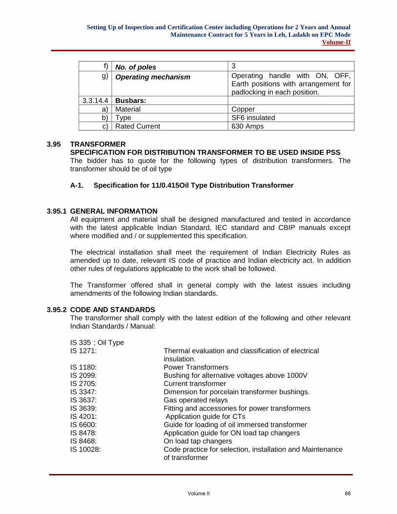
Setting Up of Inspection and Certification Center including Operations for 2 Years and Annual
Maintenance Contract for 5 Years in Leh, Ladakh on EPC Mode
Volume-II
f) No. of poles 3
g) Operating mechanism Operating handle with ON, OFF, Earth positions with arrangement for padlocking in each position.
3.3.14.4 Busbars:
a) Material Copper
b) Type SF6 insulated
c) Rated Current 630 Amps
3.95 TRANSFORMER SPECIFICATION FOR DISTRIBUTION TRANSFORMER TO BE USED INSIDE PSS The bidder has to quote for the following types of distribution transformers. The transformer should be of oil type
A-1. Specification for 11/0.415Oil Type Distribution Transformer
3.95.1 GENERAL INFORMATION
All equipment and material shall be designed manufactured and tested in accordance with the latest applicable Indian Standard, IEC standard and CBIP manuals except where modified and / or supplemented this specification.
The electrical installation shall meet the requirement of Indian Electricity Rules as amended up to date, relevant IS code of practice and Indian electricity act. In addition other rules of regulations applicable to the work shall be followed.
The Transformer offered shall in general comply with the latest issues including amendments of the following Indian standards.
3.95.2 CODE AND STANDARDS
The transformer shall comply with the latest edition of the following and other relevant Indian Standards / Manual: IS 335 ; Oil Type IS 1271: Thermal evaluation and classification of electrical
insulation. IS 1180: Power Transformers IS 2099: Bushing for alternative voltages above 1000V IS 2705: Current transformer IS 3347: Dimension for porcelain transformer bushings. IS 3637: Gas operated relays IS 3639: Fitting and accessories for power transformers IS 4201: Application guide for CTs IS 6600: Guide for loading of oil immersed transformer IS 8478: Application guide for ON load tap changers IS 8468: On load tap changers IS 10028: Code practice for selection, installation and Maintenance
of transformer
Volume II 88
Setting Up of Inspection and Certification Center including Operations for 2 Years and Annual
Maintenance Contract for 5 Years in Leh, Ladakh on EPC Mode
Volume-II
IS 13947: LV Switchgear and Control gear – Part – I General rules CBIP Manual on transformers
IS 2074: Ready mixed paint, air drying red oxide, zinc chrome priming
IS 5: Color of ready mix paint IEC 76 : Power transformer IEC 76.2 or IEC Temperature limits IEC-76-1 or IEC 726 or IS:2026 (All Parts) IEC-298, or IEC 466 High voltage Switch gear and Control gear IEC-947-1, IEC-439-1 Low voltage Switch gear and Control gear IS:1180 IS:2026 For distribution transformers IEC-550 (151):1978 SEV Chapter 151 Electro magnitude devices. IS:1885 IEC-60-1: 1989 High voltage test Technique Part-I. IS:2017 Part I General definition and test requirements. IEC-68-2-62:1991: Environmental testing – part 2, tests impact amendment
1(1993) IEC-71-2:1976 Insulation co-ordination Part 2 Application guide IS:3716 IEC:76-1:1993 Power transformer Part I general IS:2026 (Part I) IEC 76-2:1993 Power transformer Part 2 temperature rise. IEC 76-5, 1976 Power transformer Part 5 ability to withstand short circuit
test IEC:243-1,1988: Methods of tests for Electric strength of solid insulating IS:258-1 Material Part – I tests and power frequencies. IEC:354:1991: Loading guide for oil immersed power transformer. IS:6600 IEC:551:1987: Determination of transformer and reactor sound level. IS:13964 IS:2932: Enamel synthetic, exterior a) under coating b) Finishing IS:3347: Dimension of porcelain transformer bushing for use in very
heavily polluted atmosphere Indian Electricity Rules: 1956 Indian Electricity Act: 1910 The Electricity Act: 2003 Transformer shall also conform to the provisions of the latest revisions of the Indian Electricity rules and any other statutory regulations currently in force as per standards.
3.95.3 DESIGN CRITERIA
11KV/ 415 volt distribution transformer shall be a part of packaged substation which will be housed in the enclosure. The transformers shall be installed in hot, humid tropical atmosphere. All equipment accessories and wiring shall be provided with tropical finish to prevent fungus growth.
Volume II 89
Setting Up of Inspection and Certification Center including Operations for 2 Years and Annual
Maintenance Contract for 5 Years in Leh, Ladakh on EPC Mode
Volume-II
The transformers shall be capable of continuous operation of rated output under the operating conditions of voltage and frequency variations as per statutory limits governed by relevant Indian Standard and Indian Electricity Rules, 1956 / IEC with latest amendments in force. The transformer shall conform to best engineering practice. The transformers shall be capable of withstanding the short circuit stresses due to terminal fault between phase to phase and phase to ground on one winding with full voltage maintained on the other windings for a minimum period of three seconds. The transformers shall be free from annoying hum or vibration. The design shall be such as not to cause any undesirable interference with radio or communication circuits. The equipment offered shall be suitable for continuous satisfactory operation in India.
3.95.4 SPECIFIC REQUIREMENT
▪ Requirement: 11000/415 Volt Oil Type, 250 KVA LEVEL-3 ONAN cooled double wound, core type, corrugated arrangement transformer with O.L.T.C. suitable for packaged substation housed in a enclosure.
▪ Voltage Ratio: No load voltage 11000/415 volts within tolerance as stipulated in IS:
1180.
▪ Rating: The transformer shall have a continuous rating as specified at any of the specified tapping position and with the maximum temperature rise specified. The rated KVA shall be the product of the rated voltage in kV, the corresponding rated current and the phase factor 1.73. When the transformer is operated with the rated primary voltage applied to the terminals of the primary winding, the apparent power (kVA) at the terminals of the secondary winding, when carrying the rated secondary current differs from rated kVA by an amount corresponding to the regulation of the transformer and is the product of the actual secondary voltage, the rated secondary current and phase factor 1.73.
▪ System: 11000 volts A.C. supply, on H.V. side and 415 Volts on L.V. side with variations, as per statutory variation governed by relevant Indian Standard and Indian Electricity Rules, 1956 / IEC with latest amendments in force. The 11kV neutral and L.V. neutral is earthed solidly at each transformer substation. The transformers will be connected in a system consisting of both overhead and underground mains (both on HV and LV sides)
▪ Temperature Rise: The maximum temperature rise at the specified maximum continuous output shall not exceed 35°C by thermometer in the hottest portion of the oil or 45°C measured by resistance of winding above ambient temperature of 50°C.
▪ Type of Load: The transformer shall be suitable for carrying load within temperature rise indicated in the Indian Standard specification IS: 6600 ‘Guide for loading of oil
Volume II 90
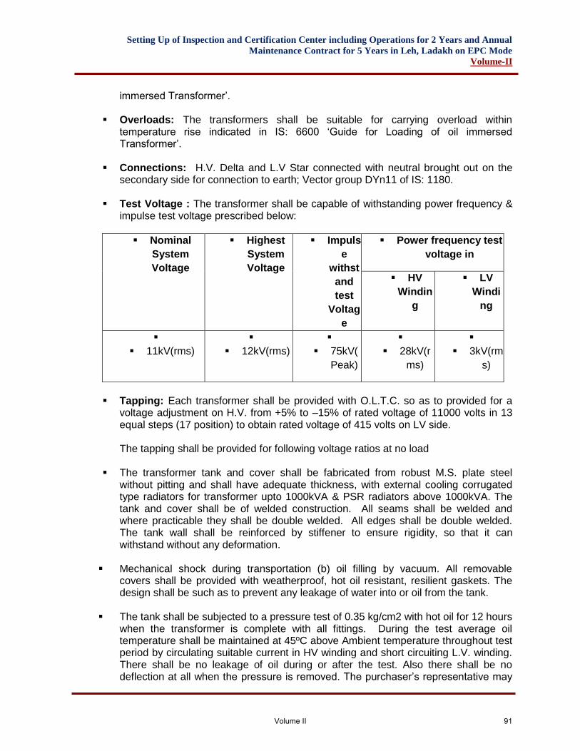
Setting Up of Inspection and Certification Center including Operations for 2 Years and Annual
Maintenance Contract for 5 Years in Leh, Ladakh on EPC Mode
Volume-II
immersed Transformer’.
▪ Overloads: The transformers shall be suitable for carrying overload within temperature rise indicated in IS: 6600 ‘Guide for Loading of oil immersed Transformer’.
▪ Connections: H.V. Delta and L.V Star connected with neutral brought out on the secondary side for connection to earth; Vector group DYn11 of IS: 1180.
▪ Test Voltage : The transformer shall be capable of withstanding power frequency & impulse test voltage prescribed below:
▪ Nominal
System
Voltage
▪ Highest
System
Voltage
▪ Impuls
e
withst
and
test
Voltag
e
▪ Power frequency test
voltage in
▪ HV
Windin
g
▪ LV
Windi
ng
▪
▪ 11kV(rms)
▪
▪ 12kV(rms)
▪
▪ 75kV(
Peak)
▪
▪ 28kV(r
ms)
▪
▪ 3kV(rm
s)
▪ Tapping: Each transformer shall be provided with O.L.T.C. so as to provided for a
voltage adjustment on H.V. from +5% to –15% of rated voltage of 11000 volts in 13 equal steps (17 position) to obtain rated voltage of 415 volts on LV side. The tapping shall be provided for following voltage ratios at no load
▪ The transformer tank and cover shall be fabricated from robust M.S. plate steel without pitting and shall have adequate thickness, with external cooling corrugated type radiators for transformer upto 1000kVA & PSR radiators above 1000kVA. The tank and cover shall be of welded construction. All seams shall be welded and where practicable they shall be double welded. All edges shall be double welded. The tank wall shall be reinforced by stiffener to ensure rigidity, so that it can withstand without any deformation.
▪ Mechanical shock during transportation (b) oil filling by vacuum. All removable covers shall be provided with weatherproof, hot oil resistant, resilient gaskets. The design shall be such as to prevent any leakage of water into or oil from the tank.
▪ The tank shall be subjected to a pressure test of 0.35 kg/cm2 with hot oil for 12 hours
when the transformer is complete with all fittings. During the test average oil temperature shall be maintained at 45ºC above Ambient temperature throughout test period by circulating suitable current in HV winding and short circuiting L.V. winding. There shall be no leakage of oil during or after the test. Also there shall be no deflection at all when the pressure is removed. The purchaser’s representative may
Volume II 91
Setting Up of Inspection and Certification Center including Operations for 2 Years and Annual
Maintenance Contract for 5 Years in Leh, Ladakh on EPC Mode
Volume-II
be present during these tests for which advance intimation shall be given and test Certificate for this test shall be produced by the supplier in triplicate before dispatching the units.
Air release plugs shall be provided on main tank top cover to cover entire area suitably. a) Inspection covers shall be provided to facilitate individual inspection, without
lifting the tank cover, for the following: b) Connection of primary winding to cable box/disconnection chamber bushings. c) Connection of secondary winding to cable box/disconnection chamber bushings. d) Main tank center for core/winding inspection.
▪ Oil: The necessary quantity of new transformer oil according to IS: 335 shall be supplied
filled in the transformer tank & up to required height. The Supplier shall furnish the relevant technical particulars and test certificates of the oil supplied.
▪ Leakage of Oil: Suitable approved type of material such as “Neoprene” which has an oil proof agent, as specified in IS: 1866 shall be provided at all joints to prevent leakage of oil during continued operation or during transportation.
▪ Drying-out: The transformer winding shall be thoroughly dried out & kept immersed in oil to avoid any further drying out by the purchaser & to facilitate immediate commissioning of the transformer on receipt.
▪ Clamping of leads: All leads from the coils to the terminals shall be suitably clamped to prevent snagging and fouling with other parts and the tank.
▪ Phase Marking: Phase markings as per IS: 2026 punched on small non-corrosion metallic tags shall be permanently fixed for H.V. just below the cable box or on some suitable removable part of the tank and above L.V. Bushings. Phase markings tags shall be properly fixed with proper alignment.
3.95.5 Core and Coil The core shall be constructed from high grade, cold rolled, non-ageing, low loss, high permeability, grain oriented, cold-rolled grain oriented silicon steel laminations. The transformer shall be so designed as to have minimum humming noise. The percentage harmonic potentials with the maximum flux density under any conditions shall be such that capacitors connected in the system shall not be overloaded.
The coils shall be manufactured from electrolytic copper conductor and fully insulated for rated voltage.
Insulating material shall be of proven design. The insulating materials shall be class “A” or above specified as per IS: 1271. Coils shall be so insulated that impulse and power frequency voltage stresses are minimum.
Transformers will be connected at the end of 11 kV and 0.415 kV overloaded feeders, in a lightning prevalent area.
Volume II 92
Setting Up of Inspection and Certification Center including Operations for 2 Years and Annual
Maintenance Contract for 5 Years in Leh, Ladakh on EPC Mode
Volume-II
The coil assembly shall be supported suitably between adjacent sections by insulating spaces & barriers. Brazing shall be arranged to ensure a free circulation of the coil & to reduce the hot spot of the winding.
All leads from the windings to the terminal board and bushings shall be rigidly supported to prevent injury from vibration or short circuit stresses. Guide tube shall be used wherever practicable.
The core and coil assembly shall be securely fixed in position so that no shifting or deformation occurs during movement of transformer. The core and coil assembly shall be capable of withstanding without injury, the thermal and mechanical effects of short circuit at the terminals of any winding as per IS:2026.
3.95.5.1 Core and Coil
The core shall be constructed from high grade, cold rolled, non-ageing, low loss, high permeability, grain oriented, cold-rolled grain oriented silicon steel laminations. The transformer shall be so designed as to have minimum humming noise. The coils shall be manufactured from electrolytic grade copper conductor and fully insulated for rated voltage by nomexcalendered meta-aramid paper type T410 and impregnated with class H resin varnish. Insulating material shall be of proven design. The insulating materials shall be class “H” or above specified as per IS 1271/1985 with latest amendments, thereto. Coils shall be so insulated that impulse and power frequency voltage stresses are minimum. Due consideration shall also be given to the fact that the transformers will be connected at the end of 11 kV and 0.415 kV overloaded feeders, in a lightning prevalent area. Winding should be wound with cu and shall be insulated with class C insulation (Nomex) system for higher temperature and fire retardant of superior quality. High voltage winding shall be either continuous disc type/cross over type while the LV winding shall be layer type. The complete coil should be impregnated by process of Vacuum pressure impregnation (VPI) in resin/varnish of class H insulation in order to seal the coil from ingress moisture and low partial discharge. Insulation of winding should be one class higher than the insulation class of transformer in order to increase the overload bearing capacity at peak load increase. All leads from the windings to the terminal board and bushings shall be rigidly supported to prevent injury from vibration or short circuit stresses. Guide tube shall be used wherever practicable. The core and coil assembly shall be securely fixed in position so that no shifting or deformation occurs during movement of transformer. The core and coil assembly shall be capable of withstanding without injury, the thermal and mechanical effects of short circuit at the terminals of any winding as per IS:2026/1977 with latest amendments thereto.
3.95.6 Fittings The following standard fittings shall be provided.
1. Two earthing terminals with symbol with tinned copper lugs.
Volume II 93
Setting Up of Inspection and Certification Center including Operations for 2 Years and Annual
Maintenance Contract for 5 Years in Leh, Ladakh on EPC Mode
Volume-II
2. Lifting lugs for lifting core and coil and transformer. 3. Plain Bi directional rollers. 4. Rating 7 terminal marking plate. 5. Winding temperature indicator.
3.95.7 Testing & Inspections
Routine Test The following tests are to be carried out as per IS 2026, clause 13.2. i. Measurement of winding resistance ii. Measurement of voltage ratio & check the voltage vector relationship iii. Measurement of impedance voltage (principal tapping), short circuit impedance &
load loss. iv. Measurement of no load loss and current v. Separate source withstand voltage vi. Induced over voltage withstand
TYPE TESTS (As per IS 2026, clause 16.1.1)
a. Measurement of winding resistance b. Measurement of voltage ratio & check the voltage vector relationship c. Measurement of impedance voltage (principal tapping), short circuit impedance
& load loss. d. Measurement of no load loss and current e. Separate source withstand voltage f. Induced over voltage withstand g. Lightning Impulse Test. h. Temperature rise test i. Short circuit test. j. Acoustic Noise Level Test
SPECIAL ACCEPTANCE TEST (As per IS 2026, clause 16.1.3)
i. Magnetic balance Test. ii. Unbalance current test. iii. Partial discharge test
Note: Transformers with Dupont technology and insulation system preferred.
LT System
LT compartment shall be suitable to house following equipment, - Bus bar connection from transformer to LT ACB / MCCB. - INCOMER As per BOQ
3.95.8 Interconnecting Bus Bar Bus bar shall be of high conductivity aluminum (E91E) supported on insulators made of non-hygroscopic, non-inflammable material with tracking index equal to or more than that defined in BIS. The main bus bars shall have uniform current ratings throughout their length as specified in data sheet / job specification. The current rating of the neutral
Volume II 94
Setting Up of Inspection and Certification Center including Operations for 2 Years and Annual
Maintenance Contract for 5 Years in Leh, Ladakh on EPC Mode
Volume-II
shall be half that of the phase busbars. Removable neutral links shall be provided on feeders to permit isolation of the neutral bus bar. Only zinc passivated or cadmium plated high tensile strength steel bolts, nuts and washers shall be used for all bus bar, joints and supports. The hot spot temperature of bus bars including joints at design ambient temperature
shall not exceed 95C for normal operating conditions. The current rating of the bus bars shall be 630A for design ambient temperature at site conditions and for being inside the cubicle at fully loaded condition. The vendor shall suitably de-rate the nominal rating to suit the above condition. Minimum clearance between live parts, between live parts / neutral to earth shall be 19mm. However clearances between terminals at components shall be as per applicable individual standard for components. Interconnections between the main bus bars and individual units shall be made using vertical / horizontal Aluminum bus bars of adequate rating. PERAMBLES TO SCHEDULE OF QUANTITIES Notes: These preambles apply to all the sections of schedule of quantities and tendered rates shall take into account all these provisions in additions to various provisions in other parts of the tendered documents.
1. The quantities given in this schedule are provisional. The contractor will be paid for the actual quantity of work executed at site at the rates quoted in his tender. The owner reserves the right to increase or decrease any of the quantities or to totally omit any item of work. Any claim by the contractor on these accounts will not be entertained.
2. All the items of work given in this schedule of quantities shall be executed strictly
in accordance with the Indian Electricity Act. The Indian Electricity Rules and requirements of the Electric supply authority read in conjunction with the relevant drawings, specifications and the appropriate Indian Standards.
3. All measurements shall be taken in accordance with the Indian standard
Electrical installation in buildings method of measurement of IS unless otherwise specified.
4. The contractor shall visit the site of work and shall satisfy himself if as to
conditions under which the work is to be performed. No extra claim consequence of ignorance or on grounds of insufficient description will be allowed at a later date.
Volume II 95
Setting Up of Inspection and Certification Center including Operations for 2 Years and Annual
Maintenance Contract for 5 Years in Leh, Ladakh on EPC Mode
Volume-II
5. No alternation whatsoever is to be made to the text or quantities of this schedule of quantities unless alteration is authorised in writing by the owner. Any such alterations notes or additions shall unless authorised in writing the disregarded when tender documents are considered.
6. In the event of error occurring to the amount column of the schedules, as a
result of wrong extension of unit rate and quantity the unit rates quoted by the tenderer shall be regarded as firm and the extensions shall be amended on the basis of rates.
7. Any error in descriptions or in quantity or omission of items from the contract
schedule shall not vitiate this contract but shall be corrected and deemed to be a variation required by the owner.
TECHNICAL SPECIFICATIONS FOR L.T. PANELS
3.96 GENERAL The electrical Installation work shall be carried out in accordance with Indian Standard Code of Practice. It shall also be in conformity with the current Indian Electricity rules and regulations and requirements of the Local Electricity Supply Authority and Fire Insurance regulations, so far as these become applicable to the installation. Electrical work in general shall be carried out as per following CPWD Specifications amended upto date. General Specifications for Electrical Works. - Part -I - Internal Work - 2005. - Part -II - External Work - 2007. - Part -IV - Substation Work - 2007. Wherever this specifications calls for a higher standard of material and or workmanship than those required by any of the above mentions regulations and specification then the specification here under shall take precedence over the said regulations and standards. The details of scope of work subhead wise are given in the subsequent paras. The quantities worked out in schedule of quantities are based on particular equipment considered at design stage. The contractor is required to recheck the quantities based on equipment offered by him to achieve required parameters.
TECHNICAL SPECIFICATIONS OF L.T. PANELS
3.97 Scope This section covers the detailed requirements of medium voltage switch panel for 433V, 3 phase 50 Hz 4 wire system. These shall be branded and/ or assembled/fabricated from a factory of repute. All switchgears shall be fully rated at an ambient of 40º C.
Volume II 96
Setting Up of Inspection and Certification Center including Operations for 2 Years and Annual
Maintenance Contract for 5 Years in Leh, Ladakh on EPC Mode
Volume-II
3.97.1 Type of Panel
The medium voltage switch board panel shall comprises of any one of the following types of switchgears or combination thereof as specified.
a) Air Circuit breakers draw out of fixed type. b) Switch Disconnect or Fuse Units fixed type, MCCB’s of suitable Ics ratings.
MCCB’s shall invariably be Current Limiting type. Features like Double Break, Positive Isolation functions shall be preferred.
The panel shall be indoor type having incoming sectionalization and outgoing switchgears as specified. The design shall be cubical type. Degree of Protection shall be IP54 up to rating of 2500Amp, IP:42 for 3200A as per IEC60529 and Above rating of indoor application Panels. For Outdoor application Panels, degree of protection shall be IP:65 with Double Door and Canopy arrangement at top of the Panel. Panel manufacturer should be a license partner or has his own Integrated Certificate as per latest IEC 61439. He should have an established track record in design. M.V. Panel
3.97.2 General Construction The switchboard shall be floor mounted free standing totally enclosed and extensible type. The switch board shall be dust & vermin proof and shall be suitable for the site conditions. The design shall include all provision for safety of operation and maintenance personnel. The general construction shall conform to IEC61439-1&2for factory assemble switch board. Enclosure shall be rugged enough to bear the Seismic resonance of Level Zone – IV / V. Type test certificate to be submitted for similar type of Assembly.
3.97.3 Cubical Type Panels Cubical type panels shall be fabricated out of CRCA / Aluzinc sheet steel not less than 2.0mm thick and partition& non load bearing members shall be made of 1.6 mm thick CRCA / Aluzinc sheet steel. Wherever necessary, such sheet steel members shall be stiffened by angle iron frame work. General construction shall comply Form of Separation of 4b for ACB vertical/ Panel includes Main LT Panel, DG Power Panel. Form-3b for Sub LT Panels and Floor Panels and Form-2a required for Wall Mounting Panels.
3.97.4 Each section of the rear accessible type panel shall have hinged access doors at the rear. Overall height of the panel shall not exceed 2.4 meters. Operating levers, handle etc. of highest unit shall not be higher than1.8meters. Multi-tier mounting of feeder is permissible. The general arrangement for multi tier construction shall be such that the horizontal tiers formed present a pleasing and aesthetic look. The general arrangement shall be approved before fabrication. Cable entries for various feeders shall be either form top or bottom. Through cable alleys located in between two circuit sections, either in the rear or in the font of the panel. All cable terminations shall be through 4 mm thick Aluminum gland plates. There shall be separate gland plate for each cable entry so that there will not be dislocation of already wire circuits when new feeders are added. Cable
Volume II 97
Setting Up of Inspection and Certification Center including Operations for 2 Years and Annual
Maintenance Contract for 5 Years in Leh, Ladakh on EPC Mode
Volume-II
entry plates shall therefore be sectionalized. The construction shall include necessary cable supports for clamping the cable in the cable alley or rear cable chamber. Gland Plate shall be of Aluminum in case of Single core Cable and CRCA for Multi Core Cable.
3.97.5 Bus Bar and Connections The bus bars shall be of high conductivity electrolytic quality and of adequate section. Current density shall not exceed 160 amps for Copper/sq. cm.&80 Amps/ Sq. cm. for aluminum. The bus bar system may comprise of system of main horizontal bus bars and ancillary vertical bus bas run in bus bar alleys on either side of which the circuit could be arrange with front access cable entries. In the case of rear access, horizontal bus system shall run suitably either at the top or bottom. All connections to individual circuits from the bus bar shall preferably be solid connections; however flexible connections shall also be permitted as per recommendations of the Panel Manufacturer. All bus bars and connections shall be suitably sleeved/ insulated in approved manner. The bus bars and interconnections shall be provided with heat resistant and colour coded sleeves. The busbars shall be supported on unbreakable, non hygroscopic insulated supports of SMC / Polymide supports at sufficiently close intervals to prevent bus bar sag and shall effectively withstand without damage electromagnetic stresses in the event of short circuit. The Busbar Insulator shall be certified for Glow Wire test as per IEC61439. The material and spacing of bus bar should be same as in type test certificate as per IEC-61439 part-1 for type tested assemblies. The neutral as well as earth bar shall also be capable of withstanding the fault level. Main Bus bar cross section shall be as per type test design, any calculation shall not be accepted for clarification. Distance to be : Phase to Phase – 25mm Maintained : Phase to Neutral – 19mm Where ever connections between copper and aluminum conductors are done, thermo couplers shall be used. Switchboard shall be Internal Arc complied to Internal Arc Resistance as per IEC61641 rated at 65KA for 0.4 Sec.
3.97.6 Incomer/ Termination Incomer termination shall be suitable for receiving bus trunking/ underground cables as per BOQ. Cable terminations shall invariably be through terminal blocks (Polymide or superior) or brought out solid terminals. ACB Terminals shall have both HR / VR or UR / VR configuration for termination of Incoming and Outgoing bus links. All MCCB’s up to 630A shall be provided with Rear Stud / Spreaders termination arrangement for finger touch proof design.
3.97.7 Instruments All voltmeters and ammeters shall be flush mounted of size minimum 96 mm. Sq. conforming to class 1.5 of IS:1248 for accuracy. All voltmeters shall be protected with MCB.
Volume II 98
Setting Up of Inspection and Certification Center including Operations for 2 Years and Annual
Maintenance Contract for 5 Years in Leh, Ladakh on EPC Mode
Volume-II
3.97.8 Indicating Lamps On all the incomers of M.V. panels, ON/OFF indicating LED lamps shall be provided and shall be suitable for operation on AC supply. Phase indicating LED lamps shall be associated with necessary ON/OFF toggle switch.
3.97.9 Small wiring All small wiring for controls, indication etc. shall be of with suitable FRLS/HFFR (halogen
free fire retardant) copper conductor cables. Wiring shall be suitably protected within switch board. Runs of wires shall be neatly bunched, suitably supported and clamped. Means shall be provided for easy identifications of the wires. Where wire are drawn through steel conduits, the works shall conform to CPWD General Specifications for Electrical works (Part I- Internal)-2005 and IS:732 as the case may be. Identification ferrules shall be used at both ends of the wires. All control wiring meant for external connections are to be brought out of terminal board.
3.98 OPERATIONAL REQUIREMENTS The indoor type MV panel shall conform to the following:-
a) The entire switch panel shall be cubical type generally conforming to IEC 61439 for factory assembled switch board.
b) The entire panel shall have a common earth bar of size as specified with two terminals for earth connections.
3.98.1 Rating and Requirements 3.98.2 Air Circuit Breaker
All Air circuit Breakers shall be 3/4 pole conforming to IEC 60947-I.Rated current shall be as per capacities specified. The equipment shall be complete with the following:-
a) Necessary circuit breaker carriage with 3 position (isolate, test, service) draw-out mechanism.
b) Necessary isolating plugs and sockets. c) Necessary mechanism interlock and automatic safe shutters gear with
arrangement for pad locking. d) Necessary independent manual spring mechanism with mechanical On/Off
indication as well as electrical On/Off indication. e) ACB shall be provided with microprocessor based releases having built in over
load, short circuit & earth fault protection. Microprocessor release shall be EMI (electro magnetic induction)/ EMC (electro magnetic compatible) certified.
f) Minimum of 4 NO & 4 NC auxiliary contacts. g) Necessary set of CTs as per requirement. h) Necessary identification, metering requirements as specified i/c. ON/OFF
indication lamps, selector switches, fuses, ammeter, voltmeter etc. i) In case of 4 pole breaker neutral shall be fully rated with adjustable settings from
50% to 100% of In. j) ACB terminals shall be suitable/ suitably brought out for direct aluminum
termination as perIEC60947-I.
Volume II 99
Setting Up of Inspection and Certification Center including Operations for 2 Years and Annual
Maintenance Contract for 5 Years in Leh, Ladakh on EPC Mode
Volume-II
3.98.3 MCCB: All MCCBs shall be current limiting type with features of load line reversibility
and suitable for Horizontal/ Vertical mounting without any de-rating. Beyond 300amps capacity MCCB’s shall have positive isolation and preferably double break/ contract repulsion & double insulation features. The MCCB’s shall invariably be used with terminal spreaders. MCCB’s shall be installed with rotary operating mechanism.
3.98.4 Test at Manufacturers Work All routine tests shall be carried out and test certificates produced to the department as per IS.
3.98.5 Installation The installation work shall cover assembly of various sections of the panels lining up, grouting the units etc. In the case of multiple panel switch boards after connection up the bus bars etc., all joints shall be insulated with necessary insulation tape or approved insulation compound. A common earth bar of adequate size shall be run inside at the back of switch panel connecting all the sections for connection to frame earth system. All protection and other small wirings for indication etc. shall be completed before calibration and commissioning checks are commenced. All relays, metes etc. shall be mounted and connected with appropriate wiring.
3.99 TESTING AND COMMISSIONING Commissioning checks and test shall include all wiring checks and checking up of connections. Relay adjustment/setting shall be done before commissioning in addition to routine Megger tests. Checks and tests shall include the following:-
a) Operation checks and lubrication of all moving parts. b) Interlock function checks. c) Continuity checks of wiring, fuses etc. as required. d) Insulation test: When measured with 1000 V Megger the insulation resistance
shall not be less than 100 mega ohms. e) Trip tests and protection gear test.
3.99.1 Switchgear
General
• The circuit breakers shall be of the air break type, robust and compact design suitable for indoor mounting and shall comply with the requirement IEC 60947-1/IS 13947-2 and 2. Rupturing capacity shall be as stipulated in Schedule of quantities. Heat loss per pole shall be low.
• The breaker shall comply with the isolation function requirement of IEC 60 947-2/IS 13947-2 section 7.12 to be marked as suitable for isolation / disconnection to facilitate safety of operating personal while the breaker is in use.
• The breaker shall provide appropriate insulation between the front panel and internal power circuits to avoid any accidental contact with the live main current carrying path with the front cover open.
• Protective devices, metering, CTs, PTs, push buttons and indicating lamps shall be provided as per schedule of quantities.
Constructional Features
Volume II 100
Setting Up of Inspection and Certification Center including Operations for 2 Years and Annual
Maintenance Contract for 5 Years in Leh, Ladakh on EPC Mode
Volume-II
• The Circuit Breaker shall be flush front, metal clad, horizontal draw-out pattern, three/four pole as required and fully interlocked. Each Circuit Breaker shall be housed in a separate compartment enclosed on all sides. In case of 4 pole breaker neutral shall be fully rated with adjustable settings from 50% to 100% of In.
• The Circuit Breaker cradle shall be designed and constructed to permit smooth withdrawal and insertion. The movement shall be free of jerks, easy to operate. Mechanical Latch to be provided to identify the Isolated, test & service position of breaker to prevent over racking.
• All current carrying parts in the breaker shall be silver plated and suitable arcing contacts shall be provided to protect the main contacts which shall be separate from the main contacts and easily replaceable. In addition, Arc chutes shall be provided for each pole, and these shall be suitable for being lifted out for the inspection of the main and the arcing contacts.
• Self aligning cluster type isolating contacts shall be provided for the Circuit Breaker, with automatically operated shutters to screen live cluster contacts when the Breaker is withdrawn from the cubicle. Sliding connections including those for the auxiliary contacts and control wiring shall also be of the self aligning type. The fixed portion of the sliding connections shall be easy access for maintenance purposes.
• There shall be flexibility in changing the types of terminals at site to suit the bus bar orientation if required.
• The cubicle for housing the Breaker shall be free standing dead front pattern, fabricated from the best quality sheet steel.
Operating Mechanism
• The Circuit Breaker shall be trip free with independent manual spring operated or motor wound spring operated mechanism as specified and with mechanical ON/OFF indication. The operating mechanism shall be such that the circuit breaker is at all times free to open immediately the trip coil is energised. The breaker shall be provided with in built antipumping mechanism.
• The closing time shall be less than or equal to 60 ms to ensure faster closing of the breaker. And tripping time Shall be less than 40 ms to reduce the let through energy in the event of fault.
• The operating handle and mechanical trip push button shall be at the front of and integral with the Circuit Breaker.
• There shall be mechanical indicator on the front panel for ‘Ready to close’ situation for the breaker by checking all interlockings.
• The Circuit Breaker shall be the following four distinct and separate positions which shall be indicated on the face of the panel. The breaker shall get latched in each of three position namely Service, Test and Isolated, operator to de latch before racking in/out to other position.
"Service" -- Both main and secondary isolating contacts closed "Test" -- Main isolating contacts open and secondary isolating contacts closed. "Isolated" -- Both main and secondary isolating contacts open "Maintenance" -- Circuit Breaker fully outside the panel ready for maintenance.
Volume II 101
Setting Up of Inspection and Certification Center including Operations for 2 Years and Annual
Maintenance Contract for 5 Years in Leh, Ladakh on EPC Mode
Volume-II
Circuit Breaker Interlocking
• Sequence type strain free interlocks shall be provided to ensure the following:
• It shall not be possible for the Breaker to be withdrawn from the cubicle when in the "ON" position. To achieve this, suitable mechanism shall be provided to lock the Breaker in the tripped position before the Breaker is isolated.
• It shall not be possible for the Breaker to be switched "ON" until it is either in the fully inserted position or, for testing purposes, it is in the fully isolated position.
• It shall not be possible for the Circuit Breaker to be plugged in unless it is in the OFF position.
• A safety latch shall be provided to ensure that the movement of the Breaker, as it is withdrawn, is checked before it is completely out of the cubicle, thus preventing its accidental fall due to its weight.
• Mechanical and electrical antipumping devices shall be incorporated in the ACB's as required.
Circuit Breaker Auxiliary Contacts The Circuit Breaker shall be suitable free / minimum 4 NO/NC auxiliary contacts rated at 10 amps 415 volts 50 Hz. These contacts shall be approachable from the front for connecting all external wiring from the front. They shall close before the main contacts when the Circuit Breaker is plugged in and vice versa when the Circuit Breaker is Drawn Out of the cubicle. Electrical Auxiliaries
• All electrical auxiliaries, including the spring charging gear motor shall be instalable on site without requiring adjustment or any tools other than a screw driver
• The auxiliaries shall be placed in a compartment which under normal operating conditions, shall not contain any conducting parts capable of entering into electrical contact with the circuit breaker poles. It shall be possible to connect all auxiliary wiring from the front of the circuit breaker.
Circuit breaker Releases The Air Circuit Breakers shall be microprocessor release with inbuilt overload, short-circuit instantaneous, ground fault protection and neutral protection. The Incoming circuit breaker to be equipped with the microprocessor based release with adjustable short circuit protection with adjustable time delay, over current protection, and adjustable earth fault protection with adjustable time delay. It Shall be possible to store tripping history of last five faults with time and date of fault and the type of fault with values. The outgoing ACBs shall be microprocessor based Release with Short circuit and overload protections On line setting of the parameters shall be possible. The setting of the ACB Shall be possible digitally and dial settings with the help of screwdriver.
Volume II 102
Setting Up of Inspection and Certification Center including Operations for 2 Years and Annual
Maintenance Contract for 5 Years in Leh, Ladakh on EPC Mode
Volume-II
All ACB release shall be inbuilt RS485 port & mod bus RTU protocol. Earthing The frame of the Circuit Breaker shall be positively earthed when the Circuit Breaker is racked into the cubicle.
3.100 MOULDED CASE CIRCUIT BREAKERS
3.100.1 General
• The circuit breakers shall comply with the requirement of IEC 60 947 / IS 13947-2 : 1993. MCCBs shall be suitable for nominal voltage of 3 phase 690 Volts AC 50 HZ supply.
• The circuit breaker shall comply with the isolation function requirement of IEC 60947-2/ IS 13947-2 section 7.1.2 to be marked as suitable for isolation / disconnection to facilitate safety of operating personnel while the breaker is in use.
• The circuit breaker shall provide class II insulation between the front cover and internal power circuits to avoid any accidental contact with the live main current carrying path with the front cover open.
• MCCBs shall be Ics=Icu Minimum 35 / 25KA (Ics) as specified in BOQ.
3.100.2 Construction Features
• The MCCBs shall be made of halogen free high strength heat resisting and flame retardant thermo setting insulating material.
• Three phase MCCBs shall be a common handle for simultaneous operation and tripping of all the three phases.
• The contact tips shall be made of suitable arc resistant sintered alloy. Terminals shall be of liberal design with adequate clearances
• Suitable arc extinguishing devices shall be provided for each contact.
3.100.3 Operating mechanism
• The operating handle of the MCCBs shall be quick make / break, trip free type.
• The operating handle of the MCCBs shall be suitable, ON, OFF and TRIPPED indicators.
• The operating handle and mechanical trip push button shall be at the front of and integral with the circuit breaker
• MCCBs shall be capable of limiting the fault currents. The maximum thermal I2 t shall be indicated by the manufacturer.
• MCCBs shall comprise of the mechanism designed to trip the circuit breaker in the event of high value short circuit currents.
• The electrical endurance of MCCBs shall be more or equal to that specified by IEC 60 947-2 standard.
• Earth fault protection if specified Shall be an integral part of the breaker, direct operating type & adjustable
• MCCBs range shall be discrimination charts available.
• MCCBs shall be of the same family.
Volume II 103
Setting Up of Inspection and Certification Center including Operations for 2 Years and Annual
Maintenance Contract for 5 Years in Leh, Ladakh on EPC Mode
Volume-II
3.100.4 Circuit Breaker Releases All MCCBs up to 250 Amps shall have adjustable thermal- magnetic release for over current and short circuit protection. Above 250 Amps, MCCB’s will have microprocessor based releases for over current and short circuit protection. All incoming MCCBs will be provided additionally with earth fault protection. Wherever earth faults are required, it should be inbuilt part of Microprocessor based Release and should be with adjustable setting. No external module for E/F protection shall be accepted.
3.100.5 Circuit Breaker Interlocking MCCBs shall be provided with following interlocking devices.
• Handle interlock to prevent unnecessary manipulations of the breaker.
• Door interlock to prevent door being opened when the breaker is in ON position
• Deinterlocking device to open the door even if the breaker is in ON position.
3.100.6 Circuit Breaker Auxiliaries The circuit breaker shall be provided with following accessories, if specified in drawings/schedule of quantities
• Under voltage trip
• Alarm switch
• Auxiliary contact.
i. Type Test Certificate The contractor shall submit type test certificate from a international recognized test house/CPRI/ERDA for the circuit breakers offered.
ii. Miniature Circuit Breakers
The MCB's shall be of the completely moulded design suitable for operation at 240/415 Volts 50 Hz system. The MCB's shall be a rupturing capacity of 10 KA at 0.5 p.f.. The MCB's shall be inverse time delayed thermal overload and instantaneous magnetic short circuit protection..
iii. Manufacturing Facilities Sheet steel manufacturing shall be done according to the drawings on in house CNC cutting and bending machines. In house facility to be available foron line multi nozzle spray system for each process on the parts hanging from the slow speed conveyor leading to the oven for drying after Pre-treatment as per IS:101-1988. Effective temp and concentration control powder coated for desired shade of RAL 7035. Paint is not required in case of parts fabricated out of Aluzinc sheet. The Pre-treatment and painting process shall be regularly checked for the stability of the process the final paint thickness shall be 60 to 80microns.
Volume II 104
Setting Up of Inspection and Certification Center including Operations for 2 Years and Annual
Maintenance Contract for 5 Years in Leh, Ladakh on EPC Mode
Volume-II
The manufacturer shall be established stores with proper procedures for checking incoming material, stocking, rejection etc so that non-Quality material does not enter the shop. In house facility for routine testing of the switchboards The Manufacturing facility shall be ISO 9001 certification.
iv. Installation (To be carried out by Electrical Contractor on site) Unless otherwise specified, the specifications for installation works shall be as follows.
Following shall be the part of the installation works
• Shifting of the unit(s) from place of storage to place of installation
• Un packing
• Verification for transit damages/ availability of all items including accessories, operating handles, instruction manuals, drawings, test certificates etc and taking necessary action where needed.
• Assembling different sections/ units when sent separately.
• Positioning of the units as per the drawings/ site requirements
• Alignment checks
• Grouting/ Securing to the floor/ foundations/ base channels etc for stable installations.
• Undertaking all related minor civil, mechanical works like chipping, plastering, cutting, welding, drilling etc.
• Taking all necessary safety precautions for the equipment as well as personnel.
• Touching up damaged painting portions
• Making earth connection to the unit
• Connecting and ensuring efficient termination of cables/ bus ducts as applicable using proper size cable lugs, glands and appropriate size GI/ zinc passivated hard ware with spring washers and plate washers at appropriate locations (smaller size bolts not to be used for bigger holes in cables lugs / switch gears to avoid weak electrical connections). – [Scope of Cable termination is covered separately as per BOQ / SOQ and shall be measured separately].
• Ensuring proper tightness of all joints, connections.
• Providing proper supporting / protection arrangement to the cables/ units etc to avoid undue stress on the termination/ joints.
• Providing required instruction/ information/ caution / name plates for easy operation and maintenance.
• Provision of interlocks wherever needed.
• Following proper codes like IS and sound engineering practices.
• Obtaining requisite statutory approval, licenses etc where applicable
• Performance pre-commissioning checks and ensuring proper functioning of all the systems.
• Satisfactory commissioning the equipment/system
• Documentation
3.101 Tests Unless otherwise specified, the specifications for testing shall be as follows.
Volume II 105
Setting Up of Inspection and Certification Center including Operations for 2 Years and Annual
Maintenance Contract for 5 Years in Leh, Ladakh on EPC Mode
Volume-II
3.101.1 Tests & Inspections
Switchgear shall be subjected to routine test as per IS 8623 All meters and other reference devices used for testing shall be valid calibration from reputed national laboratories / Institutes. Inspection by purchasers shall not be carried out unless the vendor confirms that equipment is ready for proceeding with the tests. Acceptance tests on completed switchboards shall be as follows:
a) A general visual check shall be carried out. This shall cover measurement of overall dimension, location, number and type of devices, terminal boxes, location and connection of terminals etc.
b) Checking of bill of materials as per approved drawing. c) Checking of operation of various feeders as per approved schematic drawings. d) Operation check shall be carried out for every control function as per schematic
drawings by manually simulating fault conditions and operation of control switches/relays etc.
e) Checking of inter-changeability of identical feeders. f) Insulation resistance test and value measurement on power and control circuits
before and after high voltage withstand test. g) High voltage test on power and control circuit as per IS 8623. h) For equipment bought from other suppliers, certified test reports of tests carried
out at the manufacturers works shall be submitted. Normally all routine tests as specified in the relevant standards shall be conducted by the sub supplier at its works and copies of routine test reports shall be furnished.
3.101.2 Type Test The type test certificates shall be submitted to Owner / Engineer in Charge The agency shall be CPRI test certificate for similar panel (LT Panels or MCC). Panels shall be got manufactured by only reputed panel manufacturers having got type tested by CPRI or other Government testing laboratory on similar panels (LT panel or MCC) of minimum 50KA fault level with stand capacity and IP protection.
3.101.3 Routine/ Acceptance Tests
The panels shall be checked and tested after fabrication, assembling and wiring at
factory as per the following.
3.101.4 Checks 1. Manufacture of panel as per the order SOQ/BOQ and related specifications. 2. Compliance of using approved makes. 3. Manufacture as per approved drawings. 4. Inspection for any damages. 5. Dimensional checks & Visual examination
Volume II 106
Setting Up of Inspection and Certification Center including Operations for 2 Years and Annual
Maintenance Contract for 5 Years in Leh, Ladakh on EPC Mode
Volume-II
3.101.5 Tests
1. Insulation resistance test. Wiring test shall be carried with 1000-volt Megger to ensure adequate insulation resistance. (At manufacturer’s works). While carrying out the IR test the capacitor banks shall be isolated.
2. H.T. test shall be carried out as per IS at manufacturer’s works. 3. Functional tests. 4. Primary/secondary current injection test for relays if protection relays are
supplied as part of BOQ
3.101.6 Site Tests In addition to the tests at manufacturer’s premises, all relevant pre-commissioning checks and tests shall be done at site before energizing the panel. Following shall be the minimum checks/tests to be done at site.
1. Physical inspection for breakages/damages/orderliness. 2. Insulation resistance test with 500 V Megger by isolating the Capacitor bank. The
insulation resistance shall be not less than 100 mega ohms. 3. Earth continuity test. 4. Tightness of joints/connections/terminations. 5. Safety checks. 6. General Operation/Performance Checks 7. All test results are to be recorded and reports shall be submitted to the
department.
3.101.7 Calibrations All the protective relays shall be calibrated and test certificate shall be submitted.
Test Certificates
1. Following test certificate shall be submitted by the agency: - a. Test Certificate for the routine/acceptance tests.
b. Test Certificate for the type tests such as temperature rise test, short
circuit withstand test, degree of protection for similar ratings (50 KA and above).
c. Test certificates for the calibrations.
2. All the switchgear and components shall be brand new, genuine and free from manufacturing, transit defects.
3. All the items and their quantity and make shall be as per the order and OEM’s test certificate submitted.
3.101.8 Commissioning
After the completion of installation & testing works, the panels shall be commissioned.
3.101.9 Drawings/ Documents Unless otherwise specified, the Drawings / Documents shall be as follows.
3.101.10 Drawings & Instruction Manuals
Volume II 107
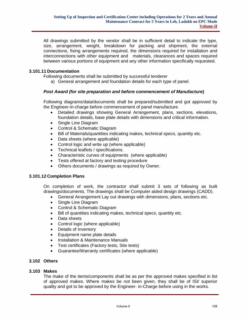
Setting Up of Inspection and Certification Center including Operations for 2 Years and Annual
Maintenance Contract for 5 Years in Leh, Ladakh on EPC Mode
Volume-II
All drawings submitted by the vendor shall be in sufficient detail to indicate the type, size, arrangement, weight, breakdown for packing and shipment, the external connections, fixing arrangements required, the dimensions required for installation and interconnections with other equipment and materials, clearances and spaces required between various portions of equipment and any other information specifically requested.
3.101.11 Documentation Following documents shall be submitted by successful tenderer
a) General arrangement and foundation details for each type of panel. Post Award (for site preparation and before commencement of Manufacture) Following diagrams/data/documents shall be prepared/submitted and got approved by the Engineer-in-charge before commencement of panel manufacture.
• Detailed drawings showing General Arrangement, plans, sections, elevations, foundation details, base plate details with dimensions and critical information.
• Single Line Diagram
• Control & Schematic Diagram
• Bill of Materials/quantities indicating makes, technical specs, quantity etc.
• Data sheets (where applicable)
• Control logic and write up (where applicable)
• Technical leaflets / specifications.
• Characteristic curves of equipments (where applicable)
• Tests offered at factory and testing procedure
• Others documents / drawings as required by Owner.
3.101.12 Completion Plans
On completion of work, the contractor shall submit 3 sets of following as built drawings/documents. The drawings shall be Computer aided design drawings (CADD).
• General Arrangement Lay out drawings with dimensions, plans, sections etc.
• Single Line Diagram
• Control & Schematic Diagram
• Bill of quantities indicating makes, technical specs, quantity etc.
• Data sheets
• Control logic (where applicable)
• Details of Inventory
• Equipment name plate details
• Installation & Maintenance Manuals
• Test certificates (Factory tests, Site tests)
• Guarantee/Warranty certificates (where applicable)
3.102 Others
3.103 Makes The make of the items/components shall be as per the approved makes specified in list of approved makes. Where makes be not been given, they shall be of ISI/ superior quality and got to be approved by the Engineer- in-Charge before using in the works.
Volume II 108
Setting Up of Inspection and Certification Center including Operations for 2 Years and Annual
Maintenance Contract for 5 Years in Leh, Ladakh on EPC Mode
Volume-II
Volume II 109
Setting Up of Inspection and Certification Center including Operations for 2 Years and Annual
Maintenance Contract for 5 Years in Leh, Ladakh on EPC Mode
Volume-II
4. SPECIFICATIONS (Vehicle Inspection Equipment)
Volume II 110
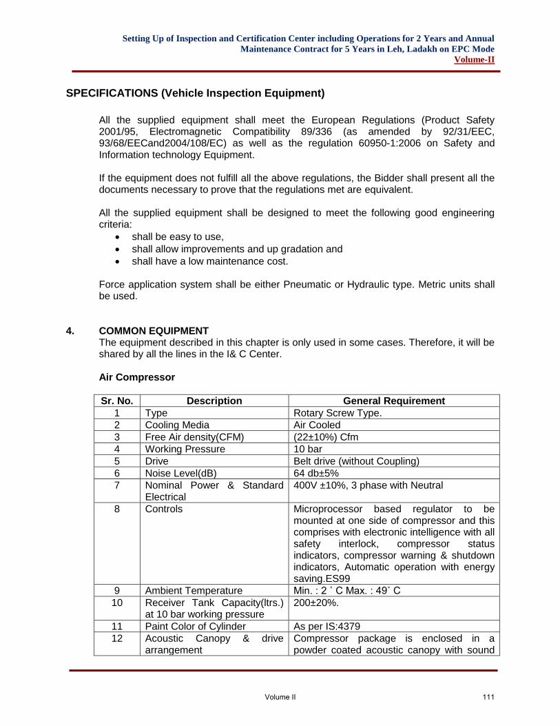
Setting Up of Inspection and Certification Center including Operations for 2 Years and Annual
Maintenance Contract for 5 Years in Leh, Ladakh on EPC Mode
Volume-II
SPECIFICATIONS (Vehicle Inspection Equipment)
All the supplied equipment shall meet the European Regulations (Product Safety 2001/95, Electromagnetic Compatibility 89/336 (as amended by 92/31/EEC, 93/68/EECand2004/108/EC) as well as the regulation 60950-1:2006 on Safety and Information technology Equipment. If the equipment does not fulfill all the above regulations, the Bidder shall present all the documents necessary to prove that the regulations met are equivalent. All the supplied equipment shall be designed to meet the following good engineering criteria:
• shall be easy to use,
• shall allow improvements and up gradation and
• shall have a low maintenance cost. Force application system shall be either Pneumatic or Hydraulic type. Metric units shall be used.
4. COMMON EQUIPMENT The equipment described in this chapter is only used in some cases. Therefore, it will be shared by all the lines in the I& C Center. Air Compressor
Sr. No. Description General Requirement
1 Type Rotary Screw Type.
2 Cooling Media Air Cooled
3 Free Air density(CFM) (22±10%) Cfm
4 Working Pressure 10 bar
5 Drive Belt drive (without Coupling)
6 Noise Level(dB) 64 db±5%
7 Nominal Power & Standard Electrical
400V ±10%, 3 phase with Neutral
8 Controls Microprocessor based regulator to be mounted at one side of compressor and this comprises with electronic intelligence with all safety interlock, compressor status indicators, compressor warning & shutdown indicators, Automatic operation with energy saving.ES99
9 Ambient Temperature Min. : 2 ˚ C Max. : 49˚ C
10 Receiver Tank Capacity(ltrs.) at 10 bar working pressure
200±20%.
11 Paint Color of Cylinder As per IS:4379
12 Acoustic Canopy & drive arrangement
Compressor package is enclosed in a powder coated acoustic canopy with sound
Volume II 111
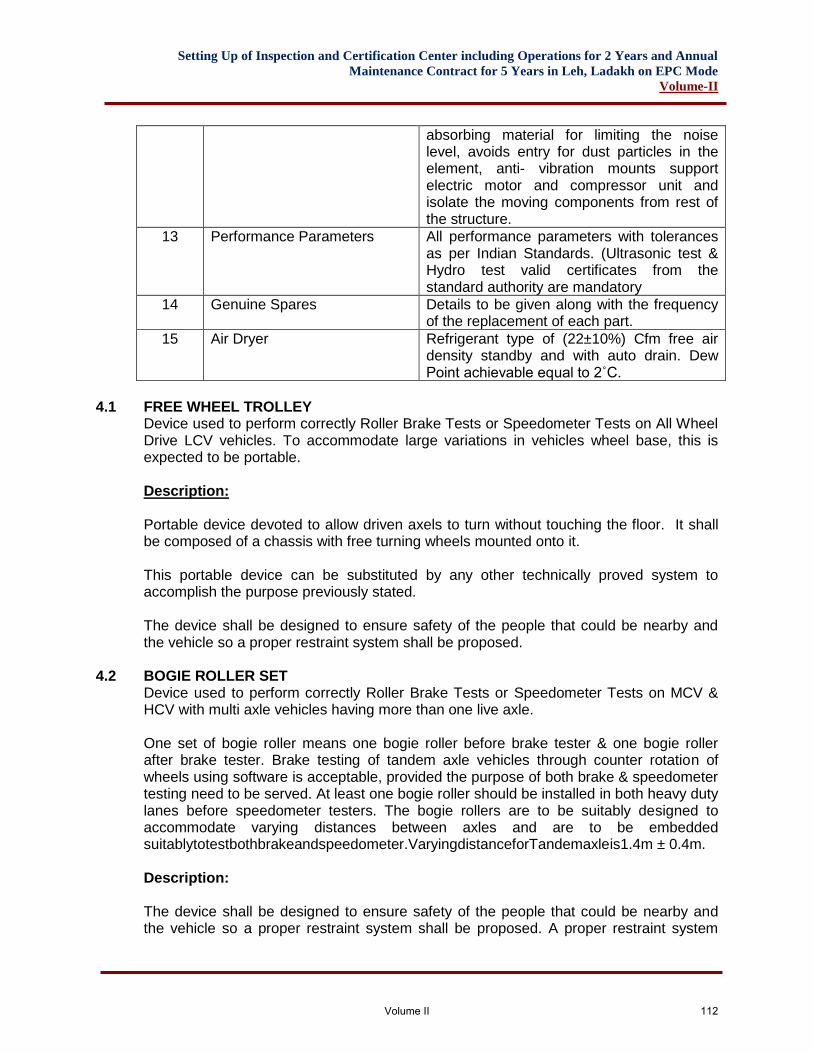
Setting Up of Inspection and Certification Center including Operations for 2 Years and Annual
Maintenance Contract for 5 Years in Leh, Ladakh on EPC Mode
Volume-II
absorbing material for limiting the noise level, avoids entry for dust particles in the element, anti- vibration mounts support electric motor and compressor unit and isolate the moving components from rest of the structure.
13 Performance Parameters All performance parameters with tolerances as per Indian Standards. (Ultrasonic test & Hydro test valid certificates from the standard authority are mandatory
14 Genuine Spares Details to be given along with the frequency of the replacement of each part.
15 Air Dryer Refrigerant type of (22±10%) Cfm free air density standby and with auto drain. Dew Point achievable equal to 2˚C.
4.1 FREE WHEEL TROLLEY
Device used to perform correctly Roller Brake Tests or Speedometer Tests on All Wheel Drive LCV vehicles. To accommodate large variations in vehicles wheel base, this is expected to be portable. Description: Portable device devoted to allow driven axels to turn without touching the floor. It shall be composed of a chassis with free turning wheels mounted onto it. This portable device can be substituted by any other technically proved system to accomplish the purpose previously stated. The device shall be designed to ensure safety of the people that could be nearby and the vehicle so a proper restraint system shall be proposed.
4.2 BOGIE ROLLER SET Device used to perform correctly Roller Brake Tests or Speedometer Tests on MCV & HCV with multi axle vehicles having more than one live axle. One set of bogie roller means one bogie roller before brake tester & one bogie roller after brake tester. Brake testing of tandem axle vehicles through counter rotation of wheels using software is acceptable, provided the purpose of both brake & speedometer testing need to be served. At least one bogie roller should be installed in both heavy duty lanes before speedometer testers. The bogie rollers are to be suitably designed to accommodate varying distances between axles and are to be embedded suitablytotestbothbrakeandspeedometer.VaryingdistanceforTandemaxleis1.4m ± 0.4m. Description: The device shall be designed to ensure safety of the people that could be nearby and the vehicle so a proper restraint system shall be proposed. A proper restraint system
Volume II 112
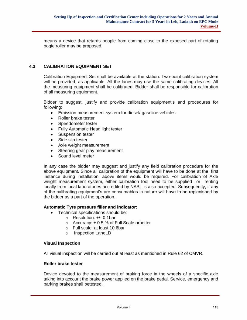
Setting Up of Inspection and Certification Center including Operations for 2 Years and Annual
Maintenance Contract for 5 Years in Leh, Ladakh on EPC Mode
Volume-II
means a device that retards people from coming close to the exposed part of rotating bogie roller may be proposed.
4.3 CALIBRATION EQUIPMENT SET Calibration Equipment Set shall be available at the station. Two-point calibration system will be provided, as applicable. All the lanes may use the same calibrating devices. All the measuring equipment shall be calibrated. Bidder shall be responsible for calibration of all measuring equipment. Bidder to suggest, justify and provide calibration equipment’s and procedures for following:
• Emission measurement system for diesel/ gasoline vehicles
• Roller brake tester
• Speedometer tester
• Fully Automatic Head light tester
• Suspension tester
• Side slip tester
• Axle weight measurement
• Steering gear play measurement
• Sound level meter In any case the bidder may suggest and justify any field calibration procedure for the above equipment. Since all calibration of the equipment will have to be done at the first instance during installation, above items would be required. For calibration of Axle weight measurement system, either calibration tool need to be supplied or renting locally from local laboratories accredited by NABL is also accepted. Subsequently, if any of the calibrating equipment’s are consumables in nature will have to be replenished by the bidder as a part of the operation. Automatic Tyre pressure filler and indicator:
• Technical specifications should be: o Resolution: +/- 0.1bar o Accuracy: ± 0.5 % of Full Scale orbetter o Full scale: at least 10.6bar o Inspection LaneLD
Visual Inspection All visual inspection will be carried out at least as mentioned in Rule 62 of CMVR. Roller brake tester Device devoted to the measurement of braking force in the wheels of a specific axle taking into account the brake power applied on the brake pedal. Service, emergency and parking brakes shall betested.
Volume II 113
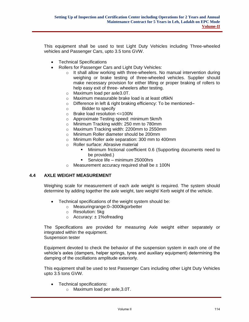
Setting Up of Inspection and Certification Center including Operations for 2 Years and Annual
Maintenance Contract for 5 Years in Leh, Ladakh on EPC Mode
Volume-II
This equipment shall be used to test Light Duty Vehicles including Three-wheeled vehicles and Passenger Cars, upto 3.5 tons GVW.
• Technical Specifications
• Rollers for Passenger Cars and Light Duty Vehicles: o It shall allow working with three-wheelers. No manual intervention during
weighing or brake testing of three-wheeled vehicles. Supplier should make necessary provision for either lifting or proper braking of rollers to help easy exit of three- wheelers after testing.
o Maximum load per axle3.0T. o Maximum measurable brake load is at least of6kN o Difference in left & right braking efficiency: To be mentioned– o Bidder to specify o Brake load resolution <=100N o Approximate Testing speed: minimum 5km/h o Minimum Tracking width: 250 mm to 780mm o Maximum Tracking width: 2200mm to 2550mm o Minimum Roller diameter should be 200mm o Minimum Roller axle separation: 300 mm to 400mm o Roller surface: Abrasive material
▪ Minimum frictional coefficient 0.6 (Supporting documents need to be provided.)
▪ Service life – minimum 25000hrs o Measurement accuracy required shall be ± 100N
4.4 AXLE WEIGHT MEASUREMENT
Weighing scale for measurement of each axle weight is required. The system should determine by adding together the axle weight, tare weight/ Kerb weight of the vehicle.
• Technical specifications of the weight system should be: o Measuringrange:0–3000kgorbetter o Resolution: 5kg o Accuracy: ± 1%ofreading
The Specifications are provided for measuring Axle weight either separately or integrated within the equipment. Suspension tester Equipment devoted to check the behavior of the suspension system in each one of the vehicle’s axles (dampers, helper springs, tyres and auxiliary equipment) determining the damping of the oscillations amplitude exteriorly. This equipment shall be used to test Passenger Cars including other Light Duty Vehicles upto 3.5 tons GVW.
• Technical specifications: o Maximum load per axle,3.0T.
Volume II 114
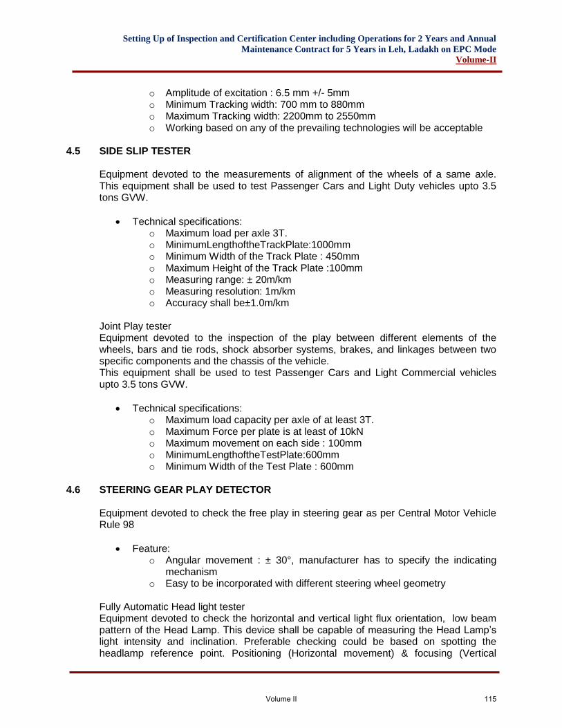
Setting Up of Inspection and Certification Center including Operations for 2 Years and Annual
Maintenance Contract for 5 Years in Leh, Ladakh on EPC Mode
Volume-II
o Amplitude of excitation : 6.5 mm +/- 5mm o Minimum Tracking width: 700 mm to 880mm o Maximum Tracking width: 2200mm to 2550mm o Working based on any of the prevailing technologies will be acceptable
4.5 SIDE SLIP TESTER
Equipment devoted to the measurements of alignment of the wheels of a same axle. This equipment shall be used to test Passenger Cars and Light Duty vehicles upto 3.5 tons GVW.
• Technical specifications: o Maximum load per axle 3T. o MinimumLengthoftheTrackPlate:1000mm o Minimum Width of the Track Plate : 450mm o Maximum Height of the Track Plate :100mm o Measuring range: ± 20m/km o Measuring resolution: 1m/km o Accuracy shall be±1.0m/km
Joint Play tester Equipment devoted to the inspection of the play between different elements of the wheels, bars and tie rods, shock absorber systems, brakes, and linkages between two specific components and the chassis of the vehicle. This equipment shall be used to test Passenger Cars and Light Commercial vehicles upto 3.5 tons GVW.
• Technical specifications: o Maximum load capacity per axle of at least 3T. o Maximum Force per plate is at least of 10kN o Maximum movement on each side : 100mm o MinimumLengthoftheTestPlate:600mm o Minimum Width of the Test Plate : 600mm
4.6 STEERING GEAR PLAY DETECTOR
Equipment devoted to check the free play in steering gear as per Central Motor Vehicle Rule 98
• Feature: o Angular movement : ± 30°, manufacturer has to specify the indicating
mechanism o Easy to be incorporated with different steering wheel geometry
Fully Automatic Head light tester Equipment devoted to check the horizontal and vertical light flux orientation, low beam pattern of the Head Lamp. This device shall be capable of measuring the Head Lamp’s light intensity and inclination. Preferable checking could be based on spotting the headlamp reference point. Positioning (Horizontal movement) & focusing (Vertical
Volume II 115
Setting Up of Inspection and Certification Center including Operations for 2 Years and Annual
Maintenance Contract for 5 Years in Leh, Ladakh on EPC Mode
Volume-II
movement) of Fully Automatic Head light tester in front of head lamps of vehicle shall be done without human intervention. Measurement of low beam pattern and test data transfer from Fully Automatic Head light tester shall be done automatically. This equipment shall be used to test Light Duty Vehicles including Passenger Cars, upto 3.5 tons GVW.
• Technical specifications: o Light Intensity range measure (min): 0-100,000cd o Illumination Intensity range measure: 0-200lux o Headlight tester must be capable of measuring headlamp with their
Centers 500 mm to 1200 mm above ground level. o Vertical and horizontal measuring range: ±50 cm/10 m (±5%) o Maximum deviation of intensity: ±5% of reading o Maximum deviation of Inclination measurement (vertical orientation) :±
0.1%
4.7 SMOKE METER (OPACIMETER) Equipment is devoted to the measurement of exhaust gas opacity in diesel engines. This equipment shall be used to test diesel fuelled vehicles as per CMVR/TAP 115/116.
• Technical specifications: o Equipment shall comply as per the requirements mentioned in the
CMVR/TAP 115/116. Bidder to provide valid type approval certificate at the time of installation and commissioning as per CMVR at Bidder’s owncost.
o Specifications shall meet the requirement as given in TAP document and approved by authorized test agency for use in India.
o The equipment must be certified to WAPCOS Limited/ CMVR/ TAP115/ 116.
o Copy of Type Approval certificate needs to be attached.
4.8 Exhaust Gas Analyzer This equipment will be used for measurements of exhaust emissions of gasoline, CNG and LPG vehicles as per CMVR/TAP 115/116.
• Technical Specifications: o Equipment shall comply as per the requirements mentioned in the CMVR
116(3) (International standard certificate to be available at time of bidding. Bidder to provide certification as per CMVR 116 (3) once it is installed, for commissioning at Bidder’s own cost)
o This equipment shall be capable measuring the CO, CO2 and O2 percentage concentration, the HC (ppm vol), the lambda value (for various fuel types including CNG, LPG & gasoline) and shall be prepared for up-gradation to measure NOx.
o The equipment shall transmit automatically all the data above specified to a PC and to a centralized storage system once the test is over.
Volume II 116
Setting Up of Inspection and Certification Center including Operations for 2 Years and Annual
Maintenance Contract for 5 Years in Leh, Ladakh on EPC Mode
Volume-II
o Specifications shall meet the requirement as given in CMVR/TAP document and approved by authorized test agency for use in India
o Must be certified as per WAPCOS Limited/CMVR/TAP115/116. o Copy of Type Approval certificate needs to be attached.
4.9 SPEEDOMETER TESTER
Device used to measure the functioning of the speedometer of the vehicle. It measures speed and distance covered by a vehicle. It shall be able to test Passenger Cars, 3 wheeled vehicles and vehicles upto 3.5 tons GVW.
• Technical Specifications: o Maximum load capacity per axle, minimum 3T. o Minimum Track width: 250mm to780mm o MaximumTrackwidth:2200mmto2550mm o MinimumRollerdiametershouldbe200mm o Minimum Roller axle separation: 300 mm to 400mm o Measuring range: 20 – 160km/h o Resolution: 1km/h o Accuracy: ± 1 % of indicated reading
4.10 SOUND LEVELMETER
• The specifications for sound level meter will be as follows:-
• Recommended as per IEC 60651/ IEC61672-1
• Measuring range: ≤ 30dB to≥120dB
• Frequency: A &C
• Accuracy: ± 1.5dB
• Tripod stand mounted
• Build (rechargeable)battery for power source of charging from outlet of 220V AC
• Time weighting characteristics designated SLOW (S), Fast (F), Impulse (I).
• Connectivity with lane software with requisite port like RS232.
• Environmental range o Minimum Temp range: -10°C to 50°C o Humidity: greater than90% o Dust: Typical Indian testing condition
• Inspection Lane HD
4.11 VISUAL INSPECTION All visual inspection will be carried out at least as mentioned in Rule 62 of CMVR. All the equipment shall be able to test Medium and Heavy Commercial Vehicles. Roller brake tester (including Axle weight measurement)
• Technical Specifications
Volume II 117
Setting Up of Inspection and Certification Center including Operations for 2 Years and Annual
Maintenance Contract for 5 Years in Leh, Ladakh on EPC Mode
Volume-II
o Maximum load charge per axle is at least of 15T or better o Maximum measurable brake load is at least of 40kN. o Difference in left & right braking efficiency: To be mentioned – Bidder to
specify o Minimum Roller Diameter : 200mm o Minimum Roller Separation: 450mm o Roller Length : 1000mm o Roller surface: Abrasive material
▪ Minimum frictional coefficient 0.6 (Supporting documents need to be provided.)
▪ Service life – minimum 25000hrs. o Brake load resolution ≤100N o Approximate Testing speed: minimum 2.5km/h o Measurement accuracy required shall be ± 2% of measured value.
4.12 AXLE WEIGHT MEASUREMENT
Weighing scale for measurement of each axle weight is required. The system should determine by adding together axle weight, tare weight/ Kerb weight of the vehicle
• Technical specifications of the weight system should be:
• Measuring range: 3500 kg – 15000 kg or better
• Resolution: 5kg
• Accuracy ± 1% of reading The Specifications are provided for measuring Axle weight either separately or integrated within the equipment.
4.13 SIDE SLIPTESTER Equipment devoted to the measurements of alignment of the wheels of a same axle.
• Technical specifications: o Maximum load per axle: at least 15T or better o Measuring range: ± 20m/km o Measuring resolution: 1m/km o Accuracy shall be±1.0m/km o Track Plate Length : 1000 to1400mm o Minimum Track Plate Width :750mm o Maximum Track Plate Height :150mm
4.14 JOINT PLAYTESTER
Equipment devoted to the inspection of the play between different elements of the wheels, bars and tie rods, shock absorber systems, brakes, and linkages between two specific components and the chassis of the vehicle.
• Technical specifications: o Maximum load capacity per axle of at least 15T or better
Volume II 118
Setting Up of Inspection and Certification Center including Operations for 2 Years and Annual
Maintenance Contract for 5 Years in Leh, Ladakh on EPC Mode
Volume-II
o Maximum Force per plate is at least of 30kN o Maximum movement on each side : 100mm o Length of the Test Plate : 750 mm to 1400mm o Minimum Width of the Test Plate : 650mm
4.15 STEERING GEAR PLAY DETECTOR
Equipment devoted to check the free play in steering gear as per Central Motor Vehicle Rule 98.
• Feature: o Angular movement : ± 30°, manufacturer has to specify the indicating
mechanism o Easy to be incorporated with different steering wheel geometry
4.16 FULLY AUTOMATIC HEAD LIGHT TESTER
Equipment devoted to check the horizontal and vertical light flux orientation, low beam pattern of the Head Lamp. This device shall be capable of measuring the Head Lamp’s light intensity and inclination. Preferable checking could be based on spotting the headlamp reference point. Positioning (Horizontal movement) & focusing (Vertical movement) of Fully Automatic Head light tester in front of head lamps of vehicle shall be done without human intervention. Measurement of low beam pattern and test data transfer from Fully Automatic Head light tester shall be done automatically. This equipment shall be used to test Medium and Heavy Commercial Vehicles above 3.5 tons GVW.
• Technical specifications: o Light Intensity range measure (min): 0-100,000cd o Illumination Intensity range measure: 0-200lux o Headlight tester must be capable of measuring headlamp with their
Centers 500 mm to 1200 mm above ground level. o Vertical and horizontal measuring range: ±50 cm/10 m (±5%) o Maximum deviation of intensity: ±5% of reading o Maximum deviation of Inclination measurement (vertical orientation): ±
0.1%
4.17 SMOKE METER (OPACIMETER) Equipment is devoted to the measurement of exhaust gas opacity in diesel engines. This equipment shall be used to test diesel fuelled vehicles as per CMVR/ TAP 115/116.
• Technical specifications: o Equipment shall comply as per the requirements mentioned in the CMVR/
TAP 115/116. Bidder to provide valid type approval certificate at the time of installation and commissioning as per CMVR at Bidder’s own cost.
• Specifications shall meet the requirement as given in TAP document and approved by authorized test agency for use in India.
Volume II 119
Setting Up of Inspection and Certification Center including Operations for 2 Years and Annual
Maintenance Contract for 5 Years in Leh, Ladakh on EPC Mode
Volume-II
• The equipment must be certified to WAPCOS Limited/CMVR/TAP115/116.
• Copy of Type Approval certificate needs to be attached.
4.18 EXHAUST GAS ANALYZER This equipment will be used for measurements of exhaust emissions of gasoline, CNG and LPG vehicles as per CMVR/ TAP 115/116.
• Technical Specifications: o Equipment shall comply as per the requirements mentioned in the CMVR
116(3) (International standard certificate to be available at time of bidding. Bidder to provide certification as per CMVR 116 (3) once it is installed, for commissioning at Bidder’s own cost)
o This equipment shall be capable measuring the CO, CO2 and O2 percentage concentration, the HC (ppm vol), the lambda value (for various fuel types including CNG, LPG & gasoline) and shall be prepared for up-gradation to measure NOx.
o The equipment shall transmit automatically all the data above specified to a PC and to a centralized storage system once the test is over.
• Specifications shall meet the requirement as given in CMVR/ TAP document and approved by authorized test agency for use in India
• Must be certified as per WAPCOS Limited/CMVR/TAP115/116.
• Copy of Type Approval certificate needs to be attached. Speedometer tester Device measure the functioning of the speedometer of the vehicle. It measures speed and distance covered by a vehicle.
• Technical specifications: o Maximum load capacity per axle: at least 15T or better o Measuring range: 25 – 100km/h o Resolution: 1km/h o Accuracy ± 1 % of indicated reading o Roller Diameter: 240mm o Minimum Roller axle separation:450mm o Minimum Track width: 700 mm to1000mm o Maximum Track width: 2200mm to 2800mm
Sound level meter
• The specifications for sound level meter will be as follows:- o Recommended as per IEC 60651/ IEC61672-1 o Measuring level: ≤ 30dB to≥120dB o Frequency: A &C o Accuracy: ± 1.5dB o Tripod stand mounted
Volume II 120
Setting Up of Inspection and Certification Center including Operations for 2 Years and Annual
Maintenance Contract for 5 Years in Leh, Ladakh on EPC Mode
Volume-II
o Build (rechargeable) battery for power source of charging from outlet of 220V AC
o Time weighting characteristics designated SLOW (S), Fast (F), Impulse (I).
o Connectivity with lane software with requisite port like RS232. o Environmental range
▪ Minimum Temp range: -10°C to50°C ▪ Humidity: greater than90% ▪ Dust: Typical Indian testing condition
Software Considerations In order to guarantee the certainty of the obtained values and to save the information, it is required that all the equipment which measures a value is connected to the central unit. A device is considered automatically connected when the result of the test is automatically obtained, transmitted to the central unit and evaluated. The database must be stored in SQL data management software platform to enable easy exchange and analysis of data with other platforms. The bidder should develop suitable software from time to time as required by Executing Agencies with an overall objective of meeting the test requirements, the operation of the Centre and meeting all the requirement of regulating authorities. Each input, whether automatic or manual shall be identified with the inspector’s reference and stored together with all the results of the tests performed on the vehicle which shall be transmitted automatically to the central unit. The inspection pass fail criteria of a test must be automatic and not editable by the inspector. The following equipment shall be connected automatically to the central unit:
• Roller brake tester
• Suspension tester
• Side slip tester
• Smoke Meter (Opacimeter)
• Exhaust gas analyzer
• Speedometer tester
• Fully Automatic Head light tester
• Sound level Meter
• OBD scan tool The software shall be able to receive the results from the following inspections that will be introduced manually in any computer in the lane or the central computer.
• Visual inspection
• Any inspection from the described above not connected automatically. The software shall verify the status of all the equipment and subsystems specified. The software shall allow templates for easier preparation of the inspection. It shall also prepare the test file in XLS export file type or similar reports. The software shall allow to view and to obtain a printout of the results of each test separately. Measured value of each test to be provided in the report. The printout and the software operation shall be
Volume II 121
Setting Up of Inspection and Certification Center including Operations for 2 Years and Annual
Maintenance Contract for 5 Years in Leh, Ladakh on EPC Mode
Volume-II
developed as required by Executing Agencies from time to time. For each test the information shall be recorded and it shall be available from all the computers in the station along with the access control. The bidder shall provide one computer per phase to be installed in the inspection zone. The bidder shall provide a central unit and the network that links all the computers in the station.
4.19 SAFETY SYSTEMS Personal Safety Systems All the equipment supplied shall be equipped with all the safety protections required for the normal usage of the equipment and for the security of the people who work in each machine. All the essential safety devices such as Safety protection in respect of single phase failure, phase sequence change, surge protection, under & over voltage protection etc., has to be provided by the successful bidder at each console unit. Safety devices can be installed after LT panel, so that, phase change or single phasing should only affect working of 3-phase equipment & not all the equipment. Other safety items must be provided by bidder to safeguard their equipment against surge voltage including frequency corrector, Hi/Lo voltage corrector etc. 2.6.2 Power cut-off protection device The safety procedure should take into account the fact of the power cut-off. In the case of occurring during a test measurement, the system shall be able to resume the test once electrical supply is back without any data loss. PC & Server Specification Server Specifications
• Processor Type: 2xIntel Xenon Processor E5-2670 (2.60GHz/8-core/20MB/8GT-s QPI/130W) or better
• Cache: Minimum of 20MB L3 Cache required
• Processor: Minimum of 8 cores/Processor
• Memory: 32GB DDR3 ECC 1333 MHz or higher
• Internal Storage: 7x900 GB SAS Disk 10 K rpm - - Hot swap
• SAS Controller: SAS Controller supporting RAID 0,1,5,6 & 10
• Server Management: Remote Management Port
• I/O Ports: Integrated Server Ethernet dual port controller (10/100/1000Gbps) with full duplex
• PCI-E Slots: Min. 1 PCI slot
• Monitor: 18.5" Wide TFT monitor Resolution: 1366 x 768 TCO certified
• Keyboard & Mouse: 104 keys OEM keyboard (USB) with bilingual support & Key Skin Cover and OEM two button with scroll optical mouse (USB)
• Operating System: 64 bit licensed Windows 2012 Pre-loaded
• Certification: Server should certify Linux/Windows/VMware
• Power supply: 650W Redundant power supply
• Integrated Graphic Controller
• USB ports
Volume II 122
Setting Up of Inspection and Certification Center including Operations for 2 Years and Annual
Maintenance Contract for 5 Years in Leh, Ladakh on EPC Mode
Volume-II
• Internal DVD writer
• System utilities with all required device driver software as per above configuration for OS installation
• System configuration & for server management
• Remote management of server over LAN
• Form Factor: 2U Rack Mount with necessary fitting accessories in rack
• Warranty: 5 years onsite comprehensive warranty Desktop Specifications
• Intel® 4th Generation Core™ i3 Processors
• Intel Core i3-4330T 3.0 GHz base frequency,
• 3 MB cache, 2 cores, 4 threads Intel HD Graphics 4600
• Intel® Q87 Chipset,
• 4 GB 1333 MHz DDR3 SDRAM
• 104 keys OEM keyboard (PS2) with bilingual support & Key Skin Cover and Indian Rupee symbol available on the keyboard
• OEM Optical scroll mouse (USB) with mouse pad
• 500 GB 7200 RPM 3.5 HDD, SATA DVD writer
• Integrated 10/100/1000 Mbps Network Adapter with IP6 compliant
• Integrated HD audio controller
• 4 USB 3.0/2.0, Ext. mic. port, Headphone port/Line out, RJ-45
• Drivers & diagnostic utilities should be made available in optical media.
• MS Windows 8 Professional Edition 64 bit OS Number Plate Reader Camera (Digital Camera)
• Camera ➢ Image Sensor 2/3” intelligent transportation network camera Video camera
Sensor Type, 1/3” Progressive Scan CCD/CMOS ➢ Min. Illumination 0.1 Lux (F1.2, AGC ON) ➢ Shutter Time 1/25 s to 1/100,000 s ➢ Lens range should be 5 – 50 mm or better ➢ Angle of view: 101° - 30.4° ➢ Lens Mount C / CS mount ➢ Auto Iris DC drive
• Compression Standard ➢ H.264 Compression output rate 32 Kbps16M bps
• Image ➢ Image format JPEG Maximum image size 1920 × 1080 Frame rate 25fps
(1920 × 1080) Image settings Saturation, brightness, contrast, white balance, gain, 3D noise reduction software adjustable.
➢ When Capture function Image Format JPEG encoder, the picture quality can be set best Image Quality License plate reader, vehicle identification, vehicle detection Flash control Flash automatic light control, time control options to support a variety of fill light: independent flash of input regulations continuous capture Interface
Volume II 123
Setting Up of Inspection and Certification Center including Operations for 2 Years and Annual
Maintenance Contract for 5 Years in Leh, Ladakh on EPC Mode
Volume-II
➢ Bidder should provide License plate reader software along with camera. The accuracy of license plate reading should be 90% in both day & night time.
• Network ➢ Local Storage: Built-in SD/SDHC slot, up to 32 GB ➢ Alarm Trigger: Motion Detection, Network diconnect, IP address conflict,
storage exception. ➢ Protocols: TCP / IP, HTTP, DHCP, DNS, RTP, RTSP, NTP, ➢ Security: Password protection, Watermark ➢ System Compatibility: ONVIF, PSIA, CGI ➢ IPv6 enabled
• General ➢ Operating Conditions -10 °C - 60 °C (14 °F - 140 °F); Humidity 90% or less
(non-condensing) ➢ Power Supply 12 V DC ± 10%; PoE (802.3af) ➢ Power Consumption Max. 10W ➢ Impact Protection: Standard. ➢ IR Range - Approx. 10 to 15 meters ➢ Camera should be certified as per CE, FCC, RoHS, UL.
30X, 2MP IP Speed dome Camera
• Image sensor 1/3’’ Progressive Scan CMOS
• Lens: ➢ 20X optical or better / digital zoom camera: Yes ➢ Focus: 4.3-129.0mm, 30x motorized zoom lens, auto focus, manual,
day/night.
• Minimum illumination ➢ Color: [email protected] ➢ B/W: [email protected] ➢ 0 Lux with IR
• White Balance: ➢ Auto / Manual , AGC :Auto / Manual ,S / N Ratio : ≥ 50dB ➢ Shutter Time: 50Hz: 1/25-1/10,000s, 60Hz: 1/25-1/10,000s ➢ Day & Night: IR Cut Filter ➢ Focus Mode :Auto / Semiautomatic / Manual
• Pan/ Tilt/ Zoom ➢ Pan Range: 360° endless, ➢ Pan Speed: Pan Manual Speed: 0.1°-160°/s, ➢ Pan Preset Speed: 160°/s, ➢ Tilt Range: -15° ~ +90° (Auto reverse) ➢ Tilt Speed: Tilt Manual Speed: 0.1°-120°/s, ➢ Tilt Preset Speed: 120°/s, ➢ Number of Preset: 256, ➢ Patrol :8 patrols, up to 32 presets per patrol
Volume II 124
Setting Up of Inspection and Certification Center including Operations for 2 Years and Annual
Maintenance Contract for 5 Years in Leh, Ladakh on EPC Mode
Volume-II
➢ Park Action: Preset / Patrol / Pattern / Pan scan / Tilt scan / Random scan / Frame scan / Panorama scan
• Network ➢ Ethernet : 10Base-T / 100Base-TX, RJ45 connector ➢ Max. Image Resolution: 1920×1080 ➢ Frame Rate: 50Hz: 25 fps (1920×1080)25 fps (1280×960) 25 fps (1280×720)
60Hz: 30 fps (1920×1080)、30 fps (1280×960) 、30 fps (1280×720)
• Image Compression: H.264/MJPEG/MPEG4 ➢ Audio Compression: G.711ulaw/G.711alaw/G.726 ➢ Protocols: IPv4 & IPv6,HTTP,HTTPS,802.1x,Qos,FTP,SMTP,UPnP,SNMP,
DNS,DDNS, NTP,RTSP,RTP,TCP,UDP,IGMP, ICMP, DHCP, PPPoE ➢ Number of Simultaneous Live View: Up to 10 ➢ Dual Streams: Support ➢ Mini SD Memory Card: Manual REC / Alarm REC. Built-in SD/SDHC Slot, up
to 32GB
➢ User/Host Level: Up to 32 users,3 Levels: Administrator, Camera control,
Live view only ➢ Security Measures : User authentication (ID and PW), Host authentication
(MAC address)
• Interface: ➢ Ethernet 10BASE-T/100BASE-TX, RJ-45 ➢ Connectors 2 alarm inputs, 1 output ➢ Composite video: 1 BNC output ➢ Audio 3.5 mm line in, 3.5 mm line out
• General ➢ Operating Conditions: -10 °C ~ 60 °C (14 °F ~ 140 °F) ➢ Humidity 90% or less (non-condensing) ➢ Power Supply: 24 VAC ± 10%, PoE or Local power supply ➢ Power Consumption: Specify ➢ Protection Level: IP66 standard (outdoor dome) ➢ TVS 4,000V lightning protection, surge protection and voltage transient
protection ➢ IR Range: IR Distance :120m IR Intensity: Automatically adjusted ➢ Camera should be certified as per CE, FCC, RoHS, UL.
CCTV
• 5MP IR Bullet Camera: ➢ Number of Pixels: 5 MP (2944 × 1656) @ 20fps ➢ Resolution: Max. 2944*1656 required. Should be adjustable to lower
resolution through web/GUI client software from NVR/PC. ➢ Scanning System: Progressive PAL/NTSC ➢ Sensor: 1/2.9" Progressive Scan CMOS ➢ User Access: at least 5 ➢ System Compatibility: ONVIF
Volume II 125
Setting Up of Inspection and Certification Center including Operations for 2 Years and Annual
Maintenance Contract for 5 Years in Leh, Ladakh on EPC Mode
Volume-II
➢ WDR: 120dB ➢ Image Enhancement: BLC/ROI/3D DNR ➢ IR Range: IR Range Upto 50 Meter ➢ Lens: Motorized Varifocal (2.8 to 12mm) ➢ Dual Stream: Support ➢ Compression: H.265+/H.265/H.264+/H.264/MJPEG dual Codec ➢ Protocol (min 6 supported): TCP/IP, ICMP, HTTP, HTTPS, FTP, DHCP,
DNS, DDNS, RTP, RTSP, RTCP, PPPoE, NTP, UPnP, SMTP, SNMP, IGMP, 802.1X, QoS, IPv6, Bonjour
➢ Smart detection: In-built video analytics: Line crossing detection, intrusion detection, unattended baggage detection, object removal detection, Motion detection, dynamic analysis.
➢ Alarm Trigger: Motion detection, video tampering, network disconnected, IP address conflict, illegal login, HDD full, HDD error, Alarm input, Alarm output
➢ General Function: One-key reset, anti-flicker, three streams, heartbeat, password protection, privacy mask, watermark, IP address filter
➢ Physical Layer: 1 RJ45 10M/100M self-adaptive Ethernet port ➢ Audio Compression: G722.1/G711ulaw/G711alaw/G726/MP2L2 ➢ Day &Night: Day & Night Mode: Yes. Automatic IR illuminated & corrected. ➢ Power Supply: DC12V ± 25%, PoE (802.3af Class3) ➢ Certificates: UL, CE, FCC ➢ Operating temperature: (-30 °C) to (+60 °C) (-22 °F to +140 °F), Humidity
95% or less ➢ Operating Humidity: 90 % or Higher ➢ Protection: IP67, IK 10
Network Video Recorder (NVR)
• Video/Audio Input ➢ IP Video Input: 16-ch ➢ Two-way Audio: 1-ch BNC (2.0Vp-p, 1kΩ)
• Video/ Audio Output: ➢ VGA Output: 1-ch, resolution: 1920×1080P/ 60Hz, 1600×1200/60Hz,
1280×1024/60Hz, 1280×720/60Hz, 1024×768/60Hz ➢ CVBS Output: 1-ch, BNC (1.0 Vp-p, 75 Ω) ➢ Resolution: 704 × 576 (PAL); 704 × 480 (NTSC) ➢ HDMI Output: 1-ch, resolution: 1920 × 1080P / 60Hz, 1920×1080P / 50Hz,
1600 × 1200 / 60Hz, 1280 × 1024 / 60Hz,1280 × 720 / 60Hz, 1024 × 768 / 60Hz
➢ Recording resolution: 5MP / 3MP / 1080P / UXGA / 720P / VGA / 4CIF / DCIF / 2CIF / CIF / QCIF
➢ Audio Output: 2-ch BNC (Linear electrical level, 600Ω) ➢ Playback Resolution: 5MP /3MP / 1080P / UXGA / 720P / 4CIF / VGA / DCIF
/ 2CIF / CIF / QCIF ➢ Synchronous Playback: 16-ch
• Hard Disk Driver:
Volume II 126
Setting Up of Inspection and Certification Center including Operations for 2 Years and Annual
Maintenance Contract for 5 Years in Leh, Ladakh on EPC Mode
Volume-II
➢ Interface Type: Minimum 5 SATA interfaces for 4 HDDs + 1 DVD-R/W (default),
➢ Capacity: Supports Up to 4TB capacity for each disk Total must be populated for getting 16TB capacity.
➢ e-SATA Interface: 1 eSATA interface
• Disk Array: Array Type: RAID0, RAID1, RAID5, RAID10,
• Number of Array: 4
• Number of Virtual Disk: 8
• External Interface: ➢ Network Interface: 2 RJ45 10M / 100M / 1000M adaptive Ethernet interfaces ➢ USB Interface: 3 USB2.0 interfaces ➢ Serial Interface: 1RS-485 interface, 1 RS-232 interface, 1 RS-485 keyboard
interface ➢ Alarm Input: 16-ch ➢ Alarm Output: 4-ch ➢ IPv6 enabled
NVR Features:
➢ Embedded OS with video recording, surveillance software & remote client software (Min 15 nos.)
• General: ➢ Power Supply: 100~240 VAC, 6.3A, 50~60Hz ➢ Consumption: ≤45W ➢ Working Temperature: -10°C ~ +55°C (14 °F ~ 131 °F) ➢ Working Humidity: 10% ~ 90% ➢ Chassis: 19-inch rack-mounted 2U chassis ➢ Weight: Specify
• Smart TV with CCTV viewer Installed to view CCTV display : ➢ 40" LED Full FHD monitors / TV, ➢ minimum brightness 350 nits, ➢ Contrast ratio - 5000 : 1, ➢ Input ports - VGA, HDMI, ➢ External Control - RS 232 / RJ 45, RoHS compliance, ➢ Suitable for 24 x 7 operation
Volume II 127
Setting Up of Inspection and Certification Center including Operations for 2 Years and Annual
Maintenance Contract for 5 Years in Leh, Ladakh on EPC Mode
Volume-II
5. SPECIFICATION FOR PLUMBING AND SANITATION WORKS
Volume II 128
Setting Up of Inspection and Certification Center including Operations for 2 Years and Annual
Maintenance Contract for 5 Years in Leh, Ladakh on EPC Mode
Volume-II
SPECIFICATION FOR PLUMBING AND SANITATION WORKS
5.0 GENERAL
5.1 SCOPE OF WORK The scope of work in this subhead comprises supply, installation, commissioning and testing of water supply, sewerage and drainage, sanitary fixtures and fittings, water pumping & water treatment system for Proposed Inspection and Certification Center at Leh Ladakh. The scope of work includes supply of all materials as per specifications and drawings, laying, fitting, fixing, installation and commissioning the same. All the water supply and sanitary works shall be carried out by the licensed plumbers approved by the Local Authorities and skilled workmen, experienced in the trade.
All works shall be completely concealed either within shafts or chases or in fills and dropped ceilings unless specifically shown in drawings or required otherwise. All work shall be adequately protected, to the satisfaction of the Engineer-in-Charge, so that the whole work is free from damage throughout the period of construction up to the time of handing over.
No work shall be covered without approval of the Engineer-in-Charge.
The Contractor shall be responsible for coordinating the work with works of other trades sufficiently ahead of time to avoid unnecessary hold-ups. Hangers, sleeves, recesses, etc. shall be left in time as the work proceeds whether or not these are shown in drawings.
All clamps, screws, brackets, hangers and all miscellaneous steel work needed in the work shall be fully galvanized.
Only specified brand of material will be used subject to the approval of the sample.
The Contractor shall submit as directed by the Engineer-in-Charge samples, manufacturer’s drawings, equipment characteristics and capacity data etc. of all equipment, accessories, devices, etc. that he proposes to use in the installation, to the Engineer-in-Charge for approval.
Before the work is handed over, the Contractor shall clean all fixtures removing all plaster, stickers, rust stains and other foreign matter of discoloration of fixtures, leaving every part in acceptable condition and ready for use, to the satisfaction of the Engineer-in-Charge.
All sanitary ware and fittings shall conform to I.S. standards. The Contractor shall submit samples of all fittings and fixtures proposed to be used to the Engineer-in-Charge for his approval. The approved samples shall remain with the Engineer-in-Charge till the completion of the work.
Volume II 129
Setting Up of Inspection and Certification Center including Operations for 2 Years and Annual
Maintenance Contract for 5 Years in Leh, Ladakh on EPC Mode
Volume-II
All workmanship shall conform to Indian Standard Codes of Practice. The fixing and finishing shall be neat, true to level and plumb. Manufacturer’s instructions shall be followed closely regarding installation and commissioning. All fixtures shall be protected throughout the progress of the work from damage. Special care shall be taken to prevent damage and scratching of fittings. Tool marks on exposed fixtures shall not be accepted. Protective paper on fixtures shall be removed with hot water only at the final completion of work.
All the water supply and sanitary works shall be carried out strictly as per specifications, ISI codes and CPWD specifications 2009 with amendments up to date.
5.2 WATER SUPPLY
5.2.1 Polo-polymutane ML5 (Poloplast)
PP-r PE 80 glass fibre compound 5 layer piping system in curry/green color with proprietary Ecosan fittings, with operating conditions as per EN ISO 21003, jointing to be by hot socket fusion method, having life span of 50 years (extrapolated) and having linear expansion of 0.038 mm/mK, pipes to be painted with ordinary cement paint for external installation . 5 LAYER TECHNOLGY, having:
• 1st layer of PP-r PE 80.
• 2nd and 4th layer of HPCE glass fibre compound for greater stability and a 75% lower linear expansion as compared to single layer pipes.
• 3rd and 5th layer of PP-RCT provides high temperature stability and improved long term resistance.
Focusing on span distance Stable and economical in all location The special multilayer pipe structure of POLO-POLYMUTAN ML5 ensure higher stability level which enables greater span distance and saves on costs and materials. No supports are required when laying POLO-POLYMUTAN ML5. Please ensure that the specified distances are not exceeded with laying pipes horizontally.
Volume II 130
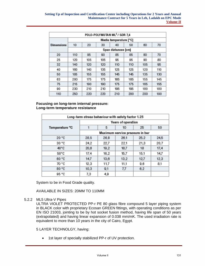
Setting Up of Inspection and Certification Center including Operations for 2 Years and Annual
Maintenance Contract for 5 Years in Leh, Ladakh on EPC Mode
Volume-II
Focusing on long-term internal pressure: Long-term temperature resistance
System to be in Food Grade quality. AVAILABLE IN SIZES: 20MM TO 110MM
5.2.2 ML5 Ultra-V Pipes ULTRA VIOLET PROTECTED PP-r PE 80 glass fibre compound 5 layer piping system in BLACK color with proprietary Ecosan GREEN fittings, with operating conditions as per EN ISO 21003, jointing to be by hot socket fusion method, having life span of 50 years (extrapolated) and having linear expansion of 0.038 mm/mK. The used irradiation rate is equivalent to more than 10 years in the city of Cairo, Egypt. 5 LAYER TECHNOLGY, having:
• 1st layer of specially stabilized PP-r of UV protection.
Volume II 131
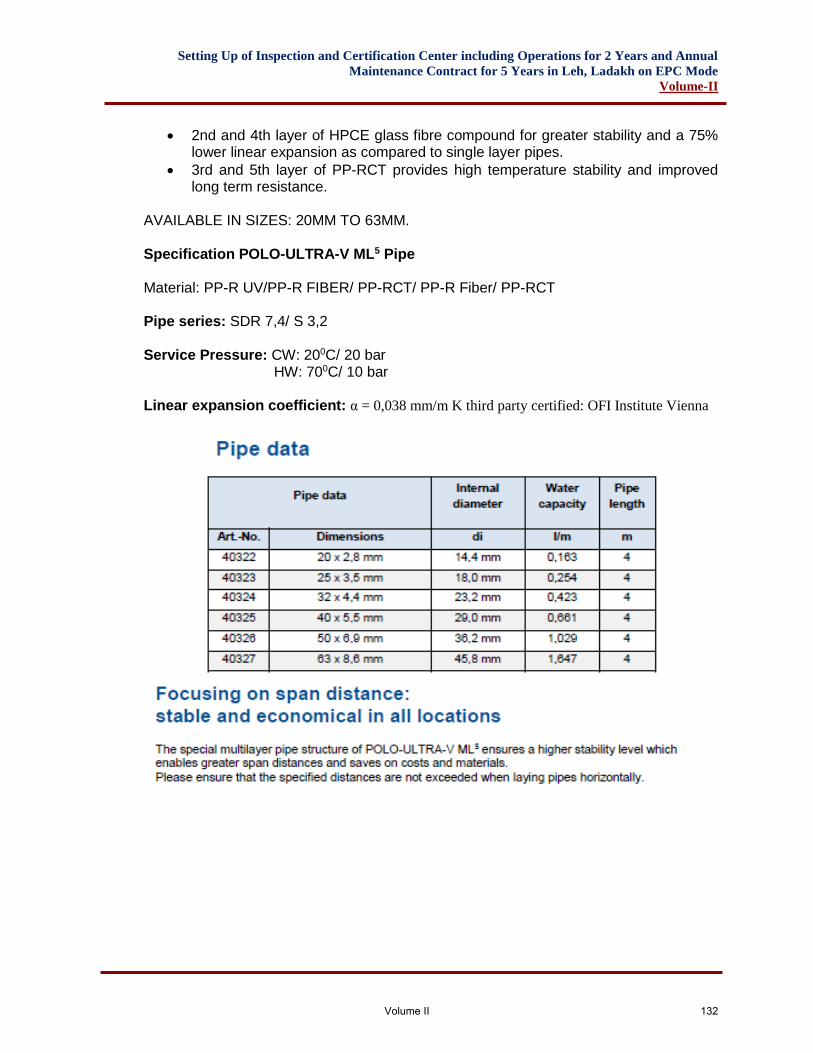
Setting Up of Inspection and Certification Center including Operations for 2 Years and Annual
Maintenance Contract for 5 Years in Leh, Ladakh on EPC Mode
Volume-II
• 2nd and 4th layer of HPCE glass fibre compound for greater stability and a 75% lower linear expansion as compared to single layer pipes.
• 3rd and 5th layer of PP-RCT provides high temperature stability and improved long term resistance.
AVAILABLE IN SIZES: 20MM TO 63MM. Specification POLO-ULTRA-V ML5 Pipe Material: PP-R UV/PP-R FIBER/ PP-RCT/ PP-R Fiber/ PP-RCT Pipe series: SDR 7,4/ S 3,2 Service Pressure: CW: 200C/ 20 bar HW: 700C/ 10 bar Linear expansion coefficient: α = 0,038 mm/m K third party certified: OFI Institute Vienna
Volume II 132
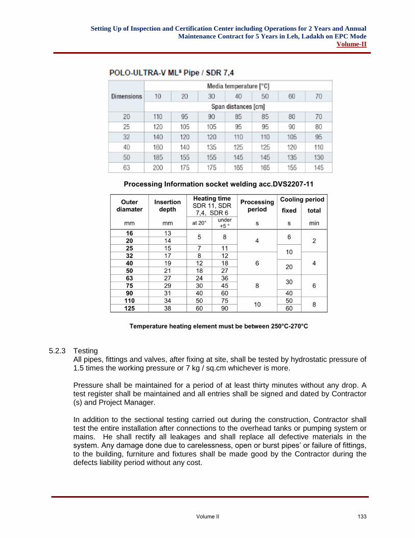
Setting Up of Inspection and Certification Center including Operations for 2 Years and Annual
Maintenance Contract for 5 Years in Leh, Ladakh on EPC Mode
Volume-II
5.2.3 Testing All pipes, fittings and valves, after fixing at site, shall be tested by hydrostatic pressure of 1.5 times the working pressure or 7 kg / sq.cm whichever is more. Pressure shall be maintained for a period of at least thirty minutes without any drop. A test register shall be maintained and all entries shall be signed and dated by Contractor (s) and Project Manager. In addition to the sectional testing carried out during the construction, Contractor shall test the entire installation after connections to the overhead tanks or pumping system or mains. He shall rectify all leakages and shall replace all defective materials in the system. Any damage done due to carelessness, open or burst pipes’ or failure of fittings, to the building, furniture and fixtures shall be made good by the Contractor during the defects liability period without any cost.
Volume II 133
Setting Up of Inspection and Certification Center including Operations for 2 Years and Annual
Maintenance Contract for 5 Years in Leh, Ladakh on EPC Mode
Volume-II
After commissioning of the water supply system, Contractor shall test each valve by closing and opening it a number of times to observe if it is working efficiently. Valves, which do not effectively operate, shall be replaced by new ones at no extra cost and the same shall be tested as above. Hot water pipes chased into the walls shall be provided with a 6mm thick insulation with elastic flexible material having hermetic closed cell structure of expanded synthetic material rated for 60ºC hot water supply.
5.2.4 Measurement a) Pipes above ground shall be measured per linear meter (to the nearest cm) and
shall be inclusive of all fittings e.g. coupling, tees, bends, elbows, unions, flanges and U clamps with nuts, bolts & washers fixed to wall or other standard supports.
b) Jointing with teflon tape, white lead, solvent, crimping and insertion gasket of appropriate temperature grade.
c) Cutting holes, and chases in walls, floors, any pipe support required for pipes below ground & making good the same.
d) Excavation, backfilling, disposal of surplus earth and restoring the ground & floor in original condition.
5.2.5 Pipe Supports
Fabricated and / or galvanised supports shall be measured by weight. Weight for each type of clamp shall be calculated on basis of the quantity of structurals and MS used from the theoretical weight calculated on basis of the components theoretical weight of the sections.
5.2.6 Valves a) Valves 50 mm and above shall be cast iron lever operated butterfly valve as per
IS: 13095 of PN-16 rating. b) Valves 50 mm dia and below shall be lever operated valves, screwed type of gun
metal body as per IS:318 with SS ball and SS stem with mild steel lever tested to 35.5 Kg/cm2 of PN-16 rating.
c) Non-return 50 mm and above valve shall be dual plate wafer check valve of PN-16 rating.
d) Non-return valve 50mm and below shall be gunmetal swing check valve confirming to IS: 778 Class-2 tested to 24.5 Kg/cm2.
5.2.7 Float Valves The ball valves shall be of heavy duty and shall be of the size as specified. The body of the ball valves shall be capable of withstanding a pressure of 10kg/ cm2. A high pressure ball valves with the float immersed not more than half of its volume shall remain closed against a test pressure of 6kg/cm2 The ball valves shall conform to IS:1703 (or as revised).
5.2.8 Underground Reservoir Underground reservoir shall be RCC as shown in drawings and as per specifications detailed in chapter for civil works. The tanks shall be provided with adequate heavy duty
Volume II 134
Setting Up of Inspection and Certification Center including Operations for 2 Years and Annual
Maintenance Contract for 5 Years in Leh, Ladakh on EPC Mode
Volume-II
manhole covers, inlet, outlet, overflow, scouring and ventilation pipes jointed to the tank with puddle flanges of sizes as stated in Bill of Quantities. .
5.2.9 Water Meters Water meters of approved make and design shall be supplied and installed at locations as shown. The water meters shall meet the approval of the local water supply authorities. All meters shall conform to Indian Standard IS:779-1978 or IS:2373-1981 and of approved manufacture. Where called for water meter shall be located in masonry chambers of size as indicated in Bill of Quantities.
5.2.10 Insulation for Hot Water Pipes Concealed Pipes All CPVC hot water supply pipes shall be insulated with Class-O Kaiflex ST Insulations rubber rings. The rubber ring shall be 6 mm thick for all diameter of pipes. The insulation shall be suitable for maximum line temperature of +1050 C and minimum line temperature -400 C. The insulation shall have density of 50-110 Kgs./ Cum. The thermal conductivity of insulation at 00 C shall be 0.036. The insulation shall have noise reduction level to 35 dB (A).
5.2.11 Exposed Pipes All CPVC hot water supply pipes shall be insulated with 32mm thick resin bonded preformed mineral wool pipe sections of density not less than 144 kg/cum. as per IS:9842 and applying 26g Aluminum sheet as cladding, properly rolled and grooved with joints sealed with a strap of roofing felt (type-III Grade-I conforming to IS:1322) complete with self tapping screws centre to centre distance of 150mm to close cladding joints.
5.3 SEWERAGE AND STORM WATER DRAINAGE
5.3.1 Stone-ware Pipes
A. General Stoneware pipes shall be salt glazed, sound, free from cracks, deformities and imperfections in glazing. They shall be cylindrical, straight and to standard dimensions. They shall be made of hard burnt stoneware of dark grey colour, and thoroughly glazed and shall give a sharp clear note when struck with a light hammer. The pipes shall conform to the requirements of Indian Standard No. IS:651.
B. Laying All pipes shall be laid on a bed of 15 cm thick cement concrete 1:5:10 mix or as specified, projecting on each side of the pipe to the specified width of the trench W. W = D + X Where D = External diameter of the pipe
Volume II 135
Setting Up of Inspection and Certification Center including Operations for 2 Years and Annual
Maintenance Contract for 5 Years in Leh, Ladakh on EPC Mode
Volume-II
X = 300 upto trench depth of 1.2m X = 400 trench depth more than 1.2m. The pipes with their crown level at 1.20 m depth and less from ground shall be covered with 15 cm thick cement concrete 1:5:10 mix above the crown of the pipe and sloped off to meet the outer edges of the base concrete to give a minimum thickness of 15 cm alround the pipe. Pipes laid at a depth greater than 1.2m at crown shall be concreted at the sides upto the level of the centre of the pipe and sloped off from the edges to meet the pipe tangentially. Pipes shall be laid true to line and grade as specified. Laying of pipes shall proceed upgrade of a slope.
C. Jointing Tarred gasket of hemp yarn soaked in thick cement slurry shall first be placed round the spigot of each pipe and the spigot shall then be slipped home well into the socket of the pipe previously laid. The pipe shall then be adjusted and fixed in the correct position and the gasket caulked tightly home so as to fill not more than 1/4th of the total depth of the socket. The remaining depth of the socket shall then be filled with a stiff mixture of cement mortar 1:1 (1 cement: 1 fine sand). When the socket is thus filled a fillet shall be formed round the joint with a trowel forming an angle of 45o with the longitudinal axis of the pipe on both sides of the collar. The joints shall be cured for atleast four days.
D. Testing Pipes and joints shall be subjected to a test pressure of 1.5 m head of water at the highest point of section under test for two hours without developing leaks/falls in pressures. If any leakage is observed, it shall be made good and test repeated till achieving satisfactory results. Any defective pipes shall be replaced. The joints shall remain exposed until the testing has been completed.
5.3.2 Cement Concrete Pipes:
A. General The pipes shall be with reinforcement as required and shall be of specified class. These shall conform to IS:458-1988. The reinforced cement concrete pipes shall be manufactured by centrigual (or spun) process. All pipes shall be true to shape, straight, perfectly sound and free from cracks and flaws. The external and internal surface of the pipes shall be free from defects resulting from imperfect grading of the aggregate mixing.
B. Laying All RCC pipes shall be laid on a bed of 15cm thick cement concrete 1:5:10 mix projecting on each side of the pipe to the full width of the trench and shall be concreted at the sides upto the level of the centre of the pipe and sloped off from the edges to meet the pipe tangentially.
Volume II 136
Setting Up of Inspection and Certification Center including Operations for 2 Years and Annual
Maintenance Contract for 5 Years in Leh, Ladakh on EPC Mode
Volume-II
Pipes shall be laid true to line and grade or specified. Laying of pipes shall proceed upgrade of a slope.
C. Jointing After setting out the pipes the collar shall be centered over the joint and filled in with tarred gasket, till sufficient space is left on either side of the collar to receive the mortar. This space shall then be filled with cement mortar 1:1 (1 cement : 1 coarse sand) and caulked by means of proper tools. All joints shall be finished at an angle of 45 degree to the longitudinal axis of the pipe on both sides of the collar. The joints shall be cured for atleast 4 days.
D. Testing Same as testing of stoneware pipes refer 1.3.1(D)
5.3.3 Manholes/Chambers/Catch pits
A. General The contractor shall construct all manholes, chambers, etc. in 75 class brick-work to such levels, dimensions and specifications as shown on the drawings or as specified in the Bill of Quantities.
B. Masonry Work All masonry and plastering work shall be done as per specifications as stated in Civil works. All manholes shall be plastered inside with cement mortar 1:3 (1 cement: 3 sand) mixed with water proofing compound finished with a floating coat of neat cement. Manholes shall be plastered outside 150mm from the bottom of top slab with cement mortar 1:4 (1 cement : 4 sand) mixed with water proofing compound.
C. Base Concrete All manholes shall have a base of cement concrete 1:4:8 (1 cement: 4 sand: 8 aggregates) 200 mm thick or as shown on drawings. Channelling and benching shall be formed to the full depth of the diameter of the pipe with cement concrete 1:2:4 (1 cement 2 sand : 4 aggregate) finished with a floating coat of neat cement.
D. M.S. Steps All manholes above 800 mm depth shall have MS steps 20 x 20mm square. These shall be embedded 20 cm deep with 20x20x20cm blocks of cement concrete 1:3:6 (1 cement : 3 coarse sand : 6 graded stone aggregate 20 mm nominal size). The block with MS foot rests placed in its centre shall be cost in situ alongwith the masonry and surface finished with 12mm thick cement plaster 1:3 (1 cement : 3 coarse sand) finished smooth. Foot rests shall be fixed 30 cm apart vertically and staggered laterally and shall project 10 cm beyond the surface of the wall. The top foot rest shall be 45 cm below the manhole cover. Foot rests shall be painted with two coats of coal-tar, the portion embedded in the masonry or cement concrete block shall be painted with thick cement slurry before fixing.
E. Fixing of C.I. frame for manhole cover
Volume II 137
Setting Up of Inspection and Certification Center including Operations for 2 Years and Annual
Maintenance Contract for 5 Years in Leh, Ladakh on EPC Mode
Volume-II
C.I. frames for manhole cover of the specified size and weight shall be embedded in reinforced cement concrete slab 1:2:4 (1 cement : 2 coarse sand : 4 graded stone aggregate 20 mm nominal size) 15 cm thick. Reinforcement shall be done as detailed in the drawings. The reinforced cement concrete slab shall be plastered after fixing of the frame underneath with 12 mm thick cement mortar 1:3 (1 cement : 3 fine sand) and finished on top with a floating coat of neat cement mortar.
F. Manhole cover & Frames Size of manholes and weight and size of cover shall be as follows unless otherwise specified in the Bill of Quantities. All manholes covers shall fit properly and bed evenly without racking in their frames. Covers shall be sealed with grease upon final completion and testing.
G. Lifting Keys A set of lifting keys shall be supplied by the Contractor.
5.3.4 Excavation for Sewers/Storm Water Drains
A. Alignment and Grading The drains are to be laid to alignment and gradients shown on the drawings but subject to such modifications as shall be ordered by the Engineer-in-Charge from time to time to meet the requirements of the works. No deviations from the lines, depths of cuttings or gradients of drains shown on the plans and sections shall be permitted except by the express direction in writing of the Engineer-in-Charge.
B. Excavation in Tunnels The excavation for drainage works shall be open cutting unless the permission of the Engineer-in-Charge for the ground to be tunnelled is obtained in writing. Where drains have to be constructed along narrow passages, the Engineer-in-Charge may order the excavation to be made partly in open cut and partly in tunnel and in such cases, the excavated soil shall be removed at once so as not to block up the passage and shall be brought back later on for refilling of the trenches or tunnels.
C. Obstruction of Roads The Contractor shall not occupy or obstruct by his operation more than one half of the width of any road or street and if the space is insufficient, for public and private transit, he shall remove the materials excavated and bring them back again when the trench is required to be refilled at no extra cost to the corporation. The contractor shall obtain the consent of the Engineer-in-Charge as well as from local Municipality or any other appropriate Authorities in writing before closing of roads to vehicular traffic. The footpaths/sidewalks must be kept clear at all times.
D. Removal of Filth All nightsoil, filth or any other offensive matter met with during the execution of the works, immediately after it is taken out of any trench, sewer or cess-pool, shall not be deposited upon the surface of any street where it is likely to cause nuisance or passed
Volume II 138
Setting Up of Inspection and Certification Center including Operations for 2 Years and Annual
Maintenance Contract for 5 Years in Leh, Ladakh on EPC Mode
Volume-II
into any sewer or drain but shall be at once put into carts and removed to a suitable place as approved by the local Municipality or any other appropriate authority.
E. Excavation to be taken to Proper depths The trenches shall be excavated to such a depth that the pipes shall rest evenly on prepared bed as described in the several clauses relating thereto and so that the inverts may be at the levels shown in drawings. In bad ground, the Engineer-in-Charge may order the Contractor to excavate to a greater depth than that shown on the drawings and to fill up the excavation to the level of the drain with concrete, broken stone, gravel or other materials. Any such extra excavation and concrete shall be paid extra at the rate laid down for such works in the schedule, but if the Contractor should excavate the trench to a greater depth than is required without a specific order to that effect in writing of the Engineer-in-Charge, the extra depth shall have to be filled up with concrete at the Contractor’s own cost and charges to the requirements and satisfaction of the Engineer-in-Charge.
F. Refilling After the pipes has been laid and proved to be watertight, the trench or other excavations shall be refilled. Utmost care shall be taken in doing this, so that no damage shall be caused to the sewer and other permanent work. The filling in the haunches and upto 75 mm above the crown of the pipe, shall consist of the finest selected materials placed carefully in 20 cm layers and flooded and consolidated. After this has been laid, the trench and other excavation shall be filled carefully in 20 cm layers with materials taken from the excavation, each layer being watered for proper consolidation, unless the Engineer-in-Charge shall otherwise direct.
G. Contractors to restore settlements and damages The Contractor shall, at his own cost and charges make good promptly during the whole period the works are in hand, any settlements that may occur in the surfaces of roads, berms, footpaths, gardens, open spaces, etc., whether public or private, caused by his trenches or his other excavations and he shall be liable for any accidents caused thereby. He shall also, at his own expense and charges, repair and make good any damage done to buildings and other property. If in the opinion of the Engineer-in-Charge he fails to make good or pay or satisfy the expenses of making good such works with all practabledespatch, the Engineer-in-Charge shall be at liberty to get the work done by other means and the expenses thereof shall be paid by the Contractor and deducted from any money that may be or become due to him or recovered from him in any other manner according to the law of the land.
H. Disposal of Surplus Soil The Contractor shall, at his own costs and charges, provide places for disposal of all surplus materials not required to be used on the works. As each trench is refilled, the surplus soil shall be immediately removed, the surface properly restored and road-ways and sides left clear.
I. Timbering of Trenches The Contractor shall at all times support efficiently and effectively the sides of the trenches and other excavations by suitable timbering, piling and sheeting and they shall
Volume II 139
Setting Up of Inspection and Certification Center including Operations for 2 Years and Annual
Maintenance Contract for 5 Years in Leh, Ladakh on EPC Mode
Volume-II
be close-timbered in loose or sandy strata and below the surface of the subsoil water level, without any extra cost. All timbering, sheeting and piling with their wallings, and supports shall be of adequate dimensions and strength and fully braced and strutted so that no risk of collapse or subsidence of the walls of the trench shall take place. The Contractor shall be held responsible and accountable for the sufficiency of all timbering, bracing, sheeting and piling used for, all damage to persons and property resulting from the improper quality, strength, placing, maintaining or removing of the same.
J. Shoring of Buildings The Contractor shall shore up all buildings, walls and other structures, the stability of which is liable to be endangered by the execution of the work and shall be fully responsible for all damages to persons or property resulting from any accident to any of such buildings.
K. Removal of Water from Trenches, etc. The Contractor shall at all times during the progress of work keep the trenches and excavations free from water which shall be disposed off by him in a manner as will neither cause injury to the public health nor to the public or private property nor to the work completed or in progress nor to the surface of any roads or streets, nor cause any intereference with the use of the same by the public. The Contractor shall not be paid any extra for dewatering of the trenches.
L. Width of Trenches Width of the trenches shall be generally pipe diameter plus 45 cm, if not otherwise required or directed by the Engineer-in-Charge.
5.4 SOIL, WASTE AND VENT AND FITTINGS Noise Insulated Piping System (POLOPLAST – POLO-KAL NG)
5.4.1 Socket Pipes Three Layer sound insulated Polypropylene piping (PP) system as per ON EN 1451-Part 1-6 & EN 12056 Part 1-5 with 3 layer pipe made of PP-C + PP-MV + PP-C in Blue Ral 5014 (halogen and calcium free) colour, push-fit type, food safe, having high impact and stiffness, offering sound levels of not more than 21 dBA with POLO clip HS/ 22 dBA with Bismat 2000 clamp /equivalent and 16 dBA with Bismat 1000 clamp/equivalent as per DIN 4109 at a flow rate of 4 l/s and having pipe ring stiffness as per 1S0/DIS 9969 and tightness as per EN 1277/B and C and DIN 19560, density = 1.25gms/cm3, elongation = 0.05mm/m0K and tensile strength > 24 N/mm2, with all necessary fittings in blue colour, fitted with factory fitted lip ring, having 3 layers, pipes to be painted with ordinary cement paint for external installation:
➢ INTERNAL LAYER: Of PP-C, hot water resistant to 97 degree C, tested in accordance to ON EN 1451-1 and DIN 19560, good heat and corrosion ageing stability as well as high chemical resistance and a smooth pipe inner-surface.
Volume II 140
Setting Up of Inspection and Certification Center including Operations for 2 Years and Annual
Maintenance Contract for 5 Years in Leh, Ladakh on EPC Mode
Volume-II
Color: Blue (halogen and calcium free)
➢ INTERMEDIATE LAYER: Of PP-MV compound reinforced with mineral aggregate, which guarantees greater stiffness and stability. Color: Grey.
➢ EXTERNAL LAYER: Of PP-C. With high impact resistance and good weathering resistance.
Color: Blue (halogen and calcium free).
5.4.2 Pipe Ring Stiffness: Pipe ring stiffness would be in accordance with IS0/DIS 9969 and TIGHTNESS as per EN 1277/B and C and DIN 19560.
5.4.3 Markings: All pipes shall carry the following markings: Batch number; year and week of manufacture; company name; dimension application class; stiffness class, test mark and material details.
5.4.4 Fittings: Single- Layered fitting reinforced with mineral aggregate, made of a Halogen free PP-C-KV synthetic material, a reinforced wall and factory fitted lip ring, hot water resistant upto 95 degree c in accordance to ON EN 1451-PART 1-6 EN 12056 PART 1-5. Color: Blue (halogen and calcium free)
5.4.5 Installation: The piping system must be clamped properly as required, pipes passing through walls, beams, slabs, columns should pass through sleeves which are padded with insulation material internally (between pipe and sleeve) covering the pipe to avoid transfer of body and structural borne sounds (refer manufacturer’s installation guide lines). The piping must not touch any wall, structure, paneling, false ceiling etc.
Volume II 141
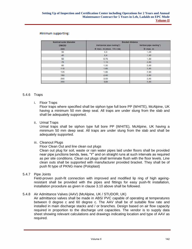
Setting Up of Inspection and Certification Center including Operations for 2 Years and Annual
Maintenance Contract for 5 Years in Leh, Ladakh on EPC Mode
Volume-II
5.4.6 Traps
i. Floor Traps
Floor traps where specified shall be siphon type full bore PP (WHITE), McAlpine, UK having a minimum 50 mm deep seal. All traps are under slung from the slab and shall be adequately supported.
ii. Urinal Traps
Urinal traps shall be siphon type full bore PP (WHITE), McAlpine, UK having a minimum 50 mm deep seal. All traps are under slung from the slab and shall be adequately supported.
iii. Cleanout Plugs
Floor Clean Out and line clean out plugs Clean out plug for soil, waste or rain water pipes laid under floors shall be provided near pipe junctions bends, tees, “Y” and on straight runs at such intervals as required as per site conditions. Clean out plugs shall terminate flush with the floor levels. Line clean outs shall be supported with manufacturer provided bracket. They shall be of push fit type of PKNG mane (Poloplast)
5.4.7 Pipe Joints
Field-proven push-fit connection with improved and modified lip ring of high ageing-resistant shall be provided with the pipes and fittings for easy push-fit installation, installation procedure as given in clause 3.10 above shall be followed.
5.4.8 Air Admittance Valves (AAV) (McAlpine, UK / STUDOR, UK) Air admittance valves shall be made in ABS/ PVC capable of operating at temperatures between 0 degree c and 60 degree c. The AAV shall be of suitable flow rate and installed in main discharge stacks and / or branches. Design based on air flow capacity required in proportion to the discharge unit capacities. The vendor is to supply data sheet showing relevant calculations and drawings indicating location and type of AAV as required.
Volume II 142
Setting Up of Inspection and Certification Center including Operations for 2 Years and Annual
Maintenance Contract for 5 Years in Leh, Ladakh on EPC Mode
Volume-II
AAV’s to have following performance parameter:
• Temperature range: -20 degree Celsius to 60 degree Celsius.
• Open pressure: -70 pa (-0.010 psi)
• Max. Pressure rating tightness: 10,000 pa (1 m/40” h2o) at 0 pa or higher
5.4.9 Maxi Filtra: Maxi Filtra shall be in black ABS to be installed at the outlet of the vent pipe discharging gases in the atmosphere. They are fitted with active carbon filters with iodine level being 1050mg/g. The replaceable carbon filters must be changed regularly as per manufacturer’s specifications.
5.5 SANITARY FIXITURES AND FITTINGS
5.5.1 Workmanship All sanitary-ware shall be fixed in a neat workmanlike manner, true to level and plumb. Manufacturer’s instructions shall be followed closely regarding installation and commissioning.
5.5.2 Protection of Fixtures Fixtures shall be protected throughout the progress of the work from damage. Special care shall be taken to prevent damage and scratching of chromium plated fittings. Tool marks on chromium fixtures, etc. shall not be accepted. All fixtures shall be fixed with chromium plated brass screws with washers whenever necessary. Protective paper on fixtures shall be removed with hot water only at the final completion of work.
5.5.3 Sanitary ware All porcelain sanitary ware shall be of first quality, free from warps, cracks and glazing defects. All sanitary ware, fittings and fixtures shall be as shown in drawings and indicated in Schedule of Quantities.
5.5.4 Testing When the installation has been completed to the satisfaction of the Engineer-in-Charge it shall be tested in the following manner: a) The entire system shall be slowly filled with water, allowing any trapped air to
escape. b) When all outlets are closed the system shall be checked for water tightness. c) Each outlet shall then be checked for rate of flow and correct operation.
5.6 SPECFICATIONS FOR CONSTRUCTION OF TUBEWELL
5.6.1 Scope of Work The scope of work comprises construction and development of 2 Nos 300 mm bore well giving a optimal yield including drilling of bore hole, collecting and recording well data, supply and installation of well assembly, development of the tubewell and carrying out various tests as specified.
Volume II 143
Setting Up of Inspection and Certification Center including Operations for 2 Years and Annual
Maintenance Contract for 5 Years in Leh, Ladakh on EPC Mode
Volume-II
5.6.2 Selection of Site
The site where tubewell is to be sunk as indicated in the drawing shall be examined by the driller and if necessary a more suitable alternative location shall be selected with the approval of the engineer so that the chances of success of tubewell might be increased. Any previous data available with the drilling agency regarding nearby tubewells or boring made for any other purpose may be used to evolve suitable procedure for drilling, developing, testing etc. of the tubewell to be sunk.
5.6.3 Test (Explanatory) Drilling In order to avoid disappointment and infructuous expenditure, it is desirable to drill a test hole first to the desired depth and collect preliminary data regarding static water level, type and nature of strata met, quality of water and probable yield that may be expected from the tubewell when completed. The cost of drilling test bore hole shall be deemed to be included in the rate of construction and development of tubewell.
5.6.4 Geological Data Samples of drill cuttings from different strata shall be collected at suitable intervals. The samples shall be collected at every 2 meter depth drilled or at closer intervals, if a change in the strata is met with. The samples shall be dried and stored in a neat cloth or polyethylene bags which shall be labelled clearly indicating the depth range of the strata. All such samples shall be sent to the required authority for testing, etc.
5.6.5 Drilling Time Log As the drilling progresses, an accurate drilling time log be kept indicating the time taken to drill each 3 metre depth.
5.6.6 Lowering of Pipe Assembly a) Housing pipe is provided in upper portion of the tubewell in which pumps and motor
assembly shall be accommodated. The pipe shall be of heavy duty and provided at least 0.6m above the ground level to have good and strong foundation.
b) Blind pipe - It shall be provided in non-acquifer portion and below housing pipe and
upto slotted pipe. The length of the blind pipe should be decided on the basis of non-acquifer portion or unwanted acquifer portion which are to be cased.
c) Slotted Pipe or Screen - The screen or slotted pipe shall be provided against the
required thickness of acquifer in order to allow ground water to be pumped into the tubewell.
d) The housing pipe, blind pipe and slotted pipe to be used in the tubewell shall be unplasticized PVC medium well casing pipes of required dia, conforming to IS: 12818. In order that the well assembly be centrally lowered in the bore, the housing and casing pipe to be fitted in allevium or over burden portion of the tubewell with
Volume II 144
Setting Up of Inspection and Certification Center including Operations for 2 Years and Annual
Maintenance Contract for 5 Years in Leh, Ladakh on EPC Mode
Volume-II
centralised guides specially approved by the Engineer-in-Charge. These guides shall be fitted at every 10 metre subject to minimum of 4 guides on each tubewell.
e) The slotted pipes to be used shall be unplasticized PVC medium well screen pipes
with ribs conforming to IS: 12818.
f) 1.5 metre long tail of uPVC blind pipe to be provided with close bottom and lifting hook of 20mm dia bars or tail plug of approved type shall be provided at the bottom of screen pipe.
g) Gravel Packing - Uniform gravel shall be used adjacent to the well screens. The
gravel must be fine enough to prevent the passage through its pores, the particles from the formation materials and coarse enough to give a lesser resistance so that the head loss in flow of water through it should be relatively small.
h) The gravel shall consist of clean, hard, well rounded uniform particles of silica or
quartz, free from dirt, foreign materials as well as flaky particles. The size of gravel will depend upon mechanical analysis of the aquifer materials for uniform aquifer. The packing of gravel around the well assembly will be a continous process and shall start from bottom upward. The gravel shall be packed systematically in layers through 35mm NB dia to 50mm NB dia uPVC pipe.
5.6.7 Drilling
a. The driller shall employ reverse circulation, direct rotary or cable percussion of DTH
process as approved by the Engineer-in-Charge to drill the bore hole. The driller shall provide all equipments necessary for the execution of the work at his own cost.
b. The driller shall make his own arrangement for electricity and water required for drilling purposes and also for ancillary excavation. He shall also arrange for the drilling mud and mud pump etc.
5.6.8 Lowering of Well Assembly
The lowering of assembly shall be done by the Contractor in the presence of the person duly authorised by the Engineer-in-Charge. The driller shall submit a chart showing the position in the bore and the location where slotted pipes or strainers have been placed including the location of joints. Verticality of the bore well shall be checked as per the standard approved practice and results shall be recorded in the proforma as given in Appendix-A.
5.6.9 Development Development of tubewell shall be carried out either by over pumping or by compressed air. Standard approved methods shall be adopted for development of tubewell. Rate of compressed air or water pumping shall be decided on the basis of strata conditions and as per approval of the Engineer-in-Charge. All equipment required to develop the tubewell shall be arranged without any extra cost. Development process shall be continued until the stabilization of sand and gravel-rock is completely assured.
Volume II 145
Setting Up of Inspection and Certification Center including Operations for 2 Years and Annual
Maintenance Contract for 5 Years in Leh, Ladakh on EPC Mode
Volume-II
5.6.10 Step Draw Down Test This test shall be conducted by installing a test pump in the tubewell temporarily and pumping out water at various speeds or by throttling delivery sluice valve. At each rate of discharge pumping shall be carried out at least for 30 minutes. If the water level and discharge are found to be fluctuating, development shall be carried out for some more hours until the discharge becomes steady and sand content is within tolerable limits. The specific capacities of the well for various pumping rates shall be computed based on the step draw down test data.
5.6.11 Yield Test The yield test of the tubewell shall be carried out by pumping out well water, after the well is satisfactorily developed. Pumping rate shall be increased gradually until the desired draw down is attained. The pumping shall be continued at the same draw down for at least 10 hours and may be increased to 12 hours as required by the Engineer-in-Charge. Necessary samples shall be collected and stored as per standard approved procedure and arranged for testing at approved laboratory for chemical and biological characteristics of the water. The yield test shall be carried out in accordance with tubewell department’s standards as per para 5.3 of IS 2800, Part II, 1979. The driller shall obtain certificate of successful construction of the tubewell from the Engineer-in-Charge and the local authorities. In the event of a tubewell declared unsuccessful by the Engineer-in-Charge, the driller shall remove the tubewell assembly by jacking or any other method approved by the Engineer-in-Charge so that no part of the well assembly is damaged. An abandoned tubewell, after removal of tubewell assembly, shall be suitably backfilled with the natural material of the encountered and duly rammed at ground level with allowances for settlement by the driller. The cost of removal of tubewell assembly from abandoned tubewell and back filling etc. shall be deemed to be included in the rate of boring of the tubewell.
5.6.12 Quality of Water Water shall be collected during aquifer performance test and analysed chemically, as desired by the Engineer-in-Charge, for different constituents depending upon the ultimate use of the water.
5.6.13 Sanitary Sealing The annular space between the bore and the housing pipe shall be cement grouted up to 5 metres below ground level or up to first clay bed whichever is obtained first and two gravel feeding pipes on either side of housing pipe to the full depth of foundation to be provided
5.6.14 Handing over of the Tubewell The tubewell shall be handed to the Engineer-in-Charge in a complete shape. The housing pipe shall be closed by a well cap for the period between the completion of the
Volume II 146
Setting Up of Inspection and Certification Center including Operations for 2 Years and Annual
Maintenance Contract for 5 Years in Leh, Ladakh on EPC Mode
Volume-II
tubewell and the installation of the pump set. The cap shall be of such a design that it is easily removable causing no damage to the housing pipe. The following information shall be furnished by the drilling agency to the Engineer-in-Charge on completion of the tubewell:
a) Strata chart of the bore hole indicating the different types of soil met with at different depths, and granular zones.
b) Samples of strata collected, neatly packed and correctly marked in sample bags; c) Chart of actual pipe assembly lowered indicating the sizes of pipes, depth ranges
where slotted pipes have been used, depth and diameter of housing pipe, reduced level of the top of the housing pipe, and the diameter and depth of bore hole;
d) Hours of developing by compressed air, pump sets or by other means; e) Results of mechanical (sieve) analysis of samples of aquifer material, wherever
applicable; f) Recommendation on the safe pumping yield, pump-setting and specification for
suitable pump set; g) Report on the chemical and bacteriological tubewells water. h) Appendix - A, giving the required details indicated in the Performa.
Volume II 147
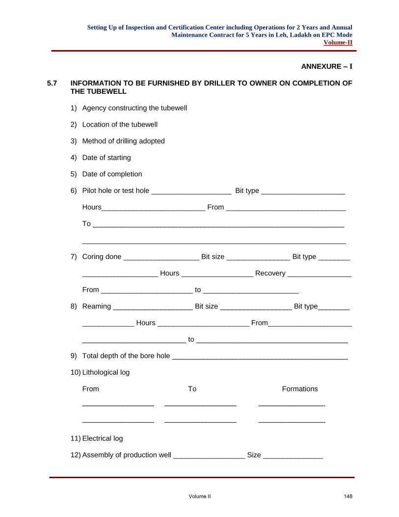
Setting Up of Inspection and Certification Center including Operations for 2 Years and Annual
Maintenance Contract for 5 Years in Leh, Ladakh on EPC Mode
Volume-II
ANNEXURE – I
5.7 INFORMATION TO BE FURNISHED BY DRILLER TO OWNER ON COMPLETION OF
THE TUBEWELL 1) Agency constructing the tubewell
2) Location of the tubewell
3) Method of drilling adopted
4) Date of starting
5) Date of completion
6) Pilot hole or test hole ____________________ Bit type _____________________
Hours__________________________ From ______________________________
To _______________________________________________________________ __________________________________________________________________
7) Coring done ___________________ Bit size ________________ Bit type ________ ___________________ Hours __________________ Recovery ________________ From _______________________ to ________________________
8) Reaming ____________________ Bit size __________________ Bit type________
_____________ Hours _______________________ From_____________________ __________________________ to ______________________________________
9) Total depth of the bore hole ____________________________________________ 10) Lithological log
From To Formations —————————— —————————— —————————- —————————— —————————— —————————-
11) Electrical log 12) Assembly of production well __________________ Size _______________
Volume II 148
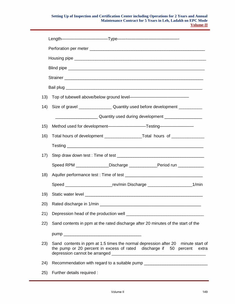
Setting Up of Inspection and Certification Center including Operations for 2 Years and Annual
Maintenance Contract for 5 Years in Leh, Ladakh on EPC Mode
Volume-II
Length———————————Type——-————————————-
Perforation per meter _________________________________________________ Housing pipe ________________________________________________________ Blind pipe __________________________________________________________ Strainer ___________________________________________________________ Bail plug __________________________________________________________
13) Top of tubewell above/below ground level—————————————— 14) Size of gravel ______________ Quantity used before development __________
__________________ Quantity used during development ________________ 15) Method used for development—————————Testing———————— 16) Total hours of development ________________Total hours of ______________
Testing __________________________________________________________
17) Step draw down test : Time of test _____________________________________
Speed RPM ______________Discharge ____________Period run ___________
18) Aquifer performance test : Time of test _________________________________
Speed ____________________rev/min Discharge ___________________1/min
19) Static water level __________________________________________________ 20) Rated discharge in 1/min ___________________________________________ 21) Depression head of the production well _________________________________ 22) Sand contents in ppm at the rated discharge after 20 minutes of the start of the
pump _________________________________ 23) Sand contents in ppm at 1.5 times the normal depression after 20 minute start of
the pump or 20 percent in excess of rated discharge if 50 percent extra depression cannot be arranged ________________________________________
24) Recommendation with regard to a suitable pump ___________________________
25) Further details required :
Volume II 149
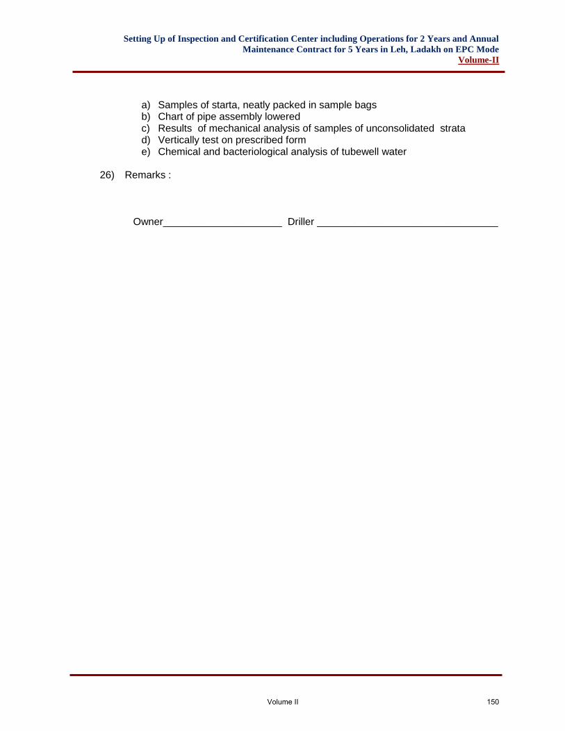
Setting Up of Inspection and Certification Center including Operations for 2 Years and Annual
Maintenance Contract for 5 Years in Leh, Ladakh on EPC Mode
Volume-II
a) Samples of starta, neatly packed in sample bags b) Chart of pipe assembly lowered c) Results of mechanical analysis of samples of unconsolidated strata d) Vertically test on prescribed form e) Chemical and bacteriological analysis of tubewell water
26) Remarks : Owner_____________________ Driller ________________________________
Volume II 150
Setting Up of Inspection and Certification Center including Operations for 2 Years and Annual
Maintenance Contract for 5 Years in Leh, Ladakh on EPC Mode
Volume-II
ANNEXURE – II
5.8 INFORMATION TO BE FURNISHED BY THE DRILLING AGENCY
When offering to sink a tubewell, the drilling agency shall furnish the following information:
a) Suitability of the site proposed. If a more suitable point, other than the one proposed exists or is available, it should be suggested.
b) Whether a test bore hole is proposed and, if so, its diameter and depth; and Depth of tubewell proposed.
c) Likelihood of increasing or decreasing the depth given at (b) above. d) Method of drilling. e) Sizes and types of pipes, strainers, or slotted pipes, etc. proposed to be used. f) Probable yield of water to be obtained. g) Guarantees with regard to the verticality of tubewell and sand content in
discharge in parts per million at the time of handing over the well; and h) Any other information
5.9 SPECIFICATIONS FOR WATER SUPPLY PUMPS & WATER TREATMENT
SYSTEM
5.9.1 Scope of Work The Scope of work in this subhead shall consist of furnishing all labour, materials, equipment and appliances necessary and required to completely do all work relating to the supply, installation, testing & commissioning of water pumping and water treatment as described hereinafter and shown on the drawings. The work shall include the following:- Supply, installation, testing & commissioning of
a) Water supply pumps & drainage pumping system. b) Water filtration system. c) Electrical works related with water supply pumps & water treatment plant. d) Painting of equipment and piping. e) Unloading of the equipment and placing in position at site. f) Foundation of equipments as required.
5.9.2 Contractor’s Experience
Contractors quoting for this work shall be engaged in the manufacture, work testing and installation of Pumping Systems and Water Treatment Plants. Contractors quoting for this work shall be engaged in the manufacture, work testing and installation of Pumping Systems and Water Treatment Plants. Contractor must have sufficient experience in the execution of turn-key projects.
Volume II 151
Setting Up of Inspection and Certification Center including Operations for 2 Years and Annual
Maintenance Contract for 5 Years in Leh, Ladakh on EPC Mode
Volume-II
Contractor must submit with the tender a list of similar jobs carried out by him in the last five years along with the name of works, name and address of clients, year of execution, capacity of plant and value of work.
5.9.3 Technical Information Contractor shall submit along with the tender copies of detailed specifications, cuts, leaflets, and other technical literature of equipment and accessories offered by him. Contractor’s attention is specially invited to the special conditions and other clauses in the agreement which required the contractor to :-
a) To Submit detail shop drawings. b) Use material of specific makes and brands. c) Obtain approval from various authorities as necessary and required. d) Execute the entire work on a turn-key basis so as to provide a totally operating
plant.
5.9.4 Exclusions Work under this contract does not include the following work:-
Electrical cables upto incoming motor control centre.
5.9.5 Site Accessibility
The equipment are to be located in pump house located at site.
The equipment must be carried from the goods receiving station to the site in an extremely careful manner to prevent damage to the equipment building or existing services.
Contractor must visit the site and familiarize himself with above problems to ensure that the equipment offered by him are of dimensions that they can be carried and placed in position without any difficulty.
5.9.6 General Requirements a) All materials shall be new and of the best quality conforming to specifications and
subject to the approval of the Engineer. b) All equipment shall be of the best available make manufactured by reputed firms. c) All equipments shall be installed on suitable foundations, true to level and in a
neat workmanlike manner. d) Equipment shall be so installed as to provide sufficient clearance between the
end walls and between equipment to equipment. e) Piping within the pump house shall be jointed with welded flanged joints.
5.9.7 Pumping System
Water supply pumps
Volume II 152
Setting Up of Inspection and Certification Center including Operations for 2 Years and Annual
Maintenance Contract for 5 Years in Leh, Ladakh on EPC Mode
Volume-II
Water supply pumps shall be monoblock vertical in line, single or multistage stainless steel pumps suitable for clean filtered water as per BOQ item.
5.9.8 Drainage Pumps All drainage pumps shall be portable submersible monoblock non clog pumps with totally water & dust proof motor compact in design. The motor portion shall be isolated from the pump by intermediate casing with double mechanical seal in oil chamber. The shaft shall be with die cast rotor on motor side & shaft protection sleeves on pump side and shall be with grease packed bearings and greesing pump. The motor housing shall be suitable for IP 68 protection. The motor shall be provided with built in temperature sensor enabling tripping of motor if temp rises above 150 Deg.C and restart at 80 Deg.C giving complete dry run protect. The pump shall be of capacities & head as given in Bill of Quantities. Level Controller/ Indicator Contractor shall provide and install low voltage transistorised level controllers/indicator as specified in Bill of Quantities. Each level controller/indicator shall be provided with required number of PVC sheathed stainless steel probes with necessary wiring and conducting. Neoprene flexible pipe connectors Suction and delivery lines of the pumps shall be provided with double flanged reinforced Neoprene flexible pipe connectors. Connectors shall be suitable for a working pressure of each pump as specified in Bill of Quantities.
5.9.9 Piping Pipes for suction and delivery line shall be galvanised steel tubes to IS:1239 (Heavy Class). Fittings shall be malleable cast iron fittings as per IS:1879.
5.9.10 Joints All G.I. pipes and fittings shall be provided with welded flanged joints unless otherwise instructed.
5.9.11 Testing All G.I. pipes shall be tested hydrostatically for a period of two hours to a pressure of 15.0 Kg/Cum. without drop in pressure. Valves Valves 50 mm and above shall be cast iron lever operated butterfly valve as per IS: 13095 of PN-16 rating. Non-return 50 mm and above valve shall be dual plate wafer check valve of PN-16 rating. Valves 50 mm dia and below shall be lever operated valves, screwed type of gun metal body as per IS:318 with SS ball and SS stem with mild steel lever tested to 35.5 Kg/cm2 of PN-16 rating.
Volume II 153
Setting Up of Inspection and Certification Center including Operations for 2 Years and Annual
Maintenance Contract for 5 Years in Leh, Ladakh on EPC Mode
Volume-II
Non-return valve 50mm and below shall be gunmetal swing check valve confirming to IS: 778 Class-2 tested to 24.5 Kg/cm2.
5.10 WATER TREATMENT SYSTEM
5.10.1 Water Filter
a) Water filter shall be dual media pressure filter / activated carbon filter suitable for a rate of filtration given in Bill of Quantities. The design fabrication and construction shall conform to the requirement of IS: 2825.
b) Filter shall be vertical type skid mounted of required diameter. The shell shall be fabricated from M.S. plates conforming to IS:2041 suitable to withstand as design pressure given in Bill of Quantities. The minimum thickness of shell shall be 6 mm and dished ends shall be 6 mm which shall include corrosion allowance and mill allowance respectively. The scaling allowance on dished ends to be considered by the bidder as per requirement of IS:2825. The filter shall have atleast one pressure tight manhole cover. Each filter shall be provided with screwed or flanged connection for inlet, outlet, individual drain connections necessary and required. Filter shall be painted inside with minimum two coats of non-toxic corrosion resistant paint and one coat of red oxide primer outside.
c) Under Drain System Each filter shall be provided with an efficient under drain system comprising of collecting pipes, polypropylene nozzle's of manufacturer design. The entire under drain system shall be supported on M.S. plate or cement concrete supports provided by the contractor.
d) Face Piping Each filter shall be provided within interconnecting face piping comprising of inlet, outlet and back wash complete with valves. Pipes shall be galvanised steel tubes to IS:1239 (Heavy Class). Fittings shall be malleable cast iron fittings as per IS:1879.
e) Accessories i. Air release valve with connecting piping. ii. 100 mm dia. Dial Bourden type gun metal pressure gauges with gun
metal isolation, cock and connecting piping on inlet and outlet, causing shall be with cast Aluminum stored enamel black finish cases.
iii. Sampling cocks on low water inlet and filtered water outlet. iv. Connection with valve for air scouring.
f) Each filter shall be provided with clean and washed filter media of type and
depths as recommended by the manufacturer.
g) Back Wash Backwash flow rate shall be 400 gallons/hr./sq.ft which shall be achieved by reversal of flow from water supply pumps through the pressure filter. Backwash shall be done once in 48 hours subject to the recommendations of manufacturer.
Volume II 154
Setting Up of Inspection and Certification Center including Operations for 2 Years and Annual
Maintenance Contract for 5 Years in Leh, Ladakh on EPC Mode
Volume-II
5.10.2 Chemical Dosing Pumps (for Chlorination) Chemical dosing pumps shall be reciprocating type with PVC or Ebonite head and adjustable stroke with 0-100% adjustment. Pump shall be driven by a totally enclosed vertical spindle motor suitable for 400/440 volts, 3 phase, 50 cycles, A.C. supply. Capacity of the pump shall be as per manufacturer’s recommendation. As the dose rate is likely to vary depending upon the quality of water select a pump of which operating capacity can be exceeded by further 50%.
5.10.3 Solution Tanks for Chlorination Provide one PVC/Rubber lined M.S. tank of minimum one day storage capacity for each pump considering the extended capacity of the pump.
5.10.4 Piping & valves for Water Treatment Plant a) Pipes shall be M.S. galvanised steel conforming to IS: 1239 (Heavy class) with
matching fittings jointed with welded flanged joints. b) Valves 50 mm and above shall be cast iron lever operated butterfly valve as per IS:
13095 of PN-16 rating. c) Non-return 50 mm and above valve shall be dual plate wafer check valve of PN-16
rating. d) Valves 50 mm dia and below shall be lever operated valves, screwed type of gun
metal body as per IS:318 with SS ball and SS stem with mild steel lever tested to 35.5 Kg/cm2 of PN-16 rating
e) Non-return valve 50mm and below shall be gunmetal swing check valve confirming to IS: 778 Class-2 tested to 24.5 Kg/cm2.
5.10.5 Flow Measurement
The contractor shall provide one bye-pass type Rota meter reading LPH on delivery line of filter and softener. The contractor shall supply one complete set of test kit for water treatment system.
5.10.6 Painting and Clean-up
a) One completion of the installation contractor shall scrub, clean all pumps, piping, filter, softener and other equipment and apply one coat of primer.
b) Apply minimum two coats of synthetic enamel paint. Type/make of paint shall be as per Engineer approval.
c) Provide painted identification legend and direction arrows on all equipment and piping as directed by the Engineer.
d) On final completion of the work, contractor shall clean up the site and pump room of all surplus materials, rubbish and leave the place in a broom clean condition.
5.10.7 Electrical Works
Volume II 155
Setting Up of Inspection and Certification Center including Operations for 2 Years and Annual
Maintenance Contract for 5 Years in Leh, Ladakh on EPC Mode
Volume-II
Cables
a) Contractor shall provide all power and control cables from motor control centre to various motors, level controllers and other control devices.
b) Cables shall conform to IS:1554 and carry ISI mark.
c) Wiring cables shall conform to IS:694.
d) All power cables shall be Aluminum conductor PVC insulated/PVC sheathed FRLS armoured cables of 1100 volts grade.
e) All control and wiring cables shall be copper conductor PVC insulated armoured
and PVC sheathed 600 volt grade.
f) All cables shall have stranded conductors. The cables shall be in drums as far as possible and bear manufacturer's name.
5.10.8 Motor Control Centres
Cubicles switch board of floor mounted and shall be fabricated from 16 gauge M.S. sheet with dust and vermin proof construction. It shall be painted with stove enamelled paint of approved make and shade. It shall be fitted with suitable etched plastic indentifications plates for each motor. The cubicles shall in general comprise of the following :
a. Incoming and outgoing MCCB’s of required capacity with rotary handle.
b. PVC Colourcoaded TPN Aluminum busbar having current density 0.8Amp/sq.mm.
c. Isolation switch fuse unit one for each motor.
d. Fully automatic DOL/Star Delta starters appropriate for motor rating with ON/OFF push buttons and on/off indicating neon lamps for individual motor.
e. Single phase preventor of appropriate rating for each motor.
f. Selector switch for pump operation.
g. Panel type ampere meters of appropriate rating one for each motor.
h. Panel type voltmeter on incoming main with rotary selector switch to read voltage between phase to neutral and phase to phase.
i. Rotary switch for manual or auto operation for each pump.
Volume II 156
Setting Up of Inspection and Certification Center including Operations for 2 Years and Annual
Maintenance Contract for 5 Years in Leh, Ladakh on EPC Mode
Volume-II
j. Space for liquid level controllers specified separately in this contract. The panel shall be prewired with colour coded wiring. All interconnecting wiring from incoming main to switch gear, meters and accessories with in the switch board panel.
5.10.9 Installation, Commissioning & Guarantees
5.10.10 Installation
a) Contractor shall supply three copies of foundation drawings giving weight, vibration and other loads required for the proper designing of the foundations.
b) All equipment shall be installed in a true workman like manner true to level and grade in accordance with the best current practice.
c) Contractor shall employ sufficient and proper equipment for lifting and placing of heavy equipment and in a manner which shall not strain or cause damage to the existing structures. If any damage is done, the same shall be made good to the satisfaction of the Engineer without any additional cost.
d) The contractor shall submit detailed shop drawings showing detailed layout of the system showing dia piping, valves etc. for approval of the Engineer. The work shall be started only after approval of shop drawings submitted by the contractor.
5.10.11 Commissioning
a) On completion of the work in all its aspects, the contractor shall start up the plant
in a manner normally done for the continuous operation for a period of not less than 48 hours and shall rectify and adjust the equipment for leakages and balancing the system.
b) After satisfactory commissioning of the plant, the contractor shall conduct performance tests on the pumps to satisfy the Engineer that all equipments are performing to the rated outputs any or all pumps and equipment shall be rectified or replaced if the same is not performing in accordance with the specifications.
5.10.12 Guarantees
a) On award of the work contractor shall submit a guarantee covering the quality
and performance of all materials supplied and installed under the contract. This guarantee shall cover each and every material whether manufactured by the contractor or not.
b) Contractor shall specify a suitable procedure to test the rated performance of the equipment and shall provide all necessary equipment, guages etc. for conducting such tests.
c) The guarantee shall cover a period of one year from the date of installation and handing over and commissioning of plant.
5.10.13 Completion
On completion of the job, the contractor shall hand over to the Engineer the following:
Volume II 157
Setting Up of Inspection and Certification Center including Operations for 2 Years and Annual
Maintenance Contract for 5 Years in Leh, Ladakh on EPC Mode
Volume-II
a) One flow chart drawn in ink on thick paper and mounted in a glass frame showing the flow diagram of the process including legend showing valves to be normally open or closed and instructions for operation and maintenance of the pumping equipment.
b) Five sets of operating and maintenance instructions with spare parts list and their manufactures and/or suppliers.
c) Five sets of catalogues and drawings for all equipment supplied. On final commissioning of the plant, contractor shall provide the services of one trained supervisor for period of two calendar weeks to train the Owners' staff in the operation and maintenance
5.11 SPECIFICATION FOR FIRE HYDRANTS SYSTEM
5.11.1 General Work under this subhead is time-bound and has to be completed within the time limit set in the tender. Work shall be executed in accordance with an agreed schedule which shall be submitted by the tenderers along with offer and agreed to by owners.
5.11.2 Scope of Work The scope of work in this subhead shall consist of furnishing all labour, materials, equipment and appliances necessary and required to completely do all work relating to the supply, installation, testing & commissioning of Fire Fighting Systems for Proposed Inspection and Certification Center At Leh Ladakh as described herein after and shown on the drawings. The scope of work in general shall include the following. i. Fire Fighting Pumps & Accessories and related electrical works ii. Internal Fire Hydrant System. iii. Hand appliances
Without restricting to the generality of the foregoing, the work shall include the following: The fire fighting system covering the entire complex and consisting of the following:
A. Five number of Pumps - One number Main electric end suction Pump of 1620 LPM at 56M head, one number Diesel Standby Pump of 1620 LPM at 56M head & one numbers Jockey Pump for System pressurization of 180 LPM at 56 M head.
B. Other piping system ancillaries such as Suction and Delivery Headers, Air
Vessel, Pressure Gauges, Pressure Switches, Pump Panel etc. as required.
C. Internal Hydrant system where required with single headed landing valves on each floor accompanied by 1 number swinging type Hose Reel, 2 numbers RRL Hoses, 1 numbers of Branch Pipe etc. all housed in the niche. Bidder shall provide front frame with shutter for niche.
D. Hand appliance as per Bill of Quantities.
Volume II 158
Setting Up of Inspection and Certification Center including Operations for 2 Years and Annual
Maintenance Contract for 5 Years in Leh, Ladakh on EPC Mode
Volume-II
E. To obtain the approval of the relevant drawings before actual installation at site
and to get the complete installation inspected and passed by the concerned authorities, as may be necessary as per local bye laws. (Any fee payable to the local bodies for such activities shall be included in the rate).
5.11.3 Contractor’s Experience
Contractors shall engaged specialist agency only for this work of Fire Fighting systems.
The selected specialist agency must have sufficient experience in the execution of turn-key projects as specified.
Contractor must submit with the tender a list of similar jobs carried out by him as required along with the name of works, name and address of clients, year of execution, capacity of plant and value of work.
5.11.4 Technical Information Contractor shall submit along with the tender copies of detailed specifications, cuts, leaflets, and other technical literature of equipment and accessories offered by him.
Contractor’s attention is specially invited to the special conditions and other clauses in the agreement which required the contractor to :-
Submit detailed shop drawings. Use material of specific makes and brands. Obtain all approvals from Fire Fighting authorities. Execute the entire work on a turn-key basis so as to provide a totally operating plant.
5.11.5 Exclusions Work under this contract does not include the following work:-
Electrical cables upto incoming motor control centre.
5.11.6 Site Accessibility
The equipments are to be located in pump house at site.
The equipment must be carried from the goods receiving station to the site in an extremely careful manner to prevent damage to the equipment building or existing services.
Contractor must visit the site and familiarize himself with above problems to ensure that the equipment offered by him are of dimensions that they can be carried and placed in position without any difficulty.
5.11.7 Approvals
Volume II 159
Setting Up of Inspection and Certification Center including Operations for 2 Years and Annual
Maintenance Contract for 5 Years in Leh, Ladakh on EPC Mode
Volume-II
The contractor shall prepare all submission drawings and obtain all approvals of fire fighting works from fire fighting authorities.
5.11.8 System Description The Fire fighting System shall comprise of AC motor driven pump sets, standby diesel pump set, jockey pump sets for pressurisation with all required accessories including valves, special fittings, instrumentation, control panels and any other components required to complete the system in all respects.
The Hydrant System shall be semi automatic in action and shall be laid covering the entire area externally and all the floors internally with independent piping system.
The fire fighting system comprising hydrant system shall be kept pressurised at all times. The proposed Jockey Pump shall take care of the leakages in the system, pipe lines and valve glands.
The pressure in the hydrant pipe work shall be kept constant at 7 Kg/cm2 for hydrant system. In the event of fire when any of the above systems operates/open, the resultant fall in header pressure shall start the AC motor driven fire pump as the case may be through pressure switches automatically. Hydrant system operates in case of fire with the help of manual landing valves & hose reels.. There shall be one Diesel Engine Driven pump as standby for all the three system. In case of failure of electricity or failure of Electric Pump to start on demand, the standby Diesel Pump shall automatically take over.
However, shutting down of the pump sets shall be manual except for the Jockey Pump which shall start and stop automatically through pressure switches. In addition to auto start arrangements, the main pump shall also have an over-riding manual starting facility by push button arrangement.
The Internal Hydrant System (Wet Risers) shall be provided at points as indicated on the drawing on each floor.
The hydrant point shall be directly tapped from the Riser pipes, and shall be furnished with required accessories such as
i. One no. SS single headed hydrant valves. ii. Two nos. RRL Hoses of size 63mm dia x 15m long. iii. One no. first aid Dunlop hose reel full swinging type 20mm dia x 30m long. iv. One no. SS Branch pipe.
The hydrant risers shall be terminated with air release valve at the highest points to release the trapped air in the pipe work. At each tapping from the Riser a Orifice Plate shall be located in the lower floors to reduce the pressure. To compensate for slight losses of pressure in the system and to provide an air cushion for counteracting pressure surges/water hammer in the underground pipe work Air Vessels shall be furnished in the pump room near fire pumps. The air vessel shall be
Volume II 160
Setting Up of Inspection and Certification Center including Operations for 2 Years and Annual
Maintenance Contract for 5 Years in Leh, Ladakh on EPC Mode
Volume-II
normally partly full of water and the remaining being filled with air which shall be under compression when the system is in normal operation.
The entire Wet Risers system shall be fed from the water supply (Static Water Tank) and pump room to be provided by the others.
5.11.9 General Specifications Pipe and Fittings Pipes for Wet Riser system shall be of Class-C, heavy duty black steel pipes. Pipes upto 150mm dia shall conform to IS-1239. Pipes with dia 200mm and above (6mm thick) shall confirm to IS-3589. All pipes shall be I.S.I. marked. Fittings for black steel pipes shall be M.S. forged fittings with tapered screwed threads. Jointing Joint for black steel pipes and fittings shall be metal-to-metal tapered thread or welded joints. A small amount of red lead may be used for lubrication and rust prevention in threaded joints. Joints between C.I. or black steel pipes, valves and other apparatus, pumps etc. shall be made with C.I. or M.S. flanges with appropriate number of bolts. Flanged joints shall be made with 3mm thick insertion rubber gasket. Note: Joints for pipes and fittings upto 50mm diameter shall be jointed by socket welded forged fittings. Joints for pipe and fittings above 50mm diameter shall be butt welded joints.
5.11.10 Pipe Protection All pipes in underground masonry trenches/service tunnels, above ground and in exposed locations shall be painted with one coat of red oxide primer and two or more coats of synthetic enamel paint of approved shade. Pipes in wall chases shall be protected from corrosion by 2 coats of bituminous paints. Protection of Underground Pipes: The underground steel pipes shall be protected by coating and wrapping. The coating and wrapping shall be done, in general, as per IS:10221-1982. The pipe coat primer shall have density of 0.92 gm/cc and drying time of 24 hours at RH 70% and temp. 30 C. Viscosity shall be 1000-2000 cps. The pipe coat shall be a puncture resistant non-woven polyester mat 4mm thick of high mechanical strength. The mat shall be in 7 layers. The layers shall be so arranged as to give extra protection to high molecular high density polythene core which is the main permeable agent in the system. Pipe coat Primer shall be applied on the pipe in a uniform coat leaving no drops runs. The entire surface of pipe should be primed without any patch left out. Unprimed
Volume II 161
Setting Up of Inspection and Certification Center including Operations for 2 Years and Annual
Maintenance Contract for 5 Years in Leh, Ladakh on EPC Mode
Volume-II
surfaces shall reprimed immediately. Any uncleaned pipe shall be scraped down to surface of pipe and reprimed Pipe coat Primer shall essentially be thin layer for quicker drying. The surface shall be dry at the time of applying Pipe coat Primer. Freshly primed pipe shall be placed on clean square cut skids and shall not be allowed to come in contact with ground or any foreign matter. It shall remain on skids until lifted or cradled after coating and wrapping operation. All primed pipes which have excessive coat of dust accumulated over them before primer is dry or where primer has become dead, shall be reprimed. Drying time shall be minimum 24 hours. The application of Pipecoat membrane shall be taken up soon after primer coat has dried up completely and in case within three days after priming. Otherwise fresh coat of primer shall be applied. Membrane shall be blown under tension by means of blowtorch. In this process, the inner surface of the membrane, being 10 micron thick polyethylene layer is burnt while at the same time the polymeric mix under it is softened taking care that the center core is not over heated. This molten polymeric mix is then passed over pipe surface so that no air is entrapped or voids formed underneath. Pipecoat Primer shall be applied with brushes after cleaning the pipe thoroughly. Pipecoat Membrane shall be wrapped as mentioned above. No wrinkling of the wrapper shall be allowed and all overlaps shall be firmly fused to secure a firm wrapping coating shall be absolutely free from pinholes and bubbles.
5.11.11 Installation of Pipes All pipes shall be adequately supported from ceiling or walls by structural clamps fabricated from M.S. structural e.g. rods, channels, angles and flats. All clamps shall be painted with one coat of primer and two coats of black enamel paint. The contractor shall provide inserts at the time of slab casting or provide suitable anchor fasteners. The pipe supports or hangers shall be designed to withstand combined weight of pipe, pipes fittings, fluid in pipe and insulation. Pipe supports shall be of steel and coated with rust preventing paint and finished with two coats black enamel paint. The maximum spacing for pipes supports shall be as below: Pipe (MM) Spacing (MTR) Size of support
Up to 25 2.0 6mm
32 to 65 2.4 8mm
75 to 125 2.7 10mm
150 & above 3.0 12mm
Volume II 162
Setting Up of Inspection and Certification Center including Operations for 2 Years and Annual
Maintenance Contract for 5 Years in Leh, Ladakh on EPC Mode
Volume-II
Pipes supports shall be spaced at maximum interval of 1.5 mtrs. on either side of heavy fitting and valves. Wherever piping passes through walls, pipes sleeves of diameter larger than that of piping shall be provided. Pipe sleeves shall be of steel or cast iron pipe. The underground piping shall be supported with cement concrete blocks of suitable size and strength provided at an interval of 2.5 mtrs. The pipes shall be laid at 1 mtr depth (top of the pipe) and trench excavated for sufficient width. The rate for pipe shall include the scope of excavation/refilling the trench. 1:2:4 concrete thrust blocks are also to be provided at turning of pipe. The cost of installation includes concrete pedestals etc. as required and to be included in the item rate.
5.11.12 Orifice Flanges Contractor shall provide orifice flanges fabricated from 6mm thick stainless steel plates on the branch lines feeding different zones/floors so as to allow required flow of water at a pressure of 3.5 kg/sq.cm. for each hydrants. The contractor shall provide orifice flanges to ensure the required pressure. The size of orifice plate shall be as per table 32 & 33 of IS code 15105:2002.
5.11.13 Air Release Valve Air Valves are to be provided on all high points in the system. These shall be 25 mm dia screwed inlet forged brass single acting air valves connected with ball valve on inlet side.
5.11.14 Valves a) Valves 50 mm and above shall be cast iron lever operated butterfly valve as per
IS: 13095 of PN-16 rating.
b) Valves 50 mm dia. and below shall be lever operated valves, screwed type of gun metal body as per IS:318 with SS ball and SS stem with mild steel lever tested to 35.5 Kg/cm2 of PN-16 rating.
c) Non-return 50 mm and above valve shall be dual plate wafer check valve of PN-16 rating.
d) Non-return valve 50mm and below shall be gunmetal swing check valve confirming to IS: 778 Class-2 tested to 24.5 Kg/cm2.
Each valve body shall be marked with cast or stamped lettering giving the following information’s: a) The manufacturer’s name or trade mark b) The size of the valve c) The guaranteed working pressure
5.11.15 Drain Valve
Drain Valves are to be provided at all low points in the system for draining the water. These shall be 50mm dia. full way ball valve fixed on 50mm dia black steel pipe.
5.11.16 Flow Switch Flow switch shall be provided on sectional mains as indicated on drawings or necessary and required and directed by the Engineer-in-charge.
Volume II 163
Setting Up of Inspection and Certification Center including Operations for 2 Years and Annual
Maintenance Contract for 5 Years in Leh, Ladakh on EPC Mode
Volume-II
5.11.17 Pressure Switches
Pressure switches shall be differential type for operation of all pumps and for the various duties and settings required. Pressure switches shall be for heavy duty operation and of approved make. All pressure switches shall be factory calibrated.
5.11.18 Internal Landing Valves The internal landing valves shall be SS sinlge-headed and conforming to IS: 5290. It shall be complete with hand -wheel, quick coupling connection spring loaded type and blank cap.
5.11.19 Hose pipes, Branch Pipes and Nozzles Hose Pipe: Hose pipe shall be rubber lined woven jacketed and 63mm in diameter. They shall conform to type-A (Reinforced rubber lined) of IS:639-1979. The hose shall be sufficiently flexible and capable of being rolled. Each run of hose pipe shall be complete with necessary coupling at the ends to match with the landing valve or with another run hose pipe or with Branch pipe. The couplings shall be of instantaneous spring lock type. Branch Pipe: Branch pipe shall be of SS 63mm dia and be complete with male instantaneous spring lock type coupling for connection to the hose pipe. The branch pipe shall be externally threaded to receive the nozzle. Nozzle: The nozzle shall be of copper or SS, 20mm in internal diameter. The screw threads at the inlet connection shall match with the threading on the branch pipe, the inlet end shall have a hexagonal head to facilitate screwing of the nozzle on to the branch pipe with nozzle spanner. End couplings, branch pipes, and nozzles shall conform to IS:903-1985. two hoses of 15 mtr. Lengths with couplings shall be provided with each external (yard) hydrant. One nozzle and one branch pipe with coupling shall be provided with each yard hydrant.
5.11.20 Internal Fire Hose Cabinet Each internal fire hydrant valve shall be housed in a nitch of size indicated on drawings. Each internal fire hose Cabinet shall hold single headed hydrant, 2 Hoses and 1 Branch pipe and 1 no. Dunlop hose reel mounted on a drum.
A. The cabinet shutters & frames shall be fabricated from boxed steel sections and MS plate 2mm thick.
B. The front glass of shutters shall be 5.0 mm thick clear float glass and shall be held by means of rubber. Locking arrangement shall also be made with one number of mortice lock of approved make. A separate Key Box of 16 mm thick MS sheet with glass facing shall be provided.
C. The Shutter shall be given a powder coat finish in post office red colour.
5.11.21 Hose Reel
Volume II 164
Setting Up of Inspection and Certification Center including Operations for 2 Years and Annual
Maintenance Contract for 5 Years in Leh, Ladakh on EPC Mode
Volume-II
The hose reel shall be directly tapped from the riser through a 25 mm dia pipe, the drum and the reel being firmly held against the wall by use of dash fasteners. The Hose Reel shall be swinging type (180 degrees) and the entire Drum, Reel etc shall be as per IS:884. The rubber tubing shall be of approved quality and the nozzle shall be 6 mm dia shut off type.
5.11.22 Brigade inlet Connections One set of 4 ways collecting head Fire Brigade connection shall be provided at the location indicated in the drawing. The inlet to the riser shall be with 150mm dia sluice valve and non-return valve. The scope shall include providing necessary reducers, tees bends and special fittings as required. Necessary enclosure made of 2mm thick sheet metal with support shall be provided, as in the case of hose cabinets.
5.12 PUMP ROOM All fire pumps shall be installed in pump house as per guidelines stated in IS: 15301:2000 (Installation & maintenance of fire fighting pumps).
5.12.1 JOCKEY PUMP
5.12.2 Scope This section covers the details of requirements of the auxiliary equipment necessary for the operation of the fire pumps and the wet-riser system.
5.12.3 Drive The pump shall be directly driven from the electric motor. Flexible coupling and coupling guard shall be provided.
5.12.4 Capacity The discharge and head of the jockey pump shall be as mentioned in Bill of Quantities. Jockey pump shall be Horizontal Centrifugal pump. The pump casing shall be of cast iron and parts like impeller, sleeve, wearing ring etc. shall be of non-corrosive metal like bronze, brass or gunmetal. The shaft shall be of stainless steel. Bearings of the pump shall be effectively sealed to prevent loss of lubricant or entry of the dust or water. The pump casing shall be designed to withstand 1.5 times the working pressure.
5.12.5 Motor The motor shall be squirrel cage A.C. induction type suitable for operation on 415 volts 3 phase 50 Hz, system. The motor shall be totally enclosed fan cooled type confirming to protection clause IP 21 of IS 4691. The class of insulation shall be B, synchronous speed shall be 3000 RPM/1500 RPM. The motor shall conform IS 325-1978 and rated for continuous duty.
5.12.6 Motor Starter
Volume II 165
Setting Up of Inspection and Certification Center including Operations for 2 Years and Annual
Maintenance Contract for 5 Years in Leh, Ladakh on EPC Mode
Volume-II
The motor starter shall be automatic star delta type with overload trip, but without under voltage/no volt trip. Starter shall conform to IS 1822-1967.
5.13 MAIN ELECTRIC FIRE HYDRANT PUMP
5.13.1 Scope This section covers the details of requirements of the motor, starter and pump for the electrically operated fire pumps.
5.13.2 General The electric fire pumps shall be suitable for automatic operation complete with necessary electric motor and automatic starting gear, suitable for operation on 415 volts, 3 phase, 50 Hz. A/C system. Both the motor and the pump shall be assembled on a common base plate of fabricated MS channel type or cast iron type.
5.13.3 Drive The pumps shall be only direct driven by means of a flexible coupling. Coupling guard shall also be provided.
5.13.4 Fire Pumps The fire pumps shall be horizontal end suction centrifugal type. It shall have a capacity to deliver 1620LPM as specified, developing adequate head so as to ensure a minimum pressure of 3.5 Kg per sq.cm at the highest and the farthest outlet. The delivery pressure at pump outlet shall be not less than 5.6 Kg. Per sq.cm. in any case. The pumps shall be capable of giving a discharge of not less than 150 percent of the rated discharge, at a head of not less than 65 percent of the rated head. The shut off head shall be within 120 percent of rate head. The pumps casing shall be of cast iron to grade FG 200 to IS:210 and parts like impeller, shaft sleeve, wearing ring etc., shall be of non-corrosive metal like bronze/ brass/ gunmetal. The shaft shall be of stainless steel. Bearing of the pumps shall be effectively sealed to prevent loss of lubricant or entry of dust or water. The pumps shall be provided with a plate indicating the suction lift delivery head, discharge speed and number of stages. The pump casing shall be designed to withstand 1.5 times the working pressure.
5.13.5 Motors The motors shall be squirrel cage A/C induction type suitable for operation on 415 volts 3 phase 50 Hz system. The motor shall be totally enclosed fan cooled type conforming to protection clause IP 21 vide I.S. 4691. The class of insulation shall be B. The motor shall be rated for continuous duty as per relevant IS and shall have a horsepower rating necessary to drive the pump at 150 percent of its rated discharge.
5.13.6 Motors Starter
Volume II 166
Setting Up of Inspection and Certification Center including Operations for 2 Years and Annual
Maintenance Contract for 5 Years in Leh, Ladakh on EPC Mode
Volume-II
The motors starter shall be automatic star Delta type conforming to IS:1822-1967. The starter shall not incorporate under voltage or overload trip or single-phase preventer. The starter assembly shall be suitably integrated in the power control panel for the wet riser system. Each pump shall be provided with vibration isolating pads of appropriate size.
5.14 DIESEL FIRE PUMP FOR HYDRANT SYSTEM
5.14.1 Scope This section covers the details or requirements of the stand by fire pump operated by a diesel engine.
5.14.2 General The diesel pump set shall be suitable for automatic operation complete with necessary automatic starting gear, for starting on wet battery system and shall be complete with all accessories. Both engine and pump shall be assembled on a common bed place, fabricated with mild steel channel.
5.14.3 Drive The pump shall be only direct driven by means of a flexible coupling. Coupling guard shall also be provided. The speed shall be 1500/1800 RPM.
5.14.4 Fire Pump The fire pump shall be horizontal end suction centrifugal type. It shall have the capacity to deliver 1620 LPM as specified. Developing adequate head so as to ensure a minimum pressure of 3.5 kg. Per sq.cm. at the highest and the farthest outlet. The delivery pressure at the pump outlet shall be not less than 5.6 kg. Per sq.cm. in any case. The pump shall be capable of giving a discharge of not less than 150% of the rated discharge at a head of not less than 65% of the rated head. The shut off head shall be within 120% of the rated head. The shaft shall be of stainless steel. The pump shall be provided with mechanical seal. The pump casing shall be designed to withstand 1.5 times the working pressure. Bearings of pump shall be effectively sealed to prevent loss of lubricant or entry of dust or water.
5.14.5 Diesel Engine Engine Rating:- The engine shall be cold starting type without the necessity of preliminary heating of the engine cylinders or combustion chamber (for example, by wicks, cartridge, heater plugs etc.). The engine shall be multi cylinder/vertical, 4-stroke cycle, water-cooled, diesel engine, developing suitable HP at the operating speed specified to drive the fire pump. Continuous capacity available for the load shall be exclusive of the power requirement of auxiliaries of the diesel engine, and after correction for altitude, ambient, temperature and humidity for the specified environmental conditions. This shall be at least 20% greater than the maximum HP required to drive the pump at its duty point. It shall also be capable of driving the pump at 150% of the rated discharge at 65% of the rated head.
Volume II 167
Setting Up of Inspection and Certification Center including Operations for 2 Years and Annual
Maintenance Contract for 5 Years in Leh, Ladakh on EPC Mode
Volume-II
The engine shall be capable of continuous non-stop operation for 8 hours. The engine shall have 10% overload capacity for one hour in any period of 12 hours continuous run. The engine shall accept full load within 15 seconds from the receipt of signal to start. The diesel engine shall conform ton B.S. 649/IS 1601/IS 10002, all amended up to date.
5.14.6 Cooling System The engine cooling system shall be radiator water cooled system. The radiator assembly shall be mounted on the common base plate. The radiator fan shall be driven by the engine as its auxiliary with a multiple fan belt. When half the belts brake remaining belts must be capable of driving the fan. Cooling water shall be circulated by means of an auxiliary pump of suitable capacity driven by the engine in a closed circuit.
5.14.7 Fuel System The fuel shall be gravity fed from the engine fuel tank to the engine driven pump. The engine fuel tank shall be mounted either over or adjacent to the engine itself suitably wall mounted on brackets. The fuel filter shall be suitably located to permit easy servicing. The engine fuel tank shall be welded steel construction (3mm thick) and of capacity sufficient to make the engine to run on full load for at least 8 hours the capacity of tank shall be 400 ltrs. The tank shall be complete with necessary supports, level indicator (protected against mechanical injury), inlet, outlet, over flow connections drain plug and piping to the engine fuel tank. The outlet should be so located as to avoid entry of any sediment into the fuel line of the engine. A semi rotary hand pump filling the engine fuel tank together with hose pipe 5 mtr. Long with a foot-valve etc. shall also form part of the scope of work.
5.14.8 Lubricating Oil System Forced feed Lubricating Oil system shall be employed for positive lubrication. Necessary Lubricating Oil filters shall be provided and located suitably for convenient servicing.
5.14.9 Starting System The starting system shall comprise of necessary battery/batteries, starter motor of adequate capacity and axle type gear to match with the toothed ring fly wheel. Suitable metallic relay to protect starting motor from excessively long cranking runs shall be included within the scope of the work. The metallic relay protection shall be integrated with engine protection system. The capacity of the battery shall be suitable for meeting the needs of the starting system but not less than 180 AH. The battery capacity shall be adequate for 10 consecutive starts without recharging with cold engine under full compression. The scope shall cover all cabling, terminals, initial charging etc.
5.14.10 Exhaust System
Volume II 168
Setting Up of Inspection and Certification Center including Operations for 2 Years and Annual
Maintenance Contract for 5 Years in Leh, Ladakh on EPC Mode
Volume-II
The exhaust system shall be complete with silencer suitable for indoor installation, and silencer piping including bends and accessories needed. The exhaust pipe shall protrude outside the pump room. The total backpressure shall not exceed the engine manufacturer’s recommendations. The exhaust piping shall be suitably supported and the pipe used shall be of medium class MS pipe. Engine exhaust pipe is to be insulated with 50mm thick glass wool insulation with 24 Gauge Aluminum Cladding all around the insulation, muffler.
5.14.11 Engine Shut Down Mechanism This shall be manually operated and shall return automatically to the starting position after use.
5.14.12 Governing System The engine shall be provided with an adjustable governor to control the engine speed within 5% of its rated speed under all conditions of load up to full load. The governor shall be set to maintain rated pump speed at maximum pump load.
5.14.13 Engine Instrumentation Engine instrumentation shall include the following:-
a) Lubricating Oil Pressure Gauge b) Lubricating Oil temperature gauge c) Water temperature gauge d) Water pressure gauge e) Tachometer f) Hour meter g) Starting key
The instrument panel shall be suitably mounted on the engine.
5.14.14 Pipe Work The piping for exhaust outlet as well as fuel piping between fuel tank ad the engine shall be with Medium class M.S.
5.14.15 Anti Vibration Mounting Suitable vibration mounting duly approved by engineer-in-charge shall be employed for mounting the unit so as to minimize transmission of vibration to the structure. The isolation efficiency achievable shall be clearly indicated in the report, which will be submitted to engineer-in-charge before installation.
5.14.16 Battery Charger Necessary float and boost charger shall be incorporated in the control section of the power and control panel to keep the battery under trickle condition. Ammeter to indicate the state of charge of the batteries shall be provided.
5.15 POWER AND CONTROL PANEL AND OTHER CONTROL COMPONENTS
Volume II 169
Setting Up of Inspection and Certification Center including Operations for 2 Years and Annual
Maintenance Contract for 5 Years in Leh, Ladakh on EPC Mode
Volume-II
5.15.1 Scope This section covers the detailed requirements of the power and the control panel for the wet riser system, and also for the various control components in the system.
5.15.2 Power and Control Panel
5.15Constructional Requirements General Features The power and control panel shall be totally enclosed, free standing floor mounted cubicle type, fabricated out of sheet steel not less than 2mm thick. Where necessary, additional stiffening shall be provided by angle iron framework. General construction shall be of compartmentalization and sectionalization such as mains incomes, electric fire pump, diesel fire pump, pressurization pump, and control, so that there is no mix up of power and control wiring and connections in the same sections as far as possible. The panel shall also have the space for cable allays. The space for cable alleys shall be at least 200mm wide to the entire depth of panel. The panel shall be front operated type with all connections accessible from the front. Front doors shall be hinged type. Back doors shall be hinged type or removable type for inspection. The door hinges shall be of concealed type. The doors for busbar chamber shall be of removable type with the help of bolts. The doors shall be provided with quick fixing doors knobs with indication. The general arrangement of the panel shall be got approved before fabrication the cubicle construction shall be to IP 21 as per IS:2147.
5.15.4 Cable entries and gland plates All cable entries shall be through gland plates which are removable and sectionalized. Where heavy cables are brought in and terminated, suitable clamps shall be incorporated to relieve the stress on the glands due to the weight of the cable. Cable entries may be from top or bottom depending on the equipment layout and cable scheme as approved.
5.15.5 Busbar and Connections The busbars shall be air insulated, and of Aluminum of high conductivity electrolytic quality (grade E 91 E to IS: 5082) and of adequate cross section. Current density shall not exceed 1.3 amps. Per sq.cm. All connections to individual circuits from the busbars shall preferably be with solid connections. The busbars and the connections shall be suitable covered with PVC sleeves or in an approved manner. Busbars shall be suitably supported using non-hygroscopic insulated supports. High tensile bolts and spring washers shall be provided at busbar joints.
5.15.6 Earthing Arrangement GI strip 25mm x 5mm shall be run at the rear of the board. 2 nos. earth terminals shall be provided at the ends of the GI strip for connection to earth system.
5.15.7 Terminal Blocks and Small Wiring Terminal blocks shall be of heavy duty type and generally not less than 15 amps 250V grade upto 100V, and 600V grade for the rest of the functions. They shall be easily accessible for maintenance. All control wiring inside the panel shall be with PVC insulated copper conductor of 2.5 sq.mm. size and 600V grade conforming to IS:694-
Volume II 170
Setting Up of Inspection and Certification Center including Operations for 2 Years and Annual
Maintenance Contract for 5 Years in Leh, Ladakh on EPC Mode
Volume-II
1977. Suitable colour-coding may be adopted. Wiring harness shall be neatly formed and run preferably function wise, and as far as possible segregated voltage wise. Identification ferrules shall be used at both ends of the wires.
5.15.8 Instruments and Lamps All indication lamps and instruments shall be flush mounted type in front of the panel. The voltmeter and ammeter shall be of size 100mm nominal (dial size) conforming to clause 1.5 of IS 1248 for accuracy. Current transformers shall be provided with ammeters. Indicating lamps to indicate the availability of electric supply shall be provided at the incoming section. Necessary indicating lamps for alarm indications and battery charging shall be provided in the respective sections. All indicating lamps and meter shall be protected with HRC cartridge type fuses.
5.15.9 Labels All internal components shall be provided with suitable identification labels. Suitably engraved labels shall be fixed at the panel for all switches, instrument push buttons, indicating lamps etc.
5.15.10 Painting The entire panel shall be given a primer coat of red lead after degreasing and phosphating treatment and 2 coat of final paint of approved shade before assembly of various items.
5.15.11 Equipment Requirements
5.15.12 General The power and control panel shall comprises individual section for the various equipment’s of the system and controls, in a combined cubicle type design. All switches, MCCBS, MCBS and fuse/fuse switch units shall be conforming to relevant IS.
5.15.12 Incomer Section & outgoing section shall comprise all switch gear indicated in the bill of quantities.
5.15.13 Electric Fire Pump Section This section shall incorporate the following facilities.
a) MCCBS b) Control system components and equipment such as relays, contractors, timers
etc. for automatic operation. c) Starter Unit, Current Transformer and ammeter. d) Indication lamps, their fuses, terminal block, push buttons, control and selector
switches etc. are as required.
Volume II 171
Setting Up of Inspection and Certification Center including Operations for 2 Years and Annual
Maintenance Contract for 5 Years in Leh, Ladakh on EPC Mode
Volume-II
e) Pump lock out devices due to faults or abnormalities as specified in operating sequence.
f) Visual/audio alarms, indications and communications facility as specified in operating sequence.
g) Necessary inter-connection and control wiring etc.
5.15.14 Engine Section The engine section shall incorporate the following facilities: i. Control system components and equipment such as relays, contractors, timers
etc. for automatic operation. ii. Instruments, indicator lamps, fuses terminal blocks, push buttons, control and
selector switches etc. as are required. iii. Engine shut down and block out devices due to faults or abnormalities as
specified. iv. Visual/audio alarms and indications as specified. v. Inter-connection and control wiring etc.
5.15.15 Auxiliary Pump Section
The auxiliary pump section for jockey pump shall incorporate the following: a) TPN & MCBS. b) Control system components such as relays, times, contractors, etc. as are
necessary for functional requirements. c) Starter unit, current transformer and ammeter. d) Indication lamps, fuses, terminal blocks, push buttons selector, switch etc. as
required. e) Inter-connections and control wirings etc.
5.15.16 Control Section This section shall incorporate the following:-
a) Control components integrating the various sections, so as to satisfy the functional requirements.
b) Battery charger unit with boost/float chare facility with voltmeter, capable of independently charging 2 sets of batteries at a time.
c) Visual/audio alarms, not covered in individual sections. d) Lamps healthy test facility. e) Instruments, indicating lamps, push buttons, fuse terminal blocks etc. as are
required. f) Test facility to simulate operation of hydrants.
5.15.16 Other Control Components
5.15.16 Pressure Switches
Pressure switches shall be provided for switching on and off the pressurization pump at preset pressures and also for switching off the fire pump at preset pressure. Being the main component for initiating the signal for the operation of the pumps, the pressure settings shall be totally reliable, sturdy in construction and of long life. The pressure settings shall be adjustable.
Volume II 172
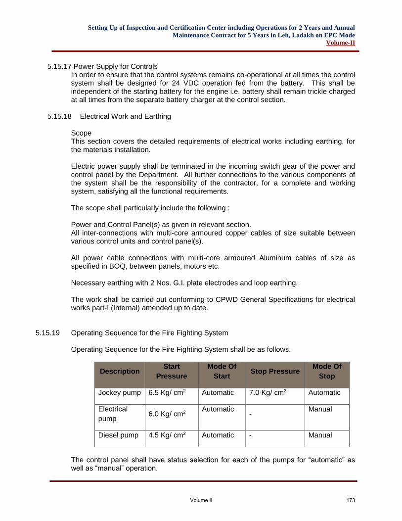
Setting Up of Inspection and Certification Center including Operations for 2 Years and Annual
Maintenance Contract for 5 Years in Leh, Ladakh on EPC Mode
Volume-II
5.15.17 Power Supply for Controls In order to ensure that the control systems remains co-operational at all times the control system shall be designed for 24 VDC operation fed from the battery. This shall be independent of the starting battery for the engine i.e. battery shall remain trickle charged at all times from the separate battery charger at the control section.
5.15.18 Electrical Work and Earthing Scope This section covers the detailed requirements of electrical works including earthing, for the materials installation. Electric power supply shall be terminated in the incoming switch gear of the power and control panel by the Department. All further connections to the various components of the system shall be the responsibility of the contractor, for a complete and working system, satisfying all the functional requirements. The scope shall particularly include the following : Power and Control Panel(s) as given in relevant section. All inter-connections with multi-core armoured copper cables of size suitable between various control units and control panel(s). All power cable connections with multi-core armoured Aluminum cables of size as specified in BOQ, between panels, motors etc. Necessary earthing with 2 Nos. G.I. plate electrodes and loop earthing. The work shall be carried out conforming to CPWD General Specifications for electrical works part-I (Internal) amended up to date.
5.15.19 Operating Sequence for the Fire Fighting System
Operating Sequence for the Fire Fighting System shall be as follows.
Description Start
Pressure
Mode Of
Start Stop Pressure
Mode Of
Stop
Jockey pump 6.5 Kg/ cm2 Automatic 7.0 Kg/ cm2 Automatic
Electrical
pump 6.0 Kg/ cm2
Automatic -
Manual
Diesel pump 4.5 Kg/ cm2 Automatic - Manual
The control panel shall have status selection for each of the pumps for “automatic” as well as “manual” operation.
Volume II 173
Setting Up of Inspection and Certification Center including Operations for 2 Years and Annual
Maintenance Contract for 5 Years in Leh, Ladakh on EPC Mode
Volume-II
Pumps when under “manual” status shall be operated manually through relevant push
buttons.
The fire pumps once started shall not be stopped automatically.
5.15.20 Testing
5.15.21 Testing on Completion of Installation The entire system shall be tested after completion of installation as per the operating sequence specified. Approvals It shall be the responsibility of the contractor to obtain the approval of
drawings and to get the installation inspected and passed by any concerned authorities, as may be necessary as per local by laws, any fee payable to the local bodies for such activities shall be included in the rate.
Standards and Codes 1. IS – 1648 – 1961 Code of Practice for fire safety of building (general) fire fighting equipment and maintenance. 2. IS – 3844 – 1966 Code of practice for installation of internal fire hydrant in multi-stores building. 3. IS – 2217 – 1963 Recommendation for providing first aid and fire fighting
arrangement in public buildings. 4. IS – 2190 – 971 Code of practice for selection, installation and maintenance of portable first fire appliance. 5. IS – 3589 Electrically Welded Steel pipes (Medium class) 6. IS – 1239 Mild steel tubes, Tubulers and other wrought steel fittings (Medium class) 7. IS – 780 C.I. Double flanges sluice valve. 8. IS – 778 Gun Metal Valves 9. IS – 909 – 1965 External fire hydrant (underground) 10. IS – 5290 – 1969 Internal Landing Valve 11. IS – 884 – 1969 First and hose reel 12. IS – 934 – 1976 Specification for portable chemical fire extinguisher soda acid type.
Volume II 174
Setting Up of Inspection and Certification Center including Operations for 2 Years and Annual
Maintenance Contract for 5 Years in Leh, Ladakh on EPC Mode
Volume-II
13. IS – 2873 – 1969 Specification for fire extinguisher for carbon dioxide 14. IS – 2189 & 2109 Automatic fire alarm system or BSS 3116.
16. National Building Code.
General
This section shall be applicable for item rate work and for variations.
This preamble covers water supply, sewerage, drainage, sanitary fittings &fire fighting system.
This preamble shall be read in conjunction with the specifications, condition of contract, drawings and all other documents accompanying the tender papers.
For all items of work the rates shall be comprehensive and all inclusive. The rates shall include for all matters and things necessary for satisfactory completion and maintenance of the work in proper working order and to the satisfaction of the Engineer-in-Charge, including testing, making samples, etc., and all that have been indicated in the specifications or other Tender Documents either directly or indirectly, and cover for all obligation of the Contractor under the Contract. No claim for additional payment shall be allowed for any error or misunderstanding by the contractor of the work involved.
Unless otherwise mentioned in the description of the item, this Bill of Quantities shall be applicable for work in any height, position or condition.
Unless otherwise stated, method of measurement as described in the latest editions of I.S. 1200 with its parts corresponding to different sections of work shall be followed. In case of any dispute in this matter, the decision of Engineer-in-Charge shall be final, binding and conclusive.
The following notations have been used throughout the Bill of quantities.
m - Metre mm - Millimetre m2 - Square Metre mm2 - Square Millimetre m3 - Cubic Metre No. - Number/Numbers Dia - Diameter Kg. - Kilogramme/s T - Metric Tonne L.S - Lumpsum Pt. - Point/Points Set - Set/Sets C/C - Centre to Centre @ - At the rate of
Volume II 175
Setting Up of Inspection and Certification Center including Operations for 2 Years and Annual
Maintenance Contract for 5 Years in Leh, Ladakh on EPC Mode
Volume-II
V - Volt/Volts A - Ampere/s SWG - Standard Wire Gauge
The Contractor shall be deemed to have full knowledge of all his obligations under the Contract and shall be deemed to have made full allowance for complying with all such obligations in his offer.
5.16 TRADE PREAMBLE
5.16.1 External Water Supply Pipes. Pipe laying, excavation, bedding, dewatering of the trench where necessary, jointing (include for all joints, gaskets, nuts, bolts, jointing compound) backfilling in trench and disposal of surplus earth pipes shall be measured by length for an average depth as a single item but separately in accordance with type and diameter of pipe, testing necessary rectification, and sterilizing the pipe line including supplying of necessary water, chemicals and disinfectant and disposal of the water after use, should be included in this rate. Pipe laying as per specifications shall be measured in Running Metre as actually laid measured along the centre line of the pipe line for and average depth. The bends, junctions, specials, fittings shall be included in Running Metre length of the pipe. The rates for pipe laying shall include :
A. Excavation of trenches in any kind of soil backfilling and disposal of surplus earth as specified.
B. Providing required beddings as shown in drawing and as specified.
C. Providing the pipes and fittings, joints, specials, etc. to the site.
D. Lowering the pipes, fitting, etc. into trench, jointing and fixing true to line and
level.
E. Providing all equipment, labour and materials, necessary to carry out the above works complete in all respects as specified and/or instructed.
F. Installation of valves, metres, other fittings and similar items, etc. as shown and
specified.
G. Construction of thrust blocks as specified.
H. Testing, cleaning sterilisation of pipe lines including supply of required water for such work.
I. Filling river sand alround GI pipe.
J. Commissioning of completed pipes lines.
Volume II 176
Setting Up of Inspection and Certification Center including Operations for 2 Years and Annual
Maintenance Contract for 5 Years in Leh, Ladakh on EPC Mode
Volume-II
K. Backfilling to finished grade level with approved materials as shown and directed
by the Engineer-in-Charge.
L. Removal of surplus excavated materials to an approved dumping yard. Chambers Valve chambers, surface boxes and similar items shall be measured by number constructed according to type. Appurtenances Valves, metres, taps and similar items shall be measured by number supplied. The installation shall be included in the rate for laying etc. of the pipes measured by length. Fittings Pipe fittings, such as tees, bends, elbows, reducers and similar items shall be measured with pipes. Installation shall be included in the linear metre rate for laying etc. of the pipe line.
5.16.2 Masonry, RCC Chambers For Valves, Hydrants, etc.
Chambers shall be measured in number according to type. The rates shall include- Necessary excavation in any kind of soil backfilling and disposal of surplus earth as specified. Protecting the excavation with all necessary shoring, strutting and keeping the excavation clear of water. Providing and laying foundation concrete as shown on drawing and as specified. Providing and constructing brick masonry walls in cement mortar/RCC walls including reinforcement as shown on drawing and as specified. The openings required to be left open for pipes and subsequent reinforcement grouting shall also be included in the rates. Providing and casting RCC top slab including reinforcement as shown on drawing and as specified. Providing fitting and fixing C.I access cover including frame as shown on drawing and as specified and/or directed at site by the Engineer-in-Charge. Providing external cement plaster 1:4 with water proofing compound 150mm from the bottom of the top slab for the external faces of the chamber walls. All external faces of chamber in touch with soil to be painted with two coats of bitumen coatings.
Volume II 177
Setting Up of Inspection and Certification Center including Operations for 2 Years and Annual
Maintenance Contract for 5 Years in Leh, Ladakh on EPC Mode
Volume-II
Providing concrete benching, seats, etc for pipes and valves as shown in the drawing and as directed by the Engineer-in-Charge. The rates quoted shall be net and should any variation occur either in drawings or in specifications, the rates of individual items of work quoted in civil work shall apply.
5.16.3 Valves, Meters etc. For supply of valves, meters, taps and similar items shall be measured by number. This rate shall also include cost of installation and fitting.
5.16.4 External Drainage a) Specified pipes shall be measured per Running Metre for the clear length
between the chambers and appurtenances for an average depth. The rate shall be inclusive of the cost of pipes, all fittings, jointing and testing of pipes and fittings etc. as specified.
b) Manholes and chambers shall be measured in number and shall include all works as stated in 4.2.2.
c) Specified gully traps shall be measured by number and the rate shall include the cost of masonry chamber with cover, 150 x 150 mm C.I. grating including fixing in position with cement mortar.
5.16.5 Soil and Waste Vent and Rain Water Pipes
a) Soil, waste, vent and rain water pipes shall be measured in running metres as
actually laid. The cost of all fittings, e.g. bends, junctions, off sets, terminal guards, clamps and jointing shall be included in the rate. The rate of pipes shall be inclusive of excavation, backfilling and disposal of surplus earth (where required), cutting chases , holes in walls and floors and making good and testing all complete as per specifications.
b) Specified floor traps shall be measured by numbers and shall include the cost of
CP brass cockroach trap & grating of the required size and setting the floor traps in cement concrete with suitable extension pieces where required.
5.16.6 Internal Water Supply
a) Specified pipes for cold and hot water supply lines shall be measured in running
metre along the centre line of the pipe lines and the rate shall include the cost of all necessary fittings, clamps, cutting chases and holes in walls, floors and making necessary excavation, backfiling and disposal of surplus earth, where required. The rate shall be inclusive of the cost of necessary fittings, testing and commissioning and painting of the pipe lines, as specified.
b) Valves and taps shall be measured by numbers.
c) Insulation to hot water pipes shall be measured separately.
5.16.7 Sanitary Fixtures
Volume II 178
Setting Up of Inspection and Certification Center including Operations for 2 Years and Annual
Maintenance Contract for 5 Years in Leh, Ladakh on EPC Mode
Volume-II
All sanitary fixtures of specified trade mark or equivalent shall be paid by number and rate shall be included all C.P. fittings, traps, flushing cisterns, specials, connecting pipes all fixing components, brackets, screws, etc. as stated in Bill of Quantities.
5.16.8 Internal Fire Hydrants Pipes Specified pipes for fire hydrant system shall be measured in running metre along the centre line of the pipe lines and the rate shall include the cost of all necessary fittings, supports, clamps, cutting chases and holes in walls, floors and making necessary excavation, backfilling and disposal of surplus earth, where required. The rate shall be inclusive of the cost of necessary fittings, painting, testing and commissioning of the pipe lines, as specified.
5.16.9 Accessories for Fire Fighting Systems All accessories for firefighting system e.g. pumps, fire hydrants, RRL hoses, hose reels, branch pipes fire hose cabinets, air valves etc. shall be measured in numbers and shall include all items as given in the Bill of quantities. Included in the rate of the particular equipment.
Volume II 179
Setting Up of Inspection and Certification Center including Operations for 2 Years and Annual
Maintenance Contract for 5 Years in Leh, Ladakh on EPC Mode
Volume-II
6. LIST OF APPROVAL MAKES
Volume II 180
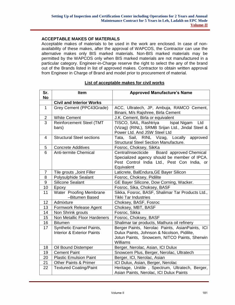
Setting Up of Inspection and Certification Center including Operations for 2 Years and Annual
Maintenance Contract for 5 Years in Leh, Ladakh on EPC Mode
Volume-II
ACCEPTABLE MAKES OF MATERIALS Acceptable makes of materials to be used in the work are enclosed. In case of non-availability of these makes, after the approval of WAPCOS, the Contractor can use the alternative makes only BIS marked materials. Non-BIS marked materials may be permitted by the WAPCOS only when BIS marked materials are not manufactured in a particular category. Engineer-in-Charge reserve the right to select the any of the brand out of the Brands listed in list of approved makes. Contractor to obtain written approval from Engineer in Charge of Brand and model prior to procurement of material.
List of acceptable makes for civil works
Sr. No
Item Approved Manufacture’s Name
Civil and Interior Works
1 Grey Cement (PPC43Grade) ACC, Ultratech, JP, Ambuja, RAMCO Cement, Binani, M/s Rajshree, Birla Cement
2 White Cement J.K. Cement, Birla or equivalent
3 Reinforcement Steel (TMT bars)
TISCO, SAIL, Rashtriya Ispat Nigam Ltd (Vizag) (RINL), SRMB Srijan Ltd., Jindal Steel & Power Ltd. And JSW Steel Ltd
4 Structural Steel sections Tata, Sail, RINL Vizag, Locally approved Structural Steel Section Manufacture.
5 Concrete Additives Fosroc, Choksey, SikKa
6 Anti-termite Chemical Central Insecticide Board approved Chemical Specialized agency should be member of IPCA. Pest Control India Ltd., Pest Con India, or Equivalent
7 Tile grouts ,Joint Filler Laticrete, BalEndura,GE Bayer Silicon
8 Polysulphide Sealant Fosroc, Choksey, Pidilite
9 Silicone Sealant GE Bayer Silicone, Dow Corning, Wacker.
10 Epoxy Fosroc, Sika, Choksey, BASF
11 Water Proofing Membrane –Bitumen Based
Sikka, Fosroc, BASF, Shalimar Tar Products Ltd., Tikki Tar Industries
12 Admixture Choksey, BASF, Fosroc
13 Formwork Release Agent Choksey, MBT, BASF
14 Non Shrink grouts Fosroc, Sikka
15 Non Metallic Floor Hardeners Fosroc, Choksey, BASF
16 Bitumen Shalimar tar products, Mathura oil refinery
17 Synthetic Enamel Paints, Interior & Exterior Paints
Berger Paints, Nerolac Paints, AsianPaints, ICI Dulux Paints, Johnson & Nicolson, Pidilite, Jotun Paints, Snowcem, NITCO Paints, Sherwin Williams
18 Oil Bound Distemper Berger, Nerolac, Asian, ICI Dulux
19 Cement Paint Snowcem Plus, Berger, Nerolac, Ultratech
20 Plastic Emulsion Paint Berger, ICI, Nerolac, Asian
21 Other Paints & Primer ICI Dulux, Asian, Berger, Nerolac
22 Textured Coating/Paint Heritage, Unitile , Spectrum, Ultratech, Berger, Asian Paints, Nerolac, ICI Dulux Paints
Volume II 181
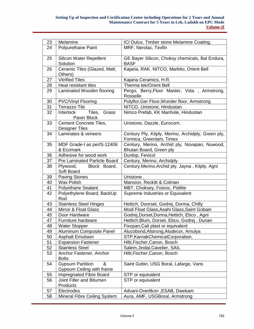
Setting Up of Inspection and Certification Center including Operations for 2 Years and Annual
Maintenance Contract for 5 Years in Leh, Ladakh on EPC Mode
Volume-II
23 Melamine ICI Dulux, Timber stone Melamine Coating,
24 Polyurethane Paint MRF, Nerolac, Texfin
25 Silicon Water Repellent Solution
GE Bayer Silicon, Choksy chemicals, Bal Endura, BASF
26 Ceramic Tiles (Glazed, Matt, Others)
Kajaria, RAK. NITCO, Marbito, Orient Bell
27 Vitrified Tiles Kajaria Ceramics, H.R.
28 Heat resistant tiles Therma tek/Orient Bell
29 Laminated Wooden flooring Pergo, Berry,Floor Master, Vsta , Armstrong, Rosselle
30 PVC/Vinyl Flooring Polyflor,Ger Floor,Wonder floor, Armstrong
31 Terrazzo Tile NITCO, Unistone, Hindustan
32 Interlock Tiles, Grass Paver Block
Nimco Prefab, KK Manhole, Hindustan
33 Cement Concrete Tiles, Designer Tiles
Unistone, Dazzle, Eurocorn.
34 Laminates & veneers Century Ply, Kitply, Merino, Archidply, Green ply, Formica, Greenlam, Timex
35 MDF Grade-I as perIS-12406 & Ecomark
Century, Merino, Archid ply, Novapan, Nuwood, Bhutan Board, Green ply
36 Adhesive for wood work Dunlop, Fevicol
37 Pre Laminated Particle Board Century, Merino, Archidply
38 Plywood, Block Board, Soft Board
Century,Merino,Archid ply, Jayna , Kitply, Agni
39 Paving Stones Unistone ,
40 Wax Polish Mansion, Reckitt & Colman
41 Polyethane Sealant MBT, Choksey, Fosroc, Pidilite
42 Polyethylene Board, BackUp Rod
Supreme Industries or Equivalent
43 Stainless Steel Hinges Hettich, Doorset, Godrej, Dorma, Chilly
44 Mirror & Float Glass Modi Float Glass,Asahi Glass,Saint Gobain
45 Door Hardware Godrej,Dorset,Dorma,Hettich, Ebco , Agni
47 Furniture hardware Hettich,Blum, Dorset, Ebco, Godrej , Durian
48 Water Stopper Fixopan,Cali plast or equivalent
49 Aluminum Composite Panel Alucobond,Alstrong,Aludecor, Amulya
50 Asphalt Emulsion STP,KarnakChemicalCorporation.
51 Expansion Fastener Hilti,Fischer,Canon, Bosch
52 Stainless Steel Salem,Jindal,Cavelier, SAIL
53 Anchor Fastener, Anchor Bolts
Hilti,Fischer,Canon, Bosch
54 Gypsum Partition & Gypsum Ceiling with frame
Saint Gobin, USG Boral, Lafarge, Vans
55 Impregnated Fibre Board STP or equivalent
56 Joint Filler and Bitumen Products
STP or equivalent
57 Electrodes Advani-Overlikon ,ESAB, Dwekam
58 Mineral Fibre Ceiling System Aura, AMF, USGBoral, Armstrong
Volume II 182
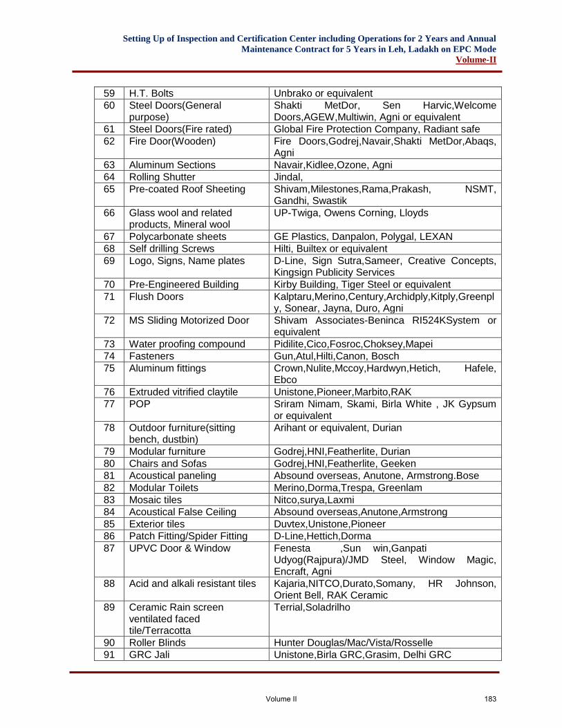
Setting Up of Inspection and Certification Center including Operations for 2 Years and Annual
Maintenance Contract for 5 Years in Leh, Ladakh on EPC Mode
Volume-II
59 H.T. Bolts Unbrako or equivalent
60 Steel Doors(General purpose)
Shakti MetDor, Sen Harvic,Welcome Doors,AGEW,Multiwin, Agni or equivalent
61 Steel Doors(Fire rated) Global Fire Protection Company, Radiant safe
62 Fire Door(Wooden) Fire Doors,Godrej,Navair,Shakti MetDor,Abaqs, Agni
63 Aluminum Sections Navair,Kidlee,Ozone, Agni
64 Rolling Shutter Jindal,
65 Pre-coated Roof Sheeting Shivam,Milestones,Rama,Prakash, NSMT, Gandhi, Swastik
66 Glass wool and related products, Mineral wool
UP-Twiga, Owens Corning, Lloyds
67 Polycarbonate sheets GE Plastics, Danpalon, Polygal, LEXAN
68 Self drilling Screws Hilti, Builtex or equivalent
69 Logo, Signs, Name plates D-Line, Sign Sutra,Sameer, Creative Concepts, Kingsign Publicity Services
70 Pre-Engineered Building Kirby Building, Tiger Steel or equivalent
71 Flush Doors Kalptaru,Merino,Century,Archidply,Kitply,Greenply, Sonear, Jayna, Duro, Agni
72 MS Sliding Motorized Door Shivam Associates-Beninca RI524KSystem or equivalent
73 Water proofing compound Pidilite,Cico,Fosroc,Choksey,Mapei
74 Fasteners Gun,Atul,Hilti,Canon, Bosch
75 Aluminum fittings Crown,Nulite,Mccoy,Hardwyn,Hetich, Hafele, Ebco
76 Extruded vitrified claytile Unistone,Pioneer,Marbito,RAK
77 POP Sriram Nimam, Skami, Birla White , JK Gypsum or equivalent
78 Outdoor furniture(sitting bench, dustbin)
Arihant or equivalent, Durian
79 Modular furniture Godrej,HNI,Featherlite, Durian
80 Chairs and Sofas Godrej,HNI,Featherlite, Geeken
81 Acoustical paneling Absound overseas, Anutone, Armstrong.Bose
82 Modular Toilets Merino,Dorma,Trespa, Greenlam
83 Mosaic tiles Nitco,surya,Laxmi
84 Acoustical False Ceiling Absound overseas,Anutone,Armstrong
85 Exterior tiles Duvtex,Unistone,Pioneer
86 Patch Fitting/Spider Fitting D-Line,Hettich,Dorma
87 UPVC Door & Window Fenesta ,Sun win,Ganpati Udyog(Rajpura)/JMD Steel, Window Magic, Encraft, Agni
88 Acid and alkali resistant tiles Kajaria,NITCO,Durato,Somany, HR Johnson, Orient Bell, RAK Ceramic
89 Ceramic Rain screen ventilated faced tile/Terracotta
Terrial,Soladrilho
90 Roller Blinds Hunter Douglas/Mac/Vista/Rosselle
91 GRC Jali Unistone,Birla GRC,Grasim, Delhi GRC
Volume II 183
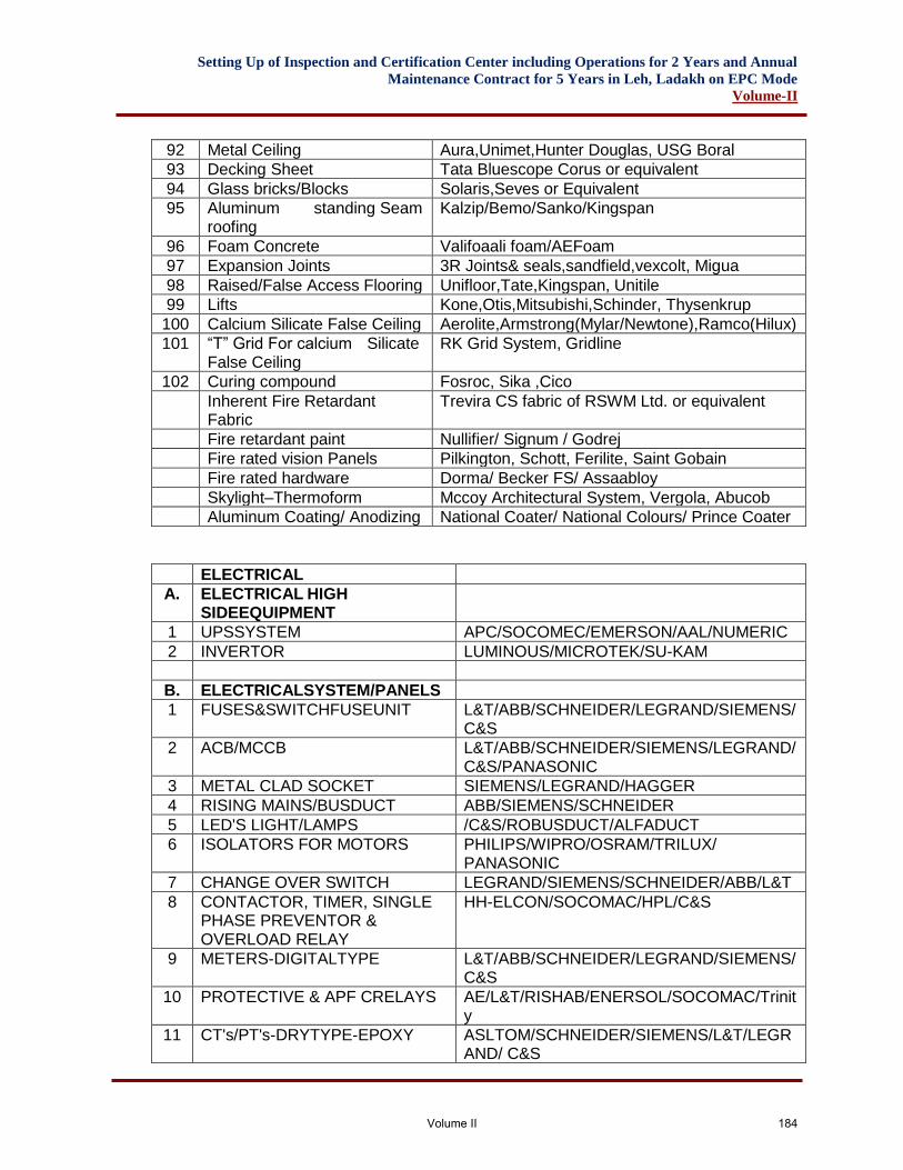
Setting Up of Inspection and Certification Center including Operations for 2 Years and Annual
Maintenance Contract for 5 Years in Leh, Ladakh on EPC Mode
Volume-II
92 Metal Ceiling Aura,Unimet,Hunter Douglas, USG Boral
93 Decking Sheet Tata Bluescope Corus or equivalent
94 Glass bricks/Blocks Solaris,Seves or Equivalent
95 Aluminum standing Seam roofing
Kalzip/Bemo/Sanko/Kingspan
96 Foam Concrete Valifoaali foam/AEFoam
97 Expansion Joints 3R Joints& seals,sandfield,vexcolt, Migua
98 Raised/False Access Flooring Unifloor,Tate,Kingspan, Unitile
99 Lifts Kone,Otis,Mitsubishi,Schinder, Thysenkrup
100 Calcium Silicate False Ceiling Aerolite,Armstrong(Mylar/Newtone),Ramco(Hilux)
101 “T” Grid For calcium Silicate False Ceiling
RK Grid System, Gridline
102 Curing compound Fosroc, Sika ,Cico
Inherent Fire Retardant Fabric
Trevira CS fabric of RSWM Ltd. or equivalent
Fire retardant paint Nullifier/ Signum / Godrej
Fire rated vision Panels Pilkington, Schott, Ferilite, Saint Gobain
Fire rated hardware Dorma/ Becker FS/ Assaabloy
Skylight–Thermoform Mccoy Architectural System, Vergola, Abucob
Aluminum Coating/ Anodizing National Coater/ National Colours/ Prince Coater
ELECTRICAL
A. ELECTRICAL HIGH SIDEEQUIPMENT
1 UPSSYSTEM APC/SOCOMEC/EMERSON/AAL/NUMERIC
2 INVERTOR LUMINOUS/MICROTEK/SU-KAM
B. ELECTRICALSYSTEM/PANELS
1 FUSES&SWITCHFUSEUNIT L&T/ABB/SCHNEIDER/LEGRAND/SIEMENS/C&S
2 ACB/MCCB L&T/ABB/SCHNEIDER/SIEMENS/LEGRAND/C&S/PANASONIC
3 METAL CLAD SOCKET SIEMENS/LEGRAND/HAGGER
4 RISING MAINS/BUSDUCT ABB/SIEMENS/SCHNEIDER
5 LED'S LIGHT/LAMPS /C&S/ROBUSDUCT/ALFADUCT
6 ISOLATORS FOR MOTORS PHILIPS/WIPRO/OSRAM/TRILUX/ PANASONIC
7 CHANGE OVER SWITCH LEGRAND/SIEMENS/SCHNEIDER/ABB/L&T
8 CONTACTOR, TIMER, SINGLE PHASE PREVENTOR & OVERLOAD RELAY
HH-ELCON/SOCOMAC/HPL/C&S
9 METERS-DIGITALTYPE L&T/ABB/SCHNEIDER/LEGRAND/SIEMENS/ C&S
10 PROTECTIVE & APF CRELAYS AE/L&T/RISHAB/ENERSOL/SOCOMAC/Trinity
11 CT's/PT's-DRYTYPE-EPOXY ASLTOM/SCHNEIDER/SIEMENS/L&T/LEGRAND/ C&S
Volume II 184
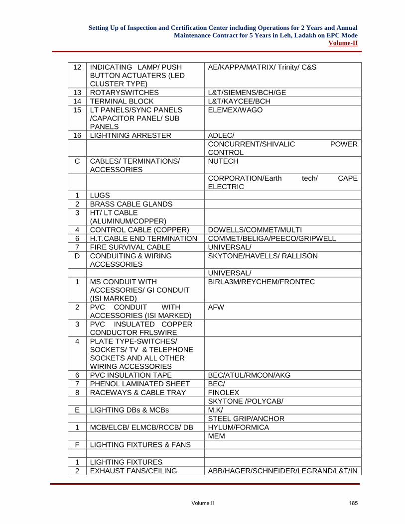
Setting Up of Inspection and Certification Center including Operations for 2 Years and Annual
Maintenance Contract for 5 Years in Leh, Ladakh on EPC Mode
Volume-II
12 INDICATING LAMP/ PUSH BUTTON ACTUATERS (LED CLUSTER TYPE)
AE/KAPPA/MATRIX/ Trinity/ C&S
13 ROTARYSWITCHES L&T/SIEMENS/BCH/GE
14 TERMINAL BLOCK L&T/KAYCEE/BCH
15 LT PANELS/SYNC PANELS /CAPACITOR PANEL/ SUB PANELS
ELEMEX/WAGO
16 LIGHTNING ARRESTER ADLEC/
CONCURRENT/SHIVALIC POWER CONTROL
C CABLES/ TERMINATIONS/ ACCESSORIES
NUTECH
CORPORATION/Earth tech/ CAPE ELECTRIC
1 LUGS
2 BRASS CABLE GLANDS
3 HT/ LT CABLE (ALUMINUM/COPPER)
4 CONTROL CABLE (COPPER) DOWELLS/COMMET/MULTI
6 H.T.CABLE END TERMINATION COMMET/BELIGA/PEECO/GRIPWELL
7 FIRE SURVIVAL CABLE UNIVERSAL/
D CONDUITING & WIRING ACCESSORIES
SKYTONE/HAVELLS/ RALLISON
UNIVERSAL/
1 MS CONDUIT WITH ACCESSORIES/ GI CONDUIT (ISI MARKED)
BIRLA3M/REYCHEM/FRONTEC
2 PVC CONDUIT WITH ACCESSORIES (ISI MARKED)
AFW
3 PVC INSULATED COPPER CONDUCTOR FRLSWIRE
4 PLATE TYPE-SWITCHES/ SOCKETS/ TV & TELEPHONE SOCKETS AND ALL OTHER WIRING ACCESSORIES
6 PVC INSULATION TAPE BEC/ATUL/RMCON/AKG
7 PHENOL LAMINATED SHEET BEC/
8 RACEWAYS & CABLE TRAY FINOLEX
SKYTONE /POLYCAB/
E LIGHTING DBs & MCBs M.K/
STEEL GRIP/ANCHOR
1 MCB/ELCB/ ELMCB/RCCB/ DB HYLUM/FORMICA
MEM
F LIGHTING FIXTURES & FANS
1 LIGHTING FIXTURES
2 EXHAUST FANS/CEILING ABB/HAGER/SCHNEIDER/LEGRAND/L&T/IN
Volume II 185
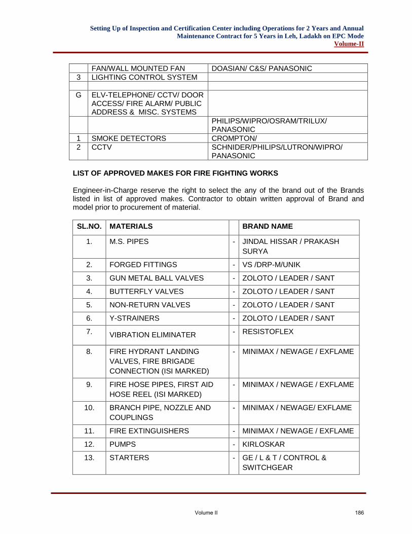
Setting Up of Inspection and Certification Center including Operations for 2 Years and Annual
Maintenance Contract for 5 Years in Leh, Ladakh on EPC Mode
Volume-II
FAN/WALL MOUNTED FAN DOASIAN/ C&S/ PANASONIC
3 LIGHTING CONTROL SYSTEM
G ELV-TELEPHONE/ CCTV/ DOOR ACCESS/ FIRE ALARM/ PUBLIC ADDRESS & MISC. SYSTEMS
PHILIPS/WIPRO/OSRAM/TRILUX/ PANASONIC
1 SMOKE DETECTORS CROMPTON/
2 CCTV SCHNIDER/PHILIPS/LUTRON/WIPRO/ PANASONIC
LIST OF APPROVED MAKES FOR FIRE FIGHTING WORKS Engineer-in-Charge reserve the right to select the any of the brand out of the Brands listed in list of approved makes. Contractor to obtain written approval of Brand and model prior to procurement of material.
SL.NO. MATERIALS BRAND NAME
1. M.S. PIPES - JINDAL HISSAR / PRAKASH
SURYA
2. FORGED FITTINGS - VS /DRP-M/UNIK
3. GUN METAL BALL VALVES - ZOLOTO / LEADER / SANT
4. BUTTERFLY VALVES - ZOLOTO / LEADER / SANT
5. NON-RETURN VALVES - ZOLOTO / LEADER / SANT
6. Y-STRAINERS - ZOLOTO / LEADER / SANT
7. VIBRATION ELIMINATER - RESISTOFLEX
8. FIRE HYDRANT LANDING
VALVES, FIRE BRIGADE
CONNECTION (ISI MARKED)
- MINIMAX / NEWAGE / EXFLAME
9. FIRE HOSE PIPES, FIRST AID
HOSE REEL (ISI MARKED)
- MINIMAX / NEWAGE / EXFLAME
10. BRANCH PIPE, NOZZLE AND
COUPLINGS
- MINIMAX / NEWAGE/ EXFLAME
11. FIRE EXTINGUISHERS - MINIMAX / NEWAGE / EXFLAME
12. PUMPS - KIRLOSKAR
13. STARTERS - GE / L & T / CONTROL &
SWITCHGEAR
Volume II 186
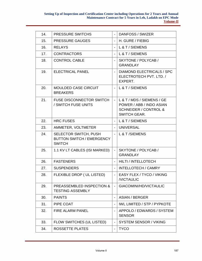
Setting Up of Inspection and Certification Center including Operations for 2 Years and Annual
Maintenance Contract for 5 Years in Leh, Ladakh on EPC Mode
Volume-II
14. PRESSURE SWITCHS - DANFOSS / SWIZER
15. PRESSURE GAUGES - H. GURE / FIEBIG
16. RELAYS - L & T / SIEMENS
17. CONTRACTORS - L & T / SIEMENS
18. CONTROL CABLE - SKYTONE / POLYCAB /
GRANDLAY
19. ELECTRICAL PANEL - DIAMOND ELECTRICALS / SPC
ELECTROTECH PVT. LTD. /
EXPERT.
20. MOULDED CASE CIRCUIT
BREAKERS
- L & T / SIEMENS
21. FUSE DISCONNECTOR SWITCH
/ SWITCH FUSE UNITS
- L & T / MDS / SIEMENS / GE
POWER / ABB / INDO ASIAN
SCHNEIDER / CONTROL &
SWITCH GEAR.
22. HRC FUSES - L & T / SIEMENS
23. AMMETER, VOLTMETER - UNIVERSAL
24. SELECTOR SWITCH, PUSH
BUTTON SWITCH / EMERGENCY
SWITCH
- L & T /SIEMENS
25. 1.1 KV LT CABLES (ISI MARKED) - SKYTONE / POLYCAB /
GRANDLAY
26. FASTENERS - HILTI / INTELLOTECH
27. SUSPENDERS - INTELLOTECH / CAMRY
28. FLEXIBLE DROP ( UL LISTED) - EASY FLEX / TYCO / VIKING
/VICTAULIC
29. PREASSEMBLED INSPECTION &
TESTING ASSEMBLY
- GIACOMINI/HD/VICTAULIC
30. PAINTS - ASIAN / BERGER
31. PIPE COAT - IWL LIMITED / STP / PYPKOTE
32. FIRE ALARM PANEL - APPOLO / EDWARDS / SYSTEM
SENSOR
33. FLOW SWITCHES (UL LISTED) - SYSTEM SENSOR / VIKING
34. ROSSETTE PLATES - TYCO
Volume II 187
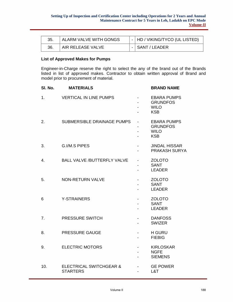
Setting Up of Inspection and Certification Center including Operations for 2 Years and Annual
Maintenance Contract for 5 Years in Leh, Ladakh on EPC Mode
Volume-II
35. ALARM VALVE WITH GONGS - HD / VIKING/TYCO (UL LISTED)
36. AIR RELEASE VALVE - SANT / LEADER
List of Approved Makes for Pumps
Engineer-in-Charge reserve the right to select the any of the brand out of the Brands listed in list of approved makes. Contractor to obtain written approval of Brand and model prior to procurement of material. Sl. No. MATERIALS BRAND NAME 1. VERTICAL IN LINE PUMPS - EBARA PUMPS - GRUNDFOS - WILO - KSB 2. SUBMERSIBLE DRAINAGE PUMPS - EBARA PUMPS - GRUNDFOS - WILO - KSB 3. G.I/M.S PIPES - JINDAL HISSAR - PRAKASH SURYA 4. BALL VALVE /BUTTERFLY VALVE - ZOLOTO - SANT - LEADER 5. NON-RETURN VALVE - ZOLOTO - SANT - LEADER 6 Y-STRAINERS - ZOLOTO - SANT - LEADER 7. PRESSURE SWITCH - DANFOSS - SWIZER 8. PRESSURE GAUGE - H GURU - FIEBIG 9. ELECTRIC MOTORS - KIRLOSKAR - NGFE - SIEMENS 10. ELECTRICAL SWITCHGEAR & - GE POWER STARTERS - L&T
Volume II 188
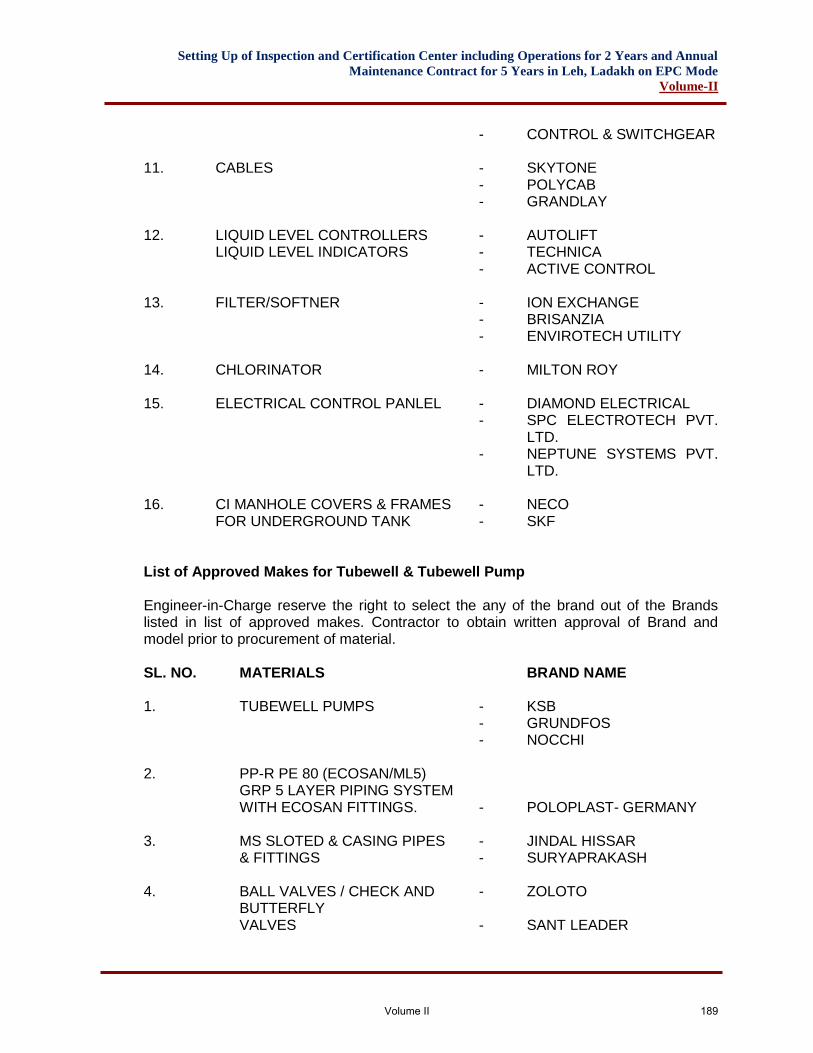
Setting Up of Inspection and Certification Center including Operations for 2 Years and Annual
Maintenance Contract for 5 Years in Leh, Ladakh on EPC Mode
Volume-II
- CONTROL & SWITCHGEAR 11. CABLES - SKYTONE - POLYCAB - GRANDLAY 12. LIQUID LEVEL CONTROLLERS - AUTOLIFT LIQUID LEVEL INDICATORS - TECHNICA - ACTIVE CONTROL 13. FILTER/SOFTNER - ION EXCHANGE - BRISANZIA - ENVIROTECH UTILITY 14. CHLORINATOR - MILTON ROY 15. ELECTRICAL CONTROL PANLEL - DIAMOND ELECTRICAL
- SPC ELECTROTECH PVT. LTD.
- NEPTUNE SYSTEMS PVT. LTD.
16. CI MANHOLE COVERS & FRAMES - NECO FOR UNDERGROUND TANK - SKF List of Approved Makes for Tubewell & Tubewell Pump Engineer-in-Charge reserve the right to select the any of the brand out of the Brands listed in list of approved makes. Contractor to obtain written approval of Brand and model prior to procurement of material. SL. NO. MATERIALS BRAND NAME 1. TUBEWELL PUMPS - KSB - GRUNDFOS - NOCCHI 2. PP-R PE 80 (ECOSAN/ML5) GRP 5 LAYER PIPING SYSTEM WITH ECOSAN FITTINGS. - POLOPLAST- GERMANY 3. MS SLOTED & CASING PIPES - JINDAL HISSAR & FITTINGS - SURYAPRAKASH 4. BALL VALVES / CHECK AND - ZOLOTO BUTTERFLY VALVES - SANT LEADER
Volume II 189
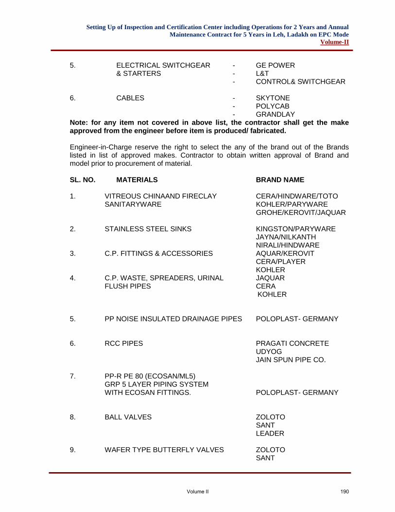
Setting Up of Inspection and Certification Center including Operations for 2 Years and Annual
Maintenance Contract for 5 Years in Leh, Ladakh on EPC Mode
Volume-II
5. ELECTRICAL SWITCHGEAR - GE POWER & STARTERS - L&T - CONTROL& SWITCHGEAR 6. CABLES - SKYTONE - POLYCAB - GRANDLAY Note: for any item not covered in above list, the contractor shall get the make approved from the engineer before item is produced/ fabricated. Engineer-in-Charge reserve the right to select the any of the brand out of the Brands listed in list of approved makes. Contractor to obtain written approval of Brand and model prior to procurement of material. SL. NO. MATERIALS BRAND NAME 1. VITREOUS CHINAAND FIRECLAY CERA/HINDWARE/TOTO SANITARYWARE KOHLER/PARYWARE GROHE/KEROVIT/JAQUAR 2. STAINLESS STEEL SINKS KINGSTON/PARYWARE JAYNA/NILKANTH NIRALI/HINDWARE 3. C.P. FITTINGS & ACCESSORIES AQUAR/KEROVIT CERA/PLAYER KOHLER 4. C.P. WASTE, SPREADERS, URINAL JAQUAR FLUSH PIPES CERA KOHLER 5. PP NOISE INSULATED DRAINAGE PIPES POLOPLAST- GERMANY 6. RCC PIPES PRAGATI CONCRETE UDYOG JAIN SPUN PIPE CO. 7. PP-R PE 80 (ECOSAN/ML5) GRP 5 LAYER PIPING SYSTEM WITH ECOSAN FITTINGS. POLOPLAST- GERMANY 8. BALL VALVES ZOLOTO SANT LEADER 9. WAFER TYPE BUTTERFLY VALVES ZOLOTO SANT
Volume II 190
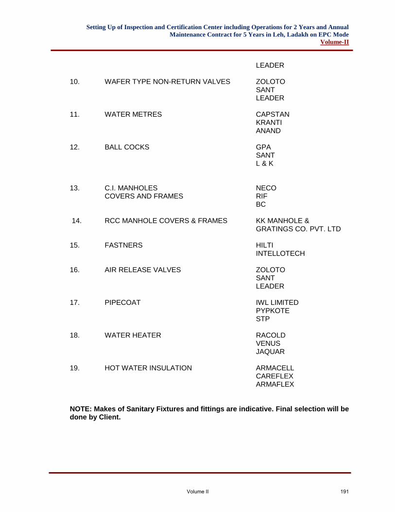
Setting Up of Inspection and Certification Center including Operations for 2 Years and Annual
Maintenance Contract for 5 Years in Leh, Ladakh on EPC Mode
Volume-II
LEADER 10. WAFER TYPE NON-RETURN VALVES ZOLOTO SANT LEADER 11. WATER METRES CAPSTAN KRANTI ANAND 12. BALL COCKS GPA SANT L & K 13. C.I. MANHOLES NECO COVERS AND FRAMES RIF BC 14. RCC MANHOLE COVERS & FRAMES KK MANHOLE & GRATINGS CO. PVT. LTD 15. FASTNERS HILTI INTELLOTECH 16. AIR RELEASE VALVES ZOLOTO SANT LEADER 17. PIPECOAT IWL LIMITED PYPKOTE STP 18. WATER HEATER RACOLD VENUS JAQUAR 19. HOT WATER INSULATION ARMACELL CAREFLEX ARMAFLEX NOTE: Makes of Sanitary Fixtures and fittings are indicative. Final selection will be done by Client.
Volume II 191