vmware nsx-t ® reference design guide
TRANSCRIPT
VMWARE NSX-T ® REFERENCE DESIGN GUIDE Software Version 3.0
DECEMBER 2020
VMware NSX-T Reference Design Guide
1
VMware NSX-T Reference Design Guide
Table of Contents
1 Introduction 8
How to Use This Document and Provide Feedback 8
Networking and Security Today 8
NSX-T Architecture Value and Scope 9
2 NSX-T Architecture Components 16
Management Plane and Control Plane 16
Management Plane 16
Control Plane 17
NSX Manager Appliance 17
Data Plane 18
NSX-T Consumption Model 19
When to use Policy vs Manager UI/API 19
NSX-T Logical Object Naming Changes 20
NSX-T Policy API Framework 20
API Usage Example 1- Templatize and Deploy 3-Tier Application Topology 21
API Usage Example 2- Application Security Policy Lifecycle Management 22
3 NSX-T Logical Switching 23
The NSX Virtual Switch 23
Segments and Transport Zones 23
Uplink vs. pNIC 25
Teaming Policy 26
Uplink Profile 29
Transport Node Profile 31
Network I/O Control 31
Enhanced Data Path NSX virtual switch 32
Logical Switching 33
Overlay Backed Segments 33
Flooded Traffic 35
Unicast Traffic 37
Data Plane Learning 38
VMware NSX-T Reference Design Guide
2
Tables Maintained by the NSX-T Controller 39
Overlay Encapsulation 41
Bridging Overlay to VLAN with the Edge Bridge 42
Overview of the Capabilities 43
4 NSX-T Logical Routing 48
Single Tier Routing 49
Distributed Router (DR) 49
Services Router 52
Two-Tier Routing 57
Interface Types on Tier-1 and Tier-0 Gateway 58
Route Types on Tier-0 and Tier-1 Gateways 59
Fully Distributed Two Tier Routing 61
Routing Capabilities 63
Static Routing 63
Dynamic Routing 64
VRF Lite 65
VRF Lite Generalities 65
IPv6 Routing Capabilities 77
Services High Availability 80
Active/Active 80
Active/Standby 83
High Availability Failover Triggers 84
Edge Node 85
Multi-TEP support on Edge Node 87
Bare Metal Edge Node 88
VM Edge Node 93
Edge Cluster 99
Failure Domain 100
Other Network Services 101
Unicast Reverse Path Forwarding (uRPF) 101
Network Address Translation 102
DHCP Services 103
Metadata Proxy Service 104
Gateway Firewall Service 104
VMware NSX-T Reference Design Guide
3
Proxy ARP 104
Topology Consideration 107
Supported Topologies 107
Unsupported Topologies 110
5 NSX-T Security 111
NSX-T Security Use Cases 111
NSX-T DFW Architecture and Components 113
Management Plane 113
Control Plane 114
Data Plane 114
NSX-T Data Plane Implementation - ESXi vs. KVM Hosts 114
ESXi Hosts- Data Plane Components 115
NSX-T DFW Policy Lookup and Packet Flow 116
NSX-T Security Policy - Plan, Design and Implement 117
Security Policy Methodology 118
Security Rule Model 119
Security Policy - Consumption Model 120
Intrusion Detection 128
Service Insertion 129
Additional Security Features 129
NSX-T Security Enforcement – Agnostic to Network Isolation 130
NSX-T Distributed Firewall for VLAN Backed workloads 130
NSX-T Distributed Firewall for Mix of VLAN and Overlay backed workloads 131
NSX-T Distributed Firewall for Overlay Backed workloads 132
Gateway Firewall 132
Consumption 133
Implementation 133
Deployment Scenarios 133
Endpoint Protection with NSX-T 135
Recommendation for Security Deployments 137
A Practical Approach to Building Micro-Segmentation Policy 138
NSX Firewall- For All Deployment Scenario 146
6 NSX-T Load Balancer 148
NSX-T Load Balancing Architecture 149
VMware NSX-T Reference Design Guide
4
NSX-T Load Balancing deployment modes 150
In-line load balancing 150
One-arm load balancing 151
NSX-T load-balancing technical details 154
Load-balancer high-availability 154
Load-balancer monitor 155
Load-balancer Layer4 or Layer7 load balancing 156
Load-balancer IPv6 158
Load-balancer traffic flows 158
Load-balancing combined with SR services (NAT and Firewall) 161
7 NSX-T Design Considerations 163
Physical Infrastructure of the Data Center 163
NSX-T Infrastructure Component Connectivity 166
NSX-T Manager Node Availability and Hypervisor interaction 167
Physical placement considerations for the NSX-T Manager Nodes 168
Deployment Options for NSX-T Management Cluster 171
Compute Cluster Design (ESXi/KVM) 177
Running a VDS prepared for NSX on ESXi hosts 178
ESXi-Based Compute Hypervisor with two pNICs 181
ESXi-Based Compute Hypervisor with Four (or more) pNICs 186
KVM-Based Compute Hypervisor with two pNICs 190
Edge Node and Services Design 192
Design Considerations with Bridging 192
Multiple N-VDS Edge Node Design before NSX-T Release 2.5 197
The Design Recommendation with Edge Node NSX-T Release 2.5 Onward 197
Bare Metal Edge Design 199
Edge Node VM 203
NSX-T Edge Resources Design 209
Multi-Compute Workload Domain Design Consideration 220
Common Deployment Consideration with NSX-T Components 222
Collapsed Management and Edge Resources Design 222
Collapsed Compute and Edge Resources Design 229
Dedicated Management and Edge Resources Design 231
8 NSX-T Performance & Optimization 235
VMware NSX-T Reference Design Guide
5
Typical Data Center Workloads 235
Next Generation Encapsulation - Geneve 235
Geneve Offload 236
(TSO) applicability to Geneve Overlay Traffic 236
NIC Supportability with TSO for Geneve Overlay Traffic 237
NIC Card Geneve Offload Capability 238
VMware’s IO Compatibility Guide 238
ESXi-Based Hypervisor 241
Receive Side Scaling (RSS) and Rx Filters 242
Benefits with RSS 242
RSS for overlay 242
Enabling RSS for Overlay 243
Checking whether RSS is enabled 243
RSS and Rx Filters - Comparison 244
Checking whether Rx Filters are enabled 245
RSS vs Rx Filters for Edge VM 246
Jumbo MTU for Higher Throughput 246
Checking MTU on an ESXi host 247
Single TEP vs Dual TEP 248
NIC Port Speed 248
PCIe Gen 4 249
Performance Factors for NSX-T Edges 250
Data Plane Development Kit (DPDK) 250
SSL Offload 251
Key Performance Factors 252
Compute Node Performance Factors 252
VM Edge Node Performance Factors 253
Bare Metal Edge Node Performance Factors 257
Summary of Performance – NSX-T Components to NIC Features 258
Results 258
NFV: Raw Packet Processing Performance 260
N-VDS Enhanced Data Path 260
Acceleration with the N-VDS in Enhanced Datapath Mode 260
Poll Mode Driver 260
VMware NSX-T Reference Design Guide
6
CPU Affinity and Optimization 261
Buffer Management 261
Flow Cache 261
Checking whether a NIC is N-VDS Enhanced Data Path Capable 261
Benchmarking Tools 262
Compute 262
Edges 262
VM Edge 262
Bare Metal Edge 263
Conclusion 263
Appendix 1: External References 265
Appendix 2: NSX-T API/JSON examples 267
Appendix 3: NSX-T Failure Domain API Example 287
Appendix 4: Bridge Traffic Optimization to Uplinks Using Teaming Policy 289
Appendix 5: The Design Recommendation with Edge Node before NSX-T Release 2.5 291
Peering with Physical Infrastructure Routers 291
Before NSX-T 2.5 - Bare Metal Design with 2 pNICs 291
Services Availability Considerations Bare metal Edge Node 292
Before NSX-T 2.5 Release - Edge Node VM Design 293
NSX-T 2.4 Edge node VM connectivity with VDS on Host with 2 pNICs 295
Dedicated Host for Edge VM Design with 4 pNICs 298
VMware NSX-T Reference Design Guide
7
Intended Audience
This document is targeted toward virtualization and network architects interested in deploying
VMware NSX® network virtualization solutions in a variety of on premise solutions covering
VMware vSphere® and KVM.
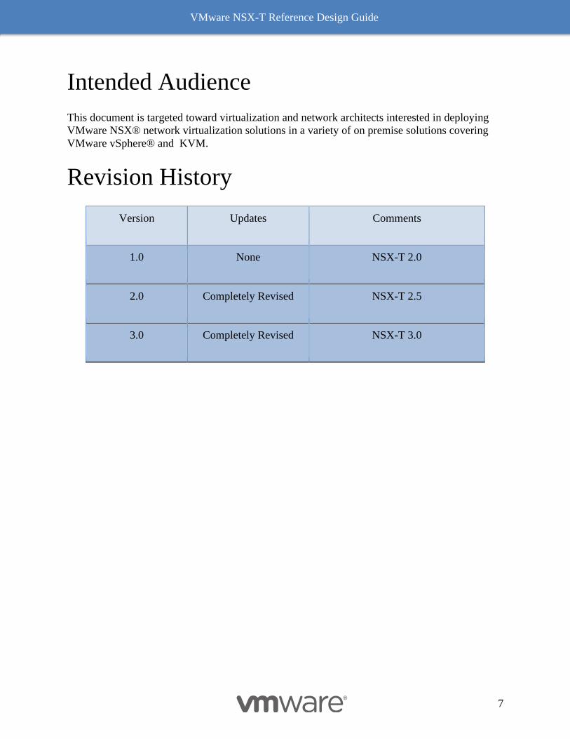
Revision History
Version Updates Comments
1.0 None NSX-T 2.0
2.0 Completely Revised NSX-T 2.5
3.0 Completely Revised NSX-T 3.0
VMware NSX-T Reference Design Guide
8
1 Introduction This document provides guidance and best practices for designing environments that leverage the
capabilities of VMware NSX-T®. It is targeted at virtualization and network architects interested
in deploying NSX Data Center solutions.
How to Use This Document and Provide Feedback
This document is organized into several chapters. Chapter 2 to 6 explain the architectural
building blocks of NSX-T as a full stack solution, providing a detail functioning of NSX-T
components, features and scope. They also describe components and functionality utilized for
security use cases. These chapters lay the groundwork to help understand and implement the
design guidance described in the design chapter.
The design chapter (Chapter 7) examines detailed use cases of network virtualization and
recommendations of either best practices or leading practices based on the type of use case or
design form factor. It offers guidance for a variety of factors including physical infrastructure
considerations, compute node requirements, and variably sized environments from small to
enterprise scale.
This version of design guide we have updated our chapter on performance. This chapter was
introduced by a popular request from our loyal customer base in version 2.0 of this document
and aims at clarifying the myths vs facts on NSX-T based SDN.
This document does not cover installation, and operational monitoring and troubleshooting. For
further details, review the complete NSX-T installation and administration guides.
A list of additional resources, specific API examples and guidance are included at the end of this
document under multiple appendixes.
Finally starting with this design guide, readers are encouraged to send a feedback to
NSXDesignFeedback_AT_groups_vmware_com (convert to email format).
Networking and Security Today
In the digital transformation era, organizations are increasingly building custom applications to
drive core business and gain competitive advantages. The speed with which development teams
deliver new applications and capabilities directly impacts the organization’s success and bottom
line. This exerts increasing pressure on organizations to innovate quickly and makes developers
central to this critical mission. As a result, the way developers create apps, and the way IT
provides services for those apps, are evolving.
Application Proliferation
VMware NSX-T Reference Design Guide
9
With applications quickly emerging as the new business model, developers are under immense
pressure to deliver apps in a record time. This increasing need to deliver more apps in a less time
can drive developers to use public clouds or open source technologies. These solutions allow
them to write and provision apps in a fraction of the time required with traditional methods.
Heterogeneity
Application proliferation has given rise to heterogeneous environments, with application
workloads being run inside VMs, containers, clouds, and bare metal servers. IT departments
must maintain governance, security, and visibility for application workloads regardless of
whether they reside on premises, in public clouds, or in clouds managed by third-parties.
Cloud-centric Architectures
Cloud-centric architectures and approaches to building and managing applications are
increasingly common because of their efficient development environments and fast delivery of
applications. These cloud architectures can put pressure on networking and security
infrastructure to integrate with private and public clouds. Logical networking and security must
be highly extensible to adapt and keep pace with ongoing change.
Against this backdrop of increasing application needs, greater heterogeneity, and the complexity
of environments, IT must still protect applications and data while addressing the reality of an
attack surface that is continuously expanding.
NSX-T Architecture Value and Scope
VMware NSX-T is designed to address application frameworks and architectures that have
heterogeneous endpoints and technology stacks. In addition to vSphere, these environments may
include other hypervisors, containers, bare metal operating systems, and public clouds. NSX-T
allows IT and development teams to choose the technologies best suited for their particular
applications. NSX-T is also designed for management, operations, and consumption by
development organizations in addition to IT.

VMware NSX-T Reference Design Guide
10
Figure 1-1: NSX-T Anywhere Architecture
The NSX-T architecture is designed around four fundamental attributes. Figure 1-1: NSX-T Anywhere
Architecture depicts the universality of those attributes that spans from any site, to any cloud, and to
any endpoint device. This enables greater decoupling, not just at the infrastructure level (e.g.,
hardware, hypervisor), but also at the public cloud (e.g., AWS, Azure) and container level (e.g.,
K8, Pivotal); all while maintaining the four key attributes of platform implemented across the
domains. NSX-T architectural value and characteristics of NSX-T architecture include:
• Policy and Consistency: Allows policy definition once and realizable end state via
RESTful API, addressing requirements of today’s automated environments. NSX-T
maintains unique and multiple inventories and controls to enumerate desired outcomes
across diverse domains.
• Networking and Connectivity: Allows consistent logical switching and distributed
routing with multiple vSphere and KVM nodes, without being tied to compute
manager/domain. The connectivity is further extended across containers and clouds via
domain specific implementation while still providing connectivity across heterogeneous
endpoints.
• Security and Services: Allows a unified security policy model as with networking
connectivity. This enables implementation of services such as load balancer, Edge
(Gateway) Firewall, Distributed Firewall, and Network Address Translation cross
multiple compute domains. Providing consistent security between VMs and container
Any Site Any Cloud Any Device
VM
Bare Metal
Container
API & Automation
On-Prem, In-Cloud, Hybrid
Multi-Domain & Diversity of End Point
Visibility & OperationServices – FW/LB/NAT/DHCP/VPN
Intrinsic Security
Networking & Connectivity
Policy & Consistency
Public
VMware Cloud
NSX Cloud
Data Center
DR Site
Branch
VMware NSX-T Reference Design Guide
11
workloads is essential to assuring the integrity of the overall framework set forth by
security operations.
• Visibility: Allows consistent monitoring, metric collection, and flow tracing via a
common toolset across compute domains. Visibility is essential for operationalizing
mixed workloads – VM and container-centric –typically both have drastically different
tools for completing similar tasks.
These attributes enable the heterogeneity, app-alignment, and extensibility required to support
diverse requirements. Additionally, NSX-T supports DPDK libraries that offer line-rate stateful
services.
Heterogeneity
In order to meet the needs of heterogeneous environments, a fundamental requirement of NSX-T
is to be compute-manager agnostic. As this approach mandates support for multi-hypervisor
and/or multi-workloads, a single NSX manager’s manageability domain can span multiple
vCenters. When designing the management plane, control plane, and data plane components of
NSX-T, special considerations were taken to enable flexibility, scalability, and performance.
The management plane was designed to be independent of any compute manager, including
vSphere. The VMware NSX-T® Manager™ is fully independent; management of the NSX
based network functions are accesses directly – either programmatically or through the GUI.
The control plane architecture is separated into two components – a centralized cluster and an
endpoint-specific local component. This separation allows the control plane to scale as the
localized implementation – both data plane implementation and security enforcement – is more
efficient and allows for heterogeneous environments.
The data plane was designed to be normalized across various environments. NSX-T introduces a
host switch that normalizes connectivity among various compute domains, including multiple
VMware vCenter® instances, KVM, containers, and other off premises or cloud
implementations. This switch is referred as N-VDS. The functionality of the N-VDS switch was
fully implemented in the ESXi VDS 7.0, which allows ESXi customers to take advantage of full
NSX-T functionality without having to change VDS. Regardless of implementation, data plane
connectivity is normalized across all platforms, allowing for a consistent experience.
App-aligned
NSX-T was built with the application as the key construct. Regardless of whether the app was
built in a traditional monolithic model or developed in a newer microservices application
framework, NSX-T treats networking and security consistently. This consistency extends across
containers and multi-hypervisors on premises, then further into the public cloud. This
functionality is first available for Amazon Web Services (AWS), Microsoft Azure and will
extend to other clouds as well on premises connectivity solutions. In turn enabling developers to
focus on the platform that provides the most benefit while providing IT operational consistency
across networking and security platforms.
VMware NSX-T Reference Design Guide
12
Containers and Cloud Native Application Integrations with NSX-T
In an age where a new application is directly tied to business gains, delays in application
deployment translates to lost revenue or business opportunity. The current era of digital
transformation challenges IT in addressing directives to normalize security of applications and
data, increase speed of delivery, and improve application availability. IT administrators realize
that a new approach must be taken to support business needs and meet timelines. Architecturally
solving the problem by specifically defining connectivity, security, and policy as a part of
application lifecycle is essential. Programmatic and automatic creation of network and switching
segments based on application driven infrastructure is the only way to meet the requirements of
these newer architectures.
NSX-T is designed to address the needs of these emerging application frameworks and
architectures with heterogeneous endpoints and technology stacks. NSX allows IT and
development teams to choose the technologies best suited for their particular applications or use
case without compromising consistent security and operations. NSX provides a common
framework to manage and increase visibility of environments that contain everything from
physical servers to VMs and containers. As developers embrace newer technologies like
containers and the percentage of workloads running in public clouds increases, network
virtualization must expand to offer a full range of networking and security services (e.g., LB,
NAT, DFW, etc.) native in these environments. NSX Container solutions provide networking,
security, visibility, and Load Balancing services for container-based applications based on
Kubernetes (Openshift and Tanzu) as well as managed Kubernetes offerings running in the
public cloud (Amazon’s Elastic Kubernetes Service – EKS, Amazon Kubernetes Service – AKS,
and Google Kubernetes Engine GKE).
The NSX Portfolio also consists of solutions like “NSX Container Networking with Project
Antrea” and Tanzu Service Mesh which help extend NSX to IaaS and CaaS platforms like
Managed Public Clouds or Far Edge Scenarios where there is no underlying NSX dataplane.
VMware NSX-T Reference Design Guide
13
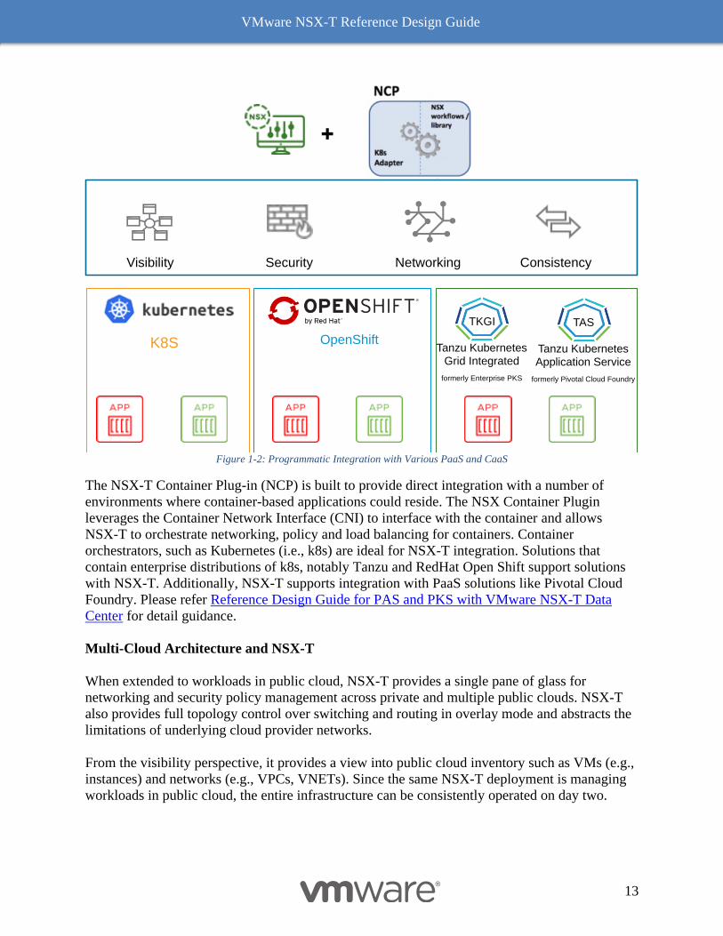
Figure 1-2: Programmatic Integration with Various PaaS and CaaS
The NSX-T Container Plug-in (NCP) is built to provide direct integration with a number of
environments where container-based applications could reside. The NSX Container Plugin
leverages the Container Network Interface (CNI) to interface with the container and allows
NSX-T to orchestrate networking, policy and load balancing for containers. Container
orchestrators, such as Kubernetes (i.e., k8s) are ideal for NSX-T integration. Solutions that
contain enterprise distributions of k8s, notably Tanzu and RedHat Open Shift support solutions
with NSX-T. Additionally, NSX-T supports integration with PaaS solutions like Pivotal Cloud
Foundry. Please refer Reference Design Guide for PAS and PKS with VMware NSX-T Data
Center for detail guidance.
Multi-Cloud Architecture and NSX-T
When extended to workloads in public cloud, NSX-T provides a single pane of glass for
networking and security policy management across private and multiple public clouds. NSX-T
also provides full topology control over switching and routing in overlay mode and abstracts the
limitations of underlying cloud provider networks.
From the visibility perspective, it provides a view into public cloud inventory such as VMs (e.g.,
instances) and networks (e.g., VPCs, VNETs). Since the same NSX-T deployment is managing
workloads in public cloud, the entire infrastructure can be consistently operated on day two.
K8S OpenShift
+
ConsistencyVisibility Security Networking
Tanzu KubernetesGrid Integrated
formerly Enterprise PKS
TKGI
Tanzu KubernetesApplication Service
formerly Pivotal Cloud Foundry
TAS
VMware NSX-T Reference Design Guide
14
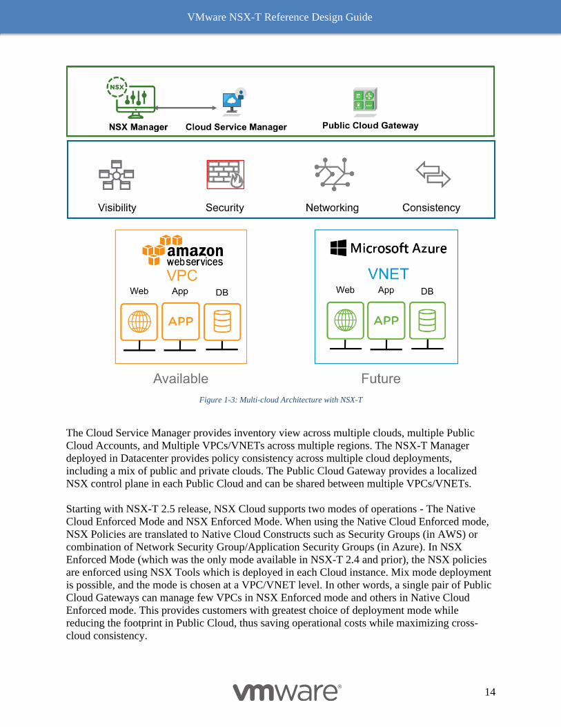
Figure 1-3: Multi-cloud Architecture with NSX-T
The Cloud Service Manager provides inventory view across multiple clouds, multiple Public
Cloud Accounts, and Multiple VPCs/VNETs across multiple regions. The NSX-T Manager
deployed in Datacenter provides policy consistency across multiple cloud deployments,
including a mix of public and private clouds. The Public Cloud Gateway provides a localized
NSX control plane in each Public Cloud and can be shared between multiple VPCs/VNETs.
Starting with NSX-T 2.5 release, NSX Cloud supports two modes of operations - The Native
Cloud Enforced Mode and NSX Enforced Mode. When using the Native Cloud Enforced mode,
NSX Policies are translated to Native Cloud Constructs such as Security Groups (in AWS) or
combination of Network Security Group/Application Security Groups (in Azure). In NSX
Enforced Mode (which was the only mode available in NSX-T 2.4 and prior), the NSX policies
are enforced using NSX Tools which is deployed in each Cloud instance. Mix mode deployment
is possible, and the mode is chosen at a VPC/VNET level. In other words, a single pair of Public
Cloud Gateways can manage few VPCs in NSX Enforced mode and others in Native Cloud
Enforced mode. This provides customers with greatest choice of deployment mode while
reducing the footprint in Public Cloud, thus saving operational costs while maximizing cross-
cloud consistency.
VMware NSX-T Reference Design Guide
15
Additionally, NSX-T 2.5 onward, native cloud service endpoints (RDS, ELB, Azure LB, etc.) are
discovered automatically and can be used in NSX-T DFW policy. Customer does not need to
find the endpoint IPs manually while creating these policies.
Architecturally, the Public Cloud Gateway is responsible for discovery of cloud VMs/service
endpoints as well as the realization of policies in both modes of operation. In Native Cloud
Enforced Mode, NSX Provides common management plane for configuring rich micro-
segmentation policies across multiple public clouds. When using NSX Enforced Mode, the
Public Cloud Gateway also provides services such as VPN, NAT and Edge Firewall, similar to
an on-premises NSX-T Edge. NSX Enforced mode further allows each cloud based VM instance
additional distributed data plane benefits including logical switching, logical routing and
monitoring features such as syslog, port-mirroring, IPFIX, etc -all the while allowing customers
to follow cloud providers best practices for designing network topologies. For further
information on how NSX-T is benefiting in cloud workload visit NSXCLOUD and explore.
Extensible
The key architectural tenets of heterogeneity and app-alignment are inherently properties of
extensibility, but full extensibility requires more. Extensibility also means the ability to support
multi-tenant and domain environments along with integration into the DevOps workflow.
VMware NSX-T Reference Design Guide
16
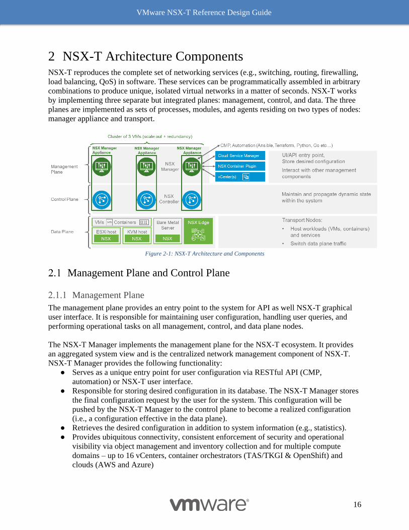
2 NSX-T Architecture Components NSX-T reproduces the complete set of networking services (e.g., switching, routing, firewalling,
load balancing, QoS) in software. These services can be programmatically assembled in arbitrary
combinations to produce unique, isolated virtual networks in a matter of seconds. NSX-T works
by implementing three separate but integrated planes: management, control, and data. The three
planes are implemented as sets of processes, modules, and agents residing on two types of nodes:
manager appliance and transport.
Figure 2-1: NSX-T Architecture and Components
Management Plane and Control Plane
Management Plane
The management plane provides an entry point to the system for API as well NSX-T graphical
user interface. It is responsible for maintaining user configuration, handling user queries, and
performing operational tasks on all management, control, and data plane nodes.
The NSX-T Manager implements the management plane for the NSX-T ecosystem. It provides
an aggregated system view and is the centralized network management component of NSX-T.
NSX-T Manager provides the following functionality:
● Serves as a unique entry point for user configuration via RESTful API (CMP,
automation) or NSX-T user interface.
● Responsible for storing desired configuration in its database. The NSX-T Manager stores
the final configuration request by the user for the system. This configuration will be
pushed by the NSX-T Manager to the control plane to become a realized configuration
(i.e., a configuration effective in the data plane).
● Retrieves the desired configuration in addition to system information (e.g., statistics).
● Provides ubiquitous connectivity, consistent enforcement of security and operational
visibility via object management and inventory collection and for multiple compute
domains – up to 16 vCenters, container orchestrators (TAS/TKGI & OpenShift) and
clouds (AWS and Azure)
VMware NSX-T Reference Design Guide
17
Data plane components or transport node run a management plane agent (MPA) that connects
them to the NSX-T Manager.
Control Plane
The control plane computes the runtime state of the system based on configuration from the
management plane. It is also responsible for disseminating topology information reported by the
data plane elements and pushing stateless configuration to forwarding engines.
NSX-T splits the control plane into two parts:
● Central Control Plane (CCP) – The CCP is implemented as a cluster of virtual
machines called CCP nodes. The cluster form factor provides both redundancy and
scalability of resources. The CCP is logically separated from all data plane traffic,
meaning any failure in the control plane does not affect existing data plane operations.
User traffic does not pass through the CCP Cluster.
● Local Control Plane (LCP) – The LCP runs on transport nodes. It is adjacent to the data
plane it controls and is connected to the CCP. The LCP is responsible for programing the
forwarding entries and firewall rules of the data plane.
NSX Manager Appliance
Instances of the NSX Manager and NSX Controller are bundled in a virtual machine called the
NSX Manager Appliance. In the releases prior to 2.4, there were separate appliances based on
the roles, one management appliance and 3 controller appliances, so total four appliances to be
deployed and managed for NSX. Starting 2.4, the NSX manager, NSX policy manager and NSX
controller elements will co-exist within a common VM. Three unique NSX appliance VMs are
required for cluster availability. NSX-T relies on a cluster of three such NSX Manager
Appliances for scaling out and for redundancy. This three-node cluster relies on a majority of the
appliances in the cluster to be available and as such, attention should be paid to placement of
these appliances for availability The NSX-T Manager stores all of its information in an in-
memory database immediately which is synchronized across the cluster and written to disk,
configuration or read operations can be performed on any appliance. The performance
requirements of the NSX Manager Appliance’s disk is significantly reduced as most operations
occur in memory.
The benefits with this converged manager appliance include less management overhead with
reduced appliances to manage. And a potential reduction in the total amount of resources (CPU,
memory and disk). With the converged manager appliance, one only need to consider the
appliance sizing once.
VMware NSX-T Reference Design Guide
18
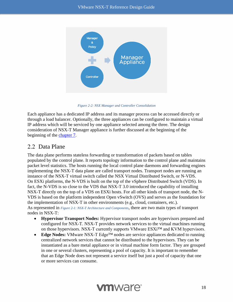
Figure 2-2: NSX Manager and Controller Consolidation
Each appliance has a dedicated IP address and its manager process can be accessed directly or
through a load balancer. Optionally, the three appliances can be configured to maintain a virtual
IP address which will be serviced by one appliance selected among the three. The design
consideration of NSX-T Manager appliance is further discussed at the beginning of the
beginning of the chapter 7.
Data Plane
The data plane performs stateless forwarding or transformation of packets based on tables
populated by the control plane. It reports topology information to the control plane and maintains
packet level statistics. The hosts running the local control plane daemons and forwarding engines
implementing the NSX-T data plane are called transport nodes. Transport nodes are running an
instance of the NSX-T virtual switch called the NSX Virtual Distributed Switch, or N-VDS.
On ESXi platforms, the N-VDS is built on the top of the vSphere Distributed Switch (VDS). In
fact, the N-VDS is so close to the VDS that NSX-T 3.0 introduced the capability of installing
NSX-T directly on the top of a VDS on ESXi hosts. For all other kinds of transport node, the N-
VDS is based on the platform independent Open vSwitch (OVS) and serves as the foundation for
the implementation of NSX-T in other environments (e.g., cloud, containers, etc.).
As represented in Figure 2-1: NSX-T Architecture and Components, there are two main types of transport
nodes in NSX-T:
• Hypervisor Transport Nodes: Hypervisor transport nodes are hypervisors prepared and
configured for NSX-T. NSX-T provides network services to the virtual machines running
on those hypervisors. NSX-T currently supports VMware ESXi™ and KVM hypervisors.
• Edge Nodes: VMware NSX-T Edge™ nodes are service appliances dedicated to running
centralized network services that cannot be distributed to the hypervisors. They can be
instantiated as a bare metal appliance or in virtual machine form factor. They are grouped
in one or several clusters, representing a pool of capacity. It is important to remember
that an Edge Node does not represent a service itself but just a pool of capacity that one
or more services can consume.
VMware NSX-T Reference Design Guide
19
NSX-T Consumption Model
A user can interact with the NSX-T platform through the Graphical User Interface or the REST
API framework. Starting with NSX-T 3.0 the GUI & REST API are available as options to
interact with the NSX Manager:
1) Policy Mode
o Default UI mode.
o Previously called the Declarative or Simplified API/Data Model.
o API accessed via URI which start with /api/policy
2) Manager Mode
o Continuing user interface to address upgrade & Cloud Management Platform (CMP)
use case, more info in the next section.
o Advanced UI/API will be deprecated over time, as we transition all features/use case
to Simplified UI/API.
o API accessed via URI which start with /api
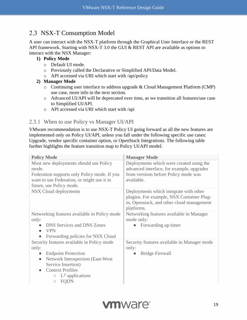
When to use Policy vs Manager UI/API
VMware recommendation is to use NSX-T Policy UI going forward as all the new features are
implemented only on Policy UI/API, unless you fall under the following specific use cases:
Upgrade, vendor specific container option, or OpenStack Integrations. The following table
further highlights the feature transition map to Policy UI/API model.
Policy Mode Manager Mode
Most new deployments should use Policy
mode.
Federation supports only Policy mode. If you
want to use Federation, or might use it in
future, use Policy mode.
Deployments which were created using the
advanced interface, for example, upgrades
from versions before Policy mode was
available.
NSX Cloud deployments Deployments which integrate with other
plugins. For example, NSX Container Plug-
in, Openstack, and other cloud management
platforms.
Networking features available in Policy mode
only:
● DNS Services and DNS Zones
● VPN
● Forwarding policies for NSX Cloud
Networking features available in Manager
mode only:
● Forwarding up timer
Security features available in Policy mode
only:
● Endpoint Protection
● Network Introspection (East-West
Service Insertion)
● Context Profiles
○ L7 applications
○ FQDN
Security features available in Manager mode
only:
● Bridge Firewall
VMware NSX-T Reference Design Guide
20
● New Distributed Firewall and
Gateway Firewall Layout
○ Categories
○ Auto service rules
○ Drafts
It is recommended that whichever mode is used to create objects (Policy or Manager) be the only
mode used (if the Manager Mode objects are required, create all objects in Manager mode). Do
not alternate use of the modes or there will be unpredictable results. Note that the default mode
for the NSX Manager is Policy mode. When working in an installation where all objects are new
and created in Policy mode, the Manager mode option will not be visible in the UI. For details
on switching between modes, please see the NSX-T documentation.
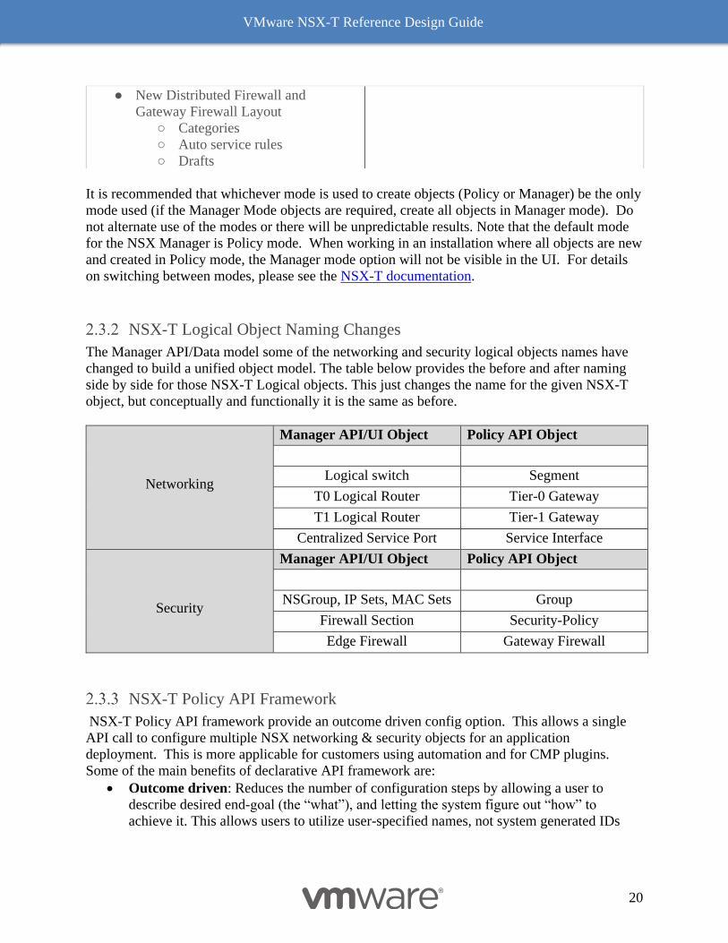
NSX-T Logical Object Naming Changes
The Manager API/Data model some of the networking and security logical objects names have
changed to build a unified object model. The table below provides the before and after naming
side by side for those NSX-T Logical objects. This just changes the name for the given NSX-T
object, but conceptually and functionally it is the same as before.
Networking
Manager API/UI Object Policy API Object
Logical switch Segment
T0 Logical Router Tier-0 Gateway
T1 Logical Router Tier-1 Gateway
Centralized Service Port Service Interface
Security
Manager API/UI Object Policy API Object
NSGroup, IP Sets, MAC Sets Group
Firewall Section Security-Policy
Edge Firewall Gateway Firewall
NSX-T Policy API Framework
NSX-T Policy API framework provide an outcome driven config option. This allows a single
API call to configure multiple NSX networking & security objects for an application
deployment. This is more applicable for customers using automation and for CMP plugins.
Some of the main benefits of declarative API framework are:
• Outcome driven: Reduces the number of configuration steps by allowing a user to
describe desired end-goal (the “what”), and letting the system figure out “how” to
achieve it. This allows users to utilize user-specified names, not system generated IDs
VMware NSX-T Reference Design Guide
21
• Order Independent: create/update/delete in any order and always arrive at the same
consistent result
• Prescriptive: reduces potential for user error with built-in dependency checks
• Policy Life Cycle Management: Simpler with single API call. Toggle marked-to-delete
flag in the JSON request body to manage life cycle of entire application topology.
The NSX-T API documentation can be accessible directly from the NSX Manager UI, under
Policy section within API documentation, or it can be accessed from code.vmware.com.
The following examples walks you through the policy API examples for two of the customer
scenarios:
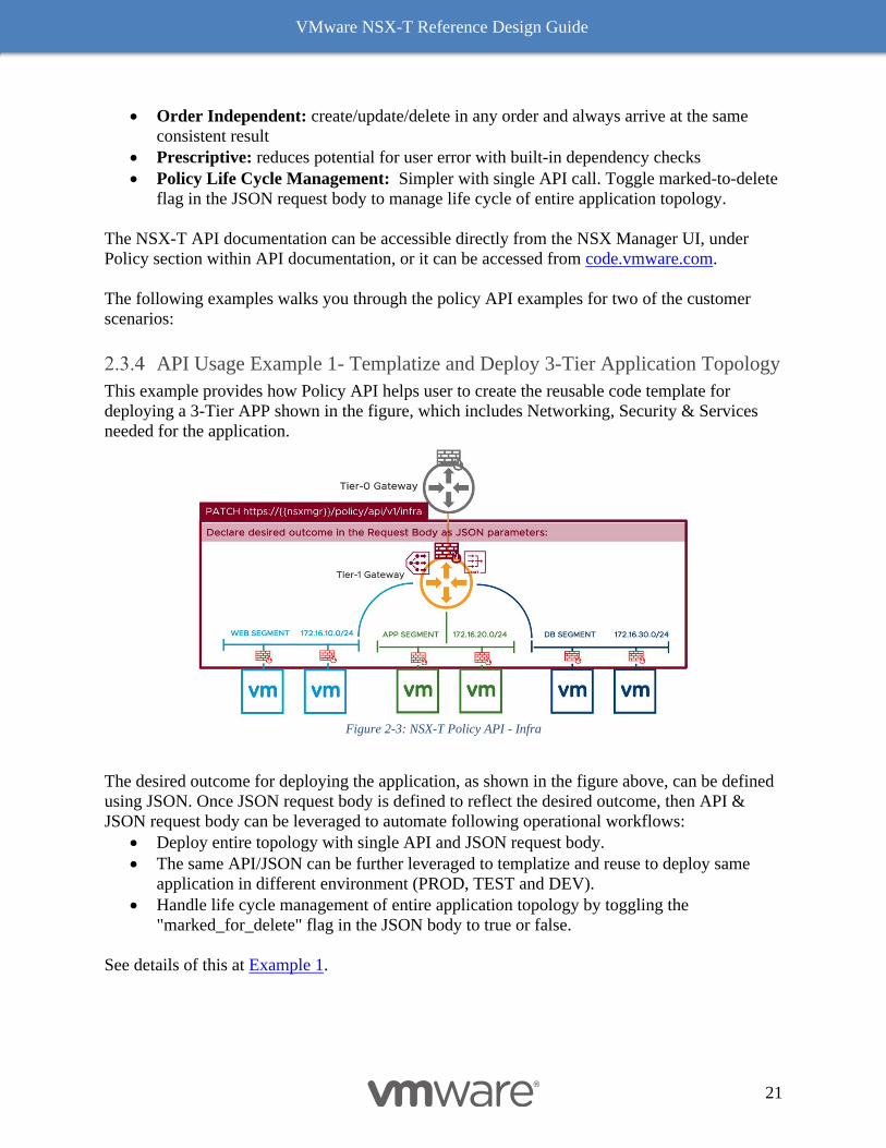
API Usage Example 1- Templatize and Deploy 3-Tier Application Topology
This example provides how Policy API helps user to create the reusable code template for
deploying a 3-Tier APP shown in the figure, which includes Networking, Security & Services
needed for the application.
Figure 2-3: NSX-T Policy API - Infra
The desired outcome for deploying the application, as shown in the figure above, can be defined
using JSON. Once JSON request body is defined to reflect the desired outcome, then API &
JSON request body can be leveraged to automate following operational workflows:
• Deploy entire topology with single API and JSON request body.
• The same API/JSON can be further leveraged to templatize and reuse to deploy same
application in different environment (PROD, TEST and DEV).
• Handle life cycle management of entire application topology by toggling the
"marked_for_delete" flag in the JSON body to true or false.
See details of this at Example 1.
VMware NSX-T Reference Design Guide
22
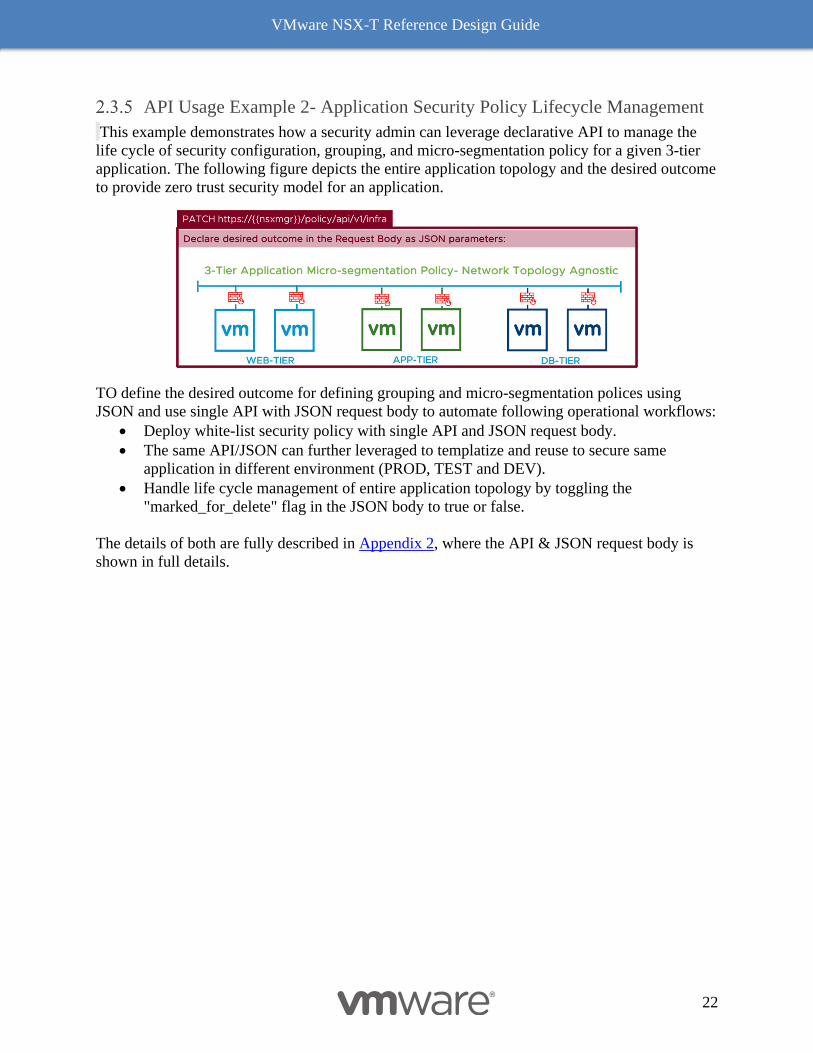
API Usage Example 2- Application Security Policy Lifecycle Management
This example demonstrates how a security admin can leverage declarative API to manage the
life cycle of security configuration, grouping, and micro-segmentation policy for a given 3-tier
application. The following figure depicts the entire application topology and the desired outcome
to provide zero trust security model for an application.
TO define the desired outcome for defining grouping and micro-segmentation polices using
JSON and use single API with JSON request body to automate following operational workflows:
• Deploy white-list security policy with single API and JSON request body.
• The same API/JSON can further leveraged to templatize and reuse to secure same
application in different environment (PROD, TEST and DEV).
• Handle life cycle management of entire application topology by toggling the
"marked_for_delete" flag in the JSON body to true or false.
The details of both are fully described in Appendix 2, where the API & JSON request body is
shown in full details.

VMware NSX-T Reference Design Guide
23
3 NSX-T Logical Switching This chapter details how NSX-T creates virtual Layer 2 networks, called segments, to provide
connectivity between its services and the different virtual machines in the environment.
The NSX Virtual Switch
A transport node is, by definition, a device implementing the NSX-T data plane. The software
component running this data plane is a virtual switch, responsible for forwarding traffic between
logical and physical ports on the device. The NSX-T virtual switch is called the NSX Virtual
Distributed Switch, or N-VDS. On ESXi hosts, the N-VDS implementation is derived from
VMware vSphere® Distributed Switch™ (VDS). With any other kind of transport node (KVM
hypervisors, Edges, bare metal servers, cloud VMs etc.) the N-VDS implementation is derived
from the Open vSwitch (OVS).
NSX-T 3.0 is introducing a new model for its ESXi transport nodes where the NSX software
components can be directly installed on the top of an existing VDS. This has several benefits
such as using existing model of VDS for non-overlay traffic and avoiding the migration of
VMkernel to N-VDS. Representations of the NSX virtual switch in this document will thus be
labeled “N-VDS or VDS with NSX” for each scenario where the transport node represented can
be an ESXi host. Note that if this new VDS-based model greatly simplifies NSX consumption on
the ESXi platform, it has very little if any impact on NSX-based designs: both N-VDS and VDS
running NSX provide the same NSX capabilities, only with a different representation in vCenter.
Operational details on how to run NSX on VDS are out of scope of this document, but
simplification in term of VMkernel interface management that this new model brings will be
called out in the design section. We thus recommend deploying NSX on the top of a VDS on
ESXi hosts instead of using an N-VDS for greenfield deployments starting with supported ESXi
and vSphere versions. The N-VDS is still the only virtual switch available on platforms other
than ESXi.
Segments and Transport Zones
In NSX-T, virtual layer 2 domains are called segments. There are two kinds of segments:
• VLAN backed segments
• Overlay backed segments
A VLAN backed segment is a layer 2 broadcast domain that is implemented as a traditional
VLAN in the physical infrastructure. That means that traffic between two VMs on two different
hosts but attached to the same VLAN backed segment will be carried over a VLAN between the
two hosts in native IEEE encapsulation. The resulting constraint is that an appropriate VLAN
needs to be provisioned in the physical infrastructure for those two VMs to communicate at layer
2 over a VLAN backed segment.
On the other hand, two VMs on different hosts and attached to the same overlay backed segment
will have their layer 2 traffic carried by tunnel between their hosts. This IP tunnel is instantiated
VMware NSX-T Reference Design Guide
24
and maintained by NSX without the need for any segment specific configuration in the physical
infrastructure, thus decoupling NSX virtual networking from this physical infrastructure.
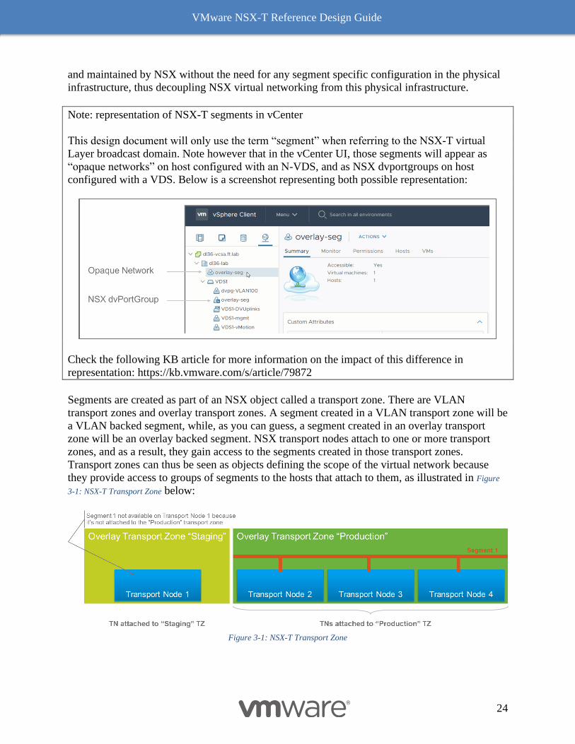
Note: representation of NSX-T segments in vCenter
This design document will only use the term “segment” when referring to the NSX-T virtual
Layer broadcast domain. Note however that in the vCenter UI, those segments will appear as
“opaque networks” on host configured with an N-VDS, and as NSX dvportgroups on host
configured with a VDS. Below is a screenshot representing both possible representation:
Check the following KB article for more information on the impact of this difference in
representation: https://kb.vmware.com/s/article/79872
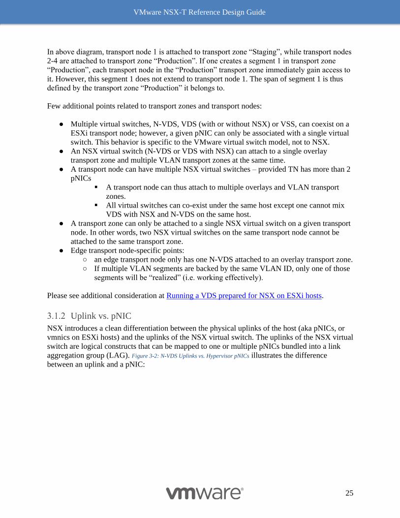
Segments are created as part of an NSX object called a transport zone. There are VLAN
transport zones and overlay transport zones. A segment created in a VLAN transport zone will be
a VLAN backed segment, while, as you can guess, a segment created in an overlay transport
zone will be an overlay backed segment. NSX transport nodes attach to one or more transport
zones, and as a result, they gain access to the segments created in those transport zones.
Transport zones can thus be seen as objects defining the scope of the virtual network because
they provide access to groups of segments to the hosts that attach to them, as illustrated in Figure
3-1: NSX-T Transport Zone below:
Figure 3-1: NSX-T Transport Zone
VMware NSX-T Reference Design Guide
25
In above diagram, transport node 1 is attached to transport zone “Staging”, while transport nodes
2-4 are attached to transport zone “Production”. If one creates a segment 1 in transport zone
“Production”, each transport node in the “Production” transport zone immediately gain access to
it. However, this segment 1 does not extend to transport node 1. The span of segment 1 is thus
defined by the transport zone “Production” it belongs to.
Few additional points related to transport zones and transport nodes:
● Multiple virtual switches, N-VDS, VDS (with or without NSX) or VSS, can coexist on a
ESXi transport node; however, a given pNIC can only be associated with a single virtual
switch. This behavior is specific to the VMware virtual switch model, not to NSX.
● An NSX virtual switch (N-VDS or VDS with NSX) can attach to a single overlay
transport zone and multiple VLAN transport zones at the same time.
● A transport node can have multiple NSX virtual switches – provided TN has more than 2
pNICs
▪ A transport node can thus attach to multiple overlays and VLAN transport
zones.
▪ All virtual switches can co-exist under the same host except one cannot mix
VDS with NSX and N-VDS on the same host.
● A transport zone can only be attached to a single NSX virtual switch on a given transport
node. In other words, two NSX virtual switches on the same transport node cannot be
attached to the same transport zone.
● Edge transport node-specific points:
○ an edge transport node only has one N-VDS attached to an overlay transport zone.
○ If multiple VLAN segments are backed by the same VLAN ID, only one of those
segments will be “realized” (i.e. working effectively).
Please see additional consideration at Running a VDS prepared for NSX on ESXi hosts.
Uplink vs. pNIC
NSX introduces a clean differentiation between the physical uplinks of the host (aka pNICs, or
vmnics on ESXi hosts) and the uplinks of the NSX virtual switch. The uplinks of the NSX virtual
switch are logical constructs that can be mapped to one or multiple pNICs bundled into a link
aggregation group (LAG). Figure 3-2: N-VDS Uplinks vs. Hypervisor pNICs illustrates the difference
between an uplink and a pNIC:
VMware NSX-T Reference Design Guide
26
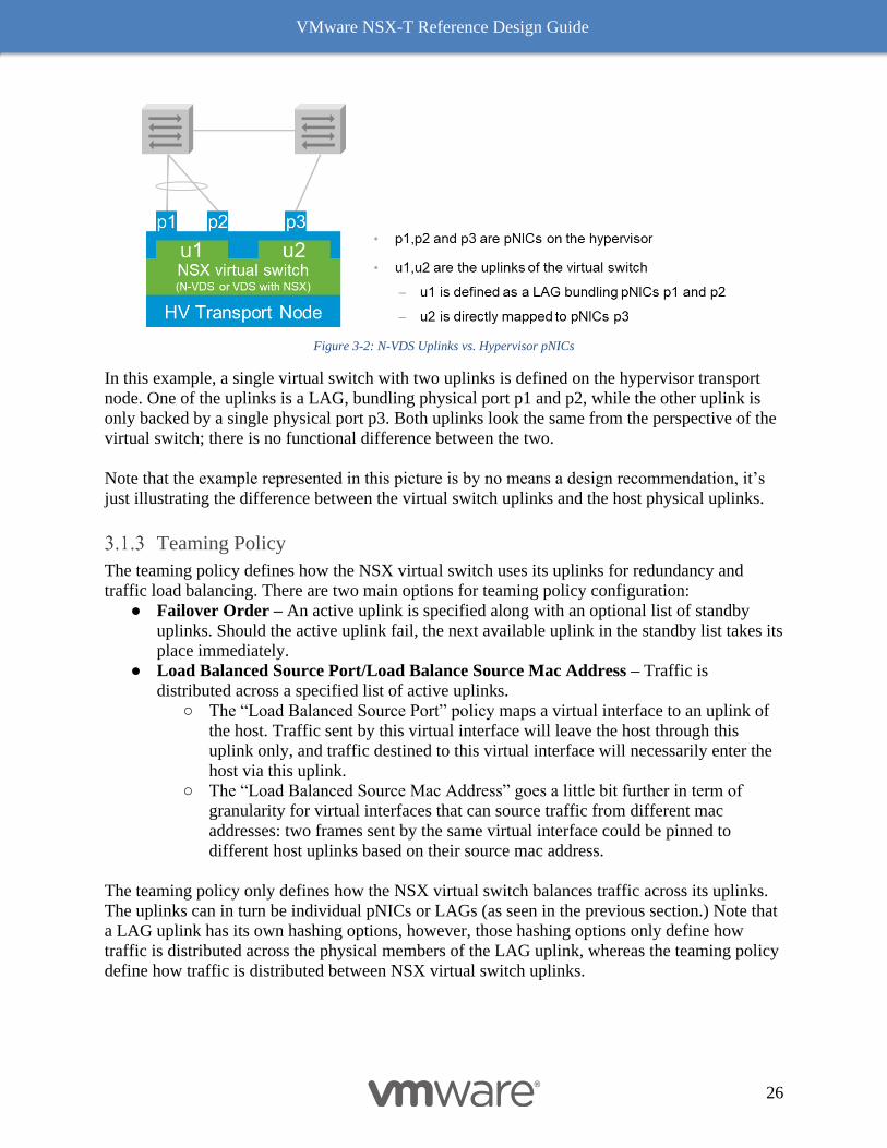
Figure 3-2: N-VDS Uplinks vs. Hypervisor pNICs
In this example, a single virtual switch with two uplinks is defined on the hypervisor transport
node. One of the uplinks is a LAG, bundling physical port p1 and p2, while the other uplink is
only backed by a single physical port p3. Both uplinks look the same from the perspective of the
virtual switch; there is no functional difference between the two.
Note that the example represented in this picture is by no means a design recommendation, it’s
just illustrating the difference between the virtual switch uplinks and the host physical uplinks.
Teaming Policy
The teaming policy defines how the NSX virtual switch uses its uplinks for redundancy and
traffic load balancing. There are two main options for teaming policy configuration:
● Failover Order – An active uplink is specified along with an optional list of standby
uplinks. Should the active uplink fail, the next available uplink in the standby list takes its
place immediately.
● Load Balanced Source Port/Load Balance Source Mac Address – Traffic is
distributed across a specified list of active uplinks.
○ The “Load Balanced Source Port” policy maps a virtual interface to an uplink of
the host. Traffic sent by this virtual interface will leave the host through this
uplink only, and traffic destined to this virtual interface will necessarily enter the
host via this uplink.
○ The “Load Balanced Source Mac Address” goes a little bit further in term of
granularity for virtual interfaces that can source traffic from different mac
addresses: two frames sent by the same virtual interface could be pinned to
different host uplinks based on their source mac address.
The teaming policy only defines how the NSX virtual switch balances traffic across its uplinks.
The uplinks can in turn be individual pNICs or LAGs (as seen in the previous section.) Note that
a LAG uplink has its own hashing options, however, those hashing options only define how
traffic is distributed across the physical members of the LAG uplink, whereas the teaming policy
define how traffic is distributed between NSX virtual switch uplinks.
VMware NSX-T Reference Design Guide
27
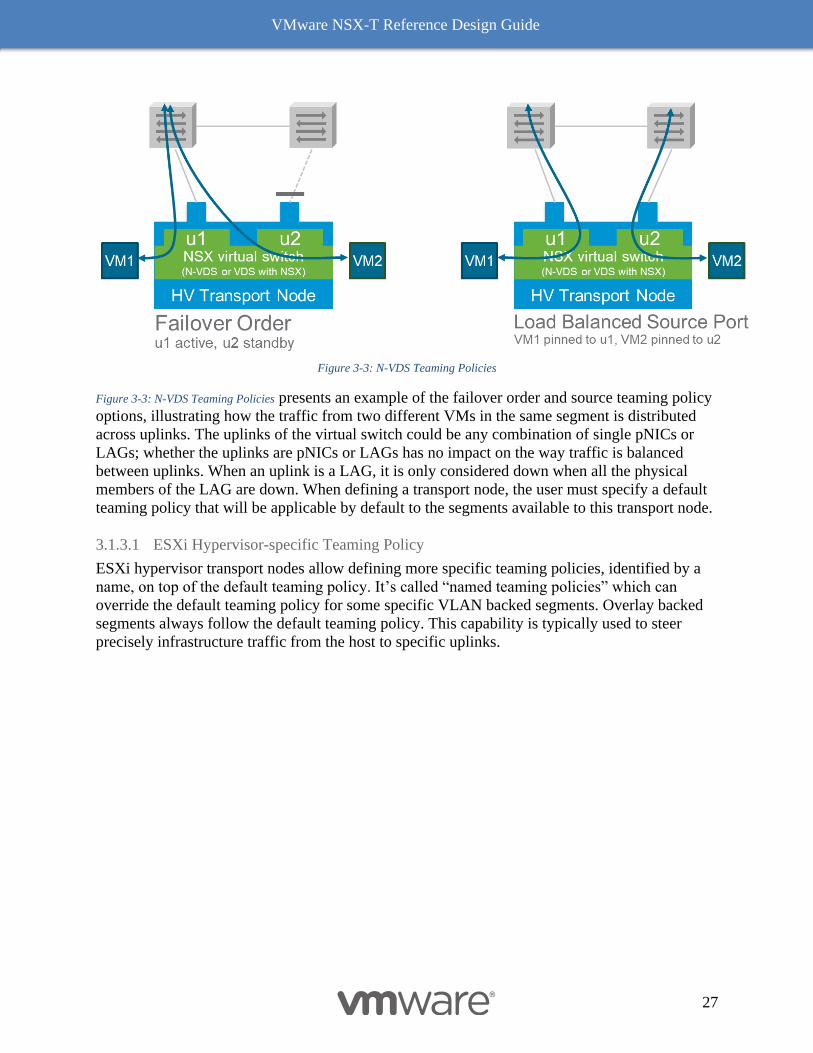
Figure 3-3: N-VDS Teaming Policies
Figure 3-3: N-VDS Teaming Policies presents an example of the failover order and source teaming policy
options, illustrating how the traffic from two different VMs in the same segment is distributed
across uplinks. The uplinks of the virtual switch could be any combination of single pNICs or
LAGs; whether the uplinks are pNICs or LAGs has no impact on the way traffic is balanced
between uplinks. When an uplink is a LAG, it is only considered down when all the physical
members of the LAG are down. When defining a transport node, the user must specify a default
teaming policy that will be applicable by default to the segments available to this transport node.
3.1.3.1 ESXi Hypervisor-specific Teaming Policy
ESXi hypervisor transport nodes allow defining more specific teaming policies, identified by a
name, on top of the default teaming policy. It’s called “named teaming policies” which can
override the default teaming policy for some specific VLAN backed segments. Overlay backed
segments always follow the default teaming policy. This capability is typically used to steer
precisely infrastructure traffic from the host to specific uplinks.
VMware NSX-T Reference Design Guide
28
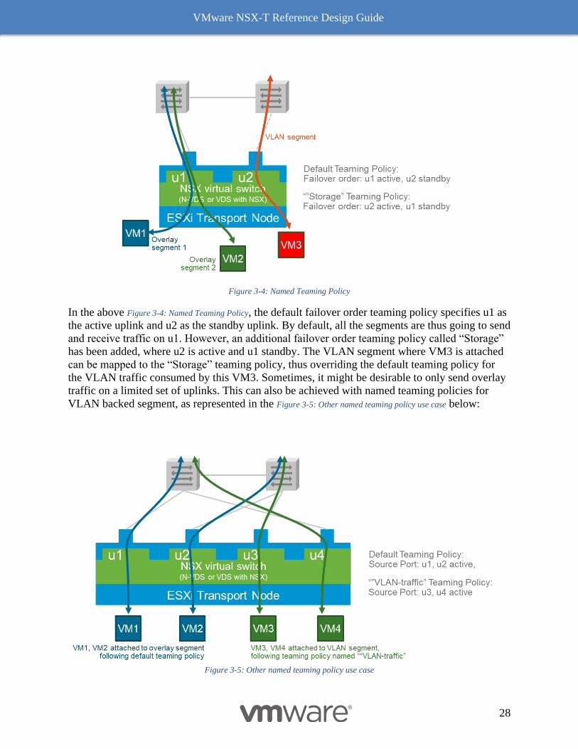
Figure 3-4: Named Teaming Policy
In the above Figure 3-4: Named Teaming Policy, the default failover order teaming policy specifies u1 as
the active uplink and u2 as the standby uplink. By default, all the segments are thus going to send
and receive traffic on u1. However, an additional failover order teaming policy called “Storage”
has been added, where u2 is active and u1 standby. The VLAN segment where VM3 is attached
can be mapped to the “Storage” teaming policy, thus overriding the default teaming policy for
the VLAN traffic consumed by this VM3. Sometimes, it might be desirable to only send overlay
traffic on a limited set of uplinks. This can also be achieved with named teaming policies for
VLAN backed segment, as represented in the Figure 3-5: Other named teaming policy use case below:
Figure 3-5: Other named teaming policy use case
VMware NSX-T Reference Design Guide
29
Here, the default teaming policy only includes uplinks u1 and u2. As a result, overlay traffic is
constrained to those uplinks. However, an additional teaming policy named “VLAN-traffic” is
configured for load balancing traffic on uplink u3 and u4. By mapping VLAN segments to this
teaming policy, overlay and VLAN traffic are segregated.
3.1.3.2 KVM Hypervisor teaming policy capabilities
KVM hypervisor transport nodes can only have a single LAG and only support the failover order
default teaming policy; the load balance source teaming policies and named teaming policies are
not available for KVM. A LAG must be configured for more than one physical uplink to be
active on an N-VDS on a KVM hypervisor.
Uplink Profile
As mentioned earlier, a transport node includes at least one NSX virtual switch, implementing
the NSX data plane. It is common for multiple transport nodes to share the exact same NSX
virtual switch configuration. It is also very difficult from an operational standpoint to configure
(and maintain) multiple parameters consistently across many devices. For this purpose, NSX
defines a separate object called an uplink profile that acts as a template for the configuration of a
virtual switch. The administrator can this way create multiple transport nodes with similar virtual
switches by simply pointing to a common uplink profile. Even better, when the administrator
modifies a parameter in the uplink profile, it is automatically updated in all the transport nodes
following this uplink profile.
The following parameters are defined in an uplink profile:
● The transport VLAN used for overlay traffic. Overlay traffic will be tagged with the
VLAN ID specified in this field.
● The MTU of the uplinks. NSX will assume that it can send overlay traffic with this MTU
on the physical uplinks of the transport node without any fragmentation by the physical
infrastructure.
● The name of the uplinks and the LAGs used by the virtual switch. LAGs are optional of
course, but if you want to define some, you can give them a name, specify the number of
links and the hash algorithm they will use.
● The teaming policies applied to the uplinks (default and named teaming policies)
The virtual switch uplinks defined in the uplink profile must be mapped to real, physical uplinks
on the device becoming a transport node.
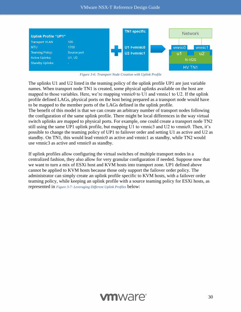
Figure 3-6: Transport Node Creation with Uplink Profile shows how a transport node “TN1” is created using
the uplink profile “UP1”.
VMware NSX-T Reference Design Guide
30
Figure 3-6: Transport Node Creation with Uplink Profile
The uplinks U1 and U2 listed in the teaming policy of the uplink profile UP1 are just variable
names. When transport node TN1 is created, some physical uplinks available on the host are
mapped to those variables. Here, we’re mapping vmnic0 to U1 and vmnic1 to U2. If the uplink
profile defined LAGs, physical ports on the host being prepared as a transport node would have
to be mapped to the member ports of the LAGs defined in the uplink profile.
The benefit of this model is that we can create an arbitrary number of transport nodes following
the configuration of the same uplink profile. There might be local differences in the way virtual
switch uplinks are mapped to physical ports. For example, one could create a transport node TN2
still using the same UP1 uplink profile, but mapping U1 to vmnic3 and U2 to vmnic0. Then, it’s
possible to change the teaming policy of UP1 to failover order and setting U1 as active and U2 as
standby. On TN1, this would lead vmnic0 as active and vmnic1 as standby, while TN2 would
use vmnic3 as active and vmnic0 as standby.
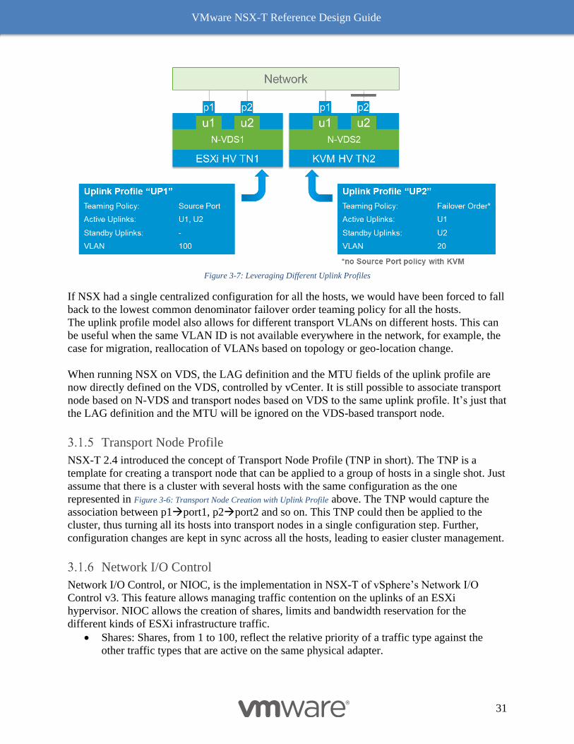
If uplink profiles allow configuring the virtual switches of multiple transport nodes in a
centralized fashion, they also allow for very granular configuration if needed. Suppose now that
we want to turn a mix of ESXi host and KVM hosts into transport zone. UP1 defined above
cannot be applied to KVM hosts because those only support the failover order policy. The
administrator can simply create an uplink profile specific to KVM hosts, with a failover order
teaming policy, while keeping an uplink profile with a source teaming policy for ESXi hosts, as
represented in Figure 3-7: Leveraging Different Uplink Profiles below:
VMware NSX-T Reference Design Guide
31
Figure 3-7: Leveraging Different Uplink Profiles
If NSX had a single centralized configuration for all the hosts, we would have been forced to fall
back to the lowest common denominator failover order teaming policy for all the hosts.
The uplink profile model also allows for different transport VLANs on different hosts. This can
be useful when the same VLAN ID is not available everywhere in the network, for example, the
case for migration, reallocation of VLANs based on topology or geo-location change.
When running NSX on VDS, the LAG definition and the MTU fields of the uplink profile are
now directly defined on the VDS, controlled by vCenter. It is still possible to associate transport
node based on N-VDS and transport nodes based on VDS to the same uplink profile. It’s just that
the LAG definition and the MTU will be ignored on the VDS-based transport node.
Transport Node Profile
NSX-T 2.4 introduced the concept of Transport Node Profile (TNP in short). The TNP is a
template for creating a transport node that can be applied to a group of hosts in a single shot. Just
assume that there is a cluster with several hosts with the same configuration as the one
represented in Figure 3-6: Transport Node Creation with Uplink Profile above. The TNP would capture the
association between p1→port1, p2→port2 and so on. This TNP could then be applied to the
cluster, thus turning all its hosts into transport nodes in a single configuration step. Further,
configuration changes are kept in sync across all the hosts, leading to easier cluster management.
Network I/O Control
Network I/O Control, or NIOC, is the implementation in NSX-T of vSphere’s Network I/O
Control v3. This feature allows managing traffic contention on the uplinks of an ESXi
hypervisor. NIOC allows the creation of shares, limits and bandwidth reservation for the
different kinds of ESXi infrastructure traffic.
• Shares: Shares, from 1 to 100, reflect the relative priority of a traffic type against the
other traffic types that are active on the same physical adapter.
VMware NSX-T Reference Design Guide
32
• Reservation: The minimum bandwidth that must be guaranteed on a single physical
adapter. Reserved bandwidth for system traffic that is unused becomes available to other
types of system traffic. Unused system traffic reservations do NOT become available to
VM traffic.
• Limit: The maximum bandwidth that a traffic type can consume on a single physical
adapter.
The pre-determined types of ESXi infrastructure traffic are:
• Management Traffic is for host management
• Fault Tolerance (FT) is for sync and recovery.
• NFS Traffic is traffic related to a file transfer in the network file system.
• vSAN traffic is generated by virtual storage area network.
• vMotion traffic is for computing resource migration.
• vSphere replication traffic is for replication.
• vSphere Data Protection Backup traffic is generated by backup of data.
• Virtual Machine traffic is generated by virtual machines workload
• iSCSI traffic is for Internet Small Computer System Interface storage
When using an N-VDS on the transport node, the NIOC parameters are specified as a profile that
is provided as part of the Uplink Profile during the ESXi Transport Node creation. If the
transport node is running NSX on top of a VDS, the NIOC configuration takes place directly in
vCenter. In addition to system traffic parameters, NIOC provides an additional level of
granularity for the VM traffic category: share, reservation and limits can also be applied at the
Virtual Machine vNIC level. This configuration is still done with vSphere, by editing the vNIC
properties of the VMs. Network Resource Pools are used to allocate bandwidth on multiple VMs.
For more details, see the vSphere documentation.
Enhanced Data Path NSX virtual switch
When creating an ESXi Transport Node, the administrator must choose between two types of
NSX virtual switch: standard or Enhanced Data Path (EDP). This option is available irrespective
of whether NSX is installed using an N-VDS or a VDS. The Enhanced Data Path virtual switch
is optimized for the Network Function Virtualization, where the workloads typically perform
networking functions with very demanding requirements in term of latency and packet rate. In
order to accommodate this use case, the Enhanced Data Path virtual switch has an optimized data
path, with a different resource allocation model on the host. The specifics of this virtual switch
are outside the scope of this document. The important points to remember regarding this switch
are:
• It can only be instantiated on an ESXi hypervisor.
• Its uses case is very specific to NFV.
The two kinds of virtual switches can however coexist on the same hypervisor. It’s not
recommended for common enterprise or cloud use cases.
For the further understanding of enhanced data path N-VDS refer to following resources. For the
performance related understanding refer to NFV: Raw Packet Processing Performance.
https://docs.vmware.com/en/VMware-vCloud-NFV-OpenStack-Edition/3.1/vmware-vcloud-nfv-
openstack-edition-ra31/GUID-177A9560-E650-4A99-8C20-887EEB723D09.html
VMware NSX-T Reference Design Guide
33
https://docs.vmware.com/en/VMware-vCloud-NFV-OpenStack-Edition/3.1/vmware-vcloud-nfv-
openstack-edition-ra31/GUID-9E12F2CD-531E-4A15-AFF7-512D5DB9BBE5.html
https://docs.vmware.com/en/VMware-vCloud-NFV-OpenStack-Edition/3.0/vmwa-vcloud-
nfv30-performance-tunning/GUID-0625AE2F-8AE0-4EBC-9AC6-2E0AD222EA2B.html
Logical Switching
This section on logical switching focuses on overlay backed segments due to their ability to
create isolated logical L2 networks with the same flexibility and agility that exists with virtual
machines. This decoupling of logical switching from the physical network infrastructure is one
of the main benefits of adopting NSX-T.
Overlay Backed Segments
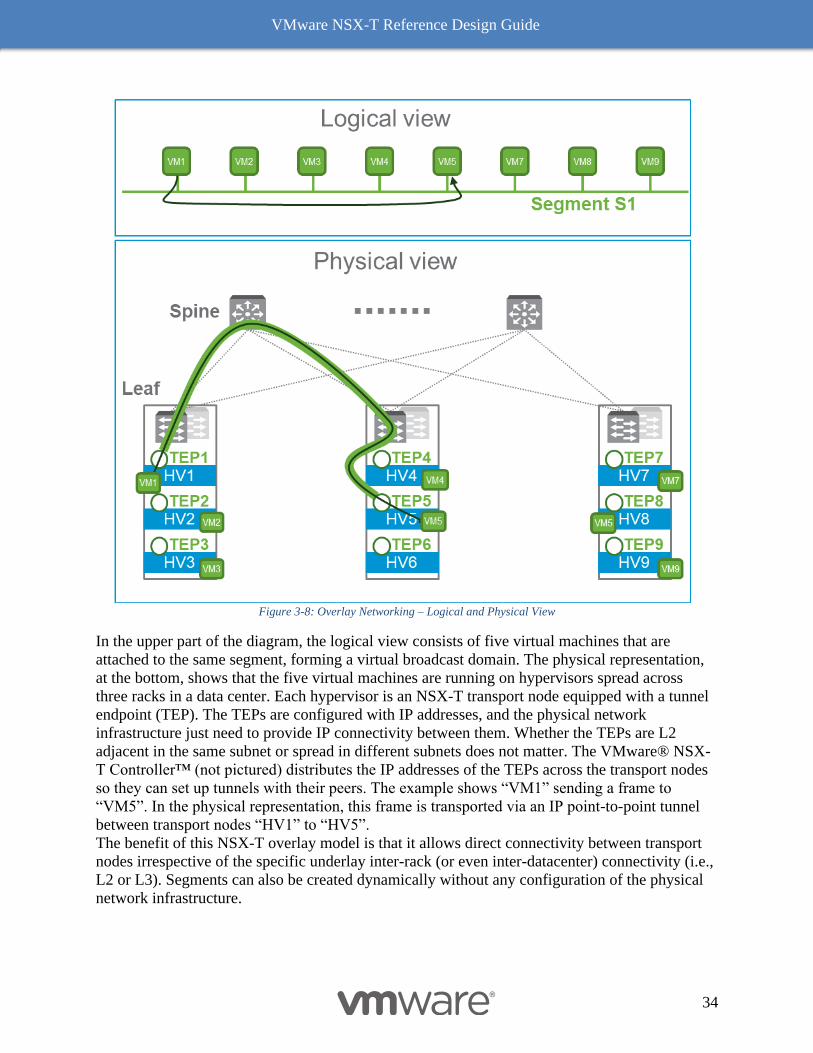
Figure 3-8: Overlay Networking – Logical and Physical View presents logical and physical network views of a
logical switching deployment.
VMware NSX-T Reference Design Guide
34
Figure 3-8: Overlay Networking – Logical and Physical View
In the upper part of the diagram, the logical view consists of five virtual machines that are
attached to the same segment, forming a virtual broadcast domain. The physical representation,
at the bottom, shows that the five virtual machines are running on hypervisors spread across
three racks in a data center. Each hypervisor is an NSX-T transport node equipped with a tunnel
endpoint (TEP). The TEPs are configured with IP addresses, and the physical network
infrastructure just need to provide IP connectivity between them. Whether the TEPs are L2
adjacent in the same subnet or spread in different subnets does not matter. The VMware® NSX-
T Controller™ (not pictured) distributes the IP addresses of the TEPs across the transport nodes
so they can set up tunnels with their peers. The example shows “VM1” sending a frame to
“VM5”. In the physical representation, this frame is transported via an IP point-to-point tunnel
between transport nodes “HV1” to “HV5”.
The benefit of this NSX-T overlay model is that it allows direct connectivity between transport
nodes irrespective of the specific underlay inter-rack (or even inter-datacenter) connectivity (i.e.,
L2 or L3). Segments can also be created dynamically without any configuration of the physical
network infrastructure.
VMware NSX-T Reference Design Guide
35
Flooded Traffic
The NSX-T segment behaves like a LAN, providing the capability of flooding traffic to all the
devices attached to this segment; this is a cornerstone capability of layer 2. NSX-T does not
differentiate between the different kinds of frames replicated to multiple destinations. Broadcast,
unknown unicast, or multicast traffic will be flooded in a similar fashion across a segment. In the
overlay model, the replication of a frame to be flooded on a segment is orchestrated by the
different NSX-T components. NSX-T provides two different methods for flooding traffic
described in the following sections. They can be selected on a per segment basis.
3.2.2.1 Head-End Replication Mode
In the head end replication mode, the transport node at the origin of the frame to be flooded
sends a copy to each other transport node that is connected to this segment.
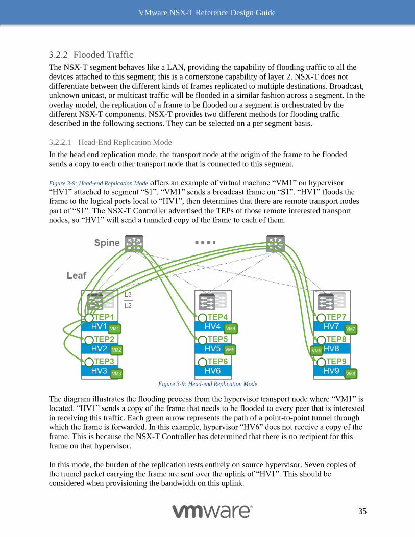
Figure 3-9: Head-end Replication Mode offers an example of virtual machine “VM1” on hypervisor
“HV1” attached to segment “S1”. “VM1” sends a broadcast frame on “S1”. “HV1” floods the
frame to the logical ports local to “HV1”, then determines that there are remote transport nodes
part of “S1”. The NSX-T Controller advertised the TEPs of those remote interested transport
nodes, so “HV1” will send a tunneled copy of the frame to each of them.
Figure 3-9: Head-end Replication Mode
The diagram illustrates the flooding process from the hypervisor transport node where “VM1” is
located. “HV1” sends a copy of the frame that needs to be flooded to every peer that is interested
in receiving this traffic. Each green arrow represents the path of a point-to-point tunnel through
which the frame is forwarded. In this example, hypervisor “HV6” does not receive a copy of the
frame. This is because the NSX-T Controller has determined that there is no recipient for this
frame on that hypervisor.
In this mode, the burden of the replication rests entirely on source hypervisor. Seven copies of
the tunnel packet carrying the frame are sent over the uplink of “HV1”. This should be
considered when provisioning the bandwidth on this uplink.
VMware NSX-T Reference Design Guide
36
3.2.2.2 Two-tier Hierarchical Mode
In the two-tier hierarchical mode, transport nodes are grouped according to the subnet of the IP
address of their TEP. Transport nodes in the same rack typically share the same subnet for their
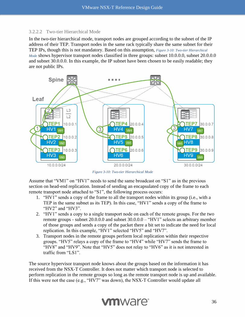
TEP IPs, though this is not mandatory. Based on this assumption, Figure 3-10: Two-tier Hierarchical
Mode shows hypervisor transport nodes classified in three groups: subnet 10.0.0.0, subnet 20.0.0.0
and subnet 30.0.0.0. In this example, the IP subnet have been chosen to be easily readable; they
are not public IPs.
Figure 3-10: Two-tier Hierarchical Mode
Assume that “VM1” on “HV1” needs to send the same broadcast on “S1” as in the previous
section on head-end replication. Instead of sending an encapsulated copy of the frame to each
remote transport node attached to “S1”, the following process occurs:
1. “HV1” sends a copy of the frame to all the transport nodes within its group (i.e., with a
TEP in the same subnet as its TEP). In this case, “HV1” sends a copy of the frame to
“HV2” and “HV3”.
2. “HV1” sends a copy to a single transport node on each of the remote groups. For the two
remote groups - subnet 20.0.0.0 and subnet 30.0.0.0 – “HV1” selects an arbitrary member
of those groups and sends a copy of the packet there a bit set to indicate the need for local
replication. In this example, “HV1” selected “HV5” and “HV7”.
3. Transport nodes in the remote groups perform local replication within their respective
groups. “HV5” relays a copy of the frame to “HV4” while “HV7” sends the frame to
“HV8” and “HV9”. Note that “HV5” does not relay to “HV6” as it is not interested in
traffic from “LS1”.
The source hypervisor transport node knows about the groups based on the information it has
received from the NSX-T Controller. It does not matter which transport node is selected to
perform replication in the remote groups so long as the remote transport node is up and available.
If this were not the case (e.g., “HV7” was down), the NSX-T Controller would update all
VMware NSX-T Reference Design Guide
37
transport nodes attached to “S1”. “HV1” would then choose “HV8” or “HV9” to perform the
replication local to group 30.0.0.0.
In this mode, as with head end replication example, seven copies of the flooded frame have been
made in software, though the cost of the replication has been spread across several transport
nodes. It is also interesting to understand the traffic pattern on the physical infrastructure. The
benefit of the two-tier hierarchical mode is that only two tunnel packets (compared to the
headend mode of five packets) were sent between racks, one for each remote group. This is a
significant improvement in the network inter-rack (or inter-datacenter) fabric utilization - where
available bandwidth is typically less than within a rack. That number that could be higher still if
there were more transport nodes interested in flooded traffic for “S1” on the remote racks. In the
case where the TEPs are in another data center, the savings could be significant. Note also that
this benefit in term of traffic optimization provided by the two-tier hierarchical mode only
applies to environments where TEPs have their IP addresses in different subnets. In a flat Layer
2 network, where all the TEPs have their IP addresses in the same subnet, the two-tier
hierarchical replication mode would lead to the same traffic pattern as the source replication
mode.
The default two-tier hierarchical flooding mode is recommended as a best practice as it typically
performs better in terms of physical uplink bandwidth utilization.
Unicast Traffic
When a frame is destined to an unknown MAC address, it is flooded in the network. Switches
typically implement a MAC address table, or filtering database (FDB), that associates MAC
addresses to ports in order to prevent flooding. When a frame is destined to a unicast MAC
address known in the MAC address table, it is only forwarded by the switch to the corresponding
port.
The NSX virtual switch maintains such a table for each segment/logical switch it is attached to.
A MAC address can be associated with either a virtual NIC (vNIC) of a locally attached VM or a
remote TEP (when the MAC address is located on a remote transport node reached via the tunnel
identified by that TEP).
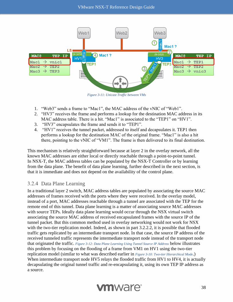
Figure 3-11: Unicast Traffic between VMs illustrates virtual machine “Web3” sending a unicast frame to
another virtual machine “Web1” on a remote hypervisor transport node. In this example, the
NSX virtual switch on both the source and destination hypervisor transport nodes are fully
populated.
VMware NSX-T Reference Design Guide
38
Figure 3-11: Unicast Traffic between VMs
1. “Web3” sends a frame to “Mac1”, the MAC address of the vNIC of “Web1”.
2. “HV3” receives the frame and performs a lookup for the destination MAC address in its
MAC address table. There is a hit. “Mac1” is associated to the “TEP1” on “HV1”.
3. “HV3” encapsulates the frame and sends it to “TEP1”.
4. “HV1” receives the tunnel packet, addressed to itself and decapsulates it. TEP1 then
performs a lookup for the destination MAC of the original frame. “Mac1” is also a hit
there, pointing to the vNIC of “VM1”. The frame is then delivered to its final destination.
This mechanism is relatively straightforward because at layer 2 in the overlay network, all the
known MAC addresses are either local or directly reachable through a point-to-point tunnel.
In NSX-T, the MAC address tables can be populated by the NSX-T Controller or by learning
from the data plane. The benefit of data plane learning, further described in the next section, is
that it is immediate and does not depend on the availability of the control plane.
Data Plane Learning
In a traditional layer 2 switch, MAC address tables are populated by associating the source MAC
addresses of frames received with the ports where they were received. In the overlay model,
instead of a port, MAC addresses reachable through a tunnel are associated with the TEP for the
remote end of this tunnel. Data plane learning is a matter of associating source MAC addresses
with source TEPs. Ideally data plane learning would occur through the NSX virtual switch
associating the source MAC address of received encapsulated frames with the source IP of the
tunnel packet. But this common method used in overlay networking would not work for NSX
with the two-tier replication model. Indeed, as shown in part 3.2.2.2, it is possible that flooded
traffic gets replicated by an intermediate transport node. In that case, the source IP address of the
received tunneled traffic represents the intermediate transport node instead of the transport node
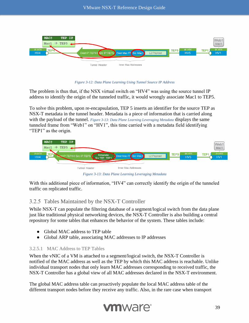
that originated the traffic. Figure 3-12: Data Plane Learning Using Tunnel Source IP Address below illustrates
this problem by focusing on the flooding of a frame from VM1 on HV1 using the two-tier
replication model (similar to what was described earlier in Figure 3-10: Two-tier Hierarchical Mode.)
When intermediate transport node HV5 relays the flooded traffic from HV1 to HV4, it is actually
decapsulating the original tunnel traffic and re-encapsulating it, using its own TEP IP address as
a source.
VMware NSX-T Reference Design Guide
39
Figure 3-12: Data Plane Learning Using Tunnel Source IP Address
The problem is thus that, if the NSX virtual switch on “HV4” was using the source tunnel IP
address to identify the origin of the tunneled traffic, it would wrongly associate Mac1 to TEP5.
To solve this problem, upon re-encapsulation, TEP 5 inserts an identifier for the source TEP as
NSX-T metadata in the tunnel header. Metadata is a piece of information that is carried along
with the payload of the tunnel. Figure 3-13: Data Plane Learning Leveraging Metadata displays the same
tunneled frame from “Web1” on “HV1”, this time carried with a metadata field identifying
“TEP1” as the origin.
Figure 3-13: Data Plane Learning Leveraging Metadata
With this additional piece of information, “HV4” can correctly identify the origin of the tunneled
traffic on replicated traffic.
Tables Maintained by the NSX-T Controller
While NSX-T can populate the filtering database of a segment/logical switch from the data plane
just like traditional physical networking devices, the NSX-T Controller is also building a central
repository for some tables that enhances the behavior of the system. These tables include:
● Global MAC address to TEP table
● Global ARP table, associating MAC addresses to IP addresses
3.2.5.1 MAC Address to TEP Tables
When the vNIC of a VM is attached to a segment/logical switch, the NSX-T Controller is
notified of the MAC address as well as the TEP by which this MAC address is reachable. Unlike
individual transport nodes that only learn MAC addresses corresponding to received traffic, the
NSX-T Controller has a global view of all MAC addresses declared in the NSX-T environment.
The global MAC address table can proactively populate the local MAC address table of the
different transport nodes before they receive any traffic. Also, in the rare case when transport
VMware NSX-T Reference Design Guide
40
node receives a frame from a VM destined to an unknown MAC address, it will send a request to
look up this MAC address in the global table of the NSX-T Controller while simultaneously
flooding the frame.
Not all the MAC addresses present in the data plane tables are reported to the NSX-T Controller.
If a VM is allowed to send traffic on a segment/logical switch from several source MAC
addresses, those secondary MAC addresses are not pushed to the NSX-T Controller. Similarly,
the NSX-T Controller is not notified of MAC addresses learned from an Edge bridge connected
to a physical layer 2 network. This behavior was implemented in order to protect the NSX-T
Controller from an injection of an arbitrarily large number of MAC addresses into in the
network.
3.2.5.2 ARP Tables
The NSX-T Controller also maintains an ARP table in order to help implement an ARP
suppression mechanism. The NSX virtual switch snoops DHCP and ARP traffic to learn MAC
address to IP associations. Those associations are then reported to the NSX-T Controller. An
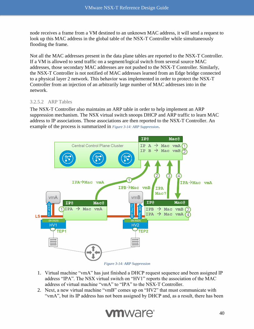
example of the process is summarized in Figure 3-14: ARP Suppression.
Figure 3-14: ARP Suppression
1. Virtual machine “vmA” has just finished a DHCP request sequence and been assigned IP
address “IPA”. The NSX virtual switch on “HV1” reports the association of the MAC
address of virtual machine “vmA” to “IPA” to the NSX-T Controller.
2. Next, a new virtual machine “vmB” comes up on “HV2” that must communicate with
“vmA”, but its IP address has not been assigned by DHCP and, as a result, there has been
VMware NSX-T Reference Design Guide
41
no DHCP snooping. The virtual switch will be able to learn this IP address by snooping
ARP traffic coming from “vmB”. Either “vmB” will send a gratuitous ARP when coming
up or it will send an ARP request for the MAC address of “vmA”. The virtual switch then
can derive the IP address “IPB” associated to “vmB”. The association (vmB -> IPB) is
then pushed to the NSX-T Controller.
3. The NSX virtual switch also holds the ARP request initiated by “vmB” and queries the
NSX-T Controller for the MAC address of “vmA”.
4. Because the MAC address of “vmA” has already been reported to the NSX-T Controller,
the NSX-T Controller can answer the request coming from the virtual switch, which can
now send an ARP reply directly to “vmB” on the behalf of “vmA”. Thanks to this
mechanism, the expensive flooding of an ARP request has been eliminated. Note that if
the NSX-T Controller did not know about the MAC address of “vmA” or if the NSX-T
Controller were down, the ARP request from “vmB” would still be flooded by the virtual
switch.
Overlay Encapsulation
NSX-T uses Generic Network Virtualization Encapsulation (Geneve) for its overlay model.
Geneve is currently an IETF Internet Draft that builds on the top of VXLAN concepts to provide
enhanced flexibility in term of data plane extensibility.
Figure 3-15: Geneve Encapsulation (from IETF Draft)
VXLAN has static fields while Geneve offers flexible field. This capability can be used by
anyone to adjust the need of typical workload and overlay fabric, thus NSX-T tunnels are only
setup between NSX-T transport nodes. NSX-T only needs efficient support for the Geneve
encapsulation by the NIC hardware; most NIC vendors support the same hardware offload for
Geneve as they would for VXLAN.
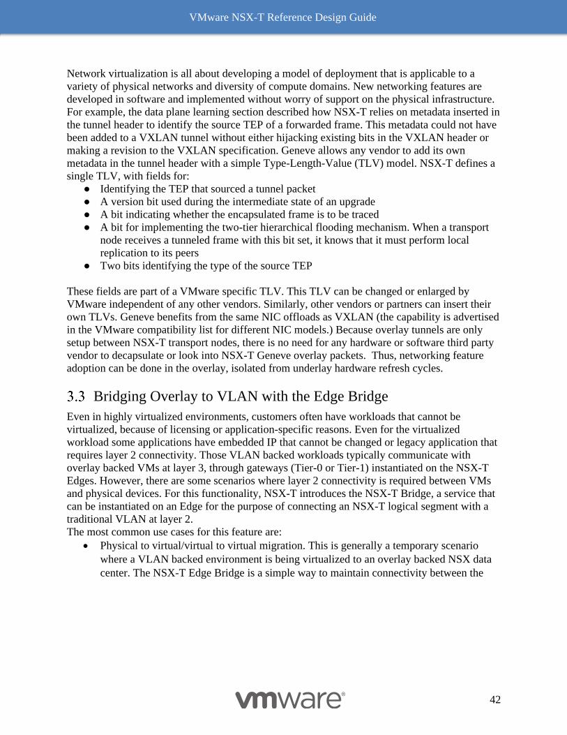
VMware NSX-T Reference Design Guide
42
Network virtualization is all about developing a model of deployment that is applicable to a
variety of physical networks and diversity of compute domains. New networking features are
developed in software and implemented without worry of support on the physical infrastructure.
For example, the data plane learning section described how NSX-T relies on metadata inserted in
the tunnel header to identify the source TEP of a forwarded frame. This metadata could not have
been added to a VXLAN tunnel without either hijacking existing bits in the VXLAN header or
making a revision to the VXLAN specification. Geneve allows any vendor to add its own
metadata in the tunnel header with a simple Type-Length-Value (TLV) model. NSX-T defines a
single TLV, with fields for:
● Identifying the TEP that sourced a tunnel packet
● A version bit used during the intermediate state of an upgrade
● A bit indicating whether the encapsulated frame is to be traced
● A bit for implementing the two-tier hierarchical flooding mechanism. When a transport
node receives a tunneled frame with this bit set, it knows that it must perform local
replication to its peers
● Two bits identifying the type of the source TEP
These fields are part of a VMware specific TLV. This TLV can be changed or enlarged by
VMware independent of any other vendors. Similarly, other vendors or partners can insert their
own TLVs. Geneve benefits from the same NIC offloads as VXLAN (the capability is advertised
in the VMware compatibility list for different NIC models.) Because overlay tunnels are only
setup between NSX-T transport nodes, there is no need for any hardware or software third party
vendor to decapsulate or look into NSX-T Geneve overlay packets. Thus, networking feature
adoption can be done in the overlay, isolated from underlay hardware refresh cycles.
Bridging Overlay to VLAN with the Edge Bridge
Even in highly virtualized environments, customers often have workloads that cannot be
virtualized, because of licensing or application-specific reasons. Even for the virtualized
workload some applications have embedded IP that cannot be changed or legacy application that
requires layer 2 connectivity. Those VLAN backed workloads typically communicate with
overlay backed VMs at layer 3, through gateways (Tier-0 or Tier-1) instantiated on the NSX-T
Edges. However, there are some scenarios where layer 2 connectivity is required between VMs
and physical devices. For this functionality, NSX-T introduces the NSX-T Bridge, a service that
can be instantiated on an Edge for the purpose of connecting an NSX-T logical segment with a
traditional VLAN at layer 2.
The most common use cases for this feature are:
• Physical to virtual/virtual to virtual migration. This is generally a temporary scenario
where a VLAN backed environment is being virtualized to an overlay backed NSX data
center. The NSX-T Edge Bridge is a simple way to maintain connectivity between the
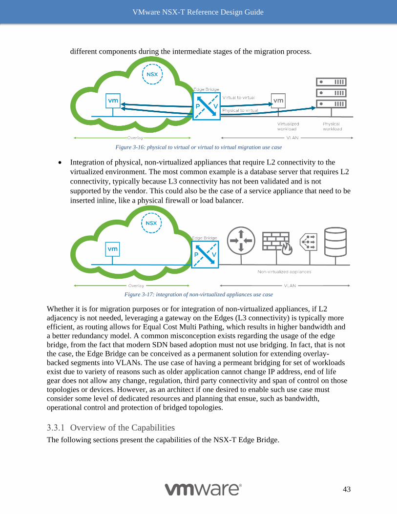
VMware NSX-T Reference Design Guide
43
different components during the intermediate stages of the migration process.
Figure 3-16: physical to virtual or virtual to virtual migration use case
• Integration of physical, non-virtualized appliances that require L2 connectivity to the
virtualized environment. The most common example is a database server that requires L2
connectivity, typically because L3 connectivity has not been validated and is not
supported by the vendor. This could also be the case of a service appliance that need to be
inserted inline, like a physical firewall or load balancer.
Figure 3-17: integration of non-virtualized appliances use case
Whether it is for migration purposes or for integration of non-virtualized appliances, if L2
adjacency is not needed, leveraging a gateway on the Edges (L3 connectivity) is typically more
efficient, as routing allows for Equal Cost Multi Pathing, which results in higher bandwidth and
a better redundancy model. A common misconception exists regarding the usage of the edge
bridge, from the fact that modern SDN based adoption must not use bridging. In fact, that is not
the case, the Edge Bridge can be conceived as a permanent solution for extending overlay-
backed segments into VLANs. The use case of having a permeant bridging for set of workloads
exist due to variety of reasons such as older application cannot change IP address, end of life
gear does not allow any change, regulation, third party connectivity and span of control on those
topologies or devices. However, as an architect if one desired to enable such use case must
consider some level of dedicated resources and planning that ensue, such as bandwidth,
operational control and protection of bridged topologies.
Overview of the Capabilities
The following sections present the capabilities of the NSX-T Edge Bridge.
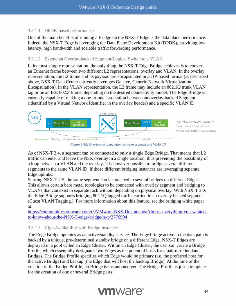
VMware NSX-T Reference Design Guide
44
3.3.1.1 DPDK-based performance
One of the main benefits of running a Bridge on the NSX-T Edge is the data plane performance.
Indeed, the NSX-T Edge is leveraging the Data Plane Development Kit (DPDK), providing low
latency, high bandwidth and scalable traffic forwarding performance.
3.3.1.2 Extend an Overlay-backed Segment/Logical Switch to a VLAN
In its most simple representation, the only thing the NSX-T Edge Bridge achieves is to convert
an Ethernet frame between two different L2 representations: overlay and VLAN. In the overlay
representation, the L2 frame and its payload are encapsulated in an IP-based format (as described
above, NSX-T Data Center currently leverages Geneve, Generic Network Virtualization
Encapsulation). In the VLAN representation, the L2 frame may include an 802.1Q trunk VLAN
tag or be an IEE 802.3 frame, depending on the desired connectivity model. The Edge Bridge is
currently capable of making a one-to-one association between an overlay-backed Segment
(identified by a Virtual Network Identifier in the overlay header) and a specific VLAN ID.
Figure 3-18: One-to-one association between segment and VLAN ID
As of NSX-T 2.4, a segment can be connected to only a single Edge Bridge. That means that L2
traffic can enter and leave the NSX overlay in a single location, thus preventing the possibility of
a loop between a VLAN and the overlay. It is however possible to bridge several different
segments to the same VLAN ID, if those different bridging instances are leveraging separate
Edge uplinks.
Starting NSX-T 2.5, the same segment can be attached to several bridges on different Edges.
This allows certain bare metal topologies to be connected with overlay segment and bridging to
VLANs that can exist in separate rack without depending on physical overlay. With NSX-T 3.0,
the Edge Bridge supports bridging 802.1Q tagged traffic carried in an overlay backed segment
(Guest VLAN Tagging.) For more information about this feature, see the bridging white paper
at:
https://communities.vmware.com/t5/VMware-NSX-Documents/Almost-everything-you-wanted-
to-know-about-the-NSX-T-edge-bridge/ta-p/2776994
3.3.1.3 High Availability with Bridge Instances
The Edge Bridge operates as an active/standby service. The Edge bridge active in the data path is
backed by a unique, pre-determined standby bridge on a different Edge. NSX-T Edges are
deployed in a pool called an Edge Cluster. Within an Edge Cluster, the user can create a Bridge
Profile, which essentially designates two Edges as the potential hosts for a pair of redundant
Bridges. The Bridge Profile specifies which Edge would be primary (i.e. the preferred host for
the active Bridge) and backup (the Edge that will host the backup Bridge). At the time of the
creation of the Bridge Profile, no Bridge is instantiated yet. The Bridge Profile is just a template
for the creation of one or several Bridge pairs.
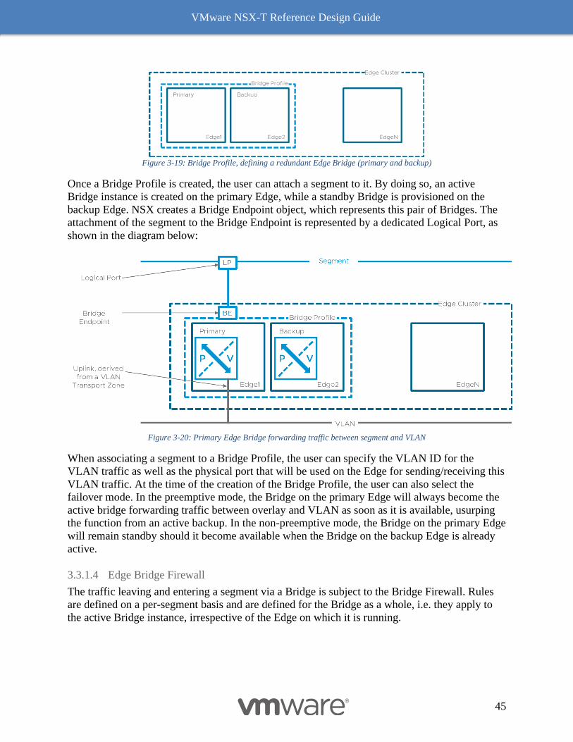
VMware NSX-T Reference Design Guide
45
Figure 3-19: Bridge Profile, defining a redundant Edge Bridge (primary and backup)
Once a Bridge Profile is created, the user can attach a segment to it. By doing so, an active
Bridge instance is created on the primary Edge, while a standby Bridge is provisioned on the
backup Edge. NSX creates a Bridge Endpoint object, which represents this pair of Bridges. The
attachment of the segment to the Bridge Endpoint is represented by a dedicated Logical Port, as
shown in the diagram below:
Figure 3-20: Primary Edge Bridge forwarding traffic between segment and VLAN
When associating a segment to a Bridge Profile, the user can specify the VLAN ID for the
VLAN traffic as well as the physical port that will be used on the Edge for sending/receiving this
VLAN traffic. At the time of the creation of the Bridge Profile, the user can also select the
failover mode. In the preemptive mode, the Bridge on the primary Edge will always become the
active bridge forwarding traffic between overlay and VLAN as soon as it is available, usurping
the function from an active backup. In the non-preemptive mode, the Bridge on the primary Edge
will remain standby should it become available when the Bridge on the backup Edge is already
active.
3.3.1.4 Edge Bridge Firewall
The traffic leaving and entering a segment via a Bridge is subject to the Bridge Firewall. Rules
are defined on a per-segment basis and are defined for the Bridge as a whole, i.e. they apply to
the active Bridge instance, irrespective of the Edge on which it is running.
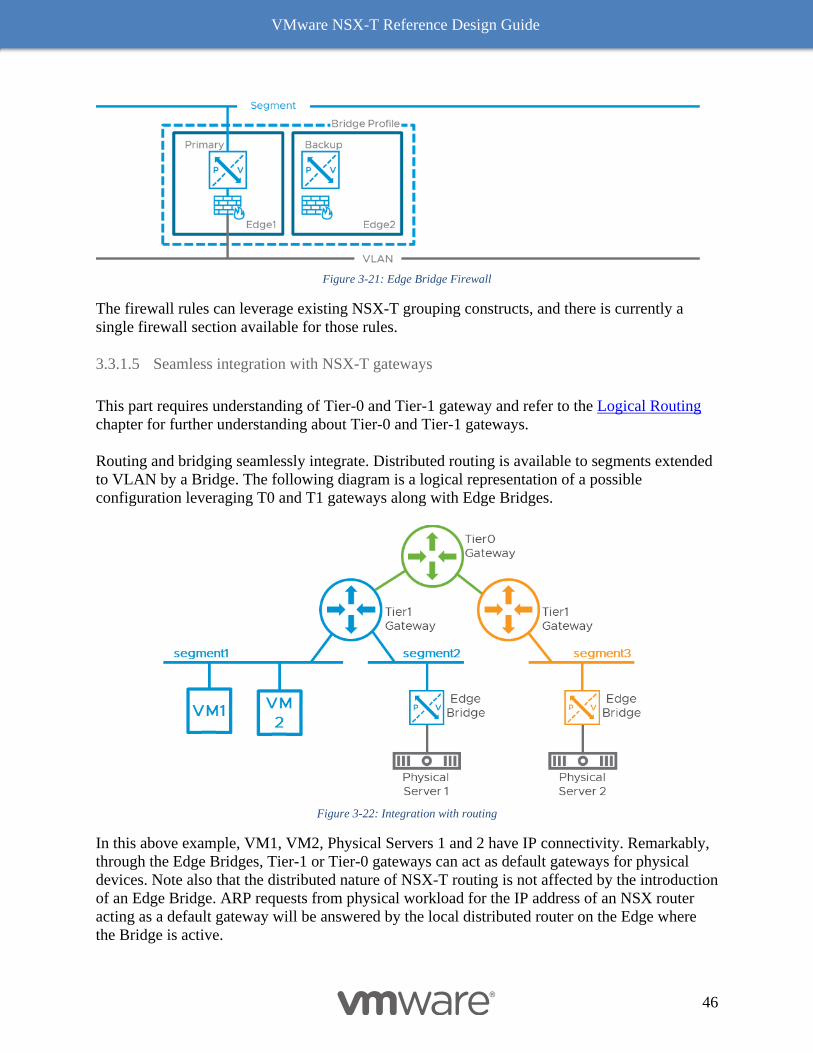
VMware NSX-T Reference Design Guide
46
Figure 3-21: Edge Bridge Firewall
The firewall rules can leverage existing NSX-T grouping constructs, and there is currently a
single firewall section available for those rules.
3.3.1.5 Seamless integration with NSX-T gateways
This part requires understanding of Tier-0 and Tier-1 gateway and refer to the Logical Routing
chapter for further understanding about Tier-0 and Tier-1 gateways.
Routing and bridging seamlessly integrate. Distributed routing is available to segments extended
to VLAN by a Bridge. The following diagram is a logical representation of a possible
configuration leveraging T0 and T1 gateways along with Edge Bridges.
Figure 3-22: Integration with routing
In this above example, VM1, VM2, Physical Servers 1 and 2 have IP connectivity. Remarkably,
through the Edge Bridges, Tier-1 or Tier-0 gateways can act as default gateways for physical
devices. Note also that the distributed nature of NSX-T routing is not affected by the introduction
of an Edge Bridge. ARP requests from physical workload for the IP address of an NSX router
acting as a default gateway will be answered by the local distributed router on the Edge where
the Bridge is active.
VMware NSX-T Reference Design Guide
47
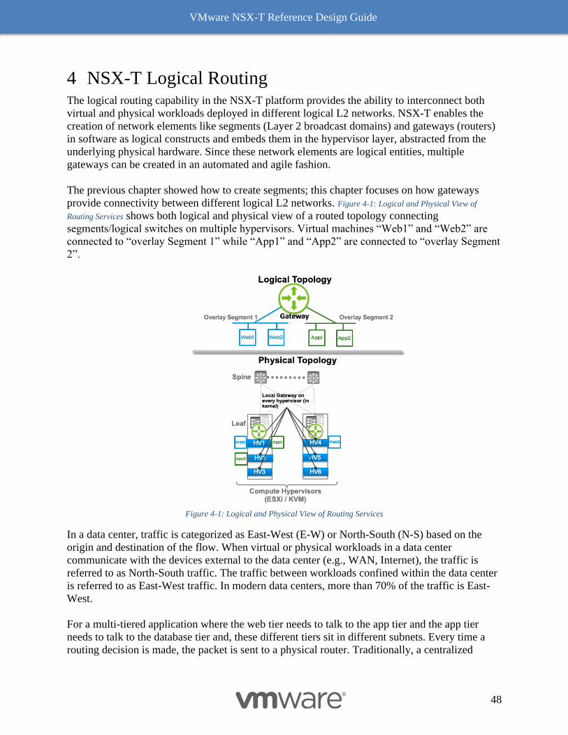
VMware NSX-T Reference Design Guide
48
4 NSX-T Logical Routing The logical routing capability in the NSX-T platform provides the ability to interconnect both
virtual and physical workloads deployed in different logical L2 networks. NSX-T enables the
creation of network elements like segments (Layer 2 broadcast domains) and gateways (routers)
in software as logical constructs and embeds them in the hypervisor layer, abstracted from the
underlying physical hardware. Since these network elements are logical entities, multiple
gateways can be created in an automated and agile fashion.
The previous chapter showed how to create segments; this chapter focuses on how gateways
provide connectivity between different logical L2 networks. Figure 4-1: Logical and Physical View of
Routing Services shows both logical and physical view of a routed topology connecting
segments/logical switches on multiple hypervisors. Virtual machines “Web1” and “Web2” are
connected to “overlay Segment 1” while “App1” and “App2” are connected to “overlay Segment
2”.
Figure 4-1: Logical and Physical View of Routing Services
In a data center, traffic is categorized as East-West (E-W) or North-South (N-S) based on the
origin and destination of the flow. When virtual or physical workloads in a data center
communicate with the devices external to the data center (e.g., WAN, Internet), the traffic is
referred to as North-South traffic. The traffic between workloads confined within the data center
is referred to as East-West traffic. In modern data centers, more than 70% of the traffic is East-
West.
For a multi-tiered application where the web tier needs to talk to the app tier and the app tier
needs to talk to the database tier and, these different tiers sit in different subnets. Every time a
routing decision is made, the packet is sent to a physical router. Traditionally, a centralized

VMware NSX-T Reference Design Guide
49
router would provide routing for these different tiers. With VMs that are hosted on same the
ESXi or KVM hypervisor, traffic will leave the hypervisor multiple times to go to the centralized
router for a routing decision, then return to the same hypervisor; this is not optimal.
NSX-T is uniquely positioned to solve these challenges as it can bring networking closest to the
workload. Configuring a Gateway via NSX-T Manager instantiates a local distributed gateway
on each hypervisor. For the VMs hosted (e.g., “Web 1”, “App 1”) on the same hypervisor, the E-
W traffic does not need to leave the hypervisor for routing.
Single Tier Routing
NSX-T Gateway provides optimized distributed routing as well as centralized routing and
services like NAT, AVI Load balancer, DHCP server etc. A single tier routing topology implies
that a Gateway is connected to segments southbound providing E-W routing and is also
connected to physical infrastructure to provide N-S connectivity. This gateway is referred to as
Tier-0 Gateway.
Tier-0 Gateway consists of two components: distributed routing component (DR) and centralized
services routing component (SR).
Distributed Router (DR)
A DR is essentially a router with logical interfaces (LIFs) connected to multiple subnets. It runs
as a kernel module and is distributed in hypervisors across all transport nodes, including Edge
nodes. The traditional data plane functionality of routing and ARP lookups is performed by the
logical interfaces connecting to the different segments. Each LIF has a vMAC address and an IP
address being the default IP gateway for its connected segment. The IP address is unique per LIF
and remains the same everywhere the segment exists. The vMAC associated with each LIF
remains constant in each hypervisor, allowing the default gateway IP and MAC addresses to
remain the same during vMotion.
The left side of Figure 4-2: E-W Routing with Workloads on the Same Hypervisor shows a logical topology with
two segments, “Web Segment” with a default gateway of 172.16.10.1/24 and “App Segment”
with a default gateway of 172.16.20.1/24 are attached to Tier-0 Gateway. In the physical
topology view on the right, VMs are shown on two hypervisors, “HV1” and “HV2”. A
distributed routing (DR) component for this Tier-0 Gateway is instantiated as a kernel module
and will act as a local gateway or first hop router for the workloads connected to the segments.
Please note that the DR is not a VM and the DR on both hypervisors has the same IP addresses.
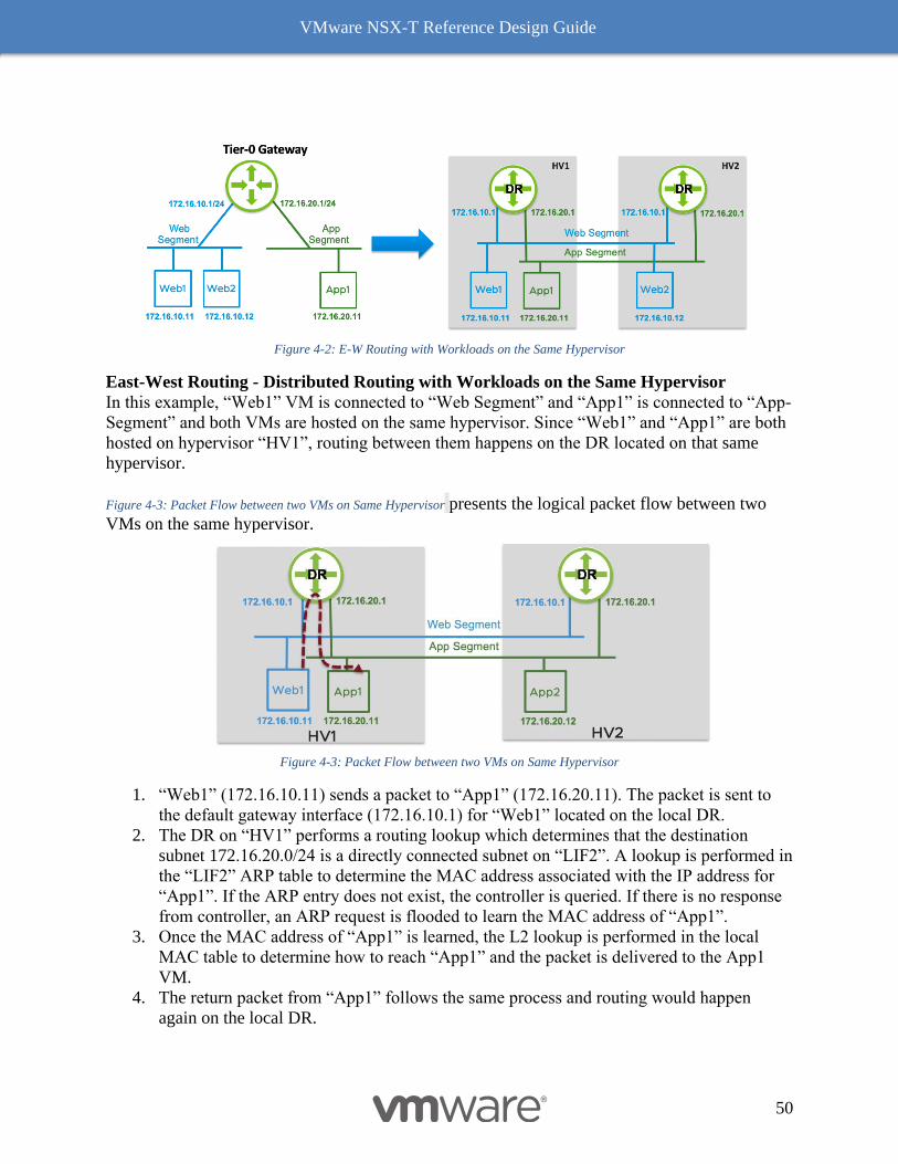
VMware NSX-T Reference Design Guide
50
Figure 4-2: E-W Routing with Workloads on the Same Hypervisor
East-West Routing - Distributed Routing with Workloads on the Same Hypervisor
In this example, “Web1” VM is connected to “Web Segment” and “App1” is connected to “App-
Segment” and both VMs are hosted on the same hypervisor. Since “Web1” and “App1” are both
hosted on hypervisor “HV1”, routing between them happens on the DR located on that same
hypervisor.
Figure 4-3: Packet Flow between two VMs on Same Hypervisor presents the logical packet flow between two
VMs on the same hypervisor.
Figure 4-3: Packet Flow between two VMs on Same Hypervisor
1. “Web1” (172.16.10.11) sends a packet to “App1” (172.16.20.11). The packet is sent to
the default gateway interface (172.16.10.1) for “Web1” located on the local DR.
2. The DR on “HV1” performs a routing lookup which determines that the destination
subnet 172.16.20.0/24 is a directly connected subnet on “LIF2”. A lookup is performed in
the “LIF2” ARP table to determine the MAC address associated with the IP address for
“App1”. If the ARP entry does not exist, the controller is queried. If there is no response
from controller, an ARP request is flooded to learn the MAC address of “App1”.
3. Once the MAC address of “App1” is learned, the L2 lookup is performed in the local
MAC table to determine how to reach “App1” and the packet is delivered to the App1
VM.
4. The return packet from “App1” follows the same process and routing would happen
again on the local DR.

VMware NSX-T Reference Design Guide
51
In this example, neither the initial packet from “Web1” to “App1” nor the return packet from
“App1” to “Web1” left the hypervisor.
East-West Routing - Distributed Routing with Workloads on Different Hypervisor
In this example, the target workload “App2” differs as it rests on a hypervisor named “HV2”. If
“Web1” needs to communicate with “App2”, the traffic would have to leave the hypervisor
“HV1” as these VMs are hosted on two different hypervisors. Figure 4-4: E-W Packet Flow between two
Hypervisors shows a logical view of topology, highlighting the routing decisions taken by the DR
on “HV1” and the DR on “HV2”. When “Web1” sends traffic to “App2”, routing is done by the
DR on “HV1”. The reverse traffic from “App2” to “Web1” is routed by DR on “HV2”. Routing
is performed on the hypervisor attached to the source VM.
Figure 4-4: E-W Packet Flow between two Hypervisors
Figure 4-5: End-to-end E-W Packet Flow shows the corresponding physical topology and packet walk
from “Web1” to “App2”.
Figure 4-5: End-to-end E-W Packet Flow
1. “Web1” (172.16.10.11) sends a packet to “App2” (172.16.20.12). The packet is sent to
the default gateway interface (172.16.10.1) for “Web1” located on the local DR. Its L2
header has the source MAC as “MAC1” and destination MAC as the vMAC of the DR.
This vMAC will be the same for all LIFs.
2. The routing lookup happens on the HV1 DR, which determines that the destination
subnet 172.16.20.0/24 is a directly connected subnet on “LIF2”. A lookup is performed in
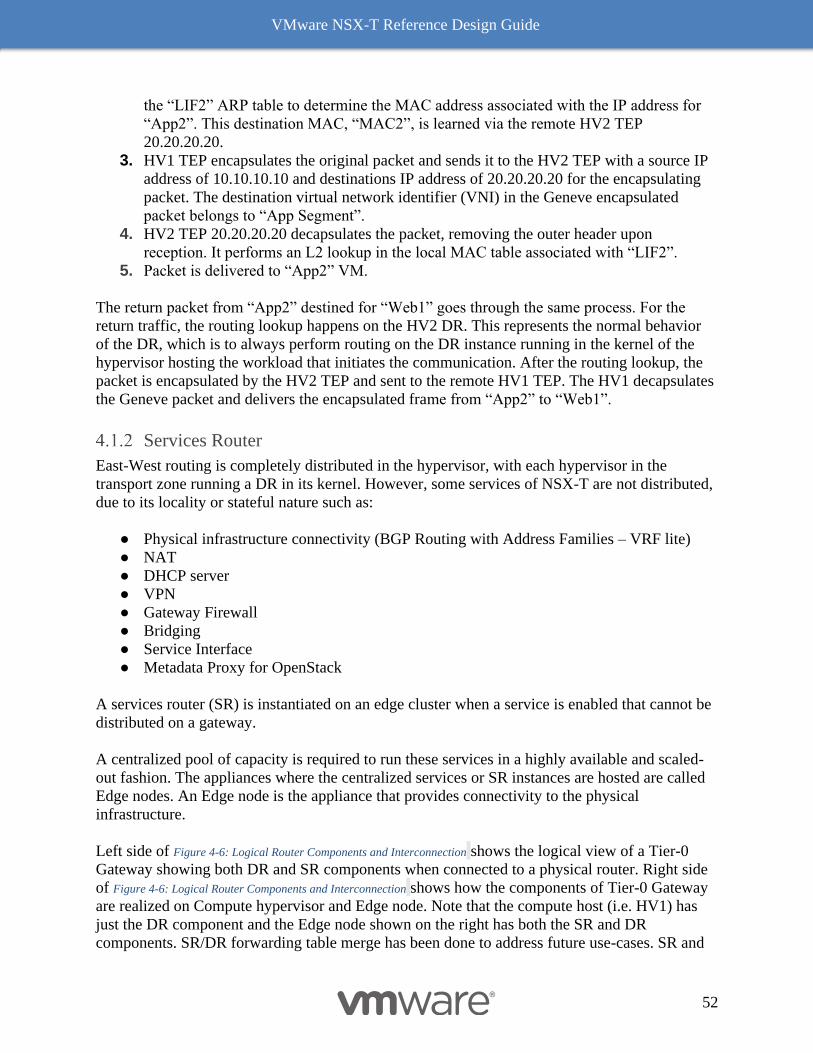
VMware NSX-T Reference Design Guide
52
the “LIF2” ARP table to determine the MAC address associated with the IP address for
“App2”. This destination MAC, “MAC2”, is learned via the remote HV2 TEP
20.20.20.20.
3. HV1 TEP encapsulates the original packet and sends it to the HV2 TEP with a source IP
address of 10.10.10.10 and destinations IP address of 20.20.20.20 for the encapsulating
packet. The destination virtual network identifier (VNI) in the Geneve encapsulated
packet belongs to “App Segment”.
4. HV2 TEP 20.20.20.20 decapsulates the packet, removing the outer header upon
reception. It performs an L2 lookup in the local MAC table associated with “LIF2”.
5. Packet is delivered to “App2” VM.
The return packet from “App2” destined for “Web1” goes through the same process. For the
return traffic, the routing lookup happens on the HV2 DR. This represents the normal behavior
of the DR, which is to always perform routing on the DR instance running in the kernel of the
hypervisor hosting the workload that initiates the communication. After the routing lookup, the
packet is encapsulated by the HV2 TEP and sent to the remote HV1 TEP. The HV1 decapsulates
the Geneve packet and delivers the encapsulated frame from “App2” to “Web1”.
Services Router
East-West routing is completely distributed in the hypervisor, with each hypervisor in the
transport zone running a DR in its kernel. However, some services of NSX-T are not distributed,
due to its locality or stateful nature such as:
● Physical infrastructure connectivity (BGP Routing with Address Families – VRF lite)
● NAT
● DHCP server
● VPN
● Gateway Firewall
● Bridging
● Service Interface
● Metadata Proxy for OpenStack
A services router (SR) is instantiated on an edge cluster when a service is enabled that cannot be
distributed on a gateway.
A centralized pool of capacity is required to run these services in a highly available and scaled-
out fashion. The appliances where the centralized services or SR instances are hosted are called
Edge nodes. An Edge node is the appliance that provides connectivity to the physical
infrastructure.
Left side of Figure 4-6: Logical Router Components and Interconnection shows the logical view of a Tier-0
Gateway showing both DR and SR components when connected to a physical router. Right side
of Figure 4-6: Logical Router Components and Interconnection shows how the components of Tier-0 Gateway
are realized on Compute hypervisor and Edge node. Note that the compute host (i.e. HV1) has
just the DR component and the Edge node shown on the right has both the SR and DR
components. SR/DR forwarding table merge has been done to address future use-cases. SR and
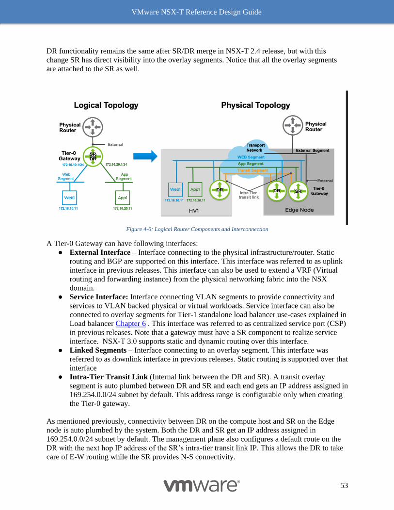
VMware NSX-T Reference Design Guide
53
DR functionality remains the same after SR/DR merge in NSX-T 2.4 release, but with this
change SR has direct visibility into the overlay segments. Notice that all the overlay segments
are attached to the SR as well.
Figure 4-6: Logical Router Components and Interconnection
A Tier-0 Gateway can have following interfaces:
● External Interface – Interface connecting to the physical infrastructure/router. Static
routing and BGP are supported on this interface. This interface was referred to as uplink
interface in previous releases. This interface can also be used to extend a VRF (Virtual
routing and forwarding instance) from the physical networking fabric into the NSX
domain.
● Service Interface: Interface connecting VLAN segments to provide connectivity and
services to VLAN backed physical or virtual workloads. Service interface can also be
connected to overlay segments for Tier-1 standalone load balancer use-cases explained in
Load balancer Chapter 6 . This interface was referred to as centralized service port (CSP)
in previous releases. Note that a gateway must have a SR component to realize service
interface. NSX-T 3.0 supports static and dynamic routing over this interface.
● Linked Segments – Interface connecting to an overlay segment. This interface was
referred to as downlink interface in previous releases. Static routing is supported over that
interface
● Intra-Tier Transit Link (Internal link between the DR and SR). A transit overlay
segment is auto plumbed between DR and SR and each end gets an IP address assigned in
169.254.0.0/24 subnet by default. This address range is configurable only when creating
the Tier-0 gateway.
As mentioned previously, connectivity between DR on the compute host and SR on the Edge
node is auto plumbed by the system. Both the DR and SR get an IP address assigned in
169.254.0.0/24 subnet by default. The management plane also configures a default route on the
DR with the next hop IP address of the SR’s intra-tier transit link IP. This allows the DR to take
care of E-W routing while the SR provides N-S connectivity.
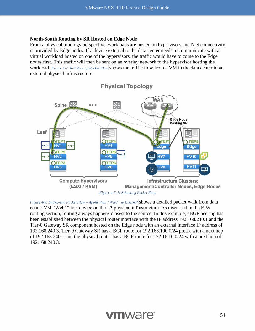
VMware NSX-T Reference Design Guide
54
North-South Routing by SR Hosted on Edge Node
From a physical topology perspective, workloads are hosted on hypervisors and N-S connectivity
is provided by Edge nodes. If a device external to the data center needs to communicate with a
virtual workload hosted on one of the hypervisors, the traffic would have to come to the Edge
nodes first. This traffic will then be sent on an overlay network to the hypervisor hosting the
workload. Figure 4-7: N-S Routing Packet Flow shows the traffic flow from a VM in the data center to an
external physical infrastructure.
Figure 4-7: N-S Routing Packet Flow
Figure 4-8: End-to-end Packet Flow – Application “Web1” to External shows a detailed packet walk from data
center VM “Web1” to a device on the L3 physical infrastructure. As discussed in the E-W
routing section, routing always happens closest to the source. In this example, eBGP peering has
been established between the physical router interface with the IP address 192.168.240.1 and the
Tier-0 Gateway SR component hosted on the Edge node with an external interface IP address of
192.168.240.3. Tier-0 Gateway SR has a BGP route for 192.168.100.0/24 prefix with a next hop
of 192.168.240.1 and the physical router has a BGP route for 172.16.10.0/24 with a next hop of
192.168.240.3.
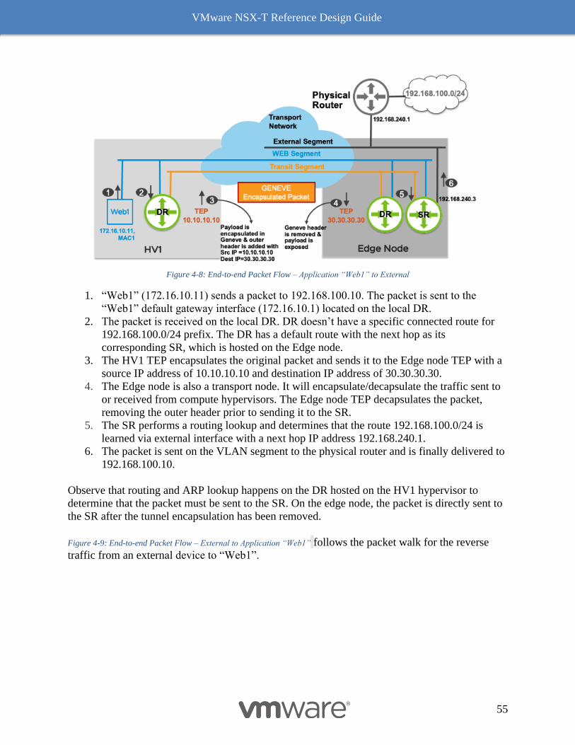
VMware NSX-T Reference Design Guide
55
Figure 4-8: End-to-end Packet Flow – Application “Web1” to External
1. “Web1” (172.16.10.11) sends a packet to 192.168.100.10. The packet is sent to the
“Web1” default gateway interface (172.16.10.1) located on the local DR.
2. The packet is received on the local DR. DR doesn’t have a specific connected route for
192.168.100.0/24 prefix. The DR has a default route with the next hop as its
corresponding SR, which is hosted on the Edge node.
3. The HV1 TEP encapsulates the original packet and sends it to the Edge node TEP with a
source IP address of 10.10.10.10 and destination IP address of 30.30.30.30.
4. The Edge node is also a transport node. It will encapsulate/decapsulate the traffic sent to
or received from compute hypervisors. The Edge node TEP decapsulates the packet,
removing the outer header prior to sending it to the SR.
5. The SR performs a routing lookup and determines that the route 192.168.100.0/24 is
learned via external interface with a next hop IP address 192.168.240.1.
6. The packet is sent on the VLAN segment to the physical router and is finally delivered to
192.168.100.10.
Observe that routing and ARP lookup happens on the DR hosted on the HV1 hypervisor to
determine that the packet must be sent to the SR. On the edge node, the packet is directly sent to
the SR after the tunnel encapsulation has been removed.
Figure 4-9: End-to-end Packet Flow – External to Application “Web1” follows the packet walk for the reverse
traffic from an external device to “Web1”.
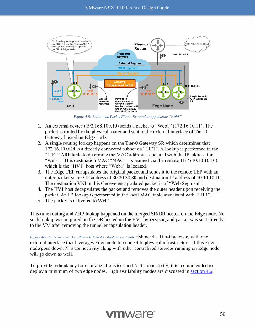
VMware NSX-T Reference Design Guide
56
Figure 4-9: End-to-end Packet Flow – External to Application “Web1”
1. An external device (192.168.100.10) sends a packet to “Web1” (172.16.10.11). The
packet is routed by the physical router and sent to the external interface of Tier-0
Gateway hosted on Edge node.
2. A single routing lookup happens on the Tier-0 Gateway SR which determines that
172.16.10.0/24 is a directly connected subnet on “LIF1”. A lookup is performed in the
“LIF1” ARP table to determine the MAC address associated with the IP address for
“Web1”. This destination MAC “MAC1” is learned via the remote TEP (10.10.10.10),
which is the “HV1” host where “Web1” is located.
3. The Edge TEP encapsulates the original packet and sends it to the remote TEP with an
outer packet source IP address of 30.30.30.30 and destination IP address of 10.10.10.10.
The destination VNI in this Geneve encapsulated packet is of “Web Segment”.
4. The HV1 host decapsulates the packet and removes the outer header upon receiving the
packet. An L2 lookup is performed in the local MAC table associated with “LIF1”.
5. The packet is delivered to Web1.
This time routing and ARP lookup happened on the merged SR/DR hosted on the Edge node. No
such lookup was required on the DR hosted on the HV1 hypervisor, and packet was sent directly
to the VM after removing the tunnel encapsulation header.
Figure 4-9: End-to-end Packet Flow – External to Application “Web1” showed a Tier-0 gateway with one
external interface that leverages Edge node to connect to physical infrastructure. If this Edge
node goes down, N-S connectivity along with other centralized services running on Edge node
will go down as well.
To provide redundancy for centralized services and N-S connectivity, it is recommended to
deploy a minimum of two edge nodes. High availability modes are discussed in section 4.6.
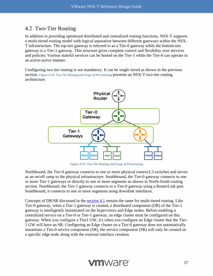
VMware NSX-T Reference Design Guide
57
Two-Tier Routing
In addition to providing optimized distributed and centralized routing functions, NSX-T supports
a multi-tiered routing model with logical separation between different gateways within the NSX-
T infrastructure. The top-tier gateway is referred to as a Tier-0 gateway while the bottom-tier
gateway is a Tier-1 gateway. This structure gives complete control and flexibility over services
and policies. Various stateful services can be hosted on the Tier-1 while the Tier-0 can operate in
an active-active manner.
Configuring two tier routing is not mandatory. It can be single tiered as shown in the previous
section. Figure 4-10: Two Tier Routing and Scope of Provisioning presents an NSX-T two-tier routing
architecture.
Figure 4-10: Two Tier Routing and Scope of Provisioning
Northbound, the Tier-0 gateway connects to one or more physical routers/L3 switches and serves
as an on/off ramp to the physical infrastructure. Southbound, the Tier-0 gateway connects to one
or more Tier-1 gateways or directly to one or more segments as shown in North-South routing
section. Northbound, the Tier-1 gateway connects to a Tier-0 gateway using a RouterLink port.
Southbound, it connects to one or more segments using downlink interfaces.
Concepts of DR/SR discussed in the section 4.1 remain the same for multi-tiered routing. Like
Tier-0 gateway, when a Tier-1 gateway is created, a distributed component (DR) of the Tier-1
gateway is intelligently instantiated on the hypervisors and Edge nodes. Before enabling a
centralized service on a Tier-0 or Tier-1 gateway, an edge cluster must be configured on this
gateway. When you configure a Tier1 GW, it's when you configure an Edge cluster that the Tier-
1 GW will have an SR. Configuring an Edge cluster on a Tier-0 gateway does not automatically
instantiate a Tier-0 service component (SR), the service component (SR) will only be created on
a specific edge node along with the external interface creation.
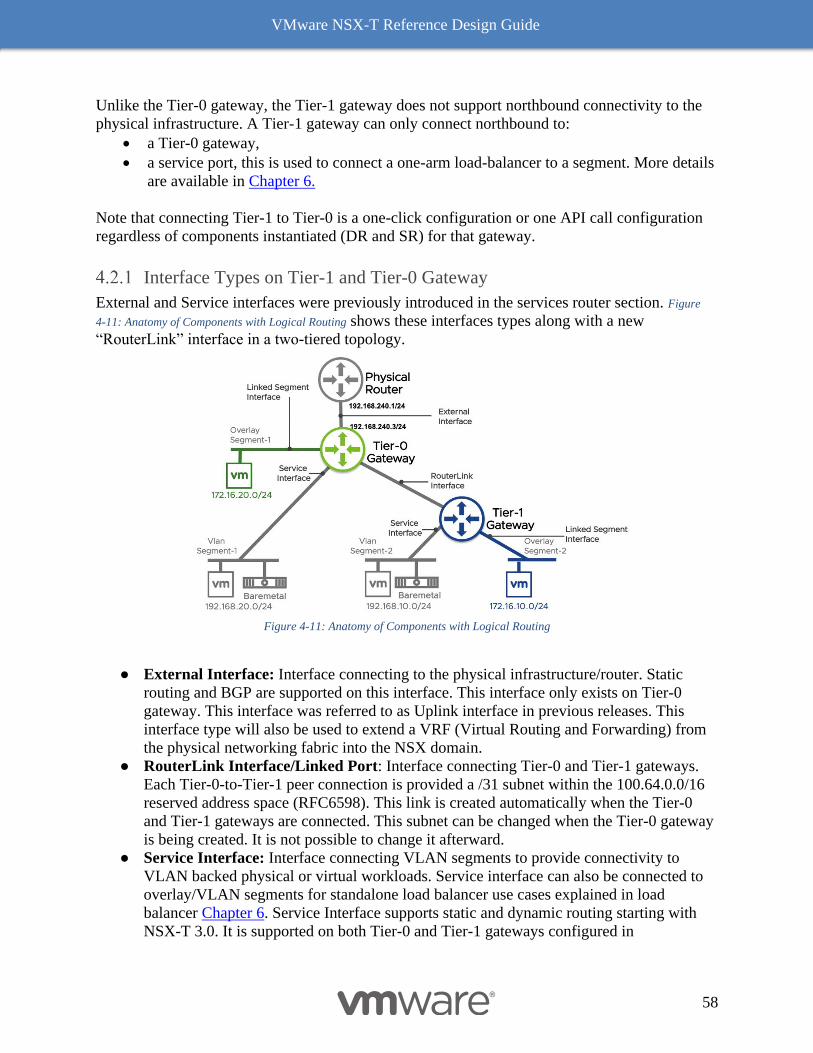
VMware NSX-T Reference Design Guide
58
Unlike the Tier-0 gateway, the Tier-1 gateway does not support northbound connectivity to the
physical infrastructure. A Tier-1 gateway can only connect northbound to:
• a Tier-0 gateway,
• a service port, this is used to connect a one-arm load-balancer to a segment. More details
are available in Chapter 6.
Note that connecting Tier-1 to Tier-0 is a one-click configuration or one API call configuration
regardless of components instantiated (DR and SR) for that gateway.
Interface Types on Tier-1 and Tier-0 Gateway
External and Service interfaces were previously introduced in the services router section. Figure
4-11: Anatomy of Components with Logical Routing shows these interfaces types along with a new
“RouterLink” interface in a two-tiered topology.
Figure 4-11: Anatomy of Components with Logical Routing
● External Interface: Interface connecting to the physical infrastructure/router. Static
routing and BGP are supported on this interface. This interface only exists on Tier-0
gateway. This interface was referred to as Uplink interface in previous releases. This
interface type will also be used to extend a VRF (Virtual Routing and Forwarding) from
the physical networking fabric into the NSX domain.
● RouterLink Interface/Linked Port: Interface connecting Tier-0 and Tier-1 gateways.
Each Tier-0-to-Tier-1 peer connection is provided a /31 subnet within the 100.64.0.0/16
reserved address space (RFC6598). This link is created automatically when the Tier-0
and Tier-1 gateways are connected. This subnet can be changed when the Tier-0 gateway
is being created. It is not possible to change it afterward.
● Service Interface: Interface connecting VLAN segments to provide connectivity to
VLAN backed physical or virtual workloads. Service interface can also be connected to
overlay/VLAN segments for standalone load balancer use cases explained in load
balancer Chapter 6. Service Interface supports static and dynamic routing starting with
NSX-T 3.0. It is supported on both Tier-0 and Tier-1 gateways configured in
VMware NSX-T Reference Design Guide
59
Active/Standby high-availability configuration mode explained in section 4.6.2. Note that
a Tier-0 or Tier-1 gateway must have an SR component to realize service interfaces. This
interface was referred to as centralized service interface in previous releases.
● Loopback: Tier-0 gateway supports the loopback interfaces. A Loopback interface is a
virtual interface, and it can be redistributed into a routing protocol.
Route Types on Tier-0 and Tier-1 Gateways
There is no dynamic routing between Tier-0 and Tier-1 gateways. The NSX-T platform takes
care of the auto-plumbing between Tier-0 and Tier-1 gateways. The following list details route
types on Tier-0 and Tier-1 gateways.
● Tier-0 Gateway
○ Connected – Connected routes on Tier-0 include external interface subnets,
service interface subnets, loopback and segment subnets connected to Tier-0. In
Figure 4-12: Routing Advertisement, 172.16.20.0/24 (Connected segment),
192.168.20.0/24 (Service Interface) and 192.168.240.0/24 (External interface) are
connected routes for the Tier-0 gateway.
○ Static – User configured static routes on Tier-0.
○ NAT IP – NAT IP addresses owned by the Tier-0 gateway discovered from NAT
rules configured on Tier-0 Gateway.
○ BGP – Routes learned via BGP neighbors.
○ IPsec Local IP – Local IPsec endpoint IP address for establishing VPN sessions.
○ DNS Forwarder IP – Listener IP for DNS queries from clients. Also used as the
source IP to forward DNS queries to the upstream DNS server.
○ Inter SR. SRs of a same Tier-0 gateway in the same edge cluster will create an
automatic iBGP peering adjacency between them to exchange routing
information. This topology is only supported with Active/Active topologies and
with NSX-T Federation.
● Tier-1 Gateway
○ Connected – Connected routes on Tier-1 include segment subnets connected to
Tier-1 and service interface subnets configured on Tier-1 gateway.
In Figure 4-12: Routing Advertisement, 172.16.10.0/24 (Connected segment) and
192.168.10.0/24 (Service Interface) are connected routes for Tier-1 gateway.
○ Static– User configured static routes on Tier-1 gateway.
○ NAT IP – NAT IP addresses owned by the Tier-1 gateway discovered from NAT
rules configured on the Tier-1 gateway.
○ LB VIP – IP address of load balancing virtual server.
○ LB SNAT – IP address or a range of IP addresses used for Source NAT by load
balancer.
○ IPsec Local IP – Local IPsec endpoint IP address for establishing VPN sessions.
○ DNS Forwarder IP – Listener IP for DNS queries from clients. Also used as the
source IP to forward DNS queries to the upstream DNS server.
Route Advertisement on the Tier-1 and Tier-0 Logical Router
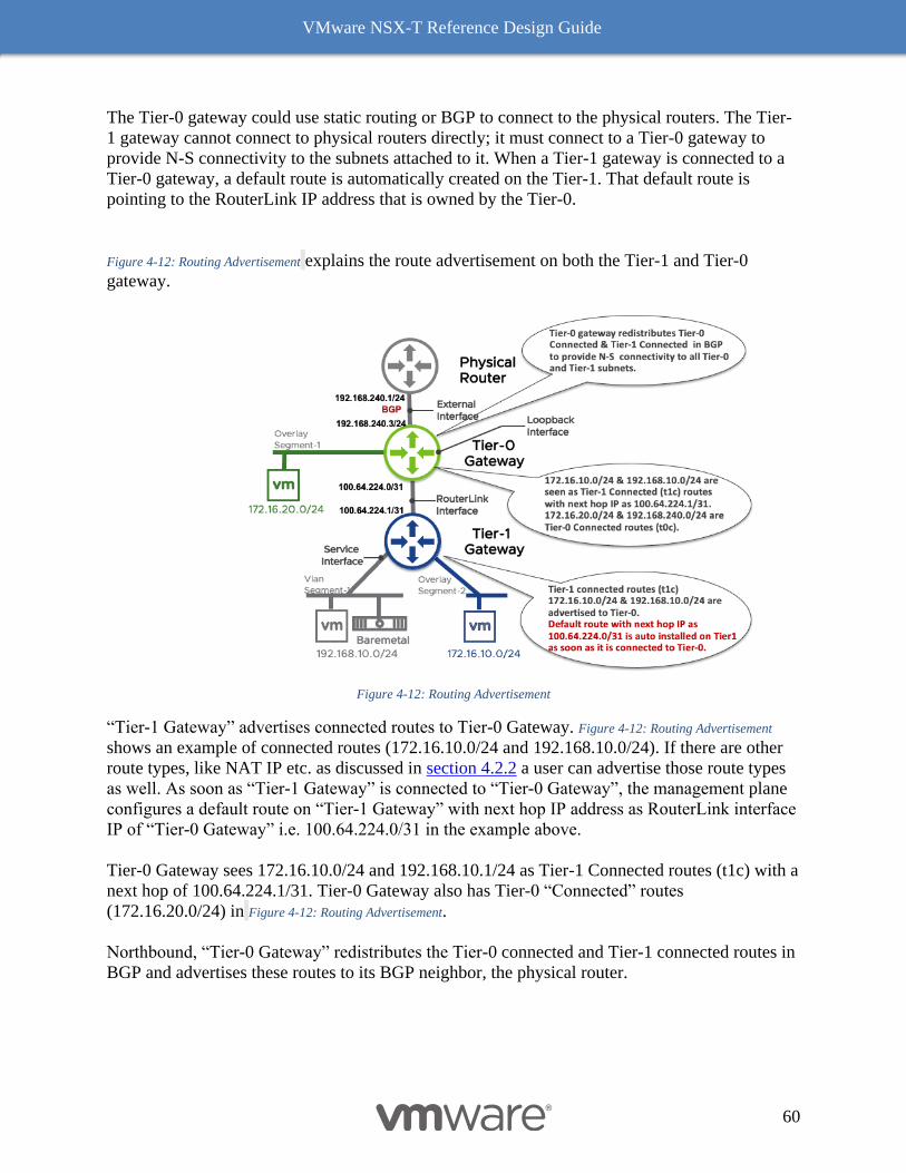
VMware NSX-T Reference Design Guide
60
The Tier-0 gateway could use static routing or BGP to connect to the physical routers. The Tier-
1 gateway cannot connect to physical routers directly; it must connect to a Tier-0 gateway to
provide N-S connectivity to the subnets attached to it. When a Tier-1 gateway is connected to a
Tier-0 gateway, a default route is automatically created on the Tier-1. That default route is
pointing to the RouterLink IP address that is owned by the Tier-0.
Figure 4-12: Routing Advertisement explains the route advertisement on both the Tier-1 and Tier-0
gateway.
Figure 4-12: Routing Advertisement
“Tier-1 Gateway” advertises connected routes to Tier-0 Gateway. Figure 4-12: Routing Advertisement
shows an example of connected routes (172.16.10.0/24 and 192.168.10.0/24). If there are other
route types, like NAT IP etc. as discussed in section 4.2.2 a user can advertise those route types
as well. As soon as “Tier-1 Gateway” is connected to “Tier-0 Gateway”, the management plane
configures a default route on “Tier-1 Gateway” with next hop IP address as RouterLink interface
IP of “Tier-0 Gateway” i.e. 100.64.224.0/31 in the example above.
Tier-0 Gateway sees 172.16.10.0/24 and 192.168.10.1/24 as Tier-1 Connected routes (t1c) with a
next hop of 100.64.224.1/31. Tier-0 Gateway also has Tier-0 “Connected” routes
(172.16.20.0/24) in Figure 4-12: Routing Advertisement.
Northbound, “Tier-0 Gateway” redistributes the Tier-0 connected and Tier-1 connected routes in
BGP and advertises these routes to its BGP neighbor, the physical router.
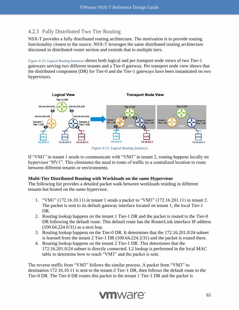
VMware NSX-T Reference Design Guide
61
Fully Distributed Two Tier Routing
NSX-T provides a fully distributed routing architecture. The motivation is to provide routing
functionality closest to the source. NSX-T leverages the same distributed routing architecture
discussed in distributed router section and extends that to multiple tiers.
Figure 4-13: Logical Routing Instances shows both logical and per transport node views of two Tier-1
gateways serving two different tenants and a Tier-0 gateway. Per transport node view shows that
the distributed component (DR) for Tier-0 and the Tier-1 gateways have been instantiated on two
hypervisors.
Figure 4-13: Logical Routing Instances
If “VM1” in tenant 1 needs to communicate with “VM3” in tenant 2, routing happens locally on
hypervisor “HV1”. This eliminates the need to route of traffic to a centralized location to route
between different tenants or environments.
Multi-Tier Distributed Routing with Workloads on the same Hypervisor
The following list provides a detailed packet walk between workloads residing in different
tenants but hosted on the same hypervisor.
1. “VM1” (172.16.10.11) in tenant 1 sends a packet to “VM3” (172.16.201.11) in tenant 2.
The packet is sent to its default gateway interface located on tenant 1, the local Tier-1
DR.
2. Routing lookup happens on the tenant 1 Tier-1 DR and the packet is routed to the Tier-0
DR following the default route. This default route has the RouterLink interface IP address
(100.64.224.0/31) as a next hop.
3. Routing lookup happens on the Tier-0 DR. It determines that the 172.16.201.0/24 subnet
is learned from the tenant 2 Tier-1 DR (100.64.224.3/31) and the packet is routed there.
4. Routing lookup happens on the tenant 2 Tier-1 DR. This determines that the
172.16.201.0/24 subnet is directly connected. L2 lookup is performed in the local MAC
table to determine how to reach “VM3” and the packet is sent.
The reverse traffic from “VM3” follows the similar process. A packet from “VM3” to
destination 172.16.10.11 is sent to the tenant-2 Tier-1 DR, then follows the default route to the
Tier-0 DR. The Tier-0 DR routes this packet to the tenant 1 Tier-1 DR and the packet is
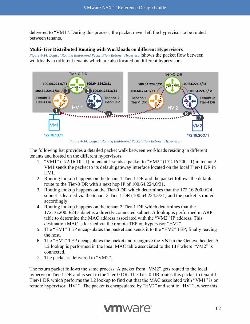
VMware NSX-T Reference Design Guide
62
delivered to “VM1”. During this process, the packet never left the hypervisor to be routed
between tenants.
Multi-Tier Distributed Routing with Workloads on different Hypervisors
Figure 4-14: Logical Routing End-to-end Packet Flow Between Hypervisor shows the packet flow between
workloads in different tenants which are also located on different hypervisors.
Figure 4-14: Logical Routing End-to-end Packet Flow Between Hypervisor
The following list provides a detailed packet walk between workloads residing in different
tenants and hosted on the different hypervisors.
1. “VM1” (172.16.10.11) in tenant 1 sends a packet to “VM2” (172.16.200.11) in tenant 2.
VM1 sends the packet to its default gateway interface located on the local Tier-1 DR in
HV1.
2. Routing lookup happens on the tenant 1 Tier-1 DR and the packet follows the default
route to the Tier-0 DR with a next hop IP of 100.64.224.0/31.
3. Routing lookup happens on the Tier-0 DR which determines that the 172.16.200.0/24
subnet is learned via the tenant 2 Tier-1 DR (100.64.224.3/31) and the packet is routed
accordingly.
4. Routing lookup happens on the tenant 2 Tier-1 DR which determines that the
172.16.200.0/24 subnet is a directly connected subnet. A lookup is performed in ARP
table to determine the MAC address associated with the “VM2” IP address. This
destination MAC is learned via the remote TEP on hypervisor “HV2”.
5. The “HV1” TEP encapsulates the packet and sends it to the “HV2” TEP, finally leaving
the host.
6. The “HV2” TEP decapsulates the packet and recognize the VNI in the Geneve header. A
L2 lookup is performed in the local MAC table associated to the LIF where “VM2” is
connected.
7. The packet is delivered to “VM2”.
The return packet follows the same process. A packet from “VM2” gets routed to the local
hypervisor Tier-1 DR and is sent to the Tier-0 DR. The Tier-0 DR routes this packet to tenant 1
Tier-1 DR which performs the L2 lookup to find out that the MAC associated with “VM1” is on
remote hypervisor “HV1”. The packet is encapsulated by “HV2” and sent to “HV1”, where this
VMware NSX-T Reference Design Guide
63
packet is decapsulated and delivered to “VM1". It is important to notice that in this use case,
routing is performed locally on the hypervisor hosting the VM sourcing the traffic.
Routing Capabilities
NSX-T supports static routing and the dynamic routing protocol BGP on Tier-0 Gateways for
IPv4 and IPv6 workloads. In addition to static routing and BGP, Tier-0 gateway also supports a
dynamically created iBGP session between its Services router component. This feature is
referred as Inter-SR routing and is available for active-active Tier-0 topologies only.
Tier-1 Gateways support static routes but do not support any dynamic routing protocols.
Static Routing
Northbound, static routes can be configured on Tier-1 gateways with the next hop IP as the
Routerlink IP of the Tier-0 gateway (100.64.0.0/16 range or a range defined by user for
Routerlink interface). Southbound, static routes can also be configured on Tier-1 gateway with a
next hop as a layer 3 device reachable via Service interface.
Tier-0 gateways can be configured with a static route toward external subnets with a next hop IP
of the physical router. Southbound, static routes can be configured on Tier-0 gateways with a
next hop of a layer 3 device reachable via Service interface.
ECMP is supported with static routes to provide load balancing, increased bandwidth, and fault
tolerance for failed paths or Edge nodes. Figure 4-15: Static Routing Configuration shows a Tier-0 gateway
with two external interfaces leveraging Edge node, EN1 and EN2 connected to two physical
routers. Two equal cost static default routes configured for ECMP on Tier-0 Gateway. Up to
eight paths are supported in ECMP. The current hash algorithm for ECMP is two-tuple, based on
source and destination IP of the traffic.
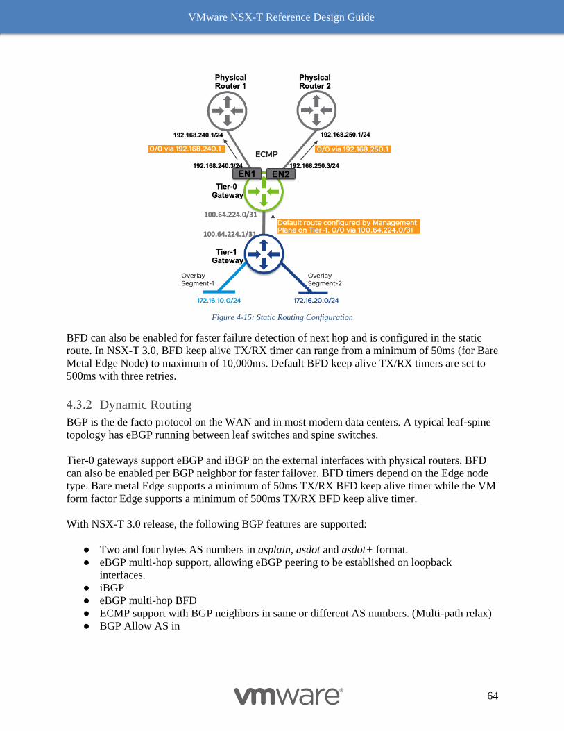
VMware NSX-T Reference Design Guide
64
Figure 4-15: Static Routing Configuration
BFD can also be enabled for faster failure detection of next hop and is configured in the static
route. In NSX-T 3.0, BFD keep alive TX/RX timer can range from a minimum of 50ms (for Bare
Metal Edge Node) to maximum of 10,000ms. Default BFD keep alive TX/RX timers are set to
500ms with three retries.
Dynamic Routing
BGP is the de facto protocol on the WAN and in most modern data centers. A typical leaf-spine
topology has eBGP running between leaf switches and spine switches.
Tier-0 gateways support eBGP and iBGP on the external interfaces with physical routers. BFD
can also be enabled per BGP neighbor for faster failover. BFD timers depend on the Edge node
type. Bare metal Edge supports a minimum of 50ms TX/RX BFD keep alive timer while the VM
form factor Edge supports a minimum of 500ms TX/RX BFD keep alive timer.
With NSX-T 3.0 release, the following BGP features are supported:
● Two and four bytes AS numbers in asplain, asdot and asdot+ format.
● eBGP multi-hop support, allowing eBGP peering to be established on loopback
interfaces.
● iBGP
● eBGP multi-hop BFD
● ECMP support with BGP neighbors in same or different AS numbers. (Multi-path relax)
● BGP Allow AS in
VMware NSX-T Reference Design Guide
65
● BGP route aggregation support with the flexibility of advertising a summary route only to
the BGP peer or advertise the summary route along with specific routes. A more specific
route must be present in the routing table to advertise a summary route.
● Route redistribution in BGP to advertise Tier-0 and Tier-1 Gateway internal routes as
mentioned in section 4.2.2.
● Inbound/outbound route filtering with BGP peer using prefix-lists or route-maps.
● Influencing BGP path selection by setting Weight, Local preference, AS Path Prepend, or
MED.
● Standard, Extended and Large BGP community support.
● BGP well-known community names (e.g., no-advertise, no-export, no-export-subconfed)
can also be included in the BGP route updates to the BGP peer.
● BGP communities can be set in a route-map to facilitate matching of communities at the
upstream router.
● Graceful restart (Full and Helper mode) in BGP.
● BGP peering authentication using plaintext or MD5.
● MP-BGP as the control plane protocol for VXLAN overlays or IPv6 address families.
Active/active ECMP services supports up to eight paths. The ECMP hash algorithm is 5-tuple
northbound of Tier-0 SR. ECMP hash is based on the source IP address, destination IP address,
source port, destination port and IP protocol. The hashing algorithm determines how incoming
traffic is forwarded to the next-hop device when there are multiple paths. ECMP hashing
algorithm from DR to multiple SRs is 2-tuple and is based on the source IP address and
destination IP address.
Graceful Restart (GR)
Graceful restart in BGP allows a BGP speaker to preserve its forwarding table while the control
plane restarts. It is recommended to enable BGP Graceful restart when the BGP peer has
multiple supervisors. A BGP control plane restart could happen due to a supervisor switchover in
a dual supervisor hardware, planned maintenance, or active routing engine crash. As soon as a
GR-enabled router restarts (control plane failure), it preserves its forwarding table, marks the
routes as stale, and sets a grace period restart timer for the BGP session to reestablish. If the BGP
session reestablishes during this grace period, route revalidation is done, and the forwarding
table is updated. If the BGP session does not reestablish within this grace period, the router
flushes the stale routes.
The BGP session will not be GR capable if only one of the peers advertises it in the BGP OPEN
message; GR needs to be configured on both ends. GR can be enabled/disabled per Tier-0
gateway. The GR restart timer is 180 seconds by default and cannot be change after a BGP
peering adjacency is in the established state, otherwise the peering needs to be negotiated again.
VRF Lite
VRF Lite Generalities
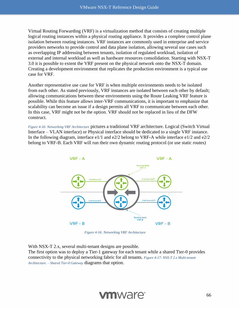
VMware NSX-T Reference Design Guide
66
Virtual Routing Forwarding (VRF) is a virtualization method that consists of creating multiple
logical routing instances within a physical routing appliance. It provides a complete control plane
isolation between routing instances. VRF instances are commonly used in enterprise and service
providers networks to provide control and data plane isolation, allowing several use cases such
as overlapping IP addressing between tenants, isolation of regulated workload, isolation of
external and internal workload as well as hardware resources consolidation. Starting with NSX-T
3.0 it is possible to extent the VRF present on the physical network onto the NSX-T domain.
Creating a development environment that replicates the production environment is a typical use
case for VRF.
Another representative use case for VRF is when multiple environments needs to be isolated
from each other. As stated previously, VRF instances are isolated between each other by default;
allowing communications between these environments using the Route Leaking VRF feature is
possible. While this feature allows inter-VRF communications, it is important to emphasize that
scalability can become an issue if a design permits all VRF to communicate between each other.
In this case, VRF might not be the option. VRF should not be replaced in lieu of the DFW
construct.
Figure 4-16: Networking VRF Architecture pictures a traditional VRF architecture. Logical (Switch Virtual
Interface – VLAN interface) or Physical interface should be dedicated to a single VRF instance.
In the following diagram, interface e1/1 and e2/2 belong to VRF-A while interface e1/2 and e2/2
belong to VRF-B. Each VRF will run their own dynamic routing protocol (or use static routes)
Figure 4-16: Networking VRF Architecture
With NSX-T 2.x, several multi-tenant designs are possible.
The first option was to deploy a Tier-1 gateway for each tenant while a shared Tier-0 provides
connectivity to the physical networking fabric for all tenants. Figure 4-17: NSX-T 2.x Multi-tenant
Architecture. – Shared Tier-0 Gateway diagrams that option.
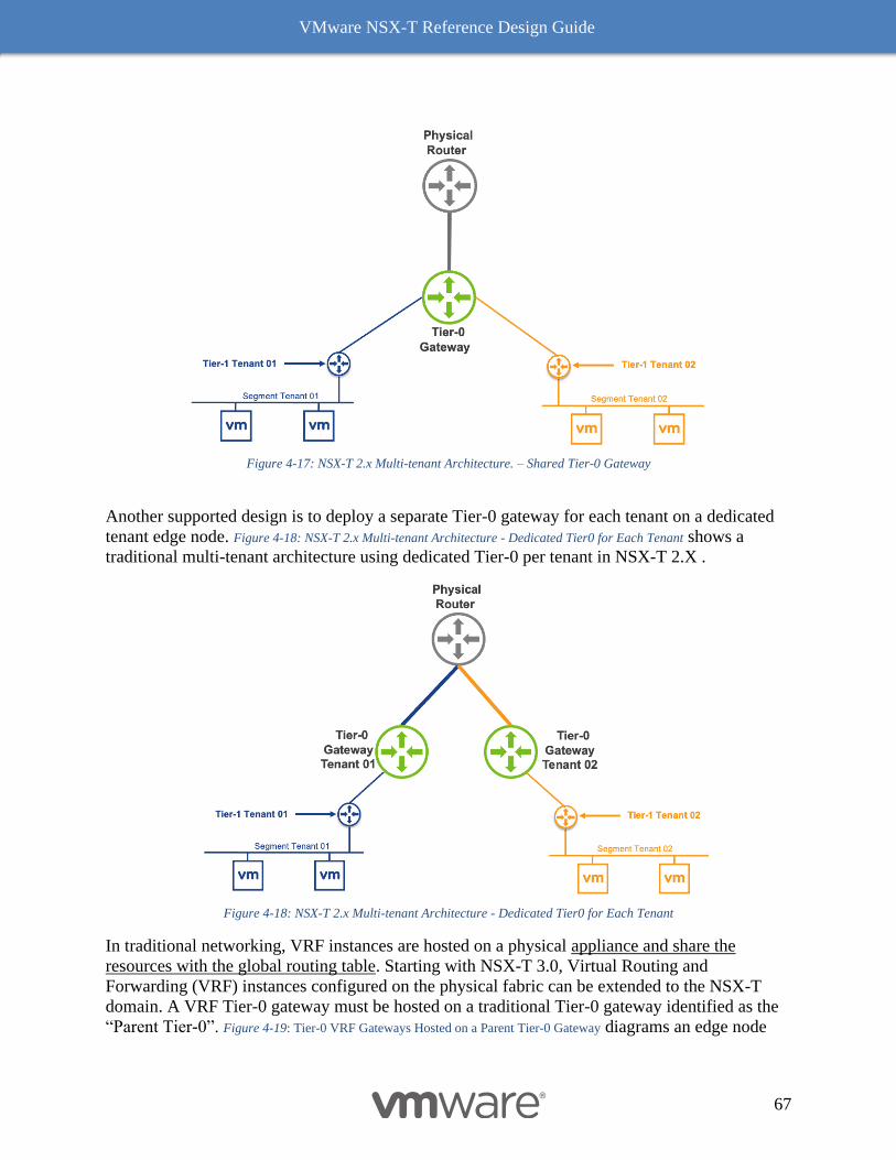
VMware NSX-T Reference Design Guide
67
Figure 4-17: NSX-T 2.x Multi-tenant Architecture. – Shared Tier-0 Gateway
Another supported design is to deploy a separate Tier-0 gateway for each tenant on a dedicated
tenant edge node. Figure 4-18: NSX-T 2.x Multi-tenant Architecture - Dedicated Tier0 for Each Tenant shows a
traditional multi-tenant architecture using dedicated Tier-0 per tenant in NSX-T 2.X .
Figure 4-18: NSX-T 2.x Multi-tenant Architecture - Dedicated Tier0 for Each Tenant
In traditional networking, VRF instances are hosted on a physical appliance and share the
resources with the global routing table. Starting with NSX-T 3.0, Virtual Routing and
Forwarding (VRF) instances configured on the physical fabric can be extended to the NSX-T
domain. A VRF Tier-0 gateway must be hosted on a traditional Tier-0 gateway identified as the
“Parent Tier-0”. Figure 4-19: Tier-0 VRF Gateways Hosted on a Parent Tier-0 Gateway diagrams an edge node
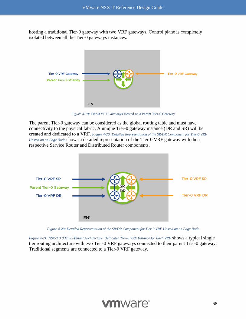
VMware NSX-T Reference Design Guide
68
hosting a traditional Tier-0 gateway with two VRF gateways. Control plane is completely
isolated between all the Tier-0 gateways instances.
Figure 4-19: Tier-0 VRF Gateways Hosted on a Parent Tier-0 Gateway
The parent Tier-0 gateway can be considered as the global routing table and must have
connectivity to the physical fabric. A unique Tier-0 gateway instance (DR and SR) will be
created and dedicated to a VRF. Figure 4-20: Detailed Representation of the SR/DR Component for Tier-0 VRF
Hosted on an Edge Node shows a detailed representation of the Tier-0 VRF gateway with their
respective Service Router and Distributed Router components.
Figure 4-20: Detailed Representation of the SR/DR Component for Tier-0 VRF Hosted on an Edge Node
Figure 4-21: NSX-T 3.0 Multi-Tenant Architecture. Dedicated Tier-0 VRF Instance for Each VRF shows a typical single
tier routing architecture with two Tier-0 VRF gateways connected to their parent Tier-0 gateway.
Traditional segments are connected to a Tier-0 VRF gateway.
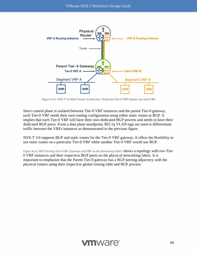
VMware NSX-T Reference Design Guide
69
Figure 4-21: NSX-T 3.0 Multi-Tenant Architecture. Dedicated Tier-0 VRF Instance for Each VRF
Since control plane is isolated between Tier-0 VRF instances and the parent Tier-0 gateway,
each Tier-0 VRF needs their own routing configuration using either static routes or BGP. It
implies that each Tier-0 VRF will have their own dedicated BGP process and needs to have their
dedicated BGP peers. From a data plane standpoint, 802.1q VLAN tags are used to differentiate
traffic between the VRFs instances as demonstrated in the previous figure.
NSX-T 3.0 supports BGP and static routes for the Tier-0 VRF gateway. It offers the flexibility to
use static routes on a particular Tier-0 VRF while another Tier-0 VRF would use BGP.
Figure 4-22: BGP Peering Tier-0 VRF Gateways and VRF on the Networking Fabric shows a topology with two Tier-
0 VRF instances and their respective BGP peers on the physical networking fabric. It is
important to emphasize that the Parent Tier-0 gateway has a BGP peering adjacency with the
physical routers using their respective global routing table and BGP process.
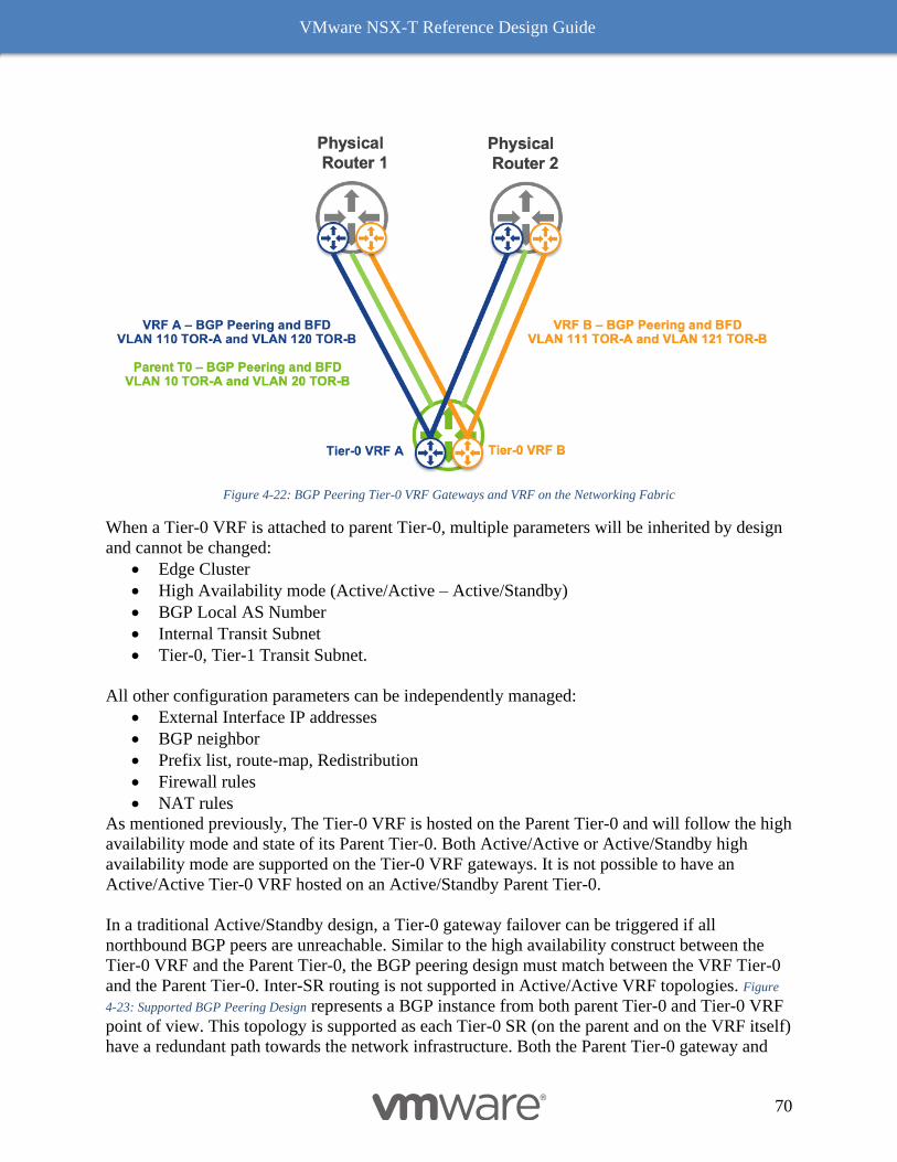
VMware NSX-T Reference Design Guide
70
Figure 4-22: BGP Peering Tier-0 VRF Gateways and VRF on the Networking Fabric
When a Tier-0 VRF is attached to parent Tier-0, multiple parameters will be inherited by design
and cannot be changed:
• Edge Cluster
• High Availability mode (Active/Active – Active/Standby)
• BGP Local AS Number
• Internal Transit Subnet
• Tier-0, Tier-1 Transit Subnet.
All other configuration parameters can be independently managed:
• External Interface IP addresses
• BGP neighbor
• Prefix list, route-map, Redistribution
• Firewall rules
• NAT rules
As mentioned previously, The Tier-0 VRF is hosted on the Parent Tier-0 and will follow the high
availability mode and state of its Parent Tier-0. Both Active/Active or Active/Standby high
availability mode are supported on the Tier-0 VRF gateways. It is not possible to have an
Active/Active Tier-0 VRF hosted on an Active/Standby Parent Tier-0.
In a traditional Active/Standby design, a Tier-0 gateway failover can be triggered if all
northbound BGP peers are unreachable. Similar to the high availability construct between the
Tier-0 VRF and the Parent Tier-0, the BGP peering design must match between the VRF Tier-0
and the Parent Tier-0. Inter-SR routing is not supported in Active/Active VRF topologies. Figure
4-23: Supported BGP Peering Design represents a BGP instance from both parent Tier-0 and Tier-0 VRF
point of view. This topology is supported as each Tier-0 SR (on the parent and on the VRF itself)
have a redundant path towards the network infrastructure. Both the Parent Tier-0 gateway and
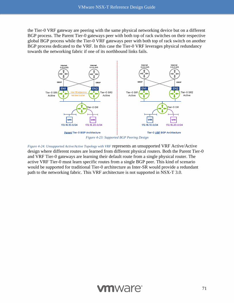
VMware NSX-T Reference Design Guide
71
the Tier-0 VRF gateway are peering with the same physical networking device but on a different
BGP process. The Parent Tier-0 gateways peer with both top of rack switches on their respective
global BGP process while the Tier-0 VRF gateways peer with both top of rack switch on another
BGP process dedicated to the VRF. In this case the Tier-0 VRF leverages physical redundancy
towards the networking fabric if one of its northbound links fails.
Figure 4-23: Supported BGP Peering Design
Figure 4-24: Unsupported Active/Active Topology with VRF represents an unsupported VRF Active/Active
design where different routes are learned from different physical routers. Both the Parent Tier-0
and VRF Tier-0 gateways are learning their default route from a single physical router. The
active VRF Tier-0 must learn specific routes from a single BGP peer. This kind of scenario
would be supported for traditional Tier-0 architecture as Inter-SR would provide a redundant
path to the networking fabric. This VRF architecture is not supported in NSX-T 3.0.
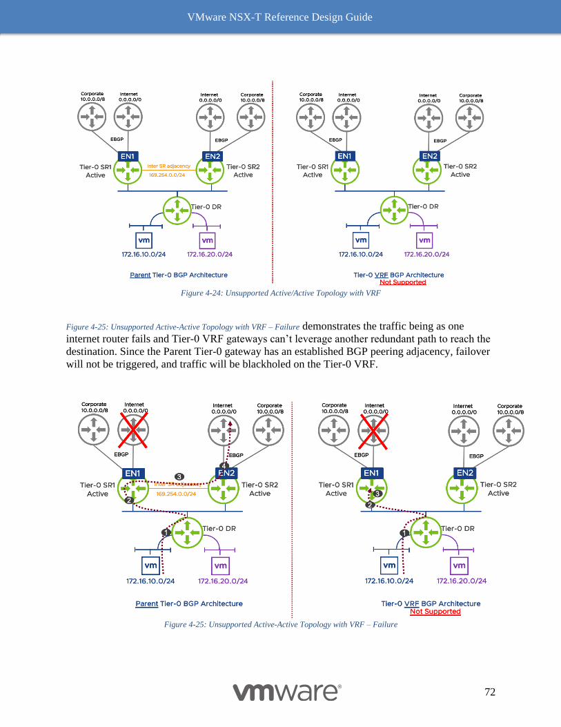
VMware NSX-T Reference Design Guide
72
Figure 4-24: Unsupported Active/Active Topology with VRF
Figure 4-25: Unsupported Active-Active Topology with VRF – Failure demonstrates the traffic being as one
internet router fails and Tier-0 VRF gateways can’t leverage another redundant path to reach the
destination. Since the Parent Tier-0 gateway has an established BGP peering adjacency, failover
will not be triggered, and traffic will be blackholed on the Tier-0 VRF.
Figure 4-25: Unsupported Active-Active Topology with VRF – Failure
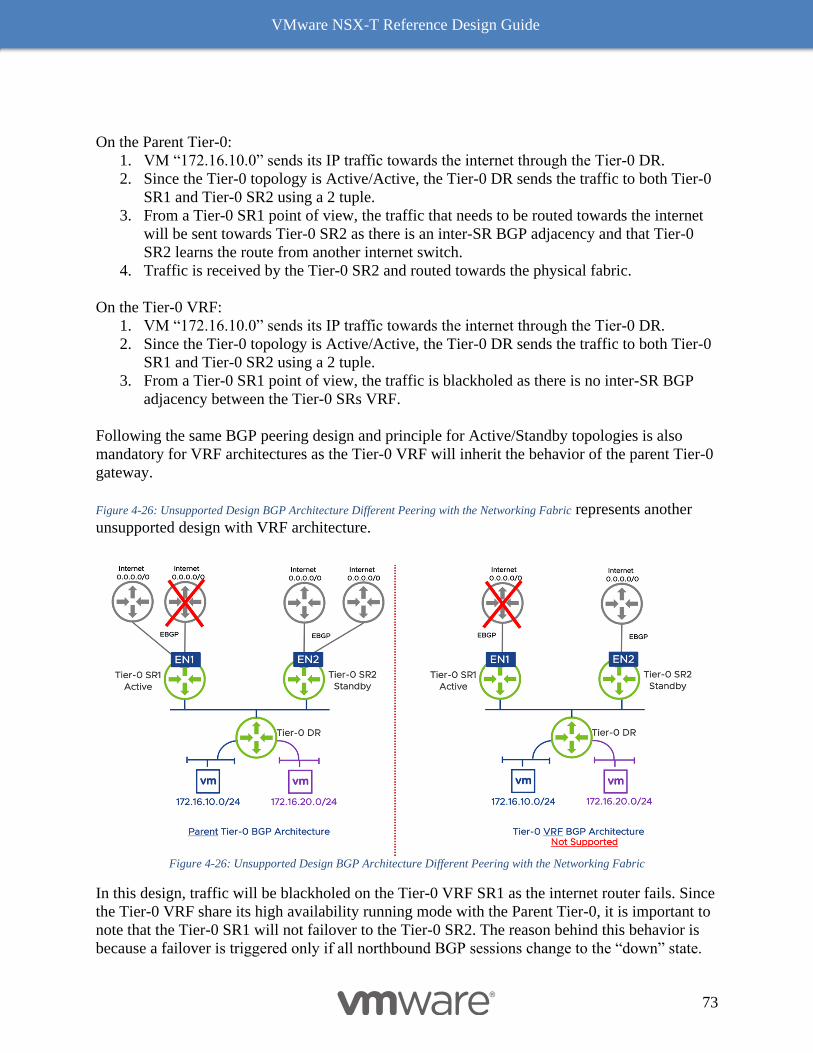
VMware NSX-T Reference Design Guide
73
On the Parent Tier-0:
1. VM “172.16.10.0” sends its IP traffic towards the internet through the Tier-0 DR.
2. Since the Tier-0 topology is Active/Active, the Tier-0 DR sends the traffic to both Tier-0
SR1 and Tier-0 SR2 using a 2 tuple.
3. From a Tier-0 SR1 point of view, the traffic that needs to be routed towards the internet
will be sent towards Tier-0 SR2 as there is an inter-SR BGP adjacency and that Tier-0
SR2 learns the route from another internet switch.
4. Traffic is received by the Tier-0 SR2 and routed towards the physical fabric.
On the Tier-0 VRF:
1. VM “172.16.10.0” sends its IP traffic towards the internet through the Tier-0 DR.
2. Since the Tier-0 topology is Active/Active, the Tier-0 DR sends the traffic to both Tier-0
SR1 and Tier-0 SR2 using a 2 tuple.
3. From a Tier-0 SR1 point of view, the traffic is blackholed as there is no inter-SR BGP
adjacency between the Tier-0 SRs VRF.
Following the same BGP peering design and principle for Active/Standby topologies is also
mandatory for VRF architectures as the Tier-0 VRF will inherit the behavior of the parent Tier-0
gateway.
Figure 4-26: Unsupported Design BGP Architecture Different Peering with the Networking Fabric represents another
unsupported design with VRF architecture.
Figure 4-26: Unsupported Design BGP Architecture Different Peering with the Networking Fabric
In this design, traffic will be blackholed on the Tier-0 VRF SR1 as the internet router fails. Since
the Tier-0 VRF share its high availability running mode with the Parent Tier-0, it is important to
note that the Tier-0 SR1 will not failover to the Tier-0 SR2. The reason behind this behavior is
because a failover is triggered only if all northbound BGP sessions change to the “down” state.

VMware NSX-T Reference Design Guide
74
Since Tier-0 SR1 still has an active BGP peering with a northbound router on the physical
networking fabric, failover will not occur, and traffic will be blackholed on the VRF that have
only one BGP peer active.
Traditional Tier-1 gateways can be connected to Tier-0 VRF to provide a multi-tier routing
architecture as demonstrated in Figure 4-27: Multi-Tier Routing Architecture and VRF-lite.
Figure 4-27: Multi-Tier Routing Architecture and VRF-lite
Stateful services can either run on a Tier-0 VRF gateway or a Tier-1 gateway except for VPN
and Load Balancing as these features are not supported on a Tier-0 VRF. Tier-1 SR in charge of
the stateful services for a particular VRF will be hosted on the same edge nodes as the Parent
Tier-0 Gateway. Figure 4-28: Stateful Services Supported on Tier-1 represents stateful services running on
traditional Tier-1 gateways SR.
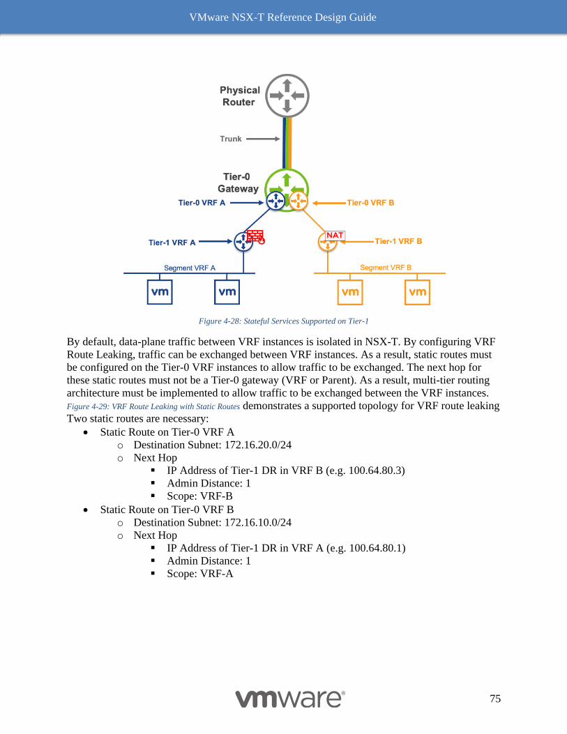
VMware NSX-T Reference Design Guide
75
Figure 4-28: Stateful Services Supported on Tier-1
By default, data-plane traffic between VRF instances is isolated in NSX-T. By configuring VRF
Route Leaking, traffic can be exchanged between VRF instances. As a result, static routes must
be configured on the Tier-0 VRF instances to allow traffic to be exchanged. The next hop for
these static routes must not be a Tier-0 gateway (VRF or Parent). As a result, multi-tier routing
architecture must be implemented to allow traffic to be exchanged between the VRF instances.
Figure 4-29: VRF Route Leaking with Static Routes demonstrates a supported topology for VRF route leaking
Two static routes are necessary:
• Static Route on Tier-0 VRF A
o Destination Subnet: 172.16.20.0/24
o Next Hop
▪ IP Address of Tier-1 DR in VRF B (e.g. 100.64.80.3)
▪ Admin Distance: 1
▪ Scope: VRF-B
• Static Route on Tier-0 VRF B
o Destination Subnet: 172.16.10.0/24
o Next Hop
▪ IP Address of Tier-1 DR in VRF A (e.g. 100.64.80.1)
▪ Admin Distance: 1
▪ Scope: VRF-A
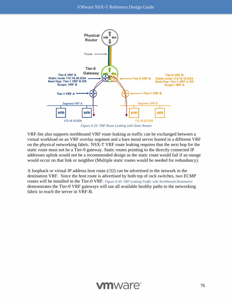
VMware NSX-T Reference Design Guide
76
Figure 4-29: VRF Route Leaking with Static Routes
VRF-lite also supports northbound VRF route leaking as traffic can be exchanged between a
virtual workload on an VRF overlay segment and a bare metal server hosted in a different VRF
on the physical networking fabric. NSX-T VRF route leaking requires that the next hop for the
static route must not be a Tier-0 gateway. Static routes pointing to the directly connected IP
addresses uplink would not be a recommended design as the static route would fail if an outage
would occur on that link or neighbor (Multiple static routes would be needed for redundancy).
A loopback or virtual IP address host route (/32) can be advertised in the network in the
destination VRF. Since the host route is advertised by both top of rack switches, two ECMP
routes will be installed in the Tier-0 VRF. Figure 4-30: VRF Leaking Traffic with Northbound Destination
demonstrates the Tier-0 VRF gateways will use all available healthy paths to the networking
fabric to reach the server in VRF-B.
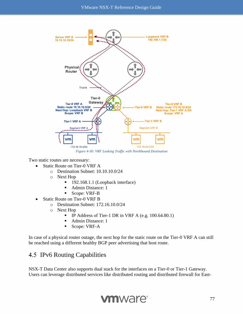
VMware NSX-T Reference Design Guide
77
Figure 4-30: VRF Leaking Traffic with Northbound Destination
Two static routes are necessary:
• Static Route on Tier-0 VRF A
o Destination Subnet: 10.10.10.0/24
o Next Hop
▪ 192.168.1.1 (Loopback interface)
▪ Admin Distance: 1
▪ Scope: VRF-B
• Static Route on Tier-0 VRF B
o Destination Subnet: 172.16.10.0/24
o Next Hop
▪ IP Address of Tier-1 DR in VRF A (e.g. 100.64.80.1)
▪ Admin Distance: 1
▪ Scope: VRF-A
In case of a physical router outage, the next hop for the static route on the Tier-0 VRF A can still
be reached using a different healthy BGP peer advertising that host route.
IPv6 Routing Capabilities
NSX-T Data Center also supports dual stack for the interfaces on a Tier-0 or Tier-1 Gateway.
Users can leverage distributed services like distributed routing and distributed firewall for East-
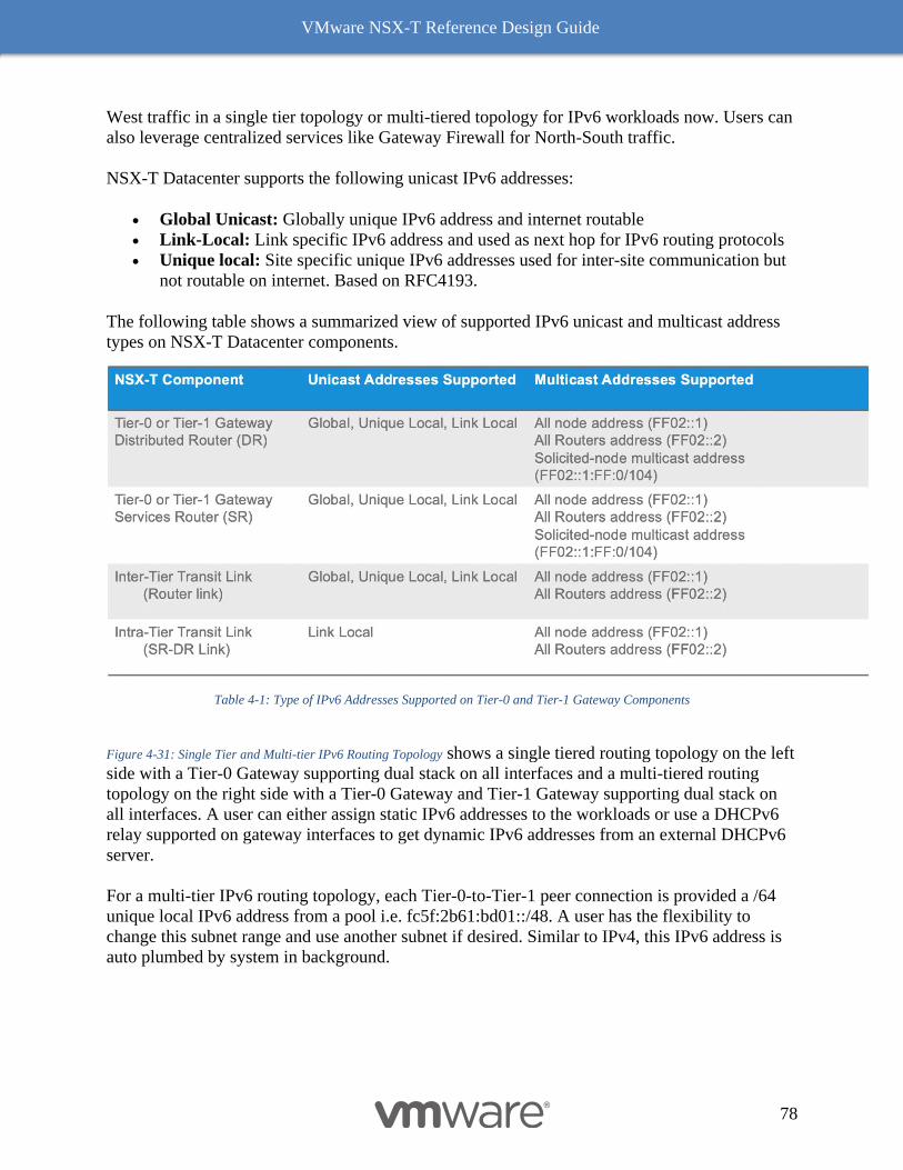
VMware NSX-T Reference Design Guide
78
West traffic in a single tier topology or multi-tiered topology for IPv6 workloads now. Users can
also leverage centralized services like Gateway Firewall for North-South traffic.
NSX-T Datacenter supports the following unicast IPv6 addresses:
• Global Unicast: Globally unique IPv6 address and internet routable
• Link-Local: Link specific IPv6 address and used as next hop for IPv6 routing protocols
• Unique local: Site specific unique IPv6 addresses used for inter-site communication but
not routable on internet. Based on RFC4193.
The following table shows a summarized view of supported IPv6 unicast and multicast address
types on NSX-T Datacenter components.
Table 4-1: Type of IPv6 Addresses Supported on Tier-0 and Tier-1 Gateway Components
Figure 4-31: Single Tier and Multi-tier IPv6 Routing Topology shows a single tiered routing topology on the left
side with a Tier-0 Gateway supporting dual stack on all interfaces and a multi-tiered routing
topology on the right side with a Tier-0 Gateway and Tier-1 Gateway supporting dual stack on
all interfaces. A user can either assign static IPv6 addresses to the workloads or use a DHCPv6
relay supported on gateway interfaces to get dynamic IPv6 addresses from an external DHCPv6
server.
For a multi-tier IPv6 routing topology, each Tier-0-to-Tier-1 peer connection is provided a /64
unique local IPv6 address from a pool i.e. fc5f:2b61:bd01::/48. A user has the flexibility to
change this subnet range and use another subnet if desired. Similar to IPv4, this IPv6 address is
auto plumbed by system in background.
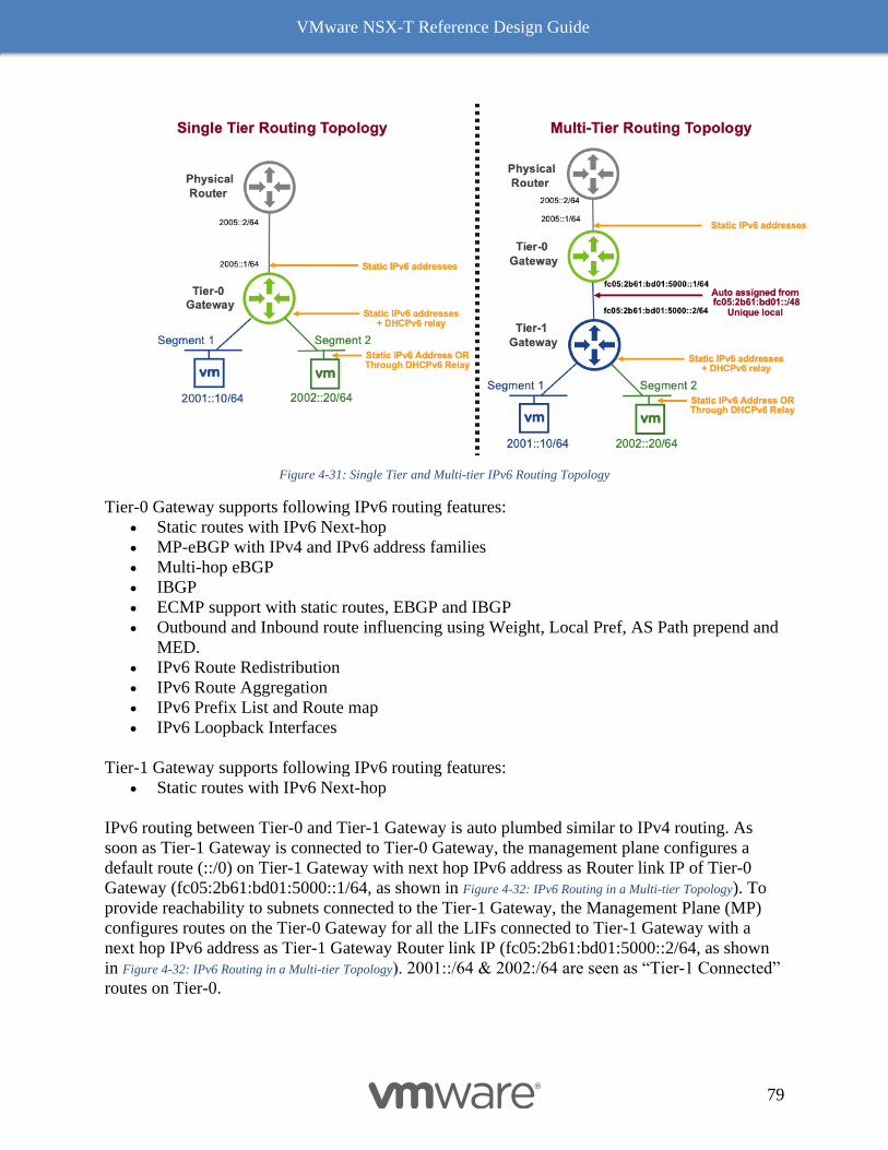
VMware NSX-T Reference Design Guide
79
Figure 4-31: Single Tier and Multi-tier IPv6 Routing Topology
Tier-0 Gateway supports following IPv6 routing features:
• Static routes with IPv6 Next-hop
• MP-eBGP with IPv4 and IPv6 address families
• Multi-hop eBGP
• IBGP
• ECMP support with static routes, EBGP and IBGP
• Outbound and Inbound route influencing using Weight, Local Pref, AS Path prepend and
MED.
• IPv6 Route Redistribution
• IPv6 Route Aggregation
• IPv6 Prefix List and Route map
• IPv6 Loopback Interfaces
Tier-1 Gateway supports following IPv6 routing features:
• Static routes with IPv6 Next-hop
IPv6 routing between Tier-0 and Tier-1 Gateway is auto plumbed similar to IPv4 routing. As
soon as Tier-1 Gateway is connected to Tier-0 Gateway, the management plane configures a
default route (::/0) on Tier-1 Gateway with next hop IPv6 address as Router link IP of Tier-0
Gateway (fc05:2b61:bd01:5000::1/64, as shown in Figure 4-32: IPv6 Routing in a Multi-tier Topology). To
provide reachability to subnets connected to the Tier-1 Gateway, the Management Plane (MP)
configures routes on the Tier-0 Gateway for all the LIFs connected to Tier-1 Gateway with a
next hop IPv6 address as Tier-1 Gateway Router link IP (fc05:2b61:bd01:5000::2/64, as shown
in Figure 4-32: IPv6 Routing in a Multi-tier Topology). 2001::/64 & 2002:/64 are seen as “Tier-1 Connected”
routes on Tier-0.
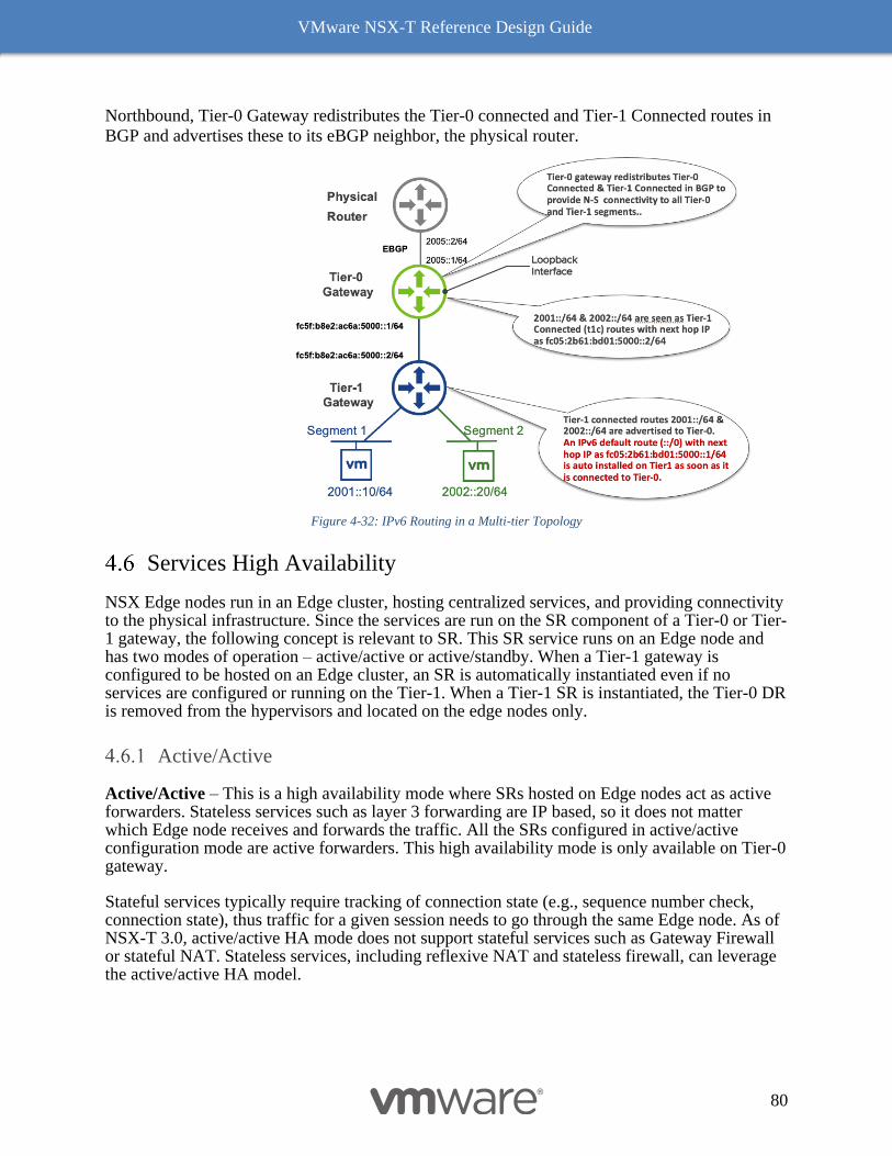
VMware NSX-T Reference Design Guide
80
Northbound, Tier-0 Gateway redistributes the Tier-0 connected and Tier-1 Connected routes in
BGP and advertises these to its eBGP neighbor, the physical router.
Figure 4-32: IPv6 Routing in a Multi-tier Topology
Services High Availability
NSX Edge nodes run in an Edge cluster, hosting centralized services, and providing connectivity to the physical infrastructure. Since the services are run on the SR component of a Tier-0 or Tier-1 gateway, the following concept is relevant to SR. This SR service runs on an Edge node and has two modes of operation – active/active or active/standby. When a Tier-1 gateway is configured to be hosted on an Edge cluster, an SR is automatically instantiated even if no services are configured or running on the Tier-1. When a Tier-1 SR is instantiated, the Tier-0 DR is removed from the hypervisors and located on the edge nodes only.
Active/Active
Active/Active – This is a high availability mode where SRs hosted on Edge nodes act as active forwarders. Stateless services such as layer 3 forwarding are IP based, so it does not matter which Edge node receives and forwards the traffic. All the SRs configured in active/active configuration mode are active forwarders. This high availability mode is only available on Tier-0 gateway.
Stateful services typically require tracking of connection state (e.g., sequence number check, connection state), thus traffic for a given session needs to go through the same Edge node. As of NSX-T 3.0, active/active HA mode does not support stateful services such as Gateway Firewall or stateful NAT. Stateless services, including reflexive NAT and stateless firewall, can leverage the active/active HA model.
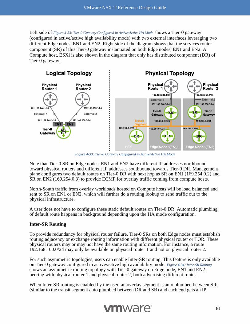
VMware NSX-T Reference Design Guide
81
Left side of Figure 4-33: Tier-0 Gateway Configured in Active/Active HA Mode shows a Tier-0 gateway
(configured in active/active high availability mode) with two external interfaces leveraging two
different Edge nodes, EN1 and EN2. Right side of the diagram shows that the services router
component (SR) of this Tier-0 gateway instantiated on both Edge nodes, EN1 and EN2. A
Compute host, ESXi is also shown in the diagram that only has distributed component (DR) of
Tier-0 gateway.
Figure 4-33: Tier-0 Gateway Configured in Active/Active HA Mode
Note that Tier-0 SR on Edge nodes, EN1 and EN2 have different IP addresses northbound toward physical routers and different IP addresses southbound towards Tier-0 DR. Management plane configures two default routes on Tier-0 DR with next hop as SR on EN1 (169.254.0.2) and SR on EN2 (169.254.0.3) to provide ECMP for overlay traffic coming from compute hosts.
North-South traffic from overlay workloads hosted on Compute hosts will be load balanced and sent to SR on EN1 or EN2, which will further do a routing lookup to send traffic out to the physical infrastructure.
A user does not have to configure these static default routes on Tier-0 DR. Automatic plumbing of default route happens in background depending upon the HA mode configuration.
Inter-SR Routing
To provide redundancy for physical router failure, Tier-0 SRs on both Edge nodes must establish routing adjacency or exchange routing information with different physical router or TOR. These physical routers may or may not have the same routing information. For instance, a route 192.168.100.0/24 may only be available on physical router 1 and not on physical router 2.
For such asymmetric topologies, users can enable Inter-SR routing. This feature is only available on Tier-0 gateway configured in active/active high availability mode. Figure 4-34: Inter-SR Routing shows an asymmetric routing topology with Tier-0 gateway on Edge node, EN1 and EN2 peering with physical router 1 and physical router 2, both advertising different routes.
When Inter-SR routing is enabled by the user, an overlay segment is auto plumbed between SRs (similar to the transit segment auto plumbed between DR and SR) and each end gets an IP
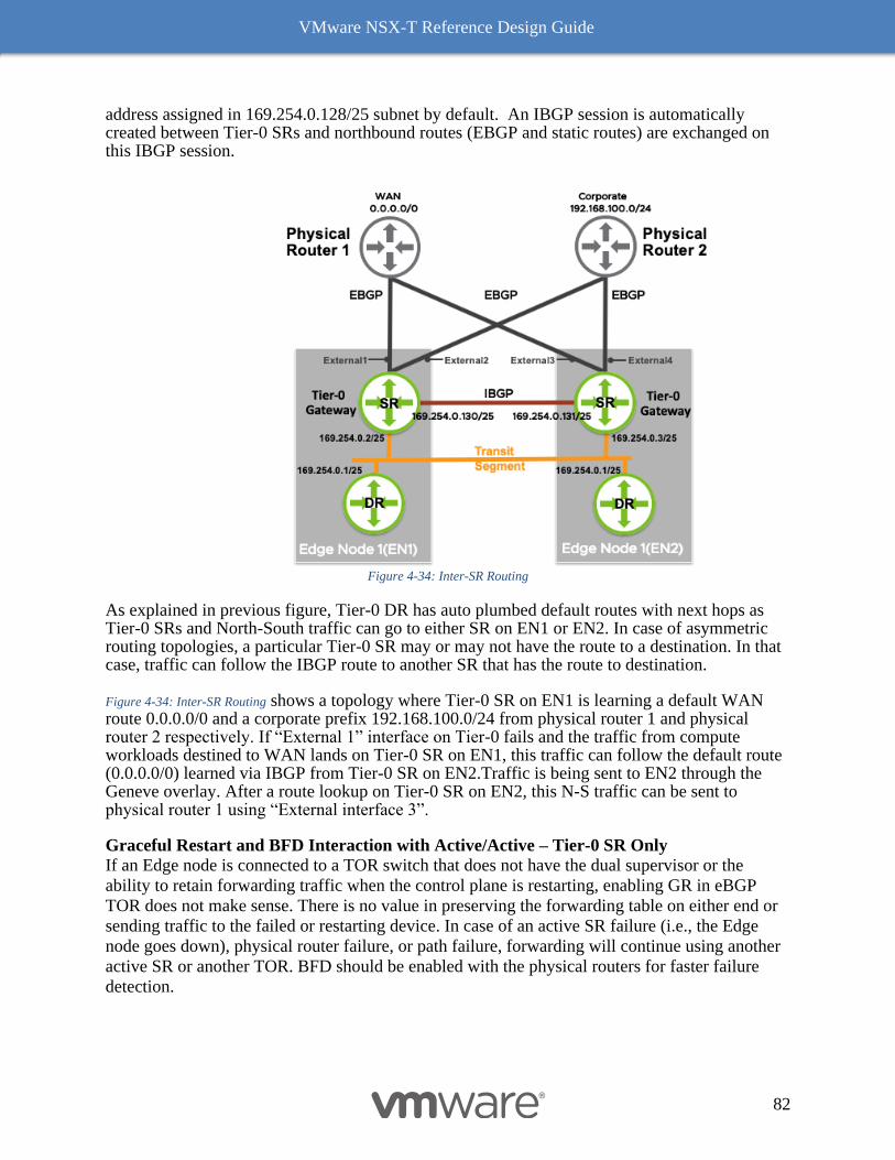
VMware NSX-T Reference Design Guide
82
address assigned in 169.254.0.128/25 subnet by default. An IBGP session is automatically created between Tier-0 SRs and northbound routes (EBGP and static routes) are exchanged on this IBGP session.
Figure 4-34: Inter-SR Routing
As explained in previous figure, Tier-0 DR has auto plumbed default routes with next hops as Tier-0 SRs and North-South traffic can go to either SR on EN1 or EN2. In case of asymmetric routing topologies, a particular Tier-0 SR may or may not have the route to a destination. In that case, traffic can follow the IBGP route to another SR that has the route to destination.
Figure 4-34: Inter-SR Routing shows a topology where Tier-0 SR on EN1 is learning a default WAN route 0.0.0.0/0 and a corporate prefix 192.168.100.0/24 from physical router 1 and physical router 2 respectively. If “External 1” interface on Tier-0 fails and the traffic from compute workloads destined to WAN lands on Tier-0 SR on EN1, this traffic can follow the default route (0.0.0.0/0) learned via IBGP from Tier-0 SR on EN2.Traffic is being sent to EN2 through the Geneve overlay. After a route lookup on Tier-0 SR on EN2, this N-S traffic can be sent to physical router 1 using “External interface 3”.
Graceful Restart and BFD Interaction with Active/Active – Tier-0 SR Only
If an Edge node is connected to a TOR switch that does not have the dual supervisor or the
ability to retain forwarding traffic when the control plane is restarting, enabling GR in eBGP
TOR does not make sense. There is no value in preserving the forwarding table on either end or
sending traffic to the failed or restarting device. In case of an active SR failure (i.e., the Edge
node goes down), physical router failure, or path failure, forwarding will continue using another
active SR or another TOR. BFD should be enabled with the physical routers for faster failure
detection.
VMware NSX-T Reference Design Guide
83
It is recommended to enable GR If the Edge node is connected to a dual supervisor system that
supports forwarding traffic when the control plane is restarting. This will ensure that forwarding
table data is preserved and forwarding will continue through the restarting supervisor or control
plane. Enabling BFD with such a system would depend on the device-specific BFD
implementation. If the BFD session goes down during supervisor failover, then BFD should not
be enabled with this system. If the BFD implementation is distributed such that the BFD session
would not go down in case of supervisor or control plane failure, then enable BFD as well as GR.
Active/Standby
Active/Standby – This is a high availability mode where only one SR act as an active forwarder. This mode is required when stateful services are enabled. Services like NAT are in constant state of sync between active and standby SRs on the Edge nodes. This mode is supported on both Tier-1 and Tier-0 SRs. Preemptive and Non-Preemptive modes are available for both Tier-0 and Tier-1 SRs. Default mode for gateways configured in active/standby high availability configuration is non-preemptive.
A user can select the preferred member (Edge node) when a gateway is configured in active/standby preemptive mode. When enabled, preemptive behavior allows a SR to resume active role on preferred edge node as soon as it recovers from a failure.
For Tier-1 Gateway, active/standby SRs have the same IP addresses northbound. Only the active SR will reply to ARP requests, while the standby SR interfaces operational state is set as down so that they will automatically drop packets.
For Tier-0 Gateway, active/standby SRs have different IP addresses northbound and both have eBGP sessions established on their uplinks. Both Tier-0 SRs (active and standby) receive routing updates from physical routers and advertise routes to the physical routers; however, the standby Tier-0 SR prepends its local AS three times in the BGP updates so that traffic from the physical routers prefer the active Tier-0 SR.
Southbound IP addresses on active and standby Tier-0 SRs are the same and the operational state of standby SR southbound interface is down. Since the operational state of southbound Tier-0 SR interface is down, the Tier-0 DR does not send any traffic to the standby SR. Figure 4-35: Active and
Standby Routing Control with eBGP shows active and standby Tier-0 SRs on Edge nodes “EN1” and “EN2”.
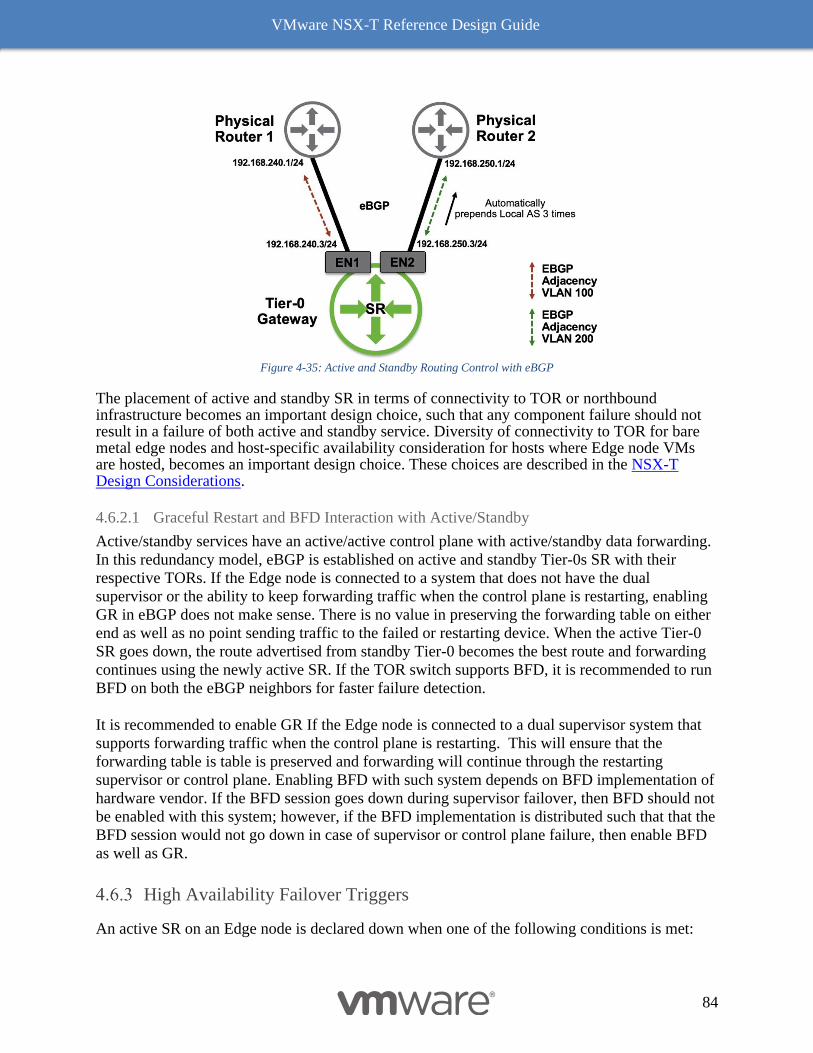
VMware NSX-T Reference Design Guide
84
Figure 4-35: Active and Standby Routing Control with eBGP
The placement of active and standby SR in terms of connectivity to TOR or northbound infrastructure becomes an important design choice, such that any component failure should not result in a failure of both active and standby service. Diversity of connectivity to TOR for bare metal edge nodes and host-specific availability consideration for hosts where Edge node VMs are hosted, becomes an important design choice. These choices are described in the NSX-T Design Considerations.
4.6.2.1 Graceful Restart and BFD Interaction with Active/Standby
Active/standby services have an active/active control plane with active/standby data forwarding.
In this redundancy model, eBGP is established on active and standby Tier-0s SR with their
respective TORs. If the Edge node is connected to a system that does not have the dual
supervisor or the ability to keep forwarding traffic when the control plane is restarting, enabling
GR in eBGP does not make sense. There is no value in preserving the forwarding table on either
end as well as no point sending traffic to the failed or restarting device. When the active Tier-0
SR goes down, the route advertised from standby Tier-0 becomes the best route and forwarding
continues using the newly active SR. If the TOR switch supports BFD, it is recommended to run
BFD on both the eBGP neighbors for faster failure detection.
It is recommended to enable GR If the Edge node is connected to a dual supervisor system that
supports forwarding traffic when the control plane is restarting. This will ensure that the
forwarding table is table is preserved and forwarding will continue through the restarting
supervisor or control plane. Enabling BFD with such system depends on BFD implementation of
hardware vendor. If the BFD session goes down during supervisor failover, then BFD should not
be enabled with this system; however, if the BFD implementation is distributed such that that the
BFD session would not go down in case of supervisor or control plane failure, then enable BFD
as well as GR.
High Availability Failover Triggers
An active SR on an Edge node is declared down when one of the following conditions is met:
VMware NSX-T Reference Design Guide
85
● Edge nodes in an Edge cluster exchange BFD keep lives on two interfaces of the Edge node, management and overlay tunnel interfaces. Failover will be triggered when a SR fails to receive keep lives on both interfaces.
● All BGP sessions or northbound routing on the SR is down. This is only applicable on Tier-0 SR. When static routes are used on a Bare Metal Edge node with NSX-T 3.0, the failover will be triggered when the status of all PNIC carrying the uplinks is down.
● Edge nodes also run BFD with compute hosts. When all the overlay tunnels are down to remote Edges and compute hypervisors, an SR would be declared down.
Edge Node
Edge nodes are service appliances with pools of capacity, dedicated to running network and
security services that cannot be distributed to the hypervisors. Edge node also provides
connectivity to the physical infrastructure. Previous sections mentioned that centralized services
will run on the SR component of Tier-0 or Tier-1 gateways. These features include:
• Connectivity to physical infrastructure (static routing / BGP / MP-BGP)
• VRF-lite
• NAT
• DHCP server
• Metadata proxy
• Gateway Firewall
• Load Balancer
• L2 Bridging
• Service Interface
• VPN
As soon as one of these services is configured or an external interface is defined on the Tier-0
gateway, a SR is instantiated on the Edge node. The Edge node is also a transport node just like
compute nodes in NSX-T, and like a compute node it can connect to more than one transport
zones. A specific Edge node can be connected to only one overlay transport zone and depending
upon the topology, is connected to one or more VLAN transport zones for N-S connectivity.
There are two transport zones on the Edge:
• Overlay Transport Zone: Any traffic that originates from a VM participating in NSX-T
domain may require reachability to external devices or networks. This is typically
described as external North-South traffic. Traffic from VMs may also require some
centralized service like NAT, load balancer etc. To provide reachability for N-S traffic
and to consume centralized services, overlay traffic is sent from compute transport nodes
to Edge nodes. Edge node needs to be configured with a single overlay transport zone so
that it can decapsulate the overlay traffic received from compute nodes as well as
encapsulate the traffic sent to compute nodes.
• VLAN Transport Zone: Edge nodes connect to physical infrastructure using VLANs.
Edge node needs to be configured for VLAN transport zone to provide external or N-S
connectivity to the physical infrastructure. Depending upon the N-S topology, an edge
node can be configured with one or more VLAN transport zones.
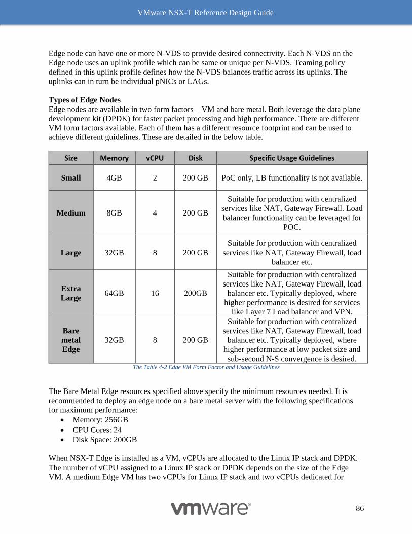
VMware NSX-T Reference Design Guide
86
Edge node can have one or more N-VDS to provide desired connectivity. Each N-VDS on the
Edge node uses an uplink profile which can be same or unique per N-VDS. Teaming policy
defined in this uplink profile defines how the N-VDS balances traffic across its uplinks. The
uplinks can in turn be individual pNICs or LAGs.
Types of Edge Nodes
Edge nodes are available in two form factors – VM and bare metal. Both leverage the data plane
development kit (DPDK) for faster packet processing and high performance. There are different
VM form factors available. Each of them has a different resource footprint and can be used to
achieve different guidelines. These are detailed in the below table.
Size Memory vCPU Disk Specific Usage Guidelines
Small 4GB 2 200 GB PoC only, LB functionality is not available.
Medium 8GB 4 200 GB
Suitable for production with centralized
services like NAT, Gateway Firewall. Load
balancer functionality can be leveraged for
POC.
Large 32GB 8 200 GB
Suitable for production with centralized
services like NAT, Gateway Firewall, load
balancer etc.
Extra
Large 64GB 16 200GB
Suitable for production with centralized
services like NAT, Gateway Firewall, load
balancer etc. Typically deployed, where
higher performance is desired for services
like Layer 7 Load balancer and VPN.
Bare
metal
Edge
32GB 8 200 GB
Suitable for production with centralized
services like NAT, Gateway Firewall, load
balancer etc. Typically deployed, where
higher performance at low packet size and
sub-second N-S convergence is desired. The Table 4-2 Edge VM Form Factor and Usage Guidelines
The Bare Metal Edge resources specified above specify the minimum resources needed. It is
recommended to deploy an edge node on a bare metal server with the following specifications
for maximum performance:
• Memory: 256GB
• CPU Cores: 24
• Disk Space: 200GB
When NSX-T Edge is installed as a VM, vCPUs are allocated to the Linux IP stack and DPDK.
The number of vCPU assigned to a Linux IP stack or DPDK depends on the size of the Edge
VM. A medium Edge VM has two vCPUs for Linux IP stack and two vCPUs dedicated for
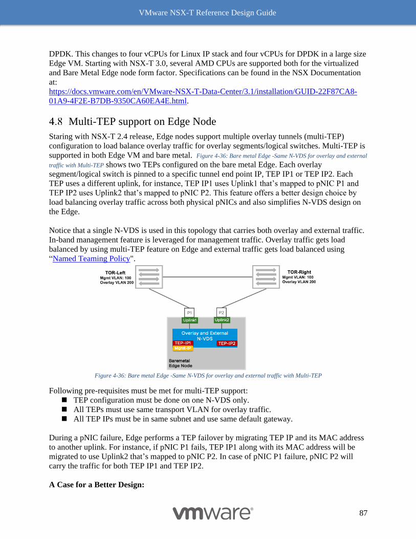
VMware NSX-T Reference Design Guide
87
DPDK. This changes to four vCPUs for Linux IP stack and four vCPUs for DPDK in a large size
Edge VM. Starting with NSX-T 3.0, several AMD CPUs are supported both for the virtualized
and Bare Metal Edge node form factor. Specifications can be found in the NSX Documentation
at:
https://docs.vmware.com/en/VMware-NSX-T-Data-Center/3.1/installation/GUID-22F87CA8-
01A9-4F2E-B7DB-9350CA60EA4E.html.
Multi-TEP support on Edge Node
Staring with NSX-T 2.4 release, Edge nodes support multiple overlay tunnels (multi-TEP)
configuration to load balance overlay traffic for overlay segments/logical switches. Multi-TEP is
supported in both Edge VM and bare metal. Figure 4-36: Bare metal Edge -Same N-VDS for overlay and external
traffic with Multi-TEP shows two TEPs configured on the bare metal Edge. Each overlay
segment/logical switch is pinned to a specific tunnel end point IP, TEP IP1 or TEP IP2. Each
TEP uses a different uplink, for instance, TEP IP1 uses Uplink1 that’s mapped to pNIC P1 and
TEP IP2 uses Uplink2 that’s mapped to pNIC P2. This feature offers a better design choice by
load balancing overlay traffic across both physical pNICs and also simplifies N-VDS design on
the Edge.
Notice that a single N-VDS is used in this topology that carries both overlay and external traffic.
In-band management feature is leveraged for management traffic. Overlay traffic gets load
balanced by using multi-TEP feature on Edge and external traffic gets load balanced using
“Named Teaming Policy".
Figure 4-36: Bare metal Edge -Same N-VDS for overlay and external traffic with Multi-TEP
Following pre-requisites must be met for multi-TEP support:
◼ TEP configuration must be done on one N-VDS only.
◼ All TEPs must use same transport VLAN for overlay traffic.
◼ All TEP IPs must be in same subnet and use same default gateway.
During a pNIC failure, Edge performs a TEP failover by migrating TEP IP and its MAC address
to another uplink. For instance, if pNIC P1 fails, TEP IP1 along with its MAC address will be
migrated to use Uplink2 that’s mapped to pNIC P2. In case of pNIC P1 failure, pNIC P2 will
carry the traffic for both TEP IP1 and TEP IP2.
A Case for a Better Design:
VMware NSX-T Reference Design Guide
88
This version of the design guide introduced a simpler way to configure Edge connectivity,
referred as “Single N-VDS Design”. The key reasons for adopting “Single N-VDS Design”:
◼ Multi-TEP support for Edge – Details of multi-TEP is described as above. Just like an
ESXi transport node supporting multiple TEP, Edge node has a capability to support
multiple TEP per uplink with following advantages:
o Removes critical topology restriction with bare metal – straight through LAG
o Allowing the use of multiple pNICs for the overlay traffic in both bare metal and
VM form factor.
■ An Edge VM supporting multiple TEP can have two uplinks from the same N-VDS,
allowing utilization of both pNICs. Efficient load sharing among host to Edge VM.
◼ Multiple teaming policy per N-VDS – Default and Named Teaming Policy
o Allows specific uplink to be designated or pinned for a given VLAN
o Allowing uplinks to be active/standby or active-only to drive specific behavior of
a given traffic types while co-existing other traffic type following entirely
different paths
◼ Normalization of N-VDS configuration – All form factors or Edge and deployments
uses single N-VDS along with host. Single teaming policy for overlay – Load Balanced
Source. Single policy for N-S peering – Named teaming Policy
◼ Reduction in management and control plane load – With each N-VDS, additional
resources are used such as IP addressing for management, connections to NSX manager
and BFD sessions to all transport nodes as well all the Edge nodes. The BFD sessions are
fully meshed, in other words the session counts increase with each N-VDS with N(N-1)
expansion. The CPU resources are also consumed by multiple N-VDS within the same
Edge VM.
Bare Metal Edge Node
NSX-T bare metal Edge runs on a physical server and is installed using an ISO file or PXE boot.
Legacy BIOS mode is the only supported booting mode on NSXT-T 3.0. A bare metal Edge
differs from the VM form factor Edge in terms of performance. It provides sub-second
convergence, faster failover, and higher throughput at low packet size (discussed in performance
Chapter 8). There are certain hardware requirements including CPU specifics and supported
NICs can be found in the NSX Edge Bare Metal Requirements section of the NSX-T installation
guide.
When a bare metal Edge node is installed, a dedicated interface is retained for management. If
redundancy is desired, two NICs can be used for management plane high availability. These
management interfaces can also be 1G. Bare metal Edge also supports in-band management
where management traffic can leverage an interface being used for overlay or external (N-S)
traffic.
Bare metal Edge node supports a maximum of 16 physical NICs for overlay traffic and external
traffic to top of rack (TOR) switches. For each of these 16 physical NICs on the server, an
internal interface is created following the naming scheme “fp-ethX”. These internal interfaces
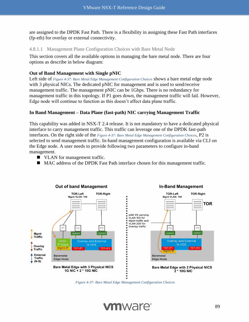
VMware NSX-T Reference Design Guide
89
are assigned to the DPDK Fast Path. There is a flexibility in assigning these Fast Path interfaces
(fp-eth) for overlay or external connectivity.
4.8.1.1 Management Plane Configuration Choices with Bare Metal Node
This section covers all the available options in managing the bare metal node. There are four
options as describe in below diagram:
Out of Band Management with Single pNIC
Left side of Figure 4-37: Bare Metal Edge Management Configuration Choices shows a bare metal edge node
with 3 physical NICs. The dedicated pNIC for management and is used to send/receive
management traffic. The management pNIC can be 1Gbps. There is no redundancy for
management traffic in this topology. If P1 goes down, the management traffic will fail. However,
Edge node will continue to function as this doesn’t affect data plane traffic.
In Band Management – Data Plane (fast-path) NIC carrying Management Traffic
This capability was added in NSX-T 2.4 release. It is not mandatory to have a dedicated physical
interface to carry management traffic. This traffic can leverage one of the DPDK fast-path
interfaces. On the right side of the Figure 4-37: Bare Metal Edge Management Configuration Choices, P2 is
selected to send management traffic. In-band management configuration is available via CLI on
the Edge node. A user needs to provide following two parameters to configure in-band
management.
◼ VLAN for management traffic.
◼ MAC address of the DPDK Fast Path interface chosen for this management traffic.
Figure 4-37: Bare Metal Edge Management Configuration Choices
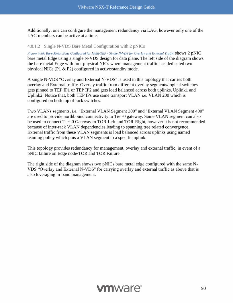
VMware NSX-T Reference Design Guide
90
Additionally, one can configure the management redundancy via LAG, however only one of the
LAG members can be active at a time.
4.8.1.2 Single N-VDS Bare Metal Configuration with 2 pNICs
Figure 4-38: Bare Metal Edge Configured for Multi-TEP - Single N-VDS for Overlay and External Traffic shows 2 pNIC
bare metal Edge using a single N-VDS design for data plane. The left side of the diagram shows
the bare metal Edge with four physical NICs where management traffic has dedicated two
physical NICs (P1 & P2) configured in active/standby mode.
A single N-VDS “Overlay and External N-VDS" is used in this topology that carries both
overlay and External traffic. Overlay traffic from different overlay segments/logical switches
gets pinned to TEP IP1 or TEP IP2 and gets load balanced across both uplinks, Uplink1 and
Uplink2. Notice that, both TEP IPs use same transport VLAN i.e. VLAN 200 which is
configured on both top of rack switches.
Two VLANs segments, i.e. "External VLAN Segment 300" and "External VLAN Segment 400"
are used to provide northbound connectivity to Tier-0 gateway. Same VLAN segment can also
be used to connect Tier-0 Gateway to TOR-Left and TOR-Right, however it is not recommended
because of inter-rack VLAN dependencies leading to spanning tree related convergence.
External traffic from these VLAN segments is load balanced across uplinks using named
teaming policy which pins a VLAN segment to a specific uplink.
This topology provides redundancy for management, overlay and external traffic, in event of a
pNIC failure on Edge node/TOR and TOR Failure.
The right side of the diagram shows two pNICs bare metal edge configured with the same N-
VDS “Overlay and External N-VDS" for carrying overlay and external traffic as above that is
also leveraging in-band management.
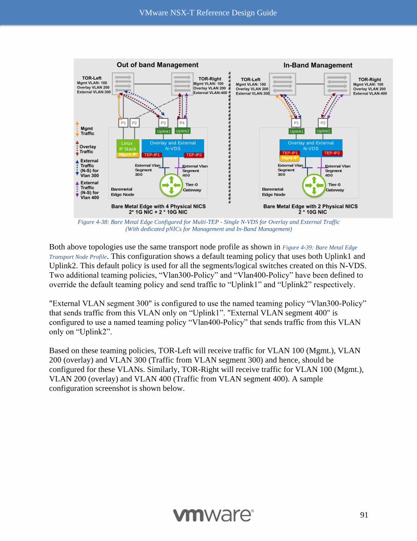
VMware NSX-T Reference Design Guide
91
Figure 4-38: Bare Metal Edge Configured for Multi-TEP - Single N-VDS for Overlay and External Traffic
(With dedicated pNICs for Management and In-Band Management)
Both above topologies use the same transport node profile as shown in Figure 4-39: Bare Metal Edge
Transport Node Profile. This configuration shows a default teaming policy that uses both Uplink1 and
Uplink2. This default policy is used for all the segments/logical switches created on this N-VDS.
Two additional teaming policies, “Vlan300-Policy” and “Vlan400-Policy” have been defined to
override the default teaming policy and send traffic to “Uplink1” and “Uplink2” respectively.
"External VLAN segment 300" is configured to use the named teaming policy “Vlan300-Policy”
that sends traffic from this VLAN only on “Uplink1”. "External VLAN segment 400" is
configured to use a named teaming policy “Vlan400-Policy” that sends traffic from this VLAN
only on “Uplink2”.
Based on these teaming policies, TOR-Left will receive traffic for VLAN 100 (Mgmt.), VLAN
200 (overlay) and VLAN 300 (Traffic from VLAN segment 300) and hence, should be
configured for these VLANs. Similarly, TOR-Right will receive traffic for VLAN 100 (Mgmt.),
VLAN 200 (overlay) and VLAN 400 (Traffic from VLAN segment 400). A sample
configuration screenshot is shown below.
External Traffic (N-S) for Vlan 300
OverlayTraffic
MgmtTraffic
Bare Metal Edge with 2 Physical NICS2 * 10G NIC
P1
Baremetal
Edge Node
P2
Overlay and External
N-VDSTEP-IP1Mgmt-IP
Bare Metal Edge with 4 Physical NICS2* 1G NIC + 2 * 10G NIC
P3
Baremetal
Edge Node
P4
External Vlan
Segment
300
Tier-0
Gateway
P1
Overlay and External
N-VDS
TEP-IP1
In-Band ManagementOut of band Management
Uplink1 Uplink2 Uplink1 Uplink2
TEP-IP2TEP-IP2
P2
Linux
IP StackMgmt-IP
External Traffic (N-S) for Vlan 400
External Vlan
Segment
400
External Vlan
Segment
300
Tier-0
Gateway
External Vlan
Segment
400
TOR-LeftMgmt VLAN: 100
Overlay VLAN 200
External VLAN:300
TOR-RightMgmt VLAN: 100
Overlay VLAN 200
External VLAN:400
TOR-LeftMgmt VLAN: 100
Overlay VLAN 200
External VLAN:300
TOR-RightMgmt VLAN: 100
Overlay VLAN 200
External VLAN:400
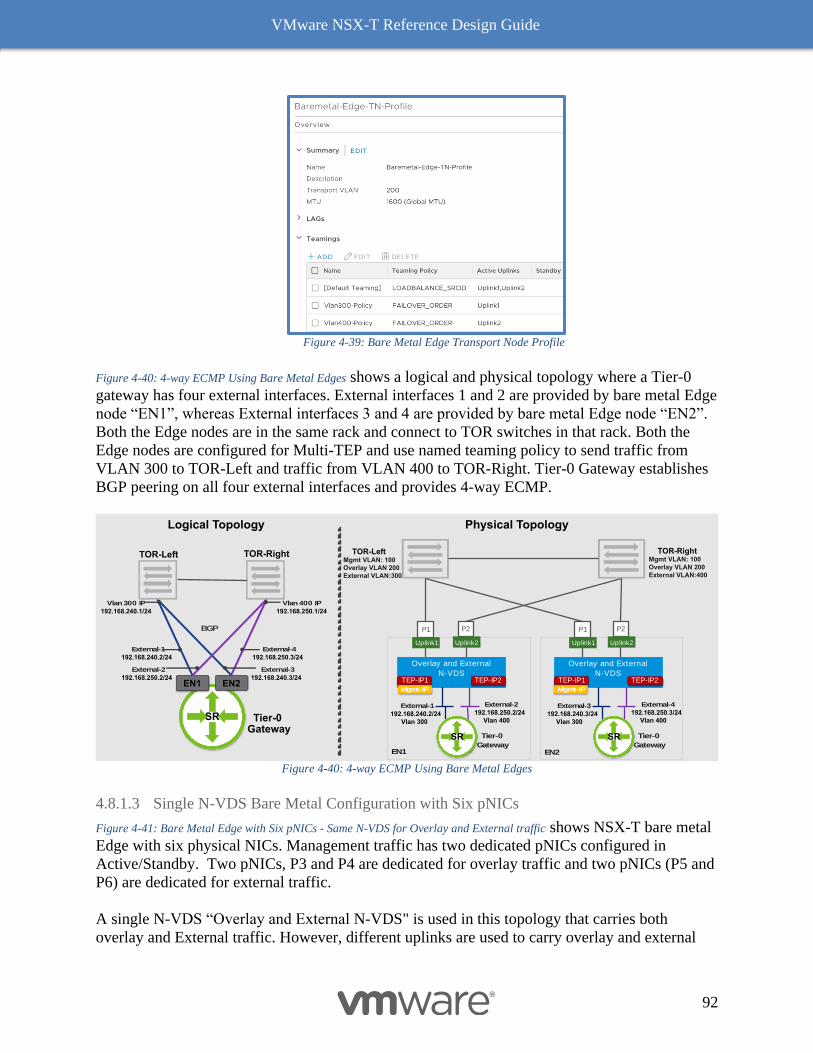
VMware NSX-T Reference Design Guide
92
Figure 4-39: Bare Metal Edge Transport Node Profile
Figure 4-40: 4-way ECMP Using Bare Metal Edges shows a logical and physical topology where a Tier-0
gateway has four external interfaces. External interfaces 1 and 2 are provided by bare metal Edge
node “EN1”, whereas External interfaces 3 and 4 are provided by bare metal Edge node “EN2”.
Both the Edge nodes are in the same rack and connect to TOR switches in that rack. Both the
Edge nodes are configured for Multi-TEP and use named teaming policy to send traffic from
VLAN 300 to TOR-Left and traffic from VLAN 400 to TOR-Right. Tier-0 Gateway establishes
BGP peering on all four external interfaces and provides 4-way ECMP.
Figure 4-40: 4-way ECMP Using Bare Metal Edges
4.8.1.3 Single N-VDS Bare Metal Configuration with Six pNICs
Figure 4-41: Bare Metal Edge with Six pNICs - Same N-VDS for Overlay and External traffic shows NSX-T bare metal
Edge with six physical NICs. Management traffic has two dedicated pNICs configured in
Active/Standby. Two pNICs, P3 and P4 are dedicated for overlay traffic and two pNICs (P5 and
P6) are dedicated for external traffic.
A single N-VDS “Overlay and External N-VDS" is used in this topology that carries both
overlay and External traffic. However, different uplinks are used to carry overlay and external
Tier-0Gateway
SR
EN1 EN2
Logical Topology Physical Topology
External-1
192.168.240.2/24
External-2
192.168.250.2/24
P1
EN1
P2
Overlay and External
N-VDSTEP-IP1
Mgmt-IP
Uplink1 Uplink2
TEP-IP2
Tier-0
Gateway
TOR-LeftMgmt VLAN: 100
Overlay VLAN 200
External VLAN:300
TOR-RightMgmt VLAN: 100
Overlay VLAN 200
External VLAN:400
External-1
192.168.240.2/24
Vlan 300
External-2
192.168.250.2/24
Vlan 400
P1 P2
Overlay and External
N-VDSTEP-IP1
Mgmt-IP
Uplink1 Uplink2
TEP-IP2
Tier-0
Gateway
External-3
192.168.240.3/24
Vlan 300
External-4
192.168.250.3/24
Vlan 400
External-4
192.168.250.3/24
External-3
192.168.240.3/24
SR SR
BGP
Vlan 300 IP
192.168.240.1/24
Vlan 400 IP
192.168.250.1/24
EN2
TOR-Left TOR-Right
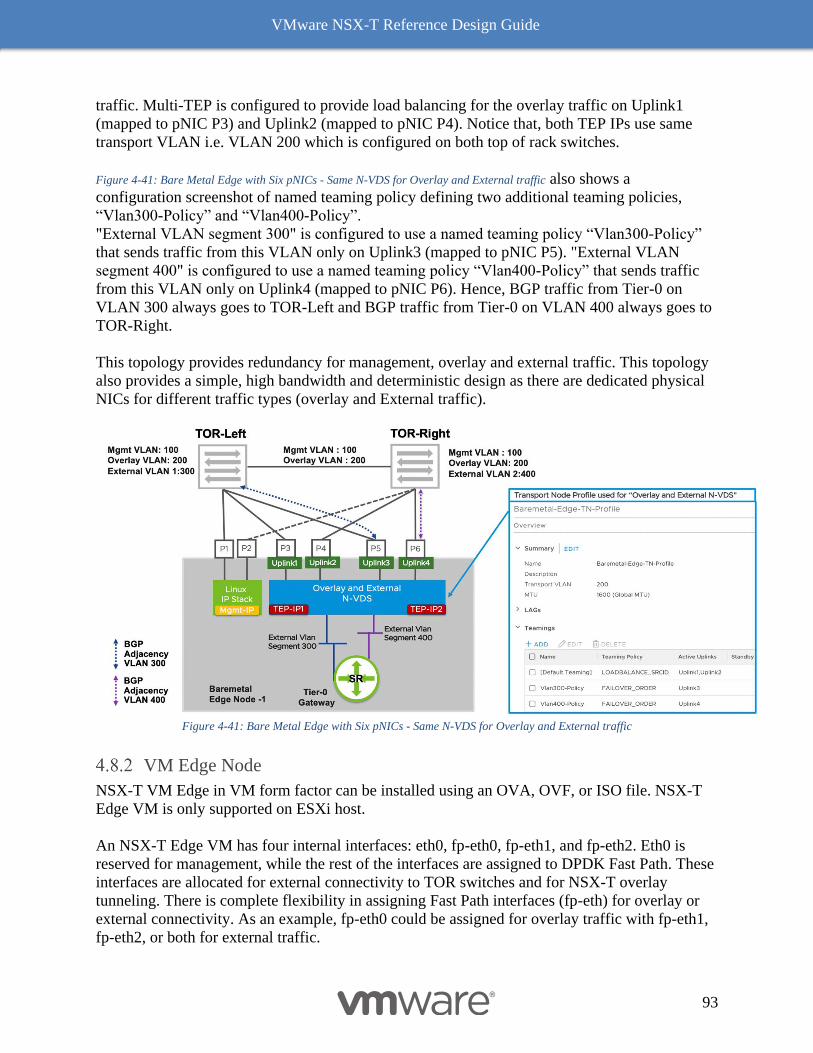
VMware NSX-T Reference Design Guide
93
traffic. Multi-TEP is configured to provide load balancing for the overlay traffic on Uplink1
(mapped to pNIC P3) and Uplink2 (mapped to pNIC P4). Notice that, both TEP IPs use same
transport VLAN i.e. VLAN 200 which is configured on both top of rack switches.
Figure 4-41: Bare Metal Edge with Six pNICs - Same N-VDS for Overlay and External traffic also shows a
configuration screenshot of named teaming policy defining two additional teaming policies,
“Vlan300-Policy” and “Vlan400-Policy”.
"External VLAN segment 300" is configured to use a named teaming policy “Vlan300-Policy”
that sends traffic from this VLAN only on Uplink3 (mapped to pNIC P5). "External VLAN
segment 400" is configured to use a named teaming policy “Vlan400-Policy” that sends traffic
from this VLAN only on Uplink4 (mapped to pNIC P6). Hence, BGP traffic from Tier-0 on
VLAN 300 always goes to TOR-Left and BGP traffic from Tier-0 on VLAN 400 always goes to
TOR-Right.
This topology provides redundancy for management, overlay and external traffic. This topology
also provides a simple, high bandwidth and deterministic design as there are dedicated physical
NICs for different traffic types (overlay and External traffic).
Figure 4-41: Bare Metal Edge with Six pNICs - Same N-VDS for Overlay and External traffic
VM Edge Node
NSX-T VM Edge in VM form factor can be installed using an OVA, OVF, or ISO file. NSX-T
Edge VM is only supported on ESXi host.
An NSX-T Edge VM has four internal interfaces: eth0, fp-eth0, fp-eth1, and fp-eth2. Eth0 is
reserved for management, while the rest of the interfaces are assigned to DPDK Fast Path. These
interfaces are allocated for external connectivity to TOR switches and for NSX-T overlay
tunneling. There is complete flexibility in assigning Fast Path interfaces (fp-eth) for overlay or
external connectivity. As an example, fp-eth0 could be assigned for overlay traffic with fp-eth1,
fp-eth2, or both for external traffic.
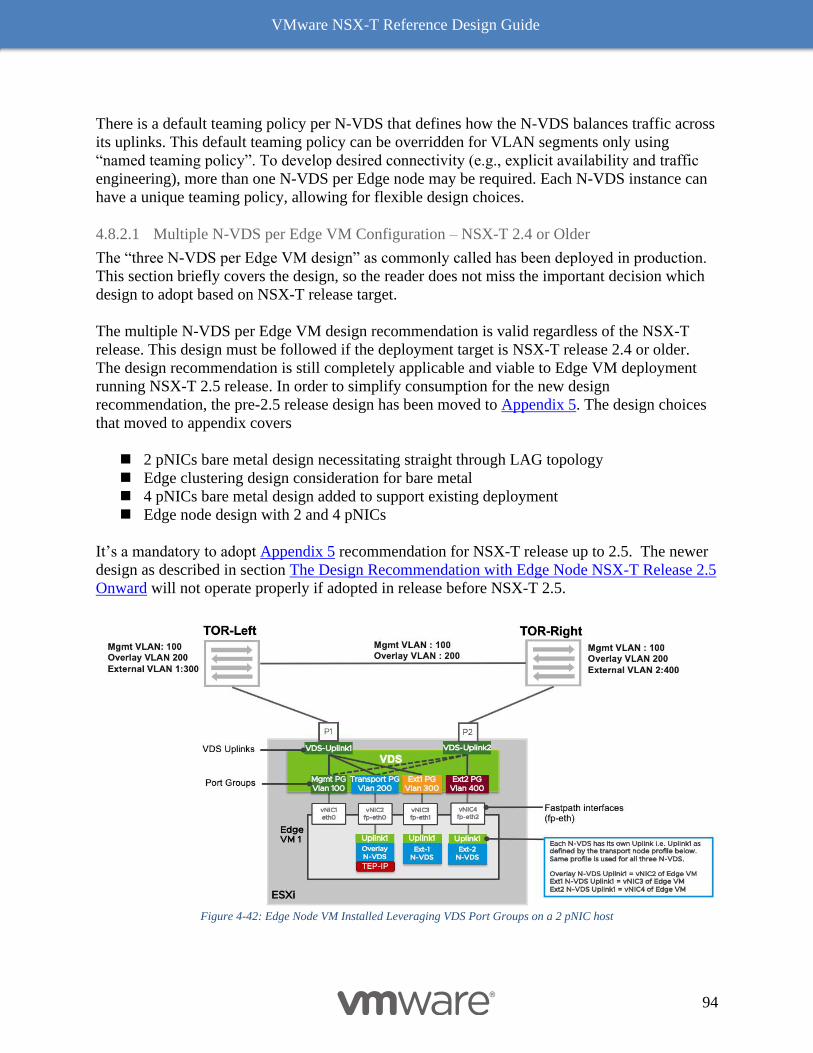
VMware NSX-T Reference Design Guide
94
There is a default teaming policy per N-VDS that defines how the N-VDS balances traffic across
its uplinks. This default teaming policy can be overridden for VLAN segments only using
“named teaming policy”. To develop desired connectivity (e.g., explicit availability and traffic
engineering), more than one N-VDS per Edge node may be required. Each N-VDS instance can
have a unique teaming policy, allowing for flexible design choices.
4.8.2.1 Multiple N-VDS per Edge VM Configuration – NSX-T 2.4 or Older
The “three N-VDS per Edge VM design” as commonly called has been deployed in production.
This section briefly covers the design, so the reader does not miss the important decision which
design to adopt based on NSX-T release target.
The multiple N-VDS per Edge VM design recommendation is valid regardless of the NSX-T
release. This design must be followed if the deployment target is NSX-T release 2.4 or older.
The design recommendation is still completely applicable and viable to Edge VM deployment
running NSX-T 2.5 release. In order to simplify consumption for the new design
recommendation, the pre-2.5 release design has been moved to Appendix 5. The design choices
that moved to appendix covers
◼ 2 pNICs bare metal design necessitating straight through LAG topology
◼ Edge clustering design consideration for bare metal
◼ 4 pNICs bare metal design added to support existing deployment
◼ Edge node design with 2 and 4 pNICs
It’s a mandatory to adopt Appendix 5 recommendation for NSX-T release up to 2.5. The newer
design as described in section The Design Recommendation with Edge Node NSX-T Release 2.5
Onward will not operate properly if adopted in release before NSX-T 2.5.
Figure 4-42: Edge Node VM Installed Leveraging VDS Port Groups on a 2 pNIC host
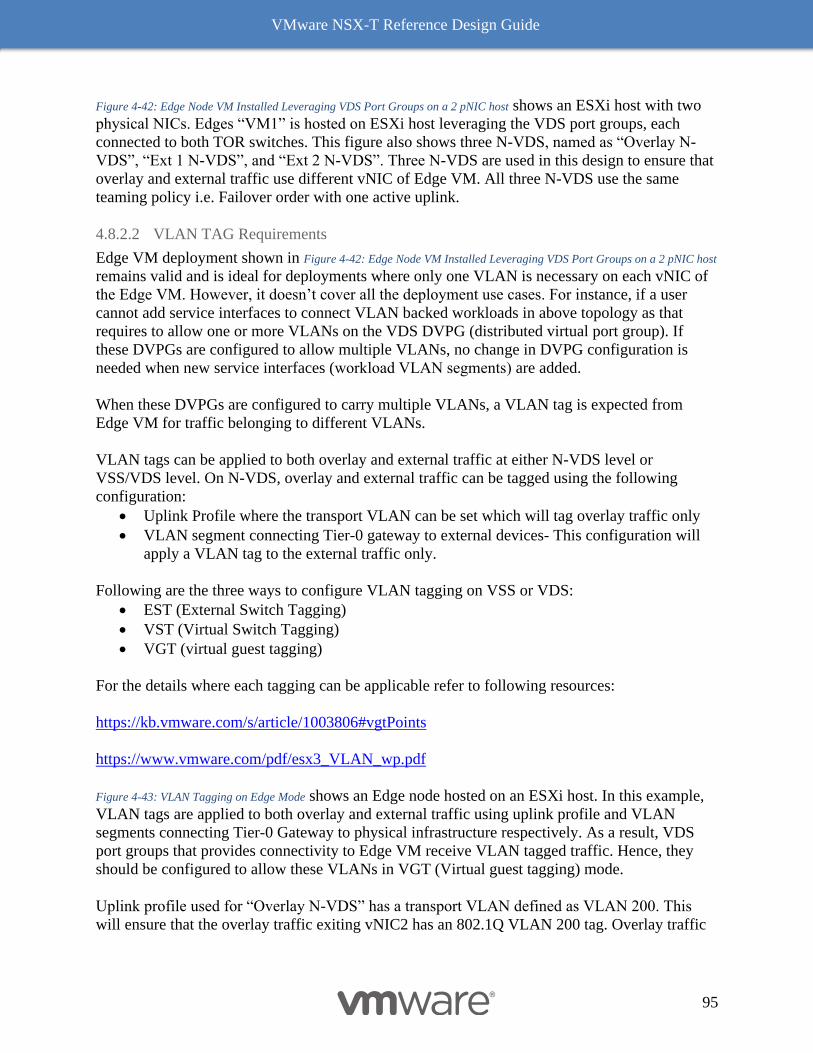
VMware NSX-T Reference Design Guide
95
Figure 4-42: Edge Node VM Installed Leveraging VDS Port Groups on a 2 pNIC host shows an ESXi host with two
physical NICs. Edges “VM1” is hosted on ESXi host leveraging the VDS port groups, each
connected to both TOR switches. This figure also shows three N-VDS, named as “Overlay N-
VDS”, “Ext 1 N-VDS”, and “Ext 2 N-VDS”. Three N-VDS are used in this design to ensure that
overlay and external traffic use different vNIC of Edge VM. All three N-VDS use the same
teaming policy i.e. Failover order with one active uplink.
4.8.2.2 VLAN TAG Requirements
Edge VM deployment shown in Figure 4-42: Edge Node VM Installed Leveraging VDS Port Groups on a 2 pNIC host
remains valid and is ideal for deployments where only one VLAN is necessary on each vNIC of
the Edge VM. However, it doesn’t cover all the deployment use cases. For instance, if a user
cannot add service interfaces to connect VLAN backed workloads in above topology as that
requires to allow one or more VLANs on the VDS DVPG (distributed virtual port group). If
these DVPGs are configured to allow multiple VLANs, no change in DVPG configuration is
needed when new service interfaces (workload VLAN segments) are added.
When these DVPGs are configured to carry multiple VLANs, a VLAN tag is expected from
Edge VM for traffic belonging to different VLANs.
VLAN tags can be applied to both overlay and external traffic at either N-VDS level or
VSS/VDS level. On N-VDS, overlay and external traffic can be tagged using the following
configuration:
• Uplink Profile where the transport VLAN can be set which will tag overlay traffic only
• VLAN segment connecting Tier-0 gateway to external devices- This configuration will
apply a VLAN tag to the external traffic only.
Following are the three ways to configure VLAN tagging on VSS or VDS:
• EST (External Switch Tagging)
• VST (Virtual Switch Tagging)
• VGT (virtual guest tagging)
For the details where each tagging can be applicable refer to following resources:
https://kb.vmware.com/s/article/1003806#vgtPoints
https://www.vmware.com/pdf/esx3_VLAN_wp.pdf
Figure 4-43: VLAN Tagging on Edge Mode shows an Edge node hosted on an ESXi host. In this example,
VLAN tags are applied to both overlay and external traffic using uplink profile and VLAN
segments connecting Tier-0 Gateway to physical infrastructure respectively. As a result, VDS
port groups that provides connectivity to Edge VM receive VLAN tagged traffic. Hence, they
should be configured to allow these VLANs in VGT (Virtual guest tagging) mode.
Uplink profile used for “Overlay N-VDS” has a transport VLAN defined as VLAN 200. This
will ensure that the overlay traffic exiting vNIC2 has an 802.1Q VLAN 200 tag. Overlay traffic
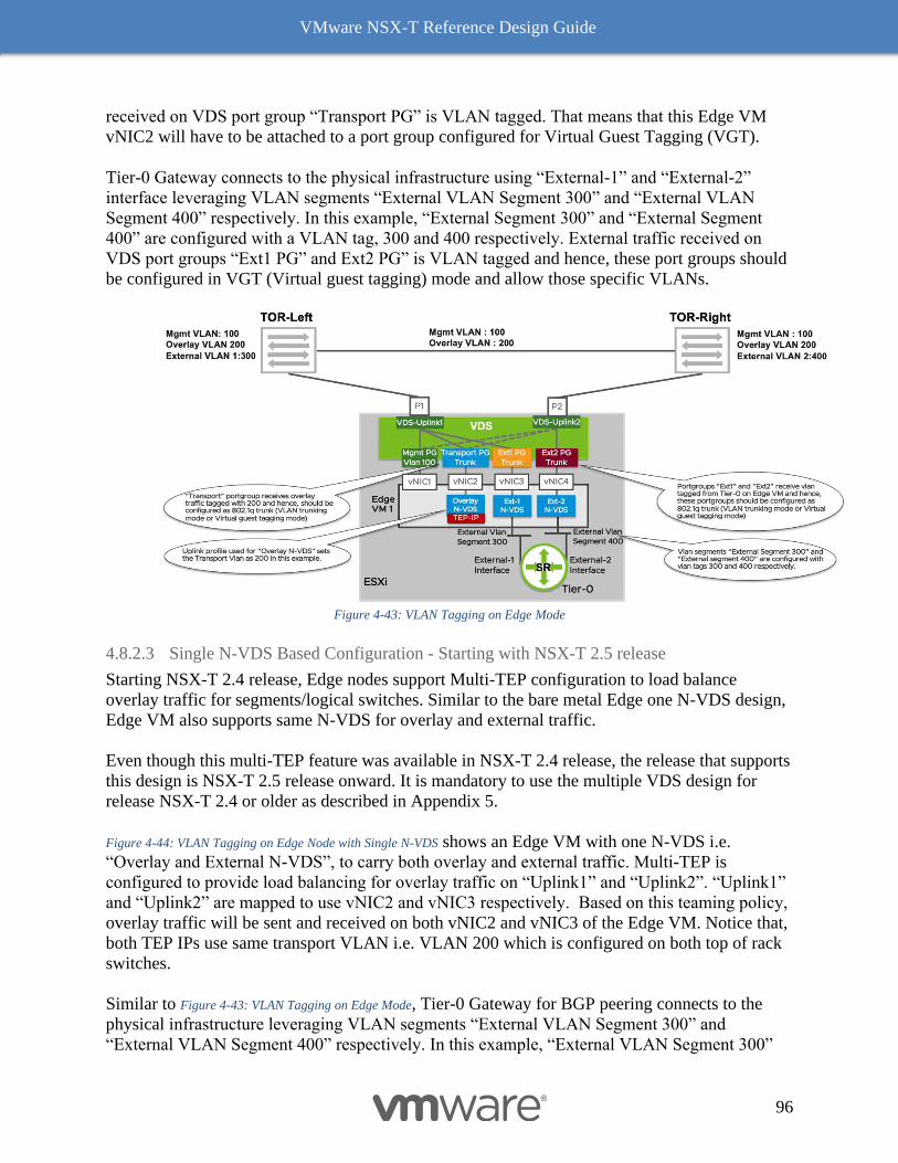
VMware NSX-T Reference Design Guide
96
received on VDS port group “Transport PG” is VLAN tagged. That means that this Edge VM
vNIC2 will have to be attached to a port group configured for Virtual Guest Tagging (VGT).
Tier-0 Gateway connects to the physical infrastructure using “External-1” and “External-2”
interface leveraging VLAN segments “External VLAN Segment 300” and “External VLAN
Segment 400” respectively. In this example, “External Segment 300” and “External Segment
400” are configured with a VLAN tag, 300 and 400 respectively. External traffic received on
VDS port groups “Ext1 PG” and Ext2 PG” is VLAN tagged and hence, these port groups should
be configured in VGT (Virtual guest tagging) mode and allow those specific VLANs.
Figure 4-43: VLAN Tagging on Edge Mode
4.8.2.3 Single N-VDS Based Configuration - Starting with NSX-T 2.5 release
Starting NSX-T 2.4 release, Edge nodes support Multi-TEP configuration to load balance
overlay traffic for segments/logical switches. Similar to the bare metal Edge one N-VDS design,
Edge VM also supports same N-VDS for overlay and external traffic.
Even though this multi-TEP feature was available in NSX-T 2.4 release, the release that supports
this design is NSX-T 2.5 release onward. It is mandatory to use the multiple VDS design for
release NSX-T 2.4 or older as described in Appendix 5.
Figure 4-44: VLAN Tagging on Edge Node with Single N-VDS shows an Edge VM with one N-VDS i.e.
“Overlay and External N-VDS”, to carry both overlay and external traffic. Multi-TEP is
configured to provide load balancing for overlay traffic on “Uplink1” and “Uplink2”. “Uplink1”
and “Uplink2” are mapped to use vNIC2 and vNIC3 respectively. Based on this teaming policy,
overlay traffic will be sent and received on both vNIC2 and vNIC3 of the Edge VM. Notice that,
both TEP IPs use same transport VLAN i.e. VLAN 200 which is configured on both top of rack
switches.
Similar to Figure 4-43: VLAN Tagging on Edge Mode, Tier-0 Gateway for BGP peering connects to the
physical infrastructure leveraging VLAN segments “External VLAN Segment 300” and
“External VLAN Segment 400” respectively. In this example, “External VLAN Segment 300”
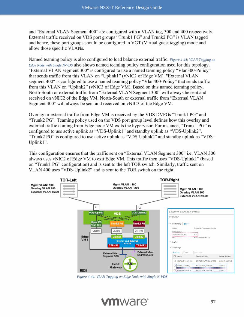
VMware NSX-T Reference Design Guide
97
and “External VLAN Segment 400” are configured with a VLAN tag, 300 and 400 respectively.
External traffic received on VDS port groups “Trunk1 PG” and Trunk2 PG” is VLAN tagged
and hence, these port groups should be configured in VGT (Virtual guest tagging) mode and
allow those specific VLANs.
Named teaming policy is also configured to load balance external traffic. Figure 4-44: VLAN Tagging on
Edge Node with Single N-VDS also shows named teaming policy configuration used for this topology.
"External VLAN segment 300" is configured to use a named teaming policy “Vlan300-Policy”
that sends traffic from this VLAN on “Uplink1” (vNIC2 of Edge VM). "External VLAN
segment 400" is configured to use a named teaming policy “Vlan400-Policy” that sends traffic
from this VLAN on “Uplink2” (vNIC3 of Edge VM). Based on this named teaming policy,
North-South or external traffic from “External VLAN Segment 300” will always be sent and
received on vNIC2 of the Edge VM. North-South or external traffic from “External VLAN
Segment 400” will always be sent and received on vNIC3 of the Edge VM.
Overlay or external traffic from Edge VM is received by the VDS DVPGs “Trunk1 PG” and
“Trunk2 PG”. Teaming policy used on the VDS port group level defines how this overlay and
external traffic coming from Edge node VM exits the hypervisor. For instance, “Trunk1 PG” is
configured to use active uplink as “VDS-Uplink1” and standby uplink as “VDS-Uplink2”.
“Trunk2 PG” is configured to use active uplink as “VDS-Uplink2” and standby uplink as “VDS-
Uplink1”.
This configuration ensures that the traffic sent on “External VLAN Segment 300” i.e. VLAN 300
always uses vNIC2 of Edge VM to exit Edge VM. This traffic then uses “VDS-Uplink1” (based
on “Trunk1 PG” configuration) and is sent to the left TOR switch. Similarly, traffic sent on
VLAN 400 uses “VDS-Uplink2” and is sent to the TOR switch on the right.
Figure 4-44: VLAN Tagging on Edge Node with Single N-VDS
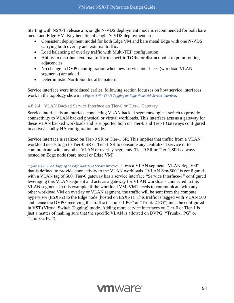
VMware NSX-T Reference Design Guide
98
Starting with NSX-T release 2.5, single N-VDS deployment mode is recommended for both bare
metal and Edge VM. Key benefits of single N-VDS deployment are:
• Consistent deployment model for both Edge VM and bare metal Edge with one N-VDS
carrying both overlay and external traffic.
• Load balancing of overlay traffic with Multi-TEP configuration.
• Ability to distribute external traffic to specific TORs for distinct point to point routing
adjacencies.
• No change in DVPG configuration when new service interfaces (workload VLAN
segments) are added.
• Deterministic North South traffic pattern.
Service interface were introduced earlier, following section focusses on how service interfaces
work in the topology shown in Figure 4-45: VLAN Tagging on Edge Node with Service Interface.
4.8.2.4 VLAN Backed Service Interface on Tier-0 or Tier-1 Gateway
Service interface is an interface connecting VLAN backed segments/logical switch to provide
connectivity to VLAN backed physical or virtual workloads. This interface acts as a gateway for
these VLAN backed workloads and is supported both on Tier-0 and Tier-1 Gateways configured
in active/standby HA configuration mode.
Service interface is realized on Tier-0 SR or Tier-1 SR. This implies that traffic from a VLAN
workload needs to go to Tier-0 SR or Tier-1 SR to consume any centralized service or to
communicate with any other VLAN or overlay segments. Tier-0 SR or Tier-1 SR is always
hosted on Edge node (bare metal or Edge VM).
Figure 4-45: VLAN Tagging on Edge Node with Service Interface shows a VLAN segment “VLAN Seg-500”
that is defined to provide connectivity to the VLAN workloads. “VLAN Seg-500” is configured
with a VLAN tag of 500. Tier-0 gateway has a service interface “Service Interface-1” configured
leveraging this VLAN segment and acts as a gateway for VLAN workloads connected to this
VLAN segment. In this example, if the workload VM, VM1 needs to communicate with any
other workload VM on overlay or VLAN segment, the traffic will be sent from the compute
hypervisor (ESXi-2) to the Edge node (hosted on ESXi-1). This traffic is tagged with VLAN 500
and hence the DVPG receiving this traffic (“Trunk-1 PG” or “Trunk-2 PG”) must be configured
in VST (Virtual Switch Tagging) mode. Adding more service interfaces on Tier-0 or Tier-1 is
just a matter of making sure that the specific VLAN is allowed on DVPG (“Trunk-1 PG” or
“Trunk-2 PG”).
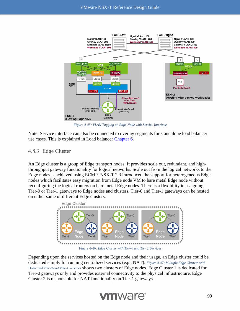
VMware NSX-T Reference Design Guide
99
Figure 4-45: VLAN Tagging on Edge Node with Service Interface
Note: Service interface can also be connected to overlay segments for standalone load balancer
use cases. This is explained in Load balancer Chapter 6.
Edge Cluster
An Edge cluster is a group of Edge transport nodes. It provides scale out, redundant, and high-
throughput gateway functionality for logical networks. Scale out from the logical networks to the
Edge nodes is achieved using ECMP. NSX-T 2.3 introduced the support for heterogeneous Edge
nodes which facilitates easy migration from Edge node VM to bare metal Edge node without
reconfiguring the logical routers on bare metal Edge nodes. There is a flexibility in assigning
Tier-0 or Tier-1 gateways to Edge nodes and clusters. Tier-0 and Tier-1 gateways can be hosted
on either same or different Edge clusters.
Figure 4-46: Edge Cluster with Tier-0 and Tier 1 Services
Depending upon the services hosted on the Edge node and their usage, an Edge cluster could be
dedicated simply for running centralized services (e.g., NAT). Figure 4-47: Multiple Edge Clusters with
Dedicated Tier-0 and Tier-1 Services shows two clusters of Edge nodes. Edge Cluster 1 is dedicated for
Tier-0 gateways only and provides external connectivity to the physical infrastructure. Edge
Cluster 2 is responsible for NAT functionality on Tier-1 gateways.
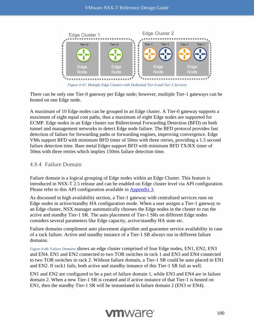
VMware NSX-T Reference Design Guide
100
Figure 4-47: Multiple Edge Clusters with Dedicated Tier-0 and Tier-1 Services
There can be only one Tier-0 gateway per Edge node; however, multiple Tier-1 gateways can be
hosted on one Edge node.
A maximum of 10 Edge nodes can be grouped in an Edge cluster. A Tier-0 gateway supports a
maximum of eight equal cost paths, thus a maximum of eight Edge nodes are supported for
ECMP. Edge nodes in an Edge cluster run Bidirectional Forwarding Detection (BFD) on both
tunnel and management networks to detect Edge node failure. The BFD protocol provides fast
detection of failure for forwarding paths or forwarding engines, improving convergence. Edge
VMs support BFD with minimum BFD timer of 50ms with three retries, providing a 1.5 second
failure detection time. Bare metal Edges support BFD with minimum BFD TX/RX timer of
50ms with three retries which implies 150ms failure detection time.
Failure Domain
Failure domain is a logical grouping of Edge nodes within an Edge Cluster. This feature is
introduced in NSX-T 2.5 release and can be enabled on Edge cluster level via API configuration.
Please refer to this API configuration available in Appendix 3.
As discussed in high availability section, a Tier-1 gateway with centralized services runs on
Edge nodes in active/standby HA configuration mode. When a user assigns a Tier-1 gateway to
an Edge cluster, NSX manager automatically chooses the Edge nodes in the cluster to run the
active and standby Tier-1 SR. The auto placement of Tier-1 SRs on different Edge nodes
considers several parameters like Edge capacity, active/standby HA state etc.
Failure domains compliment auto placement algorithm and guarantee service availability in case
of a rack failure. Active and standby instance of a Tier-1 SR always run in different failure
domains.
Figure 4-48: Failure Domains shows an edge cluster comprised of four Edge nodes, EN1, EN2, EN3
and EN4. EN1 and EN2 connected to two TOR switches in rack 1 and EN3 and EN4 connected
to two TOR switches in rack 2. Without failure domain, a Tier-1 SR could be auto placed in EN1
and EN2. If rack1 fails, both active and standby instance of this Tier-1 SR fail as well.
EN1 and EN2 are configured to be a part of failure domain 1, while EN3 and EN4 are in failure
domain 2. When a new Tier-1 SR is created and if active instance of that Tier-1 is hosted on
EN1, then the standby Tier-1 SR will be instantiated in failure domain 2 (EN3 or EN4).

VMware NSX-T Reference Design Guide
101
Figure 4-48: Failure Domains
To ensure that all Tier-1 services are active on a set of edge nodes, a user can also enforce that
all active Tier-1 SRs are placed in one failure domain. This configuration is supported for Tier-1
gateway in preemptive mode only.
Other Network Services
Unicast Reverse Path Forwarding (uRPF)
A router forwards packets based on the value of the destination IP address field that is present in
the IP header. The source IP address field is generally not used when forwarding a packet on a
network (except when networks implement source-based routing). Unicast Reverse Path
Forwarding is defined in RFC 2827 and 3704. It prevents packets with spoofed source IP address
to be forwarded in the network. uRPF is generally enabled on a router per interface and not
globally. A uRPF enabled router will inspect the source IP address of each packet received on an
interface. When a packet arrives on an interface, the router will verify if the receiving that
specific interface would be used to reach the source of the packet. It will discard the packets if
the received and routing table interfaces are different. This protection prevents spoofed source IP
address attacks that are commonly used by sending packets with random source IP addresses.
Figure 4-49 – uRPF diagrams a physical network with uRPF enabled on the core router.
1- The core router receives a packet with a source IP address of 10.1.1.1 on interface
ethernet0/2.
2- The core router has the uRPF feature enabled on all its interfaces and will check in its
routing table if the source IP address of the packet would be routed through interface
ethernet 0/2. In this case, 10.1.1.1 is the source IP address present in the IP header. The
core router has a longest prefix match for 10.1.1.0/24 via interface ethernet 0/0.
3- Since the packet does not come from the interface ethernet 0/0, the packet will be
discarded.
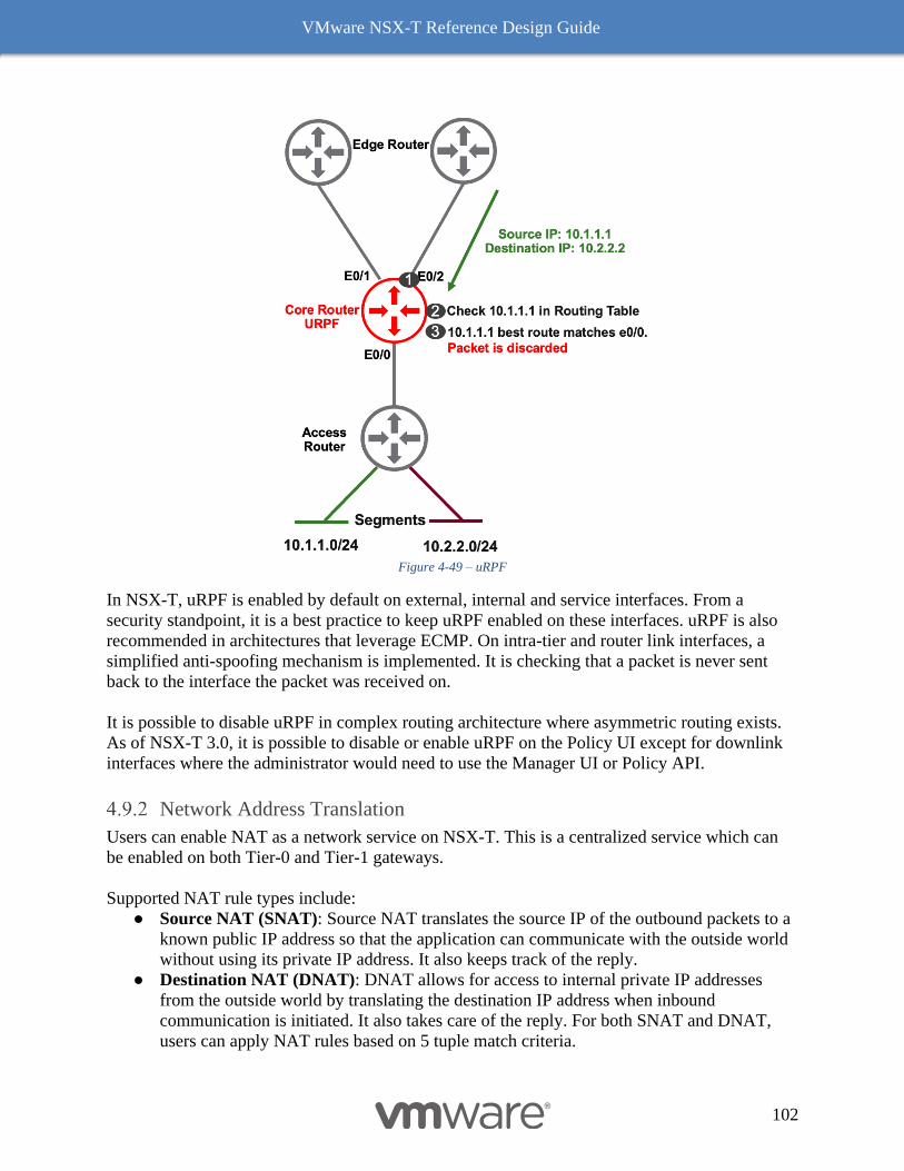
VMware NSX-T Reference Design Guide
102
Figure 4-49 – uRPF
In NSX-T, uRPF is enabled by default on external, internal and service interfaces. From a
security standpoint, it is a best practice to keep uRPF enabled on these interfaces. uRPF is also
recommended in architectures that leverage ECMP. On intra-tier and router link interfaces, a
simplified anti-spoofing mechanism is implemented. It is checking that a packet is never sent
back to the interface the packet was received on.
It is possible to disable uRPF in complex routing architecture where asymmetric routing exists.
As of NSX-T 3.0, it is possible to disable or enable uRPF on the Policy UI except for downlink
interfaces where the administrator would need to use the Manager UI or Policy API.
Network Address Translation
Users can enable NAT as a network service on NSX-T. This is a centralized service which can
be enabled on both Tier-0 and Tier-1 gateways.
Supported NAT rule types include:
● Source NAT (SNAT): Source NAT translates the source IP of the outbound packets to a
known public IP address so that the application can communicate with the outside world
without using its private IP address. It also keeps track of the reply.
● Destination NAT (DNAT): DNAT allows for access to internal private IP addresses
from the outside world by translating the destination IP address when inbound
communication is initiated. It also takes care of the reply. For both SNAT and DNAT,
users can apply NAT rules based on 5 tuple match criteria.
VMware NSX-T Reference Design Guide
103
● Reflexive NAT: Reflexive NAT rules are stateless ACLs which must be defined in both
directions. These do not keep track of the connection. Reflexive NAT rules can be used
in cases where stateful NAT cannot be used due to asymmetric paths (e.g., user needs to
enable NAT on active/active ECMP routers).
Table 4-3: NAT Usage Guidelines summarizes NAT rules and usage restrictions.
NAT Rules
Type Type Specific Usage Guidelines
Stateful Source NAT (SNAT)
Destination NAT (DNAT)
Can be enabled on both Tier-0 and Tier-1
gateways
Stateless Reflexive NAT Can be enabled on Tier-0 gateway; generally
used when the Tier-0 is in active/active mode.
Table 4-3: NAT Usage Guidelines
Table 4-4: Tier-0 and Tier-1 NAT Use Cases summarizes the use cases and advantages of running NAT on
Tier-0 and Tier-1 gateways.
Gateway Type NAT Rule
Type Specific Usage Guidelines
Tier-0 Stateful
Recommended for TAS/TKGI deployments.
E-W routing between different tenants remains completely
distributed.
Tier-1 Stateful
Recommended for high throughput ECMP topologies.
Recommended for topologies with overlapping IP address
space.
Table 4-4: Tier-0 and Tier-1 NAT Use Cases
NAT Service Router Placement
As a centralized service, whenever NAT is enabled, a service component or SR must be
instantiated on an Edge cluster. In order to configure NAT, specify the Edge cluster where the
service should run; it is also possible the NAT service on a specific Edge node pair. If no specific
Edge node is identified, the platform will perform auto placement of the services component on
an Edge node in the cluster using a weighted round robin algorithm.
DHCP Services
NSX-T provides both DHCP relay and DHCP server functionality. DHCP relay can be enabled
at the gateway level and can act as relay between non-NSX managed environment and DHCP
servers. DHCP server functionality can be enabled to service DHCP requests from VMs
connected to NSX-managed segments. DHCP server functionality is a stateful service and must
be bound to an Edge cluster or a specific pair of Edge nodes as with NAT functionality.
VMware NSX-T Reference Design Guide
104
Metadata Proxy Service
With a metadata proxy server, VM instances can retrieve instance-specific metadata from an
OpenStack Nova API server. This functionality is specific to OpenStack use-cases only.
Metadata proxy service runs as a service on an NSX Edge node. For high availability, configure
metadata proxy to run on two or more NSX Edge nodes in an NSX Edge cluster.
Gateway Firewall Service
Gateway Firewall service can be enabled on the Tier-0 and Tier-1 gateway for North-South
firewalling. Table 4-5 summarizes Gateway Firewalling usage criteria.
Gateway Firewall Specific Usage Guidelines
Stateful Can be enabled on both Tier-0 and Tier-1 gateways.
Stateless Can be enabled on Tier-0 gateway; generally used when the Tier-0 is in
active/active mode.
Table 4-5: Gateway Firewall Usage Guideline
Since Gateway Firewalling is a centralized service, it needs to run on an Edge cluster or a set of
Edge nodes. This service is described in more detail in the NSX-T Security chapter.
Proxy ARP
Proxy ARP is a method that consist of answering an ARP request on behalf of another host. This
method is performed by a layer 3 networking device (usually a router). The purpose is to provide
connectivity between 2 hosts when routing wouldn’t be possible for various reasons.
Proxy ARP in an NSX-T infrastructure can be considered in environments where IP subnets are
limited. Proof of concepts and VMware Enterprise TKGI (PKS) environments are usually using
Proxy-ARP to simplify the network topology.
For production environment, it is recommended to implement proper routing between a physical
fabric and the NSX-T Tier-0 by using either static routes or Border Gateway Protocol with BFD.
If proper routing is used between the Tier-0 gateway and the physical fabric, BFD with its sub-
second timers will converge faster. In case of failover with proxy ARP, the convergence relies on
gratuitous ARP (broadcast) to update all hosts on the VLAN segment with the new MAC
Address to use. If the Tier-0 gateway has proxy ARP enabled for 100 IP addresses, the newly
active Tier-0 SR needs to send 100 Gratuitous ARP packets.
Edge Node HA Specific Usage Guidelines
Active / Standby Supported
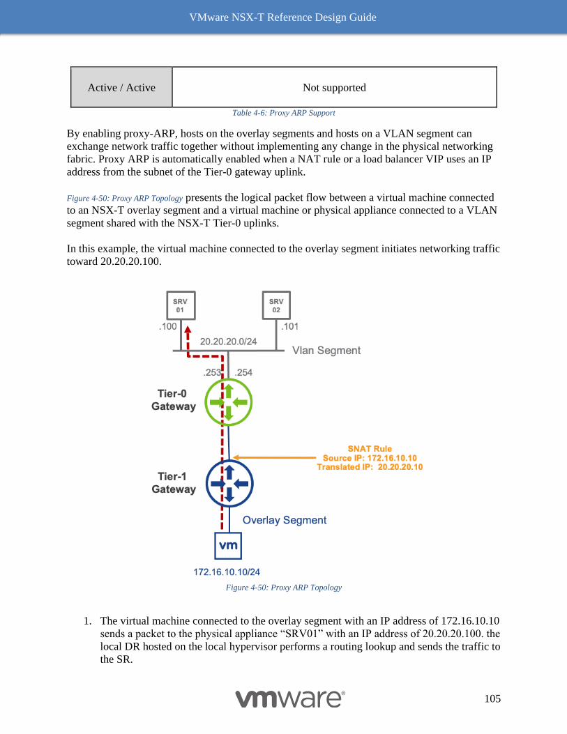
VMware NSX-T Reference Design Guide
105
Active / Active Not supported
Table 4-6: Proxy ARP Support
By enabling proxy-ARP, hosts on the overlay segments and hosts on a VLAN segment can
exchange network traffic together without implementing any change in the physical networking
fabric. Proxy ARP is automatically enabled when a NAT rule or a load balancer VIP uses an IP
address from the subnet of the Tier-0 gateway uplink.
Figure 4-50: Proxy ARP Topology presents the logical packet flow between a virtual machine connected
to an NSX-T overlay segment and a virtual machine or physical appliance connected to a VLAN
segment shared with the NSX-T Tier-0 uplinks.
In this example, the virtual machine connected to the overlay segment initiates networking traffic
toward 20.20.20.100.
Figure 4-50: Proxy ARP Topology
1. The virtual machine connected to the overlay segment with an IP address of 172.16.10.10
sends a packet to the physical appliance “SRV01” with an IP address of 20.20.20.100. the
local DR hosted on the local hypervisor performs a routing lookup and sends the traffic to
the SR.
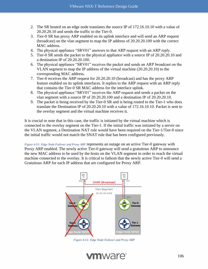
VMware NSX-T Reference Design Guide
106
2. The SR hosted on an edge node translates the source IP of 172.16.10.10 with a value of
20.20.20.10 and sends the traffic to the Tier-0.
3. Tier-0 SR has proxy ARP enabled on its uplink interface and will send an ARP request
(broadcast) on the vlan segment to map the IP address of 20.20.20.100 with the correct
MAC address.
4. The physical appliance “SRV01” answers to that ARP request with an ARP reply.
5. Tier-0 SR sends the packet to the physical appliance with a source IP of 20.20.20.10 and
a destination IP of 20.20.20.100.
6. The physical appliance “SRV01” receives the packet and sends an ARP broadcast on the
VLAN segment to map the IP address of the virtual machine (20.20.20.10) to the
corresponding MAC address.
7. Tier-0 receives the ARP request for 20.20.20.10 (broadcast) and has the proxy ARP
feature enabled on its uplink interfaces. It replies to the ARP request with an ARP reply
that contains the Tier-0 SR MAC address for the interface uplink.
8. The physical appliance “SRV01” receives the ARP request and sends a packet on the
vlan segment with a source IP of 20.20.20.100 and a destination IP of 20.20.20.10.
9. The packet is being received by the Tier-0 SR and is being routed to the Tier-1 who does
translate the Destination IP of 20.20.20.10 with a value of 172.16.10.10. Packet is sent to
the overlay segment and the virtual machine receives it.
It is crucial to note that in this case, the traffic is initiated by the virtual machine which is
connected to the overlay segment on the Tier-1. If the initial traffic was initiated by a server on
the VLAN segment, a Destination NAT rule would have been required on the Tier-1/Tier-0 since
the initial traffic would not match the SNAT rule that has been configured previously.
Figure 4-51: Edge Node Failover and Proxy ARP represents an outage on an active Tier-0 gateway with
Proxy ARP enabled. The newly active Tier-0 gateway will send a gratuitous ARP to announce
the new MAC address to be used by the hosts on the VLAN segment in order to reach the virtual
machine connected to the overlay. It is critical to fathom that the newly active Tier-0 will send a
Gratuitous ARP for each IP address that are configured for Proxy ARP.
Figure 4-51: Edge Node Failover and Proxy ARP

VMware NSX-T Reference Design Guide
107
Topology Consideration
This section covers a few of the many topologies that customers can build with NSX-T. NSX-T
routing components - Tier-1 and Tier-0 gateways - enable flexible deployment of multi-tiered
routing topologies. Topology design also depends on what services are enabled and where those
services are provided at the provider or tenant level.
Supported Topologies
Figure 4-52: Single Tier and Multi-tier Routing Topologies shows three topologies with Tier-0 gateway
providing N-S traffic connectivity via multiple Edge nodes. The first topology is single-tiered
where Tier-0 gateway connects directly to the segments and provides E-W routing between
subnets. Tier-0 gateway provides multiple active paths for N-S L3 forwarding using ECMP. The
second topology shows the multi-tiered approach where Tier-0 gateway provides multiple active
paths for L3 forwarding using ECMP and Tier-1 gateways as first hops for the segments
connected to them. Routing is fully distributed in this multi-tier topology. The third topology
shows a multi-tiered topology with Tier-0 gateway configured in Active/Standby HA mode to
provide some centralized or stateful services like NAT, VPN etc.
Figure 4-52: Single Tier and Multi-tier Routing Topologies
As discussed in the two-tier routing section, centralized services can be enabled on Tier-1 or
Tier-0 gateway level. Figure 4-52: Single Tier and Multi-tier Routing Topologies shows two multi-tiered
topologies. The first topology shows centralized services like NAT, load balancer on Tier-1
gateways while Tier-0 gateway provides multiple active paths for L3 forwarding using ECMP.
The second topology shows centralized services configured on a Tier-1 and Tier-0 gateway. In
NSX-T 2.4 release or earlier, some centralized services are only available on Tier-1 like load
balancer and other only on Tier-0 like VPN. Starting NSX-T 2.5 release, below topology can be
used where requirement is to use both Load balancer and VPN service on NSX-T. Note that
VPN is available on Tier-1 gateways starting NSX-T 2.5 release.
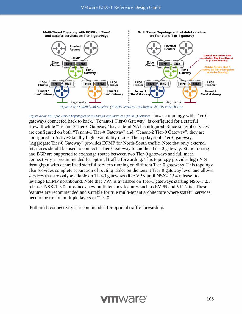
VMware NSX-T Reference Design Guide
108
Figure 4-53: Stateful and Stateless (ECMP) Services Topologies Choices at Each Tier
Figure 4-54: Multiple Tier-0 Topologies with Stateful and Stateless (ECMP) Services shows a topology with Tier-0
gateways connected back to back. “Tenant-1 Tier-0 Gateway” is configured for a stateful
firewall while “Tenant-2 Tier-0 Gateway” has stateful NAT configured. Since stateful services
are configured on both “Tenant-1 Tier-0 Gateway” and “Tenant-2 Tier-0 Gateway”, they are
configured in Active/Standby high availability mode. The top layer of Tier-0 gateway,
"Aggregate Tier-0 Gateway” provides ECMP for North-South traffic. Note that only external
interfaces should be used to connect a Tier-0 gateway to another Tier-0 gateway. Static routing
and BGP are supported to exchange routes between two Tier-0 gateways and full mesh
connectivity is recommended for optimal traffic forwarding. This topology provides high N-S
throughput with centralized stateful services running on different Tier-0 gateways. This topology
also provides complete separation of routing tables on the tenant Tier-0 gateway level and allows
services that are only available on Tier-0 gateways (like VPN until NSX-T 2.4 release) to
leverage ECMP northbound. Note that VPN is available on Tier-1 gateways starting NSX-T 2.5
release. NSX-T 3.0 introduces new multi tenancy features such as EVPN and VRF-lite. These
features are recommended and suitable for true multi-tenant architecture where stateful services
need to be run on multiple layers or Tier-0
Full mesh connectivity is recommended for optimal traffic forwarding.
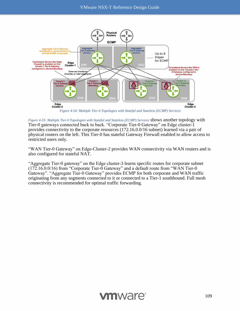
VMware NSX-T Reference Design Guide
109
Figure 4-54: Multiple Tier-0 Topologies with Stateful and Stateless (ECMP) Services
Figure 4-55: Multiple Tier-0 Topologies with Stateful and Stateless (ECMP) Services shows another topology with Tier-0 gateways connected back to back. “Corporate Tier-0 Gateway” on Edge cluster-1 provides connectivity to the corporate resources (172.16.0.0/16 subnet) learned via a pair of physical routers on the left. This Tier-0 has stateful Gateway Firewall enabled to allow access to restricted users only.
“WAN Tier-0 Gateway” on Edge-Cluster-2 provides WAN connectivity via WAN routers and is also configured for stateful NAT.
“Aggregate Tier-0 gateway” on the Edge cluster-3 learns specific routes for corporate subnet (172.16.0.0/16) from “Corporate Tier-0 Gateway” and a default route from “WAN Tier-0 Gateway”. “Aggregate Tier-0 Gateway” provides ECMP for both corporate and WAN traffic originating from any segments connected to it or connected to a Tier-1 southbound. Full mesh connectivity is recommended for optimal traffic forwarding.
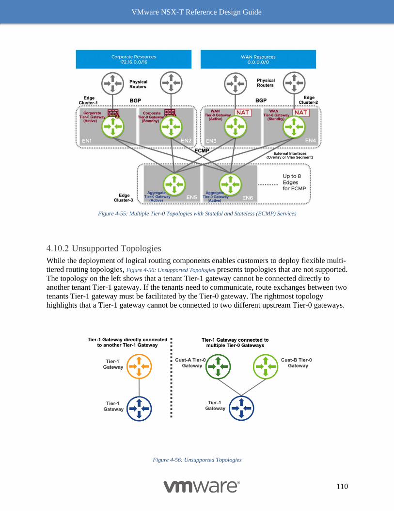
VMware NSX-T Reference Design Guide
110
Figure 4-55: Multiple Tier-0 Topologies with Stateful and Stateless (ECMP) Services
Unsupported Topologies
While the deployment of logical routing components enables customers to deploy flexible multi-
tiered routing topologies, Figure 4-56: Unsupported Topologies presents topologies that are not supported.
The topology on the left shows that a tenant Tier-1 gateway cannot be connected directly to
another tenant Tier-1 gateway. If the tenants need to communicate, route exchanges between two
tenants Tier-1 gateway must be facilitated by the Tier-0 gateway. The rightmost topology
highlights that a Tier-1 gateway cannot be connected to two different upstream Tier-0 gateways.
Figure 4-56: Unsupported Topologies
VMware NSX-T Reference Design Guide
111
5 NSX-T Security In addition to providing network virtualization, NSX-T also serves as an advanced security
platform, providing a rich set of features to streamline the deployment of security solutions. This
chapter focuses on NSX-T security capabilities, architecture, components, and implementation.
Key concepts for examination include:
● NSX-T distributed firewall (DFW) provides stateful protection of the workload at the
vNIC level. For ESXi, the DFW enforcement occurs in the hypervisor kernel, helping
deliver micro-segmentation. However, the DFW extends to physical servers, KVM
hypervisors, containers, and public clouds providing distributed policy enforcement.
● Uniform security policy model for on-premises and cloud deployment, supporting multi-
hypervisor (i.e., ESXi and KVM) and multi-workload, with a level of granularity down to
VM/containers/bare metal attributes.
● Agnostic to compute domain - supporting hypervisors managed by different compute-
managers while allowing any defined micro-segmentation policy to be applied across
hypervisors spanning multiple vCenter environments.
● Support for Layer 3, Layer 4, Layer-7 APP-ID, & Identity based firewall policies provide
security via protocol, port, and or deeper packet/session intelligence to suit diverse needs.
● NSX-T Gateway firewall serves as a centralized stateful firewall service for N-S traffic.
Gateway firewall is implemented per gateway and supported at both Tier-0 and Tier-1.
Gateway firewall is independent of NSX-T DFW from policy configuration and
enforcement perspective, providing a means for defining perimeter security control in
addition to distributed security control.
● Gateway & Distributed Firewall Service insertion capability to integrate existing security
investments using integration with partner ecosystem products on a granular basis
without the need for interrupting natural traffic flows.
● Distributed IDS extends IDS capabilities to every host in the environment.
● Dynamic grouping of objects into logical constructs called Groups based on various
criteria including tag, virtual machine name or operating system, subnet, and segments
which automates policy application.
● The scope of policy enforcement can be selective, with application or workload-level
granularity.
● Firewall Flood Protection capability to protect the workload & hypervisor resources.
● IP discovery mechanism dynamically identifies workload addressing.
● SpoofGuard blocks IP spoofing at vNIC level.
● Switch Security provides storm control and security against unauthorized traffic.
NSX-T Security Use Cases
The NSX-T security platform is designed to address the security challenges faced by IT admins.
Although it started with firewalling, the NSX-T security feature set has since grown to
encompass Identity Firewalling, IPS, and many more. The NSX-T firewall is delivered as part of
a distributed platform that offers ubiquitous enforcement, scalability, line rate performance,
multi-hypervisor support, and API-driven orchestration. These fundamental pillars of the NSX-T
firewall allow it to address many different use cases for production deployment.
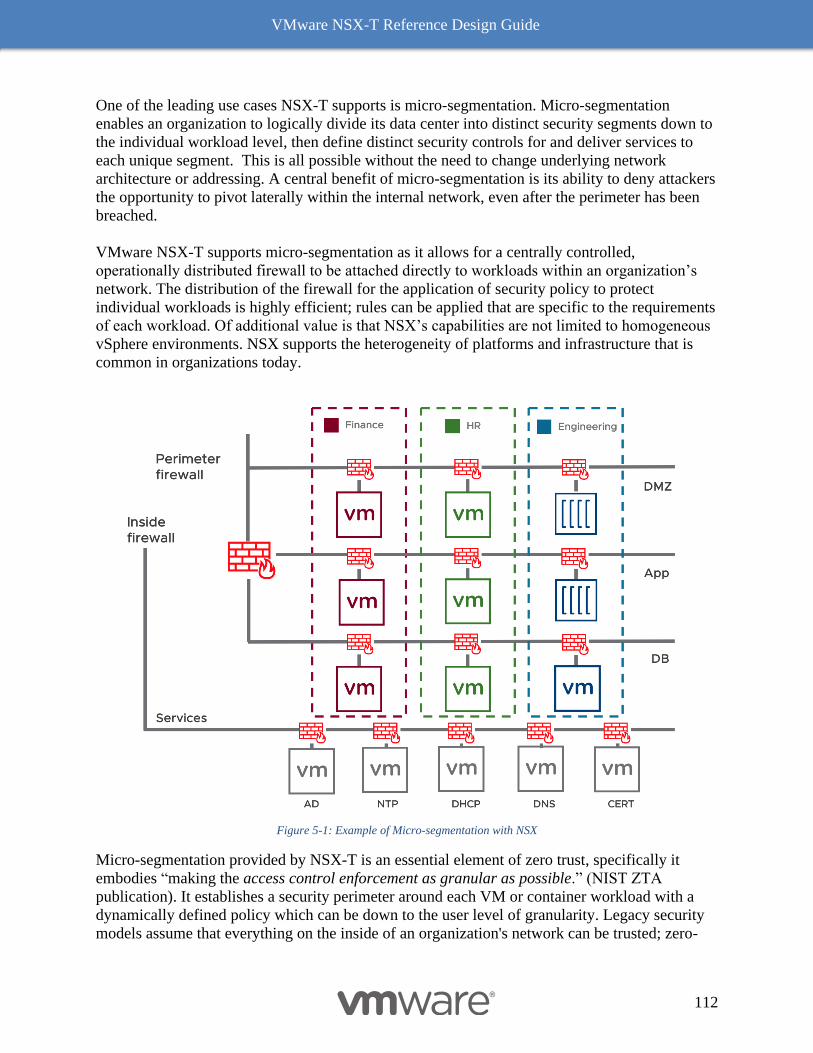
VMware NSX-T Reference Design Guide
112
One of the leading use cases NSX-T supports is micro-segmentation. Micro-segmentation
enables an organization to logically divide its data center into distinct security segments down to
the individual workload level, then define distinct security controls for and deliver services to
each unique segment. This is all possible without the need to change underlying network
architecture or addressing. A central benefit of micro-segmentation is its ability to deny attackers
the opportunity to pivot laterally within the internal network, even after the perimeter has been
breached.
VMware NSX-T supports micro-segmentation as it allows for a centrally controlled,
operationally distributed firewall to be attached directly to workloads within an organization’s
network. The distribution of the firewall for the application of security policy to protect
individual workloads is highly efficient; rules can be applied that are specific to the requirements
of each workload. Of additional value is that NSX’s capabilities are not limited to homogeneous
vSphere environments. NSX supports the heterogeneity of platforms and infrastructure that is
common in organizations today.
Figure 5-1: Example of Micro-segmentation with NSX
Micro-segmentation provided by NSX-T is an essential element of zero trust, specifically it
embodies “making the access control enforcement as granular as possible.” (NIST ZTA
publication). It establishes a security perimeter around each VM or container workload with a
dynamically defined policy which can be down to the user level of granularity. Legacy security
models assume that everything on the inside of an organization's network can be trusted; zero-
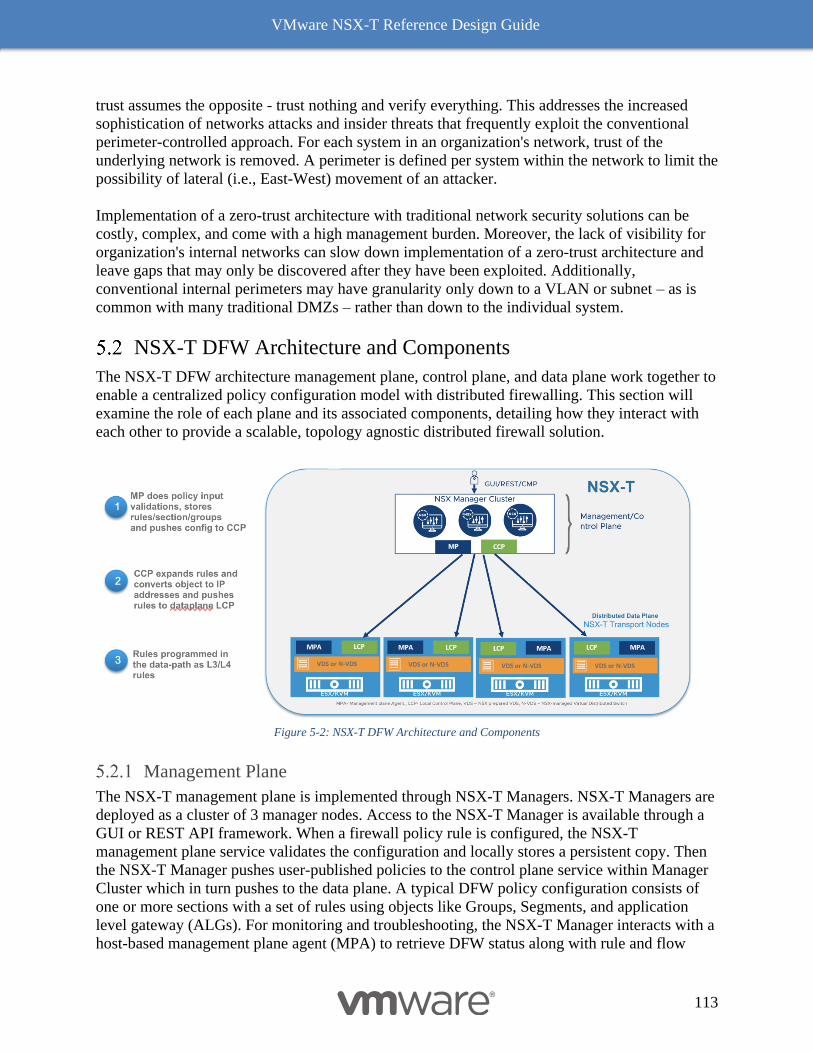
VMware NSX-T Reference Design Guide
113
trust assumes the opposite - trust nothing and verify everything. This addresses the increased
sophistication of networks attacks and insider threats that frequently exploit the conventional
perimeter-controlled approach. For each system in an organization's network, trust of the
underlying network is removed. A perimeter is defined per system within the network to limit the
possibility of lateral (i.e., East-West) movement of an attacker.
Implementation of a zero-trust architecture with traditional network security solutions can be
costly, complex, and come with a high management burden. Moreover, the lack of visibility for
organization's internal networks can slow down implementation of a zero-trust architecture and
leave gaps that may only be discovered after they have been exploited. Additionally,
conventional internal perimeters may have granularity only down to a VLAN or subnet – as is
common with many traditional DMZs – rather than down to the individual system.
NSX-T DFW Architecture and Components
The NSX-T DFW architecture management plane, control plane, and data plane work together to
enable a centralized policy configuration model with distributed firewalling. This section will
examine the role of each plane and its associated components, detailing how they interact with
each other to provide a scalable, topology agnostic distributed firewall solution.
Figure 5-2: NSX-T DFW Architecture and Components
Management Plane
The NSX-T management plane is implemented through NSX-T Managers. NSX-T Managers are
deployed as a cluster of 3 manager nodes. Access to the NSX-T Manager is available through a
GUI or REST API framework. When a firewall policy rule is configured, the NSX-T
management plane service validates the configuration and locally stores a persistent copy. Then
the NSX-T Manager pushes user-published policies to the control plane service within Manager
Cluster which in turn pushes to the data plane. A typical DFW policy configuration consists of
one or more sections with a set of rules using objects like Groups, Segments, and application
level gateway (ALGs). For monitoring and troubleshooting, the NSX-T Manager interacts with a
host-based management plane agent (MPA) to retrieve DFW status along with rule and flow
VMware NSX-T Reference Design Guide
114
statistics. The NSX-T Manager also collects an inventory of all hosted virtualized workloads on
NSX-T transport nodes. This is dynamically collected and updated from all NSX-T transport
nodes.
Control Plane
The NSX-T control plane consists of two components - the central control plane (CCP) and the
Local Control Plane (LCP). The CCP is implemented on NSX-T Manager Cluster, while the
LCP includes the user space module on all of the NSX-T transport nodes. This module interacts
with the CCP to exchange configuration and state information.
From a DFW policy configuration perspective, NSX-T Control plane will receive policy rules
pushed by the NSX-T Management plane. If the policy contains objects including segments or
Groups, it converts them into IP addresses using an object-to-IP mapping table. This table is
maintained by the control plane and updated using an IP discovery mechanism. Once the policy
is converted into a set of rules based on IP addresses, the CCP pushes the rules to the LCP on all
the NSX-T transport nodes.
The CCP utilizes a hierarchy system to distribute the load of CCP-to-LCP communication. The
responsibility for transport node notification is distributed across the managers in the manager
clusters based on an internal hashing mechanism. For example, for 30 transport nodes with three
managers, each manager will be responsible for roughly ten transport nodes.
Data Plane
The NSX-T transport nodes comprise the distributed data plane with DFW enforcement done at
the hypervisor kernel level. Each of the transport nodes, at any given time, connects to only one
of the CCP managers, based on mastership for that node. On each of the transport nodes, once
the local control plane (LCP) has received policy configuration from CCP, it pushes the firewall
policy and rules to the data plane filters (in kernel) for each of the virtual NICs. With the
“Applied To” field in the rule or section which defines scope of enforcement, the LCP makes
sure only relevant DFW rules are programmed on relevant virtual NICs instead of every rule
everywhere, which would be a suboptimal use of hypervisor resources. Additional details on data
plane components for both ESXi and KVM hosts explained in following sections.
NSX-T Data Plane Implementation - ESXi vs. KVM Hosts
NSX-T provides network virtualization and security services in a heterogeneous hypervisor
environment, managing ESXi and KVM hosts as part of the same NSX-T cluster. The DFW is
functionally identical in both environments; however, there are architectural and implementation
differences depending on the hypervisor specifics.
Management and control plane components are identical for both ESXi and KVM hosts. For the
data plane, they use a different implementation for packet handling. NSX-T uses either the VDS
in ESXi 7.0 and later or the N-VDS (which is derived from the VDS) on earlier ESXi hosts,
along with the VMware Internetworking Service Insertion Platform (vSIP) kernel module for
firewalling. (For details on the differences between the N-VDS and the VDS, see NSX-T Logical
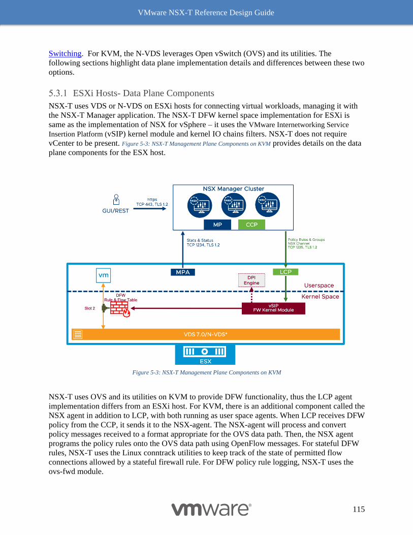
VMware NSX-T Reference Design Guide
115
Switching. For KVM, the N-VDS leverages Open vSwitch (OVS) and its utilities. The
following sections highlight data plane implementation details and differences between these two
options.
ESXi Hosts- Data Plane Components
NSX-T uses VDS or N-VDS on ESXi hosts for connecting virtual workloads, managing it with
the NSX-T Manager application. The NSX-T DFW kernel space implementation for ESXi is
same as the implementation of NSX for vSphere – it uses the VMware Internetworking Service
Insertion Platform (vSIP) kernel module and kernel IO chains filters. NSX-T does not require
vCenter to be present. Figure 5-3: NSX-T Management Plane Components on KVM provides details on the data
plane components for the ESX host.
Figure 5-3: NSX-T Management Plane Components on KVM
NSX-T uses OVS and its utilities on KVM to provide DFW functionality, thus the LCP agent
implementation differs from an ESXi host. For KVM, there is an additional component called the
NSX agent in addition to LCP, with both running as user space agents. When LCP receives DFW
policy from the CCP, it sends it to the NSX-agent. The NSX-agent will process and convert
policy messages received to a format appropriate for the OVS data path. Then, the NSX agent
programs the policy rules onto the OVS data path using OpenFlow messages. For stateful DFW
rules, NSX-T uses the Linux conntrack utilities to keep track of the state of permitted flow
connections allowed by a stateful firewall rule. For DFW policy rule logging, NSX-T uses the
ovs-fwd module.
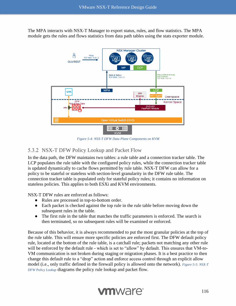
VMware NSX-T Reference Design Guide
116
The MPA interacts with NSX-T Manager to export status, rules, and flow statistics. The MPA
module gets the rules and flows statistics from data path tables using the stats exporter module.
Figure 5-4: NSX-T DFW Data Plane Components on KVM
NSX-T DFW Policy Lookup and Packet Flow
In the data path, the DFW maintains two tables: a rule table and a connection tracker table. The
LCP populates the rule table with the configured policy rules, while the connection tracker table
is updated dynamically to cache flows permitted by rule table. NSX-T DFW can allow for a
policy to be stateful or stateless with section-level granularity in the DFW rule table. The
connection tracker table is populated only for stateful policy rules; it contains no information on
stateless policies. This applies to both ESXi and KVM environments.
NSX-T DFW rules are enforced as follows:
● Rules are processed in top-to-bottom order.
● Each packet is checked against the top rule in the rule table before moving down the
subsequent rules in the table.
● The first rule in the table that matches the traffic parameters is enforced. The search is
then terminated, so no subsequent rules will be examined or enforced.
Because of this behavior, it is always recommended to put the most granular policies at the top of
the rule table. This will ensure more specific policies are enforced first. The DFW default policy
rule, located at the bottom of the rule table, is a catchall rule; packets not matching any other rule
will be enforced by the default rule - which is set to “allow” by default. This ensures that VM-to-
VM communication is not broken during staging or migration phases. It is a best practice to then
change this default rule to a “drop” action and enforce access control through an explicit allow
model (i.e., only traffic defined in the firewall policy is allowed onto the network). Figure 5-5: NSX-T
DFW Policy Lookup diagrams the policy rule lookup and packet flow.
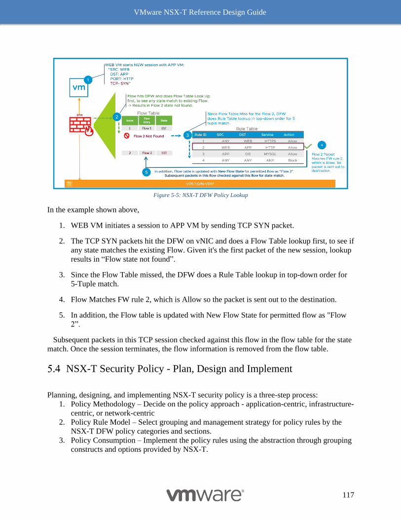
VMware NSX-T Reference Design Guide
117
Figure 5-5: NSX-T DFW Policy Lookup
In the example shown above,
1. WEB VM initiates a session to APP VM by sending TCP SYN packet.
2. The TCP SYN packets hit the DFW on vNIC and does a Flow Table lookup first, to see if
any state matches the existing Flow. Given it's the first packet of the new session, lookup
results in “Flow state not found”.
3. Since the Flow Table missed, the DFW does a Rule Table lookup in top-down order for
5-Tuple match.
4. Flow Matches FW rule 2, which is Allow so the packet is sent out to the destination.
5. In addition, the Flow table is updated with New Flow State for permitted flow as "Flow
2”.
Subsequent packets in this TCP session checked against this flow in the flow table for the state
match. Once the session terminates, the flow information is removed from the flow table.
NSX-T Security Policy - Plan, Design and Implement
Planning, designing, and implementing NSX-T security policy is a three-step process:
1. Policy Methodology – Decide on the policy approach - application-centric, infrastructure-
centric, or network-centric
2. Policy Rule Model – Select grouping and management strategy for policy rules by the
NSX-T DFW policy categories and sections.
3. Policy Consumption – Implement the policy rules using the abstraction through grouping
constructs and options provided by NSX-T.
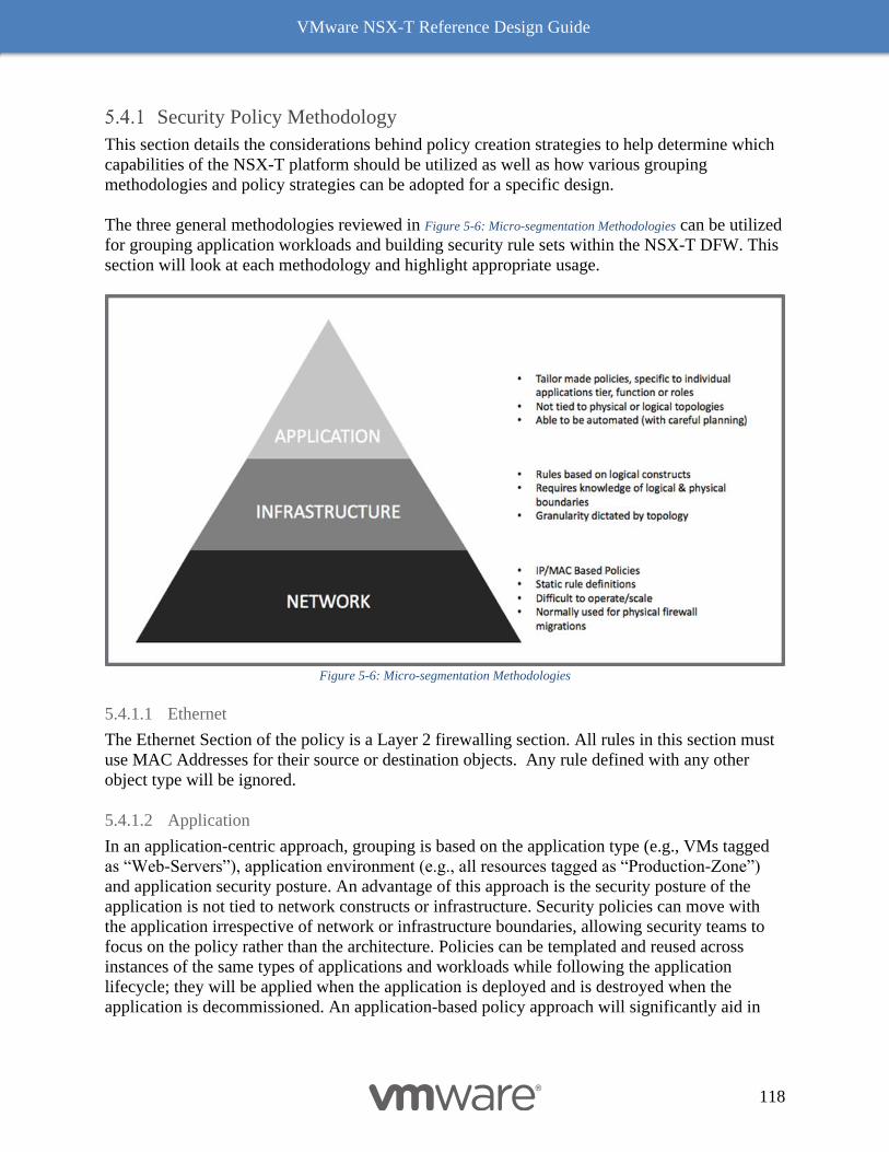
VMware NSX-T Reference Design Guide
118
Security Policy Methodology
This section details the considerations behind policy creation strategies to help determine which
capabilities of the NSX-T platform should be utilized as well as how various grouping
methodologies and policy strategies can be adopted for a specific design.
The three general methodologies reviewed in Figure 5-6: Micro-segmentation Methodologies can be utilized
for grouping application workloads and building security rule sets within the NSX-T DFW. This
section will look at each methodology and highlight appropriate usage.
Figure 5-6: Micro-segmentation Methodologies
5.4.1.1 Ethernet
The Ethernet Section of the policy is a Layer 2 firewalling section. All rules in this section must
use MAC Addresses for their source or destination objects. Any rule defined with any other
object type will be ignored.
5.4.1.2 Application
In an application-centric approach, grouping is based on the application type (e.g., VMs tagged
as “Web-Servers”), application environment (e.g., all resources tagged as “Production-Zone”)
and application security posture. An advantage of this approach is the security posture of the
application is not tied to network constructs or infrastructure. Security policies can move with
the application irrespective of network or infrastructure boundaries, allowing security teams to
focus on the policy rather than the architecture. Policies can be templated and reused across
instances of the same types of applications and workloads while following the application
lifecycle; they will be applied when the application is deployed and is destroyed when the
application is decommissioned. An application-based policy approach will significantly aid in
VMware NSX-T Reference Design Guide
119
moving towards a self-service IT model. In an environment where there is strong adherence to a
strict naming convention, the VM substring grouping option allows for simple policy definition.
An application-centric model does not provide significant benefits in an environment that is
static, lacks mobility, and has infrastructure functions that are properly demarcated.
5.4.1.3 Infrastructure
Infrastructure-centric grouping is based on infrastructure components such as segments or
segment ports, identifying where application VMs are connected. Security teams must work
closely with the network administrators to understand logical and physical boundaries.
If there are no physical or logical boundaries in the environment, then an infrastructure-centric
approach is not suitable.
5.4.1.4 Network
Network-centric is the traditional approach of grouping based on L2 or L3 elements. Grouping
can be done based on MAC addresses, IP addresses, or a combination of both. NSX-T supports
this approach of grouping objects. A security team needs to aware of networking infrastructure to
deploy network-based policies. There is a high probability of security rule sprawl as grouping
based on dynamic attributes is not used. This method of grouping works well for migrating
existing rules from an existing firewall.
A network-centric approach is not recommended in dynamic environments where there is a rapid
rate of infrastructure change or VM addition/deletion.
Security Rule Model
Policy rule models in a data center are essential to achieve optimal micro-segmentation
strategies. The first criteria in developing a policy model is to align with the natural boundaries
in the data center, such as tiers of application, SLAs, isolation requirements, and zonal access
restrictions. Associating a top-level zone or boundary to a policy helps apply consistent, yet
flexible control.
Global changes for a zone can be applied via single policy; however, within the zone there could
be a secondary policy with sub-grouping mapping to a specific sub-zone. An example production
zone might itself be carved into sub-zones like PCI or HIPAA. There are also zones for each
department as well as shared services. Zoning creates relationships between various groups,
providing basic segmentation and policy strategies.
A second criterion in developing policy models is identifying reactions to security events and
workflows. If a vulnerability is discovered, what are the mitigation strategies? Where is the
source of the exposure – internal or external? Is the exposure limited to a specific application or
operating system version?
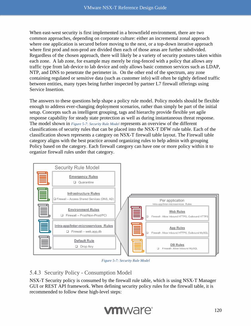
VMware NSX-T Reference Design Guide
120
When east-west security is first implemented in a brownfield environment, there are two
common approaches, depending on corporate culture: either an incremental zonal approach
where one application is secured before moving to the next, or a top-down iterative approach
where first prod and non-prod are divided then each of those areas are further subdivided.
Regardless of the chosen approach, there will likely be a variety of security postures taken within
each zone. A lab zone, for example may merely be ring-fenced with a policy that allows any
traffic type from lab device to lab device and only allows basic common services such as LDAP,
NTP, and DNS to penetrate the perimeter in. On the other end of the spectrum, any zone
containing regulated or sensitive data (such as customer info) will often be tightly defined traffic
between entities, many types being further inspected by partner L7 firewall offerings using
Service Insertion.
The answers to these questions help shape a policy rule model. Policy models should be flexible
enough to address ever-changing deployment scenarios, rather than simply be part of the initial
setup. Concepts such as intelligent grouping, tags and hierarchy provide flexible yet agile
response capability for steady state protection as well as during instantaneous threat response.
The model shown in Figure 5-7: Security Rule Model represents an overview of the different
classifications of security rules that can be placed into the NSX-T DFW rule table. Each of the
classification shown represents a category on NSX-T firewall table layout. The Firewall table
category aligns with the best practice around organizing rules to help admin with grouping
Policy based on the category. Each firewall category can have one or more policy within it to
organize firewall rules under that category.
Figure 5-7: Security Rule Model
Security Policy - Consumption Model
NSX-T Security policy is consumed by the firewall rule table, which is using NSX-T Manager
GUI or REST API framework. When defining security policy rules for the firewall table, it is
recommended to follow these high-level steps:

VMware NSX-T Reference Design Guide
121
● VM Inventory Collection – Identify and organize a list of all hosted virtualized
workloads on NSX-T transport nodes. This is dynamically collected and saved by NSX-T
Manager as the nodes – ESXi or KVM – are added as NSX-T transport nodes.
● Tag Workload – Use VM inventory collection to organize VMs with one or more tags.
Each designation consists of scope and tag association of the workload to an application,
environment, or tenant. For example, a VM tag could be “Scope = Prod, Tag = web” or
“Scope=tenant-1, Tag = app-1”. Often, these categories will dive several layers deep
including BU, project, environment, and regulatory flags. When following the iterative
approach of segmentation, categories and tags can be added to entities with existing tags.
In the application centric approach, new categories can be added with each application.
● Group Workloads – Use the NSX-T logical grouping construct with dynamic or static
membership criteria based on VM name, tags, segment, segment port, IP’s, or other
attributes. NSX-T allows for thousands of groups based on tags, although rarely are more
than a dozen or so needed.
● Define Security Policy – Using the firewall rule table, define the security policy. Have
categories and policies to separate and identify emergency, infrastructure, environment,
and application-specific policy rules based on the rule model.
The methodology and rule model mentioned earlier would influence how to tag and group the
workloads as well as affect policy definition. The following sections offer more details on
grouping and firewall rule table construction with an example of grouping objects and defining
NSX-T DFW policy.
5.4.3.1 Group Creation Strategies
The most basic grouping strategy is creation of a group around every application which is hosted
in the NSX-T environment. Each 3-tier, 2-tier, or single-tier applications should have its own
security group to enable faster operationalization of micro-segmentation. When combined with a
basic rule restricting inter-application communication to only essential shared services (e.g.,
DNS, AD, DHCP server) this enforces granular security inside the perimeter. Once this basic
micro-segmentation is in place, the writing of per-application rules can begin.
Groups
NSX-T provides collection of referenceable objects represented in a construct called Groups.
The selection of a specific policy methodology approach – application, infrastructure, or network
– will help dictate how grouping construct is used. Groups allow abstraction of workload
grouping from the underlying infrastructure topology. This allows a security policy to be written
for either a workload or zone (e.g., PCI zone, DMZ, or production environment).
A Group is a logical construct that allows grouping into a common container of static (e.g.,
IPSet/NSX objects) and dynamic (e.g., VM names/VM tags) elements. This is a generic
construct which can be leveraged across a variety of NSX-T features where applicable.
Static criteria provide capability to manually include particular objects into the Group. For
dynamic inclusion criteria, Boolean logic can be used to create groups between various criteria.
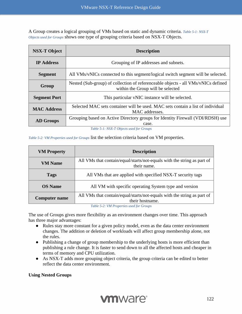
VMware NSX-T Reference Design Guide
122
A Group creates a logical grouping of VMs based on static and dynamic criteria. Table 5-1: NSX-T
Objects used for Groups shows one type of grouping criteria based on NSX-T Objects.
NSX-T Object Description
IP Address Grouping of IP addresses and subnets.
Segment All VMs/vNICs connected to this segment/logical switch segment will be selected.
Group Nested (Sub-group) of collection of referenceable objects - all VMs/vNICs defined
within the Group will be selected
Segment Port This particular vNIC instance will be selected.
MAC Address Selected MAC sets container will be used. MAC sets contain a list of individual
MAC addresses.
AD Groups Grouping based on Active Directory groups for Identity Firewall (VDI/RDSH) use
case. Table 5-1: NSX-T Objects used for Groups
Table 5-2: VM Properties used for Groups list the selection criteria based on VM properties.
VM Property Description
VM Name All VMs that contain/equal/starts/not-equals with the string as part of
their name.
Tags All VMs that are applied with specified NSX-T security tags
OS Name All VM with specific operating System type and version
Computer name All VMs that contain/equal/starts/not-equals with the string as part of
their hostname. Table 5-2: VM Properties used for Groups
The use of Groups gives more flexibility as an environment changes over time. This approach
has three major advantages:
● Rules stay more constant for a given policy model, even as the data center environment
changes. The addition or deletion of workloads will affect group membership alone, not
the rules.
● Publishing a change of group membership to the underlying hosts is more efficient than
publishing a rule change. It is faster to send down to all the affected hosts and cheaper in
terms of memory and CPU utilization.
● As NSX-T adds more grouping object criteria, the group criteria can be edited to better
reflect the data center environment.
Using Nested Groups
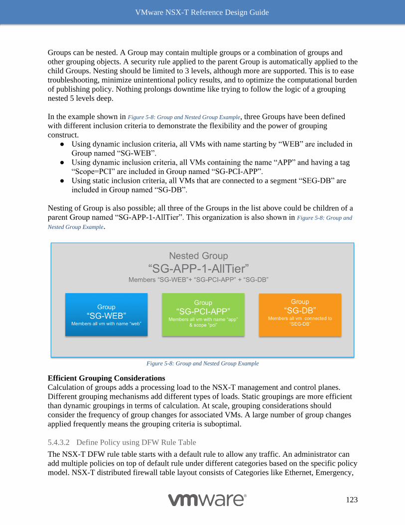
VMware NSX-T Reference Design Guide
123
Groups can be nested. A Group may contain multiple groups or a combination of groups and
other grouping objects. A security rule applied to the parent Group is automatically applied to the
child Groups. Nesting should be limited to 3 levels, although more are supported. This is to ease
troubleshooting, minimize unintentional policy results, and to optimize the computational burden
of publishing policy. Nothing prolongs downtime like trying to follow the logic of a grouping
nested 5 levels deep.
In the example shown in Figure 5-8: Group and Nested Group Example, three Groups have been defined
with different inclusion criteria to demonstrate the flexibility and the power of grouping
construct.
● Using dynamic inclusion criteria, all VMs with name starting by “WEB” are included in
Group named “SG-WEB”.
● Using dynamic inclusion criteria, all VMs containing the name “APP” and having a tag
“Scope=PCI” are included in Group named “SG-PCI-APP”.
● Using static inclusion criteria, all VMs that are connected to a segment “SEG-DB” are
included in Group named “SG-DB”.
Nesting of Group is also possible; all three of the Groups in the list above could be children of a
parent Group named “SG-APP-1-AllTier”. This organization is also shown in Figure 5-8: Group and
Nested Group Example.
Figure 5-8: Group and Nested Group Example
Efficient Grouping Considerations
Calculation of groups adds a processing load to the NSX-T management and control planes.
Different grouping mechanisms add different types of loads. Static groupings are more efficient
than dynamic groupings in terms of calculation. At scale, grouping considerations should
consider the frequency of group changes for associated VMs. A large number of group changes
applied frequently means the grouping criteria is suboptimal.
5.4.3.2 Define Policy using DFW Rule Table
The NSX-T DFW rule table starts with a default rule to allow any traffic. An administrator can
add multiple policies on top of default rule under different categories based on the specific policy
model. NSX-T distributed firewall table layout consists of Categories like Ethernet, Emergency,
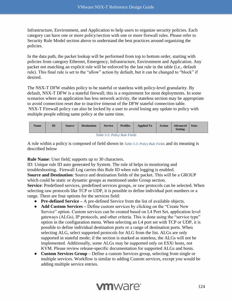
VMware NSX-T Reference Design Guide
124
Infrastructure, Environment, and Application to help users to organize security policies. Each
category can have one or more policy/section with one or more firewall rules. Please refer to
Security Rule Model section above to understand the best practices around organizing the
policies.
In the data path, the packet lookup will be performed from top to bottom order, starting with
policies from category Ethernet, Emergency, Infrastructure, Environment and Application. Any
packet not matching an explicit rule will be enforced by the last rule in the table (i.e., default
rule). This final rule is set to the “allow” action by default, but it can be changed to “block” if
desired.
The NSX-T DFW enables policy to be stateful or stateless with policy-level granularity. By
default, NSX-T DFW is a stateful firewall; this is a requirement for most deployments. In some
scenarios where an application has less network activity, the stateless section may be appropriate
to avoid connection reset due to inactive timeout of the DFW stateful connection table.
NSX-T Firewall policy can also be locked by a user to avoid losing any update to policy with
multiple people editing same policy at the same time.
Name ID Source Destination Service Profiles Applied To Action Advanced
Setting
Stats
Table 5-3: Policy Rule Fields
A rule within a policy is composed of field shown in Table 5-3: Policy Rule Fields and its meaning is
described below
Rule Name: User field; supports up to 30 characters.
ID: Unique rule ID auto generated by System. The rule id helps in monitoring and
troubleshooting. Firewall Log carries this Rule ID when rule logging is enabled.
Source and Destination: Source and destination fields of the packet. This will be a GROUP
which could be static or dynamic groups as mentioned under Group section.
Service: Predefined services, predefined services groups, or raw protocols can be selected. When
selecting raw protocols like TCP or UDP, it is possible to define individual port numbers or a
range. There are four options for the services field:
● Pre-defined Service – A pre-defined Service from the list of available objects.
● Add Custom Services – Define custom services by clicking on the “Create New
Service” option. Custom services can be created based on L4 Port Set, application level
gateways (ALGs), IP protocols, and other criteria. This is done using the “service type”
option in the configuration menu. When selecting an L4 port set with TCP or UDP, it is
possible to define individual destination ports or a range of destination ports. When
selecting ALG, select supported protocols for ALG from the list. ALGs are only
supported in stateful mode; if the section is marked as stateless, the ALGs will not be
implemented. Additionally, some ALGs may be supported only on ESXi hosts, not
KVM. Please review release-specific documentation for supported ALGs and hosts.
● Custom Services Group – Define a custom Services group, selecting from single or
multiple services. Workflow is similar to adding Custom services, except you would be
adding multiple service entries.
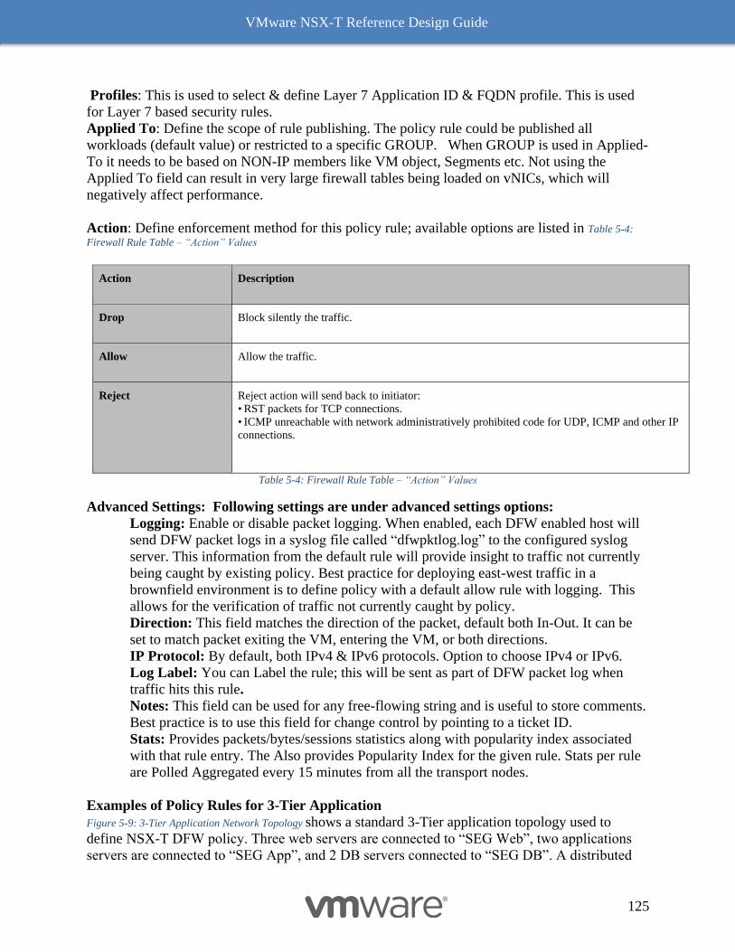
VMware NSX-T Reference Design Guide
125
Profiles: This is used to select & define Layer 7 Application ID & FQDN profile. This is used
for Layer 7 based security rules.
Applied To: Define the scope of rule publishing. The policy rule could be published all
workloads (default value) or restricted to a specific GROUP. When GROUP is used in Applied-
To it needs to be based on NON-IP members like VM object, Segments etc. Not using the
Applied To field can result in very large firewall tables being loaded on vNICs, which will
negatively affect performance.
Action: Define enforcement method for this policy rule; available options are listed in Table 5-4:
Firewall Rule Table – “Action” Values
Action Description
Drop Block silently the traffic.
Allow Allow the traffic.
Reject
Reject action will send back to initiator:
• RST packets for TCP connections.
• ICMP unreachable with network administratively prohibited code for UDP, ICMP and other IP
connections.
Table 5-4: Firewall Rule Table – “Action” Values
Advanced Settings: Following settings are under advanced settings options:
Logging: Enable or disable packet logging. When enabled, each DFW enabled host will
send DFW packet logs in a syslog file called “dfwpktlog.log” to the configured syslog
server. This information from the default rule will provide insight to traffic not currently
being caught by existing policy. Best practice for deploying east-west traffic in a
brownfield environment is to define policy with a default allow rule with logging. This
allows for the verification of traffic not currently caught by policy.
Direction: This field matches the direction of the packet, default both In-Out. It can be
set to match packet exiting the VM, entering the VM, or both directions.
IP Protocol: By default, both IPv4 & IPv6 protocols. Option to choose IPv4 or IPv6.
Log Label: You can Label the rule; this will be sent as part of DFW packet log when
traffic hits this rule.
Notes: This field can be used for any free-flowing string and is useful to store comments.
Best practice is to use this field for change control by pointing to a ticket ID.
Stats: Provides packets/bytes/sessions statistics along with popularity index associated
with that rule entry. The Also provides Popularity Index for the given rule. Stats per rule
are Polled Aggregated every 15 minutes from all the transport nodes.
Examples of Policy Rules for 3-Tier Application
Figure 5-9: 3-Tier Application Network Topology shows a standard 3-Tier application topology used to
define NSX-T DFW policy. Three web servers are connected to “SEG Web”, two applications
servers are connected to “SEG App”, and 2 DB servers connected to “SEG DB”. A distributed
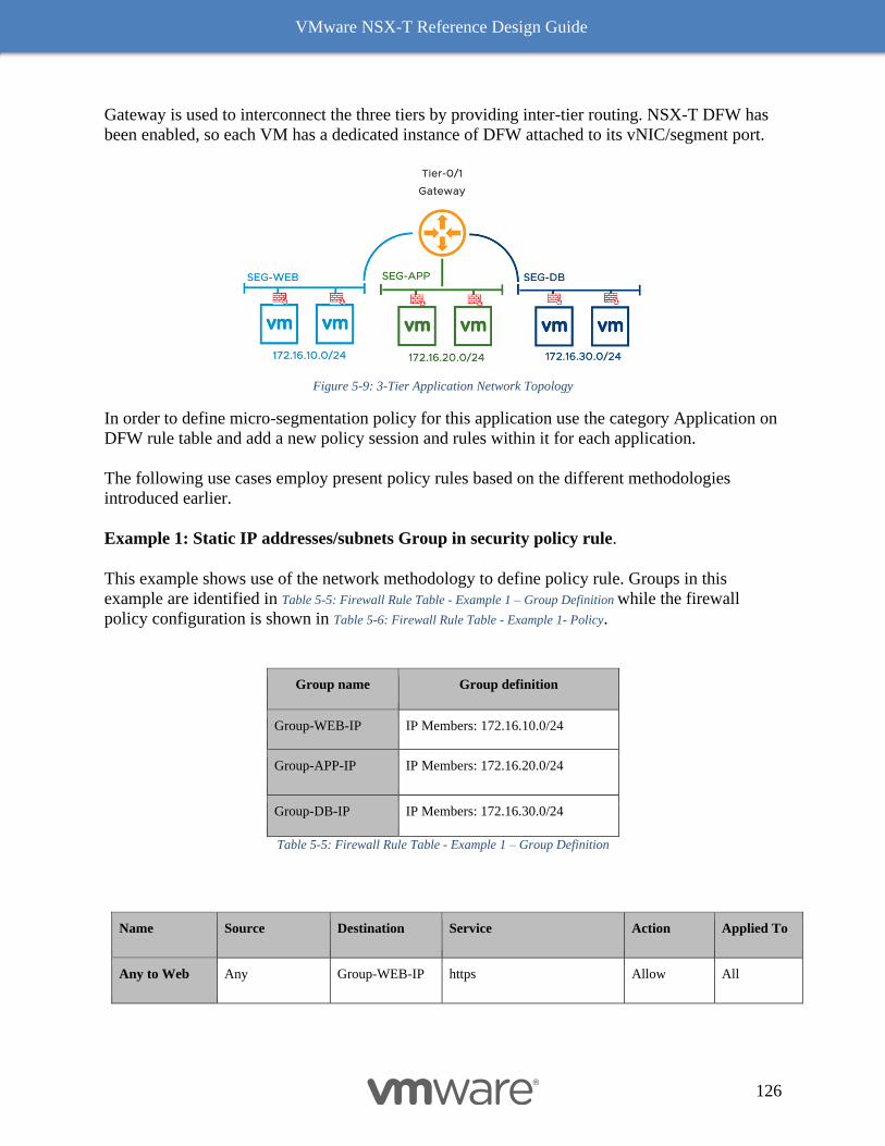
VMware NSX-T Reference Design Guide
126
Gateway is used to interconnect the three tiers by providing inter-tier routing. NSX-T DFW has
been enabled, so each VM has a dedicated instance of DFW attached to its vNIC/segment port.
Figure 5-9: 3-Tier Application Network Topology
In order to define micro-segmentation policy for this application use the category Application on
DFW rule table and add a new policy session and rules within it for each application.
The following use cases employ present policy rules based on the different methodologies
introduced earlier.
Example 1: Static IP addresses/subnets Group in security policy rule.
This example shows use of the network methodology to define policy rule. Groups in this
example are identified in Table 5-5: Firewall Rule Table - Example 1 – Group Definition while the firewall
policy configuration is shown in Table 5-6: Firewall Rule Table - Example 1- Policy.
Group name Group definition
Group-WEB-IP IP Members: 172.16.10.0/24
Group-APP-IP IP Members: 172.16.20.0/24
Group-DB-IP IP Members: 172.16.30.0/24
Table 5-5: Firewall Rule Table - Example 1 – Group Definition
Name Source Destination Service Action Applied To
Any to Web Any Group-WEB-IP https Allow All
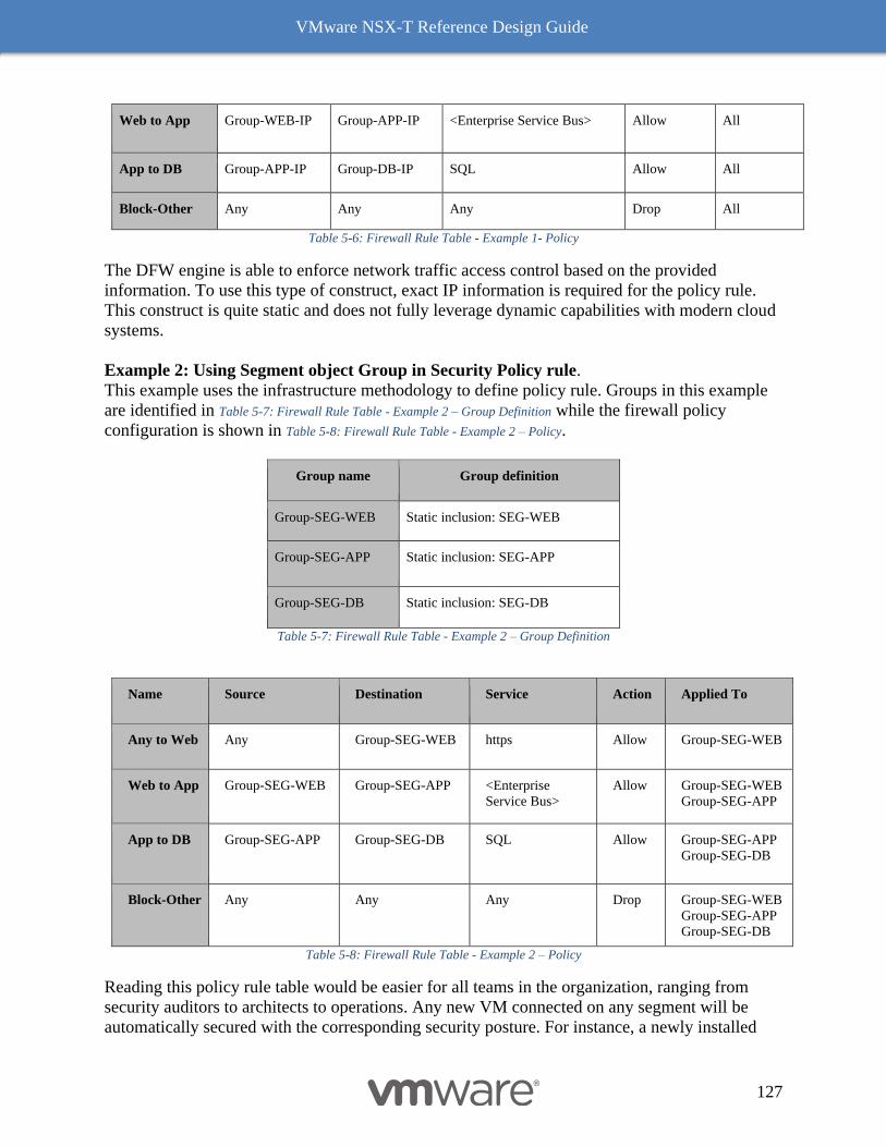
VMware NSX-T Reference Design Guide
127
Web to App Group-WEB-IP Group-APP-IP <Enterprise Service Bus> Allow All
App to DB Group-APP-IP Group-DB-IP SQL Allow All
Block-Other Any Any Any Drop All
Table 5-6: Firewall Rule Table - Example 1- Policy
The DFW engine is able to enforce network traffic access control based on the provided
information. To use this type of construct, exact IP information is required for the policy rule.
This construct is quite static and does not fully leverage dynamic capabilities with modern cloud
systems.
Example 2: Using Segment object Group in Security Policy rule.
This example uses the infrastructure methodology to define policy rule. Groups in this example
are identified in Table 5-7: Firewall Rule Table - Example 2 – Group Definition while the firewall policy
configuration is shown in Table 5-8: Firewall Rule Table - Example 2 – Policy.
Group name Group definition
Group-SEG-WEB Static inclusion: SEG-WEB
Group-SEG-APP Static inclusion: SEG-APP
Group-SEG-DB Static inclusion: SEG-DB
Table 5-7: Firewall Rule Table - Example 2 – Group Definition
Name Source Destination Service Action Applied To
Any to Web Any Group-SEG-WEB https Allow Group-SEG-WEB
Web to App Group-SEG-WEB Group-SEG-APP <Enterprise
Service Bus>
Allow Group-SEG-WEB
Group-SEG-APP
App to DB Group-SEG-APP Group-SEG-DB SQL Allow Group-SEG-APP
Group-SEG-DB
Block-Other Any Any Any Drop Group-SEG-WEB
Group-SEG-APP
Group-SEG-DB
Table 5-8: Firewall Rule Table - Example 2 – Policy
Reading this policy rule table would be easier for all teams in the organization, ranging from
security auditors to architects to operations. Any new VM connected on any segment will be
automatically secured with the corresponding security posture. For instance, a newly installed
VMware NSX-T Reference Design Guide
128
web server will be seamlessly protected by the first policy rule with no human intervention,
while VM disconnected from a segment will no longer have a security policy applied to it. This
type of construct fully leverages the dynamic nature of NSX-T. It will monitor VM connectivity
at any given point in time, and if a VM is no longer connected to a particular segment, any
associated security policies are removed.
This policy rule also uses the “Applied To” option to apply the policy to only relevant objects
rather than populating the rule everywhere. In this example, the first rule is applied to the vNIC
associated with “SEG-Web”. Use of “Applied To” is recommended to define the enforcement
point for the given rule for better resource usage.
Security policy and IP Discovery
Both NSX-T DFW and Gateway Firewall (GFW) has a dependency on VM-to-IP discovery
which is used to translate objects to IP before rules are pushed to data path. This is mainly
required when the policy is defined using grouped objects. This VM-to-IP table is maintained by
NSX-T Control plane and populated by the IP discovery mechanism. IP discovery used as a
central mechanism to ascertain the IP address of a VM. By default, this is done using DHCP and
ARP snooping, with VMware Tools available as another mechanism with ESXi hosts. These
discovered VM-to-IP mappings can be overridden by manual input if needed, and multiple IP
addresses are possible on a single vNIC. The IP and MAC addresses learned are added to the
VM-to-IP table. This table is used internally by NSX-T for SpoofGuard, ARP suppression, and
firewall object-to-IP translation.
Intrusion Detection
Much like distributed firewalling changed the game on firewalling by providing a distributed,
ubiquitous enforcement plane, NSX distributed IPS/IPS changes the game on IPS by providing a
distributed, ubiquitous enforcement plane. However, there are additional benefits that the NSX
distributed IPS model brings beyond ubiquity (which in itself is a game changer). NSX IPS is
IPS distributed across all the hosts. Much like with DFW, the distributed nature allows the IPS
capacity to grow linearly with compute capacity. Beyond that, however, there is an added
benefit to distributing IPS. This is the added context. Legacy network Intrusion Detection and
Prevention systems are deployed centrally in the network and rely either on traffic to be
hairpinned through them or a copy of the traffic to be sent to them via techniques like SPAN or
TAPs. These sensors typically match all traffic against all or a broad set of signatures and have
very little context about the assets they are protecting. Applying all signatures to all traffic is
very inefficient, as IDS/IPS unlike firewalling needs to look at the packet payload, not just the
network headers. Each signature that needs to be matched against the traffic adds inspection
overhead and potential latency introduced. Also, because legacy network IDS/IPS appliances just
see packets without having context about the protected workloads, it’s very difficult for security
teams to determine the appropriate priority for each incident. Obviously, a successful intrusion
against a vulnerable database server in production which holds mission-critical data needs more
attention than someone in the IT staff triggering an IDS event by running a vulnerability scan.
Because the NSX distributed IDS/IPS is applied to the vNIC of every workload, traffic does not
need to hairpinned to a centralized appliance, and we can be very selective as to what signatures
are applied. Signatures related to a windows vulnerability don’t need to be applied to Linux
workloads, or servers running Apache don’t need signatures that detect an exploit of a database
VMware NSX-T Reference Design Guide
129
service. Through the Guest Introspection Framework, and in-guest drivers, NSX has access to
context about each guest, including the operating system version, users logged in or any running
process. This context can be leveraged to selectively apply only the relevant signatures, not only
reducing the processing impact, but more importantly reducing the noise and quantity of false
positives compared to what would be seen if all signatures are applied to all traffic with a
traditional appliance. For a detailed description of IDS configuration, see the NSX Product
Documentation.
Service Insertion
The value of NSX security extends beyond NSX to your pre-existing security infrastructure;
NSX is the mortar that ties your security bricks to build a stronger wall. Legacy security
strategies were intolerant of pre-existing security infrastructure. Anyone who had a Checkpoint
firewall and wanted to move to a Palo Alto Networks firewall would run the 2 managers, side by
side until the transition was complete. Troubleshooting during this transition period required a lot
of chair swiveling. NSX brings a new model, complementing pre-existing infrastructure. Service
Insertion is the feature which allows NSX firewalls (both gateway and DFW) to send traffic to
legacy firewall infrastructure for processing. This can be done as granularly as a port level,
without any modification to existing network architecture. Service Insertion not only sends the
traffic to other services for processing, Service Insertion offers and a deep integration which
allows the exchange of NSX Manager objects to SI service managers. So, a group in NSX which
is comprised on VMs which a substring of “web” (for example) would get shared to the SI
service manager. Thus, when a new VM is spun up which becomes a member of the new group,
the NSX Manager will send that update to the SI Service Manager so that policy can be
consistently applied across platforms.
Additional Security Features
NSX-T extends the security solution beyond DFW with additional features to enhance data
center security posture on top of micro-segmentation. These features include:
● SpoofGuard - Provides protection against spoofing with MAC+IP+VLAN bindings.
This can be enforced at a per logical port level. The SpoofGuard feature requires static or
dynamic bindings (e.g., DHCP/ARP snooping) of IP+MAC for enforcement.
● Segment Security - Provides stateless L2 and L3 security to protect segment integrity by
filtering out malicious attacks (e.g., denial of service using broadcast/multicast storms)
and unauthorized traffic entering segment from VMs. This is accomplished by attaching
the segment security profile to a segment for enforcement. The segment security profile
has options to allow/block bridge protocol data unit (BPDU), DHCP server/client traffic,
non-IP traffic. It allows for rate limiting of broadcast and multicast traffic, both
transmitted and received.
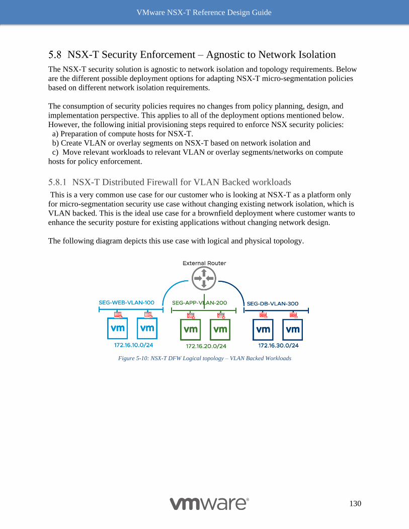
VMware NSX-T Reference Design Guide
130
NSX-T Security Enforcement – Agnostic to Network Isolation
The NSX-T security solution is agnostic to network isolation and topology requirements. Below
are the different possible deployment options for adapting NSX-T micro-segmentation policies
based on different network isolation requirements.
The consumption of security policies requires no changes from policy planning, design, and
implementation perspective. This applies to all of the deployment options mentioned below.
However, the following initial provisioning steps required to enforce NSX security policies:
a) Preparation of compute hosts for NSX-T.
b) Create VLAN or overlay segments on NSX-T based on network isolation and
c) Move relevant workloads to relevant VLAN or overlay segments/networks on compute
hosts for policy enforcement.
NSX-T Distributed Firewall for VLAN Backed workloads
This is a very common use case for our customer who is looking at NSX-T as a platform only
for micro-segmentation security use case without changing existing network isolation, which is
VLAN backed. This is the ideal use case for a brownfield deployment where customer wants to
enhance the security posture for existing applications without changing network design.
The following diagram depicts this use case with logical and physical topology.
Figure 5-10: NSX-T DFW Logical topology – VLAN Backed Workloads
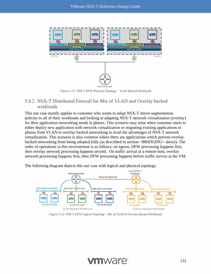
VMware NSX-T Reference Design Guide
131
Figure 5-11: NSX-T DFW Physical Topology – VLAN Backed Workloads
NSX-T Distributed Firewall for Mix of VLAN and Overlay backed
workloads
This use case mainly applies to customer who wants to adapt NSX-T micro-segmentation
policies to all of their workloads and looking at adapting NSX-T network virtualization (overlay)
for their application networking needs in phases. This scenario may arise when customer starts to
either deploy new application with network virtualization or migrating existing applications in
phases from VLAN to overlay backed networking to avail the advantages of NSX-T network
virtualization. This scenario is also common where there are applications which prevent overlay
backed networking from being adopted fully (as described in section <BRIDGING> above). The
order of operations in this environment is as follows: on egress, DFW processing happens first,
then overlay network processing happens second. On traffic arrival at a remote host, overlay
network processing happens first, then DFW processing happens before traffic arrives at the VM.
The following diagram depicts this use case with logical and physical topology.
Figure 5-12: NSX-T DFW Logical Topology – Mix of VLAN & Overlay Backed Workloads
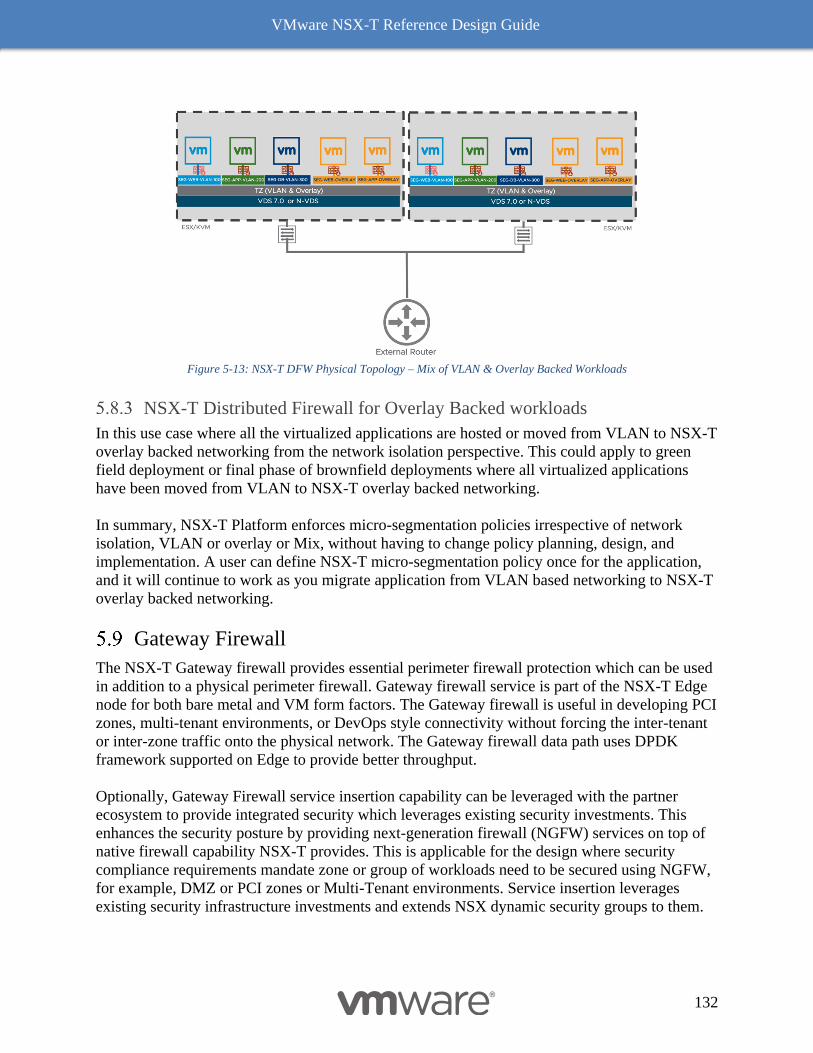
VMware NSX-T Reference Design Guide
132
Figure 5-13: NSX-T DFW Physical Topology – Mix of VLAN & Overlay Backed Workloads
NSX-T Distributed Firewall for Overlay Backed workloads
In this use case where all the virtualized applications are hosted or moved from VLAN to NSX-T
overlay backed networking from the network isolation perspective. This could apply to green
field deployment or final phase of brownfield deployments where all virtualized applications
have been moved from VLAN to NSX-T overlay backed networking.
In summary, NSX-T Platform enforces micro-segmentation policies irrespective of network
isolation, VLAN or overlay or Mix, without having to change policy planning, design, and
implementation. A user can define NSX-T micro-segmentation policy once for the application,
and it will continue to work as you migrate application from VLAN based networking to NSX-T
overlay backed networking.
Gateway Firewall
The NSX-T Gateway firewall provides essential perimeter firewall protection which can be used
in addition to a physical perimeter firewall. Gateway firewall service is part of the NSX-T Edge
node for both bare metal and VM form factors. The Gateway firewall is useful in developing PCI
zones, multi-tenant environments, or DevOps style connectivity without forcing the inter-tenant
or inter-zone traffic onto the physical network. The Gateway firewall data path uses DPDK
framework supported on Edge to provide better throughput.
Optionally, Gateway Firewall service insertion capability can be leveraged with the partner
ecosystem to provide integrated security which leverages existing security investments. This
enhances the security posture by providing next-generation firewall (NGFW) services on top of
native firewall capability NSX-T provides. This is applicable for the design where security
compliance requirements mandate zone or group of workloads need to be secured using NGFW,
for example, DMZ or PCI zones or Multi-Tenant environments. Service insertion leverages
existing security infrastructure investments and extends NSX dynamic security groups to them.
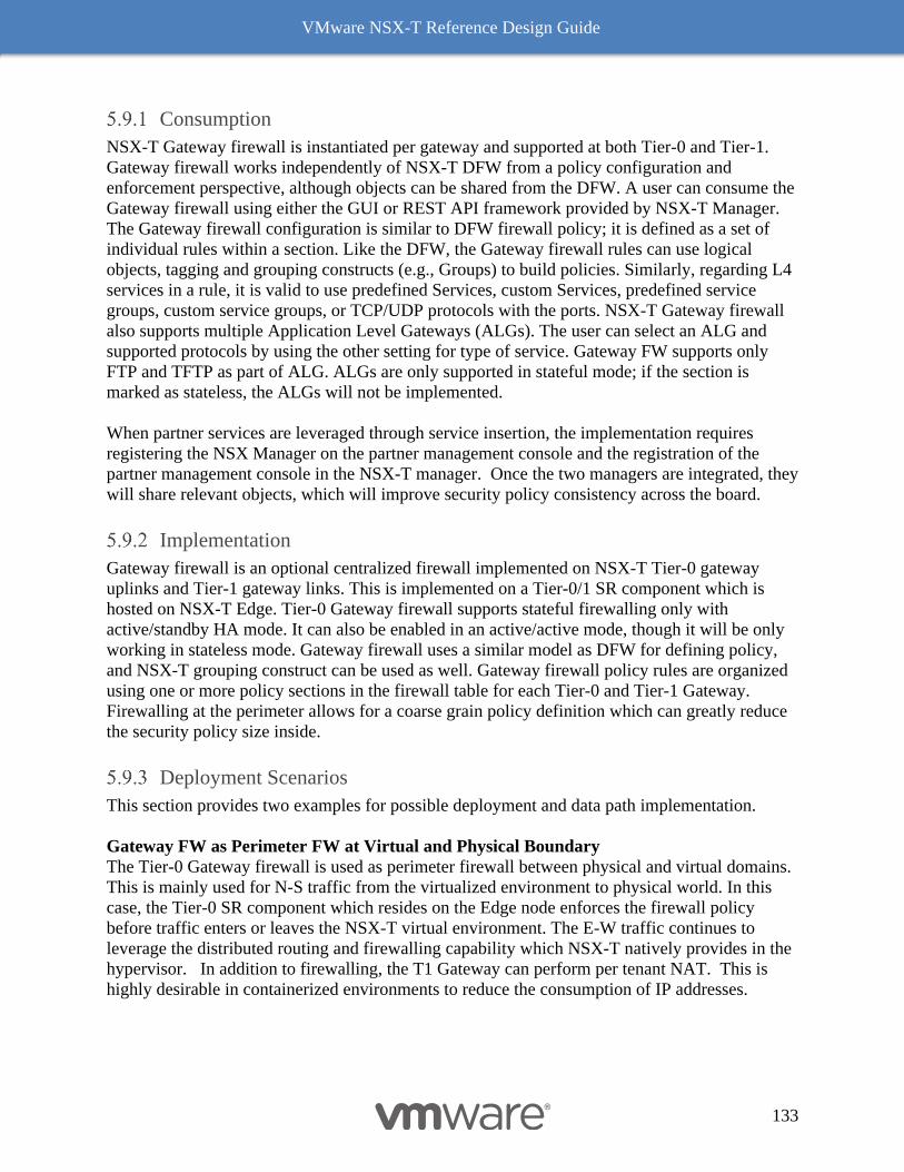
VMware NSX-T Reference Design Guide
133
Consumption
NSX-T Gateway firewall is instantiated per gateway and supported at both Tier-0 and Tier-1.
Gateway firewall works independently of NSX-T DFW from a policy configuration and
enforcement perspective, although objects can be shared from the DFW. A user can consume the
Gateway firewall using either the GUI or REST API framework provided by NSX-T Manager.
The Gateway firewall configuration is similar to DFW firewall policy; it is defined as a set of
individual rules within a section. Like the DFW, the Gateway firewall rules can use logical
objects, tagging and grouping constructs (e.g., Groups) to build policies. Similarly, regarding L4
services in a rule, it is valid to use predefined Services, custom Services, predefined service
groups, custom service groups, or TCP/UDP protocols with the ports. NSX-T Gateway firewall
also supports multiple Application Level Gateways (ALGs). The user can select an ALG and
supported protocols by using the other setting for type of service. Gateway FW supports only
FTP and TFTP as part of ALG. ALGs are only supported in stateful mode; if the section is
marked as stateless, the ALGs will not be implemented.
When partner services are leveraged through service insertion, the implementation requires
registering the NSX Manager on the partner management console and the registration of the
partner management console in the NSX-T manager. Once the two managers are integrated, they
will share relevant objects, which will improve security policy consistency across the board.
Implementation
Gateway firewall is an optional centralized firewall implemented on NSX-T Tier-0 gateway
uplinks and Tier-1 gateway links. This is implemented on a Tier-0/1 SR component which is
hosted on NSX-T Edge. Tier-0 Gateway firewall supports stateful firewalling only with
active/standby HA mode. It can also be enabled in an active/active mode, though it will be only
working in stateless mode. Gateway firewall uses a similar model as DFW for defining policy,
and NSX-T grouping construct can be used as well. Gateway firewall policy rules are organized
using one or more policy sections in the firewall table for each Tier-0 and Tier-1 Gateway.
Firewalling at the perimeter allows for a coarse grain policy definition which can greatly reduce
the security policy size inside.
Deployment Scenarios
This section provides two examples for possible deployment and data path implementation.
Gateway FW as Perimeter FW at Virtual and Physical Boundary
The Tier-0 Gateway firewall is used as perimeter firewall between physical and virtual domains.
This is mainly used for N-S traffic from the virtualized environment to physical world. In this
case, the Tier-0 SR component which resides on the Edge node enforces the firewall policy
before traffic enters or leaves the NSX-T virtual environment. The E-W traffic continues to
leverage the distributed routing and firewalling capability which NSX-T natively provides in the
hypervisor. In addition to firewalling, the T1 Gateway can perform per tenant NAT. This is
highly desirable in containerized environments to reduce the consumption of IP addresses.
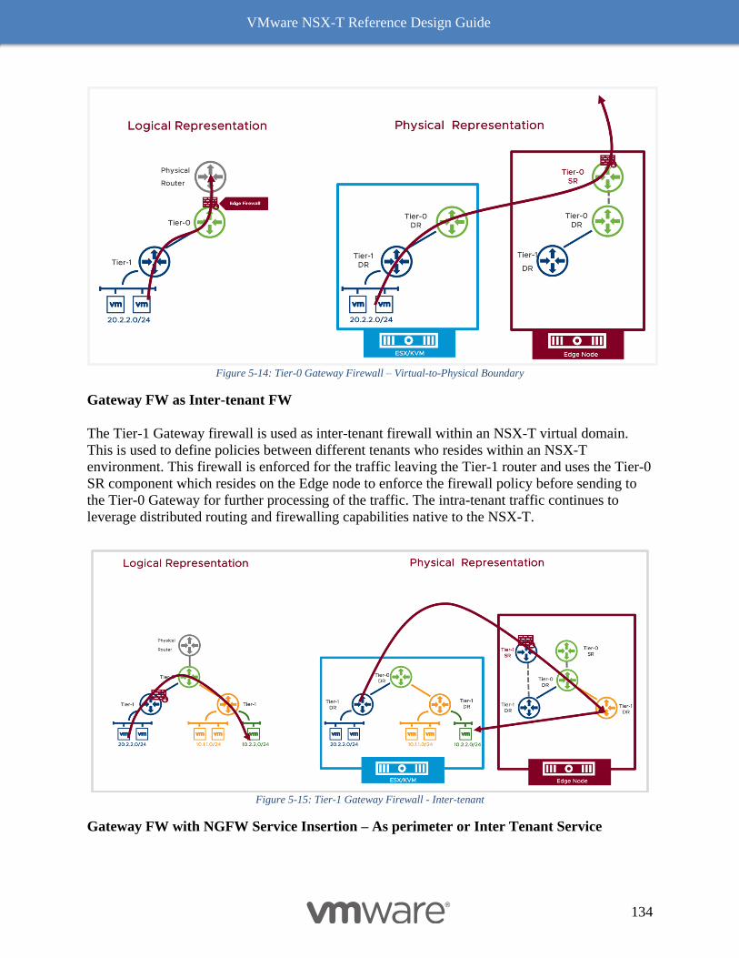
VMware NSX-T Reference Design Guide
134
Figure 5-14: Tier-0 Gateway Firewall – Virtual-to-Physical Boundary
Gateway FW as Inter-tenant FW
The Tier-1 Gateway firewall is used as inter-tenant firewall within an NSX-T virtual domain.
This is used to define policies between different tenants who resides within an NSX-T
environment. This firewall is enforced for the traffic leaving the Tier-1 router and uses the Tier-0
SR component which resides on the Edge node to enforce the firewall policy before sending to
the Tier-0 Gateway for further processing of the traffic. The intra-tenant traffic continues to
leverage distributed routing and firewalling capabilities native to the NSX-T.
Figure 5-15: Tier-1 Gateway Firewall - Inter-tenant
Gateway FW with NGFW Service Insertion – As perimeter or Inter Tenant Service
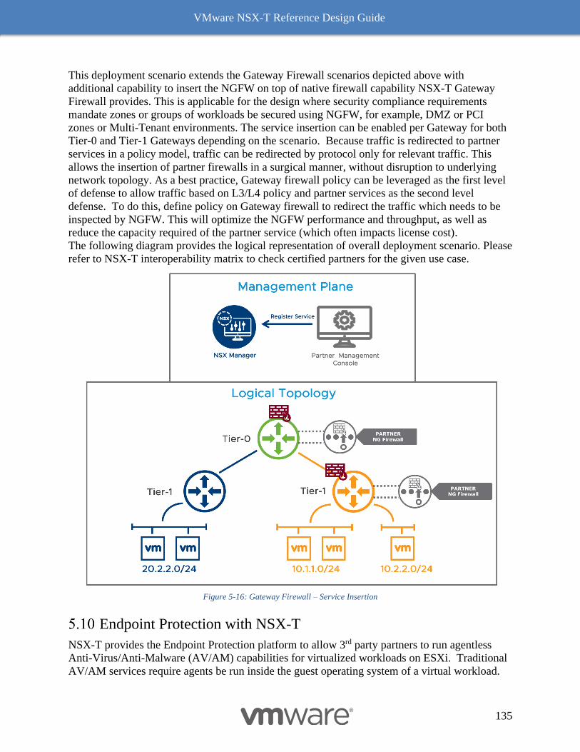
VMware NSX-T Reference Design Guide
135
This deployment scenario extends the Gateway Firewall scenarios depicted above with
additional capability to insert the NGFW on top of native firewall capability NSX-T Gateway
Firewall provides. This is applicable for the design where security compliance requirements
mandate zones or groups of workloads be secured using NGFW, for example, DMZ or PCI
zones or Multi-Tenant environments. The service insertion can be enabled per Gateway for both
Tier-0 and Tier-1 Gateways depending on the scenario. Because traffic is redirected to partner
services in a policy model, traffic can be redirected by protocol only for relevant traffic. This
allows the insertion of partner firewalls in a surgical manner, without disruption to underlying
network topology. As a best practice, Gateway firewall policy can be leveraged as the first level
of defense to allow traffic based on L3/L4 policy and partner services as the second level
defense. To do this, define policy on Gateway firewall to redirect the traffic which needs to be
inspected by NGFW. This will optimize the NGFW performance and throughput, as well as
reduce the capacity required of the partner service (which often impacts license cost).
The following diagram provides the logical representation of overall deployment scenario. Please
refer to NSX-T interoperability matrix to check certified partners for the given use case.
Figure 5-16: Gateway Firewall – Service Insertion
Endpoint Protection with NSX-T
NSX-T provides the Endpoint Protection platform to allow 3rd party partners to run agentless
Anti-Virus/Anti-Malware (AV/AM) capabilities for virtualized workloads on ESXi. Traditional
AV/AM services require agents be run inside the guest operating system of a virtual workload.
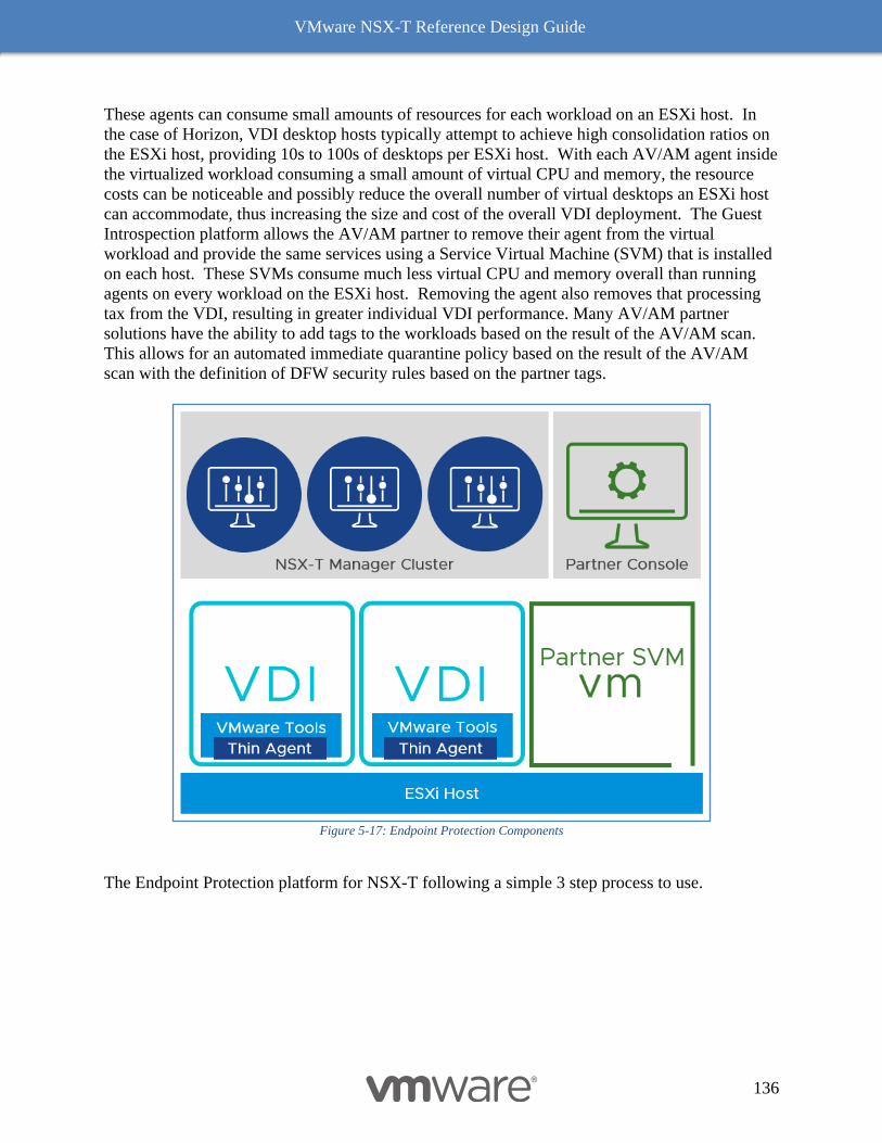
VMware NSX-T Reference Design Guide
136
These agents can consume small amounts of resources for each workload on an ESXi host. In
the case of Horizon, VDI desktop hosts typically attempt to achieve high consolidation ratios on
the ESXi host, providing 10s to 100s of desktops per ESXi host. With each AV/AM agent inside
the virtualized workload consuming a small amount of virtual CPU and memory, the resource
costs can be noticeable and possibly reduce the overall number of virtual desktops an ESXi host
can accommodate, thus increasing the size and cost of the overall VDI deployment. The Guest
Introspection platform allows the AV/AM partner to remove their agent from the virtual
workload and provide the same services using a Service Virtual Machine (SVM) that is installed
on each host. These SVMs consume much less virtual CPU and memory overall than running
agents on every workload on the ESXi host. Removing the agent also removes that processing
tax from the VDI, resulting in greater individual VDI performance. Many AV/AM partner
solutions have the ability to add tags to the workloads based on the result of the AV/AM scan.
This allows for an automated immediate quarantine policy based on the result of the AV/AM
scan with the definition of DFW security rules based on the partner tags.
Figure 5-17: Endpoint Protection Components
The Endpoint Protection platform for NSX-T following a simple 3 step process to use.
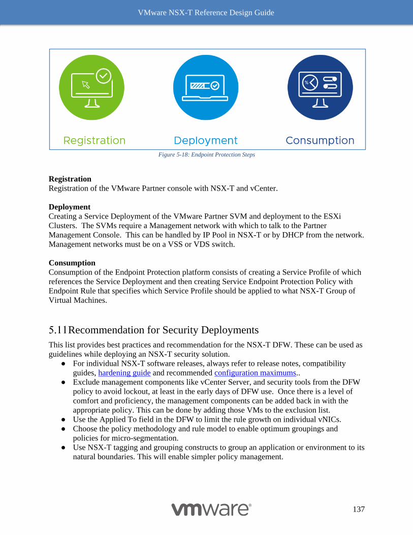
VMware NSX-T Reference Design Guide
137
Figure 5-18: Endpoint Protection Steps
Registration
Registration of the VMware Partner console with NSX-T and vCenter.
Deployment
Creating a Service Deployment of the VMware Partner SVM and deployment to the ESXi
Clusters. The SVMs require a Management network with which to talk to the Partner
Management Console. This can be handled by IP Pool in NSX-T or by DHCP from the network.
Management networks must be on a VSS or VDS switch.
Consumption
Consumption of the Endpoint Protection platform consists of creating a Service Profile of which
references the Service Deployment and then creating Service Endpoint Protection Policy with
Endpoint Rule that specifies which Service Profile should be applied to what NSX-T Group of
Virtual Machines.
Recommendation for Security Deployments
This list provides best practices and recommendation for the NSX-T DFW. These can be used as
guidelines while deploying an NSX-T security solution.
● For individual NSX-T software releases, always refer to release notes, compatibility
guides, hardening guide and recommended configuration maximums..
● Exclude management components like vCenter Server, and security tools from the DFW
policy to avoid lockout, at least in the early days of DFW use. Once there is a level of
comfort and proficiency, the management components can be added back in with the
appropriate policy. This can be done by adding those VMs to the exclusion list.
● Use the Applied To field in the DFW to limit the rule growth on individual vNICs.
● Choose the policy methodology and rule model to enable optimum groupings and
policies for micro-segmentation.
● Use NSX-T tagging and grouping constructs to group an application or environment to its
natural boundaries. This will enable simpler policy management.
VMware NSX-T Reference Design Guide
138
● Consider the flexibility and simplicity of a policy model for Day-2 operations. It should
address ever-changing deployment scenarios rather than simply be part of the initial
setup.
● Leverage DFW category and policies to group and manage policies based on the chosen
rule model. (e.g., emergency, infrastructure, environment, application...)
● Use an explicit allow model; create explicit rules for allowed traffic and change DFW the
default rule from “allow” to “drop”.
A Practical Approach to Building Micro-Segmentation Policy
The ideal way to have least privilege security model is to define security policies explicitly
allowing all the applications within your data center and denying all other traffic by default.
However, it is a big challenge to profile tens/hundreds of applications and build security policies
for each. Often times, application owners don’t know very much about their application’s
details, which further complicates the process. This may take some time to profile your
application and come up with a port defined security policy. Instead of waiting for profiling of
an application to be complete, one can start with basic outside-in fencing approach to start
defining broader security policies to enhancing the security posture and then move gradually to
the desired explicit allow model over time as you complete the application profiling. The tag
model of NSX allows this to be done quite easily as one can start with just Prod and Non-prod
tags, then add more detailed tags as appropriate (PCI, HR, Finance, etc) to applicable VMs.
(Note: Regardless of approach, experience has shown that the best starting point is common
services such as DNS, NTP, AD, SNMP, etc. A great second step is the backup infrastructure.)
In this section we will walk you through a practical approach to start securing the data center
workloads in a phased outside-in fencing approach as you are working on profiling your
application to provide zero trust model.
First, we layout the data center topology and requirements. Then we will walk you through an
approach to micro-segmentation policies in phases. This approach can be applied to both
brownfield and green field deployment.
5.11.1.1 Data Center Topology and Requirements:
The following data center topology used which matches with most of our customer data center.
This approach can be applied to both brownfield and greenfield deployment.
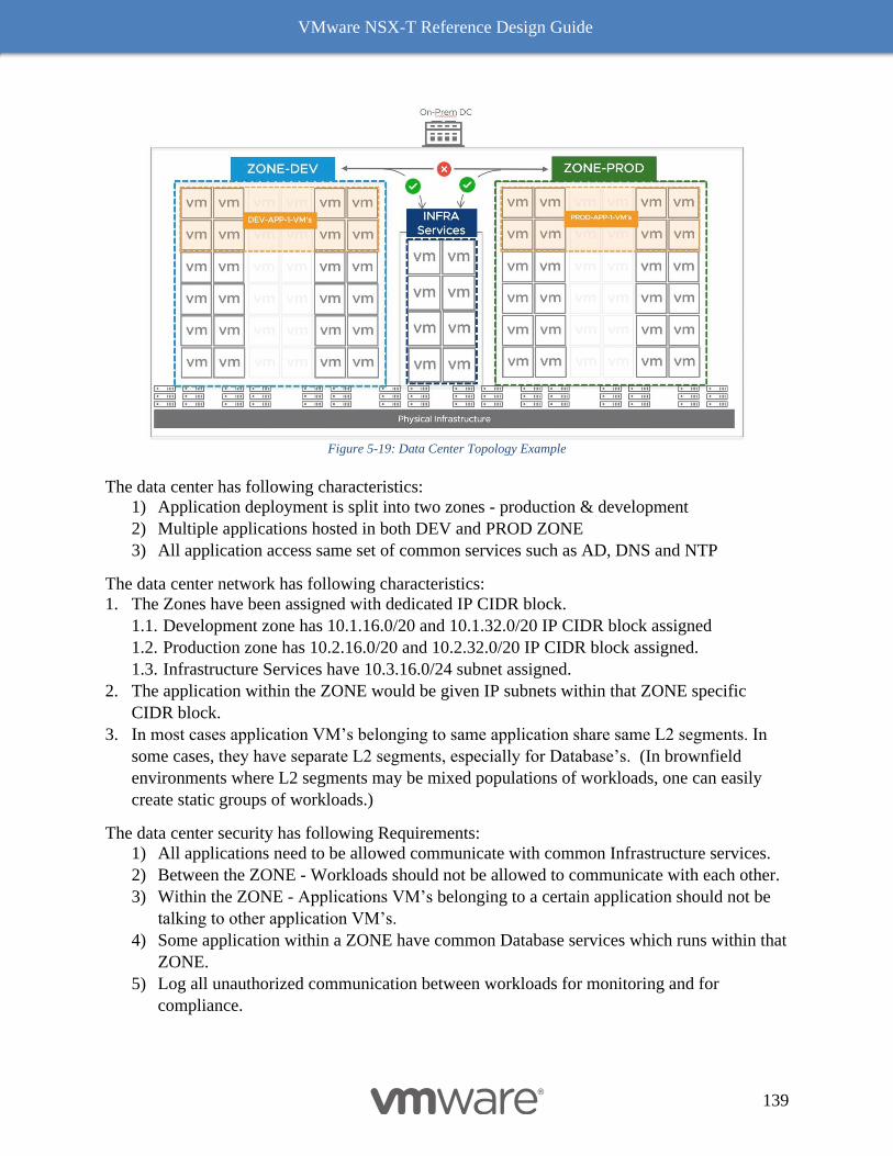
VMware NSX-T Reference Design Guide
139
Figure 5-19: Data Center Topology Example
The data center has following characteristics:
1) Application deployment is split into two zones - production & development
2) Multiple applications hosted in both DEV and PROD ZONE
3) All application access same set of common services such as AD, DNS and NTP
The data center network has following characteristics:
1. The Zones have been assigned with dedicated IP CIDR block.
1.1. Development zone has 10.1.16.0/20 and 10.1.32.0/20 IP CIDR block assigned
1.2. Production zone has 10.2.16.0/20 and 10.2.32.0/20 IP CIDR block assigned.
1.3. Infrastructure Services have 10.3.16.0/24 subnet assigned.
2. The application within the ZONE would be given IP subnets within that ZONE specific
CIDR block.
3. In most cases application VM’s belonging to same application share same L2 segments. In
some cases, they have separate L2 segments, especially for Database’s. (In brownfield
environments where L2 segments may be mixed populations of workloads, one can easily
create static groups of workloads.)
The data center security has following Requirements:
1) All applications need to be allowed communicate with common Infrastructure services.
2) Between the ZONE - Workloads should not be allowed to communicate with each other.
3) Within the ZONE - Applications VM’s belonging to a certain application should not be
talking to other application VM’s.
4) Some application within a ZONE have common Database services which runs within that
ZONE.
5) Log all unauthorized communication between workloads for monitoring and for
compliance.
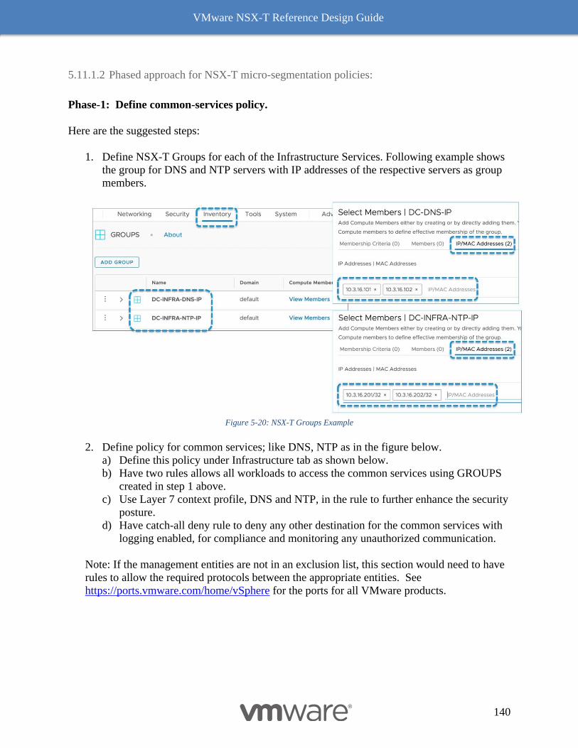
VMware NSX-T Reference Design Guide
140
5.11.1.2 Phased approach for NSX-T micro-segmentation policies:
Phase-1: Define common-services policy.
Here are the suggested steps:
1. Define NSX-T Groups for each of the Infrastructure Services. Following example shows
the group for DNS and NTP servers with IP addresses of the respective servers as group
members.
Figure 5-20: NSX-T Groups Example
2. Define policy for common services; like DNS, NTP as in the figure below.
a) Define this policy under Infrastructure tab as shown below.
b) Have two rules allows all workloads to access the common services using GROUPS
created in step 1 above.
c) Use Layer 7 context profile, DNS and NTP, in the rule to further enhance the security
posture.
d) Have catch-all deny rule to deny any other destination for the common services with
logging enabled, for compliance and monitoring any unauthorized communication.
Note: If the management entities are not in an exclusion list, this section would need to have
rules to allow the required protocols between the appropriate entities. See
https://ports.vmware.com/home/vSphere for the ports for all VMware products.
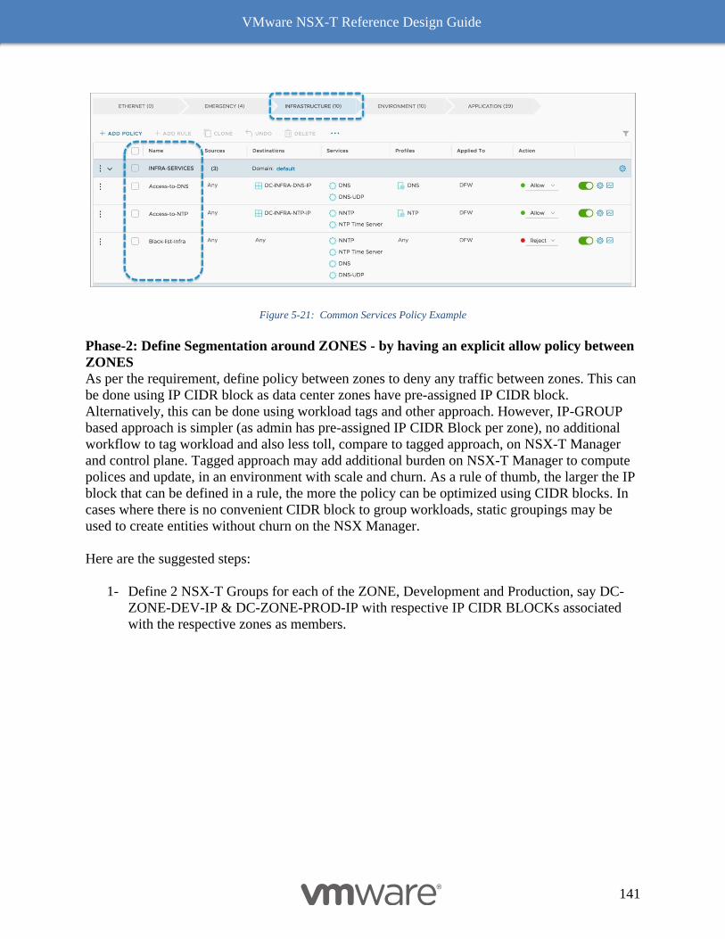
VMware NSX-T Reference Design Guide
141
Figure 5-21: Common Services Policy Example
Phase-2: Define Segmentation around ZONES - by having an explicit allow policy between
ZONES
As per the requirement, define policy between zones to deny any traffic between zones. This can
be done using IP CIDR block as data center zones have pre-assigned IP CIDR block.
Alternatively, this can be done using workload tags and other approach. However, IP-GROUP
based approach is simpler (as admin has pre-assigned IP CIDR Block per zone), no additional
workflow to tag workload and also less toll, compare to tagged approach, on NSX-T Manager
and control plane. Tagged approach may add additional burden on NSX-T Manager to compute
polices and update, in an environment with scale and churn. As a rule of thumb, the larger the IP
block that can be defined in a rule, the more the policy can be optimized using CIDR blocks. In
cases where there is no convenient CIDR block to group workloads, static groupings may be
used to create entities without churn on the NSX Manager.
Here are the suggested steps:
1- Define 2 NSX-T Groups for each of the ZONE, Development and Production, say DC-
ZONE-DEV-IP & DC-ZONE-PROD-IP with respective IP CIDR BLOCKs associated
with the respective zones as members.
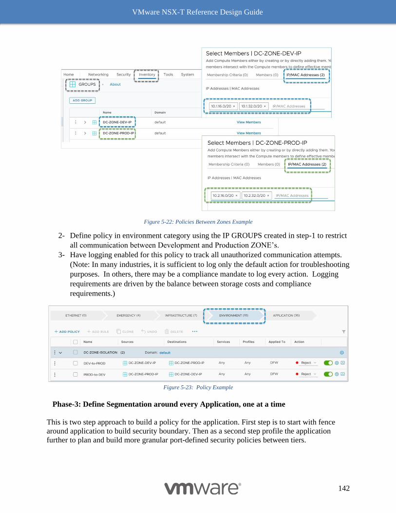
VMware NSX-T Reference Design Guide
142
Figure 5-22: Policies Between Zones Example
2- Define policy in environment category using the IP GROUPS created in step-1 to restrict
all communication between Development and Production ZONE’s.
3- Have logging enabled for this policy to track all unauthorized communication attempts.
(Note: In many industries, it is sufficient to log only the default action for troubleshooting
purposes. In others, there may be a compliance mandate to log every action. Logging
requirements are driven by the balance between storage costs and compliance
requirements.)
Figure 5-23: Policy Example
Phase-3: Define Segmentation around every Application, one at a time
This is two step approach to build a policy for the application. First step is to start with fence
around application to build security boundary. Then as a second step profile the application
further to plan and build more granular port-defined security policies between tiers.
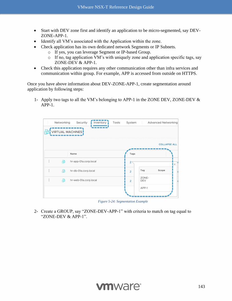
VMware NSX-T Reference Design Guide
143
• Start with DEV zone first and identify an application to be micro-segmented, say DEV-
ZONE-APP-1.
• Identify all VM’s associated with the Application within the zone.
• Check application has its own dedicated network Segments or IP Subnets.
o If yes, you can leverage Segment or IP-based Group.
o If no, tag application VM’s with uniquely zone and application specific tags, say
ZONE-DEV & APP-1.
• Check this application requires any other communication other than infra services and
communication within group. For example, APP is accessed from outside on HTTPS.
Once you have above information about DEV-ZONE-APP-1, create segmentation around
application by following steps:
1- Apply two tags to all the VM’s belonging to APP-1 in the ZONE DEV, ZONE-DEV &
APP-1.
Figure 5-24: Segmentation Example
2- Create a GROUP, say “ZONE-DEV-APP-1” with criteria to match on tag equal to
“ZONE-DEV & APP-1”.

VMware NSX-T Reference Design Guide
144
Figure 5-25: Group Example
3- Define a policy under Application category with 3 rules as in the Figure 5-26: Application Policy
Example.
a. Have “Applied To” set to “ZONE-DEV-APP-1” to limit the scope of policy only
to the application VM’s.
b. The first rule allows all internal communications between the application VM’s.
Enable logging for this rule to profile the application tiers and protocols. (Each
log entry will contain 5 tuple details about every connection.)
c. The second rule allows access to front end of the application from outside. Use
the L7 context profile to allow only SSL traffic. The below example uses Exclude
Source from within ZONE, so that application is only accessible from outside, not
from within except APP’s other VM’s, as per rule one.
d. Default deny all other communication to these “ZONE-DEV-APP-1” VM’s.
Enable log for compliance and monitoring any unauthorized communication.
Figure 5-26: Application Policy Example
Phase-4: Review Logs for Application Profile.
Log entries will identify the direction (In/Out) as well as the protocol and source IP address/port
and destination IP addresses/port for each flow. If using the log file for policy definition, it is
often advisable to process the log files using excel to sort traffic. Typically, 2 sheets are created,
one for IN traffic and one for OUT traffic. Then, each sheet is sorted by port first then IP
address. (In the case of IN traffic by destination IP address and in the case of OUT traffic by
source address. This sorting methodology allows for the grouping of multiple servers
serving/accessing the same traffic.) For each of these groupings, a rule can be inserted above
rule 1 for the application. This will prevent the known traffic from appearing in the log. Once
sufficient confidence is gained that the application is completely understood (this is typically
when the logs are empty), the original rule ZONE-DEV-APP-1 can be removed. At this point,
the security model has transitioned from zone-based to micro segmentation. (Note: Certain
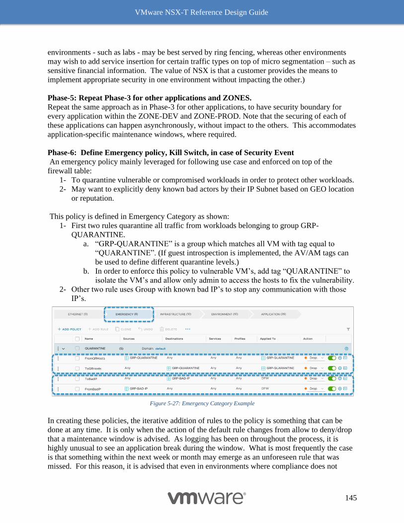
VMware NSX-T Reference Design Guide
145
environments - such as labs - may be best served by ring fencing, whereas other environments
may wish to add service insertion for certain traffic types on top of micro segmentation – such as
sensitive financial information. The value of NSX is that a customer provides the means to
implement appropriate security in one environment without impacting the other.)
Phase-5: Repeat Phase-3 for other applications and ZONES.
Repeat the same approach as in Phase-3 for other applications, to have security boundary for
every application within the ZONE-DEV and ZONE-PROD. Note that the securing of each of
these applications can happen asynchronously, without impact to the others. This accommodates
application-specific maintenance windows, where required.
Phase-6: Define Emergency policy, Kill Switch, in case of Security Event
An emergency policy mainly leveraged for following use case and enforced on top of the
firewall table:
1- To quarantine vulnerable or compromised workloads in order to protect other workloads.
2- May want to explicitly deny known bad actors by their IP Subnet based on GEO location
or reputation.
This policy is defined in Emergency Category as shown:
1- First two rules quarantine all traffic from workloads belonging to group GRP-
QUARANTINE.
a. “GRP-QUARANTINE” is a group which matches all VM with tag equal to
“QUARANTINE”. (If guest introspection is implemented, the AV/AM tags can
be used to define different quarantine levels.)
b. In order to enforce this policy to vulnerable VM’s, add tag “QUARANTINE” to
isolate the VM’s and allow only admin to access the hosts to fix the vulnerability.
2- Other two rule uses Group with known bad IP’s to stop any communication with those
IP’s.
Figure 5-27: Emergency Category Example
In creating these policies, the iterative addition of rules to the policy is something that can be
done at any time. It is only when the action of the default rule changes from allow to deny/drop
that a maintenance window is advised. As logging has been on throughout the process, it is
highly unusual to see an application break during the window. What is most frequently the case
is that something within the next week or month may emerge as an unforeseen rule that was
missed. For this reason, it is advised that even in environments where compliance does not
VMware NSX-T Reference Design Guide
146
dictate the collection of logs, the Deny All rule be set to logging. Aside from the security value
of understanding the traffic that is being blocked, the Deny All rule logs are very useful when
troubleshooting applications.
At this point you have basic level of micro-segmentation policy applied to all the workloads to
shrink the attack surface. As a next step you further break the application into application tiers
and its communication by profiling application flows using firewall logs or exporting IPFIX
flows to Network Insight platform. This will help to group the application workload based on the
function within the application and define policy based on associated port & protocols used.
Once you have these groupings and protocols identified for a given application, update the policy
for that application by creating additional groups and rules with right protocols to have
granularly defined rules one at a time.
With this approach you start with outside-in fencing to start with micro-segmentation policies
and finally come up with a granular port-based micro-segmentation policy for all the application.
NSX Firewall- For All Deployment Scenario
NSX firewall provides different security controls: Distribute Firewall, Distributed IDS, Gateway
Firewall & Bridge Firewall, as an option to provide firewalling to different deployment
scenarios.
A typical data center would have different workloads: VM's, Containers, Physical Server, and a
mix of NSX managed and non-managed workloads. These workloads may also have a
combination of a VLAN-based network or an NSX based overlay network.
The following Figure 5-28: NSX Firewall For all Deployment Scenario summarizes different datacenter
deployment scenarios and associated NSX firewall security controls, which best fits the design.
You can use same NSX manager as a single pane of glass to define Security policies to all of
these different scenarios using different security controls.
1- NSX Managed Workloads with standard VLAN based networking.
• NSX Distributed Firewall can be used to protect NSX managed VM's, Containers &
Physical Server workloads.
2- NSX Managed Workloads with NSX Overlay for networking:
• NSX Distributed Firewall can be used to protect NSX managed VM's, Containers &
Physical Server workloads.
3- Non-NSX Managed workloads on traditional VLAN based network.
• NSX Gateway Firewall can provide the Inter VLAN routing and Firewalling. The
Service Interface on NSX Gateway is used as a gateway & firewall for all non-NSX
managed VLAN workloads.
4- NSX managed Overlay workload bridged to Non-NSX managed VLAN.
• This is the bridge scenario where an Overlay network is extended at Laye-2 into a VLAN
network using NSX Bridge. In this case, NSX managed Overlay workloads can use
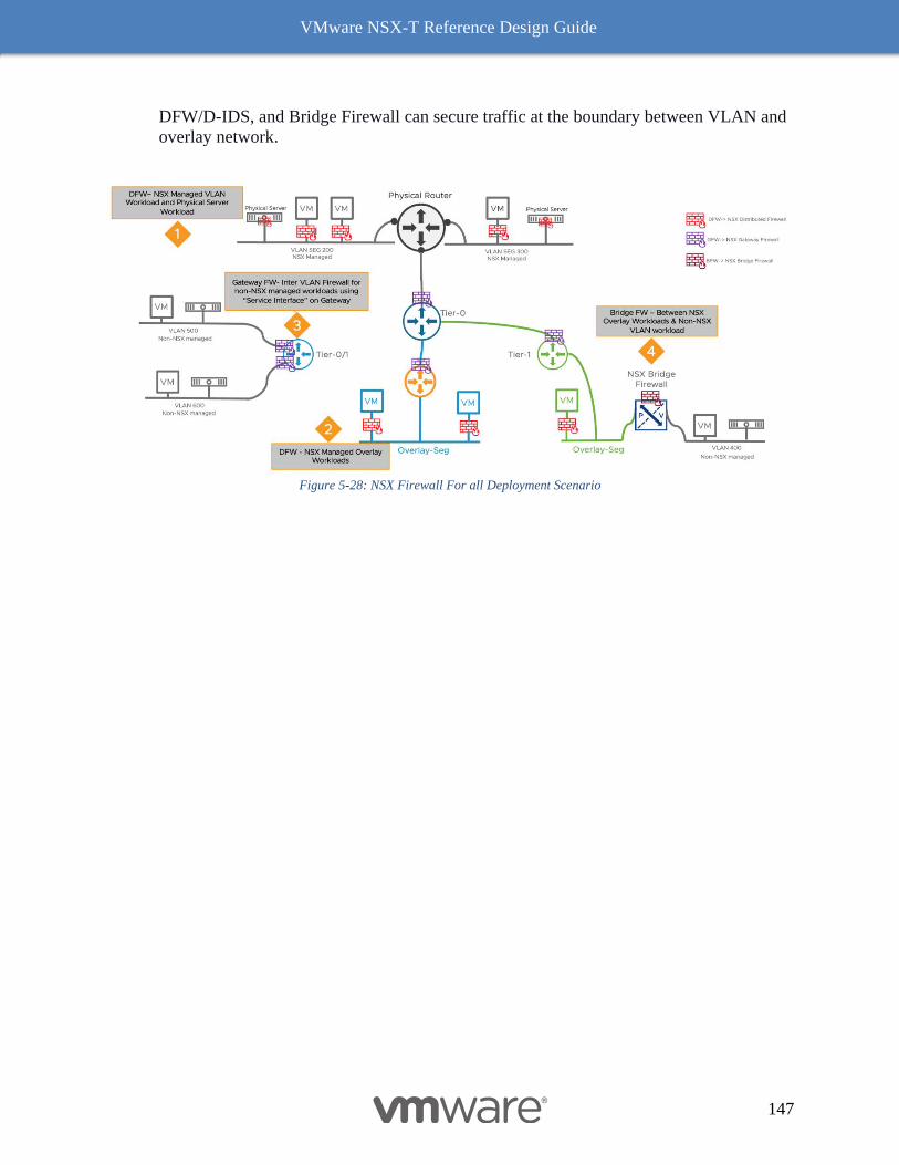
VMware NSX-T Reference Design Guide
147
DFW/D-IDS, and Bridge Firewall can secure traffic at the boundary between VLAN and
overlay network.
Figure 5-28: NSX Firewall For all Deployment Scenario
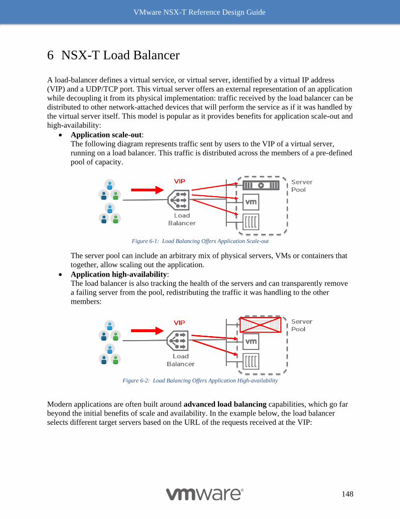
VMware NSX-T Reference Design Guide
148
6 NSX-T Load Balancer
A load-balancer defines a virtual service, or virtual server, identified by a virtual IP address
(VIP) and a UDP/TCP port. This virtual server offers an external representation of an application
while decoupling it from its physical implementation: traffic received by the load balancer can be
distributed to other network-attached devices that will perform the service as if it was handled by
the virtual server itself. This model is popular as it provides benefits for application scale-out and
high-availability:
• Application scale-out:
The following diagram represents traffic sent by users to the VIP of a virtual server,
running on a load balancer. This traffic is distributed across the members of a pre-defined
pool of capacity.
Figure 6-1: Load Balancing Offers Application Scale-out
The server pool can include an arbitrary mix of physical servers, VMs or containers that
together, allow scaling out the application.
• Application high-availability:
The load balancer is also tracking the health of the servers and can transparently remove
a failing server from the pool, redistributing the traffic it was handling to the other
members:
Figure 6-2: Load Balancing Offers Application High-availability
Modern applications are often built around advanced load balancing capabilities, which go far
beyond the initial benefits of scale and availability. In the example below, the load balancer
selects different target servers based on the URL of the requests received at the VIP:
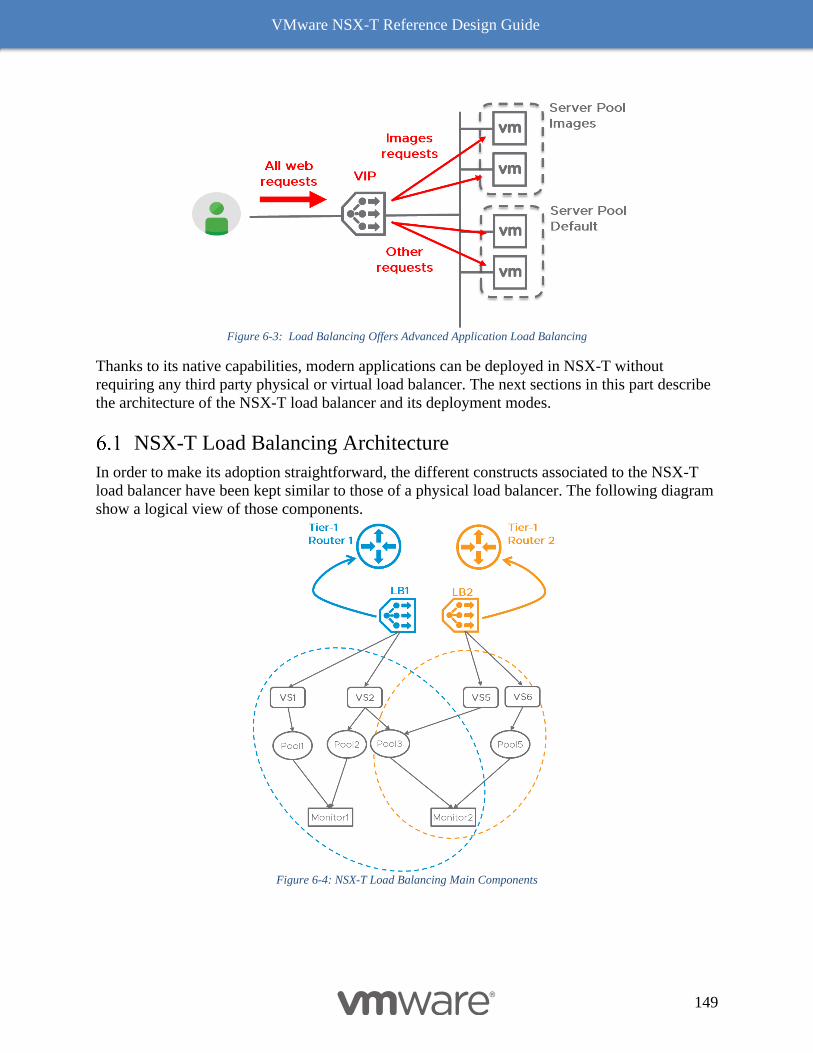
VMware NSX-T Reference Design Guide
149
Figure 6-3: Load Balancing Offers Advanced Application Load Balancing
Thanks to its native capabilities, modern applications can be deployed in NSX-T without
requiring any third party physical or virtual load balancer. The next sections in this part describe
the architecture of the NSX-T load balancer and its deployment modes.
NSX-T Load Balancing Architecture
In order to make its adoption straightforward, the different constructs associated to the NSX-T
load balancer have been kept similar to those of a physical load balancer. The following diagram
show a logical view of those components.
Figure 6-4: NSX-T Load Balancing Main Components
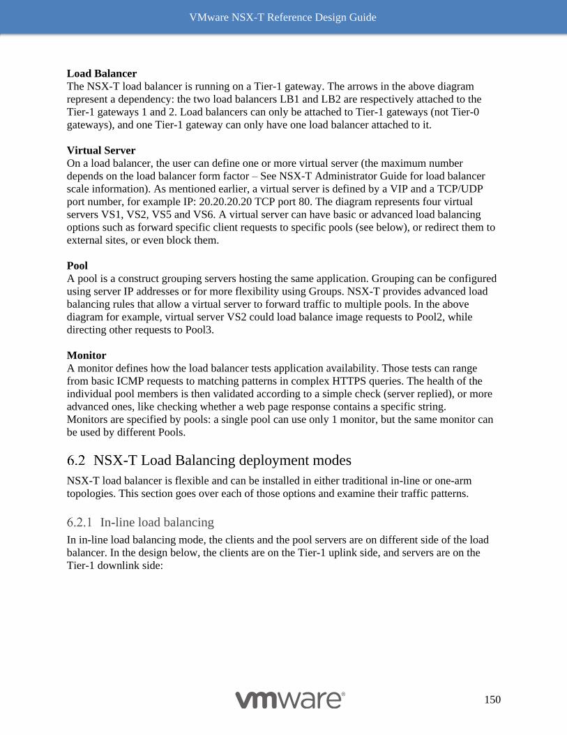
VMware NSX-T Reference Design Guide
150
Load Balancer
The NSX-T load balancer is running on a Tier-1 gateway. The arrows in the above diagram
represent a dependency: the two load balancers LB1 and LB2 are respectively attached to the
Tier-1 gateways 1 and 2. Load balancers can only be attached to Tier-1 gateways (not Tier-0
gateways), and one Tier-1 gateway can only have one load balancer attached to it.
Virtual Server
On a load balancer, the user can define one or more virtual server (the maximum number
depends on the load balancer form factor – See NSX-T Administrator Guide for load balancer
scale information). As mentioned earlier, a virtual server is defined by a VIP and a TCP/UDP
port number, for example IP: 20.20.20.20 TCP port 80. The diagram represents four virtual
servers VS1, VS2, VS5 and VS6. A virtual server can have basic or advanced load balancing
options such as forward specific client requests to specific pools (see below), or redirect them to
external sites, or even block them.
Pool
A pool is a construct grouping servers hosting the same application. Grouping can be configured
using server IP addresses or for more flexibility using Groups. NSX-T provides advanced load
balancing rules that allow a virtual server to forward traffic to multiple pools. In the above
diagram for example, virtual server VS2 could load balance image requests to Pool2, while
directing other requests to Pool3.
Monitor
A monitor defines how the load balancer tests application availability. Those tests can range
from basic ICMP requests to matching patterns in complex HTTPS queries. The health of the
individual pool members is then validated according to a simple check (server replied), or more
advanced ones, like checking whether a web page response contains a specific string.
Monitors are specified by pools: a single pool can use only 1 monitor, but the same monitor can
be used by different Pools.
NSX-T Load Balancing deployment modes
NSX-T load balancer is flexible and can be installed in either traditional in-line or one-arm
topologies. This section goes over each of those options and examine their traffic patterns.
In-line load balancing
In in-line load balancing mode, the clients and the pool servers are on different side of the load
balancer. In the design below, the clients are on the Tier-1 uplink side, and servers are on the
Tier-1 downlink side:
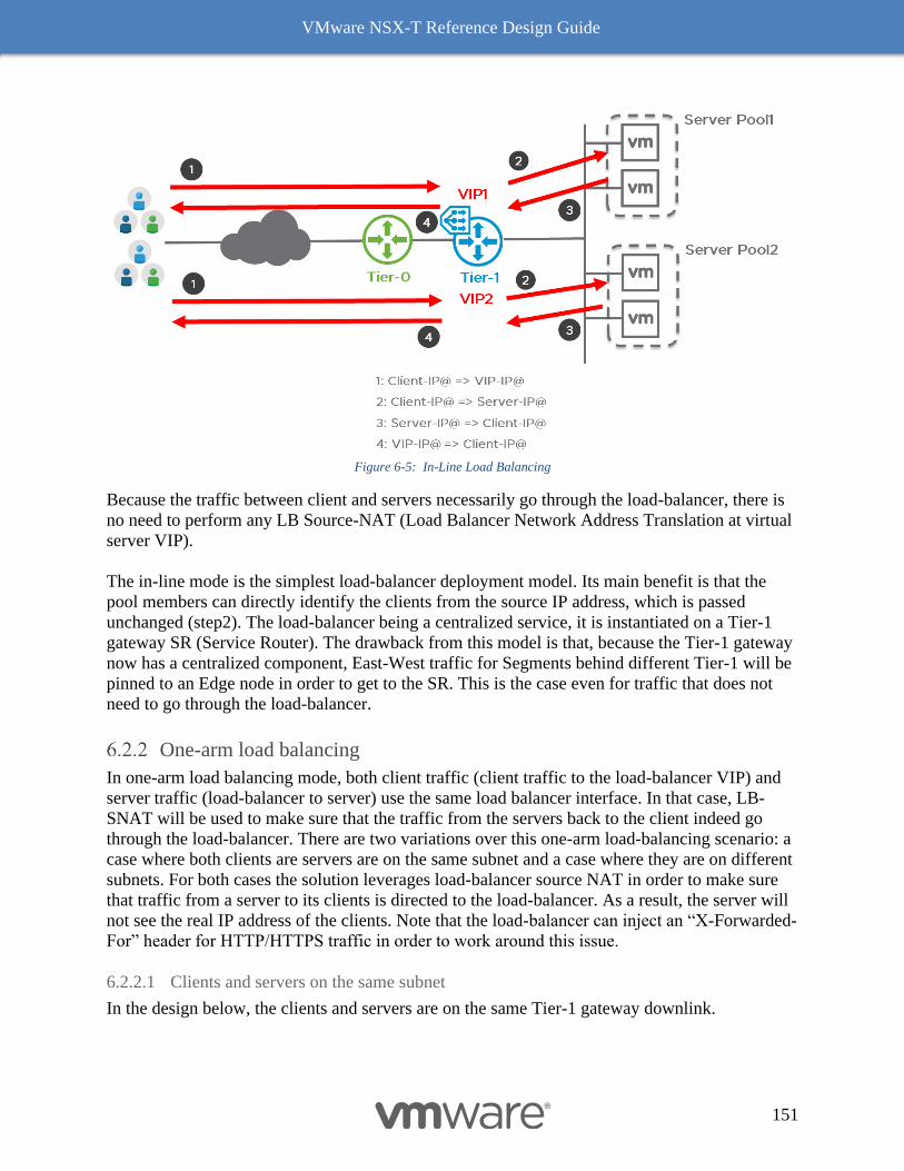
VMware NSX-T Reference Design Guide
151
Figure 6-5: In-Line Load Balancing
Because the traffic between client and servers necessarily go through the load-balancer, there is
no need to perform any LB Source-NAT (Load Balancer Network Address Translation at virtual
server VIP).
The in-line mode is the simplest load-balancer deployment model. Its main benefit is that the
pool members can directly identify the clients from the source IP address, which is passed
unchanged (step2). The load-balancer being a centralized service, it is instantiated on a Tier-1
gateway SR (Service Router). The drawback from this model is that, because the Tier-1 gateway
now has a centralized component, East-West traffic for Segments behind different Tier-1 will be
pinned to an Edge node in order to get to the SR. This is the case even for traffic that does not
need to go through the load-balancer.
One-arm load balancing
In one-arm load balancing mode, both client traffic (client traffic to the load-balancer VIP) and
server traffic (load-balancer to server) use the same load balancer interface. In that case, LB-
SNAT will be used to make sure that the traffic from the servers back to the client indeed go
through the load-balancer. There are two variations over this one-arm load-balancing scenario: a
case where both clients are servers are on the same subnet and a case where they are on different
subnets. For both cases the solution leverages load-balancer source NAT in order to make sure
that traffic from a server to its clients is directed to the load-balancer. As a result, the server will
not see the real IP address of the clients. Note that the load-balancer can inject an “X-Forwarded-
For” header for HTTP/HTTPS traffic in order to work around this issue.
6.2.2.1 Clients and servers on the same subnet
In the design below, the clients and servers are on the same Tier-1 gateway downlink.
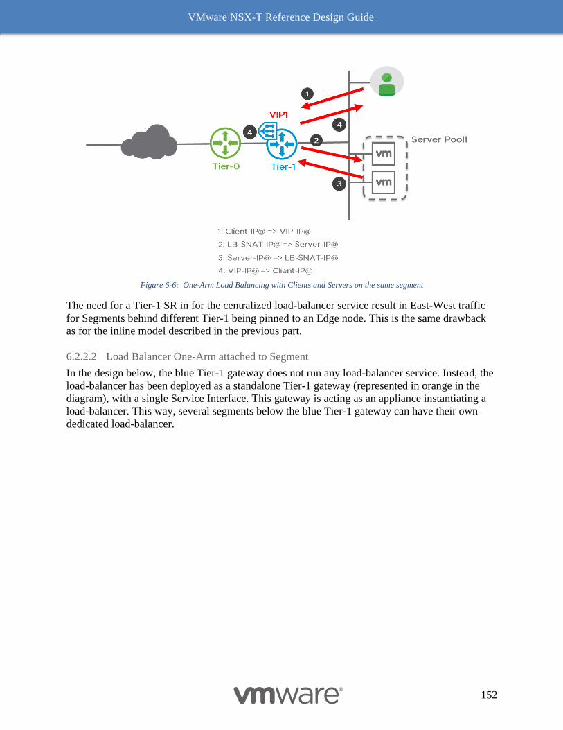
VMware NSX-T Reference Design Guide
152
Figure 6-6: One-Arm Load Balancing with Clients and Servers on the same segment
The need for a Tier-1 SR in for the centralized load-balancer service result in East-West traffic
for Segments behind different Tier-1 being pinned to an Edge node. This is the same drawback
as for the inline model described in the previous part.
6.2.2.2 Load Balancer One-Arm attached to Segment
In the design below, the blue Tier-1 gateway does not run any load-balancer service. Instead, the
load-balancer has been deployed as a standalone Tier-1 gateway (represented in orange in the
diagram), with a single Service Interface. This gateway is acting as an appliance instantiating a
load-balancer. This way, several segments below the blue Tier-1 gateway can have their own
dedicated load-balancer.
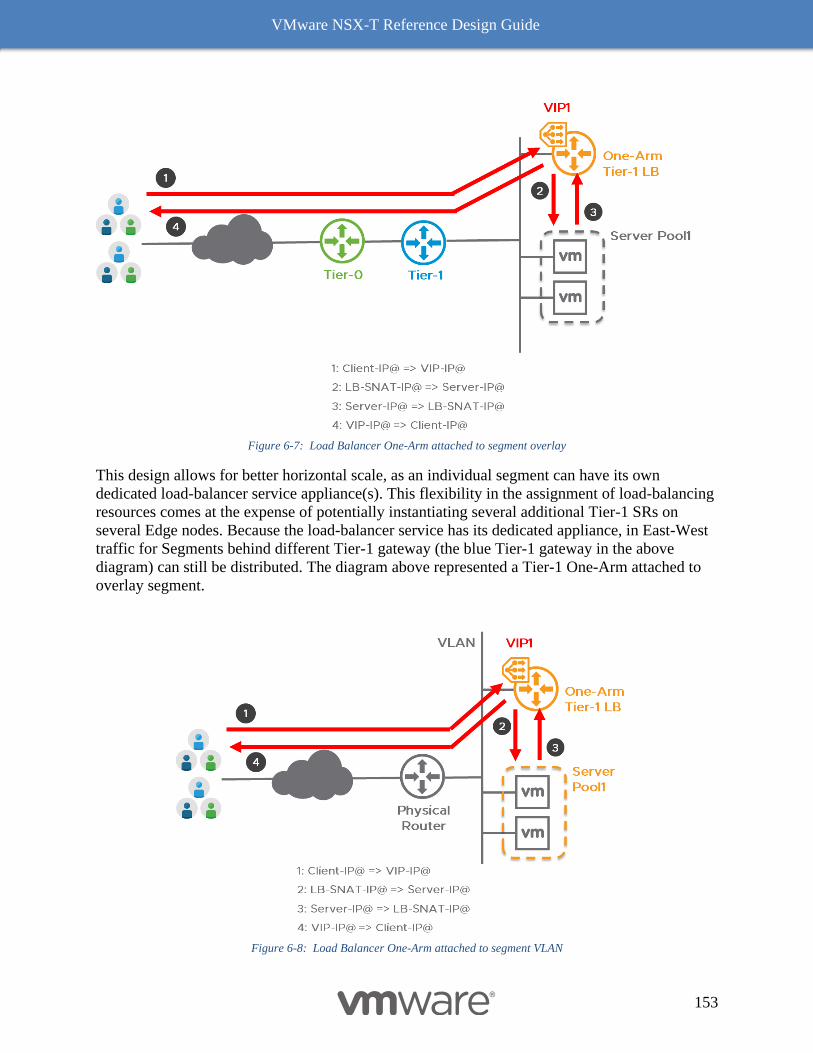
VMware NSX-T Reference Design Guide
153
Figure 6-7: Load Balancer One-Arm attached to segment overlay
This design allows for better horizontal scale, as an individual segment can have its own
dedicated load-balancer service appliance(s). This flexibility in the assignment of load-balancing
resources comes at the expense of potentially instantiating several additional Tier-1 SRs on
several Edge nodes. Because the load-balancer service has its dedicated appliance, in East-West
traffic for Segments behind different Tier-1 gateway (the blue Tier-1 gateway in the above
diagram) can still be distributed. The diagram above represented a Tier-1 One-Arm attached to
overlay segment.
Figure 6-8: Load Balancer One-Arm attached to segment VLAN
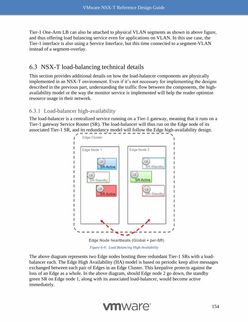
VMware NSX-T Reference Design Guide
154
Tier-1 One-Arm LB can also be attached to physical VLAN segments as shown in above figure,
and thus offering load balancing service even for applications on VLAN. In this use case, the
Tier-1 interface is also using a Service Interface, but this time connected to a segment-VLAN
instead of a segment-overlay.
NSX-T load-balancing technical details
This section provides additional details on how the load-balancer components are physically
implemented in an NSX-T environment. Even if it’s not necessary for implementing the designs
described in the previous part, understanding the traffic flow between the components, the high-
availability model or the way the monitor service is implemented will help the reader optimize
resource usage in their network.
Load-balancer high-availability
The load-balancer is a centralized service running on a Tier-1 gateway, meaning that it runs on a
Tier-1 gateway Service Router (SR). The load-balancer will thus run on the Edge node of its
associated Tier-1 SR, and its redundancy model will follow the Edge high-availability design.
Figure 6-9: Load Balancing High-Availability
The above diagram represents two Edge nodes hosting three redundant Tier-1 SRs with a load-
balancer each. The Edge High Availability (HA) model is based on periodic keep alive messages
exchanged between each pair of Edges in an Edge Cluster. This keepalive protects against the
loss of an Edge as a whole. In the above diagram, should Edge node 2 go down, the standby
green SR on Edge node 1, along with its associated load-balancer, would become active
immediately.
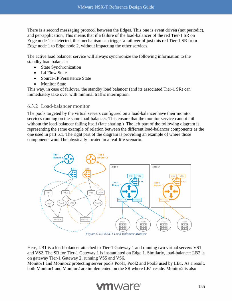
VMware NSX-T Reference Design Guide
155
There is a second messaging protocol between the Edges. This one is event driven (not periodic),
and per-application. This means that if a failure of the load-balancer of the red Tier-1 SR on
Edge node 1 is detected, this mechanism can trigger a failover of just this red Tier-1 SR from
Edge node 1 to Edge node 2, without impacting the other services.
The active load balancer service will always synchronize the following information to the
standby load balancer:
• State Synchronization
• L4 Flow State
• Source-IP Persistence State
• Monitor State
This way, in case of failover, the standby load balancer (and its associated Tier-1 SR) can
immediately take over with minimal traffic interruption.
Load-balancer monitor
The pools targeted by the virtual servers configured on a load-balancer have their monitor
services running on the same load-balancer. This ensure that the monitor service cannot fail
without the load-balancer failing itself (fate sharing.) The left part of the following diagram is
representing the same example of relation between the different load-balancer components as the
one used in part 6.1. The right part of the diagram is providing an example of where those
components would be physically located in a real-life scenario.
Figure 6-10: NSX-T Load Balancer Monitor
Here, LB1 is a load-balancer attached to Tier-1 Gateway 1 and running two virtual servers VS1
and VS2. The SR for Tier-1 Gateway 1 is instantiated on Edge 1. Similarly, load-balancer LB2 is
on gateway Tier-1 Gateway 2, running VS5 and VS6.
Monitor1 and Monitor2 protecting server pools Pool1, Pool2 and Pool3 used by LB1. As a result,
both Monitor1 and Monitor2 are implemented on the SR where LB1 reside. Monitor2 is also
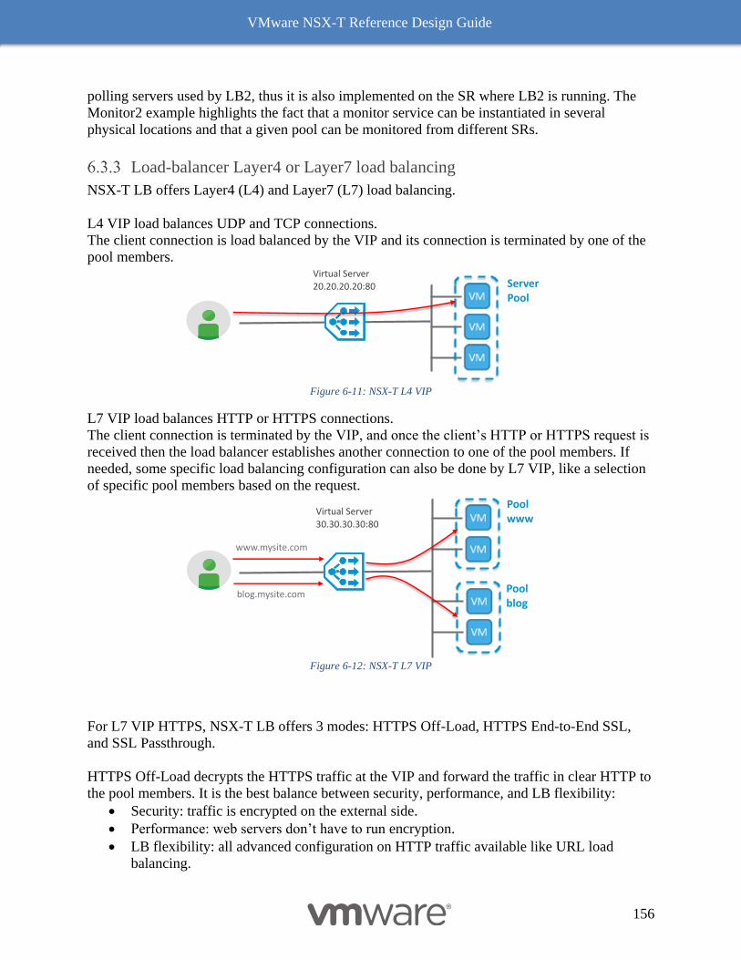
VMware NSX-T Reference Design Guide
156
polling servers used by LB2, thus it is also implemented on the SR where LB2 is running. The
Monitor2 example highlights the fact that a monitor service can be instantiated in several
physical locations and that a given pool can be monitored from different SRs.
Load-balancer Layer4 or Layer7 load balancing
NSX-T LB offers Layer4 (L4) and Layer7 (L7) load balancing.
L4 VIP load balances UDP and TCP connections.
The client connection is load balanced by the VIP and its connection is terminated by one of the
pool members.
Figure 6-11: NSX-T L4 VIP
L7 VIP load balances HTTP or HTTPS connections.
The client connection is terminated by the VIP, and once the client’s HTTP or HTTPS request is
received then the load balancer establishes another connection to one of the pool members. If
needed, some specific load balancing configuration can also be done by L7 VIP, like a selection
of specific pool members based on the request.
Figure 6-12: NSX-T L7 VIP
For L7 VIP HTTPS, NSX-T LB offers 3 modes: HTTPS Off-Load, HTTPS End-to-End SSL,
and SSL Passthrough.
HTTPS Off-Load decrypts the HTTPS traffic at the VIP and forward the traffic in clear HTTP to
the pool members. It is the best balance between security, performance, and LB flexibility:
• Security: traffic is encrypted on the external side.
• Performance: web servers don’t have to run encryption.
• LB flexibility: all advanced configuration on HTTP traffic available like URL load
balancing.
Server Pool
Virtual Server
20.20.20.20:80
Poolwww
Poolblog
www.mysite.com
blog.mysite.com
Virtual Server
30.30.30.30:80
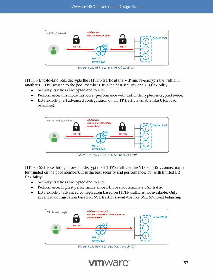
VMware NSX-T Reference Design Guide
157
Figure 6-13: NSX-T L7 HTTPS Off-Load VIP
HTTPS End-to-End SSL decrypts the HTTPS traffic at the VIP and re-encrypts the traffic in
another HTTPS session to the pool members. It is the best security and LB flexibility:
• Security: traffic is encrypted end to end.
• Performance: this mode has lower performance with traffic decrypted/encrypted twice.
• LB flexibility: all advanced configuration on HTTP traffic available like URL load
balancing.
Figure 6-14: NSX-T L7 HTTPS End-to-End VIP
HTTPS SSL Passthrough does not decrypt the HTTPS traffic at the VIP and SSL connection is
terminated on the pool members. It is the best security and performance, but with limited LB
flexibility:
• Security: traffic is encrypted end to end.
• Performance: highest performance since LB does not terminate SSL traffic
• LB flexibility: advanced configuration based on HTTP traffic is not available. Only
advanced configuration based on SSL traffic is available like SSL SNI load balancing.
Figure 6-15: NSX-T L7 SSL Passthrough VIP
HTTPS Off-Load
Server PoolS
S
S
HTTPS HTTP
VIP L7HTTPS:443
LB decryptsand forwards in clear
HTTPS End-to-End SSL
Server PoolS
S
S
HTTPS HTTPS
VIP L7HTTPS:443
LB decryptsand re-encrypts before forwarding
SSL Passthrough
Server PoolS
S
S
HTTPS
VIP L7HTTPS:443
LB does not decryptand SSL connection is terminated on Pool Members

VMware NSX-T Reference Design Guide
158
Load-balancer IPv6
NSX-T LB has many NSX-T network and security services offers its service for IPv4 and IPv6
clients.
Figure 6-16: NSX-T LB IPv4 and IPv6
Load-balancer traffic flows
Tier-1 gateway looks like a single entity from a logical point of view. However, and as
mentioned several times already, when a load-balancer is configured on a Tier-1 gateway, it is
physically instantiated on a Tier-1 Gateway Service Router. This part is exploring the scenarios
where the logical representation of a Tier-1 gateway, hiding the distinction between SR and DR,
can lead to confusion.
6.3.5.1 The in-line model
With the in-line model, traffic between the clients and the servers necessarily go through the load
balancer. Thanks to this property, there is no need for source LB-SNAT in order to make sure
that traffic goes through the load balancer both ways. The following diagram shows both logical
and physical representation of a Tier-1 gateway used to host a load-balancer operating in-line.
Clearly, traffic from clients must go through the Tier-1 SR where the load-balancer is
instantiated in order to reach the server and vice versa:
LB IPv4
Pool Members
IPv4
Clients
IPv4
VIP
IPv4
Server
PoolS
S
LBClients
IPv4 IPv4
LB IPv6
Pool Members
IPv6
Clients
IPv6
VIP
IPv6
Server
PoolS
S
LBClients
IPv6 IPv6
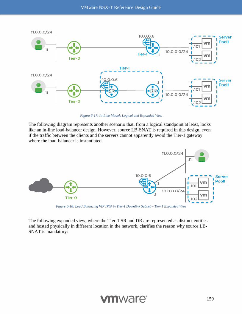
VMware NSX-T Reference Design Guide
159
Figure 6-17: In-Line Model: Logical and Expanded View
The following diagram represents another scenario that, from a logical standpoint at least, looks
like an in-line load-balancer design. However, source LB-SNAT is required in this design, even
if the traffic between the clients and the servers cannot apparently avoid the Tier-1 gateway
where the load-balancer is instantiated.
Figure 6-18: Load Balancing VIP IP@ in Tier-1 Downlink Subnet – Tier-1 Expanded View
The following expanded view, where the Tier-1 SR and DR are represented as distinct entities
and hosted physically in different location in the network, clarifies the reason why source LB-
SNAT is mandatory:
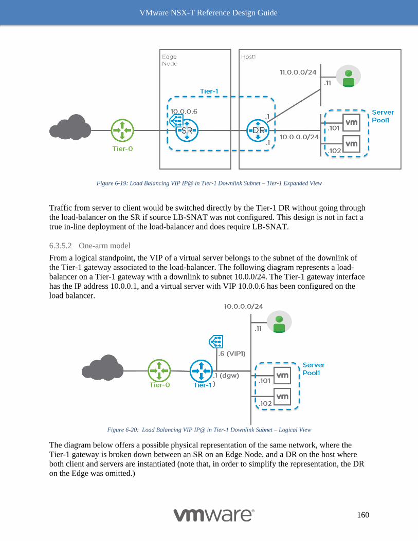
VMware NSX-T Reference Design Guide
160
Figure 6-19: Load Balancing VIP IP@ in Tier-1 Downlink Subnet – Tier-1 Expanded View
Traffic from server to client would be switched directly by the Tier-1 DR without going through
the load-balancer on the SR if source LB-SNAT was not configured. This design is not in fact a
true in-line deployment of the load-balancer and does require LB-SNAT.
6.3.5.2 One-arm model
From a logical standpoint, the VIP of a virtual server belongs to the subnet of the downlink of
the Tier-1 gateway associated to the load-balancer. The following diagram represents a load-
balancer on a Tier-1 gateway with a downlink to subnet 10.0.0/24. The Tier-1 gateway interface
has the IP address 10.0.0.1, and a virtual server with VIP 10.0.0.6 has been configured on the
load balancer.
Figure 6-20: Load Balancing VIP IP@ in Tier-1 Downlink Subnet – Logical View
The diagram below offers a possible physical representation of the same network, where the
Tier-1 gateway is broken down between an SR on an Edge Node, and a DR on the host where
both client and servers are instantiated (note that, in order to simplify the representation, the DR
on the Edge was omitted.)
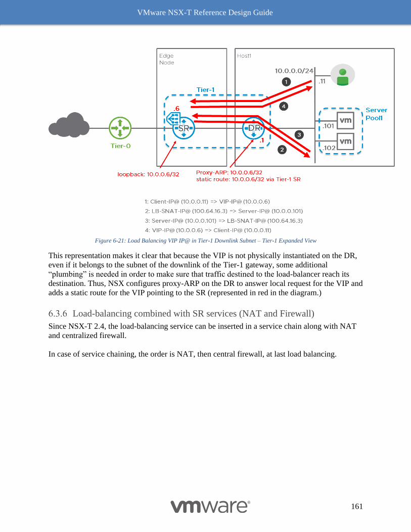
VMware NSX-T Reference Design Guide
161
Figure 6-21: Load Balancing VIP IP@ in Tier-1 Downlink Subnet – Tier-1 Expanded View
This representation makes it clear that because the VIP is not physically instantiated on the DR,
even if it belongs to the subnet of the downlink of the Tier-1 gateway, some additional
“plumbing” is needed in order to make sure that traffic destined to the load-balancer reach its
destination. Thus, NSX configures proxy-ARP on the DR to answer local request for the VIP and
adds a static route for the VIP pointing to the SR (represented in red in the diagram.)
Load-balancing combined with SR services (NAT and Firewall)
Since NSX-T 2.4, the load-balancing service can be inserted in a service chain along with NAT
and centralized firewall.
In case of service chaining, the order is NAT, then central firewall, at last load balancing.
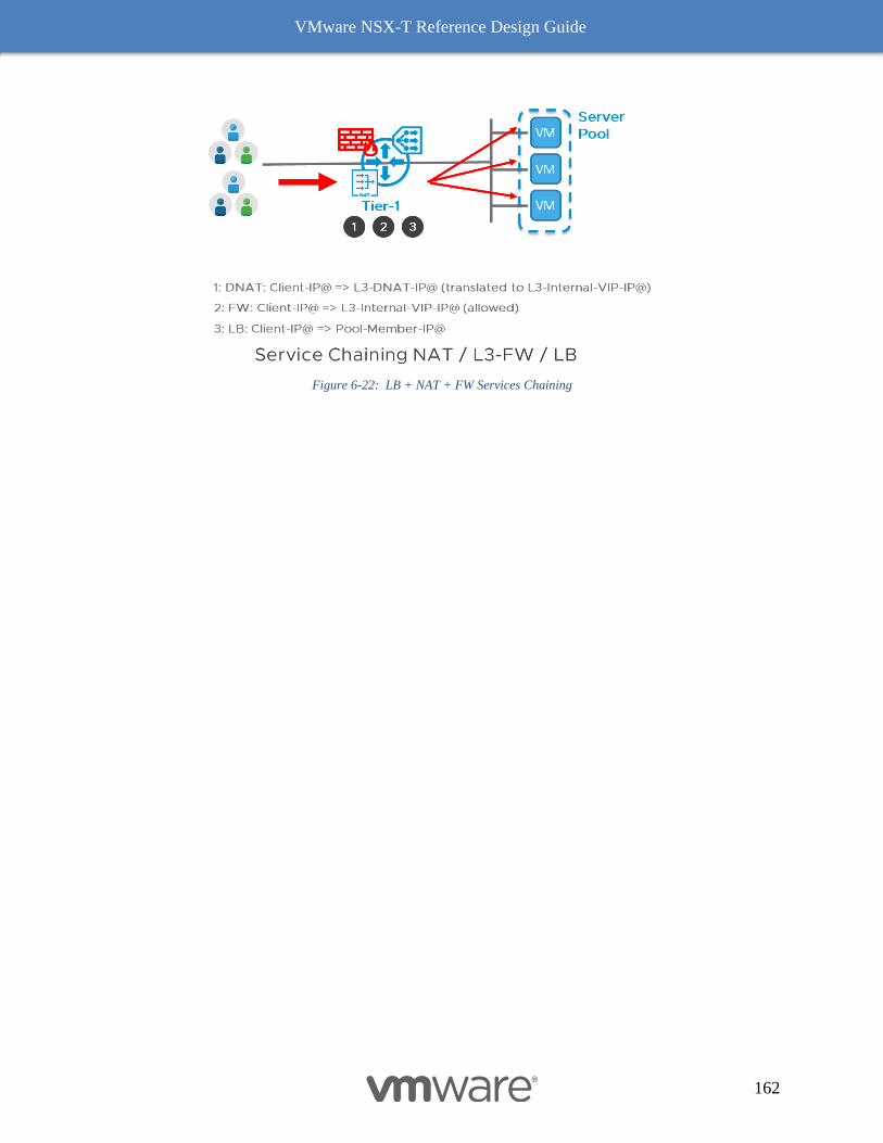
VMware NSX-T Reference Design Guide
162
Figure 6-22: LB + NAT + FW Services Chaining
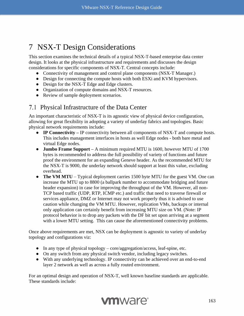
VMware NSX-T Reference Design Guide
163
7 NSX-T Design Considerations This section examines the technical details of a typical NSX-T-based enterprise data center
design. It looks at the physical infrastructure and requirements and discusses the design
considerations for specific components of NSX-T. Central concepts include:
● Connectivity of management and control plane components (NSX-T Manager.)
● Design for connecting the compute hosts with both ESXi and KVM hypervisors.
● Design for the NSX-T Edge and Edge clusters.
● Organization of compute domains and NSX-T resources.
● Review of sample deployment scenarios.
Physical Infrastructure of the Data Center
An important characteristic of NSX-T is its agnostic view of physical device configuration,
allowing for great flexibility in adopting a variety of underlay fabrics and topologies. Basic
physical network requirements include:
● IP Connectivity – IP connectivity between all components of NSX-T and compute hosts.
This includes management interfaces in hosts as well Edge nodes - both bare metal and
virtual Edge nodes.
● Jumbo Frame Support – A minimum required MTU is 1600, however MTU of 1700
bytes is recommended to address the full possibility of variety of functions and future
proof the environment for an expanding Geneve header. As the recommended MTU for
the NSX-T is 9000, the underlay network should support at least this value, excluding
overhead.
● The VM MTU – Typical deployment carries 1500 byte MTU for the guest VM. One can
increase the MTU up to 8800 (a ballpark number to accommodate bridging and future
header expansion) in case for improving the throughput of the VM. However, all non-
TCP based traffic (UDP, RTP, ICMP etc.) and traffic that need to traverse firewall or
services appliance, DMZ or Internet may not work properly thus it is advised to use
caution while changing the VM MTU. However, replication VMs, backups or internal
only application can certainly benefit from increasing MTU size on VM. (Note: IP
protocol behavior is to drop any packets with the DF bit set upon arriving at a segment
with a lower MTU setting. This can cause the aforementioned connectivity problems.
Once above requirements are met, NSX can be deployment is agnostic to variety of underlay
topology and configurations viz:
● In any type of physical topology – core/aggregation/access, leaf-spine, etc.
● On any switch from any physical switch vendor, including legacy switches.
● With any underlying technology. IP connectivity can be achieved over an end-to-end
layer 2 network as well as across a fully routed environment.
For an optimal design and operation of NSX-T, well known baseline standards are applicable.
These standards include:
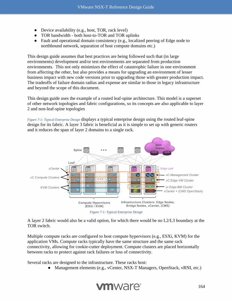
VMware NSX-T Reference Design Guide
164
● Device availability (e.g., host, TOR, rack level)
● TOR bandwidth - both host-to-TOR and TOR uplinks
● Fault and operational domain consistency (e.g., localized peering of Edge node to
northbound network, separation of host compute domains etc.)
This design guide assumes that best practices are being followed such that (in large
environments) development and/or test environments are separated from production
environments. This not only minimizes the effect of catastrophic failure in one environment
from affecting the other, but also provides a means for upgrading an environment of lesser
business impact with new code versions prior to upgrading those with greater production impact.
The tradeoffs of failure domain radius and expense are similar to those in legacy infrastructure
and beyond the scope of this document.
This design guide uses the example of a routed leaf-spine architecture. This model is a superset
of other network topologies and fabric configurations, so its concepts are also applicable to layer
2 and non-leaf-spine topologies
Figure 7-1: Typical Enterprise Design displays a typical enterprise design using the routed leaf-spine
design for its fabric. A layer 3 fabric is beneficial as it is simple to set up with generic routers
and it reduces the span of layer 2 domains to a single rack.
Figure 7-1: Typical Enterprise Design
A layer 2 fabric would also be a valid option, for which there would be no L2/L3 boundary at the
TOR switch.
Multiple compute racks are configured to host compute hypervisors (e.g., ESXi, KVM) for the
application VMs. Compute racks typically have the same structure and the same rack
connectivity, allowing for cookie-cutter deployment. Compute clusters are placed horizontally
between racks to protect against rack failures or loss of connectivity.
Several racks are designed to the infrastructure. These racks host:
● Management elements (e.g., vCenter, NSX-T Managers, OpenStack, vRNI, etc.)
VMware NSX-T Reference Design Guide
165
● Bare metal Edge or Edge node VMs
● Clustered elements are spread between racks to be resilient to rack failures
The different components involved in NSX-T send different kinds of traffic in the network; these
are typically categorized using different VLANs. A hypervisor could send management, storage,
and vMotion that would leverage three different VLAN tags. Because this particular physical
infrastructure terminates layer 3 at the TOR switch, the span of all VLANs is limited to a single
rack. The management VLAN on one rack is not the same broadcast domain as the management
VLAN on a different rack as they lack L2 connectivity. In order to simplify the configuration,
the same VLAN ID is however typically assigned consistently across rack for each category of
traffic. Figure 7-2: Typical Layer 3 Design with Example of VLAN/Subnet details an example of VLAN and IP
subnet assignment across racks.
Figure 7-2: Typical Layer 3 Design with Example of VLAN/Subnet
Upcoming examples will provide more detailed recommendations on the subnet and VLAN
assignment based on the NSX-T component specifics. For smaller NSX deployments, these
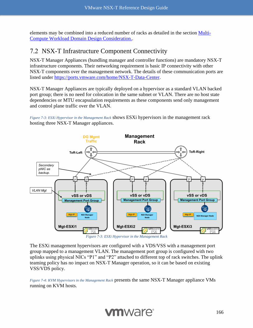
VMware NSX-T Reference Design Guide
166
elements may be combined into a reduced number of racks as detailed in the section Multi-
Compute Workload Domain Design Consideration..
NSX-T Infrastructure Component Connectivity
NSX-T Manager Appliances (bundling manager and controller functions) are mandatory NSX-T
infrastructure components. Their networking requirement is basic IP connectivity with other
NSX-T components over the management network. The details of these communication ports are
listed under https://ports.vmware.com/home/NSX-T-Data-Center.
NSX-T Manager Appliances are typically deployed on a hypervisor as a standard VLAN backed
port group; there is no need for colocation in the same subnet or VLAN. There are no host state
dependencies or MTU encapsulation requirements as these components send only management
and control plane traffic over the VLAN.
Figure 7-3: ESXi Hypervisor in the Management Rack shows ESXi hypervisors in the management rack
hosting three NSX-T Manager appliances.
Figure 7-3: ESXi Hypervisor in the Management Rack
The ESXi management hypervisors are configured with a VDS/VSS with a management port
group mapped to a management VLAN. The management port group is configured with two
uplinks using physical NICs “P1” and “P2” attached to different top of rack switches. The uplink
teaming policy has no impact on NSX-T Manager operation, so it can be based on existing
VSS/VDS policy.
Figure 7-4: KVM Hypervisors in the Management Rack presents the same NSX-T Manager appliance VMs
running on KVM hosts.
Mgt-ESXi1
Secondary pNIC as backup.
VLAN Mgt
P1
P2
vSS or vDS
DG MgmtTraffic
Management Rack
Mgt-ESXi2
P1
P2
vSS or vDSManagement Port Group
Mgt-ESXi3
P1
P2
vSS or vDSManagement Port Group
NSX Manager NodeNSX Manager
Node
Mgt-IP Mgt-IP Mgt-IP
Management Port Group
NSX Manager
Node
ToR-RightToR-Left
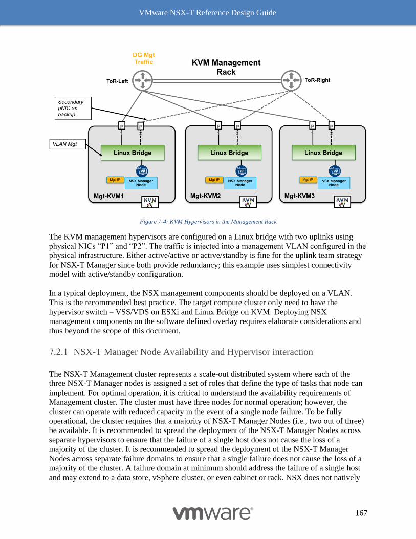
VMware NSX-T Reference Design Guide
167
Figure 7-4: KVM Hypervisors in the Management Rack
The KVM management hypervisors are configured on a Linux bridge with two uplinks using
physical NICs “P1” and “P2”. The traffic is injected into a management VLAN configured in the
physical infrastructure. Either active/active or active/standby is fine for the uplink team strategy
for NSX-T Manager since both provide redundancy; this example uses simplest connectivity
model with active/standby configuration.
In a typical deployment, the NSX management components should be deployed on a VLAN.
This is the recommended best practice. The target compute cluster only need to have the
hypervisor switch – VSS/VDS on ESXi and Linux Bridge on KVM. Deploying NSX
management components on the software defined overlay requires elaborate considerations and
thus beyond the scope of this document.
NSX-T Manager Node Availability and Hypervisor interaction
The NSX-T Management cluster represents a scale-out distributed system where each of the
three NSX-T Manager nodes is assigned a set of roles that define the type of tasks that node can
implement. For optimal operation, it is critical to understand the availability requirements of
Management cluster. The cluster must have three nodes for normal operation; however, the
cluster can operate with reduced capacity in the event of a single node failure. To be fully
operational, the cluster requires that a majority of NSX-T Manager Nodes (i.e., two out of three)
be available. It is recommended to spread the deployment of the NSX-T Manager Nodes across
separate hypervisors to ensure that the failure of a single host does not cause the loss of a
majority of the cluster. It is recommended to spread the deployment of the NSX-T Manager
Nodes across separate failure domains to ensure that a single failure does not cause the loss of a
majority of the cluster. A failure domain at minimum should address the failure of a single host
and may extend to a data store, vSphere cluster, or even cabinet or rack. NSX does not natively
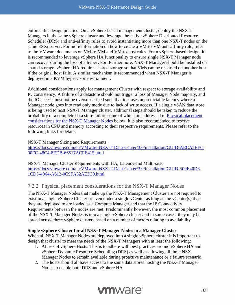
VMware NSX-T Reference Design Guide
168
enforce this design practice. On a vSphere-based management cluster, deploy the NSX-T
Managers in the same vSphere cluster and leverage the native vSphere Distributed Resource
Scheduler (DRS) and anti-affinity rules to avoid instantiating more than one NSX-T nodes on the
same ESXi server. For more information on how to create a VM-to-VM anti-affinity rule, refer
to the VMware documents on VM-to-VM and VM-to-host rules. For a vSphere-based design, it
is recommended to leverage vSphere HA functionality to ensure single NSX-T Manager node
can recover during the loss of a hypervisor. Furthermore, NSX-T Manager should be installed on
shared storage. vSphere HA requires shared storage so that VMs can be restarted on another host
if the original host fails. A similar mechanism is recommended when NSX-T Manager is
deployed in a KVM hypervisor environment.
Additional considerations apply for management Cluster with respect to storage availability and
IO consistency. A failure of a datastore should not trigger a loss of Manager Node majority, and
the IO access must not be oversubscribed such that it causes unpredictable latency where a
Manager node goes into read only mode due to lack of write access. If a single vSAN data store
is being used to host NSX-T Manager cluster, additional steps should be taken to reduce the
probability of a complete data store failure some of which are addressed in Physical placement
considerations for the NSX-T Manager Nodes below. It is also recommended to reserve
resources in CPU and memory according to their respective requirements. Please refer to the
following links for details
NSX-T Manager Sizing and Requirements:
https://docs.vmware.com/en/VMware-NSX-T-Data-Center/3.0/installation/GUID-AECA2EE0-
90FC-48C4-8EDB-66517ACFE415.html
NSX-T Manager Cluster Requirements with HA, Latency and Multi-site:
https://docs.vmware.com/en/VMware-NSX-T-Data-Center/3.0/installation/GUID-509E40D3-
1CD5-4964-A612-0C9FA32AE3C0.html
Physical placement considerations for the NSX-T Manager Nodes
The NSX-T Manager Nodes that make up the NSX-T Management Cluster are not required to
exist in a single vSphere Cluster or even under a single vCenter as long as the vCenter(s) that
they are deployed to are loaded as a Compute Manager and that the IP Connectivity
Requirements between the nodes are met. Predominantly however, the most common placement
of the NSX-T Manager Nodes is into a single vSphere cluster and in some cases, they may be
spread across three vSphere clusters based on a number of factors relating to availability.
Single vSphere Cluster for all NSX-T Manager Nodes in a Manager Cluster
When all NSX-T Manager Nodes are deployed into a single vSphere cluster it is important to
design that cluster to meet the needs of the NSX-T Managers with at least the following:
1. At least 4 vSphere Hosts. This is to adhere with best practices around vSphere HA and
vSphere Dynamic Resource Scheduling (DRS) as well as allowing all three NSX
Manager Nodes to remain available during proactive maintenance or a failure scenario.
2. The hosts should all have access to the same data stores hosting the NSX-T Manager
Nodes to enable both DRS and vSphere HA
VMware NSX-T Reference Design Guide
169
3. Each NSX-T Manager Node should be deployed onto a different data store (this is
supported as a VMFS, NFS, or other data store technology supported by vSphere)
4. DRS Anti-Affinity rules should be put in place to prevent whenever possible two Edge
Node VMs from running on the same host.
5. During lifecycle events of this cluster, each node should be independently put into
maintenance mode moving any running NSX-T Manager Node off of the host prior to
maintenance or any NSX-T Manager Node should be manually moved to a different host.
6. If possible, a rack level or critical infrastructure (e.g. Power, HVAC, ToRs) should also
be taken into account to protect this cluster from any single failure event taking down the
entire cluster at once. In many cases this means spreading this cluster across multiple
cabinets or racks and therefore connecting the hosts in it to a diverse set of physical
switches etc.
7. NSX-T Manager backups should be configured and pointed to a location that is running
outside of the vSphere Cluster that the NSX Manager Nodes are deployed on.
Figure 7-5: Single vSphere Cluster 1:1 Data Store
Single vSphere Cluster when leveraging VSAN as the storage technology
When all NSX-T Manager Nodes are deployed into a single vSphere cluster where VSAN is the
storage technology in use there are additional steps that should be taken to protect the NSX
Manager Cluster’s availability since only a single data store will be presented. VSAN as a part of
a HyperConverged Infrastructure solution ties together the Compute, Memory, and Storage
resources on a host along with ESXi as the hypervisor to present a single scale-out unit of
infrastructure for hosting Virtual Machines, Containers, or even now network attached storage
type objects as a single pool across the cluster. The availability of the resources associated with
storage are governed by a few specific parameters including, Primary Levels of Failures to
Tolerate (PFTT), Secondary Levels of Failures to Tolerate (SFTT), and Failure Tolerance Mode
(FTM) (when only a single site in VSAN is configured, PFTT is set to 0 and SFTT is usually
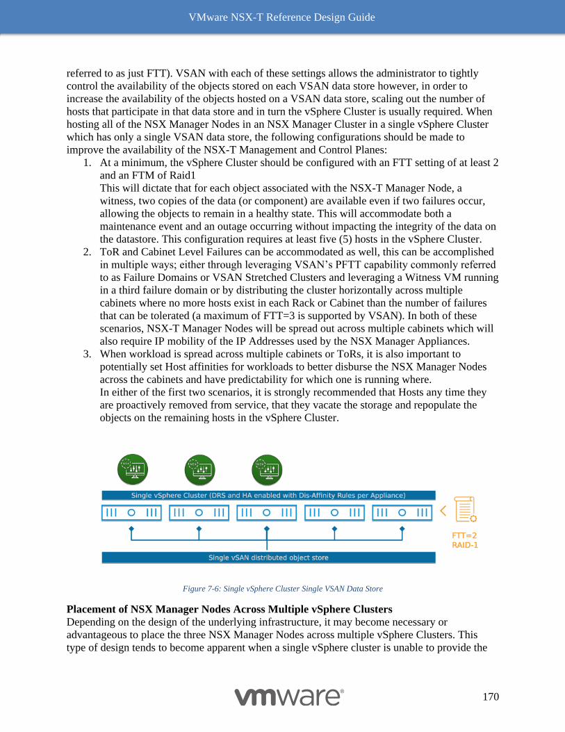
VMware NSX-T Reference Design Guide
170
referred to as just FTT). VSAN with each of these settings allows the administrator to tightly
control the availability of the objects stored on each VSAN data store however, in order to
increase the availability of the objects hosted on a VSAN data store, scaling out the number of
hosts that participate in that data store and in turn the vSphere Cluster is usually required. When
hosting all of the NSX Manager Nodes in an NSX Manager Cluster in a single vSphere Cluster
which has only a single VSAN data store, the following configurations should be made to
improve the availability of the NSX-T Management and Control Planes:
1. At a minimum, the vSphere Cluster should be configured with an FTT setting of at least 2
and an FTM of Raid1
This will dictate that for each object associated with the NSX-T Manager Node, a
witness, two copies of the data (or component) are available even if two failures occur,
allowing the objects to remain in a healthy state. This will accommodate both a
maintenance event and an outage occurring without impacting the integrity of the data on
the datastore. This configuration requires at least five (5) hosts in the vSphere Cluster.
2. ToR and Cabinet Level Failures can be accommodated as well, this can be accomplished
in multiple ways; either through leveraging VSAN’s PFTT capability commonly referred
to as Failure Domains or VSAN Stretched Clusters and leveraging a Witness VM running
in a third failure domain or by distributing the cluster horizontally across multiple
cabinets where no more hosts exist in each Rack or Cabinet than the number of failures
that can be tolerated (a maximum of FTT=3 is supported by VSAN). In both of these
scenarios, NSX-T Manager Nodes will be spread out across multiple cabinets which will
also require IP mobility of the IP Addresses used by the NSX Manager Appliances.
3. When workload is spread across multiple cabinets or ToRs, it is also important to
potentially set Host affinities for workloads to better disburse the NSX Manager Nodes
across the cabinets and have predictability for which one is running where.
In either of the first two scenarios, it is strongly recommended that Hosts any time they
are proactively removed from service, that they vacate the storage and repopulate the
objects on the remaining hosts in the vSphere Cluster.
Figure 7-6: Single vSphere Cluster Single VSAN Data Store
Placement of NSX Manager Nodes Across Multiple vSphere Clusters
Depending on the design of the underlying infrastructure, it may become necessary or
advantageous to place the three NSX Manager Nodes across multiple vSphere Clusters. This
type of design tends to become apparent when a single vSphere cluster is unable to provide the
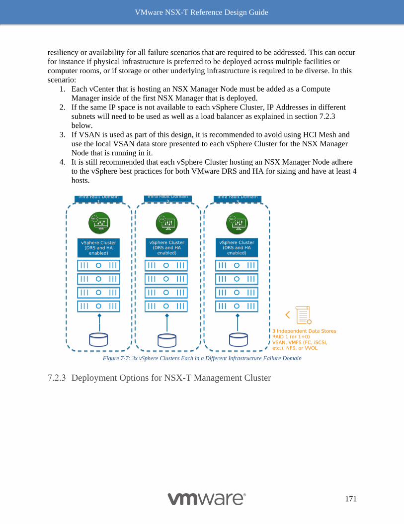
VMware NSX-T Reference Design Guide
171
resiliency or availability for all failure scenarios that are required to be addressed. This can occur
for instance if physical infrastructure is preferred to be deployed across multiple facilities or
computer rooms, or if storage or other underlying infrastructure is required to be diverse. In this
scenario:
1. Each vCenter that is hosting an NSX Manager Node must be added as a Compute
Manager inside of the first NSX Manager that is deployed.
2. If the same IP space is not available to each vSphere Cluster, IP Addresses in different
subnets will need to be used as well as a load balancer as explained in section 7.2.3
below.
3. If VSAN is used as part of this design, it is recommended to avoid using HCI Mesh and
use the local VSAN data store presented to each vSphere Cluster for the NSX Manager
Node that is running in it.
4. It is still recommended that each vSphere Cluster hosting an NSX Manager Node adhere
to the vSphere best practices for both VMware DRS and HA for sizing and have at least 4
hosts.
Figure 7-7: 3x vSphere Clusters Each in a Different Infrastructure Failure Domain
Deployment Options for NSX-T Management Cluster
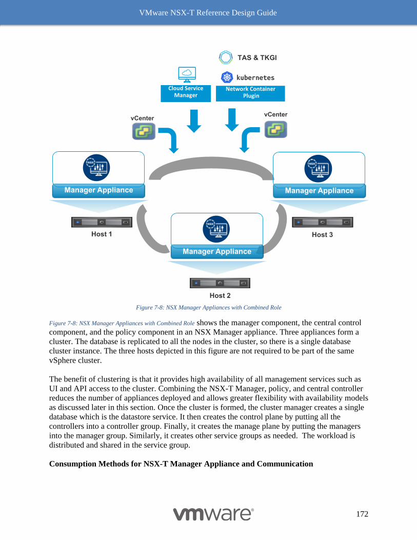
VMware NSX-T Reference Design Guide
172
Figure 7-8: NSX Manager Appliances with Combined Role
Figure 7-8: NSX Manager Appliances with Combined Role shows the manager component, the central control
component, and the policy component in an NSX Manager appliance. Three appliances form a
cluster. The database is replicated to all the nodes in the cluster, so there is a single database
cluster instance. The three hosts depicted in this figure are not required to be part of the same
vSphere cluster.
The benefit of clustering is that it provides high availability of all management services such as
UI and API access to the cluster. Combining the NSX-T Manager, policy, and central controller
reduces the number of appliances deployed and allows greater flexibility with availability models
as discussed later in this section. Once the cluster is formed, the cluster manager creates a single
database which is the datastore service. It then creates the control plane by putting all the
controllers into a controller group. Finally, it creates the manage plane by putting the managers
into the manager group. Similarly, it creates other service groups as needed. The workload is
distributed and shared in the service group.
Consumption Methods for NSX-T Manager Appliance and Communication
vCenter
Cloud ServiceManager
Network ContainerPlugin
vCenter
Host 1
Manager Appliance
Host 2
Manager Appliance
Host 3
Manager Appliance
TAS & TKGI
VMware NSX-T Reference Design Guide
173
NSX-T Manager appliance serves two critical areas of consumption. The first one is the external
systems and user access. Many different end points (such as HTTP, vRA, Terraform, Network
Container Plugin, custom automation modules) can consume NSX-T Manager from northbound
via an IP address. It’s is a single point of entry (using RESTful API - GUI internally makes and
API call). Second is communication to NSX-T components (controllers and transport node). The
controller communication to transport node is done via controller role (element) within the NSX-
T appliance node. The controller communication to NSX-T components were described chapter
2. The controller availability models remain majority based requiring all three nodes to be
available for normal operations. However, starting with NSX-T 2.4 release, the NSX-T Manager
role has multiple availability models. The rest of the section discusses the NSX-T Manager role
configuration and availability options. There are three different configuration modes available
for northbound access to the NSX-T Manager cluster.
◼ Default deployment (each node uniquely addressable, no common IP address)
◼ Cluster VIP based deployment
◼ External Load Balancer based deployment
Default Deployment
The default (and the simplest option, with the least number of IP addresses consumed) is to
deploy a 3-node cluster without any additional configuration. With this option, each node is
accessible via distinct IP address (or FQDN) and thus multiple endpoints (user and automation
systems) can access each different node to build redundancy and load balancing model for NSX-
T Manager role. Here the availability is driven via external system choosing different IP address
(FQDN). However, in case of the node failure the system using that node must externally
intervene to point to another available node. For an example, if vRA or API script uses the
FQDN of node A, in case node A fails, there has to be some manual intervention to make the
script continues to work, either you change the FQDN in your API script, or update the FQDN
entry in the DNS. In this configuration, using round robin DNS will result in intermittent
connectivity in a failure scenario. But in terms of topology requirement, as long as there is IP
connectivity between all the nodes, this mode will work.
Cluster VIP based deployment
The second deployment option is based on simple active/standbys redundancy model, in which
one has to configure a virtual IP address on the management cluster. Cluster VIP configuration
option provide node level redundancy through the virtual IP address on the cluster itself. This
virtual IP (like VRRP/HSRP) provides redundancy of accessing the cluster via single FQDN. In
other words: the entire northbound access to the NSX-T Manager is available via this FQDN (or
IP). Since it is a single FQDN name available to all end points, all the GUI and API requests are
accessed through single node owning the VIP as shown in Figure 7-9: NSX Manager Appliances Availability
with Cluster VIP. Essentially, it is a simple availability model, which is far better default option
where external intervention is not required, and availability of NSX-T Manager role is improved
from external restore option to full in-line availability which did not exist in previous releases.
Cluster virtual IP address is an IP address floating among the cluster nodes. One of the cluster
nodes is assigned as the owner of the cluster VIP. If case of failure, a new owner will be assigned
by the system. Since the cluster VIP must remain the same, it assumes that other nodes are
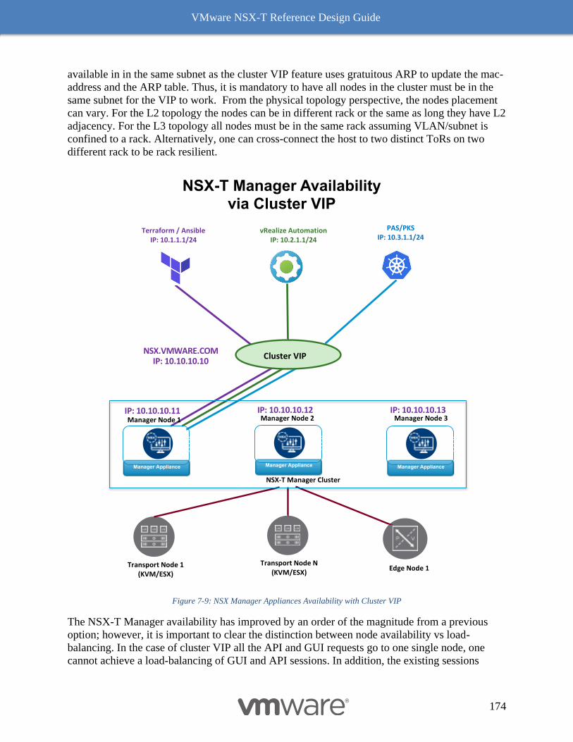
VMware NSX-T Reference Design Guide
174
available in in the same subnet as the cluster VIP feature uses gratuitous ARP to update the mac-
address and the ARP table. Thus, it is mandatory to have all nodes in the cluster must be in the
same subnet for the VIP to work. From the physical topology perspective, the nodes placement
can vary. For the L2 topology the nodes can be in different rack or the same as long they have L2
adjacency. For the L3 topology all nodes must be in the same rack assuming VLAN/subnet is
confined to a rack. Alternatively, one can cross-connect the host to two distinct ToRs on two
different rack to be rack resilient.
Figure 7-9: NSX Manager Appliances Availability with Cluster VIP
The NSX-T Manager availability has improved by an order of the magnitude from a previous
option; however, it is important to clear the distinction between node availability vs load-
balancing. In the case of cluster VIP all the API and GUI requests go to one single node, one
cannot achieve a load-balancing of GUI and API sessions. In addition, the existing sessions
PAS/PKSIP: 10.3.1.1/24
vRealize AutomationIP: 10.2.1.1/24
Terraform / AnsibleIP: 10.1.1.1/24
Cluster VIPNSX.VMWARE.COM
IP: 10.10.10.10
NSX-T Manager Availability via Cluster VIP
Manager Node 3
Edge Node 1Transport Node 1 (KVM/ESX)
Manager Node 2
Transport Node N (KVM/ESX)
Manager Appliance Manager Appliance Manager Appliance
Manager Node 1IP: 10.10.10.11 IP: 10.10.10.13IP: 10.10.10.12
NSX-T Manager Cluster
VMware NSX-T Reference Design Guide
175
established on a failed node, will need to re-authenticated and re-established at new owner of the
cluster VIP. The availability is also designed to leverage critical failure of certain services
relevant to NSX-T Manager, thus one cannot guarantee failure in certain corner cases. The
communication from northbound is via cluster VIP while the communication among the cluster
nodes and to other transport node is done via IP address assigned to each manager node.
The cluster VIP is the preferred and recommended option for achieving high availability with
NSX-T Manager appliance nodes.
External Load Balancer based deployment
The third deployment option is to keep the same configuration as the first option but adding an
external load balancer. A VIP on the load balancer will represent the manager nodes as the
physical servers in the server pool. Then the UI and API access to the management cluster will
go through the VIP on the load balancer. The advantage of this option is that not only the
endpoint access the NSX-T Manager nodes will have load-balancing but also the cluster
management access is highly available via a single IP address. The external load-balancer option
also makes the deployment of NSX-T manger nodes independent of underlying physical
topology (agnostic to L2 or L3 topology). Additionally, one can distribute nodes to more than
one rack to achieve rack redundancy (in L2 topology it is the same subnet but different rack,
while in L3 topology it will be distinct subnet per rack). The downside of this option is that it
requires an external load balancer and configuration complexity based on load-balancer models.
The make and model of load-balancer are left to user preference however one can also use NSX-
T native load balancer included as part of the system or standalone NSX-T Advanced load
balancer (formally AVI network) offered as a part of NSX-T Datacenter portfolio

VMware NSX-T Reference Design Guide
176
Figure 7-10: NSX Manager Appliances with External Load Balancer
Figure 7-10: NSX Manager Appliances with External Load Balancer shows simple source IP load balancing
choice with external load balancer. In this option only the northbound endpoints with different
source IP will be load-balanced among the available manager appliance nodes. NSX-T Manager
can be authenticated via four ways - HTML basic authentication, client certificate authentication,
vIDM and session. The API based client can use all four forms of authentication while web
browsers use session-based authentication. The session-based authentication typically requires
LB persistence configuration while API based access does not mandate that. It is for this reason
above Figure 7-10: NSX Manager Appliances with External Load Balancer represent VIP with LB persistent
configuration for both browser (GUI) and API based access.
NSX-T Manager with External Load Balancer
PAS/PKSIP: 10.3.1.1/24
vRealize AutomationIP: 10.2.1.1/24
Terraform / AnsibleIP: 10.1.1.1/24
LB Persistence
VIP - NSX.VMWARE.COMIP: 10.10.10.10
Manager Node 3
Edge Node 1Transport Node 1 (KVM/ESX)
Manager Node 2
Transport Node N (KVM/ESX)
Manager Appliance Manager Appliance Manager Appliance
Manager Node 1IP: 10.10.10.11 IP: 10.10.10.13IP: 10.10.10.12
NSX-T Manager Cluster
VMware NSX-T Reference Design Guide
177
While one can conceive advanced load-balancing schema in which dedicated VIP for browser
access with LB persistent while other VIP without LB persistence for API access. However, this
option may have limited value in terms of scale and performance differentiation while
complicating the access to the system. It is for this reason it is highly recommended to first
adopt basic option of LB persistence with single VIP for all access. Overall recommendation
still to start with cluster VIP and move to external LB if real need persist.
Compute Cluster Design (ESXi/KVM)
This section covers both ESXi and KVM compute hypervisors; discussions and
recommendations apply to both types unless otherwise clearly specified.
Compute hypervisors host the application VMs in the data center. In a typical enterprise design,
they will carry at least two kinds of traffic, typically on different VLANs – management and
overlay. Because overlay traffic is involved, the uplinks are subjects to the MTU Requirements
mentioned earlier. Additionally, based on type of hypervisor, compute hosts may carry additional
type of infrastructure traffic like storage (VSAN, NFS and iSCSI), vMotion, high availability etc.
The ESXi hypervisor defines specific VMkernel interfaces, typically connected to separate
VLANs, for this infrastructure traffic. Similarly, for the KVM hypervisor, specific interfaces and
VLANs are required. Details on specific hypervisor requirements and capabilities can found in
documentation from their respective vendors.
A specific note for the KVM compute hypervisor: NSX uses a single IP stack for management
and overlay traffic on KVM hosts. Because of this, both management and overlay interfaces
share the same routing table and default gateway. This can be an issue if those two kinds of
traffic are sent on different VLANs as the same default gateway cannot exist on two different
VLANs. In this case, it is necessary to introduce more specific static routes for the overlay
remote networks pointing to a next hop gateway specific to the overlay traffic.
Generalized Traffic Engineering and Capability with NSX
NSX-T offers choices with management of infrastructure and guest VM traffic (overlay or
VLAN) through flexibility of uplink profiles and teaming type as described in chapter 3. This
chapter utilizes configuration choices and capability based on requirements and best practices
prevalent in existing data-center deployments. Typically, traffic management carries two
overarching goals while expecting availability, namely:
Optimization of all available physical NICs– In this choice, all traffic types share all available
pNICs. Assumption is made that by providing all pNICs to all traffic, one can avoid traffic hot
spot during peak/burst and probability of contention is reduced due to number of links and speed
offered. This type of traffic management typically suitable with 25 Gbps or greater speed links.
In the case of lower speed pNIC, it may be necessary to enable traffic management tools such as
NIOC to build an assurance for a traffic type. One example of such traffic is VSAN traffic. The
type of teaming type offered in NSX-T that enables this behavior is called “Load Balanced
Source Teaming”
VMware NSX-T Reference Design Guide
178
Deterministic Traffic per pNIC– In this choice, certain traffic type is only carried on a specific
pNIC thus allowing dedicated bandwidth for a given traffic type. Additionally, it allows
deterministic failure as one or more links could be only be in standby mode. Based on number
of pNICs, one can design a traffic management schema that avoid contention of two high
bandwidth flows (e.g. VSAN vs vMotion) and highly interactive traffic such as transactional and
web. The teaming type offered in NSX-T that enables this behavior is called “Failover Order”.
One can build a failover teaming mode with only one pNIC or more. When a single pNIC is
used, by design, its failure is not covered by a standby pNIC but by some other redundancy
mechanism. An additional place where Deterministic Traffic per pNIC may be leveraged is in
the case of multiple distinct physical networks e.g. DMZ, Storage, or Backup Networks where
the physical underlay differs based on pNIC.
Additionally, one can design a traffic management schema that utilize both above principles.
This design guide leverages both type of principle based on specific requirements and makes
generalized recommendations.
Running a VDS prepared for NSX on ESXi hosts
NSX-T 3.0 introduces the capability of running NSX directly on the top of a VDS (with VDS
version 7.0 or later.) This short section introduces the reasons for this feature, its impact on ESXi
host design with NSX and some guidelines for moving to this new model.
7.3.1.1 NSX on VDS
Simpler install
The N-VDS introduced on the ESXi platform is very close to the VDS. In fact, the name “N-
VDS” was chosen to highlight this tight relationship. Still, the N-VDS is an opaque switch (an
opaque switch and an opaque network means it’s not instantiated via vCenter and does not have
any object existence native to vCenter) that needs to be instantiated separately, or migrated to,
when the user wants to start using NSX on ESXi. The capability of running NSX directly on the
top of an existing VDS removes this burden and makes the deployment and adoption of NSX
must simpler. This is especially critical with the two pNICs design and/or fully collapsed design
where management, edge and applications VMs co-exist on the same hypervisor. There is no
need for migration of VMkernel interfaces and specific considerations for security and
availability.
Compatibility with third party solutions
With the N-VDS, NSX segments appeared as opaque network in vCenter. Even if opaque
networks have been available in vCenter for almost a decade, way before NSX-T was developed,
many third-party solutions still don’t take this network type into account and, as a result, fail
with NSX-T. When running NSX on VDS, NSX segments are represented as DVPGs (now
onward called NSX DVPG) in vCenter. Third party scripts that had not been retrofitted for
opaque networks can now work natively with NSX.
7.3.1.2 Impact on ESXi host design
As we have seen earlier in this chapter, the traffic in/out an ESXi host can be classified in two
broad categories:
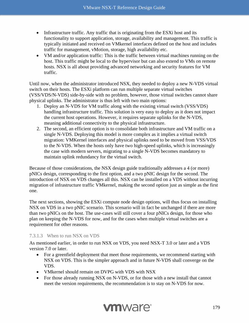
VMware NSX-T Reference Design Guide
179
• Infrastructure traffic. Any traffic that is originating from the ESXi host and its
functionality to support application, storage, availability and management. This traffic is
typically initiated and received on VMkernel interfaces defined on the host and includes
traffic for management, vMotion, storage, high availability etc.
• VM and/or application traffic: This is the traffic between virtual machines running on the
host. This traffic might be local to the hypervisor but can also extend to VMs on remote
hosts. NSX is all about providing advanced networking and security features for VM
traffic.
Until now, when the administrator introduced NSX, they needed to deploy a new N-VDS virtual
switch on their hosts. The ESXi platform can run multiple separate virtual switches
(VSS/VDS/N-VDS) side-by-side with no problem, however, those virtual switches cannot share
physical uplinks. The administrator is thus left with two main options:
1. Deploy an N-VDS for VM traffic along with the existing virtual switch (VSS/VDS)
handling infrastructure traffic. This solution is very easy to deploy as it does not impact
the current host operations. However, it requires separate uplinks for the N-VDS,
meaning additional connectivity to the physical infrastructure.
2. The second, an efficient option is to consolidate both infrastructure and VM traffic on a
single N-VDS. Deploying this model is more complex as it implies a virtual switch
migration: VMKernel interfaces and physical uplinks need to be moved from VSS/VDS
to the N-VDS. When the hosts only have two high-speed uplinks, which is increasingly
the case with modern servers, migrating to a single N-VDS becomes mandatory to
maintain uplink redundancy for the virtual switch.
Because of those considerations, the NSX design guide traditionally addresses a 4 (or more)
pNICs design, corresponding to the first option, and a two pNIC design for the second. The
introduction of NSX on VDS changes all this. NSX can be installed on a VDS without incurring
migration of infrastructure traffic VMkernel, making the second option just as simple as the first
one.
The next sections, showing the ESXi compute node design options, will thus focus on installing
NSX on VDS in a two pNIC scenario. This scenario will in fact be unchanged if there are more
than two pNICs on the host. The use-cases will still cover a four pNICs design, for those who
plan on keeping the N-VDS for now, and for the cases when multiple virtual switches are a
requirement for other reasons.
7.3.1.3 When to run NSX on VDS
As mentioned earlier, in order to run NSX on VDS, you need NSX-T 3.0 or later and a VDS
version 7.0 or later.
• For a greenfield deployment that meet those requirements, we recommend starting with
NSX on VDS. This is the simpler approach and in future N-VDS shall converge on the
VDS.
• VMkernel should remain on DVPG with VDS with NSX
• For those already running NSX on N-VDS, or for those with a new install that cannot
meet the version requirements, the recommendation is to stay on N-VDS for now.
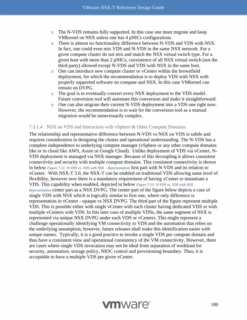
VMware NSX-T Reference Design Guide
180
o The N-VDS remains fully supported. In this case one must migrate and keep
VMkernel on NSX unless one has 4 pNICs configurations
o There is almost no functionality difference between N-VDS and VDS with NSX.
In fact, one could even mix VDS and N-VDS in the same NSX network. For a
given compute cluster do not mix and match the NSX virtual switch type. For a
given host with more than 2 pNICs, coexistence of all NSX virtual switch (not the
third party) allowed except N-VDS and VDS with NSX in the same host.
o One can introduce new compute cluster or vCenter within the brownfield
deployment, for which the recommendation is to deploy VDS with NSX with
properly supported software on compute and NSX. In this case VMkernel can
remain on DVPG.
o The goal is to eventually convert every NSX deployment to the VDS model.
Future conversion tool will automate this conversion and make it straightforward.
o One can also migrate their current N-VDS deployment into a VDS one right now.
However, the recommendation is to wait for the conversion tool as a manual
migration would be unnecessarily complex.
7.3.1.4 NSX on VDS and Interaction with vSphere & Other Compute Domains
The relationship and representative difference between N-VDS vs NSX on VDS is subtle and
requires consideration in designing the cluster and operational understanding. The N-VDS has a
complete independence to underlying compute manager (vSphere or any other compute domains
like or in cloud like AWS, Azure or Google Cloud). Unlike deployment of VDS via vCenter, N-
VDS deployment is managed via NSX manager. Because of this decoupling it allows consistent
connectivity and security with multiple compute domains. This consistent connectivity is shown
in below Figure 7-11: N-VDS vs. VDS with NSX – Representation first part with N-VDS and its relation to
vCenter. With NSX-T 3.0, the NSX-T can be enabled on traditional VDS allowing same level of
flexibility, however now there is a mandatory requirement of having vCenter to instantiate a
VDS. This capability when enabled, depicted in below Figure 7-11: N-VDS vs. VDS with NSX –
Representation center part as a NSX DVPG. The center part of the figure below depicts a case of
single VDS with NSX which is logically similar to first one, where only difference is
representation in vCenter - opaque vs NSX DVPG. The third part of the figure represent multiple
VDS. This is possible either with single vCenter with each cluster having dedicated VDS or with
multiple vCenters with VDS. In this later case of multiple VDSs, the same segment of NSX is
represented via unique NSX DVPG under each VDS or vCenters. This might represent a
challenge operationally identifying VM connectivity to VDS and the automation that relies on
the underlying assumption; however, future releases shall make this identification easier with
unique names. Typically, it is a good practice to invoke a single VDS per compute domain and
thus have a consistent view and operational consistency of the VM connectivity. However, there
are cases where single VDS invocation may not be ideal from separation of workload for
security, automation, storage policy, NIOC control and provisioning boundary. Thus, it is
acceptable to have a multiple VDS per given vCenter.
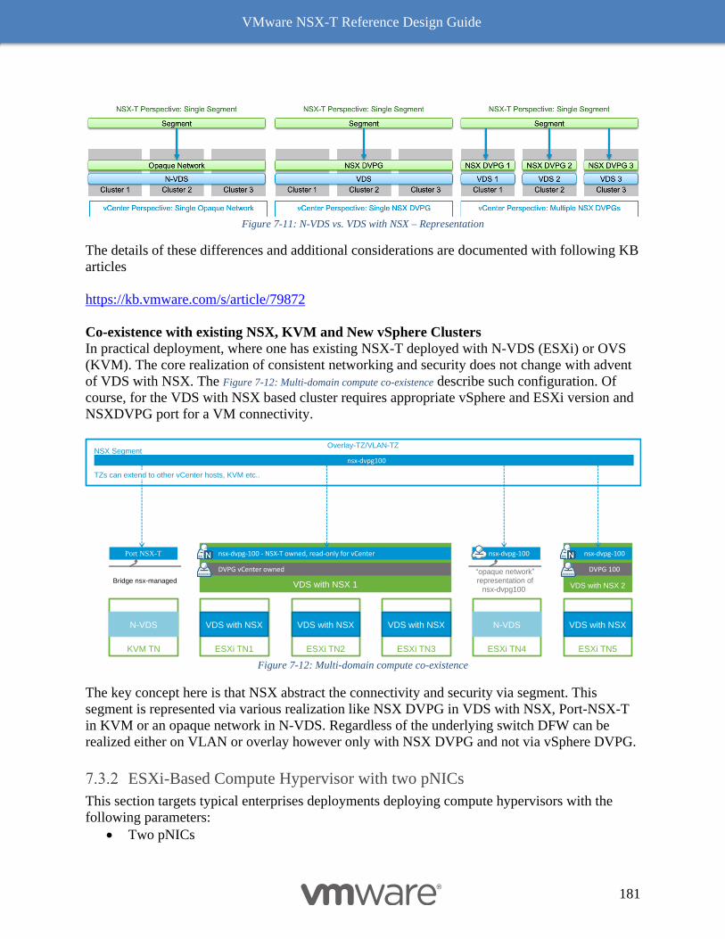
VMware NSX-T Reference Design Guide
181
Figure 7-11: N-VDS vs. VDS with NSX – Representation
The details of these differences and additional considerations are documented with following KB
articles
https://kb.vmware.com/s/article/79872
Co-existence with existing NSX, KVM and New vSphere Clusters
In practical deployment, where one has existing NSX-T deployed with N-VDS (ESXi) or OVS
(KVM). The core realization of consistent networking and security does not change with advent
of VDS with NSX. The Figure 7-12: Multi-domain compute co-existence describe such configuration. Of
course, for the VDS with NSX based cluster requires appropriate vSphere and ESXi version and
NSXDVPG port for a VM connectivity.
Figure 7-12: Multi-domain compute co-existence
The key concept here is that NSX abstract the connectivity and security via segment. This
segment is represented via various realization like NSX DVPG in VDS with NSX, Port-NSX-T
in KVM or an opaque network in N-VDS. Regardless of the underlying switch DFW can be
realized either on VLAN or overlay however only with NSX DVPG and not via vSphere DVPG.
ESXi-Based Compute Hypervisor with two pNICs
This section targets typical enterprises deployments deploying compute hypervisors with the
following parameters:
• Two pNICs
nsx-dvpg-100
VDS with NSX 1
DVPG vCenter owned
NSX Segment
ESXi TN1
VDS with NSX
Overlay-TZ/VLAN-TZ
ESXi TN2
VDS with NSX
ESXi TN3
VDS with NSX
ESXi TN4
N-VDS
ESXi TN5
VDS with NSX
nsx-dvpg-100 - NSX-T owned, read-only for vCenter
VDS with NSX 2
DVPG 100
nsx-dvpg-100
“opaque network” representation of
nsx-dvpg100)
Port NSX-T
KVM TN
N-VDS
Bridge nsx-managed
nsx-dvpg100
TZs can extend to other vCenter hosts, KVM etc..
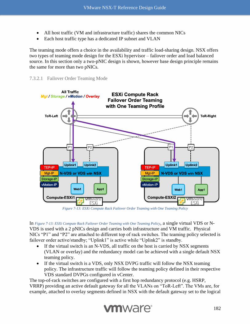
VMware NSX-T Reference Design Guide
182
• All host traffic (VM and infrastructure traffic) shares the common NICs
• Each host traffic type has a dedicated IP subnet and VLAN
The teaming mode offers a choice in the availability and traffic load-sharing design. NSX offers
two types of teaming mode design for the ESXi hypervisor – failover order and load balanced
source. In this section only a two-pNIC design is shown, however base design principle remains
the same for more than two pNICs.
7.3.2.1 Failover Order Teaming Mode
Figure 7-13: ESXi Compute Rack Failover Order Teaming with One Teaming Policy
In Figure 7-13: ESXi Compute Rack Failover Order Teaming with One Teaming Policy, a single virtual VDS or N-
VDS is used with a 2 pNICs design and carries both infrastructure and VM traffic. Physical
NICs “P1” and “P2” are attached to different top of rack switches. The teaming policy selected is
failover order active/standby; “Uplink1” is active while “Uplink2” is standby.
• If the virtual switch is an N-VDS, all traffic on the host is carried by NSX segments
(VLAN or overlay) and the redundancy model can be achieved with a single default NSX
teaming policy.
• If the virtual switch is a VDS, only NSX DVPG traffic will follow the NSX teaming
policy. The infrastructure traffic will follow the teaming policy defined in their respective
VDS standard DVPGs configured in vCenter.
The top-of-rack switches are configured with a first hop redundancy protocol (e.g. HSRP,
VRRP) providing an active default gateway for all the VLANs on “ToR-Left”. The VMs are, for
example, attached to overlay segments defined in NSX with the default gateway set to the logical
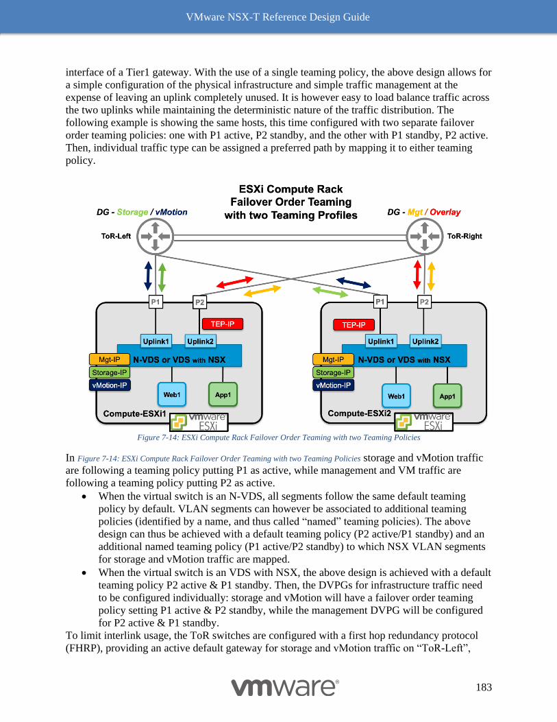
VMware NSX-T Reference Design Guide
183
interface of a Tier1 gateway. With the use of a single teaming policy, the above design allows for
a simple configuration of the physical infrastructure and simple traffic management at the
expense of leaving an uplink completely unused. It is however easy to load balance traffic across
the two uplinks while maintaining the deterministic nature of the traffic distribution. The
following example is showing the same hosts, this time configured with two separate failover
order teaming policies: one with P1 active, P2 standby, and the other with P1 standby, P2 active.
Then, individual traffic type can be assigned a preferred path by mapping it to either teaming
policy.
Figure 7-14: ESXi Compute Rack Failover Order Teaming with two Teaming Policies
In Figure 7-14: ESXi Compute Rack Failover Order Teaming with two Teaming Policies storage and vMotion traffic
are following a teaming policy putting P1 as active, while management and VM traffic are
following a teaming policy putting P2 as active.
• When the virtual switch is an N-VDS, all segments follow the same default teaming
policy by default. VLAN segments can however be associated to additional teaming
policies (identified by a name, and thus called “named” teaming policies). The above
design can thus be achieved with a default teaming policy (P2 active/P1 standby) and an
additional named teaming policy (P1 active/P2 standby) to which NSX VLAN segments
for storage and vMotion traffic are mapped.
• When the virtual switch is an VDS with NSX, the above design is achieved with a default
teaming policy P2 active & P1 standby. Then, the DVPGs for infrastructure traffic need
to be configured individually: storage and vMotion will have a failover order teaming
policy setting P1 active & P2 standby, while the management DVPG will be configured
for P2 active & P1 standby.
To limit interlink usage, the ToR switches are configured with a first hop redundancy protocol
(FHRP), providing an active default gateway for storage and vMotion traffic on “ToR-Left”,
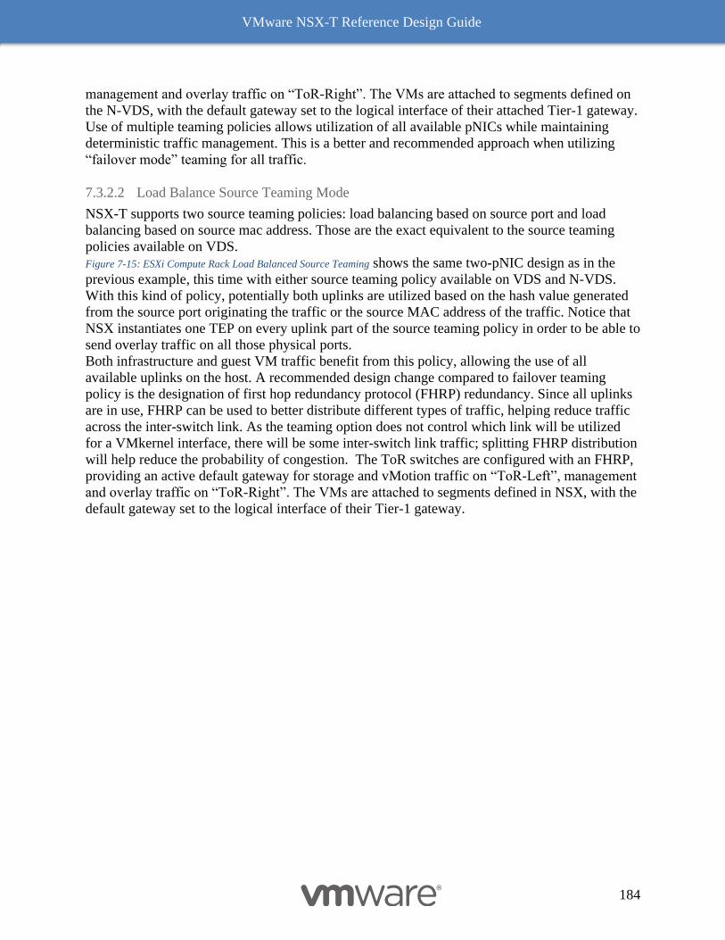
VMware NSX-T Reference Design Guide
184
management and overlay traffic on “ToR-Right”. The VMs are attached to segments defined on
the N-VDS, with the default gateway set to the logical interface of their attached Tier-1 gateway.
Use of multiple teaming policies allows utilization of all available pNICs while maintaining
deterministic traffic management. This is a better and recommended approach when utilizing
“failover mode” teaming for all traffic.
7.3.2.2 Load Balance Source Teaming Mode
NSX-T supports two source teaming policies: load balancing based on source port and load
balancing based on source mac address. Those are the exact equivalent to the source teaming
policies available on VDS.
Figure 7-15: ESXi Compute Rack Load Balanced Source Teaming shows the same two-pNIC design as in the
previous example, this time with either source teaming policy available on VDS and N-VDS.
With this kind of policy, potentially both uplinks are utilized based on the hash value generated
from the source port originating the traffic or the source MAC address of the traffic. Notice that
NSX instantiates one TEP on every uplink part of the source teaming policy in order to be able to
send overlay traffic on all those physical ports.
Both infrastructure and guest VM traffic benefit from this policy, allowing the use of all
available uplinks on the host. A recommended design change compared to failover teaming
policy is the designation of first hop redundancy protocol (FHRP) redundancy. Since all uplinks
are in use, FHRP can be used to better distribute different types of traffic, helping reduce traffic
across the inter-switch link. As the teaming option does not control which link will be utilized
for a VMkernel interface, there will be some inter-switch link traffic; splitting FHRP distribution
will help reduce the probability of congestion. The ToR switches are configured with an FHRP,
providing an active default gateway for storage and vMotion traffic on “ToR-Left”, management
and overlay traffic on “ToR-Right”. The VMs are attached to segments defined in NSX, with the
default gateway set to the logical interface of their Tier-1 gateway.
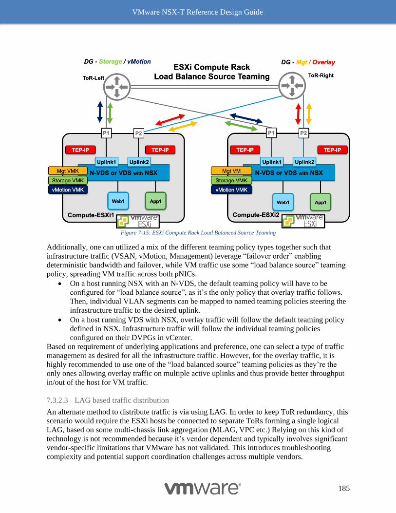
VMware NSX-T Reference Design Guide
185
Figure 7-15: ESXi Compute Rack Load Balanced Source Teaming
Additionally, one can utilized a mix of the different teaming policy types together such that
infrastructure traffic (VSAN, vMotion, Management) leverage “failover order” enabling
deterministic bandwidth and failover, while VM traffic use some “load balance source” teaming
policy, spreading VM traffic across both pNICs.
• On a host running NSX with an N-VDS, the default teaming policy will have to be
configured for “load balance source”, as it’s the only policy that overlay traffic follows.
Then, individual VLAN segments can be mapped to named teaming policies steering the
infrastructure traffic to the desired uplink.
• On a host running VDS with NSX, overlay traffic will follow the default teaming policy
defined in NSX. Infrastructure traffic will follow the individual teaming policies
configured on their DVPGs in vCenter.
Based on requirement of underlying applications and preference, one can select a type of traffic
management as desired for all the infrastructure traffic. However, for the overlay traffic, it is
highly recommended to use one of the “load balanced source” teaming policies as they’re the
only ones allowing overlay traffic on multiple active uplinks and thus provide better throughput
in/out of the host for VM traffic.
7.3.2.3 LAG based traffic distribution
An alternate method to distribute traffic is via using LAG. In order to keep ToR redundancy, this
scenario would require the ESXi hosts be connected to separate ToRs forming a single logical
LAG, based on some multi-chassis link aggregation (MLAG, VPC etc.) Relying on this kind of
technology is not recommended because it’s vendor dependent and typically involves significant
vendor-specific limitations that VMware has not validated. This introduces troubleshooting
complexity and potential support coordination challenges across multiple vendors.
VMware NSX-T Reference Design Guide
186
However, many times existing deployment of compute may carry this type of teaming and often
customer operational model has accepted the risk and knowledge set to operationalize LAG
based teaming. For those existing deployment, one can adopt LAG based teaming mode, for
compute only workload. In other words, if the compute host is carrying edge VMs (for North-
South traffic and requires peering over LAG) traffic then its highly recommended to decouple
the edge and compute with either dedicated edge hosts or edge and management. Please refer to
a specific section which discussed disadvantage of mixing compute and edge VM further below
in this chapter.
ESXi-Based Compute Hypervisor with Four (or more) pNICs
In most cases, a host with 4 or more pNICs can be configured exactly the same way as a 2-pNIC
host. There are just more available uplinks available for consumption by the different teaming
policies. We are going to focus on few scenarios where 4 pNICs or more is necessary.
7.3.3.1 Simple install, traffic on separate uplinks for policy reason
With a minimum of four pNICs, an ESXi host can run two virtual switches, each with redundant
uplinks.
• This property was appreciated by customers as it enabled a simple and non-disruptive
installation of NSX on their ESXi hypervisors. They could simply deploy and N-VDS
with two dedicated uplinks for VM traffic, while leaving an existing VSS/VDS running
on two separate uplinks to handle infrastructure traffic.
• On the top of this simple NSX installation, the model also provides for a strict separation
between VM and infrastructure traffic. There are scenarios where this separation is
mandated by policy, and the fact that NSX is deployed on its dedicated virtual switch
ensured that no misconfiguration could ever lead to VM traffic being sent on the uplinks
dedicated to infrastructure traffic, owned by a different virtual switch.
The following Figure 7-16: ESXi Compute Rack 4 pNICs – VDS and NSX virtual switch represents an example of a
host with 4 uplinks and two virtual switches:
■ A VDS dedicated to infrastructure traffic and
■ Another NSX prepared VDS or N-VDS that handles VM traffic.
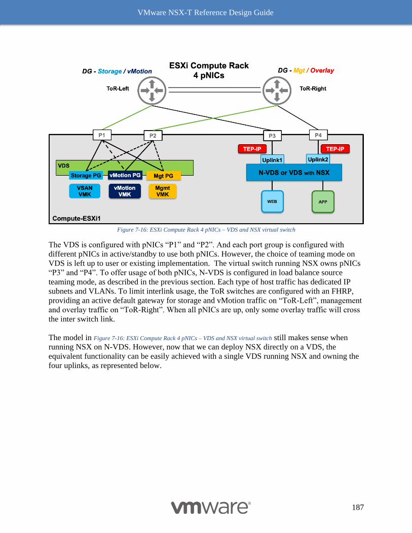
VMware NSX-T Reference Design Guide
187
Figure 7-16: ESXi Compute Rack 4 pNICs – VDS and NSX virtual switch
The VDS is configured with pNICs “P1” and “P2”. And each port group is configured with
different pNICs in active/standby to use both pNICs. However, the choice of teaming mode on
VDS is left up to user or existing implementation. The virtual switch running NSX owns pNICs
“P3” and “P4”. To offer usage of both pNICs, N-VDS is configured in load balance source
teaming mode, as described in the previous section. Each type of host traffic has dedicated IP
subnets and VLANs. To limit interlink usage, the ToR switches are configured with an FHRP,
providing an active default gateway for storage and vMotion traffic on “ToR-Left”, management
and overlay traffic on “ToR-Right”. When all pNICs are up, only some overlay traffic will cross
the inter switch link.
The model in Figure 7-16: ESXi Compute Rack 4 pNICs – VDS and NSX virtual switch still makes sense when
running NSX on N-VDS. However, now that we can deploy NSX directly on a VDS, the
equivalent functionality can be easily achieved with a single VDS running NSX and owning the
four uplinks, as represented below.
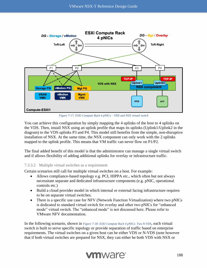
VMware NSX-T Reference Design Guide
188
Figure 7-17: ESXi Compute Rack 4 pNICs – VDS and NSX virtual switch
You can achieve this configuration by simply mapping the 4 uplinks of the host to 4 uplinks on
the VDS. Then, install NSX using an uplink profile that maps its uplinks (Uplink1/Uplink2 in the
diagram) to the VDS uplinks P3 and P4. This model still benefits from the simple, non-disruptive
installation of NSX. At the same time, the NSX component can only work with the 2 uplinks
mapped to the uplink profile. This means that VM traffic can never flow on P1/P2.
The final added benefit of this model is that the administrator can manage a single virtual switch
and if allows flexibility of adding additional uplinks for overlay or infrastructure traffic.
7.3.3.2 Multiple virtual switches as a requirement
Certain scenarios still call for multiple virtual switches on a host. For example:
• Allows compliance-based topology e.g. PCI, HIPPA etc., which often but not always
necessitate separate and dedicated infrastructure components (e.g. pNIC, operational
controls etc.)
• Build a cloud provider model in which internal or external facing infrastructure requires
to be on separate virtual switches.
• There is a specific use case for NFV (Network Function Virtualization) where two pNICs
is dedicated to standard virtual switch for overlay and other two pNICs for “enhanced
mode” virtual switch. The “enhanced mode” is not discussed here. Please refer to
VMware NFV documentation.
In the following scenario, shown in Figure 7-18: ESXi Compute Rack 4 pNICs- Two N-VDS, each virtual
switch is built to serve specific topology or provide separation of traffic based on enterprise
requirements. The virtual switches on a given host can be either VDS or N-VDS (note however
that if both virtual switches are prepared for NSX, they can either be both VDS with NSX or
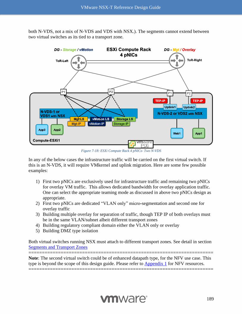
VMware NSX-T Reference Design Guide
189
both N-VDS, not a mix of N-VDS and VDS with NSX.). The segments cannot extend between
two virtual switches as its tied to a transport zone.
Figure 7-18: ESXi Compute Rack 4 pNICs- Two N-VDS
In any of the below cases the infrastructure traffic will be carried on the first virtual switch. If
this is an N-VDS, it will require VMkernel and uplink migration. Here are some few possible
examples:
1) First two pNICs are exclusively used for infrastructure traffic and remaining two pNICs
for overlay VM traffic. This allows dedicated bandwidth for overlay application traffic.
One can select the appropriate teaming mode as discussed in above two pNICs design as
appropriate.
2) First two pNICs are dedicated “VLAN only” micro-segmentation and second one for
overlay traffic
3) Building multiple overlay for separation of traffic, though TEP IP of both overlays must
be in the same VLAN/subnet albeit different transport zones
4) Building regulatory compliant domain either the VLAN only or overlay
5) Building DMZ type isolation
Both virtual switches running NSX must attach to different transport zones. See detail in section
Segments and Transport Zones
=====================================================================
Note: The second virtual switch could be of enhanced datapath type, for the NFV use case. This
type is beyond the scope of this design guide. Please refer to Appendix 1 for NFV resources.
=====================================================================
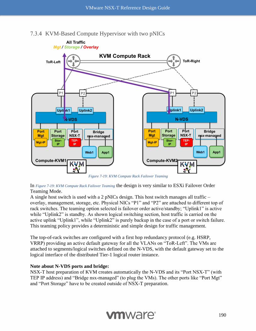
VMware NSX-T Reference Design Guide
190
KVM-Based Compute Hypervisor with two pNICs
Figure 7-19: KVM Compute Rack Failover Teaming
In Figure 7-19: KVM Compute Rack Failover Teaming the design is very similar to ESXi Failover Order
Teaming Mode.
A single host switch is used with a 2 pNICs design. This host switch manages all traffic –
overlay, management, storage, etc. Physical NICs “P1” and “P2” are attached to different top of
rack switches. The teaming option selected is failover order active/standby; “Uplink1” is active
while “Uplink2” is standby. As shown logical switching section, host traffic is carried on the
active uplink “Uplink1”, while “Uplink2” is purely backup in the case of a port or switch failure.
This teaming policy provides a deterministic and simple design for traffic management.
The top-of-rack switches are configured with a first hop redundancy protocol (e.g. HSRP,
VRRP) providing an active default gateway for all the VLANs on “ToR-Left”. The VMs are
attached to segments/logical switches defined on the N-VDS, with the default gateway set to the
logical interface of the distributed Tier-1 logical router instance.
Note about N-VDS ports and bridge:
NSX-T host preparation of KVM creates automatically the N-VDS and its “Port NSX-T” (with
TEP IP address) and “Bridge nsx-managed” (to plug the VMs). The other ports like “Port Mgt”
and “Port Storage” have to be created outside of NSX-T preparation.
Compute-KVM1 Compute-KVM2
PortNSX-T
PortMgt
N-VDS
Uplink2Uplink1
Web1 App1
Bridgensx-managed
KVM Compute Rack
All TrafficMgt / Storage / Overlay
P1 P2
PortNSX-T
PortMgt
N-VDS
Uplink2Uplink1
Web1 App1
Bridgensx-managed
PortStorage
P1 P2
TEP-
IPMgt-IP
PortStorage
Stor-
IP
TEP-
IPMgt-IP
Stor-
IP
ToR-RightToR-Left
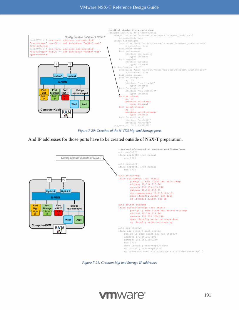
VMware NSX-T Reference Design Guide
191
Figure 7-20: Creation of the N-VDS Mgt and Storage ports
And IP addresses for those ports have to be created outside of NSX-T preparation.
Figure 7-21: Creation Mgt and Storage IP addresses
root@kvm1-ubuntu:~# ovs-vsctl show
1def29bb-ac94-41b3-8474-486c87d96ef1
Manager "unix:/var/run/vmware/nsx-agent/nsxagent_ovsdb.sock"
is_connected: true
Bridge nsx-managed
Controller "unix:/var/run/vmware/nsx-agent/nsxagent_vswitchd.sock"
is_connected: true
fail_mode: secure
Port nsx-managed
Interface nsx-managed
type: internal
Port hyperbus
Interface hyperbus
type: internal
Bridge "nsx-switch.0"
Controller "unix:/var/run/vmware/nsx-agent/nsxagent_vswitchd.sock"
is_connected: true
fail_mode: secure
Port "nsx-vtep0.0"
tag: 25
Interface "nsx-vtep0.0"
type: internal
Port "nsx-switch.0"
Interface "nsx-switch.0"
type: internal
Port switch-mgt
tag: 22
Interface switch-mgt
type: internal
Port switch-storage
tag: 23
Interface switch-storage
type: internal
Port "nsx-uplink.0"
Interface "enp3s0f1"
Interface "enp3s0f0"
ovs_version: "2.7.0.6383692"
Config created outside of NSX-T:root@KVM1:~# ovs-vsctl add-port nsx-switch.0
"switch-mgt" tag=22 -- set interface "switch-mgt"
type=internal
root@KVM1:~# ovs-vsctl add-port nsx-switch.0
"switch-mgt" tag=22 -- set interface "switch-mgt"
type=internal
Compute-KVM1
PortNSX-T
PortMgt
N-VDS
Uplink2Uplink1
Web1 App1
Bridgensx-managed
P1
P2
TEP-IP
Mgt-IP
PortStorage
Stor-IP
root@kvm1-ubuntu:~# vi /etc/network/interfaces
auto enp3s0f0
iface enp3s0f0 inet manual
mtu 1700
auto enp3s0f1
iface enp3s0f1 inet manual
mtu 1700
auto switch-mgt
iface switch-mgt inet static
pre-up ip addr flush dev switch-mgt
address 10.114.213.86
netmask 255.255.255.240
gateway 10.114.213.81
dns-nameservers 10.113.165.131
down ifconfig switch-mgt down
up ifconfig switch-mgt up
auto switch-storage
iface switch-storage inet static
pre-up ip addr flush dev switch-storage
address 10.114.214.86
netmask 255.255.255.240
down ifconfig switch-storage down
up ifconfig switch-storage up
auto nsx-vtep0.0
iface nsx-vtep0.0 inet static
pre-up ip addr flush dev nsx-vtep0.0
address 172.16.213.101
netmask 255.255.255.240
mtu 1700
down ifconfig nsx-vtep0.0 down
up ifconfig nsx-vtep0.0 up
up route add -net x.x.x.x/x gw x.x.x.x dev nsx-vtep0.0
Config created outside of NSX-T
Compute-KVM1
PortNSX-T
PortMgt
N-VDS
Uplink2Uplink1
Web1 App1
Bridgensx-managed
P1 P2
TEP-IP
Mgt-IP
PortStorage
Stor-IP
VMware NSX-T Reference Design Guide
192
Edge Node and Services Design
Edge nodes are available in two form factors – VM and bare metal server. While both form
factors offer the same functionality, their physical infrastructure connectivity is quite different,
however they have common requirement of three different types of IP networks for specific
purposes:
▪ Management – Accessing and controlling the Edge node
▪ Overlay (TEP) - Creating tunnels with peer transport nodes
▪ External (N-S) - Peering with the physical networking infrastructure to provide
connectivity between the NSX-T virtual components and the external network
Edge nodes provide a pool of capacity for running centralized services in NSX-T. Edge nodes
are always active in the context of connectivity and control plane. They host Tier-0 and Tier-1
routing services, installed in either active/active or active/standby mode. Additionally, if a Tier-0
or Tier-1 router enables stateful services (e.g., NAT, Load Balancer, Gateway Firewall & VPN)
it can only be deployed in active/standby mode. The status of active or standby mode is within
the context of data plane forwarding rather than related to the Edge node itself. The Edge node
connectivity options discussed below are independent of type of services enabled on a given
node.
Design choices with Edge node significantly improved with NSX-T 2.5 release. This section is
divided into four major areas:
▪ The bridging design
▪ The existing design recommendation with release up to version 2.5
▪ New design recommendation starting with NSX-T release 2.5
▪ Edge services and resources considerations
Design Considerations with Bridging
The chapter 3 section bridging capability covers the basic functionality and availability model
requirements. The next section covers bridging design. The respective topology also covers
adding bridging into the mix and its implications.
7.4.1.1 Bridge on a VM form factor Edge
The Edge Bridge is available on both Edge form factors - bare metal or Virtual Machine (VM)
The use of the Bridge in the bare metal form factor is relatively straightforward: the bridged
traffic is sent on the uplinks of the N-VDS selected by VLAN transport zone specified on the
Bridge Profile. There is no Bridge-specific configuration necessary on the physical infrastructure
where the bare metal Edge attaches. This section is going to focus on a Bridge running on a VM
form factor of the Edge.
VMware NSX-T Reference Design Guide
193
7.4.1.1.1 Edge VM vNIC Configuration Requirement with Bridging
For the VM form factor, it is important to remember that the Edge Bridge will end up sourcing
traffic from several different mac addresses on its VLAN vNIC. This means, that the uplink
vNIC must be connected to a DVPG port group allowing:
◼ Forged transmit
◼ Mac learning or promiscuous mode
Both above capabilities are not supported on VSS while supported on VDS. This means it’s a
strong recommendation is to use VDS when deploying Edge node. Mac learning is available on
the VDS as of vSphere 6.7. However, there is no GUI capability on vCenter to configure mac-
learning as of this writing but it can be enabled via API or using powerCLI (See
https://www.virtuallyghetto.com/2018/04/native-mac-learning-in-vsphere-6-7-removes-the-need-
for-promiscuous-mode-for-nested-esxi.html.)
If deployment is running vSphere 6.5 where mac learning is not available, the only other way to
run bridging is by enabling promiscuous mode. Typically, promiscuous mode should not be
enabled system wide. Thus, either enable promiscuous mode just for DVPG associated with
bridge vNIC or it may be worth considering dedicating an Edge VM for the bridged traffic so
that other kinds of traffic to/from the Edge do not suffer from the performance impact related to
promiscuous mode.
7.4.1.1.2 Edge VM: Virtual Guest Tagging
The Edge Bridge will be sending bridged traffic with an 802.1Q tag on its VLAN uplink. That
means that this Edge VM vNIC will have to be attached to a port group configured for Virtual
Guest Tagging (VGT, i.e. the DVPG shows as VLAN Trunk in the vCenter UI.) Refer VLAN
TAG Requirements for more information.
7.4.1.1.3 Edge VM Configuration Example for the Bridge
The following Figure 7-22: Dedicated Edge VM for Bridging represents an Edge VM dedicated to bridging
and following the rules enunciated earlier in this section. The Edge VM has four vNICs, but this
design only uses 3:
• vNIC1 is dedicated to management traffic
• vNIC2 is the uplink of N-VDS1, the N-VDS that will be used for overlay traffic. The
overlay DVPG is using active/standby both pNICs of the host for redundancy.
• vNIC3 is the uplink of N-VDS2 that is attached to the VLAN transport zone “N-VDS2”
where the bridged traffic will be sent. The “Bridge VLAN” DVPG has the following
configuration:
o Virtual Guest Tagging is enabled so that it is possible to bridge to several
segments to different VLAN IDs
o Forged transmit and mac learning, so that the bridge can send traffic sourced from
different mac addresses. If mac learning is not possible, the promiscuous can be
configured instead at the expense of degraded performance.
o Active standby teaming policy leveraging the same pNICs (but not necessarily in
the same order) as the overlay DVPG. That last point is important and will be
justified in the next part.
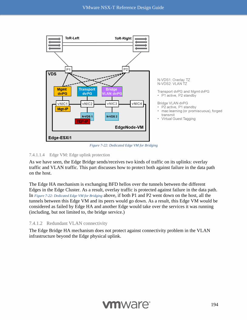
VMware NSX-T Reference Design Guide
194
Figure 7-22: Dedicated Edge VM for Bridging
7.4.1.1.4 Edge VM: Edge uplink protection
As we have seen, the Edge Bridge sends/receives two kinds of traffic on its uplinks: overlay
traffic and VLAN traffic. This part discusses how to protect both against failure in the data path
on the host.
The Edge HA mechanism is exchanging BFD hellos over the tunnels between the different
Edges in the Edge Cluster. As a result, overlay traffic is protected against failure in the data path.
In Figure 7-22: Dedicated Edge VM for Bridging above, if both P1 and P2 went down on the host, all the
tunnels between this Edge VM and its peers would go down. As a result, this Edge VM would be
considered as failed by Edge HA and another Edge would take over the services it was running
(including, but not limited to, the bridge service.)
7.4.1.2 Redundant VLAN connectivity
The Edge Bridge HA mechanism does not protect against connectivity problem in the VLAN
infrastructure beyond the Edge physical uplink.
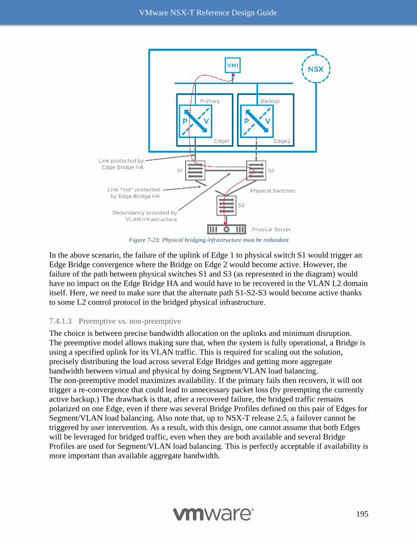
VMware NSX-T Reference Design Guide
195
Figure 7-23: Physical bridging infrastructure must be redundant
In the above scenario, the failure of the uplink of Edge 1 to physical switch S1 would trigger an
Edge Bridge convergence where the Bridge on Edge 2 would become active. However, the
failure of the path between physical switches S1 and S3 (as represented in the diagram) would
have no impact on the Edge Bridge HA and would have to be recovered in the VLAN L2 domain
itself. Here, we need to make sure that the alternate path S1-S2-S3 would become active thanks
to some L2 control protocol in the bridged physical infrastructure.
7.4.1.3 Preemptive vs. non-preemptive
The choice is between precise bandwidth allocation on the uplinks and minimum disruption.
The preemptive model allows making sure that, when the system is fully operational, a Bridge is
using a specified uplink for its VLAN traffic. This is required for scaling out the solution,
precisely distributing the load across several Edge Bridges and getting more aggregate
bandwidth between virtual and physical by doing Segment/VLAN load balancing.
The non-preemptive model maximizes availability. If the primary fails then recovers, it will not
trigger a re-convergence that could lead to unnecessary packet loss (by preempting the currently
active backup.) The drawback is that, after a recovered failure, the bridged traffic remains
polarized on one Edge, even if there was several Bridge Profiles defined on this pair of Edges for
Segment/VLAN load balancing. Also note that, up to NSX-T release 2.5, a failover cannot be
triggered by user intervention. As a result, with this design, one cannot assume that both Edges
will be leveraged for bridged traffic, even when they are both available and several Bridge
Profiles are used for Segment/VLAN load balancing. This is perfectly acceptable if availability is
more important than available aggregate bandwidth.
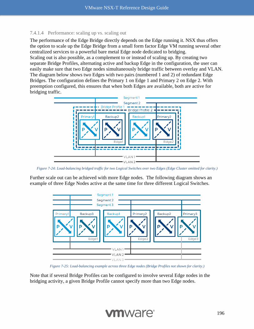
VMware NSX-T Reference Design Guide
196
7.4.1.4 Performance: scaling up vs. scaling out
The performance of the Edge Bridge directly depends on the Edge running it. NSX thus offers
the option to scale up the Edge Bridge from a small form factor Edge VM running several other
centralized services to a powerful bare metal Edge node dedicated to bridging.
Scaling out is also possible, as a complement to or instead of scaling up. By creating two
separate Bridge Profiles, alternating active and backup Edge in the configuration, the user can
easily make sure that two Edge nodes simultaneously bridge traffic between overlay and VLAN.
The diagram below shows two Edges with two pairs (numbered 1 and 2) of redundant Edge
Bridges. The configuration defines the Primary 1 on Edge 1 and Primary 2 on Edge 2. With
preemption configured, this ensures that when both Edges are available, both are active for
bridging traffic.
Figure 7-24: Load-balancing bridged traffic for two Logical Switches over two Edges (Edge Cluster omitted for clarity.)
Further scale out can be achieved with more Edge nodes. The following diagram shows an
example of three Edge Nodes active at the same time for three different Logical Switches.
Figure 7-25: Load-balancing example across three Edge nodes (Bridge Profiles not shown for clarity.)
Note that if several Bridge Profiles can be configured to involve several Edge nodes in the
bridging activity, a given Bridge Profile cannot specify more than two Edge nodes.
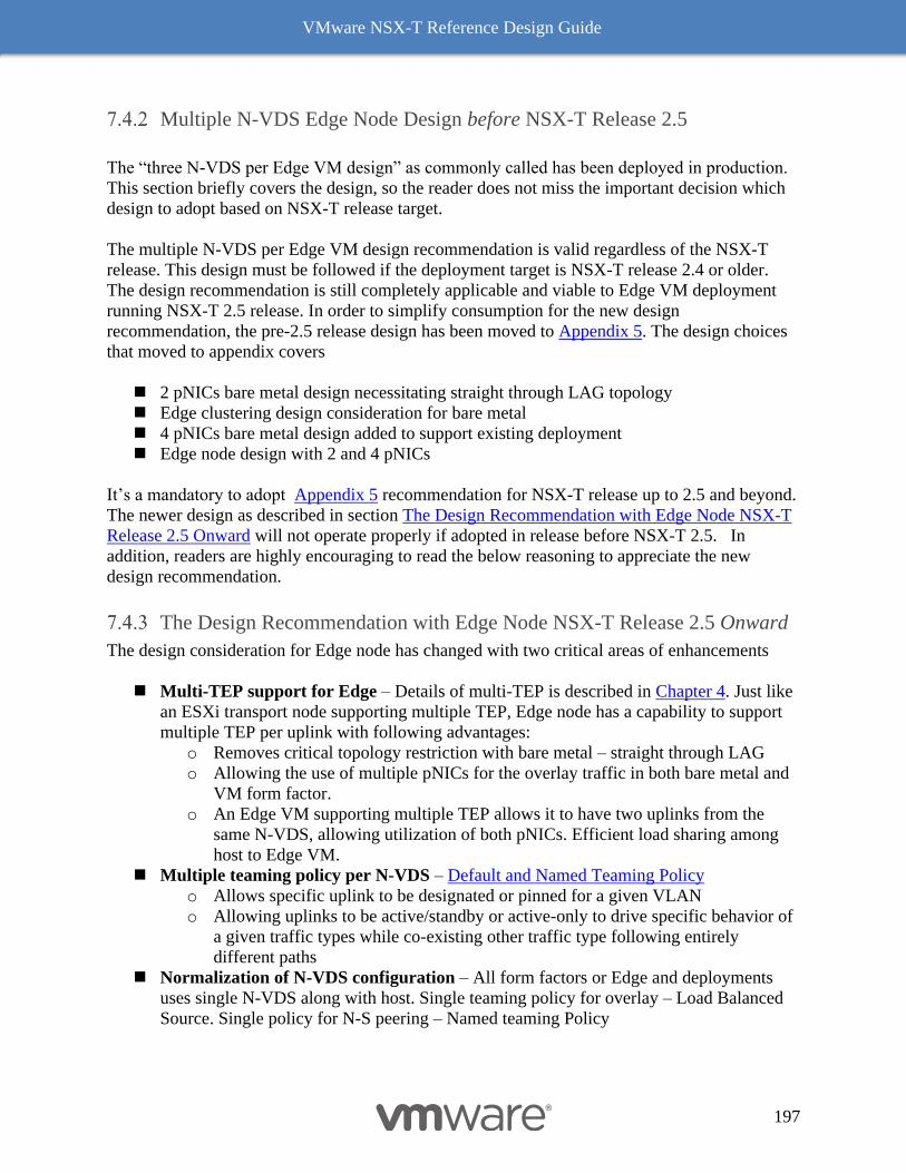
VMware NSX-T Reference Design Guide
197
Multiple N-VDS Edge Node Design before NSX-T Release 2.5
The “three N-VDS per Edge VM design” as commonly called has been deployed in production.
This section briefly covers the design, so the reader does not miss the important decision which
design to adopt based on NSX-T release target.
The multiple N-VDS per Edge VM design recommendation is valid regardless of the NSX-T
release. This design must be followed if the deployment target is NSX-T release 2.4 or older.
The design recommendation is still completely applicable and viable to Edge VM deployment
running NSX-T 2.5 release. In order to simplify consumption for the new design
recommendation, the pre-2.5 release design has been moved to Appendix 5. The design choices
that moved to appendix covers
◼ 2 pNICs bare metal design necessitating straight through LAG topology
◼ Edge clustering design consideration for bare metal
◼ 4 pNICs bare metal design added to support existing deployment
◼ Edge node design with 2 and 4 pNICs
It’s a mandatory to adopt Appendix 5 recommendation for NSX-T release up to 2.5 and beyond.
The newer design as described in section The Design Recommendation with Edge Node NSX-T
Release 2.5 Onward will not operate properly if adopted in release before NSX-T 2.5. In
addition, readers are highly encouraging to read the below reasoning to appreciate the new
design recommendation.
The Design Recommendation with Edge Node NSX-T Release 2.5 Onward
The design consideration for Edge node has changed with two critical areas of enhancements
◼ Multi-TEP support for Edge – Details of multi-TEP is described in Chapter 4. Just like
an ESXi transport node supporting multiple TEP, Edge node has a capability to support
multiple TEP per uplink with following advantages:
o Removes critical topology restriction with bare metal – straight through LAG
o Allowing the use of multiple pNICs for the overlay traffic in both bare metal and
VM form factor.
o An Edge VM supporting multiple TEP allows it to have two uplinks from the
same N-VDS, allowing utilization of both pNICs. Efficient load sharing among
host to Edge VM.
◼ Multiple teaming policy per N-VDS – Default and Named Teaming Policy
o Allows specific uplink to be designated or pinned for a given VLAN
o Allowing uplinks to be active/standby or active-only to drive specific behavior of
a given traffic types while co-existing other traffic type following entirely
different paths
◼ Normalization of N-VDS configuration – All form factors or Edge and deployments
uses single N-VDS along with host. Single teaming policy for overlay – Load Balanced
Source. Single policy for N-S peering – Named teaming Policy
VMware NSX-T Reference Design Guide
198
◼ Reduction in management and control plane load – With each N-VDS, additional
resources are used such as IP addressing for management, connections to NSX manager
and BFD sessions to all transport nodes as well all the Edge nodes. The BFD sessions are
fully meshed, in other words the session counts increase with each N-VDS with N(N-1)
expansion. The CPU resources are also consumed by multiple N-VDS within the same
Edge VM.
The above functionalities and enhancements allows a consistent configuration for any types of
deployment choices – bare metal Edge, Edge VM on VDS enabled ESXi host and Edge VM on
N-VDS enable ESXi host. In conjunction, while maintaining the existing best practices design
of N-S connectivity that is deterministic and distinct peering to two ToRs. This peering
recommendation is common to all design variation and thus only discussed once below.
One common misconception prevails that separation of TEP and BGP on two different switches
somehow increases the resiliency or availability of the system. That is not the case at all. In fact,
when both TEP and BGP are configured on the same virtual switch, enables consistent failover
of both TEP and BGP at the same time. The dual VTEP and BGP combination allows consistent
configuration either with Edge VM or bare metal Edge. However, there are corner use cases
where asymmetric bandwidth ration of E-W vs N-S exist in that case specific optimization of
design may be appropriate.
A special consideration is required with deployment of multiple TEP enabled Edge (VM or Bare
Metal) deployed with a physical fabric such as ACI. Before NSX-T 3.0.2, the deployment with
multi-TEP will result into intermittent connectivity because the way Edge represent IP/MAC
association and enforcement that exist in physical fabric. This condition can be remediated by
either disabling a multi-TEP configuration in Edge VM, while running a straight through LAG
configuration for the Bare Metal Edge. The less optimal option such as disabling flow cache is
possible but not advised due to reduced performance of edge VM, however, may work in
specific situation.
7.4.3.1 Deterministic Peering with Physical Routers
The goal of the N-S connectivity is simple, deterministic and redundant configuration without
incurring any dependencies on Spanning-tree related configuration. This means the peering
VLAN is confined to a specific ToR and do not span across ToR. This topology choice also
allows direct mapping from Edge node uplinks to physical NIC of the devices (bare metal or
ESXi host) and eventually to ToR interface. This creates 1:1 mapping of physical connectivity
and logical peering connectivity from Edge node to physical router. Resulting in to simple,
operationally deterministic connectivity of N-S traffic forwarding and troubleshooting. As
operator always knows the specific peering is impacted during the failure of pNIC, ToR or Edge-
Uplink. In the typical enterprise design, Edge nodes in Figure 7-26: Typical Enterprise Bare metal Edge Note
Logical View with Overlay/External Traffic are assigned to a Tier-0 router. This Tier-0 router peers with the
physical infrastructure using eBGP. Two adjacencies per Edge node with two logical switch
connects to distinct “External-VLAN” per ToR. Figure 7-26: Typical Enterprise Bare metal Edge Note Logical
View with Overlay/External Traffic represents the logical view of BGP peering.
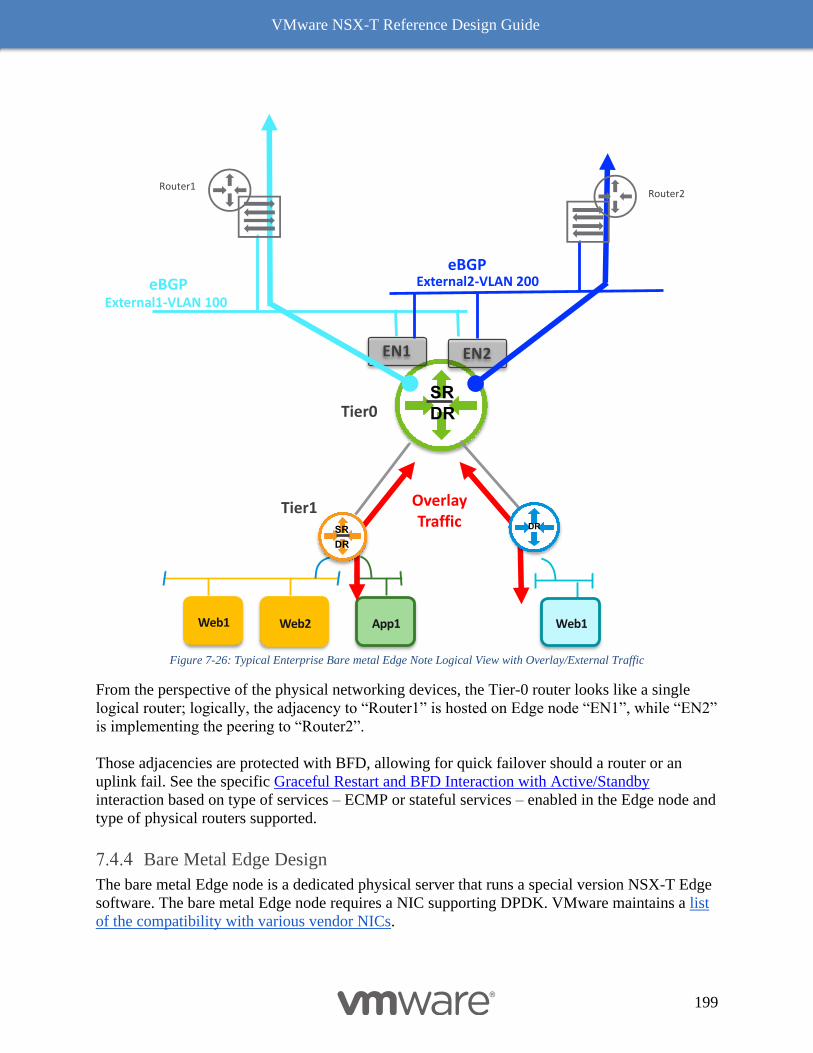
VMware NSX-T Reference Design Guide
199
Figure 7-26: Typical Enterprise Bare metal Edge Note Logical View with Overlay/External Traffic
From the perspective of the physical networking devices, the Tier-0 router looks like a single
logical router; logically, the adjacency to “Router1” is hosted on Edge node “EN1”, while “EN2”
is implementing the peering to “Router2”.
Those adjacencies are protected with BFD, allowing for quick failover should a router or an
uplink fail. See the specific Graceful Restart and BFD Interaction with Active/Standby
interaction based on type of services – ECMP or stateful services – enabled in the Edge node and
type of physical routers supported.
Bare Metal Edge Design
The bare metal Edge node is a dedicated physical server that runs a special version NSX-T Edge
software. The bare metal Edge node requires a NIC supporting DPDK. VMware maintains a list
of the compatibility with various vendor NICs.
DR
SRTier0
EN1 EN2
eBGP
Web2 App1Web1 Web1
Tier1
eBGP
OverlayTraffic
External1-VLAN 100
External2-VLAN 200
Router1Router2
DR
SR DR
VMware NSX-T Reference Design Guide
200
This design guide covers a common configuration using the minimum number of NICs on the
Edge nodes. The design covers commonly deployed bare metal configuration.
7.4.4.1 NSX-T 2.5 Based Bare metal Design with 2 pNICs
Typically, many modern pNIC capable of performing at line rate for majority of workloads and
services. Thus, Edge VM with 2 pNICs design with NIC speed of 10/25 Gbps is good enough
when compared to 2 pNICs bare metal design. However, the bare metal with two or greater
pNICs configuration is desired for few reasons. Those are:
◼ Consistent footprint (CPU and pNIC) configuration matching compute
◼ Requirement of line rate services
◼ Higher bandwidth pNIC (25 or 40 Gbps)
◼ Adaptation for certain workload that requires near line rate throughput with low packet
size (~ 250 Bytes)
◼ Sub-second link failure detection between physical and Edge node
◼ Focused Operational responsibility and consistency as appliance model with network
operation team
◼ Multiple Tier-0 deployment models with top Tier-0 driving the bandwidth and
throughput with higher speed (40 Gbps) NICs.
The details guidance and configuration recommendation is already covered in Single N-VDS
Bare Metal Configuration with 2 pNICs in logical routing chapter 4. However, few additional
considerations that applies to bare metal design as follows:
◼ Management interface redundancy is not always required but a good practice. In-band
option is most practical deployment model
◼ BFD configuration recommendation for link failure detection is 300/900 mSec
(Hello/Dead), however assure BFD configuration matches between both ToR and Edge
node. Recommended BGP timer is set to either default or matching remote BGP peer
◼ Without BFD, recommended BGP timer is 1/3 Sec (Hello/Dead)
Figure 7-27: 4-way ECMP Using Bare Metal Edges shows a logical and physical topology where a Tier-0
gateway has four external interfaces (as Edge instances is defined globally, instantiated in each
node). External interfaces 1 and 2 are provided by bare metal Edge node “EN1”, whereas
External interfaces 3 and 4 are provided by bare metal Edge node “EN2”. Both the Edge nodes
are in the same rack and connect to TOR switches in that rack. Both the Edge nodes are
configured for Multi-TEP and use named teaming policy to send traffic from VLAN 300 to
TOR-Left and traffic from VLAN 400 to TOR-Right. Tier-0 Gateway establishes BGP peering
on all four external interfaces and provides 4-way ECMP.
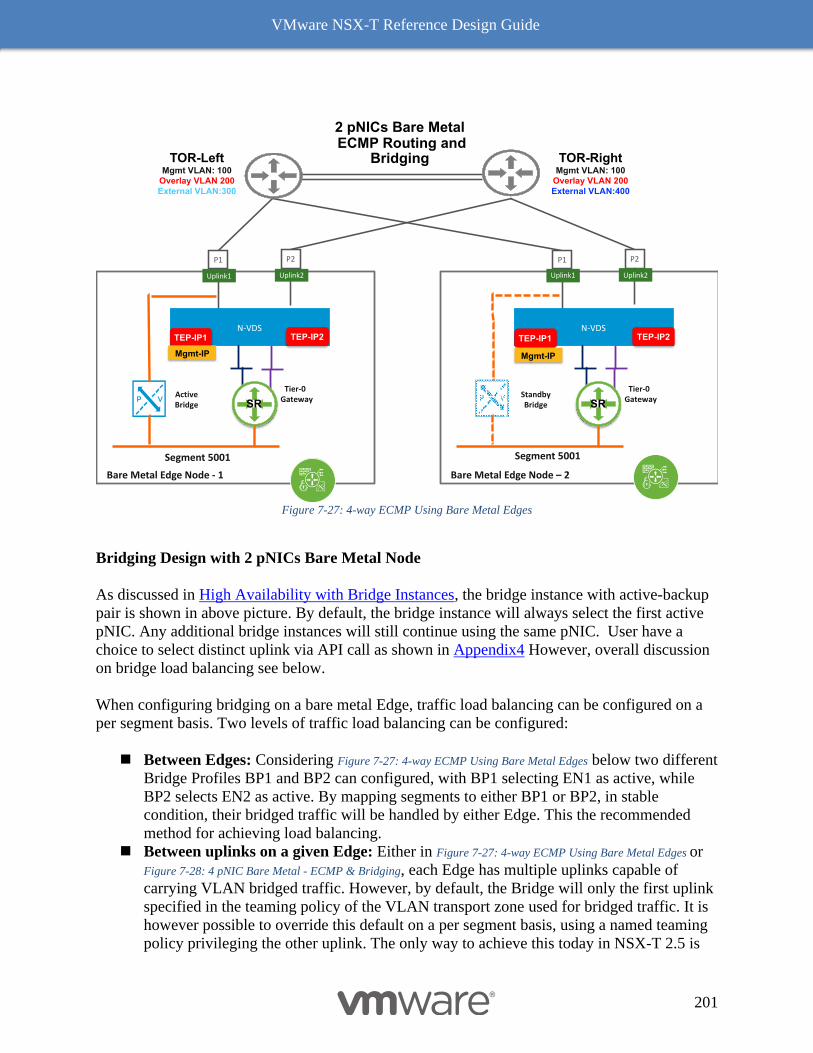
VMware NSX-T Reference Design Guide
201
Figure 7-27: 4-way ECMP Using Bare Metal Edges
Bridging Design with 2 pNICs Bare Metal Node
As discussed in High Availability with Bridge Instances, the bridge instance with active-backup
pair is shown in above picture. By default, the bridge instance will always select the first active
pNIC. Any additional bridge instances will still continue using the same pNIC. User have a
choice to select distinct uplink via API call as shown in Appendix4 However, overall discussion
on bridge load balancing see below.
When configuring bridging on a bare metal Edge, traffic load balancing can be configured on a
per segment basis. Two levels of traffic load balancing can be configured:
◼ Between Edges: Considering Figure 7-27: 4-way ECMP Using Bare Metal Edges below two different
Bridge Profiles BP1 and BP2 can configured, with BP1 selecting EN1 as active, while
BP2 selects EN2 as active. By mapping segments to either BP1 or BP2, in stable
condition, their bridged traffic will be handled by either Edge. This the recommended
method for achieving load balancing.
◼ Between uplinks on a given Edge: Either in Figure 7-27: 4-way ECMP Using Bare Metal Edges or
Figure 7-28: 4 pNIC Bare Metal - ECMP & Bridging, each Edge has multiple uplinks capable of
carrying VLAN bridged traffic. However, by default, the Bridge will only the first uplink
specified in the teaming policy of the VLAN transport zone used for bridged traffic. It is
however possible to override this default on a per segment basis, using a named teaming
policy privileging the other uplink. The only way to achieve this today in NSX-T 2.5 is
2 pNICs Bare MetalECMP Routing and
BridgingTOR-LeftMgmt VLAN: 100
Overlay VLAN 200
External VLAN:300
TOR-RightMgmt VLAN: 100
Overlay VLAN 200
External VLAN:400
P1
Bare Metal Edge Node - 1
P2
N-VDSTEP-IP1
Uplink1 Uplink2
TEP-IP2
Tier-0Gateway
SRActiveBridge
P1
Bare Metal Edge Node – 2
P2
N-VDSTEP-IP1
Uplink1 Uplink2
TEP-IP2
Tier-0Gateway
SRStandbyBridge
Segment 5001 Segment 5001
Mgmt-IP Mgmt-IP
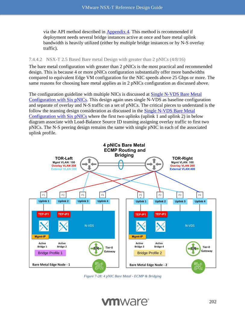
VMware NSX-T Reference Design Guide
202
via the API method described in Appendix 4. This method is recommended if
deployment needs several bridge instances active at once and bare metal uplink
bandwidth is heavily utilized (either by multiple bridge instances or by N-S overlay
traffic).
7.4.4.2 NSX-T 2.5 Based Bare metal Design with greater than 2 pNICs (4/8/16)
The bare metal configuration with greater than 2 pNICs is the most practical and recommended
design. This is because 4 or more pNICs configuration substantially offer more bandwidths
compared to equivalent Edge VM configuration for the NIC speeds above 25 Gbps or more. The
same reasons for choosing bare metal applies as in 2 pNICs configuration as discussed above.
The configuration guideline with multiple NICs is discussed at Single N-VDS Bare Metal
Configuration with Six pNICs. This design again uses single N-VDS as baseline configuration
and separate of overlay and N-S traffic on a set of pNICs. The critical pieces to understand is the
follow the teaming design consideration as discussed in the Single N-VDS Bare Metal
Configuration with Six pNICs where the first two uplinks (uplink 1 and uplink 2) in below
diagram associate with Load-Balance Source ID teaming assigning overlay traffic to first two
pNICs. The N-S peering design remains the same with single pNIC in each of the associated
uplink profile.
Figure 7-28: 4 pNIC Bare Metal - ECMP & Bridging
4 pNICs Bare MetalECMP Routing and
BridgingTOR-Left
Mgmt VLAN: 100
Overlay VLAN 200
External VLAN:300
TOR-RightMgmt VLAN: 100
Overlay VLAN 200
External VLAN:400
P1
Bare Metal Edge Node - 1
P4
TEP-IP1
Uplink 1 Uplink 4
TEP-IP2
Tier-0
GatewaySR
ActiveBridge 1
P3P2
Uplink 3Uplink 2
ActiveBridge 2
P1
Bare Metal Edge Node - 2
P4
TEP-IP1
Uplink 1 Uplink 4
TEP-IP2
Tier-0
GatewaySR
ActiveBridge 3
P3P2
Uplink 3Uplink 2
ActiveBridge 4
Bridge Profile 1 Bridge Profile 2
Mgmt-IP Mgmt-IP
N-VDS N-VDS
VMware NSX-T Reference Design Guide
203
The bare metal design with more than four pNICs for data plane follows the similar logic of
maintaining symmetric bandwidth for overlay and N-S traffic. E.g. with eight pNICs design one
can allocate first four pNICs for overlay and rest for N-S peering. The design with that
combination requires for TEP IPs and four BGP peers per bare metal node and thus additional
planning is desire on subnet/VLAN for transport and N-S ToR.
Bridging Design with greater than 2 pNICs bare metal node: See the bridging design for load
balancing in NSX-T 2.5 Based Bare metal Design with 2 pNICs. If the bridging bandwidth
requirements is high or undergoing a large scale migration to NSX-T based cloud, it may require
to dedicate 2 pNICs for bridging traffic and in that case the above 4 pNICs design configuration
changes to first two pNICs used for TEP/BP traffic and other two pNICs (P3 andP4) for
bridging. The same availability and selective load-balancing consideration applies here as well as
discussed in 2 pNICs section.
Edge Node VM
This section covers the Edge VM design in various combinations. This design is solely based on
single N-VDS per Edge VM for basic overlay and N-S connectivity. This design is consistent
with the design that has been discussed for bare metal edge and remains the same for 2 pNIC or
4 pNIC design. The design pattern benefits in following ways:
◼ Symmetric bandwidth offering to both overlay and N-S
◼ Deterministic peering of N-S
◼ Consistent design iteration with collapsed cluster design where Edge VM is deployed on
host with N-VDS
◼ Repetitive with pNIC growth
7.4.5.1 NSX-T 2.5 Edge node VM connectivity with VDS with 2 pNICs
The figure below shows the Edge VM connectivity with 2 pNIC ESXi host. The design
configuration for overlay and N-S is described in detail at Single N-VDS Based Configuration -
Starting with NSX-T 2.5 release.
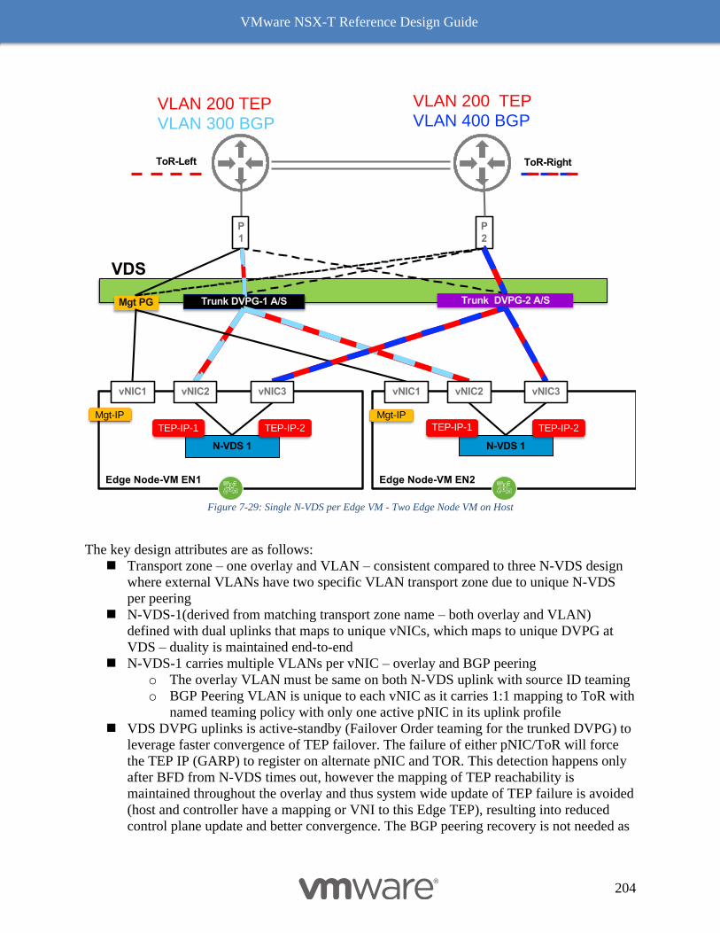
VMware NSX-T Reference Design Guide
204
Figure 7-29: Single N-VDS per Edge VM - Two Edge Node VM on Host
The key design attributes are as follows:
◼ Transport zone – one overlay and VLAN – consistent compared to three N-VDS design
where external VLANs have two specific VLAN transport zone due to unique N-VDS
per peering
◼ N-VDS-1(derived from matching transport zone name – both overlay and VLAN)
defined with dual uplinks that maps to unique vNICs, which maps to unique DVPG at
VDS – duality is maintained end-to-end
◼ N-VDS-1 carries multiple VLANs per vNIC – overlay and BGP peering
o The overlay VLAN must be same on both N-VDS uplink with source ID teaming
o BGP Peering VLAN is unique to each vNIC as it carries 1:1 mapping to ToR with
named teaming policy with only one active pNIC in its uplink profile
◼ VDS DVPG uplinks is active-standby (Failover Order teaming for the trunked DVPG) to
leverage faster convergence of TEP failover. The failure of either pNIC/ToR will force
the TEP IP (GARP) to register on alternate pNIC and TOR. This detection happens only
after BFD from N-VDS times out, however the mapping of TEP reachability is
maintained throughout the overlay and thus system wide update of TEP failure is avoided
(host and controller have a mapping or VNI to this Edge TEP), resulting into reduced
control plane update and better convergence. The BGP peering recovery is not needed as
P
1
P
2
Mgt PG Trunk DVPG-1 A/S Trunk DVPG-2 A/S
VLAN 200 TEPVLAN 300 BGP
VLAN 200 TEPVLAN 400 BGP
ToR-RightToR-Left
Edge Node-VM EN1
vNIC1
Mgt-IP
N-VDS 1
vNIC2 vNIC3
TEP-IP-1 TEP-IP-2
Edge Node-VM EN2
vNIC1
Mgt-IP
N-VDS 1
vNIC2 vNIC3
TEP-IP-1 TEP-IP-2
VDS
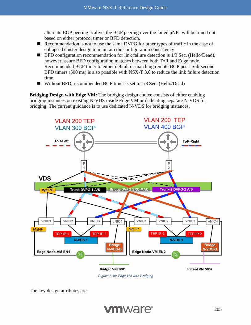
VMware NSX-T Reference Design Guide
205
alternate BGP peering is alive, the BGP peering over the failed pNIC will be timed out
based on either protocol timer or BFD detection.
◼ Recommendation is not to use the same DVPG for other types of traffic in the case of
collapsed cluster design to maintain the configuration consistency
◼ BFD configuration recommendation for link failure detection is 1/3 Sec. (Hello/Dead),
however assure BFD configuration matches between both ToR and Edge node.
Recommended BGP timer to either default or matching remote BGP peer. Sub-second
BFD timers (500 ms) is also possible with NSX-T 3.0 to reduce the link failure detection
time.
◼ Without BFD, recommended BGP timer is set to 1/3 Sec. (Hello/Dead)
Bridging Design with Edge VM: The bridging design choice consists of either enabling
bridging instances on existing N-VDS inside Edge VM or dedicating separate N-VDS for
bridging. The current guidance is to use dedicated N-VDS for bridging instances.
Figure 7-30: Edge VM with Bridging
The key design attributes are:
P
1
P
2
Mgt PG Trunk-2 DVPG-2 A/S
VLAN 200 TEPVLAN 300 BGP
VLAN 200 TEPVLAN 400 BGP
ToR-RightToR-Left
Edge Node-VM EN1
vNIC1
Mgt-IP
N-VDS 1
vNIC2 vNIC3
TEP-IP-1 TEP-IP-2
vNIC4
Bridge
N-VDS-BEdge Node-VM EN2
vNIC1
Mgt-IP
N-VDS 1
vNIC2 vNIC3
TEP-IP-1 TEP-IP-2
vNIC4
Bridge
N-VDS-B
VDS
Bridge DVPG SRC-MAC
Bridged VNI 5001 Bridged VNI 5002
Trunk DVPG-1 A/S
VMware NSX-T Reference Design Guide
206
◼ Additional vNIC (vNIC 4 in the picture) in Edge VM which maps to dedicated bridge
instance
◼ The bridge N-VDS-B must be attached to separate VLAN transport zone since two N-
VDS cannot be attached to same transport zone. Overlay transport zone is defined once
per Edge VM node and thus traffic is internally wired between two N-VDS. If a
dedicated Edge VM node is chosen for bridged traffic, then the overlay transport zone
must be the same for carrying the overlay traffic to bridge instance, while VLAN
transport zone is whatever needed for carrying bridged VLANs.
◼ Dedicated DVPG group defined at VDS to with load balance based on source mac
address teaming policy. This should help distributed flows from various sources of MAC
across available uplinks links
◼ The bridge DVPG must be enabled with mac-learning. See additional details on this topic
at Edge VM vNIC Configuration Requirement with Bridging.
◼ For load balancing of bridge traffic, multiple bridge instances are allowed, the bridge
instances shown in picture are for illustrating the diversification of bridge placement. If
deployment requires significant bandwidth for bridged traffic, either deploy additional
pNIC and add a dedicated Edge VM just for the bridging as shown in 7.4.1.1.3. The
bridge placement per uplink as discussed in bare metal case is not applicable here since
there is only one uplink from the bridge
◼ Choose preemptive vs non-preemptive mode based on need to consistent traffic load
balancing
The picture above shows multiple Edge VM per host to illustrate the symmetry and bandwidth
capacity planning matching the proportional throughput from 10/25 Gbps NICs. Additional Edge
VM can be added assuming oversubscription is afforded to build a cost-effective design.
Alternative is to deploy four pNICs and repeat the same building block of pNIC mapping as
shown in below section.
7.4.5.2 Dedicated Host for Edge VM Design with 4 pNICs
The four pNICs host can offer design choices that meet variety of business and operational need
in which multiple Edge VM can be deployed in same host. The design choices covering compute
host with four pNICs is already discussed in ESXi-Based Compute Hypervisor with Four (or
more) pNICs. The design choices with four pNICs hosts utilized for collapsed management and
edge or collapsed compute and edge are discussed further in Collapsed Management and Edge
Resources Design.
The below design choice with four pNICs is optimal for having multiple Edge nodes per host
without any oversubscription. In most cases (except host is oversubscribed with other VMs or
resources like management, multi-tenant edges etc.), it is not the host CPU but the number of
pNICs available at the host determines the number of Edge node per host. One can optimize the
design by adopting four Edge VMs per host where the oversubscription is not a concern but
building a high-density multi-tenant or services design is important.
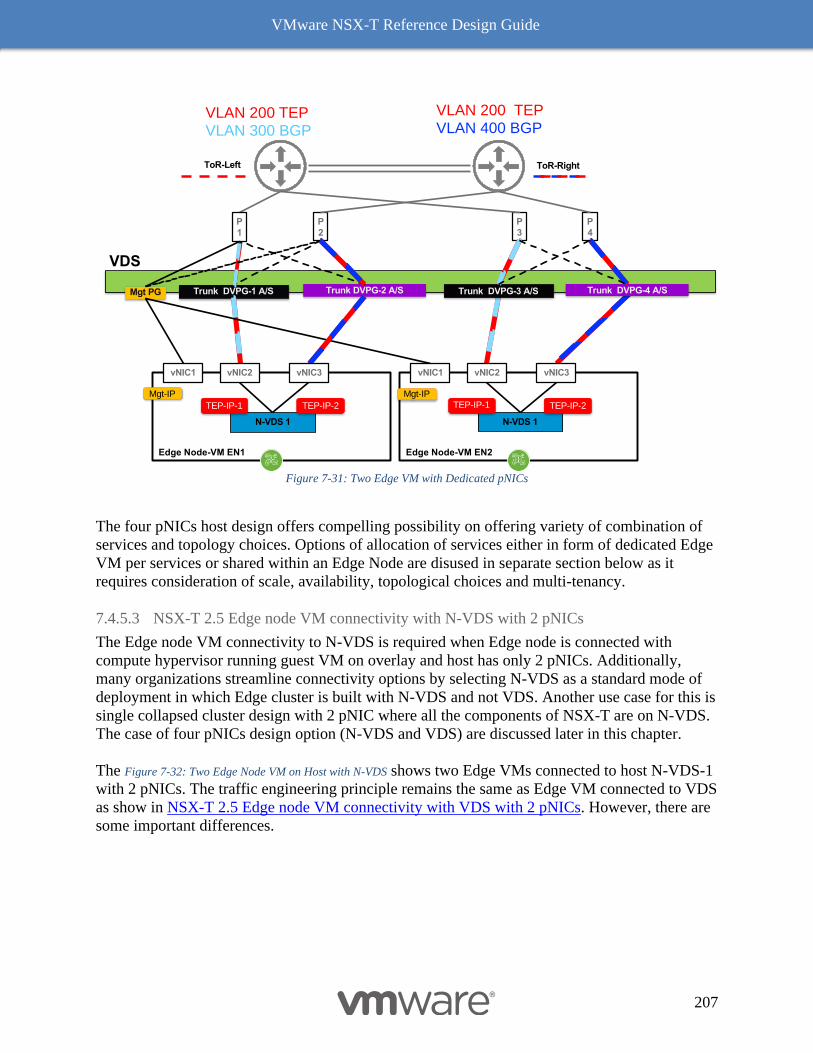
VMware NSX-T Reference Design Guide
207
Figure 7-31: Two Edge VM with Dedicated pNICs
The four pNICs host design offers compelling possibility on offering variety of combination of
services and topology choices. Options of allocation of services either in form of dedicated Edge
VM per services or shared within an Edge Node are disused in separate section below as it
requires consideration of scale, availability, topological choices and multi-tenancy.
7.4.5.3 NSX-T 2.5 Edge node VM connectivity with N-VDS with 2 pNICs
The Edge node VM connectivity to N-VDS is required when Edge node is connected with
compute hypervisor running guest VM on overlay and host has only 2 pNICs. Additionally,
many organizations streamline connectivity options by selecting N-VDS as a standard mode of
deployment in which Edge cluster is built with N-VDS and not VDS. Another use case for this is
single collapsed cluster design with 2 pNIC where all the components of NSX-T are on N-VDS.
The case of four pNICs design option (N-VDS and VDS) are discussed later in this chapter.
The Figure 7-32: Two Edge Node VM on Host with N-VDS shows two Edge VMs connected to host N-VDS-1
with 2 pNICs. The traffic engineering principle remains the same as Edge VM connected to VDS
as show in NSX-T 2.5 Edge node VM connectivity with VDS with 2 pNICs. However, there are
some important differences.
P
1
P
2
Mgt PG Trunk DVPG-1 A/S Trunk DVPG-2 A/S
VLAN 200 TEPVLAN 300 BGP
VLAN 200 TEPVLAN 400 BGP
ToR-RightToR-Left
Edge Node-VM EN1
vNIC1
Mgt-IP
N-VDS 1
vNIC2 vNIC3
TEP-IP-1 TEP-IP-2
Edge Node-VM EN2
vNIC1
Mgt-IP
N-VDS 1
vNIC2 vNIC3
TEP-IP-1 TEP-IP-2
VDS
P
3
P
4
Trunk DVPG-3 A/S Trunk DVPG-4 A/S
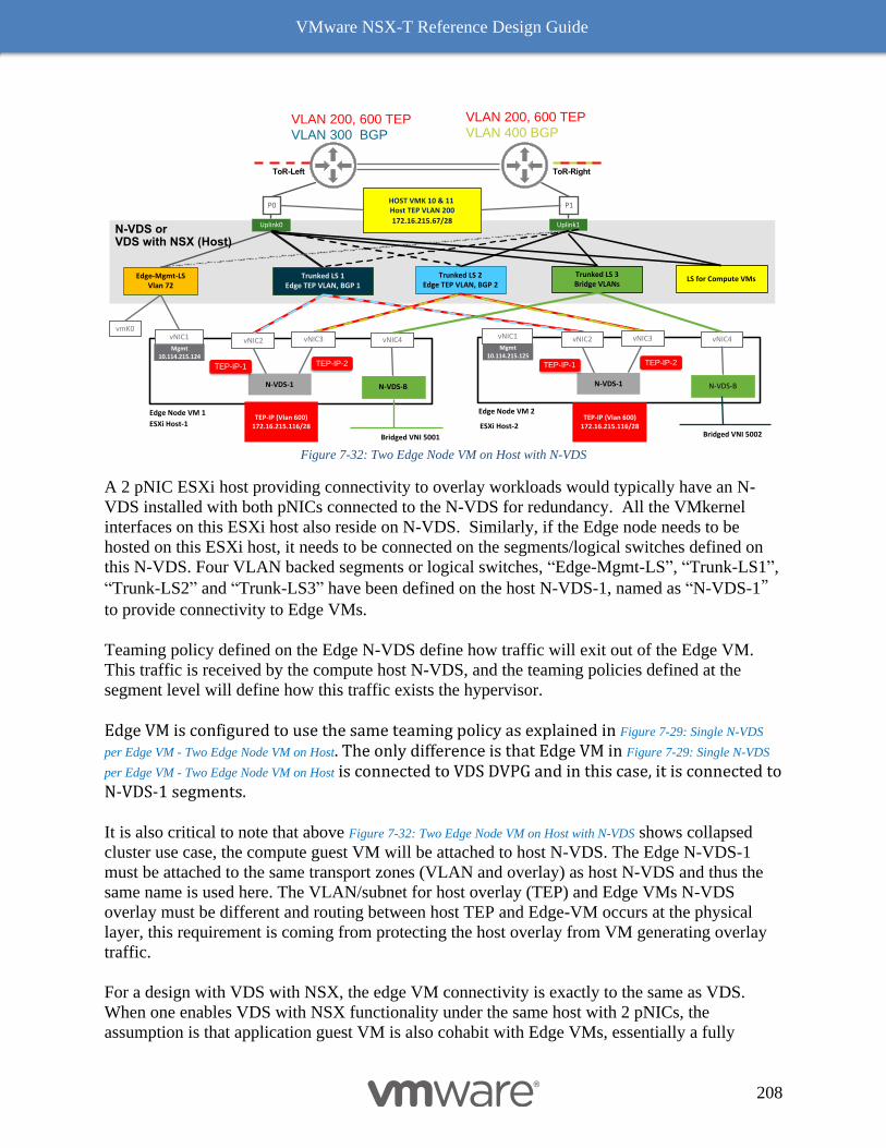
VMware NSX-T Reference Design Guide
208
Figure 7-32: Two Edge Node VM on Host with N-VDS
A 2 pNIC ESXi host providing connectivity to overlay workloads would typically have an N-
VDS installed with both pNICs connected to the N-VDS for redundancy. All the VMkernel
interfaces on this ESXi host also reside on N-VDS. Similarly, if the Edge node needs to be
hosted on this ESXi host, it needs to be connected on the segments/logical switches defined on
this N-VDS. Four VLAN backed segments or logical switches, “Edge-Mgmt-LS”, “Trunk-LS1”,
“Trunk-LS2” and “Trunk-LS3” have been defined on the host N-VDS-1, named as “N-VDS-1”
to provide connectivity to Edge VMs.
Teaming policy defined on the Edge N-VDS define how traffic will exit out of the Edge VM.
This traffic is received by the compute host N-VDS, and the teaming policies defined at the
segment level will define how this traffic exists the hypervisor.
Edge VM is configured to use the same teaming policy as explained in Figure 7-29: Single N-VDS
per Edge VM - Two Edge Node VM on Host. The only difference is that Edge VM in Figure 7-29: Single N-VDS
per Edge VM - Two Edge Node VM on Host is connected to VDS DVPG and in this case, it is connected to N-VDS-1 segments.
It is also critical to note that above Figure 7-32: Two Edge Node VM on Host with N-VDS shows collapsed
cluster use case, the compute guest VM will be attached to host N-VDS. The Edge N-VDS-1
must be attached to the same transport zones (VLAN and overlay) as host N-VDS and thus the
same name is used here. The VLAN/subnet for host overlay (TEP) and Edge VMs N-VDS
overlay must be different and routing between host TEP and Edge-VM occurs at the physical
layer, this requirement is coming from protecting the host overlay from VM generating overlay
traffic.
For a design with VDS with NSX, the edge VM connectivity is exactly to the same as VDS.
When one enables VDS with NSX functionality under the same host with 2 pNICs, the
assumption is that application guest VM is also cohabit with Edge VMs, essentially a fully
P1P0
Edge-Mgmt-LSVlan 72
Trunked LS 1Edge TEP VLAN, BGP 1
Trunked LS 2Edge TEP VLAN, BGP 2
Uplink1Uplink0
ESXi Host-1
vNIC1
Mgmt 10.114.215.124
Edge Node VM 1
vNIC2
TEP-IP (Vlan 600)172.16.215.116/28
vmK0
vNIC4
N-VDS-1
TEP-IP-1 TEP-IP-2
HOST VMK 10 & 11 Host TEP VLAN 200
172.16.215.67/28
VLAN 200, 600 TEPVLAN 300 BGP
VLAN 200, 600 TEPVLAN 400 BGP
ToR-RightToR-Left
LS for Compute VMs
N-VDS or VDS with NSX (Host)
vNIC3
N-VDS-B
Mgmt 10.114.215.125
Edge Node VM 2
vNIC2
TEP-IP (Vlan 600)172.16.215.116/28
vNIC4
N-VDS-1
TEP-IP-1 TEP-IP-2
vNIC3
N-VDS-B
vNIC1
Trunked LS 3Bridge VLANs
Bridged VNI 5001 Bridged VNI 5002ESXi Host-2
VMware NSX-T Reference Design Guide
209
collapsed cluster design. This design is discussed under Fully Collapsed Single vSphere Cluster
with 2 pNICs Host.
For the bridging services, one must enable mac-learning on N-VDS which available as natively
as compared VDS. In addition, the VLAN transport zone for the bridge must be different then
the host N-VDS, as in this recommendation the dedicated N-VDS-B is used for bridging traffic.
NSX-T Edge Resources Design
The previous section covered the Edge node wiring for both bare metal and VM. It explains how
overlay, N-S peering and bridging connectivity can be achieved with choices of design with
number of pNICs and availability model through the choice of right teaming behavior. This
section goes details into building services (e.g. ECMP, FW, NAT, LB and VPN) with either bare
metal or VM. In addition, several considerations that goes inn optimizing right footprint of
resources. There are two major considerations in designing NSX-T services cluster – Type of
services enabled and clustering.
7.4.6.1 Edge Services
The guideline that governs the overall roadmap of developing services models.
◼ Service Level Agreement desired for each service. It can be broad, bandwidth/throughput
of each service, separation of Tier-0 or Tier-1 to have an independence operational
control or varying levels of services specific offering
o Not just for bandwidth but scale
o Configuration controls – overlapping NAT, change control of security vs NAT
o Multi-tenant – dedicated Tier-1 per tenant or services as a tenant
o Services controls – failure behavior – only Tier-0 or only Tier-1, Automation
control etc.
◼ ECMP to physical devices only run at Tier-0, however that does not mean there is no
ECMP from Tier-1, there are up to 8 paths from Tier-1 to Tier-0 and up to 8 distinct BGP
peering from Tier-0
o For a given Edge node there can only one Tier-0 services, however one can have
multiple Tier-1 services. If Tier-0 is enabled with stateful services for a workload
like Kubernetes (TKGI-PKS or OpenShift), then for the other workloads it may
require separate Tier-0 (SLA considerations) and thus separate Edge node. Multi-
tier Tier-0 model is only possible with running multiple instances Edge node VM
or dedicated bare metal per Tier-0.
◼ As of NSX-T release 2.5 all edge services can be deployed in either Tier-0 or Tier-1.
However, there are exception for other services
o VPN can run on Tier-0 with BGP but not at Tier-1, VPN at Tier-1 can enabled wit
static routing
o In line LB can only be enable on Tier-1. Use in- line LB for preserving server
pools.
o One arm LB can be deployed as standalone Tier-1 services. It can be attached to
either Tier-0 or Tier-1 as a VLAN or overlay services port. To optimize East-
West distributed routing, use one-arm LB with overlay services port. The one-arm
VMware NSX-T Reference Design Guide
210
LB allows sperate life cycle of Edge node, from configuration changes to resizing
without directly affecting existing Tier-1 gateway for other traffic.
◼ Services port (SP) can be attached as VLAN or overlay. It can be attached to either Tier-0
or Tier-1. Edge node must be in active/standby mode. Typically, services interface should
be enabled on Tier-1 to avoid forcing the Tier-0 in active/standby mode and thus limiting
ECMP bandwidth for the entire NSX-T domain. Avoid using overlay services interface
attaching to Tier-0 unless it is used for LB one arm mode. Services interface should not
be used for a single tier topology with logical network (allows fully distributed routing
for) typical small scale or small size multi-tenant design unless specific use case requires
it.
Preemptive vs Non-preemptive Mode with Active/Standby Services
Each stateful services can be configured for either preemptive or non-preemptive mode. The
design choice is between deterministic balancing of services among available resources
(bandwidth and CPU) verses reducing disruption of services.
◼ The preemptive model allows making sure that, when the system is fully operational,
pool of edge resources (bandwidth and CPU) always get balanced after the restoration of
host or Edge VM. However, preemptive mode triggers the switchover of Edge VM
running services, leading secondary disruption causing packet loss. Operationally this
may not be acceptable triggering intentional switchover.
◼ The non-preemptive model maximizes availability and is the default mode for the service
deployment. If the active fails then recovers; it will be in standby mode, it will not trigger
a re-convergence that could lead to unnecessary packet loss (by preempting the currently
active.) The drawback is that, after a recovered failure, the services remains polarized on
a host or an edge cluster. This leads to an oversubscription of a host or uplink bandwidth.
If availability is more important than oversubscription (bandwidth and CPU), this mode
is perfectly acceptable. Typically, one can restore the rebalancing of the services during
off-peak or planned maintenance window.
Services can be enabled either in shared or dedicated Edge node.
◼ Shared Mode: Shared mode is the most common deployment mode and a starting point
for building the edge services model. Tier-0 or Tier-1 not enabled with stateful service,
by default runs in distributed mode. In shared mode, typically Tier-0 runs ECMP service
while Tier-1 can runs stateful services (aka either active or standby mode for that
services). If the Edge node fails, all the services within that nodes fails (this is an SLA
choice see first bullet). Below Figure 7-33: Shared Service Edge Node Cluster shows the flexibility
in deploying ECMP services along with variable services model for Tier-1. Tier-0,
represented by the green node, running the ECMP service on all four Edge nodes
providing aggregated multi-Gbps throughput for combined Tier-1 services. The Tier-1
services are deployed based on tenants or workload needs. For an example few Tier-1
services (red, black and blue) are stateful over a pair of Edge nodes where many services
are spread over four nodes. In other words, they do not have to be deployed on the same
nodes so the services can scale. The stateful services have a SR component running on
the Edge nodes. The active SR component is shown with solid color Tier-1 router icon
while the standby on in light faded icon. The Tier-1 routing function can be entirely
distributed (aka stateless yellow Tier-1) and thus does not have SR component and thus
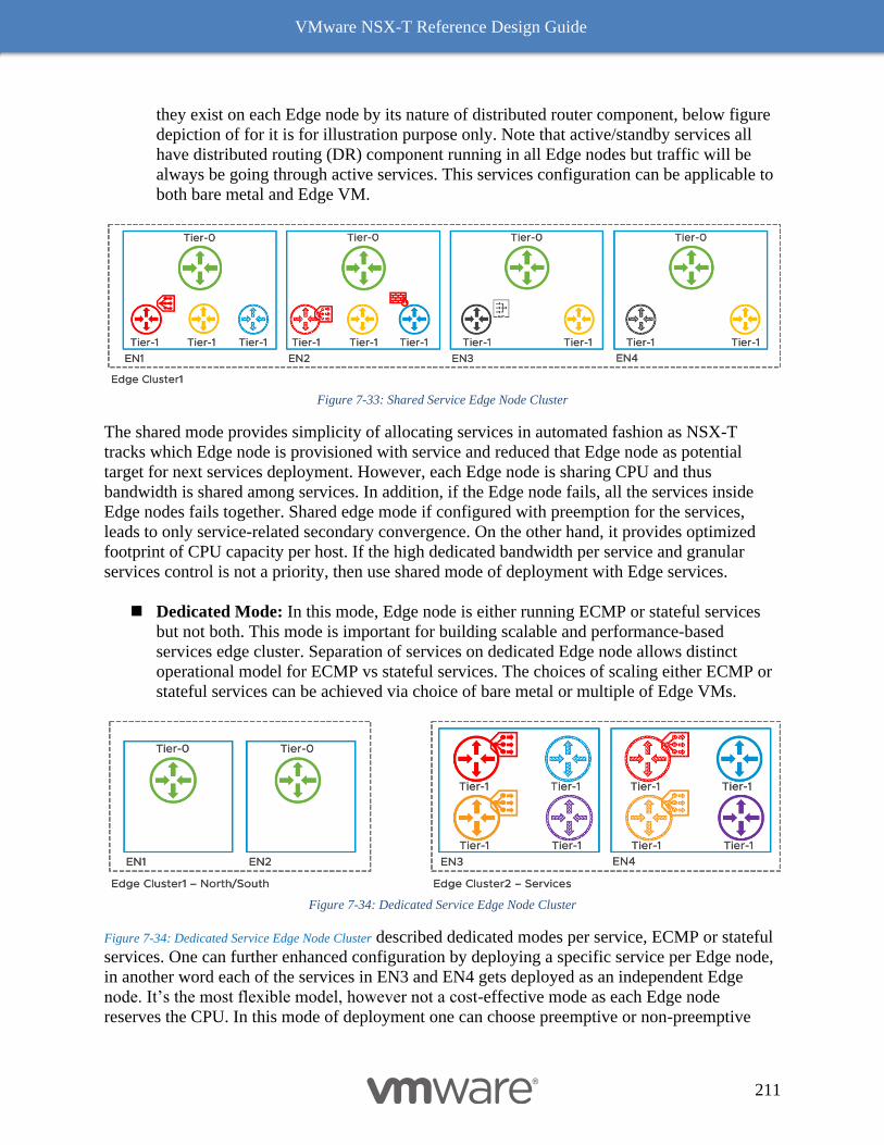
VMware NSX-T Reference Design Guide
211
they exist on each Edge node by its nature of distributed router component, below figure
depiction of for it is for illustration purpose only. Note that active/standby services all
have distributed routing (DR) component running in all Edge nodes but traffic will be
always be going through active services. This services configuration can be applicable to
both bare metal and Edge VM.
Figure 7-33: Shared Service Edge Node Cluster
The shared mode provides simplicity of allocating services in automated fashion as NSX-T
tracks which Edge node is provisioned with service and reduced that Edge node as potential
target for next services deployment. However, each Edge node is sharing CPU and thus
bandwidth is shared among services. In addition, if the Edge node fails, all the services inside
Edge nodes fails together. Shared edge mode if configured with preemption for the services,
leads to only service-related secondary convergence. On the other hand, it provides optimized
footprint of CPU capacity per host. If the high dedicated bandwidth per service and granular
services control is not a priority, then use shared mode of deployment with Edge services.
◼ Dedicated Mode: In this mode, Edge node is either running ECMP or stateful services
but not both. This mode is important for building scalable and performance-based
services edge cluster. Separation of services on dedicated Edge node allows distinct
operational model for ECMP vs stateful services. The choices of scaling either ECMP or
stateful services can be achieved via choice of bare metal or multiple of Edge VMs.
Figure 7-34: Dedicated Service Edge Node Cluster
Figure 7-34: Dedicated Service Edge Node Cluster described dedicated modes per service, ECMP or stateful
services. One can further enhanced configuration by deploying a specific service per Edge node,
in another word each of the services in EN3 and EN4 gets deployed as an independent Edge
node. It’s the most flexible model, however not a cost-effective mode as each Edge node
reserves the CPU. In this mode of deployment one can choose preemptive or non-preemptive
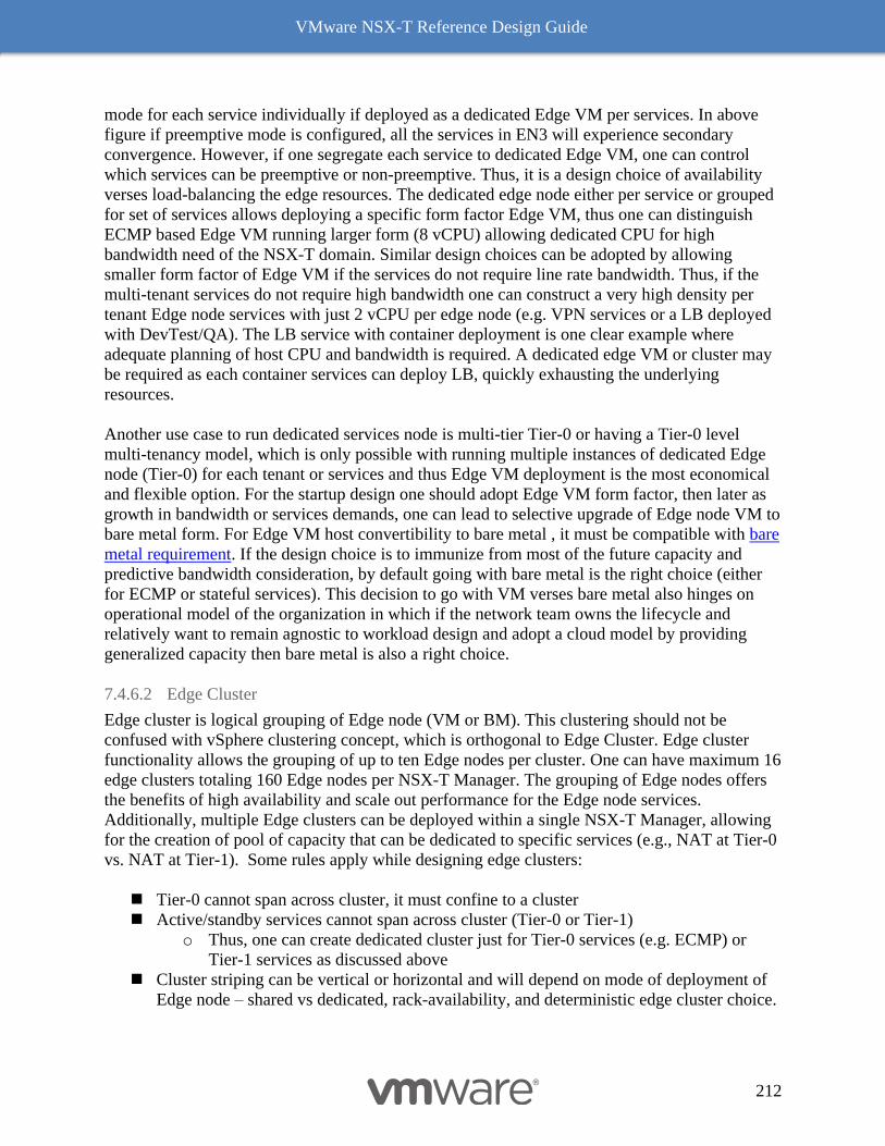
VMware NSX-T Reference Design Guide
212
mode for each service individually if deployed as a dedicated Edge VM per services. In above
figure if preemptive mode is configured, all the services in EN3 will experience secondary
convergence. However, if one segregate each service to dedicated Edge VM, one can control
which services can be preemptive or non-preemptive. Thus, it is a design choice of availability
verses load-balancing the edge resources. The dedicated edge node either per service or grouped
for set of services allows deploying a specific form factor Edge VM, thus one can distinguish
ECMP based Edge VM running larger form (8 vCPU) allowing dedicated CPU for high
bandwidth need of the NSX-T domain. Similar design choices can be adopted by allowing
smaller form factor of Edge VM if the services do not require line rate bandwidth. Thus, if the
multi-tenant services do not require high bandwidth one can construct a very high density per
tenant Edge node services with just 2 vCPU per edge node (e.g. VPN services or a LB deployed
with DevTest/QA). The LB service with container deployment is one clear example where
adequate planning of host CPU and bandwidth is required. A dedicated edge VM or cluster may
be required as each container services can deploy LB, quickly exhausting the underlying
resources.
Another use case to run dedicated services node is multi-tier Tier-0 or having a Tier-0 level
multi-tenancy model, which is only possible with running multiple instances of dedicated Edge
node (Tier-0) for each tenant or services and thus Edge VM deployment is the most economical
and flexible option. For the startup design one should adopt Edge VM form factor, then later as
growth in bandwidth or services demands, one can lead to selective upgrade of Edge node VM to
bare metal form. For Edge VM host convertibility to bare metal , it must be compatible with bare
metal requirement. If the design choice is to immunize from most of the future capacity and
predictive bandwidth consideration, by default going with bare metal is the right choice (either
for ECMP or stateful services). This decision to go with VM verses bare metal also hinges on
operational model of the organization in which if the network team owns the lifecycle and
relatively want to remain agnostic to workload design and adopt a cloud model by providing
generalized capacity then bare metal is also a right choice.
7.4.6.2 Edge Cluster
Edge cluster is logical grouping of Edge node (VM or BM). This clustering should not be
confused with vSphere clustering concept, which is orthogonal to Edge Cluster. Edge cluster
functionality allows the grouping of up to ten Edge nodes per cluster. One can have maximum 16
edge clusters totaling 160 Edge nodes per NSX-T Manager. The grouping of Edge nodes offers
the benefits of high availability and scale out performance for the Edge node services.
Additionally, multiple Edge clusters can be deployed within a single NSX-T Manager, allowing
for the creation of pool of capacity that can be dedicated to specific services (e.g., NAT at Tier-0
vs. NAT at Tier-1). Some rules apply while designing edge clusters:
◼ Tier-0 cannot span across cluster, it must confine to a cluster
◼ Active/standby services cannot span across cluster (Tier-0 or Tier-1)
o Thus, one can create dedicated cluster just for Tier-0 services (e.g. ECMP) or
Tier-1 services as discussed above
◼ Cluster striping can be vertical or horizontal and will depend on mode of deployment of
Edge node – shared vs dedicated, rack-availability, and deterministic edge cluster choice.
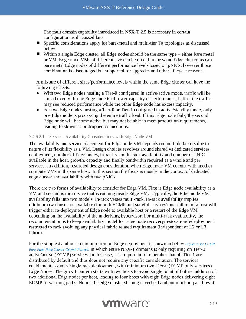
VMware NSX-T Reference Design Guide
213
The fault domain capability introduced in NSX-T 2.5 is necessary in certain
configuration as discussed later
◼ Specific considerations apply for bare-metal and multi-tier T0 topologies as discussed
below
◼ Within a single Edge cluster, all Edge nodes should be the same type – either bare metal
or VM. Edge node VMs of different size can be mixed in the same Edge cluster, as can
bare metal Edge nodes of different performance levels based on pNICs, however those
combination is discouraged but supported for upgrades and other lifecycle reasons.
A mixture of different sizes/performance levels within the same Edge cluster can have the
following effects:
● With two Edge nodes hosting a Tier-0 configured in active/active mode, traffic will be
spread evenly. If one Edge node is of lower capacity or performance, half of the traffic
may see reduced performance while the other Edge node has excess capacity.
● For two Edge nodes hosting a Tier-0 or Tier-1 configured in active/standby mode, only
one Edge node is processing the entire traffic load. If this Edge node fails, the second
Edge node will become active but may not be able to meet production requirements,
leading to slowness or dropped connections.
7.4.6.2.1 Services Availability Considerations with Edge Node VM
The availability and service placement for Edge node VM depends on multiple factors due to
nature of its flexibility as a VM. Design choices revolves around shared vs dedicated services
deployment, number of Edge nodes, in-rack vs multi-rack availability and number of pNIC
available in the host, growth, capacity and finally bandwidth required as a whole and per
services. In addition, restricted design consideration when Edge node VM coexist with another
compute VMs in the same host. In this section the focus is mostly in the context of dedicated
edge cluster and availability with two pNICs.
There are two forms of availability to consider for Edge VM. First is Edge node availability as a
VM and second is the service that is running inside Edge VM. Typically, the Edge node VM
availability falls into two models. In-rack verses multi-rack. In-rack availability implies
minimum two hosts are available (for both ECMP and stateful services) and failure of a host will
trigger either re-deployment of Edge node to available host or a restart of the Edge VM
depending on the availability of the underlying hypervisor. For multi-rack availability, the
recommendation is to keep availability model for Edge node recovery/restoration/redeployment
restricted to rack avoiding any physical fabric related requirement (independent of L2 or L3
fabric).
For the simplest and most common form of Edge deployment is shown in below Figure 7-35: ECMP
Base Edge Node Cluster Growth Pattern, in which entire NSX-T domains is only requiring on Tier-0
active/active (ECMP) services. In this case, it is important to remember that all Tier-1 are
distributed by default and thus does not require any specific consideration. The services
enablement assumes single rack deployment, with minimum two Tier-0 (ECMP only services)
Edge Nodes. The growth pattern starts with two hosts to avoid single point of failure, addition of
two additional Edge nodes per host, leading to four hosts with eight Edge nodes delivering eight
ECMP forwarding paths. Notice the edge cluster striping is vertical and not much impact how it
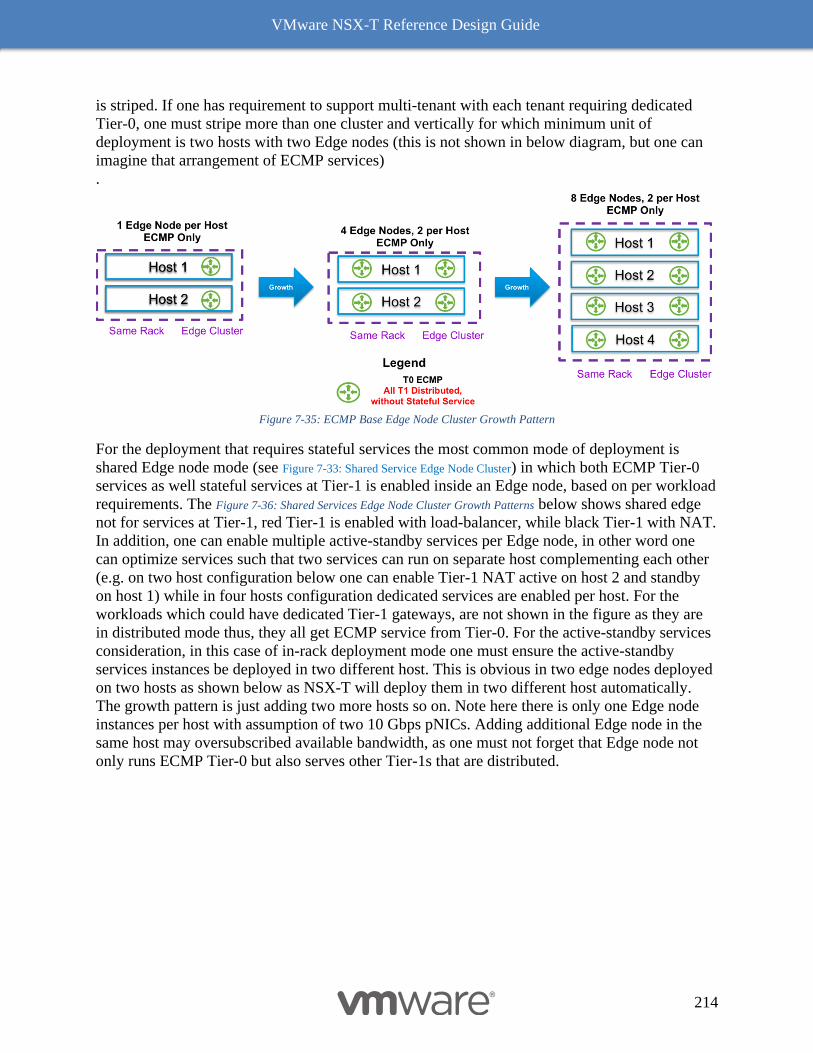
VMware NSX-T Reference Design Guide
214
is striped. If one has requirement to support multi-tenant with each tenant requiring dedicated
Tier-0, one must stripe more than one cluster and vertically for which minimum unit of
deployment is two hosts with two Edge nodes (this is not shown in below diagram, but one can
imagine that arrangement of ECMP services)
.
Figure 7-35: ECMP Base Edge Node Cluster Growth Pattern
For the deployment that requires stateful services the most common mode of deployment is
shared Edge node mode (see Figure 7-33: Shared Service Edge Node Cluster) in which both ECMP Tier-0
services as well stateful services at Tier-1 is enabled inside an Edge node, based on per workload
requirements. The Figure 7-36: Shared Services Edge Node Cluster Growth Patterns below shows shared edge
not for services at Tier-1, red Tier-1 is enabled with load-balancer, while black Tier-1 with NAT.
In addition, one can enable multiple active-standby services per Edge node, in other word one
can optimize services such that two services can run on separate host complementing each other
(e.g. on two host configuration below one can enable Tier-1 NAT active on host 2 and standby
on host 1) while in four hosts configuration dedicated services are enabled per host. For the
workloads which could have dedicated Tier-1 gateways, are not shown in the figure as they are
in distributed mode thus, they all get ECMP service from Tier-0. For the active-standby services
consideration, in this case of in-rack deployment mode one must ensure the active-standby
services instances be deployed in two different host. This is obvious in two edge nodes deployed
on two hosts as shown below as NSX-T will deploy them in two different host automatically.
The growth pattern is just adding two more hosts so on. Note here there is only one Edge node
instances per host with assumption of two 10 Gbps pNICs. Adding additional Edge node in the
same host may oversubscribed available bandwidth, as one must not forget that Edge node not
only runs ECMP Tier-0 but also serves other Tier-1s that are distributed.
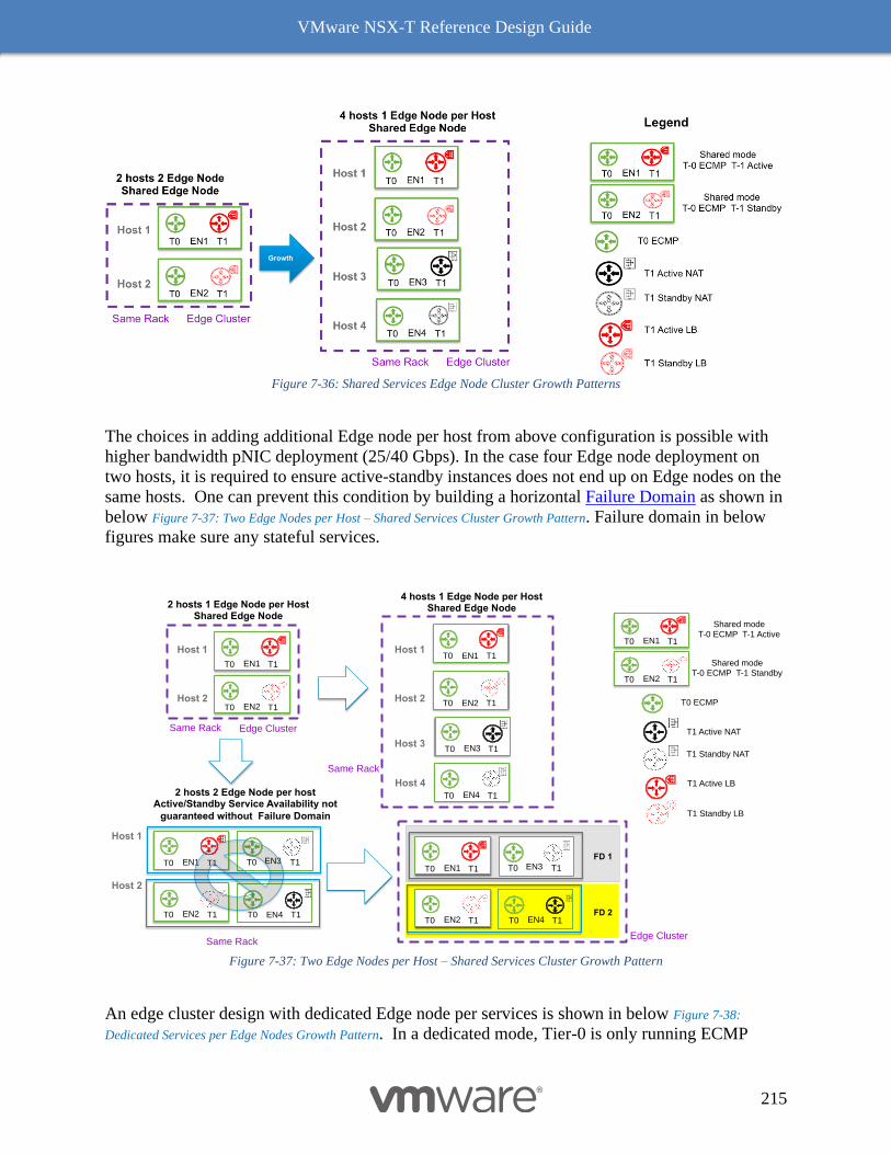
VMware NSX-T Reference Design Guide
215
Figure 7-36: Shared Services Edge Node Cluster Growth Patterns
The choices in adding additional Edge node per host from above configuration is possible with
higher bandwidth pNIC deployment (25/40 Gbps). In the case four Edge node deployment on
two hosts, it is required to ensure active-standby instances does not end up on Edge nodes on the
same hosts. One can prevent this condition by building a horizontal Failure Domain as shown in
below Figure 7-37: Two Edge Nodes per Host – Shared Services Cluster Growth Pattern. Failure domain in below
figures make sure any stateful services.
Figure 7-37: Two Edge Nodes per Host – Shared Services Cluster Growth Pattern
An edge cluster design with dedicated Edge node per services is shown in below Figure 7-38:
Dedicated Services per Edge Nodes Growth Pattern. In a dedicated mode, Tier-0 is only running ECMP
4 hosts 1 Edge Node per HostShared Edge Node2 hosts 1 Edge Node per Host
Shared Edge Node
T0 T1EN1
T0 T1EN2
T0 T1EN3
Host 1
Host 2
Host 3
T0 ECMP
T0 T1EN1
T0 T1EN2
Shared modeT-0 ECMP T-1 Active
Shared modeT-0 ECMP T-1 Standby
Growth
Same Rack
T1 Standby NAT
T1 Active NAT
T1 Active LB
T1 Standby LB
T0 T1EN1
T0 T1EN2
Host 1
Host 2
Edge ClusterSame Rack
T0 T1EN4
Edge ClusterSame Rack
Host 1
Host 2
T0 T1EN1
T0 T1EN2
Gro
wth
2 hosts 2 Edge Node per hostActive/Standby Service Availability not
guaranteed without Failure Domain
T0 T1EN3
EN4T0 T1
T0 T1EN1
T0 T1EN2
T0 T1EN3
EN4T0 T1
Use Fault Domains
FD 1
FD 2
Host 4
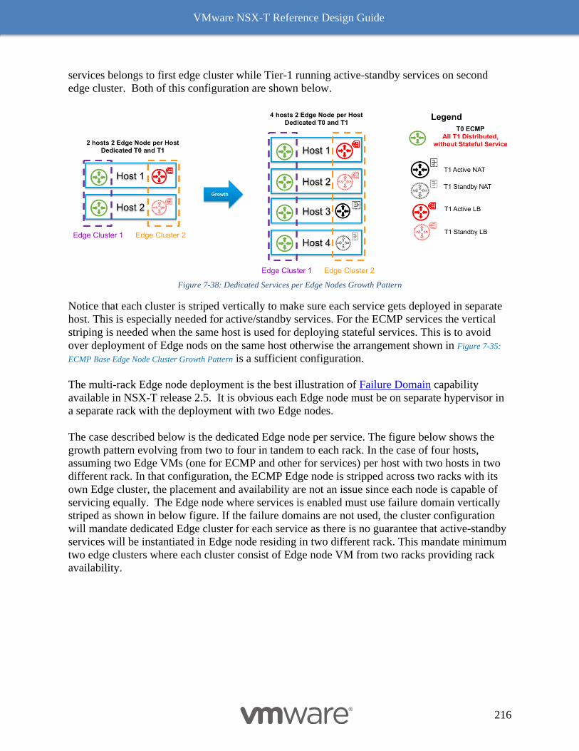
VMware NSX-T Reference Design Guide
216
services belongs to first edge cluster while Tier-1 running active-standby services on second
edge cluster. Both of this configuration are shown below.
Figure 7-38: Dedicated Services per Edge Nodes Growth Pattern
Notice that each cluster is striped vertically to make sure each service gets deployed in separate
host. This is especially needed for active/standby services. For the ECMP services the vertical
striping is needed when the same host is used for deploying stateful services. This is to avoid
over deployment of Edge nods on the same host otherwise the arrangement shown in Figure 7-35:
ECMP Base Edge Node Cluster Growth Pattern is a sufficient configuration.
The multi-rack Edge node deployment is the best illustration of Failure Domain capability
available in NSX-T release 2.5. It is obvious each Edge node must be on separate hypervisor in
a separate rack with the deployment with two Edge nodes.
The case described below is the dedicated Edge node per service. The figure below shows the
growth pattern evolving from two to four in tandem to each rack. In the case of four hosts,
assuming two Edge VMs (one for ECMP and other for services) per host with two hosts in two
different rack. In that configuration, the ECMP Edge node is stripped across two racks with its
own Edge cluster, the placement and availability are not an issue since each node is capable of
servicing equally. The Edge node where services is enabled must use failure domain vertically
striped as shown in below figure. If the failure domains are not used, the cluster configuration
will mandate dedicated Edge cluster for each service as there is no guarantee that active-standby
services will be instantiated in Edge node residing in two different rack. This mandate minimum
two edge clusters where each cluster consist of Edge node VM from two racks providing rack
availability.

VMware NSX-T Reference Design Guide
217
Figure 7-39: Dedicated Services per Edge Nodes Growth Pattern
Finally, the standby edge reallocation capability (only available to Tier-1servrices) allows a
possibility of building a multiple availability zones such that a standby edge VM can be
instantiated automatically after minimum of 10 minutes of failure detection. If the Edge node
that fails is running the active logical router, the original standby logical router becomes the
active logical router and a new standby logical router is created. If the Edge node that fails is
running the standby logical router, the new standby logical router replaces it.
There are several other combinations of topologies are possible based on the requirements of the
SLA as described in the beginning of the section. Reader can build necessary models to meet the
business requirements from above choices.
7.4.6.3 Edge Node VM Physical Host Considerations for Resiliency
As discussed above, there are numerous technical solutions in place to ensure that if/when an
Edge Node fails that the services running on that Edge Node are recovered and continued in a
reasonable amount of time. That said, there are steps that can be taken when designing the
environment hosting the Edge Node VMs to limit the impact of a failure event. An Edge Node
VM inherits the resiliency from the underlying platform that is hosting it, it is imperative that the
hosting platform is configured in a way to remove single points of failures whenever possible
such as:
1. Redundant Power and UPS infrastructure
2. Redundant Physical pNICs
3. Redundant northbound switches
4. Fault tolerant storage platform for hosting the Edge Node VM
In addition to removing the single points of failures from the individual host, limiting the
potential for cascading failures across a single NSX Edge Cluster is also a key design
consideration. Some of the important steps that should be taken to achieve this are:
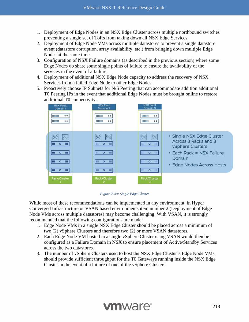
VMware NSX-T Reference Design Guide
218
1. Deployment of Edge Nodes in an NSX Edge Cluster across multiple northbound switches
preventing a single set of ToRs from taking down all NSX Edge Services.
2. Deployment of Edge Node VMs across multiple datastores to prevent a single datastore
event (datastore corruption, array availability, etc.) from bringing down multiple Edge
Nodes at the same time.
3. Configuration of NSX Failure domains (as described in the previous section) where some
Edge Nodes do share some single points of failure to ensure the availability of the
services in the event of a failure.
4. Deployment of additional NSX Edge Node capacity to address the recovery of NSX
Services from a failed Edge Node to other Edge Nodes.
5. Proactively choose IP Subnets for N/S Peering that can accommodate addition additional
T0 Peering IPs in the event that additional Edge Nodes must be brought online to restore
additional T0 connectivity.
Figure 7-40: Single Edge Cluster
While most of these recommendations can be implemented in any environment, in Hyper
Converged Infrastructure or VSAN based environments item number 2 (Deployment of Edge
Node VMs across multiple datastores) may become challenging. With VSAN, it is strongly
recommended that the following configurations are made:
1. Edge Node VMs in a single NSX Edge Cluster should be placed across a minimum of
two (2) vSphere Clusters and therefore two (2) or more VSAN datastores.
2. Each Edge Node VM hosted in a single vSphere Cluster using VSAN would then be
configured as a Failure Domain in NSX to ensure placement of Active/Standby Services
across the two datastores.
3. The number of vSphere Clusters used to host the NSX Edge Cluster’s Edge Node VMs
should provide sufficient throughput for the T0 Gateways running inside the NSX Edge
Cluster in the event of a failure of one of the vSphere Clusters.
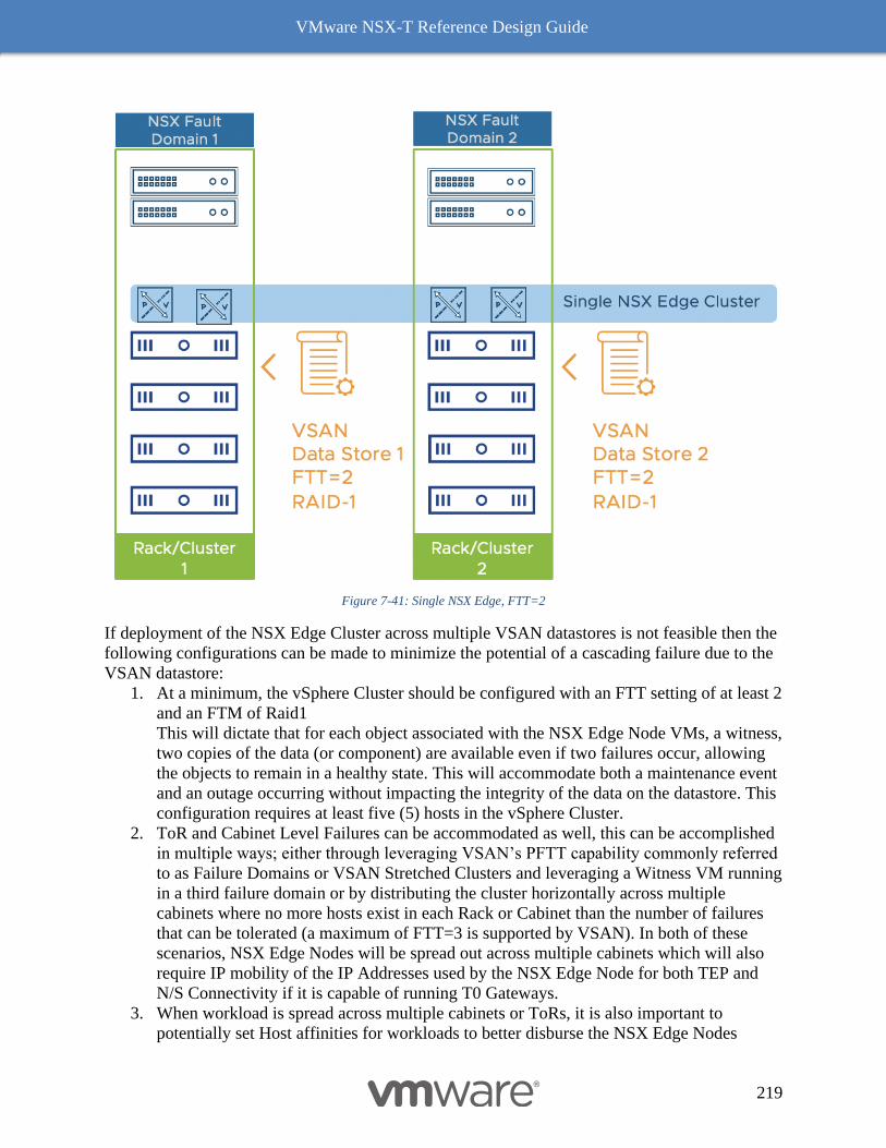
VMware NSX-T Reference Design Guide
219
Figure 7-41: Single NSX Edge, FTT=2
If deployment of the NSX Edge Cluster across multiple VSAN datastores is not feasible then the
following configurations can be made to minimize the potential of a cascading failure due to the
VSAN datastore:
1. At a minimum, the vSphere Cluster should be configured with an FTT setting of at least 2
and an FTM of Raid1
This will dictate that for each object associated with the NSX Edge Node VMs, a witness,
two copies of the data (or component) are available even if two failures occur, allowing
the objects to remain in a healthy state. This will accommodate both a maintenance event
and an outage occurring without impacting the integrity of the data on the datastore. This
configuration requires at least five (5) hosts in the vSphere Cluster.
2. ToR and Cabinet Level Failures can be accommodated as well, this can be accomplished
in multiple ways; either through leveraging VSAN’s PFTT capability commonly referred
to as Failure Domains or VSAN Stretched Clusters and leveraging a Witness VM running
in a third failure domain or by distributing the cluster horizontally across multiple
cabinets where no more hosts exist in each Rack or Cabinet than the number of failures
that can be tolerated (a maximum of FTT=3 is supported by VSAN). In both of these
scenarios, NSX Edge Nodes will be spread out across multiple cabinets which will also
require IP mobility of the IP Addresses used by the NSX Edge Node for both TEP and
N/S Connectivity if it is capable of running T0 Gateways.
3. When workload is spread across multiple cabinets or ToRs, it is also important to
potentially set Host affinities for workloads to better disburse the NSX Edge Nodes
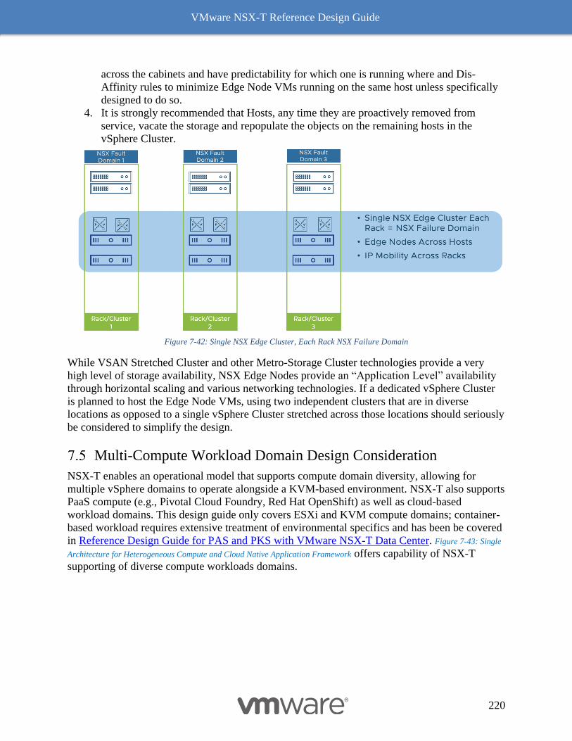
VMware NSX-T Reference Design Guide
220
across the cabinets and have predictability for which one is running where and Dis-
Affinity rules to minimize Edge Node VMs running on the same host unless specifically
designed to do so.
4. It is strongly recommended that Hosts, any time they are proactively removed from
service, vacate the storage and repopulate the objects on the remaining hosts in the
vSphere Cluster.
Figure 7-42: Single NSX Edge Cluster, Each Rack NSX Failure Domain
While VSAN Stretched Cluster and other Metro-Storage Cluster technologies provide a very
high level of storage availability, NSX Edge Nodes provide an “Application Level” availability
through horizontal scaling and various networking technologies. If a dedicated vSphere Cluster
is planned to host the Edge Node VMs, using two independent clusters that are in diverse
locations as opposed to a single vSphere Cluster stretched across those locations should seriously
be considered to simplify the design.
Multi-Compute Workload Domain Design Consideration
NSX-T enables an operational model that supports compute domain diversity, allowing for
multiple vSphere domains to operate alongside a KVM-based environment. NSX-T also supports
PaaS compute (e.g., Pivotal Cloud Foundry, Red Hat OpenShift) as well as cloud-based
workload domains. This design guide only covers ESXi and KVM compute domains; container-
based workload requires extensive treatment of environmental specifics and has been be covered
in Reference Design Guide for PAS and PKS with VMware NSX-T Data Center. Figure 7-43: Single
Architecture for Heterogeneous Compute and Cloud Native Application Framework offers capability of NSX-T
supporting of diverse compute workloads domains.
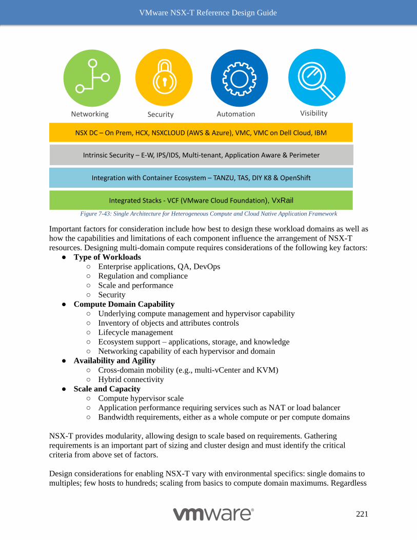
VMware NSX-T Reference Design Guide
221
Figure 7-43: Single Architecture for Heterogeneous Compute and Cloud Native Application Framework
Important factors for consideration include how best to design these workload domains as well as
how the capabilities and limitations of each component influence the arrangement of NSX-T
resources. Designing multi-domain compute requires considerations of the following key factors:
● Type of Workloads
○ Enterprise applications, QA, DevOps
○ Regulation and compliance
○ Scale and performance
○ Security
● Compute Domain Capability
○ Underlying compute management and hypervisor capability
○ Inventory of objects and attributes controls
○ Lifecycle management
○ Ecosystem support – applications, storage, and knowledge
○ Networking capability of each hypervisor and domain
● Availability and Agility
○ Cross-domain mobility (e.g., multi-vCenter and KVM)
○ Hybrid connectivity
● Scale and Capacity
○ Compute hypervisor scale
○ Application performance requiring services such as NAT or load balancer
○ Bandwidth requirements, either as a whole compute or per compute domains
NSX-T provides modularity, allowing design to scale based on requirements. Gathering
requirements is an important part of sizing and cluster design and must identify the critical
criteria from above set of factors.
Design considerations for enabling NSX-T vary with environmental specifics: single domains to
multiples; few hosts to hundreds; scaling from basics to compute domain maximums. Regardless
Visibility Automation
NSX DC – On Prem, HCX, NSXCLOUD (AWS & Azure), VMC, VMC on Dell Cloud, IBM
Integration with Container Ecosystem – TANZU, TAS, DIY K8 & OpenShift
Integrated Stacks - VCF (VMware Cloud Foundation), VxRail
Networking Security
Intrinsic Security – E-W, IPS/IDS, Multi-tenant, Application Aware & Perimeter
VMware NSX-T Reference Design Guide
222
of these deployment size concerns, there are a few baseline characteristics of the NSX-T
platform that need to be understood and can be applicable to any deployment models.
Common Deployment Consideration with NSX-T Components
Common deployment considerations include:
● NSX-T management components require only VLANs and IP connectivity; they can co-
exist with any hypervisor supported in a specific release. NSX-T manger node operation
is independent of vSphere. It can belong to any independent hypervisor or cluster as long
as the NSX-T Manager node has consistent connectivity and latency to the NSX-T
domain.
● For a predictable operational consistency, NSX-T Manager appliance and Edge node VM
elements must have their resources reserved.
● An N-VDS can coexist with another N-VDS VDS, however they cannot share interfaces.
● An Edge node VM has an embedded N-VDS which encapsulates overlay traffic for the
guest VMs. It does not require a hypervisor be prepared for the NSX-T overlay network;
the only requirements are a VLAN and proper jumbo MTU. This allows flexibility to
deploy the Edge node VM in either a dedicated or shared cluster.
● For high availability:
○ Three NSX-T Manger Appliance (NSX-T managers and controllers) must be on
different hypervisors
○ Edge node VMs must be on different hypervisors to avoid single point of failure
● Understanding of design guidance for Edge node connectivity and availability as well as
services – ECMP and/or stateful – dependencies and the related Edge clustering choices.
Deployment models of NSX-T components depend on the following criteria:
● Multi-domain compute deployment models
● Common platform deployment considerations
● Type of hypervisor used to support management and Edge components
● Optimization of infrastructure footprint – shared vs. dedicated resources
● Services scale, performance, and availability
The following subsections cover three arrangements for components applicable to these criteria.
The first design model offers collapsed management/Edge resources and compute/Edge
resources. The second one covers a typical enterprise-scale design model with dedicated
management and Edge resources. These design modes offer an insight into considerations on and
value of each approach. They do not preclude the use other models (e.g., single cluster or
dedicated purpose built) designed to address specific use cases.
Collapsed Management and Edge Resources Design
This design assumes multiple compute clusters or domains serving independent workloads. The
first example offers an ESXi-only hypervisor domain, while the second presents a multi-vendor
environment with both ESXi and KVM hypervisors. Each type of compute could be in a separate
domain with a dedicated NSX-T domain; however, this example presents a single common NSX-
T domain.
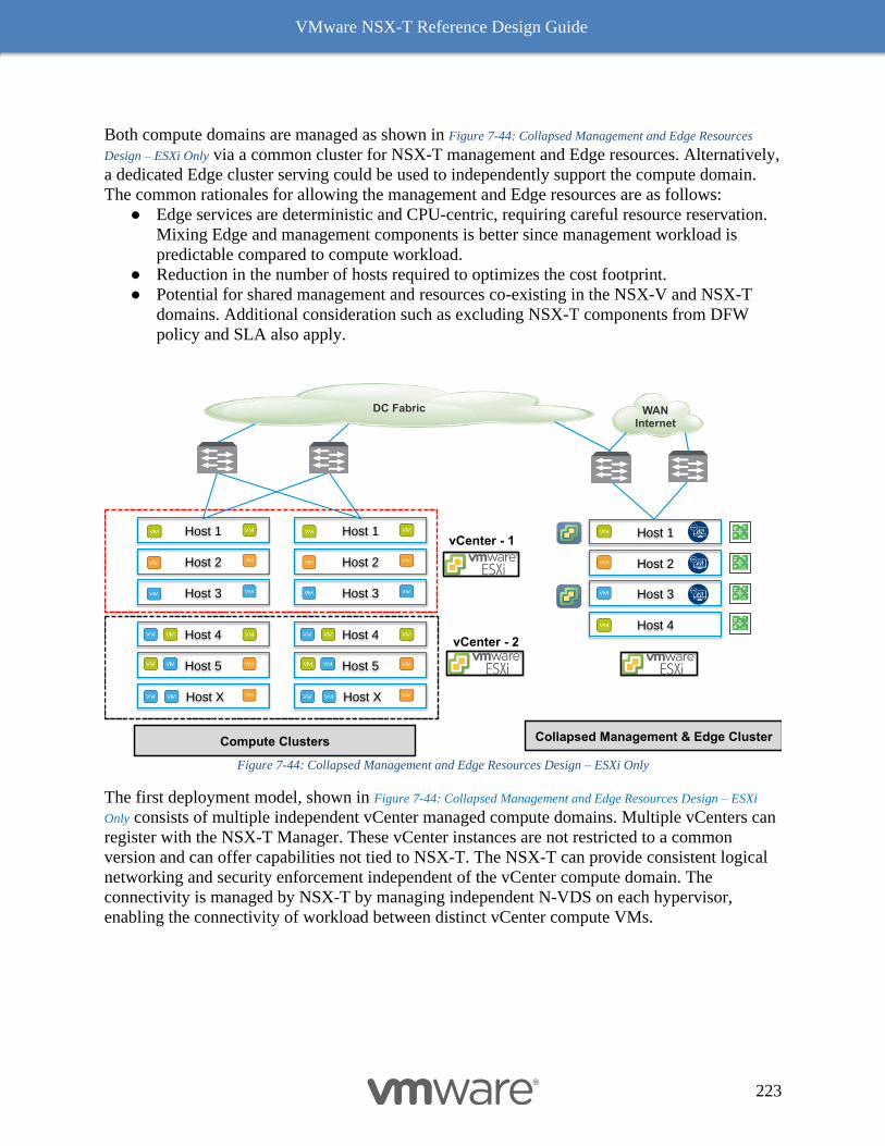
VMware NSX-T Reference Design Guide
223
Both compute domains are managed as shown in Figure 7-44: Collapsed Management and Edge Resources
Design – ESXi Only via a common cluster for NSX-T management and Edge resources. Alternatively,
a dedicated Edge cluster serving could be used to independently support the compute domain.
The common rationales for allowing the management and Edge resources are as follows:
● Edge services are deterministic and CPU-centric, requiring careful resource reservation.
Mixing Edge and management components is better since management workload is
predictable compared to compute workload.
● Reduction in the number of hosts required to optimizes the cost footprint.
● Potential for shared management and resources co-existing in the NSX-V and NSX-T
domains. Additional consideration such as excluding NSX-T components from DFW
policy and SLA also apply.
Figure 7-44: Collapsed Management and Edge Resources Design – ESXi Only
The first deployment model, shown in Figure 7-44: Collapsed Management and Edge Resources Design – ESXi
Only consists of multiple independent vCenter managed compute domains. Multiple vCenters can
register with the NSX-T Manager. These vCenter instances are not restricted to a common
version and can offer capabilities not tied to NSX-T. The NSX-T can provide consistent logical
networking and security enforcement independent of the vCenter compute domain. The
connectivity is managed by NSX-T by managing independent N-VDS on each hypervisor,
enabling the connectivity of workload between distinct vCenter compute VMs.
Collapsed Management & Edge Cluster
Host 1
Host 3
Host 2
Host 4
VPN
VPN
VPN
VPN
Compute Clusters
Host 1
Host 3
Host 2
Host X
Host 5
Host 4
Host X
Host 5
Host 4
Host 1
Host 3
Host 2
vCenter - 1
vCenter - 2
DC Fabric WANInternet
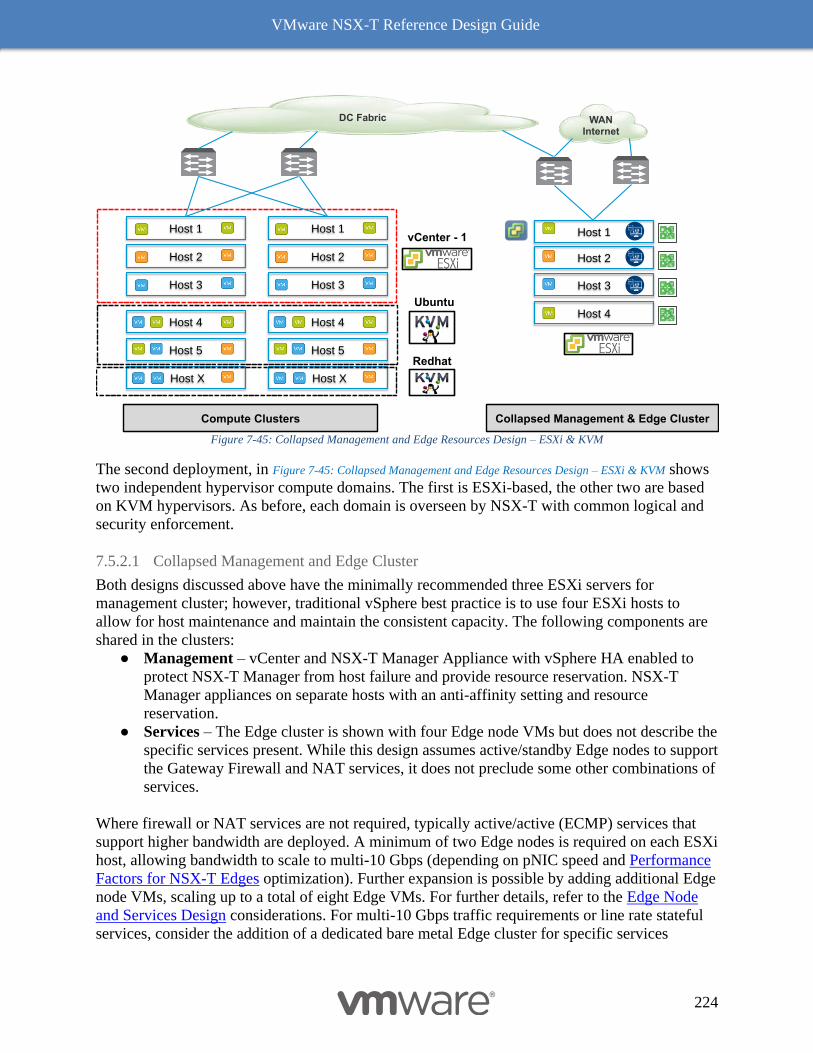
VMware NSX-T Reference Design Guide
224
Figure 7-45: Collapsed Management and Edge Resources Design – ESXi & KVM
The second deployment, in Figure 7-45: Collapsed Management and Edge Resources Design – ESXi & KVM shows
two independent hypervisor compute domains. The first is ESXi-based, the other two are based
on KVM hypervisors. As before, each domain is overseen by NSX-T with common logical and
security enforcement.
7.5.2.1 Collapsed Management and Edge Cluster
Both designs discussed above have the minimally recommended three ESXi servers for
management cluster; however, traditional vSphere best practice is to use four ESXi hosts to
allow for host maintenance and maintain the consistent capacity. The following components are
shared in the clusters:
● Management – vCenter and NSX-T Manager Appliance with vSphere HA enabled to
protect NSX-T Manager from host failure and provide resource reservation. NSX-T
Manager appliances on separate hosts with an anti-affinity setting and resource
reservation.
● Services – The Edge cluster is shown with four Edge node VMs but does not describe the
specific services present. While this design assumes active/standby Edge nodes to support
the Gateway Firewall and NAT services, it does not preclude some other combinations of
services.
Where firewall or NAT services are not required, typically active/active (ECMP) services that
support higher bandwidth are deployed. A minimum of two Edge nodes is required on each ESXi
host, allowing bandwidth to scale to multi-10 Gbps (depending on pNIC speed and Performance
Factors for NSX-T Edges optimization). Further expansion is possible by adding additional Edge
node VMs, scaling up to a total of eight Edge VMs. For further details, refer to the Edge Node
and Services Design considerations. For multi-10 Gbps traffic requirements or line rate stateful
services, consider the addition of a dedicated bare metal Edge cluster for specific services
Collapsed Management & Edge Cluster
Host 1
Host 3
Host 2
Host 4
Compute Clusters
Host 1
Host 3
Host 2
Host X
Host 5
Host 4
Host X
Host 5
Host 4
Host 1
Host 3
Host 2
VPN
VPN
VPN
VPN
vCenter - 1
Ubuntu
Redhat
DC Fabric WANInternet
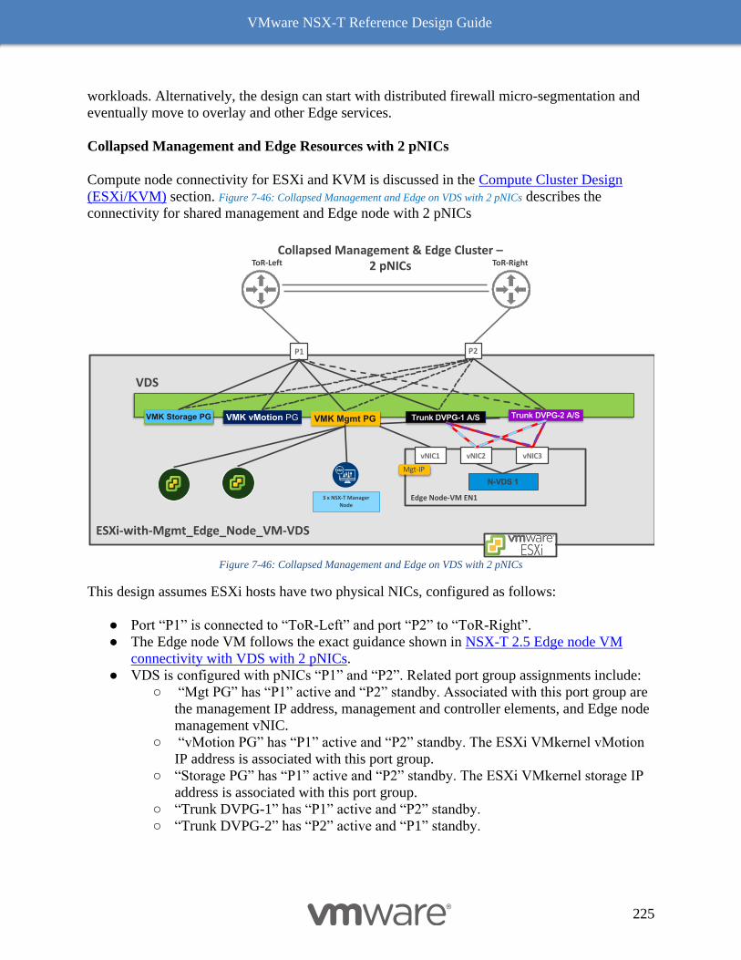
VMware NSX-T Reference Design Guide
225
workloads. Alternatively, the design can start with distributed firewall micro-segmentation and
eventually move to overlay and other Edge services.
Collapsed Management and Edge Resources with 2 pNICs
Compute node connectivity for ESXi and KVM is discussed in the Compute Cluster Design
(ESXi/KVM) section. Figure 7-46: Collapsed Management and Edge on VDS with 2 pNICs describes the
connectivity for shared management and Edge node with 2 pNICs
Figure 7-46: Collapsed Management and Edge on VDS with 2 pNICs
This design assumes ESXi hosts have two physical NICs, configured as follows:
● Port “P1” is connected to “ToR-Left” and port “P2” to “ToR-Right”.
● The Edge node VM follows the exact guidance shown in NSX-T 2.5 Edge node VM
connectivity with VDS with 2 pNICs.
● VDS is configured with pNICs “P1” and “P2”. Related port group assignments include:
○ “Mgt PG” has “P1” active and “P2” standby. Associated with this port group are
the management IP address, management and controller elements, and Edge node
management vNIC.
○ “vMotion PG” has “P1” active and “P2” standby. The ESXi VMkernel vMotion
IP address is associated with this port group.
○ “Storage PG” has “P1” active and “P2” standby. The ESXi VMkernel storage IP
address is associated with this port group.
○ “Trunk DVPG-1” has “P1” active and “P2” standby.
○ “Trunk DVPG-2” has “P2” active and “P1” standby.
P1 P2
VMK vMotion PGVMK Storage PG VMK Mgmt PG
ToR-RightToR-Left
3 x NSX-T Manager
Node
VDS
Edge Node-VM EN1
vNIC1
Mgt-IP
N-VDS 1
vNIC2 vNIC3
Trunk DVPG-1 A/S Trunk DVPG-2 A/S
Collapsed Management & Edge Cluster –2 pNICs
ESXi-with-Mgmt_Edge_Node_VM-VDS
VMware NSX-T Reference Design Guide
226
Design Choices in Collapsed Management and Edge Resources with 4 pNICs
The four pNICs offers flexibility in terms of mixing or dedicating NICs for specific resources.
The principal motivation behind four pNICs hosts is to leverage host with denser CPU/memory
to build lesser number of hosts for Edge node, while achieving the goals of, bandwidth
management, isolation, regulation/compliance control and mixing various clusters such as
management and edge. The design choices coming out of requirements for the dedicated
compute host with 4 pNICs are discussed in ESXi-Based Compute Hypervisor with Four (or
more) pNICs. That design choices are now extended in building a management and Edge node
VM connectivity in which one can have following options:
1) Dedicated VDS for each Management and Edge node VM
2) Dedicated VDS for Management and Edge node VM while Dedicated N-VDS for
Compute
3) Dedicated N-VDS for each Management and Edge Node VM
One can imaging many other options of arranging the management and Edge node VMs. In this
section focus is on option 1 and 2. While option 3 is combined case of combining ESXi-Based
Compute Hypervisor with two pNICs and NSX-T 2.5 Edge node VM connectivity with VDS
with 2 pNICs however with distinction of management components instead of compute guest
VMs.
Dedicated VDS for each Management and Edge node VM
This design choice assumes management components maintains existing VDS for known
operational control while dedicating VDS for Edge nod VM. The configuration option for
management VDS is shown below Figure 7-47: Collapsed Management and Edge VM on Separate VDS with 4
pNICs is left to user preference, however one can build a consistent teaming policy model with
Load Balanced SRC ID at the VDS level. The Edge node VM connectivity with dedicated VDS
is exactly the same described in NSX-T 2.5 Edge node VM connectivity with VDS with 2
pNICs.
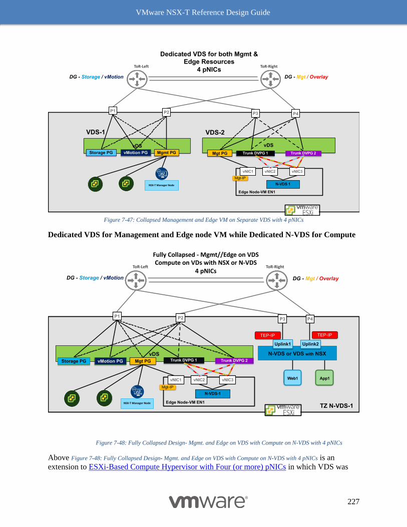
VMware NSX-T Reference Design Guide
227
Figure 7-47: Collapsed Management and Edge VM on Separate VDS with 4 pNICs
Dedicated VDS for Management and Edge node VM while Dedicated N-VDS for Compute
Figure 7-48: Fully Collapsed Design- Mgmt. and Edge on VDS with Compute on N-VDS with 4 pNICs
Above Figure 7-48: Fully Collapsed Design- Mgmt. and Edge on VDS with Compute on N-VDS with 4 pNICs is an
extension to ESXi-Based Compute Hypervisor with Four (or more) pNICs in which VDS was
P1 P2
Dedicated VDS for both Mgmt & Edge Resources
4 pNICsDG - Mgt / Overlay
P3 P4
vDS
Mgmt PGvMotion PGStorage PG
vDS
Mgt PG
NSX-T Manager Node
VDS-1 VDS-2
Edge Node-VM EN1
vNIC1
Mgt-IP
N-VDS 1
vNIC2 vNIC3
Trunk DVPG 1 Trunk DVPG 2
ToR-RightToR-Left
DG - Storage / vMotion
Fully Collapsed - Mgmt//Edge on VDS Compute on VDs with NSX or N-VDS
4 pNICs
P1 P2
DG - Storage / vMotion DG - Mgt / Overlay
P3 P4
N-VDS or VDS with NSX
Uplink2Uplink1
Web1 App1
vDS
Mgt PGvMotion PGStorage PG
TEP-IPTEP-IP
NSX-T Manager Node
ToR-RightToR-Left
Edge Node-VM EN1
vNIC1
Mgt-IP
N-VDS-1
vNIC2 vNIC3
Trunk DVPG 1 Trunk DVPG 2
TZ N-VDS-1
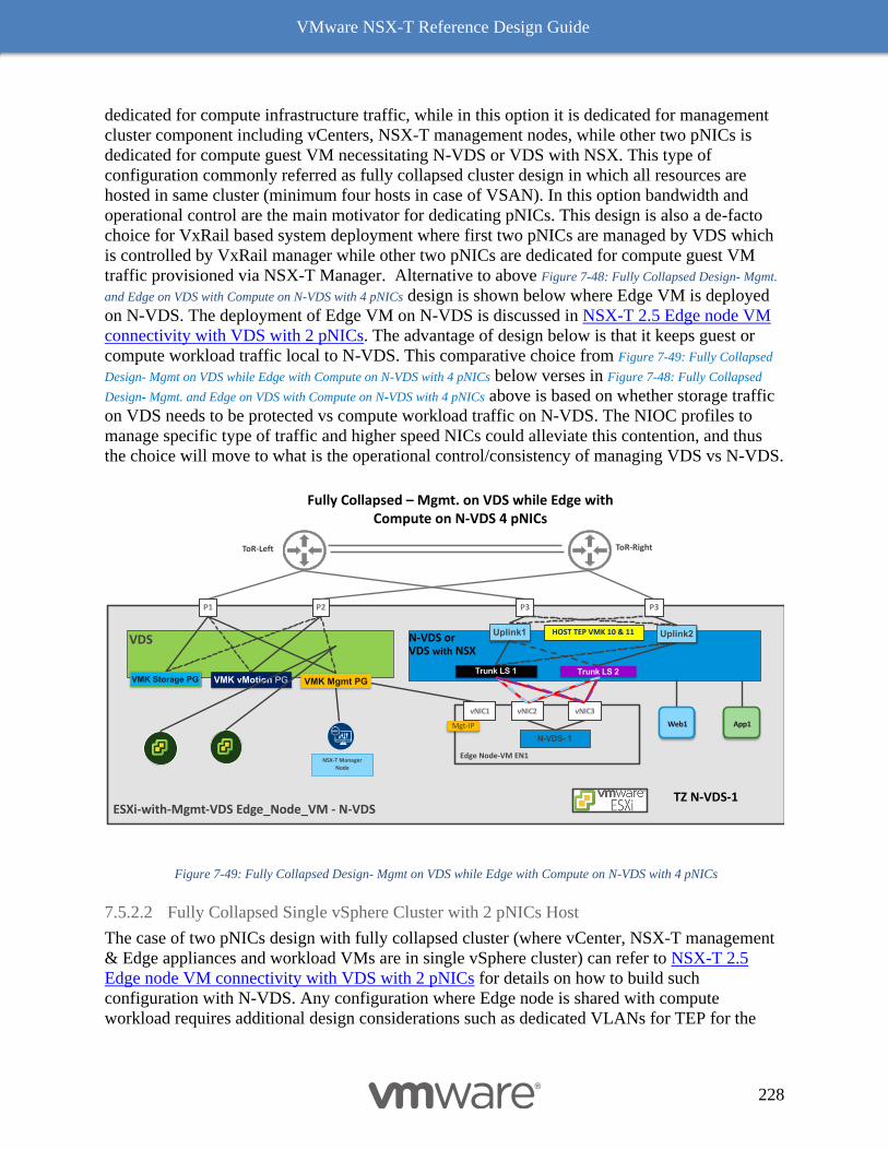
VMware NSX-T Reference Design Guide
228
dedicated for compute infrastructure traffic, while in this option it is dedicated for management
cluster component including vCenters, NSX-T management nodes, while other two pNICs is
dedicated for compute guest VM necessitating N-VDS or VDS with NSX. This type of
configuration commonly referred as fully collapsed cluster design in which all resources are
hosted in same cluster (minimum four hosts in case of VSAN). In this option bandwidth and
operational control are the main motivator for dedicating pNICs. This design is also a de-facto
choice for VxRail based system deployment where first two pNICs are managed by VDS which
is controlled by VxRail manager while other two pNICs are dedicated for compute guest VM
traffic provisioned via NSX-T Manager. Alternative to above Figure 7-48: Fully Collapsed Design- Mgmt.
and Edge on VDS with Compute on N-VDS with 4 pNICs design is shown below where Edge VM is deployed
on N-VDS. The deployment of Edge VM on N-VDS is discussed in NSX-T 2.5 Edge node VM
connectivity with VDS with 2 pNICs. The advantage of design below is that it keeps guest or
compute workload traffic local to N-VDS. This comparative choice from Figure 7-49: Fully Collapsed
Design- Mgmt on VDS while Edge with Compute on N-VDS with 4 pNICs below verses in Figure 7-48: Fully Collapsed
Design- Mgmt. and Edge on VDS with Compute on N-VDS with 4 pNICs above is based on whether storage traffic
on VDS needs to be protected vs compute workload traffic on N-VDS. The NIOC profiles to
manage specific type of traffic and higher speed NICs could alleviate this contention, and thus
the choice will move to what is the operational control/consistency of managing VDS vs N-VDS.
Figure 7-49: Fully Collapsed Design- Mgmt on VDS while Edge with Compute on N-VDS with 4 pNICs
7.5.2.2 Fully Collapsed Single vSphere Cluster with 2 pNICs Host
The case of two pNICs design with fully collapsed cluster (where vCenter, NSX-T management
& Edge appliances and workload VMs are in single vSphere cluster) can refer to NSX-T 2.5
Edge node VM connectivity with VDS with 2 pNICs for details on how to build such
configuration with N-VDS. Any configuration where Edge node is shared with compute
workload requires additional design considerations such as dedicated VLANs for TEP for the
P1 P2
Uplink2Uplink1
Web1 App1
P3
ToR-RightToR-Left
VMK vMotion PGVMK Storage PG VMK Mgmt PG
NSX-T Manager
Node
VDS
TZ N-VDS-1
Edge Node-VM EN1
vNIC1
Mgt-IP
N-VDS- 1
vNIC2 vNIC3
Trunk LS 1 Trunk LS 2
P3
HOST TEP VMK 10 & 11
ESXi-with-Mgmt-VDS Edge_Node_VM - N-VDS
N-VDS or VDS with NSX
Fully Collapsed – Mgmt. on VDS while Edge with Compute on N-VDS 4 pNICs
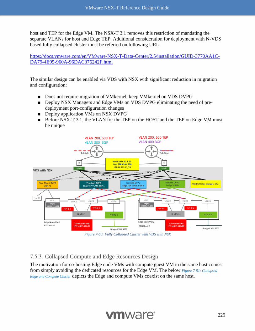
VMware NSX-T Reference Design Guide
229
host and TEP for the Edge VM. The NSX-T 3.1 removes this restriction of mandating the
separate VLANs for host and Edge TEP. Additional consideration for deployment with N-VDS
based fully collapsed cluster must be referred on following URL:
https://docs.vmware.com/en/VMware-NSX-T-Data-Center/2.5/installation/GUID-3770AA1C-
DA79-4E95-960A-96DAC376242F.html
The similar design can be enabled via VDS with NSX with significant reduction in migration
and configuration:
■ Does not require migration of VMkernel, keep VMkernel on VDS DVPG
■ Deploy NSX Managers and Edge VMs on VDS DVPG eliminating the need of pre-
deployment port-configuration changes
■ Deploy application VMs on NSX DVPG
■ Before NSX-T 3.1, the VLAN for the TEP on the HOST and the TEP on Edge VM must
be unique
Figure 7-50: Fully Collapsed Cluster with VDS with NSX
Collapsed Compute and Edge Resources Design
The motivation for co-hosting Edge node VMs with compute guest VM in the same host comes
from simply avoiding the dedicated resources for the Edge VM. The below Figure 7-51: Collapsed
Edge and Compute Cluster depicts the Edge and compute VMs coexist on the same host.
P1P0
Edge-Mgmt DVPGVlan 72
Trunked DVPGEdge TEP VLAN, BGP 1
Trunked DVPGEdge TEP VLAN, BGP 2
Uplink1Uplink0
ESXi Host-1
vNIC1
Mgmt 10.114.215.124
Edge Node VM 1
vNIC2
TEP-IP (Vlan 600)172.16.215.116/28
vmK0
vNIC4
N-VDS-1
TEP-IP-1 TEP-IP-2
HOST VMK 10 & 11 Host TEP VLAN 200
172.16.215.67/28
VLAN 200, 600 TEPVLAN 300 BGP
VLAN 200, 600 TEPVLAN 400 BGP
ToR-RightToR-Left
NSX DVPG for Compute VMs
VDS with NSX
vNIC3
N-VDS-B
Mgmt 10.114.215.125
Edge Node VM 2
vNIC2
TEP-IP (Vlan 600)172.16.215.116/28
vNIC4
N-VDS-1
TEP-IP-1 TEP-IP-2
vNIC3
N-VDS-B
vNIC1
Trunked DVPGBridge VLANs
Bridged VNI 5001 Bridged VNI 5002ESXi Host-2
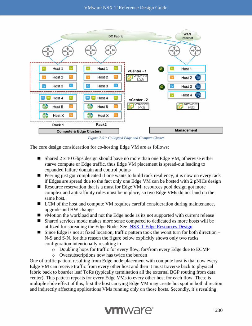
VMware NSX-T Reference Design Guide
230
Figure 7-51: Collapsed Edge and Compute Cluster
The core design consideration for co-hosting Edge VM are as follows:
◼ Shared 2 x 10 Gbps design should have no more than one Edge VM, otherwise either
starve compute or Edge traffic, thus Edge VM placement is spread-out leading to
expanded failure domain and control points
◼ Peering just got complicated if one wants to build rack resiliency, it is now on every rack
if Edges are spread due to the fact only one Edge VM can be hosted with 2 pNICs design
◼ Resource reservation that is a must for Edge VM, resources pool design got more
complex and anti-affinity rules must be in place, so two Edge VMs do not land on the
same host.
◼ LCM of the host and compute VM requires careful consideration during maintenance,
upgrade and HW change
◼ vMotion the workload and not the Edge node as its not supported with current release
◼ Shared services mode makes more sense compared to dedicated as more hosts will be
utilized for spreading the Edge Node. See NSX-T Edge Resources Design.
◼ Since Edge is not at fixed location, traffic pattern took the worst turn for both direction –
N-S and S-N, for this reason the figure below explicitly shows only two racks
configuration intentionally resulting in
o Doubling hops for traffic for every flow, for/from every Edge due to ECMP
o Oversubscriptions now has twice the burden
One of traffic pattern resulting from Edge node placement with compute host is that now every
Edge VM can receive traffic from every other host and then it must traverse back to physical
fabric back to boarder leaf ToRs (typically termination all the external BGP routing from data
center). This pattern repeats for every Edge VMs to every other host for each flow. There is
multiple slide effect of this, first the host carrying Edge VM may create hot spot in both direction
and indirectly affecting applications VMs running only on those hosts. Secondly, it’s resulting
Management
Host 1
Host 3
Host 2
Host 4
Compute & Edge Clusters
Host 1
Host 3
Host 2
Host X
Host 5
Host 4
Host X
Host 5
Host 4
Host 1
Host 3
Host 2
vCenter - 1
vCenter - 2
DC FabricWAN
Internet
Rack 1 Rack2
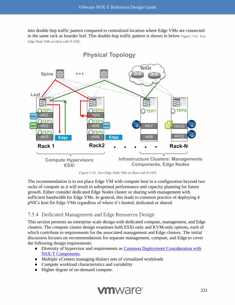
VMware NSX-T Reference Design Guide
231
into double hop traffic pattern compared to centralized location where Edge VMs are connected
in the same rack as boarder leaf. This double-hop traffic pattern is shown in below Figure 7-52: Two
Edge Node VMs on Host with N-VDS.
Figure 7-52: Two Edge Node VMs on Host with N-VDS
The recommendation is to not place Edge VM with compute host in a configuration beyond two
racks of compute as it will result in suboptimal performance and capacity planning for future
growth. Either consider dedicated Edge Nodes cluster or sharing with management with
sufficient bandwidth for Edge VMs. In general, this leads to common practice of deploying 4
pNICs host for Edge VMs regardless of where it’s hosted, dedicated or shared.
Dedicated Management and Edge Resources Design
This section presents an enterprise scale design with dedicated compute, management, and Edge
clusters. The compute cluster design examines both ESXi-only and KVM-only options, each of
which contribute to requirements for the associated management and Edge clusters. The initial
discussion focuses on recommendations for separate management, compute, and Edge to cover
the following design requirements:
● Diversity of hypervisor and requirements as Common Deployment Consideration with
NSX-T Components.
● Multiple vCenters managing distinct sets of virtualized workloads
● Compute workload characteristics and variability
● Higher degree of on-demand compute.
Leaf
Spine
HV1
TEP1
HV2TEP2
HV3TEP3
HV4
TEP4
HV5TEP5
HV6TEP6
TEP7
Edge
HV7
HV8
Web1
WAN
Edge
HV10
HV11
TEP8
Web2App2
Compute HypervisorsESXi
Infrastructure Clusters: Managements Components, Edge Nodes
Physical Topology
Rack 1 Rack2 Rack-N
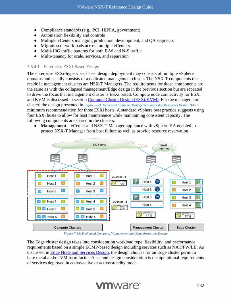
VMware NSX-T Reference Design Guide
232
● Compliance standards (e.g., PCI, HIPPA, government)
● Automation flexibility and controls
● Multiple vCenters managing production, development, and QA segments
● Migration of workloads across multiple vCenters
● Multi-10G traffic patterns for both E-W and N-S traffic
● Multi-tenancy for scale, services, and separation
7.5.4.1 Enterprise ESXi Based Design
The enterprise ESXi-hypervisor based design deployment may consists of multiple vSphere
domains and usually consists of a dedicated management cluster. The NSX-T components that
reside in management clusters are NSX-T Managers. The requirements for those components are
the same as with the collapsed management/Edge design in the previous section but are repeated
to drive the focus that management cluster is ESXi based. Compute node connectivity for ESXi
and KVM is discussed in section Compute Cluster Design (ESXi/KVM). For the management
cluster, the design presented in Figure 7-53: Dedicated Compute, Management and Edge Resources Design has a
minimum recommendation for three ESXi hosts. A standard vSphere best practice suggests using
four ESXi hosts to allow for host maintenance while maintaining consistent capacity. The
following components are shared in the clusters:
● Management – vCenter and NSX-T Manager appliance with vSphere HA enabled to
protect NSX-T Manager from host failure as well as provide resource reservation.
Figure 7-53: Dedicated Compute, Management and Edge Resources Design
The Edge cluster design takes into consideration workload type, flexibility, and performance
requirements based on a simple ECMP-based design including services such as NAT/FW/LB. As
discussed in Edge Node and Services Design, the design choices for an Edge cluster permit a
bare metal and/or VM form factor. A second design consideration is the operational requirements
of services deployed in active/active or active/standby mode.
Edge Cluster
Host 1
Host 3
Host 2
Host 4
Compute Clusters
Host 1
Host 3
Host 2
Host X
Host 5
Host 4
Host X
Host 5
Host 4
Host 1
Host 3
Host 2 VPN
VPN
Management Cluster
Host 1
Host 3
Host 2
Host 4
vCenter - 1
vCenter - 2
DC Fabric WANInternet
VPN
VPN
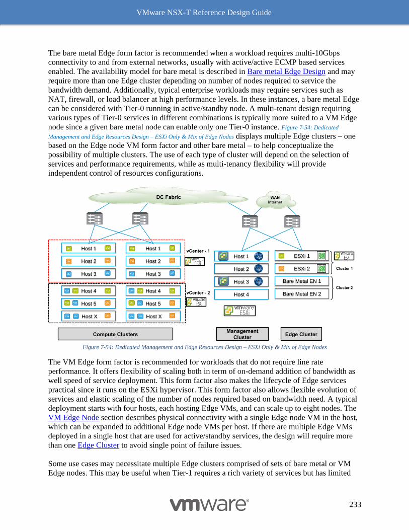
VMware NSX-T Reference Design Guide
233
The bare metal Edge form factor is recommended when a workload requires multi-10Gbps
connectivity to and from external networks, usually with active/active ECMP based services
enabled. The availability model for bare metal is described in Bare metal Edge Design and may
require more than one Edge cluster depending on number of nodes required to service the
bandwidth demand. Additionally, typical enterprise workloads may require services such as
NAT, firewall, or load balancer at high performance levels. In these instances, a bare metal Edge
can be considered with Tier-0 running in active/standby node. A multi-tenant design requiring
various types of Tier-0 services in different combinations is typically more suited to a VM Edge
node since a given bare metal node can enable only one Tier-0 instance. Figure 7-54: Dedicated
Management and Edge Resources Design – ESXi Only & Mix of Edge Nodes displays multiple Edge clusters – one
based on the Edge node VM form factor and other bare metal – to help conceptualize the
possibility of multiple clusters. The use of each type of cluster will depend on the selection of
services and performance requirements, while as multi-tenancy flexibility will provide
independent control of resources configurations.
Figure 7-54: Dedicated Management and Edge Resources Design – ESXi Only & Mix of Edge Nodes
The VM Edge form factor is recommended for workloads that do not require line rate
performance. It offers flexibility of scaling both in term of on-demand addition of bandwidth as
well speed of service deployment. This form factor also makes the lifecycle of Edge services
practical since it runs on the ESXi hypervisor. This form factor also allows flexible evolution of
services and elastic scaling of the number of nodes required based on bandwidth need. A typical
deployment starts with four hosts, each hosting Edge VMs, and can scale up to eight nodes. The
VM Edge Node section describes physical connectivity with a single Edge node VM in the host,
which can be expanded to additional Edge node VMs per host. If there are multiple Edge VMs
deployed in a single host that are used for active/standby services, the design will require more
than one Edge Cluster to avoid single point of failure issues.
Some use cases may necessitate multiple Edge clusters comprised of sets of bare metal or VM
Edge nodes. This may be useful when Tier-1 requires a rich variety of services but has limited
Edge Cluster
ESXi 1
Bare Metal EN 1
ESXi 2
Bare Metal EN 2
Compute Clusters
Host 1
Host 3
Host 2
Host X
Host 5
Host 4
Host X
Host 5
Host 4
Host 1
Host 3
Host 2VPN
VPN
Management
Cluster
Host 1
Host 3
Host 2
Host 4vCenter - 2
DC Fabric WANInternet
Cluster 2
vCenter - 1
Cluster 1
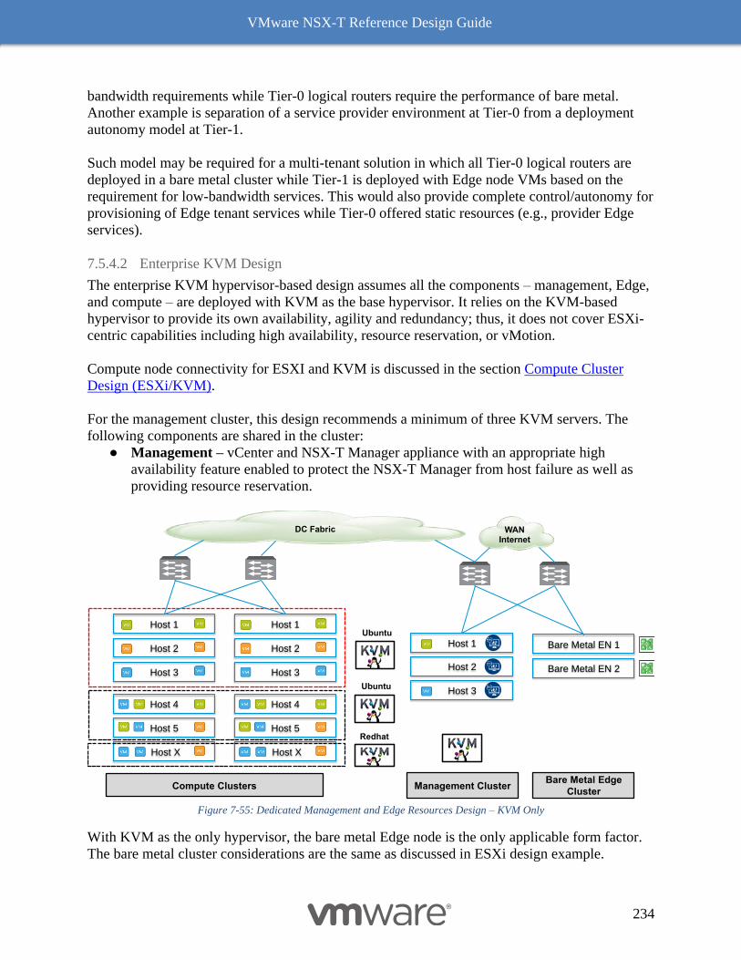
VMware NSX-T Reference Design Guide
234
bandwidth requirements while Tier-0 logical routers require the performance of bare metal.
Another example is separation of a service provider environment at Tier-0 from a deployment
autonomy model at Tier-1.
Such model may be required for a multi-tenant solution in which all Tier-0 logical routers are
deployed in a bare metal cluster while Tier-1 is deployed with Edge node VMs based on the
requirement for low-bandwidth services. This would also provide complete control/autonomy for
provisioning of Edge tenant services while Tier-0 offered static resources (e.g., provider Edge
services).
7.5.4.2 Enterprise KVM Design
The enterprise KVM hypervisor-based design assumes all the components – management, Edge,
and compute – are deployed with KVM as the base hypervisor. It relies on the KVM-based
hypervisor to provide its own availability, agility and redundancy; thus, it does not cover ESXi-
centric capabilities including high availability, resource reservation, or vMotion.
Compute node connectivity for ESXI and KVM is discussed in the section Compute Cluster
Design (ESXi/KVM).
For the management cluster, this design recommends a minimum of three KVM servers. The
following components are shared in the cluster:
● Management – vCenter and NSX-T Manager appliance with an appropriate high
availability feature enabled to protect the NSX-T Manager from host failure as well as
providing resource reservation.
Figure 7-55: Dedicated Management and Edge Resources Design – KVM Only
With KVM as the only hypervisor, the bare metal Edge node is the only applicable form factor.
The bare metal cluster considerations are the same as discussed in ESXi design example.
Bare Metal Edge
Cluster
Bare Metal EN 1
Bare Metal EN 2
Compute Clusters
Host 1
Host 3
Host 2
Host X
Host 5
Host 4
Host X
Host 5
Host 4
Host 1
Host 3
Host 2 VPN
VPN
Ubuntu
Redhat
Ubuntu
Management Cluster
Host 1
Host 3
Host 2
DC Fabric WANInternet
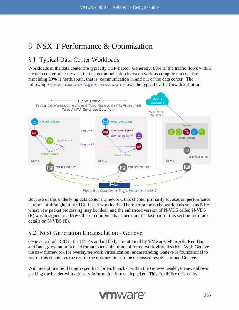
VMware NSX-T Reference Design Guide
235
8 NSX-T Performance & Optimization
Typical Data Center Workloads
Workloads in the data center are typically TCP-based. Generally, 80% of the traffic flows within
the data center are east/west, that is, communication between various compute nodes. The
remaining 20% is north/south, that is, communication in and out of the data center. The
following Figure 8-1: Data Center Traffic Pattern with NSX-T shows the typical traffic flow distribution:
Figure 8-1: Data Center Traffic Pattern with NSX-T
Because of this underlying data center framework, this chapter primarily focuses on performance
in terms of throughput for TCP-based workloads. There are some niche workloads such as NFV,
where raw packet processing may be ideal, and the enhanced version of N-VDS called N-VDS
(E) was designed to address these requirements. Check out the last part of this section for more
details on N-VDS (E).
Next Generation Encapsulation - Geneve
Geneve, a draft RFC in the IETF standard body co-authored by VMware, Microsoft, Red Hat,
and Intel, grew out of a need for an extensible protocol for network virtualization. With Geneve
the new framework for overlay/network virtualization, understanding Geneve is foundational to
rest of this chapter as the rest of the optimizations to be discussed revolve around Geneve.
With its options field length specified for each packet within the Geneve header, Geneve allows
packing the header with arbitrary information into each packet. This flexibility offered by
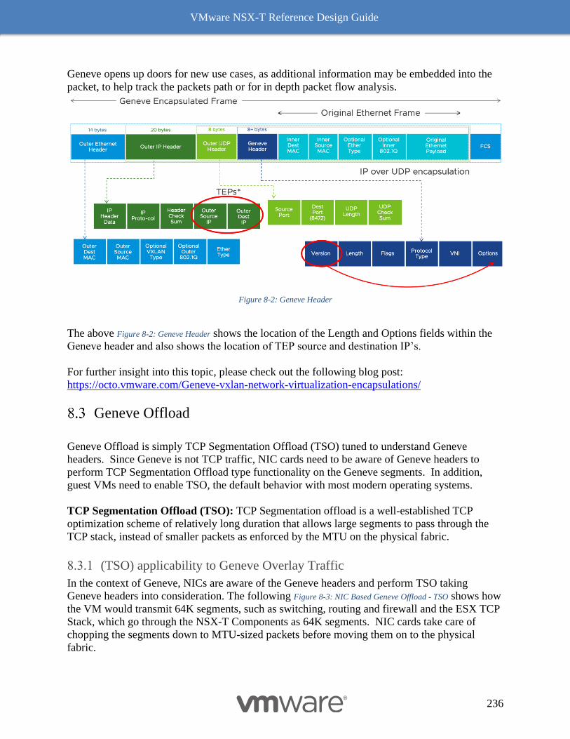
VMware NSX-T Reference Design Guide
236
Geneve opens up doors for new use cases, as additional information may be embedded into the
packet, to help track the packets path or for in depth packet flow analysis.
Figure 8-2: Geneve Header
The above Figure 8-2: Geneve Header shows the location of the Length and Options fields within the
Geneve header and also shows the location of TEP source and destination IP’s.
For further insight into this topic, please check out the following blog post:
https://octo.vmware.com/Geneve-vxlan-network-virtualization-encapsulations/
Geneve Offload
Geneve Offload is simply TCP Segmentation Offload (TSO) tuned to understand Geneve
headers. Since Geneve is not TCP traffic, NIC cards need to be aware of Geneve headers to
perform TCP Segmentation Offload type functionality on the Geneve segments. In addition,
guest VMs need to enable TSO, the default behavior with most modern operating systems.
TCP Segmentation Offload (TSO): TCP Segmentation offload is a well-established TCP
optimization scheme of relatively long duration that allows large segments to pass through the
TCP stack, instead of smaller packets as enforced by the MTU on the physical fabric.
(TSO) applicability to Geneve Overlay Traffic
In the context of Geneve, NICs are aware of the Geneve headers and perform TSO taking
Geneve headers into consideration. The following Figure 8-3: NIC Based Geneve Offload - TSO shows how
the VM would transmit 64K segments, such as switching, routing and firewall and the ESX TCP
Stack, which go through the NSX-T Components as 64K segments. NIC cards take care of
chopping the segments down to MTU-sized packets before moving them on to the physical
fabric.
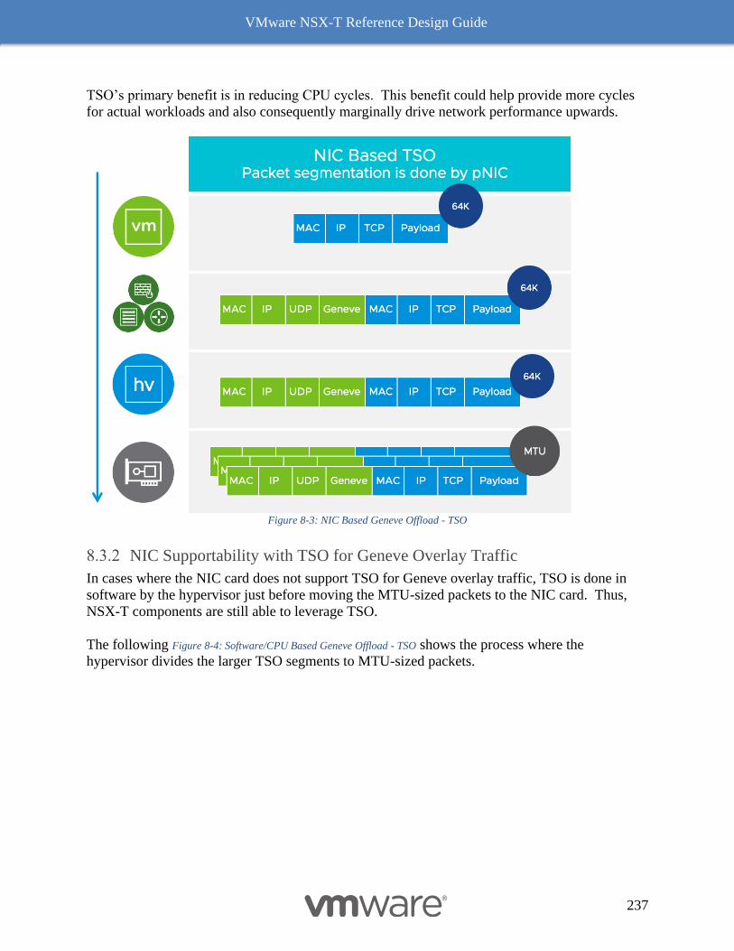
VMware NSX-T Reference Design Guide
237
TSO’s primary benefit is in reducing CPU cycles. This benefit could help provide more cycles
for actual workloads and also consequently marginally drive network performance upwards.
Figure 8-3: NIC Based Geneve Offload - TSO
NIC Supportability with TSO for Geneve Overlay Traffic
In cases where the NIC card does not support TSO for Geneve overlay traffic, TSO is done in
software by the hypervisor just before moving the MTU-sized packets to the NIC card. Thus,
NSX-T components are still able to leverage TSO.
The following Figure 8-4: Software/CPU Based Geneve Offload - TSO shows the process where the
hypervisor divides the larger TSO segments to MTU-sized packets.
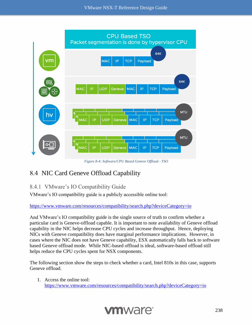
VMware NSX-T Reference Design Guide
238
Figure 8-4: Software/CPU Based Geneve Offload - TSO
NIC Card Geneve Offload Capability
VMware’s IO Compatibility Guide
VMware’s IO compatibility guide is a publicly accessible online tool:
https://www.vmware.com/resources/compatibility/search.php?deviceCategory=io
And VMware’s IO compatibility guide is the single source of truth to confirm whether a
particular card is Geneve-offload capable. It is important to note availability of Geneve offload
capability in the NIC helps decrease CPU cycles and increase throughput. Hence, deploying
NICs with Geneve compatibility does have marginal performance implications. However, in
cases where the NIC does not have Geneve capability, ESX automatically falls back to software
based Geneve offload mode. While NIC-based offload is ideal, software-based offload still
helps reduce the CPU cycles spent for NSX components.
The following section show the steps to check whether a card, Intel 810s in this case, supports
Geneve offload.
1. Access the online tool:
https://www.vmware.com/resources/compatibility/search.php?deviceCategory=io
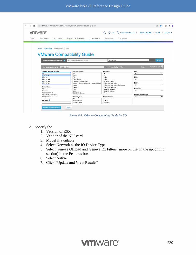
VMware NSX-T Reference Design Guide
239
Figure 8-5: VMware Compatibility Guide for I/O
2. Specify the
1. Version of ESX
2. Vendor of the NIC card
3. Model if available
4. Select Network as the IO Device Type
5. Select Geneve Offload and Geneve Rx Filters (more on that in the upcoming
section) in the Features box
6. Select Native
7. Click “Update and View Results”
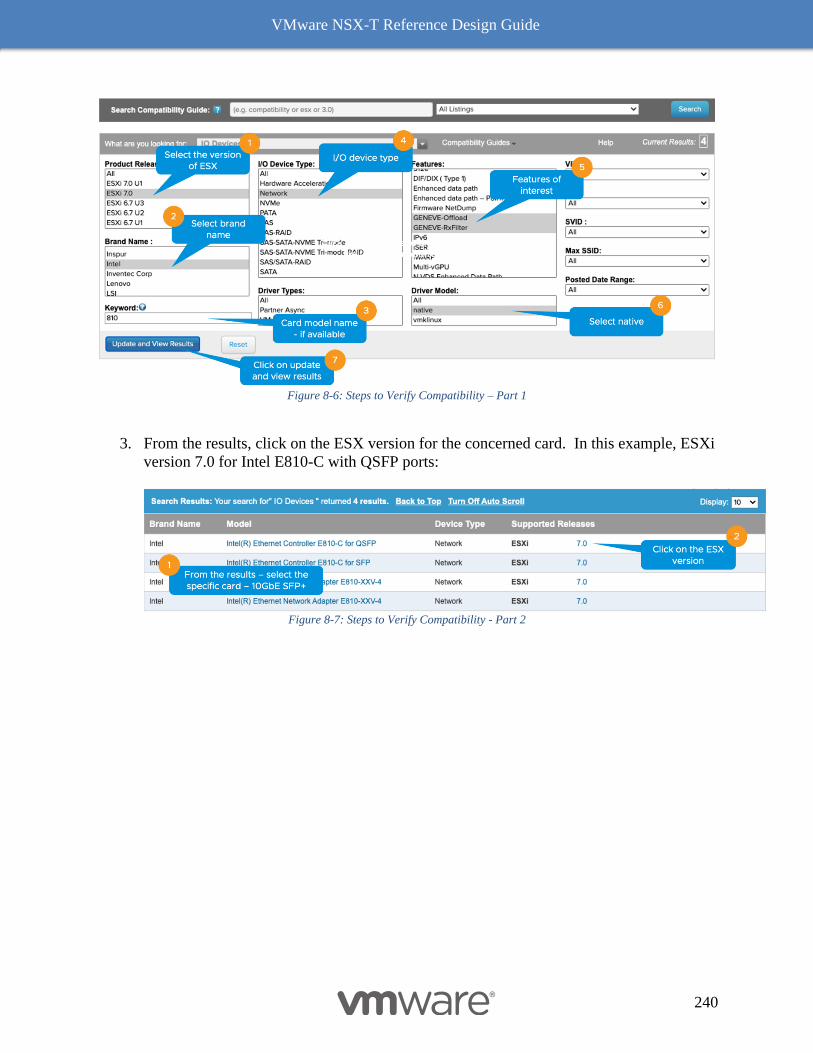
VMware NSX-T Reference Design Guide
240
Figure 8-6: Steps to Verify Compatibility – Part 1
3. From the results, click on the ESX version for the concerned card. In this example, ESXi
version 7.0 for Intel E810-C with QSFP ports:
Figure 8-7: Steps to Verify Compatibility - Part 2
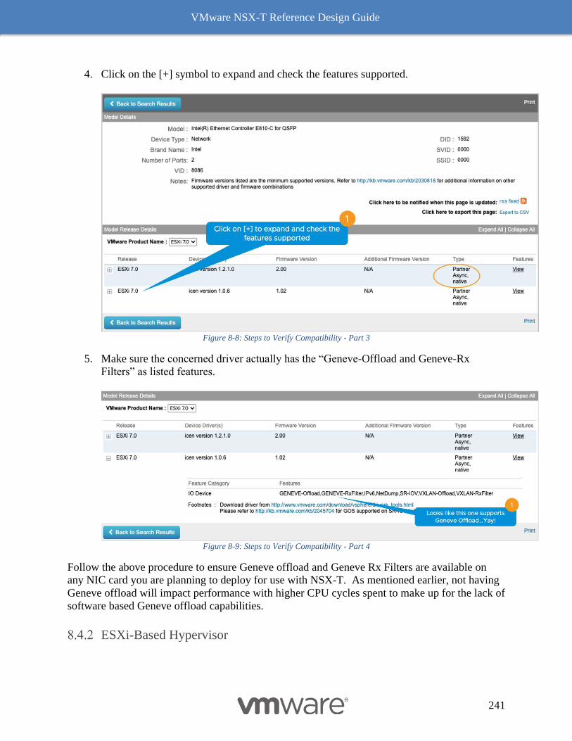
VMware NSX-T Reference Design Guide
241
4. Click on the [+] symbol to expand and check the features supported.
Figure 8-8: Steps to Verify Compatibility - Part 3
5. Make sure the concerned driver actually has the “Geneve-Offload and Geneve-Rx
Filters” as listed features.
Figure 8-9: Steps to Verify Compatibility - Part 4
Follow the above procedure to ensure Geneve offload and Geneve Rx Filters are available on
any NIC card you are planning to deploy for use with NSX-T. As mentioned earlier, not having
Geneve offload will impact performance with higher CPU cycles spent to make up for the lack of
software based Geneve offload capabilities.
ESXi-Based Hypervisor
VMware NSX-T Reference Design Guide
242
On an ESXi host with a NIC card supporting Geneve-Offload in Hardware with the appropriate
supported driver, the following commands can be used to confirm Geneve-Offload is enabled on
a pNIC – in this case pNIC vmnic3:
[Host-1] vsish -e get /net/pNics/vmnic3/properties | grep
".*Activated.*Geneve"
Device Hardware Cap Activated:: 0x793c032b ->
VMNET_CAP_SG VMNET_CAP_IP4_CSUM VMNET_CAP_HIGH_DMA
VMNET_CAP_TSO VMNET_CAP_HW_TX_VLAN VMNET_CAP_HW_RX_VLAN
VMNET_CAP_SG_SPAN_PAGES VMNET_CAP_IP6_CSUM VMNET_CAP_TSO6
VMNET_CAP_TSO256k VMNET_CAP_ENCAP VMNET_CAP_Geneve_OFFLOAD
VMNET_CAP_IP6_CSUM_EXT_HDRS VMNET_CAP_TSO6_EXT_HDRS
VMNET_CAP_SCHED
CLI 1 Check Geneve Offload Support
Look for the tag “VMNET_CAP_Geneve_OFFLOAD”, highlighted in red above. This verbiage
indicates the Geneve Offload is activated on NIC card vmnic3. If the tag is missing, then it
means Geneve Offload is not enabled because either the NIC or its driver does not support it.
Receive Side Scaling (RSS) and Rx Filters
Readers familiar with software based VxLAN deployment with NSX-V, are likely familiar with
the immense performance benefits of RSS, including improving the performance of overlay
traffic by four (4) times.
Benefits with RSS
RSS, another long-standing TCP enhancement, enables use of multiple cores on the receive side
to process incoming traffic. Without RSS, ESX by default will use only one core to process
incoming traffic. Utilizing only one core has a huge impact on the overall throughput as the
receiving node then becomes the bottleneck. RSS on the NIC creates multiple queues to process
incoming traffic and efficiently uses a core for each queue, with most NIC cards being able to
support at least 4 queues. Hence the 4x benefit of using RSS. See Figure 8-10: RSS for a visual
representation of how this works.
RSS for overlay
While RSS itself in general is in fairly common use today, there are NICs which still may not
support RSS for overlay. Hence, our recommendation is to confirm with the NIC vendor whether
RSS for overlay traffic is available in hardware, then also confirm with the VMware
Compatibility IO Guide
(https://www.vmware.com/resources/compatibility/search.php?deviceCategory=io) whether
there is a RSS-certified driver.
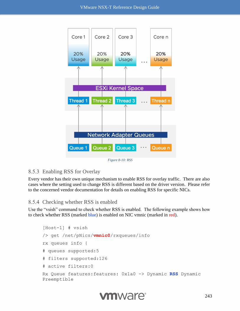
VMware NSX-T Reference Design Guide
243
Figure 8-10: RSS
Enabling RSS for Overlay
Every vendor has their own unique mechanism to enable RSS for overlay traffic. There are also
cases where the setting used to change RSS is different based on the driver version. Please refer
to the concerned vendor documentation for details on enabling RSS for specific NICs.
Checking whether RSS is enabled
Use the “vsish” command to check whether RSS is enabled. The following example shows how
to check whether RSS (marked blue) is enabled on NIC vmnic (marked in red).
[Host-1] # vsish
/> get /net/pNics/vmnic0/rxqueues/info
rx queues info {
# queues supported:5
# filters supported:126
# active filters:0
Rx Queue features:features: 0x1a0 -> Dynamic RSS Dynamic
Preemptible

VMware NSX-T Reference Design Guide
244
}
/>
CLI 2 Check RSS
RSS and Rx Filters - Comparison
RSS uses the outer headers to hash flows to different queues. Using outer headers of Geneve
overlay, especially between two hypervisors, may not be optimal as the only varying parameter
is the source port.
The following image shows the fields used by RSS (circled in red) to hash flows across various
CPU cores. Since all the fields are from the outer headers, there is a little variability and in the
worst-case scenarios the only variable may be the source port.
Figure 8-11: RSS: Fields Used for Hashing
To overcome this limitation, the latest NICs (see compatibility guide) support an advanced
feature, known as Rx Filters, which looks at the inner packet headers for hashing flows to
different queues on the receive side. In the following Figure 8-12: Rx Filters: Fields Used for Hashing fields
used by Rx Filter are circled in red.
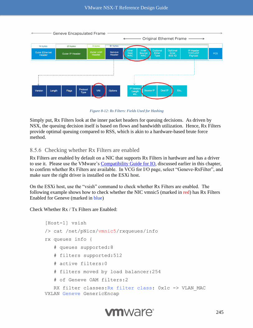
VMware NSX-T Reference Design Guide
245
Figure 8-12: Rx Filters: Fields Used for Hashing
Simply put, Rx Filters look at the inner packet headers for queuing decisions. As driven by
NSX, the queuing decision itself is based on flows and bandwidth utilization. Hence, Rx Filters
provide optimal queuing compared to RSS, which is akin to a hardware-based brute force
method.
Checking whether Rx Filters are enabled
Rx Filters are enabled by default on a NIC that supports Rx Filters in hardware and has a driver
to use it. Please use the VMware’s Compatibility Guide for IO, discussed earlier in this chapter,
to confirm whether Rx Filters are available. In VCG for I/O page, select “Geneve-RxFilter”, and
make sure the right driver is installed on the ESXi host.
On the ESXi host, use the “vsish” command to check whether Rx Filters are enabled. The
following example shows how to check whether the NIC vmnic5 (marked in red) has Rx Filters
Enabled for Geneve (marked in blue)
Check Whether Rx / Tx Filters are Enabled:
[Host-1] vsish
/> cat /net/pNics/vmnic5/rxqueues/info
rx queues info {
# queues supported:8
# filters supported:512
# active filters:0
# filters moved by load balancer:254
# of Geneve OAM filters:2
RX filter classes:Rx filter class: 0x1c -> VLAN_MAC
VXLAN Geneve GenericEncap
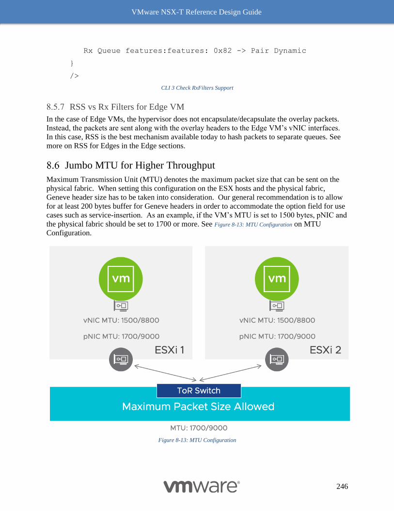
VMware NSX-T Reference Design Guide
246
Rx Queue features:features: 0x82 -> Pair Dynamic
}
/>
CLI 3 Check RxFilters Support
RSS vs Rx Filters for Edge VM
In the case of Edge VMs, the hypervisor does not encapsulate/decapsulate the overlay packets.
Instead, the packets are sent along with the overlay headers to the Edge VM’s vNIC interfaces.
In this case, RSS is the best mechanism available today to hash packets to separate queues. See
more on RSS for Edges in the Edge sections.
Jumbo MTU for Higher Throughput
Maximum Transmission Unit (MTU) denotes the maximum packet size that can be sent on the
physical fabric. When setting this configuration on the ESX hosts and the physical fabric,
Geneve header size has to be taken into consideration. Our general recommendation is to allow
for at least 200 bytes buffer for Geneve headers in order to accommodate the option field for use
cases such as service-insertion. As an example, if the VM’s MTU is set to 1500 bytes, pNIC and
the physical fabric should be set to 1700 or more. See Figure 8-13: MTU Configuration on MTU
Configuration.
Figure 8-13: MTU Configuration
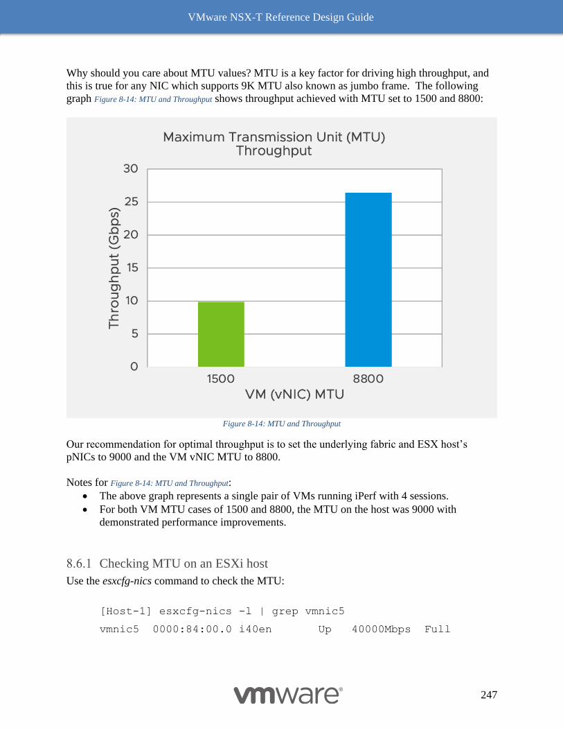
VMware NSX-T Reference Design Guide
247
Why should you care about MTU values? MTU is a key factor for driving high throughput, and
this is true for any NIC which supports 9K MTU also known as jumbo frame. The following
graph Figure 8-14: MTU and Throughput shows throughput achieved with MTU set to 1500 and 8800:
Figure 8-14: MTU and Throughput
Our recommendation for optimal throughput is to set the underlying fabric and ESX host’s
pNICs to 9000 and the VM vNIC MTU to 8800.
Notes for Figure 8-14: MTU and Throughput:
• The above graph represents a single pair of VMs running iPerf with 4 sessions.
• For both VM MTU cases of 1500 and 8800, the MTU on the host was 9000 with
demonstrated performance improvements.
Checking MTU on an ESXi host
Use the esxcfg-nics command to check the MTU:
[Host-1] esxcfg-nics -l | grep vmnic5
vmnic5 0000:84:00.0 i40en Up 40000Mbps Full
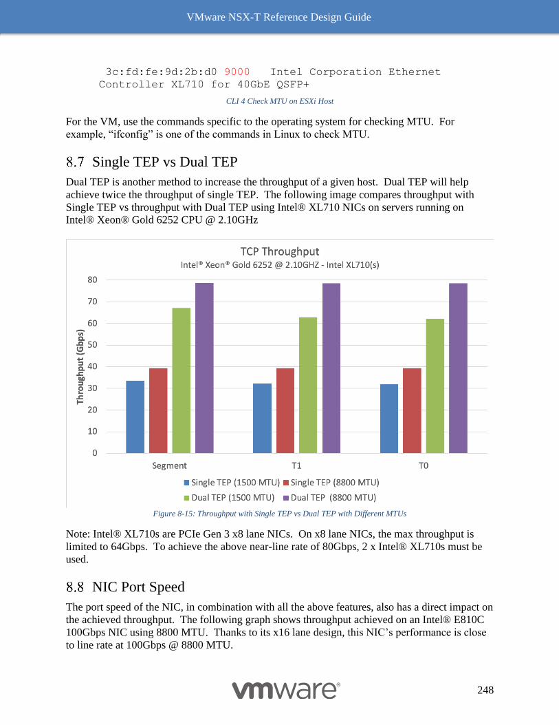
VMware NSX-T Reference Design Guide
248
3c:fd:fe:9d:2b:d0 9000 Intel Corporation Ethernet
Controller XL710 for 40GbE QSFP+
CLI 4 Check MTU on ESXi Host
For the VM, use the commands specific to the operating system for checking MTU. For
example, “ifconfig” is one of the commands in Linux to check MTU.
Single TEP vs Dual TEP
Dual TEP is another method to increase the throughput of a given host. Dual TEP will help
achieve twice the throughput of single TEP. The following image compares throughput with
Single TEP vs throughput with Dual TEP using Intel® XL710 NICs on servers running on
Intel® Xeon® Gold 6252 CPU @ 2.10GHz
Figure 8-15: Throughput with Single TEP vs Dual TEP with Different MTUs
Note: Intel® XL710s are PCIe Gen 3 x8 lane NICs. On x8 lane NICs, the max throughput is
limited to 64Gbps. To achieve the above near-line rate of 80Gbps, 2 x Intel® XL710s must be
used.
NIC Port Speed
The port speed of the NIC, in combination with all the above features, also has a direct impact on
the achieved throughput. The following graph shows throughput achieved on an Intel® E810C
100Gbps NIC using 8800 MTU. Thanks to its x16 lane design, this NIC’s performance is close
to line rate at 100Gbps @ 8800 MTU.
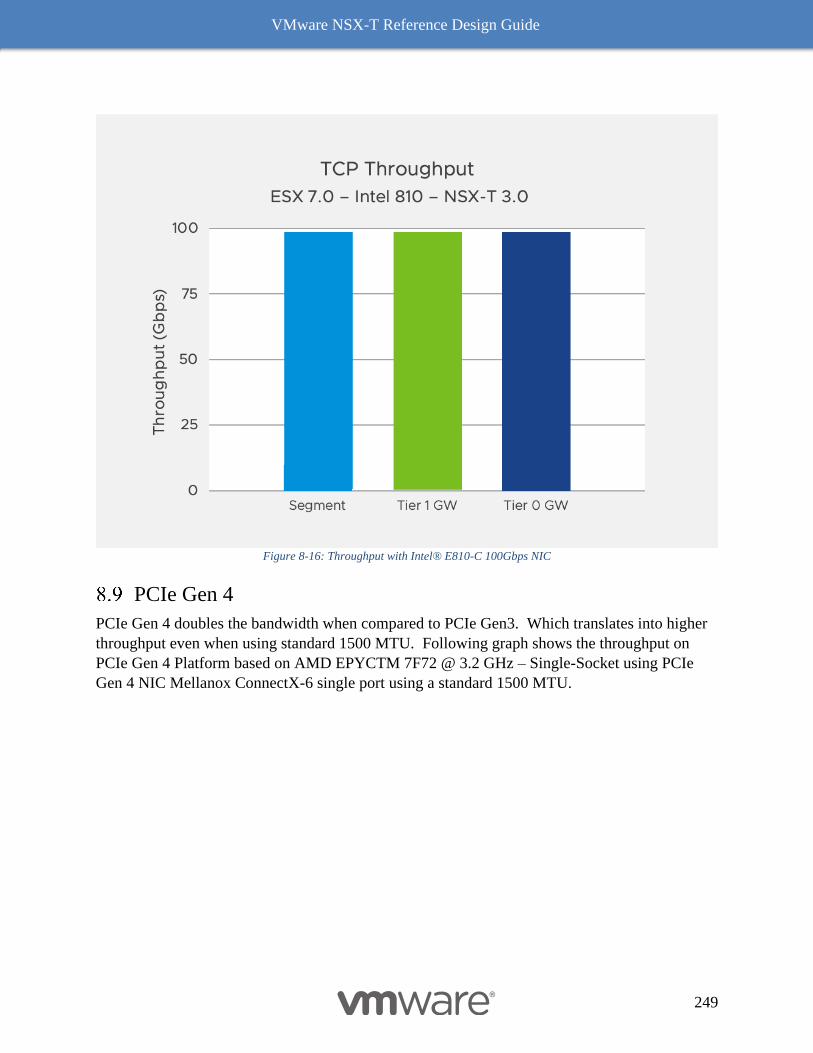
VMware NSX-T Reference Design Guide
249
Figure 8-16: Throughput with Intel® E810-C 100Gbps NIC
PCIe Gen 4
PCIe Gen 4 doubles the bandwidth when compared to PCIe Gen3. Which translates into higher
throughput even when using standard 1500 MTU. Following graph shows the throughput on
PCIe Gen 4 Platform based on AMD EPYCTM 7F72 @ 3.2 GHz – Single-Socket using PCIe
Gen 4 NIC Mellanox ConnectX-6 single port using a standard 1500 MTU.
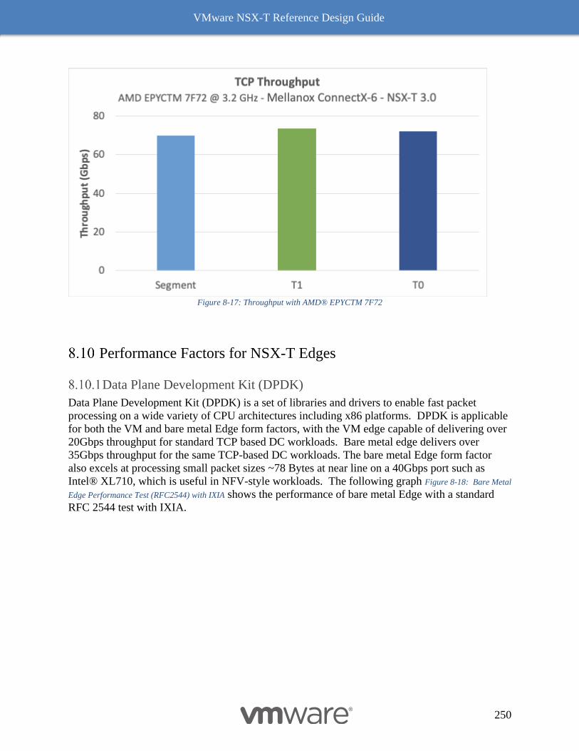
VMware NSX-T Reference Design Guide
250
Figure 8-17: Throughput with AMD® EPYCTM 7F72
Performance Factors for NSX-T Edges
Data Plane Development Kit (DPDK)
Data Plane Development Kit (DPDK) is a set of libraries and drivers to enable fast packet
processing on a wide variety of CPU architectures including x86 platforms. DPDK is applicable
for both the VM and bare metal Edge form factors, with the VM edge capable of delivering over
20Gbps throughput for standard TCP based DC workloads. Bare metal edge delivers over
35Gbps throughput for the same TCP-based DC workloads. The bare metal Edge form factor
also excels at processing small packet sizes ~78 Bytes at near line on a 40Gbps port such as
Intel® XL710, which is useful in NFV-style workloads. The following graph Figure 8-18: Bare Metal
Edge Performance Test (RFC2544) with IXIA shows the performance of bare metal Edge with a standard
RFC 2544 test with IXIA.
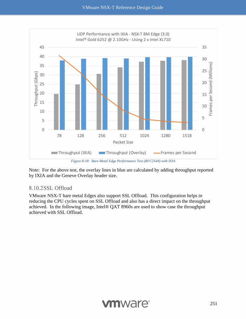
VMware NSX-T Reference Design Guide
251
Figure 8-18: Bare Metal Edge Performance Test (RFC2544) with IXIA
Note: For the above test, the overlay lines in blue are calculated by adding throughput reported
by IXIA and the Geneve Overlay header size.
SSL Offload
VMware NSX-T bare metal Edges also support SSL Offload. This configuration helps in
reducing the CPU cycles spent on SSL Offload and also has a direct impact on the throughput
achieved. In the following image, Intel® QAT 8960s are used to show case the throughput
achieved with SSL Offload.
0
5
10
15
20
25
30
35
0
5
10
15
20
25
30
35
40
45
78 128 256 512 1024 1280 1518
Fram
es p
er
Seco
nd
(M
illio
ns)
Thro
ugh
pu
t (G
bp
s)
Packet Size
UDP Performance with IXIA - NSX-T BM Edge (3.0)Intel® Gold 6252 @ 2.10GHz - Using 2 x Intel XL710
Throughput (IXIA) Throughput (Overlay) Frames per Second
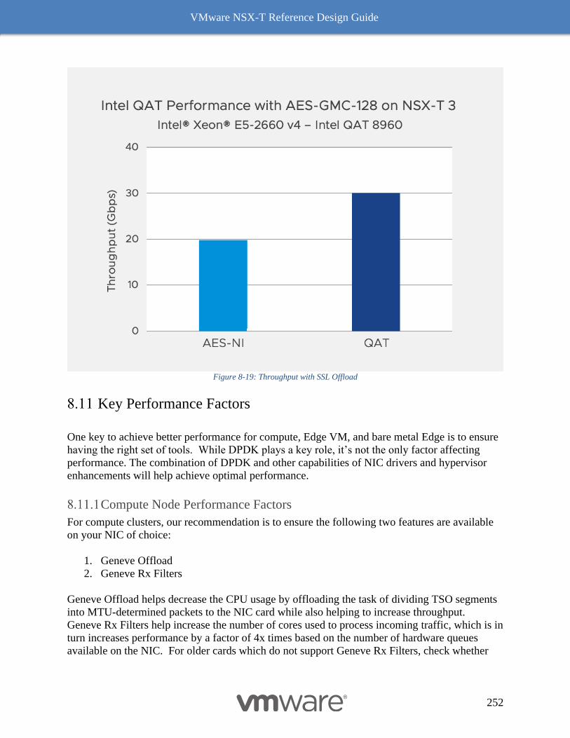
VMware NSX-T Reference Design Guide
252
Figure 8-19: Throughput with SSL Offload
Key Performance Factors
One key to achieve better performance for compute, Edge VM, and bare metal Edge is to ensure
having the right set of tools. While DPDK plays a key role, it’s not the only factor affecting
performance. The combination of DPDK and other capabilities of NIC drivers and hypervisor
enhancements will help achieve optimal performance.
Compute Node Performance Factors
For compute clusters, our recommendation is to ensure the following two features are available
on your NIC of choice:
1. Geneve Offload
2. Geneve Rx Filters
Geneve Offload helps decrease the CPU usage by offloading the task of dividing TSO segments
into MTU-determined packets to the NIC card while also helping to increase throughput.
Geneve Rx Filters help increase the number of cores used to process incoming traffic, which is in
turn increases performance by a factor of 4x times based on the number of hardware queues
available on the NIC. For older cards which do not support Geneve Rx Filters, check whether
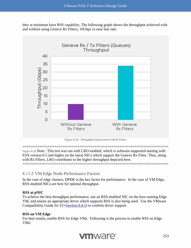
VMware NSX-T Reference Design Guide
253
they at minimum have RSS capability. The following graph shows the throughput achieved with
and without using Geneve Rx Filters, 10Gbps vs near line rate:
Figure 8-20: Throughput Improvement with Rx Filters
=====================================================================
Figure 8-20 Note: This test was run with LRO enabled, which is software-supported starting with
ESX version 6.5 and higher on the latest NICs which support the Geneve Rx Filter. Thus, along
with Rx Filters, LRO contributes to the higher throughput depicted here.
=====================================================================
VM Edge Node Performance Factors
In the case of edge clusters, DPDK is the key factor for performance. In the case of VM Edge,
RSS-enabled NICs are best for optimal throughput.
RSS at pNIC
To achieve the best throughput performance, use an RSS-enabled NIC on the host running Edge
VM, and ensure an appropriate driver which supports RSS is also being used. Use the VMware
Compatibility Guide for I/O (section 8.4.1) to confirm driver support.
RSS on VM Edge
For best results, enable RSS for Edge VMs. Following is the process to enable RSS on Edge
VMs:
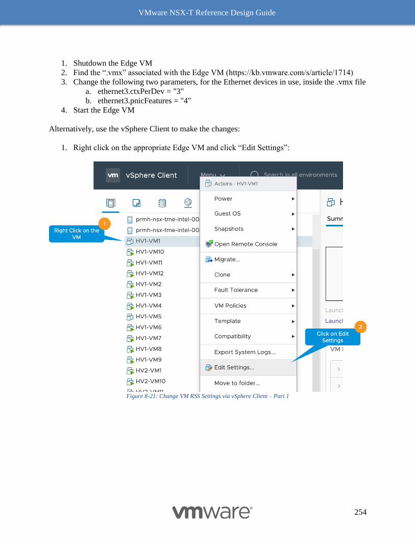
VMware NSX-T Reference Design Guide
254
1. Shutdown the Edge VM
2. Find the “.vmx” associated with the Edge VM (https://kb.vmware.com/s/article/1714)
3. Change the following two parameters, for the Ethernet devices in use, inside the .vmx file
a. ethernet3.ctxPerDev = "3"
b. ethernet3.pnicFeatures = "4"
4. Start the Edge VM
Alternatively, use the vSphere Client to make the changes:
1. Right click on the appropriate Edge VM and click “Edit Settings”:
Figure 8-21: Change VM RSS Settings via vSphere Client – Part 1
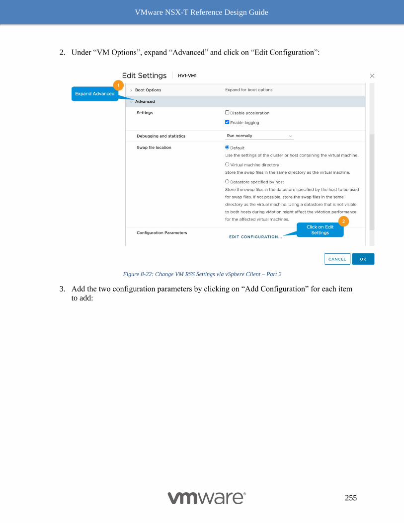
VMware NSX-T Reference Design Guide
255
2. Under “VM Options”, expand “Advanced” and click on “Edit Configuration”:
Figure 8-22: Change VM RSS Settings via vSphere Client – Part 2
3. Add the two configuration parameters by clicking on “Add Configuration” for each item
to add:

VMware NSX-T Reference Design Guide
256
Figure 8-23: Change VM RSS Settings via vSphere Client – Part 3
The following graph Figure 8-24: RSS for VM Edge shows the comparison of throughput between a NIC
which supports RSS and a NIC which does not. Note: In both cases, even where the pNIC
doesn’t support RSS, RSS was enabled on the VM Edge:
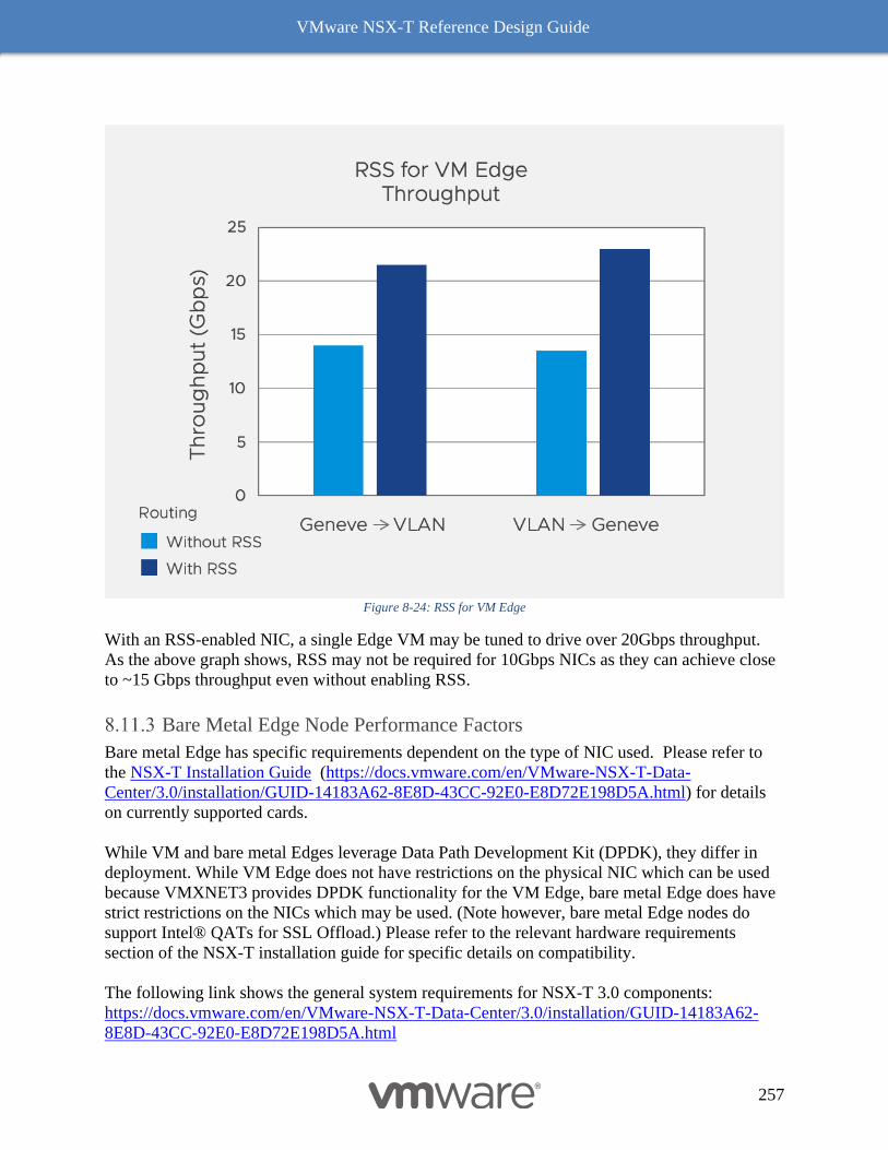
VMware NSX-T Reference Design Guide
257
Figure 8-24: RSS for VM Edge
With an RSS-enabled NIC, a single Edge VM may be tuned to drive over 20Gbps throughput.
As the above graph shows, RSS may not be required for 10Gbps NICs as they can achieve close
to ~15 Gbps throughput even without enabling RSS.
Bare Metal Edge Node Performance Factors
Bare metal Edge has specific requirements dependent on the type of NIC used. Please refer to
the NSX-T Installation Guide (https://docs.vmware.com/en/VMware-NSX-T-Data-
Center/3.0/installation/GUID-14183A62-8E8D-43CC-92E0-E8D72E198D5A.html) for details
on currently supported cards.
While VM and bare metal Edges leverage Data Path Development Kit (DPDK), they differ in
deployment. While VM Edge does not have restrictions on the physical NIC which can be used
because VMXNET3 provides DPDK functionality for the VM Edge, bare metal Edge does have
strict restrictions on the NICs which may be used. (Note however, bare metal Edge nodes do
support Intel® QATs for SSL Offload.) Please refer to the relevant hardware requirements
section of the NSX-T installation guide for specific details on compatibility.
The following link shows the general system requirements for NSX-T 3.0 components:
https://docs.vmware.com/en/VMware-NSX-T-Data-Center/3.0/installation/GUID-14183A62-
8E8D-43CC-92E0-E8D72E198D5A.html
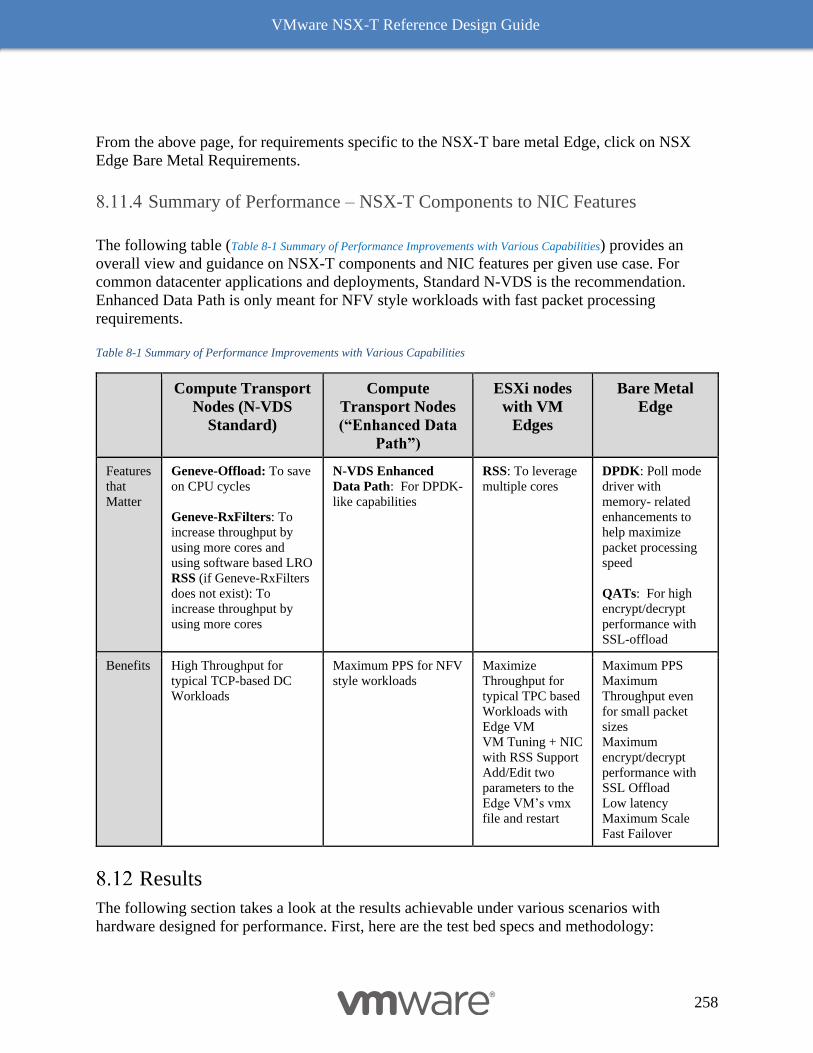
VMware NSX-T Reference Design Guide
258
From the above page, for requirements specific to the NSX-T bare metal Edge, click on NSX
Edge Bare Metal Requirements.
Summary of Performance – NSX-T Components to NIC Features
The following table (Table 8-1 Summary of Performance Improvements with Various Capabilities) provides an
overall view and guidance on NSX-T components and NIC features per given use case. For
common datacenter applications and deployments, Standard N-VDS is the recommendation.
Enhanced Data Path is only meant for NFV style workloads with fast packet processing
requirements.
Table 8-1 Summary of Performance Improvements with Various Capabilities
Compute Transport
Nodes (N-VDS
Standard)
Compute
Transport Nodes
(“Enhanced Data
Path”)
ESXi nodes
with VM
Edges
Bare Metal
Edge
Features
that
Matter
Geneve-Offload: To save
on CPU cycles
Geneve-RxFilters: To
increase throughput by
using more cores and
using software based LRO
RSS (if Geneve-RxFilters
does not exist): To
increase throughput by
using more cores
N-VDS Enhanced
Data Path: For DPDK-
like capabilities
RSS: To leverage
multiple cores
DPDK: Poll mode
driver with
memory- related
enhancements to
help maximize
packet processing
speed
QATs: For high
encrypt/decrypt
performance with
SSL-offload
Benefits
High Throughput for
typical TCP-based DC
Workloads
Maximum PPS for NFV
style workloads
Maximize
Throughput for
typical TPC based
Workloads with
Edge VM
VM Tuning + NIC
with RSS Support
Add/Edit two
parameters to the
Edge VM’s vmx
file and restart
Maximum PPS
Maximum
Throughput even
for small packet
sizes
Maximum
encrypt/decrypt
performance with
SSL Offload
Low latency
Maximum Scale
Fast Failover
Results
The following section takes a look at the results achievable under various scenarios with
hardware designed for performance. First, here are the test bed specs and methodology:
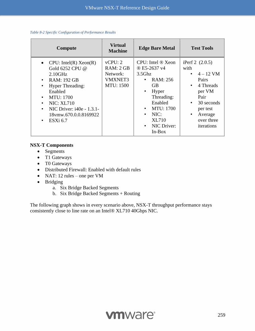
VMware NSX-T Reference Design Guide
259
Table 8-2 Specific Configuration of Performance Results
Compute Virtual
Machine Edge Bare Metal Test Tools
• CPU: Intel(R) Xeon(R)
Gold 6252 CPU @
2.10GHz
• RAM: 192 GB
• Hyper Threading:
Enabled
• MTU: 1700
• NIC: XL710
• NIC Driver: i40e - 1.3.1-
18vmw.670.0.0.8169922
• ESXi 6.7
vCPU: 2
RAM: 2 GB
Network:
VMXNET3
MTU: 1500
CPU: Intel ® Xeon
® E5-2637 v4
3.5Ghz
• RAM: 256
GB
• Hyper
Threading:
Enabled
• MTU: 1700
• NIC:
XL710
• NIC Driver:
In-Box
iPerf 2 (2.0.5)
with
• 4 – 12 VM
Pairs
• 4 Threads
per VM
Pair
• 30 seconds
per test
• Average
over three
iterations
NSX-T Components
• Segments
• T1 Gateways
• T0 Gateways
• Distributed Firewall: Enabled with default rules
• NAT: 12 rules – one per VM
• Bridging
a. Six Bridge Backed Segments
b. Six Bridge Backed Segments + Routing
The following graph shows in every scenario above, NSX-T throughput performance stays
consistently close to line rate on an Intel® XL710 40Gbps NIC.
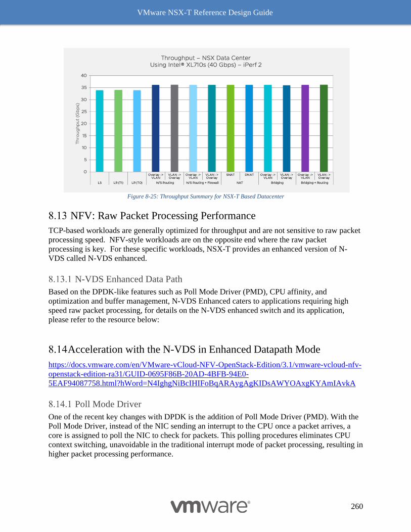
VMware NSX-T Reference Design Guide
260
Figure 8-25: Throughput Summary for NSX-T Based Datacenter
NFV: Raw Packet Processing Performance
TCP-based workloads are generally optimized for throughput and are not sensitive to raw packet
processing speed. NFV-style workloads are on the opposite end where the raw packet
processing is key. For these specific workloads, NSX-T provides an enhanced version of N-
VDS called N-VDS enhanced.
N-VDS Enhanced Data Path
Based on the DPDK-like features such as Poll Mode Driver (PMD), CPU affinity, and
optimization and buffer management, N-VDS Enhanced caters to applications requiring high
speed raw packet processing, for details on the N-VDS enhanced switch and its application,
please refer to the resource below:
Acceleration with the N-VDS in Enhanced Datapath Mode
https://docs.vmware.com/en/VMware-vCloud-NFV-OpenStack-Edition/3.1/vmware-vcloud-nfv-
openstack-edition-ra31/GUID-0695F86B-20AD-4BFB-94E0-
5EAF94087758.html?hWord=N4IghgNiBcIHIFoBqARAygAgKIDsAWYOAxgKYAmIAvkA
Poll Mode Driver
One of the recent key changes with DPDK is the addition of Poll Mode Driver (PMD). With the
Poll Mode Driver, instead of the NIC sending an interrupt to the CPU once a packet arrives, a
core is assigned to poll the NIC to check for packets. This polling procedures eliminates CPU
context switching, unavoidable in the traditional interrupt mode of packet processing, resulting in
higher packet processing performance.
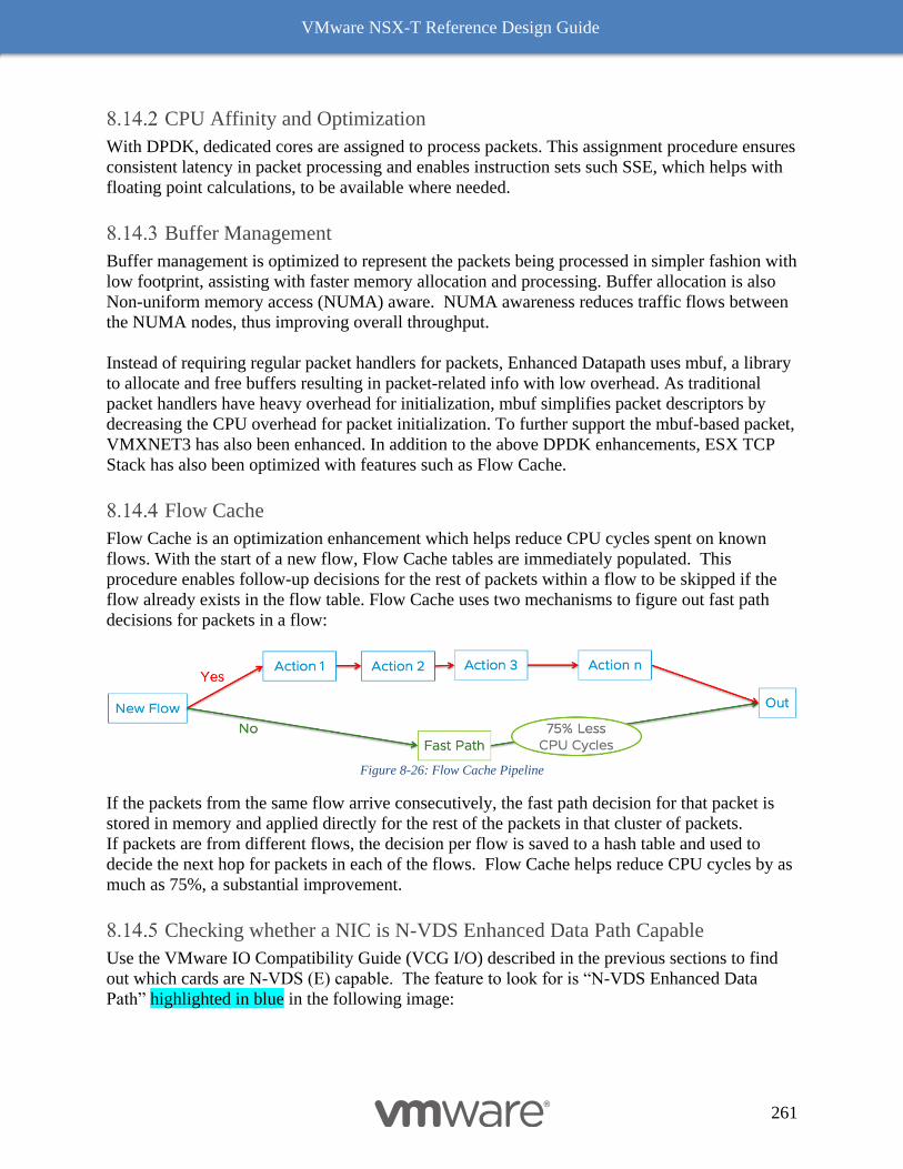
VMware NSX-T Reference Design Guide
261
CPU Affinity and Optimization
With DPDK, dedicated cores are assigned to process packets. This assignment procedure ensures
consistent latency in packet processing and enables instruction sets such SSE, which helps with
floating point calculations, to be available where needed.
Buffer Management
Buffer management is optimized to represent the packets being processed in simpler fashion with
low footprint, assisting with faster memory allocation and processing. Buffer allocation is also
Non-uniform memory access (NUMA) aware. NUMA awareness reduces traffic flows between
the NUMA nodes, thus improving overall throughput.
Instead of requiring regular packet handlers for packets, Enhanced Datapath uses mbuf, a library
to allocate and free buffers resulting in packet-related info with low overhead. As traditional
packet handlers have heavy overhead for initialization, mbuf simplifies packet descriptors by
decreasing the CPU overhead for packet initialization. To further support the mbuf-based packet,
VMXNET3 has also been enhanced. In addition to the above DPDK enhancements, ESX TCP
Stack has also been optimized with features such as Flow Cache.
Flow Cache
Flow Cache is an optimization enhancement which helps reduce CPU cycles spent on known
flows. With the start of a new flow, Flow Cache tables are immediately populated. This
procedure enables follow-up decisions for the rest of packets within a flow to be skipped if the
flow already exists in the flow table. Flow Cache uses two mechanisms to figure out fast path
decisions for packets in a flow:
Figure 8-26: Flow Cache Pipeline
If the packets from the same flow arrive consecutively, the fast path decision for that packet is
stored in memory and applied directly for the rest of the packets in that cluster of packets.
If packets are from different flows, the decision per flow is saved to a hash table and used to
decide the next hop for packets in each of the flows. Flow Cache helps reduce CPU cycles by as
much as 75%, a substantial improvement.
Checking whether a NIC is N-VDS Enhanced Data Path Capable
Use the VMware IO Compatibility Guide (VCG I/O) described in the previous sections to find
out which cards are N-VDS (E) capable. The feature to look for is “N-VDS Enhanced Data
Path” highlighted in blue in the following image:
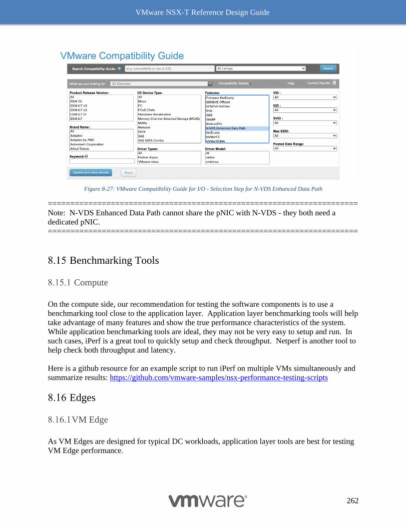
VMware NSX-T Reference Design Guide
262
Figure 8-27: VMware Compatibility Guide for I/O - Selection Step for N-VDS Enhanced Data Path
=====================================================================
Note: N-VDS Enhanced Data Path cannot share the pNIC with N-VDS - they both need a
dedicated pNIC.
=====================================================================
Benchmarking Tools
Compute
On the compute side, our recommendation for testing the software components is to use a
benchmarking tool close to the application layer. Application layer benchmarking tools will help
take advantage of many features and show the true performance characteristics of the system.
While application benchmarking tools are ideal, they may not be very easy to setup and run. In
such cases, iPerf is a great tool to quickly setup and check throughput. Netperf is another tool to
help check both throughput and latency.
Here is a github resource for an example script to run iPerf on multiple VMs simultaneously and
summarize results: https://github.com/vmware-samples/nsx-performance-testing-scripts
Edges
VM Edge
As VM Edges are designed for typical DC workloads, application layer tools are best for testing
VM Edge performance.
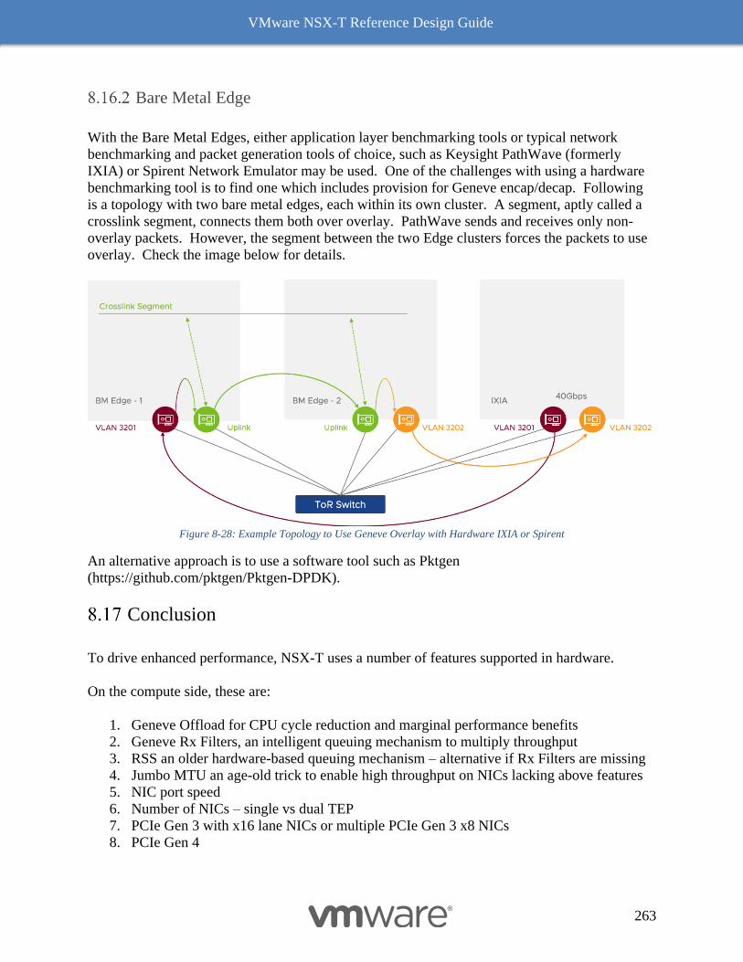
VMware NSX-T Reference Design Guide
263
Bare Metal Edge
With the Bare Metal Edges, either application layer benchmarking tools or typical network
benchmarking and packet generation tools of choice, such as Keysight PathWave (formerly
IXIA) or Spirent Network Emulator may be used. One of the challenges with using a hardware
benchmarking tool is to find one which includes provision for Geneve encap/decap. Following
is a topology with two bare metal edges, each within its own cluster. A segment, aptly called a
crosslink segment, connects them both over overlay. PathWave sends and receives only non-
overlay packets. However, the segment between the two Edge clusters forces the packets to use
overlay. Check the image below for details.
Figure 8-28: Example Topology to Use Geneve Overlay with Hardware IXIA or Spirent
An alternative approach is to use a software tool such as Pktgen
(https://github.com/pktgen/Pktgen-DPDK).
Conclusion
To drive enhanced performance, NSX-T uses a number of features supported in hardware.
On the compute side, these are:
1. Geneve Offload for CPU cycle reduction and marginal performance benefits
2. Geneve Rx Filters, an intelligent queuing mechanism to multiply throughput
3. RSS an older hardware-based queuing mechanism – alternative if Rx Filters are missing
4. Jumbo MTU an age-old trick to enable high throughput on NICs lacking above features
5. NIC port speed
6. Number of NICs – single vs dual TEP
7. PCIe Gen 3 with x16 lane NICs or multiple PCIe Gen 3 x8 NICs
8. PCIe Gen 4
VMware NSX-T Reference Design Guide
264
For compute workloads focused on high packet processing rate for primarily small packet sizes,
Enhanced Data Path Enabled NICs provide a performance boost.
For the Edges, if its VM Edges, then:
1. NIC cards which support RSS and
2. Enabling RSS on both the pNIC and the Edge VM NIC (vNIC)
For the Bare Metal Edges, leveraging optimal SSL offload performance such as Intel® QAT
8960s and deploying supported hardware from the VMware NSX-T install guide will result in
performance gains.
VMware NSX-T Reference Design Guide
265
Appendix 1: External References
• Chapter 1
o NSX-T Installation and Administration Guides –
https://docs.vmware.com/en/VMware-NSX-T/index.html
o NSX Reference Documentation – www.vmware.com/nsx
o VMware Discussion Community –
https://communities.vmware.com/community/vmtn/nsx
o Network Virtualization Blog – https://blogs.vmware.com/networkvirtualization/
o NSXCLOUD resources – https://cloud.vmware.com/nsx-cloud
• Chapter 3
o https://docs.vmware.com/en/VMware-vCloud-NFV-OpenStack-
Edition/3.1/vmware-vcloud-nfv-openstack-edition-ra31/GUID-177A9560-E650-
4A99-8C20-887EEB723D09.html
o https://docs.vmware.com/en/VMware-vCloud-NFV-OpenStack-
Edition/3.1/vmware-vcloud-nfv-openstack-edition-ra31/GUID-9E12F2CD-531E-
4A15-AFF7-512D5DB9BBE5.html o https://docs.vmware.com/en/VMware-vCloud-NFV-OpenStack-Edition/3.0/vmwa-vcloud-nfv30-
performance-tunning/GUID-0625AE2F-8AE0-4EBC-9AC6-2E0AD222EA2B.html
o https://www.virtuallyghetto.com/2018/04/native-mac-learning-in-vsphere-6-7-
removes-the-need-for-promiscuous-mode-for-nested-esxi.html
• Chapter 4
o https://kb.vmware.com/s/article/1003806#vgtPoints
o https://www.vmware.com/pdf/esx3_VLAN_wp.pdf
o NSX-T Hardware Requirements – https://docs.vmware.com/en/VMware-NSX-
T/2.0/com.vmware.nsxt.install.doc/GUID-14183A62-8E8D-43CC-92E0-
E8D72E198D5A.html
• Chapter 6
o More NSX-T LB information can be found in our NSX-T LB
https://communities.vmware.com/docs/DOC-40434
• Chapter 7
o VMware Compatibility Guide -
https://www.vmware.com/resources/compatibility/search.php?deviceCategory=io
&productid=43696&deviceCategory=io&details=1&keyword=25G&pFeatures=2
66&page=8&display_interval=10&sortColumn=Partner&sortOrder=Asc&b=150
8767551363
o NSX Edge Bare Metal Requirements - https://docs.vmware.com/en/VMware-
NSX-T-Data-Center/2.5/installation/GUID-14C3F618-AB8D-427E-AC88-
F05D1A04DE40.html
o VM-to-VM Anti-affinity Rules – https://docs.vmware.com/en/VMware-
vSphere/6.5/com.vmware.vsphere.resmgmt.doc/GUID-7297C302-378F-4AF2-
9BD6-6EDB1E0A850A.html
VMware NSX-T Reference Design Guide
266
o VM-to-host Anti-affinity Rules – https://docs.vmware.com/en/VMware-
vSphere/6.5/com.vmware.vsphere.resmgmt.doc/GUID-0591F865-91B5-4311-
ABA6-84FBA5AAFB59.html
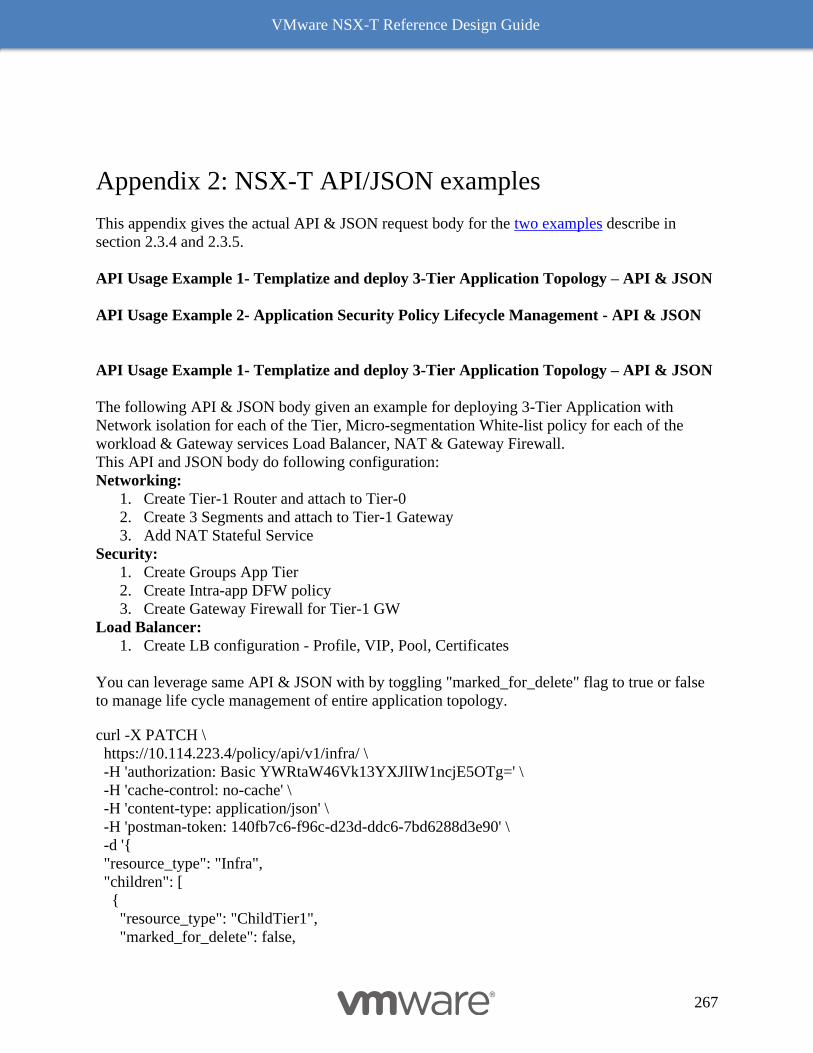
VMware NSX-T Reference Design Guide
267
Appendix 2: NSX-T API/JSON examples
This appendix gives the actual API & JSON request body for the two examples describe in
section 2.3.4 and 2.3.5.
API Usage Example 1- Templatize and deploy 3-Tier Application Topology – API & JSON
API Usage Example 2- Application Security Policy Lifecycle Management - API & JSON
API Usage Example 1- Templatize and deploy 3-Tier Application Topology – API & JSON
The following API & JSON body given an example for deploying 3-Tier Application with
Network isolation for each of the Tier, Micro-segmentation White-list policy for each of the
workload & Gateway services Load Balancer, NAT & Gateway Firewall.
This API and JSON body do following configuration:
Networking:
1. Create Tier-1 Router and attach to Tier-0
2. Create 3 Segments and attach to Tier-1 Gateway
3. Add NAT Stateful Service
Security:
1. Create Groups App Tier
2. Create Intra-app DFW policy
3. Create Gateway Firewall for Tier-1 GW
Load Balancer:
1. Create LB configuration - Profile, VIP, Pool, Certificates
You can leverage same API & JSON with by toggling "marked_for_delete" flag to true or false
to manage life cycle management of entire application topology.
curl -X PATCH \
https://10.114.223.4/policy/api/v1/infra/ \
-H 'authorization: Basic YWRtaW46Vk13YXJlIW1ncjE5OTg=' \
-H 'cache-control: no-cache' \
-H 'content-type: application/json' \
-H 'postman-token: 140fb7c6-f96c-d23d-ddc6-7bd6288d3e90' \
-d '{
"resource_type": "Infra",
"children": [
{
"resource_type": "ChildTier1",
"marked_for_delete": false,
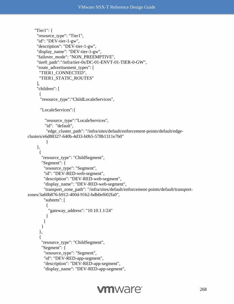
VMware NSX-T Reference Design Guide
268
"Tier1": {
"resource_type": "Tier1",
"id": "DEV-tier-1-gw",
"description": "DEV-tier-1-gw",
"display_name": "DEV-tier-1-gw",
"failover_mode": "NON_PREEMPTIVE",
"tier0_path":"/infra/tier-0s/DC-01-ENVT-01-TIER-0-GW",
"route_advertisement_types": [
"TIER1_CONNECTED",
"TIER1_STATIC_ROUTES"
],
"children": [
{
"resource_type":"ChildLocaleServices",
"LocaleServices":{
"resource_type":"LocaleServices",
"id": "default",
"edge_cluster_path": "/infra/sites/default/enforcement-points/default/edge-
clusters/e6d88327-640b-4d33-b0b5-578b1311e7b0"
}
},
{
"resource_type": "ChildSegment",
"Segment": {
"resource_type": "Segment",
"id": "DEV-RED-web-segment",
"description": "DEV-RED-web-segment",
"display_name": "DEV-RED-web-segment",
"transport_zone_path": "/infra/sites/default/enforcement-points/default/transport-
zones/3a60b876-b912-400d-91b2-bdb0ef602fa0",
"subnets": [
{
"gateway_address": "10.10.1.1/24"
}
]
}
},
{
"resource_type": "ChildSegment",
"Segment": {
"resource_type": "Segment",
"id": "DEV-RED-app-segment",
"description": "DEV-RED-app-segment",
"display_name": "DEV-RED-app-segment",
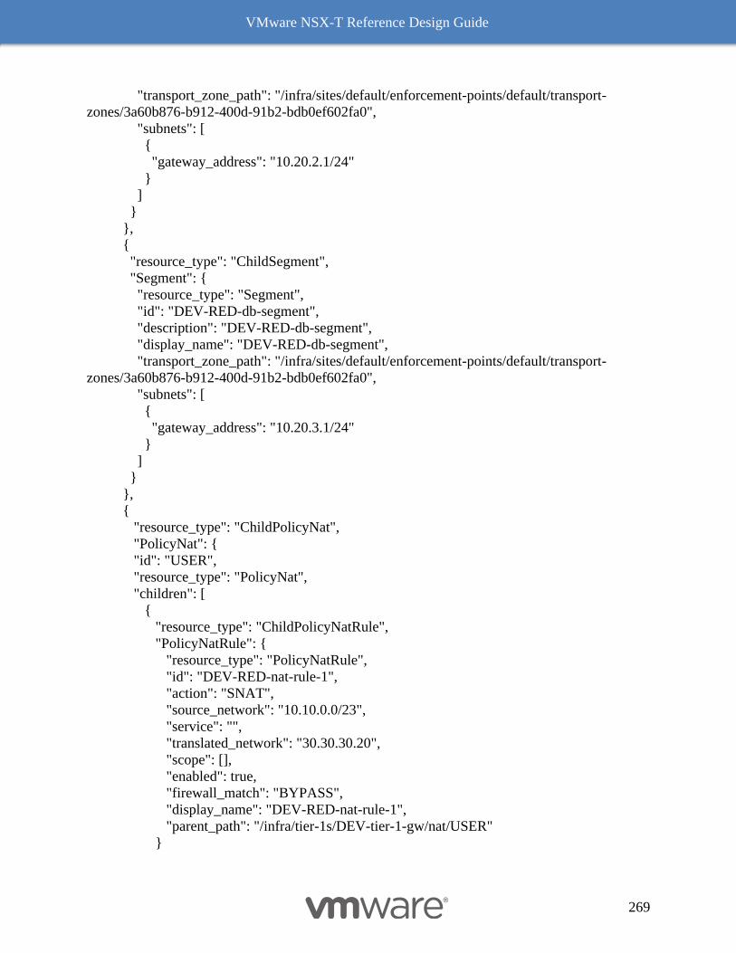
VMware NSX-T Reference Design Guide
269
"transport_zone_path": "/infra/sites/default/enforcement-points/default/transport-
zones/3a60b876-b912-400d-91b2-bdb0ef602fa0",
"subnets": [
{
"gateway_address": "10.20.2.1/24"
}
]
}
},
{
"resource_type": "ChildSegment",
"Segment": {
"resource_type": "Segment",
"id": "DEV-RED-db-segment",
"description": "DEV-RED-db-segment",
"display_name": "DEV-RED-db-segment",
"transport_zone_path": "/infra/sites/default/enforcement-points/default/transport-
zones/3a60b876-b912-400d-91b2-bdb0ef602fa0",
"subnets": [
{
"gateway_address": "10.20.3.1/24"
}
]
}
},
{
"resource_type": "ChildPolicyNat",
"PolicyNat": {
"id": "USER",
"resource_type": "PolicyNat",
"children": [
{
"resource_type": "ChildPolicyNatRule",
"PolicyNatRule": {
"resource_type": "PolicyNatRule",
"id": "DEV-RED-nat-rule-1",
"action": "SNAT",
"source_network": "10.10.0.0/23",
"service": "",
"translated_network": "30.30.30.20",
"scope": [],
"enabled": true,
"firewall_match": "BYPASS",
"display_name": "DEV-RED-nat-rule-1",
"parent_path": "/infra/tier-1s/DEV-tier-1-gw/nat/USER"
}
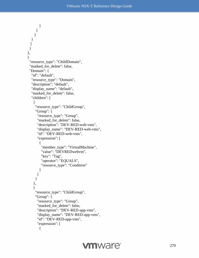
VMware NSX-T Reference Design Guide
270
}
]
}
}
]
}
},
{
"resource_type": "ChildDomain",
"marked_for_delete": false,
"Domain": {
"id": "default",
"resource_type": "Domain",
"description": "default",
"display_name": "default",
"marked_for_delete": false,
"children": [
{
"resource_type": "ChildGroup",
"Group": {
"resource_type": "Group",
"marked_for_delete": false,
"description": "DEV-RED-web-vms",
"display_name": "DEV-RED-web-vms",
"id": "DEV-RED-web-vms",
"expression": [
{
"member_type": "VirtualMachine",
"value": "DEVREDwebvm",
"key": "Tag",
"operator": "EQUALS",
"resource_type": "Condition"
}
]
}
},
{
"resource_type": "ChildGroup",
"Group": {
"resource_type": "Group",
"marked_for_delete": false,
"description": "DEV-RED-app-vms",
"display_name": "DEV-RED-app-vms",
"id": "DEV-RED-app-vms",
"expression": [
{
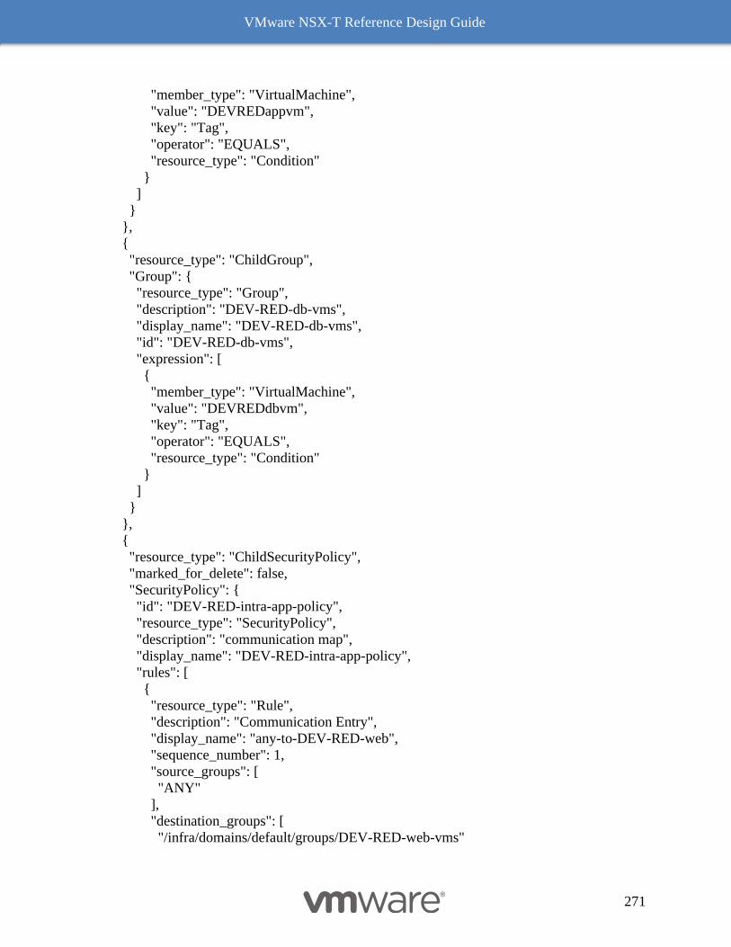
VMware NSX-T Reference Design Guide
271
"member_type": "VirtualMachine",
"value": "DEVREDappvm",
"key": "Tag",
"operator": "EQUALS",
"resource_type": "Condition"
}
]
}
},
{
"resource_type": "ChildGroup",
"Group": {
"resource_type": "Group",
"description": "DEV-RED-db-vms",
"display_name": "DEV-RED-db-vms",
"id": "DEV-RED-db-vms",
"expression": [
{
"member_type": "VirtualMachine",
"value": "DEVREDdbvm",
"key": "Tag",
"operator": "EQUALS",
"resource_type": "Condition"
}
]
}
},
{
"resource_type": "ChildSecurityPolicy",
"marked_for_delete": false,
"SecurityPolicy": {
"id": "DEV-RED-intra-app-policy",
"resource_type": "SecurityPolicy",
"description": "communication map",
"display_name": "DEV-RED-intra-app-policy",
"rules": [
{
"resource_type": "Rule",
"description": "Communication Entry",
"display_name": "any-to-DEV-RED-web",
"sequence_number": 1,
"source_groups": [
"ANY"
],
"destination_groups": [
"/infra/domains/default/groups/DEV-RED-web-vms"
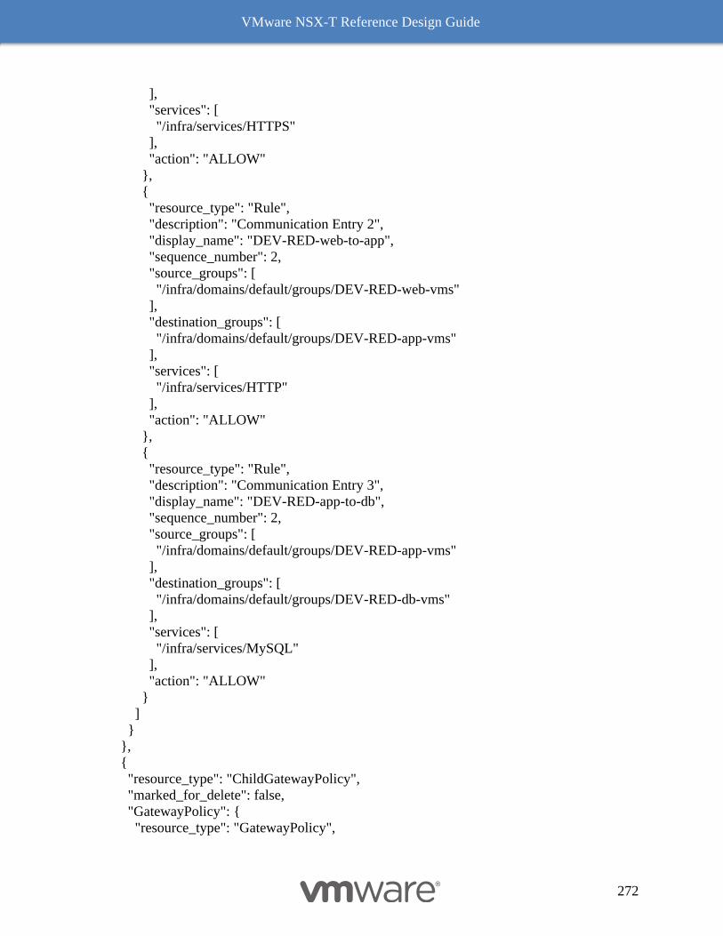
VMware NSX-T Reference Design Guide
272
],
"services": [
"/infra/services/HTTPS"
],
"action": "ALLOW"
},
{
"resource_type": "Rule",
"description": "Communication Entry 2",
"display_name": "DEV-RED-web-to-app",
"sequence_number": 2,
"source_groups": [
"/infra/domains/default/groups/DEV-RED-web-vms"
],
"destination_groups": [
"/infra/domains/default/groups/DEV-RED-app-vms"
],
"services": [
"/infra/services/HTTP"
],
"action": "ALLOW"
},
{
"resource_type": "Rule",
"description": "Communication Entry 3",
"display_name": "DEV-RED-app-to-db",
"sequence_number": 2,
"source_groups": [
"/infra/domains/default/groups/DEV-RED-app-vms"
],
"destination_groups": [
"/infra/domains/default/groups/DEV-RED-db-vms"
],
"services": [
"/infra/services/MySQL"
],
"action": "ALLOW"
}
]
}
},
{
"resource_type": "ChildGatewayPolicy",
"marked_for_delete": false,
"GatewayPolicy": {
"resource_type": "GatewayPolicy",
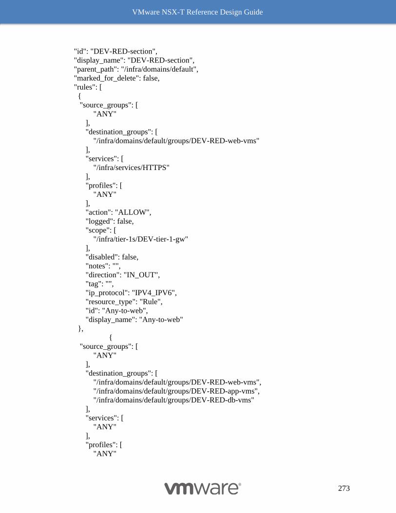
VMware NSX-T Reference Design Guide
273
"id": "DEV-RED-section",
"display_name": "DEV-RED-section",
"parent_path": "/infra/domains/default",
"marked_for_delete": false,
"rules": [
{
"source_groups": [
"ANY"
],
"destination_groups": [
"/infra/domains/default/groups/DEV-RED-web-vms"
],
"services": [
"/infra/services/HTTPS"
],
"profiles": [
"ANY"
],
"action": "ALLOW",
"logged": false,
"scope": [
"/infra/tier-1s/DEV-tier-1-gw"
],
"disabled": false,
"notes": "",
"direction": "IN_OUT",
"tag": "",
"ip_protocol": "IPV4_IPV6",
"resource_type": "Rule",
"id": "Any-to-web",
"display_name": "Any-to-web"
},
{
"source_groups": [
"ANY"
],
"destination_groups": [
"/infra/domains/default/groups/DEV-RED-web-vms",
"/infra/domains/default/groups/DEV-RED-app-vms",
"/infra/domains/default/groups/DEV-RED-db-vms"
],
"services": [
"ANY"
],
"profiles": [
"ANY"
VMware NSX-T Reference Design Guide
274
],
"action": "DROP",
"logged": false,
"scope": [
"/infra/tier-1s/DEV-tier-1-gw"
],
"disabled": false,
"notes": "",
"direction": "IN_OUT",
"tag": "",
"ip_protocol": "IPV4_IPV6",
"resource_type": "Rule",
"id": "DenyAny",
"display_name": "DenyAny"
}
]
}
}
]
}
},
{
"resource_type": "ChildLBClientSslProfile",
"marked_for_delete": false,
"LBClientSslProfile": {
"resource_type": "LBClientSslProfile",
"id": "batchSetupClientSslProfile",
"cipher_group_label": "CUSTOM",
"session_cache_enabled": true,
"ciphers": [
"TLS_ECDHE_RSA_WITH_AES_128_GCM_SHA256",
"TLS_ECDHE_RSA_WITH_AES_256_GCM_SHA384"
],
"protocols": [
"TLS_V1_2"
]
}
},
{
"resource_type": "ChildLBServerSslProfile",
"marked_for_delete": false,
"LBServerSslProfile": {
"resource_type": "LBServerSslProfile",
"id": "batchSetupServerSslProfile",
"cipher_group_label": "CUSTOM",
"session_cache_enabled": true,
VMware NSX-T Reference Design Guide
275
"ciphers": [
"TLS_ECDHE_RSA_WITH_AES_128_GCM_SHA256",
"TLS_ECDHE_RSA_WITH_AES_256_GCM_SHA384"
],
"protocols": [
"TLS_V1_2"
]
}
},
{
"resource_type": "ChildLBAppProfile",
"marked_for_delete": false,
"LBAppProfile": {
"resource_type": "LBHttpProfile",
"id": "batchSetupHttpAppProfile",
"x_forwarded_for": "INSERT"
}
},
{
"resource_type": "ChildLBMonitorProfile",
"marked_for_delete": false,
"LBMonitorProfile": {
"resource_type": "LBHttpMonitorProfile",
"marked_for_delete": false,
"id": "batchSetupHttpMonitor1",
"monitor_port": 80,
"timeout": 5,
"response_status_codes": [
200,
300
]
}
},
{
"resource_type": "ChildLBMonitorProfile",
"marked_for_delete": false,
"LBMonitorProfile": {
"resource_type": "LBHttpsMonitorProfile",
"id": "batchSetupHttpsMonitor1",
"monitor_port": 443,
"timeout": 5,
"response_status_codes": [
200
]
}
},

VMware NSX-T Reference Design Guide
276
{
"resource_type": "ChildLBService",
"marked_for_delete": false,
"LBService": {
"resource_type": "LBService",
"id": "DEV-RED-LbService",
"connectivity_path": "/infra/tier-1s/DEV-tier-1-gw",
"error_log_level": "DEBUG",
"access_log_enabled": true
}
},
{
"resource_type": "ChildLBVirtualServer",
"marked_for_delete": false,
"LBVirtualServer": {
"resource_type": "LBVirtualServer",
"id": "DEV-RED-VirtualServer1",
"lb_service_path": "/infra/lb-services/DEV-RED-LbService",
"ip_address": "30.10.200.1",
"ports": [
"443"
],
"pool_path": "/infra/lb-pools/DEV-RED-web-Pool",
"application_profile_path": "/infra/lb-app-profiles/batchSetupHttpAppProfile",
"client_ssl_profile_binding": {
"ssl_profile_path": "/infra/lb-client-ssl-profiles/batchSetupClientSslProfile",
"default_certificate_path": "/infra/certificates/batchSslSignedCertDEV-RED",
"client_auth_ca_paths": [
"/infra/certificates/batchSslCACertDEV-RED"
],
"certificate_chain_depth": 2
},
"server_ssl_profile_binding": {
"ssl_profile_path": "/infra/lb-server-ssl-profiles/batchSetupServerSslProfile",
"server_auth": "IGNORE",
"client_certificate_path": "/infra/certificates/batchSslSignedCertDEV-RED",
"server_auth_ca_paths": [
"/infra/certificates/batchSslCACertDEV-RED"
],
"certificate_chain_depth": 2
}
}
},
{
"resource_type": "ChildLBPool",
"marked_for_delete": false,
VMware NSX-T Reference Design Guide
277
"LBPool": {
"id": "DEV-RED-web-Pool",
"resource_type": "LBPool",
"marked_for_delete": false,
"active_monitor_paths": [
"/infra/lb-monitor-profiles/batchSetupHttpsMonitor1"
],
"algorithm": "ROUND_ROBIN",
"member_group": {
"group_path": "/infra/domains/default/groups/DEV-RED-web-vms",
"ip_revision_filter": "IPV4"
},
"snat_translation": {
"type": "LBSnatDisabled"
}
}
},
{
"resource_type": "ChildLBVirtualServer",
"marked_for_delete": false,
"LBVirtualServer": {
"resource_type": "LBVirtualServer",
"id": "DEV-RED-VirtualServer2",
"lb_service_path": "/infra/lb-services/DEV-RED-LbService",
"ip_address": "10.10.200.1",
"ports": [
"80"
],
"pool_path": "/infra/lb-pools/DEV-RED-app-Pool",
"application_profile_path": "/infra/lb-app-profiles/batchSetupHttpAppProfile"
}
},
{
"resource_type": "ChildLBPool",
"marked_for_delete": false,
"LBPool": {
"id": "DEV-RED-app-Pool",
"resource_type": "LBPool",
"marked_for_delete": false,
"active_monitor_paths": [
"/infra/lb-monitor-profiles/batchSetupHttpMonitor1"
],
"algorithm": "ROUND_ROBIN",
"member_group": {
"group_path": "/infra/domains/default/groups/DEV-RED-app-vms",
"ip_revision_filter": "IPV4"
VMware NSX-T Reference Design Guide
278
},
"snat_translation": {
"type": "LBSnatDisabled"
}
}
},
{
"resource_type": "ChildTlsTrustData",
"marked_for_delete": false,
"TlsTrustData": {
"resource_type": "TlsTrustData",
"marked_for_delete": false,
"id": "batchSslCACertDEV-RED",
"pem_encoded": "-----BEGIN CERTIFICATE-----
\nMIIExTCCA62gAwIBAgIBADANBgkqhkiG9w0BAQUFADB9MQswCQYDVQQGEwJFV
TEn\nMCUGA1UEChMeQUMgQ2FtZXJmaXJtYSBTQSBDSUYgQTgyNzQzMjg3MSMwIQ
YDVQQL\nExpodHRwOi8vd3d3LmNoYW1iZXJzaWduLm9yZzEgMB4GA1UEAxMXR2xvY
mFsIENo\nYW1iZXJzaWduIFJvb3QwHhcNMDMwOTMwMTYxNDE4WhcNMzcwOTMwM
TYxNDE4WjB9\nMQswCQYDVQQGEwJFVTEnMCUGA1UEChMeQUMgQ2FtZXJmaXJtY
SBTQSBDSUYgQTgy\nNzQzMjg3MSMwIQYDVQQLExpodHRwOi8vd3d3LmNoYW1iZXJz
aWduLm9yZzEgMB4G\nA1UEAxMXR2xvYmFsIENoYW1iZXJzaWduIFJvb3QwggEgMA0G
CSqGSIb3DQEBAQUA\nA4IBDQAwggEIAoIBAQCicKLQn0KuWxfH2H3PFIP8T8mhtxOvit
eePgQKkotgVvq0\nMi+ITaFgCPS3CU6gSS9J1tPfnZdan5QEcOw/Wdm3zGaLmFIoCQLfxS+E
jXqXd7/s\nQJ0lcqu1PzKY+7e3/HKE5TWH+VX6ox8Oby4o3Wmg2UIQxvi1RMLQQ3/bvOSi
PGpV\neAp3qdjqGTK3L/5cPxvusZjsyq16aUXjlg9V9ubtdepl6DJWk0aJqCWKZQbua795\nB9
Dxt6/tLE2Su8CoX6dnfQTyFQhwrJLWfQTSM/tMtgsL+xrJxI0DqX5c8lCrEqWh\nz0hQpe/SyB
oT+rB/sYIcd2oPX9wLlY/vQ37mRQklAgEDo4IBUDCCAUwwEgYDVR0T\nAQH/BAgwBgE
B/wIBDDA/BgNVHR8EODA2MDSgMqAwhi5odHRwOi8vY3JsLmNoYW1i\nZXJzaWduLm
9yZy9jaGFtYmVyc2lnbnJvb3QuY3JsMB0GA1UdDgQWBBRDnDafsJ4w\nTcbOX60Qq+UDp
fqpFDAOBgNVHQ8BAf8EBAMCAQYwEQYJYIZIAYb4QgEBBAQDAgAH\nMCoGA1UdE
QQjMCGBH2NoYW1iZXJzaWducm9vdEBjaGFtYmVyc2lnbi5vcmcwKgYD\nVR0SBCMwIY
EfY2hhbWJlcnNpZ25yb290QGNoYW1iZXJzaWduLm9yZzBbBgNVHSAE\nVDBSMFAGCys
GAQQBgYcuCgEBMEEwPwYIKwYBBQUHAgEWM2h0dHA6Ly9jcHMuY2hh\nbWJlcnNpZ
24ub3JnL2Nwcy9jaGFtYmVyc2lnbnJvb3QuaHRtbDANBgkqhkiG9w0B\nAQUFAAOCAQEA
PDtwkfkEVCeR4e3t/mh/YV3lQWVPMvEYBZRqHN4fcNs+ezICNLUM\nbKGKfKX0j//U2K0
X1S0E0T9YgOKBWYi+wONGkyT+kL0mojAt6JcmVzWJdJYY9hXi\nryQZVgICsroPFOrGim
bBhkVVi76SvpykBMdJPJ7oKXqJ1/6v/2j1pReQvayZzKWG\nVwlnRtvWFsJG8eSpUPWP0ZI
V018+xgBJOm5YstHRJw0lyDL4IBHNfTIzSJRUTN3c\necQwn+uOuFW114hcxWokPbLTBQ
NRxgfvzBRydD1ucs4YKIxKoHflCStFREest2d/\nAYoFWpO+ocH/+OcOZ6RHSXZddZAa9Sa
P8A==\n-----END CERTIFICATE-----\n"
}
},
{
"resource_type": "ChildTlsTrustData",
"marked_for_delete": false,
"TlsTrustData": {
VMware NSX-T Reference Design Guide
279
"resource_type": "TlsTrustData",
"marked_for_delete": false,
"id": "batchSslSignedCertDEV-RED",
"pem_encoded": "-----BEGIN CERTIFICATE-----
\nMIIE7zCCAtegAwIBAgICEAEwDQYJKoZIhvcNAQEFBQAwezELMAkGA1UEBhMCVV
Mx\nCzAJBgNVBAgMAkNBMQswCQYDVQQHDAJQQTEPMA0GA1UECgwGVk13YXJl
MQ0wCwYD\nVQQLDAROU0JVMQ4wDAYDVQQDDAVWaXZlazEiMCAGCSqGSIb3DQ
EJARYTdnNhcmFv\nZ2lAdm13YXJlLmNvbTAeFw0xNDA4MDYyMTE1NThaFw0xNTA4M
DYyMTE1NThaMG4x\nCzAJBgNVBAYTAlVTMQswCQYDVQQIEwJDQTEPMA0GA1UE
ChMGVk13YXJlMQ0wCwYD\nVQQLEwROU0JVMQ4wDAYDVQQDEwVWaXZlazEiMC
AGCSqGSIb3DQEJARYTdnNhcmFv\nZ2lAdm13YXJlLmNvbTCCASIwDQYJKoZIhvcNAQ
EBBQADggEPADCCAQoCggEBANHv\nl6nlZEbY+PamrPYxiit3jlYY7tIOUtLNqYtANBMT
NVuCQweREHCNIXmsDGDvht28\nTZm0RwO7U72ZMlUYIM9JeDKvf4SwpGyXEyCCPsrn
V4ZWaazLDS+rsi0daO2ak70+\nc9pnfGIogf/tcslFUb//dsK3wJQcirq3Aii/Eswzva6tiP4TOjAA8
Ujy1eLmnQVN\nIXpAeAqRmk+AKfzXS+fRjeaMQsZD0rySJ1Q2M//Y0/e9nTLUx450rIAlx/E
fwhNJ\nHkNh5hCsblaCv9bUiIkIuDBiNn2zh3hUmRo/gjk94lSoG6plILOM8BY1Ro5uSqyu\nR
SrJXzcOQ1ndmXjCxKUCAwEAAaOBiTCBhjAJBgNVHRMEAjAAMAsGA1UdDwQEAwIF\
n4DAsBglghkgBhvhCAQ0EHxYdT3BlblNTTCBHZW5lcmF0ZWQgQ2VydGlmaWNhdGUw\
nHQYDVR0OBBYEFCKOu6UTn7XsNQVQxOpOUzOc9Yh3MB8GA1UdIwQYMBaAFOqo
Dj0V\n7pC6BhIjy3sVV73EfBZMMA0GCSqGSIb3DQEBBQUAA4ICAQClSkVbIb3HEJNBa
RBW\nnm9cf+iU9lpMCYdQAsYAeE9ltSbfJMw8e+Yla+m8D4ZGSLzevjEyTHslACd7666q\n
TBviPSlopYkMmiiwaGpTVL8qIhhxzkMOMea4AiPgZ4FUDzb/yYKGSQEIE3/5MMbP\nvUEa
c+n0JIiwHZZP4TgT7vPD9so2cc6dZU0CW+vTu+50zzsOUKUYAfUkk6k5SL6H\nkho+cavL3
8Dyjx2DdvZ/dtZkommbj+wtoluRR17wTwSD1yCqpfPAvGwbSwUwX2U+\nwEqGQsnfBYslsf
81PNPzVDAsE5asf5dooOmx9LogbzVT7B27VAfcpqtaT5WH6jij\nusVzUaRVlylZHGqXQ3Qe
YFG4zulT4q2V9Q/CVnX8uOzRFIcgAyYkizd603EgMWPq\nAyEqu5HTeqomk+cwsyel35q9Q
pGl8iDjJQaCZNW7tTPobVWYcdt7VA1i0MtnNz4R\nxjb+3WKPTswawKqO1souuXpBiGptM
Kjb/gasDh2gH+MvGob+9XQ0HkKUvDUeaU5a\n+JdASpSsKswIx6rAsaIvNREXh3ur8ao3DE
Bpo/og5qNhZmnTBKcDLElgIRMjF0GD\nT0ycWSV33x4X3U+qogXOr7mAVIKBWEp/w2Je
CRFbLKxLc4q7CESaYRWGSml0McmH\n0tmEO4++tc1WSc2i/WGJYsZbHA==\n-----END
CERTIFICATE-----\n-----BEGIN CERTIFICATE-----
\nMIIF1jCCA76gAwIBAgIJANY0bE9WZ1GVMA0GCSqGSIb3DQEBBQUAMHsxCzAJBgN
V\nBAYTAlVTMQswCQYDVQQIDAJDQTELMAkGA1UEBwwCUEExDzANBgNVBAoMB
lZNd2Fy\nZTENMAsGA1UECwwETlNCVTEOMAwGA1UEAwwFVml2ZWsxIjAgBgkqhkiG
9w0BCQEW\nE3ZzYXJhb2dpQHZtd2FyZS5jb20wHhcNMTQwNzE2MTgwMjQ4WhcNMjQ
wNzEzMTgw\nMjQ4WjB7MQswCQYDVQQGEwJVUzELMAkGA1UECAwCQ0ExCzAJBg
NVBAcMAlBBMQ8w\nDQYDVQQKDAZWTXdhcmUxDTALBgNVBAsMBE5TQlUxDjAM
BgNVBAMMBVZpdmVrMSIw\nIAYJKoZIhvcNAQkBFhN2c2FyYW9naUB2bXdhcmUuY29t
MIICIjANBgkqhkiG9w0B\nAQEFAAOCAg8AMIICCgKCAgEA3bvIkxqNzTEOSlWfMRPCK
Ut2hy064GP3OwR8tXqf\n0PemyT/2SgVFPtAVv3dH7qBG+CmnYXlSymgHrVb8d9Kh08Jv+u
tkunQmGqecUjcd\nt0ziJj+aZQx6yxfOOwmYxXjVbKRgtLFby30KgFKJ1/xC45bNGzEI99u3Z
FrEfkwl\n0ebozdB6Tfjo/ZzsbtuwqGcgfWMwFqI9P/8upn7rzBTHXp4Z8zygf1+/fkIxUu9o\n5Q/
E1cjaLrKBa9ETMSmpXenEQdQvT2vmj69fafvXbBA+2nZPO/6Hmhgnbni+qglM\n0h7BUpf/N
Xb7vybTFRhm1EO2dhQnK0IHU8qeEgxt/vyuD4JlBsUw/HqD3XJ20Qj2\nulOoRa8cQdIuDX/0
gLJ92g2kCKTEE7iHa5jDdba7MqUQvOxJPJ4Mi55iuiolh88o\ne92jhS2zxImcy/IElXLxwJyWv0
WUxQNX+0h+lafK9XPsZIV3K+W7PPpMvymjDNIC\nVbjvURDaHg/uRszZovfFewiIvYCR4j
VMware NSX-T Reference Design Guide
280
B5eCud4vOLY1iLyEt2CnmTCPH9No1lk2B/\n1Ej/QJOPFJC/wbDeTiTg7sgJIdTHcRMdumIM
htQHTYYXxd3u3Oy7M9fxYCnHQE14\nejh4/37Qn1bylOqACVT0u++pamlT1fc70Y1Bwq5xS
/OJGRmK0FAHiWus/3QvV9Kj\nUucCAwEAAaNdMFswHQYDVR0OBBYEFOqoDj0V7pC6
BhIjy3sVV73EfBZMMB8GA1Ud\nIwQYMBaAFOqoDj0V7pC6BhIjy3sVV73EfBZMMAwG
A1UdEwQFMAMBAf8wCwYDVR0P\nBAQDAgEGMA0GCSqGSIb3DQEBBQUAA4ICAQ
CFD6o1SALwTxAMmHqt6rrwjZdrUMLe\n0vZ1lsjlr82MrUk9L1YOsSFRFGLpYMhmIC/pdaz
iMxEOI+RifRSI9sk/sY3XlsrL\nuI/92sE9qLV6/PGZsaHYeQcDduaqLqHj7LnsCkgoVZqYhpgp
RvgiuUm8faWW9piG\nO0t/PuKpyxWRn+0dqzsH+Nhr/lMoYPqeURphphqiiqoTGcmREEYrD
C+MoUsTeHy4\nPy2NNCB5J5qQpMfwfWBeLf0dXXpFk7ggF0dHW/Ma/b8g+fdVE6AswY3
NG6TV8phy\nOoNCgqIIO18OuFVL2DnYDoDaEjin/Y5l6U32BAsiCTyiUrCr4+4V7Awa10ipZ
iPK\niQlIs0vbXD9tSyiP1yTn3tXXHE7OZnT5nE1//UQbEaQWbQcgZOCoH54M7m03aMS5\n
1PHs9BHt7zj3ASDF682rsiZTKgW+hv6TTTdfgDHMEO5+ocpIXKAeN9Kx3XSp6jHt\n5yMT
2IUv3BEO9i+Dj8CBwvUHU9keinWCJ3i8WbiVhDsQoSnIARX51pmZ9Hz+JelS\nCh0BJtJsW
ac0Ceq5u62qzRNCj2D6ZqWHjmlzJ4WnvcQMRYxrskct4kS/zX4NTZyx\nlBH6xjE5pnf45jUW
kiAD9IfGC40bApHorgC/2wCCTmkL8nxIGY1jg1zHXO/cxTxp\nVcf1BfHFyi5CjA==\n-----
END CERTIFICATE-----\n",
"private_key": "-----BEGIN RSA PRIVATE KEY-----
\nMIIEpAIBAAKCAQEA0e+XqeVkRtj49qas9jGKK3eOVhju0g5S0s2pi0A0ExM1W4JD\nB5E
QcI0heawMYO+G3bxNmbRHA7tTvZkyVRggz0l4Mq9/hLCkbJcTIII+yudXhlZp\nrMsNL6uyL
R1o7ZqTvT5z2md8YiiB/+1yyUVRv/92wrfAlByKurcCKL8SzDO9rq2I\n/hM6MADxSPLV4ua
dBU0hekB4CpGaT4Ap/NdL59GN5oxCxkPSvJInVDYz/9jT972d\nMtTHjnSsgCXH8R/CE0ke
Q2HmEKxuVoK/1tSIiQi4MGI2fbOHeFSZGj+COT3iVKgb\nqmUgs4zwFjVGjm5KrK5FKslfN
w5DWd2ZeMLEpQIDAQABAoIBAQCBp4I4WEa9BqWD\n11580g2uWLEcdVuReW0nagLq
0GUY3sUWVfXFx46qpE7nUR14BJZ7fR9D7TXqlRfb\nwbB3I2an/ozwaLjNnzZ9JjSW4Dmdo
JDKk7XCFMl5BoYNHNu/2rahqt9sJHuKN9BJ\n2kEJEvmxJToYednC33nCZOI9ffxDBhZKN1
krnHjouI56MZv23e06+cwwjrFUnIPI\nNNfkTTqDMU/xj5xmltrWhZIr/RPogLS4kdwRS8Q8pP
vJOXQlg7+imrDxg7MckMgb\nE73uJv5sfhbsxgn9d8sYVhD9lwbb+QpXUro8f5XzVFwMpRFb
DThGE0eQx7ULCWZz\n+2+/x+jFAoGBAPqDfU/EBHVBF/O0JnVFC7A26ihQUQIqUu2N3o
Gi/L+io2uIw8Cd\n9eHuxmwI2DPJ5KlRz7i1ZeGlZoRNN7dt3p7NhKT4O+7hyBVMDItubKkw
dg2rULj6\nz9iShtKomzyZaSDA8VbNZX/qgDM7UflKcvXUA41UuJGrgiJmm3DZTqqLAoGB
ANaI\nml2NB6aFnd/4PN1XKZzFibS1DvcnooX+LPtR6+ky/0wst7DXF1qnp3XWVG6R86ci\n
CFoTNsleryrFmKnY5oUl41EcNqpnVGU1+lth6rl4LnVL9GwtiU2h9kV5p7w0ExRk\nkVjvE4K
8f8w5eDcO39QogkD0AYXpN1pj9l6EEaOPAoGAT0kqcgJx/sJZWFJeEaOG\nrYDT32p8GRlY
IcNS9uik4eoRmskwW1gjKBywRCUQeGOfsU8pVSZkVmRI6/qcdbua\nR9x37NZ78YEYGFV
3avHKBkpGMtFTvRf0jHDjpuyiJS3QrgMi3vwm8bNAW/acXTAI\n7nDppuN3fvMvPsAG1lK
QqT0CgYAJIF6QxEMjDmQc9w5/zAl1JeIp0doFIaaEVL/N\nITsL/KNnti9KUpwnuyIgnTGSUp
su7P+19UNLZb/F7goEj7meyHHXLYAV17d7ZsRz\nxsKZiUdQrh6Dy5wftVgotHgyRXTaVTz
pr6IA2cwGABvhG7zh5adE5Bx8eeNk8QO2\nGaA2eQKBgQDnpBPL0OtVcva1gOIeS41Kaa78
/VxN64fKCdkJNfwr9NUz51u6RMrh\nc2zWaTp3QG062zhdSuUATVJ9kK/NgVT9Afmb21H7
6xE9KY3fztb1SqRCZGMjHeEr\n563mDimPiOPUATWXyZS5/HQSLIRLjJ9+mfBFVFEgFNG
K55pOmyMTaQ==\n-----END RSA PRIVATE KEY-----\n",
"key_algo": "RSA"
}
}
]
}'
VMware NSX-T Reference Design Guide
281
Back to Appendix 2.
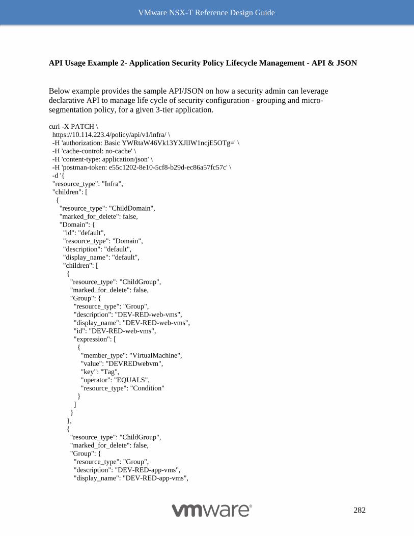
VMware NSX-T Reference Design Guide
282
API Usage Example 2- Application Security Policy Lifecycle Management - API & JSON
Below example provides the sample API/JSON on how a security admin can leverage
declarative API to manage life cycle of security configuration - grouping and micro-
segmentation policy, for a given 3-tier application.
curl -X PATCH \
https://10.114.223.4/policy/api/v1/infra/ \
-H 'authorization: Basic YWRtaW46Vk13YXJlIW1ncjE5OTg=' \
-H 'cache-control: no-cache' \
-H 'content-type: application/json' \
-H 'postman-token: e55c1202-8e10-5cf8-b29d-ec86a57fc57c' \
-d '{
"resource_type": "Infra",
"children": [
{
"resource_type": "ChildDomain",
"marked_for_delete": false,
"Domain": {
"id": "default",
"resource_type": "Domain",
"description": "default",
"display_name": "default",
"children": [
{
"resource_type": "ChildGroup",
"marked_for_delete": false,
"Group": {
"resource_type": "Group",
"description": "DEV-RED-web-vms",
"display_name": "DEV-RED-web-vms",
"id": "DEV-RED-web-vms",
"expression": [
{
"member_type": "VirtualMachine",
"value": "DEVREDwebvm",
"key": "Tag",
"operator": "EQUALS",
"resource_type": "Condition"
}
]
}
},
{
"resource_type": "ChildGroup",
"marked_for_delete": false,
"Group": {
"resource_type": "Group",
"description": "DEV-RED-app-vms",
"display_name": "DEV-RED-app-vms",
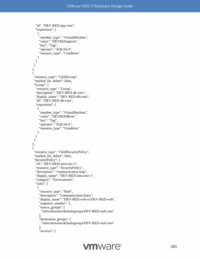
VMware NSX-T Reference Design Guide
283
"id": "DEV-RED-app-vms",
"expression": [
{
"member_type": "VirtualMachine",
"value": "DEVREDappvm",
"key": "Tag",
"operator": "EQUALS",
"resource_type": "Condition"
}
]
}
},
{
"resource_type": "ChildGroup",
"marked_for_delete": false,
"Group": {
"resource_type": "Group",
"description": "DEV-RED-db-vms",
"display_name": "DEV-RED-db-vms",
"id": "DEV-RED-db-vms",
"expression": [
{
"member_type": "VirtualMachine",
"value": "DEVREDdbvm",
"key": "Tag",
"operator": "EQUALS",
"resource_type": "Condition"
}
]
}
},
{
"resource_type": "ChildSecurityPolicy",
"marked_for_delete": false,
"SecurityPolicy": {
"id": "DEV-RED-intra-tier-1",
"resource_type": "SecurityPolicy",
"description": "communication map",
"display_name": "DEV-RED-intra-tier-1",
"category": "Environment",
"rules": [
{
"resource_type": "Rule",
"description": "Communication Entry",
"display_name": "DEV-RED-web-to-DEV-RED-web",
"sequence_number": 1,
"source_groups": [
"/infra/domains/default/groups/DEV-RED-web-vms"
],
"destination_groups": [
"/infra/domains/default/groups/DEV-RED-web-vms"
],
"services": [
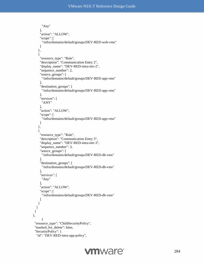
VMware NSX-T Reference Design Guide
284
"Any"
],
"action": "ALLOW",
"scope": [
"/infra/domains/default/groups/DEV-RED-web-vms"
]
},
{
"resource_type": "Rule",
"description": "Communication Entry 2",
"display_name": "DEV-RED-intra-tier-2",
"sequence_number": 2,
"source_groups": [
"/infra/domains/default/groups/DEV-RED-app-vms"
],
"destination_groups": [
"/infra/domains/default/groups/DEV-RED-app-vms"
],
"services": [
"ANY"
],
"action": "ALLOW",
"scope": [
"/infra/domains/default/groups/DEV-RED-app-vms"
]
},
{
"resource_type": "Rule",
"description": "Communication Entry 3",
"display_name": "DEV-RED-intra-tier-3",
"sequence_number": 3,
"source_groups": [
"/infra/domains/default/groups/DEV-RED-db-vms"
],
"destination_groups": [
"/infra/domains/default/groups/DEV-RED-db-vms"
],
"services": [
"Any"
],
"action": "ALLOW",
"scope": [
"/infra/domains/default/groups/DEV-RED-db-vms"
]
}
]
}
},
{
"resource_type": "ChildSecurityPolicy",
"marked_for_delete": false,
"SecurityPolicy": {
"id": "DEV-RED-intra-app-policy",
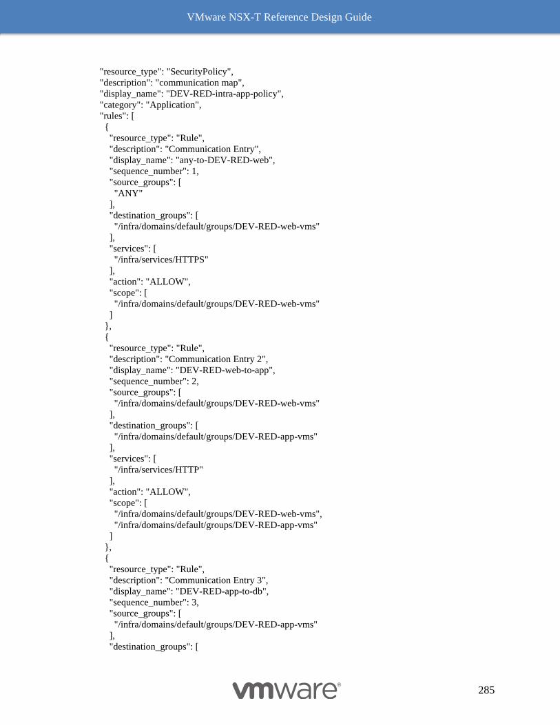
VMware NSX-T Reference Design Guide
285
"resource_type": "SecurityPolicy",
"description": "communication map",
"display_name": "DEV-RED-intra-app-policy",
"category": "Application",
"rules": [
{
"resource_type": "Rule",
"description": "Communication Entry",
"display_name": "any-to-DEV-RED-web",
"sequence_number": 1,
"source_groups": [
"ANY"
],
"destination_groups": [
"/infra/domains/default/groups/DEV-RED-web-vms"
],
"services": [
"/infra/services/HTTPS"
],
"action": "ALLOW",
"scope": [
"/infra/domains/default/groups/DEV-RED-web-vms"
]
},
{
"resource_type": "Rule",
"description": "Communication Entry 2",
"display_name": "DEV-RED-web-to-app",
"sequence_number": 2,
"source_groups": [
"/infra/domains/default/groups/DEV-RED-web-vms"
],
"destination_groups": [
"/infra/domains/default/groups/DEV-RED-app-vms"
],
"services": [
"/infra/services/HTTP"
],
"action": "ALLOW",
"scope": [
"/infra/domains/default/groups/DEV-RED-web-vms",
"/infra/domains/default/groups/DEV-RED-app-vms"
]
},
{
"resource_type": "Rule",
"description": "Communication Entry 3",
"display_name": "DEV-RED-app-to-db",
"sequence_number": 3,
"source_groups": [
"/infra/domains/default/groups/DEV-RED-app-vms"
],
"destination_groups": [
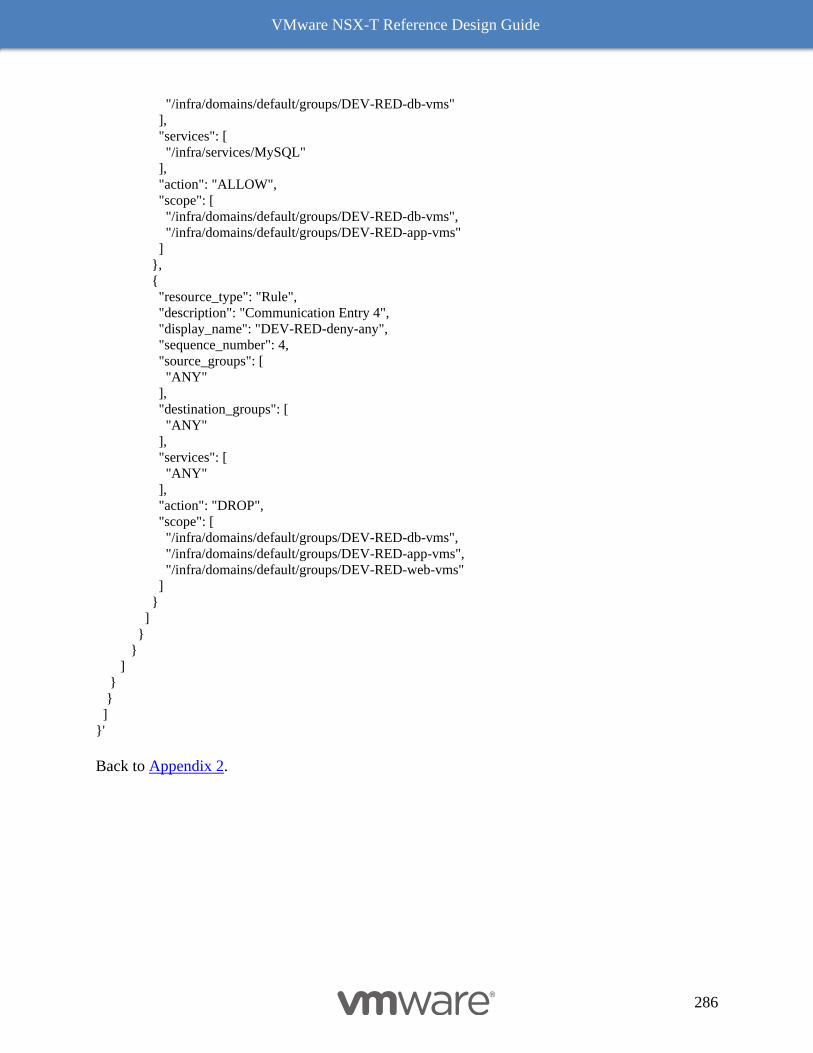
VMware NSX-T Reference Design Guide
286
"/infra/domains/default/groups/DEV-RED-db-vms"
],
"services": [
"/infra/services/MySQL"
],
"action": "ALLOW",
"scope": [
"/infra/domains/default/groups/DEV-RED-db-vms",
"/infra/domains/default/groups/DEV-RED-app-vms"
]
},
{
"resource_type": "Rule",
"description": "Communication Entry 4",
"display_name": "DEV-RED-deny-any",
"sequence_number": 4,
"source_groups": [
"ANY"
],
"destination_groups": [
"ANY"
],
"services": [
"ANY"
],
"action": "DROP",
"scope": [
"/infra/domains/default/groups/DEV-RED-db-vms",
"/infra/domains/default/groups/DEV-RED-app-vms",
"/infra/domains/default/groups/DEV-RED-web-vms"
]
}
]
}
}
]
}
}
]
}'
Back to Appendix 2.
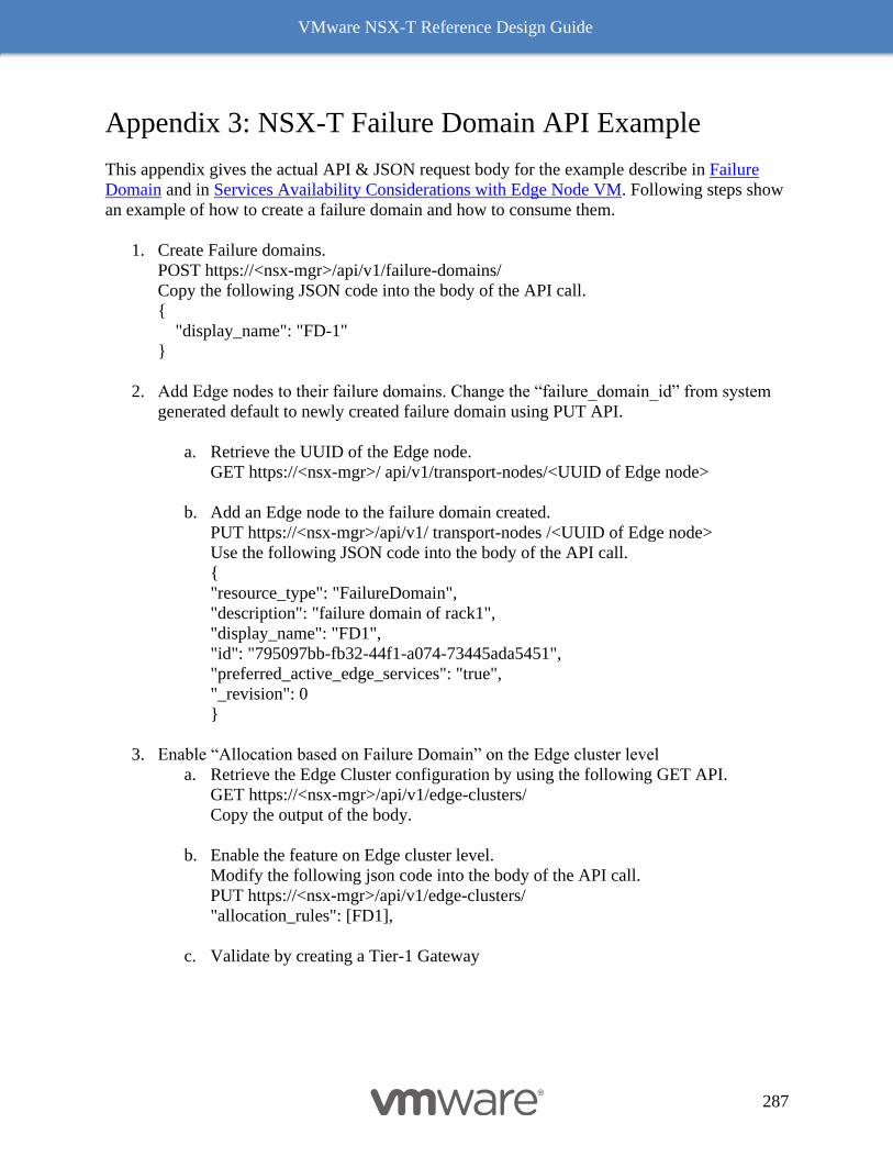
VMware NSX-T Reference Design Guide
287
Appendix 3: NSX-T Failure Domain API Example
This appendix gives the actual API & JSON request body for the example describe in Failure
Domain and in Services Availability Considerations with Edge Node VM. Following steps show
an example of how to create a failure domain and how to consume them.
1. Create Failure domains.
POST https://<nsx-mgr>/api/v1/failure-domains/
Copy the following JSON code into the body of the API call.
{
"display_name": "FD-1"
}
2. Add Edge nodes to their failure domains. Change the “failure_domain_id” from system
generated default to newly created failure domain using PUT API.
a. Retrieve the UUID of the Edge node.
GET https://<nsx-mgr>/ api/v1/transport-nodes/<UUID of Edge node>
b. Add an Edge node to the failure domain created.
PUT https://<nsx-mgr>/api/v1/ transport-nodes /<UUID of Edge node>
Use the following JSON code into the body of the API call.
{
"resource_type": "FailureDomain",
"description": "failure domain of rack1",
"display_name": "FD1",
"id": "795097bb-fb32-44f1-a074-73445ada5451",
"preferred_active_edge_services": "true",
"_revision": 0
}
3. Enable “Allocation based on Failure Domain” on the Edge cluster level
a. Retrieve the Edge Cluster configuration by using the following GET API.
GET https://<nsx-mgr>/api/v1/edge-clusters/
Copy the output of the body.
b. Enable the feature on Edge cluster level.
Modify the following json code into the body of the API call.
PUT https://<nsx-mgr>/api/v1/edge-clusters/
"allocation_rules": [FD1],
c. Validate by creating a Tier-1 Gateway
VMware NSX-T Reference Design Guide
288
A user can also enforce that all active Tier-1 SRs are placed in one failure domain. This
configuration is supported for Tier-1 gateway in preemptive mode only.
Set preference for a failure domain using “preferred_active_edge_services”
PUT https://<nsx-mgr>/api/v1/failure-domains/
{
"preferred_active_edge_services ": true
}
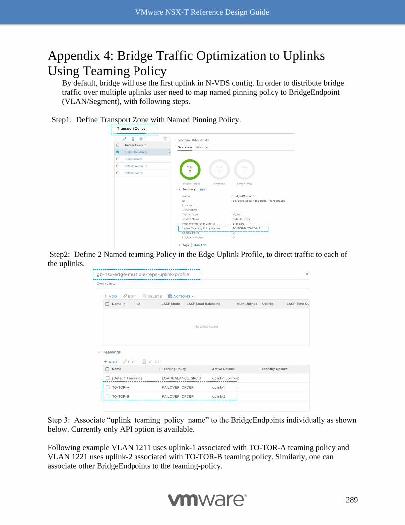
VMware NSX-T Reference Design Guide
289
Appendix 4: Bridge Traffic Optimization to Uplinks
Using Teaming Policy By default, bridge will use the first uplink in N-VDS config. In order to distribute bridge
traffic over multiple uplinks user need to map named pinning policy to BridgeEndpoint
(VLAN/Segment), with following steps.
Step1: Define Transport Zone with Named Pinning Policy.
Step2: Define 2 Named teaming Policy in the Edge Uplink Profile, to direct traffic to each of
the uplinks.
Step 3: Associate “uplink_teaming_policy_name” to the BridgeEndpoints individually as shown
below. Currently only API option is available.
Following example VLAN 1211 uses uplink-1 associated with TO-TOR-A teaming policy and
VLAN 1221 uses uplink-2 associated with TO-TOR-B teaming policy. Similarly, one can
associate other BridgeEndpoints to the teaming-policy.
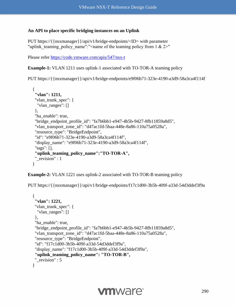
VMware NSX-T Reference Design Guide
290
An API to place specific bridging instances on an Uplink
PUT https://{{nsxmanager}}/api/v1/bridge-endpoints/<ID> with parameter
"uplink_teaming_policy_name":”<name of the teaming policy from 1 & 2>"
Please refer https://code.vmware.com/apis/547/nsx-t
Example-1: VLAN 1211 uses uplink-1 associated with TO-TOR-A teaming policy
PUT https://{{nsxmanager}}/api/v1/bridge-endpoints/e9f06b71-323e-4190-a3d9-58a3ca4f114f
{
"vlan": 1211,
"vlan_trunk_spec": {
"vlan_ranges": []
},
"ha_enable": true,
"bridge_endpoint_profile_id": "fa7b6bb1-e947-4b5b-9427-8fb11859a8d5",
"vlan_transport_zone_id": "d47ac1fd-5baa-448e-8a86-110a75a0528a",
"resource_type": "BridgeEndpoint",
"id": "e9f06b71-323e-4190-a3d9-58a3ca4f114f",
"display_name": "e9f06b71-323e-4190-a3d9-58a3ca4f114f",
"tags": [],
"uplink_teaming_policy_name":"TO-TOR-A",
"_revision" : 1
}
Example-2: VLAN 1221 uses uplink-2 associated with TO-TOR-B teaming policy
PUT https://{{nsxmanager}}/api/v1/bridge-endpoints/f17c1d00-3b5b-409f-a33d-54d3ddef3f9a
{
"vlan": 1221,
"vlan_trunk_spec": {
"vlan_ranges": []
},
"ha_enable": true,
"bridge_endpoint_profile_id": "fa7b6bb1-e947-4b5b-9427-8fb11859a8d5",
"vlan_transport_zone_id": "d47ac1fd-5baa-448e-8a86-110a75a0528a",
"resource_type": "BridgeEndpoint",
"id": "f17c1d00-3b5b-409f-a33d-54d3ddef3f9a",
"display_name": "f17c1d00-3b5b-409f-a33d-54d3ddef3f9a",
"uplink_teaming_policy_name": "TO-TOR-B",
"_revision" : 5
}
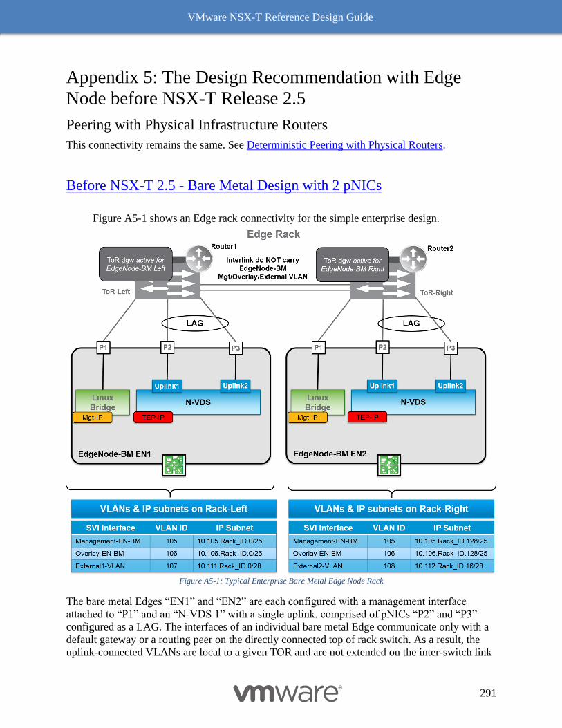
VMware NSX-T Reference Design Guide
291
Appendix 5: The Design Recommendation with Edge
Node before NSX-T Release 2.5
Peering with Physical Infrastructure Routers
This connectivity remains the same. See Deterministic Peering with Physical Routers.
Before NSX-T 2.5 - Bare Metal Design with 2 pNICs
Figure A5-1 shows an Edge rack connectivity for the simple enterprise design.
Figure A5-1: Typical Enterprise Bare Metal Edge Node Rack
The bare metal Edges “EN1” and “EN2” are each configured with a management interface
attached to “P1” and an “N-VDS 1” with a single uplink, comprised of pNICs “P2” and “P3”
configured as a LAG. The interfaces of an individual bare metal Edge communicate only with a
default gateway or a routing peer on the directly connected top of rack switch. As a result, the
uplink-connected VLANs are local to a given TOR and are not extended on the inter-switch link
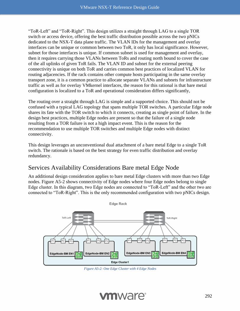
VMware NSX-T Reference Design Guide
292
“ToR-Left” and “ToR-Right”. This design utilizes a straight through LAG to a single TOR
switch or access device, offering the best traffic distribution possible across the two pNICs
dedicated to the NSX-T data plane traffic. The VLAN IDs for the management and overlay
interfaces can be unique or common between two ToR, it only has local significance. However,
subnet for those interfaces is unique. If common subnet is used for management and overlay,
then it requires carrying those VLANs between ToRs and routing north bound to cover the case
of the all uplinks of given ToR fails. The VLAN ID and subnet for the external peering
connectivity is unique on both ToR and carries common best practices of localized VLAN for
routing adjacencies. If the rack contains other compute hosts participating in the same overlay
transport zone, it is a common practice to allocate separate VLANs and subnets for infrastructure
traffic as well as for overlay VMkernel interfaces, the reason for this rational is that bare metal
configuration is localized to a ToR and operational consideration differs significantly,
The routing over a straight through LAG is simple and a supported choice. This should not be
confused with a typical LAG topology that spans multiple TOR switches. A particular Edge node
shares its fate with the TOR switch to which it connects, creating as single point of failure. In the
design best practices, multiple Edge nodes are present so that the failure of a single node
resulting from a TOR failure is not a high impact event. This is the reason for the
recommendation to use multiple TOR switches and multiple Edge nodes with distinct
connectivity.
This design leverages an unconventional dual attachment of a bare metal Edge to a single ToR
switch. The rationale is based on the best strategy for even traffic distribution and overlay
redundancy.
Services Availability Considerations Bare metal Edge Node
An additional design consideration applies to bare metal Edge clusters with more than two Edge
nodes. Figure A5-2 shows connectivity of Edge nodes where four Edge nodes belong to single
Edge cluster. In this diagram, two Edge nodes are connected to “ToR-Left” and the other two are
connected to “ToR-Right”. This is the only recommended configuration with two pNICs design.
Figure A5-2: One Edge Cluster with 4 Edge Nodes
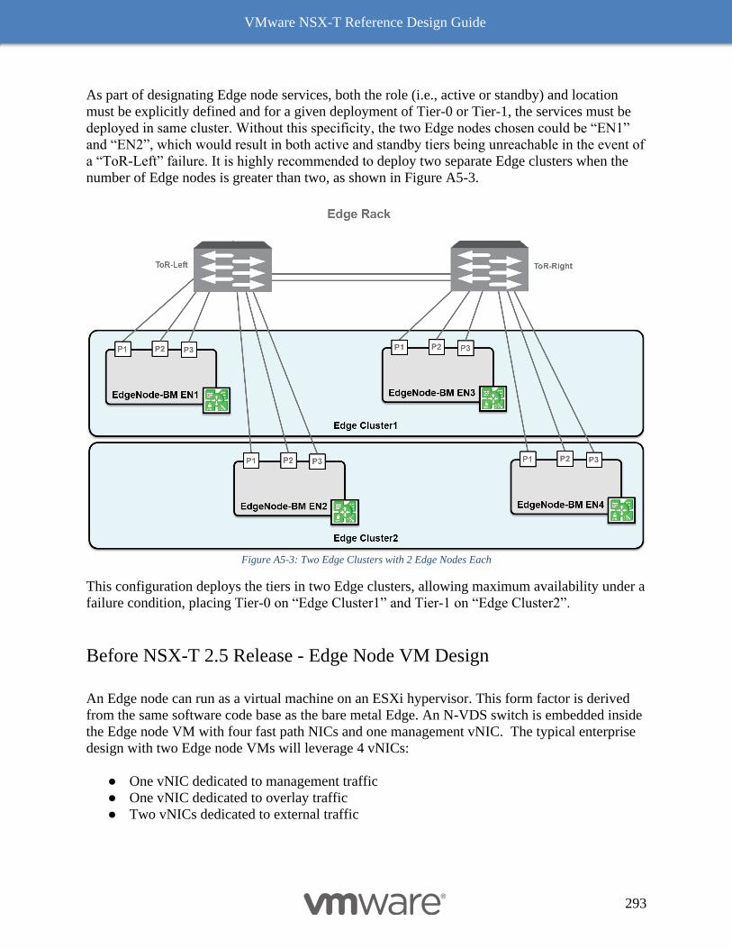
VMware NSX-T Reference Design Guide
293
As part of designating Edge node services, both the role (i.e., active or standby) and location
must be explicitly defined and for a given deployment of Tier-0 or Tier-1, the services must be
deployed in same cluster. Without this specificity, the two Edge nodes chosen could be “EN1”
and “EN2”, which would result in both active and standby tiers being unreachable in the event of
a “ToR-Left” failure. It is highly recommended to deploy two separate Edge clusters when the
number of Edge nodes is greater than two, as shown in Figure A5-3.
Figure A5-3: Two Edge Clusters with 2 Edge Nodes Each
This configuration deploys the tiers in two Edge clusters, allowing maximum availability under a
failure condition, placing Tier-0 on “Edge Cluster1” and Tier-1 on “Edge Cluster2”.
Before NSX-T 2.5 Release - Edge Node VM Design
An Edge node can run as a virtual machine on an ESXi hypervisor. This form factor is derived
from the same software code base as the bare metal Edge. An N-VDS switch is embedded inside
the Edge node VM with four fast path NICs and one management vNIC. The typical enterprise
design with two Edge node VMs will leverage 4 vNICs:
● One vNIC dedicated to management traffic
● One vNIC dedicated to overlay traffic
● Two vNICs dedicated to external traffic
VMware NSX-T Reference Design Guide
294
N-VDS when deployed at the host level offers multiple teaming options, however for N-VDS
inside the Edge node VM can only carry one teaming mode. In most cases the teaming option for
N-VDS inside the Edge is using only Failover Order Teaming. To develop a deterministic
connectivity, it is necessary to have more than one N-VDS per Edge node. Since an Edge node
runs on ESXi, it connects to a VDS(though N-VDS in shared compute with Edge or all things N-
VDS), providing flexibility in assigning a variety of teaming policies at VDS level. As a result,
each NIC will be mapped to a dedicated port group in the ESXi hypervisor, offering maximum
flexibility in the assignment of the different kind of traffic to the host’s two physical NICs.
Figure A5-4 shows an ESXi host with two physical NICs. Edges “VM1” is hosted on this ESXi
host leveraging the VDS port groups, each connected to both TOR switches. This configuration
remains the same since NSX-T 2.0 release and remains valid for NSX-T 2.5 release as well.
However, there have been several enhancements like multi-TEP support for Edge node, named
teaming policy etc. because of which this deployment is simplified by using one N-VDS to carry
both overlay and external traffic. This is discussed in Single N-VDS Based Configuration -
Starting with NSX-T 2.5 release and NSX-T 2.5 Edge node VM connectivity with VDS with 2
pNICs.
In Figure A5-4 topology, four port groups have been defined on the VDS to connect the Edge
VM; these are named “Mgmt. PG” (VLAN 100), “Transport PG” (VLAN 200), “Ext1 PG”
(VLAN 300), and “Ext2 PG” (VLAN 400). While this example uses a VDS, it would be the
same if a VSS were selected. Use of a VSS is highly discouraged due to the support and
flexibility benefits provided by the VDS. “VDS-Uplink1” on the VDS is mapped to the first
pNIC “P1” that connects to the TOR switch on the left and “VDS-Uplink2” is mapped to the
remaining pNIC “P2”, that connects to the TOR switch on the right.
The Figure A5-4 also shows three N-VDS, named as “Overlay N-VDS”, “Ext 1 N-VDS”, and
“Ext 2 N-VDS”. Three N-VDS are used in this design to ensure that overlay and external traffic
use different vNICs of Edge VM. All three N-VDS use the same teaming policy i.e. Failover
order with one active uplink i.e. Uplink1. “Uplink1” on each N-VDS is mapped to use a different
vNIC of the Edge VM.
“Uplink1” on overlay N-VDS is mapped to use vNIC2 of Edge VM.
“Uplink1” on Ext1 N-VDS is mapped to use vNIC3 of Edge VM.
“Uplink1” on Ext2 N-VDS is mapped to use vNIC4 of Edge VM.
Based on this teaming policy for each N-VDS, overlay traffic will be sent and received on
vNIC2 of the Edge VM. External traffic from any VLAN segment defined for “Ext-1 N-VDS”
will be sent and received on vNIC3 of the Edge VM. Similarly, external traffic from any VLAN
segment defined for “Ext-2 N-VDS” will be sent and received on vNIC4 of the Edge VM.
Teaming policy used on the VDS port group level defines how traffic from these different N-
VDS on Edge node VM exits from the hypervisor. For instance, “Mgmt. PG” and “Transport
PG” are configured to use active uplink as “VDS-Uplink1” and standby uplink as “VDS-
Uplink2”. “Ext1 PG” (VLAN 300) is mapped to use “VDS-Uplink1”. “Ext2 PG” (VLAN 400) is
mapped to use “VDS-Uplink2”. This configuration ensures that the traffic sent on VLAN 300
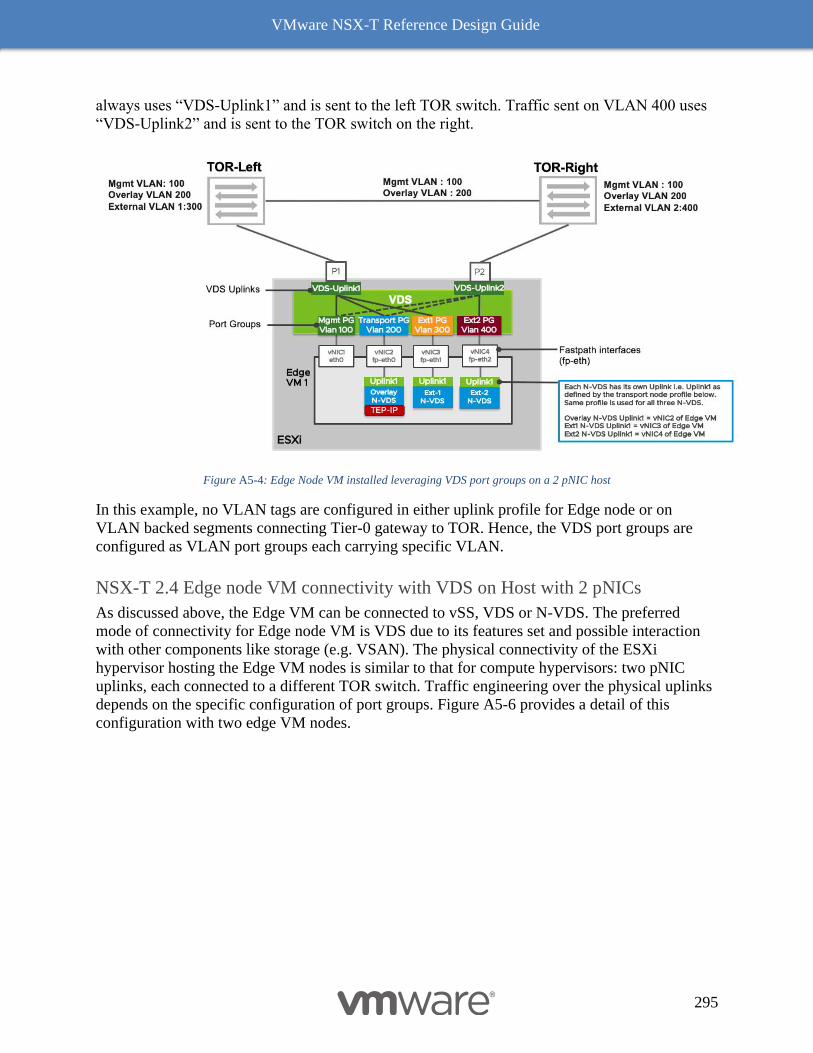
VMware NSX-T Reference Design Guide
295
always uses “VDS-Uplink1” and is sent to the left TOR switch. Traffic sent on VLAN 400 uses
“VDS-Uplink2” and is sent to the TOR switch on the right.
Figure A5-4: Edge Node VM installed leveraging VDS port groups on a 2 pNIC host
In this example, no VLAN tags are configured in either uplink profile for Edge node or on
VLAN backed segments connecting Tier-0 gateway to TOR. Hence, the VDS port groups are
configured as VLAN port groups each carrying specific VLAN.
NSX-T 2.4 Edge node VM connectivity with VDS on Host with 2 pNICs
As discussed above, the Edge VM can be connected to vSS, VDS or N-VDS. The preferred
mode of connectivity for Edge node VM is VDS due to its features set and possible interaction
with other components like storage (e.g. VSAN). The physical connectivity of the ESXi
hypervisor hosting the Edge VM nodes is similar to that for compute hypervisors: two pNIC
uplinks, each connected to a different TOR switch. Traffic engineering over the physical uplinks
depends on the specific configuration of port groups. Figure A5-6 provides a detail of this
configuration with two edge VM nodes.
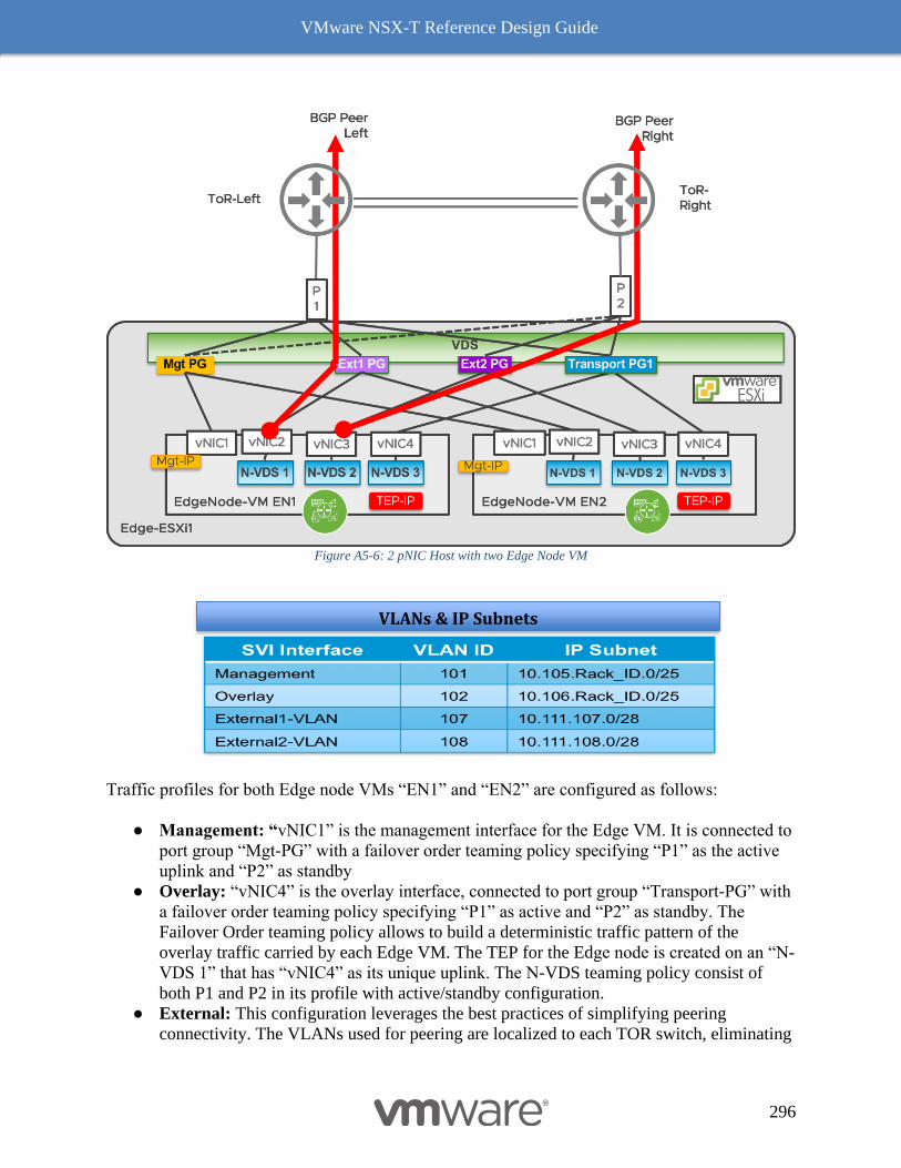
VMware NSX-T Reference Design Guide
296
Figure A5-6: 2 pNIC Host with two Edge Node VM
Traffic profiles for both Edge node VMs “EN1” and “EN2” are configured as follows:
● Management: “vNIC1” is the management interface for the Edge VM. It is connected to
port group “Mgt-PG” with a failover order teaming policy specifying “P1” as the active
uplink and “P2” as standby
● Overlay: “vNIC4” is the overlay interface, connected to port group “Transport-PG” with
a failover order teaming policy specifying “P1” as active and “P2” as standby. The
Failover Order teaming policy allows to build a deterministic traffic pattern of the
overlay traffic carried by each Edge VM. The TEP for the Edge node is created on an “N-
VDS 1” that has “vNIC4” as its unique uplink. The N-VDS teaming policy consist of
both P1 and P2 in its profile with active/standby configuration.
● External: This configuration leverages the best practices of simplifying peering
connectivity. The VLANs used for peering are localized to each TOR switch, eliminating
VLANs & IP Subnets
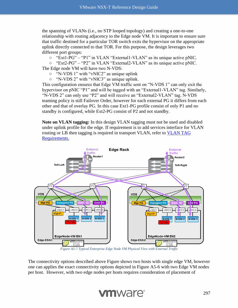
VMware NSX-T Reference Design Guide
297
the spanning of VLANs (i.e., no STP looped topology) and creating a one-to-one
relationship with routing adjacency to the Edge node VM. It is important to ensure sure
that traffic destined for a particular TOR switch exits the hypervisor on the appropriate
uplink directly connected to that TOR. For this purpose, the design leverages two
different port groups:
○ “Ext1-PG” – “P1” in VLAN “External1-VLAN” as its unique active pNIC.
○ “Ext2-PG” – “P2” in VLAN “External2-VLAN” as its unique active pNIC.
The Edge node VM will have two N-VDS:
○ “N-VDS 1” with “vNIC2” as unique uplink
○ “N-VDS 2” with “vNIC3” as unique uplink.
This configuration ensures that Edge VM traffic sent on “N-VDS 1” can only exit the
hypervisor on pNIC “P1” and will be tagged with an “External1-VLAN” tag. Similarly,
“N-VDS 2” can only use “P2” and will receive an “External2-VLAN” tag. N-VDS
teaming policy is still Failover Order, however for each external PG it differs from each
other and that of overlay PG. In this case Ext1-PG profile consist of only P1 and no
standby is configured, while Ext2-PG consist of P2 and not standby.
Note on VLAN tagging: In this design VLAN tagging must not be used and disabled
under uplink profile for the edge. If requirement is to add services interface for VLAN
routing or LB then tagging is required in transport VLAN, refer to VLAN TAG
Requirements.
Figure A5-7 Typical Enterprise Edge Node VM Physical View with External Traffic
The connectivity options described above Figure shows two hosts with single edge VM, however
one can applies the exact connectivity options depicted in Figure A5-6 with two Edge VM nodes
per host. However, with two edge nodes per hosts requires consideration of placement of
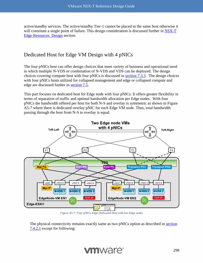
VMware NSX-T Reference Design Guide
298
active/standby services. The active/standby Tier-1 cannot be placed in the same host otherwise it
will constitute a single point of failure. This design consideration is discussed further in NSX-T
Edge Resources Design section.
Dedicated Host for Edge VM Design with 4 pNICs
The four pNICs host can offer design choices that meet variety of business and operational need
in which multiple N-VDS or combination of N-VDS and VDS can be deployed. The design
choices covering compute host with four pNICs is discussed in section 7.3.3. The design choices
with four pNICs hosts utilized for collapsed management and edge or collapsed compute and
edge are discussed further in section 7.5.
This part focuses on dedicated host for Edge node with four pNICs. It offers greater flexibility in
terms of separation of traffic and optimal bandwidth allocation per Edge nodes. With four
pNICs the bandwidth offered per host for both N-S and overlay is symmetric as shown in Figure
A5-7 where there is dedicated overlay pNIC for each Edge VM node. Thus, total bandwidth
passing through the host from N-S to overlay is equal.
Figure A5-7: Four pNICs Edge Dedicated Host with two Edge nodes
The physical connectivity remains exactly same as two pNICs option as described in section
7.4.2.1 except for following:
VMware NSX-T Reference Design Guide
299
• Overlay Traffic is allocated a dedicated pNIC
• Two types of VDS teaming configuration possible.
o The first option is depicted in Figure A5-7 in which each Edge node VM gets
a dedicated transport PG. Each one is configured with “Failover Order”
teaming under VDS. This way the overlay traffic from each Edge VM will
always go to designated pNIC.
o The second option (not shown in figure) uses single transport PG under VDS,
in which the teaming type must be “Source ID” under VDS. It saves the
configuration overhead but now the Edge node traffic is non-deterministic,
thus little harder to know the exact pNIC over which the overlay traffic is
going at a given moment.
The above design choice is optimal for having multiple Edge nodes per host. In most cases
(except host is oversubscribed with other VMs or resources like management, multi-tenant
edges etc.), it is not the host CPU but the number of pNICs available at the host determines
the number of Edge node per host. One can optimize following design by adopting four Edge
VMs per host where the oversubscription is not a concern but building a high-density multi-
tenant or services design is important.
The four pNICs host design offers compelling possibility on offering variety of combination
of services and topology choices. Options of allocation of services either in form of dedicated
Edge VM per services or shared within an Edge Node are disused in separate section below
as it requires consideration of scale, availability, topological choices and multi-tenancy.