vivid s5/vivid s6 user manual
TRANSCRIPT

GE Medical Systems
Technical Publications
Vivid S5/Vivid S6
User ManualVolume 1
Direction R2424458-100Rev. 2
Operating Documentation
Copyright © 2010 By General Electric Co.
P Y
g GE Medical Systems
Regulatory RequirementsThis product complies with regulatory requirements of the following European Directive 93/42/EEC concerning medical devices.
This manual is a reference for the Vivid S5 and Vivid S6. It applies to all versions of the 10.2.x software for the Vivid S5 and Vivid S6 ultrasound systems.
RELIMINARMANUAL STATUSR2424458-10007 February 2010Doc ID: DOC0600341
GE Medical Systems. All rights reserved. No part of this manual may be reproduced, stored in a retrieval system, or transmitted, in any form or by any means, electronic, mechanical, photocopying, recording, or otherwise, without the prior written permission of GE Medical Systems.
COMPANY DATA GE Medical Systems, Israel Ltd.4 Etgar Street39120 Tirat CarmelIsraelTel: (+972) 4851 9555 Fax: (+972) 4851 9500
GE Medical Systems Information Technologies GmbH,Munzinger Strasse 5 D-79111 Freiburg, GermanyTel: (+49) 761 45 43 0 Fax: (+49) 76145 43 233

Table of Contents
Table of Contents
Revision HistoryList of effective pages................................................................. xv
IntroductionAttention......................................................................................... 1Prescription Device....................................................................... 1Safety.............................................................................................. 1Principles of Operation ................................................................. 2Interference caution ...................................................................... 2Indications for use ........................................................................ 3Contraindications.......................................................................... 3Documentation .............................................................................. 3
Manual contents ................................................................... 4Conventions used in this manual ................................................ 5Regulatory requirements.............................................................. 6Contact information ...................................................................... 7
Chapter 1Safety
Introduction.................................................................................. 15Hazard symbols .................................................................. 16
Owner responsibility ................................................................... 17Important safety considerations................................................ 18
Notice against user modification......................................... 18Regulatory information............................................................... 19
Directives ............................................................................ 19Product Classifications ....................................................... 19Conformity to Standards ..................................................... 19Certifications ....................................................................... 21Software License Acknowledgements ................................ 21
Device labels................................................................................ 22Label Locations................................................................... 22
Vivid S5/Vivid S6 User Manual iR2424458-100 Rev. 2
Table of Contents
Label Icon Description.........................................................23Acoustic output............................................................................26
Definition of the acoustic output parameters .......................26ALARA.................................................................................26Safety statement .................................................................27System controls affecting acoustic output ...........................27
OB Exam .......................................................................................29Exam Preparation................................................................29
Acoustic Output Considerations................................................30Concerns surrounding fetal exposure .................................30
Patient safety................................................................................31Patient identification ............................................................31Diagnostic information.........................................................31Patient guidance..................................................................32
Probe Safety .................................................................................32Mechanical hazards ............................................................32Electrical Hazard .................................................................33Biological hazards ...............................................................34
Personnel and equipment safety................................................35Explosion hazard.................................................................35Electrical hazard..................................................................35Smoke and fire hazard ........................................................36Biological hazard.................................................................36Pacemaker hazard ..............................................................36LCD Monitor ........................................................................37
Electrical safety............................................................................39Internally connected peripheral devices ..............................39External Connection of other peripheral devices.................39
Allergic reactions to latex-containing medical devices ...........40Use of ECG ...................................................................................41Use of Defibrillator .......................................................................41Use of Electrosurgical Unit .........................................................41Electromagnetic Compatibility (EMC) ........................................42
EMC performance ...............................................................43Declaration of Emissions.....................................................44Declaration of Immunity.......................................................44Notice upon Installation of Product......................................44General notice .....................................................................45
ii Vivid S5/Vivid S6 User ManualR2424458-100 Rev. 2
Table of Contents
Peripheral Update for EC countries .................................... 46Patient Environmental Devices .................................................. 48
Acceptable devices............................................................. 49Unapproved devices ........................................................... 49Accessories, options, and supplies..................................... 49Environmental protection.................................................... 50
Chapter 2Getting started
Introduction.................................................................................. 52Preparing the unit for use........................................................... 53
Site requirements................................................................ 53Connecting the unit............................................................. 54Switching On/Off................................................................. 61
Moving and transporting the unit .............................................. 64Wheels................................................................................ 64Moving the unit ................................................................... 64Transporting the unit........................................................... 66Reinstalling at a new location ............................................. 67Preparing Vivid S5/Vivid S6 for scanning ........................... 67Unit acclimation time........................................................... 68
System description ..................................................................... 69System overview................................................................. 69Control panel ...................................................................... 71The Scanning screen.......................................................... 84Three-Pedal Footswitch operation...................................... 87Connecting and disconnecting probes ............................... 87Adjusting the Display Monitor ............................................. 90
Starting an examination.............................................................. 95Creating a new Patient record or starting an examination from an existing patient record.................................................... 95Selecting a Probe and an Application............................... 100
Vivid S5/Vivid S6 User Manual iiiR2424458-100 Rev. 2
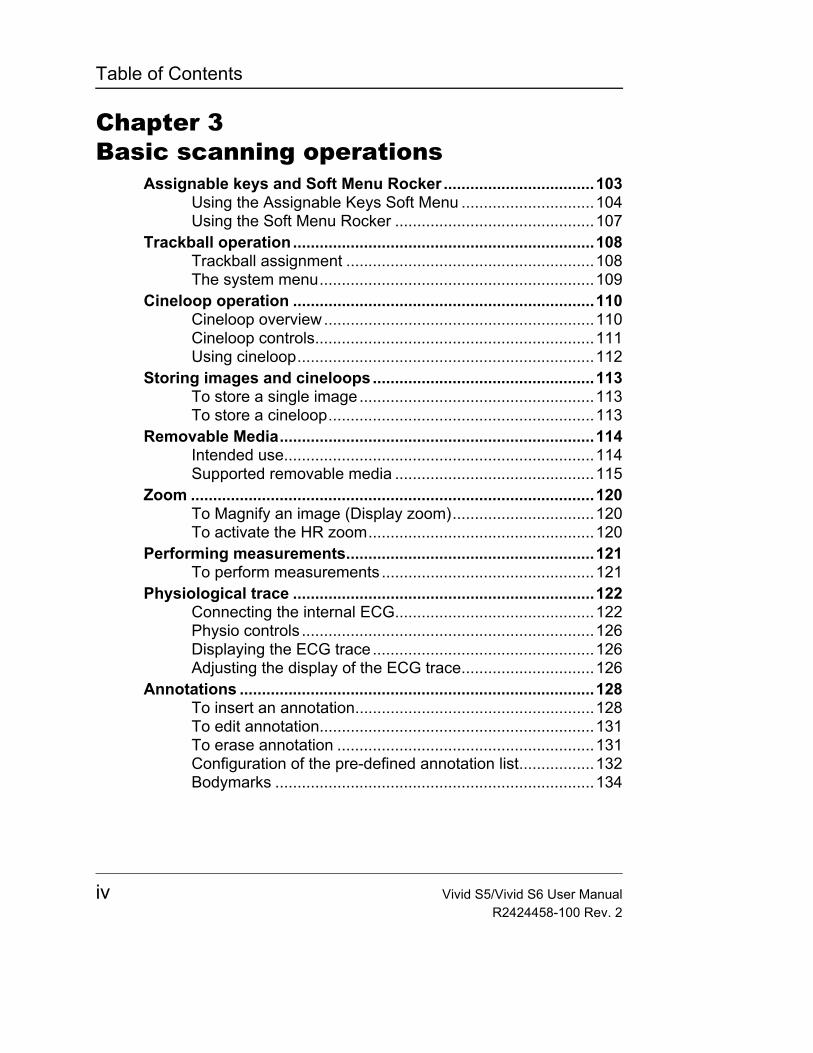
Table of Contents
Chapter 3Basic scanning operations
Assignable keys and Soft Menu Rocker ..................................103Using the Assignable Keys Soft Menu ..............................104Using the Soft Menu Rocker .............................................107
Trackball operation....................................................................108Trackball assignment ........................................................108The system menu..............................................................109
Cineloop operation ....................................................................110Cineloop overview.............................................................110Cineloop controls...............................................................111Using cineloop...................................................................112
Storing images and cineloops..................................................113To store a single image.....................................................113To store a cineloop............................................................113
Removable Media.......................................................................114Intended use......................................................................114Supported removable media .............................................115
Zoom ...........................................................................................120To Magnify an image (Display zoom)................................120To activate the HR zoom...................................................120
Performing measurements........................................................121To perform measurements ................................................121
Physiological trace ....................................................................122Connecting the internal ECG.............................................122Physio controls ..................................................................126Displaying the ECG trace..................................................126Adjusting the display of the ECG trace..............................126
Annotations ................................................................................128To insert an annotation......................................................128To edit annotation..............................................................131To erase annotation ..........................................................131Configuration of the pre-defined annotation list.................132Bodymarks ........................................................................134
iv Vivid S5/Vivid S6 User ManualR2424458-100 Rev. 2
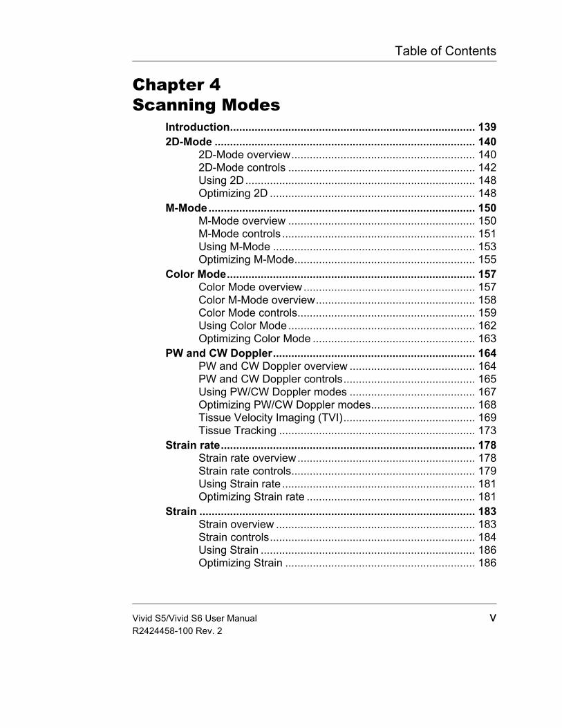
Table of Contents
Chapter 4Scanning Modes
Introduction................................................................................ 1392D-Mode ..................................................................................... 140
2D-Mode overview............................................................ 1402D-Mode controls ............................................................. 142Using 2D........................................................................... 148Optimizing 2D ................................................................... 148
M-Mode....................................................................................... 150M-Mode overview ............................................................. 150M-Mode controls ............................................................... 151Using M-Mode .................................................................. 153Optimizing M-Mode........................................................... 155
Color Mode................................................................................. 157Color Mode overview........................................................ 157Color M-Mode overview.................................................... 158Color Mode controls.......................................................... 159Using Color Mode............................................................. 162Optimizing Color Mode ..................................................... 163
PW and CW Doppler.................................................................. 164PW and CW Doppler overview ......................................... 164PW and CW Doppler controls........................................... 165Using PW/CW Doppler modes ......................................... 167Optimizing PW/CW Doppler modes.................................. 168Tissue Velocity Imaging (TVI)........................................... 169Tissue Tracking ................................................................ 173
Strain rate................................................................................... 178Strain rate overview.......................................................... 178Strain rate controls............................................................ 179Using Strain rate ............................................................... 181Optimizing Strain rate ....................................................... 181
Strain .......................................................................................... 183Strain overview ................................................................. 183Strain controls................................................................... 184Using Strain ...................................................................... 186Optimizing Strain .............................................................. 186
Vivid S5/Vivid S6 User Manual vR2424458-100 Rev. 2
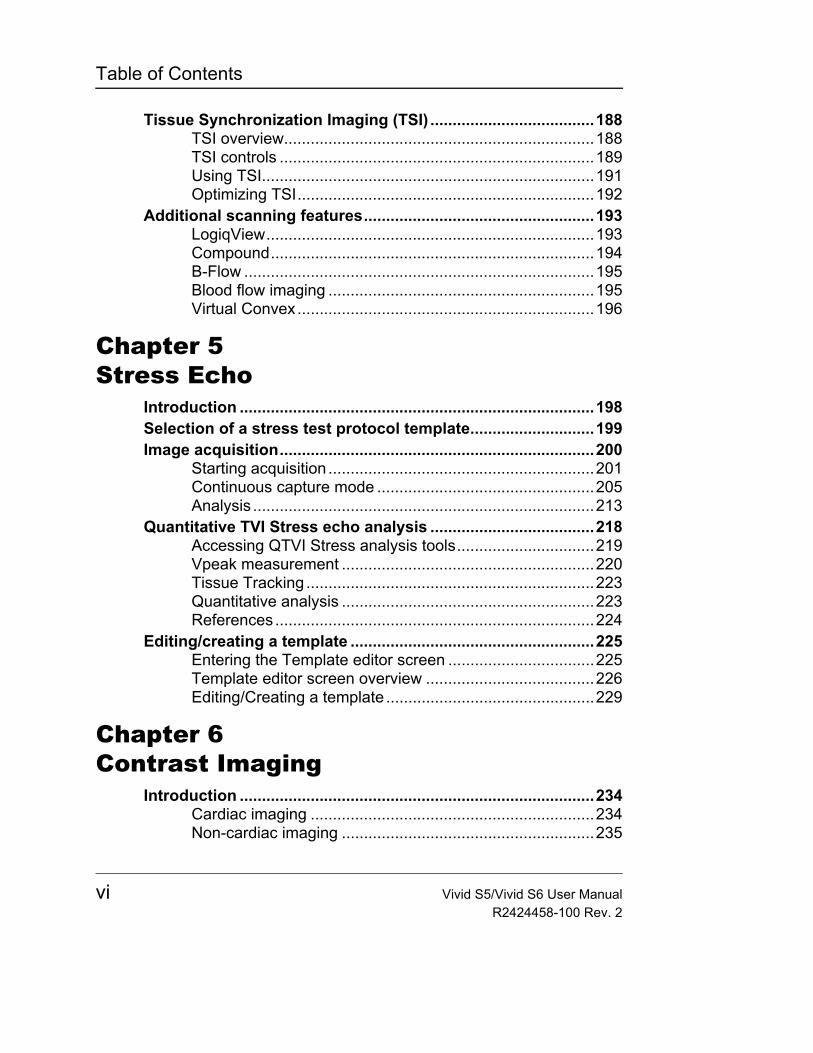
Table of Contents
Tissue Synchronization Imaging (TSI) .....................................188TSI overview......................................................................188TSI controls .......................................................................189Using TSI...........................................................................191Optimizing TSI...................................................................192
Additional scanning features....................................................193LogiqView..........................................................................193Compound.........................................................................194B-Flow ...............................................................................195Blood flow imaging ............................................................195Virtual Convex...................................................................196
Chapter 5Stress Echo
Introduction ................................................................................198Selection of a stress test protocol template............................199Image acquisition.......................................................................200
Starting acquisition ............................................................201Continuous capture mode .................................................205Analysis .............................................................................213
Quantitative TVI Stress echo analysis .....................................218Accessing QTVI Stress analysis tools...............................219Vpeak measurement .........................................................220Tissue Tracking .................................................................223Quantitative analysis .........................................................223References........................................................................224
Editing/creating a template .......................................................225Entering the Template editor screen .................................225Template editor screen overview ......................................226Editing/Creating a template ...............................................229
Chapter 6Contrast Imaging
Introduction ................................................................................234Cardiac imaging ................................................................234Non-cardiac imaging .........................................................235
vi Vivid S5/Vivid S6 User ManualR2424458-100 Rev. 2
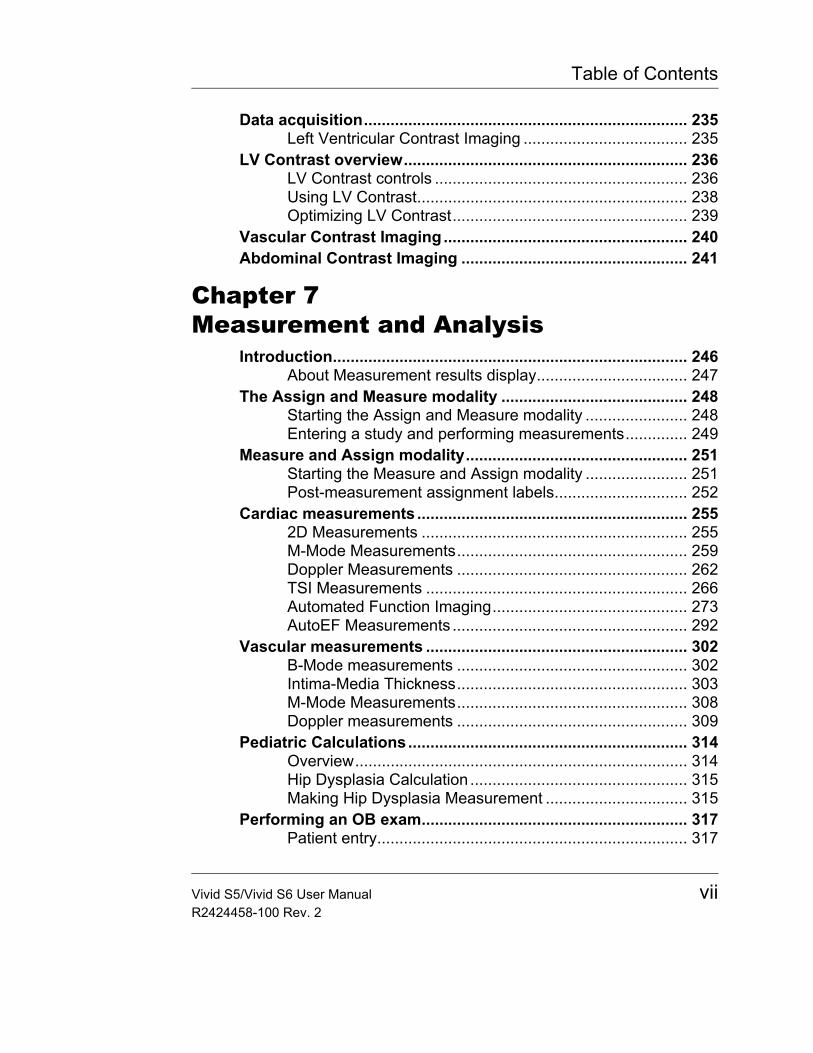
Table of Contents
Data acquisition......................................................................... 235Left Ventricular Contrast Imaging ..................................... 235
LV Contrast overview................................................................ 236LV Contrast controls ......................................................... 236Using LV Contrast............................................................. 238Optimizing LV Contrast..................................................... 239
Vascular Contrast Imaging....................................................... 240Abdominal Contrast Imaging ................................................... 241
Chapter 7Measurement and Analysis
Introduction................................................................................ 246About Measurement results display.................................. 247
The Assign and Measure modality .......................................... 248Starting the Assign and Measure modality ....................... 248Entering a study and performing measurements.............. 249
Measure and Assign modality.................................................. 251Starting the Measure and Assign modality ....................... 251Post-measurement assignment labels.............................. 252
Cardiac measurements ............................................................. 2552D Measurements ............................................................ 255M-Mode Measurements.................................................... 259Doppler Measurements .................................................... 262TSI Measurements ........................................................... 266Automated Function Imaging............................................ 273AutoEF Measurements ..................................................... 292
Vascular measurements ........................................................... 302B-Mode measurements .................................................... 302Intima-Media Thickness.................................................... 303M-Mode Measurements.................................................... 308Doppler measurements .................................................... 309
Pediatric Calculations............................................................... 314Overview........................................................................... 314Hip Dysplasia Calculation ................................................. 315Making Hip Dysplasia Measurement ................................ 315
Performing an OB exam............................................................ 317Patient entry...................................................................... 317
Vivid S5/Vivid S6 User Manual viiR2424458-100 Rev. 2
Table of Contents
Selecting probe and OB application ..................................321OB Measurements and calculations ........................................322
Introduction........................................................................322B-Mode measurements .....................................................323M-Mode measurements ....................................................330Doppler Mode Measurements ...........................................330
OB parameter configuration .....................................................333Configuring OB M&A according to geographical regions ..333
Measurement package configuration.......................................338Measurement package configuration - example ...............338
User-defined formulas...............................................................343User-defined formula - example ........................................343About units ........................................................................349
Measurement result table..........................................................351Minimizing the Measurement result table..........................351Moving the Measurement result table ...............................351Deleting measurements ....................................................352
Worksheet...................................................................................353Overview ...........................................................................353Using Worksheet ...............................................................354
OB worksheet .............................................................................356Patient data .......................................................................357Measurement information..................................................357Calculation information......................................................358
OB graphs...................................................................................359Overview ...........................................................................359Fetal Growth Curve Graph ................................................360Fetal Trending ...................................................................364Fetal Growth Bar Graph ....................................................365
OB-Multigestational ...................................................................366Multiple Fetus ....................................................................366
GYN Measurements ...................................................................370Introduction........................................................................370To Start a Gynecology Exam ............................................370
B-Mode Measurements..............................................................371Uterus length, width, and height........................................371Ovary length, width, and height.........................................372Follicle measurements length, width, and height ..............373
viii Vivid S5/Vivid S6 User ManualR2424458-100 Rev. 2
Table of Contents
Endometrium thickness (Endo)......................................... 373M-Mode Measurements............................................................. 374Doppler Mode Measurements .................................................. 374
Chapter 8Quantitative Analysis
Introduction................................................................................ 377Accessing the Quantitative analysis package........................ 378
In replay mode.................................................................. 378In live ................................................................................ 378
Quantitative Analysis window.................................................. 379Overview........................................................................... 379
Generation of a trace................................................................. 386About the sample area...................................................... 386To generate a trace .......................................................... 386Manual tracking of the sample area (dynamic anchored sample area)..................................................................... 387Zooming in the Analysis window....................................... 388
Deletion of a trace ..................................................................... 389To delete all traces ........................................................... 389To delete one specific trace.............................................. 389
Saving/retrieving Quantitative analysis .................................. 389Frame disabling......................................................................... 390
Disabling frames............................................................... 390Re-enabling all frames...................................................... 390
Optimizing sample area ............................................................ 392Reshaping a sample area................................................. 392Labelling a sample area.................................................... 393
Optimizing the trace display..................................................... 394Optimizing the Y-axis........................................................ 394Trace smoothing ............................................................... 395
Switching modes or traces....................................................... 397To switch mode................................................................. 397To switch trace.................................................................. 397
Cine compound ......................................................................... 398Anatomical M-Mode................................................................... 399
Introduction ....................................................................... 399
Vivid S5/Vivid S6 User Manual ixR2424458-100 Rev. 2
Table of Contents
Using Anatomical M-Mode ................................................399Optimizing Anatomical M-Mode ........................................401
Chapter 9Archiving
Introduction ................................................................................405Storing images and cineloops..................................................406
Storing an image ...............................................................407Storing a cineloop..............................................................407Saving images and cineloops to a standard format ..........408MPEGVue/eVue................................................................410
Retrieving and editing archived information...........................413Locating a patient record...................................................413Selecting a patient record and editing data in the archive.418Deleting archived information............................................422Moving examinations.........................................................424
Review images in archive..........................................................426Review the images from a selected examination ..............426Select images from the Image list screen .........................427
Connectivity................................................................................431The dataflow concept ........................................................431Stand-alone scanner scenario...........................................434A stand-alone scanner and a stand-alone EchoPAC PC environment.......................................................................435A scanner and EchoPAC PC in a direct connect environment.......................................................................437A scanner and EchoPAC PC in a network environment ...441A scanner and a DICOM server in a network....................443
Export/Import patient records/examinations...........................452Exporting patient records/examinations ............................452Importing patient records/examinations ............................460
Disk Management.......................................................................464Configuring the Disk management function ......................465Running the Disk management function ...........................468Data Backup and Restore .................................................471
DICOM spooler ...........................................................................479Starting the DICOM spooler ..............................................479
x Vivid S5/Vivid S6 User ManualR2424458-100 Rev. 2
Table of Contents
Database import from Vivid 3 or Vivid 4.................................. 482Transfer Procedure........................................................... 482Installing the Vivid 3/4 Data Viewer .................................. 485Using the Vivid 3/4 Data Viewer ....................................... 488
Chapter 10Report
Introduction................................................................................ 492Creating a report........................................................................ 493
Working with the report function ....................................... 493To print a report ................................................................ 496To store a report ............................................................... 496Retrieving an archived report............................................ 497Deleting an archived report............................................... 497
Structured Findings .................................................................. 498Prerequisite....................................................................... 498Starting Structured Findings ............................................. 499Structured Findings structure............................................ 499Using Structured Findings ................................................ 501Structured Findings configuration ..................................... 504
Direct report ............................................................................... 514Creating comments........................................................... 514Creating pre-defined text inputs........................................ 515
Report designer ......................................................................... 516Accessing the Report designer......................................... 516Report designer overview................................................. 516Designing a report template.............................................. 519Saving the report template................................................ 530To exit the Report designer .............................................. 530
Report templates management ................................................ 531Configuration of the Template selection menu ................. 532Export/Import of Report templates.................................... 533
Vivid S5/Vivid S6 User Manual xiR2424458-100 Rev. 2

Table of Contents
Chapter 11Probes
Probe overview...........................................................................537Supported probes..............................................................537Vivid S5 Probe/Application Overview................................542Vivid S6 Probe/Application Overview................................543Maximum probe temperature ............................................544Probe orientation...............................................................545Probe labelling...................................................................546Environmental Requirements ............................................547
Probe Integration .......................................................................548Selecting probes................................................................548Connecting the probe........................................................548Activating the probe...........................................................550Disconnecting the probe....................................................551
Care and Maintenance...............................................................552Planned maintenance........................................................552Inspecting the probe..........................................................553Special handling instructions.............................................554Cleaning and disinfecting probes ......................................556
Probe safety................................................................................562Biopsy .........................................................................................563
Precaution concerning the use of biopsy procedures .......563Preparing the Biopsy guide attachment ............................565Displaying the Guide zone ................................................569Endocavitary Probe Biopsy Guide Assembly ....................571Biopsy needle path verification..........................................573Starting the biopsy procedure ...........................................573Cleaning, disinfection and disposal ...................................573
Surgery/Intra-operative Use......................................................574Preparing for Surgery/Intra-operative Procedures ............574
xii Vivid S5/Vivid S6 User ManualR2424458-100 Rev. 2
Table of Contents
Chapter 12Peripherals
Introduction................................................................................ 576Printing....................................................................................... 577
To print an image.............................................................. 577Specifications for peripherals .................................................. 577DVR (Digital Video Recorder) ................................................... 578
Overview........................................................................... 578Using the DVR.................................................................. 578Configuring the DVR......................................................... 581Reviewing the DVR Media Externally ............................... 581
Chapter 13Presets and System setup
Introduction................................................................................ 585Starting the Configuration package......................................... 588
To open the Configuration package.................................. 588Overview..................................................................................... 589Imaging....................................................................................... 590
The Global setup sheet..................................................... 590Application ........................................................................ 593Application menu .............................................................. 596
Measure Text.............................................................................. 598The measurement menu sheet......................................... 598Configuration of the Measurement menu ......................... 601
The Advanced sheet.................................................................. 603Parameter configuration ................................................... 603
The Modify Calculations sheet................................................. 604Parameter configuration ................................................... 604The OB table sheet........................................................... 605
Report ......................................................................................... 611The diagnostic codes sheet .............................................. 612The Comment texts sheet................................................. 613
Connectivity ............................................................................... 616Dataflow............................................................................ 616
Vivid S5/Vivid S6 User Manual xiiiR2424458-100 Rev. 2
Table of Contents
Additional outputs..............................................................623Tools..................................................................................625Formats .............................................................................626TCP-IP...............................................................................632
System ........................................................................................633The system settings ..........................................................633
About...........................................................................................635Administration............................................................................636
Users .................................................................................637Unlock Patient ...................................................................640
Chapter 14User maintenance
System Care and Maintenance .................................................642Inspecting the system........................................................642Cleaning the unit ...............................................................643Prevention of static electricity interference........................645
System self-test..........................................................................646System malfunction ...........................................................646
Using InSite ExC ........................................................................650InSite ExC Functionalities .................................................650Initiating a Request for Service (RFS)...............................650Clinical Lifeline Mode ........................................................653Exiting InSite ExC..............................................................654
Index
xiv Vivid S5/Vivid S6 User ManualR2424458-100 Rev. 2

Revision History
Revision History
List of effective pages
Please verify that you are using the latest revision of this document. If you need to know the latest revision, contact your distributor, local GE Sales Representative or in the USA call the GE Medical Systems Clinical Answer Center at:1-800-682-5327 or 1-262-524-5698.
Revision Date Reason for Change
1 19 July 2009 Initial release
2 07 February 2010 Updates and additions
Revision Effective Pages
1 All
2 All
Vivid S5/Vivid S6 User Manual xvR2424458-100 Rev. 2

Revision History
xvi Vivid S5/Vivid S6 User ManualR2424458-100 Rev. 2
Introduction
Introduction
The Vivid S5/Vivid S6 ultrasound systems are light-weight, high performance innovative ergonomic mobile digital ultrasound imaging systems.
Both systems provide image generation in 2D (B) Mode, Color Doppler, Power Doppler (Angio), M-Mode, Color M-Mode, PW and CW Doppler spectra, LVO Contrast, B-Flow, BFI option applications.
Vivid S6 offers additional modes, like TVI or Tissue Tracking, and options like TSI (Tissue Synchronization Imaging) and SI/SRI (Strain/Strain-rate imaging.
The fully digital architecture of the Vivid S5/Vivid S6 unit allows optimal usage of all scanning modes and probe types, throughout the full spectrum of operating frequencies.
AttentionThis manual contains necessary and sufficient information to operate the system safely. Advanced equipment training may be provided by a factory trained Applications Specialist for the agreed-upon time period.
Read and understand all instructions in the User's Manual before attempting to use the Vivid S5/Vivid S6 ultrasound unit. Keep the manual with the equipment at all time. Periodically review the procedures for operation and safety precautions.
Prescription Device
SafetyAll information in Chapter 1, "Safety" on page 13, should be read and understood before operating the Vivid S5/Vivid S6 ultrasound unit.
CAUTION
For USA only:
United States law restricts this device to sale or use by, or on the order of a physician.
Vivid S5/Vivid S6 User Manual 1R2424458-100 Rev. 2
Introduction
Principles of OperationMedical ultrasound images are created by computer and digital memory from the transmission and reception of mechanical high-frequency waves applied through a transducer. The mechanical ultrasound waves spread through the body, producing an echo where density changes occur. For example, in the case of human tissue, an echo is created where a signal passes from an adipose tissue (fat) region to a muscular tissue region. The echoes return to the transducer where they are converted back into electrical signals.
These echo signals are highly amplified and processed by several analog and digital circuits having filters with many frequency and time response options, transforming the high-frequency electrical signals into a series of digital image signals which are stored in memory. Once in memory, the image can be displayed in real-time on the image monitor. All signal transmission, reception and processing characteristics are controlled by the main computer. By selection from the system control panel, the user can alter the characteristics and features of the system, allowing a wide range of uses, from obstetrics to peripheral vascular examinations.
Transducers are accurate, solid-state devices, providing multiple image formats. The digital design and use of solid-state components provides highly stable and consistent imaging performance with minimal required maintenance. A sophisticated system design with computer controlled extensive features and functions make the Vivid S5 and Vivid S6 easy systems to use and very user friendly.
Interference caution
Devices not to be used near this equipment:
Devices which intrinsically transmit radio waves such as cellular phones, radio transceivers, mobile radio transmitters, radio-controlled toys, and so on, should not be operated near the unit.
CAUTION
Use of devices that transmit radio waves near the unit could cause it to malfunction.
2 Vivid S5/Vivid S6 User ManualR2424458-100 Rev. 2
Introduction
Medical staff in charge of the unit are required to instruct technicians, patients, and other people who may be around the unit, to fully comply with the above recommendations.
Indications for use The Vivid S5/Vivid S6 ultrasound unit is intended for the following applications:• Abdominal• Cardiac• Musculoskeletal including Superficial• Small Organ• Pediatric• OB/Gyn• Fetal Heart• Transesophageal• Peripheral Vascular• Neonatal Cephalic• Adult Cephalic• Intraoperative
Contraindications
DocumentationVivid S5/Vivid S6 documentation consists of two manuals:• The Basic User Manual (TRANSLATED) provides
information needed by the user to operate the system safely. It describes the basic functions of the system, safety features, operating modes, measurements/calculations,
CAUTION
This machine should be used in compliance with law. Some jurisdictions restrict certain uses, such as gender determination.
DANGER
The Vivid S5/Vivid S6 ultrasound unit is not intended for ophthalmic use or any use causing the acoustic beam to pass through the eye.
Vivid S5/Vivid S6 User Manual 3R2424458-100 Rev. 2
Introduction
probes, and user care and maintenance.Note: Probe information displayed on screen examples does not necessarily reflect the probes available on your ultrasound system. Please refer to the Probes chapter for a listing of available probes and features.
• The Advanced Reference Manual (ENGLISH ONLY) contains M&A formulas and parameter-names, data tables, such as OB and Acoustic Output tables.Note: The documentation kit provides the Basic User Manual and Advanced Reference Manual in electronic format only. The CD-ROM includes English and all translations. Paper documentation may be ordered.
The Vivid S5/Vivid S6 documentation is written for users who are familiar with basic ultrasound principles and techniques. They do not include sonographic training or detailed clinical procedures.
Note: The original documentation was written in English.
Manual contentsThe Vivid S5/Vivid S6 User's Manual is organized to provide the information needed to start scanning immediately.
Some of the functions or features described in this manual are optional and may not be available in the configuration of your specific system.
Finding information
Table of Contents, lists the main topics and their location.
Headers and Footers, give the chapter name and page number.
Index, provides an alphabetical and contextual list of topics.
CAUTION
The safety instruction must be reviewed before operation of the unit.
4 Vivid S5/Vivid S6 User ManualR2424458-100 Rev. 2
Introduction
Conventions used in this manual2-column layout, the right column contains the main text. The left column contains notes, hints, and warnings.
Keys and buttons, on the control panel are indicated by over and underlined text (ex. 2D refers to the 2D mode key)
Bold type, describes button names on the screen.
Italic type: describes program windows, screens and dialogue boxes.
Safety icons, highlight safety issues as described in "Introduction" on page 15.
Product icons, indicate product variant features as follows:
Indicates that the relevant feature exists in the standard configuration of Vivid S6 and is not available on Vivid S5.
Indicates that the relevant feature exists as an option of the Vivid S6 and is not available on Vivid S5.
Indicates that the relevant feature exists as an option on both Vivid S6 and Vivid S5 systems.
Indicates that the relevant feature exists in the standard configuration of Vivid S6 and is available as an option on Vivid S5.
Indicates that the relevant feature exists in the standard configuration of Vivid S5 and is not available on Vivid S6.
Vivid S5/Vivid S6 User Manual 5R2424458-100 Rev. 2
Introduction
Regulatory requirementsThe Vivid S5/Vivid S6 ultrasound unit confirms to directives, classifications, and standards, as described in "Regulatory information" on page 19.
DANGER
Indicates that a specific hazard is known to exist which through inappropriate conditions or actions, will cause:• Severe or fatal personal injury• Substantial property damage
WARNING
Indicates that a specific hazard is known to exist which through inappropriate conditions or actions, will cause:• Severe personal injury• Substantial property damage
CAUTION
Indicates that a potential hazard may exist which through inappropriate conditions or actions, will or can cause:• Minor injury• Property damage
6 Vivid S5/Vivid S6 User ManualR2424458-100 Rev. 2
Introduction
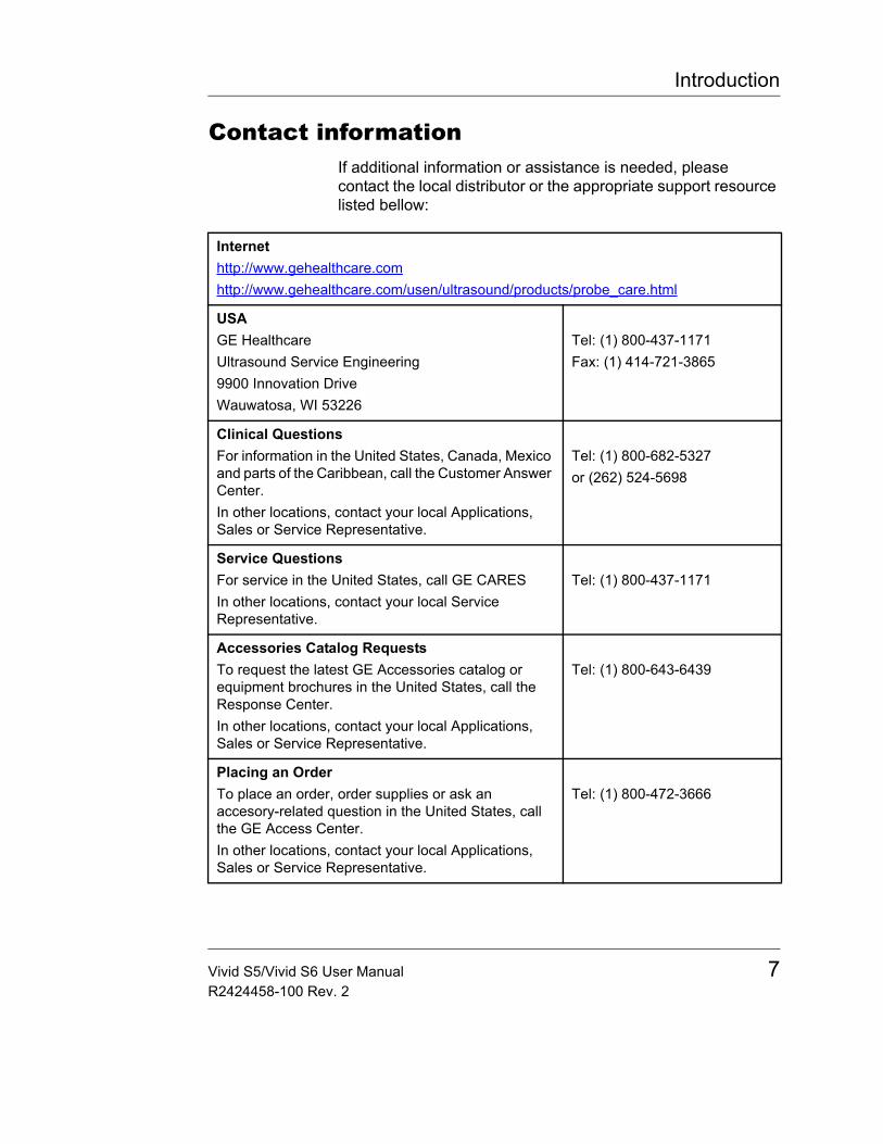
Contact informationIf additional information or assistance is needed, please contact the local distributor or the appropriate support resource listed bellow:
Internethttp://www.gehealthcare.comhttp://www.gehealthcare.com/usen/ultrasound/products/probe_care.html
USAGE HealthcareUltrasound Service Engineering9900 Innovation DriveWauwatosa, WI 53226
Tel: (1) 800-437-1171Fax: (1) 414-721-3865
Clinical QuestionsFor information in the United States, Canada, Mexico and parts of the Caribbean, call the Customer Answer Center.In other locations, contact your local Applications, Sales or Service Representative.
Tel: (1) 800-682-5327or (262) 524-5698
Service QuestionsFor service in the United States, call GE CARESIn other locations, contact your local Service Representative.
Tel: (1) 800-437-1171
Accessories Catalog RequestsTo request the latest GE Accessories catalog or equipment brochures in the United States, call the Response Center.In other locations, contact your local Applications, Sales or Service Representative.
Tel: (1) 800-643-6439
Placing an OrderTo place an order, order supplies or ask an accesory-related question in the United States, call the GE Access Center.In other locations, contact your local Applications, Sales or Service Representative.
Tel: (1) 800-472-3666
Vivid S5/Vivid S6 User Manual 7R2424458-100 Rev. 2
Introduction
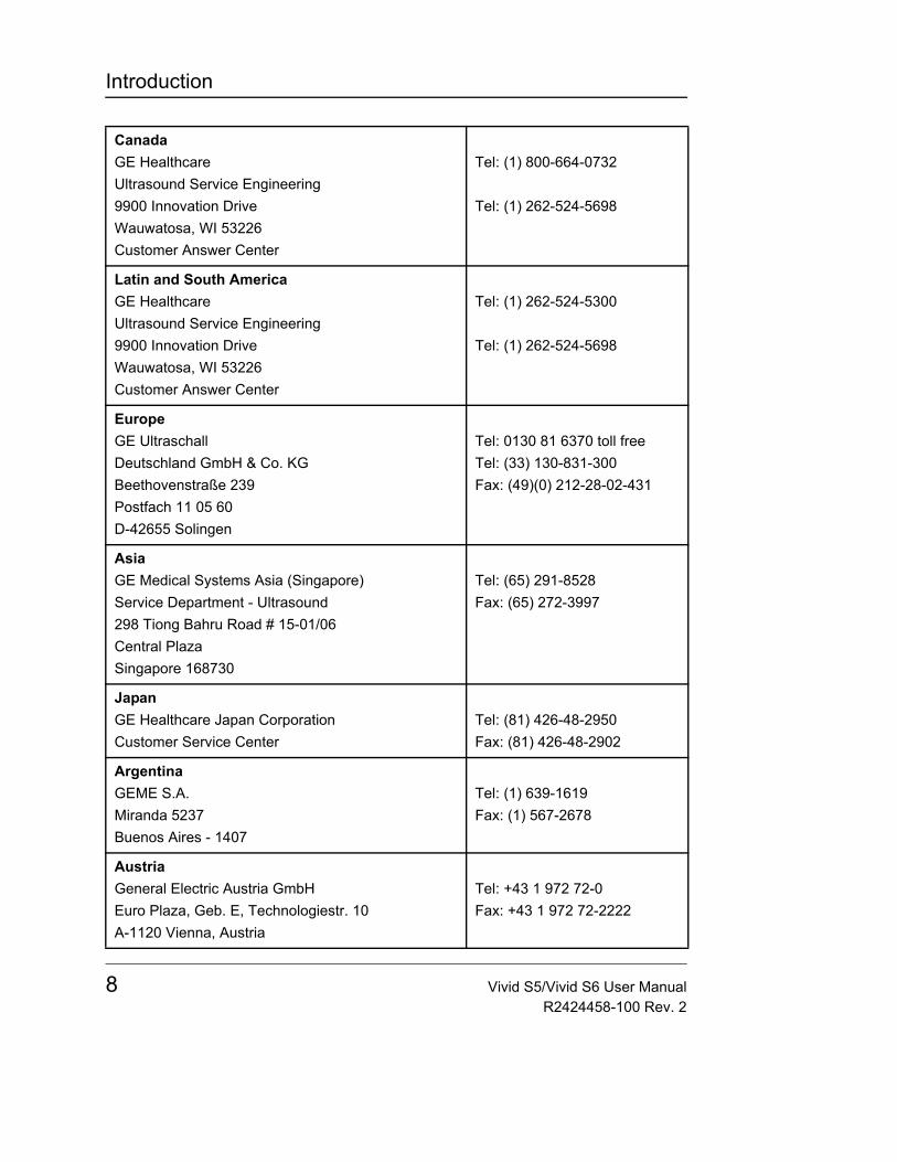
CanadaGE HealthcareUltrasound Service Engineering9900 Innovation DriveWauwatosa, WI 53226Customer Answer Center
Tel: (1) 800-664-0732
Tel: (1) 262-524-5698
Latin and South AmericaGE HealthcareUltrasound Service Engineering9900 Innovation DriveWauwatosa, WI 53226Customer Answer Center
Tel: (1) 262-524-5300
Tel: (1) 262-524-5698
EuropeGE UltraschallDeutschland GmbH & Co. KGBeethovenstraße 239Postfach 11 05 60D-42655 Solingen
Tel: 0130 81 6370 toll freeTel: (33) 130-831-300Fax: (49)(0) 212-28-02-431
AsiaGE Medical Systems Asia (Singapore)Service Department - Ultrasound298 Tiong Bahru Road # 15-01/06Central PlazaSingapore 168730
Tel: (65) 291-8528Fax: (65) 272-3997
JapanGE Healthcare Japan CorporationCustomer Service Center
Tel: (81) 426-48-2950Fax: (81) 426-48-2902
ArgentinaGEME S.A.Miranda 5237Buenos Aires - 1407
Tel: (1) 639-1619Fax: (1) 567-2678
AustriaGeneral Electric Austria GmbHEuro Plaza, Geb. E, Technologiestr. 10A-1120 Vienna, Austria
Tel: +43 1 972 72-0Fax: +43 1 972 72-2222
8 Vivid S5/Vivid S6 User ManualR2424458-100 Rev. 2
Introduction
BelgiumGE Medical Systems BeneluxKouterveldstraat 20B-1831 Diegem
Tel: +32 (0)2 719 73 11Fax: +32 (0)2 719 72 05
BrazilGE Sistemas MédicosAv Nove de Julho 5229ParaisoCep: 01407-907 - São Paulo, SP
Tel: 0800-122345Fax: (011) 3067-8298
ChinaGE Healthcare - AsiaNo. 1, Yongchang North RoadBeijing Economic & Technology Development AreaBeijing 100176, China
Tel: (8610) 5806-9403Fax: (8610) 6787-1162
DenmarkGE Medical Systems (Denmark) A/SPark Allé 2952605 Broenby
Tel: +45 4348 5400Fax: +45 4348 5399
FranceGE Healthcare France11 avenue Morane Saulnier78457 VELIZY CEDEX
Tel: +33 1 34495231Fax: +33 1 34495202
GermanyGE UltraschallDeutschland GmbH & Co. KGBeethovenstraße 239Postfach 11 05 60D-42655 Solingen
Tel: (49) 212.28.02.207Fax: (49) 212.28.02.431
GreeceGE Medical Systems Hellas AP.Λεωφόρος Κύπρου 156 AP.TΚ 164 51, ΑΡΓΥΡΟΥΠΟΛΗ
Τηλ.: +30 210 9690990Φαξ: +30 210 9625931
Vivid S5/Vivid S6 User Manual 9R2424458-100 Rev. 2
Introduction
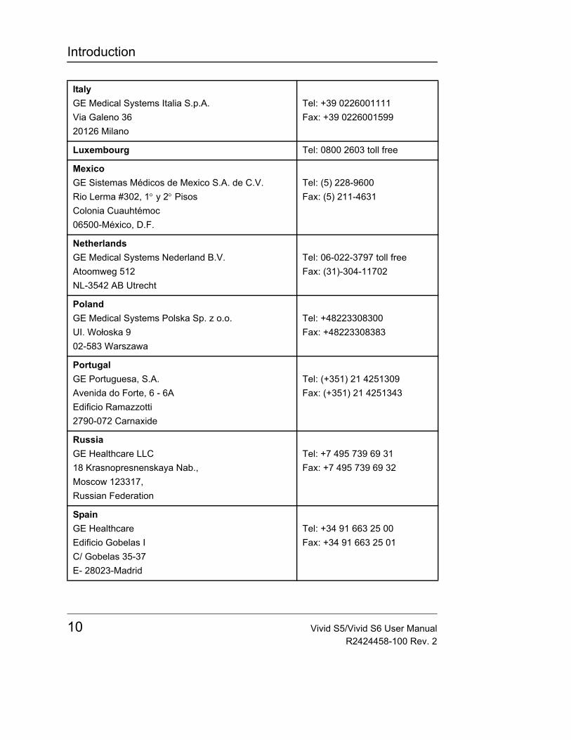
ItalyGE Medical Systems Italia S.p.A.Via Galeno 3620126 Milano
Tel: +39 0226001111Fax: +39 0226001599
Luxembourg Tel: 0800 2603 toll free
MexicoGE Sistemas Médicos de Mexico S.A. de C.V.Rio Lerma #302, 1° y 2° PisosColonia Cuauhtémoc06500-México, D.F.
Tel: (5) 228-9600Fax: (5) 211-4631
NetherlandsGE Medical Systems Nederland B.V.Atoomweg 512NL-3542 AB Utrecht
Tel: 06-022-3797 toll freeFax: (31)-304-11702
PolandGE Medical Systems Polska Sp. z o.o.UI. Wołoska 902-583 Warszawa
Tel: +48223308300Fax: +48223308383
PortugalGE Portuguesa, S.A.Avenida do Forte, 6 - 6AEdificio Ramazzotti2790-072 Carnaxide
Tel: (+351) 21 4251309Fax: (+351) 21 4251343
RussiaGE Healthcare LLC18 Krasnopresnenskaya Nab.,Moscow 123317,Russian Federation
Tel: +7 495 739 69 31Fax: +7 495 739 69 32
SpainGE HealthcareEdificio Gobelas IC/ Gobelas 35-37E- 28023-Madrid
Tel: +34 91 663 25 00Fax: +34 91 663 25 01
10 Vivid S5/Vivid S6 User ManualR2424458-100 Rev. 2
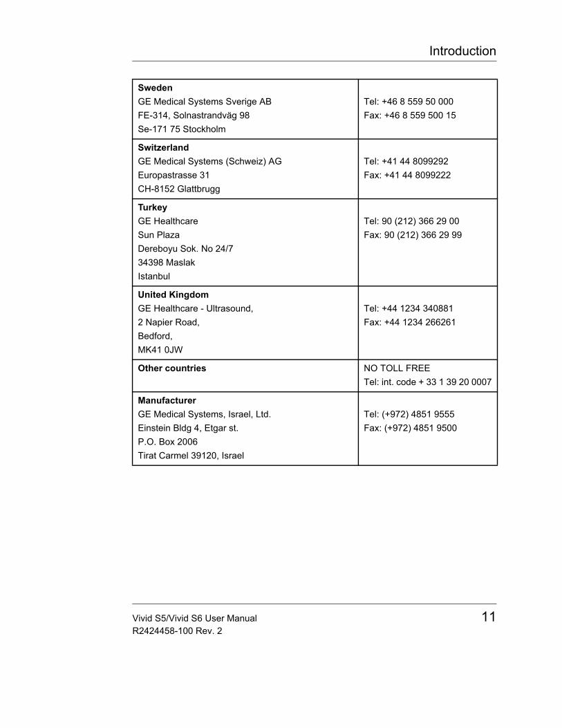
Introduction
SwedenGE Medical Systems Sverige ABFE-314, Solnastrandväg 98Se-171 75 Stockholm
Tel: +46 8 559 50 000Fax: +46 8 559 500 15
SwitzerlandGE Medical Systems (Schweiz) AGEuropastrasse 31CH-8152 Glattbrugg
Tel: +41 44 8099292Fax: +41 44 8099222
TurkeyGE HealthcareSun PlazaDereboyu Sok. No 24/734398 MaslakIstanbul
Tel: 90 (212) 366 29 00Fax: 90 (212) 366 29 99
United KingdomGE Healthcare - Ultrasound,2 Napier Road,Bedford, MK41 0JW
Tel: +44 1234 340881Fax: +44 1234 266261
Other countries NO TOLL FREETel: int. code + 33 1 39 20 0007
ManufacturerGE Medical Systems, Israel, Ltd.Einstein Bldg 4, Etgar st.P.O. Box 2006Tirat Carmel 39120, Israel
Tel: (+972) 4851 9555Fax: (+972) 4851 9500
Vivid S5/Vivid S6 User Manual 11R2424458-100 Rev. 2

Introduction
12 Vivid S5/Vivid S6 User ManualR2424458-100 Rev. 2

Safety
Chapter 1 Safety
• Introduction ................................................................................... .... 15• Hazard symbols ......................................................................... 16
• Owner responsibility .................................................................... .... 17• Important safety considerations ................................................. .... 18
• Notice against user modification ................................................ 18• Regulatory information ................................................................ .... 19
• Directives ................................................................................... 19• Product Classifications ............................................................... 19• Conformity to Standards ............................................................ 19• Certifications .............................................................................. 21• Software License Acknowledgements ....................................... 21
• Device labels ................................................................................. .... 22• Label Locations .......................................................................... 22• Label Icon Description ................................................................ 23
• Acoustic output ............................................................................. .... 26• Definition of the acoustic output parameters .............................. 26• ALARA ....................................................................................... 26• Safety statement ........................................................................ 27• System controls affecting acoustic output .................................. 27
• OB Exam ........................................................................................ .... 29• Exam Preparation ...................................................................... 29
• Acoustic Output Considerations ................................................. .... 30• Concerns surrounding fetal exposure ........................................ 30
• Patient safety ................................................................................. .... 31• Patient identification ................................................................... 31• Diagnostic information ................................................................ 31• Patient guidance ........................................................................ 32
Vivid S5/Vivid S6 User Manual 13R2424458-100 Rev. 2
Safety
• Probe Safety .................................................................................. ..... 32• Mechanical hazards ....................................................................32• Electrical Hazard .........................................................................33• Biological hazards .......................................................................34
• Personnel and equipment safety ................................................ ..... 35• Explosion hazard ........................................................................35• Electrical hazard .........................................................................35• Smoke and fire hazard ................................................................36• Biological hazard ........................................................................36• Pacemaker hazard ......................................................................36• LCD Monitor ................................................................................37
• Electrical safety ............................................................................ ..... 39• Internally connected peripheral devices .....................................39• External Connection of other peripheral devices ........................39
• Allergic reactions to latex-containing medical devices ............ ..... 40• Use of ECG .................................................................................... ..... 41• Use of Defibrillator ....................................................................... ..... 41• Use of Electrosurgical Unit .......................................................... ..... 41• Electromagnetic Compatibility (EMC) ........................................ ..... 42
• EMC performance .......................................................................43• Declaration of Emissions ............................................................44• Declaration of Immunity ..............................................................44• Notice upon Installation of Product .............................................44• General notice ............................................................................45• Peripheral Update for EC countries ............................................46
• Patient Environmental Devices ................................................... ..... 48• Acceptable devices .....................................................................49• Unapproved devices ...................................................................49• Accessories, options, and supplies .............................................49• Environmental protection ............................................................50
14 Vivid S5/Vivid S6 User ManualR2424458-100 Rev. 2
Safety
IntroductionThis section describes the important safety measures which should be taken before operating the Vivid S5/Vivid S6 ultrasound unit. Procedures for simple care and maintenance of the unit are also described.
Various levels of safety precautions may be found on the equipment, and different levels of severity are identified by one of the following icons that precede precautionary statements in the text.
The following icons and conventions are used to indicate precautions:
Note: Indicates precautions or recommendations that should be used in the operation of the ultrasound system, specifically:• Maintaining an optimum system environment• Using this Manual• Notes to emphasize or clarify a point
Other precautions or prudent-use recommendations are indicated in the note sections in the left column. These are:• Use of the Vivid S5/Vivid S6 ultrasound unit as a
prescription device, under the order of a physician.• Maintaining an optimum unit environment.• Reference to the User's Manual.
DANGER
Indicates that a specific hazard is known to exist which through inappropriate conditions or actions, will cause:• Severe or fatal personal injury• Substantial property damage
WARNING
Indicates that a specific hazard is known to exist which through inappropriate conditions or actions, will cause:• Severe personal injury• Substantial property damage
CAUTION
Indicates that a potential hazard may exist which through inappropriate conditions or actions, will or can cause:• Minor injury• Property damage
Vivid S5/Vivid S6 User Manual 15R2424458-100 Rev. 2
Safety
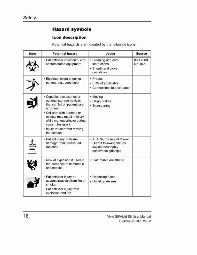
Hazard symbols
Icon description
Potential hazards are indicated by the following icons:
Icon Potential hazard Usage Source
• Patient/user infection due to contaminated equipment
• Cleaning and care instructions
• Sheath and glove guidelines
ISO 7000 No. 0659
• Electrical micro-shock to patient, e.g., ventricular
• Probes• ECG (if applicable)• Connections to back panel
• Console, accessories or optional storage devices that can fall on patient, user, or others.
• Collision with persons or objects may result in injury while maneuvering or during system transport.
• Injury to user from moving the console
• Moving• Using brakes• Transporting
• Patient injury or tissue damage from ultrasound radiation
• ALARA, the use of Power Output following the 'as low as reasonably achievable' principle
• Risk of explosion if used in the presence of flammable anesthetics
• Flammable anesthetic
• Patient/user injury or adverse reaction from fire or smoke
• Patient/user injury from explosion and fire
• Replacing fuses• Outlet guidelines
16 Vivid S5/Vivid S6 User ManualR2424458-100 Rev. 2
Safety
Owner responsibility
It is the responsibility of the owner to ensure that anyone operating the system reads and understands this section of the manual. However, there is no representation that the act of reading this manual renders the reader qualified to operate, inspect, test, align, calibrate, troubleshoot, repair or modify the system. The owner should make certain that only properly trained, fully-qualified service personnel undertake the installation, maintenance, troubleshooting, calibration and repair of the equipment.
The owner of the Vivid S5/Vivid S6 ultrasound unit should ensure that only properly trained, fully qualified personnel are authorized to operate the system. Before authorizing anyone to operate the system, it should be verified that the person has read, and fully understands, the operating instructions contained in this manual. It is advisable to maintain a list of authorized operators.
Should the system fail to operate correctly, or if the unit does not respond to the commands described in this manual, the operator should contact the nearest field GE Medical Systems Service Office.
For information about specific requirements and regulations applicable to the use of electronic medical equipment, consult the local, state and federal agencies.
CAUTION
For USA only:
Federal law restricts this device to use by, or on the orders of, a physician.
Vivid S5/Vivid S6 User Manual 17R2424458-100 Rev. 2

Safety
Important safety considerations
Notice against user modificationNever modify this product, including system components, software, cables, and so on. User modification may cause safety hazards and degradation in system performance. All modification must be done by a GE qualified person.
The equipment is not suitable for use in the presence of flammable anesthetic mixture with air or with Oxygen or Nitrous Oxide.
This section includes considerations for the following• Patient safety• Personnel and equipment safety
The information contained in this section is intended to familiarize the user with the hazards associated with the use of the unit, and to alert them to the extent to which injury and damage may occur if the precautions are not observed.
Users are obligated to familiarize themselves with these safety considerations and to avoid conditions that could result in injury or damage.
CAUTION
Improper use can result in serious injury. The user must be thoroughly familiar with the instructions and potential hazards involving ultrasound examination before attempting to use the device. Training assistance is available from GE Medical Systems if needed.
18 Vivid S5/Vivid S6 User ManualR2424458-100 Rev. 2
Safety
Regulatory information
DirectivesThe GE Healthcare Ultrasound product families are tested to meet all applicable requirements in relevant EU Directives and European/International standards.• Council Directive 93/42/EEC concerning MDD (Medical
Devices Directive): the CE label affixed to the product testifies compliance to this Directive.The location of the CE marking is specified in "Device labels" on page 22.
Product ClassificationsThe Vivid S5/Vivid S6 ultrasound unit confirms to the following classifications, in accordance with the IEC/EN 60601-1:6.8.1:• According to 93/42/EEC Medical Device Directive, this is
Class IIa Medical Device.• According to IEC/EN 60601-1, Equipment is Class I, Type
B with BF or CF Applied Parts.• According to CISPR 11, this is Group 1, Class B ISM
Equipment.• According to IEC 60529, the footswitch rate IPx8 is suitable
for use in surgical rooms.• Classification according to the degree of protection against
ingress of water as detailed in the current edition of IEC 529 (section 6.1.1): Ordinary for Main Unit (PC), IPX1, IPX7, IPX8 for ultrasound probes (transducers).
Conformity to StandardsTo fulfill the requirements of relevant EC directives and/or European Harmonized/International standards, the following documents/standards have been used:• International Electrotechnical Commission (IEC).
CAUTION
Any changes to accessories, peripheral units or any other part of the system must be approved by the manufacturer. Ignoring this advice may compromise the regulatory approvals obtained for the product.
Vivid S5/Vivid S6 User Manual 19R2424458-100 Rev. 2
Safety
• IEC/EN 60601-1: Medical Electrical Eqiupment, Part 1 General Requirements for Safety
• IEC/EN 60601-1-2: Medical electrical equipment - Part 1-2: General requirements for safety - Collateral standard: Electromagnetic compatibility - Requirements and tests
• EN 55011/ CISPR11+A2 ED3.2: Emitted noise according to Class B requirements + Electromagnetic Susceptibility
• IEC/EN 60601-1-4: Medical electrical equipment - Part 1-4: General requirements for safety - Collateral standard: Programmable electrical medical systems
• IEC/EN 60601-1-6: Medical electrical equipment - Part 1-6: General requirements for basic safety and essential performance - Collateral Standard: Usability
• IEC/EN 60601-2-37: Medical Electrical Equipment Part 2-37: Particular Requirements for the Safety of Ultrasonic Medical Diagnostic and Monitoring Equipment
• EN60601-1-1: 2001 - Medical Electrical Equipment Part 1-1: General Requirements for Safety Collateral Standard: Safety Requirements for Medical Electrical Systems
• International Organization of Standards (ISO)• ISO 10993-1: Biological Evaluation of Medical Devices -
Part 1: Evaluation & Testing• ISO 10993-5: Biological Evaluation of Medical Devices -
Part 5: Tests for In Vitro Cytotoxicity• ISO 10993-10:Biological evaluation of medical devices -
Part 10: Tests for irritation and delayed-type hypersensitivity
• Underwriters' Laboratories, Inc. (UL), an independent testing laboratory.• UL 60601-1 Medical Electrical Equipment, Part 1
General Requirements for Safety.• Canadian Standards Association (CSA).
• CSA 22.2, 601.1 Medical Electrical Equipment, Part 1 General Requirements for Safety.
20 Vivid S5/Vivid S6 User ManualR2424458-100 Rev. 2
Safety
• NEMA/AIUM Acoustic Output Display Standard (NEMA US-3, 1998).
• Medical Device Good Manufacturing Practice Manual issued by the FDA (Food and Drug Administration, Department of Health, USA).
Certifications• Quality management standards for medical devices:
General Electric Medical Systems is ISO 9001 and ISO13485 certified.
Software License Acknowledgements• WindowBlinds ™ OCX © Stardock ®
Vivid S5/Vivid S6 User Manual 21R2424458-100 Rev. 2
Safety
Device labels
Label Locations
Figure 1-1: System Label and Location
Label 1 - Vivid S5 100-120V Label 2 - Vivid S5 220-240V
Label 3 - Vivid S6 100-120V Label 4 - Vivid S6 220-240V
Label 5 - Universal Label, for all systems Vivid S5/Vivid S6 label locations
1 2
3 4
5
1 2
4 3
5
22 Vivid S5/Vivid S6 User ManualR2424458-100 Rev. 2
Safety
Label Icon DescriptionThe following table describes the purpose and location of safety labels and other important information provided on the equipment.
Label Purpose Location
Identification and Rating Plate
• Manufacturer's name and address• Date of Manufacture• Model and serial numbers• Electrical ratings (Volts, Amps,
phase, and frequency)• Device Listing/Certification Labels
Bottom of unit
Equipment Type BF, in which protection against electric shock does not rely on basic insulation only. Provides additional safety precautions such as double insulation or reinforced insulation, because there is no provision for protective earthing or reliance upon installation conditions.
Probe connectors.
Equipment Type CF, indicates equipment having a floating applied part having a degree of protection suitable for direct cardiac contact.
ECG connector
Bottom of unit.
Alternating current Various
This symbol indicates that the waste of electrical and electronic equipment must not be disposed as unsorted municipal waste and must be collected separately. Please contact an authorized representative of the manufacturer for information concerning the decommissioning of your equipment.
Bottom Cover
Vivid S5/Vivid S6 User Manual 23R2424458-100 Rev. 2
Safety
Protective earth (ground) Internal
Earth (ground) Internal
Equipotentiality: indicates terminal to be used for connecting equipotential conductors when interconnecting (grounding) with other equipment.Connection of additional protective earth conductors or potential equalization conductors is not necessary in most cases and is only recommended for situations involving multiple equipment in a high-risk patient environment to provide assurance that all equipment is at the same potential and operates within acceptable leakage current limits. An example of a high-risk patient would be a special procedure where the patient has an accessible conductive path to the heart such as exposed cardiac pacing leads.
Bottom of unit
Attention - Consult accompanying documents: alerts the user to refer to the user documentation when complete information cannot be provided on the label.This marking on the control panel is especially intended to alert the user to consult the user manual for use BEFORE operation of the system.
Various
CAUTION - Dangerous voltage: used to indicate electric shock hazards.
Various
Label Purpose Location
24 Vivid S5/Vivid S6 User ManualR2424458-100 Rev. 2
Safety
Apply a short push on the ON/OFF button to shut down the system.CAUTION: This Power Switch DOES NOT ISOLATE Mains Supply.
Keyboard
This product consists of devices that may contain mercury, which must be recycled or disposed of in accordance with local, state, or country laws. (Within this system, the backlight lamps in the monitor display contain mercury.)
Date of manufacture: The date could be a year, year and month, or year, month and day, as appropriate. See ISO 8601 for date formats.
Rear of unit
Catalog or model number Rear of unit
Serial number Rear of unit
Direct Current: For products to be powered from a DC supply.
Rear of unit
GOST-R Mark: per Law of the Russian Federation No. 184-FZ. The field 0000 will contain the number of the institute that issued the GOST label.
Bottom of unit
Prescription Device Label for United States per 21 CFR 801.109(b)(1)
Bottom of unit
Label Purpose Location
Vivid S5/Vivid S6 User Manual 25R2424458-100 Rev. 2
Safety
Acoustic output
Definition of the acoustic output parameters
Thermal Index
TI is an estimate of the temperature increase of soft tissue or bone. There are three thermal index categories:• TIS: Soft tissue thermal index. The main TI category. Used
for applications that do not image bone.• TIB: Bone thermal index (bone located in a focal region).
Used for fetal application.• TIC: Cranial bone thermal index (bone located close to the
surface). Used for transcranial application.
Mechanical Index
MI is the estimated likelihood of tissue damage due to cavitation. The absolute maximum limits of the MI is 1.9 as set by the FDA 510 (k) guidance of 1997.
Note: Further explanation on "cavitation" appears in the Reference Manual Chapter 3 - Nonthermal Bioeffects.
Ispta
The Ispta is the Spatial Peak Temporal Average Intensity. The absolute maximum limit of Ispta is 720 MW/cm2 as set by the FDA 510(k) guidance of 1997.
ALARAUltrasound procedures should be performed using output levels and exposure times As Low As Reasonably Achievable (ALARA) while acquiring clinical information.
Training
During each ultrasound examination the user is expected to weigh the medical benefit of the diagnostic information that would be obtained against the risk of potential harmful effects. Once an optimal image is achieved, the need for increasing acoustic output or prolonging the exposure cannot be justified.
26 Vivid S5/Vivid S6 User ManualR2424458-100 Rev. 2
Safety
It is recommended that all users receive proper training in applications before performing them in a clinical setting. Please contact the local GE sales representative for training assistance.
Safety statement
GE Medical Systems safety statement
Although no harmful biological effects have been demonstrated for ultrasound frequencies, intensities and exposure times used in examination with the GE Vivid S5/Vivid S6 system, GE Medical Systems recommends using the lowest acoustic output settings which will produce diagnostically acceptable information.
System controls affecting acoustic outputThe operator controls that directly affect the acoustic output are discussed in the Acoustic Output Data Tables in the Reference Manual. These tables show the highest possible acoustic intensity for a given mode, obtainable only when the maximum combination of control settings is selected. Most settings result in a much lower output. It is important to note the following:• The duration of an ultrasound examination is as important
as the acoustic output, since patient exposure to output is directly related to the exposure time.
• Better image quality yields faster clinical results, making it possible to complete the relevant ultrasound examination more rapidly. Therefore, any control that improves the quality of the examination can help to reduce patient exposure, even though it may not directly affect acoustic output.
Probe selection
As long as the appropriate application is available, any probe can be used with the knowledge that the intensities fall at, or below, those stated in the Acoustic Output Data Tables. The duration of patient exposure is most likely minimized with the use of a probe that is optimized to provide resolution and focal depth, appropriate to the examination.
Vivid S5/Vivid S6 User Manual 27R2424458-100 Rev. 2
Safety
Application selection
Selecting the probe and application preset appropriate to a particular ultrasound examination automatically provides acoustic output limits within FDA guidelines for that application. Other parameters which optimize performance for the selected application are also set automatically, and should assist in reducing the patient exposure time. See page 100, for information on selecting probes and application presets.
Changing imaging modes
Acoustic output depends on the imaging mode selected. The choice of mode (2D, M-Mode, Doppler or Color Flow) determines whether the ultrasound beam is stationary or in motion. This greatly affects the energy absorbed by the tissue.
See Chapter 4, "Scanning Modes" on page 137, for complete information on changing imaging modes.
When operating in a combined mode, such as 2D and M-Mode, the total acoustic output comprises contributions from each individual mode. Depending on the modes in use, either or both output indices may be affected.
The user can override the default settings, but care should be taken to observe the displayed MI and TI values.
Power
It is possible to change the power in all operating modes so that the operator can use the ALARA principle.
28 Vivid S5/Vivid S6 User ManualR2424458-100 Rev. 2
Safety
OB Exam
Exam PreparationPrior to an ultrasound examination, the patient should be informed of the clinical indication, specific benefits, potential risks, and alternatives, if any. In addition, if the patient requests information about the exposure time and intensity, it should be provided. Patient access to educational materials regarding ultrasound is strongly encouraged to supplement the information communicated directly to the patient. Furthermore, these examinations should be conducted in a manner and take place in a setting which assures patient dignity and privacy.• Prior material knowledge and approval of the presence of
nonessential personnel with the number of such personnel kept to a minimum.
• An intent to share with the parents per the physician's judgment, either during the examination or shortly hereafter, the information derived.
• An offer of choice about viewing the fetus.• An offer of choice about learning the sex of the fetus, if such
information becomes available.
Ultrasound examinations performed solely to satisfy the family's desire to know the fetal sex, to view the fetus, or to obtain a picture of the fetus should be discouraged.
Vivid S5/Vivid S6 User Manual 29R2424458-100 Rev. 2
Safety
Acoustic Output Considerations
Concerns surrounding fetal exposureAlways be aware of the acoustic output level by observing the Acoustic Output Display. In addition, become thoroughly familiar with the Acoustic Output Display and equipment controls affecting output.
WARNING
The Vivid S5/Vivid S6 system is a multi-use device which is capable of exceeding FDA Pre-enactment acoustic output (spatial peak-temporal average) intensity limits for fetal applications.
CAUTION
It is prudent to conduct an exam with the minimum amount and duration of acoustic output necessary to optimize the image's diagnostic value.
30 Vivid S5/Vivid S6 User ManualR2424458-100 Rev. 2
Safety
Patient safety
Patient identification
Always include proper identification with all patient data and verify the accuracy of the patient's name and/or identity number when entering such data. Ensure that the correct patient ID is provided on all recorded data and hard copy prints. Identification errors could result in an incorrect diagnosis.
Note: For further information on patient identification, see "Starting an examination" on page 95.
Diagnostic informationThe images and calculations provided by the system are intended for use by competent users, as a diagnostic tool. They are explicitly not to be regarded as the sole, irrefutable basis for clinical diagnosis. Users are encouraged to study the literature and reach their own professional conclusions regarding the clinical utility of the system.
The user should be aware of the product specifications and of the system accuracy and stability limitations. These limitations must be considered before making any decision based on quantitative values. If in doubt, the nearest GE Medical Systems Service Office should be consulted.
Equipment malfunction or incorrect settings can result in measurement errors or failure to detect details in the image. The user must become thoroughly familiar with the operation of the unit in order to optimize its performance and to recognize possible malfunctions. Application training is available through the sales representative.
WARNING
The concerns listed in this section can seriously affect the safety of the patient undergoing a diagnostic ultrasound examination.
CAUTION
Be certain to ensure privacy data of patient information.
Vivid S5/Vivid S6 User Manual 31R2424458-100 Rev. 2
Safety
Patient guidance
Probe SafetyThis section includes information on hazards to both the user and the equipment, as follow:• Mechanical hazards• Electrical hazards• Biological hazards
Mechanical hazardsDamaged probes or improper use and manipulation of the transesophageal probe may result in injury or increased risk of infection. Inspect probes frequently for sharp, pointed or rough surface damage that could cause injury or tear protective barriers (gloves and sheaths).
Never use excessive force when manipulating intracavity probes. Become familiar with all instructions and precautions provided with special purpose probes.
The use of damaged probes can result in injury or increased risk of infection. Inspect probes often for sharp, pointed, or rough surface damage that could cause injury or tear protective barriers. Become familiar with all instructions and precautions provided with special purpose probes.
CAUTION
Remember to assist the patient when moving up to the examination bed, moving down from the bed, or when moving in the vicinity of the system.
Make sure to keep the patient in full view at all times and never leave the patient unattended while on the examination bed.
WARNING
Observe immersion levels as displayed in Figure 11-5, page 559.
Inspect probes for sharp edges or rough surfaces that could injure sensitive tissue.
DO NOT bend or pull the cable forcefully, to avoid mechanical shock or impact to the probe.
32 Vivid S5/Vivid S6 User ManualR2424458-100 Rev. 2

Safety
Transesophageal probe safety
Never use excessive force when manipulating the transesophageal probe. The detailed operator manual enclosed with the transesophageal probe must be read carefully.
Electrical HazardProbes are driven by electricity, which can injure the patient or user when exposed to contact with conductive solution.
A damaged probe may increase the risk of electric shock if conductive solutions come in contact with internal live pads. Inspect probes often for cracks or openings in the housing and holes in and around the acoustic lens, or other damage that could allow moisture to enter. Become familiar with the use and care precautions described in Chapter 11, "Probes" on page 535.
CAUTION
Allowing the machine to transmit acoustic output with the probe not in use (or in its holder) can cause the transducer to build up heat. Always turn off acoustic output or freeze the image when not in use. The system's acoustic output remains transmitting when the user controls are being used.
The system is equipped with an Auto Freeze feature which disables acoustic output and freezes the image when the machine is not in use.
CAUTION
Ultrasound transducers are sensitive instruments which can easily be damaged by rough handling. Take extra care not to drop transducers and avoid contact with sharp or abrasive surfaces. A damaged housing, lens or cable can result in patient injury or serious impairment or operation.
Vivid S5/Vivid S6 User Manual 33R2424458-100 Rev. 2
Safety
Biological hazards
To minimize disease transmission, legally marketed and sterile pyrogen-free sheaths should be used for each probe recommended for intra-cavity procedures.
Adequate cleaning and disinfection are essential to prevent disease transmission. It is the responsibility of the user to verify and maintain the effectiveness of the infection control procedures in use.
WARNING
Do not immerse the probe into any liquid beyond the level shown in Figure 11-5, page 559. Never immerse the probe connector or adaptors into any liquid.
Do not subject the probe to mechanical shock or impact, which may result in cracks or chips in the housing and degrade performance.
Inspect the probe before and after each use, as described on page 553, for damage or degradation to the housing, strain relief, lens and seal.
DO NOT apply excessive force to the probe cable, to prevent insulation failure.
Electrical leakage checks should be performed regularly by a GE service representative or qualified hospital personnel, according to the procedures described in EN 60601-1/IEC 60601-1 §19.
CAUTION
Ultrasound can produce harmful effects in tissue and potentially result in patient injury. Always minimize exposure time and keep ultrasound levels low when there is no medical benefit. Use the principle of ALARA (As Low As Reasonably Achievable), increasing output only when needed to obtain diagnostic image quality. Observe the acoustic output display and be familiar with all controls affecting the output level. See the Bioeffects section of the Acoustic Output chapter in the Advanced Reference Manual for more information.
CAUTION
Transesophageal probes require a special handling. Refer to the user documentation enclosed with these probes.
34 Vivid S5/Vivid S6 User ManualR2424458-100 Rev. 2

Safety
Personnel and equipment safety
Explosion hazardNever operate the equipment in the presence of flammable or explosive liquids, vapors or gases. Malfunctions in the unit, or sparks generated by fan motors, can electrically ignite these substances. Operators should be aware of the following points to prevent such explosion hazards.• If flammable substances are detected in the environment,
do not plug in or turn on the system. • If flammable substances are detected after the system has
been turned on, do not attempt to turn off the unit, or to unplug it.
• If flammable substances are detected, evacuate and ventilate the area before turning off the unit.
Electrical hazard
If any defects are observed or malfunctions occur, stop operating the equipment and perform the proper action for the patient. Inform a qualified service person and contact a Service Representative for information.
To avoid injury• Do not remove the unit's protective covers. No
user-serviceable parts are inside. If servicing is required, contact qualified technical personnel.
• Connect the attachment plug to a hospital-grade grounding outlet to ensure adequate grounding.
• Never use any adaptor or converter of a three-prong-to two-prong type to connect with a mains power plug. The protective earth connection will loosen.
DANGER
The hazards listed below can seriously affect the safety of personnel and equipment during a diagnostic ultrasound examination.
WARNING
The internal circuits of the unit use high voltages, capable of causing serious injury or death by electrical shock.
Vivid S5/Vivid S6 User Manual 35R2424458-100 Rev. 2

Safety
• Do not place liquids on or above the unit. Conductive fluids seeping into the active circuit components may cause a short-circuit, which could result in an electrical fire.
• An electrical hazard may exist if any light, monitor or visual indicator remains on after the unit is turned off.
Fuses blown within 36 hours of being replaced may indicate a malfunctioning electrical circuit within the system. In this event, the unit must be checked by GE Medical Systems service personnel. No attempt should be made to replace the fuses with others of a higher rating.
Smoke and fire hazardThe system must be supplied from an adequately rated electrical circuit. The capacity of the supply circuit must be as specified.
Biological hazardFor patient and personnel safety, beware of biological hazards while performing transesophageal procedures. To avoid the risk of disease transmission:• Use protective barriers (gloves and probe sheaths)
whenever necessary. Follow sterile procedures as required.
• Thoroughly clean probes and reusable accessories after each patient examination and disinfect or sterilize as needed. Refer to Chapter 11, "Probes" on page 535, for probe use and care instructions.
• Follow all in-house infection control policies as they apply to personnel and equipment.
Pacemaker hazardThe possibility of the system interfering with pacemakers is minimal. However, as this system generates high frequency electrical signals, the operator should be aware of the potential hazard this could cause.
CAUTION
Do not use this equipment if a safety problem is known to exist. Have the unit repaired and performance verified by qualified service personnel before returning to use.
36 Vivid S5/Vivid S6 User ManualR2424458-100 Rev. 2
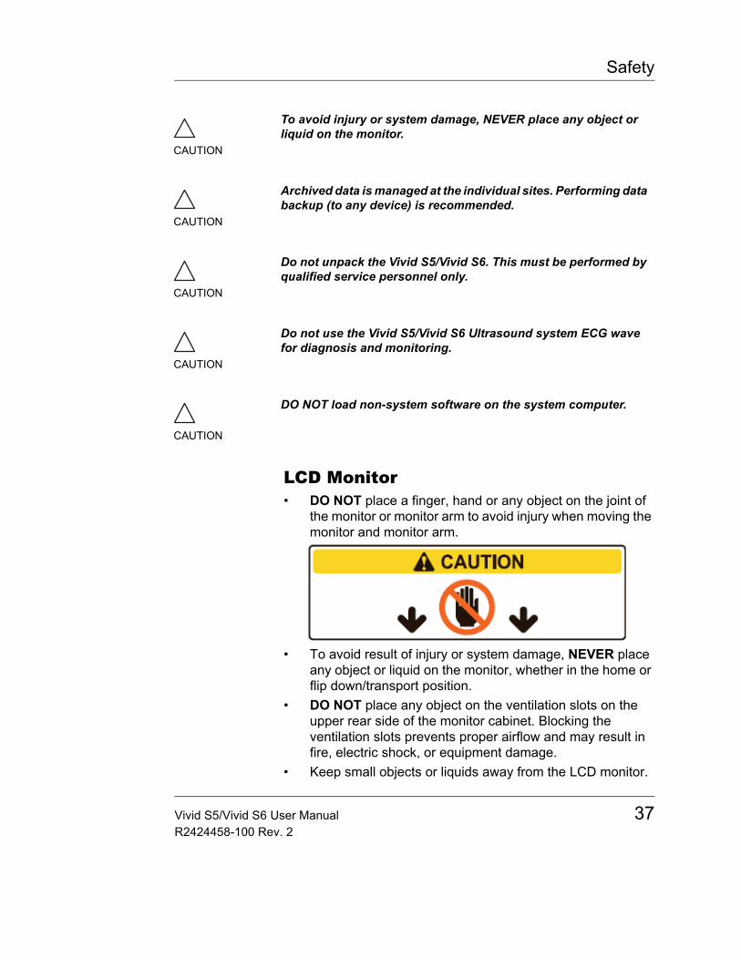
Safety
LCD Monitor• DO NOT place a finger, hand or any object on the joint of
the monitor or monitor arm to avoid injury when moving the monitor and monitor arm.
• To avoid result of injury or system damage, NEVER place any object or liquid on the monitor, whether in the home or flip down/transport position.
• DO NOT place any object on the ventilation slots on the upper rear side of the monitor cabinet. Blocking the ventilation slots prevents proper airflow and may result in fire, electric shock, or equipment damage.
• Keep small objects or liquids away from the LCD monitor.
CAUTION
To avoid injury or system damage, NEVER place any object or liquid on the monitor.
CAUTION
Archived data is managed at the individual sites. Performing data backup (to any device) is recommended.
CAUTION
Do not unpack the Vivid S5/Vivid S6. This must be performed by qualified service personnel only.
CAUTION
Do not use the Vivid S5/Vivid S6 Ultrasound system ECG wave for diagnosis and monitoring.
CAUTION
DO NOT load non-system software on the system computer.
Vivid S5/Vivid S6 User Manual 37R2424458-100 Rev. 2
Safety
Small objects or liquid may accidentally fall through the ventilation slots into the cabinet or spill into the cabinet which may result in fire, electric shock, or equipment damage.If an object or liquid falls/spills into the cabinet, unplug the system immediately. Call a Service Representative for information.
• DO NOT scratch or press on the panel with any sharp objects, such as a pencil or pen, as this may result in damage to the panel.
38 Vivid S5/Vivid S6 User ManualR2424458-100 Rev. 2
Safety
Electrical safety
Internally connected peripheral devicesThe system, together with peripheral devices, such as video tape recorders and printers, meets UL 60601-1 and IEC 60601-1 (1988) standards for electrical isolation and safety. These standards are applicable only when the specified peripheral devices are plugged into the AC outlets provided in the unit.
External Connection of other peripheral devices
Other external devices, such as laser cameras, printers, VCRs and external monitors, usually exceed allowable leakage limits and, when plugged into separate AC outlets that are then connected to the unit, are in violation of patient safety standards. Suitable electrical isolation of such external AC outlets may be required in order to meet UL2601-1 and IEC 60601-1 (1988) standards for electrical leakage.
CAUTION
External devices can be used only if CE marked and in compliance with related standards (EN 60601-1 or EN 60950). Conformance to EN 60601-1-1 (2000) must be verified.
External devices meeting EN 60950 should be kept outside of the patient environment, as defined in IEC 60601-1-1 (2000).
Vivid S5/Vivid S6 User Manual 39R2424458-100 Rev. 2

Safety
Allergic reactions to latex-containing medical devices
Due to reports of severe allergic reactions to medical devices containing latex (natural rubber), the FDA advises health-care professionals to identify latex-sensitive patients, and be prepared to treat allergic reactions promptly. Latex is a component of many medical devices, including surgical and examination gloves, catheters, incubation tubes, anesthesia masks and dental dams. Patient reaction to latex has ranged from contact urticaria, to systemic anaphylaxis.
For more details regarding allergic reaction to latex, refer to FDA Medical Alert MDA91-1, March 29, 1991 Medical Alert on latex products.
40 Vivid S5/Vivid S6 User ManualR2424458-100 Rev. 2
Safety
Use of ECG
Use of Defibrillator
Use of Electrosurgical Unit
This equipment provides no special means of protection from high frequency (HF) burns that may result from using an electrosurgical unit (ESU). To reduce the risk of HF burns, avoid contact between the patient and ultrasound transducer while operating the ESU. Where contact cannot be avoided, as in the case of TEE monitoring during surgery, make sure the transducer is not located between the ESU active and dispersive electrodes and keep the ESU cables away from the transducer cable.
CAUTION
Do not use the Vivid S5/Vivid S6 Ultrasound system ECG wave for diagnosis and monitoring.
CAUTION
Do not use the Vivid S5/Vivid S6 Ultrasound system with Defibrillator. This equipment does not have defibrillator- approved applied parts.
CAUTION
Remove the TEE probe from the patient when defibrillators are used.
CAUTION
To avoid skin burns in surgical use, do not place ECG electrodes in current path between Electrosurgical Unit (ESU) active and dispersive electrodes. Keep ESU cables away from ECG leads.
Vivid S5/Vivid S6 User Manual 41R2424458-100 Rev. 2

Safety
Electromagnetic Compatibility (EMC)NOTE: This unit carries the CE mark. It complies with regulatory requirements of the European Directive 93/42/EEC concerning medical devices. It also complies with emission limits for a Group 1, Class B Medical Device as stated in IEC/EN 60601-1-2 (2001).
All types of electronic equipment may characteristically cause electromagnetic interference with other equipment, transmitted either through air or connecting cables. The term Electromagnetic Compatibility (EMC), indicates the capability of the equipment to curb electromagnetic influence from other equipment, while at the same time not affecting other equipment with similar electromagnetic radiation.
Radiated or conducted EMC can cause distortion, degradation, or artifacts in the ultrasound image which could potentially obscure diagnostic information.
There is no guarantee that interference will not occur in a particular installation. If this equipment is found to cause or respond to interference, which may be determined by turning equipment on and off, qualified service personnel should attempt to correct the problem by one or more of the following measures:• Re-orient or re-locate the affected device.• Increase the separation between the unit and the affected
device.• Power the equipment from a source other than that of the
affected device.• Consult the service representative for further suggestions.
The manufacturer is not responsible for any interference or responses caused by the use of interconnecting cables other than those recommended, or by unauthorized changes or modifications to this unit. Unauthorized changes or modifications could void the user's authority to operate the equipment.
To comply with the regulations on electromagnetic interference, all interconnecting cables to peripheral devices must be shielded and properly grounded. Use of cables not properly shielded and grounded may result in the equipment causing or
42 Vivid S5/Vivid S6 User ManualR2424458-100 Rev. 2
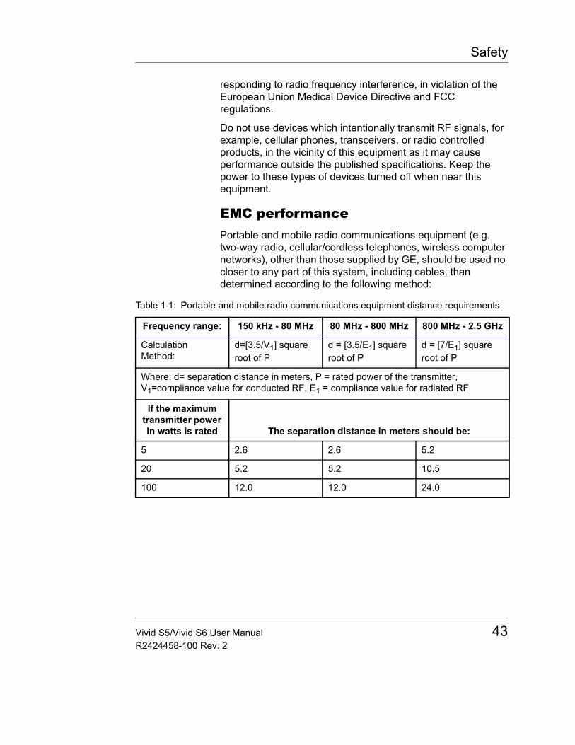
Safety
responding to radio frequency interference, in violation of the European Union Medical Device Directive and FCC regulations.
Do not use devices which intentionally transmit RF signals, for example, cellular phones, transceivers, or radio controlled products, in the vicinity of this equipment as it may cause performance outside the published specifications. Keep the power to these types of devices turned off when near this equipment.
EMC performancePortable and mobile radio communications equipment (e.g. two-way radio, cellular/cordless telephones, wireless computer networks), other than those supplied by GE, should be used no closer to any part of this system, including cables, than determined according to the following method:
Table 1-1: Portable and mobile radio communications equipment distance requirements
Frequency range: 150 kHz - 80 MHz 80 MHz - 800 MHz 800 MHz - 2.5 GHz
Calculation Method:
d=[3.5/V1] square root of P
d = [3.5/E1] square root of P
d = [7/E1] square root of P
Where: d= separation distance in meters, P = rated power of the transmitter, V1=compliance value for conducted RF, E1 = compliance value for radiated RF
If the maximum transmitter power in watts is rated The separation distance in meters should be:
5 2.6 2.6 5.2
20 5.2 5.2 10.5
100 12.0 12.0 24.0
Vivid S5/Vivid S6 User Manual 43R2424458-100 Rev. 2
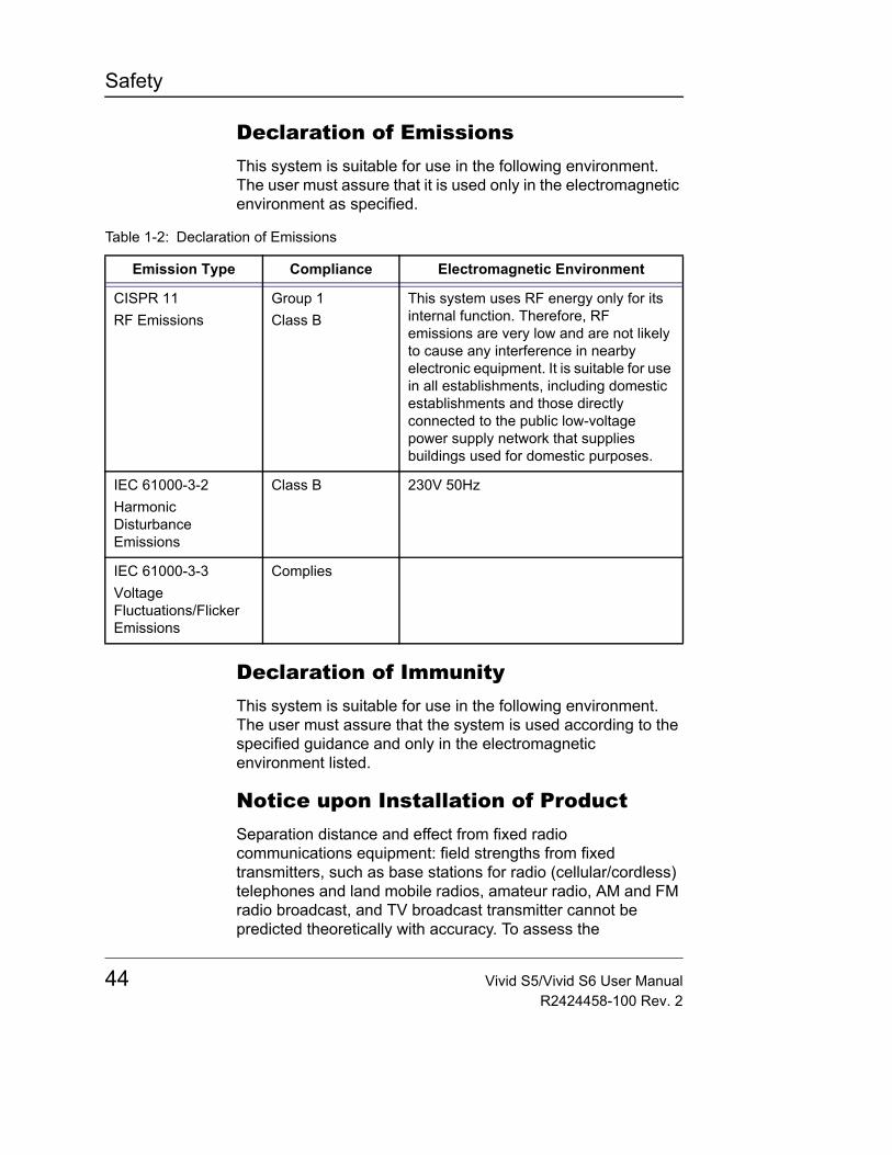
Safety
Declaration of EmissionsThis system is suitable for use in the following environment. The user must assure that it is used only in the electromagnetic environment as specified.
Declaration of ImmunityThis system is suitable for use in the following environment. The user must assure that the system is used according to the specified guidance and only in the electromagnetic environment listed.
Notice upon Installation of ProductSeparation distance and effect from fixed radio communications equipment: field strengths from fixed transmitters, such as base stations for radio (cellular/cordless) telephones and land mobile radios, amateur radio, AM and FM radio broadcast, and TV broadcast transmitter cannot be predicted theoretically with accuracy. To assess the
Table 1-2: Declaration of Emissions
Emission Type Compliance Electromagnetic Environment
CISPR 11RF Emissions
Group 1Class B
This system uses RF energy only for its internal function. Therefore, RF emissions are very low and are not likely to cause any interference in nearby electronic equipment. It is suitable for use in all establishments, including domestic establishments and those directly connected to the public low-voltage power supply network that supplies buildings used for domestic purposes.
IEC 61000-3-2Harmonic Disturbance Emissions
Class B 230V 50Hz
IEC 61000-3-3Voltage Fluctuations/Flicker Emissions
Complies
44 Vivid S5/Vivid S6 User ManualR2424458-100 Rev. 2
Safety
electromagnetic environment due to fixed RF transmitters, an electromagnetic site survey should be considered. If the measured field strength in the location in which the ultrasound system is used exceeds the applicable RF compliance level as stated in the immunity declaration, the ultrasound system should be observed to verify normal operation. If abnormal operation is observed, additional measures may be necessary, such as re-orienting or relocating the ultrasound system or using an RF shielded examination room may be necessary.1. Use either power supply cords provided by GE Medical
Systems or ones designated by GE Medical Systems. Products equipped with a power source plug should be plugged into the fixed power socket which has the protective grounding conductor. Never use any adaptor or converter to connect with a power source plug (e.g. three-prong-to-two-prong converter).
2. Locate the equipment as far away as possible from other electronic equipment.
3. Be sure to use only the cables provided by or designated by GE Medical Systems. Connect these cables following the installation procedures (e.g. wire power cables separately from signal cables).
4. Lay out the main equipment and other peripherals following the installation procedures described in the Option Installation manuals.
General notice1. Designation of Peripheral Equipment Connectable to This
Product.The equipment indicated in Chapter 12, "Peripherals" on page 575 can be hooked up to the product without compromising its EMC performance. Avoid using equipment not designated in the list. Failure to comply with this instruction may result in poor EMC performance of the product.
2. Notice against User Modification The user should never modify this product. User modifications may cause degradation in EMC performance. Modification of the product includes changes in:• Cables (length, material, wiring, etc.)• System installation/layout
Vivid S5/Vivid S6 User Manual 45R2424458-100 Rev. 2

Safety
• System configuration/components• Securing system parts (cover open/close, cover
screwing)3. Operate the system with all covers closed. If a cover is
opened for some reason, be sure to shut it before starting/ resuming operation.
4. Operating the system with any cover open may affect EMC performance.
Peripheral Update for EC countriesThe following is intended to provide the users in EC countries with updated information concerning the connection of the Vivid S5/Vivid S6 to image recording and other devices or communication networks.
The Vivid S5/Vivid S6 has been verified for overall safety, compatibility and compliance with the following on-board image recording devices:• Sony UP-D895 MD/D897MD Digital Printer• Sony UP-D23 MD Digital Color Printer• HP DeskJet 460 Series Inkjet printer• HP OfficeJet Pro K5400 Series Inkjet printer
The Vivid S5/Vivid S6 has also been verified for compatibility, and compliance for connection to a local area network (LAN) via the rear panel Ethernet connection, provided the LAN components are IEC/EN 60950 compliant.
Connection may also be made to a CE Marked and IEC/ EN 60950 compliant modem using one of the serial or USB ports on the system.
The Vivid S5/Vivid S6 may also be used safely while connected to devices other than those recommended above if the devices and their specifications, installation, and interconnection with the system conform to the requirements of IEC/EN 60601-1-1.
General precautions for installing an alternate on-board device would include:• The added device must have appropriate safety standard
conformance and CE Marking.• The total power consumption of the added devices, which
46 Vivid S5/Vivid S6 User ManualR2424458-100 Rev. 2
Safety
connect to Vivid S5/Vivid S6 and are used simultaneously, must be less than or equal to the rated supply of the Vivid S5/Vivid S6.
• There must be adequate heat dissipation and ventilation to prevent overheating of the device.
• There must be adequate mechanical mounting of the device and stability of the combination.
• Risk and leakage current of the combination must comply with IEC/EN 60601-1.
• Electromagnetic emissions and immunity of the combination must conform to IEC/EN 60601-1-2.
General precautions for installing an alternate off-board, remote device or a network would include:• The added device(s) must have appropriate safety
standard conformance and CE Marking.• The added device(s) must be used for their intended
purpose having a compatible interface.• Signal or mains isolation devices and additional protective
earth may be needed to assure compliance with IEC/EN 60601-1-1.
CAUTION
The connection of equipment or transmission networks other than as specified in the user instructions can result in an electric shock hazard or equipment malfunction. Substitute or alternate equipment and connections requires verification of compatibility and conformity to IEC/EN 60601-1-1 by the installer. Equipment modifications and possible resulting malfunctions and electromagnetic interference are the responsibility of the owner.
Vivid S5/Vivid S6 User Manual 47R2424458-100 Rev. 2
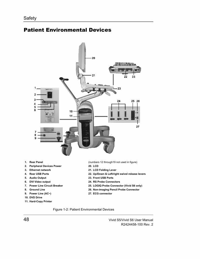
Safety
Patient Environmental Devices
Figure 1-2: Patient Environmental Devices
1. Rear Panel2. Peripheral Devices Power3. Ethernet network4. Rear USB Ports5. Audio Output6. DVI Video output7. Power Line Circuit Breaker8. Ground Line9. Power Line (AC~)10. DVD Drive11. Hard-Copy Printer
(numbers 12 through19 not used in figure)20. LCD21. LCD Folding Lever22. Up/Down & Left/right swivel release levers23. Front USB Ports24. RS Probe Connectors25. LOGIQ Probe Connector (Vivid S6 only)26. Non-imaging Pencil Probe Connector27. ECG connector
48 Vivid S5/Vivid S6 User ManualR2424458-100 Rev. 2
Safety
Acceptable devicesThe Patient Environmental devices shown on the previous page are specified to be suitable for use within the PATIENT ENVIRONMENT.
Unapproved devices
Accessories, options, and supplies
CAUTION
DO NOT connect any probes or accessories without approval by GE within the PATIENT ENVIRONMENT.
See "Peripheral Update for EC countries" on page 46 for more information.
CAUTION
DO NOT use unapproved devices.
If devices are connected without the approval of GE, the warranty will be INVALID.
Any device connected to the Vivid S5/Vivid S6 must conform to one or more of the requirements listed below:• IEC standard or equivalent standards appropriate to devices.• The devices shall be connected to PROTECTIVE EARTH
(GROUND).
CAUTION
Unsafe operation or malfunction may result. Use only the accessories, options and supplies approved or recommended in these instructions for use.
Vivid S5/Vivid S6 User Manual 49R2424458-100 Rev. 2

Safety
Environmental protection
System and battery disposal
the waste of electrical and electronic equipment must not be disposed as unsorted municipal waste and must be collected separately. Please contact an authorized representative of the manufacturer for information concerning the decommissioning of your equipment.
This product consists of devices that may contain mercury, which must be recycled or disposed of in accordance with local, state, or country laws. (Within this system, the backlight lamps in the monitor display contain mercury.)
50 Vivid S5/Vivid S6 User ManualR2424458-100 Rev. 2
Getting started
Chapter 2 Getting started
• Introduction ................................................................................... .... 52• Preparing the unit for use ............................................................ .... 53
• Site requirements ....................................................................... 53• Connecting the unit .................................................................... 54• Switching On/Off ........................................................................ 61
• Moving and transporting the unit ................................................ .... 64• Wheels ....................................................................................... 64• Moving the unit ........................................................................... 64• Transporting the unit .................................................................. 66• Reinstalling at a new location ..................................................... 67• Unit acclimation time .................................................................. 68
• System description ....................................................................... .... 69• System overview ........................................................................ 69• Control panel .............................................................................. 71• The Scanning screen ................................................................. 84• Three-Pedal Footswitch operation ............................................. 87• Connecting and disconnecting probes ....................................... 87• Adjusting the Display Monitor ..................................................... 90
• Starting an examination ............................................................... .... 95• Creating a new Patient record or starting an examination from an
existing patient record ................................................................ 95• Selecting a Probe and an Application ...................................... 100
Vivid S5/Vivid S6 User Manual 51R2424458-100 Rev. 2
Getting started
IntroductionOnly qualified physicians or ultrasound sonographers should perform scans of patients for medical diagnostic reasons. Request training, if needed.
Ensure that unauthorized personnel do not tamper with the unit.
Service representatives authorized by GE Medical Systems will unpack and install the unit. Do not attempt to install the unit alone.
Never set liquids on the unit in order to avoid spillage into the unit or the control panel. Maintain a clean environment. Turn off the circuit breaker before cleaning the unit. Refer to "System Care and Maintenance" on page 642 for cleaning instructions.
To carry out regular preventative maintenance refer to Chapter 14, "User maintenance" on page 641.
WARNING
All the warnings in "Important safety considerations" on page 18, should be read and understood before operating the unit.
52 Vivid S5/Vivid S6 User ManualR2424458-100 Rev. 2

Getting started
Preparing the unit for useThe Vivid S5/Vivid S6 ultrasound unit must operate within the proper environment and in accordance with the requirements described in this section. Before using the system, ensure that the requirements are met.
Site requirementsOptimal operation of the unit can be obtained by implementing the following requirements:
Power requirements
The Vivid S5/Vivid S6 ultrasound unit uses a separate power outlet for 100 – 120 VAC or 240 VAC, 50–60 Hz.
Operating Environment
Ensure that there is sufficient air flow around the Vivid S5/Vivid S6 ultrasound unit when installed or operated.
Environmental requirements
The Vivid S5/Vivid S6 ultrasound unit requires constant maintenance of its operational environment. Different temperature and humidity requirements are specified for operation, storage and transportation.
WARNING
Operating the unit with the wrong voltage range causes damages, voiding the factory warranty.
Table 2-1: Vivid S5/Vivid S6 temperature and humidity requirements
Requirement Temperature Humidity Air Pressure
Operational 10–40 °C 30–85% 700–1060 hPa
Storage -10–60 °C 30–70% 700–1060 hPa
Transport -10–60 °C 30–70% 700–1060 hPa
Vivid S5/Vivid S6 User Manual 53R2424458-100 Rev. 2
Getting started
Electromagnetic interferences
The Vivid S5/Vivid S6 ultrasound unit is approved for use in hospitals, clinics and other environ-mentally qualified facilities, in terms of the prevention of ra-dio wave interfer-ence. Operation of the unit in an inap-propriate environ-ment can cause electronic interfer-ence to radios and television sets situ-ated near the medi-cal equipment.
Ensure that the unit is protected from electromagnetic interferences as follows:• Operate the unit at least 4.5 meters (fifteen feet) away from
equipment that emits strong electromagnetic radiation.• Shield the unit when operating it in the vicinity of radio
broadcasting equipment, if necessary.
Connecting the unitA GE-qualified person should perform the initial system installation.
Connecting the Vivid S5/Vivid S6 ultrasound unit involves preliminary checks of the power adaptor unit and cord, voltage level and compliance with electrical safety requirements.
Use only power supply cords, cables and plugs provided by or designated by GE Medical Systems.
Ensure that the power cord and plug are intact and that the power plug is the proper hospital-grade type (where required).
The unit should be connected to a fixed power socket which has the protective grounding connector. Never use an extension cord or adapter plug.
WARNING
Failure to provide an adequate earth circuit can cause electrical shock, resulting in serious injury.
WARNING
Connection of additional protective earth conductors or potential equalization conductors is not necessary in most cases and is only recommended for situations involving multiple equipment in a high-risk patient environment to provide assurance that all equipment is at the same potential and operates within acceptable leakage current limits. An example of a high-risk patient would be a special procedure where the patient has an accessible conductive path to the heart such as exposed cardiac pacing leads
54 Vivid S5/Vivid S6 User ManualR2424458-100 Rev. 2
Getting started
Voltage level check
Check the label near the circuit breaker on the rear side of the system (Figure 2-1 or Figure 2-2).
Figure 2-1: Vivid S5 rating labels
Figure 2-2: Vivid S6 rating labels
Check the voltage range indicated on the label:• 100–120 VAC, 50/60 Hz, 5 A
Or• 230 VAC, 50/60 Hz, 2.5 A
Figure 2-3: Universal label
WARNING
If the mains supply is not within the specified range, do not connect the unit to the power source. Contact the dealer to have the unit adjusted to the specific mains supply.
Vivid S5/Vivid S6 User Manual 55R2424458-100 Rev. 2
Getting started
Connecting to the electrical outlet
1. Ensure that the wall outlet is of appropriate type, and that the power switch is turned off.
2. Uncoil the power cable, allowing sufficient slack so that the unit can be moved slightly.
3. Attach the power plug to the system and secure it in place by using the retaining clamp.
4. Secure the power plug in the wall outlet.
Figure 2-4: Power plug
WARNING
POWER OUTAGE MAY OCCUR. The Vivid S5/Vivid S6 requires a dedicated single branch circuit. To avoid circuit overload and possible loss of critical care equipment, make sure you DO NOT have other equipment operating on the same circuit.
The unit’s power must be supplied from a separate, properly rated outlet to avoid risk of fire. Refer to "Power requirements" on page 53 for rating information.
The power cord should not, under any circumstances, be altered to a configuration rated less than that specified for the current.
Do not use an extension cord or adapter plug.
a. Retaining clamp for power plug
CAUTION
Ensure that the retaining clamp for the power plug is fixed firmly.
56 Vivid S5/Vivid S6 User ManualR2424458-100 Rev. 2
Getting started
To help assure grounding reliability, connect to a "hospital grade" or "hospital only" grounded power outlet.
Figure 2-5: Example Plug and Outlet Configurations
Battery
The System contains an internal battery (optional), which is not user-accessible. The internal battery acts as a limited alternative power source, which becomes active when the AC power fails or AC cable is abruptly pulled out.
Display turns off and no scanning is possible while in battery mode. For further information about use of the battery see section "Battery Power Mode" on page 63.
The battery may only be disassem-bled and re-assem-bled by an authorized field-service engi-neer.
Battery technologyThe lithium ion technology used in the system’s battery is significantly less hazardous to the environment than the lithium metal technology used in some other batteries (such as watch batteries). Used batteries should not be placed with common household waste products. Contact local authorities for the location of a chemical waste collection program nearest you.
CAUTION
Use caution to ensure that the power cable does not disconnect during system use. If the system is accidentally unplugged, data may be lost.
WARNING
To avoid risk of fire, the system power must be supplied from a separate, properly rated outlet.
Under no circumstances should the AC power plug be altered, changed, or adapted to a configuration rated less than specified. Never use an extension cord or adapter plug.
1. 100-120 VAC, 1200 VA Plug and Outlet Configuration2. 220-240 VAC, 1200 VA Plug and Outlet Configuration
Vivid S5/Vivid S6 User Manual 57R2424458-100 Rev. 2
Getting started
Viewing Current Battery StatusWhen the system is running, a status icon is displayed in the system Status bar to indicate the current battery status.
Note: The % values mentioned above may fluctuate by up to +/- 3 % points.
View Detailed Battery StatusIn order to view further details about the battery status, click on the battery-status icon. A more detailed status description appears.
A special message may appear, suggestion to replace the battery soon. This message may appear when the battery has aged to such an extent that even after prolonged charging it will not hold enough charge.
Peripherals/Accessory connection
The external Peripherals / accessories connectors are situated on the rear side of the unit See Figure 2-6.
Refer to page 575 for further informa-tion on peripherals.
Peripherals/Accessory Connector PanelVivid S5/Vivid S6 peripherals and accessories can be properly connected using the rear connector panel.
Table 2-2: Battery status icons
Icon Status Description
AC Power is ON; no battery present
AC Power is ON; battery is fully charged (80%-100%)
AC Power is ON; battery is partially charged (40%-80%)
AC Power is ON; battery is almost empty (10%-40%)
CAUTION
Use only approved peripherals, accessories or probes.
DO NOT connect any accessories or probes without approval by GE
58 Vivid S5/Vivid S6 User ManualR2424458-100 Rev. 2
Getting started
Figure 2-6: Peripherals/Accessory Connector Panel
1. Two isolated AC sockets for peripherals (Max. 250VA total)2. LAN 10/100 Base-TX Ethernet network connector3. Two interchangeable USB ports (digital printers or other peripherals)4. Audio output5. DVI video output connection to external display
WARNING
Accessory equipment connected to the analogue and digital interfaces must be certified according to the respective IEC standards (e.g. IEC 60950 for data processing equipment and IEC 60601-1 (1988) for medical equipment). Any person connecting additional equipment to the signal input part or output part is configuring the medical system, and is therefore responsible that the system complies with the requirements of the system standard IEC 60601-1-1 (2000). If in doubt, consult the technical service department or your local representative.
Do not touch the conducting parts of the USB or Ethernet cables when connecting equipment to the unit.
Vivid S5/Vivid S6 User Manual 59R2424458-100 Rev. 2
Getting started
CAUTION
The connection of equipment or transmission networks other than as specified in these instructions can result in electric shock hazard. Alternate connections will require verification of compatibility and conformity to IEC/EN 60601-1-1 by the installer.
Table 2-3: Contents of the Rear Panel
Socket Signal type Device type Note
DVI-I Out DVI-I output high resolution video
External monitor
USB Universal serial bus x2
USB Cable / Device
Ethernet 10/100 Base-TX Ethernet IEEE 8023 Network device
Network device
60 Vivid S5/Vivid S6 User ManualR2424458-100 Rev. 2
Getting started
Switching On/Off
To switch on the unit:1. Switch on the circuit breaker on the rear of the unit (see
Figure 2-6).2. Press (on/off button) on the top left of the control panel
(see Figure 2-11).After initialization the default scanning screen (2D mode) is displayed, the active probe being the one connected to the left most connector socket.
When turning ON a system while sys-tem is in standby, it takes a few seconds before it responds. Do not push the on/off button again during this period (A second push will initiate a full shut-down).
LEDsThere are two LEDs above the On/Off switch that indicate the status of the system.
Password ProtectionLog In
By factory Login default, the Opera-tor ID is USR and there is no need to enter a password
During the turn-on process the system may require the user to enter a password in order to operate it. Personal IDs and associated passwords can be configured in the Vivid S5/Vivid S6. See "Presets and System setup" on page 583 for more information.
If IDs and passwords have been entered and "Use Auto Logon" is Off (see "Users" on page 637 for details), the Operator Login window appears, requesting for an ID and password when Power up sequence is completed, or when it is required.
Indicates power status.After pressing the On/Standby switch, the system power is ON and this LED is lit.Color: Green
Indicates battery status.When the battery is charged, the LED is green. When the battery power is low, the LED is orange.Color: Green and Orange
Vivid S5/Vivid S6 User Manual 61R2424458-100 Rev. 2
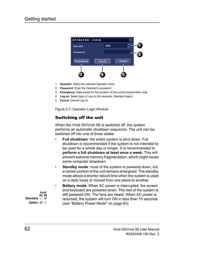
Getting started
Figure 2-7: Operator Login Window
Switching off the unit
When the Vivid S5/Vivid S6 is switched off, the system performs an automatic shutdown sequence. The unit can be switched off into one of three states.• Full shutdown: the entire system is shut down. Full
shutdown is recommended if the system is not intended to be used for a whole day or longer. It is recommended to perform a full shutdown at least once a week. This will prevent extreme memory fragmentation, which might cause some computer slowdown.
• Standby mode: most of the system is powered down, but a certain portion of the unit remains energized. The standby mode allows a shorter reboot time when the system is used on a daily basis or moved from one place to another.
• Battery mode: When AC power is interrupted, the screen and keyboard are powered down. The rest of the system is still powered ON. The fans are heard. When AC power is resumed, the system will turn ON in less than 10 seconds (see "Battery Power Mode" on page 63).
1. Operator: Select the relevant Operator name2. Password: Enter the Operator’s password3. Emergency: Data stored for the duration of the current examination only4. Log on: Select type of Log on (for example, Standard logon)5. Cancel: Cancel Log on
62 Vivid S5/Vivid S6 User ManualR2424458-100 Rev. 2
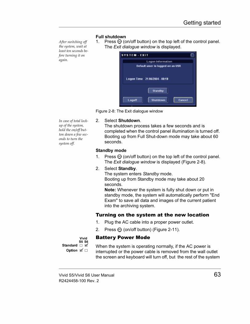
Getting started
Full shutdownAfter switching off the system, wait at least ten seconds be-fore turning it on again.
1. Press (on/off button) on the top left of the control panel.The Exit dialogue window is displayed.
Figure 2-8: The Exit dialogue window
In case of total lock-up of the system, hold the on/off but-ton down a few sec-onds to turn the system off.
2. Select Shutdown.The shutdown process takes a few seconds and is completed when the control panel illumination is turned off. Booting up from Full Shut-down mode may take about 60 seconds.
Standby mode1. Press (on/off button) on the top left of the control panel.
The Exit dialogue window is displayed (Figure 2-8).2. Select Standby.
The system enters Standby mode. Booting up from Standby mode may take about 20 seconds.Note: Whenever the system is fully shut down or put in standby mode, the system will automatically perform "End Exam" to save all data and images of the current patient into the archiving system.
Turning on the system at the new location1. Plug the AC cable into a proper power outlet.2. Press (on/off button) (Figure 2-11).
Battery Power Mode
When the system is operating normally, if the AC power is interrupted or the power cable is removed from the wall outlet the screen and keyboard will turn off, but the rest of the system
Vivid S5/Vivid S6 User Manual 63R2424458-100 Rev. 2

Getting started
will continue to operate in "Battery Mode", powered by the internal battery.
While in battery mode, if the AC power is restored within 10 minutes, the system will turn back on within less than 10 seconds.
While in Battery-power mode the system will maintain the current patient active and not perform "End-Exam". As a result, when power is restored, the current patient's details and stored images are readily available on display.
If the AC power is not restored within 10 minutes, the system will shut-down into Standby mode.
If AC is not restored, the system can remain in Standby mode for approximately 1 hour using the internal battery power (assuming battery is fully charged and relatively new). If left for more than about 1 hour while in standby-mode without AC power, the system will switch from Standby in to full Shut-down mode.
Moving and transporting the unit
WheelsThe front wheels of the unit are controlled by the break-pedals situated above each wheel.
The rear wheels of the unit are controlled by the swivel lock / release pedals situated above each wheel (see item 10 in Figure 2-11).
Examine the wheels frequently for defects to avoid breaking or jamming.
Moving the unit
To prepare the unit to be moved1. Turn system Off to Full shut-down or Standby mode.2. Remove the AC plug from the power outlet.3. Wrap the AC power cord to ensure cord is not hanging in
the wheel area or beyond the sides of the system.
64 Vivid S5/Vivid S6 User ManualR2424458-100 Rev. 2
Getting started
4. Pull the left handle and swivel the keyboard so it will lock in its central position (see page 93).
5. Disconnect all external cables linking the unit to any off-board peripheral devices and network. (Note the marks on each cable to reconnect them later).
6. Place all probes securely in proper probe holders. Ensure that the probe cables do not protrude from the side of the unit or interfere with the wheels, or foot area. Hang the cords on respective hooks provided, ensuring cords are secure and out of lower portion of the system and do not extend beyond the sides of system.
7. Ensure that no loose items are left on the unit.8. If intending to travel over bumpy surface or if more visibility
is required during transportation, fold the LCD screen forward to a horizontal position (see "Position Adjustment" on page 92).
9. Unlock the front-wheel’s brakes.10. Lock the rear wheel brakes (Swivel Brake) for long travel or
free it for short distance traveling where maneuvering is needed.Once all cables and cords are wrapped and secure out of the lower portion of the system, not extending beyond sides of system, you are ready for transport.
To ensure safety while moving the unit1. Ensure that the keyboard console is in central-locked
position.
2. Proceed cautiously when crossing door or elevator thresholds. Grasp the front handle grips and push or pull or use the rear handle bar for pushing the system. Do not attempt to move the unit using cables or probe connectors.
CAUTION
Before folding the LCD monitor, please make sure that the gel bottle is placed with the dispenser tip down into gel holder or moved sideways in order not touch the monitor's faceplate.
WARNING
Ensure that the hands of the patient are away from the console when moving the system or keyboard console.
Vivid S5/Vivid S6 User Manual 65R2424458-100 Rev. 2

Getting started
Take extra care while moving the unit on inclines. Do not hang or lean body weight on the handles.
3. Ensure that the unit does not strike the walls or door frames.
4. Ensure the pathway is clear, and probe cables are secure not to catch onto anything in the path (including wheels and feet).
5. Move the unit slowly and carefully.
Transporting the unitTake extra care when transporting the unit by vehicle. In addition to the moving precautions listed on page 64, follow the procedure described below.1. Disconnect all probes and secure them in their boxes.2. Lower the system's keyboard to its minimum height.3. Park the vehicle on a level surface for loading and
unloading.4. Secure the unit while it is on the lift, to prevent rolling. Do
not attempt to hold it in place by hand. Cushion the unit and strap the lower part so that it does not break loose.
5. Ensure that the unit is secured inside the vehicle. Secure it with straps to prevent movement while in transit.
6. Drive cautiously to prevent vibration damage.
CAUTION
The rear handle should only be used for pushing the system, not for pulling, The system might become unstable when hitting an obstacle while pulled with the rear handle.
CAUTION
Avoid ramps that are steeper than 10 degrees.
WARNING
Probe cables may get caught on external devices, such as doors, medical devices in the transporting path, wheels, or feet. Please ensure cords are wrapped properly, not extended beyond sides of system and out of the way for portables.
66 Vivid S5/Vivid S6 User ManualR2424458-100 Rev. 2
Getting started
Reinstalling at a new location1. When the unit is in place at a new location, lock the wheel
brakes (see "Moving and transporting the unit" on page 64).2. Follow the installation procedure described on "Connecting
the unit" on page 54.
Preparing Vivid S5/Vivid S6 for scanning1. Lock front Wheel brakes 2. Un-Wrap the AC power cord and plug into power source.3. Lift the LCD screen to the fully open position while pulling
out the lock. Secure the Monitor at full upright position.4. Turn the system on.5. Connect external cables if needed (LAN, USB, etc.).6. Probe being used to scan should be ready, with cables
clear of foot area and wheels by wrapping un-used portion of the cord on respective hooks provided.
7. Adjust keyboard's height and swivel (see page 93).
Note: Ensure that the probe cables do not protrude from the unit or interfere with the wheels, or foot area. The Hanging cords may cause damage to system if lodged or hooked onto nearby items. By ensuring cords are secure and out of lower portion of the system, this may provide a more secure atmosphere and avoid unnecessary damage.
Avoiding possible hazards• Avoid dragging cables on the floor. In cases where the
wheel rolls over cable or person pushing the system steps on cables, it may generate severe force to break the cable or the connector.
• Avoid hanging cables beyond sides of the system. When system is moved, these cables may be caught in door-knobs or other medical equipment and apply severe forces that may break probe cables or connectors.
• Check that the Gel bottle is not interfering with the folding screen. The gel bottle needs to be placed with dispenser tip down into gel holder or moved sideways in order not to push on the LCD frame (see Figure 2-9).
Vivid S5/Vivid S6 User Manual 67R2424458-100 Rev. 2
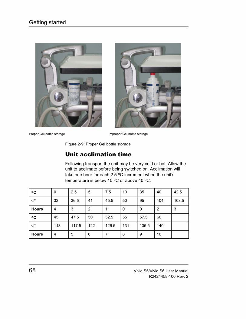
Getting started
Figure 2-9: Proper Gel bottle storage
Unit acclimation timeFollowing transport the unit may be very cold or hot. Allow the unit to acclimate before being switched on. Acclimation will take one hour for each 2.5 oC increment when the unit’s temperature is below 10 oC or above 40 oC.
Proper Gel bottle storage Improper Gel bottle storage
oC 0 2.5 5 7.5 10 35 40 42.5
oF 32 36.5 41 45.5 50 95 104 108.5
Hours 4 3 2 1 0 0 2 3
oC 45 47.5 50 52.5 55 57.5 60
oF 113 117.5 122 126.5 131 135.5 140
Hours 4 5 6 7 8 9 10
68 Vivid S5/Vivid S6 User ManualR2424458-100 Rev. 2
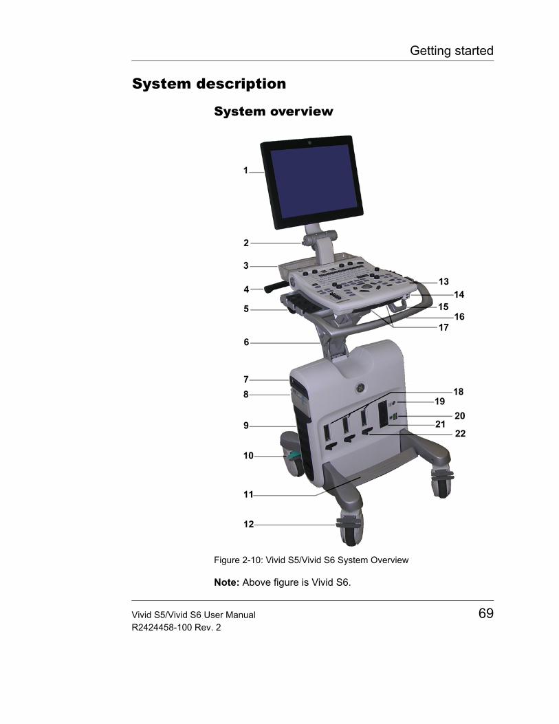
Getting started
System description
System overview
Figure 2-10: Vivid S5/Vivid S6 System Overview
Note: Above figure is Vivid S6.
Vivid S5/Vivid S6 User Manual 69R2424458-100 Rev. 2
Getting started
1. LCD Display Monitor: Swivels to the left and right, tilts backwards and forwards.
2. Display Monitor Spring-lock Release: Pull knob and fold screen forward to a horizontal position. To unfold the screen pull the same knob and lift the screen up.
3. Accessory tray (removable)4. Rear Handle5. Probe and gel holders: Removable for cleaning. Situated
on either side of the Control panel.6. Up/down "Flex-Fit" arm7. DVD Drive8. Black and white video printer9. Fans Service Cover10. Rear Wheels: Swivel wheels. May be swivel-locked11. Foot Rest (removable)12. Front Wheels: Each wheel may be braked.13. Control panel: Contains all the buttons, softkeys and the
alphanumeric keyboard used to operate the system.14. USB Port15. Probe cable hooks: Located on each side in the front and
rear of system16. Front Handle17. Console swivel operating handle: Situated on the right
side under the control panelConsole lifting operating handle: Situated on the left side under the control panel
18. Probe ports: Three RS-type Probe sockets19. Pencil probe socket20. ECG connector socket: Also supporting the external ECG
input21. Large probe socket: (Available on Vivid S6 only)
Supporting the TEE probes only22. RS-Socket locking latch
70 Vivid S5/Vivid S6 User ManualR2424458-100 Rev. 2
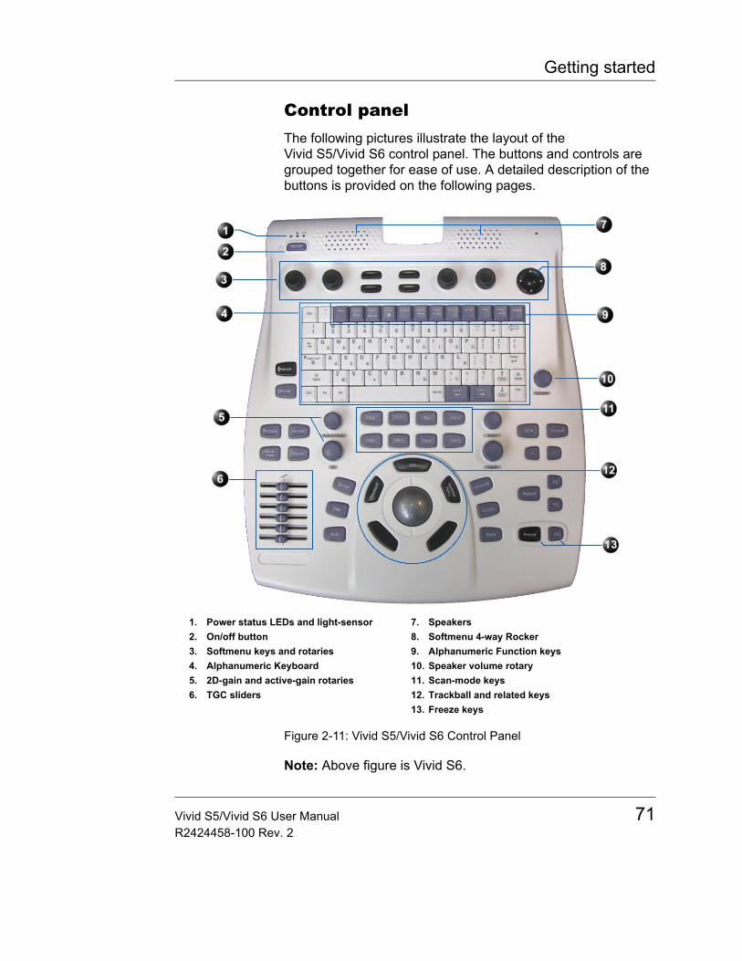
Getting started
Control panelThe following pictures illustrate the layout of the Vivid S5/Vivid S6 control panel. The buttons and controls are grouped together for ease of use. A detailed description of the buttons is provided on the following pages.
Figure 2-11: Vivid S5/Vivid S6 Control Panel
Note: Above figure is Vivid S6.
1. Power status LEDs and light-sensor2. On/off button3. Softmenu keys and rotaries4. Alphanumeric Keyboard5. 2D-gain and active-gain rotaries6. TGC sliders
7. Speakers8. Softmenu 4-way Rocker9. Alphanumeric Function keys10. Speaker volume rotary11. Scan-mode keys12. Trackball and related keys13. Freeze keys
Vivid S5/Vivid S6 User Manual 71R2424458-100 Rev. 2
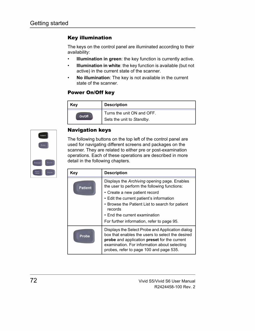
Getting started
Key illumination
The keys on the control panel are illuminated according to their availability:• Illumination in green: the key function is currently active.• Illumination in white: the key function is available (but not
active) in the current state of the scanner.• No illumination: The key is not available in the current
state of the scanner.
Power On/Off key
Navigation keys
The following buttons on the top left of the control panel are used for navigating different screens and packages on the scanner. They are related to either pre or post-examination operations. Each of these operations are described in more detail in the following chapters.
Key Description
Turns the unit ON and OFF.Sets the unit to Standby.
Key Description
Displays the Archiving opening page. Enables the user to perform the following functions:• Create a new patient record• Edit the current patient’s information• Browse the Patient List to search for patient
records• End the current examinationFor further information, refer to page 95.
Displays the Select Probe and Application dialog box that enables the users to select the desired probe and application preset for the current examination. For information about selecting probes, refer to page 100 and page 535.
72 Vivid S5/Vivid S6 User ManualR2424458-100 Rev. 2
Getting started
Enters Stress Echo mode (optional). The Protocol screen is displayed showing the default stress protocol for the current probe.
Displays the Measurement worksheet where the user may edit or delete measurements, change averaging etc. Refer to page 353 for details on how to operate the worksheet.
Brings the scanner into the Image review mode, that enables the user to select images from the clipboard for analysis, activate the image browser or enter the Image Review screen where bigger previews of the images are shown for image selection. Refer to page 426 for details on the review of images.
Displays the examination report.
Key Description
Vivid S5/Vivid S6 User Manual 73R2424458-100 Rev. 2
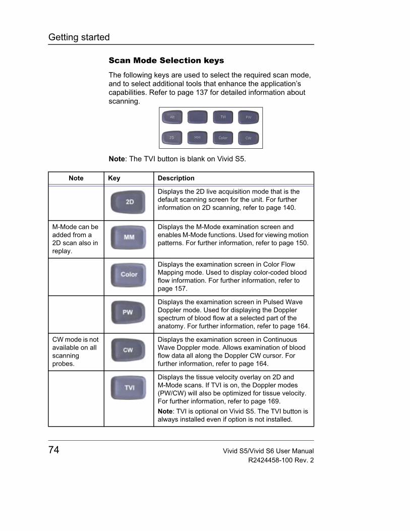
Getting started
Scan Mode Selection keys
The following keys are used to select the required scan mode, and to select additional tools that enhance the application’s capabilities. Refer to page 137 for detailed information about scanning.
Note: The TVI button is blank on Vivid S5.
Note Key Description
Displays the 2D live acquisition mode that is the default scanning screen for the unit. For further information on 2D scanning, refer to page 140.
M-Mode can be added from a 2D scan also in replay.
Displays the M-Mode examination screen and enables M-Mode functions. Used for viewing motion patterns. For further information, refer to page 150.
Displays the examination screen in Color Flow Mapping mode. Used to display color-coded blood flow information. For further information, refer to page 157.
Displays the examination screen in Pulsed Wave Doppler mode. Used for displaying the Doppler spectrum of blood flow at a selected part of the anatomy. For further information, refer to page 164.
CW mode is not available on all scanning probes.
Displays the examination screen in Continuous Wave Doppler mode. Allows examination of blood flow data all along the Doppler CW cursor. For further information, refer to page 164.
Displays the tissue velocity overlay on 2D and M-Mode scans. If TVI is on, the Doppler modes (PW/CW) will also be optimized for tissue velocity. For further information, refer to page 169.Note: TVI is optional on Vivid S5. The TVI button is always installed even if option is not installed.
74 Vivid S5/Vivid S6 User ManualR2424458-100 Rev. 2
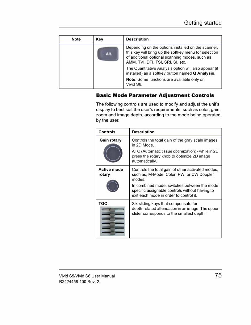
Getting started
Basic Mode Parameter Adjustment Controls
The following controls are used to modify and adjust the unit’s display to best suit the user’s requirements, such as color, gain, zoom and image depth, according to the mode being operated by the user.
Depending on the options installed on the scanner, this key will bring up the softkey menu for selection of additional optional scanning modes, such as AMM, TVI, DTI, TSI, SRI, SI, etc.The Quantitative Analysis option will also appear (if installed) as a softkey button named Q Analysis.Note: Some functions are available only on Vivid S6.
Note Key Description
Controls Description
Gain rotary Controls the total gain of the gray scale images in 2D Mode.ATO (Automatic tissue optimization) - while in 2D press the rotary knob to optimize 2D image automatically.
Active mode rotary
Controls the total gain of other activated modes, such as, M-Mode, Color, PW, or CW Doppler modes.In combined mode, switches between the mode specific assignable controls without having to exit each mode in order to control it.
TGC Six sliding keys that compensate for depth-related attenuation in an image. The upper slider corresponds to the smallest depth.
Vivid S5/Vivid S6 User Manual 75R2424458-100 Rev. 2
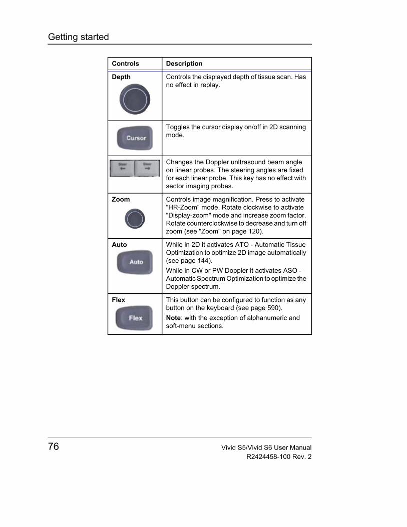
Getting started
Depth Controls the displayed depth of tissue scan. Has no effect in replay.
Toggles the cursor display on/off in 2D scanning mode.
Changes the Doppler unltrasound beam angle on linear probes. The steering angles are fixed for each linear probe. This key has no effect with sector imaging probes.
Zoom Controls image magnification. Press to activate "HR-Zoom" mode. Rotate clockwise to activate "Display-zoom" mode and increase zoom factor. Rotate counterclockwise to decrease and turn off zoom (see "Zoom" on page 120).
Auto While in 2D it activates ATO - Automatic Tissue Optimization to optimize 2D image automatically (see page 144).While in CW or PW Doppler it activates ASO - Automatic Spectrum Optimization to optimize the Doppler spectrum.
Flex This button can be configured to function as any button on the keyboard (see page 590).Note: with the exception of alphanumeric and soft-menu sections.
Controls Description
76 Vivid S5/Vivid S6 User ManualR2424458-100 Rev. 2
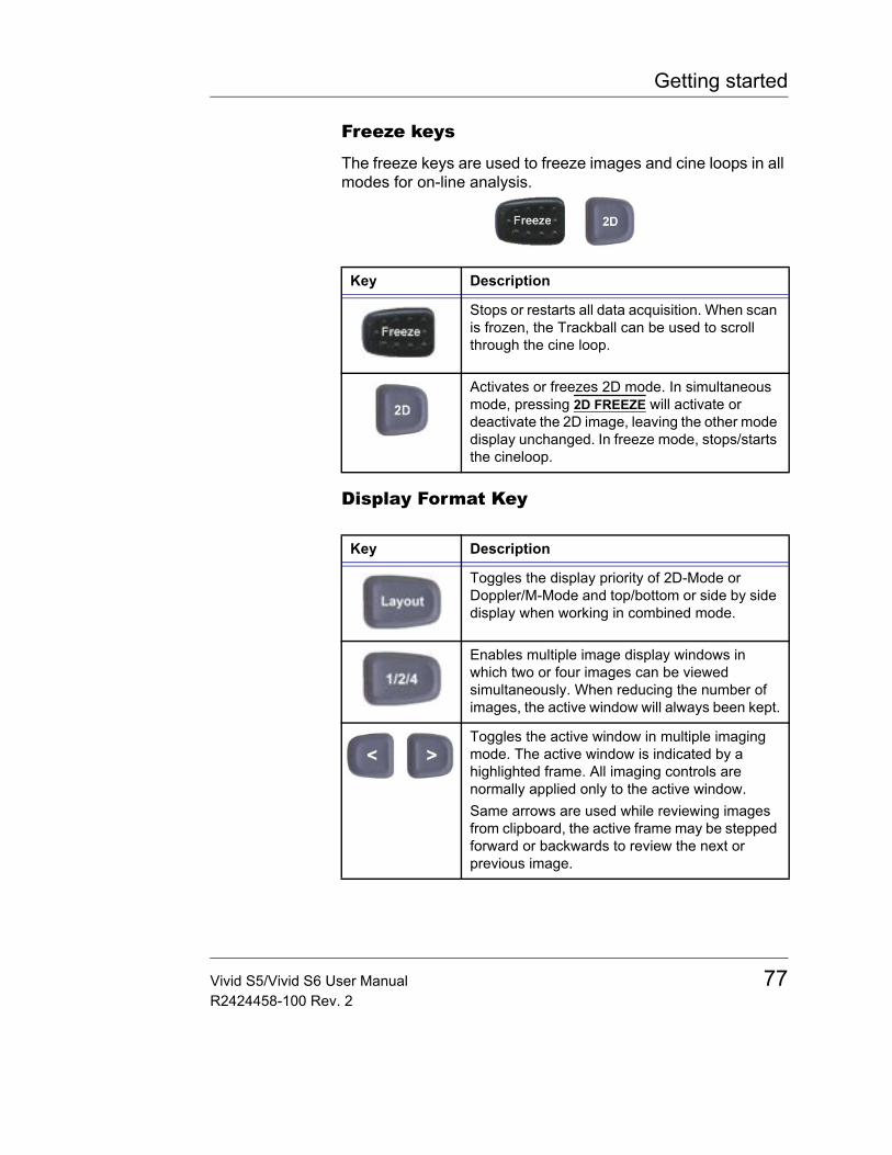
Getting started
Freeze keys
The freeze keys are used to freeze images and cine loops in all modes for on-line analysis.
Display Format Key
Key Description
Stops or restarts all data acquisition. When scan is frozen, the Trackball can be used to scroll through the cine loop.
Activates or freezes 2D mode. In simultaneous mode, pressing 2D FREEZE will activate or deactivate the 2D image, leaving the other mode display unchanged. In freeze mode, stops/starts the cineloop.
Key Description
Toggles the display priority of 2D-Mode or Doppler/M-Mode and top/bottom or side by side display when working in combined mode.
Enables multiple image display windows in which two or four images can be viewed simultaneously. When reducing the number of images, the active window will always been kept.
Toggles the active window in multiple imaging mode. The active window is indicated by a highlighted frame. All imaging controls are normally applied only to the active window.Same arrows are used while reviewing images from clipboard, the active frame may be stepped forward or backwards to review the next or previous image.
Vivid S5/Vivid S6 User Manual 77R2424458-100 Rev. 2
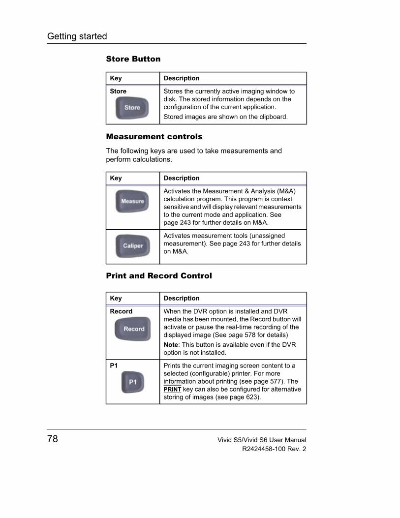
Getting started
Store Button
Measurement controls
The following keys are used to take measurements and perform calculations.
Print and Record Control
Key Description
Store Stores the currently active imaging window to disk. The stored information depends on the configuration of the current application.Stored images are shown on the clipboard.
Key Description
Activates the Measurement & Analysis (M&A) calculation program. This program is context sensitive and will display relevant measurements to the current mode and application. See page 243 for further details on M&A.
Activates measurement tools (unassigned measurement). See page 243 for further details on M&A.
Key Description
Record When the DVR option is installed and DVR media has been mounted, the Record button will activate or pause the real-time recording of the displayed image (See page 578 for details)Note: This button is available even if the DVR option is not installed.
P1 Prints the current imaging screen content to a selected (configurable) printer. For more information about printing (see page 577). The PRINT key can also be configured for alternative storing of images (see page 623).
78 Vivid S5/Vivid S6 User ManualR2424458-100 Rev. 2
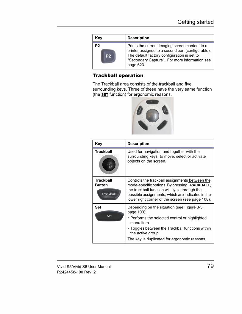
Getting started
Trackball operation
The Trackball area consists of the trackball and five surrounding keys. Three of these have the very same function (the SET function) for ergonomic reasons.
P2 Prints the current imaging screen content to a printer assigned to a second port (configurable). The default factory configuration is set to "Secondary Capture". For more information see page 623.
Key Description
Trackball Used for navigation and together with the surrounding keys, to move, select or activate objects on the screen.
Trackball Button
Controls the trackball assignments between the mode-specific options. By pressing TRACKBALL, the trackball function will cycle through the possible assignments, which are indicated in the lower right corner of the screen (see page 108).
Set Depending on the situation (see Figure 3-3, page 109):• Performs the selected control or highlighted
menu item.• Toggles between the Trackball functions within
the active group.The key is duplicated for ergonomic reasons.
Key Description
Vivid S5/Vivid S6 User Manual 79R2424458-100 Rev. 2
Getting started
Assignable keys and rotary knobs (soft keys)
The functions of the assignable keys and rotaries vary according to the mode and/or module in which the user is working.
Update/Menu In Freeze, activates menu with additional options and controls not available from the assignable keys.In live mode, toggles between 2D imaging and live time-motion imaging (Doppler/M-Mode).
Key Description
Soft Rotaries Four assignable rotary knobs, whose mode-specific functions vary according to the scan mode and position that is currently active. These assignable rotaries are used both as rotary-control knobs and as on/off toggles for different controls on the menu The assigned functions are indicated above the rotary on the LCD display. The mode-specific functions for these rotary knobs are described in Chapter 4, "Scanning Modes" on page 137.
Assignable Buttons
Four assignable buttons, whose mode-specific functions vary according to the scan mode and position that is currently active. These assignable buttons are used as on/off toggles for different controls on the menu. The assigned functions are indicated above the button on the LCD display. The mode-specific functions for these buttons are described in Chapter 4, "Scanning Modes" on page 137.
Key Description
80 Vivid S5/Vivid S6 User ManualR2424458-100 Rev. 2
Getting started
The soft menu rocker
The Alphanumeric Function keys
Key Description
Soft Menu Rocker
A 4-way rocker used to access mode-specific menus, select a menu option and adjust option-related values.• The vertical arrows are used to select the menu
options.• The horizontal arrows are used to adjust the
values. The mode-specific menus are described in Chapter 4, "Scanning Modes" on page 137.
Key Description
Help Displays the on-line version of the user manual.
Config/Diag Displays the configuration dialog box, allowing user configuration of various settings on the scanner.Diagnostics of the system is activated by pressing Shift > CONFIG.
LCD To activate LCD adjustments controlled by softkeys.
Biopsy Displays the biopsy path marker.
Bodymark Displays the available body marks for the current application.
Page Erase Erases all previously-typed annotations (and body marks).
Vivid S5/Vivid S6 User Manual 81R2424458-100 Rev. 2
Getting started
List of shortcuts on alphanumeric keyboard
Physio Provides access to controls for ECG trace. The ECG controls appear on the soft-menu.
Arrow Displays an arrow that can be used to point at a specific structure in the image.
Text Enables text annotation to be inserted on the image. The annotations can be typed or selected from a (configurable) menu.
Playback For future use
Delete Can be used to delete text during text annotation.
Key Description
Alt+E Allows to eject a device like MOD, CD or memory card.
Alt+L Allows to adjust intensity of keyboard backlight.
Alt+P Allows to view and control printer spooler.
Alt+S Allows to view and control DICOM spooler. (see "DICOM spooler" on page 479) The DICOM spooler is used for checking the current job's status when a job is saved or when the total spooler status on the right of the Archive windows displays an error.
Alt+D Allows to comment and save logfiles for diagnostics (see Chapter 14, "Adding Problem description" on page 646).
Alt+B Allows to insert a "bookmark" into the system failure log ("Adding bookmarks" on page 646)
Shift+Config Allows to run various diagnostics.
Key Description
82 Vivid S5/Vivid S6 User ManualR2424458-100 Rev. 2
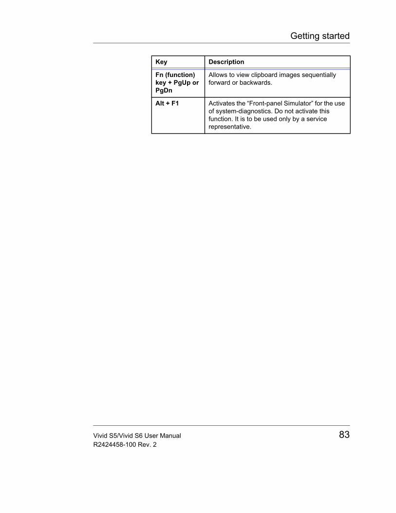
Getting started
Fn (function) key + PgUp or PgDn
Allows to view clipboard images sequentially forward or backwards.
Alt + F1 Activates the “Front-panel Simulator” for the use of system-diagnostics. Do not activate this function. It is to be used only by a service representative.
Key Description
Vivid S5/Vivid S6 User Manual 83R2424458-100 Rev. 2
Getting started
The Scanning screen
Figure 2-12: The scanning screen
1. Current patient ID data2. Date & time of original image3. Institution4. Operator ID5. Application & Temperature indicator for TEE
probe6. Probe7. Mechanical & Thermal Index8. Current date & time DVR (option) status and
counter indicators9. Heart rate10. Parameter window - all modes11. Greyscale/Color bar12. Soft menu window13. Clipboard navigator14. Cine progress bar15. Current menu name
16. Watermark area for screen calibration17. Soft menu control button18. Tracknall assignment19. Rotary soft-menu control20. Soft menu toggle button21. Clipboard image number22. Loop icon23. Service and iLinq, Caps on/off24. Clipboard25. ECG trace and Heart-rate26. Depth scale27. Focus marker28. TEE Scan plane indicator29. Probe orientation marker30. Measurement result table (measurement mode)31. Logo
84 Vivid S5/Vivid S6 User ManualR2424458-100 Rev. 2
Getting started
The scanning screen is divided in several areas as follows:
The title bar
From the left:
The patient infor-mation displayed on the Title bar is con-figurable (see page 592).
Patient InformationDisplays the information that uniquely identifies the patient, such as patient name, identification number and birth date. This information is entered in the New patient window, as described on page 95.
Institution nameThe institution name is entered from the configuration package. See page 633 for more detailed information.
Operator IDIdentification code of the operator. See page 637 for creating operator ID’s.
Date and timeDisplays the current date and time or for a retrieved image, the date and time at which it was stored.
Probe and ApplicationDisplays the currently selected probe and application or for retrieved image the probe and application that were used. See page 100 and page 548 for further information on how to select probe and application.
Live scanning related informationDisplays, if available, the current values for • Mechanical Index (MI), for the current active image• Thermal Index (TI), for the current active image• Probe temperature (for TE probe)• Heart rate (HR)
DVR Status and counter indicatorsDisplays the DVR counter as it changes in real time, and a status icon, which indicates the current operating status of the DVR.
Vivid S5/Vivid S6 User Manual 85R2424458-100 Rev. 2
Getting started
Archive InformationDisplays the currently selected patient and image archives.
Parameters window
Displays scan mode or application specific parameters. In scanning mode the parameters for the active mode are highlighted. This window also displays zoom information, stress template, and image groups in image browser.
Soft menu window
Displays the mode specific controls operated from the 4-way rocker on the control panel. The mode-specific menus are described in Chapter 4, "Scanning Modes" on page 137. For operating procedure of the 4-way rocker see page 107.
Clipboard
Displays the thumbnail images representing the acquired data during the current examination.
The status bar
Consists of four information fields as follows:
Service "Insite Express Connection" (ExC) iconEnable access to the GE Healthcare on-line service center.
Connectivity status iconDisplays the network status: Connected or disconnected.
Prompt/status fieldDisplays system messages or prompts the user for actions.
Trackball assignments fieldsDisplays the available assignments of the trackball. The current assignment is highlighted.
The acquisition window
Displays the ultrasound image with relevant indicators such as depth, focus, probe orientation marker, physiological traces etc.
86 Vivid S5/Vivid S6 User ManualR2424458-100 Rev. 2
Getting started
Three-Pedal Footswitch operationThe footswitch is used to free the hands of common key operations, such as select keys, video recording, etc. The three switches have different function assignments depending on the current application (see page 593).
To connect the footswitch• Connect the footswitch to the USB input on the External
connector (see Figure 2-6, page 59).
Connecting and disconnecting probes The connector panel situated in the front of the Vivid S6 has three imaging probe ports type RS, one imaging probe port type OR, and one pencil probe port.
The connector panel situated in the front of the Vivid S5 has three imaging probe ports type RS and one pencil probe port.
To connect a probe (Small connector - type RS)1. Hold the probe connector vertically with the cable pointing
upward.2. Push the connector locking handle to the right-most
position.3. Align the connector with the probe port and carefully push
into place.4. Push the connector locking handle to the left-most position.
WARNING
The standard footswitch is not for use in the operating room.
CAUTION
Handle the probes gently while connecting and disconnecting.
WARNING
Do NOT touch the patient and any of the connectors on the ultrasound unit simultaneously, including ultrasound probe connectors.
Vivid S5/Vivid S6 User Manual 87R2424458-100 Rev. 2
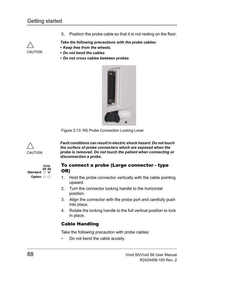
Getting started
5. Position the probe cable so that it is not resting on the floor.
Figure 2-13: RS Probe Connection Locking Lever
To connect a probe (Large connector - type OR)1. Hold the probe connector vertically with the cable pointing
upward.2. Turn the connector locking handle to the horizontal
position.3. Align the connector with the probe port and carefully push
into place.4. Rotate the locking handle to the full vertical position to lock
in place.
Cable Handling
Take the following precaution with probe cables:• Do not bend the cable acutely.
CAUTION
Take the following precautions with the probe cables:• Keep free from the wheels.• Do not bend the cables• Do not cross cables between probes
CAUTION
Fault conditions can result in electric shock hazard. Do not touch the surface of probe connectors which are exposed when the probe is removed. Do not touch the patient when connecting or disconnection a probe.
88 Vivid S5/Vivid S6 User ManualR2424458-100 Rev. 2
Getting started
Deactivating the Probe
Press the FREEZE key to deactivate the probe. When deactivating the probe, the probe is automatically placed in Standby mode.
Disconnecting the Probe
Probes can be disconnected at any time. It is recommended that the probe should not be active when being disconnected.
To disconnect a probe (Small connector - type RS):1. Freeze the image by pressing FREEZE.2. Press the connector locking lever towards the left to unlock
the connector.3. Pull the probe and connector straight out of the probe port.4. Carefully slide the probe and connector away form the
probe port and around the right side of the keyboard.5. Ensure the cable is free.6. Be sure that the probe head is clean before placing the
probe in its storage case.
To disconnect a probe (Large connector - type OR):1. Rotate the lock handle counter-clockwise to the horizontal
position to unlock the connector.2. Pull the connector straight out of the probe port.
Transporting ProbesWhen transporting a probe a long distance, store it in its carrying case.
Storing ProbesIt is recommended that all probes be stored in the carrying case provided.• First place the probe connector into the carrying case• Carefully wind the cable into the carrying case.• Carefully place the probe head into the carrying case.
DO NOT use excessive force or impact the probe face.
Vivid S5/Vivid S6 User Manual 89R2424458-100 Rev. 2
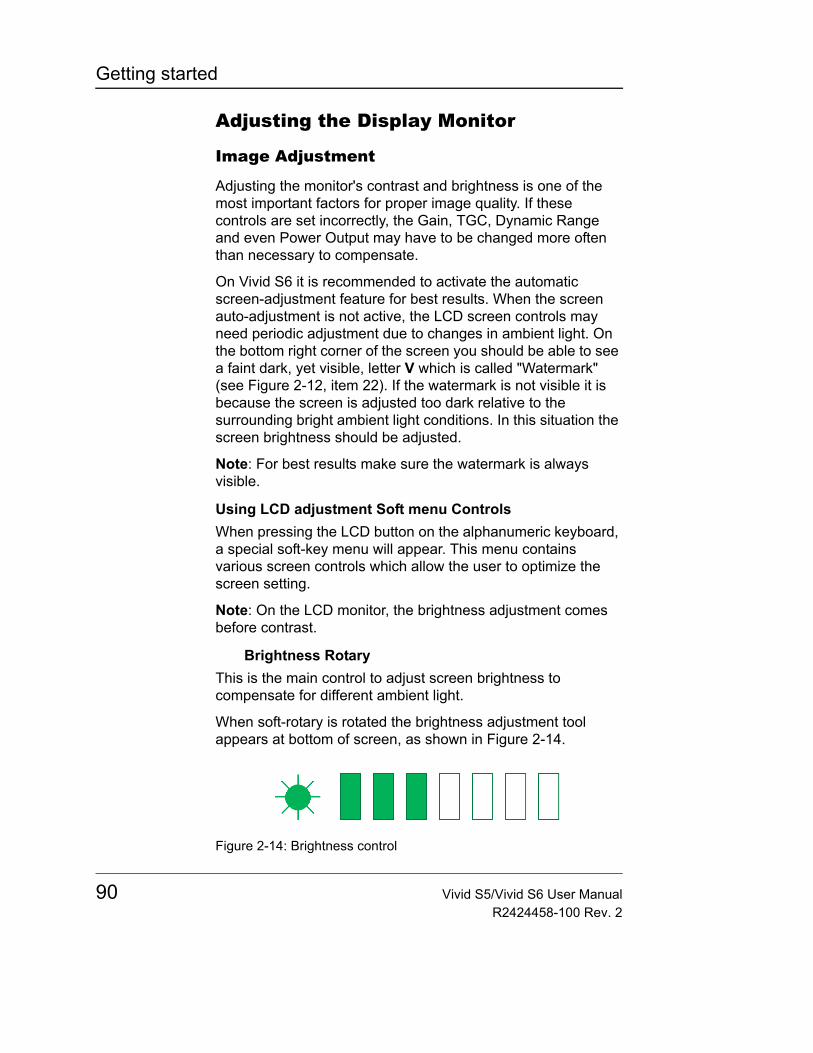
Getting started
Adjusting the Display Monitor
Image Adjustment
Adjusting the monitor's contrast and brightness is one of the most important factors for proper image quality. If these controls are set incorrectly, the Gain, TGC, Dynamic Range and even Power Output may have to be changed more often than necessary to compensate.
On Vivid S6 it is recommended to activate the automatic screen-adjustment feature for best results. When the screen auto-adjustment is not active, the LCD screen controls may need periodic adjustment due to changes in ambient light. On the bottom right corner of the screen you should be able to see a faint dark, yet visible, letter V which is called "Watermark" (see Figure 2-12, item 22). If the watermark is not visible it is because the screen is adjusted too dark relative to the surrounding bright ambient light conditions. In this situation the screen brightness should be adjusted.
Note: For best results make sure the watermark is always visible.
Using LCD adjustment Soft menu ControlsWhen pressing the LCD button on the alphanumeric keyboard, a special soft-key menu will appear. This menu contains various screen controls which allow the user to optimize the screen setting.
Note: On the LCD monitor, the brightness adjustment comes before contrast.
Brightness RotaryThis is the main control to adjust screen brightness to compensate for different ambient light.
When soft-rotary is rotated the brightness adjustment tool appears at bottom of screen, as shown in Figure 2-14.
Figure 2-14: Brightness control
90 Vivid S5/Vivid S6 User ManualR2424458-100 Rev. 2
Getting started
In a totally dark room it is recommended to set brightness down all the way (all rectangles are empty).
Make sure the wa-termark is visible at all time.
When ambient light becomes brighter and watermark becomes less visible, increase the brightness till watermark is visible again.
Contrast RotaryThis control is used to adjust screen contrast.
When soft-rotary is rotated the Contrast adjustment tool appears at bottom of screen, as shown in Figure 2-15.
Figure 2-15: Contrast control
Make sure the wa-termark is visible at all time.
In a totally dark room it is recommended to lower the contrast somewhat. In a well-lit or semi-lit room it is recommended to set contrast to its maximal setting.
Blue Tint RotaryThis control is used to adjust blue-tint or color-temperature of the white colors.
When soft-rotary is rotated the Blue-tint adjustment tool appears at bottom of screen, as shown in Figure 2-16.
Figure 2-16: Blue tint control
This may be adjusted to suite your preference.
External screen buttonActivate this button when connecting the system to an external display. It will allow you to optimize Contrast / Brightness and blue-tint to suit the particular external display.
When the button is de-activated, the previous settings that were optimized for the internal display will be restored.
Vivid S5/Vivid S6 User Manual 91R2424458-100 Rev. 2
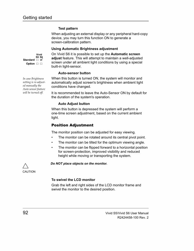
Getting started
Test patternWhen adjusting an external display or any peripheral hard-copy device, you may turn this function ON to generate a screen-calibration pattern.
Using Automatic Brightness adjustmentOn Vivid S6 it is possible to set up the Automatic screen adjust feature. This will attempt to maintain a well-adjusted screen under all ambient light conditions by using a special built-in light-sensor.
Auto-sensor buttonIn case Brightness setting is re-adjust-ed manually the Auto sensor feature will be turned off.
When this button is turned ON, the system will monitor and automatically adjust screen's brightness when ambient light conditions have changed.
It is recommended to leave the Auto-Sensor ON by default for the duration of the system's operation.
Auto Adjust buttonWhen this button is depressed the system will perform a one-time screen adjustment, based on the current ambient light.
Position Adjustment
The monitor position can be adjusted for easy viewing.• The monitor can be rotated around its central pivot point.• The monitor can be tilted for the optimum viewing angle.• The monitor can be flipped forward to a horizontal position
for screen-protection, improved visibility and reduced height while moving or transporting the system.
To swivel the LCD monitorGrab the left and right sides of the LCD monitor frame and swivel the monitor to the desired position.
CAUTION
Do NOT place objects on the monitor.
92 Vivid S5/Vivid S6 User ManualR2424458-100 Rev. 2
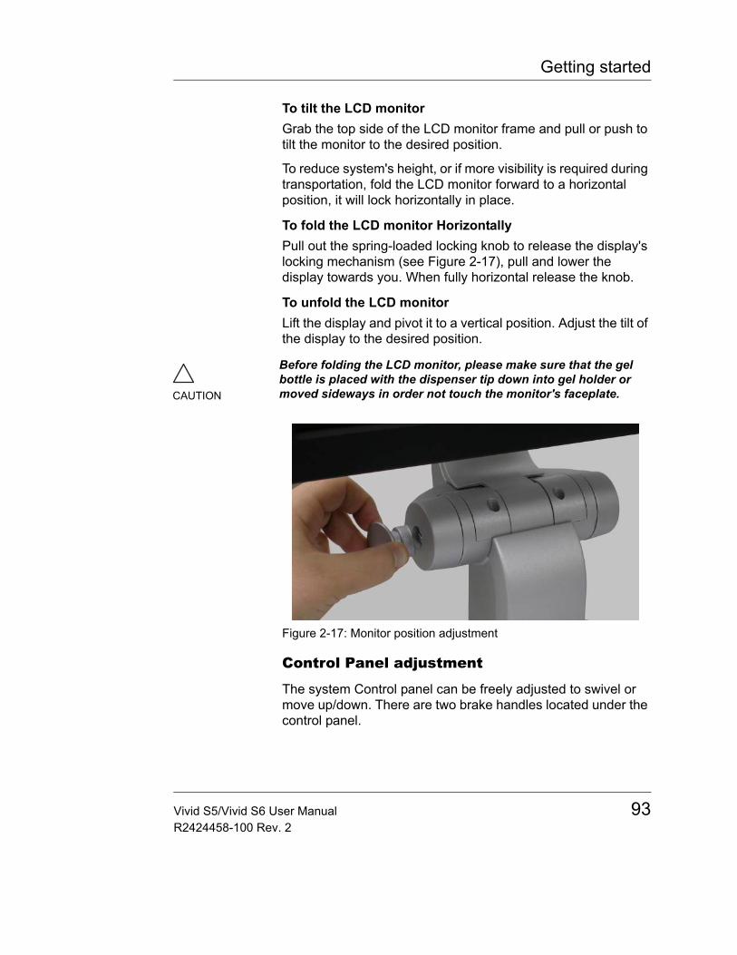
Getting started
To tilt the LCD monitorGrab the top side of the LCD monitor frame and pull or push to tilt the monitor to the desired position.
To reduce system's height, or if more visibility is required during transportation, fold the LCD monitor forward to a horizontal position, it will lock horizontally in place.
To fold the LCD monitor HorizontallyPull out the spring-loaded locking knob to release the display's locking mechanism (see Figure 2-17), pull and lower the display towards you. When fully horizontal release the knob.
To unfold the LCD monitorLift the display and pivot it to a vertical position. Adjust the tilt of the display to the desired position.
Figure 2-17: Monitor position adjustment
Control Panel adjustment
The system Control panel can be freely adjusted to swivel or move up/down. There are two brake handles located under the control panel.
CAUTION
Before folding the LCD monitor, please make sure that the gel bottle is placed with the dispenser tip down into gel holder or moved sideways in order not touch the monitor's faceplate.
Vivid S5/Vivid S6 User Manual 93R2424458-100 Rev. 2

Getting started
To swivel the control panel left or right1. Pull and hold the left brake handle, located under the
control panel.The control panel can now be freely rotated left or right.
2. When reaching the desired swivel angle, release the swivel-brake handle.The control panel will remain at the set angle.
Note: The LCD monitor will swivel together with the control-panel. In addition the LCD may be swiveled independently of the control-panel.
To move the control panel up or down1. Pull and hold the right-hand handle, located under the
control panel.The control panel can now be freely adjusted up or down.
2. When reaching the desired height, release the height-adjust handle.The control panel will remain at the set height.
Note: When the control panel is lowered it moves towards the operator. When panel is raised it also moves away from the operator.
Note: When preparing the system to be moved, pull the left handle and bring the control panel to a center position. Swivel it slightly till a locking click is heard.
94 Vivid S5/Vivid S6 User ManualR2424458-100 Rev. 2
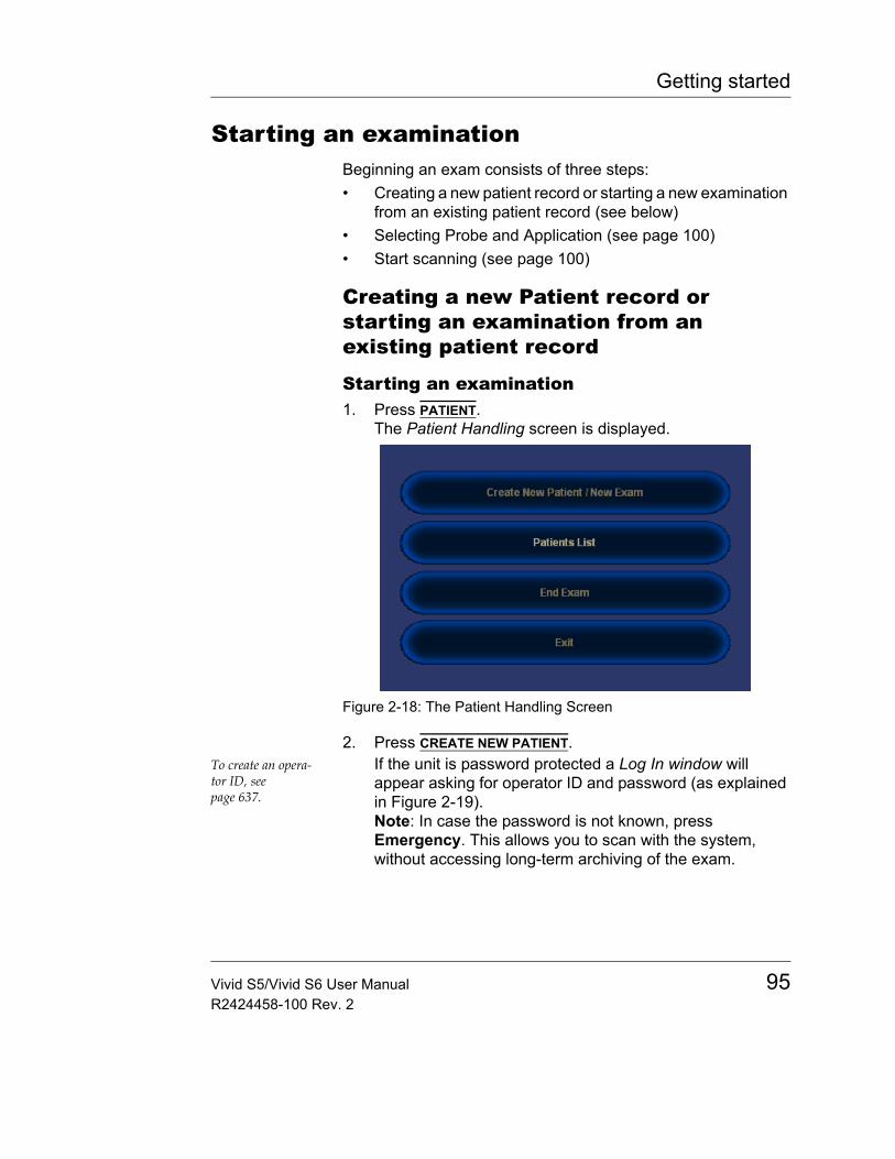
Getting started
Starting an examinationBeginning an exam consists of three steps:• Creating a new patient record or starting a new examination
from an existing patient record (see below)• Selecting Probe and Application (see page 100)• Start scanning (see page 100)
Creating a new Patient record or starting an examination from an existing patient record
Starting an examination1. Press PATIENT.
The Patient Handling screen is displayed.
Figure 2-18: The Patient Handling Screen
2. Press CREATE NEW PATIENT.To create an opera-tor ID, see page 637.
If the unit is password protected a Log In window will appear asking for operator ID and password (as explained in Figure 2-19).Note: In case the password is not known, press Emergency. This allows you to scan with the system, without accessing long-term archiving of the exam.
Vivid S5/Vivid S6 User Manual 95R2424458-100 Rev. 2
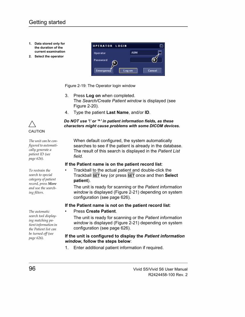
Getting started
Figure 2-19: The Operator login window
3. Press Log on when completed.The Search/Create Patient window is displayed (see Figure 2-20).
4. Type the patient Last Name, and/or ID.
The unit can be con-figured to automati-cally generate a patient ID (see page 626).
When default configured, the system automatically searches to see if the patient is already in the database. The result of this search is displayed in the Patient List field.
If the Patient name is on the patient record list:To restrain the search to special category of patient record, press More and use the search-ing filters.
• Trackball to the actual patient and double-click the Trackball SET key (or press SET once and then Select patient).The unit is ready for scanning or the Patient information window is displayed (Figure 2-21) depending on system configuration (see page 626).
If the Patient name is not on the patient record list:The automatic search tool display-ing matching pa-tient information in the Patient list can be turned off (see page 626).
• Press Create Patient.The unit is ready for scanning or the Patient information window is displayed (Figure 2-21) depending on system configuration (see page 626).
If the unit is configured to display the Patient information window, follow the steps below:1. Enter additional patient information if required.
1. Data stored only for the duration of the current examination
2. Select the operator
CAUTION
Do NOT use '\' or '^' in patient information fields, as these characters might cause problems with some DICOM devices.
96 Vivid S5/Vivid S6 User ManualR2424458-100 Rev. 2
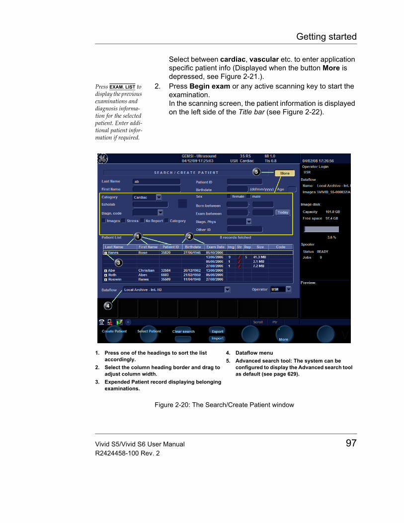
Getting started
Select between cardiac, vascular etc. to enter application specific patient info (Displayed when the button More is depressed, see Figure 2-21.).
Press EXAM. LIST to display the previous examinations and diagnosis informa-tion for the selected patient. Enter addi-tional patient infor-mation if required.
2. Press Begin exam or any active scanning key to start the examination.In the scanning screen, the patient information is displayed on the left side of the Title bar (see Figure 2-22).
Figure 2-20: The Search/Create Patient window
1. Press one of the headings to sort the list accordingly.
2. Select the column heading border and drag to adjust column width.
3. Expended Patient record displaying belonging examinations.
4. Dataflow menu5. Advanced search tool: The system can be
configured to display the Advanced search tool as default (see page 629).
Vivid S5/Vivid S6 User Manual 97R2424458-100 Rev. 2
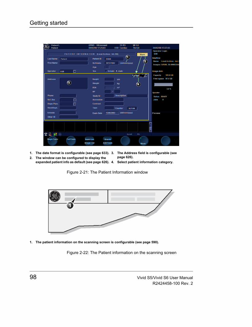
Getting started
Figure 2-21: The Patient Information window
Figure 2-22: The Patient information on the scanning screen
1. The date format is configurable (see page 633).2. The window can be configured to display the
expanded patient info as default (see page 626).
3. The Address field is configurable (see page 626).
4. Select patient information category.
1. The patient information on the scanning screen is configurable (see page 590).
98 Vivid S5/Vivid S6 User ManualR2424458-100 Rev. 2
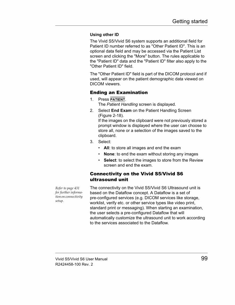
Getting started
Using other IDThe Vivid S5/Vivid S6 system supports an additional field for Patient ID number referred to as "Other Patient ID". This is an optional data field and may be accessed via the Patient List screen and clicking the "More" button. The rules applicable to the "Patient ID" data and the "Patient ID" filter also apply to the "Other Patient ID" field.
The "Other Patient ID" field is part of the DICOM protocol and if used, will appear on the patient demographic data viewed on DICOM viewers.
Ending an Examination1. Press PATIENT.
The Patient Handling screen is displayed.2. Select End Exam on the Patient Handling Screen
(Figure 2-18).If the images on the clipboard were not previously stored a prompt window is displayed where the user can choose to store all, none or a selection of the images saved to the clipboard.
3. Select:• All: to store all images and end the exam• None: to end the exam without storing any images• Select: to select the images to store from the Review
screen and end the exam.
Connectivity on the Vivid S5/Vivid S6 ultrasound unit
Refer to page 431 for further informa-tion on connectivity setup.
The connectivity on the Vivid S5/Vivid S6 Ultrasound unit is based on the Dataflow concept. A Dataflow is a set of pre-configured services (e.g. DICOM services like storage, worklist, verify etc. or other service types like video print, standard print or messaging). When starting an examination, the user selects a pre-configured Dataflow that will automatically customize the ultrasound unit to work according to the services associated to the Dataflow.
Vivid S5/Vivid S6 User Manual 99R2424458-100 Rev. 2
Getting started
Selecting a Probe and an ApplicationThe combination Probe-Application may be user-de-fined. See page 593 for information on probe/application configuration.
Probes and their related applications are selected from the Probes and applications pop-up menus as described below. Only probes currently connected are displayed in the pop-up menu. Only applications appropriate for the type of probe selected are shown.
To select a probe and an application1. Press PROBE on the control panel.
A list of the connected probes is displayed.2. Trackball to the desired probe.3. Press SET.
An Application menu for the selected probe is displayed.4. Trackball to the desired application.
To select a probe with the default ap-plication, press SET twice on the actual probe.
5. Press SET to launch the application.
CAUTION
Make sure that the probe and application names displayed on the screen correspond to the actual probe and application selection.
Check that the correct TI category is displayed (see Chapter 1, "Thermal Index" on page 26). TIB must be displayed when a fetal application is selected.
100 Vivid S5/Vivid S6 User ManualR2424458-100 Rev. 2
Basic scanning operations
Chapter 3 Basic scanning operations
This chapter describes basic operations related to scanning. Some operations described in this chapter are fully described in the respective chapters throughout the manual.
This chapter includes the following information:
• Assignable keys and Soft Menu Rocker ..................................... .. 103• Using the Assignable Keys Soft Menu ..................................... 104• Using the Soft Menu Rocker .................................................... 107
• Trackball operation ....................................................................... .. 108• Trackball assignment ............................................................... 108• The system menu ..................................................................... 109
• Cineloop operation ....................................................................... .. 110• Cineloop overview .................................................................... 110• Cineloop controls ..................................................................... 111• Using cineloop .......................................................................... 112
• Storing images and cineloops ..................................................... .. 113• To store a single image ............................................................ 113• To store a cineloop ................................................................... 113
• Removable Media .......................................................................... .. 114• Intended use ............................................................................ 114• Supported removable media .................................................... 115
• Zoom .............................................................................................. .. 120• To Magnify an image (Display zoom) ....................................... 120
• Performing measurements .......................................................... .. 121• To perform measurements ....................................................... 121
• Physiological trace ....................................................................... .. 122• Connecting the internal ECG ................................................... 122• Physio controls ......................................................................... 126• Displaying the ECG trace ......................................................... 126
Vivid S5/Vivid S6 User Manual 101R2424458-100 Rev. 2
Basic scanning operations
• Adjusting the display of the ECG trace .....................................126• Annotations ................................................................................... ... 128
• To insert an annotation .............................................................128• To edit annotation .....................................................................131• To erase annotation ..................................................................131• Configuration of the pre-defined annotation list ........................132• Bodymarks ................................................................................134
102 Vivid S5/Vivid S6 User ManualR2424458-100 Rev. 2
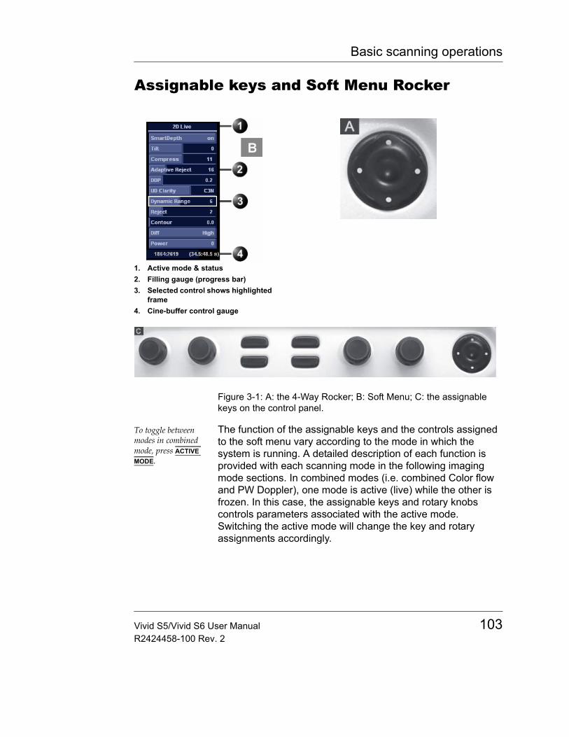
Basic scanning operations
Assignable keys and Soft Menu Rocker
Figure 3-1: A: the 4-Way Rocker; B: Soft Menu; C: the assignable keys on the control panel.
To toggle between modes in combined mode, press ACTIVE MODE.
The function of the assignable keys and the controls assigned to the soft menu vary according to the mode in which the system is running. A detailed description of each function is provided with each scanning mode in the following imaging mode sections. In combined modes (i.e. combined Color flow and PW Doppler), one mode is active (live) while the other is frozen. In this case, the assignable keys and rotary knobs controls parameters associated with the active mode. Switching the active mode will change the key and rotary assignments accordingly.
1. Active mode & status2. Filling gauge (progress bar)3. Selected control shows highlighted
frame4. Cine-buffer control gauge
Vivid S5/Vivid S6 User Manual 103R2424458-100 Rev. 2
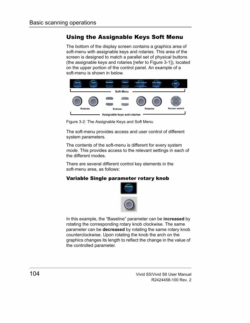
Basic scanning operations
Using the Assignable Keys Soft MenuThe bottom of the display screen contains a graphics area of soft-menu with assignable keys and rotaries. This area of the screen is designed to match a parallel set of physical buttons (the assignable keys and rotaries [refer to Figure 3-1]), located on the upper portion of the control panel. An example of a soft-menu is shown in below.
Figure 3-2: The Assignable Keys and Soft Menu
The soft-menu provides access and user control of different system parameters.
The contents of the soft-menu is different for every system mode. This provides access to the relevant settings in each of the different modes.
There are several different control key elements in the soft-menu area, as follows:
Variable Single parameter rotary knob
In this example, the “Baseline” parameter can be increased by rotating the corresponding rotary knob clockwise. The same parameter can be decreased by rotating the same rotary knob counterclockwise. Upon rotating the knob the arch on the graphics changes its length to reflect the change in the value of the controlled parameter.
104 Vivid S5/Vivid S6 User ManualR2424458-100 Rev. 2
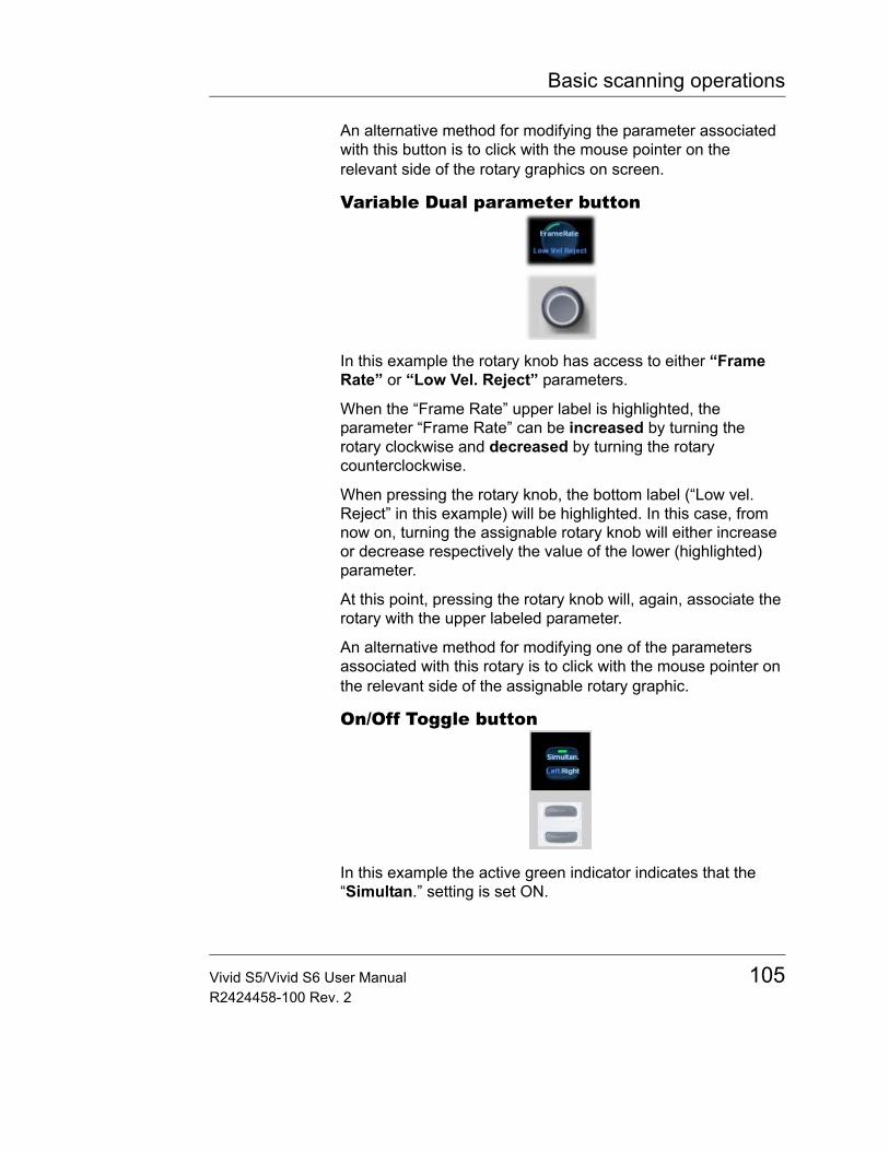
Basic scanning operations
An alternative method for modifying the parameter associated with this button is to click with the mouse pointer on the relevant side of the rotary graphics on screen.
Variable Dual parameter button
In this example the rotary knob has access to either “Frame Rate” or “Low Vel. Reject” parameters.
When the “Frame Rate” upper label is highlighted, the parameter “Frame Rate” can be increased by turning the rotary clockwise and decreased by turning the rotary counterclockwise.
When pressing the rotary knob, the bottom label (“Low vel. Reject” in this example) will be highlighted. In this case, from now on, turning the assignable rotary knob will either increase or decrease respectively the value of the lower (highlighted) parameter.
At this point, pressing the rotary knob will, again, associate the rotary with the upper labeled parameter.
An alternative method for modifying one of the parameters associated with this rotary is to click with the mouse pointer on the relevant side of the assignable rotary graphic.
On/Off Toggle button
In this example the active green indicator indicates that the “Simultan.” setting is set ON.
Vivid S5/Vivid S6 User Manual 105R2424458-100 Rev. 2
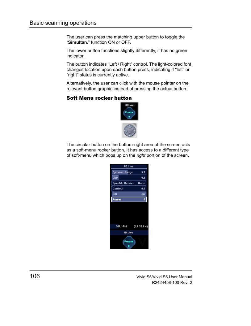
Basic scanning operations
The user can press the matching upper button to toggle the “Simultan.” function ON or OFF.
The lower button functions slightly differently, it has no green indicator.
The button indicates "Left / Right" control. The light-colored font changes location upon each button press, indicating if "left" or "right" status is currently active.
Alternatively, the user can click with the mouse pointer on the relevant button graphic instead of pressing the actual button.
Soft Menu rocker button
The circular button on the bottom-right area of the screen acts as a soft-menu rocker button. It has access to a different type of soft-menu which pops up on the right portion of the screen.
106 Vivid S5/Vivid S6 User ManualR2424458-100 Rev. 2
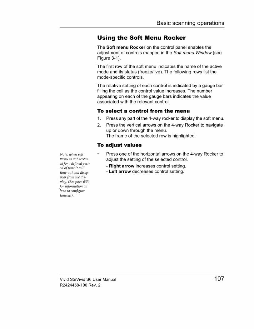
Basic scanning operations
Using the Soft Menu RockerThe Soft menu Rocker on the control panel enables the adjustment of controls mapped in the Soft menu Window (see Figure 3-1).
The first row of the soft menu indicates the name of the active mode and its status (freeze/live). The following rows list the mode-specific controls.
The relative setting of each control is indicated by a gauge bar filling the cell as the control value increases. The number appearing on each of the gauge bars indicates the value associated with the relevant control.
To select a control from the menu1. Press any part of the 4-way rocker to display the soft menu.2. Press the vertical arrows on the 4-way Rocker to navigate
up or down through the menu. The frame of the selected row is highlighted.
To adjust values
Note: when soft menu is not access-ed for a defined peri-od of time it will time-out and disap-pear from the dis-play. (See page 633 for information on how to configure timeout).
• Press one of the horizontal arrows on the 4-way Rocker to adjust the setting of the selected control. - Right arrow increases control setting.- Left arrow decreases control setting.
Vivid S5/Vivid S6 User Manual 107R2424458-100 Rev. 2
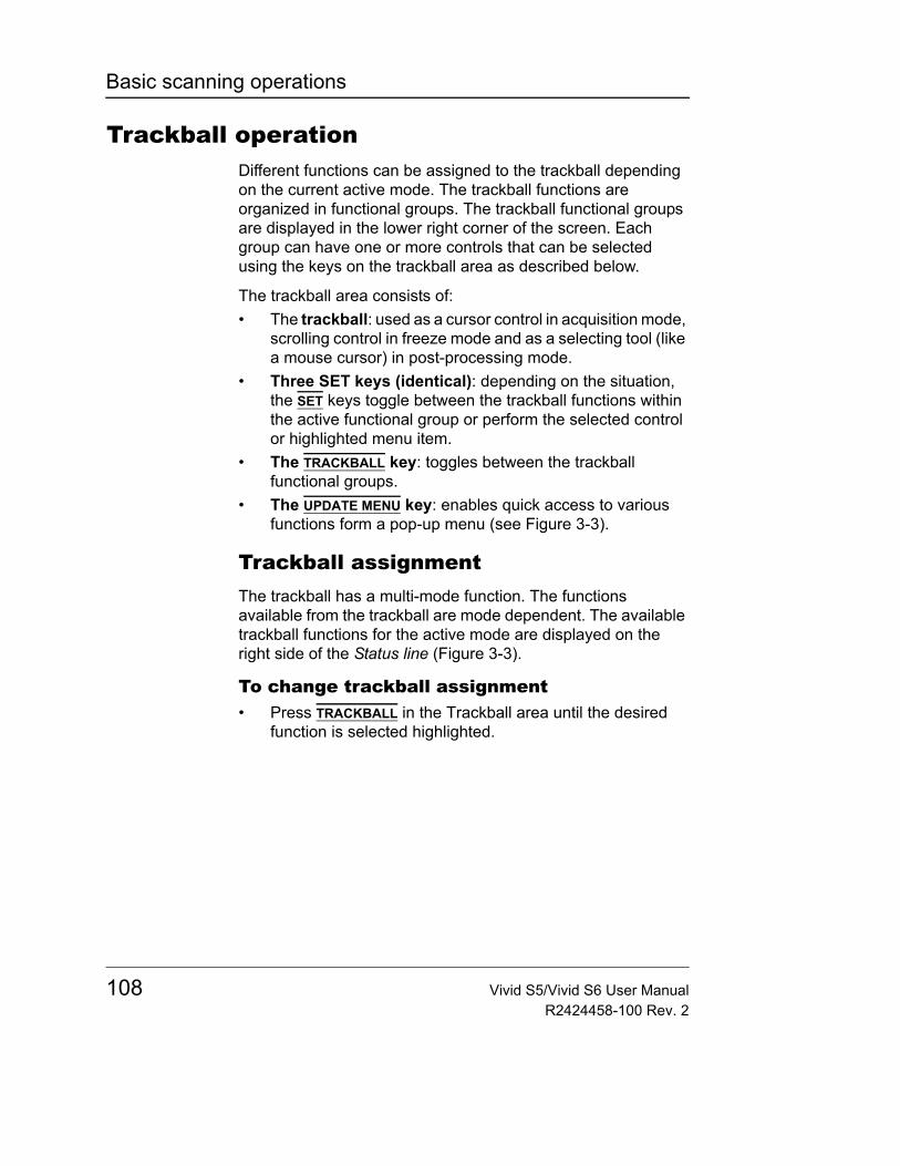
Basic scanning operations
Trackball operationDifferent functions can be assigned to the trackball depending on the current active mode. The trackball functions are organized in functional groups. The trackball functional groups are displayed in the lower right corner of the screen. Each group can have one or more controls that can be selected using the keys on the trackball area as described below.
The trackball area consists of:• The trackball: used as a cursor control in acquisition mode,
scrolling control in freeze mode and as a selecting tool (like a mouse cursor) in post-processing mode.
• Three SET keys (identical): depending on the situation, the SET keys toggle between the trackball functions within the active functional group or perform the selected control or highlighted menu item.
• The TRACKBALL key: toggles between the trackball functional groups.
• The UPDATE MENU key: enables quick access to various functions form a pop-up menu (see Figure 3-3).
Trackball assignmentThe trackball has a multi-mode function. The functions available from the trackball are mode dependent. The available trackball functions for the active mode are displayed on the right side of the Status line (Figure 3-3).
To change trackball assignment• Press TRACKBALL in the Trackball area until the desired
function is selected highlighted.
108 Vivid S5/Vivid S6 User ManualR2424458-100 Rev. 2
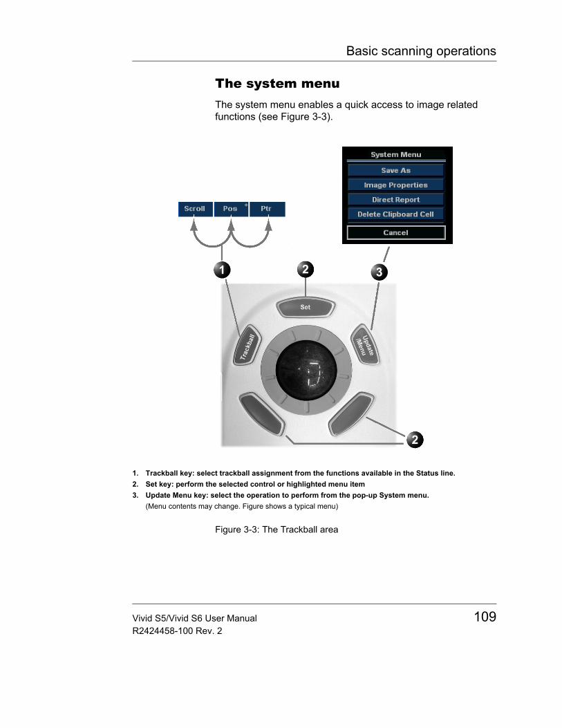
Basic scanning operations
The system menuThe system menu enables a quick access to image related functions (see Figure 3-3).
Figure 3-3: The Trackball area
1. Trackball key: select trackball assignment from the functions available in the Status line.2. Set key: perform the selected control or highlighted menu item3. Update Menu key: select the operation to perform from the pop-up System menu.
(Menu contents may change. Figure shows a typical menu)
Vivid S5/Vivid S6 User Manual 109R2424458-100 Rev. 2
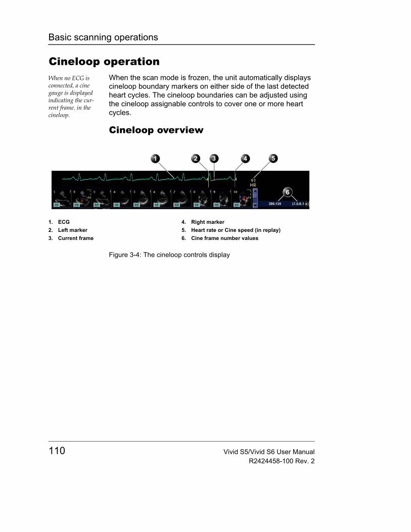
Basic scanning operations
Cineloop operationWhen no ECG is connected, a cine gauge is displayed indicating the cur-rent frame. in the cineloop.
When the scan mode is frozen, the unit automatically displays cineloop boundary markers on either side of the last detected heart cycles. The cineloop boundaries can be adjusted using the cineloop assignable controls to cover one or more heart cycles.
Cineloop overview
Figure 3-4: The cineloop controls display
1. ECG2. Left marker3. Current frame
4. Right marker5. Heart rate or Cine speed (in replay)6. Cine frame number values
110 Vivid S5/Vivid S6 User ManualR2424458-100 Rev. 2
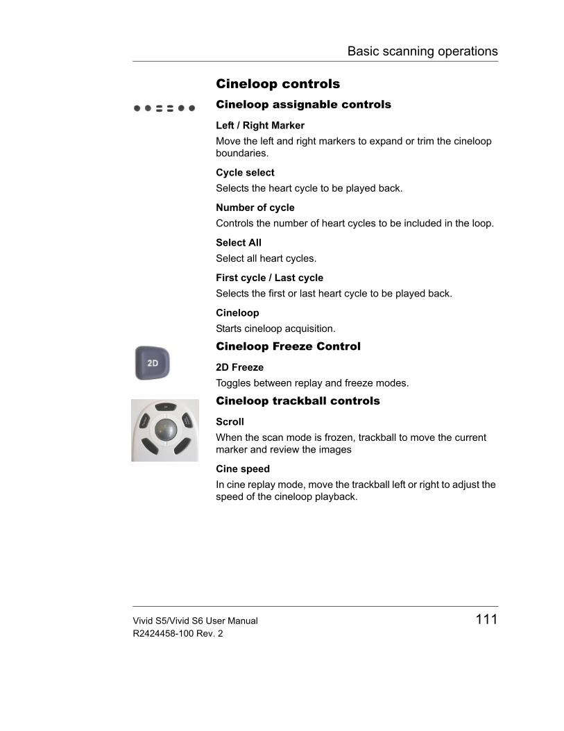
Basic scanning operations
Cineloop controlsCineloop assignable controls
Left / Right MarkerMove the left and right markers to expand or trim the cineloop boundaries.
Cycle selectSelects the heart cycle to be played back.
Number of cycleControls the number of heart cycles to be included in the loop.
Select AllSelect all heart cycles.
First cycle / Last cycleSelects the first or last heart cycle to be played back.
CineloopStarts cineloop acquisition.
Cineloop Freeze Control
2D FreezeToggles between replay and freeze modes.
Cineloop trackball controls
ScrollWhen the scan mode is frozen, trackball to move the current marker and review the images
Cine speedIn cine replay mode, move the trackball left or right to adjust the speed of the cineloop playback.
Vivid S5/Vivid S6 User Manual 111R2424458-100 Rev. 2
Basic scanning operations
Using cineloop
Selection of a cineloop1. Press FREEZE.
The left and right markers on the ECG trace are displayed on either side of the last detected heart cycle.
2. Press the 2D FREEZE button to un-freeze the cineloop and let it run between the default setting of left and right borders.
3. To modify setting of the left or right borders, press the CINELOOP assignable.The selected heart beat is played back.
4. Press on the assignable CYCLE SELECT to move from heart beat to heart beat to select the heart cycle of interest.
To jump directly to the first or to the last heart beat press the assignables FIRST CYCLE or LAST CYCLE.
5. Press on the assignable NUM CYCLES to increase or decrease the number of heart beats to be played back.
6. Adjust LEFT MARKER and RIGHT MARKER assignables to trim or expand the cineloop boundaries.
Adjustment of cineloop playback1. If in freeze mode, press the assignable 2D FREEZE to start
cineloop replay.2. Use the Trackball to increase or decrease the speed of the
cineloop playback.The speed factor is displayed on the right side of the ECG (see Figure 3-4).
To view a cineloop frame by frame1. If not in freeze mode, press the 2D FREEZE button to freeze
the cineloop.2. Use the Trackball to scroll through the cineloop frame by
frame.OrUse the Speed/Frame softkey button.
112 Vivid S5/Vivid S6 User ManualR2424458-100 Rev. 2
Basic scanning operations
Storing images and cineloopsImages stored on the clipboard dur-ing the scanning session are for im-mediate purposes. At the end of the ex-amination, the data should be archived in the patient ar-chiving system (re-fer to page 403).
Images and cine-loops can be stored at any time during the scanning session. A thumbnail of the stored image is displayed on the clipboard on the scanning screen. An icon will also be displayed in the Image Browser and Image Selection screens.
Protocol based stored images (Stress option) will also be displayed in the protocol grid in the Parameters window.
The amount of data stored from 2D live is defined by the settings of the current application. The application setting controls the number of cycles included (or time span if ECG is not active), time span before R-wave etc. (refer to page 590 and page 593 for further information).
The amount of data stored in images from 2D replay is determined by the defined cineloop.
Images can be stored in either DICOM and GE Raw Data formats or DICOM format only, depending on the dataflow configuration (refer to page 616 for further information).
To store a single image1. Press FREEZE.2. Press STORE to store the image digitally.
The thumbnail of the image is displayed on the clipboard.See also page 406 for further information.
To store a cineloopWhile in scanning mode, press the STORE button to store the last heart-cycle loop. It is possible to configure this function in several ways. Cineloops may be stored directly or after preview, depending on how the system is configured.
While in cine-loop preview mode press STORE to store the selected loop.
Cineloop length and loop selection is adjustable in several ways. The procedure for cineloop storage is described on page 406.
Vivid S5/Vivid S6 User Manual 113R2424458-100 Rev. 2
Basic scanning operations
Removable Media
Intended useRemovable media can be used for the following purposes:• Long-term image storage: the final destination of the
images, after they are moved out of the system harddisk by using the Disk Management feature (see "Disk Management" on page 464).
• Backup of patient database and system configuration presets (see "Data Backup and Restore" on page 471)
• Patient archive sneaker-net: copy a set of patient records between a scanner and EchoPAC PC using the Import/Export feature (see "Export/Import patient records/examinations" on page 452) with a removable media.
• DICOM export to copy a set of patient records to a third party DICOM review station.
• MPEGVue export: review exported images on a Windows computer (see "Export/Import patient records/examinations" on page 452).
• Excel export: exports demographics, measurements and reporting data from the unit to a third party reporting application using a removable media (see "Export/Import patient records/examinations" on page 452).
• Copy of system configuration presets between to units using the Backup/Restore feature (see "Data Backup and Restore" on page 471).
• Save images as JPEG or AVI for review on a regular computer.
114 Vivid S5/Vivid S6 User ManualR2424458-100 Rev. 2
Basic scanning operations
Supported removable mediaThe following removable media options can be used for data storage:• 5 1/4” Magneto Optical disk (from Sony only, 1.3, 2.3, 2.6,
5.4, 8.6 and 9.1 Gb)• USB Flash Card
• CD-R (CD-RW is not supported.)• DVD-R or DVD+R (use 8x or higher speed.)
DVD+RW media is used for DVR video recording only and can not be used for archive data-storage (see "DVR (Digital Video Recorder)" on page 578)
About removable media and long-term image storage
We recommend running the Disk management feature with MOD media for long-term image storage, because of the longevity and reliability of these media. It is not recommended to use CD or DVD for long-term storage, because of weaker performance in general when it comes to longevity and reliability. However, Disk management does not prevent the use of CD/DVD for long-term image storage. If CD/DVD is used it is recommended to use Archival Grade or Medical Grade CD/DVD.
CAUTION
Use only shielded USB Flash cards that are verified for EMC performance according to EN55011 Class A or B. The use of other USB Flash cards may cause interference on the system itself or on other electronic devices.
CAUTION
DO NOT USE devices containing embedded U3 technology programs as these might interfere with the proper operation of the Vivid S5/Vivid S6 system.
CAUTION
Use only 24x or higher CD-R.
Vivid S5/Vivid S6 User Manual 115R2424458-100 Rev. 2
Basic scanning operations
No matter which media is used, it is always highly recommended to take a backup of the media, which is the responsibility of the customer.
The system does not offer functionality for taking backup of images saved on long-term storage media.
Recommendation concerning CD and DVD handling
To avoid data loss, never touch the recordable surface of a disk. Handle the disk only by the outer edge. Do not place it face down on a hard surface. Fingerprints or scratches will make the disk unusable. Before usage, verify that disk surface has no visible scratches. If there are any scratches, do NOT use the disk.
Writing on CD or DVD media
Use specifically recommended for writing on CD or DVD media. Never use a solvent-based permanent marker on such media. The following pens are recommended:• Dixon Ticonderoga "Redi Sharp Plus"• Sanford "Powermark"• TDK "CD Writer"• Smart and Friendly "CD Speed Marker"
Formatting removable media
MOD, CD-R, DVD+R, and DVD-R media must be formatted before use, as described in below.
Formatting may be done in two methods:1. Formatting just prior to using the media, as described in
"Exporting patient records/examinations" on page 452.2. Preparation well ahead of time as described in the following
section.
CAUTION
The formatting process will erase any data present on the disk.
116 Vivid S5/Vivid S6 User ManualR2424458-100 Rev. 2
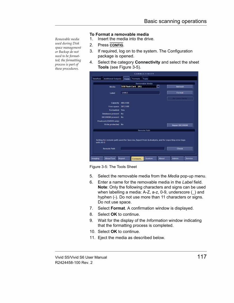
Basic scanning operations
To Format a removable mediaRemovable media used during Disk space management or Backup do not need to be format-ted; the formatting process is part of these procedures.
1. Insert the media into the drive.2. Press CONFIG.3. If required, log on to the system. The Configuration
package is opened.4. Select the category Connectivity and select the sheet
Tools (see Figure 3-5).
Figure 3-5: The Tools Sheet
5. Select the removable media from the Media pop-up menu.6. Enter a name for the removable media in the Label field.
Note: Only the following characters and signs can be used when labelling a media: A-Z, a-z, 0-9, underscore (_) and hyphen (-). Do not use more than 11 characters or signs. Do not use space.
7. Select Format. A confirmation window is displayed.8. Select OK to continue.9. Wait for the display of the Information window indicating
that the formatting process is completed.10. Select OK to continue.11. Eject the media as described below.
Vivid S5/Vivid S6 User Manual 117R2424458-100 Rev. 2
Basic scanning operations
Note: Removable media used during Disk space management, Backup, Export or "Save-As..." do not need to be formatted in advance as the formatting process is part of these procedures if required.
Additional networking functions
Additional networking functions contained in this tab are described below.
Note: Before using any of these functions, verify that the destination PC / Network has been set up with a shared folder (remote path) with user permissions. Configuring the shared folder for the first time will involve your GE field-service engineer.
Save As PDF to network pathSave As PDF Network Path is used for saving Reports as PDFs to a destination PC or network.1. Under "Save As PDF Network Path", in the Remote Path
field, type the remote path. For example type: \\IP ADDRESS\DIRECTORY, where directory is the name of the shared folder in the destination PC.
2. Click Check to verify the connection.
Note: When clicking the Check button, you might momentarily see a "failed" message that disappears if you click Check a second time. The system will then confirm the setting.
Remote Path1. Under "Setting for Remote Path used for Save As...", type
the remote path as follows:\\IP ADDRESS\DIRECTORY
2. Click Check to verify the connection.
Configurable Remote Path UserIt is possible to configure an additional user name and password for all remote paths. These settings are only used if the system fails to log on the default user and password.• Under Configurable Remote Path User, type the desired
user name and password as configured on the destination PC (this is the password usually assigned by the local IT person).
118 Vivid S5/Vivid S6 User ManualR2424458-100 Rev. 2
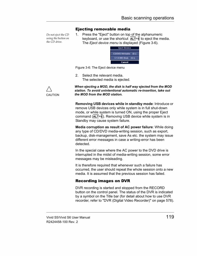
Basic scanning operations
Ejecting removable mediaDo not eject the CD using the button on the CD drive.
1. Press the "Eject" button on top of the alphanumeric keyboard, or use the shortcut ALT+E to eject the media.The Eject device menu is displayed (Figure 3-6).
Figure 3-6: The Eject device menu
2. Select the relevant media.The selected media is ejected.
Removing USB devices while in standby mode: Introduce or remove USB devices only while system is in full shut-down mode, or while system is turned ON, using the proper Eject command (ALT+E). Removing USB device while system is in Standby may cause system failure.
Media corruption as result of AC power failure: While doing any type of CD/DVD media-writing session, such as export, backup, disk-management, save As etc. the system may issue different error messages in case a writing-error has been detected.
In the special case where the AC power to the DVD drive is interrupted in the midst of media-writing session, some error messages may be misleading.
It is therefore required that whenever such a failure has occurred, the user should repeat the whole session onto a new media. It is assumed that the previous session has failed.
Recording images on DVR
DVR recording is started and stopped from the RECORD button on the control panel. The status of the DVR is indicated by a symbol on the Title bar (for detail about how to use DVR recorder, refer to "DVR (Digital Video Recorder)" on page 578).
CAUTION
When ejecting a MOD, the disk is half way ejected from the MOD station. To avoid unintentional automatic re-insertion, take out the MOD from the MOD station.
Vivid S5/Vivid S6 User Manual 119R2424458-100 Rev. 2
Basic scanning operations
ZoomThe Vivid S5/Vivid S6 supports two types of zoom: the display zoom and the high resolution (HR) zoom.• The Display zoom (sometimes called "Read" zoom)
magnifies the image display in both frozen and live 2D, M-Mode and combined modes.
• The HR zoom (sometimes called "Write" zoom) concentrates the image processing to a user selectable portion of the image, resulting in an improved image quality and a higher frame rate in the chosen ROI.
To Magnify an image (Display zoom)The Display zoom is available in live and replay.
1. Rotate the Zoom knob clockwise.The resulting magnified image appears in the acquisition window while the un-magnified image is displayed in the control window showing the outlined zoom region.
2. Use the Trackball to position the zoom area over the desired portion of the image.
3. To turn off the Display zoom, rotate the Zoom knob counterclockwise, or press it twice.
Note: While in Display zoom, pressing the zoom knob once will activate HR zoom, as explained below.
To activate the HR zoomAs a default setting, the zoom area is centered to the cur-sor/color area if present.
1. Press the Zoom knob.The resulting zoomed image appears in the acquisition window and a frozen reference image is displayed in the control window showing the outlined zoom region.
2. Use the Trackball to position the zoom area over the desired portion of the image.
3. Increase size as desired by turning the zoom knob clockwise.
4. To turn off the HR zoom, press the Zoom knob once, or rotate it counter clockwise until zoom reference image disappears.
Note: While zooming in any zoom method, pressing SET once allows using the trackball to modify zoom ROI dimensions and zoom magnification factor.
120 Vivid S5/Vivid S6 User ManualR2424458-100 Rev. 2
Basic scanning operations
Performing measurements
To perform measurements• Press MEASURE to enter the Measurement mode.
Refer to page 243 for further information.Or
• Press CALIPER to perform simple generic measurements.
Vivid S5/Vivid S6 User Manual 121R2424458-100 Rev. 2
Basic scanning operations
Physiological traceThe physiological module consists of a single connector, which can accept either a set of electrodes cable or an External-ECG cable, capable of handling external ECG signals from other diagnostic ECG devices.
The scanned image that is displayed is synchronized with the ECG trace. In M-Mode or Doppler, the traces are synchronized to that particular mode's sweep.
The operator can control the gain, the position and the sweep rate of the traces using the assignables on the control panel.
Connecting the internal ECGThe ECG cable is a modular cable consisting of two different cables parts:• The Trunk: a single cable connecting to the system at one
end, and providing a cable splitter device at the other end.• The triple color-coded electrode cable: to be inserted in
the splitter device. Each electrode cable hooks up to the appropriate stick-on electrode by a color-coded clip type connector.
The color-coding of the electrodes follows one of two standards that are common in different parts of the world. The cable splitter device has a drawing defining the color codes, names and body location for the two standard color codes. Refer to the Table 3-1.
CAUTION
Use only GE Medical Systems accessories Conductive parts of electrodes and associated connectors for applied parts, including neutral electrodes should not contact other conductive parts, including earth.
Simultaneous use of two or more applied parts will cause summation of patient leakage currents.
122 Vivid S5/Vivid S6 User ManualR2424458-100 Rev. 2
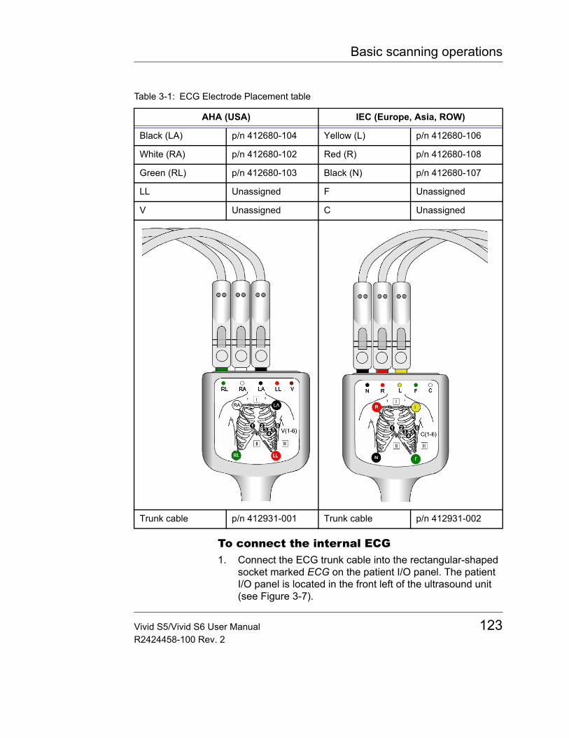
Basic scanning operations
To connect the internal ECG1. Connect the ECG trunk cable into the rectangular-shaped
socket marked ECG on the patient I/O panel. The patient I/O panel is located in the front left of the ultrasound unit (see Figure 3-7).
Table 3-1: ECG Electrode Placement table
AHA (USA) IEC (Europe, Asia, ROW)
Black (LA) p/n 412680-104 Yellow (L) p/n 412680-106
White (RA) p/n 412680-102 Red (R) p/n 412680-108
Green (RL) p/n 412680-103 Black (N) p/n 412680-107
LL Unassigned F Unassigned
V Unassigned C Unassigned
Trunk cable p/n 412931-001 Trunk cable p/n 412931-002
Vivid S5/Vivid S6 User Manual 123R2424458-100 Rev. 2
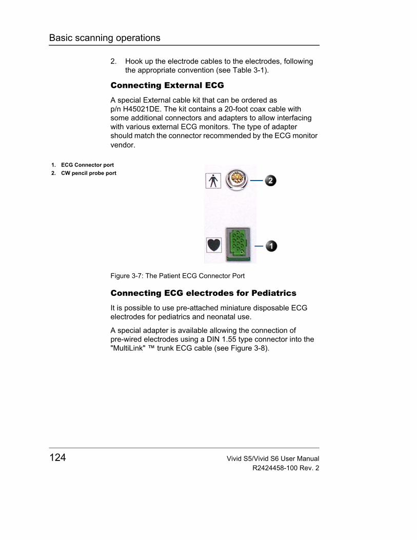
Basic scanning operations
2. Hook up the electrode cables to the electrodes, following the appropriate convention (see Table 3-1).
Connecting External ECG
A special External cable kit that can be ordered as p/n H45021DE. The kit contains a 20-foot coax cable with some additional connectors and adapters to allow interfacing with various external ECG monitors. The type of adapter should match the connector recommended by the ECG monitor vendor.
Figure 3-7: The Patient ECG Connector Port
Connecting ECG electrodes for Pediatrics
It is possible to use pre-attached miniature disposable ECG electrodes for pediatrics and neonatal use.
A special adapter is available allowing the connection of pre-wired electrodes using a DIN 1.55 type connector into the "MultiLink" ™ trunk ECG cable (see Figure 3-8).
1. ECG Connector port2. CW pencil probe port
124 Vivid S5/Vivid S6 User ManualR2424458-100 Rev. 2
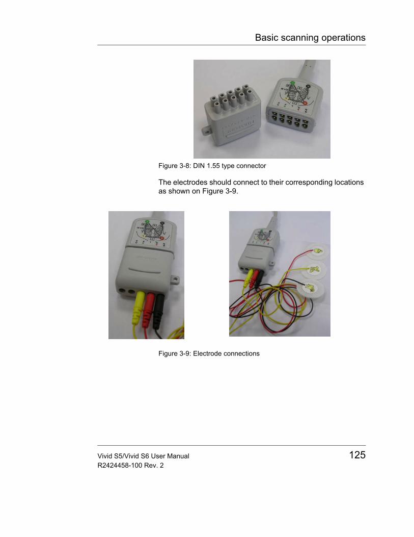
Basic scanning operations
Figure 3-8: DIN 1.55 type connector
The electrodes should connect to their corresponding locations as shown on Figure 3-9.
Figure 3-9: Electrode connections
Vivid S5/Vivid S6 User Manual 125R2424458-100 Rev. 2
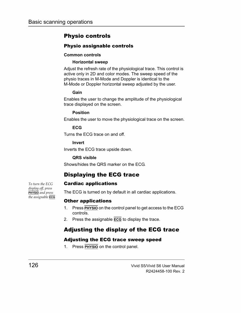
Basic scanning operations
Physio controls
Physio assignable controls
Common controlsHorizontal sweep
Adjust the refresh rate of the physiological trace. This control is active only in 2D and color modes. The sweep speed of the physio traces in M-Mode and Doppler is identical to the M-Mode or Doppler horizontal sweep adjusted by the user.
GainEnables the user to change the amplitude of the physiological trace displayed on the screen.
PositionEnables the user to move the physiological trace on the screen.
ECGTurns the ECG trace on and off.
InvertInverts the ECG trace upside down.
QRS visibleShows/hides the QRS marker on the ECG.
Displaying the ECG traceTo turn the ECG display off, press PHYSIO and press the assignable ECG
Cardiac applications
The ECG is turned on by default in all cardiac applications.
Other applications1. Press PHYSIO on the control panel to get access to the ECG
controls.2. Press the assignable ECG to display the trace.
Adjusting the display of the ECG trace
Adjusting the ECG trace sweep speed1. Press PHYSIO on the control panel.
126 Vivid S5/Vivid S6 User ManualR2424458-100 Rev. 2
Basic scanning operations
2. Adjust the assignable button HORIZONTAL SWEEP to change the sweep speed.
Adjusting the ECG trace amplitudeThe ECG signal's amplitude may vary between patients due to different skin moisture and other physiological pa-rameters.
1. Press PHYSIO on the control panel.2. Adjust the assignable button GAIN to adjust the amplitude of
the trace.
Adjusting the ECG trace position1. Press PHYSIO on the control panel.2. Adjust the assignable button POSITION to move the trace
vertically.
CAUTION
Do not use the Vivid S5/Vivid S6 Ultrasound system ECG physio waveform for diagnosis and monitoring.
Vivid S5/Vivid S6 User Manual 127R2424458-100 Rev. 2
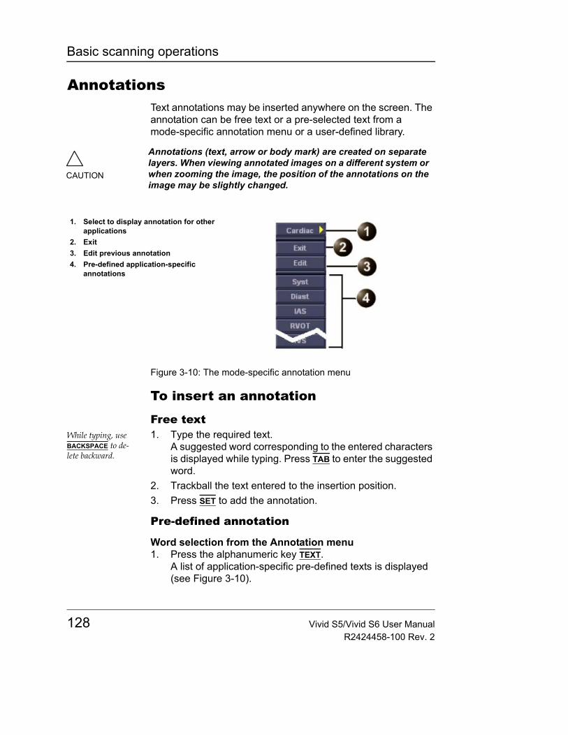
Basic scanning operations
AnnotationsText annotations may be inserted anywhere on the screen. The annotation can be free text or a pre-selected text from a mode-specific annotation menu or a user-defined library.
Figure 3-10: The mode-specific annotation menu
To insert an annotation
Free textWhile typing, use BACKSPACE to de-lete backward.
1. Type the required text.A suggested word corresponding to the entered characters is displayed while typing. Press TAB to enter the suggested word.
2. Trackball the text entered to the insertion position.3. Press SET to add the annotation.
Pre-defined annotation
Word selection from the Annotation menu1. Press the alphanumeric key TEXT.
A list of application-specific pre-defined texts is displayed (see Figure 3-10).
CAUTION
Annotations (text, arrow or body mark) are created on separate layers. When viewing annotated images on a different system or when zooming the image, the position of the annotations on the image may be slightly changed.
1. Select to display annotation for other applications
2. Exit3. Edit previous annotation4. Pre-defined application-specific
annotations
128 Vivid S5/Vivid S6 User ManualR2424458-100 Rev. 2
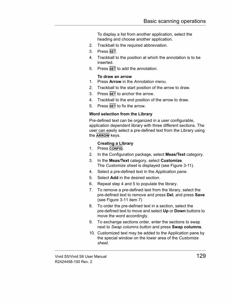
Basic scanning operations
To display a list from another application, select the heading and choose another application.
2. Trackball to the required abbreviation.3. Press SET.4. Trackball to the position at which the annotation is to be
inserted.5. Press SET to add the annotation.
To draw an arrow1. Press Arrow in the Annotation menu.2. Trackball to the start position of the arrow to draw.3. Press SET to anchor the arrow.4. Trackball to the end position of the arrow to draw.5. Press SET to fix the arrow.
Word selection from the LibraryPre-defined text can be organized in a user configurable, application dependent library with three different sections. The user can easily select a pre-defined text from the Library using the ARROW keys.
Creating a Library1. Press CONFIG.2. In the Configuration package, select Meas/Text category.3. In the Meas/Text category, select Customize.
The Customize sheet is displayed (see Figure 3-11).4. Select a pre-defined text in the Application pane.5. Select Add in the desired section.6. Repeat step 4 and 5 to populate the library.7. To remove a pre-defined text from the library, select the
pre-defined text to remove and press Del, and press Save (see Figure 3-11 item 7)
8. To order the pre-defined text in a section, select the pre-defined text to move and select Up or Down buttons to move the word accordingly.
9. To exchange sections order, enter the sections to swap next to Swap columns button and press Swap columns.
10. Customized text may be added to the Application pane by the special window on the lower area of the Customize sheet.
Vivid S5/Vivid S6 User Manual 129R2424458-100 Rev. 2
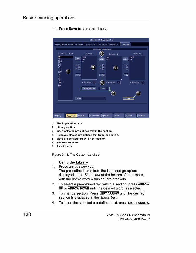
Basic scanning operations
11. Press Save to store the library.
Figure 3-11: The Customize sheet
Using the Library1. Press any ARROW key.
The pre-defined texts from the last used group are displayed in the Status bar at the bottom of the screen, with the active word within square brackets.
2. To select a pre-defined text within a section, press ARROW UP or ARROW DOWN until the desired word is selected.
3. To change section, Press LEFT ARROW until the desired section is displayed in the Status bar.
4. To insert the selected pre-defined text, press RIGHT ARROW.
1. The Application pane2. Library section3. Insert selected pre-defined text in the section.4. Remove selected pre-defined text from the section.5. Move pre-defined text within the section.6. Re-order sections.7. Save Library
130 Vivid S5/Vivid S6 User ManualR2424458-100 Rev. 2
Basic scanning operations
To edit annotation1. Press the alphanumeric key TEXT.2. Press Edit in the Annotation menu.
The pointer is changed to a cross marker.3. Trackball to the annotation to edit.4. Press SET.
Once selected, the annotation can be moved freely. The text can be edited using the following alphanumeric keys:• RIGHT ARROW: moves the text cursor forward.• LEFT ARROW: moves the text cursor backward.• TAB: moves the text cursor by word forward.• BACKSPACE: deletes backward.• DELETE: deletes the selected word.
5. Do the appropriate changes to the annotation.6. Press SET to anchor the edited annotation.
To erase annotationTo erase all annotations on the screen in one operation, press the alphanumeric key PAGE ERASE.
To erase annotation words one at a time, hit DELETE button on the alphanumeric keyboard. Each button-press will delete a single word in reversed order.
Vivid S5/Vivid S6 User Manual 131R2424458-100 Rev. 2

Basic scanning operations
Configuration of the pre-defined annotation list1. Press CONFIG.2. In the Configuration package, select Meas/Text category.3. In the Meas/Text category select Annotation.
The Annotation sheet is displayed where the user can add, delete or re-arrange the annotation text (see Figure 3-12).
To re-arrange the annotation list1. Trackball to the actual annotation text.2. Press SET.3. Press the relevant button (i.e. Delete, Move up or Move
down) to apply change.4. Press save to store the new annotation list.
To add an annotation text1. Trackball to the text entry field (see Figure 3-12).2. Press SET to activate the text cursor.3. Type the new annotation text.4. Press add.
The new annotation text is added at the end of the list.5. Press save to store the new annotation list.
132 Vivid S5/Vivid S6 User ManualR2424458-100 Rev. 2
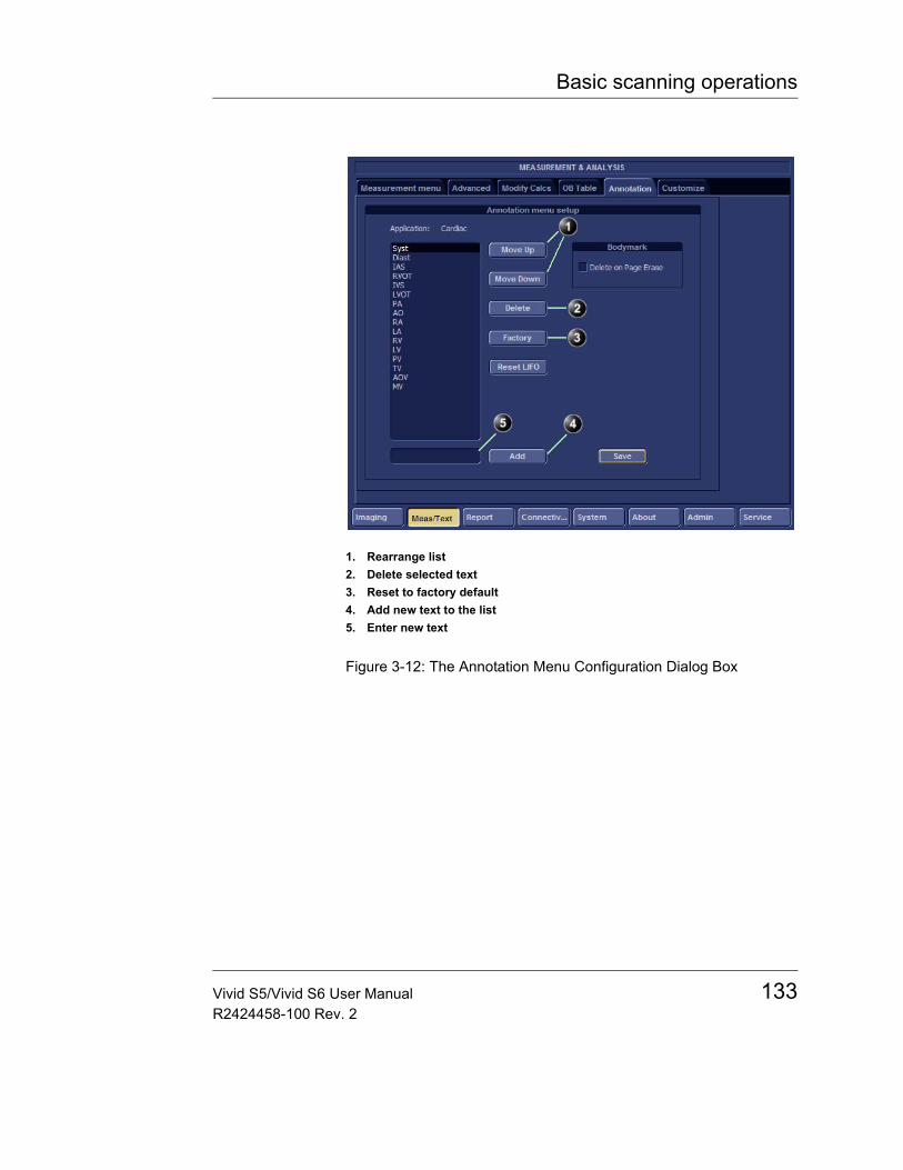
Basic scanning operations
Figure 3-12: The Annotation Menu Configuration Dialog Box
1. Rearrange list2. Delete selected text3. Reset to factory default4. Add new text to the list5. Enter new text
Vivid S5/Vivid S6 User Manual 133R2424458-100 Rev. 2
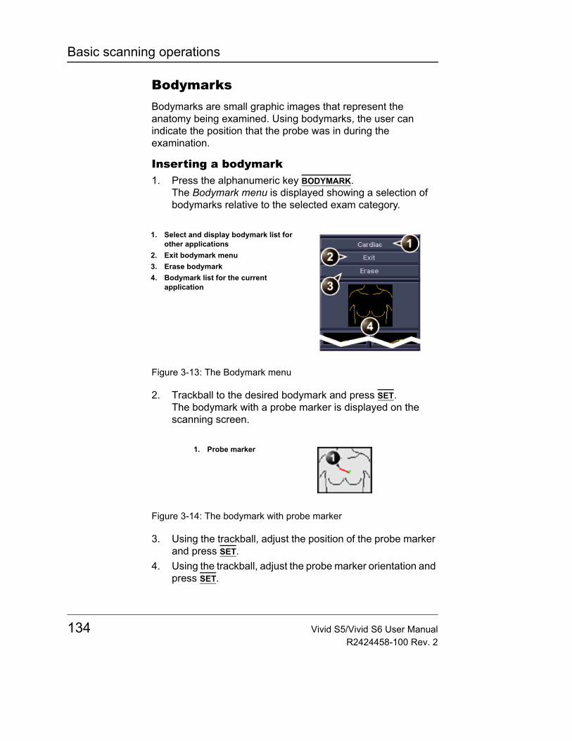
Basic scanning operations
BodymarksBodymarks are small graphic images that represent the anatomy being examined. Using bodymarks, the user can indicate the position that the probe was in during the examination.
Inserting a bodymark1. Press the alphanumeric key BODYMARK.
The Bodymark menu is displayed showing a selection of bodymarks relative to the selected exam category.
Figure 3-13: The Bodymark menu
2. Trackball to the desired bodymark and press SET.The bodymark with a probe marker is displayed on the scanning screen.
Figure 3-14: The bodymark with probe marker
3. Using the trackball, adjust the position of the probe marker and press SET.
4. Using the trackball, adjust the probe marker orientation and press SET.
1. Select and display bodymark list for other applications
2. Exit bodymark menu3. Erase bodymark4. Bodymark list for the current
application
1. Probe marker
134 Vivid S5/Vivid S6 User ManualR2424458-100 Rev. 2
Basic scanning operations
Deleting a bodymark1. Press the alphanumeric key BODYMARK.
The Bodymark menu is displayed2. Select Erase.
When pressing PAGE ERASE on alphanumeric keyboard the bodymark will be erased, provided it has been configured this way.
To change the configuration1. Press CONFIG.2. In the Configuration package, select Meas/Text category.3. In the Meas/Text category select Annotation (see
Figure 3-12).4. Check or uncheck the "Delete on Page erase" option.
Vivid S5/Vivid S6 User Manual 135R2424458-100 Rev. 2

Basic scanning operations
136 Vivid S5/Vivid S6 User ManualR2424458-100 Rev. 2
Scanning Modes
Chapter 4 Scanning Modes
• Introduction ................................................................................... .. 139• 2D-Mode ......................................................................................... .. 140
• 2D-Mode overview ................................................................... 140• 2D-Mode controls ..................................................................... 142• Using 2D .................................................................................. 148• Optimizing 2D ........................................................................... 148
• M-Mode .......................................................................................... .. 150• M-Mode overview ..................................................................... 150• M-Mode controls ...................................................................... 151• Using M-Mode .......................................................................... 153• Optimizing M-Mode .................................................................. 155
• Color Mode .................................................................................... .. 157• Color Mode overview ............................................................... 157• Color M-Mode overview ........................................................... 158• Color Mode controls ................................................................. 159• Using Color Mode .................................................................... 162• Optimizing Color Mode ............................................................. 163
• PW and CW Doppler ..................................................................... .. 164• PW and CW Doppler overview ................................................. 164• PW and CW Doppler controls .................................................. 165• Using PW/CW Doppler modes ................................................. 167• Optimizing PW/CW Doppler modes ......................................... 168• Tissue Velocity Imaging (TVI) .................................................. 169• Tissue Tracking ........................................................................ 173
• Strain rate ...................................................................................... .. 178• Strain rate overview ................................................................. 178• Strain rate controls ................................................................... 179
Vivid S5/Vivid S6 User Manual 137R2424458-100 Rev. 2
Scanning Modes
• Using Strain rate .......................................................................181• Optimizing Strain rate ...............................................................181
• Strain ............................................................................................. ... 183• Strain overview .........................................................................183• Strain controls ...........................................................................184• Using Strain ..............................................................................186• Optimizing Strain ......................................................................186
• Tissue Synchronization Imaging (TSI) ....................................... ... 188• TSI overview .............................................................................188• TSI controls ...............................................................................189• Using TSI ..................................................................................191• Optimizing TSI ..........................................................................192
• Additional scanning features ...................................................... ... 193• LogiqView .................................................................................193• Compound ................................................................................194• B-Flow .......................................................................................195• Blood flow imaging ....................................................................195• Virtual Convex ..........................................................................196
138 Vivid S5/Vivid S6 User ManualR2424458-100 Rev. 2
Scanning Modes
IntroductionThe Vivid S5/Vivid S6 ultrasound scanner provides several basic scanning modes and several options for combining the use of these modes.
The following scanning modes are described in this chapter:• 2D Mode Imaging• M-Mode Imaging• Anatomical M-Mode• Color Mode Imaging• Doppler Mode Imaging• Angio• Tissue Velocity Imaging• Tissue Tracking• Tissue Synchronization Imaging• BFlow• BFI (B-Flow Imaging)• Strain / Strain-Rate imaging
Note: Some optional scan-modes listed above are not available on Vivid S5.
See page 406 for further information on image and cineloop storage.
When performing an examination using any of these modes, images and image sequences (cineloops) can be stored. The examination or part of it can also be stored on DVD, CD, and other various media, depending on available options.
Vivid S5/Vivid S6 User Manual 139R2424458-100 Rev. 2
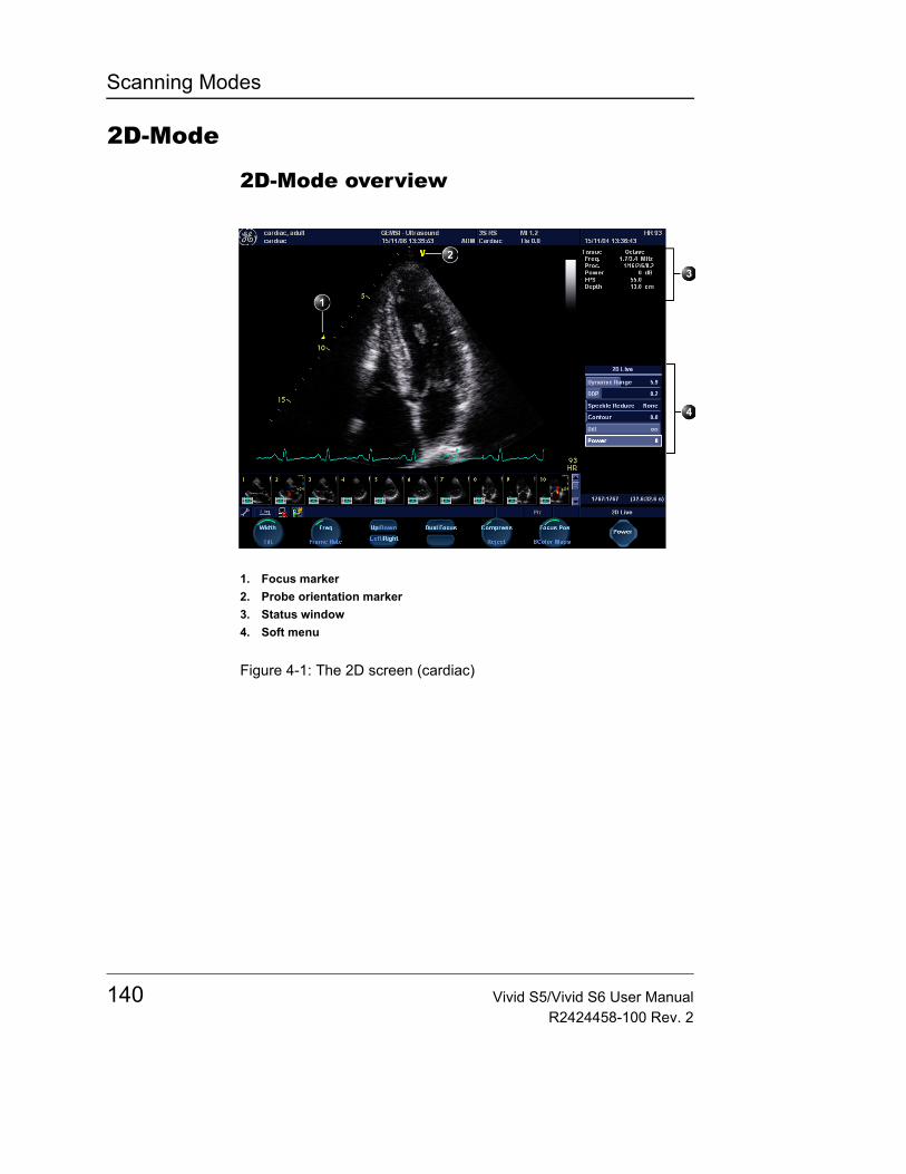
Scanning Modes
2D-Mode
2D-Mode overview
Figure 4-1: The 2D screen (cardiac)
1. Focus marker2. Probe orientation marker3. Status window4. Soft menu
140 Vivid S5/Vivid S6 User ManualR2424458-100 Rev. 2
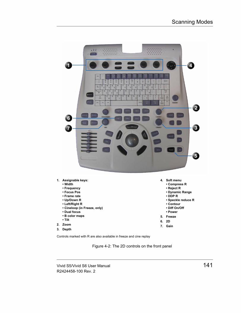
Scanning Modes
Figure 4-2: The 2D controls on the front panel
1. Assignable keys:• Width• Frequency• Focus Pos• Frame rate• Up/Down R• Left/Right R• Cineloop (in Freeze, only)• Dual focus• B color maps• Tilt
2. Zoom3. Depth
4. Soft menu • Compress R• Reject R• Dynamic Range• DDP R• Speckle reduce R• Contour• Diff On/Off• Power
5. Freeze6. 2D7. Gain
Controls marked with R are also available in freeze and cine replay
Vivid S5/Vivid S6 User Manual 141R2424458-100 Rev. 2
Scanning Modes
The 2D mode displays a two-dimensional gray scale image of the tissue within the probe's field of view. 2D mode can be combined with:
In combined mode, press ACT. MODE to toggle between modes and access to the mode specific controls.
• M-Mode, see "M-Mode" on page 150• Color Mode, see "Color Mode" on page 157• CW or PW Doppler Mode, see "PW and CW Doppler" on
page 164• Color and Doppler Modes (triplex)
2D-Mode controls
2D assignable controls
WidthControls the size or angular width of the 2D image sector. A smaller angle generally produces an image with a higher frame rate.
Focus PosChanges the location of the focal point(s). A triangular focus marker indicates the depth of the focal point.
Note: On convex and linear probes there are two additional optional focus controls:• Focus number: Allows to control the number of focal point.• Focal Spread: Allows to control the distance among the
different focal points
Frame rateAdjusts frame rate (FPS). The relative setting of the frame rate is displayed in the status window. When adjusting frame rate, there is a trade off between spatial and temporal resolution.
TiltEnables the axis of the 2D image to be tilted to the left or right. By using this control in combination with angle control the image can be “aligned” to the direction of interest, and frame rates be optimized. By default the axis of symmetry of a 2D image is vertical. (Applicable only for cardiology applications).
142 Vivid S5/Vivid S6 User ManualR2424458-100 Rev. 2
Scanning Modes
FrequencyOn some low fre-quencies, the sys-tem switches automatically to second-harmonic mode. The word “Octave” appears in the status win-dow.
Enables the adjustment of the probe's operating frequency. The selected frequency is displayed in the status window. For some probes/applications the lowest frequency settings will be Octave imaging settings.
Note: While changing the Frequency value on display, the operator actually selects different transmit patterns associated with that value, which includes transmit pulse shape, frequency and transmit sequence.
OctaveEnables quick switching over between Octave imaging and corresponding fundamental frequencies, without rotating the Frequency selection rotary knob.
Invert• Left/Right Invert: enables a mirror image of the 2D image
to be created. The left/right reference marker V moves to the other side of the image.
• Up/Down Invert: enables the 2D image to be flipped 180 degrees.
Dual focusActivates Dual focus mode (optionally available in cardiology applications only). To adjust the location of the Dual focus, activate the FOCUS assignable.
B Color mapsDisplays a color map menu to optimize the greyscale presentation. The menu enables an option from a list of non-linear gray-curves or different 2D-colorized curves to be selected. Use the assignable rotary knob to highlight and activate the desired map.
CompoundCompound is a process of combining three frames from different steering angles into a single frame. The combined single image has the benefits of reduced speckle noise, reduced clutter, and continuity of specular reflectors. Therefore, this technique can improve contrast resolution.
Vivid S5/Vivid S6 User Manual 143R2424458-100 Rev. 2
Scanning Modes
When active, the focal marker indicators change shape (see "Focal Marker Shapes" on page 150 - compound is available on Linear array and on 4C-RS curved array probes).Virtual ConvexVirtual Convex is designed to provide a wider field of view in the far field, and is available on linear probes. While in 2D-mode, use the Virtual Convex soft-key to turn virtual convex ON or OFF. When Virtual convex is turned on, you may enter other scanning modes such as Color, Doppler or M-mode and virtual convex will remain active on the 2D image.
Note: While Virtual Convex is turned on, the Zoom function will always activate in "Display-zoom" mode only.
Cineloop (in Freeze only)Allocates different cineloop control functions to the assignable soft keys.
GainWhen rotated clockwise, increases the overall gain applied to the received echo signals equally for all depth.
Time Gain Compensation (TGC)Compensates for depth-related attenuation in an image. The sliders nearest the operator affect the far field. TGC amplifies returning signals to correct for the attenuation caused by tissue at increasing depths.
Automatic Tissue Optimization (ATO)ATO provides an automatic optimization of the 2D image by adjusting the gray scale curve. Press the Auto button or the 2D GAIN rotary to toggle ATO on or off. When activated, ATO is displayed in the information window.
DepthSets the maximum (far field) distance that will be imaged. Decreasing the depth may allow higher frame rates.
144 Vivid S5/Vivid S6 User ManualR2424458-100 Rev. 2
Scanning Modes
2D Soft menu controls
CompressControls the amount of contrast in the 2D image. An index number is displayed in the status window to indicate the relative level of compression.
RejectAdjust reject level. When this control is increased, low-level echoes are rejected and appear darker in the 2D image. An index number is displayed in the status window to indicate the relative level of rejection.
Dynamic RangeEnables control of the dynamic range or contrast of the image. When dynamic range is set high, the image is softer and more low-level data is visible.
Smart DepthFor every setting of scan-depth there is an optimal Frequency / Transmit Pattern setting.
The Frequency/Transmit Pattern should be optimized to produce both a clean signal, and maximal spatial resolution.
With Smart Depth turned ON, the system will optimize the Frequency/Transmit Pattern to follow above guideline, and automatically set optimal setting for the currently selected depth.
The Frequency control value displayed on screen will be modified to display the updated value with every change of depth setting by the operator.
The operator may change the Frequency control at any time to any desired Frequency/Transmit Pattern.
If the depth setting is changed anytime after the user has manually modified the frequency, the system will attempt to optimize the Frequency/Transmit Pattern, taking into account the different frequency-preference as set by the manual modification by the user.
With Smart Depth turned OFF, the Frequency control setting will remain unchanged even when depth setting is changed.
Vivid S5/Vivid S6 User Manual 145R2424458-100 Rev. 2
Scanning Modes
DDP (Data Dependent Processing)Performs temporal processing which reduces random noise without affecting the motion of significant tissue structures. An index number is displayed in the status window (under Proc) to indicate the relative DDP level.
Contour/Edge EnhanceControls image processing related to the extent of edge enhancement applied to an image.
Diff On/OffAffects the level of reverberations in the image. When turned On, the frame rate (or the number of focal zones) will decrease, while the reverberations will be attenuated. (Applicable only for cardiology applications).
PowerWhen power is re-duced, it reduces the signal-to-noise ratio, so that the im-age may become noisier.
Controls the amount of acoustic power applied in all modes. When power is set to maximum, it is equal to or less than the maximum acoustic power permitted by the FDA. The Thermal Index (TI) and the Mechanical Index (MI) are displayed on the screen.
Ultra Definition (UD) ClarityThis control is effective in Cardiology applications only. This control reduces the unwanted effects of speckle in the ultrasound image. Image speckle usually appears as a grainy texture in otherwise uniform areas of tissue. Its appearance is related to image system characteristics, rather than tissue characteristics, so that changes in system settings, such as probe type, frequency, depth, and others, can change the appearance of the speckle.
Too much speckle can impair image quality and make it difficult to see the desired detail in the image. Likewise, too much filtering of speckle can mask or obscure desired image detail.
Extra care must be taken to select the optimal Speckle reduction level.
Ultra Definition (UD) Speckle ReduceThis control is used to reduce the amount of speckle in non-cardiology applications.
146 Vivid S5/Vivid S6 User ManualR2424458-100 Rev. 2
Scanning Modes
Ultra Definition (UD) Adaptive rejectConventional "Reject" function reduces noise by reducing low gray levels. It does so by changing the gray-map of the whole image. Noise is reduced but information in the myocardium may also be lost.
"Adaptive reject" also reduces noise by reducing low gray levels. The intensity reduction is done adaptively for each pixel in the image and does not affect the gray-map. As a result, pixels that are close to boundaries and tissue structures are less affected than with conventional reject method.
Clear VesselThis feature is available on linear probes while in live scanning under the "Carotid" application. While scanning the common carotid artery in a longitudinal scan, the "Clear Vessel" function is designed to optimize the acquired image by automatically adjusting the TGC of the system to remove noise artifacts within the vessel without affecting surrounding tissue structures.
Operation1. Use the Carotid preset with a linear probe.2. Make sure the "Clear Vessel" soft-key is turned ON.
The label CLR will appear on the upper right area of the image.
3. Scan the common carotid artery longitudinally.4. While in live scan, when the image of the carotid is
acquired, and the "Clear Vessel" function is active, it will automatically optimize the image, in real-time, removing some of the noise artifacts inside the vessel.The label CLR appears in white whenever "Clear Vessel" is active, and becomes dark-gray whenever "Clear Vessel" is not active, because scanning conditions do not allow "Clear Vessel" to detect the vessel correctly (Figure 4-3).
Vivid S5/Vivid S6 User Manual 147R2424458-100 Rev. 2
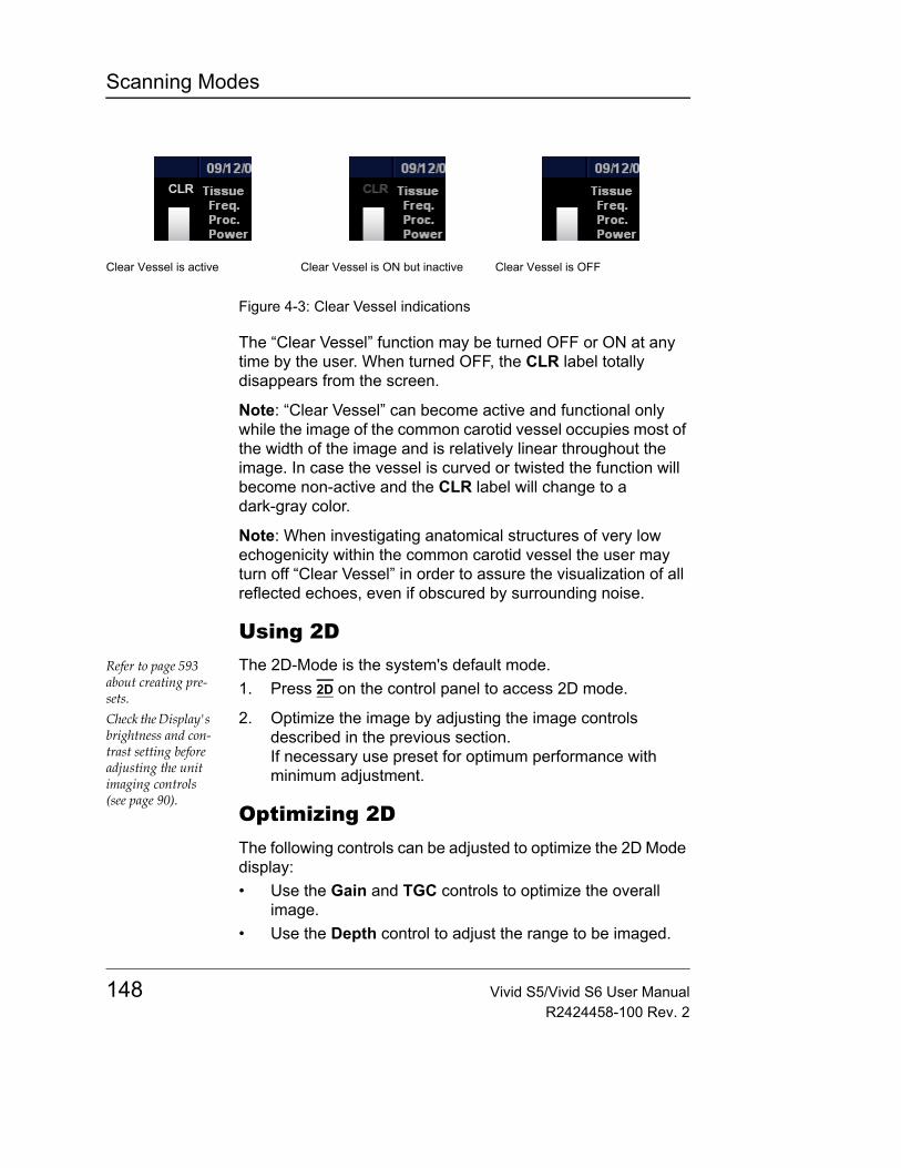
Scanning Modes
Figure 4-3: Clear Vessel indications
The “Clear Vessel” function may be turned OFF or ON at any time by the user. When turned OFF, the CLR label totally disappears from the screen.
Note: “Clear Vessel” can become active and functional only while the image of the common carotid vessel occupies most of the width of the image and is relatively linear throughout the image. In case the vessel is curved or twisted the function will become non-active and the CLR label will change to a dark-gray color.
Note: When investigating anatomical structures of very low echogenicity within the common carotid vessel the user may turn off “Clear Vessel” in order to assure the visualization of all reflected echoes, even if obscured by surrounding noise.
Using 2DRefer to page 593 about creating pre-sets.
The 2D-Mode is the system's default mode.1. Press 2D on the control panel to access 2D mode.
Check the Display's brightness and con-trast setting before adjusting the unit imaging controls (see page 90).
2. Optimize the image by adjusting the image controls described in the previous section.If necessary use preset for optimum performance with minimum adjustment.
Optimizing 2DThe following controls can be adjusted to optimize the 2D Mode display:• Use the Gain and TGC controls to optimize the overall
image.• Use the Depth control to adjust the range to be imaged.
Clear Vessel is active Clear Vessel is ON but inactive Clear Vessel is OFF
148 Vivid S5/Vivid S6 User ManualR2424458-100 Rev. 2
Scanning Modes
• Use the Focus control to center the focal point(s) around the region of interest.
• Use the Frequency (move to higher frequencies) or the Frame rate control (move to lower frame rate) to increase resolution in image
• Use the Frequency (move to lower frequency) to increase penetration.
• Use the Reject control to reduce noise in the image.• Use the DDP control to optimize imaging in the blood flow
regions and make a cleaner, less noisy image.• Use UD Clarity (Cardiac) or UD Speckle reduce
(non-cardiac) to reduce image speckle. Extra care must be taken to select the optimal Speckle reduction level, as too much filtering of speckle can mask or obscure desired image detail.
• Use Adaptive reject (Cardiac) to reduce near field haze and blood pol artifact without diluting tissue appearance of moving structures.
• Press Color maps and select a grey map from the menu on screen.
The Wide Aperture function may improve image quality by increasing spatial resolution and signal-to-noise ratio. This feature involves special processing which allows to improving the beam focus at large depth by increasing the number of probe's elements involved in producing the ultrasound beam.
Wide aperture function can not be controlled manually by the user When using linear or convex probes, the wide aperture feature may turn on or off automatically, depending on various scanning settings. In particular it turns on while placing the focus marker at relatively large depth. Wide aperture automatically turns off when focus is moved to a shallow region.
WARNING
Always use the minimum power required to obtain acceptable images in accordance with applicable guidelines and policies.
Vivid S5/Vivid S6 User Manual 149R2424458-100 Rev. 2
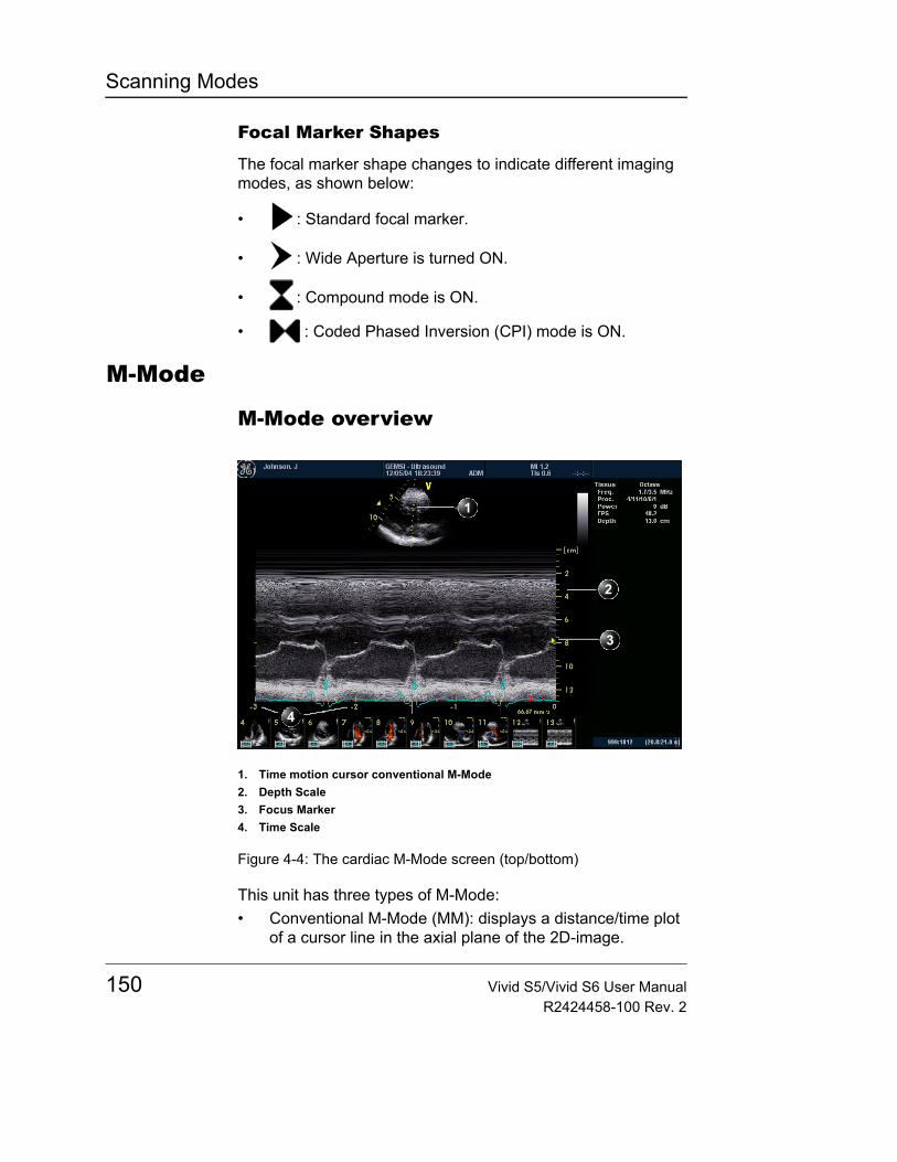
Scanning Modes
Focal Marker Shapes
The focal marker shape changes to indicate different imaging modes, as shown below:
• : Standard focal marker.
• : Wide Aperture is turned ON.
• : Compound mode is ON.
• : Coded Phased Inversion (CPI) mode is ON.
M-Mode
M-Mode overview
Figure 4-4: The cardiac M-Mode screen (top/bottom)
This unit has three types of M-Mode: • Conventional M-Mode (MM): displays a distance/time plot
of a cursor line in the axial plane of the 2D-image.
1. Time motion cursor conventional M-Mode2. Depth Scale3. Focus Marker4. Time Scale
150 Vivid S5/Vivid S6 User ManualR2424458-100 Rev. 2
Scanning Modes
• Anatomical M-Mode (AMM): displays a distance/time plot from a cursor line, which is independent from the axial plane. AMM is available in greyscale, color, or in the optional modes: TVI, Tissue Tracking, Strain rate, and Strain modes.
• Curved Anatomical M-Mode (CAMM): displays a distance/time plot from a free-drawn cursor line. CAMM is available in greyscale, color, and optional TVI, Tissue Tracking, Strain rate and Strain modes.
M-Mode and 2D Mode display areas can be side by side or top/bottom. Conventional M-Mode can be combined with Color (see "Color M-Mode overview" on page 158).
Note: The sweep speed information displayed in the bottom right corner of the image represents the user selected sweep speed and should be used only as a reference to confirm that the image was acquired at the selected sweep speed. It is not to be used for measurements or analysis. This is not an absolute value, but simply a reference number. Users performing studies using standardized protocols may find this sweep speed information useful for reading studies from other institutions.
M-Mode controls
M-Mode assignable controls
Horizontal sweepAdjusts the horizontal refresh rate of the M-Mode area of the display. Horizontal sweep does not change the acquisition resolution, so that user can change the horizontal sweep in replay (with no loss of quality).
On some low fre-quencies, the sys-tem switches automatically to second-harmonic mode. The word “Octave” appears in the status win-dow.
FrequencyEnables the adjustment of the probe's operating frequency. The selected frequency is displayed in the status window. For some probes/applications the lowest frequency settings will be Octave imaging settings.
Note: While changing the Frequency value on display, the operator actually selects different transmit patterns associated with that value, which includes transmit pulse shape, frequency and transmit sequence.
Vivid S5/Vivid S6 User Manual 151R2424458-100 Rev. 2

Scanning Modes
OctaveEnables quick switching over between Octave imaging and corresponding fundamental frequencies, without rotating the Frequency selection rotary knob.
Focus PosChanges the location of the focal point(s). A triangular focus marker indicates the depth of the focal point.
Up/DownFlips the M-Mode display 180 degrees.
Color mapsDisplays a color map menu to optimize the greyscale presentation. The menu enables an option from a list of non-linear gray-curves or different colorized curves to be selected. Use the trackball to point to a color map and press SET to activate the desired map.
AMM
Anatomical M-Mode (option) is only available for cardiac applications. See further information in "Anatomical M-Mode" on page 154.
CompressControls the amount of contrast in the image. An index number is displayed in the status window to indicate the relative level of compression.
RejectAdjust reject level. When this control is increased, low-level echoes are rejected and appear darker in the image. An index number is displayed in the status window to indicate the relative level of rejection.
152 Vivid S5/Vivid S6 User ManualR2424458-100 Rev. 2
Scanning Modes
M-Mode Soft menu controls
PowerWhen power is re-duced, it reduces the signal-to-noise ratio, so that the im-age, spectrum or color scan may be-come noisier.
Controls the amount of acoustic power applied in all modes. When power is set to maximum, it is equal to or less than the maximum acoustic power permitted by the FDA. The Thermal Index (TI) and the Mechanical Index (MI) are displayed on the screen.
Dynamic RangeEnables control of the dynamic range or contrast of the image. When dynamic range is set to High, the image is softer and more low-level data is visible.
Contour/Edge EnhanceControls image processing related to the extent of edge enhancement applied to an image.
Using M-Mode
Conventional M-Mode (greyscale)1. While in 2D-Mode press cursor on the control panel.2. Use the trackball to position the cursor over the required
area of the image.Gain, Frequency, Focus, Dynamic Range and Com-pression affect also the 2D image.
3. Press M - the M-mode sweep will start to sweep.4. Adjust horizontal sweep, Gain, Frequency, Focus, Dynamic
Range, compression and Contour to optimize the display if necessary.
5. Press FREEZE to stop imaging.
OR1. While in 2D-Mode press M on the control panel. The
M-mode sweep will start to sweep.2. Use the trackball to position the cursor over the required
area of the image.3. Adjust horizontal sweep, Gain, Frequency, Focus, Dynamic
Range, Compression and Contour to optimize the display if necessary.
4. Press FREEZE to stop imaging.
Vivid S5/Vivid S6 User Manual 153R2424458-100 Rev. 2

Scanning Modes
Conventional Color M-Mode1. While in Color Mode press cursor on the control panel.2. Use the trackball to position the cursor over the required
area of the image.3. Press M - the Color M-mode sweep will start to sweep.4. Press FREEZE to stop imaging.
OR1. While in Color Mode press M on the control panel. The
Color M-mode sweep will start to sweep.2. Use the trackball to position the cursor over the required
area of the image.3. Adjust horizontal sweep, Gain, Frequency, Focus, Dynamic
Range, Compression and Contour to optimize the display if necessary.
4. Press FREEZE to stop imaging.
Anatomical M-Mode
Anatomical M-Mode is only available for cardiac applications.
Anatomical M-Mode can also be used with previous-ly acquired digitally stored 2D images.
1. Enter live M-mode.2. Press the assignable AMM soft key to enter Live
Anatomical M-mode. Continue to step 4 below.
OR
While in 2D-Live or 2D-Freeze modes, press ALT button and press the assignable AMM soft-key
OR1. From the 2D Live, press FREEZE.2. Press M to access the Freeze Anatomical M-Mode.
The Trackball as-signable Pos (Posi-tion) is activated.
3. Use the trackball to position the cursor over the required area of the image.
The Trackball as-signable Angle is activated.
4. Press SET to allow free rotation of the solid full-length cursor line throughout the 2D image.
5. Rotate the solid cursor line to the desired direction.The Trackball as-signable Pos is acti-vated.
6. Press SET twice and reposition the intersection point to the desired position along the cursor line.
7. Repeat steps 4. and 5. to change the angle of the solid cursor line if necessary.
154 Vivid S5/Vivid S6 User ManualR2424458-100 Rev. 2
Scanning Modes
The M-Mode area of the display updates as the M-Mode sig-nal is constructed.
8. Press TRACKBALL to activate scrolling control on the trackball.
9. Use the trackball to scroll through the data acquired at that location. The M-Mode display will vary accordingly.
Curved Anatomical M-ModeCurved Anatomi-cal M-Mode can al-so be used with previously ac-quired digitally stored 2D images.
1. From the 2D or M-Mode view press ALT. The alternative modes appear on the assignable display.
2. Press CURVED AMM.3. Use the trackball to position the starting point of the time
motion curve.The time motion curve can be edited by following the curve back to the de-sired point and re-drawn as desired. Following the curve back to the starting point will delete the time motion curve.
4. Press SET to anchor the starting point of the time motion curve.
5. Use the trackball to position the second point of the time motion curve.
6. Press SET to anchor the second point of the time motion curve.
7. Repeat step 5. and 6. up to seven times to draw a complete time motion curve.
Optimizing M-ModeRefer to page 593 about creating pre-sets.
The use of preset gives optimum performance with minimum adjustment. If necessary, the following controls can be adjusted to further optimize the M-Mode display:• Adjust Horizontal sweep to optimize the display resolution.• Adjust Gain and TGC controls to adjust the range to be
imaged.Except for Con-tour, all the con-trols listed in the optimizing M-Mode section will also affect the 2D image.
• Use the Frequency (move to higher frequencies) or the Frame rate control (move to lower frame rate) to increase resolution in image.
• Use the Frequency (move to lower frequency) to increase penetration.
• Adjust Focus to move the focal point(s) around the region of interest in the M-Mode display.
• Adjust Dynamic range to optimize the useful range of incoming echoes to the available greyscale.
• Adjust Compress and Contour to further optimize the display.
• Adjust Reject to reduce noise while taking care not to
Vivid S5/Vivid S6 User Manual 155R2424458-100 Rev. 2

Scanning Modes
eliminate significant low-level diagnostic information.
156 Vivid S5/Vivid S6 User ManualR2424458-100 Rev. 2
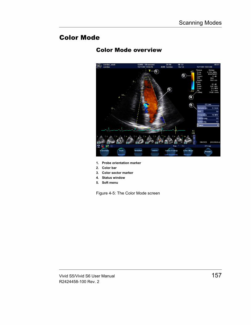
Scanning Modes
Color Mode
Color Mode overview
Figure 4-5: The Color Mode screen
1. Probe orientation marker2. Color bar3. Color sector marker4. Status window5. Soft menu
Vivid S5/Vivid S6 User Manual 157R2424458-100 Rev. 2
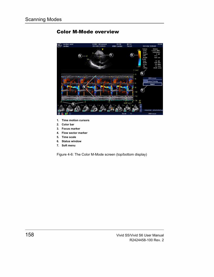
Scanning Modes
Color M-Mode overview
Figure 4-6: The Color M-Mode screen (top/bottom display)
1. Time motion cursors2. Color bar3. Focus marker4. Flow sector marker5. Time scale6. Status window7. Soft menu
158 Vivid S5/Vivid S6 User ManualR2424458-100 Rev. 2
Scanning Modes
Color Mode controls
Color Mode assignable controls
Horizontal sweep (Color M-Mode only)Adjusts the horizontal refresh rate of the M-Mode area of the display.
ScaleAdjusts the repetition rate of the Doppler pulses transmitted to acquire the data for color flow mapping. The Scale (Nyquist limit) should be adjusted so that no aliasing occurs, while still having good resolution of velocities. The Nyquist limit should be somewhat above the maximum velocity found in the data.
BaselineAdjusts the color map to emphasize flow either toward or away from the probe. Baseline is available in both Live and Freeze.
Frame rateControls the Frame-rate by changing line density. When adjusting frame rate, there is a trade off between spatial and temporal resolution.
LVR (Low Velocity Rejection)Color data produced by very low flow may cause interfer-ence.
LVR, also called Wall motion filter, enables the extent of low velocity removal to be adjusted.
InvertEnables the color scheme assigned to positive and negative velocities to be inverted. Invert is available in live and cine replay.
VarianceControls the amount of variance data added to a color display. Variance enables computer-aided detection of turbulent flow (e.g. jets or regurgitation). Variance is available in live and cine replay.
SimultaneousEnables simultaneous display of 2D and Color mode, side-by-side.
Vivid S5/Vivid S6 User Manual 159R2424458-100 Rev. 2
Scanning Modes
Color mapsDisplays a menu of color map options. Use the assignable rotary knob to point to a color map and activate the desired color map. Each color map is assigning different color hues to different velocities.
Cineloop (in Freeze, Color 2D mode only)Allocates different cineloop control functions to the assignable soft keys.
Tissue priorityEmphasize either the color of the color mode or the greyscale tissue detail of the 2D image. Tissue priority is available in both Live and Freeze.
Color-Mode Soft menu controls
Sample volumeAdjusts the size of the color flow Doppler sampling area. Lower setting gives better flow resolution while a higher setting increases sensitivity and helps to locate turbulent flows.
DDP (Data Dependant Processing)Performs temporal processing, which reduces random noise without affecting the motion of significant tissue structures.
FrequencyEnables the adjustment of the transmission frequency to control the sensitivity or the level of penetration. The selected frequency is displayed in the status window. Adjusting Frequency may affect Sample Volume and LVR settings.
Note: While changing the Frequency value on display, the operator actually selects different transmit patterns associated with that value, which includes transmit pulse shape, frequency and transmit sequence.
Smart DepthFor best sensitivity in color-mode, the Color Frequency/Transmit Pattern used should be optimized as a function of the location of the color-ROI.
160 Vivid S5/Vivid S6 User ManualR2424458-100 Rev. 2
Scanning Modes
When ROI is set to a deep region in the body it is recommended to decrease the Color Frequency value setting in order to improve reception of the Doppler signals.
When ROI is position in a shallow region, it is recommended to increase the Color Frequency value setting in order to increase the spatial resolution of the color image.
With Smart Depth turned ON, the system optimizes the Color Frequency/Transmit Pattern using the above guideline, and automatically sets an optimal setting to correspond with the current location of Color-ROI. The associated Frequency value displayed on screen changes accordingly.
The operator may change the Frequency control at any time to any desired setting, overriding any automatic settings.
With Smart Depth turned OFF, the Frequency control setting remains unchanged even while ROI depth setting is changed.
Lateral Averaging (Color 2D only)Smoothes the image by averaging collected data along the same horizontal line. An increase of the lateral averaging will reduce noise, but this will also reduce the lateral resolution.
Radial AveragingUse Averaging con-trols with caution so as not to obscure significant diagnos-tic information
Smooths the image by averaging collected data along the same radial line. An increase of the radial averaging will reduce noise, but this will also reduce the radial resolution.
PowerWhen power is re-duced, it reduces the signal-to-noise ratio, so that the im-age may become noisier.
Controls the amount of acoustic power applied in all modes. When power is set to maximum, it is equal to or less than the maximum acoustic power permitted by the FDA. The Thermal Index (TI) and the Mechanical Index (MI) are displayed on the screen.
Trackball controls
ROI (Region Of Interest) sizeWhen the trackball command Size is selected (see also "Trackball operation" on page 108), the height and width of the color area (or ROI) is adjusted from the trackball.
Vivid S5/Vivid S6 User Manual 161R2424458-100 Rev. 2
Scanning Modes
ROI (Region Of Interest) positionWhen the trackball command Pos (position) is selected (see also "Trackball operation" on page 108), the position of the color area (or ROI) is adjusted with the trackball.
Using Color Mode
Color 2D1. From an optimized 2D image press COLOR.
The assignable con-trols of the trackball are displayed in the trackball status bar in the bottom right corner of the screen.
2. Use the trackball to position the ROI frame over the area to be examined.
3. Press SET. The instruction Size should be highlighted in the trackball status bar. If not, press SET again to select Size.NOTE: If the trackball control Pointer is selected, press TRACKBALL to be able to select between Position and Size controls.
4. Use the trackball to adjust the dimensions of the ROI.To enlarge or narrow the ROI, move the trackball to the left or right.To lengthen or shorten the ROI, move the trackball up or down.
5. Press SET when the desired size is obtained, to allow repositioning of the ROI if desired.
6. Press FREEZE to stop imaging.
Color M-Mode1. From M-Mode press COLOR, or from Color-Mode press M.
The assignable con-trols of the trackball are displayed in the trackball status bar.
2. Use the trackball to position the color area in the M-Mode display.
3. Press the SET button. The instruction Size should be highlighted in the trackball status bar. If not, press SET again to select Size.NOTE: If the trackball control Pointer is selected, press TRACKBALL to be able to select between Position and Size controls.
4. Use the trackball to adjust the dimension of the color area.To enlarge the color area, move the trackball upTo narrow the color area, move the trackball down.
5. Press SET when the desired size is obtained.
162 Vivid S5/Vivid S6 User ManualR2424458-100 Rev. 2
Scanning Modes
Optimizing Color ModeRefer to page 593 about creating pre-sets.
The use of preset gives optimum performance with minimum adjustment. If necessary, the following controls can be adjusted to further optimize the Color Mode display:• Adjust the Active mode gain to set the gain in the color
flow area.The scale value may affect FPS, Low Ve-locity Reject, and Sample Volume.
• Adjust Scale to the highest setting that provides adequate flow detection.
• Adjust Low Velocity Reject to remove low velocity blood flow and tissue movement that reduces image quality.
• Adjust Variance to detect flow disturbances.• Adjust Sample volume (SV) to a low setting for better flow
resolution, or a higher setting to more easily locate disturbed flows
Frequency setting may affect FPS, SV and Low Velocity Reject.
• Adjust Frequency to optimize the color flow display. Higher settings improve resolution. Lower settings improve depth penetration and sensitivity. This does not affect the frequency used for 2D and M-Mode.
The Power setting affects all other op-erating modes.
• Adjust Power to obtain an acceptable image using the lowest setting possible.
Adjust the following settings to further optimize display of the image:• Use Invert to reverse the color assignments in the color
flow area of the display.• Use Tissue priority to emphasize either the color flow
overlay, or the underlying greyscale tissue detail.• Use Baseline to emphasize flow either toward or away
from the probe.• Use Radial and Lateral Averaging to reduce noise in the
color flow area. Radial and Lateral Averaging smooths the image by averaging collected data along the same horizontal line. An increase of the lateral averaging will reduce noise, but this will also reduce the lateral resolution.
CAUTION
Use all noise reduction controls with care. Excessive application may obscure low level diagnostic information.
Vivid S5/Vivid S6 User Manual 163R2424458-100 Rev. 2
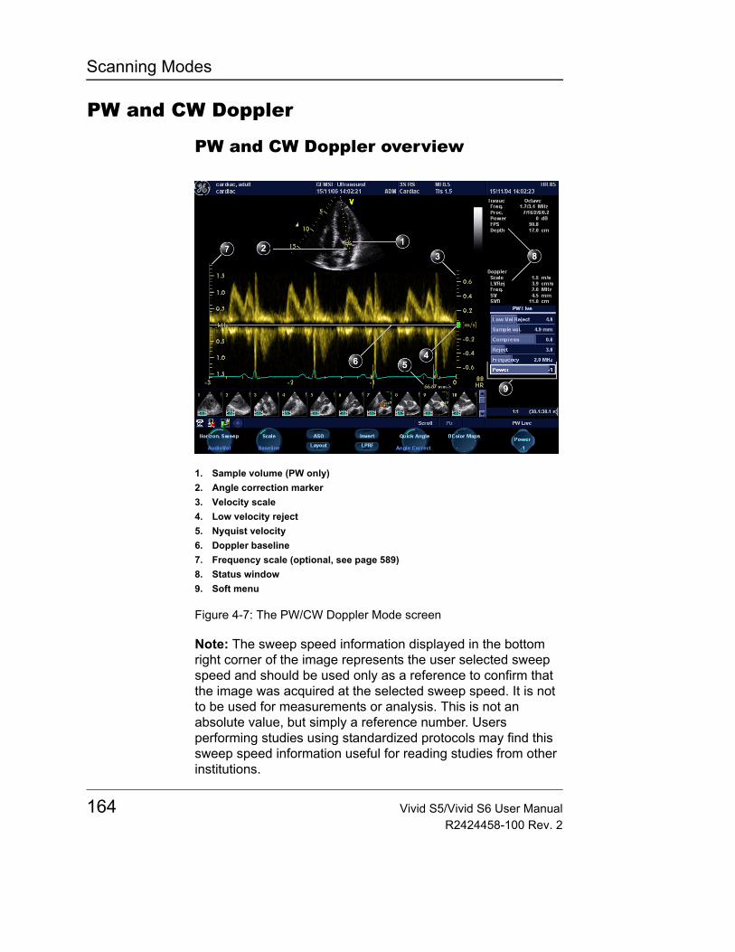
Scanning Modes
PW and CW Doppler
PW and CW Doppler overview
Figure 4-7: The PW/CW Doppler Mode screen
Note: The sweep speed information displayed in the bottom right corner of the image represents the user selected sweep speed and should be used only as a reference to confirm that the image was acquired at the selected sweep speed. It is not to be used for measurements or analysis. This is not an absolute value, but simply a reference number. Users performing studies using standardized protocols may find this sweep speed information useful for reading studies from other institutions.
1. Sample volume (PW only)2. Angle correction marker3. Velocity scale4. Low velocity reject5. Nyquist velocity6. Doppler baseline7. Frequency scale (optional, see page 589)8. Status window9. Soft menu
164 Vivid S5/Vivid S6 User ManualR2424458-100 Rev. 2
Scanning Modes
PW and CW Doppler controls
PW and CW Doppler assignable controls
Horizontal sweepAdjusts the horizontal refresh rate of the Doppler area of the display. Horizontal sweep is available in live and cine replay.
BaselineEnables the Doppler baseline to be shifted up and down. The default Doppler baseline is set at the center of the vertical aspect of the Doppler display, dividing evenly the flow toward and away from the probe. By adjusting the baseline a larger portion of the analysis is assigned to the flow direction present. Baseline is available in live and cine replay.
Maximum velocity depends on sample volume size, sample volume position and frequency set-tings.
ScaleEnables the vertical scale of the Doppler spectrum and the maximal detectable velocity to be modified. Velocity range directly controls the pulse repetition frequency, which is responsible for the setting of the Nyquist limit (the ability to detect maximum velocity without aliasing).
Low velocity rejectEnables the low velocity portions of the spectrum to be filtered, since the Doppler spectrum and audio may contain strong wall-motion signals. The amount of Low Velocity Reject. is indicated by the green vertical bar at the right end of the baseline.
Occasionally, high audio volume may cause interruptions or horizontal tonal noise in CW dis-play, in such a case lower the audio gain.
Audio Vol.Enables the loudspeaker volume control.
If the Doppler mode is combined with Color mode, the col-or map will be also inverted.
InvertEnables the Doppler spectrum to be flipped 180 degrees, so that negative velocities are displayed above the baseline and positive velocities below the baseline. Invert in PW is available in live and cine replay; invert in CW is available only in live mode.
Vivid S5/Vivid S6 User Manual 165R2424458-100 Rev. 2
Scanning Modes
LPRF (PW mode)Sets the pulse repetition frequency for the PW Doppler acquisition of flow data. Enables toggling between high and low Pulse Repetition Frequency (PRF). When the Doppler PRF is raised beyond a certain limit, more than one Doppler gate is displayed on the screen.
D Color mapsDisplays a drop down menu of different Doppler colorization maps. Use the assignable rotary knob to select the desired map and activate the map.
PW/CW Doppler Soft menu controls
Quick angle and Angle correctionIn non-cardiac ap-plications, Angle correction is con-trolled from the Trackball.
Enables correction of the Doppler velocity scale by defining the angle between the Doppler beam and the investigated blood vessel or blood flow. A thin cross bar on the Doppler cursor will rotate as the control is adjusted. Angle correction is available in both Live and Freeze.
Quick angle adjusts the angle by 60 degrees.
Angle correction adjusts the angle between zero and 90 degrees with one degree increment.
Sample volumeIn PW mode, set the longitudinal size of the region to be sampled for measurement. Adjusting Sample volume may affect the PRF (Nyquist limit) settings. SV does not apply to CW mode, where the volume sampled is the full length of the area indicated by the cursor line.
CompressEnables control over the contrast of the Doppler spectrum. When compression is raised, the spectrum image becomes softer and some low level background noise may appear. Compress is available in both Live and Freeze.
RejectEnables undesirable background noise to be removed from the Doppler spectrum resulting in a darker background. Reject is available in both Live and Freeze.
166 Vivid S5/Vivid S6 User ManualR2424458-100 Rev. 2
Scanning Modes
FrequencyAdjusts the transmission frequency in Doppler to control sensitivity or level of penetration. The selected frequency is displayed in the status window. Adjusting Frequency may affect Sample Volume (PW) and LVR settings.
PowerWhen power is re-duced, it reduces the signal-to-noise ratio, so that the im-age may become noisier.
Controls the amount of acoustic power applied in all modes. When power is set to maximum, it is equal to or less than the maximum acoustic power permitted by the FDA. The Thermal Index (TI) and the Mechanical Index (MI) are displayed on the screen.
Using PW/CW Doppler modes
Controls and opera-tions for PW and CW mode are the same unless other-wise noted.
There are two ways to start PW/CW Doppler:
Alternative 11. Press PW or CW. A scanning screen is displayed with a
Doppler cursor on the 2D mode image and a Doppler spectrum in the lower part of the screen.
2. Use the trackball to position the Doppler cursor line and in PW the sample volume location over the area of interest.
Sample Volume ad-justment may affect the Scale, Frame rate and LV rej. set-tings.
3. In PW, with the Soft menu rocker key, adjust the sample Volume (SV):To enlarge the SV, press the Right arrow of the rockerTo narrow the SV, press the Left arrow of the rocker.
Alternative 21. Press CURSOR on the control panel. A cursor line is
displayed on the 2D image.2. With the trackball adjust the position of the cursor line.3. Press PW or CW.
Vivid S5/Vivid S6 User Manual 167R2424458-100 Rev. 2
Scanning Modes
Optimizing PW/CW Doppler modesRefer to page 593 about creating pre-sets
The use of preset gives optimum performance with minimum adjustment. If necessary, the following controls can be adjusted to further optimize the PW/CW modes display:• Adjust the Active mode gain to set the gain in the spectral
Doppler area.• Adjust Low velocity reject to reduce unwanted low
velocity blood flow and tissue movement.• In PW mode, adjust Sample volume to low setting for
better resolution, or higher setting to more easily locate the disturbed flows.
• Adjust the Compress setting to balance the effect of stronger and weaker echoes and obtain the desired intensity display.
Frequency and Frame rate settings may affect the Low Velocity Reject.
• Adjust Frequency to optimize flow display. Higher setting will improve resolution and the lower setting will increase the depth penetration.
• Adjust Frame rate to a higher setting to improve motion detection, or to a lower setting to improve resolution.
The Doppler Power setting affects only Doppler operating modes.
• Adjust Power to obtain an acceptable image using the lowest setting possible. This is particularly important in CW mode, as the energy duty cycle is 100% (constant).
Adjust the following settings to further optimize the display of the image.• Use the Horizontal sweep to optimize the sweep speed.• To view signal detail, use the Velocity range to enlarge the
vertical spectral Doppler trace.• Use Invert to reverse the vertical component of the spectral
Doppler area of the display.When Zoom is ac-tive while in PW or CW modes, use the Depth rocker but-ton to adjust the zoom magnifica-tion factor
• Use Angle correction to steer the ultrasound beam to the blood flow to be measured (Not typically required during cardiac studies).
CAUTION
Use all noise reduction controls with care. Excessive application may obscure low level diagnostic information.
168 Vivid S5/Vivid S6 User ManualR2424458-100 Rev. 2
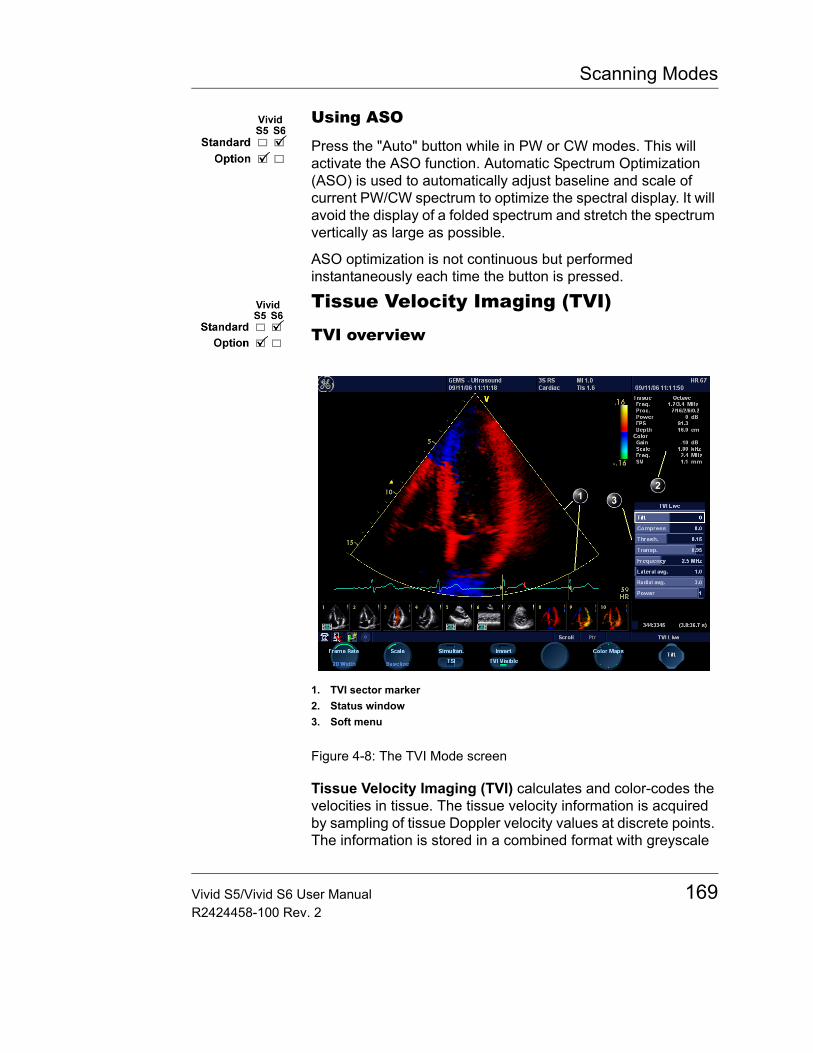
Scanning Modes
Using ASO
Press the "Auto" button while in PW or CW modes. This will activate the ASO function. Automatic Spectrum Optimization (ASO) is used to automatically adjust baseline and scale of current PW/CW spectrum to optimize the spectral display. It will avoid the display of a folded spectrum and stretch the spectrum vertically as large as possible.
ASO optimization is not continuous but performed instantaneously each time the button is pressed.
Tissue Velocity Imaging (TVI)
TVI overview
Figure 4-8: The TVI Mode screen
Tissue Velocity Imaging (TVI) calculates and color-codes the velocities in tissue. The tissue velocity information is acquired by sampling of tissue Doppler velocity values at discrete points. The information is stored in a combined format with greyscale
1. TVI sector marker2. Status window3. Soft menu
Vivid S5/Vivid S6 User Manual 169R2424458-100 Rev. 2
Scanning Modes
imaging during one or several cardiac cycles with high temporal resolution.
TVI controls
TVI assignable controls2D width
Controls the angular width of the 2D image sector.
Lower scale value allows greater depth and lower Nyquist limit.
ScaleAdjusts the repetition rate of the Doppler pulses transmitted to acquire the data for color mapping. The Scale value influences the Nyquist limit (the ability to detect maximal velocity without color-aliasing).
BaselineAdjusts the color map to emphasize tissue motion either toward or away from the probe. Baseline is available in both Live and Freeze.
Frame rateControls the line density. When adjusting frame rate, there is a trade off between spatial and temporal resolution.
InvertEnables the color scheme assigned to positive and negative tissue velocities to be inverted. Invert is available in live and cine replay.
TSIStarts TSI mode (see page 188).
SimultaneousEnables simultaneous display of 2D image and 2D image with TVI color.
TVI visibleTurns TVI display on/off. When TVI display is turned off the TVI acquisition is still in turned on and raw-data is still acquired but remains hidden from the display.
Cineloop (in Freeze only)Starts cineloop acquisition.
170 Vivid S5/Vivid S6 User ManualR2424458-100 Rev. 2
Scanning Modes
Color mapsDisplays a menu of color map options. Use the assignable rotary knob to select and activate a desired color map. Each color map is assigning different color hues to different velocities.
Q-Analysis (in Freeze only)Starts the Quantitative analysis application (see Chapter 8, "Quantitative Analysis" on page 375).
Alternative assignable controlsPress ALT to access the following modes:• Tissue Synchronization Imaging (see page 188)• Tissue Tracking (see page 173)• Curved Anatomical M-Mode (see page 155)• Strain rate (see page 178)• Strain (see page 183)
TVI Soft menu controlsCompress
Controls the amount of color compression. The color bar is adjusted accordingly.
TiltEnables the axis of the 2D image to be tilted to the left or right. By using this control in combination with angle control the image can be “aligned” to the direction of interest, and frame rates be optimized. By default the axis of symmetry of a 2D image is vertical. Tilting of the 2D image will tilt the TVI ROI along with it.
ThresholdControls the level of greyscale intensity that is used as a threshold for color.
TransparencyControls the degree of transparency of the TVI color.
FrequencyEnables the adjustment of the transmission frequency to control the sensitivity or the level of penetration.
Vivid S5/Vivid S6 User Manual 171R2424458-100 Rev. 2
Scanning Modes
Lateral AveragingUse Averaging con-trols with caution so as not to obscure significant diagnos-tic information
Smooths the image by averaging collected data along the same horizontal line. An increase of the lateral averaging will reduce noise, but this will also reduce the lateral resolution.
Radial AveragingSmooths the image by averaging collected data along the same radial line. An increase of the radial averaging will reduce noise, but this will also reduce the radial resolution.
When power is re-duced, it reduces the signal-to-noise ratio, so that the im-age may appear noisier.
PowerControls the amount of acoustic power applied in all modes. When power is set to maximum, it is equal to or less than the maximum acoustic power level permitted by regulatory standards. The Thermal Index (TI) and the Mechanical Index (MI) are displayed on the screen.
Using TVI1. Select the desired probe.2. While in 2D mode press TVI on the control panel, then select
TVI soft-key.3. Use the trackball to position the ROI frame over the area
to be examined.The assignable con-trols of the trackball are displayed in the trackball status bar in the bottom right corner of the screen.
4. Press SET. The instruction Size should be highlighted in the trackball status bar. If not, press SET again to select Size.Note: If the trackball control Pointer is selected, press TRACKBALL to be able to select between Position and Size controls.
5. Use the trackball to adjust the dimensions of the ROI.To enlarge or narrow the ROI, move the trackball to the left or right.To lengthen or shorten the ROI, move the trackball up or down.
Optimizing TVI
Refer to page 593 about creating pre-sets.
The use of preset gives optimum performance with minimum adjustment. If necessary, the following controls can be adjusted to further optimize the TVI display:
172 Vivid S5/Vivid S6 User ManualR2424458-100 Rev. 2
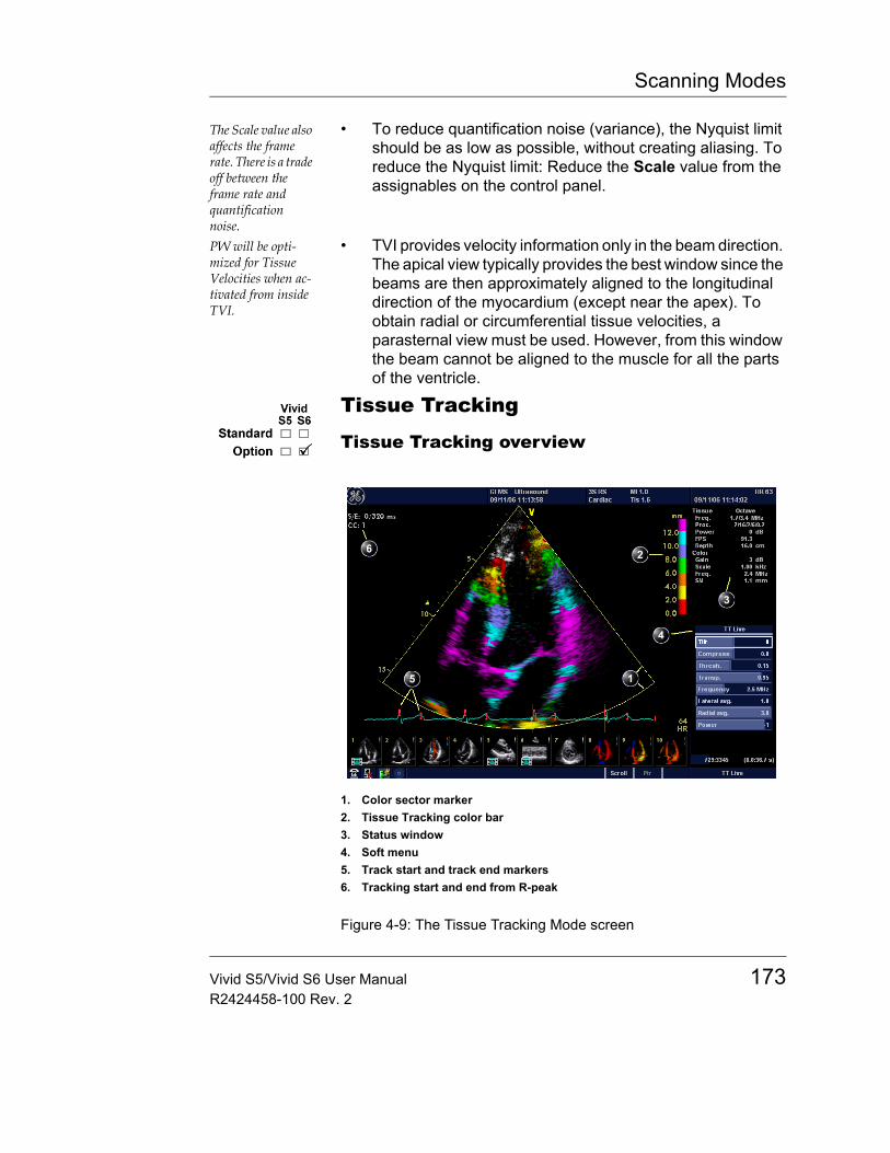
Scanning Modes
The Scale value also affects the frame rate. There is a trade off between the frame rate and quantification noise.
• To reduce quantification noise (variance), the Nyquist limit should be as low as possible, without creating aliasing. To reduce the Nyquist limit: Reduce the Scale value from the assignables on the control panel.
PW will be opti-mized for Tissue Velocities when ac-tivated from inside TVI.
• TVI provides velocity information only in the beam direction. The apical view typically provides the best window since the beams are then approximately aligned to the longitudinal direction of the myocardium (except near the apex). To obtain radial or circumferential tissue velocities, a parasternal view must be used. However, from this window the beam cannot be aligned to the muscle for all the parts of the ventricle.
Tissue Tracking
Tissue Tracking overview
Figure 4-9: The Tissue Tracking Mode screen
1. Color sector marker2. Tissue Tracking color bar3. Status window4. Soft menu5. Track start and track end markers6. Tracking start and end from R-peak
Vivid S5/Vivid S6 User Manual 173R2424458-100 Rev. 2
Scanning Modes
Tissue Tracking calculates and color-codes the displacement in the tissue over a given time interval, typically the systole. The displacement is defined as the distance the tissue move during this time interval. The displacement is found as the time integral (sum) of the tissue velocities during this interval.
Only displacements in the beam direction are found. Only positive (systolic) displacements are mapped into colors, negative displacements are mapped into greyscale.
Tissue Tracking controls
Tissue Tracking assignable controlsTracking start
The time after ECG R-peak when the integration should start.
Tracking endThe time after tracking start when the integration should end.
Tracking scaleControls the color cut-off value of max displacement displayed. The chosen values is shown on the color bar when the assignable is activated.
Frame rateControls the line density. When adjusting frame rate, there is a trade off between spatial and temporal resolution.
InvertEnables the color scheme assigned to positive and negative tissue velocities to be inverted. Invert is available in live and cine replay.
TSIStarts TSI mode (see page 188).
SimultaneousEnables simultaneous display of 2D image and 2D image with Tissue Tracking color.
Cineloop (in Freeze only)Starts cineloop acquisition.
174 Vivid S5/Vivid S6 User ManualR2424458-100 Rev. 2
Scanning Modes
Color mapsDisplays a menu of color map options. Use the assignable rotary knob to select and activate a desired color map.
Q-Analysis (in Freeze only)Starts the Quantitative analysis application (see Chapter 8, "Quantitative Analysis" on page 375).
Alternative assignable controlsPress ALT to access the following modes:• Tissue Synchronization Imaging (see page 188)• Tissue Tracking (see page 173)• Curved Anatomical M-Mode (see page 155)• Strain rate (see page 178)• Strain (see page 183)
Tissue Tracking Soft menu controls2D width
Controls the angular width of the 2D image sector.
TiltEnables the axis of the 2D image to be tilted to the left or to the right. By default the axis of the 2D image is vertical.
ThresholdControls the level of greyscale intensity that is used as a threshold for color.
TransparencyControls the degree of transparency of the Tissue Tracking color.
FrequencyEnables the adjustment of the transmission frequency to control the sensitivity or the level of penetration.
Use Averaging con-trols with caution so as not to obscure significant diagnos-tic information
Lateral AveragingSmooths the image by averaging collected data along the same horizontal line. An increase of the lateral averaging will reduce noise, but this will also reduce the lateral resolution.
Vivid S5/Vivid S6 User Manual 175R2424458-100 Rev. 2
Scanning Modes
Radial AveragingSmooths the image by averaging collected data along the same radial line. An increase of the radial averaging will reduce noise, but this will also reduce the radial resolution.
PowerControls the amount of acoustic power applied. When power is reduced the signal to noise ratio is reduced, so that the image may become noisier.
Cine Compound (Freeze only)Calculates and displays cineloops generated from a temporal averaging of multiple consecutive heart cycles. The number of cycles averaged is controlled from the Soft menu rocker. The number of averaged cycles displayed on the top left corner.
Using Tissue Tracking1. From 2D or TVI Modes, press ALT on the control panel and
select the TISSUE TRACKING assignable.2. Adjust TRACKING START (assignable) close to the R-peak.3. Adjust TRACKING END (assignable) near the T-wave.4. Use the trackball to position the ROI frame over the area
to be examined.The assignable con-trols of the trackball are displayed in the trackball status bar in the bottom right corner of the screen.
5. Press SET. The instruction Size should be highlighted in the trackball status bar. If not, press SET again to select Size.Note: If the trackball control Pointer is selected, press TRACKBALL to be able to select between Position and Size controls.
6. Use the trackball to adjust the dimensions of the ROI.
Optimizing Tissue Tracking• To reduce quantification noise (variance), the Nyquist limit
should be as low as possible, without creating aliasing. To reduce the Nyquist limit, reduce the scale while in TVI.
• To check for aliasing, freeze the loop and apply velocity trace (Press FREEZE and Q-ANALYSIS), see also Chapter 8, "Quantitative Analysis" on page 375).
• The main use of Tissue Tracking is to map positive systolic displacements. This means that TRACKING START and TRACKING END assignables should be adjusted to pick out the systolic phase of the cardiac cycle: Adjust Tracking
176 Vivid S5/Vivid S6 User ManualR2424458-100 Rev. 2
Scanning Modes
start close to the R-Peak. Adjust Tracking end near the T-wave.
• Negative displacement can be mapped by pressing INVERT. TRACKING START and TRACKING END must then be adjusted to pick out the diastolic phase of the cardiac cycle.
• The maximum displacement that is color-coded can be adjusted using the TRACKING SCALE assignable. If set too low, most of the wall will show the color indicating maximum displacement. If set too high, the maximum displacement color is never reached.
• Tissue Tracking provides velocity information only in the beam direction. The apical view typically provides the best window since the beams are then approximately aligned to the longitudinal direction of the myocardium (except near the apex).
Vivid S5/Vivid S6 User Manual 177R2424458-100 Rev. 2
Scanning Modes
Strain rateStrain rate overview
Figure 4-10: The Strain rate mode screen
Strain rate calculates and color-codes the deformation per unit time i.e the speed at which the tissue deformation occurs.
Strain rate is defined as the spatial gradient of velocity data.
1. Color sector marker2. Status window3. Soft menu4. Strain sample size
178 Vivid S5/Vivid S6 User ManualR2424458-100 Rev. 2
Scanning Modes
Strain rate controls
Strain rate assignable controls
2D widthControls the angular width of the 2D image sector.
SRI scaleDefines the scale for the color coding of the strain rate.
Frame rateControls the line density. When adjusting frame rate, there is a trade off between spatial and temporal resolution.
InvertEnables the color scheme assigned to strain rate to be inverted. Invert is available in live and cine replay.
TSIStarts TSI mode (see page 188).
SimultaneousEnables simultaneous display of 2D image and 2D image with Strain rate color.
Color mapsDisplays a menu of color map options. Use the trackball to point a color map and press SET to activate a desired color map.
Q-analysis (in Freeze only)Starts the Quantitative analysis application (see Chapter 8, "Quantitative Analysis" on page 375).
Cineloop (in Freeze only)Starts cineloop acquisition.
Alternative assignable controls
Press ALT to access to the following modes:• Curved Anatomical M-Mode (see page 155)• Tissue Synchronization Imaging (see page 188)• Tissue Tracking (see page 173)
Vivid S5/Vivid S6 User Manual 179R2424458-100 Rev. 2
Scanning Modes
• Strain rate (see page 178)• Strain (see page 183)
Strain rate Soft menu controls
Strain lengthDetermines the strain sample volume size. There is a trade-off between noise and spatial resolution controlled by the Strain length. To minimize noise the Strain length should be maximized. A value of 12mm is typical for adult cardiac patients (see "Optimizing Strain rate" on page 181).
SRI RejectAdjust the cut-off level of the low Strain rate to be discarded when generating the color image. Rejected values are displayed in green.
CompressControls the amount of color compression. The color bar is adjusted accordingly.
TransparencyControl the degree of transparency of the strain rate color.
ThresholdControls the level of greyscale intensity that is used as threshold for color.
FrequencyEnables the adjustment of the transmission frequency to control the sensitivity or the level of penetration.
Lateral AveragingSmooths the image by averaging collected data along the same horizontal line. An increase of the lateral averaging will reduce noise, but this will also reduce the lateral resolution.
Use Averaging con-trols with caution so as not to obscure significant diagnos-tic information.
Radial AveragingSmooths the image by averaging collected data along the same radial line. An increase of the radial averaging will reduce noise, but this will also reduce the radial resolution.
180 Vivid S5/Vivid S6 User ManualR2424458-100 Rev. 2
Scanning Modes
PowerControls the amount of acoustic power applied. When power is reduced the signal to noise ratio is reduced, so that the image may become noisier.
Cine Compound (Freeze only)Calculates and displays cineloops generated from a temporal averaging of multiple consecutive heart cycles. The number of cycles averaged is controlled from the Soft menu rocker. The number of averaged cycles displayed on the top left corner.
Using Strain rate1. From TVI Mode, press ALT on the control panel and press
STRAIN RATE.2. Use the trackball to position the ROI frame over the area
to be examined.The assignable con-trols of the trackball are displayed in the trackball status bar in the bottom right corner of the screen.
3. Press SET. The instruction Size should be highlighted in the trackball status bar. If not, press SET again to select Size.Note: If the trackball control Pointer is selected, press TRACKBALL to be able to select between Position and Size controls.
4. Use the trackball to adjust the dimensions of the ROI.
Optimizing Strain rate• To reduce quantification noise (variance), the Nyquist limit
should be as low as possible, without creating aliasing. To reduce the Nyquist limit, reduce the scale while in TVI.
• To check for aliasing, freeze the loop and apply velocity trace (Press FREEZE and Q-ANALYSIS), see also Chapter 8, "Quantitative Analysis" on page 375).
• Strain rate provides velocity information only in the beam direction. The apical view typically provides the best window since the beams are then approximately aligned to the longitudinal direction of the myocardium (except near the apex).
• There is a trade-off between noise and spatial resolution controlled by the Strain length. To minimize noise the Strain length should be maximized. A value of 12mm is typical for adult cardiac patients.
Vivid S5/Vivid S6 User Manual 181R2424458-100 Rev. 2

Scanning Modes
• The maximum Strain rate that is color-coded can be adjusted using the SRI SCALE assignable. If set too low, most of the wall will show the color indicating maximum Strain rate. If set too high, the maximum Strain rate color is never reached.
• Low strain rates may be masked out with a green color using the SRI Reject control.
182 Vivid S5/Vivid S6 User ManualR2424458-100 Rev. 2
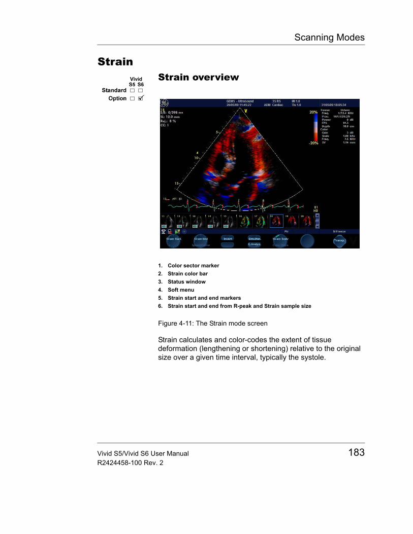
Scanning Modes
StrainStrain overview
Figure 4-11: The Strain mode screen
Strain calculates and color-codes the extent of tissue deformation (lengthening or shortening) relative to the original size over a given time interval, typically the systole.
1. Color sector marker2. Strain color bar3. Status window4. Soft menu5. Strain start and end markers6. Strain start and end from R-peak and Strain sample size
Vivid S5/Vivid S6 User Manual 183R2424458-100 Rev. 2
Scanning Modes
Strain controls
Strain assignable controls
Strain startThe time after ECG R-peak when the strain calculation should start. The strain start time is displayed on the screen and is represented on the ECG by a red marker.
Strain endThe time after strain start when the strain calculation should end. The strain end time is displayed on the screen and is represented on the ECG by a red marker.
Strain scaleDefines the scale for the color coding of the tissue deformation.
Frame rateControls the line density. When adjusting frame rate, there is a trade-off between spatial and temporal resolution.
InvertEnables the color scheme assigned to shortening and elongation tissue deformation to be inverted. Invert is available in live and cine replay.
TSIStarts TSI mode (see page 188).
SimultaneousEnables simultaneous display of 2D image and 2D image with Strain color.
Color mapsDisplays a menu of color map options. Use the trackball to point a color map and press SET to activate a desired color map.
Q-analysis (in Freeze only)Starts the Quantitative analysis application (see Chapter 8, "Quantitative Analysis" on page 375).
184 Vivid S5/Vivid S6 User ManualR2424458-100 Rev. 2
Scanning Modes
Cineloop (in Freeze only)Starts cineloop acquisition.
2D width (More menu)Controls the angular width of the 2D image sector.
Alternative assignable controls
Press ALT to access to the following modes:• Curved Anatomical M-Mode (see page 155)• Tissue Synchronization Imaging (see page 188)• Tissue Tracking (see page 173)• Strain rate (see page 178)• Strain (see page 183)
Strain Soft menu controls
Strain lengthDetermines the strain sample volume size. There is a trade-off between noise and spatial resolution controlled by the Strain length. To minimize noise the Strain length should be maximized. A value of 12mm is typical for adult cardiac patients (see "Optimizing Strain" on page 186).
Strain RejectAdjust the cut-off level of the low tissue velocity to be discarded when generating the color image. Rejected values are uncolored.
ThresholdControls the level of greyscale intensity that is used as threshold for color.
TransparencyControl the degree of transparency of the strain color.
FrequencyEnables the adjustment of the transmission frequency to control the sensitivity or the level of penetration.
Vivid S5/Vivid S6 User Manual 185R2424458-100 Rev. 2
Scanning Modes
Lateral AveragingSmooths the image by averaging collected data along the same horizontal line. An increase of the lateral averaging will reduce noise, but this will also reduce the lateral resolution.
Use Averaging con-trols with caution so as not to obscure significant diagnos-tic information.
Radial AveragingSmooths the image by averaging collected data along the same radial line. An increase of the radial averaging will reduce noise, but this will also reduce the radial resolution.
PowerControls the amount of acoustic power applied. When power is reduced the signal to noise ratio is reduced, so that the image may become noisier.
Cine Compound (Freeze only)Calculates and displays cineloops generated from a temporal averaging of multiple consecutive heart cycles. The number of cycles averaged is controlled from the Soft menu rocker. The number of averaged cycles displayed on the top left corner.
Using Strain1. From TVI Mode, press ALT on the control panel and press
STRAIN.2. Adjust STRAIN START close to the R-peak.3. Adjust STRAIN END near the T-wave.4. Use the trackball to position the ROI frame over the area
to be examined.The assignable con-trols of the trackball are displayed in the trackball status bar in the bottom right corner of the screen.
5. Press SET. The instruction Size should be highlighted in the trackball status bar. If not, press SET again to select Size.Note: If the trackball control Pointer is selected, press TRACKBALL to be able to select between Position and Size controls.
6. Use the trackball to adjust the dimensions of the ROI.
Optimizing Strain• From an optimized Strain rate display adjust strain tracking
to pick out the systolic phase.• The main use of Strain is to map negative systolic
deformation. This means that STRAIN START and STRAIN END should be adjusted to pick out the systolic phase of the
186 Vivid S5/Vivid S6 User ManualR2424458-100 Rev. 2
Scanning Modes
cardiac cycle: Adjust STRAIN START close to the R-Peak. Adjust STRAIN END near the T-wave.
• Positive deformation can be mapped by pressing INVERT. STRAIN START and STRAIN END must then be adjusted to pick out the diastolic phase of the cardiac cycle.
• The maximum deformation that is color-coded can be adjusted using the STRAIN SCALE assignable. If set too low, most of the wall will show the color indicating maximum deformation. If set too high, the maximum deformation color is never reached.
• Strain provides velocity information only in the beam direction. The apical view typically provides the best window since the beams are then approximately aligned to the longitudinal direction of the myocardium (except near the apex).
• Low strain values may be masked out with a different color using the SI Reject control.
Vivid S5/Vivid S6 User Manual 187R2424458-100 Rev. 2
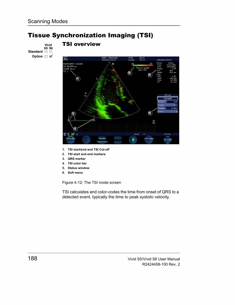
Scanning Modes
Tissue Synchronization Imaging (TSI)TSI overview
Figure 4-12: The TSI mode screen
TSI calculates and color-codes the time from onset of QRS to a detected event, typically the time to peak systolic velocity.
1. TSI start/end and TSI Cut-off2. TSI start and end markers3. QRS marker4. TSI color bar5. Status window6. Soft menu
188 Vivid S5/Vivid S6 User ManualR2424458-100 Rev. 2
Scanning Modes
TSI controls
TSI assignable controls
InvertInvert is available for TEE acquisitions. When applied, the time to peak negative velocity is calculated (instead of the time to peak positive velocity). Invert makes it possible to use TSI on TEE acquisitions where the image sector is inverted.
Frame rateControls the line density. When adjusting frame rate, there is a trade-off between spatial and temporal resolution.
TSIStarts/stops TSI Mode.
TSI StartThis rotary allows manual adjustment of TSI starting point.
TSI EndThis rotary allows manual adjustment of TSI ending point.
Note: While in Freeze, press MORE to see the TSI Start / End controls.
Q-analysis (in Freeze only)Starts the Quantitative analysis application (see Chapter 8, "Quantitative Analysis" on page 375).
SimultaneousEnables simultaneous display of 2D image and 2D image with TSI color.
Cineloop (in Freeze only)Starts cineloop acquisition.
Color mapsDisplays a menu of color map options. Use the assignable rotary knob to select and activate a desired color map.
Vivid S5/Vivid S6 User Manual 189R2424458-100 Rev. 2
Scanning Modes
Alternative assignable controls
Press ALT to access to the following modes:• Curved Anatomical M-Mode (see page 155)• Tissue Synchronization Imaging (see page 188)• Tissue Tracking (see page 173)• Strain rate (see page 178)• Strain (see page 183)
Physio assignable control
Press PHYSIO and MORE twice to access to the following control:
QRS visibleShows/hides the QRS marker on the ECG.
TSI Soft menu controls
TSI Cut-offControls the cut-off time: using this control it is possible to color all parts of the TSI image that has a time to peak less than a certain cutoff time.
ThresholdControls the level of greyscale intensity that is used as threshold for color.
TransparencyControl the degree of transparency of the TSI color.
FrequencyEnables the adjustment of the transmission frequency to control the sensitivity or the level of penetration.
PowerControls the amount of acoustic power applied. When power is reduced the signal to noise ratio is also reduced, so that the image may become noisier.
Cine Compound (Freeze only)Calculates and displays cineloops generated from a temporal averaging of multiple consecutive heart cycles. The number of
190 Vivid S5/Vivid S6 User ManualR2424458-100 Rev. 2
Scanning Modes
cycles averaged is controlled from the Soft menu rocker. The number of averaged cycles displayed on the top left corner.
Using TSI
1. Ideally, perform the AVO and AVC Event Timing measurements prior to starting TSI. See "Event timing measurements" on page 265.
2. From TVI, or Tissue Tracking mode, select TSI.3. Optionally adjust THRESHOLD.4. Use the trackball to position the ROI frame over the area
to be examined.The assignable con-trols of the trackball are displayed in the trackball status bar in the bottom right corner of the screen.
5. Press SET. The instruction Size should be highlighted in the trackball status bar. If not, press SET again to select Size.Note: If the trackball control Pointer is selected, press TRACKBALL to be able to select between Position and Size controls.
6. Use the trackball to adjust the dimensions of the ROI.
TSI markers adjustments
The default TSI markers settings are:• TSI start: The time of the Event Timing measurement
Aortic Valve Opening (AVO). (If no AVO measurement is available, 60 ms from the detected QRS is used.)
• TSI end: The time of the Event Timing measurement Aortic Valve Closure (AVC). (If no AVC measurement is available, an estimated time of end systole + 200 ms. is used.)
The system can be configured to automatically adjust the TSI start marker to Aortic Valve Opening, providing that this event is measured. If not measured, the default setting is used (60 ms).
The system can be configured to automatically adjust the TSI end marker relatively to the to Aortic Valve Closure (AVC) or Mitral Valve Opening (MVO) event, providing that these events are measured. If not measured, the TSI end marker is adjusted relatively to the estimated End Systole.
CAUTION
TSI requires correct QRS detection to function properly. Therefore always check that the yellow circle markers on the ECG are positioned correctly on each QRS complex before proceeding with the analysis.
Vivid S5/Vivid S6 User Manual 191R2424458-100 Rev. 2
Scanning Modes
The configuration alternatives are:• TSI start: 60 ms, 80, 100, 120, AVO or Manual control• TSI end: AVC - 200 ms, AVC - 150 ms, AVC - 100 ms,
AVC - 50 ms, AVC, AVC + 50 ms, AVC + 100 ms, AVC + 150 ms, AVC + 200 ms, MVO, MVO + 100 ms, MVO + 160 ms, MVO + 200 ms, MVO + 260 ms or Manual control.Note: Manual adjustment of TSI start and TSI end markers is available. Press MORE and adjust TSI START and TSI END. To store the modified marker settings, press IMG STORE and choose the configuration setting Manual control to avoid automatic adjustment of the markers.
To configure TSI markers:1. Press CONFIG and select the category Measure.2. In the Measure category, select the sheet Advanced.3. In the Application specific parameters section adjust TSI
Start and TSI End parameters by selecting a new value from the combo menu displayed upon selection.
Optimizing TSI• Use apical view when imaging and ensure that both LV
walls and opposing walls are in the view.• Activate TSI from an optimized TVI display.• Low time to peak values may be masked out with a different
color using the TSI Cutoff control.• Optimize 2D gain for clean chamber• ATO can be used• Clean ECG trace• Acquire one or more complete heart cycles• Default TSI start and end times are suggested• When analyzing TEE images where systolic velocities are
negative, the detection mode may be changed to "Time to peak negative velocity" using the Invert control.
192 Vivid S5/Vivid S6 User ManualR2424458-100 Rev. 2
Scanning Modes
Additional scanning featuresLogiqViewLogiqView provides the ability to construct and view a static 2D image which is wider than the field of view of a given transducer. This feature allows viewing and measurements of anatomy that is larger than what would fit in a single image. Examples include scanning of vascular structures and connective tissues in the arms and legs.
LogiqView constructs the extended image from individual image frames as the operator slides the transducer along the surface of the skin in the direction of the scan plane. The quality of the resulting image is somewhat user-dependent and requires some additional skill and practice to develop proper technique.
LogiqView is available with linear probes in 2D mode only.
Note: LogiqView is available only when Compound (see below) is turned off.
Using LogiqView1. Perform a detailed examination of the anatomy/pathology.
Optimize parameters for tissue texture and visible window prior to activating LogiqView.
2. Press the assigned key LOGIQVIEW.3. To start acquiring the image, press 2D FREEZE. Scan slowly
and in a uniform motion lengthwise.• Continuous contact is required throughout the length of
the extended image.• Always keep the transducer perpendicular to the skin
surface.• Keep the motion within the same scan plane.• Do not make abrupt changes in speed of motion.
4. If required, press 2D FREEZE again to restart the acquisition.5. To complete the scan, press FREEZE.6. Adjust the assigned rotary LOGIQVIEW ROTATE to rotate
the acquisition.7. Perform measurements.8. Press IMG STORE.
Vivid S5/Vivid S6 User Manual 193R2424458-100 Rev. 2
Scanning Modes
Note: Measurement error is within 5% of the distance you measured for all linear probes.
Hint: When you scan, scan slowly and in a uniform motion lengthwise, end-to-end (with or against the probe orientation marker). LOGIQView acquires images via leading edge vectors (and does not acquire slices, as in CINE). The image is being stored as you perform the scan and you can watch the LOGIQView as it is being acquired.
Uniform Motion
The quality and usefulness of LOGIQView images is affected by transducer motion. Incorrect technique can contribute to image distortion.
Guidance and precautions for uniform motion:• Continuous contact is required throughout the length of the
extended image. DO NOT lift the transducer from the skin surface.
• Always keep the transducer perpendicular to the skin surface. DO NOT rock the transducer.
• Keep the motion within the same scan plane, if possible. DO NOT slide the transducer laterally.
• Lateral turning (change in direction to follow anatomical structure) can be accommodated with slower motion. DO NOT make abrupt changes in direction.
• The system accommodates a reasonable range of motion velocity. DO NOT make abrupt changes in speed of motion. Deeper scans generally require reduced speed.
CompoundCompound is a process of combining several frames from different steering angles into a single frame. The combined single image has the benefits of reduced speckle noise, reduced clutter, and continuity of specular reflectors. Therefore, this technique can improve contrast resolution.
Compound is available with linear and 4C-RS curved probes in 2D live mode, or in the 2D image while in Color mode. Compound is on by default.
194 Vivid S5/Vivid S6 User ManualR2424458-100 Rev. 2
Scanning Modes
Using compound• Press the COMPOUND assigned key.
A compounded image is produced.
B-FlowB-Flow provides an intuitive representation of non quantitative hemodynamics in vascular structures. B-Flow enables visualization of complex hemodynamics and highlights moving blood and tissue. There are no artifacts such as bleeding, blooming, or aliasing.
B-Flow is available Color flow mode with linear probes only.
Using B-Flow1. While in Color flow, press the assigned key B-FLOW.2. Adjust the soft menu control TEXTURE GAIN. Increased
gain enhances hemodynamic.
The greater the speed, the better the image scatter density and size. If the scan direction is the same as the flow direction, then the image scatter is elongated; if the scan direction is the opposite as the flow direction, then the image scatter is tighter. Therefore, have the scan direction opposite to that of flow direction. Switch the way you hold the probe, with the probe orientation marker inferior to maintain correct orientation on the monitor. Flow starts from where the focal zone is located.
Blood flow imagingBlood flow imaging (BFI) is a Color flow mode with added speckle information. The speckle information visualizes the blood flow direction.
Note: When scanning in BFI triplex mode it is normal to have a time delay between the Doppler display/Doppler audio and the BFI color display.
Using blood flow imaging1. While in Color flow, press the assigned key BFI.2. Adjust Flow speckle. Increased Flow speckle enhances
hemodynamics.
Vivid S5/Vivid S6 User Manual 195R2424458-100 Rev. 2
Scanning Modes
3. Adjust the soft menu control BFI GAIN. Increased gain enhances hemodynamic. See page 163 for Color flow image optimization.
Virtual ConvexVirtual Convex is designed to provide a wider field of view in the far field, and is available on linear probes. While in 2D-mode, use the Virtual Convex soft-key to turn virtual convex ON or OFF. When Virtual convex is turned on, you may enter other scanning modes such as Color, Doppler or M-mode and virtual convex will remain active on the 2D image.
Note: While Virtual Convex is turned on, the Zoom function will always activate in "Display-zoom" mode only.
196 Vivid S5/Vivid S6 User ManualR2424458-100 Rev. 2
Stress Echo
Chapter 5 Stress Echo
• Introduction ................................................................................... .. 198• Selection of a stress test protocol template .............................. .. 199• Image acquisition .......................................................................... .. 200
• Starting acquisition ................................................................... 201• Continuous capture mode ........................................................ 205• Analysis .................................................................................... 213
• Quantitative TVI Stress echo analysis ........................................ .. 218• Accessing QTVI Stress analysis tools ...................................... 219• Vpeak measurement ................................................................ 220• Tissue Tracking ........................................................................ 223• Quantitative analysis ................................................................ 223• References ............................................................................... 224
• Editing/creating a template .......................................................... .. 225• Entering the Template editor screen ........................................ 225• Template editor screen overview ............................................. 226• Editing/Creating a template ...................................................... 229
Vivid S5/Vivid S6 User Manual 197R2424458-100 Rev. 2
Stress Echo
IntroductionThe Vivid S5/Vivid S6 ultrasound unit provides an integrated stress echo package option, with the ability to perform image acquisition, review, image optimization, and wall segment scoring and reporting for a complete, efficient stress echo examination.
The stress package provides protocol templates for exercise, as well as, pharmacological stress examinations. In addition to preset factory protocol templates, templates can be created or modified to suit users' needs. Users can define various quad screen review groups, in any order and combination, that will suit their normal review protocol. When reviewing stress examination images, the images are viewed at their original image quality, and different post-processing and zoom factors may be applied to the images under review for effective image optimization. The protocol template may be configured for Continuous capture.
A stress echo examination consists of three steps:• Selection of a stress test protocol template (page 199)• Image acquisition (page 200)• Stress analysis (page 213)
198 Vivid S5/Vivid S6 User ManualR2424458-100 Rev. 2
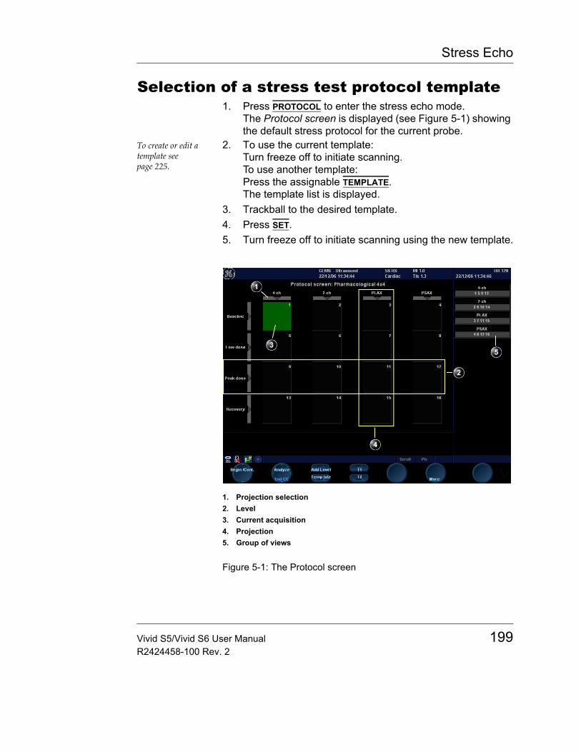
Stress Echo
Selection of a stress test protocol template1. Press PROTOCOL to enter the stress echo mode.
The Protocol screen is displayed (see Figure 5-1) showing the default stress protocol for the current probe.
To create or edit a template see page 225.
2. To use the current template:Turn freeze off to initiate scanning.To use another template:Press the assignable TEMPLATE.The template list is displayed.
3. Trackball to the desired template.4. Press SET.5. Turn freeze off to initiate scanning using the new template.
Figure 5-1: The Protocol screen
1. Projection selection2. Level3. Current acquisition4. Projection5. Group of views
Vivid S5/Vivid S6 User Manual 199R2424458-100 Rev. 2
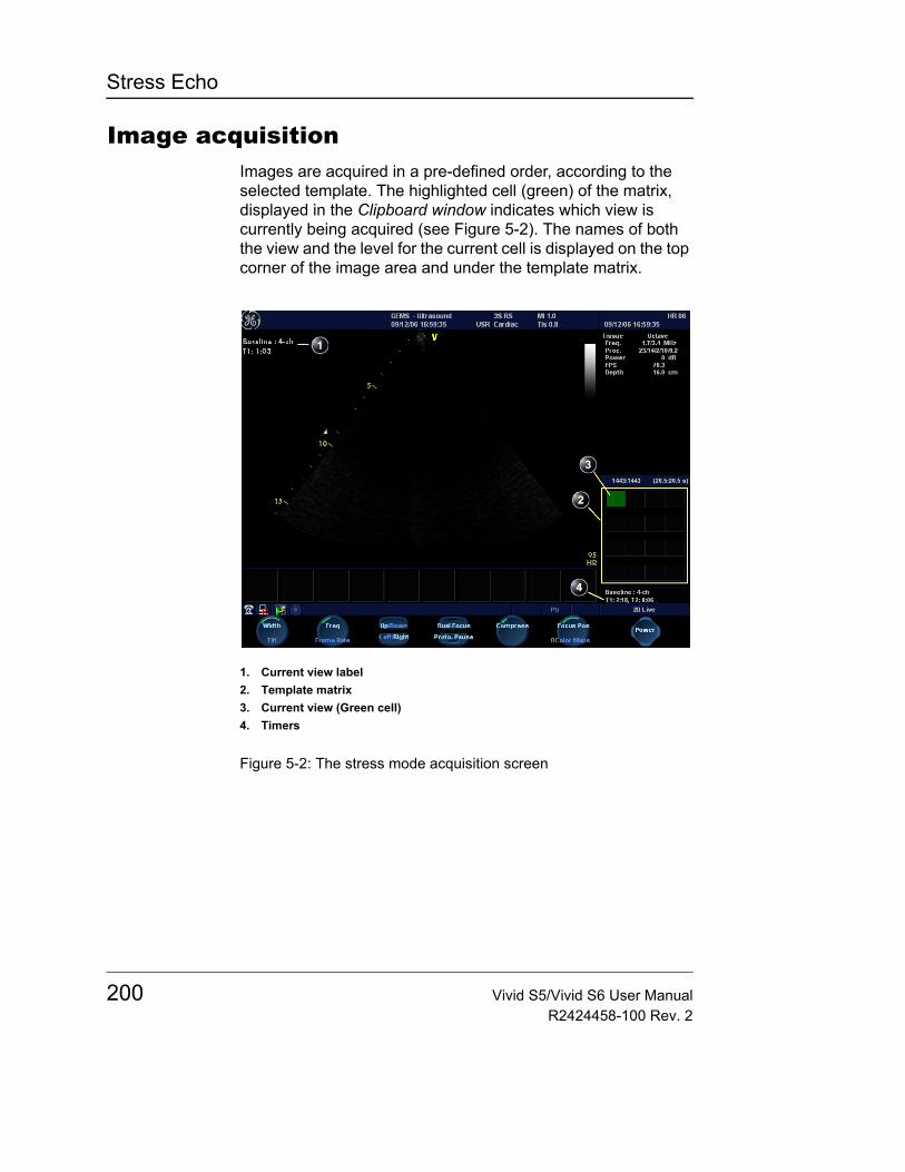
Stress Echo
Image acquisitionImages are acquired in a pre-defined order, according to the selected template. The highlighted cell (green) of the matrix, displayed in the Clipboard window indicates which view is currently being acquired (see Figure 5-2). The names of both the view and the level for the current cell is displayed on the top corner of the image area and under the template matrix.
Figure 5-2: The stress mode acquisition screen
1. Current view label2. Template matrix3. Current view (Green cell)4. Timers
200 Vivid S5/Vivid S6 User ManualR2424458-100 Rev. 2
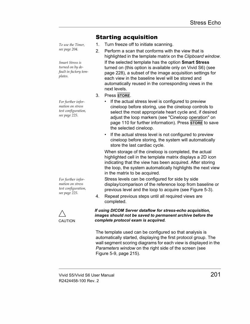
Stress Echo
Starting acquisitionTo use the Timer, see page 204.
1. Turn freeze off to initiate scanning.2. Perform a scan that conforms with the view that is
highlighted in the template matrix on the Clipboard window.Smart Stress is turned on by de-fault in factory tem-plates.
If the selected template has the option Smart Stress turned on (this option is available only on Vivid S6) (see page 228), a subset of the image acquisition settings for each view in the baseline level will be stored and automatically reused in the corresponding views in the next levels.
3. Press STORE.For further infor-mation on stress test configuration, see page 225.
• If the actual stress level is configured to preview cineloop before storing, use the cineloop controls to select the most appropriate heart cycle and, if desired adjust the loop markers (see "Cineloop operation" on page 110 for further information). Press STORE to save the selected cineloop.
• If the actual stress level is not configured to preview cineloop before storing, the system will automatically store the last cardiac cycle.
When storage of the cineloop is completed, the actual highlighted cell in the template matrix displays a 2D icon indicating that the view has been acquired. After storing the loop, the system automatically highlights the next view in the matrix to be acquired.
For further infor-mation on stress test configuration, see page 225.
Stress levels can be configured for side by side display/comparison of the reference loop from baseline or previous level and the loop to acquire (see Figure 5-3).
4. Repeat previous steps until all required views are completed.
The template used can be configured so that analysis is automatically started, displaying the first protocol group. The wall segment scoring diagrams for each view is displayed in the Parameters window on the right side of the screen (see Figure 5-9, page 215).
CAUTION
If using DICOM Server dataflow for stress-echo acquisition, images should not be saved to permanent archive before the complete protocol exam is acquired.
Vivid S5/Vivid S6 User Manual 201R2424458-100 Rev. 2
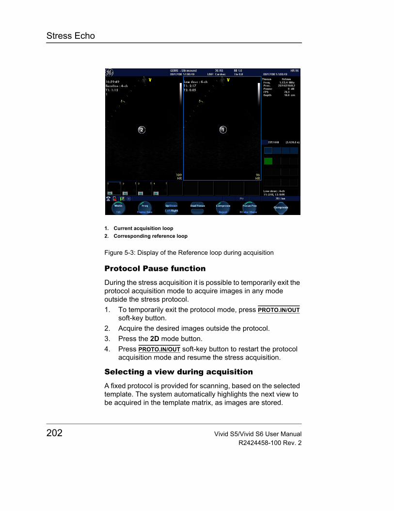
Stress Echo
Figure 5-3: Display of the Reference loop during acquisition
Protocol Pause function
During the stress acquisition it is possible to temporarily exit the protocol acquisition mode to acquire images in any mode outside the stress protocol.1. To temporarily exit the protocol mode, press PROTO.IN/OUT
soft-key button.2. Acquire the desired images outside the protocol.3. Press the 2D mode button.4. Press PROTO.IN/OUT soft-key button to restart the protocol
acquisition mode and resume the stress acquisition.
Selecting a view during acquisition
A fixed protocol is provided for scanning, based on the selected template. The system automatically highlights the next view to be acquired in the template matrix, as images are stored.
1. Current acquisition loop2. Corresponding reference loop
202 Vivid S5/Vivid S6 User ManualR2424458-100 Rev. 2

Stress Echo
However, the order of scanning may be changed manually as follows:
Manual selection of a view during acquisition1. Use the arrow keys on the alphanumeric keyboard to
highlight the cell that represents the view that is to be acquired.The selected cell in the template matrix is highlighted in red, indicating non-default position and is blinking if it contains a previously stored acquisition.
2. Turn freeze off to initiate scanning.3. Scan and save the selected loop as explained in the
previous section.
After storage the system automatically highlights the next available view to be acquired.
Replacing an acquired image1. Use the arrow keys on the alphanumeric keyboard to
highlight the cell that represents the view that is to be replaced.The selected cell in the template matrix is highlighted in red, indicating non-default position.
2. Turn freeze off to initiate scanning.3. Scan and save the selected loop as explained in the
previous section.4. Select in the dialog window if you want to Replace or Keep
the existing loop.• Replace: the original image is deleted from the
examination and replaced by the acquired image.• Keep: the original image is replaced by the acquired
image, but it is not deleted from the examination.Note: When selecting Keep, both the new and the old image will be associated with the current protocol cell and you may later perform Wall Motion Scoring for this level in the protocol using either the new or the old image. The new image may be opened from the protocol, while the old image may be opened manually from the clipboard.
After storage the system automatically highlights the next available view to be acquired.
Vivid S5/Vivid S6 User Manual 203R2424458-100 Rev. 2

Stress Echo
Moving an acquired image
An Image can be moved from one cell to another during acquisition. There are two ways to move images:
Procedure 11. When in the Protocol screen, press MORE (assignable
menu).2. Press the assignable MOVE IMAGES.3. Trackball to the image to move (source cell).4. Press SET.5. Trackball to the destination cell.6. Press SET.
The image is moved from the source cell to the destination cell.
Procedure 21. In the Protocol screen, trackball to the cell containing the
image to move (source cell).2. Press and hold down SET.3. With the SET key still depressed, trackball to the destination
cell.4. Release the SET key.
The image is moved from the source cell to the destination cell.
Stored images can-not be moved.
If the destination cell contains an image, the images from the source and destination cells will be exchanged when moving an acquired image.
Timers
Two timers can be displayed in the Stress mode acquisition screen, beside the template matrix (see Figure 5-4).
204 Vivid S5/Vivid S6 User ManualR2424458-100 Rev. 2
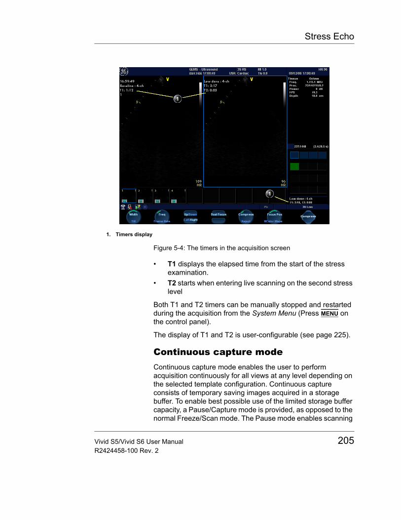
Stress Echo
Figure 5-4: The timers in the acquisition screen
• T1 displays the elapsed time from the start of the stress examination.
• T2 starts when entering live scanning on the second stress level
Both T1 and T2 timers can be manually stopped and restarted during the acquisition from the System Menu (Press MENU on the control panel).
The display of T1 and T2 is user-configurable (see page 225).
Continuous capture modeContinuous capture mode enables the user to perform acquisition continuously for all views at any level depending on the selected template configuration. Continuous capture consists of temporary saving images acquired in a storage buffer. To enable best possible use of the limited storage buffer capacity, a Pause/Capture mode is provided, as opposed to the normal Freeze/Scan mode. The Pause mode enables scanning
1. Timers display
Vivid S5/Vivid S6 User Manual 205R2424458-100 Rev. 2

Stress Echo
and live display on the screen, without any capture, thereby leaving the buffer available.
To run Continuous capture, the user has to select a template where this feature is activated (see page 225 about template configuration).
The buffer bar
When entering a level with Continuous capture enabled, a Buffer bar is displayed in the Info window (see Figure 5-5). The Buffer bar displays the following information:• The unit's scanning state:
• PAUSE (live scanning without storing)• CAPTURE (live scanning with storing to buffer)
• The percentage of the buffer that is filled• The buffer filling progression showed by a green filling
gauge• The capturing sessions, reflected by the red lines along the
Buffer bar
206 Vivid S5/Vivid S6 User ManualR2424458-100 Rev. 2
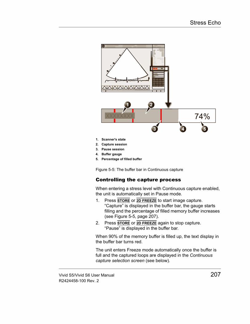
Stress Echo
Figure 5-5: The buffer bar in Continuous capture
Controlling the capture process
When entering a stress level with Continuous capture enabled, the unit is automatically set in Pause mode.1. Press STORE or 2D FREEZE to start image capture.
“Capture” is displayed in the buffer bar, the gauge starts filling and the percentage of filled memory buffer increases (see Figure 5-5, page 207).
2. Press STORE or 2D FREEZE again to stop capture.“Pause” is displayed in the buffer bar.
When 90% of the memory buffer is filled up, the text display in the buffer bar turns red.
The unit enters Freeze mode automatically once the buffer is full and the captured loops are displayed in the Continuous capture selection screen (see below).
1. Scanner's state2. Capture session3. Pause session4. Buffer gauge5. Percentage of filled buffer
Vivid S5/Vivid S6 User Manual 207R2424458-100 Rev. 2

Stress Echo
Running Continuous capture1. Do all your pre-stress acquisitions in the Cardiac
application.The application Ex-ercise should be used in order to get maximum continu-ous capture buffer.
2. Press PROTOCOL to enter the stress echo mode.The Protocol screen is displayed (see Figure 5-1, page 199).
3. Press Template.The template list is displayed.
4. Select the template Exercise 2x4.The Exercise proto-col template is auto-matically selected when the applica-tion Exercise is ac-tive.
5. Press Begin/Cont.6. Acquire the resting loops in all four views.7. Once the fourth loop is acquired the system enter into a
waiting mode where Continuous Capture is in pause state awaiting the patient to exercise.Note: Make sure the system is set to Exercise preset before starting peak-stress acquisition.
8. When the patient is back on the bed, press STORE or 2D FREEZE. The Continuous capture acquisition is started.
9. Acquire all your views. The memory buffer gauge increases (Figure 5-5). When memory filling exceeds 90%, the percent number turns red.
10. Press FREEZE to finish.11. Press the SELECT CYCLE assignable.
The Continuous capture selection screen is displayed (see Figure 5-6, page 211).If the buffer is filled up the system will automatically display the Continuous capture selection screen.Refer to the next section if additional image acquisition is necessary after the buffer is filled up.
12. Assign the cineloops to the four views (see page 211).A dialogue window is displayed asking whether the entire Continuous capture acquisition should be saved or not.
Using Store all to save the entire loop may take up to 15 seconds on Local- Arch-IntHD and several minutes on LocalArch-MOD.
13. Press Delete to discard the loopORPress Select later if you want to reselect any loops (open the capture again from the Protocol screen).ORPress Store all to keep the entire loop.
14. Perform Analysis and scoring (see page 213).
208 Vivid S5/Vivid S6 User ManualR2424458-100 Rev. 2
Stress Echo
Continuous capture with additional image acquisitionAfter acquiring Continuous capture, additional images can be stored to the clipboard before the patient's heart rate decreases toward recovery level. These additional images may be acquired with other scanning modes (using the same probe and application), before doing image assignment to the views:1. Perform Continuous capture as described above (steps 1
to 10).2. Press PROTOCOL twice on the control panel. Live scanning
is activated.If the buffer is not filled up: press PROTO.IN/OUT on the softkey menu. Live scanning is activated outside the stress protocol.If the buffer is filled up: press Select later in the Continuous capture selection screen. Live scanning is activated.
3. Perform the additional acquisition (e.g. Color flow, Doppler). Images will be stored outside the protocol.
4. In order to resume the stress echo exam and assign loops for the views from the Continuous capture buffer, press PROTOCOL.
5. Press on the Continuous capture icon on the lower left corner of the Protocol screen.The Continuous capture selection screen is displayed.
6. Assign the cineloops to the views (see page 211).A dialogue window is displayed asking whether the entire Continuous capture acquisition should be saved or not.
7. Press Delete to discard the loopORPress Select later if you want to reselect any loops (open the capture again from the Protocol screen).ORPress Store all to keep the entire acquisition.The normal procedure is to discard the acquisition. The loop is very big and will take a lot of disk space.
8. Perform Analysis and scoring (see page 213).
Postponed image assignmentThe assignment of the cineloops to the views can be done on a later stage on a stored Continuous capture acquisition.1. Perform Continuous capture as described in "Running
Vivid S5/Vivid S6 User Manual 209R2424458-100 Rev. 2
Stress Echo
Continuous capture" on page 208 (steps 1 to 11).The continuous capture loop is very big, and ending the exam may take sev-eral minutes if stor-ing through a slow network or storing to a removable me-dia.
2. Press Store all.The entire Continuous capture acquisition is stored. The examination can be ended and the image assignment, analysis and scoring can be done on a later stage.
3. Re-open the examination if necessary.4. Press PROTOCOL.
The Protocol screen is displayed.5. Press on the Continuous capture thumbnail on the lower
left corner of the Protocol screen.The Continuous capture selection screen is displayed.
6. Assign the cineloops to the views (see page 211).7. Press Done when finished.8. Perform Analysis and scoring (see page 213).9. When exiting this patient a dialogue window is displayed
asking whether the remaining continuous capture images should be deleted.• Press Yes to delete the remaining continuous capture
imagesOR
• Press No to keep the entire continuous capture acquisition.
The normal procedure is to delete the remaining images as they take a lot of disk space.
Restart capture from the Continuous capture selection screen• Press RESTART CAPTURE.
The recording in memory is deleted and the Continuous capture is started again.
Resume Continuous capture• Press CONTINUE CAPTURE.
Resumes Continuous capture recording (only if the Continuous capture buffer is not full).
210 Vivid S5/Vivid S6 User ManualR2424458-100 Rev. 2
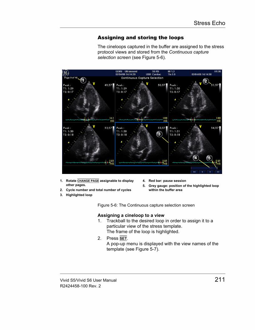
Stress Echo
Assigning and storing the loops
The cineloops captured in the buffer are assigned to the stress protocol views and stored from the Continuous capture selection screen (see Figure 5-6).
Figure 5-6: The Continuous capture selection screen
Assigning a cineloop to a view1. Trackball to the desired loop in order to assign it to a
particular view of the stress template.The frame of the loop is highlighted.
2. Press SET.A pop-up menu is displayed with the view names of the template (see Figure 5-7).
1. Rotate CHANGE PAGE assignable to display other pages.
2. Cycle number and total number of cycles3. Highlighted loop
4. Red bar: pause session5. Grey gauge: position of the highlighted loop
within the buffer area
Vivid S5/Vivid S6 User Manual 211R2424458-100 Rev. 2
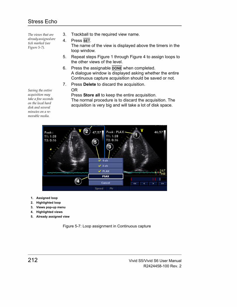
Stress Echo
The views that are already assigned are tick marked (see Figure 5-7).
3. Trackball to the required view name.4. Press SET.
The name of the view is displayed above the timers in the loop window.
5. Repeat steps Figure 1 through Figure 4 to assign loops to the other views of the level.
6. Press the assignable DONE when completed.A dialogue window is displayed asking whether the entire Continuous capture acquisition should be saved or not.
7. Press Delete to discard the acquisition.Saving the entire acquisition may take a few seconds on the local hard disk and several minutes on a re-movable media.
ORPress Store all to keep the entire acquisition.The normal procedure is to discard the acquisition. The acquisition is very big and will take a lot of disk space.
Figure 5-7: Loop assignment in Continuous capture
1. Assigned loop2. Highlighted loop3. Views pop-up menu4. Highlighted views5. Already assigned view
212 Vivid S5/Vivid S6 User ManualR2424458-100 Rev. 2

Stress Echo
AnalysisAnalysis consists of viewing previously saved loops and assigning scores to each cardiac segment, in order to quantify the function of the muscle, or wall motion.
Depending on the protocol configuration, the analysis stage can be started automatically after completion of the stress test or it can be started manually. In this case, the usual procedure consists of sequentially opening all image groups (if defined) and perform scoring from image to image.
The quad screen is the standard display for comparing heart cycles (Figure 5-9). The heart cycle loops in the display are synchronized to enable comparison. Each loop in the quad screen can be magnified, using the "Crop Images" function (see page 591) or the zoom control (see page 120).
Image selection for analysis
Images can be selected manually or from a pre-defined group in the Protocol screen.
Selection of images from a groupIf groups of images have been defined in the protocol template (see page 231), the user can select a group of images for analysis and sequentially analyze all images from all groups from within the analysis screen (see Figure 5-9, page 215).1. In a stress examination, press PROTOCOL.
A preview of the acquisitions is displayed.2. Trackball to a group in the Group list.
The frame of the images belonging to the group are highlighted.
3. Press SET to open images in the Analyze screen (see page 216).
Note: Pressing ANALYZE (while no images are selected in Protocol screen) automatically opens the first group of images in the analysis screen.
Vivid S5/Vivid S6 User Manual 213R2424458-100 Rev. 2
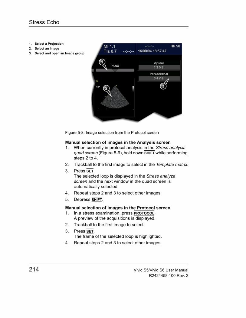
Stress Echo
Figure 5-8: Image selection from the Protocol screen
Manual selection of images in the Analysis screen1. When currently in protocol analysis in the Stress analysis
quad screen (Figure 5-9), hold down SHIFT while performing steps 2 to 4.
2. Trackball to the first image to select in the Template matrix.3. Press SET.
The selected loop is displayed in the Stress analyze screen and the next window in the quad screen is automatically selected.
4. Repeat steps 2 and 3 to select other images.5. Depress SHIFT.
Manual selection of images in the Protocol screen1. In a stress examination, press PROTOCOL.
A preview of the acquisitions is displayed.2. Trackball to the first image to select.3. Press SET.
The frame of the selected loop is highlighted.4. Repeat steps 2 and 3 to select other images.
1. Select a Projection2. Select an image3. Select and open an Image group
214 Vivid S5/Vivid S6 User ManualR2424458-100 Rev. 2
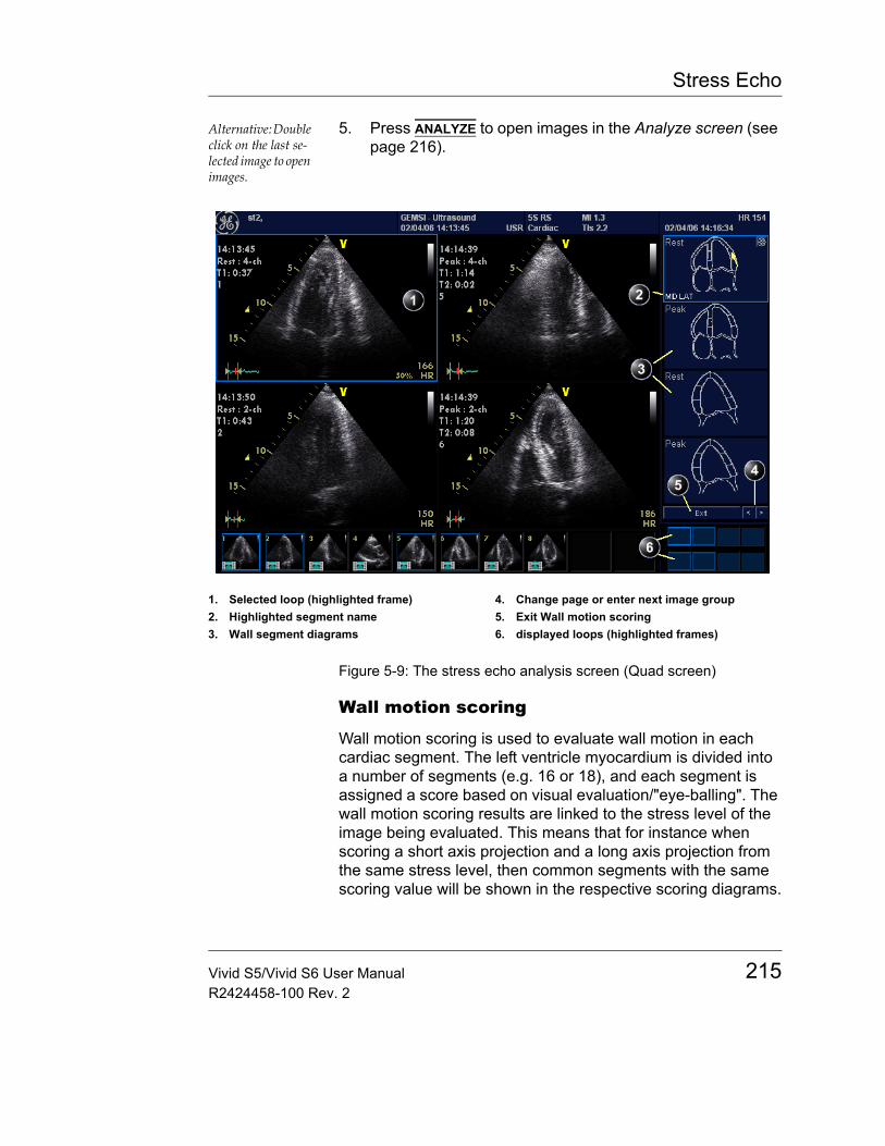
Stress Echo
Alternative: Double click on the last se-lected image to open images.
5. Press ANALYZE to open images in the Analyze screen (see page 216).
Figure 5-9: The stress echo analysis screen (Quad screen)
Wall motion scoring
Wall motion scoring is used to evaluate wall motion in each cardiac segment. The left ventricle myocardium is divided into a number of segments (e.g. 16 or 18), and each segment is assigned a score based on visual evaluation/"eye-balling". The wall motion scoring results are linked to the stress level of the image being evaluated. This means that for instance when scoring a short axis projection and a long axis projection from the same stress level, then common segments with the same scoring value will be shown in the respective scoring diagrams.
1. Selected loop (highlighted frame)2. Highlighted segment name3. Wall segment diagrams
4. Change page or enter next image group5. Exit Wall motion scoring6. displayed loops (highlighted frames)
Vivid S5/Vivid S6 User Manual 215R2424458-100 Rev. 2
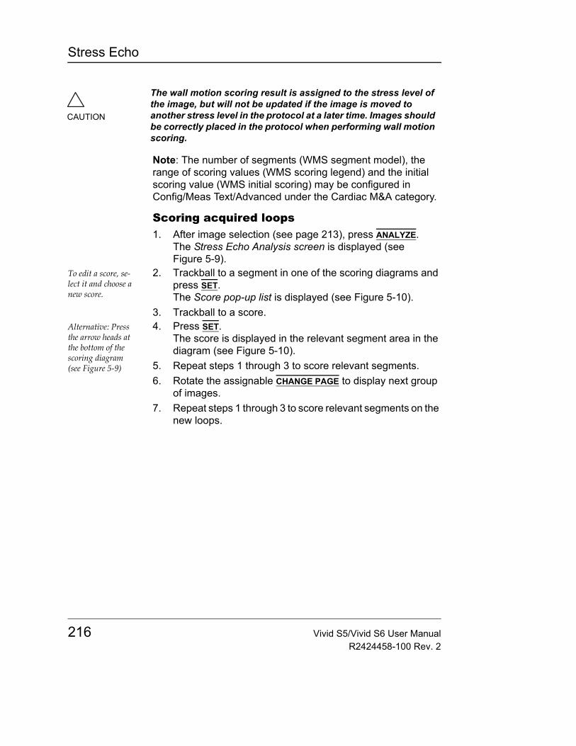
Stress Echo
Note: The number of segments (WMS segment model), the range of scoring values (WMS scoring legend) and the initial scoring value (WMS initial scoring) may be configured in Config/Meas Text/Advanced under the Cardiac M&A category.
Scoring acquired loops1. After image selection (see page 213), press ANALYZE.
The Stress Echo Analysis screen is displayed (see Figure 5-9).
To edit a score, se-lect it and choose a new score.
2. Trackball to a segment in one of the scoring diagrams and press SET.The Score pop-up list is displayed (see Figure 5-10).
3. Trackball to a score.Alternative: Press the arrow heads at the bottom of the scoring diagram (see Figure 5-9)
4. Press SET.The score is displayed in the relevant segment area in the diagram (see Figure 5-10).
5. Repeat steps 1 through 3 to score relevant segments.6. Rotate the assignable CHANGE PAGE to display next group
of images.7. Repeat steps 1 through 3 to score relevant segments on the
new loops.
CAUTION
The wall motion scoring result is assigned to the stress level of the image, but will not be updated if the image is moved to another stress level in the protocol at a later time. Images should be correctly placed in the protocol when performing wall motion scoring.
216 Vivid S5/Vivid S6 User ManualR2424458-100 Rev. 2
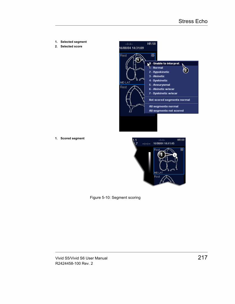
Stress Echo
Figure 5-10: Segment scoring
1. Selected segment2. Selected score
1. Scored segment
Vivid S5/Vivid S6 User Manual 217R2424458-100 Rev. 2
Stress Echo
Quantitative TVI Stress echo analysis
The Vivid S5/Vivid S6 Ultrasound unit provides a Quantitative TVI (QTVI) Stress analysis package based on Tissue velocity information (TVI). The TVI data is stored in a combined format with grey scale imaging during stress examination.
When selecting a template supporting TVI data acquisition, the ultrasound unit will automatically store TVI information, generally for the apical views of the stress examination.
The QTVI Stress analysis option currently applies only to Dobutamine stress-echo.
Wall Motion Scoring remains the basis for the diagnosis of CAD in stress echocardiography. QTVI Stress may be used as a guidance tool to check this interpretation.
QTVI Stress is based on the assessment of peak velocity at peak Dobutamine stress (see "References" on page 224. The normal ranges have been validated in the "average" patient presenting for stress testing. The velocity cutoff values for the Vpeak measurement will not work in the following cases:
Velocity measure-ments in mid and basal segments of the myocard will contain contribu-tions from the api-cal region of the myocard. E.g. if measured value in a mid segment is be-low the cutoff value for this segment then this might re-late to a reduced function in the mid or apical region.
• Submaximal stress (<85% predicted max HR)• Patients at extremes of age (<40 or >70)• Previous myocardial infarction/revascularization• Previous heart-failure / cardiomyopathy / hypertrophy /
arrhythmia / aortic regurgitation
The velocity cutoff values are based on placing the sample volume at center of each cardiac segment at start of systole, the left ventricle myocardial segments are defined by the American Society of Echocardiography 16 segments model. However, the velocity cutoff model does not cover the apical segments (due to low velocities and segment orientation), (see side note).
Tissue Doppler does not have perfect site-specificity because of tethering by adjacent segments. Thus, although an ischemic segment has little thickening (and therefore could be expected to show low velocity), measured velocity may be influenced by
WARNING
QTVI Stress analysis is meant as a guide to wall motion scoring. Diagnosis must not be based on results achieved by QTVI Stress analysis only.
218 Vivid S5/Vivid S6 User ManualR2424458-100 Rev. 2
Stress Echo
local tethering, reflecting contraction in surrounding segments. Conversely, a normal segment may have its velocity reduced by an adjacent segment with reduced velocity. This tethering effect may decrease the sensitivity for single vessel disease, but nonetheless the sensitivity and specificity of the cut-offs are approximately 80% (see "References" on page 224).
Three different analysis tools based on TVI data are available:• "Vpeak measurement" on page 220, enables the display of
a tissue velocity trace for a selected region of a previously scored segment through the entire heart cycle. In addition Vpeak is color-coded on the 2D image. From the velocity trace, the user can estimate the peak systolic velocity (see "References" on page 224).This tool is available in views from peak levels only and only when a segment has been scored in one of these views.
• "Tissue Tracking" on page 223, enables visualization of the systolic contraction of the heart by color-coding the myocardial displacement through the systole.
• "Quantitative analysis" on page 223, enables further quantitative analysis based on multiple tissue velocity traces.
The quantitative analysis is described in Chapter 8, "Quantitative Analysis" on page 375.
Accessing QTVI Stress analysis toolsThe three QTVI Stress analysis tools are entered by pressing a dedicated button on the scoring diagram (see Figure 5-11) of the selected view. Only views with TVI data acquired will display QTVI Stress tools buttons on the respective diagrams.
Vivid S5/Vivid S6 User Manual 219R2424458-100 Rev. 2
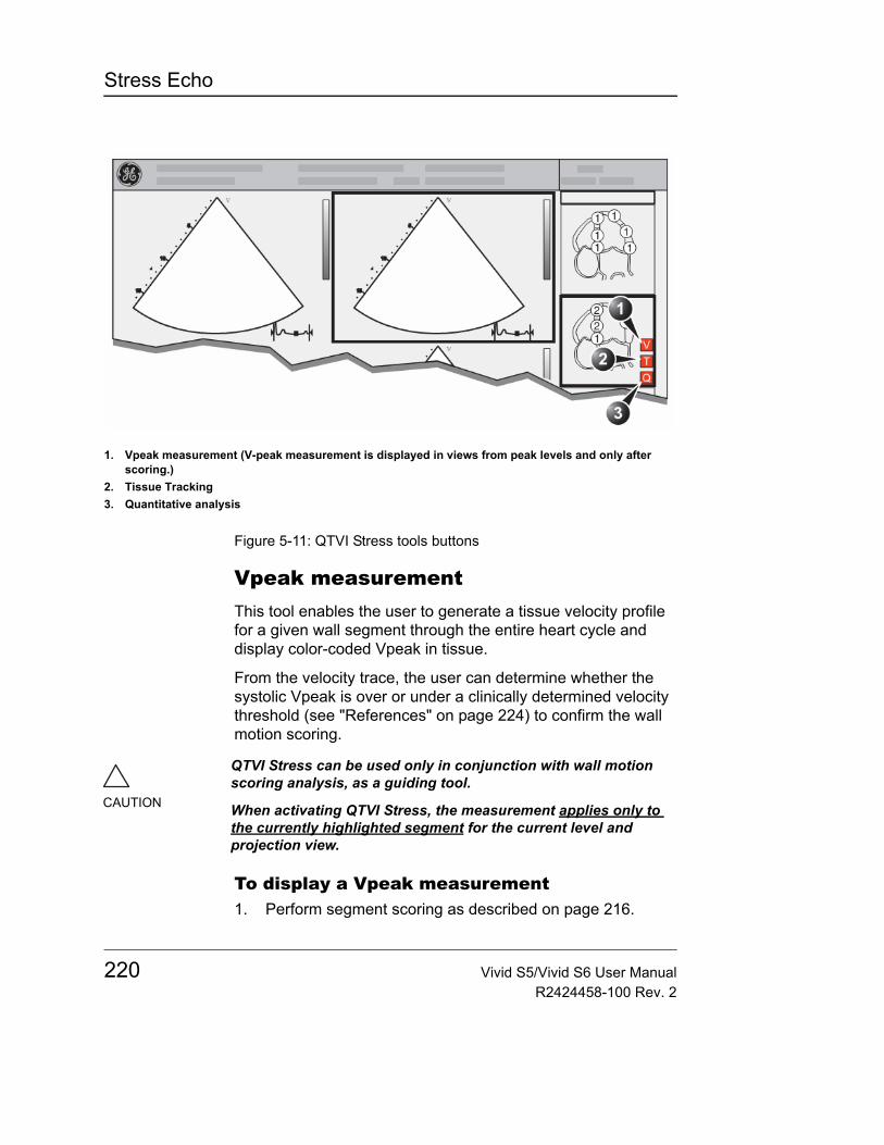
Stress Echo
Figure 5-11: QTVI Stress tools buttons
Vpeak measurementThis tool enables the user to generate a tissue velocity profile for a given wall segment through the entire heart cycle and display color-coded Vpeak in tissue.
From the velocity trace, the user can determine whether the systolic Vpeak is over or under a clinically determined velocity threshold (see "References" on page 224) to confirm the wall motion scoring.
To display a Vpeak measurement1. Perform segment scoring as described on page 216.
1. Vpeak measurement (V-peak measurement is displayed in views from peak levels and only after scoring.)
2. Tissue Tracking3. Quantitative analysis
CAUTION
QTVI Stress can be used only in conjunction with wall motion scoring analysis, as a guiding tool.
When activating QTVI Stress, the measurement applies only to the currently highlighted segment for the current level and projection view.
220 Vivid S5/Vivid S6 User ManualR2424458-100 Rev. 2

Stress Echo
When performing scoring a view from a peak level, the Vpeak measurement button (V) is displayed in the corresponding diagram.
2. In the Scoring diagram, press V.The trackball cursor is changed to sampling area and the scored peak views are updated showing:
See page 222 for further information on Vpeak measure-ment interpreta-tion.
• A diagram with the current segment highlighted (scoring bullet with a ring) and the segment's velocity cutoff (see Figure 5-12).
• Color-coded velocity in tissue. The color-coding convention is as follow:- Green: Velocities above threshold value + 5%- Yellow: Velocities near threshold (+/- 5% interval)- White: Velocities below threshold value - 5%
• A result window to display tissue velocity profile, shown when moving the sampling area in the view.
3. In the 2D sector, trackball the sampling point over the wall area corresponding to the current segment (shown as the highlighted segment in the diagram). A tissue velocity profile for the actual segment is generated in the Result window (see Figure 5-12).
4. Use SEGMENT SELECT assignable to analyze the other segments in the peak view,OrSelect another scoring bullet in the diagram in one of the peak views.
To turn off the Vpeak measurement tool1. Trackball to one of the V button in the peak view scoring
diagrams.2. Press SET in the trackball area.
Vivid S5/Vivid S6 User Manual 221R2424458-100 Rev. 2
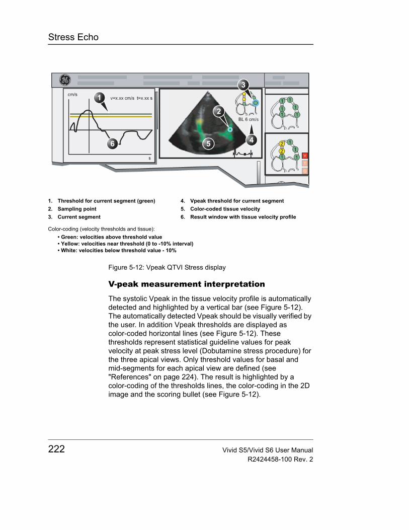
Stress Echo
Figure 5-12: Vpeak QTVI Stress display
V-peak measurement interpretation
The systolic Vpeak in the tissue velocity profile is automatically detected and highlighted by a vertical bar (see Figure 5-12). The automatically detected Vpeak should be visually verified by the user. In addition Vpeak thresholds are displayed as color-coded horizontal lines (see Figure 5-12). These thresholds represent statistical guideline values for peak velocity at peak stress level (Dobutamine stress procedure) for the three apical views. Only threshold values for basal and mid-segments for each apical view are defined (see "References" on page 224). The result is highlighted by a color-coding of the thresholds lines, the color-coding in the 2D image and the scoring bullet (see Figure 5-12).
1. Threshold for current segment (green)2. Sampling point3. Current segment
4. Vpeak threshold for current segment5. Color-coded tissue velocity6. Result window with tissue velocity profile
Color-coding (velocity thresholds and tissue):• Green: velocities above threshold value• Yellow: velocities near threshold (0 to -10% interval)• White: velocities below threshold value - 10%
222 Vivid S5/Vivid S6 User ManualR2424458-100 Rev. 2
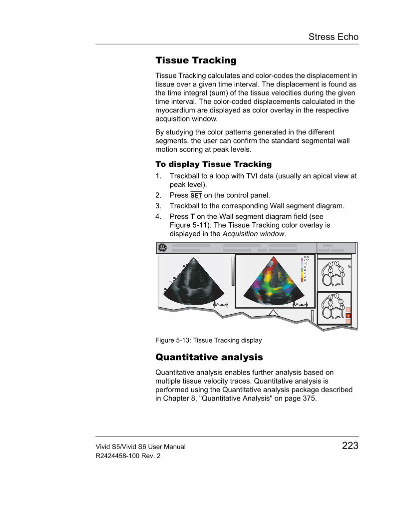
Stress Echo
Tissue TrackingTissue Tracking calculates and color-codes the displacement in tissue over a given time interval. The displacement is found as the time integral (sum) of the tissue velocities during the given time interval. The color-coded displacements calculated in the myocardium are displayed as color overlay in the respective acquisition window.
By studying the color patterns generated in the different segments, the user can confirm the standard segmental wall motion scoring at peak levels.
To display Tissue Tracking1. Trackball to a loop with TVI data (usually an apical view at
peak level).2. Press SET on the control panel.3. Trackball to the corresponding Wall segment diagram.4. Press T on the Wall segment diagram field (see
Figure 5-11). The Tissue Tracking color overlay is displayed in the Acquisition window.
Figure 5-13: Tissue Tracking display
Quantitative analysisQuantitative analysis enables further analysis based on multiple tissue velocity traces. Quantitative analysis is performed using the Quantitative analysis package described in Chapter 8, "Quantitative Analysis" on page 375.
Vivid S5/Vivid S6 User Manual 223R2424458-100 Rev. 2
Stress Echo
To start quantitative analysis1. Trackball to a loop with TVI data (usually an apical view at
peak level).2. Press SET on the control panel.3. Trackball to the corresponding Wall segment diagram.4. Press Q on the Wall segment diagram field to launch the
Quantitative analysis package (see Chapter 8, "Quantitative Analysis" on page 375).
References1. Application of Tissue Doppler to Interpretation of
Dubotamine Echocardiography and Comparison With Quantitative Coronary Angiography. Cain P, Baglin T, Case C, Spicer D, Short L. and Marwick T H. Am. J. Cardiol. 2001; 87: 525-531
224 Vivid S5/Vivid S6 User ManualR2424458-100 Rev. 2
Stress Echo
Editing/creating a templateThe stress package provides protocol templates for exercise as well as pharmacological stress examinations. The user can create new templates or modify existing templates to suit the individual needs. Up to ten projections and fourteen stress levels can be created in a template.
Templates created may be temporary, used only during the current examination, or saved as new templates, for future use and reference. The editions that may be performed include:• Adding/deleting levels and projections, page 229• Assigning new labels to levels and projections, page 230• Defining level options, page 230• Defining new groups, page 231
Templates are edited/created from the Template editor screen.
Entering the Template editor screen1. Press PROTOCOL to enter the stress echo mode.2. Press the assignable TEMPLATE.
The Template pop-up menu is displayed.3. Trackball to Template Editor.4. Press SET.
The Template editor screen is displayed (see Figure 5-14).
Vivid S5/Vivid S6 User Manual 225R2424458-100 Rev. 2
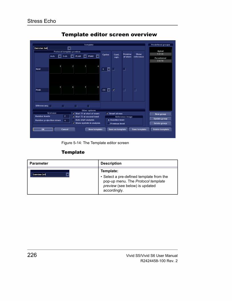
Stress Echo
Template editor screen overview
Figure 5-14: The Template editor screen
Template
Parameter Description
Template:• Select a pre-defined template from the
pop-up menu. The Protocol template preview (see below) is updated accordingly.
226 Vivid S5/Vivid S6 User ManualR2424458-100 Rev. 2
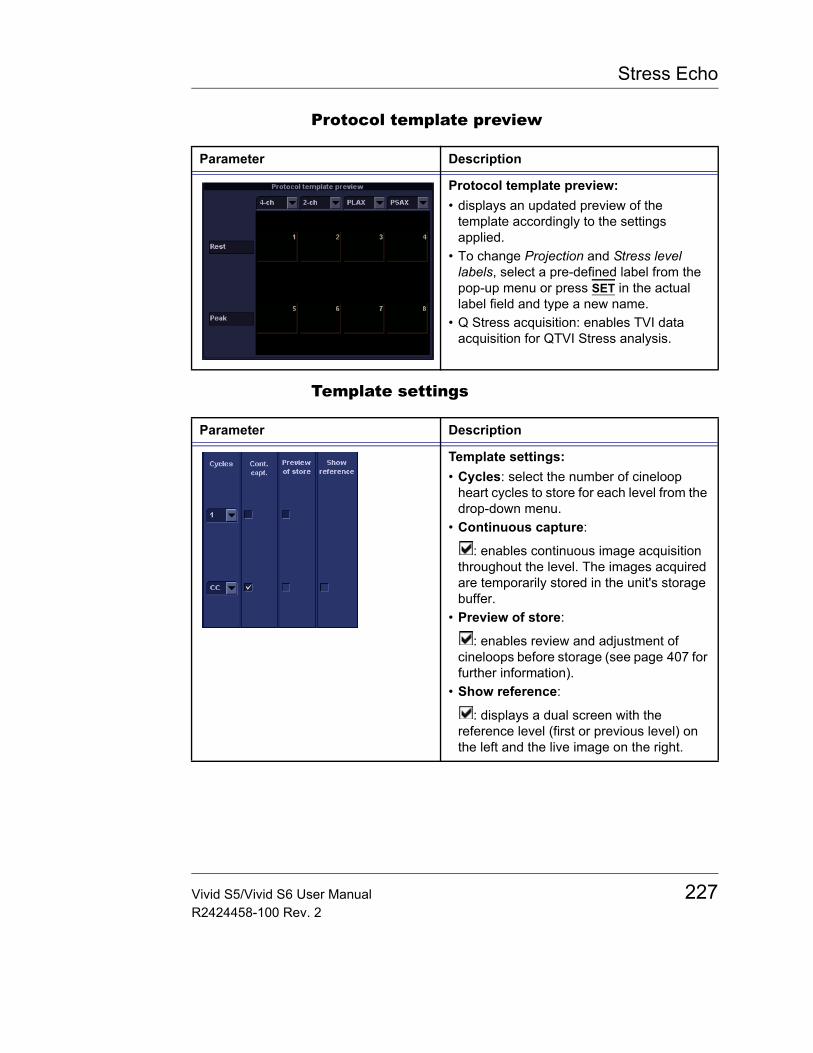
Stress Echo
Protocol template preview
Template settings
Parameter Description
Protocol template preview:• displays an updated preview of the
template accordingly to the settings applied.
• To change Projection and Stress level labels, select a pre-defined label from the pop-up menu or press SET in the actual label field and type a new name.
• Q Stress acquisition: enables TVI data acquisition for QTVI Stress analysis.
Parameter Description
Template settings:• Cycles: select the number of cineloop
heart cycles to store for each level from the drop-down menu.
• Continuous capture:
: enables continuous image acquisition throughout the level. The images acquired are temporarily stored in the unit's storage buffer.
• Preview of store:
: enables review and adjustment of cineloops before storage (see page 407 for further information).
• Show reference:
: displays a dual screen with the reference level (first or previous level) on the left and the live image on the right.
Vivid S5/Vivid S6 User Manual 227R2424458-100 Rev. 2
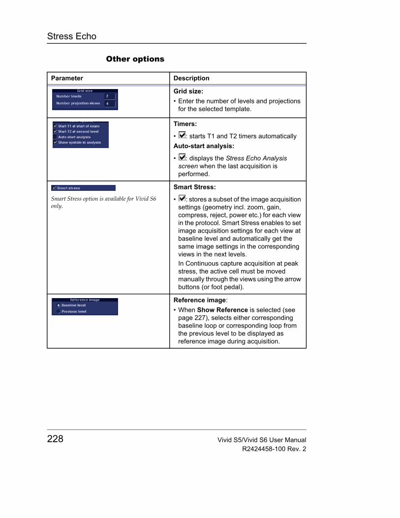
Stress Echo
Other options
Parameter Description
Grid size:• Enter the number of levels and projections
for the selected template.
Timers:
• : starts T1 and T2 timers automaticallyAuto-start analysis:
• : displays the Stress Echo Analysis screen when the last acquisition is performed.
Smart Stress option is available for Vivid S6 only.
Smart Stress:
• : stores a subset of the image acquisition settings (geometry incl. zoom, gain, compress, reject, power etc.) for each view in the protocol. Smart Stress enables to set image acquisition settings for each view at baseline level and automatically get the same image settings in the corresponding views in the next levels.In Continuous capture acquisition at peak stress, the active cell must be moved manually through the views using the arrow buttons (or foot pedal).
Reference image:• When Show Reference is selected (see
page 227), selects either corresponding baseline loop or corresponding loop from the previous level to be displayed as reference image during acquisition.
228 Vivid S5/Vivid S6 User ManualR2424458-100 Rev. 2
Stress Echo
Pre-defined groups
Editing/Creating a template
Selecting a base template to edit1. Trackball to the Template pop-up menu on the upper left
corner of the Template editor screen.2. Press SET on the arrow.
The Template pop-up menu is displayed.Determine the re-quired number of projections and lev-els you need and se-lect the most appropriate founda-tion template.
3. Trackball to the base template to edit.4. Press SET.
The selected template is displayed in the Protocol template preview field, showing the levels and projections and their labels.
Adding/deleting levels and projectionsFactory templates cannot be changed.
1. Enter the number of levels and projections in the Grid size field (see Figure 5-14).The new grid size is displayed in the Protocol template preview field.
2. Press New Template to create a new template.OrPress Save Template to update the base template.
Parameter Description
Pre-defined groups:• Shows the image groups created.• New group: creates a new image group.
Select the desired images on the template preview (see page 231).
• Update group: edits a selected group after new loop selection on the template preview (see page 231).
• Delete group: deletes selected group (see page 231).
Vivid S5/Vivid S6 User Manual 229R2424458-100 Rev. 2
Stress Echo
The timers can also be started or stopped at any time during stress exam-ination using the assignables T1 and T2 on the control panel.
Display timer(s)• Check the box(es) to display timer(s) as specified (see
Figure 5-14).
Start analysis automatically• Check Auto start analysis to display the Stress Echo
Analysis screen when the last acquisition is performed.
Smart stress
Check Smart stress to store a subset of the image acquisition settings (e.g., geometry, zoom, gain, compress, reject, power, etc.) for each view in the protocol. Smart Stress enables to set image acquisition settings for each view at baseline level and automatically get the same image settings in the corresponding views in the next levels. In Continuous capture acquisition at peak stress, the active cell must be moved manually through the views using the arrow buttons.
Assigning new labels to levels and projections1. In the Protocol template preview field, Trackball to the Label
field that is to be changed.2. Select the Label pop-up menu and press SET on the desired
pre-defined label.Or• If the Label field is empty:
Press SET and enter the label or projection name.• If the Label field has a name to be changed:
Press SET twice (double-click) to highlight the text to be replaced and enter the new label or projection name.
Configuring levels
The following options can be set up for each level:
Number of cycles to be stored in the cineloop:• Enter the desired number in the Cycles field.
Up to four cycles/cineloop can be stored.
Continuous capture• Check Continuous capture if continuous image
acquisition throughout the level is desired.
230 Vivid S5/Vivid S6 User ManualR2424458-100 Rev. 2
Stress Echo
When Continuous capture is selected, preview of cineloop and reference display (see below) during acquisition are not possible.
Preview of store• Check Preview of store if review and adjustment of
cineloops before storage is desired.
Show reference• Check Show reference if the display of the corresponding
reference loop is desired during acquisition (dual screen mode).
Adding a group1. In the Protocol template preview field select the cells to be
part of the group.2. In the Pre-defined group field, press New group.
A dialogue box is displayed asking the user to enter a name for the new group.
3. Enter the group name.4. Press OK.
The new group is displayed in the Pre-defined group field.
Updating an existing groupA selected group is highlighted by a yellow frame.
1. In the Pre-defined group field, select the group to edit.The selected cell are highlighted in the Protocol template preview field.
2. Either select (a) new cell(s) to add to the group or deselect (an) existing cell(s) to remove from the group.
3. Press Update group in the Pre-defined group field.The display in the Protocol template preview field is updated accordingly.
Deleting a groupA selected group is highlighted by a yellow frame.
1. In the Pre-defined group field, select the group to delete.2. Press Delete group.
The group is removed from the list in the Pre-defined group field.
Vivid S5/Vivid S6 User Manual 231R2424458-100 Rev. 2

Stress Echo
232 Vivid S5/Vivid S6 User ManualR2424458-100 Rev. 2
Contrast Imaging
Chapter 6 Contrast Imaging
• Introduction ................................................................................... .. 234• Cardiac imaging ....................................................................... 234• Non-cardiac imaging ................................................................ 235
• Data acquisition ............................................................................ .. 235• Left Ventricular Contrast Imaging ............................................. 235
• LV Contrast overview ................................................................... .. 236• LV Contrast controls ................................................................. 236• Using LV Contrast .................................................................... 238• Optimizing LV Contrast ............................................................ 239
• Vascular Contrast Imaging .......................................................... .. 240• Abdominal Contrast Imaging ....................................................... .. 241
Vivid S5/Vivid S6 User Manual 233R2424458-100 Rev. 2

Contrast Imaging
IntroductionVivid S5/Vivid S6 supports:• Left Ventricular Contrast imaging: Optimized for
endocardial border detection and assessment of wall motion and wall thickening (see page 235).
• Vascular Contrast imaging: optimized to visualize contrast in larger vessels (see page 240).
• Abdominal Contrast imaging: optimized to visualize contrast in liver and kidney (see page 241).
Note: This system is designed for compatibility with commercially available contrast agents. Because the availability of these agents is subject to government regulation and approval, product features intended for use with these agents may not be commercially marketed nor made available before the contrast agent is approved for use. Advanced contrast features are only enabled on systems for delivery in countries or regions where the agents are approved for use or for investigational or research use.
Cardiac imagingThe only contrast acquisition application available for cardiac imaging is Left Ventricular Contrast imaging. The LV Contrast (LVO) application is optimized for endocardial border detection and assessment of wall motion and wall thickening. This application requires the LVO Contrast option to be enabled.
WARNING
Appropriate training
Only physicians or echo technicians who have received appropriate training can use the Contrast applications.
WARNING
Always read and follow carefully the manufacturer instructions on the contrast agent label.
234 Vivid S5/Vivid S6 User ManualR2424458-100 Rev. 2
Contrast Imaging
Non-cardiac imagingThe following non-cardiac contrast acquisition applications are available.• Vascular Contrast imaging: optimized to visualize
contrast in larger vessels, e.g. carotid artery. Requires the Vascular/Abdominal Contrast option enabled.
• Abdominal Contrast imaging: optimized to visualize contrast in abdominal organs, e.g. liver and kidneys. Requires the Vascular/Abdominal Contrast option enabled.
Data acquisitionLeft Ventricular Contrast ImagingThe Left Ventricular (LV) Contrast application has an optimized system preset for Left ventricular opacification, optimal resolution of endocardial borders delineationand for optimal assessment of wall motion.
The LV Contrast application may help to identify LV thrombus and evaluate wall motion.
WARNING
Abdominal and Vascular Contrast applications are for research purposes only. Diagnosis must not be based on results achieved by contrast analysis alone.
WARNING
Misdiagnosis based on image artifacts
Misdiagnosis in ultrasound contrast images may be caused by several artifacts, most importantly:
Motion artifacts: gives rise to signals independently of contrast presence. This may be caused by patient movement; including respiration, or by probe movement influenced by the operator.
Regional drop outs: caused by unintentional destruction of the contrast agent, too low concentration of contrast agent, poor acoustic penetration due to rib/lung shadows or system failing to detect the contrast agent due to erroneous settings induced by the operator.
Tissue harmonics: gives contrast-like signals independently of the presence of contrast agent.
Vivid S5/Vivid S6 User Manual 235R2424458-100 Rev. 2
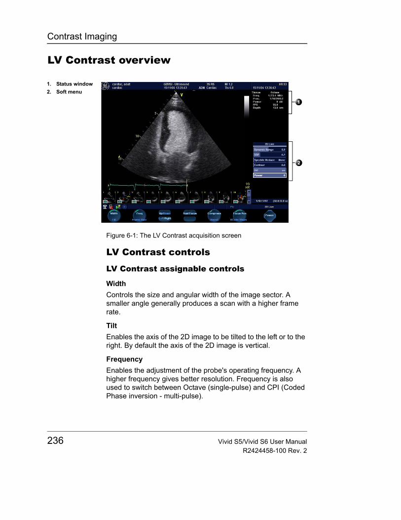
Contrast Imaging
LV Contrast overview
Figure 6-1: The LV Contrast acquisition screen
LV Contrast controls
LV Contrast assignable controls
WidthControls the size and angular width of the image sector. A smaller angle generally produces a scan with a higher frame rate.
TiltEnables the axis of the 2D image to be tilted to the left or to the right. By default the axis of the 2D image is vertical.
FrequencyEnables the adjustment of the probe's operating frequency. A higher frequency gives better resolution. Frequency is also used to switch between Octave (single-pulse) and CPI (Coded Phase inversion - multi-pulse).
1. Status window2. Soft menu
236 Vivid S5/Vivid S6 User ManualR2424458-100 Rev. 2
Contrast Imaging
Ultra Definition (UD) ClarityThis control reduces the unwanted effects of speckle in the ultrasound image.
See "Ultra Definition (UD) Clarity" on page 146.
Focus Pos.Changes the location of the focal point. A triangular marker on the depth scale along the image sector indicates the position of the focal point.
Two triangular markers pointing towards each other (><) indicate that Coded Phase Inversion (CPI) is being used. CPI is a multi-pulse technique with focus at the indicated depth.
Frame rateLower frame rate gives better spatial resolution.
Controls the line density.
Up/DownEnables the 2D image to be flipped 180 degrees.
Left/RightEnables the display of a mirrored image. When applied, the reference marker V moves to the other side of the image.
T1/T2 (Timers)Contrast timer: press T1 once to start the timer, press again to stop the timer. A second timer (T2) is available from the More menu.
B Color mapsDisplays a 2D maps menu to optimized the grey scale presentation. The menu enables an option from a list of non-linear grey-curves or different 2D-colorized curves to be selected.
LV Contrast Soft menu controls
PowerControls the amount of acoustic power applied to the transmitted pulse.
Too high Power lev-el will destroy the contrast agent.
CompressControls the degree of image contrast.
Vivid S5/Vivid S6 User Manual 237R2424458-100 Rev. 2
Contrast Imaging
RejectControls the Echo rejection level. When increased, low level echoes are rejected and appear darker in the 2D image.
Dynamic RangeControls the image contrast. A high dynamic range setting gives a softer image. Decreasing the dynamic range will provide a more black and white image.
TiltEnables the axis of the 2D image to be tilted to the left or to the right. By default the axis of the 2D image is vertical.
ContourControls the image processing related to the extent of edge enhancement applied.
The Diff control de-creases the frame rate and the number of focal zones when turned on.
Diff on/offAffects the level of reverberation in the image. The reverberation in the image is reduced when Diff control is turned on.
DDP (Data Dependant Processing)Performs temporal processing, which reduces random noise without affecting the motion of significant tissue structures.
Using LV ContrastThe LV Contrast application works with the 3S-RS, M4S-RS (Vivid S6 only) 5S-RS, 6T-RS, and 6Tc-RS probes.1. Press PROBE on the control panel.
A list of the connected probes is displayed.The Application menu for the selected probe is listed.
2. Trackball to LV Contrast application.3. Press SET to launch the application.4. Perform the acquisition.
WARNING
Always read and follow carefully the manufacturer instructions on the contrast agent label.
238 Vivid S5/Vivid S6 User ManualR2424458-100 Rev. 2
Contrast Imaging
Optimizing LV ContrastThe default setting for the LV contrast application is optimized for contrast detection and not tissue imaging. Therefore, with some patients it may be difficult to orient the probe before the contrast agent arrives. In this case we recommend to stay in the Cardiac application until the contrast agent is observed in the right ventricle and quickly switch to the LV Contrast application.
If a swirling pattern is observed and persists after the LV cavity has been filled with contrast, the power should be reduced until homogenous opacification is obtained
CAUTION
Too high Power setting will destroy the contrast agent in the LV cavity.
Vivid S5/Vivid S6 User Manual 239R2424458-100 Rev. 2
Contrast Imaging
Vascular Contrast ImagingVascular Contrast is intended for visualization of ultrasound contrast agents in large vessels (e.g. carotid artery and femoral artery).
The Vascular Contrast application works with the 8L-RS and 9L-RS probes.
The application uses Coded Phase Inversion (CPI) (greyscale) to maximize the contrast detection and visualization.
Note: This system is designed for compatibility with commercially available contrast agents. Because the availability of these agents is subject to government regulation and approval, product features intended for use with these agents may not be commercially marketed nor made available before the contrast agent is approved for use.
Note: the Vascular Contrast application requires the Vascular/Abdominal Contrast option enabled.
WARNING
Abdominal and Vascular Contrast applications are for research purposes only. Diagnosis must not be based on results achieved by contrast analysis alone.
CAUTION
This application may not be available on your system. Contrast agent for this application are undergoing clinical trial and therefore, not yet available in the United States.
240 Vivid S5/Vivid S6 User ManualR2424458-100 Rev. 2
Contrast Imaging
Abdominal Contrast ImagingAbdominal Contrast is intended for visualization of ultrasound contrast agents in abdominal organs (e.g. liver or kidney).
The Abdominal Contrast application works with the 4C-RS probe.
The application uses Coded Phase Inversion (CPI) (greyscale) to maximize the contrast detection and visualization.
Note: This system is designed for compatibility with commercially available contrast agents. Because the availability of these agents is subject to government regulation and approval, product features intended for use with these agents may not be commercially marketed nor made available before the contrast agent is approved for use.
Note: The Abdominal Contrast application requires the Vascular/Abdominal Contrast option enabled.
WARNING
Abdominal and Vascular Contrast applications are for research purposes only. Diagnosis must not be based on results achieved by contrast analysis alone.
CAUTION
This application may not be available on your system. Contrast agent for this application are undergoing clinical trial and therefore, not yet available in the United States.
Vivid S5/Vivid S6 User Manual 241R2424458-100 Rev. 2

Contrast Imaging
242 Vivid S5/Vivid S6 User ManualR2424458-100 Rev. 2
Measurement and Analysis
Chapter 7 Measurement and Analysis
• Introduction ................................................................................... .. 246• About Measurement results display ......................................... 247
• The Assign and Measure modality .............................................. .. 248• Starting the Assign and Measure modality ............................... 248• Entering a study and performing measurements ..................... 249
• Measure and Assign modality ..................................................... .. 251• Starting the Measure and Assign modality ............................... 251• Post-measurement assignment labels ..................................... 252
• Cardiac measurements ................................................................ .. 255• 2D Measurements .................................................................... 255• M-Mode Measurements ........................................................... 259• Doppler Measurements ............................................................ 262• TSI Measurements ................................................................... 266• Automated Function Imaging ................................................... 273• AutoEF Measurements ............................................................ 292
• Vascular measurements ............................................................... .. 302• B-Mode measurements ............................................................ 302• Intima-Media Thickness ........................................................... 303• M-Mode Measurements ........................................................... 308• Doppler measurements ............................................................ 309
• Pediatric Calculations .................................................................. .. 314• Overview .................................................................................. 314• Hip Dysplasia Calculation ........................................................ 315• Making Hip Dysplasia Measurement ........................................ 315
• Performing an OB exam ............................................................... .. 317• Patient entry ............................................................................. 317• Selecting probe and OB application ......................................... 321
Vivid S5/Vivid S6 User Manual 243R2424458-100 Rev. 2
Measurement and Analysis
• OB Measurements and calculations ........................................... ... 322• Introduction ...............................................................................322• B-Mode measurements ............................................................323• M-Mode measurements ............................................................330• Doppler Mode Measurements ..................................................330
• OB parameter configuration ........................................................ ... 333• Configuring OB M&A according to geographical regions .........333
• Measurement package configuration ......................................... ... 338• Measurement package configuration - example .......................338
• User-defined formulas ................................................................. ... 343• User-defined formula - example ...............................................343• About units ................................................................................349
• Measurement result table ............................................................ ... 351• Minimizing the Measurement result table .................................351• Moving the Measurement result table .......................................351• Deleting measurements ............................................................352
• Worksheet ..................................................................................... ... 353• Overview ...................................................................................353• Using Worksheet ......................................................................354
• OB worksheet ............................................................................... ... 356• Patient data ...............................................................................357• Measurement information .........................................................357• Calculation information .............................................................358
• OB graphs ..................................................................................... ... 359• Overview ...................................................................................359• Fetal Growth Curve Graph ........................................................360• Fetal Trending ...........................................................................364• Fetal Growth Bar Graph ............................................................365
• OB-Multigestational ...................................................................... ... 366• Multiple Fetus ...........................................................................366
• GYN Measurements ...................................................................... ... 370• Introduction ...............................................................................370• To Start a Gynecology Exam ....................................................370
244 Vivid S5/Vivid S6 User ManualR2424458-100 Rev. 2

Measurement and Analysis
• B-Mode Measurements ................................................................. .. 371• Uterus length, width, and height ............................................... 371• Ovary length, width, and height ................................................ 372• Follicle measurements length, width, and height ..................... 373• Endometrium thickness (Endo) ................................................ 373
• M-Mode Measurements ................................................................ .. 374• Doppler Mode Measurements ...................................................... .. 374
Vivid S5/Vivid S6 User Manual 245R2424458-100 Rev. 2
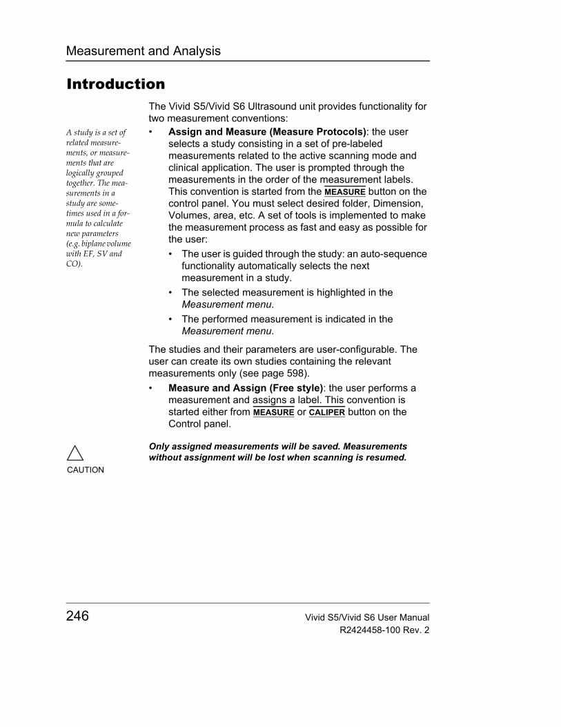
Measurement and Analysis
IntroductionThe Vivid S5/Vivid S6 Ultrasound unit provides functionality for two measurement conventions:
A study is a set of related measure-ments, or measure-ments that are logically grouped together. The mea-surements in a study are some-times used in a for-mula to calculate new parameters (e.g. biplane volume with EF, SV and CO).
• Assign and Measure (Measure Protocols): the user selects a study consisting in a set of pre-labeled measurements related to the active scanning mode and clinical application. The user is prompted through the measurements in the order of the measurement labels. This convention is started from the MEASURE button on the control panel. You must select desired folder, Dimension, Volumes, area, etc. A set of tools is implemented to make the measurement process as fast and easy as possible for the user:• The user is guided through the study: an auto-sequence
functionality automatically selects the next measurement in a study.
• The selected measurement is highlighted in the Measurement menu.
• The performed measurement is indicated in the Measurement menu.
The studies and their parameters are user-configurable. The user can create its own studies containing the relevant measurements only (see page 598).• Measure and Assign (Free style): the user performs a
measurement and assigns a label. This convention is started either from MEASURE or CALIPER button on the Control panel.
CAUTION
Only assigned measurements will be saved. Measurements without assignment will be lost when scanning is resumed.
246 Vivid S5/Vivid S6 User ManualR2424458-100 Rev. 2
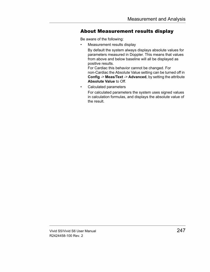
Measurement and Analysis
About Measurement results displayBe aware of the following:• Measurement results display
By default the system always displays absolute values for parameters measured in Doppler. This means that values from above and below baseline will all be displayed as positive results.For Cardiac this behavior cannot be changed. For non-Cardiac the Absolute Value setting can be turned off in Config -> Meas/Text -> Advanced, by setting the attribute Absolute Value to Off.
• Calculated parametersFor calculated parameters the system uses signed values in calculation formulas, and displays the absolute value of the result.
Vivid S5/Vivid S6 User Manual 247R2424458-100 Rev. 2

Measurement and Analysis
The Assign and Measure modalityIn this measurement modality, the user selects a study consisting in a set of related pre-labelled measurements.
Starting the Assign and Measure modality1. Press MEASURE on the control panel.
The Measurement Menu is displayed in the Parameters window (see example Figure 7-2).The trackball cursor is in the parameter window, ready for measurement selection.
Figure 7-1: Example of a measurement study
1. Active application2. Study3. Selected study4. Opened study5. Measurements related to the
area study for the cardiac application
248 Vivid S5/Vivid S6 User ManualR2424458-100 Rev. 2
Measurement and Analysis
Entering a study and performing measurements
Note: When enter-ing the Measure-ment mode for the first time, the Cali-per tool is selected by default.
1. Press MEASURE on the front panel to enter the Assign and Measure modality.The Measurement menu with a list of studies is displayed in the Parameters window (see example Figure 7-2).
When re-entering the Measurement mode, the first mea-surement in the ac-tual study that has not been performed is selected by de-fault.
2. Select any required study (other than Generic study which is reserved for the Measure and Assign modality).
3. Within the selected study, select the required parameter which you intend to measure.
4. Perform the measurement. The parameter’s name and measured value will appear in the result window.
To perform a measurement from another study1. Trackball to the required study.2. Press SET on the trackball area.
The study folder is opened displaying the measurements related to this study. Other related studies may also be available from within the study.
3. Trackball to the measurement to perform.4. Press SET on the trackball area to activate the
measurement tool.The cursor is moved back to the scanning window.
5. Perform the measurement.Completed measurements are marked with a check mark (Figure 7-2).When the measurement operation is completed the next measurement on the list is automatically selected.
To skip a measurement in a study1. Trackball to the desired measurement2. Press SET to activate the measurement tool.
Vivid S5/Vivid S6 User Manual 249R2424458-100 Rev. 2
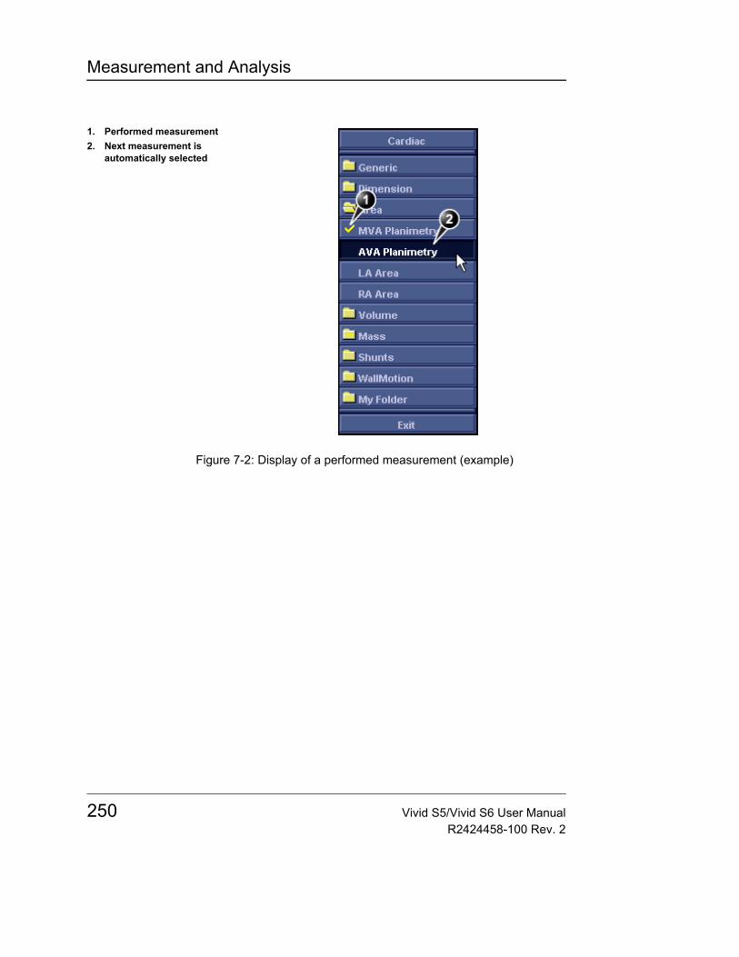
Measurement and Analysis
Figure 7-2: Display of a performed measurement (example)
1. Performed measurement2. Next measurement is
automatically selected
250 Vivid S5/Vivid S6 User ManualR2424458-100 Rev. 2
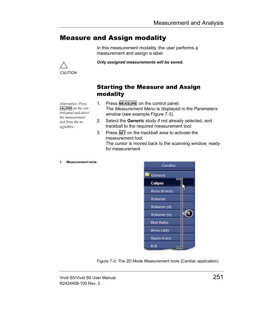
Measurement and Analysis
Measure and Assign modalityIn this measurement modality, the user performs a measurement and assign a label.
Starting the Measure and Assign modality
Alternative: Press CALIPER on the con-trol panel and select the measurement tool from the as-signables.
1. Press MEASURE on the control panel.The Measurement Menu is displayed in the Parameters window (see example Figure 7-3).
2. Select the Generic study if not already selected, and trackball to the required measurement tool.
3. Press SET on the trackball area to activate the measurement tool.The cursor is moved back to the scanning window, ready for measurement.
Figure 7-3: The 2D Mode Measurement tools (Cardiac application)
CAUTION
Only assigned measurements will be saved.
1. Measurement tools
Vivid S5/Vivid S6 User Manual 251R2424458-100 Rev. 2
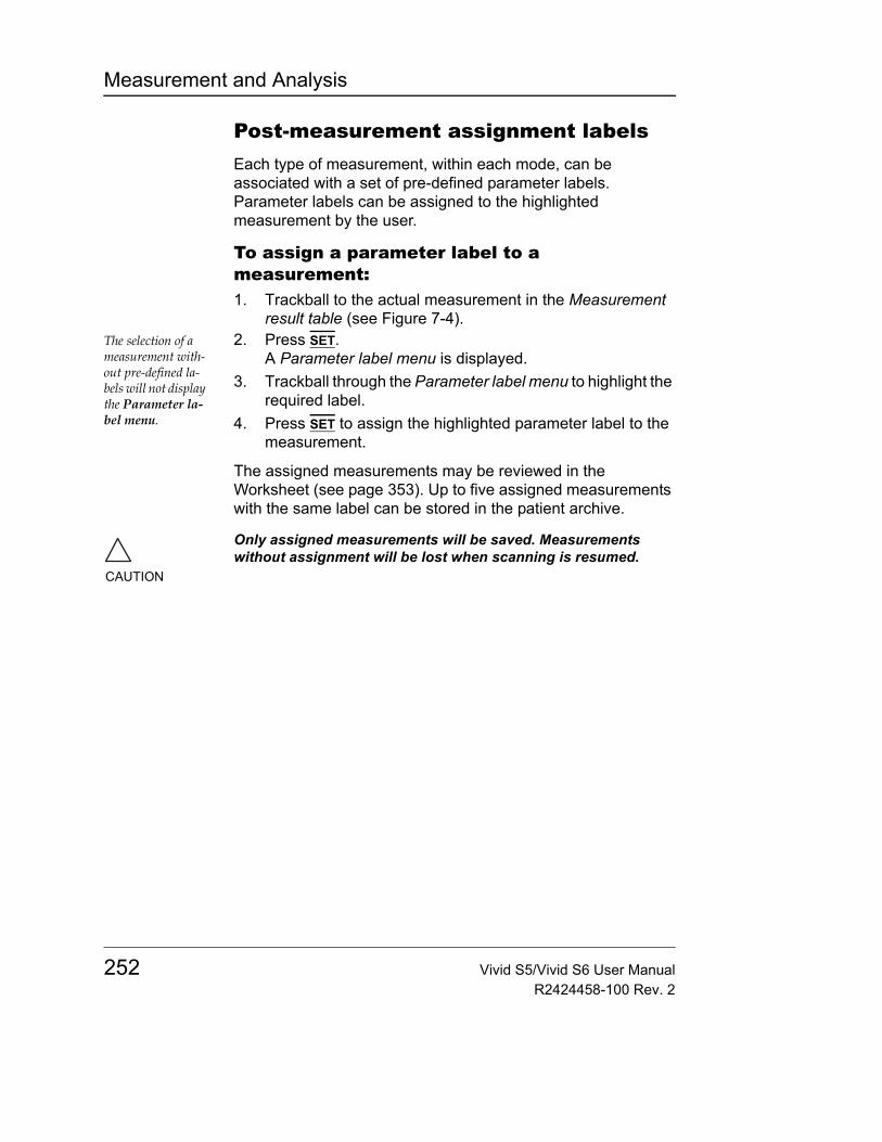
Measurement and Analysis
Post-measurement assignment labelsEach type of measurement, within each mode, can be associated with a set of pre-defined parameter labels. Parameter labels can be assigned to the highlighted measurement by the user.
To assign a parameter label to a measurement:1. Trackball to the actual measurement in the Measurement
result table (see Figure 7-4).The selection of a measurement with-out pre-defined la-bels will not display the Parameter la-bel menu.
2. Press SET.A Parameter label menu is displayed.
3. Trackball through the Parameter label menu to highlight the required label.
4. Press SET to assign the highlighted parameter label to the measurement.
The assigned measurements may be reviewed in the Worksheet (see page 353). Up to five assigned measurements with the same label can be stored in the patient archive.
CAUTION
Only assigned measurements will be saved. Measurements without assignment will be lost when scanning is resumed.
252 Vivid S5/Vivid S6 User ManualR2424458-100 Rev. 2
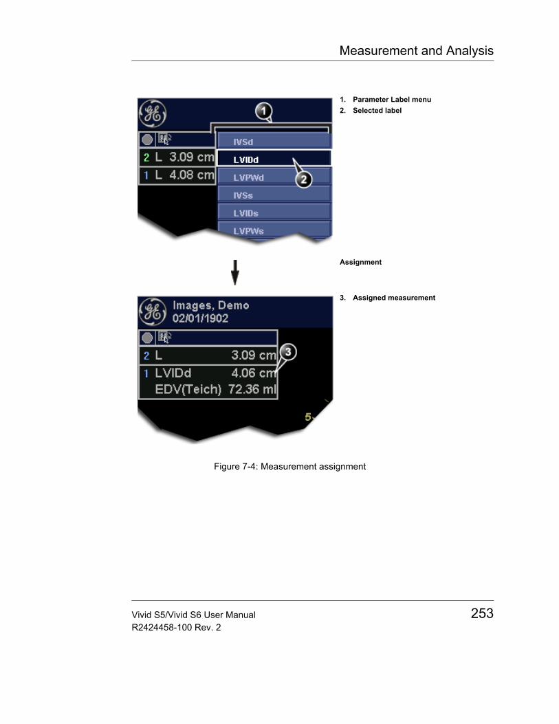
Measurement and Analysis
Figure 7-4: Measurement assignment
1. Parameter Label menu2. Selected label
Assignment
3. Assigned measurement
Vivid S5/Vivid S6 User Manual 253R2424458-100 Rev. 2
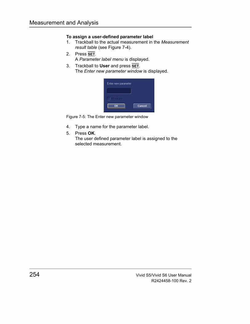
Measurement and Analysis
To assign a user-defined parameter label1. Trackball to the actual measurement in the Measurement
result table (see Figure 7-4).2. Press SET.
A Parameter label menu is displayed.3. Trackball to User and press SET.
The Enter new parameter window is displayed.
Figure 7-5: The Enter new parameter window
4. Type a name for the parameter label.5. Press OK.
The user defined parameter label is assigned to the selected measurement.
254 Vivid S5/Vivid S6 User ManualR2424458-100 Rev. 2
Measurement and Analysis
Cardiac measurements
2D Measurements
2D Length measurements1. Generate the 2D image.2. Press FREEZE to stop the cineloop.
Alternative: Press CALIPER on the con-trol panel and press CALIPER assignable.
3. Press MEASURE on the Control Panel.4. Select Caliper in the Measurement Menu (see Figure 7-1).5. Trackball the cursor to the start point of the measurement.6. Press SET to anchor the start point of the measurement.
See the Status bar to get the next step to perform.
7. Trackball the cursor to the measurement end point.The current distance value is displayed in the Measurement result table and is instantaneously updated when moving the cursor.
The measurement display color on the 2D image changes from green to blue after completion of the measurement.
8. Press SET to anchor the end point of the measurement.The measurement result is displayed in the Measurement result table.
9. To assign a label to the measurement, see page 252.10. Repeat steps 5 through 8 to make additional length
measurements.The measurements displayed on the 2D image and the cor-responding results are numbered.
2D length measurement ratio1. Generate the 2D image.2. Press FREEZE to stop the cineloop.3. Press MEASURE on the Control Panel.
Alternative: Press CALIPER and DIST RATIO assignable.
4. Select Dist. ratio in the Measurement Menu (see Figure 7-1).
5. Perform two length measurements as described in steps 5 through 8 in the above section.The measurement results including the ratio (%) of the two measured lengths are displayed in the Measurement result table.
Vivid S5/Vivid S6 User Manual 255R2424458-100 Rev. 2

Measurement and Analysis
Editing 2D Length measurements1. Trackball the cursor to one of the anchor points of the
measurement to modify.2. Double-click the SET key to select the anchor point.
The selected marker turns green and is unanchored.3. With the Trackball, reposition the marker.4. Press SET to anchor.
2D Area measurements1. Generate the 2D image.2. Press FREEZE to stop the cineloop.
Alternative: Press CALIPER and AREA assignable.
3. Press MEASURE on the Control Panel.4. Select Area (trace) in the Measurement Menu (see
Figure 7-1).5. Trackball the cursor to the start point of the measurement.
See the Status bar to get the next step to perform.
6. Press SET to anchor the start point of the measurement.7. Trace the area (planetary) with the Trackball.
The measurement display color on the 2D image changes from green to blue after completion of the measurement.
The area and circumference fields are displayed in the Measurement result table.
8. Press SET to complete the measurement.The current measurement results are instantly updated and displayed in the Measurement result table.
9. To assign a label to the measurement, see page 252.The measurements displayed on the 2D image and the cor-responding results are numbered.
10. Repeat steps 5 through 8 to make additional area measurements.
2D area measurement ratio1. Generate the 2D image.2. Press FREEZEto stop the cineloop.
Alternative: Press CALIPER, MORE as-signable and AREA RATIO.
3. Press MEASURE on the Control Panel.4. Select Area ratio in the Measurement Menu (see
Figure 7-1).5. Perform two area measurements as described in steps 5
through 8 in the above section.See the Status bar to get the next step to perform.
The measurement results including the ratio (%) of the two measured areas are displayed in the Measurement result table.
256 Vivid S5/Vivid S6 User ManualR2424458-100 Rev. 2
Measurement and Analysis
Editing 2D Area measurements1. Trackball the cursor to the anchor point of the area
measurement to modify.2. Press SET twice (Double-click) to select the anchor point.
The selected marker turns green and is unanchored.3. With the Trackball, reposition the marker.4. Press the SET to anchor.
2D Volume measurements
The measurements described in this section enable volume measurement in a defined zone. The measurements tool generates results by two methods:
For measurement formulae, refer to the Reference Manual.
• Method of Disk (displayed as Vmod in the Measurement result table), known as Simpson's method.
• Area/Length method (displayed as Va-l in the Measurement result table).
To perform a volume measurement:1. Generate the 2D image.2. Press FREEZE to stop the cineloop.
Alternative: Press CALIPER and VOLUME assignable.
3. Press MEASURE on the Control Panel.4. Select Volume in the Measurement Menu (see Figure 7-1).5. Trackball the cursor to the start point where a volume is to
be measured.See the Status bar to get the next step to perform.
6. Press SET to anchor the start point of the measurement.7. Trackball the cursor to draw the length. Use the trackball to
outline the area of interest.8. Press SET to anchor the second point. A third caliper will
appear, marking the length of the ROI.The measurement display color on the 2D image changes from green to blue after completion of the measurement.
9. If required, drag the cursor with the Trackball to modify the length marker.The current area, circumference and Area/Length Volume (Va-l) values are displayed in the Measurement result table (see Figure 7-1) and are instantaneously updated when moving the cursor.
10. Press SET to complete the measurement.The measurement results including Vmod (Simpson) are displayed in the Measurement result table (see Figure 7-1).
Vivid S5/Vivid S6 User Manual 257R2424458-100 Rev. 2
Measurement and Analysis
The measurements displayed on the 2D image and the cor-responding results are numbered.
11. To assign a label to the measurement, see page 252.12. Repeat steps 5 through 10 to make additional volume
measurements.
2D Depth measurements
The measurements described in this section enable depth measurement from the probe to a selected point.
Note: This measurement is disabled in the factory default configuration. See "Measurement package configuration" on page 338 for details about on how to enable it through configuration menu.
To perform a depth measurement:1. Generate the 2D image.2. Press FREEZE to stop the cineloop.3. Press MEASURE on the Control Panel.
See the Status bar to get the next step to perform.
4. Press the assignable POINT to select the depth measurement function.
5. Trackball the cursor to the position to measure.The current distance from the probe is displayed in the Measurement result table and is instantaneously updated when moving the cursor.
The measurements displayed on the 2D image and the cor-responding results are numbered.
6. Press SET to anchor the point.The depth value (cm) is displayed in the Measurement result table.
258 Vivid S5/Vivid S6 User ManualR2424458-100 Rev. 2
Measurement and Analysis
M-Mode MeasurementsIn M-Mode, the user can perform distance and time measurements. This measurement package has also the following pre-defined measurement studies: • LA/Ao• LV• RV
M-Mode Length measurements1. Generate the M-Mode image.2. Press FREEZE to stop the cineloop.
Alternative: Press CALIPER on the con-trol panel and press CALIPER assignable.
3. Press MEASURE on the Control Panel.4. Select caliper in the Measurement Menu.5. Trackball the cursor to the start point of the measurement.6. Press SET to anchor the start point of the measurement.
See the Status bar to get the next step to perform.
7. Trackball the cursor to the measurement end point.The current distance value is displayed in the Measurement result table and is instantaneously updated when moving the cursor.
8. Press SET to anchor the end point of the measurement.The measurement display color on the M-Mode changes from green to blue after completion of the measurement.
The measurement result is displayed in the Measurement result table.
9. To assign a label to the measurement, see page 252.10. Repeat steps 5 through 8 to make additional length
measurements.The measurements displayed on the M-Mode image and the corresponding results are num-bered.
Editing M-Mode Length measurements1. Trackball the cursor to one of the anchor points of the
measurement to modify.2. Press SET twice (double-click).
The selected marker turns green and is unanchored.3. With the Trackball, reposition the marker to a new position.4. Press SET.
Vivid S5/Vivid S6 User Manual 259R2424458-100 Rev. 2
Measurement and Analysis
Ao/LA study1. Generate the M-Mode image.2. Press FREEZE to stop the cineloop.
Alternative: Press CALIPER on the con-trol panel and press the AO/LA assign-able.
3. Press MEASURE on the Control Panel.4. Select Ao/LA in the Measurement Menu.5. Trackball the cursor along the time axis to the required point
to start measurement of Aorta root diameter.See the Status bar to get the next step to perform.
6. Press SET.The starting point for the measurement is anchored.
7. Trackball to the end point of the measurement.The current value is updated while mov-ing the cursor.
8. Press SET.The measurement end point is anchored and the value is displayed in the Measurement result table.A new free-moving cursor is displayed on the image, ready for the next measurement.
9. Repeat steps 5, through 8 to measure Left Atrium.The LA value is displayed in the Measurement result table. The Ao/LA ratio is displayed in the Measurement result table.
LV study
The LV study consists of measurements in fixed-time mode in both systole and diastole of:• Interventricular septum thickness (IVS)• Left ventricular internal dimension (LVID)• Left ventricular posterior wall thickness (LVPW)
The following parameters are also calculated:• EDV (End diastole volume)• ESV (End systole volume)• SV (Stroke volume)• EF (Ejection Fraction)• FS (Fractional Shortening)
To perform LV study1. Generate the M-Mode image.2. Press FREEZE to stop the cineloop.
260 Vivid S5/Vivid S6 User ManualR2424458-100 Rev. 2
Measurement and Analysis
Alternative: Press CALIPER on the con-trol panel and press the LV STUDY as-signable.
3. Press MEASURE on the Control Panel.4. Select LV study in the Measurement Menu.5. Trackball the cursor along the time axis to the required point
to start measurement of IVSd.6. Press SET. The starting point for the measurement is
anchored.7. Trackball to the end point of the measurement.8. Press SET. The IVSd measurement end point is anchored
and the value is displayed in the Measurement result table.
The end point of the IVSd is also the start point for the LVIDd.1. Trackball to the end point of the LVIDd measurement.2. Press SET. The LVIDd measurement end point is anchored
and the value is displayed in the Measurement result table.
The end point of the LVIDd is also the start point for the LVPWd.1. Trackball to the end point of the LVPWd measurement.2. Press SET. The LVPWd measurement end point is
anchored and the value is displayed in the Measurement result table.
3. Repeat steps 5, through 2 to measure IVS, LVID and LVPW in systole.
RV study
The RV study consists of measurement in fixed-time mode of Right ventricular internal dimension (RVID) in both diastole and systole.
To perform RV study1. Generate the M-Mode image.2. Press FREEZE to stop the cineloop.
Alternative: Press CALIPER on the con-trol panel and press the RV STUDY as-signable.
3. Press MEASURE on the Control Panel.4. Select RV study in the Measurement Menu.5. Trackball the cursor along the time axis to the required point
to start measurement of RVIDd.6. Press SET. The starting point for the measurement is
anchored.The current value is updated while mov-ing the cursor.
7. Trackball to the end point of the measurement.
Vivid S5/Vivid S6 User Manual 261R2424458-100 Rev. 2
Measurement and Analysis
8. Press SET. The measurement end point is anchored and the RVIDs measurement value is displayed in the Measurement result table.A new free-moving cursor is displayed on the image, ready for the next measurement.
9. Repeat steps 5, through 8 to measure RVIDs.Both the RVIDd and RVIDs values are displayed in the Measurement result table.
Doppler MeasurementsThe following measurements may be calculated on Doppler mode spectra:
For measurement formulae, refer to the Reference Manual.
• Maximum (peak) and mean velocity• Maximum and mean pressure gradient• Pressure half-time (PHT)• Velocity time integral (VTI)• Mitral valve area (MVA), derived from PHT
Velocity and Pressure point measurements1. Generate the spectrum to be measured.2. Press FREEZE to stop the cineloop.
Alternative: Press CALIPER on the con-trol panel and press the POINT CALIPER assignable.
3. Press MEASURE on the Control Panel.4. Select Point in the Measurement Menu.5. Trackball the cursor to the position to measure.
The current velocity is displayed in the Measurement result table and is instantaneously updated when moving the cursor.
The measurement display on the spec-trum and the corre-sponding results are numbered.
6. Press SET to anchor the point.The velocity (m/s) and pressure (mmHg) values are displayed in the Measurement result table.
Velocity and Pressure caliper measurements1. Generate the spectrum to be measured.2. Press FREEZE to stop the cineloop.
Alternative: Press CALIPER on the con-trol panel and press the CALIPER assign-able.
3. Press MEASURE on the Control Panel.4. Select Caliper in the Measurement Menu.5. Trackball the cursor to the start point of the measurement.6. Press SET to anchor the start point of the measurement.
262 Vivid S5/Vivid S6 User ManualR2424458-100 Rev. 2
Measurement and Analysis
7. Trackball the cursor to the measurement end point.The current velocity and pressure values are displayed in the Measurement result table and are instantaneously updated when moving the cursor.
The measurement display color on the spectrum changes from green to red af-ter completion of the measurement.
8. Press SET to anchor the end point of the measurement.The following measurement results are displayed in the Measurement result table:• Velocity and pressure at anchor point positions• Velocity (V3) and pressure (p3) differences between
anchor point position• Time difference (dT) between anchored points position
The measurement display on the spec-trum and the corre-sponding result are numbered.
9. To assign a label to the measurement, see page 252.10. Repeat steps 5 through 8 to make additional
measurements.
Manual Doppler trace measurementsAdjust Compress and reject controls to optimize the Doppler signal.
1. Generate the spectrum to be measured.2. Press FREEZE to stop the cineloop.3. Press MEASURE on the Control Panel.
Alternative: Press CALIPER on the con-trol panel and press the MANUAL TRACE assignable
4. Select Trace in the Measurement Menu.A vertical green cursor is displayed on the spectrum.
5. Trackball the cursor to the start point on the left side of the trace.
6. Press SET to anchor the start point of the measurement.7. With the trackball, trace the Doppler envelope.
The trace can be adjusted, while tracing, by moving the cursor backward to erase portion of the trace (or the entire trace) and then create the trace again.
The measurement display color on spectrum changes from green to red af-ter completion of the measurement.
8. Press SET to complete the trace.The following measurement results are displayed in the Measurement result table:• Maximum and mean Velocities• Maximum and mean pressures• Env. Ti • Velocity time integral (VTI)
9. Trackball the cursor to the start point of the next heart beat.10. Press the SET to anchor the next heart beat starting point.
The heart rate (BPM) is displayed in the Measurement result table.
Vivid S5/Vivid S6 User Manual 263R2424458-100 Rev. 2
Measurement and Analysis
Automatic Doppler trace measurementsAdjust Compress and reject controls to optimize the Doppler signal.
1. Generate the spectrum to be measured.2. Press FREEZE to stop the cineloop.3. Press MEASURE on the Control Panel.
Alternative: Press CALIPER on the con-trol panel and press the AUTO TRACE as-signable.
4. Select Auto Trace in the Measurement Menu.A vertical green cursor is displayed on the spectrum.
5. Trackball the cursor to the starting point.6. Press SET to anchor the start point of the measurement.7. Trackball to the end trace position.8. Press SET to anchor the end point of the trace.
The trace is automatically generated and the following measurements are displayed in the Measurement result table:• Maximum and mean Velocities• Maximum and mean pressures• Env. Ti • Velocity time integral (VTI)
9. Trackball the cursor to the next heart beat.10. Press SET to anchor the next heart beat starting point.
The heart rate (BPM) is displayed in the Measurement result table.
MV E/A ratioAdjust Compress and reject controls to optimize the Doppler signal.
1. Generate the spectrum to be measured.2. Press FREEZE to stop the cineloop.3. Press MEASURE on the Control Panel.
Alternative: Press CALIPER on the con-trol panel and press the MV E/A RATIO as-signable.
4. Select MV E/A ratio in the Measurement Menu.5. Trackball the cursor to the peak of the E wave.6. Press SET to anchor the point.7. Drag cursor to baseline to mark dT.8. Press SET on the trackball area to anchor the second point.9. Trackball the cursor to the peak of A wave.10. Press SET to anchor the point.
the velocity at peak for E and A waves and the calculated E/A ratio are displayed in the Measurement result table.
264 Vivid S5/Vivid S6 User ManualR2424458-100 Rev. 2
Measurement and Analysis
Measurements on protocol images
When performing measurements on images acquired in a protocol, the measurement results will be associated with the protocol level of the image. Average values will be calculated for each protocol level.
For example you may measure LVOT Diam for images acquired outside protocol and for images on each level of an Exercise 2x4 protocol, leading to the following results in worksheet:
Event timing measurements
Event timing enables the time measurement for opening and closure of the Aorta and Mitral valves, as referred to the automatically detected QRS marker, which normally is on the rising slope of the R-wave.
Event timing can be performed on a Doppler spectrum or an M-Mode acquisition showing the corresponding valves. The procedure is similar on both modes. In addition event timing can be done on curved anatomical M-Mode traces in Q Analysis. The measurements are shown as dashed lines in the Analysis window and Anatomical M-Mode window in Q Analysis.1. Generate the spectrum to be measured.2. Press FREEZE to stop the cineloop.3. Press MEASURE on the Control Panel.4. Select Event Timing in the Measurement menu.
Parameter Value Method M1 M2
LVOT Diam 1.0 cm Avg. 1.1 0.9
LVOT Diam, Rest 1.1 cm Avg. 1.0 1.2
LVOT Diam, Peak 1.2 cm Avg. 1.2
CAUTION
Measurement results associated with a stress level will not be updated if the image is moved to another stress level at a later time. Images should be correctly placed in the protocol when performing measurements.
Vivid S5/Vivid S6 User Manual 265R2424458-100 Rev. 2
Measurement and Analysis
The following event timing measurements are available (with the first measurement on the list selected):• AVO: Aortic Valve Opening• AVC: Aortic Valve Closure• MVO: Mitral Valve Opening• MVC: Mitral Valve Closure
5. Trackball the cursor to the corresponding point on the spectrum for the selected measurement.
6. Press SET to anchor the point.The event timing measurement (ms) is displayed in the Measurement result table.When an event timing measurement is performed, the QRS markers are displayed on the ECG trace and correct QRS marker position should be verified before the Event Timing measurements are performed.
TSI MeasurementsEach sample in the TSI image represents the time to the maximum velocity within the chosen TSI search interval from TSI Start to TSI End. (See page 189 on how to set the TSI search interval.)
There are two automatic TSI time to peak measurement tools:• Generic TSI Time to peak measurement: displays the TSI
value at the location point set by the user.• Segment TSI Time to peak measurement: measures the
time to peak velocity in specific wall segments and gets automatically calculated TSI indexes based on these measurements. The measurements may be presented in a color coded Bull's eye diagram.Alternatively, TSI time to peak measurement can be done in Q Analysis by manually measuring the time between the QRS marker and the peak velocity on the velocity trace.
Generic Time to peak measurement1. Acquire a TSI apical loop.2. Press MEASURE.3. In the Measurement menu, select Generic and Time to
peak (see Figure 7-6).The TSI loop freezes at the TSI end frame.
266 Vivid S5/Vivid S6 User ManualR2424458-100 Rev. 2
Measurement and Analysis
4. Place a point in the middle of a basal or mid-level myocardial segment in the TSI image.
5. The Time to peak value for the segment is displayed in the Measurement result window.Note: to judge the quality of your data at the measuring point in the 2D image see the Caution text on page 272.
Figure 7-6: TSI Generic Time to peak measurement screen
Segment Time to peak measurements1. Acquire TSI loops from all three apical views.2. Press MEASURE and select TSI time study.
The TSI loop freezes at the TSI end frame.The first measurement in the study is automatically selected (see Figure 7-7).
3. Place a point in the middle of the corresponding segment in the TSI image.The Time to peak and the Peak velocity for the segment are displayed in the Measurement result window.
Vivid S5/Vivid S6 User Manual 267R2424458-100 Rev. 2
Measurement and Analysis
4. Perform a measurement for all basal and mid-level segments in all three apical views.In addition to the Time to peak and the Peak velocity for each segment, the following TSI indexes are calculated:• Septal lateral delay: difference in Time to peak velocity
in the basal lateral wall and basal septum.• Septal posterior delay: difference in Time to peak
velocity in the basal posterior wall and the basal antero-septum.
• Basal max delay: difference between the maximum and minimum time to peak measurements in the six basal segments. Requires at least four of the six basal segment measurements.
• Basal standard deviation: the standard deviation of the time to peak measurements in the six basal segments. Requires at least four of the six basal segment measurements.
• All segments max delay: difference between the maximum and minimum time to peak measurements in all the measured basal and mid level segments. Requires at least eight of the twelve segmental measurements.
• All segments standard deviation: the standard deviation of the time to peak measurements in all measured basal and mid level segments. Requires at least eight of the twelve segmental measurements.
The TSI indexes indicate degrees of asynchrony in time to peak velocity
5. Select TSI Bull’s eye report in the Measurement menu.The measurements are displayed in a color coded bull’s eye diagram together with a list of the calculated TSI indexes.
268 Vivid S5/Vivid S6 User ManualR2424458-100 Rev. 2
Measurement and Analysis
Figure 7-7: Segment Time to peak measurements screen
TSI trace
The TSI Time to peak measurement can be verified and eventually manually changed from the TSI trace.1. Double click on the measurement point.
The ROI and the corresponding TSI curve are displayed (see Figure 7-8).
2. Press SET to anchor the ROI and trace.3. If required, select a new peak location in the trace.4. Click in the acquisition window to exit the TSI trace.
Vivid S5/Vivid S6 User Manual 269R2424458-100 Rev. 2
Measurement and Analysis
Figure 7-8: TSI trace
Time to peak measurement in Q Analysis1. From a TSI apical loop, press Q Analysis.2. Place a sample area in a myocardial segment. A velocity
trace is displayed in the Analysis window (see Figure 7-9).3. Press MEASURE.4. In the Measurement menu, select Generic and Time.
Note: if Time is not available in the Generic folder press ACTIVE MODE on the Control panel.
5. In the Analysis window, measure the time from the yellow QRS marker to the peak velocity of the velocity trace.
1. TSI ROI2. TSI trace3. TSI Time to peak marker
270 Vivid S5/Vivid S6 User ManualR2424458-100 Rev. 2
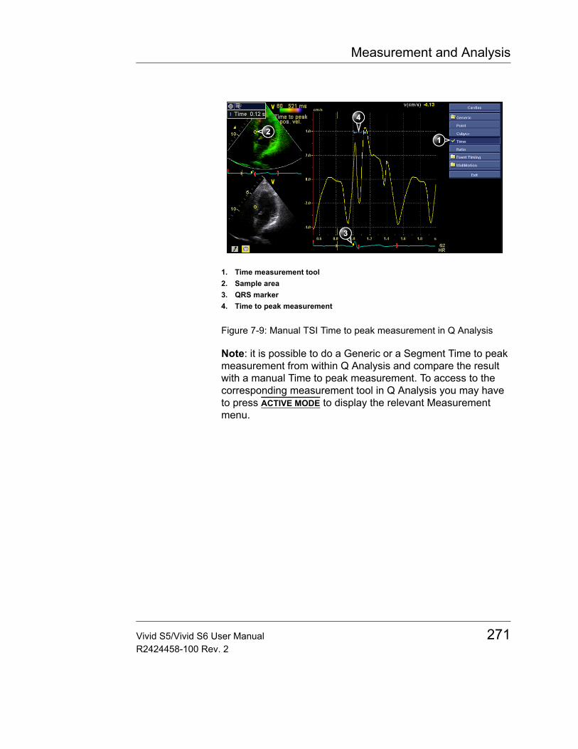
Measurement and Analysis
Figure 7-9: Manual TSI Time to peak measurement in Q Analysis
Note: it is possible to do a Generic or a Segment Time to peak measurement from within Q Analysis and compare the result with a manual Time to peak measurement. To access to the corresponding measurement tool in Q Analysis you may have to press ACTIVE MODE to display the relevant Measurement menu.
1. Time measurement tool2. Sample area3. QRS marker4. Time to peak measurement
Vivid S5/Vivid S6 User Manual 271R2424458-100 Rev. 2
Measurement and Analysis
CAUTION
The Time to peak measurement in Q Analysis may differ from the Generic and Segment Time to peak measurements due to the following considerations:• The Generic and Segment Time to peak measurements find the
maximum velocity only within the TSI search interval. If the desired peak on the velocity trace is outside the TSI search interval, the Generic and Segment Time to peak measurements will return a different result than the manual Time to peak measurement.
• If the maximum velocity is at one of the ends of the TSI search interval, the Generic and Segment time to peak measurements return the time of the end of the TSI search interval. In some cases the falling flank of an iso-volumic contraction peak at the time of TSI Start or the rising flank of a post-systolic contraction peak at the time of TSI End may be detected. In a manual measurement the time to a peak within the TSI search interval with a lower velocity than the velocity at the end of the interval may be measured instead.
• If there are two or more peaks of comparable velocity within the TSI search interval, or a poor signal quality, the Generic and Segment Time to peak measurements may return the time to a different peak than what a manual method would do. Typically in these situations, the TSI image will show a wide range of colors over a small spatial region.
272 Vivid S5/Vivid S6 User ManualR2424458-100 Rev. 2

Measurement and Analysis
Automated Function ImagingAutomated Function Imaging (AFI) is a decision support tool for regional assessment of the LV systolic function. AFI is a tool derived from the 2D Strain, which tracks and calculates the myocardial tissue deformation based on feature tracking on 2D grey scale loops.
AFI is used to compute local and global tissue deformations in the myocardium.
The purpose of AFI is to provide the user with a decision support tool when reporting myocardial function.
AFI is performed on apical views in the following order: apical long-axis, 4-chamber and 2-chamber view, following an on screen guided workflow (Figure 7-10).
The result is presented as a Bulls-Eye display showing color coded and numerical values for peak systolic longitudinal strain. All values are stored to the worksheet. In addition, Global Strain for each view, Average Global Strain for the whole LV, and the Aortic Valve Closure time used in the analysis are stored to the worksheet.
Vivid S5/Vivid S6 User Manual 273R2424458-100 Rev. 2
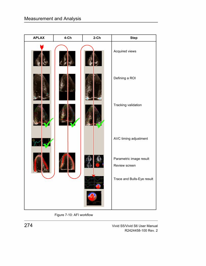
Measurement and Analysis
Figure 7-10: AFI workflow
APLAX 4-Ch 2-Ch Step
Acquired views
Defining a ROI
Tracking validation
AVC timing adjustment
Parametric image result
Review screen
Trace and Bulls-Eye result
274 Vivid S5/Vivid S6 User ManualR2424458-100 Rev. 2
Measurement and Analysis
Acquisition1. Create an exam, connect the ECG device and make sure
to obtain a stable ECG trace.2. Acquire 2D grey scale cineloops of an Apical long axis
(APLAX) view, an Apical 4 chamber view and an Apical 2 chamber view.
3. Store the loop (must store).
Note: It is recommended to acquire all three apical views sequentially in order to get similar heart rate in all views.• The frame rate should be between 37 and 80 frames per
second. A high frame rate is recommended for high heart rate.
• The scanner should be configured to store at least 100 ms before and after each heart cycle,- or -
• The scanner should be configured to store 3 loops or more.• If the stored loop contains more than one heart cycle, the
analysis will be done on the second last heart cycle.• The entire myocardium should be visible.• A depth range that includes the entire left ventricle should
be used.
Starting AFI1. Open an APLAX view and press MEASURE.2. In the Measurement menu, select AFI. The View selection
menu is displayed (Figure 7-11).
Vivid S5/Vivid S6 User Manual 275R2424458-100 Rev. 2
Measurement and Analysis
Figure 7-11: Measurement and View selection menus
3. Select APLAX.The AFI application is started. A ROI can be defined.
Note: When performing AFI on all three apical views, the user is asked to start with the APLAX view. This allows manual adjustment of the Aortic Valve Closure (AVC) event timing that is used in the calculation of the longitudinal systolic strain in all apical views.
AFI on the APLAX view
Defining a ROIWhen selecting the view to analyze, the system automatically displays a frame where the endocardial border is usually clearly visible. To use another frame, adjust SELECT FRAME.
To define a ROI, place three points at the endocardial border; two annular points at the base and one at the apex (Figure 7-12). Follow the indications displayed on the screen when placing the three points.
Note: the Yo-yo function is turned on to help finding correct location for the points. Should you wish to turn it off use the YOYO soft button.
Note: In case the Yo-yo function is not running place the trackball pointer in the vicinity of the contour trace to activate it.
276 Vivid S5/Vivid S6 User ManualR2424458-100 Rev. 2
Measurement and Analysis
Figure 7-12: Defining a ROI
After placing the apex point the ROI is displayed (Figure 7-13)
Note: Correct ROI definition is important for accurate measurements. The system has an adaptive ROI function: using the endocardial three points as a guide, the system will analyze the image and automatically adapt the ROI to an optimal position.
Figure 7-13: ROI Generation
Vivid S5/Vivid S6 User Manual 277R2424458-100 Rev. 2
Measurement and Analysis
You may adjust the shape of the ROI by moving the cursor over the inner ROI border, select an anchor point (red circle), press and hold SET button and move the red mark to a new location (Figure 7-14). The shape of the ROI is updated accordingly.
Figure 7-14: Selected anchor point on the inner ROI border
Note: System may be configured so that data processing is started automatically if the cursor is not moved for a few seconds (Figure 7-15).
Note: The auto processing function is configurable (from Config/Meas-Text/Advanced/AFI/AutoEF auto processing).
Figure 7-15: AFI auto processing configuration
CAUTION
If the ROI needs to be adjusted make sure to make the changes immediately after the ROI is displayed.
278 Vivid S5/Vivid S6 User ManualR2424458-100 Rev. 2
Measurement and Analysis
SoftmenuSelect Frame - Prior to the placement of the 3 points you may select a different frame from the default one. Marked by a blue vertical bar over the ECG trace.
YOYO - When turned ON the image will loop through some of the neighboring frames to allow improved visualization of the anatomy.
Left and Right Marker - Allows to correct the placement of the yellow markers over the ECG trace and define the R-R interval correctly.
Redraw - Allows to go back to previous screen and re-position the three points.
ROI Width - May be adjusted to include more or less of the myocardial tissue that needs to be assessed by AFI.
Process - Starts the speckle analysis of the tissue within the selected ROI.
Quick Tips
Correct ROI definition is crucial to get good tracking. Refer to the example displayed in the Tip window for correct point placements. To display additional guidelines, select the Tip button on the Tip window. Make sure to follow the recommendations when placing the three points (see below).
Base Correct Wrong
1. Correct position of the base points.
2. The ROI extends into the aortic tract.
Vivid S5/Vivid S6 User Manual 279R2424458-100 Rev. 2
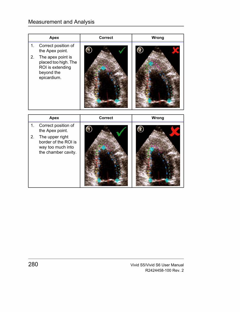
Measurement and Analysis
Apex Correct Wrong
1. Correct position of the Apex point.
2. The apex point is placed too high. The ROI is extending beyond the epicardium.
Apex Correct Wrong
1. Correct position of the Apex point.
2. The upper right border of the ROI is way too much into the chamber cavity.
280 Vivid S5/Vivid S6 User ManualR2424458-100 Rev. 2
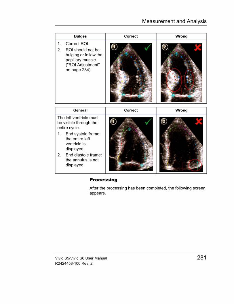
Measurement and Analysis
Processing
After the processing has been completed, the following screen appears.
Bulges Correct Wrong
1. Correct ROI2. ROI should not be
bulging or follow the papillary muscle ("ROI Adjustment" on page 284).
General Correct Wrong
The left ventricle must be visible through the entire cycle.1. End systole frame:
the entire left ventricle is displayed.
2. End diastole frame: the annulus is not displayed.
Vivid S5/Vivid S6 User Manual 281R2424458-100 Rev. 2
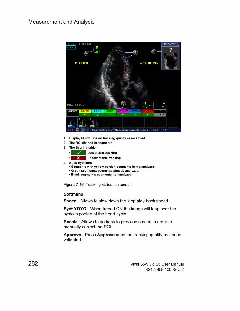
Measurement and Analysis
Figure 7-16: Tracking Validation screen
SoftmenuSpeed - Allows to slow down the loop play-back speed.
Syst YOYO - When turned ON the image will loop over the systolic portion of the heart cycle.
Recalc - Allows to go back to previous screen in order to manually correct the ROI.
Approve - Press Approve once the tracking quality has been validated.
1. Display Quick Tips on tracking quality assessment2. The ROI divided in segments3. The Scoring table
• : acceptable tracking• : unacceptable tracking
4. Bulls-Eye icon:• Segments with yellow border: segments being analyzed.• Green segments: segments already analyzed.• Black segments: segments not analyzed.
282 Vivid S5/Vivid S6 User ManualR2424458-100 Rev. 2
Measurement and Analysis
The ROI is divided into segments. The tracking quality for each segment is automatically evaluated and summarized in the Scoring table (Figure 7-61).
Tracking ValidationThe tracking for each segment must be visually controlled and validated. Poor tracking quality could result from a variety of causes. Select Quick tips (Figure 7-61) to get tips on the most common causes for bad tracking. The common causes for bad tracking are:• Erroneous placement of the basal points when defining the
ROI. If the basal points are placed too far from the annular region, the ROI segments at the annular base will not move together with the underlying 2D image throughout the entire heart beat (see example cineloops in the Quick tips).
• Erroneous placement of the apex point when defining the ROI. The point should be placed so that the resulting ROI covers mainly the endocardium. If the apex point is placed too high, the ROI will mainly cover the epicardium resulting in poor tracking (see example cineloops in the Quick tips).
• Too small ROI width. Narrowing the ROI too much will result in poor tracking due to lack of tissue data in the ROI (see example cineloops in the Quick tips).
• Too much clutter. Images with too much static clutter will result in poor tracking (see example cineloops in the Quick tips).
To validate the Tracking:1. Inspect each segment and make sure that the center line is
moving together with the underlying 2D image.Note: The tracking quality is automatically evaluated for each segment and displayed in the Scoring table. The tracking in each segment is scored as either Acceptable ( ) or unacceptable ( ).If the tracking needs to be improved for some segments, the user can modify the ROI ("ROI Adjustment" on page 284). The user may override the tracking quality evaluation done by the system by clicking on the evaluation result in the Scoring table.
2. Once the tracking quality has been validated for all segments, press Approve in the Scoring table, or Approve
Vivid S5/Vivid S6 User Manual 283R2424458-100 Rev. 2
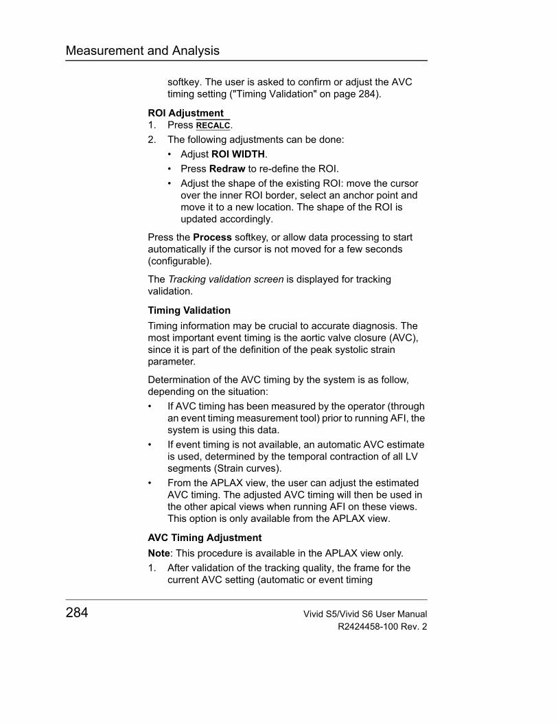
Measurement and Analysis
softkey. The user is asked to confirm or adjust the AVC timing setting ("Timing Validation" on page 284).
ROI Adjustment1. Press RECALC.2. The following adjustments can be done:
• Adjust ROI WIDTH.• Press Redraw to re-define the ROI.• Adjust the shape of the existing ROI: move the cursor
over the inner ROI border, select an anchor point and move it to a new location. The shape of the ROI is updated accordingly.
Press the Process softkey, or allow data processing to start automatically if the cursor is not moved for a few seconds (configurable).
The Tracking validation screen is displayed for tracking validation.
Timing ValidationTiming information may be crucial to accurate diagnosis. The most important event timing is the aortic valve closure (AVC), since it is part of the definition of the peak systolic strain parameter.
Determination of the AVC timing by the system is as follow, depending on the situation:• If AVC timing has been measured by the operator (through
an event timing measurement tool) prior to running AFI, the system is using this data.
• If event timing is not available, an automatic AVC estimate is used, determined by the temporal contraction of all LV segments (Strain curves).
• From the APLAX view, the user can adjust the estimated AVC timing. The adjusted AVC timing will then be used in the other apical views when running AFI on these views. This option is only available from the APLAX view.
AVC Timing AdjustmentNote: This procedure is available in the APLAX view only.1. After validation of the tracking quality, the frame for the
current AVC setting (automatic or event timing
284 Vivid S5/Vivid S6 User ManualR2424458-100 Rev. 2
Measurement and Analysis
measurement) is displayed and highlighted on the ECG.A message appears.
2. To keep the current AVC setting, press SET. To change the AVC setting, use the trackball to display another frame and press SET.If the AVC setting was changed, a Confirmation window is displayed. Select one of the following options:• Manual to accept the manual AVC setting.• Event timing to discard the manual AVC setting (if for
example the AVC setting was not possible to assess from the APLAX view). The AVC event timing measurement will then be used.Note: This choice is only visible if AVC event timing measurement has been done.
• Auto to discard the manual AVC setting and use the automatic AVC timing.
The Parametric systolic strain APLAX view is displayed (Figure 7-17).
Figure 7-17: Parametric systolic strain APLAX view
Note: The image will not be saved unless Store is pressed.
Press Quad softkey to display a quad screen (Figure 7-18) showing:• 2D image with the ROI
Vivid S5/Vivid S6 User Manual 285R2424458-100 Rev. 2
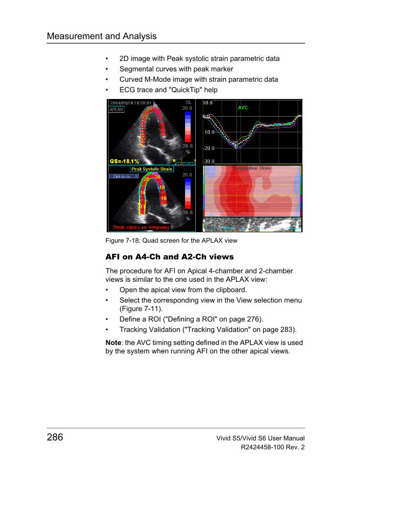
Measurement and Analysis
• 2D image with Peak systolic strain parametric data• Segmental curves with peak marker• Curved M-Mode image with strain parametric data• ECG trace and "QuickTip" help
Figure 7-18: Quad screen for the APLAX view
AFI on A4-Ch and A2-Ch views
The procedure for AFI on Apical 4-chamber and 2-chamber views is similar to the one used in the APLAX view:• Open the apical view from the clipboard.• Select the corresponding view in the View selection menu
(Figure 7-11).• Define a ROI ("Defining a ROI" on page 276).• Tracking Validation ("Tracking Validation" on page 283).
Note: the AVC timing setting defined in the APLAX view is used by the system when running AFI on the other apical views.
286 Vivid S5/Vivid S6 User ManualR2424458-100 Rev. 2
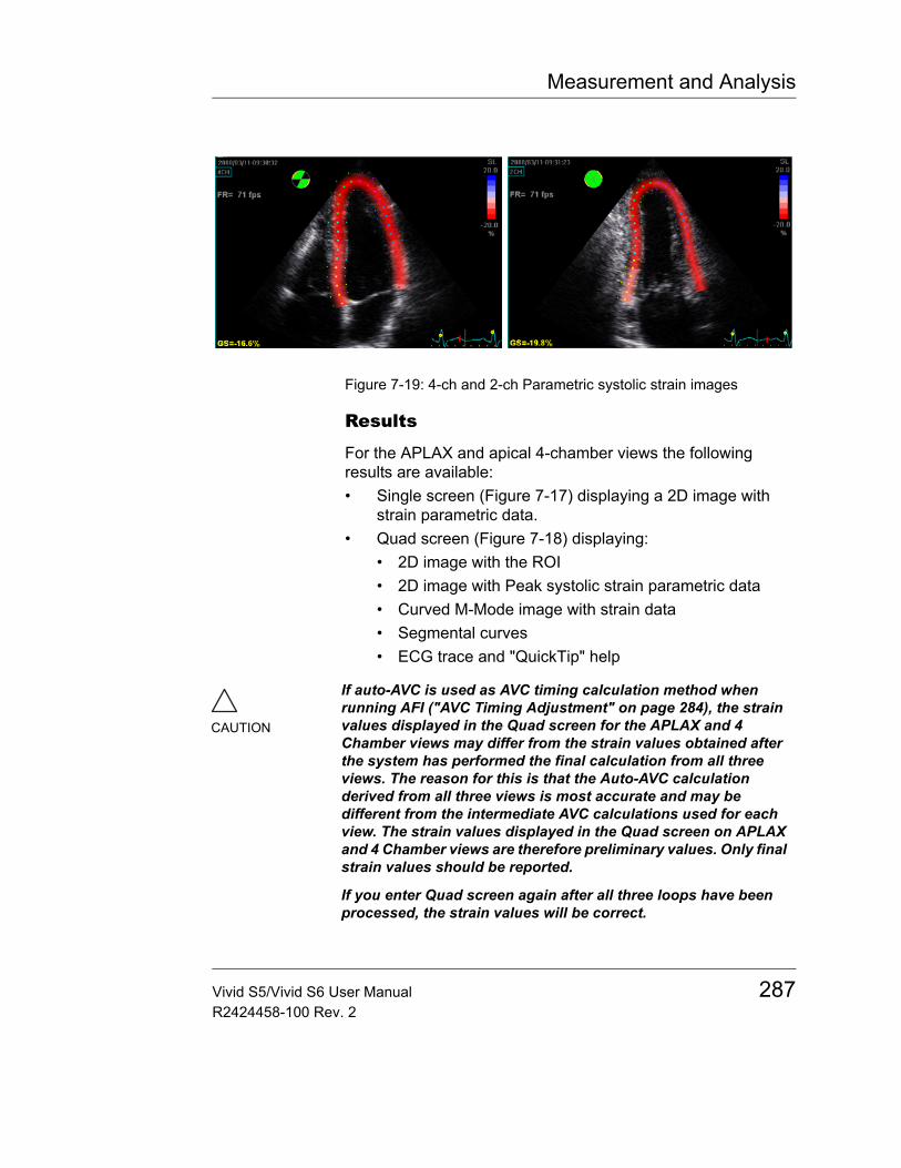
Measurement and Analysis
Figure 7-19: 4-ch and 2-ch Parametric systolic strain images
Results
For the APLAX and apical 4-chamber views the following results are available:• Single screen (Figure 7-17) displaying a 2D image with
strain parametric data.• Quad screen (Figure 7-18) displaying:
• 2D image with the ROI• 2D image with Peak systolic strain parametric data• Curved M-Mode image with strain data• Segmental curves• ECG trace and "QuickTip" help
CAUTION
If auto-AVC is used as AVC timing calculation method when running AFI ("AVC Timing Adjustment" on page 284), the strain values displayed in the Quad screen for the APLAX and 4 Chamber views may differ from the strain values obtained after the system has performed the final calculation from all three views. The reason for this is that the Auto-AVC calculation derived from all three views is most accurate and may be different from the intermediate AVC calculations used for each view. The strain values displayed in the Quad screen on APLAX and 4 Chamber views are therefore preliminary values. Only final strain values should be reported.
If you enter Quad screen again after all three loops have been processed, the strain values will be correct.
Vivid S5/Vivid S6 User Manual 287R2424458-100 Rev. 2
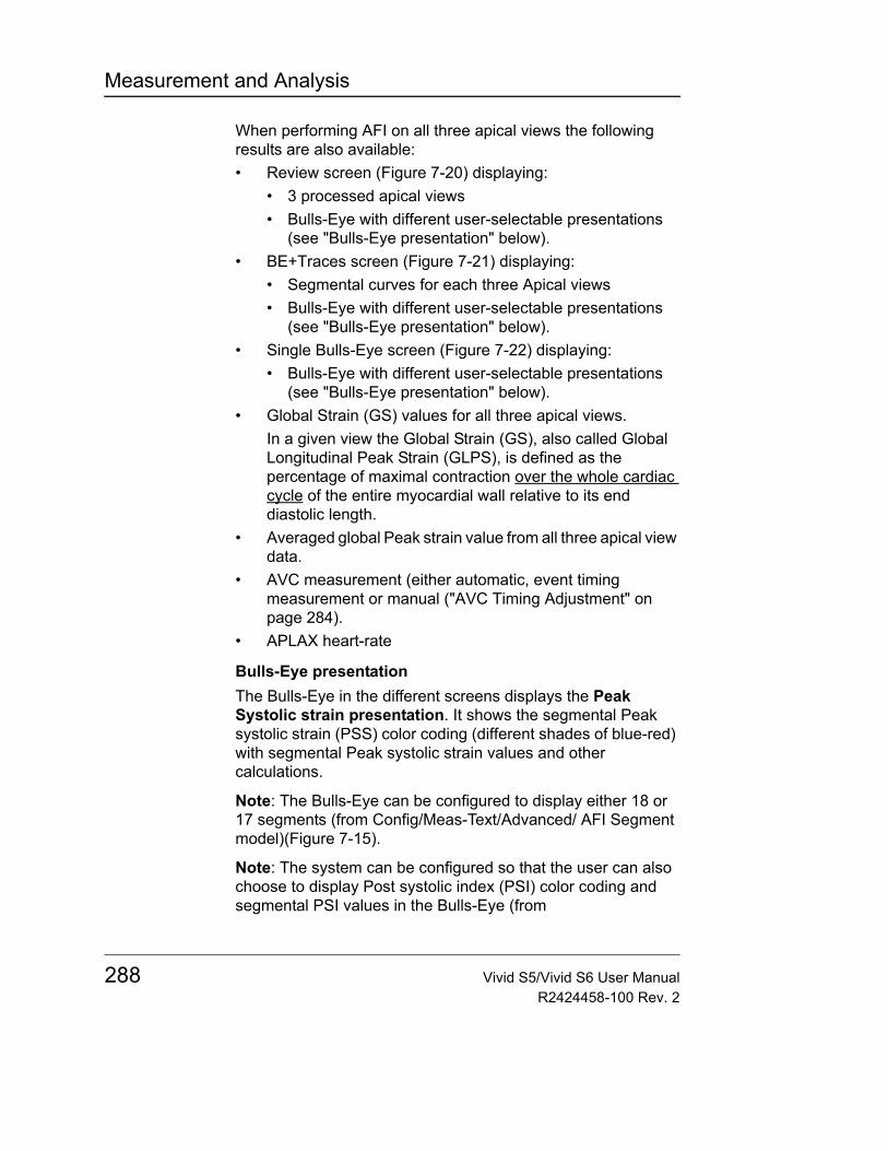
Measurement and Analysis
When performing AFI on all three apical views the following results are also available:• Review screen (Figure 7-20) displaying:
• 3 processed apical views• Bulls-Eye with different user-selectable presentations
(see "Bulls-Eye presentation" below).• BE+Traces screen (Figure 7-21) displaying:
• Segmental curves for each three Apical views• Bulls-Eye with different user-selectable presentations
(see "Bulls-Eye presentation" below).• Single Bulls-Eye screen (Figure 7-22) displaying:
• Bulls-Eye with different user-selectable presentations (see "Bulls-Eye presentation" below).
• Global Strain (GS) values for all three apical views.In a given view the Global Strain (GS), also called Global Longitudinal Peak Strain (GLPS), is defined as the percentage of maximal contraction over the whole cardiac cycle of the entire myocardial wall relative to its end diastolic length.
• Averaged global Peak strain value from all three apical view data.
• AVC measurement (either automatic, event timing measurement or manual ("AVC Timing Adjustment" on page 284).
• APLAX heart-rate
Bulls-Eye presentationThe Bulls-Eye in the different screens displays the Peak Systolic strain presentation. It shows the segmental Peak systolic strain (PSS) color coding (different shades of blue-red) with segmental Peak systolic strain values and other calculations.
Note: The Bulls-Eye can be configured to display either 18 or 17 segments (from Config/Meas-Text/Advanced/ AFI Segment model)(Figure 7-15).
Note: The system can be configured so that the user can also choose to display Post systolic index (PSI) color coding and segmental PSI values in the Bulls-Eye (from
288 Vivid S5/Vivid S6 User ManualR2424458-100 Rev. 2
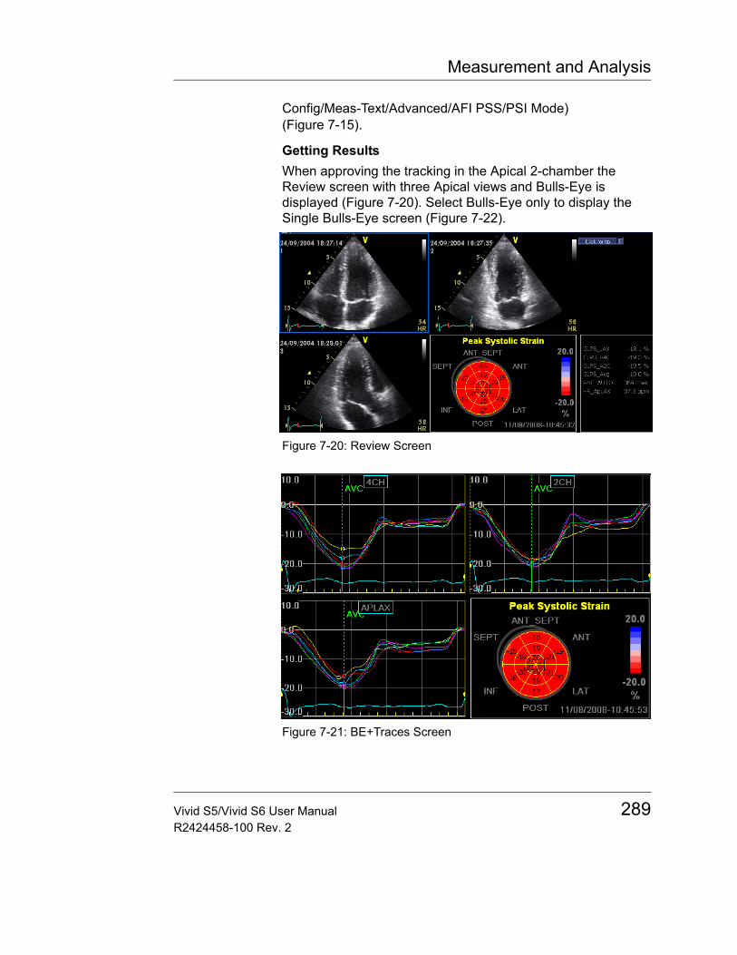
Measurement and Analysis
Config/Meas-Text/Advanced/AFI PSS/PSI Mode) (Figure 7-15).
Getting ResultsWhen approving the tracking in the Apical 2-chamber the Review screen with three Apical views and Bulls-Eye is displayed (Figure 7-20). Select Bulls-Eye only to display the Single Bulls-Eye screen (Figure 7-22).
Figure 7-20: Review Screen
Figure 7-21: BE+Traces Screen
Vivid S5/Vivid S6 User Manual 289R2424458-100 Rev. 2
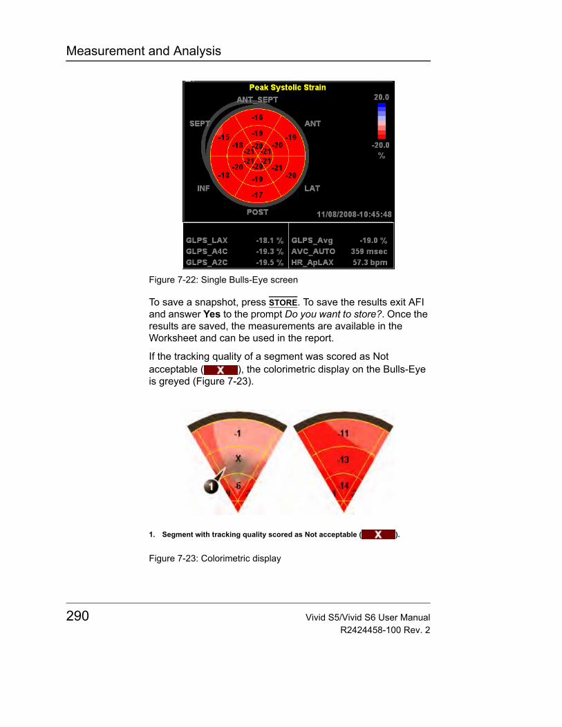
Measurement and Analysis
Figure 7-22: Single Bulls-Eye screen
To save a snapshot, press STORE. To save the results exit AFI and answer Yes to the prompt Do you want to store?. Once the results are saved, the measurements are available in the Worksheet and can be used in the report.
If the tracking quality of a segment was scored as Not acceptable ( ), the colorimetric display on the Bulls-Eye is greyed (Figure 7-23).
Figure 7-23: Colorimetric display
1. Segment with tracking quality scored as Not acceptable ( ).
290 Vivid S5/Vivid S6 User ManualR2424458-100 Rev. 2
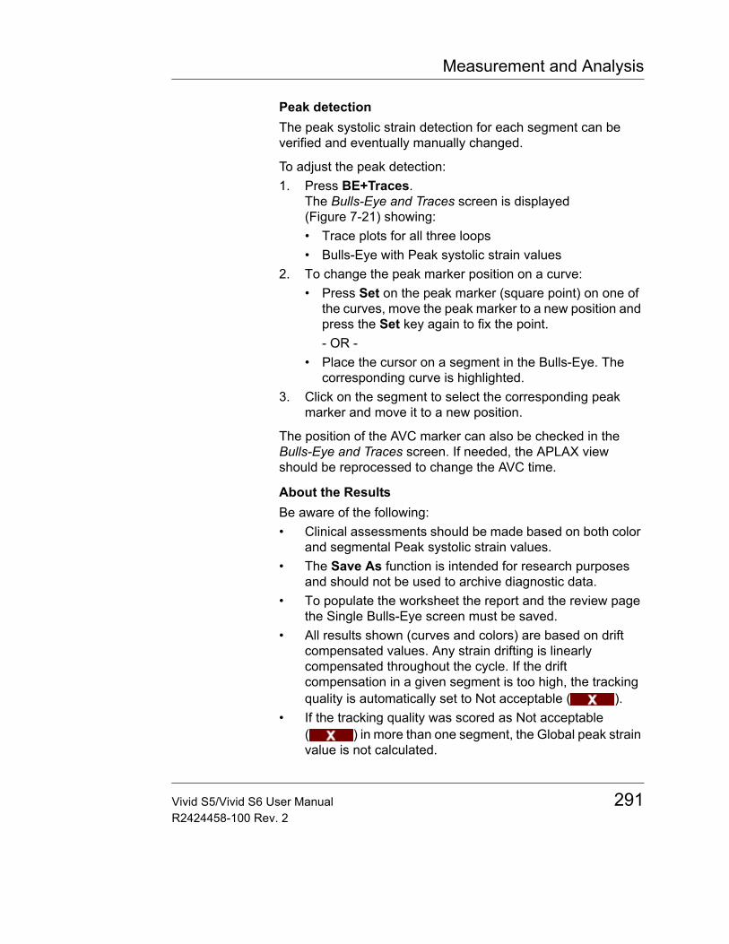
Measurement and Analysis
Peak detectionThe peak systolic strain detection for each segment can be verified and eventually manually changed.
To adjust the peak detection:1. Press BE+Traces.
The Bulls-Eye and Traces screen is displayed (Figure 7-21) showing:• Trace plots for all three loops• Bulls-Eye with Peak systolic strain values
2. To change the peak marker position on a curve:• Press Set on the peak marker (square point) on one of
the curves, move the peak marker to a new position and press the Set key again to fix the point.- OR -
• Place the cursor on a segment in the Bulls-Eye. The corresponding curve is highlighted.
3. Click on the segment to select the corresponding peak marker and move it to a new position.
The position of the AVC marker can also be checked in the Bulls-Eye and Traces screen. If needed, the APLAX view should be reprocessed to change the AVC time.
About the ResultsBe aware of the following:• Clinical assessments should be made based on both color
and segmental Peak systolic strain values.• The Save As function is intended for research purposes
and should not be used to archive diagnostic data.• To populate the worksheet the report and the review page
the Single Bulls-Eye screen must be saved.• All results shown (curves and colors) are based on drift
compensated values. Any strain drifting is linearly compensated throughout the cycle. If the drift compensation in a given segment is too high, the tracking quality is automatically set to Not acceptable ( ).
• If the tracking quality was scored as Not acceptable ( ) in more than one segment, the Global peak strain value is not calculated.
Vivid S5/Vivid S6 User Manual 291R2424458-100 Rev. 2
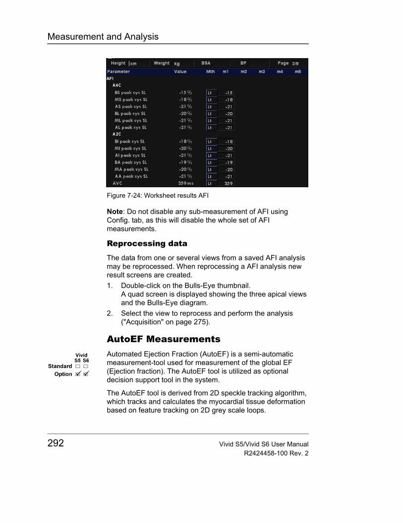
Measurement and Analysis
Figure 7-24: Worksheet results AFI
Note: Do not disable any sub-measurement of AFI using Config. tab, as this will disable the whole set of AFI measurements.
Reprocessing data
The data from one or several views from a saved AFI analysis may be reprocessed. When reprocessing a AFI analysis new result screens are created.1. Double-click on the Bulls-Eye thumbnail.
A quad screen is displayed showing the three apical views and the Bulls-Eye diagram.
2. Select the view to reprocess and perform the analysis ("Acquisition" on page 275).
AutoEF MeasurementsAutomated Ejection Fraction (AutoEF) is a semi-automatic measurement-tool used for measurement of the global EF (Ejection fraction). The AutoEF tool is utilized as optional decision support tool in the system.
The AutoEF tool is derived from 2D speckle tracking algorithm, which tracks and calculates the myocardial tissue deformation based on feature tracking on 2D grey scale loops.
292 Vivid S5/Vivid S6 User ManualR2424458-100 Rev. 2
Measurement and Analysis
AutoEF is performed on either one or both apical 4-chamber or 2-chamber views, in any order.
The result is presented as Ejection Fraction value for each view and average Ejection Fraction for the whole LV are stored to the worksheet.
Note: AutoEF tool is intended for adult cardiology and is not intended to be used in pediatrics cardiology. AutoEF tool is therefore only available when using the following probes: M4S-RS (on Vivid S6 only), 3S-RS, 5S-RS.
Acquisition1. Create an exam, connect the ECG device and make sure
to obtain a stable ECG trace.2. Acquire 2D grey scale cineloops of an Apical 4 chamber
view and an Apical 2 chamber view.• The frame rate should be between 35 and 100 frames
per second. A higher frame rate is recommended for high heart rate.
• The scanner should be configured to store at least 100 ms before and after each heart cycle.
• If the acquisition has more than one heart cycle, the analysis will be done on the second last heart cycle.
• The entire myocardium should be visible.• A depth range that includes the entire left ventricle
should be used.
Starting AutoEF1. Open any one of the stored views and press MEASURE.2. In the Measurement menu, select AutoEF. The View
selection menu is displayed (Figure 7-25).
Vivid S5/Vivid S6 User Manual 293R2424458-100 Rev. 2
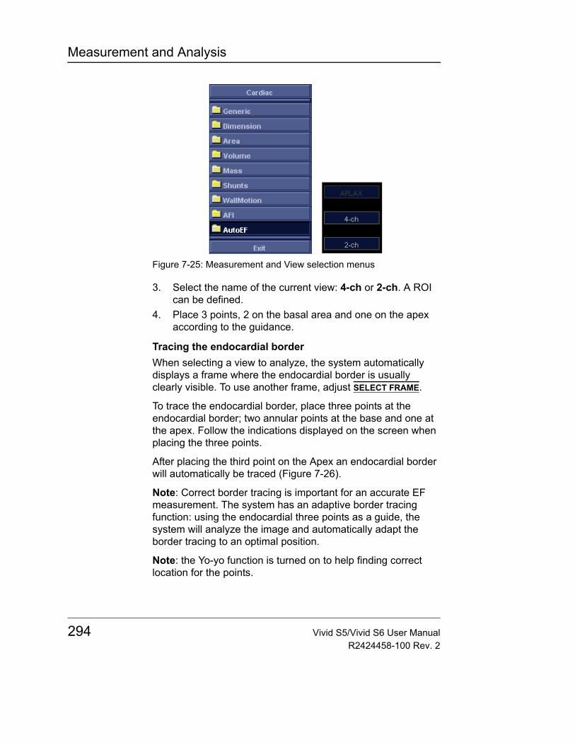
Measurement and Analysis
Figure 7-25: Measurement and View selection menus
3. Select the name of the current view: 4-ch or 2-ch. A ROI can be defined.
4. Place 3 points, 2 on the basal area and one on the apex according to the guidance.
Tracing the endocardial borderWhen selecting a view to analyze, the system automatically displays a frame where the endocardial border is usually clearly visible. To use another frame, adjust SELECT FRAME.
To trace the endocardial border, place three points at the endocardial border; two annular points at the base and one at the apex. Follow the indications displayed on the screen when placing the three points.
After placing the third point on the Apex an endocardial border will automatically be traced (Figure 7-26).
Note: Correct border tracing is important for an accurate EF measurement. The system has an adaptive border tracing function: using the endocardial three points as a guide, the system will analyze the image and automatically adapt the border tracing to an optimal position.
Note: the Yo-yo function is turned on to help finding correct location for the points.
294 Vivid S5/Vivid S6 User ManualR2424458-100 Rev. 2
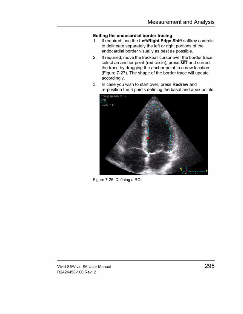
Measurement and Analysis
Editing the endocardial border tracing1. If required, use the Left/Right Edge Shift softkey controls
to delineate separately the left or right portions of the endocardial border visually as best as possible.
2. If required, move the trackball cursor over the border trace, select an anchor point (red circle), press SET and correct the trace by dragging the anchor point to a new location (Figure 7-27). The shape of the border trace will update accordingly.
3. In case you wish to start over, press Redraw and re-position the 3 points defining the basal and apex points.
Figure 7-26: Defining a ROI
Vivid S5/Vivid S6 User Manual 295R2424458-100 Rev. 2
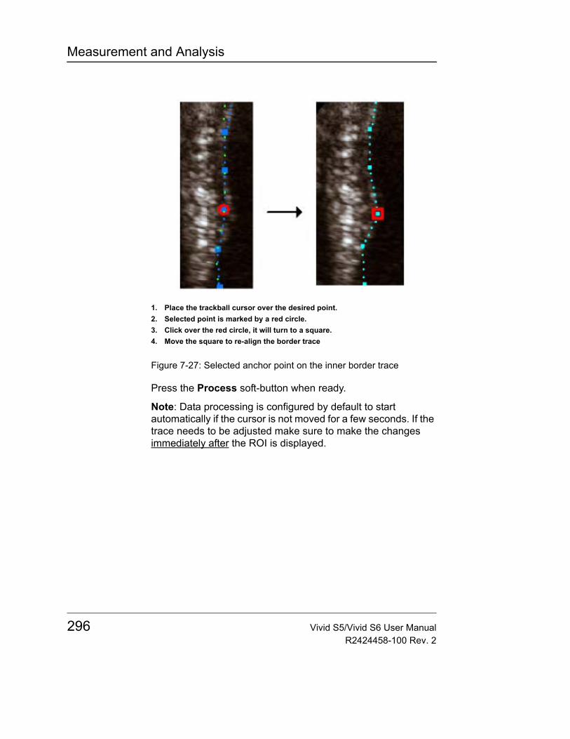
Measurement and Analysis
Figure 7-27: Selected anchor point on the inner border trace
Press the Process soft-button when ready.
Note: Data processing is configured by default to start automatically if the cursor is not moved for a few seconds. If the trace needs to be adjusted make sure to make the changes immediately after the ROI is displayed.
1. Place the trackball cursor over the desired point.2. Selected point is marked by a red circle.3. Click over the red circle, it will turn to a square.4. Move the square to re-align the border trace
296 Vivid S5/Vivid S6 User ManualR2424458-100 Rev. 2
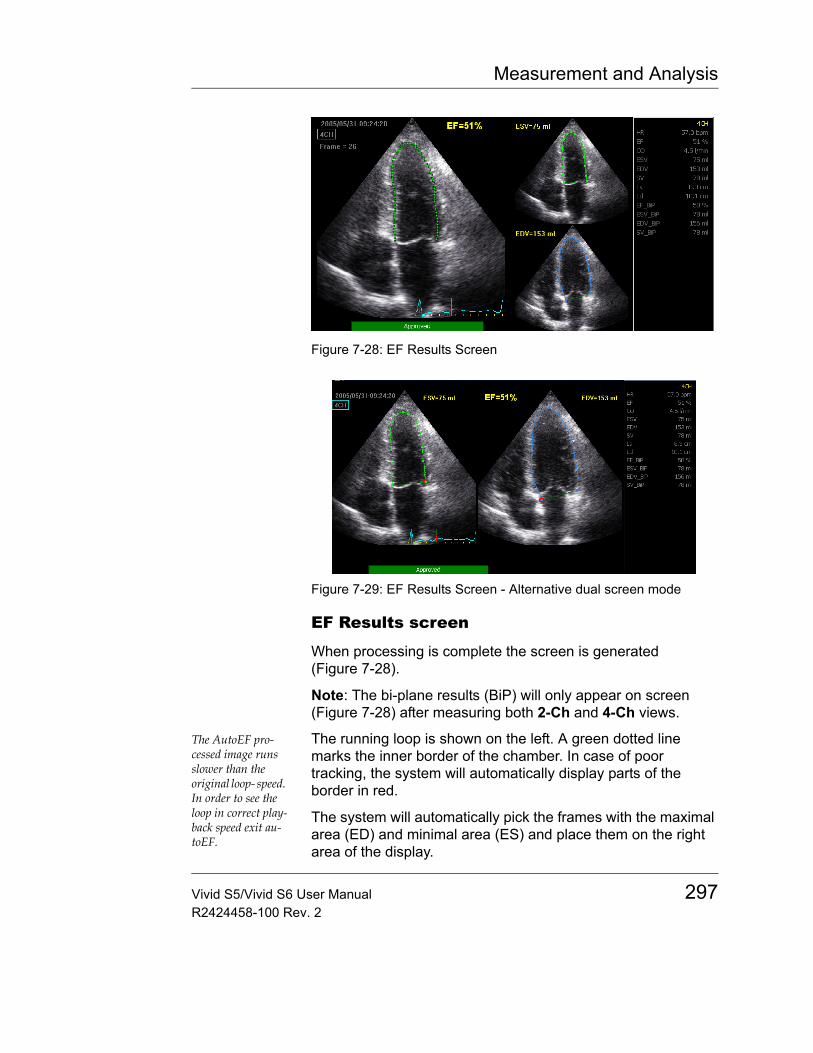
Measurement and Analysis
Figure 7-28: EF Results Screen
Figure 7-29: EF Results Screen - Alternative dual screen mode
EF Results screen
When processing is complete the screen is generated (Figure 7-28).
Note: The bi-plane results (BiP) will only appear on screen (Figure 7-28) after measuring both 2-Ch and 4-Ch views.
The AutoEF pro-cessed image runs slower than the original loop- speed. In order to see the loop in correct play-back speed exit au-toEF.
The running loop is shown on the left. A green dotted line marks the inner border of the chamber. In case of poor tracking, the system will automatically display parts of the border in red.
The system will automatically pick the frames with the maximal area (ED) and minimal area (ES) and place them on the right area of the display.
Vivid S5/Vivid S6 User Manual 297R2424458-100 Rev. 2
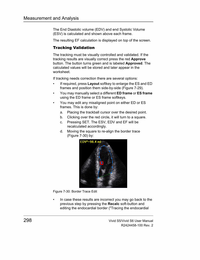
Measurement and Analysis
The End Diastolic volume (EDV) and end Systolic Volume (ESV) is calculated and shown above each frame.
The resulting EF calculation is displayed on top of the screen.
Tracking Validation
The tracking must be visually controlled and validated. If the tracking results are visually correct press the red Approve button. The button turns green and is labeled Approved. The calculated values will be stored and later appear in the worksheet.
If tracking needs correction there are several options:• If required, press Layout softkey to enlarge the ES and ED
frames and position them side-by-side (Figure 7-29).• You may manually select a different ED frame or ES frame
using the ED frame or ES frame softkeys.• You may edit any misaligned point on either ED or ES
frames. This is done by:a. Placing the trackball cursor over the desired point.b. Clicking over the red circle, it will turn to a square.c. Pressing SET. The ESV, EDV and EF will be
recalculated accordingly.d. Moving the square to re-align the border trace
(Figure 7-30) by:
Figure 7-30: Border Trace Edit
• In case these results are incorrect you may go back to the previous step by pressing the Recalc soft-button and editing the endocardial border ("Tracing the endocardial
298 Vivid S5/Vivid S6 User ManualR2424458-100 Rev. 2

Measurement and Analysis
border" on page 294).• In case editing the endocardial border is too difficult you
may start all over again by pressing Redraw and retrace the border ("Tracing the endocardial border" on page 294).
Possible causes of poor trackingPoor tracking quality could result from a variety of causes. The common causes for bad tracking are:• Erroneous placement of the basal points when defining the
border. If the basal points are placed too far from the annular region, the border segments at the annular base will not move together with the underlying 2D image throughout the entire heart beat.
• Erroneous placement of the apex point when defining the border. The point should be placed so that the resulting border trace covers mainly the endocardium. If the apex point is placed too high, the border trace will mainly cover the epicardium resulting in poor tracking.
• Too much clutter. Images with too much static clutter will result in poor tracking.
ResultsFor each of the views, a results screen containing the EF calculation, appears (Figure 7-28) with a small mini-report appearing in the results window on the right side (Figure 7-31).
Figure 7-31: Mini Report
Vivid S5/Vivid S6 User Manual 299R2424458-100 Rev. 2
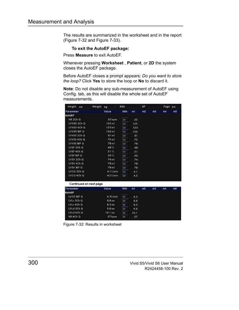
Measurement and Analysis
The results are summarized in the worksheet and in the report (Figure 7-32 and Figure 7-33).
To exit the AutoEF package:Press Measure to exit AutoEF.
Whenever pressing Worksheet , Patient, or 2D the system closes the AutoEF package.
Before AutoEF closes a prompt appears: Do you want to store the loop? Click Yes to store the loop or No to discard it.
Note: Do not disable any sub-measurement of AutoEF using Config. tab, as this will disable the whole set of AutoEF measurements.
Figure 7-32: Results in worksheet
300 Vivid S5/Vivid S6 User ManualR2424458-100 Rev. 2
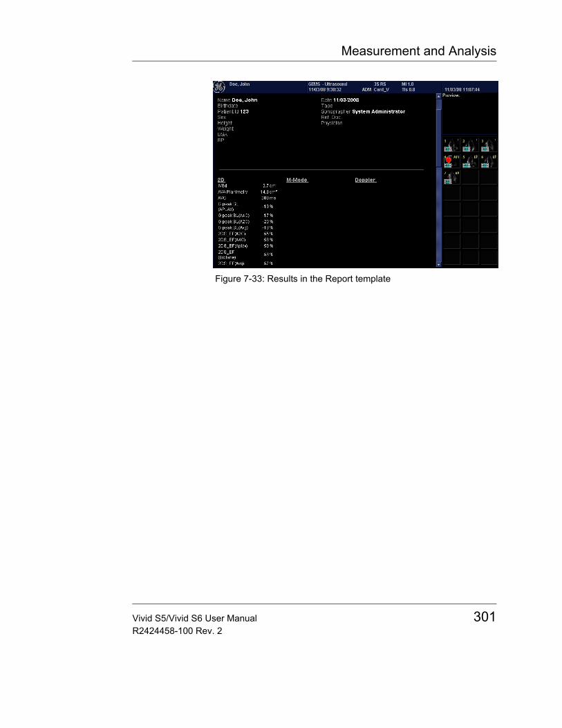
Measurement and Analysis
Figure 7-33: Results in the Report template
Vivid S5/Vivid S6 User Manual 301R2424458-100 Rev. 2
Measurement and Analysis
Vascular measurements
B-Mode measurementsThe following instructions assume that you first scan the patient and press FREEZE.
% Stenosis
% Stenosis by diameter1. Press MEASURE on the control panel.2. Open % Stenosis in the Measurement menu.3. Select % Sten (Diam).4. Make a distance measurement of the inner area of the
blood vessel.5. Make a distance measurement of the outer area of the
blood vessel.The distance measurements and the % Stenosis are displayed in the Measurement result table.
% Stenosis by area1. Press MEASURE on the control panel.2. Open % Stenosis in the Measurement menu.3. Select % Sten (Area).4. Make a trace measurement of the inner area of the blood
vessel.5. Make a trace measurement of the outer area of the blood
vessel.The area measurements and the % Stenosis are displayed in the Measurement result table.
Volume
The volume calculation can be made from one, two or three distance measurements.1. Press MEASURE on the control panel, then select select
Generic.2. Select Volume in the Measurement menu.3. When doing volume calculation from three distance
measurements (i.e. biplane volume), the measurements should be done in dual mode displaying a sagittal and an
302 Vivid S5/Vivid S6 User ManualR2424458-100 Rev. 2
Measurement and Analysis
axial view. One measurement is usually made in the sagittal plane and two measurements in the axial plane.When doing volume calculation from one or two distance measurements, make one or two distance measurements and press MENU.The distance measurement(s) and the volume calculation are displayed in the Measurement result table.
A/B Ratio
In B-Mode, A/B Ratio can be measured by diameter or area.
A/B Ratio by diameter1. Press MEASURE on the control panel.2. Open A/B Ratio in the Measurement menu.3. Select between:
• Ratio (Diam)• Ratio (Area)
4. Make the corresponding two measurements.The measurements and the corresponding A/B Ratio are displayed in the Measurement result table.
Intima-Media ThicknessThe Intima-Media Thickness (IMT) is calculated based on automatic contour detection of the Intima and Media layers on a user-defined search region along the vessel wall. Multiple IMT measurements are made between pairs of intima and adventitia points along the wall (Figure 7-34). IMT can be measured both on the posterior and the anterior walls of the vessel.
The IMT measurement is available with linear probes only.
Note: due to the physical properties of ultrasound imaging, the posterior IMT measurement is generally more accurate than the anterior IMT measurement.
The following parameters are calculated:• Average IMT• Maximum IMT• Minimum IMT• Standard deviation of IMT measurements• Number of successful IMT measurements
Vivid S5/Vivid S6 User Manual 303R2424458-100 Rev. 2
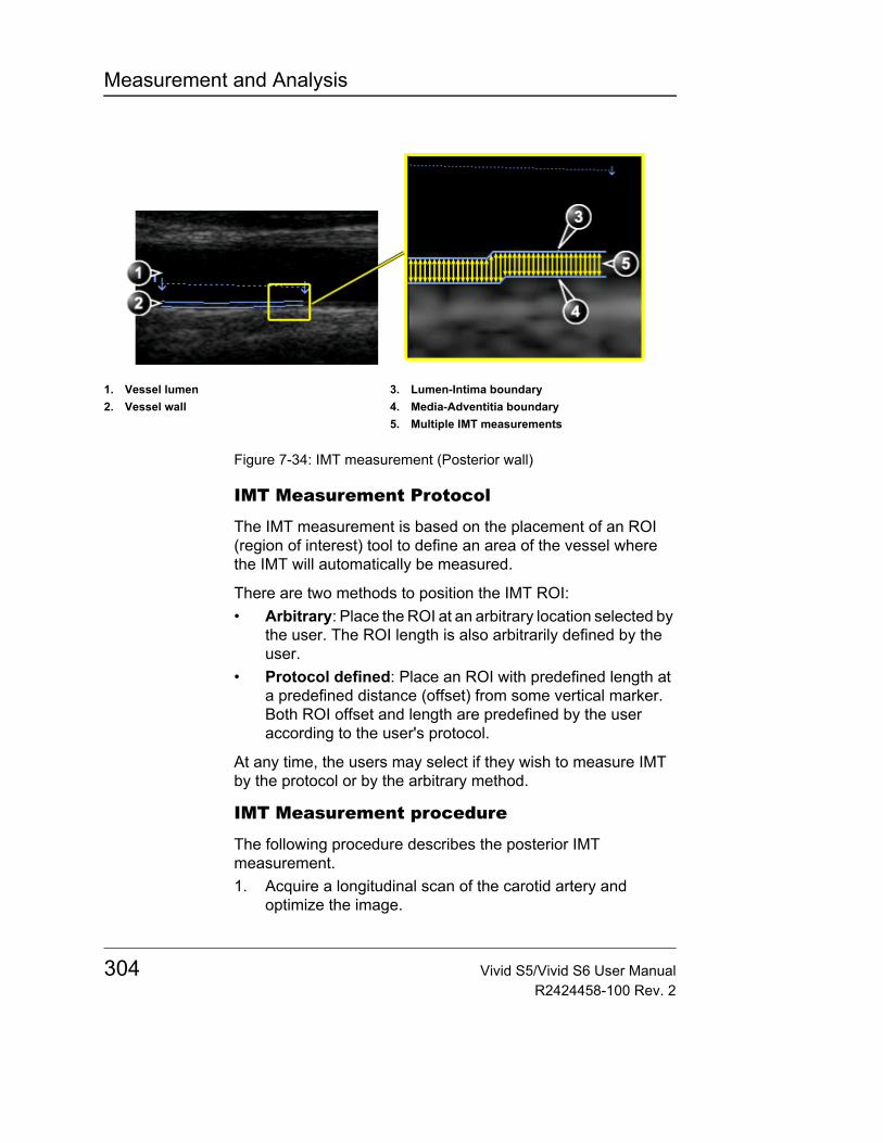
Measurement and Analysis
Figure 7-34: IMT measurement (Posterior wall)
IMT Measurement Protocol
The IMT measurement is based on the placement of an ROI (region of interest) tool to define an area of the vessel where the IMT will automatically be measured.
There are two methods to position the IMT ROI:• Arbitrary: Place the ROI at an arbitrary location selected by
the user. The ROI length is also arbitrarily defined by the user.
• Protocol defined: Place an ROI with predefined length at a predefined distance (offset) from some vertical marker. Both ROI offset and length are predefined by the user according to the user's protocol.
At any time, the users may select if they wish to measure IMT by the protocol or by the arbitrary method.
IMT Measurement procedure
The following procedure describes the posterior IMT measurement.1. Acquire a longitudinal scan of the carotid artery and
optimize the image.
1. Vessel lumen2. Vessel wall
3. Lumen-Intima boundary4. Media-Adventitia boundary5. Multiple IMT measurements
304 Vivid S5/Vivid S6 User ManualR2424458-100 Rev. 2
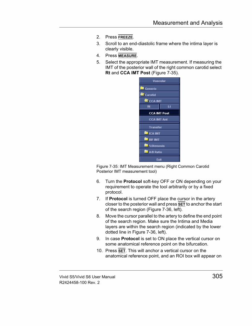
Measurement and Analysis
2. Press FREEZE.3. Scroll to an end-diastolic frame where the intima layer is
clearly visible.4. Press MEASURE.5. Select the appropriate IMT measurement. If measuring the
IMT of the posterior wall of the right common carotid select Rt and CCA IMT Post (Figure 7-35).
Figure 7-35: IMT Measurement menu (Right Common Carotid Posterior IMT measurement tool)
6. Turn the Protocol soft-key OFF or ON depending on your requirement to operate the tool arbitrarily or by a fixed protocol.
7. If Protocol is turned OFF place the cursor in the artery closer to the posterior wall and press SET to anchor the start of the search region (Figure 7-36, left).
8. Move the cursor parallel to the artery to define the end point of the search region. Make sure the Intima and Media layers are within the search region (indicated by the lower dotted line in Figure 7-36, left).
9. In case Protocol is set to ON place the vertical cursor on some anatomical reference point on the bifurcation.
10. Press SET. This will anchor a vertical cursor on the anatomical reference point, and an ROI box will appear on
Vivid S5/Vivid S6 User Manual 305R2424458-100 Rev. 2
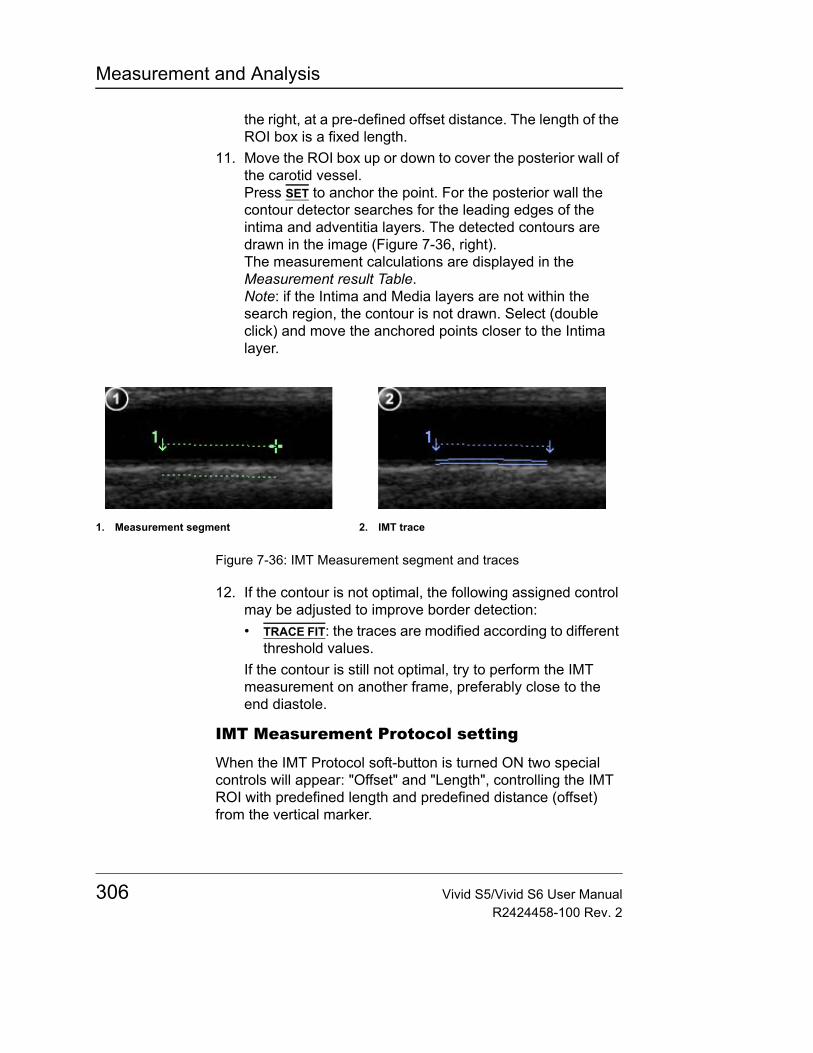
Measurement and Analysis
the right, at a pre-defined offset distance. The length of the ROI box is a fixed length.
11. Move the ROI box up or down to cover the posterior wall of the carotid vessel.Press SET to anchor the point. For the posterior wall the contour detector searches for the leading edges of the intima and adventitia layers. The detected contours are drawn in the image (Figure 7-36, right).The measurement calculations are displayed in the Measurement result Table.Note: if the Intima and Media layers are not within the search region, the contour is not drawn. Select (double click) and move the anchored points closer to the Intima layer.
Figure 7-36: IMT Measurement segment and traces
12. If the contour is not optimal, the following assigned control may be adjusted to improve border detection:• TRACE FIT: the traces are modified according to different
threshold values.If the contour is still not optimal, try to perform the IMT measurement on another frame, preferably close to the end diastole.
IMT Measurement Protocol setting
When the IMT Protocol soft-button is turned ON two special controls will appear: "Offset" and "Length", controlling the IMT ROI with predefined length and predefined distance (offset) from the vertical marker.
1. Measurement segment 2. IMT trace
306 Vivid S5/Vivid S6 User ManualR2424458-100 Rev. 2
Measurement and Analysis
The user may modify the offset or length while performing the exam, in case these are not set to optimal dimensions.
To modify Protocol defaults1. Set the Protocol button ON or OFF.2. In case Protocol is ON: adjust the Offset and Length
values.3. Press the Store default soft-key to store the status of
"protocol" button ON or OFF and the current settings of Offset and Length, to be used in the future exams.
4. The default settings may be defined differently for the CCA and the ICA.Note: When adjusting the offset for the ICA, the offset values are negative, as the ROI is located to the left of the vertical reference marker.
IMT trace approval
Since the IMT measurements are done semiautomatically, the operator has to approve the detection by visual inspection before storing the results in worksheet and report.• If the traces fit both layers of the intima-media walls,
approve the measurement by selecting Transfer in the Measurement menu.Once transferred, the calculations can be viewed in the worksheet and report.
CAUTION
Measurements that are not approved will not be saved.
CAUTION
Any image adjustments (e.g. Gain or zoom) on approved (transferred) measurements will unassign the measurements. Press Transfer to approve the measurements again.
Vivid S5/Vivid S6 User Manual 307R2424458-100 Rev. 2
Measurement and Analysis
M-Mode MeasurementsThe following instructions assume that you first scan the patient and press FREEZE.
% Stenosis1. Press MEASURE on the control panel.2. Select % Stenosis in the Measurement menu.3. Make a distance measurement of the inner area of the
blood vessel.4. Make a distance measurement of the outer area of the
blood vessel.The distance measurements and the % Stenosis are displayed in the Measurement result table.
A/B Ratio
In M-Mode, A/B Ratio can be measured by diameter, time or velocity.1. Press MEASURE on the control panel.2. Open A/B Ratio in the Measurement menu.3. Select between:
• Ratio (Diam• Ratio (Time)• Ratio (Velocity)
4. Make the corresponding two measurements.The measurements and the corresponding A/B Ratio are displayed in the Measurement result table.
308 Vivid S5/Vivid S6 User ManualR2424458-100 Rev. 2
Measurement and Analysis
Doppler measurementsThe system can detect the trace automatically or the user can draw the trace manually.
Auto vascular calculation
The system performs calculation automatically on the spectrum trace.
The auto vascular calculation can operate in live, freeze or be turned off (Live, Frozen and Off commands in the Measurements menu).
From the Modify Calcs menu, the user can:• select the calculations to be displayed in the Measurement
result table.• set the calculations that should be default when an exam is
started (Save as default command).• turn on the automatically detected trace to display max
and/or mean trace (Max and Mean commands).• display forward flow, reverse flow or both flows (Above,
Below and Both commands).
Setting up auto vascular calculation1. Press MEASURE.
The Vascular measurement menu is displayed (Figure 7-37).
2. Press Auto and select between:• Live: calculation displayed on the real-time image.• Freeze: calculation displayed on the frozen image.• Off: auto vascular calculation is turned off.
3. Press Modify Calcs.The Modify Calcs menu is displayed (Figure 7-37).
4. Select: • Above, Below or Both to select the spectrum to perform
the calculations on, i.e. above or below the baseline or both.
• Max and/or Mean to display max and/or mean velocities.5. In the Modify Calcs menu, select the measurements and
calculations to be displayed in the Measurement result table.
Vivid S5/Vivid S6 User Manual 309R2424458-100 Rev. 2
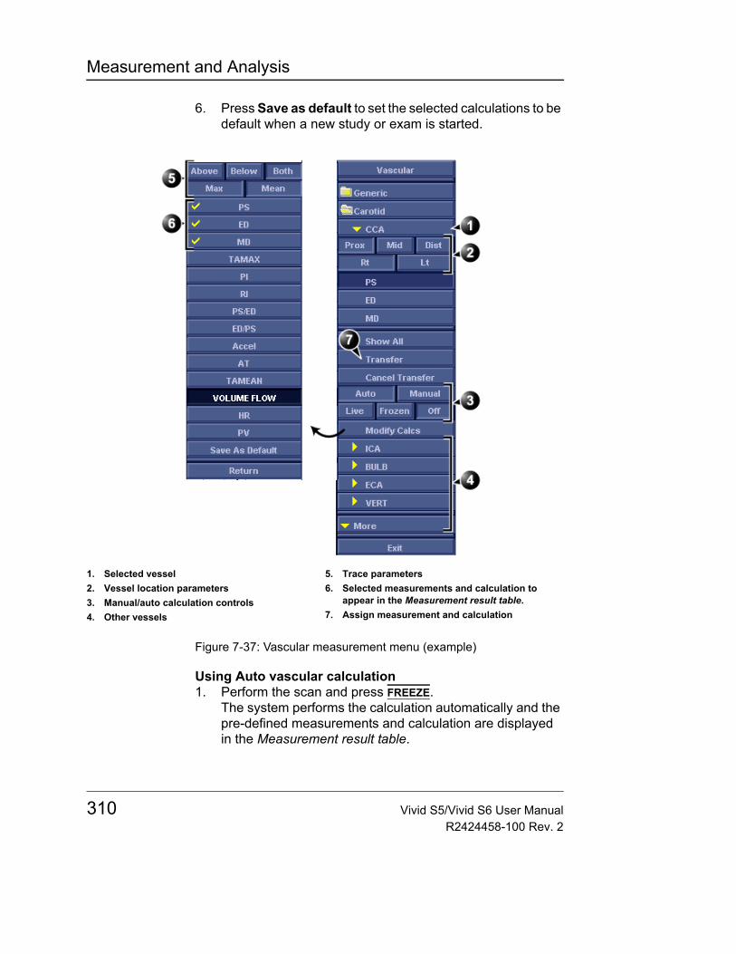
Measurement and Analysis
6. Press Save as default to set the selected calculations to be default when a new study or exam is started.
Figure 7-37: Vascular measurement menu (example)
Using Auto vascular calculation1. Perform the scan and press FREEZE.
The system performs the calculation automatically and the pre-defined measurements and calculation are displayed in the Measurement result table.
1. Selected vessel2. Vessel location parameters3. Manual/auto calculation controls4. Other vessels
5. Trace parameters6. Selected measurements and calculation to
appear in the Measurement result table.7. Assign measurement and calculation
310 Vivid S5/Vivid S6 User ManualR2424458-100 Rev. 2
Measurement and Analysis
2. The following controls may be adjusted from the control panel:• CYCLE SELECT: change the selected cycle.• TRACE SENSITIVITY: optimize the trace contour.• CURSOR SELECT: select Peak systolic or End diastolic
marker. The selected marker can be moved to a new location. Press SET to anchor the marker to its new location.
Assigning auto calculations1. In the Vascular Measurement menu (Figure 7-37), select:
• The actual vessel name• Prox, Mid or Dist: the location of the vessel (Proximal,
Middle or Distal).• Rt or Lt: right or left side of the patient.
2. Press Transfer to assign the measurements and calculations.
To undo the assign-ment, press Cancel transfer.
The Measurement result table is updated accordingly and the measurements and calculations are added to the worksheet and report.
Manual vascular calculation
When doing manual measurements, the system can detect the trace automatically or it can be drawn by the user. This is controlled by the Auto and Manual commands is the Measurement menu.
The following instructions assume that you first scan the patient and press FREEZE.1. Adjust the vessel location parameters in the Vascular
measurement menu (Figure 7-37).2. Select the measurement to be performed from the
Measurement menu or from the Show All menu for additional measurements.
3. Perform the measurement as described below.
Acceleration, Acceleration time (AT)1. Select Accel or AT.2. Position the caliper at the start point and press SET to
anchor the caliper.
Vivid S5/Vivid S6 User Manual 311R2424458-100 Rev. 2
Measurement and Analysis
3. Position the second caliper at the end point and press SET to anchor the caliper and complete the measurement.The acceleration and/or the acceleration time is displayed in the Measurement result table.
Heart rateHeart rate is calculated by selecting two identical points over two heart cycles.1. Select HR.2. Position the caliper at a recognizable point in the first cycle
and press SET to anchor the caliper.3. Position the second caliper at the identical point in the
second cycle and press SET to anchor the caliper and complete the measurement.The Heart rate is displayed in the Measurement result table.
Peak systole (PS), End diastole (ED) and Mid diastole (MD)1. Select PS, ED or MD.2. Position the caliper at the corresponding measurement
point and press SET to complete the measurement.The selected measurement is displayed in the Measurement result table.
Pulsatility index (PI) With Auto trace on
1. Select PI.2. Position the caliper at the beginning of the wave form and
press SET to anchor the caliper.3. Position the second caliper at end diastole and press SET.
A trace is displayed between the two calipers and PS, ED, MD, TAMAX, PI and RI are displayed in the Measurement result table.
With Manual trace on1. Select PI.2. Position the caliper at the beginning of the wave form and
press SET to anchor the caliper.3. Using the trackball, draw the trace to the end diastole and
press SET.The trace is displayed and PS, ED, MD, TAMAX, PI and RI are displayed in the Measurement result table.
312 Vivid S5/Vivid S6 User ManualR2424458-100 Rev. 2

Measurement and Analysis
Peak systole/End diastole (PS/ED) and End diastole/Peak systole (ED/PS) ratio1. Select PS/ED or ED/PS.2. Position the caliper at Peak systole or End systole and
press SET to anchor the caliper.3. Position the second caliper at End diastole or Peak systole
and press SET to anchor the caliper and complete the measurement.The Peak systole, End diastole and PS/ED or ED/PS ratio are displayed in the Measurement result table.
Resistive index (RI)1. Select RI.2. Position the caliper at Peak systole and press SET to anchor
the caliper.3. Position the second caliper at end diastole and press SET.
The Peak systole, End diastole and RI are displayed in the Measurement result table.
TAMAX/TAMEAN/Volume Flow With Auto trace on
1. Select TAMAX, TAMEAN or Volume Flow.2. Position the caliper at the start point and press SET to
anchor the caliper.3. Position the second caliper at the end point and press SET
to anchor the caliper and complete the measurement.A trace is displayed between the two calipers and corresponding measurements are displayed in the Measurement result table.
With Manual trace on1. Select TAMAX, TAMEAN or Volume Flow.2. Position the caliper at the start point and press SET to
anchor the caliper.3. Using the trackball, draw the trace to the end point and
press SET.The trace is displayed and the corresponding measurements are displayed in the Measurement result table.
Vivid S5/Vivid S6 User Manual 313R2424458-100 Rev. 2
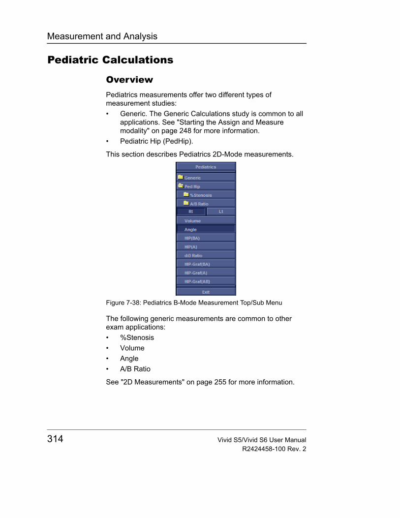
Measurement and Analysis
Pediatric Calculations
OverviewPediatrics measurements offer two different types of measurement studies:• Generic. The Generic Calculations study is common to all
applications. See "Starting the Assign and Measure modality" on page 248 for more information.
• Pediatric Hip (PedHip).
This section describes Pediatrics 2D-Mode measurements.
Figure 7-38: Pediatrics B-Mode Measurement Top/Sub Menu
The following generic measurements are common to other exam applications:• %Stenosis• Volume• Angle• A/B Ratio
See "2D Measurements" on page 255 for more information.
314 Vivid S5/Vivid S6 User ManualR2424458-100 Rev. 2
Measurement and Analysis
Hip Dysplasia CalculationThe HIP calculation assists in assessing the development of the infant hip. In this calculation, three straight lines are superimposed on the image and aligned with the anatomical features. The two angles are computed, displayed, and can be used by the physician in making a diagnosis.
The three lines are:1. The baseline connects the osseous acetabulum convexity
to the point where the joint capsule and the perichondrium unite with the iliac bone.
2. The inclination line connects the osseous convexity to labrum acetabulare.
3. The Acetabulum roof line connects the lower edge of the osilium to the osseous convexity.
The α (Alpha) angle is the supplement of the angle between 1 and 3. It characterizes the osseous convexity. The ß (Beta) angle is the angle between lines 1 and 2. It characterizes the bone supplementing additional roofing by the cartilaginous convexity.
Making Hip Dysplasia MeasurementTo make a Hip Dysplasia measurement:1. From the Top/Sub Menu, select either the right or left side
(orientation) and then select HIP. A horizontal dotted line displays.
2. To place the baseline, move the Trackball. Position the crosshairs edge at the osseous convexity of the ilium.
3. To rotate or change inclination, adjust the Ellipse control or Hip Rotate.
4. To fix the baseline, press SET. The system displays a second dotted line at an angle.
5. To place the line along the inclination line of the osseous convexity to labrum acetabulare, move the Trackball.
6. To rotate or change inclination, adjust the Ellipse control or Hip Rotate.
7. To fix the second measurement line, press SET. The system displays a third dotted line at an angle.
Vivid S5/Vivid S6 User Manual 315R2424458-100 Rev. 2
Measurement and Analysis
8. To place the caliper along the acetabular roof line, move the Trackball.
9. To rotate or change inclination, adjust the Ellipse control or Hip Rotate.
10. To fix the third measurement line and complete measurement, press SET.The system displays the hip measurements (α and ß) in the Results window.
Alpha HIP
The Alpha HIP measurement measures the angle between the iliac baseline and the bony roof line. To make an Alpha HIP measurement:1. From the Top/Sub Menu, select either the right or left side
(orientation) and then select Alpha HIP.A horizontal dotted line displays.
2. To place the baseline, move the Trackball. Position the crosshairs edge at the osseous convexity of the ilium.
3. To rotate or change inclination, adjust the Ellipse control or Hip Rotate.
4. To fix the baseline, press SET.The system displays a second dotted line at an angle.
5. To place the caliper along the acetabular roof line, move the Trackball.
6. To rotate or change inclination, adjust the Ellipse control or Hip Rotate.
7. To fix the second measurement line, press SET.The system displays the alpha hip measurement (α) in the Results window.
d:D Ratio Measurement
The d:D Ratio measurement measures the percentage of the femoral head coverage under the bony roof. To make this measurement:1. From the Top/Sub Menu, select either the right or left side
(orientation) and then select d:D Ratio.A horizontal dotted line displays.
2. Use the Trackball to place the baseline along the ilium.Position the crosshairs edge at the osseous convexity of the ilium.
316 Vivid S5/Vivid S6 User ManualR2424458-100 Rev. 2
Measurement and Analysis
3. Use the Ellipse control to adjust or change inclination or Hip Rotate.
4. Press SET to fix the baseline.5. The system displays a circle representing the femoral head.
Use the Trackball to position the circle.6. Use the Ellipse control to size the femoral head
circumference.7. Press SET to fix the femoral head circumference.
The system displays the d:D ratio for the femoral head in the Results window.
Performing an OB examPatient entry1. Enter a New Patient or a New Exam for an existing patient
by following the procedure "Starting an examination" on page 95.Note: Use "Other ID" if relevant - For further information see "Using other ID" on page 99.
2. When the Search/Create Patient screen appears, the Category field should be preset to Obstetrics. Change it if required.
3. Enter or validate the patient's Last name, First name, ID and birth-date or age.
4. Click the Create Patient softkey5. To add an additional patient information click Patient.6. Select Current Patient Information.
The Patient Information screen appears (see Figure 7-39). Use the fields in this screen to enter various data (see Table 7-1)
7. After entering data click the Begin Exam softkey to continue with the exam and get a scanning screen. Alternatively, click 2D Mode to continue scanning.
Vivid S5/Vivid S6 User Manual 317R2424458-100 Rev. 2

Measurement and Analysis
Figure 7-39: The Patient Information window
Table 7-1: Obstetric fields
Field Description
LMP Last Menstrual Period; enter the date that the patient started her last menstrual period, in dd/mm/yyyy format. You must enter 2 digits for the day or the month. When you type the month and day, the system fills in the / (slash) and the digits 20 as the first digits of the year.
EDD by LMP Estimated Delivery Date by LMP; the system fills in the date after you enter the LMP.
GA by LMP Gestational Age by LMP; the system fills in the age after you enter the LMP.
EDD If you click on the EDD by LMP button it will change into EDD. When you fill in the EDD (Estimated Delivery Date) the system calculates and fills in the LMP and the GA by EDD field.
GA If you click on the GA by LMP button it will change into GA. When you fill in the GA (Gestational Age) the system calculates and fills in the LMP and the EDD by GA field.
318 Vivid S5/Vivid S6 User ManualR2424458-100 Rev. 2
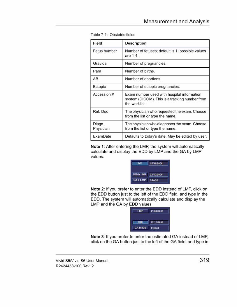
Measurement and Analysis
Note 1: After entering the LMP, the system will automatically calculate and display the EDD by LMP and the GA by LMP values.
Note 2: If you prefer to enter the EDD instead of LMP, click on the EDD button just to the left of the EDD field, and type in the EDD. The system will automatically calculate and display the LMP and the GA by EDD values
Note 3: If you prefer to enter the estimated GA instead of LMP, click on the GA button just to the left of the GA field, and type in
Fetus number Number of fetuses; default is 1; possible values are 1-4.
Gravida Number of pregnancies.
Para Number of births.
AB Number of abortions.
Ectopic Number of ectopic pregnancies.
Accession # Exam number used with hospital information system (DICOM). This is a tracking number from the worklist.
Ref. Doc The physician who requested the exam. Choose from the list or type the name.
Diagn. Physician
The physician who diagnoses the exam. Choose from the list or type the name.
ExamDate Defaults to today's date. May be edited by user.
Table 7-1: Obstetric fields
Field Description
Vivid S5/Vivid S6 User Manual 319R2424458-100 Rev. 2
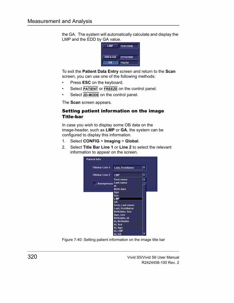
Measurement and Analysis
the GA. The system will automatically calculate and display the LMP and the EDD by GA value.
To exit the Patient Data Entry screen and return to the Scan screen, you can use one of the following methods:• Press ESC on the keyboard.• Select PATIENT or FREEZE on the control panel.• Select 2D-MODE on the control panel.
The Scan screen appears.
Setting patient information on the image Title-bar
In case you wish to display some OB data on the image-header, such as LMP or GA, the system can be configured to display this information.1. Select CONFIG > Imaging > Global.2. Select Title Bar Line 1 or Line 2 to select the relevant
information to appear on the screen.
Figure 7-40: Setting patient information on the image title bar
320 Vivid S5/Vivid S6 User ManualR2424458-100 Rev. 2
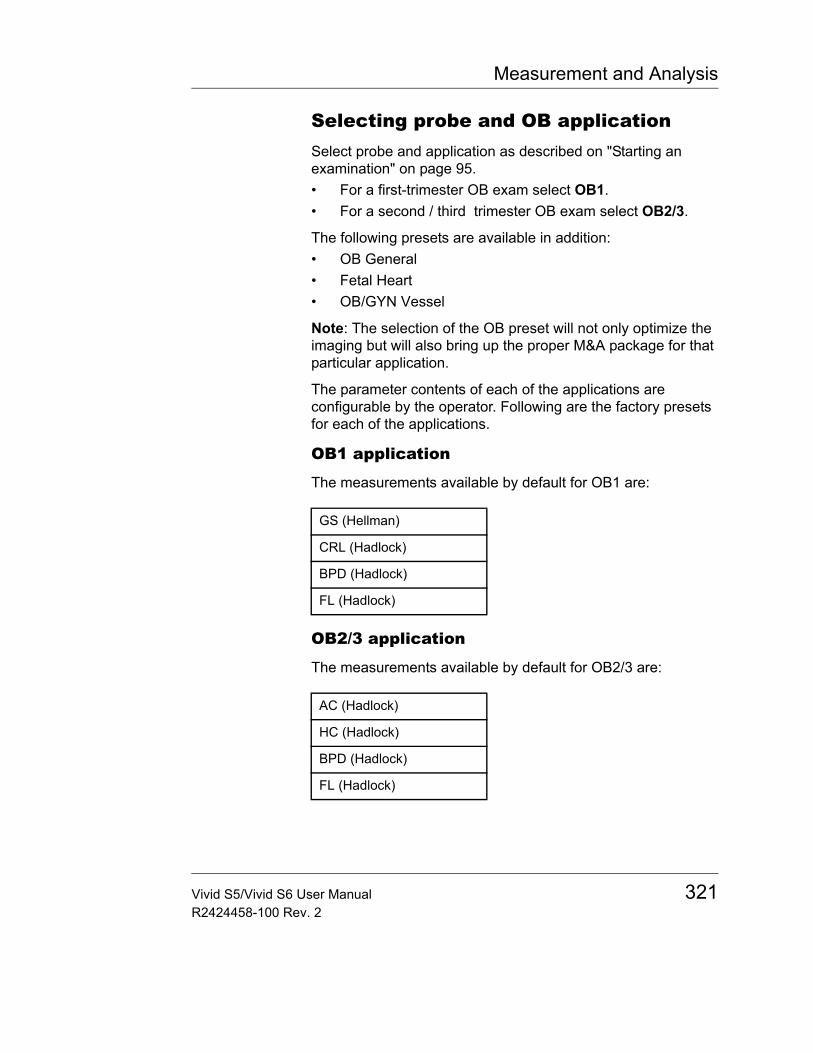
Measurement and Analysis
Selecting probe and OB applicationSelect probe and application as described on "Starting an examination" on page 95.• For a first-trimester OB exam select OB1.• For a second / third trimester OB exam select OB2/3.
The following presets are available in addition:• OB General• Fetal Heart• OB/GYN Vessel
Note: The selection of the OB preset will not only optimize the imaging but will also bring up the proper M&A package for that particular application.
The parameter contents of each of the applications are configurable by the operator. Following are the factory presets for each of the applications.
OB1 application
The measurements available by default for OB1 are:
OB2/3 application
The measurements available by default for OB2/3 are:
GS (Hellman)
CRL (Hadlock)
BPD (Hadlock)
FL (Hadlock)
AC (Hadlock)
HC (Hadlock)
BPD (Hadlock)
FL (Hadlock)
Vivid S5/Vivid S6 User Manual 321R2424458-100 Rev. 2
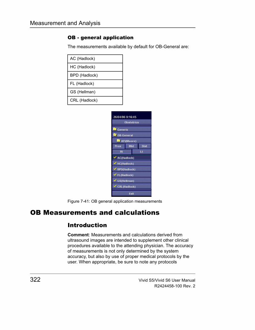
Measurement and Analysis
OB - general application
The measurements available by default for OB-General are:
Figure 7-41: OB general application measurements
OB Measurements and calculations
IntroductionComment: Measurements and calculations derived from ultrasound images are intended to supplement other clinical procedures available to the attending physician. The accuracy of measurements is not only determined by the system accuracy, but also by use of proper medical protocols by the user. When appropriate, be sure to note any protocols
AC (Hadlock)
HC (Hadlock)
BPD (Hadlock)
FL (Hadlock)
GS (Hellman)
CRL (Hadlock)
322 Vivid S5/Vivid S6 User ManualR2424458-100 Rev. 2
Measurement and Analysis
associated with a particular measurement or calculation. Formulas and databases used within the system software that are associated with specific investigators are so noted. Be sure to refer to the original article describing the investigator's recommended clinical procedures.
Note: When you make measurements, you can select the calculation before you make the measurement or after you make it. If you select the calculation before you make the measurement, the Results Window shows the estimated fetal age as you make the measurement. If you select the calculation after you make the measurement, the estimated fetal age is displayed after you complete the measurement. The measurements steps in this section tell you to select the calculation before you make the measurement.
The following pages describe how to make OB measurements and calculations. The measurements are organized by mode, and within mode are listed in alphabetical order.
Out of range: If the system indicates that a measurement is out of range (OOR), it means one of the following:• The measurement is out of the normal range based on the
gestational age that is calculated from the LMP. The system determines OOR from the ultrasound age compared to the gestational age. The gestational age is calculated from the last menstrual period or the estimated delivery date.
• The measurement is outside of the range for the data used in the calculation. That means that the measurement is either less than or more than the range of measurements used to determine fetal age based on the measurement.
Note: Calculation formulas are listed in the Reference Manual.
B-Mode measurementsThis section describes all B-Mode measurements that you typically find in OB studies. Additional OB measurements follow the typical ones.
Vivid S5/Vivid S6 User Manual 323R2424458-100 Rev. 2
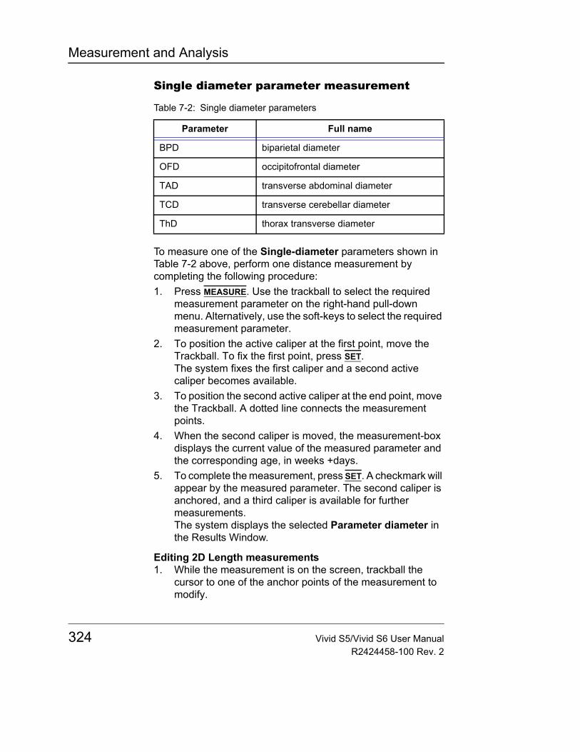
Measurement and Analysis
Single diameter parameter measurement
To measure one of the Single-diameter parameters shown in Table 7-2 above, perform one distance measurement by completing the following procedure:1. Press MEASURE. Use the trackball to select the required
measurement parameter on the right-hand pull-down menu. Alternatively, use the soft-keys to select the required measurement parameter.
2. To position the active caliper at the first point, move the Trackball. To fix the first point, press SET.The system fixes the first caliper and a second active caliper becomes available.
3. To position the second active caliper at the end point, move the Trackball. A dotted line connects the measurement points.
4. When the second caliper is moved, the measurement-box displays the current value of the measured parameter and the corresponding age, in weeks +days.
5. To complete the measurement, press SET. A checkmark will appear by the measured parameter. The second caliper is anchored, and a third caliper is available for further measurements.The system displays the selected Parameter diameter in the Results Window.
Editing 2D Length measurements1. While the measurement is on the screen, trackball the
cursor to one of the anchor points of the measurement to modify.
Table 7-2: Single diameter parameters
Parameter Full name
BPD biparietal diameter
OFD occipitofrontal diameter
TAD transverse abdominal diameter
TCD transverse cerebellar diameter
ThD thorax transverse diameter
324 Vivid S5/Vivid S6 User ManualR2424458-100 Rev. 2
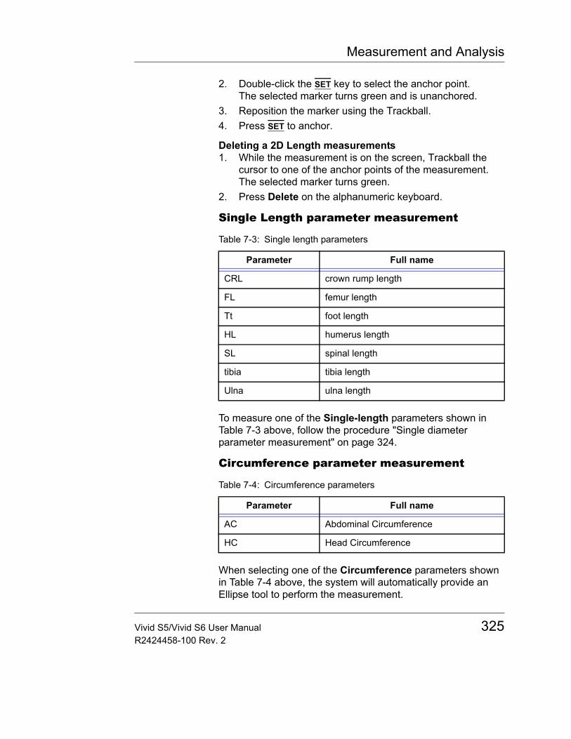
Measurement and Analysis
2. Double-click the SET key to select the anchor point.The selected marker turns green and is unanchored.
3. Reposition the marker using the Trackball.4. Press SET to anchor.
Deleting a 2D Length measurements1. While the measurement is on the screen, Trackball the
cursor to one of the anchor points of the measurement.The selected marker turns green.
2. Press Delete on the alphanumeric keyboard.
Single Length parameter measurement
To measure one of the Single-length parameters shown in Table 7-3 above, follow the procedure "Single diameter parameter measurement" on page 324.
Circumference parameter measurement
When selecting one of the Circumference parameters shown in Table 7-4 above, the system will automatically provide an Ellipse tool to perform the measurement.
Table 7-3: Single length parameters
Parameter Full name
CRL crown rump length
FL femur length
Tt foot length
HL humerus length
SL spinal length
tibia tibia length
Ulna ulna length
Table 7-4: Circumference parameters
Parameter Full name
AC Abdominal Circumference
HC Head Circumference
Vivid S5/Vivid S6 User Manual 325R2424458-100 Rev. 2
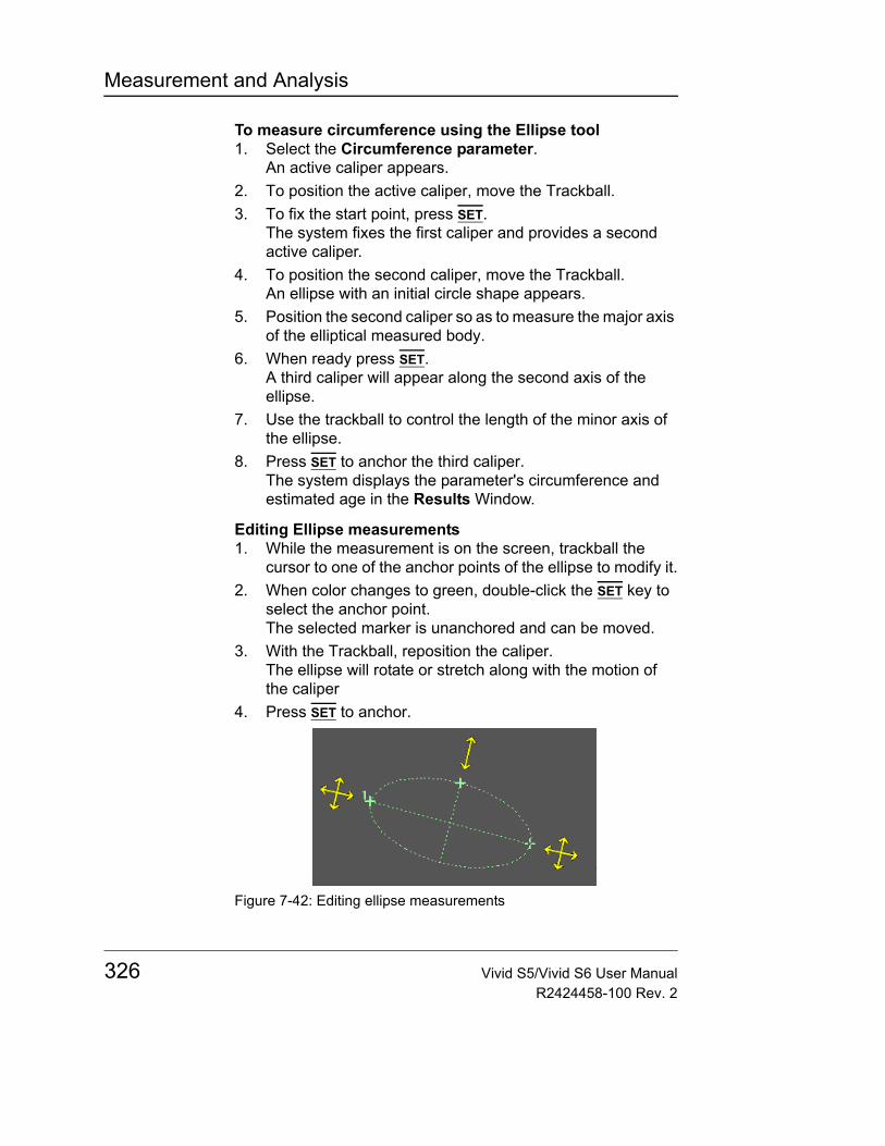
Measurement and Analysis
To measure circumference using the Ellipse tool1. Select the Circumference parameter.
An active caliper appears.2. To position the active caliper, move the Trackball. 3. To fix the start point, press SET.
The system fixes the first caliper and provides a second active caliper.
4. To position the second caliper, move the Trackball.An ellipse with an initial circle shape appears.
5. Position the second caliper so as to measure the major axis of the elliptical measured body.
6. When ready press SET.A third caliper will appear along the second axis of the ellipse.
7. Use the trackball to control the length of the minor axis of the ellipse.
8. Press SET to anchor the third caliper.The system displays the parameter's circumference and estimated age in the Results Window.
Editing Ellipse measurements1. While the measurement is on the screen, trackball the
cursor to one of the anchor points of the ellipse to modify it.2. When color changes to green, double-click the SET key to
select the anchor point.The selected marker is unanchored and can be moved.
3. With the Trackball, reposition the caliper.The ellipse will rotate or stretch along with the motion of the caliper
4. Press SET to anchor.
Figure 7-42: Editing ellipse measurements
326 Vivid S5/Vivid S6 User ManualR2424458-100 Rev. 2
Measurement and Analysis
Deleting the ellipse measurements1. While the ellipse measurement is on the screen, Trackball
the cursor to one of the anchor points of the measurement.The selected marker turns green.
2. Press Delete on the alphanumeric keyboard.
Gestational Sac
To calculate the gestational sac, you need to make diameter measurements in three orthogonal directions. These may be done either sequentially or simultaneously in two scan planes.
Measuring GS on two scan planesTo display two scan planes, press the 1/2/4 key once. Get an image in each scan plane and press FREEZE.1. Activate M&A and select GS (Hellman).
An active caliper appears.• To position the active caliper at the start point, move the
Trackball.• To fix the start point, press SET.
The system fixes the first caliper and displays a second active caliper.
• To position the second active caliper at the end point, move the Trackball.A dotted line connects the measurement points.
• To complete the measurement, press SET.The system displays the distance value in the Results Window and displays an active caliper.
2. To make the second and third distance measurement, repeat step 1.After you complete the third distance measurement, the system displays the gestational sac measurement in the Results Window. It displays the three diameters d1, d2 and d3. In addition, it shows the average diameter GS and the corresponding estimated age.
Vivid S5/Vivid S6 User Manual 327R2424458-100 Rev. 2
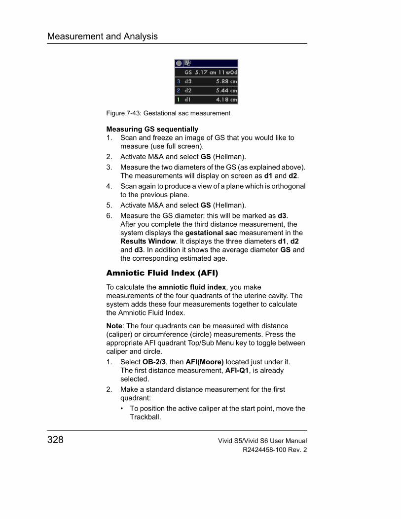
Measurement and Analysis
Figure 7-43: Gestational sac measurement
Measuring GS sequentially1. Scan and freeze an image of GS that you would like to
measure (use full screen).2. Activate M&A and select GS (Hellman).3. Measure the two diameters of the GS (as explained above).
The measurements will display on screen as d1 and d2.4. Scan again to produce a view of a plane which is orthogonal
to the previous plane.5. Activate M&A and select GS (Hellman).6. Measure the GS diameter; this will be marked as d3.
After you complete the third distance measurement, the system displays the gestational sac measurement in the Results Window. It displays the three diameters d1, d2 and d3. In addition it shows the average diameter GS and the corresponding estimated age.
Amniotic Fluid Index (AFI)
To calculate the amniotic fluid index, you make measurements of the four quadrants of the uterine cavity. The system adds these four measurements together to calculate the Amniotic Fluid Index.
Note: The four quadrants can be measured with distance (caliper) or circumference (circle) measurements. Press the appropriate AFI quadrant Top/Sub Menu key to toggle between caliper and circle.1. Select OB-2/3, then AFI(Moore) located just under it.
The first distance measurement, AFI-Q1, is already selected.
2. Make a standard distance measurement for the first quadrant:• To position the active caliper at the start point, move the
Trackball.
328 Vivid S5/Vivid S6 User ManualR2424458-100 Rev. 2
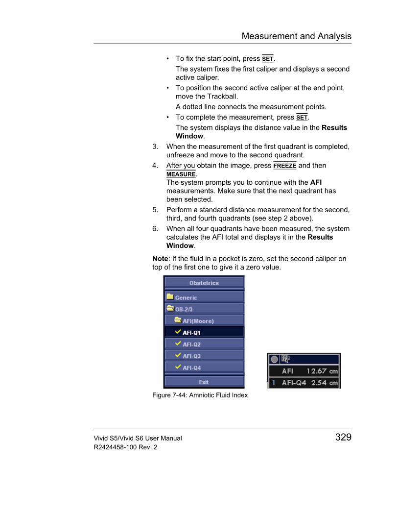
Measurement and Analysis
• To fix the start point, press SET.The system fixes the first caliper and displays a second active caliper.
• To position the second active caliper at the end point, move the Trackball.A dotted line connects the measurement points.
• To complete the measurement, press SET.The system displays the distance value in the Results Window.
3. When the measurement of the first quadrant is completed, unfreeze and move to the second quadrant.
4. After you obtain the image, press FREEZE and then MEASURE.The system prompts you to continue with the AFI measurements. Make sure that the next quadrant has been selected.
5. Perform a standard distance measurement for the second, third, and fourth quadrants (see step 2 above).
6. When all four quadrants have been measured, the system calculates the AFI total and displays it in the Results Window.
Note: If the fluid in a pocket is zero, set the second caliper on top of the first one to give it a zero value.
Figure 7-44: Amniotic Fluid Index
Vivid S5/Vivid S6 User Manual 329R2424458-100 Rev. 2
Measurement and Analysis
Estimated Fetal Weight (EFW)
To measure estimated fetal weight, you make several OB measurements. These measurements can vary, based on how your system is set up. Measurements can include biparietal diameter, fetal trunk area, femur length, antero-postero trunk diameter and transverse trunk diameter, abdominal circumference, head circumference and spinal length.• Activate the Worksheet.
The calculation for EFW will appear under 2D Calculations label as soon as the required measurements have been made.
Note: For a description of any of the required measurements, refer to that measurement.
M-Mode measurementsThere are no special tools for OB other than the general M-Mode measurement tools found under all applications.
Doppler Mode MeasurementsYou can use Doppler mode to study fetal blood flow in the heart, umbilical cord, placenta, and middle cerebral arteries. OB/GYN Doppler mode also allows you to study uterine and ovarian blood flow.
The OB/GYN vessel study includes the following vessels:• Aorta• Desc. Aorta• Middle Cerebral Artery (MCA) (right and left)• Ovarian (right and left)• Placenta• Umbilical• Uterine (right and left)
For each of these studies, you can make any of the following measurements:• Peak Systole (PS)• End Diastole (ED)• Minimum Diastole (MD)
330 Vivid S5/Vivid S6 User ManualR2424458-100 Rev. 2
Measurement and Analysis
• Resistive Index (RI)• PS/ED Ratio• ED/PS Ratio• Acceleration• AT• TAMAX• Pulsatility Index (PI)• Heart Rate• Volume Flow• TAMEAN• PV
Figure 7-45: Doppler Mode Measurements
To select OB/GYN vessel measurements
OB/GYN Vessel measurements use the auto sequence feature. With this feature, when you select a folder for the vessel you want to measure, the system automatically starts
Vivid S5/Vivid S6 User Manual 331R2424458-100 Rev. 2
Measurement and Analysis
the first measurement. It then continues with each of the other measurements in that study.1. Select the folder for the vessel you want to measure.
The system shows all the measurements for that vessel. The caliper for the first measurement is automatically displayed.
2. Make the measurement.After you complete each measurement, the system starts the next measurement. After the last measurement is complete, the system returns to the first measurement.
Your system is set up to show the measurements that you usually make for each vessel. To make a measurement that is not shown for the selected vessel:1. Select the folder for the vessel you want to measure.2. Select Show All.
The system displays all possible vessel measurements.3. Select the desired measurement.
Detailed explanations about making the different measurements and using the different tools are provided in the Doppler M&A section of the Vascular package (page 309).
The following pages describe the steps to make each specific measurement in the OB/GYN Vessel study.
332 Vivid S5/Vivid S6 User ManualR2424458-100 Rev. 2
Measurement and Analysis
OB parameter configuration
Configuring OB M&A according to geographical regionsDifferent countries use different sets of OB charts. The system supports OB charts from USA, Europe, Osaka, Tokyo, and ASUM.1. Press CONFIG.2. Select MEAS/TEXT.3. Select the Advanced tab.4. Set the M&A category to Obstetrics.5. Locate the parameter OB Type in the upper pane and click
on the region.A menu opens listing the region names.
Figure 7-46: Region name menu
USA
OB-1Folder contents
Vivid S5/Vivid S6 User Manual 333R2424458-100 Rev. 2
Measurement and Analysis
OB-2/3Folder contents
OB-GeneralFolder contents
Europe
OB-1Folder contents
334 Vivid S5/Vivid S6 User ManualR2424458-100 Rev. 2
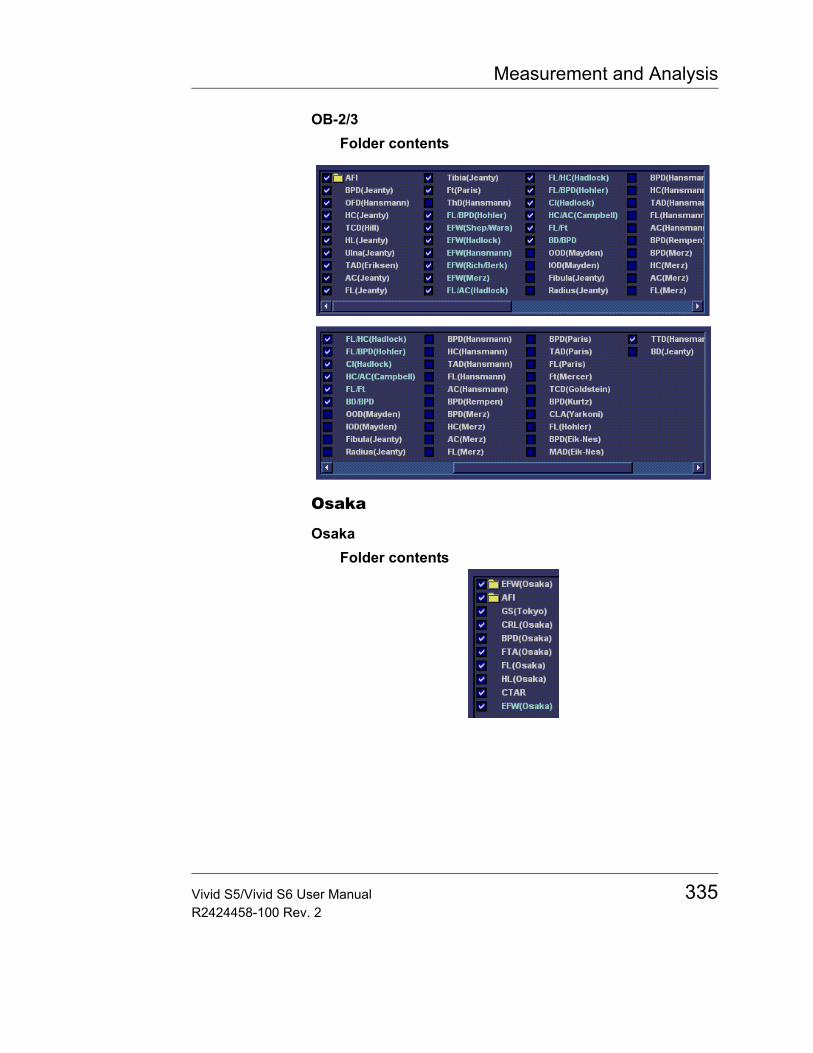
Measurement and Analysis
OB-2/3Folder contents
Osaka
OsakaFolder contents
Vivid S5/Vivid S6 User Manual 335R2424458-100 Rev. 2
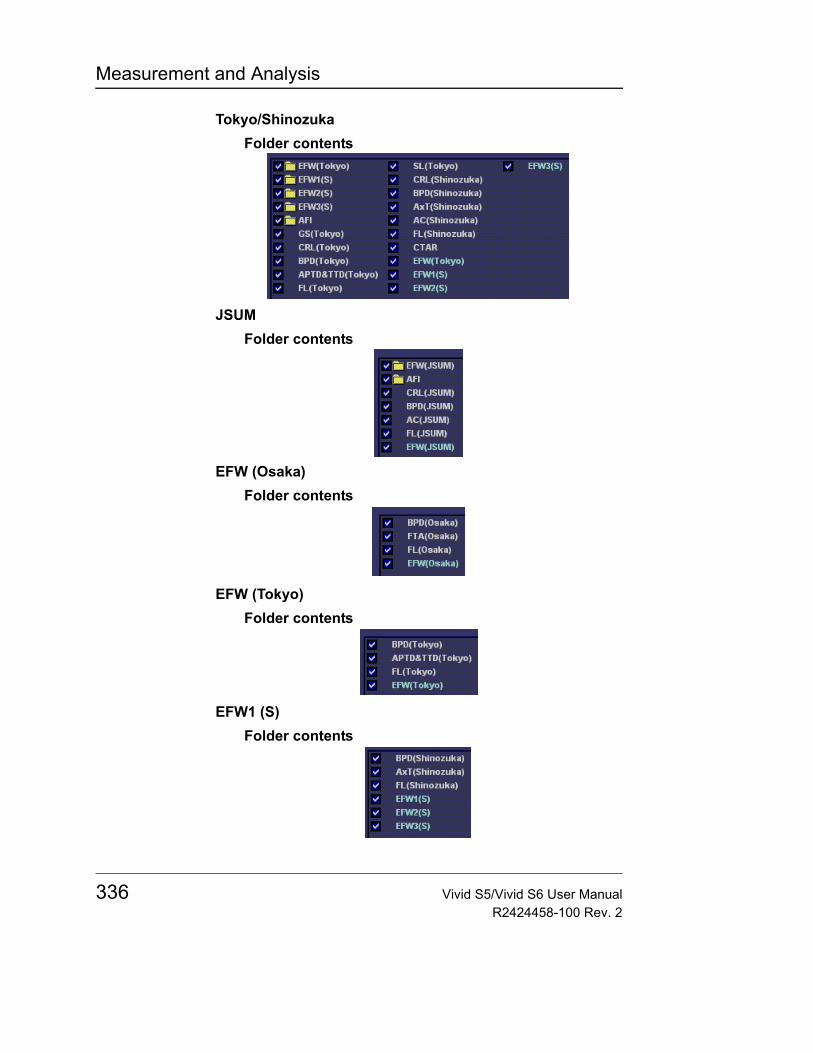
Measurement and Analysis
Tokyo/ShinozukaFolder contents
JSUMFolder contents
EFW (Osaka)Folder contents
EFW (Tokyo)Folder contents
EFW1 (S)Folder contents
336 Vivid S5/Vivid S6 User ManualR2424458-100 Rev. 2
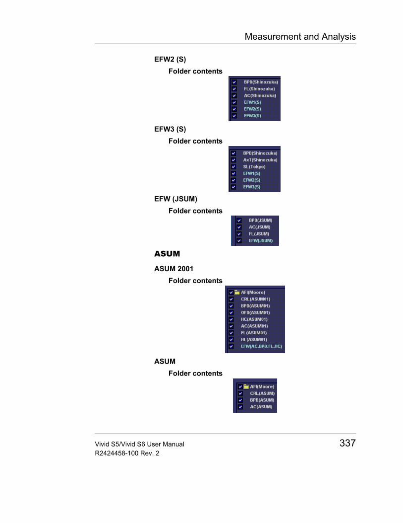
Measurement and Analysis
EFW2 (S)Folder contents
EFW3 (S)Folder contents
EFW (JSUM)Folder contents
ASUM
ASUM 2001Folder contents
ASUMFolder contents
Vivid S5/Vivid S6 User Manual 337R2424458-100 Rev. 2
Measurement and Analysis
Measurement package configurationA list of all cardiac calculations with needed measurements and location in the Measurement package can be found in the Reference manual.
There are many more measurements and parameters in the measurement package than shown in the default Measurement menu. Use the configuration system to set up the measurements that should be available in the Measurement menu and which parameters should be calculated.
The following example based on calculation of AV CO (Cardiac Output by Aortic Flow) describes how to configure the measurement package so that necessary measurements and the resulting calculations are displayed on screen.
Measurement package configuration - exampleCalculation of Cardiac Output by Aortic Flow requires measurement of:• AV diameter located in the folder Dimension (2D mode)• AV VTI located in the folder Aortic (Doppler AV Trace).• Heart rate
If a calculated parameter (e.g. AV CO in AV Trace measurement) requires another parameter to be calculated (e.g. AV Diam) the user must first measure the required parameter (e.g. AV Diam) before the dependent parameter (e.g. AV CO in AV Trace) gets calculated.
Configuration of the Measurement menu
If the AV diameter measurement is not present in the folder Dimension in the Measurement menu, follow the following procedure:1. Press CONFIG and select the category Meas/Text.
The Measurement menu sheet is displayed (see Figure 7-47).
2. AV Diam is a 2D measurement, make sure that 2D is checked in the Measurement sheet.
3. Select folder Dimension in the Measurement menu.
338 Vivid S5/Vivid S6 User ManualR2424458-100 Rev. 2
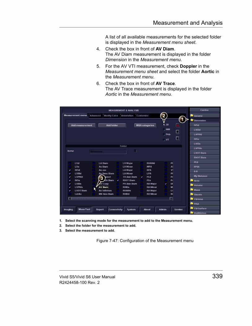
Measurement and Analysis
A list of all available measurements for the selected folder is displayed in the Measurement menu sheet.
4. Check the box in front of AV Diam.The AV Diam measurement is displayed in the folder Dimension in the Measurement menu.
5. For the AV VTI measurement, check Doppler in the Measurement menu sheet and select the folder Aortic in the Measurement menu.
6. Check the box in front of AV Trace.The AV Trace measurement is displayed in the folder Aortic in the Measurement menu.
Figure 7-47: Configuration of the Measurement menu
1. Select the scanning mode for the measurement to add to the Measurement menu.2. Select the folder for the measurement to add.3. Select the measurement to add.
Vivid S5/Vivid S6 User Manual 339R2424458-100 Rev. 2
Measurement and Analysis
Configuration of the Measurement result table
If AV CO calculation is not displayed in the Measurement result table, follow the following procedure:1. Press CONFIG and select the category Meas/Text.
The Measurement menu sheet is displayed.2. The AV CO calculation is based on Doppler AV Trace
measurement in the folder Aortic, check Doppler in the Measurement menu sheet and select the folder Aortic.A list of all available measurements and calculations for the selected folder is displayed in the Measurement menu sheet.Note: Entries in green are calculated measurements.
3. In the Measurement menu sheet, double-click on the AV Trace measurement.A list of all available measurements and calculations for the AV Trace measurement is displayed in the Measurement menu sheet.
4. Check the box in front of AV CO.The AV CO calculation will be displayed in the Measurement result table.
Normal values
Normal values can be defined by the user for all parameters. A Normal value can be either a range or a threshold. Normal values entered are grouped by measurement category (e.g. Cardiac, Pediatry etc.)
Normal values are displayed in the report.
340 Vivid S5/Vivid S6 User ManualR2424458-100 Rev. 2
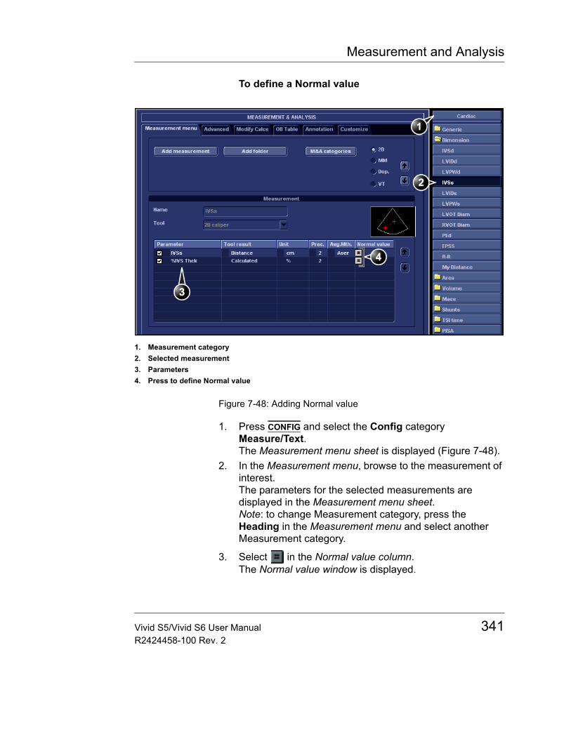
Measurement and Analysis
To define a Normal value
Figure 7-48: Adding Normal value
1. Press CONFIG and select the Config category Measure/Text.The Measurement menu sheet is displayed (Figure 7-48).
2. In the Measurement menu, browse to the measurement of interest.The parameters for the selected measurements are displayed in the Measurement menu sheet.Note: to change Measurement category, press the Heading in the Measurement menu and select another Measurement category.
3. Select in the Normal value column.The Normal value window is displayed.
1. Measurement category2. Selected measurement3. Parameters4. Press to define Normal value
Vivid S5/Vivid S6 User Manual 341R2424458-100 Rev. 2
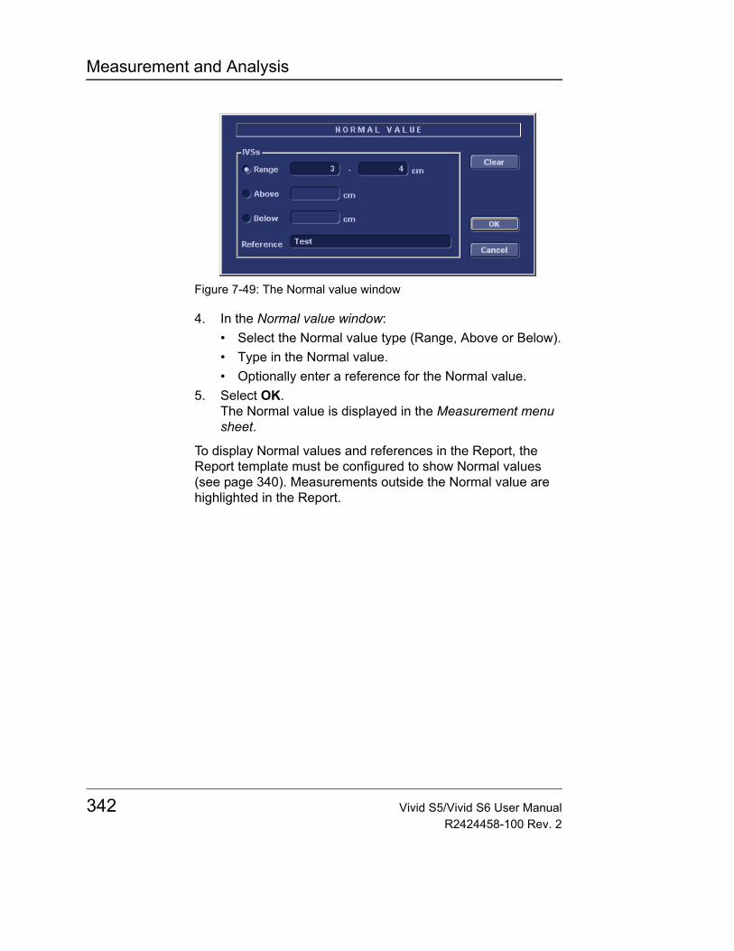
Measurement and Analysis
Figure 7-49: The Normal value window
4. In the Normal value window:• Select the Normal value type (Range, Above or Below).• Type in the Normal value.• Optionally enter a reference for the Normal value.
5. Select OK.The Normal value is displayed in the Measurement menu sheet.
To display Normal values and references in the Report, the Report template must be configured to show Normal values (see page 340). Measurements outside the Normal value are highlighted in the Report.
342 Vivid S5/Vivid S6 User ManualR2424458-100 Rev. 2
Measurement and Analysis
User-defined formulasUser-defined formulas can be created using existing measurements or by defining new measurements. The following example describes the creation of a formula based on existing measurements.
User-defined formula - exampleThe workflow for user-defined formula is:• If the user-defined formula is based on several
measurements of different types, create a user-defined folder in the Measurement menu so that all measurements and the formula are grouped together. If the formula is based on a single measurement you may select an existing appropriate folder.
• Add the measurement(s) needed for the formula to the user-defined (or existing) folder.
• Create the formula based on the added measurements.
The following procedure describes the creation of user-defined LIMP formula as follow: My LIMP = (MCO-AVET)/AVET.
CAUTION
GE Medical Systems does not take any responsibility for the correctness of the user-defined functions.
Vivid S5/Vivid S6 User Manual 343R2424458-100 Rev. 2
Measurement and Analysis
Creation of a user-defined folder
Figure 7-50: The Measurement menu sheet
1. Press CONFIG and select the category Meas/Text.2. MCO and AVET are Doppler measurements, select
Doppler in the Measurement menu sheet.3. Select Add folder.4. Give the folder a name (e.g. “My Folder”).
Adding measurements
Figure 7-51: The Measurement menu sheet
1. Select the user-defined folder (e.g. “My Folder”) in the
1. Select the appropriate scanning mode.2. Create a folder in the Measurement menu.
1. Select the user-defined folder.2. Press Add measurement.
344 Vivid S5/Vivid S6 User ManualR2424458-100 Rev. 2
Measurement and Analysis
Measurement menu.2. Press Add Measurement in the Measurement menu
sheet.The Add measure window is displayed.
Figure 7-52: The Add measure window
3. MCO and AVET are measurements that already exist on the system, check Use copy of and select MCO from the drop down menu.
4. Select OK to add the MCO measurement.5. Repeat steps 2 to 4 to add the AVET measurement.
Creation of the formula
Figure 7-53: The Measurement menu sheet
1. Select the last measurement.2. Double click and enter the formula name.3. Select “=” to create the formula.
Vivid S5/Vivid S6 User Manual 345R2424458-100 Rev. 2
Measurement and Analysis
The formula for this example is as follow: My LIMP = (MCO-AVET)/AVET1. In the user-defined folder (e.g. ”My folder”), select the last
measurement created (e.g. AVET).2. Double-click (Name) in the last line in the Parameter list in
the Measurement menu sheet.3. Enter the name for the formula (e.g. My LIMP).
4. Select .The Edit formula window is displayed.
Figure 7-54: The Edit formula window
5. Select “(“ from the Operators drop-down menu.6. In the Doppler drop-down list, select
MCO [My Folder, MCO].Make sure to select the measurement located in the user defined folder (e.g. “My Folder”).
7. Select “-“ from the Operators drop-down menu.8. In the Doppler drop-down list, select
AVET [My Folder, AVET].9. Select “)“ from the Operators drop-down menu.10. Select “/“ from the Operators drop-down menu.11. In the Doppler drop-down list, select
AVET [My Folder, AVET].The Formula line should display: ({MCO}-{AVET})/{AVET}.No units are necessary since the formula is a ratio (see also "About units" on page 349).
12. Press Check to make sure that the syntax for the formula is correct.
346 Vivid S5/Vivid S6 User ManualR2424458-100 Rev. 2
Measurement and Analysis
User-defined measurements
Some user-defined formula may require measurements that do not exist on the system. The following example based on a generic distance measurement illustrates how to create user-defined measurements.
Figure 7-55: The Measurement menu sheet
1. Press CONFIG and select the category Meas/Text.2. In the Measurement menu sheet, select the appropriate
scanning mode for the measurement to be created (e.g. 2D).
3. Select the appropriate folder in the Measurement menu (e.g. Dimension).
4. Press Add Measurement in the Measurement menu sheet.The Add measure window is displayed.
Figure 7-56: The Add measure window
1. Select the appropriate scanning mode.2. Select the appropriate folder.3. Press Add measurement.
Vivid S5/Vivid S6 User Manual 347R2424458-100 Rev. 2
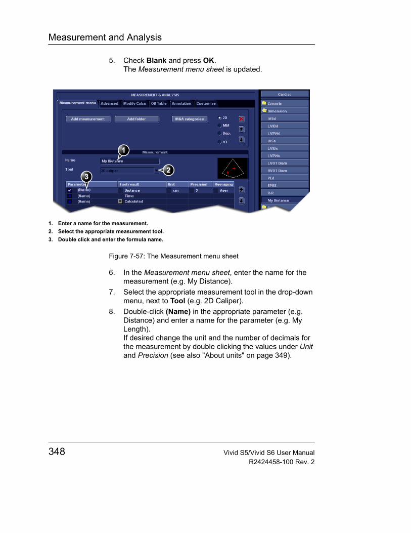
Measurement and Analysis
5. Check Blank and press OK.The Measurement menu sheet is updated.
Figure 7-57: The Measurement menu sheet
6. In the Measurement menu sheet, enter the name for the measurement (e.g. My Distance).
7. Select the appropriate measurement tool in the drop-down menu, next to Tool (e.g. 2D Caliper).
8. Double-click (Name) in the appropriate parameter (e.g. Distance) and enter a name for the parameter (e.g. My Length).If desired change the unit and the number of decimals for the measurement by double clicking the values under Unit and Precision (see also "About units" on page 349).
1. Enter a name for the measurement.2. Select the appropriate measurement tool.3. Double click and enter the formula name.
348 Vivid S5/Vivid S6 User ManualR2424458-100 Rev. 2
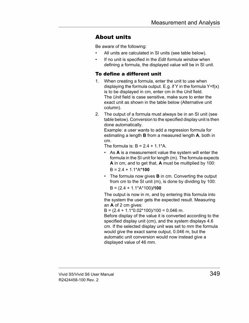
Measurement and Analysis
About unitsBe aware of the following:• All units are calculated in SI units (see table below).• If no unit is specified in the Edit formula window when
defining a formula, the displayed value will be in SI unit.
To define a different unit1. When creating a formula, enter the unit to use when
displaying the formula output. E.g. if Y in the formula Y=f(x) is to be displayed in cm, enter cm in the Unit field.The Unit field is case sensitive, make sure to enter the exact unit as shown in the table below (Alternative unit column).
2. The output of a formula must always be in an SI unit (see table below). Conversion to the specified display unit is then done automatically.Example: a user wants to add a regression formula for estimating a length B from a measured length A, both in cm.The formula is: B = 2.4 + 1.1*A.• As A is a measurement value the system will enter the
formula in the SI unit for length (m). The formula expects A in cm, and to get that, A must be multiplied by 100:B = 2.4 + 1.1*A*100
• The formula now gives B in cm. Converting the output from cm to the SI unit (m), is done by dividing by 100:B = (2.4 + 1.1*A*100)/100
The output is now in m, and by entering this formula into the system the user gets the expected result. Measuring an A of 2 cm gives:B = (2.4 + 1.1*0.02*100)/100 = 0.046 m.Before display of the value it is converted according to the specified display unit (cm), and the system displays 4.6 cm. If the selected display unit was set to mm the formula would give the exact same output, 0.046 m, but the automatic unit conversion would now instead give a displayed value of 46 mm.
Vivid S5/Vivid S6 User Manual 349R2424458-100 Rev. 2
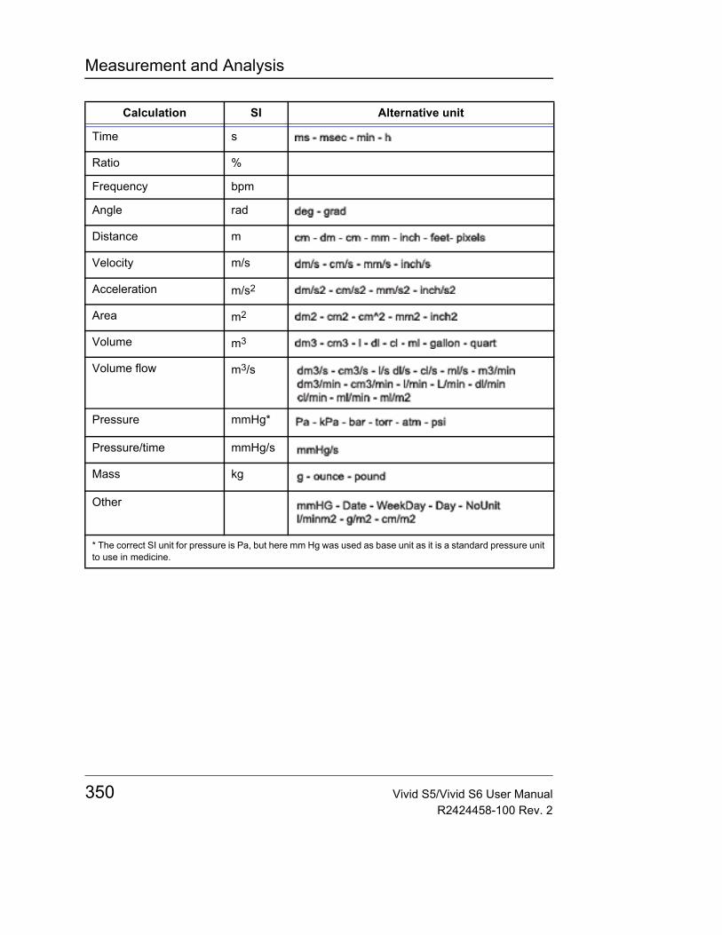
Measurement and Analysis
Calculation SI Alternative unit
Time s
Ratio %
Frequency bpm
Angle rad
Distance m
Velocity m/s
Acceleration m/s2
Area m2
Volume m3
Volume flow m3/s
Pressure mmHg*
Pressure/time mmHg/s
Mass kg
Other
* The correct SI unit for pressure is Pa, but here mm Hg was used as base unit as it is a standard pressure unit to use in medicine.
350 Vivid S5/Vivid S6 User ManualR2424458-100 Rev. 2

Measurement and Analysis
Measurement result tableThe display of the Measurement result table can be minimized and moved to prevent the table obscuring parts of the ultrasound image.
Minimizing the Measurement result table
1. Trackball to the symbol on the heading of the Measurement result table (see Figure 7-58).
2. Press SET.Repeat step 1 to en-large the Measure-ment result table.
The Measurement result table is minimized to the heading bar.
Moving the Measurement result tableAlternative: Use the Move Calc Win softkey located under More to move the Measure-ment result table from corner to cor-ner on the Acquisi-tion window.
1. Trackball to the symbol on the heading of the Measurement result table (see Figure 7-58).
2. Press SET to grab the table.3. Trackball the Measurement result table to a new position.4. Press SET to anchor the table.
Figure 7-58: Measurement result table display tools
1. Minimize/maximize table2. Move table
Vivid S5/Vivid S6 User Manual 351R2424458-100 Rev. 2

Measurement and Analysis
Deleting measurements1. Trackball to the measurement to delete in the
Measurement result table and press SET.A menu is displayed.
2. Select Delete Measurement.
352 Vivid S5/Vivid S6 User ManualR2424458-100 Rev. 2
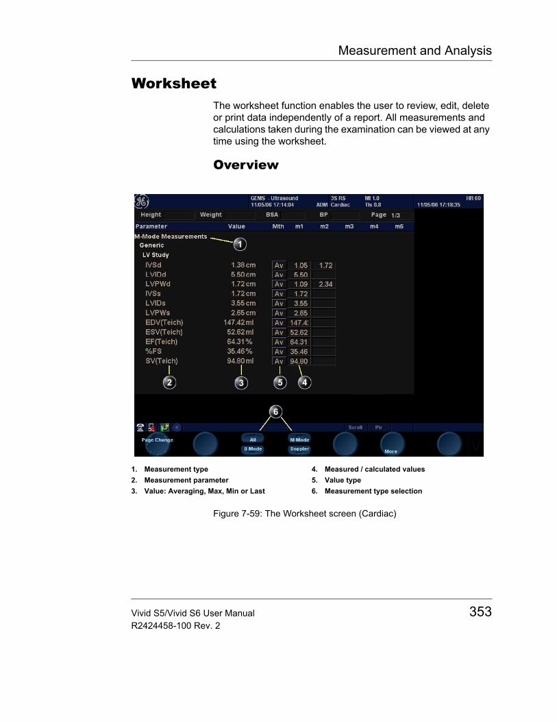
Measurement and Analysis
WorksheetThe worksheet function enables the user to review, edit, delete or print data independently of a report. All measurements and calculations taken during the examination can be viewed at any time using the worksheet.
Overview
Figure 7-59: The Worksheet screen (Cardiac)
1. Measurement type2. Measurement parameter 3. Value: Averaging, Max, Min or Last
4. Measured / calculated values5. Value type6. Measurement type selection
Vivid S5/Vivid S6 User Manual 353R2424458-100 Rev. 2
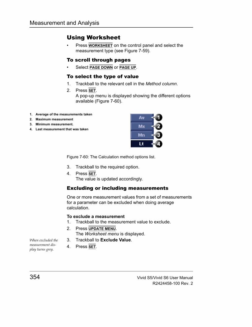
Measurement and Analysis
Using Worksheet• Press WORKSHEET on the control panel and select the
measurement type (see Figure 7-59).
To scroll through pages• Select PAGE DOWN or PAGE UP.
To select the type of value1. Trackball to the relevant cell in the Method column.2. Press SET.
A pop-up menu is displayed showing the different options available (Figure 7-60).
Figure 7-60: The Calculation method options list.
3. Trackball to the required option.4. Press SET.
The value is updated accordingly.
Excluding or including measurements
One or more measurement values from a set of measurements for a parameter can be excluded when doing average calculation.
To exclude a measurement1. Trackball to the measurement value to exclude.2. Press UPDATE MENU.
The Worksheet menu is displayed.When excluded the measurement dis-play turns grey.
3. Trackball to Exclude Value.4. Press SET.
1. Average of the measurements taken2. Maximum measurement3. Minimum measurement.4. Last measurement that was taken
354 Vivid S5/Vivid S6 User ManualR2424458-100 Rev. 2
Measurement and Analysis
To include a measurement1. Trackball to the measurement value to include.2. Press UPDATE MENU.
The Worksheet menu is displayed.3. Trackball to Include Value.4. Press SET.
Manually changing a value
Individual measured values can be manually changed using the alphanumeric keyboard.
To manually change a value1. Trackball to the value that is to be changed.2. Press SET.
An asterisk indi-cates that the value has been manually altered. The calcula-tion type is changed to Edit.
3. Use the alphanumeric keyboard to enter the required value.
To restore automatic calculation1. Trackball to the relevant cell in the Method column.2. Press SET.
A pop-up menu is displayed showing the different calculation options available (Figure 7-60).
3. Press SET.The value is re-calculated according the method selected.
Deleting measurement parameter1. Trackball to the measurement parameter to delete.2. Press UPDATE MENU.
The Worksheet menu is displayed.3. Trackball to Delete Value.4. Press SET.
Vivid S5/Vivid S6 User Manual 355R2424458-100 Rev. 2
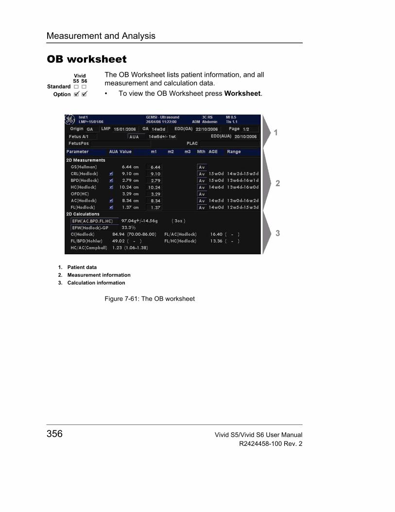
Measurement and Analysis
OB worksheetThe OB Worksheet lists patient information, and all measurement and calculation data.• To view the OB Worksheet press Worksheet.
Figure 7-61: The OB worksheet
1. Patient data2. Measurement information3. Calculation information
356 Vivid S5/Vivid S6 User ManualR2424458-100 Rev. 2
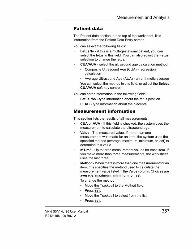
Measurement and Analysis
Patient dataThe Patient data section, at the top of the worksheet, lists information from the Patient Data Entry screen.
You can select the following fields:• FetusNo - if this is a multi-gestational patient, you can
select the fetus in this field. You can also adjust the Fetus selection to change the fetus.
• CUA/AUA - select the ultrasound age calculation method:• Composite Ultrasound Age (CUA) - regression
calculation• Average Ultrasound Age (AUA) - an arithmetic averageYou can select the method in this field, or adjust the Select CUA/AUA soft-key control.
You can enter information in the following fields:• FetusPos - type information about the fetus position.• PLAC - type information about the placenta.
Measurement informationThis section lists the results of all measurements.• CUA or AUA - If this field is checked, the system uses the
measurement to calculate the ultrasound age.• Value - The measured value. If more than one
measurement was made for an item, the system uses the specified method (average, maximum, minimum, or last) to determine this value.
• m1-m3 - Up to three measurement values for each item. If you make more than three measurements, the worksheet uses the last three.
• Method - When there is more than one measurement for an item, this specifies the method used to calculate the measurement value listed in the Value column. Choices are average, maximum, minimum, or last.To change the method:• Move the Trackball to the Method field.• Press SET.• Move the Trackball to select from the list.• Press SET.
Vivid S5/Vivid S6 User Manual 357R2424458-100 Rev. 2
Measurement and Analysis
• AGE - The fetal age for this measurement.• Range - The typical range of fetal age for this
measurement.
Calculation informationThis section of the worksheet provides calculation choices and lists calculation results.• EFW - lists the parameters used to calculate EFW. This is
followed by the calculation result.To change which parameters are used:• Select this field, or press Select EFW.• Select the desired parameters.
• EFW GP - lists the source used to calculate EFW-GP (growth percentile). This is followed by the growth percentile.To change the source:• Select this field, or press Select GP.• Select the desired source.
The remaining calculation information shows ratios for several measurements, and the Cephalic Index (CI).
The worksheet shows if any of the ratios are out of range (OOR). Out of range indicates one of the following:• The measurement is out of the normal range based on the
gestational age that is calculated from the LMP. The system determines OOR from the ultrasound age compared to the gestational age. The gestational age is calculated from the last menstrual period or the estimated delivery date.
• The measurement is outside of the range for the data used in the calculation. That means that the measurement is either less than or more than the range of measurements used to determine fetal age based on the measurement.
For more information about how to use the worksheet, see "Worksheet" on page 353.
358 Vivid S5/Vivid S6 User ManualR2424458-100 Rev. 2

Measurement and Analysis
OB graphsOverviewOB Graphs allow you to assess fetal growth compared to a normal growth curve. When a patient has completed two or more ultrasound exams, you can also use the graphs to look at fetal trending. For multi-gestational patients you can plot all fetuses and compare the growth on the graphs.
Vivid S5/Vivid S6 provides the following two basic types of graphs:• Fetal Growth Curve graphs - show one measurement per
graph. These graphs show the normal growth curve, positive and negative standard deviations or applicable percentiles, and ultrasound age of the fetus using the current measurement. For multi-gestational pregnancies, you can show curves for all fetuses. If previous exam data is available, the graph can show fetal trending.
• Fetal Growth Bar graph - shows the ultrasound age and the gestational age based on patient data. Plots all measurements on one graph.
To view OB graphs1. Press Worksheet.2. Press the Graph soft-key button
The Fetal growth curve graph is displayed (see Figure 7-62).
Vivid S5/Vivid S6 User Manual 359R2424458-100 Rev. 2
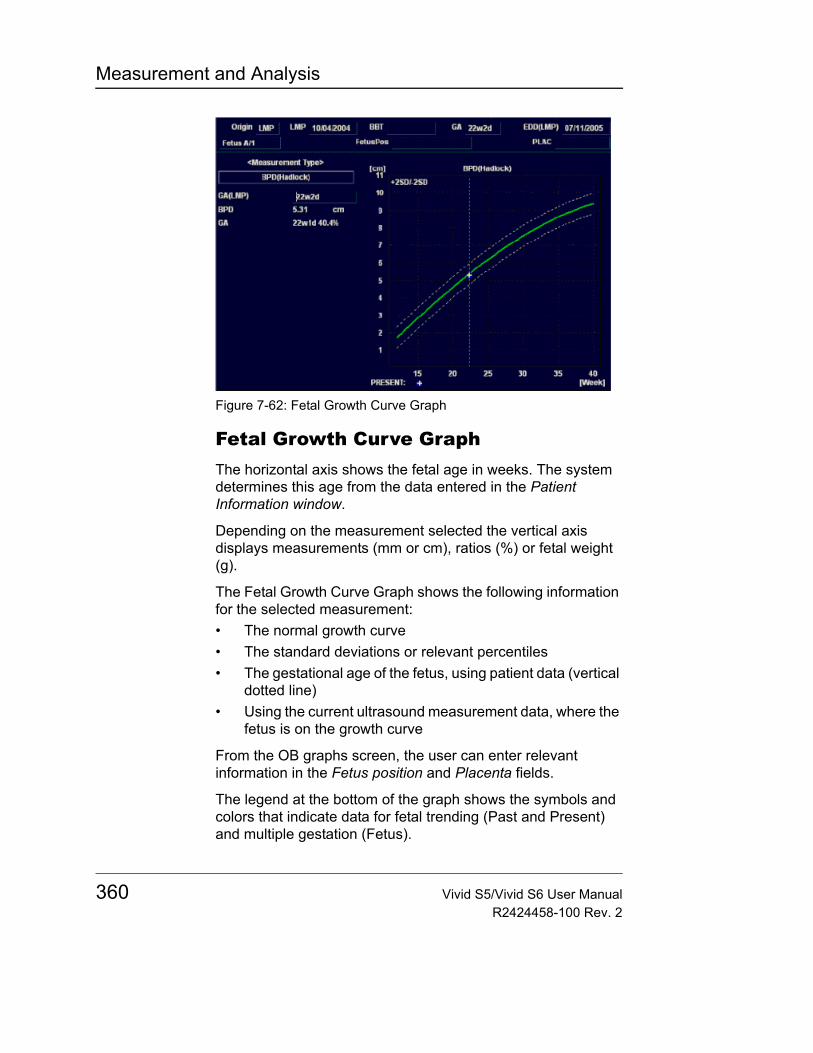
Measurement and Analysis
Figure 7-62: Fetal Growth Curve Graph
Fetal Growth Curve GraphThe horizontal axis shows the fetal age in weeks. The system determines this age from the data entered in the Patient Information window.
Depending on the measurement selected the vertical axis displays measurements (mm or cm), ratios (%) or fetal weight (g).
The Fetal Growth Curve Graph shows the following information for the selected measurement:• The normal growth curve• The standard deviations or relevant percentiles• The gestational age of the fetus, using patient data (vertical
dotted line)• Using the current ultrasound measurement data, where the
fetus is on the growth curve
From the OB graphs screen, the user can enter relevant information in the Fetus position and Placenta fields.
The legend at the bottom of the graph shows the symbols and colors that indicate data for fetal trending (Past and Present) and multiple gestation (Fetus).
360 Vivid S5/Vivid S6 User ManualR2424458-100 Rev. 2
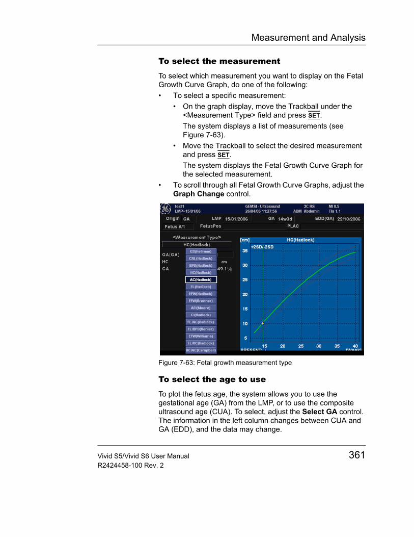
Measurement and Analysis
To select the measurement
To select which measurement you want to display on the Fetal Growth Curve Graph, do one of the following:• To select a specific measurement:
• On the graph display, move the Trackball under the <Measurement Type> field and press SET.The system displays a list of measurements (see Figure 7-63).
• Move the Trackball to select the desired measurement and press SET.The system displays the Fetal Growth Curve Graph for the selected measurement.
• To scroll through all Fetal Growth Curve Graphs, adjust the Graph Change control.
Figure 7-63: Fetal growth measurement type
To select the age to use
To plot the fetus age, the system allows you to use the gestational age (GA) from the LMP, or to use the composite ultrasound age (CUA). To select, adjust the Select GA control. The information in the left column changes between CUA and GA (EDD), and the data may change.
Vivid S5/Vivid S6 User Manual 361R2424458-100 Rev. 2
Measurement and Analysis
When selected, the gestational age may be changed by the user.1. Select the GA (LMP) value.
An editing window is displayed.2. Enter a new value and select OK.
The GA (LMP) label is changed to GA (GA) showing the new value entered. This information is also updated in the Patient information window. In addition the EDD (LMP) is updated to EDD (GA) with new calculated value.
To view a single or four graphs
You can view either a single Fetal Growth Curve Graph or you can view four graphs at the same time. To select each view, press Single or Quad on softkey button.
Figure 7-64: Fetal Growth Curve Graph: Quad View
The measurement values are displayed at the bottom of the graph.
362 Vivid S5/Vivid S6 User ManualR2424458-100 Rev. 2
Measurement and Analysis
To change measurements in quad view
When you view four graphs simultaneously, you can select which four you want to see. To change each graph in quad view:1. On the graph display, use the Trackball to move the cursor
to the small box that is upper left of each graph, then press SET.The system displays a list of measurements.
2. Move the Trackball to select the desired measurement and press SET.The system displays the Fetal Growth Curve Graph for the selected measurement.
To scroll through all Fetal Growth Curve Graphs, adjust the Graph Change control.
Figure 7-65: Changing a chart in quad view
To edit patient data
When you are working with graphs, you can change or enter the following patient data.• GA (LMP) - this field is computed using the LMP date on
the Patient Data Entry screen. To change this field:Note: You can only change this field on the Fetal Growth Curve Graph in single view.• Move the Trackball to the field, which is left of the graph.
To select the field press SET.The system displays a window with the GA weeks and days.
• To select each field, move the Trackball to the field and press SET.
Vivid S5/Vivid S6 User Manual 363R2424458-100 Rev. 2
Measurement and Analysis
• Type the correct weeks or days.• Select OK.
The system makes the following changes:• GA (LMP) is now GA (GA) and shows the age you entered.• In the Patient Data section, the GA changes.• In the Patient Data section, the EDD (LMP) changes to
EDD (GA) and shows an updated date, using the GA you entered. In addition, the LMP is erased.
• FetusPos - type information about the fetus position.• PLAC - type information about the placenta.
Note: To return from a graph to the scan display press Worksheet or Freeze.
Fetal TrendingWhen you have ultrasound data for more than one exam for a patient, you can use the data to look at fetal trending on the Fetal growth curve graphs. Fetal trending requires that a LMP value is entered in the Patient information screen.1. Press Worksheet.2. Press Graphs and select the desired measurement to
display.3. Press More and then Plot Both.
The system automatically finds the data from previous ultrasound exams, and displays it on the graph with the present data.
Figure 7-66: Fetal Trending
364 Vivid S5/Vivid S6 User ManualR2424458-100 Rev. 2
Measurement and Analysis
Fetal Growth Bar GraphThe fetal growth bar graph shows current exam measurements and the normal growth range based on the gestational age. It shows all measurements on one graph.
To view the Fetal Growth Bar Graph:1. Press Worksheet.2. Select Graph.3. Select Bar.
Figure 7-67: Fetal Growth Bar Graph
Graph description:• The horizontal axis shows the gestational weeks.• The red vertical line shows the gestational age using the
patient data.• The blue dotted vertical line shows the ultrasound age
using the current measurements.• The yellow x shows the ultrasound age for each
measurement.• The green rectangle shows the normal age range for the
measurement.
You cannot do fetal trending or view multiple gestation data on the bar graph.
Note: To return to the graphs, press the Worksheet and the Graph soft-key; or press the "More" and the Graph soft-key.
Vivid S5/Vivid S6 User Manual 365R2424458-100 Rev. 2
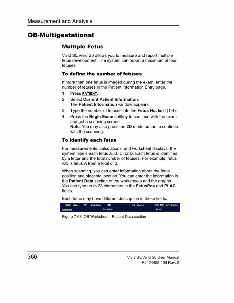
Measurement and Analysis
OB-Multigestational
Multiple FetusVivid S5/Vivid S6 allows you to measure and report multiple fetus development. The system can report a maximum of four fetuses.
To define the number of fetuses
If more than one fetus is imaged during the exam, enter the number of fetuses in the Patient Information Entry page.1. Press PATIENT.2. Select Current Patient Information.
The Patient Information window appears.3. Type the number of fetuses into the Fetus No. field (1-4).4. Press the Begin Exam softkey to continue with the exam
and get a scanning screen.Note: You may also press the 2D mode button to continue with the scanning.
To identify each fetus
For measurements, calculations, and worksheet displays, the system labels each fetus A, B, C, or D. Each fetus is identified by a letter and the total number of fetuses. For example, fetus A/3 is fetus A from a total of 3.
When scanning, you can enter information about the fetus position and placenta location. You can enter the information in the Patient Data section of the worksheets and the graphs. You can type up to 23 characters in the FetusPos and PLAC fields.
Each fetus may have different description in these fields.
Figure 7-68: OB Worksheet - Patient Data section
366 Vivid S5/Vivid S6 User ManualR2424458-100 Rev. 2
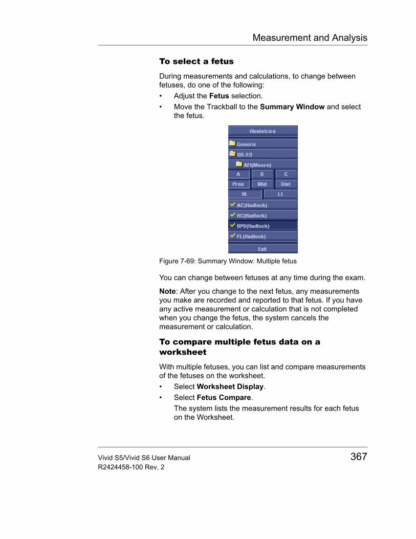
Measurement and Analysis
To select a fetus
During measurements and calculations, to change between fetuses, do one of the following:• Adjust the Fetus selection.• Move the Trackball to the Summary Window and select
the fetus.
Figure 7-69: Summary Window: Multiple fetus
You can change between fetuses at any time during the exam.
Note: After you change to the next fetus, any measurements you make are recorded and reported to that fetus. If you have any active measurement or calculation that is not completed when you change the fetus, the system cancels the measurement or calculation.
To compare multiple fetus data on a worksheet
With multiple fetuses, you can list and compare measurements of the fetuses on the worksheet.• Select Worksheet Display.• Select Fetus Compare.
The system lists the measurement results for each fetus on the Worksheet.
Vivid S5/Vivid S6 User Manual 367R2424458-100 Rev. 2
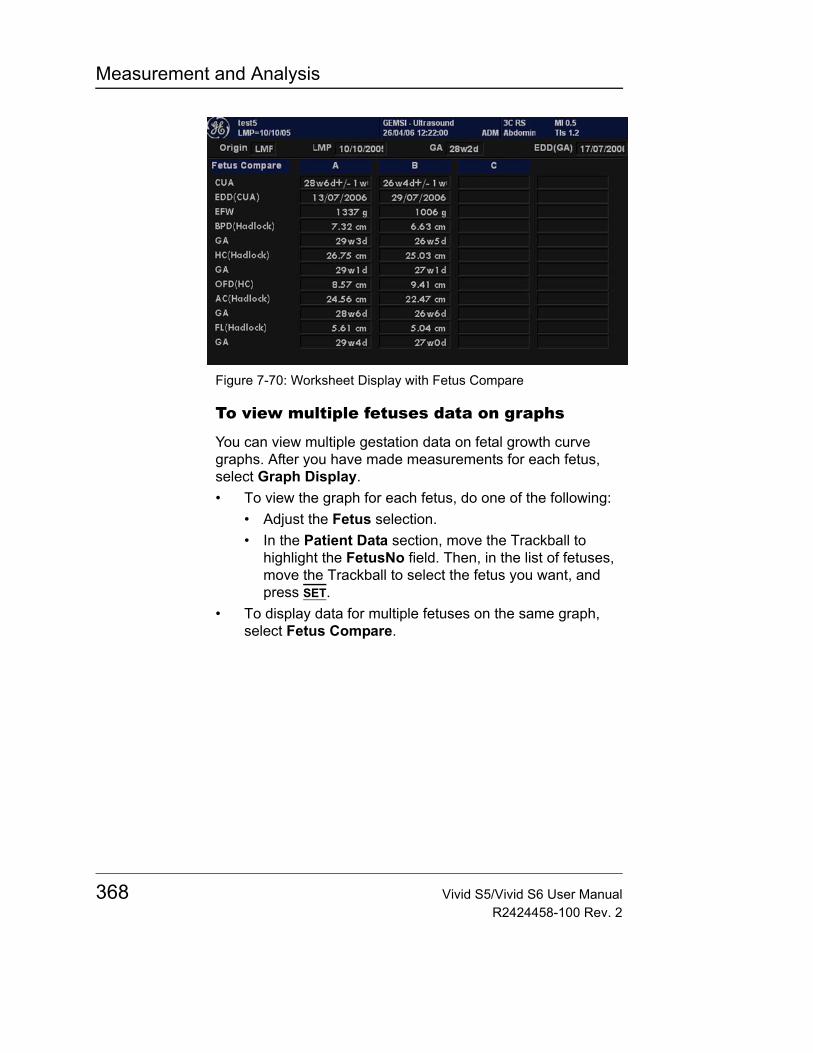
Measurement and Analysis
Figure 7-70: Worksheet Display with Fetus Compare
To view multiple fetuses data on graphs
You can view multiple gestation data on fetal growth curve graphs. After you have made measurements for each fetus, select Graph Display.• To view the graph for each fetus, do one of the following:
• Adjust the Fetus selection.• In the Patient Data section, move the Trackball to
highlight the FetusNo field. Then, in the list of fetuses, move the Trackball to select the fetus you want, and press SET.
• To display data for multiple fetuses on the same graph, select Fetus Compare.
368 Vivid S5/Vivid S6 User ManualR2424458-100 Rev. 2
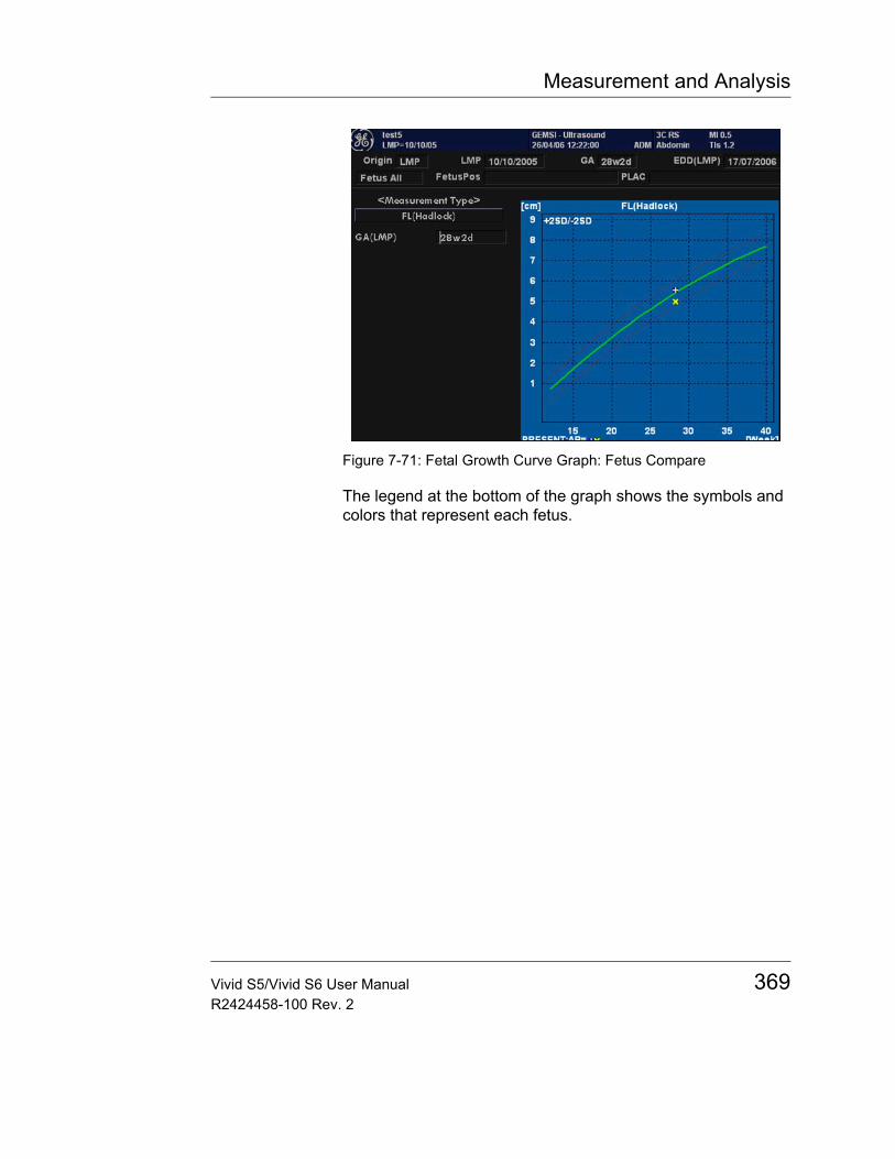
Measurement and Analysis
Figure 7-71: Fetal Growth Curve Graph: Fetus Compare
The legend at the bottom of the graph shows the symbols and colors that represent each fetus.
Vivid S5/Vivid S6 User Manual 369R2424458-100 Rev. 2
Measurement and Analysis
GYN MeasurementsIntroductionThe Gynecology exam category includes the following three studies:• Generic: This study is common to all exam categories, and
is part of the Measure and Assign Modality. See "Starting the Measure and Assign modality" on page 251 for more information.
• General Gynecology: This study includes uterine, ovarian, ovarian follicle, and endometrium measurements.
• OB/GYN Vessel: This study includes the following vessels: uterine, ovarian, umbilical, middle cerebral artery, aorta, placenta, and descending aorta.
Note: The calculation formulas are listed in the Advanced Reference Manual.
To Start a Gynecology ExamTo begin a gynecology exam, you enter patient data or, if the patient data from a previous exam is saved in the system, find the patient information.
For details about how to start an exam, see "Performing an OB exam" on page 317.
After you complete the patient information, you can begin the scan.1. To change from the Patient Data Entry screen to the Scan
screen, do one of the following:• On the keyboard, press Esc.• On the Control Panel, select PATIENT or FREEZE.• On the Control Panel, press the B-MODE key.The system displays the Scan screen.
2. On the Control Panel, press MEASURE.
The default Gynecology study is displayed on the Top/Sub Menu.
370 Vivid S5/Vivid S6 User ManualR2424458-100 Rev. 2
Measurement and Analysis
B-Mode MeasurementsIn B-Mode, you make the measurements in the General Gynecology study. These measurements include:• Uterine length, width, and height• Ovarian length, width, and height• Ovarian follicle• Endometrium thickness
Uterus length, width, and heightEach of these is a standard distance measurement. Typically, length and height are measured on the saggital plane while the width is measured on the axial/transverse plane.
To measure uterus length, width, or height:1. Scan the patient in the appropriate scan plane.2. Select the UV folder, then select UV L, UV H, or UV W.
An active caliper displays.3. Perform a standard distance measurement:
• To position the active caliper at the start point, move the Trackball.
• To fix the start point, press SET.The system fixes the first caliper and displays a second active caliper.
• To position the second active caliper at the end point, move the Trackball.A dotted line connects the measurement points.
• To complete the measurement, press SET.The system displays the distance value in the Results window. After the first and second measurement, the system displays an active caliper for the next measurement.
4. To make the second and third distance measurement, repeat steps 2-3 above.After you complete the third distance measurement, the system displays the Ut-Vol (uterine volume) in the Results Window, together with the three dimensions: Ut-L, Ut-H, Ut-W.
Vivid S5/Vivid S6 User Manual 371R2424458-100 Rev. 2

Measurement and Analysis
Ovary length, width, and heightYou can measure the length, width, and height of the left and right ovaries. Each measurement is a typical distance measurement made in the appropriate scan plane.
Typically, length and height are measured on the saggital plane while the width is measured on the axial/transverse plane.
To measure ovarian length, width, or height:1. Scan the patient's right or left ovary in the appropriate
plane.2. Select the OV folder, then select left or right side.3. Select length, width or height: OV L, OV W, or OV H.4. Perform a standard distance measurement:
• To position the active caliper at the start point, move the Trackball.
• To fix the start point, press SET.The system fixes the first caliper and displays a second active caliper.
• To position the second active caliper at the end point, move the Trackball.A dotted line connects the measurement points.
• To complete the measurement, press SET.The system displays the distance value in the Results window. After the first and second measurement, the system displays an active caliper for the next measurement.
5. To make the second and third distance measurements, repeat steps 3-4 above.
After you complete the length, width, and height measurements, the system displays the ovarian volume in the Results window. The results are:• Right side: Rt Ov-L, Rt Ov-H, Rt Ov-W, Rt Ov Vol
Or:• Left side: Lt Ov-L, Lt Ov-H, Lt Ov-W, Lt Ov Vol
372 Vivid S5/Vivid S6 User ManualR2424458-100 Rev. 2

Measurement and Analysis
Follicle measurements length, width, and heightYou can make left and right ovary follicle volume measurements from three distances.1. Select the right or left side by clicking Rt or Lt.2. Select Follicle.
An active caliper displays.3. Measure the 3 dimensions length, width, height of the
follicle as follows:4. Make the first distance measurement:
• To position the active caliper at the start point, move the Trackball.
• To fix the start point, press SET.The system fixes the first caliper and displays a second active caliper.
• To position the second active caliper at the end point, move the Trackball.A dotted line connects the measurement points.
• To complete the measurement, press SET.The system displays the distance value in the Results Window. After the first and second measurement, the system displays an active caliper.
5. To make the second and third distance measurements, repeat step 4 above.The three distances will display in the Results Window. After the third measurement, the system displays the follicle volume calculation including previous measurements in the Results window.
Endometrium thickness (Endo)To measure the endometrium thickness, make one distance measurement.1. Select Endo.
An active caliper displays.2. To position the active caliper at the start point, move the
Trackball.3. To fix the start point, press SET.
Vivid S5/Vivid S6 User Manual 373R2424458-100 Rev. 2
Measurement and Analysis
The system fixes the first caliper and displays a second active caliper.
4. To position the second active caliper at the end point, move the Trackball.A dotted line connects the measurement points.
5. To complete the measurement, press SET.The system displays the endometrium thickness in the Results window.
M-Mode MeasurementsM-Mode measurements for the Gynecology exam are identical to M-Mode measurements for the Obstetrics exam. These measurements include % stenosis, A/B ratio, and heart rate.
For details regarding these measurements, see "M-Mode Measurements" on page 308.
Doppler Mode MeasurementsDoppler measurements for the Gynecology exam are identical to Doppler measurements for the Obstetrics exam. These measurements include the following vessels: uterine, ovarian, umbilical, middle cerebral artery, aorta, placenta, and descending aorta. For each vessel, you can make any of the following measurements: peak systole, minimum diastole, end diastole, heart rate, TAMAX, pulsatility index, resistive index, acceleration, PS/ED, ED/PS, and acceleration time.
For details regarding these measurements, see "Doppler measurements" on page 309.
374 Vivid S5/Vivid S6 User ManualR2424458-100 Rev. 2
Quantitative Analysis
Chapter 8 Quantitative Analysis
• Introduction ................................................................................... .. 377• Accessing the Quantitative analysis package ........................... .. 378• Quantitative Analysis window ..................................................... .. 379
• Overview .................................................................................. 379• Generation of a trace .................................................................... .. 386
• About the sample area ............................................................. 386• To generate a trace .................................................................. 386• Manual tracking of the sample area (dynamic anchored sample
area) ......................................................................................... 387• Zooming in the Analysis window .............................................. 388
• Deletion of a trace ......................................................................... .. 389• To delete all traces ................................................................... 389• To delete one specific trace ..................................................... 389
• Saving/retrieving Quantitative analysis ...................................... .. 389• Frame disabling ............................................................................ .. 390
• Disabling frames ...................................................................... 390• Re-enabling all frames ............................................................. 390
• Optimizing sample area ................................................................ .. 392• Reshaping a sample area ........................................................ 392• Labelling a sample area ........................................................... 393
• Optimizing the trace display ........................................................ .. 394• Optimizing the Y-axis ............................................................... 394• Trace smoothing ...................................................................... 395
• Switching modes or traces .......................................................... .. 397• To switch mode ........................................................................ 397• To switch trace ......................................................................... 397
• Cine compound ............................................................................. .. 398
Vivid S5/Vivid S6 User Manual 375R2424458-100 Rev. 2

Quantitative Analysis
• Anatomical M-Mode ...................................................................... ... 399• Introduction ...............................................................................399• Using Anatomical M-Mode ........................................................399
376 Vivid S5/Vivid S6 User ManualR2424458-100 Rev. 2
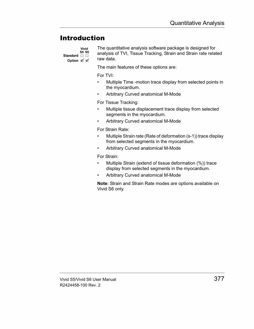
Quantitative Analysis
IntroductionThe quantitative analysis software package is designed for analysis of TVI, Tissue Tracking, Strain and Strain rate related raw data.
The main features of these options are:
For TVI:• Multiple Time -motion trace display from selected points in
the myocardium.• Arbitrary Curved anatomical M-Mode
For Tissue Tracking:• Multiple tissue displacement trace display from selected
segments in the myocardium.• Arbitrary Curved anatomical M-Mode
For Strain Rate:• Multiple Strain rate (Rate of deformation (s-1)) trace display
from selected segments in the myocardium.• Arbitrary Curved anatomical M-Mode
For Strain:• Multiple Strain (extend of tissue deformation (%)) trace
display from selected segments in the myocardium.• Arbitrary Curved anatomical M-Mode
Note: Strain and Strain Rate modes are options available on Vivid S6 only.
Vivid S5/Vivid S6 User Manual 377R2424458-100 Rev. 2
Quantitative Analysis
Accessing the Quantitative analysis package
In replay mode1. Open an examination and recall a TVI or contrast loop.2. Press the assignable Q ANALYSIS.
The Quantitative Analysis screen is displayed (see Figure 8-1).
In live1. Press FREEZE.
Note: if in 2D mode outside a contrast application, press ALT and MORE assignable.
2. Press the assignable Q ANALYSIS.The Quantitative Analysis screen is displayed (see Figure 8-1).
378 Vivid S5/Vivid S6 User ManualR2424458-100 Rev. 2
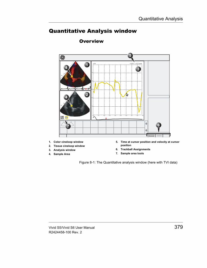
Quantitative Analysis
Quantitative Analysis window
Overview
Figure 8-1: The Quantitative analysis window (here with TVI data)
1. Color cineloop window2. Tissue cineloop window3. Analysis window4. Sample Area
5. Time at cursor position and velocity at cursor position
6. Trackball Assignments7. Sample area tools
7
Vivid S5/Vivid S6 User Manual 379R2424458-100 Rev. 2
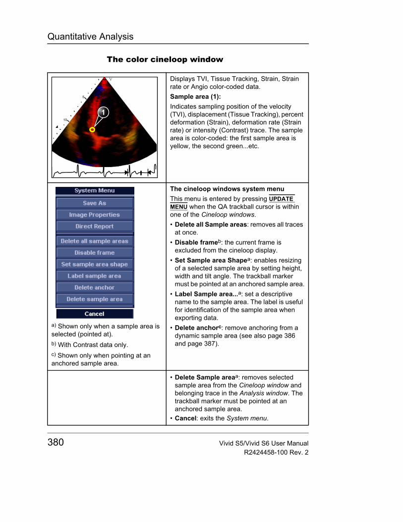
Quantitative Analysis
The color cineloop window
Displays TVI, Tissue Tracking, Strain, Strain rate or Angio color-coded data.Sample area (1):Indicates sampling position of the velocity (TVI), displacement (Tissue Tracking), percent deformation (Strain), deformation rate (Strain rate) or intensity (Contrast) trace. The sample area is color-coded: the first sample area is yellow, the second green...etc.
a) Shown only when a sample area is selected (pointed at).b) With Contrast data only.c) Shown only when pointing at an anchored sample area.
The cineloop windows system menuThis menu is entered by pressing UPDATE MENU when the QA trackball cursor is within one of the Cineloop windows.• Delete all Sample areas: removes all traces
at once.• Disable frameb: the current frame is
excluded from the cineloop display.• Set Sample area Shapea: enables resizing
of a selected sample area by setting height, width and tilt angle. The trackball marker must be pointed at an anchored sample area.
• Label Sample area...a: set a descriptive name to the sample area. The label is useful for identification of the sample area when exporting data.
• Delete anchorc: remove anchoring from a dynamic sample area (see also page 386 and page 387).
• Delete Sample areaa: removes selected sample area from the Cineloop window and belonging trace in the Analysis window. The trackball marker must be pointed at an anchored sample area.
• Cancel: exits the System menu.
1
380 Vivid S5/Vivid S6 User ManualR2424458-100 Rev. 2
Quantitative Analysis
The Tissue cineloop window
Displays 2D dataSample area (1):Indicates sampling position of the velocity (TVI), displacement (Tissue Tracking), percent deformation (Strain), deformation rate (Strain rate) or intensity (Contrast) trace. The sample area is color-coded: the first sample area is yellow, the second green...etc.
Sample area tools:
• : creates a sample area based on freehand drawing.
• : creates a sample area with a pre-defined circular/elliptic shape (configurable, see page 392)
1
Vivid S5/Vivid S6 User Manual 381R2424458-100 Rev. 2
Quantitative Analysis
The analysis window
TVI:Displays velocity trace1. Y axis: velocity scale (cm/s)2. X axis: Time (s)3. ECG4. Time at cursor position5. Velocity at cursor position6. Velocity at frame marker position
(color coded)Tissue Tracking:Displays tissue displacement trace1. Y axis: displacement scale (mm)2. X axis: time (s)3. ECG with Tracking start and Tracking
end markers4. Time at cursor position5. Displacement at cursor position6. Displacement at frame marker
position (color coded)Strain rate:Displays Strain rate trace (rate of deformation (s-1))
1. Y axis: s-1
2. X axis: time (s)3. ECG4. Time at cursor position5. Strain rate at cursor position6. Strain rate at frame marker position
1
2
3
45
-2.3
6
382 Vivid S5/Vivid S6 User ManualR2424458-100 Rev. 2
Quantitative Analysis
Strain:Displays Strain trace (extent of tissue deformation (%))1. Y axis: percent displacement2. X axis: time (s)3. ECG with Strain start and Strain end
markers4. Time at cursor position5. % deformation at cursor position6. % deformation at frame marker
position (color coded)
1
2
3
45
-2.3
6
Vivid S5/Vivid S6 User Manual 383R2424458-100 Rev. 2
Quantitative Analysis
a) With contrast data only.b) Shown only in zoom mode.
The analysis window system menu:This menu is entered by pressing UPDATE MENU when the QA cursor is within one of the analysis window.• Delete all Sample areas: removes all traces
at once.• Analysis signal: toggles trace display
between velocity, displacement, strain rate, stain or greyscale intensity curves.
• Drift compensation: compensates drifting of strain or Tissue Tracking curves by either resetting the curve to zero at the tracking start point (cycle resetting) or by linear compensation throughout the cycle (linear compensation)
• Horizontal scale: set horizontal unit as time (s) or time interval (dt) between frames.
• Vertical auto-scaling: selects between full unit range or a range according to the maximum and minimum values of the displayed trace(s).
• Vertical unita: toggles between logarithmic (dB) and linear acoustical units (AU).
• Line style: selects between solid line only or solid line with square markers at each data point.
• Smoothing: smooths the trace displayed by applying a filter over a defined time window. Both the filter type and time window are user-selectable. The type of filter available is depending on the analysis signal displayed.
• Export traces: saves trace data in ASCII format, readable in spreadsheet programs. If present, trace data for physiological traces are also exported.
• Unzoomb: restores full analysis window display when in zoom mode.
• Cancel: exits the System menu.
384 Vivid S5/Vivid S6 User ManualR2424458-100 Rev. 2

Quantitative Analysis
The Trackball assignments
QA:Pointing tool in Quantitative analysis mode.Scroll/Speed:• When the cineloop is stopped, enables
scrolling through the cineloop.• When the cineloop is running, enables
control of the cine replay speed.
Vivid S5/Vivid S6 User Manual 385R2424458-100 Rev. 2
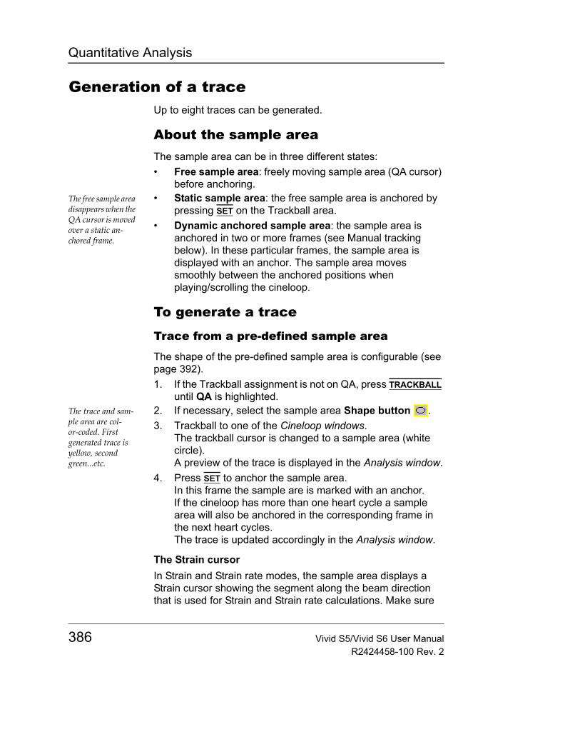
Quantitative Analysis
Generation of a traceUp to eight traces can be generated.
About the sample areaThe sample area can be in three different states:• Free sample area: freely moving sample area (QA cursor)
before anchoring.The free sample area disappears when the QA cursor is moved over a static an-chored frame.
• Static sample area: the free sample area is anchored by pressing SET on the Trackball area.
• Dynamic anchored sample area: the sample area is anchored in two or more frames (see Manual tracking below). In these particular frames, the sample area is displayed with an anchor. The sample area moves smoothly between the anchored positions when playing/scrolling the cineloop.
To generate a trace
Trace from a pre-defined sample area
The shape of the pre-defined sample area is configurable (see page 392).1. If the Trackball assignment is not on QA, press TRACKBALL
until QA is highlighted.The trace and sam-ple area are col-or-coded. First generated trace is yellow, second green...etc.
2. If necessary, select the sample area Shape button . 3. Trackball to one of the Cineloop windows.
The trackball cursor is changed to a sample area (white circle).A preview of the trace is displayed in the Analysis window.
4. Press SET to anchor the sample area.In this frame the sample are is marked with an anchor.If the cineloop has more than one heart cycle a sample area will also be anchored in the corresponding frame in the next heart cycles.The trace is updated accordingly in the Analysis window.
The Strain cursorIn Strain and Strain rate modes, the sample area displays a Strain cursor showing the segment along the beam direction that is used for Strain and Strain rate calculations. Make sure
386 Vivid S5/Vivid S6 User ManualR2424458-100 Rev. 2
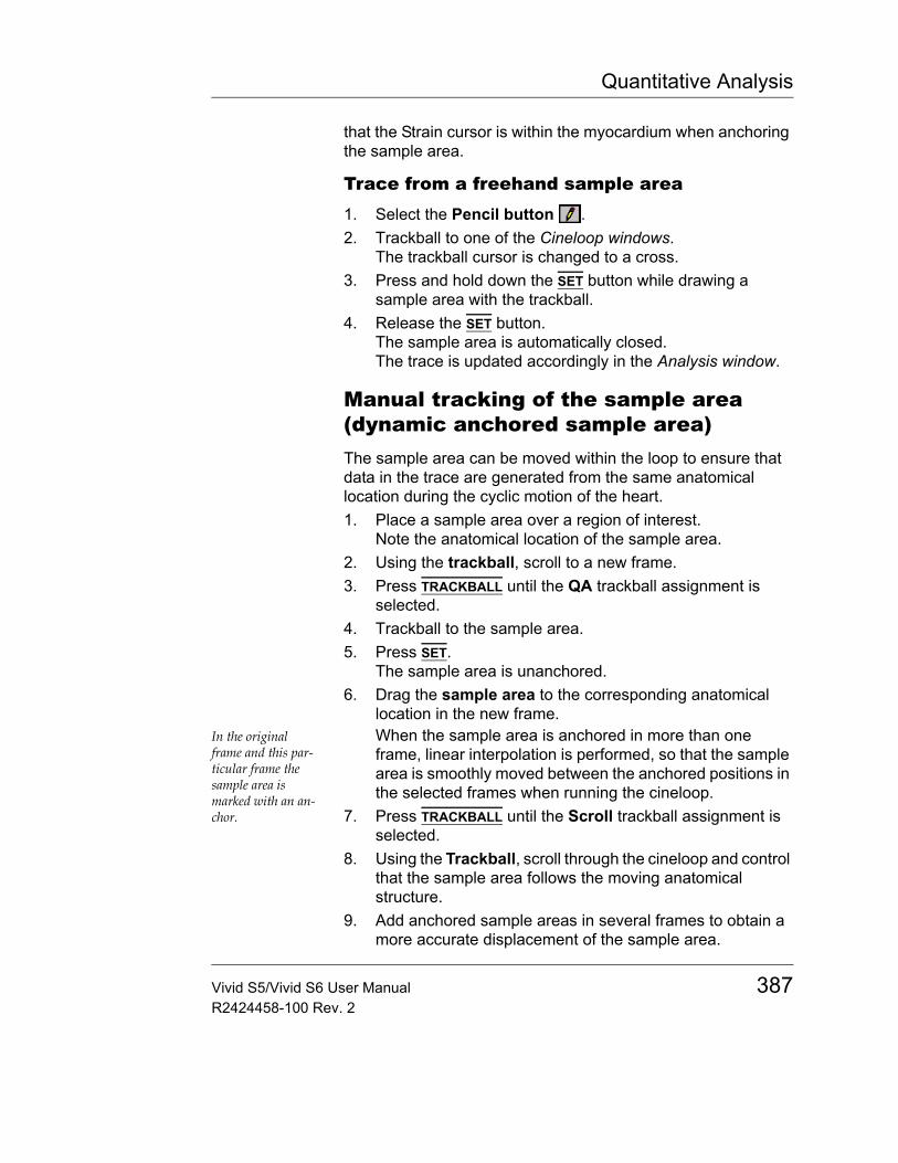
Quantitative Analysis
that the Strain cursor is within the myocardium when anchoring the sample area.
Trace from a freehand sample area1. Select the Pencil button .2. Trackball to one of the Cineloop windows.
The trackball cursor is changed to a cross.3. Press and hold down the SET button while drawing a
sample area with the trackball.4. Release the SET button.
The sample area is automatically closed.The trace is updated accordingly in the Analysis window.
Manual tracking of the sample area (dynamic anchored sample area)The sample area can be moved within the loop to ensure that data in the trace are generated from the same anatomical location during the cyclic motion of the heart.1. Place a sample area over a region of interest.
Note the anatomical location of the sample area.2. Using the trackball, scroll to a new frame.3. Press TRACKBALL until the QA trackball assignment is
selected.4. Trackball to the sample area.5. Press SET.
The sample area is unanchored.6. Drag the sample area to the corresponding anatomical
location in the new frame.In the original frame and this par-ticular frame the sample area is marked with an an-chor.
When the sample area is anchored in more than one frame, linear interpolation is performed, so that the sample area is smoothly moved between the anchored positions in the selected frames when running the cineloop.
7. Press TRACKBALL until the Scroll trackball assignment is selected.
8. Using the Trackball, scroll through the cineloop and control that the sample area follows the moving anatomical structure.
9. Add anchored sample areas in several frames to obtain a more accurate displacement of the sample area.
Vivid S5/Vivid S6 User Manual 387R2424458-100 Rev. 2
Quantitative Analysis
To move a dynamic anchored sample area1. Press TRACKBALL until the Scroll trackball assignment is
selected.In these frames the sample area is marked with an an-chor.
2. Using the trackball, browse through the cineloop to display one of the frames where the sample area was anchored.
3. Press TRACKBALL until the QA trackball assignment is selected.
4. Trackball to the sample area to move, in one of the Cineloop windows.
5. Press SET.The sample area is unanchored.
6. Drag the sample area to a new location.7. Press SET to anchor the sample area to the new location.
Zooming in the Analysis window1. In the Analysis window, press and hold down the SET key
while dragging the trackball cursor to define the zooming area.
2. Release the SET key.The selected area is displayed in the Analysis window.
To unzoom1. Press UPDATE MENU in the trackball area on the control
panel.The System menu is displayed.
2. Trackball to Unzoom.3. Press SET.
388 Vivid S5/Vivid S6 User ManualR2424458-100 Rev. 2

Quantitative Analysis
Deletion of a traceThe user can delete all traces at once or one at a time.
To delete all traces1. If necessary, press TRACKBALL until the QA trackball
assignment is selected.2. Press UPDATE MENU in the trackball area on the control
panel.The System menu is displayed.
3. Trackball to Delete all traces.4. Press SET.
To delete one specific trace1. If necessary, press TRACKBALL until the QA trackball
assignment is selected.2. Trackball to the sample area to delete.3. Press UPDATE MENU in the trackball area on the control
panel.The System menu is displayed.
4. Trackball to Delete trace.5. Press SET to perform deletion.
Saving/retrieving Quantitative analysis1. Press IMAGE STORE to save the quantitative analysis
session.2. To recall the Quantitative analysis session, select the icon
on the clipboard, and press the assigned key Q ANALYSIS.
Vivid S5/Vivid S6 User Manual 389R2424458-100 Rev. 2
Quantitative Analysis
Frame disablingFrame disabling excludes the actual frame from the cineloop display. Frame disabling is available only with contrast data.
Disabling framesTo re-enable a frame: Press SELECT on the cor-responding frame marker.
1. Trackball to the frame marker of the frame to disable beneath the Analysis window (see Figure 8-2).
2. Press SET to disable the frame. The frame marker turns red.
disabling successive frames at a timeTo re-enable succes-sive frames: press and hold down the SELECT key while dragging the cursor over the frame markers.
1. Press and hold down SET while dragging the cursor over the frame markers of the frames to disable.The frame markers turn red.
ECG triggered frame disabling
In a multi-cycle acquisition, the user may deselect all frames in all heart cycles but a selected one. This function can be used for example to select a particular systolic frame for each heart cycle.1. Scroll through the cineloop to identify the cardiac phase to
analyze or identify the cardiac phase on the ECG trace.2. Trackball to the frame marker of the frame of interest in one
of the heart cycles (see Figure 8-2).3. Press UPDATE MENU.
The System menu is displayed.4. Trackball to ECG triggering.5. Press SET.
All frames in all heart cycles are disabled except for the selected and corresponding frames in the other heart cycles.
Re-enabling all frames1. Trackball the cursor to the Frame marker axis.2. Press UPDATE MENU in the trackball area on the control
panel.The System menu is displayed.
3. Trackball to Enable all frames.4. Press SET.
390 Vivid S5/Vivid S6 User ManualR2424458-100 Rev. 2
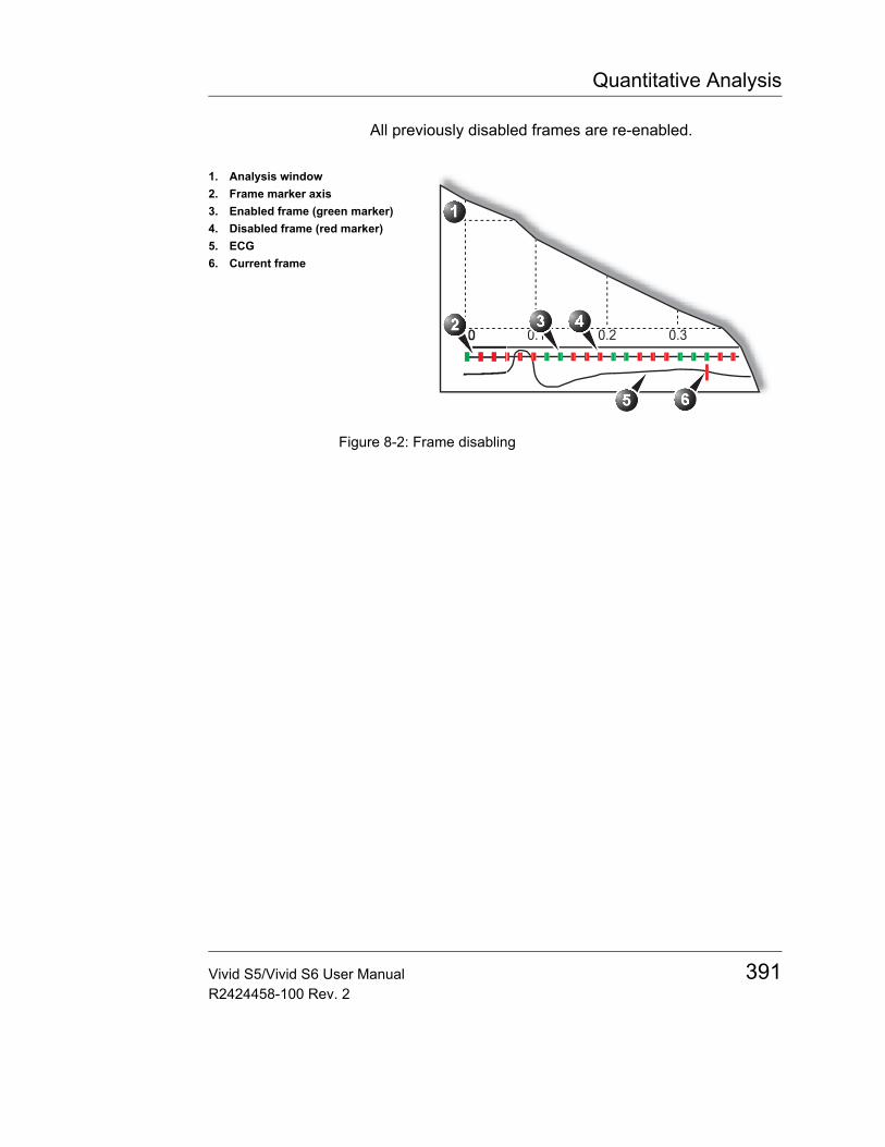
Quantitative Analysis
All previously disabled frames are re-enabled.
Figure 8-2: Frame disabling
1. Analysis window2. Frame marker axis3. Enabled frame (green marker)4. Disabled frame (red marker)5. ECG6. Current frame
Vivid S5/Vivid S6 User Manual 391R2424458-100 Rev. 2
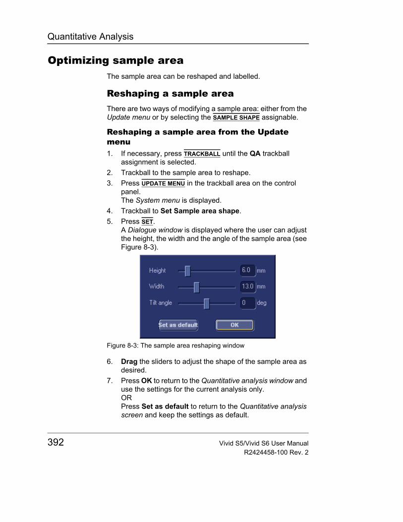
Quantitative Analysis
Optimizing sample areaThe sample area can be reshaped and labelled.
Reshaping a sample areaThere are two ways of modifying a sample area: either from the Update menu or by selecting the SAMPLE SHAPE assignable.
Reshaping a sample area from the Update menu1. If necessary, press TRACKBALL until the QA trackball
assignment is selected.2. Trackball to the sample area to reshape.3. Press UPDATE MENU in the trackball area on the control
panel.The System menu is displayed.
4. Trackball to Set Sample area shape.5. Press SET.
A Dialogue window is displayed where the user can adjust the height, the width and the angle of the sample area (see Figure 8-3).
Figure 8-3: The sample area reshaping window
6. Drag the sliders to adjust the shape of the sample area as desired.
7. Press OK to return to the Quantitative analysis window and use the settings for the current analysis only.ORPress Set as default to return to the Quantitative analysis screen and keep the settings as default.
392 Vivid S5/Vivid S6 User ManualR2424458-100 Rev. 2
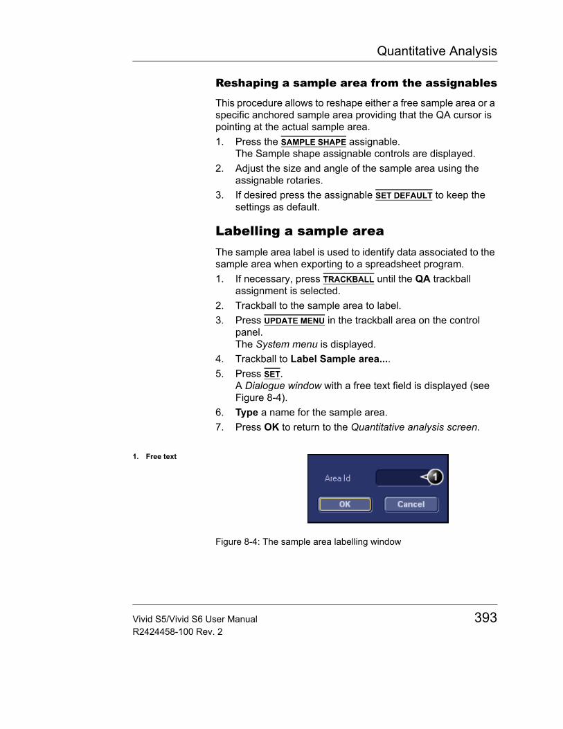
Quantitative Analysis
Reshaping a sample area from the assignables
This procedure allows to reshape either a free sample area or a specific anchored sample area providing that the QA cursor is pointing at the actual sample area.1. Press the SAMPLE SHAPE assignable.
The Sample shape assignable controls are displayed.2. Adjust the size and angle of the sample area using the
assignable rotaries.3. If desired press the assignable SET DEFAULT to keep the
settings as default.
Labelling a sample areaThe sample area label is used to identify data associated to the sample area when exporting to a spreadsheet program.1. If necessary, press TRACKBALL until the QA trackball
assignment is selected.2. Trackball to the sample area to label.3. Press UPDATE MENU in the trackball area on the control
panel.The System menu is displayed.
4. Trackball to Label Sample area....5. Press SET.
A Dialogue window with a free text field is displayed (see Figure 8-4).
6. Type a name for the sample area.7. Press OK to return to the Quantitative analysis screen.
Figure 8-4: The sample area labelling window
1. Free text
Vivid S5/Vivid S6 User Manual 393R2424458-100 Rev. 2
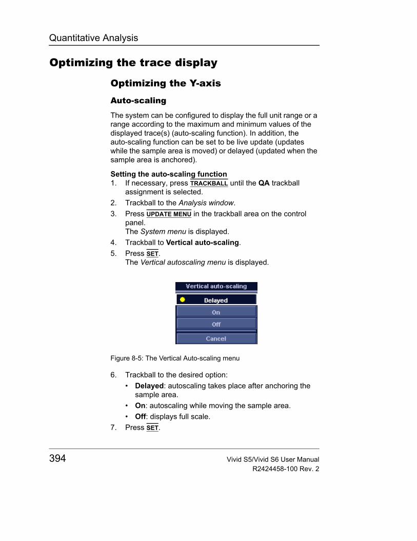
Quantitative Analysis
Optimizing the trace display
Optimizing the Y-axis
Auto-scaling
The system can be configured to display the full unit range or a range according to the maximum and minimum values of the displayed trace(s) (auto-scaling function). In addition, the auto-scaling function can be set to be live update (updates while the sample area is moved) or delayed (updated when the sample area is anchored).
Setting the auto-scaling function1. If necessary, press TRACKBALL until the QA trackball
assignment is selected.2. Trackball to the Analysis window.3. Press UPDATE MENU in the trackball area on the control
panel.The System menu is displayed.
4. Trackball to Vertical auto-scaling.5. Press SET.
The Vertical autoscaling menu is displayed.
Figure 8-5: The Vertical Auto-scaling menu
6. Trackball to the desired option:• Delayed: autoscaling takes place after anchoring the
sample area.• On: autoscaling while moving the sample area.• Off: displays full scale.
7. Press SET.
394 Vivid S5/Vivid S6 User ManualR2424458-100 Rev. 2
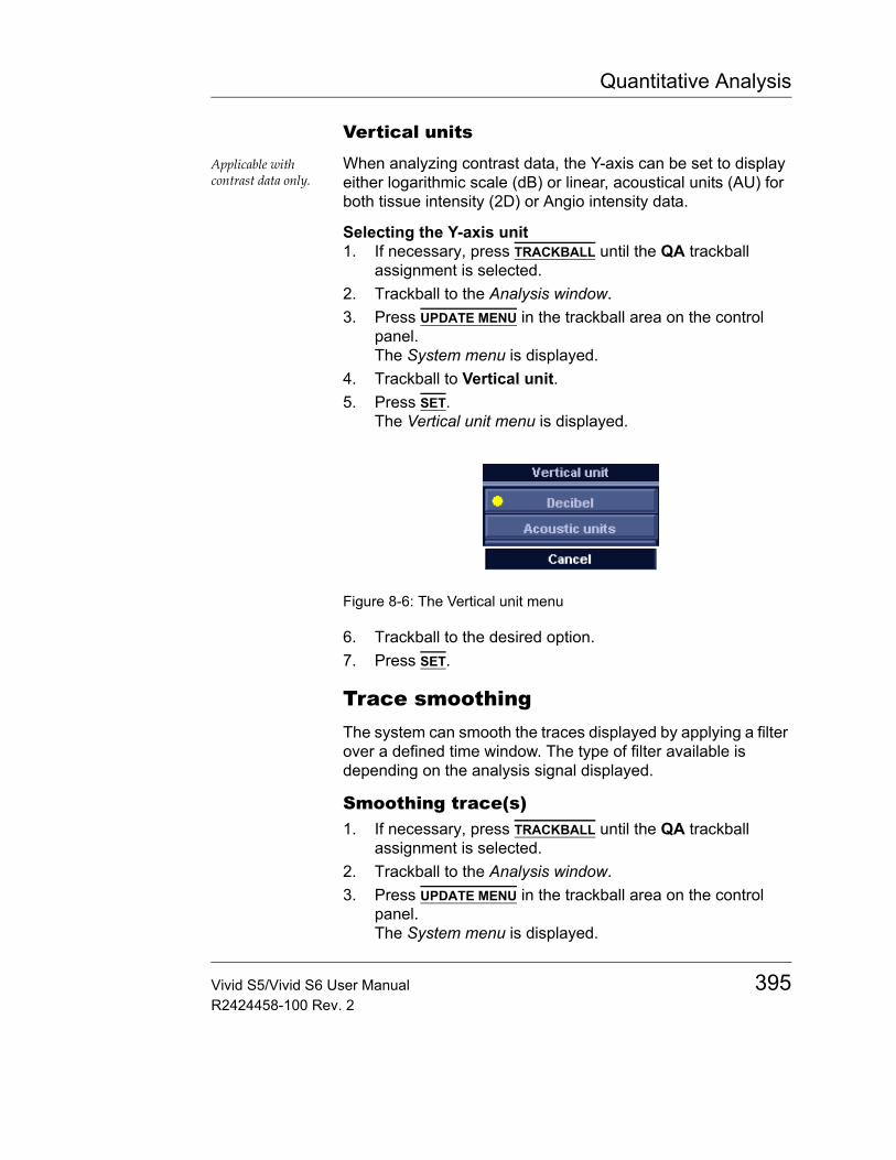
Quantitative Analysis
Vertical units
Applicable with contrast data only.
When analyzing contrast data, the Y-axis can be set to display either logarithmic scale (dB) or linear, acoustical units (AU) for both tissue intensity (2D) or Angio intensity data.
Selecting the Y-axis unit1. If necessary, press TRACKBALL until the QA trackball
assignment is selected.2. Trackball to the Analysis window.3. Press UPDATE MENU in the trackball area on the control
panel.The System menu is displayed.
4. Trackball to Vertical unit.5. Press SET.
The Vertical unit menu is displayed.
Figure 8-6: The Vertical unit menu
6. Trackball to the desired option.7. Press SET.
Trace smoothingThe system can smooth the traces displayed by applying a filter over a defined time window. The type of filter available is depending on the analysis signal displayed.
Smoothing trace(s)1. If necessary, press TRACKBALL until the QA trackball
assignment is selected.2. Trackball to the Analysis window.3. Press UPDATE MENU in the trackball area on the control
panel.The System menu is displayed.
Vivid S5/Vivid S6 User Manual 395R2424458-100 Rev. 2

Quantitative Analysis
4. Select Smoothing.The Smoothing menu is displayed.
5. Select a smoothing filter.The trace display is updated.
396 Vivid S5/Vivid S6 User ManualR2424458-100 Rev. 2
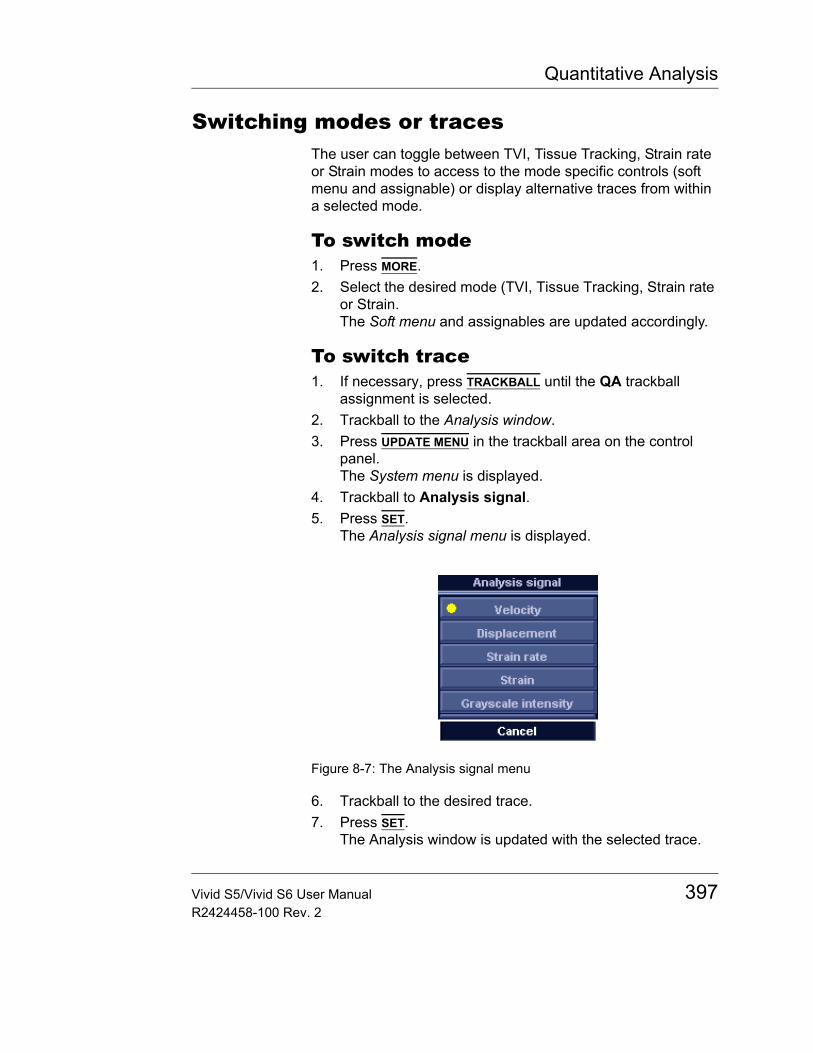
Quantitative Analysis
Switching modes or tracesThe user can toggle between TVI, Tissue Tracking, Strain rate or Strain modes to access to the mode specific controls (soft menu and assignable) or display alternative traces from within a selected mode.
To switch mode1. Press MORE.2. Select the desired mode (TVI, Tissue Tracking, Strain rate
or Strain.The Soft menu and assignables are updated accordingly.
To switch trace1. If necessary, press TRACKBALL until the QA trackball
assignment is selected.2. Trackball to the Analysis window.3. Press UPDATE MENU in the trackball area on the control
panel.The System menu is displayed.
4. Trackball to Analysis signal.5. Press SET.
The Analysis signal menu is displayed.
Figure 8-7: The Analysis signal menu
6. Trackball to the desired trace.7. Press SET.
The Analysis window is updated with the selected trace.
Vivid S5/Vivid S6 User Manual 397R2424458-100 Rev. 2

Quantitative Analysis
Cine compoundCine compound calculates and displays cineloops generated from a temporal averaging of multiple consecutive heart cycles. The number of averaged cycles is displayed on the top left corner.
To apply cine compound:1. Using the Soft menu rocker, adjust the number of heart
cycles to average.The traces are updated showing averaged data. The number of heart cycles averaged is displayed on the top left corner.
2. Press the assigned key CC Zoom to display the last recorded heart cycle.
3. Press CC Zoom again to unzoom.
398 Vivid S5/Vivid S6 User ManualR2424458-100 Rev. 2
Quantitative Analysis
Anatomical M-Mode
IntroductionM-Mode applied to TVI, Tissue Tracking, Strain rate, Strain or intensity data (Contrast) calculates and color/codes data accordingly along a path drawn by the operator.
Using Anatomical M-Mode1. Press the CAMM assignable.2. In one of the Cineloop windows, trackball to the region from
where to start the sampling path.3. Press SET to anchor the first point of the path.4. Trackball to the location for the next anchoring point of the
path.To edit a path under construction, trackball back-ward and retrace the path.
5. Press SET to anchor the point.A path with two anchor points will give a straight anatomical M-Mode profile. By creating more than two anchor points, the user can bend the path and obtain a curved anatomical M-Mode profile.
6. To end the trace press SET twice (double clicking).Rotate HORIZ. SWEEP and scroll through the cineloop to optimize the display to the portion of interest.
The color-coded display of the corresponding data calculated along the path is shown in the Analysis window (see Figure 8-8).
Vivid S5/Vivid S6 User Manual 399R2424458-100 Rev. 2
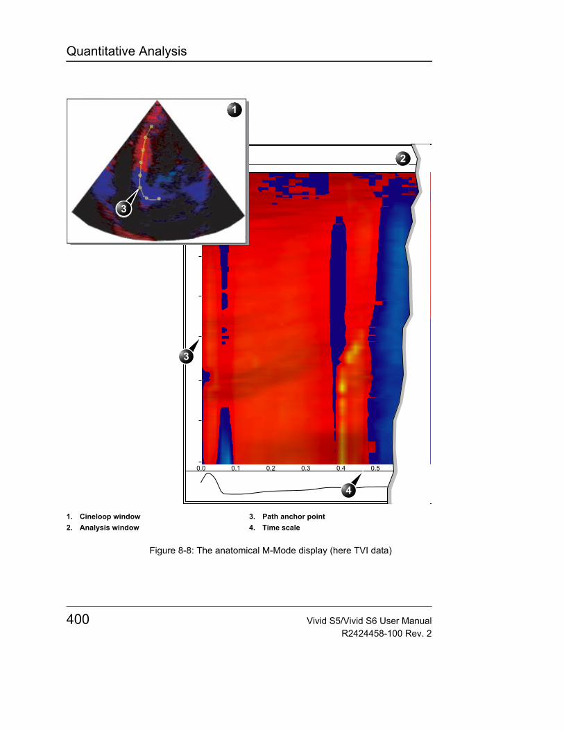
Quantitative Analysis
Figure 8-8: The anatomical M-Mode display (here TVI data)
1. Cineloop window2. Analysis window
3. Path anchor point4. Time scale
2
3
4
1
3
400 Vivid S5/Vivid S6 User ManualR2424458-100 Rev. 2

Quantitative Analysis
Optimizing Anatomical M-Mode
Edition of the curve
The drawn Anatomical M-Mode path can be edited by moving the anchor points.
To move an anchor point1. Trackball to anchor point to move.2. Press SET.3. Trackball the anchor point to a new position.
4. Press SET to anchor the point to its new location.
Vivid S5/Vivid S6 User Manual 401R2424458-100 Rev. 2

Quantitative Analysis
402 Vivid S5/Vivid S6 User ManualR2424458-100 Rev. 2
Archiving
Chapter 9 Archiving
• Introduction ................................................................................... .. 405• Storing images and cineloops ..................................................... .. 406
• Storing an image ...................................................................... 407• Storing a cineloop .................................................................... 407• Saving images and cineloops to a standard format ................. 408• MPEGVue/eVue ....................................................................... 410
• Retrieving and editing archived information .............................. .. 413• Locating a patient record .......................................................... 413• Selecting a patient record and editing data in the archive ....... 418• Deleting archived information ................................................... 422• Moving examinations ............................................................... 424
• Review images in archive ............................................................ .. 426• Review the images from a selected examination ..................... 426• Select images from the Image list screen ................................ 427
• Connectivity .................................................................................. .. 431• The dataflow concept ............................................................... 431• Stand-alone scanner scenario ................................................. 434• A stand-alone scanner and a stand-alone EchoPAC PC
environment .............................................................................. 435• A scanner and EchoPAC PC in a direct connect environment 437• A scanner and EchoPAC PC in a network environment .......... 441• A scanner and a DICOM server in a network ........................... 443
• Export/Import patient records/examinations ............................. .. 452• Exporting patient records/examinations ................................... 452• Importing patient records/examinations ................................... 460
Vivid S5/Vivid S6 User Manual 403R2424458-100 Rev. 2

Archiving
• Disk Management ......................................................................... ... 464• Configuring the Disk management function ..............................465• Running the Disk management function ...................................468• Data Backup and Restore .........................................................471
• DICOM spooler .............................................................................. ... 479• Starting the DICOM spooler ......................................................479
• Database import from Vivid 3 or Vivid 4 ..................................... ... 482• Transfer Procedure ...................................................................482• Installing the Vivid 3/4 Data Viewer ..........................................485• Using the Vivid 3/4 Data Viewer ...............................................488
404 Vivid S5/Vivid S6 User ManualR2424458-100 Rev. 2
Archiving
IntroductionDuring an examination, the operator stores data, images and cineloops for immediate purposes. The Vivid S5/Vivid S6 ultrasound unit includes an integrated patient archiving system for data and image storage.
The Vivid S5/Vivid S6 ultrasound unit enables also storing of data and images to external databases (Image Vault, Magneto Optical (MO) disk, CD-R or DVD-R). The patient and image archives are set by the selected dataflow (see page 616 about available dataflows and default dataflow selection).
CAUTION
Do not use the internal hard drive for long-term image storage.
Vivid S5/Vivid S6 User Manual 405R2424458-100 Rev. 2
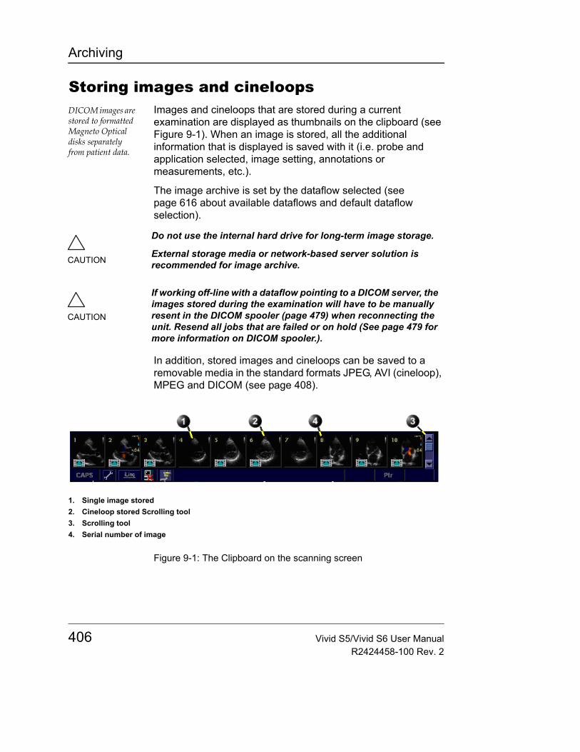
Archiving
Storing images and cineloopsDICOM images are stored to formatted Magneto Optical disks separately from patient data.
Images and cineloops that are stored during a current examination are displayed as thumbnails on the clipboard (see Figure 9-1). When an image is stored, all the additional information that is displayed is saved with it (i.e. probe and application selected, image setting, annotations or measurements, etc.).
The image archive is set by the dataflow selected (see page 616 about available dataflows and default dataflow selection).
In addition, stored images and cineloops can be saved to a removable media in the standard formats JPEG, AVI (cineloop), MPEG and DICOM (see page 408).
Figure 9-1: The Clipboard on the scanning screen
CAUTION
Do not use the internal hard drive for long-term image storage.
External storage media or network-based server solution is recommended for image archive.
CAUTION
If working off-line with a dataflow pointing to a DICOM server, the images stored during the examination will have to be manually resent in the DICOM spooler (page 479) when reconnecting the unit. Resend all jobs that are failed or on hold (See page 479 for more information on DICOM spooler.).
1. Single image stored2. Cineloop stored Scrolling tool3. Scrolling tool4. Serial number of image
406 Vivid S5/Vivid S6 User ManualR2424458-100 Rev. 2
Archiving
Storing an imageImages are displayed chronologically on the clipboard.1. While scanning in any mode, press FREEZE.2. Trackball to scroll through the cineloop and select the
required image.3. Press STORE.
The image is stored and a thumbnail is displayed on the clipboard. A serial number appears on each thumbnail, start from “1” in chronological order (see Figure 9-1).
Storing a cineloopA cineloop is a sequence of images recorded over a certain time frame. The time frame can be adjusted to cover one or more heart cycles. The stored cineloops are displayed chronologically on the clipboard. Cineloops can be stored at any time during the scanning session. The user can choose to preview the cineloop before storage or save the cineloop directly as described below.
Preview and storage of a cineloop1. While scanning in any mode, press FREEZE.2. Press the Assignable CINELOOP.3. Determine the best cineloop to store using the assignables
(see page 110 for further information on cineloop operation).
4. Press STORE.The cineloop is stored and a thumbnail is displayed on the clipboard. The "loop" icon appears on the thumbnail image indicating that the image stored is a loop (see Figure 9-1). A serial number appears on each thumbnail, starting from “1” in chronological order.
Note: Cineloop storage can be configured to store heart cycles with additional time before and after the R-wave (see "The Global setup sheet" on page 590).
Direct storage of a cineloop
Depending on whether the system has been configured to enable or disable the Preview Loop before store function
Vivid S5/Vivid S6 User Manual 407R2424458-100 Rev. 2
Archiving
(see page 590), the following procedures enable the cineloop to be stored directly.
Storing cineloop without previewThe function Preview Loop before store is disabled (see page 590).• While scanning, press STORE.
The last valid cineloop is stored in the archive and a thumbnail is displayed on the clipboard.Scanning resumes immediately.
Storing cineloop with previewThe function Preview Loop before store is enabled (see page 590).1. While scanning, press STORE.
The last valid cineloop is previewed on the screen (but not stored).
2. If desired, press CINELOOP and adjust the cineloop to be stored using the assignables (see page 110).
3. Press STORE to save the cineloop.A thumbnail is displayed on the clipboard.
Saving images and cineloops to a standard formatImages and cineloops can be saved to a removable media or a shared network folder in the following standard formats:• Still images: JPEG, MPEG, DICOM and RawDICOM (Raw
data + DICOM), and HDF• Cineloops: AVI, MPEG, DICOM and RawDICOM (Raw
data + DICOM), and HDF
Images can also be stored as MPEG format on a CD-R using the Export function as described on page 410.
Procedure:1. In live: press FREEZE.
In replay: select an image thumbnail on the clipboard.2. Press UPDATE/MENU on the control panel.
The System menu is displayed.
408 Vivid S5/Vivid S6 User ManualR2424458-100 Rev. 2
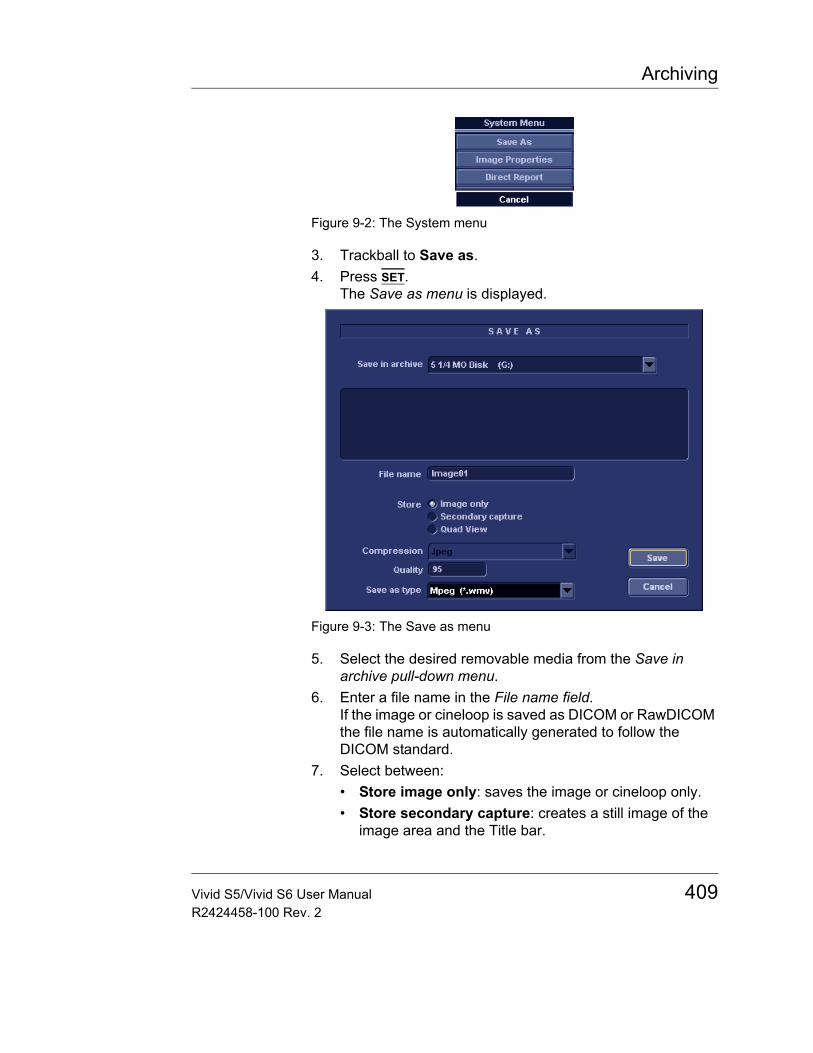
Archiving
Figure 9-2: The System menu
3. Trackball to Save as.4. Press SET.
The Save as menu is displayed.
Figure 9-3: The Save as menu
5. Select the desired removable media from the Save in archive pull-down menu.
6. Enter a file name in the File name field.If the image or cineloop is saved as DICOM or RawDICOM the file name is automatically generated to follow the DICOM standard.
7. Select between:• Store image only: saves the image or cineloop only.• Store secondary capture: creates a still image of the
image area and the Title bar.
Vivid S5/Vivid S6 User Manual 409R2424458-100 Rev. 2

Archiving
The secondary capture is not available when saving images as DICOM or RawDICOM.• Quad view: saves all images or cineloop when in quad
view.Quad view is not available when storing RawDICOM.
8. Select the image compression type (JPEG or RIe) or no compression.
9. Enter in the desired Image quality (between 10 and 100).A high quality setting will give a lower compression.
10. In the Save as type field select one of the following formats:• RawDICOM: saves the still image or cineloop in both GE
raw format and DICOM format.• DICOM: saves the still image or cineloop in pure DICOM
format.• JPEG: saves a still image in JPEG format.• MPEG: saves the still image or cineloop in MPEG format• AVI: saves the cineloop in AVI format.• HDF: saves the image or cineloop in HDF (Hierarchical
Data Format). HDF is a portable data format for exchange of scientific numerical and graphical data. More information about HDF format at:http://hdf.ncsa.uiuc.eduA tool for viewing HDF files can be downloaded from:http://hdf.ncsa.uiuc.edu/hdf-java-html/hdfview/
11. Press Save.A file is saved in the selected archive.
MPEGVue/eVueMPEGVue/eVue enables the user to export or save an exam (images, measurements and reports) into MPEG format readable from a regular Windows computer together with a special MPEG viewer.
Note: MPEGVue is optionally available on both Vivid S5 and Vivid S6, while eVue is available for Vivid S6 only.
CAUTION
MPGEGVue Viewer is intended for secondary review and patient consultation.
410 Vivid S5/Vivid S6 User ManualR2424458-100 Rev. 2
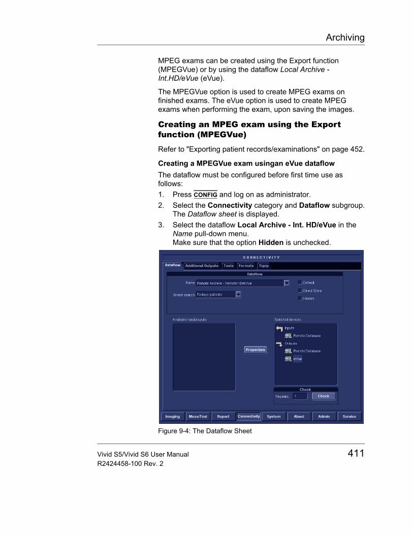
Archiving
MPEG exams can be created using the Export function (MPEGVue) or by using the dataflow Local Archive - Int.HD/eVue (eVue).
The MPEGVue option is used to create MPEG exams on finished exams. The eVue option is used to create MPEG exams when performing the exam, upon saving the images.
Creating an MPEG exam using the Export function (MPEGVue)
Refer to "Exporting patient records/examinations" on page 452.
Creating a MPEGVue exam usingan eVue dataflowThe dataflow must be configured before first time use as follows:1. Press CONFIG and log on as administrator.2. Select the Connectivity category and Dataflow subgroup.
The Dataflow sheet is displayed.3. Select the dataflow Local Archive - Int. HD/eVue in the
Name pull-down menu.Make sure that the option Hidden is unchecked.
Figure 9-4: The Dataflow Sheet
Vivid S5/Vivid S6 User Manual 411R2424458-100 Rev. 2
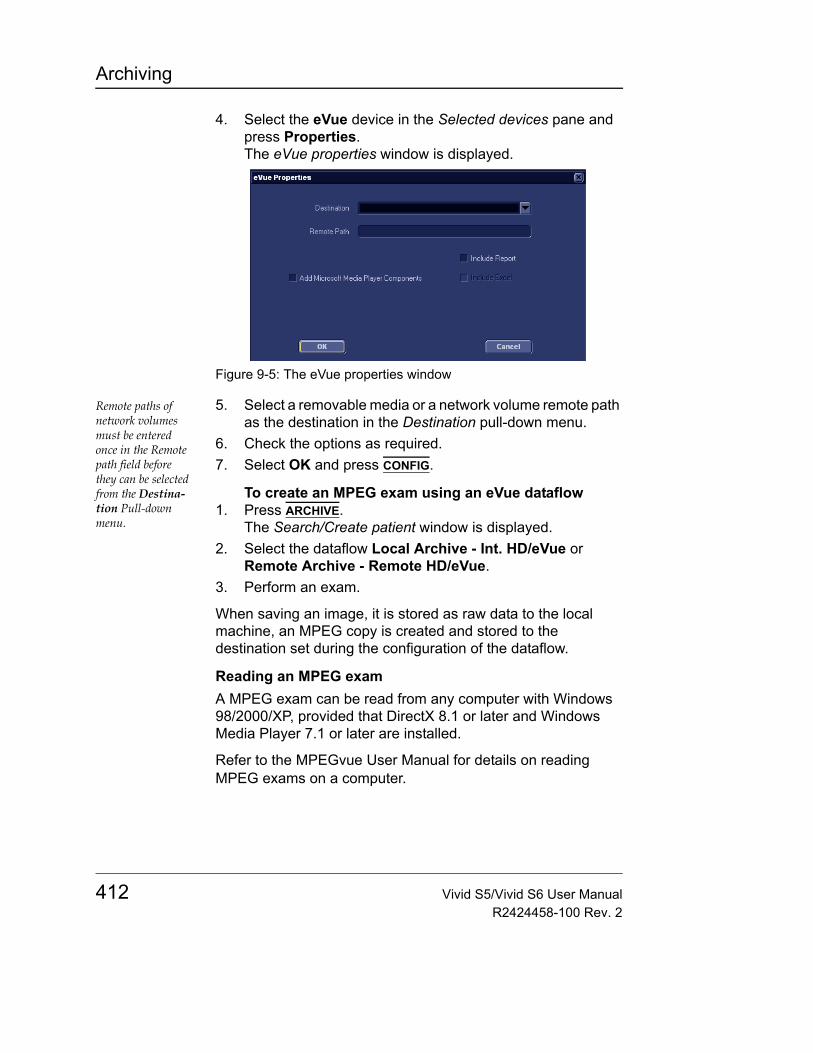
Archiving
4. Select the eVue device in the Selected devices pane and press Properties.The eVue properties window is displayed.
Figure 9-5: The eVue properties window
Remote paths of network volumes must be entered once in the Remote path field before they can be selected from the Destina-tion Pull-down menu.
5. Select a removable media or a network volume remote path as the destination in the Destination pull-down menu.
6. Check the options as required.7. Select OK and press CONFIG.
To create an MPEG exam using an eVue dataflow1. Press ARCHIVE.
The Search/Create patient window is displayed.2. Select the dataflow Local Archive - Int. HD/eVue or
Remote Archive - Remote HD/eVue.3. Perform an exam.
When saving an image, it is stored as raw data to the local machine, an MPEG copy is created and stored to the destination set during the configuration of the dataflow.
Reading an MPEG examA MPEG exam can be read from any computer with Windows 98/2000/XP, provided that DirectX 8.1 or later and Windows Media Player 7.1 or later are installed.
Refer to the MPEGvue User Manual for details on reading MPEG exams on a computer.
412 Vivid S5/Vivid S6 User ManualR2424458-100 Rev. 2
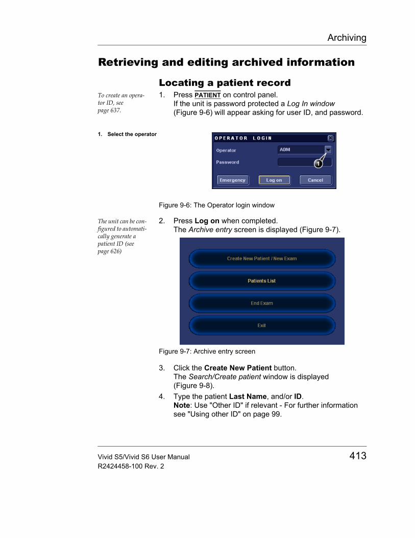
Archiving
Retrieving and editing archived information
Locating a patient recordTo create an opera-tor ID, see page 637.
1. Press PATIENT on control panel.If the unit is password protected a Log In window (Figure 9-6) will appear asking for user ID, and password.
Figure 9-6: The Operator login window
The unit can be con-figured to automati-cally generate a patient ID (see page 626)
2. Press Log on when completed.The Archive entry screen is displayed (Figure 9-7).
Figure 9-7: Archive entry screen
3. Click the Create New Patient button.The Search/Create patient window is displayed (Figure 9-8).
4. Type the patient Last Name, and/or ID.Note: Use "Other ID" if relevant - For further information see "Using other ID" on page 99.
1. Select the operator
Vivid S5/Vivid S6 User Manual 413R2424458-100 Rev. 2
Archiving
The automatic searching tool dis-playing matching patient information in the Patient list can be turned off (see page 626)
When default configured, the system automatically searches to see if the patient is already in the database. The result of this search is displayed in the Patient list field.
5. Trackball to the actual patient and press the Trackball SET key.The patient record is highlighted.
6. Press SELECT PATIENTOrPress [+] in front of the actual patient record and select the desired examination.The Examination List window for the actual patient is displayed (refer to Figure 9-10).
CAUTION
Do NOT use '\' or '^' in patient information fields, as these characters might cause problems with some DICOM devices.
414 Vivid S5/Vivid S6 User ManualR2424458-100 Rev. 2
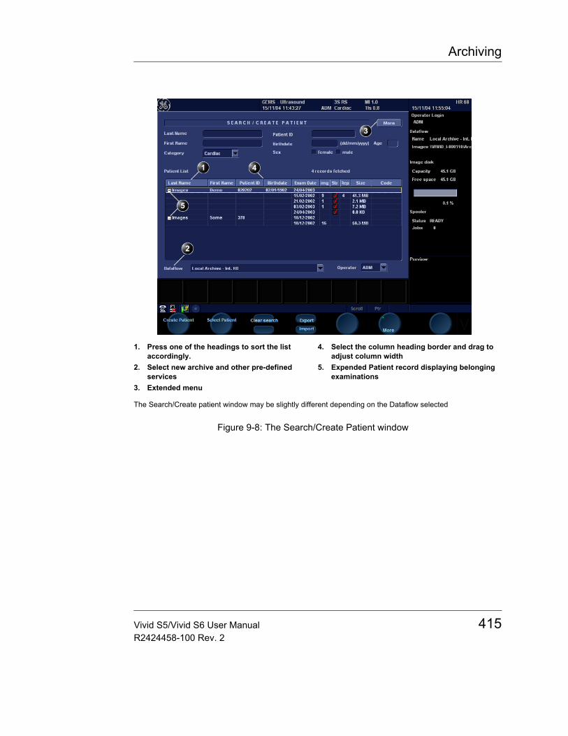
Archiving
Figure 9-8: The Search/Create Patient window
1. Press one of the headings to sort the list accordingly.
2. Select new archive and other pre-defined services
3. Extended menu
4. Select the column heading border and drag to adjust column width
5. Expended Patient record displaying belonging examinations
The Search/Create patient window may be slightly different depending on the Dataflow selected
Vivid S5/Vivid S6 User Manual 415R2424458-100 Rev. 2
Archiving
Advanced search
The list of searching filters may vary de-pending on the Dataflow selected
To restrain the search to a specific patient group, one or more filters may be applied to the search. The table below shows the filters applicable to a patient search:
Searching with filter:The unit can be con-figured to display the Advanced search tool as de-fault (see page 626)
1. Trackball to the More button in the Search/Create Patient window.
2. Press SET on the control panel.The Search/Create Patient window is extended displaying the searching filters (see Figure 9-9).
3. Type the information in the required searching filter field.4. Type the patient Last Name, and/or ID.
The matching data is displayed in the Patient list when the automatic search function is turned on.
Note: Use "Other ID" if relevant - For further information see "Using other ID" on page 99.
Sorting data
The search result can be sorted according to the fields displayed in the patient list, in ascending or descending order.
Searching filter
Echolab
Diagnostic code
Born between
Examination date between
Current date
Images: patient records with examinations with images
Stress examinations: patient records with stress echo examinations
No Report: Patient record with examination(s) without stored reports
Category: displays only patient records for the selected category
Diagnosis Physician
416 Vivid S5/Vivid S6 User ManualR2424458-100 Rev. 2
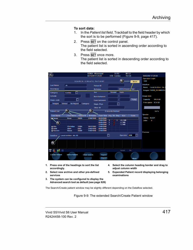
Archiving
To sort data:1. In the Patient list field, Trackball to the field header by which
the sort is to be performed (Figure 9-9, page 417).2. Press SET on the control panel.
The patient list is sorted in ascending order according to the field selected.
3. Press SET once more.The patient list is sorted in descending order according to the field selected.
Figure 9-9: The extended Search/Create Patient window
1. Press one of the headings to sort the list accordingly.
2. Select new archive and other pre-defined services
3. The system can be configured to display the Advanced search tool as default (see page 626)
4. Select the column heading border and drag to adjust column width
5. Expended Patient record displaying belonging examinations
The Search/Create patient window may be slightly different depending on the Dataflow selected.
Vivid S5/Vivid S6 User Manual 417R2424458-100 Rev. 2
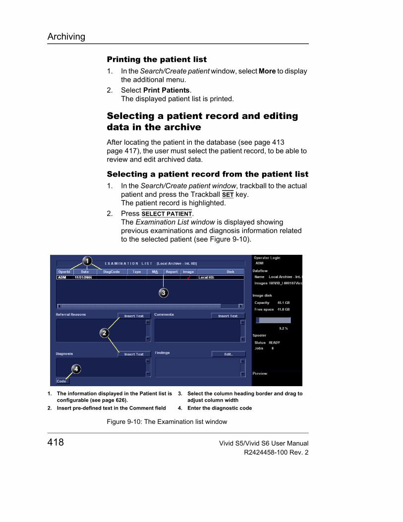
Archiving
Printing the patient list1. In the Search/Create patient window, select More to display
the additional menu.2. Select Print Patients.
The displayed patient list is printed.
Selecting a patient record and editing data in the archiveAfter locating the patient in the database (see page 413 page 417), the user must select the patient record, to be able to review and edit archived data.
Selecting a patient record from the patient list1. In the Search/Create patient window, trackball to the actual
patient and press the Trackball SET key.The patient record is highlighted.
2. Press SELECT PATIENT.The Examination List window is displayed showing previous examinations and diagnosis information related to the selected patient (see Figure 9-10).
Figure 9-10: The Examination list window
1. The information displayed in the Patient list is configurable (see page 626).
2. Insert pre-defined text in the Comment field
3. Select the column heading border and drag to adjust column width
4. Enter the diagnostic code
418 Vivid S5/Vivid S6 User ManualR2424458-100 Rev. 2
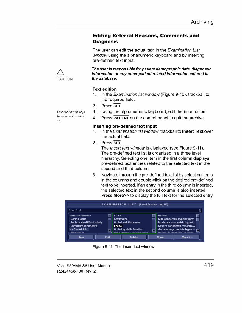
Archiving
Editing Referral Reasons, Comments and Diagnosis
The user can edit the actual text in the Examination List window using the alphanumeric keyboard and by inserting pre-defined text input.
Text edition1. In the Examination list window (Figure 9-10), trackball to
the required field.2. Press SET.
Use the Arrow keys to move text mark-er.
3. Using the alphanumeric keyboard, edit the information.4. Press PATIENT on the control panel to quit the archive.
Inserting pre-defined text input1. In the Examination list window, trackball to Insert Text over
the actual field.2. Press SET.
The Insert text window is displayed (see Figure 9-11).The pre-defined text list is organized in a three level hierarchy. Selecting one item in the first column displays pre-defined text entries related to the selected text in the second and third column.
3. Navigate through the pre-defined text list by selecting items in the columns and double-click on the desired pre-defined text to be inserted. If an entry in the third column is inserted, the selected text in the second column is also inserted.Press More>> to display the full text for the selected entry.
Figure 9-11: The Insert text window
CAUTION
The user is responsible for patient demographic data, diagnostic information or any other patient related information entered in the database.
Vivid S5/Vivid S6 User Manual 419R2424458-100 Rev. 2

Archiving
Creating, editing and deleting text inputThese features are described in "The Comment texts sheet" on page 613.
Diagnosis code
Entering a Diagnosis code1. In the Examination list window, select Code (see
Figure 9-10).The Entered Code window is displayed.
2. Select Add.The Code list window is displayed.
3. Double-click the code to enter.The selected code is displayed in the Examination list window.
Figure 9-12: Entering Diagnosis codes
Deleting an entered Diagnosis code1. In the Examination list window, select Code (see
Figure 9-10).The Entered Code window is displayed.
2. In the Entered Code window, select the code to delete and press Delete.
Creating a Diagnosis code1. In the Examination list window, select Code (see
Figure 9-10)The Entered Code window is displayed.
2. Select Add.The Code List window is displayed.
1. The Entered Code window2. The Code list window
420 Vivid S5/Vivid S6 User ManualR2424458-100 Rev. 2
Archiving
3. Select New.4. Enter the new code.5. Select Done to exit.
See also "The diagnostic codes sheet" on page 612.
Editing Demographic details
1. Press the PATIENT button on the control panel.2. Select Patient Details.
The Patient information window is displayed.3. Trackball to the field to edit.4. Press SET on the control panel.5. Using the alphanumeric keyboard, edit the information.
Alternative: Press any active scanning mode key.
6. Press the EXAM LIST assignable to go back to the Examination list window. ORPress PATIENT on the control panel to quit the archive.
WARNING
If you modify the Patient ID, Last name, First name or Date of birth on a patient in the archive, be aware that the contents of the archived images for that patient is not updated. If the images are still in the buffer and not yet archived, the image files are updated if you modify any patient information, but not if the images are archived. So if any of these images are later on exported to DICOM media or DICOM server, they will still contain the original patient information, as it was before you did the modification in the archive. The system does not alter the contents of the image files at all when doing DICOM export.
Note: Patient ID may also refer to patient's "other ID". For further information see "Using other ID" on page 99.
CAUTION
Do NOT use '\' or '^' in patient information fields, as these characters might cause problems with some DICOM devices.
Vivid S5/Vivid S6 User Manual 421R2424458-100 Rev. 2
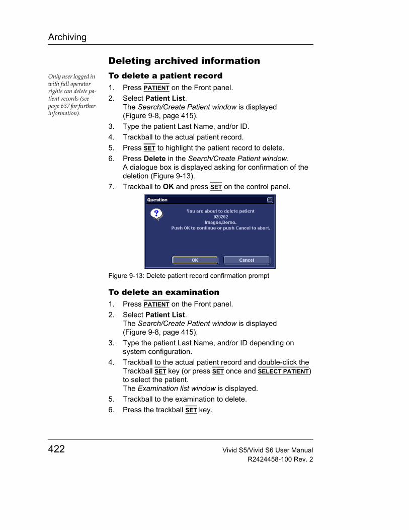
Archiving
Deleting archived informationOnly user logged in with full operator rights can delete pa-tient records (see page 637 for further information).
To delete a patient record1. Press PATIENT on the Front panel.2. Select Patient List.
The Search/Create Patient window is displayed (Figure 9-8, page 415).
3. Type the patient Last Name, and/or ID.4. Trackball to the actual patient record.5. Press SET to highlight the patient record to delete.6. Press Delete in the Search/Create Patient window.
A dialogue box is displayed asking for confirmation of the deletion (Figure 9-13).
7. Trackball to OK and press SET on the control panel.
Figure 9-13: Delete patient record confirmation prompt
To delete an examination1. Press PATIENT on the Front panel.2. Select Patient List.
The Search/Create Patient window is displayed (Figure 9-8, page 415).
3. Type the patient Last Name, and/or ID depending on system configuration.
4. Trackball to the actual patient record and double-click the Trackball SET key (or press SET once and SELECT PATIENT) to select the patient.The Examination list window is displayed.
5. Trackball to the examination to delete.6. Press the trackball SET key.
422 Vivid S5/Vivid S6 User ManualR2424458-100 Rev. 2
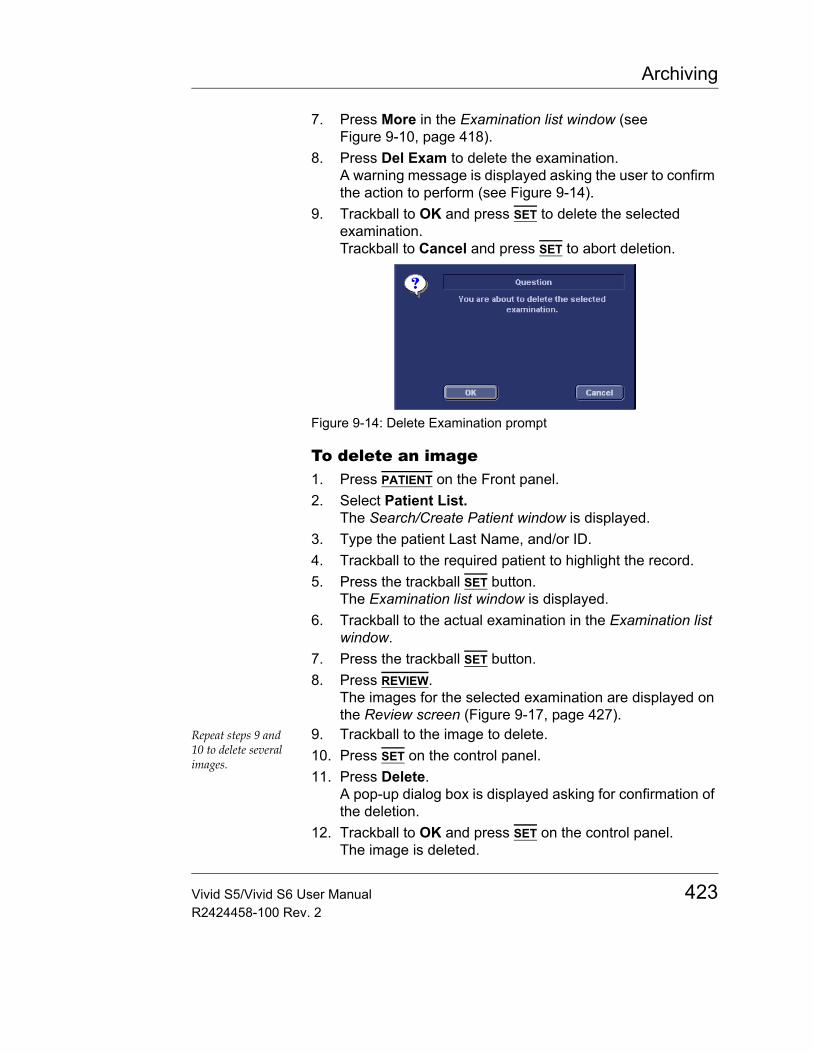
Archiving
7. Press More in the Examination list window (see Figure 9-10, page 418).
8. Press Del Exam to delete the examination.A warning message is displayed asking the user to confirm the action to perform (see Figure 9-14).
9. Trackball to OK and press SET to delete the selected examination.Trackball to Cancel and press SET to abort deletion.
Figure 9-14: Delete Examination prompt
To delete an image1. Press PATIENT on the Front panel.2. Select Patient List.
The Search/Create Patient window is displayed.3. Type the patient Last Name, and/or ID. 4. Trackball to the required patient to highlight the record.5. Press the trackball SET button.
The Examination list window is displayed.6. Trackball to the actual examination in the Examination list
window.7. Press the trackball SET button.8. Press REVIEW.
The images for the selected examination are displayed on the Review screen (Figure 9-17, page 427).
Repeat steps 9 and 10 to delete several images.
9. Trackball to the image to delete.10. Press SET on the control panel.11. Press Delete.
A pop-up dialog box is displayed asking for confirmation of the deletion.
12. Trackball to OK and press SET on the control panel.The image is deleted.
Vivid S5/Vivid S6 User Manual 423R2424458-100 Rev. 2
Archiving
To delete an image from the clipboard1. If in live, press FREEZE.2. Press TRACKBALL until the Pointer tool is selected.3. Move the pointer over and select the image to delete in the
clipboard.4. Press the Update/Menu button.5. Select Delete clipboard cell from the Update menu.
A pop-up dialog box is displayed asking for confirmation of the deletion.
6. Trackball to OK and press SET on the control panel.The image is deleted.
Moving examinationsAn examination can be moved from one patient record to another. This feature should only be used if an examination was performed and stored to a wrong patient record.
1. In the Search/Create Patient window press [+] in front of the patient record containing the examination(s) to move (see Figure 9-8, page 415).
2. Select the examination to move.3. Press the More soft button in the lower, right-hand corner
of the Search/Create Patient window. 4. Press the Move Exam soft button.
The Move exam window is displayed.
CAUTION
When moving an examination, verify that the target patient record is correct.
424 Vivid S5/Vivid S6 User ManualR2424458-100 Rev. 2
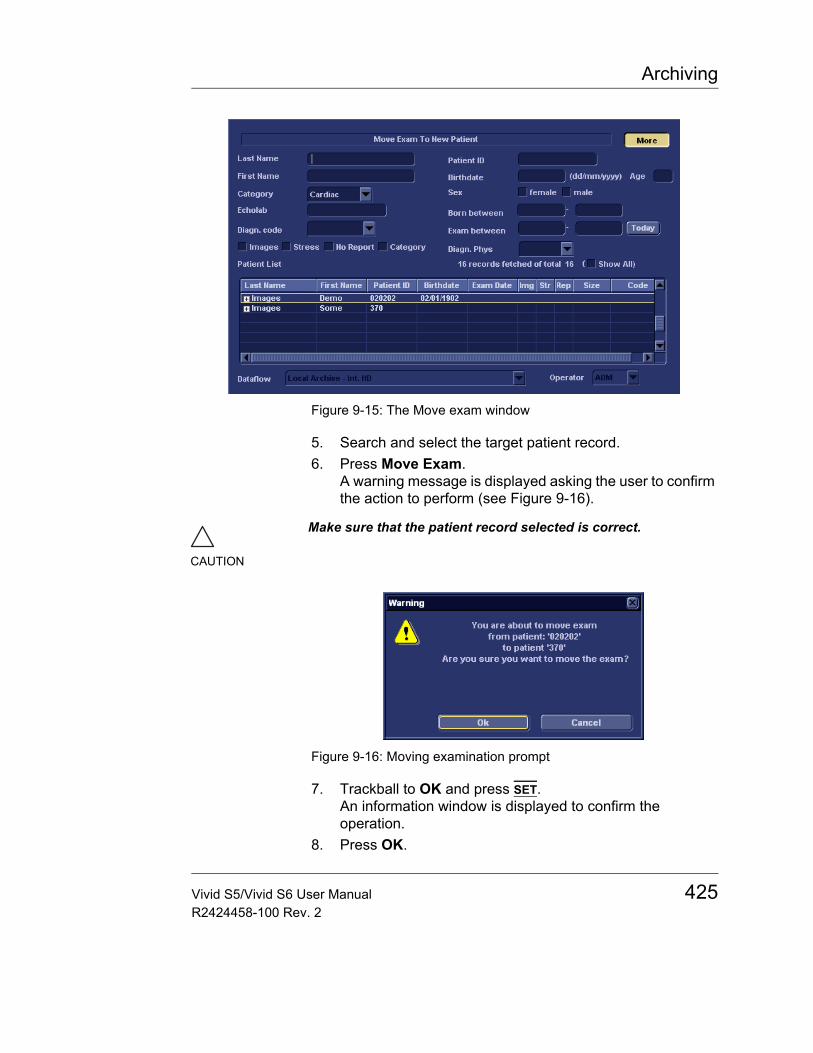
Archiving
Figure 9-15: The Move exam window
5. Search and select the target patient record.6. Press Move Exam.
A warning message is displayed asking the user to confirm the action to perform (see Figure 9-16).
Figure 9-16: Moving examination prompt
7. Trackball to OK and press SET.An information window is displayed to confirm the operation.
8. Press OK.
CAUTION
Make sure that the patient record selected is correct.
Vivid S5/Vivid S6 User Manual 425R2424458-100 Rev. 2

Archiving
Review images in archiveThere are two ways to access to archived images:• Review the images from a selected examination.• Select images from the Image list screen displaying all the
images sorted by examination sessions for the actual patient.
Review the images from a selected examination1. In the Examination list window (see Figure 9-10, page 418),
trackball to the actual examination.2. Press SET on the control panel to highlight the examination.3. Press REVIEW on the control panel.
The stored images for the selected examination are displayed in the Review screen (see Figure 9-17).
To analyze images:1. Press SET on the images to analyze.2. Press ANALYZE.
426 Vivid S5/Vivid S6 User ManualR2424458-100 Rev. 2

Archiving
Figure 9-17: The Review screen
Select images from the Image list screenThe procedure described below enables the analysis of images belonging to different examinations for a selected patient record. If images are stored on multiple removable media, they have to be restored to the local hard drive prior to review as described below.1. In the Examination list window (see Figure 9-10, page 418),
press Image list.The Image list screen is displayed (see Figure 9-20) showing thumbnails of stored images for the actual patient sorted by examination.
1. Page number2. Selected image (bold frame)
3. Selection tools
Vivid S5/Vivid S6 User Manual 427R2424458-100 Rev. 2
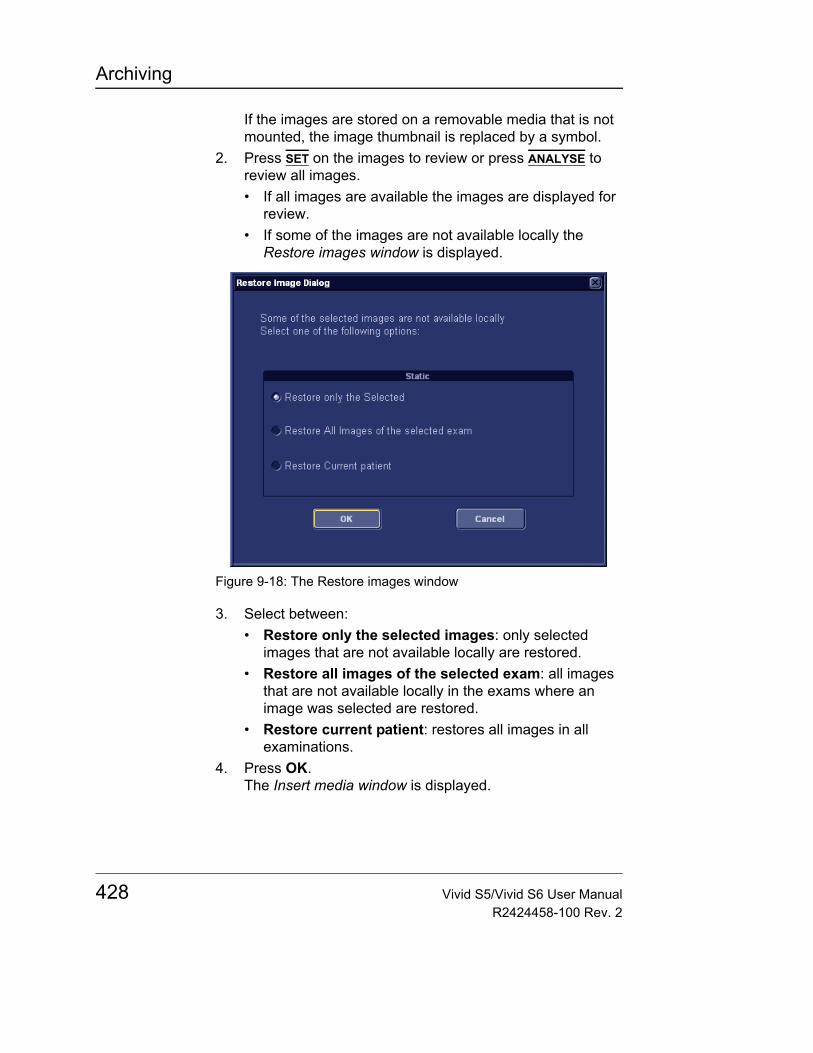
Archiving
If the images are stored on a removable media that is not mounted, the image thumbnail is replaced by a symbol.
2. Press SET on the images to review or press ANALYSE to review all images.• If all images are available the images are displayed for
review.• If some of the images are not available locally the
Restore images window is displayed.
Figure 9-18: The Restore images window
3. Select between:• Restore only the selected images: only selected
images that are not available locally are restored.• Restore all images of the selected exam: all images
that are not available locally in the exams where an image was selected are restored.
• Restore current patient: restores all images in all examinations.
4. Press OK.The Insert media window is displayed.
428 Vivid S5/Vivid S6 User ManualR2424458-100 Rev. 2
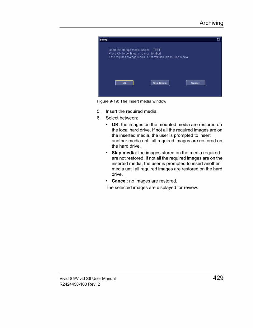
Archiving
Figure 9-19: The Insert media window
5. Insert the required media.6. Select between:
• OK: the images on the mounted media are restored on the local hard drive. If not all the required images are on the inserted media, the user is prompted to insert another media until all required images are restored on the hard drive.
• Skip media: the images stored on the media required are not restored. If not all the required images are on the inserted media, the user is prompted to insert another media until all required images are restored on the hard drive.
• Cancel: no images are restored.The selected images are displayed for review.
Vivid S5/Vivid S6 User Manual 429R2424458-100 Rev. 2
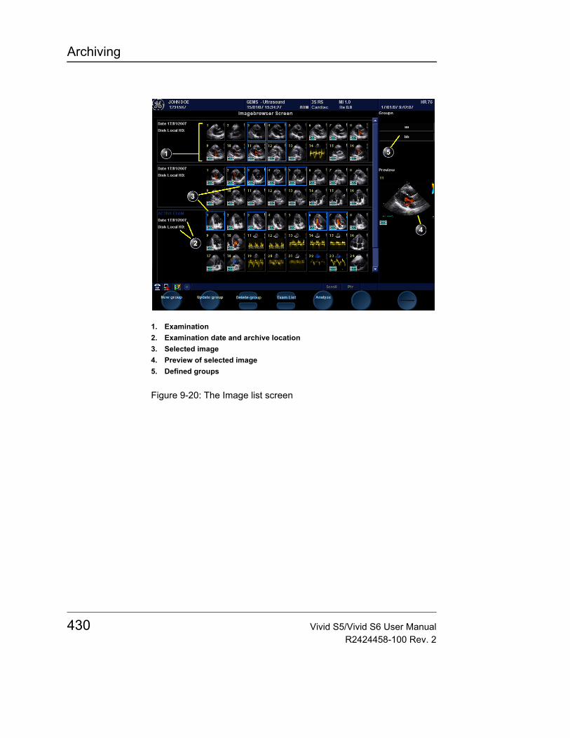
Archiving
Figure 9-20: The Image list screen
1. Examination2. Examination date and archive location3. Selected image4. Preview of selected image5. Defined groups
430 Vivid S5/Vivid S6 User ManualR2424458-100 Rev. 2
Archiving
ConnectivityThis section describes the communication and connection options for the Vivid S5/Vivid S6 ultrasound unit with other devices in the hospital information system. This section covers the procedures for configuration and optimal data management from a Vivid S5/Vivid S6 in the following scenarios:• A stand-alone Vivid S5/Vivid S6 (page 434).• A Vivid S5/Vivid S6 and one or several EchoPAC PC
workstations in a sneaker net environment (page 435).• A Vivid S5/Vivid S6 and an EchoPAC PC workstations in a
direct connect environment (page 437).• A Vivid S5/Vivid S6 and a DICOM server in a network
(page 443).• A Vivid S5/Vivid S6 and one or more PC stations in
MPEGvue or eVue environment.
The dataflow conceptCommunication between the Vivid S5/Vivid S6 ultrasound unit and other information providers on the network takes the form of dataflows. Selecting a dataflow will automatically customize the ultrasound unit to work according to the services associated with this dataflow. Each dataflow defines the location and format of patient information. Patient information can include demographic data and images, as well as reports, measurement and analysis data. By utilizing dataflows, the user can configure the Vivid S5/Vivid S6 ultrasound unit to optimally meet the connectivity needs of the facility, while keeping the user interface unchanged. The dataflow concept allows the flexibility of data to be obtained from various sources and allows data to flow to various output sources.
Dataflow examples
Refer to "Dataflow" on page 616 for a complete list and description of supported dataflows.
Stand-alone scannerThe figure below illustrates dataflow for a stand-alone scanner.
Vivid S5/Vivid S6 User Manual 431R2424458-100 Rev. 2
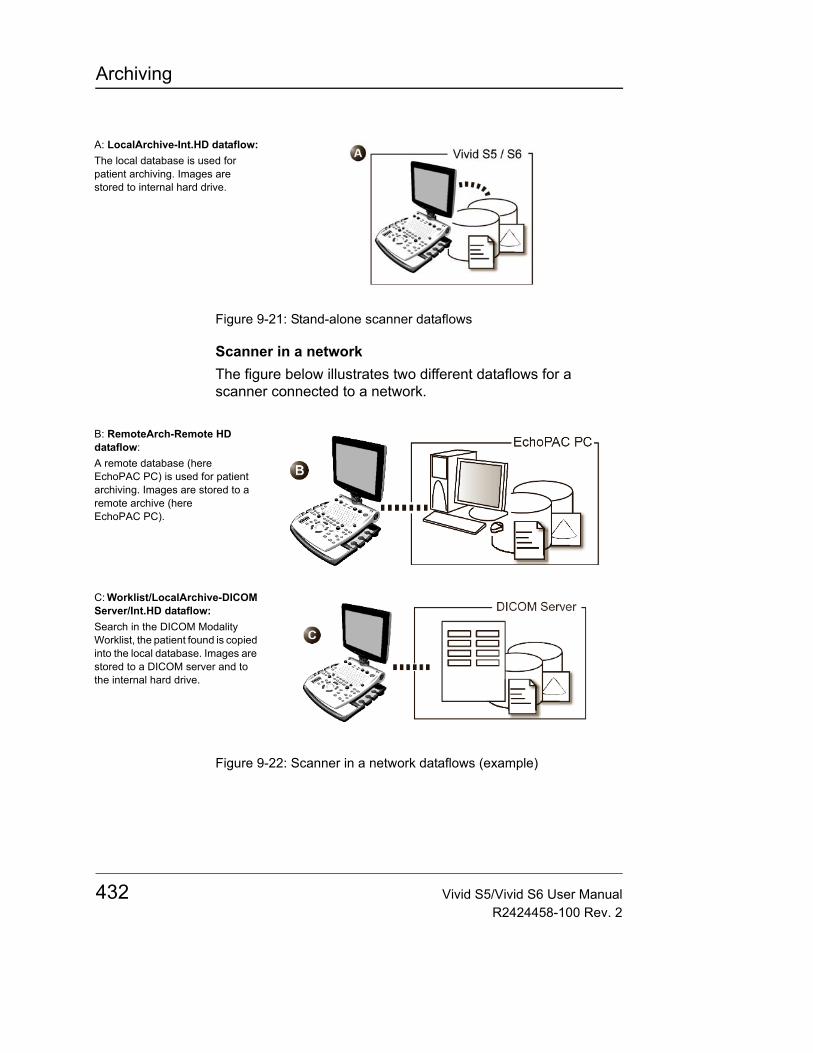
Archiving
Figure 9-21: Stand-alone scanner dataflows
Scanner in a networkThe figure below illustrates two different dataflows for a scanner connected to a network.
Figure 9-22: Scanner in a network dataflows (example)
A: LocalArchive-Int.HD dataflow:The local database is used for patient archiving. Images are stored to internal hard drive.
B: RemoteArch-Remote HD dataflow:A remote database (here EchoPAC PC) is used for patient archiving. Images are stored to a remote archive (here EchoPAC PC).
C: Worklist/LocalArchive-DICOM Server/Int.HD dataflow:Search in the DICOM Modality Worklist, the patient found is copied into the local database. Images are stored to a DICOM server and to the internal hard drive.
432 Vivid S5/Vivid S6 User ManualR2424458-100 Rev. 2

Archiving
Dataflow selection
Select a dataflow from the Search/Create Patient window (see "Creating a new Patient record or starting an examination from an existing patient record" on page 95) or configure the system with a default dataflow from the Configuration management package as described below.
Default dataflow selection1. Press CONFIG and log on as administrator if required.2. Select the Connectivity category and Dataflow subgroup.
The Dataflow sheet is displayed (see Figure 9-23).3. Select the desired dataflow in the Name pull-down menu
and check the option Default.4. Press CONFIG to exit the Configuration management
package.
Figure 9-23: Default dataflow setting
1. Select Connectivity category2. Select Dataflow subgroup3. Select a dataflow4. Default option for the selected dataflow
Vivid S5/Vivid S6 User Manual 433R2424458-100 Rev. 2
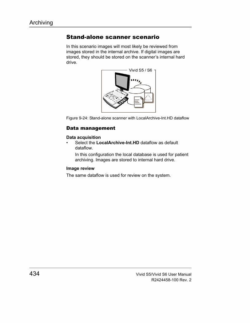
Archiving
Stand-alone scanner scenarioIn this scenario images will most likely be reviewed from images stored in the internal archive. If digital images are stored, they should be stored on the scanner’s internal hard drive.
Figure 9-24: Stand-alone scanner with LocalArchive-Int.HD dataflow
Data management
Data acquisition• Select the LocalArchive-Int.HD dataflow as default
dataflow.In this configuration the local database is used for patient archiving. Images are stored to internal hard drive.
Image reviewThe same dataflow is used for review on the system.
434 Vivid S5/Vivid S6 User ManualR2424458-100 Rev. 2
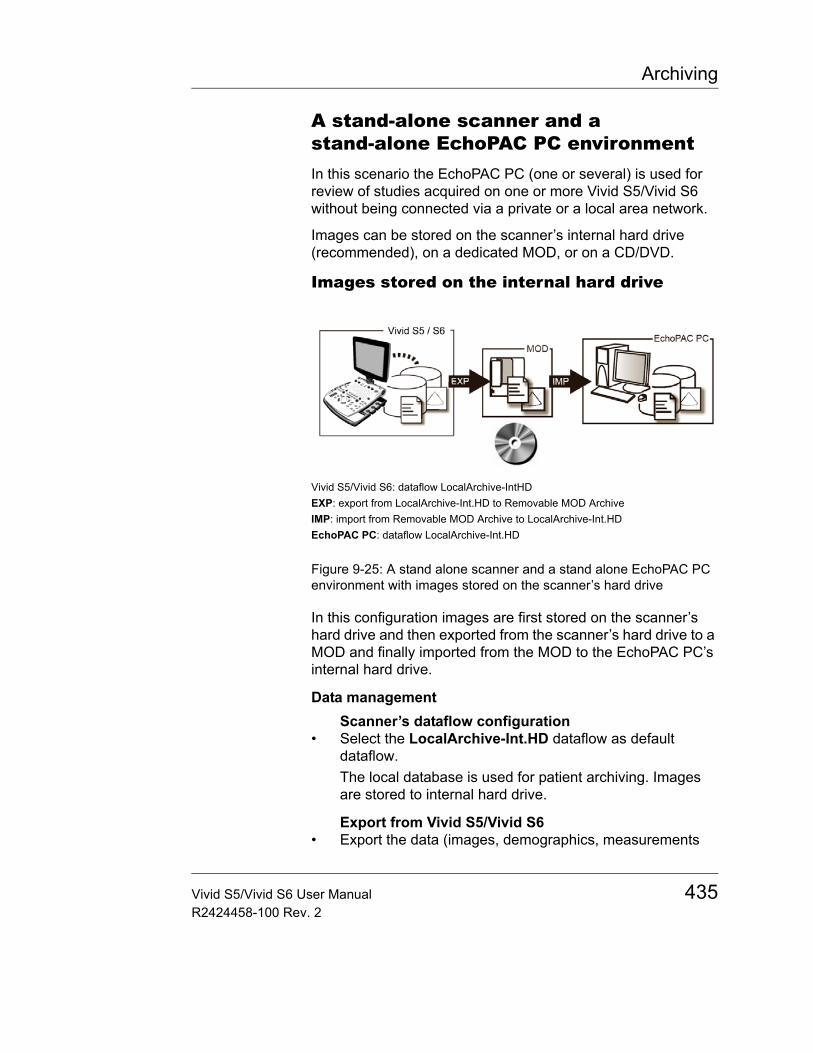
Archiving
A stand-alone scanner and a stand-alone EchoPAC PC environmentIn this scenario the EchoPAC PC (one or several) is used for review of studies acquired on one or more Vivid S5/Vivid S6 without being connected via a private or a local area network.
Images can be stored on the scanner’s internal hard drive (recommended), on a dedicated MOD, or on a CD/DVD.
Images stored on the internal hard drive
Figure 9-25: A stand alone scanner and a stand alone EchoPAC PC environment with images stored on the scanner’s hard drive
In this configuration images are first stored on the scanner’s hard drive and then exported from the scanner’s hard drive to a MOD and finally imported from the MOD to the EchoPAC PC’s internal hard drive.
Data managementScanner’s dataflow configuration
• Select the LocalArchive-Int.HD dataflow as default dataflow.The local database is used for patient archiving. Images are stored to internal hard drive.
Export from Vivid S5/Vivid S6• Export the data (images, demographics, measurements
Vivid S5/Vivid S6: dataflow LocalArchive-IntHDEXP: export from LocalArchive-Int.HD to Removable MOD ArchiveIMP: import from Removable MOD Archive to LocalArchive-Int.HDEchoPAC PC: dataflow LocalArchive-Int.HD
Vivid S5/Vivid S6 User Manual 435R2424458-100 Rev. 2
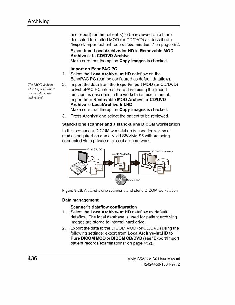
Archiving
and report) for the patient(s) to be reviewed on a blank dedicated formatted MOD (or CD/DVD) as described in "Export/Import patient records/examinations" on page 452.Export from LocalArchive-Int.HD to Removable MOD Archive or to CD/DVD Archive.Make sure that the option Copy images is checked.
Import on EchoPAC PC1. Select the LocalArchive-Int.HD dataflow on the
EchoPAC PC (can be configured as default dataflow).The MOD dedicat-ed to Export/Import can be reformatted and reused.
2. Import the data from the Export/import MOD (or CD/DVD) to EchoPAC PC internal hard drive using the Import function as described in the workstation user manual.Import from Removable MOD Archive or CD/DVD Archive to LocalArchive-Int.HDMake sure that the option Copy images is checked.
3. Press Archive and select the patient to be reviewed.
Stand-alone scanner and a stand-alone DICOM workstationIn this scenario a DICOM workstation is used for review of studies acquired on one a Vivid S5/Vivid S6 without being connected via a private or a local area network.
Figure 9-26: A stand-alone scanner stand-alone DICOM workstation
Data managementScanner's dataflow configuration
1. Select the LocalArchive-Int.HD dataflow as default dataflow. The local database is used for patient archiving. Images are stored to internal hard drive.
2. Export the data to the DICOM MOD (or CD/DVD) using the following settings: export from LocalArchive-Int.HD to Pure DICOM MOD or DICOM CD/DVD (see "Export/Import patient records/examinations" on page 452).
436 Vivid S5/Vivid S6 User ManualR2424458-100 Rev. 2
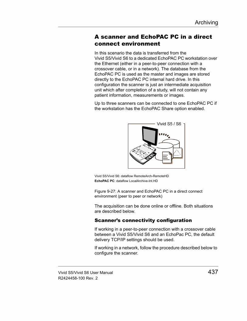
Archiving
A scanner and EchoPAC PC in a direct connect environmentIn this scenario the data is transferred from the Vivid S5/Vivid S6 to a dedicated EchoPAC PC workstation over the Ethernet (either in a peer-to-peer connection with a crossover cable, or in a network). The database from the EchoPAC PC is used as the master and images are stored directly to the EchoPAC PC internal hard drive. In this configuration the scanner is just an intermediate acquisition unit which after completion of a study, will not contain any patient information, measurements or images.
Up to three scanners can be connected to one EchoPAC PC if the workstation has the EchoPAC Share option enabled.
Figure 9-27: A scanner and EchoPAC PC in a direct connect environment (peer to peer or network)
The acquisition can be done online or offline. Both situations are described below.
Scanner’s connectivity configuration
If working in a peer-to-peer connection with a crossover cable between a Vivid S5/Vivid S6 and an EchoPac PC, the default delivery TCP/IP settings should be used.
If working in a network, follow the procedure described below to configure the scanner.
Vivid S5/Vivid S6: dataflow RemoteArch-RemoteHDEchoPAC PC: dataflow LocalArchive-Int.HD
Vivid S5/Vivid S6 User Manual 437R2424458-100 Rev. 2
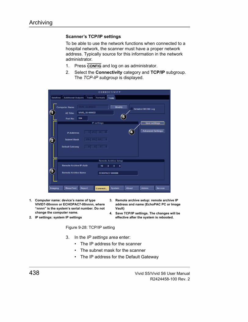
Archiving
Scanner’s TCP/IP settingsTo be able to use the network functions when connected to a hospital network, the scanner must have a proper network address. Typically source for this information in the network administrator.1. Press CONFIG and log on as administrator.2. Select the Connectivity category and TCP/IP subgroup.
The TCP-IP subgroup is displayed.
Figure 9-28: TCP/IP setting
3. In the IP settings area enter:• The IP address for the scanner• The subnet mask for the scanner• The IP address for the Default Gateway
1. Computer name: device’s name of type VIVID7-00nnnn or ECHOPAC7-00nnnn, where “nnnn” is the system’s serial number. Do not change the computer name.
2. IP settings: system IP settings
3. Remote archive setup: remote archive IP address and name (EchoPAC PC or Image Vault)
4. Save TCP/IP settings. The changes will be effective after the system is rebooted.
438 Vivid S5/Vivid S6 User ManualR2424458-100 Rev. 2
Archiving
4. In the Remote archive setup area enter:• The IP address for the remote archive• The name of the remote archive
5. Press Save settings and reboot the system.
Direct connect with online acquisition
Data managementScanner’s dataflow configuration
• Select the RemoteArch-RemoteHD dataflow as default dataflow.When saving the study on the scanner, the images are transferred from the scanner’s image buffer to the hard drive of the EchoPAC PC. Patient demographics, measurements and reports are transferred on the fly when entering the information on the Vivid S5/Vivid S6.
Review on the EchoPAC PC workstation1. Select the LocalArchive-Int.HD dataflow on the
EchoPAC PC (can be configured as default dataflow).
2. Press Archive and select the patient to be reviewed.
CAUTION
Do NOT open a study on the EchoPAC PC workstation before the study is closed on the scanner.
Vivid S5/Vivid S6 User Manual 439R2424458-100 Rev. 2
Archiving
Direct connect with offline acquisition
Data managementScanner’s dataflow configuration for offline acquisition
• When offline, select the LocalArchive-IntHD dataflow.The local database is used for patient archiving. Images are stored to internal hard drive.
Export examinations done offline from the scanner to EchoPAC PC
• When reconnected, export the data (images, demographics, measurements and report) for the examination(s) done offline to EchoPAC PC as describes in "Export/Import patient records/examinations" on page 452.
Press Today to dis-play today’s exams to ease the search.
Export from LocalArchive-Int.HD to RemoteArch-RemoteHD.Make sure that the option Copy images is checked.
The examination done offline can now be reviewed on the workstation.
440 Vivid S5/Vivid S6 User ManualR2424458-100 Rev. 2
Archiving
A scanner and EchoPAC PC in a network environmentIn this scenario the Vivid S5/Vivid S6 is configured to work with an ImageVault 4.0 or an Image Vault 7 patient demographics and image server in a network environment. Images are first saved on the local image buffer on the scanner and transferred to the server when saving the examination.
The acquisition can be done online or offline. Both situations are described below.
Network environment with online acquisition
Data managementScanner’s dataflow configuration
• Select the RemoteArch-RemoteHD dataflow as default dataflow in the sublevel Dataflow in the subgroup Connectivity of the Configuration management package (see page 616 and following pages).When saving the study on the scanner, the images are transferred from the scanner’s image buffer to the server. Patient demographics, measurements and reports are transferred on the fly when entering the information on the Vivid S5/Vivid S6.
Review on the EchoPAC PC workstation1. Select the RemoteArch-RemoteHD dataflow on the
EchoPAC PC (can be configured as default dataflow).
2. Press Archive and select the patient to be reviewed.
CAUTION
Do NOT open a study on the EchoPAC PC workstation before the study is closed on the scanner.
Vivid S5/Vivid S6 User Manual 441R2424458-100 Rev. 2
Archiving
Network environment with offline acquisition
Data managementScanner’s dataflow configuration for offline acquisition
• When offline, select the LocalArchive-IntHD dataflow.The local database is used for patient archiving. Images are stored to internal hard drive.
Export examinations done offline from the scanner to the server
• When reconnected, export the data (images, demographics, measurements and report) for the examination(s) done offline to the server as described in "Export/Import patient records/examinations" on page 452.
Press Today to dis-play today’s exams to ease the search.
Export from LocalArchive-Int.HD to RemoteArch-RemoteHD.Make sure that the option Copy images is checked.
The examination done offline can now be reviewed on the workstation.
442 Vivid S5/Vivid S6 User ManualR2424458-100 Rev. 2
Archiving
A scanner and a DICOM server in a networkIn this scenario the Vivid S5/Vivid S6 is configured to work with a DICOM server in a network environment. Images are first saved on the local image buffer on the scanner. At the end of the examination the images are sent to the DICOM server via a DICOM spooler.
The DICOM server dataflow supported are:• DICOM server: images are stored to a DICOM server• Local Archive - Int HD/DICOM Server: the local archive is
used for patient archiving. Images are stored to the internal hard drive and to a DICOM server.
• Remote Archive - Remote HD/DICOM Server: a remote database is used for patient archiving. Images are stored to a network image volume and to a DICOM server.
• Worklist/Local Archive - DICOM Server/Int HD: search in a DICOM Modality Worklist, the patient found is copied into local database. The patient information and the examination results are stored to the local database. Images are stored to a DICOM server and to an image volume on the local hard drive.
• Worklist/Remote Archive - DICOM Server/Remote HD: search in a DICOM Modality Worklist, the patient found is copied into a remote database. The patient information and the examination results are stored to a remote database. Images are stored to a DICOM server and to an image network volume as pure DICOM in both locations.
• Query/Retrieve: retrieve images from a DICOM server based on query parameters.
This scenario requires that the scanner is configured to be connected to the DICOM server as described below.
Vivid S5/Vivid S6 User Manual 443R2424458-100 Rev. 2
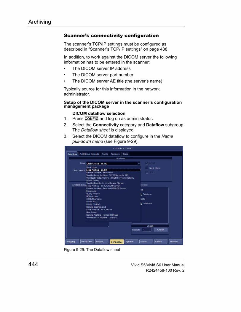
Archiving
Scanner’s connectivity configuration
The scanner’s TCP/IP settings must be configured as described in "Scanner’s TCP/IP settings" on page 438.
In addition, to work against the DICOM server the following information has to be entered in the scanner:• The DICOM server IP address• The DICOM server port number• The DICOM server AE title (the server’s name)
Typically source for this information in the network administrator.
Setup of the DICOM server in the scanner’s configuration management package
DICOM dataflow selection1. Press CONFIG and log on as administrator.2. Select the Connectivity category and Dataflow subgroup.
The Dataflow sheet is displayed.3. Select the DICOM dataflow to configure in the Name
pull-down menu (see Figure 9-29).
Figure 9-29: The Dataflow sheet
444 Vivid S5/Vivid S6 User ManualR2424458-100 Rev. 2
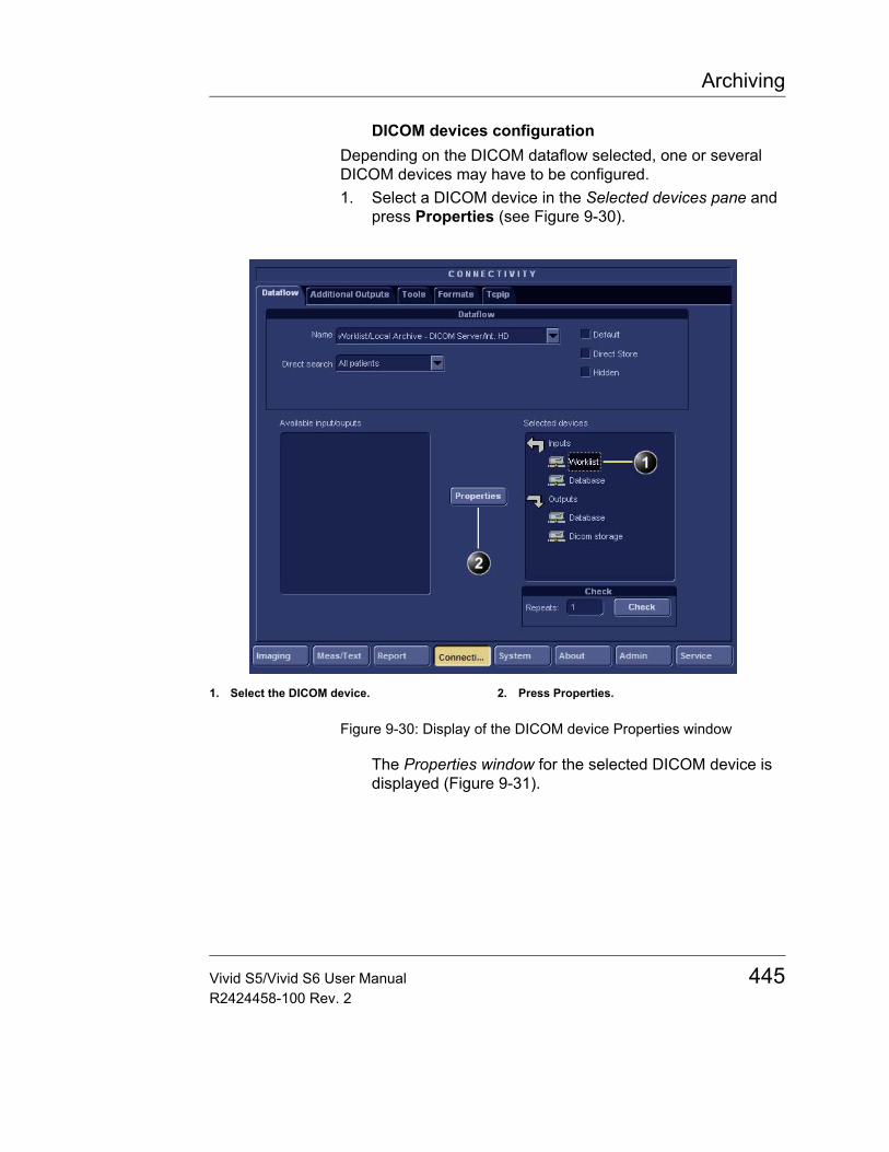
Archiving
DICOM devices configurationDepending on the DICOM dataflow selected, one or several DICOM devices may have to be configured.1. Select a DICOM device in the Selected devices pane and
press Properties (see Figure 9-30).
Figure 9-30: Display of the DICOM device Properties window
The Properties window for the selected DICOM device is displayed (Figure 9-31).
1. Select the DICOM device. 2. Press Properties.
Vivid S5/Vivid S6 User Manual 445R2424458-100 Rev. 2
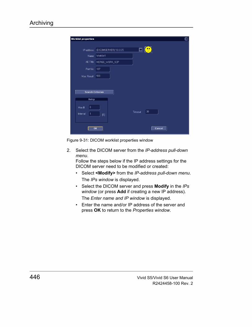
Archiving
Figure 9-31: DICOM worklist properties window
2. Select the DICOM server from the IP-address pull-down menu.Follow the steps below if the IP address settings for the DICOM server need to be modified or created:• Select <Modify> from the IP-address pull-down menu.
The IPs window is displayed.• Select the DICOM server and press Modify in the IPs
window (or press Add if creating a new IP address). The Enter name and IP window is displayed.
• Enter the name and/or IP address of the server and press OK to return to the Properties window.
446 Vivid S5/Vivid S6 User ManualR2424458-100 Rev. 2
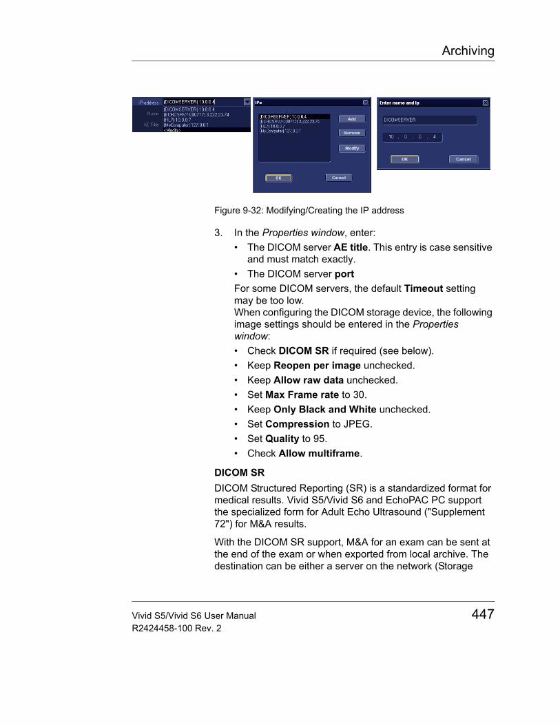
Archiving
Figure 9-32: Modifying/Creating the IP address
3. In the Properties window, enter:• The DICOM server AE title. This entry is case sensitive
and must match exactly.• The DICOM server portFor some DICOM servers, the default Timeout setting may be too low.When configuring the DICOM storage device, the following image settings should be entered in the Properties window:• Check DICOM SR if required (see below).• Keep Reopen per image unchecked.• Keep Allow raw data unchecked.• Set Max Frame rate to 30.• Keep Only Black and White unchecked.• Set Compression to JPEG.• Set Quality to 95.• Check Allow multiframe.
DICOM SRDICOM Structured Reporting (SR) is a standardized format for medical results. Vivid S5/Vivid S6 and EchoPAC PC support the specialized form for Adult Echo Ultrasound ("Supplement 72") for M&A results.
With the DICOM SR support, M&A for an exam can be sent at the end of the exam or when exported from local archive. The destination can be either a server on the network (Storage
Vivid S5/Vivid S6 User Manual 447R2424458-100 Rev. 2
Archiving
SCP) or a removable media (DICOM Media) depending on the DICOM dataflow selected.
"Supplement 72" does not support all M&A results from Vivid S5/Vivid S6 and EchoPAC PC. "Supplement 72" limits the information that is possible to send to the following:• Publicly coded parameters, no pediatric or fetal cardiac or
unassigned measurement. Refer to the Vivid S5/Vivid S6 Reference manual for a complete list of supported parameters.
• Basic modes: 2D, M-mode, Color Flow, PW and CW Doppler.
• Publicly coded methods, not Modified Simpson or Bullet.Refer to the Vivid S5/Vivid S6 Reference manual for a complete list of supported methods.
• Basic derivations (Average, Last), no references between the derived measurements and the ones they were made from.
• Wall Motion Scoring: individual segment scores only according to 16-segment model, no graded Hypokinesis (only Hypokinesis is used).
Activating DICOM SRDICOM SR must be activated for each DICOM device.1. Press CONFIG and log on as administrator.2. Select the Connectivity category and Dataflow subgroup.
The Dataflow sheet is displayed.3. Select the DICOM dataflow to configure in the Name
pull-down menu (see Figure 9-29).4. Select a DICOM storage device in the Selected devices
pane and press Properties.The Properties window for the selected DICOM stogare device is displayed.
448 Vivid S5/Vivid S6 User ManualR2424458-100 Rev. 2
Archiving
Figure 9-33: DICOM storage properties window
5. Check the option DICOM SR.6. Select OK.7. Press CONFIG.
Adjusting the Search criteriaWhen selecting a DICOM Worklist dataflow or Query/Retrieve, search criteria can be set for the system to use when searching the database.1. Press CONFIG and log on as administrator.2. Select the Connectivity category and Dataflow subgroup.
The Dataflow sheet is displayed (see Figure 9-34).3. Select a DICOM Worklist dataflow or the Query/Retrieve
dataflow.4. Select the Worklist or Query/Retrieve device in the
Selected devices pane and press Properties.The Properties window for the selected DICOM device is displayed.
5. Press Search criteria.The Search criteria window is displayed.
6. Select a Search criteria from the Select tag pull-down menu.
Vivid S5/Vivid S6 User Manual 449R2424458-100 Rev. 2
Archiving
7. Enter a value if required or leave blank if not to be used. This entry is case sensitive and must match exactly.
8. Press Add to list.9. Press OK to close the Search criteria window.
Figure 9-34: Adjusting the Search criteria
1. The dataflow sheet2. The Properties window for the Worklist device.3. The Search criteria window
450 Vivid S5/Vivid S6 User ManualR2424458-100 Rev. 2
Archiving
Checking the connection to the DICOM server1. In the Dataflow sheet, select the DICOM device to verify the
connection to.2. Press Check.
The verification process may takes several seconds.• A green check mark is displayed in front of the DICOM
device if the verification is successful.• A red cross is displayed in front of the DICOM device if
the verification failed.
Data management (DICOM dataflows)Performing a studyOnline scanner
1. In the Search/Create patient window, select a DICOM dataflow.
2. If a DICOM worklist dataflow is selected, enter a search criteria and press QUERY. The patient list is updated.
3. Select or create a new patient and perform the examination in a usual manner. During the examination images are temporarily stored in the local buffer on the system.
4. At the end of the study press END EXAM on the Control panel. The save images dialogue window is displayed.
5. Press ALL to save all images on the DICOM server or press SELECT to display the Image review screen where to select specific images to be saved. The images are transferred to the server via the DICOM spooler.
6. Press F4 or ALT+S to display the DICOM spooler (see "DICOM spooler" on page 479 for further details).
Offline scannerWhen working offline the images are stored in the DICOM spooler. Images are sent to the DICOM server when re-connecting the system to the network.1. If a DICOM worklist dataflow is selected, the patient list
must be queried before the system is disconnected.2. After offline acquisition, the images stored on the DICOM
spooler are automatically sent to the DICOM server when connecting the system. Press F4 or ALT+S to display the DICOM spooler (see "DICOM spooler" on page 479 for further details).
Vivid S5/Vivid S6 User Manual 451R2424458-100 Rev. 2
Archiving
Export/Import patient records/examinationsPatient records/examinations from the local archive on one system (Vivid S5/Vivid S6 or EchoPAC PC) can be exported to the local archive on another system via a removable media. Patient records/examinations from the local archive can also be exported directly to a remote archive (Echo server, DICOM server or EchoPAC PC depending on the environment). In addition patient records/examinations from a remote archive (Echo server or EchoPAC PC depending on the environment) can be exported to a removable media or to a DICOM server. Database information (patient and report archives) can be exported with or without images. No data is deleted from the source archive when exporting data unless the command Delete selected patient(s) after copy is checked in the Export patient window (see Figure 9-36, page 454).
Similarly, patient records/examinations from the local archive on one system can be imported to the local archive on another system via a removable media. Database information can be imported with or without images. No data is deleted from the source archive when importing data. In addition patient records from a removable archive can be imported to a remote archive (Echo server).
Exporting patient records/examinations1. If exporting to a removable media, insert a removable
media in the drive.2. Press PATIENT on the Front panel, then select Patient List.
The Search/Create Patient window is displayed (Figure 9-8, page 415).
3. Select the source archive in the Dataflow field:• LocalArchive-Int.HD: exports data from the local
archive.• RemoteArch-RemoteHD: exports data from an Echo
server.4. Press Export in the Search/Create Patient window.
CAUTION
If an examination is opened, it must be closed before performing Export/Import of patient records/examinations to guarantee that all data is included in the transfer.
452 Vivid S5/Vivid S6 User ManualR2424458-100 Rev. 2
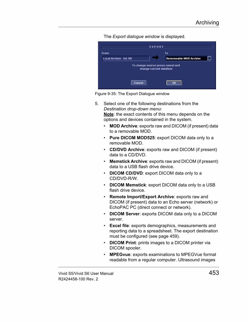
Archiving
The Export dialogue window is displayed.
Figure 9-35: The Export Dialogue window
5. Select one of the following destinations from the Destination drop-down menu:Note: the exact contents of this menu depends on the options and devices contained in the system.• MOD Archive: exports raw and DICOM (if present) data
to a removable MOD.• Pure DICOM MOD525: export DICOM data only to a
removable MOD.• CD/DVD Archive: exports raw and DICOM (if present)
data to a CD/DVD.• Memstick Archive: exports raw and DICOM (if present)
data to a USB flash drive device.• DICOM CD/DVD: export DICOM data only to a
CD/DVD-R/W.• DICOM Memstick: export DICOM data only to a USB
flash drive device.• Remote Import/Export Archive: exports raw and
DICOM (if present) data to an Echo server (network) or EchoPAC PC (direct connect or network).
• DICOM Server: exports DICOM data only to a DICOM server.
• Excel file: exports demographics, measurements and reporting data to a spreadsheet. The export destination must be configured (see page 459).
• DICOM Print: prints images to a DICOM printer via DICOM spooler.
• MPEGvue: exports examinations to MPEGVue format readable from a regular computer. Ultrasound images
Vivid S5/Vivid S6 User Manual 453R2424458-100 Rev. 2
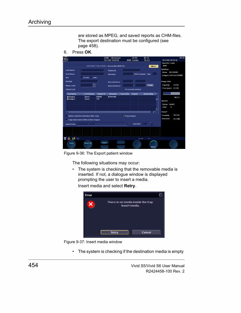
Archiving
are stored as MPEG, and saved reports as CHM-files. The export destination must be configured (see page 458).
6. Press OK.
Figure 9-36: The Export patient window
The following situations may occur:• The system is checking that the removable media is
inserted. If not, a dialogue window is displayed prompting the user to insert a media.Insert media and select Retry.
Figure 9-37: Insert media window
• The system is checking if the destination media is empty
454 Vivid S5/Vivid S6 User ManualR2424458-100 Rev. 2
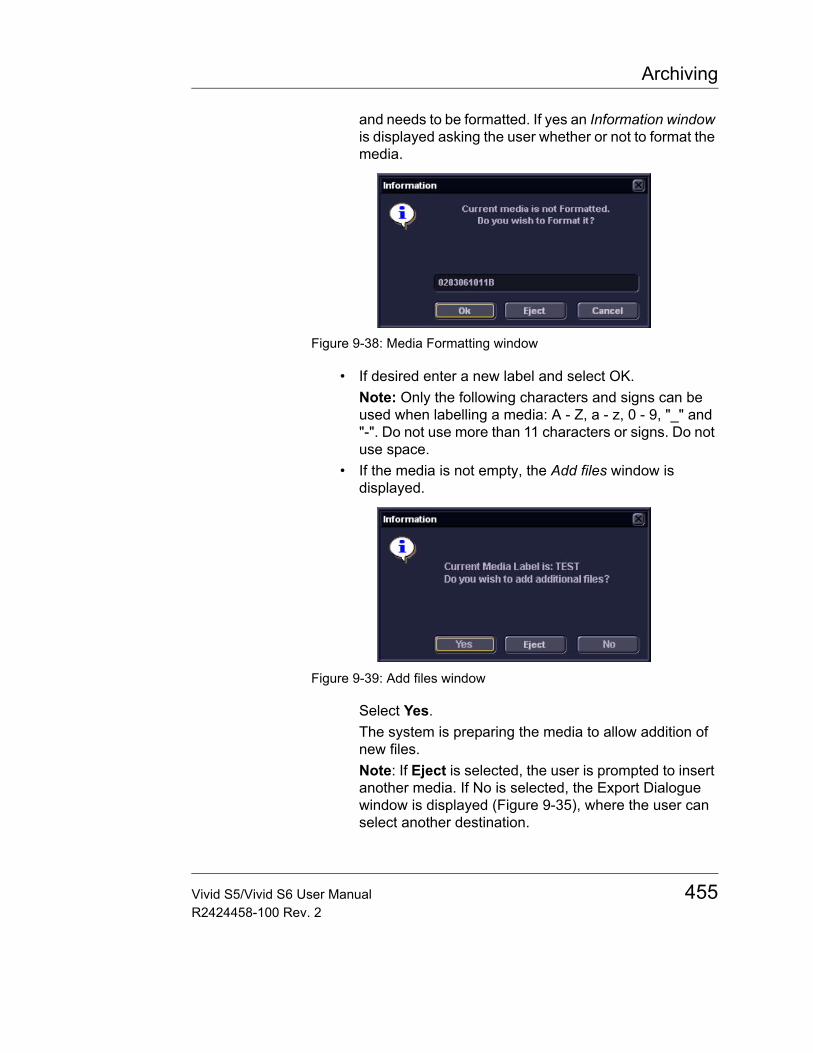
Archiving
and needs to be formatted. If yes an Information window is displayed asking the user whether or not to format the media.
Figure 9-38: Media Formatting window
• If desired enter a new label and select OK.Note: Only the following characters and signs can be used when labelling a media: A - Z, a - z, 0 - 9, "_" and "-". Do not use more than 11 characters or signs. Do not use space.
• If the media is not empty, the Add files window is displayed.
Figure 9-39: Add files window
Select Yes.The system is preparing the media to allow addition of new files.Note: If Eject is selected, the user is prompted to insert another media. If No is selected, the Export Dialogue window is displayed (Figure 9-35), where the user can select another destination.
Vivid S5/Vivid S6 User Manual 455R2424458-100 Rev. 2
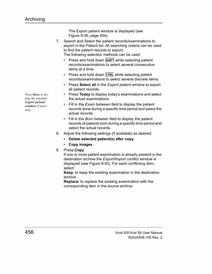
Archiving
The Export patient window is displayed (see Figure 9-36, page 454).
7. Search and Select the patient records/examinations to export in the Patient list. All searching criteria can be used to find the patient records to export.The following selection methods can be used: • Press and hold down SHIFT while selecting patient
records/examinations to select several consecutive items at a time.
• Press and hold down CTRL while selecting patient records/examinations to select several discrete items.
• Press Select all in the Export patient window to export all patient records.
Press More to dis-play the extended Export patient window if neces-sary.
• Press Today to display today's examinations and select the actual examinations.
• Fill in the Exam between field to display the patient records done during a specific time period and select the actual records.
• Fill in the Born between field to display the patient records of patients born during a specific time period and select the actual records.
8. Adjust the following settings (if available) as desired:• Delete selected patient(s) after copy• Copy images
9. Press Copy.If one or more patient examination is already present in the destination archive the Export/Import conflict window is displayed (see Figure 9-40). For each conflicting item, select:Keep: to keep the existing examination in the destination archive.Replace: to replace the existing examination with the corresponding item in the source archive.
456 Vivid S5/Vivid S6 User ManualR2424458-100 Rev. 2
Archiving
Figure 9-40: The Export/Import conflict window
Press OK to resume export.A progress indicator is displayed. When done a status window is displayed showing the number of patient records that have been successfully exported.
10. Press OK.A check mark is displayed in the Copied field in the Export patient window for each item exported.A status message is displayed for each item exported. Make sure that the operation was successful for each item exported.
11. Press Done in the Export patient window to complete the process.
Do not eject the CD using the button on the CD drive.
12. If exporting to a removable media, press Eject or ALT+E to eject the disk.The Eject device menu is displayed.
Figure 9-41: The Eject device menu
13. Select the relevant media.The selected removable media is ejected.
Vivid S5/Vivid S6 User Manual 457R2424458-100 Rev. 2
Archiving
Export Configuration
The destination for Export of patient records to Excel and MPEG must be configured prior to use (both are options). This is done from the Dataflow sheet in the Configuration package.
To display the Dataflow sheet:1. Press CONFIG and log on as administrator.2. Select Connectivity category and Dataflow subgroup.
The Dataflow sheet is displayed (Figure 9-4, page 411).3. Select the dataflow Misc Export in the Name pull-down
menu.
Figure 9-42: The Dataflow Sheet
Configuring an Excel Export1. Select the Excel storage device in the Selected devices
pane and press Properties.The Excel properties window is displayed.
458 Vivid S5/Vivid S6 User ManualR2424458-100 Rev. 2
Archiving
Figure 9-43: The Excel properties window
Remote paths of network volumes must be entered once in the Remote Path field before they can be selected from the Destina-tion pull-down menu.
2. Select a removable media or a network volume remote path as the destination in the Destination pull-down menu.
3. Select OK and press CONFIG.
Export to an eVue Configuration1. Select the eVue device in the Selected devices pane and
press Properties.The eVue properties window is displayed (Figure 9-5, page 412).
Remote paths of network volumes must be entered once in the Remote Path field before they can be selected from the Destina-tion pull-down menu.
2. Select a removable media or a network volume remote path as the destination in the Destination pull-down menu.
3. Check the options as required.4. Select OK and press CONFIG.
Vivid S5/Vivid S6 User Manual 459R2424458-100 Rev. 2
Archiving
Importing patient records/examinations1. Insert the removable media of the source archive in the
corresponding drive (MO drive or CD-ROM).2. Press PATIENT on the Front panel, then select Patient List.
The Search/Create Patient window is displayed (Figure 9-8, page 415).
3. Select destination archive in the Dataflow field: • LocalArchive-Int.HD: imports data to the local archive.• RemoteArch-RemoteHD: imports data to an Echo
server (network) or an EchoPAC PC (direct connect).4. Press Import in the Search/Create Patient window.
The Import dialogue window is displayed (see Figure 9-44).
Figure 9-44: The Import Dialogue window
5. Select one of the following source archive from the Source drop-down menu:• MOD Archive: imports raw and DICOM data (if present)
from a MOD.• DICOM MOD525: imports DICOM data only from a
MOD.• CD/DVD Archive: imports raw and DICOM data (if
present) from a CD/DVD-R.• Memstick Archive: imports raw and DICOM (if present)
data from a USB flash drive device.• DICOM CD/DVD: imports DICOM data only from a
CD/DVD-R/W.• DICOM Memstick: imports DICOM data only from a
USB flash drive device.• Remote Import/Export Archive: imports raw and
460 Vivid S5/Vivid S6 User ManualR2424458-100 Rev. 2
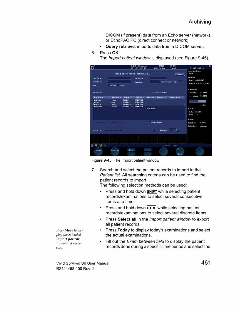
Archiving
DICOM (if present) data from an Echo server (network) or EchoPAC PC (direct connect or network).
• Query retrieve: imports data from a DICOM server.6. Press OK.
The Import patient window is displayed (see Figure 9-45).
Figure 9-45: The Import patient window
7. Search and select the patient records to import in the Patient list. All searching criteria can be used to find the patient records to import.The following selection methods can be used: • Press and hold down SHIFT while selecting patient
records/examinations to select several consecutive items at a time.
• Press and hold down CTRL while selecting patient records/examinations to select several discrete items.
• Press Select all in the Import patient window to export all patient records.
Press More to dis-play the extended Import patient window if neces-sary.
• Press Today to display today's examinations and select the actual examinations.
• Fill out the Exam between field to display the patient records done during a specific time period and select the
Vivid S5/Vivid S6 User Manual 461R2424458-100 Rev. 2
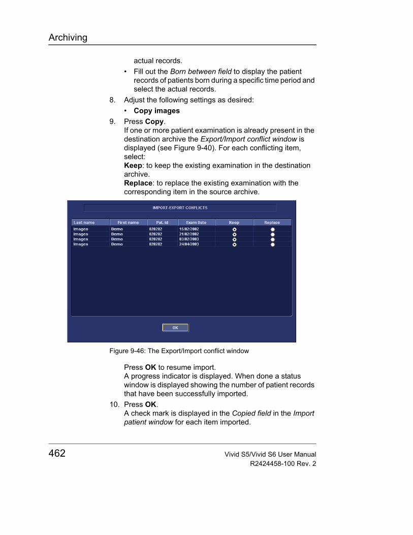
Archiving
actual records.• Fill out the Born between field to display the patient
records of patients born during a specific time period and select the actual records.
8. Adjust the following settings as desired:• Copy images
9. Press Copy.If one or more patient examination is already present in the destination archive the Export/Import conflict window is displayed (see Figure 9-40). For each conflicting item, select:Keep: to keep the existing examination in the destination archive.Replace: to replace the existing examination with the corresponding item in the source archive.
Figure 9-46: The Export/Import conflict window
Press OK to resume import.A progress indicator is displayed. When done a status window is displayed showing the number of patient records that have been successfully imported.
10. Press OK.A check mark is displayed in the Copied field in the Import patient window for each item imported.
462 Vivid S5/Vivid S6 User ManualR2424458-100 Rev. 2

Archiving
A status message is displayed for each item imported. Make sure that the operation was successful for each item imported.
11. Press Done in the Import patient window to complete the process.
Vivid S5/Vivid S6 User Manual 463R2424458-100 Rev. 2
Archiving
Disk ManagementThe Disk management function allows the user to manage hard disk space while maintaining the patient database on the system. The Disk management function can be used to move, copy or delete images and move or copy reports from the oldest patient records (configurable). The Disk management function has also an auto-purge feature that automatically deletes images that have already been copied if the local hard disk is approaching its capacity limit.
When moving or copying files a copy of the patient ar-chive is also created on the media.
Three different disk management scenarios are possible depending on the system configuration:• Disk management is set to move files: the user runs the
Disk management function on a regular basis to move images and reports from older patient records to removable media or to a network volume. Using this setting, moved images and reports are deleted from the local hard drive and copied to the specified destination. This scenario prevents the local disk to fill up and keeps images and reports from the most recent patient records on the local disk. Using this scenario, the user can control what should remain on the system while keeping the disk free space at an operational level.
• Disk management is set to copy files: the user runs the Disk management function on a regular basis to copy images and reports from older patient records to removable media or to a network volume. To prevent the local disk to fill up, the auto-purge function automatically deletes files that were previously copied when the disk free space has reached the minimum allowed limit. This scenario lets the system automatically manage the disk space on the system.Note: When using this setting, the images location displayed in the Examination list screen is the selected destination for the copy operation, even if the images are still present on the local hard drive. When reviewing the exam, the original images is retrieved from the local hard drive as long as they are available there. When the images are deleted from the local hard drive by the auto-purge function, the copied images are retrieved.
464 Vivid S5/Vivid S6 User ManualR2424458-100 Rev. 2
Archiving
• Disk management is set to delete files: the user runs the Disk management function on a regular basis to delete images and reports from older patient records.
Ensure that you have established a data management protocol for your office/institution. The user MUST manage the removable media used when running Disk management by keeping a log and by creating a media filing system.
A person should be in charge of performing the process. The Disk management system can be set up so that a reminder is displayed at a regular time span.
Configuring the Disk management functionConfiguration of the Disk management system can only be done by user with administration rights.1. Press CONFIG.
If required, log on as administrator.2. Select the Admin category.3. In the Admin category, select the sheet Data Management.
Vivid S5/Vivid S6 User Manual 465R2424458-100 Rev. 2
Archiving
Figure 9-47: The Disk management sheet
Disk management schedule settings• Next to Reminder interval, specify the number of
days/weeks you want the system to prompt you to perform disk management. This setting should be set based on the activity of your office/institution. If None is selected, no reminder is displayed.
1. Sets the reminder time interval for running Disk management2. Sets the files to be managed based on the examination dates3. Sets the Disk management to copy, move or delete images4. Sets the destination device
466 Vivid S5/Vivid S6 User ManualR2424458-100 Rev. 2
Archiving
Disk management settings1. Select a number of days, weeks or months or a specific
date next to Manage files older than. Only files older than the specified setting are copied or moved. If None is selected, all files are copied or moved.
2. Next to Operation, select one of the following options:• Copy: the images and reports from the examinations
older than the specified setting defined in step 1 are copied to the specified destination. After using this setting, the files exist in two locations, the local hard drive and the media used to copy to.
• Move: the images and reports from the examinations older than the specified setting defined in step 1 are copied to the specified destination, verified and then deleted from the local hard drive. After using this setting, the files exist in one location, the media used to move the files to. They are removed from the local hard drive.
• Delete: the images and reports from the examinations older than the specified setting defined in step 1 are deleted from the hard drive.
Destination device settings• Next to Destination device, select a removable media or a
network shared folder.Note: To be able to select a network shared folder in the Destination device field, its path must have been entered once in the field next to Remote path.
CAUTION
If using removable media, it is recommended to use dedicated media to the Disk management process. Removable media used for data backup must not be used when performing Disk management.
Do not use the same removable media on several systems.
Vivid S5/Vivid S6 User Manual 467R2424458-100 Rev. 2
Archiving
Running the Disk management functionThe Disk management function can be run at any time. In addition, the user may be prompted to run Disk management if the time since the last Disk management operation performed has reached the setting for the Reminder interval (see page 466), or if the local hard drive is about to reach its capacity limit.
Manual start of disk management1. Press PATIENT on the control panel, then select Patient list.
The Search/Create patient window is displayed.2. Press More in the Search/Create patient window to display
additional menu options and select Disk management.The Disk management welcome screen is displayed (Figure 9-48). The Disk management operation will either copy, remove or delete files from the local archives depending on the Disk management configuration (see page 465). Make sure that the correct configuration is set.
Figure 9-48: The Disk management welcome screen
3. Press Next.The Storage size information window is displayed (Figure 9-49). Verify the information displayed. If using removable media, the operation may require several
468 Vivid S5/Vivid S6 User ManualR2424458-100 Rev. 2
Archiving
media as specified on the screen. Make sure to gather the necessary number of disks.
Figure 9-49: The Storage size information window
The media does not need to be format-ted.
4. Insert a removable media into the specified drive. The disk does not need to be formatted.
5. Press Next.The Copying files window is displayed (Figure 9-50).
Figure 9-50: The copying files window
Vivid S5/Vivid S6 User Manual 469R2424458-100 Rev. 2
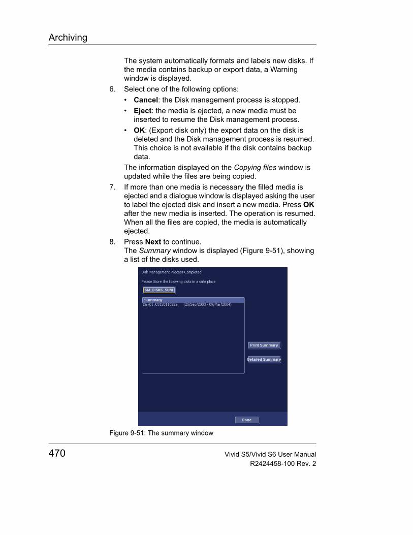
Archiving
The system automatically formats and labels new disks. If the media contains backup or export data, a Warning window is displayed.
6. Select one of the following options:• Cancel: the Disk management process is stopped.• Eject: the media is ejected, a new media must be
inserted to resume the Disk management process.• OK: (Export disk only) the export data on the disk is
deleted and the Disk management process is resumed. This choice is not available if the disk contains backup data.
The information displayed on the Copying files window is updated while the files are being copied.
7. If more than one media is necessary the filled media is ejected and a dialogue window is displayed asking the user to label the ejected disk and insert a new media. Press OK after the new media is inserted. The operation is resumed.When all the files are copied, the media is automatically ejected.
8. Press Next to continue.The Summary window is displayed (Figure 9-51), showing a list of the disks used.
Figure 9-51: The summary window
470 Vivid S5/Vivid S6 User ManualR2424458-100 Rev. 2
Archiving
• Select Print summary to print the list for archiving purpose.
• Select Detailed summary to display the list of the patient records copied.
9. Make sure that all media are physically labeled according to the list displayed in the Summary window. The media label should also have an identification of the system the Disk management was run from.
10. Press Done to complete the Disk management operation and file the media.
Data Backup and RestoreThe Backup/Restore function enables the user to:• Copy/Restore the patient archive.• Copy/Restore the system configuration. The Copy/Restore
system configuration feature enables the user to configure several units with identical presets, providing that the units have the same software version.
To minimize accidental loss of data, perform backup of the patient archive stored on the local hard drive at least once a week.
There is no backup function for the images or reports (no creation of a safety copy). For long-term storage, images and reports should be moved to removable MOD or to a network shared folder using the Disk management procedure (see page 464).
The backup of the patient archive on the hard drive and the system configuration is done from the configuration management package as described on page 472.
WARNING
GE Medical Systems is not responsible for lost data if the suggested backup procedures are not followed and will not aid in the recovery of lost data.
CAUTION
DO NOT use the local hard drive for long-term image storage.
Vivid S5/Vivid S6 User Manual 471R2424458-100 Rev. 2
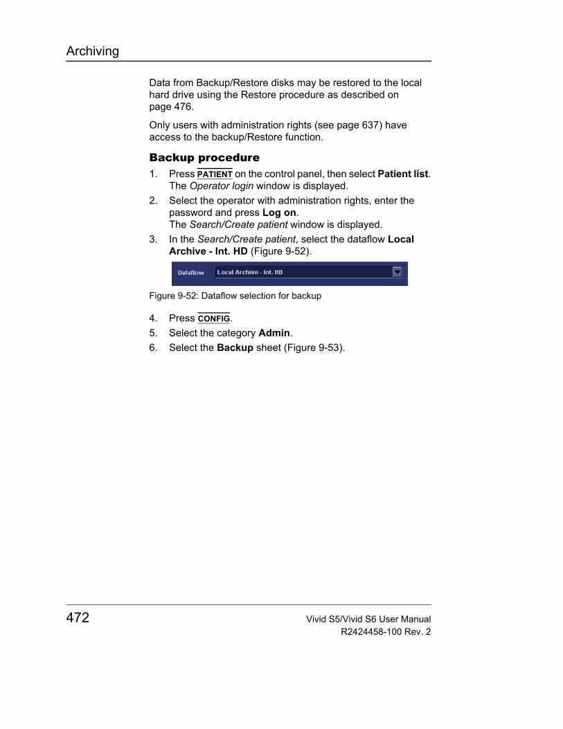
Archiving
Data from Backup/Restore disks may be restored to the local hard drive using the Restore procedure as described on page 476.
Only users with administration rights (see page 637) have access to the backup/Restore function.
Backup procedure1. Press PATIENT on the control panel, then select Patient list.
The Operator login window is displayed.2. Select the operator with administration rights, enter the
password and press Log on.The Search/Create patient window is displayed.
3. In the Search/Create patient, select the dataflow Local Archive - Int. HD (Figure 9-52).
Figure 9-52: Dataflow selection for backup
4. Press CONFIG.5. Select the category Admin.6. Select the Backup sheet (Figure 9-53).
472 Vivid S5/Vivid S6 User ManualR2424458-100 Rev. 2
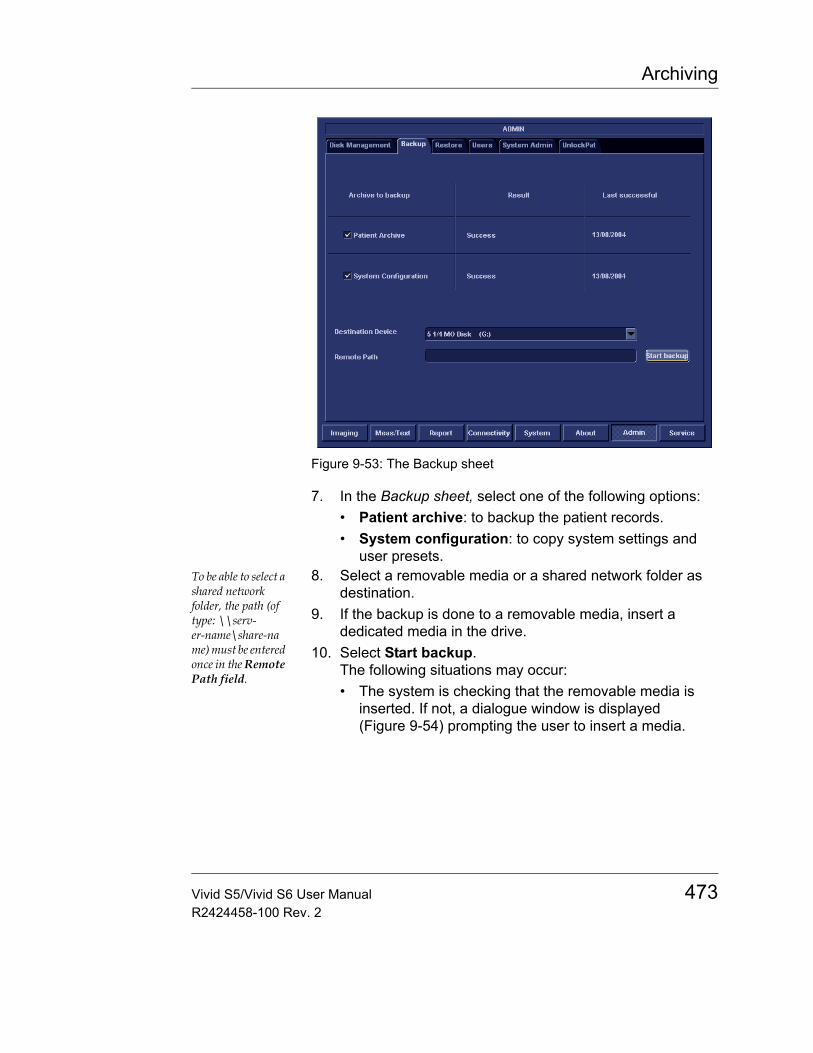
Archiving
Figure 9-53: The Backup sheet
7. In the Backup sheet, select one of the following options:• Patient archive: to backup the patient records.• System configuration: to copy system settings and
user presets.To be able to select a shared network folder, the path (of type: \\serv-er-name\share-name) must be entered once in the Remote Path field.
8. Select a removable media or a shared network folder as destination.
9. If the backup is done to a removable media, insert a dedicated media in the drive.
10. Select Start backup.The following situations may occur:• The system is checking that the removable media is
inserted. If not, a dialogue window is displayed (Figure 9-54) prompting the user to insert a media.
Vivid S5/Vivid S6 User Manual 473R2424458-100 Rev. 2
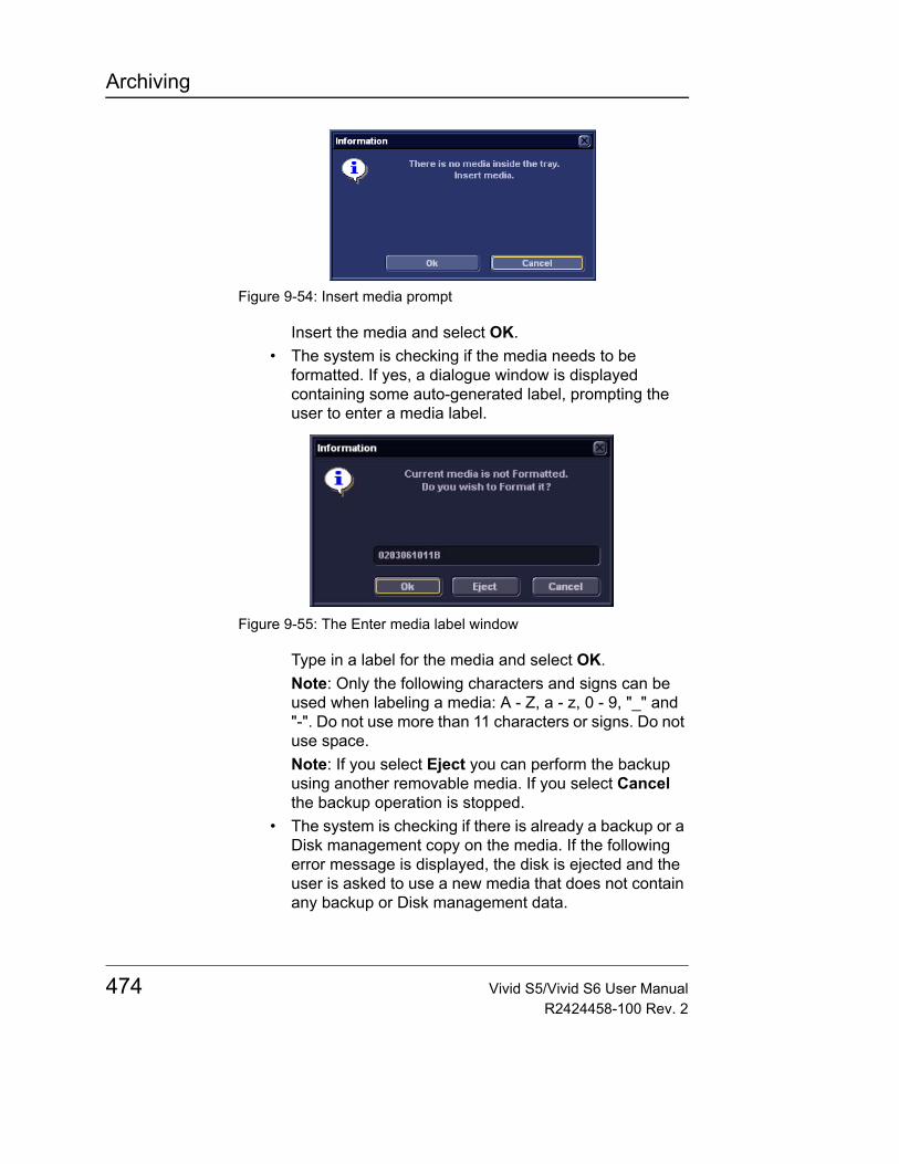
Archiving
Figure 9-54: Insert media prompt
Insert the media and select OK.• The system is checking if the media needs to be
formatted. If yes, a dialogue window is displayed containing some auto-generated label, prompting the user to enter a media label.
Figure 9-55: The Enter media label window
Type in a label for the media and select OK.Note: Only the following characters and signs can be used when labeling a media: A - Z, a - z, 0 - 9, "_" and "-". Do not use more than 11 characters or signs. Do not use space.Note: If you select Eject you can perform the backup using another removable media. If you select Cancel the backup operation is stopped.
• The system is checking if there is already a backup or a Disk management copy on the media. If the following error message is displayed, the disk is ejected and the user is asked to use a new media that does not contain any backup or Disk management data.
474 Vivid S5/Vivid S6 User ManualR2424458-100 Rev. 2
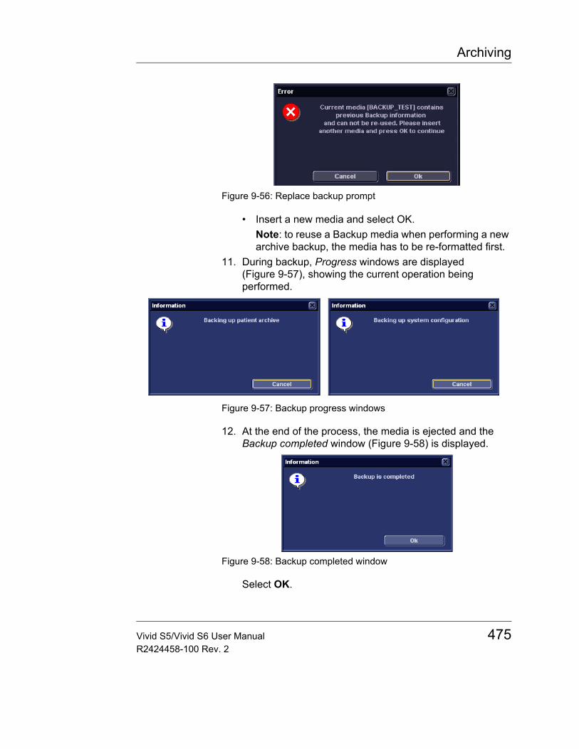
Archiving
Figure 9-56: Replace backup prompt
• Insert a new media and select OK.Note: to reuse a Backup media when performing a new archive backup, the media has to be re-formatted first.
11. During backup, Progress windows are displayed (Figure 9-57), showing the current operation being performed.
Figure 9-57: Backup progress windows
12. At the end of the process, the media is ejected and the Backup completed window (Figure 9-58) is displayed.
Figure 9-58: Backup completed window
Select OK.
Vivid S5/Vivid S6 User Manual 475R2424458-100 Rev. 2

Archiving
The Backup result is displayed on the Backup sheet (Figure 9-59).
Figure 9-59: Backup result
13. Make sure to physically label the media. An identification of the system should also be noted on the media and a backup log should be kept.File the media in a safe place.
Restore procedure1. Press CONFIG.2. Select the category Admin.3. Select the Restore sheet (Figure 9-60).
476 Vivid S5/Vivid S6 User ManualR2424458-100 Rev. 2
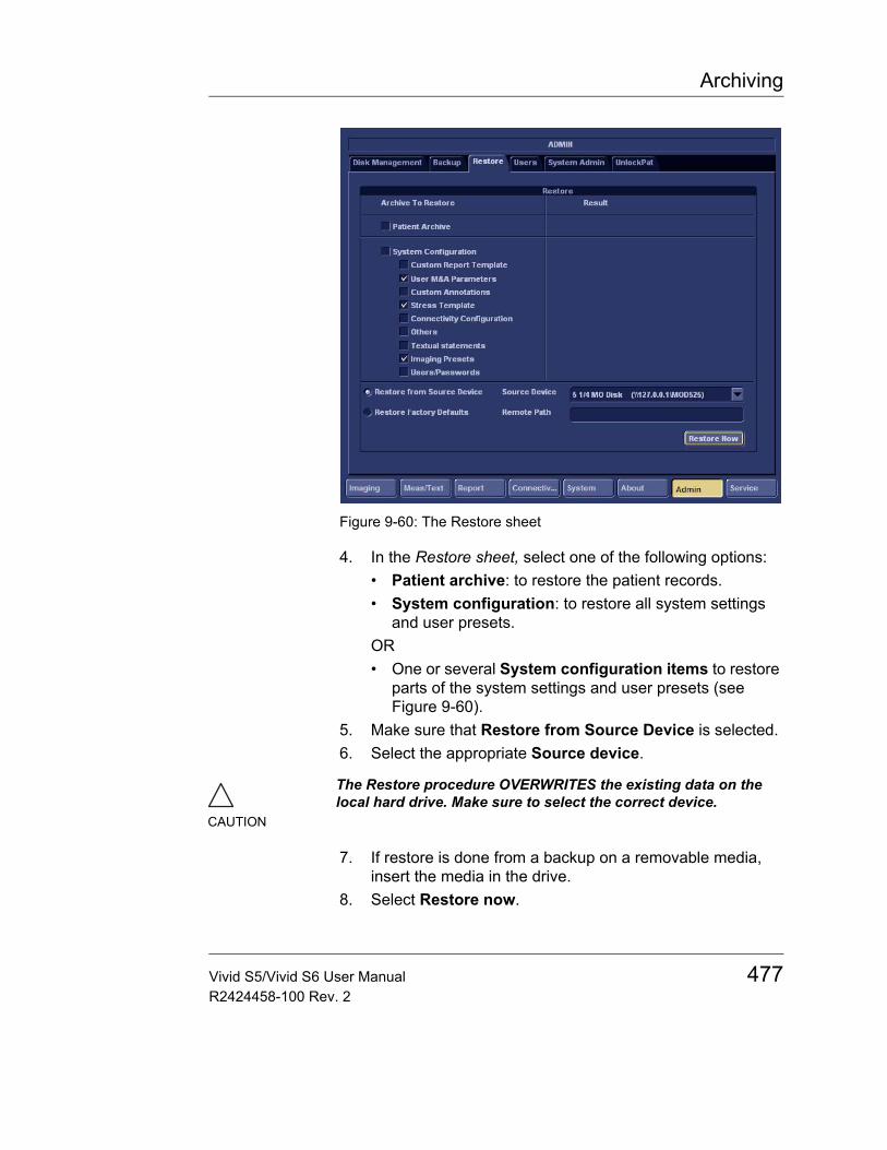
Archiving
Figure 9-60: The Restore sheet
4. In the Restore sheet, select one of the following options:• Patient archive: to restore the patient records.• System configuration: to restore all system settings
and user presets.OR• One or several System configuration items to restore
parts of the system settings and user presets (see Figure 9-60).
5. Make sure that Restore from Source Device is selected.6. Select the appropriate Source device.
7. If restore is done from a backup on a removable media, insert the media in the drive.
8. Select Restore now.
CAUTION
The Restore procedure OVERWRITES the existing data on the local hard drive. Make sure to select the correct device.
Vivid S5/Vivid S6 User Manual 477R2424458-100 Rev. 2
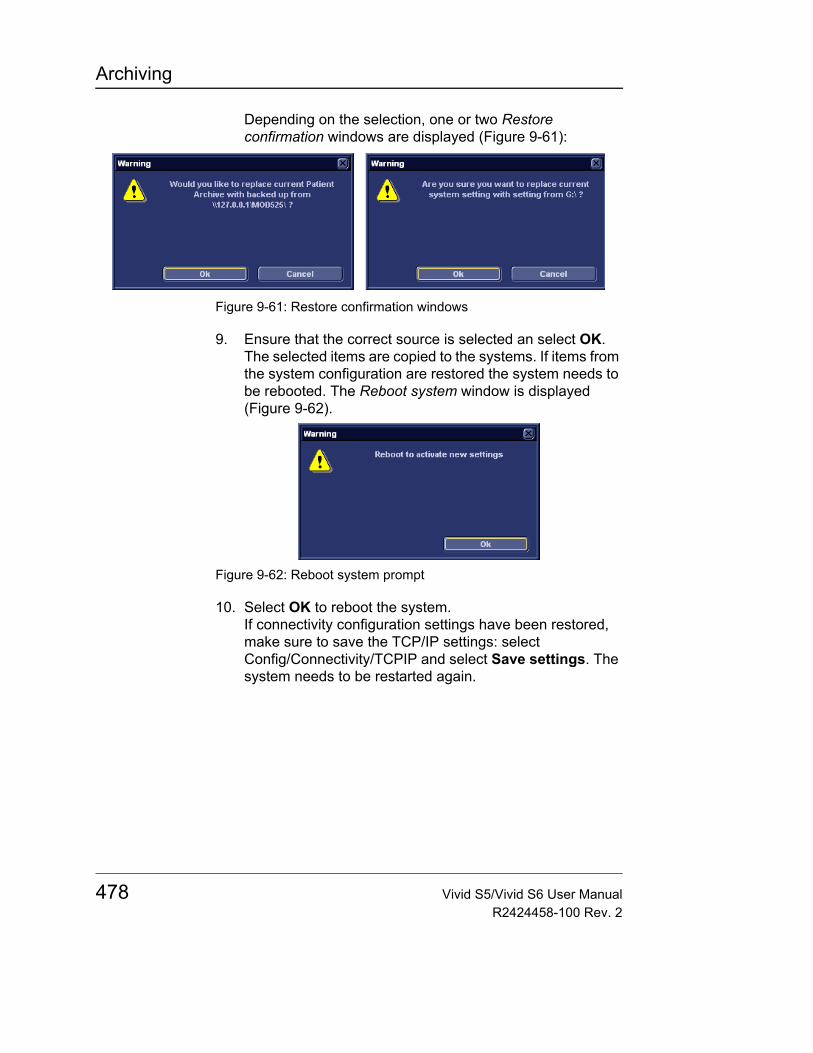
Archiving
Depending on the selection, one or two Restore confirmation windows are displayed (Figure 9-61):
Figure 9-61: Restore confirmation windows
9. Ensure that the correct source is selected an select OK.The selected items are copied to the systems. If items from the system configuration are restored the system needs to be rebooted. The Reboot system window is displayed (Figure 9-62).
Figure 9-62: Reboot system prompt
10. Select OK to reboot the system.If connectivity configuration settings have been restored, make sure to save the TCP/IP settings: select Config/Connectivity/TCPIP and select Save settings. The system needs to be restarted again.
478 Vivid S5/Vivid S6 User ManualR2424458-100 Rev. 2

Archiving
DICOM spoolerDICOM spooler displays the current DICOM output jobs. The jobs may be Storage, Print, Modality Performed Procedure Step or Storage Commitment. The DICOM spooler is used for checking the current job's status when a job is saved or when the total spooler status on the right of the Archive windows displays an error.
From the DICOM spooler the user can also:• Delete non-active jobs• Resend a job that has failed or is in hold• Send a job that has failed or is in hold, to a new destination.• Hold a job that is not active.
The job's status displayed in the DICOM spooler window can be:• Pending: the job is complete, waiting to be active.• Hold: the job is complete, but suspended, waiting for a user
action.• the job is incomplete, waiting for more images.• Append: the job is incomplete, waiting for more images
(Direct store function).• Active: the job is complete and connected to the
destination device.• Failed: the job is complete but one or more images failed to
transmit to the destination device.• Done: the job is saved to the destination device. The jobs
that are done are removed from the spooler after a while.
Starting the DICOM spooler• On the alphanumeric keyboard, press and hold down the
ALT key and press S.The DICOM spooler window is displayed (see Figure 9-63).
The DICOM spooler window is automatically updated. Press Refresh to update the information displayed at any time.
Vivid S5/Vivid S6 User Manual 479R2424458-100 Rev. 2
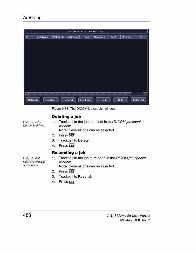
Archiving
Figure 9-63: The DICOM job spooler window
Deleting a jobOnly non-active jobs can be deleted.
1. Trackball to the job to delete in the DICOM job spooler window.Note: Several jobs can be selected.
2. Press SET.3. Trackball to Delete.4. Press SET.
Resending a jobOnly jobs that failed or are in hold can be resent.
1. Trackball to the job to re-send in the DICOM job spooler window.Note: Several jobs can be selected.
2. Press SET.3. Trackball to Resend.4. Press SET.
480 Vivid S5/Vivid S6 User ManualR2424458-100 Rev. 2

Archiving
Sending a job to a new destinationOnly jobs that failed or are in hold can be sent to a new destination.
1. Trackball to the job to send in the DICOM job spooler window.
2. Press SET.3. Trackball to Send to...4. Press SET.
A dialogue window is displayed.5. Select the new destination from the Destination popup
menu.6. Trackball to Send.7. Press SET.
Holding a job1. Trackball to the job to hold in the DICOM job spooler
window.Note: several jobs can be selected. Only inactive jobs can be set on hold.
2. Press SET.3. Trackball to Hold.4. Press SET.
To undo hold, press Resend.
Vivid S5/Vivid S6 User Manual 481R2424458-100 Rev. 2
Archiving
Database import from Vivid 3 or Vivid 4The Vivid 3/Vivid 4 Database Import option provides the capability to import data from a Vivid 3 or Vivid 4 system with software version BT02 or higher, into the Vivid S5/Vivid S6 system.
This feature allows the user to review examinations previously acquired on a Vivid 3 or Vivid 4 system, on the Vivid S5/Vivid S6 in DICOM format. In addition, the user may review all measurements made on the Vivid 3/4 , using an Excel viewer installed on a separate PC.
Note: The following procedure is valid for Vivid 3 or 4 of version BT02 and upwards.
Transfer ProcedureThis is a one-time procedure which will normally be performed by your GE representative, during the system's installation.
1. While in regular scanning mode, press PATIENT.2. Log in as an Administrator.3. Press Create New Patient/New Exam.
The Search/Create patient window is displayed.4. Verify that the Patient list is empty.5. From the Dataflow drop-down menu select No Archive
(see Figure 9-64).
CAUTION
The database imported from the Vivid 3 /4 into Vivid S5/Vivid S6 should only be imported during the installation, while the Vivid S5/Vivid S6 archive is still empty. Importing the database at a later stage is not possible without first erasing the whole Vivid S5/Vivid S6 database.
CAUTION
Data must be imported only from the LATEST backup media. In case you are not sure, it is advisable to perform another backup from the Vivid 3/4.
Attempting to import data from any backup version other than the latest, will make the Vivid S5/Vivid S6 database incomplete, with missing exams.
482 Vivid S5/Vivid S6 User ManualR2424458-100 Rev. 2
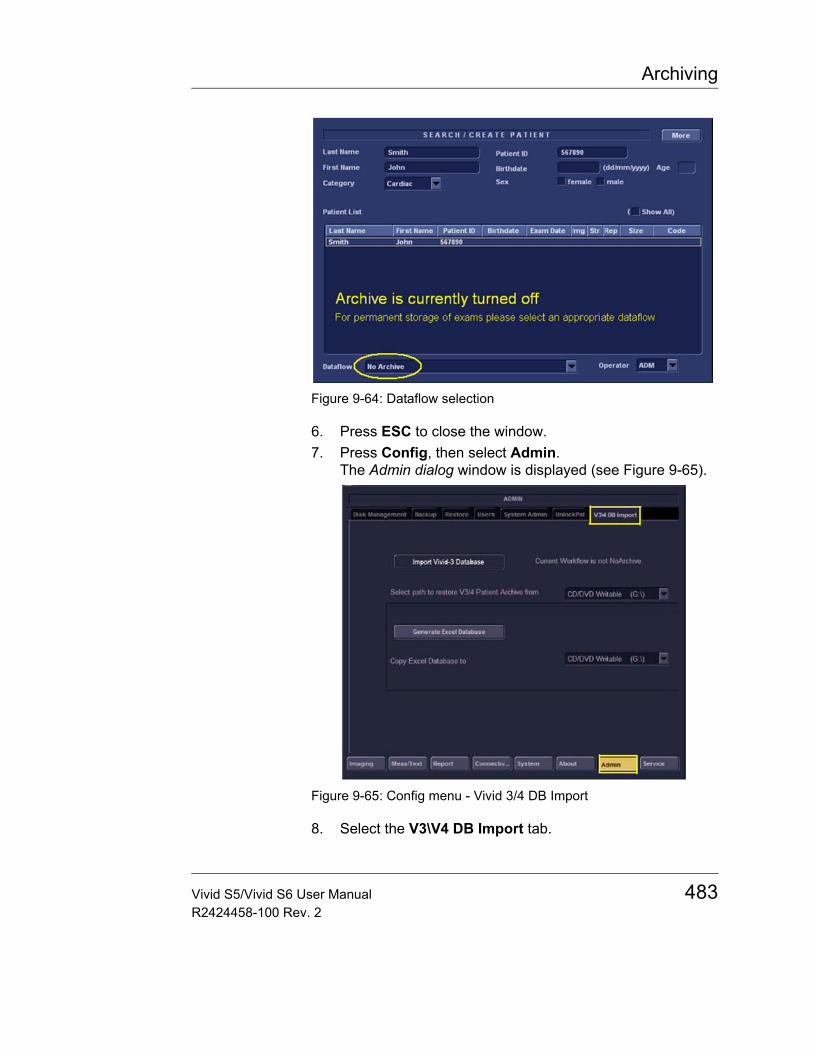
Archiving
Figure 9-64: Dataflow selection
6. Press ESC to close the window.7. Press Config, then select Admin.
The Admin dialog window is displayed (see Figure 9-65).
Figure 9-65: Config menu - Vivid 3/4 DB Import
8. Select the V3\V4 DB Import tab.
Vivid S5/Vivid S6 User Manual 483R2424458-100 Rev. 2
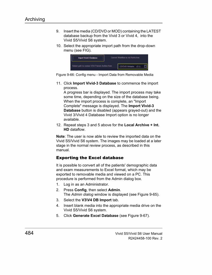
Archiving
9. Insert the media (CD/DVD or MOD) containing the LATEST database backup from the Vivid 3 or Vivid 4, into the Vivid S5/Vivid S6 system.
10. Select the appropriate import path from the drop-down menu (see FIG).
Figure 9-66: Config menu - Import Data from Removable Media
11. Click Import Vivid-3 Database to commence the import process.A progress bar is displayed. The import process may take some time, depending on the size of the database being.When the import process is complete, an "Import Complete" message is displayed. The Import Vivid-3 Database button is disabled (appears grayed-out) and the Vivid 3/Vivid 4 Database Import option is no longer available.
12. Repeat steps 3 and 5 above for the Local Archive + Int. HD dataflow.
Note: The user is now able to review the imported data on the Vivid S5/Vivid S6 system. The images may be loaded at a later stage in the normal review process, as described in this manual.
Exporting the Excel database
It is possible to convert all of the patients' demographic data and exam measurements to Excel format, which may be exported to removable media and viewed on a PC. This procedure is performed from the Admin dialog box.1. Log in as an Administrator.2. Press Config, then select Admin.
The Admin dialog window is displayed (see Figure 9-65).3. Select the V3\V4 DB Import tab.4. Insert blank media into the appropriate media drive on the
Vivid S5/Vivid S6 system.5. Click Generate Excel Database (see Figure 9-67).
484 Vivid S5/Vivid S6 User ManualR2424458-100 Rev. 2
Archiving
Figure 9-67: Export Excel Data to Removable Media
A progress bar is displayed during the export process. The measurements and demographics database is generated and compressed into a ZIP file.
6. When done, eject the media and label it accordingly.
Installing the Vivid 3/4 Data ViewerThe Vivid 3/4 Data Viewer installation consists of two procedures: Extraction and Formatting.
Extraction1. Insert the media created in the section above ("Exporting
the Excel database" on page 484).2. Browse to the media location, copy the database file
Patients.zip from the media, and paste it to a dedicated path on the PC hard disk.
3. Right-click the Patients.zip file on the hard disk and select Extract All... from the context menu. The Extraction Wizard appears.
4. Click Next twice.During the extraction process, a password prompt appears (see Figure 9-68).
Figure 9-68: Extraction password prompt
5. Type dolphin in the password field, then click OK.The files are extracted into a new Patients folder, located under the dedicated path on the hard disk.
6. Proceed to the following procedure - Formatting.
Vivid S5/Vivid S6 User Manual 485R2424458-100 Rev. 2
Archiving
Formatting1. Locate the file Master.xls under the Patients folder and
double click it (see Figure 9-69).
Figure 9-69: Patients folder contents
While the Excel file opens, a macro prompt appears (see Figure 9-70).
Figure 9-70: Excel macro prompt
2. Click Enable Macros.The Start formatting V3/4 Data Viewer window appears (see Figure 9-71).
3. Select a language.4. Type any password you wish to use into the password field.
This later provides privacy protection to your Vivid 3/4 Data Viewer database.
486 Vivid S5/Vivid S6 User ManualR2424458-100 Rev. 2
Archiving
Figure 9-71: Start formatting V3/4 Data Viewer window
5. Click Run.Automatic formatting begins. When finished, the Progress field on the bottom-right shows 100% and the Stop button is grayed-out (see Figure 9-72).
Figure 9-72: Formatting complete
Note: Depending on the database size, formatting may take several hours. In case you need to stop the process
Vivid S5/Vivid S6 User Manual 487R2424458-100 Rev. 2
Archiving
before it concludes, click Stop. Then, remove the previously generated files and repeat the entire procedure.Note: While formatting takes place, if prompted by AutoSave, do not save Master.xls.
6. Press Exit.All files, including Master.xls are closed.
Using the Vivid 3/4 Data Viewer
Opening the Data Viewer1. Locate the file Vivid 3_4 Data Viewer.xls under the
Patients folder and double click it.2. When prompted for a password, type in the password you
defined in step 4 of the previous procedure (see "Formatting" on page 486).The Data Viewer database opens in Excel (see Figure 9-73).
Figure 9-73: Vivid 3/4 Data Viewer
488 Vivid S5/Vivid S6 User ManualR2424458-100 Rev. 2
Archiving
Using the Data Viewer
The Data Viewer Excel database contains several useful tabs. The main tab is Index_patient, detailing demographic data of each exam. Each row details one exam. The left-most Patient Index column contains internal index numbers, each unique to an exam.
To browse exam results:1. Use the Last name, Patient ID or Exam date tab to identify
the patient or exam of interest.2. Click records in blue font to jump to the corresponding
exam in the Index_patient tab.3. Identify and locate the exam of interest in the
Index_patient tab.4. Click the corresponding Patient Index number to see all of
the relevant measurements for that particular exam.5. Click on same Patient Index to return to the main
Index_patient tab.
Vivid S5/Vivid S6 User Manual 489R2424458-100 Rev. 2

Archiving
490 Vivid S5/Vivid S6 User ManualR2424458-100 Rev. 2
Report
Chapter 10 Report
• Introduction ................................................................................... .. 492• Creating a report ........................................................................... .. 493
• Working with the report function ............................................... 493• To print a report ........................................................................ 496• To store a report ....................................................................... 496• Retrieving an archived report ................................................... 497• Deleting an archived report ...................................................... 497
• Structured Findings ...................................................................... .. 498• Prerequisite .............................................................................. 498• Starting Structured Findings ..................................................... 499• Structured Findings structure ................................................... 499• Using Structured Findings ........................................................ 501• Structured Findings configuration ............................................ 504
• Direct report .................................................................................. .. 514• Creating comments .................................................................. 514• Creating pre-defined text inputs ............................................... 515
• Report designer ............................................................................ .. 516• Accessing the Report designer ................................................ 516• Report designer overview ........................................................ 516• Designing a report template ..................................................... 519• Saving the report template ....................................................... 530• To exit the Report designer ...................................................... 530
• Report templates management ................................................... .. 531• Configuration of the Template selection menu ......................... 532• Export/Import of Report templates ........................................... 533
Vivid S5/Vivid S6 User Manual 491R2424458-100 Rev. 2
Report
IntroductionThe Vivid S5/Vivid S6 system enables the creation of patient and examination reports containing measurements, images and analysis that were made during the examination. The layout of the reports is defined by generic templates delivered with the system. Custom templates can also be made.
Saved reports are read-only. Therefore it is recommended that the data be carefully reviewed before the report is saved. Use the worksheet (see page 353) to facilitate the review and adjustment of data before generating a report. The final report can be printed on a regular laser printer.
492 Vivid S5/Vivid S6 User ManualR2424458-100 Rev. 2
Report
Creating a reportReports summarize data obtained in the examination. They can contain data and images.
Once generated, the report can be viewed, images can be added, wall segment diagrams can be assigned, and text can be entered in the free text fields. All other information must be changed from the Patient information window and the Worksheet screen.
Note: "Other ID" does not appear as a separate item in the system's Report templates. The user should generate a custom report sheet if Other ID data is required to be recorded.
Working with the report function• Press REPORT.
The default template for the current examination, or the template last used, is displayed (see Figure 10-1). The information entered during the examination in automatically filled out (e.g. demographic, Diagnosis, Comments etc.)
Vivid S5/Vivid S6 User Manual 493R2424458-100 Rev. 2
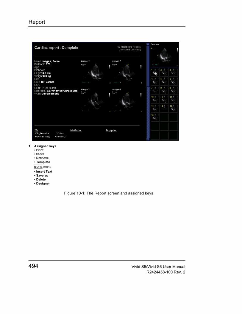
Report
Figure 10-1: The Report screen and assigned keys
1. Assigned keys• Print• Store• Retrieve• TemplateMORE menu• Insert Text• Save as• Delete• Designer
494 Vivid S5/Vivid S6 User ManualR2424458-100 Rev. 2
Report
To choose another report template1. Press the assignable TEMPLATE.
The Template selec-tion menu can be configured to dis-play only the tem-plates of interest (see page 532).
The Template selection menu is displayed showing the available report templates organized by application.
2. Do one of the following:• Select a template from the current application template
list.• Select another application and select the desired
template from the sub-menu displayed.Note: From a sub-menu, select Back to return to the current application template list.
The selected template is displayed on the screen.
Note: After selecting a different report template the selected template becomes the default template which will be selected next time
To change patient information1. Trackball to heading of the information to change.
The trackball marker is changed to a hand with pointing finger .
2. Press SET on the Trackball area.The original location of the data is displayed.
3. Change the information entered if required.4. Press REPORT when completed.
Images in the report• To add an image to the report, place the pointer over an
image in the clipboard and double-click the SET key.The image is inserted into the first free image container in the report.
• To move an image in the report, select and drag the image to move it to a new image container.
• To replace an image in the report, select and drag an image from the clipboard over the image to replace in the report.
• To remove an image from the report, select and drag the image to remove outside the report page.
Vivid S5/Vivid S6 User Manual 495R2424458-100 Rev. 2

Report
To print a reportOnly members of the user group "Cardiologist" are allowed to print a report (see page 637).• Press PRINT.
The report is printed on the default printer. A status window is displayed showing the printing process.For printer configuration, see Chapter 12, "Peripherals" on page 575.
Printing a report with the Ink-saving feature
When a report containing many images is printed it contains many large areas with black background. When printing to an ink-jet printer these black areas utilize a lot of ink and take longer to print.
The report may be configured In order to eliminate these large areas of black background while printing.
To configure the Ink-saving feature:1. Press CONFIG and select the Report - Template tab (see
Figure 10-26).2. Set the Ink-Save checkmark.
All reports generated from now on will be printed with images containing white background.
To store a reportOnly members of the user group “Cardiologist” are allowed to store a report (see page 637).1. Press STORE.
The report is stored in the Report archive.A confirmation window is displayed when completed.
2. Press OK.
Alternative storage
Reports can also be saved in a user-defined locations in the following formats:• Compiled HTML (.CHM) files: readable from any web
browser.• Portable Document Format (.PDF) files: readable with
496 Vivid S5/Vivid S6 User ManualR2424458-100 Rev. 2

Report
Adobe Acrobat reader (not available on EchoPAC PC).1. Press MORE.
The additional controls are displayed (Figure 10-1).2. Press SAVE AS.
The Save as dialogue window is displayed.3. Select the destination folder from the Save in pull down
menu.The default location is the Export folder.The Report archive folder is selected by default.The default name for the report is of type:<exam DICOM UID>
4. Select PDF or CHM format from the Save as type pull down menu.
5. Press SAVE.
Retrieving an archived report1. Press RETRIEVE.
A list of the available reports for the actual examination is displayed.The default name for a report is of type:<template type>_<store date>_<store time>To display the current report, select Show active exam.
2. Trackball to the report to retrieve.3. Press SET.
Deleting an archived reportOnly members of the user group “Cardiologist” are allowed to store a report (see page 637).1. Press MORE.
The additional controls are displayed (Figure 10-1).2. Press DELETE.
A list of the available reports for the actual examination is displayed.The default name for a report is of type:<template type>_<store date>_<store time>
3. Trackball to the report to delete.4. Press SET.
Vivid S5/Vivid S6 User Manual 497R2424458-100 Rev. 2

Report
Structured FindingsStructured Findings is a feature that enables the user to insert pre-configured structured diagnostic statements and codes (e.g. Billing, Accreditation) in the patient report and create a conclusion based on the inserted statements.
PrerequisiteTo be able to insert structured diagnostic statements and create a conclusion in a patient record, the report template used must have assigned fields for the structured findings, the codes and the conclusion.
To create the assigned fields in a report template:1. Press REPORT.2. Press TEMPLATE and select the desired report template.3. Press MORE and DESIGNER.
The Report designer screen is displayed.4. Select the location in the report template where to insert the
Structured findings fields.5. Select Insert and Archive Information.
The Archive information box is displayed (Figure 10-2).6. Double-click on Select All under all three parameter fields
in the Archive information box to deselect all parameters.7. Select Structured findings, Findings conclusion
Indication codes and Billing codes in the Exam Information field (Figure 10-2).
8. Select OK.9. Save the Report template and exit the Report designer.
498 Vivid S5/Vivid S6 User ManualR2424458-100 Rev. 2
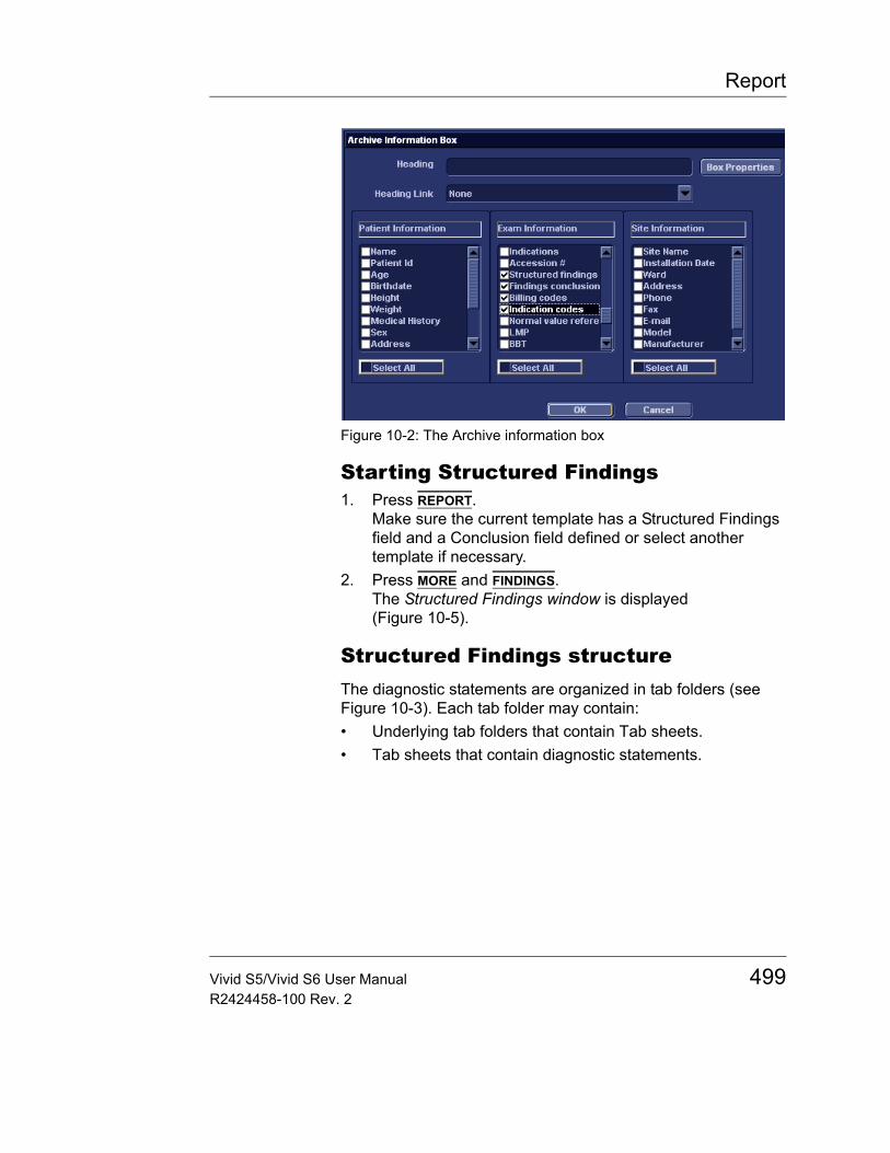
Report
Figure 10-2: The Archive information box
Starting Structured Findings1. Press REPORT.
Make sure the current template has a Structured Findings field and a Conclusion field defined or select another template if necessary.
2. Press MORE and FINDINGS.The Structured Findings window is displayed (Figure 10-5).
Structured Findings structureThe diagnostic statements are organized in tab folders (see Figure 10-3). Each tab folder may contain:• Underlying tab folders that contain Tab sheets.• Tab sheets that contain diagnostic statements.
Vivid S5/Vivid S6 User Manual 499R2424458-100 Rev. 2
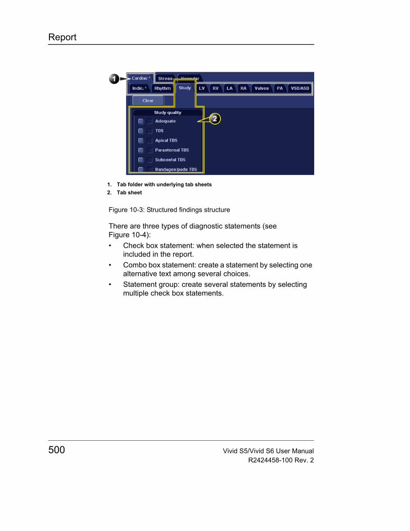
Report
Figure 10-3: Structured findings structure
There are three types of diagnostic statements (see Figure 10-4):• Check box statement: when selected the statement is
included in the report.• Combo box statement: create a statement by selecting one
alternative text among several choices.• Statement group: create several statements by selecting
multiple check box statements.
1. Tab folder with underlying tab sheets2. Tab sheet
500 Vivid S5/Vivid S6 User ManualR2424458-100 Rev. 2
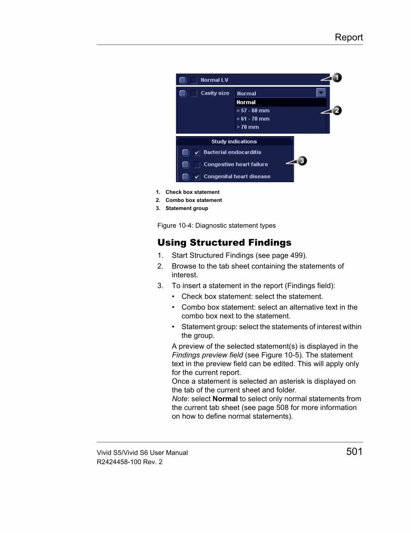
Report
Figure 10-4: Diagnostic statement types
Using Structured Findings1. Start Structured Findings (see page 499).2. Browse to the tab sheet containing the statements of
interest.3. To insert a statement in the report (Findings field):
• Check box statement: select the statement.• Combo box statement: select an alternative text in the
combo box next to the statement.• Statement group: select the statements of interest within
the group.A preview of the selected statement(s) is displayed in the Findings preview field (see Figure 10-5). The statement text in the preview field can be edited. This will apply only for the current report.Once a statement is selected an asterisk is displayed on the tab of the current sheet and folder.Note: select Normal to select only normal statements from the current tab sheet (see page 508 for more information on how to define normal statements).
1. Check box statement2. Combo box statement3. Statement group
Vivid S5/Vivid S6 User Manual 501R2424458-100 Rev. 2
Report
Note: select Clear to deselect all statements from the current tab sheet.To insert a conclusion statement in the report:• Press the Conclusion button in front of the statement of
interest.A preview of the selected conclusion statement is displayed in the Conclusion preview field (see Figure 10-5). Conclusion statements are displayed in a numbered list. The list can be reordered: triple-click on the conclusion statement to move in the Conclusion preview field and use the ARROW UP or ARROW DOWN key to move the statement up or down.The conclusion statements can be reordered using drag and drop procedure in the Conclusion preview field. The conclusion text in the preview field can be edited. This will apply only for the current report.Note: pressing the Conclusion button in front of a statement that was not previously selected results in simultaneously inserting the finding statement and create the conclusion.
4. Press OK.The report for the current patient is displayed with the selected findings, conclusion statement(s) and associated codes (if any).Note: Some diagnostic statements have measurements values in the body text referred by a tag (e.g. the {EF} tag refers to EF measurement). These statements require that the actual measurement is done to display correctly in the report.
502 Vivid S5/Vivid S6 User ManualR2424458-100 Rev. 2
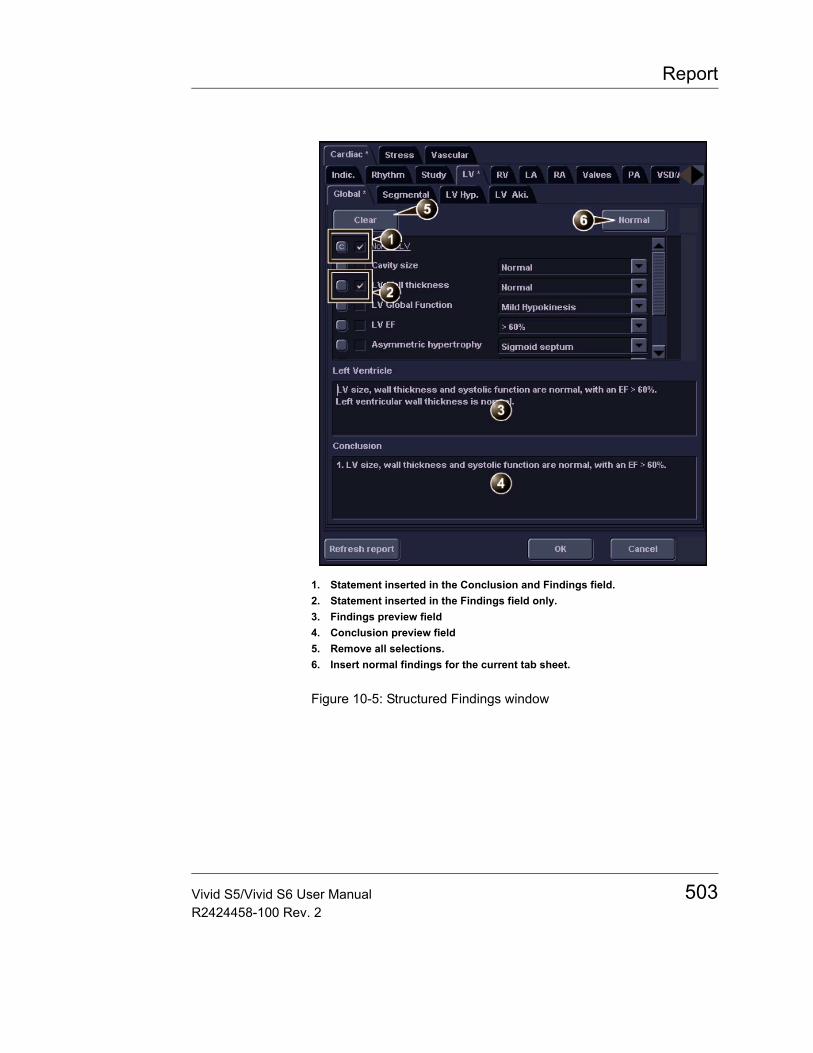
Report
Figure 10-5: Structured Findings window
1. Statement inserted in the Conclusion and Findings field.2. Statement inserted in the Findings field only.3. Findings preview field4. Conclusion preview field5. Remove all selections.6. Insert normal findings for the current tab sheet.
Vivid S5/Vivid S6 User Manual 503R2424458-100 Rev. 2
Report
Global selection of normal statements
It is possible to select all normal statements from all tab sheets.1. Place the cursor in the Statement field, press UPDATE MENU
on the control panel and select All normal.All statements defined as normal are selected from all the tab sheets. An asterisk is displayed on the tab of all the tab sheets that contain normal statements.Note: this operation will remove any other “non-normal” previously selected statements.
2. To remove all statements at once, place the cursor in the Statement field, press UPDATE MENU and select Clear all.
Structured Findings configurationStructured Findings configuration is used to:• Create, edit or delete finding statements, conclusion
statements and codes.• Organize the diagnostic statements in the Structured
Findings screen.• Define the normal diagnostic statements.
Accessing the Structured Findings configuration screen1. Press CONFIG and select the Report category.2. Select the Structured Findings tab.
The Structured Findings configuration screen is displayed (Figure 10-6).
Or from within Structured Findings:• Press UPDATE MENU on the control panel and select Config.
504 Vivid S5/Vivid S6 User ManualR2424458-100 Rev. 2
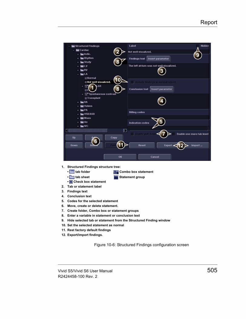
Report
Figure 10-6: Structured Findings configuration screen
1. Structured Findings structure tree:• tab folder Combo box statement• tab sheet Statement group• Check box statement
2. Tab or statement label3. Findings text4. Conclusion text5. Codes for the selected statement6. Move, create or delete statement.7. Create folder, Combo box or statement groups8. Enter a variable in statement or conclusion text9. Hide selected tab or statement from the Structured Finding window10. Set the selected statement as normal11. Rest factory default findings12. Export/import findings.
Vivid S5/Vivid S6 User Manual 505R2424458-100 Rev. 2
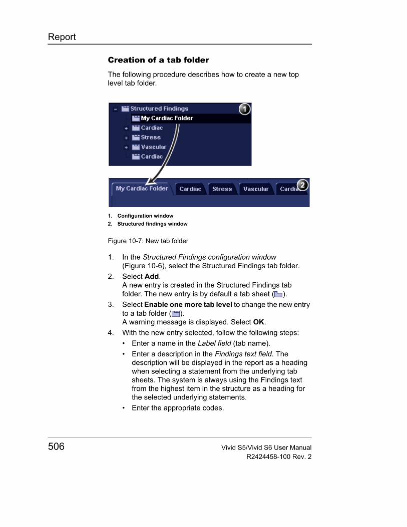
Report
Creation of a tab folder
The following procedure describes how to create a new top level tab folder.
Figure 10-7: New tab folder
1. In the Structured Findings configuration window (Figure 10-6), select the Structured Findings tab folder.
2. Select Add.A new entry is created in the Structured Findings tab folder. The new entry is by default a tab sheet ( ).
3. Select Enable one more tab level to change the new entry to a tab folder ( ).A warning message is displayed. Select OK.
4. With the new entry selected, follow the following steps:• Enter a name in the Label field (tab name).• Enter a description in the Findings text field. The
description will be displayed in the report as a heading when selecting a statement from the underlying tab sheets. The system is always using the Findings text from the highest item in the structure as a heading for the selected underlying statements.
• Enter the appropriate codes.
1. Configuration window2. Structured findings window
506 Vivid S5/Vivid S6 User ManualR2424458-100 Rev. 2
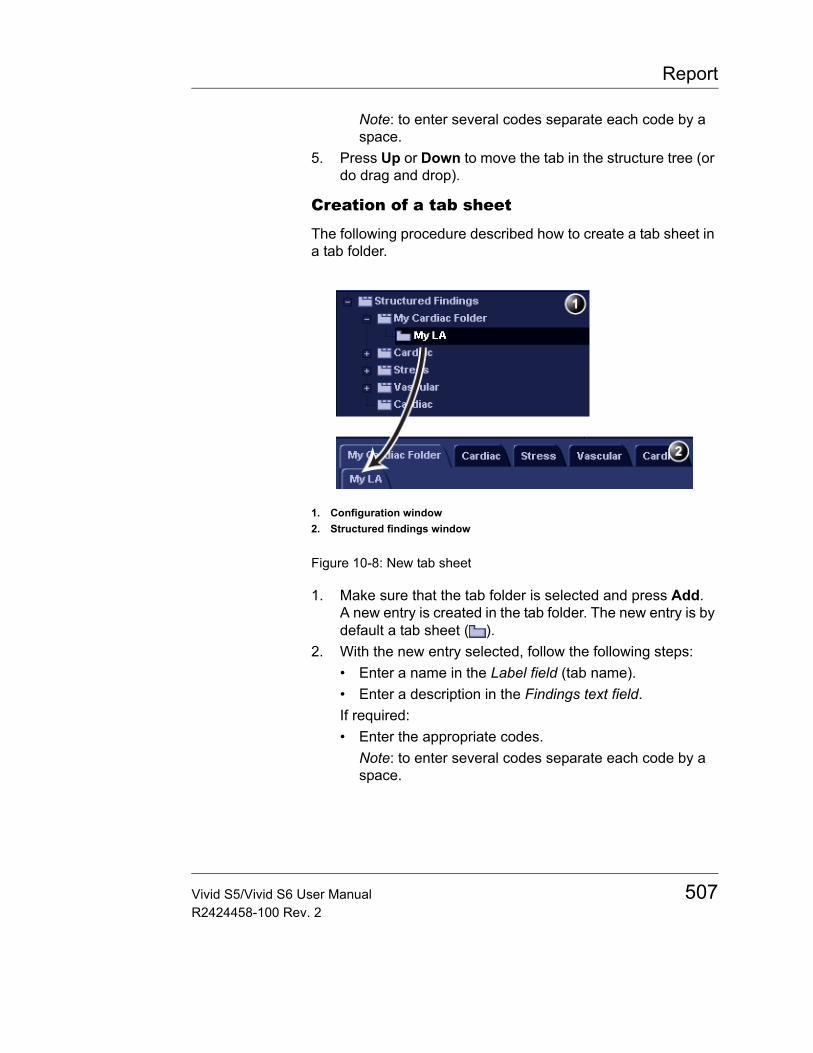
Report
Note: to enter several codes separate each code by a space.
5. Press Up or Down to move the tab in the structure tree (or do drag and drop).
Creation of a tab sheet
The following procedure described how to create a tab sheet in a tab folder.
Figure 10-8: New tab sheet
1. Make sure that the tab folder is selected and press Add.A new entry is created in the tab folder. The new entry is by default a tab sheet ( ).
2. With the new entry selected, follow the following steps:• Enter a name in the Label field (tab name).• Enter a description in the Findings text field.If required:• Enter the appropriate codes.
Note: to enter several codes separate each code by a space.
1. Configuration window2. Structured findings window
Vivid S5/Vivid S6 User Manual 507R2424458-100 Rev. 2
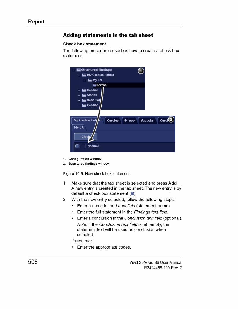
Report
Adding statements in the tab sheet
Check box statementThe following procedure describes how to create a check box statement.
Figure 10-9: New check box statement
1. Make sure that the tab sheet is selected and press Add.A new entry is created in the tab sheet. The new entry is by default a check box statement ( ).
2. With the new entry selected, follow the following steps:• Enter a name in the Label field (statement name).• Enter the full statement in the Findings text field.• Enter a conclusion in the Conclusion text field (optional).
Note: if the Conclusion text field is left empty, the statement text will be used as conclusion when selected.
If required:• Enter the appropriate codes.
1. Configuration window2. Structured findings window
508 Vivid S5/Vivid S6 User ManualR2424458-100 Rev. 2
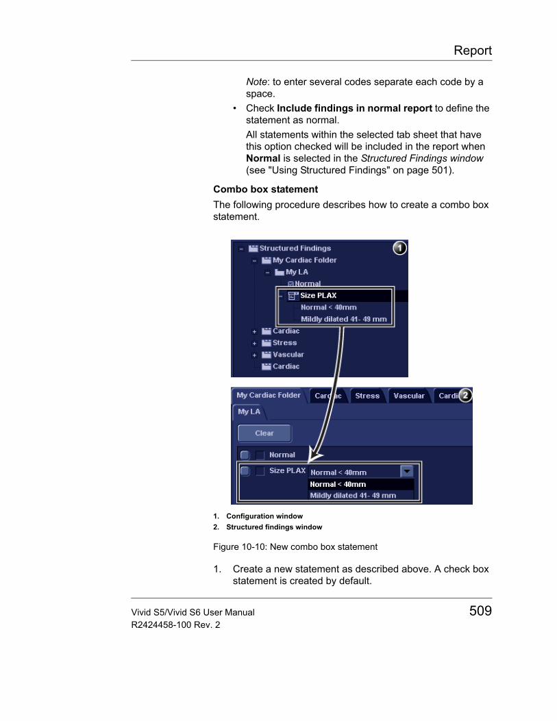
Report
Note: to enter several codes separate each code by a space.
• Check Include findings in normal report to define the statement as normal.All statements within the selected tab sheet that have this option checked will be included in the report when Normal is selected in the Structured Findings window (see "Using Structured Findings" on page 501).
Combo box statementThe following procedure describes how to create a combo box statement.
Figure 10-10: New combo box statement
1. Create a new statement as described above. A check box statement is created by default.
1. Configuration window2. Structured findings window
Vivid S5/Vivid S6 User Manual 509R2424458-100 Rev. 2

Report
2. With the new statement selected, press Add.A new underlying entry is created and the parent statement is changed to a Combo box statement ( ).
3. With the new underlying entry selected, follow the following steps:• Enter a name in the Label field.• Enter a text in the Findings text field.• Enter a conclusion in the Conclusion text field (optional).
4. Repeat the procedure from step 2 to create as many underlying statements as necessary. Each underlying statement will be a selectable entry in the combo box.
Statement groupStatement groups are created by changing a combo statement to a statement group.1. Create a combo box statement as described above.2. Make sure the combo box statement is selected and
deselect the option Enable pull-downs.The combo box statement is changed to a statement group ( ). Each underlaying entries are changed to check box statements.
Editing a statement
Tab label, statements and statement alternative texts can be edited.1. In the Structured Findings configuration window
(Figure 10-6), select the item to edit.2. Make the required changes.
510 Vivid S5/Vivid S6 User ManualR2424458-100 Rev. 2
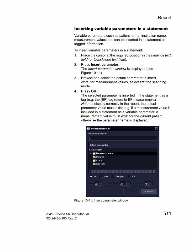
Report
Inserting variable parameters in a statement
Variable parameters such as patient name, institution name, measurement values etc. can be inserted in a statement as tagged information.
To insert variable parameters in a statement:1. Place the cursor at the required position in the Findings text
field (or Conclusion text field).2. Press Insert parameter.
The Insert parameter window is displayed (see Figure 10-11).
3. Browse and select the actual parameter to insert.Note: for measurement values, select first the scanning mode.
4. Press OK.The selected parameter is inserted in the statement as a tag (e.g. the {EF} tag refers to EF measurement)Note: to display correctly in the report, the actual parameter value must exist, e.g. if a measurement value is included in a statement as a variable parameter, a measurement value must exist for the current patient, otherwise the parameter name is displayed.
Figure 10-11: Insert parameter window
Vivid S5/Vivid S6 User Manual 511R2424458-100 Rev. 2
Report
Copy of a statement
Tab folders, tab sheets and statements can be copied from one location to another. The word "Copied" is added to the copied item name.1. In the Structured Findings configuration window
(Figure 10-6), select the item to copy.2. Select Copy.3. Select the item to contain the copy.4. Select Paste.
Note: if the item to copy cannot be copied in the selected location, the operation is ignored.
Note: copy can be done by drag-and-drop, while holding CTRL depressed.
Deletion of a statement
Tab folders, tab sheets and statements can be deleted.
1. In the Structured Findings configuration window (Figure 10-6), select the item to delete.
2. Select Delete.The selected item is deleted.
Factory reset
All statements can be reset back to the factory default.
1. Select Reset.The Reset statements window is displayed.
2. Select:• Yes to reset all statement to the factory default (No
undo).• No to cancel the operation.
CAUTION
Deletion cannot be undone.
CAUTION
Factory reset cannot be undone.
512 Vivid S5/Vivid S6 User ManualR2424458-100 Rev. 2
Report
Exporting/Importing statements
Diagnostic statements can be exported from one system and imported on another system.
Exporting statements1. In the Structured Findings configuration window
(Figure 10-6), select Export.A browsing window is displayed.
2. Browse to a destination and select Save.
Importing statements
1. In the Structured Findings configuration window (Figure 10-6), select Import.A browsing window is displayed.
2. Browse to a destination and select Open.
CAUTION
Importing statements will replace the current statements. If necessary, backup the current statements by exporting them before performing import.
Vivid S5/Vivid S6 User Manual 513R2424458-100 Rev. 2
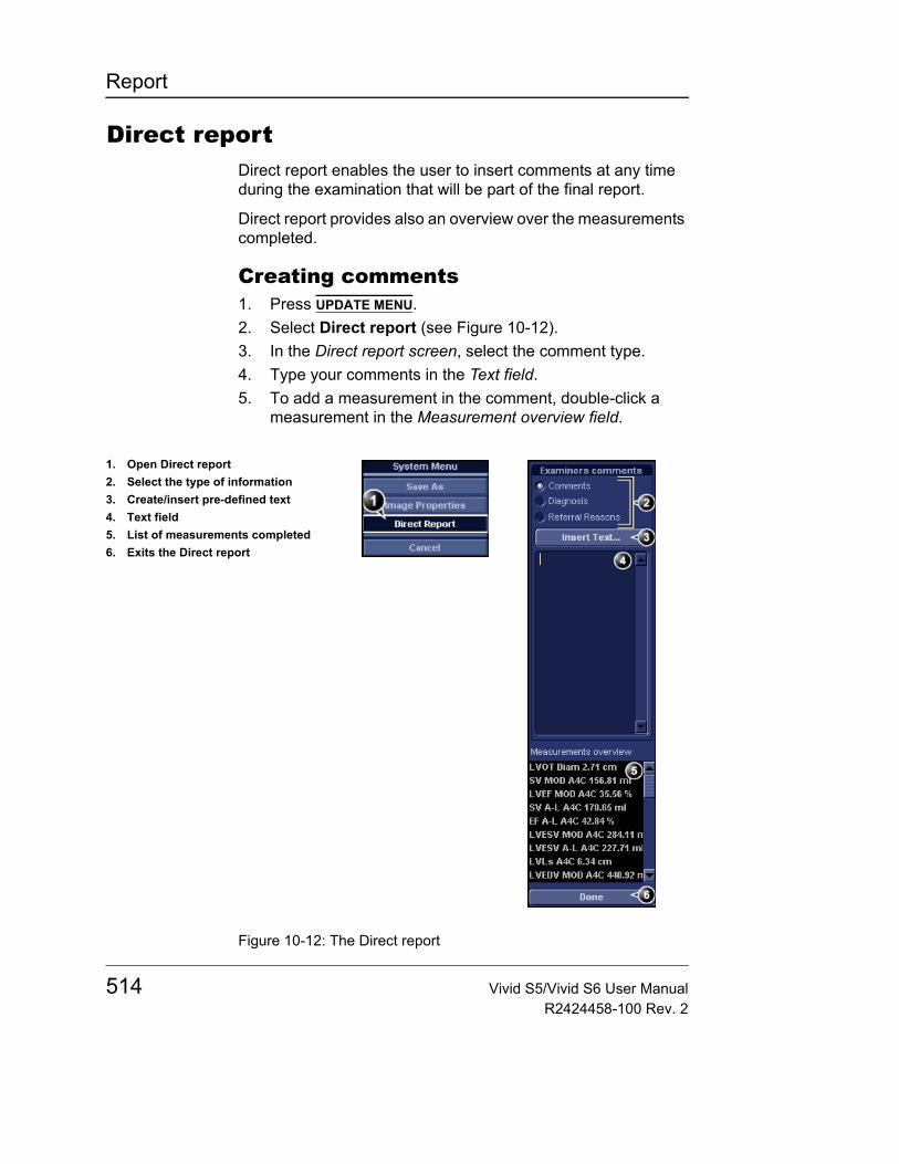
Report
Direct reportDirect report enables the user to insert comments at any time during the examination that will be part of the final report.
Direct report provides also an overview over the measurements completed.
Creating comments1. Press UPDATE MENU.2. Select Direct report (see Figure 10-12).3. In the Direct report screen, select the comment type.4. Type your comments in the Text field.5. To add a measurement in the comment, double-click a
measurement in the Measurement overview field.
Figure 10-12: The Direct report
1. Open Direct report2. Select the type of information3. Create/insert pre-defined text4. Text field5. List of measurements completed6. Exits the Direct report
514 Vivid S5/Vivid S6 User ManualR2424458-100 Rev. 2
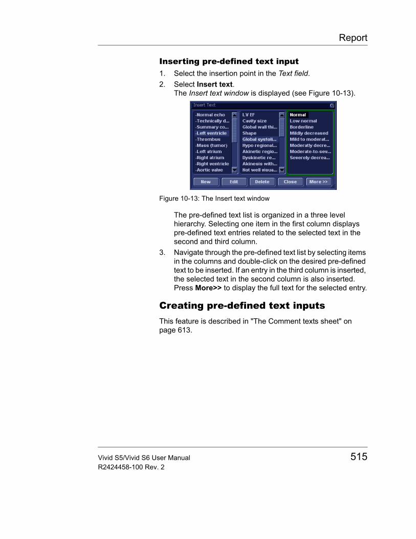
Report
Inserting pre-defined text input1. Select the insertion point in the Text field.2. Select Insert text.
The Insert text window is displayed (see Figure 10-13).
Figure 10-13: The Insert text window
The pre-defined text list is organized in a three level hierarchy. Selecting one item in the first column displays pre-defined text entries related to the selected text in the second and third column.
3. Navigate through the pre-defined text list by selecting items in the columns and double-click on the desired pre-defined text to be inserted. If an entry in the third column is inserted, the selected text in the second column is also inserted.Press More>> to display the full text for the selected entry.
Creating pre-defined text inputsThis feature is described in "The Comment texts sheet" on page 613.
Vivid S5/Vivid S6 User Manual 515R2424458-100 Rev. 2
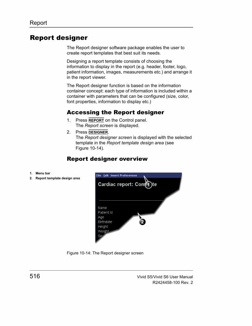
Report
Report designerThe Report designer software package enables the user to create report templates that best suit its needs.
Designing a report template consists of choosing the information to display in the report (e.g. header, footer, logo, patient information, images, measurements etc.) and arrange it in the report viewer.
The Report designer function is based on the information container concept: each type of information is included within a container with parameters that can be configured (size, color, font properties, information to display etc.)
Accessing the Report designer1. Press REPORT on the Control panel.
The Report screen is displayed.2. Press DESIGNER.
The Report designer screen is displayed with the selected template in the Report template design area (see Figure 10-14).
Report designer overview
Figure 10-14: The Report designer screen
1. Menu bar2. Report template design area
516 Vivid S5/Vivid S6 User ManualR2424458-100 Rev. 2
Report
The menu bar
Menu Description
File • New: start working on an new template• Save: save the template using the same name. Factory
report templates cannot be overwritten.• Save as: save the template using a new name.• Page setup: define printing orientation and
header/footer for the printed report.• Print Preview: display a print preview of the report
template.• Exit: exit the Report designer and returns to the report
function. The user can choose whether to save the updates or restore the original template.
Menu Description
Edit • Delete: remove the selected object from the report template.
• Undo: restore the previous state of the report template.
Vivid S5/Vivid S6 User Manual 517R2424458-100 Rev. 2
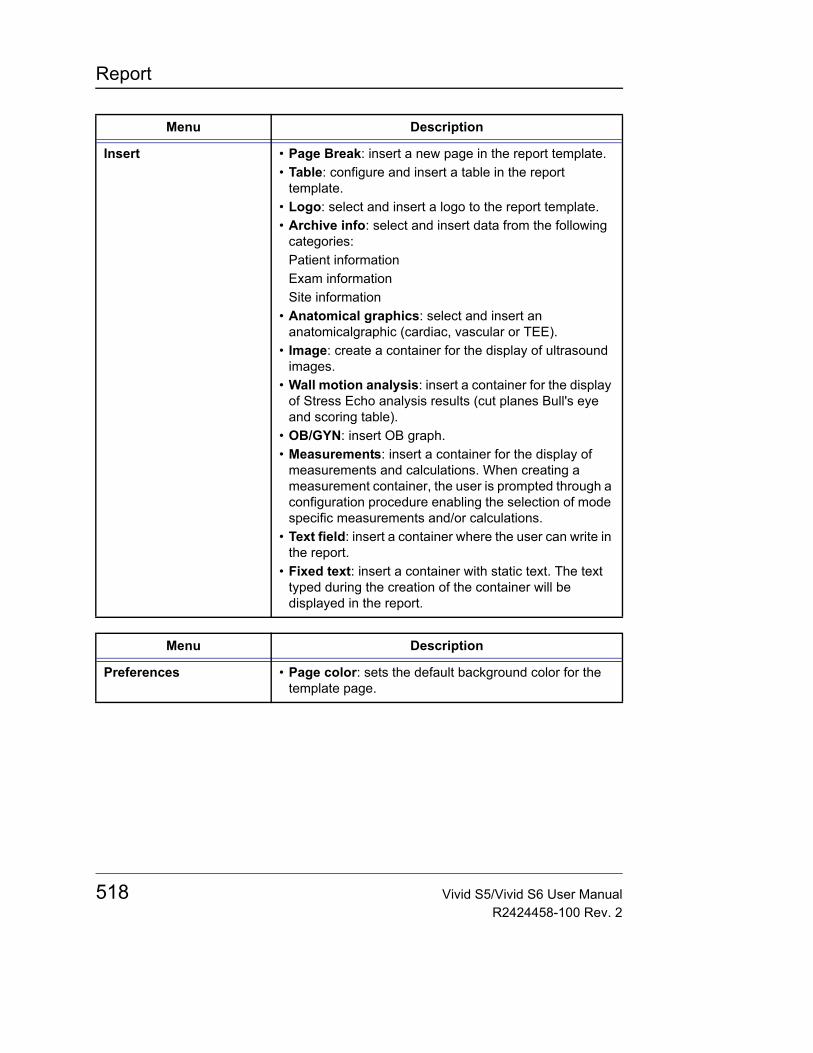
Report
Menu Description
Insert • Page Break: insert a new page in the report template.• Table: configure and insert a table in the report
template.• Logo: select and insert a logo to the report template.• Archive info: select and insert data from the following
categories:Patient informationExam informationSite information
• Anatomical graphics: select and insert an anatomicalgraphic (cardiac, vascular or TEE).
• Image: create a container for the display of ultrasound images.
• Wall motion analysis: insert a container for the display of Stress Echo analysis results (cut planes Bull's eye and scoring table).
• OB/GYN: insert OB graph.• Measurements: insert a container for the display of
measurements and calculations. When creating a measurement container, the user is prompted through a configuration procedure enabling the selection of mode specific measurements and/or calculations.
• Text field: insert a container where the user can write in the report.
• Fixed text: insert a container with static text. The text typed during the creation of the container will be displayed in the report.
Menu Description
Preferences • Page color: sets the default background color for the template page.
518 Vivid S5/Vivid S6 User ManualR2424458-100 Rev. 2
Report
Designing a report template
Starting template designing1. Start the Report designer (see page 516).2. Press File and select New to display a blank page or use
the current report template as basis template.
Setting the layout preferences
Adjusting the report page color background1. Press Preferences and select Page Color.
The Color selection window is displayed.2. Select the desired color.3. Press OK.
Header and footer in the printed reportThis function is described on page 528.
Inserting an information container in the report template body
The different type of information to be included in a report are grouped in information containers. Designing a report template consists in inserting and configuring the different information containers in the template page in an ordered manner.
Information containers can be inserted either:• Directly into the report template body: this procedure does
not allow side-by-side insertion, the information container will normally cover the width of the report template page.
• Within a table: this procedure allows side-by-side insertion of several information containers.
Inserting a table1. Press the Left mouse button at the desired insertion point
in the Report template design area.2. Press Insert and select Table.
The Container properties window is displayed (see Figure 10-15).
3. Adjust the parameters as desired.4. Press OK.
The table is displayed in the template.
Vivid S5/Vivid S6 User Manual 519R2424458-100 Rev. 2
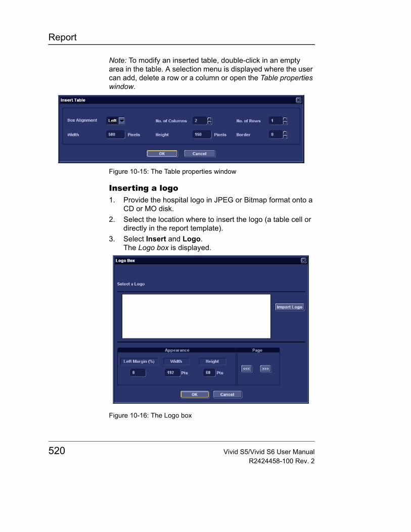
Report
Note: To modify an inserted table, double-click in an empty area in the table. A selection menu is displayed where the user can add, delete a row or a column or open the Table properties window.
Figure 10-15: The Table properties window
Inserting a logo1. Provide the hospital logo in JPEG or Bitmap format onto a
CD or MO disk.2. Select the location where to insert the logo (a table cell or
directly in the report template).3. Select Insert and Logo.
The Logo box is displayed.
Figure 10-16: The Logo box
520 Vivid S5/Vivid S6 User ManualR2424458-100 Rev. 2
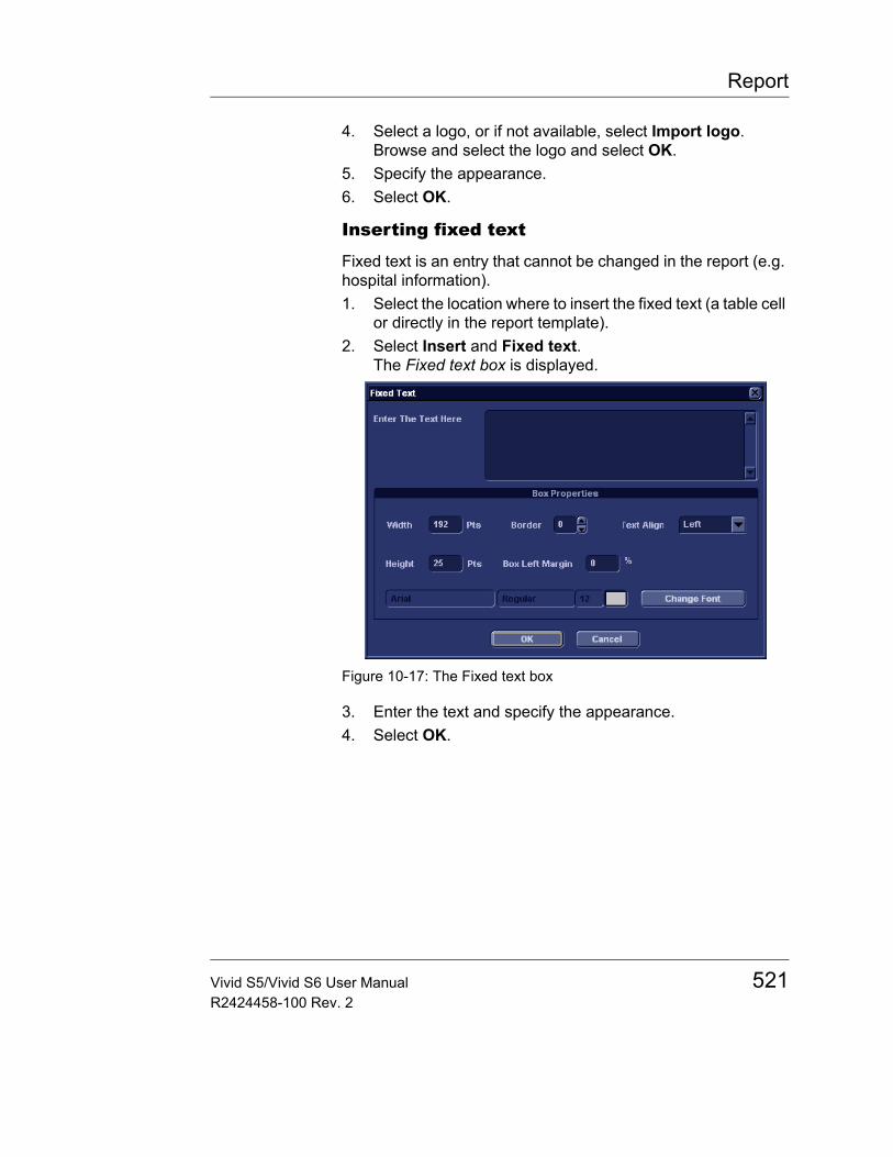
Report
4. Select a logo, or if not available, select Import logo.Browse and select the logo and select OK.
5. Specify the appearance.6. Select OK.
Inserting fixed text
Fixed text is an entry that cannot be changed in the report (e.g. hospital information).1. Select the location where to insert the fixed text (a table cell
or directly in the report template).2. Select Insert and Fixed text.
The Fixed text box is displayed.
Figure 10-17: The Fixed text box
3. Enter the text and specify the appearance.4. Select OK.
Vivid S5/Vivid S6 User Manual 521R2424458-100 Rev. 2

Report
Inserting archive information
Archive information contains all the objects of the different information menus (Patient, Exam, Study and Site Information).
You may display the archive information over two columns using a table container as described below.1. Insert a table for the archive information to the desired
location (a table cell or directly in the report template).2. Select the first table cell.3. Select Insert and Archive information.
The Archive information box is displayed.
Figure 10-18: The Archive information box
4. If desired, enter a heading and select a heading link from the pull-down menu.
5. Select the Information parameters to be displayed in the first cell.Select Box properties to change the font, alignment, appearance, etc.
6. Select OK.7. Select the next table cell and repeat steps 3 to 6 to enter the
remaining archive information.
522 Vivid S5/Vivid S6 User ManualR2424458-100 Rev. 2
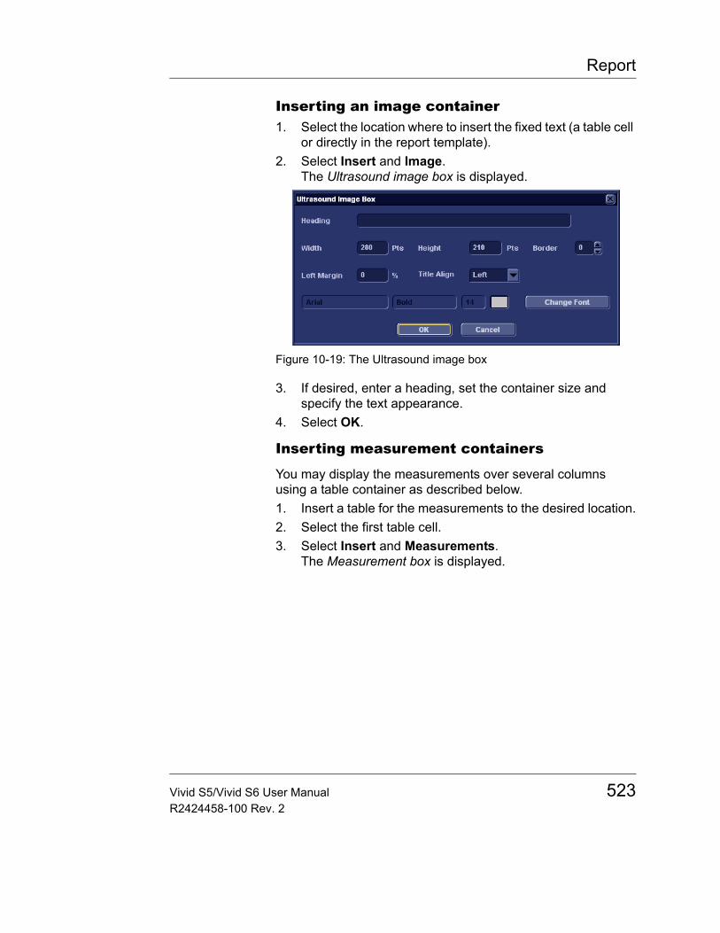
Report
Inserting an image container1. Select the location where to insert the fixed text (a table cell
or directly in the report template).2. Select Insert and Image.
The Ultrasound image box is displayed.
Figure 10-19: The Ultrasound image box
3. If desired, enter a heading, set the container size and specify the text appearance.
4. Select OK.
Inserting measurement containers
You may display the measurements over several columns using a table container as described below.1. Insert a table for the measurements to the desired location.2. Select the first table cell.3. Select Insert and Measurements.
The Measurement box is displayed.
Vivid S5/Vivid S6 User Manual 523R2424458-100 Rev. 2
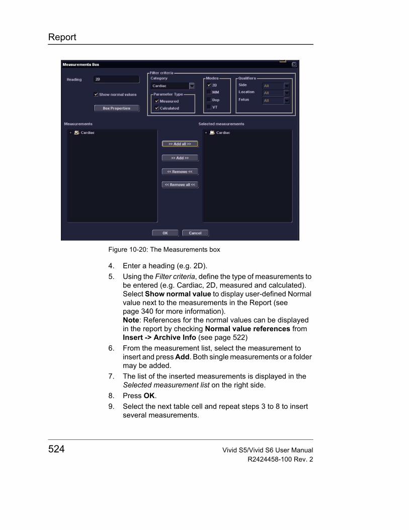
Report
Figure 10-20: The Measurements box
4. Enter a heading (e.g. 2D).5. Using the Filter criteria, define the type of measurements to
be entered (e.g. Cardiac, 2D, measured and calculated).Select Show normal value to display user-defined Normal value next to the measurements in the Report (see page 340 for more information).Note: References for the normal values can be displayed in the report by checking Normal value references from Insert -> Archive Info (see page 522)
6. From the measurement list, select the measurement to insert and press Add. Both single measurements or a folder may be added.
7. The list of the inserted measurements is displayed in the Selected measurement list on the right side.
8. Press OK.9. Select the next table cell and repeat steps 3 to 8 to insert
several measurements.
524 Vivid S5/Vivid S6 User ManualR2424458-100 Rev. 2
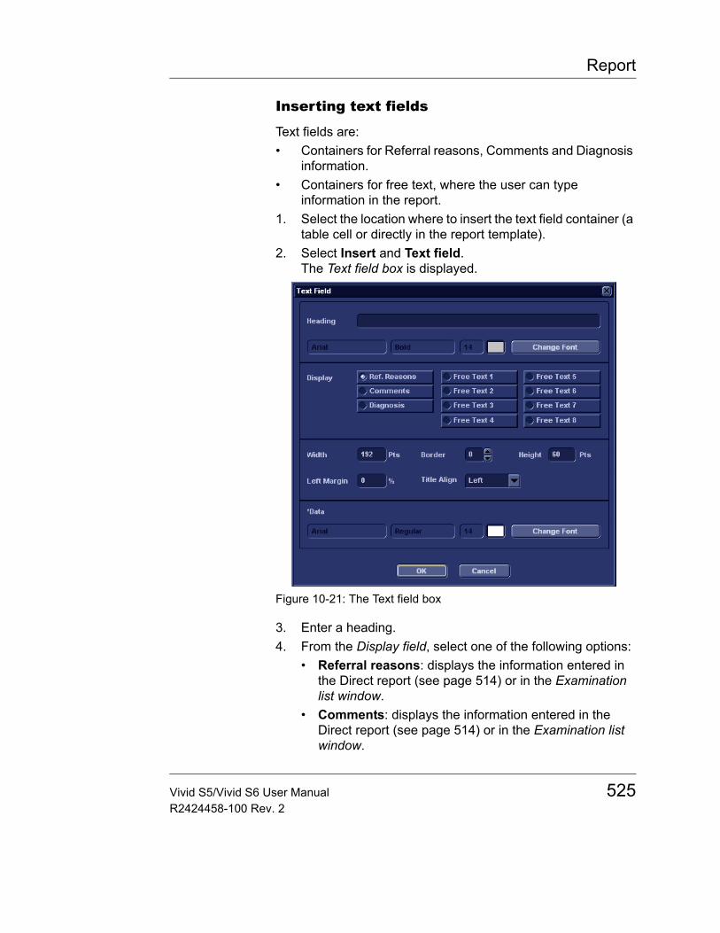
Report
Inserting text fields
Text fields are:• Containers for Referral reasons, Comments and Diagnosis
information.• Containers for free text, where the user can type
information in the report.1. Select the location where to insert the text field container (a
table cell or directly in the report template).2. Select Insert and Text field.
The Text field box is displayed.
Figure 10-21: The Text field box
3. Enter a heading.4. From the Display field, select one of the following options:
• Referral reasons: displays the information entered in the Direct report (see page 514) or in the Examination list window.
• Comments: displays the information entered in the Direct report (see page 514) or in the Examination list window.
Vivid S5/Vivid S6 User Manual 525R2424458-100 Rev. 2
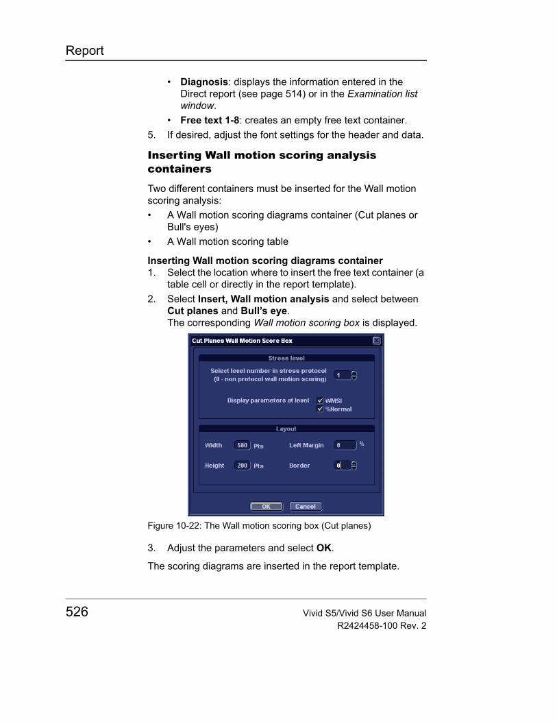
Report
• Diagnosis: displays the information entered in the Direct report (see page 514) or in the Examination list window.
• Free text 1-8: creates an empty free text container.5. If desired, adjust the font settings for the header and data.
Inserting Wall motion scoring analysis containers
Two different containers must be inserted for the Wall motion scoring analysis:• A Wall motion scoring diagrams container (Cut planes or
Bull's eyes)• A Wall motion scoring table
Inserting Wall motion scoring diagrams container1. Select the location where to insert the free text container (a
table cell or directly in the report template).2. Select Insert, Wall motion analysis and select between
Cut planes and Bull’s eye.The corresponding Wall motion scoring box is displayed.
Figure 10-22: The Wall motion scoring box (Cut planes)
3. Adjust the parameters and select OK.
The scoring diagrams are inserted in the report template.
526 Vivid S5/Vivid S6 User ManualR2424458-100 Rev. 2
Report
Inserting Wall motion scoring diagrams container1. Place the cursor right below the Wall motion scoring
diagrams container.2. Select Insert, Wall motion analysis and select Score
table box.The Score table box is displayed.
Figure 10-23: The Score table box
3. Adjust the layout parameters in the Score table box and select OK.
The Score table is inserted in the report template.
Editing the information container
Resizing the information container1. Move the Mouse cursor over the border of the container to
resize.The mouse cursor is changed to a cross .
2. Press Left mouse button once.The container is displayed with anchor squares on the sides and at the corners.
3. Resize the container by dragging from the anchor points.
Editing the information container propertiesModifying the container’s specific properties
1. Move the Mouse cursor over the border of the container to edit.The mouse cursor is changed to a cross .
2. Double-click on the Left mouse button.The Container box is displayed.
Vivid S5/Vivid S6 User Manual 527R2424458-100 Rev. 2
Report
3. Adjust the parameters specific to the selected container.Note: Some information containers have additional parameters that may be adjusted by selecting Box properties.
Inserting a new page1. In the template, position the Mouse cursor at the insertion
point.2. Press the Left mouse button.3. Press Insert and select Page Break.
Inserting header and footer
Header and footer may be defined to be displayed in the printed report. The header and footer are not visible in the on screen report.
To insert header and footer in the printed report:1. Select File and Page setup.
The Page setup box is displayed.
Figure 10-24: The Page setup box
2. Adjust the printing orientation.3. Define the header and footer for the printed report, by
typing text and entering the required variables listed in the table below.
528 Vivid S5/Vivid S6 User ManualR2424458-100 Rev. 2
Report
Check Different on first page and create a specific header/footer for the first page.
4. Select OK.To check the display of the header and footer, select File and Print preview.
Variable Description
{pid} Patient ID
{pnm} Patient name
{pdb} Patient date of birth
{exd} Examination date
{prd} Current date (printing date)
{prt} Current time (printing time)
{cp} Current page
{tp} Page count
{c} Subsequent entries are centered
{r} Subsequent entries are right aligned
Vivid S5/Vivid S6 User Manual 529R2424458-100 Rev. 2
Report
Saving the report template
Replace an existing template
Factory templates cannot be overwritten.1. Press File and select Save.
A dialogue window is displayed asking for confirmation.2. Select:
• Yes to save the report template• No to discard the report template• Cancel to go back to the Report designer without saving
the report template.
Save existing template with a new name1. Press File and select Save as.
The Save as template window is displayed.
Figure 10-25: The Save as template window
2. Enter a name for the template.3. Press OK.
The template is saved.
To exit the Report designer1. Select File and Exit.
The Exit window is displayed.2. In the Exit window, select one of the following:
• Yes: to save the report template and exit the application.• No: to exit the application without saving the changes
made in the report template.• Cancel: to return to the application.
530 Vivid S5/Vivid S6 User ManualR2424458-100 Rev. 2
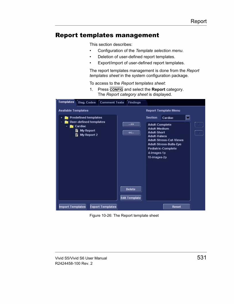
Report
Report templates managementThis section describes:• Configuration of the Template selection menu.• Deletion of user-defined report templates.• Export/import of user-defined report templates.
The report templates management is done from the Report templates sheet in the system configuration package.
To access to the Report templates sheet:1. Press CONFIG and select the Report category.
The Report category sheet is displayed.
Figure 10-26: The Report template sheet
Vivid S5/Vivid S6 User Manual 531R2424458-100 Rev. 2

Report
Configuration of the Template selection menuThe Template selection menu displays the application specific report templates that can be selected when creating a report. The Template selection menu can be configured to display only the templates of interest.
Inserting a template in the Templates selection menu1. Press CONFIG and select Report.
The Report template sheet is displayed (Figure 10-26)2. In the Available templates field (left field), select the
template to insert in the Template selection menu.3. Next to Section, select the appropriate application.4. Press the Right arrow button .
The selected template is inserted in the Template selection menu.Note: Double-clicking on a template in the Available template field will also insert the template in the Template menu.
Removing a template from the Template selection menu1. In the Report template menu field (right field), select the
template to remove.2. Press the Left arrow button .
The selected template is removed from the Template selection menu.Note: Double-clicking on a template in the Available template field will also insert the template in the Template menu.
Sorting the templates in the Template selection menu1. In the Report template menu field, select the template to
move. 2. Press the Up or Down arrow buttons .
The selected template is moved accordingly in the Template selection menu.
532 Vivid S5/Vivid S6 User ManualR2424458-100 Rev. 2
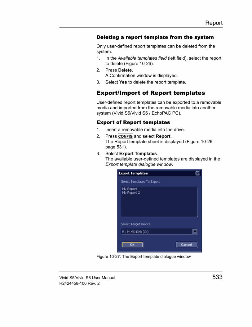
Report
Deleting a report template from the system
Only user-defined report templates can be deleted from the system.1. In the Available templates field (left field), select the report
to delete (Figure 10-26).2. Press Delete.
A Confirmation window is displayed.3. Select Yes to delete the report template.
Export/Import of Report templatesUser-defined report templates can be exported to a removable media and imported from the removable media into another system (Vivid S5/Vivid S6 / EchoPAC PC).
Export of Report templates1. Insert a removable media into the drive.2. Press CONFIG and select Report.
The Report template sheet is displayed (Figure 10-26, page 531).
3. Select Export Templates.The available user-defined templates are displayed in the Export template dialogue window.
Figure 10-27: The Export template dialogue window
Vivid S5/Vivid S6 User Manual 533R2424458-100 Rev. 2
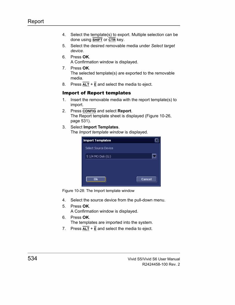
Report
4. Select the template(s) to export. Multiple selection can be done using SHIFT or CTR key.
5. Select the desired removable media under Select target device.
6. Press OK.A Confirmation window is displayed.
7. Press OK.The selected template(s) are exported to the removable media.
8. Press ALT + E and select the media to eject.
Import of Report templates1. Insert the removable media with the report template(s) to
import.2. Press CONFIG and select Report.
The Report template sheet is displayed (Figure 10-26, page 531).
3. Select Import Templates.The Import template window is displayed.
Figure 10-28: The Import template window
4. Select the source device from the pull-down menu.5. Press OK.
A Confirmation window is displayed.6. Press OK.
The templates are imported into the system.7. Press ALT + E and select the media to eject.
534 Vivid S5/Vivid S6 User ManualR2424458-100 Rev. 2

Probes
Chapter 11 Probes
• Probe overview ............................................................................. .. 537• Supported probes ..................................................................... 537• Vivid S5 Probe/Application Overview ....................................... 542• Vivid S6 Probe/Application Overview ....................................... 543• Maximum probe temperature ................................................... 544• Probe orientation ...................................................................... 545• Probe labelling ......................................................................... 546• Environmental Requirements ................................................... 547
• Probe Integration .......................................................................... .. 548• Selecting probes ...................................................................... 548• Connecting the probe ............................................................... 548• Activating the probe ................................................................. 550• Disconnecting the probe .......................................................... 551
• Care and Maintenance .................................................................. .. 552• Planned maintenance .............................................................. 552• Inspecting the probe ................................................................. 553• Special handling instructions .................................................... 554• Cleaning and disinfecting probes ............................................. 556
• Probe safety .................................................................................. .. 562• Biopsy ............................................................................................ .. 563
• Precaution concerning the use of biopsy procedures .............. 563• Preparing the Biopsy guide attachment ................................... 565• Displaying the Guide zone ....................................................... 569• Endocavitary Probe Biopsy Guide Assembly ........................... 571• Biopsy needle path verification ................................................ 573• Starting the biopsy procedure .................................................. 573• Cleaning, disinfection and disposal .......................................... 573
Vivid S5/Vivid S6 User Manual 535R2424458-100 Rev. 2

Probes
• Surgery/Intra-operative Use ........................................................ ... 574• Preparing for Surgery/Intra-operative Procedures ....................574
536 Vivid S5/Vivid S6 User ManualR2424458-100 Rev. 2
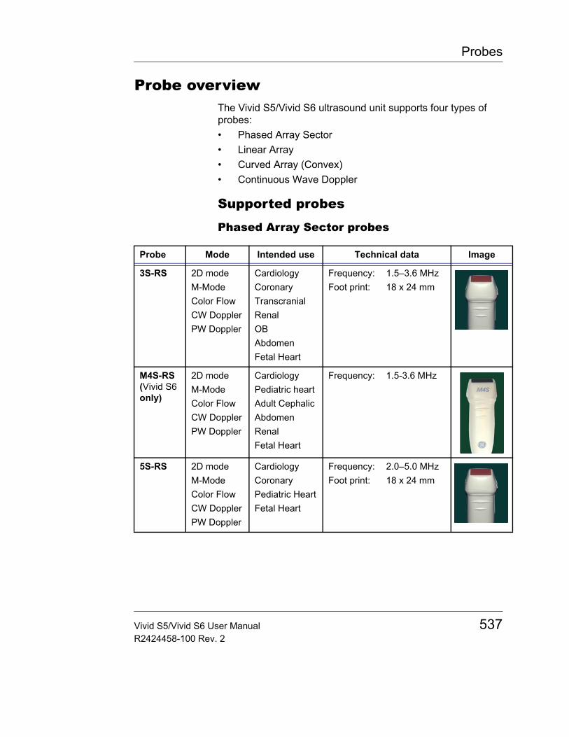
Probes
Probe overviewThe Vivid S5/Vivid S6 ultrasound unit supports four types of probes:• Phased Array Sector• Linear Array• Curved Array (Convex)• Continuous Wave Doppler
Supported probes
Phased Array Sector probes
Probe Mode Intended use Technical data Image
3S-RS 2D modeM-ModeColor FlowCW DopplerPW Doppler
CardiologyCoronaryTranscranialRenalOBAbdomenFetal Heart
Frequency:Foot print:
1.5–3.6 MHz18 x 24 mm
M4S-RS (Vivid S6 only)
2D modeM-ModeColor FlowCW DopplerPW Doppler
CardiologyPediatric heartAdult CephalicAbdomenRenalFetal Heart
Frequency: 1.5-3.6 MHz
5S-RS 2D modeM-ModeColor FlowCW DopplerPW Doppler
CardiologyCoronaryPediatric HeartFetal Heart
Frequency:Foot print:
2.0–5.0 MHz18 x 24 mm
Vivid S5/Vivid S6 User Manual 537R2424458-100 Rev. 2
Probes
Linear Array probes
6S-RS 2D modeM-ModeColor FlowCW DopplerPW Doppler
CardiologyPediatric HeartFetal HeartNeonatal cephalic
Frequency: 2.7-8.0 MHz
7S-RS 2D modeM-ModeColor FlowCW DopplerPW Doppler
CardiologyPediatric heartCoronaryNeonatal head
Frequency:Foot print:
3.5–8.0 MHz15 x 21 mm
10S-RS 2D modeM-ModeColor FlowCW DopplerPW Doppler
CardiologyPediatric heartCoronaryNeonatal head
Frequency:Foot print:
4.5–11.5 MHz10 x 14 mm
Probe Mode Intended use Technical data Image
Probe Mode Intended use Technical data Image
8L-RS 2D modeM-ModeColor FlowPW Doppler
Peripheral vascularSmall parts
Frequency:Foot print:
4.0–13.0 MHz14 x 48 mm
9L-RS 2D modeM-ModeColor FlowPW Doppler
Peripheral vascularSmall parts
Frequency:Foot print:
4.0–13.0 MHz14 x 52 mm
538 Vivid S5/Vivid S6 User ManualR2424458-100 Rev. 2
Probes
Curved Array (Convex) probes
Doppler probes
12L-RS 2D modeM-ModeColor FlowPW Doppler
Peripheral vascularSmall parts
Frequency:Foot print:
6.0–13.0 MHz14 x 48 mm
Probe Mode Intended use Technical data Image
Probe Mode Intended use Technical data Image
4C-RS 2D modeM-ModeColor FlowPW Doppler
AbdomenFetal HeartRenalOB
Frequency:Foot print:FOV:
1.8–6.0 MHz17 x 65 mm58 degrees
8C-RS 2D modeM-ModeColor FlowPW Doppler
Pediatrics AbdomenNeonatal HeadCartoidSmall partsCardiac
Frequency:Foot print:FOV:
4.0-11.0 MHz26 x 10 mm133 degrees
e8C-RS 2D modeM-ModeColor FlowPW Doppler
EndocavityFetal HeartObstetricsPelvic
Frequency:Foot print:FOV:
4.0-11.0 MHz23 x 10 mm133 degrees
Probe Mode Intended use Technical data Image
2D-RS (P2D)
CW Doppler Cardiology Frequency: 2.0 MHz
Vivid S5/Vivid S6 User Manual 539R2424458-100 Rev. 2
Probes
Multiplane Transesophageal Phased Array probe
* Applicable only for Vivid S6.
6D-RS (P6D)
CW Doppler Vascular Frequency: 6.0 MHz
Probe Mode Intended use Technical data Image
Probe Mode Intended use Technical data Image
6T-RS6T*
2D modeM-ModeColor FlowCW DopplerPW Doppler
Transesophageal Cardiology
Frequency: 2.9–8.0 MHz
6Tc-RS 2D modeM-ModeColor FlowCW DopplerPW Doppler
Transesophageal Cardiology
Frequency: 2.9-8.0 MHz
9T-RS9T*
2D modeM-ModeColor FlowCW DopplerPW Doppler
Transesophageal Cardiology
Frequency: 4.0–10.0 MHz
540 Vivid S5/Vivid S6 User ManualR2424458-100 Rev. 2
Probes
Intra Operative Probes
* Excluding direct contact with the heart
Probe Mode Intended use Technical data Image
i12L-RS 2D modeM-ModeColor FlowPW Doppler
Intraoperative*Thoracic Vascular and abdominalPediatricSmall partsMusculo-skeletalMusculo-skeletal SuperficialPeripheral vascular
Frequency: 5.0-13.0 MHz
Foot print: 14 x 33 mm
Vivid S5/Vivid S6 User Manual 541R2424458-100 Rev. 2
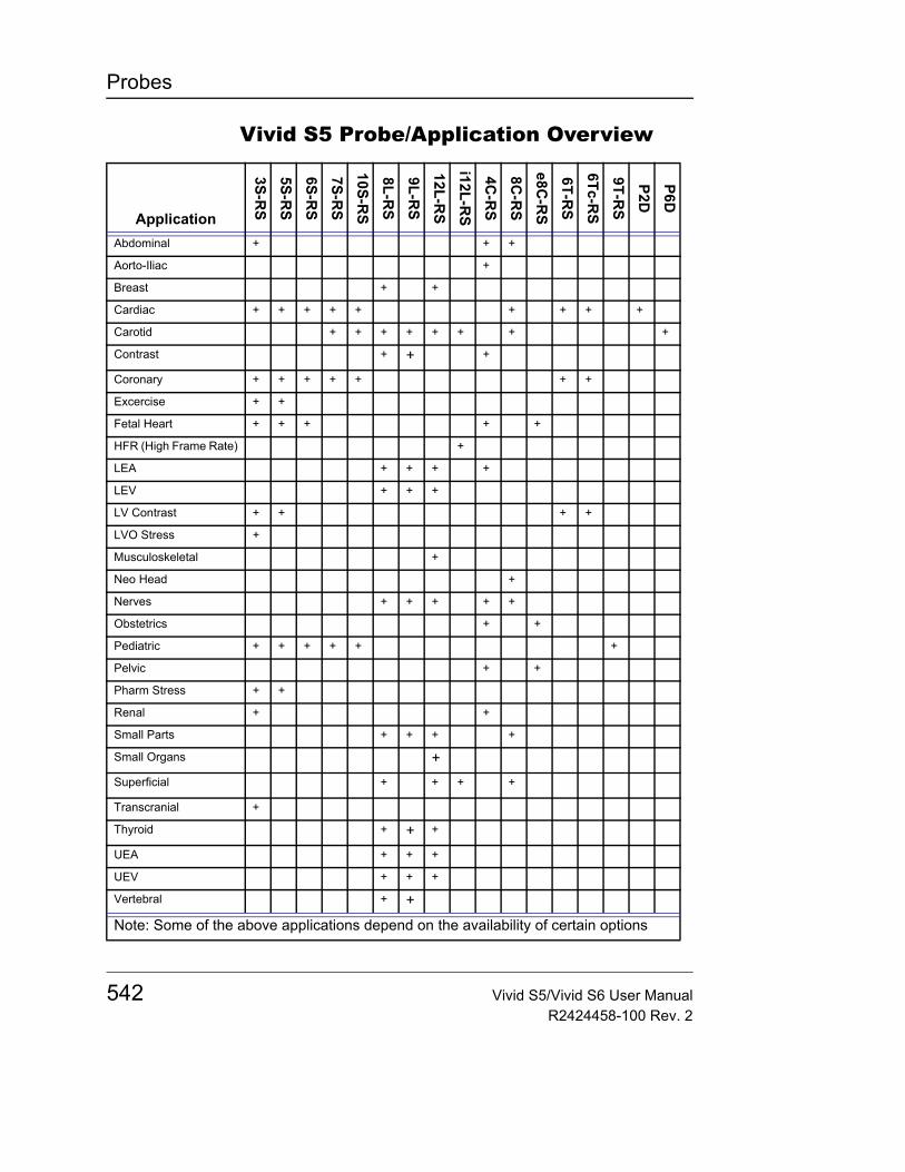
Probes
Vivid S5 Probe/Application Overview
Application
3S-RS
5S-RS
6S-RS
7S-RS
10S-RS
8L-RS
9L-RS
12L-RS
i12L-RS
4C-R
S
8C-R
S
e8C-R
S
6T-RS
6Tc-RS
9T-RS
P2D
P6DAbdominal + + +
Aorto-Iliac +
Breast + +
Cardiac + + + + + + + + +
Carotid + + + + + + + +
Contrast + + +
Coronary + + + + + + +
Excercise + +
Fetal Heart + + + + +
HFR (High Frame Rate) +
LEA + + + +
LEV + + +
LV Contrast + + + +
LVO Stress +
Musculoskeletal +
Neo Head +
Nerves + + + + +
Obstetrics + +
Pediatric + + + + + +
Pelvic + +
Pharm Stress + +
Renal + +
Small Parts + + + +
Small Organs +Superficial + + + +
Transcranial +
Thyroid + + +
UEA + + +
UEV + + +
Vertebral + +
Note: Some of the above applications depend on the availability of certain options
542 Vivid S5/Vivid S6 User ManualR2424458-100 Rev. 2
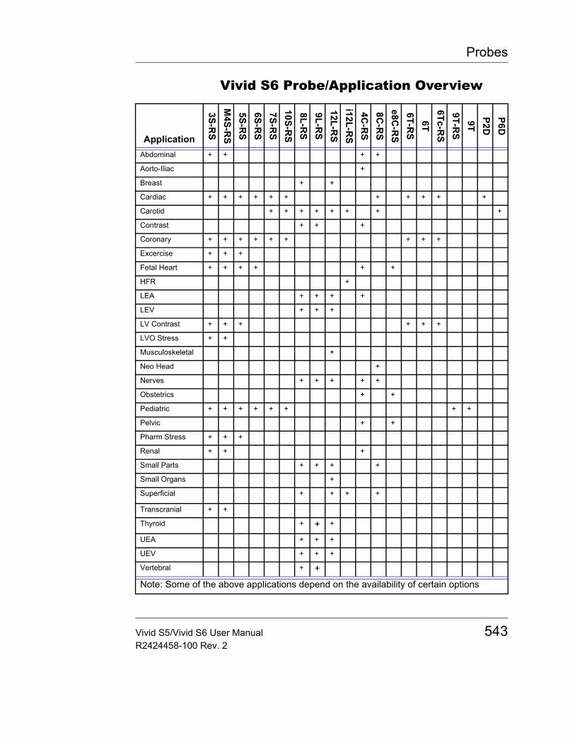
Probes
Vivid S6 Probe/Application Overview
Application
3S-RS
M4S-R
S5S-R
S6S-R
S7S-R
S10S-R
S8L-R
S9L-R
S12L-R
Si12L-R
S4C
-RS
8C-R
Se8C
-RS
6T-RS
6T6Tc-R
S9T-R
S9T
P2DP6D
Abdominal + + + +
Aorto-Iliac +
Breast + +
Cardiac + + + + + + + + + + +
Carotid + + + + + + + +
Contrast + + +
Coronary + + + + + + + + +
Excercise + + +
Fetal Heart + + + + + +
HFR +
LEA + + + +
LEV + + +
LV Contrast + + + + + +
LVO Stress + +
Musculoskeletal +
Neo Head +
Nerves + + + + +
Obstetrics + +
Pediatric + + + + + + + +
Pelvic + +
Pharm Stress + + +
Renal + + +
Small Parts + + + +
Small Organs +
Superficial + + + +
Transcranial + +
Thyroid + + +
UEA + + +
UEV + + +
Vertebral + +
Note: Some of the above applications depend on the availability of certain options
Vivid S5/Vivid S6 User Manual 543R2424458-100 Rev. 2

Probes
Maximum probe temperature
Notes: Lens temperature measured under following conditions per IEC 60601-2-37 Amd. 2:1. Thermocouple was placed at the geometric center of the
lens. Thermal phantom made with tissue-mimicking material as referenced in IEC60601-2-37 Amd 2: Annex BB.
2. a: Thermal phantom at 23 +/- 3 °C for all probes.b: Temperature rise is measured and added to 33 for External-Use probes or 37 °C for Non External-Use probes.
3. Probe placed upright in contact with above thermal phantom.
Probe Max Temp
3S -RS 40.5
M4S-RS 42.8
5S-RS 40.8
6S-RS 39.5
7S-RS 37.7
10S-RS 36.1
8L-RS 41.0
9L-RS 40.4
12L-RS 36.6
i12L-RS 40.5
4C-RS 37.8
8C-RS 37.3
E8C-RS 40.7
6T/6T-RS 40.8
6Tc-RS 42.3
9T/9T-RS 42.1
P2D 35.3
P6D 36.0
544 Vivid S5/Vivid S6 User ManualR2424458-100 Rev. 2
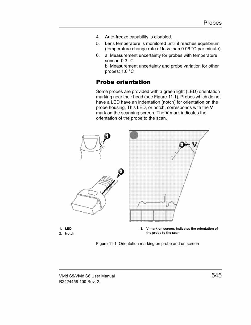
Probes
4. Auto-freeze capability is disabled.5. Lens temperature is monitored until it reaches equilibrium
(temperature change rate of less than 0.06 °C per minute).6. a: Measurement uncertainty for probes with temperature
sensor: 0.3 °Cb: Measurement uncertainty and probe variation for other probes: 1.6 °C
Probe orientationSome probes are provided with a green light (LED) orientation marking near their head (see Figure 11-1). Probes which do not have a LED have an indentation (notch) for orientation on the probe housing. This LED, or notch, corresponds with the V mark on the scanning screen. The V mark indicates the orientation of the probe to the scan.
Figure 11-1: Orientation marking on probe and on screen
1. LED2. Notch
3. V-mark on screen: indicates the orientation of the probe to the scan.
Vivid S5/Vivid S6 User Manual 545R2424458-100 Rev. 2
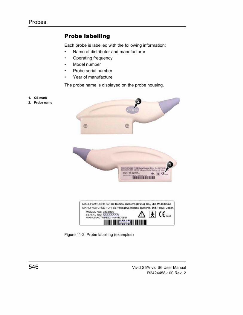
Probes
Probe labellingEach probe is labelled with the following information:• Name of distributor and manufacturer• Operating frequency• Model number• Probe serial number• Year of manufacture
The probe name is displayed on the probe housing.
Figure 11-2: Probe labelling (examples)
1. CE mark2. Probe name
546 Vivid S5/Vivid S6 User ManualR2424458-100 Rev. 2

Probes
Environmental RequirementsProbes should be operated, stored, or transported within parameters outlined in Table 2-1, page 53.
Ensure that the probe face temperature does not exceed normal operation temperature range (see table on page 544).
Vivid S5/Vivid S6 User Manual 547R2424458-100 Rev. 2
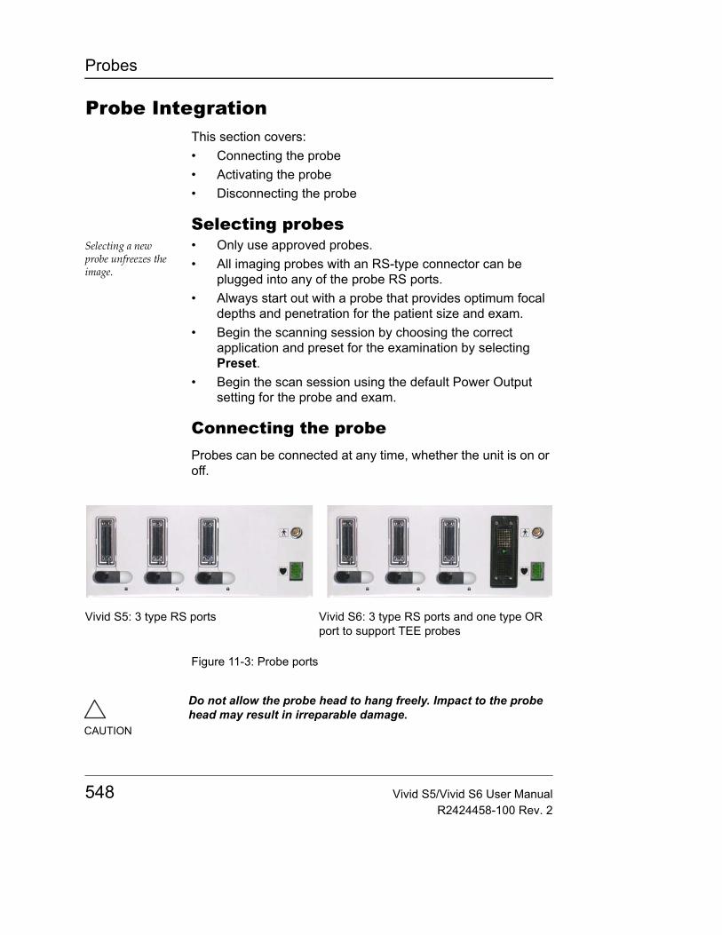
Probes
Probe IntegrationThis section covers:• Connecting the probe• Activating the probe• Disconnecting the probe
Selecting probesSelecting a new probe unfreezes the image.
• Only use approved probes.• All imaging probes with an RS-type connector can be
plugged into any of the probe RS ports.• Always start out with a probe that provides optimum focal
depths and penetration for the patient size and exam.• Begin the scanning session by choosing the correct
application and preset for the examination by selecting Preset.
• Begin the scan session using the default Power Output setting for the probe and exam.
Connecting the probeProbes can be connected at any time, whether the unit is on or off.
Figure 11-3: Probe ports
Vivid S5: 3 type RS ports Vivid S6: 3 type RS ports and one type OR port to support TEE probes
CAUTION
Do not allow the probe head to hang freely. Impact to the probe head may result in irreparable damage.
548 Vivid S5/Vivid S6 User ManualR2424458-100 Rev. 2
Probes
To connect a probe (small connector - type RS)1. Hold the probe connector vertically with the cable pointing
upwards.2. Push the connector locking handle to the right-most
position.3. Align the connector with the probe port and carefully push
into place.4. Push the connector locking handle to the left-most position.
To connect a probe (large connector - type OR)1. Hold the probe connector vertically with the cable pointing
upwards.2. Turn the connector locking handle horizontically.3. Align the connector with the probe port and carefully push
into place.4. Rotate the locking handle to the full vertical position to lock
in place.
CAUTION
Fault conditions can result in electric shock hazard. Do not touch the surface of probe connectors which are exposed when the probe is removed.
WARNING
Do NOT touch the patient and any of the connectors on the ultrasound unit simultaneously, including ultrasound probe connectors.
CAUTION
Take the following precautions with the probe cables:• Keep free from the wheels.• Do not bend cable sharply.
Vivid S5/Vivid S6 User Manual 549R2424458-100 Rev. 2
Probes
Activating the probeWhen a probe is connected to the unit it is automatically detected.
To select a probe and an application1. Press PROBE on the control panel. A list of the connected
probes will pop up.2. Trackball to the desired probe.
An application menu for the desired probe is then listed.3. Trackball to the desired application4. Press SET to launch the application.
CAUTION
Make sure that the probe and application names displayed on the screen correspond to the actual probe and application selection.
Check that the correct TI category is displayed (see "Thermal Index" on page 26). TIB must be displayed when a fetal application is selected.
550 Vivid S5/Vivid S6 User ManualR2424458-100 Rev. 2

Probes
Disconnecting the probeProbes can be disconnected at any time. It is recommended that the probe should not be active when being disconnected.
To disconnect a probe (small connector - type RS)1. Freeze the image by pressing FREEZE.2. Press the connector locking lever towards the left to unlock
the connector.3. Pull the probe and connector straight out of the probe port.4. Carefully slide the probe and connector away form the
probe port and around the right side of the keyboard.5. Ensure that the cable is free.6. Verify that the probe head is clean before placing the probe
in its storage case.
To disconnect a probe (large connector - type OR)1. Rotate the lock handle counter-clockwise to the horizontal
position to unlock the connector.2. Pull the connector straight out of the probe port.3. Verify that the probe head is clean before placing the probe
in its storage case.
Vivid S5/Vivid S6 User Manual 551R2424458-100 Rev. 2
Probes
Care and MaintenanceThis section covers:• Planned maintenance• Probe inspection• Probe cleaning• Probe disinfection
Planned maintenance
It is recommended to keep a maintenance log and note all probe malfunctions. Follow the maintenance schedule below to ensure optimum operation and safety:
After each use• Inspect the probe• Clean the probe• If required disinfect the probe
Before each use• Inspect the probe
CAUTION
Improper handling can lead to early probe failure and electric shock hazards.
DO follow the specific cleaning and disinfection procedures provided in this chapter and the germicide manufacturers instructions.
Failure to do so will void probe warranty.
CAUTION
Transesophageal and intraoperative probes require a special handling. Refer to the user documentation enclosed with these probes.
552 Vivid S5/Vivid S6 User ManualR2424458-100 Rev. 2
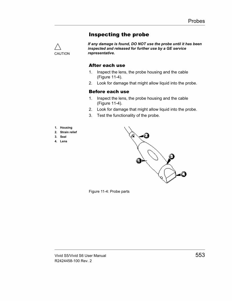
Probes
Inspecting the probe
After each use1. Inspect the lens, the probe housing and the cable
(Figure 11-4).2. Look for damage that might allow liquid into the probe.
Before each use1. Inspect the lens, the probe housing and the cable
(Figure 11-4).2. Look for damage that might allow liquid into the probe.3. Test the functionality of the probe.
Figure 11-4: Probe parts
CAUTION
If any damage is found, DO NOT use the probe until it has been inspected and released for further use by a GE service representative.
1. Housing2. Strain relief3. Seal4. Lens
Vivid S5/Vivid S6 User Manual 553R2424458-100 Rev. 2
Probes
Special handling instructions
Using protective sheaths
InstructionsCustom made sheaths are available for each probe. Each probe sheath kit consists of a flexible sheath used to cover the probe and cable and elastic bands used to secure the sheath.
Sterile probe sheaths are supplied as part of biopsy kits for those probes intended for use in biopsy procedures. In addition to the sheath and elastic bands, there are associated accessories for performing a biopsy procedure which are included in the kit. Refer to the biopsy instructions for the specific probes in the Discussion section of this chapter for further information.
ReorderingTo reorder sheaths, please contact your local distributor or the appropriate support resource.
CAUTION
Protective barriers may be required to minimize disease transmission. Probe sheaths are available for use with all clinical situations where infection is a concern. Use of legally marketed, sterile probe sheaths is strongly recommended for intra-cavitary and intra-operative procedures. Use of legally marketed, sterile, pyrogen free probe sheaths is REQUIRED for neurological intra-operative procedures.
CAUTION
Devices containing latex may cause severe allergic reaction in latex sensitive individuals. Refer to FDA's March 29, 1991 Medical Alert on latex products.
CAUTION
Do not use pre-lubricated condoms as a sheath. In some cases, they may damage the probe. Lubricants in these condoms may not be compatible with probe construction.
CAUTION
DO NOT use an expired probe sheath. Before using probe sheaths, verify whether the term of validity has expired.
554 Vivid S5/Vivid S6 User ManualR2424458-100 Rev. 2
Probes
Endocavitary Probe Handling Precautions
If the sterilization solution comes out of the endocavitary probe, please follow the cautions below.
Probe handling and infection control
This information is intended to increase user awareness of the risks of disease transmission associated with using this equipment and provide guidance in making decisions directly affecting the safety of the patient as well as the equipment user.
Diagnostic ultrasound systems utilize ultrasound energy that must be coupled to the patient by direct physical contact. Depending on the type of examination, this contact occurs with a variety of tissues ranging from intact skin in a routine exam to re-circulating blood in a surgical procedure. The level of risk of infection varies greatly with the type of contact.
One of the most effective ways to prevent transmission between patients is with single use or disposable devices. However, ultrasound transducers are complex and expensive devices that must be reused between patients. It is very important, therefore, to minimize the risk of disease
CAUTION
Sterilant Exposure to Patient (e.g., Cidex): Contact with a sterilant to the patient's skin or mucous membrane may cause an inflammation. If this happens, refer to the sterilant's instruction manual.
Sterilant Exposure from Probe Handle to Patient (e.g., Cidex): DO NOT allow the sterilant to contact the patient. Only immerse the probe to its specified level. Ensure that no solution has entered the probe's handle before scanning the patient. If sterilant comes into contact with the patient, refer to the sterilant's instruction manual.
Sterilant Exposure from Probe Connector to Patient (e.g., Cidex): DO NOT allow the sterilant to contact the patient. Only immerse the probe to its specified level. Ensure that no solution has entered the probe's connector before scanning the paitent. If sterilant comes into contact with the patient, refer the the sterilant's instruction manual.
Endocavitary Probe Point of Contact: Refer to the sterilant's instruction manual.
Vivid S5/Vivid S6 User Manual 555R2424458-100 Rev. 2
Probes
transmission by using barriers and through proper processing between patients.
Cleaning and disinfecting probes
Cleaning probes
Cleaning procedure1. Disconnect the probe from the unit.2. Remove the coupling gel by wiping the probe lens with a
soft cloth.3. Wipe the probe and cable with a soft cloth moisten in a
warm soap and water solution (<80 oF/27 oC).4. Wipe the probe and cable with a soft cloth moisten in clean
water (<80 oF/27 oC) until all soap is removed.5. Wipe dry with a soft towel.
CAUTION
Risk of Infection: ALWAYS clean and disinfect the probe between patients to the level appropriate for the type of examination and use FDA-cleared probe sheaths where appropriate.
CAUTION
Adequate cleaning and disinfection are necessary to prevent disease transmission. It is the responsibility of the equipment user to verify and maintain the effectiveness of the infection control procedures in use. Always use sterile, legally marketed probe sheaths for intra-cavitary and intra-operative procedures.
For neurological intra-operative procedures, use of a legally marketed, sterile, pyrogen free probe sheath is REQUIRED. robes for neuro surgical use must not be sterilized with liquid chemical sterilants because of the possibility of neuro toxic residues remaining on the probe.
CAUTION
Transesophageal and intraoperative probes require a special handling. Refer to the user documentation enclosed with these probes.
CAUTION
You MUST disconnect the probe from the Vivid S5/Vivid S6 prior to cleaning/disinfecting the probe. Failure to do so could damage the system.
556 Vivid S5/Vivid S6 User ManualR2424458-100 Rev. 2
Probes
Disinfecting probes
In order to provide users with options in choosing a germicide, GE Medical Systems routinely reviews new medical germicides for compatibility with the materials used in the transducer housing, cable and lens. Although a necessary step in protecting patients and employees from disease transmission, liquid chemical germicides must also be selected to minimize potential damage to the transducer.
Refer to the Probe Care Card enclosed in the probe case or to http://www.gehealthcare.com/usen/ultrasound/products/probe_care.html for the latest list of compatible cleaning solutions and disinfectants.
Low-level disinfection• After cleaning, the probe and cable may be wiped with a
tissue sprayed with a recommended disinfectant.
Use additional precautions (e.g. gloves and gown) when decontaminating an infected probe.
CAUTION
To minimize the risk of infection from blood-borne pathogens, you must handle the probe and all disposables which have contacted blood, other potentially infectious materials, mucous membranes, and non-intact skin in accordance with infection control procedures. You must wear protective gloves when handling potentially infectious material. Use a face shield and gown if there is a risk of splashing or splatter.
Vivid S5/Vivid S6 User Manual 557R2424458-100 Rev. 2

Probes
High-level disinfectionHigh-level Disinfection destroys vegetative bacteria; lipid & non-lipid viruses, fungi and, depending highly on time of contact, is effective on bacterial spores. This is required for endocavity (TV, TR, and TE) probes after contact with mucosal membrane.
High-level disinfection procedureFollow the manu-facturer's instruc-tions for storage, use and disposal of the disinfection so-lution.
1. Prepare the germicide solution according to the manufacturer's instructions.
2. Place the cleaned dried probe in contact with the germicide for the time duration specified by the manufacturer.
3. Rinse the part of the probe which was in contact with the germicide according to the germicide manufacturer's instructions.
4. Wipe dry with a soft towel or air dry the probe.
WARNING
Use only germicides that are listed in the Probe Care Card enclosed with the probe. In addition, refer to the local / national regulations.
Do not steam autoclave or subject the probe to Ethylene Oxide (ETO).
WARNING
Do not immerse the probe in liquid beyond the level specified for that probe (see Figure 11-5).
Never immerse the probe connector or probe adapters in liquid.
The probe should not be exposed to the germicide longer than specified to achieve the desired effect.
DO NOT soak or saturate probes with solutions containing alcohol, bleach, ammonium chloride compounds. In addition TE probes must not be immersed in solutions containing hydrogen peroxide.
WARNING
CREUTZFELD-JACOB DISEASE
Neurological use on patients with this disease must be avoided. If a probe becomes contaminated, there is no adequate disinfecting means.
558 Vivid S5/Vivid S6 User ManualR2424458-100 Rev. 2
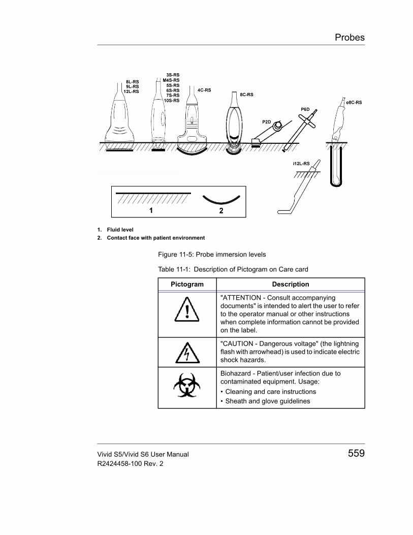
Probes
Figure 11-5: Probe immersion levels
1. Fluid level2. Contact face with patient environment
Table 11-1: Description of Pictogram on Care card
Pictogram Description
"ATTENTION - Consult accompanying documents" is intended to alert the user to refer to the operator manual or other instructions when complete information cannot be provided on the label.
"CAUTION - Dangerous voltage" (the lightning flash with arrowhead) is used to indicate electric shock hazards.
Biohazard - Patient/user infection due to contaminated equipment. Usage:• Cleaning and care instructions• Sheath and glove guidelines
Vivid S5/Vivid S6 User Manual 559R2424458-100 Rev. 2
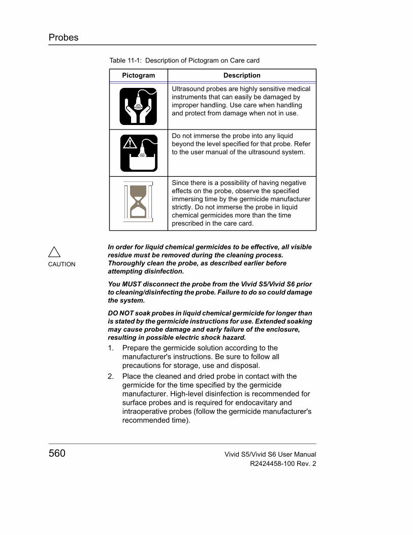
Probes
Ultrasound probes are highly sensitive medical instruments that can easily be damaged by improper handling. Use care when handling and protect from damage when not in use.
Do not immerse the probe into any liquid beyond the level specified for that probe. Refer to the user manual of the ultrasound system.
Since there is a possibility of having negative effects on the probe, observe the specified immersing time by the germicide manufacturer strictly. Do not immerse the probe in liquid chemical germicides more than the time prescribed in the care card.
Table 11-1: Description of Pictogram on Care card
Pictogram Description
CAUTION
In order for liquid chemical germicides to be effective, all visible residue must be removed during the cleaning process. Thoroughly clean the probe, as described earlier before attempting disinfection.
You MUST disconnect the probe from the Vivid S5/Vivid S6 prior to cleaning/disinfecting the probe. Failure to do so could damage the system.
DO NOT soak probes in liquid chemical germicide for longer than is stated by the germicide instructions for use. Extended soaking may cause probe damage and early failure of the enclosure, resulting in possible electric shock hazard.1. Prepare the germicide solution according to the
manufacturer's instructions. Be sure to follow all precautions for storage, use and disposal.
2. Place the cleaned and dried probe in contact with the germicide for the time specified by the germicide manufacturer. High-level disinfection is recommended for surface probes and is required for endocavitary and intraoperative probes (follow the germicide manufacturer's recommended time).
560 Vivid S5/Vivid S6 User ManualR2424458-100 Rev. 2
Probes
Coupling gels
In order to assure optimal transmission of energy between the patient and probe, a conductive gel or couplant must be applied liberally to the patient where scanning will be performed.
Coupling gels should not contain the following ingredients as they are known to cause probe damage:• Methanol, ethanol, isopropanol, or any other alcohol-based
product• Mineral oil• Iodine• Lotions• Lanolin• Aloe Vera• Olive Oil• Methyl or Ethyl Parabens (para hydroxybenzoic acid)• Dimethylsilicone
Returning/shipping probes and repair partsUS Department of Transportation and GE Medical Systems policy requires that equipment returned for service MUST be clean and free of blood and other infectious substances.
CAUTION
Probes for neuro surgical intra-operative use must NOT be sterilized with liquid chemical sterilants because of the possibility of neuro toxic residues remaining on the probe. Neurological procedures must be done with the use of legally marketed, sterile, pyrogen free probe sheaths.3. After removing from the germicide, rinse the probe
following the germicide manufacturer's rinsing instructions. Flush all visible germicide residue from the probe and allow to air dry.
CAUTION
Do not use gels (lubricants) that are not recommended. They may damage the probe and void the warranty.
WARNING
Do not apply gel to the eyes. If there is gel contact to the eye, flush eye thoroughly with water.
Vivid S5/Vivid S6 User Manual 561R2424458-100 Rev. 2
Probes
When you return a probe or part for service (Field Engineer or customer), you need to clean and disinfect the probe or part prior to packing and shipping the equipment.Ensure that you follow probe cleaning and disinfection instructions provided in the Basic User Manual.This ensures that employees in the transportation industry as well as the people who receive the package are protected from any risk.
Probe safety
WARNING
Ultrasound probes are highly sensitive medical instruments that can easily be damaged by improper handling. Use care when handling and protect from damage when not in use. DO NOT use a damaged or defective probe. Failure to follow these precautions can result in serious injury and equipment damage.For a detailed description of the safety guidelines see "Probe Safety" on page 32.
562 Vivid S5/Vivid S6 User ManualR2424458-100 Rev. 2
Probes
BiopsyThe Vivid S5/Vivid S6 supports biopsy capability for the 3S-RS, M4S-RS (Vivid S6 only), 4C-RS, 8L-RS, 9L-RS, 12L-RS, and e8C-RS probes. The biopsy option is intended for use by a duly licensed physician who has received the appropriate training in biopsy techniques as dictated by current relevant practices, as well as in proper operation of the Vivid S5/Vivid S6 ultrasound unit.
Precaution concerning the use of biopsy procedures
WARNING
Do not freeze the image during a biopsy procedure. The image must be live to avoid a positioning error.
CAUTION
Biopsy guidezones are intended to assist the user in determining optimal probe placement and approximate the needle path. However, actual needle movement is likely to deviate from the guideline. Always monitor the relative positions of the biopsy needle and the subject mass during the procedure.
CAUTION
The use of biopsy devices and accessories that have not been evaluated for use with the equipment may not be compatible and could result in injury.
Vivid S5/Vivid S6 User Manual 563R2424458-100 Rev. 2
Probes
CAUTION
The invasive nature of biopsy procedures requires proper preparation and technique to control infection and disease transmission. Equipment must be cleaned as appropriate for the procedure prior to use.• Follow the probe cleaning and disinfection procedures and
precautions to properly prepare the probe.• Follow the manufacturer’s instructions for the cleaning of biopsy
devices and accessories.• Use protective barriers such as gloves and probe sheaths.• After use, follow proper procedures for decontamination, cleaning,
and waste disposal.
Improper cleaning methods and the use of certain cleaning and disinfecting agents can cause damage to the plastic components that will degrade imaging performance or increase the risk of electric shock.
564 Vivid S5/Vivid S6 User ManualR2424458-100 Rev. 2
Probes
Preparing the Biopsy guide attachmentThe 3S-RS, 4C-RS, 8L-RS, 9L-RS, and 12L-RS probes have an optional biopsy kit specific for each probe. The biopsy kit consists of:• One reusable non-sterile bracket• Five disposable, single-use sterile Ultra-Pro IITM Needle
guide kits (Civco Medical Instruments Co, Inc.) consisting of:• Two sets with needle inserts covering gauge
size 14 through 23 (2.1 mm to 0.6 mm)• One sterile sheath• Two rubber bands• Sterile gel• One reusable needle guide
• Instructions
In addition sterile Ultra-Pro IITM Needle guide kits can be ordered as replacement kit.
Introduction to CIVCO's Needle Guidance Systems
CIVCO's Needle Guidance Systems utilize a two-part system consisting of a reusable biopsy bracket and a disposable snap-on needle guide. The disposable needle guides snap onto the biopsy bracket, providing a fixed path for visualizing ultrasound-guided instrument placement procedures. Applications include tissue biopsy, fluid aspirations and catheter placement. Single-angle brackets offer imaging professionals a fixed angle needle path during puncture procedures. Multi-angle brackets offer professionals different angles for needle placement. Once the desired angle has been selected, a stainless steel pin locks the angle securely into position. The pin is removable from the bracket for easy reprocessing between patients. Brackets should be cleaned and disinfected according to your CIVCO User's Guide.
The Ultra-Pro II™ allows for accurate placement for ultrasound-guided biopsy and drainage procedures. The needle guide directs instruments according to on-screen system software guidelines. The Ultra-Pro II features a
Vivid S5/Vivid S6 User Manual 565R2424458-100 Rev. 2
Probes
mechanism for quick-release detachment of the needle guide from the transducer while maintaining secure needle placement. The Ultra-Pro II includes disposable needle inserts for 14 to 23 gauge instruments. 8.5 French gauge inserts also available. Replacement kits include sterile needle guide, transducer cover, gel packet and colored elastic bands. Biopsy depth is indicated in centimeters.
Bracket attachment procedure1. Identify the appropriate biopsy guide bracket as shown in
Figure 11-6.
WARNING
Read the following instructions and the user's guide for the Ultra-Pro IITM Needle Guide kit before using the biopsy equipment.
566 Vivid S5/Vivid S6 User ManualR2424458-100 Rev. 2

Probes
Figure 11-6: Biopsy Guide Brackets
Probe Bracket Probe with Bracket
3S-RS
4C-RS
8L-RS
9L-RS
12L-RS
E8c-RS
Vivid S5/Vivid S6 User Manual 567R2424458-100 Rev. 2
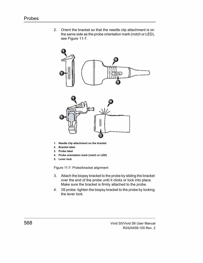
Probes
2. Orient the bracket so that the needle clip attachment is on the same side as the probe orientation mark (notch or LED), see Figure 11-7.
Figure 11-7: Probe/bracket alignment
3. Attach the biopsy bracket to the probe by sliding the bracket over the end of the probe until it clicks or lock into place.Make sure the bracket is firmly attached to the probe.
4. 3S probe: tighten the biopsy bracket to the probe by locking the lever lock.
1. Needle clip attachment on the bracket2. Bracket label3. Probe label4. Probe orientation mark (notch or LED)5. Lever lock
568 Vivid S5/Vivid S6 User ManualR2424458-100 Rev. 2
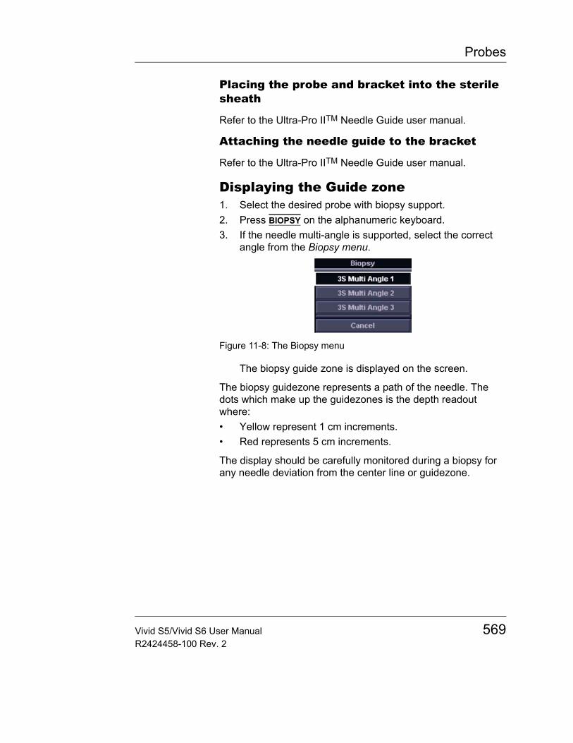
Probes
Placing the probe and bracket into the sterile sheath
Refer to the Ultra-Pro IITM Needle Guide user manual.
Attaching the needle guide to the bracket
Refer to the Ultra-Pro IITM Needle Guide user manual.
Displaying the Guide zone1. Select the desired probe with biopsy support.2. Press BIOPSY on the alphanumeric keyboard.3. If the needle multi-angle is supported, select the correct
angle from the Biopsy menu.
Figure 11-8: The Biopsy menu
The biopsy guide zone is displayed on the screen.
The biopsy guidezone represents a path of the needle. The dots which make up the guidezones is the depth readout where:• Yellow represent 1 cm increments.• Red represents 5 cm increments.
The display should be carefully monitored during a biopsy for any needle deviation from the center line or guidezone.
Vivid S5/Vivid S6 User Manual 569R2424458-100 Rev. 2
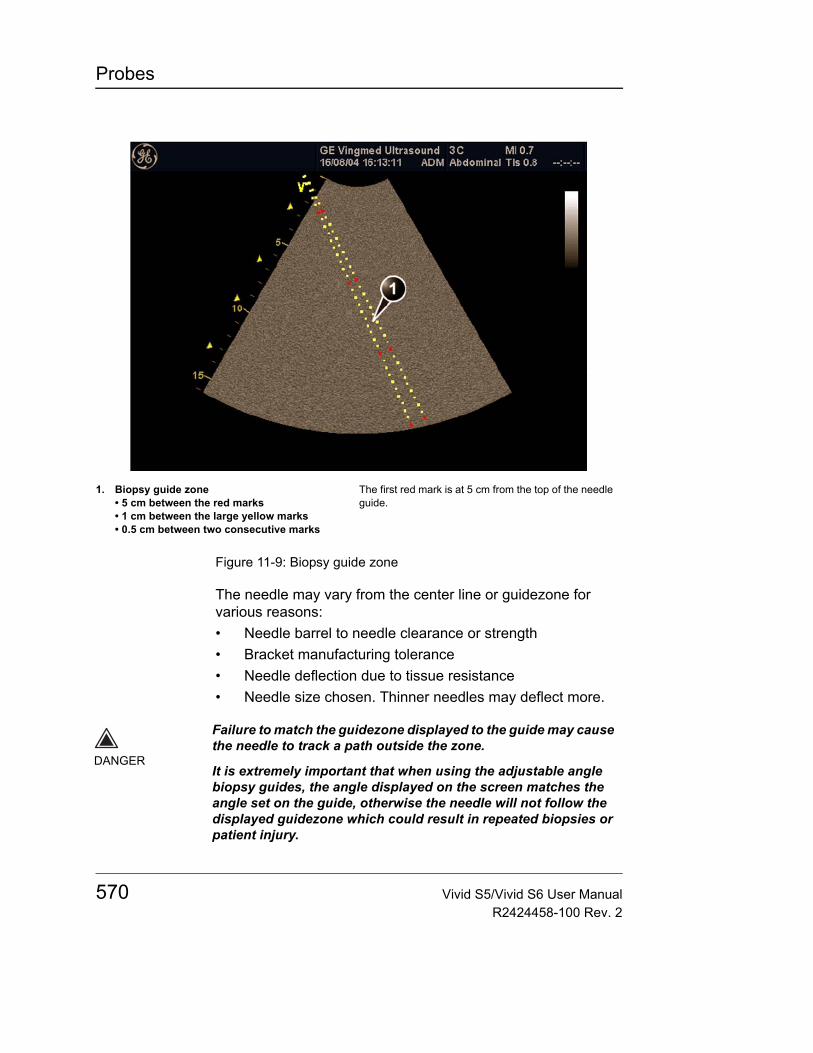
Probes
Figure 11-9: Biopsy guide zone
The needle may vary from the center line or guidezone for various reasons:• Needle barrel to needle clearance or strength• Bracket manufacturing tolerance• Needle deflection due to tissue resistance• Needle size chosen. Thinner needles may deflect more.
1. Biopsy guide zone• 5 cm between the red marks• 1 cm between the large yellow marks• 0.5 cm between two consecutive marks
The first red mark is at 5 cm from the top of the needle guide.
DANGER
Failure to match the guidezone displayed to the guide may cause the needle to track a path outside the zone.
It is extremely important that when using the adjustable angle biopsy guides, the angle displayed on the screen matches the angle set on the guide, otherwise the needle will not follow the displayed guidezone which could result in repeated biopsies or patient injury.
570 Vivid S5/Vivid S6 User ManualR2424458-100 Rev. 2

Probes
Endocavitary Probe Biopsy Guide AssemblyNote: The reusable biopsy guide fits with 16G needle or thinner.
E8C Preparation
To prepare the E8C for use:1. Remove the probe from the box and carefully examine it for
any damage.2. If the biopsy guide is to be attached, use the filling removal
tool to clean out the attachment area on the probe head.
Figure 11-10: Attachment Filling Removal
3. Clean, then disinfect the probe.Note: Ensure that protective gloves are worn.
Installing the sheath
To install the sheath:1. Remove the sheath from its package. Do not unroll the
sheath.Note: Remember to rinse all sanitary probe sheaths of powder before placing on the probe. Powder can degrade the displayed image.
2. Place an adequate amount of ultrasound gel inside the sheath tip (the gel is between the sheath inner surface and the probe aperture).Note: Ensure that only acoustic coupling gel is used for this purpose.
a. Probe Headb. Attachementc. Filling Removal Tool
Vivid S5/Vivid S6 User Manual 571R2424458-100 Rev. 2
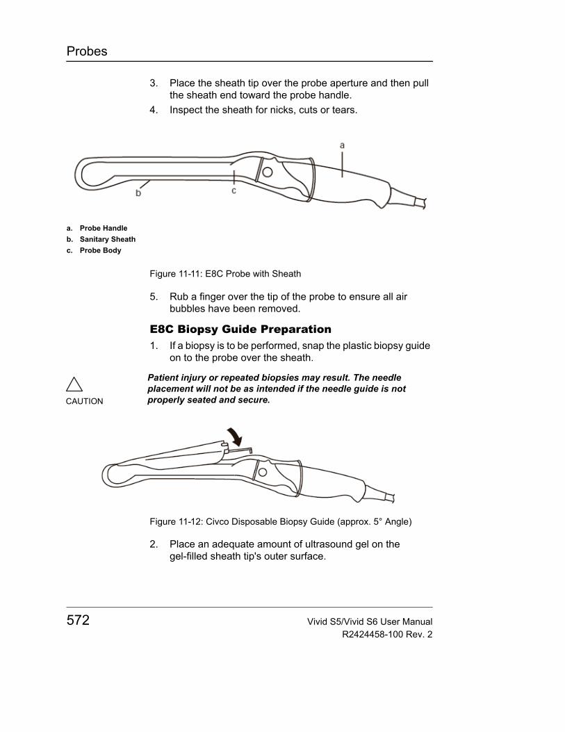
Probes
3. Place the sheath tip over the probe aperture and then pull the sheath end toward the probe handle.
4. Inspect the sheath for nicks, cuts or tears.
Figure 11-11: E8C Probe with Sheath
5. Rub a finger over the tip of the probe to ensure all air bubbles have been removed.
E8C Biopsy Guide Preparation1. If a biopsy is to be performed, snap the plastic biopsy guide
on to the probe over the sheath.
Figure 11-12: Civco Disposable Biopsy Guide (approx. 5° Angle)
2. Place an adequate amount of ultrasound gel on the gel-filled sheath tip's outer surface.
a. Probe Handleb. Sanitary Sheathc. Probe Body
CAUTION
Patient injury or repeated biopsies may result. The needle placement will not be as intended if the needle guide is not properly seated and secure.
572 Vivid S5/Vivid S6 User ManualR2424458-100 Rev. 2
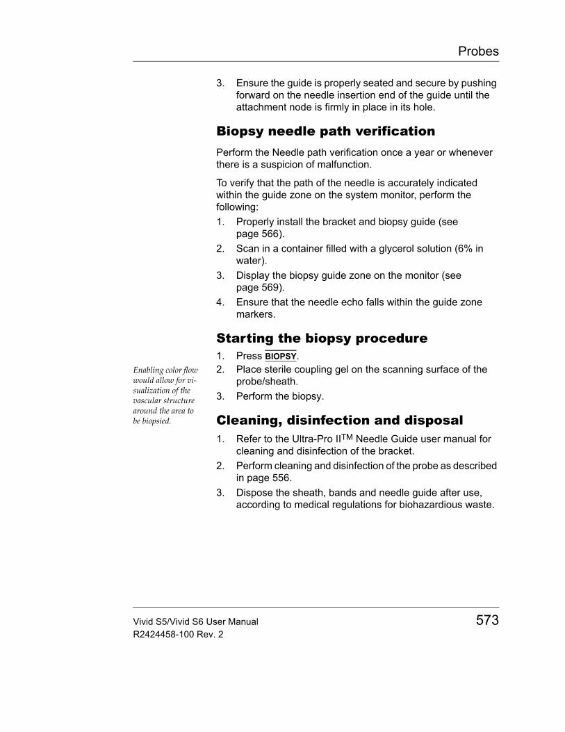
Probes
3. Ensure the guide is properly seated and secure by pushing forward on the needle insertion end of the guide until the attachment node is firmly in place in its hole.
Biopsy needle path verificationPerform the Needle path verification once a year or whenever there is a suspicion of malfunction.
To verify that the path of the needle is accurately indicated within the guide zone on the system monitor, perform the following:1. Properly install the bracket and biopsy guide (see
page 566).2. Scan in a container filled with a glycerol solution (6% in
water).3. Display the biopsy guide zone on the monitor (see
page 569).4. Ensure that the needle echo falls within the guide zone
markers.
Starting the biopsy procedure1. Press BIOPSY.
Enabling color flow would allow for vi-sualization of the vascular structure around the area to be biopsied.
2. Place sterile coupling gel on the scanning surface of the probe/sheath.
3. Perform the biopsy.
Cleaning, disinfection and disposal1. Refer to the Ultra-Pro IITM Needle Guide user manual for
cleaning and disinfection of the bracket.2. Perform cleaning and disinfection of the probe as described
in page 556.3. Dispose the sheath, bands and needle guide after use,
according to medical regulations for biohazardious waste.
Vivid S5/Vivid S6 User Manual 573R2424458-100 Rev. 2
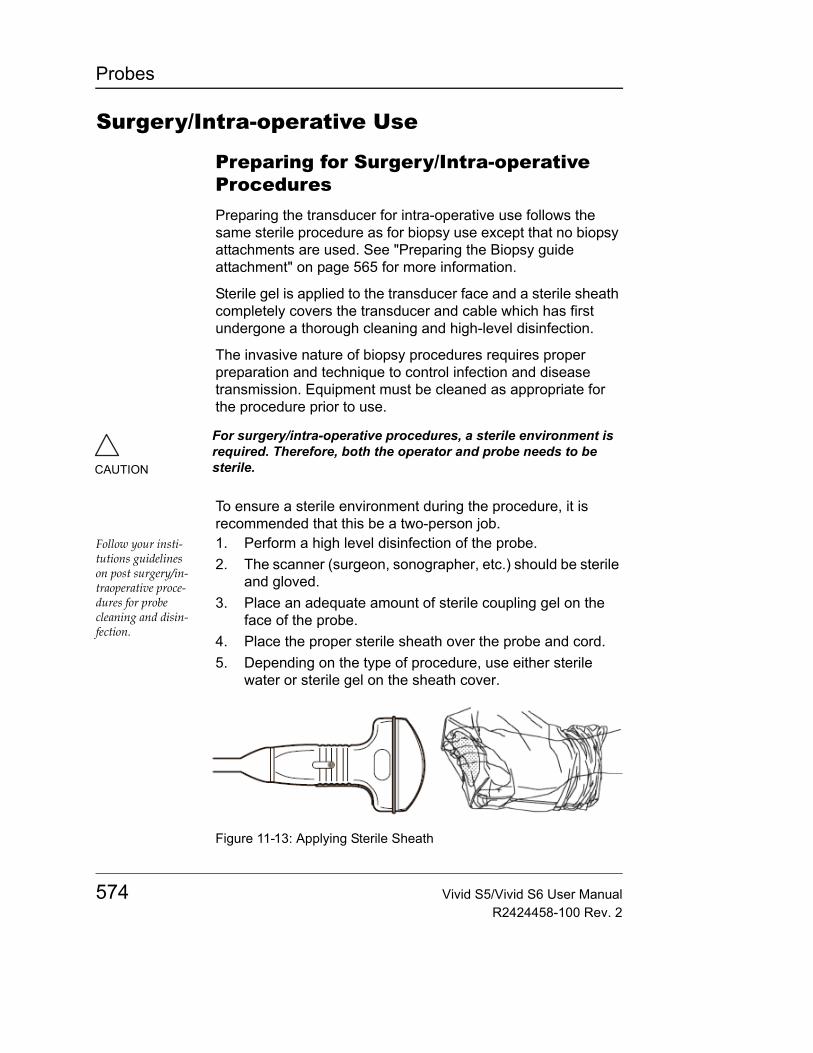
Probes
Surgery/Intra-operative Use
Preparing for Surgery/Intra-operative ProceduresPreparing the transducer for intra-operative use follows the same sterile procedure as for biopsy use except that no biopsy attachments are used. See "Preparing the Biopsy guide attachment" on page 565 for more information.
Sterile gel is applied to the transducer face and a sterile sheath completely covers the transducer and cable which has first undergone a thorough cleaning and high-level disinfection.
The invasive nature of biopsy procedures requires proper preparation and technique to control infection and disease transmission. Equipment must be cleaned as appropriate for the procedure prior to use.
To ensure a sterile environment during the procedure, it is recommended that this be a two-person job.
Follow your insti-tutions guidelines on post surgery/in-traoperative proce-dures for probe cleaning and disin-fection.
1. Perform a high level disinfection of the probe.2. The scanner (surgeon, sonographer, etc.) should be sterile
and gloved.3. Place an adequate amount of sterile coupling gel on the
face of the probe.4. Place the proper sterile sheath over the probe and cord.5. Depending on the type of procedure, use either sterile
water or sterile gel on the sheath cover.
Figure 11-13: Applying Sterile Sheath
CAUTION
For surgery/intra-operative procedures, a sterile environment is required. Therefore, both the operator and probe needs to be sterile.
574 Vivid S5/Vivid S6 User ManualR2424458-100 Rev. 2
Peripherals
Chapter 12 Peripherals
• Introduction ................................................................................... .. 576• Printing .......................................................................................... .. 577
• To print an image ..................................................................... 577• Specifications for peripherals ..................................................... .. 577• DVR (Digital Video Recorder) ...................................................... .. 578
• Overview .................................................................................. 578• Using the DVR ......................................................................... 578• Configuring the DVR ................................................................ 581• Reviewing the DVR Media Externally ...................................... 581
Vivid S5/Vivid S6 User Manual 575R2424458-100 Rev. 2
Peripherals
IntroductionThis chapter provides information on peripherals that can operate with the Vivid S5/Vivid S6 ultrasound unit, as follows:• Color Thermal Video Printer• Black & White Thermal Video Printer• Integrated Digital video Recorder (DVR)
CAUTION
Use only GE Medical Systems approved internal equipment when replacing an internal peripheral.
External peripheral equipment must be CE marked and in compliance with related standards (EN 60601-1 or EN 60950). Conformance to EN 60601-1-1 (2000) must be verified.
All devices meeting IEC60950 must be kept outside of the patient environment, as defined in IEC60601-1-1 (2000), unless it, according to IEC60601-1-1 (2000), is equipped with additional protective earth or extra isolating transformer. Commercial devices such as laser cameras, printers, VCRs and external monitors, usually exceed allowable leakage current limits and, when plugged into separate AC outlets, are in violation of patient safety standards. Suitable electrical isolation of such external AC outlets, or providing the device with extra protective earth, will be required in order to meet UL2601-1 and IEC60601-1 standards for electrical leakage.
WARNING
When using peripheral device, observe all warnings and cautions given in peripheral operator manuals.
576 Vivid S5/Vivid S6 User ManualR2424458-100 Rev. 2
Peripherals
PrintingThe Vivid S5/Vivid S6 ultrasound unit can support a color and a black & white thermal video printer. The printer devices are controlled from the PRINT key on the control panel.
The PRINT key can also be configured to perform alternative storage (i.e. storage to DICOM media or secondary capture). See page 623 for configuration of the PRINT key.
To print an imageFor details on the Thermal video printers operation, consult the manu-facturer operator manual provided with the printer.
• Press PRINT on the Control panel.The image displayed on the screen is printed on B&W or Color printer, depending on the key assignment configuration (see page 623).
Specifications for peripheralsPlease refer to the documentation accompanying the peripherals.
Vivid S5/Vivid S6 User Manual 577R2424458-100 Rev. 2
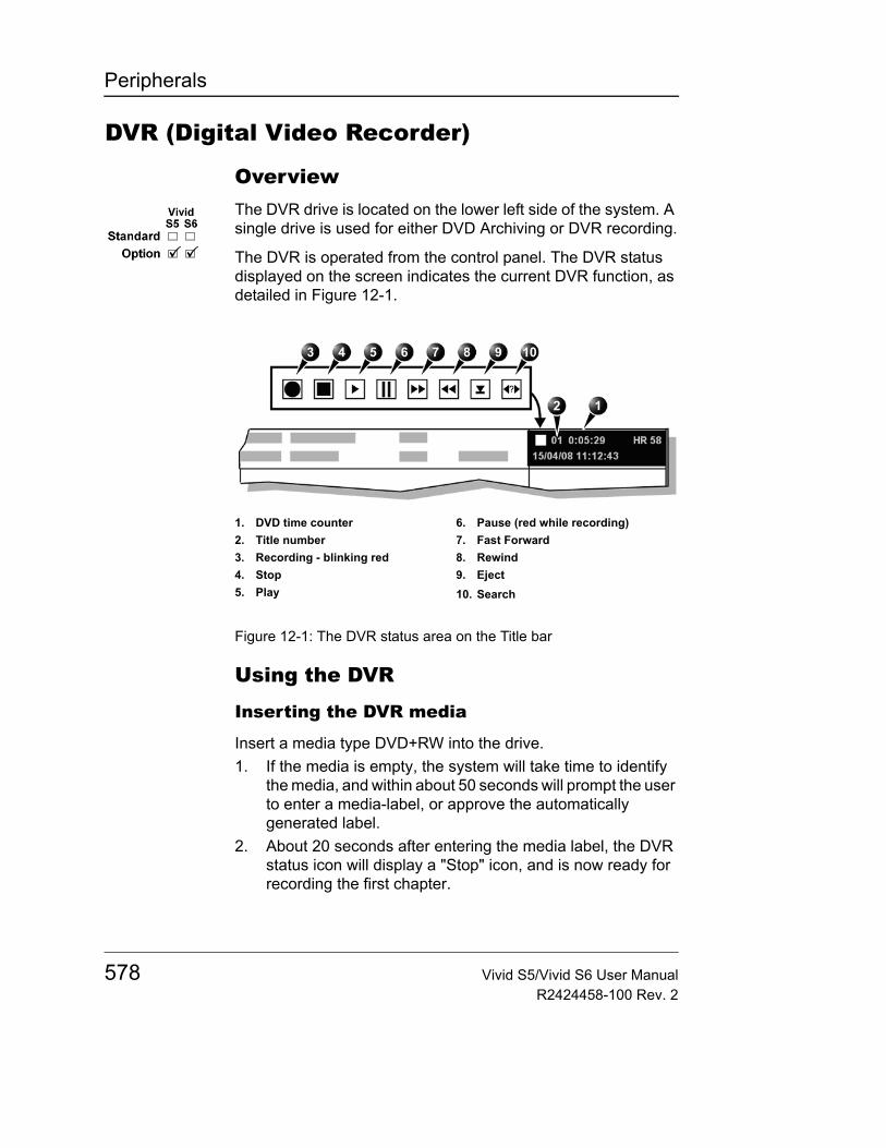
Peripherals
DVR (Digital Video Recorder)
OverviewThe DVR drive is located on the lower left side of the system. A single drive is used for either DVD Archiving or DVR recording.
The DVR is operated from the control panel. The DVR status displayed on the screen indicates the current DVR function, as detailed in Figure 12-1.
Figure 12-1: The DVR status area on the Title bar
Using the DVR
Inserting the DVR media
Insert a media type DVD+RW into the drive.1. If the media is empty, the system will take time to identify
the media, and within about 50 seconds will prompt the user to enter a media-label, or approve the automatically generated label.
2. About 20 seconds after entering the media label, the DVR status icon will display a "Stop" icon, and is now ready for recording the first chapter.
1. DVD time counter2. Title number3. Recording - blinking red4. Stop5. Play
6. Pause (red while recording)7. Fast Forward8. Rewind9. Eject10. Search
578 Vivid S5/Vivid S6 User ManualR2424458-100 Rev. 2
Peripherals
3. If the media contains some previously recorded material it will ask the user whether recording or playback is requested.
Note: When inserting a DVD-R or DVD+R type media, the system will accept this as an archiving-type media and will not allow using it for DVR recording.
Recording Titles and Chapters
TitlesThe DVR media is divided into titles and chapters. There may be up to 8 titles on each media.
A new uniquely named title is created for each recording session or whenever a new patient is entered.
ChaptersEach title contains several chapters. There may be up to 99 chapters within each title. Every continuous recording segment generates a chapter. Whenever recording is paused, the current chapter is closed and when recording is continued a new chapter begins.
Recording TimeThe total recording time which is the sum of all chapters on all titles may be as long as 70 minutes on one DVR media.
Recording1. When DVR media is inserted and the "Stop" icon appears,
the media is ready for recording.2. Press the Record button once. The blinking red indicator
indicates that recording has begun. The data recorded is stored directly onto the DVR media.
3. To stop recording press Record button once again. The recording will stop and a red "Pause" indicator will appear.
4. Press the Record button to toggle between pause and record.
Note: When recording is resumed after pause a new chapter is created.
Vivid S5/Vivid S6 User Manual 579R2424458-100 Rev. 2

Peripherals
DVR playback on the system1. In order to play-back any of the recordings on the current
DVR media, simply press the Playback button (F12).2. Within about 1 minute for the media to load. The recording
of the first title will soon start to play.3. While in Playback mode the softmenu will contain different
dedicated playback controls.
Note: Upon changing from recording to playback mode, the system will close the current title. Any further recording will be made on a new title.
DVR playback controls• Chapter select rotary - Rotate the rotary to display a list of
all titles on the current media. Highlight the required title and press rotary to select and play the desired title.
• Title select rotary - Rotate the rotary to advance to any desired chapter. The selected chapter will begin to play as soon as the rotary is held still.
• Play/Pause button - Press this button to toggle between Play & Pause.
• Next /Previous Title / Chapter - Four buttons allowing to skip chapter or title
• Cineloop - Press this button to capture the last few seconds of playback into frame-memory and run them in cineloop mode.
• Left & Right markers - Allows you to trim the cineloop borders.
• Frame rotary - When cine is stopped, allows you to view the recording frame by frame.
• Speed rotary - When cine is running, allows you to modify the cine review speed.
• Freeze button - When playback is running, press Freeze to stop playback. Once stopped, use the trackball to review the last few seconds captured in the frame-memory.
• 2D Freeze button - When the Freeze button has been pressed, use the "2D Freeze" button to run or stop looping the last few seconds of captured playback frames.
580 Vivid S5/Vivid S6 User ManualR2424458-100 Rev. 2
Peripherals
Ejecting the DVR
Press the Eject button at any time during recording or playback. The media will eject after a short delay.
Configuring the DVRPress Config and select the DVR configuration tab.• PAL / NTSC• WIDE / Narrow
Reviewing the DVR Media Externally
DVR playback on an external DVD player
You may use any good-quality commercially available DVD player to playback the DVD. Select the desired title and then select the desired chapter from the displayed list.
DVR playback on a separate PC
The DVR media can be played back on any PC containing the following components:• Windows XP OS or higher• Installed with any commercially-available DVD player
software• Configured with a high quality display
Be sure to adjust your screen to display the full range of gray-levels. It may assist to record and playback a screen test-pattern.
To generate a test pattern, use the Test pattern button available on the LCD adjustment Soft menu Controls (see page 90).
Vivid S5/Vivid S6 User Manual 581R2424458-100 Rev. 2

Peripherals
582 Vivid S5/Vivid S6 User ManualR2424458-100 Rev. 2
Presets and System setup
Chapter 13 Presets and System setup
• Introduction ................................................................................... .. 585• Starting the Configuration package ............................................ .. 588
• To open the Configuration package ......................................... 588• Overview ........................................................................................ .. 589• Imaging .......................................................................................... .. 590
• The Global setup sheet ............................................................ 590• Application ................................................................................ 593• Application menu ...................................................................... 596
• Measure Text ................................................................................. .. 598• The measurement menu sheet ................................................ 598• Configuration of the Measurement menu ................................. 601
• The Advanced sheet ..................................................................... .. 603• Parameter configuration ........................................................... 603
• The Modify Calculations sheet .................................................... .. 604• Parameter configuration ........................................................... 604• The OB table sheet .................................................................. 605
• Report ............................................................................................ .. 611• The diagnostic codes sheet ..................................................... 612• The Comment texts sheet ........................................................ 613
• Connectivity .................................................................................. .. 616• Dataflow ................................................................................... 616• Additional outputs ..................................................................... 623• Tools ........................................................................................ 625• Formats .................................................................................... 626• TCP-IP ..................................................................................... 632
• System ........................................................................................... .. 633• The system settings ................................................................. 633
Vivid S5/Vivid S6 User Manual 583R2424458-100 Rev. 2

Presets and System setup
• About ............................................................................................. ... 635• Administration .............................................................................. ... 636
• Users ........................................................................................637• Unlock Patient ...........................................................................640
584 Vivid S5/Vivid S6 User ManualR2424458-100 Rev. 2

Presets and System setup
IntroductionThis chapter describes the configuration management package of the Vivid S5/Vivid S6 ultrasound unit. The Vivid S5/Vivid S6 configuration package enables users to customize the global configuration for the unit and the application-specific settings.
In addition, users with administration rights have access to the local archive backup function, local archive restore function and creation of users.
Note: the default factory password for the "ADM" user is ulsadm (case sensitive).
The configuration management package consists of a Setup dialogue window divided in different setup categories with sublevels.
The table below summarizes the contents and access rights of the different categories and sublevels of the Vivid S5/Vivid S6 configuration package:
Category and sublevel Description access Refer to
Imaging page 590
• Global Sets the cineloop controls and display.Sets the patient information display.Sets the scan information displayed on the video record.
All
• Application Configures the probe and application specific settings.
All
• Application menu Configures the Application menu.
All
Measure / Text page 598
Vivid S5/Vivid S6 User Manual 585R2424458-100 Rev. 2
Presets and System setup
• Measurement menu• Advanced• Modify calculations
Configures the Measurement menu by selecting and defining the sequence of the measurements and calculation to perform.Creates user-defined measurementsConfigures vascular Doppler calculations to be performed.
All
• Annotation• Customize
Configures the Annotation menu and create pre-defined annotation.
All
Report page 611
• Templates • Configures the Report templates menu by selecting and ordering the templates to show in the menu.
All
• Diagnostic codes Create or delete pre-defined text input for the referral reasons and diagnosis.
All
• Comment texts Create or delete pre-defined text input for the comments.
All
• Structured findings Enables the insertion of pre-configured structured diagnosis statements in the patient report.
All page 498
Connectivity page 616
• Dataflow Create new dataflows or configure existing dataflows.
Admin
• Additional outputs Configure the PRINT key. All
• Tools Formats removable media. All
• Formats Configures the Examination list window display and other options related to the patient management.
All
Category and sublevel Description access Refer to
586 Vivid S5/Vivid S6 User ManualR2424458-100 Rev. 2
Presets and System setup
• TCP-IP Sets the Transmission Protocol/Internet Protocol.
Admin
System page 633
• Settings Sets the date and time format, language and units.
Admin
• Test Enables testing of the different parts of the unit.
Admin
About Displays information about the software, hardware and probes.
All page 635
Administration page 636
• Disk management Enables the management of the hard disk space while maintaining the patient database on the system.
All page 464
• Backup Local archive and system configuration backup.
Admin
• Restore Restore local archive and system configuration from a backup.
Admin
• Users Operator and referring staff registration, operator's rights settings.
Admin
• System administration Keeps track of all the options implemented in the unit.
Admin
• Unlock patient Unlock patient records that were not properly finished.
Admin
Service This sheet is for service staff only. Deals with printer definition and keyboard configuration.
Admin
Category and sublevel Description access Refer to
Vivid S5/Vivid S6 User Manual 587R2424458-100 Rev. 2
Presets and System setup
Starting the Configuration packageTo access the Configuration package the user has to log on as a specific user (see page 637). This ensures user-specific and user-defined settings and presets to be used.
The access to the entire configuration package is user configuration dependent (see page 637).
To open the Configuration package1. Press CONFIG on the alphanumeric keyboard.
The Log In window is displayed asking for operator ID and password (see Figure 13-1).
2. Select Log on when completed.The Setup dialogue window is displayed (see Figure 13-2).
Figure 13-1: The Operator login window
1. Select the operator2. Type password
588 Vivid S5/Vivid S6 User ManualR2424458-100 Rev. 2
Presets and System setup
OverviewThe configuration management package consists of a Setup dialogue window divided in different setup categories with sublevels (sheets labelled with tab).
The functionality of each configuration category and associated sublevels are described on the following pages.
Note: Whenever making any modifications of settings through the different configuration screens and tabs, it is always required to re-boot the system for the modifications to become valid.
Figure 13-2: The Setup dialogue window structure
1. Sublevel tabs for the selected Setup category.
2. Setup categories3. Selected Setup category
Vivid S5/Vivid S6 User Manual 589R2424458-100 Rev. 2
Presets and System setup
Imaging• Global: enables the user to configure display-related
settings.• Application: enables configuration of the probe and
application specific settings.• Application menu: enables configuration of the
Measurement menu.
The Global setup sheet
Figure 13-3: The Global setup sheet
Flex Button configuration
The Flex button can be configured to function as any button on the keyboard with the exception of alphanumeric and soft-menu sections.
590 Vivid S5/Vivid S6 User ManualR2424458-100 Rev. 2
Presets and System setup
Configuring the Flex buttonClick the combo-box menu and select one of the functions on the list. The selected function will be assigned to the Flex button.
Configuring the Flex button while in the Global tab will assign the selected function independent of any probe or application selection.
Configuring the Flex button while in the Application tab will assign the selected function only for the selected preset application.
Cineloop store
Crop images
Doppler
Parameter Description
Cineloop store:• Time before/after heart cycle: sets the total
storage time span of the cineloop in ECG mode.
• Time span (no ECG): sets the total storage time span of the cineloop with no ECG.
• Preview loop before store: when selected enable review of cineloops before storage.
Parameter Description
Crop images:: In the Analysis screen, removes top and
bottom of the image when more than two images have been selected.
Parameter Description
Doppler:• Show KHz scale: when selected, displays
the KHz scale on the left side of the Doppler spectrum (see page 164).
Vivid S5/Vivid S6 User Manual 591R2424458-100 Rev. 2
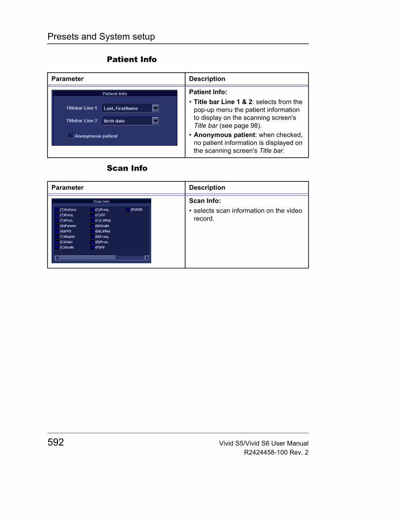
Presets and System setup
Patient Info
Scan Info
Parameter Description
Patient Info:• Title bar Line 1 & 2: selects from the
pop-up menu the patient information to display on the scanning screen's Title bar (see page 98).
• Anonymous patient: when checked, no patient information is displayed on the scanning screen's Title bar.
Parameter Description
Scan Info:• selects scan information on the video
record.
592 Vivid S5/Vivid S6 User ManualR2424458-100 Rev. 2
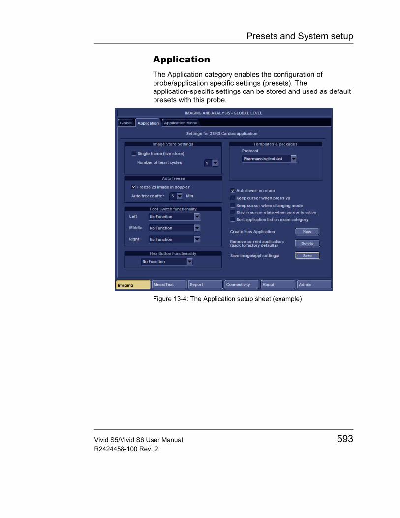
Presets and System setup
ApplicationThe Application category enables the configuration of probe/application specific settings (presets). The application-specific settings can be stored and used as default presets with this probe.
Figure 13-4: The Application setup sheet (example)
Vivid S5/Vivid S6 User Manual 593R2424458-100 Rev. 2
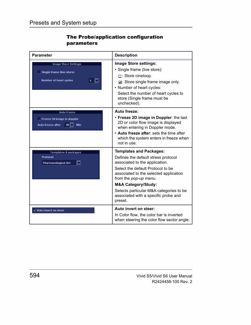
Presets and System setup
The Probe/application configuration parameters
Parameter Description
Image Store settings:• Single frame (live store):
: Store cineloop.: Store single frame image only.
• Number of heart cycles:Select the number of heart cycles to store (Single frame must be unchecked).
Auto freeze:• Freeze 2D image in Doppler: the last
2D or color flow image is displayed when entering in Doppler mode.
• Auto freeze after: sets the time after which the system enters in freeze when not in use.
Templates and Packages:Defines the default stress protocol associated to the application.Select the default Protocol to be associated to the selected application from the pop-up menu.M&A Category/Study:Selects particular M&A categories to be associated with a specific probe and preset.
Auto invert on steer:In Color flow, the color bar is inverted when steering the color flow sector angle.
594 Vivid S5/Vivid S6 User ManualR2424458-100 Rev. 2
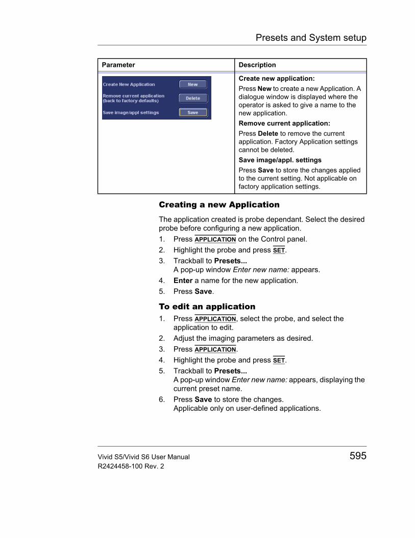
Presets and System setup
Creating a new Application
The application created is probe dependant. Select the desired probe before configuring a new application.1. Press APPLICATION on the Control panel.2. Highlight the probe and press SET.3. Trackball to Presets...
A pop-up window Enter new name: appears.4. Enter a name for the new application.5. Press Save.
To edit an application1. Press APPLICATION, select the probe, and select the
application to edit.2. Adjust the imaging parameters as desired.3. Press APPLICATION.4. Highlight the probe and press SET.5. Trackball to Presets...
A pop-up window Enter new name: appears, displaying the current preset name.
6. Press Save to store the changes.Applicable only on user-defined applications.
Create new application:Press New to create a new Application. A dialogue window is displayed where the operator is asked to give a name to the new application.Remove current application:Press Delete to remove the current application. Factory Application settings cannot be deleted.Save image/appl. settingsPress Save to store the changes applied to the current setting. Not applicable on factory application settings.
Parameter Description
Vivid S5/Vivid S6 User Manual 595R2424458-100 Rev. 2
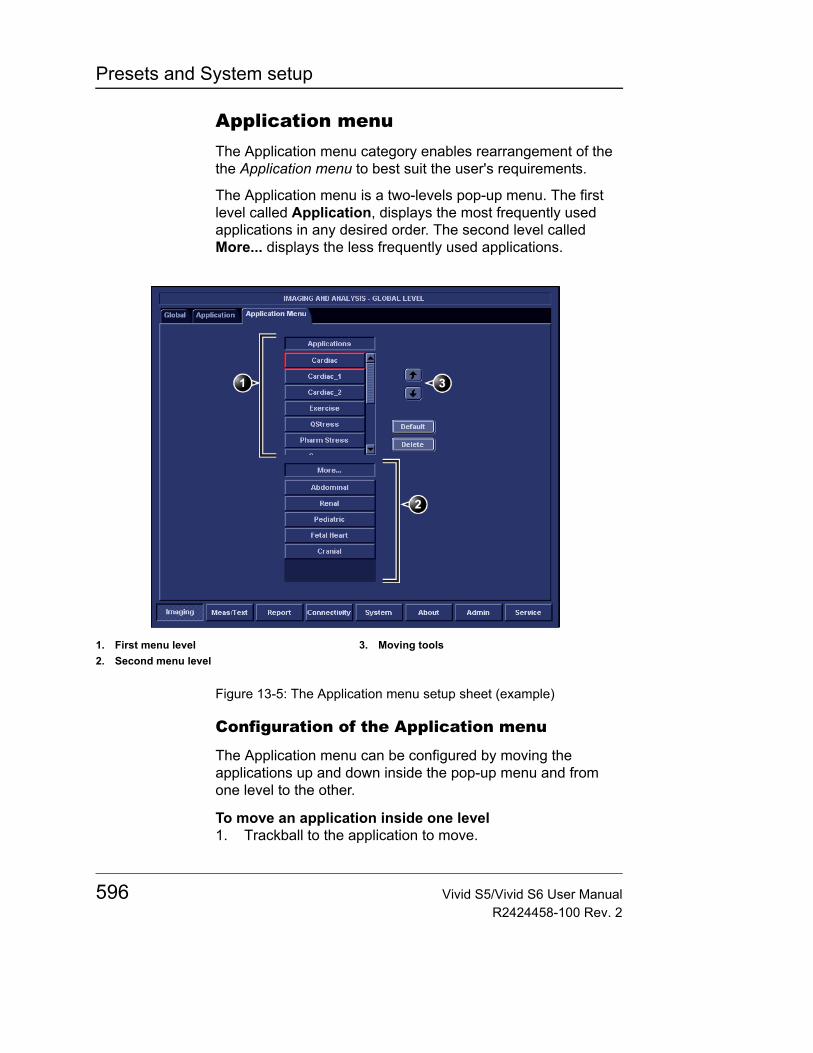
Presets and System setup
Application menuThe Application menu category enables rearrangement of the the Application menu to best suit the user's requirements.
The Application menu is a two-levels pop-up menu. The first level called Application, displays the most frequently used applications in any desired order. The second level called More... displays the less frequently used applications.
Figure 13-5: The Application menu setup sheet (example)
Configuration of the Application menu
The Application menu can be configured by moving the applications up and down inside the pop-up menu and from one level to the other.
To move an application inside one level1. Trackball to the application to move.
1. First menu level2. Second menu level
3. Moving tools
596 Vivid S5/Vivid S6 User ManualR2424458-100 Rev. 2
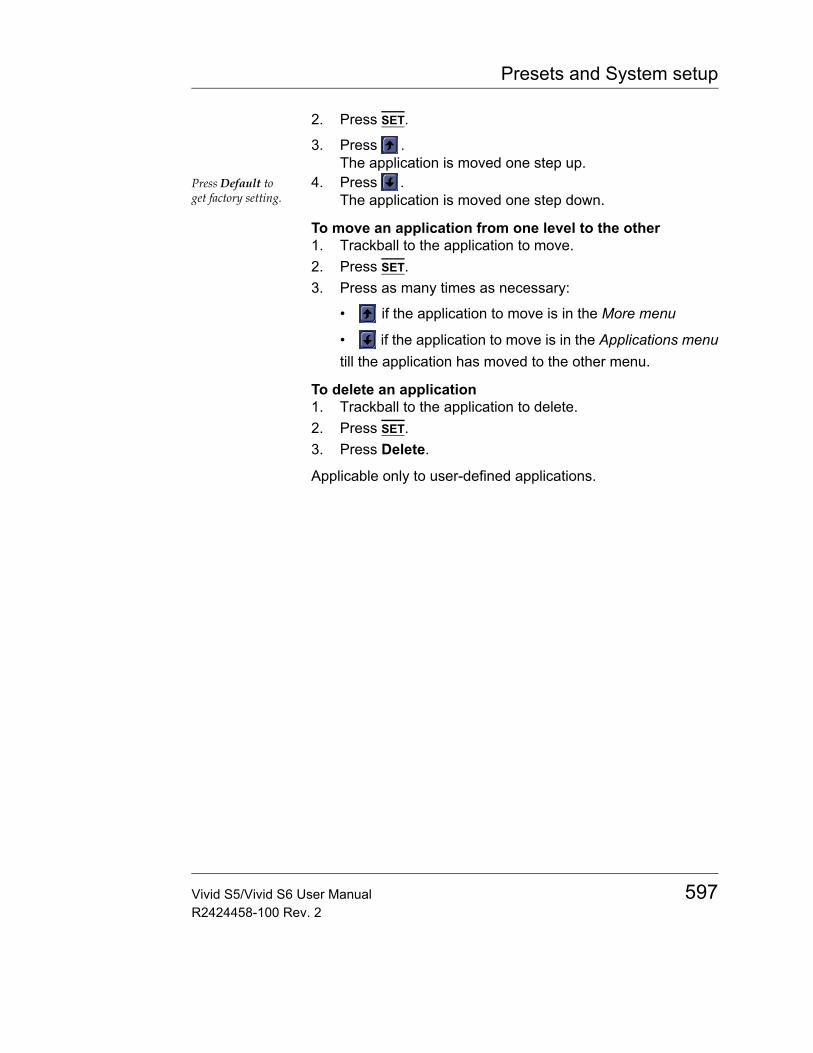
Presets and System setup
2. Press SET.
3. Press .The application is moved one step up.
Press Default to get factory setting.
4. Press .The application is moved one step down.
To move an application from one level to the other1. Trackball to the application to move.2. Press SET.3. Press as many times as necessary:
• if the application to move is in the More menu
• if the application to move is in the Applications menutill the application has moved to the other menu.
To delete an application1. Trackball to the application to delete.2. Press SET.3. Press Delete.
Applicable only to user-defined applications.
Vivid S5/Vivid S6 User Manual 597R2424458-100 Rev. 2
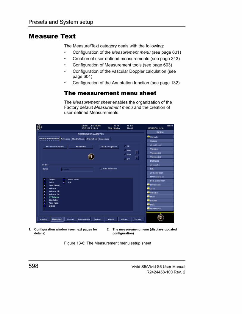
Presets and System setup
Measure TextThe Measure/Text category deals with the following:• Configuration of the Measurement menu (see page 601)• Creation of user-defined measurements (see page 343)• Configuration of Measurement tools (see page 603)• Configuration of the vascular Doppler calculation (see
page 604)• Configuration of the Annotation function (see page 132)
The measurement menu sheetThe Measurement sheet enables the organization of the Factory default Measurement menu and the creation of user-defined Measurements.
Figure 13-6: The Measurement menu setup sheet
1. Configuration window (see next pages for details)
2. The measurement menu (displays updated configuration)
598 Vivid S5/Vivid S6 User ManualR2424458-100 Rev. 2
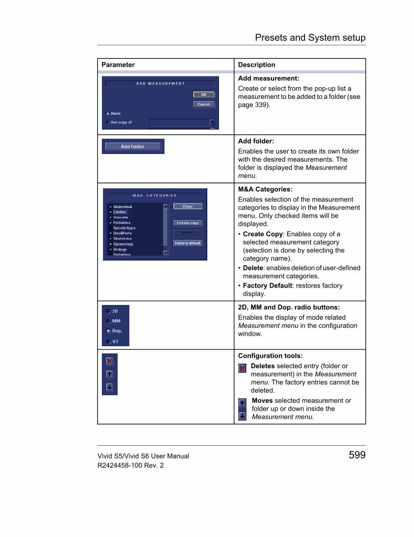
Presets and System setup
Parameter Description
Add measurement:Create or select from the pop-up list a measurement to be added to a folder (see page 339).
Add folder:Enables the user to create its own folder with the desired measurements. The folder is displayed the Measurement menu.
M&A Categories:Enables selection of the measurement categories to display in the Measurement menu. Only checked items will be displayed.• Create Copy: Enables copy of a
selected measurement category (selection is done by selecting the category name).
• Delete: enables deletion of user-defined measurement categories.
• Factory Default: restores factory display.
2D, MM and Dop. radio buttons:Enables the display of mode related Measurement menu in the configuration window.
Configuration tools:Deletes selected entry (folder or measurement) in the Measurement menu. The factory entries cannot be deleted.Moves selected measurement or folder up or down inside the Measurement menu.
Vivid S5/Vivid S6 User Manual 599R2424458-100 Rev. 2
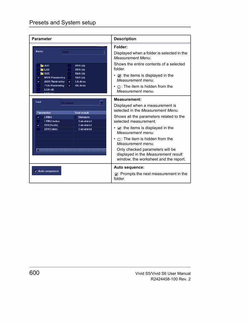
Presets and System setup
Folder:Displayed when a folder is selected in the Measurement Menu.Shows the entire contents of a selected folder.• : the items is displayed in the
Measurement menu.• : The item is hidden from the
Measurement menu.
Measurement:Displayed when a measurement is selected in the Measurement Menu.Shows all the parameters related to the selected measurement.• : the items is displayed in the
Measurement menu.• : The item is hidden from the
Measurement menu.Only checked parameters will be displayed in the Measurement result window, the worksheet and the report.
Auto sequence:: Prompts the next measurement in the
folder.
Parameter Description
600 Vivid S5/Vivid S6 User ManualR2424458-100 Rev. 2

Presets and System setup
Configuration of the Measurement menuThere are many more measurements and parameters in the measurement package than shown in the default Measurement menu. Use the configuration system to set up the measurements that should be available in the Measurement menu and which parameters should be calculated (see also "Measurement package configuration" on page 338).
Display of the Measurement categories1. Press M&A categories in the Configuration window.
The M&A categories are displayed in a pop-up window (see page 599).
2. Check the categories to be displayed.Uncheck the categories to hide.
To copy a Measurement category1. Press M&A categories in the Configuration window.
The M&A categories are displayed in a pop-up window (see page 599).
2. Move the trackball marker over the M&A category name.3. Press SET to highlight the category.4. Press Create copy.
A copy of the selected measurement category is displayed in the Measurement menu.
Factory Measure-ment categories cannot be renamed.
To rename the Measurement category:1. Select the Measurement category in the Measurement
menu.2. Enter a new name in the Measurement field.
Selection of a Measurement category1. Trackball to the Measurement menu heading.2. Press SET.
The measurement categories are displayed in a sub-menu.
3. Trackball to the measurement category of interest.4. Press SET.
The measurement category is displayed.
Vivid S5/Vivid S6 User Manual 601R2424458-100 Rev. 2
Presets and System setup
Moving an item in the Measurement menu1. Trackball to the entry to move into the Measurement menu.2. Press SET.
3. Press or to move the selection up or down inside the Measurement menu.
Deleting an item in the Measurement menuOnly user created items can be delet-ed.
1. Trackball to the entry to delete in the Measurement menu.2. Press SET.
3. Press to delete the item.
Display/hide a folder or a measurement in the Measurement menu
The Measurement menu (Folders and Measurements) can be configured to display only the entries (folders and measurements) of interest.
To hide a folder or a measurement:• Uncheck the actual folder or measurement in the Folder or
Measurement field in the Configuration window.
To display a hidden folder or measurement:• Check the actual folder or measurement in the Folder or
Measurement field in the Configuration window.
Creating a user-defined folder1. If the folder is to be inside another folder, select the actual
folder in the Measurement menu.2. Press Add folder.
The Measurement menu is updated.3. Select the new folder and Enter the folder name in the
Name text field.
Adding a measurement to a folder
The user can either add a pre-defined measurement or create a new measurement with user-defined parameters to a folder (see page 339 for more information).
602 Vivid S5/Vivid S6 User ManualR2424458-100 Rev. 2
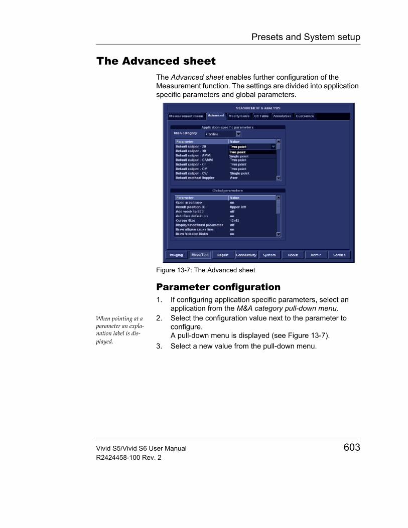
Presets and System setup
The Advanced sheetThe Advanced sheet enables further configuration of the Measurement function. The settings are divided into application specific parameters and global parameters.
Figure 13-7: The Advanced sheet
Parameter configuration1. If configuring application specific parameters, select an
application from the M&A category pull-down menu.When pointing at a parameter an expla-nation label is dis-played.
2. Select the configuration value next to the parameter to configure.A pull-down menu is displayed (see Figure 13-7).
3. Select a new value from the pull-down menu.
Vivid S5/Vivid S6 User Manual 603R2424458-100 Rev. 2
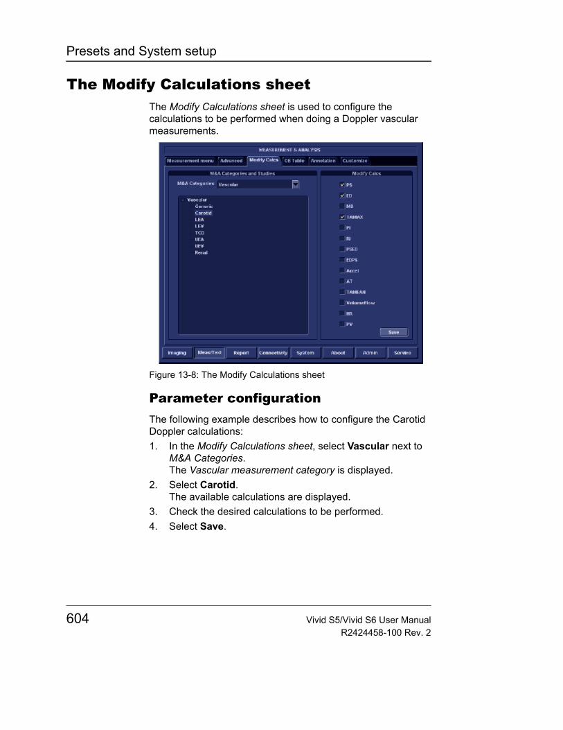
Presets and System setup
The Modify Calculations sheetThe Modify Calculations sheet is used to configure the calculations to be performed when doing a Doppler vascular measurements.
Figure 13-8: The Modify Calculations sheet
Parameter configurationThe following example describes how to configure the Carotid Doppler calculations:1. In the Modify Calculations sheet, select Vascular next to
M&A Categories.The Vascular measurement category is displayed.
2. Select Carotid.The available calculations are displayed.
3. Check the desired calculations to be performed.4. Select Save.
604 Vivid S5/Vivid S6 User ManualR2424458-100 Rev. 2
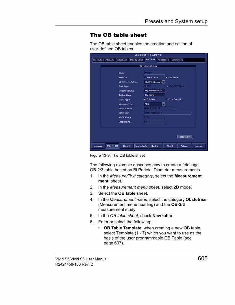
Presets and System setup
The OB table sheetThe OB table sheet enables the creation and edition of user-defined OB tables.
Figure 13-9: The OB table sheet
The following example describes how to create a fetal age OB-2/3 table based on Bi Parietal Diameter measurements.1. In the Measure/Text category, select the Measurement
menu sheet.2. In the Measurement menu sheet, select 2D mode.3. Select the OB table sheet.4. In the Measurement menu, select the category Obstetrics
(Measurement menu heading) and the OB-2/3 measurement study.
5. In the OB table sheet, check New table.6. Enter or select the following:
• OB Table Template: when creating a new OB table, select Template (1 - 7) which you want to use as the basis of the user programmable OB Table (see page 607).
Vivid S5/Vivid S6 User Manual 605R2424458-100 Rev. 2
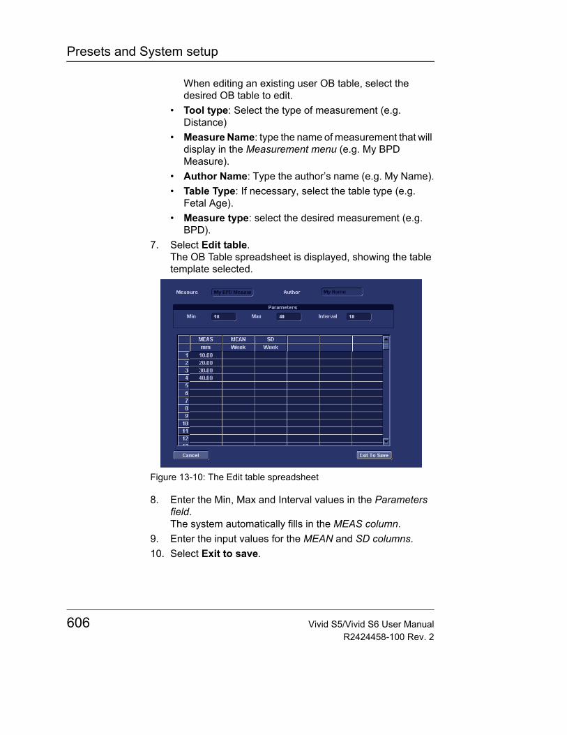
Presets and System setup
When editing an existing user OB table, select the desired OB table to edit.
• Tool type: Select the type of measurement (e.g. Distance)
• Measure Name: type the name of measurement that will display in the Measurement menu (e.g. My BPD Measure).
• Author Name: Type the author’s name (e.g. My Name).• Table Type: If necessary, select the table type (e.g.
Fetal Age).• Measure type: select the desired measurement (e.g.
BPD).7. Select Edit table.
The OB Table spreadsheet is displayed, showing the table template selected.
Figure 13-10: The Edit table spreadsheet
8. Enter the Min, Max and Interval values in the Parameters field.The system automatically fills in the MEAS column.
9. Enter the input values for the MEAN and SD columns.10. Select Exit to save.
606 Vivid S5/Vivid S6 User ManualR2424458-100 Rev. 2
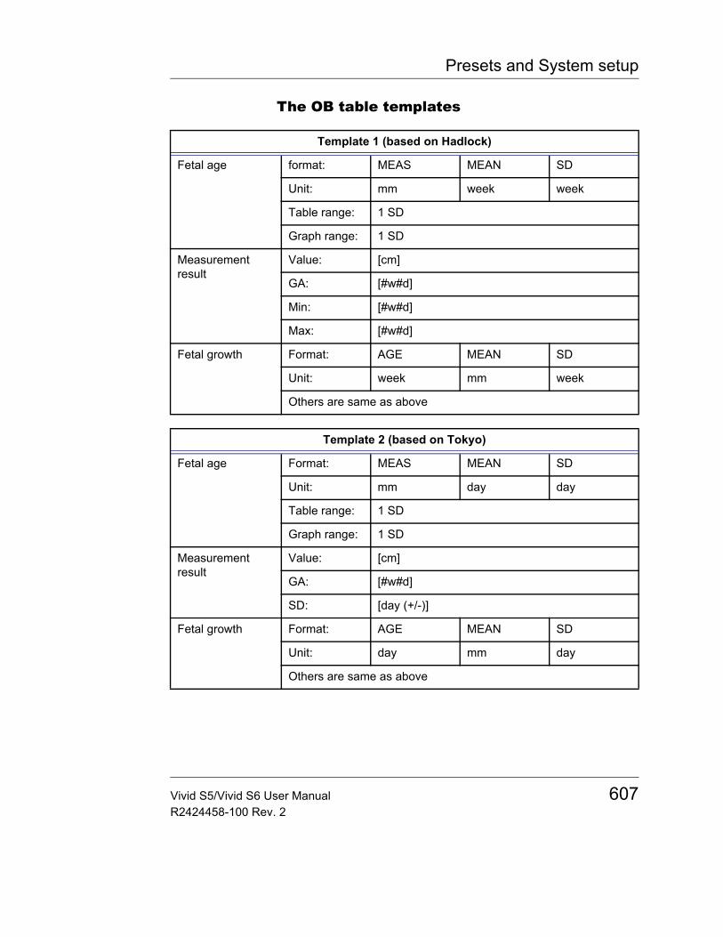
Presets and System setup
The OB table templates
Template 1 (based on Hadlock)
Fetal age format: MEAS MEAN SD
Unit: mm week week
Table range: 1 SD
Graph range: 1 SD
Measurement result
Value: [cm]
GA: [#w#d]
Min: [#w#d]
Max: [#w#d]
Fetal growth Format: AGE MEAN SD
Unit: week mm week
Others are same as above
Template 2 (based on Tokyo)
Fetal age Format: MEAS MEAN SD
Unit: mm day day
Table range: 1 SD
Graph range: 1 SD
Measurement result
Value: [cm]
GA: [#w#d]
SD: [day (+/-)]
Fetal growth Format: AGE MEAN SD
Unit: day mm day
Others are same as above
Vivid S5/Vivid S6 User Manual 607R2424458-100 Rev. 2
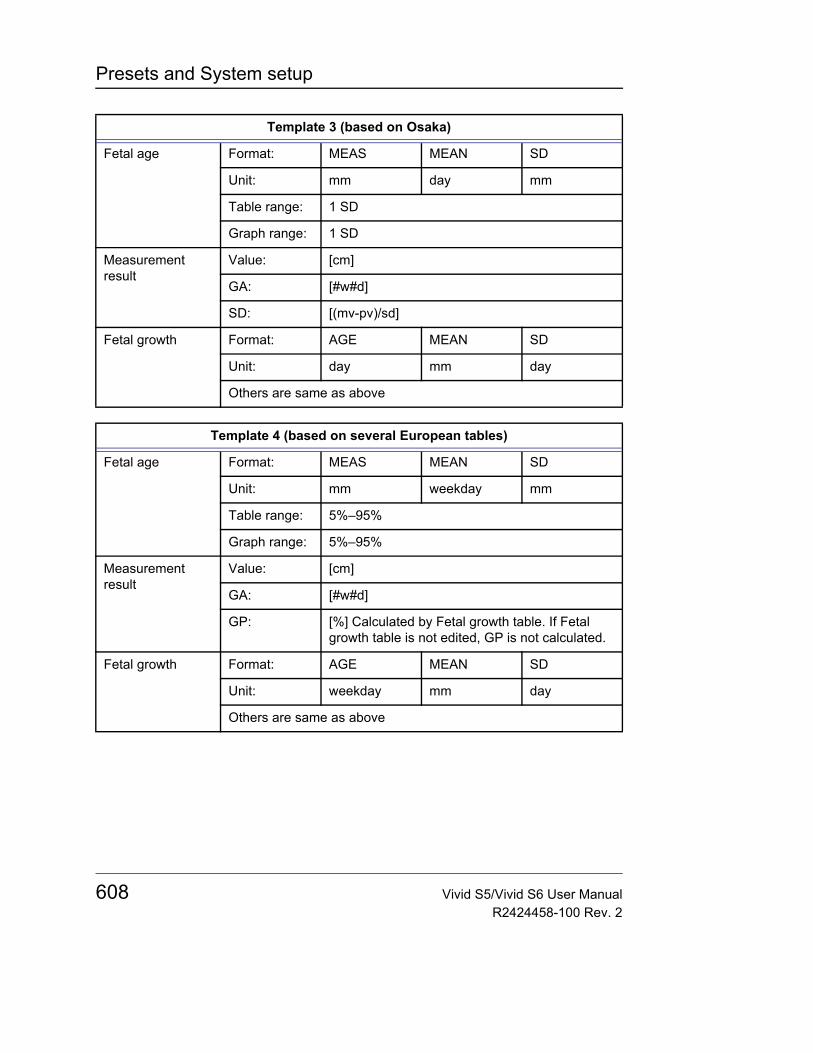
Presets and System setup
Template 3 (based on Osaka)
Fetal age Format: MEAS MEAN SD
Unit: mm day mm
Table range: 1 SD
Graph range: 1 SD
Measurement result
Value: [cm]
GA: [#w#d]
SD: [(mv-pv)/sd]
Fetal growth Format: AGE MEAN SD
Unit: day mm day
Others are same as above
Template 4 (based on several European tables)
Fetal age Format: MEAS MEAN SD
Unit: mm weekday mm
Table range: 5%–95%
Graph range: 5%–95%
Measurement result
Value: [cm]
GA: [#w#d]
GP: [%] Calculated by Fetal growth table. If Fetal growth table is not edited, GP is not calculated.
Fetal growth Format: AGE MEAN SD
Unit: weekday mm day
Others are same as above
608 Vivid S5/Vivid S6 User ManualR2424458-100 Rev. 2
Presets and System setup
Template 5 (based on several European tables)
Fetal age Format: MEAS MEAN SD
Unit: mm weekday mm
Table range: 1 SD
Graph range: 5%–95%
Measurement result
Value: [cm]
GA: [#w#d]
GP: [%] Calculated by Fetal growth table. If Fetal growth table is not edited, GP is not calculated.
Fetal growth Format: AGE MEAN SD
Unit: weekday mm day
Others are same as above
Template 6 (based on several European tables)
Fetal age Format: MEAS MIN MEAN SD
Unit: mm weekday weekday weekday
Table range:
10%–90%
Graph range:
10%–90%
Measurement result
Value: [cm]
GA: [#w#d]
GP: [%] Calculated by Fetal growth table. If Fetal growth table is not edited, GP is not calculated.
Fetal growth Format: AGE MIN MEAN SD
Unit: weekday mm mm mm
Others are same as above
Vivid S5/Vivid S6 User Manual 609R2424458-100 Rev. 2
Presets and System setup
Template 7 (based on several European tables)
Fetal age Format: MEAS MEAN SD
Unit: mm weekday mm
Table range: 1 SD
Graph range: 10%–90%
Measurement result
Value: [cm]
GA: [#w#d]
GP: [%] Calculated by Fetal growth table. If Fetal growth table is not edited, GP is not calculated.
Fetal growth Format: AGE MEAN SD
Unit: weekday mm mm
Others are same as above
610 Vivid S5/Vivid S6 User ManualR2424458-100 Rev. 2
Presets and System setup
ReportThe Report configuration category is divided in three sheets:• Templates: enables the configuration of the Template
selection menu and the export/import of user-defined templates. See "Report templates management" on page 531 for more information.
• Diagnostic codes: enables the creation of pre-defined text inputs to be used in the Diagnosis information field in the Examination list window (see Figure 9-10, page 418).
• Comment texts: enables the creation of pre-defines text inputs to be used in the Comment information field in the Examination list window (see Figure 9-10, page 418).
• Structured findings: enables the insertion of pre-configured structured diagnosis statements and Billing/Accreditation codes in the patient report (see "Structured Findings" on page 498).
Vivid S5/Vivid S6 User Manual 611R2424458-100 Rev. 2
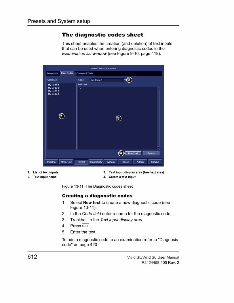
Presets and System setup
The diagnostic codes sheetThis sheet enables the creation (and deletion) of text inputs that can be used when entering diagnostic codes in the Examination list window (see Figure 9-10, page 418).
Figure 13-11: The Diagnostic codes sheet
Creating a diagnostic codes1. Select New text to create a new diagnostic code (see
Figure 13-11).2. In the Code field enter a name for the diagnostic code.3. Trackball to the Text input display area.4. Press SET.5. Enter the text.
To add a diagnostic code to an examination refer to "Diagnosis code" on page 420
1. List of text inputs2. Text input name
3. Text input display area (free text area)4. Create a text input
612 Vivid S5/Vivid S6 User ManualR2424458-100 Rev. 2
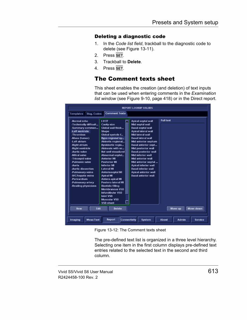
Presets and System setup
Deleting a diagnostic code1. In the Code list field, trackball to the diagnostic code to
delete (see Figure 13-11).2. Press SET.3. Trackball to Delete.4. Press SET.
The Comment texts sheetThis sheet enables the creation (and deletion) of text inputs that can be used when entering comments in the Examination list window (see Figure 9-10, page 418) or in the Direct report.
Figure 13-12: The Comment texts sheet
The pre-defined text list is organized in a three level hierarchy. Selecting one item in the first column displays pre-defined text entries related to the selected text in the second and third column.
Vivid S5/Vivid S6 User Manual 613R2424458-100 Rev. 2
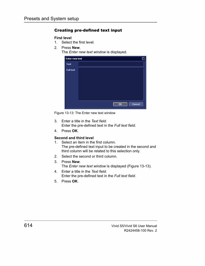
Presets and System setup
Creating pre-defined text input
First level1. Select the first level.2. Press New.
The Enter new text window is displayed.
Figure 13-13: The Enter new text window
3. Enter a title in the Text field.Enter the pre-defined text in the Full text field.
4. Press OK.
Second and third level1. Select an item in the first column.
The pre-defined text input to be created in the second and third column will be related to this selection only.
2. Select the second or third column.3. Press New.
The Enter new text window is displayed (Figure 13-13).4. Enter a title in the Text field.
Enter the pre-defined text in the Full text field.5. Press OK.
614 Vivid S5/Vivid S6 User ManualR2424458-100 Rev. 2
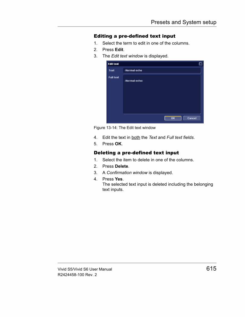
Presets and System setup
Editing a pre-defined text input1. Select the term to edit in one of the columns.2. Press Edit.3. The Edit text window is displayed.
Figure 13-14: The Edit text window
4. Edit the text in both the Text and Full text fields.5. Press OK.
Deleting a pre-defined text input1. Select the item to delete in one of the columns.2. Press Delete.3. A Confirmation window is displayed.4. Press Yes.
The selected text input is deleted including the belonging text inputs.
Vivid S5/Vivid S6 User Manual 615R2424458-100 Rev. 2
Presets and System setup
ConnectivityThis configuration setup category deals with: • Dataflow: connection and communication setup of the
ultrasound unit with other devices.• Additional output: configuration of the PRINT and ALT keys
on the control panel.• Tools: formatting of removable media• Formats: configuration of the Examination list window and
other tools related to patient management.• TCPIP: internet protocol configuration
DataflowCommunication between the Vivid S5/Vivid S6 ultrasound unit and other information providers on the network takes the form of dataflows. Each dataflow defines the transfer of patient information and images from an input source to the unit, and from the unit to one or several output sources. Input/output devices cannot be added/removed to/from the pre-defined dataflows. However the settings for the devices can be adjusted.
A dataflow is a set of pre-configured settings. Selecting a dataflow will automatically customize the unit to work according to the settings associated with this dataflow.
Dataflows are configured in the Dataflow sublevel sheet in the Connectivity setup category as described below. The Dataflow sublevel sheet is only available to users with administration rights.
616 Vivid S5/Vivid S6 User ManualR2424458-100 Rev. 2
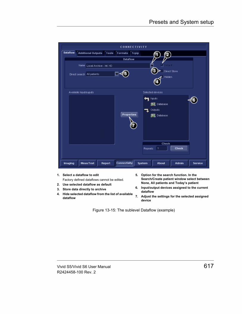
Presets and System setup
Figure 13-15: The sublevel Dataflow (example)
1. Select a dataflow to editFactory defined dataflows cannot be edited.
2. Use selected dataflow as default3. Store data directly to archive4. Hide selected dataflow from the list of available
dataflow
5. Option for the search function. In the Search/Create patient window select between None, All patients and Today’s patient
6. Input/output devices assigned to the current dataflow
7. Adjust the settings for the selected assigned device
Vivid S5/Vivid S6 User Manual 617R2424458-100 Rev. 2
Presets and System setup
Dataflows available
A set of pre-defined dataflows is available on the unit as listed in the table below. Input/output devices cannot be added/removed to/from the pre-defined dataflows. However the settings for the devices can be adjusted (see page 621).
Dataflow Description
No Archive Enables to perform an examination without storing the data to the archive.
LocalArchive-Int.HD Local archive internal hard driveThe local database is used for patient archiving. Images are stored to internal hard drive. The stored image files will consist of raw data only, together with a single-frame DICOM preview image (no DICOM multi-frame is stored).
Local Archive - Int HD/DICOM Server
The local archive is used for patient archiving. Images are stored to the internal hard drive and to a DICOM server.Some of the measurements are stored if DICOM SR is turned on (see page 447)
RemoteArch-RemoteHD Remote archive remote hard driveA remote database (either on EchoPAC workstation or a server) is used for patient archiving. Images are stored to a network image volume (either internal HD on EchoPAC workstation or a server).
Remote Archive - Remote HD/DICOM Server
A remote database is used for patient archiving. Images are stored to a network image volume and to a DICOM server.Some of the measurements are stored if DICOM SR is turned on (see page 447)
618 Vivid S5/Vivid S6 User ManualR2424458-100 Rev. 2
Presets and System setup
WL-LA-DServ: the local database is not searched, only the DICOM Modality Worklist.
Worklist/LocalArchive-DICOMServer/Int.HD
Modality Worklist local archive DICOM server and local hard driveSearch in the DICOM Modality Worklist, the patient found is copied into local database. The patient information and the examination results are stored to the local the database. Images are stored to a DICOM Server and to an image volume on the local hard drive.Some of the measurements are stored if DICOM SR is turned on (see page 447)
Worklist/RemoteArchive-DICOMServer/RemoteHD
Modality Worklist remote archive DICOM server and remote hard driveSearch in the DICOM Modality Worklist, the patient found is copied into a remote database. The patient information and examination results are stored to a remote database. Images are stored to a DICOM Server and to an image network volume as pure DICOM in both locations.Some of the measurements are stored if DICOM SR is turned on (see page 447)
Worklist/Remote Archive - Remote Storage
This dataflow is used in a network environment that includes Vivid HL7 Gateway. The patient list in the Search/Create Patient window is coming from Vivid HL7 Gateway through DICOM Modality Worklist. All patient data and images are stored to a server.
Dataflow Description
Vivid S5/Vivid S6 User Manual 619R2424458-100 Rev. 2
Presets and System setup
DICOM MOD Pure DICOM image format to/from a DICOM Magneto Optical DiskRead/Write images in “pure” DICOM format from/to a DICOM formatted 5.25'' MO-disk.Some of the measurements are stored if DICOM SR is turned on (see page 447).
DICOM CD/DVD read DICOM CD/DVD readRead DICOM Media from the CD/DVD-drive.Read-only dataflow, no data can be stored.
DICOM Server DICOM serverStore pure DICOM images to a DICOM device.Some of the measurements are stored if DICOM SR is turned on (see page 447).
DICOM Print DICOM PrintSend images to a DICOM printer.
Query Retrieve Query RetrieveRetrieve images from a DICOM server
LocalArchive-Int.HD/ eVue
The local database is used for patient archiving. Images are stored to internal hard drive and a MPEG exam is created to the configured destination.
RemoteArch-RemoteHD/eVue
A remote database (either on EchoPAC workstation or on Image Vault) is used for patient archiving. Images are stored to a network image volume (either internal HD on EchoPAC workstation or Image Vault volume) and a MPEG exam is created to the configured destination.
Dataflow Description
620 Vivid S5/Vivid S6 User ManualR2424458-100 Rev. 2

Presets and System setup
To select the default dataflow1. Select the dataflow in the Name drop-down menu. (see
Figure 13-15).2. Check the Default box.
The dataflow will be selected by default when restarting the unit.
3. Check the Direct Store box to have data stored automatically to the archive (no buffer storage).
Adjusting the assigned devices1. Select the device in the Selected devices field.2. Press Properties.
The Properties window is displayed.3. Adjust the device specific parameters as desired (see table
below). Not all the settings listed below apply to all devices.
General settings Definition
Name Free text: give a descriptive name for the device.
IP address Select from drop-down menu
Database Name Automatically selected according to the IP address
File destination Automatically selected according to the IP address
Removable Check the entry is the media is removable.
MPPS Modality Perform Procedure Step: send information (typically to a HIS) that a scheduled exam has been started, performed or interrupted.
Image settings Definition
Allow raw data : save data in both raw and DICOM format.: save data in DICOM format only.
Raw Compression Enables compression of raw data images upon storage and export. Raw compression is active only if the setting Allow raw data is checked.
Max Framerate Select 25, 30 or Full from the pop-up menu. Full (original acquisition) is default.
Compression Select compression type or no compression.
Vivid S5/Vivid S6 User Manual 621R2424458-100 Rev. 2
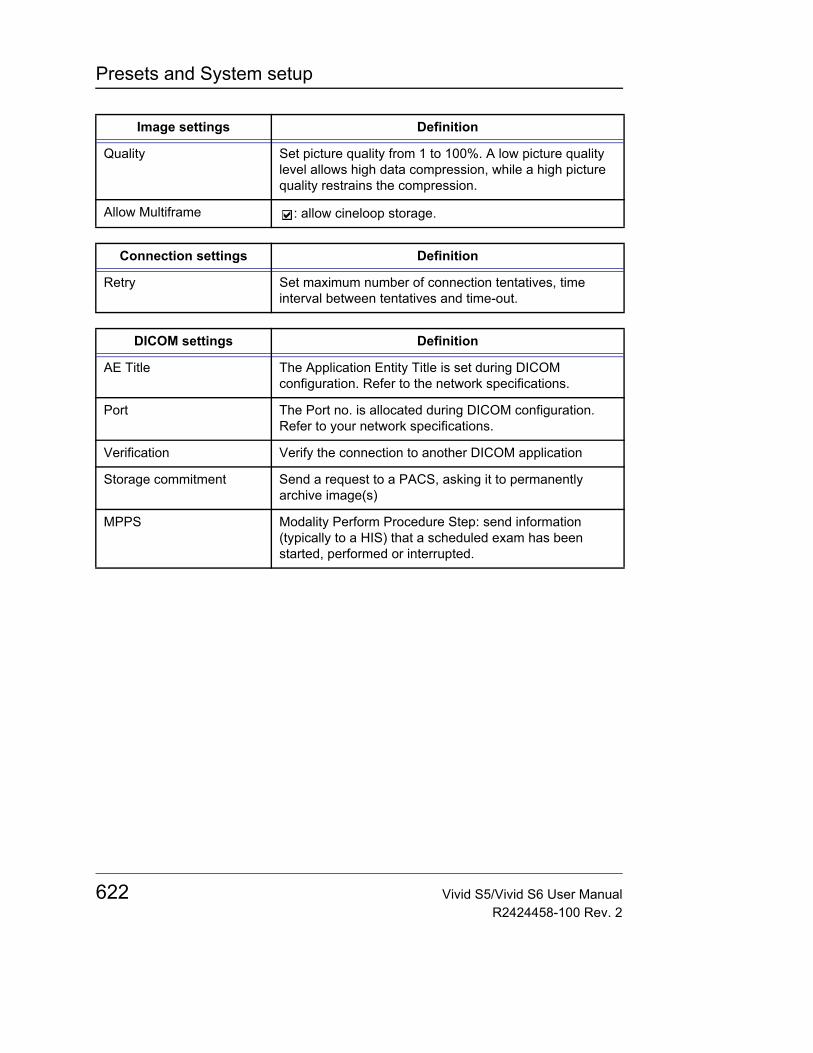
Presets and System setup
Quality Set picture quality from 1 to 100%. A low picture quality level allows high data compression, while a high picture quality restrains the compression.
Allow Multiframe : allow cineloop storage.
Connection settings Definition
Retry Set maximum number of connection tentatives, time interval between tentatives and time-out.
DICOM settings Definition
AE Title The Application Entity Title is set during DICOM configuration. Refer to the network specifications.
Port The Port no. is allocated during DICOM configuration. Refer to your network specifications.
Verification Verify the connection to another DICOM application
Storage commitment Send a request to a PACS, asking it to permanently archive image(s)
MPPS Modality Perform Procedure Step: send information (typically to a HIS) that a scheduled exam has been started, performed or interrupted.
Image settings Definition
622 Vivid S5/Vivid S6 User ManualR2424458-100 Rev. 2
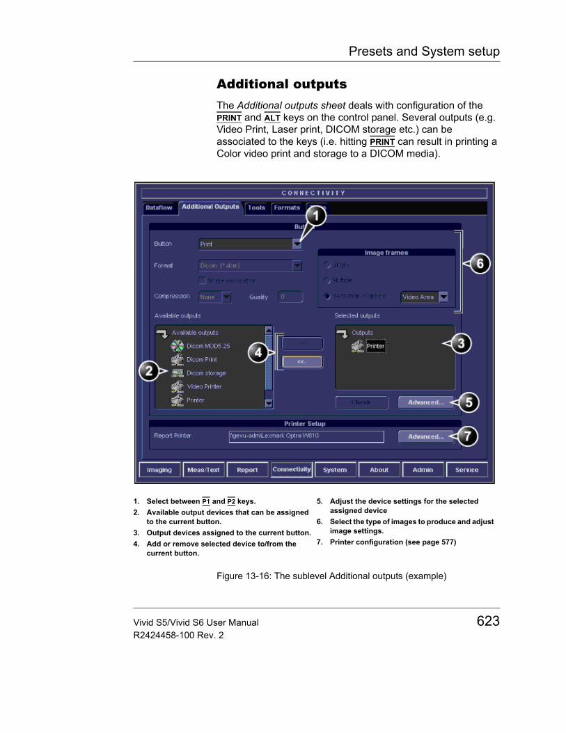
Presets and System setup
Additional outputsThe Additional outputs sheet deals with configuration of the PRINT and ALT keys on the control panel. Several outputs (e.g. Video Print, Laser print, DICOM storage etc.) can be associated to the keys (i.e. hitting PRINT can result in printing a Color video print and storage to a DICOM media).
Figure 13-16: The sublevel Additional outputs (example)
1. Select between P1 and P2 keys.2. Available output devices that can be assigned
to the current button.3. Output devices assigned to the current button.4. Add or remove selected device to/from the
current button.
5. Adjust the device settings for the selected assigned device
6. Select the type of images to produce and adjust image settings.
7. Printer configuration (see page 577)
Vivid S5/Vivid S6 User Manual 623R2424458-100 Rev. 2
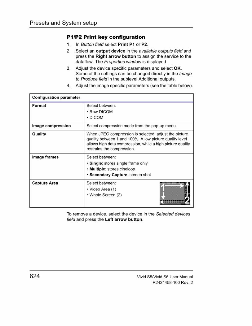
Presets and System setup
P1/P2 Print key configuration1. In Button field select Print P1 or P2.2. Select an output device in the available outputs field and
press the Right arrow button to assign the service to the dataflow. The Properties window is displayed
3. Adjust the device specific parameters and select OK.Some of the settings can be changed directly in the Image to Produce field in the sublevel Additional outputs.
4. Adjust the image specific parameters (see the table below).
To remove a device, select the device in the Selected devices field and press the Left arrow button.
Configuration parameter
Format Select between:• Raw DICOM• DICOM
Image compression Select compression mode from the pop-up menu.
Quality When JPEG compression is selected, adjust the picture quality between 1 and 100%. A low picture quality level allows high data compression, while a high picture quality restrains the compression.
Image frames Select between:• Single: stores single frame only• Multiple: stores cineloop• Secondary Capture: screen shot
Capture Area Select between:• Video Area (1)• Whole Screen (2)
624 Vivid S5/Vivid S6 User ManualR2424458-100 Rev. 2
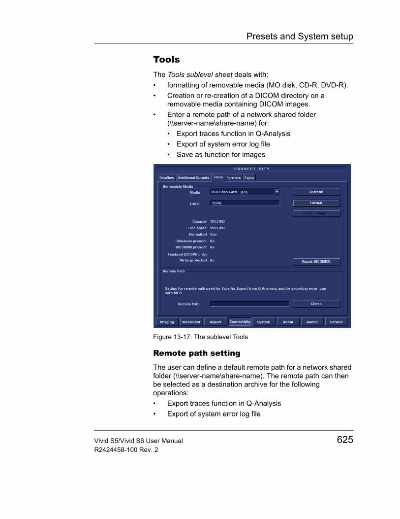
Presets and System setup
ToolsThe Tools sublevel sheet deals with: • formatting of removable media (MO disk, CD-R, DVD-R).• Creation or re-creation of a DICOM directory on a
removable media containing DICOM images.• Enter a remote path of a network shared folder
(\\server-name\share-name) for:• Export traces function in Q-Analysis• Export of system error log file• Save as function for images
Figure 13-17: The sublevel Tools
Remote path setting
The user can define a default remote path for a network shared folder (\\server-name\share-name). The remote path can then be selected as a destination archive for the following operations:• Export traces function in Q-Analysis• Export of system error log file
Vivid S5/Vivid S6 User Manual 625R2424458-100 Rev. 2

Presets and System setup
• Export of report templates• Save as function for images• Save as function for reports
To define a remote path1. Press Utility/Config on the Touch panel and log on as
administrator if required.2. Select the Connectivity category and Tools subgroup. The
Tool sheet is displayed.3. Enter a remote path of a shared folder on the network.
To check the connection, press Check.
Creation of a DICOM directory1. Insert the media in the drive.2. Select Repair DICOM DIR.
Wait for the display of the Information window indicating that the process is completed.
FormatsThe Formats sublevel enables configuration of the Examination list window (see Figure 9-10, page 418) and other tools related to patient management, as described below.
626 Vivid S5/Vivid S6 User ManualR2424458-100 Rev. 2
Presets and System setup
Figure 13-18: The sublevel Formats (example)
Configuration of the Examination list window
The user can configure the examination list displayed in the Examination list window (see Figure 9-10, page 418) by deleting, adding columns and change the information type displayed in each column.
Column configuration1. Trackball to the column to edit.
To adjust column width, select and drag column head-ing border.
2. Press the SET key in the trackball area.A sub-menu is displayed (see Figure 13-19).
3. Select the action to perform:• Insert: creates a new column• Delete: removes selected column• select the desired information to be displayed in the
selected column.
Vivid S5/Vivid S6 User Manual 627R2424458-100 Rev. 2

Presets and System setup
Figure 13-19: Configuration of the Examination list window
1. Insert new column to the left of the selected column
2. Delete selected column3. Select column heading
628 Vivid S5/Vivid S6 User ManualR2424458-100 Rev. 2
Presets and System setup
Other configuration settings
Parameter Description
Use free text addresses:In the Patient information window (see page 98),
: The address information (e.g. street, city etc.) is entered in type-specific fields.
: The address information is entered in a single field (free text).
Use Date of birth:In the Patient information window (see page 98), enter either the patient age or the birth date:
: Enter age (Date of birth field not available)
: Enter Date of birth, the age is calculated.
Use extended patient dialog:In the Patient information window (see page 98),
: The entire patient information data is displayed.
: Patient information data displayed is restricted to a minimum (e.g. name and Patient ID). When unchecked, press More to display the entire patient information data.
Use extended search dialog:In the Search/Create Patient window (see page 97, page 415 and page 417),
: All the searching filters are displayed as default.
: The searching criteria are restricted to a minimum. When unchecked, press More to display all the searching filters.
Vivid S5/Vivid S6 User Manual 629R2424458-100 Rev. 2
Presets and System setup
Auto search for patient:In the Search/Create Patient window (see page 97, page 415 and page 417),
: The system searches automatically through the patient archive selected while entering patient information.
: The system searches through the patient archive after pressing SET.
Pre-defined text directly:In the Examination list window (see page 418),
: the Insert text key launches pre-defined text input.
: the Insert text key open the extended text field.
Examination list on Archive buttonWhen a patient is selected, pressing ARCHIVE will:
: open the Examination list window for the selected patient.
: open the Patient Information window for the selected patient.
Automatic generation of patient ID:In the Search/Create Patient window (page 97),
: Patient ID is not required when entering a new patient in the archive. The system generates automatically an ID number.
: Patient ID is required when entering a new patient in the archive.
Request acknowledge of End Exam action:
: The user is asked to confirm action when ending an examination.
Parameter Description
630 Vivid S5/Vivid S6 User ManualR2424458-100 Rev. 2
Presets and System setup
Go directly to scanning from search:: The unit goes directly to the Scanning
screen after selecting/creating patient record.
: The unit displays the Patient information window after selecting/creating patient record for further information entry. The user must press Begin Exam to enter the Scanning screen.
Save all images on end exam:: All images on the clipboard are
automatically saved when ending an examination. A dialogue window is displayed when ending an exam where the user can select between:• Store all images• Select images to store• Store no images
Exam screen/Report headings:Enter user-defined headings for Comments, Diagnosis and Referral reasons fields.
DICOM images:Select between:• No extra info• Add visible patient info in the DICOM
images: displays patient information (name, date of birth and ID) on DICOM images.
• Add titlebar: adds the Titlebar to the DICOM images.
Parameter Description
Vivid S5/Vivid S6 User Manual 631R2424458-100 Rev. 2
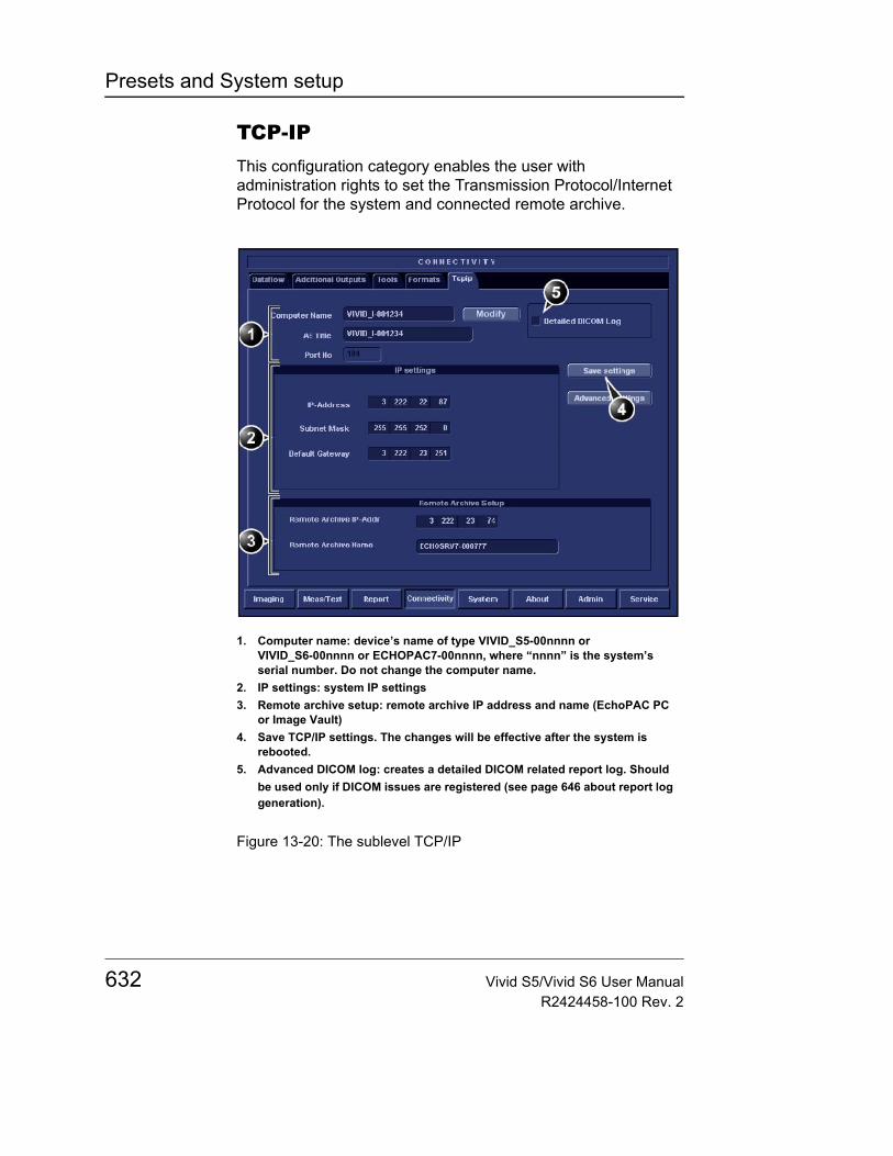
Presets and System setup
TCP-IPThis configuration category enables the user with administration rights to set the Transmission Protocol/Internet Protocol for the system and connected remote archive.
Figure 13-20: The sublevel TCP/IP
1. Computer name: device’s name of type VIVID_S5-00nnnn or VIVID_S6-00nnnn or ECHOPAC7-00nnnn, where “nnnn” is the system’s serial number. Do not change the computer name.
2. IP settings: system IP settings3. Remote archive setup: remote archive IP address and name (EchoPAC PC
or Image Vault)4. Save TCP/IP settings. The changes will be effective after the system is
rebooted.5. Advanced DICOM log: creates a detailed DICOM related report log. Should
be used only if DICOM issues are registered (see page 646 about report log generation).
632 Vivid S5/Vivid S6 User ManualR2424458-100 Rev. 2
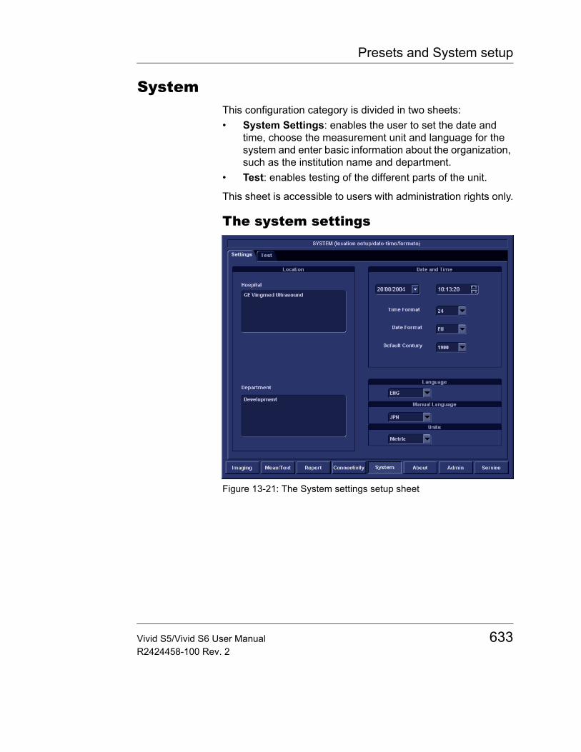
Presets and System setup
SystemThis configuration category is divided in two sheets:• System Settings: enables the user to set the date and
time, choose the measurement unit and language for the system and enter basic information about the organization, such as the institution name and department.
• Test: enables testing of the different parts of the unit.
This sheet is accessible to users with administration rights only.
The system settings
Figure 13-21: The System settings setup sheet
Vivid S5/Vivid S6 User Manual 633R2424458-100 Rev. 2
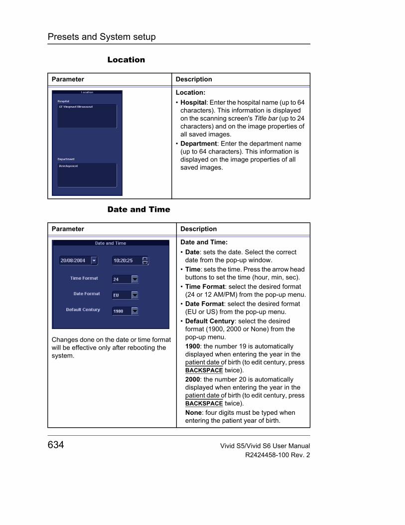
Presets and System setup
Location
Date and Time
Parameter Description
Location:• Hospital: Enter the hospital name (up to 64
characters). This information is displayed on the scanning screen's Title bar (up to 24 characters) and on the image properties of all saved images.
• Department: Enter the department name (up to 64 characters). This information is displayed on the image properties of all saved images.
Parameter Description
Changes done on the date or time format will be effective only after rebooting the system.
Date and Time:• Date: sets the date. Select the correct
date from the pop-up window.• Time: sets the time. Press the arrow head
buttons to set the time (hour, min, sec).• Time Format: select the desired format
(24 or 12 AM/PM) from the pop-up menu.• Date Format: select the desired format
(EU or US) from the pop-up menu.• Default Century: select the desired
format (1900, 2000 or None) from the pop-up menu.1900: the number 19 is automatically displayed when entering the year in the patient date of birth (to edit century, press BACKSPACE twice).2000: the number 20 is automatically displayed when entering the year in the patient date of birth (to edit century, press BACKSPACE twice).None: four digits must be typed when entering the patient year of birth.
634 Vivid S5/Vivid S6 User ManualR2424458-100 Rev. 2
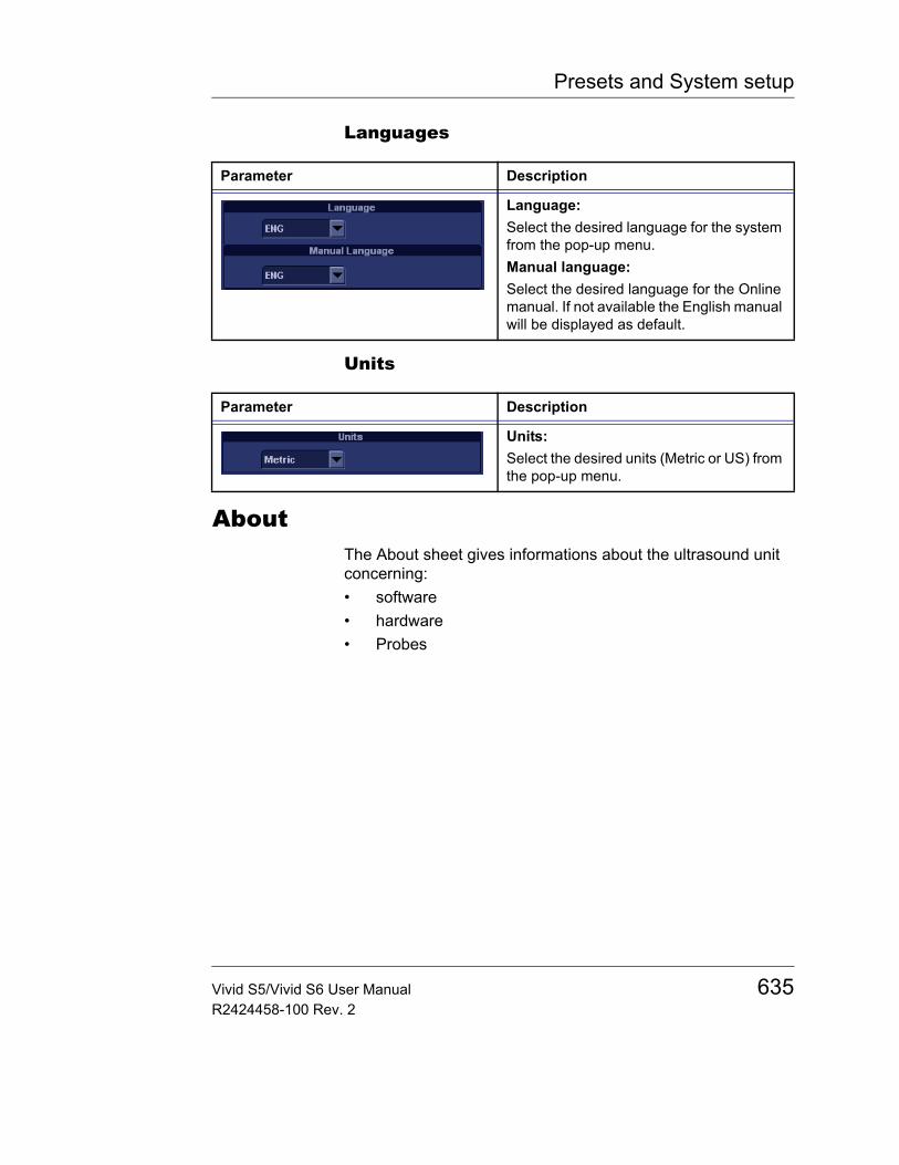
Presets and System setup
Languages
Units
AboutThe About sheet gives informations about the ultrasound unit concerning:• software• hardware• Probes
Parameter Description
Language:Select the desired language for the system from the pop-up menu.Manual language:Select the desired language for the Online manual. If not available the English manual will be displayed as default.
Parameter Description
Units:Select the desired units (Metric or US) from the pop-up menu.
Vivid S5/Vivid S6 User Manual 635R2424458-100 Rev. 2
Presets and System setup
AdministrationOnly users with ad-ministration rights have access to this setup category (see page 637).
The Admin. category deals with the following:• Disk management: enables the management of the hard
disk space while maintaining the patient database on the system (see page 468).
• Backup: enables the backup procedures for local patient, and report archives as well as system and user-defined configuration (see page 472).
• Restore: enables data retrieving of patient and report archives as well as system and user-defined configuration (presets) from a backup (see page 476).
• Users: deals with operators registration, operator's rights setting and registration of staff related to an examination (e.g. referral doctors, sonographers etc.)
• System Administration: keeps track of all the options implemented in the unit.
• Unlock patient: enables to unlock patient records that were not properly terminated (see page 640).
636 Vivid S5/Vivid S6 User ManualR2424458-100 Rev. 2
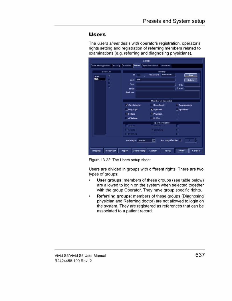
Presets and System setup
UsersThe Users sheet deals with operators registration, operator's rights setting and registration of referring members related to examinations (e.g. referring and diagnosing physicians).
Figure 13-22: The Users setup sheet
Users are divided in groups with different rights. There are two types of groups:• User groups: members of these groups (see table below)
are allowed to login on the system when selected together with the group Operator. They have group specific rights.
• Referring groups: members of these groups (Diagnosing physician and Referring doctor) are not allowed to login on the system. They are registered as references that can be associated to a patient record.
Vivid S5/Vivid S6 User Manual 637R2424458-100 Rev. 2

Presets and System setup
The rights associated to the user groups are:
Table 13-1: The User groups
Right (see definition below)
Group
Create
Print report
Store report
Adm
in
Service
Cardiologist + + + Activated with a DonglePhysician + +
Sonographer + +
Fellow + +
Sys Admin + + +
Hosp admin +
GE admin + + +
Right Definition
Create and delete • Create, update and delete a patient record• Create, update and delete an examination• Create, update and delete an user or a referring member• Import/Export patient records, examinations• Move examinations
Print report • Print a report
Store report • Store a report
Admin • System administration
Service • Access to the service platform
638 Vivid S5/Vivid S6 User ManualR2424458-100 Rev. 2
Presets and System setup
Creating a user or a referring member1. Press New2. Enter the user’s information. 3. Select the type of user/referring member in Member of
Group(s).
Editing an user configuration1. Select the actual user in the User list.2. Make the desired changes.3. Press CONFIG or any active scanning key to exit the
Configuration management package.
Deleting a user1. Select the actual user in the User list.2. Press Delete.
The user is removed from the User list.
Auto logon and auto Screenlock
Auto logon• Select the desired logon setup from the pull down menu:
• Disabled: no default user is selected when logging on.• Last user: the last user is selected automatically when
logging on.• A specific user: select one of the users to be the default
user when logging on.
Auto logoff• Set the time span (from 10 min) for the system to
automatically get locked when not in use. When the system is locked, the current user may either log on again or the system may be restarted by a different user.
CAUTION
To be able to login on the system, the group Operator MUST be selected.
Vivid S5/Vivid S6 User Manual 639R2424458-100 Rev. 2
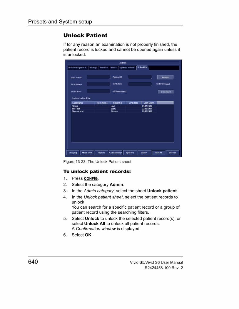
Presets and System setup
Unlock PatientIf for any reason an examination is not properly finished, the patient record is locked and cannot be opened again unless it is unlocked.
Figure 13-23: The Unlock Patient sheet
To unlock patient records:1. Press CONFIG.2. Select the category Admin.3. In the Admin category, select the sheet Unlock patient.4. In the Unlock patient sheet, select the patient records to
unlockYou can search for a specific patient record or a group of patient record using the searching filters.
5. Select Unlock to unlock the selected patient record(s), or select Unlock All to unlock all patient records.A Confirmation window is displayed.
6. Select OK.
640 Vivid S5/Vivid S6 User ManualR2424458-100 Rev. 2
User maintenance
Chapter 14 User maintenance
• System Care and Maintenance .................................................... .. 642• Inspecting the system .............................................................. 642• Cleaning the unit ...................................................................... 643• Prevention of static electricity interference ............................... 645
• System self-test ............................................................................ .. 646• System malfunction .................................................................. 646
• Using InSite ExC ........................................................................... .. 650• InSite ExC Functionalities ........................................................ 650• Initiating a Request for Service (RFS) ...................................... 650• Clinical Lifeline Mode ............................................................... 653• Exiting InSite ExC .................................................................... 654
Vivid S5/Vivid S6 User Manual 641R2424458-100 Rev. 2
User maintenance
System Care and MaintenanceHaving been determined by GE Medical Systems engineers that your Vivid S5/Vivid S6 system has no high-wearing components likely to fail due to frequent use, no Periodic Maintenance Inspections are mandatory. However, some Customer Quality Assurance Programs may require additional tasks and/or inspections to be performed at periods of frequency different from those listed in this manual.
To ensure that the Vivid S5/Vivid S6 unit constantly operates at maximum efficiency we recommend that the following procedures be observed as part of the customer’s internal routine maintenance program.
Inspecting the system
Monthly
Examine the following on a monthly basis (or whenever there is a reason to assume that any issue may have occurred):• Connectors on cables, for any mechanical defects• Entire length of electrical and power cables, for cuts or
abrasions• Equipment, for loose or missing hardware• Control panel for defects• Brakes
CAUTION
The user must ensure that safety inspections are performed at least every 12 months according to the requirements of the patient safety standard IEC 60601-1 (1988).
Only trained persons are allowed to perform the safety inspections mentioned above.
Technical descriptions are available on request.
CAUTION
If any defects are observed or malfunctions occur, DO NOT operate the equipment, and inform a qualified service person.
WARNING
To avoid electrical shock hazard, do not remove panels or covers from the unit.
642 Vivid S5/Vivid S6 User ManualR2424458-100 Rev. 2
User maintenance
Virus Protection
To minimize virus vulnerability Vivid S5/Vivid S6 is configured with a minimal set of open ports and with all network services not actively used by the system closed down. This significantly reduces the risk of a virus attack on Vivid S5/Vivid S6. GE is continuously judging the need for additional actions to reduce vulnerability of equipment, this includes vulnerability scanning of our products and evaluation of new security patches for the third party technology used. Microsoft (and other) security patches that addresses serious issues with Vivid S5/Vivid S6 will be made available to customers after GE verification of those patches.
Cleaning the unit
General Cleaning
Frequent and diligent cleaning of the Vivid S5/Vivid S6 ultrasound unit reduces the risk of spreading infection from person to person, and also helps to maintain a clean working environment.
System Cabinet
On a weekly basis, moisten a soft, non-abrasive folded cloth or sponge with a mild, general purpose, non-abrasive soap and water solution. Do not use any solution containing abrasive powder or strong chemicals such as acid or alkaline. Squeeze excess liquid from the cloth/sponge, them wipe down the top, front, back and both sides of the unit. Do not spray any liquid directly onto the unit!1. Rinse the cloth/sponge with clean running water and wipe
the unit surfaces again.
CAUTION
When performing Cleaning Procedures, to prevent the risk of system damage, always observe the following precautions:• Use only recommended cleaning materials and solutions.• Do not use any solutions or products not listed in the
Vivid S5/Vivid S6 User Manual.• Do not spray any liquid directly onto the Vivid S5/Vivid S6 covers,
LCD Display or keyboard!• Do not allow any liquid to drip or seep into the system.• Prior to cleaning, turn OFF power to the system.
Vivid S5/Vivid S6 User Manual 643R2424458-100 Rev. 2

User maintenance
2. Use a dry, soft, lint-free cloth to dry the unit surfaces.3. Wait for the unit surfaces to dry completely.
Note: In the event that disinfection is required or any stubborn stains remain, remove them with a soft, dust-free cloth on which a small quantity of isopropyl rubbing alcohol has been absorbed, as described below for cleaning the Keyboard.
LCD Display
On a weekly basis, gently wipe the LCD Display with a dry, soft, lint-free non-abrasive folded cloth.
Note: In the event that you see a scratch-like mark on the LCD Display, this may be a stain transferred from the Keyboard or Trackball when the LCD Display Cover was pressed from the outside. Proceed as follows:
Wipe or dust the stain gently with a soft, dry cloth. If the stain remains, moisten a soft, lint-free cloth with water or a 50-50 mixture of isopropyl alcohol and water that does not contain impurities. Wring out as much of the liquid as possible then wipe the LCD Display again. Do not let any liquid drip into the computer!
Be sure to dry the LCD Display before closing the cover.
Control Panel and Keyboard
Control Panel:On a weekly basis, moisten a soft, non-abrasive folded cloth or sponge with a mild, general purpose, non-abrasive soap and water solution or general purpose disinfectant. Do not use any solution containing abrasive powder or strong chemicals such as acid or alkaline.
Squeeze excess liquid from the cloth/sponge, them wipe down the Control Panel.
Do not spray any liquid directly onto the Control Panel!1. Rinse the cloth/sponge with clean running water and wipe
the Control Panel again.2. Use a dry, soft, lint-free cloth to dry the Control Panel.3. Wait for the Control Panel surfaces to dry completely.
644 Vivid S5/Vivid S6 User ManualR2424458-100 Rev. 2
User maintenance
Keyboard:Clean the keyboard as described (above) for cleaning the Control Panel.
Note: In the event that disinfection is required or any stubborn stains remain, absorb a small quantity of isopropyl rubbing alcohol on a soft, dust-free cloth.
Wipe the surface of the keycaps with the cloth, making sure that no liquid drips on or between the keys. Allow to dry.
Magneto Optical Disk (MOD)
Clean the drive head and media with the vendor-supplied cleaning kit. Advised to repeat this often, to prevent future problems. MOD disks must be stored away from dust and cigarette smoke. Do not use alcohol or benzene to clean the MOD cartridge.
DVD - CD-RW Drive
Clean the drive head and media with the vendor-supplied cleaning kit. Advise the user to repeat this often, to prevent future problems. CDs must be stored away from dust and cigarette smoke. Do not use alcohol or benzene to clean the CD drive.
Peripherals
Clean the peripherals in accordance with the respective manufacturer's directions.
Prevention of static electricity interferenceInterference from static electricity can damage electronic components in the system. The following measures help to reduce the likelihood of electrostatic discharge:• Wipe the alphanumeric keyboard and monitor with lint-free
tissue or a soft cloth dampened with anti-static spray on a monthly basis.
• Spray carpets with anti-static spray because constant walking on carpets in or near the scanning room may be a source of static electricity.
Vivid S5/Vivid S6 User Manual 645R2424458-100 Rev. 2
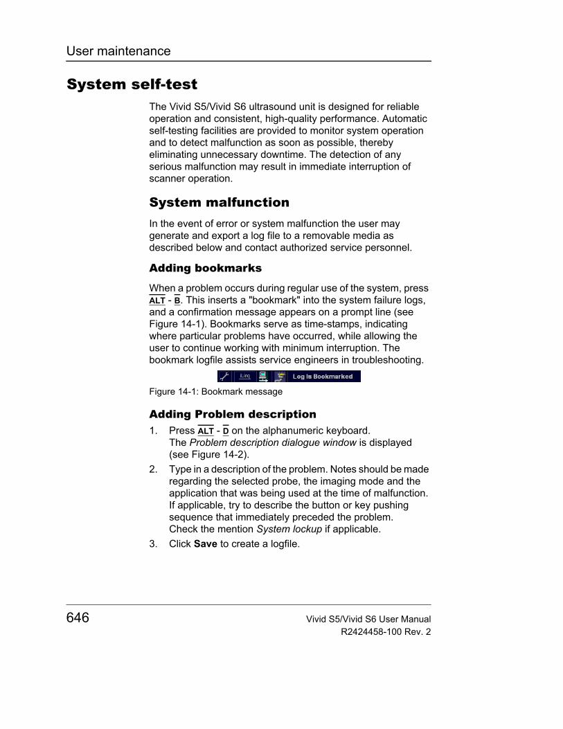
User maintenance
System self-testThe Vivid S5/Vivid S6 ultrasound unit is designed for reliable operation and consistent, high-quality performance. Automatic self-testing facilities are provided to monitor system operation and to detect malfunction as soon as possible, thereby eliminating unnecessary downtime. The detection of any serious malfunction may result in immediate interruption of scanner operation.
System malfunctionIn the event of error or system malfunction the user may generate and export a log file to a removable media as described below and contact authorized service personnel.
Adding bookmarks
When a problem occurs during regular use of the system, press ALT - B. This inserts a "bookmark" into the system failure logs, and a confirmation message appears on a prompt line (see Figure 14-1). Bookmarks serve as time-stamps, indicating where particular problems have occurred, while allowing the user to continue working with minimum interruption. The bookmark logfile assists service engineers in troubleshooting.
Figure 14-1: Bookmark message
Adding Problem description1. Press ALT - D on the alphanumeric keyboard.
The Problem description dialogue window is displayed (see Figure 14-2).
2. Type in a description of the problem. Notes should be made regarding the selected probe, the imaging mode and the application that was being used at the time of malfunction. If applicable, try to describe the button or key pushing sequence that immediately preceded the problem.Check the mention System lockup if applicable.
3. Click Save to create a logfile.
646 Vivid S5/Vivid S6 User ManualR2424458-100 Rev. 2
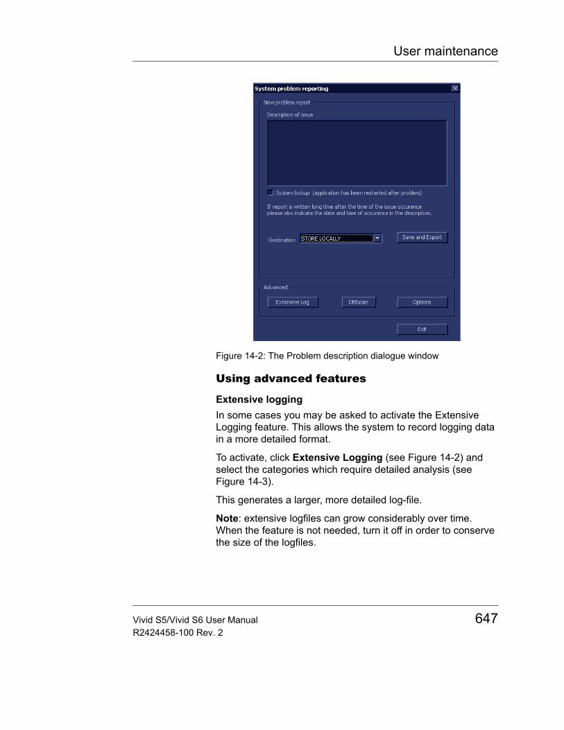
User maintenance
Figure 14-2: The Problem description dialogue window
Using advanced features
Extensive loggingIn some cases you may be asked to activate the Extensive Logging feature. This allows the system to record logging data in a more detailed format.
To activate, click Extensive Logging (see Figure 14-2) and select the categories which require detailed analysis (see Figure 14-3).
This generates a larger, more detailed log-file.
Note: extensive logfiles can grow considerably over time. When the feature is not needed, turn it off in order to conserve the size of the logfiles.
Vivid S5/Vivid S6 User Manual 647R2424458-100 Rev. 2
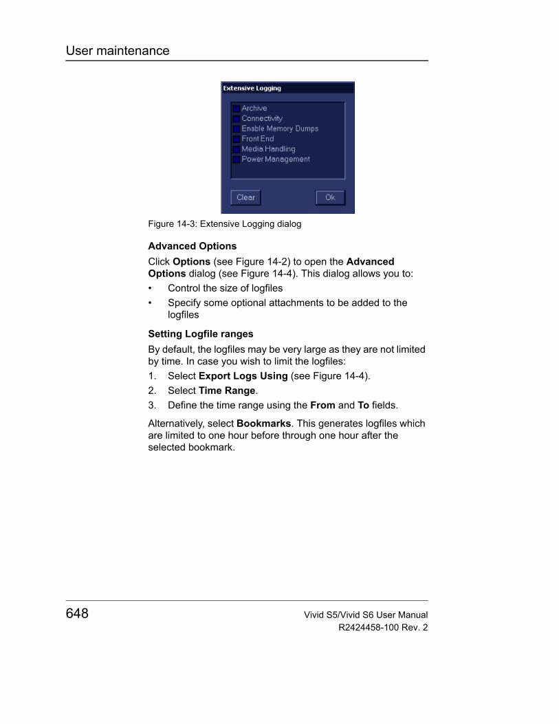
User maintenance
Figure 14-3: Extensive Logging dialog
Advanced OptionsClick Options (see Figure 14-2) to open the Advanced Options dialog (see Figure 14-4). This dialog allows you to:• Control the size of logfiles• Specify some optional attachments to be added to the
logfiles
Setting Logfile rangesBy default, the logfiles may be very large as they are not limited by time. In case you wish to limit the logfiles:1. Select Export Logs Using (see Figure 14-4).2. Select Time Range.3. Define the time range using the From and To fields.
Alternatively, select Bookmarks. This generates logfiles which are limited to one hour before through one hour after the selected bookmark.
648 Vivid S5/Vivid S6 User ManualR2424458-100 Rev. 2
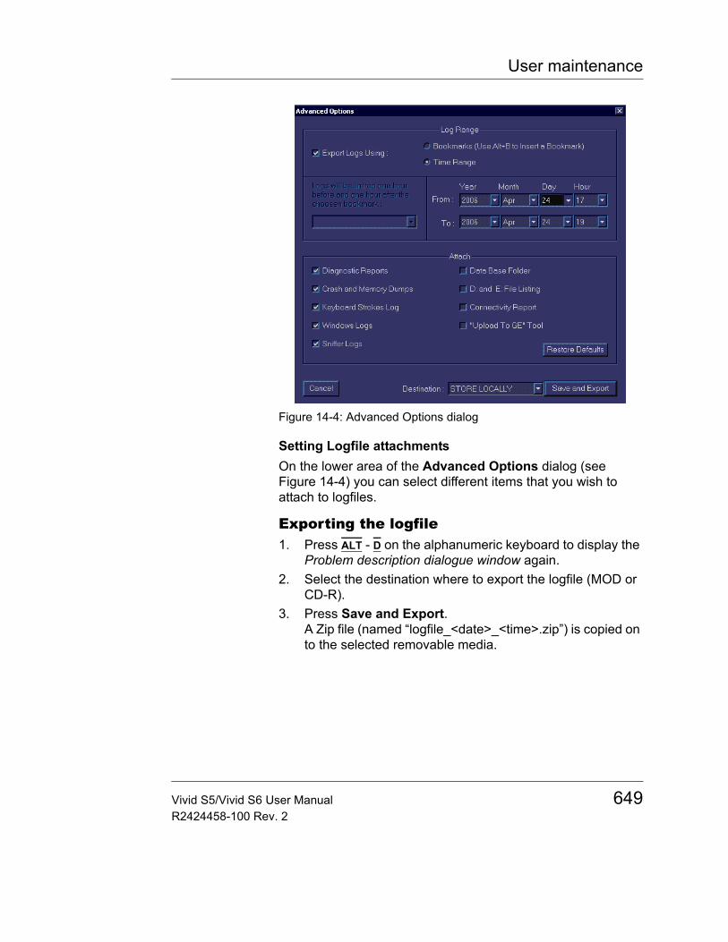
User maintenance
Figure 14-4: Advanced Options dialog
Setting Logfile attachmentsOn the lower area of the Advanced Options dialog (see Figure 14-4) you can select different items that you wish to attach to logfiles.
Exporting the logfile1. Press ALT - D on the alphanumeric keyboard to display the
Problem description dialogue window again.2. Select the destination where to export the logfile (MOD or
CD-R).3. Press Save and Export.
A Zip file (named “logfile_<date>_<time>.zip”) is copied on to the selected removable media.
Vivid S5/Vivid S6 User Manual 649R2424458-100 Rev. 2
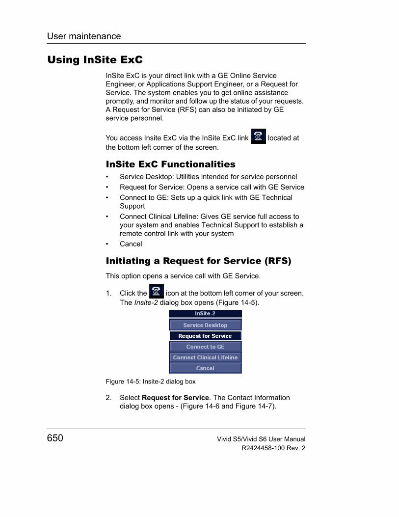
User maintenance
Using InSite ExCInSite ExC is your direct link with a GE Online Service Engineer, or Applications Support Engineer, or a Request for Service. The system enables you to get online assistance promptly, and monitor and follow up the status of your requests. A Request for Service (RFS) can also be initiated by GE service personnel.
You access Insite ExC via the InSite ExC link located at the bottom left corner of the screen.
InSite ExC Functionalities• Service Desktop: Utilities intended for service personnel• Request for Service: Opens a service call with GE Service• Connect to GE: Sets up a quick link with GE Technical
Support• Connect Clinical Lifeline: Gives GE service full access to
your system and enables Technical Support to establish a remote control link with your system
• Cancel
Initiating a Request for Service (RFS)This option opens a service call with GE Service.
1. Click the icon at the bottom left corner of your screen. The Insite-2 dialog box opens (Figure 14-5).
Figure 14-5: Insite-2 dialog box
2. Select Request for Service. The Contact Information dialog box opens - (Figure 14-6 and Figure 14-7).
650 Vivid S5/Vivid S6 User ManualR2424458-100 Rev. 2
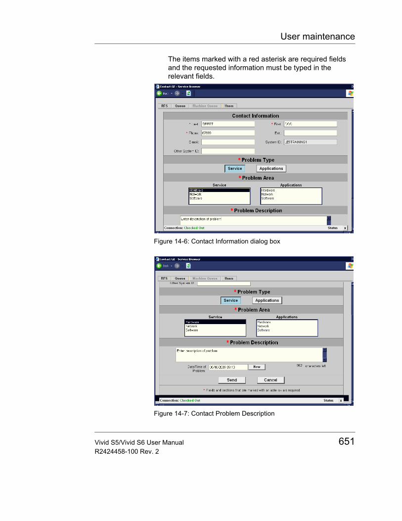
User maintenance
The items marked with a red asterisk are required fields and the requested information must be typed in the relevant fields.
Figure 14-6: Contact Information dialog box
Figure 14-7: Contact Problem Description
Vivid S5/Vivid S6 User Manual 651R2424458-100 Rev. 2
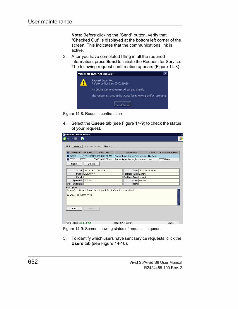
User maintenance
Note: Before clicking the "Send" button, verify that "Checked Out" is displayed at the bottom left corner of the screen. This indicates that the communications link is active.
3. After you have completed filling in all the required information, press Send to initiate the Request for Service. The following request confirmation appears (Figure 14-8).
Figure 14-8: Request confirmation
4. Select the Queue tab (see Figure 14-9) to check the status of your request.
Figure 14-9: Screen showing status of requests in queue
5. To identify which users have sent service requests, click the Users tab (see Figure 14-10).
652 Vivid S5/Vivid S6 User ManualR2424458-100 Rev. 2
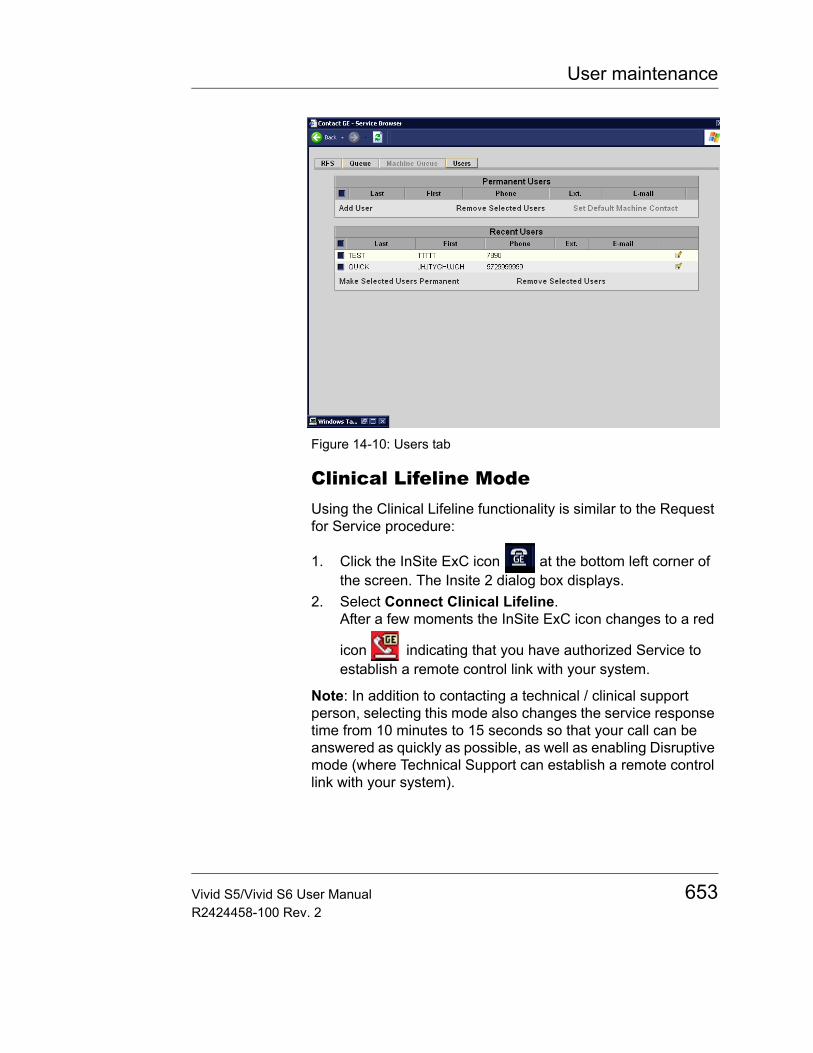
User maintenance
Figure 14-10: Users tab
Clinical Lifeline ModeUsing the Clinical Lifeline functionality is similar to the Request for Service procedure:
1. Click the InSite ExC icon at the bottom left corner of the screen. The Insite 2 dialog box displays.
2. Select Connect Clinical Lifeline.After a few moments the InSite ExC icon changes to a red
icon indicating that you have authorized Service to establish a remote control link with your system.
Note: In addition to contacting a technical / clinical support person, selecting this mode also changes the service response time from 10 minutes to 15 seconds so that your call can be answered as quickly as possible, as well as enabling Disruptive mode (where Technical Support can establish a remote control link with your system).
Vivid S5/Vivid S6 User Manual 653R2424458-100 Rev. 2

User maintenance
Exiting InSite ExC
1. Click at top right corner of the screen to exit InSite ExC.2. After you have finished using InSite ExC, reboot the
system.
654 Vivid S5/Vivid S6 User ManualR2424458-100 Rev. 2
Index
Index
Numerics2D Soft menu controls............................................................................ 1452D-Mode.......................................................................................... 140–150
Controls............................................................................................. 142Optimizing ......................................................................................... 148Overview........................................................................................... 140Using................................................................................................. 148
AActive mode gain
Optimizing Color Mode ..................................................................... 163Optimizing CW Doppler .................................................................... 168Optimizing PW Doppler..................................................................... 168
adding malfunction description............................................................... 646Advanced sheet............................................................................... 603, 604AFI.......................................................................................................... 328Alpha HIP ............................................................................................... 316Amniotic Fluid Index............................................................................... 328Angle correction
CW Doppler ...................................................................................... 166Optimizing CW Doppler .................................................................... 168Optimizing PW Doppler..................................................................... 168PW Doppler....................................................................................... 166
Annotations ..................................................................................... 128–135Configure .......................................................................................... 132Editing............................................................................................... 131Erasing.............................................................................................. 131Inserting ............................................................................................ 128
Applicationselecting............................................................................................ 100
Assignable keys ..................................................................................... 103Audio Volume
PW/CW Doppler................................................................................ 165AutoEF ................................................................................................... 292AVI.......................................................................................................... 408
Vivid S5/Vivid S6 User Manual 655R2424458-100 Rev. 2
Index
BB Color maps
2D Mode............................................................................................143Baseline
Color Mode........................................................................................159CW Doppler .......................................................................................165Optimizing Color Mode......................................................................163PW Doppler .......................................................................................165TVI .....................................................................................................170
battery, internal .........................................................................................57BFI ..........................................................................................................195B-Flow.....................................................................................................195Biopsy .....................................................................................................563
needle path........................................................................................573Blood flow imaging..................................................................................195B-Mode measurements....................................................................323, 371Bodymark................................................................................................134bookmark ................................................................................................646
CCare and Maintenance.....................................................................642–645Cine Compound
Strain .................................................................................................186Strain rate ..........................................................................................181Tissue Tracking ..........................................................................176, 190
Cineloop........................................................................................... 110–113Controls ............................................................................................. 111Overview............................................................................................ 110Saving as AVI ....................................................................................408Using ................................................................................................. 112
Circumference parameter .......................................................................325CIVCO.....................................................................................................565Cleaning
Ultrasound unit ..................................................................................643Color 2D
Using .................................................................................................162Color maps
Color Mode........................................................................................160CW Doppler .......................................................................................166
656 Vivid S5/Vivid S6 User ManualR2424458-100 Rev. 2
Index
M-Mode............................................................................................. 152Strain................................................................................................. 184Strain rate ......................................................................................... 179Tissue Synchronization Imaging ....................................................... 189Tissue tracking.................................................................................. 175TVI .................................................................................................... 171
Color M-ModeOverview........................................................................................... 158Using................................................................................................. 162
Color Mode...................................................................................... 157–163Controls............................................................................................. 159Optimizing ......................................................................................... 163Overview........................................................................................... 157using ................................................................................................. 162
Comments .............................................................................................. 419Compound....................................................................................... 143, 194Compress
2D ..................................................................................................... 145CW Doppler ...................................................................................... 166LV Contrast ....................................................................................... 237M-Mode............................................................................................. 152Optimizing CW Doppler .................................................................... 168Optimizing M-Mode........................................................................... 155Optimizing PW Doppler..................................................................... 168PW Doppler....................................................................................... 166Strain rate ......................................................................................... 180TVI .................................................................................................... 171
Compund......................................................................................... 143, 194Configurable Remote Path ......................................................................118Configuration see System setupConnecting peripherals ............................................................................ 58Connecting the unit .................................................................................. 54Connectivity
Buttons.............................................................................................. 623Dataflow............................................................................................ 616Overview........................................................................................... 616
Continuous capture ................................................................................ 205Contour
2D ..................................................................................................... 146LV Contrast ....................................................................................... 238
Vivid S5/Vivid S6 User Manual 657R2424458-100 Rev. 2

Index
M-Mode .............................................................................................153Optimizing M-Mode ...........................................................................155
Contrast Imaging..............................................................................233–241Abdominal Contrast Imaging .............................................................241LV Contrast Imaging..........................................................................235Vascular Contrast Imaging ................................................................240
Control panel........................................................................................71–82Coupling gels ..........................................................................................561CW Doppler .....................................................................................164–168
Controls .............................................................................................165Optimizing..........................................................................................168Overview............................................................................................164Using .................................................................................................167
DD Color maps
PW Doppler .......................................................................................166d-D Ratio.................................................................................................316DDP
2D......................................................................................................146LV Contrast........................................................................................238Optimizing 2D....................................................................................149
DeleteExamination.......................................................................................422Image.................................................................................................423Patient record ....................................................................................422
Depth2D......................................................................................................144Optimizing 2D....................................................................................148
Diagnosis code .......................................................................................420Diagnosis information .............................................................................419DICOM spooler .......................................................................................479DICOM verification..................................................................................625Diff On/Off
2D......................................................................................................146Diff on/off
LV Contrast........................................................................................238Digital Video Recorder ............................................................................578Direct report ............................................................................................514
658 Vivid S5/Vivid S6 User ManualR2424458-100 Rev. 2
Index
Disk Backup ........................................................................................... 471Disk Management .................................................................................. 464
configuring ........................................................................................ 465destination device ............................................................................. 467manual start ...................................................................................... 468running .............................................................................................. 468schedule............................................................................................ 466settings.............................................................................................. 467
Disk Restore........................................................................................... 471Doppler measurements .......................................................................... 330Doppler see PW or CW DopplerDual focus
2D ..................................................................................................... 143DVR........................................................................................................ 578
playback controls .............................................................................. 580Titles and Chapters........................................................................... 579
Dynamic RangeLV Contrast ....................................................................................... 238
Dynamic range2D ..................................................................................................... 145M-Mode............................................................................................. 153Optimizing M-Mode........................................................................... 155
Dysplasia................................................................................................ 315
EECG
Adjusting trace .................................................................................. 126Connecting........................................................................................ 122Controls............................................................................................. 126
Edge Enhance, M-Mode......................................................................... 153EFW ....................................................................................................... 330Ejection Fraction, automated.................................................................. 292Emission declaration ................................................................................ 44Estimated Fetal Weight .......................................................................... 330Event timing............................................................................................ 265eVue....................................................................................................... 410Examination
Starting................................................................................................ 95Export
Vivid S5/Vivid S6 User Manual 659R2424458-100 Rev. 2
Index
Patient records ..................................................................................452extensive logging ....................................................................................647
FFetal growth
bar graph ...........................................................................................365Fetal growth curve graph ........................................................................360File Management ....................................................................................464Focus
2D......................................................................................................142LV Contrast........................................................................................237M-Mode .............................................................................................152Optimizing 2D....................................................................................149Optimizing M-Mode ...........................................................................155
Follicle measurements ............................................................................373footswitch ..................................................................................................87Formatting
Removable media..............................................................................625Frame rate
2D......................................................................................................142Optimizing CW Doppler .....................................................................168Optimizing M-Mode ...........................................................................155Optimizing PW Doppler .....................................................................168Strain .................................................................................................184Strain rate ..........................................................................................179Tissue Synchronization Imaging........................................................189Tissue Tracking .................................................................................174TVI .....................................................................................................170
Frequency2D......................................................................................................143Color Mode........................................................................................160CW Doppler .......................................................................................167LV Contrast........................................................................................236M-Mode .............................................................................................151Optimizing Color Mode......................................................................163Optimizing CW Doppler .....................................................................168Optimizing M-Mode ...........................................................................155Optimizing PW Doppler .....................................................................168PW Doppler .......................................................................................167
660 Vivid S5/Vivid S6 User ManualR2424458-100 Rev. 2
Index
Strain................................................................................................. 185Strain rate ......................................................................................... 180Tissue Synchronization Imaging ....................................................... 190Tissue Tracking................................................................................. 175TVI .................................................................................................... 171
GGain
2D ..................................................................................................... 144Optimizing 2D ................................................................................... 148Optimizing M-Mode........................................................................... 155
Gel.......................................................................................................... 561Gestational Sac...................................................................................... 327GS .......................................................................................................... 327GYN measurements............................................................................... 370
HHazard symbols........................................................................................ 16Hip Dysplasia ......................................................................................... 315Horizontal sweep
Color M-Mode ................................................................................... 159CW Doppler ...................................................................................... 165M-Mode............................................................................................. 151Optimizing CW Doppler .................................................................... 168Optimizing M-Mode........................................................................... 155Optimizing PW Doppler..................................................................... 168PW Doppler....................................................................................... 165
IImages
Saving as JPEG................................................................................ 408Import
Patient records.................................................................................. 460Intima-Media Thickness ......................................................................... 303Invert
2D ..................................................................................................... 143Color Mode ....................................................................................... 159CW Doppler ...................................................................................... 165Optimizing Color Mode ..................................................................... 163
Vivid S5/Vivid S6 User Manual 661R2424458-100 Rev. 2
Index
Optimizing CW Doppler .....................................................................168Optimizing PW Doppler .....................................................................168PW Doppler .......................................................................................165Strain rate ..........................................................................................179Tissue Tracking .................................................................................174TVI .....................................................................................................170
JJPEG.......................................................................................................408
LLanguage
Online manual ...................................................................................635System...............................................................................................635
Lateral AveragingColor Mode........................................................................................161Optimizing Color Mode......................................................................163Strain .................................................................................................186Strain rate ..........................................................................................180Tissue Tracking .................................................................................175TVI .....................................................................................................172
LCD monitor safety ...................................................................................37logfile.......................................................................................................648
exporting............................................................................................649LogiqView ...............................................................................................193Low Velocity Reject see LVRLPRF.......................................................................................................166LVR
Color Mode........................................................................................159CW Doppler .......................................................................................165Optimizing Color Mode......................................................................163Optimizing CW Doppler .....................................................................168Optimizing PW Doppler .....................................................................168
MM&A ........................................................................................................333Magneto Optical Disk
Formatting .........................................................................................625Measurements
662 Vivid S5/Vivid S6 User ManualR2424458-100 Rev. 2
Index
Configuration..................................................................................... 338User-defined formulas....................................................................... 343
Measurements (Cardiac)................................................................. 243–3512D ..................................................................................................... 255Doppler ............................................................................................. 262M-Mode............................................................................................. 259TSI .................................................................................................... 266
Measurements (Vascular)B-Mode ............................................................................................. 302Doppler ............................................................................................. 309M-Mode............................................................................................. 308
M-Mode ........................................................................................... 150–156Anatomical M-Mode.......................................................................... 154Controls............................................................................................. 151Conventional M-Mode................................................................ 153, 154Curved Anatomical M-Mode ............................................................. 155Optimizing ......................................................................................... 155Overview........................................................................................... 150Using................................................................................................. 153
Monitoradjusting image................................................................................... 90adjusting position ................................................................................ 92
Moving the unit ......................................................................................... 64moving the unit ......................................................................................... 64MPEG exams ......................................................................................... 410MPEGVue/eVue..................................................................................... 410multiple fetus .......................................................................................... 366
NNeedle Guidance Systems..................................................................... 565normal values ......................................................................................... 340
OOB application........................................................................................ 321OB exam ................................................................................................ 317OB graphs .............................................................................................. 359OB measurements ................................................................................. 322OB Multigestational ................................................................................ 366OB parameter configuration ................................................................... 333
Vivid S5/Vivid S6 User Manual 663R2424458-100 Rev. 2
Index
OB table sheet ........................................................................................605OB worksheet .........................................................................................356On/Off .......................................................................................................61Operation principles ....................................................................................2Ovary measurements..............................................................................372
PPatient
Entering information ............................................................................95Pediatric Calculations .............................................................................314Phono
Adjusting trace...................................................................................126Controls .............................................................................................126
Physiological traces .........................................................................122–127Power
2D......................................................................................................146Color Mode........................................................................................161CW Doppler .......................................................................................167LV Contrast........................................................................................237M-Mode .............................................................................................153Optimizing Color Mode......................................................................163PW Doppler .......................................................................................167Strain rate ..........................................................................................181Tissue Synchronization Imaging.................................................186, 190Tissue Tracking .................................................................................176
Probe-Application OverviewVivid S5 .............................................................................................542Vivid S6 .............................................................................................543
ProbesActivating...........................................................................................550Care and Maintenance ......................................................................552Cleaning ............................................................................................556Connecting ...................................................................................87, 548Disconnecting....................................................................................551Disconnecting and connecting.............................................................87Disinfecting........................................................................................558Intra-operative use.............................................................................574Labelling ............................................................................................546Orientation markers ...........................................................................545
664 Vivid S5/Vivid S6 User ManualR2424458-100 Rev. 2
Index
returning............................................................................................ 561Safety................................................................................................ 562Selecting ........................................................................................... 100shipping............................................................................................. 561special handling ................................................................................ 554surgery use ....................................................................................... 574Types ................................................................................................ 537
probes, selecting .................................................................................... 548protective sheaths .................................................................................. 554Pulse Pressure
Adjusting trace .................................................................................. 126Pulse Pressure transducer
Controls............................................................................................. 126PW Doppler ..................................................................................... 164–168
Controls............................................................................................. 165Optimizing ......................................................................................... 168Overview........................................................................................... 164Using................................................................................................. 167
QQuantitative Analysis.............................................................................. 375
Anatomical M-Mode.......................................................................... 399Deletion of a trace............................................................................. 389Frame disabling ................................................................................ 390Labelling a sample area.................................................................... 393Manual tracking................................................................................. 387Optimizing Anatomical M-Mode........................................................ 401Optimizing sample area .................................................................... 392Optimizing the trace display.............................................................. 394Overview........................................................................................... 379Sample area...................................................................................... 386Strain cursor...................................................................................... 386To generate a trace........................................................................... 386Trace smoothing ............................................................................... 395
RRadial Averaging
Color Mode ....................................................................................... 161Optimizing Color Mode ..................................................................... 163
Vivid S5/Vivid S6 User Manual 665R2424458-100 Rev. 2
Index
Strain .................................................................................................186Strain rate ..........................................................................................180Tissue Tracking .................................................................................176TVI .....................................................................................................172
Referral reasons .....................................................................................419Regulatory requirements.............................................................................6Reject
2D......................................................................................................145LV Contrast........................................................................................238M-Mode .............................................................................................152Optimizing 2D....................................................................................149Optimizing M-Mode ...........................................................................155Strain .................................................................................................185Strain rate ..........................................................................................180
Remote Path........................................................................................... 118Removable media
Ejecting.............................................................................................. 119Flash Card ......................................................................................... 115Formatting .........................................................................................625
Report ..............................................................................................491–534Configuration of the Template selection menu..................................532Creating.............................................................................................493Deleting .............................................................................................497Direct report.......................................................................................514Export/Import templates ....................................................................533managing report images....................................................................495Print ...................................................................................................496Retrieving ..........................................................................................497Save ..................................................................................................496
Report designer ......................................................................................516Designing a template.........................................................................519
ROI sizeColor Mode........................................................................................161
SSafety...................................................................................................13–50
Biological hazard .................................................................................36Electrical hazard ..................................................................................35Equipment safety.................................................................................35
666 Vivid S5/Vivid S6 User ManualR2424458-100 Rev. 2
Index
Explosion hazard ................................................................................ 35Mechanical hazard.............................................................................. 32Pacemaker hazard.............................................................................. 36Patient safety ...................................................................................... 31Personnel safety ................................................................................. 35
Sample volumeColor Mode ....................................................................................... 160CW Doppler ...................................................................................... 166Optimizing Color Mode ..................................................................... 163Optimizing CW Doppler .................................................................... 168Optimizing PW Doppler..................................................................... 168PW Doppler....................................................................................... 166
save as PDF to network ..........................................................................118Scale
Color Mode ....................................................................................... 159CW Doppler ...................................................................................... 165PW Doppler....................................................................................... 165Strain................................................................................................. 184TVI .................................................................................................... 170
ScanningScreen layout ...................................................................................... 84starting .............................................................................................. 100
SimultaneousStrain................................................................................................. 184Strain rate ......................................................................................... 179Tissue Synchronization Imaging ....................................................... 189Tissue tracking.................................................................................. 174TVI .................................................................................................... 170
Single length parameter ......................................................................... 325Site requirements ..................................................................................... 53Soft Menu Rocker................................................................................... 103
using ................................................................................................. 107Strain ...................................................................................................... 183
Controls............................................................................................. 184Optimizing ......................................................................................... 186Overview........................................................................................... 183Using................................................................................................. 186
Strain cursor ........................................................................................... 386Strain rate............................................................................................... 178
Controls............................................................................................. 179
Vivid S5/Vivid S6 User Manual 667R2424458-100 Rev. 2
Y
Index
R
E
L
I
M
I
N
A
R
Optimizing..........................................................................................181Overview............................................................................................178Using .................................................................................................181
Stress Echo......................................................................................197–231Acquisition .........................................................................................200Analysis .............................................................................................213Configuring levels ..............................................................................230Creating an image group...................................................................231Deleting a group ................................................................................231Editing template.................................................................................225Labelling a level.................................................................................230Labelling a projection.........................................................................230Scoring ..............................................................................................216Selecting a template ..........................................................................199Timers.........................................................................................204, 230
SystemControls affecting acoustic output .......................................................27Switching On/Off..................................................................................61
System documentation ...............................................................................3System setup ...................................................................................583–640
Application .........................................................................................593Connectivity ................................................................................616–632Examination list window ....................................................................626Examination signoff ...........................................................................626Imaging setup....................................................................................590Language...........................................................................................633M&A...................................................................................................598Patient ID...........................................................................................626Patient information.............................................................................592Scan information................................................................................592Starting system setup........................................................................588Units ..................................................................................................633Unlock Patient ...................................................................................640User configuration .............................................................................637
TTCP-IP ....................................................................................................632TGC see Time Gain Compensation........................................................144Threshold
P668 Vivid S5/Vivid S6 User ManualR2424458-100 Rev. 2
Index
Strain................................................................................................. 185Strain rate ......................................................................................... 180Tissue Synchronization Imaging ....................................................... 190Tissue Tracking................................................................................. 175TVI .................................................................................................... 171
Tilt2D ..................................................................................................... 142LV Contrast ................................................................................ 236, 238
Time Gain Compensation (TGC)2D ..................................................................................................... 144Optimizing 2D ................................................................................... 148Optimizing M-Mode........................................................................... 155
Tissue priorityColor Mode ....................................................................................... 160Optimizing Color Mode ..................................................................... 163
Tissue Synchronization Imaging ............................................................ 188Controls............................................................................................. 189Optimizing ......................................................................................... 192Overview........................................................................................... 188Using................................................................................................. 191
Tissue Tracking ...................................................................................... 173Controls............................................................................................. 174Optimizing ......................................................................................... 176Overview........................................................................................... 173Using................................................................................................. 176
Tissue Velocity Imaging see TVITrackball
Operation .......................................................................................... 108Transparency
Strain................................................................................................. 185Strain rate ......................................................................................... 180Tissue Synchronization Imaging ....................................................... 190Tissue Tracking................................................................................. 175TVI .................................................................................................... 171
TSI................................................................................................... 170, 174TSI, see Tissue Synchronization ImagingTVI.......................................................................................................... 169
Controls............................................................................................. 170Optimizing ......................................................................................... 172Overview........................................................................................... 169
Vivid S5/Vivid S6 User Manual 669R2424458-100 Rev. 2
Index
Using .................................................................................................172
UUD....................................................................................................146, 237Ultra Definition Clarity ......................................................................146, 237Uterus measurements.............................................................................371
VVariance
Color Mode........................................................................................159Optimizing Color Mode......................................................................163
Velocity rangeOptimizing CW Doppler .....................................................................168Optimizing PW Doppler .....................................................................168
Virtual Convex.........................................................................................196
Wwheels.......................................................................................................64Width
2D......................................................................................................142LV Contrast........................................................................................236
Worksheet...............................................................................................353
670 Vivid S5/Vivid S6 User ManualR2424458-100 Rev. 2