visvesvaraya technological university, belagavi
TRANSCRIPT
Visvesvaraya Technological University, Belagavi.
PROJECT REPORT
on
“Mobile Drive Robot”
Project Report submitted in partial fulfillment of the requirement for the award of
the degree of
Bachelor of Engineering
in
Electronics and Communication Engineering
For the academic year 2019-20
Submitted by
USN lCR16EC165 SHUCHI DEVEN JANI
USN 1CR16EC166 SNEHA C
USN 1CR16EC167 SNEHA SWATI
USN 1CR16EC176 SUSHMITHA M
Under the guidance of
Mr. Sachin Aralikatti
Asst.Professor
Department of ECE
CMRIT, Bengaluru
Department of Electronics and Communication Engineering
CMR Institute of Technology, Bengaluru – 560 037
DEPARTMENT OF ELECTRONICS AND COMMUNICATION ENGINEERING
CERTIFICATE This is to Certify that the dissertation work “Mobile Drive Robot” carried out by Shuchi Deven Jani
,1CR16EC165; Sneha C,1CR16EC166; Sneha Swati,1CR16EC167; Sushmitha M,1CR16EC176
bonafide students of CMRIT in partial fulfillment for the award of Bachelor of Engineering in
Electronics and Communication Engineering of the Visvesvaraya Technological University,
Belagavi, during the academic year 2019-20. It is certified that all corrections/suggestions indicated for
internal assessment have been incorporated in the report deposited in the departmental library. The
project report has been approved as it satisfies the academic requirements in respect of Project work
prescribed for the said degree.
Signature of Guide Signature of HOD Signature of Principal
_________________ _________________ __________________
Mr.Sachin Aralikatti, Dr. R. Elumalai Dr. Sanjay Jain
Asst.Professor, Head of the Department, Principal,
Dept. of ECE., Dept. of ECE., CMRIT,
CMRIT, Bengaluru. CMRIT, Bengaluru. Bengaluru.
External Viva
Name of Examiners Signature & date
1.
2
ACKNOWLEDGEMENT
The satisfaction and euphoria that accompany the successful completion of any task
would be incomplete without the mention of people who made it possible, whose
consistent guidance and encouragement crowned our efforts with success.
We consider it as our privilege to express the gratitude to all those who guided in
the completion of the project.
We express my gratitude to Principal, Dr. Sanjay Jain, for having provided us the
golden opportunity to undertake this project work in their esteemed organization.
We sincerely thank Dr. R. Elumalai, HOD, Department of Electronics and
Communication Engineering, CMR Institute of Technology for the immense
support given to us.
We express my gratitude to our project guide Mr. Sachin Aralikatti , Asst.Professor,
for their support, guidance and suggestions throughout the project work.
Last but not the least, heartful thanks to our parents and friends for their support.
Above all, We thank the Lord Almighty for His grace on us to succeed in this
endeavor.
Mobile Drive Robot
TABLE OF CONTENTS
Chapter 1.0 3
INTRODUCTION 3
1.1 Problem Statement 3
Chapter 2.0 5
LITERATURE SURVEY 5
Chapter 3.0 11
HARDWARE 11
3.1 Functional Hardware Requirements 11
3.2 Non-Functional Requirements 11
3.3 Hardware Components: 12
3.3.1 Raspberry Pi 13
3.3.2 Motors used 19
Chapter 4.0 22
SOFTWARE 22
4.1 Software Used: 22
4.1.1 Autodesk Inventor: 22
4.1.2 OpenVSLAM: 23
4.1.3 OpenCV: 24
Chapter 5.0 26
DESIGN AND IMPLEMENTATION 26
5.1 Mechanical Structure 26
5.1.2 Robot Design 28
5.1.3 Connections 30
5.2 Implementation 31
5.2.1 ALGORITHM - Room Mapping 31
5.2.2 ALGORITHM-Object Detection 32
Chapter 6.0 34
RESULTS 34
Chapter 7.0 35
Department of ECE, CMRIT, Bangalore 2019-20 1
Mobile Drive Robot
APPLICATIONS AND ADVANTAGES 35
Chapter 8.0 36
CONCLUSION AND SCOPE FOR FUTURE WORK 36
8.1 CONCLUSION 36
8.2 FUTURE WORK 37
REFERENCES 38
Department of ECE, CMRIT, Bangalore 2019-20 2
Mobile Drive Robot
CHAPTER 1.0
INTRODUCTION
In this fast-paced world, anyone who can't keep up gets left behind,
there are no exceptions made for anyone. The graph of the number of
differently-abled people that have entered the industry and are scaling new
heights is positively pacing, but these individuals require additional help to
keep up with their peers.
Autonomous robots are helpful in busy environments, like a hospital.
Instead of employees leaving their posts, an autonomous robot can deliver
lab results and patient samples expeditiously. Without traditional guidance,
these robots can navigate the hospital hallways, and can even find alternate
routes when another is blocked. They will stop at pick-up points, and collect
samples to bring to the lab. As the population grows, the health industry is
also experiencing the saddening truth that the ratio of medical professionals
to patients is 1:1000 in India which leads to many patients not receiving
the care that they deserve, especially in the care of the disadvantaged and
the elderly.
1.1 Problem Statement
Mortality rates have gone down; the minimum age till which a regular
individual survives has now crossed 80 years. When an individual crosses
this limit, there are a lot of tasks that they require assistance in eg. picking
things up from the ground or cleaning up after themselves, or sometimes
even to take their medicines. In old age and assisted homes, the ratio of
nurses to patients is 1:10, which stretches the nurses too thin and also does
not give the patients the attention they deserve.
Department of ECE, CMRIT, Bangalore 2019-20 3
Mobile Drive Robot
COVID 19 has created a situation where senior citizens are the most
at risk, they have to practice social distancing. This leads to a situation which
puts their caregivers into jeopardy, instead of physical transfer of items, our
robot can bridge the gap.
The percentage of people that work in companies that are
differently-abled has increased in the past few years, they require assistance
but they should not have to rely on another human to do so.
Today technology is fast-evolving, which makes it imperative that we,
the students, come up with ideas that can be used in numerous fields and
make the most of our product. Our project comprises a mobile drive robot
that will have an arm connected to it. Mobile robots can move around in their
environment and are not fixed to one physical location. This gives them the
advantage of being able to cover a larger area and have vast applications.
Mobile robots are also termed as “Autonomous Mobile Robots”, that is,
AMR, which also means that they are capable of navigating in an
uncontrolled environment without using physical or electro-mechanical
guidance devices that allow them to travel a predefined navigation route in
relatively controlled space. Hence, also termed as “AGV-Autonomous
Guided Vehicle”.
Department of ECE, CMRIT, Bangalore 2019-20 4
Mobile Drive Robot
CHAPTER 2.0
LITERATURE SURVEY
Paper- 1
Design and Implementation of Robot Arm Control Based on MATLAB
with Arduino Interface
By- T.Rajesh, M. Karthik Reddy, Afreen Begum, D.Venkatesh
In the present days, a number of situations exist where it is not
possible for a human operator to do an activity on his/her own, due to a level
of danger or difficulty involved. They may involve taking readings from an
active volcano, entering a building on fire, diffusing a bomb, or collecting a
radioactive sample. Rather than compromising on human lives, it is better to
employ robotic systems for performing difficult tasks. Robotic systems are
far superior in ensuring the accuracy of the system under adverse
circumstances wherein a human operator may lose his/her composure and
focus. Here we propose to build a robotic arm controlled by Matlab/Simulink
interfacing with Arduino Uno. The development of this arm is based on the
Arduino platform and Matlab A servo motor is a combination of DC motor,
position control system, gears. The position of the shaft of the DC motor is
adjusted by the control electronics in the servo, based on the duty ratio of the
PWM signal. Servo is proposed for low speed, medium torque and accurate
position application. These motors are used in robotic arm machines, flight
controls and control systems. This project presents an interactive module for
learning both the fundamental and practical issues of servo systems interface
with ARDUINO UNO. This project, developed using Matlab coding tool, is
Department of ECE, CMRIT, Bangalore 2019-20 5
Mobile Drive Robot used to control robotics applications. The objective of this project is to
control the servo by using ARDUINO UNO with MATLAB & SIMULINK.
This paper proposes to build a robotic arm controlled by
MATLAB/Simulink interfacing with Arduino Uno. The development of this
arm is based on the Arduino platform and MATLAB. A servo motor is a
combination of DC motor, position control system, gears. The position of the
shaft of the DC motor is adjusted by the control electronics in the servo,
based on the duty ratio of the PWM signal. Servo is proposed for low speed,
medium torque and accurate position application. These motors are used in
robotic arm machines, flight controls and control systems. This project
presents an interactive module for learning both the fundamental and
practical issues of servo systems interface with ARDUINO UNO. This
project developed using MATLAB coding tool, is used to control robotics
applications. The objective of this project is to control the servo by using
ARDUINO UNO with MATLAB & SIMULINK.
Paper - 2
Design of a mobile robot with a robotic arm utilizing microcontroller
and wireless communication
By- I.B.Alit Swamardika
The purpose of this study is to design a prototype of a mobile robot
equipped with a robotic arm which can be controlled by wireless technology.
In this scheme, the mobile robot in the form of 6 Wheel Drive Robot
equipped with robotic arm 6 Degree of Freedom and is controlled wirelessly
through remote control based on XBee Pro Series 1. Data on the remote is
sent serially via XBee transmitter, processed on the receiver, and then used
Department of ECE, CMRIT, Bangalore 2019-20 6

Mobile Drive Robot as a reference to control the robot. The tests on the forward, backwards, turn
left, turn right, stop and linear movement of the robot was performed
successfully, which elevates the robot deployment potentials. The Six
Degree of Freedom (6 DOF) has enabled the robotic arm to perform the
designed movements very well. Furthermore, the mobile robot successfully
follows the command from each input variable resistor via the remote control
to move the robotic arm. The mobile robot and the robotic arm movement
can successfully be done simultaneously, which elevates its potentials for
deployment.
Hardware: ● Microcontroller Arduino Mega 2560 as a data processor and
robot controllers. ● Wireless communications module XBee-PRO as sender and
recipient of the data instructions.
Software:
● The Arduino IDE is used to create the program in the microcontroller.
Paper - 3
Pick and Place Robot with Wireless Charging Application
by N. Firthous Begum, P
Mankind has always strived to give life-like qualities to its artifacts in an
attempt to find substitutes for himself to carry out his orders and also to work
in a hostile environment. The popular concept of a robot is of a machine that
looks and works like a human being. The industry is moving from the
current state of automation to Robotization, to increase productivity and to
Department of ECE, CMRIT, Bangalore 2019-20 7

Mobile Drive Robot deliver uniform quality. One type of robot commonly used in industry is a
robotic manipulator or simply a robotic arm known as a pick and place robot.
It is an open or closed kinematic chain of rigid links interconnected by
movable joints. In this paper pick and place, Robot is designed which
performs its operation by using android via object detection application and
PIC microcontroller. This application has been programmed in java
language. In the transmitter part, the voice input is given by using HM2007
to the microcontroller by using RF module. In the receiver section, the RF
receiver will receive this voice input and it will be given to the
microcontroller. Simultaneously the object to be picked will be done by
using an android application where the camera of the android mobile will
capture the objects. The output from the mobile will be sent through
Bluetooth to the microcontroller and that will allow the motor to move in
order to pick the object. In this paper, wireless charging application is also
implemented by using electromagnetic induction concept that allows the
robot to charge itself whenever the onboard battery goes low. Keywords:
robotics, pick and place robots, wireless charging application, android object
detection application.
In the proposed system, a humanoid robot is implemented which performs
the task initiated by the user without human assistance by voice input. The
pick and place robot eliminates the need for sensors which are used to detect
object and object detection application is developed using java language. The
input voice is given to the microcontroller and sent to the receiver using an
RF transmitter. Simultaneously the object picking is done by using an
android application where the camera of android mobile will detect and
capture the image of the object. The output from the android mobile is sent
Department of ECE, CMRIT, Bangalore 2019-20 8
Mobile Drive Robot to the microcontroller through Bluetooth and it allows the motor to move in
order to pick the object by using the motor drive. Wireless charging is
implemented on the principle of electromagnetic induction.
Paper - 4
Development of real-time tracking and control mobile robot using video
capturing feature for unmanned applications
By-P. Velrajkumar, S. Solai Manohar, C. Aravind, A. Darwin Jose Raju and
R. Arshad
A wireless tracking and controlling mobile robot using video
capturing features (VCF) for unmanned applications is presented. It is
wheel-based and Radiofrequency (RF wireless communicated) is used for
communication between the controller and the robot. The available motions
of the robot are forward, backward, right, left and the combination of these
movements. Besides, a camera is built in the robot for tracking. The video
captured by the camera is displayed in the computer or Laptop by using the
Window Media Encoder (WME) software that is able to be controlled by
using Windows GUI remote control. It is built for the purpose of viewing the
places that humans cannot reach. Same with other robots which are built to
work in dangerous environments, it can be used to explore the situation of
dangerous places that humans cannot reach, for example, the natural disaster
area, cave, underground and so on. On the other hand, it can also serve as an
investigation robot in the military field. It suits the task of searching for an
ambush or sneaking into an enemy base to gather information.
This research presented the controlling and tracking of mobile robots using
Video Broadcast Feature and Audio Broadcasting Feature for the unknown
Department of ECE, CMRIT, Bangalore 2019-20 9
Mobile Drive Robot environment applications. It is an android based autonomous robot with
Bluetooth and Wi-Fi that is used for communication between the robot and a
remote controller. The robot is self -powered with 9V supply to power up the
microcontroller, motors and transmitter for audio broadcast. The
microcontroller used to control the robot remotely in the Arduino, it has
built-in input and output ports. For the real-time audio transmitter, it will
detect voice and any kind of audio using a mini electric microphone to
transmit a signal when detected through a transmitter circuit that is designed
to transmit the sound with the specified frequency range.
This robot has real-time video broadcasting capability to watch the activities
that take place in other places. The real-time video coverage is broadcast by
using smartphones that use broadcasting software. The video is transmitted
using the internet medium for longer range receiving destination. The
designed mobile robot can be used for surveillance purposes or military
purposes for spying.
Department of ECE, CMRIT, Bangalore 2019-20 10
Mobile Drive Robot
CHAPTER 3.0
HARDWARE
3.1 Functional Hardware Requirements
Functional Requirement defines a function of a software system and
how the system must behave when presented with specific inputs or
conditions. These may include calculations, data manipulation and
processing and other specific functionality.
The different Functional Requirement used are as follows:
● Arm
● Gripper gears
● Gripper fingers
● Arm base
● Control Device
● Electronic speed controllers
● Transmitter and receiver
● Rechargeable battery
● Pi Cam
● Raspberry Pi
● Mini Breadboard
3.2 Non-Functional Requirements
Non-functional requirements are the requirements which are not
directly concerned with the specific function delivered by the system. They
specify the criteria that can be used to judge the operation of a system rather
than specific behaviours. They may relate to emergent system properties
Department of ECE, CMRIT, Bangalore 2019-20 11
Mobile Drive Robot such as reliability, response time and store occupancy. Non-functional
requirements arise through the user needs, because of budget constraints,
organizational policies, the need for interoperability with other software and
hardware systems or because of external factors such as product
Requirements. Non-functional requirements are also called the qualities of a
system. These qualities can be divided into execution quality & evolution
quality. Execution qualities are security & usability of the system which are
observed during run time, whereas evolution quality involves testability,
maintainability, extensibility or scalability.
The different Non-Functional Requirement used are as follows:
● Arm Module
● Wheels
● Base body Kit
● Arm body kit
● Wires
● Switches
● Buttons
3.3 Hardware Components:
The machines, wiring, and other physical components of a computer
or other electronic system are called hardware components. A hardware
platform is a set of compatible hardware on which software applications can
be run. Each specific hardware platform has its own machine language, and
programs must be built specifically for a platform that involves a
standardized type of processor and associated hardware pieces. The
components we are using here are:
Department of ECE, CMRIT, Bangalore 2019-20 12
Mobile Drive Robot 3.3.1 Raspberry Pi
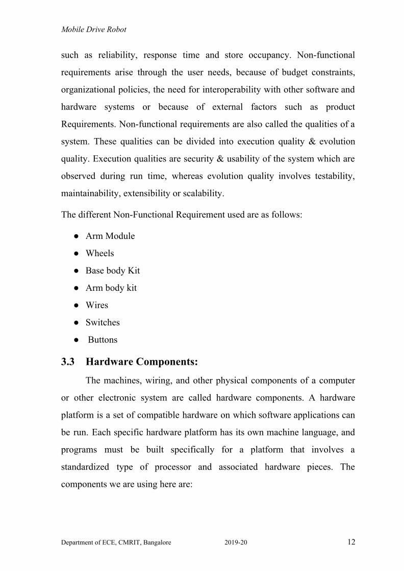
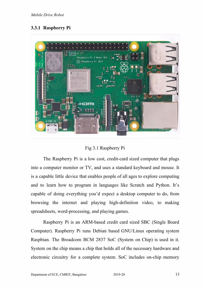
Fig 3.1 Raspberry Pi
The Raspberry Pi is a low cost, credit-card sized computer that plugs
into a computer monitor or TV, and uses a standard keyboard and mouse. It
is a capable little device that enables people of all ages to explore computing
and to learn how to program in languages like Scratch and Python. It’s
capable of doing everything you’d expect a desktop computer to do, from
browsing the internet and playing high-definition video, to making
spreadsheets, word-processing, and playing games.
Raspberry Pi is an ARM-based credit card sized SBC (Single Board
Computer). Raspberry Pi runs Debian based GNU/Linux operating system
Raspbian. The Broadcom BCM 2837 SoC (System on Chip) is used in it.
System on the chip means a chip that holds all of the necessary hardware and
electronic circuitry for a complete system. SoC includes on-chip memory
Department of ECE, CMRIT, Bangalore 2019-20 13
Mobile Drive Robot (RAM and ROM), the microprocessor, peripheral interfaces, I/O logic
control, data converters, and other components that comprise a complete
computer system.
Features:
● Processor: Raspberry Pi-3 uses a Broadcom BCM2837 SoC with
1.2GHz 64 bit quad-core ARM Cortex-A53 processor.
● Performance: The Raspberry Pi 3, with a quad-core Cortex-A53
processor, is described as 10 times the performance of a Raspberry Pi
1. This was suggested to be highly dependent upon task threading and
instruction set to use. Benchmarks showed the Raspberry Pi 3 to be
approximately 80% faster than the Raspberry Pi 2.
● Overclocking: The CPU chips of the first and second-generation
Raspberry Pi board did not require cooling, such as a heat sink unless
the chip was overclocked, but the Raspberry Pi 2 and Raspberry Pi 3
SoC may heat more than usual under overclocking. Most Raspberry Pi
chips could be overclocked to 800 MHz, and some to 1000 MHz. In
the Raspbian Linux distro, the overclocking options on boot can be
done by a software command running "sudo raspi-config" without
voiding the warranty. In those cases, the Pi automatically shuts the
overclocking down if the chip reaches 85 °C (185 °F), but it is
possible to override automatic over-voltage and overclocking settings
(voiding the warranty); an appropriately sized heat sink is needed to
protect the chip from serious overheating. In an attempt to maximize
the performance of the SoC without impairing the lifetime of the
board new versions have come into existence, which contains the
option to choose between overclock presets. This is done by
Department of ECE, CMRIT, Bangalore 2019-20 14
Mobile Drive Robot
monitoring the core temperature of the chip, the CPU load,
dynamically adjusting the clock speeds and the core voltage. The
overclock preset for Raspberry Pi 3 is 1100MHz ARM, 550 MHz
core, 500MHz SDRAM, 6 overvolt.
● Real-Time Clock: Raspberry Pi doesn’t have a built-in real-time
clock, so they don’t know the time of the day. A program running on it
can get time from a network time server. To provide consistency of
time for the file system, it automatically saves the time it has on shut
down and re-installs that time on booting.
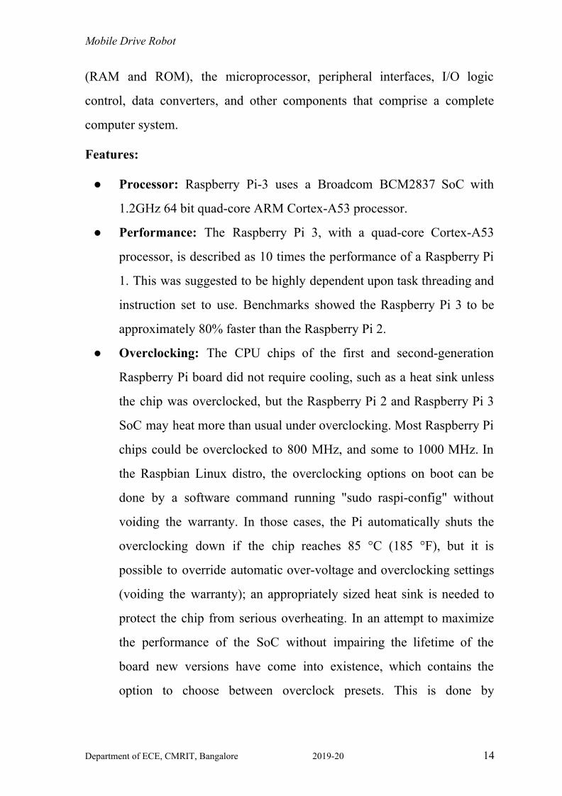
Fig 3.3 Component Description of Raspberry Pi
● RAM: Raspberry Pi 3 has 1GB of RAM which has higher than the
previous versions.
● GPU: The Graphical Processing Unit of Raspberry Pi 3 can operate at
250 MHz for video core 4, at 300 MHz for the 3D part, 400 MHz for a
video part.
Department of ECE, CMRIT, Bangalore 2019-20 15
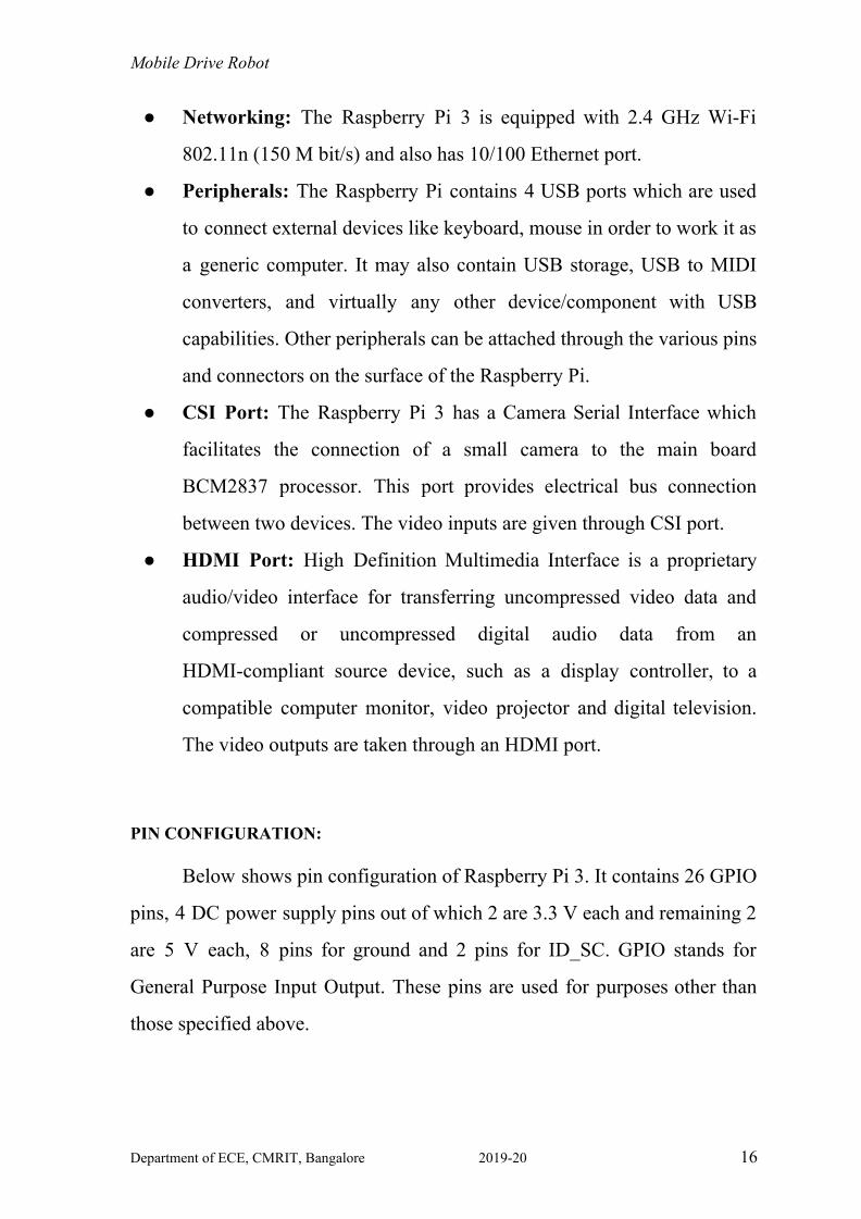
Mobile Drive Robot ● Networking: The Raspberry Pi 3 is equipped with 2.4 GHz Wi-Fi
802.11n (150 M bit/s) and also has 10/100 Ethernet port.
● Peripherals: The Raspberry Pi contains 4 USB ports which are used
to connect external devices like keyboard, mouse in order to work it as
a generic computer. It may also contain USB storage, USB to MIDI
converters, and virtually any other device/component with USB
capabilities. Other peripherals can be attached through the various pins
and connectors on the surface of the Raspberry Pi.
● CSI Port: The Raspberry Pi 3 has a Camera Serial Interface which
facilitates the connection of a small camera to the main board
BCM2837 processor. This port provides electrical bus connection
between two devices. The video inputs are given through CSI port.
● HDMI Port: High Definition Multimedia Interface is a proprietary
audio/video interface for transferring uncompressed video data and
compressed or uncompressed digital audio data from an
HDMI-compliant source device, such as a display controller, to a
compatible computer monitor, video projector and digital television.
The video outputs are taken through an HDMI port.
PIN CONFIGURATION:
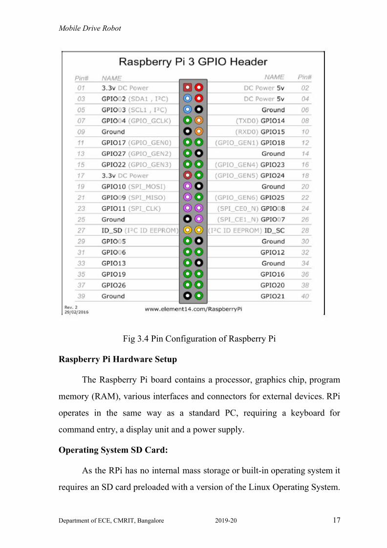
Below shows pin configuration of Raspberry Pi 3. It contains 26 GPIO
pins, 4 DC power supply pins out of which 2 are 3.3 V each and remaining 2
are 5 V each, 8 pins for ground and 2 pins for ID_SC. GPIO stands for
General Purpose Input Output. These pins are used for purposes other than
those specified above.
Department of ECE, CMRIT, Bangalore 2019-20 16
Mobile Drive Robot
Fig 3.4 Pin Configuration of Raspberry Pi
Raspberry Pi Hardware Setup
The Raspberry Pi board contains a processor, graphics chip, program
memory (RAM), various interfaces and connectors for external devices. RPi
operates in the same way as a standard PC, requiring a keyboard for
command entry, a display unit and a power supply.
Operating System SD Card:
As the RPi has no internal mass storage or built-in operating system it
requires an SD card preloaded with a version of the Linux Operating System.
Department of ECE, CMRIT, Bangalore 2019-20 17
Mobile Drive Robot One can create their own preloaded card using any suitable SD card
(4GBytes or above) one has in hand. It is suggested to use a new blank card
to avoid arguments over lost pictures.
Keyboard and Mouse:
Raspberry Pi 3 contains 4 USB ports, out of which two ports are
utilized to connect keyboard and mouse.
Display:
There are two main connection options for the RPi display, HDMI (High
Definition) and Composite (Standard Definition).
● HD TVs and many LCD monitors can be connected using a full-size
'male' HDMI cable.
● Older TVs can be connected using Composite video.
Power Supply:
The entire Raspberry Pi unit is powered via the MicroUSB connector. By
using a USB connector one can supply 700mA at +5V dc.
Internet and BlueTooth Connection:
The Raspberry Pi 3 contains onboard Wi-Fi and BlueTooth module and
10/100 Ethernet port. The internet connection is established through
Ethernet/LAN port or by Wi-Fi module.
Expansion and Low-Level Peripheral:
In order to make use of the low-level interfaces available on the RPi,
then have a suitable plug for the GPIO header pins.
Department of ECE, CMRIT, Bangalore 2019-20 18
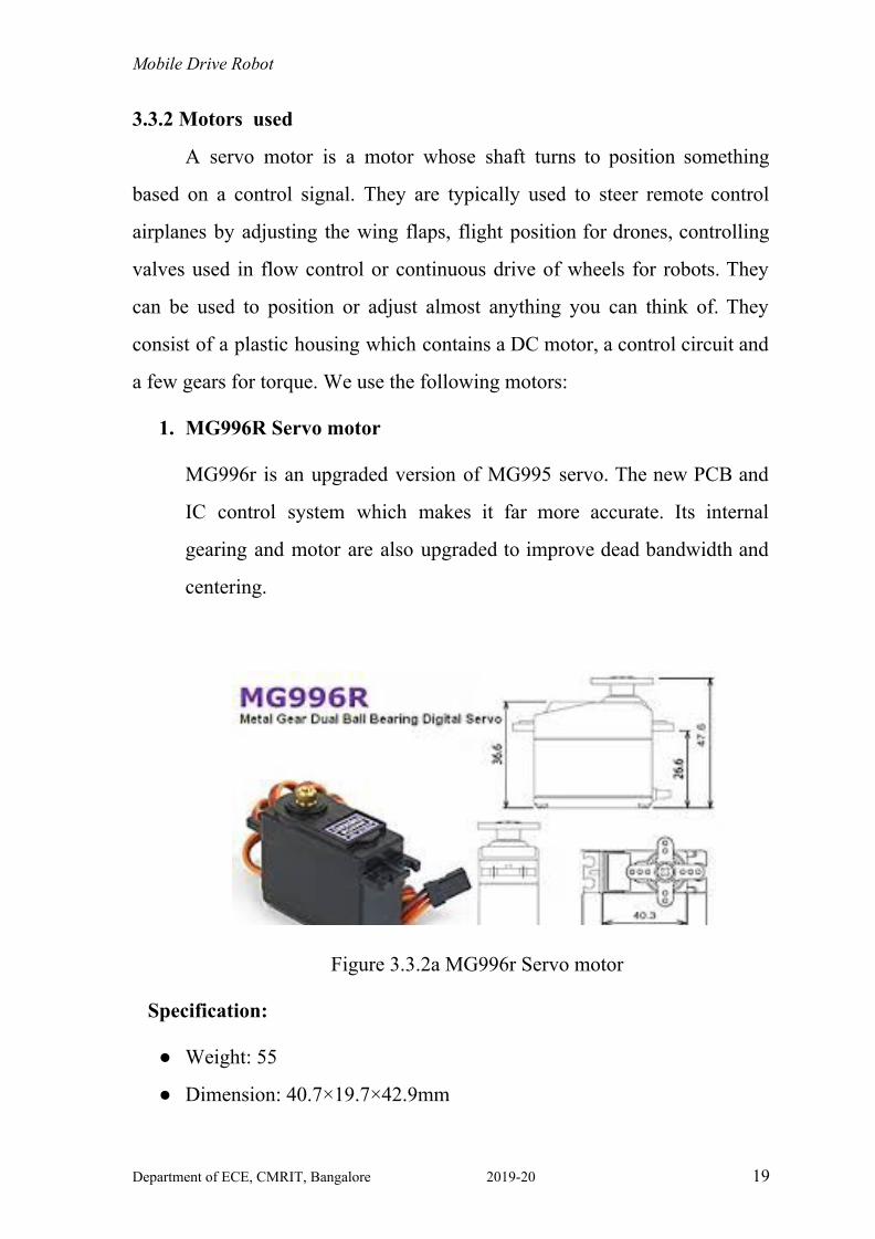
Mobile Drive Robot 3.3.2 Motors used
A servo motor is a motor whose shaft turns to position something
based on a control signal. They are typically used to steer remote control
airplanes by adjusting the wing flaps, flight position for drones, controlling
valves used in flow control or continuous drive of wheels for robots. They
can be used to position or adjust almost anything you can think of. They
consist of a plastic housing which contains a DC motor, a control circuit and
a few gears for torque. We use the following motors:
1. MG996R Servo motor
MG996r is an upgraded version of MG995 servo. The new PCB and
IC control system which makes it far more accurate. Its internal
gearing and motor are also upgraded to improve dead bandwidth and
centering.
Figure 3.3.2a MG996r Servo motor
Specification:
● Weight: 55
● Dimension: 40.7×19.7×42.9mm
Department of ECE, CMRIT, Bangalore 2019-20 19
Mobile Drive Robot ● Stall torque: 9.4kg/cm (4.8v); 11kg/cm (6.0v)
● OperatingSpeed:0.19sec/60degree(4.8v);0.15sec/60degree (6.0v)
● Operating voltage: 4.8~ 6.6v
● Gear Type: Metal gear
● Temperature range: 0- 55deg
● Servo Plug: JR (Fits JR and Futaba)
● Dead band width: 1us
● Servo wire length: 32cm
● Current draw at idle 10mA
● No load operating current draw 170mA
● Stall current draw 1400mA
● servo arms & screws included and fit with Futaba servo arm. It’s
universal “S” type connector that fits most receivers
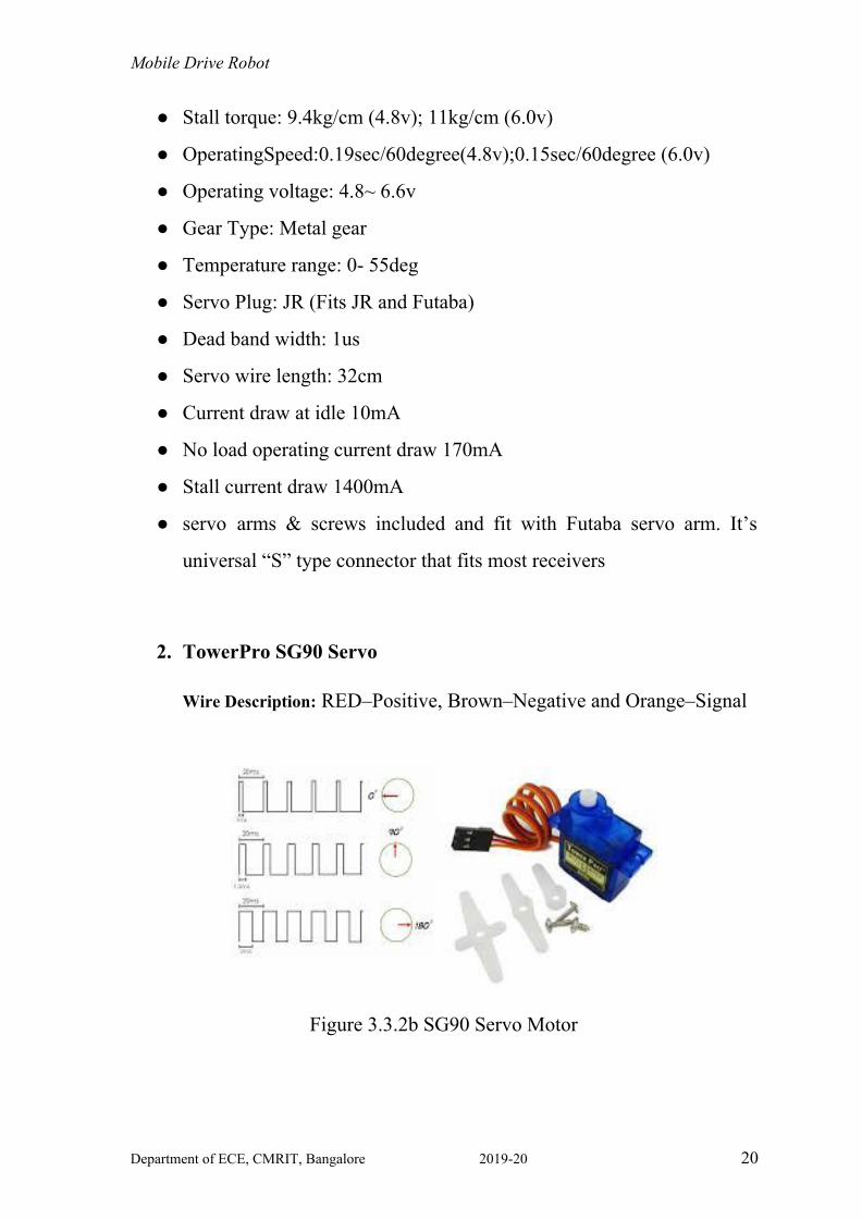
2. TowerPro SG90 Servo
Wire Description: RED–Positive, Brown–Negative and Orange–Signal
Figure 3.3.2b SG90 Servo Motor
Department of ECE, CMRIT, Bangalore 2019-20 20
Mobile Drive Robot
Specifications:
● Modulation: Analog
● Torque: 4.8V: 25.00 oz-in (1.80 kg-cm)
● Speed: 4.8V: 0.12 sec/60°
● Weight: 0.32 oz (9.0 g)
● Dimensions: Length:0.91 in (23.0 mm)
● Width: 0.48 in (12.2 mm)
● Height: 1.14 in (29.0 mm)
● Motor Type:3-pole
● Gear Type: Plastic
● Rotation/Support: Bushing
● Rotational Range: 180o
● Pulse Width: 500-2400 µs
● Connector Type: JR
Department of ECE, CMRIT, Bangalore 2019-20 21
Mobile Drive Robot
CHAPTER 4.0
SOFTWARE
The implementation phase of the project is where the detailed design
is actually transformed into working code. Aim of the phase is to translate
the design into the best possible solution in a suitable programming
language. This chapter covers the implementation aspects of the project,
giving details of the programming language and development environment
used. It also gives an overview of the core modules of the project with their
step by step flow.
The implementation stage requires the following tasks.
● Careful planning.
● Investigation of system and constraints.
● Design of methods to achieve the changeover.
● Evaluation of the changeover method.
● Correct decisions regarding the selection of the platform
● Appropriate selection of the language for application development
4.1 Software Used:
4.1.1 Autodesk Inventor:
Autodesk Inventor is one of the world's most used 3D mechanical
CAD design software for creating 3D digital prototypes used in the design,
visualization, and simulation of products for mechanical design. Autodesk
Inventor allows 2D and 3D data integration in a single environment, creating
Department of ECE, CMRIT, Bangalore 2019-20 22
Mobile Drive Robot a virtual representation of the final product that enables users to validate the
form, fit, and function of the product before it is ever built. Autodesk
Inventor includes powerful parametric, direct edit and freeform modelling
tools as well as multi-CAD translation capabilities and in their standard
DWG drawings. Inventor uses a shape manager.
4.1.2 OpenVSLAM:
OpenVSLAM is based on an indirect SLAM algorithm with sparse
features, such as ORB-SLAM, ProSLAM, and UcoSLAM. One of the
noteworthy features of OpenVSLAM is that the system can deal with various
types of camera models, such as perspective, fisheye, and equirectangular. If
needed, users can implement extra camera models (e.g. dual fisheye,
catadioptric) with ease. Visual SLAM systems are essential for AR devices,
autonomous control of robots and drones, etc. Simultaneous localization and
mapping (SLAM) systems have experienced a notable and rapid progression
through enthusiastic research and investigation conducted by researchers in
the fields of computer vision and robotics. OpenVSLAM can accept images
captured with perspective, fisheye and equirectangular cameras. Refer the
further sections-5.2.1 for algorithm and design flow.
The main contributions of OpenVSLAM are:
● It is compatible with various types of camera models and can be
customized for optional camera models.
● Created maps can be stored and loaded, then OpenVSLAM can
localize new images using prebuilt maps.
● A cross-platform viewer running on web browsers is provided for the
convenience of users.
Department of ECE, CMRIT, Bangalore 2019-20 23

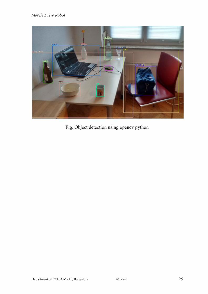
Mobile Drive Robot 4.1.3 OpenCV:
OpenCV (Open Source Computer Vision Library) is an open-source
computer vision and machine learning software library. OpenCV was built to
provide a common infrastructure for computer vision applications and to
accelerate the use of machine perception in commercial products. The
OpenCV project was initially an Intel Research initiative to advance
CPU-intensive applications, part of a series of projects including real-time
ray tracing and 3D display walls.
The library has more than 2500 optimized algorithms, which includes a
comprehensive set of both classic and state-of-the-art computer vision and
machine learning algorithms. These algorithms can be used to detect and
recognize faces, identify objects, classify human actions in videos, track
camera movements, track moving objects, extract 3D models of objects,
produce 3D point clouds from stereo cameras, stitch images together to
produce a high-resolution image of an entire scene, find similar images from
an image database, remove red eyes from images taken using flash, follow
eye movements, recognize scenery and establish markers to overlay it with
augmented reality, etc.
Department of ECE, CMRIT, Bangalore 2019-20 24
Mobile Drive Robot
Fig. Object detection using opencv python
Department of ECE, CMRIT, Bangalore 2019-20 25

Mobile Drive Robot
CHAPTER 5.0
DESIGN AND IMPLEMENTATION Our robot consists of a base with wheels and an arm attached on its top. The
design for each part is shown in the below sections. Figure 5.3 describes the
3D model of the robot designed using Autodesk Inventor.
Fig 5 3 Model Design of the Robot
5.1 Mechanical Structure
Fig 3D-view (Opaque) of Robot5.1.1 Design Process
Department of ECE, CMRIT, Bangalore 2019-20 26
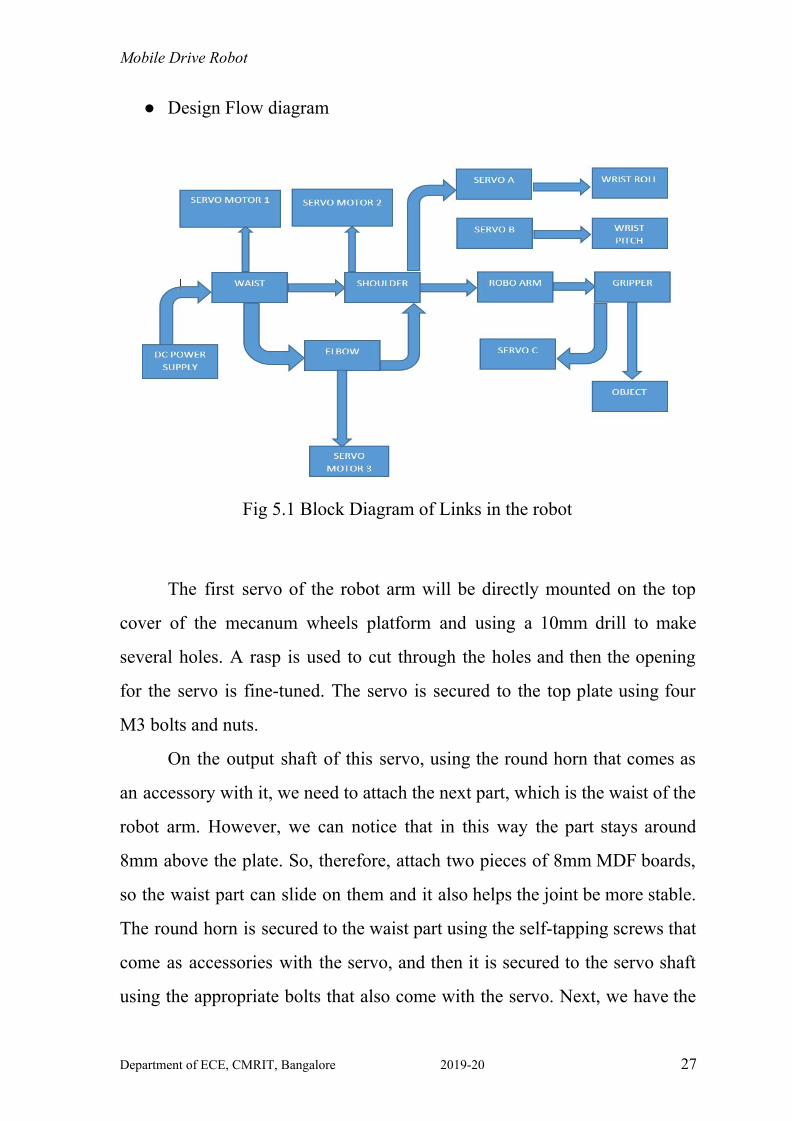
Mobile Drive Robot ● Design Flow diagram
Fig 5.1 Block Diagram of Links in the robot
The first servo of the robot arm will be directly mounted on the top
cover of the mecanum wheels platform and using a 10mm drill to make
several holes. A rasp is used to cut through the holes and then the opening
for the servo is fine-tuned. The servo is secured to the top plate using four
M3 bolts and nuts.
On the output shaft of this servo, using the round horn that comes as
an accessory with it, we need to attach the next part, which is the waist of the
robot arm. However, we can notice that in this way the part stays around
8mm above the plate. So, therefore, attach two pieces of 8mm MDF boards,
so the waist part can slide on them and it also helps the joint be more stable.
The round horn is secured to the waist part using the self-tapping screws that
come as accessories with the servo, and then it is secured to the servo shaft
using the appropriate bolts that also come with the servo. Next, we have the
Department of ECE, CMRIT, Bangalore 2019-20 27
Mobile Drive Robot shoulder servo. Simply put it in place and secure it to the 3D printed part
using self-tapping screws. The round horn goes on the shoulder, and then the
two parts are secured to each other using a bolt on the output shaft of the
servo. Before securing the parts, we need to make sure that they have a full
range of motion. Also, add a rubber band to the shoulder joint so that it gives
a little bit of help to the servo because this servo carries the weight of the rest
of the arm as well as the payload.
5.1.2 Robot Design
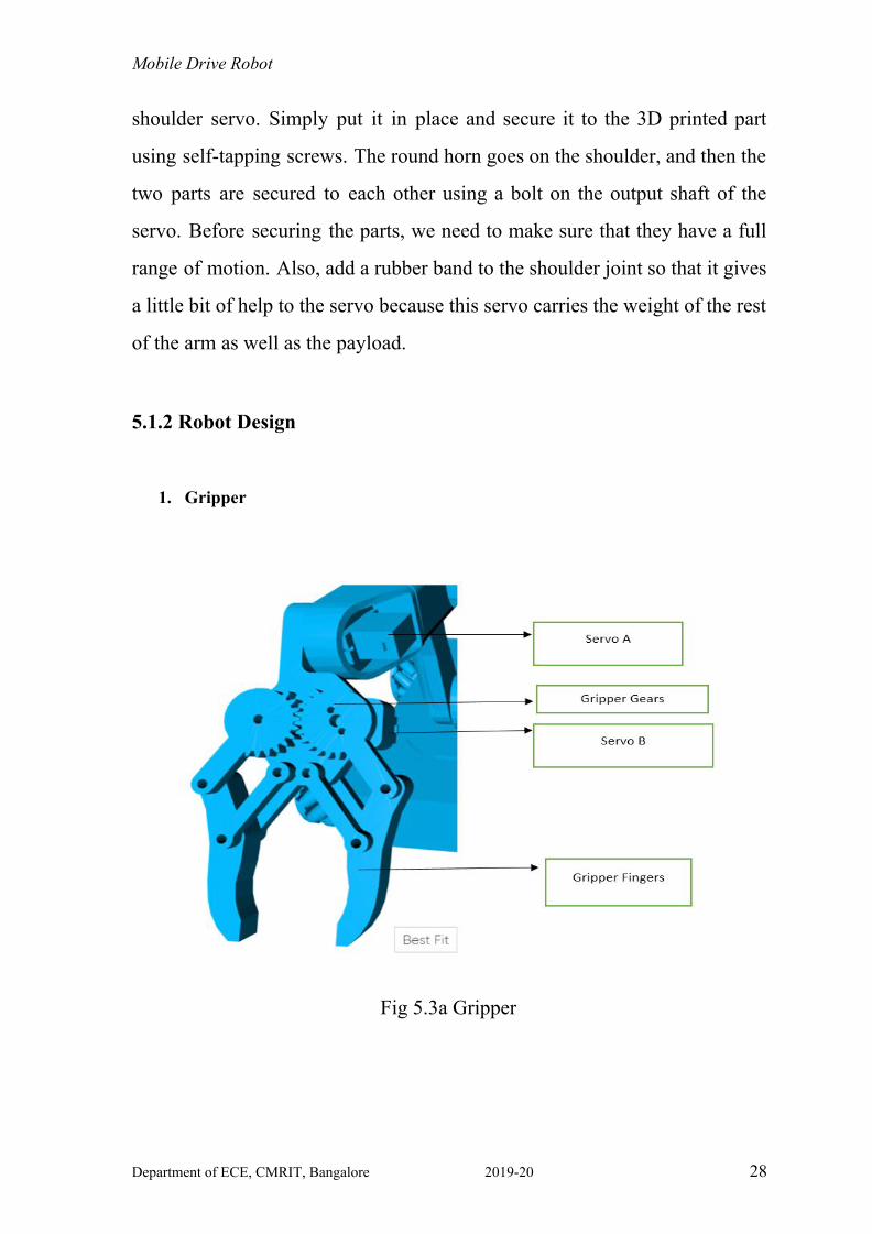
1. Gripper
Fig 5.3a Gripper
Department of ECE, CMRIT, Bangalore 2019-20 28

Mobile Drive Robot
2. Arm-1
Fig 5.3b Arm1
3. Arm-2
Fig 5.3c Design of Arm 2
Department of ECE, CMRIT, Bangalore 2019-20 29
Mobile Drive Robot
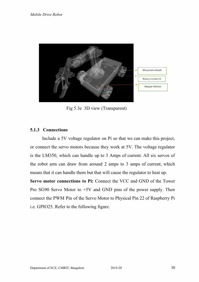
Fig 5.3e 3D view (Transparent)
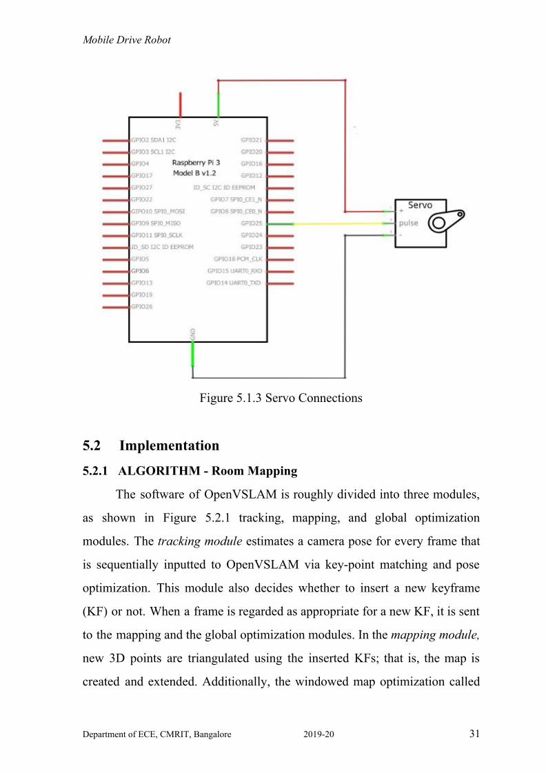
5.1.3 Connections
Include a 5V voltage regulator on Pi so that we can make this project,
or connect the servo motors because they work at 5V. The voltage regulator
is the LM350, which can handle up to 3 Amps of current. All six servos of
the robot arm can draw from around 2 amps to 3 amps of current, which
means that it can handle them but that will cause the regulator to heat up.
Servo motor connections to Pi: Connect the VCC and GND of the Tower
Pro SG90 Servo Motor to +5V and GND pins of the power supply. Then
connect the PWM Pin of the Servo Motor to Physical Pin 22 of Raspberry Pi
i.e. GPIO25. Refer to the following figure.
Department of ECE, CMRIT, Bangalore 2019-20 30
Mobile Drive Robot
Figure 5.1.3 Servo Connections
5.2 Implementation
5.2.1 ALGORITHM - Room Mapping
The software of OpenVSLAM is roughly divided into three modules,
as shown in Figure 5.2.1 tracking, mapping, and global optimization
modules. The tracking module estimates a camera pose for every frame that
is sequentially inputted to OpenVSLAM via key-point matching and pose
optimization. This module also decides whether to insert a new keyframe
(KF) or not. When a frame is regarded as appropriate for a new KF, it is sent
to the mapping and the global optimization modules. In the mapping module,
new 3D points are triangulated using the inserted KFs; that is, the map is
created and extended. Additionally, the windowed map optimization called
Department of ECE, CMRIT, Bangalore 2019-20 31
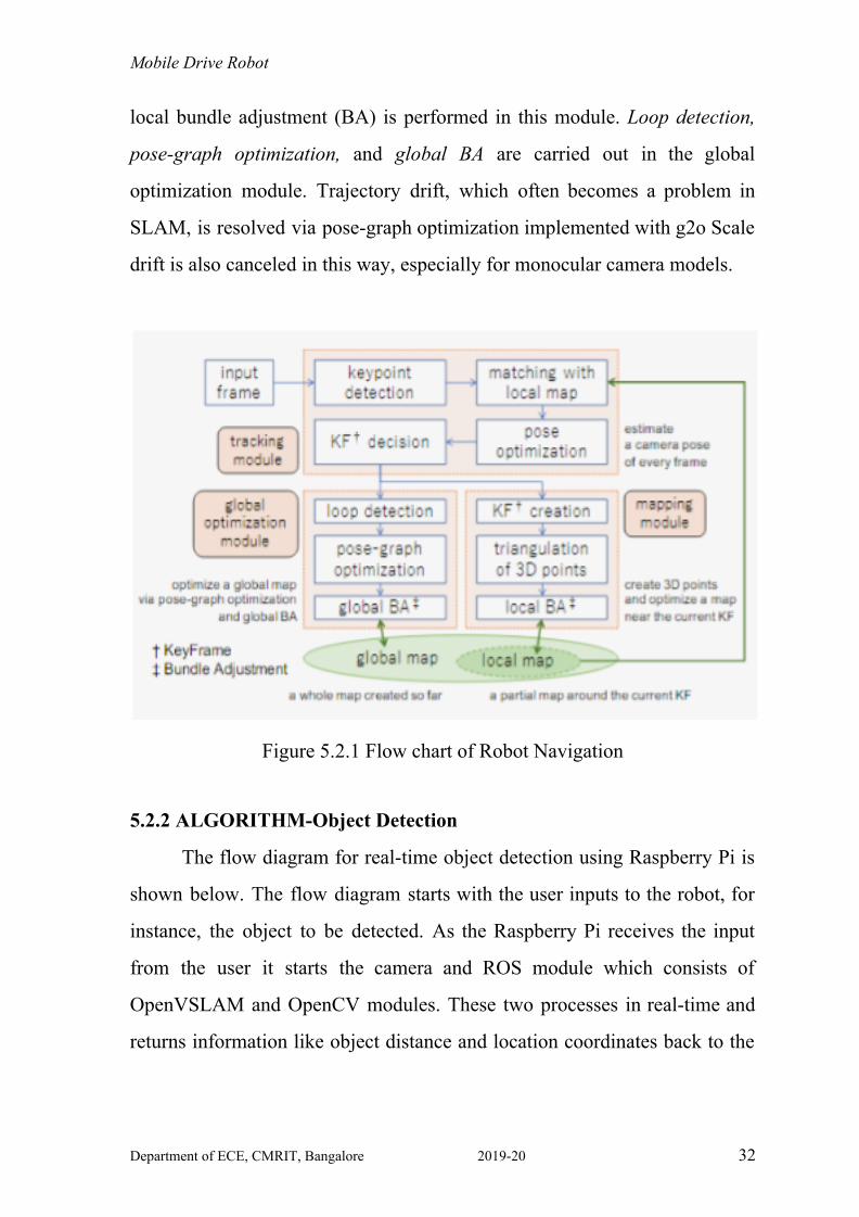
Mobile Drive Robot local bundle adjustment (BA) is performed in this module. Loop detection,
pose-graph optimization, and global BA are carried out in the global
optimization module. Trajectory drift, which often becomes a problem in
SLAM, is resolved via pose-graph optimization implemented with g2o Scale
drift is also canceled in this way, especially for monocular camera models.
Figure 5.2.1 Flow chart of Robot Navigation
5.2.2 ALGORITHM-Object Detection
The flow diagram for real-time object detection using Raspberry Pi is
shown below. The flow diagram starts with the user inputs to the robot, for
instance, the object to be detected. As the Raspberry Pi receives the input
from the user it starts the camera and ROS module which consists of
OpenVSLAM and OpenCV modules. These two processes in real-time and
returns information like object distance and location coordinates back to the
Department of ECE, CMRIT, Bangalore 2019-20 32

Mobile Drive Robot Pi. Further, The Pi sends commands to the motor for the designated
process-pick and place.
Figure 5.2.2 Flow chart of Object Detection
Department of ECE, CMRIT, Bangalore 2019-20 33
Mobile Drive Robot
CHAPTER 6.0
RESULTS
The robot is able to localize and develop a map for the environment
and travel from point A to B . It is also able to detect the desired object and
use its arm to pick it up and move it from one position to the other. The
movement of the robot’s arm and body should be coordinated according to
the readings given by both the cameras.
The robot is able to detect the landmarks in each frame that it captures
using the pi camera. It then is able to measure and make note of the
displacement in the area that it moves in, using this it plots a map of the area
that it moves in; this has been made possible by the OpenVSLAM
framework.
It is also able to collect information about the objects in the room and
detect the desired object based on the database provided. This object
detection is made possible by using OpenCV.
Once the object is recognized, the gripper opens up to the required
size and clamps the object between it, it then moves towards the desired
location and then carefully drops it.
Department of ECE, CMRIT, Bangalore 2019-20 34
Mobile Drive Robot
CHAPTER 7.0
APPLICATIONS AND ADVANTAGES
This project has multiple and varied applications, but at the moment
we are focusing on it coming of use to medical professionals, the elderly, and
the disabled.
● It can be used to pick up objects based on the need, for eg - bringing
water or medicines to someone sick.
● It can move files from one place to another in the workplace and can
also deliver parcels to the intended recipients.
● The robot can be used by nurses to send medicines to patients at a
specified time, thus reducing the load on the nurses.
● This can be used in quarantine zones to send materials, and later can
be cleaned by sanitizing it. This will reduce the risk of infection and
will keep people safe.
● Autonomous robots are helpful in busy environments, like a hospital.
Instead of employees leaving their posts, an autonomous robot can
deliver lab results and patient samples expeditiously. Without
traditional guidance, these robots can navigate the hospital hallways,
and can even find alternate routes when another is blocked. They will
stop at pick-up points, and collect samples to bring to the lab.
Department of ECE, CMRIT, Bangalore 2019-20 35
Mobile Drive Robot
CHAPTER 8.0
CONCLUSION AND SCOPE FOR FUTURE WORK
8.1 CONCLUSION
The main aim of this project is to make the lives of the disadvantaged
and the elderly easier. Using a combination of mechanical, electronics and
computer engineering we have come up with a robot that can be used in
multiple domains, but in this particular scenario is being made to assist the
medical industry, which by reducing the amount of human interaction can
reduce the spread of infection and ease the amount of burden on the medical
industry.
Department of ECE, CMRIT, Bangalore 2019-20 36
Mobile Drive Robot
8.2 FUTURE WORK
The AGV (Autonomous Guided Vehicle) has the potential to be used
in the medical industry to be used in nursing homes and in old age homes to
be used by nurses and patients to move objects like medicines or water
bottles etc. It can also be used to transport objects to people that are in
quarantine and reduce the chance of infection spreading. There are chances
that this robot can be used for military applications and even by our police
for remote bomb deactivation. This can also be used as a personal robot and
can be trained to do simple tasks such as getting the newspaper in the
morning or even giving medicines to the family members at a specific time
in the day.
There is scope for the AGV to be able to detect multiple objects and
map multiple areas. The gripper arm can be modified according to the usage
of the AGV and the size of the robot can be changed according to the load of
the object it has to carry. A voice recognition feature can also be attached to
the AGV, making it easy for individuals who find it difficult to operate
mobile devices or disabled people who do not have the capability to operate
the AGV manually.
Department of ECE, CMRIT, Bangalore 2019-20 37
Mobile Drive Robot
REFERENCES
1. Design and Implementation of Robot Arm Control Based on
MATLAB with Arduino Interface T.Rajesh, M. Karthik Reddy,
Afreen Begum, D.Venkatesh. International Journal of Engineering
Research in Electrical and Electronic Engineering (IJEREEE) Vol 4,
Issue 2, February 2018
2. Design of mobile robot with robotic arm utilizing microcontroller
and wireless communication - I.B.Alit Swamardika International
Journal of Engineering and Technology (Volume 9 Issue 2, April
2017)
3. Pick and Place Robot with Wireless Charging Application by N.
Firthous Begum, P. Vignesh International Journal of Science and
Research (IJSR) Volume 4 Issue 2, February 2015
4. P. Velrajkumar, S. Solai Manohar, C. Aravind, A. Darwin Jose Raju
and R. Arshad, "Development of real-time tracking and control
mobile robot using video capturing feature for unmanned
applications," 2010 INTERNATIONAL CONFERENCE ON
COMMUNICATION CONTROL AND COMPUTING
TECHNOLOGIES, Ramanathapuram, 2010, pp. 90-92
Department of ECE, CMRIT, Bangalore 2019-20 38