vintage-s800 - ftp directory listing
TRANSCRIPT

®
User Guide
Barebone System
Vintage-S800

2
Copyright © 2004 ASUSTeK COMPUTER INC. All Rights Reserved.No part of this manual, including the products and software described in it, may bereproduced, transmitted, transcribed, stored in a retrieval system, or translated into anylanguage in any form or by any means, except documentation kept by the purchaser forbackup purposes, without the express written permission of ASUSTeK COMPUTER INC.(“ASUS”).
Product warranty or service will not be extended if: (1) the product is repaired, modified oraltered, unless such repair, modification of alteration is authorized in writing by ASUS; or (2)the serial number of the product is defaced or missing.
ASUS PROVIDES THIS MANUAL “AS IS” WITHOUT WARRANTY OF ANY KIND, EITHEREXPRESS OR IMPLIED, INCLUDING BUT NOT LIMITED TO THE IMPLIED WARRANTIESOR CONDITIONS OF MERCHANTABILITY OR FITNESS FOR A PARTICULAR PURPOSE.IN NO EVENT SHALL ASUS, ITS DIRECTORS, OFFICERS, EMPLOYEES OR AGENTS BELIABLE FOR ANY INDIRECT, SPECIAL, INCIDENTAL, OR CONSEQUENTIAL DAMAGES(INCLUDING DAMAGES FOR LOSS OF PROFITS, LOSS OF BUSINESS, LOSS OF USEOR DATA, INTERRUPTION OF BUSINESS AND THE LIKE), EVEN IF ASUS HAS BEENADVISED OF THE POSSIBILITY OF SUCH DAMAGES ARISING FROM ANY DEFECT ORERROR IN THIS MANUAL OR PRODUCT.
SPECIFICATIONS AND INFORMATION CONTAINED IN THIS MANUAL ARE FURNISHEDFOR INFORMATIONAL USE ONLY, AND ARE SUBJECT TO CHANGE AT ANY TIMEWITHOUT NOTICE, AND SHOULD NOT BE CONSTRUED AS A COMMITMENT BY ASUS.ASUS ASSUMES NO RESPONSIBILITY OR LIABILITY FOR ANY ERRORS ORINACCURACIES THAT MAY APPEAR IN THIS MANUAL, INCLUDING THE PRODUCTSAND SOFTWARE DESCRIBED IN IT.
Products and corporate names appearing in this manual may or may not be registeredtrademarks or copyrights of their respective companies, and are used only for identification orexplanation and to the owners’ benefit, without intent to infringe.
E1661
First Edition V1June 2004

3
Table of contentsNotices ........................................................................................... 6
Safety information .......................................................................... 7
About this guide .............................................................................. 8
System package contents ............................................................ 10
Chapter 1:System Introduction1.1 Welcome! ............................................................................ 12
1.2 Front panel .......................................................................... 12
1.3 Rear panel ........................................................................... 14
1.4 Internal components ............................................................ 16
Chapter 2: Basic Installation2.1 Preparation .......................................................................... 18
2.2 Before you proceed ............................................................. 18
2.3 Removing the side plate and front cover ............................. 19
2.4 Central Processing Unit (CPU) ............................................ 212.4.1 Overview ............................................................... 212.4.2 Installing the CPU ................................................. 22
2.5 Installing the fan and heatsink assembly ............................. 23
2.6 Installing system memory .................................................... 262.6.1 Memory configurations .......................................... 262.6.2 DIMM installation ................................................... 27
2.7 Installing an expansion card ................................................ 282.7.1 Expansion slots ..................................................... 282.7.2 Expansion card installation ................................... 292.7.3 Configuring an expansion card ............................. 292.7.4 Standard interrupt assignments ............................ 302.7.5 IRQ assignments for this motherboard ................. 30
2.8 Installing a CD-ROM drive ................................................... 31
2.9 Installing a hard disk drive ................................................... 33
2.10 Re-connecting cables .......................................................... 35
2.11 Replacing the side plate and front cover ............................. 36
2.12 Connecting External Devices .............................................. 38

4
Table of contentsChapter 3: Starting up
3.1 Installing an operating system ............................................. 40
3.2 Support CD information ....................................................... 403.2.1 Running the support CD........................................ 403.2.2 Drivers menu ......................................................... 413.2.3 Utilities menu ......................................................... 413.2.4 ASUS contact information ..................................... 42
Chapter 4: Motherboard Info4.1 Introduction .......................................................................... 44
4.2 Motherboard layout ............................................................. 44
4.3 Jumpers ............................................................................... 45
4.4 Connectors .......................................................................... 48
Chapter 5: BIOS Information5.1 Managing and updating your BIOS ..................................... 58
5.1.1 Creating a bootable floppy disk ............................. 585.1.2 Using AFUDOS to copy the current BIOS ............. 595.1.3 Using AFUDOS to update the BIOS...................... 605.1.4 Using ASUS EZ Flash to update the BIOS ........... 61
5.2 BIOS Setup program ........................................................... 635.2.1 BIOS menu screen ................................................ 645.2.2 Menu bar ............................................................... 645.2.3 Navigation keys ..................................................... 645.2.4 Menu items ............................................................ 655.2.5 Sub-menu items .................................................... 655.2.6 Configuration fields ............................................... 655.2.7 Pop-up window...................................................... 655.2.8 Scroll bar ............................................................... 655.2.9 General help .......................................................... 65
5.3 Main menu ........................................................................... 665.3.1 System Time ......................................................... 665.3.2 System Date .......................................................... 665.3.3 Legacy Diskette A .................................................. 665.3.4 Primary/Secondary IDE Master/Slave ................... 675.3.5 System Information ............................................... 68

5
Table of contents5.4 Advanced menu .................................................................. 69
5.4.1 JumperFree Configuration .................................... 695.4.2 CPU Configuration ................................................ 705.4.3 Chipset .................................................................. 715.4.4 Onboard Devices Configuration ............................ 735.4.5 PCI PnP ................................................................ 745.4.6 USB Configuration ................................................ 75
5.5 Power menu ........................................................................ 765.5.1 ACPI AWARE O/S ................................................. 765.5.2 Suspend Mode ...................................................... 765.5.3 Repost Video on S3 Resume ................................ 765.5.4 ACPI APIC Support ............................................... 775.5.5 APM Configuration ................................................ 775.5.6 Hardware Monitor .................................................. 79
5.6 Boot menu ........................................................................... 805.6.1 Boot Device Priority ............................................... 805.6.2 Boot Settings Configuration .................................. 815.6.3 Security ................................................................. 82
5.7 Exit menu ............................................................................ 84

6
NoticesFederal Communications Commission StatementThis device complies with Part 15 of the FCC Rules. Operation is subjectto the following two conditions:
• This device may not cause harmful interference, and
• This device must accept any interference received includinginterference that may cause undesired operation.
This equipment has been tested and found to comply with the limits for aClass B digital device, pursuant to Part 15 of the FCC Rules. These limitsare designed to provide reasonable protection against harmful interferencein a residential installation. This equipment generates, uses and canradiate radio frequency energy and, if not installed and used inaccordance with manufacturer’s instructions, may cause harmfulinterference to radio communications. However, there is no guarantee thatinterference will not occur in a particular installation. If this equipment doescause harmful interference to radio or television reception, which can bedetermined by turning the equipment off and on, the user is encouraged totry to correct the interference by one or more of the following measures:
• Reorient or relocate the receiving antenna.
• Increase the separation between the equipment and receiver.
• Connect the equipment to an outlet on a circuit different from that towhich the receiver is connected.
• Consult the dealer or an experienced radio/TV technician for help.
Canadian Department of Communications StatementThis digital apparatus does not exceed the Class B limits for radio noiseemissions from digital apparatus set out in the Radio InterferenceRegulations of the Canadian Department of Communications.
This class B digital apparatus complies with Canadian ICES-003.
WARNING! The use of shielded cables for connection of the monitor tothe graphics card is required to assure compliance with FCC regulations.Changes or modifications to this unit not expressly approved by the partyresponsible for compliance could void the user’s authority to operate thisequipment.

7
Safety information
Electrical safety• To prevent electrical shock hazard, disconnect the power cable from
the electrical outlet before relocating the system.
• When adding or removing devices to or from the system, ensure thatthe power cables for the devices are unplugged before the signalcables are connected.
• If the power supply is broken, do not try to fix it by yourself. Contact aqualified service technician or your retailer.
Operation safety• Before installing devices into the system, carefully read all the
documentation that came with the package.
• Before using the product, make sure all cables are correctlyconnected and the power cables are not damaged. If you detect anydamage, contact your dealer immediately.
• To avoid short circuits, keep paper clips, screws, and staples awayfrom connectors, slots, sockets and circuitry.
• Avoid dust, humidity, and temperature extremes. Do not place theproduct in any area where it may become wet. Place the product on astable surface.
• If you encounter technical problems with the product, contact aqualified service technician or your retailer.
Lithium-Ion Battery WarningCAUTION: Danger of explosion if battery is incorrectly replaced.Replace only with the same or equivalent type recommended bythe manufacturer. Dispose of used batteries according to themanufacturerís instructions.
VORSICHT: Explosionsgetahr bei unsachgemäßen Austausch derBatterie. Ersatz nur durch denselben oder einem vom Herstellerempfohlenem ähnljchen Typ. Entsorgung gebrauchter Batteriennach Angaben des Herstellers.
LASER PRODUCT WARNING
CLASS 1 LASER PRODUCT

8
About this guide
AudienceThis guide provides general information and installation instructions aboutthe ASUS Terminator 1 barebone system. This guide is intended forexperienced users and integrators with hardware knowledge of personalcomputers.
How this guide is organizedThis guide contains the following parts:
1. Chapter 1: System introduction
This chapter gives a general description of the ASUS Terminator 1.The chapter lists the system features including introduction on thefront and rear panel, and internal components.
2. Chapter 2: Basic installation
This chapter provides step-by-step instructions on how to installcomponents in the system.
3. Chapter 3: Starting up
This chapter helps you power up the system and install drivers andutilities from the support CD.
4. Chapter 4: Motherboard information
This chapter gives information about the motherboard that comeswith the system. This chapter includes the motherboard layout,jumper settings, and connector locations.
5. Chapter 5: BIOS setup
This chapter tells how to change system settings through the BIOSSetup menus and describes the BIOS parameters.

9
Conventions used in this guide
WARNING: Information to prevent injury to yourself when trying tocomplete a task.
CAUTION: Information to prevent damage to the componentswhen trying to complete a task.
IMPORTANT: Instructions that you MUST follow to complete a task.
NOTE: Tips and additional information to aid in completing a task.
Where to find more informationRefer to the following sources for additional information and for productand software updates.
1. ASUS Websites
The ASUS websites worldwide provide updated information on ASUShardware and software products. Refer to the ASUS contactinformation.
2. Optional Documentation
Your product package may include optional documentation, such aswarranty flyers, that may have been added by your dealer. Thesedocuments are not part of the standard package.

10
* CD-ROM/CD-RW/DVD-ROM/DVD-RW
If any of the items is damaged or missing, contact your retailerimmediately.
Check your ASUS Vintage-S800 package for the following items:
1. ASUS Vintage-S800 barebone system with:
• ASUS P4S800-MX motherboard• Floppy disk drive• Optical drive (optional)*
2. Power cable and plug
3. Support CD
4. User guide
System package contents

11ASUS Vintage S-800 barebone system
This chapter gives a general description ofthe ASUS Vintage-S800 barebone system.It includes introduction on the front and rearpanel features, and the internal features.
Sys
tem
Intr
od
uct
ion
Chapter 1

12 Chapter 1: System introduction
1.2 Front panelThe ASUS Vintage-S800 barebone system is composed of the ASUSP4S800-MX motherboard, a power supply, and a floppy disk drive.
The CD-ROM drive and modem card are optional items.
1.1 Welcome!Thank you for choosing the ASUS Vintage-S800!
The ASUS Vintage-S800 is an all-in-one barebone system with a versatilehome entertainment feature.
The system comes in a stylish mini-tower casing, and is powered by theASUS P4S800-MX motherboard that supports Intel® Pentium® 4processors in the 478-pin package.
1. Two empty 5.25-inch bays. These bays are for optional IDE opticaldrives.
2. Hard disk drive bay. This door covers a hard disk drive.
1
3
2
4
5
External Internal
6 7 8 6 7 8

ASUS Vintage-S800 barebone system 13
3. Floppy drive door. This drive is for 1.44MB, 3.5-inch floppy disk.
4. HDD LED. This LED lights up when data is being read from or writtento the hard disk drive
5. Power button. Press this button to turn the system on.
6. Headphone port. This port connects a headphone with a stereomini-plug.
7. Microphone port. This Mic (pink) port connects a microphone.
Audio ports function variation
Port Headphone/2-Channel 4-Channel 6-Channel
Light Blue Line In No function LFE Output*/Center
Lime Line Out Front Speaker Out Front Speaker Out
Pink Mic In Surround Surround
* Low Frequency Enhanced Output
8. USB 2.0 ports. These Universal Serial Bus 2.0 (USB 2.0) ports areavailable for connecting USB 2.0 devices such as a mouse, printer,scanner, camera, PDA, and others.

14 Chapter 1: System introduction
1.3 Rear panelThe system rear panel includes the power socket and several I/O portsthat allow convenient connection of devices.
1
2
3
4
5
6
7
8
9
1. PS/2 keyboard port. This purple 6-pin connector is for a PS/2keyboard.
2. PS/2 mouse port. This green 6-pin connector is for a PS/2 mouse.
3. Serial port. This port connects a mouse, modem, or other devicesthat conform with serial specification.
4. Parallel port. This 25-pin port connects a printer, scanner, or otherdevices.
5. VGA port. This port connects a VGA monitor.
6. USB 2.0 ports. These Universal Serial Bus 2.0 (USB 2.0) ports areavailable for connecting USB 2.0 devices such as a mouse, printer,scanner, camera, PDA, and others.
10
11
115V/230VVoltage selector
12
14
13
15
16
ASUS Vintage-S800 barebone system 15
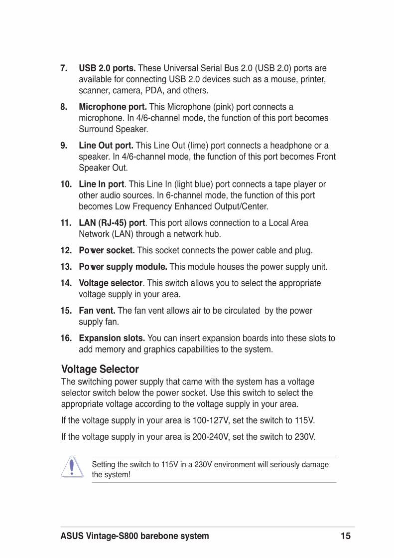
7. USB 2.0 ports. These Universal Serial Bus 2.0 (USB 2.0) ports areavailable for connecting USB 2.0 devices such as a mouse, printer,scanner, camera, PDA, and others.
8. Microphone port. This Microphone (pink) port connects amicrophone. In 4/6-channel mode, the function of this port becomesSurround Speaker.
9. Line Out port. This Line Out (lime) port connects a headphone or aspeaker. In 4/6-channel mode, the function of this port becomes FrontSpeaker Out.
10. Line In port. This Line In (light blue) port connects a tape player orother audio sources. In 6-channel mode, the function of this portbecomes Low Frequency Enhanced Output/Center.
11. LAN (RJ-45) port. This port allows connection to a Local AreaNetwork (LAN) through a network hub.
12. Power socket. This socket connects the power cable and plug.
13. Power supply module. This module houses the power supply unit.
14. Voltage selector. This switch allows you to select the appropriatevoltage supply in your area.
15. Fan vent. The fan vent allows air to be circulated by the powersupply fan.
16. Expansion slots. You can insert expansion boards into these slots toadd memory and graphics capabilities to the system.
Setting the switch to 115V in a 230V environment will seriously damagethe system!
Voltage SelectorThe switching power supply that came with the system has a voltageselector switch below the power socket. Use this switch to select theappropriate voltage according to the voltage supply in your area.
If the voltage supply in your area is 100-127V, set the switch to 115V.
If the voltage supply in your area is 200-240V, set the switch to 230V.

16 Chapter 1: System introduction
1.4 Internal componentsThe figure below shows the internal view of the system when you removethe cover and flip out the drive frame. The standard components alreadyinstalled in the system and the locations of the available drive bays arepointed out.
The system may come with either a PFC (Power Factor Correction) ornon-PFC power supply.
4. 3.5” HDD drive bay
5. 3.5” floppy drive
1. PFC/Non-PFC power supply
2. Motherboard
3. Two 5.25” drive bays(Optional CD-ROM)
1
2
3
4
5

17ASUS Vintage-S800 barebone system
This chapter gives step-by-step instructionson how to install components into thebarebone system.
Bas
ic In
stal
lati
on
Chapter 2

18 Chapter 2: Basic Installation
2.1 PreparationBefore you proceed, make sure that you have all the components that youplan to install in the system.
Basic components to install1. Central processing unit (CPU)
2. DDR Dual Inline Memory Module (DIMM)
3. Expansion card(s)
4. Hard disk drive
5. Second optical drive
ToolPhillips (cross) screw driver
2.2 Before you proceedTake note of the following precautions before you install components intothe system.
The motherboard comes with an onboard standby power LED. This LEDlights up to indicate that the system is ON, in sleep mode or in soft-offmode, and not powered OFF. Unplug the power cable from the poweroutlet and make sure that the standby power LED is OFF before installingany system component.
• Use a grounded wrist strap or touch a safely grounded object ora metal object, such as the power supply case, before handlingcomponents to avoid damaging them due to static electricity.
• Hold components by the edges to avoid touching the ICs on them.
• Whenever you uninstall any component, place it on a groundedantistatic pad or in the bag that came with the component.

ASUS Vintage-S800 barebone system 19
2.3 Removing the side plate and front coverThe system has two chassis side plates, each one secured by two screwslocated on the rear panel.
To remove the chassis side plate:
1. Turn each screwcounterclockwise to releasethe side cover. Set the screwsaside.
2. Slide the side panel for abouthalf an inch toward the rearuntil it disengages from thechassis.
Remove only the left sideplate.
3. Release the side lock tabsfrom the steel railing.
Screw
Side lock tab
Steel railing

20 Chapter 2: Basic Installation
4. Swing the left edge of the frontpanel outward.
5. Unhook the hinge-like tabsfrom the holes on the right sideof the front panel to completelydetach the front panelassembly from the chassis.
Hinge-like tab

ASUS Vintage-S800 barebone system 21
2.4 Central Processing Unit (CPU)2.4.1 OverviewThe Intel® Pentium® 4 processor in the 478-pin package has a goldtriangular mark on one corner. This mark indicates the processor Pin 1 thatshould match a specific corner of the CPU socket.
Incorrect installation of the CPU into the socket may bend the pins andseverely damage the CPU!
Notes on Intel® Hyper-Threading Technology
• Hyper-Threading Technology is supported under Windows® XP andLinux 2.4.x (kernel) and later versions only. Under Linux, use theHyper-Threading compliler to compile the code. If you are using anyother operating systems, disable the Hyper-Threading Techonologyitem in BIOS to ensure system stability and performance.
• Installing Windows® XP Service Pack 1 is recommended.
• Make sure to enable the Hyper-Threading Technology item in theBIOS before installing a supported operating system.
• For more information on Hyper-Threading Technology, visitwww.intel.com/info/hyperthreading.
P4S
800-M
X
P4S800-MX Socket 478
Gold Arrow

22 Chapter 2: Basic Installation
2.4.2 Installing the CPUFollow these steps to install a CPU.
1. Locate the 478-pin ZIF socketon the motherboard.
2. Unlock the socket by pressingthe lever sideways, then lift it upto a 90°-100° angle.
Make sure that the socket leveris lifted up to a 90°-100° angle,otherwise the CPU does not fitin completely.
3. Position the CPU above thesocket such that its markedcorner matches the base of thesocket lever.
4. Carefully insert the CPU into thesocket until it fits in place.
The CPU fits only in one correctorientation. DO NOT force theCPU into the socket to preventbending the pins and damagingthe CPU!
5. When the CPU is in place, pushdown the socket lever to securethe CPU. The lever clicks on theside tab to indicate that it islocked.
Socket lever
90 - 100
Gold mark

ASUS Vintage-S800 barebone system 23
2.5 Installing the fan and heatsink assemblyThe Intel® Pentium® 4 Processor requires a specially designed heatsinkand fan assembly to ensure optimum thermal condition and performance.
Retention module base
CPU heatsink
Follow these steps to install the CPU heatsink and fan.
1. Place the heatsink on top of the installed CPU, making sure that theheatsink fits properly on the retention module base.
Your boxed Intel® Pentium® 4 processor package should come withinstallation instructions for the CPU, heatsink, and the retentionmechanism. If the instructions in this section do not match the CPUdocumentation, follow the latter.
• When you buy a boxed Intel® Pentium® 4 processor, the packageincludes the heatsink, fan, and retention mechanism.
• If you buy a CPU separately, make sure that you use onlyIntel®-certified heatsink and fan.
• The retention module base is already installed on the motherboardupon purchase.
• You do not have to remove the retention module base when installingthe CPU or installing other motherboard components.

24 Chapter 2: Basic Installation
2. Position the fan with the retention mechanism on top of the heatsink.Align and snap the four hooks of the retention mechanism to theholes on each corner of the module base.
Retention hole
Retention hook snapped tothe retention hole
Retention lock
Keep the retention locks lifted upward while fitting the retentionmechanism to the module base.
Make sure that the fan and retention mechanism assembly perfectly fitsthe heatsink and module base; otherwise, you cannot snap the hooksinto the holes.

ASUS Vintage-S800 barebone system 25
Connecting the CPU fan cableWhen the fan, heatsink, and the retention mechanism are in place,connect the CPU fan cable to the connector on the motherboard labeledCPU_FAN1.
3. Push down the locks on the retention mechanism to secure theheatsink and fan to the module base.
When secure, the retention locks should point to opposite directions.
Do not forget to connect the CPU fan connector! Hardware monitoringerrors can occur if you fail to plug this connector.
CPU Fan Connector (CPU_FAN1)

26 Chapter 2: Basic Installation
2.6.1 Memory configurationsYou may install any DDR DIMMs with 64 MB, 128 MB, 256 MB, 512 MB,and 1 GB densities into the DIMM sockets.
Memory frequency/CPU FSB synchronization
CPU FSB DDR DIMM Type Memory Frequency
800MHz PC3200/PC2700/PC2100 400/333*/266 MHz
533MHz PC2700/PC2100 333/266 MHz
400MHz PC2100 266 MHz
2.6 Installing system memoryThe motherboard comes with two Double Data Rate (DDR) Dual InlineMemory Module (DIMM) sockets. These sockets support up to 2 GBsystem memory using unbuffered ECC or non-ECC PC2700/1600/2100DIMMs.
*When using 800 MHz CPU FSB, PC2700 DDR DIMMs may run only at320 MHz (not 333 MHz) due to chipset limitation.
P4S
800-M
X
P4S800-MX 184-Pin DDR DIMM Sockets
80 P
ins
104
Pin
s
DIM
M1
DIM
M2

ASUS Vintage-S800 barebone system 27
Follow these steps to install a DDRDIMM.
1. Locate the two DIMM socketson the motherboard.
2. Unlock a socket by pressingthe retaining clips outward.
3. Align a DIMM on the socketsuch that the notch on theDIMM matches the break onthe socket.
4. Firmly insert the DIMM into thesocket until the retaining clipssnap back in place and theDIMM is properly seated.
A DDR DIMM is keyed with a notch so that it fits in only one direction. DONOT force a DIMM into a socket to avoid damaging the DIMM.
Socket break
DIMM notch
DDR DIMM sockets
2.6.2 DIMM installation

28 Chapter 2: Basic Installation
2.7 Installing an expansion cardIn the future, you may need to install expansion cards. The motherboardhas one 32-bit PCI slot and one Accelerated Graphic Port (AGP) slot. Thefollowing sub-sections describe the slots and the expansion cards thatthey support.
Install only +1.5V AGP cards. The motherboard does not support 3.3VAGP cards.
Make sure to unplug the power cord before adding or removingexpansion cards. Failure to do so may cause you physical injury anddamage the motherboard.
2.7.1 Expansion slotsPCI slotThe PCI slot supports PCI slots such as a LAN card, SCSI card, USBcard, and other cards that comply with PCI specifications
AGP slotThe AGP slot supports AGP 4x cards. When you buy an AGP card, makesure that you ask for one with 1.5V specification.

ASUS Vintage-S800 barebone system 29
Follow these steps to install a PCIor AGP card.
1. Place the chassis on its side.
2. Remove the metal bracketopposite the slot that you wishto use.
3. Align the card golden fingersto the slot and its metalbracket to the slot opening onthe chassis.
4. Press the card firmly until it isproperly seated on the slot.
5. Secure the card to the chassiswith a bracket screw.
If your system came with the optional modem card, the PCI slot isalready occupied.
PCI slots (PCI1)Metal bracket
AGP slot (AGP1)
2.7.2 Expansion card installation
2.7.3 Configuring an expansion cardAfter installing the expansion card, configure it by adjusting the softwaresettings.
1. Turn on the system and change the necessary BIOS settings, if any.See Chapter 5 for information on BIOS setup.
2. Assign an IRQ to the card. Refer to the tables below.
3. Install the software drivers for the expansion card.

30 Chapter 2: Basic Installation
IRQ Priority Standard Function
0 1 System Timer 1 2 Keyboard Controller 2 N/A Programmable Interrupt 3* 11 Communications Port (COM2) 4* 12 Communications Port (COM1) 5* 13 IRQ holder for PCI steering 6 14 Floppy Disk Controller 7* 15 Printer Port (LPT1) 8 3 System CMOS/Real Time Clock 9* 4 IRQ holder for PCI steering10* 5 Advance AC’97 CODEC11* 6 Standard PCI Graphics Adapter (VGA)12* 7 PS/2 Compatible Mouse Port13 8 Numeric Data Processor14* 9 Primary IDE Channel15* 10 Secondary IDE Channel
2.7.4 Standard interrupt assignments
When using PCI cards on shared slots, ensure that the drivers support“Share IRQ” or that the cards do not need IRQ assignments; otherwise,conflicts will arise between the two PCI groups, making the systemunstable and the card inoperable.
2.7.5 IRQ assignments for this motherboard
A B C D E F G H
PCI slot 1 shared –– –– –– –– –– –– ––PCI slot 2 –– used –– –– –– –– –– ––PCI slot 3 –– –– shared –– –– –– –– ––AGP slot shared –– –– –– –– –– –– ––Onboard USB controller 1 –– –– –– –– used –– –– ––Onboard USB controller 2 –– –– –– –– –– used –– ––Onboard USB 2.0 controller –– –– –– –– –– –– –– usedOnboard LAN –– –– –– used –– –– –– ––Onboard audio –– –– shared –– –– –– –– ––
* These IRQs are usually available for ISA or PCI devices.

ASUS Vintage-S800 barebone system 31
2.8 Installing a CD-ROM driveA CD-ROM drive is an optional item in this barebone system. Refer to theinstructions in this section if you acquired a model without a CD-ROM.
Follow these steps to install aCD-ROM drive.
1. Place the chassis upright.
2. Insert the CD-ROM drive intothe upper 5.25-inch drive bay.
CD-ROM screw holes
3. Carefully push the CD-ROMdrive into the bay until itsscrew holes align with theholes on the bay as shown.
4. Secure the CD-ROM with twoscrews.
CD-ROM screws

32 Chapter 2: Basic Installation
5. Connect a power cable fromthe power supply to the powerconnector at the back of theCD-ROM. Use the cable withthe white connector labeledP1.
6. Connect one end of the IDEribbon cable to the IDEinterface at the back of theCD-ROM, matching the redstripe on the cable with Pin 1on the IDE interface.
7. Connect one end of theCD-ROM audio cable to the4-pin connector at the back ofthe CD-ROM.
8. Connect the other end of theIDE ribbon cable to thesecondary IDE connector(black connector labeledSEC_IDE1) on themotherboard.
Red stripe to pin 1
IDE ribbon cable
Power cable (P1)
CD-ROM audio cable
9. Connect the other end of theaudio cable to the black 4-pinconnector labeled CD1 on themotherboard.
CD-ROM Connector(CD1)
Secondary IDE connector(SEC_IDE1)

ASUS Vintage-S800 barebone system 33
2.9 Installing a hard disk drive
The chassis has one 3.5-inch hard disk drive (HDD) bay right under the5.25-inch bay. The following figures show the internal and external viewsof the HDD bay location.
5.25-inch Drive bay
3.5-inch HDD drive bay
Internal view External view
Follow these steps to install an IDEHDD.
1. Place the chassis upright.
2. With the HDD label side up,carefully insert the drive intothe 3.5-inch bay.
HDD label side
3. Push the drive into the bayuntil its screw holes align withthe holes on the bay markedHDD.
4. Secure the drive with twoscrews.
HDD screw holes

34 Chapter 2: Basic Installation
5. Connect a power cable fromthe power supply to the powerconnector at the back of theHDD. Use the cable with thewhite connector labeled P3.
6. Connect one end of the IDEhard disk ribbon cable to theIDE interface at the back ofthe HDD, matching the redstripe on the cable with Pin 1on the IDE interface. Red stripe to Pin 1
IDE ribbon cable Power cable (P3)
7. Connect the other end of theIDE ribbon cable to theprimary IDE connector (blueconnector labeled PRI_IDE1)on the motherboard.
Primary IDE connector(PRI_IDE1)

ASUS Vintage-S800 barebone system 35
2.10 Re-connecting cablesYou may have disconnected some cables when you were installingcomponents. You must re-connect these cables before you replace thechassis cover.
LED cables
Connect the power switch and power LED cables to their respectiveleads in the PANEL1 connector on the motherboard.
Connect the HDD LED cable to the 2-pin lead marked IDE_LED1.
Power switch
Power LED
HDD LED
PANEL1
F_PANEL1
PLE
D-
PW
R
PLE
D+
Gro
und
GN
DR
eset
IDE
_LE
D+
IDE
_LE
D-
PLED
RESET
PWRBTN*
HDLED
* Requires an ATX power supply.

36 Chapter 2: Basic Installation
2.11 Replacing the side plate and front coverAfter you have installed all the internal components and you haveconnected all the necessary cables, you are now ready to put the systemback together.
1. Hook the hinge-like tabs to theholes on the right side of thefront panel to attach the frontpanel assembly to the chassis.
2. Swing the front panel inward.
Hinge-like tab
3. Snap the side lock tabs to thesteel railing.
Side lock tab
Steel railing

ASUS Vintage-S800 barebone system 37
4. Fit the rail tabs on the sideplate into the locking tab holesin the chassis.
5. Firmly push the side plate fromthe rear until it fits the chassiscompletely.
The locking tabs snap into thehole on the chassis to indicatethat the side plate is in place.
Screw6. Lock the side plate with thescrews on the rear panel.
Lockingtab hole
Railtabs

38 Chapter 2: Basic Installation
2.12 Connecting External DevicesThe figure below shows the specific connectors and devices that you canconnect to the rear panel ports.
Serial
PS/2 KB
VGA
Line Out
Line In
Mic
PS/2 Mouse
AC
Parallel
USB
RJ-45

39ASUS Vintage-S800 barebone system
This chapter helps you power up yoursystem and install drivers and utilities thatcame with the support CD.
Sta
rtin
g u
p
Chapter 3

40 Chapter3: Starting up
3.1 Installing an operating systemThis motherboard supports Windows® 98SE/ME/2000/XP operatingsystem (OS). Always install the latest OS version and correspondingupdates so you can maximize the features of your hardware.
Because motherboard settings and hardware options vary, use the setupprocedures presented in this chapter for general reference only. Refer toyour OS documentation for more information.
3.2 Support CD informationThe support CD that came with the motherboard contains useful softwareand several utility drivers that enhance the motherboard features.
3.2.1 Running the support CDTo begin using the support CD, simply insert the CD into your CD-ROMdrive. The CD automatically displays the Drivers menu if Autorun isenabled in your computer. Click on an item to install.
The contents of the support CD are subject to change at any time withoutnotice. Visit the ASUS website for updates.
If Autorun is NOT enabled in your computer, browse the contents of thesupport CD to locate the file ASSETUP.EXE from the BIN folder. Double-click the ASSETUP.EXE to run the CD.

ASUS Vintage-S800 barebone system 41
3.2.2 Drivers menuThe drivers menu shows the available device drivers if the system detectsinstalled devices. Install the necessary drivers to activate the devices.
SiS AGP DriverThe item installs the SiS AGP Driver.
SiS Compatible VGA display driverThis item installs SiS VGA display driver.
SoundMAX Audio Driver and ApplicationThe item installs the AD1888 audio driver and SoundMAX® application.
SiS PCI LAN DriverThis item installs the driver for the onboard SiS PCI LAN controller.
USB 1.1 DriverThis item installs the USB 1.1 driver.
3.2.3 Utilities menuThe Utilities menu shows the applications and other software that themotherboard supports.
ASUS PC ProbeThis smart utility monitors the fan speed, CPU temperature, and systemvoltages, and alerts you on any detected problems. This utility helps youkeep your computer at a healthy operating condition.

42 Chapter3: Starting up
Install ASUS UpdateThis program allows you to download the latest version of the BIOS fromthe ASUS website. Before using the ASUS Update, make sure that youhave an Internet connection so you can connect to the ASUS website.
Microsoft® DirectX 8.1This item installs the Microsoft® DirectX 8.1.
PC-CILLIN 2002This item installs the Tren Micro PC-CILLIN 2002 anti-virus program.Viewthe PC-CILLIN online help for details.
Adobe Acrobat ReaderThis item installs the Adobe® Acrobat® Reader V5.0. The Acrobat® Readersoftware is for viewing files saved in Portable Document Format (PDF).
ASUS Screen SaverThis item installs the ASUS screen saver.
3.2.4 ASUS contact informationClick the Contact tab to display the ASUS contact information.
Screen display and utilities option may not be the same for otheroperating system version.

43ASUS Vintage-S800 barebone system
This chapter gives information about themotherboard that came with thesystem.This chapter includes themotherboard layout, jumper settings, andconnector locations.
Mo
ther
bo
ard
Info
Chapter 4

44 Chapter 4: Motherboard information
4.1 IntroductionThe ASUS P4S800-MX motherboard comes already installed in the ASUSVintage-S800 barebone system. This chapter provides technicalinformation about the motherboard for future upgrades or systemreconfiguraiton.
4.2 Motherboard layout24.5cm (9.6in)
PCI1
P4S
800-M
X
CR2032 3VLithium Cell
CMOS PowerCD1AUX1
SuperI/O
2MbISA
PS/2KBMST: MouseB: Keyboard
Below:Mic In
Center:Line Out
Top:Line In
Accelerated Graphics Port (AGP1)
CPU_FAN1
FP_AUDIO1
AD1888CODEC
USB2.0T: USB3B: USB4
Top:RJ-45
GAME1
CLRTC
FLO
PP
Y1
PR
I_ID
E1
SE
C_I
DE
1
ATX
Pow
er C
onne
ctor
DD
R D
IMM
1 (6
4 bi
t,184
-pin
mod
ule)
DD
R D
IMM
2 (6
4 bi
t,184
-pin
mod
ule)
CHA_FAN1
USB1USB2
USB56
24.5
cm (
9.6i
n)
US
BP
WR
12U
SB
PW
R34
USBPW56
PAR
AL
LE
L P
OR
T
COM1
VGA1
PCI2
PCI3SPDIF
VIA
VT
6103
SiS661FX
North Bridge
SiS963L
Chipset
SB_PWR1
KBPWR1
Socket 478
ATX12V1
F_PANEL1
SPEAKER1PLED1
CHASSIS1
COM2
Northbridge

ASUS Vintage-S800 barebone system 45
4.3 JumpersThis section describes and illustrates the jumpers on the motherboard.
1. Clear RTC RAM (CLRTC1)
This jumper allows you to clear the Real Time Clock (RTC) RAM inCMOS. You can clear the CMOS memory of date, time, and systemsetup parameters by erasing the CMOS RTC RAM data. The RAMdata in CMOS, that include system setup information such as systempasswords, is powered by the onboard button cell battery.
To erase the RTC RAM:
1. Turn OFF the computer and unplug the power cord.
2. Move the jumper cap from pins 1-2 (default) to pins 2-3. Keep the cap onpins 2-3 for about 5~10 seconds, then move the cap back to pins 1-2.
3. Plug the power cord and turn ON the computer.
4. Hold down the <Del> key during the boot process and enter BIOS setup tore-enter data.
Except when clearing the RTC RAM, never remove the cap on CLRTC1 jumperdefault position. Removing the cap will cause system boot failure!
1 2 2 3
AD1888CODEC
P4S800-MX Clear RTC RAM
CLRTC1
Normal Clear CMOS(Default)

46 Chapter 4: Motherboard information
2. USB device wake-up (3-pin USBPW12, USBPW34, USBPW56)
Set these jumpers to +5V to wake up the computer from S1 sleep mode(CPU stopped, DRAM refreshed, system running in low power mode)using the connected USB devices. Set to +5VSB to wake up from S3sleep mode (no power to CPU, DRAM in slow refresh, power supply inreduced power mode). Both jumpers are set to pins 1-2 (+5V) by defaultbecause not all computers have the appropriate power supply to supportthis feature.
The USBPW_12 and USBPW_34 jumpers are for the rear USB ports. TheUSBPW_56 jumper is for the internal USB header that you can connect tothe front USB ports.
•. This feature requires a power supply that can provide at least 1A onthe +5VSB lead when these jumpers are set to +5VSB; otherwise,the system would not power up.
• The total current consumed must NOT exceed the power supplycapability (+5VSB), whether under normal condition or in sleep mode.
+5V(Default)
+5VSB
21
32
AD1888CODEC
P4S800-MX USB device wake-up
USBPW12USBPW34
2 321
+5V(Default)
+5VSB
USBPW56

ASUS Vintage-S800 barebone system 47
3. Keyboard power (3-pin KBPWR1)
This jumper allows you to enable or disable the keyboard wake-up feature.Set this jumper to pins 2-3 (+5VSB) if you wish to wake up the computerwhen you press a key on the keyboard (the default is the Space Bar). Thisfeature requires an ATX power supply that can supply at least 1A on the+5VSB lead, and a corresponding setting in the BIOS (see 5.5.5 “APMConfiguration”).
P4S800-MX Keyboard power setting
(Default)+5V +5VSB
KBPWR12 31 2
AD1888CODEC

48 Chapter 4: Motherboard information
4.4 ConnectorsThis section describes and illustrates the connectors on the motherboard.See page 14 for the description of rear panel connectors.
1. IDE connectors (40-1 pin PRI_IDE1, SEC_IDE1)
This connector is for an Ultra DMA 100/66 signal cable. The UltraDMA 100/66 signal cable has three connectors: a blue connector forthe primary IDE connector on the motherboard, a black connector foran Ultra DMA 100/66 IDE slave device (optical drive/hard disk drive),and a gray connector for an Ultra DMA 100/66 IDE master device(hard disk drive). If you install two hard disk drives, you mustconfigure the second drive as a slave device by setting its jumperaccordingly. Refer to the hard disk documentation for the jumpersettings.
• Pin 20 on the IDE connector is removed to match the covered hole onthe Ultra ATA cable connector. This prevents incorrect orientationwhen you connect the cables.
• For Ultra ATA/133 IDE devices, use an 80-conductor IDE cable.
P4S800-MX IDE connectors
NOTE: Orient the red markings(usually zigzag) on the IDEribbon cable to PIN 1.
SE
C_I
DE
1
PR
I_ID
E1
PIN 1
AD1888CODEC

ASUS Vintage-S800 barebone system 49
2. Floppy disk drive connector (34-1 pin FLOPPY1)
This connector is for the provided floppy disk drive (FDD) signalcable. Insert one end of the cable to this connector, then connect theother end to the signal connector at the back of the floppy disk drive.
NOTE: Orient the red markings onthe floppy ribbon cable to PIN 1.
P4S800-MX Floppy disk drive connector
PIN 1
FLOPPY1
AD1888CODEC
Pin 5 on the connector is removed to prevent incorrect cable connectionwhen using a FDD cable with a covered Pin 5.
3. Front panel audio connectors (10-1 pin FP_AUDIO1)
This connector is for a chassis-mounted front panel audio I/O module.Connect one end of the audio I/O module cable to this connector foranalog audio input/output.
P4S800-MX Front panel audio connector
FP_AUDIO1
BLI
NE
_OU
T_L
MIC
2
Line
out
_R
Line
out
_L
BLI
NE
_OU
T_R
NC
MIC
PW
R+
5VA
AG
ND
AD1888CODEC

50 Chapter 4: Motherboard information
4. ATX power connectors (20-pin ATXPWR, 4-pin ATX +12V)
These connectors are for an ATX power supply. The plugs from the powersupply are designed to fit these connectors in only one orientation. Findthe proper orientation and push down firmly until the connectorscompletely fit.
• Do not forget to connect the 4-pin ATX +12V power plug; otherwise,the system does not boot up.
• Make sure that your ATX 12V power supply can provide 8A on the+12V lead and at least 1A on the +5-volt standby lead (+5VSB). Theminimum recommended wattage is 250W, or 300W for a fullyconfigured system. The system may become unstable or may notboot up if the power is inadequate.
P4S800-MX ATX power connector
ATXPWR1
+3.3VDC-12.0VDCCOMPS_ON#
COMCOM
COM-5.0VDC+5.0VDC+5.0VDC
PWR_OK
+12.0VDC
+3.3VDC+3.3VDC
COM
+5.0VDCCOM
+5.0VDC
COM
+5VSB
ATX12V1
+12V DCGND
+12V DCGND
AD1888CODEC

ASUS Vintage-S800 barebone system 51
5. CPU, Chassis, and Power Fan Connectors(3-pin CPU_FAN1, CHA_FAN1)
These connectors support cooling fans of 350mA~740mA (8.88W max.) ora total of 1A~2.22A (26.64W max) at +12V. Connect the fan cables to thefan connectors on the motherboard, making sure that the black wire ofeach cable matches the ground pin of the connector.
Do not forget to connect the fan cables to the fan connectors. Lack ofsufficient air flow within the system may damage the motherboardcomponents. These are not jumpers! DO NOT place jumper caps on thefan connectors!
P4S800-MX 12-Volt fan connectors
CPU_FAN1
CHA_FAN1
GN
D
Rot
atio
n+
12V
GN
D
Rot
atio
n+
12V
AD1888CODEC
6. Internal audio connectors (4-pin AUX1, CD1)
These connectors allow you to receive stereo audio input from soundsources such as an optical drive, TV tuner, or MPEG card.
AD1888CODEC
P4S800-MX Internal audio connectors
CD1 (Black)AUX1 (White)
Right Audio Channel
Left Audio ChannelGroundGround

52 Chapter 4: Motherboard information
The USB module is purchased separately.
8. Digital audio connector (4-1 pin SPDIF_OUT1)
An S/PDIF Out connector is available for an S/PDIF audio module.Connect one end of the S/PDIF audio module cable to this connectorand the other end to the S/PDIF module.
The S/PDIF module is purchased separately.
P4S800-MX Digital audio connector
+5V
SP
DIF
OU
TG
ND
SPDIF_OUT1
AD1888CODEC
7. USB 2.0 connector (10-1 pin USB56)
This connector is for USB 2.0 ports. Connect a USB module cable tothis connector, then install the module to a slot opening at the back ofthe system chassis. The USB connector complies with USB 2.0specification that supports up to 480 Mbps connection speed.
P4S800-MX USB 2.0 connector
USB56
US
B+
5VU
SB
_P6-
US
B_P
6+G
ND
NC
US
B+
5VU
SB
_P5-
US
B_P
5+G
ND
1
AD1888CODEC
Never connect a 1394 cable to the USB connector. Doing so will damagethe motherboard!

ASUS Vintage-S800 barebone system 53
9. Speaker out connector (4-pin SPEAKER1)
This 4-pin connector is for the chassis-mounted system warningspeaker. The speaker allows you to hear system beeps andwarnings.
P4S800-MX Speaker Out connector
1
SPEAKER1
+5V
GN
DG
ND
Spe
ak O
utAD1888CODEC
P4S800-MX Game connector
GAME1
+5V
+5V
J2B
1J2
CX
MID
I_O
UT
J2C
YJ2
B2
MID
I_IN
J1B
1J1
CX
GN
DG
ND
J1C
YJ1
B2
+5V
AD1888CODEC
10. GAME/MIDI connector (16-1 pin GAME1)
This connector is for a GAME/MIDI port. Connect the USB/GAMEmodule cable to this connector, then install the module to a slotopening at the back of the system chassis. The GAME/MIDI portconnects a joystick or game pad for playing games, and MIDI devicesfor playing or editing audio files.
The GAME module is purchased separately.

54 Chapter 4: Motherboard information
11. Chassis intrusion connector (4-1 pin CHASSIS1)
This connector is for a chassis designed with intrusion detectionfeature. This requires an external detection mechanism such as achassis intrusion sensor or microswitch. When you remove anychassis component, the sensor triggers and sends a high-level signalto this lead to record a chassis intrusion event.
12. Serial port connector (10-1 pin COM2)
This connector accommodates a second serial port using an optionalserial port bracket. Connect the bracket cable to this connector then installthe bracket into a slot opening at the back of the system chassis.
P4S800-MX Chassis intrusion connector
CHASSIS1
+5V
SB
_MB
Cha
ssis
Sig
nal
GN
D
(Default)AD1888CODEC
AD1888CODEC
P4S800-MX Serial port connector
PIN 1
COM2

ASUS Vintage-S800 barebone system 55
P4S800-MX PLED setting
PLED1P
LED
+1
NC
PLE
D-
AD1888CODEC
13. Power LED Lead (3-1 pin PLED1)
This 3-1 pin connector is for the system power LED. Connect the3-pin power LED cable from the system chassis to this connector.The LED lights up when you turn on the system power, and blinkswhen the system is in sleep mode.
The power LED lead (PLED1) is present only on PCB versions 1.03 orlater.
14. System panel connector (10-1 pin F_PANEL1)
This connector supports several chassis-mounted functions.
P4S800-MX System panel connector
F_PANEL1
PLE
D-
PW
R
PLE
D+
Gro
und
GN
DR
eset
IDE
_LE
D+
IDE
_LE
D-
PLED
RESET
PWRBTN*
HDLED
* Requires an ATX power supply.
AD1888CODEC
• System power LED (3-pin PLED)
This 3-pin connector is for the system power LED. Connect thechassis power LED cable to this connector. The system power LEDlights up when you turn on the system power, and blinks when thesystem is in sleep mode.

56 Chapter 4: Motherboard information
• Power/Soft-off button (2-pin PWR_BTN)
This connector is for the system power button. Pressing the powerbutton turns the system ON or puts the system in SLEEP or SOFT-OFF mode depending on the BIOS settings. Pressing the powerswitch for more than four seconds while the system is ON turns thesystem OFF.
• Hard disk drive activity (2-pin IDE_LED)
This 2-pin connector is for the HDD Activity LED. Connect the HDDActivity LED cable to this connector. The IDE LED lights up or flasheswhen data is read from or written to the HDD.
• Reset button (2-pin RESET)
This 2-pin connector is for the chassis-mounted reset button forsystem reboot without turning off the system power.

57ASUS Vintage-S800 barebone system
This chapter tells how to change systemsettings through the BIOS Setup menus. Itincludes detailed descriptions of the BIOSparameters.
BIO
S In
form
atio
n
Chapter 5

58
5.1 Managing and updating your BIOSThe following utilities allow you to manage and update the motherboardBasic Input/Output System (BIOS) setup.
1. AFUDOS (Updates the BIOS in DOS mode using a bootable floppydisk.)
2. ASUS EZ Flash (Updates the BIOS using a floppy disk duringPOST.)
Refer to the corresponding section for each utility.
5.1.1 Creating a bootable floppy disk1. Do either one of the following to create a bootable floppy disk.
DOS environment
Insert a 1.44MB floppy disk into the drive. At the DOS prompt, type:
format A:/S then press <Enter>.
Windows® XP environment
a. Insert a 1.44MB floppy disk into the floppy disk drive.b. From your Windows® desktop, click on Start, then select My
Computer.c. Select the 3 1/2 Floppy Drive icon.d. Click File from the menu, then select Format. A Format 3 1/2
Floppy Disk window appears.e. Select Create an MS-DOS startup disk from the format options
field, then click Start.
2. Copy the original (or the latest) motherboard BIOS to the bootablefloppy disk.
• Save a copy of the original motherboard BIOS file to a bootable floppydisk in case you need to restore the BIOS in the future. Copy theoriginal motherboard BIOS using the AFUDOS utility.
• Refer to the ASUS website for details about updating the BIOS.

59ASUS Vintage-S800 barebone system
5.1.2 Using AFUDOS to copy the current BIOSThe AFUDOS.EXE utility can also be used to copy the current systemBIOS settings to a floppy or hard disk. The copy can be used as a backupin case the system BIOS fails or gets corrupted.
1. At the DOS prompt, type the command line:
afudos /o[filename]
where “filename” can be any user-provided filename of not more thaneight alphanumeric characters for the main filename and threealphanumeric characters for the extension name.
Press <Enter>.
2. The utility will copy the current system BIOS by default to the floppydisk. Make sure that the floppy disk is not write-protected and hasenough space (at least 600 KB) to store the file.
The BIOS information on the screen is for reference only. What you seeon your screen may not be exactly the same as shown.
When the BIOS copy process is complete, the utility returns to theDOS prompt.
A:\>afudos /oMYBIOS03.rom
AMI Firmware Update Utility - Version 1.10
Copyright (C) 2002 American Megatrends, Inc. All rights reserved.
Reading flash ..... done
A:\>
Main filename Extension name
A:\>afudos /oMYBIOS03.rom
AMI Firmware Update Utility - Version 1.10
Copyright (C) 2002 American Megatrends, Inc. All rights reserved.
Reading flash ..... 0x0008CC00 (9%)

60
A:\>afudos /iP4S800-MX.rom
AMI Firmware Update Utility - Version 1.10
Copyright (C) 2002 American Megatrends, Inc. All rights reserved.
Reading file ..... done
Erasing flash .... done
Writing flash .... 0x0008CC00 (9%)
DO NOT shut down or reset the system while updating the BIOS! Doingso can cause system boot failure!
The BIOS information on the screen is for reference only. What you seeon your screen may not be exactly the same as shown.
5.1.3 Using AFUDOS to update the BIOSThe AFUDOS is a DOS-based application that lets you update the BIOSfile using a bootable floppy diskette. AFUDOS also allows you to copy theoriginal BIOS file to a floppy diskette.
To update the BIOS using the AFUDOS.EXE:
1. Download the latest BIOS file from the website provided by thesystem builder.
Write the BIOS filename on a piece of paper. You need to type the exactBIOS file name at the prompt.
2. Copy the AFUDOS.EXE utility from the support CD to the bootablefloppy disk that contains the BIOS file.
3. Boot the system from the floppy disk.
4. At the DOS prompt, type the command line:
afudos /i[filename.rom]
where [filename.rom] means the latest (or original) BIOS file that youcopied to the bootable floppy disk.
5. Press <Enter>. The screen displays the status of the update process.

61ASUS Vintage-S800 barebone system
When the BIOS update process is complete, the utility returns to theDOS prompt.
A:\>afudos /iP4S800-MX.rom
AMI Firmware Update Utility - Version 1.10
Copyright (C) 2002 American Megatrends, Inc. All rights reserved.
Reading file ..... done
Erasing flash .... done
Writing flash .... 0x0008CC00 (9%)
Verifying flash .. done
A:\>
6. Reboot the system from the hard disk.
5.1.4 Using ASUS EZ Flash to update the BIOSThe ASUS EZ Flash feature allows you to easily update the BIOS withouthaving to go through the long process of booting from a floppy disk andusing a DOS-based utility. The EZ Flash is built-in the BIOS LPC chip so itis accessible by simply pressing <Alt> + <F2> during the Power-On SelfTests (POST).
To update the BIOS using ASUS EZ Flash:1. Visit the system builder website to download the latest BIOS file for
your motherboard and rename it to P4S800-MX.ROM. Save the BIOSfile to a floppy disk.
2. Reboot the system.
3. To launch EZ Flash, press <Alt> + <F2> during POST to display thefollowing.
User recovery requested. Starting BIOS recovery...
Checking for floppy...
• If there is no floppy disk in the drive, the error message “Floppy notfound!” appears.
• If the correct BIOS file is not found in the floppy disk, the errormessage “P4S800-MX.ROM not found!” is displayed.

62
4. Insert the floppy disk that contains the BIOS file. If theP4S800-MX.ROM file is found in the floppy disk, EZ Flash performsthe BIOS update process and automatically reboots the system whendone.
DO NOT shut down or reset the system while updating the BIOS! Doingso can cause system boot failure!
User recovery requested. Starting BIOS recovery...
Checking for floppy...
Floppy found!
Reading file “p4s800-mx”. Completed.
Start flashing...
Flashed successfully. Rebooting.

63ASUS Vintage-S800 barebone system
5.2 BIOS Setup programThe BIOS software is constantly being updated so the BIOS setupscreens and descriptions in this section are for reference purposes only,and may not exactly match what you see on your screen.
This motherboard supports a programmable Low Pin Count (LPC) chipthat you can update using the provided utility described in section “2.1Managing and updating your BIOS.”
Use the BIOS Setup program when you are installing a motherboard,reconfiguring your system, or prompted to “Run Setup”. This sectionexplains how to configure your system using this utility.
Even if you are not prompted to use the Setup program, you can changethe configuration of your computer in the future. For example, you canenable the security password feature or make changes to the powermanagement settings. This requires you to reconfigure your system usingthe BIOS Setup program so that the computer can recognize thesechanges and record them in the CMOS RAM of the LPC chip.
The LPC chip on the motherboard stores the Setup utility. When you startup the computer, the system provides you with the opportunity to run thisprogram. Press <Delete> during the Power-On Self Test (POST) to enterthe Setup utility; otherwise, POST continues with its test routines.
To enter Setup after POST, restart the system by pressing<Ctrl+Alt+Delete>, or by pressing the reset button on the system chassis.You can also restart by turning the system off and then back on. Do thislast option only if the first two fail.
The Setup program is designed to make it as easy to use as possible.Being a menu-driven program, it lets you scroll through the various sub-menus and make your selections among the predetermined choices.

64
System Time [17:08:35]System Date [Mon 04/19/2004]Legacy Diskette A [1.44M, 3.5 in.]
Primary IDE Master [ST320410A]Primary IDE Slave [Pioneer CD-ROM ATA]
Seconday IDE Master [Not Detected]
Secondary IDE Slave [Not Detected]
System Information
Use [ENTER], [TAB]or [SHIFT-TAB] toselect a field.
Use [+] or [-] toconfigure System Time.
Some of the navigation keys differ from one screen to another.
5.2.2 Menu barThe menu bar on top of the screen has the following main items:
Main For changing the basic system configuration
Advanced For changing the advanced system settings
Power For changing the advanced power management (APM)configuration
Boot For changing the system boot configuration
Exit For selecting the exit options and loading default settings
To select an item on the menu bar, press the right or left arrow key on thekeyboard until the desired item is highlighted.
5.2.1 BIOS menu screen
5.2.3 Navigation keysAt the bottom right corner of a menu screen are the navigation keys forthat particular menu. Use the navigation keys to select items in the menuand change the settings.
Navigation keys
General helpMenu bar
Sub-menu items
Configuration fieldsMenu items

65ASUS Vintage-S800 barebone system
5.2.4 Menu itemsThe highlighted item on the menubar displays the specific items forthat menu. For example, selectingMain shows the Main menu items.
The other items (Advanced,Power, Boot, and Exit) on themenu bar have their respectivemenu items.
5.2.5 Sub-menu itemsA solid triangle before each item on any menu screen means that the itemhas a sub-menu. To display the sub-menu, select the item, then press<Enter>.
5.2.6 Configuration fieldsThese fields show the values for the menu items. If an item is user-configurable, you can change the value of the field opposite the item. Youcannot select an item that is not user-configurable.
A configurable field is enclosed in brackets, and is highlighted whenselected. To change the value of a field, select it then press <Enter> todisplay a list of options. Refer to “5.2.7 Pop-up window.”
5.2.7 Pop-up windowSelect a menu item then press<Enter> to display a pop-upwindow with the configurationoptions for that item.
5.2.8 Scroll barA scroll bar appears on the rightside of a menu screen when thereare items that do not fit on thescreen. Press the Up/Down arrow keys or <PageUp> / <PageDown> keysto display the other items on the screen.
5.2.9 General helpAt the top right corner of the menu screen is a brief description of theselected item.
Main menu items
System Time [17:08:35]System Date [Mon 04/19/2004]Legacy Diskette A [1.44M, 3.5 in.]
Primary IDE Master [ST320410A]Primary IDE Slave [Pioneer CD-ROM ATA]Seconday IDE Master [Not Detected]Secondary IDE Slave [Not Detected]System Information
Use [ENTER], [TAB]or [SHIFT-TAB] toselect a field.
Use [+] or [-] toconfigure SystemTime.
Scroll barPop-up window
Primary Graphics Adapter [AGP]Search for MDA Resources [Yes]
AGP Mode [AGP 8X]AGP Fast Write [Enabled]Graphics Aperture Size [64MB]
OptionsEnabled
Disabled

66
5.3 Main menuWhen you enter the BIOS Setup program, the Main menu screen appears,giving you an overview of the basic system information.
5.3.1 System Time [xx:xx:xxxx]Allows you to set the system time.
5.3.2 System Date [Day xx/xx/xxxx]Allows you to set the system date.
5.3.3 Legacy Diskette A [1.44M, 3.5 in.]Sets the type of floppy drive installed. Configuration options: [Disabled][360K, 5.25 in.] [1.2M , 5.25 in.] [720K , 3.5 in.] [1.44M, 3.5 in.] [2.88M,3.5�in.]
Refer to section “5.2.1 BIOS menu screen” for information on the menuscreen items and how to navigate through them.
System Time [17:08:35]System Date [Mon 04/19/2004]Legacy Diskette A [1.44M, 3.5 in.]Language [English]
Primary IDE Master [ST320410A]Primary IDE Slave [Pioneer CD-ROM ATA]
Seconday IDE Master [Not Detected]
Secondary IDE Slave [Not Detected]
System Information
Use [ENTER], [TAB]or [SHIFT-TAB] toselect a field.
Use [+] or [-] toconfigure System Time.

67ASUS Vintage-S800 barebone system
5.3.4 Primary/Secondary IDE Master/SlaveWhile entering Setup, BIOS automatically detects the presence of IDEdevices. There is a separate sub-menu for each IDE device. Select adevice item then press <Enter> to display the IDE device information.
The BIOS automatically detects the values opposite the dimmed items(Device, Vendor, Size, LBA Mode, Block Mode, PIO Mode, Async DMA,Ultra DMA, and SMART monitoring). These values are notuser-configurable. These items show N/A if no IDE device is installed inthe system.
Type [Auto]Selects the type of IDE drive.Configuration options: [Auto] [Not Installed] [CDROM] [ARMD]
LBA/Large Mode [Auto]Enables or disables the LBA mode. Setting to Auto enables the LBA modeif the device supports this mode, and if the device was not previouslyformatted with LBA mode disabled. Configuration options: [Auto] [Disabled]
Block (Multi-Sector Transfer) [Auto]Enables or disables data multi-sectors transfers. When set to Auto, thedata transfer from and to the device occurs multiple sectors at a time if thedevice supports multi-sector transfer feature. When set to Disabled, thedata transfer from and to the device occurs one sector at a time.Configuration options: [Auto] [Disabled]
PIO Mode [Auto]Selects the PIO mode. Configuration options: [Auto] [0] [1] [2] [3] [4]
Primary IDE Master
Device : Hard DiskVendor : ST320410ASize : 20.0GBLBA Mode : SupportedBlock Mode : 16 SectorsPIO Mode : 4Async DMA : MultiWord DMA-2Ultra DMA : Ultra DMA-5SMART Monitoring: Supported
Select the type ofdevice connected to thesystem.
Type [Auto]LBA/Large Mode [Auto]Block (Multi-Sector Transfer) M [Auto]PIO Mode [Auto]SMART Monitoring [Auto]32Bit Data Transfer [Disabled]

68
SMART Monitoring [Auto]Sets the Smart Monitoring, Analysis, and Reporting Technology.Configuration options: [Auto] [Disabled] [Enabled]
32Bit Data Transfer [Disabled]Enables or disables 32-bit data transfer.Configuration options: [Disabled] [Enabled]
5.3.5 System InformationThis menu gives you an overview of the general system specifications.The items in this menu are auto-detected by the BIOS.
AMI BIOSDisplays the auto-detected BIOS information.
ProcessorDisplays the auto-detected processor information.
System MemoryDisplays the auto-detected system memory.
AMI BIOSVersion : 08.00.09Build Date : 04/23/04ID : A0088001
ProcessorType : Intel (R) Pentium (R) 4 Family CPU2.40 GSpeed : 2400MHzCount: : 1
System MemorySize : 224MB

69ASUS Vintage-S800 barebone system
5.4 Advanced menuThe Advanced menu items allow you to change the settings for the CPUand other system devices.
Take caution when changing the settings of the Advanced menu items.Incorrect field values can cause the system to malfunction.
JumperFree ConfigurationCPU ConfigurationChipsetOnboard Devices ConfigurationPCIPnPUSB Configuration
Adjust system frequency/voltage.
5.4.1 JumperFree Configuration
AI Overclock Tuner [Standard]DRAM Frequency [Auto]Configure System Frequency/Voltage
Select the target CPUfrequency, and therelevant parameters willbe auto-adjusted.Frequencies higher thanwhat the CPUmanufacturer recommendsare not guaranteed to bestable. If the systembecomes unstable, returnto the default.
AI Overclock Tuner [Standard]When set to [Standard], the system automatically adjusts the relevantparameters. When set to [Manual], the user may the select the CPUfrequency by entering a value between 100 - 300.Configuration options: [Standard] [Manual]
70
DRAM Frequency [Auto]Allows you to set the DDR operating frequency. Configuration options:[200 MHz] [266 MHz] [333 MHz] [400 MHz] [450 MHz] [533 MHz] [Auto]
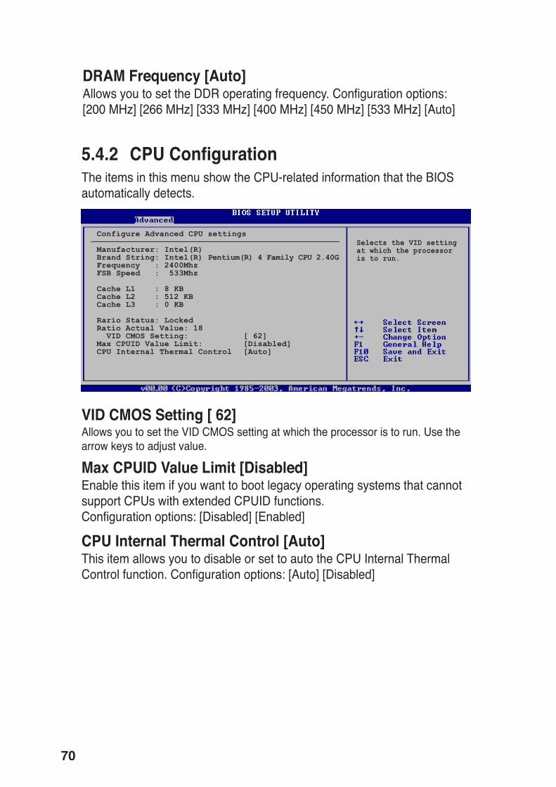
5.4.2 CPU ConfigurationThe items in this menu show the CPU-related information that the BIOSautomatically detects.
Selects the VID settingat which the processoris to run.
Configure Advanced CPU settings
Manufacturer: Intel(R)Brand String: Intel(R) Pentium(R) 4 Family CPU 2.40GFrequency : 2400MhzFSB Speed : 533Mhz
Cache L1 : 8 KBCache L2 : 512 KBCache L3 : 0 KB
Rario Status: LockedRatio Actual Value: 18 VID CMOS Setting: [ 62]Max CPUID Value Limit: [Disabled]CPU Internal Thermal Control [Auto]
VID CMOS Setting [ 62]Allows you to set the VID CMOS setting at which the processor is to run. Use thearrow keys to adjust value.
Max CPUID Value Limit [Disabled]Enable this item if you want to boot legacy operating systems that cannotsupport CPUs with extended CPUID functions.Configuration options: [Disabled] [Enabled]
CPU Internal Thermal Control [Auto]This item allows you to disable or set to auto the CPU Internal ThermalControl function. Configuration options: [Auto] [Disabled]

71ASUS Vintage-S800 barebone system
5.4.3 ChipsetThe Chipset menu allows you to change the advanced chipset settings. Select anitem then press <Enter> to display the sub-menu.
Northbridge SiS661FX ConfigurationSouthbridge SiS963/SiS963L Configuration
Options for NB
Northbridge SiS661FX Configuration
Primary Graphics Adapter [PCI]MA 1T/2T Select [Auto]DRAM CAS# Latency [By SPD]DRAM Precharge Delay [Auto]DRAM RAS# to CAS# Delay [Auto]DRAM RAS# Precharge [Auto]Graphic Win Size [ 64MB]
Share Memory Size [ 32MB]
Primary Graphics Adapter [PCI]Allows selection of the graphics controller to use as primary boot device.Configuration options: [PCI] [AGP] [Onboard AGP]
MA 1T/2T Select [Auto]Configuration options: [MA2T] [MA1T]

72
DRAM CAS# Latency [By SPD]When set to [By SPD], the DRAM timing parameters are set according tothe DRAM SPD (Serial Presence Detect).Configuration options: [By SPD] [2T] [2.5T] [3T]
DRAM Precharge Delay [Auto]Configuration options: [Auto] [6T] [7T] [5T] [4T] [8T] [9T]
DRAM RAS# to CAS# Delay [Auto]This item controls the latency between the DDR SDRAM active commandand the read/write command. Configuration options: [Auto] [3T] [2T] [4T][5T]
DRAM RAS# Precharge [Auto]This item controls the idle clocks after issuing a precharge command tothe DDR SDRAM. Configuration options: [Auto] [3T] [2T] [4T] [5T]
Graphic Win Size [ 64MB]Configuration options: [32MB] [64MB] [128MB]
Share Memory Size [ 32MB]Configuration options: [16MB] [32MB] [64MB] [128MB] [Disabled]
Onboard AC97 Audio Device [Enabled]Onboard SiS900 LAN Device [Enabled]
Onboard LAN Boot ROM [Disabled]
<Enter> to enable ordisable
Southbridge SiS963/SiS963L Configuration
Onboard AC97 Audio Device [Enabled]Selecting [Enabled] allows the BIOS to detect whether you are using anyaudio device. If an audio device is detected, the onboard audio controlleris enabled. If no audio device is detected, the controller is disabled.Configuration options: [Enabled] [Disabled]

73ASUS Vintage-S800 barebone system
Onboard SiS900 LAN Device [Enabled]Enables or disables the onboard SiS900 LAN device.Configuration options: [Enabled] [Disabled]
Onboard LAN Boot ROM [Disabled]Enables or disables the onboard LAN Boot ROM.Configuration options: [Enabled] [Disabled]
5.4.4 Onboard Devices Configuration
Serial Port1 Address [3F8/IRQ4]Serial Port2 Address [2F8/IRQ3]Parallel Port Address [Disabled]Onboard Game Port [Disabled]Onboard MIDI Port [Disabled]
Allows BIOS to selectSerial Port1 BaseAddresses.
Configure Win697 Super IO Chipset
Serial Port1 Address [3F8/IRQ4]Allows you to select the Serial Port1 base address.Configuration options: [Disabled] [3F8/IRQ4] [3E8/IRQ4] [2E8/IRQ3]
Serial Port2 Address [2F8/IRQ3]Allows you to select the Serial Port2 base address.Configuration options: [Disabled] [2F8/IRQ3] [3E8/IRQ4] [2E8/IRQ3]
Parallel Port Address [Disabled]Allows you to select the Parallel port base addresses.Configuration options: [Disabled] [378] [278] [3BC]
Onboard Game Port [Disabled]Enables or disables the onboard Game Port.Configuration options: [Disabled] [Enabled]
Onboard MIDI Port [Disabled]Allows you to disable the onboard MIDI Port, or select MIDI Portaddresses. Configuration options: [Disabled] [300] [330]

74
Plug And Play O/S [No]When set to [No], BIOS configures all the devices in the system. When setto [Yes] and if you installed a Plug and Play operating system, theoperating system configures the Plug and Play devices not required forboot. Configuration options: [Yes] [No]
PCI Latency Timer [64]Allows you to select the value in units of PCI clocks for the PCI devicelatency timer register. Configuration options: [32] [64] [96] [128] [160] [192][224] [248]
Allocate IRQ to PCI VGA [Yes]When set to [Yes], BIOS assigns an IRQ to PCI VGA card if the cardrequests for an IRQ. When set to [No], BIOS does not assign an IRQ tothe PCI VGA card even if requested. Configuration options: [No] [Yes]
Palette Snooping [Disabled]When set to [Enabled], the palette snooping feature informs the PCIdevices that an ISA graphics device is installed in the system so that thelatter can function correctly. Configuration options: [Disabled] [Enabled]
IRQ xx [Available]
5.4.5 PCI PnPThe PCI PnP menu items allow you to change the advanced settings for PCI/PnPdevices. The menu includes setting IRQ and DMA channel resources for eitherPCI/PnP or legacy ISA devices.
Take caution when changing the settings of the PCIPnP menu items.Incorrect field values can cause the system to malfunction.
NO: lets the BIOSconfigure all thedevices in the system.YES: lets theoperating systemconfigure Plug andPlay (PnP) devices notrequired for boot ifyour system has a Plugand Play operatingsystem.
Advanced PCI/PnP settings
WARNING: Setting wrong values in the sections below may cause system to malfunction.
Plug And Play OS [No]PCI Latency Timer [64]Allocate IRQ to PCI VGA [Yes]Palette Snooping [Disabled]PCI IDE Bus Master [Enabled]
IRQ-3 assigned to [PCI Device]IRQ-4 assigned to [PCI Device]IRQ-5 assigned to [PCI Device]IRQ-7 assigned to [PCI Device]IRQ-9 assigned to [PCI Device]IRQ-10 assigned to [PCI Device]IRQ-11 assigned to [PCI Device]IRQ-14 assigned to [PCI Device]IRQ-15 assigned to [PCI Device]

75ASUS Vintage-S800 barebone system
PCI IDE Bus Master [Enabled]When set to [Enabled], the BIOS uses PCI bus mastering for reading/writing to IDE drives. Configuration options: [Enabled] [Disabled]
IRQ-xx assigned to [PCI Device]When set to [PCI Device], the specific IRQ is free for use of PCI/PnPdevices. When set to [Reserved], the IRQ is reserved for legacy ISAdevices. Configuration options: [PCI Device] [Reserved]
5.4.6 USB ConfigurationThe items in this menu allows you to change the USB-related features.Select an item then press <Enter> to display the configuration options.
Onboard SiS USB1.1 Device [Enabled]Onboard SiS USB2.0 Device [Enabled]
USB Configuration
Module Version - 2.23.2-9.4USB Devices Enabled: None
Legacy USB Support [Auto]USB 2.0 Controller Mode [FullSpeed]Stop EHCI HC in OHCI handover [Enabled]
<Enter> to enable ordisable.
Onboard SiS USB1.1 Device [Enabled]Enables or disables the onboard SiS USB1.1 device.Configuration options: [Enabled] [Disabled]
Onboard SiS USB2.0 Device [Enabled]Enables or disables the onboard SiS USB2.0 device.Configuration options: [Enabled] [Disabled]
Legacy USB Support[Auto]Allows you to enable or disable support for legacy USB devices. Setting toAuto allows the system to detect the presence of USB devices at startup. Ifdetected, the USB controller legacy mode is enabled. If no USB device isdetected, the legacy USB support is disabled. Configuration options:[Disabled] [Enabled] [Auto]

76
5.5 Power menuThe Power menu items allow you to change the power settings. Select an itemthen press <Enter> to display the configuration options.
5.5.1 ACPI Aware O/SEnables or disable ACPI support for the operating system. Configurationoptions: [Yes] [No]
5.5.2 Suspend Mode [Auto]Allows you to select the ACPI state to be used for system suspend.Configuration options: [S1 (POS) only] [S3 Only] [Auto]
5.5.3 Repost Video on S3 Resume [No]Determines whether to invoke VGA BIOS POST on S3/STR resume.Configuration options: [No] [Yes]
ACPI Aware O/S [Yes]Suspend Mode [Auto]Repost Video on S3 Resume [No]ACPI APIC Support [Enabled]
APM ConfigurationHardware Monitor
Enable/Disable ACPIsupport for OperatingSystem.
ENABLE: If OS supportsACPI.
DISABLE: If OS doesnot support ACPI
USB 2.0 Controller Mode [HiSpeed]Allows you to configure the USB 2.0 controller in HiSpeed (480 Mbps) orFull Speed (12 Mbps). Configuration options: [HiSpeed ] [Full Speed]
Stop EHCI HC in OHCI handover [Enabled]When set to [Enabled], the BIOS stops the EHCI host controller duringOHCI OS handover call. This is needed for installing operating systemsthat do not support EHCI host controllers.

77ASUS Vintage-S800 barebone system
5.5.4 ACPI APIC Support [Enabled]Enables or disables the ACPI support in the ASIC. When set to [Enabled], the ACPIAPIC table pointer is included in the RSDT pointer list.Configuration options: [Disabled] [Enabled]
5.5.5 APM Configuration
Restore On AC Power Loss [Always OFF]Power On By PS/2 KeyBoard [Disabled]Power On By PS/2 Mouse [Disabled]Power On By Internal MAC LAN [Disabled]Power On By PCI Devices [Disabled]Power On By External Modems [Disabled]Power On By RTC Alarm [Disabled]
<Enter> to select whetheror not to restart thesystem after AC powerloss.
Restore on AC Power Loss [Always OFF]When set to [Always Off], the system goes into off state after an AC powerloss. When set to [Always On], the system goes on after an AC powerloss. When set to [Keep previous state], the system goes into either off oron state whatever was the system state before the AC power loss.Configuration options: [Always Off] [Always On] [Keep previous state]
Power On By PS/2 KeyBoard [Disabled]Allows you to use specific keys on the keyboard to turn on the system.Configuration options: [Disabled] [Space Bar] [Ctrl-Esc] [Power Key]
Power On By PS/2 Mouse [Disabled]When set to [Enabled], this parameter allows you to use the PS/2 mouseto resume the system. This feature requires an ATX power supply thatprovides at least 1A on the +5VSB lead. Configuration options: [Disabled][Enabled]
Power On By Internal MAC LAN [Disabled]Enables or disables MAC wake from sleep state.Configuration options: [Disabled] [Enabled]

78
Power On By PCI Device [Disabled]When set to [Enabled], this parameter allows you to turn on the systemthrough a PCI LAN or modem card. This feature requires an ATX powersupply that provides at least 1A on the +5VSB lead. Configuration options:[Enabled] [Disabled]
Power On By External Modems [Disabled]Allows either settings of [Enabled] or [Disabled] for powering up thecomputer when the external modem receives a call while the computer isin Soft-off mode. Configuration options: [Disabled] [Enabled]
The computer cannot receive or transmit data until the computer andapplications are fully running. Thus, connection cannot be made on the first try.Turning an external modem off and then back on while the computer is offcauses an initialization string that turns the system power on.
Power On By RTC Alarm [Disabled]Allows you to enable or disable RTC to generate a wake event. When thisitem is set to Enabled, the items RTC Alarm Date, RTC Alarm Hour, RTCAlarm Minute, and RTC Alarm Second appear with set values.Configuration options: [Disabled] [Enabled]

79ASUS Vintage-S800 barebone system
5.5.6 Hardware Monitor
Hardware Monitor
CPU Temperature [28.5°C/83°F]MB Temperature [28°C/82°F]
CPU Fan Speed [2934RPM]Chassis Fan Speed [N/A]
Q-Fan Control [Enabled]Q-Fan Control Temperature [45 Degrees]Q-Fan Control Tolerance [+-3]
VCORE Voltage [1.520V]3.3V Voltage [3.344V]5V Voltage [5.053V]12V Voltage [11.904V]
Chassis Intrude [Disabled]
CPU Temperature [xxx°C/xxx°F]MB Temperature [xxx°C/xxx°F]The onboard hardware monitor automatically detects and displays theCPU and motherboard temperatures.
CPU Fan Speed [xxxxRPM] or [N/A]Chassis Fan Speed [xxxxRPM] or [N/A]The onboard hardware monitor automatically detects and displays theCPU and chassis fan speeds in rotations per minute (RPM). If any of thefans is not connected to the motherboard, the specific field shows N/A.
Q-Fan Control [Enabled]Allows you to enable or disable the ASUS Q-Fan feature that smartlyadjusts the fan speeds for more efficient system operation. When this fieldis set to [Enabled], the Q-Fan Control Temperature and Q-Fan ControlTolerance items appear to allow selection of the appropriate values.Configuration options: [Disabled] [Enabled]
VCORE Voltage, 3.3V Voltage, 5V Voltage, 12V VoltageThe onboard hardware monitor automatically detects the voltage outputthrough the onboard voltage regulators.
If any of the monitored items is out of range, the following error messageappears: “Hardware Monitor found an error. Enter Power setup menu fordetails”. You will then be prompted to “Press F1 to continue or DEL toenter SETUP”.

80
5.6 Boot menuThe Boot menu items allow you to change the system boot options. Selectan item then press <Enter> to display the sub-menu.
5.6.1 Boot Device Priority
1st ~ xxth Boot Device [1st FLOPPY DRIVE]These items specify the boot device priority sequence from the availabledevices. The number of device items that appear on the screen dependson the number of devices installed in the system. Configuration options:[xxxxx Drive] [Disabled]
Boot Device Priority
1st Boot Device [1st FLOPPY DRIVE]2nd Boot Device [PS-Pioneer CD-ROM]
Specifies the bootsequence from theavailable devices.
A device enclosed inparenthesis has beendisabled in thecorresponding typemenu.
Boot Settings
Boot Device Priority
Boot Settings ConfigurationSecurity
Specifies the BootDevice Prioritysequence.
Chassis Intrude [Disabled]Enables or disables the chassis intrusion feature.Configuration options: [Disabled] [Enabled]

81ASUS Vintage-S800 barebone system
5.6.2 Boot Settings Configuration
Quick Boot [Enabled]Enabling this item allows BIOS to skip some power on self tests (POST)while booting to decrease the time needed to boot the system. When setto [Disabled], BIOS performs all the POST items.Configuration options: [Enabled] [Disabled]
AddOn ROM Display Mode [Force BIOS]Sets the display mode for option ROM.Configuration options: [Force BIOS] [Keep Current]
Bootup Num-Lock [On]Allows you to select the power-on state for the NumLock.Configuration options: [On] [Off]
PS/2 Mouse Support [Auto]Allows you to enable or disable support for PS/2 mouse.Configuration options: [Auto] [Disabled] [Enabled]
Wait for ‘F1’ If Error [Enabled]When set to [Enabled], the system waits for F1 key to be pressed whenerror occurs. Configuration options: [Enabled] [Disabled]
Hit ‘DEL’ Message Display [Enabled]When set to [Enabled], the system displays the message “Press DEL torun Setup” during POST. Configuration options: [Enabled] [Disabled]
Interrupt 19 Capture [Disabled]When set to [Enabled], this function allows the option ROMs to trapInterrupt 19. This is required by some PCI cards that provide a ROM-based setup utility. Configuration options: [Disabled] [Enabled]
Boot Settings Configuration
Quick Boot [Enabled]AddOn ROM Display Mode [Force BIOS]Bootup Num-Lock [On]PS/2 Mouse Support [Auto]Wait for ‘F1’ If Error [Enabled]Hit ‘DEL’ Message Display [Enabled]Interrupt 19 Capture [Disabled]
Allows BIOS to skipcertain tests whilebooting. This willdecrease the timeneeded to boot thesystem.

82
Change Supervisor PasswordSelect this item to set or change the supervisor password. The SupervisorPassword item on top of the screen shows the default Not Installed. Afteryou have set a password, this item shows Installed.
To set a Supervisor Password:
1. Select the Change Supervisor Password item and press <Enter>.
2. On the password box that appears, type a password composed of atleast six letters and/or numbers, then press <Enter>.
3. Confirm the password when prompted.
The message “Password Installed” appears after you successfully set yourpassword. The Supervisor Password item now shows “Installed”. Tochange the supervisor password, follow the same steps as in setting auser password.
To clear the supervisor password, select the Change Supervisor Passwordthen press Enter. The message “Password Uninstalled” appears.
5.6.3 SecurityThe Security menu items allow you to change the system security settings.Select an item then press <Enter> to display the configuration options.
Security Settings
Supervisor Password Not InstalledUser Password Not Installed
Change Supervisor PasswordChange User PasswordClear User Password
<Enter> to changepassword.<Enter> again to disablepassword.

83ASUS Vintage-S800 barebone system
Security Settings
Supervisor Password Not InstalledUser Password Not Installed
Change Supervisor PasswordUser Access Level [Full Access]Change User PasswordPassword Check [Setup]
<Enter> to changepassword.<Enter> again to disablepassword.
User Access Level (Full Access]Allows you to select the access restriction to the Setup items.Configuration options: [No Access] [View Only] [Limited] [Full Access]
No Access prevents user access to the Setup utility.View Only allows access but does not allow change to any field.Limited allows change to only selected fields, such as Date and Time.Full Access allows viewing and changing all the fields in the Setup utility.
Change User PasswordSelect this item to set or change the user password. The User Password item ontop of the screen shows the default Not Installed. After you have set a password,this item shows Installed.
To set a User Password:
1. Select the Change User Password item and press <Ente>r.
2. On the password box that appears, type a password composed of letters and/ornumbers, then press Enter. Your password should have at least six characters.
3. Confirm the password when prompted.
The message “Password Installed” appears after you have successfully set yourpassword. The User Password item now shows Installed. To change the userpassword, follow the same steps as in setting a user password
Clear User PasswordChoose this option to immediately clear the user password,
After you set a supervisor password, the other items appear to allow youto change other security settings.

84
Exit & Save ChangesOnce you are finished making your selections, choose this option from theExit menu to ensure the values you selected are saved to the CMOS RAM.The CMOS RAM is sustained by an onboard backup battery and stays oneven when the PC is turned off. When you select this option, aconfirmation window appears. Select [Yes] to save changes and exit.
If you attempt to exit the Setup program without saving your changes, theprogram prompts you with a message asking if you want to save yourchanges before exiting. Pressing <Enter> saves the changes whileexiting.
5.7 Exit menuThe Exit menu items allow you to load the optimal or failsafe default valuesfor the BIOS items, and save or discard your changes to the BIOS items.
Pressing <Esc> does not immediately exit this menu. Select one of theoptions from this menu or <F10> from the legend bar to exit.
Exit Options
Exit & Save ChangesExit & Discard ChangesDiscard Changes
Load Setup Defaults
Exit system setup aftersaving the changes.
F10 key can be used forthis operation.

85ASUS Vintage-S800 barebone system
Exit & Discard ChangesSelect this option only if you do not want to save the changes that youmade to the Setup program. If you made changes to fields other thansystem date, system time, and password, the BIOS asks for a confirmationbefore exiting.
Discard ChangesThis option allows you to discard the selections you made and restore thepreviously saved values. After selecting this option, a confirmationappears. Select [Yes] to discard any changes and load the previouslysaved values.
Load Setup DefaultsThis option allows you to load the default values for each of theparameters on the Setup menus. When you select this option, or if youpress <F5>, a confirmation window appears. Select [Yes] to load thedefault values. Select Exit & Save Changes or make other changes beforesaving the values to the non-volatile RAM.

86