vibrotactile haptic feedback for intuitive control of robotic extra fingers
TRANSCRIPT

Vibrotactile Haptic Feedback for Intuitive Control of Robotic Extra Fingers
Irfan Hussain1, Leonardo Meli1,2, Claudio Pacchierotti1,2, Gionata Salvietti2, and Domenico Prattichizzo1,2
Abstract— Wearable robots have been mostly designed asexoskeletons, with segments and joints corresponding to thoseof the person they are coupled with. Exoskeletons are mainlyemployed to augment human body force and precision capabili-ties, or for rehabilitation purposes. More recently, new wearablerobots resembling additional robotic limbs have been developedthanks to the progress in miniaturization and efficiency ofmechanical and sensing components. However, wearable roboticextra limbs presented in the literature lack of effective hapticfeedback systems. In this paper, we present a robotic extrafinger coupled with a vibrotactile ring interface. The humanuser is able to control the motion of the robotic finger through aswitch placed on the ring, while being provided with vibrotactilefeedback about the forces exerted by the robotic finger on theenvironment. To understand how to control the vibrotactileinterface to evoke the most effective cutaneous sensations, weexecuted perceptual experiments to evaluate its absolute anddifferential thresholds. We also carried out a pick-and-placeexperiment with ten subjects. Haptic feedback significantlyimproved the performance in task execution in terms ofcompletion time, exerted force, and perceived effectiveness. Allsubjects preferred experimental conditions employing hapticfeedback with respect to those not providing any force feedback.
I. INTRODUCTION
Wearable robots can potentially interact and collaborate
with people in an intelligent environment [1]. In the last
decades, wearable robots have been mostly designed as
mechatronic systems shaped around and in function of the
human body, with segments and joints corresponding to
those of the person they were externally coupled with [2].
These systems have been often referred to as exoskeletons,
whose main purposes are enhancing human body force
and precision capabilities [3] or helping in rehabilitation
processes [4].
The progress in miniaturization and efficiency of the
mechanical and sensing components is extending the field of
wearable robotics toward new devices which do not replicate
or assist a part of the human body, but can rather be seen
as robotic extra limbs. In [5], [6], two additional robotic
arms, worn through a backpack-like harness, have been pre-
sented as possible device to assist human workers in aircraft
assembly by holding an object, manipulating a workpiece,
etc.. Although the principle is very promising, finding a trade
off between wearability, efficiency and performance on such
bulky robots still represents an open challenge.
The research leading to these results has received funding from theEuropean Union Seventh Framework Program FP7/2007-2013 under grantagreement 601165 of the project “WEARHAP”.
1Dept. of Information Engineering, University of Siena, Via Roma56, 53100 Siena, Italy. {hussain, meli, pacchierotti,prattichizzo}@dii.unisi.it
2Dept. of Advanced Robotics, Istituto Italiano di Tecnologia, Via Morego30, 16163 Genoa, Italy. [email protected]
Fig. 1. The robotic extra finger together with the vibrotactile interface ring.The ring provides haptic feedback through a vibrating motor and enablesthe user to start and stop the finger motion through a switch.
Wearability is the key concept in the design of these type
of devices. For this reason, we decided to augment the func-
tions of the human hand, instead of developing additional
robotic arms as in [5]. The goal is to integrate the human
hand with an additional robotic finger as represented in
Fig. 1. The availability of one or more extra fingers enhances
the capabilities of the human hand in terms of workspace
and in terms of manipulation capabilities. The extra finger
increases the workspace volume, so that the augmented
hand can, for instance, grasp objects that are anatomically
impossible to grasp using one hand, or even manipulate more
objects at the same time. In [7], we presented a 4 Degrees
of Freedom (DoFs) modular device that can be worn on the
wrist by means of an elastic band. Each module was actuated
with servomotor and controlled by PWM with an Arduino
board. Differently from [8], the design was highly focused
on the wearability and portability of the system.
Beyond design guidelines, another interesting issue is how
to interface the extra finger with the human hand motion.
In [9], we presented a possible control strategy able to
transfer to one or more extra fingers a part or the whole
motion of the human hand. We considered an extension
of the mapping method proposed in [10], [11] to the case
of a human hand augmented with a robotic extra finger.
A commercial dataglove was used to measure the hand
configuration during a grasping task. Although this control
approach guarantees a reliable tracking of the human hand
and can be extended to more fingers, there are two main
drawbacks to be solved. First, the user lacks a feedback
of the robotic finger status and can only perceive the force

(a) Ring. (b) Modular finger.
Fig. 2. CAD models of the vibrotactile interface and of the modular finger.Three single DoF modules are connected to a wrist elastic band. The ringis equipped with a push button which is used as an interface with the userand a vibrotactile motor to provide an haptic stimulus.
exerted by the device mediated by the grasped object. The
second problem is related to the approaching phase of the
grasp. In fact, the algorithm presented in [9] considers the
motion of the whole hand to compute the motion of the extra
finger, thus limiting the possibility of the user to make fine
adjustments to adapt the finger shape to that of the grasped
object.
In this work, we addressed these issues by introducing a
vibrotactile interface that can be worn as a ring. The human
user receives information through the vibrotactile interface
about the robotic finger status in terms of contact/no contact
with the grasped object and in terms of force exerted by the
device. Haptic stimuli have been indeed proved to enhance
the performance of robotic systems in many scenarios [12],
[13], [14], [15]. However, most robotic systems with force
reflection provide force feedback through grounded haptic
devices, such as the Omega (Force Dimension, Switzerland)
interfaces. Although these devices can be very accurate and
able to provide a wide range of forces, their form factor
makes them not suitable to be used in wearable applications,
where the system needs to be lightweight, small, and easy to
wear [16]. For this reason, we designed a custom wearable
vibrotactile interface, since vibrotactile stimuli convey rich
information and have an extremely compact form factor with
respect to more popular grounded interfaces [17], [18], [19],
[20].
Regarding the grasp approaching phase, we introduce a
new control strategy that enables the finger to autonomously
adapt to the shape of the grasped object. We developed a
new finger prototype with 3 DoFs and three modules to
resemble the kinematics of the human finger. Each module
has been equipped with a force sensor able to detect contacts
with the grasped object. We defined a grasping procedure
that starts from a predefined position, when the robotic
finger is open at its maximum. As soon as one module is
in contact with the object, that module stops its motion,
while the others keep moving toward the object. The details
of the closing procedure will be described in Sec. II. The
procedure can be activated by pressing the switch placed on
the interface ring (see Fig. 1). This approach dramatically
simplifies the interaction with the robotic finger, reducing
it to the activation of a grasping procedure through the
wearable switch. This shared autonomy between the user and
the device has been kept also in the control of the exerted
force. We developed a variable compliance control that let
the finger adapt its stiffness according to the force necessary
to guarantee a stable grasp. The user is provided through the
vibrating ring with information about the exerted forces and,
therefore, about the finger compliance.
We tested the system in a pick and place task where
users were asked to move an object between two prede-
fined positions by taking advantage of the extra finger. We
demonstrated that haptic feedback, together with the intuitive
human robot interface, enhances users’ performance in terms
of completion time and exerted force.
The rest of the paper is organized as it follows. Section II
describes the extra finger and the ring interface. Section III
presents two preliminary experiments aiming at evaluating
the absolute and differential thresholds of our vibrotactile
haptic device. Section IV deals with the pick-and-place
experiment carried out to evaluate the effectiveness of the
system, while in Section V conclusion and future work are
outlined.
II. THE EXTRA FINGER ROBOTIC DEVICE
A. System design
The robotic finger has a modular structure. Each mod-
ule consists of a servomotor (HS-53 Microservo, HiTech,
Korea) and a 3D printed plastic part with dimensions of
42 × 33 × 16 mm. The prototype presented in this paper
has 3 DoFs, that are obtained by considering three modules
in a pitch-pitch connection. These modules replicate the
flexion/extension motion of the human fingers.
A Force Sensing Resistor (FSR) (408, Interlink Electronics
Inc., USA) was placed on each module, as reported in Fig. 2.
These sensors will be used for the closing procedure and the
compliance variation described in Sec. II-B. The finger is
attached to a support base that can be worn on the wrist by
means of an elastic band. We placed the device on the wrist
center to enlarge the hand workspace [7].
The vibrotactile ring interface is designed to be worn on
the index finger of the human hand, see Fig. 1. The ring
is equipped with a switch and a vibro motor, as shown in
Fig. 2. The ring housing is 3D printed. The motor used
is an eccentric rotating mass vibrotactile motor (Precision
MicroDrives, United Kingdom). The switch is used to start
the finger closing procedure, as described in Sec. II-B, and
move the finger back to the initial grasp position. The
vibrotactile motor is used to provide vibrotactile feedback,
as explained in Sec. IV.
The module actuator is controlled by PWM signal gen-
erated by an Arduino Nano board. The servos position
feedback and FSRs signals are interfaced with the analog
channels of the Arduino. An external battery is used to
provide power to all the circuits (similarly to .
0.5 1 1.5 2 2.5 3 3.5 4 4.5 50
2
4
6
8
10
12
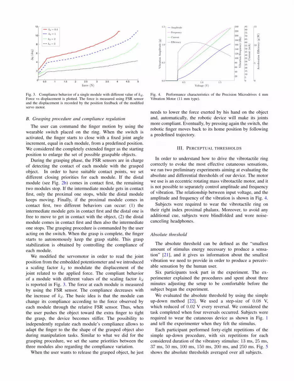
Fig. 3. Compliance behavior of a single module with different value of kd.Force vs displacement is plotted. The force is measured using FSR sensorand the displacement is recorded by the position feedback of the modifiedservo motor.
B. Grasping procedure and compliance regulation
The user can command the finger motion by using the
wearable switch placed on the ring. When the switch is
activated, the finger starts to close with a fixed joint angle
increment, equal in each module, from a predefined position.
We considered the completely extended finger as the starting
position to enlarge the set of possible graspable objects.
During the grasping phase, the FSR sensors are in charge
of detecting the contact of each module with the grasped
object. In order to have suitable contact points, we set
different closing priorities for each module. If the distal
module (see Fig. 2b) comes in contact first, the remaining
two modules stop. If the intermediate module gets in contact
first, only the proximal one stops, while the distal module
keeps moving. Finally, if the proximal module comes in
contact first, two different behaviors can occur: (1) the
intermediate module gets in contact first and the distal one is
free to move to get in contact with the object, (2) the distal
module comes in contact first and then also the intermediate
one stops. The grasping procedure is commanded by the user
acting on the switch. When the grasp is complete, the finger
starts to autonomously keep the grasp stable. This grasp
stabilization is obtained by controlling the compliance of
each module.
We modified the servomotor in order to read the joint
position from the embedded potentiometer and we introduced
a scaling factor kd to modulate the displacement of the
joint related to the applied force. The compliant behavior
of a module with different values of the scaling factor kdis reported in Fig. 3. The force at each module is measured
by using the FSR sensor. The compliance decreases with
the increase of kd. The basic idea is that the module can
change its compliance according to the force observed by
each module through the relative FSR sensor. Thus, when
the user pushes the object toward the extra finger to tight
the grasp, the device becomes stiffer. The possibility to
independently regulate each module’s compliance allows to
adapt the finger to the the shape of the grasped object also
during manipulation tasks. Similar to what we did for the
grasping procedure, we set the same priorities between the
three modules also regarding the compliance variation.
When the user wants to release the grasped object, he just
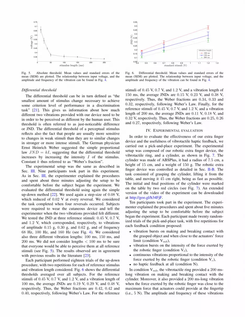
Fig. 4. Performance characteristics of the Precision Microdrives 4 mmVibration Motor (11 mm type).
needs to lower the force exerted by his hand on the object
and, automatically, the robotic device will make its joints
more compliant. Eventually, by pressing again the switch, the
robotic finger moves back to its home position by following
a predefined trajectory.
III. PERCEPTUAL THRESHOLDS
In order to understand how to drive the vibrotactile ring
correctly to evoke the most effective cutaneous sensations,
we ran two preliminary experiments aiming at evaluating the
absolute and differential thresholds of our device. The motor
we use is an eccentric rotating mass vibrotactile motor, and it
is not possible to separately control amplitude and frequency
of vibration. The relationship between input voltage, and the
amplitude and frequency of the vibration is shown in Fig. 4.
Subjects were required to wear the vibrotactile ring on
their right index proximal phalanx. Moreover, to avoid any
additional cue, subjects were blindfolded and wore noise-
canceling headphones.
Absolute threshold
The absolute threshold can be defined as the “smallest
amount of stimulus energy necessary to produce a sensa-
tion” [21], and it gives us information about the smallest
vibration we need to provide in order to produce a perceiv-
able sensation by the human user.
Six participants took part in the experiment. The ex-
perimenter explained the procedures and spent about three
minutes adjusting the setup to be comfortable before the
subject began the experiment.
We evaluated the absolute threshold by using the simple
up-down method [22]. We used a step-size of 0.08 V,
which reduced of 0.02 V every reversal. We considered the
task completed when four reversals occurred. Subjects were
required to wear the cutaneous device as shown in Fig. 1
and tell the experimenter when they felt the stimulus.
Each participant performed forty-eight repetitions of the
simple up-down procedure, with six repetitions for each
considered duration of the vibratory stimulus: 13 ms, 25 ms,
37 ms, 50 ms, 100 ms, 150 ms, 200 ms, and 250 ms. Fig. 5
shows the absolute thresholds averaged over all subjects.
0 50 100 150 200 250
0.35
0.4
0.45
0.5
0.55
0.6
0.65
0.7
0.75
Fig. 5. Absolute threshold. Mean values and standard errors of themean (SEM) are plotted. The relationship between input voltage, and theamplitude and frequency of the vibration can be found in Fig. 4.
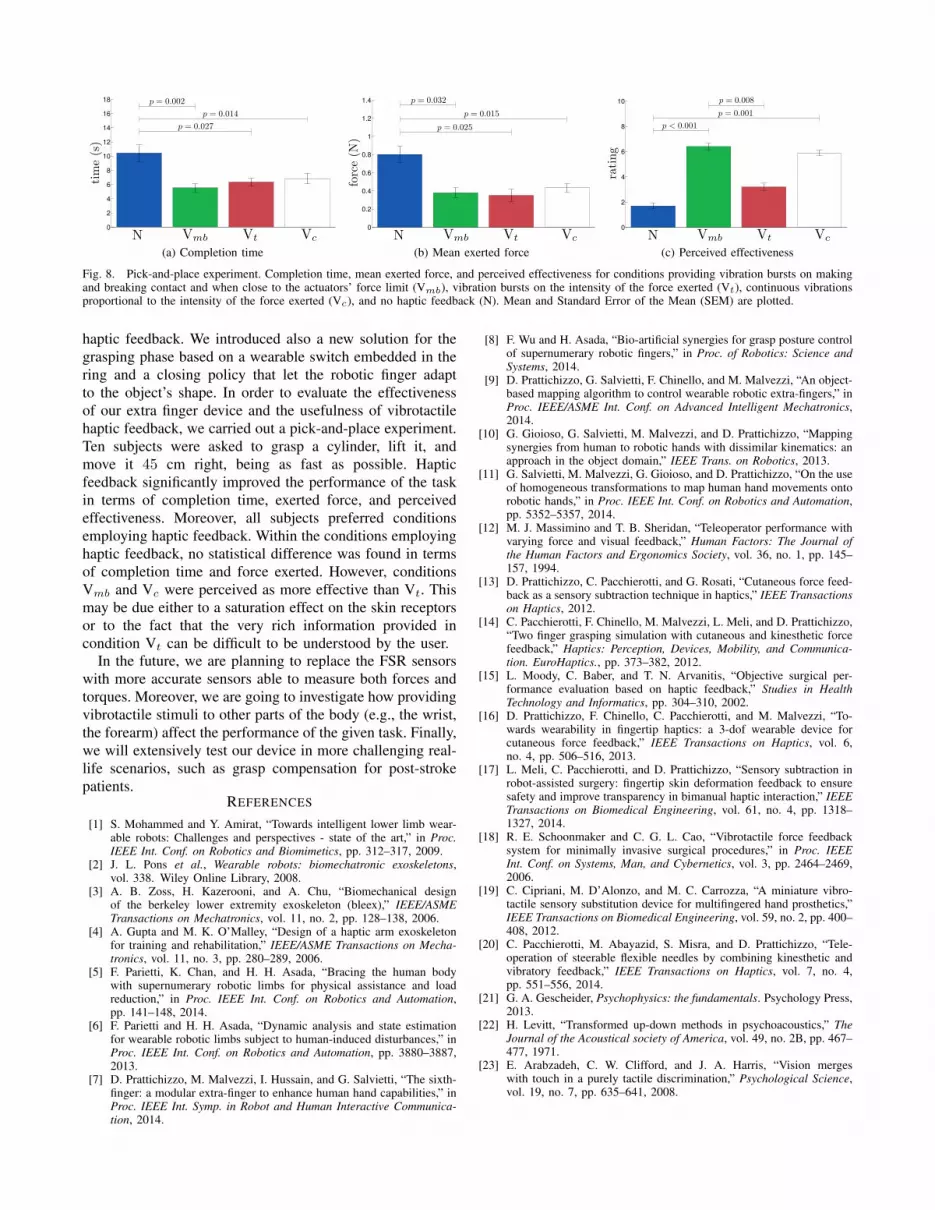
Differential threshold
The differential threshold can be in turn defined as “the
smallest amount of stimulus change necessary to achieve
some criterion level of performance in a discrimination
task” [21]. This gives us information about how much
different two vibrations provided with our device need to be
in order to be perceived as different by the human user. This
threshold is often referred to as just-noticeable difference
or JND. The differential threshold of a perceptual stimulus
reflects also the fact that people are usually more sensitive
to changes in weak stimuli than they are to similar changes
in stronger or more intense stimuli. The German physician
Ernst Heinrich Weber suggested the simple proportional
law JND = kI , suggesting that the differential threshold
increases by increasing the intensity I of the stimulus.
Constant k thus referred to as “Weber’s fraction”.
The experimental setup was the same as described in
Sec. III. Nine participants took part in this experiment.
As in Sec. III, the experimenter explained the procedures
and spent about three minutes adjusting the setup to be
comfortable before the subject began the experiment. We
evaluated the differential threshold using again the simple
up-down method [22]. We used again a step-size of 0.08 V,
which reduced of 0.02 V at every reversal. We considered
the task completed when four reversals occurred. Subjects
were required to wear the cutaneous device and tell the
experimenter when the two vibrations provided felt different.
We tested the JND at three reference stimuli: 0.45 V, 0.7 V,
and 1.2 V, which corresponded, respectively, to vibrations
of amplitude 0.15 g, 0.30 g, and 0.62 g, and of frequency
68 Hz, 100 Hz, and 160 Hz (see Fig. 4). We considered
also three different vibration lengths: 100 ms, 150 ms, and
200 ms. We did not consider lengths < 100 ms to be sure
that everyone would be able to perceive them at all reference
stimuli (see Fig. 5). The results observed are in agreement
with previous results in the literature [23].
Each participant performed eighteen trials of the up-down
procedure, with two repetitions for each of reference stimulus
and vibration length considered. Fig. 6 shows the differential
thresholds averaged over all subjects. For the reference
stimuli of 0.45 V, 0.7 V, and 1.2 V, and a vibration length of
100 ms, the average JNDs are 0.19 V, 0.29 V, and 0.48 V,
respectively. Thus, the Weber fractions are 0.42, 0.42 and
0.40, respectively, following Weber’s Law. For the reference
0.4 0.5 0.6 0.7 0.8 0.9 1 1.1 1.2 1.30.05
0.1
0.15
0.2
0.25
0.3
0.35
0.4
0.45
0.5
0.55
Fig. 6. Differential threshold. Mean values and standard errors of themean (SEM) are plotted. The relationship between input voltage, and theamplitude and frequency of the vibration can be found in Fig. 4.
stimuli of 0.45 V, 0.7 V, and 1.2 V, and a vibration length of
150 ms, the average JNDs are 0.15 V, 0.23 V, and 0.38 V,
respectively. Thus, the Weber fractions are 0.34, 0.33 and
0.32, respectively, following Weber’s Law. Finally, for the
reference stimuli of 0.45 V, 0.7 V, and 1.2 V, and a vibration
length of 200 ms, the average JNDs are 0.11 V, 0.18 V, and
0.32 V, respectively. Thus, the Weber fractions are 0.25, 0.26and 0.27, respectively, following Weber’s Law.
IV. EXPERIMENTAL EVALUATION
In order to evaluate the effectiveness of our extra finger
device and the usefulness of vibrotactile haptic feedback, we
carried out a pick-and-place experiment. The experimental
setup was composed of our robotic extra finger device, the
vibrotactile ring, and a cylinder, as shown in Fig. 7. The
cylinder was made of ABSPlus, it had a radius of 7.5 cm, a
height of 15 cm, and a weight of 150 g. The robotic extra
finger device was controlled as detailed in Sec. II-B. The
task consisted of grasping the cylinder, lifting it from the
table, and moving it 45 cm right, being as fast as possible.
The initial and final positions of the cylinder were marked
on the table by two red circles (see Fig. 7). An extended
version of the video of the experiment can be downloaded
at http://goo.gl/h34FjF.
Ten participants took part in the experiment. The experi-
menter explained the procedures and spent about five minutes
adjusting the setup to be comfortable before the subject
began the experiment. Each participant made twenty random-
ized trials of the pick-and-place task, with five repetitions for
each feedback condition proposed:
• vibration bursts on making and breaking contact with
the grasped object and when close to the actuators’ force
limit (condition Vmb),
• vibration bursts on the intensity of the force exerted by
the robotic finger (condition Vt),
• continuous vibrations proportional to the intensity of the
force exerted by the robotic finger (condition Vc),
• no haptic feedback at all (condition N).
In condition Vmb, the vibrotactile ring provided a 200 ms-
long vibration on making and breaking contact with the
cylinder. Moreover, it also provided a 200 ms-long vibration
when the force exerted by the robotic finger was close to the
maximum force that actuators could provide at the fingertip
(i.e., 5 N). The amplitude and frequency of these vibrations
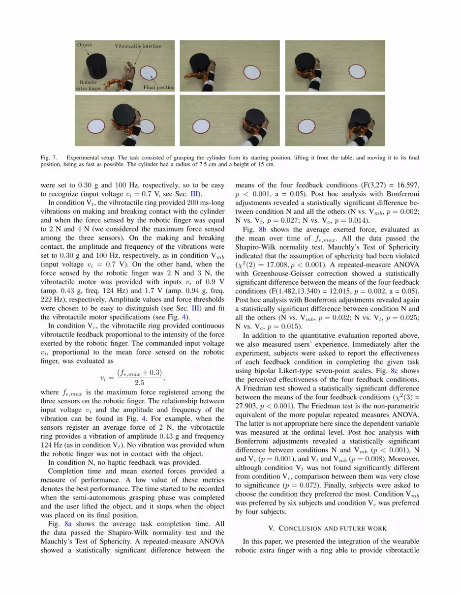
Fig. 7. Experimental setup. The task consisted of grasping the cylinder from its starting position, lifting it from the table, and moving it to its finalposition, being as fast as possible. The cylinder had a radius of 7.5 cm and a height of 15 cm.
were set to 0.30 g and 100 Hz, respectively, so to be easy
to recognize (input voltage vi = 0.7 V, see Sec. III).
In condition Vt, the vibrotactile ring provided 200 ms-long
vibrations on making and breaking contact with the cylinder
and when the force sensed by the robotic finger was equal
to 2 N and 4 N (we considered the maximum force sensed
among the three sensors). On the making and breaking
contact, the amplitude and frequency of the vibrations were
set to 0.30 g and 100 Hz, respectively, as in condition Vmb
(input voltage vi = 0.7 V). On the other hand, when the
force sensed by the robotic finger was 2 N and 3 N, the
vibrotactile motor was provided with inputs vi of 0.9 V
(amp. 0.43 g, freq. 124 Hz) and 1.7 V (amp. 0.94 g, freq.
222 Hz), respectively. Amplitude values and force thresholds
were chosen to be easy to distinguish (see Sec. III) and fit
the vibrotactile motor specifications (see Fig. 4).
In condition Vc, the vibrotactile ring provided continuous
vibrotactile feedback proportional to the intensity of the force
exerted by the robotic finger. The commanded input voltage
vi, proportional to the mean force sensed on the robotic
finger, was evaluated as
vi =(fe,max + 0.3)
2.5,
where fe,max is the maximum force registered among the
three sensors on the robotic finger. The relationship between
input voltage vi and the amplitude and frequency of the
vibration can be found in Fig. 4. For example, when the
sensors register an average force of 2 N, the vibrotactile
ring provides a vibration of amplitude 0.43 g and frequency
124 Hz (as in condition Vt). No vibration was provided when
the robotic finger was not in contact with the object.
In condition N, no haptic feedback was provided.
Completion time and mean exerted forces provided a
measure of performance. A low value of these metrics
denotes the best performance. The time started to be recorded
when the semi-autonomous grasping phase was completed
and the user lifted the object, and it stops when the object
was placed on its final position.
Fig. 8a shows the average task completion time. All
the data passed the Shapiro-Wilk normality test and the
Mauchly’s Test of Sphericity. A repeated-measure ANOVA
showed a statistically significant difference between the
means of the four feedback conditions (F(3,27) = 16.597,
p < 0.001, a = 0.05). Post hoc analysis with Bonferroni
adjustments revealed a statistically significant difference be-
tween condition N and all the others (N vs. Vmb, p = 0.002;
N vs. Vt, p = 0.027; N vs. Vc, p = 0.014).
Fig. 8b shows the average exerted force, evaluated as
the mean over time of fe,max. All the data passed the
Shapiro-Wilk normality test. Mauchly’s Test of Sphericity
indicated that the assumption of sphericity had been violated
(χ2(2) = 17.008, p < 0.001). A repeated-measure ANOVA
with Greenhouse-Geisser correction showed a statistically
significant difference between the means of the four feedback
conditions (F(1.482,13.340) = 12.015, p = 0.002, a = 0.05).
Post hoc analysis with Bonferroni adjustments revealed again
a statistically significant difference between condition N and
all the others (N vs. Vmb, p = 0.032; N vs. Vt, p = 0.025;
N vs. Vc, p = 0.015).
In addition to the quantitative evaluation reported above,
we also measured users’ experience. Immediately after the
experiment, subjects were asked to report the effectiveness
of each feedback condition in completing the given task
using bipolar Likert-type seven-point scales. Fig. 8c shows
the perceived effectiveness of the four feedback conditions.
A Friedman test showed a statistically significant difference
between the means of the four feedback conditions (χ2(3) =
27.903, p < 0.001). The Friedman test is the non-parametric
equivalent of the more popular repeated measures ANOVA.
The latter is not appropriate here since the dependent variable
was measured at the ordinal level. Post hoc analysis with
Bonferroni adjustments revealed a statistically significant
difference between conditions N and Vmb (p < 0.001), N
and Vc (p = 0.001), and Vt and Vmb (p = 0.008). Moreover,
although condition Vt was not found significantly different
from condition Vc, comparison between them was very close
to significance (p = 0.072). Finally, subjects were asked to
choose the condition they preferred the most. Condition Vmb
was preferred by six subjects and condition Vc was preferred
by four subjects.
V. CONCLUSION AND FUTURE WORK
In this paper, we presented the integration of the wearable
robotic extra finger with a ring able to provide vibrotactile
0
2
4
6
8
10
12
14
16
18
(a) Completion time
0
0.2
0.4
0.6
0.8
1
1.2
1.4
(b) Mean exerted force
0
2
4
6
8
10
(c) Perceived effectiveness
Fig. 8. Pick-and-place experiment. Completion time, mean exerted force, and perceived effectiveness for conditions providing vibration bursts on makingand breaking contact and when close to the actuators’ force limit (Vmb), vibration bursts on the intensity of the force exerted (Vt), continuous vibrationsproportional to the intensity of the force exerted (Vc), and no haptic feedback (N). Mean and Standard Error of the Mean (SEM) are plotted.
haptic feedback. We introduced also a new solution for the
grasping phase based on a wearable switch embedded in the
ring and a closing policy that let the robotic finger adapt
to the object’s shape. In order to evaluate the effectiveness
of our extra finger device and the usefulness of vibrotactile
haptic feedback, we carried out a pick-and-place experiment.
Ten subjects were asked to grasp a cylinder, lift it, and
move it 45 cm right, being as fast as possible. Haptic
feedback significantly improved the performance of the task
in terms of completion time, exerted force, and perceived
effectiveness. Moreover, all subjects preferred conditions
employing haptic feedback. Within the conditions employing
haptic feedback, no statistical difference was found in terms
of completion time and force exerted. However, conditions
Vmb and Vc were perceived as more effective than Vt. This
may be due either to a saturation effect on the skin receptors
or to the fact that the very rich information provided in
condition Vt can be difficult to be understood by the user.
In the future, we are planning to replace the FSR sensors
with more accurate sensors able to measure both forces and
torques. Moreover, we are going to investigate how providing
vibrotactile stimuli to other parts of the body (e.g., the wrist,
the forearm) affect the performance of the given task. Finally,
we will extensively test our device in more challenging real-
life scenarios, such as grasp compensation for post-stroke
patients.REFERENCES
[1] S. Mohammed and Y. Amirat, “Towards intelligent lower limb wear-able robots: Challenges and perspectives - state of the art,” in Proc.IEEE Int. Conf. on Robotics and Biomimetics, pp. 312–317, 2009.
[2] J. L. Pons et al., Wearable robots: biomechatronic exoskeletons,vol. 338. Wiley Online Library, 2008.
[3] A. B. Zoss, H. Kazerooni, and A. Chu, “Biomechanical designof the berkeley lower extremity exoskeleton (bleex),” IEEE/ASMETransactions on Mechatronics, vol. 11, no. 2, pp. 128–138, 2006.
[4] A. Gupta and M. K. O’Malley, “Design of a haptic arm exoskeletonfor training and rehabilitation,” IEEE/ASME Transactions on Mecha-tronics, vol. 11, no. 3, pp. 280–289, 2006.
[5] F. Parietti, K. Chan, and H. H. Asada, “Bracing the human bodywith supernumerary robotic limbs for physical assistance and loadreduction,” in Proc. IEEE Int. Conf. on Robotics and Automation,pp. 141–148, 2014.
[6] F. Parietti and H. H. Asada, “Dynamic analysis and state estimationfor wearable robotic limbs subject to human-induced disturbances,” inProc. IEEE Int. Conf. on Robotics and Automation, pp. 3880–3887,2013.
[7] D. Prattichizzo, M. Malvezzi, I. Hussain, and G. Salvietti, “The sixth-finger: a modular extra-finger to enhance human hand capabilities,” inProc. IEEE Int. Symp. in Robot and Human Interactive Communica-tion, 2014.
[8] F. Wu and H. Asada, “Bio-artificial synergies for grasp posture controlof supernumerary robotic fingers,” in Proc. of Robotics: Science andSystems, 2014.
[9] D. Prattichizzo, G. Salvietti, F. Chinello, and M. Malvezzi, “An object-based mapping algorithm to control wearable robotic extra-fingers,” inProc. IEEE/ASME Int. Conf. on Advanced Intelligent Mechatronics,2014.
[10] G. Gioioso, G. Salvietti, M. Malvezzi, and D. Prattichizzo, “Mappingsynergies from human to robotic hands with dissimilar kinematics: anapproach in the object domain,” IEEE Trans. on Robotics, 2013.
[11] G. Salvietti, M. Malvezzi, G. Gioioso, and D. Prattichizzo, “On the useof homogeneous transformations to map human hand movements ontorobotic hands,” in Proc. IEEE Int. Conf. on Robotics and Automation,pp. 5352–5357, 2014.
[12] M. J. Massimino and T. B. Sheridan, “Teleoperator performance withvarying force and visual feedback,” Human Factors: The Journal ofthe Human Factors and Ergonomics Society, vol. 36, no. 1, pp. 145–157, 1994.
[13] D. Prattichizzo, C. Pacchierotti, and G. Rosati, “Cutaneous force feed-back as a sensory subtraction technique in haptics,” IEEE Transactionson Haptics, 2012.
[14] C. Pacchierotti, F. Chinello, M. Malvezzi, L. Meli, and D. Prattichizzo,“Two finger grasping simulation with cutaneous and kinesthetic forcefeedback,” Haptics: Perception, Devices, Mobility, and Communica-tion. EuroHaptics., pp. 373–382, 2012.
[15] L. Moody, C. Baber, and T. N. Arvanitis, “Objective surgical per-formance evaluation based on haptic feedback,” Studies in HealthTechnology and Informatics, pp. 304–310, 2002.
[16] D. Prattichizzo, F. Chinello, C. Pacchierotti, and M. Malvezzi, “To-wards wearability in fingertip haptics: a 3-dof wearable device forcutaneous force feedback,” IEEE Transactions on Haptics, vol. 6,no. 4, pp. 506–516, 2013.
[17] L. Meli, C. Pacchierotti, and D. Prattichizzo, “Sensory subtraction inrobot-assisted surgery: fingertip skin deformation feedback to ensuresafety and improve transparency in bimanual haptic interaction,” IEEETransactions on Biomedical Engineering, vol. 61, no. 4, pp. 1318–1327, 2014.
[18] R. E. Schoonmaker and C. G. L. Cao, “Vibrotactile force feedbacksystem for minimally invasive surgical procedures,” in Proc. IEEEInt. Conf. on Systems, Man, and Cybernetics, vol. 3, pp. 2464–2469,2006.
[19] C. Cipriani, M. D’Alonzo, and M. C. Carrozza, “A miniature vibro-tactile sensory substitution device for multifingered hand prosthetics,”IEEE Transactions on Biomedical Engineering, vol. 59, no. 2, pp. 400–408, 2012.
[20] C. Pacchierotti, M. Abayazid, S. Misra, and D. Prattichizzo, “Tele-operation of steerable flexible needles by combining kinesthetic andvibratory feedback,” IEEE Transactions on Haptics, vol. 7, no. 4,pp. 551–556, 2014.
[21] G. A. Gescheider, Psychophysics: the fundamentals. Psychology Press,2013.
[22] H. Levitt, “Transformed up-down methods in psychoacoustics,” TheJournal of the Acoustical society of America, vol. 49, no. 2B, pp. 467–477, 1971.
[23] E. Arabzadeh, C. W. Clifford, and J. A. Harris, “Vision mergeswith touch in a purely tactile discrimination,” Psychological Science,vol. 19, no. 7, pp. 635–641, 2008.